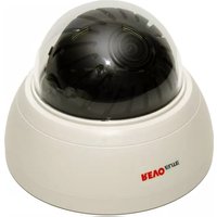
RECDH2812-2 - Security Camera REVO - Free user manual and instructions
Find the device manual for free RECDH2812-2 REVO in PDF.


| Product Type | Security Camera |
| Brand | REVO |
| Model | RECDH2812-2 |
| Dimensions (W x H x D) | Approx. 70 x 70 x 130 mm |
| Weight | Approx. 400 g |
| Power Supply | 12V DC, PoE (802.3af) |
| Image Sensor | 1/2.8" Progressive Scan CMOS |
| Resolution | 1920 x 1080 (Full HD) |
| Lens | 2.8 mm fixed lens |
| Night Vision | Up to 30 meters with IR LEDs |
| Field of View | 92° horizontal |
| Weatherproof Rating | IP67 |
| Connectivity | Ethernet (RJ-45), Wi-Fi optional |
| Storage | MicroSD card up to 128 GB, NVR |
| Audio | Built-in microphone and speaker |
| Mounting Type | Wall or ceiling mount included |
| Compatibility | ONVIF Profile S, REVO NVRs |
| Operation Temperature | -20°C to 50°C |
| Power Consumption | Max 5W |
| Safety Certifications | CE, FCC, RoHS |
| Included Accessories | Mounting kit, power adapter, quick start guide |
Frequently Asked Questions - RECDH2812-2 REVO
User questions about RECDH2812-2 REVO
0 question about this device. Answer the ones you know or ask your own.
Ask a new question about this device
Download the instructions for your Security Camera in PDF format for free! Find your manual RECDH2812-2 - REVO and take your electronic device back in hand. On this page are published all the documents necessary for the use of your device. RECDH2812-2 by REVO.
USER MANUAL RECDH2812-2 REVO
Please read this manual thoroughly before use, and keep it handy for future reference.
Design and specifications are subject to change without notice.
WARNING
TO REDUCE THE RISK OF FIRE OR ELECTRIC SHOCK. DO NOT EXPOSE THIS PRODUCT TO RAIN OR MOISTURE. DO NOT INSERT ANY METALLIC OBJECTS THROUGH THE VENTILATION GRILLS OR OTHER OPENINGS ON THE EQUIPMENT.
CAUTION

EXPLANATION OF GRAPHICAL SYMBOLS

The lightning flash with snowhead symbol, within an equilateral triangle, is intended to start the user to the presence of uninsulated "dangerous voltage" within the product's enclosure that may be of sufficient magnitude to constitute a risk of electric shock to persons.

The exclamation point within an equilateral triangle is intended to alert the user to the presence of important operating and maintenance (servicing) instructions in the literature accompanying the product.
PRECAUTIONS
Safety
Should any liquid or solid object be into the nominal, under the unit and have it checked by the qualified personnel before operating it any further.
Unplug the unit from the wall cut at it is not going to be need for several days or more. To disconnect the cord, pull it out by the plug. Never pull the cord itself.
Allow adequate air circulation to prevent internal heat build-up. Do not place the unit air surfaces (raps, blankets, etc.) or near materials (carbents, draperies) that may block the ventilation holes.
Height and vertical linearity controls located at the near panel area for special adjustments by qualified personnel only.
Installation Do not install the unit in an extremely hot or humid place or in a place subject to excessive dual, mechanical vibration.
Cleaning
Clean the unit with a slightly damp soft cloth. Use a mild household dotergent. Never use strong solvents such as thinner or benzene as they might damage the finish of the unit.
Retain the original carlon and packing materials for safe transport of this unit in the future.
FCC COMPLIANCE STATEMENT
FCC INFORMATION: THIS EQUIPMENT HAS BEEN TESTED AND FOUND TO COMPLY WITH THE LIMITS FOR A CLASS A DIGITAL DEVICE, PURSUANT TO PART 15 OF THE FCC RULES. THESE LIMITS ARE DESIGNED TO PROVIDE REASONABLE PROTECTION AGAINST HARMFUL INTERFERENCE WHEN THE EQUIPMENT IS OPERATED IN A COMMERCIAL ENVIRONMENT. THIS EQUIPMENT GENERATES, USES, AND CAN RADIATE RADIO FREQUENCY ENERGY AND IF NOT INSTALLED AND USED IN ACCORDANCE WITH THE INSTRUCTION MANUAL MAY CAUSE HARMFUL INTERFERENCE TO RADIO COMMUNICATIONS. OPERATION OF THIS EQUIPMENT IN A RESIDENTIAL AREA IS LIKELY TO CAUSE HARMFUL INTERFERENCE IN WHICH CASE THE USER WILL BE REQUIRED TO CORRECT THE INTERFERENCE AT HIS OWN EXPENSE.
CAUTION : CHANGES OR MODIFICATIONS NOT EXPRESSLY APPROVED BY THE PARTY RESPONSIBLE FOR COMPLIANCE COULD VOID THE USER'S AUTHORITY TO OPERATE THE EQUIPMENT.
THIS CLASS A DIGITAL APPARATUS COMPLIES WITH CANADIAN ICES-003. CET APPAREIL NUMÉRIQUE DE LA CLASSE A EST CONFORME À LA NORME NMB-003 DU CANADA.
CE COMPLIANCE STATEMENT
WARNING
THIS IS A CLASS A PRODUCT. IN A DOMESTIC ENVIRONMENT THIS PRODUCT MAY CAUSE RADIO INTERFERENCE IN WHICH CASE THE USER MAY BE REQUIRED TO TAKE ADEQUATE MEASURES.
IMPORTANT SAFETY INSTRUCTIONS
-
Read these instructions.
-
Keep these instructions.
-
Heed all warnings.
-
Follow all instructions.
-
Do not use this apparatus near water.
-
Clean only with dry cloth
-
Do not block any ventilation openings. Install in accordance with the manufacturer's instructions.
-
Do not install near any heat sources such as radiators, heat registers, stoves, or other apparatus (including amplifiers) that produce heat.
-
Do not defeat the safety purpose of the polarized or grounding-type plug. A polarized plug has two blades with one wider than the other. A grounding type plug has two blades and a third grounding prompt. The wide blade or the third prong are provided for your safety. If the provided plug does not fit into your bullet, consult an electrician for replacement of the opposite bullet.
-
Protect the power card from being walked on or pinched particularly at plugs, convenience receptacles, and the point where they exit from the apparatus.
-
Only use attachments/accessories specified by the manufacturer.
-
Use only with the cart, stand, tripod, bracket, or table specified by the manufacturer, or sold with the apparatus. When a cart is used, use caution when moving the carl/apparatus combination to avoid injury from tip-over.
-
Unplug this apparatus during lightning storms or when unused for long periods of time.
-
Refer all servicing to qualified service personnel. Servicing is required when the apparatus has been damaged in any way, such as power-supply cord or plug is damaged, liquid has been moisture, does not operate normally, or has been dropped.
-
CAUTION THESE SERVICING INSTRUCTIONS ARE FOR USE BY QUALIFIED SERVICE PERSONNEL ONLY, TO REDUCE THE RISK OF ELECTRIC SHOCK DO NOT PERFORM ANY SERVICING OTHER THAN THAT CONTAINED IN THE OPERATING INSTRUCTIONS UNLESS YOU QRE QUALIFIED TO DO SO.
-
Use satisfy clause 2.5 of IEC60950-1/UL60950-1 or Certified/Listed Class 2 power source only.

INTRODUCTION
The camera provides high-quality images using Sony CCD technology especially designed for closed-circuit television (CCTV) and security surveillance applications.
Features:
• High resolution and high performance Sony®Supra r HAID® II Technology
• Excellent picture quality
• 600 lines{Color} of resolution
• 0.1 lux(Color), 0.04lux(B/W) @ F1.2 50IRE Sensitivity
- Auto electronic shutter [1/60/1/50] - 1/100,000] and manual electronic shutter modes
- OSD (On Screen Division)
• Auto and manual white balance modes
• DVD
- OSD Font Color (16 Color)
• BLC (Back Light Compensation)
• Day&Night (Auto / DAY / NIGHT / EXT)
• Private Mask (8 position, 15 Colors)
• AGC (Auto Gain Control)
• MIRROR (ON/OFF)
• VIDEO OUT BNC
• Motion Detection(4 point)
• HLC (High Light Compensation)
• DPC (Dead Pixel Cancellation)
• 2.8-12mm All Vertical Lens F1.2(D&N Lens option)
• (1402) All Vertical Lens F1.4 (D&N Lens option)
• 4-0mm A/I Vartifocal Lens F1.6 (C&N Lens option)
• Operatee in AC24V 47-10% / DC12V 47-10%
+ Use Certified / Listed Class 2 power source only
Test monitor Output

IMPORTANT: The user of this camera is responsible for checking and complying with local, state, and federal laws and statutes concerning the recording and monitoring of audio signals.
CAMERA CONNECTIONS

-
Lens: All Var-local lens for wide area monitoring, DSN with ICR model option)
-
Power : 24V AC input / 12V DC input
power source from a DC 12V or AC 24V ac +1-10% 80/60Hz +1-1Hz (ac GndHind) in the case I power source only
C24. Coninkrict B#### C##s 2 p##m S###/G#y
If using DC 12V power adaptor, use a power supply capable of supplying 6 Watts.
- Video : BNC connector used to connect the camera to a monitor, switcher, etc.

REMINDER:
Never aim the camera directly into the sun.
CONTENTS of PACKAGE
The package contains the following.
Camera in Housing 1
Instruction Manual (This Document 1
Accessory Kit for installation 1 1Drilling guide label
BASE INSTALLATION
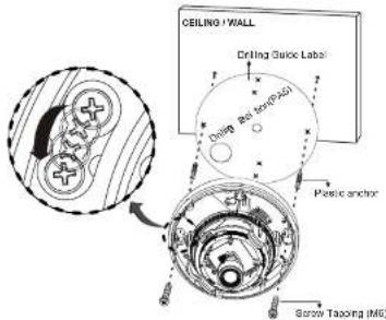
- Make mounting holes and cable hole in the place (ceiling or wall) to which this dome camera is installed using the Drilling guide label.
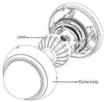
- To remove dome cover, turn the dome body counterclockwise until locators reach end of travel and pull off. Push the liner on the sides where the patterns are put in the teeth of a comb and pull it out.
-
Attach the housing to the ceiling using suitable fasteners, M6x35 tapping screws are supplied only use if they are suitable. Turn the housing to right direction about 18 degrees to lock in place.
-
The assembly of the dome body and liner is in reverse order of disassembly. Finally, lock dome body with locking screw(M3X5) from the accessory kit.
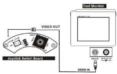
- Video out check-
STRUCTURE OF THE SETUP MENU

flowchart
graph TD
    A["<SETUP>"] --> B["LENS EXPOSURE"]
    B --> C["WHITE BAL BACKLIGHT DAY NIGHT DPC SPECIAL IMAGE ADJ RESET E XIT"]
    A --> D["<LENS> DC MANUAL"]
    A --> E["<EXPOSURE> SHUTTER BRIGHTNESS AGC ORDER RETURN"]
    F["<WHITE BAL> <DAY NIGHT> ATW1 ATW2 AWC → SET MANUAL"] --> G["<BACKLIGHT> OFF BLC HLC"]
    F --> H["AUTO COLOR B/W EXT"]
    I["<DPC> COVER THE LENS THEN PRESS ENTER KEY"] --> J["<SPECIAL CAM TITLE MOTION PRIVACY PARKLINE LANGUAGE RETURN"]
    K["<IMAGE ADJUST> LENS SHAD 2 DNR MIRROR FONT COLOR CONTRAST SHARPNESS DISPLAY NEGIMAGE RETURN"] --> L["<RESET> FACTORY RETURN"]
LENS (Selection)
This function is used to adjust the brightness of the screen.
- When the SETUP menu is displayed on the screen, please position the arrow to point to 'LENS' by using the UP and DOWN buttons.
- Please select the type of the lens you wish to use by pressing the LEFT or RIGHT button.

Note The brightness of the screen can be adjusted in DC mode
EXPOSURE
The EXPOSURE menu is used to set the automatic light control method for this camera.
1) SHUTTER Select the shutter mode (Auto. 1/60:50). FLK- 1/100.000 sec)
Can be charged while in shutter mode.
2) BRIGHTNESS Adjust BRIGHTNESS level (0 - 255)
Can be adjusted while in DC/ manual length mode.
3) AGC Auto gain control (OFF / LOW / MIDDLE / HIGH)
4) DWDR Digital Wide dynamic range (Xtanded Dynamic Range)
OFF/ON

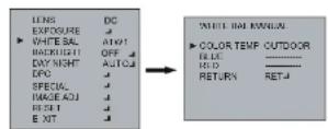
WHITE BAL
The screen color can be adjusted by using the WHITE BALANCE function.
1) ADW1
2) ATW2
3) AWC -> SET
。
Sel the color temperature 2500°K 10000°K
Sat the color temperature 2000K 13000K
Please press the ENTER button while the camera is directed
at a place of white paper to obtain the optimum state under
current illumination, if the environment including the light source
is changed, you have to adjust the white balance again.
4) MANUAL Manual mode. User can change R and B Gain manually.
INDOOR Set the make temperature in 3200K
INDOOR 60. The color temperature to 6200K OUTDOOR Set the color temperature to 6300K
BACKLIGHT
1) BLC
2) HLC
Prevents such a back light effect to secure a clear image under all
illumination environments
The function improves the identification capability of subjects facing a
Brighly it situation by filling out the strength of the light.
< MODE> BACKLIGHT

flowchart
graph LR
    A["LENS"] --> B["DC"]
    C["EXPOSURE"] --> D["ATM"]
    E["WHITE VAL"] --> F["ATM"]
    G["BACKLIGHT OFF"] --> H["DAY NIGHT AUTCA"]
    I["DAY"] --> J["DTC"]
    K["SPECIAL"] --> L["SPECIAL"]
    M["RACK ALI"] --> N["RET"]
    O["RESET"] --> P["E Alt"]
    Q["BACKLIGHT HLC"] --> R["AREA SEL AREA1"]
    S["LEFT RIGHT"] --> T["AREA STATE ON"]
    U["TOP/BOTTOM"] --> V["HEIGHT ON"]
    W["RETURN"] --> X["RIGHT ON"]
    Y["RETRIN"] --> Z["RETURN ON"]
    AA["RETRIN"] --> AB["RETURN ON"]
    AC["RETRIN"] --> AD["RETURN ON"]
    AE["RETRIN"] --> AF["RETURN ON"]
    AG["RETRIN"] --> AH["RETURN ON"]
    AI["RETRIN"] --> AJ["RETURN ON"]
    AK["RETRIN"] --> AL["RETURN ON"]
    AM["RETRIN"] --> AN["RETURN ON"]
    AO["RETRIN"] --> AP["RETURN ON"]
    AQ["RETRIN"] --> AR["RETURN ON"]
    AS["RETRIN"] --> AT["RETURN ON"]
    AU["RETRIN"] --> AV["RETURN ON"]
    AW["RETRIN"] --> AX["RETURN ON"]
    AY["LEVEL"] --> AZ["202"]
    BA["MODE"] --> BB["NIGHT ONLY"]
    BC["RETURN"] --> BD["RETURN"]
DAY NIGHT
The DAY:NIGHT menu is used to configure the day and night related setting for this camera.
This camera can turn the IR(infrared)filter an or off
Mode: AUTO / COLOR / B/W / EXT (The EXT is not operating in this mode)

flowchart
graph LR
    A["LINE"] --> B["EXPOSURE"]
    B --> C["WHITE BAL"]
    C --> D["BACK/SHIFT"]
    D --> E["DAY NIGHT AUTO"]
    E --> F["OFF"]
    F --> G["AUC/CA"]
    G --> H["UPC"]
    H --> I["SPECIAL"]
    I --> J["BACK/INT"]
    J --> K["RESET"]
    K --> L["EAT"]
    L --> M["DAY NIGHT AUTO"]
    M --> N["1-LEVEL"]
    N --> O["1-LEVEL"]
    O --> P["2-LEVEL"]
    P --> Q["3-LEVEL"]
    Q --> R["4-LEVEL"]
    R --> S["5-LEVEL"]
    S --> T["6-LEVEL"]
    T --> U["7-LEVEL"]
    U --> V["8-LEVEL"]
    V --> W["9-LEVEL"]
    W --> X["10-LEVEL"]

flowchart
graph LR
    A["LENS/DC"] --> B["DAY NIGHT BW"]
    C["INTEGRAL/ATM1"] --> B
    D["WHITE BAL/OFF"] --> B
    E["NOCK/INT"] --> B
    F["DAY NIGHT/AUTO2"] --> B
    G["OPC"] --> B
    H["SIGN"] --> B
    I["INBASE ADJ"] --> B
    J["RESET"] --> B
    K["SUV"] --> B
    L["BLREST"] --> B
    M["RF SMART"] --> B
    N["REF"] --> B
    O["OFF"] --> P["RET"]
    Q["R GAIN"] --> P
    R["HEIGHT"] --> P
    S["KHO"] --> P
    T["LEFT/RIGHT"] --> P
    U["TOR/TOWN"] --> P
    V["REF"] --> P
    W["8000"] --> X["Output"]
*The IR LEVEL is not operating in DAY NIGHT B/W mode.
DPC
DPC Auto setting (Dead pixels are automatically removed)

flowchart
graph LR
    A["LENS"] --> B["OC"]
    B --> C["ANTIMAL"]
    C --> D["AUTON"]
    D --> E["BRIGHT"]
    E --> F["OFF"]
    F --> G["DAY NIGHT"]
    G --> H["AUTO"]
    H --> I["DPC"]
    I --> J["SPECIAL"]
    J --> K["MODE ADJ"]
    K --> L["AVLT"]
    L --> M["E XIT"]
    M --> N["✓"]

    C --> O["DPC"]
    O --> P["COVER THE LENS THEN PRESSIVEN KEY"]
    P --> Q["INNOCKING NON"]
SPECIAL
1) CAM TITLE
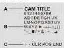
A. CAM TITLE B. Character Table C. Command Line + : Move to left - : Move to right CLR : Erase all characters POS : Move the position of title END : Save and End
2) MOTION
AREA SELECT Select MD area number. (AREA1 - AREA4)
AREA STATE SELECT MD ON/OFF
HEIGHT WIDTH Adjust height of MD area
WIDTH Adjust width of MD area LEFTRIGHT Adjust the location of the MD area with boundary LEFT and RIGHT
TOP/BOTTOM Adjust the location of the MD area with boundary TOP and BOTTOM
DEGREE Adjust versatility of MD area (0-255)
VIEW
In the selected area, the pink dots are displayed on the screen.

flowchart
graph LR
    A["INS"] --> B["GC"]
    C["EXPOSURE"] --> D["↓"]
    E["ANIMAL"] --> F["ATNT"]
    G["BACKLIGHT"] --> H["OFF"]
    I["DAY NIGHT"] --> J["AUTO"]
    K["CPE"] --> L["▶"]
    M["SPECIAL"] --> N["▶"]
    O["OKT"] --> P["▶"]
    Q["PREXCH"] --> R["CN"]
    S["PRIKACY"] --> T["OFF"]
    U["PARKLINE"] --> V["OFF"]
    W["LANGUAGE"] --> X["ENGLISH"]
    Y["RETURN"] --> Z["RET"]
    AA["MOTION"] --> AB["▶ AREA SELECT"]
    AC["AREA1"] --> AD["AREA1"]
    AE["AREA STATE"] --> AF["ON"]
    AG["HEIGHT"] --> AH["4"]
    AI["NIDTH"] --> AJ["2"]
    AK["LIFT RIGHT"] --> AL["2"]
    AM["TOP/BOTTOM"] --> AN["56"]
    AO["DEGREE"] --> AP["38"]
    AQ["VEN"] --> AR["OFF"]
    AS["RETURN"] --> AT["RET"]
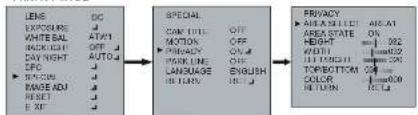
3) PRIVACY
AREA SELECT Select MASK area number.(Area 1 - Area 8)
AREA STATE Select MASK ON/OFF
HEIGHT Adjust height of MASK area
WIDTH Adjust width of MASK area
LEFT/RIGHT Adjust the location of the MASK area with boundary LEFT and RIGHT
TOP/BOTTOM Adjust the location of the MASK area with boundary
TOP and BOTTOM.
COLOR Select MASK color. (0-15)
RETURN
flowchart
graph LR
    A["LENS"] --> B["EXPOSURE"]
    B --> C["WHITE BAL"]
    C --> D["AUT/1"]
    D --> E["BACK/IGHT"]
    E --> F["OFF"]
    F --> G["DATA"]
    G --> H["AUTO"]
    H --> I["EPC"]
    I --> J["SIN/CNN"]
    J --> K["PAGE ADJ"]
    K --> L["RESET"]
    L --> M["EAT"]
    M --> N["SPECIAL"]
    N --> O["CANTILE"]
    O --> P["OFF"]
    P --> Q["MOTION"]
    Q --> R["OFF"]
    R --> S["PRIVACY"]
    S --> T["ON"]
    T --> U["PARK LINE"]
    U --> V["OFF"]
    V --> W["LANGUAGE"]
    W --> X["ENGLISH"]
    X --> Y["RETURN"]
    Y --> Z["HOLD"]
    Z --> AA["RELUY"]
    AA --> AB["UNITS"]
    AB --> AC["OR/TIME"]
    AC --> AD["MINI/TIME"]
    AD --> AE["MINI/TIME"]
    AE --> AF["MINI/TIME"]
    AF --> AG["MINI/TIME"]
    AG --> AH["MINI/TIME"]
    AH --> AI["MINI/TIME"]
    AI --> AJ["MINI/TIME"]
    AJ --> AK["MINI/TIME"]
    AK --> AL["MINI/TIME"]
    AL --> AM["MINI/TIME"]
    AM --> AN["MINI/TIME"]
    AN --> AO["MINI/TIME"]
    AO --> AP["MINI/TIME"]
    AP --> AQ["MINI/TIME"]
    AQ --> AR["MINI/TIME"]
    AR --> AS["MINI/TIME"]
    AS --> AT["MINI/TIME"]
    AT --> AU["MINI/TIME"]
    AU --> AV["MINI/TIME"]
    AV --> AW["MINI/TIME"]
    AW --> AX["MINI/TIME"]
    AX --> AY["MINI/TIME"]
    AY --> AZ["MINI/TIME"]
    AZ --> BA["MINI/TIME"]
    BA --> BB["MINI/TIME"]
    BB --> BC["MINI/TIME"]
    BC --> BD["MINI/TIME"]
    BD --> BE["MINI/TIME"]
    BE --> BF["MINI/TIME"]
    BF --> BG["MINI/TIME"]
    BG --> BH["MINI/TIME"]
    BH --> BI["MINI/TIME"]
    BI --> BJ["MINI/TIME"]
    BJ --> BK["MINI/TIME"]
    BK --> BL["MINI/TIME"]
    BL --> BM["MINI/TIME"]
    BM --> BN["MINI/TIME"]
    BN --> BO["MINI/TIME"]
    BO --> BP["MINI/TIME"]
    BP --> BQ["MINI/TIME"]
    BQ --> BR["MINI/TIME"]
    BR --> BS["MINI/TIME"]
    BS --> BT["MINI/TIME"]
    BT --> BU["MINI/TIME"]
    BU --> BV["MINI/TIME"]
    BV --> BW["MINI/TIME"]
    BW --> BX["MINI/TIME"]
    BX --> BY["MINI/TIME"]
    BY --> BZ["MINI/TIME"]
4) PARK.LINE
Select Parking area

5) LANGUAGE
ENGLISH or CHINESE
6) RETURN
REI
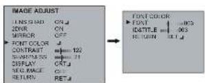
IMAGE ADJUST
1) LENS SHAD Adjust Lens shading level (0-255)
3) MIRROR Select MIRROR ON/OFF
4) FONT COLOR Select FONT COLOR level (0-15)
Select IDR TITLE level (0-15)
5) CONTRAST Adjust: CONTRAST level (0-265)
8) SHARPNESS Adjust SHARPNESS level (0-31)
7) DISPLAY Select DISPLAY mode (CRT/LCDUSER)
8) NEG. IMAGE Select Negative Image mode ON/OFF


flowchart
graph TD
    A["IMAGE ADJUST"] --> B["CAT ADJUST"]
    B --> C["LCD ADJUST"]
    C --> D["USER ADJUST"]
RESET
1) FACTORY Returns to the level which was set by the manufacturer for shipment.
EXIT
1) EXIT Saves all settings and exits.
LENS ADJUSTMENT (OPTIONAL VARIFOCAL LENS)
Field of view: Adjust setting from Tele (T) to Wide (W) field of View.
Focus: Adjust lens focus from near (N) to infinity (∞).

DC AUTO IRIS LENS
| 2.8-12mm | 9-22mm | 4-9mm | |
| Image Size | 1/3" CCD | 1/3" CCD | 1/3" CCD |
| Focal Length | 2.8-12mm ±5% | 9-22mm ±5% | 4-9mm ±5% |
| Aperture Ratio | 1: 1.2 ±5% | 1: 1.4 ±5% | 1: 1.6 ±5% |
| Angular Field of View | DIAGONAL2.8mm : 119.9'12mm : 28.80' | DIAGONAL9mm : 40.2'22mm : 16.1' | DIAGONAL4mm : 92.4'9mm : 39.2' |

SPECIFICATIONS
| MODEL | NTSC | PAL | |
| Power | Power source | AC20V ± 10V, DC20V ± 175 | |
| Power source type | DC20V ± 175 W/m3 | ||
| General | Impulse source | 1/4" Systc Super-HO-CCD II | |
| Tool sample | BUTU (60%)* | NAMR (60%)* | |
| Scanning system | 2 Intersec | ||
| Scanning efficiency | 15.000V ± 15.000 V/m3 | 15.000V ± 15.000 V/m3 | |
| Systc system | Internal | ||
| Eccentric System | 500 - 1000 MHz | 100 - 1500 MHz | |
| Standard | 800 V/1000 COOL# | ||
| VR, Max power | 0.7 Litter C/O 60A, Low BW, Q FL 2.98E | ||
| System load | 500 V/1000 Co., Current | ||
| SFC Rate | V/Hz for 2000 MHz | ||
| Current Control (200V, 200Hz, 30Hz) | |||
| FUNCTION | Loss | NAMR/DC | |
| Turner | AL 1000 V/1000 V/1000 V/1000 V/1000 V/1000 V/1000 V/1000 V/1000 V/1000 V/1000 V/1000 V/1000 V/1000 V/1000 V/1000 V/1000 V/100 | ||
| Bitloss | 0-25E | ||
| Loss | CHF 1000 V/1000 V/1000 V/1000 V/1000 V/1000 V/1000 V/1000 V/1000 V/1000 V/1000 V/1000 V/1000 V/1000 V/1000 V/1000 V/10 | ||
| C/CFL | OFFLA | ||
| White filter | ADOT / ADOT / ADOT / ADOT / ADOT | ||
| Body & Right | AL 1000 V/1000 V/1000 V/1000 V/1000 V/1000 V/1000 V/1000 V/1000 V/1000 V/1000 V/1000 V/1000 V/1000 V/1000 V/1000 V/ | ||
| Sound | OFF 12W | ||
| Tilt sensor | OFF 12W | ||
| IR Sensor, Gain | 0-25E | ||
| Current Line | OFF 12W | ||
| Magnetic Ducturing | OPT ON (Analog) | ||
| Frequency Smashing | OPT ON (Analog) | ||
| Parking Line | OFF 12W | ||
| Left Shading | OFF 12W | ||
| Motion | OFF 12W | ||
| Mirror | OFF 12W | ||
| Front Color | FONT TO COLOR, OUTLINE TO COLOR | ||
| Current | 0-25E | ||
| Exposure | OFF 12W | ||
| Energy | OFF 12W | ||
| Energy Transfer | OFF 12W | ||
| Cap/Coop | ENGL/SP/ON/CRESE | ||
| CPU | East Road Connection (East 44 GHz) | ||
| Power | AC20V ± 10W / AC20V ± 10W | ||
| Comductor & Resistor | Power Plant | 4.5 W/m3 | |
| Water Watch | 300 V/1000 V/1000 V/1000 V/1000 V/1000 V/1000 V/1000 V/1000 V/1000 V/1000 V/1000 V/ | ||
| Low | 25V-12W / 2.25V-12W (High 2.2W) / 2.2W-12W (High 2.2W) (Low 2.2W) | ||
| Control Interface | 30V-12W / 3.2W-12W (High 2.2W) / 3.2W-12W (High 2.2W) (Low 2.2W) | ||
| Control to Humble | W/DC / W/DC / W/DC / W/DC / W/DC / W/DC / W/DC / W/DC / W/DC / W/DC / W/DC / W/DC / W/DC / W/DC / W/DC / W/DC / W/DC / W/DC / W/DC / W/DC / W/DC / W/DC / W/DC / W/DC / W/DC / W/DC / | ||
| Power Dimension | P/WC / P/WC / P/WC | ||
| Weight | 40Ω | ||
EXTERNAL DIMENSION
| Dimensions | |
 | 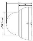 |
| 30, mm | |
| Window Size | 0.1 in. (2.5mm thick), impact-resistant P.C (LEXAN) 3.93 in. (10cm) diameter |
| Cable Entry | One 1" opening holes |
| Weight - Unit: Shipping: | 0.88 lb. (0.4kg) 1.41 lb. (0.64 kg) |
- WARNING
- CAUTION
- EXPLANATION OF GRAPHICAL SYMBOLS
- PRECAUTIONS
- Safety
- FCC COMPLIANCE STATEMENT
- CE COMPLIANCE STATEMENT
- IMPORTANT SAFETY INSTRUCTIONS
- INTRODUCTION
- Features:
- CAMERA CONNECTIONS
- REMINDER:
- CONTENTS of PACKAGE
- BASE INSTALLATION
- LENS (Selection)
- EXPOSURE
- WHITE BAL
- BACKLIGHT
- < MODE> BACKLIGHT
- DAY NIGHT
- DPC
- SPECIAL
- 1) CAM TITLE
- 2) MOTION
- 3) PRIVACY
- RETURN
- 5) LANGUAGE
- 6) RETURN
- IMAGE ADJUST
- RESET
- EXIT
- LENS ADJUSTMENT (OPTIONAL VARIFOCAL LENS)
- EXTERNAL DIMENSION
Brand : REVO
Model : RECDH2812-2
Category : Security Camera