
39500QY - Sewing machine Union Special - Free user manual and instructions
Find the device manual for free 39500QY Union Special in PDF.


| Product type | Industrial Sewing Machine |
| Brand | Union Special |
| Model | 39500QY |
| Dimensions (L x W x H) | 550 x 450 x 400 mm |
| Weight | 28 kg |
| Power supply | 220 V, 50/60 Hz |
| Power consumption | 250 W |
| Stitch type | Chainstitch, Overedge |
| Maximum sewing speed | 6000 stitches per minute |
| Needle system | UY128GAS, size 16-22 |
| Lubrication | Automatic oiling system |
| Presser foot lift | Up to 10 mm |
| Safety features | Safety clutch, needle guard |
| Maintenance | Regular cleaning and oiling |
| Included accessories | Needles, bobbins, tools |
| Manual format | PDF, 52 pages |
| Language | English |
Frequently Asked Questions - 39500QY Union Special
User questions about 39500QY Union Special
0 question about this device. Answer the ones you know or ask your own.
Ask a new question about this device
Download the instructions for your Sewing machine in PDF format for free! Find your manual 39500QY - Union Special and take your electronic device back in hand. On this page are published all the documents necessary for the use of your device. 39500QY by Union Special.
USER MANUAL 39500QY Union Special
Union Special INDUSTRIAL SEWING EQUIPMENT
CATALOG NO. 103QA
STYLES
| 39500QA | 39500RS |
| 39500QB | 39500SE |
| 39500QP | 39500SF |
| 39500QY | 39500SG |
| 39500RA | 39500TA |
| 39500RF | 39500TD |
| 39500RM | 39500TH |
| 39500RR |
39500 CLASS
MARK IV HIGH SPEED SINGLE NEEDLE TWO
OR THREE THREAD DIFFERENTIAL FEED
OVERSEAMING MACHINES
Catalog No. 103 QA
INSTRUCTIONS
FOR
ADJUSTING AND OPERATING
LIST OF PARTS
CLASS 39500
Styles
| 39500 QA | 39500 RF | 39500 SF |
| 39500 QB | 39500 RM | 39500 SG |
| 39500 QP | 39500 RR | 39500 TA |
| 39500 QY | 39500 RS | 39500 TD |
| 39500 RA | 39500 SE | 39500 TH |
First Edition
Copyright © 1973
By
Union Special Corporation
Rights Reserved in All Countries
INDUSTRIAL SEWING MACHINES
CHICAGO
Printed in U.S.A.
April, 1980.
IDENTIFICATION OF MACHINES
Each UNION SPECIAL machine is identified by a Style number on a name plate on the machine. Style numbers are classified as standard and special. Standard Style numbers have one or more letters suffixed, but never contain the letter "Z". Example: "Style 39500 QA". Special Style numbers contain the letter "Z". When only minor changes are made in a standard machine, a "Z" is suffixed to the standard Style number. Example: "Style 39500 QAZ".
Styles of machines similar in construction are grouped under a Class number which differs from the Style number in that it contains no letters. Example: "Class 39500".
APPLICATION OF CATALOG
This catalog applies specifically to the Standard Styles of machines as listed herein. It can also be applied with discretion to some Special Styles of machines in Class 39500. References to directions, such as right, left, front, back, etc., are given from the operator's position while seated at the machine. Operating direction of handwheel is away from operator.
STYLES OF MACHINES
MARK IV Hi-Styled High Speed, Single Curved Blade Needle, Two Looper - Three Thread or One Looper - One Spreader - Two Thread Machine, Differential Feed, Trimming Mechanism with Spring Pressed Lower Knife, Automatic Lubricating System, Improved Air Cooling System.
39500 QA Light to medium duty machine for seaming light and medium weight flat, warp, and ribbed knit fabrics of cotton, silk, or similar weight synthetics. The sewing combination has been designed especially for use on women's and children's slips, pajamas, nightgowns, or similar articles where long straight hanging seams are a primary requisite. Seam Specification, 504-SSa-1; standard seam widths, 3/32 and 1/8 inch (2.38 and 3.17 mm); stitch range, 8-30 per inch; cam adjusted main and differential feeds. Maximum recommended speed 8000 R.P.M.
39500 QB Light to medium duty machine for seaming light and medium weight flat, warp, and ribbed knit fabrics of cotton, silk, or similar weight synthetics. The sewing combination has been designed for general purpose seaming of "T" shirts, polo shirts, panties, infant and children's knit wear, and similar garments. Seam Specification, 504-SSa-1; standard seam widths, 3/32 and 1/8 inch (2.38 and 3.17 mm); stitch range, 8-30 per inch; cam adjusted main and differential feeds. Maximum recommended speed 8000 R.P.M.
39500 QP Medium to heavy duty machine for seaming medium to heavy weight flat, warp, and ribbed knit fabrics made from cotton and wool, used on snow suits, sweat shirts, underwear and similar garments. Seam Specification, 504-SSa-1; standard seam width, 1/8 inch (3.17 mm); stitch range, 8-20 per inch; cam adjusted main and differential feeds. Maximum recommended speed 7500 R.P.M.
*39500 QY Medium to heavy duty machine for seaming medium and heavy loosely knit outerwear made from cotton, wool and synthetic yarns. Wide cutting knives. Seam Specification, 504-SSa-1; standard seam width, 1/8 inch (3.17 mm); stitch range, 8-20 per inch; cam adjusted main and differential feeds. Maximum recommended speed 7500 R.P.M.
* DISCONTINUED - In most instances, component parts can be ordered for customer repair.
STYLES OF MACHINES (Continued)
39500 RA Medium to heavy duty machine for seaming medium and heavy knit outerwear made from cotton, wool and synthetic yarns, with provision for inserting a reinforcing tape used on shoulder seams of sweaters and similar garments. Wide cutting knives. Seam Specification, 504-SSa-1; standard seam width, 5/32 inch (3.97 mm); stitch range, 8-20 per inch; cam adjusted main and differential feeds. Maximum recommended speed 7500 R.P.M.
39500 RF Medium to heavy duty machine, same as Style 39500 QP, except fitted with 39500 QB sewing parts. For seaming all types and weights of flat, warp and ribbed knit cotton, wool, rayon and silk fabrics. Seam Specification, 504-SSa-1; standard seam widths, 3/32, 1/8 and 5/32 inch (2.38, 3.17 and 3.97 mm); stitch range, 8-20 per inch; cam adjusted main and differential feeds. Maximum recommended speed 7500 R.P.M.
* 39500 RM Light to medium duty machine for seaming, trimming and attaching frill elastic to panties, half slips and similar garments. Prepared for use with Galkin power driven metering device and elastic guide roller. Elastic width, 5/16 to 5/8 inch (7.94 to 15.88 mm); can also be ordered to handle narrow 7/32 inch (5.56 mm) wide leg elastic. Seam Specification 503-SSa-1; standard seam width, 3/32 inch (2.38 mm); stitch range, 8-30 per inch; cam adjusted main and differential feeds. Maximum recommended speed 7500 R.P.M.
39500 RR Medium to heavy duty machine for break open seaming and attaching of elastic to girdles and foundation garments with either a two or three thread stitch. Machine can be used with or without the standard trimming knives. For those who do not wish to trim the material, a front fabric guide is included. Seam Specification 503 or 505-SSa-1, hinged open to make LSA-1; standard seam width 1/4 inch (6.35 mm); stitch range, 8-30 per inch; cam adjusted main and differential feeds. Maximum recommended speed 7500 R.P.M.
39500 RS Light to medium duty machine for producing high quality, turned down edge seams on pajamas, negligees, peignoirs, blouses and similar sheer items requiring reinforced seams. Seam Specification, 504-EFe-1 inverted; standard seam width, 3/32 inch (2.38 mm); stitch range, 8-30 per inch; cam adjusted main and differential feeds. Maximum recommended speed 8000 R.P.M.
39500 SE. Light to medium duty machine with reverse differential feed for general purpose of seaming and attaching collarettes to "T" shirts. Prepared to accept Jesse Heap folder No. U-100. Seam Specification, 504-SSa-1; standard seam width 1/8 inch (3.17 mm); stitch range, 8-30 per inch; cam adjusted main and differential feeds. Maximum recommended speed 8000 R.P.M.
39500 SF Medium to heavy duty machine for seaming bulky knit sweaters; can be used for attaching a reinforcing tape used on shoulder seams of sweaters and similar garments, tape automatically guided by slot in presser foot. Straight knife parts. Seam Specification, 504-SSa-1; standard seam widths 1/8 and 3/16 inch (3.17 and 4.76 mm); stitch range, 8-20 per inch; cam adjusted main and differential feeds. Maximum recommended speed 7500 R.P.M.
* 39500 SG Light to medium duty machine for upturned hem on cotton wash cloths and other light to medium weight material. Seam Specification, 505-EFa-1; standard seam width, 1/8 inch (3.17 mm); stitch range, 8-15 per inch; cam adjusted main and differential feeds. Maximum recommended speed 8000·R.P.M.
* DISCONTINUED - In most instances, component parts can be ordered for customer repair.
STYLES OF MACHINES (Continued)
39500 TA Light duty machine, for toe closing on women's seamless hosiery. Seam Specification 505-EFe-1 inverted; standard seam width, 1/16 to 3/32 inch (1.59 to 2.38 mm) depending on material; stitch range, 15-100 per inch; cam adjusted main and differential feeds. Maximum recommended speed 8000 R.P.M.
* 39500 TD Light to medium duty machine with the main and differential feed dogs having a square separation located approximately at the needle, for seaming light and medium weight perma-press materials where long straight pucker free seams are a primary requisite. Seam Specification 504-SSa-1; standard seam widths, 3/32 and 1/8 inch (2.38 and 3.17 mm); stitch range, 8-30 per inch; cam adjusted main and differential feeds. Maximum recommended speed 8000 R.P.M.
* 39500 TH Medium to heavy duty machine for simultaneously attaching right pants flies and zipper tapes to pants fronts; also attaching zippers to right flies only and similar operations. Seam Specification 504-SSa-1; standard seam width, 3/8 inch (9.52 mm); stitch range, 6-16 per inch; cam adjusted main and differential feeds. Maximum recommended speed 7500 R.P.M.
SPEED RECOMMENDATION
39500 MARK IV machines have been tested in their complete stitch range at their maximum rated speeds. Varied field conditions, severity and cleanliness of the sewing operation may necessitate operating at a lower speed. When operating from 50-100% machine running cycle and a longer than recommended stitch length, it may be necessary to reduce the machine's speed by 10-15%.
The MARK IV is a precision manufactured and tested sewing machine. To obtain maximum performance, the machine should be operated at 1000 R.P.M. below maximum recommended speed for the first 20 days of field operation. This will minimize readjustment of precision mechanisms.
OILING
CAUTION! Oil was drained from machine when shipped, so reservoir must be filled before beginning to operate. Oil capacity of Class 39500 is eight ounces. A straight mineral oil of a Saybolt viscosity of 90 to 125 seconds at 100° Fahrenheit should be used.
Machine is filled with oil at spring cap in top cover. Oil level is checked at sight gauge on front of machine. Red tip of oil indicator should show between gauge lines when machine is stationary.
Machine is automatically lubricated. No oiling is necessary, other than keeping main reservoir filled. Check oil daily before the morning start; add oil as required.
To maintain maximum recommended speed and serviceability of this equipment when operating continuously, the oil must be changed at least every six months. In no case should oil remain in machine for more than one year.
The drain plug screw is located at back of machine near bottom edge of base. It is a magnetic screw designed to accumulate possible foreign materials which may have entered the crank case. It should be removed and cleaned periodically.
* DISCONTINUED - In most instances, component parts can be ordered for customer repair.
NEEDLES
Each UNION SPECIAL needle has both type and size number. The type number denotes the kind of shank, point, length, groove, finish and other details. The size number, stamped on the needle shank, denotes largest diameter of blade, measured in thousandths of an inch, midway between shank and eye. Collectively, type and size number represent the complete symbol which is given on the label of all needles packaged and sold by Union Special.
Class 39500 machines use a curved blade needle. The standard recommended needle for Styles 39500 QA, QB, QP, QY, RA, RF, SE, SF, SG, TA and TH is Type 154 GAS. For Styles 39500 RS and TD, the standard recommended needle is Type 154 GBS; while for Styles 39500 RM and RR, the standard recommended needle is 154 GHS. Below are the type numbers, descriptions and sizes available of the recommended needles.
Type No. Description and Sizes
| 154 GAS | Round shank, round point, curved blade, standard length, single groove, struck groove, spotted, chromium plated and is available in sizes 055/022, 065/025, 070/027, 075/029, 080/032, 090/036, 100/040, 110/044, 125/049, 140/054, 150/060. |
| 154 GBS | Round shank, round point, curved blade, standard length, double groove, struck groove, spotted, chromium plated and is available in sizes 070/027, 075/029, 080/032. |
| 154 GHS | Round shank, round point, curved blade, standard length, single groove, struck groove, ball point, spotted, chromium plated and is available in sizes 065/025, 070/027, 075/029, 080/032, 090/036. |
To have needle orders promptly and accurately filled, an empty package, a sample needle, or the type and size number should be forwarded. Use description on label. A complete order would read: "1000 Needles, Type 154 GAS, Size 027".
Selection of proper needle size is determined by size of thread used. Thread should pass freely through needle eye in order to produce a good stitch formation.
Success in the operation of UNION SPECIAL machines can be secured only by use of needles packaged under our brand name, UnionSpecial, which is backed by a reputation for producing highest quality needles in materials and workmanship for more than three-quarters of a century.
CHANGING NEEDLES
Release pressure on presser foot by turning presser foot release bushing (AG, Fig. 1, 1A, 1B or 1C) and swing presser arm (U) out of position. Turn handwheel in operating direction until needle is at its lowest point of travel. Using hexagonal socket wrench No. 21388 AU, furnished with machine, loosen needle clamp nut about 1/4 turn. Again turn handwheel until needle is at high position; withdraw needle.
To replace needle, leave needle holder at high position and, with the flat to the left, insert needle in holder until it rests against stop pin. Keeping needle in this position, turn handwheel until holder is again at its low point of travel; then tighten nut. Return presser arm (U) to position; re-lock presser foot release bushing (AG).
THREAD STAND (503 STITCH)
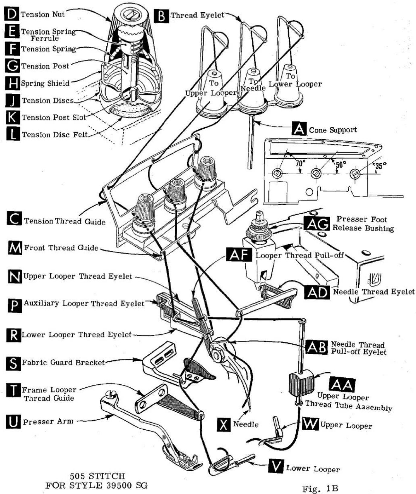
After thread comes from cone on cone support (A, Fig. 1A) it is brought up through the back hole of thread eyelet (B), then down through the front hole of thread eyelet. The needle thread is then threaded through the upper hole of tension thread guide (C) from front to back, and then through the lower hole from back to front. The lower looper thread is threaded through the upper hole back to front, through the middle hole from front to back, and finally through the lower hole from back to front. Both threads then continue between the tension discs (J), through tension post slot (K) in tension post (G) and on through front thread guide (M).
THREAD STAND (504 and 505 STITCH)
After thread comes from cone on conc support (A, Fig. 1, 1B or 1C) as applicable. It is brought up through the back hole of thread eyelet (B), then down through the front hole of thread eyelet. The needle and upper looper threads are then threaded through the upper hole of tension thread guide (C) from front to back, and then through the lower hole from back to front. The lower looper thread is threaded through the upper hole back to front, through the middle hole from front to back, and finally through the lower hole from back to front. All three threads then continue between the tension discs (J), through tension post slot (K) in tension post (G) and on through front thread guide (M).


Fig. 1A

THREADING
Only parts involved in threading are shown in threading diagrams (Fig. 1, 1A, 1B and 1C). Parts are placed in their relative positions for clarity.
It will simplify the threading of these machines to follow the recommended sequence of threading the lower looper first and the needle second when using the 503 stitch (Fig. 1A). The recommended sequence when using the 504 or 505 stitch (Fig. 1, 1B and 1C) is to thread the lower looper first, upper looper second, and the needle third.
Before beginning to thread, swing cloth plate open, turn handwheel in operating direction until needle (X) is at high position, release pressure on presser foot by turning presser foot release bushing (AG) and swing presser arm (U) out of position.
Be sure threads, as they come from the tension thread guide (C), are between tension discs (J) and in diagonal slots (K) in tension posts (G).
TO THREAD THE LOWER LOOPER
Double end of thread and lead it through the right eyelet of front thread guide (M, Fig. 1, 1A, 1B or 1C). Then lead thread through both eyes of lower looper thread eyelet (R, Fig. 1, 1A, 1B or 1C) from right to left. NOTE: Thread must pass in front of looper thread pull-off (AF). Lead thread behind fabric guard (S) and through frame looper thread guide (T). Turn handwheel in operating direction until heel of lower looper (V) is all the way to the left, then thread through both eyes from left to right. Left eye of lower looper can be threaded easily if tweezers are in left hand.
NOTE: In Fig. 1C for the 505 stitch, the lower looper thread eyelet is placed in the upper position.
TO THREAD UPPER LOOPER (504 AND 505 STITCH ONLY)
Thread upper looper thread through left eyelet of front thread guide (M). Then turn handwheel until point of upper looper (W) is all the way left. Lead thread through auxiliary looper thread eyelet (P) from back to front, then through both eyes of upper looper thread eyelet (N) from left to right. Note: thread must pass in front of looper thread pull-off (AF). After pulling up upper looper thread tube assembly (AA), lead thread under neck of top cover casting and down through thread tube assembly (AA). Pull thread out bottom of tube; push tube down, then insert thread through upper looper eye from front to back.
NOTE: In Fig. 1C for the 505 stitch, the upper looper thread eyelet is placed in the lower position.
CAUTION! Be sure upper looper thread is under lower looper thread when passing from tube assembly to upper looper eye.
TO THREAD THE NEEDLE (FOR ALL STYLES EXCEPT 39500 SG)
Thread needle thread through middle eyelet of front thread guide (M). Then turn handwheel in operating direction until needle (X, Fig. 1, 1A, 1C) is at its highe position. Insert needle thread from right to left, through both eyes of needle three eyelet (AD), under neck of top cover casting; then down through hole in top cove needle thread eyelet (AC). Thread needle from front.
TO THREAD THE NEEDLE (FOR STYLE 39500 SG)
Thread needle thread through middle eyelet of front thread guide (M). Then turn handwheel in operating direction until needle (X; Fig. 1B) is at its highest position. Insert needle thread from back to front of needle thread eyelet (AD), under neck of top cover casting; then through needle thread pull-off eyelet (AB) from right to left. Thread needle from front.
THREAD TENSION
The amount of tension on the needle and looper threads is regulated by knurled tension nuts (D, Fig. 1, 1A, 1B, 1C). Tension on threads should be only enough to secure proper stitch formation.
PRESSER FOOT PRESSURE
Sufficient presser foot pressure to feed work uniformly should be maintained. Should it be necessary to increase or decrease amount of pressure on presser foot, loosen lock nut (A, Fig. 2) and turn adjusting screw (B). Adjusting screw has a right hand thread so tightening increases pressure, loosening decreases pressure. When pressure adjusting screw (B) has been properly set, tighten lock nut (A). With presser foot resting on throat plate, position locking nut (C) so that its under surface is approximately 1/32 inch to 1/16 inch (.79 to 1.59 mm) from the top surface of adjusting screw (B). Set cap (D) against locking nut (C).

Fig. 2
FEED ECCENTRICS
Feed eccentrics used in Style 39500 QA machines have been selected to produce approximately 12 stitches per inch. It will be noted that the part number of main feed eccentric is No. 39540 B-10 while that of differential feed eccentric is No. 39540 B-12. Minor numbers of the part symbol indicate approximately the number of stitches obtainable when using that eccentric. Unless otherwise specified, machine Style 39500 QA will be shipped with above combination of eccentrics. Refer to exploded views in catalog for eccentrics furnished on other styles of machines.
Generally speaking, differential (right hand) feed eccentric determines number of stitches produced; main (left hand) feed eccentric is selected in relation to degree and direction of stretch of material being sewn, or type of operation.
Following stitch number feed eccentrics are available under No. 39540 B-4, 5, 6, 7, 8, 9, 10, 11, 12, 13, 14, 15, 16, 18, 20, 22, 24, 26, 28, 30, 32, 34, 36, 40, 50, 60, 70, 100. Only two eccentrics are supplied with each machine. Additional eccentrics may be ordered separately. To order an eccentric use No. 39540 B with a minor number suffixed to indicate number of stitches desired. Example: "39540 B-12".
ASSEMBLING AND ADJUSTING SEWING PARTS
Before assembling and adjusting sewing parts, remove cloth plate, fabric guard, chip guard, upper knife assembly, lower knife holder assembly, then follow the procedure that begins on the next page.
SETTING THE NEEDLE
With throat plate assembled in position, needle should center in the front end of needle slot. When needle is at high position, needle point should be set 1/2 inch

Fig. 3
(12.70 mm) above throat plate (A, Fig. 3) for Styles 39500 QA, QB, QP, QY, RF, RM, RS, SE, SG, TA and TD; 15/32 inch (11.91 mm) for Styles 39500 RA, RR, SF and TH. To align needle or set the height above the throat plate, move needle driving arm (B, Fig. 3) by loosening clamp screw (C). After needle has been set properly, tighten screw (C) and remove throat plate.
If needle thread cam pull-off (A, Fig. 4) overlaps looper thread pull-off (B), separate by moving looper thread pull-off back. When retightening looper pull-off screw, be sure to take up end play in needle driving arm.
On all of the Styles covered in this catalog except Style 39500 TH, insert lower looper (A, Fig. 5) into bar (B). With lower looper at left end of its stroke, set looper point 1/8 inch (3.17 mm) from center of needle (Fig. 5), using looper gauge No. 21225-1/8. Do not have lower looper deflecting needle. Tighten nut (C).
On machine Style 39500 TH insert lower looper (A, Fig. 5) into bar (B). With lower looper at left end of its stroke, set looper point 3/32 inch (2.38 mm) from center of needle (Fig. 5), using 'looper gauge No. 21225-3/32. Do not have lower looper deflecting needle. Tighten nut (C).

Fig. 4
Now assemble differential (front) feed dog to all Styles.
SETTING THE REAR NEEDLE GUARD
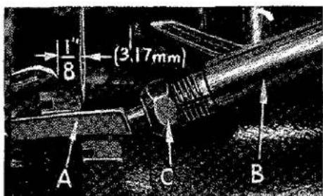
Fig. 5
Set rear needle guard (A, Fig. 6) as high as possible, without interfering with either lower looper or movement of lower knife holder, but still in position to deflect needle forward .002-.004 inch (.051-.102 mm). Screw (B) is used to set rear needle guard. Make sure there is no interference between rear needle guard and lower looper.
SETTING THE LOWER LOOPER
Now finish lower looper adjustment. As lower looper moves to the right, its point should be set into the needle scarf (A, Fig. 7) until the needle springs forward from rear guard surface another .002-.004 inch (.051-.102 mm).
SETTING THE FRONT NEEDLE GUARD
Assemble front needle guard (C, Fig. 6). When lower looper is springing needle off backguard, set front needle guard as close as possible to needle without touching. Screw (D) is used to adjust and set front needle guard. After this setting make sure there is no interference between needle guards and differential feed dog.

Fig. 7
SETTING THE UPPER LOOPER
Insert upper looper (A, Fig. 8) in its holder. Screw (B) holds upper looper in its holder, and permits it to be pushed in or out, or turned around its shank. Insert upper looper holder into upper looper shaft, if it is not already in place. Screw (C, Fig. 8) on clamp holds the upper looper holder in the shaft. Locate upper looper in its holder so that the shank extends 1/32 to 1/16 inch (.79 to 1.59 mm) beyond holder (Fig. 8), for Styles 39500 QA, QB, RS, SE, SG, TA and TD, and 1/16 to 3/32 inch (1.59 to 2.38 mm)
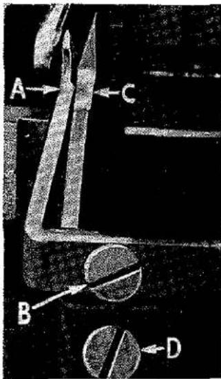
Fig. 6
for Styles 39500 QP, QY, RA, RF, RR, SF and TH.
When the upper looper is at the right end of its stroke, upper looper holder should be set to position upper looper shank slightly back of vertical on Styles 39500 QA, QB, QP, QY, RA, RF, RS, SE, SG, TA, TD and TH (Fig. 8). On Styles 39500 RR and SF upper looper holder should be set to position the upper looper shank about vertically.
Be sure, on all styles, there is a clearance between heel of looper and casting. By adjusting looper holder in or out of upper looper shaft and by turning the looper around its shank, set upper looper point to cross lower looper to the left of the lower looper eye with .002 to .004 (.051 to .102 mm) clearance (Fig. 9).
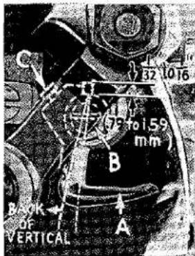
Fig. 8
As the upper looper moves toward the top of its stroke, the heel of the upper looper should pass behind the lower looper head with 1/64 to 1/32 inch (.40 to .79 mm) clearance.

Fig. 9
Next, turn handwheel until looper is at the left end of its travel; check dimensions of upper looper point with respect to needle and throat plate (Fig. 10). If resetting is necessary, do it by moving the upper looper holder (A, Fig. 10). Figure 10 represents the dimensional setting for Styles 39500 QA, QB, RS, SE, SG, TA and TD.
NOTE: For Styles 39500 QP and TH the dimensional settings are 9/64 and 35/64 inch (3.57 and 13.89 mm). For Styles 39500 QY, RA and RF, the settings are 9/64 and 1/2 inch (3.57 mm and 12.70 mm). For Styles 39500 RR and RF the settings are 9/64 and 15/32 inch (3.57 and 11.91 mm).
SETTING THE UPPER LOOPER (Continued)
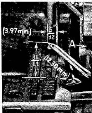
Fig. 10
For example, dimension 31/64 inch (12.30 mm) in increased by turning upper looper holder counterclockwise looking from left end of machine; dimension 5/32 inch (3.97 mm) is increased by pulling upper looper holder left, out of upper looper shaft. After these changes are made it may be necessary to turn upper looper around its shank slightly to maintain the condition shown in Fig. 9.
When the correct setting is obtained, it can be checked quickly as follows: As upper looper is moving to the right, when upper looper eye centers on the needle, bottom of the needle eye should be about
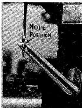
Fig. 11
level with top surface of upper looper (Fig. 11) for Styles 39500 QA, QB, RS, SE, SG, TA and TD.
NOTE: For Styles 39500 QP, QY, RA, RF, RR, SF and TH, the eyes of the upper looper and needle should align exactly.
Check setting to avoid interference between upper looper and needle on needle downstroke. If needle rubs the back of upper looper, pull looper out of its holder slightly and rotate looper a short distance counterclockwise, looking from left end of machine. Reset to maintain dimensions of Figs. 9, 10, 11.
SETTING THE UPPER SPREADER (FOR STYLES 39500 RM AND RR ONLY)
Insert upper spreader (A, Fig. 8A) in its holder. Screw (B) holds upper spreader in its holder, and permits it to be pushed in or out, or turned around its shank. Insert spreader holder into spreader shaft, if it is not already in place. Screw (C, Fig. 8A) on clamp collar holds spreader holder in the shaft, and allows holder to be rotated or adjusted laterally.
Preliminary Setting: When upper spreader is at the right end of its stroke, spreader holder should be set to position spreader shank slightly back of vertical (Fig. 8A). Top end of spreader shank should extend 1/32 to 1/16 inch (.79 to 1.59 mm) above the spreader holder for Style 39500 RM. The same is true of Style 39500 RR except the spreader holder should be
set to position spreader shank approximately vertical. Top end of spreader shank should extend 1/16 to 3/32 inch (1.59 to 2.38 mm) above the spreader holder for Style 39500 RR.
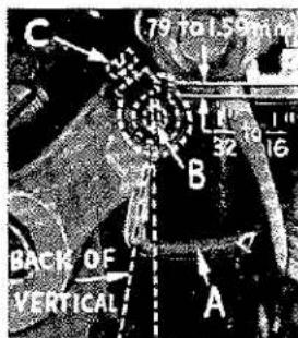
Fig. 8A
As spreader moves from right to left, the Vee notch of the spreader should pass just behind the eye of the lower looper, with .002 to .004 inch (.051 to .102 mm) clearance between spreader and lower looper (Fig. 9A).
SETTING THE UPPER SPREADER (FOR STYLES 39500 RM AND RR ONLY) (Continued)
Turn the handwheel until upper spreader is at the left end of its travel. At this position, the lower point of the spreader should extend about 5/32 inch (3.97 mm) to the left of the centerline of the needle and should be approximately 7/16 inch (11.11 mm) above the throat plate (Fig. 10A) for Style 39500 RM. Style 39500 RR is the same except the lower point of the spreader should extend about 9/64 inch (3.57 mm) to the left of the centerline of the needle and should be 15/32 inch (11.91 mm) above the top of the throat plate.

Fig. 9A
Now check setting between upper spreader and needle. If needle rubs the back of spreader, pull spreader out of its holder slightly and rotate spreader holder forward a short distance. These same adjustments, in opposite movement, will reduce the clearance between spreader and needle. Reset to lower looper (Fig. 9A).

Fig. 10A
the same time.
SETTING THE FEED DOGS
Now assemble differential (front) feed dog (A, Fig. 12), if not already in place, main (back) feed dog (B) and chaining feed dog (C).
On Styles 39500 QA, RS and TD, set all three feed dogs (A, B, C, Fig. 12) so the top surfaces of teeth all lay in the same plane. This can be checked by sighting across teeth with a straight edge. Now assemble throat plate. Feed dogs should now be leveled with throat plate surface by rotating feed tilting adjusting pin (D). This pin raises or lowers the back end of both feed bars at
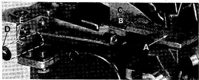
Fig. 12
The feed dogs should be set level at the time teeth first appear above the throat plate. Screw (E) locks feed tilting adjusting pin in place. Now set feed dogs so that teeth rise about 3/64 inch (1.19 mm) above throat plate, except on Style 39500 SG the differential feed dog should rise 1/32 inch (.79 mm) above throat plate.
NOTE: On Styles 39500 QB, QP, QY, RA, RF, RM, RR, SE, SF, SG, TA and TH, set chaining feed dog (C) level with top of throat plate when feed is at the top of its travel.
NOTE: Style 39500 TA does not use a chaining feed dog.
SETTING THE LOWER KNIFE
Replace lower knife holder assembly. Lower knife (A, Fig. 13) should be set with cutting edge flush with throat plate surface. Adjustments are made with hexa-
gonal head screw which holds lower knife. Lower knife is spring pressed against upper knife, so no lateral adjustment is necessary when width of trim is changed.
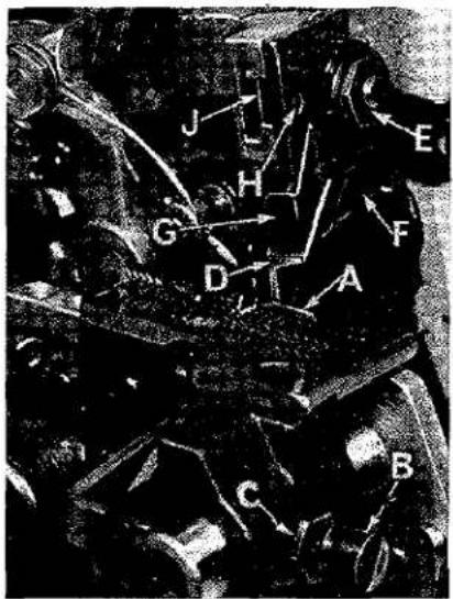
Fig. 13
Lower knife may be secured in any position by tightening screw (B) and locking nut (C) against support bracket. Because screw (B) also serves as latch pin for the cloth plate latch spring, it should always be locked with nut (C) even when screw is not tightened against lower knife holder.
SETTING THE UPPER KNIFE (FOR ALL STYLES EXCEPT 39500 SF)
Replace upper knife assembly. Clamp upper knife (D, Fig. 13) in position, setting nut (E) to hold clamp (F) in its most clockwise position against upper knife. At bottom of its stroke, front cutting edge of upper knife should extend not less than 1/64 inch (.40 mm) below cutting edge of lower knife. The chain guard (G) should be set down against the upper knife and slightly
back from the cutting edge.
After upper knife has been set for proper width of trim, screw (H) should be tightened to lock upper knife holding block (J) in place. This will simplify resetting when upper knife is replaced.
SETTING UPPER KNIFE (FOR STYLE 39500 SF)
Replace upper knife assembly. Clamp upper knife in position, setting Allen screw located on the right side to hold clamp against the upper knife. At bottom of its stroke, front cutting edge of upper knife should extend not less than 1/64 inch (.40 mm) below cutting edge of the lower knife.
After the upper knife has been set for the proper width of trim, the upper knife holding block should be locked in place using the screw at the front of the holding block.
SETTING THE STITCH LENGTH
Length of stitch is determined by the combination of feed eccentricis used. Outer (left) eccentric (A, Fig. 14) actuates main (rear) feed dog; while the inner (right) eccentric (B) actuates the differential (front) feed dog.
In assembling feed eccentrics, be sure hubs are facing each other. Be careful not to damage shaft or key. Tighten nut (C) securely.

Fig. 14
SETTING THE STITCH LENGTH (Continued)
To change feed eccentrics, remove nut (C) and washer (D) from end of shaft (E). Turn handwheel in operating direction until key slot in eccentric is toward front. Using hooked eccentric extractor (F), supplied with machine, reach behind eccentrics as shown and withdraw eccentrics. It may be necessary to move handwheel back and forth slightly during extraction.
If eccentrics are unusually tight fitting, in addition to removing nut (C) and washer (D, Fig. 15) from shaft (E), it may be helpful to remove nut (G) and feed driving connection (H). Then continue as originally suggested.
SETTING THE PRESSER FOOT
Assemble the presser foot to presser arm. With needle in high position, swing presser arm into sewing position and set the presser foot to align needle holes (front and back) and flat on throat plate. The front edge of needle hole in presser foot must be aligned with front edge of needle hole in throat plate. It is also important that the bottom of the presser foot be flat on the throat plate. If necessary, presser foot can be re-aligned with throat plate slots by shifting the foot lifter lever shaft (H, Fig. 16). To

Fig. 15

Fig. 16
move the shaft, loosen collar screws (B, Fig. 16) and clamp screw (G) and then shift the foot lifter lever shaft to the left or right as required. Retighten collar screws and clamp screw.
The foot lifter lever arm (A, Fig. 16) and the collar (B) secure the shaft. Be sure the presser arm does not bind and rise when presser foot release bushing is unlocked.
Adjust lifter lever stop screw (C) so that presser foot can be raised no higher than upper looper will permit; then lock the nut (D). There should be from 1/16 to 1/8 inch (1.59 to 3.17 mm) free motion of foot lifter lever before the presser foot begins to rise. This adjustment should be made with screw (E) and
locked with nut (F). Re-assemble the chip guard, fabric guard and cloth plate. To assemble chip guard, turn handwheel until upper knife assembly reaches its highest position.
STARTING TO OPERATE (503 AND 504 STITCH)
Be sure machine is threaded according to threading diagram Fig. 1A for the 503 stitch or according to Fig. 1 for the 504 stitch. With thread tensions light, set looper thread eyelet (R, Fig. 1A) or looper thread eyelets (N and R, Fig. 1) approximately horizontal and in the middle of their front to back locations. Operate machine slowly, without presser foot in place, to make sure chain forms and moves off stitch tongue freely. Swing presser foot into position, insert material and sew slowly.
NEEDLE THREAD CONTROL (503 AND 504 STITCH)
While sewing on material, check needle thread control as follows: Usually all needle thread is drawn on needle down stroke. At top of needle stroke, thread should be just tight enough to feed chain off stitch tongue. Stitch tends to pull down slightly if excessive thread is pulled on the up stroke. With needle at bottom of stroke, position needle thread eyelet (AD, Fig. 1) so that needle thread cam pull-off (AE) just contacts needle thread.
It is desirable to adjust the needle thread eyelet well-forward (toward the operator) to delay slightly, the tightening of the needle thread.
LOWER LOOPER THREAD CONTROL (503 STITCH)
With material under presser foot, set lower looper thread eyelet (R, Fig. 1A) back and down far enough so thread is a little slack when spreader reaches its extreme left position. Lower looper thread eyelet (R) should be about horizontal.
Frame looper thread guide (T) should be set with its eyelet approximately 1/8 inch (3.17 mm) to the right of heel eyelet of looper (V) at the time lower looper is at extreme left end of its travel.
LOWER LOOPER THREAD CONTROL (504 STITCH)
With material under presser foot, set lower looper thread eyelet (R, Fig. 1) back far enough so thread is a little slack when looper thread pull-off (AF) reaches its most rearward position. Looper thread pull-off (AF) is set about 1/32 inch (.79 mm) distance behind needle thread campull-off (AE). Frame looper thread guide (T) should be set with its eyelet approximately 1/8 inch (3.17 mm) to the right of lower looper (V) heel eyelet at the time lower looper is at extreme left end of its travel.
While sewing on material, check drawing off of looper thread as follows: A portion of lower looper thread should be drawn through the tension before lower looper thread comes off upper looper. To increase amount of thread drawn through the tension while lower looper thread is on upper looper, move lower looper thread eyelet (R) down, keeping the same amount of pull-off action.
UPPER LOOPER THREAD CONTROL (504 STITCH)
Before proceeding to adjust upper looper thread eyelet (N, Fig. 1) balance all three tensions to give a normal appearing stitch. Moderate change in these tensions will not markedly affect the purl.
During needle down stroke, forward stroke of looper thread pull-off (AF) will draw upper looper thread through the tension. When normal amount of looper thread is drawn, upper looper thread will have almost all slack taken up as looper thread pull-off reaches its most rearward position.
POSITIONING THE PURL (504 STITCH)
To move the purl more under the edge, both looper thread eyelets (N and R, Fig. 1) should be raised keeping the same amount of pull-off. Usually it is better to have slightly more pull-off on upper thread than on lower thread.
If it becomes necessary to move looper thread pull-off (AF), be sure to take up all end play in needle drive shaft before tightening. If upper looper is located so that it is higher over throat plate than recommended in Fig. 10, the purl will tend to form near top edge. If upper looper is too low, the purl will form nearer bottom edge.
THREAD TENSIONS (503 STITCH)
Balance both tensions to give a normal appearing stitch. Moderate change in these tensions will not markedly affect the purl.
THREAD TENSIONS (504 STITCH)
The needle thread tension required is a function of needle thread and material being sewn. In general, lower looper thread tension should be set as high as possible without causing needle thread to be pulled down. Upper looper thread tension should be increased as long as the elasticity of the chain increases, or until the purl is pulled too far over the top.
STARTING TO OPERATE (505 STITCH)
Be sure machine is threaded according to threading diagram (Fig. 1, 1B or 1C).
With thread tensions light, set upper and lower looper thread eyelets (N and R) about horizontal and in the middle of their front to back locations.
Operate machine slowly, without presser foot in place, to make sure that chain forms and moves off the tongue freely.
Swing presser foot into position, insert materials, and sew slowly.
NEEDLE THREAD CONTROL (505 STITCH)
While sewing on material, check needle thread control as follows: About 60% of needle thread required for the stitch should be drawn on needle downstroke.
To increase thread drawn on downstroke, position needle thread eyelet (AD, Fig. 1, 1B or 1C) farther to the rear.
LOWER LOOPER THREAD CONTROL (505 STITCH)
Set lower looper thread eyelet (R, Fig. 1, 1B or 1C) about horizontal and all the way forward in its slot.
Frame looper thread guide (T) should be set with its eyelet approximately 1/8 inch (3.17 mm) to the right of lower looper (V) heel eyelet, when lower looper is at the left end of its stroke.
UPPER LOOPER THREAD CONTROL (505 STITCH)
With material under presser foot, set upper looper thread eyelet (N, Fig. 1, 1B or 1C) to rest on top of lower looper thread eyelet (R), and back far enough so upper looper thread is a little slack when upper looper reaches the left end of its stroke.
POSITIONING THE SQUARE EDGE (505 STITCH)
Position of lower looper thread at the edge is located by balancing needle and upper looper thread tensions.
To reduce amount of lower looper thread in the stitch, or close the edge more, increase lower looper thread tension.

Fig. 17
TO REMOVE CRANKSHAFT
Crankshaft can be withdrawn easier if these steps are followed:
- Drain oil by removing plug screw located on back of machine near bottom edge of base.
- Remove top and bottom covers of machine.
- Remove feed eccentric nut (A, Fig. 17) and washer (B), and, with the aid of the eccentric extractor, slip off the eccentrics (C).
- Remove key (D).
- Remove three counterweights (E). Identify these counterweights so that they will be re-assembled in the proper places.
- Remove screw (F) which holds crankshaft split bearing. This screw is reached through bottom of bed casting.
TO REMOVE CRANKSHAFT (Continued)
-
Remove caps of bearings on crankshaft at points G, H, and J. When re-assembling bearing caps make sure they are in their original position. Trade marks are stamped on both halves of the caps and both trade marks should be on the same side of the bearings. Also, screws should be re-assembled in the same holes from which they were removed.
-
Loosen clamp nut (A, Fig. 18) which holds upper knife driving arm (B). Access to clamp nut is through top cover. Draw driving arm to the left until upper

Fig. 18
knife driving lever (C) and connecting rod (D) drop, allowing removal of bearing cap (E). This is at bearing point (K, Fig. 17) on crankshaft. Observe same precautions when re-assembling cap as described in 7 above.
-
Remove screw (L, Fig. 17) which holds inner right crankshaft bearing. This screw is reached through bottom of bed casting.
-
Loosen two screws (M) in fan collar; remove both halves of cooling fan.
-
Remove screw (N); take off pulley cap (P).
-
Loosen two screws (R); remove pulley (S).
-
Remove three screws (T); take off bearing retaining plate (U); also, spacer collars (V) and (W) may be removed at this time.
-
Crankshaft may now be removed.
-
If necessary to replace ball bearing (X), it should be pressed off shaft on an arbor press. In replacing bearing it must be pressed on carefully until it seats against ground thrust washer (Y).
-
Carefully observing reverse of the foregoing operations should simplify re-assembly of crankshaft. Checking exploded view drawings for location of various parts and constant testing for binds during re-assembly will also prove helpful.
-
Before re-assembling thoroughly clean and dry top and bottom covers and gaskets. Before re-assembling bottom cover make sure that spring pressed oil wick which lubricates left crankshaft bearing is inserted in hole in casting and that it contacts shaft. The wick stands vertically on its spring against bottom cover. Coat oil drain plug with a sealing compound before re-assembling to prevent oil leakage. No. 1 Crane Lead Seal is recommended.
ORDERING REPAIR PARTS
ILLUSTRATIONS
This catalog has been arranged to simplify ordering repair parts. Exploded views of various sections of the mechanism are shown so that the parts may be seen in their actual position in the machine. On the page opposite the illustration will be found a listing of the parts with their part numbers, description and the number of pieces required in the particular view being shown.
Numbers in the first column are reference numbers only, and merely indicate the position of that part in the illustration. Reference number should never be used in ordering parts. Always use the part number listed in the second column.
Component parts of sub-assemblies which can be furnished for repairs are indicated by indenting their descriptions under the description of the main sub-assembly. Example:
| 23 | 29477 JM | Crankshaft and Needle Driving Arm Crank Assembly,for Styles 39500 QA, QB, RM, RS, SE, SG, TA, TD----1 |
| - | 29477 KE | Crankshaft and Needle Driving Arm Crank Assembly,for Styles 39500 QP, QY, RA, RF, RR, SF, TH----1 |
| 24 | 29477 MC | Needle Driving Arm Crank and Connecting RodAssembly----1 |
| 25 | 22768 C | Screw, for needle driving arm connecting rodpin----1 |
| 26 | 22596 H | Screw, for needle driving arm crank----1 |
| 27 | 22587 M | Screw, for needle driving arm connecting rod---2 |
| 28 | 51-228 Blk. | Vent Plug----1 |
| 29 | 39541 A | Feed Driving Eccentric Key----1 |
| 30 | 30-106 Blk. | Wood Plug----1 |
| 31 | CO67 E | Cork Plug----1 |
| 32 | 40-46 | Washer----1 |
| 33 | 258 | Nut----1 |
It will be noted in the above example that the crankshaft, needle driving arm crank or connecting rod are not listed. The reason is that replacement of these parts individually is not recommended, so the complete sub-assembly should be ordered.
Where the parts for all the styles covered in this catalog are not the same, the difference will be shown in the illustrations or mentioned in the descriptions. When a part is used in all machines covered by this catalog no machine style will be mentioned.
At the back of the book will be found a numerical index of all the parts shown in this book. This will facilitate locating the illustration and description when only the part number is known.
IDENTIFYING PARTS
Where the construction permits, each part is stamped with its part number. On some of the smaller parts, and on those where construction does not permit, an identification letter is stamped in to distinguish the part from similar ones.
PART NUMBERS REPRESENT THE SAME PART, REGARDLESS OF CATALOG IN WHICH THEY APPEAR.
USE GENUINE NEEDLES AND REPAIR PARTS
Success in the operation of these machines can be secured only with genuine UNION SPECIAL Needles and Repair Parts as furnished by the Union Special Corporation, its subsidiaries and authorized distributors. They are designed according to the most scientific principles, and are made with utmost precision. Maximum efficiency and durability are assured.
Genuine needles are packaged with labels marked Union Special®. Genuine repair parts are stamped with the Union Special trademark, U S Emblem. Each trademark is your guarantee of the highest quality in materials and workmanship.
TERMS
Prices are net cash and subject to change without notice. All shipments are forwarded f.o.b. shipping point. Parcel post shipments are insured unless otherwise directed. A charge is made to cover postage and insurance.
TORQUE REQUIREMENTS
Torque (measured in inch-pounds) is a rotating force (in pounds) applied through a distance by a lever (in inches or feet). This is accomplished by a wrench, screw driver, etc. Many of these devices are available, which when set at the proper amount of torque will tighten the part to the correct amount and no tighter.
All straps and eccentrics should be tightened to 19-21 inch-pounds (22-24cm/kg) unless otherwise noted. All other nuts, bolts, screws, etc., should be tightened by hand as tightly as possible, unless otherwise noted.
The screws requiring a specific torque, will be indicated on the picture plates.
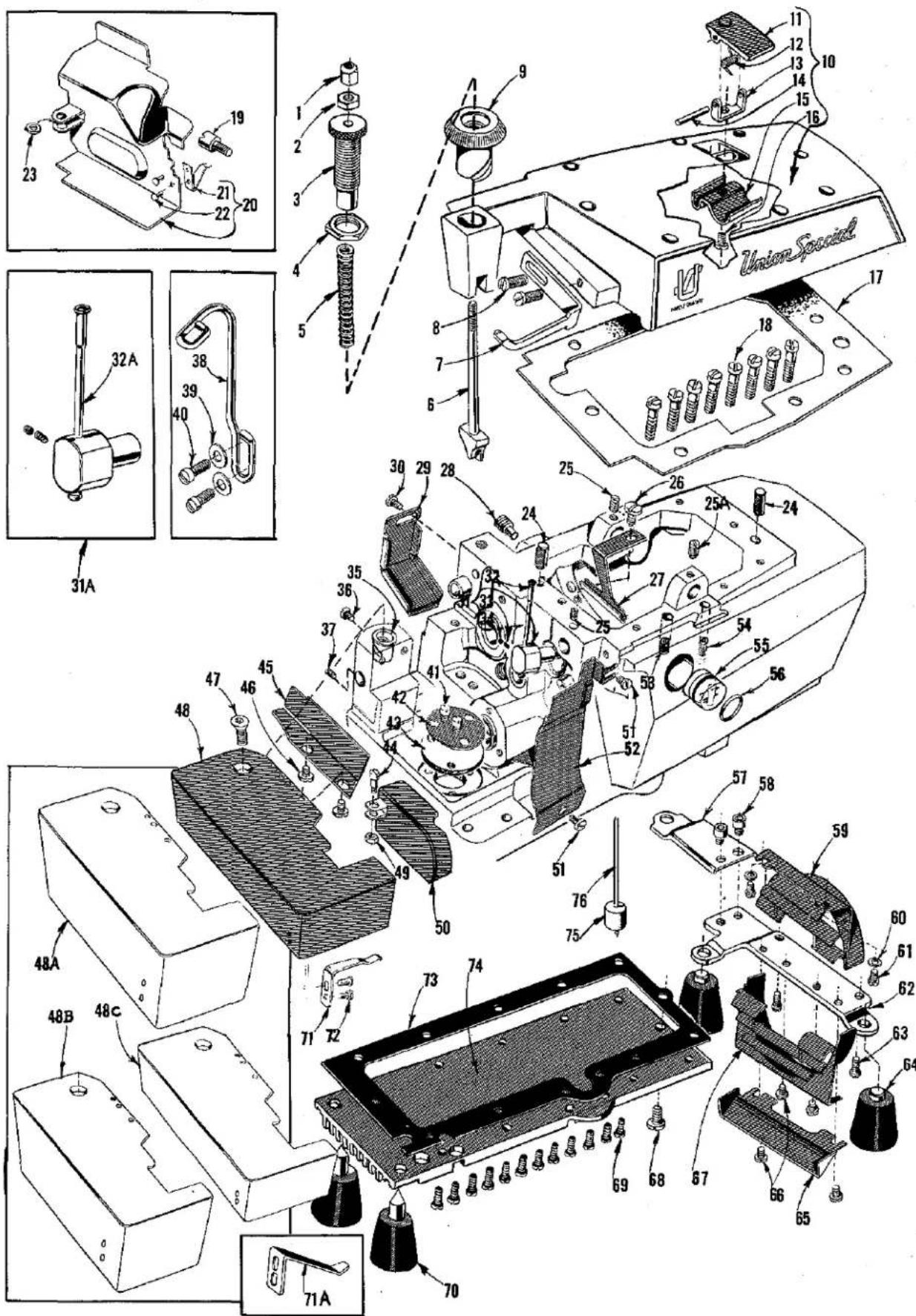
MAIN FRAME, PRESSER FOOT RELEASE PARTS,
MISCELLANEOUS COVERS AND PLATES
| Ref.No. | PartNo. | Description | Amt.Req. |
| 1 | 39557 B | Presser Spring Plunger Cap Nut | 1 |
| 2 | 39557 E | Presser Spring Plunger Locking Nut | 1 |
| 3 | 39557 C | Presser Spring Plunger Adjusting Screw | 1 |
| 4 | 39557 F | Lock Nut, for adjusting screw | 1 |
| 5 | 39557 | Presser Spring | 1 |
| 6 | 39557 A | Presser Spring Plunger | 1 |
| 7 | 39563 F | Top Cover Needle Thread Eyelet, for all Styles except 39500 QY, RA, SF, SG | 1 |
| - | 39563 T | Top Cover Needle Thread Eyelet, for Styles 39500 QY, RA, SF | 1 |
| 8 | 22569 B | Screw, for top cover needle thread eyelet | 2 |
| 9 | 39556 A | Presser Foot Release Bushing | 1 |
| 10 | 39582 AD | Top Cover | 1 |
| 11 | 39582 AF | Oil Filler Cover | 1 |
| 12 | 39582 V | Spring | 1 |
| 13 | 39582 AG | Hinge Bracket | 1 |
| 14 | 51-103 Blk. | Hinge Pin | 1 |
| 15 | 39582 W | Oil Guard | 1 |
| 16 | 22562 A | Screw, for hinge bracket | 1 |
| 17 | 39582 AE | Top Cover Gasket | 1 |
| 18 | 22541 | Screw, for top cover | 8 |
| 19 | 22585 G | Side Cover Latch Stud, for Styles 39500 RA, RR, SF | 1 |
| 20 | 39582 GG | Side Cover, for Styles 39500 RA, RR, SF | 1 |
| 21 | 39582 H | Spring | 1 |
| 22 | 39582 J | Rivet, for spring | 2 |
| 23 | 53634 C | Washer, for No. 39582 GG and used with 86 X on Style 39500 SF | 1 |
| 24 | 667 D-8 | Dowel Pin | 2 |
| 25 | 22565 | Set Screw, for upper looper thread tube assembly and for upper looper drive lever shaft | 2 |
| 25A | 22565 S | Spot Screw, for upper looper drive lever shaft | 1 |
| 26 | 22569 D | Screw, for oil collector plate | 1 |
| 27 | 39594 R | Oil Collector Plate | 1 |
| 28 | 22571 E | Magnetic Oil Drain Plug Screw | 1 |
| 29 | 39534 R | Feed Bar Oil Shield | 1 |
| 30 | 90 | Screw, for feed bar oil shield | 1 |
| 31 | 29477 GW | Upper Looper Thread Tube Assembly, for all Styles except 39500 QY | 1 |
| 31A | 29477 HJ | Upper Looper Thread Tube Assembly, for Style 39500 QY only | 1 |
| 32 | 39568 G | Thread Tube, for No. 29477 GW | 1 |
| 32A | 39568 P | Thread Tube, for No. 29477 HJ | 1 |
| 33 | 39568 J | Thread Tube Tension Spring | 1 |
| 34 | 22743 | Set Screw, for thread tube tension spring | 1 |
| 35 | 39501 K | Cloth Plate Stud | 1 |
| 36 | 22569 | Screw, for cloth plate stud | 1 |
| 37 | 22565 F | Screw, for feed adjusting pin | 1 |
| 38 | 39599 | Tape Guide, for Styles 39500 RA, SF | 1 |
| 39 | 69 H | Washer, for tape guide | 2 |
| 40 | 22569 | Screw, for tape guide | 2 |
| 41 | 22569 B | Screw, for oil filter screen and strainer | 2 |
| 42 | 39594 G | Oil Filter Screen | 1 |
| 43 | 39594 H | Oil Strainer, felt | 1 |
| 44 thru 76 | See following page | ||

MAIN FRAME, PRESSER FOOT RELEASE PARTS,
MISCELLANEOUS COVERS AND PLATES
| Ref.No. | PartNo. | Description | Amt.Req. |
| 1 thru 43 | See preceding page | ||
| 44 | 86 X | Screw, for feed mechanism cover | 1 |
| 45 | 39578 F | Cloth Plate Fabric Guard, for all Styles except 39500 RR, SF | 1 |
| 46 | 138 | Screw, for cloth plate fabric guard | 2 |
| 47 | 22657 D-12 | Screw, for cloth plate | 1 |
| 48 | 39501 D | Cloth Plate, for semi or fully submerged installation on all Styles except 39500 RR, SF | 1 |
| 48A | 39501 E | Cloth Plate, for Style 39500 RR and for non submerged installation on all Styles except 39500 SF | 1 |
| 48B | 39501 EB | Cloth Plate, for non submerged installation on Style 39500 SF | 1 |
| 48C | 39501 DB | Cloth Plate, for semi or fully submerged installation on Style 39500 SF | 1 |
| 49 | 41071 G | Nut, for feed mechanism cover | 1 |
| 50 | 39582 D | Feed Mechanism Cover, for all Styles except 39500 QY, RA, RR, SF | 1 |
| - | 39582 DA | Feed Mechanism Cover, for Style 39500 QY | 1 |
| 51 | 22569 D | Screw, for chip guard | 2 |
| 52 | 39578 T | Chip Guard, for all Styles except 39500 RA, RF-5/32, RR, SG, TH | 1 |
| - | 39578 U | Chip Guard, for Styles 39500 RR, SG | 1 |
| - | 39578 AH | Chip Guard, for Style 39500 RF-5/32 only | 1 |
| - | 39578 TA | Chip Guard, for Styles 39500 RA, TH | 1 |
| 53 | 22569 K | Screw, for oil sight gauge | 1 |
| 54 | 22894 AE | Screw, for lower looper bar driving lever shaft | 2 |
| 55 | 39593 H | Oil Sight Gauge | 1 |
| 56 | 660-243 | Oil Gauge Seal Ring | 1 |
| 57 | 39582 F | Bottom Cover Extension | 1 |
| 58 | 22653 D-4 | Screw, for bottom cover extension | 2 |
| 59 | 39582 BV | Air Duct, upper | 1 |
| 60 | 8372 A | Washer, for upper air duct | 2 |
| 61 | 22569 C | Screw, for upper air duct | 2 |
| 62 | 39582 BM | Base Plate | 1 |
| 63 | 22541 B | Screw, for base plate | 2 |
| 64 | 39595 | Isolator, for all Styles except 39500 TA | 2 |
| - | 39595 | Isolator, for Style 39500 TA | 4 |
| 65 | 39582 BL | Air Duct, outer | 1 |
| 66 | 22569 D | Screw, for lower and outer air duct | 4 |
| 67 | 39582 BK | Air Duct, lower | 1 |
| 68 | 22586 T | Screw, for bottom cover | 1 |
| 69 | 22541 B | Screw, for bottom cover | 12 |
| 70 | 51295 B | Isolator, for all Styles except 39500 TA | 2 |
| 71 | 39532 A | Cloth Plate Latch Spring, for all Styles except 39500 SF | 1 |
| 71A | 39532 E | Cloth Plate Latch Spring, for Style 39500 SF | 1 |
| 72 | 90 | Screw, for latch spring | 2 |
| 73 | 39582 BH | Bottom Cover Gasket | 1 |
| 74 | 39582 BW | Bottom Cover | 1 |
| 75 | 39593 C | Oil Gauge Float | 1 |
| 76 | 39593 D | Oil Gauge Indicator | 1 |

CRANKSHAFT MECHANISM AND BUSHINGS
| Ref. No. | Part No. | Description | Amt. Req. |
| 1 | 22769 B | Screw, for pulley cap | 1 |
| 2 | 39521 D | Pulley Cap | 1 |
| 3 | 39521 G | Pulley | 1 |
| 4 | 95 | Screw, for pulley | 2 |
| 5 | 22569 B | Screw, for crankshaft ball bearing retaining plate | 3 |
| 6 | 39590 H | Crankshaft Ball Bearing Retaining Plate | 1 |
| 7 | 39590 S | Spacer Collar | 1 |
| 8 | 39590 R | Ball Bearing Stop Collar | 1 |
| 9 | 660-268 | Crankshaft Ball Bearing | 1 |
| 10 | 39590 G | Crankshaft Ball Bearing Housing | 1 |
| 11 | 39590 J | Thrust Washer | 1 |
| 12 | 39591 L | Crank Chamber Cooling Fan | 1 |
| 13 | 39591 H | Crank Chamber Cooling Fan Collar | 1 |
| 14 | 22894 D | Spot Screw, for crank chamber cooling fan collar | 2 |
| 15 | 39590 X | Crankshaft Bearing, inner right | 1 |
| 16 | 660-443 | "O" Ring, for crankshaft bearing, inner right | 1 |
| 17 | 660-204 | "O" Ring, for crankshaft bearing, inner right | 1 |
| 18 | 39590 P | Oil Slinger Collar | 1 |
| 19 | 77 Q | Set Screw, for oil slinger collar | 2 |
| 20 | 22565 F | Screw, for crankshaft bearing, inner right | 1 |
| 21 | 39590 D | Crankshaft Split Bearing | 1 |
| 22 | 97 A | Screw, for crankshaft split bearing | 2 |
| 23 | 29477 JM | Crankshaft and Needle Driving Arm Crank Assembly,for Styles 39500 QA, QB, RM, RS, SE, SG, TA, TD | 1 |
| 29477 KE | Crankshaft and Needle Driving Arm Crank Assembly,for Styles 39500 QP, QY, RA, RF, RR, SF, TH | 1 | |
| 24 | 29477 MC | Needle Driving Arm Crank and Connecting RodAssembly | 1 |
| 25 | 22768 C | Screw, for needle driving arm connecting rodpin | 1 |
| 26 | 22596 H | Screw, for needle driving arm crank | 1 |
| 27 | 22587 M | Screw, for needle driving arm connecting rod | 2 |
| 28 | 51-228 Blk. | Vent Plug | 1 |
| 29 | 39541 A | Feed Driving Eccentric Key | 1 |
| 30 | 30-106 Blk. | Wood Plug | 1 |
| 31 | CO67 E | Cork Plug | 1 |
| 32 | 40-46 | Washer | 1 |
| 33 | 258 | Nut | 1 |
| 34 | 39591 B | Crankshaft Counterweight, right | 1 |
| 35 | 22747 B | Screw, for crankshaft counterweights | 6 |
| 36 | 39590 N | Stud, for crankshaft split bearing | 1 |
| 37 | 39591 A | Crankshaft Counterweight, middle | 1 |
| 38 | 39591 K | Crankshaft Counterweight, left | 1 |
| 39 | 87 U | Screw, for oil splasher | 1 |
| 40 | 39594 N | Oil Splasher | 1 |
| 41 | 666-94 | Oil Wick and Spring | 1 |
| 42 | 39590 | Crankshaft Bushing, left | 1 |
| 43 | 39590 T | Crankshaft Bushing, inner left | 1 |
| 44 | 39544 X | Lower Looper Bar Bushing | 1 |
| 45 | 39552 P | Needle Driving Arm Crank Bushing, right | 1 |
| 46 | 39573 AA | Upper Knife Driving Arm Bushing, right | 1 |
| 47 | 39555 N | Foot Lifter Shaft Bushing, right | 1 |
| 48 | 39555 P | Foot Lifter Shaft Bushing, left | 1 |
| 49 | 39573 K | Upper Knife Driving Arm Bushing, left | 1 |
| 50 | 39552 U | Needle Driving Arm Crank Bushing, left | 1 |
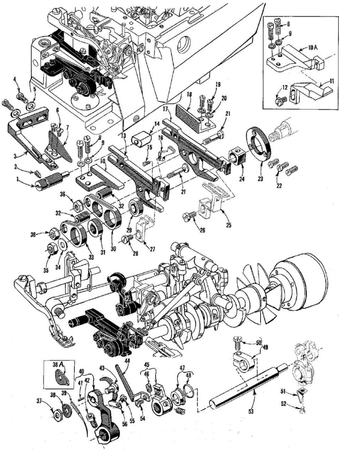
NEEDLE DRIVE AND FEED MECHANISM
| Ref.No. | PartNo. | Description | AmRec |
| 1 | 39535 C | Feed Adjusting Pin | 1 |
| 2 | 22565 F | Screw, for feed adjusting pin | 1 |
| 3 | 39578 P | Fabric Guard Mounting Bracket | 1 |
| 4 | 22569 B | Screw, for fabric guard mounting bracket | 2 |
| 5 | 8372 A | Washer, for mounting bracket screw | 2 |
| 6 | 87 | Screw, for fabric guard | 2 |
| 7 | 39578 R | Fabric Guard, for all Styles except 39500 TH | 1 |
| - | 39578 S | Fabric Guard, for Style 39500 TH only | 1 |
| 8 | 22569 B | Screw, for main feed bar guide, left | 2 |
| 9 | 53634 C | Washer, for main feed bar guide screw | 2 |
| 10 | 39535 | Main Feed Bar Guide, left, for all Styles except 39500 QY | 1 |
| 10A | 39535 | Main Feed Bar Guide, left, for Style 39500 QY only | 1 |
| 11 | 39580 H | Throat Plate Support Stop, for Style 39500 QY only | 1 |
| 12 | 93 A | Screw, for main feed bar guide, left, for Style 39500 QY only | 1 |
| 13 | 39534 | Main Feed Bar, for all Styles except 39500 SF | 1 |
| - | 39534 C | Main Feed Bar, for Style 39500 SF only | 1 |
| 14 | 39535 J | Feed Bar Guide Block | 1 |
| 15 | 22797 A | Screw, for chaining feed dog on all Styles except 39500 TA | 1 |
| 16 | Chaining Feed Dog (See Pages 42, 44, 46) | 1 | |
| 17 | 39534 G | Differential Feed Bar | 1 |
| 18 | 39535 D | Differential Feed Bar Guide, right | 1 |
| 19 | 22569 B | Screw, for differential feed bar guide, right | 2 |
| 20 | 53634 C | Washer, for differential feed bar guide screw | 2 |
| 21 | 39536 B | Feed Bar Driving Stud | 2 |
| 22 | 22569 G | Screw, for thrust washer | 3 |
| 23 | 39534 H | Differential Feed Bar Thrust Washer | 1 |
| 24 | 39538 | Feed Lift Block | 1 |
| 25 | Differential Feed Dog (See Pages 42, 44, 46) | 1 | |
| 26 | 22528 | Screw, for differential feed dog | 1 |
| 27 | Main Feed Dog (See Pages 42, 44, 46) | 1 | |
| 28 | 93 A | Screw, for main feed dog | 1 |
| 29 | Differential Feed Driving Eccentric (See Chart Below) | 1 | |
| 30 | 39536 AE | Differential Feed Bar Driving Connection | 1 |
| 31 | Main Feed Driving Eccentric (See Chart Below) | 1 | |
| 32 | 39536 C | Feed Bar Driving Stud Bushing | 2 |
| 33 | 39536 AF | Main Feed Bar Driving Connection | 1 |
| 34 | 40-46 | Washer, for crankshaft | 1 |
| 35 | 258 | Nut, for crankshaft | 1 |
| 36 | 39536 E | Nut, for feed bar driving stud | 2 |
| 37 | 14077 A | Nut, for needle clamp stud | 1 |
| 38 | 39551 H | Needle Clamp Washer, for all Styles except 39500 SG | 1 |
| 38A | 39563 AA | Needle Thread Pull-up Eyelet and Needle Clamp Washer, for Style 39500 SG | 1 |
| 39 | Needle (See Page 6 for needle used on a specific style) | 1 | |
| 40 | 39552 Z | Needle Driving Arm, marked "K" | 1 |
| 41 | 39552 AD | Stop Pin, for needle | 1 |
| 42 | 22596 E | Screw, for needle driving arm | 1 |
| 43 | 39551 J | Needle Clamp Stud | 1 |
| 44 | 39568 A | Looper Thread Pull-off | 1 |
| 45 | 39568 AC | Looper Thread Pull-off Lever | 1 |
| 46 | 88 B | Screw, for looper thread pull-off lever | 2 |
| 47 | 39552 AG | Oil Seal, for needle driving shaft | 1 |
| 48 | 660-207 | Oil Seal Ring | 1 |
| 49 | 39543 Y | Needle Drive Shaft Thrust Collar | 1 |
| 50 | 22782 A | Screw, for needle drive shaft thrust collar | 1 |
| 51 | 39594 N | Oil Splasher | 1 |
| 52 | 87 U | Screw, for oil splasher | 1 |
| 53 | 39552 R | Needle Driving Shaft | 1 |
| 54 | 22513 | Screw, for looper thread pull-off | 1 |
| 55 | 87 U | Screw, for needle thread cam pull-off | 1 |
| 56 | 39563 G | Needle Thread Cam Pull-off, for all Styles except 39500 RM, SG | 1 |
| - | 39563 J | Needle Thread Cam Pull-off, for Style 39500 RM only | 1 |
| STYLES | DET, 29DIFF. FEED DRIVING ECC. | DET, 31MAIN FEED DRIVING ECC. |
| 39500 QA, TD | 39540 B-12 | 39540 B-10 |
| 39500 QB, QP, RF | 39540 B-10 | 39540 B-12 |
| 39500 QY, RA | 39540 B-6 | 39540 B-10 |
| 39500 RM | 39540 B-10 | 39540 B-10 |
| 39500 RR | 39540 B-18 | 39540 B-20 |
| 39500 RS | 39540 B-14 | 39540 B-14 |
| 39500 SE | 39540 B-12 | 39540 B-9 |
| 39500 SF | 39540 B-4 | 39540 B-10 |
| 39500 SG | 39540 B-9 | 39540 B-9 |
| 39500 TA | 39540 B-30 | 39540 B-30 |
| 39500 TH | 39540 B-8 | 39540 B-7 |
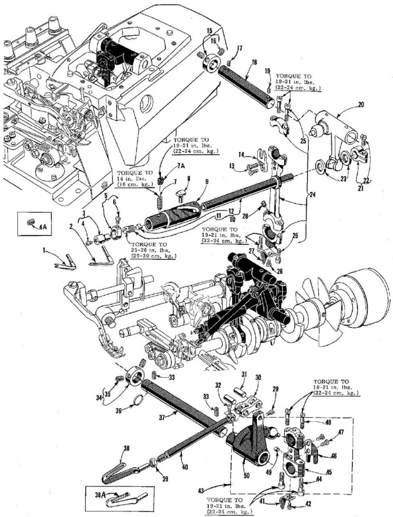
UPPER AND LOWER LOOPER DRIVING PARTS
| Ref. No. | Part No. | Description | Amt. Req. |
| 1 | 39560 A | Upper Spreader, for Styles 39500 RM, RR (for 503 stitch only on RR)---- | 1 |
| 2 | 39508 AH | Upper Looper, marked "CC", for all Styles except 39500 QY, RA, RM, SF---- | 1 |
| - | 39508 E | Upper Looper, marked "CK", for Styles 39500 QY, RA, SF---- | 1 |
| 3 | 39543 | Upper Looper Holder---- | 1 |
| 4 | 22564 G | Screw, for upper looper---- | 1 |
| 4A | 22894 Y | Set Screw, for looper and spreader on Style 39500 RR only---- | 1 |
| 5 | 39543 A | Upper Looper Holder Collar---- | 1 |
| 6 | 77 | Screw, for upper looper holder collar---- | 1 |
| 7 | 22565 H | Spot Screw, for bushing and cam guide---- | 1 |
| 7A | 1025 L | Lock Screw, for bushing and cam guide screw---- | 1 |
| * 8 | 39543 T | Cam Follower---- | 1 |
| * 9 | 39543 S | Bushing and Cam Guide---- | 1 |
| *10 | 39543 K | Upper Looper Drive Shaft---- | 1 |
| 11 | 22503 F | Screw, for cam follower locking clamp---- | 1 |
| 12 | 39543 E | Cam Follower Locking Clamp---- | 1 |
| 13 | 97 | Screw, for ball joint guide fork---- | 2 |
| 14 | 39544 J | Ball Joint Guide Fork, for upper looper drive lever---- | 1 |
| 15 | 482 C | Upper Looper Shaft Collar---- | 1 |
| 16 | 22894 C | Set Screw, for upper looper shaft collar---- | 2 |
| 17 | 22565 | Set Screw, for upper looper rock shaft---- | 1 |
| 18 | 39543 X | Upper Looper Drive Lever Shaft---- | 1 |
| 19 | 22565 S | Spot Screw, for upper looper drive lever shaft---- | 1 |
| 20 | 39543 W | Upper Looper Drive Lever---- | 1 |
| 21 | 39543 M | Clamp Collar, for upper looper drive shaft---- | 1 |
| 22 | 22562 A | Screw, for clamp collar---- | 1 |
| 23 | 39543 P | Upper Looper Drive Shaft Thrust Washer---- | 2 |
| 24 | 39543 U | Upper Looper Drive Lever Connecting Rod---- | 1 |
| 25 | 22729 D | Screw, for upper looper drive lever connecting rod---- | 4 |
| 26 | 87 U | Screw, for oil splasher---- | 1 |
| 27 | 39594 N | Oil Splasher---- | 1 |
| 28 | 666-255 | Felt, for connecting rod---- | 1 |
| 29 | 77 | Screw, for lower looper bar connecting link pin---- | 1 |
| 30 | 39544 B | Lower Looper Bar Connecting Link---- | 1 |
| 31 | 39544 D | Lower Looper Bar Connecting Link Pin---- | 2 |
| 32 | 77 | Screw, for lower looper bar connecting link pin---- | 1 |
| 33 | 22894 AE | Set Screw, for lower looper driving shaft---- | 2 |
| 34 | 482 C | Lower Looper Driving Shaft Collar---- | 1 |
| 35 | 22894 C | Set Screw, for lower looper driving shaft collar---- | 2 |
| 36 | 660-206 | "O" Ring, for lower looper driving shaft---- | 1 |
| 37 | 39544 V | Lower Looper Driving Shaft---- | 1 |
| 38 | 39508 B | Lower Looper, for all Styles except 39500 QY, RA, SF---- | 1 |
| 38A | 39508 D | Lower Looper, for Styles 39500 QY, RA, SF---- | 1 |
| 39 | 39151 | Nut, for lower looper bar---- | 1 |
| 40 | 39544 | Lower Looper Bar---- | 1 |
| 41 | 39594 N | Oil Splasher---- | 1 |
| 42 | 87 U | Screw, for oil splasher---- | 1 |
| 43 | 29126 DF | Lower Looper Bar Driving Lever and Connecting Rod Assembly- | 1 |
| 44 | 22729 E | Screw, for connecting rod---- | 2 |
| 45 | 39544 N | Lower Looper Drive Lever Connecting Rod---- | 1 |
| 46 | 39544 S | Ball Joint Guide Fork---- | 1 |
| 47 | 97 | Screw, for ball joint guide fork---- | 2 |
| 48 | 22729 D | Screw, for connecting rod---- | 2 |
| 49 | 666-255 | Felt, for connecting rod---- | 1 |
| 50 | 39544 U | Lower Looper Bar Driving Lever---- | 1 |
* The use of assembly No. 29126 EC is recommended instead of the individual parts.

UPPER AND LOWER KNIFE MECHANISM
| Ref.No. | PartNo. | Description | Amt.Req. |
| 1 | 39573 J | Upper Knife Driving Connecting Rod | 1 |
| 2 | 22587 J | Screw, for upper knife driving connecting rod | 2 |
| 3 | 39573 E | Upper Knife Driving Lever | 1 |
| 4 | 55235 E | Nut, for upper knife driving lever | 1 |
| 5 | 6042 A | Washer, for upper knife driving lever | 1 |
| 6 | 55235 D | Locking Stud, for upper knife driving lever | 1 |
| 7 | 39270 E | Upper Knife, for Style 39500 SF only | 1 |
| 8 | 39571 E | Upper Knife Clamp Bar, for Style 39500 SF only | 1 |
| 9 | 39573 H | Upper Knife Driving Arm | 1 |
| 10 | 39571 A | Upper Knife Clamp Nut, for Style 39500 SF only | 1 |
| 11 | 39572 B | Upper Knife Holder Block, for Style 39500 SF only | 1 |
| 12 | 22829 | Screw, for upper knife holder block on Style 39500 SF only | 1 |
| 13 | 22650 CB-4 | Set Screw, for upper knife on Style 39500 SF | 1 |
| 14 | 39571 D | Upper Knife Clamp Stud, for all Styles except 39500 RR, SF, SG, TH | 1 |
| - | 39571 C | Upper Knife Clamp Stud, for Styles 39500 RR, SG, TH | 1 |
| 15 | 39572 | Upper Knife Holder Block, for all Styles except 39500 RR, SF, SG, TH | 1 |
| - | 39572 A | Upper Knife Holder Block, for Styles 39500 RR, SG, TH | 1 |
| 16 | 22738 | Screw, for upper knife clamp stud on all Styles except 39500 SF | 1 |
| 17 | 39570 | Upper Knife, for all Styles except 39500 QY, RA, SF, TH | 1 |
| 17A | 39570 K | Upper Knife, for Styles 39500 QY, RA | 1 |
| 17B | 39570 J | Upper Knife, for Style 39500 TH only | 1 |
| 18 | 39571 F | Upper Knife Clamp, for all Styles except 39500 SF | 1 |
| 19 | 39571 B | Upper Knife Chain Guard, for all Styles except 39500 SF | 1 |
| 20 | 14077 | Nut, for upper knife clamp stud on all Styles except 39500 SF | 1 |
| 21 | 39525 | Needle Guard, front, for all Styles except 39500 SF, TA | 1 |
| - | 39525 L | Needle Guard, front, for Style 39500 SF, TA | 1 |
| 22 | 39525 A | Needle Guard, rear | 1 |
| 23 | 22585 A | Screw, for needle guards | 2 |
| 24 | 39580 A | Throat Plate and Lower Knife Support Bracket, for all Styles except 39500 RA, RR, SF | 1 |
| - | 39580 AD | Throat Plate and Lower Knife Support Bracket, for Styles 39500 RA, RR, SF | 1 |
| 25 | 22653 B-12 | Screw, for throat plate and lower knife support bracket | 2 |
| 26 | 39580 F | Washer, for throat plate and lower knife support bracket | 2 |
| 27 | 14077 | Nut, for lower knife holder locking screw | 1 |
| 28 | 22892 B | Locking Screw, for lower knife holder on all Styles except 39500 SF | 1 |
| 28A | 88 B | Locking Screw, for lower knife holder on Style 39500 SF | 1 |
| 29 | 39550 C | Lower Knife Holder Locking Stud, for all Styles except 39500 TH | 1 |
| - | 39550 R | Lower Knife Holder Locking Stud, for Style 39500 TH only | 1 |
| 30 | 22729 B | Screw, for lower knife holder locking stud | 1 |
| 31 | 39549 | Lower Knife, for all Styles except 39500 QY, RA, SF, TH | 1 |
| 31A | 39549 J | Lower Knife, for Styles 39500 QY, RA, SF, TH | 1 |
| 31B | 39503 H | Front Fabric Guide, for Style 39500 RR only | 1 |
| 32 | 22588 J | Screw, for lower knife clamp | 1 |
| 33 | 39550 Z | Lower Knife Clamp, for all Styles except 39500 TA | 1 |
| 34 | 39550 M | Lower Knife Clamp Spring, for all Styles except 39500 TA | 1 |
| 35 | 39550 S | Lower Knife Holder, for all Styles except 39500 TA | 1 |
| 36 | 39550 E | Lower Knife Holder Spring, for all Styles except 39500 SG, TH | 1 |
| - | 39550 P | Lower Knife Holder Spring, for Styles 39500 SG, TH | 1 |
| 37 | Throat Plate (See Pages 42, 44, 46) | 1 | |
| 38 | 22524 | Screw, for throat plate | 1 |
| 39 | 39573 A | Upper Knife Driving Arm Washer | 1 |
| 40 | 39550 AF | Lower Knife Holder, for Style 39500 TA | 1 |
| 41 | 39550 AC | Knife Guide Plate, for Style 39500 TA | 1 |
| 42 | 39550 AE | Lower Knife Clamp Spring, for Style 39500 TA | 1 |
| 43 | 605 A | Screw, for lower knife clamp spring, for Style 39500 TA | 1 |
| 44 | 39550 AD | Lower Knife Clamp, for Style 39500 TA | 1 |

FOOT LIFTER, CHAIN CUTTING KNIFE, EDGE GUIDE, THREAD TENSION PARTS AND MISCELLANEOUS EYELETS
| Ref.No. | PartNo. | Description | Amt.Req. |
| 1 | 39855 | Foot Lifter Lever---- | 1 |
| 2 | 39555 B | Foot Lifter Lever Spring---- | 1 |
| 3 | 39555 D | Foot Lifter Intermediate Lever---- | 1 |
| 4 | 660-142 | Cotter Pin, for foot lifter lever connecting link---- | 2 |
| 5 | 39555 F | Foot Lifter Lever Connecting Link---- | 1 |
| 6 | 22566 B | Screw, for foot lifter lever---- | 1 |
| 7 | 39555 C | Foot Lifter Lever Arm---- | 1 |
| 8 | 22597 E | Set Screw, for foot lifter lever arm---- | 2 |
| 9 | 12538 | Lock Nut, for foot lifter lever arm---- | 2 |
| 10 | 627 | Screw, for foot lifter lever arm---- | 1 |
| 11 | 12865 | Foot Lifter Lever Shaft Thrust Collar---- | 1 |
| 12 | 88 | Screw, for foot lifter lever shaft collar---- | 2 |
| 13 | 39555 A | Foot Lifter Lever Shaft---- | 1 |
| 14 | 22791 H | Screw Pin, for presser arm---- | 1 |
| 15 | 258 A | Nut, for presser arm screw---- | 1 |
| 16 | 39556 P | Presser Arm, for Style 39500 SG only---- | 1 |
| - | 39556 F | Presser Arm, for all Styles except 39500 SE, SG, TH---- | 1 |
| 16A | 39556 D | Presser Arm, for Style 39500 TH only---- | 1 |
| - | 39556 J | Presser Arm, for Style 39500 SE only---- | 1 |
| 17 | 39556 K | Chain Cutting Knife, marked "J", for Style 39500 RR---- | 1 |
| 18 | 22704 | Screw, for chain cutting knife---- | 1 |
| 19 | 39556 M | Chain Cutting Knife, for Style 39500 TH only---- | 1 |
| 20 | 22738 G | Screw, for chain cutter blade---- | 1 |
| 21 | 39556 L | Chain Cutter Blade---- | 1 |
| 22 | 605 | Screw, for chain cutting knife on Style 39500 TH only---- | 2 |
| 23 | 605 A | Screw, for presser foot hold down plate on Styles 39500 RS, TD- | 2 |
| 24 | 39556 H | Presser Foot Hold Down Plate, for Styles 39500 RS, TD---- | 1 |
| 25 | 376 A | Screw, for upper looper thread eyelet on all Styles except39500 RM---- | 1 |
| 26 | 39568 E | Auxiliary Looper Thread Eyelet, for all Styles except39500 QY, RA, RM, SF---- | 1 |
| - | 39568 U | Auxiliary Looper Thread Eyelet, for Styles 39500 QY, RA, SF-- | 1 |
| 27 | 376 A | Screw, for lower looper thread eyelet---- | 1 |
| 28 | 39568 B | Lower Looper Thread Eyelet, for all Styles except39500 QY, RA, SF---- | 1 |
| - | 39568 S | Lower Looper Thread Eyelet, for Styles 39500 QY, RA, SF---- | 1 |
| 29 | 39568 L | Upper Looper Thread Eyelet, for all Styles except39500 QY, RA, RM, SF, SG---- | 1 |
| - | 39568 B | Upper Looper Thread Eyelet, for Style 39500 SG only---- | 1 |
| - | 39568 T | Upper Looper Thread Eyelet, for Styles 39500 QY, RA, SF---- | 1 |
| 30 | 39568 D | Looper Thread Eyelet Mounting Bracket---- | 1 |
| 31 | 22569 B | Screw, for looper thread eyelet mounting bracket---- | 1 |
| 32 | Presser Foot (See Pages 42, 44, 46)---- | 1 | |
| 33 | 43139 A | Nut, for looper thread eyelet screw on all Styles except39500 RM---- | 2 |
| - | 43139 A | Nut, for looper thread eyelet screw, on Style 39500 RM---- | 1 |
| 34 | 39563 H | Needle Thread Eyelet, for all Styles except 39500 QY,RA, SF, SG---- | 1 |
| - | 39563 U | Needle Thread Eyelet, for Styles QY, RA, SF---- | 1 |
| 34A | 39563 D | Needle Thread Eyelet, for Style 39500 SG only---- | 1 |
| 35 | 22569 D | Screw, for needle thread eyelet---- | 1 |
| 36 | 39568 W | Frame Thread Guide, for lower looper thread on allStyle except 39500 QY---- | 1 |
| 36A | 39668 W | Frame Thread Guide, for lower looper thread on Style39500 QY only---- | 1 |
| 37 | 73 X | Screw, for frame thread guide---- | 2 |
| 38 thru 57 | See following page |

FOOT LIFTER, CHAIN CUTTING KNIFE, EDGE GUIDE, THREAD TENSION PARTS AND MISCELLANEOUS EYELETS
| Ref.No. | PartNo. | Description | Amt.Req. |
| 1 thru 37 | See preceding page | ||
| 38 | 39503 A | Edge Guide, for Style 39500 TH only | 1 |
| 39 | 604 | Screw, for edge guide on Style 39500 TH only | 2 |
| 40 | 39503 D | Edge Guide Swinging Arm, for Style 39500 TH only | 1 |
| 41 | 12957 E | Spring Washer, for swinging arm on Style 39500 TH only | 1 |
| 42 | 22758 E | Screw, for swinging arm on Style 39500 TH only | 1 |
| 43 | 22569 C | Screw, for edge guide mounting bracket on Style 39500 TH only | 2 |
| 44 | 39503 C | Edge Guide Mounting Bracket, for Style 39500 TH only | 1 |
| 45 | 39592 AA | Needle Tension Nut, green | 1 |
| - | 39592 AB | Upper Looper Tension Nut, blue, for all Styles except 39500 RM | 1 |
| - | 39592 AC | Lower Looper Tension Nut, red | 1 |
| 46 | 39592 AK | Tension Spring Ferrule, for all Styles except 39500 RM | 3 |
| - | 39592 AK | Tension Spring Ferrule, for Style 39500 RM only | 2 |
| 47 | 39592 AR-4 | Upper and Lower Thread Tension Spring, for Styles 39500 QY, RA, RS, SF, TA, TD, TH | 2 |
| - | 39592 AR-5 | Upper and Lower Thread Tension Spring, for Styles 39500 QA, QB, QP, RF, SE | 2 |
| - | 39592 AR-1 | Needle Thread Tension Spring, for Style 39500 RR only | 1 |
| - | 39592 AR-4 | Needle Thread Tension Spring, for Styles 39500 RS, SG, TA | 1 |
| - | 39592 AR-8 | Needle Thread Tension Spring, for all Styles except 39500 RR, RS, SG, TA | 1 |
| - | 39592 AR-2 | Upper Looper Thread Tension Spring, for Style 39500 RR only | 1 |
| - | 39592 AR-4 | Upper Looper Thread Tension Spring, for Style 39500 SG | 1 |
| - | 39592 AR-4 | Lower Looper Thread Tension Spring, for Style 39500 RM | 1 |
| - | 39592 AR-8 | Lower Looper Thread Tension Spring, for Styles 39500 RR, SG | 1 |
| 48 | 39592 AD | Thread Tension Disc, for all Styles except 39500 RM | 6 |
| - | 39592 AD | Thread Tension Disc, for Style 39500 RM only | 4 |
| 49 | 39592 AF | Tension Disc Felt, for all Styles except 39500 RM | 3 |
| - | 39592 AF | Tension Disc Felt, for Style 39500 RM only | 2 |
| 50 | 39592 AL | Tension Post, for all Styles except 39500 RM | 3 |
| - | 39592 AL | Tension Post, for Style 39500 RM only | 2 |
| 51 | 8372 A | Washer, for tension post on all Styles except 39500 RM | 3 |
| - | 8372 A | Washer, for tension post on Style 39500 RM only | 2 |
| 52 | 39592 AH | Locating Nut, for tension post on all Styles except 39500 RM | 3 |
| - | 39592 AH | Locating Nut, for tension post on Style 39500 RM only | 2 |
| 53 | 22806 A | Screw, for tension mounting bracket | 1 |
| 54 | 39592 AG-3 | Tension Post Mounting Bracket | 1 |
| 55 | 39592 AM | Tension Post Bar | 1 |
| 56 | 22847 B | Screw, for tension post mounting bracket | 1 |
| - | 40-46 | Washer, for No. 22806 A screw on Style 39500 TA only (not shown) | 1 |
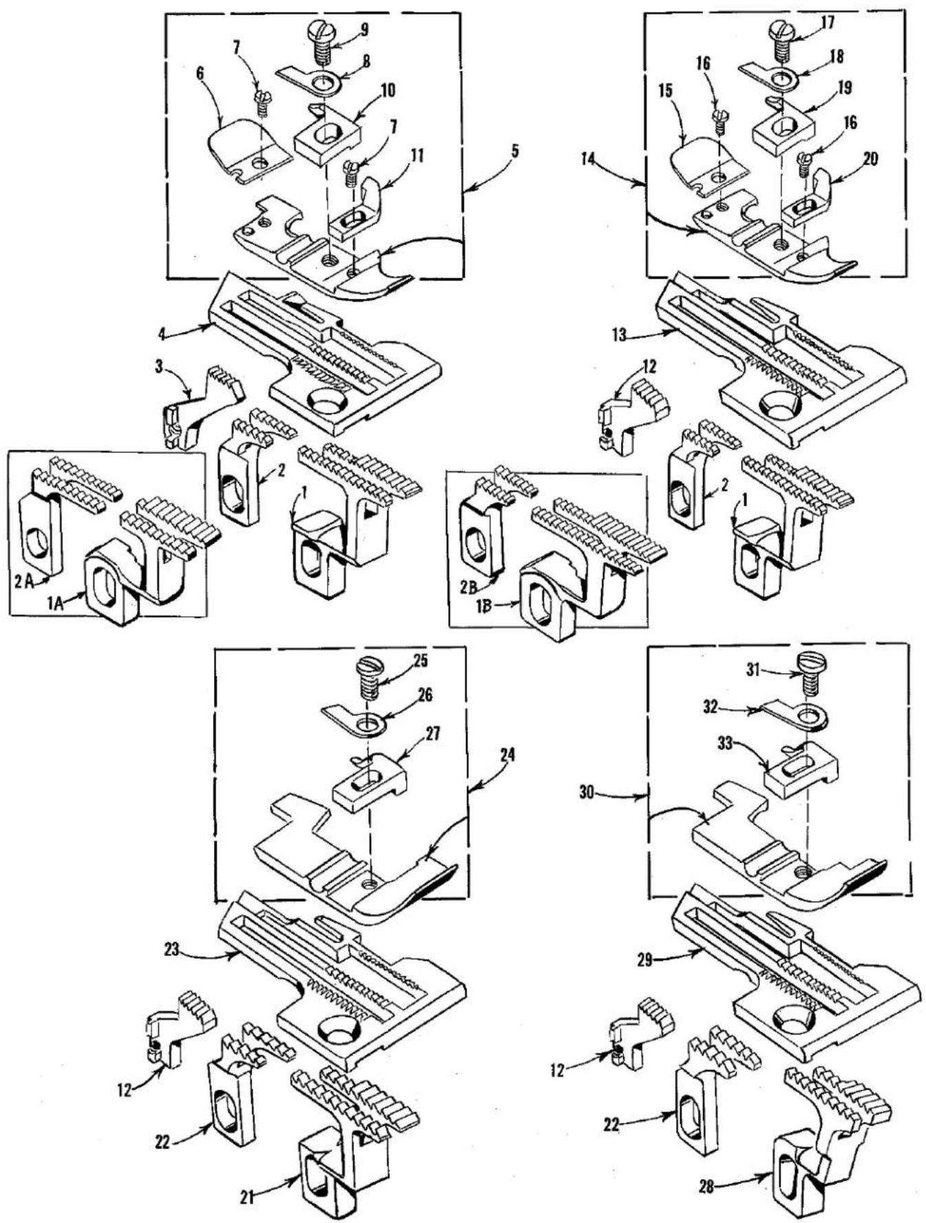
FEED DOGS, THROAT PLATES AND PRESSER FEET
| Ref.No. | PartNo. | Description | Amt.Req. |
| 1 | 39526 B | Differential Feed Dog, 16 t.p.i., for Styles 39500 QA, QB, RF | 1 |
| 1A | 39526 BJ | Differential Feed Dog, 16 t.p.i., for Style 39500 TD only | 1 |
| 1B | 39526 D | Differential Feed Dog, 20 t.p.i., for Style 39500 RM only | 1 |
| 2 | 39505 B | Main Feed Dog, marked "B", 16 t.p.i., for Styles 39500 QA, QB, RF | 1 |
| 2A | 39505 BJ | Main Feed Dog, marked "EA", 16 t.p.i., for Style 39500 TD only | 1 |
| 2B | 39505 D | Main Feed Dog, marked "E", 20 t.p.i., for Style 39500 RM only | 1 |
| 3 | 39505 C | Chaining Feed Dog, marked "C", 20 t.p.i., for Styles 39500 QA, RS, SG, TD | 1 |
| 4 | 39524 C-3/32 | Throat Plate, marked "AC-3/32", for 3/32 inch (2.38 mm) wide seam on Styles 39500 QA, TD | 1 |
| - | 39524 C-1/8 | Throat Plate, marked "AC-1/8", for 1/8 inch (3.17 mm) wide seam on Styles 39500 QA, TD | 1 |
| 5 | 39520 B | Presser Foot, for Styles 39500 QA, TD | 1 |
| 6 | 39530 C | Presser Foot Chain Shield | 1 |
| 7 | 22738 B | Screw, for chain shield and chip guard | 2 |
| 8 | 39530 | Presser Foot Hinge Spring | 1 |
| 9 | 22768 B | Screw, for stitch tongue and hinge spring | 1 |
| 10 | 39597 A | Presser Foot Stitch Tongue, marked "DS" | 1 |
| 11 | 39530 P | Presser Foot Chip Guard | 1 |
| 12 | 39505 E | Chaining Feed Dog, 20 t.p.i., for Styles 39500 QB, QP, QY, RA, RF, RM, RR, SE, SF, TH | 1 |
| 13 | 39524 B-3/32 | Throat Plate, marked "V-3/32", for 3/32 inch (2.38 mm) wide seam for Styles 39500 QB, RF, RM | 1 |
| - | 39524 B-1/8 | Throat Plate, marked "V-1/8", for 1/8 inch (3.17 mm) wide seam for Styles 39500 QB, RF | 1 |
| - | 39524 B-5/32 | Throat Plate, marked "BH", for 5/32 inch (3.97 mm) wide seam for Style 39500 RF | 1 |
| 14 | 39520 A | Presser Foot, for Styles 39500 QB, RF | 1 |
| 15 | 39530 C | Presser Foot Chain Shield | 1 |
| 16 | 22738 B | Screw, for chain shield and chip guard | 2 |
| 17 | 22768 B | Screw, for stitch tongue and hinge spring | 1 |
| 18 | 39530 | Presser Foot Hinge Spring | 1 |
| 19 | 39597 A | Presser Foot Stitch Tongue, marked "DS" | 1 |
| 20 | 39530 P | Presser Foot Chip Guard | 1 |
| 21 | 39526 P | Differential Feed Dog, 12 t.p.i., for Style 39500 QP | 1 |
| 22 | 39505 P | Main Feed Dog, marked "J", 12 t.p.i., for Styles 39500 QP, QY, RA, RR | 1 |
| 23 | 39524 P | Throat Plate, marked "AJ", for 1/8 inch (3.17 mm) wide seam for Style 39500 QP | 1 |
| 24 | 39520 P | Presser Foot, for Style 39500 QP | 1 |
| 25 | 22768 B | Screw, for stitch tongue and hinge spring | 1 |
| 26 | 39530 | Presser Foot Hinge Spring | 1 |
| 27 | 39597 P | Presser Foot Stitch Tongue, marked "EA" | 1 |
| 28 | 39526 Y | Differential Feed Dog, marked "AB", 12 t.p.i. for Style 39500 QY | 1 |
| 29 | 39524 Y | Throat Plate, marked "AS", for 1/8 inch (3.17 mm) wide seam for Style 39500 QY | 1 |
| 30 | 39520 Y | Presser Foot, for Style 39500 QY | 1 |
| 31 | 22768 B | Screw, for stitch tongue and hinge spring | 1 |
| 32 | 39530 | Presser Foot Hinge Spring | 1 |
| 33 | 39597 P | Presser Foot Stitch Tongue, marked "EA" | 1 |
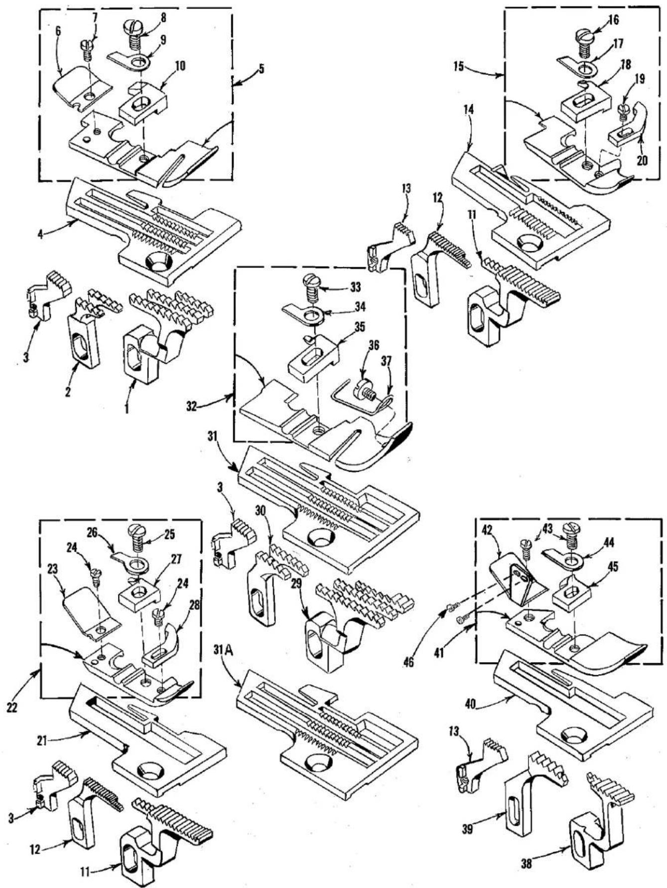
FEED DOGS, THROAT PLATES AND PRESSER FEET
| Ref.No. | PartNo. | Description | Amt.Req. |
| 1 | 39526 AA | Differential Feed Dog, marked "AA", 12 t.p.i., for Styles 39500 RA, RR | 1 |
| 2 | 39505 P | Main Feed Dog, marked "J", 12 t.p.i., for Styles 39500 QP, QY, RA, RR | 1 |
| 3 | 39505 E | Chaining Feed Dog, 20 t.p.i., for Styles 39500 QB, QP, QY, RA, RF, RM, RR, SE, SF, TH | 1 |
| 4 | 39524 AA | Throat Plate, marked "AT", for 5/32 inch (3.97 mm) wide seam for Style 39500 RA | 1 |
| 5 | 39520 AA | Presser Foot, for Style 39500 RA | 1 |
| 6 | 39530 C | Presser Foot Chain Shield | 1 |
| 7 | 22738 | Screw, for presser foot chain shield | 1 |
| 8 | 22768 B | Screw, for stitch tongue and hinge spring | 1 |
| 9 | 39530 | Presser Foot Hinge Spring | 1 |
| 10 | 39597 AA | Presser Foot Stitch Tongue, marked "EG" | 1 |
| 11 | 39526 AC | Differential Feed Dog, 22 t.p.i., for Styles 39500 RS, SE | 1 |
| 12 | 39505 AC | Main Feed Dog, marked "AM", 22 t.p.i., for Styles 39500 RS, SE | 1 |
| 13 | 39505 C | Chaining Feed Dog, marked "C", 20 t.p.i., for Styles 39500 QA, RS, SG, TD | 1 |
| 14 | 39524 AS | Throat Plate, marked "BE", for 3/32 inch (2.38 mm) wide seam for Style 39500 RS | 1 |
| 15 | 39520 AS | Presser Foot, for Styles 39500 RS, TA | 1 |
| 16 | 22768 B | Screw, for stitch tongue and hinge spring | 1 |
| 17 | 39530 | Presser Foot Hinge Spring | 1 |
| 18 | 39597 AS | Presser Foot Stitch Tongue, marked "ES" | 1 |
| 19 | 22738 B | Screw, for presser foot chip guard | 1 |
| 20 | 39530 P | Presser Foot Chip Guard | 1 |
| 21 | 39528 AD | Throat Plate, marked "BJ", for 1/8 inch (3.17 mm) wide seam for Style 39500 SE | 1 |
| 22 | 39527 AD | Presser Foot, for Style 39500 SE | 1 |
| 23 | 39530 R | Presser Foot Chain Shield | 1 |
| 24 | 22738 | Screw, for presser foot chain shield and chip guard | 2 |
| 25 | 22768 B | Screw, for stitch tongue and hinge spring | 1 |
| 26 | 39530 G | Presser Foot Hinge Spring | 1 |
| 27 | 39597 AB | Presser Foot Stitch Tongue, marked "EK" | 1 |
| 28 | 39530 P | Presser Foot Chip Guard | 1 |
| 29 | 39526 BF | Differential Feed Dog, marked "BZ", 12 t.p.i., for Style 39500 SF | 1 |
| 30 | 39505 BF | Main Feed Dog, marked "BY", 12 t.p.i., for Style 39500 SF- | 1 |
| 31 | 39524 BF | Throat Plate, marked "BK", for 1/8 inch (3.17 mm) wide seam for Style 39500 SF | 1 |
| 31A | 39524 BF-3/16 | Throat Plate, marked "DG", for 3/16 inch (4.76 mm) wide seam for Style 39500 SF | 1 |
| 32 | 39520 BF | Presser Foot, for Style 39500 SF | 1 |
| 33 | 22768 B | Screw, for stitch tongue and hinge spring | 1 |
| 34 | 39530 | Presser Foot Hinge Spring | 1 |
| 35 | 39597 P | Presser Foot Stitch Tongue, marked "EA" | 1 |
| 36 | 22798 B | Screw, for presser foot tape guide | 1 |
| 37 | 39530 BF | Presser Foot Tape Guide | 1 |
| 38 | 39526 BG | Differential Feed Dog, 12 t.p.i., for Style 39500 SG | 1 |
| 39 | 39505 BG | Main Feed Dog, marked "CH", 12 t.p.i., for Style 39500 SG- | 1 |
| 40 | 39524 BG | Throat Plate, for 3/32 inch (2.38 mm) wide seam for Style 39500 SG | 1 |
| 41 | 39520 BG | Presser Foot, for Style 39500 SG | 1 |
| 42 | 39530 X | Presser Foot Chain Shield and Hold Down Plate- | 1 |
| 43 | 22768 B | Screw, for stitch tongue and hinge spring | 2 |
| 44 | 39530 | Presser Foot Hinge Spring | 1 |
| 45 | 39597 BG | Presser Foot Stitch Tongue, marked "EV" | 1 |
| 46 | 22768 | Screw, for presser foot hold down plate on Style 39500 SG only | 2 |
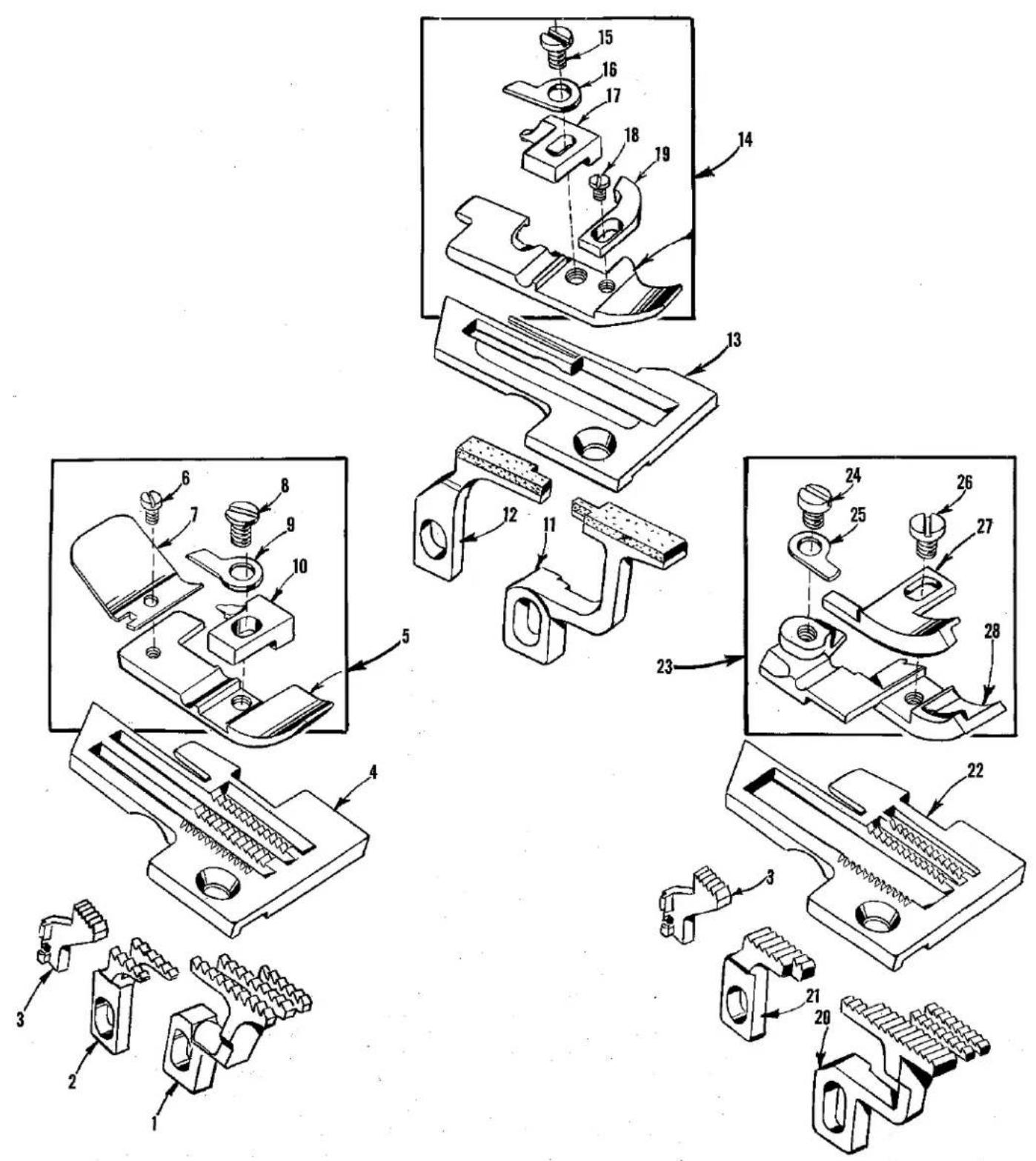
FEED DOGS, THROAT PLATES AND PRESSER FEET
| Ref.No. | PartNo. | Description | Amt.Req. |
| 1 | 39526 AA | Differential Feed Dog, marked "AA", 12 t.p.i.,for Styles 39500 RA, RR | 1 |
| 2 | 39505 P | Main Feed Dog, marked "J", 12 t.p.i., for Styles39500 QP, QY, RA, RR | 1 |
| 3 | 39505 E | Chaining Feed Dog, 20 t.p.i., for Styles 39500 QB,QP, QY, RA, RF, RM, RR, SE, SF, TH | 1 |
| 4 | 39524 AR-1/4 | Throat Plate, marked "BC-1/4", for 1/4 inch(6.35 mm) wide seam for Style 39500 RR only | 1 |
| 5 | 39520 AR | Presser Foot, for Style 39500 RR only | 1 |
| 6 | 22738 | Screw, for chain shield | 1 |
| 7 | 39530 H | Presser Foot Chain Shield | 1 |
| 8 | 22768 B | Screw, for stitch tongue and hinge spring | 1 |
| 9 | 39530 | Presser Foot Hinge Spring | 1 |
| 10 | 39597 AR | Presser Foot Stitch Tongue, marked "EN" | 1 |
| 11 | 39526 AB | Differential Feed Dog, vulcanized rubber feedsurface, for Style 39500 TA only | 1 |
| 12 | 39505 AB | Main Feed Dog, marked "AG", vulcanized rubberfeed surface, for Style 39500 TA only | 1 |
| 13 | 39524 AV | Throat Plate, marked "BZ", 1/16 to 3/32 inch (1.59to 2.38 mm) wide seam for Style 39500 TA only | 1 |
| 14 | 39520 AS | Presser Foot, for Styles 39500 RS, TA | 1 |
| 15 | 22768 B | Screw, for stitch tongue and hinge spring | 1 |
| 16 | 39530 | Presser Foot Hinge Spring | 1 |
| 17 | 39597 AS | Presser Foot Stitch Tongue, marked "ES" | 1 |
| 18 | 22738 B | Screw, for presser foot chip guard | 1 |
| 19 | 39530 P | Presser Foot Chip Guard | 1 |
| 20 | 39526 AR | Differential Feed Dog, marked "FD", 16 t.p.i.,for Style 39500 TH | 1 |
| 21 | 39505 AR | Main Feed Dog, marked "FC", 16 t.p.i., for Style39500 TH | 1 |
| 22 | 39524 X | Throat Plate, marked "AR", for Style 39500 TH | 1 |
| 23 | 39520 FX | Presser Foot, marked "CR", for 3/8 inch (9.52 mm)wide seam, for Style 39500 TH | 1 |
| 24 | 87 U | Screw, for hinge spring | 1 |
| 25 | 39530 | Presser Foot Hinge Spring | 1 |
| 26 | 28 | Screw, for edge guide | 1 |
| 27 | 39530 AB | Edge Guide, marked "S" | 1 |
| 28 | 39530 AC | Presser Foot Bottom, marked "CA" | 1 |

THREAD STAND AND MISCELLANEOUS TOOLS
| Ref. No. | Part No. | Description | Amt. Req. |
| 1 | 21113 F | Thread Stand Eyelet and Support Rod, for all Styles except 39500 TA | 3 |
| 2 | 21104 V | Pad, for thread cone | 3 |
| 3 | 69 S | Spool Pin | 3 |
| 4 | 21130 W-3 | Cone Support | 1 |
| 5 | 22650 CB-4 | Screw, for thread stand eyelet | 3 |
| 6 | 22650 CE-6 | Screw, for thread stand rod | 1 |
| 7 | 21104 AA | Thread Stand Rod | 1 |
| 8 | 652 J-24 | Washer | 1 |
| 9 | 652 J-16 | Washer | 1 |
| 10 | WA9 A | Lock Washer | 1 |
| 11 | 651 A-16 | Nut | 1 |
| 12 | SC333 A | Wood Screw, round head #9 x 5/8 inch (15.88 mm) long for Style 39500 TA | 3 |
| 13 | 39592 W | Tension Post Bracket, for mounting on tableboard for Style 39500 TA | 1 |
| 14 | 660-264 | "S" Hook, for treadle chain | 2 |
| 15 | 116 | Wrench, for 9/32 inch (7.142 mm) nuts | 1 |
| 16 | 39599 A | Threading Wire, for Style 39500 TA | 1 |
| 17 | 660-240 | Thread Tweezers | 1 |
| 18 | 21388 AU | Socket Wrench, for 3/8 inch (9.52 mm) nuts holding feed eccentricis | 1 |
| 19 | 21227 BF | Cam Extractor | 1 |
| 20 | 421 D-34 | Treadle Chain, for presser foot lifter | 1 |
| 21 | 21202 | Screwdriver, 3/16 inch (4.76 mm) diameter, 10 3/4 inches (273.05) mm) long overall(not furnished) | 1 |
| 22 | 21113 G | Thread Stand Eyelet and Support Rod, for Style 39500 TA | 3 |
| 23 | 22565 C | Screw, for tension post | 1 |
| 24 | 39592 D | Tension Post, for Style 39500 TA | 3 |
| 25 | 109 | Tension Disc (inverted), for Style 39500 TA | 6 |
| 26 | 39592 E | Tension Spring Pad, felt, for Style 35900 TA | 6 |
| 27 | 51292 F-1 | Tension Spring, for Style 39500 TA | 3 |
| 28 | 107 | Tension Post Ferrule, for Style 39500 TA | 3 |
| 29 | 108 | Tension Post Nut, for Style 39500 TA | 3 |
| - | 660-458 | Dust Cover (not shown) | 1 |
| - | 28604 R | Container of Oil, 16 ounces, Spec. 175 (not shown) | 1 |
| - | 652-24 | Washer, for all Styles except 39500 TA (not shown) | 8 |
| - | 21375 BB | Belt Guard (not shown) | 1 |
| - | 80 | Screw, for belt guard (not shown) | 2 |
ACCESSORIES AVAILABLE AS EXTRAS (Not Illustrated)
| 21233 HA | Light Fixture Assembly, with screw base sealed beam lamp, machine mounting for machines driven by "Electro Drive" which supplies the current. |
| 21261 M-330 | No. 1 "V" Belt, 33 inches (838.20 mm) long, for fully-submerged individual power table installation (Amco Drive). |
| 21261 M-350 | No. 1 "V" Belt, 35 inches (889.00 mm) long, for semi-submerged individual power table installation (Amco Drive). |
| 21261 M-360 | No. 1 "V" Belt, 36 inches (914.40 mm) long, for non-submerged individual power table installation (Amco Drive). |
| 21377 BP | Tray 1 3/4 inches (44.45 mm) high for semi-submerged installation. |
| 21695 U | Finger Protector. |
| 39556 M | Presser Arm Chain Cutting Knife. |
| 605 | Screw, for presser arm chain cutting knife (two required). |
| 39598 | Knife Grinder, complete. |
| 51278 F | Chip Disposal Chute. |
| Belt Slot to Right Edge of Board | Cloth Plate to Front Edge of Board | ||
| 21371 UH | Individual Power Table | ||
| 21371 PJ-48 | Table Top, 48 x 20 x 1 3/4 inches (1219.20 x 508.00 x 44.45 mm) for non-submerged power table installation - no chip chute; | 14 inch (355.60 mm) | 3/8 inch (9.52 mm) |
| 21371 RD-48 | Table Top, same except non-submerged with chip chute; | 7 1/2 inch (190.50 mm) | 3 inch (76.20 mm) |
| 21371 RF-48 | Table Top, same except non-submerged - no chip chute; | 7 1/2 inch (190.50 mm) | 3/8 inch (9.52 mm) |
| 21371 RJ-48 | Table Top, same except semi-submerged with chip chute; | 10 1/2 inch (266.70 mm) | 2 1/4 inch (57.15 mm) |
| 21371 RL-48 | Table Top, same except semi-submerged with chip chute; | 7 1/2 inch (190.50 mm) | 2 1/4 inch (57.15 mm) |
| 21371 WL-48 | Table Top, same except fully-submerged with chip chute; | 7 1/2 inch (190.50 mm) | 2 1/4 inch (57.15 mm) |
| 21371 RC-47 3/4 | Table Top, 47 3/4 x 16 x 1 3/4 inches (1212.85 x 406x40 x 44.45 mm) for non-submerged line shaft installation - no chip chute; | 7 1/2 inch (190.50 mm) | 3/8 inch (9.52 mm) |
| 21371 RE-47 3/4 | Table Top, same except non-submerged with chip chute; | 7 1/2 inch (190.50 mm) | 3 inch (76.20 mm) |
| 21371 RE-47 3/4 | Table Top, same except semi-submerged with chip chute; | 7 1/2 inch (190.50 mm) | 2 1/4 inch (57.15 mm) |
NUMERICAL INDEX OF PARTS
| Part No. | Page No. | Part No. | Page No. | Part No. | Page No. |
| WA9 A. | 49 | 22513. | 33 | 39501 EB. | 29 |
| 28. | 47 | 22524. | 37 | 39503 A. | 41 |
| 30-106 Blk. | 31 | 22528. | 33 | 39503 C. | 41 |
| 40-46. | 31, 33, 41 | 22541. | 27 | 39503 D. | 41 |
| 51-103 Blk. | 27 | 22541 B. | 29 | 39503 H. | 37 |
| 51-228 Blk. | 31 | 22562 A. | 27, 35 | 39505 B. | 43 |
| C067 E. | 31 | 22564 C. | 35 | 39505 C. | 43, 45 |
| 69 H. | 27 | 22565. | 27, 35 | 39505 D. | 43 |
| 69 S. | 49 | 22565 C. | 49 | 39505 E. | 43, 45, 47 |
| 73 X. | 39 | 22565 F. | 27, 31, 33 | 39505 P. | 43, 45, 47 |
| 77. | 35 | 22565 H. | 35 | 39505 AB. | 47 |
| 77 Q. | 31 | 22565 S. | 27, 35 | 39505 AC. | 45 |
| 80. | 49 | 22566 B. | 39 | 39505 AR. | 47 |
| 86 X. | 29 | 22569. | 27 | 39505 BF. | 45 |
| 87. | 33 | 22569 B. | 27, 31, 33 | 39505 BG. | 45 |
| 87 U. | 31, 33, 35 | 39 | 39505 BJ. | 43 | |
| 47 | 22569 C. | 29, 41 | 39508 A. | 35 | |
| 88. | 39 | 22569 D. | 27, 29, 39 | 39508 B. | 35 |
| 88 E. | 33, 37 | 22569 C. | 33 | 39508 D. | 35 |
| 90. | 27, 29 | 22569 K. | 29 | 39508 E. | 35 |
| 93 A. | 33 | 22571 E. | 27 | 39520 A. | 43 |
| 95. | 31 | 22585 A. | 37 | 39520 B. | 43 |
| 97. | 35 | 22585 G. | 27 | 39520 P. | 43 |
| 97 A. | 31 | 22586 T. | 29 | 39520 Y. | 43 |
| 107. | 49 | 22587 J. | 37 | 39520 AA. | 45 |
| 108. | 49 | 22587 M. | 31 | 39520 AR. | 47 |
| 109. | 49 | 22588 J. | 37 | 39520 AS. | 45, 47 |
| 116. | 49 | 22596 E. | 33 | 39520 BF. | 45 |
| 138. | 29 | 22596 H. | 31 | 39520 BG. | 45 |
| 258. | 31, 33 | 22597 E. | 39 | 39520 FX. | 47 |
| 258 A. | 39 | 22650 CB-4. | 37, 49 | 39521 D. | 31 |
| SC333 A. | 49 | 22650 CF-6. | 49 | 39521 G. | 31 |
| 376 A. | 39 | 22653 B-12. | 37 | 39524 B-3/32. | 43 |
| 421 D-34. | 49 | 22653 D-4. | 29 | 39524 B-1/8. | 43 |
| 482 C. | 35 | 22657 D-12. | 29 | 39524 B-5/32. | 43 |
| 604. | 41 | 22704. | 39 | 39524 C-3/32. | 43 |
| 605. | 37, 39 | 22729 B. | 37 | 39524 C-1/8. | 43 |
| 605 A. | 39 | 22729 D. | 35 | 39524 P. | 43 |
| 627. | 39 | 22729 E. | 35 | 39524 X. | 47 |
| 651 A-16. | 49 | 22738. | 37, 45, 47 | 39524 Y. | 43 |
| 652-24. | 49 | 22738 B. | 43, 45, 47 | 39524 AA. | 45 |
| 652 J-16. | 49 | 22738 G. | 39 | 39524 AR-1/4. | 47 |
| 652 J-24. | 49 | 22743. | 27 | 39524 AS. | 45 |
| 660-142. | 39 | 22747 B. | 31 | 39524 AV. | 47 |
| 660-202. | 31 | 22758 E. | 41 | 39524 BF. | 45 |
| 660-206. | 35 | 22768. | 45 | 39524 BF-3/16. | 45 |
| 660-207. | 33 | 22768 B. | 43, 45, 47 | 39524 BG. | 45 |
| 660-240. | 49 | 22768 C. | 31 | 39525. | 37 |
| 660-243. | 29 | 22769 B. | 31 | 39525 A. | 37 |
| 660-264. | 49 | 22782 A. | 33 | 39525 L. | 37 |
| 660-268. | 31 | 22791 H. | 39 | 39526 B. | 43 |
| 660-443. | 31 | 22797 A. | 33 | 39526 D. | 43 |
| 660-458. | 49 | 22798 B. | 45 | 39526 P. | 43 |
| 666-94. | 31 | 22806 A. | 41 | 39526 Y. | 43 |
| 666-255. | 35 | 22829. | 37 | 39526 AA. | 45, 47 |
| 667 D-8. | 27 | 22847 B. | 41 | 39526 AB. | 47 |
| 1025 L. | 35 | 22892 B. | 37 | 39526 AC. | 45 |
| 6042 A. | 37 | 22894 C. | 35 | 39526 AR. | 47 |
| 8372 A. | 29, 33, 41 | 22894 D. | 31 | 39526 BF. | 45 |
| 12538. | 39 | 22894 Y. | 35 | 39526 BG. | 45 |
| 12865. | 39 | 22894 AE. | 29, 35 | 39526 BJ. | 43 |
| 12957 E. | 41 | 28604 R. | 49 | 39527 AD. | 45 |
| 14077. | 33, 37 | 29126 DF. | 35 | 39528 AD. | 45 |
| 14077 A. | 33 | 29477 GW. | 27 | 39530. | 43, 45, 47 |
| 21104 V. | 49 | 29477 HJ. | 27 | 39530 C. | 43, 45 |
| 21104 AA. | 49 | 29477 JM. | 31 | 39530 G. | 45 |
| 21113 F. | 49 | 29477 KE. | 31 | 39530 H. | 47 |
| 21113 G. | 49 | 29477 MC. | 31 | 39530 P. | 43, 45, 47 |
| 21130 W-3. | 49 | 39151. | 35 | 39530 R. | 45 |
| 21202. | 49 | 39270 E. | 37 | 39530 X. | 45 |
| 21227 BF. | 49 | 39501 D. | 29 | 39530 AB. | 47 |
| 21375 BB. | 49 | 39501 E. | 29 | 39530 AC. | 47 |
| 21388 AU. | 49 | 39501 K. | 27 | 39530 BF. | 45 |
| 22503 F. | 35 | 39501 DB. | 29 | 39532 A. | 29 |
NUMERICAL INDEX OF PARTS
| Part No. | Page No. | Part No. | Page No. | Part No. | Page No. |
| 39532 | E....29 | 39555 | F....39 | 39582 | V....27 |
| 39534 | ....33 | 39555 | N....31 | 39582 | W....27 |
| 39534 | C....33 | 39555 | P....31 | 39582 | AD....27 |
| 39534 | G....33 | 39556 | A....27 | 39582 | AE....27 |
| 39534 | H....33 | 39556 | D....39 | 39582 | AF....27 |
| 39534 | R....27 | 39556 | F....39 | 39582 | AC....27 |
| 39535 | ....33 | 39556 | H....39 | 39582 | BH....29 |
| 39535 | C....33 | 39556 | J....39 | 39582 | BK....29 |
| 39535 | D....33 | 39556 | K....39 | 39582 | BL....29 |
| 39535 | J....33 | 39556 | L....39 | 39582 | BM....29 |
| 39536 | B....33 | 39556 | M....39 | 39582 | BV....29 |
| 39536 | C....33 | 39556 | P....39 | 39582 | BW....29 |
| 39536 | E....33 | 39557 | ....27 | 39582 | DA....29 |
| 39536 | AE....33 | 39557 | A....27 | 39582 | GC....27 |
| 39536 | AF....33 | 39557 | B....27 | 39590 | ....31 |
| 39538 | ....33 | 39557 | C....27 | 39590 | D....31 |
| 39540 | B-4....33 | 39557 | E....27 | 39590 | G....31 |
| 39540 | B-6....33 | 39557 | F....27 | 39590 | H....31 |
| 39540 | B-7....33 | 39560 | A....35 | 39590 | J....31 |
| 39540 | B-8....33 | 39563 | D....39 | 39590 | N....31 |
| 39540 | B-9....33 | 39563 | F....27 | 39590 | P....31 |
| 39540 | B-10....33 | 39563 | G....33 | 39590 | R....31 |
| 39540 | B-12....33 | 39563 | H....39 | 39590 | S....31 |
| 39540 | B-14....33 | 39563 | J....33 | 39590 | T....31 |
| 39540 | B-18....33 | 39563 | T....27 | 39590 | X....31 |
| 39540 | B-20....33 | 39563 | U....39 | 39591 | A....31 |
| 39540 | B-30....33 | 39563 | Z....33 | 39591 | B....31 |
| 39541 | A....31 | 39568 | A....33 | 39591 | H....31 |
| 39543 | ....35 | 39568 | B....39 | 39591 | K....31 |
| 39543 | A....35 | 39568 | D....39 | 39591 | L....31 |
| 39543 | E....35 | 39568 | E....39 | 39592 | D....49 |
| 39543 | K....35 | 39568 | G....27 | 39592 | E....49 |
| 39543 | M....35 | 39568 | J....27 | 39592 | W....49 |
| 39543 | P....35 | 39568 | L....39 | 39592 | AA....41 |
| 39543 | S....35 | 39568 | P....27 | 39592 | AB....41 |
| 39543 | T....35 | 39568 | S....39 | 39592 | AC....41 |
| 39543 | U....35 | 39568 | T....39 | 39592 | AD....41 |
| 39543 | W....35 | 39568 | U....39 | 39592 | AF....41 |
| 39543 | X....35 | 39568 | W....39 | 39592 | AG-3....41 |
| 39543 | Y....33 | 39568 | AC....33 | 39592 | AH....41 |
| 39544 | ....35 | 39570 | ....37 | 39592 | AK....41 |
| 39544 | B....35 | 39570 | J....37 | 39592 | AL....41 |
| 39544 | D....35 | 39570 | K....37 | 39592 | AM....41 |
| 39544 | J....35 | 39571 | A....37 | 39592 | AR-1....41 |
| 39544 | N....35 | 39571 | B....37 | 39592 | AR-2....41 |
| 39544 | S....35 | 39571 | C....37 | 39592 | AR-4....41 |
| 39544 | U....35 | 39571 | D....37 | 39592 | AR-5....41 |
| 39544 | V....35 | 39571 | E....37 | 39592 | AR-8....41 |
| 39544 | X....31 | 39571 | F....37 | 39593 | C....29 |
| 39549 | ....37 | 39572 | ....37 | 39593 | D....29 |
| 39549 | J....37 | 39572 | A....37 | 39593 | H....29 |
| 39550 | C....37 | 39572 | B....37 | 39594 | G....27 |
| 39550 | E....37 | 39573 | A....37 | 39594 | H....27 |
| 39550 | M....37 | 39573 | E....37 | 39594 | N....31,33,35 |
| 39550 | P....37 | 39573 | H....37 | 39594 | R....27 |
| 39550 | R....37 | 39573 | J....37 | 39595 | ....29 |
| 39550 | S....37 | 39573 | K....31 | 39597 | A....43 |
| 39550 | Z....37 | 39573 | AA....31 | 39597 | P....43,45 |
| 39550 | AC....37 | 39578 | F....29 | 39597 | AA....45 |
| 39550 | AD....37 | 39578 | P....33 | 39597 | AB....45 |
| 39550 | AE....37 | 39578 | R....33 | 39597 | AR....47 |
| 39550 | AF....37 | 39578 | S....33 | 39597 | AS....45,47 |
| 39551 | II....33 | 39578 | T....29 | 39597 | BG....45 |
| 39551 | J....33 | 39578 | U....29 | 39599 | ....27 |
| 39552 | P....31 | 39578 | AB....29 | 39599 | A....49 |
| 39552 | R....33 | 39578 | TA....29 | 39635 | ....33 |
| 39552 | U....31 | 39580 | A....37 | 39668 | W....39 |
| 39552 | Z....33 | 39580 | F....37 | 39855 | ....39 |
| 39552 | AD....33 | 39580 | H....33 | 41071 | G....29 |
| 39552 | AG....33 | 39580 | AD....37 | 43139 | A....39 |
| 39555 | A....39 | 39582 | D....29 | 51292 | F-1....49 |
| 39555 | B....39 | 39582 | F....29 | 51295 | B....29 |
| 39555 | C....39 | 39582 | H....27 | 53634 | C....27,33 |
| 39555 | D....39 | 39582 | J....27 | 55235 | D....37 |
| 55235 | E....37 |
WORLDWIDE SALES AND SERVICE
Union Special Corporation maintains sales and service facilities throughout the world. These offices will aid you in the selection of the right sewing equipment for your particular operation. Union Special Corporation representatives and service technicians are factory trained and are able to serve your needs promptly and efficiently. Whatever your location, there is a qualified representative to serve you.
It is important to remember that LEWIS® machines are also products of Union Special Corporation, thus offering the Finest Quality sewing machines.
Corporate Offices:
One Union Special Plaza
Huntley, IL 60142
(708) 669-5101
Union Special GmbH
Raiffeisenstrasse 3
D-71696 Möglingen, Germany
Tel. 07141-2470
Brussels, Belgium
Commerce, CA
Leicester, England
Lille, France
Miami, FL
Möglingen, Germany
Huntley, IL
Milan, Italy
Osaka, Japan
Hong Kong
Charlotte, N.C.
Warminster, PA
Montreal, Quebec
El Paso, TX
Mission, TX
Other Representatives throughout all parts of the world.

Finest Quality
Union Special INDUSTRIAL SEWING EQUIPMENT
- UNION SPECIAL INDUSTRIAL SEWING EQUIPMENT
- CATALOG NO. 103QA
- IDENTIFICATION OF MACHINES
- APPLICATION OF CATALOG
- STYLES OF MACHINES
- STYLES OF MACHINES (CONTINUED)
- SPEED RECOMMENDATION
- OILING
- NEEDLES
- CHANGING NEEDLES
- THREAD STAND (503 STITCH)
- THREAD STAND (504 AND 505 STITCH)
- THREADING
- TO THREAD THE LOWER LOOPER
- TO THREAD UPPER LOOPER (504 AND 505 STITCH ONLY)
- TO THREAD THE NEEDLE (FOR ALL STYLES EXCEPT 39500 SG)
- TO THREAD THE NEEDLE (FOR STYLE 39500 SG)
- THREAD TENSION
- PRESSER FOOT PRESSURE
- FEED ECCENTRICS
- ASSEMBLING AND ADJUSTING SEWING PARTS
- SETTING THE NEEDLE
- SETTING THE REAR NEEDLE GUARD
- SETTING THE LOWER LOOPER
- SETTING THE FRONT NEEDLE GUARD
- SETTING THE UPPER LOOPER
- SETTING THE UPPER LOOPER (CONTINUED)
- SETTING THE UPPER SPREADER (FOR STYLES 39500 RM AND RR ONLY)
- SETTING THE UPPER SPREADER (FOR STYLES 39500 RM AND RR ONLY) (CONTINUED)
- SETTING THE FEED DOGS
- SETTING THE LOWER KNIFE
- SETTING THE UPPER KNIFE (FOR ALL STYLES EXCEPT 39500 SF)
- SETTING UPPER KNIFE (FOR STYLE 39500 SF)
- SETTING THE STITCH LENGTH
- SETTING THE STITCH LENGTH (CONTINUED)
- SETTING THE PRESSER FOOT
- STARTING TO OPERATE (503 AND 504 STITCH)
- NEEDLE THREAD CONTROL (503 AND 504 STITCH)
- LOWER LOOPER THREAD CONTROL (503 STITCH)
- LOWER LOOPER THREAD CONTROL (504 STITCH)
- UPPER LOOPER THREAD CONTROL (504 STITCH)
- POSITIONING THE PURL (504 STITCH)
- THREAD TENSIONS (503 STITCH)
- THREAD TENSIONS (504 STITCH)
- STARTING TO OPERATE (505 STITCH)
- NEEDLE THREAD CONTROL (505 STITCH)
- LOWER LOOPER THREAD CONTROL (505 STITCH)
- UPPER LOOPER THREAD CONTROL (505 STITCH)
- POSITIONING THE SQUARE EDGE (505 STITCH)
- TO REMOVE CRANKSHAFT
- TO REMOVE CRANKSHAFT (CONTINUED)
- ORDERING REPAIR PARTS
- ILLUSTRATIONS
- IDENTIFYING PARTS
- USE GENUINE NEEDLES AND REPAIR PARTS
- TERMS
- TORQUE REQUIREMENTS
- WORLDWIDE SALES AND SERVICE
Brand : Union Special
Model : 39500QY
Category : Sewing machine