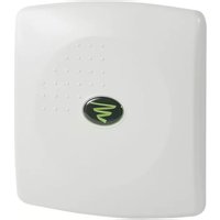
Xen XAP-1040 - NAS Luxul - Free user manual and instructions
Find the device manual for free Xen XAP-1040 Luxul in PDF.


| Product Type | Outdoor 802.11b/g/n Wireless Access Point |
| Model Number | XAP-1040 |
| Dimensions (W x H x D) | 7.9" x 7.5" x 3.15" (200 mm x 190 mm x 80 mm) |
| Weight (Item) | 1.2 lbs (0.54 kg) |
| Weight (with packaging) | 2 lbs (0.91 kg) |
| Operating Temperature | -4°F to 131°F (-20°C to 55°C) |
| Storage Temperature | -40°F to 158°F (-40°C to 70°C) |
| Operating Humidity | 5% to 95% (non-condensing) |
| Power Input | Ethernet PoE: 48VDC/0.375A (IEEE 802.3af compliant) |
| Power Consumption | 5W nominal, 13W max |
| Enclosure Rating | IP-66 weather resistant |
| Wireless Standards | IEEE 802.11b/g/n, 2.4 GHz band |
| Maximum Transmit Power (EIRP) | Up to 36 dBm (FCC approved) |
| Receive Gain | Up to 18 dB |
| Antenna Type | 7 dBi Circular Polarized Directional |
| Wireless Modes | Access Point, Point-to-Point Bridge, Point-to-Multipoint Bridge |
| Number of SSIDs | Up to 8 with individual security settings |
| VLAN Support | Yes, 1 VLAN per SSID (PVID 1-8) |
| Security Features | WEP 128-bit, WPA-PSK (TKIP/AES), WPA2-PSK (AES), WPA/WPA2 Auto |
| Management Interface | XenSmart™ web-based (HTTP) |
| Firmware Upgrade | Yes, via web interface |
| Mounting Options | Wall or pole mount with included bracket |
| Warranty | Refer to dealer; no user-serviceable parts |
Frequently Asked Questions - Xen XAP-1040 Luxul
User questions about Xen XAP-1040 Luxul
0 question about this device. Answer the ones you know or ask your own.
Ask a new question about this device
Download the instructions for your NAS in PDF format for free! Find your manual Xen XAP-1040 - Luxul and take your electronic device back in hand. On this page are published all the documents necessary for the use of your device. Xen XAP-1040 by Luxul.
USER MANUAL Xen XAP-1040 Luxul
Luxul Xen™ High Performance Outdoor 802.11b/g/n Wireless Access Point


Use the XAP-1040 to:
Provide a High Performance Outdoor 802.1In Wi-Fi Network
Setup a Superior Point-to-Point or Point-to-Multipoint Bridge Link
Increase Mobile Client Device Network Sensitivity and Performance
Simplify Installation While Minimizing Setup Time and Expense
Eliminate Client Device Roaming Issues
LUXUL XEN™ HIGH PERFORMANCE OUTDOOR
802.11b/g/n Wireless Access Point
Model Number: XAP-1040
FCC ID: W59XAP1040
IC: 8584A-XAP1040
USER GUIDE
© 2011 Luxul. All Rights Reserved.
No part of this publication may be modified or adapted in any way, for any purposes without permission in writing from Luxul. The material in this manual is subject to change without notice. Luxul reserves the right to make changes to any product to improve reliability, function, or design. No license is granted, either expressly or by implication or otherwise under any Luxul intellectual property rights. An implied license only exists for equipment, circuits and subsystems contained in this or any Luxul product.
This product is covered by one or more U.S. and foreign patents Patents: 7,379,717,6,606,075, 6,373,448, other patents pending
DOCUMENT CONVENTIONS
The following graphical alerts are used in this document to indicate notable situations:

NOTE: Tips, hints, or special requirements that you should take note of.

CAUTION: Care is required. Disregarding a caution can result in data loss or equipment malfunction.

WARNING!: Indicates a condition or procedure that could result in personal injury or equipment damage.
FCC COMPLIANCE
This device complies with Part 15 of the FCC Rules. Operation is subject to the following two conditions: (1) this device may not cause harmful interference, and (2) this device must accept any interference received, including interference that may cause undesired operation.
CONTENTS
1 INTRODUCTION 4
1.1Warnings 5
1.2 Site Preparation 5
2 XAP-1040 SPECIFICATIONS 6
3 GETTING STARTED 7
3.1 System Requirements 7
3.2 Package Contents 7
3.3 Safety Information 8
4 HARDWARE FEATURES AND INSTALLATION 8
4.1 Front View 8
4.2 Rear View 9
4.3 Bottom View 10
4.4 Inside View 10
4.5 Environmental Requirements 12
4.6 Hardware Installation 13
5 CONFIGURATION 16
5.1 Login 16
5.2 Quick Setup 17
5.3 WIRELESS 20
5.4 Maintenance 23
5.6 Status 27
6 REGULATORY COMPLIANCE 29
6.1 Health and Safety Recommendations 29
6.2 RF Exposure Guidelines 29
6.3 Radio Frequency Interference Requirements—FCC 30
6.4 Radio Transmitters (Part 15) 31
6.5 Industry Canada (RSS-Gen Issue 2) 31
APPENDIX 1: TECHNICAL SUPPORT 32
1 INTRODUCTION
Congratulations on your purchase of the Luxul Xen™ High Performance Outdoor 802.11n Wireless Access Point (XAP-1040). The XAP-1040 provides superior Wi-Fi coverage for outdoor areas while maintaining an unobtrusive profi le for use in residential and commercial Wi-Fi installations. The ruggedly elegant XAP-1040 is weather resistant to IP-66 specifications and can be installed directly on a wall or on a pole with the included mounting bracket. It is also an excellent solution for creating a point-to-point or point-to-multipoint bridge link. Powered by Luxul's Xen3D™ Technology, the XAP-1040 enhances data throughput and coverage by as much as 400% over traditional Wi-Fi gear, providing for superior area coverage and a farther reaching signal. With this high performance wireless access point, computers and wireless devices that are compatible with 802.11b/g and/or 802.11n can sustain maximum data rates and improved overall performance at signifi cantly greater distances.
The XAP-1040 features Luxul's XenSmart™ web based management interface. XenSmart provides a powerful, yet simple method for setting up and optimizing the wireless network. The XAP-1040 is also XenConnect™ enabled for optimal performance and installation simplicity when deployed together with Luxul Routers, Gigabit Switches, and other Luxul products.
XAP-1040 Features:
Implements Patented Xen3D™ Technology for Enhanced Throughput and Coverage
Highest FCC Approved Performance (Effective EIRP 36dBm) for Farther Reaching Signal and Maximum Data Rates
18dB of Receive Gain Increases Client Device Network Sensitivity and Performance
Complies with 2.4 GHz IEEE 802.11n Standard. Backward Compatible with IEEE 802.11g/b
Supports WMM QoS Functionality to Prioritize Multimedia Traffic c
Enhanced Multi-Level Security with WPA-PSK (TKIP, AES, TKIP & AES), WPA2-PSK (AES), WPA-PSK/WPA2-PSK Personal (TKIP & AES) and 128-bit WEP
Supports up to 8 SSIDs with Individual Security Settings
Multiple SSIDs Support VLAN Tagging (1 VLAN per SSID)
Single Cable Installation with PoE (supports both IEEE 802.3af and Legacy)
Firmware Upgradeable
Easy 3 Step Setup through Web-based XenSmart™ User Interface
Weather Resistant IP-66 Compliant Enclosure
Installs Directly on an Outdoor Wall or on a Pole Using Adjustable Mounting Bracket
XenConnect™ Enabled for Maximum Compatibility and Performance with Other Luxul Xen Products
1.1 Warnings
Read all installation instructions and site survey reports, and verify correct equipment installation before connecting the XAP-1040 to its power source.
Remove jewelry and watches before installing this equipment.
Verify that the unit is grounded before connecting it to the power source.
Verify that any device connected to this unit is properly wired and grounded.
Connect all power cords to a properly wired and grounded electrical circuit.
Verify that the electrical circuits have appropriate overload protection.
Attach only approved power cords to the device.
Verify that the power connector and socket are accessible at all times during the operation of the equipment.
Do not work with power circuits in dimly lit spaces.
Do not install this equipment or work with its power circuits during thunderstorms or other weather conditions that could cause a power surge.
Verify there is adequate ventilation around the device, and that ambient temperatures meet equipment operation specifications.
Products outside the approved configurations may be in violation of Part 15 of the FCC Rules.
1.2 Site Preparation
Consult your site survey and network analysis reports to determine specific equipment placement, power drops, and so on.
Assign installation responsibility to the appropriate personnel.
Identify and document where all installed components are located.
Provide a sufficient number of power drops for your equipment.
Ensure adequate, dust-free ventilation to all installed equipment.
Identify and prepare Ethernet and console port connections.
Verify that cable lengths are within the maximum allowable distances for optimal and certified signal transmission.
2 XAP-1040 SPECIFICATIONS
| Standards | IEEE 802.11nIEEE 802.11b/gIEEE 802.3afIP-66 |
| Hardware | LAN Port: 1 RJ45 10/100 Mbps data and power input7dBi Circular Polarized Directional AntennaLEDs: All LEDs are internal and not visible when cover plate is in place (Power, WLAN active, LAN link/activity, Bridge mode active). |
| RF Information | Frequency Band: 2.401 – 2.473GHzOperating Channels: 11 |
| Available Transmit Power | 2.401 – 2.473GHz (IEEE802.11g/n):Up to 36dBm EIRP30dBm @ 6-9Mbps / MCS029dBm @ 12-18Mbps / MCS1-227dBm @ 24-36Mbps / MCS3-426dBm @ 48-54Mbps / MCS5-72.401 – 2.473GHz (IEEE802.11b):Up to 36dBm EIRP30dBm @ 1-11Mbps |
| Available Receive Gain | 2.401 – 2.473GHz (IEEE802.11g/n):Up to 18dBm2.401 – 2.473GHz (IEEE802.11b):Up to 18dBm |
| Receive Sensitivity(Typical) | 2.401 – 2.473GHz (IEEE802.11n): Up to -91dBm2.401 – 2.473GHz (IEEE802.11g): Up to -92dBm2.401 – 2.473GHz (IEEE802.11b): Up to -93dBm |
| Wireless Operation Modes | Access PointPoint-to Point Wireless BridgePoint-to-Multipoint Wireless Bridge |
| Management and Security | XenSmartTM Remote Web-based ManagementWEP (128 bit)WPA-PSK (TKIP, AES, TKIP&AES)WPA2-PSK (AES)WPA-PSK/WPA2-PSK Auto (TKIP&AES)Web Based Firmware UpgradeQoS: Wireless Multi-Media (WMM) Extensions |
| Certifi cations | FCC Part 15, Class B |
| Power Requirements | Ethernet POE in: 48VDC/0.375A for IEEE 802.3af CompliancePower Consumption: 5W Nominal, 13W Max |
| Temperature Range | Operating: -4°F to 131°F (-20°C to 55°C)Storage: -40°F to 158°F (-40°C to 70°C) |
| Operating Humidity | 5% to 95% (Non-condensing) |
| Mechanical | Dimensions WxHxD: 7.9" (200mm) x 7.5" (190mm) x 3.15" (80mm) |
| Weight | Item: 1.2 lbsWith Packaging: 2 lbs |
3 GETTING STARTED
3.1 System Requirements
Devices Supporting 802.11b, 802.11g or 802.11n
Web Browser (Microsoft IE 7.0 and up, Mozilla Firefox 1.0 and up, Safari 1.0 and up, Google Chrome 5.0 and up)
CAT5 Ethernet Cable
AC Power Socket (100 - 240 V, 50/60 Hz)
Internet Connection to View Documentation Online
3.2 Package Contents
XAP-1040 Wireless Access Point
Weather Resistant RJ45 Connector Gland
POE Injector, Power Adapter, Noise Suppressor
Dual Purpose Mounting Bracket for Wall or Pole
Quick Install Guide

NOTE: If any of the listed items are missing or damaged, please contact the reseller from whom you purchased for return/replacement.
3.3 Safety Information
To maintain the safety of users and property, follow these safety instructions:
The XAP-1040 wireless access point is designed for outdoor use and is compliant with IP-66 standards. However, this does not mean it is waterproof or weather-proof. Rather, that it is weather and water resistant and care should still be taken to avoid excessive exposure to heat, moisture, etc.
DO NOT pull any connected cable with force. When disconnecting cables, do so by disconnecting first from the access point. When reconnecting, connect the AP first and then the Power/data source.
When installing the access point, be sure it is firmly secured
Accessories of this access point, such as mounting screws, the POE injector and power supply may be dangerous to small children under 3 years of age. KEEP All ACCESSORIES OUT OF THE REACH OF CHILDREN!
The access point may become hot when in use for extended time periods. This is normal and is not a malfunction. DO NOT install this access point where it will be exposed to paper, cloth or other fl ammable materials. If not using the electrical box included with the unit, ALWAYS use a properly shielded and UL listed electrical box for installation.
The XAP-1040 contains no user-serviceable parts. If the access point is not working properly, contact your dealer and ask for help. DO NOT attempt to disassemble the access point.
4 HARDWARE FEATURES AND INSTALLATION
The XAP-1040 high powered access point is designed for optimal performance as well as for simple and efficient installation and setup. It implements Luxul's circular polarized directional antenna technology and is packaged for installation outdoors on a wall or pole. Because the signal generated by the XAP-1040 is directional in nature, the unit should be placed in a location that allows the antenna face to be "pointed" towards the desired coverage area.
4.1 Front View
For maximum weather resistance, the XAP-1040 has no external LED indicators. The front consists simply of the access point cover with the Luxul icon that indicates proper top/bottom installation orientation of the access point.

XAP-1040 Front View
4.2 Rear View
The rear of the XAP-1040 provides various mounting options. It is designed to mount optimally to a wall or pole using the included mounting bracket and hardware.

XAP-1040 Rear View
4.3 Bottom View
The bottom of the XAP-1040 provides one RJ-45 connection that is used to deliver both power and data to the access point. When installation is complete, a weather resistant RJ-45 connector gland will cover the RJ-45 connection.

XAP-1040 Bottom View
4.4 Inside View
For maximum weather resistance, all System LEDs and the Reset button are located internally. Unless it becomes necessary to do so, opening the XAP-1040 is not suggested. Note that there are no user serviceable parts. There is also a metal insert for grounding power.
For troubleshooting, functional validation or system Reset, you will need to open the XAP-1040. To do so, remove the 4 screws at the back of the unit. After doing so, carefully lift the base up and to the right as demonstrated below:

View of XAP-1040 Opened

CAUTION: Before removing the cover and/or attempting to service the XAP-1040, be sure to unplug all cables and dismount the device. Use caution to see that no external elements are introduced inside the enclosure and that reasonable precautions are taken to minimize static and electromagnetic contamination of the electronic components. Avoid touching any of the internal electronics, except in the case of a Reset.

CAUTION: When lifting the base, be careful not to pull, bend or otherwise move the base or cover excessively. By simply lifting the base slightly, you should be able to see the LEDs as well as access the Reset button. When re-assembling the unit, be sure to maintain the weather-resistant integrity of the enclosure by verifying that the rubber seal is properly seated and the four screws are firmly in place, but not over-tightened.
With the base lifted to the right, System LEDs and the Reset button can be seen as shown here:

Reset Button and LED Location
Status Indicators:
With the unit facing down and the base moved to the right as shown above, the XAP-1040 has four LEDs, positioned horizontally on the bottom, left side of the board. When viewed left to right, LEDs are as follows: 1) Bridge Mode (Green); 2) WLAN Status (Blue); 3) LAN Link/Activity (Amber); and 4) Power (Green).
The following table describes the LED functionality:
| Indicator Name Description | ||
| Bridge Mode | On Bridge Mode is enabled | |
| Off The AP is in default “Access Point” mode. | ||
| WLAN Status | On The wireless radio is active and wireless access is enabled an active connection to the internet | |
| Off The wireless radio is not active and wireless access is disabled | ||
| LAN Link/Activity | On There is an active Ethernet connection | |
| Flashing Indicates Ethernet activity | ||
| Off There is no active Ethernet connection | ||
| Power | On The power is on | |
| Off No power, check power connections | ||
| At startup, the Green Power LED will stay on while the amber LAN Link light fl ashes. The blue LED will come on once the XAP-1040 radio is active. | ||
Reset Button:
The Reset button is used to clear the current settings of the XAP-1040 and restore factory default settings.
To Restore the Default Settings: With the XAP-1040 powered on, press and hold the Reset button for 10 seconds. When the Power LED comes on again, release the reset button. The XAP-1040 will be set to factory defaults.

CAUTION: Pressing and holding the Reset button will remove any custom configurations done to the XAP-1040.
4.5 Environmental Requirements
Ethernet cable to provide Power and Data to the XAP-1040.
A computer supporting TCP/IP and equipped with a Web browser. Supported Web browser versions include Microsoft IE 7.0 and up, Safari 1.0 and up, Mozilla Firefox 1.0 and up, and Google Chrome 5.0 and up. The Web browser is used to configure the XAP-1040.
The XAP-1040 uses 36-57VDC power. The POE injector power supply requires AC 100V \~ 240V, 50Hz \~ 60Hz.
Temperature of the operating environment: -4F\~131F (-20C to 55C). Be sure to place the access point away from heat generating devices.
Humidity of the operating environment: 5%-95% non-condensing. Do not place the access point in an extremely dirty or damp location.
Keep the access point away from strong electromagnetic fi elds (i.e. Air Conditioner compressors, fl uorescent light ballasts, CRT monitors/televisions, etc.), and free from vibration, dust and direct sun light.
4.6 Hardware Installation
4.6.1 Access Point Placement
This XAP-1040 implements Luxul's Circular Polarized directional antenna technology. For maximum efficiency, it should be aimed towards the area to which you would like to provide coverage. With this in mind, the ideal placement option is usually on an outside wall or pole pointed into the coverage area.

XAP-1040 Suggested Mounting Location
4.6.2 Mounting the Access Point on a Wall or Pole
The XAP-1040 can be mounted directly to a wall or pole using the included mounting bracket. Once the mounting location has been selected, installation is as simple as plugging the Ethernet cable into the RJ-45 connector and then mounting the access point directly to the wall or pole as shown in the diagram below:

The XAP-1040 mount assembles as show above. The u-bolts may be removed and the plate may be mounted directly to a wall using your hardware.

CAUTION: Do not drill holes in the enclosure or the weather proofing will be compromised and your warranty voided.
4.6.3 Assembling the Weather Resistant RJ-45 Connector Gland
To ensure proper protection from the elements, the weather resistant RJ-45 connector gland must be installed correctly. To do so requires the installer to terminate the Ethernet Cable that will be plugged into the XAP-1040. The diagram below indicates the correct assembly for the RJ-45 Connector Gland.

RJ-45 Connector Gland assembly

NOTE: Category-5, super Category-5 or Category-6 unshielded twisted pair (CAT5/CAT5e/CAT6 UTP) cables can be used. For best results, it is recommended that Category-6 shielded twisted pair be used to ensure stable data transmission at highest data rates.
Once the RJ45 Connector Gland has been assembled and the Ethernet Cable has been terminated, the cable can now be plugged into the XAP-1040. You can now attach the RJ-45 Connector Gland by placing it over the cable connector and turning it clockwise until it is firmly secured. At this time, also tighten the gland around the cable by turning it clockwise and thus creating a water-tight seal.
4.6.4 Connecting to the Power Source
The XAP-1040 is POE ready and supports Legacy (48v 1a), 802.3af, and 802.3at POE injectors. A POE injector kit, including power supply and noise suppressor are included with the device. To apply power, simply connect the opposite end of the Ethernet cable to which the access point is already connected to the provided POE injector or other POE switch or injector. An Ethernet cable length of up to 300 feet can be used. DO NOT yet apply power to the POE injector or switch.

NOTE: To ensure FCC compliance and minimize high frequency noise, a Ferrite Noise Suppressor is included with the POE injector kit. It should be placed on the Ethernet cable at or near the connector on the end of the Ethernet cable that plugs into the POE device. To install it, simply unsnap the plastic fasteners, place it on the Ethernet cable as demonstrated below and re-snap the plastic fasteners to secure it in place.
4.6.5 Connecting to the Internet Source

NOTE: If your Internet source (Router or Switch) is a POE enabled device and connected via POE, it can be plugged directly into the access point without the need to run a separate POE injector.
![graph TD A["Power Source"] --> B["Data Source"] B --> C["Data/Pwr Out"] D["Ferrite Noise Suppressor"] --> E["POE Injector"] E --> F["Power In"] F --> G["Data In"]](/content/2026/06/1246410/images/b0cc50f2c32e946b713e50c90b6639fe586b9dda4d51bae9c422fe8a0815777d.jpg)
The POE Injector Sends Power and Signal Over One Ethernet Cable
4.6.6 Applying Power
Once the Ethernet cables have been properly connected, connect the power supply to the POE injector and plug it in to a standard AC power outlet. Or, if plugging into a POE switch, turn the switch (or appropriate port) on. The network source device can also now be powered back on.

NOTE: If your Internet source (Router or Switch) is a POE enabled device and connected via POE, it can be plugged directly into the access point without the need to run a separate POE injector.
5 CONFIGURATION
5.1 Login
The XAP-1040 is not equipped with internal DHCP server. If connected to the Luxul XBR-2300 Enterprise Dual-WAN Router, configuration will be automatic. Otherwise, the IP address of the computer for login and configuration will need to be manually configured. The table below lists the default parameters of the XAP-1040.
| Parameter Default Value | |
| Default IP address | 192.168.0.14 |
| Default user name | admin |
| Default password | admin |
Login to the XAP-1040 Wireless Access Point with the following steps:
a. Be sure the XAP-1040 is properly installed and powered on
b. Open your Web Browser, and enter http://192.168.0.14.
The login window appears as shown below:

c. Enter the user name and password (default user name is "admin" and default password is "admin"), and then click "OK" to login to the Quick Setup window.
5.2 Quick Setup
LUXUL
Simply Connected
XenSmart™
- Quick Setup
▶ Wireless
▶ Maintenance
▶ Status
IP Address
DHCP Client Disabled
IP Address 192.168.0.14
Subnet Mask 255.255.255.0
Default Gateway
[Non-Text]
Wireless Settings

Administrator Login

Luxul AP Help
Quick Setup
This page displays all basic information required to setup and configure the Luxul Xen™ Access Point. It is recommended to change the Network Name to something other than the default name and also change the Administrator Login Password. Typically, nothing else needs to be changed in order for the Access Point to be up and working.
Note, if more than one SSID is setup (in the Wireless Settings section), the information displayed on this page is only used for the Primary SSID (first SSID - SSID 1).
Quick Setup: For most installations, it is expected that the Quick Setup page will be sufficient to optimally configure and deploy the XAP-1040 Wi-Fi network. The Quick Setup page consists of the following:
DHCP Client: Enabled or Disabled. DHCP (Dynamic Host Configuration Protocol) is used to automatically assign an IP Addresses to a device on the network. If DHCP is enabled on the Access Point, it will no longer use the static address set by Luxul at time of manufacturing and will request a dynamic IP Address from the Router (sometimes referred to as the Gateway).
When DHCP is enabled on the Access Point, the new IP address will be needed in order to access the XenSmart™ web management interface. The Router web interface can be used to look up the IP address assigned to the Access Point. To Enable DHCP, click on the drop down menu and select Enable. Select Apply and then Reboot for the change to take effect.

NOTE: DHCP is set as Disabled by default and is the recommended setting in order to ensure optimal communications with all Luxul Xen devices on the network.
IP Address: An IP address is a numerical label assigned to each device on the network. This fi eld shows the IP address that is assigned to the XAP-1040. To ensure plug and play capability with other Luxul networking products, the IP Address is automatically defaulted to 192.168.0.14. If desired, the user can set this to a different static IP Address. To change the IP address of the Access Point, simply type in the desired IP address (the text fi eld will be red if the address is incomplete), click Apply and then Reboot for the changed to take effect. When connecting to the Access Point through the XenSmart™ web interface, the NEW IP Address must be used.

NOTE: Each device on the same network must have a unique IP address. If the Access Point is assigned an IP address already in use, it will result in an IP address conflict that will need to be resolved manually. For optimal communications with all Luxul Xen devices on the network, it is recommended that IP addresses not be changed unless absolutely necessary.
Subnet Mask: To ensure plug and play capability with other Luxul networking products, the Subnet Mask is automatically defaulted to 255.255.255.0. If desired, the user can set this to a different static Subnet Mask.
Default Gateway: A gateway is a router on the network that connects two or more networks together. Typically the gateway (router) connects the local area network (LAN) to the Internet. The Internet Service Provider (ISP) often provides a physical device (usually a DSL modem or cable modem) that connects to the gateway with an Ethernet cable, thus completing the link to the Internet. For optimal connectivity and network functionality, this device could also be the Luxul Xen XBR-2300 Router.
The Default Gateway fi eld is the IP address for this routing device. The default configuration is left blank or empty, allowing the Access Point to automatically find the necessary route to the Internet. It is recommended to leave this fi eld blank.
Network Name (SSID): Sets the name of the Wireless Network. Default name is LuxulXen. It is recommended to change the SSID from the default name. The SSID is case sensitive and can contain:
2 – 32 alphanumeric characters
▶ Spaces
▶ Special characters (i.e. @#\$%&*)
To change the SSID of the wireless network, simply type the desired name, click Save, and then Reboot for the change to take effect.
Security Mode: Sets the wireless security encryption mode. It is HIGHLY recommended to change the Security Mode and use the highest security level supported by the client devices in the network. In most wireless networks, WPA/WPA2 Personal is an excellent option that will support the largest cross section of client devices. Security options include:
▶ Open (default - no security)
WEP (128 bit shared key)
WPA Personal
WPA2 Personal
WPA/WPA2 Personal
To change the Security Mode, click the drop down menu and select the desired mode. The available options for the selected mode will then appear. AFTER all options are complete, click Save, and then Reboot for the change to take effect.
Encryption: This fi eld sets the type of encryption to be used by the Security Mode. The encryption options are dependent upon the Security Mode selected and this fi eld only shows while in WPA mode. For WEP and WPA2, and WPA/WPA2 Personal, encryption is automatically set to 128 bits, AES, and TKIP & AES respectively. For WPA, there are three options: AES, TKIP, and TKIP & AES. When set to WPA, it is recommended that TKIP & AES be used. To change the Encryption, click the drop down menu and select the desired encryption type. Once all options are selected, click Save and then Reboot for the change to take effect.
WEP Key: This fi eld only shows while in WEP mode and sets the WEP key to be used in the network. WEP 128 bit keys require 26 characters. Allowed characters are numbers 0-9 and letters a-f. There are WEP key generators online that can automatically create a key. To change the WEP Key, simply enter the 26 character key then click Save and then Reboot for the change to take effect.
WPA Passphrase: This sets the passphrase used by client devices to connect to the wireless network when using WPA Security Mode. For WPA the passphrase:
▶Must be a minimum of 8, maximum of 63 characters
- Can contain spaces or special characters (i.e. @#\$%&*)
To change the WPA Passphrase, simply type in the desired passphrase, click Save, then Reboot for the change to take effect.

NOTE: It is recommended to use a strong password containing:
▶ More than the minimum number of characters
One or more capital letters
▶ Numbers and/or special characters
Administrator Login: Sets the password for Administrator access to the XenSmart™ web management interface. When connecting to the Access Point through the XenSmart™ web interface, the user is prompted for a User ID (this is always admin) and Password (the default value is "admin"). It is HIGHLY recommended to change to a secure password when initially confi guring the Access Point. To change the password, simply enter the new password, confi rm the password, then click Save, and then Reboot for the change to take effect.
After confirming the desired Quick Setup configuration settings, select Save and then Reboot for the settings to take effect.
5.3 WIRELESS
5.3.1 Basic Wireless Settings

- Quick Setup
▼ Wireless
Settings
▼ Profiles
- SSD 1
- SSID 2
- SSD 3
- SSD 4
- SSD 5
- SSD 6
- SSD 7
- SSD B
▶ Maintenance
▶ Status
Wireless Settings
Wireless Radio Enabled
Channel 6 (Recommended)
Wireless Mode 11gn HT20
Channel Width 20/40MHz Auto
Save Reboot Cancel
XenSmart™
Wireless Settings
This page allows management of some of the more advanced features available with the Luxul Xen™ Access Point. For most installations, it is recommended to leave these settings at the default values.
Basic Wireless Settings: This screen allows the modification of the following basic settings for the wireless network:
Wireless Radio: This fi eld is used to Enable and Disable the wireless network and is set to Enabled by default. If the Radio is Disabled the Access Point will not broadcast a wireless signal. To Disable the Wireless Radio, click the dropdown menu, select Disabled, then click Save and then Reboot for the change to take effect.
Channel: This fi eld allows the user to set which 2.4GHz channel to use. The default is set to Channel 6 and is the recommended setting due to the Access Point being optimized to run on Channel 6. However, any other channel (1-11) may be selected. To change the Channel, click the dropdown menu, select the desired channel, then click Save and then Reboot for the change to take effect.
Wireless Mode: Sets the type of 802.11 wireless network to be broadcast.
Available modes are:
11g (802.11g)
▶11gnHT20 (802.11g/n with 20MHz only channels)
▶11gnHT40+ (802.11g/n with 20/40MHz channels expanding to channels above the set channel)
▶11gnHT40- (802.11g/n with 20/40MHz channels expanding to channels below the set channel)
The default setting is 11gnHT20, and is recommended for optimal performance of all types of devices in the network. Use the 11g Mode ONLY if there are 802.11b/g client devices in the network that will not connect in 11gnHT20 Mode. 11gnHT40+ and 11gnHT40- Modes should only be used when all client devices in the network are 802.11n and capable of supporting 40MHz channels.
Channel Width: Sets the width of the 802.1In channel. Available widths are:
▶20MHz (only available for 11g and 11gnHT20 modes)
40MHZ (only available for 11gnHT40+ and 11gnHT40-)
20/40MHz Auto (available for all modes)
The default (and recommended) setting is 20/40 MHz Auto to provide maximum performance to all client devices and to avoid any potential client issues.

NOTE: HT40 mode will use two channels. For example, if HT40- is selected and the radio is using channel 6, it would also use channel 1. If HT40+ is selected and the radio is using channel 6, it would also use channel 11.
If making any change to the Wireless Settings, select Save and then Reboot for the settings to take effect.
5.3.2 Wireless Profi les
LUXUL
Simply Connected
XenSmart™
- Quick Setup
▼ Wireless
- Settings
▼ Profiles
o SSID 1
- SSID 2
- SSID 3
- SSID 4
- SSID 5
- SSID 6
o SSID 7
o SSID B
▶ Maintenance
▶ Status
Wireless Settings
Network Name (SSID)

LuxulXen
Security Mode

Open
VLAN Settings
VLAN ID

Save
Reboot
Cancel
Profiles
Multiple SSID's can be configured on this page in order to deploy multiple networks (i.e. Home, Guest, Control, etc.) Luxul Xen™ Access Points support up to 8 separate SSID's. Only profiles with an SSID name are active. A blank SSID means that a particular SSID is not in use. To create a new SSID, simply enter a valid name, set the desired security level for the SSID, click Save, and then Reboot and the new SSID will be active.
Wireless Profi les: This page allows configuration of up to 8 Wireless Network SSID's:
Network Name (SSID): Sets the name of the Wireless Network. If the SSID is not set on a profile, the name of the network will not be broadcast.

NOTE: Profi le 1 is set during Quick Setup
Security Mode: Sets the wireless security encryption mode.
Encryption: This fi eld only shows while in WPA mode. It is used to select the encryption method WPA will use (default is TKIP & AES).
WEP Key: This fi eld only shows while in WEP mode. Allows the input of a 128 bit WEP key.
WPA Passphrase: Sets the passphrase for wireless network access.

NOTE: If no Network Name (SSID) is specified, the profile is not active.
VLAN ID: This fi eld is used to set the Port VLAN Identifi er (PVID) associated with a particular SSID. This feature is used to create multiple wireless networks that are not accessible to each other (i.e. Home, Guest, Control, etc.). Up to 8 VLAN ID's can be set (one for each Profi le). A smart/managed switch is required to fully utilize this feature (see the Luxul Xen™ XMS-1024 or XMS-1008P).
To change or set a VLAN ID, simply enter a number from 1-8, then click Save, and then Reboot for the change to take effect.
5.4 Maintenance
5.4.1 Firmware Upgrade

Firmware Upgrade: This page allows for the upgrade of the firmware on the XAP-1040. To check for firmware updates, visit www.luxul.com/support.
- Go to the Luxul website and download the new version of firmware
- Click Browse to locate the fi rmware fi le on your computer
- Click Upgrade to perform the update

CAUTION: Do not power off the access point or computer being used during the upgrade or the access point may be damaged.
5.4.2 Factory Defaults
LUXUL
Simply Connected
XenSmart™
- Quick Setup
▼ Wireless
- Settings
▼ Profiles
- SSID 1
- SSID 2
- SSID 3
o SSID 4
○ SSID 5
○ SSID 6
- SSID 7
- SSID 8
▼ Maintenance
- Upgrade
- Factory Defaults
- Backup/Restore
▶ Status
Factory Defaults
Restore factory defaults

FactoryReset
Factory Defaults
Use this page to return the Luxul Xen™ Access Point to the original default settings. Please note that any custom changes or settings that have been made will be lost once Factory Defaults have been restored. It is recommended to backup current settings prior to performing a Factory Default.
Factory Defaults: Use this page to return the XAP-1040 to the original default settings. Please note that using this feature will reset ALL values and custom changes or settings that have been made to default settings. It is recommended to backup current settings prior to performing a Factory Default. To restore factory defaults, select Yes in the drop down menu and then select Save and then Reboot for the settings to take effect.

CAUTION: Restoring default configuration will re-set all of your settings to factory defaults. The XAP-1040 will now have the default IP address 192.168.0.14. For login, default user name will be “admin” and default password will be “admin.”
5.4.3 Backup/Restore
LUXUL
Simply Connected
XenSmart™
- Quick Setup
▼ Wireless
- Settings
▼ Profiles
o SSID 1
- SSID 2
- SSID 3
- SSID 4
o SSID 5
- SSID 6
- SSID 7
o SSID 8
▼ Maintenance
- Upgrade
- Factory Defaults
- Backup/Restore
▶ Status
Backup Configuration
Backup configuration

Restore Configuration

Backup/Restore
This page is used to create a backup of the Luxul Xen™ Access Point configuration and Restore the configuration at a later time if desired. The backup file can also be used to set up multiple Luxul Xen Access Points using the same configuration.
Backup/Restore: This page is used to create a backup of the XAP-1040 configuration and Restore the configuration at a later time if desired. The backup file can also be used to set up multiple Luxul Xen Access Points using the same configuration. Click Backup to save the current configuration settings as a file. To restore those settings, click Browse and select the backup file on your Computer, and then click Restore.

CAUTION: It can take several minutes to complete the restoration. To avoid errors during the restoration, do not power off the XAP-1040 or computer being used. At the end of restoration, the XAP-1040 will restart.
5.5 QoS
QoS: The XAP-1040 is automatically configured to take advantage of Wireless Multi-Media (WMM) extensions. This means that any packets from devices tagged with WMM will be given top priority. There are 4 priority levels, from highest to lowest:
- Voice
- Video
- Background
- Best Effort
5.6 Status
5.6.1 Basic Status
LUXUL
Simply Connected
XenSmart™
-
Quick Setup
▼ Wireless -
Settings
▼ Profiles
o SSID 1
- SSID 2
o SSID 3
- SSID 4
o SSID 5
o SSID 6
- SSID 7
o SSID 8
▼ Maintenance
- Upgrade
- Factory Defaults
- Backup/Restore
▼ Status
Basic Status
- Client List
System Information
Firmware Version 1.0
Hardware Model XAP-1040
Uptime 00:05:15
Ethernet Settings
IP Address 192.168.0.14
Subnet Mask 255.255.255.0
Default Gateway
MAC Address A4:13:4E:00:0E:01
Wireless Settings
Wireless Mode 11NGHT20
Channel Width 1
Channel 6
MAC Address A4:13:4E:00:0C:01
Primary SSID
Network Name (SSID) LuxulXen
Security Open
Basic Status
Displays the current running status of the Luxul Xen Access Point. All wireless settings only apply to Profile 1.
Basic Status: This page displays basic setup information of the configuration and status of the AP including: Firmware Version, Hardware Model, Uptime, Connection Type, IP Address, Subnet Mask, Default Gateway, LAN MAC Address, Wireless Mode, Wireless MAC Address, Network Name (SSID), Channel Width, Channel, and type of Security
5.6.2 Connected Clients
LUXUL
Simply Connected
XenSmart™
- Quick Setup
▼ Wireless
- Settings
Profiles
o SSID 1
0 SSID 2
o SSID 3
o SSID 4
o SSID 5
- SSID 6
- SSID 7
- SSID 8
▼ Maintenance
- Upgrade
- Factory Defaults
- Backup/Restore
▼ Status
- Basic Status
- Client List
| MAC Address | Rate | RSSI |
| 70:1a:04:ae:c8:2c | 34M | 63 |
| 90:21:55:d6:d2:34 | 51M | 55 |
Connected Clients
Displays the MAC Address, Speed and Signal Strength of all currently attached wireless devices.
Connected Clients: This page displays the MAC Address, Speed and Signal Strength of all currently attached wireless devices.
6 REGULATORY COMPLIANCE
The device complies with internationally recognized standards covering human exposure to electromagnetic fi elds from radio devices. This equipment also complies with FCC radiation exposure set forth for an uncontrolled environment. In order to avoid the possibility of exceeding the FCC radio frequency exposure limits, human proximity to the antenna shall not be less than 20 cm (8 inches) during normal operation.
Unauthorized antennas, modifications, or attachments could cause damage and may violate regulatory approvals. Any changes or modifications not expressly approved by the party responsible for compliance could void the authority to operate the equipment.
The equipment version marketed in the U.S. is restricted to usage of channels 1-11 only.
6.1 Health and Safety Recommendations
Warnings for the use of Wireless Devices: Please observe all warning notices with regard to the usage of wireless devices
Potentially Hazardous Atmospheres: You are reminded of the need to observe restrictions on the use of radio devices in fuel depots, chemical plants etc. and areas where the air contains chemicals or particles (such as grain, dust, or metal powders).
Safety in Hospitals: Wireless devices transmit radio frequency energy and may affect medical electrical equipment. When installed adjacent to other equipment, it is advised to verify that the adjacent equipment is not adversely affected.
6.2 RF Exposure Guidelines
Safety Information: The device complies with internationally recognized standards covering human exposure to electromagnetic fi elds from radio devices.
Warning: Exposure to Radio Frequency (RF) Radiation:
The radiated output of this device is below the FCC radio frequency exposure limits. Nevertheless, the device should be used in such a manner that the potential for human contact during normal operation is minimized.
The end user must avoid any extended human RF exposure directly in front of the device, up to a distance of 20cm, when unit is on.
When servicing the equipment and selecting a location for the antennas, it is important to note that a minimum distance of 20cm is required between personnel and the device or antenna to comply with the radio frequency exposure limit.
The antenna used for this transmitter must be installed to provide a separation distance of at least 20cm from all persons and must not be co-located or operating in conjunction with any other antenna or transmitter.
The following safety precautions should be observed:
Do not touch or move the antenna while the unit is transmitting or receiving.
Do not hold any component containing the radio such that the antenna is very close or touching any exposed parts of the body, especially the face or eyes, while transmitting.
Do not operate the radio or attempt to transmit data unless the antenna is connected; this behavior may cause damage to the radio.
Remote and Standalone Antenna Confi gurations: To comply with FCC RF exposure requirements, antennas that are mounted externally at remote locations or operating near users at stand-alone desktop of similar confi gurations must operate with a minimum separation distance of 20 cm from all persons.
6.3 Radio Frequency Interference Requirements—FCC
This equipment has been tested and found to comply with the limits for a Class B digital device, pursuant to Part 15 of the FCC rules. These limits are designed to
provide reasonable protection against harmful interference in a residential installation. This equipment generates, uses and can radiate radio frequency energy and, if not installed and used in accordance with the instructions, may cause harmful interference to radio communications. However there is no guarantee that interference will not occur in a particular installation. If this equipment does cause harmful interference to radio or television reception, which can be determined by turning the equipment off and on, the user is encouraged to try to correct the interference by one or more of the following measures:
Reorient or relocate the receiving antenna
Increase the separation between the equipment and receiver
Connect the equipment into an outlet on a circuit different from that to which the receiver is connected
Consult the dealer or an experienced radio/TV technician for help.
6.4 Radio Transmitters (Part 15)
This device complies with Part 15 of the FCC Rules. Operation is subject to the following two conditions: (1) this device may not cause harmful interference, and (2) this device must accept any interference received, including interference that may cause undesired operation.
6.5 Industry Canada (RSS-Gen Issue 2)
This device complies with Industry Canada licence-exempt RSS standard(s).
Operation is subject to the following two conditions: (1) this device may not cause interference, and (2) this device must accept any interference, including interference that may cause undesired operation of the device.
This Class B digital apparatus complies with Canadian ICES-003.
For any problems during the installation or configuration of your XAP-1040, contact support@luxul.com for help.
To check for fi rmware updates visit www.luxul.com/downloads
Technical Support
Tel: (801) 822-5450
Email: support@luxul.com
Contact Information:
Address:
Luxul Corporation
357 South 670 West, Suite 160
Lindon UT, 84042
Tel: (801) 822-5450
Technical Support: support@luxul.com

- LUXUL XEN™ HIGH PERFORMANCE OUTDOOR 802.11B/G/N WIRELESS ACCESS POINT
- USE THE XAP-1040 TO
- LUXUL XEN™ HIGH PERFORMANCE OUTDOOR
- DOCUMENT CONVENTIONS
- FCC COMPLIANCE
- CONTENTS
- 1 INTRODUCTION 4
- 4 HARDWARE FEATURES AND INSTALLATION 8
- 5 CONFIGURATION 16
- 6 REGULATORY COMPLIANCE 29
- APPENDIX 1: TECHNICAL SUPPORT 32
- 1 INTRODUCTION
- XAP-1040 FEATURES
- 1.1 WARNINGS
- 1.2 SITE PREPARATION
- 3 GETTING STARTED
- 3.1 SYSTEM REQUIREMENTS
- 3.2 PACKAGE CONTENTS
- 3.3 SAFETY INFORMATION
- 4 HARDWARE FEATURES AND INSTALLATION
- 4.1 FRONT VIEW
- 4.2 REAR VIEW
- 4.3 BOTTOM VIEW
- 4.4 INSIDE VIEW
- STATUS INDICATORS
- RESET BUTTON
- 4.5 ENVIRONMENTAL REQUIREMENTS
- 4.6 HARDWARE INSTALLATION
- 4.6.1 ACCESS POINT PLACEMENT
- 4.6.2 MOUNTING THE ACCESS POINT ON A WALL OR POLE
- 4.6.3 ASSEMBLING THE WEATHER RESISTANT RJ-45 CONNECTOR GLAND
- RJ-45 CONNECTOR GLAND ASSEMBLY
- 4.6.4 CONNECTING TO THE POWER SOURCE
- 4.6.5 CONNECTING TO THE INTERNET SOURCE
- 4.6.6 APPLYING POWER
- 5 CONFIGURATION
- 5.1 LOGIN
- 5.2 QUICK SETUP
- LUXUL
- IP ADDRESS
- WIRELESS SETTINGS
- ADMINISTRATOR LOGIN
- LUXUL AP HELP
- QUICK SETUP
- 5.3 WIRELESS
- 5.3.1 BASIC WIRELESS SETTINGS
- XENSMART™
- 5.3.2 WIRELESS PROFI LES
- VLAN SETTINGS
- PROFILES
- 5.4 MAINTENANCE
- 5.4.1 FIRMWARE UPGRADE
- 5.4.2 FACTORY DEFAULTS
- FACTORY DEFAULTS
- 5.4.3 BACKUP/RESTORE
- BACKUP CONFIGURATION
- RESTORE CONFIGURATION
- BACKUP/RESTORE
- 5.5 QOS
- 5.6 STATUS
- 5.6.1 BASIC STATUS
- SIMPLY CONNECTED
- SYSTEM INFORMATION
- ETHERNET SETTINGS
- PRIMARY SSID
- BASIC STATUS
- 5.6.2 CONNECTED CLIENTS
- CONNECTED CLIENTS
- 6 REGULATORY COMPLIANCE
- 6.1 HEALTH AND SAFETY RECOMMENDATIONS
- 6.2 RF EXPOSURE GUIDELINES
- WARNING: EXPOSURE TO RADIO FREQUENCY (RF) RADIATION
- 6.3 RADIO FREQUENCY INTERFERENCE REQUIREMENTS—FCC
- 6.4 RADIO TRANSMITTERS (PART 15)
- 6.5 INDUSTRY CANADA (RSS-GEN ISSUE 2)
- TECHNICAL SUPPORT
- CONTACT INFORMATION
- ADDRESS
Brand : Luxul
Model : Xen XAP-1040
Category : NAS