AV8003/ZWA - Receiver MARANTZ - Free user manual and instructions
Find the device manual for free AV8003/ZWA MARANTZ in PDF.

User questions about AV8003/ZWA MARANTZ
0 question about this device. Answer the ones you know or ask your own.
Ask a new question about this device
Download the instructions for your Receiver in PDF format for free! Find your manual AV8003/ZWA - MARANTZ and take your electronic device back in hand. On this page are published all the documents necessary for the use of your device. AV8003/ZWA by MARANTZ.
USER MANUAL AV8003/ZWA MARANTZ
natural_image
Pure electrical circuit lines without any symbolsmarantz®
AV Pre Tuner
AV8003
User Guide
ENGLISHFRANÇAISDEL
ENGLISH
WARRANTY
For warranty information, contact your local Marantz distributor.
RETAIN YOUR PURCHASE RECEIPT
Your purchase receipt is your permanent record of a valuable purchase. It should be kept in a safe place to be referred to as necessary for insurance purposes or when corresponding with Marantz.
IMPORTANT
When seeking warranty service, it is the responsibility of the consumer to establish proof and date of purchase. Your purchase receipt or invoice is adequate for such proof.
FOR U.K. ONLY
This undertaking is in addition to a consumer's statutory rights and does not affect those rights in any way.
FRANÇAIS
GARANTIE
The AV8003 is in conformity with the EMC directive and low-voltage directive.
Français
- Do not expose the equipment to rain, moisture, dripping or splashing.
- Do not remove the cover from the equipment.
- Do not insert anything into the equipment through the ventilation holes.
- Do not handle the mains cord with wet hands.
- Do not cover the ventilation with any items such as tablecloths, newspapers, curtains, etc.
- No naked flame sources, such as lighted candles, should be placed on the equipment.
- When disposing of used batteries, please comply with governmental regulations or environmental public instruction's rules that apply in your country or area.
- Make a space of about 0.2 meter around the unit.
- No objects filled with liquids, such as vases, shall be placed on the equipment.
- When the switch is in the OFF position, the equipment is not completely switched off from MAINS.
- The equipment shall be installed near the power supply so that the power supply is easily accessible.
- Do not touch hot spots during and immediately after use.
- During and immediately after use, this product is hot in areas other than the controls and rear panel connection jacks. Do not touch hot spots and especially the top panel. Contact with hot areas can cause burns.
- Do not expose the unit to excessive heat such as direct sunlight, fire or the like.
Français
AVERTISSEMENTS
Thank you for purchasing the Marantz AV8003 AV Pre tuner.
This remarkable component has been engineered to provide you with many years of home theater enjoyment. Please take a few minutes to read this manual thoroughly before you connect and operate the AV8003.
As there are a number of connection and configuration options, you are encouraged to discuss your own particular home theater setup with your Marantz A/V specialist dealer.
ACCESSORIES CHECK
Before use, check the below accessories were included in the package.
Remote Controller RC2001
AAA-size Alkaline batteries · 4

Remote Controller RC101 for Zone
AAA-size Dry batteries. 2

Microphone

USB cable for RC2001
AC power cable

AV8003 User Guide
AV8003 NETWORK User Guide

Wizz.it3 User Guide

AM Loop Antenna
FM Anlenna
A NOTE ABOUT RECYCLING

This product's packaging materials are recyclable and can be reused. This product and the accessories packed together are the applicable product to the WEEE directive except batteries.
Please dispose of any materials in accordance with your local recycling regulations.
When discarding the unit, comply with your local rules or regulations.
Batteries should never be thrown away or incinerated but disposed of in accordance with your local regulations concerning chemical wastes.
ENGLISH
TABLE OF CONTENTS
INTRODUCTION....1
ACCESSORIES CHECK 1
TABLE OF CONTENTS 2
FEATURES....2
BEFORE USE 3
NAMES AND FUNCTION ....5
FRONT PANEL 5
FL DISPLAY AND INDICATER....6
REAR PANEL 7
REMOTE CONTROLLER RC2001 8
RC2001 LCD INDICATORS 8
REMOTE CONTROLLER RC101 9
CONNECTIONS....10
SPEAKER PLACEMENT .... 10
CONNECTION TO AN MM8003 (BALANCED)....11
CONNECTION TO AN MM8003 (UNBALANCED) .....11
CONNECTING AUDIO COMPONENTS 12
CONNECTING VIDEO COMPONENTS 13
CONNECTING HDMI COMPONENTS ....14
CONNECTING MULTI CHANNEL AUDIO COMPONENTS..15
CONNECTING THE REMOTE CONTROL JACKS .....15
CONNECTING THE ANTENNA TERMINALS ....16
CONNECTING FOR THE ZONE 17
CONNECTING FOR SPEAKER C USE BI-AMP
CONNECTION) 18
CONNECTIONS WITH NETWORK DEVICES .....19
CONNECTING OTHER EQUIPMENT 19
SETUP 20
ONSCREEN DISPLAY MENU SYSTEM 20
1 INPUT SETUP 22
2 SPKR (SPEAKER) SETUP 25
ERROR MESSAGES 28
3 SURROUND SETUP 31
4 VIDEO SETUP 33
5 PREFERENCE 34
6 ACOUSTIC EQ 36
7 NETWORK SETUP 37
ADJUSTING THE MAIN VOLUME 39
ADJUSTING THE TONE (BASS & TREELE) CONTROL...39
TEMPORARILY TURNING OFF THE SOUND ....39
USING THE SLEEP TIMER 39
M-DAX (Marantz Dynamic Audio eXpander) 39
VIDEO CONVERT 39
COMPONENT IP 40
HDMI RESOLUTION 40
This unit incorporates the latest generation of digital surround sound decoding technology such as Dolby Digital EX, Dolby Digital, DTS ES (Discrete 6.1 and Matrix 6.1), DTS Neo:6 (Cinema, Music), Dolby Pro-Logic II (Movie, Music and Game), Dolby Pro-Logic IIx (Movie, Music and Game), Circle Surround II (Cinema, Music and Mono).
Additionally, the unit is compatible with Dolby TrueHD and DTS-HD (as used for Blu-ray and HD DVD discs) as well as Dolby Digital Plus, an expanded and improved version of Dolby Digital positioned as the next-generation delivery format. These audio formats can be sent with video signals via an HDMI cable to HDMI 1.3a-compatible equipment.
In addition, Marantz has focused on the future. By utilizing pre-out jacks, 7.1 direct inputs and a RS-232C communication port, the unit is tomorrow's technology, today!
• THX ultra 2 certifi ed
This unit incorporates the most advanced Digital Signal Processing circuitry, along with a 192kHz/24 bit D/A converter in each of the 7 channels, independent power supply circuits are Incorporated for the FL display, audio and video sections for maximum separation, clarity and dynamic range. Together with hand-selected customized components, all elements work in harmony to recreate the emotion, exactly as the artist had intended.
This unit is designed and engineered with extensive feedback from custom installation experts, dealers and consumers. It features zone/multisource, assignable DC trigger, a RS-232C communication port, Flasher input and an extensive array of both analog and digital inputs / outputs. With 6 assignable digital inputs, 4 component inputs, Super Audio CD Multi Channel (7.1 channel) direct inputs, video convert system and OSD output versatility is taken to a stunning new level. Furthermore, the unit can output the OSD information through the Y/C (S-video) and composite video outputs.
An easy-to-use programmable, learning remote controller allows full access to all of the operating functions and can be used for system operation as well.
The new generation of Marantz Receivers is stylish and completely symmetrical. On the front panel of the unit, buttons are kept to a minimum. Source selectors and volume controls are intuitively placed.
This unit is here to perform in your unrivaled home entertainment setup.
ENGLISH
• HDMI
HDMI (High-Delition Multimedia Interface) is an enhancement to the DVI (Digital Visual Interface) standard. It adds capabilities for digitally transmitting audio signals in addition to video signals. Where multiple cables were previously needed for audio/video, HDMI enables audio/video connection via a single cable.
The HDMI input jacks of this unit support HDMI Ver. 1.3a. and the HDMI output jacks of this transmitter support HDMI Ver. 1.3a.
Copyright Protection
This unit supports HDCP (High-bandwidth Digital Content Protection). HDCP is copyright protection technology that consists of data encoding and other device authentication. Its purpose is to protect digital video content. Both this unit and the connected component (such as a video player or monitor) must support HDCP. Before connecting a component to this unit, refer to its instruction manual.
- x.v.Color
- Deep Color 36bit
• THX / THX Surround EX
• Dolby True HD, Dolby Digital Plus, dts HD
• Dolby Digital EX, Dolby Digital, DTS ES
(Discrete 6.1, Matrix 6.1, Neo:6)
• Dolby Headphone
• Dolby Pro Logic II (Movie, Music, Game)
• Dolby Pro Logic IIx (Movie, Music, Game)
• Circle Surround II (Cinema, Music, Mono)
- HDCD
• Balanced Preout Terminal
• Balanced CD/CDR input terminal
• Bi-amp Pre out
• Source/Pure Direct mode
• 9 bands x 7 ch GEQ
• DSD to PCM converter
• Audyssey MultEQ
• M-DAX (Marantz Dynamic Audio eXpander)
- Improved Station Name Input Method, 60 Presets
• Auto Adjust Function for Speaker Distance Settings
(Delay Time)
- Assignable DC Trigger Output
- Assignable Video Input
• Auto Lipsync (Audio Delay)
• Massive Energy Power Supply
• Troidal Core Transformer
- Function Rename
• 192 kHz/24 bit DAC for all 8 Channels
• 32 bit Digital Surround Processing Chipsets
• Auto Input Signal Detection
- Zone B output
• Up-scaling to full HD HDMI out from analog video
(480i/480p/576i/576p)
• Video Off Mode
- Set Up Menu via all Video Output
(Composite, S-Video, Component video and
HDMI)
• Video convert system
HDMI ← Component Video ↔
S-Video ↔ Composit Video
- Two component monitor outputs
• Video I/P Converter
- Selectable Zone Component Video output
• RS-232C Terminal for Future Upgrade or System
Control
- Emitter Output
• Programmable, learning remote controller
- Customize RC2001 by using Wizz.it3 software
- Flasher Input
- IR Receiver Input
- Allows playback of music, photos, and movies stored on a network device.
BEFORE USE
This section must be read before any connection is made to the mains supply.
EQUIPMENT MAINS WORKING SETTING
Your Marantz product has been prepared to comply with the household power and safety requirements that exist in your area.
AV8003 can be powered by 230V AC only.
COPYRIGHT
Recording and playback of any material may require consent. For further information refer to the following:
Copyright Act 1956
— Dramatic and Musical Performers Act 1958
— Performers Protection Acts 1963 and 1972
— Any subsequent statutory enactments and orders
DO NOT LOCATE IN THE FOLLOWING PLACES
To ensure long-lasting use, do not locate the unit where:
- Exposed to direct sunlight.
• Near to sources of heat such as heaters.
• Highly humid or poorly ventilated.
• Dusty.
- Subjected to mechanical vibrations.
• On wobbly, inclined or otherwise unstable surfaces
• Radiated heat is blocked such as in cramped
audio racks.
• Make a space of about 0.2 meter around the unit.
To ensure proper heat radiation, ensure the below
clearance from walls and other equipment.

text_image
with 0.2 m (inches) on more Abdoms 0.2 m (inches) on more Right 0.2 m (inches) on more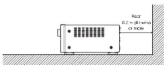
text_image
Radar 0.2 m (8 inches) or moreKEEP OBJECTS OFF
Keep objects off the unit. Blocking the vent can result in accident and damage.
DO NOT TOUCH HOT SPOTS DURING AND IMMEDIATELY AFTER USE
During and immediately after use, the unit is hot in areas other than the controls and rear panel connection jacks. Do not touch hot spots and especially the top panel. Contact with hot areas can cause burns.
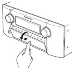
Opening and closing the front panel door When you want to use the controls behind the front panel door, open the door by gently pressing on the lower part of the panel. Keep the door closed when not using these controls.
text_image
Hand-drawn diagram of a radio device with a dial and pointer indicating the function or direction.Caution:
- Be careful not to pinch your fingers between the door and the panel.
ENGLISH
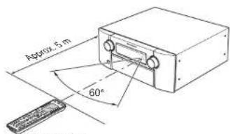
Operate the remote controller within a distance of approx. 5m from the infrared receptor window on the front of the unit.
text_image
Approx. 5 m 60°Remote controller
Caution:
- Do not allow direct sunlight, an inverter fluorescent light or other strong source of light to shine onto the unit's infrared receptor window. Otherwise, the operation of the remote controller may be disabled.
- Bear in mind that operating the remote controller may cause other devices operated by infrared rays to be operated by mistake.
- The remote controller cannot be operated if the space between the controller and the unit's infrared receptor window is obstructed.
- Do not place any objects on top of the remote controller. Doing so may cause one or more buttons to be held down which will cause the batteries to run down.
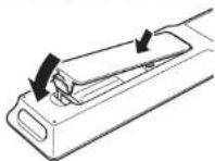
LOADING BATTERIES
Before using the remote controller for the first time, load the batteries in the remote controller. The batteries provided are used to verify the operations of the remote controller only.
- Remove the back cover.
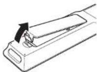
- Insert the new alkaline batteries (AAA type) with correct ⊕ and ⊖ polarity.
natural_image
Diagram showing two mechanical components with arrows indicating motion, no text or symbols present- Close the battery cover until it clicks shut.
Notes:
- Under normal usage, alkaline batteries last approximately 3 months. The battery life varies depending on the frequency of use and the remote controller settings. Frequent use will wear down the batteries quicker.
Rechargeable batteries can also be used. In this case, be sure to use only AAA type NIMH (Nickel Metal Hydride) rechargeable batteries. When using rechargeable batteries, be sure to follow manufacturer guidelines for safety and proper usage.
- When the batteries are almost worn out, "LOW" is displayed on the LCD battery indicator.
- The settings remain saved in the remote controller even if the power completely runs out. However, the time setting will be lost, and so please set the time setting again.
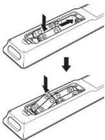
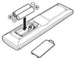
- Remove the battery cover.

- Insert the new batteries (AAA type) with correct and polarity.
natural_image
Diagram of a remote control device with battery and cylindrical components (no text or labels)- Close the battery cover until it clicks shut.
Note:
• The life of the batteries used with the remote controller is about 4 months with normal use.
CAUTIONS ON BATTERIES
- Use "AAA" type batteries in this remote controller.
- We recommend that you use alkali batteries.
- If the remote controller does not operate from close to the unit, replace the batteries with new ones, even if less then a year has passed.
- The included battery is only for verifying operation. Replace it with a new battery as soon as possible.
- When inserting the batteries, be careful to do so in the proper direction, following the + and - marks in the remote controller's battery compartment.
• To prevent damage or battery fluid leakage:
- Do not use a new battery with an old one.
- Do not use two different types of batteries.
- Do not short-circuit, disassemble, heat or dispose of batteries in flames.
- Remove the batteries when not planning to use the remote controller for a long period of time.
- If the batteries should leak, carefully wipe off the fluid from the inside of the battery compartment, then insert new batteries.
- When disposing of used batteries, please comply with governmental regulations or environmental public instruction's rules that apply in your country or area.
NAMES AND FUNCTION
FRONT PANEL

text_image
① ② ③ ④ ⑤ ⑥ ⑦ ⑧ ⑨ ⑩ ⑪ ⑫ ⑬ ⑭ ⑮ ⑯ ma:ant ⑰ ⑱ ⑲ ⑳ ㉑ ㉒ ㉓ ㉔ ㉕ ㉖ ㉗ ㉘ ㉙ ㉚ ㉛ ㉜ ㉝ ㉞ ㉟ ㉳ ㉴ ㉵ ㉶ ㉇ ㉈ ㉒ ㉓ ㉔ ㉕ ㉖ ㉗ ㉘ ㉙ ㉚ ㉛ ㉜ ㉝ ㉞ ㉟ ㉟a ㉟b ㉟c ㉟d ㉟e ㉟f ㉟g ㉟h ㉟i ㉟j ㉟k ㉟l ㉟m ㉟n ㉟o ㉟p ㉟q ㉟r ㉟s ㉟t ㉟u ㉟v ㉟w ㉟x ㉟y ㉟z ㉟c ㉟d ㉟e ㉟f ㉟g ㉟h ㉟i ㉟j ㉟k ㉟l ㉟m ㉟n ㉟o ㉟p ㉟q ㉟r ㉟s ㉟t ㉟u ㉟v ㉟w ㉟x ㉟y ㉟z① POWER switch and STANDBY indicator
Press the button to turn the power ON, and press again to turn it OFF. If the POWER switch is in the ON position, the power of this unit can be turned ON/OFF by pressing the POWER button on the remote controller.
When this unit is in the standby mode with the POWER switch set to the ON position, pressing the ENTER button also allows to turn the power on.
The STANDBY indicator lights up when this unit is the standby mode (power OFF) by the remote controller.
② INPUT SELECTOR knob (AUDIO/VIDEO)
This knob is used to select the input sources. (See page 38)
③ SURROUND MODE button
Press this button to select the surround mode.
④ AUTO (Auto surround) button
Press this button to select the AUTO mode from the surround modes. When this mode is selected, the unit determines the surround mode corresponding to a digital input signal automatically.
⑤ PURE DIRECT button and indicator
When this button is pressed once, "SOURCE DIRECT" appears on the FL display. If pressed again, "PURE DIRECT" appears. After 2 seconds, the FL display indication goes out. In the source/pure direct mode, the tone control circuitry and bass management are bypassed.
Notes:
- The surround mode is automatically switched to AUTO when the pure direct function is turned on.
- Additionally, speaker configurations are fixed automatically as follows.
Front SPKR = LARGE
Center SPKR = LARGE
Surround SPKR = LARGE
Surround Back SPKR = LARGE
Sub woofer = YES
⑥ ZONE button
Press this button to activate the Zone system. "MULTI" indicator will be illuminated in the display. (See page 51)
Press this button to activate the Zone Speaker system, "MULTI" indicator will be illuminated in the display.(See page 52)
⑧ MENU button
Press this button to enter the SETUP MAIN MENU.
⑨ EXIT button
Press this button to exit from the SETUP MAIN MENU.
⑩ BAND button
Press this button to switch between FM and AM in the TUNER mode.
⑪ T-MODE button
Press this button to select the auto stereo mode or mono mode when the FM band is selected. The "AUTO" indicator lights in the auto stereo mode. (See page 48)
⑫ INFRARED receiving sensor window This window receives infrared signals for the remote controller.
⑬ MEMORY button
Press this button to enter the tuner preset memory numbers or station names. (See page 48)
⑭ CLEAR button
Press this button to cancel the station-memory setting mode or preset scan tuning. (See page 49)
⑮ VOLUME control knob
This knob is used to adjust the overall sound level. Turning the control clockwise increases the sound level.
⑯ DISPLAY button
Press this button to change the FL display mode.
⑰ M-DAX button
Press this button to select M-DAX processing for input source. (See page 39)
⑱ TOP button
Press this button to return to the top screen of the main menu when configuring setup items. (See page 20) Also, press this button to return to the top screen of the network when using the network.
⑲ Cursor (5,∞,2,3) / ENTER button Press these buttons to operate the SETUP MAIN MENU, NETWORK and TUNER function.
ENGLISH
20 7.1CH INPUT button
Press this button to select the output of an external multichannel player.
② MIC jack
Automatically measure speaker characteristics using the included microphone. (See page 26)
② THX button
Press this button to select THX processing for input source.
②3 HEADPHONE jack for stereo headphones This jack may be used to listen to the unit's output through a pair of headphones. Be certain that the headphones have a standard 1/4" stereo phono plug.
ENGLISH
FL DISPLAY AND INDICATER

flowchart
graph TD
    A["MODE"] --> B["(21)"]
    A --> C["(20)"]
    D["PURE DIRECT"] --> E["DISP"]
    D --> F["Multi Audio"]
    D --> G["Tuning ST V"]
    D --> H["Sleep"]
    D --> I["Auto Surr"]
    D --> J["DISC.1 DIRECT MTX 6.1"]
    D --> K["EO"]
    L["OFF"] --> M["DISC.1"]
    N["NIGHT PEAK ANAUDG"] --> O["DISC.1"]
    P["Digital"] --> Q["POM"]
    R["DISC.1"] --> S["17"]
    T["Digital"] --> U["16"]
    V["Digital"] --> W["15"]
    X["Digital"] --> Y["14"]
    Z["Digital"] --> AA["13"]
    AB["Digital"] --> AC["12"]
    AD["Digital"] --> AE["11"]
    AF["Digital"] --> AG["10"]
    AH["Digital"] --> AI["9"]
    AJ["Digital"] --> AK["8"]
    AL["Digital"] --> AM["7"]
    AN["Digital"] --> AO["6"]
    AP["Digital"] --> AQ["5"]
    AR["Digital"] --> AS["4"]
    AT["Digital"] --> AU["3"]
    AV["Digital"] --> AW["2"]
    AX["Digital"] --> AY["1"]
    AZ["Digital"] --> BA["0"]
(1) DISP (Display Off) indicator
This indicator is illuminated when this unit is in the display off mode.
(2) SLEEP timer indicator
This indicator is illuminated when the sleep timer function in the main-zone is in use.
(3) MULTI (Zone system) indicator
This indicator is illuminated when the zone system is active.
(4) AUTO SURR
(Auto Surround mode) indicator
This indicator is illuminated to show that the AUTO SURROUND mode is in use.
(5) TUNER's indicators
AUTO: This indicator illuminates when the tuner's Auto mode is in use.
TUNED: This indicator illuminates when the tuner receives a sufficiently strong radio signal.
ST(Stereo): This indicator illuminates when an FM station is being tuned into stereo condition.
(6) DTS-ES mode indicators (DISC6.1, MTX6.1)
These indicators will illuminate to show the DTS-ES decoding mode (Discrete 6.1 or Matrix 6.1).
(7) V (video)-OFF mode indicator
This indicator is illuminated when the Video-OFF function is active.
(8) NIGHT mode indicator
This indicator is illuminated when this unit is in the Night mode, which reduces the dynamic range of digital program material at low volume levels.
(9) PEAK indicator
This indicator is a monitor for an analog audio input signal. If the selected analog audio input signal is greater than the capable level of internal processing, this will illuminate. If this happens, you should press the ATT button. (See page 55)
(10) EQ indicator
This indicator is illuminated when the EQ MODE is selected to "AUDDYSSEY", "FRONT" or "FLAT".
(11) ATT (Attenuation) indicator
This indicator is illuminated when the attenuation function is active.
(12) DIGITAL Input Indicator
This indicator is illuminated when a digital input has been selected.
(13) ANALOG input indicator
This indicator is illuminated when an analog input source has been selected.
(14) SIGNAL FORMAT indicators
□□ DIGITAL
This indicator is illuminated when a Dolby Digital signal is input.
EX
This indicator is illuminated when a Dolby Digital EX signal is input.
dts
This indicator is illuminated when a DTS signal is input.
ES
This indicator is illuminated when a DTS ES signal is input.
96/24
This indicator is illuminated when a DTS 96/24 signal is input.
PCM
This indicator is illuminated when the input signal is PCM (pulse code modulation).
□□ SURROUND
This indicator is illuminated when a Dolby Surround signal is input.
(15) HDMI indicator
This indicator is illuminated when the HDMI device is connected to the unit.
(16) ENCODED CHANNEL STATUS indicators These indicators display the channels that are encoded with a digital input signal.
If the digital input signal is Dolby Digital 5.1ch or DTS 5.1ch, "L", "C", "R", "SL", "SR" and "LFE" will be illuminated.
If the digital input signal is 2 channel PCM-audio, "L" and "R" will be illuminated.
If the digital input signal is 7.1 channel PCM-audio, "L", "C", "R", "SL", "S", "SR" and "LFE" will be illuminated.
If the digital input signal is Dolby Digital 5.1ch signal with Surround EX flag or DTS-ES, "L", "C", "R", "SL", "S", "SR" and "LFE" will be illuminated.
Note:
When the unit is decoding Dolby TrueHD, the input signal status displayed depends on the number of channels of the speakers used.
If a 7.1-channel signal is supplied for a 5.1-channel speaker system (L/C/R/SI/SR/SW), the "S" indicator is not illuminated.
(17) HDCD indicator
This indicator is illuminated when the HDCD signal is decoded from digital input signal.
(18) Main Information Display
This display shows messages relating to the status, input source, surround mode, tuner, volume level or other aspects of unit's operation.
(19) DIRECT indicator
This indicator is illuminated when this unit is in the SOURCE DIRECT mode. PURE DIRECT mode or 7.1ch input mode.
(20) M-DAX indicator
This indicator illuminates when this unit is in the M-DAX mode.
(21) PURE DIRECT indicator
This indicator is illuminated when this unit is in the PURE DIRECT mode.
REAR PANEL

text_image
Diagram of a multi-chamber network device with numbered ports and labeled connectors① FM antenna terminal (75 ohms)
Connect an external FM antenna with a coaxial cable, or a cable network FM source.
AM antenna and ground terminals
Connect the supplied AM loop antenna. Use the terminals marked "AM" and "GND". The supplied AM loop antenna will provide good AM reception in most areas. Position the loop antenna until you hear the best reception.
② COMPONENT VIDEO INPUT/OUTPUT
If your DVD player or other device has component video connectors, be sure to connect them to these component video connectors on the unit. This unit has 4 component video input connectors to obtain the color information (Y, Cs, Cs) directly from the recorded DVD signal or other video component and two component video outputs connector to output it directly into the matrix decoder of the display device. By sending the pure DVD component video signal directly, the DVD signal forgoes the extra processing that normally would degrade the image. The result is vastly increased image quality, with incredibly life like colors and crisp detail.
The Monitor Out 2 terminal is also used for ZONE output.
③ Zone Outputs
(Audio output A/B, Video)
These are the audio and video output jacks for the Multi zone.
Connect these jacks to optional audio power amplifiers or video display devices to listen and view the source selected by the zone system in a remote room.
4 MONITOR OUT
These are monitor outputs and each one includes both composite video and S-video confi gurations. When connecting two video monitors or televisions, be aware that the OSD interface can be used with both MONITOR OUT connections.
⑤ UNBALANCED PREOUT
(L, R, SL, SR, SBL, SBR, C)
Connect the L (front left), R (front right), C (center), SL (Surround left), SR (Surround right), SBL (Surround back left), and SBR (Surround back right) terminals to the unbalanced input terminals of a power amp such as the MM8003.
⑥ BALANCED PREOUT (L, R, SL, SR, SBL, SBR, C)
Connect the L (front left), R (front right), C (center), SL (Surround left), SR (Surround right), SBL (Surround back left), and SBR (Surround back right) terminals to the balanced input terminals of a power amp such as the MM8003.
7 NETWORK
Connect to a network device such as a router or hub.
This allows you to play back music, photos, and movie files stored on a connected network device.
⑧ Subwoofer Output
These are subwoofer outputs and each one includes both unbalanced and balanced jack confi gulations. Connect this jack to the line level input of a powered subwoofer.
⑨ SPEAKER C switch
Set to ON to connect a bi-amp to this unit or set to OFF for normal connection (surround back and zone speakers). (See page 18)
⑩ RS-232C
The RS-232C port is to be used in connection with an external controller to control the operation of the unit by using an external device.
The RS-232C port may also be used in the future to update the operating software of the unit so that it will be able to support new digital audio formats and the like as they are introduced.
⑪ AC INLET
Plug the supplied power cable into this AC INLET and then into the power outlet on the wall.
This unit can be powered by 230V AC only.
⑫ CD/CDR Input Selection Switch
Switches between BALANCED and UNBALANCED for the CD/CDR IN terminals.
Notes:
• Always set the input selection before turning on the power. Equipment failure may result If the input selection is switched while the power is on.
- Audio may not be output from the main unit if the input to the unit differs from the setting of the Input Selection Switch.
⑬ BALANCED CD/CDR IN
Connect to the balanced output terminal of a Super Audio CD Player or similar player.
The UNBALANCED CD/CDR input terminals are the CD/CDR IN terminals in 21.
Note:
Do not connect to the BALANCED and UNBALANCED terminals at the same time.
14 7.1 CHANNEL or AUX INPUT
By connecting a DVD Audio player, Super Audio CD multichannel player, or other components that has a multichannel port, you can playback the audio with 5.1 channel or 7.1 channel outputs.
⑮ EMITTER OUT
The signals input to the IR RECEIVER IN terminals are output to this terminal. External devices can be controlled by connecting them to this terminal.
16 IR RECEIVER IN
Connect to an external IR receiver.
⑰ FLASHER IN (Flasher input terminal)
These terminals are to control the unit from each zone. Connect the control signal from a Keypad, etc.
18 DC TRIGGER output terminal
Connect a device that needs to be triggered by DC under certain conditions (screen, power strip, etc...) Use the system OSD setup menu to determine the conditions by which those jack will be active. (See page 35)
Note:
- This output voltage is for (status) control only, It is not sufficient for drive capability.
19 ZONE REMOTE IN/OUT terminals
IN: Connect to a zone remote control device, available from your Marantz dealer. OUT: Connect to the Marantz component equipped with remote control (RC-5) terminals in Multi zone.
20 REMOTE CONT. IN/OUT terminals
Connect to a Marantz component equipped with remote control (RC-5) terminals.
ENGLISH
ENGLISH
② AUDIO IN/OUT (TV, DVD, VCR1, DSS/VCR2, TAPE, CD/CDR)
These are the analog audio inputs and outputs. There are 6 audio inputs and 4 audio outputs. The audio jacks are nominally labeled for cassette tape decks, compact disc players, DVD players and etc... The audio inputs and outputs require RCA-type connectors.
② DIGITAL INPUT (Dig.1 - 6) / OUTPUT (coaxial, optical)
These are the digital audio inputs and outputs. There are 3 digital inputs with coaxial jacks, 3 with optical jacks.
The inputs accept digital audio signals from a CD, DVD, or other digital source component. For digital output, there is 1 coaxial output and 1 optical output.
The digital outputs can be connected to MD recorders, CD recorders, or other similar components.
23 VIDEO IN/OUT (TV, DVD, VCR1, DSS/VCR2)
These are the video inputs and outputs. There are 4 video inputs and 2 video outputs and each one includes both composite video and S-video confi gurations. Connect VCRs, DVD players, and other video components to the video inputs.
The 2 video output channels can be used to be connected to video tape recorders for making recordings.
24 HDMI INPUT / OUTPUT
This unit has 4 HDMI inputs and 2 HDMI output. The input function can be selected from the OSD menu system. (See page 23)
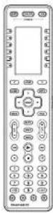
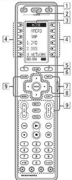
REMOTE CONTROLLER RC2001
The provided remote controller is a universal remote controller. The POWER button, numeric buttons and control buttons are used in common across different input source components.
You can use the Wizz.it3 editing software to select your favorite settings for the buttons and pages of the remote controller.
text_image
OFF ON/OFF ON POWER HOME NPCRO RHP 1.3VD 2.0SS 3. NETWORK 601/604 HOME GUIDE INFO MENO EXIT 1 2 3 4 5 6 7 8 9 WRITE INPUT PHY + - - - - - - - - - - - - - - - - - - - - - - - - - - - - - - - - - - - - - - - - - - - - - - - - - - - - - - - - - - - - - - - - - - - - - - - - - - - - - - - - - - - - - - - - - - - - - - - - - - - - - - marantz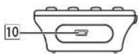
1 POWER ON and OFF buttons
These buttons are used when controlling devices that have been set with separately powered on and off remote commands.
2 SOURCE ON/OFF button
This button is used when controlling devices that have been set with a single power on/off remote command.
|3| LCD Display
Remote controller display
4 Programmable soft buttons
These buttons are used by the Wizz.it 3 editor software to make LCD display and button operation settings.
These buttons are also used to adjust the number of pages for each device.
5 Page Scroll buttons
These buttons are used when scrolling pages in Home mode and the device modes.
|6| Home button
This button is used to select Home mode.
To select a device that will be controlled, first select Home mode, then select the device.
7 Light button
This button is used to turn on the backlight for the buttons and LCD.
|8| Cursor, ENTER buttons
9 Programmable Hard buttons
These buttons are used by the Wizz.it 3 editor software to make the remote controller command settings for learning and macro operations.
10 USB port
This port is used to connect the remote controller and a PC with the supplied USB cable to enable editing with the Wizz.it 3 editor software.
RC2001 LCD INDICATORS

text_image
HOME MACRO AMP 1. DVD 2. DSS 3. NETWORK 001/004 A B C DⒶ Mode display area
Home:
This is displayed during Home mode.
Device Name:
This displays the device mode name that is currently active.
This area is always highlighted.
⑧ Command display area
This displays the information that has been set for the display items in the device modes.
© Battery indicator
This displays the remaining battery power.
Sub info. Area
Normal operation:
The page number that has been set for the respective mode is displayed.
When sending IR command:
The command name that has been set for the respective button is highlighted.
Operation when not sending an IR command (such as jump operation):
The operation name that has been set for the button is displayed normally (not highlighted).
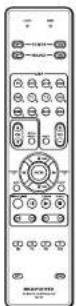
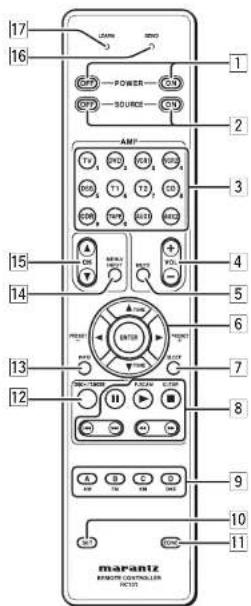
REMOTE CONTROLLER RC101
The included remote controller can be used in zone systems. Using this remote controller, you can operate the unit through infrared receivers or the Infrared receptor of Marantz products in multiple ZONEs. The SOURCE ON/OFF button and control buttons are used in common across different input source components.
The input source controlled with the remote controller changes when one of the input selector buttons is pressed.
text_image
17 16 POWER SOURCE AMP TV PGD PGB PGS PGN PGU PGK PGL PGM PGN PGO PGP PGQ PGR PGS PGN PGO PGP PGQ PGR PGS PGN PGO PGP PGQ PGR PGS PGN PGO PGP PGQ PGR PGS PGN PGO PGP PGQ PGR PGS PGN PGO PGP PGQ PGR PGS PGN PGO PGP1 POWER ON and OFF buttons
(When Zone A/B mode is selected)
These buttons are used to turn on or off, for the ZONE control or zone speaker control of the unit.
(When Zone D (MAIN ZONE) mode is selected) These buttons are used to turn on or off, for the u in main zone.
② SOURCE ON and OFF buttons
These buttons are used to turn on or off a specific source (such as a DVD player) independently from the rest of the system.
(When NETWORK mode (AUX2) is selected)
SOURCE ON button
This button is used to select the screen resolution.
SOURCE OFF button
This button is used to return to the previous screen.
③ AMP - SOURCE /Numeric buttons
SOURCE buttons
These buttons are used to switch the source of the unit. Each time a source button is pressed, the remote control changes to the source which was pressed.
This remote controller can control 12 types of equipment. To change the unit source, press this button twice within two seconds. The signal is sent when it is pressed the second time.
Notes:
- Press AUX2 to switch to NETWORK function.
• The T2 button is not used for this unit.
(When Zone A/B mode is selected)
These buttons are used to select the source for the zone/zone speaker control of the unit.
(When Zone D (MAIN ZONE) mode is selected)
These buttons are used to select the source for the unit in main zone.
Numeric buttons
Use these buttons only for preset setting.
4 AMP - VOL +/- buttons
(When Zone A/B mode is selected)
These buttons are used to adjust the volume for the zone control or zone speaker.
(When Zone D (MAIN ZONE) mode is selected)
These buttons are used to adjust the volume for the unit in main zone.
5 AMP - MUTE button
(When Zone A/B mode is selected)
This button is used to mute the audio for the zone control or zone speaker control of the unit.
(When Zone D (MAIN ZONE) mode is selected)
These buttons are used to mute the audio for the unit in main zone.
6 ▲,▼,◀,(CURSOR)/ENTER
buttons
These buttons are used when operating cursor of a source.
(When Tuner mode (T1) is selected)
PRESET +/ PRESET - buttons
Used to select a preset station up and down.
TUNE ▲ /TUNE ▼ buttons
Used to tune a frequency station up and down.
7 SLEEP button
(When Zone A/B mode is selected)
This button is used for setting the sleep timer of zone control mode.
(When Zone D (MAIN ZONE) mode is selected)
This button is used for setting the sleep timer of the unit receiver in main zone.
8 CONTROL buttons
These buttons are used when operating PLAY, STOP, PAUSE and other commands of a source.
(When TUNER mode (T1) is selected)
P.SCAN button
Used to start preset scan.
CLEAR button
Used to stop preset scan.
9 A/B/C/D buttons
(When TUNER mode (T1) is selected)
Used to select the band of tuner (AM/FM).
Note:
The C (XM) and D (DAB) button are not used for this unit.
(When the other source is selected)
Reserve key for the learning commands.
ENGLISH
10 SET button
This button is used to enter learn mode, preset mode and clone mode.
11 ZONE button
This button is used to set the zone area.
- Zone A
- Zone B
• Zone C (The unit does not use this zone.)
• Zone D (MAIN ZONE)
[12] DISC+/T.MODE
(When TUNER mode (T1) is selected)
Used to select auto stereo mode or mono mode when the FM band is selected.
The "AUTO" indicator lights in the auto stereo mode.
(When CD/DVD/CDR mode is selected)
Used to change the disc for the CD/DVD/CDR changer.
|13| INFO button
(When Zone A mode is selected)
When this button is pressed, the current setting for selected zone control of the unit is displayed on the TV monitor.
(When Zone D (MAIN ZONE) mode is selected)
When this button is pressed, the current setting for the unit are displayed on the TV monitor.
14 MENU/INPUT button
(When DVD mode is selected)
Used to menu command.
(When TV mode is selected)
Used to select the TV video input.
[15] CH ▲/▼ buttons
These buttons are used to change channels in TV mode and DSS mode.
[16] SEND indicator
Indicates when the remote controller is transmitting a signal.
[17] LEARN indicator
Indicates when the remote controller is in the LEARN mode.
ENGLISH
CONNECTIONS
SPEAKER PLACEMENT
The ideal surround speaker system for this unit is 7-speaker systems, using front left and right speakers, a center speaker, surround left and right speakers, a surround back left and right speakers, and a subwoofer.
For best results we recommend that all front speakers be of the same type, with identical or similar driver units. This will deliver smooth pans across the front sound stage as the action moves from side to side. Your center channel speaker is very important as over 80 % of the dialog from a typical motion picture emanates from the center channel.
It should possess similar sonic characteristics to the main speakers. Surround channel speakers need not be identical to the front channel speakers, but they should be of high quality.
The surround center speaker is useful for playback of Dolby Digital Surround EX or DTS-ES. One of the benefits of both Dolby Digital and DTS is that surround channels are discrete full range, while they were frequency limited in earlier "Pro Logic" type systems.
Bass effects are an important part of home theater. For optimal enjoyment a subwoofer should be used as it is optimized for low frequency reproduction. If you have full range front speakers, however, they may be used in place of a subwoofer with proper setting of the switches in the menu system.
text_image
Subwoofer Surround Right Front Right Surround Back Right Front Center 0° 45°-60° 22° 30° 150° 135° 110° 90° 150° 110° Surround Left Surround Back left
natural_image
Interior view of a room with a person seated in a chair, surrounded by wall-mounted devices and floating objects (no text or symbols visible)Front left and right speakers
We recommend to set the front L and R speakers with 45-60 degrees from the listening position.
Center speaker
Align the front line of the center speaker with the front L/R speakers. Or place the center speaker a little backward from the line.
Surround left and right speakers
When this unit is used in surround operation, the preferred location for surround speakers is on the side walls of the room, at or slightly behind the listening position.
The center of the speaker should face into the room.
Surround back left and right speakers
Surround back speakers are required when a full 7.1-channel system is installed.
Speakers should be placed on a rear wall, behind the listening position.
The center of the speaker should face into the room.
Subwoofer
We recommend using a sub-woofer to have maximum bass effect. As the subwoofer only handle low frequency. You can place it any where in the room.
HEIGHT OF THE SPEAKER UNITS
Front left and right speakers, and a center speaker Align the tweeters and mid-range drivers on the three front speakers at the same height, as best as possible.
Surround left and right speakers, and surround back speaker
Place the surround left, right and surround back speakers higher than your ears by about 70cm–1m. Also place the speakers at the same height, as best as possible.

text_image
70cm ~ 1mNote:
- Use magnetically-shielded speakers for front left, right and the center speakers when the speakers are installed near the TV.
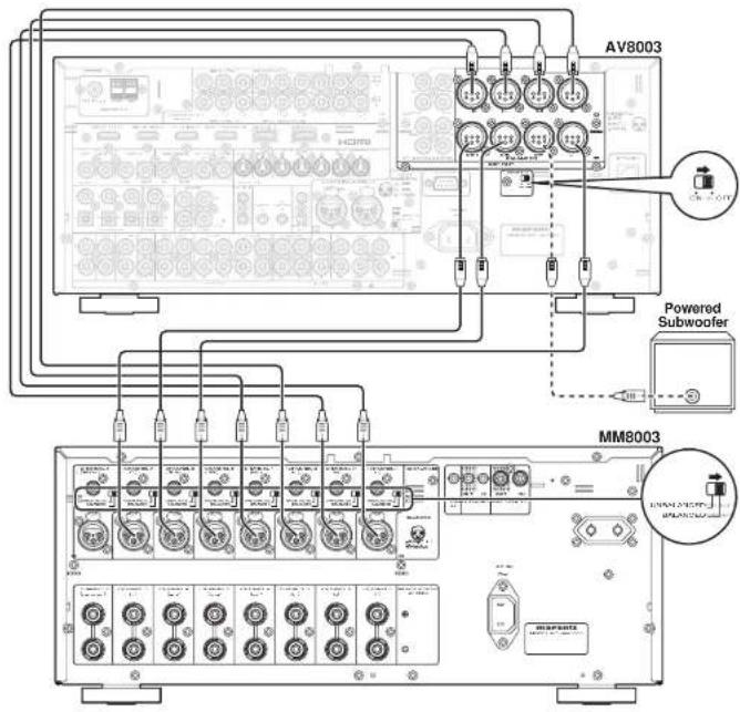
CONNECTION TO AN MM8003 (BALANCED)
Connect the L (front left), R (front right), C (center), SL (Surround left), SR (Surround right), SBL (Surround back left), and SBR (Surround back right) terminals to the balanced input terminals of a power amp such as the MM8003.
CONNECTING A SUBWOOFER
Use the SW jack to connect a powered subwoofer (power amplifi er built in ).
text_image
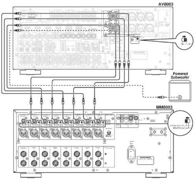
AV8003 Powered Subwoofer MM8003CONNECTION TO AN MM8003 (UNBALANCED)
Connect the L (front left), R (front right), C (center), SL (Surround left), SR (Surround right), SBL (Surround back left), and SBR (Surround back right) terminals to the unbalanced input terminals of a power amp such as the MM8003.
CONNECTING A SUBWOOFER
Use the SW jack to connect a powered subwoofer (power amplifi er built in ).
text_image
AV8003 Powered Subwoofer MM8003ENGLISH
ENGLISH
ABOUT BALANCED JACKS
- The balanced output connector uses a XLR connector.
- The XLR connector for professional use is internally wired in either of the following two systems.
- European system
(Pin ② = HOT, Pin ③ = COLD)
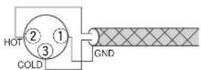
- USA system (Pin ② = COLD, Pin ③ = HOT)

- This unit uses the 1. European system. When a preamp or main amplifier adopting the European system is connected using a cable with XLR balanced connectors, the reproduced signal may be inverted of phase.
CONNECTING AUDIO COMPONENTS
CD recorder

flowchart
graph TD
    A["Analog Audio"] --> B["Analog 2.5"]
    A --> C["Analog 1.5"]
    A --> D["Analog 0.5"]
    A --> E["Analog 0.25"]
    A --> F["Analog 0.1"]
    G["Digital Audio (coaxial)"] --> H["Digital 1.5"]
    I["Digital Audio (optical)"] --> J["Digital 0.5"]
    K["Analog 2.5"] --> L["Analog 1.5"]
    M["Analog 0.5"] --> N["Analog 0.25"]
    O["Analog 0.1"] --> P["Analog 0.05"]
    Q["Analog 0.05"] --> R["Analog 0.025"]
    S["Analog 0.025"] --> T["Analog 0.01"]
    U["Analog 0.01"] --> V["Analog 0.005"]
    W["Analog 0.005"] --> X["Analog 0.0025"]
    Y["Analog 0.0025"] --> Z["Analog 0.001"]
    AA["Analog 0.001"] --> AB["Analog 0.0005"]
    AC["Analog 0.0005"] --> AD["Analog 0.00025"]
    AE["Analog 0.00025"] --> AF["Analog 0.0001"]
    AG["Analog 0.0001"] --> AH["Analog 0.00005"]
    AI["Analog 0.00005"] --> AJ["Analog 0.000025"]
    AK["Analog 0.000025"] --> AL["Analog 0.00001"]
    AM["Analog 0.00001"] --> AN["Analog 0.000005"]
    AO["Analog 0.000005"] --> AP["Analog 0.0000025"]
    AQ["Analog 0.0000025"] --> AR["Analog 0.000001"]
    AS["Analog 0.000001"] --> AT["Analog 0.0000005"]
    AU["Analog 0.000001"] --> AV["Analog 0.00000025"]
    AW["Analog 0.000001"] --> AX["Analog 0.0000001"]
    AY["Digital Audio (coaxial)"] --> AZ["Digital Audio (optical)"]
    BA["Digital Audio (coaxial)"] --> BB["Digital Audio (optical)"]
    BC["Digital Audio (coaxial)"] --> BD["Digital Audio (optical)"]
    BE["Digital Audio (coaxial)"] --> BF["Digital Audio (optical)"]
    BG["Digital Audio (coaxial)"] --> BH["Digital Audio (optical)"]
    BI["Digital Audio (coaxial)"] --> BJ["Digital Audio (optical)"]
    BK["Digital Audio (coaxial)"] --> BL["Digital Audio (optical)"]
    BM["Digital Audio (coaxial)"] --> BN["Digital Audio (optical)"]
    BO["Digital Audio (coaxial)"] --> BP["Digital Audio (optical)"]
    BQ["Digital Audio (coaxial)"] --> BR["Digital Audio (optical)"]
    BS["Digital Audio (coaxial)"] --> BT["Digital Audio (optical)"]
    BU["Digital Audio (coaxial)"] --> BV["Digital Audio (optical)"]
    BW["Digital Audio (coaxial)"] --> BX["Digital Audio (optical)"]
    BY["Digital Audio (coaxial)"] --> BZ["Digital Audio (optical)"]
    CA["Digital Audio (coaxial)"] --> CB["Digital Audio (optical)"]
    CC["Digital Audio (coaxial)"] --> CD["Digital Audio (optical)"]
    CE["Digital Audio (coaxial)"] --> CF["Digital Audio (optical)"]
    DG["Digital Audio (coaxial)"] --> DH["Digital Audio (optical)"]
    DI["Digital Audio (coaxial)"] --> DJ["Digital Audio (optical)"]
    DK["Digital Audio (coaxial)"] --> DL["Digital Audio (optical)"]
    DM["Digital Audio (coaxial)"] --> DE["Digital Audio (optical)"]
    DF["Digital Audio (coaxial)"] --> DG
    DG --> DG
    DG --> DG
    DG --> DG
    DG --> DG
    DG --> DG
    DG --> DG
    DG --> DG
    DG --> DG
    DG --> DG
    DG --> DG
    DG --> DG
    DG --> DG
    DG --> DG
    DG --> DG
    DG --> DG
    DG --> DG
    DG --> DG
    DG --> DG
    DG --> DG
    DG --> DG
    DN["Analog Audio"] --> DN
    DN --> DN
    DN --> DN
    DN --> DN
    DN --> DN
    DN --> DN
    DN --> DN
    DN --> DN
    DN --> DN
    DN --> DN
    DN --> DN
    DN --> DN
    DN --> DN
    DN --> DN
    DN --> DN
    DN --> DN
    DN --> DN
    DN --> DN
    DN --> DN
    DN --> DN
    DN --> DN
    BN["Analog Audio"] --> BN
    BN --> BN
    BN --> BN
    BN --> BN
    BN --> BN
    BN --> BN
    BN --> BN
    BN --> BN
    BN --> BN
    BN --> BN
    BN --> BN
    BN --> BN
    BN --> BN
    BN --> BN
    BN --> BN
    BN --> BN
    BN --> BN
    BN --> BN
    BN --> BN
    BN --> BN
    BN --> BN
    BZ["Analog Audio"] --> BZ
    BZ --> BZ
    BZ --> BZ
    BZ --> BZ
    BZ --> BZ
    BZ --> BZ
    BZ --> BZ
    BZ --> BZ
    BZ --> BZ
    BZ --> BZ
    BZ --> BZ
    BZ --> BZ
    BZ --> BZ
    BZ --> BZ
    BZ --> BZ
    BZ --> BN
Super Audio CD
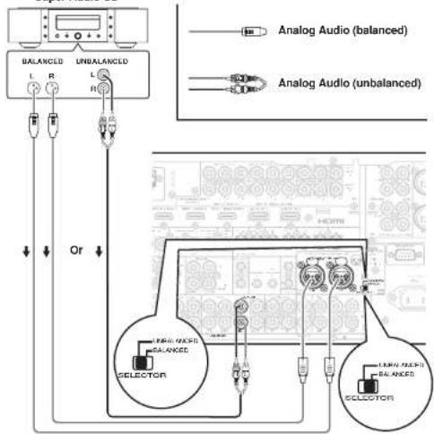
text_image
BALANCED UNBALANCED L R L Or Analog Audio (balanced) Analog Audio (unbalanced) SELECTOR BALANCED BALANCED LARGE SLIKES BALANCED SELECTORThe output audio signal from the TAPE OUT jack and the CD/CD RECORDER OUT jack is the same signal which is currently selected.
Caution:
- Do not connect this unit and other components to mains power until all connections between components have been completed.
Notes:
- Insert all plugs and connectors securely. Incomplete connections may make noise.
- Be sure to connect the left and right channels properly.
Red connectors are for the R (right) channel, and white connectors are for the L (left) channel. - Be sure to connect input and output properly.
- Refer to the instructions for each component that is connected to this unit.
- Do not bind audio/video connection cables with power cords and speaker cables this will result in generating a hum or other noise.
CONNECTING DIGITAL AUDIO COMPONENTS
- There are 6 digital inputs, 3 coaxial jacks and 3 optical jacks, on the rear panel. You can use these jacks to input PCM, Dolby Digital and DTS bitstream signals from a CD, DVD, or other digital source components.
- There is one digital output coaxial jack and one optical output jack on the rear panel. These jacks can be connected to a CD recorder, or a MD deck inputs, respectively.
- Refer to the instructions for each component. To setup the digital audio format of DVD player, or other digital source's connected to digital input jacks.
- Use fiber optical cables (optical) for DIG-1,2,3 input jacks. Use 75 ohms coaxial cables (for digital audio or video) for DIG-4, 5, 6 input jacks.
- You can designate the input for each digital input/output jacks according to your component. See page 23.
Notes:
- There is no Dolby Digital RF input jack. Use an external RF demodulator Dolby Digital decoder when connecting the Dolby Digital RF output jack of the videodisc player to the digital input jack.
- The digital signal jacks on this unit conform to the EIA standard. If you use a cable that does not conform to this standard, this unit may not function properly.
- Each type of audio jack works independently. Signals input through the digital and analog jacks are output through the corresponding digital and analog jacks, respectively.
CONNECTING VIDEO COMPONENTS

flowchart
graph TD
    A["DVD player"] --> B["VIDEO PROJECTOR"]
    B --> C["COMPONENT VIDEO OUT"]
    B --> D["S-VIDEO OUT"]
    C --> E["VIDEO OUT"]
    D --> F["VIDEO OUT"]
    G["VCR"] --> H["VIDEO OUT"]
    I["AUDIO IN"] --> J["VIDEO OUT IN"]
    K["S-VIDEO IN"] --> L["VIDEO OUT IN"]
    M["LOGIC"] --> N["LOGIC"]
    O["LOGIC"] --> P["LOGIC"]
    Q["LOGIC"] --> R["LOGIC"]
    S["LOGIC"] --> T["LOGIC"]
    U["LOGIC"] --> V["LOGIC"]
    W["LOGIC"] --> X["LOGIC"]
    Y["LOGIC"] --> Z["LOGIC"]
    AA["LOGIC"] --> AB["LOGIC"]
    AC["LOGIC"] --> AD["LOGIC"]
    AE["LOGIC"] --> AF["LOGIC"]
    AG["LOGIC"] --> AH["LOGIC"]
    AI["LOGIC"] --> AJ["LOGIC"]
    AK["LOGIC"] --> AL["LOGIC"]
    AM["LOGIC"] --> AN["LOGIC"]
    AO["LOGIC"] --> AP["LOGIC"]
    AQ["LOGIC"] --> AR["LOGIC"]
    AS["LOGIC"] --> AT["LOGIC"]
    AU["LOGIC"] --> AV["LOGIC"]
    AW["LOGIC"] --> AX["LOGIC"]
flowchart
graph TD
    A["Satellite Tuner"] --> B["Digital OUT"]
    A --> C["AUDIO OUT"]
    A --> D["VIDEO OUT"]
    A --> E["S-VIDEO OUT"]
    B --> F["Analog Audio"]
    C --> G["Analog Audio"]
    D --> H["Analog Audio"]
    E --> I["Analog Audio"]
    F --> J["Video"]
    G --> K["Video"]
    H --> L["Video"]
    I --> M["Video"]
    J --> N["TV"]
    K --> N
    L --> N
    M --> N
    N --> O["Analog Audio (coaxial)"]
    N --> P["Analog Audio (optical)"]
ENGLISH
There are 3 types of video jacks on the rear panel.
VIDEO jack
The video signal for the VIDEO jacks is the conventional composite video signal.
S-VIDEO Jack
The video signal is separated into luminance (Y) and color (C) signals for the S-VIDEO jack. The S-VIDEO signals enables high-quality color reproduction. Connect the S-VIDEO output jack on your video component to the S-VIDEO input jack on this unit.
Component jack
Make component video connections to a TV or monitor with component inputs to produce higher quality video images. Use a component video cable or 3 video cords to connect the component video out jacks on the unit to the monitor.
Notes:
- Be sure to connect the left and right audio channels properly. Red connectors are for the R (right) channel, and while connectors are the for L (left) channel.
- Be sure to connect the inputs and outputs of the video signals properly.
- If you connect the S-VIDEO or component signal to the S-VIDEO or component jack on this unit, it is not necessary to connect the conventional video signal to the VIDEO (composite) jack. If you use both video inputs, this unit gives priority to the S-VIDEO signal.
• Each type of video jack works independently. Signals input to the VIDEO (composite) and S-VIDEO jacks or component are output to the corresponding VIDEO (composite) and S-VIDEO or component jacks, respectively. - This unit has the "TV-AUTO ON/OFF" function to turn the TV ON or OFF automatically, by sensing the incoming video signal from the VIDEO jacks.
- You may need to setup the digital audio output format of your DVD player, or other digital source components. Refer to the instructions of the each component connected to the digital input jacks.
- There is no Dolby Digital RF input jack. Use an external RF demodulator with a Dolby Digital decoder to connect the Dolby Digital RF output jack of the DVD player to the digital input jack on this unit.
- The COMPONENT OUTPUT 1 and 2 terminals of this unit can output the same video signal. Moreover, the OUTPUT 2 terminal of the unit can output video signals for zone playback. (See page 33)
ENGLISH
CONNECTING HDMI COMPONENTS
HDMI JACK
This unit has four HDMI inputs and two HDMI output. It can send digital video and audio signals from DVDs and other sources directly to a display. It minimizes signal degradation caused by analog conversion so that high quality images can be enjoyed.
This unit is also capable of converting analog video signals (Composite Video, S-Video, Component Video) for HDMI output.
Select an input source from the OSD menu system. (See page 23)
Notes:
- When the HDMI output is connected to a display monitor that does not support HDCP, signals are not output. To view images in HDMI, it is necessary to connect to a display that supports HDCP.
- There may be no image output if connected to a TV or display that is not compatible with the above format.
- Refer to the instruction manual of the TV or display to be connected to the unit for detailed information regarding the HDMI terminal.
* HDCP: High-handwidth Digital Content Protection
CONNECTING HDMI COMPONENTS
An HDMI cable (sold separately) is used to connect the HDMI jack on the unit with the HDMI jack on a DVD player, TV, projector or other component. To transmit multichannel audio via HDMI, the connected player must support multichannel audio transmission through its HDMI jack.
HDMI video streaming is compatible with DVI in principle. Therefore, it is possible to connect to a TV or monitor that has a DVI terminal using an HDMI-DVI conversion cable or plug. When connecting to a DVI terminal, connect the audio signal separately.
Notes:
- Some HDMI components can be controlled over the HDMI cable, but this unit cannot control other components this way.
-
When connected to a monitor (i.e., TV, projector, etc.) that does not support HDCP, video and audio are not output.
-
Some source devices such as DVD players or set top box do not support HDMI repeater operations like those of the unit. In such case, pictures are not properly projected on monitors such as TVs and projectors.
- When multiple components are connected to this unit, turn power to unused components off to prevent interference between them.
- Disconnecting or connecting cables with the power on can damage the equipment. Turn the power off before disconnecting or connecting cables.
- Some DVD-Audio disks disable downmixing. These types of disks are not played back correctly unless the left, center, right and surround left and right speakers, and subwoofer are connected.
- If a DVD player that does not support HDMI 1.1 or later is connected to the unit, multi channel PCM playback is not possible even with DVD-Audio disks.
- If an Super Audio CD player that does not support HDMI 1.2 or later is connected to the unit, DSD playback is not possible even with Super Audio CD.
(*DSD: Direct Stream Digital)
- The following functions are not available when the unit is connected to equipment that does not support HDMI 1.3a.
- Deep Color
• x.v.Color
• Auto Lipsync
- Bitstream audio signal decoding, as for Dolby Digital Plus, Dolby TrueHD, DTS-HD, and so on For details, refer to the user's manuals of connected equipment.
- If a DVD player or other device with DVI output is connected to the unit, a separate audio cable (optical-digital, coaxial digital or analog) is needed for the audio signals. In this case, select the connected audio input as explained in "1-1 FUNC INPUT SETUP". (See page 23)
- Multi channel PCM signals and audio signals of 64 kHz or higher that are input from the HDMI jack are not output from the DIGITAL OUT jacks.
- Depending on the quiality of the cable used, the HDMI signal may be affected by noise.

flowchart
graph TD
    A["DVD player VIDEO PROJECTOR"] --> B["HDMI OUTPUT"]
    A --> C["HDMI INPUT"]
    B --> D["SATELLITE TUNER"]
    C --> D
    D --> E["HDMI OUTPUT"]
    style A fill:#f9f,stroke:#333
    style B fill:#ccf,stroke:#333
    style C fill:#ccf,stroke:#333
    style D fill:#cfc,stroke:#333
    style E fill:#fcc,stroke:#333
CONNECTING MULTI CHANNEL AUDIO COMPONENTS

text_image
DVD Audio player or Super Audio CD Multi channel player L R FRONT SURR. SUBR. BACK CENTER SUB WOOFER HDMIThe 7.1CH INPUT jacks are for multichannel audio source such as a Super Audio CD multichannel player, DVD audio player or external decoder. If you use these jacks, switch on the 7.1CH INPUT and set the 7.1CH INPUT level by using the SETUP MAIN MENU. See page 23.
CONNECTING THE REMOTE CONTROL JACKS

flowchart
graph TD
    A["MM8003"] -->|1| B["Remote Control"]
    A -->|2| C["Remote Control"]
    A --> D["DVD player"]
    A --> E["CD player"]
    B --> F["External Internal"]
    C --> G["External Internal"]
    D --> H["External Internal"]
    E --> I["External Internal"]
    J["RC OUT"] --> K["OPTION"]
①
You can control other Marantz products through this unit with the remote controller by connecting the REMOTE CONTROL terminals on each unit. The signal transmitted from the remote controller is received by the remote sensor on this unit. Then the signal is sent to the connected device through this terminal. Therefore you need to aim the remote control only at the unit. Also, if a Marantz power amplifier (some models excluded) is connected to one of these terminals, the power amplifier's, power switch is synchronized with this unit's power switch. To make REMOTE CONTROL connections with an MM8003, set P.AMPLINK to ENABLE. To make REMOTE CONTROL connections with another power amp, set P.AMPLINK to DISABLE. (See page 34)
Set the REMOTE CONTROL SWITCH on the back of other units (not the AV8003) to "EXT." (EXTERNAL) to use this feature.
②
Whenever external infrared sensors or similar devices are connected to RC-5 IN of the unit, be sure to always disable operation of the infrared sensor on the unit by using the following procedure.
- Hold down the ZONE button and the MENU button on the front panel at the same time for five seconds.
- The setting "IR=ENABLE" is shown on the FL DISPLAY.
- Press the CURSOR buttons (◀, ▶) to change this to "IR=DISABLE".
- Press the ENTER button. Once this setting is made, the infrared sensor on the unit is disabled.
Note:
- Be sure to set to "IR=ENABLE" when external infrared sensors or similar devices are not connected. Otherwise, the unit will be unable to receive remote control commands.
- To restore the original setting, perform steps 1 to 4 to set to "IR-ENABLE".
ENGLISH
CONNECTING THE ANTENNA TERMINALS
text_image
FM Antenna FM External Antenna AM Loop Antenna AM External Antenna GND GND AM TENNAASSEMBLING THE AM LOOP ANTENNA
- Release the vinyl tie and take out the connection line.
- Bend the base part in the reverse direction.

- Insert the hook at the bottom of the loop part into the slot at the base part.
- Place the antenna on stable surface.

CONNECTING THE SUPPLIED ANTENNAS
Connecting the supplied FM antenna
The supplied FM antenna is for indoor use only.
During use, extend the antenna and move it in various directions until the clearest signal is received.
Fix it with push pins or similar implements in the position that will cause the least amount of distortion.
If you experience poor reception quality, an outdoor antenna may improve the quality.
Connecting the supplied AM loop antenna
The supplied AM loop antenna is for indoor use only.
Set it in the direction and position it to where you receive the clearest sound. Put it as far away as possible from the unit, televisions, speaker cables, and power cords.
If you experience poor reception quality, an outdoor antenna may improve the quality.
- Press and hold down the lever of the AM antenna terminal.
- Insert the bare wire into the antenna terminal.
- Release the lever.
Note:
- Connect the shielded grounding wire (black) to the
AM antenna GND terminal.
CONNECTING AN FM OUTDOOR ANTENNA
Notes:
- Keep the antenna away from noise sources (neon signs, busy roads, etc.).
- Do not put the antenna close to power lines. Keep it well away from power lines, transformers, etc.
- To avoid the risk of lightning and electrical shock, grounding is necessary.
CONNECTING AN AM OUTDOOR ANTENNA
An outdoor antenna will be more effective if it is stretched horizontally above a window or outside.
Notes:
- Do not remove the AM loop antenna.
• To avoid the risk of lightning and electrical shock, grounding is necessary.
ENGLISH
CONNECTING FOR THE ZONE
As shown in the diagram, a player connected to this unit in another ZONE can be used to play music and movies when used in combination with an amp from Marantz or other manufacturer.

flowchart
graph TD
    subgraph_Zone_A["Zone A"]
        A1["IR RECEIVER"] --> B1["MONITOR"]
        A2["VIDEO IN"] --> B2["MONITOR"]
        A3["MAIN AMP (For zone)"] --> B3["MONITOR"]
        B1 --> C1["UNBALANCED CABLE"]
        B2 --> C2["UNBALANCED CABLE"]
        B3 --> C3["UNBALANCED CABLE"]
        C1 --> D1["BALANCED CABLE"]
        C2 --> D2["BALANCED CABLE"]
        C3 --> D3["BALANCED CABLE"]
    end

    subgraph_Zone_B["Zone B"]
        B4["IR RECEIVER"] --> C4["L FRONT"]
        B5["VIDEO IN"] --> C5["MONITOR"]
        C6["MAIN AMP (For zone)"] --> C7["UNBALANCED CABLE"]
        C7 --> D8["BALANCED CABLE"]
        C8["UNBALANCED CABLE"] --> D9["UNBALANCED CABLE"]

    end

    subgraph Zone_A_ZONE_A
        D1 --> E1["RIGHT SPEAKER"]
        D2 --> E2["LEFT SPEAKER"]
        D3 --> E3["RIGHT RECEIVER"]
        D4 --> E4["VIDEO OUT"]
        D5 --> E5["VIDEO IN"]
        D6 --> E6["MONITOR"]
        D7 --> E7["L FRONTIC IN"]
        D8 --> E8["UNBALANCED CABLE"]

    end

    note1["If Surround back speakers or SPEAKER C are not being used, the Surround Back Preout terminals can be used for the ZONE SPEAKER terminals."]
ENGLISH
CONNECTING FOR SPEAKER C USE (BI-AMP CONNECTION)
A bi-amp connection is possible with speakers that have two sets of inputs (for treble and bass).
This allows you to drive the treble and bass units with separate channel amps, which enables better sound quality.
Connect the speakers as shown in the figure.
Set the SPEAKER C selector switch on the rear panel to ON.
Notes:
- If incorrectly connected, a protective circuit in the unit will trip and set the unit to standby. (The STANDBY indicator will flash.) In such case, recheck the connections between the speakers and the unit.
- Turn power to the unit off before changing the setting of the SPEAKER C selector switch.

text_image
BALANCED CABLE UNBALANCED CABLE RIGHT SPEAKER LEFT SPEAKERCONNECTIONS WITH NETWORK DEVICES
As shown in the diagram, music, images, and movie fi les stored on a network device can be played by connecting to a network device such as a router or a hub.
Use a LAN cable when connecting a network device to the NETWORK terminal of this unit.
For settings necessary to use the network and method of operation, see the NETWORK User Guide.
flowchart
graph TD
    A["Computer"] -->|Windows Media Player 11 or server software that supports DLNA| B["Router"]
    C["Network HDD that supports DLNA"] -->|Straight LAN cable (purchase separately)| D["Modem"]
    E["HDD recorder that supports DLNA"] -->|To the Internet connection| D
    F["Modem"] -->|Straight LAN cable (purchase separately)| D
    G["Modem"] -->|Straight LAN cable (purchase separately)| D
    H["Modem"] -->|Straight LAN cable (purchase separately)| D
    I["Modem"] -->|Straight LAN cable (purchase separately)| D
    J["Modem"] -->|Straight LAN cable (purchase separately)| D
    K["Modem"] -->|Straight LAN cable (purchase separately)| D
    L["Modem"] -->|Straight LAN cable (purchase separately)| D
    M["Modem"] -->|Straight LAN cable (purchase separately)| D
    N["Modem"] -->|Straight LAN cable (purchase separately)| D
    O["Modem"] -->|Straight LAN cable (purchase separately)| D
    P["Modem"] -->|Straight LAN cable (purchase separately)| D
    Q["Modem"] -->|Straight LAN cable (purchase separately)| D
    R["Modem"] -->|Straight LAN cable (purchase separately)| D
    S["Modem"] -->|Straight LAN cable (purchase separately)| D
    T["Modem"] -->|Straight LAN cable (purchase separately)| D
    U["Modem"] -->|Straight LAN cable (purchase separately)| D
    V["Modem"] -->|Straight LAN cable (purchase separately)| D
    W["Modem"] -->|Straight LAN cable (purchase separately)| D
    X["Modem"] -->|Straight LAN cable (purchase separately)| D
    Y["Modem"] -->|Straight LAN cable (purchase separately)| D
    Z["Modem"] -->|Straight LAN cable (purchase separately)| D
Note:
- The unit's network connector supports 10BASE-T/100BASE-TX. Use a 100BASE-TX connection to ensure smooth playback.
- Use a straight LAN cable that is category 5 or higher.
- If there are not enough LAN connectors, add a hub (purchase separately) to the router.
• The term network device refers to the following devices.
- Hard disk with a built-in DLNA server function (LAN connection type)
– HDD recorder or audio system that supports DLNA
- A computer can be used when either of the following server software programs is installed.
• Windows Media Player II
• Server software that supports DLNA
CONNECTING OTHER EQUIPMENT
text_image
(1) HOMI (5) (2) (4) (3)[1] RS232C
Connect an external control device or other device for servicing. (Use a straight cable for the connection.)
(2) DC OUT (DC TRIGGER)
External devices can be controlled from the unit by connecting them to the DC OUT terminal (12 V 44mA max).
(3) EMITTER OUT
Outputs the remote control signal input to the IR RECEIVER IN terminals. External components can be controlled by connecting them to the EMITTER OUT terminal.
[4] FLASHER IN
This unit can be controlled by connecting a control box or other control device to this unit.
(5) IR RECEIVER IN
This unit can be operated by remote controller without using the internal IR receiver, by connecting an external IR receiver.
An IR receiver is connected as shown above.
Caution:
- Wrongly connecting an IR receiver or connecting an IR receiver of the wrong voltage can damage the unit, therefore do not do this.
- 50 mA of current are supplied to the device connected to the IR RECEIVER IN terminal.
- Connecting a device that requires more than 50 mA of current to this unit will damage this unit. Before using other devices, carefully check the specifications of those devices.
ENGLISH
SETUP
After all components are connected, initial setup must be performed.
ONSCREEN DISPLAY MENU SYSTEM
This unit incorporates an onscreen menu system, which makes various operations possible by using the cursor (▲, ▼, ◀, ▶) and ENTER buttons on the remote controller or on the front panel.
Note:
• To view the onscreen displays, make certain you have connected the MONITOR OUT jack on the rear panel to the composite, S-Video, component video or HDMI input of your TV or projector. (See page 13, 14)
-
Press the HOME button on the remote controller. (This step is not needed when operating the setup menus from the unit.)
-
Press the MENU button on the remote controller or press the MENU button on the front panel. The "MAIN MENU" of the OSD menu system is displayed.
There are 7 items in the MAIN MENU.
- Select the desired sub-menu with the ▲ or ▼ cursor buttons and press the ENTER button. The display will change to the selected sub-menu.
Notes:
- If you desire to adjust any sub-menu, you need to set it to UNLOCKED.
- To lock sub-menus, set items 1-7 on the MAIN MENU to "LOCKED".
(1) Move the cursor to "1. INPUT SETUP" in the MAIN MENU.
(2) Select the "●" mark left of "LOCKED" with the ◀ or ▶ cursor buttons.
- To exit from OSD menu system, press the EXITbutton, or move the cursor to EXIT and press the ENTER button.
Note:
- Settings are entered with the ENTER button on the unit or the remote controller.
RC2001 BUTTON CONTROL
text_image
HOME button ENTER button GUIDE INFO UP button LEFT button ENTER RIGHT button DOWN button MENU button MENU MUTE INPUT PREV EXIT EXIT button Press this button to display the OSD menu system. MENU button Press this button to exit the OSD menu system.AV8003 FRONT BUTTON CONTROL
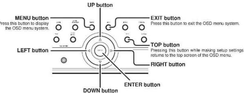
text_image
UP button MENU button Press this button to display the OSD menu system. LEFT button DOWN button EXIT button Press this button to exit the OSD menu system. TOP button Pressing this button while making setup settings returns to the top screen of the OSD menu. RIGHT button ENTER buttonNote:
- After you complete this portion of the setup, move cursor to "RETURN" with the ▲, ▼, ◀ and ▶ cursor buttons and press the ENTER button.
- Press the TOP button on this unit to return to the top screen of the main menu while setting setup items.
ENGLISH
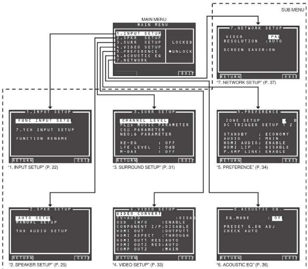
flowchart
graph TD
    A["MAIN MENU MAIN MENU"] --> B["1. INPUT SETUP\nFUNC INPUT SETUP\n7.1CH INPUT SETUP\nFUNCTION RENAME"]
    A --> C["3. Surr Setup\nCHANNEL LEVEL\nPLNX MUSIC PARAMETER\nCSU PARAMETER\nNEO:6 PARAMETER\nRE-EQ : OFF\nLFE LEVEL : 0dB\nM-DAX : OFF"]
    A --> D["5. Preference\nZONE SETUP : B\nDC TRIGGER SETUP 1 2\nSTANDBY : ECONOMY\nAUDIO : MAIN\nHDMI AUDIO : ENABLE\nHDMI LIP : DISABLE\nP.AMP LINK : ENABLE"]
    A --> E["6. Acoustic EQ\nEQ.MODE : OF\nPRESET G.EQ ADJ\nCHECK AUTO"]
    B --> F[""1. INPUT SETUP" (P. 22)"]
    C --> G[""3. SURROUND SETUP" (P. 31)"]
    D --> H[""5. Preference" (P. 34)"]
    E --> I[""6. Acoustic EQ" (P. 36)"]
    F --> J["2. SPKR SETUP\nAUTO SETUP\nMANUAL SETUP\nTHX AUDIO SETUP"]
    G --> K["4. VIDEO SETUP\nVIDEO CONVERT\nTV-AUTO : DISAB\nOSD INFO : ENABLE\nCOMPONENT I/P: DISABLE\nHDMI OUT : OUTPUT1\nHDMI ASPECT : THROUGH\nHDMI OUT1 RES:AUTO\nHDMI OUT2 RES:AUTO\nCOMP OUT2 : MAIN"]
    H --> L[""5. Preference" (P. 34)"]
    I --> M[""6. Acoustic EQ" (P. 36)"]
    J --> N[""2. SPEAKER SETUP" (P. 25)"]
    K --> O[""4. VIDEO SETUP" (P. 33)"]
    L --> P[""5. Preference" (P. 34)"]
    M --> Q[""6. Acoustic EQ" (P. 36)"]
    N --> R["7. NETWORK SETUP\nVIDEO : PAI\nRESOLUTION : AUTO\nSCREEN SAVER:ON"]
    O --> S[""7. NETWORK SETUP" (P. 37)"]
    P --> T[""7. NETWORK SETUP" (P. 37)"]
    Q --> U[""7. NETWORK SETUP" (P. 37)"]
    R --> V[""7. NETWORK SETUP" (P. 37)"]
    S --> W[""7. NETWORK SETUP" (P. 37)"]
    T --> X[""7. NETWORK SETUP" (P. 37)"]
    U --> Y[""7. NETWORK SETUP" (P. 37)"]
    V --> Z[""7. NETWORK SETUP" (P. 37)"]
    W --> AA[""7. NETWORK SETUP" (P. 37)"]
    X --> AB[""7. NETWORK SETUP" (P. 37)"]
    Y --> AC[""7. NETWORK SETUP" (P. 37)"]
ENGLISH
1 INPUT SETUP
This menu is for setting the matching the output of connected audio devices and the input jacks of this unit.
• FUNC INPUT SETUP :
"1-1 FUNC INPUT SETUP" (see page 23)
- 7.1 CH INPUT SETUP
"1-2 7.1 CH INPUT SETUP" (see page 23)
• FUNC RENAME
"1-3 FUNCTION RENAME" (see page 24)
- Select "1. INPUT SETUP" from the MAIN MENU with ▲ or ▼ cursor button, and press the ENTER button.

- Select the desired sub-menu with the ▲ or ▼ cursor buttons, and press the ENTER button.

flowchart
graph TD
    A["1. INPUT SETUP"] --> B["FUNC INPUT SETUP 1"]
    A --> C["7.1CH INPUT SETUP FUNCTION RENAME"]
    B --> D["RETURN: NEXT EXIT"]
    C --> E["RETURN: EXIT"]
    D --> F["P. 23"]
    E --> G["P. 24"]
    F --> H["FUNC INPUT SETUP 2"]
    H --> I["TAFE AUTO - - - TAPE AUTO - - - CA/RC AUTO - - - AUX AUTO - - -"]
    I --> J["RETURN: EXIT"]
    G --> K["FUNC INPUT SETUP 3"]
    K --> L["RETURN: NEXT EXIT"]
    K --> M["RETURN: EXIT"]
    style A fill:#000,stroke:#fff,color:#fff
    style B fill:#000,stroke:#fff,color:#fff
    style C fill:#000,stroke:#fff,color:#fff
    style D fill:#000,stroke:#fff,color:#fff
    style E fill:#000,stroke:#fff,color:#fff
    style F fill:#000,stroke:#fff,color:#fff
    style G fill:#000,stroke:#fff,color:#fff
    style H fill:#000,stroke:#fff,color:#fff
    style I fill:#000,stroke:#fff,color:#fff
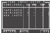
1-1 FUNC INPUT SETUP
(ASSIGNABLE DIGITAL INPUT)
The 6 digital inputs can be assigned to a desired source.
HDMI and COMPONENT inputs can be assigned to the preferred source.
Use this menu to select which digital input jacks are to be assigned to which input source.
- Select "FUNC INPUT SETUP" from the 1.INPUT SETUP menu with the ▲ or ▼ cursor buttons and press the ENTER button.
- Select a setting with the ▲, ▼, ◀, and ▶ cursor buttons, and assign a mode and input jack (DIG, HDMI, COMP, V/S).
MODE
AUTO:
Select "AUTO", for automatic detection of the digital input signal condition.
If there is no digital signal, but there is an analog signal present, the analog signal will be played. "AUTO" is the initial setting of all input sources.
HDMI:
Select "HDMI", when only a HDMI signal will be used.
DIG:
Select "DIG", when only a digital signal will be used.
ANA:
Select "ANA" for input sources for which no digital input jacks are used.
DIG
The 6 digital inputs can be assigned to a desired source.
Assign the number of a digital input jack to the device.
HDMI
Assign the number of an HDMI input jack to the device.
Note:
- When FUNCTION MODE is set to HDMI and HDMI AUDIO of "5. PREFERENCE" is set to THROUGH, audio is not output from the unit. (See page 34)
COMP
Assign the number of a component video input jack to the device.
V/S
Assign the number of a composite video and S-video Input jack to the device.
Note:
• Video and S-video can use the same numbers when assigning to input functions.
3.
-
Select each mode setting and input terminal with the ◀ or ▶ cursor buttons.
-
Press the ENTER button.
-
Repeat steps 2-5 until all items are set.
-
After you complete this portion of the setup, move the cursor to "NEXT" with the ▲, ▼, ◀, and ▶ cursor buttons and then press the ENTER button to go to the next page.
- Repeat steps 2-5 until all items are set.
After you complete this portion of the setup, move the cursor to "RETURN" with ▲, ▼, ◀, and ▶ cursor buttons and press the ENTER button. To return to the Func Input Setup 1 menu from the Func Input Setup 2 menu, move the cursor to "BACK" with the ▲, ▼, ◀, and ▶ cursor buttons and press the ENTER button. Move the cursor to "RETURN" with the ▲, ▼, ◀, and ▶ cursor buttons, and press the ENTER button to go to the 1 INPUT SETUP menu.
Note:
- Assignments cannot be made in sections with a mark.
1-2 7.1 CH INPUT SETUP
This menu is for adjusting the speaker levels for 7.1-channel input sources.
Here you will adjust the volume for each channel so that they are all heard by the listener at the same level.
- Select "7.1 CH INPUT SETUP" from the 1.INPUT SETUP menu with the ▲ or ▼ cursor buttons and press the ENTER button.

-
Select "VIDEO-IN" with the ▲ or ▼ cursor buttons.
-
Using the ◀ or ▶ cursor buttons, select the video input source to be played through the MONITOR OUT jack.
The input source is switched by pressing the ◀ or ▶ cursor buttons as follows;
LAST ↔ TV ↔ DVD ↔ VCR1 ↔ DSS ↔ NET ↔ TAPE ↔ CD/R ↔ AUX ↔ V-OFF ↔ LAST ↔ ...
Notes:
- When "LAST" is selected, the source is set to the source selected before the 7.1 ch input menu was activated.
- When "V-OFF" is selected, no signal is emitted from MONITOR OUT jack.
ENGLISH
- Select desired channel with the ▲ or ▼ cursor buttons.
- Using the ◀ or ▶ cursor buttons, adjust the volume level of each channel.
Move the cursor to "RETURN" with the ▲, ▼, ◀, and ▶ cursor buttons, and press the ENTER button to go to the 1. INPUT SETUP menu.
Note:
- The volume level can be set between -12 dB and +12 dB in 1 dB increments on all channels except the subwoofer (SUB W), which can be set from -18dB to +12 dB in 1 dB increments.
ENGLISH
1-3 FUNCTION RENAME
Input sources can be registered under any name. This menu is for renaming input source.
This menu is for renaming function name. Names can be up to 10 characters long, including spaces. (Characters are selected from those appearing on the display.) This name appears on the unit's FL display and the OSD, but it does not appear in the OSD Setup menu.
- Select "FUNCTION RENAME" from the 1 INPUT SETUP menu with the ▲ or ▼ cursor buttons and press the ENTER button.

- Select "FUNCTION" with the ▲ or ▼ cursor buttons.
- Select an input source with the ◀ or ▶ cursor buttons.
- Select "RENAME" with the ▲or ▼ cursor buttons.
- Move the cursor to the character (1st to 10th) to change with the ◀ or ▶ cursor buttons.
- Move the cursor to the character list with the▼ cursor button. (Move the cursor to the letter "A" to begin with.)
- Select a character with the ▲, ▼, ◀, and ▶ cursor buttons.
-
Press the ENTER button to enter the selected letter.
-
Repeat steps 5-8 until the new name is input.
BACK:
Deletes the character left of the cursor in the "RENAME" area one character at a time.
DEFAULT:
Restores the name in the "RENAME" area to the name in the "FUNCTION" area.
SPACE:
Inserts a space at the cursor point of the "RENAME" area.
Note:
- RENAME cannot be left blank.
Move the cursor to "RETURN" with the ▲, ▼, ◀, and ▶ cursor buttons and press the ENTER button to go to the 1. INPUT SETUP menu.
2 SPKR (SPEAKER) SETUP
After you have installed the unit connected all the components and determined the speaker layout, it is now time to perform the settings in the Speaker Setup menu for the optimum sound acoustics for your environment and speaker layout.
Before you perform the following settings, it is important that you first determine the following
Important that you first determine the following characteristics:
• AUTO SETUP
"2-1 AUTO SETUP (MultEQ Setup)" (see page 26)
• MANUAL SETUP
"2-2 MANUAL SETUP" (see page 29)
• THX AUDIO SETUP:
"2-3 THX AUDIO SETUP" (see page 30)
- Select "2.SPKR SETUP" from the MAIN MENU with ▲ or ▼ cursor buttons and press the ENTER button.
- Select the desired menu with the ▲ or ▼ cursor buttons, and press the ENTER button.
After you complete this the portion of the setup, press the ▲, ▼, ◀, and ▶ cursor button. The cursor will move to "RETURN" and press the ENTER button to go to the Sub-menu.

flowchart
graph TD
    A["2. SPKR SETUP\nAUTO SETUP\nMANUAL SETUP\nTHX AUDIO SETUP"] --> B["P. 26"]
    A --> C["P. 29"]
    A --> D["P. 30"]
    B --> E["AUTO SETUP\nAUTO SETUP: START\nMAIN ZONE\nSURR BACK: 2CH"]
    C --> F["AUTO SETUP\nNOW ANALYZING!!\nCANCEL"]
    D --> G["AUTO SETUP\nBOUNDARY GAIN COMP\nTHX ULTRAZ SUB-W:165\nB.G.C.: 10K\nADVANCED SPKR ARRAY\nSURR.B SPKR:\TOSEHER"]
    E --> H["AUTO SETUP\nSPEAKERS CHECK:--\n1st MIC POSITION\nNON ANALYZING !!\nCANCEL"]
    F --> I["SPEAKER SIZE\nTHX SPKR: YES\nSUB W: YES\nFRONT: SMALL\nCENTER: SMALL\nSUBR.: SMALL\nSURR.B: 2CH\nSURR.B SIZE: SMALL\nLPI/UPF: 80Hz\nBASS MIX: MIX"]
    G --> J["SPEAKER DISTANCE\nUNIT: 0\nFRONT L: 3.05 m\nCENTER: 3.05 m\nFRONT R: 3.05 m\nSUBR.B: 3.05 m\nSURR.B R: 3.05 m\nSUBR.B L: 3.05 m\nSUB R.L: 3.05 m\nSUB W: 3.05 m"]
    H --> K["AUTO SETUP\nSPEAKERS CHECK:OK\n2nd MIC POSITION!!\nSTART\nCHECK\nCALCULATE"]
    I --> L["SPEAKER LEVEL\nTEST MODE: MANUAL\nFRONT L: 0.0dB\nCENTER: 0.0dB\nFRONT R: 0.0dB\nSURR.R: 0.0dB\nSURR.B R: 0.0dB\nSURR.B L: 0.0dB\nSUB R.L: 0.0dB\nSUB W: 0.0dB"]
    J --> M["SPEAKER RESULT\nCHECK RESULT\nSPEAKERS CHECK:SPEAKERS SIZE\nDISTANCE\nCHANNEL LEVEL\nCROSSVER FREE\nSTORE"]
    K --> N["SPEAKER LEVEL\nTEST MODE: MANUAL\nFRONT L: 0.0dB\nCENTER: 0.0dB\nFRONT R: 0.0dB\nSURR.R: 0.0dB\nSURR.B R: 0.0dB\nSURR.B L: 0.0dB\nSUB R.L: 0.0dB\nSUB W: 0.0dB"]
    L --> O["SPEAKER LEVEL\nTEST MODE: MANUAL\nFRONT L: 0.0dB\nCENTER: 0.0dB\nFRONT R: 0.0dB\nSURR.R: 0.0dB\nSURR.B R: 0.0dB\nSURR.B L: 0.0dB\nSUB R.L: 0.0dB\nSUB W: 0.0dB"]
    M --> P["SPEAKER LEVEL\nTEST MODE: MANUAL\nFRONT L: 0.0dB\nCENTER: 0.0dB\nFRONT R: 0.0dB\nSURR.R: 0.0dB\nSURR.B R: 0.0dB\nSURR.B L: 0.0dB\nSUB R.L: 0.0dB\nSUB W: 0.0dB"]
ENGLISH
ENGLISH
2-1 AUTO SETUP (MultEQ™ SETUP)
The AUTO SETUP (MultEQ™ Setup) feature of the unit measures sound characteristics of the speaker system and room where the unit is used and automatically optimizes settings.
The Audyssey MultEQ™ technology adopted by this unit provides the best listening environment for multiple listeners.
To do this, the AUTO SETUP feature measures a test tone emitted by each channel in a maximum of 6 listening positions, using the supplied microphone. The measurement results are analyzed using an original algorithm and environmental settings are made to improve the sound characteristics of the listening area.
To set up the speaker system (i.e., adjusting speaker distance, etc.) without using the AUTO SETUP feature, see "MANUAL SETUP" on page 29 of the manual.
HOW TO PERFORM AUTO SETUP
During measurement, the OSD menu displays the condition, therefore turn power to the monitor on.
- Connect the speakers, power amp of a MM8003 or other amp to this unit and place the speakers in suitable locations.
- Connect the supplied microphone to the MIC jack on the unit.
- Set the microphone in the listening position.
natural_image
Diagram of a person sitting in a chair inside a room with equipment and floating objects (no text or symbols)Notes:
• Measurement can be done in a maximum of 6 listening positions.
For the first measurement, set the microphone in the main listening position.
- Use a stand or tripod to position the microphone at ear height in the listening position.
- Remove any obstructions between the speakers and microphone.
- To use the internal subwoofer of the amp, set the volume to the middle point and set the crossover frequency to the highest.
- During measurement, step away from the microphone and operate the unit via the remote controller from a position that is out of the path of the speaker sound.
- The test tone output from the speakers during measurement is loud. Be mindful of neighbors and watch out for small children.
-
Select "2. SPKR SETUP" from the MAIN MENU, select "AUTO SETUP" with the ▲/▼ cursor buttons, and press the ENTER button to display the start screen.
-
Select the number of channels for the surround back speaker you are using.
For a 5.1 channel speaker system, select "NON" (Surround Back speaker off). (To use speaker C or zone speaker, select "NON". See page 18, 35.)
Select "START" with the ▲▼ cursor buttons and press the ENTER button to start measurement.

6. 1 st Position Check
During the fi rst position check, the following screen is displayed as the unit checks background noise in the listening room, presence of speakers, and speaker polarity and measures the acoustical characteristics in the fi rst position where the microphone is set up.
Note:
- The detection check measures the state of use of all speakers whether actually used or not. For example, if the center speaker is not used, the test tone will require time to go from the L-channel to the R-channel, therefore be careful not to unplug the microphone or operate this unit during this time.
- When the 1st Position Check ends, the following OSD appears on the display.
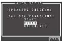
Here, to view the results of the detection check, select "CHECK" with the ▲▼ cursor buttons and press the ENTER button. The results will be displayed.
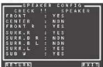
If the check results indicate an error, take suitable action with that item and remeasure. (For error messages, see "ERROR MESSAGES" on page 28.)
After confirming the check results, select
"RETURN" with the ▲▼ cursor buttons and press the ENTER button to return to the OSD menu.
At this point, you can select "EXIT" to end Auto Setup and return to "2. SPKR SETUP".
Note:
- AUTO SETUP is not available in Pure Direct, Source Direct, or 7.1 Channel Input modes.
- Move the microphone to the second listening position, select "START" with the ▲▼ cursor buttons and press the ENTER button to measure the second point. At this point, you can cancel second point measurement and calculate measurement results by selecting "CALCULATE" and pressing the ENTER button.
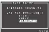
- Repeat steps 7 until measuring 6 points between the main listening position and surrounding positions.
When all measurements end, the following OSD appears on the display.

Select "CALCULATE" with the ▲/▼ cursor buttons and press the ENTER button to calculate measurement results. During calculations, the following OSD appears on the display.

Note:
- Less than 6 positions can be measured, but it is recommended to measure in all 6 positions in order to obtain the best results.
- The time needed to complete calculations depends on the number of connected speakers and measured listening positions. The more speakers and listening positions, the more time is needed.
10. Checking Measurement Results
When calculations for the measurement results end, a screen appears for confirming the calculation results.

Select items to check with the ▲▼ cursor buttons and press the ENTER button to enter them.
Note:
To check equalizer (MultFQ) parameters, see page 37.
[Example] Confirmation screen for speaker detection
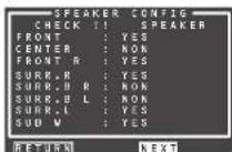
[Example] Confirmation screen for the distance from speakers to the listening position
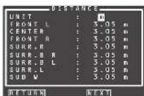
The units can be changed by moving the cursor to [ft] of UNIT and pressing ◀/▶ the cursor buttons. Each time a ◀/▶ cursor button is pressed, the units alternate between [ft] (feet) and [m] (meters).
[Example] Confirmation screen for speaker size and crossover frequency
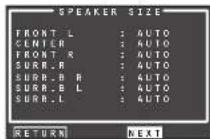

* AUTO is displayed to indicate that the speaker size and crossover frequency results were automatically measured.
11. Storing Measurement Results in Memory
Once finished confirming the measurement results, select "RETURN" with the ▲▼ cursor buttons and press the ENTER button to display the CHECK RESULT screen.


Place the cursor on "STORE" and press the ENTER button to store all parameters including the equalizer parameters in memory. If not wanting to store the calculation results in memory, place the cursor on "EXIT" and press the ENTER button.
Note:
Pressing "EXIT" prior to pressing "STORE" erases all measurement results and calculation results, therefore operate the remote controller with cure.
When storing operations end, the following OSD appears on the display.

Notes:
- Do not turn the power to the unit off while storing parameters in memory. This may erase all data in the unit's memory and may damage the unit.
- Please set any THX Certified speakers manually to "Small" and the crossover "80 Hz" after Auto setup operation.
ENGLISH
ERROR MESSAGES
| Displayed Error Cause How to Remedy | |||
MIC SET ERROR!! | • The microphone is not properly connected. • Connect the included microphone.• Check the microphone connection. | ||
NOISE ERROR!!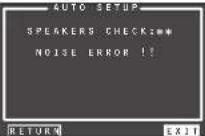 | • There is too much noise in the listening room to measure properly.• Volume from the speakers is low. | • During measurement, turn off devices that make noise such as air conditioners.• Measure at a time when the surrounding area is quiet. | |
ANALYZE ERROR!! * Under ANALYZE ERROR, select “NEXT” with the ▲▼ cursor buttons and press the ENTER button. A detail screen like the following appears on the display. * Under ANALYZE ERROR, select “NEXT” with the ▲▼ cursor buttons and press the ENTER button. A detail screen like the following appears on the display. | • The speakers required for suitable playback were not detected.• Speaker polarity is connected backwards.In the examples at left, the following trouble is detected.• The polarity of the left and right channels of the front speakers is backwards ([REV] appears on the display.)• The surround speaker is not connected ([NON] is displayed), but the surround back speaker is connected(In this kind of situation, [ERR] is displayed for all surround and surround back speakers.)An error is indicated in addition to the above if the speakers are connected as follows.• When using just one surround back speaker, but it is connected to the surround back R-channel(To use just one surround back speaker, connect it to the L-channel.) | • Check the speaker that is indicated as having reversed polarity ([REV] can appear with some speakers even when properly connected. In such case, ignore the error indication.)• Check speaker direction and layout | |
2-2 MANUAL SETUP
- Select "2. SPKR SETUP" from the MAIN MENU.
- Select "MANUAL SETUP" with the ▲or ▼ cursor buttons.
- Press the ENTER button to enter the selection.

When setting the speaker size in the SPEAKER SIZE menu, use the guidelines below.
LARGE:
The complete frequency range for the channel you are setting will be output from the speaker.
SMALL:
Frequencies of the channel you are setting that are lower than approx. 80 Hz will be output from the subwoofer.
If the SUB. W is set to "NONE" and the front speakers are set to "LARGE," then the sound will be output from both the left and right speakers.
- Select each speaker with the ▲ or ▼ cursor buttons.
- Set the size of each speaker with the ◀ or ▶ cursor buttons.
- After you complete this portion of the setup, move the cursor to "NEXT" with the ▲, ▼, ◀ and ▶ cursor buttons and press the ENTER button to go to the next page.
THX SPKR
If you are using a full THX speaker systems which are approved by THX Ltd:
- The front, center and surround speaker size should be "SMALL".
• The subwoofer should be "YES".
- LPF/HPF (the crossover frequency) should be "80Hz".
You need to set the number of surround back speakers and the surround back speaker size should be "SMALL".
Note:
- When making settings for all channels manually, set THX SPKR to "NO."
SUB W
YES:
Select when a subwoofer is connected.
NO:
Select when a subwoofer is not connected.
FRONT
LARGE:
Select if the front speakers are large.
SMALL:
Select if the front speakers are small.
- If "NO" is selected for the subwoofer setting, then this setting is fixed at "LARGE".
CENTER
NONE:
Select if no center speaker is connected.
LARGE:
Select if the center speaker is large.
SMALL:
Select if the center speaker is small.
SURR.
NONE:
Select if no surround left and right speakers are connected.
LARGE:
Select if the surround left and right speakers are large.
SMALL:
Select if the surround left and right speakers are small.
SURR. B
NONE:
Select if no surround back left and right speakers are connected.
1CH:
Select if one surround back speaker is connected. In this case, the audio signal is emitted from the SURR BACK LEFT output terminal.
2CH:
Select if the surround back left and right speakers are connected.
ZSP A:
Select if using the SURROUND BACK output terminal as Zone Speaker A.
ZSP B:
Select if using the SURROUND BACK output terminal as Zone Speaker B.
Notes:
- If "NONE" is selected for the SURR. setting, then this setting is fixed to "NONE."
SURR. BACK SIZE
LARGE:
Select if the surround back speakers are large.
SMALL:
Select if the surround back speakers are small.
Note:
- If "NONE" is selected for the SURR. setting, then this setting is not available.
LPF/HPF
When you use a subwoofer, you can select the cutoff frequency for the small speakers used. Select one of the crossover frequency levels according to the size of the small speakers connected.
60Hz → 80Hz → 100Hz → 120Hz → 140Hz → 160Hz → 180Hz
Note:
- If using small front speakers, set a slightly higher frequency. If using large front speakers, set a slightly lower frequency.
BASS MIX
- The bass mix setting is only valid when "LARGE" is set for the front speakers and "YES" is set for the subwoofer during stereo playback.
This setting has effect only during playback of PCM or analog stereo sources. - When "BOTH" is selected, the low frequencies will be played through the main L&R speakers and the subwoofer.
In this playback mode, the low frequency range expands more uniformly throughout the room, but depending on the size and shape of the room, interference may result in a decrease of the actual volume of the low frequency range. - By selecting "MIX", the low frequencies will play through the main L&R only. This selection is preferred by THX.
Note:
- LFE signals during playback of Dolby Digital or DTS will be played through the subwoofer.
- After you complete this portion of the setup, move the cursor to 'NEXT' with the ▲, ▼, ◀ and ▶ cursor buttons and press the ENTER button to go to the next page.
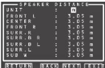
Use this menu to specify the distance of each speaker's position from the listening position. The delay time is automatically calculated according to these distances.
Begin by determining the ideal or most commonly used seating position in the room.
This is important for the timing of the acoustics to create the proper sound space that the unit and today's sound systems are able to produce.
Note:
- For speakers for which you have selected “NONE”, the speaker configuration sub-menu will not appear here. (There are several useful books and special DVD and LD’s available to guide you through proper home theater configuration. If you are unsure, have your Marantz dealer perform the installation for you. They are trained professionals familiar with even the most sophisticated custom installations. Marantz recommends the www.cedia.org website for further information.)
-
Select either m (meters) or ft (feet) for UNIT with the ◀ or ▶ cursor buttons.
-
Select each speaker with the ▲ or ▼ cursor buttons.
-
Set the distance for each speaker, press the ◀ or ▶ cursor buttons.
FRONT L:
Set the distance from the front left speaker to your normal listening position.
CENTER:
Set the distance from the center speaker to your normal listening position.
FRONT R:
Set the distance from the front right speaker to your normal listening position.
SURR. L:
Set the distance from the surround left speaker to your normal listening position.
SURR. R:
Set the distance from the surround right speaker to your normal listening position.
ENGLISH
SUB W:
Set the distance from the subwoofer to your normal listening position.
SURR. B L:
Set the distance from the surround back left speaker to your normal listening position.
SURR. B R:
Set the distance from the surround back right speaker to your normal listening position.
Notes:
- Set the distance to each speaker in meters (m) or feet (ft) as follows.
m: 0.03 - 9.15 m in 0.03 m steps
ft: 0.1 - 30.0 ft in 0.1 ft steps
(The values appearing on the FL display are approximate.)
- For the speakers that you have selected "NONE" the speaker size menu will not appear.
- The setting for surr.back I, and surr.back R appears if it is set, two surround back speakers in the SPEAKER SIZE menu.
- The setting of SURR. BACK appears if it is set for one surround back speaker in the SPEAKER SIZE menu.
11
- After you complete this portion of the setup, move the cursor to "NEXT" with the ▲, ▼, ◀ and ▶ cursor buttons and press the ENTER button to go to the next page.

Here you can set the volume for each speaker so that they are all heard by the listener at the same level. We recommend holding a dB SPL (Sound Pressure Level) meter at the listening position, at arms length, and pointing straight up at the ceiling, adjust the level of each speaker in turn unit it reads 75dB SPL when the meter is set to "C" weighting and Slow response.
Note:
The speaker level settings are not available in 7.1 Channel Input mode, Pure Direct mode and Source Direct mode.
TEST MODE:
Select "MANUAL" or "AUTO" generation of the test tone with the ◀ or ▶ cursor buttons.
If you select "AUTO", the test tone will be cycled through in a circular pattern beginning at Left → Center → Right → Surround Right → Surround Back Right → Surround Back Left → Surround Left → Subwoofer → Left, in 2 seconds increments for each channel.
Using the ◀ or ▶ cursor buttons, adjust the volume level of the noise from the speaker so that it is the same level for all the speakers.
If you select "MANUAL", adjust the output level of each speaker as listed below.
- Move the cursor to FRONT L by pressing the ▼ cursor button. This unit will emit a pink noise from the front left speaker.
Remember the level of this noise and then press the ▼ cursor button.
(Note that this can be adjusted to any level between -12 and +12 dB in 0.5 dB increments.) This unit will now emit the pink noise from the center speaker.
-
Using the ◀ and ▶ cursor buttons, adjust the volume level of the noise from the center speaker so that it is the same level as the front left speaker.
-
Press the ▼ cursor button again. This unit will now emit the pink noise from the front right speaker.
-
Repeat steps 13 and 14 for the front right and other speakers until all speakers are adjusted to the same volume level.
After you complete this portion of the setup, press the ENTER button to move the cursor to "RETURN". Press the ENTER button to go to "2. SPKR SETUP".
Notes:
- Speakers for which you selected "NONE" in the SPEAKER SIZE menu will not appear.
- Surr. Back L and Surr. Back R appear if it is set for two surround back speakers in the SPEAKER SIZE menu.
- Surr. Back appears if it is set for one surround back speaker in the SPEAKER SIZE menu.
• To adjust the speaker levels for 7.1 channel input sources, you will need to use the 7.1 Ch Input sub menu. (See page 23)
- SUB W can be set from -18dB to +12dB.
2-3 THX AUDIO SETUP
You can set the advanced Speaker Array.
-
Select "2. SPEAKER SETUP" from the MAIN MENU.
-
Select "THX AUDIO SETUP" with the ▲ or ▼ cursor buttons.
-
Press the ENTER button to enter the selection.
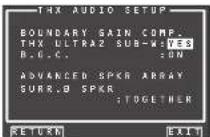
Boundary Gain Compensation
THX ULTRA2 SUB-W : YES or NO
If you have a THX Ultra2 certified subwoofer (or other subwoofer with flat anechoic response to 20Hz), select "YES".
If set to "YES", you can chose to activate B.G.C. (Boundary Gain Compensation).
If set to "NO", Boundary Gain Compensation may not be activated and the feature is locked out.
B.G.C.: ON or OFF
Set to ON when you feel too much bass is being output.
OFF: Boundary Gain Compensation is not applied. ON: Boundary Gain Compensation is applied.
Notes:
- If you set SUB W = NO in SPEAKER SIZE menu, Boundary Gain Compensation will not be activated. THX ULTRA2 SUB-W also cannot be set.
- If you set THX ULTRA2 SUB-W = YES, the Bass Peak Level setting is not applied.
Advanced Speaker Array (ASA)
SURR.B SPKR: TOGETHER, CLOSE or APART
The best ASA effect is when the surround back speakers are together and facing forward. If the distance between the surround back speakers is,
• Less than 30 cm (12 in.): TOGETHER
- Greater than 30 cm (12 in.), and less than 48 in. (122 cm): CLOSE
• Greater than 122 cm (48 in.): APART
Speaker type and positioning
This diagram shows the desired positioning for 7.1 channel speaker systems used in ASA mode. During system setup, select the distance between surround back speakers.

text_image
Front-L Center Front-R Surround-L Surround-A Surround-R Surround-A Surround-R Surround Back L R Surround-B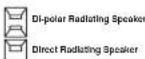
Notes:
- The Advanced Speaker Array setting cannot be made when using the Zone Speaker function or when ON is set for SPEAKER C on the rear panel of this unit.
- If you set Surr.B = NONE, 1CH, ZSPA or ZSP B in the SPEAKER SIZE menu, Advanced Speaker Array will not be activated.
After you complete this portion of the setup, move the cursor to "RETURN" with ▲, ▼, ◀ and ▶ cursor buttons and press ENTER button to go to the 2. SPKR SETUP menu.
3 SURROUND SETUP
This menu is for setting surround effect parameters for the various surround input signals so as to bring out the live audio effect of your speaker system.
• CHANNEL LEVEL:
"3-1 CHANNEL LEVEL" (see page 31)
- PLIX MUSIC PARAMETER:
-3-2 PL1x MUSIC PARAMETER page 32)
• CSII PARAMETER:
*3-3 PARAMETER*(see page 32)
- NEO:6 PARAMETER
"3-4 NEO:6 PARAMETER" (see page 32)
-
Select "3. SURR SETUP" from the MAIN MENU with the ▲ or ▼ cursor buttons and press the ENTER button.
-
Select the desired menu with the ▲ or ▼ cursor buttons and press the ENTER button.

RE-EQ:
Turns THX Cinema Re-EQ™ on and off.
Select the Cinema Re-EQ™ with the ◀ or ▶ cursor button to activate it.
LFE LEVEL:
Select the output level of the LFE signal included in
the Dolby Digital signal or the DTS signal.
Select "0dB", "-10 dB" or "OFF" with ◀ or ▶ cursor button.
M-DAX:
Select the desired M-DAX mode.
Select "HIGH", "LOW" or "OFF" with the ◀ or ▶ cursor button. (See page 39)
After you complete this portion of the setup, move the cursor to "RETURN" with the ▲, ▼ cursor buttons and press the ENTER button.
Note:
- Some settings cannot be made depending on Pure Direct, Source Direct, and the selected surround mode.

flowchart
graph TD
    A["3.SURK SETUP"] --> B["CHANNEL LEVEL"]
    A --> C["CSU PARAMETER"]
    A --> D["NEO & PARAMETER"]
    B --> E["RE-EQ : OFF"]
    B --> F["LIE LEVEL : 0 dB"]
    B --> G["X-BAX : OFF"]
    C --> H["EXIT"]
    D --> I["EXIT"]
    E --> J["P.31"]
    F --> K["P.32"]
    G --> L["P.32"]
    H --> M["P.32"]
    I --> N["P.32"]
    J --> O["RETURN: EXIT"]
    K --> P["RETURN: EXIT"]
    L --> Q["RETURN: EXIT"]
    M --> R["RETURN: EXIT"]
    N --> S["RETURN: EXIT"]
    O --> T["RETURN: EXIT"]
    P --> U["RETURN: EXIT"]
    Q --> V["RETURN: EXIT"]
    R --> W["RETURN: EXIT"]
    S --> X["RETURN: EXIT"]
    T --> Y["RETURN: EXIT"]
    U --> Z["RETURN: EXIT"]
    V --> AA["RETURN: EXIT"]
    W --> AB["RETURN: EXIT"]
    X --> AC["RETURN: EXIT"]
    Y --> AD["RETURN: EXIT"]
    Z --> AE["RETURN: EXIT"]
ENGLISH
3-1 CHANNEL LEVEL
-
Select "3. SURR SETUP" from MAIN MENU with ▲ or ▼ cursor buttons and press the ENTER button.
-
Select "CHANNEL LEVEL" with the ▲ or ▼ cursor buttons and press the ENTER button.
-
Sel the SURR. MODE with the ◀ or ▶ cursor buttons.
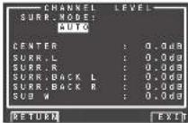
- Select the desired menu item with the ▲ or ▼ cursor buttons, set the desired level with the ◀ or ▶ cursor buttons, and press the ENTER button.
SURROUND MODE:
The surround mode can be independently set for 3 modes.
- Multi Ch STEREO
2.CSII
- Others
CHANNEL LEVEL
CENTER LEVEL:
Set the effect level of the center speaker between -12 and +12 level in 0.5 level interval.
- If "NONE" was selected for the center speaker setting in the SPEAKER SIZE, then this setting will not appear.
SURR L or R LEVEL:
Set the effect level of the Surround speaker between -12 and +12 level in 0.5 level interval.
- If "NONE" was selected for the surround speakers setting in the SPEAKER SIZE, then this setting will not appear.
Set the effect level of the Surround Back speaker between -12 and +12 level in 0.5 level interval.
- If "NONE" was selected for the surround back speakers setting in the SPEAKER SIZE, then this setting will not appear.
ENGLISH
SUB W LEVEL:
Set the effect level of the subwoofer speaker between -18 and +12 level in 0.5 level interval.
If "NONE" was selected for the subwoofer speaker setting in the SPEAKER SIZE, then this setting will not appear.
Note:
Setting to a mode other than multichannel stereo or CSII will affect the speaker level as explained in "2-2 MANUAL SETUP".
After you complete this portion of the setup, move the cursor to "RETURN" with the ▲, ▼, ◀ and ▶ cursor buttons and press the ENTER button to go to the 3. SURR SETUP menu.
3-2. PLⅡx (PRO LOGIC Ⅱx) MUSIC PARAMETER
Pro Logicix-Music mode creates a rich and enveloping surround ambience from stereo sources such as CDs.
In this mode, this unit includes three controls to fi netune the sound fi eld as follows.
-
Select "3. SURR SETUP" in MAIN MENU with ▲ or ▼ cursor buttons and press the ENTER button.
-
Select "PILx MUSIC PARAMETER" with the ▲ or ▼ cursor buttons.
-
Press the ENTER button to enter the selection.

PARAMETER:
Select "DEFAULT" or "CUSTOM" with the ◀ or ▶ cursor buttons.
If you select "CUSTOM", you can adjust three parameters as listed below.
PANORAMA:
Select the PANORAMA mode "ON" or "OFF" with the ◀ or ▶ cursor buttons.
Panorama wraps the sound of the front left and right speakers around you, for an exciting perspective.
DIMENSION:
Set the DIMENSION level between -3 and +3 level in 1 level intervals with the ◀ or ▶ cursor buttons. Adjust the sound fi eld either towards the front or towards the rear.
This can be useful to help achieve a more suitable balance from all the speakers with certain recordings.
CENTER WIDTH:
Set the CENTER WIDTH level between 0 and 7 in 1 level intervals with the ◀ or ▶ cursor buttons. Center width allows you to gradually spread the center channel sound into the front left and right speakers.
At its widest setting, all the sound from the center is mixed into the left and right speakers.
This control may help achieve a more spacious sound or a better blend for the front image.
If "NONE" was selected for the center speaker setting in the SPEAKER SIZE menu, this setting cannot be selected.
After you complete this portion of the setup, move cursor to "RETURN" with the ▲, ▼, ◀ and ▶ cursor buttons and press the ENTER button.
3-3 CSII PARAMETER
-
Select "3. SURROUND SETUP" from MAIN MENU with the ▲ or ▼ cursor buttons and press the ENTER button.
-
Select "CSI PARAMETER" with the ▲ or ▼ cursor buttons.
-
Press the ENTER button to enter the selection.

TRUBASS:
Set the TRUBASS level between 0 and 6 in 1-level increments with the ◀ or ▶ cursor buttons.
TRUBASS produced by the speakers are an octave below the actual physical capabilities of the speakers adding exciting, deeper bass effects.
SRS DIALOG:
Set the SRS DIALOG level between 0 and 6 in 1-increments with the ◀ or ▶ cursor buttons.
This can be popped out of the surround audio effects, allowing the listener to easily discern what the actors say.
If "NONE" was selected for the center speaker setting in the SPEAKER SIZE menu, this setting cannot be selected.
After you complete this portion of the setup, move cursor to "RETURN" with the ▲, ▼, ◀ and ▶ cursor buttons and press the ENTER button.
Note:
• This parameter can only be set in the CSII mode.
3-4 NEO:6 PARAMETER
The DTS NEO:6 mode enables a maximum 6.1 channel output with just 2 channel input. (It also supports 5.1 channel input.)
This mode expands the sound image from the center channel.
-
Select "3. SURROUND SETUP" from MAIN MENU with the ▲ or ▼ cursor buttons and press the ENTER button.
-
Select "NEO:6 PARAMETER" with the ▲ or ▼ cursor buttons.
-
Press the ENTER button to enter the selection.
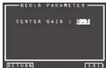
- Set the CENTER GAIN level between 0.0 and 1.0 in 0.1 level increments with the ◀ or ▶ cursor buttons.
After you complete this portion of the setup, move cursor to "RETURN" with the ▲, ▼ cursor buttons and press the ENTER button.
Notes:
- This parameter can only be set in the NEO:6-Music mode.
- If "NONE" was selected for the center speaker setting in the SPEAKER SIZE menu, this setting is disabled.
4 VIDEO SETUP
Video settings are made as follows.
- Select "4. VIDEO SETUP" from the MAIN MENU with the ▲▼ cursor buttons and press the ENTER button.
- Select the desired menu with the ▲/▼ cursor buttons and press the ENTER button.
• VIDEO CONVERT
This unit is equipped to convert video signals for monitor output. This section explains how to set up conversion for each type of video input.
-
Select "4. VIDEO SETUP" from the MAIN MENU with the ▲/▼ cursor buttons and press the ENTER button.
-
Select "VIDEO CONVERT" with the ▲/▼ cursor buttons and press the ENTER button.
- Select "FUNCTION" with the ▲ / ▼ cursor buttons and set the video conversion mode with the ◀ / ▶ cursor buttons
ANA&HDMI:
This mode both up-converts and down-converts analog video signals (Composite Video, S-Video, Component Video). Furthermore, it up-converts from analog video signal to HDMI. (It cannot down-convert from HDMI digital video signals to analog video signals.)
ANA ONLY:
This mode both up-converts and down-converts analog video signals (Composite Video, S-Video, Component Video). It does not up-convert to HDMI.
OFF:
This mode turns off all conversion features.
Note:
- For details on video convert feature, see page 39.
• TV-AUTO
Select the TV AUTO ON/OFF function to enable or disable with the ◀ or ▶ cursor buttons. (refer to page 46)
• OSD INFO
Select the OSD information function to "ENABLE" or "DISABLE" with the ◀ or ▶ cursor buttons. If you select "ENABLE", this unit will display the status of the feature (Volume up/down, input select, etc.) on the monitor. If you do not desire this information, select "DISABLE".
Note:
- OSD information is not output to Monitor Output of HDMI and Component Video. However, OSD information is output if the Video Convert function is used to output Video or S-Video video signals to Monitor Out of HDMI and Component Video. For details, refer to "VIDEO CONVERT" on page 39.
- COMPONENT I/P
Set whether or not to convert 480i/576i signals to 480p/576p signals when outputting the analog video input signal input from the COMPOSITE terminals, S-VIDEO terminals, or COMPONENT terminals.
Select "ENABLE" or "DISABLE."
DISABLE: Do not convert
ENABLE: Convert
Note:
This setting is enabled only when VIDEO CONVERT is set to other than OFF.
• HDMI OUT
This setting is for selecting which output terminal, OUTPUT1 or OUTPUT2, to output the signal to. Select the output destination with the ◀/▶ cursor buttons.
To use the remote controller (RC2001) to change the HDMI OUT setting, press the HOME button, then the AMP button, and press the < i > button until 002 is displayed. After HDMI 1 or HDMI 2 is displayed on the remote controller, press the HDMI 1 or HDMI 2 button to switch between them.
text_image
HOME MACRO APP 1.0V 2.0SS 3. NETMOPK 031/04 APP 7 1CH IN 9/0 AUDIO 1-HDMI-2 IP SYNC 800/305• HDMI ASPECT
Set HDMI ASPECT in accordance with the screen size of the television connected to this unit. Select 16:9NORM or THROUGH using the ◀ or ▶ cursor buttons.
THROUGH:
Output is in the same screen size as the input.
16:9 NORM:
Output includes black bands on the left and right of the television screen.
Notes:
- This setting is enabled only when a 480i/576i signal is input and HDMI RESOLUTION is set to other than THROUGH, or when a 480p/576p signal is input.
• The aspect ratio cannot be changed when the input video signal is 720p or 1080i. - This setting depends on network settings when a network is selected.
• HDMI OUT 1 RES
HDMI OUT 2 RES
Selects the resolution of the video signal output from the HDMI terminal of this unit. Select from the following using the ◀ or ▶ cursor buttons.
THROUGH ↔ 480/576p ↔ 720p ↔ 1080i ↔ 1080p ↔ AUTO ↔ THROUGH
ENGLISH
AUTO:
Sets an appropriate resolution for a television that is connected using HDMI.
(If connected by converting to DVI, the output is 480p/576p)
THROUGH:
The output is same resolution as that input.
480p/576p:
The output is 480p/576p.
720p:
The output is 720p.
1080i:
The output is 1080i.
1080p:
The output is 1080p.
Notes:
- The resolution cannot be changed when the input video signal is 720p or 1080i.
• The resolution depends on the network settings when a network is selected.
• Signals are not output when connected to a monitor that does not support HDCP.
• COMP OUT 2
This setting is for selecting whether to output the images for the main zone or the images for the zone system to the COMPONENT MONITOR OUT 2 terminal. Select the output destination between MAIN and ZONE A with the ◀/▶ cursor buttons.
Note:
- When ZONE A is selected, video signals converted from the MONITOR OUT 2 terminal are not output.
After you complete this portion of the setup, move cursor to "RETURN" with the ▲, ▼, ◀ and ▶ cursor buttons and press the ENTER button.
ENGLISH
5 PREFERENCE
ZONE SETUP :
"5-1 ZONE SETUP"
(see page 35)
* DC TRIGGER SETUP
"5-2 DC TRIGGER SETUP" (see page 35)
- Select "5. PREFERENCE" from MAIN MENU with the ▲ or ▼ cursor buttons and press the ENTER button.
- Select the desired menu with the ▲ or ▼ cursor buttons and press the ENTER button.
STAND BY:
When this is set to "ECONOMY", you can reduce the power consumption when the unit is in the Standby mode. When "ECONOMY" is selected, "TV AUTO" and "RS-232C" are disabled when the unit is in the Standby mode.
AUDIO
In the Audio mode, Dolby Digital and DTS output is set to either "MAIN" or "SUB". Select "AUDIO" with the ◀ or ▶ cursor buttons, then select MAIN ← SUB ← MAIN+SUB with the ◀ or ▶ cursor buttons.
HDMI AUDIO:
This setting determines whether to play back audio input to the HDMI jacks through the unit or output it through the unit to a TV or projector.
ENABLE: The audio input to the HDMI jacks can be played back by this unit. In such case, audio signals are not output to the TV or projector.
THROUGH: The audio input to the HDMI jacks is not output from the speaker terminals of the unit. Audio data is output directly to the TV or projector. This setting is used to listen to audio on a multi channel TV, etc.
HDMI LIP (Auto Lipsync Correction):
Video signals may take longer to process than audio signals depending on the connected video equipment.
When the unit is connected to TV or Projector supporting Auto Lipsync Correction in HDMI 1.3a, audio and video can be automatically synchronized using this function.
Use the ◀ or ▶ cursor buttons to switch between ENABLE and DISABLE.
ENABLE: Auto Lipsync Correction is used to synchronize audio and video.
DIESABLE: Deactivates this function.
Note:
- This function is not available when the unit is connected to equipment that does not support HDMI 1.3a or Auto Lipsyne Correction. For details, check the user's manual of the connected equipment.
- If this function is unavailable, you can use the regular Lipsync function to synchronize audio and video. (See page 46)
P.AMP LINK:
ENABLE: Set when performing REMOTE CONTROL connection with MM8003.
DISABLE: Set when performing REMOTE CONTROL connection with a MARANTZ power amp other than MM8003.
ter you complete this portion of the setup, move the cursor to "RETURN" with the ▲, ▼ cursor buttons and less the ENTER button.
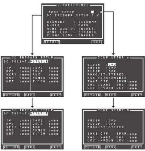
flowchart
graph TD
    A["5.PREFERENCE"] --> B["DC TRIG-1: DISABLE"]
    A --> C["Zone SETUP A"]
    B --> D["DC TRIG-2: DISABLE"]
    C --> E["Zone SETUP B"]
    D --> F["RETURN BACK EXIT"]
    E --> G["RETURN BACK EXIT"]
    F --> H["STANDBY : ECONOMY<br>AUDIO : MAIN<br>HDMI AUDIO : ENABLE<br>HDMI LIP : DISABLE<br>P.AMP LINK : ENABLE"]
    G --> I["AUDIO : DVD<br>SLEEP : OFF<br>MONO/ST: STEREO<br>OSD INFO : OFF<br>ZONE: OFF SPKR: ***<br>VOL : VANI VOL : ***<br>LEV : -90dB LEV : ***"]
5-1 ZONE SETUP
The AV8003 has source selectors, sleep timers and zonespeaker output remote controller for the two other ZONEs in the zone system. These features can be set from this menu.
- Select "5. PREFERENCE" from the MAIN MENU with the ▲ or ▼ cursor buttons and press the ENTER button.
- Select "ZONE SETUP" with the ▲ or ▼ cursor buttons and select either "ZONE A" or "ZONE B" with the ◀ or ▶ cursor buttons.
- Press the ENTER button to enter the setting.
The following explanation shows how to operate ZONE A of the zone system. The ZONE B setting does not have the VIDEO FUNCTION.
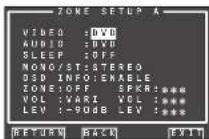
- Select the desired item with the ▲ or ▼ cursor button.
VIDEO:
Select the video source of the zone output with the ◀ or ▶ cursor buttons.
AUDIO:
Select the audio source of the zone output with the ◀ or ▶ cursor buttons.
SLEEP:
The sleep mode is available when the zone is active, set the time with ◀ or ▶ cursor buttons. The sleep timer can be set to a maximum 120 minutes in 10 minute increments.
MONO/ST:
This mode switches audio output to the zone system between MONAURAL and STEREO, using the ◀ and ▶ cursor buttons.
OSD INFO:
With this function, on-screen display information is shown on connected TVs or other devices when you switch input functions. Select "ENABLE" with the ◀ or ▶ cursor buttons to enable OSD INFO or "DISABLE" to disable it. Select "DISABLE" if this function is not needed.
ZONE:
Switch the zone output "ON" or "OFF" with the ◀ or ▶ cursor buttons.
SPKR (ZONE SPEAKER):
Switch the speaker output "ON" or "OFF" with the ◀ or ▶ cursor buttons.
VOL (VOLUME SETUP):
Select whether the zone or zone speaker output level is variable or fixed with the ◀ or ▶ cursor buttons.
LEVEL (VOLUME LEVEL):
Adjust the zone output level with the ◀ or ▶ cursor buttons. The volume can be set between -90 dB and 0 dB in 1 dB increments.
Note:
- SPKR setting can be changed when the SURR B is set to "NONE" in the SPEAKER SIZE menu and "SPEAKER C" is in the OFF position on the rear panel. When this setting is unavailable, "***" is displayed.
- If "VOLUME" is set to "FIXED", the zone output level cannot be adjusted from the A or B ZONE.
- SPKR cannot be on for both ZONE A and ZONE B at the same time. After you complete this portion of the setup, move the cursor to "RETURN" with the ▲ or ▼ cursor buttons and press the ENTER button.
5-2 DC TRIGGER SETUP
This unit has 2 DC trigger control jacks, which can be used to link with input functions for the main zone or zone. Each trigger can be setup separately.
- Select "5. PREFERENCE" from MAIN MENU with the ▲ or ▼ cursor buttons and press the ENTER button.
- Select "DC TRIGGER SETUP 1or 2" with the ▲, ▼, ◀ and ▶ cursor buttons.
- Press the ENTER button to enter the selection.

- You can select "MAIN ZONE", "ZONE A", "ZONE B", "REMOTE" or "DISABLE" with the ◀ or ▶ cursor buttons.
Note:
- REMOTE is available for the external control. The RC2001 cannot operate the function.
- Select desired input source with the ▲ or ▼ cursor buttons.
- Set to "ON" or "OFF" with the ◀ or ▶ cursor buttons.
- After you complete this portion of the setup, move the cursor to "RETURN" with the ▲ or ▼ cursor button and press the ENTER button.
Note:
- When an input source that is on in the set ZONE is selected, voltage is output to the DC TRIGGER output terminal.
ENGLISH
6 ACOUSTIC EQ
This display is for setting up the equalizer and changing the Equalizer mode.
• PRESET G. EQ ADJ :
"6-1 PRESET G. EQ ADJ" (see page 37)
- CHECK AUTO 1 & 2 :
(see page 37)
EQ MODE:
There are 4 equalizer modes to choose from; PRESET G, EQ that allows the user to manually adjust the equalizer, and AUDYSSEY, FRONT and FLAT that automatically adjust the equalizer from the measurement results of the AUTO SETUP feature (see page 26).
FRONT:
This mode matches the characteristics of each speaker to those of the front speakers.
FLAT:
This mode if attens the frequency characteristics of all speakers. It is suited for playback of multichannel music such as Dolby Digital and DTS.
AUDYSSEY:
This mode adjusts the frequency characteristics of all speakers so as to create the best listening environment for the sound characteristics of the listening room.
PRESET
This mode adjusts the graphic equalizer that was set in PRESET G.EQ ADJ to adjust the characteristics of each speaker (see page 37).
OFF:
The graphic equalizer is not used.
- Select "6. ACOUSTIC EQ" from MAIN MENU with the ▲ or ▼ cursor buttons and press the ENTER button.

- Select "EQ. MODE" with the ▲ or ▼ cursor buttons.
3. Select "FRONT", "FLAT", "AUDYSSEY",
"PRESET" or "OFF" with the ◀ or ▶ cursor buttons.
After you complete this portion of the setup, move the cursor to "RETURN" with the ▲, ▼, ◀ and ▶ cursor buttons and press the ENTER button. To use the remote controller (RC2001) to change the EQ MODE. To use the remote controller (RC2001) to change the EQ MODE, switch the remote controller to AMP mode, and press the < / > button until 003 is displayed. When EQ is displayed on the remote controller, press the EQ button.
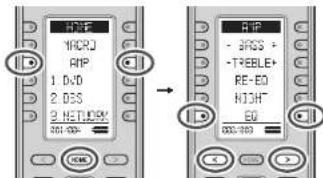
text_image
MVR MVR RIP 1 DVD 2 DOS 2 NETLRC 301-030 → RIP - 2RGS + - TREBLE+ RE-ED RIGHT ED 301-030Each time this button is pressed, the EQ MODE changes as follows.
OFF FRONT FLAT PRESETAUDYSSEY →
Notes:
- "FRONT", "FLAT" and "AUDYSSEY" can be selected after executing the AUTO SETUP feature.
- If a speaker that was determined "NON" in Auto Setup is manually turned on, the "FRONT", "FLAT" and "AUDYSSEY" modes cannot be selected.
- The equalizer turns off when the Pure Direct mode, Source Direct mode, Dolby Headphone or Virtual mode is set.
- ACOUSTIC EQ MODEs are not used during playback of Dolby TrueHD, Dolby Digital Plus, or DTS-HD signals.
- Tone Control is disabled when an EQ MODE is in use.
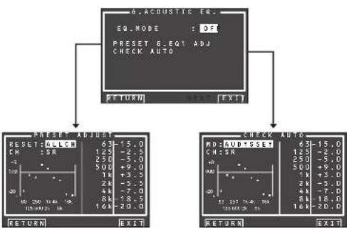
flowchart
graph TD
    A["6.ACOUSTIC EQ."] --> B["EQ.MODE : OFF"]
    A --> C["PRESET G.EQT ADJ CHECK AUTO"]
    A --> D["RETURN : EXIT"]
    A --> E["PRESDET ADJ UDT"]
    E --> F["RESET G.LCH: 63-15.0, CH: SR: 125-2.5, 250-5.0, 500+9.0, 1k+3.5, 2k-5.0, 4k-7.0, 8k-18.5, 16k-20.0"]
    E --> G["RESET RUD SSET: 6-15.0, CH: SR: 125-2.0, 250-5.0, 500+9.0, 1k+3.5, 2k-5.0, 4k-7.0, 8k-18.0, 16k-20.0"]
    E --> H["RETURN : EXIT"]
    E --> I["PRESDET ADJ UDT"]
    I --> J["RESET RUD SSET: 6-15.0, CH: SR: 125-2.0, 250-5.0, 500+9.0, 1k+3.5, 2k-5.0, 4k-7.0, 8k-18.0, 16k-20.0"]
6-1 PRESET G. EQ ADJ
These modes allow you to set a 9-band graphic equalizer for each of the 7 channels.
- Select "6. ACOUSTIC EQ" from MAIN MENU with the ▲ or ▼ cursor buttons and press the ENTER button.
- Select "PRESET G. EQ ADJ" with the ▲ or ▼ cursor buttons.
- Press the ENTER button to enter the selection.

RESET:
Using the ◀ or ▶ cursor buttons, select the channel(s) to be reset to either the currently displayed channel ("CH") or all channels ("ALL"), and press the ENTER button to enter the setting. "ALL": Resets all channels.
"CH": Resets only the currently displayed channel.
CH:
Select the channel ("FL", "C", "FR", "SR", "SBR", "SBL" or "SL") to adjust with the ◀ or ▶ cursor buttons, and switch to the adjustment mode with the ▼ cursor button.
Frequency:
Select the target frequency on the graph with the ◀ or ▶ cursor buttons and press the ENTER button to enter the selection. Adjust the level with the ▲ or ▼ cursor buttons. (Note that this can be adjusted to any level between -20 and +9 dB in 0.5 dB increments.)
Move to the next frequency with the ◀ or ▶ cursor buttons, and adjust the level.
After you complete this portion of the setup, press the ENTER button to enter the settings. Move cursor to "RETURN" with the ▲, ▼ cursor buttons and press the ENTER button.
6-2 CHECK AUTO
These menus are for confirming the results of AUTO SETUP function equalizer measurement (AUDYSSEY, FRONT, FLAT).
- Select "6. ACOUSTIC EQ" from MAIN MENU with the ▲ or ▼ cursor buttons and press the ENTER button.
- Select "CHECK AUTO" with the ▲ or ▼ cursor buttons.
- Press the ENTER button to enter the selection.
Select MD (mode) with the ▲ / ▼ cursor buttons followed by the desired equalizer ("AUDYSSEY", "FRONT", "FLAT").
CH:
Select the channel to check with the ◀ or ▶ cursor buttons.
Notes:
- The frequency will not be exactly the same as in the Preset G. EQ modes.
-
FL and FR are not indicated on the CHECK AUTO 2 mem.
-
Once finished checking, select "RETURN" with the ▲/▼ cursor buttons and press the ENTER button to return to the "6. ACOUSTIC EQ" menu.
7 NETWORK SETUP
These settings relate to playing music, photos, and movie fi les stored on a network device connected to this unit.
- Select "7. NETWORK SETUP" on the MAIN MENU using the cursor buttons ▲ or ▼.
- Select the menu you want to set using the cursor buttons ▲ or ▼, and press ENTER.
-VIDEO:
Select "PAL" or "NTSC" for the video system of the video signal to be output from this unit using the cursor buttons ◀ or ▶.
PAL:
Select this if the connected TV has the PAL colour system. It will change the video signal of an NTSC and output it to PAL format.
NTSC:
Select this if the connected TV has the NTSC colour system. It will change the video signal of a PAL and output it to NTSC format.
- RESOLUTION:
Use the ◀ / ▶ cursor buttons to select video signal resolution (pixel count) on the NETWORK PLAYER from the following options.
"480/576i" ↔ "480/576p" ↔ "720p" ↔ "1080i" ↔ "AUTO" ↔ "480/576i"
AUTO:
Sets an appropriate resolution for a television that is connected using HDMI.
(If the unit is not connected to the television using HDMI, the output is 480i/576i)
(If connected by converting to DVI, the output is 480p/576p)
480i/576i:
The output is 480i/576i.
480p/576p:
The output is 480p/576p.
720p:
The output is 720p.
1080i:
The output is 1080l.
Notes:
- If a monitor connected using HDMI is changed during the AUTO setting, the screen returns automatically to the top menu and the resolution is changed to one that is appropriate for the monitor. If a dialog box or the TOOL menu is displayed at this time, the resolution is changed after the dialog box or TOOL menu is closed.
- Set 480i/576i if you are using VIDEO/S-VIDEO output.
- If you are using a monitor connected using HDMI, and the signal is being input from the network, the video signal is output in the resolution that was set in RESOLUTION.
- SCREEN SAVER:
Use the ◀/▶ cursor buttons to select "ON" or "OFF" for the screen saver from the video signal that is output from the unit.
ON:
If no operation is made for 10 minutes on the NETWORK screen or SETTING screen, the screen saver is activated on the monitor. (The screen goes dark)
OFF:
The screen saver is not activated even if no operation is made for 10 minutes.
Notes:
- The screen saver is not activated during photo display or video playback.
- This setting can only be changed when the NETWORK function of this unit is selected.
ENGLISH
BASIC OPERATION
SELECTING AN INPUT SOURCE
Before you can listen to any input media, you must first select the input source on the unit.
Example : DVD
(Using the unit)
To select DVD, turn the INPUT SELECTOR knob on the front panel.
(Using the remote controller)
There are three ways to select DVD.
text_image
HYPE MAC20 RIP 1 DVD 2 DCS 3 NETWORK 90V/30V 1. 2. merants- Press the HOME button
- Press the 1 button.
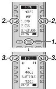
text_image
HDF HDP3 RNP 1. DVD 2. DSS 2. NETWORK 800-000 1. ↓ 3. 1. 1/2/3 & ANGLE SUBTITLE AUDIO 800-000- Press the HOME button.
- Press the 1.DVD button.
- Press the 1.DVD button.
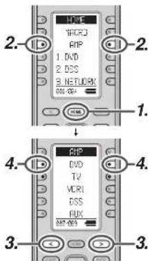
text_image
2. 1. DVD 2. DSS 3. NETWORK 4. 3. 2. 1. 4. 3.- Press the HOME button.
- Press the AMP button.
- Press the < / > button until 007 is displayed.
-
Press the DVD button.
-
As the input source is changed, the new input name will appear momentarily an OSD information on the video display. The input name will also appear in the display, on the front-panel.
- If you use the FUNCTION RENAME feature (see page 24), the renamed name appears on the display.
- As the input is changed, this unit will automatically switch to the digital input, surround mode, attenuation, and night mode status which were entered during the confi guration process for that source.
- When a video source is selected, the selected video signal is output from the MONITOR OUT terminal.
To select the Auto surround mode during playback, press the AUTO button on the front panel.
(Using the remote controller)
To select the Auto surround mode, press the HOME button, press the AMP button and press the < / > button until 005 is displayed. Press the AUTO Surr button.
- For surround modes, see "Surround Mode" on page 40.
• To add the THX mode to the Auto Surround mode, press either the THX button on the unit or the THX button on the remote controller. - To select a specific surround mode, Press the individual surround mode button on page 005, 006 on the remote controller.
DIALOGUE NORMALIZATION MESSAGE
Dialogue Normalization (Dial Norm) is a feature of Dolby Digital.
When playing back software which has been encoded in Dolby Digital, sometimes you may see a brief message on the FL display which will read "D-NORM X dB" (X being a numeric value).
Dialogue Normalization serves to let you know if the source material has been recorded at a higher or lower level than usual.
NIGHT MODE
Useful at night or when loud noise is undesirable, this mode compresses the dynamic range, making it easier to hear quieter audio content without increasing the overall volume.
Note that the effect of night mode is determined by the Dolby Digital content. Night mode may have no effect with content that does not support this function.

- To select this mode, switch the remote controller to AMP mode, and then press the < / > button until 003 is displayed.
- Each time the NIGHT button is pressed, the mode changes according to the following options indicated on the front of the unit.
- AUTO Mode
NIGHT AUTO
AUTO mode is available when decoding Dolby TrueHD signals.
When night mode is activated, "NIGHT" is illuminated on the front of the unit. (See page 6)
↓
• NIGHT Mode ON
NIGHT ON
Setting the Night mode to "ON" compresses the dynamic range in Dolby Digital only.
↓
• NIGHT Mode OFF
NIGHT OFF
Turn off the Night mode.
ADJUSTING THE MAIN VOLUME

Adjust the volume to a comfortable level using the VOLUME control knob on the front panel or VOL + / - buttons on the remote controller.
To increase the volume, turn the VOLUME knob clockwise or press VOL + button on the remote, to decrease the volume. turn counterclockwise or press VOL - button on the remote controller.
Notes:
- The volume can be adjusted within the range of - to 18 dB, in steps of 1 dB.
- However, when the channel level is set as described on page 31, if the volume for any channel is set at +1 dB or greater, the volume cannot be adjusted up to 18 dB. (In this case the maximum volume adjustment range is "18 dB - Maximum value of channel level)
- If the Main Volume is set to +9 dB or higher, it will be set to +8 dB the next time power is turned on. It will also be saved at +8 dB during back up.
ADJUSTING THE TONE (BASS & TREBLE) CONTROL
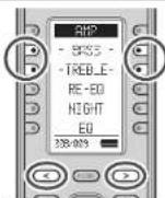
During a listening session you may wish to adjust the Bass and Treble Control to suit your listening tastes or room acoustics.
(Using the remote controller)
To adjust the tone, switch the remote controller to AMP mode, and press the < / > button until 003 is displayed.
To adjust the bass effect, press BASS+ or BASS-. To adjust the treble effect, TREBLE+ or TREBLE-.
Notes:
- The tone control function is unavailable for the Source Direct, Pure Direct, Headphone, Dolby Virtual Speaker THX mode, and 176.4/192kHz PCM.
• The Tone control function is not available when M-DAX is being used. - The lone control function is not available when ACOUSTIC EQ is being used.
- Additionally, tone control is not available during Dolby TrueHD, Dolby Digital Plus, or DTS-HD playback.
TEMPORARILY TURNING OFF THE SOUND
To temporarily silence all speaker outputs such as when interrupted by a phone call, press the MUTE button on the remote controller.
This will interrupt the output to all speakers and the head-phone jack, but it will not affect any recording or dubbing that may be in progress.
When the system is muted, the display will show "MUTE".
Press the MUTE button again to return to normal operation.
USING THE SLEEP TIMER
To program this unit for automatic standby, switch the remote controller to AMP mode, and press the SLEEP button on the remote controller.
Each press of the button will increase the time before shut down in the following sequence.

The sleep time will be shown for a few seconds in the display on the front panel, and it will count down until the time has elapsed.
When the programmed sleep time has elapsed, the unit will automatically turn off.
Note that the SLEEP indicator on the display will illuminate when the Sleep function is programmed. To cancel the Sleep function, press the SLEEP button until the display shows "SLEEP OFF" and the SLEEP indicator will disappear.
M-DAX (Marantz Dynamic Audio eXpander)

This function makes up for lost audio content in MP3 or AAC sources (from lossy compression) during playback. Choose one of the following levels for this effect as desired.
"HIGH": Stronger effect
"LOW": Weaker effect
"OFF": Deactivated.
(Using the remote controller)
To switch to M-DAX mode, switch the remote controller to AMP mode, and then press the < / > button until 001 is displayed.
When "M-DAX" is displayed on the remote controller, press the M-DAX button.
Each time this button is pressed, M-DAX changes as follows.

Notes:
• M-DAX is compatible with PCM (48 kHz or lower) and two-channel analog sources.
- The M-DAX is not available when Dolby Virtual Speaker mode is being used.
VIDEO CONVERT
ANALOG VIDEO CONVERSION
This unit is equipped to convert video signals for monitor output. Because of this, indifferent of the connection (VIDEO, S-VIDEO, COMPONENT VIDEO) between the playback device and this unit, listening and viewing are possible with a single higher grade cable between the MONITOR OUT terminal of the unit and the monitor.
UP-CONVERSION FROM ANALOG VIDEO SIGNALS TO HDMI
The up-conversion feature of this unit can output the input analog video signals (for component video signals of 480i/576i, 480p/576p, 1080i and 720p resolution, and S-Video and Video (composite) of 480i/576i resolution) to the HDMI MONITOR terminal.
Notes:
- HDMI video input is only output to the HDMI MONITOR OUT terminal of the unit. If connecting a playback device such as a DVD player to the HDMI input jack, connect the HDMI MONITOR OUT terminal of the unit to a TV monitor.
• This mode is unavailable for the REC out terminal. - This mode is unavailable for still picture, fast forward and reverse play on video component.
- If, while attempting to use the video convert feature, the unit cannot synchronize with the display device, "NO SIGNAL" appears on the monitor or noise is generated, this feature cannot be used. All of these signs are caused by equipment incompatibility; there is nothing wrong with the unit. If this occurs, set "VIDEO CONVERT" in the "VIDEO SETUP" menu to "DISABLE". Next, connect the video input signal to the display component via the MONITOR OUT terminal under VIDEO and the S-video input signal to the display component via the MONITOR OUT terminal under S-VIDEO.
- The video convert feature constantly monitors input video signals and determines whether to convert the input signals or not. However, some input video signals cannot be detected correctly. If this occurs, set "VIDEO CONVERT" in the "VIDEO SETUP" menu to "DISABLE".
ENGLISH
- For optimal video performance, THX recommends setting the "VIDEO CONVERT" mode "DISABLE".
CONNECTION EXAMPLE
- When a monitor is connected to the HDMI MONITOR OUT terminal of the unit

flowchart
graph TD
    A["Device"] -->|VIDEO or S-VIDEO or component or HDMI| B["Monitor"]
    B -->|HDMI| C["Computer"]
Notes:
- If the resolution of the component video signal input from the playback device is other than 480i/576i, 480p/576p, 1080i or 720p, images are not output from the HDMI MONITOR OUT terminal of the unit.
- If the resolution of the S-Video or Video signal input from the playback device is other than 480i/576i, images are not output from the HDMI MONITOR OUT terminal of the unit.
- When a monitor is connected to the VIDEO or S-VIDEO MONITOR OUT terminals of the unit
flowchart
graph TD
    A["Device"] -->|VIDEO or S-VIDEO or component| B["Monitor"]
    B -->|VIDEO or S-VIDEO| C["Computer"]
    A --> D["HDMI"]
    D -->|no connection| A
Notes:
- The HDMI video signal input from the playback device is not output from the VIDEO or S-VIDEO MONITOR OUT terminals of the unit.
- If the resolution of the component video signal input from the playback device is other than 480i/576i, it is not output from the VIDEO or S-VIDEO MONITOR OUT terminals of the unit.
- When a monitor is connected to the COMPONENT VIDEO MONITOR OUT terminal of the unit
flowchart
graph TD
    A["Device"] --> B["Component"]
    B --> C["Monitor"]
    D["VIDEO or S-VIDEO or component"] --> E["HDMI"]
    E --> A
Notes:
- The HDMI video signal input from the playback device is not output from the COMPONENT VIDEO MONITOR OUT terminal of the unit.
Notes of OSD menu system:
- The setup menu can be displayed through all video out terminals ("HDMI", "COMPONENT", "SVIDEO" and "VIDEO").
- OSD information is output only to the VIDEO and S-VIDEO MONITOR OUT terminals.
OSD information is also output when the video conversion feature is on and the video signal input to the VIDEO or S-VIDEO input jack of the unit is converted and output from the COMPONENT VIDEO or HDMI MONITOR OUT terminals.
COMPONENT I/P
The video circuit of the unit is equipped with an I/P conversion feature.
When this feature is on, 480i/576i analog video signals (VIDEO, S-VIDEO or COMPONENT VIDEO) input from a playback device can be converted to 480p/576p and progressively output to the COMPONENT VIDEO OUT terminals of the unit.
(For setting instructions, see page 33)
HDMI RESOLUTION
This function is used to output the analog video signal to HDMI.
480i/576i signals can be converted to 480p/576p, 1080i, 720p, or 1080p signals, while 480p/576p signals can be converted to 1080i, 720p, or 1080p signals.
The output resolution can be set for HDMI OUT 1 and HDMI OUT 2.
Notes:
- Do not set to 1080i, 720p, or 1080p when connected to a monitor that does not support 1080i, 720p, or 1080p signals. The SETUP MENU will not be displayed. If the SETUP MENU is not displayed, change settings while viewing the main unit display panel.
- A 720p signal cannot be converted to 1080i or 1080p signal, and a 1080i signal cannot be converted to a 1080p signal.
- The resolution of analog component output cannot be changed.
• HDMI OUT 1 and HDMI OUT 2 cannot be output simultaneously.
SURROUND MODE
This unit is equipped with many surround modes. These are provided to reproduce a variety of surround sound effects, according to the content of the source to be played.
The available surround modes may be restricted depending on the input signal and speaker setup.
The relationship between the selected surround mode and the input signal
The surround mode is selected with the surround mode selector on the unit or the remote controller. However, the sound you hear is subject to the relationship between the selected surround mode and the input signal. That relationship is as follows:
| Surround Mode | Input Signal | Decoding | Output Chain | Front Information Display | ||||
| L-R | C | SL SR | SOL SER | Task | Signal format indicators Channel status | |||
| AUTO | Deby Sun LX | Deby Digital LX | ○ | ○ | ○ | ○ | ○ | ○ DIGITAL LX L.C.R.SI,SR,S.LTE |
| Deby D (5.1ch) | Deby Digital 5.1 | ○ | ○ | ○ | ○ | ○ | ○ DIGITAL L.C.R.SI,SR,LFE | |
| Deby D (20h) | Deby Digital 20 | ○ | - | - | - | ○ | ○ DIGITAL L.R | |
| Deby D (20h Sun) | Pro-Legion-Remote | ○ | ○ | ○ | ○ | ○ | ○ DIGITAL,OD SURROUND L.R.S | |
| Deby Digital Plus(3.1h) | Deby Digital + | ○ | ○ | ○ | ○ | ○ | ○ DIGITAL L.C.R.SI,SR,LFE | |
| Deby Digital Plus(3.1ch) | Deby Digital | ○ | ○ | ○ | ○ | ○ | ○ DIGITAL L.C.R.SI,SR,S.LTE | |
| Deby Digital Plus(7.1) | Deby Digital - | ○ | ○ | ○ | ○ | ○ | ○ DIGITAL L.C.D.SI,SR,S.LFE | |
| Deby Ture(D 5.1ch) | Deby TureHD | ○ | ○ | ○ | ○ | ○ | ○ DIGITAL Deboard on speaker setup | |
| Deby Ture(D 5.1ch) | Deby TureHD | ○ | ○ | ○ | ○ | ○ | ○ DIGITAL Deboard on speaker setup | |
| Deby Ture(D 7.1ch) | Deby TureHD | ○ | ○ | ○ | ○ | ○ | ○ DIGITAL Deboard on speaker setup | |
| CTS-RS | CTS-RS | ○ | ○ | ○ | ○ | ○ | obs PS | |
| CTS-RS24 | CTS-RS-M | ○ | ○ | ○ | - | obs PS24 L.C.D.SI,SR,LFE | ||
| CTS-RS Plus | CTS-RS-I | ○ | ○ | ○ | - | obs L.C.D.SI,SR,LFE | ||
| CTS HD (5.1) | CTS HD | ○ | ○ | ○ | obs L.C.D.SI,SR,LFE | |||
| CTS HD (6.1) | CTS HD | ○ | ○ | ○ | ○ | obs L.C.D.SI,SR,S.LFE | ||
| CTS HD (7.1) | CTS HD | ○ | ○ | ○ | ○ | obs L.C.D.SI,SR,S.LFE | ||
| Multi-CPU | Multi-CPU PCM | ○ | ○ | ○ | PCM L.C.D.SI,SR,S.LFE | |||
| Multi-CPU PCM Plus | Multi-CPU PCM Plus | ○ | ○ | ○ | PCM L.C.D.SI,SR,S.LFE | |||
| SA CD (5.1ch) | Multi-CPU PCM | ○ | ○ | ○ | DSD L.C.R.SI,SR,LTE | |||
| SA CD (20h) | PCM (Stance) | ○ | - | - | - | DSD L.R | ||
| PCM (Audio) | PCM (Stance) | ○ | PCM L.R | |||||
| PCM (Video) | PCM (Stance Video) | ○ | - | - | - | PCM L.R | ||
| HDC2 | HDC2 | ○ | PCM HDC2 L.R | |||||
| Analog | Analog | ○ | ANALOG | |||||
| Tech Parp | Multi Ch | ○ | ○ | ○ | ○ | ANALOG | ||
| SOURCE DIRECT PHL DIRECT | Daily Sun FX | Daily Digital FX | ○ | ○ | ○ | ○ | ○ DIGITAL FX L.C.R.SI,SR,S.LFE | |
| Deby D (5.1ch) | Deby Digital 5.1 | ○ | ○ | ○ | - | ○ DIGITAL L.C.R.SI,SR,LTE | ||
| Deby D (20h) | Deby Digital 20 | ○ | ○ DIGITAL L.R | |||||
| Daily D (20h Sun) | Pro-Legion-Remote | ○ | ○ | ○ | ○ | ○ DIGITAL,OD SURROUND L.R.S | ||
| Deby Digital Plus(3.1) | Deby Digital | ○ | ○ | ○ | ○ | ○ DIGITAL L.C.R.SI,SR,LTE | ||
| Deby Digital Plus(7.1) | Deby Digital + | ○ | ○ | ○ | ○ | ○ DIGITAL L.C.R.SI,SR,S.LFE | ||
| Deby Digital Plus(7.1) | Deby Digital | ○ | ○ | ○ | ○ | ○ DIGITAL L.C.R.SI,SR,S.LFE | ||
| Daily True-D (5.1) | Daily TrueHD | ○ | ○ | ○ | ○ | ○ DIGITAL Deboard on speaker setup | ||
| Daily True-D (5.1) | Daily TrueHD | ○ | ○ | ○ | ○ | ○ DIGITAL Deboard on speaker setup | ||
| Daily True-D (7.1) | Daily TrueHD | ○ | ○ | ○ | ○ | ○ DIGITAL Deboard on speaker setup | ||
| CTS-RS | CTS-RS | ○ | ○ | ○ | ○ | obs LS L.C.R.SI,SR,S.TLE | ||
| CTS-RS24 | CTS-RS-M | ○ | ○ | ○ | ○ | obs RSE24 L.C.R.SI,SR,LTE | ||
| CTS-RS Plus | CTS-RS-I | ○ | ○ | ○ | ○ | obs L.C.R.SI,SR,LTE | ||
| CTS-RS (5.1) | CTS-RS-D | ○ | ○ | ○ | - | obs L.C.D.SI,SR,LFE | ||
| CTS-HD (5.1) | CTS-HD | ○ | ○ | ○ | ○ | obs L.C.R.SI,SR,S.TLE | ||
| CTS-HD (7.1) | CTS-HD | ○ | ○ | ○ | ○ | obs L.C.R.SI,SR,S.TLE | ||
| Multi CD PCM | Multi CD PCM | ○ | ○ | ○ | ○ | PCM L.C.R.SI,SR,S.LTE | ||
| Multi CD Multi-Scale2 | Multi CD PCM+50Hz | ○ | ○ | ○ | - | PCM L.C.R.SI,SR,LFE | ||
| SA CD (5.1ch) | SA CD (5.1ch) | ○ | ○ | ○ | - | DSD L.C.R.SI,SR,LTE | ||
| SA CD (20h) | SA CD (20h) | DSD L.R | ||||||
| PCM (Audio) | PCM (Stance) | ○ | - | - | - | PCM L.R | ||
| PCM Core2 | PCM (Stance Core2) | ○ | PCM L.R | |||||
| HDC5 | HDC5 | ○ | - | - | - | PCM,HDCD L.R | ||
| Analog | Analog | ○ | - | - | - | ANALOG | ||
| TAC Plus | Multi Ch | ○ | ○ | ○ | ○ | ANALOG | ||
| EXITS | Daily Sun LX | Deby Digital LX | ○ | ○ | ○ | ○ | ○ DIGITAL LX L.C.R.SI,SR,S.TLE | |
| Daily D (5.1ch) | Daily Digital FX | ○ | ○ | ○ | ○ | ○ DIGITAL L.C.R.SI,SR,LFE | ||
| Deby Digital Plus(3.1) | Deby Digital - | ○ | ○ | ○ | ○ | ○ DIGITAL L.C.R.SI,SR,S.LTE | ||
| Deby True-D (5.1) | Deby TrueHD | ○ | ○ | ○ | ○ | ○ DIGITAL Deboard on speaker setup | ||
| CTS-RS | CTS-RS | ○ | ○ | ○ | ○ | obs PS L.C.D.SI,SR,S.LFE | ||
| CTS-RS Plus | CTS-RS | ○ | ○ | ○ | ○ | obs L.C.R.SI,SR,S.TLE | ||
| Multi-PCM | Multi-Ch-PCM + Dummy Digital LX | ○ | ○ | ○ | ○ | PCM L.C.R.SI,SR,S.TLE | ||
| SA CD (5.1ch) | Multi-Ch-PCM + Dummy Digital EX | ○ | ○ | ○ | ○ | DSD L.C.R.SI,SR,S.TLE | ||
ENGLISH
| Surround Mode Input | Signal Decoding | Output Channel Front Information display | ||||||
| L/R C | SL SR | SBL SBR | J&W | Signal format indicators channel status | ||||
| DOLBY(PLX moves)(PLX moves)(PLX game) | Doby Sun/LX | Doby Digital LX | O | O | O | - | ○ | ○ DIGITAL LX |
| Doby (5, 1ch) | Doby Digital 5.1 | O | O | O | - | ○ | ○ DIGITAL | |
| Doby (5, 1ch) | Doby Digital 5.1 + 2Hz | O | O | O | ○ | ○ | ○ DIGITAL | |
| Doby (10ch) | Doby Digital LX | O | O | O | ○ | ○ | ○ DIGITAL | |
| Doby (2nd Sun) | Doby Digital LX | O | O | O | ○ | ○ | ○ DIGITAL ☐ SURROUND | |
| Doby Digital 3.1(h) | Doby Digital I | O | O | O | ○ | ○ | ○ DIGITAL | |
| Doby Digital Plus 4.1(h) | Doby Digital + | O | O | O | ○ | ○ | ○ DIGITAL | |
| Doby Digital Plus 7.1(h) | Doby Digital + | O | O | O | ○ | ○ | ○ DIGITAL | |
| Doby Trust+DI (5, 1) | Doby Trust+CI | O | O | O | - | ○ | ○ DIGITAL | |
| Doby Trust+DI (5, 1) | Doby Trust+CI | O | O | O | ○ | ○ | ○ DIGITAL | |
| Doby Trust+DI (7, 1) | Doby Trust+CI | O | O | O | ○ | ○ | ○ DIGITAL | |
| Multi CD+DI | Multi CD+DI + 2Hz | O | O | O | ○ | ○ | ○ PCM | |
| SA-CD (5 ch) | Multi CD+DI + 2Hz | O | O | O | ○ | ○ | ○ SSD | |
| SA-CD (2ch) | Pro Logic IIx | O | O | O | ○ | ○ | ○ SSD | |
| PCM Audio | Pro Logic IIx | O | O | O | ○ | ○ | PCM | |
| HDCO | Pro Logic IIIx | O | O | O | ○ | ○ | PCM, HDCO | |
| Analog | Pro Logic IIx | O | O | O | ○ | ○ | ANALOG | |
| MTS(Mixed Channel(Mixed Music) | DTS-PS DTS 5.1 | DTS-DI | O | O | O | - | ○ | do L, P, R, S, SL, SR, S, LFE |
| DTS 9524-DTS 9628 | DTS-DI | O | O | O | ○ | ○ | do 9524-L, C, R, SL, SR, LFE | |
| DTS (5 ch) DTS 5.1 | DTS-DI | O | O | O | - | ○ | do L, C, R, SL, SR, LFE | |
| DTS HDV (1) | DTS HD | O | O | O | ○ | ○ | do L, C, R, SL, SR, LFE | |
| DTS-HDV (1) | DTS-HD | O | O | O | ○ | ○ | do L, C, R, SL, SR, S, LFE | |
| DTS-HDV (1) | DTS-HD | O | O | O | ○ | ○ | do L, C, R, SL, SR, S, LFE | |
| Doby D (2ch) | Necs | O | O | O | ○ | ○ | ○ DIGITAL | |
| Doby D (2ch Sum) | Necs | O | O | O | ○ | ○ | ○ DIGITAL ☐ SURROUND | |
| SA-CD (2ch) | Necs | O | O | O | ○ | ○ | SSD | |
| PCM Audio | Necs | O | O | O | ○ | ○ | PCM | |
| HDCO | Necs | O | O | O | ○ | ○ | PCM, HDCO | |
| Analog | Necs | O | O | O | ○ | ○ | ANALOG | |
| CS BChemoCS MusicCS Remote | Doby D (2ch) | CSI | O | O | O | ○ | ○ | ○ DIGITAL |
| Doby (2nd Sun) | CSI | O | O | O | ○ | ○ | ○ DIGITAL ☐ SURROUND | |
| SA-CD (2ch) | CSI | O | O | O | ○ | ○ | SSD | |
| PCM Audio) | CSI | O | O | O | ○ | ○ | PCM | |
| HDCO | CSI | O | O | O | ○ | ○ | PCM, HDCO | |
| Analog | CSI | O | O | O | ○ | ○ | ANALOG | |
| STECHLO Duty Sun | LX | Streco | O | - | - | - | ○ | ○ DIGITAL LX |
| Doby D (5 ch) | Streco | O | ○ | ○ DIGITAL | ||||
| Doby D (2ch) | Streco | O | - | - | - | ○ | ○ DIGITAL | |
| Doby D (2ch Sum) | Streco | O | - | - | - | ○ | ○ DIGITAL ☐ SURROUND | |
| Doby Signal Plus (5 h) | Streco | O | - | - | - | ○ | ○ DIGITAL | |
| Doby Signal Plus (6 h) | Streco | O | ○ | ○ DIGITAL | ||||
| Doby Signal Plus (7 h) | Streco | O | - | - | - | ○ | ○ DIGITAL | |
| Doby Trust+DI (5 h) | Streco | O | - | - | - | ○ | ○ DIGITAL | |
| Doby Trust+DI (6 h) | Streco | O | ○ | ○ DIGITAL | ||||
| Doby Trust+DI (7 h) | Streco | O | ○ | ○ DIGITAL | ||||
| DTS 9524 Stroco | O | ○ | do E, L, C, R, SL, SR, S, LFE | |||||
| DTS 9524 Stroco | O | ○ | do 9524-L, C, R, SL, SR, LFE | |||||
| DTS (5 ch) Stroco | O | - | - | - | ○ | do L, C, R, SL, SR, LFE | ||
| DTS-HD (5 h) | Streco | O | - | - | - | ○ | do L, C, R, SL, SR, S, LFE | |
| DTS HD (1 h) | Streco | O | - | - | - | ○ | do L, C, R, SL, SR, S, LFE | |
| DTS HD (1 h) | Streco | O | ○ | ○ PCM | ||||
| Multi CD+DI Streco | Streco | O | - | - | - | ○ | ○ PCM | |
| Multi CD+DI Streco | Streco | O | - | - | - | ○ | ○ PCM | |
| SA-CD (5 ch) | Streco | O | ○ | ○ PCM | ||||
| SA-CD (2ch) | Streco | O | - | - | - | ○ | ○ PCM | |
| PCM Audio) | Streco | O | - | - | - | ○ | ○ PCM | |
| PCM (5ch) Series | Streco | O | ○ | ○ PCM, HDCO | ||||
| HDCO | Streco | O | ○ | ○ ANALOG | ||||
| Analog | Streco | O | ○ | ○ DIGITAL LX | ||||
| Doby VirtualSpeaker | Doby Sun/LX | Doby Virtual Speaker | O | ○ | ○ DIGITAL | |||
| Doby D (5 ch) | Doby Virtual Speaker | O | - | - | - | ○ | ○ DIGITAL | |
| Doby D (2ch) | Doby Virtual Speaker | O | - | - | - | ○ | ○ DIGITAL ☐ SURROUND | |
| Doby D (2ch Sum) | Doby Virtual Speaker | O | ○ | ○ L, S | ||||
| DTS-PS Doby Virtual Speaker | O | - | - | - | dx PS | |||
| DTS 9524-Duty Virtual Speaker | O | - | - | - | dx 9524 | |||
| DTS (5 ch) Duty Virtual Speaker | O | - | - | - | dx | |||
| Multi CD+DI | O | ○ PCM | ||||||
| SA-CD (5 ch) | Doby Virtual Speaker | O | ○ DSP | |||||
| SA-CD (2ch) | Doby Virtual Speaker | O | ○ DSP | |||||
| PCM Audio) | Doby Virtual Speaker | O | ○ PCM | |||||
| HDCO | Doby Virtual Speaker | O | ○ PCM, HDCO | |||||
| Analog | Doby Virtual Speaker | O | ○ ANALOG | |||||
| Multi Ch.MoveMusic(Q): None more only. | Doby Sun/LX | Doby Digital EX | O | [O] O O O | ○ DIGITAL LX | |||
| Doby D (5 ch) | Doby Digital 5.1 | O [O] O | ○ DIGITAL | |||||
| Doby D (2ch) | Multi Channel | O [O] O O O | ○ DIGITAL | |||||
| Doby D (2ch Sum) | Multi Channel | O [O] O O O | ○ DIGITAL ☐ SURROUND | |||||
| Surround Mode Input | Signal Ordering | Output Channel From Information display | ||||||
| L/R C | SL SR | SSL SBR | SBR | Signal format Indicators Channel | status | |||
| Multi Ch. Music Music | DTS-CS DTS-CS | ○ (○) | ○ | ○ | dsa, LS, L, C, R, SL, SR, S, LFE | |||
| DTS 9024 DTS SC-24 | ○ (○) | ○ | ○ | dsa 9024, L, C, R, SL, SR, LFE | ||||
| DTS (6.1sc.) DTS 5.1 | ○ (○) | ○ | - | ○ | dsa 1, D, N, SL, SR, LFE | |||
| Multi CP-PCM | Multi CP-PCM | ○ (○) | ○ | - | ○ | FCM | ||
| Multi Ch-PDM-SH-K | Multi Ch-PDM-SH-K | ○ (○) | ○ | - | ○ | FCM | ||
| SA CD (5.1ch) | Multi Ch-PCM | ○ (○) | ○ | ○ | DSD | |||
| SA CD (2nd) | Multi Channel | ○ (○) | ○ | ○ | ○ | DSD | ||
| PCM (Audio) | Multi Channel | ○ (○) | ○ | ○ | ○ | FCM | ||
| HDCO | Multi Channel | ○ (○) | ○ | ○ | ○ | FCM HDCO | ||
| (D) News-industry | Analog | Multi Channel | ○ (○) | ○ | ○ | ○ | ANALOG | |
| Daddy H.P | Daddy Sun BX | Daddy Sun BX | ○ | - | - DIGITAL BX | |||
| Daddy (5.1ch) | Daddy HP | ○ | - | - | - | - DIGITAL | ||
| Daddy (2nd) | Daddy HP | ○ | - | - | - | - DIGITAL | ||
| Daddy (2nd Sun) | Daddy HP | ○ | - | - | - | - DIGITAL CO SURROUND | ||
| Desc Digital Plus (5.1) | Stress | ○ | - | - DIGITAL | ||||
| Desc Digital Plus (8.1) | Stress | ○ | - | - DIGITAL | ||||
| Desc Digital Plus (7.1) | Stress | ○ | - | - DIGITAL | ||||
| Daddy True-HD (5.1) | Stress | ○ | - | - | - | - DIGITAL | ||
| Daddy True-HD (6.1) | Stress | ○ | - | - | - DIGITAL | |||
| Daddy True-HD (7.1) | Stress | ○ | - | - | - | - DIGITAL | ||
| DTS ES-Daddy HP | - | dsa ES | ||||||
| DTS 9024 Dolly HP | ○ | - | - | - | dsa 9024 | |||
| DTS IS Tsc.Dolly HP | ○ | - | - | dsa | ||||
| DTS HD (6.1) | Stress | ○ | - | cs | ||||
| DTS HD (6.1) | Stress | ○ | - | cs | ||||
| DTS HD (7.1) | Stress | ○ | - | - | cs | |||
| Multi Ch-PCM | Daddy HP | ○ | - | - | FCM | |||
| SA CD (5.1ch) | Daddy HP | ○ | - | DSD | ||||
| SA CD (2nd) | Daddy HP | ○ | - | DSD | ||||
| PCM (Audio) | Daddy HP | ○ | - | FCM | ||||
| HDCO | Daddy HP | ○ | - | FCM HDCO | ||||
| Analog | Daddy HP | ○ | ANALOG | |||||
| THX (AUTO) | Daddy Sun-EX | Daddy Sun + ThBS and SX | ○ | ○ | ○ | ○ | ○ | - DIGITAL BX |
| Daddy (5.1ch) | Daddy Digital S + Tox X | ○ | ○ | ○ | - | ○ | - DIGITAL | |
| Daddy (2nd) | Pro Loge III move + Tox X | ○ | ○ | ○ | ○ | ○ | - DIGITAL | |
| Daddy (2nd Sun) | Pro Loge III move + Tox X | ○ | ○ | ○ | ○ | ○ | - DIGITAL SURROUND | |
| DTS ES DTS SS + Tox X | ○ | ○ | ○ | ○ | ○ | dsa ES, L, C, R, SL, SR, S, LFE | ||
| DTS (6.1sc.) DTS + Tox X | ○ | ○ | ○ | - | dsa 1, D, N, SL, SR, LFE | |||
| Multi Ch-PCM | Multi Ch-PCM + Tox X1 | ○ | ○ | ○ | ○ | FCM | ||
| SA CD (5.1ch) | Multi Ch-PCM + Tox X1 | ○ | ○ | ○ | ○ | DSD | ||
| SA CD (2nd) | Pro Loge III move + Tox X | ○ | ○ | ○ | ○ | ○ | DSD | |
| PCM (Audio) | Pro Loge III move + Tox X | ○ | ○ | ○ | ○ | ○ | FCM | |
| HDCO | Pro Loge III move + Tox X | ○ | ○ | ○ | ○ | ○ | FCM HDCO | |
| Analog | Pro Loge III move + Tox X | ○ | ○ | ○ | ○ | ○ | ANALOG | |
| THX Ultra2 (THX EX) (THX Cinema) (THX Music) (THX Games) | Daddy Sun-EX | Daddy Sun + ThBS and SX | ○ | ○ | ○ | ○ | ○ | - DIGITAL BX |
| Daddy (5.1ch) | Daddy Digital S + Tox X1 | ○ | ○ | ○ | ○ | ○ | - DIGITAL | |
| Ultra Cinema | ||||||||
| Daddy (2nd) | Pro Loge III move + Tox X | ○ | ○ | ○ | ○ | ○ | - DIGITAL | |
| Daddy (2nd Sun) | Pro Loge III move + Tox X | ○ | ○ | ○ | ○ | ○ | - DIGITAL SURROUND | |
| DTS ES DTS SS + Tox X | ○ | ○ | ○ | ○ | ○ | dsa EL, L, C, R, SL, SR, S, LFE | ||
| DTS (6.1ch) | 21s a ThTX Ultra Cinema | ○ | ○ | ○ | ○ | dsa L, C, R, SL, SR, LFE | ||
| Multi Ch-PCM | Multi Ch-PCM + ThTX Ultra Cinema | ○ | ○ | ○ | ○ | FCM | ||
| SA CD (5.1ch) | Multi Ch-PCM + ThTX Ultra Cinema | ○ | ○ | ○ | ○ | DSD | ||
| SA CD (2nd) | Pro Loge III move + Tox X | ○ | ○ | ○ | ○ | DSD | ||
| PCM (Audio) | Pro Loge III move + Tox X | ○ | ○ | ○ | ○ | FCM | ||
| HDCO | Pro Loge III move + Tox X | ○ | ○ | ○ | ○ | FCM HDCO | ||
| Analog | Pro Loge III move + Tox X | ○ | ○ | ○ | ○ | ANALOG | ||
Notes:
- Surround modes other than Stereo are not available during Dolby TrueHD, Dolby Digital Plus, or DTS-HD playback.
If surround modes other than Stereo are selected and Dolby TrueHD, Dolby Digital Plus, or DTS-HD content is played, the surround mode setting is disabled.
Abbreviations
L/R : Front speakers
C : Center speaker
SL/SR : Surround speakers
SBL/SBR : Surround back speakers
SubW : Subwoofer
ENGLISH
AUTO
When this mode is selected, the unit determines whether the digital input signal is Dolby Digital, Dolby Digital Surround EX, Dolby Digital Plus, Dolby TrueHD, DTS-HD, DTS, DTS-ES, DTS 96/24 or PCM audio.
Surround EX & DTS-ES will operate for multichannel sources that have a Dolby Digital Surround EX or DTS-ES auto trigger II ag in the digital signal. When a Dolby Digital or DTS signal is input, the number of channels for which the corresponding signal is encoded will be played.
Inputting a Dolby Digital two channel signal with Dolby surround status automatically subjects that signal to Pro Logic IIx movie processing before play. PCM 96 kHz source material can be played in this mode.
Notes:
- When you use this mode with certain DVD and CD players, performing operations such as skip or stop may momentarily interrupt the output.
- When the signal is not decoded, the mode is changed to AUTO mode automatically. See page 40 to confirm the available decoding modes.
SOURCE DIRECT
In the Source Direct mode, the tone control circuit Acoustic EQ. and bass management configuration are bypassed for full-range frequency response and the purist audio reproduction.
Notes:
- Speaker size is set to Front L/R = LARGE, Center = LARGE, Surround L/R = LARGE and Subwoofer = YES automatically. Tone controls, equalizer and additional processing are deactivated.
- When you use this mode with certain DVD and CD players, performing operations such as skip or stop may momentarily interrupt the output.
• In SOURCE DIRECT mode, ACOUSTIC EQ and M-DAX are not available.
PURE DIRECT
The Pure Direct mode further reduces sources of noise in addition to effect of the Source Direct mode, by blocking output from the video jacks (VIDEO, S-VIDEO, COMPONENT VIDEO and HDMI) and turning the FL display off.
Note:
- In PURE DIRECT mode, ACOUSTIC EQ and M-DAX are not available.
EX:ES
This mode provides 6.1 channel surround for Dolby Digital EX, and DTS-ES-encoded source material such as DVD.
This mode cannot be used when an analog input has been selected.
Dolby Digital EX
In a movie theater, li lm soundtracks that have been encoded with Dolby Digital Surround EX technology are able to reproduce an extra channel which has been added during the mixing of the program.
This channel, called surround back, places sounds behind the listener in addition to the currently available front left, front center, front right, surround right, surround left and subwoofer channels.
This additional channel provides the opportunity for more detailed imaging behind the listener and brings more depth, spacious ambience and sound localization than ever before.
Dolby Digital EX is not available in systems that do not have without surround back speaker(s).
DTS-ES (Discrete 6.1, Matrix 6.1)
DTS-ES adds the surround center channel audio to the DTS 5.1 channel format to improve the acoustic positioning, and makes acoustic image movement more natural with the 6.1 channel reproduction.
This unit incorporates a DTS-ES decoder, which can handle DTS-ES Discrete-encoded and DTS-ES Matrix-encoded program sources from DVD, etc. DTS-ES Discrete 6.1 features digital discrete recording of all channels, including the surround back channel(s), and higher quality audio reproduction. DTS-ES is not available in systems that do not have surround back speakers.
Dolby MODE
(Dolby Digital, Pro Logic IIx MOVIE, Pro Logic IIx MUSIC, Pro Logic IIx GAME)
This mode is used with source materials encoded in Dolby Digital and Dolby Surround.
DOLBY DIGITAL
This mode is enabled when playing source materials encoded in Dolby Digital.
Playing multichannel-encoded 5.1 channel Dolby Digital sources provides 5 main audio channels (left, center, right, surround left and surround right) and a Low Frequency Effect channel.
Dolby Digital EX decoding is not available in this mode.
Dolby Pro Logic 11x has 5 modes:
Pro Logic IIx MOVIE
This mode provides 6.1 or 7.1 channel surround sound from Dolby Surround, encoded stereo movie soundtracks.
Pro Logic IIx MUSIC
This mode provides 6.1 or 7.1 channel surround sound from conventional stereo sources (analog or digital), such as CD, tape, FM, TV, stereo VCR, etc.
Pro Logic IIx GAME
This mode restores the impact low-frequency surround effects by routing them to the system's subwoofer.
5.1ch + Pro Logic IIx Movie
This mode provides 7.1 channel surround sound from 5.1 channel sources movie soundtracks.
5.1ch + Pro Logic IX Music
This mode provides 6.1 or 7.1 channel surround sound from 5.1 channel sources music soundtracks.
Notes:
- Pro Logic IIx mode will decode as Pro Logic II mode when the SURR, B is set to "NONE" from SPEAKER SETUP menu. (See page 29)
• Pro Logic IIx mode is available for a 2 channel input signal which is encoded in Dolby Digital, HDCD or PCM format.
dts
dts. Neo:6 Cinema. Neo:6 Music
This mode is for DTS-encoded source materials such as laserdisc, CD and DVD. Neo:6 is for some 2 channel sources.
dts
This mode is enabled when playing source materials encoded in dts multichannel.
Playing multichannel encoded-5.1 channel dts sources provides five main audio channels (left, center, right, surround left and surround right) and a Low Frequency Effects channel.
dts-ES decoding is not available in this mode.
The DTS mode cannot be used when an analog input has been selected.
Neo:6 Cinema, Neo:6 Music
This mode decodes 2 channel signals into 6 channel signals using high-accuracy digital matrix technology. The DTS Neo:6 decoder has near-discrete properties in the frequency characteristics of the channels as well as in channel separation.
According to the signals to be played back, DTS Neo:6 uses either the Neo:6 Cinema mode optimized for movie playback or the Neo:6 Music mode optimized for music playback.
Note:
- The Neo:6 mode is available for 2 channel input signals which are encoded in Dolby Digital. HDCD or PCM format.
CIRCLE SURROUND II
(CSII-CINEMA, CSII-MUSIC, CSII-MONO)
Circle Surround is designed to enable multichannel surround sound playback of non-encoded and multichannel encoded material.
Backward compatibility provides listeners with up to 6.1 channels of surround performance from an entire collection of music and film, Including broadcast videotape and stereo recorded music.
Depending on source material, you can select CSII-Cinema mode, CSII-Music mode or CSII-Mono mode.
Note:
- The CS II mode is available for 2 channel input signals which are encoded in Dolby Digital, HDCD or PCM format.
ENGLISH
STEREO
This mode bypasses all surround processing. In stereo program sources, the left and right channels play normally when PCM audio or analog stereo is input.
With Dolby Digital and DTS sources, the 5.1 channels are converted to two channel stereo. 96 kHz PCM source material can be played back in stereo mode.
Dolby Virtual Speaker
Dolby Virtual Speaker technology uses proprietary technology of Dolby Laboratories to create a virtual surround sound field using only two speakers for the front channels, allowing the user to experience sound as if surround speakers were actually being used.
MULTI CH. (MOVIE, MUSIC)
This mode is used to create a wider, deeper and more natural soundstage from two channel source material. This is done by feeding the left channel signal to both the left front and left surround speakers and the right channel signal to both the right front and right surround speakers. Additionally, the center channel reproduces a mix of the right and left channels.
Note:
- Audio is not output from the CENTER channel when using MULTI CH. MUSIC mode.
THX CINEMA
THX Cinema mode applies additional processing to Dolby Digital, DTS and Dolby Pro Logic multi-channel, surround sources. The THX processing was developed by THX Ltd. to recreate the sound of top-quality theater.
Use the THX Cinema mode for all movies on disc, tape or broadcast. In this mode, the THX Surround EX mode is not available.
THX SURROUND EX
In a movie theater, film soundtracks that have been encoded with Dolby Digital Surround EX technology are able to reproduce an extra channel which has been added during the mixing of the program.
This channel, called Surround Back, places sounds behind the listener in addition to the currently available front left, front center, front right, surround right, surround left and subwoofer channels.
This additional channel provides the opportunity for more detailed imaging behind the listener and brings more depth, spacious ambience and sound localization than ever before.
THX Surround EX will operate for any 5.1 channel source whenever THX is active.
THX Surround EX is not available in system without surround back speaker(s).
Note:
- When playing Dolby Digital Surround EX-encoded software in 6.1 channels, it is required to select the THX Surround EX mode.
THX ULTRA2 CINEMA
THX ULTRA2 Cinema mode plays 5.1 movies using all 7.1 speakers giving you the best possible movie watching experience. In this mode, ASA processing blends the surround L/R speakers and surround back speakers, providing the optimal mix of ambient and directional surround sound.
This mode permits the playback of a non Surround EX/ES-encoded 5.1 movie over a 7.1 system. DTS-ES (Matrix and 6.1 Discrete) and Dolby Digital Surround EX-encoded soundtracks will be automatically detected, if the appropriate flag has been encoded.
Some Dolby Digital Surround EX soundtracks are missing the digital 11ag that allows automatic switching.
If you know that the movie that you are watching is encoded in Surround EX, you can manually select the THX Surround EX playback mode; otherwise the THX ULTRA2 Cinema mode will apply ASA processing to provide optimum replay.
THX MUSIC
For the replay of multichannel music, the THX Music mode should be selected. In this mode, THX ASA processing is applied to the surround channels of all 5.1-encoded music sources, such as DTS and Dolby Digital, to provide a wide, stable, rear soundstage. This mode is to be used with multichannel music sources such as DTS 5.1 music and Dolby Digital 5.1 music.
Notes:
• These modes are only available when you have setup SPEAKER SIZE menu system (i.e. 2 surround buck speakers).
• These modes are only available when the input signal has surround left and surround right contents.
THX GAMES
For the replay of stereo and multichannel game audio the THX Games mode should be selected. In this mode, THX ASA processing is applied to the surround channels of all 5.1 and 2.0-encoded game sources such as analog, PCM, DTS and Dolby Digital. This accurately places all game audio surround information, providing a full 360-degree playback environment. THX Games mode is unique as it gives you a smooth transition of audio in all points of the surround fi eld.
Neural Surround
Neural Surround™ represents the latest advancement in surround technology developed for music.
Neural Surround ^™ employs psychoacoustic frequency domain processing which allows delivery of a more detailed sound stage with superior channel separation and localization of audio elements. System playback is scalable from 5.1 to 7.1 multi-channel surround playback.
CAUTION
Note for DTS
• To connected DVD player, laserdisc player or CD player needs to support DTS digital output. You may not be able to play some DTS source signals from certain CD players and LD players even if you connect the player to the unit digitally. This is because the digital signal has been processed (such as the output level, sampling frequency or frequency response), and the unit cannot recognize the signal as DTS data.
- Depending on the player used, DTS play may produce a short noise. This is not a malfunction.
- While signals from a DTS laserdisc or CD are playing in another surround mode, you cannot switch to digital input or from digital input to analog input from the INPUT SETUP in the MAIN MENU or by pressing the A/D button.
- You can not listen to DTS-encoded software in a ZONE.
- The outputs for VCR 1 OUT, DSS/VCR 2 OUT, TAPE OUT and CD-R OUT output analog audio signals only. Do not record from CDs or LDs that support DTS using these outputs. If you do, the DTS-encoded signal will be recorded as noise.
Note or Dolby Digital Surround EX
- When playing Dolby Digital Surround EX-encoded software in 6.1 channels, it is required to set the EX/ES mode.
- Note that some Dolby Digital Surround EX-encoded software does not contain the identification signal. In this case, set the EX/ES mode manually.
Note for 96 kHz/192 kHz PCM audio
- The AUTO, Pure Direct, and Stereo modes can be used when playing PCM signals with a sampling frequency of 96/192 kHz (such as from DVD-Video/Audio discs).
- Certain DVD player models inhibit digital output. For details, refer to the player's operation manual.
- Some DVD discs feature copy protection. When using such disc, 96 kHz PCM signal are not output from the DVD player. For details, refer to the player's operation manual.
Note for HDCD
• HDCD is effective only through digital input.
- You may not be able to play some HDCD source signals from certain CD players if you connect the player to the unit digitally. This is because the digital signal has been processed (such as the output level, sampling frequency or frequency response) and the unit cannot recognize the signal as HDCD data.
ENGLISH
ADVANCED OPERATION
DISPLAY MODE
DISP DISPLAY

text_image
MOSSEM RIP Y-DARK SLEEP DISPLAY SURF MODE - INPUT - 001/001You can select the display mode for the front display of the unit.
To select this mode, press the DISPLAY button on the front panel, or switch the remote controller to AMP mode and press the DISPLAY button.
When this button is pressed, the display mode is switched in the following sequence.
Input Mode → Surround Mode → Auto display OFF → Display OFF → Normal Mode → Input Mode
Normal Mode:
Displays the selected input function. If the function has been renamed using the Function Rename feature (see page 24), the renamed name appears on the display.
Input Mode:
Displays the input mode set via the Function Input Setup feature (see page 23).
Surround Mode:
Displays the status of the selected surround mode.
Auto Display Off mode:
The display is off. But, if you make a change to the unit such as the input or surround mode, the display will show that change, then go back to off after about 3 seconds.
Display Off mode:
The display is off completely.
Note:
- Only the DISP indicator will be illuminated on the front display in display off condition.
RECORDING AN ANALOG SOURCE
In normal operation, the audio or video source selected for listening through this unit is sent to the record outputs.
This means that any program you are watching or listening to may be recorded simply by placing machines connected to the outputs for TAPE OUT, CD/CDR OUT, VCR1 OUT, and DSS/VCR2 OUT in the record mode.
To record the input source signal you are currently watching or listening to
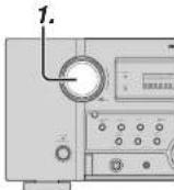
-
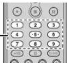
-
To select the input source for recording, turn the INPUT FUNCTION SELECTOR knob on the front panel or press the HOME button and then the appropriate numeric buttons 1 through 9 on the remote controller.
The input source is now selected and you may watch or listen to it as desired.
-
The currently selected input source signal is output to the TAPE OUT, CD/CDR OUT, VCR1 OUT, and DSS/VCR2 OUT outputs for recording.
-
Start recording to the recording component as desired.
Notes:
- When connecting only digital signal input, output cannot be made to the TAPEOUT, CD/CDR OUT, VCR1 OUT, or DSS/VCR2 OUT terminals. When using recording functions, be sure to also make connections for analog signal input.
- No conversion is made from Video signal input to S-Video signal output or from S-Video signal input to Video signal output. Always use the same signal type for both input and output.
• Video or audio signals input to HDMI input terminals cannot be recorded.
SELECTING ANALOG AUDIO INPUT OR DIGITAL AUDIO INPUT
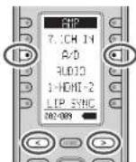
If you have already assigned the digital inputs, you can temporarily select the audio input mode for each input source as following procedures.
Switch the remote controller to AMP mode and press the < / > button until 002 is displayed. Then press the A/D button.
When this button is pressed, the input mode is switched in the following sequence.
Auto → HDMI → Digital → Analog → Auto
Auto mode:
The types of signals being input to the digital and analog input jacks for the selected input source are detected automatically.
If no digital signal is being input, the analog input jacks are selected automatically.
HDMI mode:
HDMI mode can be selected only when an HDMI input has been assigned as an input source.
When "HDMI AUDIO" under PREFERENCE of the SETUP MENU is set to "THROUGH", the HDMI mode cannot be selected.
Digital mode:
The input signal is fixed to an assigned digital input terminal.
Analog mode:
The analog input jacks are selected.
This selection is temporary and will not be stored in memory.
To store changes to the input mode, select "1. INPUT SETUP" from the MAIN MENU. (See page 23)
LISTENING THROUGH HEADPHONES
This jack may be used to listen to the unit's output through a pair of headphones. Be certain that the headphones have a standard 1/4" stereo phono plug.
Note that the speakers will automatically be turned off when the headphone jack is in use.
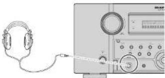
natural_image
Illustration of a headset connected to a digital audio workstation (no text or symbols visible)Notes:
- When using headphones, the surround mode will change to STEREO and Dolby Headphone by MENU and Cursor button.
- The surround mode returns to the previous setting as soon as the headphone plug is removed from the jack.
- The 7.1ch input mode returns to the previous setting as soon as the headphone plug is inserted to the jack.
natural_image
Line drawing of a headset connected to a digital audio workstation (no text or symbols visible)DOLBY HEADPHONE MODE
This feature simulates the waveforms of the actual sounds heard from the speakers.
When headphones are used, the MENU button automatically switches to the Dolby headphone mode.
The OSD that appears when the MENU button is pressed is shown below.
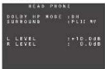
DOLBY HP (Headphone) MODE can be selected with the left and right cursor buttons.
BYPASS → DH (DOLBY Headphone) → BYPASS
BYPASS: Bypasses the Dolby headphone mode and delivers ordinary 2-channel stereo.
DH: Dolby Headphone is a signal processing system that delivers a sound similar to room speakers.
It makes it possible to experience the volume and space of a 5-channel surround system using ordinary stereo headphones.
When the PURE DIRECT mode is selected, Dolby surround processing is bypassed and “***” is displayed as the mode indication.
The surround mode can be selected when the modes in DH is selected.
L/R LEVEL can be set in the ±12 dB range.
Notes:
- The surround mode returns to the previous setting as soon as the plug is removed from the jack.
- In headphone mode, Tone Control and ACOUSTIC EQ are not available.
ATTENUATION TO ANALOG INPUT SIGNAL

If the selected analog audio input signal is greater than the capable level of internal processing, the "PEAK" indicator will light up on the front display. If this happens, switch the remote controller to AMP mode and press the < / > button until 004 is displayed. Then press the ATT button.
"ATT" indicator will be illuminated when this function is activated. The signal-input level is reduced by about half. Attenuation will not work with the output signal of TAPE-OUT, CD/CD-R, VCR1-OUT and DSS/VCR2-OUT.
This function is memorized for each individual input source.
7.1 CH INPUT
This unit is equipped for future expansion through the use of Multi channel Super Audio CD multichannel player or DVD-Audio player.
When this is selected, the input signals connected to the L(front left), R (front right). CENTER, SL (surround left), SR (surround right) and SBL (surround back left) and SBR (surround back right) channels of the 7.1 CH. In jacks are output directly to the front (left and right), center, surround (left and right) and surround back speaker systems as well as the pre-out jacks without passing through the surround circuitry.
In addition, the signal input to the SW (subwoofer) jack is output to the PRE OUT SW (subwoofer) jack. When 7.1 CH, INPUT is selected, the last video input used remains routed to the Monitor Outputs. This permits simultaneous viewing with video sources
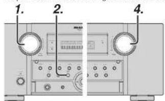
text_image
1. 2. 4.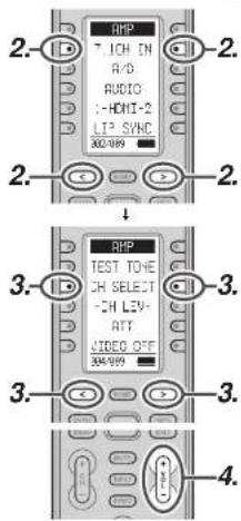
text_image
2. RHP 7.ICH IN A/D AUDIO 1-HDMI-2 LTP SVC 300-989 2. 3. 4. 3. 3. 3. 3. 3. 4.ENGLISH
-
Select a desired Video source to decide the routed video signal to the Monitor Outputs.
-
Press the 7.1 CH INPUT button on the front panel or switch the remote controller to AMP mode and press the < / > button until 002 is displayed. Then press 7.1 CH IN on the remote controller to switch to 7.1 channel input.
-
If it is necessary to adjust the output level of each channel, press the < / > button until 004 is displayed. Press the CH SELECT button on the remote controller.
Adjust the speaker output levels so that you can hear the same sound level from each speaker at the listening position. For the front left, front right, center, surround left, surround right and surround back speakers, the output levels can be adjusted between -12 to +12 dB.
The subwoofer can be adjusted between -18 and +12 dB.
These adjustments result will be stored to 7.1 CH. INPUT memory.
- Adjust the main volume with the MAINVOLUME knob or the VOL + / - buttons on the remote controller.
To cancel the 7.1 CH. INPUT, press the 7.1 CH INPUT button on the front panel or press 7.1 CH IN on the remote controller.
Notes:
- When the 7.1 CH. Input is in use, you may not select a surround mode, as the external decoder determines processing.
- In addition, there is no signal at the record outputs when the 7.1 CH. Input is in use.
• Furthermore, the following functions are not available during 7.1 CH Input use.
Test Tone, NIGHT MODE, Source Direct, Pure Direct, RE-EQ, Tone Control, Multi EQ.
ENGLISH
AUX INPUT
If you don't need to connect 7.1 Ch. input terminals with multi channel decoder,
L(front left) and R (front right) inputs terminals are available as AUX input.
In this case, You can connect additional audio source to AUX as other audio input terminals.
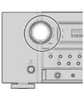
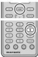
To select AUX, turn the INPUT SELECTOR knob on the front panel, or press HOME button and press 6 button on remote controller.
VIDEO ON/OFF
When no video signal is connected to the unit or a DVD, etc., is connected directly to your TV, the unnecessary video circuit can be turned off by selecting the "VIDEO OFF" setting.
To select video off, switch the remote controller to AMP mode and press the < / > button until 004 is displayed. Then press the VIDEO OFF button.
V-OFF
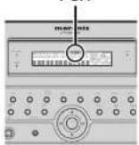
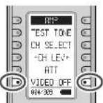
The "V-OFF" indicator on the main unit display panel will light.
TV AUTO ON/OFF FUNCTION
This function allows the component connected to the TV-VIDEO in jack to control the power (ON/OFF) to the unit.
AUTO POWER ON
- Be sure the TV auto mode is ENABLED. (Refer to page 33)
- Connect your TV TUNER (etc) to the TV-VIDEO in terminal. Be sure to connect the VIDEO input.
- Turn OFF the power to the TV TUNER and the unit.
- Turn ON the TV TUNER and tune in a receivable station.
- When the station is received, this unit turns ON and TV is selected automatically.
AUTO POWER OFF
- In the above situation, turn the TV TUNER OFF or select a channel that does not contain any broadcast.
- The power to the unit switches to STANDBY after approx. 5 minutes.
Notes:
- AUTO POWER OFF is canceled if this unit is set to a source other than TV.
The function reactivates when TV is selected again. - Some TV broadcasts may cause the TV AUTO FUNCTION to turn ON.
- The S-Video terminal does not support "TV AUTO ON/OFF" function.
- This function is inactive when STANDBY MODE is set to ECONOMY. To use this function, set STANDBY MODE to NORMAL.
LIP.SYNC
Depending on the image device (TV, monitor, projector, etc.) connected to the unit a time lag can occur between image signal processing and audio signal processing. Though minor, this time lag can interfere with movie and music enjoyment. The LIP. SYNC feature delays the audio signal with respect to the image signal output from the unit to correct the time lag between the sound and image. It can be operated with the "LIP.SYNC" and ◀ and ▶ cursor buttons of the remote controller. To select Lip-sync mode, set the remote controller to the AMP mode, press the </> button until 002 is displayed. Press the LIP. SYNC button. The initial setting is OFF (0 ms).The time lag can be adjusted in 10 ms steps up to 200 ms.
Watch the picture on the image device (i.e., TV, monitor, projector, etc.) as you adjust the time lag.
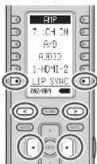
Note:
- The LIP.SYSNC feature turns OFF (0 ms) in the SOURCE/PURE DIRECT mode. When the SOURCE/PURE DIRECT mode is deactivated, the set value of the LIP.SYSNC feature is automatically restored.
- Even if you do not correct the time lag manually this way, audio and video are automatically synchronized when the unit is connected to TV or Projector supporting Auto Lipsync Correction in HDMI 1.3a. 1'or instructions on Auto Lipsync Correction, see page 34.
DUAL BACKUP MEMORY
The unit stores settings information in nonvolatile memory even when the main power supply is turned off. Using the Dual Backup Memory function, you can write settings information to another memory area to back up saved settings for recovery anytime as needed.
BACKUP
Set up the unit in the state for which you want to store the settings. Hold the MEMORY and ENTER buttons on the front panel simultaneously for at least 3 seconds.
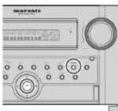
"MEMORY SAVING" is displayed and the unit's settings are saved. The stored settings information is retained until Dual Backup Memory is used again and the information is overwritten.
MEMORY SAVING
Note:
- The following settings values cannot be backed up.
- Main Zone Volume
• Zone Volume
• Zone Speaker Volume
RECOVERY OF MEMORY
Recover backed up settings as follows.
Hold the MEMORY and MENU buttons on the front panel simultaneously for at least 3 seconds.

"MEMORY LOAD" is displayed and the unit's stored settings are reapplied.
The unit temporarily enters standby mode. If there is no backup data, "NO BACKUP" is displayed and no data is recovered.
MEMORY LOAD
NO BACKUP
Note:
Because the following settings values are not backed up, each Volume value is set to Minimum.
- Main Zone Volume
- Zone Vol
• Zone Speaker Volume
TUNER OPERATION
TO SELECTING THE TUNER
(Using the unit)
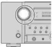
To select TUNER, turn the INPUT SELECTOR knob on the front panel.
(Using the remote controller)
There are three ways to select TUNER.
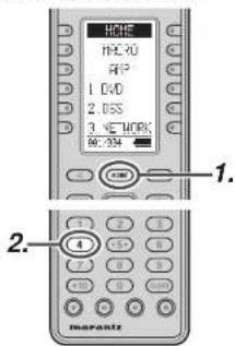
text_image
HCPE HCL30 RIP 1. CVD 2. BSS 3. NETWORK W: 204 1. 2. A marantz- Press the HOME button
- Press the 4 button.
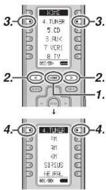
text_image
3. 4. TUNER 5. CD 6. PUX 7. VCR1 8. TV 80/80 2. 2. 1. 4. 4.- Press the HOME button.
- Press the </> button until 002 is displayed.
- Press the 4.TUNER button.
- Press the 4.TUNER button.

text_image
HOME MACRO APP 1. DVD 2. OSS 3. NETWORK VOL-50Hz 1. 2. 4. 3. 4. 3.- Press the HOME button.
- Press the AMP button.
- Press the </> button until 008 is displayed.
- Press the TUNER button.
LISTENING TO THE TUNER
AUTO TUNING
text_image
1. 3. 2.
text_image
3. TURER FM AM VH SIRIUS NEURIL 2. 2. 4. 4.(Using the unit)
- Turn the INPUT SELECTOR knob to select "TUNER".
- Press the BAND button to select either FM AM.
- Press the ▲ or ▼ cursor buttons on the front Panel for more than 1 second to start the auto tuning function.
- Automatic searching begins then stops when a station is tuned in.
(Using the remote controller)
- Switch the remote controller to TUNER mode.
- Press the < / > button until 001 is displayed.
- Press the FM or AM button.
- Press and hold the ▲ or ▼ cursor button for 1 second or more.
- Automatic searching begins then stops when a station is tuned in.
ENGLISH
Note:
The same operations performed using the ▲/▼ buttons can be performed using the - TUNE + button of item 002 when the remote controller is in TUNER mode.
If tuning does not stop at the desired station, use to the "Manual Tuning" operation.
MANUAL TUNING

text_image
1. 2. 3.
text_image
3. 3. 2. 2. 4. 4.(Using the unit)
- Turn the INPUT SELECTOR knob to select "TUNER".
- Press the BAND button to select either FM or AM.
- Press the ▲ or ▼ cursor buttons on the front Panel to select the desired station.
(Using the remote controller)
- Switch the remote controller to TUNER mode.
- Press the </> button until 001 is displayed.
- Press the FM or AM button.
- Press the ▲ or ▼ cursor buttons to tune in the desired station.
DIRECT FREQUENCY CALL
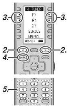
text_image
3. F1 A1 X1 SIRUS NEURAL 65/001 2. 4. 2. 5.- Switch the remote controller to TUNER mode.
- Press the </> button until 001 is displayed.
- Press the FM or AM button.
- Press the GUIDE button on the remote controller, display will show "FREQ---".
- Input your desired station's, frequency with the ten numbered keypad on the remote controller.
- The desired station will automatically be tuned.
(FM) TUNING MODE (AUTO STEREO OR MONO)
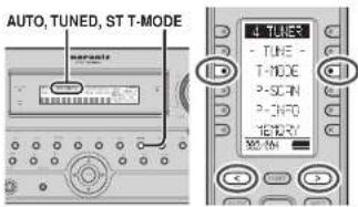
text_image
AUTO, TUNED, ST T-MODE TUNER TUNE T-MODE P-SCAN P-INFO MEMORY MENWhen in the auto stereo mode, AUTO indicator will be illuminated on the display.
The "ST" indicator is illuminated when a stereo broadcast is tuned in.
At open frequencies, the noise is muted and the "TUNED" and "ST" indicators are not illuminated. If the signal is weak, it may be difficult to tune into the station in stereo. In such a case, press the T-MODE button on the front panel, or switch the remote controller to TUNER mode and press the < / > button until 002 is displayed. Then press the T-MODE button.
"AUTO" indicator is not illuminated, if FM stereo broadcasts are received in monaural and the "ST" indicator is not illuminated.
To return to auto stereo mode, Press the T-MODE button or Press T-MODE button on the remote controller again. AUTO indicator is illuminated the display.
PRESET MEMORY
With this unit you can preset up to 60 FM/AM stations in any order. For each station, you can memorize the frequency and reception mode if desired.
AUTO PRESET MEMORY
This function automatically scans the FM and AM band and enters all stations with proper signal strength into the memory.
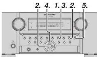
text_image
2. 4. 1.3. 2. 5.- To select FM, press the BAND button on the front panel.
- While pressing the MEMORY button, press the cursor button.
" AUTO PRESET" will appear on the display, and scanning starts from the lowest frequency. -
Each time the tuner fi nds a station, scanning will pause and the station will be played for fi ve seconds.
During this time, the following operations are possible.
The band can be changed by the BAND button. -
If no button is pressed during this period, the current station is memorized in location Preset 02.
If you wish to skip the current station, press the ▲ cursor button during this period, this station is skipped and auto presetting continues.
- Operation stops automatically when all 60 preset memory positions are filled or when auto scanning attains the highest end of all bands. If you desire to stop the auto preset memory at anytime, press the CLEAR button.
MANUAL PRESET MEMORY
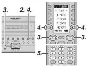
text_image
3. 2. 4. maranta 3. 4. 3. 3. 5.(Using the unit)
- Tune into the radio station you desire (Refer to the "MANUAL TUNING" or "AUTO TUNING" section).
- Press the MEMORY button on the front panel. *--* (preset number) starts blinking on the display.
- Select the preset number by pressing the ◀ or ▶ cursor buttons, while this is still blinking (approx. 5 seconds)
- Press the MEMORY button again to enter. The display stops blinking.
The station is now stored in the specified preset memory location.
(Using the remote controller)
- Tune into the radio station you desire (Refer to the "MANUAL TUNING" or "AUTO TUNING" section).
- Switch the remote controller to TUNER mode.
- Press the </ / > button until 002 is displayed in TUNER mode.
- Press the MEMORY button on the remote controller. “—” (preset number) starts blinking on the display.
- Enter the desired preset number by pressing the numeric buttons.
Note:
- When entering a single digit number (2 for example), either input "02" or just input "2" and wait for a few seconds.
RECALLING A PRESET STATION

(Using the unit)
- Select the desired preset station by pressing the ◀ or ▶ cursor buttons on the front panel.
(Using the remote controller)
- Switch the remote controller to TUNER mode.
- Press the ◀ or ▶ cursor buttons to tune in the desired preset station.
Or enter the preset station number with the numeric buttons.
Note:
The same operations performed using the ◀ or ▶ buttons can be performed using the CH +/- buttons when the remote controller is in TUNER mode.
PRESET SCAN
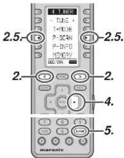
text_image
4 TUNER TUNE T-DOLE P-SCAN P-INFO MEMORY 2.5. 2.5. 2. 2. 4. 5. maranta(Using the remote controller)
- Switch the remote controller to TUNER mode.
- Press the </ / > button until 002 is displayed and press the P-SCAN button on the remote.
"PRESET SCAN" appears on the front display and then the preset station with the lowest preset number is recalled first.
- Preset stations are recalled in sequence (No.1 → No.2 → etc.) for 10 seconds each. No stored preset number will be skipped.
- You can last forward the preset stations, press the ▶ cursor button continuously.
- When the desired preset station is received, cancel the preset scan operation by pressing the CLEAR button or P-SCAN button on the remote controller.
PRESET CHANNEL LIST DISPLAY
A complete list of the broadcast channels stored in this unit can be displayed.

text_image
2.4. TJHE - P-SON P-TNF3 RENTON 2.4.- Switch the remote controller to TUNER mode.
- Press < / > on the remote controller to display 002, then press P-INFO button.
- The list of preset channels will be displayed on the screen of the TV monitor connected to this unit.

- Up to 10 channels can be displayed at a time. If there are more than 10 channels, press P-INFO button on the remote controller once more to display the next page.
The list display will disappear automatically in 5 seconds.
ENGLISH
CLEARING STORED PRESET STATIONS
You can remove preset stations from the memory using the following procedure.
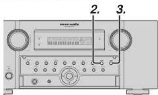
text_image
2. 3.
text_image
TUNES -TUNE + -T-MODE -P-SCRN -P-INFO -METRUM 2. 2. 3. marantz- Recall the preset number to be cleared with the method described in "Recalling" a preset station.
- Press the MEMORY button on the front part or press the MEMORY button on the remote.
- The stored preset number blinks in the display for 5 seconds. While blinking, press the CLEAR button on the front panel or the remote controller.
- xx CLEAR ^* appears on the display to indicate that the specified preset number has been cleared.
Note:
• To clear all stored preset stations, press and hold the CLEAR and the ENTER buttons for two seconds.
ENGLISH
SORTING PRESET STATIONS

natural_image
Front view of a vintage audio recording device with multiple knobs and a digital display (no visible text or symbols)If you have stations memorized, and there is a gap in the sequential order:
I.e. the stations are stored as follows
1) 87.1 MHz
2) 93.1 MHz
3) 94.7 MHz
10) 105.9 MHz
(notice there is no stations programmed for pre sets for 4-9); you can have pre set 10 become pre set 4: To sort the numbers, press the ▼ cursor button while holding down the MEMORY button.
"PRESET SORT" will appear on the display and sorting will be done.
NAME INPUT OF THE PRESET STATION.
This function allows the name of each preset channel to be entered using alphanumeric characters. Before name inputting, you need to store preset stations with the preset memory operation.
text_image
4. 5. 2. 5. 6.
text_image
TONE -TUNE + -T-HODE -SON -P-CNFD METHRY 2.5.6. -2.5.6. 5. 4. 5. 4.- Recall the preset number to be inputled name with the method described in "Recalling" a preset station.
- Press the MEMORY button on the front panel or press the MEMORY button on the remote controller for more than 3 seconds.
- The left most column of the station name indicator fl ashes, indicating the character entry ready status.
- When you press the ▲ or ▼ cursor buttons on the front panel or the ▲ or ▼ cursor buttons on the remote controller, alphabetic and numeric characters will be displayed in the following order:
$$ \begin{array}{l}\mathrm{A} \rightarrow \mathrm{B} \rightarrow \mathrm{C} \dots \mathrm{Z} \rightarrow 1 \rightarrow 2 \rightarrow 3 \dots 0 \rightarrow - \rightarrow +\\rightarrow / \rightarrow (\text { Blank }) \rightarrow \mathrm{A}\end{array} $$
$$ \begin{array}{c}\text {UP} \rightarrow\\rightarrow \text {DOWN}\end{array} $$
- After selecting the first character to be entered, press the MEMORY or ENTER button, or press the MEMORY button on the remote controller. The entry in this column is fixed and the next column starts to flash. Fill the next column the same way.
To move back and forth between the characters, press the ◀/▶ cursor buttons on the front panel or the remote controller.
Note:
- Unused columns should be filled by entering blanks.
- To save the name, press the MEMORY or ENTER button on the front panel, or press the MEMORY button on the remote controller for more than 2 seconds.
Instead of using the ▲ and ▼ cursor buttons or the on the front panel remote controller to select characters, characters can be input from the numeric keys of the remote controller. See the below table for a correspondence between characters and numeric keys.
| Ten keypad Press, press again, press again, etc. | |
| 1 | A→B→C→I→A |
| 2 | D→E→F→2→D |
| 3 | G→H→I→3→G |
| 4 | J→K→L→4→J |
| 5 | M→N→O→5→M |
| 6 | P→Q→R→6→P |
| 7 | S→T→U→7→S |
| 8 | V→W→X→8→V |
| 9 | Y→Z→space→S→Y |
| 0 | -→←→I→0 |
RDS OPERATION
Now in use in many countries, RDS (Radio Data System) is a description of the station's programming hidden space in the FM signal.
Your new unit is equipped with RDS to assist in the selection of FM stations using station and network names, rather than broadcast frequencies. Additional RDS functions include the ability to search for programme types.
RADIO TEXT
Some RDS stations broadcast RADIO TEXT, which is additional information on the station and programme being broadcast.
RADIO TEXT information appears as 'running' text in the display. RADIO TEXT is transmitted character by the radio station. As a result of that it may take some time until the entire text has been completely received.
RDS DISPLAY
When a unit is tuned to an FM station that is transmitting RDS data, the Front Panel Information Display will automatically show the station name or RDS TEXT in place of the typical display of the station's broadcast frequency.
To change the display, switch the remote controller to TUNER mode and press the </ / > button until 004 is displayed. Press the DISPLAY button.
PROGRAMME TYPE (PTY) DISPLAY
The RDS system categorizes programmes according to their genre into different programme type (PTY) groups. To display the programme type information of the current station, switch the remote controller to TUNER mode and press the < / > button until 004 is displayed. Press the PTY button.
PS (Program Service Name) Frequittio(RADIO TEXT) →
PTY AUTO SEARCH
Your unit is equipped to automatically search for stations transmitting any of 29 different programme types. To search for a PTY, follow these procedures:

text_image
2. 1.3.4 DISPLAY PTY RF STM DHP 004-004 1.3.4 2. marants- Press the PTY button in the TUNER MODE on the remote controller. The current station's PTY will be displayed, or the currently selected PTY group will be displayed in blinking if no station or RDS data is present.
- To change to a new PTY type, press the TUNING ▲ or ▼ button on the front panel or numeric buttons on the remote controller until the desired PTY is shown in the display.
- Once the desired PTY group or type has been selected, press the PTY button while the display blink (approx. 5 seconds). The PTY Auto search will start, and the tuner will pause at each station broadcasting RDS PTY information corresponding to the selected choice.
- To advance to the next RDS station with the desired PTY, press the PTY button again within 5 seconds.
| NUMSER | DISPLAY | PROGRAMME TYPE |
| 1 | POP | Pop Music |
| 2 | ROCK | Rock Music |
| 3 | MOR | M. D. R. Music |
| 4 | LIGHT | Light classical |
| 5 | CLASSIC | Serious classical |
| 6 | NEWS | News |
| 7 | AFFAIR | Current Affairs |
| 8 | INFO | Information |
| 9 | SPORT | Sport |
| 10 | EDUCATE | Education |
| 11 | DRAMA | Drama |
| 12 | CULTURE | Culture |
| 13 | SCIENCE | Science |
| 14 | OTHERS | Varied |
| 15 | OTHER | Other Music |
| 16 | WEATHER | Weather |
| 17 | FINANCE | Finance |
| 18 | CHILDREN | Children's programmes |
| 19 | SOCIAL | Social Affairs |
| 20 | RELIGN | Religion |
| 21 | PHONE IN | Phone In |
| 22 | TRAVEL | Travel |
| 23 | HORRIER | Hobbies |
| 24 | JAZZ | Jazz Music |
| 25 | COUNTRY | Country Music |
| 26 | NATION | National Music |
| 27 | OLDIES | Orders Music |
| 28 | FOLK | Folk Music |
| 29 | DOCUMENT | Documentary |
ZONE SYSTEM
The Zone System mode allows the same source or different sources to be heard in two ZONEs other than where this unit is installed.
To use the zone system, connect the audio from the ZONE OUT A and B AUDIO output terminals to the ZONE A and B amps.
Connect the VIDEO output (ZONE OUT) terminal to the monitor in Zone A.
(ZONE OUT terminal is linked to the source selector in Zone A.)
If a surround channel back speaker or speaker C (see page 18) are not used in the ZONE where this unit is installed, the zone speaker system can be used with the amp for the surround back channel.
Also, the COMPONENT VIDEO MONITOR OUT 2 terminal can be used for the monitor output of ZONE A.
This unit supports zone system functions such as source selectors, OSD menu systems, sleep timers and remote control.
ZONE PLAYBACK USING THE ZONE OUT TERMINALS
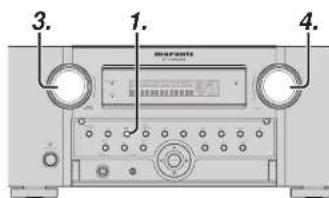
text_image
3. 1. 4.- Pressing the ZONE button on the unit one time accesses the ZONE A settings. Pressing it two times accesses the ZONE B settings. Then, pressing it a third time turns the zone feature off.
- When the ZONE setting mode is engaged, one of the following screens appears on the display for 10 seconds.
* Display when ZONE A is selected

* Display when ZONE B is selected

- Select an input source with the INPUT SELECTOR knob.
- Turn the VOLUME knob to set the volume of the ZONE used in the zone system as you like.
Note:
• The sleep timer, monaural output and other features can also be set using the MAIN MENU. (See page 35)
ENGLISH
This unit allows you to connect another set of power amp and place them in a different ZONE or separated area for listening to music.
3.4.1.
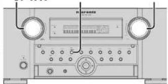
natural_image
Front view of a vintage electronic device with two circular ports and a central control panel (no visible text or labels)- Pressing the ZONE SPEAKER button on the unit one time accesses the ZONE SPEAKER A settings. Pressing it two times accesses the ZONE SPEAKER B settings. Then, pressing it a third time turns the ZONE SPEAKER feature off.
- When the ZONE SPEAKER setting mode is engaged, one of the following screens appears on the display for 10 seconds.
* Display when ZONE SPEAKER A is selected

* Display when ZONE SPEAKER B is selected

- Select an input source with the INPUT SELECTOR knob.
- Turn the VOLUME knob to set the volume of the ZONE used in the zone system as you like.
Note:
- The sleep timer, monaural output and other features can also be set using the MAIN MENU. (See page 35.)
Notes for Zone Speaker
• The Zone Speaker mode can be set for only one of the ZONEs, A or B.
- The ZONE SPEAKER output can be used when Surround Back Speaker = "NONE. ZSP A or ZSP B" in the SPEAKER SETUP menu. (See SPEAKER SETUP, page 29)
- "The Surr. Back Speakers are in use" is displayed when the ZONE SPEAKER button is pressed when the Surround Back Speaker is not set to "NONE, ZSP A or ZSP B" in the SPEAKER SETUP menu. (See SPEAKER SETUP, page 29)
- The Zonespeaker mode cannot be used at the same time as the speaker C. When connecting for zone use, set the SPEAKER C selector switch on the rear panel to OFF.
- When the unit is put in ZONE SPEAKER mode and ZSP A or ZSP B has been set as the Surround Back Speaker (P.29), the ZONE SPEAKER function can be turned on automatically simply by pressing the SOURCE button.
CONTROLLING THE ZONE FUNCTION FROM ANOTHER ROOM
The ZONE function can be controlled from another ZONE, even from a ZONE not set for this unit, by connecting a MARANTZ product with external IR receiver or infrared receiver using the RC2001 or Zone remote controller RC101. (See page 17)
SET THE REMOTE CONTROLLER TO A MODE THAT CONTROLS ZONE A OR B.
Operations such as switching the input source between ZONE A and B and turning the ZONE function on/off can be performed by setting the ZONE for using the remote controller.
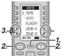
text_image
NONE 9. TAPE VCR2 FLASHA ZONE-A ZONE-B 3. 3. 2. 1. 2.- Press the HOME button.
- Press the </> button umtil 003 is displayed.
- Press the ZONE-A or ZONE-B button.
ZONE A mode (default setting)
ZONE B mode
ZONE C mode (this zone not used by this unit)
ZONE D mode: MAIN ZONE (the ZONE in which this unit is installed)

- (In the example given here, the user changes the mode used to control ZONE A.) Hold down the SET button and ZONE button simultaneously until the Send indicator flashes twice. The backlight lights.
- Press the ZONE A button. The Send indicator flashes twice when the setting is complete. The following buttons are now used for ZONE A only. Volume adjustment, sleep timer, mute and input functions can be selected from the ZONE.
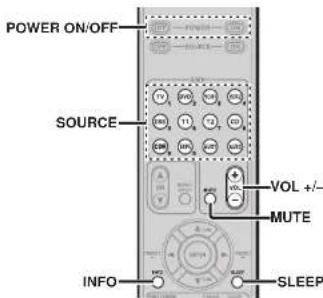
text_image
POWER ON/OFF SOURCE VOL +/- MUTE INFO SLEEPOnce the operation in 2. is performed, pressing the ZONE B button switches the mode being controlled to ZONE B. Pressing the ZONE D button switches the mode being controlled to MAIN ZONE.
Notes:
- When using a tuner (AM or FM) in the MAIN ZONE and tuner is selected for the input function of ZONE, the tuner cannot be used from ZONE. Only the same broadcast as that being used for MAIN ZONE can be listened to.
• ZONE output is analog only. Digital signal input is not supported.
Switch the remote controller to ZONE-A or ZONE-B mode.
ZONE Speakers can be controlled on the first page of the remote controller.

An RC101 remote controller set to ZONE A or ZONE B can be switched to control the ZONE Speaker function.
- (In the example given here, the setting for ZONE is switched to the setting for ZONE Speakers.)
Hold down the SET button and POWER ON button simultaneously until the Send indicator fl ashes twice.
The backlight continues to flash.
- Press numeric key 2.
ZONE mode: 1 (default setting)
ZONE Speaker mode: 2
Notes:
- To restore the settings for ZONE, press numeric key 1 in step 2.
-
Only the MAIN ZONE can be controlled when ZONE D mode is set.
-
Press the ENTER button. Once settings are complete, the Send indicator fl ashes twice.
The following buttons are used for set ZONE mode or ZONE Speaker mode only.
text_image
POWER ON/OFF SOURCE VOL +/- MUTE INFO SleepOSD INFORMATION DISPLAY ON THE ZONE MONITOR
The setting status of ZONE A can be displayed on a TV monitor connected to the video output for ZONE (ZONE OUT) terminals.
- Switch the remote controller to ZONE-A mode.
- Press the INFO button.
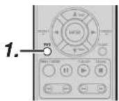
- Press the INFO button.
OSD information is displayed on the ZONE monitor.

Notes:
The OSD cannot be displayed on the ZONE monitor when the OSD is being displayed for ZONE.
ENGLISH
To control the unit by your RC2001, you have to select the device AMP, NETWORK or TUNER by pressing the function selector in HOME mode. Please refer below for the details in AMP, NETWORK and TUNER mode. Note:
Except for some buttons, soft buttons result in the same operation as pressing either the Left or Right buttons for each command. (Excluding the * symbol)
HOME MODE
| HOTY | ON/OFF | ON | HOMES |
| HOME | |||
| HACRB | |||
| M2 | |||
| 1. DVD | |||
| 2. DSS | |||
| 3. NETWORK | |||
| BRL/804 | |||
| SOURCE ON/OFF Turn the AV8003 on and off | |
| POWER ON Turn the AV8003 on | |
| POWER OFF Turn the AV8003 off | |
| Soft button Refer to the list of soft buttons in the table below. | |
| < / > Scroll the page | |
| INFO OSD information on/off | |
| Cursor Move the cursor for setting in SETUP MENU mode | |
| ENTER | Enter the SETUP MENU |
| Confirms the setting in SETUP MENU mode | |
| MENU Enter the SETUP MENU | |
| EXIT Exits from SETUP MENU | |
| MUTE Decreases the sound temporarily | |
| VOL +/- Adjust the over all sound level | |
| 1 SELECT DVD function | |
| 2 SELECT DSS function | |
| 3 SELECT NETWORK function | |
| 4 SELECT TUNER function | |
| 5 SELECT CD function | |
| 6 SELECT AUX function | |
| 7 SELECT VCR1 function | |
| 8 SELECT TV function | |
| 9 SELECT TAPE function | |
List of Soft buttons
| Page | Command | Note |
| 1 | HOME | |
| MACRO | Switch the remote controller to MACRO mode. | |
| AMP | Switch the remote controller to AMP mode. | |
| 1.DVD | Switch the remote controller to 1. DVD mode. | |
| 2.DSS | Switch the remote controller to 2. DSS mode. | |
| 3.NETWORK | Switch the remote controller to 3. NETWORK mode. | |
| 2 | HOME | |
| 4.TUNER Switch the remote controller to 4. TUNER mode. | ||
| 5.CD | Switch the remote controller to 5. CD mode. | |
| 6.AUX | Switch the remote controller to 6. AUX mode. | |
| 7.VCR1 Switch the remote controller to 7. VCR1 mode. | ||
| 8.TV | Switch the remote controller to 8. TV mode. | |
| 3 | HOME | |
| 9.TAPE | Switch the remote controller to 9. TAPE mode. | |
| VCR2 Switch the remote controller to VCR2 mode. | ||
| PLASMA | Switch the remote controller to PLASMA mode. | |
| ZONE-A | Switch the remote controller to ZONE-A mode. | |
| ZONE-B | Switch the remote controller to ZONE-B mode. | |
| 4 | HOME | |
| IPOD | Switch the remote controller to IPOD mode. | |
| V-SWITCH | Switch the remote controller to V-SWITCH mode. | |
| CD-R | Switch the remote controller to CDR mode. | |
| MD | Switch the remote controller to MD mode. | |
| BLU-RAY Switch the remote controller to BLU-RAY mode. | ||
MACRO MODE
A macro is a function for performing multiple button operations at one time. Ex.) WATCH DVD
Turn on the AV8003. → Turn on the TV. → Turn on the DVD. → Set the TV function to DVD. → Set the AMP function to DVD. → Set the remote controller to DVD mode.
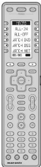
text_image
PS-80 ALL-IN ALL-OFF ATCH DVD ATCH DSS ATCH NET 801-803 marantzList of Soft buttons
| Page | Command | Note |
| 1 | MACRO | |
| ALL_ON | Turn on all components. | |
| ALL-OFF Turn off all components. | ||
| WATCH_DVD | View DVD | |
| WATCH_DSS | View DSS | |
| WATCH_NET | View NETWORK | |
| 2 | MACRO | |
| LISTEN_AM | Listen to AM | |
| LISTEN_FM | Listen to FM | |
| LISTEN_XM | Listen to XM | |
| LISTEN_SR | Listen to SIRIUS | |
| LISTEN_CD | Listen to CD | |
| 3 | MACRO | |
| LSTN_IPOD | Listen to iPod | |
| WATCH_VCR | View VCR | |
| WATCH_TV | View TV | |
AMP MODE

text_image
ON/OFF POWER RHP M-DEK SLEEP DISPLAY SURR MODE - INPUT + 836.409 RHP M-DEK SLEEP DISPLAY SURR MODE - INPUT + 836.409 RHP M-DEK SLEEP DISPLAY SURR MODE - INPUT + 1 2 3 4 5 6 7 8 9 10 11 12 mapantz| SOURCE ON/OFF Turn the AV8003 on and off | |
| POWER ON Turn the AV8003 on | |
| POWER OFF Turn the AV8003 off | |
| Soft button Refer to the list of soft buttons in the table below. | |
| HOME Switch the remote controller to HOME mode. | |
| < / > Scroll the page | |
| INFO OSD information on/off | |
| Cursor Move the cursor for settling in SETUP MENU mode | |
| ENTER | Enter the SETUP MENU |
| Confi rms the settling in SETUP MENU mode | |
| MENU Enter the SETUP MENU | |
| EXIT Exits from SETUP MENU | |
| MUTE Decreases the sound temporarily | |
| VOL + / - Adjust the over all sound level | |
| 1 Select DVD function | |
| 2 Select DSS function | |
| 3 Select NETWORK function | |
| 4 Select TUNER function | |
| 5 Select CD function | |
| 6 Select AUX function | |
| 7 Select VCR1 function | |
| 8 Select TV function | |
| 9 Select TAPE function | |
List of Soft buttons
| Page | Command | Note |
| 1 | AMP | |
| M-DAX | M-DAX ON/OFF | |
| SLEEP | Sets the sleep timer function | |
| DISPLAY | Changes the front display mode | |
| SURR MODE | Sets the surround mode | |
| - INPUT + | Switches the amp function* | |
| 2 | AMP | |
| 7.1CH IN | Turns 7.1CH INPUT mode ON/OFF. | |
| A/D SELECT ANALOG/DIGITAL | ||
| AUDIO | SELECT AUDIO mode | |
| 1-HDMI-2 | [Left] SELECT HDMI OUTPUT 1* | |
| [Right] SELECT HDMI OUTPUT 2* | ||
| LIP SYNC | Selects the LIP.SYNC mode | |
| 3 | AMP | |
| - BASS + | [Left] BASS -* | |
| [Right] BASS -* | ||
| -TREBLE+ | [Left] TREBLE -* | |
| [Right] TREBLE +* | ||
| RE-EQ | RE-EQ ON/OFF | |
| NIGHT | NIGHT mode ON/OFF | |
| EQ | SELECT EQ mode | |
| 4 | AMP | |
| TEST TONE | Select TEST TONE menu | |
| CH SELECT | Call up SETUP MENU and adjusts speaker levels or 7.1ch input setup | |
| -CH LEV+ | [Left] CH LEVEL-* | |
| [Right] CH LEVEL+* | ||
| ATT | Reduces the input level | |
| VIDEO OFF | VIDEO OFF | |
| 5 | AMP | |
| AUTO SURR | Select AUTO SURROUND mode | |
| STEREO | Select STEREO mode | |
| P DIRECT | Select PURE DIRECT mode | |
| THX | Select THX mode | |
| M-CH ST | Select MULTI CHANNEL STEREO mode | |
| 6 | AMP | |
| DO | Select DOLBY mode | |
| DTS | Select DTS mode | |
| ES/EX | Select EX/ES mode | |
| CS2 | Select CS2 mode | |
| VIRTUAL Select V | RITUAL mode | |
ENGLISH
| Page | Command | Note |
| 7 | AMP | |
| DVD | Select DVD function | |
| TV | Select TV function | |
| VCR1 Select VCR1 function | ||
| DSS | Select DSS function | |
| AUX | Select AUX function | |
| 8 | AMP | |
| TAPE | Select TAPE function | |
| CD | Select CD function | |
| TUNER Select TUNER function | ||
| NETWORK | Select NETWORK function | |
| 9 | AMP | |
| P. AMP ON | Use when you want to turn on the MM8003 by itself. | |
| P. AMP OFF | Use when you want to turn off the MM8003 by itself. | |
ENGLISH
NETWORK MODE
| 103 | ||
| Soft button Refer to the list of soft buttons in the table below. | |
| HOME Switch the remote controller to HOME mode. | |
| < / > Scroll the page | |
| GUIDE Move to top of NETWORK page | |
| INFO Used for displaying file details, etc. | |
| Cursor Used for moving the cursor, etc. | |
| ENTER Used for item selection, etc. | |
| MENU Enter the Tool menu | |
| EXIT Used to return to the previous page, etc. | |
| CH-/- Switch the page | |
| ▶ | Play |
| ◀◀ / ▶◀ | Skip forward or previous track |
| ■ | Stop |
| II | Pause |
| 0-9 Used during NET WORK settings | |
| Blue Move to top of MUSIC page | |
| Red Move to top of P HOTO page | |
| Green Move to top of VIDEO page | |
| Yellow Move to top of SERVER page | |
List of Soft buttons
| Page | Command | Note |
| 1 | 3.NETWORK | Select NETWORK function |
| <--> | (left) REWIND* | |
| (Right) FAST FORWARD* | ||
| RANDOM | RANDOM play | |
| REPEAT | REPEAT play | |
| TOP Move to top of NETWORK page | ||
| - PAGE 4 | (left) Move to previous page* | |
| (right) Move to next page* | ||
| 2 | 3.NETWORK | Select NETWORK function |
| MUSIC ALL | Move to All Songs | |
| M ARTIST | Move to MUSIC ARTIST | |
| M ALBUM | Move to MUSIC ALBUM | |
| M GENRE | Move to MUSIC GENRE | |
| M P-LIST | Move to MUSIC PLAYLIST | |
| 3 | 3.NETWORK | Select NETWORK function |
| PHOTO ALL | Move to ALL PHOTO | |
| P ALBUM | Move to PHOTO ALBUM | |
| P P LIST | Move to PHOTO PLAYLIST | |
| 4 | 3.NETWORK | Select NETWORK function |
| VIDEO ALL | Move to ALL Video | |
| V ALBUM | Move to VIDEO ALBUM | |
| V GENRE | Move to VIDEO GENRE | |
| V P LIST | Move to VIDEO PLAYLIST | |
| 5 | 3.NETWORK | Select NETWORK function |
| PLAYLIST | Add to playlist | |
| BILINGUAL | Switch audio during movie playback | |
| SETTINGS | Move to SETTINGS MENU | |
| RESTART | Restart NETWORK | |
TUNER MODE
| 71 FP | ||
| FM | ||
| RH | ||
| XII | ||
| SIRIUS | ||
| NEURL | ||
| 00:004 | ||
| < | > | |
| OK | > | |
| MINT | ||
| ON | ON | |
| ON | ON | |
| ON | ON | |
| ON | ON | |
| ON | ON | |
| ON | ON | |
| ON | ON | |
| ON | ON | |
| ON | ON | |
| ON | ON | |
| ON | ON | |
| ON | ON | |
| ON | ON | |
| ON | ON | |
| ON | ON | |
| Soft button Refer to the list of soft buttons in the table below. | |
| HOME Switch the remote controller to HOME mode. | |
| < / > Scroll the page | |
| GUIDE Enter F-DIRECT mode. | |
| Cursor UP | Frequency scan up |
| Cursor DOWN | Frequency scan down |
| Cursor LEFT | Selects a preset station down |
| Cursor RIGHT | Selects a preset station up |
| CH + / - | Selects a preset station up and down |
| 0-9 | Input the numeric |
| CLEAR | Clears the inputting |
List of Soft buttons
| Page | Command | Note |
| 1 | 4.TUNER | Select TUNER function |
| FM Select FM | ||
| AM | Select AM | |
| XM | Select XM | |
| SIRIUS | Select SIRIUS | |
| NEURAL | Select NEURAL AUDIO | |
| 2 | 4.TUNER | Select TUNER function |
| -TUNE + | (Left) Frequency scan down* | |
| (Right) Frequency scan up* | ||
| T-MODE | Select MONOSTEREO | |
| P-SCAN | Select PRESET SCAN | |
| P-INFO | SHOW PRESET INFORMATION | |
| MEMORY | Enter the tuner preset memory numbers | |
| 3 | 4.TUNER | Select TUNER function |
| -SAT TUN+ | (Left) Frequency scan down* | |
| (Right) Frequency scan up* | ||
| SAT DISP | Switch display information | |
| -SAT CAT+ | (Left) Category search down* | |
| (Right) Category search up* | ||
| XM SPI | (Left) Select XM* | |
| (Right) Select SIRIUS* | ||
| P-LOCK | Select PAEEENTAL LOCK | |
| 4 | 4.TUNER | Select TUNER function |
| DISPLAY Switch display information | ||
| PTY | RDS PTY AUTO SEARCH mode | |
| AF | RDS ALTERNATE FREQUENCY | |
| STM | RDS STATION mode | |
| DWR | RDS DSH WAVE LANGUAGE | |
CONTROLLING MARANTZ COMPONENTS
Note:
- Not all commands are necessarily supported by each source component.
CONTROLLING A MARANTZ DVD PLAYER (DVD MODE)
| OFF | ORDER | CO | |
| AVENUE | |||
| R.5.0 | |||
| + | |||
| + | |||
| + | |||
| + | |||
| + | |||
| + | |||
| + | |||
| + | |||
| + | |||
| + | |||
| + | |||
| + | |||
| + | |||
| + | |||
| + |
| SOURCE ON/OFF Turns the DVD player on and off | |
| POWER ON Turns the DVD player on | |
| POWER OFF Turns the DVD player off | |
| Soft button Refer to the list of soft button in the table below. | |
| HOME Switch the remote controller to HOME mode | |
| scroll the page | |
| GUIDE Move to TOP MENU | |
| INFO OSD ON/OFF | |
| Cursor Move the cursor | |
| ENTER enters the setting | |
| MENU Calls up the menu of DVD disc | |
| EXIT Return to MENU | |
| ▶ | Play |
| ◀/▶▶ | Skip forward or previous track |
| ■ | Stop |
| II | Pause |
| 0-9, +10 Input the numeric | |
| CLEAR Clears the inputting | |
List of Soft buttons
| Page | Command | Note |
| 1 | 1.DVD | Select DVD function |
| ◀/▶ | (left) REWIND*(Right) FAST FORWARD* | |
| ▲ | Tray OPEN/CLOSE | |
| ANGLE | Select ANGLE | |
| SUBTITLE Select | SUB TITLE | |
| AUDIO | Select LANGUAGES | |
| 2 | 1.DVD | Select DVD function |
| ZOOM | ZOOM mode ON/OFF | |
| SETUP | Select SETUP MENU | |
| VIDEO ADJ | Fine Video adjustment | |
| V ON/OFF VIDEO | ON/OFF | |
| DIMMER | FL Display Dimmer | |
| 3 | 1.DVD | Select DVD function |
| PROGRAM | PROGRAM mode | |
| REPEAT | REPEAT mode | |
| A/B REPEAT A to B | ||
| RANDOM | RANDOM play | |
| COND MEMO | Memorize the disc settings | |
| 4 | 1.DVD | Select DVD function |
| SOUNDMODE | Switch to PLAY mode | |
| SEARCH | Switch to SEARCH mode | |
| SCAN | Enter the scan mode | |
| PAGE | Switch page for DVD Audio | |
| HDMI | Change HDMI resolution | |
| 5 | 1.DVD | Select DVD function |
| DISC SKIP | Moves to the next available disc tray. | |
| 1-DISC-2 | (Left) DVD Changer DISC1*(Right) DVD Changer DISC2* | |
| 3-DISC-4 | (Left) DVD Changer DISC3*(Right) DVD Changer DISC4* | |
| 5-DISC- | (Left) DVD Changer DISC5* | |
ENGLISH
ENGLISH
CONTROLLING A DSS (DSS MODE)

text_image
2.1CS RENO DISPLAY TV/VCR AUDIO EJECT 801-602 OK Cancel HOLD HOLD HOLD HOLD HOLD HOLD HOLD HOLD HOLD HOLD HOLD HOLD HOLD HOLD HOLD HOLD HOLD HOLD HOLD HOLD HOLD HOLD HOLD HOLD HOLD HOLD HOLD HOLD HOLD HOLD HOLD HOLD HOLD HOLD| SOURCE ON/OFF Turns the DSS on and off | |
| Soft button Refer to the list of soft buttons in the table below. | |
| HOME Switch the remote controller to HOME mode. | |
| < / > Scroll the page | |
| GUIDE Move to TOP MENU. | |
| INFO OSD ON/OFF | |
| Cursor Move the cursor | |
| ENTER enters the setting | |
| MENU Calls up the menu of DVD disc | |
| EXIT RETURN TO MENU | |
| INPUT Switch DSS input | |
| PREV Goes to previous selected channel | |
| CH +/- Switch DSS channel | |
| ▶ | Play |
| ◀◀/▶◀ | Skip forward or previous track |
| ● | Rec |
| ■ | Stop |
| II | Pause |
| 0-9 Select VCR channel / Input the numeric | |
| CLEAR Clears the inputting | |
List of Soft buttons
| Page | Command | Note |
| 1 | 2.DSS | Select DSS function |
| MEMO | Enter a recording program | |
| DISPLAY On screen channel marker | ||
| TV/VCR | Select TV/ VCR | |
| AUDIO | Select Audio mode | |
| EJECT | Eject | |
| 2 | 2.DSS | Select DSS function |
| FAV | Favorite user channel list | |
| ALT | Alternate audio channel language | |
| FTCH | Brings up on screen channel logo | |
| ANT Select broadcast or antenna | ||
CONTROLLING A MARANTZ CD PLAYER (CD MODE)
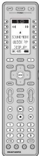
text_image
5.00 SOUND TONE QUICK R JSP R 30.65% marantz| SOURCE ON/OFF Turns the CD player on and off | |
| POWER ON | Turns the CD player on |
| POWER OFF | Turns the CD player off |
| Soft button Refer to the list of soft buttons in the table below. | |
| HOME Switch the remote controller to HOME mode. | |
| < / > Scroll the page. | |
| ENTER enters the selling | |
| MENU Switches the display information | |
| ▶ | Play |
| ◀◀/▶◀ | Skip forward or previous frack |
| ■ | Stop |
| II | Pause |
| 0-9, +10 | Input the numeric |
| CLEAR Clears the inputting | |
List of Soft buttons
| Page | Command | Note |
| 1 | 5.CO | Select CD function |
| ←/→ | (Left) REWIND* | |
| (Right) FAST FORWARD* | ||
| ▲ | Tray OPEN/CLOSE | |
| SOUNDMODE | Change sound mode | |
| QUICK RP | Jump back the current playing | |
| DISPLAY Turn off | the display | |
| 2 | 5.CO | Select CD function |
| PROGRAM | PROGRAM | |
| RANDOM | RANDOM play | |
| REPEAT | REPEAT play | |
| A-B REPEAT A to B | ||
| INTRO SCN | AUTO MUSIC SCAN | |
| 3 | 5.CO | Select CD function |
| EDIT | Edit the program | |
| TEXT | Select TEXT display mode | |
| TIME | Select TIME display mode | |
| SCROLL | Scroll the text display | |
| DIG OUT | Turn the digital output on and off, | |
| 4 | 5.CO | Select CD function |
| NEXT DISC | CD changer next disc | |
| PREV DISC | CD changer previous disc | |
| 1-DISC-2 | (Left) CD Changer DISC1* | |
| (Right) CD Changer DISC2* | ||
| 3-DISC-4 | (Left) CD Changer DISC3* | |
| (Right) CD Changer DISC4* | ||
| 5-DISC- | (Left) CD Changer DISC5* | |
| 5 | 5.CO | Select CD function |
| - PITCH + | (Left) Adjust the play speed down* | |
| (Right) Adjust the play speed up* | ||
| PITCH RST | Reset the play speed | |
CONTROLLING A MARANTZ UNIVERSAL DOCK (AUX MODE / IPOD MODE)

text_image
6 HLD MODE REPEAT SHUFFLE $0.499 mapantz| SOURCE ON/OFF Turns the UNIVERSAL DOCK (Dock connector) ON and OFF | |
| POWER ON Turns the UNIVERSAL DOCK (Dock connector) ON | |
| POWER OFF Turns the UNIVERSAL DOCK (Dock connector) OFF | |
| Soft button Refer to the list of soft buttons in the table below. | |
| HOME Switch the remote controller to HOME mode. | |
| scroll the page | |
| Cursor Move the cursor | |
| ENTER Enters the setting | |
| MENU Call up the menu | |
| ▶ | Play |
| ◀◀/▶▶ | Skip forward or previous track |
| ■ | Stop |
| II | Pause |
| D-9 Input the numeric | |
| CLEAR Clears the inputting | |
List of Soft buttons
| Page Command Note | ||
| 1 | 6.AUX Select AUX function | |
| <--> | (left) REWIND* | |
| (Right) FAST FORWARD* | ||
| MODE | CHANGE USER INTERFACE MODE | |
| REPEAT | Select REPEAT PLAY | |
| SHUFFLE | Select SHUFFLE PLAY | |
| 2 | 6.AUX Select AUX function | |
| ARTIST | SORT ORDER (ARTIST) | |
| ALBUM SORT ORDER (ALBUM) | ||
| SONGS | SORT ORDER (SONG) | |
| GENRE | SORT ORDER (GENRE) | |
| COMPOSER | SORT ORDER (COMPOSER) | |
| 3 | 6.AUX Select AUX function | |
| PLAYLSIT | SORT ORDER (PLAY LIST) | |
| PODCAST | SORT ORDER (POOCAST) | |
| AUDIOBOOK | SORT ORDER (AUDIOBOOK) | |
CONTROLLING A MARANTZ VCR (VCR1 MODE)
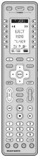
text_image
EJET M80 TV/ACR 2K P.82 6V, 100 MARATE| SOURCE ON/OFF Turns the VCR on and off | |
| Soft button Refer to the list of soft buttons in the table below. | |
| HOME Switch the remote controller to HOME mode. | |
| Cursor Move the cursor | |
| ENTER Enters the setting | |
| MENU Calls the menu | |
| EXIT | Exits the programming menu |
| CH = 1 | Select VCR channel |
| Play | |
| Skip forward or previous track | |
| Record | |
| Stop | |
| Pause | |
| 0-9,+10 | Select VCR channel / Input the numeric |
| CLEAR Clears the inpulling | |
List of Soft buttons
| Page Command Note | ||
| 1 | 7.VCR1 Select VCR1 function | |
| <--> | (left) REWIND* | |
| (Right) FAST FORWARD* | ||
| EJECT | Eject | |
| MEMO | Enter a recording program | |
| TV/VCR | Select TV/VCR | |
| 2 x PLAY | TWICE NORMAL PLAYBACK SPEED | |
| 2 | 7.VCR1 Select VCR1 function | |
| SLOW | SLOW PLAYBACK SPEED | |
| STILL | STILL FRAME | |
| OTR | ONE TOUCH RECORDING | |
| AUDIO | Select AUDIO MODE | |
| SKIP | SKIP TO NEXT PROG.MARKER | |
| 3 | 7.VCR1 Select VCR1 function | |
| VIS- | VHS INDEX SERCH NEXT | |
| VIS- | VHS INDEX SERCH PREVIOUS | |
CONTROLLING A MARANTZ TV (TV MODE)
| SOURCE ON/OFF Turns the TV on and off | |
| POWER ON Turns the TV on | |
| POWER OFF Turns the TV off | |
| Soft button Refer to the list of soft buttons in the table below. HOME Switch the remote controller to HOME mode. | |
| < / > Scroll the page | |
| GUIDE Display Programmable TV menu | |
| INFO OSD On/Off | |
| Cursor Move cursor on menus, etc. | |
| ENTER Confirm selection on menus, etc. | |
| MENU Display menu | |
| EXIT Exit menu | |
| MUTE Temporarily stop audio output and cancels | |
| INPUT Switch input | |
| PREV LAST CHANNEL function | |
| VOL +/- | Adjust the TV sound level |
| CH +/- | Select channel |
| 0-9, +10 | Select TV channel / Input the numeric |
| CLEAR | Cancel various input |
List of Soft buttons
| Page | Command | Note |
| 1 | 8.TV | SELECT TV function |
| MEMO | Starts program | |
| ALT-CH LAST CHANNEL function | ||
| CH CALL | Channel call On/off | |
| SLEEP | Sleep Timer | |
| VIDEO | Switch TV to VIDEO function | |
| 8.TV | SELECT TV function | |
| S-VIDEO Switch TV to S-VIDEO function | ||
| 2 | 1 COMP 2 | (Left) Switch TV to COMPONENT1 function*(Right) Switch TV to COMPONENT2 function* |
| RGB | Switch TV to RGB function | |
| HDMWDVI | Switch TV to HDMIWDVI function | |
| HDMI2 | Switch TV to HDMIP function | |
| 8.TV | SELECT TV function | |
| 3 | ASPECT | Select aspect ratio |
| ZOOM | Aspect Zoom | |
| NORMAL | Aspect Normal | |
| THROUGH | Aspect Through | |
| FULL | Aspect Full | |
| 8.TV | SELECT TV function | |
| STANDARD | Select Standard mode | |
| 4 | THEATER | Select Theater mode |
| DYNAMIC | Select Dynamic mode | |
| CINEMA | Select Cinema mode | |
| PATTERN | Focus Pattern on/off | |
| 8.TV | SELECT TV function | |
| LIGHT | Rear panel light on/off | |
| 5 | VMUTE ON | VIDEO MUTE ON |
| VMUTE OFF | VIDEO MUTE OFF | |
CONTROLLING A MARANTZ TAPE DECK (TAPE MODE)
| ON/OFF | OFF | |
| RANGE | ||
| 3 TAFE | ||
| TAFE-A | ||
| TAFE-B | ||
| REC MUTE | ||
| DIRECTION | ||
| 00 MHz | ||
| SOURCE ON/OFF Tums the TAPE deck on and off | |
| POWER ON Tums the TAPE deck on | |
| POWER OFF Tums the TAPE deck off | |
| Soft button Refer to the list of soft buttons in the table below. | |
| HOME Switch the remote controller to HOME mode. | |
| <|> Scroll the page | |
| ▶ | Play |
| ◀◀/▶◀ | Skip forward or previous track |
| ● | Record |
| ■ | Stop |
| || | Pause |
| 0-9 Input the numeric | |
| CLEAR Cears the inputting | |
List of Soft buttons
| Page Command Note | ||
| 1 | 9.TAPE Select TAPE function | |
| <--> | (left) REWIND* | |
| (Right) FAST FORWARD* | ||
| TAPE-A Select TAPE DECK A | ||
| TAPE-B Select TAPE DECK B | ||
| REC MUTE Insert blank during recording | ||
| DIRECTION | AUTO REVERSE DIRECTION | |
| 2 | 9.TAPE Select TAPE function | |
| COUNT RST | COUNT RESET | |
| AMS | AUTO MUSIC SCAN | |
| BLANKSKIP | Searches for an empty part | |
| TIME | TIME DISPLAY mode | |
| TRAY | TRAY OPEN/CLOSE | |
CONTROLLING A MARANTZ VCR (VCR2 MODE)
| OFFICE | ||
| ELECT | ||
| 1800 | ||
| 2V/ACR | ||
| 2X PLAY | ||
| W. 209 | ||
| < | > | |
| + | > | |
| + | + | |
| + | + | |
| + | + | |
| + | + | |
| + | + | |
| + | + | |
| + | + | |
| + | + | |
| + | + | |
| + | + | |
| + | + | |
| + | + | |
| + | + | |
| + | + | |
| + | + | |
ENGLISH
| SOURCE ON/OFF Turns the VCR on and off | |
| Soft button Refer to the list of soft buttons in the table below. | |
| HOME Switch the remote controller to HOME mode. | |
| < / > Scroll the page | |
| Cursor Move the cursor | |
| ENTER | enters the setting |
| MENU | Calls the menu |
| EXIT | Exits the programming menu |
| CH + / - | Select VCR channel |
| ▶ | Play |
| ◀◀ / ▶◀◀ | Skip forward or previous track |
| ● | Record |
| ■ | Stop |
| || | Pause |
| 0-9, +10 | Select VCR channel / input the numeric |
| CLEAR Clears the inputting | |
List of Soft buttons
| Page Command Note | ||
| 1 | VCR2 | Select DSS/VCR2 function |
| ◄◄/►► | (left) REWIND* | |
| (Right) FAST FORWARD* | ||
| EJECT | EJECT | |
| MEMO | Enter a recording program | |
| TVVCR | Select TVVCR | |
| 2 x PLAY | TWICE NORMAL PLAYBACK SPEED | |
| 2 | VCR2 | Select DSS/VCR2 function |
| SLOW | SLOW PLAYBACK SPEED | |
| STILL | STILL FRAME | |
| OTR | ONE TOUCH RECORDING | |
| AUDIO | Select AUDIO MODE | |
| SKIP | SKIP TO NEXT PROG.MARKER | |
| 3 | VCR2 | Select DSS/VCR2 function |
| VIS+ | VHS INDEX SERCH NEXT | |
| VIS- | VHS INDEX SERCH PREVIOUS | |
ENGLISH
CONTROLLING A MARANTZ PLASMA (PLASMA MODE)
| OFF | ON | EXP |
| POWER | ||
| P-PS+1 | ||
| VIDEO | ||
| HO/DVD | ||
| PZ/RGB | ||
| ASPECT | ||
| PZ/HND | ||
| 60-WG | ||
| OK | Cancel | ADD |
| MOM | ||
| MINI | ||
| MINI | ||
| MINI | ||
| MINI | ||
| MINI | ||
| MINI | ||
| MINI | ||
| MINI | ||
| MINI | ||
| MINI | ||
| MINI | ||
| MINI | ||
| MINI | ||
| MINI | ||
| MINI | ||
| POWER ON Tums the PLASMA on | |
| POWER OFF Turns the PLASMA cft | |
| Soft button Refer to the list of soft buttons in the table below. | |
| HOME Switch the remote controller to HOME mode. | |
| < / > Scroll the page | |
| INFO OSD OrvOll | |
| Cursor Move cursor on menus, etc. | |
| ENTER Confirm selection on menus, etc. | |
| MENU Display menu | |
| EXIT Exit menu | |
| MUTE Temporarily stop audio output and cancel | |
| INPUT Switch input | |
| VOL +/- Adjust the PLASMA sound level | |
List of Soft buttons
| Page | Command | Note |
| 1 | PLASMA | Select TV function |
| VIDEO | VIDEO input select | |
| HD/DVD | HD/DVD input select | |
| PC/RGB | RGB input select | |
| ASPECT | ASPECT select | |
| PIC MEMO | Picture memory select | |
| 2 | PLASMA | Select TV function |
| COLOR TEMP | Color temp | |
| PIC MODE | Picture mode | |
| AUTO ADJ | Auto adjust on | |
| CONTRAST | Call contrast adjustment | |
| BRIGHT | Call brightness adjustment | |
| 3 | PLASMA | Select TV function |
| -CONT + | Contrast adjustment* | |
| -BRIGHT- | Brightness adjustment* | |
| -SHARP+ | Sharpness adjustment* | |
| -COLOR+ | Color adjustment* | |
| -TINT + | Tint adjustment* | |
| 4 | PLASMA | Select TV function |
| POP ON | SIDE BY SIDE on | |
| PIP ON | PICTURE IN PICTURE on | |
| SINGLE | PIP/POP off | |
| 5 | PLASMA | Select TV function |
| ID SELECT | ID select | |
| M SCREEN | Multi screen display | |
| ID CLEAR | ID clear | |
| ACTIV SEL | Active screen select | |
| I-VIDEO-2 | (Left) Select VIDEO1* | |
| (Right) Select VIDEO2* | ||
| 6 | PLASMA | Select TV function |
| 3-VIDEO- | (Left) Select VIDEOS* | |
| 1DVD/HD2 | (Left) Select HD/DVD1* | |
| (Right) Select HD/DVD2* | ||
| 3DVD/HD4 | (Left) Select HD/DVD3* | |
| (Right) Select HD/DVD4* | ||
| 1PC/RGB2 | (Left) Select RGB1* | |
| (Right) Select RGB2* | ||
| 3PC/RGB | (Left) Select RGB3* | |
| 7 | PLASMA | Select TV function |
| NORMAL | Select aspect NORMAL | |
| FULL | Select aspect FULL | |
| STADIUM | Select aspect STADIUM | |
| ZOOM | Select aspect ZOOM | |
| 14:9 | Select aspect 14:9 | |
| 8 | PLASMA | Select TV function |
| 2.35:1 | Select aspect 2.35:1 | |
| NORMAL | Select picture mode NORMAL | |
| 1THEATER2 | (Left) Select picture mode THEATER1* | |
| (Right) Select picture mode THEATER2* | ||
| DEFAULT | Select picture mode DEFAULT | |
| BRIGHT | Select picture mode BRIGHT |
CONTROLLING A MARANTZ CD-R (CD-R MODE)

text_image
OUTPUT POWER INPUT TR INCR SYNC REC AM-VR HDMI V VOUT REAL 1 2 3 4 5 6 7 8 9 0 0 11 marante| SOURCE ON/OFF Turns the CD recorder on and off | |
| POWER ON Turns the CD recorder on | |
| POWER OFF Turns the CD recorder off | |
| Soft button Refer to the list of soft buttons in the table below. | |
| HOME Switch the remote controller to HOME mode. | |
| < / > Scroll the page | |
| ENTER enters the setting | |
| MENU Switches the display information | |
| ▶ Play | |
| 1 ◀ ◀ ▶ ▶ | Skip forward or previous track |
| ● RECORDING | |
| ■ Stop | |
| II Pause | |
| 0-9 Input the numeric | |
| CLEAR Clears the inputting | |
List of Soft buttons
| Page Command Note | ||
| 1 | CD-R Select CD function | |
| <-->|>> | (Left) REWIND | |
| (Right) FAST FORWARD | ||
| ▲ | THAY OPEN/CLOSE | |
| INPUT Select INPUT SOURCE | ||
| TR INCR | Select INPUT SOURCE | |
| SYNC REC | ACTIVATE SYNCRO RECORDING | |
| 2 | CD-R Select CD function | |
| PROGRAM | PROGRAM | |
| RANDOM | RANDOM PLAY | |
| REPEAT | REPEAT PLAY | |
| A-B REPEAT A TO B | ||
| INTRO SCN | AUTO MUSIC SCAN | |
| 3 | CD-R Select CD function | |
| DISPLAY | Turn off the display | |
| BLANK | RECORDS BLANK | |
| SCROLL | scroll the text display | |
CONTROLLING A MARANTZ MD DECK (MD MODE)

text_image
OFF START ON POWER CPU INPUT MARKER SYNC REC W.100 MOS I/O I/O I/O I/O I/O I/O I/O I/O I/O I/O I/O I/O I/O I/O I/O I/O I/O I/O I/O I/O I/O I/O I/O I/O I/O I/O I/O I/O I/O I/O I/O I/O I/O I/O| SOURCE ON/OFF | Turns the MD deck on and off |
| POWER ON | Turns the MD deck on |
| POWER OFF | Turns the MD deck off |
| Soft button | Refer to the list of soft buttons in the table below. |
| HOME | Switch the remote controller to HOME mode. |
| < / > | Scroll the page |
| ENTER | enters the setting |
| MENU Switches the display information | |
| ▶ | Play |
| ◀◀/▶◀ | Skip forward or previous track |
| ● | RECORDING3 |
| ■ | Stop |
| || | Pause |
| 0-9 | Input the numeric |
| CLEAR | Cleared the inputting |
List of Soft buttons
| Page Command Note | ||
| 1 | MD | |
| ◀/▶ | (left) REWIND* | |
| (Right) FAST FORWARD* | ||
| ▲ | TRAY OPEN/CLOSE | |
| INPUT Select INPUT SOURCE | ||
| MARKER Select AUTO MARKER | ||
| SYNC REC | SYNCRO REC | |
| 2 | MD | |
| PROGRAM | PROGRAM | |
| RANDOM | RANDOM PLAY | |
| REPEAT | REPEAT PLAY | |
| EDIT | Select EDIT mode | |
| SP/LP | Select SP/LP mode | |
| 3 | MD | |
| TIME | Select TIME mode | |
| CHAR | Select CHARACTER mode | |
ENGLISH
CONTROLLING A MARANTZ BLU-RAY PLAYER (BLU-RAY MODE)

text_image
R-1-FR AVSLE SUB-TILE AUDIO 001-WU OK Cancel OFF OK OK OK OK OK OK OK OK OK OK OK OK OK OK OK OK OK OK OK OK OK OK OK OK OK OK OK OK OK OK OK OK OK OK OK OK OK OK OK OK OK OK OK OK OK OK OK OK OK OK Ok OK OK OK OK OK OK OK OK OK OK OK OK OK OK OK OK OK OK OK OK OK OK OK OK OK OK OK OK OK OK| POWER ON Turns the Blu-ray player on | |
| POWER OFF Turns the Blu-ray player off | |
| Soft button Refer to the list of soft buttons in the table below. | |
| HOME Switch the remote controller to HOME mode. | |
| < / > Scroll the page | |
| GUIDE Move to TOP MENU | |
| INFO OSD ON/OFF | |
| Cursor Move the cursor | |
| ENTER enters the setting | |
| MENU Calls up the menu of disc | |
| EXIT RETURN TO MENU | |
| ▶ | Play |
| ◀◀ / ▶▶ | Skip forward or previous track |
| ■ | Stop |
| ■ | Pause |
| 0-9 Input the numeric | |
| CLEAR Clears the inputting | |
| BLUE, RED, GREEN, YELLOW | Select item on some BD menus |
Note:
If the BLUE, RED, GREEN, and YELLOW buttons on the BD8003 do not function correctly, perform Learning.
List of Soft buttons
| Page | Command | Note |
| 1 | BLU-RAY | |
| ◀/▶ | (left) REWIND | |
| (Right) FAST FORWARD | ||
| ▲ | Tray OPEN/CLOSE | |
| ANGLE | Select ANGLE | |
| SUBTITLE Select SUB TITLE | ||
| AUDIO | Select LANGUAGES | |
| 2 | BLU-RAY | |
| ZOOM | enlarge the picture on the screen | |
| SET UP | Select SETUP MENU | |
| MODE | Change various menus | |
| F-DIRECT Select pure direct mode. | ||
| DIMMER | adjust the brightness of the front panel display | |
| 3 | BLU-RAY | |
| SEARCH | Switch the SEARCH mode | |
| REPEAT | REPEAT mode | |
| A-B REPEAT A to B | ||
| RANDOM | RANDOM play | |
The supplied RC2001 remote controller can be used for Zones. To use the remote controller for Zones, be sure to switch it to ZONE-A or ZONE-B mode.
ZONE A (ZONE-A MODE)
| POWER | |||
| Z-NE-H | |||
| Z-SP4-ON | |||
| Z-SP6-OFF | |||
| 34V OFF | |||
| -SP4 VOL+ | |||
| 50K HUTE | |||
| 850-855 | |||
| SOURCE ON/OFF Turn the ZONE A on and off | |
| POWER ON Turn the ZONE A on | |
| POWER OFF Turn the ZONE A off | |
| Soft button Refer to the list of soft buttons in the table below. | |
| HOME Switch the remote controller to HOME mode. | |
| < / > Scroll the page | |
| INFO OSD information on/off | |
| Cursor Used to move the cursor, etc. | |
| ENTER Used to select items, etc. | |
| EXIT Used to return to the previous screen, etc. | |
| MUTE Decrease the sound temporarily for ZONE A | |
| VOL + / - Adjust the order all sound level for ZONE A | |
| ▶ | Play |
| ◀◀ / ▶◀◀ | Skip forward or previous track |
| ■ | Stop |
| II | Pause |
Note:
Soft buttons on Page 5 and the ▶, ▶◀, ▶▶, ■, and ■ buttons are only used for the NETWORK function.
List of Soft buttons
| Page Command Note | ||
| 1 | ZONE-A | |
| Z.SPK-ON Turn on ZONE SPEAKER A | ||
| Z.SPK-OFF | Turn off ZONE SPEAKER A | |
| ON/OFF | Turn on/off ZONE SPEAKER A | |
| -SPK VOL+ | {Left} Decrease volume for ZONE SPEAKER A* {Right} Increase volume for ZONE SPEAKER A* | |
| SPK MUTE | Mute ZONE SPEAKER A | |
| 2 | ZONE-A | |
| DVD | Set ZONE A function to DVD | |
| TV | Set ZONE A function to TV | |
| VCR1 Set ZONE A function to VCR1 | ||
| DSS Set ZONE A function to DSS | ||
| AUX Set ZONE A function to AUX | ||
| 3 | ZONE-A | |
| TAPE | Set ZONE A function to TAPE | |
| CD | Set ZONE A function to CD | |
| TUNER Set ZONE A function to TUNER | ||
| NETWORK | Set ZONE A function to NETWORK | |
| 4 | ZONE-A | |
| AM FM | {Left} Set the band for the ZONE A tuner to AM* {Right} Set the band for the ZONE A tuner to FM* | |
| XM SR | {Left} Set the band for the ZONE A tuner to XM* {Right} Set the band for the ZONE A tuner to SIRIUS* | |
| P-SCAN | Perform PRESET SCAN for the ZONE A tuner | |
| -PRESET- | {Left} Perform PRESET - for the ZONE A tuner* {Right} Perform PRESET + for the ZONE A tuner* | |
| -TUNE+ | {Left} Decrease the frequency for the ZONE A tuner* {Right} Increase the frequency for the ZONE A tuner* | |
| 5 | ZONE-A | |
| ALL-M RND | {Left} Move to All Songs* {Right} RANDOM play* | |
| ALL-P RPT | {Left} Move to All Photo* {Right} REPEAT play* | |
| ALL-V RES | {Left}Move to ALL Video* {Right} Select the resolution* | |
| -PAGE+ | {Left} Move to previous page* {Right} Move to next page* | |
| <</>> | {Left} REWIND* {Right} FAST FORWARD* | |
ENGLISH
ENGLISH
ZONE B (ZONE-B MODE)
text_image
OFF START POWER ZONE=3 Z. SPK-ON Z. SPK-OFF ON/OFF SPK VOL+ 52K HUTE ON-WG OFF MARELLA RUTS 100% 100% 100% 100% 100% 100% 100% 100% 100% 100% 100% 100% 100% 100% 100% 100% 100% 100% 100% 100% 100% 100% 100% 100% 100% 100%| SOURCE ON/OFF Tum the ZONE B on and off | |
| POWER ON Tum the ZONE B on | |
| POWER OFF Tum the ZONE B off | |
| Soft button Refer to the list of soft buttons in the table below. | |
| HOME Switch the remote controller to HOME mode. | |
| < / > Scroll the page | |
| INFO OSD information on/off | |
| Cursor Used to move the cursor, etc. | |
| ENTER Used to select items, etc. | |
| EXIT Used to return to the previous screen, etc. | |
| MUTE Decrease the sound temporarily for ZONE B | |
| VOL + / - Adjust the over all sound level for ZONE B | |
| ▶ | Play |
| I<< /▶▶ | Skip forward or previous track |
| ■ | Stop |
| II | Pause |
Note:
Soft buttons on Page 5 and the ▶, ◀◀, ▶▶, ■, and || buttons are only used for the NETWORK function.
List of Soft buttons
| Page Command Note | ||
| 1 | ZONE-3 | |
| Z.SPK-ON Tum on | ZONE SPEAKER B | |
| Z.SPK-OFF Turn off | ZONE SPEAKER B | |
| ON/OFF | Turn on/off ZONE SPEAKER B | |
| -SPK VOL+ | (Left) Decrease volume for ZONE SPEAKER B(Right) Increase volume for ZONE SPEAKER B | |
| SPK MUTE | Mule ZONE SPEAKER B | |
| 2 | ZONE-3 | |
| DVD Set ZONE B function to DVD | ||
| TV | Set ZONE B function to TV | |
| VCR1 | Set ZONE B function to VCR1 | |
| DSS | Set ZONE B function to DSS | |
| AUX | Set ZONE B function to AUX | |
| 3 | ZONE-3 | |
| TAPE Set ZONE B function to TAPE | ||
| CD | Set ZONE B function to CD | |
| TUNER | Set ZONE B function to TUNER | |
| NETWORK | Set ZONE B function to NETWORK | |
| 4 | ZONE-3 | |
| AM FM | (Left) Set the band for the ZONE B tuner to AM*(Right) Set the band for the ZONE B tuner to FM* | |
| XM SR | (Left) Set the band for the ZONE B tuner to XM*(Right) Set the band for the ZONE B tuner to SIRIUS* | |
| P-SCAN | Perform PRESET SCAN for the ZONE B tuner | |
| -PRESET+ | (Left) Perform PRESET - for the ZONE B tuner*(Right) Perform PRESET + for the ZONE B tuner* | |
| -TUNE+ | (Left) Decrease the frequency for the ZONE B tuner*(Right) Increase the frequency for the ZONE B tuner* | |
| 5 | ZONE-3 | |
| RANDOM | RANDOM play | |
| REPEAT REPEAT play | ||
| ALL MUSIC | Move to All Songs | |
| ↔/↔ | (Left) REWIND*(Right) FAST FORWARD* | |
BASIC OPERATION
RC2001 BUTTON SETTINGS
The Wizz.it 3 editor software can be used to make the settings for the IR Command, LINK, JUMP, One Touch Operation (Macro) and other functions in the RC2001.
This enables a customized user interface, optimized for the customer's environment, to be built.
The Wizz.it 3 editor software can be downloaded from www.marantz.com. For more information about the setting procedures, see the PC Editor Software Wizz.it 3 User Guide.
This is the basic operation procedure for the RC2001.
- Press the Home button to enter Home mode for the RC2001.
- Select the devices that are set in Home mode.
- Perform operation of the device that you want to control in the selected device mode.
- To control another device, return to Home mode and select another device.
The preinstalled default user file is used to control Marantz products. The AV receiver device input switching code is assigned to the button next to the displayed device name of the device mode.
Example:
After DVD mode is selected in the remote controller, pressing the button next to DVD, shown in the first column in the LCD, transmits the AV receiver DVD input command.

text_image
1.DVD ANGLE SUBTITLE AUDIO 031/085DVD input command for Marantz AV Receiver.
SLEEP TIMER
The SLEEP TIMER is a function that sends a preset remote command after the sleep time has elapsed.
- The setting is made using the Wizz.it 3 editor, and the buttons that are assigned to the sleep timer are operated as shown below.
-
This is a convenient function for devices that do not have a sleep timer or for setting the sleep timer using multiple devices.
• The RC2001 performs regular operation even when the sleep timer is activated. -
Press the button that will be assigned to the sleep timer. The message "PROCEED?" is displayed on the LCD.
-
Each time the button is pressed, the sleep setting time changes in the cycle shown below.
-
When the time that you want to set is displayed, wait at the setting for three seconds.
-
The sleep setting screen is no longer displayed on the LCD, and the sleep timer is automatically started.
And the sleep timer icon is displayed in Sub Info area of the LCD. - When the remaining time for the sleep timer setting is 10 minutes, the remaining time is displayed in the SubInfo area of the LCD.
text_image
HOME MACRO AMP 1.DVD 2.OSS 3.NETWIDE 001/404 SLEEP TIMER iconMAIN MENU
The various settings for the remote device are made in the main menu.
ENTERING THE MAIN MENU
- Press the Home button to enter Home mode for the RC2001.
- Hold down the Home button and Menu button at the same time for three seconds to display MAIN MENU on the LCD.

text_image
MAIN MEN LEARNING TIMER SYS. SETUP STATUS1. LEARNING FUNCTION
- Place the remote controller so that its infrared signal transmitter is facing the infrared signal receiver on the Marantz remote controller at a distance of about 0.05 m.
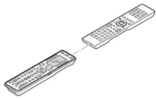
natural_image
Line drawing of two connected remote devices (no text or symbols)- Display the MAIN MENU on the LCD of the RC2001, and then press the button next to the "LEARNING" indicator.
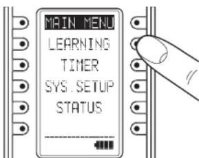
text_image
MAIN MENU LEARNING TIMER SYS. SETUP STATUS- The screen appears as shown below. Either press the ENTER button or wait for three seconds.

text_image
LEARNING SELECT DEVICEENGLISH
- This screen changes to HOME mode. Press the button next to the displayed device name whose commands you want to learn.
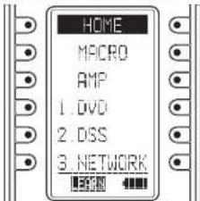
text_image
HOME MACRO AMP 1. DVD 2. DSS 3. NETWORKNote:
In Home mode, learning cannot be performed with the SOFT button using the procedure shown below. Use the Wizz.it 3 editor to make any changes.
5. After selecting the device name, press the button whose command you want to learn.
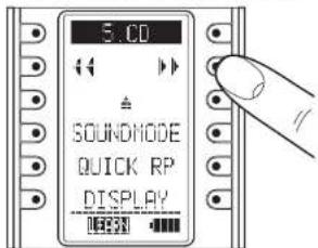
text_image
5.00 SOUNDMODE QUICK RP DISPLAY- This enters the learning standby mode.
Press the remote controller button that you want to have learn the command. Hold down the button until "LEARN OK" is displayed on the remote controller's LCD.
Send the remote controller code that you want to learn.
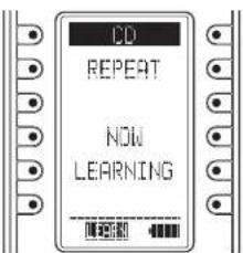
text_image
CD REPEAT NOW LEARNING-
The remote controller has completed learning when "LEARN OK" is displayed on the LCD.
-
Pressing the ENTER button enables you to continue learning commands for another button in the same device mode.
- When the learning mode is completed, press the Home button three times to return the LCD to the MAIN MENU.
Notes:
- If learning could not be performed, "LEARN ERROR" is displayed on the LCD. Try performing steps 5 to 6 again.
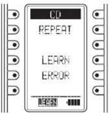
text_image
CD REPEAT LEARN ERROR- When making the learning settings, the "LEARN ERROR" message may occasionally be displayed repeatedly on the LCD. In some cases, this can be due to transmission of a special remote controller signal code. Learning cannot be performed when a special remote controller signal code is used.
- The RC2001 can learn up to a maximum of 1,000 remote controller codes. Once 1,000 codes are programmed for learning, "LEARNFULL" is displayed on the LCD, and learning can no longer be performed.
To perform further learning, use the Wizz.it 3 editor to delete any unneeded learning codes.
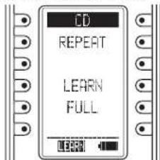
text_image
CD REPEAT LEARN FULL2. TIMER
The timer function of the RC2001 can be used to send a preset remote controller command at a programmed time.
The Wizz.it 3 editor can be used to operate multiple devices. One Touch Operation (Macro) can also use the timer function for transmission.
Checking the Settings
- Display the MAIN MENU on the LCD of the RC2001, then press the button next to the "TIMER" indicator.
- The TIMER menu is displayed. Pressing the button next to the "CHECK" indicator on the LCD displays the timer settings.

text_image
TIMER CHECK TIMER SET ON/OFFWhen the LCD appears as shown below, the timer has not been set.

text_image
TIMER TIME-- -- -- -- -- -- Either press the ENTER button or wait three seconds for the LCD to automatically return to the MAIN menu.
- Pressing the Home button from the TIMER MENU screen returns the LCD to the MAIN MENU.
Operation Settings
- Press the button next to the "TIMER SET" indicator in the LCD in the TIMER menu screen to display the timer programming setting screen.
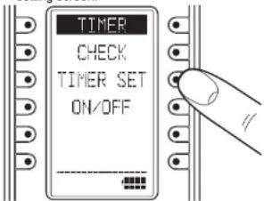
text_image
TIMER CHECK TIMER SET ON/OFF- Use the numeric buttons (0 to 9) and cursor buttons (◀ and ▶) to set the time for the timer. After making the setting, press the ENTER button.

text_image
TIMER TIME? 00:00-
Home mode is shown in the LCD. Select the commands and devices for the commands that will be sent by timer programming.
-
If a command assigned to the HARD button is to be sent by timer programming, press the HARD button when selecting the command to make the setting.
- If a command assigned to the SOFT button is to be sent by timer programming, use the < and > buttons when selecting the command to move the page, and select the command assigned to the SOFT button.

text_image
HOME MACRO AMP 1. DVD 2. DSS 3. NETWORK TIMER SET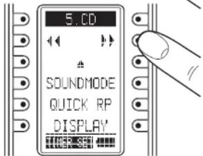
text_image
5.CD SOUNDMODE QUICK RP DISPLAYNote:
The timer setting for the SOFT button cannot be used in Home mode.
- Press a button next to the "EVERYDAY" or "ONE TIME" indicators on the LCD to set timer operation to either everyday or one-time only operation.

text_image
TIMER SET EVERYDAY ONE TIME- The timer settings are displayed. Check that the settings are correct.
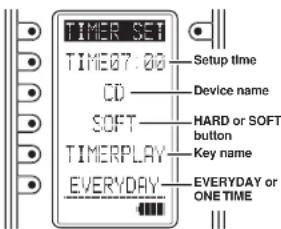
text_image
TIMER SET TIME07.00 CD SOFT TIMERPLAY EVERYDAY Setup time Device name HARD or SOFT button Key name EVERYDAY or ONE TIME- Either press the ENTER button or wait three seconds so that "COMPLETED" is displayed on the LCD and the operation settings are automatically completed.

text_image
TIMER SET COMPLETED- Either press the ENTER button or wait three seconds for the LCD to automatically return to the MAIN menu.
ENGLISH
ENGLISH
Operation ON/OFF Settings
- Press the button next to the "ON/OFF" indicator in the TIMER menu screen on the LCD to display the timer operation ON/OFF setting screen.
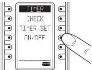
text_image
TIMER CHECK TIMER SET ON/OFF- Press the button next to the "TIMER ON" (Enable) or "TIMER OFF" (Disable) indicators on the LCD to either enable or disable timer operation.
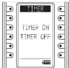
text_image
TIMER TIMER ON TIMER OFF- Either press the ENTER button or wait three seconds so that "COMPLETED" is displayed on the LCD and the operation settings are automatically completed.

text_image
TIMER TIMER ON COMPLETED- Either press the ENTER button or wait three seconds for the LCD to automatically return to the MAIN menu.
- When timer operation is set to ON, the timer icon is displayed in the Sub Info area of the LCD.
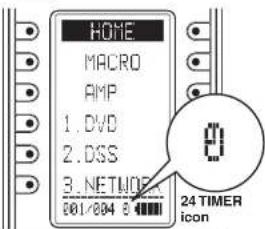
text_image
HOME MACRO AMP 1. DVD 2. DSS 3. NETWORK 001/004 8 24 TIMER icon3. SYS.SETUP
Display the MAIN MENU on the LCD of the RC2001, then press the button next to the "SYS.SETUP" indicator.
The items below can be set in the SYS.SETUP screen.
- CLOCK (Clock setting)
• BACK LIGHT (Backlight illumination time setting) - LCD (LCD setting)
• BEEP (Beep sound setting)
• MEM CLEAR (Initialization setting)
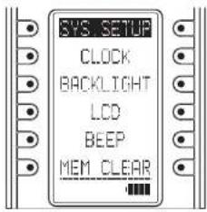
text_image
SYS SETUP CLOCK BACKLIGHT LCD BEEP MEM CLEARCLOCK (Clock setting)
This sets the clock for the RC2001.
- Press the button next to the "CLOCK" indicator in the SYS.SETUP menu screen in the LCD to display the clock setting screen.
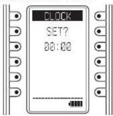
text_image
CLOCK SET? 00:00- Use the numeric buttons (0 to 9) and cursor buttons (◀ and ▶) to set the current time. After setting the correct time, press the ENTER button.

text_image
CLOCK SET? 13:00- The message "COMPLETED" is displayed in the LCD to indicate that the clock setting is completed.
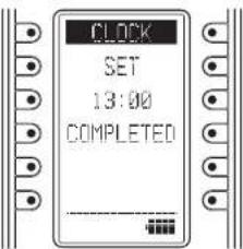
text_image
CLOCK SET 13:00 COMPLETED- Either press the ENTER button or wait three seconds for the LCD to automatically return to the SYS.SETUP menu.
- Pressing the Home button returns the LCD to the MAIN MENU.
Notes:
The clock can become out of sync over time. Please check it occasionally and set to the correct time if necessary.
The clock setting is not backed up when the battery pack is replaced. Please reset the time after replacing the battery pack.
BACK LIGHT (Backlight illumination time setting) Press the LIGHT button on the RC2001 to turn on the backlight, then set the time until the backlight turns off.
- Press the button next to the "BACKLIGHT" indicator in the SYS.SETUP menu screen in the LCD to display the backlight illumination time setting screen.

text_image
BACKLIGHT OFF TIME? 5 SEC - TIME +- Press the buttons (right: +, left: -) displayed next to TIME to set the illumination time. The time can be set in 1-second intervals from 0 to 60 seconds.
After deciding the settings, press the ENTER button.
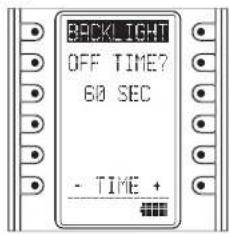
text_image
BACKLIGHT OFF TIME? 60 SEC - TIME +- The message "COMPLETED" is displayed on the LCD to indicate that the illumination time setting is completed.
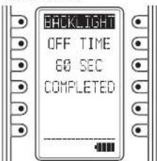
text_image
BACKLIGHT OFF TIME 60 SEC COMPLETED- Either press the ENTER button or wait three seconds for the LCD to automatically return to the SYS.SETUP menu.
- Pressing the Home button returns the LCD to the MAIN MENU.
Note:
Setting the BACK LIGHT TIMER to 0 sec is equivalent to turning off the backlight so that the backlight does not turn on even when the LIGHT button is pressed.
ENGLISH
LCD (LCD setting)
Press the button next to the "LCD" indicator in the SYS.SETUP menu screen in the LCD.
The LCD setting menu is displayed.
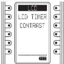
text_image
LCD LCD TIMER CONTRAST• LCD TIMER (LCD timer setting)
This sets the time that the LCD remains on, after a button is pressed on the RC2001.
When there are no operations and the LCD is turned off, this setting enables power consumption to be reduced and the life of the battery pack to be extended.
The default setting is 10 seconds.
- The LCD setting menu is displayed, and so press the button next to "LCD TIMER" in the LCD display.
- Press the buttons (right: +, left: -) displayed next to TIME to set the display time. The time can be set in 1-second intervals from 10 to 60 seconds.
To leave the LCD always on, press the button next to the "ALWAYS ON" indicator. However, please note that this setting will shorten the life of the battery pack.
After deciding the settings, press the ENTER button.
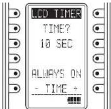
text_image
LCD TIMER TIME? 10 SEC ALWAYS ON - TIME -- The message "COMPLETED" is displayed on the LCD to indicate that the display time setting is completed.
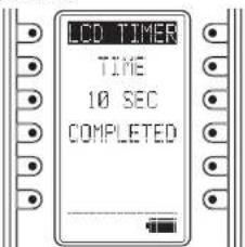
text_image
LCD TIMER TIME 10 SEC COMPLETED- Either press the ENTER button or wait three seconds for the LCD to automatically return to the SYS.SETUP menu.
- Pressing the Home button returns the LCD to the MAIN MENU.
Note:
If the LCD is turned off by the LCD timer, pressing any of the buttons on the remote controller will turn it on again. When the LCD is turned on, the pressed command is not activated.
To execute a command operation, press the button while the LCD is on.
• CONTRAST
(LCD CONTRAST ADJUSTMENT)
This enables the LCD contrast to be adjusted. Adjust for maximum visibility according to your viewing environment.
- The LCD setting menu is displayed, and so press the buttons next to "CONTRAST" in the LCD display.
- Press the side buttons (right: +, left: -) to adjust the contrast level.
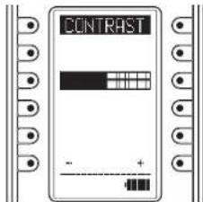
text_image
CONTRASTAfter deciding the settings, press the ENTER button.
The message "COMPLETED" is displayed on the LCD to indicate that the setting is completed.
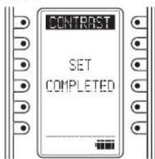
text_image
CONTRAST SET COMPLETED- Either press the ENTER button or wait three seconds for the LCD to automatically return to the SYS.SETUP menu.
- Pressing the Home button returns the LCD to the MAIN MENU.
BEEP (Beep sound setting)
This sets the built-in beep sound in the RC2001.
- Press the button next to the "BEEP" indicator in the SYS.SETUP menu screen in the LCD to display the beep setting screen.
- Press the button next to the "ENABLE" or "DISABLE" indicators on the LCD to either enable or disable the beep sound.
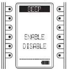
text_image
BEEP ENABLE DISABLE- Either press the ENTER button or wait three seconds so that "ENABLE" or "DISABLE" is displayed on the LCD and the settings are automatically completed.

text_image
BEEP ENABLED- Either press the ENTER button or wait three seconds for the LCD to automatically return to the SYS. SETUP menu.
- Pressing the Home button returns the LCD to the MAIN MENU.
MEM CLEAR (Initialization setting)
This returns the settings made in the RC2001 to their initial settings.
- Press the button next to the "MEM CLEAR" indicator in the SYS.SETUP menu screen in the LCD to display the initialization setting screen.
- Press the button next to the "NO" (Disable) or "YES" (Enable) indicators on the LCD to either enable or disable initialization.
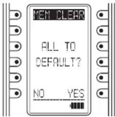
text_image
MEN CLEAR ALL TO DEFAULT? NO YES- Pressing the NO button automatically returns the LCD to the SYS.SETUP menu.
Pressing the YES button displays "COMPLETED" on the LCD and completes initialization.
The setting items that are initialized are shown below.
- TIMER SETUP
The LEARNING and CLOCK settings are not initialized.

text_image
MEM CLEAR ALL TO DEFAULT COMPLETED- Either press the ENTER button or wait three seconds for the LCD to automatically return to the SYS.SETUP menu.
- Pressing the Home button returns the LCD to the MAIN MENU.
4. STATUS INDICATOR
This displays the settings made in the MAIN MENU and the status of the remote device.
Checking the status
- Display the MAIN MENU on the LCD of the RC2001, then press the button next to the "STATUS" indicator.
- Pressing the ENTER button cycles through the statuses of each of the items below.
• Remaining learning memory
- Remaining macro steps
- LCD timer setting
- Backlight timer setting
- Beep setting
- Firmware version
- Current clock time
Either press the ENTER button or wait three seconds so that the LCD returns to the MAIN MENU.
5. RESET
If the RC2001 is not operating properly, use the procedure below to perform a reset (restart). Performing a reset does not erase the settings in the RC2001.
- Remove the battery case cover.
- Use a paper clip or other object to press the reset button in the reset hole as shown in the figure below to reset the RC2001.
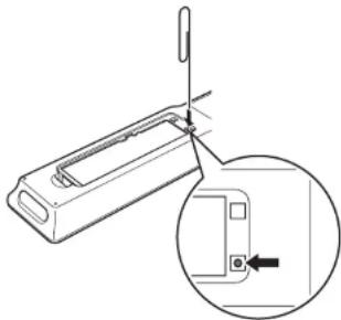
natural_image
Technical line drawing of a mechanical component with an inset showing a close-up view of a component (no text or symbols)Note:
Perform the reset with the battery pack loaded.
6. PROGRAMMABLE CODES
Number of Programmable Codes
This remote control has Flash memory 4M bit (512KB) that enables it to program remote control signals include the learned codes for up to 8000 codes.
This number is for Marantz remote control codes. The actual number of codes may be less than 8000 depending on the type of the programmed remote control signals.
Programmable Codes
This remote control may be unable to learn the codes for some AV equipment due to the code types, system, or other differences.
ENGLISH
GENERAL INFORMATION OF RC101 TO THE UNIT
The included remote controller can be used in zone systems. Using this remote controller, you can operate the unit through infrared receivers or the infrared receptor of Marantz products in multiple ZONEs.
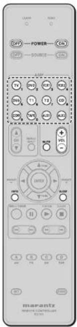
text_image
POWER SOURCE 1V 2V 3V 4V 5V 1A 1B 1C 1D 1E COM 1F 2F 3F VOL POWER SOURCE 100% 100% 100% 100% 100% 100% 100% 100% 100% 100% 100% 100% 100% 100% 100% 100% 100% 100% 100% 100% 100% 100% 100% 100% 100% 100%Zone A
Zone B
Zone C (The unit does not use this zone.)
| POWER ON/OFF | Turns on or off for each multi zone of the unit. |
| SOURCE | Selects a particular source component for each multi zone. |
| VOL +/- | Adjusts the over all sound level for each multi zone. |
| MUTE Decreases the sound temporarily. | |
| SLEEP Sets the sleep timer function. | |
| INFO | Turns on or off the "On Screen Display" for the multi zone. |
Zone D (Main zone control)
| POWER ON/OFF | Turns on or off for main zone of the unit. |
| SOURCE | Selects a particular source component for main zone. |
| VOL +/- | Adjusts the over all sound level for Main zone. |
| MUTE Decreases the sound temporarily. | |
| SLEEP Sets the sleep timer function. | |
| INFO | Turns on or off the "On Screen Display" for the main zone. |
CONTROLLING MARANTZ COMPONENTS
-
Press the desired SOURCE button.
-
Press the desired operation buttons to play the selected component.
- For details, refer to the component's user guide.
- It may not be possible to operate some models.

text_image
OFF POWER ON OFF SOURCE ON TV DVD WBS GDR DSG T1 T2 CD DDR TMP AVS ADC USB VOL ENTER F-CAK SLAM OK OK OK OK OK OK OK OK OK OK OK OK OK OK OK OK OK OK OK OK OK OK OK OK OK OK OK OK OK OK OK OK OK OK OK OK OK OK OK OK OK OK OK OK OK OK OK OK OKCONTROLLING A MARANTZ TV (TV)
| SOURCE ON/OFF | Turns the TV on and off |
| MENU/INPUT Select | the TV video input |
| CHA ▼▼ Selects TV | channel up or down |
| ENTER | Moves the cursor for setting in TV menu |
| ▲(CURSOR) | |
| ▼(CURSOR) | |
| ▶(CURSOR) | |
| ◀(CURSOR) | |
| ▶ | - |
| ■ | - |
| II | - |
| ▶H | - |
| ◀◀ | - |
| ▶▶ | - |
| ◀◀ | - |
| DISC+/T.MODE - | |
| A Reserve for learning | |
| B Reserve for learning | |
| C Reserve for learning | |
| D Reserve for learning |
ENGLISH
CONTROLLING A MARANTZ DVD PLAYER (DVD)
- (^) RC101 dose not have the PRESET code library for this key.
| SOURCE ON/OFF Turns the DVD Player on and off | |
| MENUINPUT Select the DVD menu | |
| CHA▼ - | |
| ENTER | Moves the cursor for setting in DVD menu |
| ▲(CURSOR) | |
| ▼(CURSOR) | |
| ▶(CURSOR) | |
| ◀(CURSOR) | |
| ▶ | Play |
| ■ | Stop |
| II | Pause |
| ▶▶ | Skips to forward chapter/track |
| ◀◀ | Skips to previous chapter/track |
| ▶▶ | Searchs forward |
| ◀◀ | Searchs backward |
| DISC+T.MODE DVD changer next disc (*) | |
| A Reserve for learning | |
| B Reserve for learning | |
| C Reserve for learning | |
| D Reserve for learning | |
CONTROLLING A MARANTZ VCR DECK (VCR1/VCR2)
- RC101 dose not have the PRESET code library for this device.
| SOURCE ON/OFF | Turns the VCR deck on and off |
| MENUINPUT - | |
| CHA▼ - | |
| ENTER | Moves the cursor for setting in VCR menu |
| ▲(CURSOR) | |
| ▼(CURSOR) | |
| ▶(CURSOR) | |
| ◀(CURSOR) | |
| ▶ | Play |
| ■ | Stop |
| II | Pause |
| ▶▶ | Skips to forward track |
| ◀◀ | Skips to previous track |
| ▶▶ | Searchs forward |
| ◀◀ | Searchs backward |
| DISC+/T.MODE - | |
| A Reserve for learning | |
| B Reserve for learning | |
| C Reserve for learning | |
| D Reserve for learning |
CONTROLLING A MARANTZ SATELLITE BROADCASTING TUNER (DSS)
- (*) RC101 dose not have the PRESET code library for this key.
| SOURCE ON/OFF | Turns the satellite broadcasting tuner on and off |
| MENU/INPUT Select the satellite tuner menu | |
| CHA▼ | Selects satellite tuner channel up or down |
| ENTER | Moves the cursor for setting in SATELLITE Broadcasting TUNER menu |
| ▲(CURSOR) | |
| ▼(CURSOR) | |
| ▶(CURSOR) | |
| ◀(CURSOR) | |
| ▶ | Play (*) |
| ■ | Stop (*) |
| II | PAUSE (*) |
| ▶◀ | - |
| ◀◀ | - |
| ▶▶ | Search forward (*) |
| ◀◀ | Searches backward (*) |
| DISC+/T.MODE - | |
| A Reserve for learning | |
| B Reserve for learning | |
| C Reserve for learning | |
| D Reserve for learning | |
CONTROLLING A MARANTZ TUNER (T1)
- RC101 dose not have the PRESET code library for this device.
| SOURCE ON/OFF Turns the Tuner on and off | |
| MENU/INPUT – | |
| CHA ▲▼ – | |
| ENTER – | |
| ▲(CURSOR) Tunes a frequency station up and down | |
| ▼(CURSOR) Tunes a frequency station up and down | |
| ▶(CURSOR) Selects a preset station up and down | |
| ◀(CURSOR) Selects a preset station up and down | |
| ▶ | Starts preset scan |
| ■ | Stop preset scan |
| || | – |
| ▶◀ | – |
| ◀◀ | – |
| ▶▶ | – |
| ◀◀ | – |
| DISC+/T.MODE | Selects the auto stereo mode or mono mode |
| A. Selects AM mode | |
| B. Selects FM mode | |
| C. Selects XM mode | |
| D. Selects DAB mode | |
ENGLISH
CONTROLLING A MARANTZ CD PLAYER (CD)
- (^) RC101 dose not have the PRESET code library for this key.
| SOURCE ON/OFF Tums the CD Player on and off | |
| MENU/INPUT - | |
| CHA▼ - | |
| ENTER - | |
| ▲(CURSOR) - | |
| ▼(CURSOR) - | |
| ▶(CURSOR) - | |
| ◀(CURSOR) - | |
| ▶ | Play |
| ■ | Stop |
| II | Pause |
| ▶▶ | Skips to forward track |
| ▶◀ | Skips to previous track |
| ▶▶ | Searchs forward |
| ◀◀ | Searchs backward |
| DISC-/T.MODE CD changer next disc (*) | |
| A Reserve for learing | |
| B Reserve for learing | |
| C Reserve for learing | |
| D Reserve for learing | |
CONTROLLING A MARANTZ CD RECORDER (CDR)
- RC101 dose not have the PRESET code library for this device.
| SOURCE ON/OFF | Turns the CD Recorder on and off |
| MENU/INPUT - | |
| CHA▼ - | |
| ENTER - | |
| ▲(CURSOR) - | |
| ▼(CURSOR) - | |
| ▶(CURSOR) - | |
| ◀(CURSOR) - | |
| ▶ | Play |
| ■ | Stop |
| || | Pause |
| ▶H | Skips to forward track |
| H◀ | Skips to previous track |
| ▶▶ | Searches forward |
| ◀◀ | Searches backward |
| DISC+IT.MODE CDH changer next disc | |
| A Reserve for learing | |
| B Reserve for learing | |
| C Reserve for learing | |
| D Reserve for learing | |
CONTROLLONG A MARANTZ TAPE DECK (TAPE)
- RC101 dose not have the PRESET code library for this device.
| SOURCE ON/OFF Turns the tape deck on and off | |
| MENUNINPUT - | |
| CH▲▼ - | |
| ENTER - | |
| ▲|CURSOR| - | |
| ▼|CURSOR| - | |
| ▶|CURSOR| - | |
| ◀|CURSOR| - | |
| ▶ | Play |
| ■ | Stop |
| II | Pause |
| ▶▶ | Skips to forward track |
| ◀◀ | Skips to previous track |
| ▶▶ | Searchs forward |
| ◀◀ | Searchs backward |
| DISC-//T.MODE - | |
| A Reserve for learing | |
| B Reserve for learing | |
| C Reserve for learing | |
| D Reserve for learing | |
CONTROLLING A MARANTZ UNIVERSAL DOCK (AUX1)
- RC101 dose not have the PRESET code library for this device.
| SOURCE ON/OFF | Turns the Universal Dock on and off |
| MENU/INPUT Call up the menu | |
| CHA▼ - | |
| ENTER | Moves the cursor for setting in Universal dock menu |
| ▲(CURSOR) | |
| ▼(CURSOR) | |
| ▶(CURSOR) | |
| ◀(CURSOR) | |
| ▶ | Play |
| ■ | Stop |
| || | Pause |
| ▶▶ | Skips to forward track |
| ◀◀ | Skips to previous track |
| ▶▶ | Search forward |
| ◀◀ | Search backward |
| DISC++T.MODE Change the userinterface mode | |
| A Reserve for learing | |
| B Reserve for learing | |
| C Reserve for learing | |
| D Reserve for learing | |
BASIC OPERATION
NORMAL MODE
(When operating Marantz AV equipment products) This remote controller is preset with a total of 12 types of remote codes, including Marantz TV (television), DVD, VCR (VCR deck), DSS (satellite broadcasting tuner), TUNER 1, TUNER 2, CD, CD-R, TAPE (tape deck), AUX1 and AUX2.
Learning is not necessary for Marantz products. You can use these products without setting any codes.
- Press the SOURCE button. For this example, press DVD. Pressing the SOURCE button once changes the remote control to the settings for the source that was pressed. To change the amplifier on other source, press the SOURCE button twice (double-click). The code is sent, and then the amplifier source changes to DVD.
SETTING THE BACK LIGHT
Each time press the buttons, illuminate button 2 seconds.
To turn off back light, press and hold down the SET and ◀ button until SEND indicator blinks twice. To turn on it again, press and hold down the SET and ▶ button until SEND indicator blinks twice.
Initial is back light ON.
PRESET MODE
(When operating non-Marantz AV equipment products)
This remote controller is preset with remote control codes from AV equipment by other manufacturers. The preset codes are TV, DVD, CD and DSS. Settings can be made in one of two ways.
When the preset codes are set, the following codes are contained in the source button of the remote controller.
See the attached manufacturer number list for the preset manufacturers, devices, preset numbers, and other settings.
| Remote control source name | Corresponding preset code | Device name |
| TV TV Television | ||
| DVD DVD DVD player | ||
| CD CD CD player | ||
| DSS SATELLITE Satellite broadcasting | tuner equipment | |
Importants:
- Some codes may be not match your equipment. In this case, you can use LEARN mode to store these codes.
- The preset codes do not cover full functions. If you need extra function, use LEARN mode to store extra function.
- When the batteries are getting weak, the preset procedure is not successful.
PROGRAMMING WITH THE 4-DIGIT CODE
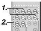

- Press and hold down the SOURCE button (ex TV) for the appliance which should be controlled and press SET button until the SEND indicator blinks twice. Then back light flashes.
- Press the 4-digit code by numeric keys for appliance (code table at the end of this book) When the procedure is successful, the SEND indicator will blink twice.
Note:
If the indicator did not blink twice, then repeat steps 1 through 2 and try entering the same code again.
SCANNING THE CODE TABLE
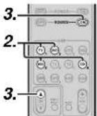
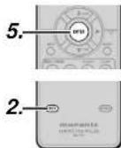
- Switch on the appliance which should be controlled.
- Press and hold down the SOURCE button for appliance which should be controlled and press SET button until the SEND indicator blinking twice. Then back light flashes.
-
Aim the remote controller at the appliance and alternately press the CH+ and SOURCE ON buttons slowly.
-
Stop when the appliance turns off.
- Press ENTER button once to lock in the code. When the procedure is successful, the SEND indicator will blink twice.
CHECKING THE CODE
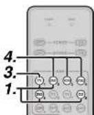

- Press and hold down the SOURCE button for appliance which should be controlled and press SET button until the SEND indicator blinking twice then back light fl ashes.
- Press the INFO button. The SEND indicator will blink twice.
- To view the code for first digit, press 1 once.
Count the SEND indicator blinks (e.g. 3 blinks = 3) and write down the number.
Note:
If a code digit is "0", the SEND indicator will not blink.
4. Repeat step 3 three more times for remaining digits. Use 2 for the second digit, 3 for the third digit, and 4 for the fourth digit.
RESETTING THE CODE


-
Press and hold down the SOURCE button for appliance which should be controlled and press SET button until the SEND indicator blinking twice.
Then back light flashes. -
Press the below codes to reset.
The indicator will blink twice.
Note:
After this procedure, the selected SOURCE button is set initial code.
ENGLISH
LEARN MODE
This remote controller is capable of learning and storing codes used by other remote controls that you already own.
For codes which are not learned, the remote controller will transmit either the Marantz preset codes from the initial settings, or remote codes from another manufacturer's AV equipment which is set by the customer.
The receiver sensor for the remote control signals is located at the top of the remote controller.
Notes:
- This remote controller is capable to learn around 60 codes.
- When the batteries are getting weak, the learning procedure is not successful.
LEARNING PROCEDURE
- Place the remote controller so that its infrared signal transmitter is facing the infrared signal receiver on the Marantz remote controller at a distance of about 5 cm.
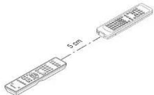
text_image
5cm- Press and hold down the SET and MENU/INPUT buttons until LEARN indicator blinks.
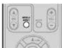

- Select the SOURCE button to select the SOURCE.

- Select the button to be learned.
• LEARN indicator lights up.
When the following key learned
- SOURCE buttons
The learning function is unavailable for all SOURCE buttons in any mode.
- POWER ON button
- POWER OFF button
• VOL +/- button
- MUTE button
- INFO button
- SLEEP button
The above keys are common use in each device mode. It can be learned in TV mode.
- Press and hold the button of the original remote controller to learn until the SEND indicator blinks twice.
- When the SEND indicator blinks once, repeat this step.
- When the memory of the RC101 is full, the LEARN and SEND indicators blink once. If you want to learn the code, you should erase other learned button.
-
Repeat steps 4 and 5 to learn other buttons in same SOURCE.
-
Repeat steps 8 to 6 to learn other SOURCE.
-
When you have finished programming the remote controller, press the SET button, then LEARN indicator stops blinking and exits from the LEARN mode.
Notes:
- When the SEND indicator blinks once again, the transmitting code is unavailable for RC101, or the transmitting signal is intercepted by noise.
- If no buttons are pressed for approximately 1 minutes while in the LEARN mode, the remote controller automatically exits from the LEARN mode.
ERASING PROGRAMMED CODES (RETURNING TO INITIAL SETTINGS)
Codes can be erased in three ways: by buttons, sources, and by all memory contents.
Erasing the code by buttons
- Press and hold down the SET and MENU/INPUT buttons until LEARN indicator blinks.
- Select the SOURCE button to select the button to be erased.

- Press and hold down the SLEEP button and press the learned button twice to be erased.
- SEND indicator blinks twice and the mode
returns to LEARN mode.

- To return the NORMAL mode, press the SET button.
Erasing the code by SOURCE
- Press and hold down the SET and MENU INPUT buttons until LEARN indicator blinks.


- Press and hold down the SLEEP button and press the learned SOURCE button twice to be erased.
• LEARN indicator lights.


- Press ENTER button to continue erasing.
- The SEND indicator blinks twice and the mode returns to LEARN mode.
- To cancel the erasing operation, do not press ENTER button and simply touch any other button.
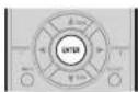
- To return the NORMAL mode, press the SET button.
Erasing the all SOURCES
- Press and hold down the SET and MENU/INPUT buttons until LEARN indicator blinks.
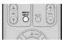

- Press and hold down the SLEEP button and press POWER ON and POWER OFF button.
- LEARN indicator lights.

- Press ENTER button to continue erasing
- The SEND indicator blinks twice and the mode returns to LEARN mode.
- To cancel the erasing operation, do not press ENTER button and simply touch any other button.
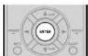
- To return the NORMAL mode, press the SET button.
Note:
Erasing codes will return to the factory preset code, or there will leave empty if the button has no factory preset code.
CLONE MODE
Creating copies using clone mode
All of the codes programmed to the RC101 remote controller can be copied to another RC101 using a few simple operations.
- The remote controller can copy the entire contents.
- When copying the entire contents, all programmed codes are copied.
Note:
The clone function can only be used for copying when using the same model (RC101) for both the transmitting and receiving remote controller.
Copying entire contents
- Place the receiver sensor of the receiving remote controller (top) so that it is facing the transmitter of the transmitting remote controller (top) at a distance of about 5 cm.
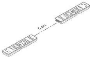
text_image
6 cm- Press SET button and PLAY button of the transmitting remote controller until the SEND indicator blinks twice.

Then backlight flashes
The transmitting side is now ready.
- Press SET button and STOP button of the receiving remote controller until the LEARN indicator blinks twice.


Then backlight flashes.
The receiving side is now ready.
- Press the ENTER cursor button on the receiving remote controller.

Then back lights tune off.
- Press the ENTER cursor button on the transmitting remote controller.
Then backlights tune off.
- When copying is started, the SEND indicator of transmitting remote controller and the LEARN indicator of receiving remote controller start to blink.
When the copying operation is completed, the back lights of transmitting remote controller and receiving remote controller are turned on. Do not touch either of the remote controls during the copying operation. Doing so could cause copying to fail.
If the copying fails in the middle of the copying process, back light of receiving remote are flash. Press the SET button to return the normal mode. Check and perform steps 1 to 5 again.
Copying takes about 30 seconds to complete when the transmitting remote controller has been programmed to 100% capacity.
- Once copying is completed, press the SET button on both remote controls.

OTHER OPERATIONS
CHANGE THE ZONE CONTROL COMMANDS FOR EACH ZONE
(When operating the unit by Multi Zone connected)
- Zone A (Default)
- Zone B
• Zone C (The unit does not use this zone.)
• Zone D (MAIN ZONE)
Change the control commands for each zone.

- Press SET button and ZONE button until the SEND indicator blinks twice.
Then backlight flashes. - Press each zone button(A/B button)
When the procedure is successful, the SEND
Indicator will blink twice.
These buttons change a special code of each zone.
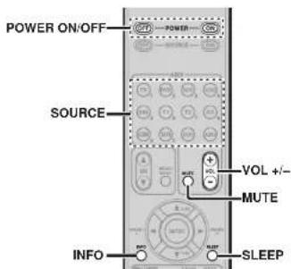
text_image
POWER ON/OFF SOURCE VOL +/- MUTE INFO SLEEPTuner mode operation remote code (Refer to page 75)
CHANGE THE CONTROL COMMANDS OF ZONE
SPEAKER FUNCTION FROM ZONE.
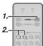

- Press SET button and POWER ON button until the SEND indicator blinks twice.
Then backlight fl ashes.
- Press the 1-digit code by numeric keys. • Zone mode: 1 (Default)
• Zone speaker mode: 2
Note
In case of Zone D, only control for main zone is possible.
3. Press ENTER button once to lock in the code. When the procedure is successful, the SEND Indicator will blink twice.
These buttons change a special code of zone mode or zone speaker mode.
Note
The control commands can be set independently in ZONE A/B.
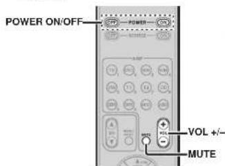
text_image
POWER ON/OFF VOL +/- MUTEENGLISH
SETUP CODES (RC101)
TV
| Acer | 1141 |
| Admiral | 1092, 1009, 1089 |
| Aiko | 1059 |
| Alwa | 1117, 1118 |
| Akai | 1001 |
| Antron | 1023 |
| Anam | 1113 |
| Anam National | 1023, 1069, 1092 |
| AOC | 1003, 1024, 1049, 1127 |
| Audiovox | 1023 |
| Bell & Howell | 1009, 1025 |
| Benq | 1104, 1142 |
| Broksonic | 1003, 1097, 1098, 1113 |
| Celebrity | 1001 |
| Citizen | 1003, 1013, 1023 |
| 1026, 1059, 1063 | |
| Coloryme | 1003, 1043 |
| Contec | 1113 |
| Contec/Cony | 1023, 1045, 1047 |
| Craig | 1020, 1022, 1023, 1113 |
| Crown | 1023, 1067 |
| Curtis Mathes | 1003, 1013, 1025 |
| 1026, 1062, 1103, 1110 | |
| Daswo | 1003, 1013, 1024, 1035 |
| 1035, 1059, 1084, 1101 | |
| Daytron | 1003, 1013, 1016 |
| Dimersla | 1103, 1110 |
| Dumont | 1003, 1010, 1153 |
| Electroband | 1001 |
| Electrohome | 1001, 1003, 1069, 1133 |
| Emerson | 1003, 1013, 1015 |
| 1020, 1021, 1022, 1023 | |
| 1025, 1038, 1044, 1045 | |
| 1048, 1056, 1061, 1094 | |
| 1096, 1099, 1101, 1113 | |
| Envision | 1003 |
| Fisher | 1025, 1051, 1091, 1160 |
| Fujitsu | 1038, 1124, 1125, 1155 |
| Funal | 1023, 1038, 1113 |
| Gateway | 1150 |
| GE | 1003, 1018, 1022, 1046 |
| 1054, 1069, 1085, 1103 | |
| 1110, 1113, 1133, 1136, 1153 |
| Goldstar | 1003, 1013, 1024 |
| 1030, 1045, 1080 | |
| 1100, 1112, 1154 | |
| Hallmark | 1003 |
| Hsense | 1116 |
| Hitachi | 1003, 1012, 1031, 1032 |
| 1037, 1041, 1045, 1047 | |
| 1065, 1068, 1082, 1088 | |
| 1094, 1139, 1140, 1145, 1159 | |
| Inti nity | 1067 |
| Janeil | 1134 |
| JBL | 1067 |
| JC Penney | 1003, 1013, 1018 |
| 1019, 1024, 1026 | |
| 1048, 1047, 1054 | |
| 1063, 1083, 1085 | |
| 1100, 1103, 1110 | |
| 1112, 1133, 1154 | |
| Jensen | 1003 |
| JVC | 1028, 1029, 1045 |
| 1047, 1050, 1060, 1065 | |
| Kawasho | 1001, 1003 |
| Kenwood | 1003 |
| Kloss Novabeam | 1023, 1056, 1057, 1134 |
| KTV | 1013, 1023, 1033 |
| 1034, 1073, 1099, 1113 | |
| LG | 1024, 1030 |
| M.Wards | 1002, 1009, 1038 |
| Magnavox | 1003, 1052, 1053 |
| 1056, 1057, 1063 | |
| 1067, 1081, 1106 | |
| Marantz | 1003, 1031, 1067, 1122 |
| Mitsubishi | 1003, 1024, 1051 |
| 1115, 1122, 1133 | |
| Motorola | 1014, 1069 |
| NEC | 1003, 1012, 1024, 1043, 1069 |
| NET-TV | 1137, 1150 |
| Orion | 1020, 1095 |
| Panasonic | 1017, 1067, 1069, 1095, 1111 |
| Phillips | 1003, 1011, 1045, 1052 |
| 1054, 1056, 1057, 1058 | |
| 1063, 1067, 1069, 1106 | |
| Pioneer | 1003, 1018, 1037 |
| 1070, 1071, 1094 | |
| 1145, 1147, 1149 | |
| Plasmsync | 1135 |
| Portland | 1003, 1013, 1024, 1059 |
| Price Club | 1026 |
| Pfsm | 1018 |
| Proscan | 1004, 1005, 1006, 1007 |
| 1006, 1085, 1103, 1110 |
| Prolon | 1003, 1045 |
| Quasar | 1010, 1069, 1073, 1111, 1153 |
| Radio Shack | 1003, 1013, 1015 |
| 1023, 1024, 1025, 1045 | |
| 1100, 1103, 1110, 1113 | |
| RCA | 1003, 1004, 1005 |
| 1006, 1007, 1008 | |
| 1014, 1024, 1049, 1069 | |
| 1075, 1079, 1085, 1087 | |
| 1088, 1093, 1094, 1101 | |
| 1103, 1110, 1113, 1153 | |
| Realistic | 1013, 1015, 1023, 1025 |
| 1045, 1100, 1103, 1110 | |
| Runco | 1010, 1153 |
| Sampo | 1150 |
| Samsung | 1003, 1013, 1024, 1026 |
| 1040, 1045, 1062, 1078 | |
| 1083, 1090, 1100, 1105/1114 | |
| 1120, 1121, 1146, 1148, 1157 | |
| Sansul | 1119 |
| Sanyo | 1003, 1025, 1051, 1072 |
| 1077, 1091, 1156, 1157, 1158 | |
| Sharp | 1003, 1013, 1014 |
| 1015, 1045, 1055, 1064 | |
| 1066, 1076, 1089, 1123 | |
| Signature | 1009 |
| Sony | 1001, 1102, 1106 |
| Soundesign | 1003, 1023, 1038, 1063, 1113 |
| Starlite | 1023 |
| Supre-Macy | 1134 |
| Sylvania | 1005, 1039, 1042 |
| 1052, 1053, 1056, 1057 | |
| 1063, 1067, 1089, 1151 | |
| Symphonic | 1023, 1039, 1044 |
| Tandy | 1014 |
| Tatung | 1069 |
| Technics | 1015 |
| Techwood | 1003, 1018 |
| Teknika | 1003, 1009, 1013, 1023 |
| 1024, 1026, 1036, 1045 | |
| 1047, 1059, 1063, 1111, 1113 | |
| Telecapition | 1074 |
| Toshiba | 1003, 1019, 1025 |
| 1026, 1042, 1074, 1098 | |
| 1107, 1111, 1135, 1136 | |
| Television | 1013 |
| Universal | 1046, 1054 |
| Video Concepts | 1113 |
| VIEWSO | 1006, 1022, 1109 |
| 1128, 1129, 1130, 1131 | |
| 1138, 1143, 1145, 1150 |
| Wards | 1003, 1009, 1015 |
| 1024, 1038, 1044, 1046 | |
| 1052, 1054, 1056, 1057 | |
| 1067, 1086, 1103, 1110 | |
| White Westinghouse | 1001, 1101 |
| Yamana | 1003, 1024 |
| Zenith | 1003, 1009, 1010 |
| 1132, 1144, 1153 |
CD
| AWA | 3001, 3002, 3003 |
| AKAI | 3004, 3005, 3006 |
| AUDIO | 3007 |
| AUDIO LABS | 3008 |
| CALIFORNIA | 3008 |
| CARVER | 3010, 3011, 3009 |
| CASIO | 3012, 3020 |
| CURTIS | 3020, 3012 |
| DENON | 3013 |
| EMERSON | 3014 |
| FISHER | 3011, 3015, 3016, 3017, 3018 |
| GE | 3019 |
| GENEXXA | 3014, 3021, 3020 |
| HARMON | 3022, 3023, 3051 |
| HITACHI | 3020 |
| INKEL | 3024 |
| JC PENNEY | 3012, 3020, 3025 |
| JVC | 3026, 3027 |
| KARDON | 3022, 3051, 3023 |
| KENWOOD | 3028, 3029, 3030, 3031 |
| 3032, 3033 | |
| KRELL | 3010 |
| LUXMAN | 3035, 3036, 3037, 3038 |
| LX I | 3012, 3020, 3014 |
| MAGNAVOX | 3010, 3039, 3040 |
| MARANTZ | 3010, 3041, 3042, 3043 |
| MATHES | 3012, 3020 |
| MCS | 3012, 3020 |
| MGA | 3023 |
| MISSION | 3010 |
| MITSUBISHI | 3023, 3044 |
| NAD | 3034, 3045 |
| NAKAMICHI | 3046, 3047, 3048 |
| NEO MCS | 3025 |
| NIKKO | 3007, 3016 |
| ONKYO | 3049, 3050, 3051, 3052 |
| 3055, 3056 | |
| OPTIMUS | 3011, 3014, 3020, 3028, 3033 |
| 3054, 3056, 3057, 3058, 3059 | |
| PANASONIC | 3008, 3060, 3061 |
| PHILIPS | 3009, 3010, 3010, 3040 |
| PIONEER | 3020, 3021, 3062, 3063, 3064 |
| QUASAR | 3008 |
| RCA | 3011, 3014, 3065, 3066, 3067 |
| 3068, | |
| REALISTIC | 3011, 3014, 3020, 3042 |
| 3054, | |
| ROTEL | 3010 |
| RS ORIGINAL | 3070 |
| SAE | 3010, 3083 |
| SAMSUNG | 3071 |
| SANSUI | 3014, 3068, 3072, 3073 |
| SANYO | 3011, 3018, 3074, 3075, 3076 |
| SCOTT | 3014 |
| SEARS | 3012, 3014, 3020, 3028, 3042 |
| SHARP | 3028, 3042, 3077 |
| SHERWOOD | 3042, 3056, 3070, 3078, 3024 |
| SHURE | 3025 |
| SONY | 3039, 3079, 3080, 3081, 3082, 3097 |
| SYLVANIA | 3010 |
| SYMPHONIC | 3083 |
| TEAC | 3016, 3042, 3057, 3083, 3084 |
| 3085, | |
| TECHNICA | 3007, 3008, 3061, 3087, 3088 |
| THETA DIGITAL | 3040 |
| TOSHIBA | 3045 |
| VICTOR | 3026 |
| YAMAHA | 3007, 3069, 3090, 3091, 3092 |
| ZENITH | 3016, 3093, 3094, 3095, 3096 |
| DVD | ||
| Aliwa | 2036, 2037 | |
| Apex | 2012, 2017, 2018, 2019, 2021, 2034 | |
| BOSE | 2038, 2039 | |
| Denon | 3069 | 2047, 2048 |
| Funai | 2049 | |
| GE | 3057 | 2009, 2020, 2029, 2033 |
| Harman Kardon | 2061 | |
| Hitachi | 2008, 2012, 2031 | |
| JVC | 2006, 2010, 2040 | |
| 2041, 2042, 2043 | ||
| Kenwood | 2053, 2054 | |
| Koss | 2058 | |
| Magnavox | 2007, 2011, 2023, 2025 | |
| Marantz | 2025 | |
| Mitsubishi | 2011, 2015 | |
| Onkyo | 2062 | |
| Oritron | 2009, 2030 | |
| Panasonic | 2003, 2015, 2016, 2055 | |
| Philips | 2007, 2011, 2058 | |
| Pioneer | 2002, 2014, 2056 | |
| Proscan | 2009, 2020, 2032 | |
| RCA | 3086 | 2005, 2009, 2020, 2036, 2057 |
| Sampo | 2041 | |
| Samsung | 2008, 2012, 2022, 2024, 2027 | |
| Sanyo | 2050, 2052 | |
| Sharp | 2044, 2045 | |
| Sherwood | 2051 | |
| Sony | 2001, 2013, 2059 | |
| Toshiba | 2004, 2008, 2026, 2028 | |
| Yamaha | 2046, 2060 | |
| Zenith | 2010 | |
| DSS | |
| Alphastar | 4027 |
| BSB | 4021 |
| Chaparral | 4039 |
| DIRECTV | 4001, 4016 |
| DISH Network | 4030 |
| Drake | 4026 |
| Echostar | 4007, 4017, 4018, 4019, 4020 |
| Express Vu | 4017 |
| Fujitsu | 4025 |
| GE | 4002, 4008, 4009 |
| General Instruments | 4036, 4037 |
| Hitachi | 4001, 4015 |
| Hughes | 4001, 4016 |
| Janeli | 4025 |
| JVC | 4017 |
| Mitsubishi | 4001 |
| Panasonic | 4004, 4010 |
| Philips | 4031, 4035 |
| Proscan | 4002, 4008, 4009, 4011 |
| Radio Shack | 4036, 4037 |
| RCA | 4002, 4008, 4009, 4029 |
| Realistic | 4040 |
| Rural Cable | 4036 |
| Samsung | 4022, 4027 |
| Sony | 4003, 4012, 4014 |
| Star Choice | 4032 |
| Star Trax | 4024 |
| STS | 4038 |
| SuperDish | 4028 |
| Toshiba | 4001, 4034 |
| Uniden | 4005, 4006, 4013 |
| Video Pall | 4025 |
| Zenith | 4026, 4033 |
ENGLISH
ENGLISH
TROUBLESHOOTING
In case of trouble, check the following before calling for service:
- Are the connections made properly?
- Are you operating the unit properly following the user's guide?
- Are the power amplifiers and speaker working properly?
If the unit does not operate properly, check items shown in the following table.
If your trouble cannot be recovered with the remedy actions listed in the following table, malfunction of the internal circuitry is suspected; immediately unplug the power cable and contact your dealer, nearest Marantz authorized dealer or the Marantz Service Center in your country.
| SYMPTOM CAUSE REMEDY | ||
| This unit cannot be turned up. | The power plug is not connected. | Connect the power plug to the outlet. |
| No sound and picture are output even when power is on. | Mute is on. | Cancel mute using the remote controller. |
| The input or power amp are not connected correctly. | See the connection diagram and connect the cables correctly. | |
| The master volume control is turned all the way down. | Adjust the master volume. | |
| The function selector position is wrong. | Select correct position. | |
| No speaker output. The headphones are connected to the headphone jack. | Disconnect the headphones. (Speakers will not output sound when headphones are connected.) | |
| Incorrect Audio or Video for selected source. | Input cable connected incorrectly. | Connect the cable correctly by referring to the connection diagram. |
| Incorrect Audio from a channel. | The power amp and speakers are not connected correctly. | While referring to the connection diagram, connect the power amp and speakers to the correct channel. |
| No Audio output from the center channel speaker. | The power amp and speakers are not connected correctly. | While referring to the connection diagram, connect the power amp and speakers to the correct channel. |
| STEREO has been selected for Surround mode. | When STEREO is selected for Surround mode, no sound will be output from the center speaker. Set another Surround mode. | |
| Center = NONE has been selected in SETUP mode. | Make the correct setting. | |
| No Audio output from the surround speakers. | The power amp and speakers are not connected correctly. | While referring to the connection diagram, connect the power amp and speakers to the correct channel. |
| STEREO has been selected for Surround mode. | When STEREO has been selected for Surround mode, no sound will be output from the surround speaker. Set another Surround mode. | |
| Surround = NONE has been selected in SETUP mode. | Make the correct setting. | |
| No Audio output from the surround back speakers. | The power amp and speakers are not connected correctly. | While referring to the connection diagram, connect the power amp and speakers to the correct channel. |
| Surround mode is not EX/ES mode. | Set surround mode EX/ES. | |
| Surround back = NONE has been selected in SPEAKERS SIZE SETUP | Make the correct setting. | |
| SYMPTOM CAUSE REMEDY | ||
| Can not select EXES mode. S### | round center= NONE has been selected in SPEAKERS SIZE SETUP | Make the correct setting. |
| Input signal is incompatible. | Use 5.1channel source. | |
| Can not select Pro Logic Iix mode. | Input signal is incompatible. | Use 2 channel Dolby Digital input signal, PCM input signal or analog input signal. |
| Can not select Neo-6 mode. Input | signal is incompatible. | Use 2 channel DTS input signal, PCM Input signal or analog input signal. |
| Can not select CSII mode. Input | signal is incompatible. | Use 2 channel Dolby Digital input signal, PCM input signal or analog input signal. |
| No output to Subwoofer Out. S### | Subwoofer = NONE has been selected in SETUP mode. | Select Subwoofer = YES. |
| Noise is produced during DTS-encoded CD or laser disc play. | Analog has been selected for input. | Be sure to perform digital connection, select digital input, then play. |
| A specific channel does not produce output. | Nothing recorded on source. | Check the encoded channel on the source side. |
| FM or AM reception fails. Anten | a connection is incomplete. | Correctly connect the indoor FM and AM antennas to FM and AM antenna outlets. |
| Noise is heard during AM reception. | Reception is affected by other electrical fields. | Try changing location where the AM indoor antenna is set up. |
| Noise is heard during FM reception. | The radio waves from the broadcasting station are weak. | Install an FM outdoor antenna. |
| Cannot get programmed station when the PRESET button is pressed. | Preset data has been erased. | Disconnecting power plug for long periods of time will erase preset data. If that happens, input the preset data again. |
| Control with the remote controller fails. | Batteries are consumed. | Replace all the batteries with new ones. |
| The remote controller mode is incorrect | Switch the remote controller to the mode used for the component to be controlled. | |
| The distance between this unit and the remote commander is too far. | Move closer to this unit. | |
| Something is blocking the unit and the remote commander. | Remove offending object. | |
| Auto Setup (SPEAKER SETUP) is not working. | Headphones are connected. | Disconnect the headphones. |
HDMI
| SYMPTOM CAUSE REMEDY | ||
| The display does not appear over an HDMI connection. | The connected monitor or projector does not support HDCP. | A video signal is not output except when using an HDCP-compatible device. Either connect to an HDCP-compatible device or use analog video connections. |
| The HDMI input of on the TV is not on. Set | HDMI input so that it turns on, as explained in the TV's instruction manual. | |
| The HDMI output on the source component (DVD, Set Top Box, etc.) is not on. | Set HDMI output so that it turns on, as explained in the source component's instruction manual. | |
| The HDMI mode is not correctly set on the unit. | Set HDMI input on the FUNC INPUT SETUP menu as explained on page 23. | |
| The HDMI output video resolution of the source component (DVD, Set Top Box, etc.) does not match the TV specifications. | Set the resolution so that it matches, as explained in the instruction manuals of both components. | |
| The device is connected with a non-standard HDMI cable. | A 5 m or shorter cable is recommended to ensure stable operation and prevent image quality deterioration. | |
| Power to the unit is off. (When the unit is on standby, HDMI connections cannot be turned on.) | Turn on the power to the unit. | |
| The connection between HDMI components was not authenticated. | Shut off and then turn the power back on to the unit, TV and source component. | |
| Time is needed for the display of an HDMI connection to appear. | The connection is being authenticated between the HDMI devices. | There is nothing wrong with the system. Some HDMI devices require time for authentication. |
| Audio is not played back over an HDMI connection. | The HDMI audio output of the source component (DVD, Set Top Box, etc.) is not on. | Set the HDMI audio output so that it turns on, as explained in the source component's instruction manual. |
| The signal format of the source component (DVD, Set Top Box, etc.) is not supported by the unit. | Set the HDMI audio output so that it can connect to the unit, as explained in the source component's instruction manual. | |
| This unit is set to the HDMI audio "THROUGH" mode. | In the "THROUGH" mode, sound is not produced from the unit. Set it to "ENABLE". (see page 94) | |
| DVD-Audio is not played back over an HDMI connection. | The DVD player does not support CPPM, therefore it cannot output HDMI audio. | • Use a DVD-Audio player that supports CPPM.• Turn on PCM downsampling on the DVD player.• Use an analog connection. |
ENGLISH
PROTECTIVE FEATURE
In some cases, the STANDBY indicator may blink slowly, twice per second. In this case, turn off the unit, unplug the power cord, and check the following points.
- Make sure the speaker cables are not reversed and connected to the wrong sides (+ and -) on the unit.
- Make sure the speaker cables connected to the unit are not shorted. (Check both the unit end and the speaker end.)
- Make sure the volume does not exceed the level that the unit is capable of producing.
- When using the unit in a rack or other enclosed space, heat may build up inside the unit and cause a fi re. When installing the unit, be sure to leave sufficient space between the top, back and both sides of the unit and walls or other AV components to prevent the internal temperature from rising.
After checking these points, plug in the power cord and use the remote controller to turn on the unit. Turn down the volume before resuming playback. Confirm that there are no problems with the speaker connections and playback performance.
If this symptom recurs, request service at your nearest service center.
In rare instances, the unit may enter standby mode and the STANDBY indicator may blink rapidly, 8 times per second. In this case, unplug the power cord and request service at your nearest service center.
EXIT TOPZONEAUTO

natural_image
Front view of a CD-ROM drive with buttons and ports (no visible text or labels)FRONT KEY (BUTTON) LOCK OF THE UNIT
To lock all front panel buttons (except the POWER ON/OFF button) and the INPUT SELECTER and VOLUME knobs, hold the AUTO and EXIT buttons on the front panel simultaneously for at least 3 seconds. At this time, "F-KEY LOCK!" is displayed.
To unlock the controls, press the same buttons again simultaneously for at least 3 seconds. At this time, "F-KEY UNLOCK" is displayed, and the buttons are released.
GENERAL MALFUNCTION
If the equipment malfunctions, this may be because an electrostatic discharge or AC line interference has corrupted the information in the equipment memory circuits. Therefore:
- disconnect the plug from the AC line supply
- after waiting at least three minutes, reconnect the plug to the AC line supply
- re-attempt to operate the equipment
Memory backup
- In case a power outage occurs or the power cord is accidentally unplugged, this unit is equipped with a backup function to prevent memory data such as the preset memory from being erased.
HOW TO RESET THE UNIT
Should the operation or display seem to be abnormal, reset the unit with the following procedure.
This unit is turned on, press and hold the ZONE + TOP buttons simultaneously for 3 seconds or more. Remember that the procedure will reset the settings of the function selector, Surround mode, delay time, TUNER PRESET etc., to their initial settings.
Note:
The NETWORK function setting cannot be reset. For information on resetting the NETWORK function setting, see the NETWORK User Guide.
ENGLISH
OTHERS
TECHNICAL SPECIFICATIONS
FM TUNER SECTION
| Frequency Range | 87.5 – 108.0 MHz |
| Usable Sensitivity | IHF 1.8 μV/16.4 dB |
| Signal to Noise Ratio | Mono/Stereo 75/70 dB |
| Distortion | Mono/Stereo 0.2/0.3 % |
| Stereo Separation | 1 kHz 45 dB |
| Alternate Channel Selectivity | ±300 kHz 60 dB |
| Image Rejection | 98 MHz 70 dB |
| Tuner Output Level | 1 kHz, ±75 kHz Dev 800 mV |
AM TUNER SECTION
| Frequency Range | 531 – 1602 kHz |
| Signal to Noise Ratio | 50 dB |
| Usable Sensitivity | Loop 400μV |
| Distortion | 400Hz, 30 % Mod. 0.5 % |
| Selectivity | ± 20 kHz 70 dB |
AUDIO SECTION
| Input | Sensitivity/Impedance |
| (Unbalanced) | 200 mW/47 k ohms |
| (Balanced) | 400 mW/30 k ohms |
| Output | Level/Impedance |
| (Unbalanced) | 1 W/470 ohms |
| (Balanced) | 2 W/470 ohms |
| Signal to Noise Ratio(Analog Input / Pure Direct) | |
| Frequency | Response |
| (Analog Input / Pure Direct) | |
| (Digital Input / 96 kHz PCM) | 8 Hz - 100 kHz (±3 dB) |
| 8 Hz - 45 kHz (±3 dB) | |
VIDEO
| Television | Format | NTSC/PAL |
| Input Level/Impedance | 1 Vp-p/75 ohms | |
| Output Level/Impedance | 1 Vp-p/75 ohms | |
| Video Frequency Response | .5 Hz to 8 MHz (-1 dB) | |
| Video Frequency (Component) | .5 Hz to 100 MHz (-3 dB) | |
| S/N | 60 dB | |
HDMI
| Version | 1.3a | [INPUT] |
| 1.3a | [OUTPUT] |
GENERAL
| Power Requirement | AC 230 V 50/60 Hz | ||
| Power Consumption | 85 W | ||
| Standby Power Consumption | (Normal) 1.0 W | ||
| (Economy) | 0.7 | W | |
| Weight | 11.6 | kg |
ACCESSORIES
| Remote Controller RC2001 | 1 |
| Remote Controller RC101 | 1 |
| Microphone | |
| AAA-size alkaline batteries | 4 |
| AAA-size dry batteries | 2 |
| FM Antenna | 1 |
| AM Loop Antenna | 1 |
| AC cable | |
| USB cable |
DIMENSIONS
text_image
8 mm36 395 mm 17 mm
text_image
440 mm 184.5 mm 70.5 mm 14 mm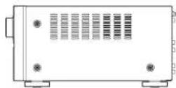
Specifications subject to change without prior notice.
DESCRIPTION
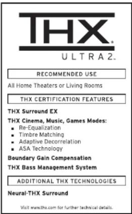
text_image
THX ULTRA2. RECOMMENDED USE All Home Theaters or Living Rooms THX CERTIFICATION FEATURES THX Surround EX THX Cinema, Music, Games Modes: ■ Re-Equalization ■ Timbre Matching ■ Adaptive Decorrelation ■ ASA Technology Boundary Gain Compensation THX Bass Management System ADDITIONAL THX TECHNOLOGIES Neural-THX Surround Visit www.thx.com for further technical details.THX® is an exclusive set of standards and technologies established by the world-renowned film production company. Lucasli Im Ltd. THX resulted from George Lucas' desire to reproduce the movie soundtrack as faithfully as possible both in the movie theater and in the home theater.
THX engineers developed patented technologies to accurately translate the sound from a movie theater environment into the home, correcting the tonal and spatial errors that occur.
When the THX mode of the unit is on, three distinct THX technologies are automatically added:
Re-Equalization-restores the correct tonal balance for watching a movie in a home environment.
These sounds are otherwise mixed to be brighter for a large movie theater. Re-EQ compensates for this and prevents the soundtracks from being overly bright and harsh when played in a home theater.
Timbre Matching-fi Iters the information going to the surround speakers so they more closely match the tonal characteristics of the sound coming from the front speakers.
This ensures seamless panning between the front and surround speakers.
Adaptive Decorrelation-slightly changes one surround channel's time and phase relationship with respect to the other surround channel.
This expands the listening position and creates with only two surround speakers the same spacious surround experience as in a movie theater with multiple surround speakers.
The unit was required to pass a rigorous series of quality and performance tests, in addition to incorporating the technologies explained above, in order to be THX certified.
THX requirements cover every aspect of performance including pre-amplifier and power amplifier performance and operation, and hundreds of other parameters in both the digital and analog domain.
Movies which have been encoded in Dolby Digital, DTS, Dolby Pro Logic, stereo and Mono will all benefit from the THX mode when being viewed.
The THX mode should only be activated when watching movies which were originally produced for a movie theater environment.
THX need not be activated for music, movies made especially for TV, or shows such as sports programming, talk shows, etc.
This is because they were originally mixed for a small room environment.
The THX logo is a trademark of THX Ltd. which may be registered in some jurisdictions. All rights reserved.
THX SURROUND EX
THX Surround EX—Dolby Digital Surround EX is a joint development of Dolby Laboratories and THX Ltd.
In a movie theater, fi Im soundtracks that have been encoded with Dolby Digital Surround EX technology are able to reproduce an extra channel which has been added during the mixing of the program. This channel, called Surround Back, places sounds behind the listener in addition to the currently available front left, front center, front right, surround right, surround left and subwoofer channels. This additional channel provides the opportunity for more detailed imaging behind the listener and brings more depth, spacious ambience and sound localization than ever before.
Movies that were created using the Dolby Digital Surround EX technology, when released into the home consumer market may exhibit wording to that effect on the packaging. A list of movies created using this technology can be found on the Dolby web site at www.dolby.com. A list of available DVD software titles encoded with this technology an be found at www.thx.com.
Only receiver and controller products bearing the THX Surround EX logo, when in the THX Surround EX mode, faithfully reproduce this new technology in the home. This product may also engage the THX Surround EX mode during the playback of 5.1 channel material that is not Dolby Digital Surround EX eoccended. In such case, the information delivered to the Surround Back channel will be program dependent and may or may not be very pleasing depending on the particular soundtrack and the tastes of the individual listener.
"SURROUND EX™" is a trademark of Dolby Laboratories. Used under authorization.
The THX Ultra2 specification provides uncompromised 7.1 channel playback of any multi-channel program, whether movie soundtracks or music over the widest possible seating area.
There are an additional two processing's for THX Ultra2 as bellow.
A.S.A. (Advanced Speaker Array)
"ASA" is a proprietary THX technology which processes the sound fed to 2 surround and 2 surround back speakers to provide the optimal surround sound experience. When you set up your home theater system using all eight speaker outputs (Left, Center, Right, Surround Right, Surround Back Right, Surround Back Left, Surround Left and Subwoofer), placing the two Surround Back speakers close together facing the front of the room as shown in the diagram will provide the largest sweet spot. If for practical reasons you have to place the Surround Back speakers apart, you will need to go to the THX Audio Set-up screen and choose the setting that most closely corresponds to the speaker distance, which will re-optimize the surround sound-fi eld. ASA is used in two new surround modes; THX Ultra2 Cinema, THX Music Mode and THX Games mode.
B.G.C. (Boundary Gain Compensation)
If your chosen listening room layout (for practical or aesthetic reasons) results in most of the listeners being close to the rear wall, the resulting bass level can be suffi cienly reinforced by the boundary that the overall sound quality becomes "boomy". THX Ultra2 receivers contain the BGC (Boundary Gain Compensation) feature to provide an improved bass balance. BGC can be selected by choosing "THX Ultra2 Subwoofer-Yes" from the "Boundary Gain Compensation" section of the "THX Audio setup menu".
ENGLISH

Neural-THX ^® Surround has been chosen as the offi clal surround sound broadcast format for leading FM/HD and satellite radio and television stations worldwide. Neural-THX Surround delivers the rich envelopment and discrete image detail of surround sound in a format 100% compatible with stereo.
Neural-THX Surround draws the brain's attention to sonic details in musical instruments, vocals and ambience that are typically masked by other playback systems. This allows the listener to fully experience the richness and subtleties in recorded performance as never before for both surround encoded material and regular stereo material such as CDs or digital media players.
Neural-THX Surround: Taking Surround to the Next Level.
This product is manufactured under license from Neural Audio Corporation and THX Ltd. Marantz hereby grants the user a non-exclusive, non-transferable, limited right of use to this product under USA and foreign patent, patent pending and other technology or trademarks owned by Neural Audio Corporation and THX Ltd. "Neural Surround", "Neural Audio", "Neural" and "NRL" are trademarks and logos owned by Neural Audio Corporation, THX is a trademark of THX Ltd., which may be registered in some jurisdictions. All rights reserved.

Manufactured under license under U.S. Patent #s: 5,451,942; 5,956,674; 5,974,380; 5,978,762; 6,226,616; 6,487,535; 7,003,467; 7,212,872 & other U.S. and worldwide patents issued & pending. DTS, DTS Digital Surround, ES, and Neo:6 are registered trademarks and the DTS logos, Symbol and DTS 96/24 are trademarks of DTS, Inc. © 1996-2007 DTS, Inc. All Rights Reserved.
- dts Digital Surround
DTS was introduced in 1994 to provide 5.1 channels of discrete digital audio into home theater systems. DTS brings you premium quality discrete multichannel digital sound to both movies and music.
DTS is a multichannel sound system designed to create full range digital sound reproduction.
ENGLISH
The no compromise DTS digital process sets the standard of quality for cinema sound by delivering an exact copy of the studio master recordings to neighborhood and home theaters.
Now, every moviegoer can hear the sound exactly as the moviemaker intended.
DTS can be enjoyed in the home for either movies or music on of DVD's, LD's, and CD's.
• dts Neo:6 ^®
The advantages of discrete multichannel systems over matrix are well known.
But even in homes equipped for discrete multichannel, there remains a need for high-quality matrix decoding. This is because of the large library of matrix surround motion pictures available on disc and on VHS tape; and analog television broadcasts.
The typical matrix decoder of today derives a center channel and a mono surround channel from two-channel matrix stereo material. It is better than a simple matrix in that it includes steering logic to improve separation, but because of its mono, band-limited surround it can be disappointing to users accustomed to discrete multichannel.
Neo:6 offers several important improvements as follow.
- Neo:6 provides up to six full-band channels of matrix decoding from stereo matrix material. Users with 6.1 and 5.1 systems will derive six and five separate channels, respectively, corresponding to the standard home-theater speaker layouts.
- Neo:6 technology allows various sound elements within a channel or channels to be steered separately, and in a way which follows naturally from the original presentation.
- Neo:6 offers a music mode to expand stereo nonmatrix recordings into the fl ve- or six-channel layout, in a way which does not diminish the subtlety and integrity of the original stereo recording.
- dts Digital Surround ES ^®
DTS-ES Extended Surround is a now multichannel digital signal format developed by Digital Theater Systems Inc. While offering high compatibility with the conventional DTS Digital Surround format, DTS-ES Extended Surround greatly improves the 360-degree surround impression and space expression thanks to further expanded surround signals. This format has been used professionally in movie theaters since 1999.
In addition to the 5.1 surround channels (FL, FR, C, SL, SR and LFE), DTS-ES Extended Surround also offers the SB (Surround Back) channel for surround playback with a total of 6.1 channels. DTS-ES Extended Surround includes two signal formats with different surround signal recording methods, as DTS-ES Discrete 6.1 and DTS-ES Matrix 6.1.
• dts Digital Surround 96/24
The stereo CD is a 16-bit medium with sampling at 44.1kHz . Professional audio has been 20- or 24-bit for some time, and there is increasing interest in higher sampling rates both for recording and for delivery into the home. Greater bit depths provide extended dynamic range. Higher sampling rates allow wider frequency response and the use of anti-alias and reconstruction fiters with more favorable aural characteristics.
DTS 96/24 allows for 5.1 channel sound tracks to be encoded at a rate of 96kHz/24bits on DVD-Video titles.
When DVD-video appeared, it became possible to deliver 24-bit, 96 kHz audio into the home, but only in two channels, and with serious limitations on picture. This capability has had little use.
DVD audio allows 96/24 in six channels, but a new player is needed, and only analog outputs are provided, necessitating the use of the D/A converters and analog electronics provided in the player.
DTS 96/24 offers the following
-
Sound quality transparent to the original 96/24 master.
-
Full backward compatibility with all existing decoders. (Existing decoders will output a 48 kHz signal)
- No new player required: DTS 96/24 can be carried on DVD-video, or in the video zone of DVD-audio, accessible to all DVD players.
- 96/24 5.1-channel sound with full-quality full-motion video, for music programs and motion picture soundtracks on DVD-video.
dts-HD
Master Audio
DTS-HD Master Audio is capable of delivering audio that is a bit-for-bit identical to the studio master. DTS-HD Master Audio delivers audio at super high variable bit rates -24.5 mega-bits per second (Mbps) on Blu-ray discs and 18.0 Mbps on HD-DVD - that are signifi cantly higher than standard DVDs . This bit stream is so "fast" and the transfer rate is so "high" that it can deliver the Holy Grail of audio: 7.1 audio channels at 96k sampling frequency/24 bit depths that are identical to the original. With DTS-HD Master Audio, you will be able to experience movies and music, exactly as the artist intended: clear, pure, and uncompromised.
Manufactured under license under U.S. Patent #'s: 5,451,942; 5,956,674; 5,974,380; 5,978,762; 6,226,616; 6,487,535 & other U.S. and worldwide patents issued & pending.
DTS is a registered trademark and the DTS logos, Symbol, DTS-HD and DTS-HD Master Audio are trademarks of DTS, Inc. © 1996-2007 DTS, Inc. All Rights Reserved.
dts-hd
High Resolution Audio
DTS-HD High Resolution Audio can deliver up to 7.1 channels of sound that is virtually indistinguishable from the original. DTS-HD High Resolution Audio delivers audio at high constant bit rates superior to standard DVDs--6.0 Mbps on Blu-ray discs and 3.0 Mbps on HD-DVD to produce outstanding sound quality. It is capable of delivering up to 7.1 channels at 96k sampling frequency/24 bit depth resolution. It allows content creators to deliver rich, high definition audio on movies where disc space may not allow for DTS-HD Master Audio.
Manufactured under license under U.S. Patent #s: 5,451,942; 5,956,674; 5,974,380; 5,978,762; 6,226,616; 6,487,535 & other U.S. and worldwide patents issued & pending. DTS is a registered trademark and the DTS logos, Symbol, DTS-HD, DTS-HD High Resolution
Audio and DTS-HD High Res Audio are trademarks of DTS, Inc. © 1996-2007 DTS, Inc. All Rights Reserved.
DOLBY
DIGITAL EX
PROLOGIC IX
Dolby Digital identifies the use of Dolby Digital audio coding for such consumer formats as DVD and DTV. As with fi Im sound, Dolby Digital can provide up to fi ve full-range channels for left, center, and right screen channels, independent left and right surround channels, and a sixth (.1") channel for low-frequency effects.
Dolby Surround Pro Logic II is an improved matrix decoding technology that provides better spatiality and directionality on Dolby Surround program material; provides a convincing three-dimensional soundfield on conventional stereo music recordings and is ideally suited to bring the surround experience to automotive sound. While conventional surround programming is fully compatible with Dolby Surround
Pro Logic II decoders, soundtracks will be able to be encoded specifically to take full advantage of Pro Logic II playback, including separate left and right surround channels. (Such material is also compatible with conventional Pro Logic decoders.)
Dolby Digital EX creates six full-bandwidth output channels from 5.1-channel sources. This is done using a matrix decoder that derives three surround channels from the two in the original recording. For best results, Dolby Digital EX should be used with movies soundtracks recorded with Dolby Digital Surround EX.
About Dolby Pro Logic IIx
Dolby Pro Logic Tlx technology delivers a natural and immersing 7.1-channel listening experience to the home theater environment. A product of Dolby's expertise in surround sound and matrix decoding technologies, Dolby Pro Logic Tlx is a complete surround sound solution that maximizes the entertainment experience from stereo as well as 5.1-channel encoded sources.
Dolby Pro Logic 11x is fully compatible with Dolby Surround Pro Logic technology and can optimally decode the thousands of commercially available Dolby Surround encoded video cassettes and television programs with enhanced depth and spatiality. It can also process any high-quality stereo or Advanced Resolution 5.1-channel music content into a seamless 6.1- or 7.1-channel listening experience.
#
The Dolby Headphone technology provides a surround sound listening experience over headphones. When listening to multichannel content such as DVD movies over headphones, the listening experience is fundamentally different than listening to speakers. Since the headphone speaker drivers are covering the pinna of the ear, the listening experience differs greatly from traditional speaker playback. Dolby utilizes patented headphone perspective curves to solve this problem and provides a non-fatiguing, immersive, home theater listening experience. Dolby Headphone also delivers exceptional 3D audio from stereo material.
DOLBY
VIRTUAL SPEAKER
Dolby Virtual Speaker is a technology certified by Dolby Laboratories that creates a virtualized surround sound experience from two speakers using a multichannel Dolby Digital source. Additionally, Dolby Virtual Speaker can simulate the surround sound effect produced by Dolby Pro Logic or Dolby Pro Logic II.
Dolby Virtual Speaker retains all the original Multichannel audio information and provides the listener with the sensation of being surrounded by additional speakers.
DOLBY
TRUEHD
Dolby ^® TrueHD is Dolby's next-generation lossless technology developed for high-defition disc-based media. Dolby TrueHD delivers tantalizing sound that is bit-for-bit identical to the studio master, unlocking the true high-definition entertainment experience on next-generation discs. When coupled with high-defition video, Dolby TrueHD offers an unprecedented home theater experience that lets you enjoy sound as stunning as the high-definition picture.
DOLBY
DIGITAL PLUS
Dolby Digital Plus is a highly sophisticated and versatile audio codec based on Dolby Digital and designed specifically to adapt to the changing demands of future audio, video delivery, and audio storage systems while simultaneously retaining backwards compatibility with the existing Dolby Digital 5.1-channel home theater systems in use today.
Manufactured under license from Dolby Laboratories. "Dolby", "Pro Logic", "Surround EX", and the double-D symbol are trademarks of Dolby Laboratories.
SRS(○)
Circle SurroundII
Circle Surround II (CS-II) is a powerful and versatile multichannel technology. CS-II is designed to enable up to 6.1 multichannel surround sound playback from mono, stereo, CS encoded sources and other matrix encoded sources. In all cases the decoder extends it into 6 channels of surround audio and a LFE/subwoofer signal. The CS-II decoder creates a listening environment that places the listener "inside" music performances and dramatically improves both hi-fi audio conventional surround-encoded video material. CS-II provides composite stereo rear channels to greatly improve separation and image positioning—adding a heightened sense of realism to both audio and A/V productions.
CS-II is packed with other useful feature like dialog clarity (SRS Dialog) for movies and cinema-like bass enrichment (TruBass). CS-II can enable the dialog to become clearer and more discernable in movies and it enables the bass frequencies contained in the original programming to more closely achieve low frequencies—overcoming the low frequency limitations of the speakers by full octave.
Circle Surround II, SRS and (●)® symbol are trademarks of SRS Labs, Inc.
Circle Surround II is incorporated under license from SRS Labs, Inc.
Microsoft ^®

HDCD ^x (High Defi nition Compatible Digital ^b ) is a patented process for delivering on Compact Disc the full richness and details of the original microphone feed.
HDCD encoded CDs sound better because they are encoded with 20-bits of real musical information as compared to 16-bits for all other CDs.
HDCD overcomes the limitation of the 16-bit CD format by using a sophisticated system to encode the additional four bits onto the CD while remaining completely compatible with the CD format.
When listening to HDCD recordings, you hear more dynamic range, a focused 3-D sound stage, and extremely natural vocal and musical timbre. With HDCD, you get the body, depth and emotion of the original performance not a fl at, digital imitation.
HDCD system manufactured under license from Microsoft. This product is covered by one or more of the following: In the United States 5,479,168 5,638,074 5,640,161 5,808,574 5,838,274 5,854,600 5,864,311 5,872,531 and in Australia 669,114 with other patents pending.
"Microsoft, HDCD, and the HDCD logo are trademarks or registered trademarks of Microsoft Corporation in the United States and / or other countries."
HDMI
HDMI, the HOMM-Definition Multimedia
Interface are trademarks or registered trademarks of HDMI Licensing LLC.
AUDYSSEY
"MULTEQ"
There are several factors that can degrade the sound from even the best loudspeakers in a listening room. One of the most important is the interaction of sound from the loudspeakers with large surfaces such as walls, the floor, and the ceiling in the room. Even with careful loudspeaker placement and acoustical treatments, there are significant problems that are caused by room acoustics. These include reflections from nearby surfaces and standing waves that are created between large parallel surfaces in the room. In a home theater the situation is further complicated because there are several listening locations. The effects of room acoustics on the sound arriving at each person's ears are very different and the result is a listening experience that is degraded in a different way for every person in the room. It is not uncommon to have variations in two adjacent seats that are as large as 10 dB, particularly in the frequency range below 250 Hz.
The solution to this problem is to apply room correction after precisely measuring how each loudspeaker interacts with the room. Because the room causes variations in the frequency response of the loudspeakers that are so large from seat to seat, it is important to measure each loudspeaker at several locations in the listening room. This should be done even if there is only one listener. Measurement at a single location is not representative of the acoustical problems in the room and will in most cases, degrade overall performance. Audyssey MultEQ is the only technology that can achieve room correction for multiple listeners in a large listening area. It does so by combining the data collected at several points in the room from each loudspeaker and then applying correction that minimizes the acoustical effects of the room and is matched to the frequency resolution of human perception (known as psychoacoustics).
ENGLISH
Furthermore, MultEO correction is applied both in frequency and time domains and so there are no artifacts (such as smearing of sound or modal ringing) that are sometimes associated with traditional methods of room equalization.
In addition to correcting frequency response problems over a wide listening area, Audyssey MultEQ provides a completely automated sound system set-up process. It identifies how many loudspeakers are connected to the amplifiers and whether they are full-range, satellites, or subwoofers. If there is a least one subwoofer connected, Audyssey MultEQ determines the optimum crossover frequency between each satellite and the subwoofer(s). It automatically checks the polarity of each loudspeaker and alerts the user if there are any that may be wired out-of-phase relative to the others. It measures the distance to each loudspeaker from the main listening position and adjusts the delays so that sound from each loudspeaker arrives at the same time. Finally, Audyssey MultEQ determines the playback level of each loudspeaker and adjusts the volume trims so that all levels are equal.
AUDYSSEY
MultEQ and the Audyssey MultEQ logo are trademarks of Audyssey Laboratories, Inc. All rights reserved.

DLNA CERTIFIED™ Audio/Video/Image Player DLNA®, the DLNA Logo and DLNA CERTIFIED™ are trademarks, service marks, or certification marks of the Digital Living Network Alliance.
x.v.Color
"x.v.Color" and "x.v.Color" logo are trademarks of Sony Corporation.
www.marantz.com
You can find your nearest authorized distributor or dealer on our website.
marantz®
is a registered trademark.
