ProLiant DL180 G6 - Server HP - Free user manual and instructions
Find the device manual for free ProLiant DL180 G6 HP in PDF.

User questions about ProLiant DL180 G6 HP
0 question about this device. Answer the ones you know or ask your own.
Ask a new question about this device
Download the instructions for your Server in PDF format for free! Find your manual ProLiant DL180 G6 - HP and take your electronic device back in hand. On this page are published all the documents necessary for the use of your device. ProLiant DL180 G6 by HP.
USER MANUAL ProLiant DL180 G6 HP
HP ProLiant DL180 G6 Server
Maintenance and Service Guide

Legal notices
© Copyright 2010, 2011 Hewlett-Packard Development Company, L.P.
The information contained herein is subject to change without notice. The only warranties for HP products and services are set forth in the express warranty statements accompanying such products and services. Nothing herein should be construed as constituting an additional warranty. HP shall not be liable for technical or editorial errors or omissions contained herein.
Intel and Xeon are registered trademarks of Intel Corporation in the U.S. and other countries.
Contents
Customer self repair .... 1
Parts only warranty service....1
Illustrated parts catalog....12
Mechanical components / 4 3.5" HDD model....12
Mechanical components / 8 3.5" HDD model....13
Mechanical components / 8 2.5" HDD model....14
Mechanical components / 12 3.5" HDD model....15
Mechanical components / 25 2.5" HDD model....16
System components / 4 3.5" HDD model 20
System components / 8 3.5" HDD model 24
System components / 8 2.5" HDD model 27
System components / 12 3.5" HDD model 30
System components /25 2.5" HDD model 33
HP contact information 37
Before you contact HP 37
Removal and replacement procedures 39
Hardware configuration tools 39
Hardware configuration information....39
Electrostatic discharge information 39
Pre-installation procedure 40
Post-installation instructions 40
Server warnings and cautions....40
HP Trusted Platform Module 41
Symbols on equipment....41
Powering down the server 42
System cover 43
Top cover 43
Drives....44
Cable management 44
Cable connections 45
Drive bay configuration 49
Optical disc drive bay 52
Hard drives 55
SAS/SATA HDD backplane 61
System board configuration....70
Processor 70
Memory....79
DIMM identification....82
PCI expansion card 83
Dedicated management port (Optional) 102
TPM Module (Optional) 105
System battery 107
BBWC (Optional)....110
System board removal and replacement procedure 112
Power supply unit (PSU) 114
System fan cage 117
System fan 122
Connectors, switches, and LEDs 125
Connectors and components 125
Front panel components....125
Rear panel components 130
System board components.... 133
Jumpers 134
LED indicators 135
Front panel LED indicators.... 135
Optical disc drive activity LED indicator 136
Hard drive LED indicator....137
Rear panel LED indicators 138
System board LED indicator.... 139
Diagnostic tools and setup utilities 140
BIOS software 140
BIOS Setup Utility 140
Accessing the BIOS Setup Utility 140
Navigating through the Setup Utility 141
Setup Utility menu bar 142
BIOS update 148
Clear CMOS....148
Power-On Self-Test (POST)....148
POST error indicators 149
POST error descriptions 149
POST related troubleshooting.... 150
SETSYS utility....151
Physical and operating specifications 152
System unit.... 152
Index 157
Customer self repair
HP products are designed with many Customer Self Repair (CSR) parts to minimize repair time and allow for greater flexibility in performing defective parts replacement. If during the diagnosis period HP (or HP service providers or service partners) identifies that the repair can be accomplished by the use of a CSR part, HP will ship that part directly to you for replacement. There are two categories of CSR parts:
- Mandatory—Parts for which customer self repair is mandatory. If, however, you require that HP replace them for you, there may or may not be additional charges, depending on the type of warranty service designated for your product.
- No—Some HP parts are not designed for customer self repair. In order to satisfy the customer warranty, HP requires that an authorized service provider replace the part. These parts are identified as "No" in the Illustrated Parts Catalog.
Based on availability and where geography permits, CSR parts will be shipped for next business day delivery. Same day or four-hour delivery may be offered at an additional charge where geography permits. If assistance is required, you can call the HP Technical Support Center and a technician will help you over the telephone. HP specifies in the materials shipped with a replacement CSR part whether a defective part must be returned to HP. In cases where it is required to return the defective part to HP, you must ship the defective part back to HP within a defined period of time, normally five (5) business days. The defective part must be returned with the associated documentation in the provided shipping material. Failure to return the defective part may result in HP billing you for the replacement. With a customer self repair, HP will pay all shipping and part return costs and determine the courier/carrier to be used.
For more information about HP's Customer Self Repair program, contact your local service provider. For the North American program, refer to the HP website (http://www.hp.com/go/selfrepair).
Parts only warranty service
Your HP Limited Warranty may include a parts only warranty service. Under the terms of parts only warranty service, HP will provide replacement parts free of charge.
For parts only warranty service, CSR part replacement is mandatory. If you request HP to replace these parts, you will be charged for the travel and labor costs of this service.
Customer self repair
Customer self repair
Illustrated parts catalog
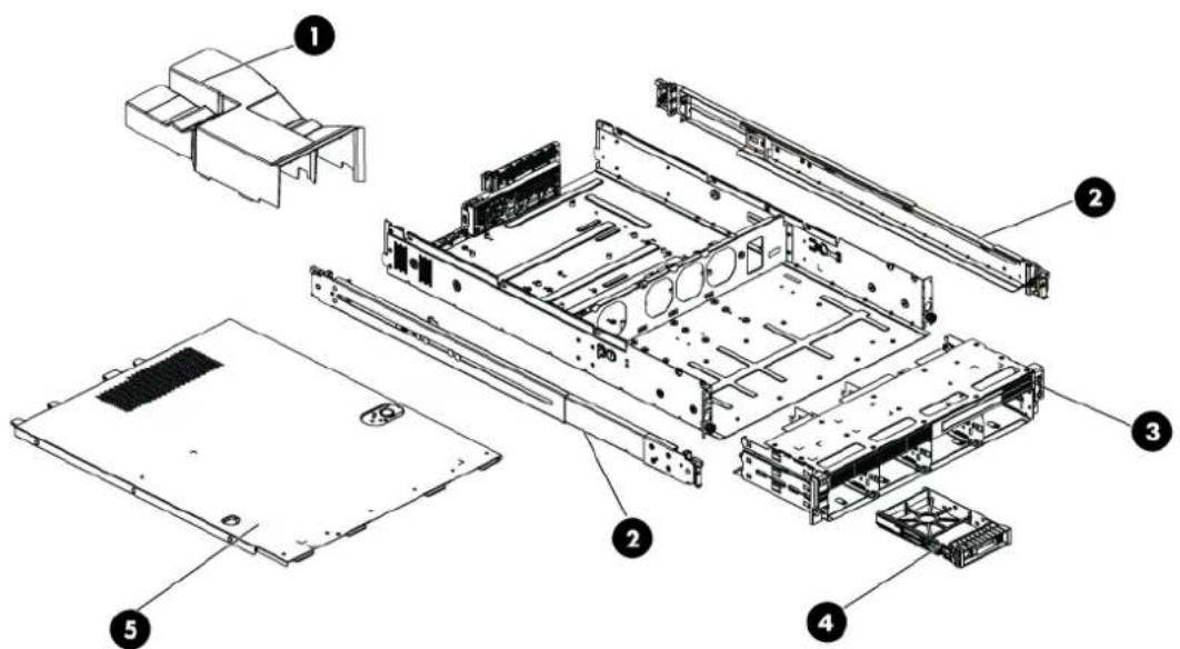
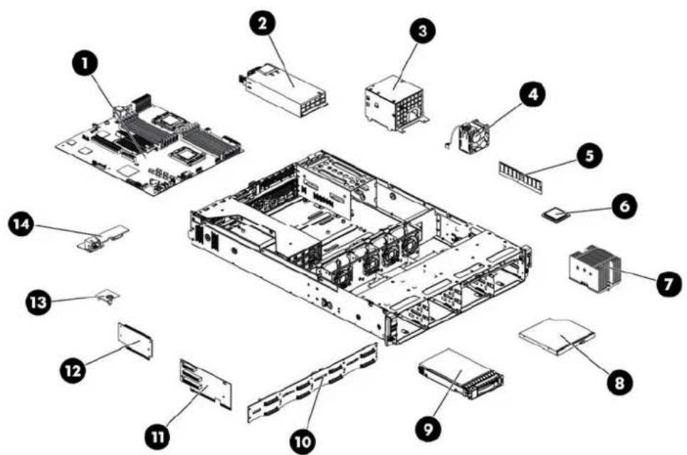
Mechanical components / 4 3.5" HDD model

text_image
Exploded view diagram of a computer system showing internal components and labeled partsTable 1 Mechanical Components Spare Parts List / 4 3.5" HDD Model
| Item | Description | Spare Part | Number | Customer self repair | ||
| 1 | Air | baffle | 507256-001 | Mandatory | 1 | |
| 2 | Rail | kit | 573091-001 | Mandatory | 1 | |
| 3 | Hard drive cage for 4 3.5" HDDs (includes control panel) | 507305-001 | Mandatory | 1 | ||
| 4 | Hardware/Plastics | Kit | 507260-001 | Mandatory1 | ||
| ASSY, BLANK,SFF | ||||||
| BRKT, PCI,LOW PROFILE, ARRAY CONT | ||||||
| BRKT,HDD,SLIMLINE,12.7 | ||||||
| SCR, M2-0.4x.2.1mm, 6G, PH | ||||||
| SCR TT, 6-32x.160,SLT-T15 | ||||||
| BLANK, PS, NONPERF, IDOF | ||||||
| REAR I/O PANEL, LC2UG6 | ||||||
| 5 | Top | cover | 507262-001 | Mandatory | 1 | |
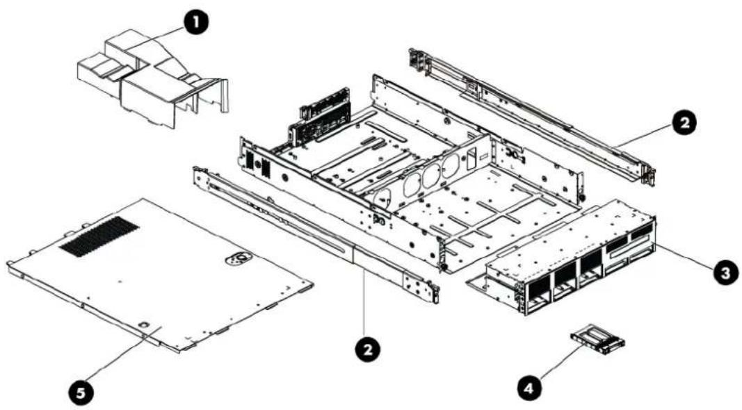
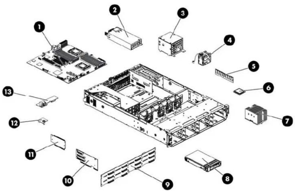
Mechanical components / 8 3.5" HDD model
text_image
Exploded view diagram of a computer motherboard with numbered components for identificationTable 2 Mechanical Components Spare Parts List / 8 3.5" HDD Model
| Item | Description | Spare Part | Number | Customer self repair | ||
| 1 | Air | baffle | 507256-001 | Mandatory | 1 | |
| 2 | Rail | kit | 573091-001 | Mandatory | 1 | |
| 3 | Hard drive cage for 8 3.5" HDDs(includes control panel) | 507305-001 | Mandatory | 1 | ||
| 4 | Hardware/Plastics | Kit | 507260-001 | Mandatory1 | ||
| ASSY, BLANK,SFF | ||||||
| BRKT, PCI,LOW PROFILE, ARRAY CONT | ||||||
| BRKT,HDD,SLIMLINE,12.7 | ||||||
| SCR, M2-0.4x.2.1mm, 6G, PH | ||||||
| SCR TT, 6-32x.160,SLT-T15 | ||||||
| BLANK, PS, NONPERF, IDOF | ||||||
| REAR I/O PANEL, LC2UG6 | ||||||
| 5 | Top | cover | 507262-001 | Mandatory | 1 | |
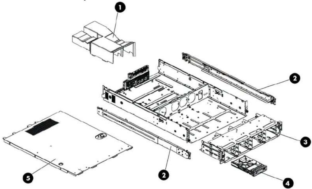
Mechanical components / 8 2.5" HDD model
text_image
Exploded view diagram of a computer chassis with numbered components for identificationTable 3 Mechanical Components Spare Parts List / 8 2.5" HDD Model
| Item | Description | Spare Part | Number | Customer self repair | ||
| 1 | Air | baffle | 507256-001 | Mandatory | 1 | |
| 2 | Rail | kit | 573091-001 | Mandatory | 1 | |
| 3 | Hard drive cage for 8 2.5" HDDs (includes control panel) | 507253-001 | Mandatory | 1 | ||
| 4 | Hardware/Plastics Kit | 507260-001 | Mandatory1 | |||
| ASSY, BLANK,SFF | ||||||
| BRKT, PCI,LOW PROFILE, ARRAY CONT | ||||||
| BRKT,HDD,SUIMLINE,12.7 | ||||||
| SCR, M2-0.4x.2.1mm, 6G, PH | ||||||
| SCR TT, 6-32x.160,SLT-T15 | ||||||
| BLANK, PS, NONPERF, IDOF | ||||||
| REAR I/O PANEL, LC2UG6 | ||||||
| 5 | Top cover | 507262-001 | Mandatory | 1 | ||
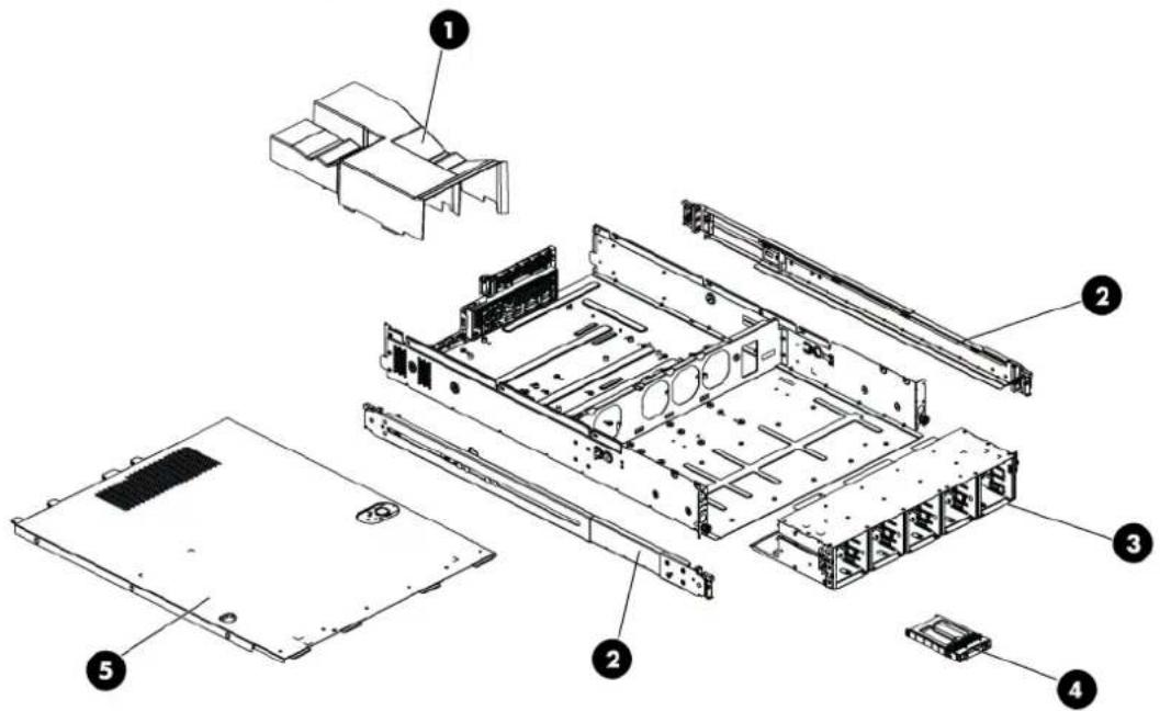
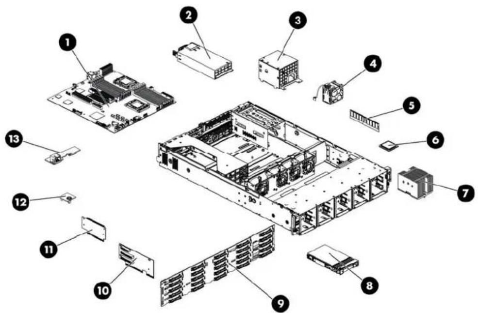
Mechanical components / 12 3.5" HDD model
text_image
Exploded view diagram of a computer motherboard with numbered components for identificationTable 4 Mechanical Components Spare Parts List / 12 3.5" HDD Model
| Item | Description | Spare Part | Number | Customer self repair | ||
| 1 | Air | baffle | 507256-001 | Mandatory | 1 | |
| 2 | Rail | kit | 573091-001 | Mandatory | 1 | |
| 3 | Hard drive cage for 12 3.5" HDDs (includes control panel) | 587326-001 | Mandatory | 1 | ||
| 4 | Hardware/Plastics | Kit | 536390-001 | Mandatory1 | ||
| ASSY, BLANK,SFF | ||||||
| BRKT, PCI,LOW PROFILE, ARRAY CONT | ||||||
| BRKT,HDD,SLIMLINE,12.7 | ||||||
| SCR, M2-0.4x.2.1mm, 6G, PH | ||||||
| SCR TT, 6-32x.160,SLT-T15 | ||||||
| BLANK, PS, NONPERF, IDOF | ||||||
| REAR I/O PANEL, LC2UG6 | ||||||
| 5 | Top | cover | 507262-001 | Mandatory | 1 | |
Mechanical components / 25 2.5" HDD model
text_image
Exploded view diagram of a computer drive system with numbered components for identificationTable 5 Mechanical Components Spare Parts List / 25 2.5" HDD Model
| Item | Description | Spare Part | Number | Customer self repair | ||
| 1 | Air | baffle | 507256-001 | Mandatory | 1 | |
| 2 | Rail | kit | 573091-001 | Mandatory | 1 | |
| 3 | Hard drive cage for 25 2.5" HDDs (includes control panel) | 530946-001 | Mandatory | 1 | ||
| 4 | Hardware/Plastics | Kit | 507260-001 | Mandatory1 | ||
| ASSY, BLANK,SFF | ||||||
| BRKT, PCI,LOW PROFILE, ARRAY CONT | ||||||
| BRKT,HDD,SUIMLINE,12.7 | ||||||
| SCR, M2-0.4x.2.1mm, 6G, PH | ||||||
| SCR TT, 6-32x.160,SLT-T15 | ||||||
| BLANK, PS, NONPERF, IDOF | ||||||
| REAR I/O PANEL, LC2UG6 | ||||||
| 5 | Top | cover | 507262-001 | Mandatory | 1 | |
^1 Mandatory—Parts for which customer self repair is mandatory. If you request HP to replace these parts, you will be charged for the travel and labor costs of this service.
^2 Optional—Parts for which customer self repair is optional. These parts are also designed for customer self repair. If, however, you require that HP replace them for you, there may or may not be additional charges, depending on the type of warranty service designated for your product.
^3 No—Some HP parts are not designed for customer self repair. In order to satisfy the customer warranty, HP requires that an authorized service provider replace the part. These parts are identified as "No" in the Illustrated Parts Catalog.
The system supports five kinds of HDD configurations, three types of PCI cage and three types of power supply unit. The following table lists the detailed system configurations.
Table 6 System Configurations
| System model PCI cage Power supply unit | ||
| 4 3.5" HDD model Standard PCI cageOptical disc drive PCI cage | One or two 460 W power supply unit | |
| 8 3.5" HDD model Standard PCI cageOptical disc drive PCI cage | One or two 460 W power supply unit | |
| 8 2.5" HDD model Standard PCI cageOptical disc drive PCI cage | One or two 460 W power supply unit | |
| 12 3.5" HDD model Standard PCI cageOptical disc drive PCI cageHDD PCI cage | One or two 750 W power supply unit | |
| 25 2.5" HDD model Standard PCI cageOptical disc drive PCI cage | One or two 750W power supply unit | |
System components / 4 3.5" HDD model

text_image
Exploded view diagram of a computer motherboard with numbered components for identificationTable 7 System Components Spare Parts List / 4 3.5" HDD Model
| Item Description Spare Part | Number | Customer self repair | ||
| 1 | System board, Intel 5500 series processors | 507255-001 | Optional^2 | |
| System board, Intel 5500 & 5600 series processors | 608865-001 | |||
| 2 | Power supplies (all support hot-plug) | |||
| Power supply 460 W 511777-001 Mandatory | 1 | |||
| Power supply 750 W 511778-001 Mandatory | 1 | |||
| Power supply 460 W 94% 599381-001 Mandatory | 1 | |||
| Power supply 750 W 94% 599383-001 Mandatory | 1 | |||
| 3 | DC Converter Power Backplane Assy. 519200-001 Mandatory | 1 | ||
| 4 | System fans 519199-001 Mandatory | 1 | ||
| 5 | Memory modules | |||
| Registered DIMMs (RDIMMs) | ||||
| DIMM, 2GB 2Rx8 PC3-10600R-9 | 501533-001 Mandatory | 1 | ||
| DIMM, 4GB 2Rx4 PC3-10600R-9 | 501534-001 Mandatory | 1 | ||
| DIMM, 4GB 4Rx8 PC3-8500R-7 LP | 501535-001 Mandatory | 1 | ||
| DIMM, 8GB 2Rx4 PC3-8500R-7 | 519201-001 Mandatory | 1 | ||
| DIMM, 16GB 2RX4 PC3L-10600R-9 | 632204-001 Mandatory | 1 | ||
| DIMM, 16GB 4RX4 PC3-8500R-7 | 501538-001 Mandatory | 1 | ||
| Unregistered DIMMs (UDIMMs) | ||||
| DIMM, 1GB 1Rx8 PC3-10600E-9 | 501539-001 Mandatory | 1 | ||
| DIMM, 2GB 2Rx8 PC3-10600E-9 | 501540-001 Mandatory | 1 | ||
| 6 | Processors, FCLGA 1366 Intel Xeon series | |||
| PROC,Xeon EP 2.93 Ghz, 8M, 95W | 506012-001 Optional | 2 | ||
| PROC,Xeon EP 2.67 Ghz, 8M, 95W | 490070-001 Optional | 2 | ||
| PROC,Xeon EP 2.26 Ghz, 8M, 80W | 490073-001 Optional | 2 | ||
| PROC,Xeon EP 2.0 Ghz, 4M, 80W QC | 490074-001 Optional | 2 | ||
| PROC,Xeon EP 2.53 Ghz, 8M, 80W | 490071-001 Optional | 2 | ||
| PROC,Xeon EP 2.26 Ghz, 8M, 60W | 508567-001 Optional | 2 | ||
| PROC,Xeon EP E5506 2.13 Ghz,4M, 80W | 506013-001 Optional | 2 | ||
| PROC,Xeon EP E5503 2.0 Ghz,4M, DC | 594889-001 Optional | 2 | ||
| PROC,Xeon L5630 4c, 2.13 Ghz, 12M, 40W | 594891-001 Optional | 2 | ||
| PROC,Xeon E5620 4c, 2.4 Ghz, 12M, 80W | 594887-001 Optional | 2 | ||
Table 7 System Components Spare Parts List / 4 3.5" HDD Model
| Item Description Spare Part | Number | Customer self repair | |
| PROC,Xeon X5650 6c, 2.66 Ghz, 12M, 95W 594884-001 Optional | 2 | ||
| PROC,Xeon L5640 6c, 2.26 Ghz, 12M, 60W 594890-001 Optional | 2 | ||
| PROC,Xeon E5630 4c, 2.53 Ghz, 12M, 80W 594886-001 Optional | 2 | ||
| PROC,Xeon E5640 4c, 2.66 Ghz, 12M, 80W 594885-001 Optional | 2 | ||
| PROC,Xeon X5660 6c, 2.8 Ghz, 12M, 95W 594883-001 Optional | 2 | ||
| PROC,Xeon X5670 6c, 2.93 Ghz, 12M, 95W 594882-001 Optional | 2 | ||
| PROC,Xeon X5675 6c, 3.06GHz, 12M, 95W 638134-001 Optional | 2 | ||
| PROC,Xeon X5672 4c, 3.2GHz, 12M, 95W 638135-001 Optional | 2 | ||
| PROC,Xeon E5649 6c, 2.53GHz, 12M, 80W 628695-001 Optional | 2 | ||
| PROC,Xeon E5645 6c, 2.4GHz, 12M, 80W 628696-001 Optional | 2 | ||
| PROC,Xeon E5606 4c, 2.13GHz, 8M, 80W 628699-001 Optional | 2 | ||
| PROC,Xeon E5603 4c,1.6GHz, 4M, 80W 628700-001 Optional | 2 | ||
| 7 Processor heat sinks | 507247-001 | ^1 Mandatory | |
| 8 Optical disc drive (optional) | |||
| SPS-DRV,ODD, SLIM SATA DVD-ROM | 481428-001 Mandatory | 1 | |
| SPS-DRV,ODD, SLIM SATA DVD RW | 481429-001 Mandatory | 1 | |
| 9 Hard drives | |||
| 3.5" hot-plug SAS hard drives with carriers | |||
| 72 GB 15,000 rpm | 376594-001 Mandatory | 1 | |
| 146 GB 15,000 rpm | 376595-001 Mandatory | 1 | |
| 300 GB 15,000 rpm | 432146-001 Mandatory | 1 | |
| 400 GB 10,000 rpm | 456896-001 Mandatory | 1 | |
| 450 GB 15,000 rpm | 454274-001 Mandatory | 1 | |
| 750 GB 7,200 rpm | 461288-001 Mandatory | 1 | |
| 1 TB 7,200 rpm | 461289-001 Mandatory | 1 | |
| 3.5" hot-plug SATA hard drives with carriers | |||
| 160 GB 7,200 rpm, 1.5Gbps | 353043-001 Mandatory | 1 | |
| 160 GB 7,200 rpm, 3.0Gbps | 483095-001 Mandatory | 1 | |
| 250 GB 7,200 rpm, 1.5Gbps | 353044-001 Mandatory | 1 | |
| 250 GB 7,200 rpm, 3.0Gbps | 459318-001 Mandatory | 1 | |
| 500 GB 7,200 rpm, 1.5Gbps | 395501-001 Mandatory | 1 | |
| 500 GB 7,200 rpm, 3.0Gbps | 459319-001 Mandatory | 1 | |
Table 7 System Components Spare Parts List / 4 3.5" HDD Model
| Item | Description | Spare Part | Number | Customer self repair | |
| 750 GB | 7,200 rpm, 1.5Gbps | 432401-001 | Mandatory | 1 | |
| 750 GB | 7,200 rpm, 3.0Gbps | 459320-001 | Mandatory | 1 | |
| 1 TB | 7,200 rpm, 3.0Gbps | 454273-001 | Mandatory | 1 | |
| 3.5"non- hot-plug SATA hard drives with carriers | |||||
| 160 GB | 7,200 rpm | 459314-001 | Mandatory | 1 | |
| 250 GB | 7,200 rpm | 373313-001 | Mandatory | 1 | |
| 500 GB | 7,200 rpm | 404654-001 | Mandatory | 1 | |
| 750 GB | 7,200 rpm | 463047-001 | Mandatory | 1 | |
| 10 Backplane four bays SAS/SATA hard drive | 535348-001 | Mandatory | 1 | ||
| 11 FH/FL PCI-E riser card | |||||
| PCI-E | x16+2PCI-X | 507306-001 | Mandatory | 1 | |
| 3PCI-EX8 | 534235-001 | Mandatory^1 | |||
| 2PCI-EX8 | 516803-001 | Mandatory^1 | |||
| PCI-E | x16 | 534238-001 | Mandatory | ||
| 12 LP PCI-E riser card | |||||
| PCI-E | x16 | 507258-001 | Mandatory | ||
| 13 TPM Module (Must be replaced with system board if present) | 505836-001 | Optional^2 | |||
| 14 Dedicated Management Port Card | 516806-001 | Mandatory | |||
System components / 8 3.5" HDD model
text_image
Exploded view diagram of a computer motherboard with numbered components for identificationTable 8 System Components Spare Parts List / 8 3.5" HDD Model
| Item Description Spare Part | Number | Customer self repair | |||
| 1 System board, Intel 5500 series processors | 507255-001 | Optional^2 | |||
| System board, Intel 5500 & 5600 series processors | 608865-001 | ||||
| 2 Power supplies (all support hot-plug) | |||||
| Power supply 460 W 511777-001 Mandatory | 1 | ||||
| Power supply 750 W 511778-001 Mandatory | 1 | ||||
| Power supply 460 W 94% 599381-001 Mandatory | 1 | ||||
| Power supply 750 W 94% 599383-001 Mandatory | 1 | ||||
| 3 DC Converter Power Backplane Assy. 519200-001 Mandatory | 1 | ||||
| 4 System fans 519199-001 Mandatory | 1 | ||||
| 5 Memory modules | |||||
| Registered DIMMs (RDIMMs) | |||||
| DIMM, 2GB 2Rx8 PC3-10600R-9 | 501533-001 Mandatory | 1 | |||
| DIMM, 4GB 2Rx4 PC3-10600R-9 | 501534-001 Mandatory | 1 | |||
| DIMM, 4GB 4Rx8 PC3-8500R-7 LP | 501535-001 Mandatory | 1 | |||
| DIMM, 8GB 2Rx4 PC3-8500R-7 | 519201-001 Mandatory | 1 | |||
| DIMM, 16GB 2RX4 PC3L-10600R-9 | 632204-001 Mandatory | 1 | |||
Table 8 System Components Spare Parts List / 8 3.5" HDD Model
| Item Description Spare Part | Number | Customer self repair |
| DIMM, 16GB 4RX4 PC3-8500R-7 501538-001 Mandatory | 1 | |
| Unregistered DIMMs (UDIMMs) | ||
| DIMM, 1GB 1Rx8 PC3-10600E-9 501539-001 Mandatory | 1 | |
| DIMM, 2GB 2Rx8 PC3-10600E-9 501540-001 Mandatory | 1 | |
| 6 Processors, FCLGA 1366 Intel Xeon series | ||
| PROC,Xeon EP 2.93 Ghz, 8M, 95W 506012-001 Optional | 2 | |
| PROC,Xeon EP 2.67 Ghz, 8M, 95W 490070-001 Optional | 2 | |
| PROC,Xeon EP 2.26 Ghz, 8M, 80W 490073-001 Optional | 2 | |
| PROC,Xeon EP 2.0 Ghz, 4M, 80W QC 490074-001 Optional | 2 | |
| PROC,Xeon EP 2.53 Ghz, 8M, 80W 490071-001 Optional | 2 | |
| PROC,Xeon EP 2.26 Ghz, 8M, 60W 508567-001 Optional | 2 | |
| PROC,Xeon EP E5506 2.13 Ghz,4M, 80W 506013-001 Optional | 2 | |
| PROC,Xeon EP E5503 2.0 Ghz,4M, DC 594889-001 Optional | 2 | |
| PROC,Xeon L5630 4c, 2.13 Ghz, 12M, 40W | 594891-001 Optional | 2 |
| PROC,Xeon E5620 4c, 2.4 Ghz, 12M, 80W | 594887-001 Optional | 2 |
| PROC,Xeon X5650 6c, 2.66 Ghz, 12M, 95W | 594884-001 Optional | 2 |
| PROC,Xeon L5640 6c, 2.26 Ghz, 12M, 60W | 594890-001 Optional | 2 |
| PROC,Xeon E5630 4c, 2.53 Ghz, 12M, 80W | 594886-001 Optional | 2 |
| PROC,Xeon E5640 4c, 2.66 Ghz, 12M, 80W | 594885-001 Optional | 2 |
| PROC,Xeon X5660 6c, 2.8 Ghz, 12M, 95W | 594883-001 Optional | 2 |
| PROC,Xeon X5670 6c, 2.93 Ghz, 12M, 95W | 594882-001 Optional | 2 |
| PROC,Xeon X5675 6c, 3.06GHz, 12M, 95W | 638134-001 Optional | 2 |
| PROC,Xeon X5672 4c, 3.2GHz, 12M, 95W | 638135-001 Optional | 2 |
| PROC,Xeon E5649 6c, 2.53GHz, 12M, 80W | 628695-001 Optional | 2 |
| PROC,Xeon E5645 6c, 2.4GHz, 12M, 80W | 628696-001 Optional | 2 |
| PROC,Xeon E5606 4c, 2.13GHz, 8M, 80W | 628699-001 Optional | 2 |
| PROC,Xeon E5603 4c,1.6GHz, 4M, 80W | 628700-001 Optional | 2 |
| 7 Processor heat sinks | 507247-001 Mandatory ^1 | |
| 8 Optical disc drive (optional) | ||
| SPS-DRV,ODD, SLIM SATA DVD-ROM | 481428-001 Mandatory | 1 |
| SPS-DRV,ODD, SLIM SATA DVD RW | 481429-001 Mandatory | 1 |
| 9 Hard drives | ||
Table 8 System Components Spare Parts List / 8 3.5" HDD Model
| Item | Description | Spare Part | Number | Customer self repair |
| 3.5" hot-plug LFF SAS hard drives with carriers | ||||
| 72 GB | 15,000 rpm | 376594-001 Mandatory | 1 | |
| 146 GB | 15,000 rpm | 376595-001 Mandatory | 1 | |
| 300 GB | 15,000 rpm | 432146-001 Mandatory | 1 | |
| 400 GB | 10,000 rpm | 456896-001 Mandatory | 1 | |
| 450 GB | 15,000 rpm | 454274-001 Mandatory | 1 | |
| 750 GB | 7,200 rpm | 461288-001 Mandatory | 1 | |
| 1 TB | 7,200 rpm | 461289-001 Mandatory | 1 | |
| 3.5" hot-plug SATA hard drives with carriers | ||||
| 160 GB | 7,200 rpm, 1.5Gbps | 353043-001 Mandatory | 1 | |
| 160 GB | 7,200 rpm, 3.0Gbps | 483095-001 Mandatory | 1 | |
| 250 GB | 7,200 rpm, 1.5Gbps | 353044-001 Mandatory | 1 | |
| 250 GB | 7,200 rpm, 3.0Gbps | 459318-001 Mandatory | 1 | |
| 500 GB | 7,200 rpm, 1.5Gbps | 395501-001 Mandatory | 1 | |
| 500 GB | 7,200 rpm, 3.0Gbps | 459319-001 Mandatory | 1 | |
| 750 GB | 7,200 rpm, 1.5Gbps | 432401-001 Mandatory | 1 | |
| 750 GB | 7,200 rpm, 3.0Gbps | 459320-001 Mandatory | 1 | |
| 1 TB | 7,200 rpm, 3.0Gbps | 454273-001 Mandatory | 1 | |
| 3.5"non-hot-plug SATA hard drives with carriers | ||||
| 160 GB | 7,200 rpm | 459314-001 Mandatory | 1 | |
| 250 GB | 7,200 rpm | 373313-001 Mandatory | 1 | |
| 500 GB | 7,200 rpm | 404654-001 Mandatory | 1 | |
| 750 GB | 7,200 rpm | 463047-001 Mandatory | 1 | |
| 10 | Backplane eight bays SAS/SATA hard drive | 507303-001 | Mandatory ^1 | |
| 11 | FH/FL PCI-E riser card | |||
| PCI-E x16+2PCI-X | 507306-001 | Mandatory ^1 | ||
| 3PCI-EX8 | ||||
| 2PCI-EX8 | 516803-001 | Mandatory ^1 | ||
| PCI-E x16 | 534238-001 | Mandatory ^1 | ||
| 12 | LP PCI-E riser card | |||
| PCI-E x16 | 507258-001 | Mandatory ^1 | ||
| 13 | TPM Module (Must be replaced with system board if present) | 505836-001 | Optional ^2 | |
Table 8 System Components Spare Parts List / 8 3.5" HDD Model
| Item Description Spare Part | Number | Customer self repair | |
| 14 Dedicated Management Port Card 516806-001 Mandatory | 1 | ||
System components / 8 2.5" HDD model

text_image
Exploded view diagram of a server rack with numbered components for identificationTable 9 System Components Spare Parts List / 8 2.5" HDD Model
| Item Description Spare Part | Number | Customer self repair |
| 1 System board, Intel 5500 series processors | 507255-001 | Optional^2 |
| System board, Intel 5500 & 5600 series processors | 608865-001 | |
| 2 Power supplies (all support hot-plug) | ||
| Power supply 460 W 511777-001 Mandatory | 1 | |
| Power supply 750 W 511778-001 Mandatory | 1 | |
| Power supply 460 W 94% | 599381-001 Mandatory | 1 |
| Power supply 750 W 94% | 599383-001 Mandatory | 1 |
| 3 DC Converter Power Backplane Assy. | 519200-001 Mandatory | 1 |
| 4 System fans | 519199-001 Mandatory | 1 |
| 5 Memory modules | ||
| Registered DIMMs (RDIMMs) | ||
| DIMM, 2GB 2Rx8 PC3-10600R-9 | 501533-001 Mandatory | 1 |
Table 9 System Components Spare Parts List / 8 2.5" HDD Model
| Item Description Spare Part | Number | Customer self repair |
| DIMM, 4GB 2Rx4 PC3-10600R-9 501534-001 Mandatory | 1 | |
| DIMM, 4GB 4Rx8 PC3-8500R-7 LP 501535-001 Mandatory | 1 | |
| DIMM, 8GB 2Rx4 PC3-8500R-7 519201-001 Mandatory | 1 | |
| DIMM, 16GB 2RX4 PC3 L-10600R-9 632204-001 Mandatory | 1 | |
| DIMM, 16GB 4RX4 PC3-8500R-7 501538-001 Mandatory | 1 | |
| Unregistered DIMMs (UDIMMs) | ||
| DIMM, 1GB 1Rx8 PC3-10600E-9 501539-001 Mandatory | 1 | |
| DIMM, 2GB 2Rx8 PC3-10600E-9 501540-001 Mandatory | 1 | |
| 6 Processors, FCLGA 1366 Intel Xeon series | ||
| PROC,Xeon EP 2.93 Ghz, 8M, 95W 506012-001 Optional | 2 | |
| PROC,Xeon EP 2.67 Ghz, 8M, 95W 490070-001 Optional | 2 | |
| PROC,Xeon EP 2.26 Ghz, 8M, 80W 490073-001 Optional | 2 | |
| PROC,Xeon EP 2.0 Ghz, 4M, 80W QC | 490074-001 Optional | 2 |
| PROC,Xeon EP 2.53 Ghz, 8M, 80W 490071-001 Optional | 2 | |
| PROC,Xeon EP 2.26 Ghz, 8M, 60W 508567-001 Optional | 2 | |
| PROC,Xeon EP E5506 2.13 Ghz,4M, 80W | 506013-001 Optional | 2 |
| PROC,Xeon EP E5503 2.0 Ghz,4M, DC | 594889-001 Optional | 2 |
| PROC,Xeon L5630 4c, 2.13 Ghz, 12M, 40W | 594891-001 Optional | 2 |
| PROC,Xeon E5620 4c, 2.4 Ghz, 12M, 80W | 594887-001 Optional | 2 |
| PROC,Xeon X5650 6c, 2.66 Ghz, 12M, 95W | 594884-001 Optional | 2 |
| PROC,Xeon L5640 6c, 2.26 Ghz, 12M, 60W | 594890-001 Optional | 2 |
| PROC,Xeon E5630 4c, 2.53 Ghz, 12M, 80W | 594886-001 Optional | 2 |
| PROC,Xeon E5640 4c, 2.66 Ghz, 12M, 80W | 594885-001 Optional | 2 |
| PROC,Xeon X5660 6c, 2.8 Ghz, 12M, 95W | 594883-001 Optional | 2 |
| PROC,Xeon X5670 6c, 2.93 Ghz, 12M, 95W | 594882-001 Optional | 2 |
| PROC,Xeon X5675 6c, 3.06GHz, 12M, 95W | 638134-001 Optional | 2 |
| PROC,Xeon X5672 4c, 3.2GHz, 12M, 95W | 638135-001 Optional | 2 |
| PROC,Xeon E5649 6c, 2.53GHz, 12M, 80W | 628695-001 Optional | 2 |
| PROC,Xeon E5645 6c, 2.4GHz, 12M, 80W | 628696-001 Optional | 2 |
| PROC,Xeon E5606 4c, 2.13GHz, 8M, 80W | 628699-001 Optional | 2 |
| PROC,Xeon E5603 4c,1.6GHz, 4M, 80W | 628700-001 Optional | 2 |
| 7 Processor heat sinks | 507247-001 Mandatory ^1 | |
Table 9 System Components Spare Parts List / 8 2.5" HDD Model
| Item Description Spare Part | Number | Customer self repair | |
| 8 Optical disc drive (optional) | |||
| SPS-DRV,ODD, SLIM SATA DVD-ROM 481428-001 Mandatory | 1 | ||
| SPS-DRV,ODD, SLIM SATA DVD RW 481429-001 Mandatory | 1 | ||
| 9 Hard drives | |||
| 2.5" hot-plug SAS hard drives with carriers | |||
| 36 GB 15,000 rpm DP 418397-001 Mandatory | 1 | ||
| 72 GB 10,000 rpm SP 376597-001 Mandatory | 1 | ||
| 72 GB 10,000 rpm DP 389346-001 Mandatory | 1 | ||
| 72 GB 15,000 rpm SP 432321-001 Mandatory | 1 | ||
| 72 GB 15,000 rpm DP 418398-001 Mandatory | 1 | ||
| 146 GB 10,000 rpm SP 432320-001 Mandatory | 1 | ||
| 146 GB 10,000 rpm DP | 418399-001 Mandatory | 1 | |
| 146 GB 15,000 rpm DP | 504334-001 Mandatory | 1 | |
| 300 GB 10,000 rpm DP | 493083-001 Mandatory | 1 | |
| 2.5" hot-plug SATA hard drives with carriers | |||
| 120 GB 5,400 rpm | 459322-001 Mandatory | 1 | |
| 250 GB 5,400 rpm | 460426-001 Mandatory | 1 | |
| 500 GB 5,400 rpm | 508035-001 Mandatory | 1 | |
| 10 Backplane eight bays SAS/SATA hard drive | 532481-001 Mandatory ^1 | ||
| 11 FH/FL PCI-E riser card | |||
| PCI-E x16+2PCI-X FH | 507306-001 Mandatory | 1 | |
| 3PCI-EX8 | |||
| 2PCI-EX8FH | 516803-001 Mandatory ^1 | ||
| PCI-E x16 | 534238-001 Mandatory ^1 | ||
| 12 LP PCI-E riser card | |||
| PCI-E x16 | 507258-001 Mandatory ^1 | ||
| 13 TPM Module (Must be replaced with system board if present) | 505836-001 Optional ^2 | ||
| 14 Dedicated Management Port Card | 516806-001 Mandatory | 1 | |
System components / 12 3.5" HDD model
text_image
Exploded view diagram of a computer system with numbered components for identificationTable 10 System Components Spare Parts List / 12 3.5" HDD Model
| Item Description Spare Part | Number | Customer self repair | |
| 1 System board, Intel 5500 series processors | 507255-001 | Optional^2 | |
| System board, Intel 5500 & 5600 series processors | 608865-001 | ||
| 2 Power supplies (all support hot-plug) | |||
| Power supply 460 W 511777-001 Mandatory | 1 | ||
| Power supply 750 W 511778-001 Mandatory | 1 | ||
| Power supply 460 W 94% 599381-001 Mandatory | 1 | ||
| Power supply 750 W 94% 599383-001 Mandatory | 1 | ||
| 3 DC Converter Power Backplane Assy. 519200-001 Mandatory | 1 | ||
| 4 System fans | 519199-001 | Mandatory | |
| 5 Memory modules | |||
| Registered DIMMs (RDIMMs) | |||
| DIMM, 2GB 2Rx8 PC3-10600R-9 | 501533-001 Mandatory | 1 | |
| DIMM, 4GB 2Rx4 PC3-10600R-9 | 501534-001 Mandatory | 1 | |
| DIMM, 4GB 4Rx8 PC3-8500R-7 LP | 501535-001 Mandatory | 1 | |
| DIMM, 8GB 2Rx4 PC3-8500R-7 | 519201-001 Mandatory | 1 | |
| DIMM, 16GB 2RX4 PC3 L-10600R-9 | 632204-001 Mandatory | 1 | |
Table 10 System Components Spare Parts List / 12 3.5" HDD Model
| Item Description Spare Part | Number | Customer self repair |
| DIMM, 16GB 4RX4 PC3-8500R-7 501538-001 Mandatory | 1 | |
| Unregistered DIMMs (UDIMMs) | ||
| DIMM, 1GB 1Rx8 PC3-10600E-9 501539-001 Mandatory | 1 | |
| DIMM, 2GB 2Rx8 PC3-10600E-9 501540-001 Mandatory | 1 | |
| 6 Processors, FCLGA 1366 Intel Xeon series | ||
| PROC,Xeon EP 2.93 Ghz, 8M, 95W 506012-001 Optional | 2 | |
| PROC,Xeon EP 2.67 Ghz, 8M, 95W 490070-001 Optional | 2 | |
| PROC,Xeon EP 2.26 Ghz, 8M, 80W 490073-001 Optional | 2 | |
| PROC,Xeon EP 2.0 Ghz, 4M, 80W QC 490074-001 Optional | 2 | |
| PROC,Xeon EP 2.53 Ghz, 8M, 80W 490071-001 Optional | 2 | |
| PROC,Xeon EP 2.26 Ghz, 8M, 60W 508567-001 Optional | 2 | |
| PROC,Xeon EP E5506 2.13 Ghz,4M, 80W 506013-001 Optional | 2 | |
| PROC,Xeon EP E5503 2.0 Ghz,4M, DC 594889-001 Optional | 2 | |
| PROC,Xeon L5630 4c, 2.13 Ghz, 12M, 40W | 594891-001 Optional | 2 |
| PROC,Xeon E5620 4c, 2.4 Ghz, 12M, 80W | 594887-001 Optional | 2 |
| PROC,Xeon X5650 6c, 2.66 Ghz, 12M, 95W | 594884-001 Optional | 2 |
| PROC,Xeon L5640 6c, 2.26 Ghz, 12M, 60W | 594890-001 Optional | 2 |
| PROC,Xeon E5630 4c, 2.53 Ghz, 12M, 80W | 594886-001 Optional | 2 |
| PROC,Xeon E5640 4c, 2.66 Ghz, 12M, 80W | 594885-001 Optional | 2 |
| PROC,Xeon X5660 6c, 2.8 Ghz, 12M, 95W | 594883-001 Optional | 2 |
| PROC,Xeon X5670 6c, 2.93 Ghz, 12M, 95W | 594882-001 Optional | 2 |
| PROC,Xeon X5675 6c, 3.06GHz, 12M, 95W | 638134-001 Optional | 2 |
| PROC,Xeon X5672 4c, 3.2GHz, 12M, 95W | 638135-001 Optional | 2 |
| PROC,Xeon E5649 6c, 2.53GHz, 12M, 80W | 628695-001 Optional | 2 |
| PROC,Xeon E5645 6c, 2.4GHz, 12M, 80W | 628696-001 Optional | 2 |
| PROC,Xeon E5606 4c, 2.13GHz, 8M, 80W | 628699-001 Optional | 2 |
| PROC,Xeon E5603 4c,1.6GHz, 4M, 80W | 628700-001 Optional | 2 |
| 7 Processor heat sinks | 507247-001 Mandatory ^1 | |
| 8 Hard drives | ||
| 3.5" hot-plug SAS hard drives with carriers | ||
| 72 GB 15,000 rpm | 376594-001 Mandatory | 1 |
| 146 GB 15,000 rpm | 376595-001 Mandatory | 1 |
Table 10 System Components Spare Parts List / 12 3.5" HDD Model
| Item | Description | Spare Part | Number | Customer self repair |
| 300 GB | 15,000 rpm | 432146-001 Mandatory | 1 | |
| 400 GB | 10,000 rpm | 456896-001 Mandatory | 1 | |
| 450 GB | 15,000 rpm | 454274-001 Mandatory | 1 | |
| 750 GB | 7,200 rpm | 461288-001 Mandatory | 1 | |
| 1 TB | 7,200 rpm | 461289-001 Mandatory | 1 | |
| 3.5" hot-plug SATA hard drives with carriers | ||||
| 160 GB | 7,200 rpm, 1.5Gbps | 353043-001 Mandatory | 1 | |
| 160 GB | 7,200 rpm, 3.0Gbps | 483095-001 Mandatory | 1 | |
| 250 GB | 7,200 rpm, 1.5Gbps | 353044-001 Mandatory | 1 | |
| 250 GB | 7,200 rpm, 3.0Gbps | 459318-001 Mandatory | 1 | |
| 500 GB | 7,200 rpm, 1.5Gbps | 395501-001 Mandatory | 1 | |
| 500 GB | 7,200 rpm, 3.0Gbps | 459319-001 Mandatory | 1 | |
| 750 GB | 7,200 rpm, 1.5Gbps | 432401-001 Mandatory | 1 | |
| 750 GB | 7,200 rpm, 3.0Gbps | 459320-001 Mandatory | 1 | |
| 1 TB | 7,200 rpm, 3.0Gbps | 454273-001 Mandatory | 1 | |
| 3.5" non-hot-plug SATA hard drives with carriers | ||||
| 160 GB | 7,200 rpm | 459314-001 Mandatory | 1 | |
| 250 GB | 7,200 rpm | 373313-001 Mandatory | 1 | |
| 500 GB | 7,200 rpm | 404654-001 Mandatory | 1 | |
| 750 GB | 7,200 rpm | 463047-001 Mandatory | 1 | |
| 9 Backplane twelve bays SAS/SATA hard drive | 507304-001 Mandatory | 1 | ||
| 10 FH/FL PCI-E riser card | ||||
| PCI-E x16+2PCI-X | 507306-001 Mandatory | 1 | ||
| 3PCI-EX8 | ||||
| 2PCI-EX8 | 516803-001 Mandatory ^1 | |||
| PCI-E x16 | 534238-001 Mandatory ^1 | |||
| 11 LP PCI-E riser card | ||||
| PCI-E x16 | 507258-001 Mandatory ^1 | |||
| 12 TPM Module (Must be replaced with system board if present) | 505836-001 Optional ^2 | |||
| 13 Dedicated Management Port Card | 516806-001 Mandatory | 1 | ||
System components /25 2.5" HDD model
text_image
Exploded view diagram of a server rack with numbered components for identificationTable 11 System Components Spare Parts List / 25 2.5" HDD Model
| Item Description Spare Part | Number | Customer self repair | |
| 1 System board, Intel 5500 series processors | 507255-001 | Optiona^2 | |
| System board, Intel 5500 & 5600 series processors | 608865-001 | ||
| 2 Power supplies (all support hot-plug) | |||
| Power supply 460 W 511777-001 Mandatory | 1 | ||
| Power supply 750 W 511778-001 Mandatory | 1 | ||
| Power supply 460 W 94% 599381-001 Mandatory | 1 | ||
| Power supply 750 W 94% 599383-001 Mandatory | 1 | ||
| 3 DC Converter Power Backplane Assy. 519200-001 Mandatory | 1 | ||
| 4 System fans | 519199-001 | Mandatory | |
| 5 Memory modules | |||
| Registered DIMMs (RDIMMs) | |||
| DIMM, 2GB 2Rx8 PC3-10600R-9 | 501533-001 Mandatory | 1 | |
| DIMM, 4GB 2Rx4 PC3-10600R-9 | 501534-001 Mandatory | 1 | |
| DIMM, 4GB 4Rx8 PC3-8500R-7 LP | 501535-001 Mandatory | 1 | |
| DIMM, 8GB 2Rx4 PC3-8500R-7 | 519201-001 Mandatory | 1 | |
Table 11 System Components Spare Parts List / 25 2.5" HDD Model
| Item Description Spare Part | Number | Customer self repair |
| DIMM, 16GB 2RX4 PC3L-10600R-9 632204-001 Mandatory | 1 | |
| DIMM, 16GB 4RX4 PC3-8500R-7 501538-001 Mandatory | 1 | |
| Unregistered DIMMs (UDIMMs) | ||
| DIMM, 1GB 1Rx8 PC3-10600E-9 501539-001 Mandatory | 1 | |
| DIMM, 2GB 2Rx8 PC3-10600E-9 501540-001 Mandatory | 1 | |
| 6 Processors, FCLGA 1366 Intel Xeon series | ||
| PROC,Xeon EP 2.93 Ghz, 8M, 95W 506012-001 Optional | 2 | |
| PROC,Xeon EP 2.67 Ghz, 8M, 95W 490070-001 Optional | 2 | |
| PROC,Xeon EP 2.26 Ghz, 8M, 80W 490073-001 Optional | 2 | |
| PROC,Xeon EP 2.0 Ghz, 4M, 80W QC 490074-001 Optional | 2 | |
| PROC,Xeon EP 2.53 Ghz, 8M, 80W 490071-001 Optional | 2 | |
| PROC,Xeon EP 2.26 Ghz, 8M, 60W 508567-001 Optional | 2 | |
| PROC,Xeon EP E5506 2.13 Ghz,4M, 80W 506013-001 Optional | 2 | |
| PROC,Xeon EP E5503 2.0 Ghz,4M, DC | 594889-001 Optional | 2 |
| PROC,Xeon L5630 4c, 2.13 Ghz, 12M, 40W | 594891-001 Optional | 2 |
| PROC,Xeon E5620 4c, 2.4 Ghz, 12M, 80W | 594887-001 Optional | 2 |
| PROC,Xeon X5650 6c, 2.66 Ghz, 12M, 95W | 594884-001 Optional | 2 |
| PROC,Xeon L5640 6c, 2.26 Ghz, 12M, 60W | 594890-001 Optional | 2 |
| PROC,Xeon E5630 4c, 2.53 Ghz, 12M, 80W | 594886-001 Optional | 2 |
| PROC,Xeon E5640 4c, 2.66 Ghz, 12M, 80W | 594885-001 Optional | 2 |
| PROC,Xeon X5660 6c, 2.8 Ghz, 12M, 95W | 594883-001 Optional | 2 |
| PROC,Xeon X5670 6c, 2.93 Ghz, 12M, 95W | 594882-001 Optional | 2 |
| PROC,Xeon X5675 6c, 3.06GHz, 12M, 95W | 638134-001 Optional | 2 |
| PROC,Xeon X5672 4c, 3.2GHz, 12M, 95W | 638135-001 Optional | 2 |
| PROC,Xeon E5649 6c, 2.53GHz, 12M, 80W | 628695-001 Optional | 2 |
| PROC,Xeon E5645 6c, 2.4GHz, 12M, 80W | 628696-001 Optional | 2 |
| PROC,Xeon E5606 4c, 2.13GHz, 8M, 80W | 628699-001 Optional | 2 |
| PROC,Xeon E5603 4c,1.6GHz, 4M, 80W | 628700-001 Optional | 2 |
| 7 Processor heat sinks | 507247-001 Mandatory ^1 | |
| 8 Hard drives | ||
| 2.5" hot-plug SAS hard drives with carriers | ||
| 36 GB 15,000 rpm DP | 418397-001 Mandatory | 1 |
Table 11 System Components Spare Parts List / 25 2.5" HDD Model
| Item | Description | Spare Part | Number | Customer self repair |
| 72 GB | 10,000 rpm SP | 376597-001 Mandatory | 1 | |
| 72 GB | 10,000 rpm DP | 389346-001 Mandatory | 1 | |
| 72 GB | 15,000 rpm SP | 432321-001 Mandatory | 1 | |
| 72 GB | 15,000 rpm DP | 418398-001 Mandatory | 1 | |
| 146 GB | 10,000 rpm SP | 432320-001 Mandatory | 1 | |
| 146 GB | 10,000 rpm DP | 418399-001 Mandatory | 1 | |
| 146 GB | 15,000 rpm DP | 504334-001 Mandatory | 1 | |
| 300 GB | 10,000 rpm DP | 493083-001 Mandatory | 1 | |
| 2.5" hot-plug SATA hard drives with carriers | ||||
| 120 GB | 5,400 rpm | 459322-001 Mandatory | 1 | |
| 250 GB | 5,400 rpm | 460426-001 Mandatory | 1 | |
| 500 GB | 5,400 rpm | 508035-001 Mandatory | 1 | |
| 9 | Backplane twenty-five bays SAS/SATA hard drive | 516809-001 | Mandatory ^1 | |
| 10 | FH/FL PCIe riser card | |||
| PCI-E x16+2PCI-X | 507306-001 | Mandatory ^1 | ||
| 3PCI-EX8 | ||||
| 2PCI-EX8 | 516803-001 | Mandatory ^1 | ||
| PCI-E x16 | 534238-001 | Mandatory ^1 | ||
| 11 | LP PCIe riser card | |||
| PCI-E x16 | 507258-001 | Mandatory ^1 | ||
| 12 | TPM Module (Must be replaced with system board if present) | 505836-001 | Optional ^2 | |
| 13 | Dedicated Management Port Card | 516806-001 | Mandatory ^1 | |
^1 Mandatory—Parts for which customer self repair is mandatory. If you request HP to replace these parts, you will be charged for the travel and labor costs of this service.
^2 Optional—Parts for which customer self repair is optional. These parts are also designed for customer self repair. If, however, you require that HP replace them for you, there may or may not be additional charges, depending on the type of warranty service designated for your product.
^3 No—Some HP parts are not designed for customer self repair. In order to satisfy the customer warranty, HP requires that an authorized service provider replace the part. These parts are identified as "No" in the Illustrated Parts Catalog.
For the name of the nearest HP authorized reseller:
• In the United States, call 1-800-345-1518.
• In Canada, call 1-800-263-5868.
• In other locations, refer to the HP website at http://www.hp.com/.
For HP technical support:
• In North America:
○ Call 1-800-HP-INVENT (1-800-474-6836). This service is available 24 hours a day, 7 days a week. For continuous quality improvement, calls may be recorded or monitored.
If you have purchased a Care Pack (service upgrade), call 1-800-633-3600. For more information about Care Packs, refer to the HP website at http://www.hp.com/.
- Outside North America, call the nearest HP Technical Support Phone Center. For telephone numbers for worldwide Technical Support Centers, refer to the HP website at http://www.hp.com/.
Before you contact HP
Be sure to have the following information available before you call HP:
• Technical support registration number (if applicable)
• Product serial number
• Product model name and number
• Applicable error messages
- Add-on boards or hardware model number and serial number
• Third-party hardware or software model number
- Operating system type and revision level
Removal and replacement procedures
This chapter provides subassembly/module-level removal and replacement procedures for the HP ProLiant DL180 G6 server.
Review the specifications of a new component before installing it to make sure it is compatible with the server. When you integrate new components into the system, record its model and serial number, and any other pertinent information for future reference. After completing any removal or replacement procedure, run the diagnostics program to verify that all components operate properly.
NOTE: The figures used in this chapter to illustrate procedural steps are labeled numerically (i.e., 1, 2...). When these figures are used in substep items, the alphabetically labeled instructions correspond to the numbered labels on the related figure (i.e., label 1 corresponds to step a, label 2 corresponds to step b, etc.). The procedures described in this section assume that the server is out of the rack and is positioned on a flat, stable surface.
Hardware configuration tools
You will need the following tools:
• T-10/T-15 wrench
The following references and software tools will assist with the hardware configuration:
• HP ProLiant DL180 G6 Server Easy set-up CD
- IPMI Event Log
• Diagnostics Utility Software
Hardware configuration information
Electrostatic discharge information
An electrostatic discharge (ESD) can damage static-sensitive devices or micro circuitry. Proper packaging and grounding techniques are necessary precautions to prevent damage. To prevent electrostatic damage, observe the following precautions:
- Transport products in static-safe containers such as conductive tubes, bags, or boxes.
- Keep electrostatic-sensitive parts in their containers until they arrive at static-free stations.
- Cover workstations with approved static-dissipating material. Use a wrist strap connected to the work surface, and properly grounded (earthed) tools and equipment.
- Keep work area free of nonconductive materials, such as ordinary plastic assembly aids and foam packing.
- Make sure that you are always properly grounded (earthed) when touching a static-sensitive component or assembly.
- Avoid touching pins, leads, or circuitry.
• Always place drives with the Printed Circuit Board (PCB) assembly-side down. - Use conductive field service tools.
Pre-installation procedure
Perform the steps below before you open the server or before you remove or replace any component.

WARNING: Failure to properly turn off the server before you open the server or before your start installing and removing components may cause serious damage as well as bodily harm.
- Turn off the server and all the peripherals connected to it.
- Unplug all cables from the power outlet(s) to avoid exposure to high energy levels that may cause burns when parts are short-circuited by metal objects such as tools or jewelry.
- If necessary, label each one to expedite reassembly.
- Disconnect telecommunication cables to avoid exposure to shock hazard from ringing voltages.
- If server is installed in a rack, remove server and place it on a flat surface.
- Remove the top cover according to the instructions described in the "System cover" section in this chapter.
- Follow the ESD precautions listed previously in this chapter when handling a server component.

IMPORTANT: To streamline the configuration process, read through the entire installation and removal procedures first and make sure you understand them before you begin.
Post-installation instructions
Observe the following items after installing or removing a server component:
- Be sure all components are installed according to the described step-by-step instructions.
- Reinstall the rear cage, air baffle, peripherals, and system cables that you have removed.
- Reinstall the top cover.
- Reinstall server into rack.
- Connect all external cables and the AC power cord(s) to the system.
- Press the power button on the front panel to turn on the server.
Server warnings and cautions
Before installing a server, be sure that you understand the following warnings and cautions.

WARNING: To reduce the risk of electric shock or damage to the equipment:
- Do not disable the power cord grounding plug. The grounding plug is an important safety feature.
- Plug the power cord into a grounded (earthed) electrical outlet that is easily accessible at all times.
- Unplug the power cord from the power supply to disconnect power to the equipment.
- Do not route the power cord where it can be walked on or pinched by items placed against it. Pay particular attention to the plug, electrical outlet, and the point where the cord extends from the server.

WARNING: To reduce the risk of personal injury from hot surfaces, allow the drives and the internal system components to cool before touching them.

CAUTION: Do not operate the server for long periods with the system cover open or removed. Operating the server in this manner results in improper airflow and improper cooling that can lead to thermal damage.
HP Trusted Platform Module
The TPM is not a customer-removable part.

CAUTION: Any attempt to remove an installed TPM from the system board breaks or disfigures the TPM security rivet. Upon locating a broken or disfigured rivet on an installed TPM, administrators should consider the system compromised and take appropriate measures to ensure the integrity of the system data.

IMPORTANT: If you suspect a TPM board failure, leave the TPM installed and remove the system. Contact an HP authorized service provider for a replacement system board and TPM board.
Symbols on equipment
The following symbols may be placed on equipment to indicate the presence of potentially hazardous conditions.

This symbol indicates the presence of hazardous energy circuits or electric shock hazards. Refer all servicing to qualified personnel.
WARNING: To reduce the risk of injury from electric shock hazards, do not open this enclosure. Refer all maintenance, upgrades, and servicing to qualified personnel.
This symbol indicates the presence of electric shock hazards. The area contains no user or field serviceable parts. Do not open for any reason.
WARNING: To reduce the risk of injury from electric shock hazards, do not open this enclosure.
This symbol on an RJ-45 receptacle indicates a network interface connection.
WARNING: To reduce the risk of electric shock, fire, or damage to the equipment, do not plug telephone or telecommunications connectors into this receptacle.
This symbol indicates the presence of a hot surface or hot component. If this surface is contacted, the potential for injury exists.
WARNING: To reduce the risk of injury from a hot component, allow the surface to cool before touching.
This symbol indicates that the component exceeds the recommended weight for one individual to handle safely.
Weight in kg. Weight in lb.
WARNING: To reduce the risk of personal injury or damage to the equipment, observe local occupational health and safety requirements and guidelines for manual material handling.
These symbols, on power supplies or systems, indicate that the equipment is supplied by multiple sources of power.
WARNING: To reduce the risk of injury from electric shock, remove all power cords to completely disconnect power from the system.
Powering down the server
The server does not completely power down when the power button on the front panel is pressed. The button toggles between On and Standby. The standby position removes power from most electronics and the drives, but some internal circuitry remains active. To completely remove all power from the system, disconnect all power cords from the server.
To power down the server:
- Shut down the server as directed by the operating system documentation.
- Press the power button to toggle to Standby.
- This places the server in standby mode changing the power LED indicator to amber. In this mode, the main power supply output is disabled. Standby does not completely disable or remove power from the system.
- Disconnect the AC power cord(s) from the power outlet(s) and then from the server.
- Be sure that the power LED indicator is turned off and that the fan noise has stopped.
- Disconnect all peripheral devices from the server.
System cover
You need to remove the top cover before you can remove or replace a server component. The top cover needs to be removed to service the SAS/SATA backplane.
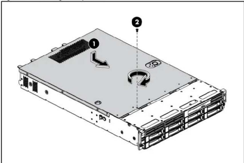
Top cover
To remove the top cover:
- Loosen the screw on the top cover with a T-10 wrench.
- Press the latch on the top cover.
- Slide the cover toward the rear of the server and then lift the top cover to remove it from the chassis. Lift the top cover away from the chassis.
Figure 1 Removing the Top Cover

text_image
Diagram of a server rack with labeled components and directional arrows indicating motion or movement.To reinstall the top cover:
- Align the top cover to the chassis and then slide it towards the front panel to position it into place.
- Once the cover is attached to the chassis, tighten the screw on the top cover with a T-10 wrench.
Figure 2 Reinstalling the Top Cover
text_image
Diagram of a server rack with labeled components and directional arrows indicating movement or assembly.Drives
The server supports the following configurations:
- 4 drive bays for 3.5 in. hard disk drives and 1 drive bay for optical disc drive
- 8 drive bays for 3.5 in. hard disk drives and 1 drive bay for optical disc drive
- 8 drive bays for 2.5 in. hard disk drives and 1 drive bay for optical disc drive
- 12 drive bays for 3.5 in. hard disk drives (14 drive bays with optional rear two drive kit)
• 25 drive bays for 2.5 in. hard disk drives
Cable management
Always follow good cable management practices when working inside the computer.
- Keep cables away from major heat sources like the heat sink.
- Do not jam cables on top of expansion cards or memory modules. Printed circuit cards are not designed to withstand excessive pressure.
- Keep cables clear of sliding or moveable parts to prevent cutting or crimping.
- When folding a flat ribbon cable, never fold to a sharp crease. Sharp creases may damage the wires.
• Some flat ribbon cables come pre-folded. Never change the folds on these cables.
- Do not sharply bend any cable. A sharp bend can break the internal wires.
- Never bend a SATA data cable tighter than a 30 mm (1.18 in.) radius.
- Never crease a SATA data cable.
- Do not rely on components like the drive cage, power supply, or system cover to push cables down into the chassis.
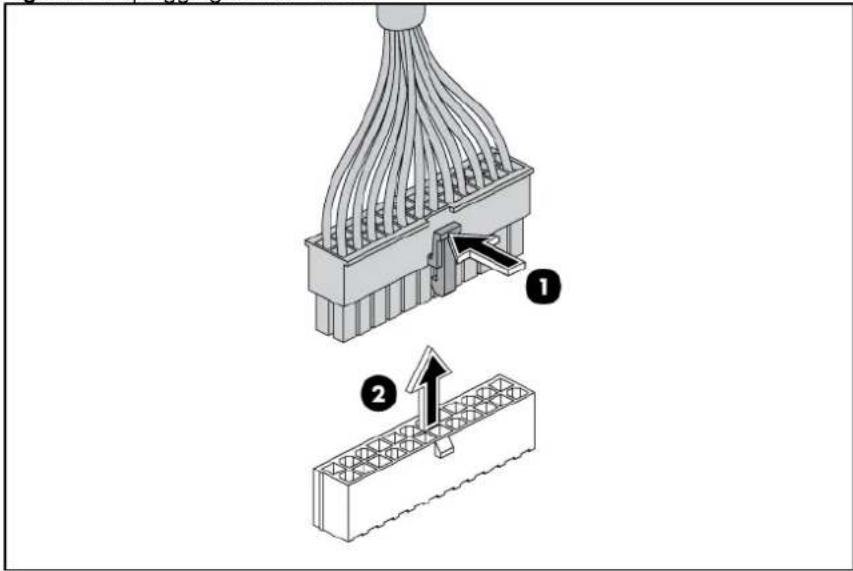
The next steps illustrate the removal of power cable from connector J60, 51, and 64 on system board.
-
Squeeze on the top of the retaining latch attached to the cable end of the connector.
-
Grasp the cable end of the connector and pull it straight up.

CAUTION: Always pull the connector—NEVER pull on the cable. Pulling on the cable could damage the cable and result in a failed power supply.
Figure 3 Unplugging Power Cable
text_image
Technical diagram showing two stages of a connector assembly: one with internal wiring and labeled component 1, and another with wire mesh structure and component 2.Cable connections
The following tables provide information about switching power supply cable connector labels.
Table 12 Cable Connections from the 460/750 W Power Supply
| Cable | To | Cable |
| Switching power supply | System board 24-pin power connector P1 | |
| Switching power supply | System board 8-pin power connector P2 | |
| Switching power supply | System board 4-pin power connector P3 | |
| Switching power supply | System board power supply EFF connector | RPS |
| Switching power supply | Front optical disk drive or rear optical disk drive | CD |
| Switching power supply | 4/8 HDD backplane P4 | |
| Switching power supply | 12/25 HDD backplane without 2HDD backplane | P4 and P5 |
| Switching power supply | 12 HDD backplane and 2 HDD backplane | P5 extended connectors, the two short cable connectors to 12HDD backplane, the long cable connector to 2HDD backplane |
design
The following tables provide the system board designators that various cables plug into. For more detailed information about system board components, see "System board components".
Table 13 Cable Connections from the System Board
| Cable To System board designator | ||
| 20-Pin front panel connector Front panel J42 | ||
| USB 0/1 connector Front panel USB 2.0 J53 | ||
| USB 4 connector Internal USB 2.0 J69 | ||
| 24-pin power connector Power supply J51 | ||
| 8-pin power connector Power supply J64 | ||
| 4-pin power connector Power supply J60 | ||
| 3-pin backplane I2C connector Backplane J65 | ||
| 12-pin power supply EFF connector Power supply J79 | ||
| 16-pin Power backplane control connector | Power supply RPS | J76 |
| 10-pin Hard drive backplane SGPIO connector | 2 HDD backplane on the HDD PCI cage | J66 |
| 6-pin system fan 1 connector | System fan 1 (four system fans) or system fan 1/2 (eight system fans) | J63 |
| 6-pin system fan 2 connector | System fan 2 (four system fans) or system fan 3/4 (eight system fans) | J71 |
| 6-pin system fan 3 connector | System fan 3 (four system fans) System fan 5/6 (eight system fans) | J62 |
| 6-pin system fan 5 connector | System fan 4 (four system fans) or system fan 7/8 (eight system fans) | J68 |
| LCD connector (optional) | Optional LCD module | J56 |
Table 14 Drive Cable Connections / 4 3.5" HDD Model
| Cable | To | SATA&SAS connector designator |
| SATAs 1 to 4 | 4 3.5" HDD Backplane |
Table 15 Drive Cable Connections / 8 3.5" HDD Model
| Cable | To | SATA&SAS connector designator |
| PCI storage controller card (LP) | 8 3.5" HDD Backplane | 3^rd party Mini-SAS connector |
| PCI storage controller card (LP) | 8 3.5" HDD Backplane | 3^rd party Mini-SAS connector |
Table 15 Drive Cable Connections / 8 3.5" HDD Model
| Cable | To | SATA&SASdesignator |
| SATA 5 connector (optional) | Optical disk drive on the front panel | J57 |
Table 16 Drive Cable Connections / 8 2.5" HDD Model
| Cable | To | SATA&SAS designator |
| PCI storage controller card 8 2.5" HDD Backplane 3 | ^rd party Mini-SAS connector 1 | |
| PCI storage controller card 8 2.5" HDD Backplane 3 | ^rd party Mini-SAS connector 2 | |
| SATA 5 connector (optional) Optical disk drive on the front panel | J57 | |
Table 17 Drive Cable Connections / 12 3.5" HDD Model with Optical Disc Drive PCI Cages
| Cable | To | SATA&SASdesignator |
| PCI storage controller card (FH/FL) 12 3.5" HDD Backplane 3 | ^rd party Mini-SASconnector | |
| SATA 5 connector Rear optical disk drive on the ODD PCI cage | J57 | |
Table 18 Drive Cable Connections / 12 3.5" HDD Model with HDD PCI Cages
| Cable | To | SATA&SAS designator |
| PCI storage controller card (LP) 12 3.5" HDD backplane 3 | ^rd party Mini-SAS connector | |
| HDD connector 13 on 12 3.5" HDD backplane 2 HDD backplane on the HDD PCI cages | J3 | |
| HDD connector 14 on 12 3.5" HDD backplane 2 HDD backplane on the HDD PCI cages | J2 | |
| HDD LED connector on the 12 3.5" HDD backplane 2 HDD backplane J10 | ||
Table 19 Drive Cable Connections / 25 2.5" HDD Model
| Cable | To | SATA&SASdesignator |
Table 19 Drive Cable Connections / 25 2.5" HDD Model
| Cable | To | SATA&SASdesignator |
| PCI storage controller card 25 2.5" HDD Backplane 3 | ^rd party Mini-SASconnector 1 | |
| PCI storage controller card 25 2.5" HDD Backplane 3 | ^rd party Mini-SASconnector 2 | |
Drive bay configuration
The server supports a maximum of twenty-five 2.5 in. hard disk drive bays.
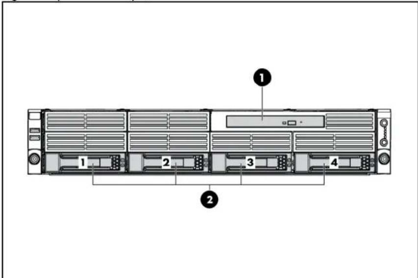
Figure 4 System Drive Bays / 4 3.5" HDD Model
text_image
Diagram of a server rack with numbered components, showing front, rear, and side views.Item Description
1 Optical disc drive bay (optional)
2 3.5 in. hard disk drive bays (4)
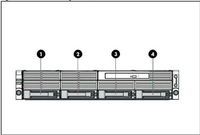
Figure 5 System Drive Bays / 8 3.5" HDD Model

text_image
1 2 3 4 5 6 7 8 ①Item Description
1 Optical disc drive bay (optional)
2 3.5 in. hard disk drive bays (8)
Figure 6 System Drive Bays / 8 2.5" HDD Model

text_image
Diagram of a server rack with labeled components including numbered slots and ventilation unitsItem Description
1 Optical disc drive bay (optional)
2 2.5 in. hard disk drive bays (8)
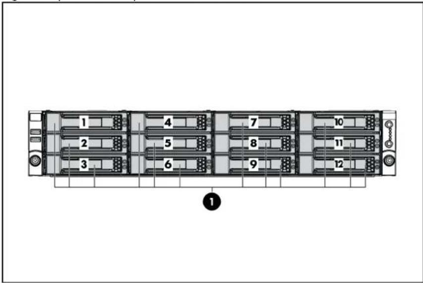
Figure 7 System Drive Bays / 12 3.5" HDD Model
text_image
1 2 3 4 5 6 7 8 9 10 11 12 ①Item Description
1 3.5 in. hard disk drive bays (12)
Figure 8 System Drive Bays / 25 2.5" HDD Model

text_image
1 2 3 4 5 6 7 8 9 10 11 12 13 14 15 16 17 18 19 20 21 22 23 24 25 ①Item Description
1 2.5 in. hard disk drive bays (25)
Optical disc drive bay
The Optical disc drive bay of servers with 8 3.5-inch HDDs, 8 2.5-inch HDDs and 12 3.5-inch HDDs support the optional installation of a 12.7 mm (0.5 in.) optical disc drive, so the following procedure is for servers with 8 3.5-inch HDDs.
To remove the optical disc drive:
- Remove the top cover.
- Unplug the SATA and power cables.
- Loosen the screws.
Figure 9 Removing the Cables and Screws

text_image
Technical diagram of a computer drive system with labeled components including folders, rollers, and connectors- Push the optical disc drive toward the front of the unit.
- Pull the optical disc drive out of the chassis.
Figure 10 Removing the Optical disc drive

text_image
Technical diagram of a computer drive system showing component layout and assembly, with numbered annotations highlighting parts 1 and 2.
IMPORTANT: If you remove an optical disc drive without plans of installing a new one, you must reinstall the blank to maintain proper system airflow.
To remove the bezel blank:
- Poke the hook of the bezel blank with a T-10/15 wrench through the round hole on the top side of the HDD cage.
- Pull the bezel blank out of the bezel.

CAUTION: Do not discard the bezel blank. If the optical disc drive is removed in the future, you must reinstall the bezel blank to maintain proper system function.
Figure 11 Removing the Bezel Blank

text_image
Technical diagram of a computer drive chassis with labeled components and an inset magnified view showing part 1 and part 2.To install the optical disc drive:
- Slide the optical disc drive into the chassis.
- Secure the optical disc drive to the chassis with the two screws.
- Connect the SATA and power cables to their corresponding connectors on the optical disc drive.
Figure 12 Installing the Optical disc drive
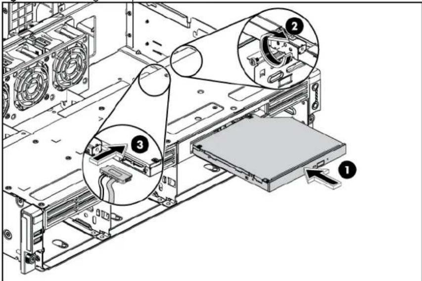
text_image
Technical diagram of a computer drive assembly with numbered components and labeled partsHard drives
The drive bays on the front panel can accommodate up to twenty-five 2.5-inch hard drives. You can install either SAS hard drives or SATA hard drives in the server.
For servers with 4 3.5-inch HDDs, the hard drives installed in the server are labeled from Device 1 to Device 4, from left to right, when viewed from the front of the server.
Figure 13 Hard Drive Configuration / 4 3.5" HDD Model
text_image
Diagram of a server rack with numbered labels pointing to different componentsItem Description
1-4 SAS/SATA hard drives 1-4
For servers with 8 3.5-inch HDDs, the hard drives installed in the server are labeled from Device 1 to Device 8, from top to bottom, left to right, when viewed from the front of the server.
Figure 14 Hard Drive Configuration / 8 3.5" HDD Model
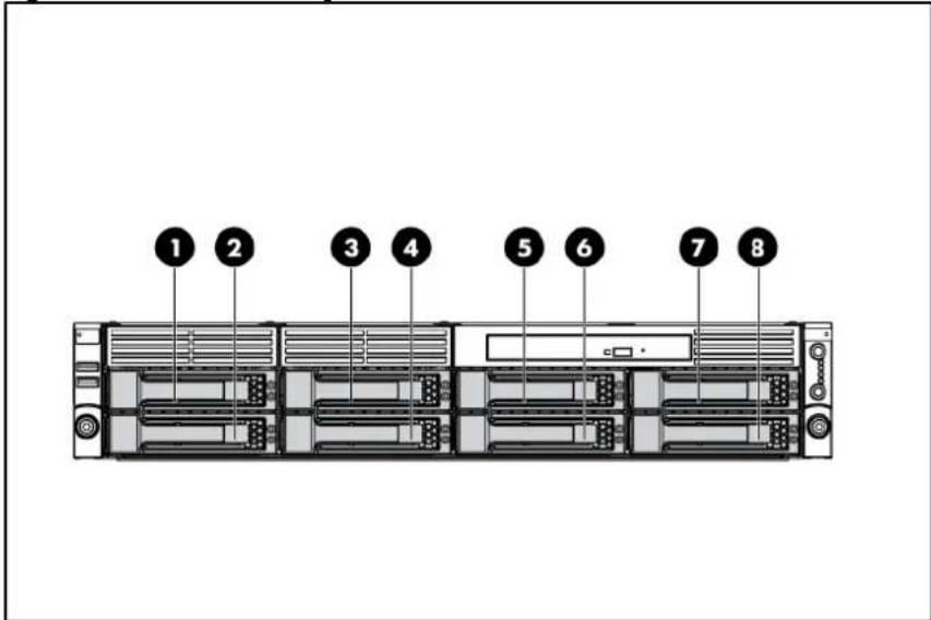
text_image
1 2 3 4 5 6 7 8Item Description
1-8 SAS/SATA hard drives 1-8
For servers with 8 2.5-inch HDDs, the hard drives installed in the server are labeled from Device 1 to Device 8, from top to bottom, left to right, when viewed from the front of the server.
Figure 15 Hard Drive Configuration / 8 2.5" HDD Model
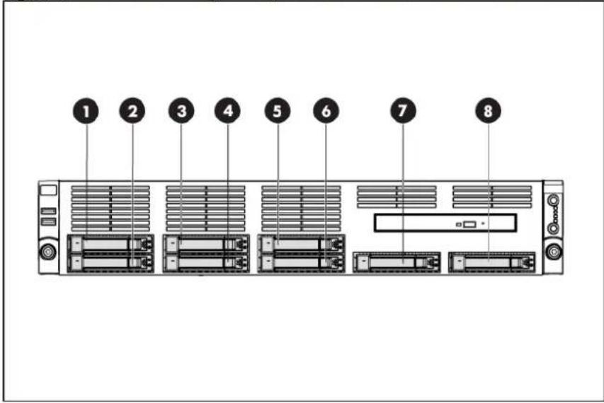
text_image
1 2 3 4 5 6 7 8Item Description
1-8 SAS/SATA hard drives 1-8
For servers with 12 3.5-inch HDDs, the hard drives installed in the server are labeled from Device 1 to Device 12, from top to bottom, left to right, when viewed from the front of the server.
Figure 16 Hard Drive Configuration / 12 3.5" HDD Model

text_image
1 2 3 4 5 6 7 8 9 10 11 12Item Description
1-12 SAS/SATA hard drives 1-12
For servers with 25 2.5-inch HDDs, the hard drives installed in the server are labeled from Device 1 to Device 25, from top to bottom, left to right, when viewed from the front of the server.
Figure 17 Hard Drive Configuration / 25 2.5" HDD Model
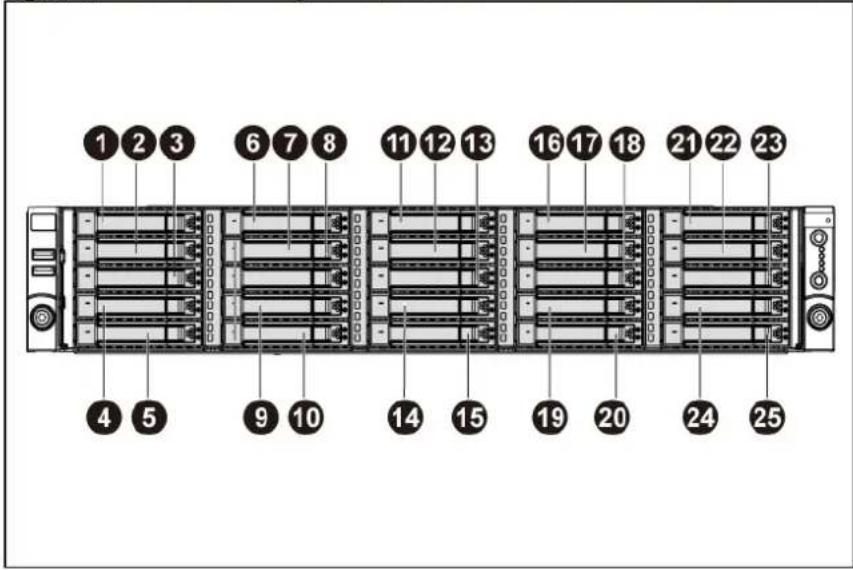
text_image
1 2 3 6 7 8 11 12 13 16 17 18 21 22 23 4 5 9 10 14 15 19 20 24 25Item Description
1-25 SAS/SATA hard drives 1-25
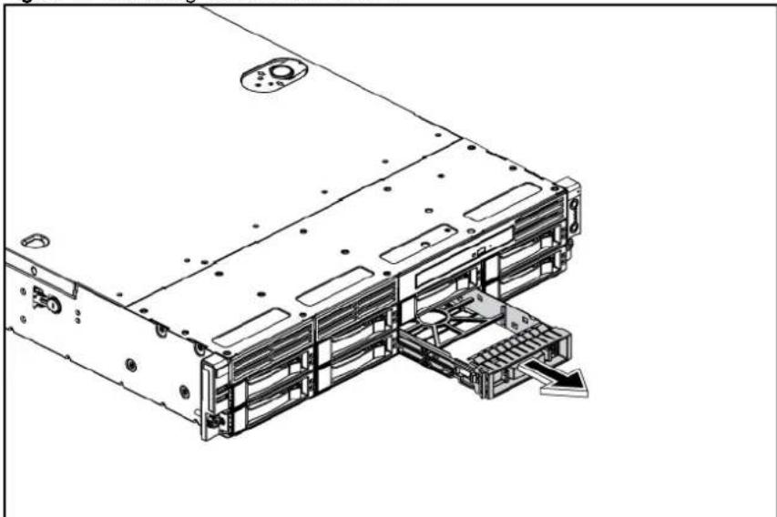
To remove the hard drive:
- Press the hard disk carrier button to release the ejector lever.
- Use the HDD carrier latch to pull the drive out of the cage. Make sure to support the drive when pulling it out of the cage.
- Pull the hard drive assembly out of the drive bay.
Figure 18 Removing the Hard Drive

text_image
Technical diagram of a server rack with three views showing internal components and assembly stepsTo install the hard drive:
- Pull the hard drive blank out of the chassis.
Figure 19 Removing the Hard Drive Blank
natural_image
Technical line drawing of a server rack with mounting holes and internal components (no text or symbols)
IMPORTANT: Do not discard the hard drive blank. If the drive is removed in the future, you must reinstall the hard drive blank to maintain proper system airflow.
- Push the hard drive assembly into the drive bay until it stops.
- Press the HDD carrier latch inward until it clicks.
Figure 20 Installing the Hard Drive
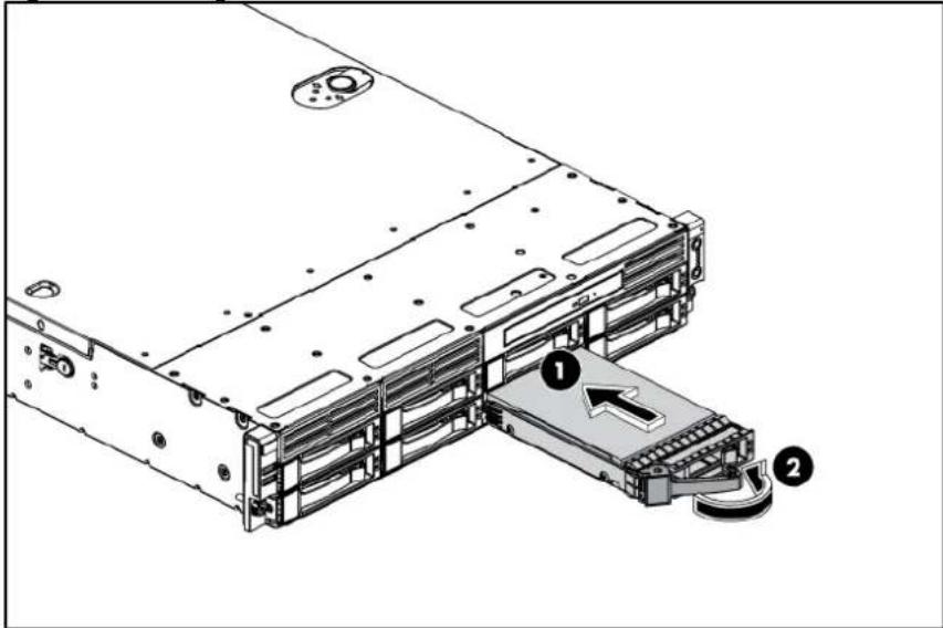
text_image
Technical diagram of a server rack with labeled components, showing internal structure and connection points.SAS/SATA HDD backplane
The following figures show the front and back side of the backplane.
Figure 21 Backplane Connectors / 4 3.5" HDD Model (component side)

flowchart
graph TD
    A["Component 1"] --> B["Block 1"]
    C["Component 2"] --> D["Block 2"]
    E["Component 3"] --> F["Block 3"]
    G["Component 1"] --> H["Block 1"]
    I["Component 2"] --> J["Block 2"]
    K["Component 3"] --> L["Block 3"]
Item Description
| 1 | Screw | holes |
| 2 | LED | indicators |
| 3 | Headers for hard drive | |
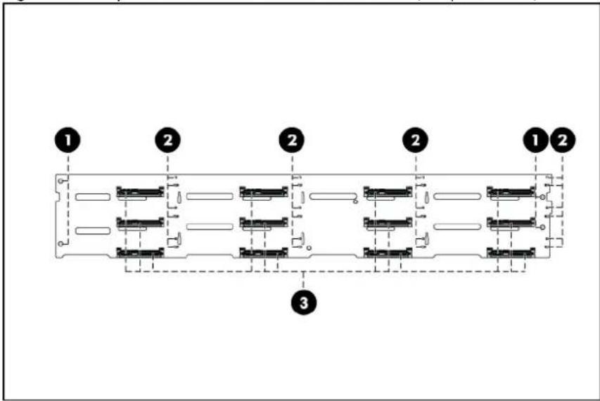
Figure 22 Backplane Connectors / 8 3.5" HDD Model (component side)
text_image
1 2 2 2 1 2 3Item Description
| 1 | Screw | holes |
| 2 | LED | indicators |
| 3 | Headers for hard drive | |
Figure 23 Backplane Connectors / 8 2.5" HDD Model (component side)

text_image
1 2 1 2 1 2 1 2 1 2 1 3Item Description
| 1 | LED | indicators |
| 2 | Screw | holes |
| 3 | Headers for hard drive | |
Figure 24 Backplane Connectors / 12 3.5" HDD Model (component side)
text_image
1 2 2 2 1 2 3Item Description
| 1 | Screw | holes |
| 2 | LED | indicators |
| 3 | Headers for hard drive | |
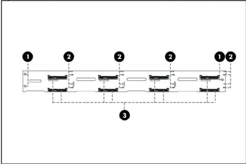
Figure 25 Backplane Connectors / 25 2.5" HDD Model (component side)

text_image
1 2 1 2 2 1 2 1 2 3Item Description
| 1 | Screw | holes |
| 2 | LED | indicators |
| 3 | Headers for hard drive | |
Figure 26 Backplane Connectors / 4 3.5" HDD Model (solder side)

text_image
1 2 3 4| Item | Description | ||
| 1 | Power | connector | |
| 2 | Mini | SAS | connector |
| 3 | PROG | connector | |
| 4 | I^2C connector |
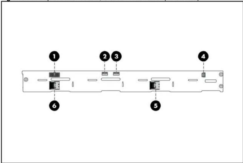
Figure 27 Backplane Connectors / 8 3.5" HDD Model (solder side)
text_image
1 2 3 4 5 6| Item Description |
| 1 Power connector |
| 2 PIC 2 PROG connector |
| 3 PIC 1 PROG connector |
Item Description
| 4 | I^2C connector |
| 5 | Mini SAS connector 1 |
| 6 | Mini SAS connector 2 |
Figure 28 Backplane Connectors / 8 2.5" HDD Model (solder side)

text_image
Technical diagram of a mechanical or electrical component with numbered parts labeled 1 to 5Item Description
| 1 PIC 2 PROG connector | |||
| 2 | Power | connector | |
| 3 | I^2C connector | ||
| 4 PIC 1 PROG connector | |||
| 5 | Mini | SAS | connectors |
Figure 29 Backplane Connectors / 12 3.5" HDD Model (solder side)

text_image
1 2 3 4 5 6 7 8 9Item Description
| 1 Power connector 1 | |||
| 2 | PROG | connector | |
| 3 | SAS/SATA expander chip with heat sink covered | ||
| 4 | Mini | SAS | connector |
| 5 | HDD LED connector | ||
| 6 | I^2C connector | ||
| 7 | HDD 14 connector | ||
| 8 | HDD 13 connector | ||
| 9 | Power connector 2 | ||
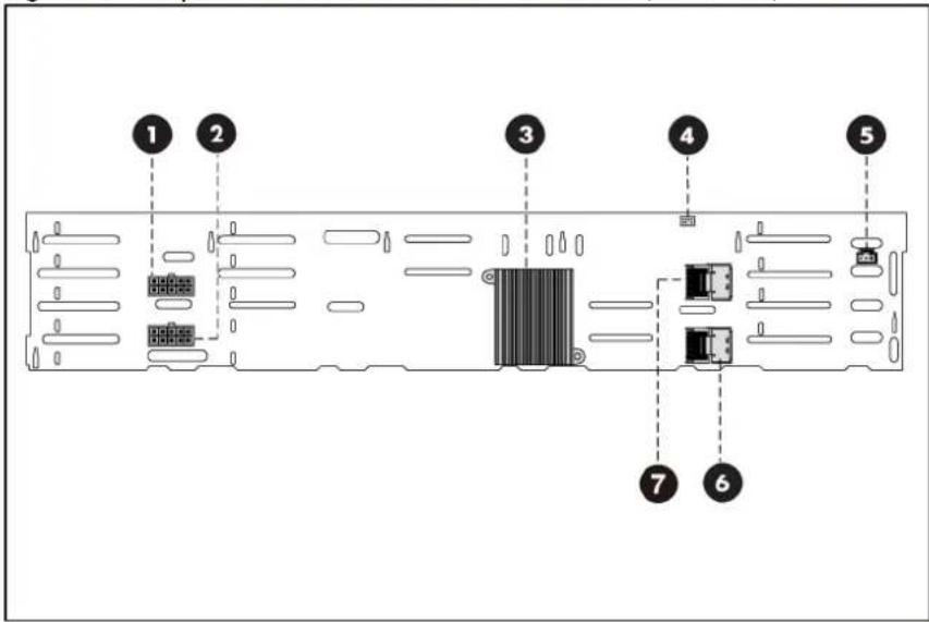
Figure 30 Backplane Connectors / 25 2.5" HDD Model (solder side)
text_image
1 2 3 4 5 7 6Item Description
| 1 Power connector 1 | |||
| 2 Power connector 2 | |||
| 3 SAS/SATA expander chip with heat sink covered | |||
| 4 CPLD PROG connector | |||
| 5 I^2C connector | |||
| 6 Mini SAS connector 1 | |||
| 7 Mini SAS connector 2 |

WARNING: Ensure that the system is powered off and all power sources have been disconnected from the server. Voltages are present at various locations within the server whenever an AC power source is connected. This voltage is present even when the main power switch is in the off position.
To remove the backplane:
- Remove all drives out of the drive bays.
Refer to the "Optical disc drive bay" and "Hard drives" sections in this chapter for detailed procedures.
-
Remove the top cover.
-
Remove all cables connected to the backplane.
-
Remove the backplane.
a. Remove the three screws that secure the backplane to the hard drive cage.
b. Pull the backplane up and out to release it from the hard drive cage.
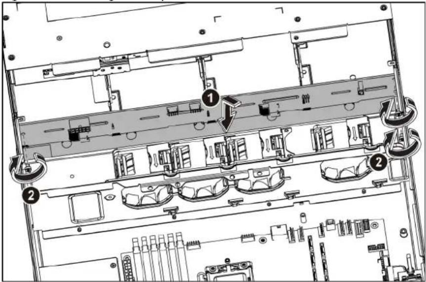
Figure 31 Removing the Backplane

text_image
Technical diagram of an electronic device rear panel with labeled components and numbered partsTo reinstall the backplane:
- Orient the backplane so that the notches on the backplane align with the hook on the drive cage and then press the backplane down until it clicks into place.
- Secure the backplane with three screws.
Figure 32 Reinstalling the Backplane
text_image
Technical diagram of a computer rack with numbered components and directional arrows indicating assembly or movement.- Install all necessary cables.
System board configuration
Processor
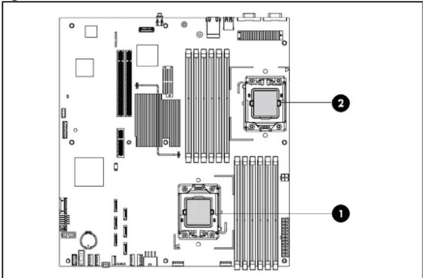
HP ProLiant DL180 G6 Server supports Intel Xeon 5500 and 5600 Series processors. If a single processor is installed, then use socket 1. When two processors are used, the server supports boot functions through the processor installed in socket 1. However, if processor 1 fails, the system cannot boot up, and if processor 2 fails, the system will be automatically booted from processor 1 and provide a processor failure message.
The processor socket supports 2P Intel Xeon processor with integrated memory controller.

CAUTION: It is recommended to use processors of the same speeds or cache sizes to prevent possible server malfunction.
Figure 33 Processor Locations
text_image
Diagram of a computer motherboard showing CPU socket, RAM slots, and drive bays with numbered annotationsItem Description
| 1 | Processor | 1 |
| 2 | Processor | 2 |

WARNING: To reduce the risk of personal injury from hot surfaces, allow the heat sink and the processor to cool before touching them.
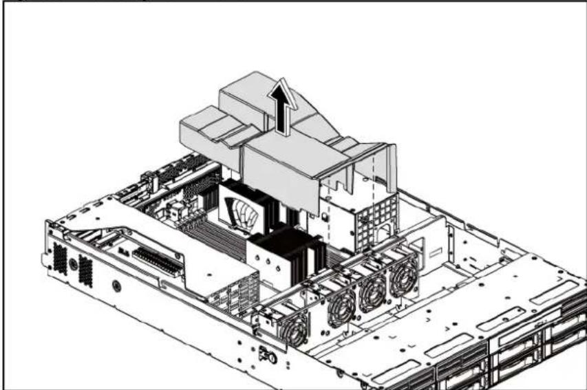
NOTE: Before installing the processor, remove the air baffle.
To remove the air baffle:
- Gently rock the air baffle up.
- Take the air baffle out from the system board.
Figure 34 Removing the Air Baffle
natural_image
Technical diagram of a computer motherboard showing internal components and ventilation ducts (no text or labels)To remove the heat sink:
- Loosen the two spring-loaded screws.
- Lift the heat sink away from the system board.

CAUTION: Place the heat sink down in an upright position with the thermal patch facing upward. Do not let the thermal patch touch the work surface.
Figure 35 Removing the Heat Sink Assembly

text_image
Technical diagram of a computer motherboard with labeled components and directional arrows indicating assembly or installation.
IMPORTANT: If the heat sink has been removed for any reason on a previously installed processor, it is critical that you clean any residue of the old thermal compound with alcohol and apply more thermal grease compound to the integrated heat spreader on the processor to ensure proper thermal bonding between the processor and the heat sink.
△
CAUTION: Do not over-tighten the spring-loaded screws to prevent them from breaking off. A maximum torque of 6 inch-lb is set for each screw. Rotate the heat sink a few degrees to the left and right to break the bonding of the thermal grease compound before removing the heat sink from the processor.
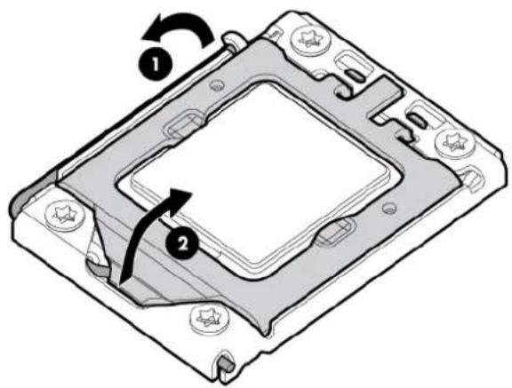
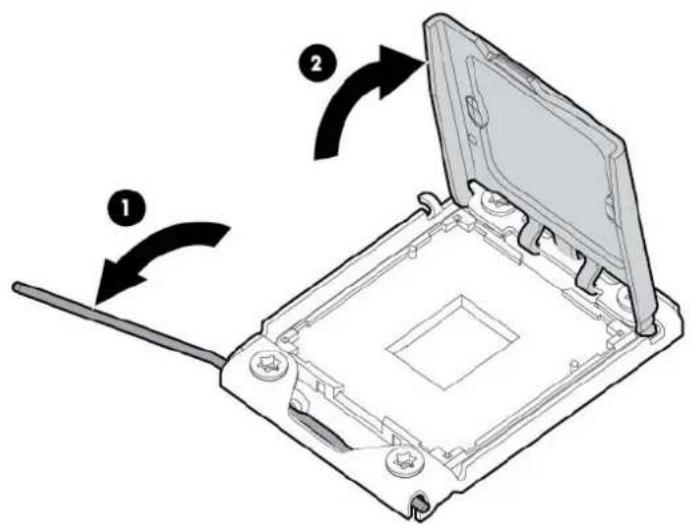
To remove the processor:
- Open the processor locking lever.
- Open the processor socket retaining bracket.
Figure 36 Opening the lever and bracket
text_image
Technical diagram of a computer processor with labeled components and directional arrows indicating rotation or assembly.△
CAUTION: The pins of the socket are very fragile. Do not bend or damage them.
△
CAUTION: Place the processor on a static-dissipating work surface or in an anti-static bag.
△
CAUTION: To allow heat sink to draw as much heat as possible from the processor base, there must be good contact between the heat sink base and the top of the processor. To ensure good contact, you must first remove any residue of the old thermal compound with alcohol and apply new thermal grease compound.
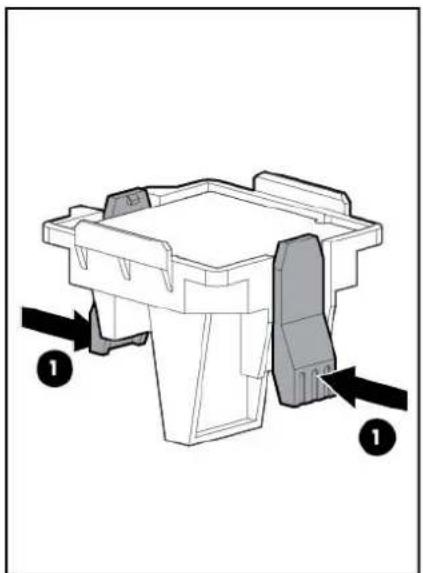
- Using the processor removal tool, remove the processor from the system board.
a. Line up the processor tool, ensuring the locking lever graphic on the tool is correctly oriented.
b. Press in on the plastic tabs, and then place the tool on the processor.
c. Release the tabs, and then carefully lift the processor and tool straight up.
Figure 37 Removing the Processor
text_image
Technical diagram of a mechanical assembly with numbered components and an inset showing a detail view of a component.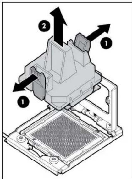
text_image
Technical diagram of a mechanical assembly with numbered components and directional arrows indicating motion or assembly.- Carefully rotate the tool, and then push in and release the tabs to secure the processor in the tool.
Figure 38 Removing the Processor
natural_image
Mechanical component diagram showing a base with two arrows pointing to a cutaway section (no text or symbols present)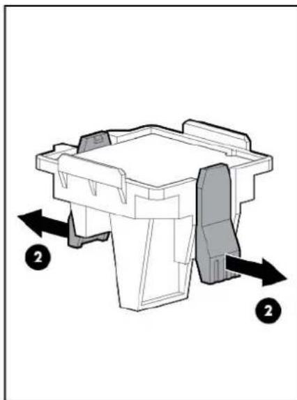
natural_image
Technical diagram of a mechanical component with directional arrows indicating movement or force (no text or symbols present)△ CAUTION: To avoid damage to the processor, do not touch the bottom of the processor, especially the contact area.
To apply the thermal grease compound:
- Use a clean cloth dipped in rubbing alcohol to clean the contact surface on the heat sink and the new processor. Wipe the contact surfaces several times to make sure that no particles or dust contaminants are evident.
- Apply the thermal grease compound to the CPU contact surface.

CAUTION: HP recommends using Shin-Etsu X-23-7783D thermal grease compound for your ProLiant server.
3. Apply new grease to the top of the processor using a five-dot pattern to ensure even distribution.
Figure 39 The top of the Processor

natural_image
Simple diagram of a four-hole electrical socket with five gray circles, no text or symbols present.
CAUTION: Never touch the bottom of the processor; any contaminant could prevent the mounting pads from making contact with the socket.

CAUTION: Applying too much grease creates a gap between the contact surfaces, significantly reducing the ability of the heat sink to draw out heat. Installing the heat sink with excessive grease can also cause the grease to spread over the processor pins or the system board base, which can cause electrical shorts that damage the system.

CAUTION: To prevent damage to processor socket pins the processor installation tool must be used to insert the processor into the socket. Instructions are provided in the Option Kits and spare part kits.
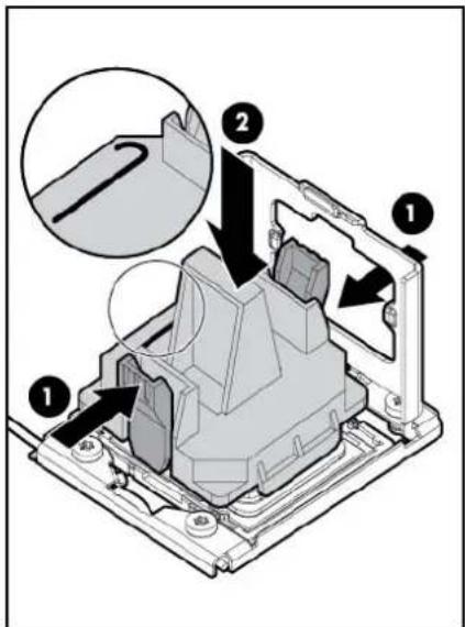
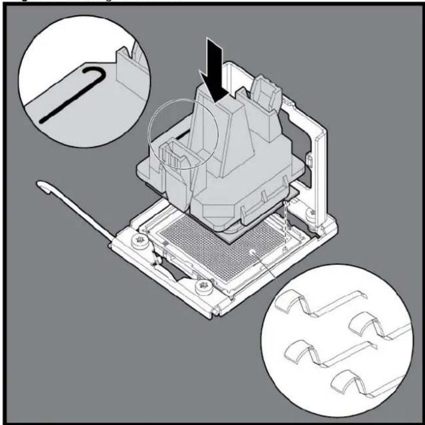
To install a processor:

CAUTION: Failure to completely open the processor locking lever prevents the processor from seating during installation, leading to hardware damage.
- Open the processor locking lever and the processor socket retaining bracket. DO NOT REMOVE THE PROCESSOR SOCKET COVER
Figure 40 Opening the lever and bracket
text_image
Diagram showing a device with labeled parts and directional arrows indicating assembly or operation steps.
IMPORTANT: Be sure the processor remains inside the processor installation tool.
- If the processor has separated from the installation tool, carefully re-insert the processor in the tool. Handle the processor by the edges only, and do not touch the bottom of the processor, especially the contact area.
Figure 41 Installing the processor in the installation tool

text_image
Technical diagram showing a mechanical assembly with labeled components and a magnified cross-section view of a textured material.- Be sure the tool is oriented correctly. Align the processor installation tool with the socket, and then install the processor. THE PINS ON THE SYSTEM BOARD ARE VERY FRAGILE AND EASILY DAMAGED.
Figure 42 Installing the Processor
natural_image
Technical illustration of a mechanical device with multiple views and a close-up inset showing a tool interacting with the component (no text or symbols present)
CAUTION: THE PINS ON THE SYSTEM BOARD ARE VERY FRAGILE AND EASILY DAMAGED. To avoid damage to the system board:
- Never install or remove a processor without using the processor installation tool.
- Do not touch the processor socket contacts.
-
Do not tilt or slide the processor when lowering the processor into the socket.
-
Press and hold the tabs on the processor installation tool to separate it from the processor, and then remove the tool.
Figure 43 Removing the processor installation tool

natural_image
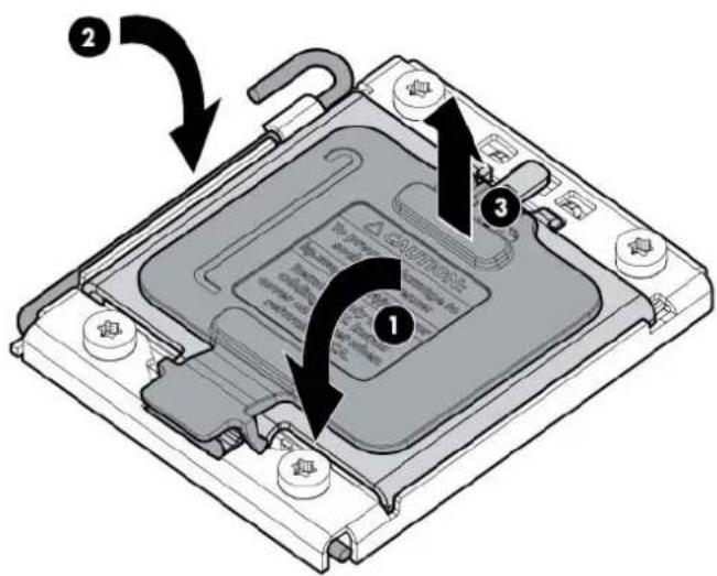
Technical line drawing of a mechanical device with internal components and directional arrows (no text or symbols)- Close the processor socket retaining bracket and the processor locking lever.
Figure 44 Closing the processor socket
text_image
Diagram of a computer processor's internal structure with numbered annotations indicating component placement and rotation.
CAUTION: Be sure to close the processor socket retaining bracket before closing the processor locking lever. The lever should close without resistance. Forcing the lever closed can damage the processor and socket, requiring system board replacement.
- Apply all the grease to the top of the processor in the following pattern to ensure even distribution.
Figure 45 The top of the processor
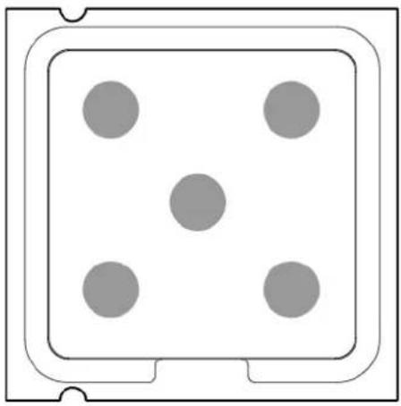
natural_image
Simple diagram of a four-hole electrical socket with five gray circles, no text or symbols present.
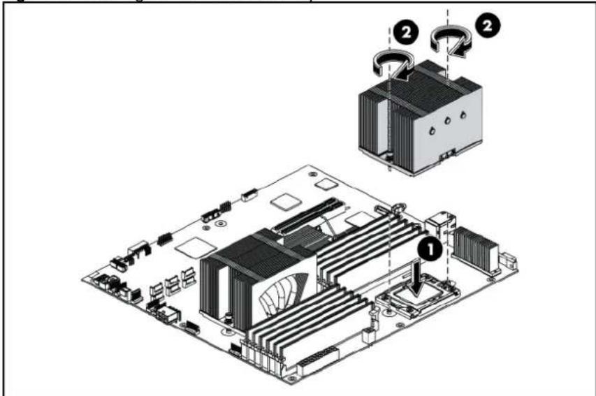
CAUTION: To prevent overheating or a possible system crash, use only a heat sink model specified for the HP ProLiant DL180 G6 server.
To install the heat sink:
- Properly align the heat sink spring-loaded screws to the system board mounting holes.
- Tighten the spring-loaded screws clockwise to secure the heat sink connection to the system board.
Figure 46 Installing the Heat Sink Assembly
text_image
Technical diagram of a computer motherboard with labeled components and parts, showing exploded view and assembly steps.NOTE: When installing two heat sinks, it is recommended to put the heat sinks with the 14-fin side facing the DIMMs.

CAUTION: For proper cooling, do not operate the server without the top cover, air baffle, expansion slot covers, or blanks installed. For additional information, see the user guide. If hot-plug components are supported, minimize the amount of time the top cover is removed.
To install the air baffle:
- Connect all necessary cables.
- Gently place the air baffle on the system board.
Figure 47 Installing the Air Baffle

natural_image
Technical line drawing of a computer motherboard with cooling fans and a downward arrow indicating a component (no text or symbols present)Memory
The system board has twelve DIMM slots that support up to 192 GB maximum system memory (Two 16 GB Quad-rank or Dual-rank DIMMs in each of the four channels).
You must adhere to the following guidelines when adding or replacing memory modules:
• Use 800/1066/1333 MHz DDR3 RDIMM/UDIMM.
• Supported DIMM capacity: 2 GB, 4 GB, 8 GB and 16 GB
- For 2P system, both physical processors must be of the same type and speed.
• Installation guide for 1P configuration:
- Follow the sequence of 2A, 4B, 6C, 1D, 3E, and 5F for the corresponding processor when installing the memory.
• Installation guide for 2P configuration:
- Follow the sequence of 2A, 4B, 6C, 1D, 3E, and 5F for the corresponding processor when installing the memory.
○ Install at least one memory DIMM for each processor. - The memory quantity installed for each processor can be different.
Figure 48 DIMM Population
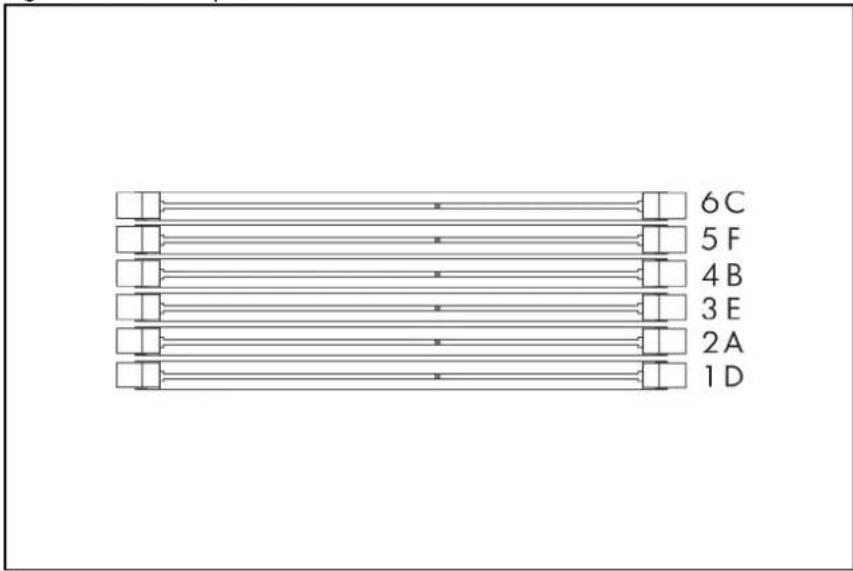
text_image
6C 5 F 4 B 3 E 2 A 1 DFigure 49 DIMM Slots

natural_image
Diagram of a computer motherboard with CPU socket layout and an inset showing internal hardware components (no text or labels)NOTE: Before installing the memory, remove the air baffle first. For a detailed procedure, see the "Processor" section in this chapter.
To remove the memory module:
- Completely open the holding clips securing the memory module.
- Gently pull the memory module upward to remove it from the slot.
Figure 50 Removing the Memory Module

text_image
Diagram showing a mechanical assembly with labeled components and directional arrows indicating motion or assembly.
CAUTION: Place the memory module on a static-dissipating work surface or inside of an anti-static bag.
To install the memory module:
- Align the notch on the bottom edge of the memory module with the keyed surface of the DIMM slot and then fully press the memory module into the slot until the holding clips snap back in place.
Figure 51 Installing the Memory Module

natural_image
Mechanical assembly diagram showing a component being processed with arrows indicating motion (no text or symbols present)
CAUTION: The DIMM slots are structured to ensure proper installation. If you insert a DIMM but it does not fit easily into the slot, you may have inserted it incorrectly. Reverse the orientation of the DIMM and insert it again.
DIMM identification

IMPORTANT: This server does not support mixing RDIMMs and UDIMMs. Attempting to mix these two types causes the server to halt during BIOS initialization.
The memory subsystem may be populated with either RDIMMs or UDIMMs, but mixing the two types is not supported. To determine DIMM characteristics, use the label attached to the DIMM and the following illustration and table.
Figure 52 DIMM identification

text_image
HP 8GB 2Rx8 PC3-10600R-9-08 HP 8GB 2x8 PC3-10600R-9-08| Item Description Definition | |
| 1 Size — | |
| 2 Rank 1R = Single-rank | 2R = Dual-rank 4R = Quad-rank |
| 3 Data width x4 = 4-bit | x8 = 8-bit |
| 4 Memory speed 10600 = 1333-MHz | 8500 = 1067-MHz |
| 5 DIMM type R = RDIMM (registered) | E = UDIMM (unbuffered with ECC) |
PCI expansion card
System board PCI expansion slot
There are three PCI expansion slots on the system board.
Figure 53 System Board PCI Expansion Slots

text_image
Diagram of a computer motherboard with numbered components and labeled parts| Item | Component Designator | Component Function | |
| 1 | J31 | PCIe x4 (FH/FL) slot 1b | Supports a PCIe riser card or PCIe & PCI-X riser card |
| 2 | J17 | PCIe x16 (FH/FL) slot 1a | Supports a PCIe riser card or PCIe & PCI-X riser card |
| 3 | J18 PCIe x16 (LP) slot 2 | Supports a PCIe riser card |
PCI riser card expansion slot
The one PCIe riser card attached to the PCI cage converts the functionality of the system board expansion slot to the slot positioned at a 90^ angle from the system board.
NOTE: Users have the option to replace the standard riser card in slot 1a&1b with other four models using the dual PCIe x8 riser card, single PCIe x16 riser card, dual PCI-X riser card, or PCIe x16 & dual PCI-X riser card option kit. This will allow support for PCIe x8, PCIe x16, and PCI-X devices.
Figure 54 Three PCIe x8 Riser Card Connector Location

natural_image
Technical diagram of a server rack with three labeled connectors, showing internal structure and connection (no text or symbols present)• Three slots PCIe riser card (Three x8 link with x8 slots)
Figure 55 Two PCIe x8 Riser Card Connector Location

natural_image
Technical line drawing of a server rack with two connectors, showing internal structure and connection (no text or symbols)• Two slots PCIe riser card (Two x8 link with x8 slots)
Figure 56 PCIe x16 Riser Card Connector Location
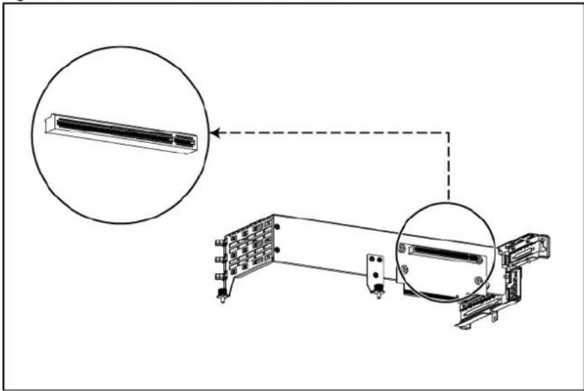
text_image
Technical diagram showing a device assembly with zoomed-in insets and labeled components• One slot PCIe riser card (x16 link with x16 slots)
PCI cage
The server supports three types of PCI cages. They are the standard PCI cage, the HDD PCI cage, the ODD PCI cage.
The table below identifies the PCI cages by their function and shows their corresponding server type and supported riser cards.
| PCI cage Riser Card System model | ||
| Standard PCI Cage Slot 1a&1b: | 4 3.5" HDD model; | |
| dual PCIe x8 riser card for standard PCI | 8 3.5" HDD model; | |
| cage; | 8 2.5" HDD model; | |
| or three PCIe x8 riser card | 12 3.5" HDD model; | |
| or PCIe x16 + dual PCI-X riser card | 25 2.5" HDD model; | |
| or dual PCI-X riser card | ||
| or single PCIe x16 riser card (Full-height / Full-length Side) | ||
| Slot 2: | ||
| single PCIe x16 riser card (Low Profile) | ||
| Rear HDD PCI cage Slot 2: | 12 3.5" HDD model | |
| single PCIe x16 riser card (Low Profile) | ||
| Rear Optical Disc Drive PCI cage Slot 1a&1b: | 4 3.5" HDD model; | |
| dual PCIe x8 riser card for Optical Disc Drive PCI cage | 8 3.5" HDD model; | |
| 8 2.5" HDD model; | ||
| 12 3.5" HDD model; | ||
| 25 2.5" HDD model; | ||
To remove the PCI cage:
NOTE: Disconnect all cables connecting an existing expansion board to the system board.
-
Loosen the thumbscrews that secure the PCI cage to the system board and remove the screw that secures the PCI cage to the rear of the server.
-
Lift the PCI cage away from the system board.
Figure 57 Removing the PCI Cage
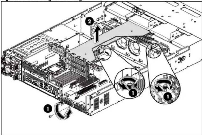
text_image
Technical diagram of a server rack with numbered components and labeled parts in ChineseInstalling PCIe riser card
The system supports up to two riser cards at a time. Use only HP supported expansion boards that meet the following specifications:
- Compliance
○ PCIe x8 or x16 (FH, FL)
○ PCIe x16 (LP)
○ PCI-X (FH, FL)
- Form Factor
○ Full-Height/Full-Length
○ Low-Profile
- Full-Height/Half-Length
To remove the PCIe riser card:
- Loosen the screw securing the riser card to the PCI cage.
- Remove the riser card from the PCI cage.
Figure 58 Removing the Three PCIe x8 Riser Card
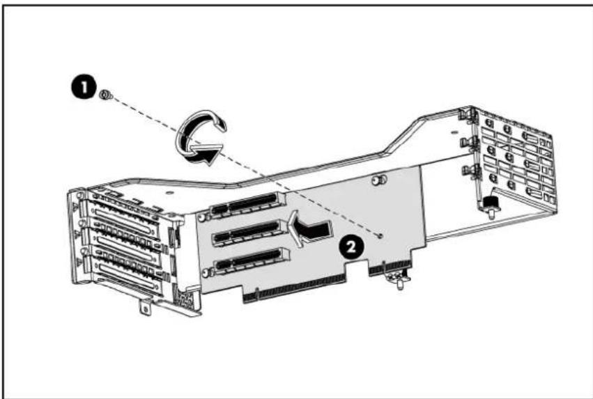
text_image
Technical diagram of a server rack with labeled components and directional arrows indicating rotation or movement.Figure 59 Removing the two PCIe x8 Riser Card
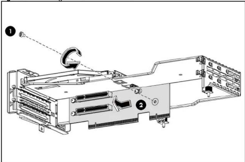
text_image
Technical diagram of a computer motherboard showing component labels and directional arrows indicating movement or assembly.Figure 60 Removing the PCIe x16 Riser Card

text_image
Technical diagram of a server rack with labeled components and directional arrows indicating flow or movement.To install the PCIe riser card:
- Align the three riser card locking-tab holes to the corresponding standoffs on the PCI cage, and then push the card rightwards.
- Tighten the screw that secures the riser card to the PCI cage.
Figure 61 Installing the Three PCIe x8 Riser Card

text_image
Technical diagram of a server rack with labeled components and directional arrows indicating movement or assembly.Figure 62 Installing the Two PCIe x8 Riser Card

text_image
Technical diagram of a computer rack with labeled components and directional arrows indicating assembly or movement.- Align the four riser card locking-tab holes to the corresponding screw standoffs on the PCI cage.
- Tighten the screws that secure the riser card to the PCI cage.
Figure 63 Installing the PCIe x16 Riser Card
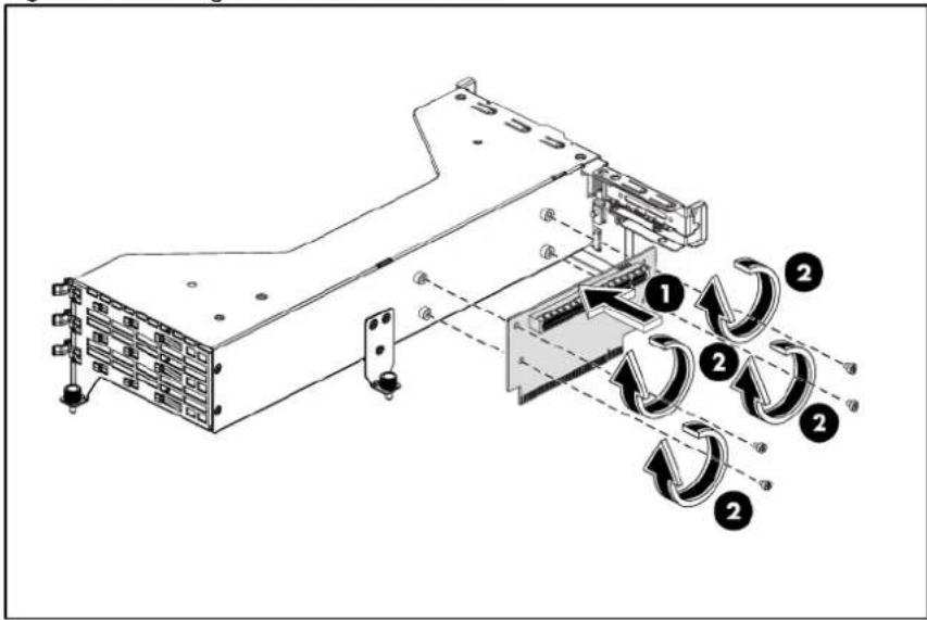
text_image
Technical diagram of a server rack with labeled components and directional arrows indicating flow or movement.To install the PCI expansion board:
- Remove the screw near the slot cover on the PCI cage.
Figure 64 Removing the Screw on the PCI Cage on the Full-height / Full-length Side

natural_image
Technical line drawing of a server rack with multiple slots and mounting holes (no text or symbols)Figure 65 Removing the Screw on the PCI Cage on the Low-profile Side

natural_image
Technical line drawing of a mechanical assembly with no visible text or symbols-
Remove the slot cover from the PCI cage.
-
Slide the expansion board into the slot, aligning the board with its matching connector. Firmly press the board to seat it properly on the slot.
-
Tighten the screw that secures the expansion board to the PCI cage.
Figure 66 Installing the Three PCIe x8 Expansion Board

text_image
Technical diagram of a computer drive system with labeled components and directional arrows indicating motion or assembly.Figure 67 Installing the Two PCIe x8 Expansion Board

text_image
Technical diagram of a computer drive system with labeled components and directional arrows indicating motion or assembly.Figure 68 Installing the PCIe x16 Expansion Board

text_image
Technical diagram of an electronic device with labeled components and directional arrows indicating assembly or movement.To reinstall the PCI cage:
The following figures show the front and back side of the backplane.
Figure 69 Backplane Connectors / 2 3.5" HDD Model (component side)
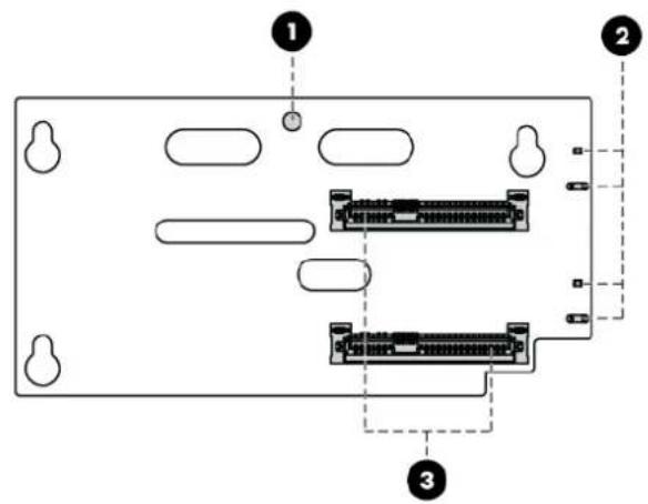
text_image
Diagram of a computer RAM module with labeled ports and connectorsItem Description
| 1 | Screw | hole |
| 2 | LED | indicators |
| 3 | Headers for hard drive | |
Figure 70 Backplane Connectors / 2 3.5" HDD Model (solder side)
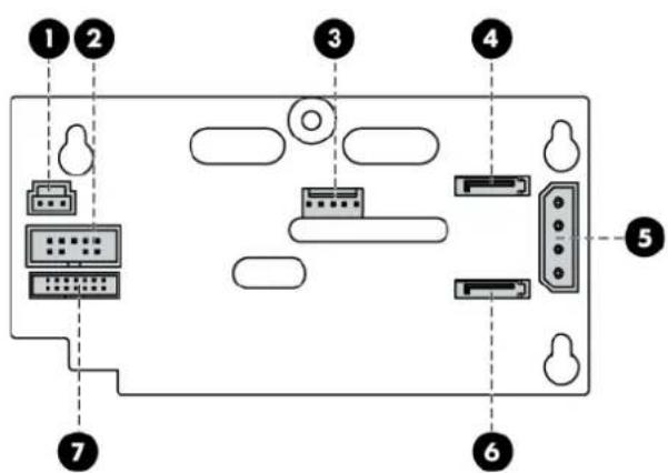
text_image
Diagram of a computer RAM module with labeled ports and connectorsItem Description
| 1 | I^2C connector | |
| 2 | SGPIO | connector |
Item Description
| 3 | PIC | PROG | connector |
| 4 | HDD 13 connector | ||
| 5 | Power | connector | |
| 6 | HDD 14 connector | ||
| 7 | HDD LED connector |
- Install the PCI expansion board into the PCI cage.
a. Align the PCI expansion board with the open expansion slot.
b. Press the PCI expansion board into the expansion slot on the riser card.
c. Tighten the screw that secures the expansion board to the PCI cage.
- Align the PCI cage assembly to the system board expansion slot, and then press it down to ensure full connection to the system board.
- Tighten the thumbscrews to secure the PCI cage assembly to the system board and secure the screw on the rear panel of the chassis.
Figure 71 Reinstalling the PCI Cage with PCI Expansion Board
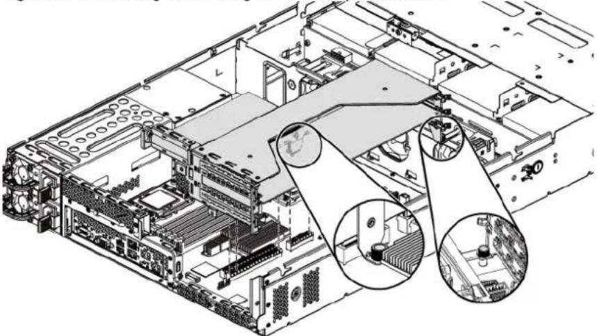
natural_image
Technical line drawing of a server rack with internal components and highlighted structural elements (no text or symbols)- Connect the necessary cable(s) to the system board.
To install the HDD PCI cage:
-
Loosen the thumbscrew and screws that secure the HDD PCI cage to the system board.
-
Lift the HDD PCI cage assembly away from the system board.
Figure 72 Removing the HDD PCI Cage Assembly

text_image
Technical diagram of a server rack with numbered components and labeled parts, showing internal structure and rotation arrows.-
Align the four backplane holes to the corresponding standoffs on the HDD PCI cage, and then push the card down.
-
Tighten the screw that secures the backplane to the HDD PCI cage.
Figure 73 Installing the 2HDD Backplane
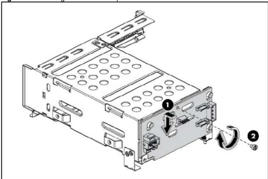
text_image
Technical diagram of a computer drive chassis with labeled components and directional arrows indicating rotation or movement.- Align the HDD PCI cage assembly to the system board expansion slot, and then press it down to ensure full connection to the system board.
- Tighten the thumbscrew to secure the HDD PCI cage assembly to the system board and secure the screws on the side and the rear panel of the chassis.
Figure 74 Installing the HDD PCI Cage Assembly

text_image
Technical diagram of a server rack with numbered components and directional arrows indicating motion or assembly steps.- Pull the rear hard drive blank out of the HDD PCI cage assembly.
Figure 75 Removing the Rear Hard Drive Blank

natural_image
Technical line drawing of an internal computer drive bay with labeled ports and a directional arrow indicating motion (no text or symbols present)- Push the hard dive assembly into the drive bay until it stops.
- Press the HDD carrier latch inward until it clicks.
Figure 76 Installing the Rear Hard Drive

text_image
Technical diagram of an internal computer drive showing labeled components and a directional arrow indicating movement or flow.To install the Optical Disc Drive PCI cage:
- Loosen the thumbscrews that secure the optical disc drive PCI cage to the system board and remove the screw on the rear panel of the chassis.
- Lift the optical disc drive PCI cage away from the system board.
Figure 77 Removing the optical disc drive PCI Cage
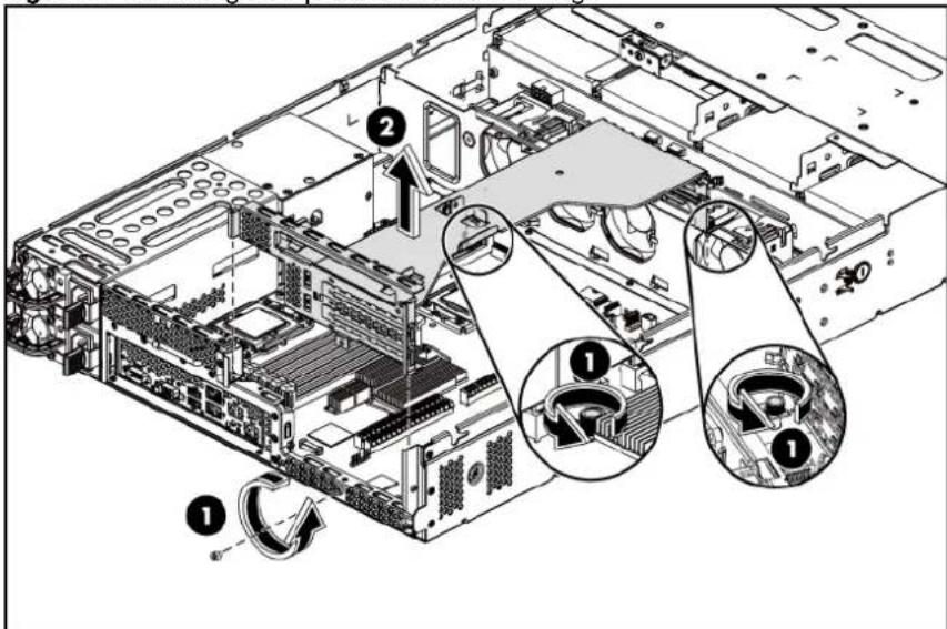
text_image
Technical diagram of a server rack with labeled components and directional arrows indicating assembly or movement.- Pushing the optical disc drive ROM into the ODD PCI cage.
Figure 78 Pushing the optical disc drive DVD-ROM into the ODD PCI Cage
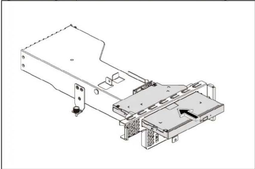
natural_image
Technical line drawing of a mechanical device with mounting brackets and a highlighted component (no text or symbols)- Tighten the screw that secures the optical disc drive to the ODD PCI cage.
Figure 79 Securing the Optical Disc Drive
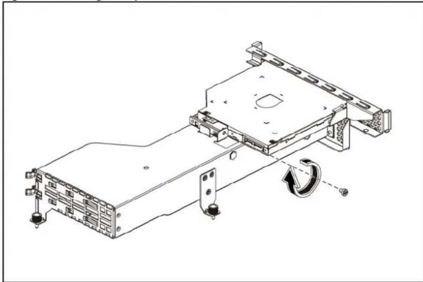
natural_image
Technical line drawing of a mechanical assembly with mounting brackets and a rotating component (no text or symbols)-
Align the ODD PCI cage assembly to the system board expansion slot, and then press it down to ensure full connection to the system board.
-
Tighten the thumbscrews to secure the ODD PCI cage assembly to the system board and secure the screw on the rear panel of the chassis.
Figure 80 Reinstalling the ODD PCI Cage Assembly
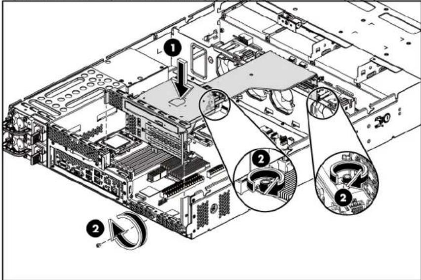
text_image
Technical diagram of a server rack with numbered annotations indicating component locations and assembly stepsDedicated management port (Optional)
The server can support a dedicated management port. The dedicated management port is optional for the shipment.
The following figure shows the dedicated management port location.
Figure 81 Dedicated management port Location

natural_image
Diagram of a computer motherboard showing CPU socket, RAM slots, and an attached hardware component (no text or labels)To remove the dedicated management port:
- Remove the PCI cage assembly out of the chassis.
Refer to the "PCI cage" section in this chapter for detailed procedures.
- Loosen the screw.
- Pull the dedicated management port upwards, and then remove the dedicated management port from the dedicated management port connector.
Figure 82 Removing the dedicated management port

text_image
Technical diagram of a computer motherboard with labeled components and directional arrows indicating assembly or movement.- Remove the spacer from the system board.
Figure 83 Removing the Spacer
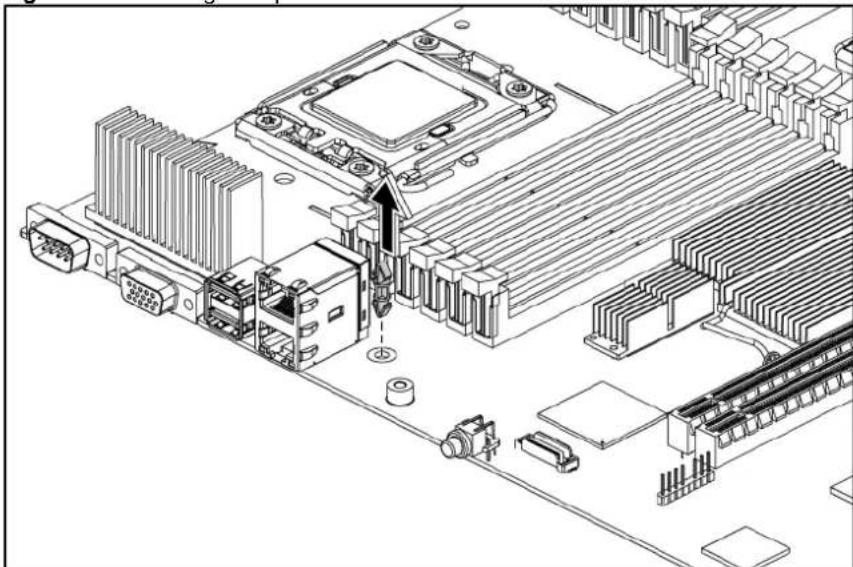
natural_image
Isometric technical diagram of a computer motherboard with CPU socket, connectors, and wiring (no text or labels)To reinstall the dedicated management port:
- Remove the dedicated management port cover.
Figure 84 Removing the Dedicated management Port Cover

text_image
Technical diagram of a computer drive rear panel with labeled ports and connectors- Insert the spacer into the system board.
Figure 85 Inserting the Spacer

natural_image
Isometric technical line drawing of a computer motherboard with CPU socket, RAM slots, and connector (no text or labels)- Align the dedicated management port to the plastic standoff, and insert the dedicated management port into the dedicated management port connector.
- Tighten the screw clockwise to secure the dedicated management port to the system board.
Figure 86 Reinstalling the Dedicated management port
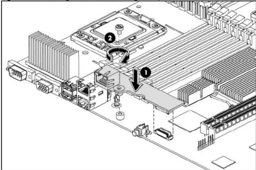
text_image
Technical diagram of a computer motherboard with labeled components and directional arrows indicating assembly or movement.TPM Module (Optional)
The server can support a TPM module. The TPM module is optional for the shipment. The following figure shows the TPM module location.
Figure 87 TPM module Location

natural_image
Diagram of a computer motherboard with an inset showing a close-up of a mechanical component (no text or symbols present)To remove the Dedicated management port:
- Remove the security rivet from the system board
Figure 88 Removing the security rivet
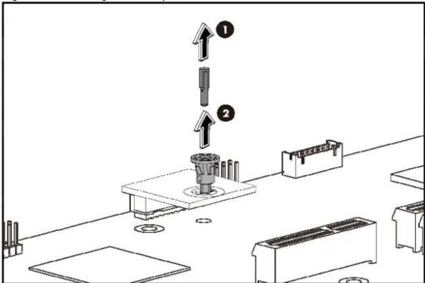
text_image
Technical diagram showing a mechanical assembly with numbered components and directional arrows indicating assembly steps.- Remove the TPM card from system board.
Figure 89 Removing the TPM card
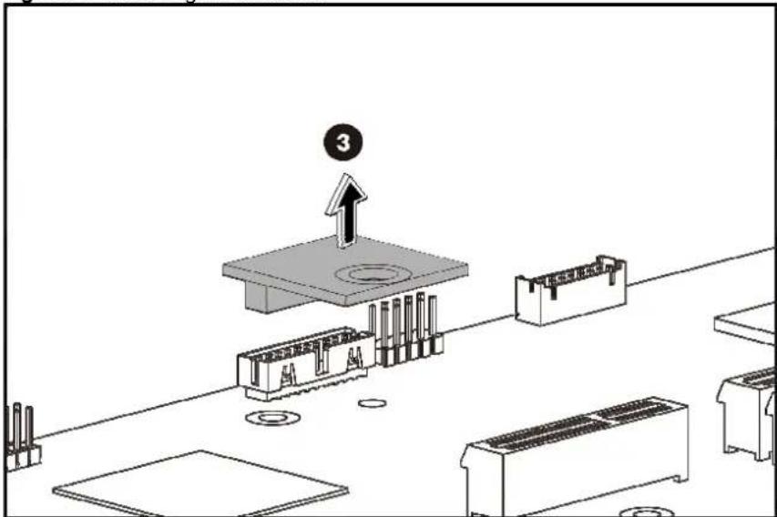
text_image
Technical diagram showing a mechanical assembly with labeled components and an upward arrow indicating motion or assembly.To reinstall the dedicated management port:
- Install the TPM card. Press down the TPM card to the connector to seat on the system board
Figure 90 Inserting the TPM card
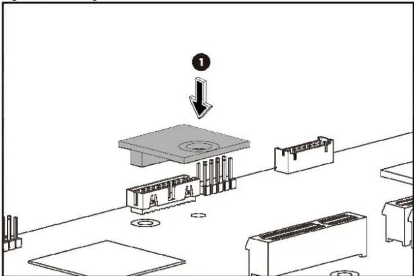
text_image
Technical diagram showing a mechanical assembly with labeled component '1' and directional arrow indicating process flow.- Insert the TPM security rivet by pressing the rivet firmly into the system board
Figure 91 Inserting security rivet

text_image
Technical diagram showing a mechanical assembly with labeled components and directional arrows indicating assembly steps.System battery
The server uses nonvolatile memory that requires a system battery to retain system information when power is removed.
This 3 V lithium coin cell battery is located on the system board.
Figure 92 System Battery Location
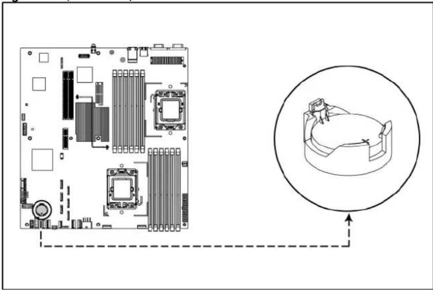
text_image
Diagram showing CPU socket layout and corresponding 3D device diagram with directional arrows indicating connection.
WARNING: Note the following reminders when replacing the system battery:
- Replace the system battery with the same type as the system battery recommended by HP. Use of another system battery may present a risk of fire or explosion.
- A risk of fire and chemical burn exists if the system battery is not handled properly. Do not disassemble, crush, puncture, or short external contacts, or expose the system battery to temperatures higher than 60^ C ( 140^ F).
- Do not dispose of used system battery in water or fire. Dispose of used system battery according to manufacturer's instructions.

CAUTION: Loss of BIOS settings occurs when the system battery is removed. You must reconfigure BIOS settings whenever you replace the system battery.
NOTE: If the server no longer automatically displays the correct date and time, you may need to replace the system battery. Under normal usage, system battery life is five to ten years.
To replace the system battery:
- Power down the server.
- Disconnect the power cord(s).
- Unlock the server if necessary and remove the top cover as described in the section "System cover".
NOTE: If the expansion board is installed to the PCI cage, remove the PCI cage before releasing the battery. Refer to the "PCI cage" section in this chapter for detailed procedures.
- Release the battery from its holder by squeezing the metal clamp that extends above one edge of the battery. When the battery pops up, lift it out.
- To insert the new battery, slide one edge of the replacement battery under the holder's lip with the positive side up. Push the other edge down until the clamp snaps over the other edge of the battery.
Figure 93 Replacing the System Battery
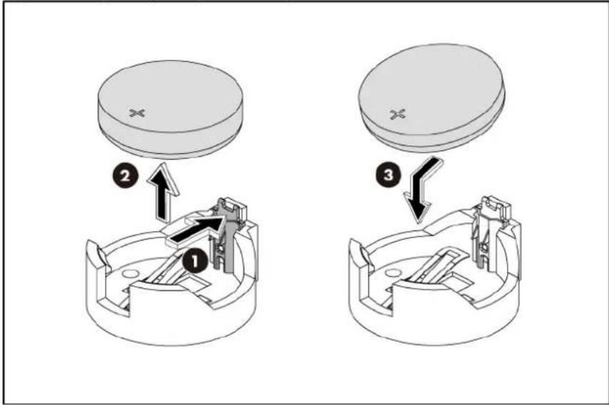
text_image
Technical diagram showing three steps of a mechanical assembly or assembly process, labeled 1, 2, and 3 with arrows indicating direction.BBWC (Optional)
The system board can support up to two BBWC. The BBWC is optional for the shipment.
Figure 94 BBWC Locations
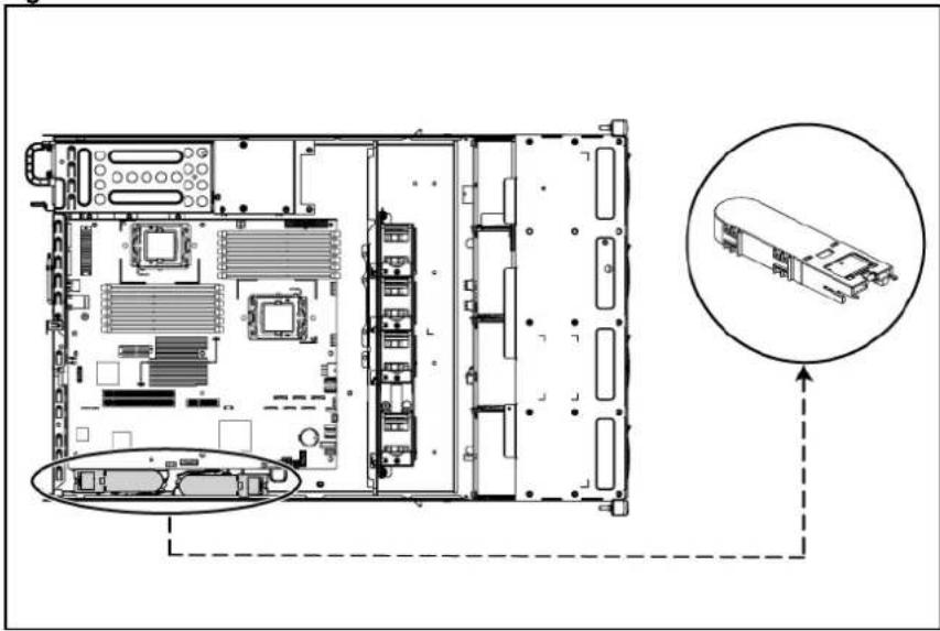
natural_image
Technical line drawing of an internal server rack with highlighted components and a magnified inset showing internal hardware layout (no text or symbols)To remove the BBWC:
- Pull the BBWC retaining latch.
- Slide the BBWC back, up and out of the tray.
Figure 95 Removing the BBWC

text_image
Technical diagram of an electronic device showing labeled components including CPU socket, memory, and heat sink.To reinstall the BBWC:
-
Pull the BBWC retaining latch.
-
At the same time, align the locking tabs on the BBWC to their holes on the tray. Press the BBWC into the tray, and then push it along the direction of the arrow to lock the locking tabs.
Figure 96 Reinstalling the BBWC
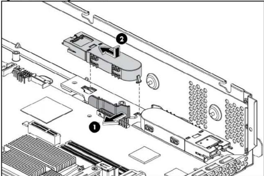
text_image
Technical diagram of an electronic device showing labeled components including CPU socket, memory, and drive slotsSystem board removal and replacement procedure
To remove the system board:
- Remove the top cover.
- Loose the nine screws that secure the system board to the chassis.
- Slide the system board back, up and out of the chassis. Remove the system board from the chassis.
Figure 97 Removing the System Board

text_image
Technical diagram of an electronic device with numbered components, likely a rack or chassis layout.To reinstall the system board:
-
Align the system board I/O connectors to their openings and slide the system board into place. The nine screw holes on the chassis should align with the system board.
-
Fasten the nine screws on the system board to secure the system board to the chassis.
Figure 98 Reinstalling the System Board
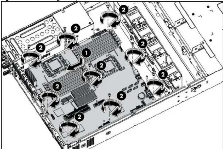
text_image
Technical diagram of an electronic device rear panel with numbered components and directional arrows indicating flow or movement.Power supply unit (PSU)
Located on the rear panel of the server power supply is designed with three types of power supply units. They are 460 W and 750 W PSU with power factor correction (PFC) function. Table 20 lists how to configure the power supply with the different system models.
Table 20 Power Supply Unit Configurations
| System model Power supply unit | |
| 4 3.5" HDD model One or two 460 W power supply unit | |
| 8 3.5" HDD model One or two 460 W power supply unit | |
| 8 2.5" HDD model One or two 460 W power supply unit | |
| 12 3.5" HDD model One or two 750 W power supply unit | |
| 25 2.5" HDD model One or two 750 W power supply unit |
Figure 99 Power Supply Unit
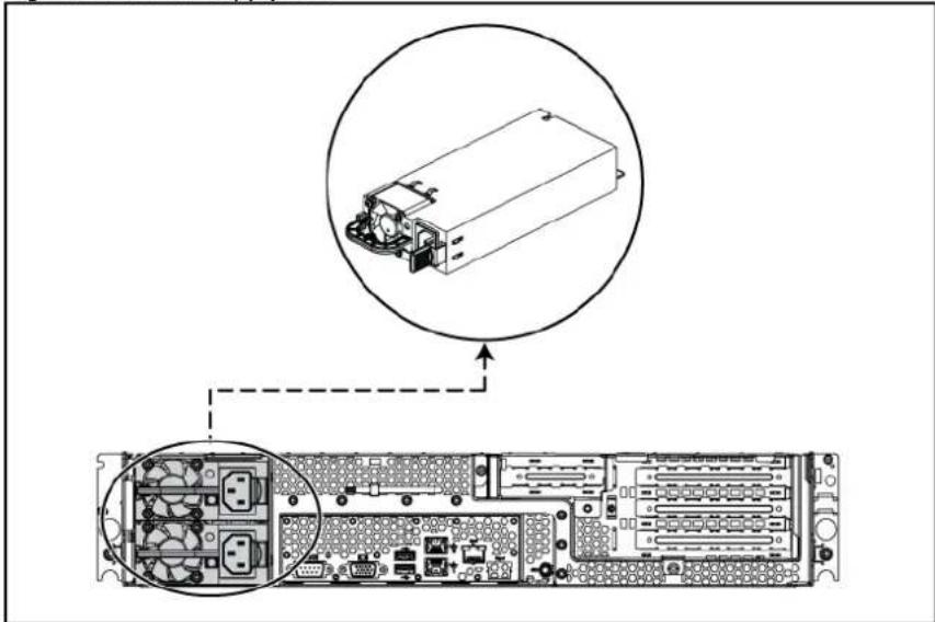
natural_image
Technical diagram of an electronic device showing internal components and a zoomed-in view of the front panel (no text or labels present)
WARNING: Take note of the following reminders to reduce the risk of personal injury from electric shock hazards and/or damage to the equipment.
- Installation of power supply units should be referred to individuals who are qualified to service server systems and are trained to deal with equipment capability of generating hazardous energy levels.
- DO not open the power supply unit. There are no serviceable parts inside it.
To remove the power supply:
- Press the port wine colored tab.
- Slide the hot-plug power supply out of the power supply bay.
Figure 100 Removing the Power Supply
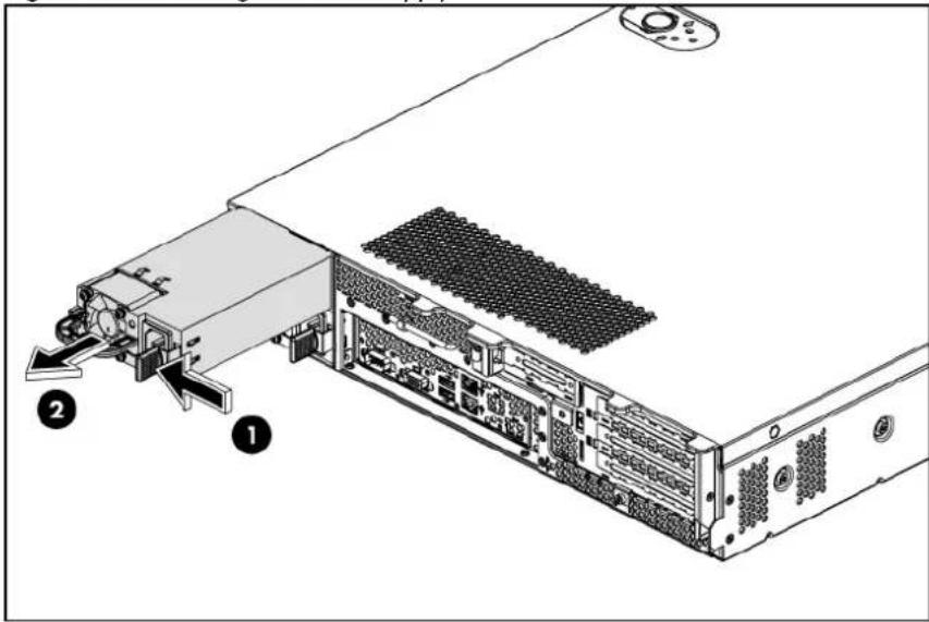
text_image
Technical diagram of a server rack with labeled components, showing internal structure and component layout.To reinstall the power supply:
- Press the release tabs of the power supply blank, and then pull the power supply blank out of the chassis.
Figure 101 Removing the Power Supply Blank
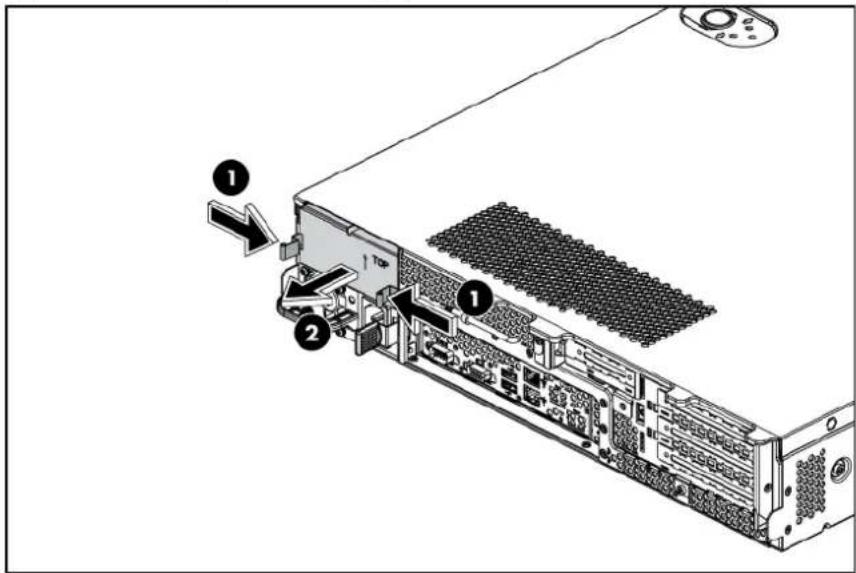
text_image
Diagram of a server rack with labeled components and directional arrows indicating assembly or movement.- Align the hot-plug power supply cage connector with the open power supply bay and slide the power supply into the chassis.
- Snap the latch cover over port colored handle. Latch cover only installs one way.
Figure 102 Reinstalling the Power Supply

natural_image
Technical line drawing of an internal server rack with ports and connectors (no text or symbols)System fan cage
The server supports two kinds of fan cage. The system redundant fan cage is optional for shipment.
natural_image
Technical line drawing of a mechanical housing or enclosure with internal components (no text or symbols)Figure 104 System Redundant Fan Cage

natural_image
Technical line drawing of a multi-chamber industrial device with visible internal components (no text or symbols)To remove the system non-redundant fan cage
- Remove all screws on the system non-redundant fan cage.
- Lift the system fan cage up and out of the chassis.
Figure 105 Removing the System Non-redundant Fan Cage
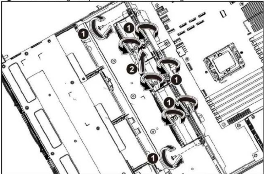
text_image
Technical diagram of an electronic device with numbered components, likely a rack or chassis assembly.To remove the system redundant fan cage
- Loosen the screws that secure the system redundant fan cage.
- Lift the system fan cage up and out of the chassis.
Figure 106 Removing the System Redundant Fan Cage
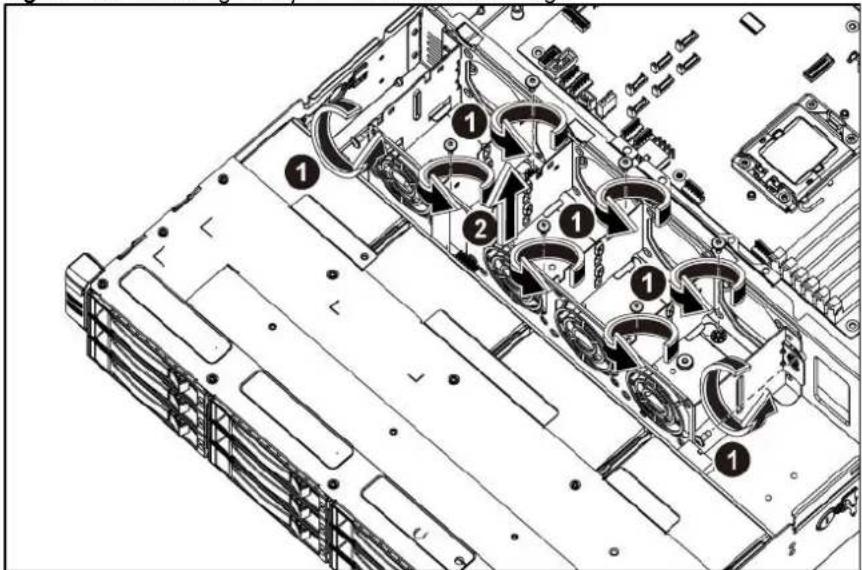
text_image
Technical diagram of a server rack with numbered components and wiring annotationsTo reinstall the system non-redundant fan cage
- Align the system non-redundant fan cage to the chassis, press the system non-redundant fan cage down.
- Tighten the screws that secure the system fan cage.
Figure 107 Reinstalling the System Non-redundant Fan Cage
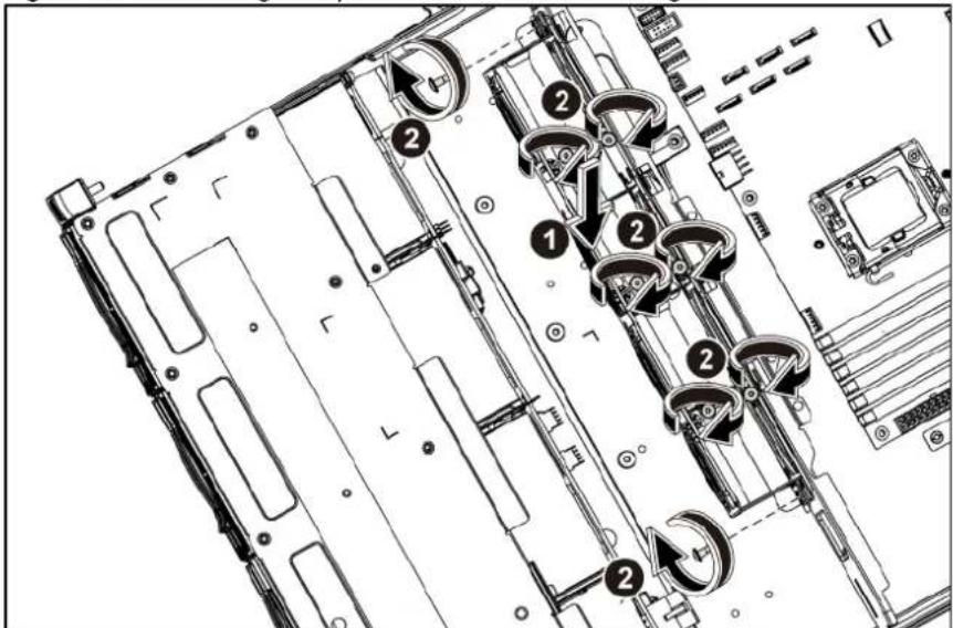
text_image
Technical diagram of a computer motherboard with numbered components and directional arrows indicating movement or assembly.To install the system redundant fan cage
- Get eight screws from the existing system non-redundant fan cage. See figure "Figure 105"
- Remove the foam on the system redundant fan cage.
Figure 108 Removing the foam
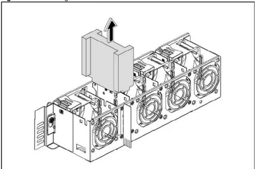
natural_image
Technical line drawing of an internal mechanical assembly with no visible text or symbols- The redundant fan kit has 4 fans installed on the cage. Squeeze the release tab on the system fan and lift the system fan away from the fan cage.
Figure 109 Removing the system fans
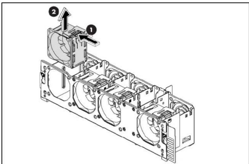
text_image
Technical diagram of an internal combustion engine unit with labeled components and directional arrows-
Locate the system fan cage on the chassis and vertical wall.
-
Fasten the screws.
Figure 110 Installing the System Redundant Fan Cage

text_image
Technical diagram of a server rack with numbered components and ventilation slots-
Install the foam on the system redundant fan cage.
-
Paste the mylar on the fan bracket.
Figure 111 Installing the Foam and Mylar
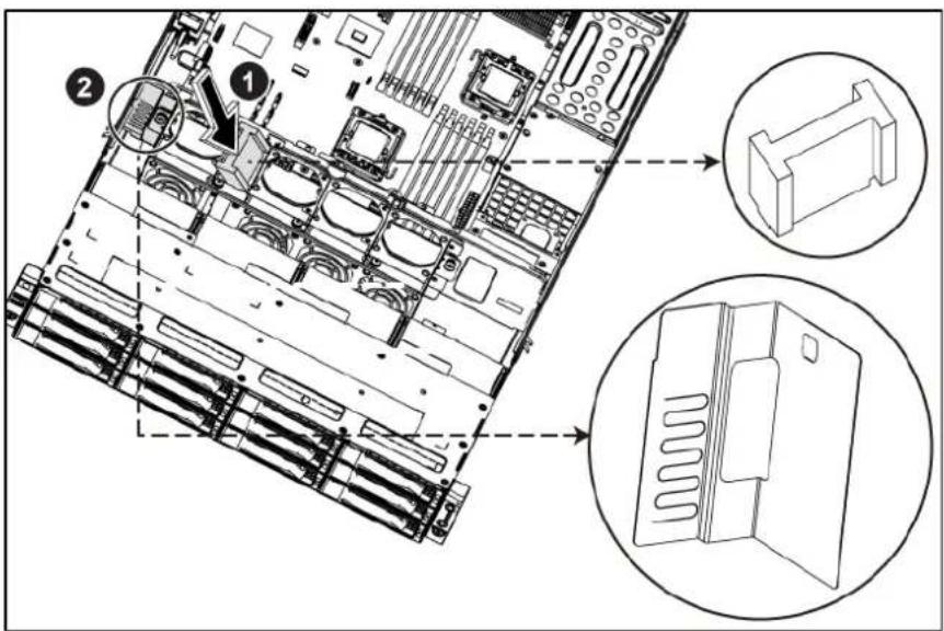
text_image
Technical diagram of a server rack with labeled components and zoomed-in views showing internal structure and assembly.System fan
The server has four or eight system fans located on the center wall of the chassis. While the server is equipped with eight system fans, the redundant function is provided.
The figure below identifies the system fans by their device number and shows their corresponding cable connections.
Figure 112 Connection of the Four System Fans
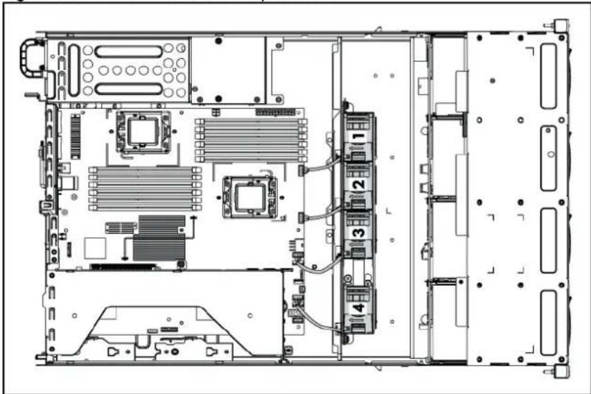
natural_image
Technical line drawing of an internal server rack with multiple CPU racks and ventilation units (no text or labels)Device number Connector
| System fan 1 J63 on the system board |
| System fan 2 J71 on the system board |
| System fan 3 J62 on the system board |
| System fan 4 J68 on the system board |
| System fans 1 to 3 are for the memory modules and processors, while system fan 4 is for the PCI slots and system chipsets. |
Figure 113 Connection of the Eight System Fans

text_image
Technical diagram of an internal server rack layout with numbered components and ventilation slotsDevice number Connector
| System fan 1/2 J63 on the system board |
| System fan 3/4 J71 on the system board |
| System fan 5/6 J62 on the system board |
| System fan 7/8 J68 on the system board |
| System fans 1 to 6 are for the memory modules and processors, while system fan 7/8 is for the PCI slots and system chipsets. |
A new system fan can be installed to allow the server to operate properly in case a default system fan becomes defective.
The installation and removal of fans on the system redundant fan cage and system non-redundant fan cage are same, here we take the removal and installation of fans on the system non-redundant fan cage for example.
To remove the system fan:
- Power down the server.
- Disconnect the power cord(s).
- Unlock the server if necessary and remove the top cover as described in the section "System cover".
- Disconnect the system fan cable from its corresponding board connector.
- Release the fan cable from the cable clip securing it to the chassis partition wall.
- Squeeze the release tab on the system fan to release it from the chassis.
- Lift the system fan away from the chassis.
Figure 114 Removing the System Fan
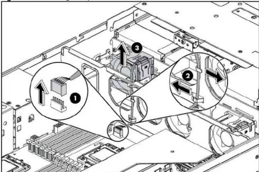
text_image
Technical diagram of an electronic device showing labeled components and assembly steps, including connectors and parts with numbered annotations.To reinstall the system fan:
- Hold the system fan and press it into the system fan bracket.
- Secure the cable using the cable clip located on the chassis partition wall.
- Connect the system fan cable to its corresponding board connector.
Figure 115 Reinstalling the System Fan
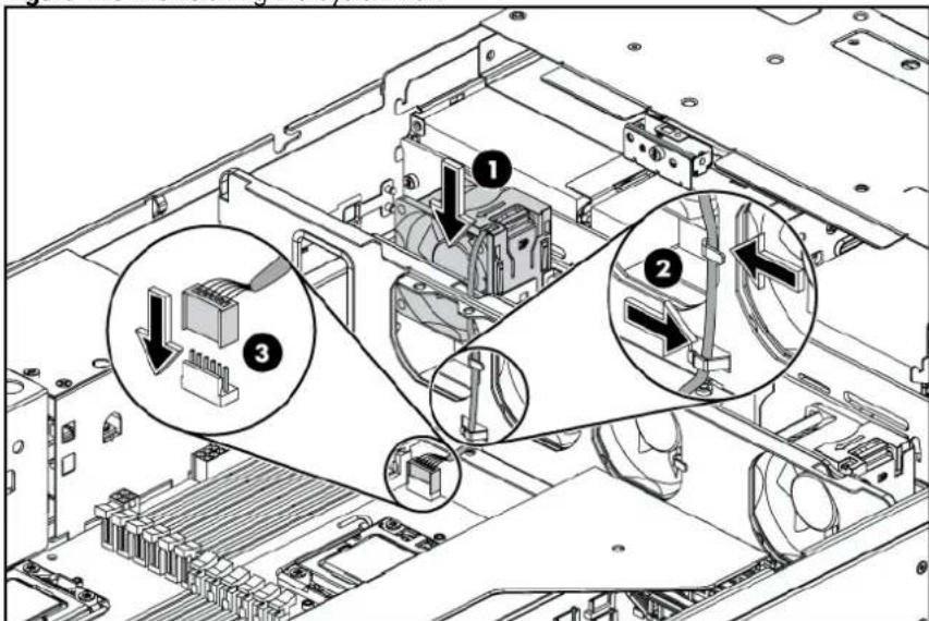
text_image
Technical diagram of an electronic device showing internal components with numbered annotations highlighting specific areas.Connectors, switches, and LEDs
This chapter contains illustrations and tables identifying and describing the connectors, jumpers, switch, buttons, and LED indicators located on the front panel, rear panel, system board and hard drives of the HP ProLiant DL180 G6 server.
Connectors and components
Front panel components
Figure 116 Front Panel Components / 4 3.5" HDD Model

text_image
Diagram of a server rack with numbered components for identification| Item | Description |
| 1 | Front panel USB 2.0 port 0/1 |
| 2 | Optical disc drive |
| 3 | System health LED |
| 4 | Front UID LED/switch |
| 5 | NIC 1 activity LED |
| 6 | NIC 2 activity LED |
| 7 | Hard Drive activity LED |
| 8 | Power LED/switch |
| 9 | Thumbscrews for rack mounting |
| 10 | Drive online/error LED |
| 11 | Drive activity LED |
Item
Description
12 Hard disk drive (HDD) bays
Figure 117 Front Panel Components / 8 3.5" HDD Model
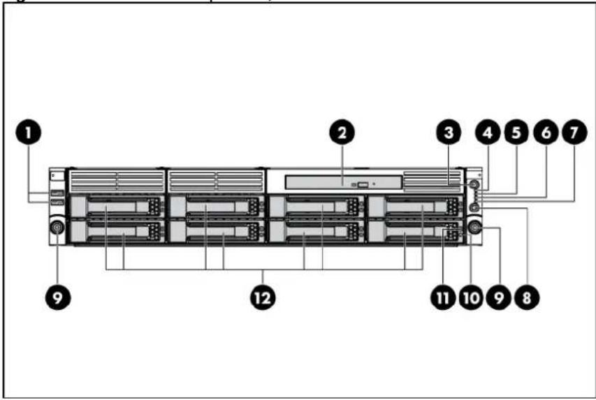
text_image
Diagram of a server rack with numbered components for identificationItem Description
| 1 Front panel USB 2.0 port 0/1 |
| 2 Optical disc drive |
| 3 Front UID LED/switch |
| 4 System health LED |
| 5 NIC 1 activity LED |
| 6 NIC 2 activity LED |
| 7 Hard drive activity LED |
| 8 Power LED/switch |
| 9 Thumbscrews for rack mounting |
| 10 Drive activity LED |
| 11 Drive online/error LED |
| 12 Hard disk drive (HDD) bays |
Figure 118 Front Panel Components / 8 2.5" HDD Model

text_image
1 2 3 4 5 6 7 9 12 11 10 9 8| Item | Description |
| 1 | Front panel USB 2.0 port 0/1 |
| 2 | Optical disc drive |
| 3 | Front UID LED/switch |
| 4 | System health LED |
| 5 | NIC 1 activity LED |
| 6 | NIC 2 activity LED |
| 7 | Hard drive activity LED |
| 8 | Power LED/switch |
| 9 | Thumbscrews for rack mounting |
| 10 | Drive activity LED |
| 11 | Drive online/error LED |
| 12 | Hard disk drive (HDD) bays |
Figure 119 Front Panel Components / 12 3.5" HDD Model
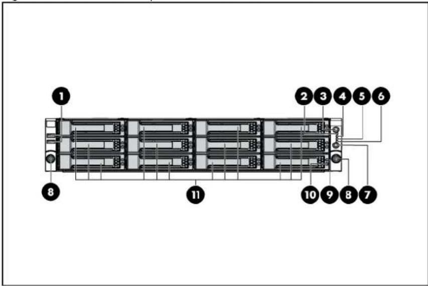
text_image
1 2 3 4 5 6 8 11 10 9 8 7| Item | Description |
| 1 | Front panel USB 2.0 port 0/1 |
| 2 | System health LED |
| 3 | Front UID LED/switch |
| 4 | NIC 1 activity LED |
| 5 | NIC 2 activity LED |
| 6 | Hard drive activity LED |
| 7 | Power LED/switch |
| 8 | Thumbscrews for rack mounting |
| 9 | Drive online/error LED |
| 10 | Drive activity LED |
| 11 | Hard disk drive (HDD) bays |
Figure 120 Front Panel Components / 25 2.5" HDD Model
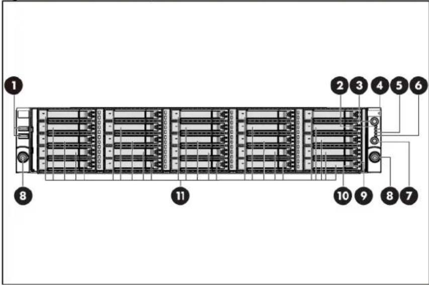
text_image
1 2 3 4 5 6 8 11 10 9 8 7| Item | Description |
| 1 | Front panel USB 2.0 port 0/1 |
| 2 | System health LED |
| 3 | Front UID LED/switch |
| 4 | NIC 1 activity LED |
| 5 | NIC 2 activity LED |
| 6 | Hard drive activity LED |
| 7 | Power LED/switch |
| 8 | Thumbscrews for rack mounting |
| 9 | Drive online/error LED |
| 10 | Drive activity LED |
| 11 | Hard disk drive (HDD) bays |
Rear panel components
Figure 121 Rear Panel Components for Standard PCI Cage
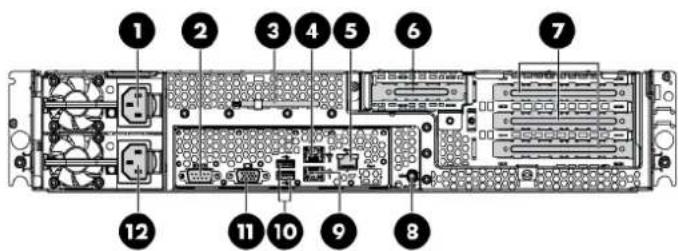
text_image
Labeled diagram of an electronic device rack with numbered components for identificationItem Description
| 1 Power supply 2 cable socket | ||
| 2 Serial port | ||
| 3 T-10/T-15 wrench | ||
| 4 GbE LAN port for NIC 2 | ||
| 5 Dedicated management port (optional) | ||
| 6 Low-profile PCI expansion card slot cover | ||
| 7 Full-height/full-length PCI expansion card slot covers | ||
| 8 Rear UID LED/switch | ||
| 9 GbE LAN port for NIC 1 | ||
| 10 Rear panel USB 2.0 port 2/3 | ||
| 11 VGA port | ||
| 12 Power supply 1 cable socket |
Figure 122 Rear Panel Components for HDD PCI Cage
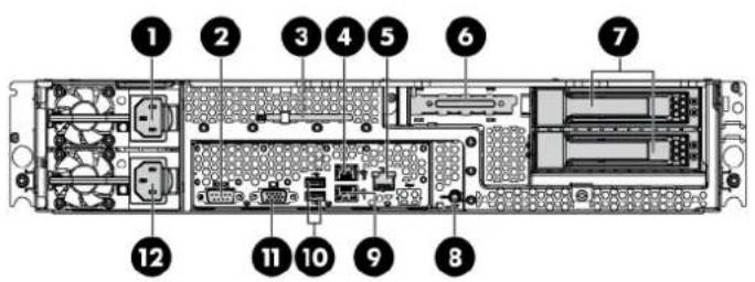
text_image
Labeled diagram of an internal server rack with numbered components for identificationItem Description
| 1 Power supply 2 cable socket |
| 2 Serial port |
| 3 T-10/T-15 wrench |
| 4 GbE LAN port for NIC 2 |
| 5 Dedicated management port (optional) |
| 6 Low-profile PCI expansion card slot cover |
| 7 Hard disk drive (HDD) bay |
| 8 Rear UID LED/switch |
| 9 GbE LAN port for NIC 1 |
| 10 Rear panel USB 2.0 port 2/3 |
| 11 VGA port |
| 12 Power supply 1 cable socket |
Figure 123 Rear Panel Components for ODD PCI Cage
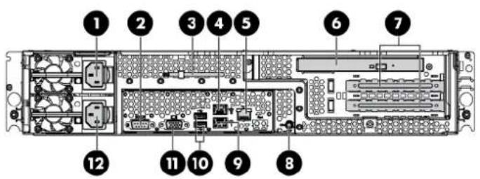
text_image
Diagram of a server rack with numbered components for identificationItem Description
| 1 Power supply 2 cable socket | |||
| 2 Serial port | |||
| 3 T-10/T-15 wrench | |||
| 4 GbE LAN port for NIC 2 | |||
| 5 Dedicated management port (optional) | |||
| 6 Optical disk drive (ODD) bay | |||
| 7 Full-height/full-length PCI expansion card slot covers | |||
| 8 Rear panel USB 2.0 port 2/3 | |||
| 9 GbE LAN port for NIC 1 | |||
| 10 Rear UID LED/switch | |||
| 11 VGA port | |||
| 12 Power supply 1 cable socket |
System board components
Figure 124 System Board Components
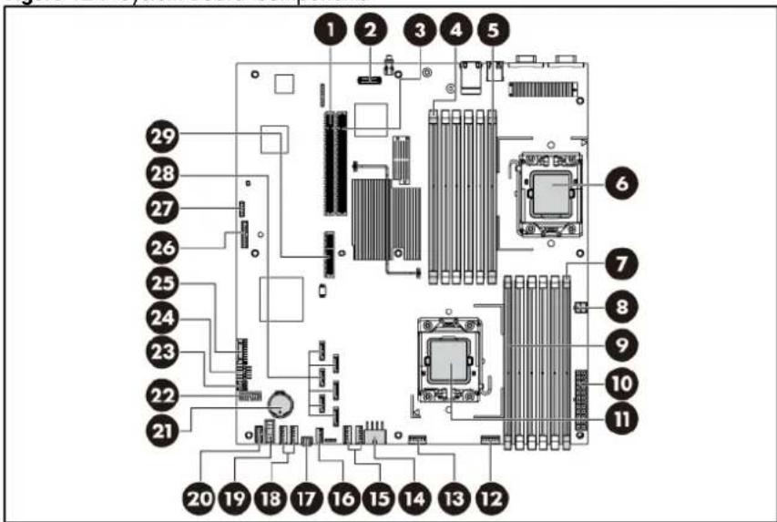
text_image
Labeled diagram of a computer motherboard showing numbered components for identification| Item | Designator | Description | ||
| 1 | J17 | PCIe | slot | |
| 2 J11 | Dedicated management port connector | |||
| 3 | J18 | PCIe | slot | |
| 4 J21 | DIMM slot 6C for processor 2 | |||
| 5 J26 | DIMM slot 1D for processor 2 | |||
| 6 | CPU2 | Processor | 2 | |
| 7 J48 | DIMM slot 6C for processor 1 | |||
| 8 J60 | 4-pin power connector | |||
| 9 J43 | DIMM slot 1D for processor 1 | |||
| 10 J51 | System power connector | |||
| 11 | CPU1 | Processor | 1 | |
| 12 | J63 | Fan | connector | 1 |
| 13 | J71 | Fan | connector | 2 |
| 14 J64 | 8-pin power connector | |||
| 15 J62, J70 | Fan connector 3/4 (Fan 4 is unused) | |||
| 16 J69 | Internal USB 2.0 port 4 | |||
| 17 | J65 | Backplane connector | 1 | |
| 18 J68, J67 | Fan connector 5/6 (Fan 6 is unused) | |||
| 19 J66 | Hard drive backplane SGPIO connector | |||
| 20 J79 | Power supply EFF connector | |||
| 21 | B1 3 V CMOS battery (CR2032) | |||
| 22 | J76 Power backplane control connector | |||
| 23 | J56 | LCD | connector | (optional) |
| 24 | J53 Front panel USB 2.0 port 0/1 | |||
| 25 | J42 Front panel header | |||
| 26 | J29 | TPM | connector | |
| 27 | J27 System maintenance jumper | |||
| 28 | SATA SATA connectors | |||
| 29 | J31 | PCIe | slot | |
Jumpers
The system board contains a system maintenance jumper (J27). Table 21 describes the jumper settings.
Table 21 System Maintenance Jumper Setting (J27)
| Jumper Status (default=off) | ||
| A | Clear | CMOS |
| B | Clear | password |
| C | Recovery | BIOS |
| D | Recovery | BMC |
| E | RTC | reset |
LED indicators
This section contains illustration and descriptions of internal and external status LED indicators located on the:
- Front panel
• Optical disc drive - Hard drive
- Rear panel
- System board
These LED indicators aid in problem diagnosis by indicating the status of system components and operations of the server.
Front panel LED indicators
The front panel LED indicators allow constant monitoring of basic system functions while the server is operating.
Figure 125 Front Panel LED Indicators on the Right Ear

text_image
Diagram of server rack with numbered components and a zoomed-in view highlighting internal structure.Table 22 Front Panel LED Indicator Status on the Right Ear
| Item | LED indicator | Status | Description | |
| 1 | System health LED | Steady green | Healthy | |
| Red | Critical error | |||
| Amber | Non-critical error | |||
| 2 | NIC 2 activity LED | Steady green | Linked to the network | |
| Flashing green | Linked and activity on the network. | |||
| Off | No | connection |
Table 22 Front Panel LED Indicator Status on the Right Ear
| Item | LED indicator | Status | Description |
| 3 | Hard drive activity | LED | Flashing green Hard drive activity |
| Off | No hard drive activity | ||
| 4 | Power LED/switch | Steady green | The system has AC power and is turned on. |
| Steady amber | The system has AC power but in standby mode. | ||
| Off | No AC power to the system. | ||
| 5 | NIC 1 activity | LED | Steady green Linked to the network |
| Flashing green | Linked and activity on the network. | ||
| Off | No connection | ||
| 6 | Front UID LED/switch | Steady blue | Identification. |
| Flashing blue | The system is being remotely managed. | ||
| Off | No identification. | ||
Optical disc drive activity LED indicator
The optical disc drive has an activity indicator that indicates when the drive is reading media.
Figure 126 Optical disc drive activity LED indicator

natural_image
Front view diagram of a server rack with multiple racks and a labeled connection point (no text or symbols beyond the label)Table 23 Optical Disc Drive Activity LED Indicator Status
| Item | Component | Status | Description | |
| 1 | Optical disc drive activity LED indicator | Flashing green | Ongoing drive activity. | |
| Off | No drive activity. | |||
Hard drive LED indicator
The status of hard drives installed in the server is indicated by the hard drive LED indicators located on the HDD.
Figure 127 Hard Drive LED Indicator
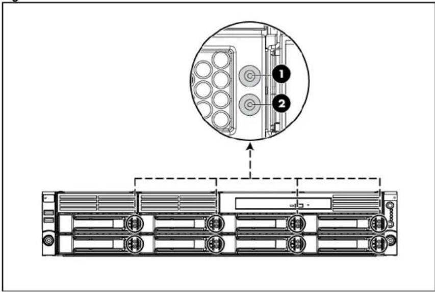
text_image
Diagram showing server rack layout with labeled components and a magnified inset highlighting component 1 and component 2.Table 24 Hard Drive LED Indicator Status
| Item | LED indicator | Status | Description |
| 1 | Drive online/error | LED indicator | Steady blue The drive is located |
| Steady orange | The drive is in a failed state. | ||
| Off | The drive is not in a failed state. | ||
| 2 | Drive activity | LED indicator | Flashing green The drive is in an activity state. |
| Off | The drive is not in an activity state. | ||
Rear panel LED indicators
The LAN port on the rear panel has two LED indicators that allow monitoring of network activity.
Figure 128 LAN LED Indicators Location

text_image
Technical diagram of an internal server rack with labeled components and a magnified inset showing internal layout.Table 25 LAN LED Indicator Status
| Item | Component | Status | Description |
| 1 | NIC activity | LED indicator | Flashing green Linked and activity on the network. |
| Off | No connection or linking at 10 Mbps speed. | ||
| 2 | NIC link | LED indicator | Flashing green LAN is active. |
| Steady green LAN is linking. | |||
| 3 | Dedicated management port activity | LED indicator (optional) | Flashing amber LAN is active. |
| 4 | Dedicated management port link LED indicator (optional) | Steady green Linking at 100 Mbps speed. | |
| Off | No connection or linking at 10 Mbps speed. | ||
System board LED indicator
The system board contains one LED indicator for use during troubleshooting operations.
Figure 129 System Board LED Indicator
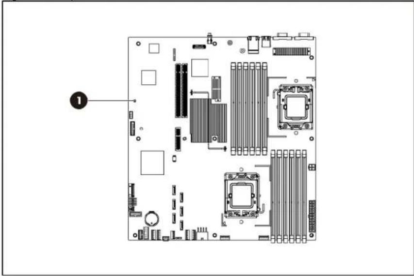
natural_image
Top-down schematic of a computer motherboard showing CPU socket, RAM slots, and drive bays (no text or labels)Table 26 BMC activity LED Indicator Status
| Item | Component | Status | Description |
| 1 | BMC activity | LED indicator | Steady green BMC is power on and in initialization process. |
| Flashing green | BMC activity. | ||
| Off AC is Off. | |||
Diagnostic tools and setup utilities
This chapter provides an overview of the Power-On Self-Test (POST), the POST error messages, and BIOS, SAS and SATA setup utilities.
BIOS software
The server uses BIOS to boot up the system. BIOS software is a ROM-based firmware that allows reliability, manageability, and connectivity for the server platforms. This software contains a set of programs permanently stored in an EEPROM chipset located on the system board. These programs assist in managing, initializing, and testing the hardware devices installed on the computer.
BIOS software allows you to:
- Perform configuration from the BIOS Setup Utility
Using the Setup Utility, you can install, configure, and optimize the hardware devices on the system board. In addition, you can set various features such as serial console redirection, PXE boot, and much more.
- Initialize hardware at boot up using POST routines
During power-on or warm reset, the BIOS perform POST routines to test system components, allocate resource for various hardware devices, and prepare the system to boot to various operating systems.
BIOS Setup Utility
The HP server BIOS Setup Utility is used to configure five primary menu selections:
- Main
- Advanced
- Boot
- Security
- Exit
Accessing the BIOS Setup Utility
- Turn on the monitor and server.
If the server is already turned on, save your data and exit from all open applications, and then restart the server.
- When the HP logo is displayed during POST, press F10 into BIOS Setup Utility. If you fail to press F10 before POST is completed, you will need to restart the server.
- The first page displayed is the Main menu showing the Setup Utility menu bar. Use the left ( ) and right ( ) arrow keys to change the options for each setting. Use the up ( ) and down ( ) arrow keys to move among the different settings in each menu.
Navigating through the Setup Utility
Use the keys listed in the legend bar on the right of the Setup screen to navigate through the various menu and submenu screens of the Setup Utility. Table 27 lists these legend keys and their respective functions.
Table 27 Setup Utility Navigation Keys
| Key Function | |||
| ← and → | Select | different | screens. |
| ↑ and ↓ Select items in each menu. | |||
| Enter, Tab, or Shift-Tab | Select a field value or display a submenu screen. | ||
| Display more options for items marked with ▶ | |||
| Esc Exit the CMOS Setup menu. | |||
| <+>, <-> Configure the system time or change field. | |||
| F1 To bring up the General Help window.The General Help window describes other Setup navigation keys that are not displayed on the legend bar. | |||
| F10 To save changes and exit the CMOS Setup Utility. | |||
Setup Utility menu bar
The BIOS Setup Utility provides a menu bar with the menu selections. The menu bar choices are described in the topics below.
Main menu
Figure 130 Main Menu of the BIOS Setup Utility
| ROM-based Setup Utility | ||
| Advanced Boot Security Exit | ||
| System Overview | Use [ENTER], [TAB]or [SHIFT-TAB] to select a field.Use [+] or [-] to configure system time. | |
| Product Name: ProLiant DL180 G6ProLiant BIOS: O20Build Date: 01/26/2010ROM ID 12DIM191 | ||
| ProcessorIntel(R) Xeon(R) CPU xxxxxxxxxxxxxSpeed: xxxxMHzCount: 1 | ||
| System MemorySize: 1024MB+- Change FieldSystem Time [16:52:34] Tab Select FieldSystem Date [Sat 02/14/2009] F1 General HelpSystem Serial Number F10 Save and ExitNIC#1 MAC Address 00-21-5A-4A-11-21NIC#2 MAC Address 00-1E-0B-4A-89-24Asset Tag [ ]POST F1 Prompt [Delayed] | ←→ Select Screen↑↓ Select ItemESC Exit | |
| v02. 61 (C) Copyright 1985-2006, American Megatrends, Inc. | ||
Use this menu to configure the following items:
• View product name.
• View BIOS build date and ROM ID.
• View processor information and system memory size.
• Set system time and date.
• View system serial number.
• View NIC 1&2 MAC addresses.
- Configure asset tags and POST F1 Prompt settings.
Advanced menu
Figure 131 Advanced Menu of the BIOS Setup Utility
| ROM-based Setup Utility | |
| MainBoot Security Exit | |
| Advanced Settings | Custom: Allow toconfigure Efficiency/Performance relateditems individually.Efficiency/Performance: Impactgroups as CPUConfiguration/CPUbridge Configuration |
| WARNING: Setting wrong values in below sectionsmay cause system to malfunction. | |
| Power Efficiency Mode [Efficiency]Power Supply Redundancy Mode [High Efficiency] | |
| >CPU Configuration>CPU Bridge Configuration>SATA Configuration>SuperIO Configuration>USB Configuration>PCI Configuration>PCI Express Configuration>IPMI Configuration>BIOS Serial Console Configuration>Trusted Computing►Intel VT-d ConfigurationF10 Save and ExitESC Exit | /PCI ExpressConfiguration☐ Select Screen☐ Select ItemEnter Go to Sub ScreenF1 General Help |
| V02. 61(C) Copyright 1985-2006, American Megatrends, Inc. | |

WARNING: Incorrect settings may cause the server to malfunction. To correct the settings, press the F9 key to restore the default settings.
• CPU Configuration—Configure CPU settings.
• CPU Bridge Configuration—Configure CPU bridge settings.
- SATA Configuration—Configure SATA settings.
• SuperIO Configuration—Configure Super I/O settings.
• USB Configuration—Configure USB settings.
• PCI Configuration—Configure PCI settings.
- PCI-Express Configuration—Configure PCI Express settings.
- IPMI Configuration—Configure the IPMI settings.
- BIOS Serial Console Configuration—Configure the BIOS Serial Console settings.
Figure 132 IPMI Submenu of the BIOS Setup Utility
| ROM-based Setup Utility | |
| IPMI 2.0 Configuration | InPut for Set LANConfiguration command.NOTE: Each question in this group may take considerable amount of time. |
| Status of BMC Working | |
| BMC Firmware Revision 09.57 | |
| BMC/IPMI FW Date: Jan/13/2010 | |
| BMC SDR Version: 2.17.0.43 | |
| Warehouse Build Number XXX | |
| >Set LAN Configuration | |
| >SEL Configuration | |
| >Hardware Health Information | |
| >Watchdog Configuration | |
| >Serial Port Configuration | |
| Enter Go to Sub Screen | ←→ Select Screen↑↓ Select Item |
| F1 General Help | |
| F10 Save and Exit | |
| ESC Exit | |
| V02. 61(C)Copyright 1985-2006, American Megatrends, Inc. | |
• Status of BMC—Display the status of BMC.
• BMC Firmware Revision—Display the current revision of the BMC firmware.
• BMC/IPMI FW Date—Display the date of the BMC/IPMI firmware.
• BMC SDR Version—Display the current version of the BMC SDR.
- Set LAN Configuration—Set LAN settings.
- SEL Configuration—Display and clear the BMC system event log.
- Hardware Health Information—Set temperature and fan rotation rate.
- Watchdog Configuration—Configure watch dog timer status.
- Serial Port Configuration—Configure serial port connection settings.
Boot menu
Figure 133 Boot Menu of the BIOS Setup Utility
| ROM-based Setup Utility | |
| Main AdvancedSecurity Exit | |
| Boot Settings | Configure Settings during System Boot. |
| >Boot Settings Configuration | |
| >Standard Boot Order | |
| >Hard Disk Drives | |
| USB Device Boot Priority [High] | Select Screen |
| Restore on AC Power Loss [Last State] | Select Item Enter Go to Sub Screen F1 General Help F10 Save and Exit ESC Exit |
| V02. 61 (C) Copyright 1985-2006, American Megatrends, Inc. | |
- Boot Settings Configuration—Configure settings during system boot.
- Standard Boot Order—View and configure standard boot order settings.
- Hard Disk Drives—Display HDD information if detect HDD installed.
- USB Device Boot Priority—Configure priority settings for USB devices. Users can configure the BIOS to avoid attempting to boot non-bootable USB devices that are left plugged into the server during POST. The options are High (default) and Low.
- Restore on AC Power Loss—Use this screen to restore the AC power loss.
Security menu
Figure 134 Security Menu of the BIOS Setup Utility
| ROM-based Setup Utility | |
| Main Advanced BootExit | |
| Security Settings | Install or Change the Password. |
| Admin Password: Not Installed | |
| User Password: Not Installed | |
| Change Admin Password | |
| Boot Sector Virus Protection: [Disabled] | ☐ Select Screen☐ Select ItemEnter ChangeF1 General HelpF10 Save and ExitESC Exit |
| V02. 61(C) Copyright 1985-2006, American Megatrends, Inc. | |
Use this menu to configure the following items:
- Admin Password—Indicate if an admin password has been installed to the system.
- User Password—Indicate if a user password has been installed to the system.
- Change Admin Password—Modify or change your admin password.
- Boot Sector Virus Protection—Set Enabled to boot sector virus protection. The options are Enabled and Disabled.
Exit menu
Figure 135 Exit Menu of the BIOS Setup Utility
| ROM-based Setup Utility | |
| Main Advanced Boot Security | |
| Exit Options | Exit system setup after saving the changes. |
| Save Changes and Exit | |
| Discard Changes and Exit | |
| Discard Changes | F10 key can be used for this operation.. |
| Restore Default Settings | ☐ Select Screen☐ Select ItemEnter Go to Sub ScreenF1 General HelpF10 Save and ExitESC Exit |
| V02. 61(C) Copyright 1985-2006, American Megatrends, Inc. | |
Use this menu to save changes or discard changes. When you save and exit, the server reboots.
- Save Changes and Exit—Save the changes you have made and exit the BIOS Setup Utility.
- Discard Changes and Exit—Exit the BIOS Setup Utility without saving the changes you have made.
- Discard Changes—Discard (cancel) any changes you have made. F10 can be used for this operation. You will remain in the Setup Utility.
- Restore Default Settings—Restore the default settings for all items in the BIOS Setup.
BIOS update
HP recommends that you update the server BIOS with the latest system BIOS version to take advantage of the most recent compatibility fixes. The latest BIOS version for your server can be downloaded from http://www.hp.com.
Clear CMOS
You may need to clear the Setup configuration values (CMOS) if the configuration has been corrupted, or if incorrect settings made in the Setup Utility have caused error messages to be unreadable.
To clear CMOS:
- Perform the Pre-installation procedure.
- If necessary, remove any accessory boards or cables that prevent access to the system configuration switch.
- Locate the system maintenance jumper (J27-A) on the system board.
- Press the button. AC power must not be connected.
- Perform the Post-installation instructions.
- During POST, press F10 to access the Setup Utility.
- Load setup defaults by pressing F9.
- Set time, date, and other system values.
- Press F10 to close the Setup Utility.
NOTE: Clearing CMOS restore all system configurations and password default settings.
Power-On Self-Test (POST)
Before you can use a server, all devices must be tested and initialized, and the operating system must be bootstrapped to the memory. This is referred to as Power-On Self-Test or POST. POST is a series of diagnostic tests that checks firmware and hardware components on the system to ensure that the server is properly functioning. This diagnostic function automatically runs each time the server is powered on.
These diagnostics, which reside in the BIOS ROM, isolate the server-related logic failures and indicate the board or component that you need to replace, as indicated by the error messages. Most server hardware failures will be accurately isolated during POST. The number of tests displayed depends on the configuration of the server.
During POST you can:
- Press ESC to skip the HP logo and go to POST boot progress display system summary screen.
- Press F10 to access the Setup Utility.
- Press F12 to request a network boot (PXE).
- Press F1 to continue POST after POST errors are detected.
POST error indicators
When POST detects a system failure, it displays a POST error message.
POST error descriptions
When a non-fatal error occurs during POST, the screen will display an error message with the format "xxx-Error Identifier String" where "xxx" is a unique number code that matches ODM system specific error documentation and may be a hexadecimal or decimal value.
All Error messages describe the problems as shown below:
Table 28 POST Error Messages
| Error code Description |
| 10 Floppy Controller Failure |
| 00B CMOS Memory Size Wrong |
| 00C RAM R/W test failed |
| 003 CMOS Battery Low |
| 005 CMOS Checksum Bad |
| 040 Refresh timer test failed |
| 041 Display memory test failed |
| 048 Password check failed |
| 120 A0CCMOS Cleared by Jumper. Restore the Jumper and Continue... |
| 122A0CPassword Cleared By Jumper. Restore the Jumper and Continue... |
| 150 Processor failed BIST |
| 160 Processor missing microcode: |
| 192 L3 cache size mismatch |
| 193 CPUID, Processor stepping are different |
| 194 CPUID, Processor family are different |
| 195 Front side bus mismatch. System halted. |
| 196 CPUID, Processor Model are different |
| 197 Processor speeds mismatched |
| 198 Processor QPI speed mismatch detected. |
| 601 Error: BMC Not Responding |
| 605 BMC Has Detected Fatal Hardware Error |
| 611 Internal User Area Of BMC FRU Corrupted |
| 612 Controller Update 'boot block' Firmware Corrupted |
| 613 Controller Operational Firmware Corrupted |
Table 28 POST Error Messages
| Error code Description | |
| 620 Non-Redundant Fan Failure or Missing | |
| 621 Redundant Fan Configuration, One Fan Failure or Missing | |
| 622 Redundant Fan Configuration, Multiple Fans Failure or Missing | |
| 623 | Temperature Violation DetectedWaiting 5 minutes for system to coolPress ESC Key to resume booting without waiting for the system to coolWarning: Pressing ESC is NOT recommended as the system may shutdown unexpectedly |
| 624 Power Supply Failure or Power Supply Unplugged | |
| 626 Update SDRR/Configuration Image failed | |
| 627 | Invalid or Unknown SKU/Chassis IDPlease check Front panel, System ID Jumper or Riser cardPress F1 to Continue |
| 628 Redundant Power Supply Mismatch | |
| 701 | Insufficient Runtime space for MPS data.!!System may operate in PIC or Non-MPS mode. |
| 702 | No enough APIC ID in range 0-0Fh can be assigned to IO APICs.(Re-assigning CPUs' local APIC ID may solve this issue)MPS Table is not built! System may operate in PIC or Non-MPS mode. |
POST related troubleshooting
Perform the following procedures when POST fails to run, displays error messages.
If the POST failure is during a routine boot up, check the following:
- All external cables and power cables should be firmly plugged in.
- The power outlet to the server should be connected and works correctly.
- The server and monitor are both turned on. The bicolour status LED indicator on the front panel must be lit up green.
• The monitor's contrast and brightness settings are correct. - All internal cables are properly connected and all boards firmly seated.
• The processor is fully seated in its socket on the system board. - The heat sink assembly is properly installed on top of the processor.
• All memory modules are properly installed. - If you have installed a PCI accessory board, verify that the board is firmly seated and any jumpers on the board are properly set. Refer to the documentation provided with the accessory board.
- All internal cabling and connections are in their proper order.
- If you have changed the jumpers on the system board, verify that each is properly set.
SETSYS utility
SETSYS.EXE (DOS application) is the correct tool for setting the Serial Number/Asset Tag text on this server after a system board replacement has occurred.
Once the Serial Number/Asset Tag text has been entered via SETSYS, populating the SMBIOS data, the system BIOS will automatically write this info into the BMC IPMI FRU data on the next boot up.
Physical and operating specifications
This chapter provides physical and operating specifications for the HP ProLiant DL180 G6 server. Specifications include:
System unit
Table 29 Hardware Specifications
| Item Components | |
| Processor socket Intel FCLGA1366 socket | |
| Processor | 2P Intel Xeon processor 5500 series with integrated memory controller |
| 2P Intel Xeon processor 5600 series with integrated memory controller | |
| Chipset Tylersberg-36D/ICH-10R | |
| Hardware monitoring device ServerEngines Pilot 2 management controller | |
| Gigabit ethernet controller HP NC362i GbE controller for NICLO100i sideband support | |
| Onboard storage controller Integrated ICH10R SATA (6-port) | |
| ODD & Floppy interface Optional Optical Disc Drive (SATA)Optional Floppy (USB only, USB key) | |
| Embedded video controller ServerEngines Pilot 2 management controller | |
| I/O subsystem One PCIe x16 links with x16 slot + PCIe x4 links with x4 slotOne PCIe x16 links with x16 slot | |
| Memory Twelve DDR3 800/1066/1333 MHz RDIMM/UDIMM slots, up to96 GB | |
| Default media storage Four bays hot-plug HDD cage for 3.5" SAS or SATA driversEight bays hot-plug HDD cage for 3.5" SAS or SATA drivesEight bays hot-plug HDD cage for 2.5" SAS or SATA drivesTwelve bays hot-plug HDD cage for 3.5" SAS or SATA drivesTwenty-five bays hot-plug HDD cage for 2.5" SAS or SATA drives | |
| Optical disc drive | One slim optical disc drive bay for optical disc drive on the front (83.5" HDD model) |
| I/O ports | PS/2 keyboard port, PS/2 mouse port, USB 2.0 ports (two rearUSB ports, one internal USB port, two front USB ports), video port,serial port and GbE port and IPMI LAN port. |
Table 29 Hardware Specifications
| Item Components | |
| Status LED indicators | |
| Front panel | |
| System Health LED | |
| NIC 1/2 activity LED | |
| Power Switch/LED | |
| Hard drive activity LED indicator | |
| UID Switch/LED | |
| Rear panel | |
| UID LED | |
| LAN link status | |
| System board | BMC Activity LED |
| Power supply unit 460 W redundant, power supply | |
| 750 W redundant, power supply | |
| Thermal solution Four system fans | |
| Or eight system fans | |
Table 30 Physical Dimensions
| Item Description | |
| System board platform | EATX (Extended Advanced Technology Extended) |
| System board dimension 304.8 mm x 330.2 mm (12 in x 13 in) | |
| Server dimensions (H x W x D) | 87.6 mm x 448.0 mm x 703.4 mm (3.45 in x 17.64 in x 27.69 in) |
| Rack | |
| Server weight Basic configuration (excludes monitor): 16~24kg | |
Table 31 Environmental Specifications
| Item Description | |
| Temperature: | |
| Operating | +10°C to +35°C (+50°F to +95°F) |
| Non-operating | -30°C to 60°C (-22°F to 140°F) |
| Storage | -30°C to 60°C (-22°F to 140°F) |
| Wet-bulb temperature | 38.7°C (101.7°F) |
| Relative humidity: | |
| Operating | 10% to 90% (non-condensing) |
| Non-operating | 5% to 95% |
| Storage | 5% to 95% |
| Altitude: | |
| Operating | 0 to 3049 m (0 to 10,000 ft) |
| Non-operating | 0 to 9146 m (0 to 30,000 ft) |
| Thermal output (maximum operating) | 1000 W/hr |
| Acoustic emissions | LWad: 6.7 Bels |
| Normal configuration | (operating at room temperature)LWad: 6.7 Bels(Idle at room temperature) |
Table 32 Power Supply Specifications / 460 W
| Item Description | |
| Dimensions (H x W x D) 38.5 mm x 86.4 mm x 190.5 mm (1.52 in x 3.4 in x 7.5 in) | |
| Weight (approximate) 1.36 kg | |
| Input requirements: | |
| Rated input voltage | 90 VAC to 264 VAC |
| Normal line voltage | 100 VAC to 120 VAC/200 VAC to 240 VAC |
| Line frequency 47–63 Hz | |
| Rated input current 6.0 ARMS max @ 100 V | 5.0 ARMS max @ 120 V |
| 3.00 ARMS max @ 200 V to 240 V | |
| BTU rating N/A | |
| Power supply output power: | |
| Rated steady state power | 460 W (1+1 Redundant) |
| Maximum peak power | N/A |
| Temperature range: | |
| Operating | +5°C to +50°C |
| Shipping | -40°C to +85°C |
| Relative humidity: | |
| Operating | 5% to 95% relative humidity, non-condensing |
| Non-operating | 5% to 95% relative humidity, non-condensing |
Table 33 Power Supply Specifications / 750 W
| Item Description | |
| Dimensions (H x W x D) 38.5 mm x 86.4 mm x 190.5 mm (1.52 in x 3.4 in x 7.5 in) | |
| Weight (approximate) 1.36 kg | |
| Input requirements: | |
| Rated input voltage | 90 VAC to 264 VAC |
| Normal line voltage | 100 VAC to 120 VAC/200 VAC to 240 VAC |
| Line frequency 47–63 Hz | |
| Rated input current 9.10 ARMS max @ 100V | 5.10 ARMS max @ 200V |
| BTU rating N/A | |
| Power supply output power: | |
| Rated steady state power | 750 W (1+1 Redundant) |
| Maximum peak power | N/A |
Table 33 Power Supply Specifications / 750 W
| Item Description | |
| Temperature range: | |
| Operating | +5°C to +50°C |
| Shipping | -40°C to +85°C |
| Relative humidity: | |
| Operating | 5% to 95% relative humidity, non-condensing |
| Non-operating | 5% to 95% relative humidity, non-condensing |
Index
A
AC power
power-down procedures, 42
air baffle
installing, 79
removing, 71
B
backplane, 61
reinstalling, 68
removing, 68
battery
replacement warnings, 108
BBWC
reinstalling, 111
removing, 110
bezel blank
removing, 53
BIOS Setup Utility
accessing, 140
additional navigation keys, 141
menu bar, 140
BIOS software
overview, 140
C
cable connections, 45
cable management, 44
CSR (customer self repair), 1
CSR program
part categories, 2
website, 1
customer self repair (CSR), 1
D
dedicated management port
reinstalling, 104, 106
removing, 103, 105
diagnostic tools and setup utilities
BIOS Setup Utility, 140
BIOS software, 140
BIOS update, 148
POST, 148
Diagnostic tools and Setup Utilities
clear CMOS, 148
drive bay configuration, 49
drives
backplane, 61
cable connections, 45
cable management, 44
drive bay configuration, 49
hard drives, 55
Optical disc drive, 52
E
electric shock
symbol, 41
warning, 40
environmental specifications, 154
exploded view
Mechanical Components Spare Parts List / 12 3.5, 15
Mechanical Components Spare Parts List / 25 2.5, 16
Mechanical Components Spare Parts List / 8 2.5, 14
Mechanical Components Spare Parts List / 8 3.5, 13
System Components Spare Parts List / 12 3.5, 30
System Components Spare Parts List / 4 3.5, 21
System Components Spare Parts List / 8 2.5, 27
System Components Spare Parts List / 8 3.5, 24
System Components Spare Parts List /25 2.5, 33
F
front panel components, 125
H
hard drive
installing, 60
removing, 60
hard drive cage for 12 3.5, 15
hard drive cage for 25 2.5, 16
hard drive cage for 4 3.5, 12
hard drive cage for 8 2.5, 14
hard drive cage for 8 3.5, 13
Hard drive LED indicators, 137
hardware configuration
BBWC, 110
dedicated management port, 102, 105
hard drives, 55
memory, 79
Optical disc drive, 52
PCI expansion card, 83
power supply unit, 114
processor, 70
references, 39
system battery, 107
system fan, 122
hardware specifications
I/O ports, 152
LAN controller, 152
memory, 152
processor socket, 152
processor support, 152
status LED indicators, 153
thermal solution, 153
Hardware Specifications, 152
chipset, 152
default media storage, 152
Hardware monitoring device, 152
I/O subsystem, 152
optical media storage, 152
hazardous conditions. See symbols on equipment
hazardous energy circuits
symbol, 41
heat sink
installing, 78
removing, 71
hot surface
symbol, 41
warning, 40
HP
authorized reseller, 37
contact information, 37
technical support, 37
technical support requirements, 37
|
improper airflow
caution, 40
L
LAN controller, 152
LED indicator
optical disc drive activity, 136
system board LED, 139
LED indicators
LAN, 138
M
mechanical components / 12 3.5, 15
mechanical components / 25 2.5, 16
mechanical components / 4 3.5, 12
mechanical components / 8 2.5, 14
mechanical components / 8 3.5, 13
memory module
installing, 81
removing, 81
memory modules
spare part number, 21, 24, 25, 27, 28, 30, 31, 33, 34
0
onboard controllers
LAN, 152
storage controller, 152
optical carrier
installing, 54
optical disc drive
activity indicator, 136
removing, 52
P
PCI cage
reinstalling, 95, 97, 99
removing, 87
PCI card
installing, 92
PCI riser card expansion slot, 84
PCIe riser card
installing, 87, 90
removing, 88
physical dimensions, 154
server, 154
system board, 154
Power Supply Specifications / 460 W, 155
Power Supply Specifications / 750 W, 155
power supply unit. See PSU
Power-On Self Test
POST error indicators, 149
POST related troubleshooting, 150
recoverable POST errors, 149
SETSYS utility, 151
processor
applying thermal grease compound, 74
removing, 72
processor socket
specification, 152
processors
spare part number, 21, 25, 28, 31, 34
PSU
reinstalling, 115
removing, 114
replacement warnings, 114
R
rear panel components, 130
S
SAS/SATA hard drives with carriers
spare part number, 22, 23, 25, 26, 29, 31, 32, 34, 35
server dimensions
rack, 154
server warnings and cautions, 40
Setup Utility menu bar
advanced menu, 143
boot menu, 145
exit menu, 147
security menu, 146
specifications
physical and operating, 152
storage controller, 152
symbols on equipment, 41
system battery
replacing, 108
system board
components, 133
dimensions, 154
LED, 139
platform, 154
reinstalling, 113
removing, 112
spare part number, 21, 24, 27, 30, 33
system components / 12 3.5, 30
system components / 25 2.5, 33
system components / 4 3.5, 20
system components / 8 2.5, 27
system components / 8 3.5, 24
system cover
top cover, 43
system fan
installing, 124
removing, 123
system fans
spare part number, 21, 23, 24, 26, 27, 29, 30, 32, 33, 35
system LEDs. See status LEDs
system non-redundant fan cage
reinstalling, 118
system non-redundant fan cage
removing, 118
spare part number, 12, 13, 14, 15, 16
W
warnings
battery replacement, 108
PSU replacement, 114
warranty, 1