FCA3X1U - Flat screen mount Chief - Free user manual and instructions
Find the device manual for free FCA3X1U Chief in PDF.

User questions about FCA3X1U Chief
0 question about this device. Answer the ones you know or ask your own.
Ask a new question about this device
Download the instructions for your Flat screen mount in PDF format for free! Find your manual FCA3X1U - Chief and take your electronic device back in hand. On this page are published all the documents necessary for the use of your device. FCA3X1U by Chief.
USER MANUAL FCA3X1U Chief
INSTALLATION INSTRUCTIONS

natural_image
Isometric line drawing of a multi-tiered shelving unit with wheels and railings (no text or symbols)FCA2X1U

natural_image
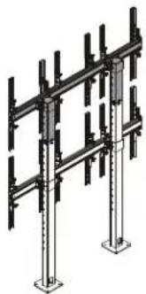
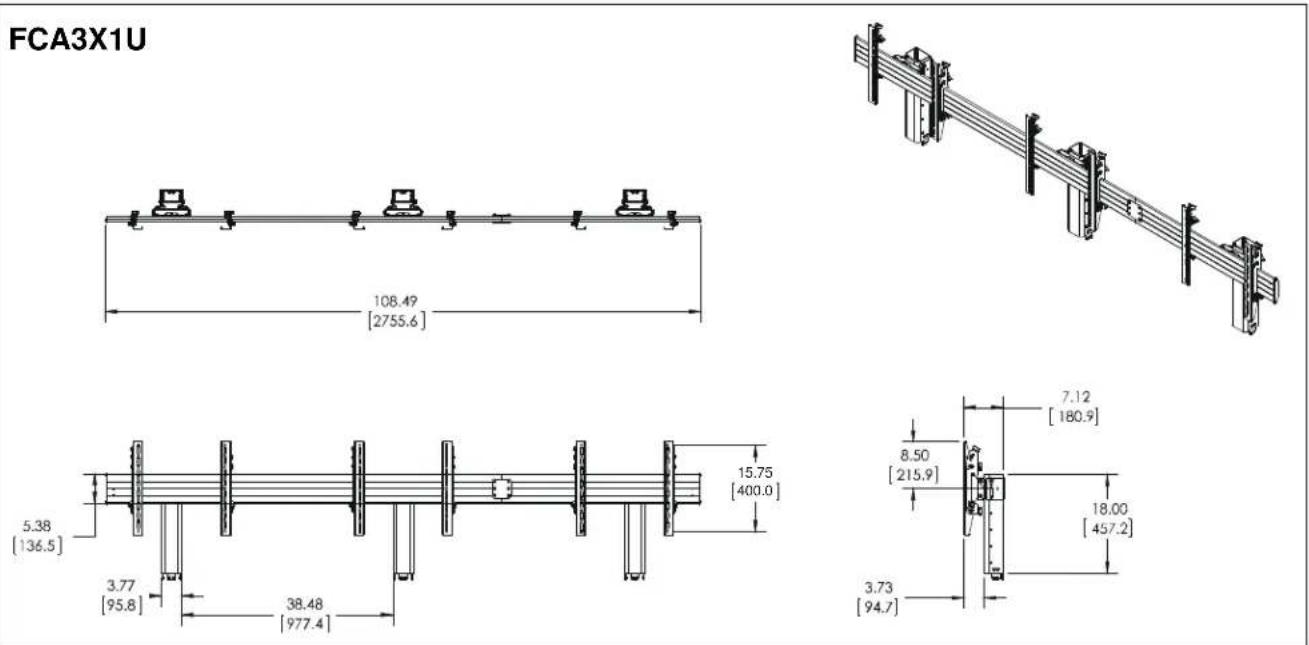
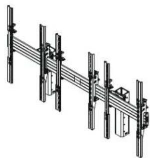
Isometric line drawing of a multi-tiered metal frame structure with support beams (no text or symbols)FCA3X1U
natural_image
Isometric diagram of a structural framework with vertical supports and two base platforms (no text or symbols)FCA3X1UP
Video Wall Add-On Accessories
DISCLAIMER
Milestone AV Technologies and its affiliated corporations and subsidiaries (collectively "Milestone"), intend to make this manual accurate and complete. However, Milestone makes no claim that the information contained herein covers all details, conditions or variations, nor does it provide for every possible contingency in connection with the installation or use of this product. The information contained in this document is subject to change without notice or obligation of any kind. Milestone makes no representation of warranty, expressed or implied, regarding the information contained herein. Milestone assumes no responsibility for accuracy, completeness or sufficiency of the information contained in this document.
Chief® is a registered trademark of Milestone AV Technologies. All rights reserved.

IMPORTANT SAFETY INSTRUCTIONS

WARNING: A WARNING alerts you to the possibility of serious injury or death if you do not follow the instructions.

CAUTION: A CAUTION alerts you to the possibility of damage or destruction of equipment if you do not follow the corresponding instructions.

WARNING: Failure to read, thoroughly understand, and follow all instructions can result in serious personal injury, damage to equipment, or voiding of factory warranty! It is the installer's responsibility to make sure all components are properly assembled and installed using the instructions provided.

WARNING: Failure to provide adequate structural strength for this component can result in serious personal injury or damage to equipment! It is the installer's responsibility to make sure the structure to which this component is attached can support five times the combined weight of all equipment. Reinforce the structure as required before installing the component.

WARNING: Do NOT stack multiple accessories on the same display cart! Do NOT connect accessories to carts that are already three display high. Display carts may NOT be stacked higher than three displays high! Portrait versions may NOT be stacked higher than two displays high!

WARNING: RISK OF SERIOUS INJURY OR DEATH! Placing a remote control or toy on the cart may encourage a child to climb onto the cart causing the cart to tip over onto the child. DO NOT place remote controls or toys on the cart!

WARNING: RISK OF SERIOUS INJURY OR DEATH! Relocating audio and/or video equipment to the cart may result in the cart collapsing or overturning onto a child. DO NOT relocate audio and/or video equipment to the cart!

WARNING: Exceeding the weight capacity can result in serious personal injury or damage to equipment! It is the installer's responsibility to make sure the combined weight of each display and attached accessories does not exceed the limits listed below.
| MODEL Max Weight Allowed for EACH Display | Total Max Weight Capacity of Mounting System w/ Accessory | |
| FCA2X1U with LVM2x2U | 100 lbs(45.4 kg) | 600 lbs(272.2 kg) |
| FCA3X1U with LVM3x2U | 100 lbs(45.4 kg) | 900 lbs(408.2 kg) |
| FCA3X1UP with LVM3x1UP | 100 lbs(45.4 kg) | 600 lbs(272.2 kg) |
| FCA2X1U with LBM2x2U | 125 lbs(56.7 kg) | 900 lbs(408.2 kg) |
| FCA3X1U with LBM3x2U | 125 lbs(56.7 kg) | 1125 lbs(510.3 kg) |
| FCA3X1UP with LBM3x1UP | 125 lbs(56.7 kg) | 900 lbs(408.2 kg) |
FCA2X1U with LVM2X2U
| 100 100 |
| 100100 |
| 100 100 |
FCA3X1U with LVM3X2U
| 100 | 100 | 100 |
| 100 | 100 | 100 |
| 100 | 100 | 100 |
FCA3X1UP with LVM3X1UP
| 100 | 100 | 100 |
| 100 | 100 | 100 |
FCA2X1U with LBM2X2U
| 125 | 125 |
| 125 | 125 |
| 125 | 125 |
FCA3X1U with LBM3X2U
| 125 | 125 | 125 |
| 125 | 125 | 125 |
| 125 | 125 | 125 |
FCA3X1UP with LBM3X1UP
| 125 | 125 | 125 |
| 125 | 125125 |

WARNING: RISK OF SERIOUS INJURY OR DEATH! Use with televisions weighing more than the maximum weight indicated may result in the cart collapsing or overturning onto a person causing serious injury or death!

WARNING: Do not use this product outdoors.
NOTE: The FCA2X1U, FCA3X1U and FCA3X1UP have no user serviceable parts.
NOTE: The UL Listed FCA add-on row may be used with the following UL Listed models: FCA2X1U may be used with LVM2X2U and LBM2X2U. FCA3X1U may be used with LVM3X2U and LBM3X2U. FCA3X1UP may be used with LVM3X1UP and LBM3X1UP.
NOTE: The UL listed FCA add-on row may be used with the UL Listed FCAX08, FCAX14 and FCAX20 horizontal extension brackets (not included).
--SAVE THESE INSTRUCTIONS--
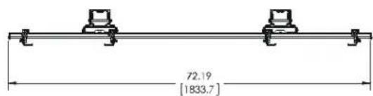
DIMENSIONS
FCA2X1U
text_image
72.19 [1833.7]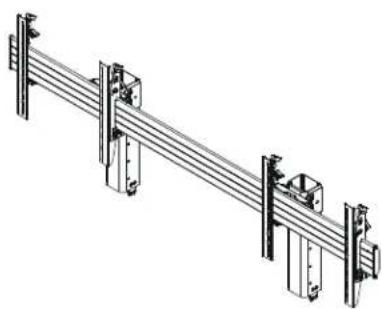
natural_image
Technical line drawing of a mechanical assembly with vertical supports and a central bracket (no text or symbols)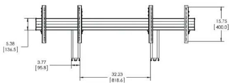
text_image
5.38 [136.5] 3.77 [95.8] 32.23 [818.6] 15.75 [400.0]
text_image
7.12 [180.9] 8.50 [215.9] 18.00 [457.2] 3.73 [94.7]DIMENSIONS (CONTINUED)
FCA3X1UP
MAX WEIGHT:
100 LBS PER DISPLAY
300 LBS TOTAL CAPACITY

natural_image
Technical line drawing of a mechanical or structural assembly with vertical supports and mounting brackets (no text or symbols)
text_image
68.00 [1727.2] 31.50 [800.0] MAX DISPLAY PATTERN HEIGHT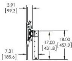
text_image
3.91 [99.3] 7.31 [185.6] 17.00 [431.8] 18.00 [457.2]LEGEND
 | Tighten Fastener |  | Pencil Mark |
| Apretar elemento de fijación | Marcar con lápiz | ||
| Befestigungsteil festziehen | Stiftmarkierung | ||
| Apertar fixador | Marcar com lápis | ||
| Serrare il fissaggio | Segno a matita | ||
| Bevestiging vastdraaien | Potloodmerkteken | ||
| Serrez les fixations | Marquage au crayon | ||
 | Loosen Fastener |  | Drill Hole |
| Aflojar elemento de fijación | Perforar | ||
| Befestigungsteil lösen | Bohrloch | ||
| Desapertar fixador | Fazer furo | ||
| Allentare il fissaggio | Praticare un foro | ||
| Bevestiging losdraaien | Gat boren | ||
| Desserrez les fixations | Percez un trou | ||
 | Phillips Screwdriver |  | Adjust |
| Destornillador Phillips | Ajustar | ||
| Kreuzschlitzschraubendreher | Einstellen | ||
| Chave de fendas Phillips | Ajustar | ||
| Cacciavite a stella | Regolare | ||
| Kruiskopschroevendraaier | Afstellen | ||
| Tournevis à pointe cruciforme | Ajuster | ||
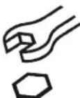 | Open-Ended Wrench |  | Remove |
| Llave de boca | Quitar | ||
| Gabelschlüssel | Entfernen | ||
| Chave de bocas | Remover | ||
| Chiave a punte aperte | Rimuovere | ||
| Steeksleutel | Verwijderen | ||
| Clé à fourche | Retirez | ||
 | By Hand |  | Optional |
| A mano | Opcional | ||
| Von Hand | Optional | ||
| Com a mão | Opcional | ||
| A mano | Opzionale | ||
| Met de hand | Optie | ||
| À la main | En option | ||
 | Hex-Head Wrench |  | Security Wrench |
| Llave de cabeza hexagonal | Llave de seguridad | ||
| Sechskantschlüssel | Sicherheitsschlüssel | ||
| Chave de cabeça sextavada | Chave de segurança | ||
| Chiave esagonale | Chiave di sicurezza | ||
| Zeskantsleutel | Veiligheidssleutel | ||
| Clé à tête hexagonale | Clé de sécurité |
TOOLS REQUIRED FOR INSTALLATION

text_image
1/2" (12.7mm) #2 3/16" (included with all) 1/8" (included with FCA3X1U) 5/32" (included with all)PARTS
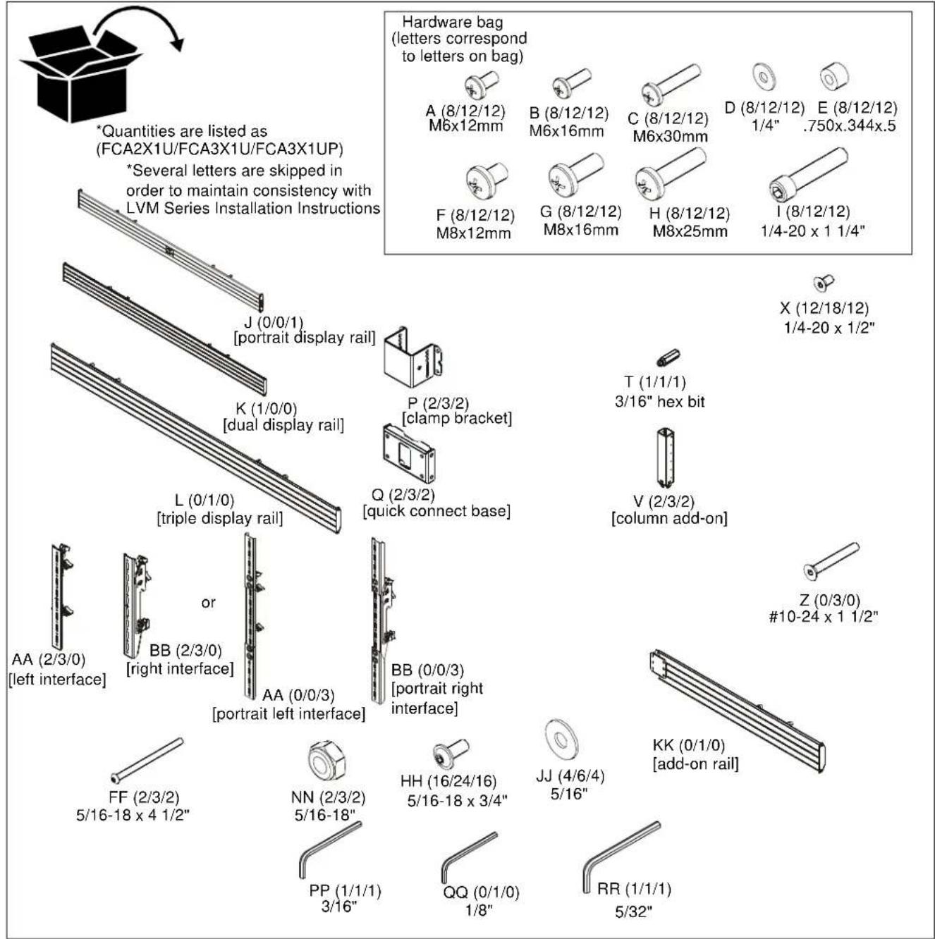
text_image
Hardware bag (letters correspond to letters on bag) *Quantities are listed as (FCA2X1U/FCA3X1U/FCA3X1UP) *Several letters are skipped in order to maintain consistency with LVM Series Installation Instructions A (8/12/12) M6x12mm B (8/12/12) M6x16mm C (8/12/12) M6x30mm D (8/12/12) 1/4" E (8/12/12) .750x.344x.5 F (8/12/12) M8x12mm G (8/12/12) M8x16mm H (8/12/12) M8x25mm I (8/12/12) 1/4-20 x 1 1/4" J (0/0/1) [portrait display rail] K (1/0/0) [dual display rail] L (0/1/0) [triple display rail] P (2/3/2) [clamp bracket] Q (2/3/2) [quick connect base] T (1/1/1) 3/16" hex bit V (2/3/2) [column add-on] X (12/18/12) 1/4-20 x 1/2" Z (0/3/0) #10-24 x 1 1/2" AA (2/3/0) [left interface] or BB (2/3/0) [right interface] AA (0/0/3) [portrait left interface] BB (0/0/3) [portrait right interface] FF (2/3/2) 5/16-18 x 4 1/2" NN (2/3/2) 5/16-18" PP (1/1/1) 3/16" HH (16/24/16) 5/16-18 x 3/4" JJ (4/6/4) 5/16" KK (0/1/0) [add-on rail] QQ (0/1/0) 1/8" RR (1/1/1) 5/32"Assembly And Installation
The following installation instructions assume that the LVM or LBM Series video wall has been assembled prior to the point of installing the rails to the columns. Refer to LVM or LBM Series installation instructions for details.
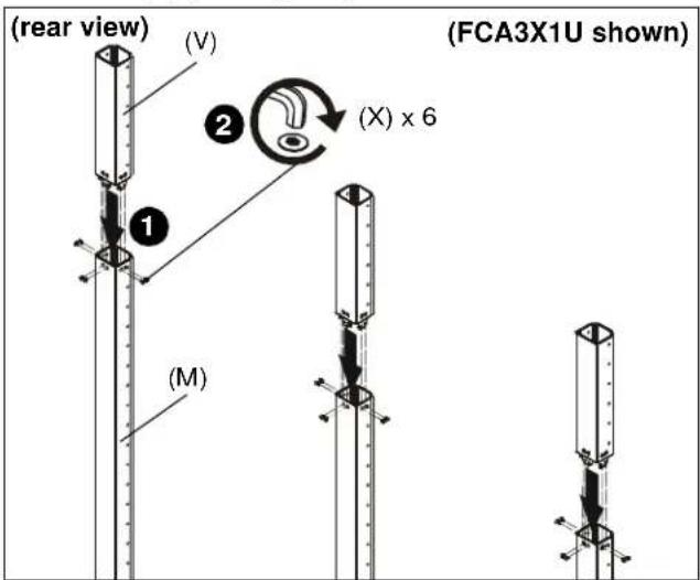
Column Add-On Installation
- Insert one column add-on (V) to each column (M) making sure holes are lined up on each side. (See Figure 1)
- Use 5/32" hex key (RR) and six 1/4-20 x 1/2" flat head cap screws (X) to secure each column add-on (V) to each column (M). (See Figure 1)
text_image
(rear view) (V) ② (X) x 6 (FCA3X1U shown) ① (M)Figure 1
Rails Installation
- Using display dimensions, determine where the center of the top displays will be on the cart.
IMPORTANT ! : Install all column add-ons (V), if applicable, prior to installing rails to columns.
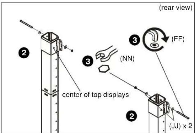
- Place clamp brackets (P) on column add-ons (V) in the position of where the center of the top displays will be on the cart with the diamond on the brackets being placed at the exact center location. (See Figure 2)
text_image
(rear view) (FF) (NN) center of top displays (JNJ) x 2Figure 2
- Use 5/16-18 x 4 1/2" button head cap screw (FF), two 5/16" washers (JJ) and 5/16-18" lock nut (NN) to secure each clamp bracket (P) to column. (See Figure 2)
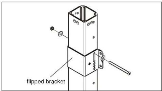
NOTE: Clamp brackets (P) may be flipped in order to use long slots for installation if necessary. (See Figure 3)
text_image
flipped bracketFigure 3
-
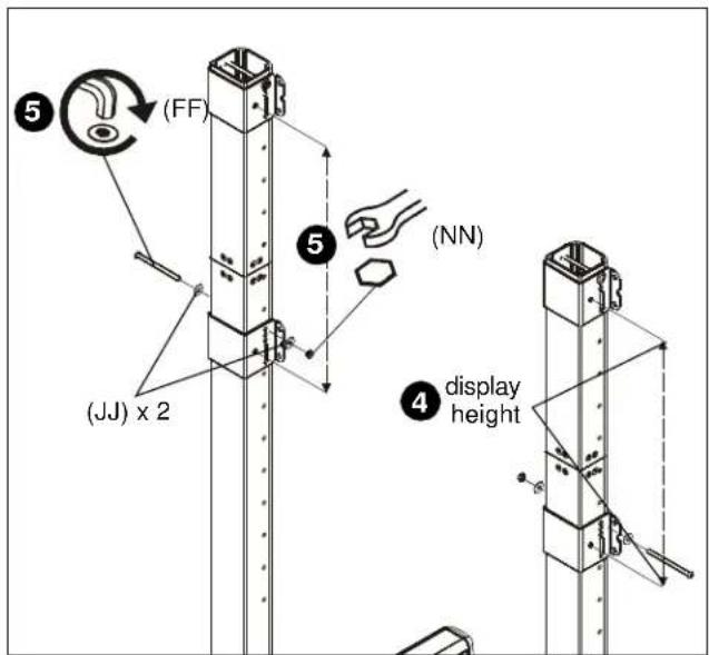
Measure one screen height down from center point on installed clamp brackets to determine mounting location of lower clamp brackets. (See Figure 4)
-
Use 5/16-18 x 4 1/2" button head cap screw (FF), two 5/16" washers (JJ) and 5/16-18" lock nut (NN) to install clamp brackets for lower displays with center diamond one screen height below center diamond of upper installed brackets. (See Figure 4)
NOTE: If some clearance is desired in between displays, install lower brackets slightly more than one screen height below upper brackets.
text_image
(FF) (JJ) x 2 (NN) 4 display heightFigure 4
- Use four 5/16-18 x 3/4" button head flange screws (HH) to secure each attached clamp bracket (P) to a quick connect base (Q). (See Figure 5)

text_image
(6) (HH) x 4 (Q) (P)Figure 5
NOTE: If rails must be installed over cable management holes on column, cables must be routed prior to installing rails onto quick connect bases. See Cable Management section for details.
7. Install two 5/16-18 x 3/4" button head flange screws (HH) into the top holes on each quick connect base (Q). (See Figure 6)

text_image
(K or L) (HH) x 2 (Q) 7 8Figure 6
8. Hang rails (J, K or L) into screws installed in previous step to quick connect bases (Q). (See Figure 6)
IMPORTANT ! : If installing the triple display rail (L), install rail to left and center columns so that add-on rail can be installed to right column. See Add-On Rail Installation section for details.
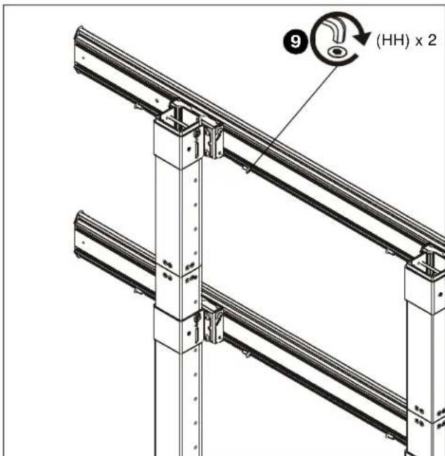
- Install two 5/16-18 x 3/4" button head flange screws (HH) into the lower holes on each quick connect base (Q) to secure rails to quick connect bases. (See Figure 7)
- Tighten all 5/16-18 x 3/4" button head flange screws (HH).
text_image
(HH) x 2Figure 7
Add-On Rail Installation (FCA3X1 only)
-
Install add-on rail (KK) to right column following instructions in Rails Installation section.
-
Use three #10-24 x 1 1/2" flat head cap screws (Z) to attach add-on rail (KK) to display rail (L). (See Figure 8)

text_image
(Z) x 3 (KK)Figure 8
Complete installation of displays following LVM or LBM Series installation instructions.
IMPORTANT ! : Install displays to lower rails prior to installing displays to upper rails. See LVM or LBM Series installation instructions for further details regarding acceptable and safe mounting orders.
FCA2X1U·FCA3X1U·FCA3X1UP
Installation Instructions