PPCU - Flat screen mount Chief - Free user manual and instructions
Find the device manual for free PPCU Chief in PDF.

User questions about PPCU Chief
0 question about this device. Answer the ones you know or ask your own.
Ask a new question about this device
Download the instructions for your Flat screen mount in PDF format for free! Find your manual PPCU - Chief and take your electronic device back in hand. On this page are published all the documents necessary for the use of your device. PPCU by Chief.
USER MANUAL PPCU Chief
INSTALLATION INSTRUCTIONS
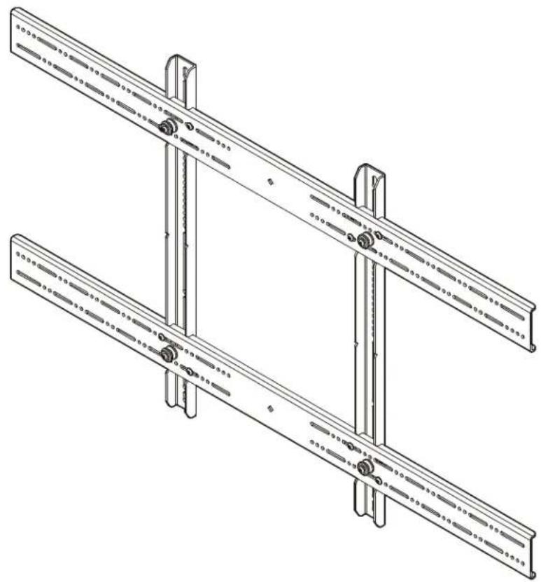
natural_image
Technical line drawing of a mechanical assembly with two parallel plates and mounting brackets (no text or symbols)Universal Large Interface Bracket
DISCLAIMER
Milestone AV Technologies, and its affiliated corporations and subsidiaries (collectively, "Milestone"), intend to make this manual accurate and complete. However, Milestone makes no claim that the information contained herein covers all details, conditions or variations, nor does it provide for every possible contingency in connection with the installation or use of this product. The information contained in this document is subject to change without notice or obligation of any kind. Milestone makes no representation of warranty, expressed or implied, regarding the information contained herein. Milestone assumes no responsibility for accuracy, completeness or sufficiency of the information contained in this document.
®Chief is a registered trademark of Milestone AV Technologies. All rights reserved.
DEFINITIONS
MOUNTING SYSTEM: A MOUNTING SYSTEM is the primary Chief product to which an accessory and/or component is attached.
ACCESSORY: AN ACCESSORY is the secondary Chief product which is attached to a primary Chief product, and may have a component attached or setting on it.
COMPONENT: A COMPONENT is an audiovisual item designed to be attached or resting on an accessory or mounting system such as a video camera, CPU, screen, display, projector, etc.

WARNING: A WARNING alerts you to the possibility of serious injury or death if you do not follow the instructions.

CAUTION: A CAUTION alerts you to the possibility of damage or destruction of equipment if you do not follow the corresponding instructions.

IMPORTANT SAFETY INSTRUCTIONS!

WARNING: Failure to read, thoroughly understand, and follow all instructions can result in serious personal injury, damage to equipment, or voiding of factory warranty! It is the installer's responsibility to make sure all accessories are properly assembled and installed using the instructions provided.

WARNING: Failure to provide adequate structural strength for this accessory can result in serious personal injury or damage to equipment! It is the installer's responsibility to make sure the structure to which this accessory is attached can support five times the combined weight of all equipment. Reinforce the structure as required before installing the accessory.

WARNING: Exceeding the weight capacity can result in serious personal injury or damage to equipment! It is the installer's responsibility to make sure the combined weight of all components attached to the PSBU does not exceed 200 lbs (90.7 kg).

WARNING: Use this accessory only for its intended use as described in these instructions. Do not use attachments not recommended by the manufacturer.

WARNING: Never operate this accessory if it is damaged. Return the accessory to a service center for examination and repair.

WARNING: Do not use this product outdoors.
IMPORTANT ! : The PSBU interface brackets are designed to be mounted to a UL-Listed Chief large flat panel mount:
- PCM2000 large single ceiling mount with angled column
• PCS2000 large single ceiling mount
• PDC2000 large dual ceiling mount
• PNRIW Series large in-wall swing arm wall mount
--SAVE THESE INSTRUCTIONS--
DIMENSIONS

text_image
RJ10000000000000000000000000000000000000000000000000000000000000000000 RJ100000000000000000000000000000000000000 RJ1545 DEPTH TO MOUNT [1.4] [2.3] C.I. OF MOUNTING PATTERN [1.4] [2.3] [3.3] [4.3] [5.3] [6.3] [7.3] [8.3] [9.3] [10.3] [11.3] [12.3] [13.3] [14.3] [15.3] [16.3] [17.3] [18.3] [19.3] [20.3] [21.3] [22.3] [23.3] [24.3] [25.3] [26.3] [27.3] [28.3] [29.3] [30.3] [31.3] [32.3] [33.3] [34.3] [35.3] [36.3] [37.3] [38.3] [39.3] [40.3] [41.3] [42.3] [43.3] [44.3] [45.3] [46.3] [47.3] [48.3] [49.3] [50.3] [51.3] [52.3] [53.3] [54.3] [55.3] [56.3] [57.3] [58.3] [59.3] [60.3] [61.3] [62.3] [63.3] [64.3] [65.3] [66.3] [67.3] [68.3] [69.3] [70.3] [71.3] [72.3] [73.3] [74.3] [75.3] [76.3] [77.3] [78.3] [79.3] [80.3] [81.3] [82.3] [83.3] [84.3] [85.3] [86.3] [87.3] [88.3] [89.3] [90.3] [91.3] [92.3] [93.3] [94.3] [95.3] [96.3] [97.3] [98.3] [99.3] [100.3]LEGEND
| Tighten Fastener | Philips Screwdriver Destornillador Philips Kreuzschlitzschraubendeher Chave de fendas Philips Cacciavite a stella Kruiskopschroevendraaier Taumevis à pointe cruciforme Oreepna |
| Apretar elemento de fijación | |
| Befestigungsteil lesziehen | |
| Apertar fixador | |
| Serrare il fissaggio | |
| Bevestiging vas idraaien | |
| Serrez les fixations | |
| Coximire 3acrekxy | |
| Loosen Fastener | Hex-Head Wrench Llave de cabeza hexagonal |
| Aflazar elemento de fijación |
TOOLS REQUIRED FOR INSTALLATION


PARTS

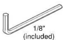
text_image
R (2) [Vertical bracket] Q (2) [Horizontal bracket]Hardware Kit
Bag A Bag B A (4)M4 x 12mm A (4)M4 x 12mm |  B (4)M4 x 20mm B (4)M4 x 20mm | Bag C C (4)M4 x 25mm C (4)M4 x 25mm |
Bag D D (4)M5 x 12mm D (4)M5 x 12mm | Bag E E (4)M5 x 20mm E (4)M5 x 20mm | Bag F F (4)M5 x 25mm F (4)M5 x 25mm |
Bag G G (4)M6 G (4)M6  nm M6 x 20ml nm M6 x 20ml | Bag H H (4) H (4) | Bag I I (4) I (4) ?5mm ?5mm |
Bag J ·)M8 x 12mm M8 x 20mm ·)M8 x 12mm M8 x 20mm | Bag K (4) (4) | Bag L - (4)M8 x 30mm - (4)M8 x 30mm |
Bag M  MA (8)[Nesting spacer] MB (4)[Universal spacer] MA (8)[Nesting spacer] MB (4)[Universal spacer] | ||
M

N (8)
10-24 x 1/2"

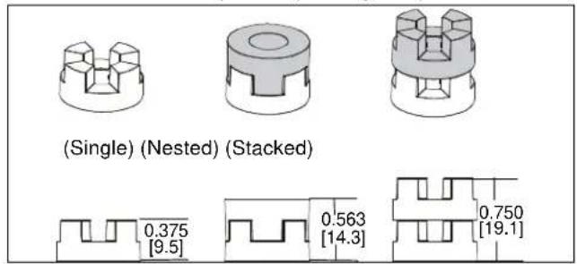
P (1)
1/8"
INSTALLATION

WARNING: IMPROPER INSTALLATION CAN LEAD TO MOUNT FALLING CAUSING SERIOUS PERSONAL INJURY OR DAMAGE TO EQUIPMENT! DO NOT substitute hardware. Only use hardware provided or specified by manufacturer.
- Determine and mark the vertical center position between the Left side Upper and Lower mounting holes in display. (See Figure 1)
- Determine and mark the vertical center position between the Right side Upper and Lower mounting holes in display. (See Figure 1)

text_image
(R) x 2 Mounting holes 1 2 3 4 5 ① Mounting Slots 1 2 3 4 5 ④Figure 1
- Orient vertical mounting bracket (R) so that mounting holes are on top and mounting slots are on bottom. (See Figure 1)
- Align mounting holes in vertical mounting bracket (R) with upper and lower mounting holes in display.
- Adjust vertical mounting bracket (R) position until mark made in Step 1 aligns with center mark in vertical mounting bracket (R).
- Select correct screws, nesting spacers (if necessary) and universal washers (if required) from the hardware bag (A-M) and attach brackets to back of screen. (See Figure 3)
IMPORTANT ! : The M8 screws do NOT require a washer. Use the universal washer (MB) only with M4, M5 and M6 screws.
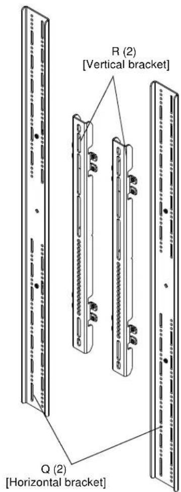
NOTE: The nesting spacers (MA) may be used separately, or put two together in different configurations to create different size spacers. (See Figure 2)
text_image
(Single) (Nested) (Stacked) 0.375 [9.5] 0.563 [14.3] 0.750 [19.1]Figure 2
- If the display has a recessed mounting surface, protrusions or a power box, a spacer and longer mounting hardware must be placed between the display and vertical mounting bracket (R). (See Figure 3)
- Repeat Steps 3 through 6 for Right side vertical mounting bracket using the same hole locations to align brackets horizontally.

text_image
(MA) x 4 (MB) x 4 (R) (A through L) x 4 (R) x 2 6 8Figure 3
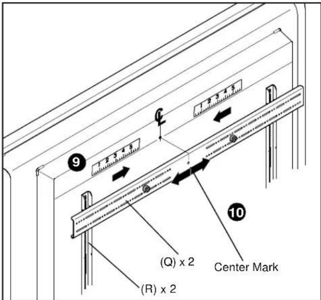
- Determine and mark the horizontal center position between the Left and Right TOP mounting holes in display. (See Figure 4)
- Determine and mark the horizontal center position between the Left and Right BOTTOM mounting holes in display. (See Figure 4)
- Orient upper horizontal mounting bracket (Q) so that flanges are facing towards display and resting in recessed area of left and right vertical mounting brackets (R). (See Figure 4)
- Adjust Upper horizontal mounting bracket (Q) position until center diamond in horizontal mounting bracket (U) aligns with mark made in Step 9, and mounting holes and slots in horizontal mounting bracket (Q) are aligned with threaded holes in mounting tabs of left and right vertical mounting brackets (R). (See Figure 4) and (See Figure 5)
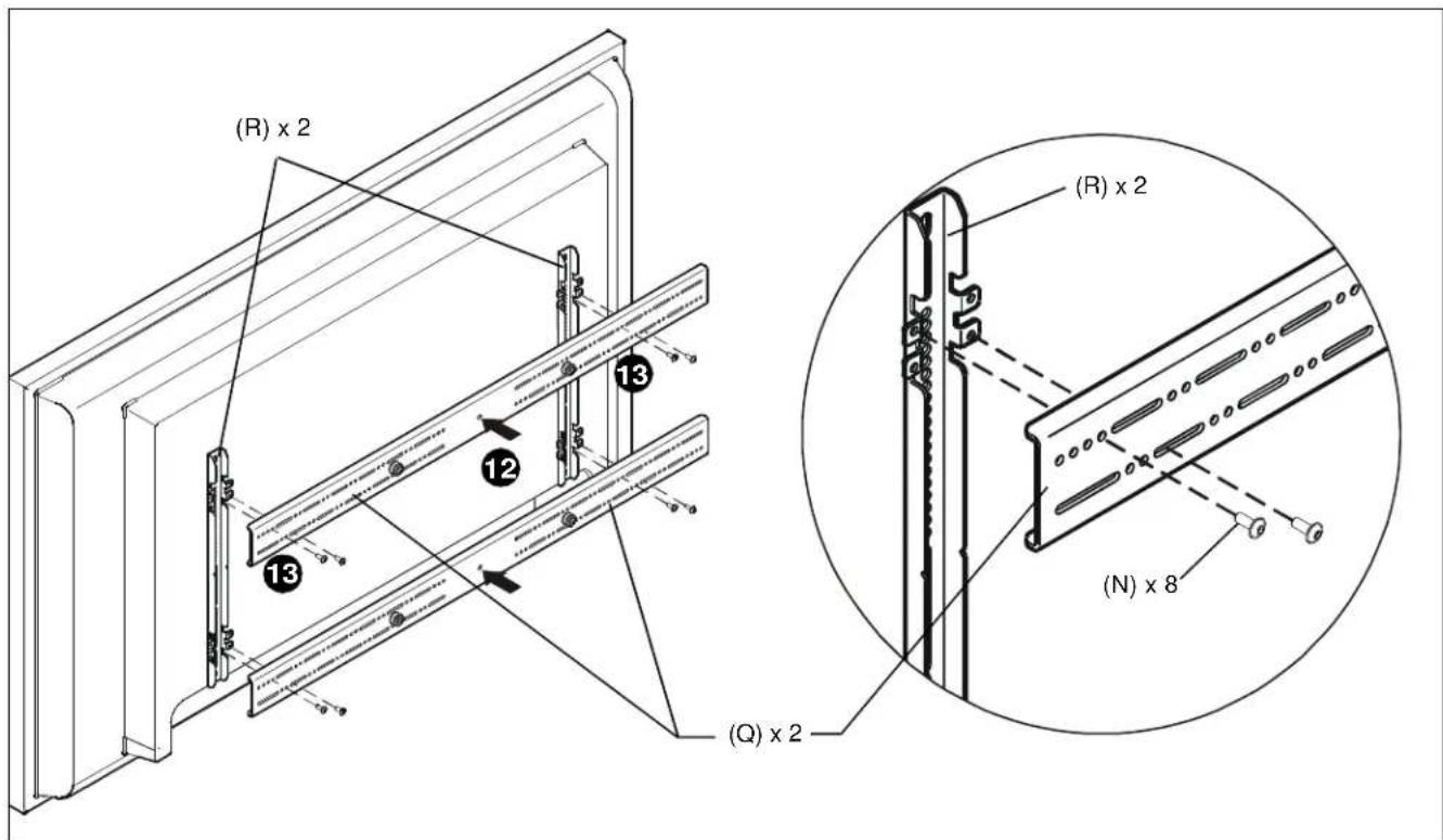
- Use 1/8" hex key (P) to secure upper horizontal mounting bracket (Q) to left and right vertical mounting brackets (R) using four button head flanged screws (N). (See Figure 5)
- Repeat Steps 10 through 13 for lower horizontal mounting bracket (Q).
IMPORTANT ! : The orientation of, and mounting holes used, when installing the lower horizontal mounting bracket must be the same as the upper horizontal mounting bracket. Vertically align upper and lower brackets by aligning holes or end of slots. (See Figure 5)
IMPORTANT ! : Whenever possible install mounting screws diagonally as shown in detail in Figure 4 below.
- Install display with attached universal interface to mount following the installation instructions provided with the mount.
text_image
1.3 3.4 5 9 1.2 3.4 5 (Q) x 2 (R) x 2 Center Mark 10Figure 4
text_image
(R) x 2 13 12 13 (Q) x 2 (R) x 2 (N) x 8Figure 5