HCP-850 - PC Power Supply ANTEC - Free user manual and instructions
Find the device manual for free HCP-850 ANTEC in PDF.

User questions about HCP-850 ANTEC
0 question about this device. Answer the ones you know or ask your own.
Ask a new question about this device
Download the instructions for your PC Power Supply in PDF format for free! Find your manual HCP-850 - ANTEC and take your electronic device back in hand. On this page are published all the documents necessary for the use of your device. HCP-850 by ANTEC.
USER MANUAL HCP-850 ANTEC
text_image
Antec® 850W CONTINUOUS POWER HIGH CURRENT PRO%CP-850 POWER SUPPLY
USER'S MANUAL
USER'S MANUAL
HIGH CURRENT PRO SERIES
HCP-850 POWER SUPPLY
RAW POWER MEETS UNRIVATED PERFORMANCE
Antec's HCP-850 unifies raw power with advanced PSU engineering to meet the demands of high performing PCs. A full-featured, 80 PLUS® Gold-certified unit, the HCP-850 is capable of outputting 99 percent of its rated power on four +12V rails, ensuring CPU and graphics card compatibility. Exclusive to the High Current series, HCP-850 boasts High Current heavy-gauge 16 AWG wiring that boosts conductivity, increasing efficiency and improving power delivery. In addition, a double-layer PCB, onboard DC-to-DC converters and Active Power Factor Correction (PFC) provide substantial voltage stability. To tackle the needs of your system, pick up Antec's HCP-850.
STANDARDS AND FEATURES
The connectors and power specifications of the HCP-850 PSU are all compatible with ATX12V v2.3 and EPS12V v2.92 specifications. The HCP-850 features Universal Input, which automatically senses when you connect the power supply to any AC power source between 100 - 240V without setting a voltage switch. This power supply also features Active Power Factor Correction (PFC), which improves the power factor value of the power supply by altering the input current wave shape, helping to power transmission across the grid.
SYSTEM PROTECTION
A variety of industrial-grade safety circuitry will help protect your computer: Over Current Protection (OCP), Over Voltage Protection (OVP), Short Circuit Protection (SCP), Over Power Protection (OPP) and Over Temperature Protection (OTP). Sometimes the PSU will "latch" into a protected state. You will need to power off the PSU and clear the fault before it will function again. There are no user-replaceable fuses in your HCP-850.
SPECIAL × UIET COMPUTING™ PULSE WIDTH MODULATION (PWM) FAN
A PWM fan can spin much more slowly and be quieter than a voltage-controlled fan. The PSU uses a PWM fan that can spin as slow as 260 RPM or as fast as 2600 RPM, depending on load and ambient temperature. The PSU will vary the fan speed depending on the load of your computer and should be nearly inaudible when your computer is idling. The location of the PSU fan also helps to reduce the sound emitted by your computer.
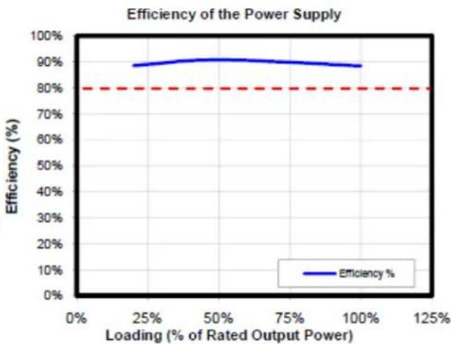
80 PLUS® CERTIFICATION
80 PLUS® certification is the most widely recognized independent standard in power supply efficiency. An 80 PLUS® certified power supply uses less energy and generates less heat to stay cooler, run quieter and last longer. The HCP-850 has been 80 PLUS® Gold certified to be at least 87% efficient at a wide range of operating loads; this will lower your operating costs and help protect the environment.
NVIDIA™ SLI™-R EADY CERTIFIED
Antec's HCP-850 is NVIDIA™ SLI™-Ready and ATI CrossFireX™ certified for use with multiple high-end graphics cards for superior parallel graphics processing.
POWER OUTPUT
The HCP-850 power supply distributes power on separate rails. To see the output capacity and regulation for each different voltage, see Table 1.
TABLE 1
| Output Voltage Load Max. Regulation Ripple & Noise | |||
| +3.3V 25A ±3% < 50 mV | |||
| +5V 25A ±3% < 50 mV | |||
| +12V1 | 40A ±3% | < 120 | mV |
| +12V2 | 40A ±3% | < 120 | mV |
| +12V3 | 40A ±3% | < 120 | mV |
| +12V4 | 40A ±3% | < 120 | mV |
| -12V 0.5A ±6% | < 120 mV | ||
| +5VSB | 4A | ±3% < 50 | mV |
line
| Loading (% of Rated Output Power) | Efficiency (%) | | --------------------------------- | -------------- | | 0% | 80% | | 25% | 85% | | 50% | 90% | | 75% | 88% | | 100% | 86% |INTELLIGENT HYBRID CABLE MANAGEMENT
The HCP-850 uses Intelligent Hybrid Cable Management. Cables that are important or mandatory are permanently connected to the PSU for the highest quality power delivery. There are modular jacks on the back of the PSU to add additional cables as needed. Using only the cables you need will reduce clutter and improve airflow inside your case. For the list of connected and optional cables, see Table 3.
MODULAR CABLE ±AC
There are three 5-pin black jacks and five 10-pin red jacks on the back of your HCP-850 PSU. These jacks are for the optional cables that come with your power supply. A modular 10-pin connector system allows you plug 5-pin connectors into the 10-pin jacks if you run out of 5-pin jacks.
+12 VOLT RAIL DISTRIBUTION
The HCP-850 uses four separate +12 volt power rails. Different connectors are hooked up to separate circuits to aid in the balanced distribution of power between devices in your computer. The +12V rails have been assigned to different connectors, as shown in Table 2, to prevent voltage sags in one device due to sudden demands for power by another device.
TABLE 2
Direct Cabling +12V Rail 24(20 + 4)-pin Motherboard 1 8(4 + 4)-pin ATX12V/EPS12V 2 8(6 + 2)-pin PCI-E 3
TABLE 3
Cable Quantity Power Connectors Part Name Description N/A 
Power supply direct cabling 1  x 3
x 3Molex connector w/cable 1 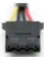 x 3
x 3 x 1
x 1Molex connector + floppy connector 3  x 3
x 3Serial ATA connector w/cable 2 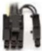 x 2
x 2PCI-Express connector w/cable
INSTALLATION :
1. Install the HCP-850 PSU into either the top or bottom of your case with the four screws provided. Refer to your case manual if you are unsure where the power supply should be installed.

natural_image
Technical line drawing of a server rack with internal components and mounting bracket (no text or symbols)
2. Install the HCP-850 PSU into your case with the four screws provided.
3. Connect the 24-pin main power connector to your motherboard. If your motherboard uses a 20-pin connector, detach the 4-pin attachment on the 24-pin connector.
Note: The detachable 4-pin section cannot be used in place of a 4-pin +12V connector.

natural_image
Illustration of industrial components including a conveyor belt, flasks, and a factory block (no text or symbols)
4. Connect the 8-pin or 4+4-pin connector for the CPU. If your motherboard has an 8-pin socket with a cover on some of the openings, we recommend that you remove the cover and use the 8-pin connector.
Note: Please also refer to your motherboard user's manual for any special instructions.

natural_image
Abstract 3D illustration of industrial machinery components with no visible text or symbols

natural_image
Abstract 3D illustration of industrial machinery and storage units (no text or symbols)
5. Connect extra cables from the cable pack to the sockets on the power supply only if needed. If you are going to plug the PCI-E cables into the PSU, they should go into the red sockets. If the red sockets are not being used for PCI-E, then they can be used for any other type of cable supplied in the pack that accompanies the PSU.

text_image
12V3/PCI8/HDD
12V4/PCI8/HDD
12V1/HDD
12V1/HDD
12V1/HDD
12V2/CPU8HDD
6. Connect the AC power cord to the power supply AC inlet. Be sure to use the heavy-duty cord supplied with your %CP-850.

natural_image
Pure electrical circuit lines without any symbols
7. PCI- E graphics cards use different amounts of power. For some, a single 6-pin connector is sufficient, making the hardwired connector the preferred choice. More powerful cards use multiple connectors, including the advanced 8-pin PCI-E connector. The 8-pin PCI-E connector on the %CP-850 can be used as either a 6- or 8-pin connector.
8. %ard drives, optical drives (CD/DVD/BluRay™) and other accessories will use either the older 4-pin Molex connector or the newer 15-pin SATA connector. 4-pin Molex connectors have two black, one yellow and one red wire. The SATA connector has an additional orange power wire.
9. When you have all the connections secured, turn the switch on the PSU to the “|” position.
Antec, Inc.
47900 Fremont Blvd.
Fremont, CA 94538
tel: 510-770-1200
fax: 510-770-1288
Antec Europe B.V.
Stuttgartstraat 12
3047 A Rotterdam
Netherlands
tel: +31 (0) 10 462-2060
fax: +31 (0) 10 437-1752
Technical Support:
US & Canada
1-800-22ANTEC
customersupport@antec.com
Europe
+31 (0) 10 462-2060
europe.techsupport@antec.com
www.antec.com
© Copyright 2010 Antec, Inc. All rights reserved.
All trademarks are the property of their respective owners.
Reproduction in whole or in part without written permission is prohibited.
+12 VOLT RAIL DISTRIBUTION
The HCP-850 uses four separate +12 volt power rails. Different connectors are hooked up to separate circuits to aid in the balanced distribution of power between devices in your computer. The +12V rails have been assigned to different connectors, as shown in Table 2, to prevent voltage sags in one device due to sudden demands for power by another device. TABLE 2| Direct Cabling +12V Rail | |
| 24(20 + 4)-pin Motherboard | 1 |
| 8(4 + 4)-pin ATX12V/EPS12V | 2 |
| 8(6 + 2)-pin PCI-E 3 | |
| Cable Quantity | Power Connectors | Part Name Description |
| N/A | | Power supply direct cabling |
| 1 | x 3 | Molex connector w/cable |
| 1 | x 3 x 1 | Molex connector + floppy connector |
| 3 | x 3 | Serial ATA connector w/cable |
| 2 | x 2 | PCI-Express connector w/cable |