MD50B2 - Outboard motor Tohatsu - Free user manual and instructions
Find the device manual for free MD50B2 Tohatsu in PDF.

User questions about MD50B2 Tohatsu
0 question about this device. Answer the ones you know or ask your own.
Ask a new question about this device
Download the instructions for your Outboard motor in PDF format for free! Find your manual MD50B2 - Tohatsu and take your electronic device back in hand. On this page are published all the documents necessary for the use of your device. MD50B2 by Tohatsu.
USER MANUAL MD50B2 Tohatsu
natural_image
Abstract black and gray logo design resembling a stylized 'V' within a circular frame (no text or symbols)TOHATSU
Feel the Wind™
Original instructions
MD 30B2 MD 40B2 MD 50B2 MD 75C2 MD 90C2 MD 115A2
OB No.003-11119-5AH1

text_image
BACKS YOU UP™
text_image
TOHATSU CORPORATIONENOM00001-0

READ THIS MANUAL BEFORE USING THE OUTBOARD MOTOR. FAILURE TO FOLLOW THE INSTRUCTIONS AND SAFETY PRECAUTIONS IN THIS MANUAL CAN RESULT IN SERIOUS INJURY OR DEAT MANUAL IN A SAFE LOCATION FOR FUTURE REFERENCE.
Copyright © 2018 Tohatsu Corporation. All rights reserved. No part of this manual may be reproduced or transmitted in any from or by any means without the express written permission of Tohatsu Corporation.
To You, Our Customer
Thank you for selecting a TOHATSU outboard motor. You are now the proud owner of an excellent outboard motor that will service you for many years to come.
This manual should be read in its entirety and the inspection and maintenance procedures described later in this manual should be followed carefully. Should a problem arise with the outboard motor, please follow the troubleshooting procedures listed at the end of this manual. If the problem persists, contact an authorized TOHATSU service shop or dealer.
All information in this manual is based on the latest product information available at the time of approval for printing.
Tohatsu Corporation reserves the right to make changes at any time without notice and without incurring any obligation.
Please always keep this manual together with the outboard motor as a reference to everyone who uses the outboard motor. If the outboard motor is resold, make sure the manual is passed on to the next owner.
We hope you will enjoy your outboard motor and wish you good luck in your boating adventures.
TOHATSU CORPORATION
ENOM00113-0
EC DECLARATION OF CONFORMITY (DoC)
This product conforms to certain portion of the European Parliament directive. DoC contains the following information;
● Name and Address of the manufacturer.
● Applied community directives
• Reference standard
● Description of the product. (Model name and serial number)
● Signature of the responsible person (Name / Title / Date and place of issue).
ENOM00002-0
OWNER REGISTRATION AND IDENTIFICATION
Upon purchasing this product, be sure that the WARRANTY CARD is correctly and completely filled out and mailed to the addressee noted there on. This WARRANTY CARD identifies you as the legal owner of the product and serves as your warranty registration.
TO THE EXTENT PERMITTED BY APPLICABLE LAW, YOUR OUTBOARD MOTOR WILL NOT BE COVERED BY THE APPLICABLE LIMITED WARRANTY, IF THIS PROCEDURE IS NOT FOLLOWED.
ENOM00003-0
PRE-DELIVERY CHECK
Be sure that the product has been checked by an authorized TOHATSU dealer before you take delivery.
ENOM00005-A
Serial Number
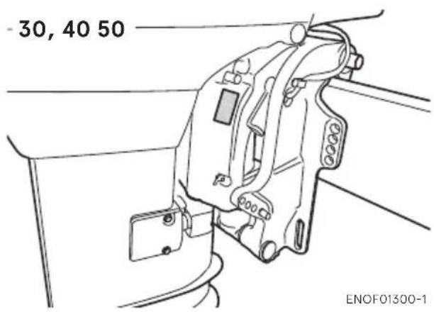
In the space below, please record the outboard motor's serial number (indicated both on the bottom cowl and on the cylinder block). The serial number will be needed when ordering parts, and when making technical or warranty inquiries.
Serial Number:
text_image
- 30, 40 50 ENOF01300-1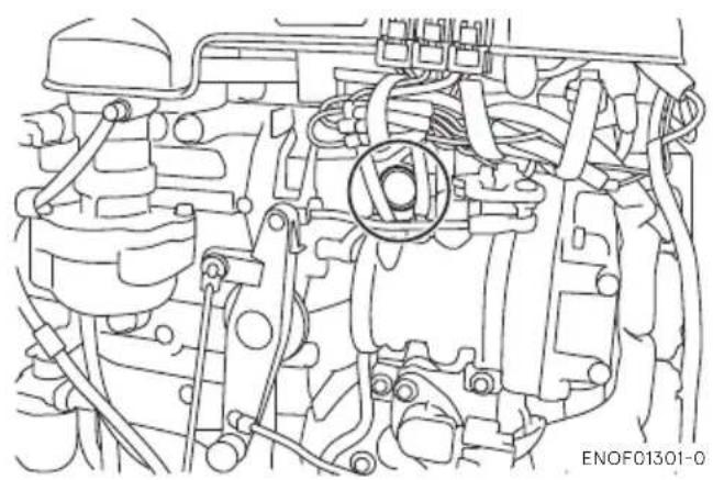
natural_image
Technical line drawing of an internal combustion engine assembly (no text or labels)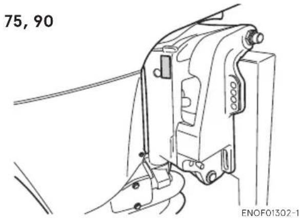
text_image
75, 90 ENOF01302-1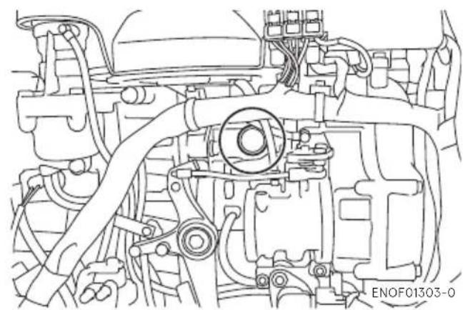
natural_image
Technical line drawing of an engine bay with hoses and components (no text or symbols)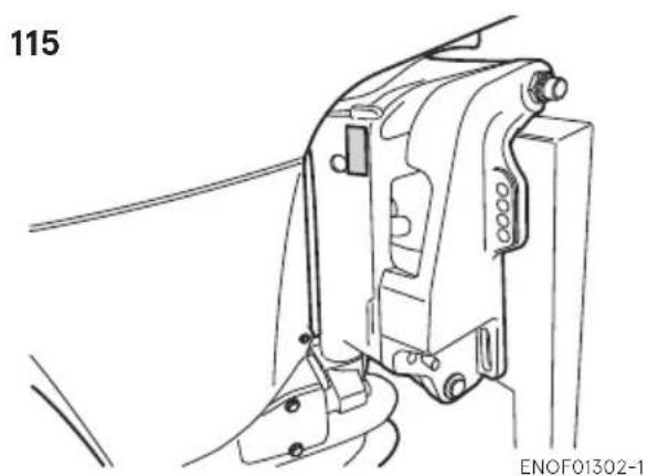
natural_image
Technical line drawing of a mechanical assembly with no visible text or symbols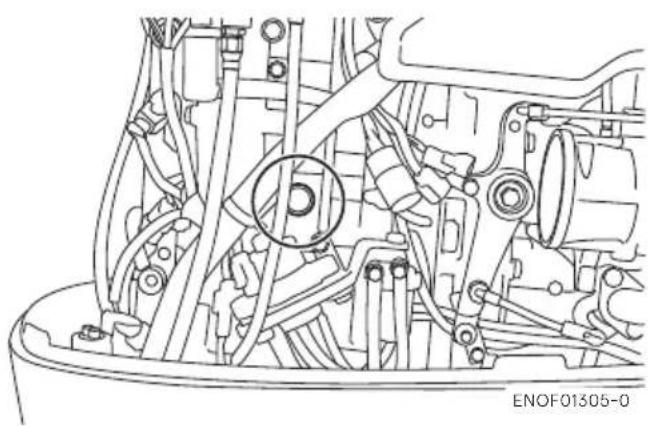
natural_image
Technical line drawing of an engine bay with visible internal components and a circular component (no text or symbols)Serial Number:
Date of purchase:
ENOM00007-0
NOTICE: DANGER/WARNING/CAUTION/Note
Before installing, operating or otherwise handling your outboard motor, be sure to thoroughly read and understand this Owner's Manual and carefully follow all of the instructions. Of particular importance is information preceded by the words "DANGER," "WARNING," "CAUTION," and "Note." Always pay special attention to such information to ensure safe operation of the outboard motor at all times.
ENOW00001-0

DANGER
Failure to observe will result in severe personal injury or death, and possibly property damage.
ENOW00002-0

WARNING
Failure to observe could result in severe personal injury or death, or property damage.
ENOW00003-0

CAUTION
Failure to observe could result in personal injury or property damage.
ENON00001-0
Note
This instruction provides special information to facilitate the use or maintenance of the outboard motor or to clarify important points.
CONTENTS
- GENERAL SAFETY INFORMATION....10
- SPECIFICATIONS 12
- PARTS NAME 18
- LABEL LOCATIONS 23
-
INSTALLATION 27
-
Mounting the outboard motor on boat .....27
- Remote control device installation 30
- Battery installation....31
- Propeller installation 32
-
TOCS (Tohatsu Onboard Communication System) installation..... 34
-
PRE-OPERATING PREPARATIONS 35
-
Fuel handling 35
- Fuel filling 36
- Engine oil recommendation ..... 37
- Break-In 39
-
Warning system 40
-
ENGINE OPERATION 43
Before starting 43
- Engine oil feeding 43
- Fuel feeding 45
- Starting the engine 46
- Warming up the engine 52
- Forward, reverse, and acceleration 54
- Stopping the engine .....57
- Steering 60
8.Trim angle 60 -
Tilt up and down 62
10.Shallow water operation 65 -
REMOVING AND CARRYING THE OUTBOARD MOTOR.....67
-
Removing the outboard motor 67
- Carrying the outboard motor 67
-
Trailering 68
-
ADJUSTMENT....70
-
Steering friction 70
- Throttle grip friction 70
- Remote control lever friction 70
-
Trim tab adjustment 71
-
INSPECTION AND MAINTENANCE....72
-
Daily Inspection 73
- Periodic Inspection 79
- Off-season storage 91
- Pre-season check 94
-
Submerged outboard motor 94
-
Cold weather precautions.... 95
- Striking underwater object 95
-
Operation with multiple outboard motors 95
-
TROUBLESHOOTING 96
- ACCESSORIES KIT 98
- PROPELLER TABLE ..... 100
INDEX
- GENERAL SAFETY INFORMATION 1
- SPECIFICATIONS 2
- PARTS NAME 3
- LABEL LOCATIONS 4
- INSTALLATION 5
- PRE-OPERATING PREPARATIONS 6
- ENGINE OPERATION 7
- REMOVING AND CARRYING THE OUTBOARD MOTOR 8
- ADJUSTMENT 9
10.INSPECTION AND MAINTENANCE 10 - TROUBLESHOOTING 11
- ACCESSORIES KIT 12
- PROPELLER TABL 13
GENERAL SAFETY INFORMATION
1
ENOM00009-0
As the operator/driver of the boat, you are responsible for the safety of those aboard and those in other boat around yours, and for following local boating regulations. You should be thoroughly knowledgeable on how to correctly operate the boat, outboard motor, and accessories. To learn about the correct operation and maintenance of the outboard motor, please read through this manual carefully.
It is very difficult for a person standing or floating in the water to take evasive action should he or she see a power boat heading in his/her direction, even at a slow speed. Therefore, when your boat is in the immediate vicinity of people in the water, the outboard motor should be shifted to neutral and shut off.
ENOW00005-0

WARNING
SERIOUS INJURY IS LIKELY IF A PERSON IN THE WATER MAKES CONTACT WITH A MOVING BOAT, GEAR HOUSING, PROPELLER, OR ANY SOLID DEVICE RIGIDLY ATTACHED TO A BOAT OR GEAR HOUSING.
ENOM0008-A
EMERGENCY STOP SWITCH
The Emergency Stop Switch will stall the outboard motor when the stop switch lanyard is pulled off. This stop switch lanyard has to be attached to the operator of the outboard motor to minimize or prevent injuries from the propeller in case the operator falls overboard.
It is operator's responsibility to use the Emergency Stop Switch Lanyard.
ENOW00004-A

WARNING
Accidental activation of the Emergency Stop Switch (such as the tether being pulled out in heavy seas) could cause passengers to lose their balance and even fall overboard, or it could result in loss of power in heavy seas, strong currents, or high winds. Loss of control while mooring is another potential hazard.
To minimize accidental activation of the Emergency Stop Switch, the 500 mm (20 inch.) stop switch lanyard is coiled and can extended to a full 1300 mm (51 inch.).
ENOM00800-A
PERSONAL FLOATATION DEVICE
As the operator/driver and passenger of the boat, you are responsible to wear a PFD (Personal Flotation Device) while on the boat.
ENOM00010-0
SERVICING, REPLACEMENT PARTS & LUBRICANTS
1
We recommend that only an authorized service shop perform service or maintenance on this outboard motor. Be sure to use genuine parts, genuine lubricants, or recommended lubricants.
ENOM00011-A
MAINTENANCE
As the owner of this outboard motor, you should be acquainted with correct maintenance procedures following maintenance section of this manual (See page 68). It is the operator's responsibility to perform all safety checks and to ensure that all lubrication and maintenance instructions are complied with for safe operation. Please comply with all instructions concerning lubrication and maintenance. You should take the engine to an authorized dealer or service shop for periodic inspection at the prescribed intervals.
Correct periodic maintenance and proper care of this outboard motor will reduce the chance of problems and limit overall operating expenses.
Carbon Monoxide Poisoning Hazard
Exhaust gas contains carbon monoxide, a colorless and odorless gas which can be fatal if inhaled for any length of time.
Never start or operate the engine indoors or in any space which is not well ventilated.
Gasoline
Gasoline and its vapors are very flammable and can be explosive. Use extreme care when handling gasoline. You should be thoroughly knowledgeable on how to correctly handle gasoline by reading this manual.
SPECIFICATIONS
ENOM00810-A
MODEL FEATURE
| Model D30B2 D40B2 D50B2 | ||||||
| Type ETO ETO EO ETO EO | ||||||
| Transom heights | S ● ● | ● ● ● | ||||
| L ● ● | ● ● ● | |||||
| Electrical start ● ● ● ● ● | ||||||
| Multi-function tiller handle | *1 | *1 | *1 | *1 | *1 | |
| Remote Control ● ● ● ● ● | ||||||
| Power Trim & Tilt | ● ● | ● | ||||
| Manual tilt | ● | ● | ||||
*1 Option.
| Model | D75C2 | D90C2 | |
| Type | EPTO | EPTO | |
| Transom heights | L ● ● | ||
| UL | ● ● | ||
| Electrical start ● ● | |||
| Remote Control ● ● | |||
| Power Trim & Tilt | ● ● | ||
| Oil auto-mixing | ● ● | ||
| Model | D115A2 | |
| Type | EPTO | |
| Transom heights | L● | |
| UL | ● | |
| Electrical start ● | ||
| Remote Control ● | ||
| Power Trim & Tilt | ● | |
| Oil auto-mixing | ● | |
MODEL NAME EXAMPLE
D115A2 EPTOL
| D | 115 | A2 | E | P | T | O | L |
| Model description | Horse power | Product generation | Starter system | Steering system | Tilt system | Lubrication system | Shaft length |
| F= Four stroke D= Two stroke DI | - | A and up | E= Electrical start M= Manual start | P=Remote control (Pleasure) F=Tiller handle (Fisher) *Multi-function tiller handle is available as an optional part | T= Power trim&tilt G= Gas assist Blank= Manual tilt | O= Oil auto-mixing Blank= Oil Pre-mix-ing | S= Short 15 in L= Long 20 in UL= Ultra long 25 in |
30B2 (Available in specific region), 40B2
| Item MODEL | 30B2 40B2 | ||
| EPTO | |||
| Overall Length mm (in) 630 (24.8) | |||
| Overall Width mm (in) 355 (14.0) | |||
| Overall Height S·L mm (in) 1227 (48.3) 1354 (53.3) | |||
| Transom Height S·L mm (in) 403 (15.9) 530 (20.9) | |||
| Weight | S kg (lb) 93.5 (206) | ||
| L kg (lb) 94.5 (208) | |||
| Output kW (ps) 22.1 (30) | 29.4 (40) | ||
| Max. Operating Range min-1(rpm) | 4750-5750 5150-5850 | ||
| Idle Speed min-1(rpm) | 700/800/900-1 | ||
| Engine Type | Direct fuel injection | ||
| Number of Cylinder | 3 | ||
| Bore × Stroke mm (in) | 68 × 64 (2.68 × 2.52) | ||
| Piston Displacement cm3(Cu in) 697 (42.5) | |||
| Exhaust System | Through hub exhaust | ||
| Cooling System | Water cooling | ||
| Engine Lubrication | Oil injection | ||
| Starting System | Electric starter motor | ||
| Ignition System | Inductive Ignition | ||
| Spark Plug | NGK IZFR6Q | ||
| Alternator | 12 V, 280 W (Max.) | ||
| Trim Position | 4 | ||
| Engine Oil | Genuine Motor Oil or recommended one | ||
| Gear Oil | Genuine Gear Oil or API GL5, SAE #80 to #90, approx. 500 mL | ||
| Fuel Tank Capacity L (US gal) | 25 (6.6) | ||
| Engine Oil Capacity L (US gal) | Approx. 2.0 (0.53) | ||
| Gear Reduction Ratio | 1.85 (13 : 24) | ||
| Fuel | Unleaded Regular Gasoline: R+M/2: 87 or higher RON: 91 or higher | ||
| Emission Control System | DFI (Direct Fuel Injection) | ||
| Operator Sound Pressure (ICOMIA 39/94) dB (A) | 84.0 | ||
| Hand Vibration Level (ICOMIA 38/94) m/s2 | — | ||
Remark: Specifications subject to change without notice.
*1: The idling speed can be set to any of the three rpm ranges, 700, 800 or 900. (See page 53)
Tohatsu outboard is power rated in accordance with ISO8665 (propeller shaft output).
ENOM00601-1
40B2
| Item MODEL | 40B2 | |||
| EPTO(with multi-func-tion tiller handle*option) | EPO(with multi-func-tion tiller handle*option) | EPO | ||
| Overall Length mm (in) 775 (30.5) 630 (24.8) | ||||
| Overall Width mm (in) 355 (14.0) 345 (13.6) | ||||
| Overall Height S·L mm (in) 1227 (48.3) 1354 (53.3) | ||||
| Transom Height S·L mm (in) 403 (15.9) 530 (20.9) | ||||
| Weight | S kg (lb) 97.5 (215) | 89.5 (197) 85.5 (188) | ||
| L kg (lb) 98.5 (217) | 90.5 (200) 86.5 (191) | |||
| Output kW (ps) | 29.4 (40) | |||
| Max. Operating Range min-1(rpm) | 5150-5850 | |||
| Idle Speed min-1(rpm) | 700/800/900-1 | |||
| Engine Type | Direct fuel injection | |||
| Number of Cylinder | 3 | |||
| Bore × Stroke mm (in) | 68 × 64 (2.68 × 2.52) | |||
| Piston Displacement cm3(Cu in) | 697 (42.5) | |||
| Exhaust System | Through hub exhaust | |||
| Cooling System | Water cooling | |||
| Engine Lubrication | Oil injection | |||
| Starting System | Electric starter motor | |||
| Ignition System | Inductive Ignition | |||
| Spark Plug | NGK IZFR6Q | |||
| Alternator | 12 V, 280 W (Max.) | |||
| Trim Position | 4 | 6 | ||
| Engine Oil | Genuine Motor Oil or recommended one | |||
| Gear Oil | Genuine Gear Oil or API GL5, SAE #80 to #90, approx. 500 mL | |||
| Fuel Tank Capacity L (US gal) | 25 (6.6) | |||
| Engine Oil Capacity L (US gal) | Approx. 2.0 (0.53) | |||
| Gear Reduction Ratio | 1.85 (13 : 24) | |||
| Fuel | Unleaded Regular Gasoline: R+M/2: 87 or higher RON: 91 or higher | |||
| Emission Control System | DFI (Direct Fuel Injection) | |||
| Operator Sound Pressure(ICOMIA 39/94) dB (A) | 84.0 | |||
| Hand Vibration Level(ICOMIA 38/94) m/s2 | 3.8 | - | ||
Remark: Specifications subject to change without notice.
*1: The idling speed can be set to any of the three rpm ranges, 700, 800 or 900. (See page 53)
Tohatsu outboard is power rated in accordance with ISO8665 (propeller shaft output).
ENOM00602-0
50B2
| Item MODEL | 50B2 | ||
| EPTO | EPTO(with multi-function tiller handle *option) | ||
| Overall Length mm (in) 630 (24.8) 775 (30.5) | |||
| Overall Width mm (in) 355 (14.0) | |||
| Overall Height S·L mm (in) 1227 (48.3) 1354 (53.3) | |||
| Transom Height S·L mm (in) 403 (15.9) 530 (20.9) | |||
| Weight | S kg (lb) | 93.5 (206) 97.5 (215) | |
| L kg (lb) | 94.5 (208) | 98.5 (217) | |
| Output kW (ps) | 36.8 (50) | ||
| Max. Operating Range min-1(rpm) | 5150-5850 | ||
| Idle Speed min-1(rpm) | 700/800/900*1 | ||
| Engine Type | Direct fuel injection | ||
| Number of Cylinder | 3 | ||
| Bore × Stroke mm (in) | 68 × 64 (2.68 × 2.52) | ||
| Piston Displacement cm3(Cu in) 697 (42.5) | |||
| Exhaust System | Through hub exhaust | ||
| Cooling System | Water cooling | ||
| Engine Lubrication | Oil injection | ||
| Starting System | Electric starter motor | ||
| Ignition System | Inductive Ignition | ||
| Spark Plug | NGK IZFR6Q | ||
| Alternator | 12 V, 280 W (Max.) | ||
| Trim Position | 4 | ||
| Engine Oil | Genuine Motor Oil or recommended one | ||
| Gear Oil | Genuine Gear Oil or API GL5, SAE #80 to #90, approx. 500 mL | ||
| Fuel Tank Capacity L (US gal) | 25 (6.6) | ||
| Engine Oil Capacity L (US gal) | Approx. 2.0 (0.53) | ||
| Gear Reduction Ratio | 1.85 (13 : 24) | ||
| Fuel | Unleaded Regular Gasoline: R+M/2: 87 or higher RON: 91 or higher | ||
| Emission Control System | DFI (Direct Fuel Injection) | ||
| Operator Sound Pressure (ICOMIA 39/94) dB (A) | 84.0 | ||
| Hand Vibration Level (ICOMIA 38/94) m/s2 | - | 3.8 | |
Remark: Specifications subject to change without notice.
*1: The idling speed can be set to any of the three rpm ranges, 700, 800 or 900. (See page 53)
Tohatsu outboard is power rated in accordance with ISO8665 (propeller shaft output).
ENOM00604-0
75C2, 90C2

| Item MODEL | 75C2 90C2 | |
| EPTO | ||
| Overall Length mm (in) 810 (31.9) | ||
| Overall Width mm (in) 508 (20.0) | ||
| Overall Height L·UL mm (in) 1540 (60.6) | 1667 (65.6) | |
| Transom Height L·UL mm (in) 517 (20.4) | 644 (25.4) | |
| Weight L·UL kg (lb) | 150 (331) 153 (337) | |
| Output kW (ps) | 55.2 (75) | 66.2 (90) |
| Max. Operating Range min-1(rpm) | 5150-5850 | |
| Idle Speed min-1(rpm) | 700/800/900 | *1 |
| Engine Type | Direct fuel injection | |
| Number of Cylinder | 3 | |
| Bore × Stroke mm (in) 86 × 72.7 (3.39 × 2 | 86) | |
| Piston Displacement cm3(Cu in) | 1267 | |
| Exhaust System | Through hub exhaust | |
| Cooling System | Water cooling | |
| Engine Lubrication | Oil injection | |
| Starting System | Electric starter motor | |
| Ignition System | Inductive Ignition | |
| Spark Plug | NGK IZFR6Q | |
| Alternator | 12 V, 490 W (Max.) | |
| Trim Position | 2 | |
| Engine Oil | Genuine Motor Oil or recommended one | |
| Gear Oil | Genuine Gear Oil or API GL5, SAE #80 to #90, approx. 900 mL | |
| Fuel Tank Capacity L (US gal) | - | |
| Engine Oil Capacity L (US gal) | Approx. 4 (1.06) | |
| Gear Reduction Ratio | 2.33 (12:28) | |
| Fuel | Unleaded Regular Gasoline : R+M/2: 87 or higher RON: 91 or higher | |
| Emission Control System | DFI (Direct Fuel Injection) | |
| Operator Sound Pressure (ICOMIA 39/94) dB (A) | 81.7 | |
| Hand Vibration Level (ICOMIA 38/94) m/s2 | - | |
Remark: Specifications subject to change without notice.
*1: The idling speed can be set to any of the three rpm ranges, 700, 800 or 900. (See page 53)
Tohatsu outboard is power rated in accordance with ISO8665 (propeller shaft output).
115A2
| Item MODEL | 115A2 |
| EPTO | |
| Overall Length mm (in) 800 (31.5) | |
| Overall Width mm (in) 495 (19.5) | |
| Overall Height L-UL mm (in) 1640 (64.6) | 1767 (69.6) |
| Transom Height L-UL mm (in) 517 (20.4) | 644 (25.4) |
| Weight L-UL kg (lb) 178 (392) 181 (399) | |
| Output kW (ps) | 84.6 (115) |
| Max. Operating Range min ^-1 (rpm) | 5150-5850 |
| Idle Speed min ^-1 (rpm) | 700/800/900 ^-1 |
| Engine Type | Direct fuel injection |
| Number of Cylinder | 4 |
| Bore × Stroke mm (in) | 88 × 72.7 (3.46 × 2.86) |
| Piston Displacement cm ^3 (Cu in) | 1768 (107.9) |
| Exhaust System | Through hub exhaust |
| Cooling System | Water cooling |
| Engine Lubrication | Oil injection |
| Starting System | Electric starter motor |
| Ignition System | Inductive Ignition |
| Spark Plug | NGK IZFR5J |
| Alternator | 12 V, 490 W (Max.) |
| Trim Position | 2 |
| Engine Oil | Genuine Motor Oil or recommended one |
| Gear Oil | Genuine Gear Oil or API GL5, SAE #80 to #90, approx. 900 mL |
| Fuel Tank Capacity L (US gal) | — |
| Engine Oil Capacity L (US gal) | Approx. 6.7 (1.77) |
| Gear Reduction Ratio | 2.0 (13:26) |
| Fuel | Unleaded Regular Gasoline : R+M/2: 87 or higher RON: 91 or higher |
| Emission Control System | DFI (Direct Fuel Injection) |
| Operator Sound Pressure (ICOMIA 39/94) dB (A) | 83.3 |
| Hand Vibration Level (ICOMIA 38/94) m/s ^2 | — |
Remark: Specifications subject to change without notice.
*1: The idling speed can be set to any of the three rpm ranges, 700, 800 or 900. (See page 53)
Tohatsu outboard is power rated in accordance with ISO8665 (propeller shaft output).
ENOM00607-0
ETO (with multi-function tiller handle)/40B2, 50B2

text_image
Technical diagram of an electric motor with numbered parts for identification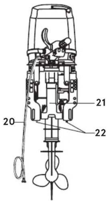
text_image
20 21 22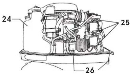
text_image
24 25 26ENOF01307-0
1 Tilt Handle
2 Top Cowl
3 Hook Lever
4 Water Check Port
5 Tilt Stopper
6 Water Plug
7 Anti-ventilation Plate
8 Trim Tab
9 Propeller
10 Oil Plug (lower)
11 Water Inlet
12 Oil Plug (upper)
13 Clamp Bracket
14 Thrust Rod
15 Throttle Grip
16 Shift Lever
17 Stop Switch
18 Pilot Lamp
19 Main Switch
20 Battery Cords
21 Power Trim & Tilt
22 Anode
23 Power Trim & Tilt Switch
24 Oil Tank
25 Spark Plug
26 Fuel Filter
ENOM00608-0
ETO (with RC)/30B2, 40B2, 50B2

text_image
1 2 3 4 5 6 7 8 9 10 11 12 13 14 15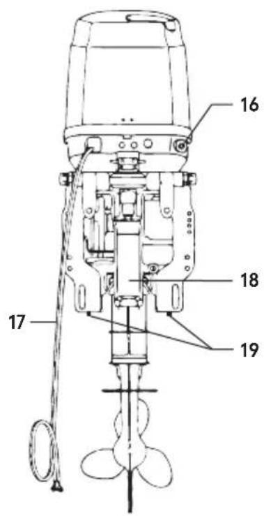
text_image
Technical diagram of an electric motor with numbered components labeled 16, 17, 18, and 19.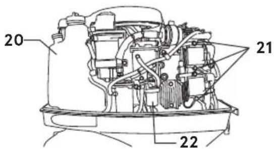
text_image
20 21 22ENOF01308-0
1 Tilt Handle
2 Top Cowl
3 Hook Lever
4 Water Check Port
5 Tilt Stopper
6 Water Plug
7 Anti-ventilation Plate
8 Trim Tab
9 Propeller
10 Oil Plug (lower)
11 Water Inlet
12 Oil Plug (upper)
13 Clamp Bracket
14 Thrust Rod
15 Power Trim & Tilt Switch
16 Fuel Connector
17 Battery Cords
18 Power Trim & Tilt
19 Anode
20 Oil Tank
21 Spark Plug
22 Fuel Filter
ENOM00609-0
EPTO/75C2, 90C2
3

text_image
Technical diagram of a boat's internal components with numbered parts for identification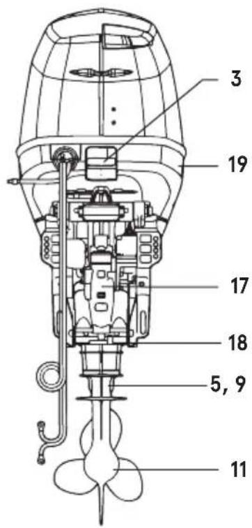
text_image
3 19 17 18 5, 9 11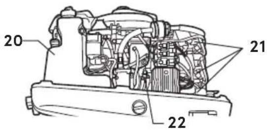
text_image
20 21 22ENOF01309-0
1 Tilt Handle
2 Top Cowl
3 Hook Lever
4 Water Check Port
5 Water Plug
6 Anti-ventilation Plate
7 Trim Tab
8 Propeller
9 Oil Plug (upper)
10 Water Inlet
11 Oil Plug (lower)
12 Clamp Bracket
13 Thrust Rod
14 Fuel Nipple
15 Power Trim & Tilt Switch
16 Battery Cords
17 Power Trim & Tilt
18 Anode
19 Flushing Connector Cap
20 Oil Tank
21 Spark Plug
22 Fuel Filter
EPTO/115A2

text_image
1 2 3 4 6 7 8 10 12 13 14 15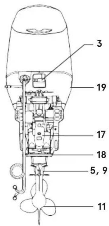
text_image
3 19 17 18 5, 9 11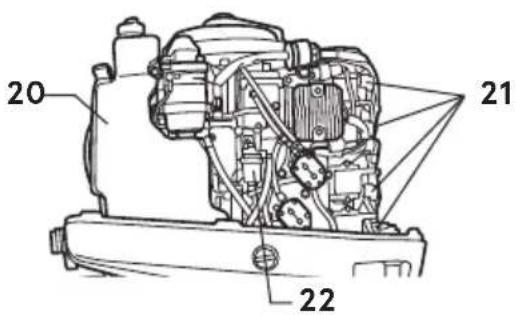
text_image
20 21 22ENOF01310-0
1 Tilt Handle
2 Top Cowl
3 Hook Lever
4 Water Check Port
5 Water Plug
6 Anti-ventilation Plate
7 Trim Tab
8 Propeller
9 Oil Plug (upper)
10 Water Inlet
11 Oil Plug (lower)
12 Clamp Bracket
13 Thrust Rod
14 Fuel Nipple
15 Power Trim & Tilt Switch
16 Battery Cords
17 Power Trim & Tilt
18 Anode
19 Flushing Connector Cap
20 Oil Tank
21 Spark Plug
22 Fuel Filter
ENOM00822-0
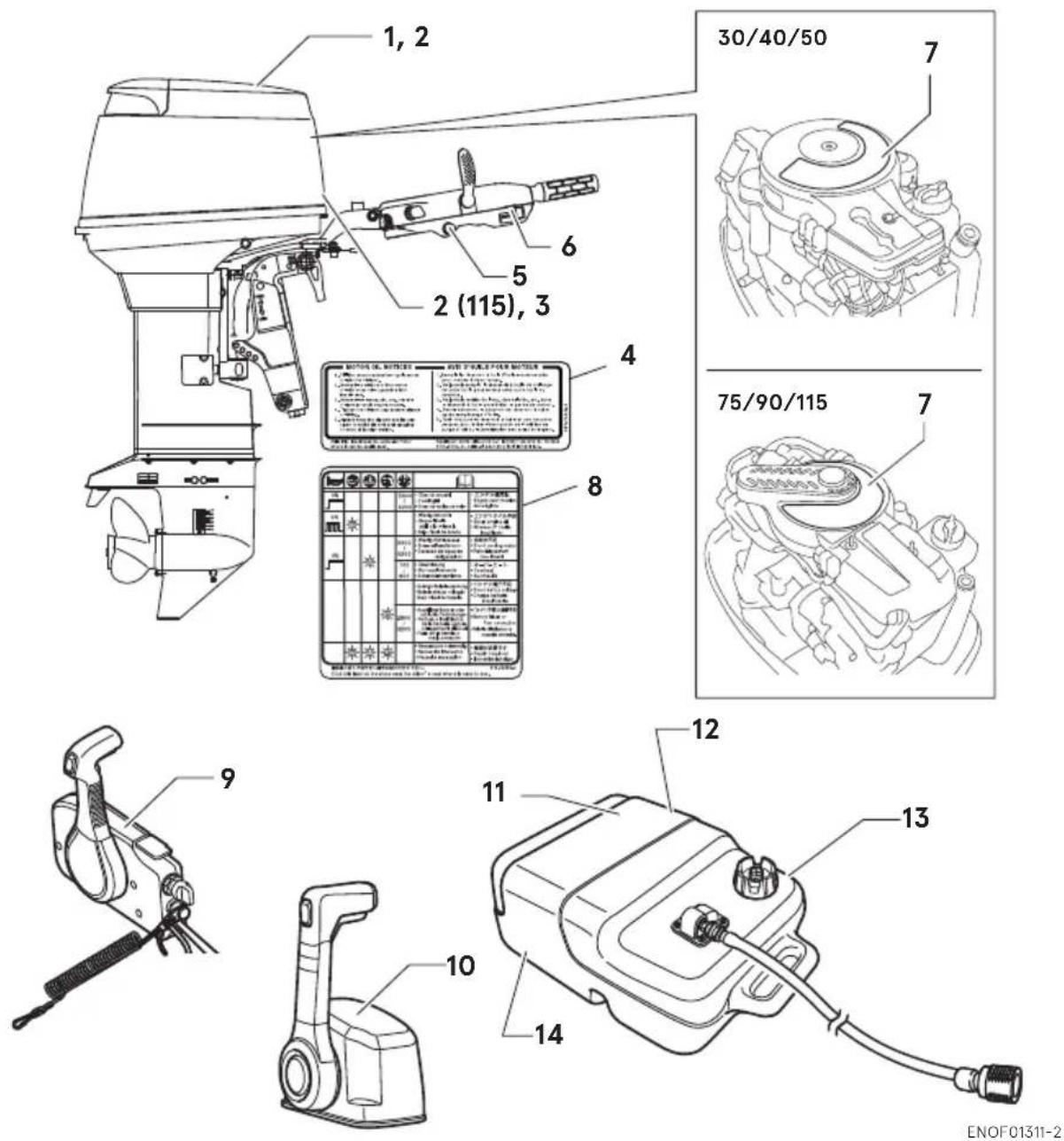
Remote control box & Fuel tank
3

text_image
Technical diagram of a device with numbered parts, including a cable, switch, and battery packENOF00127-H1
1 Control Lever
2 Neutral lock arm
3 PTT switch
4 Free throttle lever
5 Main switch
6 Stop switch
7 Stop switch lock
8 Stop switch lanyard
9 Control lever
10 Neutral lock arm
11 PTT switch
12 Neutral throttle button
13 Main switch
14 Stop switch
15 Stop switch lock
16 Stop switch lanyard
17 Fuel gauge
18 Air vent screw
19 Fuel tank cap
20 Fuel connector (Engine side)
21 Primer bulb
22 Fuel connector (Fuel tank side)
LABEL LOCATIONS
ENOM00019-A
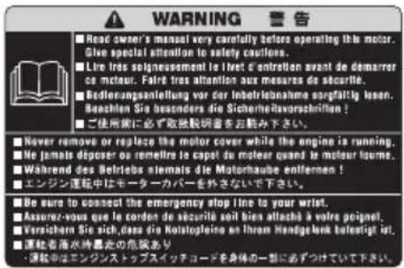
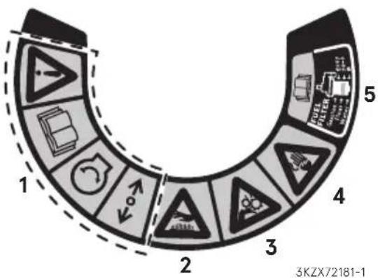
Warning label locations
- Warning label regarding owner's manual, top cowl, engine stop switch,
text_image
WARNING 警告 Read swor's manual very carefully before operating the motor. Give special attention to safety caufiers. Lire tres solnissement le livet d'entretten avant de demarrer ce moteur. Faire tres attention aux mesures de securite. Bedlerungsanteilung vor der inbetriebnahme sorgfaltig lesson. Beachten Sie besonders die Sicherheitsvorschriften! ■ ご使用のに必ず取扱説明書をお願い下さい。 Never remove or replace the motor cover while the engine is running. ■ Ne jamais deposer ou remettre le capel du moteur quand le moteur loure. ■ Während des Betriebs atemais die Motorhaube entfernen! ■ エンジン運転中はモーターカバーを外さないで下さい。 ■ Be sure to connect the emergency stop line to your wrist. ■ Asserez-vous que le corden de sécurité soit bien attaché à votre poignet. ■ Versichern Sie sich, dass die Kolatopleine an ihrem Handgelsenk belastigt ist. ■ 運転者落水時最危の危険あり • 運転中はエンジンストッズスイッチコードを身体的一部に必ずつけていて下さい.ENOF00005-W
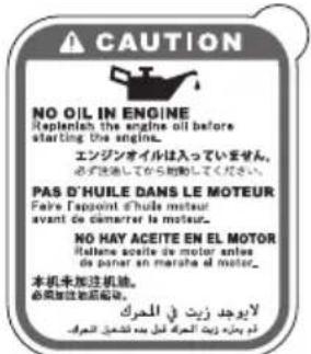
- Warning regarding engine oil replenishment. (See page 37, 40)
text_image
CAUTION NO OIL IN ENGINE Replenish the engine oil before starting the engine. エンジンオイルは入っていません。 必ず洗浄してから始動してください。 PAS D'HUILE DANS LE MOTEUR Fare l'appoint d'huile moteur avant de ciamnérer le moteur. NO HAY ACEITE EN EL MOTOR Haltene aceite de motor andes da panar en marate el motor. 本机未加注机油。 必須加注油氣輕載。 لايوجد زيتي في المحرك أم بحانه رويتى المحرك فلل بع تبانيات المحرك3T1-72043-0
- Warning label regarding installation of remote control system (See page 30).

ENOF00120-0
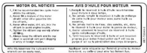
- Warning regarding engine oil replenishment (See page 37, 40).
Affix this label near the outboard motor where it can be easily read.
7-1. Warning regarding emergency starting (See 49).
7-2. Warning regarding high temperature.
7-3. Warning regarding rotating object.
7-4. Warning regarding high voltage.
7-5. Caution regarding fuel filter. (See page 58, 63, 67)
text_image
1 2 3 4 5 3KZX72181-1- Indicator label regarding engine failure/malfunction (See page 40). stick this label at pace near the driver's seat where is easy to see.

text_image
ON 5900 6200 • User de verzahl • Fusingell • Esoa de vallba de motor • エンジン満励電 • Engine over rotation • Sur-oligne • エンジンオイル不足 • Short engine oil • Novate d' bulke Insufficient ON 5900 6200 • Weng Kühwasser • Scave infestamente • Ecoastenz de agua de refrigeración • 常温水不足 • Short cooling water • Rehydration insufficient 700 800 • Overhizung • Suntopaldamente • Sotemcalentamente • オーバーヒート • Duvrust • Surchaffs • パッテリ電圧不足 • Short battery voltage • Charge batteries Insufficient 2800 3200 • Ausfallder Batter is oder schlechtus Verbindungen • Rottura e infeicenza della batteries appure • Biogomont diattrol • Fail en la batteria e mala congeneris • パッテリ不換で機器不足 • Battery holes or Pout connection Infera conductance or reversible connection. • Reparature notewendig • Necosalia intervento • Necosalia reparación • 機脂が必要です Stick this label at the piece near the driver's seat where is easy to see. STL:766543T5-72050-0
For RC model
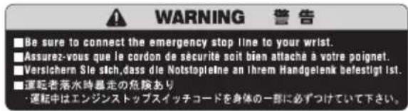
- Warning label on engine stop switch.
text_image
WARNING 警告 ■Be sure to connect the emergency stop line to your wrist. ■Assurez-vous que le cordon de sécurité soit bien attaché à votre poignet. ■Versichern Sie sich,dass die Notstopletne an ihrem Handgelenk befestigt ist. ■運転者落水時暴走の危険あり ・運転中はエンジンストップスイッチコードを身体の一部に必ずつけていて下さい。ENOF00008-0
For Top mount RC
- Warning label urge owner's manual.

ENOF00120-0
- Warning regarding gasoline.
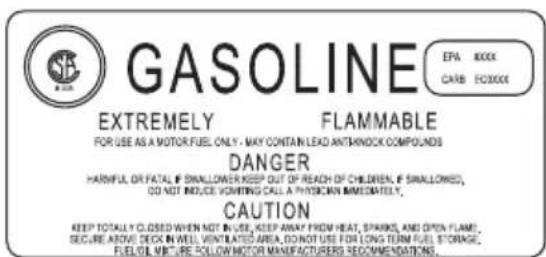
text_image
GASOLINE EPA BOX CARB 100000 EXTREMELY FLAMMABLE FOR USE AS A MOTOR FUEL ONLY - MAY CONTAIN LEAD ANTHROCK COMPOUNDS DANGER HARMFUL OR FATAL IF SMALLLOWER KEEP OUT OF REACH OF CHILDREN, IF SMALLOWNED, DO NOT INDUCE VOTING CALL A PHYSICIAN IMMEDIATELY. CAUTION KEEP TOTALLY CLOSED WHEN NOT IN USE, KEEP AWAY FROM HEAT, SPRAKS, AND OPEN FLAME, SECURE ABOVE DECK IN WELL, VENTILATED AREA, DO NOT USE FOR LONG TERM FUEL STORAGE, FUELLOT, VIRTURE FOLLOW MOTOR MANUFACTURERS RECOMMENDATIONS.ENOF00005-E
- Warning regarding gasoline (See page 35).

text_image
Safety warning symbols for fuel and flame hazard, including a gas pump icon and a triangular warning sign.ENOF00005-L
- Warning regarding gasoline (See page 35).

text_image
GASOLINE EXTREMELY FLAMMABLE REMOVE FROM BOAT FOR FILLING GASOLINA PELIGRO FLAMABLE QUITARLO DEL BARCO PARA PONER GASENOF00005-M
- Warning regarding gasoline (See page 35).

text_image
FLAMMABLE DANGEROUS GASOLINE REMOVE FROM BOAT FOR FILLING INFLAMMABLE DANGEREUX GAZOLINE SORTIR DU BATEAU POUR REFAIRÉ LE PLEIN D' ESSENCEENOF00005-F
ENOM00019-B
CE label locations

text_image
CE 0123 Ou board Motor a R Re vento : f : a $M Serial No. Made in a plan CAN ICES-2/NMB-2 1) 2) 3) 4) 5) 6)ENOF01312-1
- Model code(Model name)
- Rated power
- Dry mass weight( Without propeller, with battery cable)
- Serial No.
- Manufacturer name
- Manufacturer address
Description of serial number year code
Last two digits of alphabet represent production year as below.
| Year Code | AG | AH | AK | BX | BA |
| Year of manufacture | 2017 | 2018 | 2019 | 2020 | 2021 |
INSTALLATION
ENOM00024-A
1. Mounting the outboard motor on boat
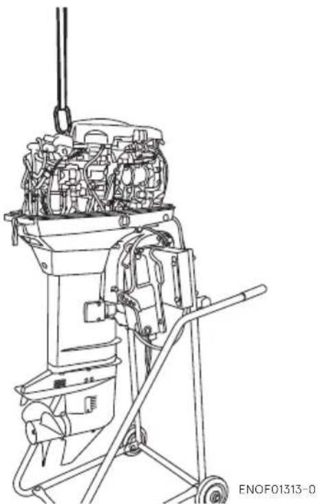
ENOW00006-B

WARNING
Before installing the outboard motor on the boat, hang the outboard motor with the hoist or equivalent device by attaching the engine hanger to the outboard. Use the hoist with allowable load is 250 kg (550 lbs) or above.
natural_image
Technical line drawing of a mechanical device with internal components and a lever mechanism (no text or symbols)ENOW00006-0

WARNING
Most boats are rated and certified in terms of their maximum allowable horsepower, as shown on the boat's certification plate. Do not equip your boat with an outboard motor that exceeds this limit. If in doubt, contact your dealer.
Do not operate the outboard motor until it has been securely mounted on the boat in accordance with the instructions below.
ENOW00009-0

WARNING
- Mounting the outboard motor without following this manual can lead to unsafe conditions such as poor maneuverability, lack of control or fire.
- Loose clamp screws and/or mounting bolts can lead to the release or displacement of the outboard motor, possibly resulting in lost of control and/or serious personal injury. Be sure that fasteners are tightened to the specified torque (30 N·m (3.0 kgf·m) 13 ft·lb). Check the fasteners for tightness from time to time.
- Be sure to use outboard mounting fasteners included in the outboard motor package or their equivalents in terms of size, material, quality and strength. Tighten fasteners to the specified torque (30 N·m (3.0 kgf·m) 13 ft·lb). Test cruise to check if fasteners are tightened securely.
- Outboard motor mounting must be performed by trained service person(s) using lift or hoist with sufficient capacity.
Outboard motor mounting must be performed by trained service person(s) using lift or hoist with sufficient capacity.
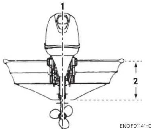
ENOM00025-0
Position ... Above keel line
Set engine at center of boat.
text_image
1 2 ENOF01141-0-
Center of boat
-
Boat transom
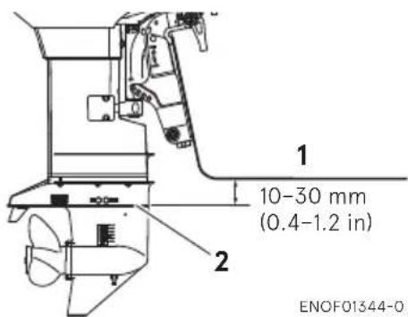
ENOM00026-0
Transom matching
Be sure that the anti ventilation plate of the outboard motor is 10–30 mm (0.4–1.2 in) below the bottom of hull.
If the above condition cannot be met due to the shape of the bottom of your boat, please consult your authorized dealer.
text_image
1 10-30 mm (0.4-1.2 in) 2 ENOF01344-0-
Bottom of hull
-
Anti ventilation plate
ENOW00007-0

CAUTION
- Before beginning the running test, check that the boat with maximum capacity loading floats on the water in a proper
attitude. Check the position of water surface on the driveshaft housing. If the water surface is near the bottom cowling, in high waves, water may enter the engine cylinders.
- Incorrect outboard motor mounting height or existence of underwater object(s), such as hull bottom design, bottom surface conditions or underwater accessories, can cause water spray possibly reaching the engine through an opening of the bottom cowling during cruising. Exposing the engine to such conditions for extended periods can lead to severe engine damage.
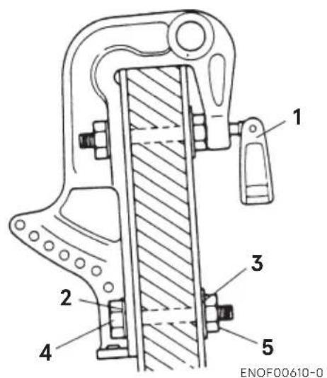
ENOM00830-B
Mounting bolts
Manual tilt type
40,50
- To attach the outboard motor to the boat, tighten the clamp screws by turning their handles.
Also, use the bolts to secure the outboard motor brackets on transom board.
Secure the outboard motor with a rope to prevent loss overboard.
ENON00002-0
Note
A rope is not included in the standard accessories.
text_image
1 2 3 4 5 ENOF00610-0- Clamp Screw
- Washer (small diameter)
- Washer (large diameter)
- Bolt (12 mm × length 105 mm)
- Nut

text_image
234 (9.21") 117 (4.61) 117 (4.61) 25 (0.98") 25 (0.98") ø13 204 (8.03") 102 (4.02"1)02 (4.02") ø13 39 (1.54") 64 (2.52") 89 (3.50") 222 (8.74") 248 19.76"26 (1.02") ENOF00611-0- Top of transom
ENOW00945-0

CAUTION
- Please inspect whether there is a loosening of the clamp screw or mounting bolts before departure.
- Loosening may cause a dangerous situation, such as loss of control.
Power trim and tilt type
- To attach the outboard motor to the boat, use the bolts to secure the outboard motor brackets on transom board.
30, 40, 50

text_image
1 2 3 4 ENOF00612-1- Washer (small diameter)
- Washer (large diameter)
- Bolt (12 mm × length 105 mm)
- Nut
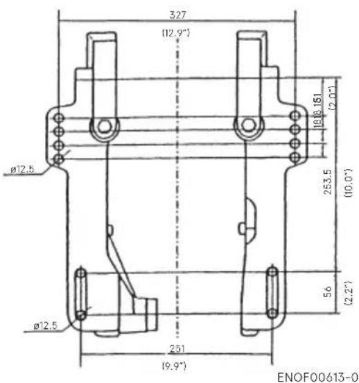
text_image
327 (12.9°) Ø12.5 Ø12.5 251 (9.9°) 253.5 (10.0°) 18Ø161 (2.0°) 56 (2.2°) ENOF00613-075, 90, 115
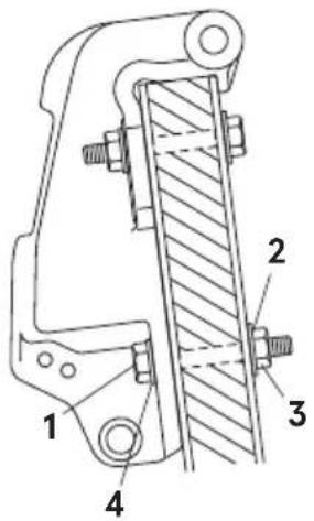
text_image
Technical diagram of a mechanical clamp or bracket assembly with numbered parts labeled 1, 2, 3, and 4.ENOF00614-0
- Bolt (12 mm × length 105 mm)
- Washer (large diameter)
- Nut
- Washer (small diameter)

text_image
327 (12.9") 1 51 (2") 17.5 (0.7") 17.5 (0.7") 17.5 (0.7") ø15 (0.5") 254 (10°) 56 (2.2") 251 (9.9") ENOF00615-0- Top of transom
ENOW00008-A

CAUTION
- Mounting bolts should be installed with the bolt head at inside surface of the transom. Mounting bolts installed with the threaded end at the inside surface of the transom can cause personal injury.
● Tighten the bolts sufficiency, otherwise falling down of outboard could be happened.
ENON00003-0
Notes
- Apply sealing agent, such as silicone sealed between the bolts and the transom board holes before tightening the bolts.
- Be sure to tighten the mounting bolt nuts to the specified torque. (30 N·m (3.0 kgf·m) 13 ft·lb)
ENOM00840-0
2. Remote control device installation
ENOW00850-0
Remote control box location

text_image
3 1, 2 ENOF00841-1- Shift cable
- Throttle cable
- Cable harness B
Install the remote control box in a position where it is easy to reach and operate the controls.
Make sure there are no obstacles that can interfere with the operation of the remote control cable.
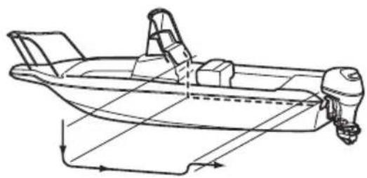
ENOW00850-0
Remote control cable length
ENOW00100-A

CAUTION
Be careful not to loop the remote control cables to a diameter of 406 mm (16 in) or less. Otherwise, it affects the service life of the cable.
natural_image
Technical line drawing of a boat with structural components and directional arrows indicating flow or movement (no text or symbols)ENOF00842-0
Measure the distance from the remote control box to the outboard motor where the remote control cable should be routed.
Prepare a cable that is 300-450mm (11.8-17.7in) longer than the measured distance.
Temporarily pull the cable along the intended cable route to check its length is sufficient.
Connect the remote control cable to the engine, then run the cable to the remote control box, making sure it is not sharply bent, too taut and free from obstructions that could interfere with steering.
ENOM00029-A
3. Battery installation
ENOW00012-0

WARNING
Battery electrolyte contains sulfuric acid and thus is hazardous, causing a burn if it
comes in contact with your skin, or poisonous if swallowed.
Keep battery and electrolyte away from reach of children
When handling the battery, be sure to:
- Read all warnings shown on the bat case - Prevent electrolyte from coming in contact with any part of your body. Contact can cause serious burn or, if it comes in contact with your eye, loss of sight. Use safety glasses and rubber gloves.
In case battery electrolyte comes in contact with:
● Skin, flush thoroughly with water.
- Eye, flush thoroughly with water, and then seek immediate medical treatment.
In case battery electrolyte is swallowed:
- Seek immediate medical treatment.
ENOW00013-A

WARNING
Battery generates explosive hydrogen gas. Be sure to:
- Charge the battery in a well-ventilated place.
- Place the battery away from any source of fire, sparks and open flames such as burners or welding equipment.
- Do not smoke near the battery when the battery is charging.
- Do not charge the battery when the electrolyte level is low. Otherwise, the battery will be damaged and may cause malfunction.
ENOW00014-0

CAUTION
● Make sure that the battery leads do not get stuck between the outboard motor and boat when turning, etc.
● The starter motor may fail to operate if the leads are incorrectly connected.
- Be sure to correctly connect the (+) and (−) leads. If not, the charging system will be damaged.
- Do not disconnect the battery leads from battery while the engine is operating, the electrical parts could be damaged.
● Always use a fully charged battery.
ENOW00015-0

CAUTION
Do not use a battery that is not recommended. Use of a battery not recommended can lead to poor performance of, and/or damage to, the electrical system.
ENON00006-A
Note
Recommended battery: 12V 100Ah/5HR, 850 (Cold Cranking Amps (CCA), In case of cold whether: 12V120Ah/5HR (1000CCA)) Specifications and features of batteries vary among the manufacturers. Consult the manufacturer for details.
* The battery should be purchased separately and is not supplied with the outboard motor.
- Place the battery box in a convenient position away from possible water spray. Securely fasten both the box and the battery so they do not shake loose.
- Connect the positive lead (+) to the positive terminal (+) of the battery, and then connect the negative lead (−). When disconnecting the battery always remove the negative lead (−) first. After connecting the positive terminal (+), securely place a cap on it to prevent short circuits.

text_image
1 2 ENOENOF00022-0
- Battery cord (red)
- Battery cord (black)
ENOM00123-0
4. Propeller installation
ENOW00085-A

WARNING
Do not begin propeller removal and installation procedure with spark plug caps attached, shift in forward or reverse, main switch at other than "OFF", engine stop switch lock attached to the switch, and starter key attached, or engine could accidentally start leading to serious personal injury.
Disconnect battery cable if possible.
ENOW00085-0

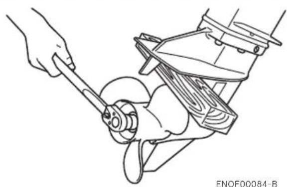
WARNING
Do not hold propeller with hand(s) when loosening or tightening propeller nut. Put a piece of wood block between propeller blade and anti-ventilation plate to hold propeller.
natural_image
Line drawing of a hand using a wrench to adjust or install a mechanical component (no text or symbols present)ENOW00086-0

CAUTION
- Do not install propeller without thrust holder, or propeller boss could be damaged.
- Do not reuse split pin.
- After installing split pin, spread the pin apart to prevent it from falling out which could lead to the propeller coming off during operation.
Propeller must be selected that will allow the engine to reach recommended maximum operating range during cruising.
Wide-open throttle rpm range
30/40:4750-5750 min ^-1 (rpm)
50:5150-5850 min ^-1 (rpm)
75/90 : :5150 - 5850 min ^-1 (rpm)
115:5150-5850 min ^-1 (rpm)
Genuine propellers are listed on PROPEL-LER TABLE of this manual (See page 100).
- Remove the split pin, propeller nut and washer.
- Remove the propeller and thrust holder.
- Apply water proof grease to the propeller shaft before installing a new propeller.
- Install the thrust holder, propeller, stopper, washer and propeller nut onto the shaft.
30, 40, 50

text_image
ENOF01315-- Propeller
- Thrust holder
- Stopper
- Washer
- Propeller nut
- Split pin
75,90
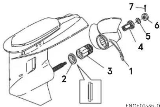
text_image
7 1 6 5 4 3 2 1 ENOF01335-0- Propeller
- Thrust holder
- Bush
- Adaptor
- Washer
- Propeller nut
- Split pin
115

text_image
ENOF01336-0- Propeller
- Thrust holder
- Bush
- Stopper
- Washer
- Propeller nut
-
Split pin
-
Tighten the propeller nut to speci- fied torque with holding the propel- ler by wood block. And align one of grooves to propeller shaft hole.
Propeller nut torque:
35 N·m (25 ft·lb, 3.5kgf·m)

natural_image
Line drawing of a hand using a wrench to adjust or install a mechanical component (no text or symbols present)- Install a new split pin into the nut hole and bend it.
ENOM00971-0
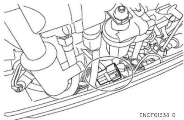
5. TOCS (Tohatsu Onboard Communication System) installation
TOCS (Tohatsu Onboard Communication System) interface coupler can provide information regarding engine speed, fuel consumption, and various malfunction via an optional interface cable. Contact authorized Tohatsu dealer for more detail.
30, 40, 50
natural_image
Technical line drawing of a mechanical assembly with no visible text or symbols75, 90, 115
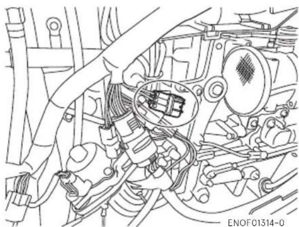
natural_image
Technical line drawing of an engine assembly with hoses and components (no text or symbols)PRE-OPERATING PREPARATIONS
ENOM00030-A
1. Fuel handling
ENOW000017-0

CAUTION
Use of improper gasoline can damage your engine. Engine damage resulting from the use of improper gasoline is considered misuse of the engine, and damage caused thereby will not be covered under the limited warranty.
ENOM00031-A
FUEL RATING
TOHATSU engines will operate satisfactorily when using a major brand of unleaded gasoline meeting the following specifications:
USA and Canada — having a posted pump Octane Rating of 87 (R+M)/2 minimum. Premium gasoline (92 [R+M]/2 Octane) is also acceptable. Do not use leaded gasoline.
Outside USA and Canada — Use unleaded gasoline with declared octane rating of 91 RON or over. Use of premium gasoline of 98 RON is also allowed.
ENOM00032-A
GASOLINES CONTAINING ALCOHOL
The fuel system components on your TOHATSU engine will withstand up to 10% ethyl alcohol (hereinafter referred to as the "ethanol"), content in the gasoline. But even if the gasoline in your area contains ethanol less than 10%, you should be aware of certain adverse effects that can occur. Increasing the percentage of ethanol in the fuel can also worsen these adverse effects. Some of these adverse effects are caused because the ethanol in the gasoline can absorb moisture from the air, resulting in a separation of the water/ethanol from the gasoline in the fuel tank.
These may cause increased:
● Corrosion of metal parts
● Deterioration of rubber or plastic parts
● Fuel permeation through rubber fuel lines
● Starting and operating difficulties
If the use of gasoline containing alcohol
is inevitable, or presence of alcohol is suspected in the gasoline, it is recommended to add a filter that has water separating capability, and check the fuel system for leaks and mechanical parts for corrosion and abnormal wear more frequently.
And, in case any of such abnormality is found, discontinue the use of such gasoline and contact our dealer immediately.
If the outboard motor will only be used infrequently, please see the remarks on fuel deterioration in the STORAGE chapter (P 87) for additional information.
ENOW00020-1

CAUTION
When operating a TOHATSU engine on gasoline containing alcohol, storage of gasoline in the fuel tank for long periods should be avoided. Long periods of storage, create unique problems. In cars, alcohol blend fuels normally are consumed before they can absorb enough moisture to cause trouble, but boats often sit idle long enough for
phase separation to take place. In addition, internal corrosion may take place during storage if alcohol has washed protective oil films from internal components.
ENOW00018-0

WARNING
Fuel leakage can cause fire or explosion, potentially leading to severe injury or loss of life. Every fuel system part should be checked periodically, and especially after long term storage, for fuel leak, change of hardness of rubber, expansion and/or corrosion of metals. In case any indication of fuel leakage or degradation of fuel part is found, replace relevant part immediately before continuing operation.
ENOM00043-B
2. Fuel filling
ENOW00019-1

WARNING
Do not fill the fuel tank over capacity. The rise of gasoline temperature may cause gasoline to expand which, may leak through air vent screw when it is open. Leaking gasoline is a dangerous fire hazard.
ENOW00028-A

WARNING
Consult an authorized dealer for details on handling gasoline, if necessary.
Gasoline and its vapors are very flammable and can be explosive.
When carrying a fuel tank containing gasoline:
- Close the fuel tank cap and air vent screw of fuel tank cap, or gasoline vapor will be emitted through the air vent screw, creating a fire hazard.
-
Do not smoke.
-
Be sure to remove the static electricity charged in your body before refueling.
- The sparks due to static electricity may cause explosion of flammable gasoline.
- Stop the engine, and do not start the engine during refueling.
- Do not smoke.
- Be careful not to overfill fuel tank. Wipe up any spilled gasoline immediately.
When or before cleaning the gasoline tank:
● Dismount fuel tank from the boat.
- Place the fuel tank away source of ignition, such as sparks or open flames.
- Do the work outdoors or in a well ventilated area.
- Wipe off gasoline well immediately if spilled.
After cleaning gasoline tank:
- Wipe off gasoline well immediately if spilled.
- If the fuel tank is disassembled for cleaning, reassemble carefully. Imperfect assembly may cause a fuel leak, possibly leading to fire or explosion.
- Dispose aged or contaminated gasoline in accordance with local regulations.
ENOW00029-A

WARNING
When opening fuel tank cap, be sure to follow the procedure described below. Fuel could blast out through the fuel tank cap in case the cap is loosened by using another procedure when internal pressure of fuel tank is raised by heat from sources such as sun light.
ENOW00946-0

CAUTION
Separate tank must be fixed at appropriate position so that well ventilated and tank does not move or fall down while operating.
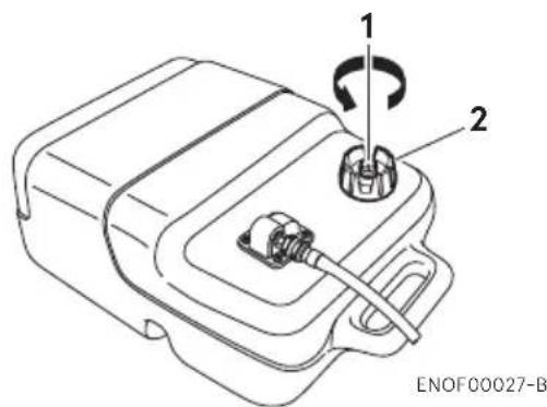
- Full open the air vent screw on the fuel tank cap and release internal pressure.
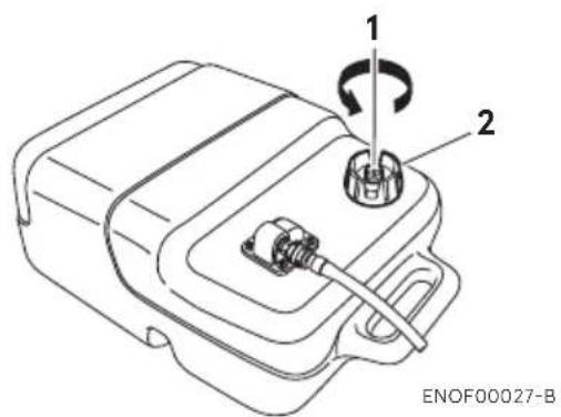
text_image
1 2 ENOF00027-B- Air vent screw
- Fuel tank cap
- Open the fuel tank cap slowly.
- Fill the fuel carefully not to over flow.

text_image
SAFE FILL LEVEL 25 L NIVEAU MAXIMUM ENOF00030-A- After filling the tank, close the fuel tank cap.
ENOM00037-B
3. Engine oil recommendation
ENOW00022-A

CAUTION
The engine oil is drained for shipping from the factory. Be sure to fill the engine to the proper level before starting engine. (To
properly fill the engine with oil follow the instructions, See page 74)
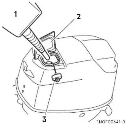
text_image
1 2 3 ENOF00641-0- Genuine of recommended engine oil
- Filler lid
- Oil tank cap
Use a genuine engine oil or recommended one. Refer to your Distributor. Will not recommend use of other two stroke engine oil.
ENOW0002A-A

CAUTION
Use of engine oils that do not meet these requirements will result in reduced engine life, and other engine problems.
ENOW00603-0

CAUTION
Do not mix different brands of oil. Mixing different brands of oil, or different types of oil even if the brand is the same, may cause gelling, resulting in possible filter screen blockage. This could result in serious engine damage because of impaired lubrication performance.
ENOW00022-0

CAUTION
The engine oil is drained for shipping from the factory. Be sure to fill the engine to the proper level before starting engine. (To properly fill the engine with oil follow the instructions in section 10 of this manual)
ENON00007-0
Note
Use of engine oils that do not meet these requirements will result in reduced engine life, and other engine problems.
ENOW00604-0

CAUTION
- In the unlikely event that gasoline by mistake is filled into the oil tank, drain the oil tank completely, and consult an authorized service shop for advice.
- Check the amount of oil in the oil tank visually before starting the engine. Running out of oil at sea is a cause for potential disaster.
The required amount of engine oil is automatically supplied from the oil tank, through the oil pump, according to the engine running conditions. Gasoline is fed over a separate feeding line.
ENOM00644-1
Replenishing oil in the engine oil tank.
- Open the filler lid from the top cowl.
- Open the oil tank cap.
- Fill the oil tank with the genuine engine oil.
- After replenishment of the oil tank, be sure to close the oil tank cap tightly.
ENOM00645-0
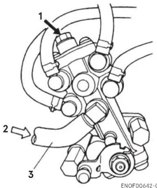
Oil pump air vent
Visually check whether there is air in the oil through the vinyl pipe connecting the oil tank with the oil pump. If present, Purge the air as follows:
30, 40, 50
Loosen the air vent screw on the oil pump to purge the air, and tighten it when all air, as seen through the vinyl pipe on the oil pump side, has been purged.
30, 40, 50
text_image
1 2 3 ENOF00642-0- Air vent screw
- From oil filter
- Vinyl pipe
75, 90, 115
See page 44 for air removal from the oil lines.
ENON00608-0
Note
Wipe off any spilled oil with a rag, and dispose of it.
ENOM00033-A
4. Break-In
Your new outboard motor and lower unit require break-in for the moving components according to the conditions described in the following time table.
Please refer to ENGINE OPERATION section (See page 43) to learn how to correctly start and operate the outboard motor.
ENOW00024-A

DANGER
Do not operate the outboard motor in closed area or area with no forced ventilation.
Exhaust gas emitted by this outboard motor contains carbon monoxide that will cause death if inhaled continuously. Inhaling the gas initially causes symptoms such as feeling of sickness, drowsiness and headache.
During operation of the outboard motor:
- Keep peripheral area well ventilated.
● Always attempt to stay on the windward side of emission.
ENOW00023-1

CAUTION
Operating the outboard motor without break-in can shorten service life.
If any abnormality is experienced during the break-in:
● Discontinue the operation immediately.
- Have the dealer check the product and take proper action(s) if necessary.
ENON00008-0
Note
Proper break-in allows outboard motor to deliver it full performance for longer service life.
| 1–10 min | 10 min – 2 hrs | 2–3 hrs | 3–10 hrs | After 10 hrs | |
| Throttle Position Idle | Less than 1/2 throttle | Less than 3/4 throttle | 3/4 throttle | Full throttle available | |
| Speed | Approx. 3000 min ^-1 (rpm) max | Full throttle run allowed for 1 min every 10 min | Approx. 4000 min ^-1 (rpm). Full throttle run allowed for 2 min every 10 min |
ENOM00039-0
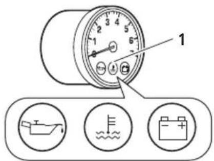
5. Warning system
If outboard motor encounters an abnormal condition of fault, the warning buzzer will emit a continuous beep or intermittent short beeps and the warning lamp (LED) will synchronize with the buzzer and engine speed will be limited (engine will not be stopped).
See next page for conditions which will lead to an abnormal condition or fault.

text_image
Technical diagram of a mechanical device with labeled parts and three supporting icons belowENOF00852-0
1. Warning lamp
ENOM00040-B
Location of warning buzzer and lamp
■ Warning buzzer
RC model: Located inside the remote control.
Multi-Function tiller handle model: Located in the tiller handle. *Only for 30, 40, 50
■ Warning lamp (LED)
RC model: Located in the tachometer.
Multi-Function tiller handle model:
Located in the tiller handle. *Only for 30, 40, 50
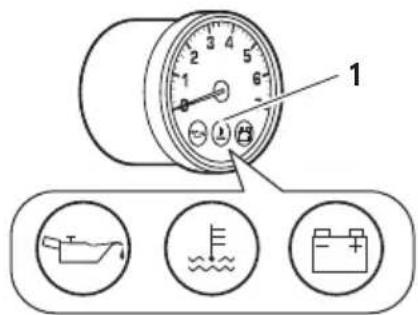
text_image
Diagram showing a pressure gauge with labeled components and three circular icons below indicating water, battery, and boat.ENOF00851-0
1. Warning lamp
ENOM00041-C
Warning indicators, faults and remedy
| Warning indicators | ESG | Description of faults or notice | Remark | Rem-edy | |||
| Sound | |||||||
| A lamp | B lamp | C lamp | |||||
| Continuous | ON ON | ON - | Normal system test when key on | 1 second | |||
| Continuous | --- | High speed ESG | Engine speed exceeds maximum allowable RPM | Approx. 6,000 r/min | 1 | ||
| Intermittent (3 beeps for every 2 minutes) | Flashing | - | - | Low speed ESG | Low oil level 2 | ||
| Continuous | - | Flashing | - | Low speed ESG | Cooling water temp. is high | 3 | |
| Continuous | - | Flashing | - | Forced idling | Cooling water temp is abnormally high | 3 | |
| - | - | - | Flashing | - Battery voltage is low | Engine is stopped under 9V | 4 | |
| - | - | Flashing | - | Low speed ESG | Battery voltage is low Approx. 10V or less 4 | ||
| - | Flashing | Flashing | Flashing | Low speed ESG | Malfunction of sensor 5 | ||
| - | Flashing | Flashing | Flashing | Forced idling | Malfunction of sensor 5 | ||
| - | Flashing | Flashing | Flashing | - | Malfunction of electrical part or sensor | 5 | |
High speed ESG (Electronic Safety Governor)
High speed ESG is a device to prevent over revolution of the engine. If the load to the engine becomes light for some reason, it runs at a higher speed than the usual. In such the case, the buzzer sounds and the ESG is activated not to ignite the spark plug, therefore, the engine speed varies and be controlled under 6000min ^-1 (rpm).
Low speed ESG
Low speed ESG is a device to prevent the engine from getting damage. If the engine has problems regarding cooling water, oil pressure, and sensors, the low speed ESG is activated not to ignite the spark plug, and disable fueling therefore, the engine speed varies and be controlled under 3000min ^1 (rpm).
Remedy
- Reduce the throttle to less than half opening, and move to safe place quickly, and stop the engine.
Check the propeller for bent or damaged blades.
Consult an authorized dealer if engine shows the same result even after replacing propeller with new one.
- Move to safe place quickly, and stop the engine.
Check the engine oil level, and add engine oil if necessary.
- Move to safe place quickly, and check the discharge of cooling water from the water check port at idle speed and stop engine.
Remove any foreign matter on the gear case and propeller if necessary. Consult an authorized dealer if no discharge of cooling water.
-
Charge or replace the battery.
-
Consult an authorized dealer.
ENOW00025-A

CAUTION
- Low speed ESG ON: Engine speed will be limited to 3000 min ^-1 (rpm), however you should not continue to run engine.
- High speed ESG ON: Engine speed will be limited to 6000 min ^-1 (rpm) and engine will run rough until throttle is reduced.
■ ENGINE OPERATION
ENOM00042-0
Before starting
ENOW00022-A

CAUTION
The engine oil is drained for shipping from the factory. Be sure to fill the engine to the proper level before starting engine. (To properly fill the engine with oil follow the instructions. See page 74)

text_image
1 2 3 ENOF00641-0- Genuine of recommended engine oil
- Filler lid
- Oil tank cap
ENOW00027-A

CAUTION
Before starting engine for the first time after reassembling engine or off-season storage, disconnect stop switch lock and crank approximately 10 times in order to prime the oil pump.
ENOM00656-A
1. Engine oil feeding
When the engine is new or have been left without operation for a long time, or just after the engine is overhauled, be
sure to execute the following operation for forcedly feeding the engine oil to the oil line before starting the engine.
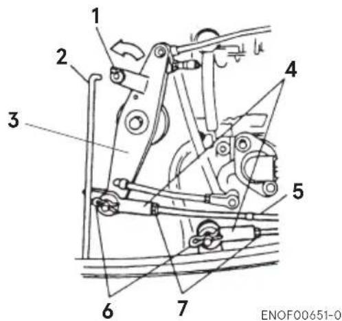
ENOM00657-0
30, 40, 50 type
a. Disconnect the link rod by turning the rod snap interlocking with the oil pump as shown in the figure.
b. Make sure that the oil pump control lever is set at open side position.
c. Idle the engine for more than 30 minutes.
d. Reset the link rod to the advancer arm.
30, 40, 50
text_image
1 2 3 4 5 6 7 ENOF00651-0- Rod snap
- Link rod
- Advancer arm
- Cable joint
- Throttle cable
- R shaped pin
- Nut

text_image
Technical diagram of a mechanical assembly with numbered components and directional arrows indicating motion or flow.ENOF00652-0
- Air vent screw
- Link rod
- From oil filter
- Vinyl pipe
- Open side
- Control lever
ENOM00658-0
75, 90, 115 type (Electric oil pump)
Check to see by eyes if the oil line from the oil tank to the cylinder block (1) to (4) in the 75, 90, 115 model) gets air inside or not. If there is air inside the oil line, remove it as follows.
- Oil tank-Filter (1)
a. Fill the oil tank up with the specified oil.
b. Remove the pipe of the filter inlet side at the part (A).
c. Since the oil drains out with air, wait until air is completely discharged from the pipe. After checking for no air in the oil line, reconnect the pipe as it was and attach the clip to secure pipe connection.
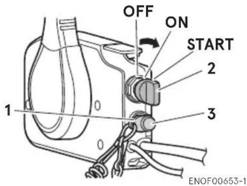
- Filter-Oil Pump-Cylinder Block [75, 90, 115: (2)-(4)]
a. Turn on the key switch.
b. Within 1 second after the buzzer stops sounding, remove the stop switch lock.
c. Within 2 seconds after removing the stop switch lock, quickly repeat pulling and pushing back the stop switch knob 2 times.
d. The buzzer sounds 3 times and the oil pump is actuated for about 1 minute for pressure feed or oil.
e. When air is completely removed from the oil line, turn off the key switch.
75, 90, 115
Side mount RC type
text_image
OFF ON START 2 3 1 ENOF00653-1- Look
- Key switch
- Stop switch knob
Top mount RC type

text_image
OFF ON START 2 1 3 ENOF00938-C- Look
- Key switch
- Stop switch knob
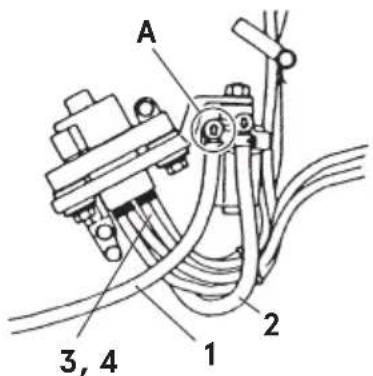
text_image
A 3, 4 1 2ENOF00654-0
- Oil tank-Filter
- Filter-Oil Pump
- 75,90:Oil Pump-Cylinder Block (seven lines)
- 115:Oil Pump-Cylinder Block (nine lines)
ENOM00044-B
2. Fuel feeding
ENOW00029-A

WARNING
When opening fuel tank cap, be sure to follow the procedure described below. Fuel could blast out through the fuel tank cap in case the cap is loosened by using another procedure when internal pressure of fuel tank is raised by heat from sources such as sun light.
ENOW00947-0

CAUTION
When using a separate tank, be sure that the fuel line is not kinked and is connected securely.
- Full open the air vent screw on the fuel tank cap.
text_image
1 2 ENOF00027-B- Air vent screw
-
Fuel tank cap
-
Connect the fuel connector to the engine and fuel tank.
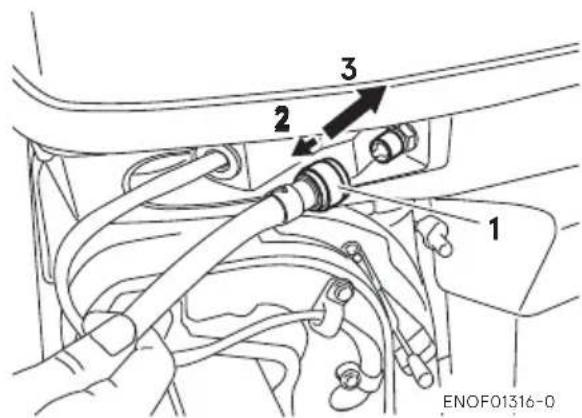
text_image
1 2 3 ENOF01316-0- Fuel connector
- Pull
- Insert

text_image
Diagram showing a hand holding a connector with labeled parts 1 and 2, indicating assembly or insertion steps.- Pull
- Insert
ENOF00861-A
- Squeeze primer bulb until it becomes stiff to feed fuel to vapor separator. Direct arrow mark upward when priming.
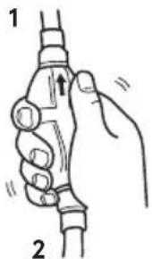
text_image
1 2ENOF00862-0
- Engine side
- Fuel tank side
Do not squeeze primer bulb with engine running or when the outboard motor is tilted up. Otherwise, fuel could overflow.
ENOM00045-A
3. Starting the engine
ENOW00036-A

CAUTION
When the engine is started in the test tank, to avoid over heating and water pump damage, be sure the water level is at least 10 cm (4 in.) above the anti ventilation plate.
And be sure to remove the propeller, when starting the engine in the test tank. (See page 83)
Run the engine only at idling.

text_image
3 1 2ENOF00863-0
- Water
- Over 10 cm (4 in.)
ENOW00036-0

CAUTION
Be sure to stop engine immediately if cooling water check port is not discharging water, and check if cooling water intake is blocked. Operating engine could lead to overheating potentially leading to engine damage. Consult an authorized dealer if the cause cannot be found.
ENOW00032-A

CAUTION
Do not hold turning starter motor for more than 5 seconds, or the battery may be consumed, potentially making the engine starting impossible and/or damaging the starter. If cranking over 5 seconds fails to start engine, return main switch to "ON", and crank engine again after 10 seconds or more. Do not try to crank after engine has started.
This model is provided with start in gear protection.
ENON00010-0
Note
Start-in-gear protection prevents engine from starting at other than neutral shift. In-gear starting of engine will move the boat immediately, potentially leading to falling down or causing passenger(s) to be thrown overboard.
- Test tank
Tiller handle type
- Be sure to install the stop switch lock to the stop switch, and attach the stop switch lanyard securely to the operator or to the operator's PFD (Personal Flotation Device.)

text_image
2 1 ENOF00864-0- Stop switch lock
- Insert the main switch key.
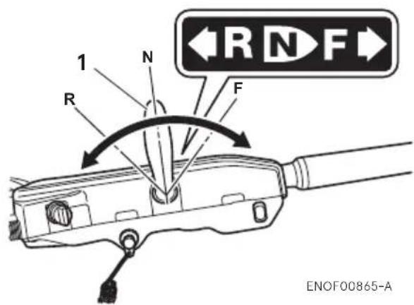
- Set the control lever in the Neutral position.

text_image
1 R N F ←R N F ENOF00865-0-
Shift lever
-
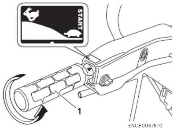
Set the throttle grip to START position.
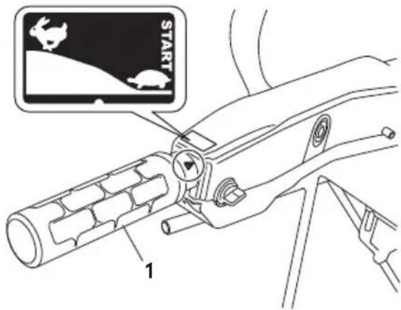
text_image
START 1ENOF00866-0
- Throttle grip
ENON00613-A
Note
Turn the throttle grip to the "START" (fully closed), before turning the main switch key to "ON".
The wrong operation i.e. turn the main switch key to "ON" on the condition that the handle grip or accel lever is opened will be memorized by ECU (engine control unit).
If this wrong operation has done repeatedly, it will have a possibility that the three warning lamps flash. In this case, turn the throttle grip to "START" (fully closed) and start the next operation after returning the main switch key to "OFF".
- Turn the main switch key to ON position and confirm three warning lamps light up with buzzer sound and then go off.
- Turn the main switch key to START position and release the key when the engine has started. The key returns to the original position, automatically.
text_image
N R F 1 2 OFF ON START PUSH TO IDLE CHANGEENOF00867-0
- Main switch key
- Warning lamp
ENOW00032-1

CAUTION
Do not hold turning starter motor more than 5 seconds, or the battery may be consumed, potentially making the engine starting impossible and/or damaging the starter.
If cranking over 5 seconds fails to start engine, return main switch to "ON", and crank engine again after 10 seconds or more.
- Check the cooling water from cooling water check port.
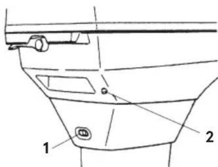
text_image
1 2ENOF00664-0
- Idle port
- Cooling water check port 30, 40, 50

text_image
Diagram of a funnel with labeled parts, showing internal components and directional arrowsENOF00665-0
- Idle port
- Cooling water check port 75, 90, 115
Side mount RC type
- Be sure to install the stop switch lock to the stop switch, and attach the stop switch lanyard securely to the operator or to the operator's PFD (Personal Flotation Device.)

natural_image
Technical diagram of a mechanical clamp or bracket assembly with a spring and rope connection (no text or symbols)ENOF00869-1
- Stop switch lock
- Insert the main switch key.
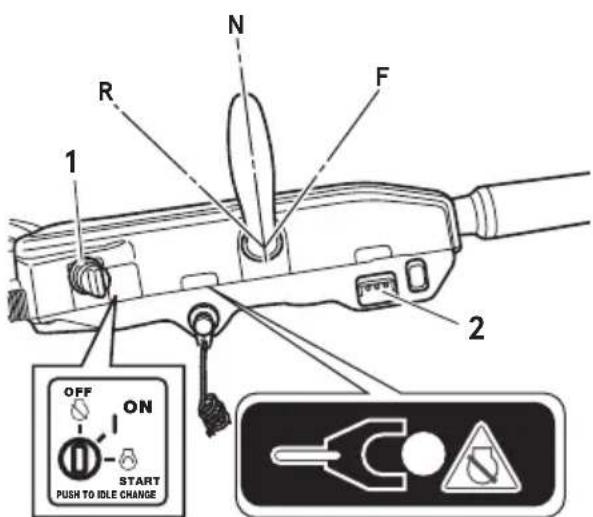
- Set the control lever in the Neutral position. Do not raise the free throttle lever when starting the engine.
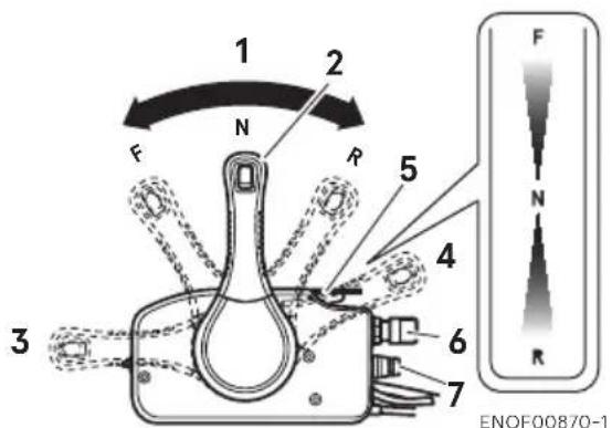
text_image
1 2 F N R 5 4 3 6 7 ENOF00870-1- Neutral (N)
- Control lever
- Fully opened (Forward)
- Fully opened (Reverse)
- Free throttle lever
- Main switch key
-
Stop switch
-
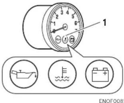
Turn the main switch key to ON position and confirm three warning lamps light up with buzzer sound and then go off.
text_image
Diagram showing a pressure gauge with labeled components and three circular icons below indicating water, battery, and boat.ENOF00851-0
- Warning lamp
- Turn the main switch key to START position and release the key when the engine has started. The key returns to the original position, automatically.
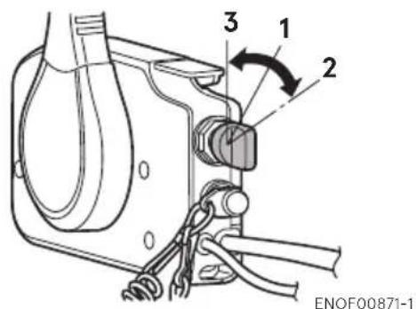
text_image
3 1 2 ENOF00871-1- ON
- START
- OFF
ENON00035-A
Note
The free throttle lever can not be raised when the control lever shift is in Forward or Reverse.
- Check the cooling water from cooling water check port.

text_image
1 2ENOF00664-0
- Idle port
- Cooling water check port 30, 40, 50

text_image
Diagram of a funnel with labeled parts, showing internal components and numbered partsENOF00665-0
- Idle port
- Cooling water check port 75, 90, 115
Top mount RC type
- Be sure to install the stop switch lock to the stop switch, and attach the stop switch lanyard securely to the operator or to the operator's PFD (Personal Flotation Device.)

natural_image
Diagram of a control panel with a rotary knob and connected cable (no text or symbols)- Stop switch lock
- Insert the main switch key.
- Set the control lever in the Neutral position. Do not use the Neutral throttle button to open the throttle when starting the engine.

text_image
1 2 3 7 8 F N R 5 4 6 ENOF00937-0- Forward (F)
- Neutral (N)
- Reverse (R)
- Fully opened (Forward)
- Fully opened (Reverse)
- Neutral throttle button
- Control lever
-
Neutral lock arm
-
Turn the main switch key to ON position and confirm three warning lamps light up with buzzer sound and then go off.

text_image
1 ENOF008- Warning lamp
- Turn the main switch key to START position and release the key when the engine has started. The key returns to the original position, automatically.

text_image
1 2 3ENOF00938-0
- ON
- START
- OFF
text_image
1 ENOF0085- Warning lamp
ENON00939-0
Note
The neutral throttle button can not be push-in when the control lever shift is in Forward or Reverse.
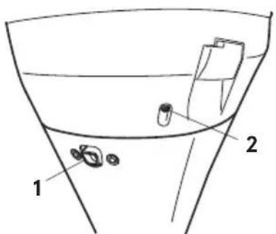
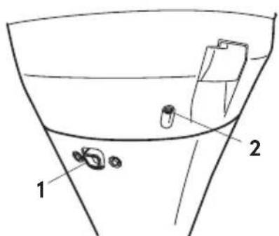
- Check the cooling water from cooling water check port.

text_image
1 2ENOF00664-0
- Idle port
- Cooling water check port 40, 50
text_image
Diagram of a funnel with labeled parts, showing components like a container and two parts inside.ENOF00665-0
- Idle port
- Cooling water check port 75, 90, 115
ENOM00042-A
Emergency starting
*Only for 30, 40, 50
ENOW00099-A

WARNING
When the emergency starter rope is used for starting engine;
- Start in gear protection does not work. Be sure to shift is at neutral position. Otherwise the engine will move the boat immediately and cause personal injury.
-
Be careful that your clothes or other items do not get caught in the rotating engine parts.
-
To prevent accident and injury by rotating parts, do not re-attach flywheel cover and the top cowl after the engine has been started.
- Do not pull starter rope if any bystander is behind. The action can injure the bystander.
-
Attach engine stop switch lanyard to clothing or any part of body like arm before starting engine.
-
Remove the top cowl.
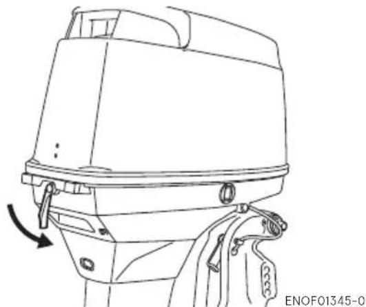
natural_image
Line drawing of a boat hull with a directional arrow indicating motion (no text or symbols)- Remove the flywheel cover.
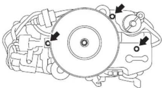
natural_image
Technical line drawing of a mechanical assembly with no visible text or symbolsENOF00661-0
-
Insert the knotted end of the starter rope into the notch in the flywheel and wind the rope around the flywheel several turns clockwise.
-
Tie a loop in the another end of the emergency starter rope and attach socket wrench that is included in the tool kit.

natural_image
Line drawing of a mechanical engine with a hand adjusting the component (no text or symbols present)ENOW00860-0

CAUTION
Be sure to keep the harness away from the rotation parts.
- Be sure to install the stop switch lock to the stop switch, and attach the stop switch lanyard securely to the operator or to the operator's PFD (Personal Flotation Device.)
- Set the control lever in the Neutral position.
- Pull the starter handle slowly until you feel engagement, keep pulling till you feel less resistance. Then pull it quickly.
- After engine starts, do not reinstall flywheel cover and top cowl.
ENOM00043-A
4. Warming up the engine
ENOW00932-0

CAUTION
Be sure to check that cooling water is coming out of the cooling water check port during warm up.
Warm the engine at low engine speeds for about
3 minutes : above 5°C (41°F)
5 minutes at 2000 min ^-1 (rpm):
below 5°C (41°F)
This allows the lubricating oil to circulate to all parts of the engine. Operating the engine without warm up shortens the engine's life.

text_image
1 2 ENOF00664-0- Idle port
- Cooling water check port 30, 40, 50
text_image
Diagram of a funnel with labeled parts 1 and 2, showing internal components and directional arrows.ENOF00665-0
- Idle port
- Cooling water check port 75, 90, 115
ENOM00044-0
Engine speeds
Idling speed after warming up.
Remark: In case of cold engine starting, idling speed is increased about 400 min ^-1 (rpm) for several minutes.
| Clutch in (In gear) Clutch off (Out of gear) | |
| 800 min ^-1 (rpm) 800 min ^-1 (rpm) |
ENOM00972-0
Free throttle lever (Side mount RC type)
ENOW00956-0

CAUTION
- Keep the free throttle lever fully closed-position when start the engine.
● The free throttle lever is inoperative unless the control lever is in neutral. - Also, the control lever is inoperative unless the free throttle lever is returned to the fully-closed position.
The free throttle lever is for warm-up operation.(Not required for engine starting) With the control lever in neutral, move the free throttle lever upward to open the throttle.

text_image
Technical diagram of a mechanical device with labeled parts 1 and 2, showing a handle and cable assembly.ENOF00934-0
- Fully-open
- Fully-closed
ENOM00973-0
Neutral throttle button (Top mount RC type)
ENOW00957-0

CAUTION
The control lever does not operate unless the neutral lock arm is pulled.
The neutral throttle button is for warm-up operation. (Not required for engine starting) When the control lever is in neutral, push and hold the neutral throttle button. While holding the button, move the lever forward to throttle up the engine.
When the control lever is returned to the neutral position, the button will reset automatically.
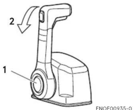
text_image
2 1 ENOF00935-0- Neutral throttle button
- Forward
ENOM00880-0
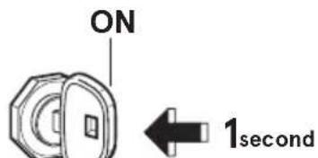
Trolling engine speed control function
If the main switch key is pressed for 1 (one) second during idling or trolling operation, engine revolution change.
text_image
ON 1secondENOF00876-0
Each time the main switch key is pressed in the above manner, engine speed changes as follows.
Starting
$$ \begin{array}{c} 700 \min^{-1}(\mathrm{rpm}) \to 800 \min^{-1}(\mathrm{rpm}) \ \uparrow \ 800 \min^{-1}(\mathrm{rpm}) \leftarrow 900 \min^{-1}(\mathrm{rpm}) \end{array} $$
ENOM00046-A
5. Forward, reverse, and acceleration
ENOW00037-0

WARNING
Before shifting into forward or reverse, make sure that boat is properly moored and outboard motor can be steered fully to the right and left. Make sure that no swimmer(s) is ahead or astern of the boat.
ENOW00038-A

WARNING
- Attach other end of emergency stop switch lanyard to the operator's PFD (Personal Flotation device) or arm and keep it attached during cruising.
- Do not attach the tether to a part of clothing that can be torn easily when pulled.
- Arrange the tether so that will not be caught by any object when pulled.
- Be careful not to pull the tether accidentally during cruising. Unintentional stop of engine can cause loss of control of outboard motor. Rapid loss of engine power can lead to falling down or causing passenger(s) to be thrown overboard.
ENOW00042-0

WARNING
- Do not shift into Reverse during planing, or control will be lost leading to serious personal injury, boat may swamp, and/or hull may be damaged.
- Do not shift into Reverse during cruising, or control may be lost, falling down or causing passenger(s) to be thrown overboard. Leading to serious personal injury, and steering system and/or shifting mechanism may be damaged.
ENOW00861-0

WARNING
Do not shift at high boat speed, or control may be lost, falling down or causing passenger(s) to be thrown overboard. Leading to serious personal injury.
ENOW00862-0

CAUTION
Gear and clutch damage may occur if shifting at high engine speed.
Engine must be in the slow idle position before shifting is attempted.
ENOW00863-0

CAUTION
Idle speed may be higher during warming up of engine. If shifted to Forward or Reverse during warming up, it may be difficult to shift back to neutral. In such case, stop engine, shift to neutral, and restart engine to warm up.
ENON00014-0
Note
Frequent shifting to forward or reverse can accelerate wear or degradation of parts. In such case, replace gear oil earlier than the period specified.
ENOW00864-0

CAUTION
Do not increase engine speed unnecessarily when the shift is in neutral and reverse, or engine damage may occur.
ENOM00890-A
Tiller handle type
ENOW00865-0

CAUTION
Do not force to shift when the throttle grip is not in the fully closed position, otherwise, steering system and/or shifting mechanism may be damaged. The control lever is inoperative unless the throttle grip is in the fully closed position. (Multi-function tiller type)
text_image
1 R N F ←RN→F ENOF00865-A- Shift lever
Forward
- Turn the throttle grip to reduce engine speed.
- When the engine reaches trolling (or idling) speed, quickly pull the shift lever to the Forward position.
Reverse
- Turn the throttle grip to reduce engine speed.
- When the engine reaches trolling (or idling) speed, quickly pull the shift lever to the Reverse position.
Acceleration
ENOW00867-0

WARNING
Sudden acceleration and deceleration may cause passenger(s) to be thrown overboard or falling down.
Open throttle grip gradually.
text_image
START 1 ENOF00878-0- Throttle grip

text_image
1 ENOF01119-0- Throttle grip
ENOM0900-0
Side mount RC type
ENOW00867-0

WARNING
Sudden acceleration and deceleration may cause passenger(s) to be thrown overboard or falling down.

text_image
1 2 3 4 5 6 7 8 F N R ENOF00877-1- Forward (F)
- Neutral (N)
- Reverse (R)
- Fully opened (Forward)
- Fully opened (Reverse)
- Free throttle lever
- Control lever
- Neutral lock arm
Forward
- Quickly push the control lever to the Forward (F) position 32°, where the gear is connected, while lifting up on the lock button located under the control lever grip.
- Further forward motion will open the throttle.
Reverse
- Quickly pull the control lever to the Reverse (R) position at 32°, where the gear is connected, while lifting up on the lock button located under the control lever grip.
- Further rearward motion will open the throttle.
Acceleration
ENOW00867-0

WARNING
Sudden acceleration and deceleration may cause passenger(s) to be thrown overboard or falling down.
Open throttle grip or control lever gradually.
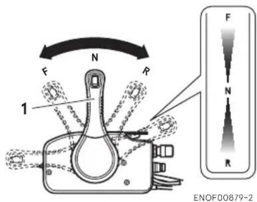
text_image
F N R 1 F N R ENOF00879-2- Control lever
NOM00975-0
Top mount RC type
ENOW00867-0

WARNING
Sudden acceleration and deceleration may cause passenger(s) to be thrown overboard or falling down.
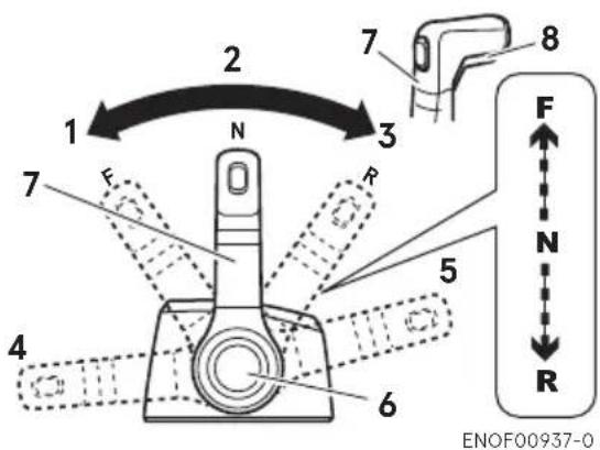
text_image
1 2 3 7 8 N R 5 4 6 F N R ENOF00937-0- Forward (F)
- Neutral (N)
- Reverse (R)
- Fully opened (Forward)
- Fully opened (Reverse)
- Neutral throttle button
- Control lever
- Neutral lock arm
Forward
-
Quickly push the control lever to the Forward (F) position 35°, where the gear is connected, while lifting up on the neutral lock arm located under the control lever grip.
-
Further forward motion will open the throttle.
Reverse
-
Quickly pull the control lever to the Reverse (R) position at 35^ , where the gear is connected, while lifting up on the neutral lock arm located under the control lever grip.
-
Further rearward motion will open the throttle.
Acceleration
ENOW00867-0

WARNING
Sudden acceleration and deceleration may cause passenger(s) to be thrown overboard or falling down.
Open throttle grip or control lever gradually.
ENOM00049-A
6. Stopping the engine
ENOW00868-0

WARNING
Be careful not to remove engine stop switch lanyard from engine accidentally while boat is running. Sudden stop of engine can cause loss of steering control. It can also cause loss of boat speed, possibly leading the crew(s) and or objects on the boat to be thrown forward due to inertial force.
Tiller handle type
- Turn the throttle grip to the slow position.
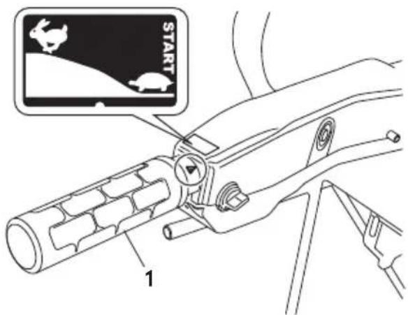
text_image
START 1ENOF00866-0
-
Throttle grip
-
Put the shift lever in the Neutral position.
Run the engine for 2-3 minutes at idling speed for cooling down if it has been running at full speed.
- Turn the main switch key to the OFF position or push the stop switch. (Do not forget to turn the key off).

text_image
N 2 F R 3 OFF ON START PUSH TO IDLE CHANGE ENOF00880-0- Throttle grip
- Shift lever
- Main switch key
Side mount RC type
- Put the control lever in the Neutral position and run the engine for 2-3 minutes at idling speed for cooling down if it has been running at full speed.
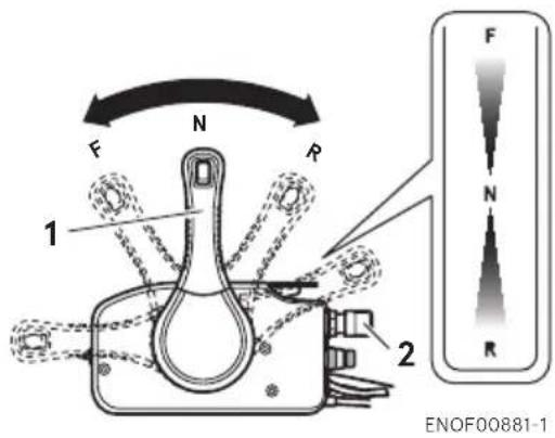
text_image
F N R 1 2 ENOF00881-1- Control lever
- Main switch key
- Turn the main switch key to the OFF position.

text_image
3 1 2 ENOF00871-1- ON
- START
- OFF
ENOW00869-0

WARNING
After stopping the engine:
- Close the air vent screw on the fuel tank cap.
- Disconnect the fuel connector of the engine and the fuel tank.
- Disconnect the battery cord, after each use.
ENOM00975-0
Top mount RC type
- Put the control lever in the Neutral position and run the engine for 2-3 minutes at idling speed for cooling down if it has been running at full speed.

text_image
1 F N R F N R ENOF00939-0- Control lever
- Turn the main switch key to the OFF position.
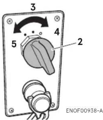
text_image
3 4 2 5 ENOF00938-A- Main switch key
- ON
- START
- OFF
ENOW00869-0

WARNING
After stopping the engine:
- Close the air vent screw on the fuel tank cap.
- Disconnect the fuel connector of the engine and the fuel tank.
- Disconnect the battery cord, after each use.
Emergency engine stopping
Press the emergency stop switch or remove stop switch lock to stop the engine.
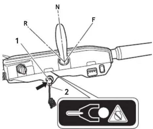
text_image
1 R N F 2ENOF00883-0
- Stop switch
- Stop switch lock
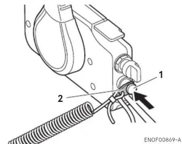
text_image
1 2 ENOF00869-A- Stop switch
- Stop switch lock

text_image
1 2 ENENOF00938-B
- Stop switch
- Stop switch lock
ENOM00910-0
Spare emergency stop switch lock
A spare emergency stop switch lock is provided in the tool bag.
When used as described, the emergency stop switch clip and emergency stop switch lanyard system stops the engine if the operator falls away from the controls.
When an operator falls into water, be sure to use emergency stop switch lock of the spare.
Be sure to confirm the spare stop switch lock is in the tool bag before begin to operate.

ENOF00891-0
ENOM00920-0
7. Steering
ENOW00870-0

WARNING
Sudden steering may cause passenger(s) to be thrown overboard or falling down.
Tiller handle type
Right turn
Move the tiller handle to the left
Left turn
Move the tiller handle to the right.
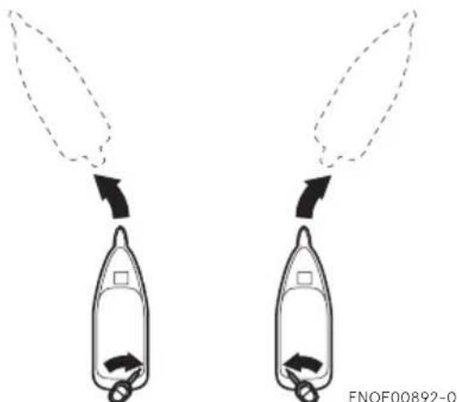
natural_image
Diagram showing two identical mechanical components with arrows indicating motion or force direction (no text or symbols)Remote control type
Right turn
Turn the steering wheel to the right.
Left turn
Turn the steering wheel to the left.
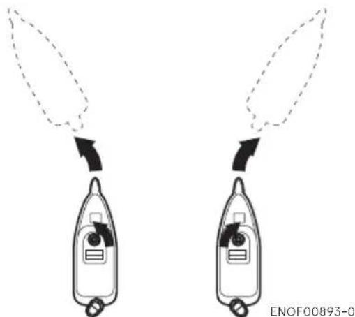
natural_image
Diagram showing two identical mechanical components with arrows indicating motion or force direction (no text or symbols)ENOM00050-0
8. Trim angle
ENOW00043-A

WARNING
- Adjust the trim angle when the engine is stopped.
- Do not put hand or finger in between outboard motor body and clamp bracket when adjusting trim angle to prevent injury in case the outboard motor body falls.
● Unsuitable trim position can cause loss of control of boat. When testing a trim position, run boat slow initially to see if it can be controlled safely.
ENOW00044-0

WARNING
Excessive trim up or down may lead to unstable boat operation, potentially causing the steering difficulty that leads to accident during cruising.
- Do not cruise at high speed if improve trim position is suspected. Stop the boat and readjust trim angle before continuing cruise.
- For outboard motor model with PTT switch on the bottom cowl, do not operate the switch during cruising, or control of boat may be lost.
The trim angle of the outboard motor can be adjusted to suit the transom angle of the hull, and load conditions. Choose an appropriate trim angle that will allow the anti-ventilation plate to run parallel to the water surface during operation.
ENOM00052-0
Proper trim angle
The position of the thrust rod is correct if the hull is horizontal during operation.
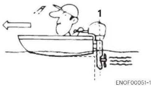
natural_image
Cartoon illustration of a person in a boat with a speedometer and directional arrow, no text or symbols present- Perpendicular to the water surface
ENOM00053-0
Improper trim angle (bow rises too high)
Set the thrust rod lower if the bow of the boat rises above horizontal.
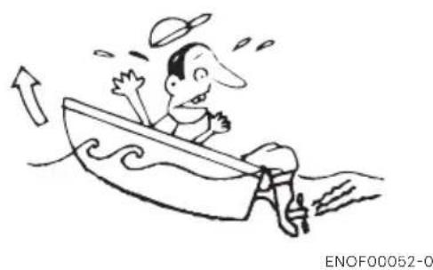
natural_image
Cartoon illustration of a man in a boat with motion lines indicating speed or effort (no text or symbols)ENOM00054-0
Improper trim angle (bow dips into the water)
Set the thrust rod higher if the bow of the boat is below horizontal.
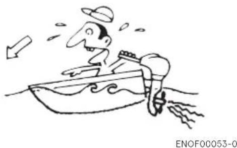
natural_image
Cartoon drawing of a man in a boat with a hat and surfboard, floating on water (no text or symbols)■ Manual Tilt type

text_image
1 2 ENOF00674-A- Thrust rod
- Higher
- Lower
■ Power Tilt type
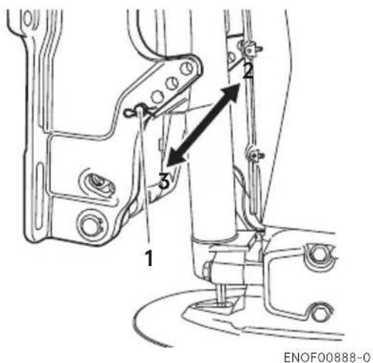
text_image
1 2 3 ENOF00888-0- Thrust rod
- Higher
- Lower
Trim angle adjustment (Manual tilt type)
The transom angle adjustment
- Stop the engine.
- Shift into neutral.
-
Raise the outboard motor to the tilt up position.
-
Change the thrust rod position as following picture.
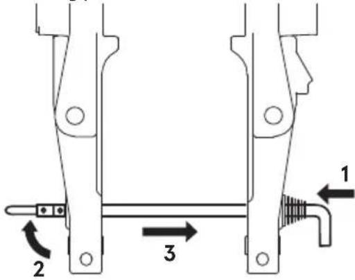
text_image
Technical diagram of a mechanical assembly with labeled parts 1, 2, and 3 indicating directional movement or assembly.ENOF01238-1
- Push in
- Rise the stopper
- Pull out
- Reinstall the thrust rod securely.
- Gentry lower the outboard.
Trim angle adjustment (Power tilt type)
The transom angle adjustment
- Stop the engine
- Operate the Power Tilt switch and raise the outboard motor to the tilt up position.
- Lock the tilt with the Tilt stopper.
- Change the trim lock pin position as following picture.
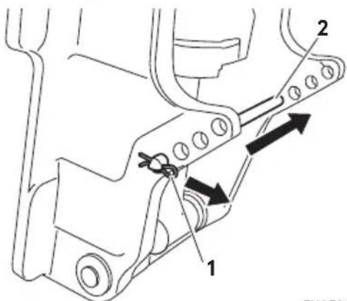
text_image
Technical diagram showing mechanical assembly with labeled parts and directional arrows indicating movement or forceENOF01147-0
- Snap pin
- Thrust rod
-
Reinstall the thrust rod securely.
-
Operate the Power Tilt switch and lower the outboard.
ENOM00060-A
9. Tilt up and down
ENOW00055-0
WARNING
Do not tilt up or down outboard motor when swimmer(s) or passenger is near to prevent them from being caught between outboard motor body and clamp bracket in case the outboard motor body falls.
ENOW00048-0
WARNING
When tilting up or down, be careful not to place your hand between the swivel bracket and the stern bracket.
Be sure to tilt the outboard motor down slowly.
ENOW00056-A
WARNING
When tilting up outboard motor with fuel joint for over a few minutes, be sure to disconnect fuel hose, or fuel may leak, potentially catching fire.
ENOW00057-0
CAUTION
Do not tilt up outboard motor while engine operates, or no cooling water may be fed, leading to engine seizure due to overheating.
ENON00921-0
Note
Before tilting the outboard motor up, after stopping the motor leave it in the running position for about a minute to
allow water to drain from inside the engine.
ENOM00062-A
Manual Tilt type (\*30, 40, 50 only) Tilt up
Push the reverse lock lever down until it stops. (This is the tilt up position.) Now, tilt the outboard motor all the way up until it is locked in place.
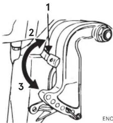
text_image
1 2 3 ENOENOF00059-0
- Reverse lock lever
- Tilt up position
- Tilt down position
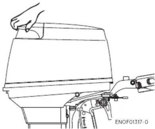
natural_image
Line drawing of a hand operating a mechanical component with a tool (no text or symbols)ENOM00063-0
Tilt down
Pull the reverse lock lever upward until it stops. (This is the tilt down position.) Now, lift up the outboard motor slightly, and then allow gravity to lower it for you.
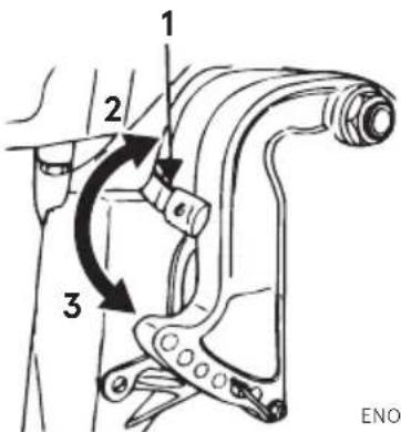
text_image
1 2 3 ENOENOF00059-0
- Reverse lock lever
- Tilt up position
- Tilt down position
ENOM00069-A
Power Trim & Tilt type
Tilt up
- Operate the Power Trim & Tilt switch and tilt the outboard motor up.
- Lock the tilt with the Tilt stopper after the outboard motor has been tilted up
Tilt down
- Release the tilt stopper from the set-up position while slightly tilting up outboard motor.
- Operate the Power Trim & Tilt switch and tilt the outboard motor down until the motor touches to the thrust rod.
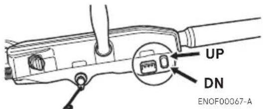
text_image
UP DN ENOF00067-A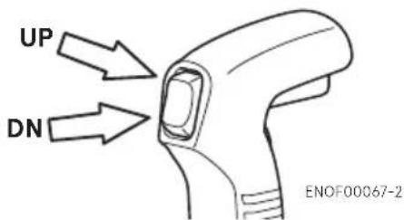
text_image
UP DN ENOF00067-2
text_image
UP DN ENOF00941-030, 40, 50

natural_image
Technical line drawing of a mechanical assembly with no visible text or symbolsENOF01318-0
- Tilt stopper
75, 90, 115
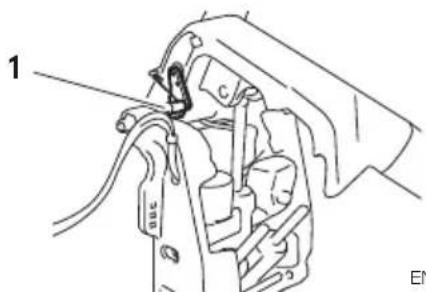
natural_image
Mechanical assembly diagram showing a clamp and lever mechanism (no text or labels)ENOF01319-0
- Tilt stopper
The outboard motor can also be tilted up and down using the switch provided under the bottom cowl.
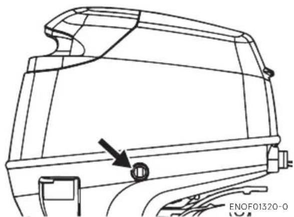
natural_image
Technical line drawing of a car door panel with an arrow pointing to a circular component (no text or symbols present)It is possible to tilt up or down in spite
of main switch "ON" or "OFF".
ENOM00940-0
Manual relief valve
If the battery is dead, and the power tilt switch thus inoperative, open the manual valve completely in the Manual direction. This will allow manual tilting of the outboard motor.
ENOW00872-0
WARNING
Make sure the manual relief valve is closed before operating the outboard motor. If the manual relief valve is not closed, the outboard motor will tilt up when operated in reverse.
ENOW00873-0
WARNING
Before opening the manual relief valve, make sure nobody is under the outboard motor. If the outboard motor is in the tilted up position, it will tilt down suddenly if the manual relief valve is loosened in the "Manual" direction.
30, 40, 50

text_image
POWER MANUAL 1 2ENOF00070-1
-
POWER
-
MANUAL
75, 90, 115
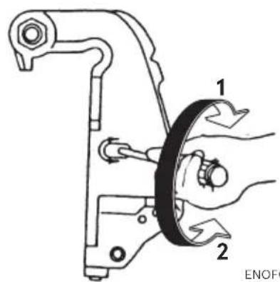
text_image
1 2 ENOF-
POWER
-
MANUAL
ENOM00068-A
10.Shallow water operation
ENOW00051-0

WARNING
During shallow water operation, be careful not to place your hand between the swivel bracket and the clamp bracket. Be sure to tilt the outboard motor down slowly.
ENOW00053-0

CAUTION
While in shallow water drive position, do not operate the outboard motor in Reverse. Operate the outboard motor at slow speed and keep the cooling water intake submerged.
ENOW00054-0

CAUTION
Do not overtilt outboard motor when driving shallow water, or air may be sucked through water inlet, potentially leading to engine overheating.

natural_image
Technical line drawing of a mechanical component with labeled parts (no readable text or symbols)ENOF01144-A
- Water inlet
Manual tilt type (\*30, 40, 50 only)
- Shallow water running position:
Put the reverse lock lever in the tilt up position, and tilt up the outboard motor to put the outboard motor in the shallow water running position.
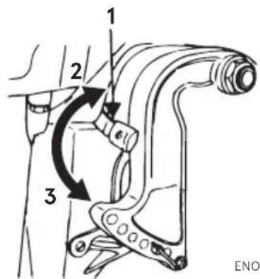
text_image
1 2 3 ENOENOF00059-0
- Reverse lock lever
- Tilt up position
- Tilt down position

natural_image
Technical line drawing of a mechanical device with an arrow indicating rotational motion (no text or symbols)- Return to normal running position:
Put the reverse lock lever in the tilt down position, slightly lift up the outboard motor, and then put it down.
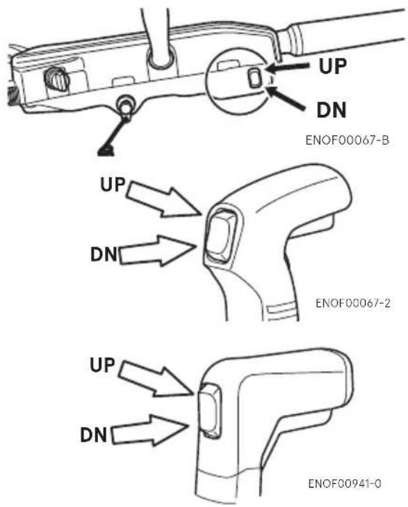
text_image
UP DN ENOF00067-B UP DN ENOF00067-2 UP DN ENOF00941-0
text_image
1 2 3 ENOF00059-0- Reverse lock lever
- Tilt up position
- Tilt down position
ENOM00069-A
Power Tilt type
- Operate the Power Tilt switch and tilt the outboard motor up into desired shallow water running position.
■ REMOVING AND CARRYING THE OUTBOARD MOTOR
ENOM00070-A
1. Removing the outboard motor
ENOW00890-0

WARNING
Before installing the outboard motor on the boat, hang the outboard motor with the hoist or equivalent device by attaching the engine hanger to the outboard.
Use the hoist with allowable load is 250 kg (550 lbs) or above.
ENOW00064-0

CAUTION
Engine may be hot immediately after operating and could cause burns if touched. Allow engine to cool down before attempting to carry the outboard.
- Stop the engine.
- Remove the top cowl.
- Disconnect the fuel connector, the remote control cables and the battery cords from the outboard motor.
- Attach the hoist hooks to the engine hanger.
- Remove the outboard motor from boat and completely drain the water from the gear case.
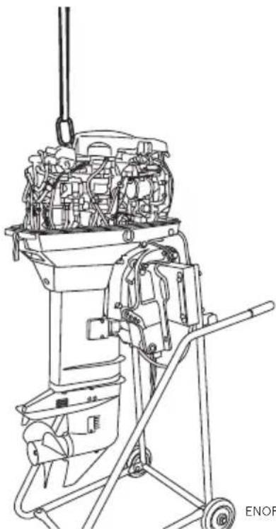
natural_image
Line drawing of a mechanical device with internal components and wheels (no text or symbols)ENOF01313-0
ENOM00071-A
2. Carrying the outboard motor
ENOW00933-0

WARNING
Be sure to disconnect fuel connector except when operating engine.
Fuel leakage is a fire or explosion hazard, which can cause serious injury or death.
ENOW00065-0

WARNING
Close air vent screw of fuel tank before carrying or storing outboard motor and fuel tank, or fuel may leak, potentially catching fire.
ENOW00066-A

CAUTION
Do not give a shock to an outboard motor during transportation. It becomes a cause of breakage.
Keep the outboard motor in a vertical position when carrying.
The optional outboard motor stand is recommended for keeping the outboard motor vertical both during transport and storage.

natural_image
Technical line drawing of a mechanical device with no visible text or symbolsENOF01321-0
ENON00021-A Note
- If the outboard motor must be laid down be sure drain the fuel and engine oil, then the port side faces down as shown in the following drawing.
- Elevate power unit 2 inches to 4 inches if traveling to avoid oil spillage.
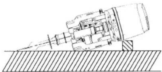
natural_image
Technical line drawing of a mechanical device with a sloped surface and no visible text or symbolsENOF00680-0
ENOM00072-A
3. Trailering
ENOW00072-0

CAUTION
Trailering in the tilted position may cause damage to the outboard motor, boat, etc.
ENOW00073-A

WARNING
Be sure to disconnect fuel connector except when operating engine.
Fuel leakage is a fire or explosion hazard, which can cause serious injury or death.
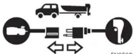
text_image
Diagram showing vehicle fuel system with truck, battery, plug, and valve symbols connected by bidirectional arrowsENOF00075-1
ENOW00068-0

WARNING
Close air vent screw of fuel tank and fuel cock before carrying or storing outboard motor and fuel tank, or fuel may leak, potentially catching fire.
ENOW00071-0

CAUTION
The tilt support device supplied on your outboard motor is not intended for towing. It is intended to support the outboard motor while the boat is docked, beached, etc.
When transporting a boat on a trailer with the outboard motor still attached, disconnect the fuel line from the outboard motor beforehand and keep the outboard motor in the normal running position or on a transom saver bar.
Tiller handle type
To prevent the outboard motor from moving when it is attached on a boat during transport on a trailer, properly tighten the steering friction lever (page 70).

text_image
1 2 ENOE00074-A- Ground clearance should be provided sufficiently.
- Transom saver bar
ENOW00067-0

WARNING
Do not go under outboard motor tilted up even if it is supported by support bar, or accidental fall of outboard motor could lead to severe personal injury.
ENOM00073-A
1. Steering friction
Tiller handle type (*30, 40, 50 only)
ENOW00074-B

WARNING
Do not overtighten the steering friction lever it could result in difficulty of movement resulting in the loss of control causing an accident and could lead to severe injury.
Adjust this lever to achieve the desired steering friction (drag) on the tiller handle. Move lever towards (2) to decrease friction and move lever towards (3) to increase friction.

text_image
Technical diagram of a mechanical assembly with numbered components and directional arrows indicating movement or force.

ENOF00910-0
- Steering friction lever
- Decrease
- Increase
ENOM00074-A
2. Throttle grip friction
*30, 40, 50 only
ENOW00074-B

WARNING
Do not overtighten the throttle adjustment screw or it could result in difficulty of move-
ment resulting in the loss of control causing an accident and could lead to severe injury.
Friction adjustment of the throttle grip can be made with the throttle adjustment screw.

text_image
1 2 3 ENOF00911-0- Throttle friction adjustment screw
- Decrease
- Increase
ENOM00075-0
3. Remote control lever friction
ENOW00074-C

WARNING
Do not overtighten the remote control throttle friction adjustment screw or it could result in difficulty of movement resulting in the loss of control causing an accident and could lead to severe injury.
To adjust the friction of the remote control lever, turn the throttle friction adjustment screw on the front of the remote control. Turn clockwise to increase the friction and counter-clockwise to decrease it.
Side mount type
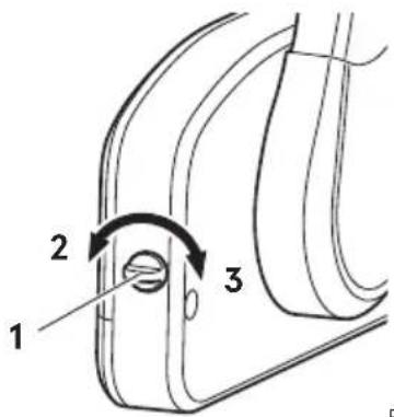
text_image
1 2 3ENOF00078-2
- Throttle friction adjustment screw
- Decrease
- Increase
Top mount type

text_image
2 3 1 ENOF00942-0- Throttle friction adjustment screw
- Lighter
- Heavier
ENOM00076-0
4. Trim tab adjustment
ENOW00076-1

WARNING
- Be sure that outboard motor is secured to transom or service stand, or accidental drop or fall of outboard motor could lead to severe personal injury.
- Be sure to lock outboard motor when it is tilted up, otherwise accidental fall of outboard motor could lead to severe personal injury.
- Do not go under outboard motor tilted up and locked, or accidental fall of outboard
motor could lead to severe personal injury.
ENOW00075-1

WARNING
Inappropriate adjustment of trim tab could cause steering difficulty. After installing or readjusting trim tab, check if steering load is even.
If straight-line cruising can not be achieved, adjust the trim tab located under the anti-ventilation plate.
- If the boat veers toward the left direct the trim tab towards A (left from rear of boat).
- If the boat veers toward the right direct the trim tab towards B (right from rear of boat).

natural_image
Diagram of a handheld device with an arrow indicating direction (no text or symbols)
natural_image
Simple line drawing of a handheld device with an upward arrow and dashed motion path (no text or symbols)
text_image
A 1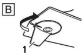
text_image
B 1ENOF00912-A
- Trim tab
ENON00022-A
Notes
● After adjustment securely tighten the trim tab fixing bolt.
- Check for looseness of the bolt and the trim tab at regular intervals.
INSPECTION AND MAINTENANCE
ENOM00077-0
Care of your outboard motor
To keep your outboard motor in the best operating condition, it is very important that you perform daily and periodic maintenance as suggested in the maintenance schedules that follow.
ENOW00077-0

CAUTION
- Your personal safety and that of your passengers depends on how well you maintain your outboard motor. Carefully observe all of the inspection and maintenance procedures described in this section.
- The maintenance intervals shown in the checklist apply to an outboard motor in normal use. If you use your outboard motor under severe conditions such as frequent full-throttle operation, frequent operation in brackish water, or for commercial use, maintenance should be performed at shorter intervals. If in doubt, consult your dealer for advice.
- We strongly recommend that you use only genuine replacement parts on your outboard motor. Damage to your outboard motor arising from the use of other than genuine parts is not covered under the warranty.
ENOM00703-0
1. Daily inspection
Perform the following checks and inspection before and after use.
ENOW00078-1

WARNING
Do not use outboard motor if any abnormality is found during pre-operation check otherwise it could result in severe damage to the motor or severe personal injury.
| Item Points to Check Remedy | ||
| Fuel System | ·Check the amount of fuel in the tank. Replenish·Check for dust or water in the fuel filter. Clean·Check rubber pipes for oil leakage. Replace·F u e l | |
| Fuel Tank Cap | ·Check for crack, leakage, damage in the fuel tank cap. Replace·Check for crack, damage in the gasket.·Check for leakage at full close. | ReplaceReplace |
| Lubrication System | ·Check the amount of engine oil in the oil tank.·Check for dust or water in the oil filters. | ReplenishClean |
| Electrical Equipment | ·Check the spark plugs for dirt, wear and carbon built-up.Spark plugs (30·40·50·75·90) NGK IZFR6Q (0.8 mm gap) (0.0315 in) Spark plugs (115) NGK IZFR5J (0.8 mm gap) (0.0315 in)·Check if the main switch functions normality.·Check if the battery electrolyte level and specific gravity are normal·Check for loose connections on battery terminal.·Check if the stop switch functions normally and make sure the lock plate is present.·Check cords for loose connections and damage. | Clean or replaceRemedy or replaceReplenish or rechargeRetightenRemedy or replaceCorrect or replace |
| Throttle Sys-tem | ·Check if the magneto works normally when turning the throttle grip, and also check links for looseness. | Correct |
| Clutch and Propeller Sys-tem | ·Check if the clutch engages correctly when operating the Remote Control. (or Shift lever)·Check the propeller for bent or damaged blades.·Check if the propeller nut is tightened and the split pin is present. | AdjustReplace |
| Installation of Motor | ·Check all the motor installation bolts with the boat.·Check the thrust rod installation. | TightenTighten |
| Power Trim & Tilt | ·Check working of the tilt up and down of the motor. | |
| Cooling Water | ·Check that cooling water is discharged from the cooling water check port after the engine has started. | |
| Tools and Spares | ·To be prepare tools and spare parts for replacing spark plugs, propeller, etc.·Check if the spare rope is provided. | |
| Item Points to Check | Remedy | |
| Steering Devices | ·Check working of steering handle and remote control. | |
| Other parts | ·Check if the anode and trim tab are securely installed. Repair if necessary·Check the anode and trim tab for corrosion and deformation. Replace | |
ENOM00082-A
Engine oil replenishing
ENOW00079-A

CAUTION
- Do not add engine oil of brand and grade other than existing one. In case engine oil of other brand or grade is added, drain all oil and ask dealer for treatment.
- In case other than engine oil such as gasoline is put in the oil chamber, empty the chamber and ask dealer for treatment.
- When replenishing engine oil, be careful not to allow entry of foreign matters such as dust or water into oil chamber.
- Wipe off engine oil well im spilled and dispose of it in accordance with local fire prevention and environment protection regulations.
- Do not replenish engine oil over upper limit. If overfilled, remove oil to upper limit. If engine oil is over the upper limit, it can leak and potentially lead to engine damage.
If the oil level is low, or at lowest mark, add recommended oil to the oil tank.
- Open the filler lid from the top cowl.
- Open the oil tank cap
- Fill the oil tank with the genuine engine oil.
- After replenishing of the oil tank, be sure to close the oil tank cap tightly.

text_image
1 2 3 ENOF00641-0- Genuine of recommended engine oil
mediately if - Oil tank cap
ENOM00083-A
Washing outboard motor
ENOW00081-0

WARNING
Do not start engine without removing propeller, or accidentally turning propeller could cause personal injury.
ENOW00082-0

WARNING
Never start or operate the engine indoors or in any space which is not well ventilated. Exhaust gas contains carbon monoxide, a colorless and odorless gas which can be fatal if inhaled for any length of time.
ENOW00920-0

CAUTION
When washing the outboard motor, be careful not to spray the water inside of the top cowl, especially electrical components.
ENON00026-0
Note
It is recommended to check chemical properties of water on which your outboard motor is regularly used.
If outboard motor is used in salt water, brackish water or water with a high acidic level, use fresh water to remove salt, chemicals or mud. And flush cooling water passage after every cruising or before storing outboard motor for long time. Before flushing, remove the propeller and the forward thrust holder.
ENOM00085-B
Flushing attachment (gear case) 30, 40, 50
ENOW00922-0

CAUTION
To prevent the engine from starting when you are near the propeller, remove the stop switch lock.
- Tilt down the outboard motor.
- Remove the water plug from the gear case, and screw in the flushing attachment.
-
Attach the flushing attachment and connect a water hose. Turn on the water and adjust the flow (Be sure to seal the water inlet and sub water inlet, located in the gear case with tape)
-
Put the shift lever in the neutral position and start the engine. Continue flushing the outboard motor for 3 to 5 minutes at idling.
- Stop the engine and water supply. Remove the flushing attachment and tape.
30, 40, 50
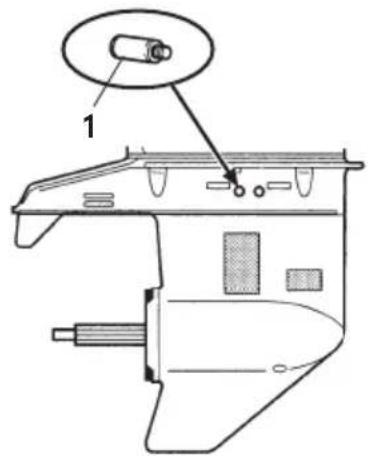
text_image
Technical diagram of a mechanical component with labeled parts and an inset detail viewENOF01324-0
- Flushing attachment
75, 90, 115.

text_image
Technical diagram of a mechanical device with labeled component 1 and annotation marker 'EN'ENOF01325-0
- Flushing attachment
ENOM00085-C
Flushing hose joint (bottom cowl)
*75, 90, 115
ENOW00921-0

CAUTION
Do not operate the engine when flushing the outboard motor with a flushing attachment as this can cause damage to the outboard motor.
ENOW00922-0

CAUTION
To prevent the engine from starting when you are near the propeller, remove the stop switch lock.
- Tilt down the outboard motor.
- Remove the flushing connector cap from the outboard motor, and screw in the hose joint.
- Attach the flushing attachment and connect a water hose. Turn on the water and adjust the flow.
Continue flushing the outboard motor for 3 to 5 minutes
- After the flushing, be sure to reattach the flushing connector cap.
- Tilt up the outboard motor.
75, 90, 115

text_image
ENOF01326-0- Hose joint
ENOM00085-A
Flushing by test tank
ENOW00081-0

WARNING
Do not start engine without removing propeller, or accidentally turning propeller could cause personal injury.
ENOW00082-0

WARNING
Never start or operate the engine indoors or in any space which is not well ventilated. Exhaust gas contains carbon monoxide, a colorless and odorless gas which can be fatal if inhaled for any length of time.
ENOW00036-A

CAUTION
When the engine is started in the test tank, to avoid over heating and water pump damage, be sure the water level is at least 10 cm (4 in.) above the anti ventilation plate.
And be sure to remove the propeller, when starting the engine in the test tank. (See page 83)
Run the engine only at idling.
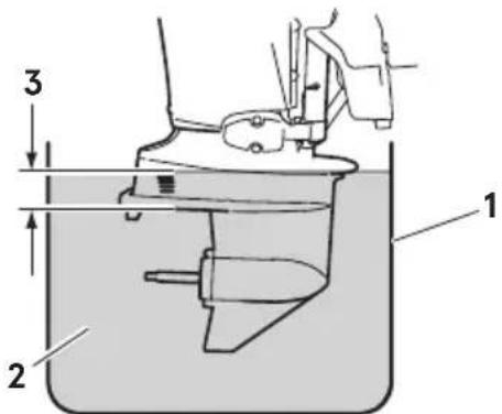
text_image
1 2 3ENOF00863-0
- Test tank
- Water
- Over 10 cm (4 in.)
ENOM00950-0
Fuse replacement
ENOW00923-0

CAUTION
Before replacing a fuse, disconnect the battery cable from the battery negative (-) terminal. Failure to do so may cause a short-circuit.
ENOW00924-0

CAUTION
Never use a fuse with a rating that exceeds the specified rating as this could cause serious damage to the electrical system.
If a blown fuse is detected, try to determine the cause for this and correct it. If the cause for the problem is not corrected, the fuse will likely blow again.
If the fuse continues to blow, request an authorized Tohatsu dealer to inspect the outboard motor.
- Stop the engine and disconnect the battery cable from the battery negative (-) terminal.
- Remove the engine cover.
- Remove the fuse box lid.
- Remove the fuse and check it. If the fuse is blown, replace it with a fuse of the same specified rating. The outboard motor is supplied with spare fuses in the spare fuse holder.
30, 40, 50.
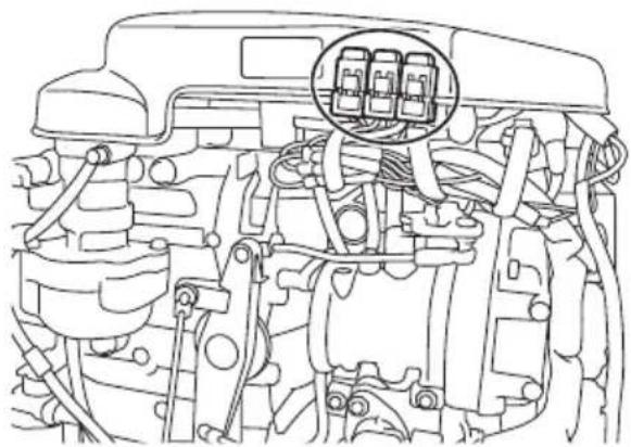
natural_image
Technical line drawing of an engine bay with internal components and a highlighted component (no text or symbols)
natural_image
Technical diagram of a mechanical component with labeled part 1 (no text or symbols beyond label)ENOF01327-0
- Blown fuse
75,90
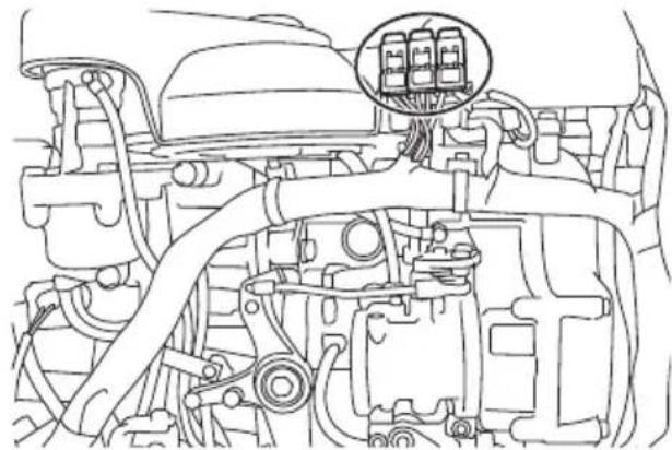
natural_image
Technical line drawing of an engine bay with a highlighted component (no text or symbols)
natural_image
Technical line drawing of a mechanical component with labeled part 1 (no text or symbols beyond label)ENOF01329-0
- Blown fuse
115
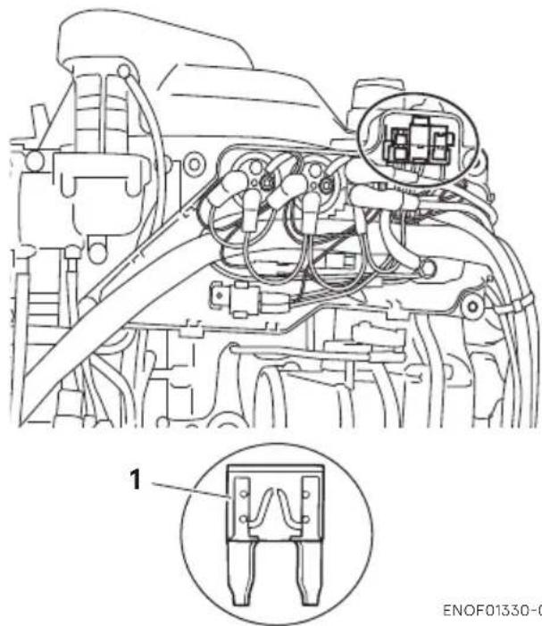
text_image
1 ENOF01330-0- Blown fuse
2. Periodic inspection
It is important to inspect and maintain your outboard motor regularly. At each interval on the chart below, be sure to perform the indicated servicing. Maintenance intervals should be determined according to the number of hours or number of months, whichever comes first.
For periodic inspection and maintenance, consult your servicing dealer.
| Description | Inspection intervals | Inspection procedure Remarks | |||||
| First 20 hours of 1 month | Every 50 hours of 3 months | Every 100 hours of 6 months | Every 200 hours of 1 year | ||||
| Fuel System/Compression System | Fuel filter | ● | ● | Replace ● | Check and clean or Replace if necessary. | Entire cartridge | |
| High pressure fuel filter ^-1 | Replace ● | Replace every 200 hrs or 2 years | |||||
| Piping/Hoses | ● | ● | ● | Replace ● | Check and clean or Replace if necessary | ||
| Fuel tank | ● | ● | ● | ● | Clean Including filter | ||
| Fuel tank cap | ● | ● | ● | ● | Check and clean or Replace if necessary. | ||
| Fuel pump ^*1 | ● | ● | ● | ● | Check and clean or Replace if necessary. | ||
| Air filter ^*1 | ● | ● | Check and clean or Replace if necessary. | ||||
| Drive belt ^*1 | ● | ● | Check and Replace if necessary. | ||||
| Fuel Pressure ^*1 | ● | ● | Check and replace defective parts if necessary. | ||||
| Air Pressure ^*1 | ● | ● | Check and replace defective parts if necessary. | ||||
| Ignition Spark | plug | ● | ● | ● | Remove carbon deposits or Replace if necessary. | 0.8-0.9 mm(0.031-0.035 in) | |
| Starting System | Starter motor ^*1 | ● | ● | Check for salt deposits and the battery cable condition. | |||
| Battery | ● | ● | ● | ● | Check installation, fluid quantity, gravity. | ||
| Engine oil system | Oil tank | ● | ● | ● | Check and clean or Replace if necessary. | ||
| Oil pipe | ● | ● | ● | ||||
| Oil filter | ● | ● | ● | Check and clean or Replace if necessary. | |||
| Lower Unit | Propeller | ● | ● | ● | ● | Check for bent blades, damage, wear. | |
| Gear oil | Replace ● | Replace ● | Replace ● | Change or replenish-oil and check for water leaks. | |||
| Water pump ^*1 | ● | ● | ● | Check for wear or damage. | Replace impeller every 12 months. | ||
| Thermostat ^1 | ● | ● | Check and Replace if necessary. | ||||
| Power trim & tilt ^*1 | ● | ● | ● | Check & replenish oil, manually operate | |||
| Warning system*1 | ● | ● | ● | Check function | |||
| Bolts and Nuts | ● | ● | ● | ● | Retighten | ||
| Sliding and Rotating Parts. Grease Nipples | ● | ● | ● | ● | Apply and pump in grease. | ||
| Outer Equipment | ● | ● | ● | ● | Check for corrosion. | ||
| Anode | ● | ● | ● | Check for corrosion and deformation. | Replace if necessary. | ||
*1: Have this handled by your dealer
ENON00030-0
Note
Your outboard motor should receive careful, and complete inspection at 300 hours. This is the best time for major maintenance procedures to be carried out.
ENOM00093-A
Fuel filters and fuel tank cleaning
ENOW00093-A

WARNING
Gasoline and its vapors are very flammable and can be explosive.
- Do not start this procedure while engine is operating or hot even after stopping it.
- Place fuel filter away from every source of ignition such as sparks or open flames.
● Wipe off gasoline well spilled and dispose of it in accordance with local fire prevention and environment protection regulations.
● Install fuel filter with all related parts in place, or fuel leak could occur, leading to catching fire or explosion. - Check fuel system regularly for leakage.
- Contact authorized dealer for fuel system services. Services by unqualified person could lead to engine damage.
Fuel filters are provided inside the fuel tank and engine.
ENOM00094-0
Fuel filter (for engine)
- Check in the cup for water and debris.
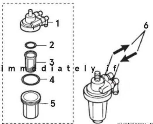
text_image
1 2 3 4 5 im m e d i a t e l y i f 6 FNOF00096-P-
Body
-
O-ring
-
Filter
-
O-ring
-
Cup
-
Arrow to indicate fuel flow direction
-
If present, disconnect hoses from the fuel connector (male) and the fuel pump.
-
Remove the cup, filter and O-rings from the fuel filter body.
-
Check the wear and clogging for each parts, and replace if necessary.
- Remove fuel and any water or debris from the cup, filter and hoses.
- Reassemble all parts.
ENOM00096-A
Fuel filter (for fuel tank)
Water or dirt in the fuel tank will cause engine performance problems.
Check and clean the tank at specified times or after the outboard motor has been stored for a long period of time (over three months).
- Remove four screws to remove the Fuel Pick-Up.
- Clean the fuel filter and replace the gasket.
- Reassemble all parts.
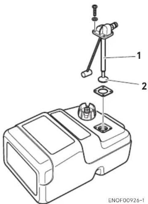
text_image
1 2 ENOF00926-1- Fuel pick-up
- Filter
ENOM00725-0
Oil filter
Oil filter and oil tank. Check the oil tank and/or filter for entrapped water and dust.
- Disconnect all pipes between the oil tank and oil pump.
- Clean out foreign matter.
- Refit the pipes to the oil tank and pumps, and then fill up with new engine oil.
- For air purging, refer to "Engine oil feeding" (See page 38)
30, 40, 50
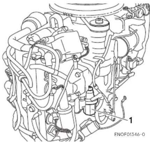
natural_image
Technical line drawing of an internal combustion engine assembly (no text or labels)- Oil filter
75, 90, 115

natural_image
Technical line drawing of an engine assembly with hoses and components (no text or symbols)- Oil filter
ENOM00098-A
Gear oil replacement
ENOW00094-0

WARNING
- Be sure that outboard motor is secured to transom or service stand, or accidental drop or fall of outboard motor could lead to severe personal injury.
- Be sure to lock outboard motor tilted up, or accidental fall of outboard motor could lead to severe personal injury.
-
Do not go under outboard motor tilted up and locked, or accidental fall of outboard motor could lead to severe personal injury.
-
Tilt down the outboard motor.
- Remove the oil plugs (lower and upper), and completely drain the gear oil into a pan.
30, 40, 50

natural_image
Line drawing of a propeller inside a container with a hand holding a screwdriver (no text or symbols)75, 90, 115

text_image
if it is ENOF01332-0- Insert the oil tube nozzle into the lower oil plug hole, and fill with gear oil by squeezing the oil tube until oil flows out of the upper plug hole and bubbles is disappeared to remove the air.
30, 40, 50
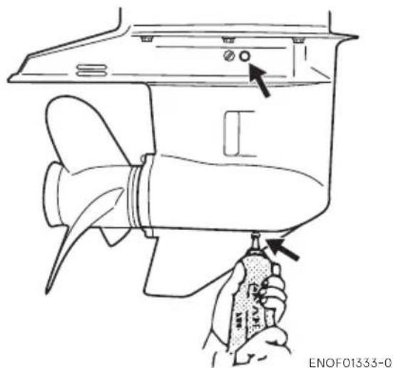
natural_image
Line drawing of a hand holding a propeller inside a boat hull, with no visible text or symbols75, 90, 115
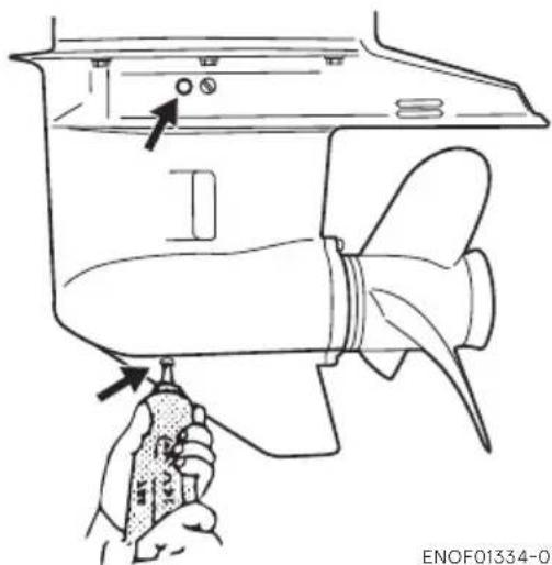
natural_image
Line drawing of a ship's propeller with a hand holding a tool, showing structural components and a valve (no text or symbols)- Install the upper oil plug, and then remove oil tube nozzle and install the lower oil plug.
ENOW00095-0

CAUTION
Do not reuse oil plug gasket. Always use new gasket and tighten oil plug properly to prevent entry of water into lower unit.
30, 40, 50

natural_image
Technical line drawing of a propeller inside a container with a hand holding a screwdriver (no text or symbols)75, 90, 115
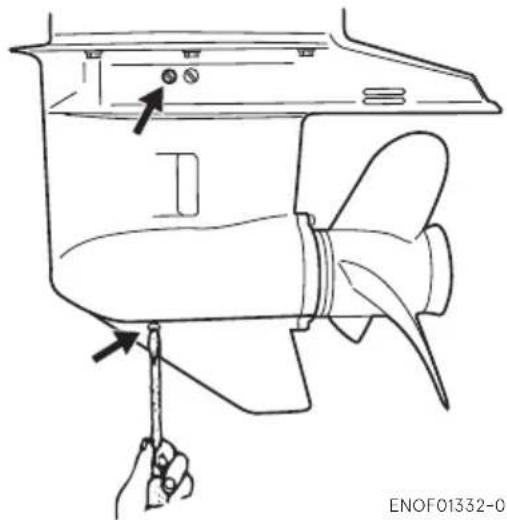
natural_image
Line drawing of a propeller with a hand holding a screwdriver, showing internal components and mounting brackets (no text or symbols)ENOW00928-0

CAUTION
Wipe off gear oil well immediately if spilled and dispose of it in accordance with local fire prevention and environment protection regulations.
ENON00032-0
Note
If water in the oil, giving it a milky colored appearance. Contact your dealer.
ENON00033-0
Note
Use genuine gear oil or the recommended one (API GL-5: SAE #80 to #90).
Required volume 30, 40, 50: approx. 500 mL (16.9 fl.oz), 75, 90, 115 approx. 900 mL (30.4 fl.oz).
ENOM00086-A
Propeller replacement
ENOW00084-0

WARNING
- Do not begin propeller removal and installation procedure with spark plug caps attached, shift in forward or reverse, main switch at other than "OFF",
engine stop switch lock attached to the switch, and starter key attached, or engine could accidentally start leading to serious personal injury. Disconnect battery cable if possible.
● The propeller edge is thin and sharp. Wear the groves during replacement to protect your hands.
ENOW00086-0

CAUTION
- Do not install propeller without thrust holder, or propeller boss could be damaged.
- Do not reuse split pin.
- After installing split pin, spread the pin apart to prevent it from falling out which could lead to the propeller coming off during operation.
A worn-out or bent propeller will lower the motor's performance, and cause engine trouble.
- Put a piece of wood block between propeller blade and anti-ventilation plate to hold propeller.

natural_image
Line drawing of a hand using a wrench to adjust or install a mechanical component (no text or symbols present)- Remove the split pin, propeller nut and washer.
-
Remove the propeller and thrust holder.
-
Apply water proof grease to the propeller shaft before installing a new propeller.
- Install the thrust holder, propeller, stopper, washer and propeller nut onto the shaft.
30, 40, 50

text_image
ENOF01315-0- Propeller
- Thrust holder
- Stopper
- Washer
- Propeller nut
- Split pin
75, 90, 115
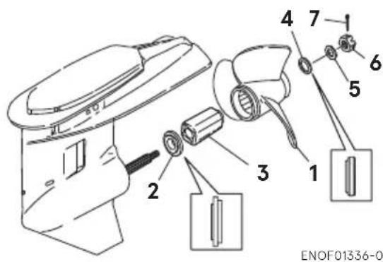
text_image
ENOF01336-0- Propeller
- Thrust holder
- Bush
- Stopper
- Washer
- Propeller nut
-
Split pin
-
Tighten the propeller nut to speci- fied torque, and align one of grooves to propeller shaft hole.
Propeller nut torque:
35 N·m (25 ft·lb, 3.5kgf·m)
- Install a new split pin into the nut hole and bend it.
ENOF00084-D
ENOM00087-A
Spark plugs replacement
ENOW00087-0

WARNING
- Do not reuse spark plug with damaged insulation, or sparks can leak through crack, potentially leading to electric shock, explosion and/or fire.
- Do not touch spark plugs immediately after stopping engine as they will be hot and could cause severe burns if touched. Allow motor to cool down first.
ENOW00929-0

CAUTION
Use only the recommended spark plugs. Spark plugs which have an different heat range may cause engine damage.
If the spark plug(s) is fouled, has carbon build up, or is worn, it should be replaced.
When reusing spark plugs, remove dirt from the electrodes and adjust spark gap to specification.
- Stop the engine.
- Remove the top cowl.
- Remove the spark plug caps.
- Remove the spark plugs by turning it counter-clockwise, using a 5/8" (16 mm) socket wrench and handle that is provided in tool bag.
- Inspect the spark plug. Replace the spark plug if the electrodes are worn or if the insulators are cracked or chipped.
- Measure the spark plug electrode gap with a wire type feeler gauge. The gap should be 0.8-0.9 mm (0.031-0.035 inches). If the gap is different, replace the spark plug with a new one
Use spark plug with referring specification (See page 13)

text_image
1 2 ENOE00085-0ENOF00085-0
- Electrode
-
Spark gap (0.8–0.9 mm, 0.031–0.035 in)
-
Install the spark plug by hand and turn it carefully to avoid cross-threading.
-
Tighten the spark plug to the specified torque.
ENON00028-0
Note
- Spark plug torque:
18.0 N·m (13.3 ft·lb) [1.84 kgf·m]
If a torque-wrench is not available when you are fitting a spark plug, a good estimate of the correct torque is 1/4 to 1/2 a turn past finger-tight. Have the spark plug adjusted to the correct torque as soon as possible with a torque-wrench.

natural_image
Line drawing of hands assembling or adjusting an internal engine block (no text or symbols visible)ENOM00088-A
Anode replacement
A sacrificial anode protects the outboard motor from electrolytic corrosion. Anode is located on the gear case, cylinder etc.. When the anode is eroded more than 1/3 of original size, replace it.
ENON00029-0
Notes
● Never grease or paint the anode.
- At each inspection re-tighten the anode attaching bolt. As it is likely to be subjected to electrolytic corrosion.

text_image
75, 90, 115 30, 40, 50 *1 75, 90 75, 90 *2 75, 90, 115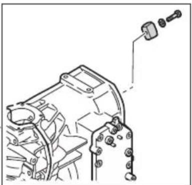
natural_image
Technical line drawing of a mechanical assembly with a bracket and mounting holes (no text or symbols)
natural_image
Technical line drawing of a car engine bay with a magnified inset showing internal components (no text or symbols)
natural_image
Line drawing of a portable air conditioner unit with attached accessories (no text or symbols)*1
ENOF01339-0
*1: Both side
*2 : Handle by your dealer
ENOM00089-B
Power Tilt oil checking
ENOW00088-0

WARNING
- Be sure that outboard motor is secured to transom or service stand, or accidental drop or fall of outboard motor could lead to severe personal injury.
- Be sure to lock outboard mo tilted up, or accidental fall of outboard motor could lead to severe personal injury.
- Do not go under outboard motor tilted up and locked, or accidental fall of outboard motor could lead to severe personal injury.
ENOW00089-A

CAUTION
Do not unscrew the oil cap with the outboard motor tilted down. Pressurized oil in the oil tank may spurt out.
Check the oil level in the reservoir tank while the tank is kept in a vertical position.
- Tilt the outboard motor up and lock the tilt with the tilt stopper.
- Remove the oil cap by turning counter clockwise, then check if the oil level reaches the bottom line of the plug hole.
40,50
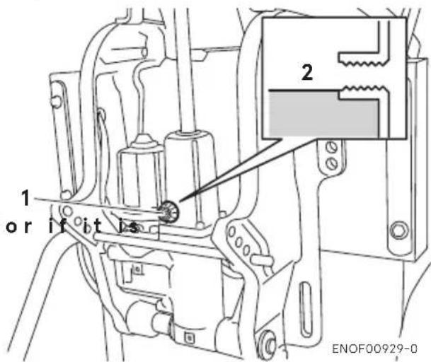
text_image
1 or it it is 2 ENOF00929-0- Oil cap
- Oil level
75, 90, 115
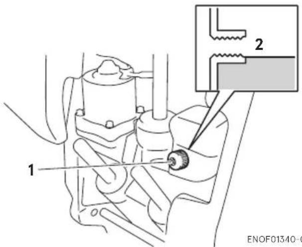
text_image
1 2 ENOF01340-0- Oil cap
- Oil level
Recommended oil
Use an automatic transmission fluid or equivalent.
Recommended oils are as shown below.
ATF Dexron III
Air purging from the Power Trim and Tilt unit.
Entrapped air in the Power Tilt unit will cause poor tilting movement and increased noise.
-
With the outboard motor mounted on the boat, set the manual release valve to the Manual side, and tilt the outboard motor manually up/down 5-6 times while checking the oil level.
-
When done, close the valve by turning it clockwise towards the Power side.
30, 40, 50
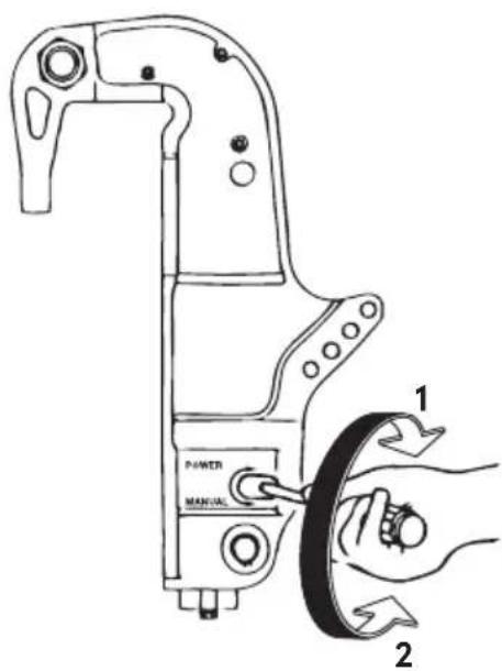
text_image
POWER MANUAL 1 2ENOF00070-1
-
POWER
-
MANUAL
75, 90, 115
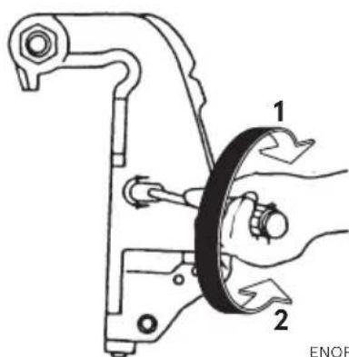
text_image
Technical diagram showing mechanical assembly with labeled parts 1 and 2, indicating a turning or disassembly process.ENOF00679-0
-
POWER
-
MANUAL
ENOM00960-0
Grease point
Apply water proof grease to the parts shown below.
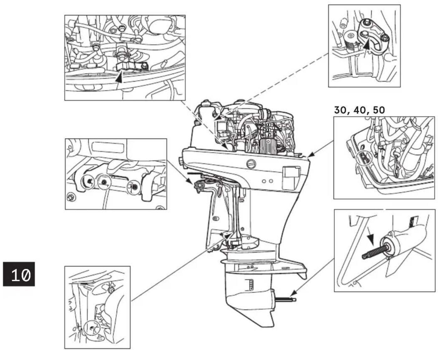
text_image
30, 40, 50 10ENOF01341-0
ENOM00100-A
3. Off-season storage
ENOW00934-0

WARNING
- Be sure to disconnect except when operating engine.
- Fuel leakage is a fire or explosion hazard, which can cause serious injury or death.
ENOW00097-0

WARNING
Be sure to use cloth to remove fuel remaining in the cowl and dispose of it in accordance with local fire prevention and environment protection regulations.
ENOW00096-0

CAUTION
Before servicing the motor for storage:
- Remove the battery cables.
- Remove the spark plug caps from the spark plugs.
- Do not run the motor out of the water.
Before you put your outboard motor in storage, it is a good opportunity to have it serviced and prepared by your dealer. Be sure to use fuel stabilizer while running the motor before storage. (See page 92)
ENOM00101-B
Engine
-
Wash the engine exterior and flush the cooling water system thoroughly with fresh water. Drain the water completely.
Wipe off any surface water with an oily rag. -
Remove the fuel hose from the outboard motor.
-
Drain all fuel from the fuel hoses, fuel pump, fuel filter (See page 80) and vapor separator (See page 92), and clean these parts.
Keep in mind that if gasoline is kept in the vapor separator for a long time, gum and varnish will develop, causing the float valve to stick, restricting the fuel flow. -
Remove the spark plugs and put a teaspoon of engine oil or spray storage oil into the combustion chamber through the spark plug holes.
-
Turn the starter motor several turns to lubricate inside the cylinder.
ENOW00930-0

WARNING
- Be sure to remove stop switch lock to prevent ignited the spark plugs.
-
Put a cloth to spark plug hole and wipe up any spilled engine oil, when cranking the outboard motor.
-
Change the gear oil in the gear case (See page 82).
-
Apply grease to grease point (See page 90).
-
Stand the outboard motor up vertically in a dry place.

natural_image
Technical line drawing of a mechanical device with no visible text or symbolsENON00021-A
Note
- If the outboard motor must be laid be sure drain the fuel and engine oil, then the outboard motor on a cushion as shown in the following drawing (See page 68 and 92). - Elevate power unit 2 inches to 4 inches if traveling to avoid air intrusion in the Power Trim and Tilt pump system.
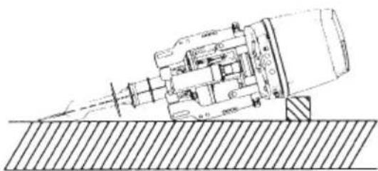
natural_image
Technical line drawing of a mechanical assembly with no visible text or symbolsENOF00680-0
ENOM00950-0
Adding a fuel stabilizer
When adding a fuel stabilizer additive (commercially available), first fill the fuel tank with fresh fuel. If the fuel tank is only partially filled, air in the tank can cause the fuel to deteriorate during storage.
- Before adding fuel stabilizer additive, drain the vapor separator (See page 92).
- Follow the instructions on the label when adding the fuel stabilizer additive.
-
After adding the additive, let the outboard motor run in the water for 10 minutes to make sure any old fuel in the fuel system has been completely replaced by the fuel with additive.
-
Turn the engine OFF
ENON00891-0
Note
If your motor is used occasionally, it is recommended to use a good fuel stabilizer in every tank of fuel and keep the container full to reduce condensation and evaporation.
ENOM00970-0
Fuel system draining
ENOW00028-A

WARNING
For details on handling fuel, contact an authorized dealer.
Fuel and fuel vapors are extremely flammable and can be explosive.
- If fuel is spilled, wipe it up immediately.
- Keep the fuel tank well away from sources of ignition, e.g. sparks or open flames
● Perform all work outdoors or in ventilated place.
ENOW00097-0

WARNING
Be sure to use cloth to remove fuel remaining in the cowl and dispose of it in accordance with local fire prevention and environment protection regulations.
-
Disconnect the fuel hose from the outboard motor.
-
Remove the top cowl.
-
Release the drain tube from the clamp and pull the tube outside the bottom cowl. Place an approved fuel container under the drain tube end and use a funnel to avoid spilling fuel.
-
Loosen the vapor separator drain screw.
-
Tilt up the outboard motor until fuel flows out of the drain tube.
-
Leave the outboard motor in this position until all fuel has been drained.
-
When thoroughly drained, retighten the drain screw securely.
-
Check the drained fuel for the presence of water or other contaminants. If either reassemble the outboard motor, refill the vapor separator with fuel, and then drain the fuel again. Repeat this procedure until no water or other contaminants are present in the drained fuel.
30, 40, 50
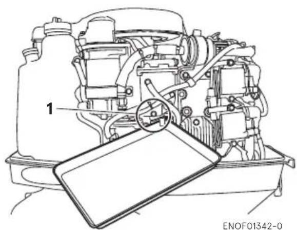
natural_image
Technical line drawing of a mechanical assembly with labeled component '1' and a tablet device (no text or symbols beyond label)*Remove fuel filter before draining
- Vapor separator drain screw
75, 90, 115
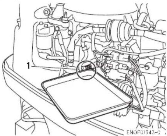
natural_image
Technical line drawing of an engine bay with a tray and gear assembly (no text or symbols)- Vapor separator drain screw
ENOM00102-0
Battery
ENOW00931-A
WARNING
- Place the battery away from any source of fire, sparks and open flames such as burners or welding equipment.
- Place the battery away from fuel tank. s present Accidental sparks of battery may cause explosion of gasoline.
-
Disconnect the battery cables and be sure to remove the negative terminal first.
-
Wipe off any chemical deposits, dirt, or grease.
-
Apply grease to the battery terminals.
-
Charge the battery completely before storing it for the winter.
-
Recharge the battery once a month to prevent it from discharging and the electrolyte from deteriorating.
-
Store the battery in a dry place.
ENOM00104-C
4. Pre-season check
The following steps must be taken when first using the engine after off-season storage.
- Check that the shift and throttle function properly. (Be sure to turn the propeller shaft when checking the shift function or else the shift linkage may be damaged.)
- Check the electrolyte level, and measure the voltage and specific gravity of the battery.
| Specific Gravity at 20°C | Terminal Voltage (V) | Charge Condition |
| 1.120 10.5 | Fully discharged | |
| 1.160 11.1 | 1/4 charged | |
| 1.210 11.7 | 1/2 charged | |
| 1.250 | 12 | 3/4 charged |
| 1.280 | 13.2 | Fully charged |
- Check that the battery is secure and the battery cables are properly installed.
- Change the engine oil (See page 74).
- Before starting the engine, disconnect stop switch lock and crank approximately 3 times of 3 sec. turning the starter motor in order to prime the oil pump.
- Fill fuel tank completely.
- Start the engine and warm up the engine for 3 minutes in the "NEU-TRAL" position.
-
Run the engine for 5 minutes at the slowest speed.
-
Run the engine for 10 minutes at half throttle. The oil used for storage inside the engine will be circulated out to assure optimum performance.
ENOM00105-A
5. Submerged outboard motor
ENOW00098-0
CAUTION
Do not attempt to start submerged outboard motor immediately after it is recovered, or engine could be severely damaged.
After taking your outboard motor out of the water, immediately take it to your dealer.
The following are the emergency measures to be taken for a submerged outboard motor, if you can not take it your dealer right away.
- Wash the outboard motor with fresh water to remove salt or dirt.
- Remove the engine oil drain screw and completely drain water and oil from the engine.
-
Remove the spark plugs, and completely drain the water from the engine by pulling emergency starter rope (See page 51) several times.
Replace oil filter and oil to the correct level.
The oil and filter may need to be changed again after running a short period to get all moisture completely out of the crankcase. -
Inject a sufficient amount of engine oil through the spark plug holes.
Pull the emergency starter rope several times to circulate the oil throughout the outboard motor.
ENOM00106-A
6. Cold weather precautions
If you moor your boat in cold weather at temperatures below 0^ C ( 32^ F), there is the danger of remained water freezing in the cooling water pump, which may damage the pump, impeller, etc. To avoid this problem, submerge the lower half of the outboard motor into the water.
ENOM00107-A
7. Striking underwater object
ENOW00935-0

CAUTION
Striking the sea bottom or an underwater object may severely damage the outboard motor.
Follow the procedure below and consult a dealer as soon as possible.
-
Stop the engine immediately.
-
Check the control system, gear case, boat transom etc.
-
Return to the nearest harbor slowly and carefully.
-
Consult a dealer check the outboard motor before operation again.
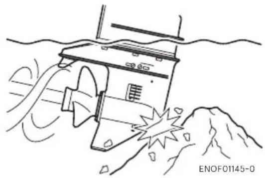
natural_image
Illustration of a ship navigating through water with visible wake and hull (no text or symbols)ENOM00121-0
8. Operation with multiple outboard motors
When operating the outboard motors in reverse at more than the lowest speed, be sure that all engines are running.
If any engine has stopped, be sure to tilt the outboard motor up and keep its propeller out of the water.
Otherwise, water could enter the engine and cause damage to it.
TROUBLESHOOTING
ENOM00720-0
If you encounter problem with the engine, check the list below and locate the problem you are experiencing. Then follow the suggested remedies.
Do not hesitate to contact your dealer, as professionals advice and assistance is the best way to keep the engine in optimum condition.
| Difficult to start engine | Engine runs erratically | Boat speed loss | Battery will not hold charge | Starter motor will not crank | Power Trim & Tilt Inoperative | Possible cause |
| ● | Empty fuel tank | |||||
| ● | ● | Incorrect connection of fuel system | ||||
| ● | ● | Air enters fuel line | ||||
| ● | ● | Deformed or damaged fuel pipe | ||||
| ● | Closed air vent on fuel tank cap | |||||
| ● | ● | Fuel filter/fuel pump is clogged with dust. | ||||
| ● | Use of improper gasoline | |||||
| ● | Incomplete forced fuel feeling by primer bulb | |||||
| ● | ● | Poor connection in compression system | ||||
| ● | ● | Use of non-specified spark plugs | ||||
| ● | ● | Dirt or carbon deposits on spark plugs | ||||
| ● | ● | No sparking or poor sparking (Failure in component of Ignition system) | ||||
| ● Insufficient cooling water flow | ||||||
| ● | ● | Propeller cavitation | ||||
| ● Incorrect propeller selection | ||||||
| ● | ● | Damaged or bent propeller | ||||
| ● Unbalanced loading. Overload | ||||||
| ● Transom is too high/low | ||||||
| ● Bottom of the boat is stained or damaged. | ||||||
| ● | ● | Insufficient throttle aperture. | ||||
| ● | ● | Battery is charged insufficiently. | ||||
| ● | ● | ● | ● | Battery is nearly dead, Poor connection of battery terminal, Low level of electrolyte | ||
| ● | Power trim & tilt switch is defective. | |||||
| ● | ● | Wrong positioning of shift lever at N (neutral) position. | ||||
| ● | ● | ● | ● | Main switch in defective. | ||
| ● | Lock plate is not inserted or poorly inserted into stop switch. | |||||
| ● | ● | ● | ● | Wrong wiring, disconnection, poor connection. | ||
| ● | ● | Faulty operation of starter motor/starter solenoid | ||||
| ● | A great deal of air is contained inside pump. | |||||
ENOM00721-0
30, 40, 50
The following a list of the tools and spare parts provided with the motor.
| Name Quantity Remark | |||
| Service tools | Tool bag 1Socket wrench 1 10 × 13 mmSocket wrench 1 16 mmSocket wrench handle 1Pliers 1Screwdriver 1 Cross-and straight-pointScrewdriver handle 1 | ||
| Spare parts | Emergency starter rope 1Spark plug 3 NGK IZFR6QSplit pin 1 Diameter × Length 3 × 25 mmStop switch lock | 1 | |
| Parts packaged with engine* | Bracket fixing boltsBracket fixing nutsWashers A, BDrag linkFuel tank (with primer bulb)Remote control boxTachometer 1Trim meterLead wire for meter | 4 12 mm4 12 mm4 each1111 | A (large), B (small)Not included as standard accessories in US & Canada markets. |
ENOM00722-0
75, 90, 115
The following a list of the tools and spare parts provided with the motor.
| Name | Quantity | Remark | ||
| MD 75/90 MD 115 | ||||
| Service tools | Tool bag 11Socket wrench (16 mm) 1 1Socket wrench (10 × 13) 1 1Socket wrench handle 1 1Pliers 1 1Screwdriver (Phillips-type and flat head) | 1 | 1 | A d a |
| Spare parts | Spark plug (75/90)Spark plug (115)Split pin 1 1 Diameter × Length 3 × 25 mm | 3 | 4 | NGK IZFR6QNGK IZFR5J |
| Parts packaged with engine* | Bracket fixing boltsBracket fixing nutsWashers A, BDrag linkHose jointPrimer bulb ass'y | 444 each11111 | 444 eachFor flushing | 12 mm12 mmA (large), B (small) |
* Fuel tank, remote control box, tachometer, trim meter, meter lead wire and propeller are not enclosed in the engine package.
PROPELLER TABL
ENOM00724-0
To ensure optimum performance, the propeller should match the boat type and its load.
Use a genuine propeller.
A propeller must be selected so that the engine rpm measured at wide open throttle, while cruising, is within the recommended range.
5150-5850 min ^-1 (rpm)
30, 40, 50
| Pitch | |
| Lighter load 15 | |
| 14 | |
| 13 | |
| 12 | |
| 11 | |
| 9 | |
| Heavier load 7 | ^1 |
*1: Shows propeller with four blades.
75, 90, 115 ^*2
| Pitch | |
| Lighter load 21 | |
| 19 | |
| 17 | |
| 15 | |
| 13 | |
| 11 | |
| Heavier load 9 |
*2: The 75-115 model is supplied with so standard propeller. It is shipped from the factory without a propeller.
OWNER'S MANUAL
MD 30B2
MD 40B2
MD 50B2
MD 75C2
MD 90C2
MD 115A2
TOHATSU CORPORATION
5-4, Azusawa 3-Chome, Itabashi-Ku
Tokyo 174-0051, Japan
Tel: +81-3-3966-3117 Fax: +81-3-3966-0090
www.tohatsu.com