Cadet 240 Aero - Boat ZODIAC - Free user manual and instructions
Find the device manual for free Cadet 240 Aero ZODIAC in PDF.

User questions about Cadet 240 Aero ZODIAC
0 question about this device. Answer the ones you know or ask your own.
Ask a new question about this device
Download the instructions for your Boat in PDF format for free! Find your manual Cadet 240 Aero - ZODIAC and take your electronic device back in hand. On this page are published all the documents necessary for the use of your device. Cadet 240 Aero by ZODIAC.
USER MANUAL Cadet 240 Aero ZODIAC
● CAREFULLY READ THIS MANUAL BEFORE OPERATING YOUR BOAT.
- THIS OWNER'S MANUAL IS IN TWO VOLUMES THAT MUST BE KEPT TOGETHER.
NOTICE:
THE OWNER'S MANUAL IS IN TWO VOLUMES:
- VOLUME 1
DEALS WITH OPERATING PRECAUTIONS AND SAFETY RECOMMENDATIONS THAT MUST BE OBSERVED.
- VOLUME 2
DEALS WITH TECHNICAL SPECIFICATIONS AND ASSEMBLY PROCEDURE OF THE BOAT AND ITS EQUIPMENT.
VOLUME 2
TECHNICAL SPECIFICATIONS - ASSEMBLY PROCEDURE
ZODIAC
CADET AERO
240 AERO - 260 AERO
CADET FAST ROLLER ACTI-V
CFR 285 ACTI-V - CFR 325 ACTI-V
CADET FAST ROLLER ACTI-V INT'L
CFR 360 ACTI-V INT'L
CONTENTS
| Page | Page | ||
| ⇒Assembly procedure | 2 | ⇒Pressure | 7 |
| ⇒Check on unpacking | 2 | ⇒Assembly of equipment | 8 |
| ⇒Assembly | 3-4 | ⇒Deflation - folding the boat | 9 |
| ⇒Inflation system 5 | |||
| ⇒Inflation | 6 | ⇒General description | I - VI |
ASSEMBLY PROCEDURE
We recommend that you follow the specific order of the assembly procedure. Proceed step by step and refer to the corresponding pages.
| PROCEDURE PAGE SECTION | ||
| 1. inventory the elements composing your boat, and learn how to recognise them | 2 | CHECK ON UNPACKING |
| I - V | DESCRIPTION | |
| 2. Install the stowage box (Model Int’L only) | 3 | ASSEMBLY |
| 3. activate valves into inflating position | 5 | INFLATION SYSTEM |
| 4. install the H2P floor in the boat | 4 | ASSEMBLY |
| 5. Begin inflation of the boat. (not completely) | 6 | INFLATION |
| 6. Inflate the H2P floor to correct pressure | 6 | INFLATION / PRESSURE |
| 7. Install the seat 8 | ASSEMBLY OF EQUIPMENT | |
| 8. finish inflation of the boat to the correct pressure | 6- 7 | INFLATION / PRESSURE |
| 9. Install the oars 8 | ASSEMBLY OF EQUIPMENT |
CHECK ON UNPACKING

DO NOT USE A SHARP TOOL
The pack must contain: 1 buoyancy tube +
| CADET | Aero240 | Aero260 | CFR285 acti-v | CFR325 acti-v | CFR360 acti-v – Int’L |
| Inflatable floorboard H2P + keel | X | X | |||
| Acti-V floorboard (built-in keel) | X | ||||
| Repair kit | X | X | X | X | X |
| Owner’s manual * | X | X | X | X | X |
| Standard equipment | |||||
| Removable wooden seat | X | X | X | X | X |
| Carry bag | X | X | X | X | X |
| Reinforced aluminium oar | 2 | 2 | 2 | 2 | 2 |
| Fuel tank strap | X | X | X | X | X |
| High pressure foot pump | X | X | X | X | X |
| Stowage box Int'L (with bag) | X | ||||
* 2 volumes
You can equip your boat with many optional accessories (transportation wheels, boarding ladder, lifting rings etc.). Ask your dealer to advise you.
BOAT ASSEMBLY

CHOOSE A SMOOTH, CLEAN SURFACE.
IF THE BUOYANCY TUBE WAS STORED AT A TEMPERATURE BELOW 0°C / 32°F, LEAVE IT AT 20°C / 68°F FOR 12 HOURS BEFORE UNFOLDING.
INSTALLING THE REMOVABLE RECESSED STOWAGE BOX (INT'L SYSTEM ONLY).

THE STOWAGE BOX MUST BE INSTALLED ON ITS FLANGE BEFORE INFLATING THE MAIN BUOYANCY TUBE.
IF THE TUBE IS INFLATED WITHOUT THE BOX, THE POCKET PROVIDING SEALING INTEGRITY MAY BE DAMAGED.

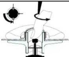
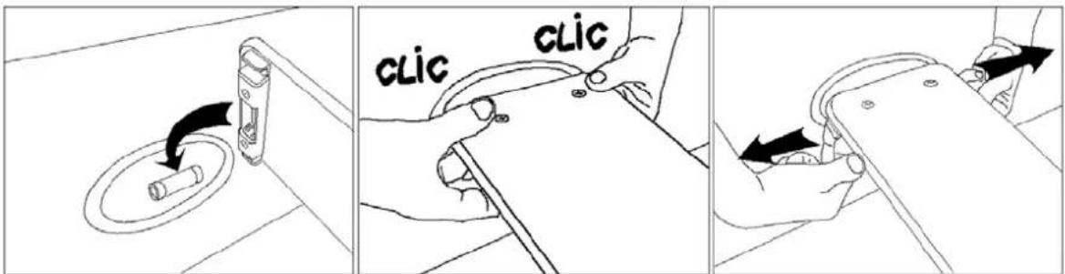
TO LOCK THE BOX ON ITS FLANGE, INSERT THE BOX LUGS INTO THE CORRESPONDING SOCKETS ON THE FLANGE.
CAUTION THERE IS A PREFERENTIAL POSITION (LOCK SLOT TOWARDS THE INSIDE AND IN THE BOAT'S LONGITUDINAL CENTERLINE) TO ALLOW THE BOX TO BE TURNED TO ITS LOCKED POSITION.
CAUTION:
THE BOAT MUST BE DEFLATED FOR THE INSTALLATION
THE BOAT MUST NEVER BE INFLATED WITHOUT THE BOX BEING INSTALLED.
1- Insert the box into the buoyancy tube flange.
The lock closing slot must be in the boat's longitudinal centerline and towards the inside of the deck
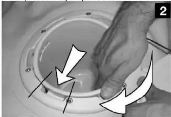
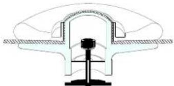
2- Lock the box by turning it through a 1/6th of a turn in the clockwise direction.
3- Make sure that the box is properly locked and fully home.
You can then inflate the boat
4- Always use the key to open or close.
natural_image
Close-up of a hand pressing down on a circular mechanical component with directional arrows indicating motion (no text or symbols)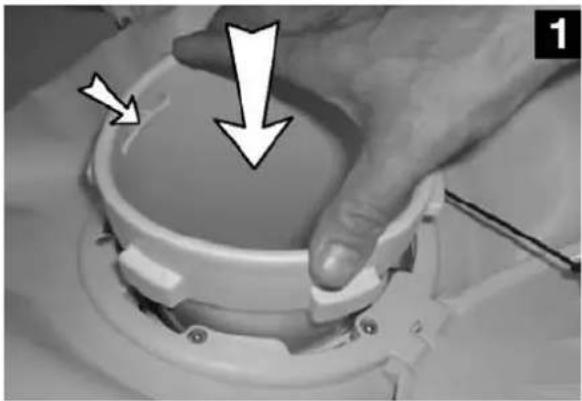
natural_image
Close-up of a hand holding a small electronic device with two white arrows pointing to the top surface (no text or symbols visible)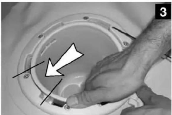
natural_image
Close-up of hands adjusting a circular mechanical component with arrows pointing to features (no text or symbols visible)REMOVING THE REMOVABLE RECESSED STOWAGE BOX.

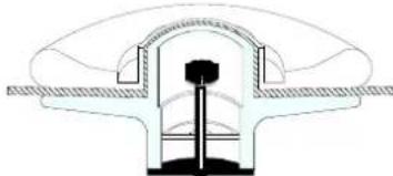
IT IS ESSENTIAL TO DEFLATE THE BOAT (ZERO PRESSURE) BEFORE REMOVING THE REMOVABLE BOX.
TO FOLD THE BOAT AFTER DEFLATING IT, FIRST REMOVE THE REMOVABLE BOX (following the assembly procedure in the reverse order).
ASSEMBLY
Choose a smooth and clean surface.

IF THE BUOYANCY TUBE WAS STORED AT A TEMPERATURE BELOW 0°C / 32°F, LEAVE IT AT 20°C / 68°F FOR 12 HOURS BEFORE UNFOLDING.
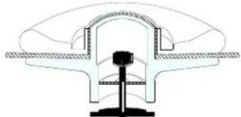
THE H2P INFLATABLE FLOOR:
H2P INFLATABLE FLOOR DEFLATED
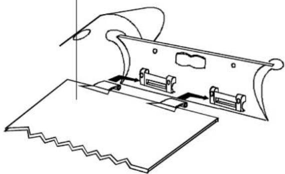
natural_image
Technical line drawing of a mechanical assembly with spring-loaded components and a curved housing (no text or symbols)Your boat is delivered with the inflatable floor and its keel already assembled.

Cadet fast roller Acti-V - Air floor Inflating procedure:
- Before inflating, open out the boat and position the keel on the central band of the bottom and on the floorboard axis (centered between the positioning pins).
- FIRST inflate the keel-floorboard assembly to its rated pressure.
- Check that the keel inflated perpendicular to the floorboard and that it is still positioned on the central band of the bottom (otherwise, reposition).
- Inflate the main buoyancy tube.
- Press the floorboard down around the edges to fit it into the hollow of the angle.
MAINTENANCE / DISMANTLE OF THE H2P INFLATABLE FLOOR
We recommend that you leave the H2P floor in the boat when folding.
To clean perfectly the boat proceed as follow :
Deflate the boat and the floor.
inflate again the boat a little.
Wash off with clear water, then raise the boat's nose to evacuate water and sand or rubbish.
Do not separate the keel from the floor nor from the buttom.
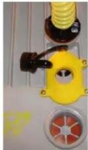
INFLATION SYSTEM
THE HIGH PRESSURE FOOT-PUMP
A

natural_image
Close-up of a yellow spiral hose with black components and a star-shaped emblem (no visible text or symbols)
MAX PRESSURE
0,3 bar (4,4 psi)
B
natural_image
Close-up of industrial piping components including a yellow valve, black connector, and red circular valve (no visible text or symbols)
MAX PRESSURE 1,0 bar (14,7 psi)

A

C

Position A
The pump has maximum flow but low pressure: this position is used to give shape rapidly to all inflatable parts of the boat.
Position B
The flow is inferior to position A, but provides pressure that is superior, with the same effort.
Position C
To deflate. Insert the tube as indicated in figure C and pump normally.
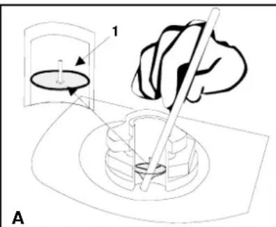
THE STANDARD VALVES
(1) cap (2) valve insert (3) base
To activate the standard valves into INFLATION position:
• Free the valve insert from its protection.
- Unscrew the valve cap.
- Screw the valve support onto its base (screw it tight but without exaggeration, not to deteriorate the screw thread) and check that the valve cap stays accessible.
TO DEFLATE:
Unscrew the valve support from its base

text_image
1 2 3THE SEMI-RECESSED VALVES
| To activate the valves: | Inflation position | Deflation position | |
 |  |  | |
| press the push-in stem a quarter of a turn | diaphragm closed, the inner button springs upwards | diaphragm open, the inner button goes down | |
| NOTICE: | TO SCREW OR UNSCREW THE VALVE CAPS, TURN WITHOUT PRESSING OR FORCING (THIS COULD UNSCREW THE INNER VALVE SYSTEM). | ||
NOTICE:
THE VALVES « EASY – PUSH ».
| To change the position: | Inflation position | Deflation position |
 |  |  |
| Push / Push | diaphragm closed, the inner button springs upwards | diaphragm open, the inner button goes down |
INFLATION
Activate all valves into inflation position.
Fit the hose to the foot-pump.
To inflate your boat properly, the bottom side of the foot-pump must rest on a flat ground. Pump evenly to inflate rapidly.

natural_image
Illustration of a robotic arm with human and non-robotic symbols, no text or labels present
DO NOT USE A COMPRESSOR OR A BOTTLE OF COMPRESSED AIR
A - INFLATE THE FLOOR (AERO) OR THE ACTI-V FLOORBOARD / KEEL ASSEMBLY
- Activate the valve into inflating position.
- Inflate in position A (cap inserted) until it becomes difficult to operate.
- Finish inflation in position B (cap removed) until you reach correct pressure (800 mb–11.3 PSI)
B - INFLATE THE MAIN BUOYANCY TUBE

MAXIMUM PRESSURE IN THE MAIN BUOYANCY TUBE: 240 MBARS (3.48 PSI) NEVER USE POSITION B TO INFLATE THE MAIN TUBE OR THE KEEL : THERE WOULD BE A RISK OF BURST.
- Insert the pump hose end piece (add to the semi-recessed valve the correct connecting tip).
- Inflate the main buoyancy tube and the keel (in position A - cap inserted) until it becomes difficult to operate.(correct pressure = 240 mb / 3.48 PSI), reefer to PRESSURE section making sure that each compartment is equal. When correctly inflated, the compartments bulkheads are not visible.

NEVER INFLATE A COMPARTMENT TO FULL PRESSURE IF OTHER COMPARTMENTS ARE TOTALLY DEFLATED
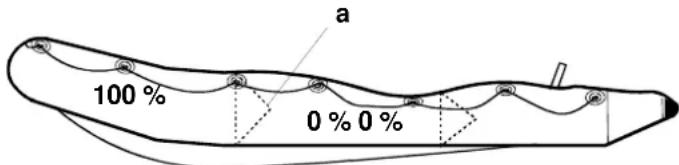
text_image
100% 0% 0% a
1
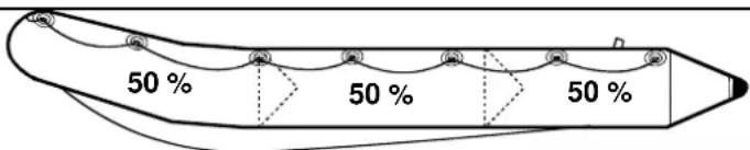
text_image
50 % 50 % 50 %
2

text_image
100 % 100 % 100 %INFLATE THE KEEL (AERO RANGE only)
- Once the H2P floorboard is installed, inflate the keel (240 mb).
Inflation is over: fit the valve caps tight (clockwise).
| NOTICE : | A slight air-leak before screwing the valve caps is normal.ONLY THE VALVE CAPS CAN ENSURE FINAL AIR TIGHTNESS. |
PRESSURE
The correct pressure for the buoyancy tube and the AirLite keel is 240 mb / 3,48 PSI, and 800 mb / 11,3 PSI for the H2P inflatable floor.
If your boat is not equipped with an ACCESS pressure indicator, we recommend that you purchase one from your Dealer. This will permit a quick and efficient control of the pressure during inflation. Without a pressure indicator, stop inflating when the foot-pump gets difficult to operate, and the boat is « hard » (you should not be able to bend the cone ends).
| Ambient temperature of air and water Ambient have an effect on the boat's internal +1°C / +1,8°F pressure -1°C / -1,8°F -4 mb / 0,06 PSI | int temperature tubes' internal pressure |
Therefore, it is important to anticipate:
Because of temperature variations (especially when this variation is important between the beginning and the end of the day, in hot areas) check and adjust the pressure in the inflated compartments by inflating or deflating. Be sure that pressure remains within the recommended pressure, between 220 mb / 3,10 PSI and 270 mb / 3,85 PSI.
RISK OF UNDERPRESSURE
EXAMPLE: Your boat is in direct sunlight on the beach (temperature =50°C/122°F) at recommended pressure (240 mb/3,48 PSI). after putting it in the colder water (temperature =20°C/68°F), the internal temperature and pressure of the tubes will both drop (up to 120 mb/1,7 PSI) and YOU WILL HAVE TO INFLATE AGAIN until you regain the lost pressure due to the difference in temperatures. Therefore, a loss of pressure, at the end of the day when ambient temperature drops, is perfectly normal.
NOTICE :
Proper inflation is critical to the performance of the boat. It is the pressure in the tubes that gives your boat the necessary rigidity to perform well. Under-inflation causes improper flexing of the tubes which will result in stress and chafe
RISK OF OVERPRESSURE
EXAMPLE: Your boat is inflated to the recommended pressure (240 mb/3,48 PSI) at the beginning of the day (low ambient temperature =10°C/50°F). Later in the day, your boat is in direct sunlight on the beach or on a yacht's deck (temperature =50°C/122°F). Internal temperature of all inflated compartments can then increase and reach up to 70°C/158°F (especially for dark-coloured tubes). The consequence will be a doubling of previous pressure (480 mb/6,8 PSI). YOU WILL THEN HAVE TO DEFLATE until you reach the recommended pressure.

WHEN YOUR BOAT IS OVER INFLATED, PRESSURE BECOMES TOO STRONG FOR THE INFLATABLE STRUCTURE, AND COULD CAUSE A BREAK IN THE FABRIC ASSEMBLY
IN CASE OF OVERPRESSURE
STANDARD VALVE (A):
Free some air by pushing on the diaphragm (1) with a blunt object.
Beware not to fold down the diaphragm.
SEMI-RECESSED OR "EASY PUSH" VALVE (B):
Deflate by pressing the spring loaded button.
text_image
1 A
natural_image
Diagram of a mechanical or fluidic device with directional arrows indicating flow or movement (no text or symbols)ASSEMBLY OF STANDARD EQUIPMENT
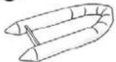
TO ASSEMBLE AND INSTALL THE OARS:

text_image
Technical diagram illustrating four-step assembly steps of a cleaning tool, labeled 1 to 4 with directional arrows and component illustrations.
text_image
Clic
natural_image
Three-step diagram showing mechanical assembly steps: press, clamping, and hand press (no text or symbols)THE REMOVABLE SEAT
Install the seat before the boat is totally inflated.
text_image
CLIC CLICDEFLATING / FOLDING THE BOAT
We recommend that you leave the H2P floor in the boat when folding. To clean perfectly the boat proceed as follow:
- Deflate the boat and the floor; then inflate again the boat a little.
- Wash off with clear water, and then raise the boat's nose to evacuate water and sand or rubbish.
Acti- V models : do not separate the keel from the floor nor from the buttom.
- Deflate the boat (remember to hold the valve insert on the H2P inflatable floor so that it doesn't fly off) and remove the stowage box on Int'l models.
- Replace the valve protections.
- Remove oars and equipment.
- Empty the boat of all water and sand by opening the self-bailers, dry it.
- Fold in the 2 sides of the main buoyancy tube, fold the cones onto the transom (A), then fold the boat as show on figure B and C. Start again if you feel there is still some air left in the tubes.

text_image
A B buoyancy tube floor tube deflated 1 : floor 2 : anti-skidding fins 3 : transom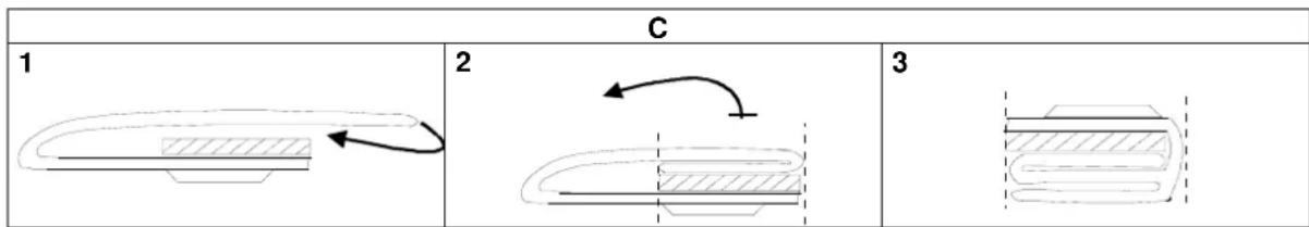
text_image
C 1 2 3| CAUTION | DO NOT ATTEMPT TO FOLD THE ANTI-SKIDDING FINS, YOU COULD DETACH THEM FROM THE FLOOR |
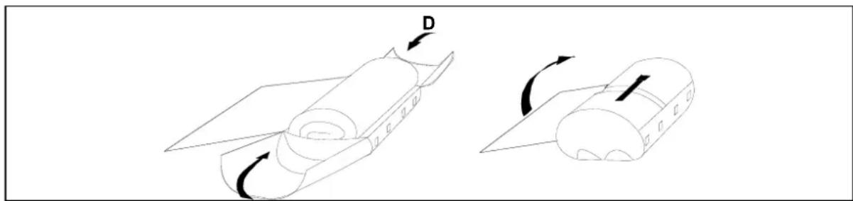
Stow the boat in its bag as follows (D):
. Stow the boat folded on its bag open (back side of the bag visible).
. Position the oars dismantled on top
. Close the bag and fasten the two front straps.
. Tight the side ropes (make sure that all equipment stays inside).
. To finish, store the foot-pump in the front pocket.