VR-6070 - Receiver KENWOOD - Free user manual and instructions
Find the device manual for free VR-6070 KENWOOD in PDF.

User questions about VR-6070 KENWOOD
0 question about this device. Answer the ones you know or ask your own.
Ask a new question about this device
Download the instructions for your Receiver in PDF format for free! Find your manual VR-6070 - KENWOOD and take your electronic device back in hand. On this page are published all the documents necessary for the use of your device. VR-6070 by KENWOOD.
USER MANUAL VR-6070 KENWOOD
This instruction manual is for some models. Model availability and features (functions) may differ depending on the country and sales area.
About the supplied remote control
Compared to standard remote controls, the remote control supplied with this receiver has several operation modes. These modes enable the remote control to control other audio/video components. In order to effectively use the remote control it is important to read the operating instructions and obtain a proper understanding of the remote control and how to switch its operation modes (etc.). Using the remote control without completely understanding its design and how to switch the operation modes may result in incorrect operations.
Units are designed for operation as follows.
U.S.A. and Canada AC 120 V only
Australia AC 240 V only
Europe and U.K. AC 230 V only
China and Russia AC 220 V only
Other countries ...... AC 110-120 / 220-240 V switchable*
For the United Kingdom
Factory fitted moulded mains plug
- The mains plug contains a fuse. For replacement, use only a 13-Amp ASTA-approved (BS1362) fuse.
- The fuse cover must be refitted when replacing the fuse in the moulded plug.
- Do not cut off the mains plug from this equipment. If the plug fitted is not suitable for the power points in your home or the cable is too short to reach a power point, then obtain an appropriate safety approved extension lead or adapter, or consult your dealer. If nonetheless the mains plug is cut off, remove the fuse and dispose of the plug immediately, to avoid a possible shock hazard by inadvertent connection to the mains supply.
IMPORTANT: The wires in the mains lead are coloured in accordance with the following code:
Blue : Neutral
Brown : Live
Do not connect those leads to the earth terminal of a three-pin plug.
\* AC voltage selection
The AC voltage selector switch on the rear panel is set to the voltage that prevails in the area to which the unit is shipped. Before connecting the power cord to your AC outlet, make sure that the setting position of this switch matches your line voltage. If not, it must be set to your voltage in accordance with the following direction.
AC voltage selector switch

text_image
Move switch lever to match your line voltage with a small screwdriver or other pointed tool. VOLTAGE SELECTOR 4C.118- 120V~ 4C.228- 24V~Note:
Our warranty does not cover damage caused by excessive line voltage due to improper setting of the AC voltage selector switch.
Safety precautions
WARNING :
TO PREVENT FIRE OR ELECTRIC SHOCK, DO NOT EXPOSE THIS APPLIANCE TO RAIN OR MOISTURE.

CAUTION
RISK OF ELECTRIC SHOCK
DO NOT OPEN
DO NOT OPEN

CAUTION: TO REDUCE THE RISK OF ELECTRIC SHOCK, DO NOT REMOVE COVER (OR BACK). NO USER-SERVICEABLE PARTS INSIDE. REFER SERVICING TO QUALIFIED SERVICE PERSONNEL.

THE LIGHTNING FLASH WITH ARROWHEAD SYMBOL, WITHIN AN EQUILATERAL TRIANGLE, IS INTENDED TO ALERT THE USER TO THE PRESENCE OF UNINSULATED "DANGEROUS VOLTAGE" WITHIN THE PRODUCT'S ENCLOSURE THAT MAY BE OF SUFFICIENT MAGNITUDE TO CONSTITUTE A RISK OF ELECTRIC SHOCK TO PERSONS.

THE EXCLAMATION POINT WITHIN AN EQUILATERAL TRIANGLE IS INTENDED TO ALERT THE USER TO THE PRESENCE OF IMPORTANT OPERATING AND MAINTENANCE (SERVICING) INSTRUCTIONS IN THE LITERATURE ACCOMPANYING THE APPLIANCE.
Contents
Caution : Read the pages marked carefully to ensure safe operation.
| Preparations | Before applying the power ...... 2Safety precautions ...... 2Unpacking ...... 3How to use this manual ...... 4Special features ...... 5Names and functions of parts ...... 6Main Unit ...... 6Remote control unit (RC-R0813) (VR-6070) and (RC-R0814) (KRF-X9060D) ...... 7Remote control unit (RC-R0815) (KRF-X9060D)(For the U.K. only) ...... 8Setting up the system ...... 9Connecting audio components ...... 10Connecting video components ...... 11Digital connections ...... 12Connecting video components (COMPONENT VIDEO) ...... 13Connecting a DVD player (6-channel input) .... 14Connecting the speakers ...... 15Connecting the terminals ...... 16Connecting to another room (ROOM B) ...... 17PRE OUT connections ...... 18Connecting the RF antenna and external IR Repeater (For VR-6070 only) ...... 19Connecting to the AV AUX jacks ...... 20Connecting the antennas ...... 20Connecting the system control ...... 21Preparing the remote control ...... 22RF remote control function (For VR-6070 only) ... 22Preparing for surround sound ...... 23Speaker settings ...... 23 |
| Operations | Normal playback......26Preparing for playback......26Listening to a source component......26Adjusting the sound......27Recording......29Recording audio (analog sources)......29Recording video......29Recording audio (digital sources)......29Listening to radio broadcasts......30Tuning (non-RDS) radio stations......30Using RDS (Radio Data System)(For the U.K. only)......30Presetting radio stations manually......30Receiving preset stations......31Receiving preset stations in order (P.CALL) ... 31Using the RDS DISP (Display) key(For the U.K. only)......31Presetting RDS stations (RDS AUTOMEMORY) (For the U.K. only)......32Tuning by Program TYPE (PTY search)(For the U.K. only)......32Ambience effects......33Surround modes......33Surround play......36DVD 6-channel playback......37Convenient functions......38 |
| Remote Control | Basic remote control operations for other components......41 |
| Registering setup codes for other components......41 | |
| Operating other components......42 | |
| Storing the remote control code of the other components......42 |
| Remote Control | Setup code chart (RC-R0813) (VR-6070) and (RC-R0814) (KRF-X9060D)...... 43 |
| Setup code chart (RC-R0815) (KRF-X9060D) (For the U.K. only)...... 44 | |
| CASSETTE deck, CD player & MD recorder operations...... 45 | |
| Other components' operations...... 46 |
| Additional Information | In case of difficulty | 48 |
| Specifications | 50 |
Unpacking
Unpack the unit carefully and make sure that all accessories are present.
| FM indoor antenna (1) AM loop antenna (1)RF remote antenna (1)(For VR-6070 only) |
| For VR-6070Remote control unit (1) Batteries (R6/AA) (2)RC-R0813 |
| For KRF-X9060DRemote control unit (1) Batteries (R6/AA) (2)RC-R0814 |
| For KRF-X9060D(For the U.K. only)Remote control unit (1) Batteries (R6/AA) (2)RC-R0815 |
| *AC plug adaptor (1)*Use to adapt the plug on the power cord to the shape of the wall outlet.(Accessory only for regions where use is necessary.) |
If any accessories are missing, or if the unit is damaged or fails to operate, notify your dealer immediately. If the unit was shipped to you directly, notify your shipper immediately. Kenwood recommends that you retain the original carton and packing materials in case you need to move or ship the unit in the future.
Keep this manual handy for future reference.
How to use this manual
This manual is divided into four sections, Preparations, Operations, Remote Control, and Additional Information.
Preparations
Shows you how to connect your audio and video components to the receiver and prepare the surround processor.
Since this receiver works with all your audio and video components, we will guide you in setting up your system to be as easy as possible.
Operations
Shows you how to operate the various functions available on the receiver.
Remote Control
Shows you how to operate other components using the remote control, as well as a detailed explanation of all remote control operations. Once you have registered your components with the proper setup codes, you'll be able to operate both this receiver and your other AV components (TV, VCR, DVD player, CD player, etc.) using the remote control supplied with this receiver.
Additional Information
Shows you additional information such as "In case of difficulty" (trouble-shooting) and "Specifications".
Maintenance of the unit
When the front panel or case becomes dirty, wipe with a soft, dry cloth. Do not use thinner, benzine, alcohol, etc. for these agents may cause discoloration.
In regard to contact cleaner
Do not use contact cleaners because it could cause a malfunction. Be specially careful not to use contact cleaners containing oil, for they may deform the plastic component.

As an ENERGY STAR® Partner, Kenwood Corporation has determined that this product meets the ENERGY STAR® guidelines for energy efficiency.
This product can save energy. Saving energy reduces air pollution and lowers utility bills.
Memory back-up function
Please note that the following items will be deleted from the unit's memory if the power cord is disconnected from the AC outlet for approximately 1 day.
- Power mode.
- Input selector settings.
- Picture output.
- Speaker ON/OFF.
- Volume level.
• BASS, TREBLE, INPUT level. - TONE ON/OFF.
- LOUDNESS ON/OFF.
- Dimmer level.
- MD/TAPE settings.
• RF-BAND. (VR-6070 only) - Listen mode setting.
- Speaker settings
-
SW RE-MIX ON/OFF.
-
Distance setting.
- Bass peak level.
- Input mode setting.
- Midnight mode setting.
• PRO LOGIC II mode setting. - CS II mode setting.
- Broadcast band.
- Frequency setting.
- Preset stations.
- Tuning mode.
- THX mode.
- ACTIVE EQ mode.
- SPEAKER EQ mode.
- DSP mode.
For the U.S.A.
FCC WARNING
This equipment may generate or use radio frequency energy. Changes or modifications to this equipment may cause harmful interference unless the modifications are expressly approved in the instruction manual. The user could lose the authority to operate this equipment if an unauthorized change or modification is made.
NOTE:
This equipment has been tested and found to comply with the limits for a Class B digital device, pursuant to Part 15 of the FCC Rules. These limits are designed to provide reasonable protection against harmful interference in a residential installation. This equipment may cause harmful interference to radio communications, if it is not installed and used in accordance with the instructions. However, there is no guarantee that interference will not occur in a particular installation. If this equipment does cause harmful interference to radio or television reception, which can be determined by turning the equipment off and on, the user is encouraged to try to correct the interference by one or more of the following measures:
-- Reorient or relocate the receiving antenna.
-- Increase the separation between the equipment and receiver.
-- Connect the equipment into an outlet on a circuit different from that to which the receiver is connected.
- - Consult the dealer or an experienced radio / TV technician for help.
For the U.S.A.
FCC Compliance Notice
Audio-video Receiver, VR-6070
These devices comply with Part 15 of FCC Rules. Operation is subject to the following two conditions: (1) This device may not cause harmful interference, and (2) this device must accept any interference received, including interference that may cause undesired operation.
KENWOOD U.S.A. CORPORATION
2201 East Dominguez St., Long Beach, CA 90801-5745
Telephone: 310-639-9000
For Canada
IC (Industry Canada) Notice
Operation is subject to the following two conditions: (1) This device may not cause interference, and (2) this device must accept any interference, including interference that may cause undesired operation of the device.
The term "IC:" before the certification/registration number only signifies that the Industry Canada technical specifications were met.
For the U.S.A.
Note to CATV system installer
This reminder is provided to call the CATV system installer's attention to Article 820-40 of the NEC that provides guidelines for proper grounding and, in particular, specifies that the cable ground shall be connected to the grounding system of the building, as close to the point of cable entry as practical.
Special features
True home theater sound
This receiver incorporates a wide variety of surround modes to bring you maximum enjoyment from your video software. Select a surround mode according to your equipment or the software you are going to play and enjoy! - 33
THX Surround EX
THX Surround EX is an extension of THX which was jointly developed by Lucasfilm THX and Dolby Laboratories. It allows you to experience a new dimension of depth, spacious ambience and sound localization to home theater audio.
This system features Re-equalization (Re-EQ), Timbre Matching, Adaptive Decorrelation, Bass Peak Level Manager and Loudspeaker Position Time Synchronization, which reproduces similar cinematic effects in the home environment.
Dolby Digital and Dolby Digital EX
The DOLBY DIGITAL mode lets you enjoy full digital surround from software processed in the Dolby Digital format. Dolby Digital provides up to 5.1 channels of independent digital audio for better sound quality and more powerful presence than conventional Dolby Surround.
As for Dolby Digital EX, it creates six full-bandwidth output channels from the 5.1 channel sources. This is done using a matrix decoder that derives three surround channels from the two in the original recording. For best results, Dolby Digital EX should be used with movie soundtracks recorded with Dolby Digital Surround EX.
Dolby PRO LOGIC II
DOLBY PRO LOGIC II, whilst totally compatible with its predecessor PRO LOGIC, provides greater advantages in surround sound. It allows the user to enjoy the conventional stereo or Dolby Surround with a convincing "5.1 like" presentation. PRO LOGIC II offers special features for controlling the overall spatial, dimensionality and frontal sound field imaging. PRO LOGIC II produces an impressive surround sound from video software marked □□(DOLBY SURROUND) and three-dimensional space from music CD. When listening to music, you will be able to enjoy the experience of sheer STEREO surround sound.
DTS-ES
The DTS-ES (Digital Theater System-Extended Surround) is a 6.1-channel Discrete Surround format which is extended to DTS-ES Discrete 6.1, DTS-Matrix 6.1 and DTS NEO:6. It is a 6.1 channel expanded from 5.1 surround which includes an additional surround-center channel developed within surround-left and surround-right. DTS-ES will be able to produce the original sound recorded similar to the theatrical effects.
In the DTS-ES mode, the 5.1 or 6.1 channel digital input from a DTS CD, LD or DVD disc (carrying the "DTS" or "DTS-ES" marking) can be played in Digital Surround.
Important:
When a DTS disc is played on a CD, LD or DVD player, noise may be output from the analog output. It is recommended that you connect the digital output of the player to the digital input of this unit.
Multi channel surround sound
(SRS Circle Surround II (●)CS ^TM )
SRS Circle Surround II ^™ improves on its predecessor CS-5.1 ^™ resulting in the CS-6.1 ^™ system, enabling you to listen to realistic, multi-channel, surround sound playback from a stereo source or conventional surround-encoded video source. You already enjoy listening to Dolby digital sound/DTS multi-channel sound with your multi-speakers. Now you can listen to audio CDs, MDs, Broadcast and Home Theater using your multi-speakers. You will discover a new type of sound through SRS Circle Surround II.
DSP surround modes
The DSP (Digital Signal Processor) used for this receiver incorporates a variety of high quality adjustable sound fields, like "ARENA", "JAZZ CLUB", "THEATER", "STADIUM" and "DISCO". It is compatible with almost any kind of program source.
DVD 6-channel input
If you own a DVD player equipped with 6-channel output, this receiver allows you to obtain the full surround sound impact of DVD source material featuring multi-channel encoding. Since the source signals are digital and each channel is input independently, the resulting ambience is far superior to what can be achieved with conventional surround sound systems.
ACTIVE EQ
ACTIVE EQ mode will produce a more dynamic sound quality in any condition. You can enjoy a more impressive sound effect when ACTIVE EQ is turned on during Dolby Digital and DTS playback.
SPEAKER EQ
The SPEAKER EQ function will automatically detect the various features of each speaker and effectively creates a stereoscopic sound effect.
Remote control
Some of the remote controls have two kinds of signal.
Universal IR (InfraRed) remote control
In addition to the basic receiver, the remote control supplied with this receiver can also operate almost all of your remote controllable audio and video components. Just follow the simple setup procedure to register the components you have connected.
RF remote signal (For VR-6070 only)
You can operate the receiver by sending RF remote signal from the remote control. The controllable range of the remote control is not influenced by surroundings such as distance or an obstruction.
RDS (Radio Data System) tuner (For the U.K. only)
The receiver is equipped with an RDS tuner that provides several convenient tuning functions: RDS Auto Memory, to automatically preset up to 40 RDS stations broadcasting different programs; station name display, to show you the name of the current broadcast station; and PTY search to let you tune stations by program type.
PTY (Program TYpe) search (For the U.K. only)
Tune the stations by specifying the type of program you want to hear.
Main unit
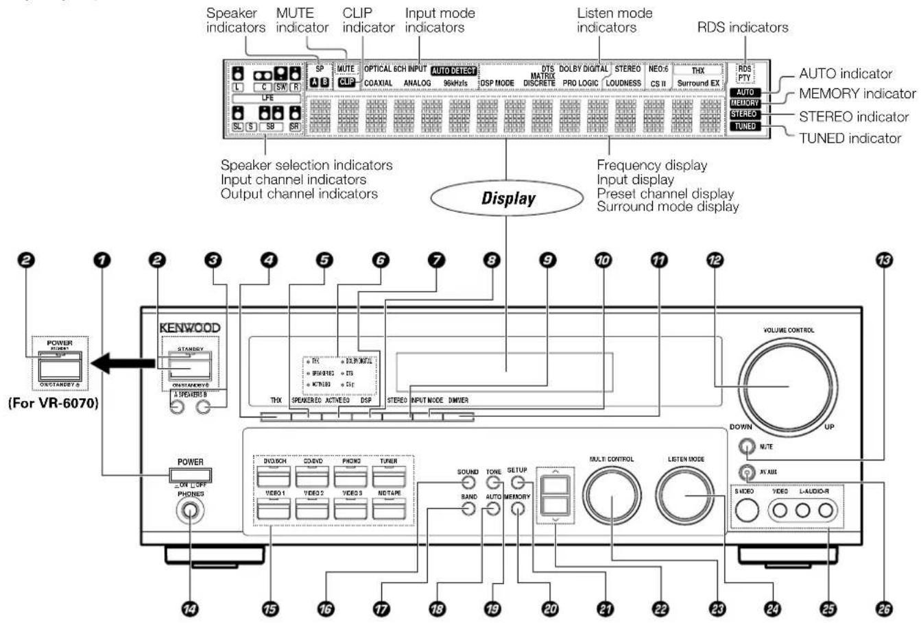
text_image
Speaker indicators MUTE indicator CLIP indicator Input mode indicators Listen mode indicators RDS indicators L C SW R SP A B MUTE COAXIAL ANALOG 96kHz OPTICAL SCH INPUT AUTO DETECT DSP MODE DTS MATRIX DISCRETE DOLBY DIGITAL PRO LOGIC STEREO LOUDNESS NEO-5 CS II THX Surround EX AUTO indicator MEMORY indicator STEREO indicator TUNED indicator Speaker selection indicators Input channel indicators Output channel indicators Display Frequency display Input display Preset channel display Surround mode display 2 1 2 3 4 5 6 7 8 9 10 11 12 13 POWER ONSTANSDY & KENWOOD STANSDY ONSTANSDY & A SPEAKER & THX SPEAKER/EO AUTINESO DSP STEREO INPUT MODE DMIVER (VOLUME CONTROL) DOWN UP POWER ON L OFF PHONES DVD/CH CONVD PHONE TURER VIDEO 1 VIDEO 2 VIDEOS NDTAPE SOUND TOXE SETUP RAND AUTO MEMORY MULT CONTROL LISTEN MODE SVIDEO VIDEO L AUDIO-R (For VR-6070)① POWER ON/OFF key
(For KRF-X9060D) - 23
Use to turn the main power ON/OFF.
② ON/STANDBY ⏻ key
(For KRF-X9060D) - 23
Use to turn the power ON/STANDBY when the POWER is turned ON.
STANDBY indicator
② POWER ON/STANDBY ⏻ key
(For VR-6070) - 23
Use to turn the power ON/STANDBY.
STANDBY indicator
③ A SPEAKERS B keys - 26
Use to turn the A/B speakers ON/OFF.
④ THX key - [36]
Use to switch the status of THX.
⑤ SPEAKER EQ key → 27
Use to select SPEAKER EQ's setting.
⑥ Surround indicators
THX indicator - 37
Lights when the receiver is in the THX mode.
SPEAKER EQ indicator → 28
Lights when the receiver is in the SPEAKER EQ mode.
ACTIVE EQ indicator → 28
Lights when the receiver is in the ACTIVE EQ mode.
DOLBY DIGITAL indicator - 36
Lights when the receiver is in the Dolby Digital mode.
DTS indicator → 36
Lights when the receiver is in the DTS mode.
CS indicator → 36
Lights when the receiver is in the CIRCLE SURROUND II mode.
⑦ ACTIVE EQ key →27
Use to select ACTIVE EQ's setting.
⑧ DSP key → [36]
Use to select any of the DSP mode.
⑨ STEREO key → 38
Use to switch the listen mode to STEREO.
10 INPUT MODE key →9
Use to switch between the full auto, digital and analog inputs.
11 DIMMER key
Use to select the REC MODE. →29
Use to adjust the brightness of the display.
-40
⑫ VOLUME CONTROL knob → 26
⑬ MUTE key -27
Use to temporarily mute the sound.
14 PHONES jack → 28
Use for headphone listening.
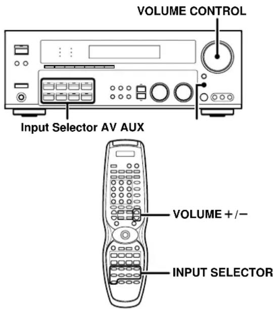
⑮ Input Selector keys → 26
(DVD/6CH, CD/DVD, PHONO, TUNER,
Use to select input sources.
16 SOUND key → 38
Use to adjust the sound quality and the ambience effects.
⑰ BAND key → 30
Use to select the broadcast band.
18 AUTO key - 30
Use to select the auto or manual tuning mode.
⑲ TONE key → 27
Use to switch the status of TONE control.
20 MEMORY key - 30
Use to store radio stations in the preset memory.
21 SETUP key - 23
Use to select the speakers' settings etc.
22 ∧/∨ keys → [23]
Use for selection adjustments during SOUND, SETUP and PRESET CHANNEL functions.
MULTI CONTROL knob → [23]
Use to control a variety of settings.
24 LISTEN MODE knob
→36
Use to select the listening mode.
25 AV AUX (S VIDEO, VIDEO, L-AUDIO-R) jacks - 20
26 AV AUX key
→20
Use to switch the input to AV AUX.
Standby mode
While the standby indicator is lit, a small amount of power is supplied to the system to back up the memory. This is called standby mode.
Under the condition, the system can be turned ON by remote control unit.
Connection at POWER ON/OFF key (for KRF-X9060D)
The power in this equipment will not be completely cut off from the AC wall outlet when the main switch is turned OFF.
Remote control unit (RC-R0813) (VR-6070) and (RC-R0814) (KRF-X9060D)
This remote control unit can be use not only for Kenwood products but also for other non-Kenwood products by setting the appropriate manufacturer's setup codes. Only remote control RC-R0813 has RF remote signal.
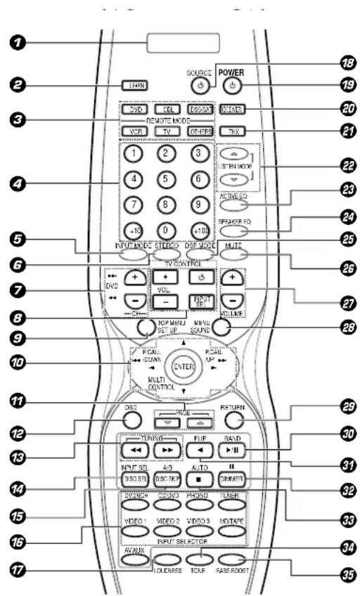
text_image
1 2 3 4 5 6 7 8 9 10 11 12 13 14 15 16 17 SOURCE POWER DVD CEL ORDER CREATE REMOTE MODE VCD TV OTHER 1 2 3 4 5 6 7 8 9 -10 0 -100 INPUT MODE STUDIO DSP MODE TV CONTROL DVD + VOL + CH - INPUT SET UP INPUT SOUND ROLL DOWN MULTI CONTROL CALL ON/OFF RETURN ON/OFF TURAVES FLIP SADD AUTO NUT SE A/O II DIS SE DIS/EXP DIMETER POWER COLD PHOLO PUNER VIDEO 2 VIDEO 3 MOTAPE INPUT SELECTOR AVIKS LOADNESS TCAE RASE ROBOTIf the name of a function is different on the receiver and on the remote control, the name of the remote control key in this manual is indicated in parentheses.
⑦ LCD (Liquid Crystal Display)
2 LEARN key →42
Use to memorize the operation of the other remote controls.
⑤ REMOTE MODE keys (DVD, CBL, DSS/SAT, VCR, TV, OTHERS) → 41 Use to select the components registered at the respective input.
4 Numeric keys
Provide functions identical to those of the original remote control supplied with the component you are controlling.
⑤ INPUT MODE key
Use to switch between the full auto, digital and analog input.
⑥ STEREO key
- 38
Use to switch the listen mode to STEREO.
7 CH +/- keys
Use to select the channels.
▶▶▶ DVD ◀◀◀ keys
When in DVD player operations, these keys function as skip keys.
⑧ TV CONTROL keys
Use when in TV operation.
⑨ TOP MENU key
Use to operate the DVD component.
SET UP key
- 23
Use to select the speakers' settings etc.
10 Joystick
ENTER
Use to operate other components.
MULTI CONTROL /
- 23
Use to control a variety of settings.
Use to operate other components.
P.CALL ▶/DOWN ▶ and P.CALL/UP ▶
- 31
Use for selection adjustments during SOUND,
SET UP and PRESET channel functions.
⑰ PAGE △/▽ key
Use to operate the DVD component.
12 OSD key
Use to operate the DVD component.
13 TUNING ◀◀/▶▶ keys
Use to operate the tuner mode.
If CD, MD or TAPE is selected as the input source, these keys function as search keys.
14 DISC SEL key
Use to operate other components.
INPUT SEL key
Use to operate other components.
15 DISC SKIP key
If CD is selected as the input source, this key functions as the multi-CD player disc skip key.
A/B key
If TAPE is selected as the input source, this is A and B deck of a double cassette deck.
16 INPUT SELECTOR keys (DVD/6CH, CD/DVD, PHONO, TUNER, VIDEO 1, VIDEO 2, VIDEO 3, MD/TAPE, AV AUX) - [26]
Use to select the input sources.
⑰ LOUDNESS key - 27
Use to switch the status of LOUDNESS.
18 SOURCE ⏻ key
Use to turn the other components ON/OFF.
19 POWER ⏻ key → 23
Use to turn the receiver ON/OFF.
20 RECEIVER key
Use to return to the operation of the receiver.
21 THX key → 36
Use to switch the status of THX.
22 LISTEN MODE △/▽ keys → 36
Use to select the listening mode.
23 ACTIVE EQ key - 27
Use to select ACTIVE EQ's setting.
24 SPEAKER EQ key - 27 Use to select SPEAKER EQ's setting.
25 DSP MODE key → 36
Use to select any of the DSP mode.
26 MUTE key - 27 Use to temporarily mute the sound.
27 VOLUME +/- keys - 26
Use to adjust the receiver volume.
28 MENU key
Use to operate other components.
SOUND key → 38
Use to adjust the sound quality and
ence effects.
29 RETURN key
Use to operate other components.
30 ▶/II key
If CD is selected as the input source, this key functions as the play/pause key.
If MD or TAPE key is selected as input source, this key functions as the play key.
BAND key
→ 30
Use to select the broadcast band.
11 ▶ key
Use to operate other components.
FLIP key
Use to operate other components.
DIMMER key
- 40
Use to adjust the brightness of the display.
II key
Use to operate other components.
■ key
If CD, MD, or TAPE is selected as the input source, this key functions as the stop key.
AUTO key
- 30
Use to select the auto or manual tuning mode.
34 TONE key - 27 Use to switch the status of TONE control.
35 BASS BOOST key → 27
Use to select the maximum adjustment setting for the low frequency range.
Remote control unit (RC-R0815) (KRF-X9060D) (For the U.K. only)
This remote control unit can be used not only for Kenwood products but also for other non-Kenwood products by setting the appropriate manufacturer's setup codes.
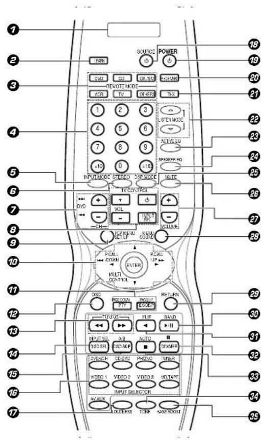
text_image
Labeled diagram of a mobile phone control panel with numbered buttons, function keys, and function buttons.If the name of a function is different on the receiver and on the remote control, the name of the remote control key in this manual is indicated in parentheses.
⑦ LCD (Liquid Crystal Display)
2 LEARN key
- 42
Use to memorize the operation of the other remote controls.
③ REMOTE MODE keys (DVD, CD, CBL/SAT, VCR, TV, OTHERS)
Use to select the components registered at the respective input.
4 Numeric keys
Provide functions identical to those of the original remote control supplied with the component you are controlling.
⑤ INPUT MODE key
Use to switch between the full auto, digital and analog input.
6 STEREO key
→38
Use to switch the listen mode to STEREO.
7 CH +/- keys
Use to select the channels.
▶▶▶ DVD ◀◀◀ keys
When in DVD player operations, these keys function as skip keys.
⑧ TV CONTROL keys
Use when in TV operation.
9 TOP MENU key
Use to operate the DVD component.
SET UP key → 23
Use to select the speakers' settings etc.
Joystick
ENTER
Use to operate other components.
MULTI CONTROL /
→ 23
Use to control a variety of settings.
Use to operate other components.
P.CALL ◀◀/DOWN ◀ and P.CALL/UP ▶▶
▶
Use for selection adjustments during SOUND, SET UP and PRESET channel functions.
17 PTY key
Use for PTY search.
PAGE DOWN
Use to operate the DVD component.
RDS DISP key - 31
Use to receive RDS broadcast.
PAGE UP
Use to operate the DVD component.
12 OSD key
Use to operate the DVD component.
⑬ TUNING ◀◀/▶▶ keys
Use to operate the tuner mode.
If CD, MD or TAPE is selected as the input source, these keys function as search keys.
14 DISC SEL key
Use to operate other components.
INPUT SEL key
Use to operate other components.
15 DISC SKIP key
If CD is selected as the input source, this key functions as the multi-CD player disc skip key.
A/B key
If TAPE is selected as the input source, this is A and B deck of a double cassette deck.
16 INPUT SELECTOR keys (DVD/6CH, CD/DVD, PHONO, TUNER, VIDEO 1, VIDEO 2, VIDEO 3,
MD/TAPE, AV AUX) - 26
Use to select the input sources.
17 LOUDNESS key - 27
Use to switch the status of LOUDNESS.
18 SOURCE ⏻ key
Use to turn the other components ON/OFF.
49 POWER ⏻ key - 23
Use to turn the receiver ON/OFF.
20 RECEIVER key
Use to return to the operation of the receiver.
21 THX key - 36
Use to switch the status of THX.
22 LISTEN MODE △/▽ keys
Use to select the listening mode.
23 ACTIVE EQ key → 27
Use to select ACTIVE EQ's setting.
24 SPEAKER EQ key → 27
Use to select SPEAKER EQ's setting.
25 DSP MODE key - 36
Use to select any of the DSP mode.
26 MUTE key → 27
Use to temporarily mute the sound.
27 VOLUME +/- keys → [26]
Use to adjust the receiver volume.
28 MENU key
Use to operate other components.
SOUND key - 38
Use to adjust the sound quality and the ambience effects.
29 RETURN key
Use to operate other components.
30 ▶/II key
If CD is selected as the input source, this key functions as the play/pause key.
If MD or TAPE key is selected as input source, this key functions as the play key.
BAND key → 30
Use to select the broadcast band.
37 key
Use to operate other components.
FLIP key
Use to operate other components.
32 DIMMER key
Use to adjust the brightness of the display.
II key
Use to operate other components.
33 ■ key
If CD, MD, or TAPE is selected as the input source, this key functions as the stop key.
AUTO key - 30
Use to select the auto or manual tuning mode.
34 TONE key
Use to switch the status of TONE control.
35 BASS BOOST key
Use to select the maximum adjustment setting for the low frequency range.
Make connections as shown in the following pages. When connecting the related system components, be sure to refer to the instruction manuals supplied with the components you are connecting.
Do not connect the power cord to a wall outlet until all connections are completed.
Notes
- Be sure to insert all connection cords securely. If their connections are imperfect, sound may not be produced or there will be noise inference.
- Be sure to remove the power cord from the AC outlet before plugging or unplugging any connection cords. Plugging/unplugging connection cords without disconnecting the power cord can cause malfunctions and may damage the unit.
- Do not connect power cords from components whose power consumption is larger than what is indicated on the AC outlet at the rear of this unit.
Analog connections
Audio connections are made using RCA pin cords. These cables transfer stereo audio signal in an "analog" form. This means the audio signal corresponds to the actual audio of two channels. These cables usually have 2 plugs on each end, one red for the right channel and one white for the left channel. These cables are usually packed together with the source unit, or are available at your local electronics retailer.
Microcomputer malfunction
If operation is not possible or an erroneous display appears, even though all connections have been made properly, reset the microcomputer referring to "In case of difficulty". +48
CAUTION
Be sure to adhere to the following, or proper ventilation will be blocked causing damage or fire hazard.
- Do not place any objects impairing heat radiation onto the top of the unit.
- Leave some space around the unit (from the largest outside dimension including projection) equal to or greater than, shown below.
Top panel : 50 cm Side panel : 10 cm Back panel : 10 cm
Input mode settings
CD/DVD, VIDEO 2, VIDEO 3 and DVD/6CH inputs each include jacks for digital audio input and analog audio input.
The initial factory settings for audio signal playback for CD/DVD, DVD/6CH, VIDEO 2 and VIDEO 3 are full auto.
To use the analog audio input for playback instead (if, for example, you have connected a VCR to the VIDEO 2 or VIDEO 3 input), you must set the input mode for the corresponding input to the analog mode.
After completing connections and turning on the receiver, follow the steps below.
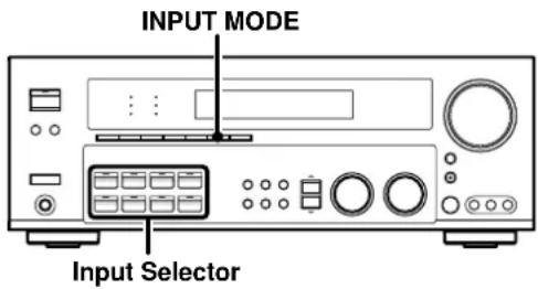
text_image
INPUT MODE Input Selector⑦ Use the Input Selector keys to select CD/DVD, VIDEO 2, VIDEO 3 or DVD/6CH.
② Press the INPUT MODE key.
Each press switches the setting as follows:
In DTS play mode
①FULL AUTO (digital input, analog input)
② DIGITAL MANUAL (digital input)
In CD/DVD, VIDEO 2, VIDEO 3 or DVD/6CH play mode
①FULL AUTO (digital input, analog input)
② DIGITAL MANUAL (digital input)
③6CH INPUT (DVD/6CH input)
④ANALOG (analog input)
Digital input:
Select this setting to play digital signals from a DVD, CD, or LD player.
Analog input:
Select this setting to play analog signals from a cassette deck, VCR, or record player.
Auto detect:
In "FULL AUTO" mode (AUTO DETECT indicator light up), the receiver detects the digital or analog input signals automatically. Priority is given to digital signal during input mode selection. The receiver will select the input mode and listening mode automatically during playback to match the type of input signal (Dolby Digital, PCM, DTS) and the speaker setting. The OPTICAL and COAXIAL indicator on the display will light up when digital signal is detected. If the input signal is analog, the ANALOG indicator will light up.
To keep the receiver set to the currently selected listening mode, use the INPUT MODE key to select "DIGITAL MANUAL" (manual sound). However, even when this setting is selected, there may be cases in which the listening mode is selected automatically to match a Dolby Digital source signal depending on the combination of listening mode and source signal.
If the INPUT MODE key is pressed quickly, sound may not be produced. Press the INPUT MODE key again.
Connecting audio components
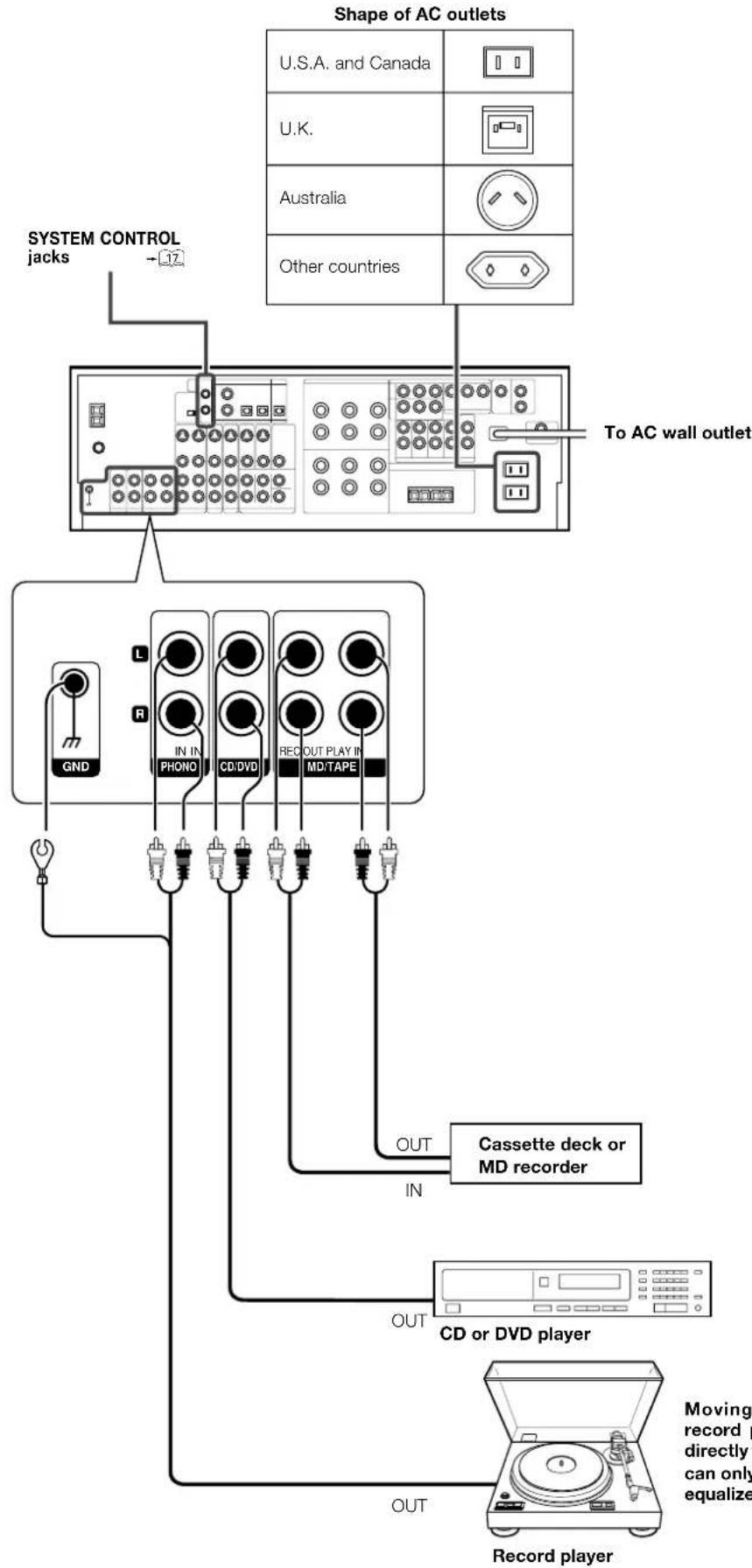
flowchart
graph TD
    A["Shape of AC outlets"] --> B["To AC wall outlet"]
    B --> C["CD or DVD player"]
    C --> D["Record player"]
    D --> E["Out"]
    B --> F["GND"]
    B --> G["L"]
    B --> H["R"]
    B --> I["IN IN PHONO"]
    B --> J["CD/DVD"]
    B --> K["REC OUT PLAY IN MD/TAPE"]
    B --> L["OUT"]
    style A fill:#f9f,stroke:#333
    style B fill:#ccf,stroke:#333
    style C fill:#cfc,stroke:#333
    style D fill:#fcc,stroke:#333
    note right of A
        System Control jacks
        U.S.A. and Canada
        U.K.
        Australia
        Other countries
    end
    note right of B
        Cassette deck or MD recorder
    end
Connecting video components

flowchart
graph TD
    A["S Video jacks"] --> B["Monitor TV"]
    B --> C["Video deck"]
    C --> D["DVD player or LD player"]
    D --> E["Audio in/OUT"]
    B --> F["Video inputs (Yellow RCA pin cords)"]
    B --> G["Video in"]
    B --> H["Video in/OUT"]
    B --> I["IN"]
    B --> J["IN"]
    B --> K["IN"]
    B --> L["IN"]
    B --> M["IN"]
    B --> N["IN"]
    B --> O["IN"]
    B --> P["IN"]
    B --> Q["IN"]
    B --> R["IN"]
    B --> S["IN"]
    B --> T["IN"]
    B --> U["IN"]
    B --> V["IN"]
    B --> W["IN"]
    B --> X["IN"]
    B --> Y["IN"]
    B --> Z["IN"]
    B --> AA["IN"]
    B --> AB["IN"]
    B --> AC["IN"]
    B --> AD["IN"]
    B --> AE["IN"]
    B --> AF["IN"]
    B --> AG["IN"]
    B --> AH["IN"]
    B --> AI["IN"]
    B --> AJ["IN"]
    B --> AK["IN"]
    B --> AL["IN"]
    B --> AM["IN"]
    B --> AN["IN"]
    B --> AO["IN"]
    B --> AP["IN"]
    B --> AQ["IN"]
    B --> AR["IN"]
    B --> AS["IN"]
    B --> AT["IN"]
    B --> AU["IN"]
    B --> AV["IN"]
A video component with digital audio outputs should be connected to the VIDEO 2 or VIDEO 3 jacks.
Digital connections
The digital in jacks can accept DTS, Dolby Digital, or PCM signals. Connect components capable of outputting DTS, Dolby Digital, or standard PCM (CD) format digital signals.
If you have connected any digital components to the receiver, be sure to read the "Input mode settings" section carefully.


flowchart
graph TD
    A["Coaxial Optical Optical"] --> B["VIDEO 2"]
    A --> C["VIDEO 3"]
    A --> D["MO monitored DVD"]
    A --> E["DVD/5CH"]
    A --> F["DIGITAL IN"]
    A --> G["DIGITAL OUT"]
    H["Optical fiber cable"] --> I["OPTICAL DIGITAL IN (AUDIO)"]
    I --> J["MD player"]
    K["Optical fiber cable"] --> L["OPTICAL DIGITAL OUT (AUDIO)"]
    L --> M["Component with DTS, Dolby Digital, or PCM OPTICAL DIGITAL OUT"]
    N["Optical fiber cable"] --> O["Connect the video signal and digital audio signals to the VIDEO 3 jacks. (See "Connecting video components".)"] +11
    P["Optical fiber cable"] --> Q["OPTICAL DIGITAL OUT (AUDIO)"]
    Q --> R["CD or DVD player"]
    S["COAXIAL DIGITAL OUT (AUDIO)"] --> T["RF digital demodulator (DEM-9991D) (sold separately)"]
    T --> U["DOLBY DIGITAL RF OUT (AUDIO)"]
    V["PCM OUT"] --> W["LD player"]
To connect an LD player with a DIGITAL RF OUT, connect the LD player to the KENWOOD RF digital demodulator (DEM-9991D). Next, connect the DIGITAL OUT jacks of the demodulator to the DIGITAL IN jacks of the receiver. Connect the video signal and analog audio signals to the VIDEO 2 or VIDEO 3 jacks. (See "Connecting video components".)
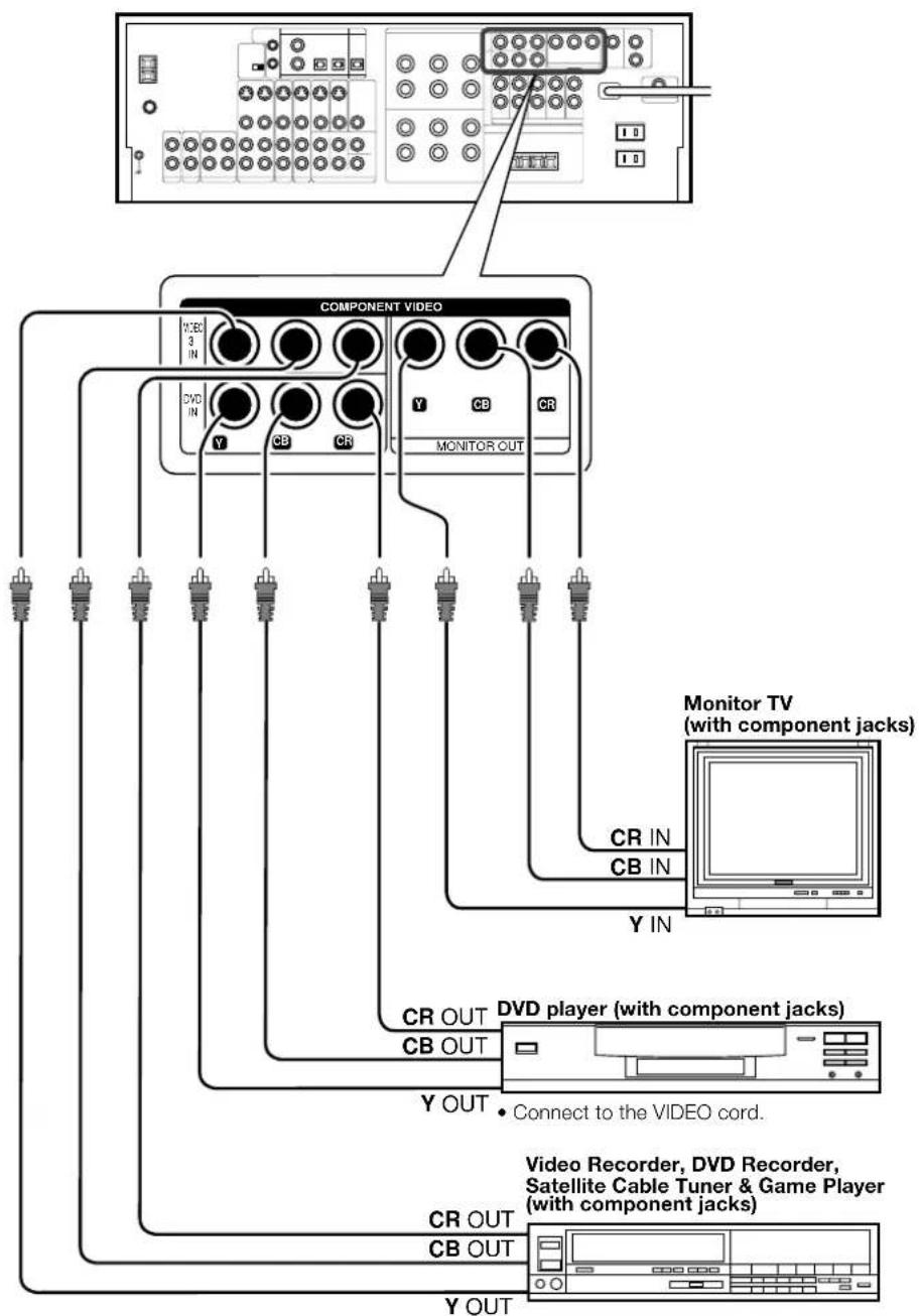
Connecting video components (COMPONENT VIDEO)
If you have connected the receiver to a video component with COMPONENT jacks, you can get a better picture quality than by connecting to the S VIDEO jacks.
flowchart
graph TD
    A["Monitor TV (with component jacks)"] --> B["Component Video"]
    B --> C["Video Recorder, DVD Recorder, Satellite Cable Tuner & Game Player (with component jacks)"]
    B --> D["Monitor TV (with component jacks)"]
    B --> E["Video Recorder, DVD Recorder, Satellite Cable Tuner & Game Player (with component jacks)"]
    B --> F["Monitor TV (with component jacks)"]
    B --> G["Video Recorder, DVD Recorder, Satellite Cable Tuner & Game Player (with component jacks)"]
    B --> H["Monitor TV (with component jacks)"]
    B --> I["Monitor TV (with component jacks)"]
    B --> J["Monitor TV (with component jacks)"]
    B --> K["Monitor TV (with component jacks)"]
    B --> L["Monitor TV (with component jacks)"]
    B --> M["Monitor TV (with component jacks)"]
    B --> N["Monitor TV (with component jacks)"]
    B --> O["Monitor TV (with component jacks)"]
    B --> P["Monitor TV (with component jacks)"]
    B --> Q["Monitor TV (with component jacks)"]
    B --> R["Monitor TV (with component jacks)"]
    B --> S["Monitor TV (with component jacks)"]
    B --> T["Monitor TV (with component jacks)"]
    B --> U["Monitor TV (with component jacks)"]
    B --> V["Monitor TV (with component jacks)"]
    B --> W["Monitor TV (with component jacks)"]
    B --> X["Monitor TV (with component jacks)"]
    B --> Y["Monitor TV (with component jacks)"]
    B --> Z["Monitor TV (with component jacks)"]
    B --> AA["Monitor TV (with component jacks)"]
    B --> AB["Monitor TV (with component jacks)"]
    B --> AC["Monitor TV (with component jacks)"]
    B --> AD["Monitor TV (with component jacks)"]
    B --> AE["Monitor TV (with component jacks)"]
    B --> AF["Monitor TV (with component jacks)"]
    B --> AG["Monitor TV (with component jacks)"]
    B --> AH["Monitor TV (with component jacks)"]
    B --> AI["Monitor TV (with component jacks)"]
    B --> AJ["Monitor TV (with component jacks)"]
    B --> AK["Monitor TV (with component jacks)"]
    B --> AL["Monitor TV (with component jacks)"]
    B --> AM["Monitor TV (with component jacks)"]
    B --> AN["Monitor TV (with component jacks)"]
    B --> AO["Monitor TV (with component jacks)"]
    B --> AP["Monitor TV (with component jacks)"]
    B --> AQ["Monitor TV (with component jacks)"]
    B --> AR["Monitor TV (with component jacks)"]
    B --> AS["Monitor TV (with component jacks)"]
    B --> AT["Monitor TV (with component jacks)"]
    B --> AU["Monitor TV (with component jacks)"]
    B --> AV["Monitor TV (with component jacks)"]
    B --> AW["Monitor TV (with component jacks)"]
    B --> AX["Monitor TV (with component jacks)"]
    B --> AY["Monitor TV (with component jacks)"]
    B --> AZ["Monitor TV (with component jacks)"]
    B --> BA["Monitor TV (with component jacks)"]
    B --> BB["Monitor TV (with component jacks)"]
    B --> BC["Monitor TV (with component jacks)"]
    B --> BD["Monitor TV (with component jacks)"]
    B --> BE["Monitor TV (with component jacks)"]
    B --> BF["Monitor TV (with component jacks)"]
    B --> BG["Monitor TV (with component jacks)"]
    B --> BH["Monitor TV (with component jacks)"]
    B --> BI["Monitor TV (with component jacks)"]
    B --> BJ["Monitor TV (with component jacks)"]
    B --> BK["Monitor TV (with component jacks)"]
    B --> BL["Monitor TV (with component jacks)"]
    B --> BM["Monitor TV (with component jacks)"]
    B --> BN["Monitor TV (with component jacks)"]
    B --> BO["Monitor TV (with component jacks)"]
    B --> BP["Monitor TV (with component jacks)"]
    B --> BQ["Monitor TV (with component jacks)"]
    B --> BR["Monitor TV (with component jacks)"]
    B --> BS["Monitor TV (with component jacks)"]
    B --> BT["Monitor TV (with component jacks)"]
    B --> BU["Monitor TV (with component jacks)"]
    B --> BV["Monitor TV (with component jacks)"]
    B --> BW["Monitor TV (with component jacks)"]
    B --> BX["Monitor TV (with component jacks)"]
    B --> BY["Monitor TV (with component jacks)"]
    B --> CA["Monitor TV (with component jacks)"]
    B --> CB["Monitor TV (with component jacks)"]
    B --> CC["Monitor TV (with component jacks)"]
    B --> CD["Monitor TV (with component jacks)"]
    B --> CE["Monitor TV (with component jacks)"]
    B --> CF["Monitor TV (with component jacks)"]
    B --> CG["Monitor TV (with component jacks)"]
    B --> CH["Monitor TV (with component jacks)"]
    B --> CI["Monitor TV (with component jacks)"]
    B --> CJ["Monitor TV (with component jacks)"]
    B --> CK["Monitor TV (with component jacks)"]
    B --> CR["Monitor TV (with component jacks)"]
    B --> CS["Monitor TV (with component jacks)"]
    B --> CT["Monitor TV (with component jacks)"]
    B --> CU["Monitor TV (with component jacks)"]
    B --> CV["Monitor TV (with component jacks)"]
    B --> CW["Monitor TV (with component jacks)"]
    B --> CX["Monitor TV (with component jacks)"]
    B --> CY["Monitor TV (with component jacks)"]
    B --> CZ["Monitor TV (with component jacks)"]
    B --> DA["Monitor TV (with component jacks)"]
    B --> DB["Monitor TV (with component jacks)"]
    B --> DC["Monitor TV (with component jacks)"]
    B --> DD["Monitor TV (with component jacks)"]
    B --> DE["Monitor TV (with component jacks)"]
    B --> DF["DVD player with component jacks"]
    B --> DG["DVD player with video recorder"]
    style A fill:#f9f,stroke:#333
    style BC fill:#f9f,stroke:#333
    style BD fill:#f9f,stroke:#333
    style BE fill:#f9f,stroke:#333
    style BF fill:#f9f,stroke:#333
    style BG fill:#f9f,stroke:#333
    style BH fill:#f9f,stroke:#333
    style BI fill:#f9f,stroke:#333
    style BJ fill:#f9f,stroke:#333
    style BK fill:#f9f,stroke:#333
    style BL fill:#f9f,stroke:#333
    style BG fill:#f9f,stroke:#333
    style BH fill:#f9f,stroke:#333
    style BI fill:#f9f,stroke:#333
    style BJ fill:#f9f,stroke:#333
    style BK fill:#f9f,stroke:#333
    style BL fill:#f9f,stroke:#386
    style BG fill:#f9f,stroke:#386
    style BH fill:#f9f,stroke:#386
    style BI fill:#f9f,stroke:#386
    style BJ fill:#f9f,stroke:#386
    style BK fill:#f9f,stroke:#386
    style BL fill:#f9f,stroke:#386
    style BG fill:#f9f,stroke:#386
    style BH fill:#f9f,stroke:#386
    style BI fill:#f9f,stroke:#386
    style BJ fill:#f9f,stroke:#386
    style BK fill:#f9f,stroke:#386
    style BL fill:#f9f.stroke:#386
    style BG fill:#f9f.stroke:#386
    style BH fill:#f9f.stroke:#386
    style BI fill:#f9f.stroke:#386
    style BJ fill:#f9f.stroke:#386
    style BK fill:#f9f.stroke:#386
    style BL fill:#f9f.stroke:#386
    style BG fill:#f9f.stroke:#386
    style BH fill:#f9f.stroke:#386
    style BI fill:#f9f.stroke:#386
    style BJ fill:#f9f.stroke:#386
    style BK fill:#f9f.stroke:#386
    style BLfill fill:#f9f.stroke:#386
</details>
When connecting the TV to the COMPONENT jacks, be sure to connect all the other components to the COMPONENT jacks.
<h1 id="connecting-a-dvd-player-6-channel-input">Connecting a DVD player (6-channel input)</h1>
If you have connected a DVD player to the receiver with digital connection, be sure to read the "Input mode settings" section carefully.
→9

<details>
<summary>text_image</summary>
OUT VIDEO
IN VIDEO
IN VIDEO
IN VIDEO
IN VIDEO
OUT VIDEO
DVD MONITOR
COAXIAL OPTICAL OPTICAL
OPTICAL
VIDEO 2
VIDEO 3
MONITOR/DVD
DVD 5CH
DIGITAL IN
DIGITAL OUT
S VIDEO IN VIDEO
S VIDEO IN VIDEO
S VIDEO IN VIDEO
S VIDEO OUT VIDEO
ROOM B OUT
VIDEO 2 VIDEO 3
PLAY IN
FRONT
SURROUND
DVD/6CH INPUT
CENTER
SUB MCOFER
VIDEO OUT (Yellow RCA pin cord)
COAXIAL DIGITAL OUT (AUDIO)
FRONT OUT L/R
SURROUND OUT L/R
DVD player
CENTER OUT
SUBWOOFER OUT
S VIDEO OUT
S VIDEO cord
</details>
<h1 id="connecting-the-speakers">Connecting the speakers</h1>

<details>
<summary>text_image</summary>
Surround Speakers
(Be sure to connect both
surround speakers)
Surround Back/Subwoofer
Use this terminal it you wish to
connect to a Surround Back
speaker with the SETUP of
"6ch AMP SB" or to connect
to a Subwoofer speaker with
the SETUP of "6ch AMP SW"
Powered
subwoofer
SPEAKERS (8-16Ω)
SURROUND
GRAY
BLUE
6Ω)
SURROUND BACK
SUBWOOFER
PURPLE
CENTER
SUB
WOOFER
GREENWITERED
R
L
CENTER FRONT A
SPEAKERS (8-16Ω)
FRONT B
R
L
Front Speakers B
Right
Left
Center
Speaker
</details>
Front Speakers A
<h1 id="connecting-the-terminals">Connecting the terminals</h1>
① Strip coating. ② Loosen.


③ Insert. ④ Secure.


① Strip coating. ② Push the lever.


③ Insert the cord. ④ Return the lever.


<h1 id="connection-of-banana-plugs-for-the-usa-and-canada">Connection of banana plugs (For the U.S.A. and Canada)</h1>
① Secure. ② Insert.


\- Sound will not be heard if the speaker terminal is not fully secured.
\- Never short circuit the + and - speaker cords.
\- If the left and right speakers are connected inversely or the speaker cords are connected with reversed polarity, the sound will be unnatural with ambiguous acoustic imaging. Be sure to connect the speakers correctly.
<h1 id="speaker-impedance">Speaker impedance</h1>
After confirming the speaker impedance indications printed on the rear panel of the receiver, connect speakers with matching impedance ratings. Using speakers with a rated impedance other than that indicated on the rear panel of the receiver could result in malfunctions or damage to the speakers or receiver.
Speaker placement

<details>
<summary>flowchart</summary>
```mermaid
graph TD
A["Front speakers (L,R)"] --> B["Subwoofer"]
C["Center speaker"] --> D["TV"]
E["Listening position"] --> F["Surround back speakers (SBL/SBR)"]
B --> G["Speaker 1"]
B --> H["Speaker 2"]
style B fill:#f9f,stroke:#333
style D fill:#ccf,stroke:#333
style F fill:#cfc,stroke:#333
Front speakers : Place at the front left and right of the listening position. Front speakers are required for all surround modes.
Center speaker : Place front and center. This speaker stabilizes the sound image and helps recreate sound motion. Required for surround playback.
Surround speakers : Place at the direct left and right, or slightly behind, the listening position at even heights, approximately 1 meter above the ears of the listeners. These speakers recreate sound motion and atmosphere. Required for surround playback.
Subwoofer : Reproduces powerful deep bass sounds.
Surround back speakers : Place the surround back left and right speakers behind the listening position at the same height as the side surround speakers.
- Although the ideal surround system consists of all the speakers listed above, if you don't have a center speaker or a subwoofer, you can divide those signals between the available speakers in the speaker settings steps to obtain the best possible surround reproduction from the speakers you have available. - [23]
Channel space switching
(Except for the U.S.A., Canada, U.K., and Australia)
The space between radio channels has been set to the one that prevails in the area to which the system is shipped. However, if the current channel space setting does not match the setting in the area where the system is to be used, for instance when you move from area 1 or area 2 shown in the following table or vice versa, proper reception of AM/FM broadcasts cannot be expected. In this case, change the channel space setting in accordance with your area by referring to the following table.
| Area | CHANNELSpace Frequency | |
| 1 | U.S.A., Canada and South FM: 100 kHzAmerican countries AM: 10 kHz | |
| 2 | Other countries | FM: 50 kHzAM: 9 kHz |

text_image
75us AM10KHz FM100kHz 50us AM8KHz FM50kHz DE-EMPHASIS CHANNEL SPACETurn the power OFF by pressing the POWER key before moving the switch level. Move switch lever to match your area with a small screwdriver or other pointed tool, then turn the power on again.
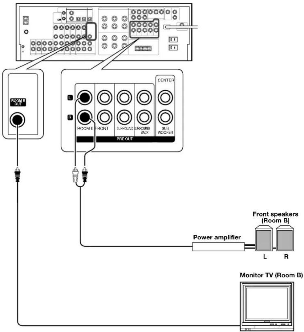
Connecting to another room (ROOM B)
This connection allows you to connect your main system to a monitor TV and speaker system located in another area (ROOM B).
flowchart
graph TD
    A["Room B OUT"] --> B["ROOM B FRONT"]
    B --> C["PRE OUT"]
    C --> D["SUB WOOFER"]
    D --> E["Power amplifier"]
    E --> F["Front speakers (Room B)"]
    E --> G["L"]
    E --> H["R"]
    I["Monitor TV (Room B)"] --> J["Power amplifier"]
    J --> K["Power amplifier"]
    style A fill:#f9f,stroke:#333
    style I fill:#ccf,stroke:#333
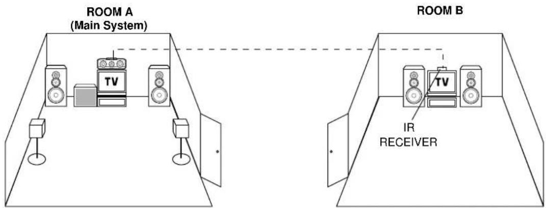
text_image
ROOM A (Main System) ROOM B TV IR RECEIVERPRE OUT connections
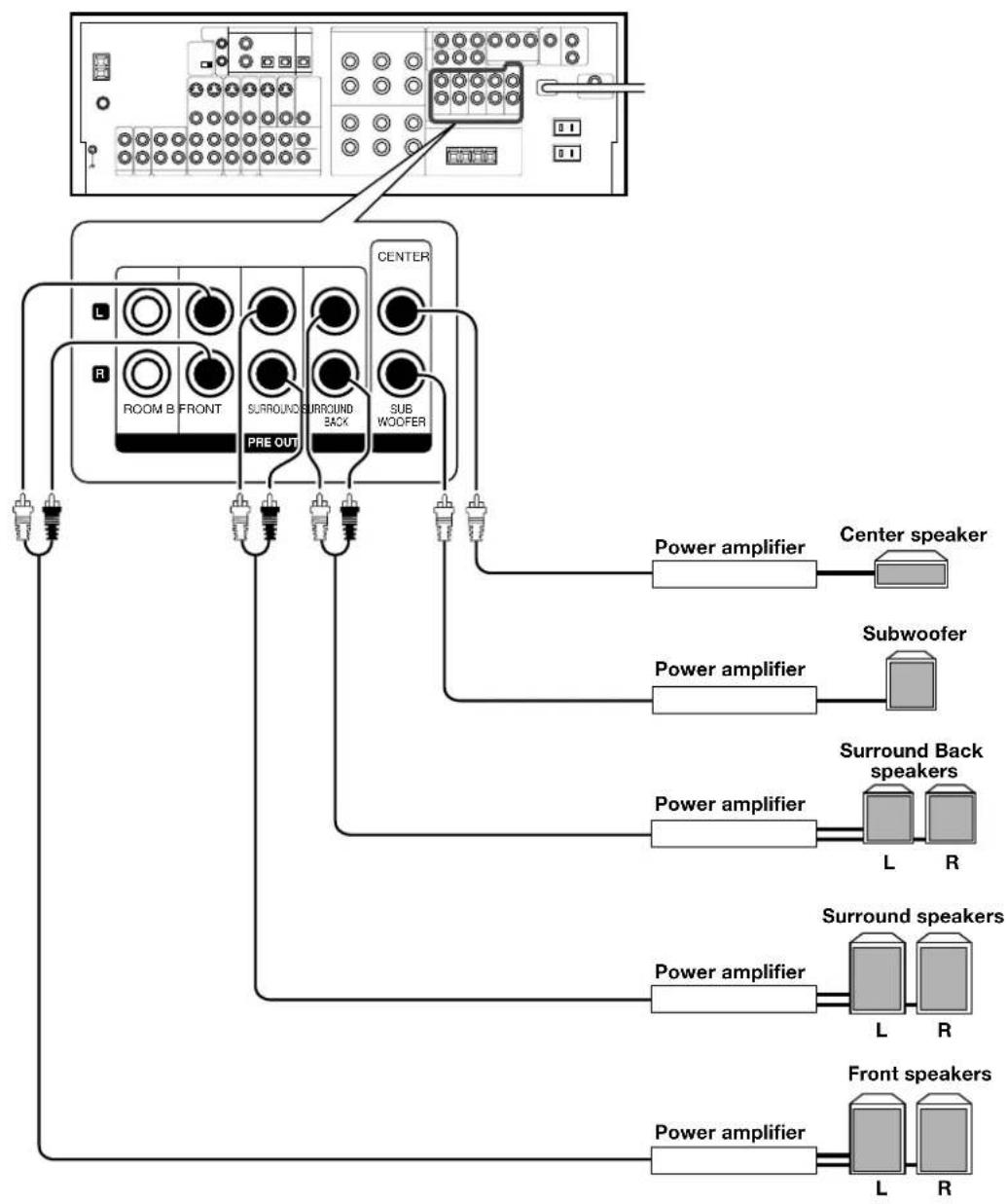
This receiver has additional preout jacks. These can be used for various purposes, but will need to be connected to an external power amplifier as shown in the example below.
flowchart
graph TD
    A["Room B FRONT"] --> B["PRE OUT"]
    B --> C["SURROUND BACK"]
    C --> D["SUB WOOFER"]
    D --> E["Power amplifier"]
    E --> F["Center speaker"]
    C --> G["Power amplifier"]
    G --> H["Subwoofer"]
    C --> I["Power amplifier"]
    I --> J["Surround Back speakers"]
    C --> K["Power amplifier"]
    K --> L["L R"]
    C --> M["Power amplifier"]
    M --> N["L R"]
    C --> O["Power amplifier"]
    O --> P["Front speakers"]
    style A fill:#f9f,stroke:#333
    style B fill:#ccf,stroke:#333
    style C fill:#cfc,stroke:#333
    style D fill:#fcc,stroke:#333
    style E fill:#ffc,stroke:#333
    style F fill:#fcc,stroke:#333
    style G fill:#fcc,stroke:#333
    style H fill:#fcc,stroke:#333
    style I fill:#fcc,stroke:#333
    style J fill:#fcc,stroke:#333
    style K fill:#fcc,stroke:#333
    style L fill:#fcc,stroke:#333
    style M fill:#fcc,stroke:#333
    style N fill:#fcc,stroke:#333
    style O fill:#fcc,stroke:#333
- Connecting a speaker cord directly to a PRE OUT jack will not produce any sound from the speaker.
• To use the PRE OUT jacks, press only the SPEAKERS A key to the ON position. - If you choose "6ch AMP SB", sound will be heard from the PRE OUT Surround Back Left speaker (monoraul) only.
- This connection is available for listening in ROOM B.
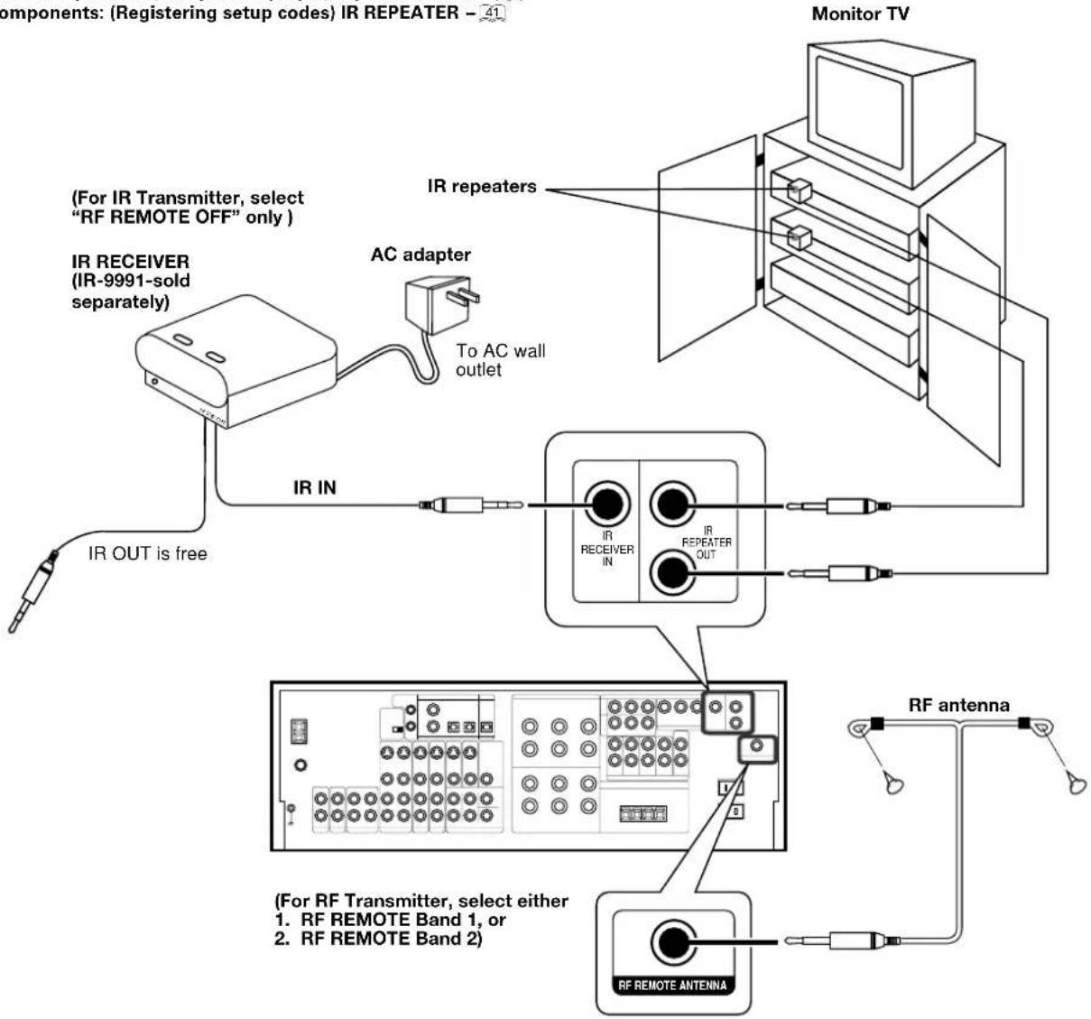
Connecting the RF antenna and external IR Repeater (For VR-6070 only)
The remote control for this receiver has the RF (radio frequency) and IR (infrared rays) transmission function. IR repeaters enables you to control components located in cabinets or behind glass doors. You can enjoy a wider remote control signal range by placing the RF antenna and IR repeater away from the receiver.
KENWOOD components (except DVD player): System control → 21
Other components: (Registering setup codes) IR REPEATER - 41
text_image
Components: (Registering setup codes) IR REPEATER - 41 Monitor TV (For IR Transmitter, select "RF REMOTE OFF" only ) IR RECEIVER (IR-9991-sold separately) AC adapter To AC wall outlet IR IN IR OUT is free IR repeaters IR REPEATER OUT IR RECEIVER IN RF antenna (For RF Transmitter, select either 1. RF REMOTE Band 1, or 2. RF REMOTE Band 2) RF REMOTE ANTENNAConnecting IR repeater
① Connect the IR repeater to the device as described in the repeater's manual.
② Connect the IR repeater cable(s) to the IR REPEATER OUT jack(s).
Notes
- IR repeaters send a signal similar to the device's own remote control. Xantech repeaters (models 282-00, 286-00, or 283-00) are compatible with your new audio-video receiver.
Connecting the RF remote antenna
① Insert the jack of the provided RF remote antenna into the RF REMOTE ANTENNA jack.
2 Place the antenna wire vertically and fix it.
• Place the antenna away from the metallic panel.
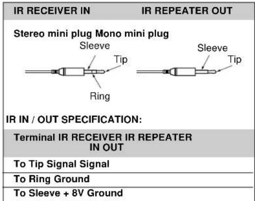
Shape of plug to be connected.
text_image
IR RECEIVER IN IR REPEATER OUT Stereo mini plug Mono mini plug Sleeve Tip Ring Sleeve Tip IR IN / OUT SPECIFICATION: Terminal IR RECEIVER IR REPEATER IN OUT To Tip Signal Signal To Ring Ground To Sleeve + 8V GroundConnecting to the AV AUX jacks
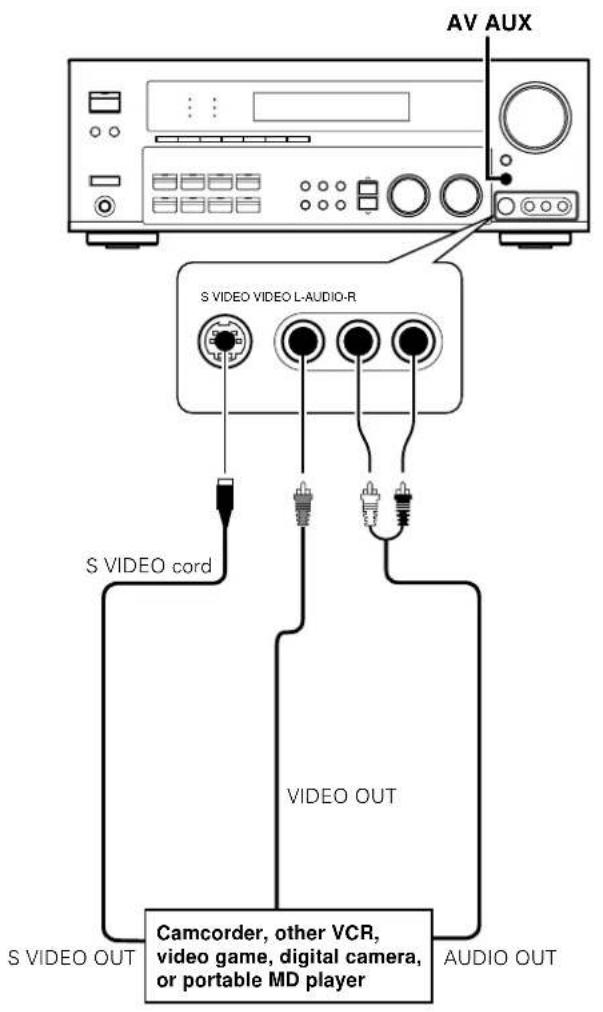
The AV AUX jacks are convenient for connection of video components such as a camcorder or a video game.
text_image
AV AUX S VIDEO VIDEO L-AUDIO-R S VIDEO cord VIDEO OUT CAMCORDER, other VCR, video game, digital camera, or portable MD player S VIDEO OUT AUDIO OUT• To select the source connected to the AV AUX jacks and press AV AUX key. →26
- When you connect the audio source such as the MD player, you do not need to connect the video cable.
- When you connect the unit and the component with the S VIDEO cord, you can get better picture quality.
Connecting the antennas
AM loop antenna
The supplied loop antenna is for use indoors. Place it as far as possible from the receiver, TV set, speaker cords and power cord, and adjust the direction for best reception.
AM antenna terminal connections
① Push lever.
② Insert cord.
③ Release lever.


FM indoor antenna
The supplied indoor antenna is for temporary use only. For stable signal reception we recommend using an outdoor antenna. Disconnect the indoor antenna when you connect one outdoors.
FM antenna terminal connections
Insert cord.

FM outdoor antenna
Lead the 75Ω coaxial cable connected to the FM outdoor antenna into the room and connect it to the FM 75Ω terminal.

text_image
ATTENNA AM GND 75 Ω FM Use an antenna adaptor (Commercially available) Attach to the stand AM loop antenna FM indoor antenna FM outdoor antennaConnecting the system control
Connecting system control cords after connecting a KENWOOD audio component system lets you take advantage of convenient system control operations.
This unit is compatible only with the [SL-16] mode. The system control operation is not available if the unit is connected in the [XS8], [XS], or [XR] connection mode.
If your component has the mode select switch, set the connected components to the [SL16] mode.
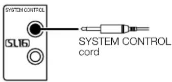
text_image
SYSTEM CONTROL SL16 SYSTEM CONTROL cord- You may connect the system control cord to either the up or down jack.
EXAMPLE: [SL16] mode connections
The underlined portion represents the setting of the system control mode.
![KENWOOD VR-6070 - EXAMPLE: [SL16] mode connections - 1](/content/2026/06/1244111/images/baf06f3285008c0b0d8aa654b798bd1e9dd0b3611dd9baef6aac2a64719c9198.jpg)
text_image
[SL16] Receiver [SL16] [XS] [XS8] [XR] [SL16] [XS] [XS8] CD player [XS] Record player Cassette deck or MD recorder SYSTEM CONTROL cord- In order to take advantage of the system control operations, the components must be connected to the correct jacks. To use a CD player it must be connected to the CD jacks. To use a cassette deck (or MD recorder) it must be connected to the MD/TAPE jacks. When using more than one CD player (etc.) only the one connected to the specified jacks may be connected for system control.
- Some CD players and cassette decks are not compatible with the [SL16] system control mode. Do not make system connections with equipment that is not [SL16] compatible.
- Some MD players are not system control compatible. You cannot make system control connections to this kind of equipment.
Notes
- [SL16] equipment cannot be combined with [XR], [XS], and [XS8] equipment for system operations. If your equipment consists of this kind of combination, please do not connect any system control cords. Even without system control cords, normal operations can be carried out without effecting performance.
- Do not connect system control cords to any components other than those specified by KENWOOD. It may cause a malfunction and damage your equipment.
- Be sure the system control plugs are inserted all the way in to the system control terminals.
Lets you operate this unit with the system remote supplied with the receiver.
Automatic Operation
When you start playback from a source component, the input selector on this unit switches to that component automatically.
Synchronized Recording
Lets you synchronize recording with the start of playback when recording from CD, MD or analog discs.
Registering setup codes for KENWOOD audio components
If you own remote controllable KENWOOD audio components that are not compatible with system control, registering the setup code enables you to control those components using the remote control supplied with this unit (without connecting system control cords). To register setup codes for your remote controllable KENWOOD audio components, see "Registering setup codes for other components".
→41
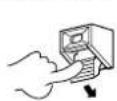
Preparing the remote control
Loading the batteries
① Remove the cover. ② Insert the batteries.
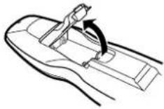
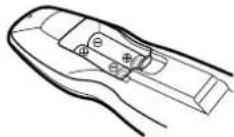
③ Close the cover.

- Insert two AA-size (R6) batteries as indicated by the polarity markings.
RF remote control function (For VR-6070 only)
The remote control has the RF remote function in addition to the IR remote function. The VR-6070 can receive the remote control commands even when they are installed in a position where the IR remote signal can hardly access, for example inside a cabinet.
Changing the RF transmission frequency
The RF remote function may be unavailable due to radio wave cross talk, etc. In this case, the transmission frequency can be changed.
To change the RF remote transmission frequency:
⑦ Change the RF switch setting.
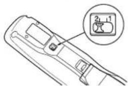
text_image
Diagram of a handheld device with labeled buttons and a magnified inset showing two numbered components.After changing the RF frequency of remote control, be also sure to change that of the receiver.
② Change the receiver's RF reception frequency.
- Press and hold the SETUP key on the front panel of the receiver for more than 2 seconds. Each time you press the SETUP key, the RF reception frequency changes as follows:
①"RF REMOTE BAND 1" ②"RF REMOTE BAND 2" ③"RF REMOTE OFF"
- Select the same number as the position number of the RF switch of the remote control except for "OFF".
Remote control operation
When the STANDBY indicator is lit, the power turns ON when you press the POWER or SOURCE key on the remote control. When the power comes ON, press the key you want to operate.
Operating other component range (IR Transmitter)
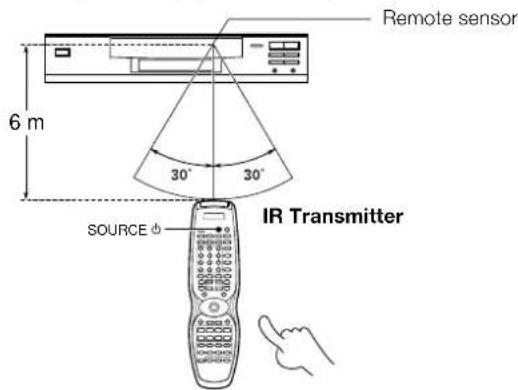
text_image
Remote sensor 6 m 30° 30° SOURCE IR TransmitterOperating receiver range (RF Transmitter)

text_image
RF Remote antenna 10 m POWER RF Transmitter- The remote control signal received by main unit IR and RF signals.
- When pressing more than one remote control key successively, press the keys securely by leaving an interval of 1 second or more between keys.
Notes
- The supplied batteries may have shorter lives than ordinary batteries due to use during operation checks.
- When the remote-controllable distance gets shorter than before, replace both batteries with new ones.
- Placing the remote sensor in direct sunlight, or in direct light from a high frequency fluorescent lamp may cause a malfunction. In such a case, change the location of the system installation to prevent malfunction.
Important notes
Here is list of adjustment which can maximize the operation of your remote control. For optimal operation of the remote control:
①Aim the remote control toward the room where the receiver is located.
②Do not position the receiver and remote control near metal (such as heat ducts). Metal can absorb RF signals.
③Make sure the batteries in the remote control are fully charged. Weak batteries will affect the range of the remote control.
④When there is an obstruction around other equipments that send signal from the remote control, the control distance of the RF remote signal will be short.
Note
- The tests for range limits of the remote control and the receiver are conducted in open-air distance test. Actual distance of the signal will be based on the construction of the building where the unit is being used in as well as other factors such as outside interference.
Speaker settings
To enable you to obtain optimum enjoyment from the receiver's listening modes, make sure to complete the speaker settings (subwoofer, front, center, and surround speakers) as described below.

text_image
POWER ON/STANDBY (VR-6070) ON/STANDBY (KRF-X9060D) SETUP MULTI CONTROL POWER ON/OFF (KRF-X9060D) SET UP POWER Joystick (MULTI CONTROL▲ /▼ , DOWN◄ /UP►)1 Turn on the power to this receiver by pressing the POWER ON/STANDBY (for VR-6070) or POWER ON/OFF and ON/STANDBY (for KRF-X9060D) key or POWER key.
2 Press the SETUP key to enter the SETUP mode.
The Surround Back and Subwoofer speaker output selections are displayed as follows:

text_image
①6ch AMP SB : Surround Back/Subwoofer speaker terminal will output SB sound. Surround Back pre out will have output from SBL only. ②6ch AMP SW : Surround Back/Subwoofer speaker terminal will have no sound. Surround Back pre out will have output from SBL and SBR. ③ 6ch AMP OFF : It is not advisable to use Surround Back/ Subwoofer speaker terminal for this selection.Use the MULTI CONTROL knob or Joystick (▲/▼) to select the speakers. Press the SETUP key to proceed to the next SET UP selection.
Use ∧ ∨ keys or Joystick (◄/►) for the following displays.

The flow of the SET UP is as follows:

flowchart
graph TD
    A["SP SETUP"] --> B["TEST TONE"]
    B --> C["BASS PEAK"]
    C --> D["SP DISTANCE"]
    D --> E["DISP MODE"]
    E --> F["EXIT"]

    subgraph SP_SETUP
        A1["Subwoofer"] --> A2["Front"]
        A2 --> A3["Center"]
        A3 --> A4["Surround Back"]
        A4 --> A5["Surround Mix"]
        A5 --> A6["Subwoofer Re-mix"]
    end

    subgraph TEST_TONE
        B1["T.TONE AUTO"] --> B2["T.TONE MANUAL"]
        B2 --> B3["L C R SR (SBP/SSL) SL SW"]
        B3 --> B4["C H SR (SBP/SSL) SL SW"]
    end

    subgraph BASS_PEAK
        C1["SP DISTANCE"] --> C2["DISP MODE"]
    end

    subgraph SP_DISTANCE
        D1["SP_DISTANCE"] --> D2["DISP_MODE"]
    end

    subgraph DISP_MODE
        E1["DISP_MODE"] --> E2["EXIT"]

    F1["EXIT"] --> F2["Display Selector"]
    F2 --> F3["Display Listen"]
    F3 --> F4["Front Left Center"]
    F4 --> F5["Front Right Surround Right"]
    F5 --> F6["Surround Back (Surround Back Right/Left)"]
    F6 --> F7["Surround Left Subwoofer"]
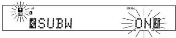
3 Select a speaker system.
⑦ Select the SP SETUP and press the SETUP key again so that the subwoofer setting indication "SUBW ON" appears.
text_image
SP A SUBW STEPED ONE② Use the MULTI CONTROL knob or Joystick (▲/▼) to select the appropriate subwoofer setting.
① SUBW ON : Subwoofer setting mode to the receiver is ON. ② SUBW OFF : Subwoofer setting mode to the receiver is OFF.
• The initial setting is "SUBW ON".
- When the setting "SUBW OFF" is selected, the front speakers are automatically set to "FRNT LARGE" and the procedure skips to step 5.
Before step 6, press the SETUP key to accept the setting.
- When subwoofer output sound is required, select "FRNT NML/THX", or select both "FRNT LARGE" and "SW RE-MIX ON".
- After setting SW (subwoofer) from OFF to ON, 6ch AMP setup display will appear to enable you to re-select either SW, SB or OFF from the surround back or subwoofer speaker terminal.
⑤ Press the ^ key or Joystick (▶) to accept the setting.
- The front speakers setting indication "FRNT" appears.
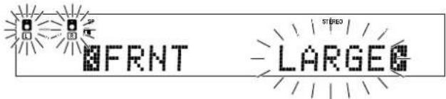
text_image
FRNT - LARGE④ Use the MULTI CONTROL knob or Joystick (▲/▼) to select the appropriate front speakers setting.
① FRNT LARGE : Large front speakers are connected to the receiver. ② FRNT NML/THX : Average size front speakers are connected to the receiver.
- For "FRNT LARGE" selection, no sound will be heard from subwoofer speaker even when it is set to ON. However, if you select "SW RE-MIX ON" when subwoofer is selected, you will be able to hear sound from the subwoofer. When in STEREO mode, the sound goes directly to front speaker.
⑤ Press the ^ key or Joystick (▶) to accept the setting.
- The center speaker setting indication "CNTR" appears.
⑥ Use the MULTI CONTROL knob or Joystick (▲/▼) to select the appropriate center speaker setting.
If you selected "LARGE" as the front speakers setting,
① CNTR LARGE : A large center speaker is connected to the receiver. ② CNTR NML/THX : An average size center speaker is connected to the receiver. ③ CNTR OFF : Center speaker setting mode to the receiver is OFF.
If you selected "NML/THX" as the front speakers setting,
① CNTR NML/THX : Center speaker setting mode to the receiver is ON. ② CNTR OFF : Center speaker setting mode to the receiver is OFF.
⑦ Press the ^ key or Joystick (▶) again to accept the setting.
- The surround speaker setting indication "SURR" appears.
Continued to next page.
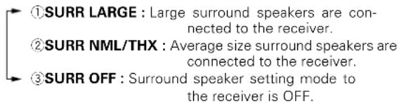
③ Use the MULTI CONTROL knob or Joystick (▲/▼) to select the appropriate surround speaker setting.
If you selected "LARGE" as the center speaker setting,
text_image
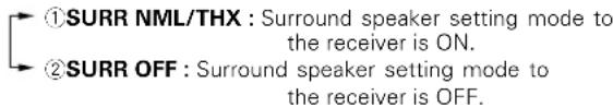
①SURR LARGE : Large surround speakers are connected to the receiver. ②SURR NML/THX : Average size surround speakers are connected to the receiver. ③SURR OFF : Surround speaker setting mode to the receiver is OFF.If you selected other than "LARGE" as the center speaker setting,
text_image
①SURR NML/THX : Surround speaker setting mode to the receiver is ON. ②SURR OFF : Surround speaker setting mode to the receiver is OFF.- When the setting "SURR OFF" is selected, the procedure skips to step 13.
9 Press the ^ key or Joystick (▶) again to accept the setting.
- The surround speaker setting indication "SB" appears.
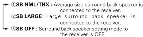
⑩ Use the MULTI CONTROL knob or Joystick (▲/▼) to select appropriate surround back speaker setting.
If you selected "LARGE" as the surround speaker setting,
text_image
①SB NML/THX : Average size surround back speaker is connected to the receiver. ②SB LARGE : Large surround back speaker is connected to the receiver. ③SB OFF : Surround back speaker setting mode to the receiver is OFF.
text_image
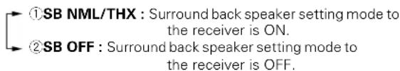
SP SB STREEO LARGEIf you selected other than "LARGE" as the surround speaker setting,
text_image
①SB NML/THX : Surround back speaker setting mode to the receiver is ON. ②SB OFF : Surround back speaker setting mode to the receiver is OFF.- After setting SB (surround back) from OFF to NML/THX, 6ch AMP setup display will appear to enable you to re-select either SW, SB or OFF from the surround back or subwoofer speaker terminal.
7 Press the ^ key or Joystick (▶) again to accept the setting and "SURR:MIX" appears.
- Surr:mix is when the SL and SR speakers signals are mixed to produce sound from the surround back speaker which would enable the listener to enjoy sound coming from the back.

text_image
SP L C: [SB] H SUBR: MIX ON STEREOUse the MULTI CONTROL knob or Joystick (▲/▼) to select the following.

text_image
① SURR:MIX ON : Surround mix setting mode to the receiver is ON. ② SURR:MIX OFF : Surround mix setting mode to the receiver is OFF.- If surround back speaker is turned OFF, SURR:MIX setting is not visible and the procedure skips to step 13.
13 Press the ^ key or Joystick (▶) again to accept the setting. • The subwoofer re-mix setting indication "SW RE-MIX" appears.
Use the MULTI CONTROL knob or Joystick (▲/▼) to select the appropriate subwoofer re-mix setting.
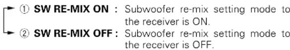
text_image
① SW RE-MIX ON : Subwoofer re-mix setting mode to the receiver is ON. ② SW RE-MIX OFF : Subwoofer re-mix setting mode to the receiver is OFF.- If subwoofer is turned OFF, subwoofer re-mix setting is not visible.
⑮ Press the SETUP key again to return to the main setup displays.
- The receiver enters the speaker volume level adjustment mode. - In steps 4 and 5, indications appear only for the selected channels of the speakers that require adjusting.
4 Adjust the speaker volume level.
From your usual listening position, adjust the volume levels. The volume levels from each speaker should be the same.
⑦ Press the ∧/∨ keys or Joystick (◄/►) to select TEST TONE.
② Press the SETUP key for the following displays:

⑨ The selection of AUTO/MANUAL TEST TONE is done by the MULTI CONTROL knob or Joystick (▲/▼). Press the SETUP key again to begin TEST TONE.
Use the MULTI CONTROL knob or Joystick (▲/▼) to adjust the volume level of the test tone output from the speaker channel to be adjusted.
For AUTO selection, the first test tone is heard from the front left speaker for 2.5 seconds. The next test tone is heard from the speakers in the following sequence for 2 seconds each.
When the 6ch AMP SB has been selected.

When the 6ch AMP SW or OFF has been selected.

The channel indication blinks while the test tone is being output.
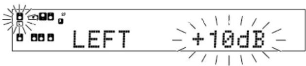
text_image
LEFT -+10dB-- If you change the volume level settings for the speakers while listening to music, the settings referred to on this page are also changed. - If the speaker setting selects are OFF, the speaker level settings are reset.
For MANUAL selection, press the ^/▼ keys or Joystick (◄/►) each time to select the speaker channel.
④ Press the SETUP key again.
- The test tone is turned off and return to the main setup displays.
5 Adjust the bass peak level.
A restriction is put on the low frequency so that the bass peak level will not go higher than the acceptable level when the volume is increased. If subwoofer speaker is OFF, the limitation will affect the low frequency of the front left and right speakers
⑦ Press the ^/√ keys or Joystick (◀/▶) to select BASS PEAK and press the SETUP key.

text_image
SP (B) BASS PEAK OFF STUDIO② Use the MULTI CONTROL knob or Joystick (▲/▼) to adjust the bass peak level to -30dB.
- The adjustment range is from -30dB to 0dB and OFF.
② For optimum bass peak level, keep increasing the bass peak level by using the MULTI CONTROL knob or Joystick (▲/▼) while test tone is being output until clip sound is heard from the subwoofer or front speaker.
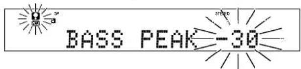
text_image
SP SP BASS PEAK-30 STRED4 Press the SETUP key to accept the setting.
6 Input the distance to the speakers.
① Press the ^/√ keys or Joystick (◀/▶) to select the SP DISTANCE on setup displays and press the SETUP key.
② Measure the distance from the listening position to each of the speakers.
Jot down the distance to each of the speakers.
Distance to Front left speaker (L) : ____ feet (meters) Distance to Center speaker (C) : ____ feet (meters) Distance to Front right speaker (R) : ____ feet (meters) Distance to Surround right (SR) : ____ feet (meters) Distance to Surround back right (SBR) : ____ feet (meters) Distance to Surround back left (SBL) : ____ feet (meters) Distance to Surround left (SL) : ____ feet (meters) Distance to Subwoofer (SW) : ____ feet (meters)
⑨ Use the ∧/∨ keys or Joystick (◄/►) to select the speakers and the MULTI CONTROL knob or Joystick (▲/▼) to adjust the distance to the front speakers.
The speaker indicator to be adjusted blinks.

text_image
SP SP L - 10ft/3.0m STEREO Indication in feet Indication in meters- The allowable setting range is 1 to 30 feet (0.3 to 9.0 m), adjustable in 1 foot (0.3 m) increments.
④ Repeat steps ③ to input the distance for each of the speakers.
⑤ Press the SETUP key again to return to main set up displays.
- The speakers you have selected should appear on the display. Confirm that all the speakers have been correctly selected.
7 Select the display mode.
① Press the ∧/∨ keys or Joystick (◄/►) to select the DISP MODE.
2 Press the SETUP key for the following displays:
① DISP SELECTOR : Displays the current input selector. ② DISP LISTEN : Displays the current listen mode.
③ Use the MULTI CONTROL knob or Joystick (▲/▼) to select the display mode.
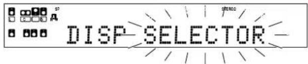
text_image
S7 DISP SELECTOR STEREO④ Press the SETUP key again to accept the setting.
⑤ Use the ^ key or Joystick (▶) to select EXIT.
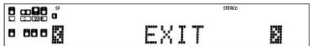
text_image
STRECO EXIT⑥ Press the SETUP key to exit the SET UP mode.
Input level adjustment (analog sources only)
If the input level of an analog source signal is too high, the CLIP indicator will blink to indicate the source signal. Adjust the input level.

① Use the Input Selector keys to select the source of which the input level you want to adjust.
- You can store a separate input level for each input source.
2 Press the SOUND and ∧/∨ keys or Joystick (◄/►) repeatedly until the "INPUT" indication appears.
③ Use the MULTI CONTROL knob or Joystick (▲/▼) to adjust the input level.
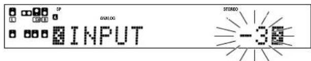
text_image
3P COLD DIALOG INPUT STEREO -3- The adjustment mode is displayed for approximately 8 seconds.
- The input level may be adjusted to any one of three settings: 0dB, -3dB, and -6dB. (The initial setting is 0dB.)
④ Press the SOUND key again to return to the input indication.
Preparing for playback
Some preparatory steps are needed before starting playback.
text_image
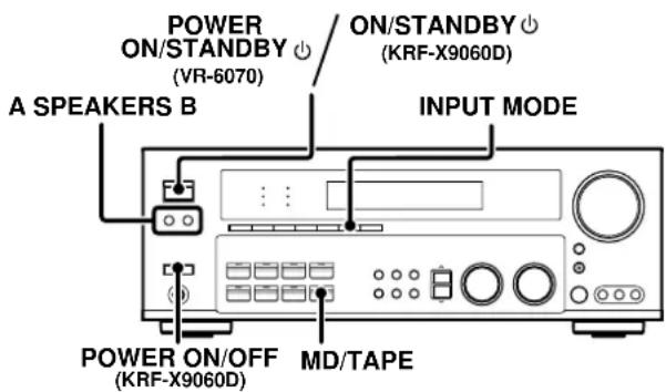
POWER ON/STANDBY (VR-6070) ON/STANDBY (KRF-X9060D) A SPEAKERS B INPUT MODE POWER ON/OFF (KRF-X9060D) MD/TAPETurning on the receiver
⑦ Turn on the power to the related components.
2 Turn on the power to this receiver by pressing the POWER ON/STANDBY (for VR-6070) or POWER ON/OFF and ON/STANDBY (for KRF-X9060D) key.
Selecting the input mode
If you have selected a component connected to the CD/DVD, VIDEO 2, VIDEO 3 or DVD/6CH jacks, make sure that the input mode setting is correct for the type of audio signal to be used. →
Selecting MD/TAPE
Select the source name corresponding to the component connected to the MD/TAPE jacks. The initial factory setting is "TAPE". To change the source to "MD", follow the steps below:
Hold down the MD/TAPE key for more than 2 seconds.
- The source indication changes to "MD".
- To return to the original indication, repeat the above procedure.
Selecting the speaker system
Press the A SPEAKERS B key to select the speaker system to be used.
A ON : Sound from the speakers connected to the SPEAKERS A terminals on the rear panel.
B ON : Sound from the speakers connected to the SPEAKERS B terminals on the rear panel. No sound will be heard from the subwoofer.
A+B ON : Sound from both the speakers connected to the SPEAKERS A and B terminals on the rear panel.
A+B OFF: No sound from the speakers. Use this setting when listening with headphones for stereo sound in all playback modes. The display segments are different depending on the type of input signal.
The indicator for the speakers you want to use should be lit.
- Selecting "6CH INPUT" by pressing the INPUT MODE key, whereby "DVD/6CH" is the input source will cause SPEAKERS A to be selected automatically.
Listening to a source component
text_image
VOLUME CONTROL Input Selector AV AUX VOLUME +/- INPUT SELECTOR1 Use the Input Selector and AV AUX keys to select the source you want to listen to.
Selecting a source using each key.
①"DVD/6CH"
②"CD/DVD"
③"PHONO"
④"TUNER"
⑤"VIDEO 1"
⑥"VIDEO 2"
⑦"VIDEO 3"
⑧"MD/TAPE"
⑨"AV AUX"
2 Start playback from the selected source.
3 Use the VOLUME CONTROL knob or VOLUME +/- keys to adjust the volume.
Adjusting the sound
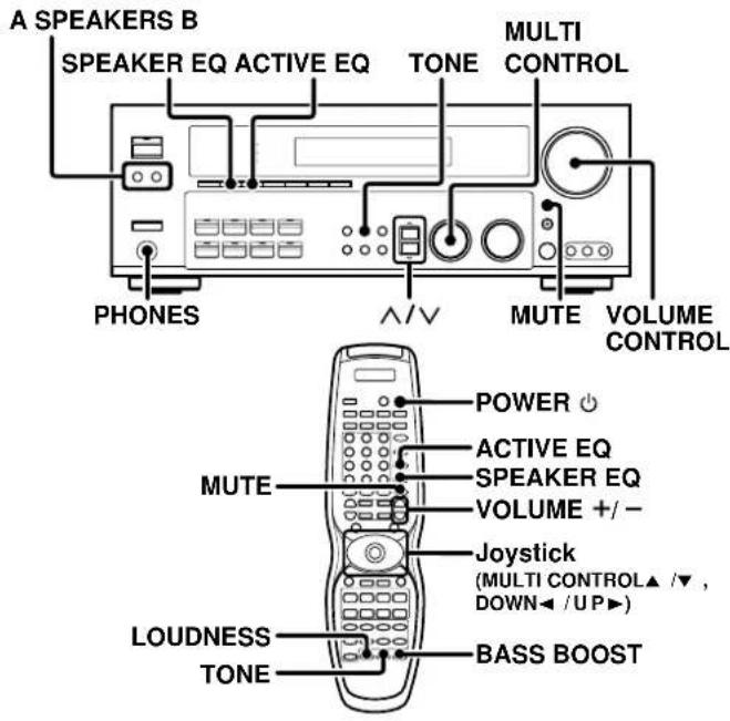
text_image
A SPEAKERS B SPEAKER EQ ACTIVE EQ TONE MULTI CONTROL PHONES ∧/∨ MUTE VOLUME CONTROL MUTE POWER + ACTIVE EQ SPEAKER EQ VOLUME +/- - Joystick (MULTI CONTROL▲ /▼ , DOWN◄ / UP►) LOUDNESS TONE BASS BOOSTAdjusting the TONE
You can adjust the sound quality when the receiver is in the PCM stereo and analog stereo mode and when "THX OFF".
⑦ Press the TONE key to select the TONE mode.
② Use the MULTI CONTROL knob or Joystick (▲/▼) to select TONE ON/OFF.

text_image
SP R 200 3 TONE ANALOG STEREO ON③ When in TONE ON selection, press the TONE key for the following displays.
BASS : Select this to adjust the low frequency range. TREBLE : Select this to adjust the high frequency range.
④ Use the MULTI CONTROL knob or Joystick (▲/▼) to adjust the sound quality.
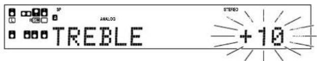
text_image
SP ANALOG TREBLE STEREO +10- The bass and treble levels are adjustable from -10 to +10 in 2 step increments.
• The adjustment item is displayed for approximately 8 seconds.
Once-touch low frequency emphasis (BASS BOOST) (remote control only)
You can adjust the sound quality when the receiver is in the PCM stereo and analog stereo modes and when "THX OFF".
Press the BASS BOOST key.
- Press the key once to select the maximum (+10) low frequency emphasis setting.
- This key does not function when the receiver is in the sound quality or ambience effects adjustment mode.
Switching back to the previous setting
Press the BASS BOOST key again.
Adjusting the LOUDNESS mode (remote control only)
You can adjust the Loudness function which controls the low volume settings to maintain the music's richness. The adjustment can be made when the receiver is in the PCM stereo and analog stereo mode and when "THX OFF".
Press the LOUDNESS key to turn the LOUDNESS setting ON.
To cancel
Press the LOUDNESS key again so that the "LOUDNESS" indicator goes off.
Muting the sound
The MUTE key lets you mute the sound of the speakers.
Press the MUTE key.
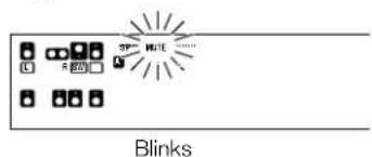
text_image
SP HATE ...... BlinksTo cancel
Press the MUTE key again so that the "MUTE" indicator goes off. - MUTE ON can also be deactivated by turning the VOLUME CONTROL knob or pressing VOLUME +/- keys.
ACTIVE EQ mode
You can enjoy a more impressive sound effect when ACTIVE EQ is turned ON during Dolby Digital and DTS playback and, when in PCM and analog stereo mode.
Press the ACTIVE EQ key for the following selections;
① ACTIVE EQ MUSIC : Effective when listening to music. (The ACTIVE EQ indicator lights up.)
② ACTIVE EQ CINEMA : Effective when watching a movie. (The ACTIVE EQ indicator lights up.)
③ACTIVE EQ TV : Effective when watching TV.
(The ACTIVE EQ indicator lights up.)
④ACTIVE EQ OFF: The ACTIVE EQ function is turned OFF. (The ACTIVE EQ indicator goes off.)
- "ACTIVE EQ" will scroll from right to left.
- When ACTIVE EQ and SPEAKER EQ are OFF and ACTIVE EQ (MUSIC) is turned ON, SPEAKER EQ (SMALL) will turn ON automatically.
- ACTIVE EQ function will not be available when REC MODE, AUTO TUNING or PRESET MEMORY is ON, and during 96kHz LPCM playback.
SPEAKER EQ mode
SPEAKER EQ's function will automatically detect the various features of each speaker and effectively creates a stereoscopic sound effect.
Press the SPEAKER EQ key to switch the following setting;
① SPEAKER EQ SMALL : To select a small sizespeaker.
(The SPEAKER EQ indicator lights up.)
②SPEAKER EQ NORMAL : To select an average size speaker.
(The SPEAKER EQ indicator lights up.)
③ SPEAKER EQ LARGE : To select a large size speaker.
(The SPEAKER EQ indicator lights up.)
④ SPEAKER EQ OFF : The SPEAKER EQ function is turned OFF.
(The SPEAKER EQ indicator goes off.)
- "SPEAKER EQ" will scroll from right to left.
- SPEAKER EQ cannot be turned OFF when ACTIVE EQ is turned ON.
- SPEAKER EQ function will not be available when REC MODE, AUTO TUNING or PRESET MEMORY is ON, and during 96kHz LPCM playback.
Listening with headphones
① Press the A and B speaker keys so that the speaker indicator goes off.
Make sure the SPEAKERS indicators are turned off.
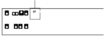
flowchart
graph TD
    A[" "] --> B[" "]
    B --> C[" "]
    C --> D[" "]
    D --> E[" "]
    E --> F[" "]
    F --> G[" "]
    G --> H[" "]
    H --> I[" "]
    I --> J[" "]
    J --> K[" "]
    K --> L[" "]
    L --> M[" "]
    M --> N[" "]
    N --> O[" "]
    O --> P[" "]
    P --> Q[" "]
    Q --> R[" "]
    R --> S[" "]
    S --> T[" "]
    T --> U[" "]
    U --> V[" "]
    V --> W[" "]
    W --> X[" "]
    X --> Y[" "]
    Y --> Z[" "]
    Z --> A
- If you turn off all of the speakers when in surround mode, the surround mode will be canceled as well, resulting in stereo playback.
② Connect headphones to the PHONES jack.
natural_image
Line drawing of a stethoscope with a circular head and ear (no text or symbols)③ Use the VOLUME CONTROL knob or VOLUME +/- keys to adjust the volume.
Recording audio (analog sources)
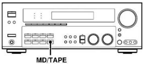
text_image
MD/TAPERecording a music source
⑦ Use the input selector keys to select the source (other than "MD/TAPE") you want to record.
② Set the MD or TAPE recorder to record.
③ Start playback, then start recording.
Recording video
① Use the Input selector keys to select the video source (other than "VIDEO 1") you want to record.
② Set the video deck connected to VIDEO 1 to record.
- Select the REC MODE to record a digital input source.
③ Start playback, then start recording.
- Recording may not be normal for some video software. This is due to the copy guard condition. →[48]
Recording audio (digital sources)
Switch on the REC MODE to record a digital input source.
Usually use the AUTO REC MODE to record audio input sources. When the digital mode changes during recording in the AUTO REC MODE, the audio input source may be interrupted momentarily.
Recording music in AUTO REC or MANUAL REC mode
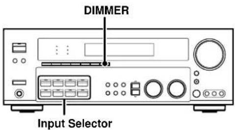
text_image
DIMMER Input Selector⑦ Use the Input Selector keys to select the source (CD/DVD, DVD/6CH, VIDEO 2, VIDEO 3) you want to record.
② Set the MD or TAPE recorder to record.
③ Press and hold the DIMMER key for more than 2 seconds to select the AUTO REC or MANUAL REC mode.
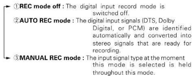
text_image
①REC mode off : The digital input record mode is switched off. ②AUTO REC mode : The digital input signals (DTS, Dolby Digital, or PCM) are identified automatically and converted into stereo signals that are ready for recording. ③MANUAL REC mode : The input signal type at the moment this mode is selected is held throughout this mode.For AUTO REC mode :
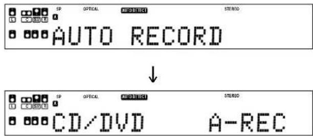
text_image
SP OPTICAL AUTO DIRECT STEREO AUTO RECORD ↓ SP OPTICAL AUTO DIRECT STEREO CD/DVD A-RECFor MANUAL REC mode :
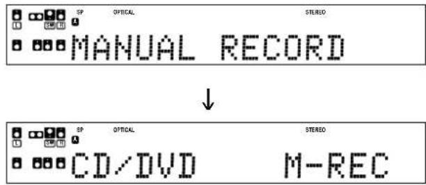
text_image
SP OPTICAL STEREO MANUAL RECORD ↓ SP OPTICAL STEREO CD/DVD M-REC④ Start playback, then start recording.
- If the audio reproduction stops in the middle due to change in the input signals, etc., press the DIMMER key.
The receiver can store up to 40 stations in the memory and recall them by one-touch operation.
Radio stations can be classified into RDS (Radio Data System) stations and other stations. To listen to or store RDS stations in the preset memory see "Using RDS (Radio Data System)". (For the U.K. only)
Tuning (non-RDS) radio stations
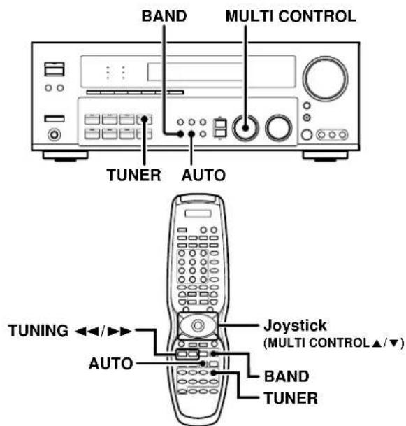
text_image
BAND MULTI CONTROL TUNER AUTO TUNING ←/→ AUTO Joystick (MULTI CONTROL▲/▼) BAND TUNER1 Use the TUNER key to select the tuner.
2 Use the BAND key to select the desired broadcast band.
Each press switches the band.

text_image
SBERD FM108.00 MHz3 Use the AUTO key to select the desired tuning method.
Each press switches the tuning method to either auto or manual tuning.
"AUTO" indicator lights up in the display.
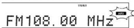
text_image
STEREO FM108.00 MHz AUTO- Normally, set to "AUTO" (auto tuning). If the radio waves are weak and there is a lot of interference, switch to manual tuning. (With manual tuning, stereo broadcasts will be received in monaural.)
4 Use the MULTI CONTROL knob or Joystick (▲/▼) or TUNING ◀◀/▶▶ keys to select the station.
"STEREO" lights when a broadcast is being received in stereo.
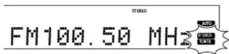
text_image
STEREO FM100.50 MHz AUTO AUDIO LUNO"TUNED" is displayed when a station is received.
Auto tuning : The next station is tuned automatically. Manual tuning : Turn the knob or use the Joystick (▲/▼) to select the desired station.
(For the U.K. only)
Using RDS (Radio Data System)
RDS is a system that transmits useful information (in the form of digital data) for FM broadcasts along with the broadcast signal. Tuners and receivers designed for RDS reception can extract the information from the broadcast signal for use with various functions, such as automatic display of the station name.
RDS functions:
PTY (Program TYPE Identification) Search → 32
Automatically tunes to a station that is currently broadcasting the specified program type (genre).
PS (Program Service Name) Display
Automatically displays the station name transmitted by the RDS station.
RDS AUTO MEMORY function → 32
Automatically selects and stores up to 40 RDS stations in the preset memory.
If fewer than 40 RDS stations have been stored in the preset memory, regular FM stations will be stored in the remaining places.
Radio Text function
Displays the radio text data transmitted by some RDS stations when you press the RDS DISP (display) key. There is "NO RT" if no text data is transmitted.
The "RDS" indicator lights up when an RDS broadcast (signal) is received.
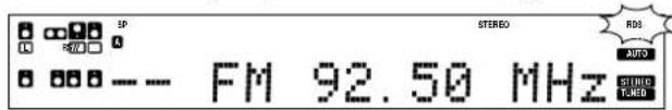
text_image
SP LU SP SP STEREO ROS AUTO FM 92.50 MHz STUDIO TUNEDNote
Some functions and function names may differ for certain countries and areas.
Before using a function utilizing the RDS, be sure to perform the RDS Auto Memory operation by referring to the description in "Presetting RDS stations (RDS AUTO MEMORY)". →[32]
Presetting radio stations manually
The RDS auto memory function assigns preset numbers to RDS stations starting from preset number "1". Therefore, be sure to execute the RDS auto memory function before using the following operations to manually store AM stations and other FM stations, and RDS stations. See "Presetting RDS stations (RDS AUTO MEMORY)". (For the U.K. only)
→32
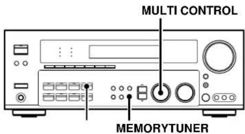
text_image
MULTI CONTROL MEMORYTUNER1 Tune to the station you want to store.
2 Press the MEMORY key while receiving the station.
Blinks for 5 seconds
Lights for 5 seconds

text_image
01 FM108.00 MHz STEREO RADIO METHO TURSDProceed to step 3 within 5 seconds. (If more than 5 seconds elapse, press the MEMORY key again).
3 Use the MULTI CONTROL knob or Joystick (▲/▼) to select one of the station presets (1 - 40).
4 Press the MEMORY key again to confirm the setting.
- Repeat steps 1, 2, 3, and 4 to store as many stations as necessary.
- If you store a station at a previously used preset, the old station will be replaced by the new one.
Receiving preset stations
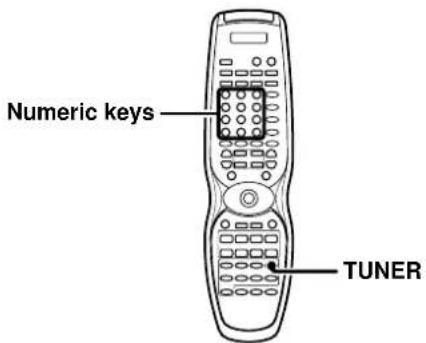
text_image
Numeric keys TUNER1 Press the TUNER key to select tuner as the source.
2 Enter the number of the preset station you want to receive (up to "40").
Press the numeric keys in the following order:
For "15", press +10, 5 For "20", press +10, +10, 0
- If you make a mistake entering a two digit number, press the +10 key repeatedly to return to the original display and start again.
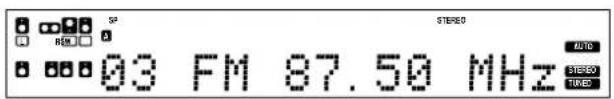
text_image
SF STREED 03 FM 87.50 MHz AUTO STREED TAKESReceiving preset stations in order (P.CALL)
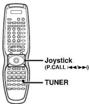
text_image
Joystick (P.CALL |◄►►►) TUNER1 Press the TUNER key to select the tuner as the source.
2 Use the Joystick to adjust the P.CALL |◀◀/▶▶| direction to select the desired station.
• Each time you push the Joystick, another preset station is received in order.
Pushing the Joystick to P.CALL ▶▶ does the following:
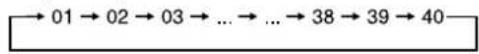
Pushing the Joystick to P.CALL ◀◀ does the following:

Holding the Joystick on ▶▶ or ◀◀ direction, lets you skip through the presets, receiving each preset station at 0.5 second intervals.
(For the U.K. only) Using the RDS DISP (Display) key
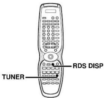
text_image
TUNER RDS DISPPressing the RDS DISP key changes the contents of the display.
Each press switches the display mode as follows :
① PS (Program Service name) display
② RT (Radio Text) display
③Frequency display
PS (Program Service name) display :
The station name is displayed automatically when an RDS broadcast is received. If no PS data was sent, "NO PS" is displayed.
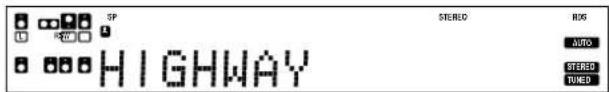
text_image
SP H I G H W A Y STEREO RIO AUTO STEREO FIXED2 RT (Radio Text) display :
Text data accompanying the RDS broadcast scrolls across the display. "NO RT" is displayed if the current RDS station does not provide RT data.
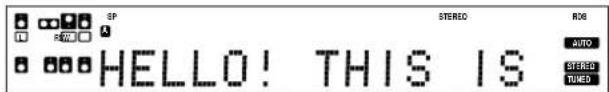
text_image
SP A STEREO ROS AUTO STEREO HOLD HELLO! THIS IS③ Frequency display :
Displays the frequency of the current station.
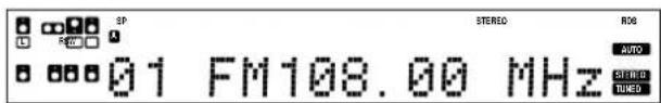
text_image
SP STEREO ROG 01 FM108.00 MHz AUTO STRED RHO(For the U.K. only)
Presetting RDS stations (RDS AUTO MEMORY)
This function automatically stores up to 40 RDS stations in the preset memory. In order to use the PTY function, the RDS stations must be stored in the preset memory using the RDS Auto Memory function.
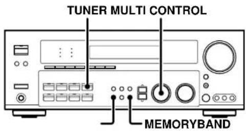
text_image
TUNER MULTI CONTROL MEMORYBAND1 Press the TUNER key to enter tuner mode.
2 Use the BAND key to set the broadcast band to "FM".
3 Press the MEMORY key continuously for more than 3 seconds will start AUTO MEMORY.

text_image
AUTO MEMORY- After a few minutes, up to 40 RDS stations are preset in order from channel "01".
- Stations already stored in the preset memory may be replaced by RDS stations. (i.e., If the RDS AUTO MEMORY function detects 15 RDS stations, the stations currently preset at numbers 01\~15 will be replaced by the RDS stations.)
(For the U.K. only)
Tuning by Program TYpe (PTY search)
This function lets you set the tuner to automatically search for stations which are currently broadcasting the type of program (genre) you want to listen to.
Under certain receiving conditions, it may take more than 1 minute to complete the search.

text_image
PTY TUNING Joystick (MULTI CONTROL▲/▼, DOWN◄/UP►)Preparations
- Execute the RDS auto memory procedure.
- Set the broadcast band to FM.
- Tune to an RDS station.
1 Press the PTY key to activate the PTY search mode.
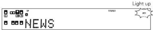
text_image
Light up STREED NEWS PTYWhen an RDS broadcast is received, the program type is shown on the display. If no PTY data is available, or if the station is not an RDS station, "NONE" is displayed.
2 While the "PTY" indicator is lit, use the Joystick (▲/▼) or TUNING ◀◀/▶▶ keys to select the program type of your choice.
Program type table
| Program Type Name | Display | Program Type Name Display | |
| Pop Music | POP M | Weather | WEATHER |
| Rock Music | ROCK M | Finance | FINANCE |
| Easy Music | EASY M | Children's Program | CHILDREN |
| Light Classical Music | LIGHT M | Social Affairs | SOCIAL |
| Serious Classical Music | CLASSICS | Religion | RELIGION |
| Other Music | OTHER M Phone In | PHONE IN | |
| News | NEWS | Travel | TRAVEL |
| Current Affairs | AFFAIRS | Leisure | LEISURE |
| Information | INFO | Jazz Music | JAZZ |
| Sport | SPORT | Country Music | COUNTRY |
| Education | EDUCATE National Music | NATION M | |
| Drama | DRAMA | Oldies Music | OLDIES |
| Culture | CULTURE Folk Music | FOLK M | |
| Science | SCIENCE | Documentary | DOCUMENT |
| Varied Speech | VARIED | ||
"NO PROGRAM" is displayed if this operation is attempted before performing the RDS Auto Memory operation.
3 Press the PTY key to start searching.
EXAMPLE : Searching for a Pop Music broadcast.
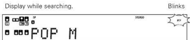
text_image
Display while searching. Blinks SP STEREO POP MProgram type name display

text_image
Display when a station is received. SP BBC 1FM STEREO Goes outStation name display
- No sound is heard while "PTY" is blinking.
- If the desired program type cannot be found, "NO PROGRAM" is displayed, then after several seconds the display returns to the original display.
To select another program type.
Repeat steps 1, 2 and 3.
This receiver is equipped with listening modes that allow you to enjoy an enhanced sonic ambience with a variety of video sources.
In order to obtain the optimum effect from the surround modes, make sure to input the proper speaker settings beforehand. → 23
Surround modes
Dolby Digital
The Dolby Digital surround format lets you enjoy up to 5.1 channels of digital surround sound from Dolby Digital program sources (such as Laserdisc or DVD software marked [M] DOBY). Compared with previous Dolby surround, Dolby Digital provides even better sound quality, greater spatial accuracy, and improved dynamic range.
Note
Although a full set of speakers (front left, right, and center, surround left and right, and a subwoofer) is required for true 5.1 channel Dolby Digital surround sound, this receiver lets you enjoy Dolby Digital (and Dolby Surround) program sources, even if you connect only the front speakers.
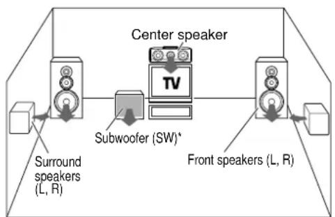
flowchart
graph LR
    A["Front speakers (L, R)"] --> B["Subwoofer (SW)*"]
    B --> C["Center speaker"]
    C --> D["Surround speakers (L, R)"]
    style C fill:#f9f,stroke:#333
    style D fill:#ccf,stroke:#333
* Optional in this mode.
* LFE = Low Frequency Effects. This channel delivers separate non-directional bass signals to the subwoofer for more dynamic deep bass sound effects.
Although only Dolby Digital soundtracks incorporate a separate low frequency channel, connecting a subwoofer will also improve deep bass performance in the other surround modes.
The indication "LFE" appears in the display when a signal is being input for this channel.
"DTS", "DTS-ES Extended Surround" and "Neo:6" are trademarks of Digital Theater Systems, Inc.

Manufactured under license from Dolby Laboratories. "Dolby", "Pro Logic", "Surround EX" and the double-D symbol are trademarks of Dolby Laboratories.
"Circle Surround II and the (●)® symbol are trademarks of SRS Labs, Inc. Circle Surround II technology is incorporated under license from SRS Labs, Inc".
Lucasfilm and THX are trademarks or registered trademarks of Lucasfilm, Ltd. ©Lucasfilm Ltd. & TM. Surround EX is a jointly developed technology of THX and Dolby Laboratories Inc. and is a trademark of Dolby Laboratories Inc. All rights reserved. Used under authorization.
Dolby Digital EX
Dolby Digital EX is an extension of Dolby Digital technology, Dolby Digital EX creates six full-bandwidth output channels from 6.1-channel sources. This is done using a matrix decoder that derives three surround channels from the two in the original recording.
This is achieved by using three different surround signals, Left Surround, Right Surround, and Back Surround, each driving its own array of speakers. Think of it as adding a center channel for the rear speakers, which give more diffuse and natural surround effect, even if you wanted the ability to completely encircle the audience with sound, positioning sound effects exactly where they wolud be heard in real life. For best results, Dolby Digital EX should be used with movie soundtracks recorded with Dolby Digital Surround EX which contain a digital flag that will automatically activate this feature. However, for titles released prior to late 2001, this feature has to be activated manually.
Note
Although a full set of speakers (front left, right, and center, surround left and right, surround back left and right, and a subwoofer) is required for true 6.1 channel Dolby Digital surround EX sound, this receiver lets you enjoy Dolby Digital (and Dolby Surround) program sources, even if you connect only the front speakers.
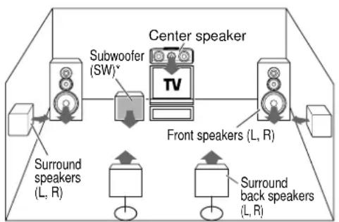
flowchart
graph TD
    A["Front speakers (L, R)"] --> B["Subwoofer (SW)*"]
    B --> C["Center speaker"]
    C --> D["Surround back speakers (L, R)"]
    D --> E["Surround speakers (L, R)"]
    C --> F["TV"]
* Optional in this mode.
* LFE = Low Frequency Effects. This channel delivers separate non-directional bass signals to the subwoofer for more dynamic deep bass sound effects.
Although only Dolby Digital soundtracks incorporate a separate low frequency channel, connecting a subwoofer will also improve deep bass performance in the other surround modes.
The indication "LFE" appears in the display when a signal is being input for this channel.
Dolby PRO LOGIC II
Dolby Pro Logic II was designed specifically to provide a new sense of spatiality, directionality and articulation of sounds from Dolby Surround encoded sources (such as video and Laserdisc software marked ☐☐ DOLBY SURROUND ). This is achieved with an intelligent, built-in feedback logic design, a matrix surround decoding and the decoding of stereo, full bandwidth surround outputs. The PRO LOGIC II modes programmed into this receiver are "MOVIE", "MUSIC" and "PRO LOGIC". The "MOVIE" mode of the PRO LOGIC II has preset characteristics to produce a calibrated, high-level surround sound playback while the "MUSIC" mode has user-adjustable characteristics to offer the three optional controls, like "Dimension", "Center Width" and "Panorama" modes to allow optimization of the soundfields as desired. The "Dimension" control allows the user to gradually adjust the soundfield either towards the front or towards the rear; the "Center Width" control allows various adjustment of the left-center-right speakers' balance; the "Panorama" mode extends the front stereo image to include the surround speakers for an exciting "wraparound" effect with side wall imaging.
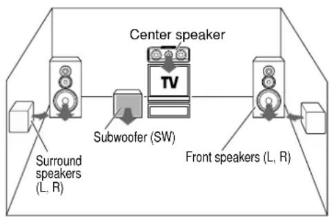
flowchart
graph TD
    A["Front speakers (L, R)"] --> B["Subwoofer (SW)"]
    B --> C["Center speaker"]
    C --> D["TV"]
    D --> E["Surround speakers (L, R)"]
DTS-ES
The DTS-ES (Digital Theater System-Extended Surround) represents 6.1-channel Discrete Surround format, expanding upon 5.1 surround. DTS-ES format is a 6.1 channel sound system for movie theaters that includes an additional surround center channel matrixed within surround left and surround right. It's compatible on predecessor DTS 5.1 system. The extra channel allows more accurate placement and steering of sound across the rear soundstage. The DTS-ES receiver will be required, to experience a discrete 6.1-channel mix.
The DTS-ES decoders used in home cinema systems have decoding options for utilizing the extra channel, in addition to processing existing 5.1 channel surround sound :
DTS-ES Discrete 6.1 and DTS-ES Matrix 6.1 add the surround back channel audio to the DTS 5.1-channel format to improve the acoustic positioning and makes acoustic image movement more natural with the 6.1-channel reproduction.
NEO:6 is a new technology which decodes 2-channel signals into 6-channel signals using high-accuracy digital matrix technology. For the best results, DTS-ES should be used with movie sound tracks recorded with DTS-ES format which contain a digital flag that will automatically activate this feature. However, for some titles, this feature has to be activated manually.
According to the signals to be played back, DTS NEO:6 uses either the NEO:CINEMA mode optimized for movie playback or the NEO:MUSIC mode optimized for music playback.

flowchart
graph TD
    A["Front speakers (L, R)"] --> B["Subwoofer (SW)*"]
    B --> C["Center speaker"]
    C --> D["Surround back speakers (L, R)"]
    D --> E["Surround speakers (L, R)"]
    F["Subwoofer"] --> G["TV"]
* Optional in this mode.
* LFE = Low Frequency Effects. This channel delivers separate non-directional bass signals to the subwoofer for more dynamic deep bass sound effects.
DTS has a .1 or LFE channel.
The indication "LFE" appears in the display when a signal is being input for this channel.
THX Surround EX mode
THX Surround EX is an extension of THX which was jointly developed by Lucasfilm THX and Dolby Laboratories.
This new technology is able to place sound directly behind the listener as it allows the sound mixers to encircle the listener with 360-degree pans.
THX Surround EX is able to redirect bass energy in the surround back channels to the subwoofer. It requires re-equalization of the surround back channels to match the characteristics of the front and left or right surround channels.
It also consist of the basic THX features such as Re-equalization (ReEQ), Timbre Matching, Adaptive Decorrelation, Bass Peak Level Manager and Loudspeaker Position Time Synchronisation.
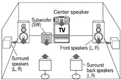
flowchart
graph TD
    A["Front speakers (L, R)"] --> B["Subwoofer (SW)"]
    B --> C["Center speaker"]
    C --> D["Surround back speakers (L, R)"]
    D --> E["Surround speakers (L, R)"]
    E --> F["Left Speaker"]
    style A fill:#f9f,stroke:#333
    style B fill:#ccf,stroke:#333
    style C fill:#cfc,stroke:#333
    style D fill:#fcc,stroke:#333
    style E fill:#cff,stroke:#333
When listening in a typical home room, there may be some variation of echo due to air absorption and smaller space. The sound produced by flat response loudspeakers normally used in the cinema can be overly bright in the home environment. Thus, Re-equalization (Re-EO) will adjust this condition to fit the home environment for a similar cinema effect.
Timbre Matching
Due to human condition, listening to sound from various directions of speakers can be very disturbing. So, it is important to smoothen the flow of sound to suit the home cinema environment. Timbre Matching is able to smoothen the flow of sound to the listener who will be able to enjoy the cinema effect at home.
Adaptive Decorrelation
Mono sound track produced from the speaker system comes from only one direction, which does not exemplify the cinema surround sound experience. Adaptive Decorrelation is able to adjust the inaccuracy of this sound distribution.
Bass Peak Level Manager
Certain sound tracks may produce various bass peaks that could be unpleasant in a home cinema environment. Therefore, a user-adjustable Bass Peak Level Manager is used to control the bass level to suit the system's capacity. →[25]
Loudspeaker Position Time Synchronisation
This function enables you to adjust the different speaker's distance to your listening position. It permits an accurate synchronisation, which creates the ultimate sound environment.
DSP mode
The DSP mode lets you add the atmosphere of a live concert or hall to almost any type of program source. These modes are particularly effective when used with stereo program sources, like CD, television, and FM radio. You might enjoy trying the ARENA, JAZZ CLUB, THEATER, STADIUM or DISCO mode the next time you watch a concert or sporting event!

flowchart
graph TD
    A["Front speakers (L, R)"] --> B["Subwoofer (SW)"]
    B --> C["TV"]
    C --> D["Center speaker"]
    D --> E["Surround speakers (L, R)"]
What's DSP?
DSP stands for Digital Signal Processor.
The way a sound is heard in an actual environment depends on a variety of different factors. One of the most important is reverberation (the act of decaying elements of sound echoing in various places).
The DSP modes produce the feeling of presence by using the DSP to create reverberation, without spoiling the sound quality of the original signal.
Multi channel surround sound (SRS Circle Surround II)
SRS Circle Surround II ^™ improves on its predecessor CS-5.1 ^™ resulting in the CS-6.1 ^™ system, enabling you to listen to realistic, multi-channel, surround sound playback from a stereo source or conventional surround-encoded video source. You already enjoy listening to Dolby Digital sound/DTS multi-channel sound with your multi-speakers. Now you can listen to audio CDs, MDs, Broadcast and Home Theater using your multi-speakers. You will discover a new type of sound through SRS Circle Surround II.
The CS system dramatically reduces storage space requirements for multi-channel content. It creates a listening environment that places the listener "inside" music performances, and dramatically improves both hi-fi audio and conventional surround-encoded video material.
The CS decoder also includes the SRS technologies Focus™ and TruBass™. Focus electronically raises the sound stage from the speaker location to an optimal position. TruBass creates deep, rich bass in small speaker systems without the need for a subwoofer.

flowchart
graph TD
    A["Front speakers (L, R)"] --> B["Subwoofer (SW)"]
    B --> C["Center speaker"]
    C --> D["Surround back speakers (L, R)"]
    D --> E["Surround speakers (L, R)"]
    E --> F["Left Speaker"]
    style A fill:#f9f,stroke:#333
    style B fill:#ccf,stroke:#333
    style C fill:#cfc,stroke:#333
    style D fill:#fcc,stroke:#333
    style E fill:#cff,stroke:#333
DVD 6-channel mode
Using a DVD player or the like equipped with six (5.1) output channels and the receiver, you can enjoy multi-channel encoded DVD source material in all its splendor. Since the source signals are digital and each channel is input independently, the resulting sound quality, sense of spaciousness, and dynamic range are superb.
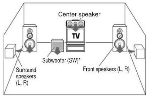
flowchart
graph LR
    A["Front speakers (L, R)"] --> B["Subwoofer (SW)*"]
    B --> C["TV Center speaker"]
    C --> D["Surround speakers (L, R)"]
    D --> E["External Device"]
    C --> F["External Device"]
* LFE = Low Frequency Effects. This channel delivers separate non-directional bass signals to the subwoofer for more dynamic deep bass sound effects.
Surround play
The DTS compatible models can reproduce a CD, DVD, or LD carrying the DTS mark.
DOLBY DIGITAL can be used when playing DVD or LD software bearing the DOLBY DIGITAL mark and DOLBY DIGITAL format digital broadcasts (etc.). DOLBY PRO LOGIC can be used when playing video, DVD, or LD software bearing the DOLBY SURROUND mark.
SRS Circle Surround enables you to listen to multi channel sound from the stereo source.

text_image
THX DSP INPUT MODE Input Selector LISTEN MODE INPUT MODE THX LISTEN MODE△/▽ DSP MODE INPUT SELECTORPreparations
- Turn ON related components.
- Complete "Preparing for surround sound" (speaker settings). - [23]
- Use the Input Selector keys to select the component you wish to play back with surround sound.
- Use the INPUT MODE key to select the input mode (analog or digital) for the source you wish to play back.
- Noise will be produced when a DTS source is played by selecting the analog input.
1 Start playing the video software.
2 Turn the LISTEN MODE knob or LISTEN MODE △/▽ keys to select the listening mode.
The listening mode settings are stored separately for each input. If the input mode is set to full auto ("AUTO DETECT" lights), the receiver selects the optimal listening mode automatically based on the type of input signal and the speaker settings.
Each turn of the LISTEN MODE knob or press of the LISTEN MODE / keys switches the setting as listed below.
The listening mode settings are different depending on the type of input signal.
When the DOLBY DIGITAL or DOLBY DIGITAL EX signal is input :
(The DOLBY DIGITAL or PRO LOGIC, indicator lights up.)
① DOLBY DIGITAL : DOLBY DIGITAL surround.
② DOLBY D EX : DOLBY DIGITAL EX surround.
③ PLII MOVIE : PRO LOGIC II surround MOVIE mode. (The PRO LOGIC indicator lights up.)
④ PLII MUSIC : PRO LOGIC II surround MUSIC mode. (The PRO LOGIC indicator lights up.)
⑤ PRO LOGIC : PRO LOGIC II surround PRO LOGIC mode. (The PRO LOGIC indicator lights up.)
⑥ STEREO : Normal stereo playback.
When you select DOLBY DIGITAL
"DOLBY DIGITAL" will be displayed.

text_image
SP AUTO SELECT COLEY DIGITAL DOLBY DIGITALWhen the DTS or DTS-ES (matrix or discrete) signal is input :
①DTS : (DTS indicator lights up.)
②DTS MATRIX : (DTS and MATRIX indicators light up.)
③DTS DISCRETE : (DTS and DISCRETE indicators light up.)
④STEREO : Normal stereo playback.
When the analog signal or the digital signal (except for DOLBY DIGITAL or DTS signal) is input :
① PLII MOVIE : PRO LOGIC II surround MOVIE mode. (The PRO LOGIC indicator lights up.)
② PLII MUSIC : PRO LOGIC II surround MUSIC mode. (The PRO LOGIC indicator lights up.)
③ PRO LOGIC : PRO LOGIC II surround PRO LOGIC mode. (The PRO LOGIC indicator lights up.)
④ NEO:CINEMA : NEO:6 surround.
(The NEO:6 indicator lights up.)
⑤NEO:MUSIC : NEO:6 surround.
(The NEO:6 indicator lights up.)
⑥ CSII CINEMA : CS 6.1 surround.
(The CS II indicator lights up.)
⑦ CSII MUSIC : CS 6.1 surround.
(The CS II indicator lights up.)
⑧ CSII MONO : CS 6.1 surround.
(The CS II indicator lights up.)
⑨STEREO : Normal stereo playback.
(The STEREO indicator lights up.)
- Dolby Digital or DTS signal having more channels than the maximum number of playback channels available using the receiver's current settings is input, downmixing is performed to match the number of available channels.
3 DSP mode (Digital Signal Processor).
DSP can produce these effects without spoiling the sound quality of the original music or video source.
⑦ Pressing the DSP key or DSP MODE key will display the current DSP MODE status.
② Each press of the key will switch to the next status as shown bellow:
①ARENA : DSP surround ARENA mode.
② JAZZ CLUB : DSP surround JAZZ CLUB mode.
③ THEATER : DSP surround THEATER mode.
④ STADIUM : DSP surround STADIUM mode.
⑤ DISCO : DSP surround DISCO mode.
- The DSP mode selection is displayed for approximately 3 seconds.
4 THX mode.
This mode creates a home theater environment which is able to reproduce a cinema surround sound system featuring improved special representation and acoustic imaging of surround channels by translating THX Surround EX technology.
Press the THX key to switch the following setting :
①THX Sur EX ON : THX Surround EX function is turned ON when Dolby Digital 5.1ch signal is detected. (THX indicator lights up.)
②THX Sur EX AUTO : THX Surround EX function is turned ON when Dolby Digital Surround EX signal is detected. (THX indicator lights up.)
③THX ON : THX mode is turned ON. (THX indicator lights up.)
④THX OFF : THX mode is turned OFF. (THX indicator goes off.)
• THX functions when the display segment is turned ON.
- THX Sur EX ON and THX Sur EX AUTO will not be available if surround back speakers are turned OFF.
• The THX setting differs depending on the input selector.
5 Adjust the volume.
Notes
- Depending on the type of the signal or speaker setting, some listening modes cannot be selected.
- When playback is started, the sound may be cut or interrupted before the input source is confirmed as Dolby Digital.
- To enjoy Dolby Digital surround (as well as all the other listening modes) from a single component, be sure to use a Dolby Digital compatible source component.
- Dialogue Normalization (Dial Norm) is a feature of Dolby Digital. It is able to automatically maintain the overall audio output level constant. When playing source material with Dolby Digital software encoding, a brief message will appear.
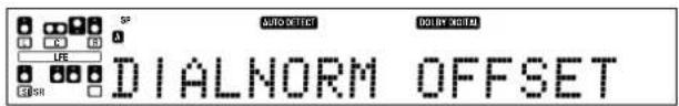
text_image
S# A B C D E F G H I J K L M N O P Q R S T U V W X Y Z A B C D E F G H I J K L M N O P Q R S T U V W X Y Z A B C D E F G H I J K L M N O P Q R S T U V W XThis message informs you that the source material has been recorded at a different level than usual. For example, "DIALNORM OFFSET +4 dB" will scroll across the display to indicate that it had been automatically adjusted to the normal output. If this message does not appear, no adjustment will be made.
DVD 6-channel playback
Using a DVD player or the like equipped with six (5.1) output channels and the receiver, you can enjoy surround sound playback.
When you try to play a disc other than Dolby Digital such as DTS CD, no sound is produced or, noise may be heard. To avoid this situation, make sure that you connect the component to the receiver's DVD/6CH INPUT jacks through a surround processor which can decode the surround signal you want to listen to.
Connecting a DVD player which can decode the surround signal itself is also acceptable.

text_image
INPUT MODE VOLUME DVD/6CH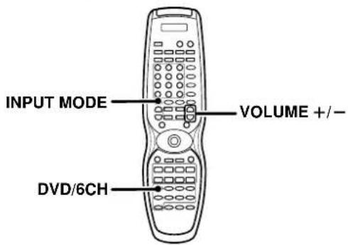
text_image
INPUT MODE VOLUME +/- DVD/6CHPreparations
- Connect your DVD player to the DVD/6CH jacks of the receiver.
- Turn on all other components that will be used.
- Complete "Preparing for surround sound". → 23
1 Press "DVD/6CH" as the input source.
- If speaker system B is on when "DVD/6CH" is selected as the input source, it switches off and speaker system A turns on automatically.
2 Select "6CH INPUT" by pressing the INPUT MODE key.
3 Start playback of the DVD software.
4 Adjust the volume.
- It is not possible to adjust the volume level or sound quality (SET UP, SOUND) of the channels separately when the receiver is in the DVD/6CH mode. Adjust the volume with the controls of the DVD player. For the powered subwoofer, you can adjust the volume of the subwoofer using the subwoofer's own volume control.
Convenient functions
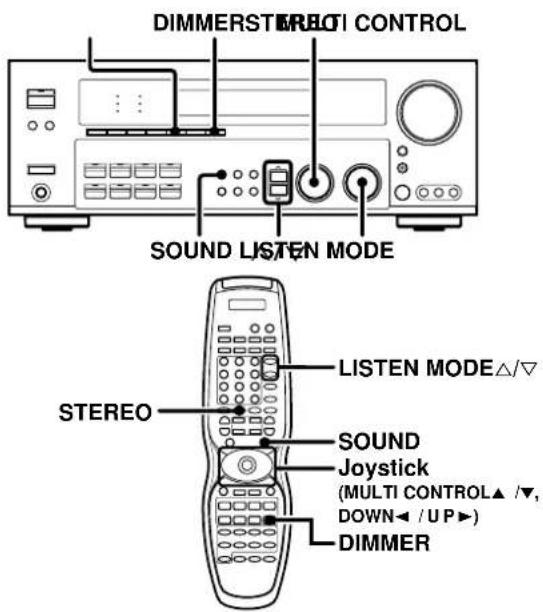
text_image
DIMMERSTRELI CONTROL SOUND LISTEN MODE STEREO LISTEN MODE△/▽ SOUND Joystick (MULTI CONTROL▲ /▼, DOWN◄ / UP►) DIMMERAdjusting the sound
You can make further adjustments to the sound while listening to playback in the surround mode.
① Press the SOUND key and then use to the ^/▼ keys or joystick (</►) until the desired item appears in the display.
Each time you press the ^/√ keys or Joystick (◄/►), the menu changes as follows: Note that some items are not displayed in certain modes.
① CNTR (Center speaker level adjustment)*
② SR (Right surround speaker level adjustment)*
③ SBR (Surround back right speaker level adjustment)*
④ SBL (Surround back left speaker level adjustment)*
⑤ SL (Left surround speaker level adjustment)*
⑥SUBW (Subwoofer level adjustment)*
⑦ INPUT (Input level adjustment - analog mode only) - 26
⑧MIDNIGHT (Midnight mode ON/OFF - Dolby Digital mode only)
⑨PANORAMA (Panorama mode ON/OFF)**
⑩DIMENSION (Dimension adjustment)**
⑪CENTER WIDTH (Center width adjustment)**
⑫CENTER FOCUS (Center focus adjustment)***
⑬ CSII DLY (Rear speaker delay adjustment)***
⑭ CSII GAIN (Input gain adjustment)***
⑮TruBass (Trubass adjustment)***
* The adjustment is only temporary for the current input selection. The value will return automatically to the original setup value when the power is turned on/off or when the input selection is changed.
** Pro Logic II Music mode only.
*** CS II mode only.
② Use the MULTI CONTROL knob or Joystick (▲/▼) to adjust the setting as desired.
• The adjustment item is displayed for approximately 8 seconds.
Midnight mode (Dolby Digital mode only)
When watching movies at night, you might not be able to raise the volume as loud as normal. Midnight mode compresses the dynamic range of previously specified parts of the Dolby Digital sound track (like scenes with sudden increases in volume) to minimize the difference in volume between the specified and non-specified parts. This makes it easy to hear all of the sound track, even when listening at low volumes.
① Press the SOUND key, then press the ∧/∨ keys or Joystick (◄/►) until "MIDNIGHT" appears on the display.
- This can be selected only if CD/DVD, DVD/6CH, VIDEO 2 or VIDEO 3 is selected as the source and the listen mode is set to "DOLBY DIGITAL."
② Use the MULTI CONTROL knob or Joystick (▲/▼) to select the ON or OFF setting.
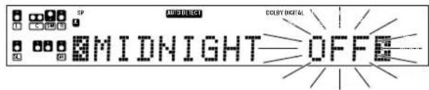
text_image
SP AUTO DIRECT COLDY DIGITAL MIDNIGHT OFFE- The adjustment item is displayed for approximately 8 seconds.
- Some Dolby Digital software may not be compatible with the Midnight mode.
Panorama mode (Pro Logic II Music mode only)
When listening to music, you will be able to enjoy the "wraparound" sound effect when you adjust the panorama mode.
① Press the SOUND key, then press the ^/▼ keys or Joystick (◄/►) until "PANORAMA" appears on the display.
② Use the MULTI CONTROL knob or Joystick (▲/▼) to select PANORAMA ON or OFF.
① PANORAMA ON : PANORAMA mode is ON.
② PANORAMA OFF: PANORAMA mode is OFF.

text_image
3D PRO LOGO PANORAMA ONEDimension mode (Pro Logic II Music mode only)
When listening to music with certain recordings, you will also be able to achieve a suitable balance from all the speakers by adjusting the dimension mode.
⑦ Press the SOUND key, then press the ∧/∨ keys or Joystick (◄/►) until "DIMENSION" appears on the display.
② Use the MULTI CONTROL knob or Joystick (▲/▼) to adjust the soundfield towards the rear or the front.
Soundfield is adjusted towards the front.

text_image
AUTO SELECT PRO LOGIC REAR----x----FRNTSoundfield is in neutral position.

text_image
AUTO DETECT PRO LOGIC REAR-----FRNTSoundfield is adjusted towards the rear.

text_image
GND GND PRO LOGC REAR --- x --- FRNTCenter Width mode (Pro Logic II Music mode only)
Center width adjustment allows you to enjoy an enhanced sound when listening to music through center image from only center speaker, or left and right speakers or various combinations adjustments.
⑦ Press the SOUND key, then press the ^/√ keys or Joystick (◄/►) until "CENTER WIDTH" appears on the display.
- The CENTER WIDTH indication scrolls across the display.
- When the center speaker is switched OFF, this mode will not be effective.
② Use the MULTI CONTROL knob or Joystick (▲/▼) to adjust the left-center-right output.
Center image will be heard from center speaker only.
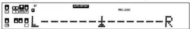
text_image
PROLOGIC PRO LOGIC RCenter image will be heard from left and right speakers only.

text_image
AUTO DETECT PRO LOGIC- When in other position, center image from center speaker, left and right speakers can be heard simultaneously with various combinations.
Circle Surround II mode
When you select the circle surround II mode, you will be able to enjoy the multi surround sound from the stereo source.
Use the LISTEN MODE knob or LISTEN MODE / keys for CS II selection.
Center Focus mode (CS II mode only)
Center focus elevate level adjustment allows you to enjoy an enhanced sound when you select CS II CINEMA/MUSIC/MONO. It repositions the sound image to an optimal position more natural to the listener through the center image.
① Press the SOUND key, then press the ^/√ keys or Joystick (◄/►) until "CENTER FOCUS" appears on the display.

text_image
MOO ELECT L C: GND R R 000 L ..... S S8 CS ...... HOFF② Use the MULTI CONTROL knob or Joystick (▲/▼) to adjust the center elevation level.
• The adjustment range is from 0 to 10.

text_image
L C 30 H 4 B S 58.1 B S L ....... H=10- CENTER FOCUS will not be effective when the center speaker is OFF.
CS II Rear Delay adjustment mode (CS II mode only)
CS II Rear Delay adjustment provides a better sound effect from the rear speakers.
⑦ Press the SOUND key, then press the ∧/∨ keys or Joystick (◄/►) until "CSII DLY" appears on the display.
② Use the MULTI CONTROL knob or Joystick (▲/▼) to adjust the rear speaker.
• The adjustment range is 0 ms to 25 ms.

text_image
SP C: 472 01 CSII DLY 0msCS II Gain adjustment mode (CS II mode only)
GS II GAIN allow user to adjust the input gain for the Circle Surround II processing.
① Press the SOUND key, then press the ∧/∨ keys or Joystick (◄/►) until "CSII GAIN" appears on the display.
② Use the MULTI CONTROL knob or Joystick (▲/▼) to select the input gain step.
• The gain steps are from 0 to 18.
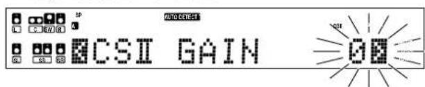
text_image
SP AUTO SELECT CSII GAINTruBass adjustment mode (CS II mode only)
TruBass adjustment provides deep, rich bass sound to various speakers.
① Press the SOUND key, then press the ^/▼ keys or Joystick (◄/►) until "TruBass" appears.
② Use the MULTI CONTROL knob or Joystick (▲/▼) to select the following;

- After selecting ②, ③ or ④, TruBass speaker size and level adjustment selection will be available.
③ For TruBass speaker selection, use the MULTI CONTROL knob or Joystick (▲/▼) to select any of the following display;
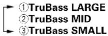
④ Use the MULTI CONTROL knob or Joystick (▲/▼) to adjust the TruBass Level.
- The adjustment range is from 0 (TruBass OFF) to 10.
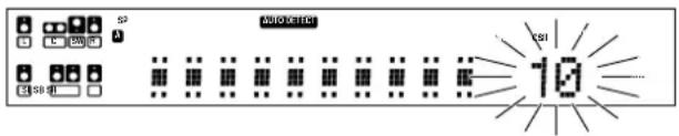
text_image
S2 C 250 SB 8 AUTOCHIO CS1 10Display dimmer adjustment
The dimmer function lets you select the brightness of the receiver's display. You might find this useful if you darken your room to watch movies or listen to music.
Each time you press the DIMMER key, the display's brightness changes among the three available settings.
Select the brightness level you find most pleasing.

96kHz LPCM playback
The receiver is compatible with the 96kHz LPCM playback. To play a 96kHz DVD, set the listen mode to "STEREO".
- In FULL AUTO input mode, the listen mode will automatically be STEREO.
- When in DIGITAL MANUAL input mode (listen mode is not STEREO), "FS 96kHz" will appear in the display and no sound can be heard from the speakers.
Press the LISTEN MODE or STEREO key (the listen mode changes to the STEREO mode) to output sound from the speakers.
The remote control supplied with this receiver is also capable of controlling components from a variety of manufacturers once you register the appropriate setup codes into the remote control unit.
Low battery warning
Replace all two batteries with new ones when you notice a shortening of the distance from which the remote control will operate. The remote control is designed to retain setup codes in memory while you change batteries.
Registering setup codes for other components

text_image
REMOTE MODE SOURCE Numeric keys INPUT SELECTOR1 Find the setup code of the component to be registered.
- Refer to the setup code lists to find the setup code for the component to be registered. - [43] - [44] Example: To register a DVD made by KENWOOD, you would enter "805".
| Input Component Maker Code Key | |||
| (DVD) DVD player KENWOOD 805, 808 DVD | |||
2 Registering components for REMOTE MODE [(DVD, CBL, DSS/SAT, VCR, TV, OTHERS - RC-R0813/R0814) or (DVD, CD, CBL/SAT, VCR, TV, OTHERS - RC-R0815)] keys.
⑦ For DVD, CD, CBL, DSS/SAT, CBL/SAT, VCR or TV keys;
Hold down the SOURCE ⏻ key and press the numeric keys to enter the setup code.
- Example: Press "805" to register a DVD player manufactured by KENWOOD.
- If you push an invalid key, the remote control will display "ERROR" and exit the setup mode.

② The OTHERS key enables you to operate another DVD, CD, CBL, DSS/SAT, CBL/SAT, VCR or TV component.
For OTHERS key;
Hold down the OTHERS key and press the numeric keys to enter the setup code.
- Example: After you have registered the KENWOOD DVD player, press "804" to register another DVD player which is manufactured by Panasonic.
- If you push an invalid key, the remote control will display "ERROR" and exit the setup mode.
3 Press any of the REMOTE MODE key and then press the SOURCE ⏻ key to check that the component you want to control turns on.
If the component does not react, and there is more than one setup code, enter another setup code and try again.
- If the component is already on, pressing the SOURCE ⏻ key will turn it off.
4 Repeat steps 2 to 3 to register additional components until all components have been registered.
Alternative REMOTE MODE key.
This operation is optional and is convenient when you link an INPUT SELECTOR key to the REMOTE MODE key. While operating one component, the INPUT SELECTOR key functions as an alternative REMOTE MODE key to select another component.
- Example: REMOTE MODE (DVD) key can be linked to the INPUT SELECTOR (VIDEO 1) key as described below;
⑦ After registering the setup code, press and hold the SOURCE ⏻ key and then press the REMOTE MODE (DVD) key.
2 While holding down the SOURCE ⏻, press the INPUT SELECTOR (VIDEO 1) key. - Now the VIDEO 1 key will function as a DVD key which can be selected at the same time while operating a CD player.
- Repeat step 1 to 2 to link other INPUT SELECTOR keys.
Note
Although each setup code is designed to work with a number of different models, certain codes may not work with some models. (Also, certain codes may only operate some of the functions available on a given model.)
Operating other components
This operation lets you operate the registered components.
KENWOOD audio components with system control turn on and off automatically with the receiver via the system control connections.
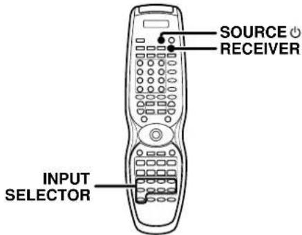
text_image
SOURCE RECEIVER INPUT SELECTOR1 Use the INPUT SELECTOR keys to select the component you desire.
- Pressing the INPUT SELECTOR keys also changes the input selector on the receiver.
- When you operate your registered DVD player, CD player, Cable tuner, DSS/SAT receiver, VCR or TV, go to step 2.
- When you operate the CD player, Cassette deck, MD player, or Tuner with system control connection, go to step 3.
2 Press the SOURCE Key.
- To return to the receiver operation mode, press the RECEIVER key.
3 Press the operation keys you desire.

The remote control mode remains at the selected input. If you wish to operate another component, repeat step 2 or 3.
Note
Be sure to point the remote control at the remote sensor on the receiver when you want to operate KENWOOD components connected by system control cords. Otherwise, point the remote control at the component you want to operate.
Storing the remote control code of the other components
The remote control unit can store the remote control code of the other components and you can operate the other components from the remote control unit. The remote control code is stored on the key or memory of the remote control unit.
Storing on the key
You can store the remote control code to the key as shown below:
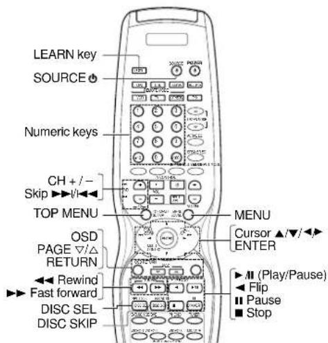
text_image
LEARN key SOURCE Numeric keys CH + / - Skip ▶▶▶/◀◀◀ TOP MENU OSD PAGE ▽/△ RETURN ◀◀◀ ▶◀▶ Fast forward DISC SEL DISC SKIP MENU Cursor ▲/▼/◀◀ ENTER ◀◀ (Play/Pause) ◀◀ Flip ◀◀ Pause ◀◀ Stop① Point the infrared ray system part of another remote control unit to the remote sensor of the remote control unit.
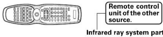
text_image
Remote control unit of the other source. Infrared ray system part② Press the LEARN key.
- This remote control is ready to receive the remote control code from the other source.

⑦ Press any of the REMOTE MODE (DVD, CD, CBL, DSS/SAT, CBL/SAT, VCR, TV, OTHERS) keys to select the input of the desired remote control unit.
④ Press the desired key of the remote control unit.
⑤ From the remote control unit of the other source, press the key that you want to store.
- The remote control code is sent to the remote control unit.
- "OK" appears when finished.

- When the appropriate code is not properly stored, "AGAIN" will be displayed. Repeat from step 2 onwards.
- If the code cannot be stored after a few attempts, "ERROR" will appear. Repeat from step 2 onwards.
- If LEARN mode's storage is full, "FULL" appears on the display.
⑥ The remote control code is stored on the key of this remote control unit.
⑦ Press the LEARN key again to exit the learning mode.
Setup code chart (RC-R0813) (VR-6070) and (RC-R0814)(KRF-X9060D)
TV Setup codes
| Maker Setup codes | |
| AKAI 125 | |
| BELL+HOWELL 142 | |
| CENTURION 126 | |
| CORONAD 127 | |
| DAEWOO 136, 140, 141, 145 | |
| EMERSON 130, 131, 132, 133, 146 | |
| FISHER 119 | |
| G.E. 102, 122, 129 | |
| GOLD STAR 137, 148 | |
| HITACHI 114, 115 | |
| JVC 113 | |
| KTV 138, 139 | |
| LOEWE 123, 124 | |
| MAGNAVOX 109, 147 | |
| MARANTZ 121 | |
| MITSUBISHI 121 | |
| PANASONIC 111, 112, 122, 129 | |
| PHILIPS 109, 147 | |
| PIONEER | 116 |
| PROSCAN | 117 |
| RADIOSHACK | 128 |
| RCA | 102, 103, 104, 105, 106, 126 |
| SAMSUNG 134, 135 | |
| SANYO | 119 |
| SEARS | 120 |
| SHARP | 110 |
| SONY | 101 |
| SYMPHONIC | 143, 144 |
| TOSHIBA | 120 |
| QUASAR | 111, 118 |
| ZENITH 107, 108 |
CBL codes
| Maker Setup codes | |
| GEMINI 218 | |
| G.I. | 209 |
| HAMLIN 210, 211, 234, 235 | |
| JERROLD | 201, 202, 224, 225, 226, 227, 228, 229, 233 |
| MACOM | 215, 216, 217 |
| MAGNAVOX 236 | |
| OAK | 212, 213, 214 |
| PANASONIC 221, 222, 232 | |
| PHILIPS 219, 220, 237, 238, 239, 240 | |
| PIONEER | 206, 207 |
| SAMSUNG 223 | |
| S. ATLANTA 203, 230, 231 | |
| TOCOM | 208 |
| ZENITH 204, 205 | |
VCR Setup codes
| Maker Setup codes | |
| AIWA | 352 |
| AKAI 354, 355, 356 | |
| BELL+HOWELL 351 | |
| DAEWOO 349 | |
| EMERSON 334, 335, 336, 337, 338 | |
| FISHER 330, 341, 342, 343 | |
| G.E. 307, 321 | |
| GOLD STAR 323 | |
| GO_VIDEO 347, 348, 353 | |
| HITACHI 307, 308, 328, 329 | |
| JVC 324, 325, 326, 327 | |
| MAGNAVOX 311, 312, 313 | |
| MITSUBISHI 315, 316, 317, 318, 357, 358 | |
| NEC | 344, 345 |
| ORION | 335 |
| PANASONIC 309, 310 | |
| PHILIPS 313 | |
| QUASAR | 309, 310, 311, 312 |
| RCA | 308 |
| SAMSUNG 332, 339, 340 | |
| SANYO | 351 |
| SCOTT | 331 |
| SHARP | 319, 320 |
| SHINTOM | 333 |
| SONY | 301, 302, 303, 304, 305, 306 |
| SYNPHO | 346 |
| TEKNICA | 346, 350 |
| TOSHIBA | 314 |
| ZENITH 322 | |
DVD player Setup codes
| Maker Setup codes | |
| HITACHI 812 | |
| JVC 801 | |
| KENWOOD | 805, 808 |
| MITSUBISHI 810 | |
| ONKYO | 815, 816 |
| PANASONIC 804 | |
| PHILIPS 807 | |
| PIONEER | 803 |
| PROSCAN | 811 |
| RCA | 811 |
| SAMSUNG 814 | |
| SONY | 802 |
| TOSHIBA | 806 |
| YAMAHA | 809 |
| ZENITH 806, 813 |
DSS/SAT codes
| Maker Setup codes | |
| ECHOSTAR | 903 |
| G.I. | 902 |
| HITACHI 908 | |
| HUGHES | 906 |
| PANASONIC 905 | |
| PRIMESTAR | 909 |
| RCA | 901 |
| SONY | 907 |
| TOSHIBA | 904 |
Setup code chart (RC-R0815) (KRF-X9060D) (For the U.K. only)
TV Setup codes
| Maker Setup codes | |
| AKAI 408 | |
| BLAUPUNKT 401 | |
| FENNER 412 | |
| FISHER 413 | |
| GRUNDIG 402 | |
| HITACHI 414, 415 | |
| INNO-HIT 416 | |
| IRRADIO 408 | |
| JVC 417 | |
| LOEWE 429, 430 | |
| MAGNAVOX 406 | |
| MIVER 401 | |
| NOKIA | 403 |
| NORDMENDE | 404, 405 |
| OKANO 416 | |
| ORION | 418 |
| PANASONIC 419, 420 | |
| PHILIPS 406 | |
| SABA | 404, 407 |
| SAMSUNG | 421 |
| SANYO | 413 |
| SCHNEIDER | 408 |
| SHARP | 422 |
| SONY 423, 424, 425, 426, | 427 |
| TELEFUNKEN | 407, 409, 410 |
| THOMSON | 411 |
| TOSHIBA 428 |
VCR Setup codes
| Maker Setup codes | |
| AIWA | 513 |
| BELL+HOWELL | 514 |
| BLAUPUNKT 501 | |
| CGM | 514, 515 |
| DIGTAL | 515 |
| FISHER 514 | |
| G.E. | 516 |
| GRUNDIG 502 | |
| HITACHI 517, 518 | |
| JVC 519 | |
| LOEWE 503, 504 | |
| MAGNAVOX 501, 515 | |
| MITSUBISHI | 520, 521, 522, 523 |
| NOKIA | 505 |
| NORDMENDE | 506, 507, 508 |
| PANASONIC 524 | |
| PHILIPS 509 | |
| PHONOLA | 515 |
| SABA | 510 |
| SAMSUNG | 525, 526 |
| SANYO | 514 |
| SHARP | 527, 528 |
| SIEMENS | 502 |
| SONY 529, 530, 531 | |
| TELEFUNKEN | 511, 512 |
| TOSHIBA 532 |
CBL/SAT codes
| Maker Setup codes | |
| AMSTRAD | 601, 602, 603, 604, 633 |
| CANAL+ | 622 |
| D-BOX | 626 |
| ECHOSTAR | 619, 620, 621, 623 |
| FORCE | 630 |
| GALAXIS | 629 |
| GRUNDIG 605, 606 | |
| HIRSCHMANN | 639 |
| ITT | 609 |
| JERROLD | 616 |
| JVC 614 | |
| JVC/BT | 613 |
| KATHREIN | 611, 612, 636 |
| MASCOM | 634 |
| NOKIA | 628, 635 |
| PACE | 608, 627 |
| PANASONIC 615 | |
| PHILIPS 607, 625 | |
| SELECTOR | 631 |
| SKYMASTER | 610, 638 |
| THOMSON | 637 |
| TPS/SAGEM | 624 |
| TRIAX | 632 |
| VIDEOWAY | 617, 618 |
DVD player Setup codes
| Maker Setup codes | |
| JVC 801 | |
| KENWOOD 805, 808 | |
| PANASONIC 804 | |
| PHILIPS 807 | |
| PIONEER 803 | |
| SONY 802 | |
| TOSHIBA 806 |
CD player Setup codes
| Maker Setup codes | |
| DENON 702 | |
| ONKYO | 704 |
| PHILIPS 705 | |
| PIONEER 706 | |
| SONY 701 | |
| TEAC | 703 |
| YAMAHA 707 |
CASSETTE deck, CD player & MD recorder operations
You can perform these basic operations using the keys described below when connected to KENWOOD cassette deck, CD player or MD recorder equipped with system control operations. -21
Cassette deck operations keys CD player operation keys

text_image
(For RC-RD815 only) FOR (Rewind) (Fast Forward) A/B (Cassette deck selection) PAGE-CONN PAGE-IP [For RC-RD815 only] -/II (Play) -/Reverse play ■ (Stop)
text_image
POWER For RC-R0815 only) Numeric keys (Select tracks) ► (Skip up) ► (Skip down) ▲ (Backward Search) ► (Forward Search) DISC SEL (Disc selection) DISC SKIP PAGE 32/41 PAGE 32/42 PAGE 32/43 PAGE 32/44 PAGE 32/45 PAGE 32/46 PAGE 32/47 PAGE 32/48 PAGE 32/49 PAGE 32/50 PAGE 32/51 PAGE 32/52 PAGE 32/53 PAGE 32/54 PAGE 32/55 PAGE 32/56 PAGE 32/57 PAGE 32/58 PAGE 32/59 PAGE 32/60 PAGE 32/61 PAGE 32/62 PAGE 32/63 PAGE 32/64 PAGE 32/65 PAGE 32/66 PAGE 32/67 PAGE 32/68 PAGE 32/69 PAGE 32/70 PAGE 32/71 PAGE 32/72 PAGE 32/73 PAGE 32/74 PAGE 32/75 PAGE 32/76 PAGE 32/77 PAGE 32/78 PAGE 32/79 PAGE 32/80 PAGE 32/81 PAGE 32/82 PAGE 32/83 PAGE 32/84 PAGE 32/85 PAGE 32/86 PAGE 32/87 PAGE 32/88 PAGE 32/89 PAGE 32/90 PAGE 32/91 PAGE 32/92 PAGE 32/93 PAGE 32/94 PAGE 32/95 PAGE 32/96 PAGE 32/97 PAGE 32/98 PAGE 32/99 PAGE 32/100 PAGE 32/101 PAGE 32/102 PAGE 32/103 PAGE 32/104 PAGE 32/105 PAGE 32/106 PAGE 32/107 PAGE 32/108 PAGE 32/109 PAGE 32/110 PAGE 32/111 PAGE 32/112 PAGE 32/113 PAGE 32/114 PAGE 32/115 PAGE 32/116 PAGE 32/117 PAGE 32/118 PAGE 32/119 PAGE 32/120 PAGE 32/121 PAGE 32/122 PAGE 32/123 PAGE 32/124 PAGE 32/125 PAGE 32/126 PAGE 32/127 PAGE 32/128 PAGE 32/129 PAGE 32/130 PAGE 32/131 PAGE 32/132 PAGE 32/133 PAGE 32/134 PAGE 32/135 PAGE 32/136 PAGE 32/137 PAGE 32/138 PAGE 32/139 PAGE 32/140 PAGE 32/141 PAGE 32/142 PAGE 32/143 PAGE 32/144 PAGE 32/145 PAGE 32/146 PAGE 32/147 PAGE 32/148 PAGE 32/149 PAGE 32/150MD recorder operation keys
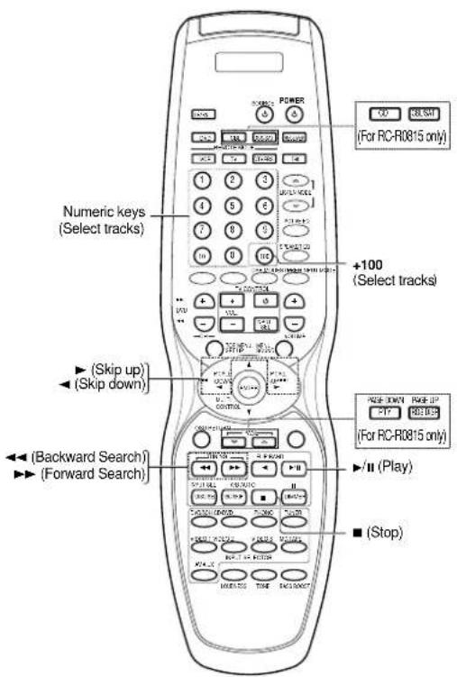
text_image
POWER For RC-R0815 only) Numeric keys (Select tracks) +100 (Select tracks) ◀ (Skip up) ◀ (Skip down) ◀ (Backward Search) ▶ (Forward Search) ▶/II (Play) ■ (Stop)Other components' operations
Refer to the following for the type of remote control operations available for each component.
① Select the input source.
2 Press the keys corresponding to the operations you desire. Refer to the following sections for details.
- When pressing keys in succession, press each key firmly and be sure to wait at least 1 second before pressing the next key.
- Numeric keys function the same as the numeric keys on the original remote.
These keys can be used to perform the basic operations of KENWOOD and other manufacturers' components which the setup code for each component had been entered beforehand. -43 - 44
TV operation keys VCR operation keys
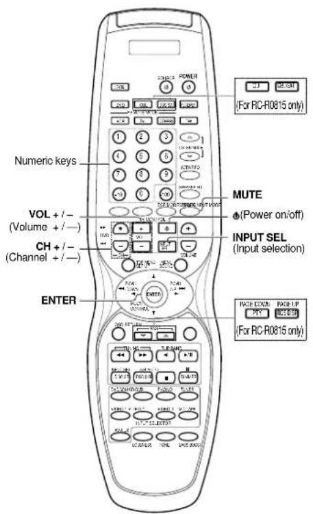
text_image
Numeric keys VOL + / - (Volume + / -) CH + / - (Channel + / -) ENTER MUTE (Power on/off) INPUT SEL (Input selection) PAGE COPY: PAGE-LIP [For RC-R0815 only]
text_image
SOURCE Φ (Source power) Numeric keys CH + / - (Channel + / -) INPUT SEL (Input selection) FOR RC-R0815 only) For RC-R0815 only) Play) (Pause) (Stop)DSS/SAT (or CBL / SAT) receiver operation keys Cable tuner operation keys
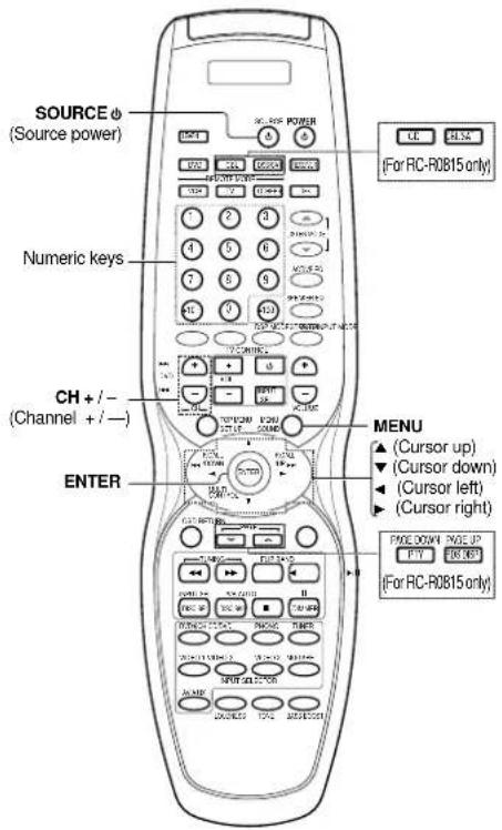
text_image
SOURCE φ (Source power) Numeric keys CH + / - (Channel + / —) ENTER FOR RC-R0815 only) FOR RC-R0815 only) MENU ▲ (Cursor up) ▼ (Cursor down) ◀ (Cursor left) ▶ (Cursor right) PHONE DOWN PAGE UP BUY CHECK FOR RC-R0815 only)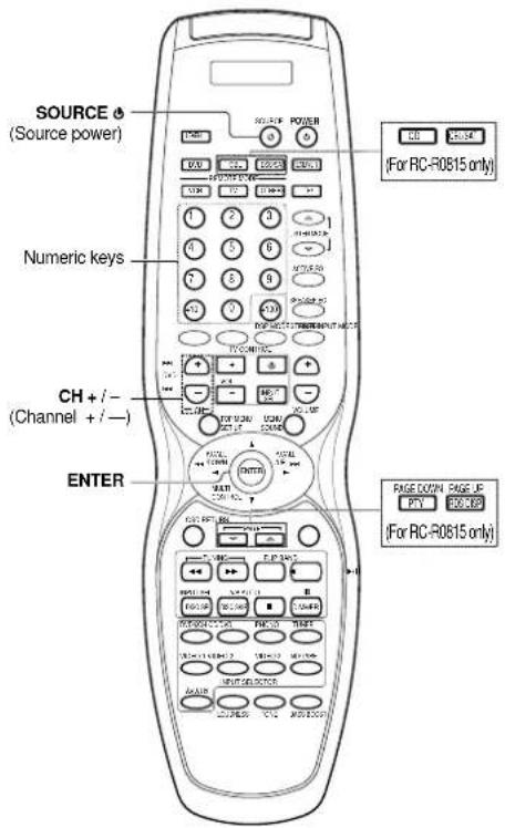
text_image
SOURCE (Source power) Numeric keys CH + / - (Channel + / —) ENTER FOR RC-R0815 only) FOR RC-R0815 only) PAGE DOWN PAGE UP PTY BOOKUP FOR RC-R0815 only)DVD player operation keys
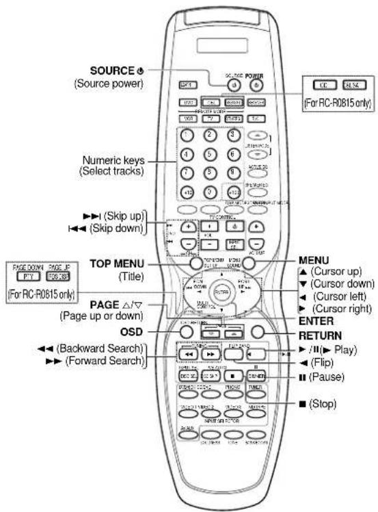
text_image
SOURCE (Source power) Numeric keys (Select tracks) ►► (Skip up) ►► (Skip down) TOP MENU (Title) PAGE △/▽ (Page up or down) OSD ►► (Backward Search) ►► (Forward Search) FOR RC-R0815 only) FOR PC-R0815 only) FOR PC-R0815 only) FOR PC-R0815 only) FOR PC-R0815 only) FOR PC-R0815 only) FOR PC-R0815 only) FOR PC-R0815 only) FOR PC-R0815 only) FOR PC-R0815 only) FOR PC-R0815 only) FOR PC-R0815 only) FOR PC - R0815 only) FOR PC - For PC-R0815 only) FOR PC - For PC-R0815 only) FOR PC - For PC-R0815 only) FOR PC - For PC-R0815 only) FOR PC - For PC-R0815 only) FOR PC - For PC-R0815 only) FOR PC - For PC-R0815 only) FOR PC - For PC-R0815 only) FOR PC - For PC-R0816 only) FOR PC - For PC-R0816 only) FOR PC - For PC-R0816 only) FOR PC - For PC-R0816 only) FOR PC - For PC-R0816 only) FOR PC - For PC-R0816 only) FOR PC - For PC-R0816 only) FOR PC - For PC-R0816 only) FOR PC - For PC-R0816 only) FOR MC FOR MC FOR MC FOR MC FOR MC FOR MC FOR MC FOR MC FOR MC FOR MC FOR MC FOR MC FOR MC FOR MC FOR MC FOR MC FOR MC FOR MC FOR MC FOR MC FOR MC FOR MC FOR MC FOR MC FOR MC FOR MC FOR MC FOR MC FOR MC FOR MC FOR MC FOR MC FOR MC FOR MC For PC-R0815 only) For PC-R0815 only) For PC-R0815 only) For PC-R0815 only) For PC-R0815 only) For PC-R0815 only) For PC-R0815 only) For PC-R0815 only) For PC-R0815 only) For PC-R0815 only) For PC-R0815 only) For PC-R0815 only) All other functions listed in the image: Source (Source power) Page 32 Page 33 Page 34 Page 35 Page 36 Page 37 Page 38 Page 39 Page 40 Page 41 Page 42 Page 43 Page 44 Page 45 Page 46 Page 47 Page 48 Page 49 Page 50 Page 51 Page 52 Page 53 Page 54 Page 55 Page 56 Page 57 Page 58 Page 59 Page 60 Page 61 Page 62 Page 63 Page 64 Page 65 Page 66 Page 67 Page 68 Page 69 Page 70 Page 71 Page 72 Page 73 Page 74 Page 75 Page 76 Page 77 Page 78 Page 79 Page 80 Page 81 Page 82 Page 83 Page 84 Page 85 Page 86 Page 87 Page 88 Page 89 Page 90 Page 91 Page 92 Page 93 Page 94 Page 95 Page 96 Page 97 Page 98 Page 99 Page 100Resetting the Microcomputer
The microcomputer may malfunction (unit cannot be operated, or shows an erroneous display) if the power cord is unplugged while the power is ON, or due to some other external factor. If this happens, execute the following procedure to reset the microcomputer and return the unit to its normal operating condition.
- Please note that resetting the microcomputer will clear the contents of the memory and returns the unit to the state it was in when it left the factory.
For the U.S.A. and Canada
Unplug the power cord from the wall outlet, then plug it back in while holding down the POWER ON/STANDBY ⏻ key.
For other countries
With the power cord plugged in, turn the POWER ON/OFF key OFF. Then, while holding down the ON/STANDBY ⏻ key, press POWER ON/OFF.
Amplifier
| Symptom | Cause | Remedy |
| No sound from the speakers. | The speaker cords are disconnected.VOLUME is set to the minimum position.MUTE is ON.The SPEAKERS switches are set to OFF. | Connect them properly referring to “Connecting the speakers” →15Adjust the volume to a proper level.Turn OFF the MUTE. →27Set the SPEAKERS switches to ON. →26 |
| The standby indicator blinks and sound is not output. | Speaker cords are short-circuited. | Turn the power off, eliminate the short-circuiting, then turn on the power again. |
| Sound is not output from one of the speakers. | The speaker cord is disconnected. | Connect it properly referring to “Connecting the speakers”. →15 |
| Sound is not output from the surround speakers and / or the center speaker, or their sound is very small. | The surround speaker cords and/or the center speaker cord is disconnected.A surround mode has not been engaged.The surround and/or center volume controls are set to the minimum level. | Connect it properly referring to “Connecting the speakers”. →15Select a surround mode.Adjust the speaker levels using the test tone.→24 |
| A humming noise is generated when the PHONO input selector is selected. | The audio cord from the record player is not connected to the PHONO jacks.The record player is not grounded. | Insert the audio cord plugs securely into the PHONO jacks.Connect the grounding wire to the GND terminal on the rear panel. |
| When playing a Dolby Digital source signal using a DVD player, the sound is cut off soon after it starts. | There are many possible causes for this problem, depending on the type of DVD player used. | Set the input mode to digital manual before starting playback of the Dolby Digital source.→9 |
| No sound is produced during playback from a DVD player. | The input mode is set to digital manual. | Press the INPUT MODE key to select to full auto mode. →9 |
| A video source cannot be recorded normally. | The software is copy-guarded. | Copy-guarded video software cannot be recorded. |
Tuner
| Symptom | Cause | Remedy |
| Radio stations cannot be received. | No antenna is connected.The broadcast band is not set properly.The frequency of the desired station is not tuned. | Connect an antenna. -20Set the broadcast band properly.Tune the frequency of the desired station. -30 |
| Interference. | Noise due to ignition noise from an automobile.Noise due to interference from an electric appliance.Noise due to a nearby TV set. | Install the outdoor antenna away from the road.Turn off the power to the appliance.Install the receiver farther away from the TV. |
| A station which was preset cannot be received by pressing the corresponding numeric key. | The preset station belongs to a frequency that cannot be received.The preset memory was cleared because the power cord had been unplugged for a long period of time. | Preset a station with a receivable frequency.Preset the station again. |
Remote control unit
| Symptom | Cause | Remedy |
| Certain inputs cannot be selected using the remote control. | No setup codes registered for the respective input(s). | Register a setup code at the respective input(s).→43→44 |
| Remote control operation is not possible. | The remote control is set to a different operation mode.Batteries are exhausted.The remote control unit is too far away from the main system, controlling angle is too large, or there is an obstacle between the receiver and the remote.The audio cords and system control cords are not connected properly.No software is loaded in the source component.An attempt is made to play a tape which is being recorded in the cassette deck.The remote control has not been set to the operation mode for the component you wish to control. | Press the source select keys or SOURCE keys to select the appropriate operation mode.Replace with new batteries.Operate the remote control unit within the controllable range.Connect properly referring to “Setting up the system”.Place software in the source component you want to play.Wait until recording has completed.Press the source select keys or SOURCE key to activate the operation mode for the component you want to control before operation.→42 |
For the U.S.A and Canada
AUDIO section (VR-6070)
Rated power output during STEREO operation
100 watts per channel minimum RMS, both channels driven, at 8 Ω from 20 Hz to 20 kHz with no more than 0.09% total harmonic distortion. (FTC)
Effective power output during SURROUND operation
FRONT (20 Hz \~ 20 kHz, 0.09% T.H.D. at 8 Ω one channel driven)
100 W + 100 W
CENTER (20 Hz \~ 20 kHz, 0.09% T.H.D. at 8 Ω one channel
driven) 100 W
SURROUND (20 Hz \~ 20 kHz, 0.7% T.H.D. at 8 Ω one channel
driven) 100 W + 100 W
SURROUND BACK/SUBWOOFER (20 Hz \~ 20 kHz, 0.09%
T.H.D. at 8 Ω one channel driven) .... 100 W
Total harmonic distortion 0.009% (1 kHz, 50 W, 8 Ω)
Frequency response
Line (CD/DVD, TAPE, VIDEO 1, VIDEO 2, VIDEO 3, DVD/6CH)
10 Hz \~ 100 kHz, +0 dB \~ -3.0 dB
PHONO 'RIAA' response .... 40 Hz \~ 20 kHz, +1.5 dB \~ -3.0 dB
Maximum input level
PHONO (MM) 45 mV, 1% T.H.D. at 1 kHz
Signal to noise ratio (IHF'66)
PHONO (MM) 75 dB
Line (CD/DVD, TAPE, VIDEO 1, VIDEO 2, VIDEO 3, DVD/6CH)
95 dB
Loudness control
VOLUME at -30 dB level +6 dB (100 Hz)
Input sensitivity / impedance
PHONO (MM) 4.0 mV / 47 kΩ
Line (CD/DVD, TAPE, VIDEO 1, VIDEO 2, VIDEO 3, DVD/6CH)
320 mV / 47 kΩ
Output level / impedance
TAPE REC 320 mV / 1 kΩ
PRE OUT (FRONT,CENTER,SURROUND) .....1 V / 500 Ω
PRE OUT (SURROUND BACK) 1 V / 500 Ω
PRE OUT (SUBWOOFER) 1 V / 500 Ω
Tone control
BASS ±10 dB (at 100 Hz)
TREBLE ....±10 dB (at 10 kHz)
For other countries (except for the U.K.)
AUDIO section (KRF-X9060D)
Effective power output during STEREO operation
1 kHz, 10 %, 8 Ω 130 W + 130 W
Rated power output during STEREO operation
100 watts per channel minimum RMS, both channels driven,
at 8 Ω from 20 Hz to 20 kHz with no more than 0.09% total
harmonic distortion. (FTC)
Effective power output during SURROUND operation
FRONT (1 kHz, 10 % T.H.D. at 8 Ω one channel driven)
130 W + 130 W
CENTER (1 kHz, 10 % T.H.D. at 8 Ω one channel driven)
130 W
SURROUND (1 kHz, 10 % T.H.D. at 8 Ω one channel driven)
130 W + 130 W
SURROUND BACK/SUBWOOFER (1 kHz, 10 % T.H.D. at 8 Ω
one channel driven) 130 W
Total harmonic distortion 0.009% (1 kHz, 50 W,
Frequency response
Line (CD/DVD, TAPE, VIDEO 1, VIDEO 2, VIDEO 3, DVD/6CH)
10 Hz \~ 100 kHz, +0 dB \~ -3.0 dB
PHONO 'RIAA' response .... 40 Hz \~ 20 kHz, 1.5 dB \~ -3.0 dB
Maximum input level
PHONO (MM) 45 mV, 1 % T.H.D. at 1 kHz
Signal to noise ratio (IHF'66)
PHONO (MM) 75 dB
Line (CD/DVD, TAPE, VIDEO 1, VIDEO 2, VIDEO 3, DVD/6CH)
95 dB
Loudness control
VOLUME at -30 dB level +6 dB (100 Hz)
Input sensitivity / impedance
PHONO (MM) 4.0 mV / 47 kΩ
Line (CD/DVD, TAPE, VIDEO 1, VIDEO 2, VIDEO 3, DVD/6CH)
320 mV / 47 kΩ
Output level / impedance
TAPE REC 320 mV / 1 kΩ
PRE OUT (FRONT,CENTER,SURROUND) .....1 V / 500 Ω
PRE OUT (SURROUND BACK) 1 V / 500 Ω
PRE OUT (SUBWOOFER) 1 V / 500 Ω
Tone control
BASS ±10 dB (at 100 Hz)
TREBLE ....±10 dB (at 10 kHz)
DIGITAL AUDIO section
Sampling frequency .... 32 kHz, 44.1 kHz, 48 kHz, 96 kHz
Input level / impedance / wave length
Optical ....(-15 dBm \~ -24 dBm), 660 nm ±30 nm
Coaxial 0.5 Vp-p / 75 Ω
Output level / impedance / wave length
Optical ....(-21 dBm \~ -15 dBm), 660 nm ±30 nm
VIDEO section
VIDEO inputs / outputs
VIDEO (composite) 1 Vp-p / 75 Ω
S VIDEO inputs /outputs
S VIDEO (luminance signal) 1 Vp-p / 75 Ω
S VIDEO (chrominance signal) 0.286 Vp-p / 75 Ω
COMPONENT VIDEO inputs /outputs
COMPONENT VIDEO (luminance signal) ...... 1 Vp-p / 75 Ω
COMPONENT VIDEO (CB/CR-signal) .... ±0.32 Vp-p / 75 Ω
FM tuner section
Tuning frequency range.... 87.5 MHz \~ 108 MHz
Usable sensitivity (MONO)
VR-6070
1.3 μV (75 Ω)/ 13.2 dBf (75 kHz dev, SINAD 30 dB)
KRF-X9060D
1.6 μV (75 Ω)/ 15.2 dBf (75 kHz dev, SINAD 30 dB)
50 dB quieting sensitivity
STEREO 28 μV (75 Ω)/ 40.2 dBf
Total harmonic distortion
MONO (1 kHz, 75 kHz dev) 0.5% (65 dBf input)
STEREO (1 kHz, 67.5 + 6.75 kHz dev) ..... 0.7% (65 dBf input)
Signal to noise ratio
MONO (1 kHz, 75 kHz dev) 75 dB (65 dBf input)
STEREO (1 kHz, 67.5 + 6.75 kHz dev) ..... 68 dB (65 dBf input)
Stereo separation (1 kHz)
Selectivity (±400 kHz) (VR-6070) 70 dB
(KRF-X9060D) 50 dB
Frequency response (30 Hz \~ 15kHz) ..... +0.5 dB, -3.0 dB
AM tuner section
Tuning frequency range
10 kHz step 530 kHz \~ 1,700 kHz (VR-6070)
10 kHz step 530 kHz \~ 1,610 kHz (KRF-X9060D)
9 kHz step 531 kHz \~ 1,602 kHz (KRF-X9060D)
Usable sensitivity (30% mod, S/N 20 dB) ..... 16 μV / (600 μV/m)
Signal to noise ratio (30% mod, 400 Hz)
50 dB (60 dBμ VEMF input)
GENERAL
Power consumption VR-6070 3 A
KRF-X9060D 300 W
AC outlet
SWITCHED VR-6070 (total 150 W, 1.25 A max.)
KRF-X9060D (total 90 W max.)
Dimensions W : 440 mm (17-5/16")
H : 159 mm (6-1/4")
D : 392 mm (15-7/16")
Weight (Net)
VR-6070 9.4 kg (20.7 lb)
KRF-X9060D 10.0 kg (22.0 lb)
For the U.K. only
AUDIO section (KRF-X9060D)
Rated power output during STEREO operation
DIN/IEC (20 Hz \~ 20 kHz, 0.09% T.H.D. at 6 Ω)
100 W + 100 W
Effective power output during SURROUND operation
FRONT (20 Hz \~ 20 kHz, 0.09% T.H.D. at 6 Ω one channel driven)
100 W + 100 W
CENTER (20 Hz \~ 20 kHz, 0.09% T.H.D. at 6 Ω one channel
driven) 100 W
SURROUND (20 Hz \~ 20 kHz, 0.7% T.H.D. at 6 Ω one channel)
driven) 100 W + 100 W
SURROUND BACK/SUBWOOFER (20 Hz \~ 20 kHz, 0.09%
T.H.D. at 6 Ω one channel driven) 100 W
Total harmonic distortion 0.009% (1 kHz, 50 W, 6 Ω)
Frequency response
Line (CD/DVD, TAPE, VIDEO 1, VIDEO 2, VIDEO 3, DVD/6CH)
10 Hz \~ 100 kHz, +0 dB \~ -3.0 dB
PHONO 'RIAA' response ...... 40 Hz \~ 20 kHz, +1.5 dB \~ -3.0 dB
Maximum input level
PHONO (MM) 45 mV, 1% T.H.D. at 1 kHz
Signal to noise ratio (IHF'66)
PHONO (MM) 75 dB
Line (CD/DVD, TAPE, VIDEO 1, VIDEO 2, VIDEO 3, DVD/6CH)
95 dB
Loudness control
VOLUME at -30 dB level +6 dB (100 Hz)
Input sensitivity / impedance
PHONO (MM) 4.0 mV / 47 kΩ
Line (CD/DVD, TAPE, VIDEO 1, VIDEO 2, VIDEO 3, DVD/6CH)
320 mV / 47 kΩ
Output level / impedance
TAPE REC 320 mV / 1 kΩ
PRE OUT (FRONT,CENTER,SURROUND) 1 V / 500 Ω
PRE OUT (SURROUND BACK) 1 V / 500 Ω
PRE OUT (SUBWOOFER) 1 V / 500 Ω
Tone control
BASS ±10 dB (at 100 Hz)
TREBLE .... ±10 dB (at 10 kHz)
DIGITAL AUDIO section
Sampling frequency 32 kHz, 44.1 kHz, 48 kHz, 96 kHz
Input level / impedance / wave length
Optical ....(-15 dBm \~ -24 dBm), 660 nm ±30 nm
Coaxial....0.5 Vp-p / 75 Ω
Output level / impedance / wave length
Optical ....(-21 dBm \~ -15 dBm), 660 nm ±30 nm
VIDEO section
VIDEO inputs / outputs
VIDEO (composite) 1 Vp-p / 75 Ω
S VIDEO inputs /outputs
S VIDEO (luminance signal).... 1 Vp-p / 75 Ω
S VIDEO (chrominance signal) 0.286 Vp-p / 75 Ω
COMPONENT VIDEO inputs /outputs
COMPONENT VIDEO (luminance signal) ...... 1 Vp-p / 75 Ω
COMPONENT VIDEO (CB/CR-signal) .... ±0.32 Vp-p / 75 Ω
FM tuner section
Tuning frequency range 87.5 MHz \~ 108 MHz
Usable sensitivity
MONO.... 1.3 μV (75 Ω)/ 13.2 dBf (40 kHz dev, S/N 26 dB)
STEREO .... 45 μV (75 Ω)/ 42.1 dBf (40 + 6 kHz dev, S/N 46 dB)
Total harmonic distortion
MONO (1 kHz, 40 kHz dev) 0.2% (65.2 dBf input)
STEREO (1 kHz, 40 + 6 kHz dev) 0.8% (65.2 dBf input)
Signal to noise ratio (DIN weighted at 1 kHz)
MONO 65 dB (65.2 dBf input)
STEREO 60 dB (65.2 dBf input)
Stereo separation (1 kHz) 36 dB
Selectivity (±300 kHz) 64 dB
Frequency response (30 Hz \~ 15 kHz) ..... +0.5 dB, -3.0 dB
MW tuner section
Tuning frequency range 531 kHz \~ 1,602 kHz
Usable sensitivity (30% mod, S/N 20 dB) ..... 16 μV / (600 μV/m)
Signal to noise ratio (400 Hz, 30% mod)
50 dB (60 dBμ VEMF input)
GENERAL
Power consumption 330 W
AC outlet
SWITCHED (total 90 W max.)
Dimensions W : 440 mm (17-5/16")
H : 159 mm (6-1/4")
D : 392 mm (15-7/16")
Weight (Net) 9.8 kg (21.6 lb)
KENWOOD
For your records
Record the serial number, found on the back of the unit, in the spaces designated on the warranty card, and in the space provided below. Refer to the model and serial numbers whenever you call upon your dealer for information or service on this product.
Model ____ Serial Number ____