TX-SR501E - Receiver ONKYO - Free user manual and instructions
Find the device manual for free TX-SR501E ONKYO in PDF.

User questions about TX-SR501E ONKYO
0 question about this device. Answer the ones you know or ask your own.
Ask a new question about this device
Download the instructions for your Receiver in PDF format for free! Find your manual TX-SR501E - ONKYO and take your electronic device back in hand. On this page are published all the documents necessary for the use of your device. TX-SR501E by ONKYO.
USER MANUAL TX-SR501E ONKYO
Important Safeguards....2
Precautions....3
Supplied Accessories....4
Features....4
Before Using the TX-SR501/TX-SR501E ....5
Controls & Connectors......6
Connections
Connecting Your AV Components....10
Connecting Rcompatible AV Components.....19
Installing Your Speakers ....20
Connecting Antenna 22
Setup
Powering Up & Setting Up the TX-SR501/TX-SR501E....24
Important—First Time Setup....24
Configuring Speaker Set A....26
Operation
Playing Your AV Components....28
Using the Tuner 30
Common Functions....32
Using the Listening Modes....34
Audio Adjust Functions....37
Recording....39
Thank you for purchasing the Onkyo AV Receiver.
Please read this manual thoroughly before making connections and plugging in the unit.
Following the instructions in this manual will enable you to obtain optimum performance and listening enjoyment from your new AV Receiver.
Please retain this manual for future reference.
Remote Controller
Using the Remote Controller RC-479S with Your Other AV Components....40
Using the Remote Controller RC-518M with Your Other AV Components....41
Appendix
Troubleshooting....45
Specifications....48
WARNING:
TO REDUCE THE RISK OF FIRE OR ELECTRIC SHOCK, DO NOT EXPOSE THIS APPLIANCE TO RAIN OR MOISTURE.
CAUTION:
TO REDUCE THE RISK OF ELECTRIC SHOCK, DO NOT REMOVE COVER (OR BACK). NO USER-SERVICEABLE PARTS INSIDE. REFER SERVICING TO QUALIFIED SERVICE PERSONNEL.
WARNING RISK OF ELECTRIC SHOCK DO NOT OPEN
AVIS RISQUE DE CHOC ELECTRIQUE NE PAS OUVRIR


The lightning flash with arrowhead symbol, within an equilateral triangle, is intended to alert the user to the presence of uninsulated "dangerous voltage" within the product's enclosure that may be of sufficient magnitude to constitute a risk of electric shock to persons.

The exclamation point within an equilateral triangle is intended to alert the user to the presence of important operating and maintenance (servicing) instructions in the literature accompanying the appliance.
Important Safeguards
-
Read Instructions—All the safety and operating instructions should be read before the appliance is operated.
-
Retain Instructions—The safety and operating instructions should be retained for future reference.
-
Heed Warnings—All warnings on the appliance and in the operating instructions should be adhered to.
-
Follow Instructions—All operating and use instructions should be followed.
-
Cleaning—Unplug the appliance from the wall outlet before cleaning. The appliance should be cleaned only as recommended by the manufacturer.
-
Attachments—Do not use attachments not recommended by the appliance manufacturer as they may cause hazards.
-
Water and Moisture—Do not use the appliance near water—for example, near a bath tub, wash bowl, kitchen sink, or laundry tub; in a wet basement; or near a swimming pool; and the like.
-
Accessories—Do not place the appliance on an unstable cart, stand, tripod, bracket, or table. The appliance may fall, causing serious injury to a child or adult, and serious damage to the appliance. Use only with a cart, stand, tripod, bracket, or table recommended by the manufacturer, or sold with the

text_image
PORTABLE CART WARNING S3125Ace should follow the use a mounting acces-
-
An appliance and cart combination should be moved with care. Quick stops, excessive force, and uneven surfaces may cause the appliance and cart combination to overturn.
-
Ventilation—Slots and openings in the cabinet are provided for ventilation and to ensure reliable operation of the appliance and to protect it from overheating, and these openings must not be blocked or covered. The openings should never be blocked by placing the appliance on a bed, sofa, rug, or other similar surface. The appliance should not be placed in a built-in installation such as a bookcase or rack unless proper ventilation is provided. There should be free space of at least 8 in. (20 cm) and an opening behind the appliance.
-
Power Sources—The appliance should be operated only from the type of power source indicated on the marking label. If you are not sure of the type of power supply to your home, consult your appliance dealer or local power company.
-
Grounding or Polarization—The appliance may be equipped with a polarized alternating current line plug (a plug having one blade wider than the other). This plug will fit into the power outlet only one way. This is a safety feature. If you are unable to insert the plug fully into the outlet, try reversing the plug. If the plug should still fail to fit, contact your electrician to replace your obsolete outlet. Do not defeat the safety purpose of the polarized plug.
-
Power Cord Protection—Power-supply cords should be routed so that they are not likely to be walked on or pinched by items placed upon or against them, paying particular attention to cords at plugs, convenience receptacles, and the point where they exit from the appliance.
-
Outdoor Antenna Grounding—If an outside antenna or cable system is connected to the appliance, be sure the antenna or cable system is grounded so as to provide some protection against voltage surges and built-up static charges. Article 810 of the National Electrical Code, ANSI/NFPA 70, provides information with regard to proper grounding of the mast and supporting structure, grounding of the lead-in wire to an antenna-discharge unit, size of grounding conductors, location of antenna-discharge unit, connection to grounding electrodes, and requirements for the grounding electrode. See Figure 1.
-
Lightning—For added protection for the appliance during a lightning storm, or when it is left unattended and unused for long periods of time, unplug it from the wall outlet and disconnect the antenna or cable system. This will prevent damage to the appliance due to lightning and power-line surges.
-
Power Lines—An outside antenna system should not be located in the vicinity of overhead power lines or other electric light or power circuits, or where it can fall into such power lines or circuits. When installing an outside antenna system, extreme care should be taken to keep from touching such power lines or circuits as contact with them might be fatal.
-
Overloading—Do not overload wall outlets, extension cords, or integral convenience receptacles as this can result in a risk of fire or electric shock.
-
Object and Liquid Entry—Never push objects of any kind into the appliance through openings as they may touch dangerous voltage points or short-out parts that could result in a fire or electric shock. Never spill liquid of any kind on the appliance.
-
Servicing—Do not attempt to service the appliance yourself as opening or removing covers may expose you to dangerous voltage or other hazards. Refer all servicing to qualified service personnel.
-
Damage Requiring Service—Unplug the appliance form the wall outlet and refer servicing to qualified service personnel under the following conditions:
A. When the power-supply cord or plug is damaged,
B. If liquid has been spilled, or objects have fallen into the appliance,
C. If the appliance has been exposed to rain or water,
D. If the appliance does not operate normally by following the operating instructions. Adjust only those controls that are covered by the operating instructions as an improper adjustment of other controls may result in damage and will often require extensive work by a qualified technician to restore the appliance to its normal operation,
E. If the appliance has been dropped or damaged in any way, and
F. When the appliance exhibits a distinct change in performance – this indicates a need for service.
- Replacement Parts—When replacement parts are required, be sure the service technician has used replacement parts specified by the manufacturer or have the same characteristics as the original part. Unauthorized substitutions may result in fire, electric shock, or other hazards.
- Safety Check—Upon completion of any service or repairs to the appliance, ask the service technician to perform safety checks to determine that the appliance is in proper operation condition.
- Wall or Ceiling Mounting—The appliance should be mounted to a wall or ceiling only as recommended by the manufacturer.
- Heat—The appliance should be situated away from heat sources such as radiators, heat registers, stoves, or other appliances (including amplifiers) that produce heat.
- Liquid Hazards—The appliance should not be exposed to dripping or splashing and no objects filled with liquids, such as vases should be placed on the appliance.
FIGURE 1: EXAMPLE OF ANTENNA GROUNDING AS PER NATIONAL ELECTRICAL CODE, ANSI/NFPA 70

text_image
ANTENNA LEAD IN WIRE GROUND CLAMP ANTENNA DISCHARGE UNIT (NEC SECTION 810-20) ELECTRIC SERVICE EQUIPMENT GROUNDED CONDUCTORS (NEC SECTION 810-21) GROUND CLAMPS POWER SERVICE GROUNDING ELECTRODE SYSTEM (NEC ART 250. PART H) NEC - NATIONAL ELECTRICAL CODE S2898APrecautions
For British models
Replacement and mounting of an AC plug on the power supply cord of this unit should be performed only by qualified service personnel.
IMPORTANT
The wires in the mains lead are coloured in accordance with the following code:
Blue: Neutral
Brown: Live
As the colours of the wires in the mains lead of this apparatus may not correspond with the coloured markings identifying the terminals in your plug, proceed as follows:
The wire which is coloured blue must be connected to the terminal which is marked with the letter N or coloured black.
The wire which is coloured brown must be connected to the terminal which is marked with the letter L or coloured red.
IMPORTANT
A 5 ampere fuse is fitted in this plug. Should the fuse need to be replaced, please ensure that the replacement fuse has a rating of 5 amperes and that it is approved by ASTA or BSI to BS1362. Check for the ASTA mark or the BSI mark on the body of the fuse.
IF THE FITTED MOULDED PLUG IS UNSUITABLE FOR THE SOCKET OUTLET IN YOUR HOME THEN THE FUSE SHOULD BE REMOVED AND THE PLUG CUT OFF AND DISPOSED OF SAFELY. THERE IS A DANGER OF SEVERE ELECTRICAL SHOCK IF THE CUT OFF PLUG IS INSERTED INTO ANY 13 AMPERE SOCKET.
If in any doubt, consult a qualified electrician.
For European Models
Declaration of Conformity
We, ONKYO EUROPE ELECTRONICS GmbH LIEGNITZERSTRASSE 6, 82194 GROEBENZELL, GERMANY

declare in own responsibility, that the ONKYO product described in this instruction manual is in compliance with the corresponding technical standards such as EN60065, EN55013, EN55020 and EN61000-3-2, -3-3.
GROEBENZELL, GERMANY

ONKYO EUROPE ELECTRONICS GmbH
For U.S. models
Note to CATV system installer:
This reminder is provided to call the CATV system installer's attention to Section 820-40 of the NEC which provides guidelines for proper grounding and, in particular, specifies that the cable ground shall be connected to the grounding system of the building, as close to the point of cable entry as practical.
FCC Information for User
CAUTION:
The user changes or modifications not expressly approved by the party responsible for compliance could void the user's authority to operate the equipment.
NOTE:
This equipment has been tested and found to comply with the limits for a Class B digital device, pursuant to Part 15 of the FCC Rules. These limits are designed to provide reasonable protection against harmful interference in a residential installation.
This equipment generates, uses and can radiate radio frequency energy and, if not installed and used in accordance with the instructions, may cause harmful interference to radio communications. However, there is no guarantee that interference will not occur in a particular installation. If this equipment does cause harmful interference to radio or television reception, which can be determined by turning the equipment off and on, the user is encouraged to try to
correct the interference by one or more of the following measures:
- Reorient or relocate the receiving antenna.
- Increase the separation between the equipment and receiver.
- Connect the equipment into an outlet on a circuit different from that to which the receiver is connected.
- Consult the dealer or an experienced radio/TV technician for help.
For Canadian Models
NOTE: THIS CLASS B DIGITAL APPARATUS COMPLIES WITH CANADIAN ICES-003.
For models having a power cord with a polarized plug:
CAUTION: TO PREVENT ELECTRIC SHOCK, MATCH
WIDE BLADE OF PLUG TO WIDE SLOT, FULLY INSERT.
Modèle canadien
REMARQUE: CET APPAREIL NUMÉRIQUE DE LA CLASSE B EST CONFORME À LA NORME NMB-003 DU CANADA.
- Recording Copyright—Unless it's for personal use only, recording copyrighted material is illegal without the permission of the copyright holder.
- AC Fuse—The AC fuse inside the TX-SR501/TX-SR501E is not user-serviceable. If you cannot turn on the TX-SR501/TX-SR501E, contact your Onkyo dealer.
- Care—Occasionally you should dust the TX-SR501/TX-SR501E all over with a soft cloth. For stubborn stains, use a soft cloth dampened with a weak solution of mild detergent and water. Dry the TX-SR501/TX-SR501E immediately afterwards with a clean cloth. Don't use abrasive cloths, thinners, alcohol, or other chemical solvents, because they may damage the finish or remove the panel lettering.
4. Power
WARNING
BEFORE PLUGGING IN THE UNIT FOR THE FIRST TIME, READ THE FOLLOWING SECTION CAREFULLY.
AC outlet voltages vary from country to country. Make sure that the voltage in your area meets the voltage requirements printed on the TX-SR501/TX-SR501E's rear panel (e.g., AC 230 V, 50 Hz or AC 120 V, 60 Hz).
The Worldwide model has a voltage selector for compatibility with power systems around the world. Before you plug in this model, make sure that the voltage selector is set to the correct voltage for your area.
Setting the [STANDBY/ON] switch to STANDBY does not fully shutdown the TX-SR501/TX-SR501E. If you do not intend to use the TX-SR501/TX-SR501E for an extended period, remove the power cord from the AC outlet.
Memory backup
The TX-SR501/TX-SR501E uses a battery-less memory backup system in order to retain radio presets and other settings when it's unplugged or in the case of a power failure. Although no batteries are required, the TX-SR501/TX-SR501E must be plugged into an AC outlet in order to charge the backup system.
(On non-North American models, the TX-SR501/
TX-SR501E's POWER switch must be set to ON in order to charge the backup system.) Once it has been charged, the TX-SR501/TX-SR501E will retain the settings for several weeks, although this depends on the environment and will be shorter in humid climates.
Supplied Accessories
Make sure you have the following accessories:
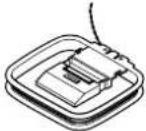 AM loop antenna AM loop antenna |  Indoor FM antenna (connector type varies from country to country) Indoor FM antenna (connector type varies from country to country) |  Power-plug adapter Power-plug adapter | Only supplied in certain countries. Use this adapter if your AC outlet does not match with the plug on the TX-SR501/ TX-SR501E's power cord. (Adapter var-ies from country to country.) |
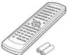 Remote controller & two batteries (AA/R6) Remote controller & two batteries (AA/R6) | 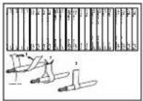 Speaker cable labels Speaker cable labels |  75/300-ohm antenna adapter 75/300-ohm antenna adapter | Not supplied with North American and European models. |
* In catalogs and on packaging, the letter added to the end of the product name indicates the color of the TX-SR501/TX-SR501E. Specifications and operation are the same regardless of color.
Features
Amp
- 6-channel amplifier
- 65 watts per channel into 8 ohms, 20 Hz–20 kHz with less than 0.08% total harmonic distortion
• WRAT (Wide Range Amplifier Technology) - Optimum gain volume circuitry
Audio/Video
• Dolby ^1 Digital EX and Dolby Pro Logic II
- DTS, DTS-ES Matrix/Discrete 6.1, and DTS Neo:6 processing ^2
• Cinema Filter function
- Advanced 24-bit DSP chip (5 DSP soundfields)
• Linear PCM 96 kHz/24-bit D/A converters on all channels
- Adjustable crossover (60, 80, 100, 120, 150 Hz)
• 2 component video inputs, 1 output
• 4 S-Video inputs, 2 outputs
• 3 assignable digital inputs (2 optical, 1 coaxial)
- Subwoofer pre out
• Color-coded multi-channel inputs
• Color-coded speaker terminal posts (SPEAKERS B use push-type terminals)
FM/AM Tuner
• 30 FM/AM presets
- FM auto tuning
• RDS (Radio Data System) (Europe only)
*1. Manufactured under license from Dolby Laboratories. "Dolby," "Pro Logic," Surround EX," and the double-D symbol are trademarks of Dolby Laboratories.
*2. "DTS," "DTS-ES Extended Surround," and "Neo:6" are trademarks of Digital Theater Systems, Inc.
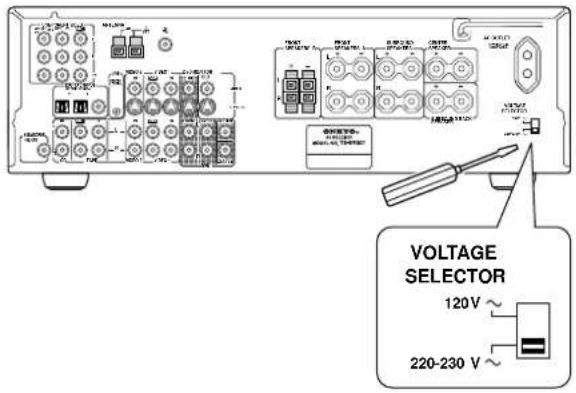
Setting the Voltage Selector (Worldwide model only)
The Worldwide model has a voltage selector for compatibility with power systems around the world. Before you plug in this model, make sure that the voltage selector is set to the correct voltage for your area. If it isn't, use a small screwdriver to set it as appropriate. For example, if the voltage in your area is 120 volts (V), set the selector to "120V." And if it's between 220 and 230 volts (V), set it to "220-230V."
text_image
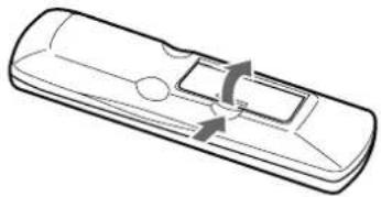
VOLTAGE SELECTOR 120 V ~ 220-230 V ~Installing the Batteries
1 Open the battery compartment, as shown.
natural_image
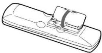
Line drawing of a remote control device with scroll arrows indicating speed (no text or symbols)2 Insert the two supplied batteries (AA/R6) in accordance with the polarity diagram inside the battery compartment.

natural_image
Line drawing of a remote control device with handle and buttons (no text or symbols)3 Close the battery compartment.
natural_image
Line drawing of a remote control device with a scroll wheel (no text or symbols)Notes:
- The supplied batteries should last for about six months, although this will vary with usage.
- If the remote controller doesn't work reliably, try replacing both batteries.
-
Don't mix new and old batteries, or different types of batteries.
-
If you intend not to use the remote controller for a long time, remove the batteries to prevent possible leakage and corrosion.
- Flat batteries should be removed as soon as possible to prevent possible leakage and corrosion.
Using the Remote Controller
To use the remote controller, point it at the TX-SR501/TX-SR501E's remote control sensor, as shown below. The TX-SR501/TX-SR501E's STANDBY indicator flashes while a signal is being received from the remote controller.
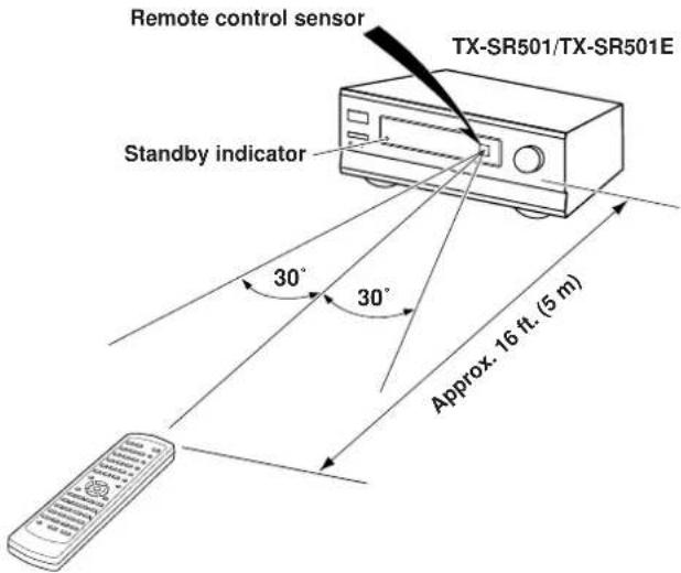
text_image
Remote control sensor TX-SR501/TX-SR501E Standby indicator 30° 30° Approx. 16 ft. (5 m)Notes:
- The remote controller may not work reliably if the TX-SR501/TX-SR501E is subjected to bright light, such as direct sunlight or inverter-type fluorescent lights. Keep this in mind when installing the TX-SR501/TX-SR501E.
- If another remote controller of the same type is used in the same room, or the TX-SR501/TX-SR501E is installed close to equipment that uses infrared rays, the remote controller may not work reliably.
- Don't put anything, such as a book, on the remote controller, because the buttons may be pressed inadvertently, thereby draining the batteries.
- The remote controller may not work reliably if the TX-SR501/TX-SR501E is installed in a rack behind colored glass doors. Keep this in mind when installing the TX-SR501/TX-SR501E.
- The remote controller will not work if there's an obstacle between it and the TX-SR501/TX-SR501E's remote control sensor.
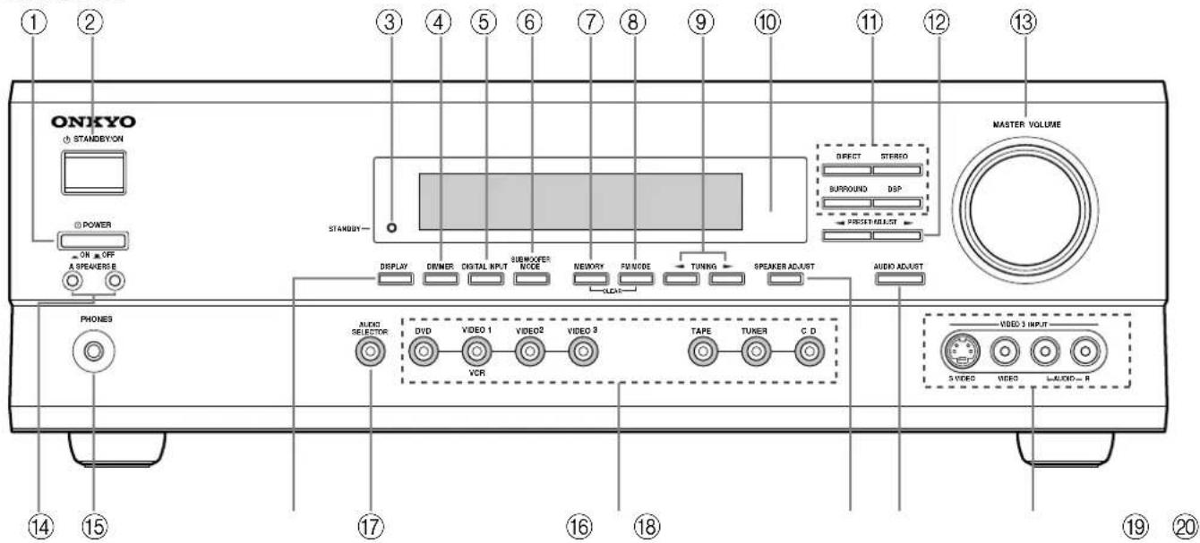
Front Panel
North American Model

text_image
ONKYO STANDBYON 2 3 4 5 6 7 8 9 10 11 12 13 STANDBY MASTER VOLUME DIRECT SIERO SURROUND DSP FROETHALIST DISPLAY DEMARK DIGITAL INPUT TURBOODER NODE NARIDAY FLOWS TUNING SPANDER ADJINT AUDIO ADJINT PHONES TVOR SICUERSE DVD VIDEO 1 VIDEO 2 VIDEO 3 TAPE TUNER CD VCR VIDEO 3 INPUT 5 VIDEO AUTHWIDE LTR 14 15 17 18 20Other Models
text_image
ONKYO STANDEYON POWER ON OFF A SPEAKER B PHONES AUDIO SELECTOR DVD VIDEO 1 VIDEO 2 VIDEO 3 TAPE TUNER C D VIDEO 3 INPUT 3 VIDEO VIDEO AUDIO R STANDEY— DISPLAY DINNER DIGITAL INPUT SUBEXFER NICE MEMORY FUNCTIONE TUNING SPEAKER ADJUST AUDIO ADJUST DIRECT STEREO SURROUND DSP PRESPECTRASSIST MASTER VOLUMEFor detailed information, refer to the pages in parenthesis.
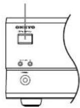
① POWER switch (24)
The North American model doesn't have this switch. This is the main power switch. When set to OFF, the TX-SR501/TX-SR501E is completely shutdown. When set to ON, the TX-SR501/TX-SR501E is in Standby mode and the STANDBY indicator lights up. Don't turn on the power until you've completed, and double checked all connections (pages 10–23).
Note:
Turning on the TX-SR501/TX-SR501E may cause a momentary power surge that might interfere with other electrical equipment on the same circuit. If this is a problem, plug the TX-SR501/TX-SR501E into a different branch circuit.
② STANDBY/ON button (24)
This button is used to set the TX-SR501/TX-SR501E to On or Standby. For models with a POWER switch, this button has no effect unless the POWER switch is set to ON.
③ STANDBY indicator (24)
This indicator lights up when the TX-SR501/TX-SR501E is in Standby mode, and it flashes while a signal is being received from the remote controller.
④ DIMMER button (32)
This button is used to adjust the display brightness.
⑤ DIGITAL INPUT button (24)
This button is used to assign the digital inputs.
⑥ SUBWOOFER MODE button (25)
This button is used to select the Subwoofer modes.
⑦ MEMORY button (30, 31)
This button is used when storing and deleting radio presets.
⑧ FM MODE button (31)
This button is used to select the FM radio Stereo and Mono modes. It's also used when deleting radio presets.
⑨ TUNING [◀] buttons (30)
These buttons are used to tune into radio stations.
⑩ Remote control sensor (5)
This sensor receives control signals from the remote controller.
⑪ Listening mode buttons (36)
These buttons are used to select the listening modes.
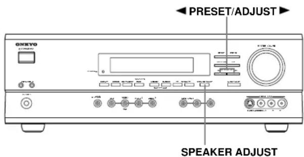
⑫ PRESET/ADJUST [◀] buttons (25, 26, 31, 37)
This button is used to select radio presets and adjust parameter values.
⑬ MASTER VOLUME control (28, 30)
This control is used to set the volume of the TX-SR501/TX-SR501E.
⑭ SPEAKER A & B buttons (28, 32)
These buttons are used to turn speaker sets A and B on and off.
⑮ PHONES jack (33)
This 1/4-inch phone jack is for connecting a standard pair of stereo headphones for private listening.
⑯ DISPLAY button (32)
This button is used to display various information about the currently selected source.
⑰ AUDIO SELECTOR button (28, 29)
This button is used to select the input signal format.
⑱ Input selector buttons (24, 28–30, 39)
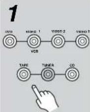
These buttons are used to select the audio and video sources: CD, DVD, TAPE, TUNER, VIDEO 1, VIDEO 2, or VIDEO 3.
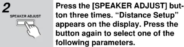
⑲ SPEAKER ADJUST button (25, 26)
This button is used to adjust various speaker-related parameters.
⑳ AUDIO ADJUST button (37)
This button is used to set the Bass, Treble, Late Night, Cinema Filter, Center Image, Panorama, Dimension, and Center Width functions.
②1 VIDEO 3 INPUT connectors (15, 39)
These S-Video, composite video (RCA/phono), and analog audio (RCA/phono) inputs can be used to connect a video camera or games console.
Display
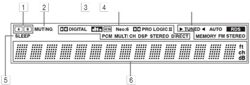
text_image
1 2 3 4 SLEEP DIGITAL Neo:6 PRO LOGIC II TUNED AUTO RDS PCM MULTI CH DSP STEREO DIRECT MEMORY FM STEREO ft ch dB 5 6For detailed information, refer to the pages in parenthesis.
1 A & B speaker indicators (28, 32)
Indicator A lights up when speaker set A is on. Indicator B lights up when speaker set B is on.
2 MUTING indicator (33)
This indicator flashes when the TX-SR501/TX-SR501E is muted.
3 Source/listening mode indicators (28, 36)
These indicators display information about the currently selected source and listening mode.
4 Tuning indicators (30, 31)
TUNED (30): This indicator lights up when the TX-SR501/TX-SR501E is tuned into a radio station.
AUTO (30): This indicator lights up when the Auto Tuning function is on.
RDS (European model only) (31): This indicator lights up when the TX-SR501E is tuned into a radio station that supports RDS (Radio Data System).
MEMORY (31): This indicator lights up when programming radio presets.
FM STEREO (31): This indicator lights up when the TX-SR501/TX-SR501E is tuned into a stereo FM station.
5 SLEEP indicator (33)
This indicator lights up when the Sleep function has been set.
6 Message area
This area of the display shows various information about the currently selected source.
Rear Panel
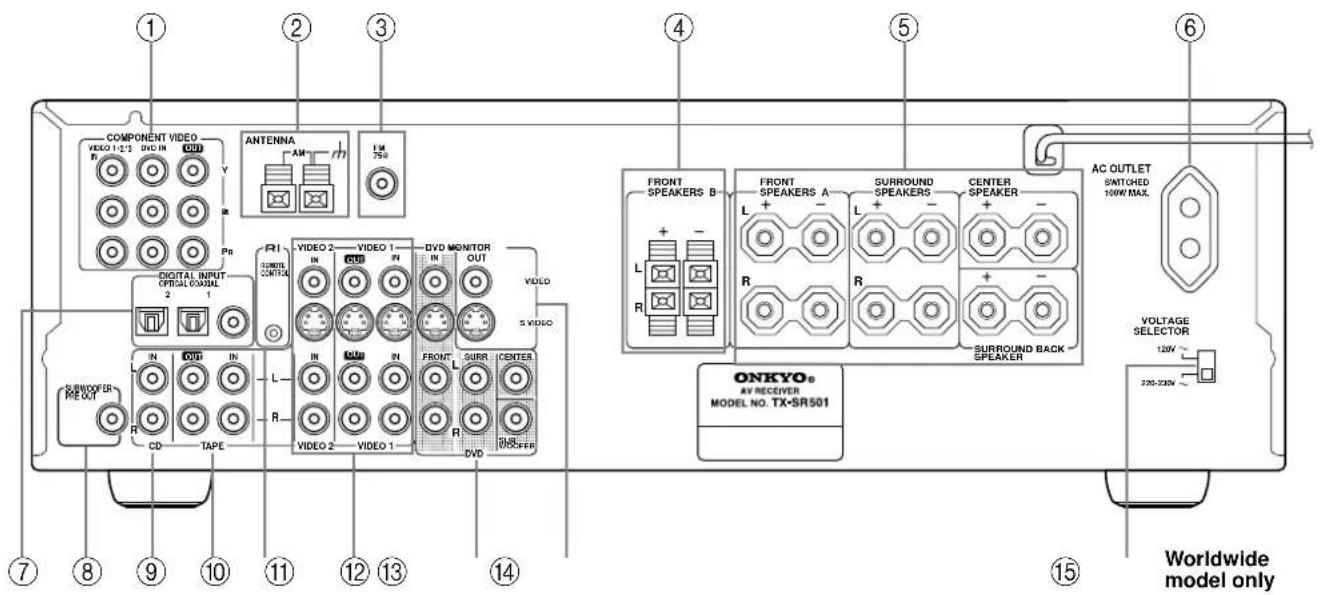
text_image
COMPONENT VIDEO VIDEO 1-2/3 DVD IN OUT Antenna AM TM Digital INPUT OPTICAL CONTROL 2 R1 SUBSOFFER PREVAT IN OUT IN R VIDEO 2 VIDEO 1 DVD MONITOR IN OUT VIDEO 5 VIDEO R IN IN R VIDEO 2 VIDEO 1 FRONT SURR CENTER R DVD ONKYO® AV RECEIVER MODEL NO. TX-SR501 FRONT SPEAKERS B L R FRONT SPEAKERS A L R SURROUND SPEAKERS L R CENTER SPEAKER + - + - SURROUND BACK SPEAKER AC OUTLET SWITCHED 100W MAX. VOLTAGE SELECTOR 120V~ 220-230V~ Worldwide model onlyFor detailed information, refer to the pages in parenthesis.
① COMPONENT VIDEO (10, 12, 14, 16)
These RCA/phono connectors can be used to connect a TV, DVD player, or other AV component with component video inputs and outputs.
② AM ANTENNA (22, 23)
These push terminals are for connecting an AM antenna.
③ FM ANTENNA (22, 23)
This connector is for connecting an FM antenna.
④ FRONT SPEAKERS B (21)
These push terminals are for connecting speaker set B.
These terminal posts are for connecting speaker set A, including the front, surround, center, and surround-back speakers. They accept bare wires or banana plugs (European models don't accept banana plugs).
⑥ AC OUTLET (11)
This switched AC outlet can be used to supply power to another AV component. The connector type depends on the country in which you purchased your TX-SR501/TX-SR501E.
⑦ DIGITAL INPUT OPTICAL 1, 2 & COAXIAL (10, 13, 14, 16–18)
These optical and coaxial connectors can be used to connect a CD, DVD, or LD (laser disc) player, or other AV component with digital outputs.
⑧ SUBWOOFER PRE OUT (21)
This RCA/phono connector can be used to connect an active subwoofer.
⑨ CD IN (10, 17)
These RCA/phono connectors can be used to connect a CD player with analog outputs.
⑩ TAPE IN/OUT (10, 17, 18)
These RCA/phono connectors can be used to connect a cassette recorder, MiniDisc recorder, or other recorder with analog inputs and outputs.
⑪ (29)
This Remote Interactive) connector can be connected to the Connector on another Onkyo AV component, for example, a CD player, DVD player, or cassette recorder. The TX-SR501/TX-SR501E's remote controller can then be used to control that component. To use you must make an analog RCA/phono connection between your TX-SR501/TX-SR501E and the other AV component, even if they are connected digitally.
⑫ VIDEO 1 IN/OUT & VIDEO 2 IN (10, 14–16, 39)
These connectors can be used to connect a VCR or other AV component. There are RCA/phono connectors for connecting to stereo analog audio inputs and outputs, and S-Video and composite video (RCA/phono) connectors for connecting to video inputs and outputs.
⑬ DVD IN/MULTI CH INPUT (10, 12, 13)
The FRONT, SURR, CENTER, and SUBWOOFER RCA/phono connectors can be used to connect AV components with multiple analog audio outputs, including DVD players with individual 5.1 surround analog outputs. There's an S-Video input and composite video (RCA/phono) input for connecting the video signal.
⑭ MONITOR OUT (10, 12)
These S-Video and composite video (RCA/phono) outputs can be connected to the video input on your TV or projector.
⑮ VOLTAGE SELECTOR (Worldwide model only) (5)
This voltage selector provides compatibility with power systems around the world.
Tip:
A turntable with a built-in preamp can be connected to a pair of unused TX-SR501/TX-SR501E analog inputs. To connect a turntable without a built-in preamp, you'll need a commercially available phono preamp. See pages 17 and 18 and the instructions supplied with your phono preamp and turntable for more information.
Remote Controller—RCVR Mode
RC-518M (North American model)

text_image
1 2 3 4 5 6 7 8 9 10 11 12 13 14 15 16 STANDARD SLEEP DIMMER 0/1 DSP PRESET VCR DIRECT STEREO TV 1 2 3 CABLE/SAT SURROUND AJSTEREO 4 5 6 CINE FLTR SP A CO/DVD 7 8 9 RDVR/TAPE LATE NIGHT SP B DISC +10 OK TOP MENU RICH-UP MENU TV VOL DOWN AUDIO ADJUE ENT TV VOL UP RETURN SET UP TV TVCH DOWN TV MUTE CH + TEST CH SEL LEVEL AUDIO SEL TAPE TUNER CD DVD VIDEO 1 VIDEO 2 VIDEO 3 MUTING VOLUME ONKYO RC-518MRC-479S (other models)

text_image
1 2 3 4 5 6 7 8 9 STANDIRY ON SLEEP DIMMER 0 / 1 DSP PRESET DVD DIRECT STEREO 1 2 3 CD SURROUND ASTEREO 4 5 6 RCVR/TAPE CINE FLTR SP A 7 B 9 LATE NIGHT SP B DISC +10 OK TOP MENU MENU AUDIO AC/AC/AC/AC/AC/AC/AC/AC/AC/AC/AC/AC/AC/AC/AC/AC/AC/AC/AC/AC/AC/AC/AC/AC/AC/AC/AC/AC/AC/AC/AC/AC/AC/AC/AC/AC/AC/AC/AC/AC/AC/AC/AC/AC/AC/AC/AC/AC/AC/AC/AC/DC RETURN SETUP TEST CH SEL LEVEL AUDIO SEL TAPE TUNER CD DVD VIDEO 1 VIDEO 2 VIDEO 3 MUTING VOLUME ONKYO REMOTE CONTROLLER RC-479SThis page describes only those buttons that can be used to control the TX-SR501/TX-SR501E when the remote controller is in RCVR mode (Receiver mode). The other modes, and information on using the remote controller to control your other AV components, are explained on page 40.
To select RCVR mode, press the [RCVR] button.
For detailed information, refer to the pages in parenthesis.
① SLEEP button (33)
This button is used to set the Sleep function. This function can be set only with the remote controller.
② STANDBY/ON button (24)
This button is used to set the TX-SR501/TX-SR501E to On or Standby.
③ Listening mode buttons (36)
These buttons are used to select the listening modes.
④ CINE FLTR button (37)
This button is used to set the Cinema Filter function.
⑤ LATE NIGHT button (37)
This button is used to set the Late Night function.
⑥ TEST, CH SEL & LEVEL [A [ ] buttons (27, 29, 33)
These buttons are used to set the level of each speaker individually. This function can be set only with the remote controller.
⑦ AUDIO SEL button (29)
This button is used to select analog or digital inputs for the CD, DVD, TAPE, VIDEO 1, VIDEO 2, and VIDEO 3 sources.
⑧ Input selector buttons (28, 30, 39)
These buttons are used to select the audio and video sources: CD, DVD, TAPE, TUNER, VIDEO 1, VIDEO 2, and VIDEO 3.
⑨ MUTING button (33)
This button is used to mute the TX-SR501/TX-SR501E. This function can be set only with the remote controller.
⑩ PRESET [◀] [ ] buttons (31)
These buttons are used to select radio presets.
⑪ DIMMER button (32)
This button is used to adjust the display brightness.
⑫ Remote Controller Mode buttons (28, 40, 42)
These buttons are used to select the remote controller modes. To select RCVR mode, press the [RCVR] button.
⑬ SP A & SP B buttons (28, 32)
These buttons are used to turn on and off speaker sets A and B individually.
⑭ AUDIO ADJUST button (37)
This button is used to set the Bass, Treble, Late Night, Cinema Filter, Center Image, Panorama, Dimension, and Center Width functions.
⑮ ADJUST [◀] [ ] buttons (37)
These buttons are used to adjust the functions selected with the AUDIO ADJUST button.
⑯ VOLUME [▲] buttons (27, 28, 33)
These buttons are used to set the volume of the TX-SR501/TX-SR501E.
Connecting Your AV Components
Before Making Any Connections
- Read the manuals supplied with your AV components.
- Don't connect the power cord until you've completed all audio and video connections.
Optical Digital Inputs
The TX-SR501/TX-SR501E's optical digital connectors have a shutter-type cover that opens when an optical plug is inserted, and closes when it's removed. Push the plug in all the way.
RCA/phono AV Connection Color Coding
RCA/phono AV connections are usually color coded: red, white, and yellow. Use red plugs to connect right-channel audio inputs and outputs (typically labeled "R"). Use white plugs to connect left-channel audio inputs and outputs (typically labeled "L"). And use yellow plugs to connect composite video inputs and outputs.
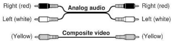
text_image
Right (red) Analog audio Right (red) Left (white) Left (white) (Yellow) Composite video (Yellow)- Push the plugs in all the way to make a good connection.
• T o prevent interference, keep audio and video cables away from power cords and speaker cables.

AV Cables & Connectors
Video
| Component video | 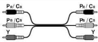 | 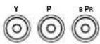 | Component video separates the luminance (Y) and color difference signals (PR, PB), providing the best picture quality. Some TV manufacturers label their component video inputs differently. |
| S-Video |  |  | S-Video provides better picture quality than composite video. |
| Composite video | [IC6A] | [4ZA2] | Composite video can be found on virtually all TVs, VCRs, and video equipment. |
Audio
| Optical digital |  |  | Optical digital audio connections provide better audio quality than analog connections. Audio quality is the same as for coaxial. |
| Coaxial digital | 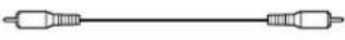 |  | Coaxial digital audio connections provide better audio quality than analog connections. Audio quality is the same as for optical. |
| Analog |  |  | RCA/phono analog audio connectors can be found on virtually all AV components. |
| Multi-channel connection | 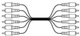 |  | Toconnect an AV component with multiple analog audio outputs, for example, a DVD player with individual 5.1 surround analog outputs, you need to make six connections, which can be done with three stereo RCA/phono audio cables. |
Which Connections To Use?
The TX-SR501/TX-SR501E offers several connection formats for compatibility with a wide range of AV equipment. The format you choose will depend on the formats supported by your AV components. Use the following sections as a guide.
When connecting video equipment, you need to make video and audio connections.
Video Connection Formats
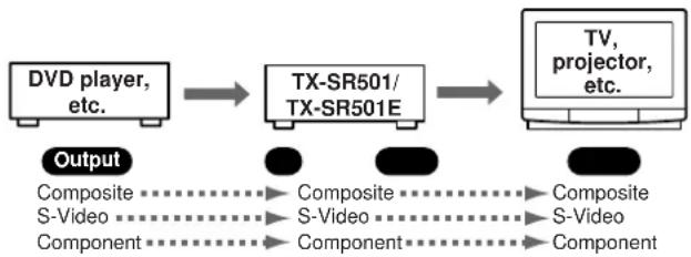
Video equipment can be connected to the TX-SR501/TX-SR501E using the following video connection formats: composite video, S-Video, or component video, the latter offering the best picture quality.
When choosing a connection format, bear in mind that the TX-SR501/TX-SR501E doesn't convert between formats, so only output connectors of the same format as the input connector will output a signal, as shown below.
For example, if you connect your DVD player to the S-VIDEO DVD IN, a video signal will be output by the S-VIDEO MONITOR OUT (for your TV) and the S-VIDEO VIDEO 1 OUT (for your VCR), but not the composite video or component video outputs.
flowchart
graph LR
    A["DVD player, etc."] --> B["TX-SR501/TX-SR501E"]
    B --> C["TV, projector, etc."]
    D["Composite"] --> E["Composite"]
    F["S-Video"] --> G["S-Video"]
    H["Component"] --> I["Component"]
    E --> J["Composite"]
    G --> K["S-Video"]
    I --> L["Component"]
Audio Connection Formats
Audio equipment can be connected to the TX-SR501/TX-SR501E using the following audio connection formats: analog, optical, coaxial, and multi-channel (5.1).
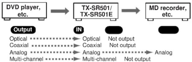
When choosing a connection format, bear in mind that the TX-SR501/TX-SR501E doesn't convert between formats, as shown below.
For example, audio signals connected to the OPTICAL or COAXIAL digital input are not output by the analog TAPE OUT connectors, so if you want to record from, for example, your CD player, in addition to connecting it to a digital input, you must also connect it to the analog CD IN connectors.
flowchart
graph LR
    A["DVD player, etc."] --> B["TX-SR501/TX-SR501E"]
    B --> C["MD recorder, etc."]
    D["Output"] --> E["IN"]
    E --> F["Optical"]
    E --> G["Coaxial"]
    E --> H["Analog"]
    E --> I["Multi-channel"]
    B --> J["Optical"]
    B --> K["Coaxial"]
    B --> L["Analog"]
    B --> M["Multi-channel"]
    C --> N["Not output"]
    C --> O["Not output"]
    C --> P["Analog"]
    C --> Q["Not output"]
Using the AC OUTLET
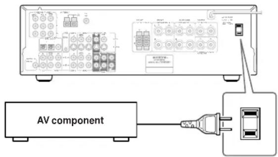
The switched AC outlet on the TX-SR501/TX-SR501E's rear panel can be used to supply power to another AV component, as shown. The connector type depends on the country in which you purchased your TX-SR501/TX-SR501E.
text_image
AV componentMake sure that the wattage requirements of the AV component that you connect to the TX-SR501/TX-SR501E's AC outlet do not exceed the maximum wattage printed on the rear panel.
Connecting Your TV or Projector
■ Using Composite Video
Use a composite video cable to connect the TX-SR501/TX-SR501E's VIDEO MONITOR OUT to a composite video input on your TV, as shown.

text_image
MONITOR OUT VIDEO VIDEO IN TV, projector, etc.■ Using S-Video
Use an S-Video cable to connect the TX-SR501/TX-SR501E's S VIDEO MONITOR OUT to an S-Video input on your TV, as shown.
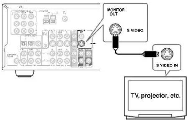
text_image
MONITOR OUT S VIDEO S VIDEO IN TV, projector, etc.■ Using Component Video
Use a component video cable to connect the TX-SR501/TX-SR501E's COMPONENT VIDEO OUT connectors to the component video inputs on your TV, as shown.

flowchart
graph TD
    A["TV, projector, etc."] --> B["OUT"]
    A --> C["Y"]
    A --> D["PB"]
    A --> E["PR"]
    B --> F["COMPONENT VIDEO IN"]
    C --> F
    D --> F
    E --> F
Connecting a DVD player
Video Connections
■ Using Composite Video
Use a composite video cable to connect the TX-SR501/TX-SR501E's VIDEO DVD IN to the composite video output on your DVD player, as shown.
- Y our TV must also be connected via composite video.

text_image
DVD IN VIDEO OUT DVD player■ Using S-Video
Use an S-Video cable to connect the TX-SR501/TX-SR501E's S VIDEO DVD IN to the S-Video output on your DVD player, as shown.
- Y our TV must also be connected via S-Video.
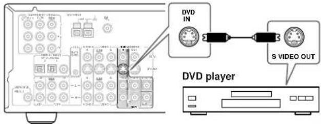
text_image
DVD IN S VIDEO OUT DVD player■ Using Component Video
Use a component video cable to connect the TX-SR501/TX-SR501E's COMPONENT DVD IN connectors to the component video outputs on your DVD player, as shown.
- Y our TV must also be connected via component video.

text_image
DVD player DVD IN Y PB PR COMPONENT VIDEO OUTAudio Connections
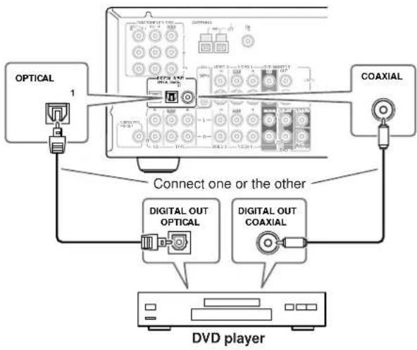
■ Using Optical or Coaxial Connections
- Use an optical digital audio cable to connect the TX-SR501/TX-SR501E's OPTICAL 1 DIGITAL INPUT to the optical output on your DVD player, as shown.
OR
- Use a coaxial digital audio cable to connect the TX-SR501/TX-SR501E's COAXIAL DIGITAL INPUT to the coaxial output on your DVD player, as shown.
flowchart
graph TD
    A["OPTICAL"] -->|1| B["DVD player"]
    C["COAXIAL"] -->|Connect one or the other| B
    D["DIGITAL OUT OPTICAL"] --> B
    E["DIGITAL OUT COAXIAL"] --> B
Initially, the OPTICAL 1 digital input is assigned to the DVD input source. If you connect your DVD player to a different digital input, you'll need to assign that input to the DVD input source (see page 24).
■ Using Analog Connections
Even if your DVD player is connected digitally (coaxial or optical), to use R to record audio from your DVD player, you'll need to make analog connections as well.
Use an RCA/phono audio cable to connect the TX-SR501/TX-SR501E's FRONT DVD IN connectors to the analog audio outputs on your DVD player, as shown.
If your DVD player has L/R outputs and multi-channel 5.1 outputs, be sure to use the L/R outputs.
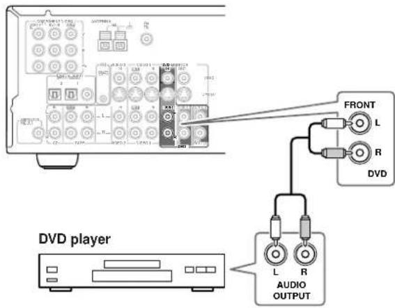
text_image
DVD player FRONT L R DVD L R AUDIO OUTPUT■ Using Multi-channel Connections
Use a multi-channel RCA/phono audio cable to connect the TX-SR501/TX-SR501E's L/R FRONT, L/R SURR, CENTER, and SUB WOOFER DVD IN connectors to the 5.1 analog outputs on your DVD player, as shown.
Alternatively, use three stereo RCA/phono audio cables.

flowchart
graph TD
    A["DVD player"] --> B["FRONT L"]
    A --> C["FRONT R"]
    A --> D["SURR L"]
    A --> E["SURR R"]
    A --> F["CENTER"]
    A --> G["SUB WOOFER"]
    B --> H["FRONT L"]
    C --> I["FRONT R"]
    D --> J["SURR L"]
    E --> K["SURR R"]
    F --> L["CENTER"]
    G --> M["SUB WOOFER"]
    H --> N["FRONT L"]
    I --> O["FRONT R"]
    J --> P["SURR L"]
    K --> Q["SURR R"]
    L --> R["CENTER"]
    M --> S["SUB WOOFER"]
    N --> T["FRONT L"]
    O --> U["FRONT R"]
    P --> V["SURR L"]
    Q --> W["SURR R"]
    R --> X["CENTER"]
    S --> Y["SUB WOOFER"]
Connecting a VCR for Playback
Video Connections
- Use an S-Video cable to connect the TX-SR501/TX-SR501E's S VIDEO VIDEO 2 IN to the S-Video output on your VCR, as shown. Your TV must also be connected via S-Video.
OR
- Use a composite video cable to connect the TX-SR501/TX-SR501E's VIDEO VIDEO 2 IN to a composite video output on your VCR, as shown. Your TV must also be connected via composite video.
Audio Connections
Use an RCA/phono audio cable to connect the TX-SR501/TX-SR501E's L/R VIDEO 2 IN connectors to the analog audio outputs on your VCR, as shown.

flowchart
graph TD
    A["VCR"] --> B["Connect one or the other"]
    B --> C["VIDEO OUT"]
    B --> D["S VIDEO OUT"]
    B --> E["L AUDIO OUTPUT"]
    B --> F["R"]
    C --> G["VIDEO 2 IN"]
    D --> H["S VIDEO"]
    E --> I["L AUDIO OUTPUT"]
Connecting a D-VHS Recorder
Video connections
Use a component video cable to connect the TX-SR501/TX-SR501E's COMPONENT VIDEO 1/2/3 IN connectors to the component video outputs on your D-VHS recorder, as shown.
- Y our TV must also be connected via component video.
Audio connections
- Use a coaxial digital audio cable to connect the TX-SR501/TX-SR501E's COAXIAL DIGITAL INPUT to the coaxial output on your D-VHS recorder, as shown.
OR
- Use an optical digital audio cable to connect the TX-SR501/TX-SR501E's OPTICAL 2 DIGITAL INPUT to the optical output on your D-VHS recorder, as shown.

flowchart
graph TD
    A["COMPONENT OUT"] --> B["VIDEO 1/2/3 IN"]
    A --> C["VIDEO OUT"]
    A --> D["VIDEO OUT"]
    A --> E["D-VHS recorder"]
    F["OPTICAL 2"] --> G["Connect one or the other"]
    H["COAXIAL"] --> I["Digital OUT COAXIAL"]
    J["DIGITAL OUT OPTICAL"] --> K["Digital OUT OPTICAL"]
    style A fill:#f9f,stroke:#333
    style B fill:#ccf,stroke:#333
    style C fill:#ccf,stroke:#333
    style D fill:#ccf,stroke:#333
    style E fill:#ccf,stroke:#333
    style F fill:#cfc,stroke:#333
    style G fill:#cfc,stroke:#333
    style H fill:#cfc,stroke:#333
    style I fill:#cfc,stroke:#333
    style J fill:#cfc,stroke:#333
    style K fill:#cfc,stroke:#333
You may need to change the input source to digital input assignments (see page 24).
Connecting a VCR for Recording
If your TV has AV outputs and you want to record from your TV to your VCR via the TX-SR501/TX-SR501E, make the following connections.
- Use an S-Video cable to connect the TX-SR501/TX-SR501E's S VIDEO VIDEO 2 IN to an S-Video output on your TV, and use another S-Video cable to connect the TX-SR501/TX-SR501E's S VIDEO VIDEO 1 OUT to an S-Video input on your VCR, as shown.
OR
- Use a composite video cable to connect the TX-SR501/TX-SR501E's VIDEO VIDEO 2 IN to a composite video output on your TV, and use another composite video cable to connect the TX-SR501/TX-SR501E's VIDEO VIDEO 1 OUT to a composite video input on your VCR, as shown.
Use an RCA/phono audio cable to connect the TX-SR501/TX-SR501E's L/R VIDEO 2 IN connectors to the analog audio outputs on your TV, and use another RCA/phono audio cable to connect the TX-SR501/TX-SR501E's L/R VIDEO 1 OUT connectors to the analog audio inputs on your VCR, as shown.

flowchart
graph TD
    A["TV"] --> B["Connect one or the other"]
    B --> C["Video OUT"]
    B --> D["S VIDEO OUT"]
    B --> E["L R AUDIO OUTPUT"]
    B --> F["VIDEO 2"]
    B --> G["VIDEO 1 OUT"]
    B --> H["S VIDEO IN"]
    B --> I["L R AUDIO INPUT"]
    A --> J["VCR"]
    J --> K["Connect one or the other"]
    K --> L["Video OUT"]
    K --> M["S VIDEO OUT"]
    K --> N["L R AUDIO OUTPUT"]
    K --> O["VIDEO 2"]
    K --> P["VIDEO 1 OUT"]
Note:
The TX-SR501/TX-SR501E must be turned on (not Standby) in order to record.
If you want to record from your TV to your VCR without going through the TX-SR501/TX-SR501E, connect your TV's AV outputs directly to your VCR's AV inputs. See the manuals supplied with your TV and VCR for details.
Connecting a Camcorder, Games Console, etc.
Video Connections
■ Using S-Video
Use an S-Video cable to connect the TX-SR501/TX-SR501E's S VIDEO VIDEO 3 INPUT to the S-Video output on your camcorder, games console, etc., as shown.
- Y our TV must also be connected via S-Video.
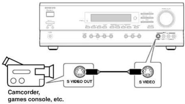
text_image
Camcorder, games console, etc.■ Using Composite Video
Use a composite video cable to connect the TX-SR501/TX-SR501E's VIDEO VIDEO 3 INPUT to the composite video output on your camcorder, games console, etc., as shown.
- Y our TV must also be connected via composite video.

text_image
CAMCORDER, games console, etc.Audio Connections
Use an RCA/phono audio cable to connect the TX-SR501/TX-SR501E's L/R VIDEO 3 INPUT connectors to the analog audio outputs on your camcorder, games console, etc., as shown.
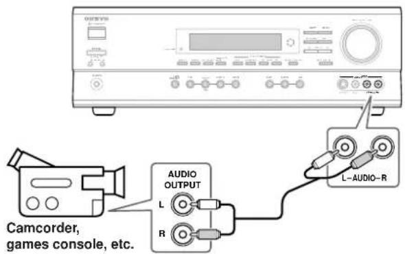
text_image
Camcorder, games console, etc. AUDIO OUTPUT L R L-AUDIO-RConnecting a Satellite/Cable Tuner, LD player, etc.
Video Connections
■ Using Composite Video
Use a composite video cable to connect the TX-SR501/TX-SR501E's VIDEO VIDEO 2 IN to the composite video output on your satellite/cable tuner, LD player, etc., as shown.
- Y our TV must also be connected via composite video.
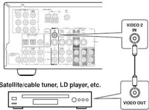
text_image
Satellite/cable tuner, LD player, etc. VIDEO OUT VIDEO 2 IN■ Using S-Video
Use an S-Video cable to connect the TX-SR501/TX-SR501E's S VIDEO VIDEO 2 IN to the S-Video output on your satellite/cable tuner, LD player, etc., as shown.
- Y our TV must also be connected via S-Video.
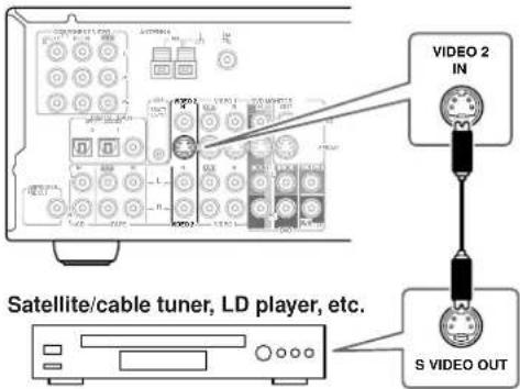
text_image
VIDEO 2 IN Satellite/cable tuner, LD player, etc. S VIDEO OUT■ Using Component Video
Use a component video cable to connect the TX-SR501/TX-SR501E's COMPONENT VIDEO 1/2/3 IN connectors to the component video outputs on your satellite/cable tuner, LD player, etc., as shown.
- Y our TV must also be connected via component video.
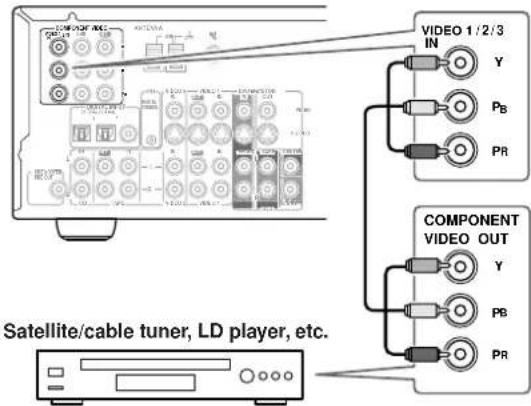
text_image
VIDEO 1/2/3 IN Y PB PR COMPONENT VIDEO OUT Y PB PR Satellite/cable tuner, LD player, etc.Audio Connections
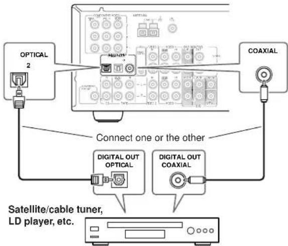
■ Using Coaxial or Optical Connections
- Use a coaxial digital audio cable to connect the TX-SR501/TX-SR501E's COAXIAL DIGITAL INPUT to the coaxial output on your satellite/cable tuner, LD player, etc., as shown.
OR
- Use an optical digital audio cable to connect the TX-SR501/TX-SR501E's OPTICAL 2 DIGITAL INPUT to the optical output on your satellite/cable tuner, LD player, etc., as shown.
flowchart
graph TD
    A["OPTICAL 2"] --> B["Connect one or the other"]
    C["COAXIAL"] --> B
    D["DIGITAL OUT OPTICAL"] --> B
    E["DIGITAL OUT COAXIAL"] --> B
    B --> F["Satellite/cable tuner, LD player, etc."]
Initially, the VIDEO 2 input source is assigned to OPTICAL 2. If you connect to different audio input, you'll need to assign that input to the VIDEO 2 input source (see page 24).
■ Using Analog Connections
If your satellite/cable tuner, LD player, etc., doesn't have digital audio outputs, or you want to record from it, you'll need to make the following analog connections.
Use an RCA/phono audio cable to connect the TX-SR501/TX-SR501E's L/R VIDEO 2 IN connectors to the analog audio outputs on your satellite/cable tuner, LD player, etc., as shown.

text_image
IN VIDEO 2 Satellite/cable tuner, LD player, etc. AUDIO OUTPUT L RNote:
To connect the TX-SR501/TX-SR501E to a LD player's AC-3RF output, you need a commercially available demodulator.
Connecting a CD Player
■ Using Coaxial or Optical Connections
- Use a coaxial digital audio cable to connect the TX-SR501/TX-SR501E's COAXIAL DIGITAL INPUT to the coaxial output on your CD player, as shown.
OR
- Use an optical digital audio cable to connect the TX-SR501/TX-SR501E's OPTICAL 2 DIGITAL INPUT to the optical output on your CD player, as shown.

flowchart
graph TD
    A["CD player"] --> B["OPTICAL 2"]
    A --> C["DIGITAL OUT OPTICAL"]
    A --> D["DIGITAL OUT COAXIAL"]
    B --> E["Connect one or the other"]
    C --> E
    D --> E
    E --> F["COAXIAL"]
Initially, the COAXIAL digital input is assigned to the CD input source. If you connect your CD player to a different digital input, you'll need to assign that input to the CD input source (see page 24).
■ Using Analog Connections
Even if your CD player is connected digitally (coaxial or optical), to use R to record audio from your CD player, you'll need to make analog connections as well.
Use an RCA/phono audio cable to connect the TX-SR501/TX-SR501E's L/R CD IN connectors to the analog audio outputs on your CD player, as shown.

text_image
CD player AUDIO OUTPUTConnecting a Turntable
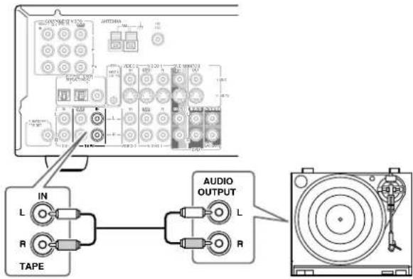
■ Turntable with a Built-in Phono Preamp
Use an RCA/phono audio cable to connect the TX-SR501/TX-SR501E's L/R TAPE IN connectors to the audio outputs on your turntable, as shown.
text_image
IN L R TAPE AUDIO OUTPUT L R■ Turntable without a Built-in Phono Preamp
Use an RCA/phono audio cable to connect the TX-SR501/TX-SR501E's L/R TAPE IN connectors to the audio outputs on your phono preamp, and use another RCA/phono audio cable to connect the phono preamp's inputs to your turntable, as shown.

flowchart
graph TD
    A["Audio OUTPUT"] --> B["TAPE"]
    B --> C["Phono preamp"]
    C --> D["AUDIO INPUT"]
    D --> E["AUDIO OUTPUT"]
    E --> F["IN"]
    style A fill:#f9f,stroke:#333
    style C fill:#ccf,stroke:#333
    style D fill:#cfc,stroke:#333
■ Turntable with an MC-type (Moving Coil) Cartridge
Use an RCA/phono audio cable to connect the TX-SR501/TX-SR501E's L/R TAPE IN connectors to the audio outputs on your phono preamp. Use another RCA/phono audio cable to connect the phono preamp's inputs to your MC head amp's outputs. And use another RCA/phono audio cable to connect the MC head amp's inputs to your turntable, as shown.

flowchart
graph TD
    A["TAPE"] --> B["Phono preamp"]
    B --> C["AUDIO INPUT L R"]
    C --> D["AUDIO OUTPUT L R"]
    D --> E["MC head amp"]
    E --> F["AUDIO OUTPUT L R"]
    F --> G["AUDIO INPUT L R"]
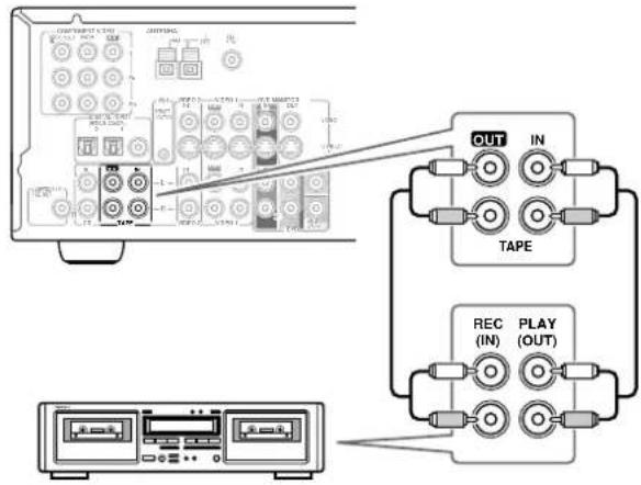
Connecting a Cassette Recorder
Use an RCA/phono audio cable to connect the TX-SR501/TX-SR501E's L/R TAPE IN connectors to the cassette recorders outputs, and use another RCA/phono audio cable to connect the TX-SR501/TX-SR501E's L/R TAPE OUT connectors to the cassette recorders inputs, as shown.
text_image
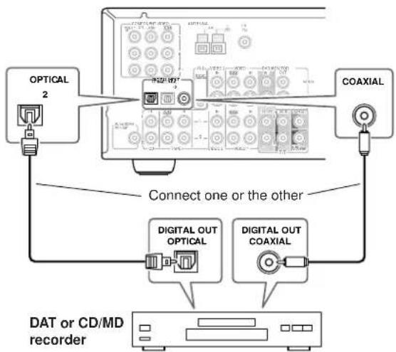
Diagram showing connection between a computer interface with labeled components including OUT, IN, TAPE, REC (IN), and PLAY (OUT) ports.Connecting a DAT or CD/MD Recorder
■ Using Coaxial or Optical Connections (playback only)
- Use a coaxial digital audio cable to connect the TX-SR501/TX-SR501E's COAXIAL DIGITAL INPUT to the coaxial output on your DAT or CD/MD recorder, as shown.
OR
- Use an optical digital audio cable to connect the TX-SR501/TX-SR501E's OPTICAL 2 DIGITAL INPUT to the optical output on your DAT or CD/MD recorder, as shown.
flowchart
graph TD
    A["OPTICAL 2"] --> B["Connect one or the other"]
    C["COAXIAL"] --> B
    B --> D["DIGITAL OUT OPTICAL"]
    B --> E["DIGITAL OUT COAXIAL"]
    D --> F["DAT or CD/MD recorder"]
    E --> F
    style A fill:#f9f,stroke:#333
    style C fill:#f9f,stroke:#333
    style D fill:#ccf,stroke:#333
    style E fill:#ccf,stroke:#333
You may need to change the input source to digital input assignments (see page 24).
■ Using Analog Connections (recording & playback)
Use an RCA/phono audio cable to connect the TX-SR501/TX-SR501E's L/R TAPE IN connectors to the DAT or CD/MD recorder outputs, and use another RCA/phono audio cable to connect the TX-SR501/TX-SR501E's L/R TAPE OUT connectors to the DAT or CD/MD recorder inputs, as shown.
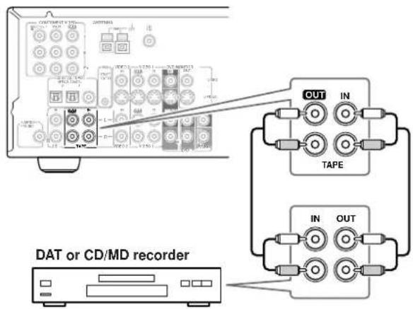
text_image
DAT or CD/MD recorder OUT IN TAPE IN OUTConnecting Compatible AV Components
With R(Remote Interactive) you can control your - RI compatible Onkyo CD player, DVD player, or cassette recorder with the TX-SR501/TX-SR501E's remote controller, and use the following special Functions:
■ Auto Power On
When you turn on an AV component connected via while the TX-SR501/TX-SR501E is in Standby, the TX-SR501/TX-SR501E automatically turns on and selects that AV component as the input source.
This function will not work if the AV component's power cord is connected to the TX-SR501/TX-SR501E's AC OUTLET, or if the TX-SR501/TX-SR501E is already on.
■ Auto Source Select
When you press the play button on an AV component connected via Rthe TX-SR501/TX-SR501E automatically selects that AV component as the input source.
■ Auto Power Off
When you set the TX-SR501/TX-SR501E to Standby, all AV components connected via R also enter Standby.
See page 40 for information on using the remote controller to control the other functions of your Rbmppatible AV components.
Connecting RI-compatible Components
To use RI, you need to connect the TX-SR501/TX-SR501E's RI connector to the RI connector on the other AV component with an Rable. An cable is supplied with each -compatible CD player, DVD player, and cassette recorder.
Example:

text_image
Onkyo DVD player DIGITAL OUT OFFICIAL R1 L n ANGLOOM OUTPUT RI cable You must make an analog RCA/phono connection between your TX-SR501/ TX-SR501E and AV component, even if they are connected digitally. Connecting several RI-compatible Onkyo AV components TX-SR501/TX-SR501E RI connector Onkyo CD player RI connector Onkyo cassette recorder COMPONENT VIDEO VIDEO 1 / 2/13 DVD IN R Y AM FM TBD DI DIGITAL INPUT OPTICAL COA IUL 2 1 PI R1 VIDEO 2 IN VIDEO 1 IN DVD MON TOR OUT VIDEO R VIDEO SUBVOODER PRE OUT IN CD TAPE L R VIDEO 2 VIDEO 1 R DVD SUB MOOFER ONKYO® AV RECEIVER MODEL NO. TX-SR501 FRONT SPEAKERS B EBONT SPEAKERS A L+ - SUBROUND SPEAKERS L+ - CENTER SPEAKER R+ - SURROUND BACK SPEAKER Disconnect the power cord before making any connections!Notes:
- Push the plugs in all the way to make a good connection.
- Use only enables for confections.
- Y ou must make an analog RCA/phono connection between your TX-SR501/TX-SR501E and the other AV component, even if they are connected digitally.
-
If an AV component has two R connectors, you can connect either one to the TX-SR501/TX-SR501E. The other connector is for connecting additional R compatible components.
-
Connect the TX-SR501/TX-SR501E's Rconnector to only Onkyo AV components. Connecting to other manufacturer's AV components may cause them to malfunction.
- Some Onkyo R incompatible AV components may not support the special functions described above.
You can use two sets of speakers with your TX-SR501/TX-SR501E: speaker set A and speaker set B.
With speaker set A, which should be installed in your main listening room, and can be used with Dolby Digital or DTS surround material, you can connect front-left, front-right, center, surround-left, surround-right, surround-back, and subwoofer speakers.
With speaker set B, which can be installed in another room, and used with stereo or mono material, you can connect a pair of standard hi-fi speakers.
Positioning Your Speakers
Speaker-set B can be positioned in the standard position for stereo speakers or where you like.
Speaker-set A, however, must be positioned at specific points in your listening room to achieve the best results from surround sound material. The following illustration shows the best positions for your surround-sound speakers. Obviously, the positions you choose will depend on the shape of your room and the position of your TV or projector screen. Either way, use this illustration as a guide and try to use the same positions relative to your listening position.

flowchart
graph TD
    A["TV/screen"] --> B["Front-left speaker"]
    A --> C["Subwoofer"]
    A --> D["Center speaker"]
    A --> E["Front-right speaker"]
    F["Surround-left speaker"] --> G["Surround-back speaker"]
    H["Surround-right speaker"] --> G
    I["Top diagram: Screen layout with icons for rear/back speakers"]
To get the most from surround sound, you should connect all seven speakers. However, if you don't connect a center speaker or surround speakers, you can still enjoy surround sound material by specifying the number of speakers connected, and the TX-SR501/TX-SR501E will produce the best surround sound possible with the available speakers. See page 34.
Similarly, if you don't have a subwoofer, you can turn off the subwoofer so that bass sounds are produced by the other speakers. See page 25.
■ Front Speakers
Front speakers consist of front-left, front-right, and center speakers. The center speaker adds directionality and movement.
- In general, the front-left, front-right, and center speakers should be installed facing the listener at ear-level.
■ Surround Speakers
Surround speakers add a sense of movement and put you, the listener, in the middle of the action.
- The surround-left and surround-right speakers should be installed at the sides, or slightly behind the listener, 2–3 ft. (60–100 cm) above ear level, and against the side walls. The surround-back speaker should be installed behind the listener also at 2–3 ft. (60–100 cm) above ear level. Make sure that the listening position is within the range of the speakers.
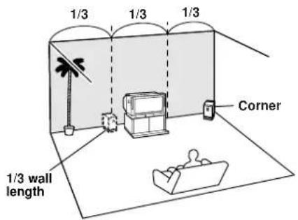
■ Subwoofer
You'll need a subwoofer with a built-in power amp, what's known as an active subwoofer, to achieve the best bass performance.
- The volume and quality of the bass output from your subwoofer will depend on its position, the shape of your listening room, and your listening position. In general, a good bass sound can be obtained by installing the subwoofer in a front corner, or at one-third the width of the wall, as shown.
text_image
1/3 1/3 1/3 Corner 1/3 wall lengthSee the instructions supplied with your speakers for more information.
Attaching the Supplied Speaker Labels
Speaker cables are two-wire cables, with one wire for connecting to the positive (+) terminal, and one for connecting to the negative (−) terminal.
The TX-SR501/TX-SR501E's positive (+) speaker terminals are color-coded for ease of identification. (The negative (-) speaker terminals are black.)
| Speaker terminal Color | |
| Front left White | |
| Front right Red | |
| Center Green | |
| Surround left Blue | |
| Surround right Gray | |
| Surround back | Brown |
The supplied speaker labels are also color-coded and you should attach them to the positive side of each speaker cable as appropriate. For example, put the white labels on the positive sides of the front-left speaker cable, as shown below.

text_image
Front-left speakerConnecting Your Speakers
Before you connect your speakers, read the following:
- Disconnect the power cord from the wall outlet.
- Read the instructions supplied with your speakers.
- Pay close attention to speaker wiring polarity. In other words, connect positive (+) terminals only to positive (+) terminals, and negative (−) terminals only to negative (−) terminals. If you get them the wrong way around, the sound will be out of phase and will sound odd.
- Only use speakers with an impedance of between 6 and 16 ohms. Connecting speakers with an impedance of less than 6 ohms may damage your TX-SR501/TX-SR501E.
- Unnecessarily long, or very thin speaker cables may affect the sound quality and should be avoided.
- Be careful not to short the positive and negative connections. Doing so may damage your TX-SR501/TX-SR501E.
- Don't connect more than one cable to each speaker terminal. Doing so may damage your TX-SR501/TX-SR501E.
- If you want to connect a single speaker instead of a pair of speakers, don't connect it to both the left and right speaker terminals.
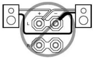
text_image
L + - R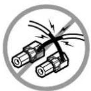

text_image
L + - RConnecting Speaker Set A
| 1 | Strip 5/8" (15 mm) of insulation from the ends of the speaker cables, and twist the bare wires tightly, as shown. | 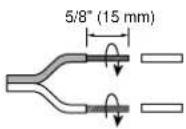 |
| 2 | Unscrew the terminal. |  |
| 3 | Fully insert the wire. |  |
| 4 | Screw the terminal tight. |  |
Connecting Speaker Set B
| 1 | Strip 3/8" (10 mm) of insulation from the ends of the speaker cables, and twist the bare wires tightly, as shown. | 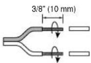 |
| 2 | While pressing the lever, insert the wire into the hole, and then release the lever.Make sure that the terminals are gripping the bare wires, not the insulation. | 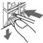 |
The following illustration shows which speakers should be connected to which terminals.
Speakers Set A
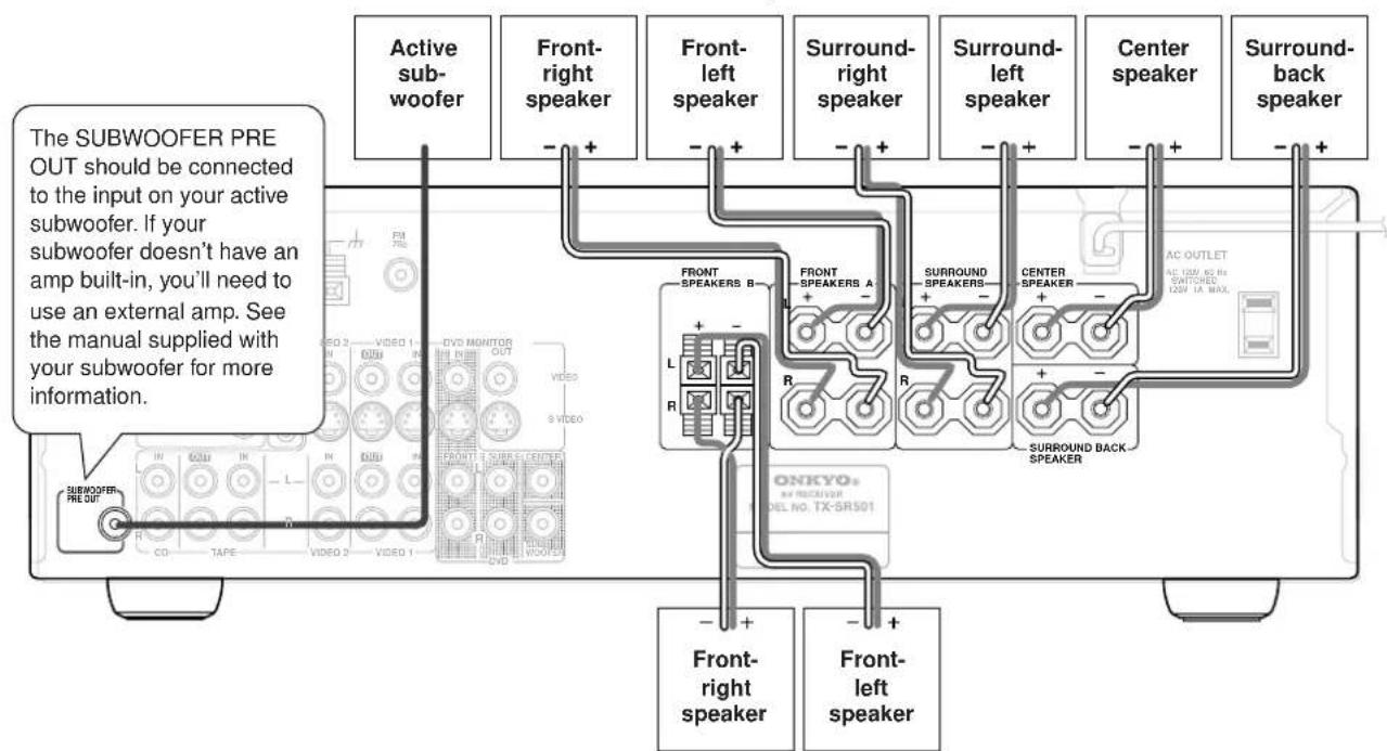
text_image
The SUBWOOFER PRE OUT should be connected to the input on your active subwoofer. If your subwoofer doesn't have an amp built-in, you'll need to use an external amp. See the manual supplied with your subwoofer for more information. Active sub-woofer Front-right speaker Front-left speaker Surround-right speaker Surround-left speaker Center speaker Surround-back speaker FRONT SPEAKERS B FRONT SPEAKERS A R L R R R ONKYO® AV RECEIVER DEL NO. TX-SR501 CO TAPE VIDEO 3 VIDEO 1 SUBWOOFER PRE OUT Front-right speaker Front-left speakerSpeakers Set B
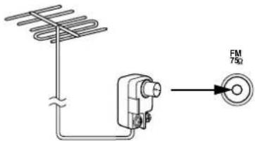
This chapter explains how to connect the supplied indoor FM antenna and AM loop antenna, and how to connect commercially available outdoor FM and AM antennas.

text_image
AM antenna push terminals FM antenna connectorConnecting the Indoor FM Antenna
The supplied indoor FM antenna is for indoor use only.
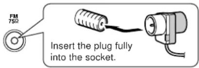
1 Attach the FM antenna, as shown.
■ North American Model
text_image
FM 75Ω Insert the plug fully into the socket.■ Other Models

text_image
FM 750 Insert the plug fully into the socket.Once your TX-SR501/TX-SR501E is ready for use, you'll need to tune into an FM radio station and adjust the position of the FM antenna to achieve the best possible reception.
2 Use thumbtacks or something similar to fix the FM antenna into position.

text_image
Thumbtacks, etc.Caution: Be careful that you don't injure yourself when using thumbtacks.
If you cannot achieve good reception with the supplied indoor FM antenna, try a commercially available outdoor FM antenna instead (see page 23).
Connecting the AM Loop Antenna
The supplied indoor AM loop antenna is for indoor use only.
1 Assemble the AM loop antenna, inserting the tabs into the base, as shown.
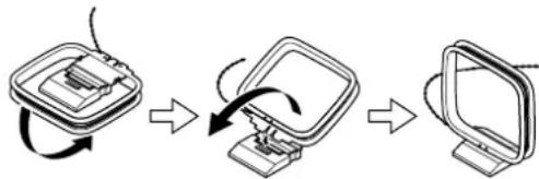
flowchart
graph TD
    A["Start Screen"] --> B["Close-up Display"]
    B --> C["Insert Display"]
    C --> D["Screen with Remote Interface"]
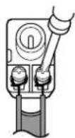
2 Connect both wires of the AM loop antenna to the AM push terminals, as shown.
(The antenna's wires are not polarity sensitive, so they can be connected either way around).
Make sure that the wires are attached securely and that the push terminals are gripping the bare wires, not the insulation.
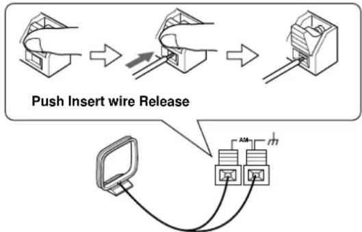
flowchart
graph TD
    A["Push Insert wire Release"] --> B["Switch with cable attachment"]
    B --> C["Switch with cable attachment"]
    C --> D["Computer via network routing"]
    D --> E["Network routing with two switches"]
Once your TX-SR501/TX-SR501E is ready for use, you'll need to tune into an AM radio station and adjust the position of the AM antenna to achieve the best possible reception. Keep the antenna as far away as possible from your TX-SR501/TX-SR501E, TV, speaker cables, and power cords.
If you cannot achieve good reception with the supplied indoor AM loop antenna, try using it with a commercially available outdoor AM antenna (see page 23).
Connecting an Outdoor FM Antenna
If you cannot achieve good reception with the supplied indoor FM antenna, try a commercially available outdoor FM antenna instead.
text_image
FM 75ΩNotes:
- Outdoor FM antennas work best outside, but usable results can sometimes be obtained when installed in an attic or loft.
- F or best results, install the outdoor FM antenna well away for tall buildings, preferably with a clear line of sight to your local FM transmitter.
- Outdoor antenna should be located away from possible noise sources, such as neon signs, busy roads, etc.
- F or safety reasons, outdoor antenna should be situated well away from power lines and other high-voltage equipment.
- Outdoor antenna must be grounded in accordance with local regulations to prevent electrical shock hazards. See item 14 of the "Important Safeguards" on page 2 of this manual.
Using the 75/300-ohm Antenna Adapter
The 75/300-ohm Antenna Adapter is not supplied with North American and European models.
The 75/300-ohm antenna adapter can be used to connect an FM antenna using either 75-ohm coaxial cable or 300-ohm twin-core flat cable.
Connecting 300-ohm Flat Cable
1 Using a screwdriver, loosen the two screws on the adapter, wrap the bare wires around the screws, and then retighten them, as shown.
2 Plug the adapter into the 75Ω socket.
Connecting 75-ohm Coaxial Cable
1 Strip and prepare the 75 ohm coaxial cable, as shown.

2 Using your fingernails or a small screw-driver, lever the adapter's tabs outward and remove the cover, as shown.
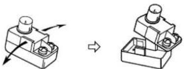
natural_image
Mechanical assembly diagram showing a bolted component before and after assembly (no text or symbols)3 Move the small wire inside the adapter from position A to position B, as shown.
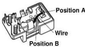
text_image
Position A Wire Position B4 Insert the central conductor (①), as shown, and use a small pair of pliers to clamp the shielding and outer insulation sections of the cable (②), as shown.
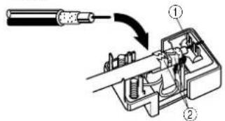
text_image
Technical diagram showing a mechanical assembly with labeled parts and directional arrow indicating process flowMake sure the shielding is not touching the central conductor.
5 Refit the adapter's cover, and then plug the adapter into the 75Ω socket.
Using a TV/FM Antenna Splitter
It's best not to use the same antenna for both FM and TV reception, as this can cause interference problems. If circumstances demand it, use a TV/FM antenna splitter, as shown.

text_image
TV/FM antenna splitter To AV reciever To TV (or VCR)Connecting an Outdoor AM Antenna
If good reception cannot be achieved using the supplied AM loop antenna, an outdoor AM antenna can be used in addition to the loop antenna, as shown.

text_image
AM loop antenna Outdoor antenna (aerial) Insulated antenna cableOutdoor AM antennas work best when installed outside horizontally, but good results can sometimes be obtained indoors by mounting horizontally above a window. Note that the AM loop antenna should be left connected.
Outdoor antenna must be grounded in accordance with local regulations to prevent electrical shock hazards. See item 14 of the "Important Safeguards" on page 2 of this manual.
Powering Up & Setting Up the TX-SR501/TX-SR501E
This chapter explains basic settings that you need to make in order to enjoy your TX-SR501/TX-SR501E after turning it on for the very first time. These include, assigning input sources to digital inputs, specifying the number of speakers, and setting the subwoofer mode, as explained on pages 24 and 25.
• North American model
- Other models
STANDBY/ONSTANDBY/ON

text_image
PICKER SLEEP RIMBER R/L 1 2 3 4 5 6 7 8 9 10 11 12 13 14 15 16 17 18 19 20 21 22 23 24 25 26 27 28 29 30 31 32 33 34 35 36 37 38 39 40 41 42 43 44 45 46 47 48 49 50 51 52 53 54 55 56 57 58 59 60 61 62 63 64 65 66 67 68 69 70 71 72 73 74 75 76 77 78 79 80 81 82 83 84 85 86 87 88 89 90 91 92 93 94 95 96 97 98 99 100POWER
Powering Up the TX-SR501/TX-SR501E
Before connecting the power cord, connect all your speakers and AV components (see page 10 to page 21).
1
Connect the power cord to a suitable wall outlet.
Turning on the TX-SR501/TX-SR501E may cause a momentary power surge that might interfere with other electrical equipment on the same circuit. If this is a problem, plug the TX-SR501/TX-SR501E into a different branch circuit.
2

Press the [POWER] switch to turn on the power (does not apply to the North American model).
The TX-SR501/TX-SR501E enters Standby mode, and the STANDBY indicator comes on.
Notes:
- The TX-SR501/TX-SR501E is shipped with the [POWER] switch in the ON position.
• T o completely shutdown the TX-SR501/TX-SR501E, press the [POWER] switch. - The remote controller has no effect while the [POWER] switch in the OFF position.
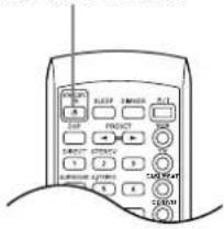
3

Remote controller
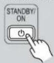
Press the [STANDBY/ON] button.
The TX-SR501/TX-SR501E comes on, the display lights up, and the STANDBY indicator goes off.
To turn off the TX-SR501/TX-SR501E, press the [STANDBY/ON] button. The TX-SR501/TX-SR501E will enter Standby mode. To prevent any loud surprises the next time you turn on your TX-SR501/TX-SR501E, always turn down the volume before turning it off.
Important—First Time Setup
![ONKYO TX-SR501E - Press the [STANDBY/ON] button. - 1](/content/2026/06/1244103/images/07b3928cce0c52186c26505ba4550c776a500410c85253a4ff0955ee3ee55426.jpg)
text_image
DIGITAL INPUT TAPE PRESET/ADJUST ONKYO SUBWOOFER MODE SPEAKER ADJUST Input selector buttonsAssigning Digital Inputs to Input Sources
With this function you can assign AV components (i.e., input sources) with digital audio outputs to the TX-SR501/TX-SR501E's digital inputs. You only need to change these assignments if your connections don't match the default assignments listed in the following table.
| Input source | DIGITAL INPUT |
| DVD | OPTICAL 1 |
| VIDEO 1 | Not assigned |
| VIDEO 2 | OPTICAL 2 |
| VIDEO 3 | Not assigned |
| TAPE | Not assigned |
| CD | COAXIAL |
If, for example, you connect your DVD player's coaxial digital audio output to the TX-SR501/TX-SR501E's COAXIAL DIGITAL INPUT, you'll need to change the DVD input source assignment from OPTICAL 1 to COAXIAL.
You can change the assignments as follows.
flowchart
graph LR
    A["VCR"] --> B["VOB 1"]
    B --> C["VCR"]
    C --> D["VOB 2"]
    D --> E["VOB 3"]
    F["TAPE"] --> G["TUNA"]
    G --> H["CD"]
Press the input selector button for the source that you want to assign: [DVD], [VIDEO 1], [VIDEO 2], [VIDEO 3], [TAPE], or [CD].
The selected source appears on the display. (The value next to the input source is the volume setting.)
DVD 58
![ONKYO TX-SR501E - Press the input selector button for the source that you want to assign: [DVD], [VIDEO 1], [VIDEO 2], [VIDEO 3], [TAPE], or [CD]. - 1](/content/2026/06/1244103/images/13ce7827932df9365959ce64faaa99cde53f3a6d5cee6227dea42f68ca9288bd.jpg)
Press the [DIGITAL INPUT] button.
The current source assignment appears, as shown.
DJD + QPTI
![ONKYO TX-SR501E - Press the [DIGITAL INPUT] button. - 1](/content/2026/06/1244103/images/f6a45971fc892348714bea271fcd11f4f7080209bdabe595a0eebe9fef1519aa.jpg)
Use the [DIGITAL INPUT] button to select COAX (COAXIAL), OPT1 (OPTICAL 1), OPT2 (OPTICAL 2), or ---- (no assignment).
DVD + COAX
If you've connected a MiniDisc recorder to the TAPE inputs, you can set the TX-SR501/TX-SR501E so that "MD" appears on the display instead of "TAPE." Simply press and hold the [TAPE] button until "MD" appears (about two seconds).
Notes:
- F or AV components that are connected to only analog inputs, choose the “----” setting.
- If you don't press the [DIGITAL INPUT] button for three seconds, the previous display reappears.
- Y ou can also specify a signal format for the DIGITAL INPUTs (page 28).
Specifying the Number of Speakers
With this function you can specify the number of speakers that you are using.
| 1SPEAKER ADJUST | Press the [SPEAKER ADJUST] button.The current speaker configuration is displayed. |
| 2PRESET/ADJUST | Use the PRESET/ADJUST [◀[ ]▶buttons to specify the number of speakers.Front left Center Front rightSpeaker: ▶□□□□ ▶6chSurround left Surround rightSurround backThe available settings are shown below.6 speakers5 speakers4 speakers3 speakers2 speakers |
Notes:
- Since some listening modes require a minimum number of speakers, when you change the above setting, the listening mode may change as well (see page 34).
- This setting cannot be set if a pair of headphones are connected, speaker set B is on, or Multich is selected.
- The TX-SR501/TX-SR501E remembers this setting, so you only need to set it once.
Setting the Subwoofer Mode
With this function you can choose the surround channels from which the subwoofer's output is derived.
| 1SUBWOOFERMODE | Press the [SUBWOOFER MODE]button once.The current subwoofer mode is displayed. | |
| 2SUBWOOFERMODE | Press the [SUBWOOFER MODE]button repeatedly to select the following modes: | |
| Parameter | Description | |
| SubwooferMode 1 | The subwoofer outputsthe low frequencies of all channels. | |
| SubwooferMode 2 | The subwoofer outputsthe low frequencies of the center and surround channels only. | |
| SubwooferMode 3 | The subwoofer outputsthe LFE (Low Frequency Effects) channel of 6.1 source material. | |
| SubwooferOff | The subwoofer output is off.Choose this setting if you're not using a sub-woofer, or want to turn off your subwoofer. | |
| If you don't press the [SUBWOOFER MODE] button for three seconds, the previous display reappears. | ||
Notes:
- If you use Mode 2 or Mode 3 with the Stereo listening mode, your subwoofer may produce no sound when you play material in certain surround formats, including 2-channel Dolby Digital, DTS, etc.
- The subwoofer mode cannot be set if a pair of headphones are connected, speaker set B is on, or Multich is selected.
- The TX-SR501/TX-SR501E remembers the subwoofer mode setting, so you only need to set it once.
This chapter describes how to configure speaker set A to achieve the best results from your surround sound system. There is no speaker configuration for speaker set B.
- Before configuring, you must:
—Disconnect any headphones (see page 33)
—Turn off speaker set B (see page 32)
—Make sure that Multich is off (see page 29)
- The TX-SR501/TX-SR501E stores each setting, so you only need to configure your speakers once.
text_image
GKEYO PRESET/ADJUST SPEAKER ADJUSTSetting the Crossover Frequency
To achieve the best bass performance from your speaker system, you need to set the crossover frequency according to the size and frequency response of your subwoofer and other speakers (front, center, and surround).
If you're not using a subwoofer, bass sounds are output by the other speakers and this setting has no effect.
| 1SPEAKER ADJUST | Press the [SPEAKER ADJUST] button twice.The current crossover frequency is displayed. | |
| 2PRESET/ADJUST | Use the PRESET/ADJUST [▶] buttons to select a crossover frequency.You can select: 60 Hz, 80 Hz, 100 Hz, 120 Hz, or 150 Hz.The following table lists the crossover frequency you should choose depending on the diameter of your front speakers. | |
| Front speaker diameter | Crossover frequency | |
| Larger than 8 inch (20 cm) | 60 Hz | |
| 6-1/2–8 inch (16–20 cm) | 80 Hz | |
| 5-1/4–6-1/2 inch (13–16 cm) | 100 Hz (default) | |
| 3-1/2–5-1/4 inch (9–13 cm) | 120 Hz | |
| Less than 3-1/2 inch (9 cm) | 150 Hz | |
For a more accurate setting, look up the frequency response in the manuals supplied with your speakers and set accordingly. In addition, listen to some music that you know well and choose a higher crossover frequency if you think there's not enough sound coming from the subwoofer; a lower setting if you think there's too much.
Specifying Speaker Distances
To get the best from surround sound, it's important that the sound from each speaker reaches the listener at the same time. To achieve this, you need to specify the distance from the listening position to each speaker.
| 1 | Measure and make a note of the distance from the listening position to each speaker.You can specify speaker distances of between 1 and 30 ft. in 1 ft. steps (0.3 and 9 meters in 0.3 meter steps). | |
 | ||
| Parameter | Description | |
| Front | Front-left and front-right speakers | |
| Center | Center speaker | |
| SurrRight | Surround-right speaker | |
| Surr Back | Surround-back speaker | |
| Surr Left | Surround-left speaker | |
| Subwoofer | Subwoofer | |
| 3PRESET/ADJUST | Use the PRESET/ADJUST [+]▶ buttons to specify the speaker distance.Use the [DISPLAY] button to select meters or feet. | |
| 4 | Repeat steps 2 and 3 for all six parameters. | |
| 3PRESET/ADJUST | Use the PRESET/ADJUST [ ][ ]▶buttons to specify the speaker distance.Use the [DISPLAY] button to select meters or feet. |
| 4 | Repeat steps 2 and 3 for all six parameters. |
Notes:
- The Center and Subwoofer distances should be up to 5 ft. (1.5 m) more or less than the Front distance. For example, if the Front distance is set to 20 ft. (6 m), you should set the Center and Subwoofer distances between 15 and 25 ft. (4.5 and 7.5 m).
- The SurrRight, Surr Left, and Surr Back distances should be up to 5 ft. (1.5 m) more or 15 ft. (4.5 m) less than the Front distance. For example, if the Front distance is set to 20 ft. (6 m), you should set the SurrRight, Surr Left, and Surr Back distances between 5 and 25 ft. (1.5 and 7.5 m).
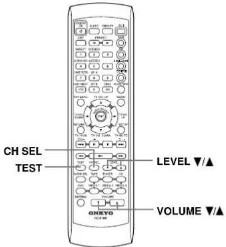
text_image
CH SEL TEST LEVEL ▼/▲ VOLUME ▼/▲Adjusting Individual Speaker Volume
With this function you can adjust the volume of each individual speaker so that you can hear all speakers equally at the listening position.
Note:
You cannot use this function while the TX-SR501/TX-SR501E is muted (see page 33).
| 1TESTVOLUME | Press the remote controller's[TEST] button, and turn up the volume so that you can hear the test tone sufficiently.While each speaker outputs the test tone (pink noise), its name appears on the display, as shown.Left = 0 db |
| 2CH SELLEVEL | Use the remote controller's[CH SEL] button to select each speaker, and use the LEVEL [▲[]▼buttons to adjust the volume.Speakers are selected in the following order: Left → Center → Right → SurrRight → Surr Back → Surr Left → Subwoofer.You can adjust the volume of each speaker from -12 dB to +12 dB.Notes:Only speakers that are included in the current configuration output the test tone. See “Specifying the Number of Speakers” on page 25.The subwoofer will not output the test tone if it’s off. See “Setting the Subwoofer Mode” on page 25.If you don’t press any buttons for two seconds, the next speaker is selected automatically. |
3

When you've adjusted each speaker, press the remote controller's [TEST] button.
The test tone stops and the previous display reappears.
Note:
If no adjustments are made for two minutes, this function is cancelled automatically and the previous display reappears.
This chapter explains how you can play your AV components through the TX-SR501/TX-SR501E.
See pages 10–19 for information on connecting your AV components to the TX-SR501/TX-SR501E.
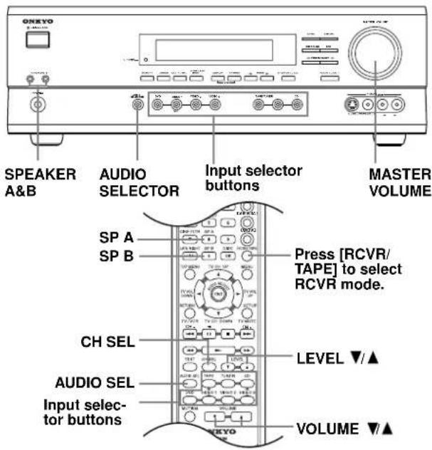
text_image
ONEYO SPEAKER A&B AUDIO SELECTOR Input selector buttons MASTER VOLUME SP A SP B CH SEL AUDIO SEL Input selec- tor buttons Press [RCVR/ TAPE] to select RCVR mode. LEVEL ▼/▲ VOLUME ▼/▲Selecting the Source AV Component
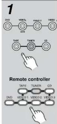
flowchart
graph TD
    A["1"] --> B["DVD"]
    B --> C["VIDEO1"]
    C --> D["VIDEO2"]
    D --> E["VIDEO3"]
    F["TAPE"] --> G["TUNES"]
    G --> H["CD"]
    I["Remote controller"] --> J["TAPE"]
    J --> K["TUNER"]
    K --> L["CD"]
    M["DVD"] --> N["VIDEO1"]
    N --> O["VIDEO2"]
    O --> P["VIDEO3"]
Use the following input selector buttons to select the AV component: [DVD], [VIDEO 1], [VIDEO 2], [VIDEO 3], [TAPE], or [CD].
The name of the selected source appears on the display, as shown.
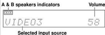
text_image
A & B speakers indicators Volume VIDEO3 58 Selected input sourceIf you're using a MiniDisc recorder, you can set the display to show "MD" instead of "TAPE." See page 25.
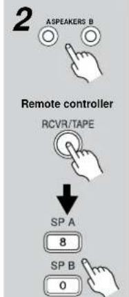
text_image
2 ASPEAKERS B Remote controller RCVR/TAPE ↓ SP A 8 SP B 0Use the SPEAKERS [A] and [B] buttons, or the remote controller's [SP A] and [SP B] buttons to select the speaker set that you want to use.
Press the remote controller's [RCVR/TAPE] button to select RCVR mode before using the remote controller.
The A and B speaker indicators show whether each speaker set is on or off.
3 Start playback on the selected AV component.
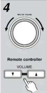
text_image
4 MASTER VOLUME Remote controller VOLUMETo adjust the volume, use the MASTER VOLUME control, or the remote controller's VOLUME [▼] buttons.
The volume can typically be set to MIN, 1 though 79, or MAX.
Using Digital Inputs
The digital input assigned to the input source (see page 24) has priority over that input source's analog input. To use the analog input, set the input source's format to Analog (see the following section).
The format of the digital input signal appears on the display, as shown: DOLBY DIGITAL, DTS, DTS-ES, or PCM (stereo).

text_image
DOLBY DIGITAL DTS PCM DTS-ES Digital PCMOther Functions:
See page 32 for functions that you can use while listening to your AV components.
Listening Modes:
See page 34 for information on the listening modes that you can use while listening to your AV components.
Remote Controller:
See pages 40, 41 for information on using the TX-SR501/TX-SR501E's remote controller to control your other AV components.
Setting the Input Signal Format
With this function you can choose which signal format (analog or digital) you want to use for AV components that are connected to a digital input and analog input. When an input source is assigned to an OPTICAL or COAXIAL digital input (page 24), the digital input has priority over the corresponding analog input. However, with this function you can override that and force the TX-SR501/TX-SR501E to use the analog input. In addition, you can set the DVD input source to use the multi-channel inputs.
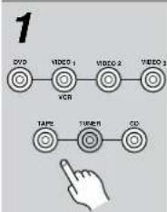
flowchart
graph LR
    A["1"] --> B["DVD"]
    B --> C["VIDEO 1"]
    C --> D["VCR"]
    D --> E["VIDEO 2"]
    E --> F["VIDEO 3"]
    F --> G["TAPPE"]
    G --> H["TIMER"]
    H --> I["CD"]
    I --> J["Hand Icon"]
Press the input selector button for the source that you want to set: [DVD], [VIDEO 1], [VIDEO 2], [VIDEO 3], [TAPE], or [CD].
The name of the selected source appears on the display.

Press the [AUDIO SELECTOR] button.
The current format appears on the display for about three seconds.
3

While the format is being displayed, use the [AUDIO SELECTOR] button to select: Auto, Analog, or Multich (DVD input source only).
While “Auto” is displayed, the name of the digital input currently assigned to the input source (page 24) is displayed in parenthesis. For example, “Auto (COAX).” The possible inputs are OPT1, OPT2, and COAX.
The options are explained below.
Auto: The assigned digital input will have priority over the analog inputs. If no digital signal is present, the analog inputs will be used.
Analog: The analog inputs will be used even if the input source (i.e., AV component) is connected digitally.
Multich: The multi-channel inputs will be used even if the input source is connected digitally.
Notes:
- When you assign an input source to COAX, OPT1, or OPT2 on page 24, if the signal format for that input source was previously set to Analog, it's automatically set to Auto.
- When you assign an input source to “----” on page 24, if the signal format for that input source was previously set to Auto, it’s automatically set to Analog.
Fixing the signal format at DTS or PCM
If you experience either of the following issues when playing DTS or PCM source material with the Auto setting, you can fix the signal format at PCM or DTS, as explained below.
- If the beginnings of tracks from a PCM source are cut off in Auto mode, try fixing the format at PCM.
- If noise is produced when fast forwarding or reversing a DTS format CD or LD in Auto mode, try fixing the format at DTS.
1) To fix the signal format, use the [AUDIO SELECTOR] button, or the remote controller's [AUDIO SEL] button to select Auto.
2) While "Auto" is being displayed, use the PRESET/ADJUST [◀] buttons to select: PCM, DTS, or Auto.
When the digital signal format is fixed at DTS or PCM, only signals in the corresponding format will be output. Digital signals in other formats will be ignored, and the DTS or PCM indicator, depending on which format you have set, will flash.
Using the Multi-Channel Inputs
The multi-channel inputs are for connecting an AV component with individual 5.1-surround analog outputs, such as a DVD player or MPEG decoder.
See “Connecting Your AV Components” on page 13 for connection information.

Press the remote controller's [DVD] input selector button, then [AUDIO SEL] button to select "Multich." Start playback on the AV component.
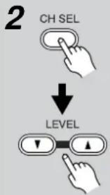
text_image
2 CH SEL ↓ LEVELTo adjust the volume of an individual speaker, use the remote controller's [CH SEL] button to select it, and then use the LEVEL [▲[ ]▼ buttons.
You can adjust the volume level of each individual speaker as you like. For the front-left, front-right, center, surround-left, and surround-right speakers, you can adjust the volume from -12 dB to +12 dB. The subwoofer can be adjusted from -30 dB to +12 dB.
Note that these settings work independently of the individual speaker volume settings on page 27.
Enabling the Tone Controls
To use the Bass and Treble functions with the multi-channel inputs, first you need to enable them. To do this, press the [SURROUND] button. "Tone On" appears on the display. You can now use the [AUDIO ADJUST] button to select the Bass and Treble functions and adjust as explained on page 37. To switch off the Bass and Treble functions, press the [DIRECT] button. "Tone Off" appears on the display.
Notes:
- To use the multi-channel inputs, you must connect an AV component with individual 5.1-surround analog outputs to the TX-SR501/TX-SR501E's multi-channel inputs.
- You can select Multich only when the DVD input source is selected.
- While Multich is selected, you can't select a listening mode. If you select Multich while using a listening mode, the listening mode will be cancelled.
- While Multich is selected, the speaker configuration setting (page 25) is ignored, so even if you have specified two speakers, the multi-channel input signals will be fed to the front-left, front-right, center, surround-left, and surround-right speakers regardless.
- While Multich is selected, the subwoofer mode (page page 25) is ignored, so even if you have specified “Subwoofer Off,” the signal connected to the SUBWOOFER DVD IN will be fed to the SUBWOOFER PRE OUT regardless.
This chapter explains how to use the built-in tuner.
You can store your favorite radio stations as presets for convenient selection.
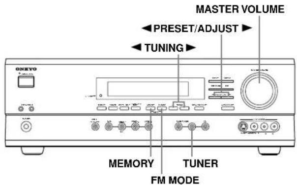
text_image
MASTER VOLUME PRESET/ADJUST TUNING ONEXO MEMORY TUNER FM MODE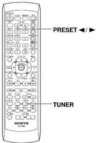
text_image
ONKEYO HOLDEN RESET PRESET TUNER PRESET ◀/► ONKEYO HOLDENSetting the AM Tuning Interval (Worldwide model only)
If you're using the Worldwide model (i.e., your TX-SR501/TX-SR501E has a VOLTAGE SELECTOR on the rear panel), you need to set the AM tuning interval for compatibility with AM broadcasts in your particular country. The initial setting is 9 kHz.
North America: 10 kHz
Other countries: 9 kHz
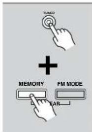
text_image
Touch Screen + MEMORY FM MODE EARTo set the AM tuning interval, while holding down the [TUNER] button, press the [MEMORY] button.
Note:
All presets are deleted when you change this setting.
Tuning into Radio Stations
1

Use the [TUNER] input selector button to select either AM or FM.
In this example, the FM band has been selected.
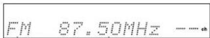
Band
Frequency
2

To adjust the volume, use the MAS-TER VOLUME control.
The volume can typically be set to MIN, 1 though 79, or MAX.
3

Press and hold the TUNING [◀] or [▶] b utton for more than half a second and then release it.
If you selected the FM band:
The AUTO indicator appears on the display and the TX-SR501/TX-SR501E searches for the next station automatically. Searching stops when a station is found, and the TUNED and FM STEREO indicators appear, as shown.
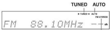
text_image
TUNED AUTO ► TUNED ← AUTO FM STEREO FM 88.10MHz ----+ chFM STEREO
The North American model searches the FM band in 0.1 MHz intervals. For other models it's 0.05 MHz.
If you selected the AM band:
The frequency stops changing when you release the TUNING button. The TX-SR501/TX-SR501E doesn't automatically search for AM stations. You must use the TUNING [◀] [▶] buttons. Press repeatedly to change the frequency one interval at a time, or press and hold to quickly change the frequency. When you're tuned into a station, the TUNED indicator appears.
The North American model steps through the AM band in 10 kHz intervals. For other models it's 9 kHz.
4
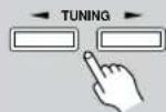
To fine-tune the frequency, use the TUNING [▶] buttons.
If you've selected the FM band, be careful that you don't press either button for more than half a second, otherwise the TX-SR501/TX-SR501E will start searching for the next station.
Tuning into weak FM stations
If the signal strength of the station you are trying to tune into is poor, you may not be able to tune into that station, or reception may be noisy. In this case, press the [FM MODE] button to select mono mode and disable auto-tuning (the AUTO and FM STEREO indicators will go off), and try tuning manually.
Using RDS (European models only)
When tuned into an RDS (Radio Data System) station that's broadcasting PS (Program Service Name) information, the RDS indicator appears, as shown, and the name of the station appears on the display. Only European models support RDS, and only in areas where RDS is used.
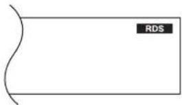
text_image
RDSPresetting Radio Stations
You can store up to 30 of your favorite radio stations as pre-sets.
| 1 | Tune into the station that you want to store as a preset.See “Tuning into Radio Stations” on page 30 for more information. |
 | Press the [MEMORY] button.The preset number flashes. |
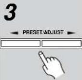 |  In this example, preset #3 has been selected. In this example, preset #3 has been selected. |
4 |  The station is stored and the preset num-ber stops flashing.Repeat this procedure for all of your favorite radio stations. The station is stored and the preset num-ber stops flashing.Repeat this procedure for all of your favorite radio stations. |
Selecting Preset Stations
You can easily select previously stored presets as follows.
| 1 Remote controller TUNER | Use the [TUNER] input selector button to select either AM or FM.In this example, the FM band has been selected. |
| FM 87.50MHz ----ch |
| 2 | Use the [PRESET/ADJUST] [H] ▶ buttons, or the remote controller's PRESET [H] ▶ buttons to select the presets. In this example, preset #3 has been selected. |
| FM 88.10MHz 3ch |
Deleting Presets
You can delete unwanted presets as follows.
| 1 | Select the preset that you want to delete.See the previous section for more information.In this example, preset #3 has been selected. |
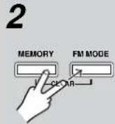 | While holding down the [MEMORY] button, press the [FM MODE] button.The selected preset is deleted and its number disappears from the display, as shown. |
Other Functions:
See page 32 for functions that you can use while listening to the radio.
Listening Modes:
See page 34 for information on the listening modes that you can use while listening to the radio.
This chapter explains functions that can be used with any input source.
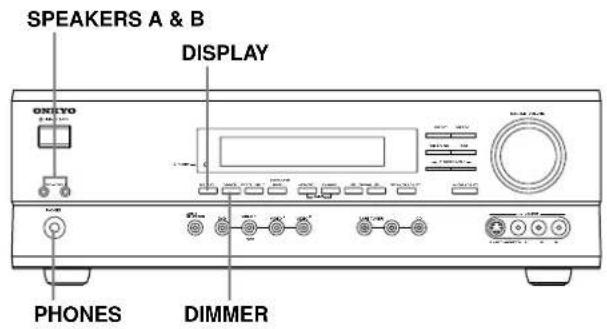
text_image
SPEAKERS A & B DISPLAY OKYO PHONES DIMMER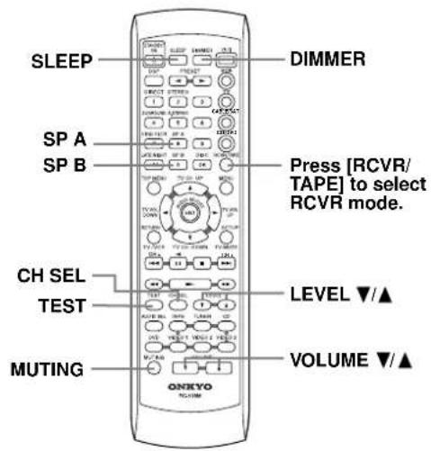
text_image
SLEEP SP A SP B CH SEL TEST MUTING DIMMER Press [RCVR/TAPE] to select RCVR mode. LEVEL ▼/▲ VOLUME ▼/▲Turning Speaker Sets On & Off
You can turn on and off speaker sets A and B individually.
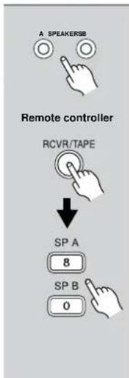
text_image
A SPEAKERSB Remote controller RCVR/TAPE ↓ SP A 8 SP B 0To turn on or off speaker set A, use the SPEAKER [A] button, or the remote controller's [SP A] button.
To turn on or off speaker set B, use the SPEAKER [B] button, or the remote controller's [SP B] button.
Press the remote controller's [RCVR/TAPE] button to select RCVR mode before using the remote controller.
Indicator A lights up when speaker set A is on. Indicator B lights up when speaker set B is on.
A & B speakers indicators
A B
Note:
When you turn on speaker set B, the listening mode for speaker set A is set to Stereo.
Setting the Display Brightness
With this function you can adjust the brightness of the display.

text_image
DIMMER Remote controller DIMMERUse the [DIMMER] button to select: dim, dimmer, or normal brightness.
Displaying Source Information
This section explains how to display information about the currently selected input source.
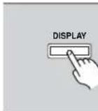
Press the [DISPLAY] button.
Press the [DISPLAY] button repeatedly to cycle through all the information available for the current input source.
When the input source is not AM or FM:
![ONKYO TX-SR501E - Press the [DISPLAY] button. - 1](/content/2026/06/1244103/images/cd9902217ef5ff347277ad49395a5c1e0b3995e9f1d3843811f79e031d0f99ca.jpg)
flowchart
graph TD
    A["Input source & volume"] --> B["DVD"]
    B --> C["25"]
    D["Sound format*"] --> E["Dolby D"]
    E --> F["3/2.1"]
    G["Input source & listening mode"] --> H["DVD"]
    H --> I["Dolby D"]
    I --> J["↑"]
    J --> K["↓"]
    K --> L["↑"]
* If the input signal is analog, no sound format information is displayed. For non-PCM digital sources, the sound format is displayed. This information is displayed for about three seconds, then the previously displayed information reappears.
When the input source is AM or FM:
![ONKYO TX-SR501E - Press the [DISPLAY] button. - 2](/content/2026/06/1244103/images/c3a8ba80d5064160b0b175bbf8229f960079ffae08b8b4fd84231830c77da0ed.jpg)
text_image
Band, frequency & preset # FM 88.10MHz 1 Band & listening mode FM StereoWhen the input source is an RDS radio station broadcasting PS information (European models only):
![ONKYO TX-SR501E - Press the [DISPLAY] button. - 3](/content/2026/06/1244103/images/f84567ba63db431577dcd8b64e36d21fb93bba4f4940fb71aef2c9454b4dea5d.jpg)
text_image
Station name & preset # WDR-R2 1# Band, frequency & preset #* FM 88.10MHz 1# Band & listening mode FM Stereo* This information is displayed for about five seconds, then the previously displayed information reappears.
Muting the TX-SR501/TX-SR501E (remote controller only)
With this function you can temporarily mute the output of the TX-SR501/TX-SR501E.
Remote controller

Press the remote controller's [MUTING] button.
The output is muted and the MUTING indicator flashes on the display, as shown.
![ONKYO TX-SR501E - Press the remote controller's [MUTING] button. - 1](/content/2026/06/1244103/images/889461fbb3d5bcdbcc153cb80dd68407c70a678de2506e61138ef2300ddf0d25.jpg)
![ONKYO TX-SR501E - Press the remote controller's [MUTING] button. - 2](/content/2026/06/1244103/images/8f9acca9f2f5bd3b8391504a2d8788ce6f5b8e574d81e485bf34e060a31ef702.jpg)
To unmute the TX-SR501/TX-SR501E, press the remote controller's [MUTING] button again, or adjust the volume.
The output is unmuted and the MUTING indicator goes off.
Muting is cancelled when the TX-SR501/TX-SR501E is set to Standby.
Adjusting the Speaker Balance Temporarily
With this function you can adjust the volume level of each individual speaker as you like. Unlike the individual speaker volume settings described on page 27, these adjustments can be carried out while listening to your favorite music, and they are temporary (i.e., they are not saved when the TX-SR501/TX-SR501E is set to Standby), although you can save them if you want.
1

Use the remote controller's [CH SEL] button to select each speaker, and use the LEVEL [A[ ]▼ buttons to adjust the volume.
Speakers are selected in the following order: Left → Center → Right → Surr Right → Surr Back → Surr Left → Subwoofer.
You can adjust the volume of each speaker from -12 dB to +12 dB.
The name of the currently selected speaker and its volume appear on the display, as shown.
![ONKYO TX-SR501E - Use the remote controller's [CH SEL] button to select each speaker, and use the LEVEL [A[ ]▼ buttons to adjust the volume. - 1](/content/2026/06/1244103/images/952e09922f80c9688abf9f0daa96db3fa0f2decdfea013593f11629d6460237d.jpg)
To cancel this function, press the [CH SEL] button repeatedly until the previous display appears.
To save your adjustments, updating the settings described on page 27, press the [TEST] button.
Notes:
- Y ou cannot use this function while the TX-SR501/TX-SR501E is muted (see page 33).
- Only speakers that are included in the current configuration can be adjusted. See “Specifying the Number of Speakers” on page 25.
- The subwoofer cannot be selected if the subwoofer mode is set to "Subwoofer Off" (page 25).
Using the Sleep Timer (remote controller only)
With the sleep timer you can set the TX-SR501/TX-SR501E so that it automatically turns off after a set period.
Remote controller

Press the [SLEEP] button repeatedly to select the required sleep time.
You can set the sleep time from 90 to 10 minutes in 10 minute steps.
The SLEEP indicator appears on the display when the sleep timer has been set, as shown. The specified sleep time appears on the display for about five seconds, then the previous display reappears.
SLEEP indicator
![ONKYO TX-SR501E - Press the [SLEEP] button repeatedly to select the required sleep time. - 1](/content/2026/06/1244103/images/59726b72051cf3f0bf3471d8600b98b491665cb0f011730fe216e6c92b88dea4.jpg)
To cancel the sleep timer, press the [SLEEP] button repeatedly until the SLEEP indicator disappears.
To check the remaining sleep time, press the [SLEEP] button. Note that if you press the [SLEEP] button while the sleep time is being displayed, you'll shorten the sleep time by 10 minutes.
Using Headphones
You can connect a pair of stereo headphones (1/4-inch phone plug) to the TX-SR501/TX-SR501E's PHONES jack for private listening, as shown.

natural_image
Line drawing of an orange headphones connected to a small electronic device labeled 'ONEXO' (no text or symbols on the devices themselves)Notes:
- A lways turn down the volume before connecting your headphones.
- Speaker sets A and B are turned off while the headphones plug is inserted in the PHONES jack.
- When you connect a pair of headphones to the TX-SR501/TX-SR501E, the listening mode is set to Stereo, unless it's already set to Stereo or Direct. When you disconnect the headphones, the previous listening mode is selected.
- When you use the multi-channel inputs, only the front-left and front-right channels can be heard in the headphones.
With its built-in surround-sound decoders and DSP programs, the TX-SR501/TX-SR501E can transform your home listening room into a movie theater or concert hall.
To get the most from surround sound, it's important that you install and configure your speakers correctly. See “Installing Your Speakers” on page 20 and “Configuring Speaker Set A” on page 26 for information.
About the Listening Modes
The TX-SR501/TX-SR501E provides a number of listening modes for use with various types of source material, including Dolby Digital, DTS, Pro Logic II, and Neo:6. In addition, you can use the special Onkyo DSP programs, Orchestra, Unplugged, and so on, to add surround effects to stereo sources.
Listening mode availability depends on the format of the currently selected input signal. For example, the Dolby Digital listening modes are available only while a Dolby Digital format signal is being received. Likewise, the DTS listening modes are available only while a DTS format signal is being received.
The following table lists all the possible listening modes and indicates which modes can be selected for each source format. The “Speakers” column lists the minimum number of speakers (excluding subwoofer) necessary to use each mode. The adjacent diagram graphically indicates which speakers are actually used in that mode. If you use less than the minimum number of speakers, some modes will not be available.
See page 20 for information on connecting the necessary speakers, and see page 25 for information specifying the number of speakers connected.
| Source format | Analog/PCM | 96 kHzPCM | Dolby Digital DTS | |||||
| Listening mode Speakers* 2-channel Others 5.1.0.1 | ||||||||
| Direct | 2 | □□○□□□ | √ | √ | ||||
| Stereo | 2 | □□●□□□ | √ | √ | √ | √ | √ | √ |
| PL II Movie(Pro Logic II Movie) | 3 | ■□●□□● | √ | √ | ||||
| PL II Music(Pro Logic II Music) | 3 | ■□●□□● | √ | √ | ||||
| Neo: Cinema(DTS Neo:6 Cinema) | 3 | ■□●□□● | √ | |||||
| Neo: Music(DTS Neo:6 Music) | 4 | ■□●□□● | √ | |||||
| Dolby D(Dolby Digital) | 3 | □□● | √ | √ | ||||
| Dolby D EX(Dolby Digital EX) | 6 | □□● | √ | √ | ||||
| DTS | 3 | □□● | √ | √ | √ | |||
| DTS-ES | 6 Matrix 6.1 Discrete 6.1 | |||||||
| Orchestra | 4 | □□● | √ | |||||
| Unplugged | 4 | □□● | √ | |||||
| Studio-Mix | 4 | □□● | √ | |||||
| TV Logic | 4 | □□● | √ | |||||
| All Ch St | 4 | □□● | √ | |||||
* This is the minimum number of speakers (excluding subwoofer) necessary to use each mode.
The adjacent diagrams graphically indicate which speakers are actually used in each mode: black means used, white means not used.

text_image
Center Front left Front right Subwoofer Sur left Sur back Sur rightThe listening modes are explained below.
Basic Modes
Direct: The selected input source is fed directly to the power-amp stages and through to the front left and right speakers with minimal processing. Use this mode when watching an old movie that has a mono soundtrack, when listening to either the left or right channel of multilingual material, or when playing a DVD or other source that has multiplexed audio, such as a karaoke DVD.
Stereo: The selected input source is processed as a stereo signal and output by the front left and right speakers and subwoofer. Use this mode when listening to stereo sources.
Surround Modes
Pro Logic II Movie: Dolby Pro Logic II Movie mode decoding for 5.1 surround.

Use this mode with DVDs and videos that bear the Dolby Surround logo or TV programs that feature Dolby Surround. You can also use this mode with stereo movies or TV programs and the TX-SR501/TX-SR501E will create a 5.1 surround mix.
Pro Logic II Music: Dolby Pro Logic II Music mode. Use this mode to add 5.1 surround to stereo sources such as music CDs.
DTS Neo:6 Cinema: DTS Neo:6 Cinema mode. This mode is intended for use with movies, providing surround sound with a realistic sense of movement. Use this mode to add 6.1 surround to stereo movies, videos, and TV programs.
DTS Neo:6 Music: DTS Neo:6 Music mode. This mode uses the surround channels to create a natural sound field that cannot be produced with conventional stereo. Even with two-channel music, a natural sound field can be produced from the surround channels. Use this mode to add 6.1 surround to stereo sources such as music CDs.
Dolby Digital: Dolby Digital decoding with up to 5.1 channels. With this format you can experience the same superb sound that you get at a m or concert hall. Use this mode with DVDs that be Digital logo.

Dolby Digital EX: Dolby Digital EX decoding with up to 6.1 channels. With an added sur-

round-back channel, this 6.1 channel format offers a heightened sense of space, for added realism with moving sounds such as those that rotate 360 degrees or pass overhead. Dolby Digital EX material can also be played on conventional 5.1 channel systems, in which case the surround-back channel sound is divided between the left and right surround channels. Use this mode with DVDs that have a 5.1-channel soundtrack and bear the Dolby Digital logo.
DTS: DTS decoding with up to 5.1 channels. This digital surround format offers a surround sound experience with exceptional fidelity. It's com-

pressed digital audio data, with six completely separate channels (5.1), and the ability to handle large amounts of audio data while remaining faithful to the original. DTS provides very high-quality sound. You'll need a DTS compatible DVD player in order to enjoy DTS material. Use this mode with DVDs, LDs, or CDs that bear the DTS logo.
- When listening to DTS material, using the pause, fast forward, or reverse functions on your DTS-compatible player may produce a short audible noise. This is normal.
- When DTS material ends and the DTS signal transmission stops, the TX-SR501/TX-SR501E remains in DTS listening mode, and the DTS indicator remains on. This is to prevent noise when you use the pause, fast forward, or reverse functions on your DTS-compatible player. If you switch your player from DTS to PCM, because the TX-SR501/TX-SR501E does not switch formats immediately, you may not hear any sound, in which case you should stop your player for about 3 seconds, and then restart playback.
- With some CD and LD players, you won't be able to play-back DTS material properly even though your player is connected to a digital input on the TX-SR501/TX-SR501E. This is usually because the digital signal has been processed (e.g., output level, sampling rate, or frequency response changed) and the TX-SR501/TX-SR501E cannot recognize the signal as a genuine DTS signal. In such cases, you may hear noise.
- The TX-SR501/TX-SR501E's TAPE OUT and VIDEO 1 OUT connectors output only analog audio, so don't try and record a DTS CD or LD from these outputs because all you'll get is noise.
DTS-ES: DTS-ES decoding with up to 6.1 channels. Use this mode with DVDs, LDs, or CDs that bear the DTS-ES logo. The TX-SR501/TX-SR501E supports both DTS-ES Discrete 6.1 and DTS-ES Matrix 6.1.
Discrete 6.1 is for use with material encoded in the DTS 6.1 format. With an additional surround-back channel, each 6.1 channel is digitally recorded for a realistic sense of movement and space. You can enjoy this format with CDs, DVDs, or LDs that bear the DTS-ES logo.
Matrix 6.1 allows you to play DTS 5.1 material on a 6.1 channel system. Since DTS 5.1 material includes information about the surround-back channel, channels can be reconstructed for playback on a 6.1 channel system. You can enjoy this format with CDs, DVDs, or LDs that bear the DTS logo.


DSP Modes
Orchestra: Suitable for classical or operatic music. The center speaker is turned off and the surround channels are emphasized in order to widen the stereo image. In addition, it simulates the natural reverberation of a large hall.
Unplugged: Suitable for acoustic instrument sounds, vocals, and jazz music. By emphasizing the front stereo image, it simulates the stage-front experience.
Studio-Mix: Suitable for rock and pop music. Listening to music in this mode creates a lively soundfield with a powerful acoustic image, like being at a club or rock concert.
TV Logic: Adds realistic acoustics to TV programs produced in a TV studio. In addition, it adds surround effects to the entire sound and adds clarity to voices.
All Ch St (All Channel Stereo): Ideal for background music. The front, surround, and surround-back channels create a stereo image that fills the entire listening area.
Selecting the Listening Modes
You can select the listening modes by using the following buttons: [DIRECT], [STEREO], [SURROUND], [DSP], and [A.STEREO] (the last button is available only on the remote controller).

Listening mode availability depends on the format of the currently selected input signal and the number of speakers that you are using. If you use less than the minimum number of speakers, some modes will not be available. See “About the Listening Modes” on page 34 for more information.
Notes:
- You cannot select a listening mode when the Multich input source is selected. See "Using the Multi-Channel Inputs" on page 29.
- While speaker set B is on, or a pair of headphones are plugged in, you can only select the Direct or Stereo listening mode.
The options for each button are explained below:
[DIRECT] button
- This button selects the Direct listening mode, which can be used with PCM, analog, and 96 kHz PCM sources.
[STEREO] button
- This button selects the Stereo listening mode, which can be used with any source format.
[SURROUND] button
- With PCM and analog sources, you can select the Pro Logic II Movie, Pro Logic II Music, DTS Neo:6 Cinema, and Neo:6 Music listening modes.
- With Dolby Digital 2-channel sources, you can select the Pro Logic II Movie and Pro Logic II Music listening modes.
- With Dolby Digital sources with more than two or three channels, you can select the following:
On: Dolby Digital EX listening mode.
Off: Dolby Digital listening mode.
Auto: If the source signal contains an EX flag, which is an identification code for Surround EX, the Dolby Digital EX listening mode is selected automatically. If not, the Dolby Digital listening mode is used.
These options appear only if you're using, and have specified four or more speakers (see page 25). If you are using fewer speakers, the Dolby Digital listening mode is used.
• W ith DTS sources, you can select the following:
On: If the source signal contains a DTS-ES flag, which is an identification code for DTS-ES, the DTS-ES Discrete 6.1 or DTS-ES Matrix 6.1 listening mode is selected automatically. If not, DTS-ES Matrix 6.1 is used.
Off: The DTS listening mode is used for all DTS sources, even if a DTS-ES flag is present.
Auto: If the source signal contains a DTS-ES flag, the DTS-ES Discrete 6.1 or DTS-ES Matrix 6.1 listening mode is selected automatically. If not, the DTS mode is used.
These options appear only if you're using, and have specified four or more speakers (see page 25). If you are using fewer speakers, the DTS listening mode is used.
[DSP] button
The remote controller's [DSP] button works differently to the TX-SR501/TX-SR501E's [DSP] button.
- TX-SR501/TX-SR501E [DSP] button: You can select the following Onkyo DSP modes: Orchestra, Unplugged, Studio Mix, TV Logic, and All Ch St.
- Remote controller's [DSP] button: You can select all of the currently available listening modes (basic, surround, and DSP). You can use this button even when a remote controller mode other than RCVR/TAPE is selected (see page 40).
[A.STEREO] button
The button selects the All Ch St listening mode. (This button is available only on the remote controller).
Using the Audio Adjust Functions
These functions only work with speaker set A.
Audio Adjust provides various functions for adjusting the sound, including several especially for use with Dolby Digital, DTS, and Pro Logic II material.
The following table lists the Audio Adjust functions, their ranges and default values. Function availability depends on the current source and listening mode, as listed in the “Supported listening mode” column. See page 34 for information on listening modes.
| Function | Range Default | Supported listening mode | |
| Bass -12 dB to +12 dB in 2 dB steps | 0 dB | All modes except Direct | |
| Treble | |||
| Late Night | Low, High, Off | Off | Dolby D |
| Cinema Filter (Cine Fltr) | On, Off | PL II Movie Dolby D/Dolby D EX DTS/DTS-ES Neo:6 Cinema | |
| Center Image | 0, 1, 2, 3, 4, 5 3 | Neo:6 Music | |
| Panorama | On, Off Off | PL II Music | |
| Dimension | 0, 1, 2, 3, 4, 5, 6 | 3 | |
| Center Width | 0, 1, 2, 3, 4, 5, 6, 7 | ||

text_image
PRESET/ADJUST OXEGO Nurses AUDIO ADJUST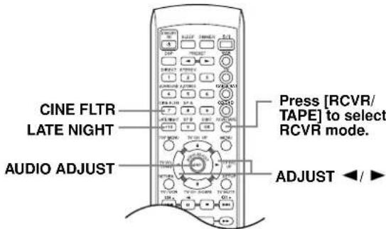
text_image
CINE FLTR LATE NIGHT AUDIO ADJUST Press [RCVR/ TAPE] to select RCVR mode. ADJUST ←/ ►1

Remote controller
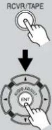
Use the [AUDIO/ADJUST] button to select a function.
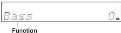
text_image
Pass Function U dBNote:
Before pressing the remote controller's [AUDIO/ADJUST] button, press its [RCVR/TAPE] button to select RCVR mode.
2
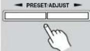
Remote controller
Use the [PRESET/ADJUST] ◀▶ buttons on the TX-SR501/TX-SR501E, or the ADJUST ◀▶ buttons on the remote controller to set the selected function.
Note:
The Cinema Filter and Late Night functions can be controlled from the remote controller by using the dedicated [CINE FLTR] and [LATE NIGHT] buttons. First press the remote controller's [RCVR/TAPE] button to select RCVR mode, then press [CINE FLTR] or [LATE NIGHT] to display the current setting; press again to change it.
The Audio Adjust functions are explained below.
■ Bass
With this function you can boost or cut low-frequency sounds output by the front speakers from -12 dB to +12 dB in 2 dB steps.
■ Treble
With this function you can boost or cut high-frequency sounds output by the front speakers from -12 dB to +12 dB in 2 dB steps.
■ Late Night (Dolby Digital)
With this function you can reduce the dynamic range of Dolby Digital material so that you can still hear quiet parts even when listening at low volume levels—ideal for watching movies late at night when you don't want to disturb anyone.
Late Night=Off......no effect
Late Night=Low......small reduction in dynamic range
Late Night=High ......big reduction in dynamic range
Note that the impact of the Late Night function depends on the Dolby Digital material that you are playing, and with some material there will be little or no effect.
This function is automatically cancelled when you set the TX-SR501/TX-SR501E to Standby.
■ Cinema Filter
With this function, you can soften the harshness, or brightness sometimes experienced with movie soundtracks, which are typically mixed for reproduction in a movie theater.
■ Center Image (DTS Neo:6 Music)
The DTS Neo:6 surround format derives its center-channel signal from stereo material, either analog or digital. In Music mode, the center speaker is intended to augment the left and right speakers, allowing them to faithfully reproduce the original stereo mix. For this reason, the center channel sound is not fully subtracted from the left and right channels. With this function, you can adjust the amount of subtraction depending on your room layout and personal preference.
Center Image: 5......nothing is subtracted from the left and right channels.
Center Image: 0......the left and right channel levels are halved (−6 dB), making the center channel more dominant, particularly useful when the listener is off-center.
This function has no effect on the level of the center speaker.
■ Panorama (Pro Logic II Music)
With this function, you can extend the front stereo image to the surround speakers to provide a “wraparound” effect, especially useful when not much sound is being output by the surround speakers.
■ Dimension (Pro Logic II Music)
With this function, you can move the soundfield backward or forward.
Dimension: 3...... the soundfield is in the normal position.
Choose a lower setting to move the soundfield forward.
Choose a higher setting to move it backward.
If the stereo image is too wide, or there's too much surround information, try moving the soundfield forward to achieve a better balance. If the stereo image is too narrow, or it sounds almost like it's in mono, try moving the soundfield backward.
■ Center Width (Pro Logic II Music)
In Pro Logic II decoding, the center-channel signal is output by the center speaker. If a center speaker is not used, the decoder divides the center signal equally between the front left and right speakers, producing what's known as a "phantom" center. With this function you can choose to have the center-channel signal output by only the center speaker, by only the front left and right speakers ("phantom" center), or by a mix of the two.
Center Width: 0...... the center-channel signal is output only by the center speaker.
Center Width: 7...... it's output only by the front left and right speakers ("phantom" center).
In home theaters, adding some width to the center channel can improve the balance between the center and front left and right speakers. Most stereo material will benefit from appropriate use of this function.
This chapter explains how to record the selected input source to an AV component with recording capability, and how to record audio and video from two different sources.
Recording the Input Source
You can record only to AV components that are connected to the TAPE OUT or VIDEO 1 OUT connectors.
See pages 10–19 for information on connecting your AV components to the TX-SR501/TX-SR501E.
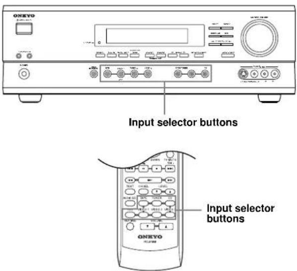
text_image
ONEXO Input selector buttons ONEXO| 1 | Use the following input selector buttons to select the AV component that you want to record. |
| Audio signals from the selected input source are output by the VIDEO 1 OUT and TAPE OUT connectors. | |
| Remote controller | You can listen to the source while recording. The TX-SR501/TX-SR501E's VOLUME control has no effect on recording. |
| 2 | Start recording on the AV component connected to the TAPE OUT or VIDEO 1 OUT connectors. |
| 3 | Start playback on the source AV component. |
Notes:
- You cannot record from AV components that are connected to the digital inputs. You must use analog connections.
- The surround effects produced by the surround and DSP listening modes cannot be recorded.
- Y ou cannot record from an AV component that is connected to the multi-channel inputs.
- If you select another input source while recording, that input source will be recorded instead.
Recording from Different AV Sources
With this function you can record audio and video from different sources, allowing you to overdub audio onto your video recordings. This function takes advantage of the fact that when an audio-only input source (i.e., TAPE, TUNER, or CD) is selected, the video input source remains unchanged. For example, if you first select the VIDEO 3 input source, followed by the CD input source, you can watch the video from the VIDEO 3 input and listen to the audio from the CD input.
In the following example, audio from the CD player connected to the CD IN connectors, and video from the video camera connected to the VIDEO 3 INPUT VIDEO connector are recorded onto the VCR, which is connected to the VIDEO 1 OUT connectors.
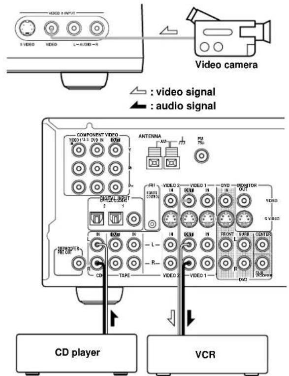
text_image
VIDEO 3 INPUT 3 VIDEO VIDEO L-AUDIO-R Video camera : video signal : audio signal COMPONENT VIDEO VIDEO 12.5 DVD IN ANTENNA FM 750 DIGITAL INPUT 2 1 FVI HUNTIL CONTROL VIDEO 2 IN VIDEO 1 DVD MONITOR OUT VIDEO S VIBED L IN IN IN FRONT SURR CENTER L R R R R R CD TAPE VIDEO 2 VIDEO 1 DVD CD player VCR- Prepare the camera and CD player for playback.
- Prepare the VCR for recording.
- Press the [VIDEO 3] input selector button.
- Press the [CD] input selector button.
This selects the CD player as the audio source, but leaves the video camera as the video source.
- Start recording on the VCR and start playback on the video camera and CD player.
The video from the camera, and the audio from the CD player are recorded by the VCR.
Notes:
- Y ou cannot record audio from an AV component that is connected digitally. You must use an analog connection.
- The surround effects produced by the surround and DSP listening modes cannot be recorded.
- If you select another input source while recording, that input source will be recorded instead.
Using the Remote Controller RC-479S with Your Other AV Components
RC-479S (not North America)
Connecting your Rbmppatible Onkyo CD player, DVD player, or cassette recorder to the TX-SR501/TX-SR501E via Rllows you to control it with the TX-SR501/TX-SR501E's remote controller. Since you only need to point the remote controller at the TX-SR501/TX-SR501E, you can control components that are out of sight, for example, in a cabinet. See page 19 for connection information.
Note:
- To use the function, you must make an connection and an analog RCA/phono connection between the AV component and your TX-SR501, even if they are connected digitally.
Using the RC-479S
1 Point the remote controller at the TX-SR501/TX-SR501E and use the input selector buttons to select an input source for the TX-SR501/TX-SR501E.
2 Use the remote controller's mode buttons (i.e., [DVD], [CD], or [RCVR/TAPE]) to select a remote controller mode. (You don't have to point the remote controller at anything for this step.)
3 Point the remote controller at the TX-SR501/TX-SR501E and press the Power [button to turn on the AV component. (A cassette recorder can't be turned on or off from the remote controller. However, pressing the remote controller's Play button will turn it on and start playback.)
4 Use the buttons as explained below. In the following illustrations, buttons that control the TX-SR501/TX-SR501E regardless of which mode is selected are shaded.
| DVD mode CD mode Tape mode* | ||
| 3. 0/1 2. DVD 4. DVD control buttons 1. DVD input selector | 3. 0/1 2. CD 4. CD control buttons 1. CD input selector | 2. RCVR/TAPE 3. Tape control buttons 1. Tape input selector |
| Power on/off | ||
| Start playback Play side A (front-facing side) | ||
| Stop playback, fast forward, or fast reverse Stop playback, recording, fast forward, or rewind | ||
| Fast forward | ||
| Fast reverse Rewind | ||
| Pause playback | Play side B (rear-facing side) | |
| Go to next chapter or track | * Since this is RCVR/TAPE mode, you can control the cassette recorder and fully control the TX-SR501/TX-SR501E at the same time. | |
| Go to beginning of current chapter or track | ||
| Select a disc (DVD/CD changers only) | ||
| Enter numbers | ||
| Display the disc's main menu | ||
| Display the last sub-menu | ||
| Return to previous menu | ||
| Display setup menu | ||
| Select menu items | ||
| Go to selected menu item | ||
Using the Remote Controller RC-518M with Your Other AV Components
RC-518M (North America only)
Connecting your R compatible Onkyo CD player, DVD player, or cassette recorder to the TX-SR501 via R allows you to control your system with the TX-SR501's remote controller by pointing it at the TX-SR501. This allows you to control components that are out of sight, for example, in a cabinet. Since you don't have to enter any special codes, or do any programming, R allows you to control these components quickly and easily. See page 19 for connection information. See page 42 for operating information.
In addition, you can control an AV component made by another manufacturer by entering the appropriate manufacturer's code into the remote controller.
Note:
- To use the function, you must make an connection and an analog RCA/phono connection between the AV component and your TX-SR501, even if they are connected digitally.
Entering the Manufacturer's Code
If you're using an Onkyo CD player connected to the TX-SR501's Rconnector, an Onkyo AV component without an Rconnection, or an AV component made by another manufacturer, do the following.
| 1 | Determine the appropriate manufacturer’s code from the following list.Where several codes are listed, try the first one, and if that doesn’t work, try the others until you find one that does. |
| 2 | While holding down the remote controller’s [VCR], [TV], [CABLE/SAT], or [CD/DVD] button, press the [ENT] button.For the [CD/DVD] button, you can enter a CD code or DVD code, not both. And for the [CABLE/SAT] button, a Cable code or Satellite code, not both. |
| 3 | Within 10 seconds, use the remote controller’s number buttons to enter the manufacturer’s code. |
| 4 | Check to see if you can control the AV component from the remote controller. |
If it works as expected, the code has been entered correctly. If not, go back to step 3 and try again.
Note that with some manufacturer's AV components, some of the remote controller's buttons may not work as expected.
By default, the [CD/DVD] button is set to code 316, which is for use with an Rcompatible Onkyo DVD player connected to the TX-SR501's Rconnector. To control an Rcompatible Onkyo CD player connected to the TX-SR501's Rconnector, you must enter code 300. To control an Onkyo DVD player without an RI connection, you must enter either code 301 or 313. The [CD/DVD] button can be used with only one AV component.
| Manufacturer TV VCR DVD Cable Satellite | |||||
| AIWA 137 | |||||
| AKAI 227 | |||||
| DENON 302 | |||||
| ECHOSTAR | 500 | ||||
| EMERSON | 228 | ||||
| FISHER | 200 | 100, 101, 102, 140 | |||
| GE 103, 104 | |||||
| GE • PANA 201, | 202 | ||||
| GE • RCA | 203 | ||||
| GEMINI | 401 | ||||
| GENERAL INSTRUMENT | 501 | ||||
| G.I. | 400 | ||||
| GO VIDEO | 105, 106, 107 | ||||
| GOLD STAR | 204, 205 | 108 | |||
| HAMLIN | 402, 403, 404, 405 | ||||
| HITACHI | 206, 207 | 103, 109 | 303 | 502 | |
| HUGHES NETWORK SYSTEM | 503 | ||||
| JERROLD | 406, 407, 408, 409, 410, 411, 412, 413, 414 | ||||
| JVC | 208 | 110, 111, 112, 113 | 304 | ||
| KENWOOD | 305 | ||||
| MACOM | 415, 416, 417 | ||||
| MAGNAVOX | 209, 210 | 114, 115, 116 | 306 | 418 | |
| MARANTZ | 211 | 307 | |||
| MITSUBISHI | 117, 118, 119, 120, 121, 139 | 308 | |||
| NEC | 136 | ||||
| OAK | 419, 420, 421 | ||||
| ONKYO | 301, 313, 316 (for RI DVD), 300 (for CD) | ||||
| PANASONIC | 212, 213 | 122, 123 | 309 | 422, 423 | 504, 505, 506 |
| PHILIPS | 214 114 | 424, 425, 426, 427, 428, 429 | |||
| PIONEER | 215 | 310 | 430, 431 | ||
| PRIMESTAR | 507 | ||||
| PROSCAN | 216 | 311 | 508, 509, 510 | ||
| RCA | 217, 218, 219, 220, 229, 230 | 109 311 | 508, 509, 510 | ||
| S.ATLANTA | 432, 433, 434 | ||||
| SAMSUNG | 221, 222 | 124, 125, 126 | 304 | 435 | |
| SHARP | 223 | 127, 128 | |||
| SHINTOM | 138 | ||||
| SONY | 224 | 129, 130, 131, 132, 133, 141 | 312 | 511 | |
| TOCOM | 436 | ||||
| TOSHIBA | 134 313 | 512 | |||
| YAMAHA | 314 | ||||
| ZENITH 225, 226 | 135 315 | 437, 438 | |||
Using the RC-518M
If you need to enter the manufacturer's code for your AV component into the remote controller, see page 41.
| 1 | Point the remote controller at the TX-SR501 and use the input selector buttons to select an input source for the TX-SR501. |
| 2 | Use the remote controller's mode buttons (i.e., [VCR], [TV], [CABLE/SAT], [CD/DVD], or [RCVR/TAPE]) to select a remote controller mode.(You don't have to point the remote controller at anything for this step.) |
3
Use the remote controller's Power [J]/putton to turn on the AV component.
Remember, if your AV component is connected to the TX-SR501 via a point the remote controller at the TX-SR501. If not, point the remote controller at the AV component.
(A cassette recorder can't be turned on or off from the remote controller. However, pressing the remote controller's Play ▶ button will turn it on and start playback.)
4
Use the buttons as explained below.
In the following illustrations, buttons that control the TX-SR501 regardless of which mode is selected are shaded.
| DVD mode*1 | CD mode*1 | Tape mode2 | |
 You must enter the appropriate manufacturer's code for your DVD player (see page 41). You must enter the appropriate manufacturer's code for your DVD player (see page 41). | 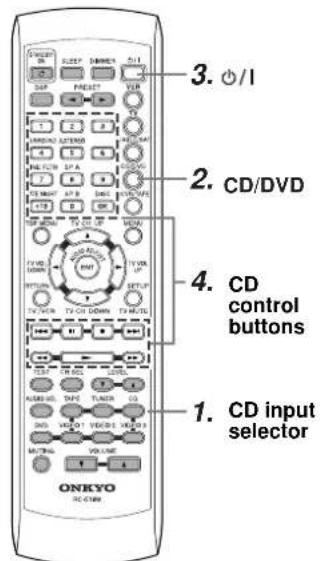 CD mode can be used only with an Onkyo CD player, and you must enter the appropriate Onkyo CD player code (see page 41). CD mode can be used only with an Onkyo CD player, and you must enter the appropriate Onkyo CD player code (see page 41). | 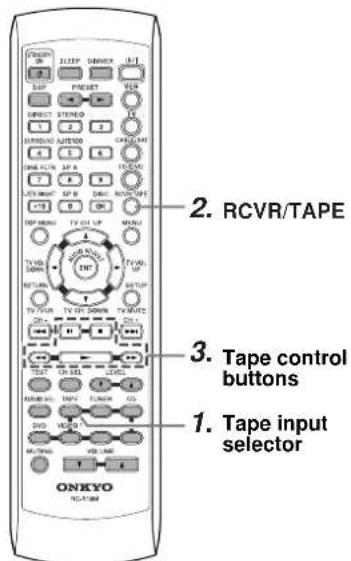 | |
| ∅/I | Power on/off | ||
| ▶ | Start playback Play side A (front-facing side) | ||
| ■ | Stop playback Stop playback, fast forward, or fast reverse | Stop playback, recording, fast forward, or rewind | |
| ▶▶ | Fast forward | ||
| ◀◀ | Fast reverse Rewind | ||
| ■■ | Pause playback Play side B (rear-facing side) | ||
| ▶▶■ | Go to next chapter or track | *2 Since this is RCVR/TAPE mode, you can control the cassette recorder and fully control the TX-SR501 at the same time. | |
| ◀◀◀ | Go to beginning of current chapter or track | ||
| DISC Select a disc (DVD/CD changers only) | |||
| 1-9, +10, 0 Enter numbers | |||
| TOP MENU Display the disc's main menu | *1 Since you can only enter a CD code or DVD code for the [CD/DVD] button, you can use CD mode or DVD mode, but not both. | ||
| MENU | Display the last sub-menu | ||
| RETURN | Return to previous menu | ||
| SETUP | Display setup menu | ||
| ▲/▼/◀/▶ | Select menu items | ||
| ENT | Go to selected menu item | ||

text_image
VCR mode TV mode You must enter the appropriate manufacturer's code (see page 41). You must enter the appropriate manufacturer's code (see page 41). 3. ○/1 2. VCR Control TV if appropriate TV code has been entered 1. Input Selectors 4. VCR control buttons 3. TV control buttons 2. ○/1 1. TV Control VCR if appropriate VCR code has been entered| ⏻/l | Power on/off | |
| 1-9, +10, 0 Enter numbers | ||
| OK Confirm | ||
| TV CH UP ▲ | Select next received channel Select next TV channel | |
| TV CH DOWN ▼ | Select previous received channel Select previous TV channel | |
| TV VOL UP ▶ | Raise TV volume | |
| TV VOL DOWN ◀ | Lower TV volume | |
| TV/VCR Switch TV/VCR inputs | ||
| TV MUTE Mute the sound | ||
| ▶ | Start playback | |
| ■ | Stop playback, recording, fast forward, or rewind | |
| ▶▶ | Fast forward | |
| ◀◀ | Rewind | |
| ▶▶▶ | Select next VCR channel | |
| ◀◀◀ | Select previous VCR channel | |
| ■■ | Pause playback | |


text_image
Cable mode* Satellite mode* You must enter the appropriate manufacturer's code (see page 41). You must enter the appropriate manufacturer's code (see page 41). 3. ○/| 2. CABLE/SAT 4. Cable control buttons 1. Input Selectors 4. Satellite control buttons 3. ○/| 2. CABLE/SAT 1. Input Selectors| /1 | Power on/off | |
| 1-9, 0 Enter numbers | ||
| CH+ Select next channel Select next channel preset | ||
| CH- Select previous channel Select previous channel preset | ||
| MENU Display menu | ||
| ▲/▼★▶ | Select menu items | |
| ENT Confirm | ||
* Since you can only enter a Cable code or Satellite code for the [CABLE/SAT] button, you can use Cable mode or Satellite mode, but not both.
Amp
| Symptom Possible cause Remedy | |||
| Can't turn on the TX-SR501/TX-SR501E? | The power cord is not connected. | Connect the power cord to a suitable wall outlet (page 24). | |
| The [POWER] switch is set to OFF (TX-SR501E only). | Set the [POWER] switch to ON (page 24). | ||
| External interference is affecting the TX-SR501/TX-SR501E's digital circuitry. | Turn off the TX-SR501/TX-SR501E, wait five seconds, then try turning it on again. If that fails, disconnect the power cord from the wall outlet, wait five seconds, reconnect it, then try turning it on again. | ||
| The TX-SR501/TX-SR501E shuts down immediately after being turned on? | The amp protection system has been activated. | Contact your Onkyo dealer. | |
| The buttons on the TX-SR501/TX-SR501E and remote controller don't work? | Power supply voltage fluctuations and other anomalies, such as static electricity, can interfere with normal operation. | Turn off the TX-SR501/TX-SR501E, wait five seconds, then try turning it on again. If that fails, disconnect the power cord from the wall outlet, wait five seconds, reconnect it, then try turning it on again. | |
| There's no sound coming from the speakers? | The TX-SR501/TX-SR501E is muted. Unmute the TX-SR501/TX-SR501E (page 33). | ||
| The TX-SR501/TX-SR501E is not connected properly. | Check your connections. | ||
| If your turntable doesn't have a built-in phono preamp, you must connect one between your turntable and the TX-SR501/TX-SR501E. | |||
| If your turntable uses an MC cartridge, you must use a compatible phono preamp. | |||
| The speaker cables are not connected properly. | Check the speaker connections (page 21). | ||
| The wrong input source is selected. Select the correct input source (page 28). | |||
| A pair of headphones are connected. Disconnect the headphones (page 33). | |||
| The input signal format is set to PCM or DTS. Set the input signal format to Auto (page 29). | |||
| The volume is set at minimum. Turn up the volume (page 28). | |||
| The speakers are configured incorrectly. Check the speaker configuration (page 25). | |||
| Some speakers are not used with certain listening modes. | See page 34 for information on listening modes. | ||
| A connecting cable may be damaged. | Check your connecting cables for signs of damage and replace as necessary. | ||
| Only the front speakers are working? | The Stereo listening mode is selected. | In Stereo listening mode, only the front speakers and subwoofer are used (page 34). | |
| The center speaker is not working or is very quiet? | The center speaker is not connected properly. | Check the center speaker connections (page 21). | |
| The Stereo, Direct, or Orchestra listening mode is selected. | The center speaker is not used with these modes (page 34). | ||
| The volume of the center speaker is set at minimum. | Check the volume of the center speaker (page 27). | ||
| The currently selected speaker configuration doesn't use the center speaker. | Check the speaker configuration (page 25). | ||
| Only the center speaker is working? | You're listening to a mono sound source (e.g., TV or AM broadcast) and the PL II MOVIE or PL II MUSIC listening mode is selected, so the sound is concentrated in the center speaker. | Select another listening mode (page 34). | |
| The surround speakers are not working? | The surround speakers are not used with certain listening modes. | See page 34 for information on listening modes. | |
| Surround speaker output depends on the source material. Some material may not use the surround speakers much. | |||
| The volume of the surround speakers is set at minimum. | Check the volume of the surround speakers (page 27). | ||
| The currently selected speaker configuration doesn't use the surround speakers. | Check the speaker configuration (page 25). | ||
| Symptom Possible cause Remedy | |||
| Amp | A low-frequency noise or hum can be heard? | The audio connecting cables at the rear of the TX-SR501/TX-SR501E are too close to the power cord. | Untangle the audio cables and position them as far away as possible from the power cord. |
| The sound is too bright or harsh and the high range is not clear. | The Treble function is set too high. Adjust the Treble function (pages 29, 37). | ||
| The subwoofer is not working or is very quiet? | The subwoofer mode is set to OFF or is set incorrectly. | Check the subwoofer mode (page 25). | |
| The volume of the subwoofer is set at minimum. | Check the volume of the subwoofer (page 27). | ||
| Subwoofer output depends on the source material. Some material may not use the subwoofer much. | |||
| There's no picture on the TV or monitor? | The TV's input selector is set incorrectly. | Select the correct input on the TV (i.e., the input to which the TX-SR501/TX-SR501E is connected). | |
| The video cable is not connected properly. | Check your video cables and connections (pages 10–19). | ||
| The video input and output are different formats. | The TX-SR501/TX-SR501E doesn't convert between video formats. It works as a video signal switcher. Composite video input signals are output only by composite video outputs. S-Video input signals are output only by S-Video outputs. And component video input signals are output only by component video outputs. | ||
| Can't hear an AV component? | The wrong input source is selected. Select the correct input source (page 28). | ||
| Remote controller | The buttons on the TX-SR501/TX-SR501E work OK but those on the remote controller don't? | The wrong remote controller mode is selected. Select the correct mode (page 9). | |
| There are no batteries in the remote controller. Install new batteries (page 5). | |||
| The batteries are flat. Replace with new batteries (page 5). | |||
| The batteries are installed incorrectly. | Check the batteries and correct as necessary (page 5). | ||
| You're not pointing the remote controller at the TX-SR501/TX-SR501E's remote sensor. | Point the remote controller at the TX-SR501/ TX-SR501E's remote sensor (page 5). | ||
| You're too far away from the TX-SR501/ TX-SR501E. | Use the remote controller closer to the TX-SR501/ TX-SR501E (page 5). The remote controller has a range of approximately 16 ft. (5 meters). | ||
| A strong light source is interfering with the TX-SR501/TX-SR501E's remote sensor. | Make sure that the TX-SR501/TX-SR501E is not subjected to direct sunshine or inverter-type fluorescent lights. Relocate if necessary. | ||
| If the TX-SR501/TX-SR501E is installed in a cabinet with colored glass doors, the remote controller may not work reliably when the doors are closed. | Open the doors, or use a cabinet without colored glass. | ||
| Can't use the remote controller with other AV components? | The wrong manufacturer's code has been entered. | Try entering the code again (page 41). | |
| If more than one code is provided, try them all (page 41). | |||
| With some manufacturer's AV components, certain buttons will not work as expected. | |||
| You're pointing the remote controller at the wrong AV component. | To control an AV component connected via RI point the remote controller at the TX-SR501/ TX-SR501E. To control an AV component that's not connected via Rint the remote controller at that AV component (pages 40, 42) | ||
| You've made an RI connection but not an analog RCA/phono connection. | To use RI, you must make an RI connection and an analog RCA/phono connection between the AV component and TX-SR501/TX-SR501E, even if they are connected digitally (page 19). | ||
| Tuner | Reception is noisy, intermittent, and the FM STE-REO indicator flashes? | You're too far away from the transmitter. Or, your FM antenna is in the wrong position or pointing in the wrong direction. Or, the station's signal strength is poor. | Use the [FM MODE] button to select mono mode (page 31). |
| Adjust the position, height, and direction of your FM antenna. | |||
| Install an outdoor FM antenna, preferably one with many elements. Installing an outdoor antenna is a specialist job, so contact your nearest dealer for advice (page 23). | |||
| Reception is hindered by a crackling noise? | Interference is being caused by fluorescent lights being turned on or off or by passing cars. | Install an outdoor antenna as far away as possible from nearby roads. | |
| Adjust the position or direction of your outdoor antenna. | |||
| Move your antenna as far away as possible from fluo-rescent lights. | |||
| AM reception is hindered by a buzzing noise, especially at night or with weak signals? | Interference caused by electrical equipment, including fluorescent lights. | Relocate your AM antenna. | |
| Install an outdoor AM antenna (page 23). | |||
| AM reception is hindered by a high-pitched noise? | Interference caused by your TV. | Move the AM loop antenna as far away as possible from your TV. | |
| Move the TX-SR501/TX-SR501E as far away as possi-ble from your TV. | |||
| FM reception and stereo separation are poor even though the TUNING and FM STEREO indicators are shown. | Tall buildings, mountains, or hills are causing wave reflections that interfere with the main signal. | 'Try an FM antenna with better directionality. | |
| The tuner presets no longer work? | The power cord has not been connected to a wall outlet, or the power has been turned off for an extended period. | Preset your favorite radio stations again (page 31). The power cord must be plugged into a wall outlet a few times each month in order to preserve the presets. | |
| Recording | Sound can be heard from the speakers, but it cannot be recorded? | You cannot record from an AV component that is connected digitally. | Connect the AV component using analog connections (pages 10–19). |
| You're playing Dolby Digital or DTS source material. | Although you cannot record Dolby Digital or DTS surround channels, you can record the left and right channels by connecting the source AV component's analog left and right outputs to a pair of analog inputs on the TX-SR501/TX-SR501E. | ||
| The wrong input source is selected on your recorder. | Select the correct input source. See your recorder's manual for more information. | ||
| Others | The Late Night function doesn't work? | The Late Night function only works with Dolby Digital. | "DIGITAL" appears on the display when using a Dolby Digital source (page 28). |
| The multi-channel inputs don't work? | The input signal format is set to Auto or Analog. | Set the input signal format to Multich (page 29). | |
| The AV component is not properly connected. | Connect the AV component's 5.1 channel outputs to the TX-SR501/TX-SR501E's DVD IN FRONT L and R, SURR L and R, CENTER, and SUBWOOFER connectors (page 13). | ||
| The listening mode changes to Stereo when headphones are connected? | This is normal. When you connect a pair of headphones, the Stereo listening mode is selected automatically. | ||
- The TX-SR501/TX-SR501E contains a microcomputer for signal processing and control functions. In very rare situations, severe interference, noise from an external source, or static electricity may cause it to lockup. In the unlikely even that this should happen, unplug the power cord from the wall outlet, wait at least five seconds, and then plug it back in again. That should fix it.
- To reset the TX-SR501/TX-SR501E to its factory defaults, turn it on and, while holding down the [VIDEO 1] button, press the [STANDBY/ON] button. "Clear" will appear on the display and the TX-SR501/TX-SR501E will enter Standby mode.
AMPLIFIER SECTION
Continuous Average Power output (FTC)
All channels: 65 watts per channel min. RMS at
8 Ω, 2 channels driven from 20 Hz
to 20 kHz with no more than 0.08%
total harmonic distortion.
Continuous Power output (DIN)
85 watts · 2 at 6 Ω
Maximum Power output (EIAJ)
115 watts · 2 at 6 Ω
Dynamic power output:
160 watts · 2 at 3 Ω
125 watts · 2 at 4 Ω
85 watts · 2 at 8 Ω
Total Harmonic Distortion: 0.08% at rated power
0.08% at 1 watt output
IM Distortion: 0.08% at rated power
0.08% at 1 watt output
Damping Factor: 60 at 8 Ω
Input Sensitivity and Impedance
DIGITAL INPUT (OPTICAL 1, 2): 0.5 Vp-p, 75 Ω
DIGITAL INPUT (COAXIAL): 0.5 Vp-p, 75 Ω
LINE (CD, VIDEO 1, 2, 3, TAPE): 200 mV, 47 kΩ
Multichannel Input
(DVD FRONT L/C/R, SURR L/R): 200 mV, 47 kΩ
(SUBWOOFER): 36 mV, 47 kΩ
Output Level and Impedance
Rec out (TAPE, VIDEO 1): 200 mV, 470 Ω
Pre out (SUBWOOFER): 1 V, 470 Ω
Frequency Response: 10 Hz to 100 kHz,
+1/-3 dB (Direct mode)
Tone Control
Bass:
±12 dB at 50 Hz
Treble:
±12 dB at 20 kHz
Signal-to-Noise Ratio:
CD/TAPE: 100 dB
Muting:
(IHF-A, Direct mode)
-50 dB
VIDEO SECTION
Input Sensitivity and Impedance
VIDEO (DVD, VIDEO 1, 2, 3):
1 Vp-p, 75 Ω
S VIDEO (DVD, VIDEO 1, 2, 3):
1 Vp-p, 75 Ω (Y)
0.28 Vp-p, 75 Ω (C)
COMPONENT VIDEO 1, 2:
1 Vp-p, 75 Ω (Y)
Output Level and Impedance
0.7 Vp-p, 75 Ω (P B , P R )
VIDEO (VIDEO 1, 2, MONITOR):
1 Vp-p, 75 Ω
S VIDEO (VIDEO 1, 2, MONITOR):
1 Vp-p, 75 Ω (Y)
COMPONENT VIDEO OUT:
0.28 Vp-p, 75 Ω (C)
1 Vp-p, 75 Ω (Y)
0.7 Vp-p, 75 Ω (PB, PR)
TUNER SECTION
FM
Tuning Range
North American models:
87.50-108.00 MHz (100 kHz steps)
87.50-108.00 MHz (50 kHz steps)
Usable Sensitivity
Mono:
Stereo:
11.2 dBf, 1.0 μV (75 Ω, IHF)
0.9 μV (75 Ω, DIN)
17.2 dBf, 2.0 μV (75 Ω, IHF)
23 μV (75 Ω DIN)
50 dB Quieting Sensitivity
Mono:
17.2 dBf, 2.0 μV (75 Ω)
Stereo:
37.2 dBf, 20.0 μV (75 Ω)
Capture Ratio:
Image Rejection Ratio
North American models:
Other models:
40 dB
85 dB
IF Rejection Ratio:
Signal-to-Noise Ratio
Mono:
76 dB
Stereo:
70 dB
Alternate Channel Attenuation:
Selectivity
50 dB (DIN)
AM Suppression Ratio:
Total Harmonic Distortion
Mono:
0.2%
Stereo:
0.3%
Frequency Response:
30 Hz-15 kHz, -1.0 dB
Stereo Separation:
45 dB at 1 kHz
30 dB at 100 Hz-10 kHz
AM
Tuning Range
North American models:
530-1,710 kHz (10 kHz steps)
European & Australian models:
522-1,611 kHz (9 kHz steps)
Worldwide models:
522-1,611 kHz (9 kHz steps), or
530-1,710 kHz (10 kHz steps)
Usable Sensitivity:
30 μV
Image Rejection Ratio:
40 dB
IF Rejection Ratio:
40 dB
Signal-to-Noise Ratio:
40 dB
Total Harmonic Distortion:
0.7%
GENERAL
Power Supply and Power Consumption:
AC 120 V, 60 Hz
4.6 A
AC 230-240 V, 50 Hz
370 W
AC 220-230 V and 120 V switchable, 50/60 Hz 370 W
North American models:
19.6 lbs., 8.9 kg
European models: 21.6 lbs., 9.8 kg
Other models:
21.8 lbs., 9.9 kg
REMOTE CONTROL
Transmitter:
Infrared
Signal range:
Approx. 16 ft., 5 meters
Power supply:
Two "AA" batteries (1.5 V·2)
Specifications and features are subject to change without notice. Power supply and voltage vary depending on the area in which the unit is purchased.
ONKYO CORPORATION
Sales & Product Planning Div.: 2-1, Nisshin-cho, Neyagawa-shi, OSAKA 572-8540, JAPAN
Tel: 072-831-8111 Fax: 072-831-8124
18 Park Way, Upper Saddle River, N.J. 07458, U.S.A.
Tel: 201-785-2600 Fax: 201-785-2650 http://www.onkyousa.com
ONKYO EUROPE ELECTRONICS GmbH
Liegnitzerstrasse 6, 82194 Groebenzell, GERMANY
Tel: +49-8142-4401-0 Fax: +49-8142-4401-555 http://www.onkyo.net
ONKYO CHINA LIMITED
Units 2102-2107, Metroplaza Tower I, 223 Hing Fong Road, Kwai Chung,
N.T., HONG KONG Tel: 852-2429-3118 Fax: 852-2428-9039