8800 - Printer KODAK - Free user manual and instructions
Find the device manual for free 8800 KODAK in PDF.

User questions about 8800 KODAK
0 question about this device. Answer the ones you know or ask your own.
Ask a new question about this device
Download the instructions for your Printer in PDF format for free! Find your manual 8800 - KODAK and take your electronic device back in hand. On this page are published all the documents necessary for the use of your device. 8800 by KODAK.
USER MANUAL 8800 KODAK
KODAK Photo Printer 8800

natural_image
Exterior view of a gray and white printer with a digital display and paper feed (no visible text or symbols)User Guide

Eastman Kodak Company
343 State Street
Rochester, New York 14650
© Eastman Kodak Company, 2006
Kodak is a trademark of Eastman Kodak Company.
P/N 4J2007 Rev B December 12, 2006
Table of Contents
1 Setting Up the Printer
Before You Begin 1-1
Recommended Air Flow Clearances 1-1
Loading the Paper 1-2
Loading the Ribbon 1-6
Installing the Print Catcher 1-7
Connecting the Cables 1-8
Connecting the power cable 1-8
Connecting the USB cable....1-8
Turning On the Printer 1-8
2 Operating the Printer
Understanding the Operator Panel Lights 2-1
Using Setup Mode to Review Printer Settings 2-1
Accessing the Printer Settings....2-2
Working in Test Print Mode 2-2
Making a test print 2-2
Changing the quantity of test prints....2-3
Appendix A: Important Printer Information
Printer Specifications ......A-1
Appendix B: Safety and Regulatory Information
Important Safety Information ......B-1
Safety Labels......B-2
Regulatory and Safety Compliance....B-2
Safety ......B-2
Radio frequency interference....B-2
Noise emission....B-3
Disposal......B-3
1 Setting Up the Printer
Before You Begin
Have the following items available before you begin your printer setup:
- A KODAK Photo Print Kit that contains the correct size paper and ribbon for your printer.
- USB cable (included).
IMPORTANT: The printer weighs 18 kg (40 lbs). Use caution when lifting or moving the printer.
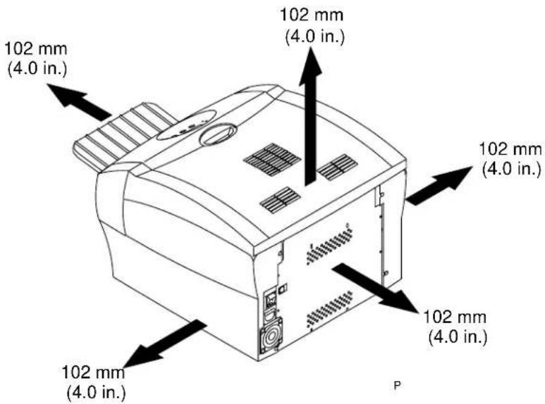
Recommended Air Flow Clearances
Refer to the following illustration for the recommended air flow clearances for the printer.
text_image
102 mm (4.0 in.) 102 mm (4.0 in.) 102 mm (4.0 in.) 102 mm (4.0 in.) 102 mm (4.0 in.) PLoading the Paper
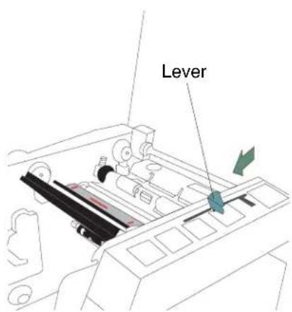
To load the paper into the printer:
- Open the printer cover.
-
If necessary, remove the ribbon from the printer.
-
Move the lever to the unlocked position.
text_image
Lever

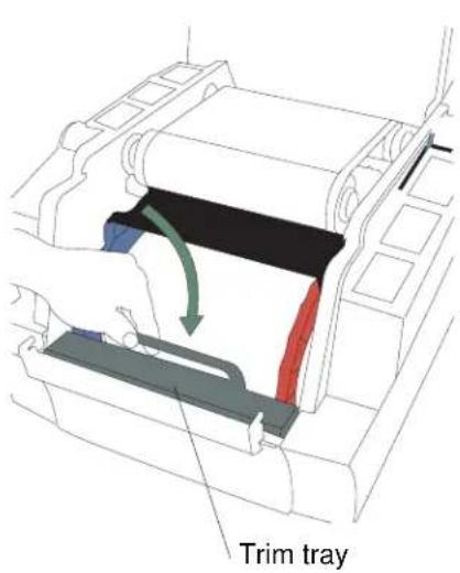
text_image
Trim tray- Remove the trim tray.
IMPORTANT: To keep your prints dust-free and to prevent paper jams, empty the trim tray each time you change the paper.

text_image
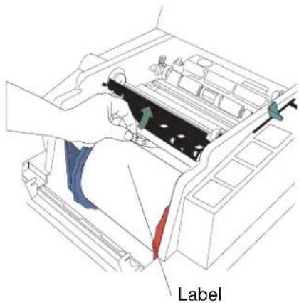
Label- Remove the plastic cover from the new paper roll.
IMPORTANT: Do not remove the label from the paper roll until you have successfully loaded the paper into the printer.

text_image
Blue paper flange Notches Lugs Red paper flange- Attach the paper flanges provided with the printer to each end of the paper roll.
a. Line up the lugs on the blue paper flange with the notches on the left side of the paper roll.
b. Place the blue paper flange on the left side of the paper roll.
c. Place the red paper flange on the right side of the paper roll.
NOTE: Be sure to line up the lugs on the blue paper flange with the notches on the left side of the paper roll. If you do not attach the paper flange properly, the paper roll will not fit into the printer.

natural_image
Illustration of a hand using a red mechanical component to adjust or install a machine (no text or symbols visible)- Gently set the paper roll into the printer according to the blue and red arrows on the label.
text_image
Label- Remove the label.
text_image
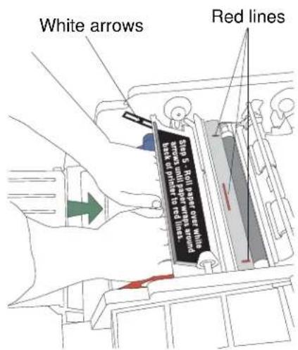
White arrows Red lines Step 5: Roll taper cross which arrows on primer to red lines. test or primer to red lines.SIDE VIEW
- Feed the paper in the direction of the white arrows until the paper wraps around the back of the printer and touches the red lines.

natural_image
Line drawing of a hand operating a mechanical device with a circular base (no text or symbols)
text_image
Step 5 - Roll paper over white arrows until paper wraps around back of printer to red lines.- Hold the paper in place between the red lines with your hand. Make sure the paper edges do not extend over the red lines.

text_image
Red lines- Move the lever to the locked position.

text_image
Trim tray- Install the trim tray.
Loading the Ribbon

text_image
Label/wrapperTo load the ribbon into the printer:
-
If you are replacing a ribbon, remove the used ribbon from the printer. NOTE: Images remain on the ribbon after printing. If you need to maintain confidentiality, dispose of the used ribbon appropriately.
-
Insert your fingers into the holes in the plastic on the end of the ribbon. Remove the plastic cover from the ribbon.
IMPORTANT: Do not remove the label/wrapper from the ribbon at this time.

text_image
Supply spool- Push the right end of the supply spool into the front spool holder on the right.
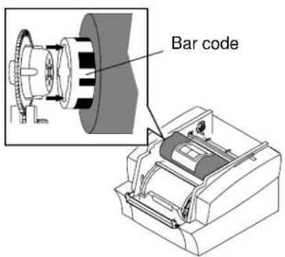
text_image
Bar code- Place the bar code end of the supply spool into the front spool holder on the left. IMPORTANT: Make sure to line up the notches on the supply spool with the lugs on the spool holder.

text_image
Label/wrapper- Remove the label/wrapper from the ribbon.
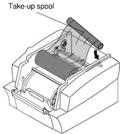
text_image
Take-up spool- Push the right side of the take-up spool into the rear spool holder on the right.
- Place the left side of the take-up spool into the rear spool holder on the left.
- Rotate the take-up spool until it locks into place.
- If there is any slack in the ribbon, remove it by turning the take-up spool.
IMPORTANT: Slack in the ribbon can cause a paper jam when making prints.
Installing the Print Catcher
The print catcher collects finished prints as they exit the printer.
- Set the print catcher into the printer as shown.

text_image
Diagram illustrating a printer's internal structure with labeled parts and a magnified view of the printer's base components.Print catcher
Connecting the Cables
Connecting the power cable
You may have received more than one power cable with your printer. Be sure to use the correct power cable required for your country.

text_image
Technical diagram showing installation of a device with labeled components and connection arrows- Check that the power switch is turned off (☐)
CAUTION:
The power outlet must be grounded. An ungrounded outlet can cause fire, electric shock, or harmful interference to nearby electrical devices.
- Connect the power cable to the power connector on the back of the printer and to a grounded power outlet.
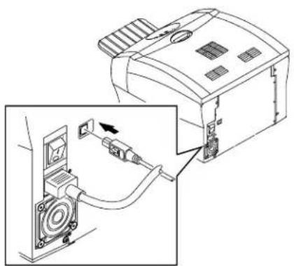
Connecting the USB cable
Use the included USB cable.
natural_image
Diagram showing a device connected to a speaker, with an inset view of the speaker's cable being inserted (no text or symbols present)-
Check that the power switch is turned off (☐)
-
Connect the USB cable to the USB connector on the back of the printer and to the USB connector on the computer.
Turning On the Printer

text_image
ON OFF- Press the power switch to on ( | ).
On the operator panel, the orange Power light and the green Ready light illuminate, and the Ready message appears when the printer is initialized.
- To turn off the printer, press the power switch to off ( Ⓞ
2 Operating the Printer
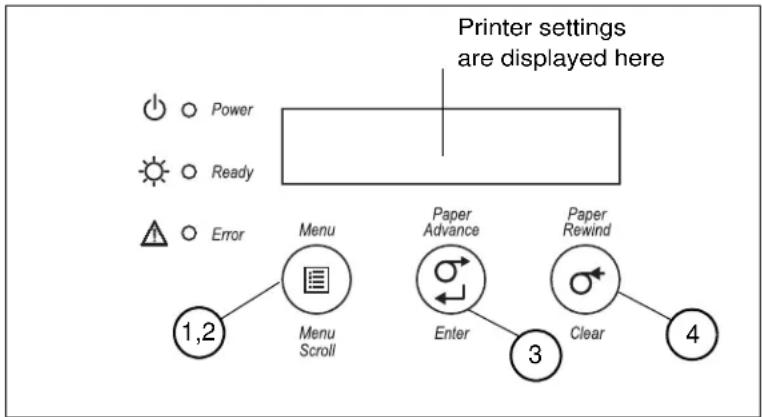
Understanding the Operator Panel Lights
| Light Color Printer Status | ||
| [T0T0] | Power Orange The printer power is on. | |
| [X074] | Ready Green The printer is ready to make prints. | |
 | Error Red An error has occurred. | |
Using Setup Mode to Review Printer Settings
Use the operator panel to review printer settings in Setup mode.
flowchart
graph TD
    A["Power"] --> B["Menu Scroll"]
    C["Ready"] --> B
    D["Error"] --> B
    E["1,2"] --> B
    F["Menu"] --> G["Enter"]
    H["Paper Advance"] --> I["Clear"]
    J["Paper Rewind"] --> K["3"]
    L["4"] --> K
    style A fill:#fff,stroke:#000
    style C fill:#fff,stroke:#000
    style D fill:#fff,stroke:#000
    style E fill:#fff,stroke:#000
    style F fill:#fff,stroke:#000
    style H fill:#fff,stroke:#000
    style J fill:#fff,stroke:#000
    style L fill:#fff,stroke:#000
- Press Menu to enter Setup Mode.
-
Press Menu Scroll repeatedly to scroll through the printer settings.
-
Press Enter to initiate an action.
- Press Clear to accept a change or exit Setup Mode.
Accessing the Printer Settings
Press Menu Scroll repeatedly to scroll through the printer settings in the following order.
| Printer Setting Operator Panel Display Action Required | ||
| Printer ready Ready None. The printer is on and ready to make prints. | ||
| Making a test print | Test Print Mode | Press Enter to enter test print mode. See “Making a test print”. |
| Checking remaining media | Remain = XXX/YYYY None. XXX represents the number of prints remaining out of the total possible (YYYY) for the media currently installed. | |
| Checking the printer total print count | Printed =XXXXX None. XXXX represents the total number of prints made since the printer was manufactured. This counter cannot be reset. | |
| Checking the FEE firmware version | FEE Firm X.XX None. The printer | FEE firmware version is displayed. |
| Checking the DSP firmware version | DSP Firm X.XX | None. The printer DSP firmware version is displayed. |
| Checking the engine firmware version | ENG Firm X.XX | None. The engine firmware version is displayed. |
| Setting the operator control panel (OCP) language | Language | 1. Press Enter.2. Select the language. |
| Setting the standby timeout | Standby Timeout | 1. Press Enter.2. Select the standby timeout (Never, 30 minutes, 60 minutes, 120 minutes, 480 minutes). |
| Setting the level of matte lamination | Matte Level | 1. Press Enter.2. Select the level of matte lamination. (-4, -3, -2, -1, 0, 1, 2, 3, 4) |
Working in Test Print Mode
Making a test print
Make a test print to check that the printer is installed and set up correctly.
- Press Menu once until Test Print Mode appears.
- Press Enter once until Pattern appears.
- Press Enter once to select the test print type.
- Press Menu to cycle through the available test print types.
- Press Enter to print the selected test print.
When printing is complete, the printer returns to Ready mode.
Changing the quantity of test prints
- Press Menu once until Test Print Mode appears.
- Press Enter once until Pattern appears.
- Press Menu once until Count appears.
- Press Enter once to select the test print count.
- Press Menu to cycle through the number of test print copies you want.
- Press Clear to accept the value you just selected.
NOTE: The value you selected is the number of test prints you will receive until the printer is turned off and turned back on.
- Press Menu once until Pattern appears.
- Continue with step 3 of "Making a test print" on page 2-2.
Appendix A: Important Printer Information
Printer Specifications
| Dimensions Width | 17 in. (432 mm) |
| Depth | 19 in. (483 mm) - without Print Catcher |
| Height | 25 in. (635 mm) - with Print Catcher |
| 13 in. (330 mm) | |
| Weight(without ribbon and paper) | 18 kg (40 lbs) |
| Ambient Operating Temperature 15 - 35°C (59 - 95°F) | |
| Relative Humidity 20 - 80% (non-condensing) | |
| Voltage AC 100 - 240 V | |
| Current rating 5A | |
| Frequency 50 / 60 Hz | |
| Print sizes 8 x 10 in. (203 x 254 mm) | 8 x 12 in. (203 x 305 mm) |
Appendix B: Safety and Regulatory Information
Important Safety Information
CAUTION:
Use of controls or adjustments, or performance of procedures other than those specified in this manual may result in injury and/or damage to the printer.
- The power outlet should be easily accessible and installed near the printer.
- Position the power cable so that it cannot be pulled on or tripped over.
- Never allow the power cable to contact hot surfaces.
- The power outlet must be grounded. An ungrounded outlet can cause fire, electric shock, or harmful interference to nearby electrical devices.
- Use only the power cable provided with the printer.
- Do not operate the printer with a damaged power cable.
- Always unplug the power cable from the printer before cleaning or when the printer is not in use.
- If the printer has been dropped or damaged, be sure a qualified service person examines the printer before you use it.
- Do not block the filter openings on the printer cabinet.
- Do not expose the printer to moisture or water.
- Do not allow any foreign objects or liquids to fall or spill inside the printer. Fire or electric shock could result.
- The thermal head becomes extremely hot during normal operation. Do not touch it.
Safety Labels
Please observe the important safety warnings that are posted on the printer.
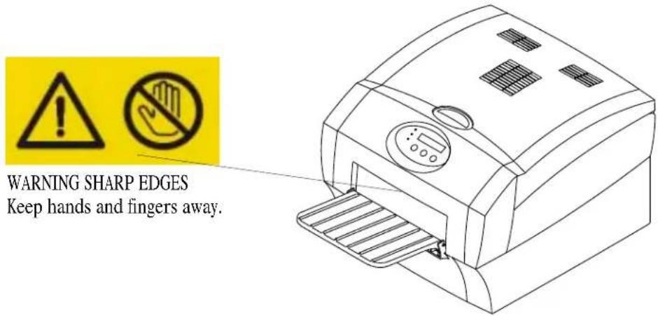
text_image
WARNING SHARP EDGES Keep hands and fingers away.Regulatory and Safety Compliance
Safety Complies with UL 60950-1 First Edition—CAN/CSA C22.2 No. 60950-1-3 First
Edition
EN 60950-1
IEC 60950-1
Tested for Norwegian IT Power systems 240V phase to phase

natural_image
Abstract circular logo with concentric circles and a central stylized 'e' with directional arrows (no text or symbols)Radio frequency interference
NOTE: This equipment has been tested and found to comply with the limits for a Class A digital device, pursuant to part 15 of the FCC rules. These limits are designed to provide reasonable protection against interference when the equipment is operated in a commercial environment. This equipment generates, uses, and can radiate radio frequency energy and, if not installed and used in accordance with the instruction manual, may cause interference to radio communications. Operation of this equipment in a residential area is
likely to cause interference in which case the user will be required to correct the interference at his or her own expense.
Requirements of the EMC directive 89/336/EEC were met through compliance with the following:
• EN 55022: 98 (class A)
• EN 55024: 98 ITE Immunity includes the following:
EN61000-4-2 ESD
EN61000-4-3 Radiated rf immunity
EN61000-4-4 EFT
EN61000-4-5 Surge
EN61000-4-6 Conducted rf immunity
EN61000-4-11 Voltage dips and interruptions
• EN 61000-3-2 Harmonics
• EN 61000--3-3 Flicker
Changes or modifications not expressly approved by the party responsible for compliance could void the user's authority to operate the equipment.
Noise emission The operator-position noise emission value is 58 dB(A).*
* Average value specified in accordance to JIS Z873.
Disposal This product contains a small amount of lead in the solder on the circuit
boards. Disposal of this material may be regulated due to environmental considerations. For disposal or recycling information, please contact your local authorities. In the USA, contact the Electronics Industry Alliance at http://www.eiae.org

In the European Union, this symbol indicates that when the last user wishes to discard this product, it must be sent to appropriate facilities for recovery and recycling. Contact your local Kodak representative or refer to www.kodak.com/go/recycle for additional information on the collection and recovery programs available for this product.
Index
A
air flow clearances, 1-1
C
cables
connecting, 1-8
power, 1-8
USB, 1-8
connecting cables, 1-8
D
disposal, B-3
H
humidity
printer specifications, A-1
|
installing
paper, 1-2
ribbon, 1-6
L
labels, safety, B-2
loading
paper, 1-2
ribbon, 1-6
N
noise emission spec, B-3
0
operator panel
error/red light, 2-1
language, 2-2
making a test print, 2-2
power/orange light, 2-1
printer settings, 2-2
Ready message, 2-2
ready/green light, 2-1
setup mode, 2-2
standby timeout, 2-2
P
paper
loading, 1-2
power
cable, 1-8
requirements, A-1
turning on, 1-8
printer
operating, 2-1
setting up, 1-1
settings, 2-1
specifications, A-1
printer disposal, B-3
printing
test print, 2-2
R
radio frequency compliance, B-2
Ready message, operator panel, 2-2
recycling, B-3
ribbon
loading, 1-6
S
safety
compliance, B-2
tips, B-1
warning labels, B-2
setting up the printer, 1-1
setup mode, 2-1
specifications
printer, A-1
switch, power, 1-8
T
temperature
printer specifications, A-1 test print, making, 2-2
U
USB cable, connecting, 1-8

Eastman Kodak Company
Rochester, NY 14650
Kodak is a trademark of Eastman Kodak Company.
© Eastman Kodak Company, 2006 Rev B December 12, 2006