BL-C131A - Surveillance Camera PANASONIC - Free user manual and instructions
Find the device manual for free BL-C131A PANASONIC in PDF.

User questions about BL-C131A PANASONIC
0 question about this device. Answer the ones you know or ask your own.
Ask a new question about this device
Download the instructions for your Surveillance Camera in PDF format for free! Find your manual BL-C131A - PANASONIC and take your electronic device back in hand. On this page are published all the documents necessary for the use of your device. BL-C131A by PANASONIC.
USER MANUAL BL-C131A PANASONIC
Operating Instructions
Network Camera
BL-C131A
BL-C111A (Wired Type) Model BL-C131A (Wireless/Wired Type)
Main Features
On-site and remote camera monitoring
Camera images can be monitored from a PC, both on-site and over the Internet. You can even use your mobile phone to view still images when you're out of the house.
MPEG-4 and Motion JPEG (MJPEG) support
Live camera images can be viewed and recorded in both MPEG-4 and MJPEG formats, allowing you to select the video format that best suits your needs.
Built-in sensor
The camera features a built-in pyroelectric infrared sensor, which uses infrared rays to detect temperature differences within its range that are emitted naturally by people, animals, etc. The sensor can be used to trigger the camera to buffer (i.e., temporarily store) camera images in its memory. You can view these images later as desired. The sensor can also be used to trigger the camera to transfer images to someone or somewhere, by FTP, E-mail, or HTTP.
Motion detection feature
The camera's motion detection feature allows you to buffer or transfer camera images when the camera detects motion in the camera image.
Camera image recording, playback, and sharing
Camera images can be automatically buffered at specific times, when the camera's sensor is triggered, or when the camera detects motion. You can program the camera to buffer these camera images, and then you can play back these images later while accessing the camera or save them to your PC. You can also program the camera to transfer images via E-mail or upload them to an FTP or HTTP server as they are being recorded.
Digital zoom
The camera has a digital zoom feature that allows you to zoom up to 10× (by area) and get a closer look. You can use your mouse to zoom in and out simply.
Protecting your privacy
Simply press the camera's PRIVACY button to hide the lens from view and protect your privacy. You can even activate the privacy mode while away from home.
UPnP™ support
When connecting the camera to a UPnP™ compatible router, the camera's network settings can be automatically configured, making setup quick and easy. For more information, see Page 71.
Viewnetcam.com support
After registering your camera with the Viewnetcam.com service, you can access the camera while away from home using an easy to remember Internet address of your choosing, such as bob.viewnetcam.com. For more information, see Page 75.
Multi-language support
The most commonly used camera pages can be displayed in English, French, German, Italian, Spanish, Russian, Simplified Chinese, Korean, and Japanese. All camera pages can be displayed in English, Simplified Chinese, and Japanese.
Wireless connectivity (BL-C131A only)
The BL-C131A supports wireless standards IEEE 802.11b and IEEE 802.11g, giving you the option of using the camera in either wired or wireless mode. When used in wireless mode, up to 152-bit encryption ensures that access to the camera is secure.
Other Information
About this documentation
- This manual is written for both the BL-C111A (Wired Type) and BL-C131A (Wireless/Wired Type). Available features and operations vary slightly depending on the model. You can confirm the model no. of your camera by checking the model no. printed on the front of the camera.
• The camera illustrations in this document depict the BL-C131A.
Trademarks
- Adobe and Reader are either registered trademarks or trademarks of Adobe Systems Incorporated in the United States and/or other countries.
• Microsoft, Windows, Hotmail, ActiveX, Internet Explorer, and Windows Media are either registered trademarks or trademarks of Microsoft Corporation in the United States and/or other countries. - Pentium is a trademark or registered trademark of Intel Corporation or its subsidiaries in the United States and other countries.
- Screen shots reprinted with permission from Microsoft Corporation.
- All other trademarks identified herein are the property of their respective owners.
- This software is based in part on the work of the Independent JPEG Group.
Abbreviations
- UPnP is the abbreviation for "Universal Plug and Play".
- The Network Camera is referred to as "the camera" in this document.
- The Setup CD-ROM is referred to as "the CD-ROM" in this document.
Table of Contents
1 Camera Monitoring ....7
1.1 Accessing the Camera 7
1.2 Viewing Live Camera Images 9
1.2.1 Using the Operation Bar 14
1.2.2 Aiming the Camera Lens 15
1.2.3 Limiting the Pan/Tilt Range 17
1.2.4 White Balance 18
1.2.5 Video Images (MJPEG and MPEG-4) and Image Refresh Rate 19
1.2.6 Zooming 20
1.2.7 Taking Snapshots 21
1.2.8 Registering and Changing Presets 22
1.2.9 Audio Features 23
1.3 Viewing Multiple Camera Images 24
2 Using Triggers to Buffer and Transfer Images ......26
2.1 Configuring a Timer Trigger 27
2.2 Configuring a Sensor or Motion Detection Trigger 30
2.3 Disabling and Enabling a Trigger 35
2.4 Configuring the Camera to Transfer Images 36
2.4.1 Transferring Images by FTP 37
2.4.2 Transferring Images by E-mail 39
2.4.3 Transferring Images by HTTP 42
2.5 Configuring the Camera to Send Trigger Notifications ....44
2.5.1 Sending Trigger Notifications by E-mail 45
2.5.2 Sending Trigger Notifications by HTTP 48
2.6 Viewing Buffered Images 50
2.7 Deleting Buffered Images 54
2.8 Adjusting Sensor Sensitivity ....56
2.9 Adjusting Motion Detection Sensitivity ....57
2.10 Sending Alarm Log Information 59
3 Mobile Phone Features 6
3.1 Accessing the Camera from Your Mobile Phone 63
3.2 Viewing Still Images on Your Mobile Phone 64
3.3 Viewing Alarm Logs on Your Mobile Phone 65
3.4 Enabling and Disabling Image Buffering Using Your Mobile Phone 66
4 Configuring the Camera for Access from the Internet 67
4.1 Configuring Port Forwarding 71
4.2 Configuring the Camera to Use a Dynamic DNS Service ....74
4.2.1 Configuring the Camera to Use Viewnetcam.com 75
4.2.2 Configuring the Camera to Use a Third-party Dynamic DNS Service 78
4.3 Confirming Internet Access 80
5 Changing Camera Settings 81
5.1 Network Settings 81
5.1.1 Network (IPv4) Settings 82
5.1.2 Proxy Server Settings 87
5.2 Using the Camera in Wireless Mode (BL-C131A Only) 88
5.2.1 Configuring the Camera for Wireless Connection (BL-C131A Only) 89
5.2.2 Restarting the Camera in Wireless Mode (BL-C131A Only) 93
5.3 UPnP™ Settings 94
5.4 Setting the Date and Time 95
5.5 Changing Basic Camera Settings 97
5.6 Changing Audio Settings 98
5.7 Changing Video Streaming Settings 99
6 User Accounts ....102
6.1 Understanding User Accounts ....102
6.2 Changing the Administrator User Name and Password ....103
6.3 General Users 104
6.4 Guest Users 107
6.5 The Login Tab 109
7 Advanced Settings ....110
7.1 Changing Image Display Settings ....110
7.2 Registering Multiple Cameras 113
7.3 Specifying Operation Times ....115
7.4 Changing the Indicator Display ....117
7.5 Privacy Mode 118
8 Camera Administration and Maintenance ....119
8.1 Confirming Camera Status 119
8.2 Confirming Wireless Status (BL-C131A Only) 120
8.3 Confirming Session Status ....121
8.4 Confirming Alarm Logs 122
8.5 Restarting the Camera 123
8.6 Updating the Camera Firmware 124
8.7 Saving Settings in a Configuration File 125
8.8 Restoring Settings from a Configuration File 126
8.9 Resetting the Camera 127
9 The [Support] Tab 129
10 Using IPv6 ....130
10.1 Configuring Your Router for IPv6 131
10.2 Configuring Your PC for IPv6 132
10.3 Configuring Your Camera for IPv6 133
10.4 Accessing the Camera in IPv6 Mode 136
11 PC Settings ....137
11.1 Proxy Server Settings ....137
11.2 Creating a Shortcut to the Camera 140
11.3 Changing the [Temporary Internet files] Setting 141
11.4 About the MPEG-4 Viewer Program 142
12 Using the Setup Program ....143
13 Technical Information ....146
13.1 Cleaning the Camera 146
13.2 ASCII Character Table 147
13.3 Internal Memory Specifications for Buffered Images 148
13.4 Default Setting List ....149
13.5 Specifications 153
Index....155
1 Camera Monitoring
1.1 Accessing the Camera
You will need to know the following information to access the camera.
• The camera's IP address (e.g., 192.168.0.253) or URL (e.g., bob.viewnetcam.com)
- The port number of the camera, if it is not 80.
- The user name and password required to access the camera, which were set during camera setup.
-
Start your PC's web browser.
-
In the browser's address bar, enter http:// followed by the IP address of the camera, then press [Enter] on the keyboard.
Example: http://192.168.0.253
If the camera's port number is a port number other than 80, enter “:” and the port number after the IP address.
Example: http://192.168.0.253:50001
If you have registered with a DNS service, such as Viewnetcam.com (see Page 75), enter the URL instead of the IP address. Note that accessing the camera this way may only work when you are accessing the camera from outside, i.e., from a PC that is not connected to the same network as the camera.
Example: http://bob.viewnetcam.com
- When the authentication dialog is displayed, enter the user name and password, then click [OK]. The top page is displayed.
Note
- If the authentication dialog is not displayed, click the [Login] tab after the camera's top page is displayed. For more information, see Page 109.
- After the top page is displayed, click the desired tab. (Depending on how the camera has been configured, certain tabs may not be displayed.)
text_image
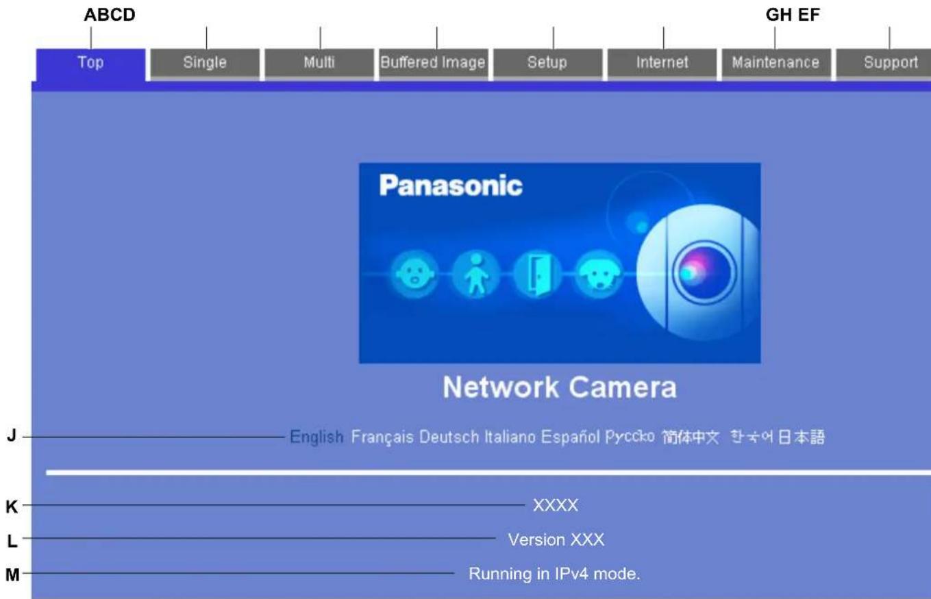
ABCD Top Single Multi Buffered Image Setup Internet Maintenance Support GH EF Panasonic Network Camera J——English Français Deutsch Italiano Español Pycoko 简体中文 한국어日本語 K——XXXX L——Version XXX M——Running in IPv4 mode.A. To display the top page
B. To view images from this camera (see Page 9)
C. To view images from multiple cameras (see Page 24)
D. To view buffered camera images (see Page 50)
E. To configure the camera
F. To configure the camera to be accessed over the Internet (see Page 67)
G. To confirm camera status and perform camera maintenance (see Page 119)
H. To view URLs for Panasonic Network Camera support sites on the Internet (see Page 129)
I. To log in to the camera as the administrator or as a general user (see Page 109)
J. Click the desired display language
K. Displays the camera's model number
L. Displays the camera's firmware version number
M. Displays [IPv4] or [IPv6] depending on the camera's network configuration
1.2 Viewing Live Camera Images
- Access the camera (see Page 7).
- Click the [Single] tab.
- ActiveX® Controls must be installed in order to view MPEG-4 images, MJPEG images, or to use audio features. If the appropriate ActiveX Control is not installed, the camera will prompt you to install them. For more information see Page 11 or Page 12 depending on which operating system you are using.
- If the [Security Warning] dialog is displayed, see Page 12.
- If the camera image is not displayed, or if the ActiveX message is displayed at the top of the screen, see Page 12.
The single camera page
text_image
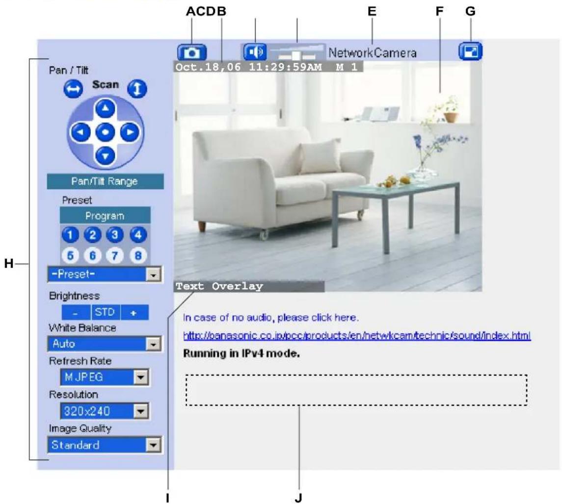
Pan / Tilt Scan Pan/Tilt Range Preset Program -Preset- Brightness - STD + White Balance Auto Refresh Rate M JPEG Resolution 320x240 Image Quality Standard ACDB E F G NetworkCamera Oct.18,06 11:29:59AM M 1 Text Overlay In case of no audio, please click here. http://panasonic.co.jp/bcc/products/en/netw/kcam/technic/sound/index.html Running in IPv4 mode.A. Snapshot button (see Page 21)
B. Date and time overlay, alarm state overlay (see Page 110)
C. Listen button (see Page 23)
D. Volume slider (see Page 23)
E. Camera name (see Page 110)
F. Camera image (click an area of the camera image to use the click to center feature (see Page 15), or use your mouse to use the digital zoom feature (see Page 20) when displaying MJPEG video)
G. Full-screen button (click to view the image in 4:3 full-screen mode; click 📋 to return to normal mode)
H. Operation bar (see Page 14)
I. Text overlay (see Page 110)
J. Banner (see Page 110)
Note
- If no camera image is displayed, ActiveX Controls may not be installed. See Page 11 or Page 12 for more information.
- The default settings for [Refresh Rate], [Resolution], and [Image Quality] that are used each time the single camera page is accessed can be changed (see Page 110).
- If the camera image is not displayed immediately or correctly, click your web browser's refresh button to display the latest camera image.
- Using the [Refresh Rate] selector in the operation bar, you can select whether video images ([MPEG-4] or [MJPEG]) are displayed, or still images that are refreshed periodically (3 seconds, 5 seconds, etc.) are displayed.
- The image refresh rate may vary depending on network conditions, PC performance, the number of people accessing the camera, and the type of objects being viewed.
- To reduce data traffic when other users are accessing the camera, you can configure the camera to automatically switch from displaying video images to still images. Set the [Video Display Time] for general users (see Page 104) and for guest users (see Page 107).
- When the camera is in a dark environment, Color Night View mode (if enabled; see Page 97) automatically brightens the image, however the image refresh rate may decrease (i.e., images may appear “choppy”) and overall image quality may decrease (i.e., images may appear grainy).
- When the camera is in a dark environment, white or colored dots or horizontal lines may be displayed in the camera image. This is a characteristic of the camera's optical sensor, and is not a malfunction.
- A gray screen is displayed instead of the camera image in the following situations:
- The camera's privacy mode (see Page 118) has been turned on.
- Too many users are accessing the camera. The camera allows up to 30 users to view video images and buffered images simultaneously. Additional users will see a gray screen, and [The maximum number of accesses has been exceeded.] will be displayed under the camera image. Click your web browser's refresh button periodically until you are allowed to view video images, or use the [Refresh Rate] selector to select to view still images.
- The camera is configured to not display images at this time of day (see Page 115). [The operation time has ended.] will be displayed under the camera image.
- BL-C131A only: If using the camera in wireless mode, camera images will stop refreshing if there is a disturbance in the wireless signal. If you experience difficulty when accessing the camera in wireless mode, refer to the 1.4 Wireless Connection Issues (BL-C131A Only) in the Troubleshooting Guide.
ActiveX dialog for Windows XP Service Pack 2
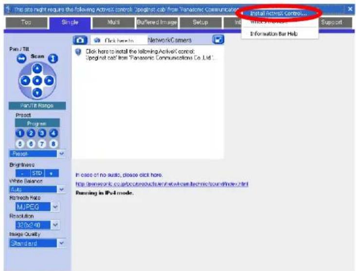
To view video images (i.e., MPEG-4 and MJPEG images) or use the camera's audio features, the corresponding ActiveX Controls must be installed on your PC. Follow the steps below to install ActiveX Control when using Windows XP Service Pack 2.
Note
- If ActiveX Controls cannot be installed, download them from the Panasonic Network Camera website (http://panasonic.co.jp/pcc/products/en/netwkcam/).
- When the ActiveX Control message is displayed in Internet Explorer®, click the message and select [Install ActiveX Control...].
text_image
The site might require the following ActiveX control: Upregnt cab from Panasonic Communications Top Single Multi Buffered Image Setup Init Install ActiveX Control... White Box 10000000000000000000000000000000000000000000000000000000000000000000000000000000000000000 Pan/TTI Scan Pan/TTI Range Project Program 1 2 3 4 5 6 7 8 Project Brightness - STD White Balance Auto Refresh Rate MUPEG Resolution 32.0x2.40 Image Quality Standard Click here to install the following ActiveX control: Upregnt cab from Panasonic Communications Co., Ltd. In case of no audio, please click here. http://www.net/cp.com/products/sn/ew/nc/tech/sound/index.html Running in IPv4 mode.- Click [Install].
text_image
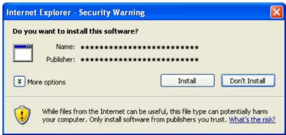
Internet Explorer - Security Warning Do you want to install this software? Name: ********** Publisher: ********** More options Install Don't Install While files from the Internet can be useful, this file type can potentially harm your computer. Only install software from publishers you trust. What's the risk?Security Warning dialog (for Windows 2000)
To view video images (i.e., MPEG-4 and MJPEG images) or use the camera's audio features, ActiveX Controls must be installed on your PC. If ActiveX Controls need to be installed on your PC, the [Security Warning] dialog will be displayed when trying to view video images (MPEG-4 or MJPEG) for the first time. You can install ActiveX Controls by clicking [Yes] when the following dialog is displayed, however, you must be logged into your PC as a user with Administrator privileges.
Note
- If ActiveX Controls cannot be installed, download them from the Panasonic Network Camera website (http://panasonic.co.jp/pcc/products/en/netwkcam/).
text_image
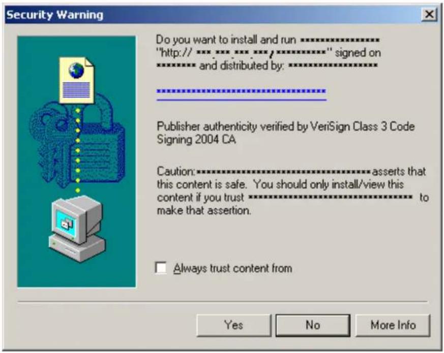
Security Warning Do you want to install and run…………** "http://…………/…………/…………/" signed on and distributed by:…………** Publisher authenticity verified by VeriSign Class 3 Code Signing 2004 CA Caution:………… asserts that this content is safe. You should only install/view this content if you trust………… to make that assertion. □ Always trust content from Yes No More InfoIf you cannot install ActiveX Controls If you cannot see video (MPEG-4 or MJPEG) images in Internet Explorer
Confirm the following Internet Explorer settings.
- Click [Tools]→[Internet Options]→[Security] tab and click [Custom level] on the web browser.
- Under [Download signed ActiveX controls], select [Prompt].
- Under [Run ActiveX controls and plug-ins], select [Enable].
If you need to install ActiveX Controls, you can download them from the Panasonic Network Camera support site (http://panasonic.co.jp/pcc/products/en/netwkcam) or install them using the CD-ROM included with your camera.
- After downloading the ActiveX Controls installer or inserting the CD-ROM in your PC, restart the PC.
-
Confirm that Internet Explorer is closed.
-
Double-click the downloaded ActiveX Controls installer, or open the [ocx] folder on the CD-ROM and double-click [ActiveXInst.exe].
Note
• After installing or enabling ActiveX Controls, you may need to wait a moment before camera images are displayed.
- If you use a proxy server, see Page 137.
- If your computer or your network uses a firewall for security purposes, the firewall may prevent video images from being displayed. In this case, you can use the [Refresh Rate] selector to select to view still images. If you want to view video images, consult your network administrator.
1.2.1 Using the Operation Bar
The operation bar is displayed to the left of the camera image when viewing images from a single camera, and provides the following features.
text_image
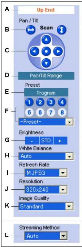
A Up End Pan / Tilt Scan B C D Pan/Tilt Range E Preset Program F -Preset- G Brightness White Balance H Auto Refresh Rate I M JPEG Resolution J 320x240 Image Quality K Standard L Streaming Method AutoA. End Display and Preset Display: When the lens has reached the end of its pan or tilt range, the appropriate message will be displayed here ([Left End], [Right End], [Up End] or [Down End]). Additionally, when a preset (see Page 22) is selected, the name of the preset is displayed here (except [Home Position]).
B. Pan and Tilt Scan Buttons: Allow you to pan or tilt the lens to its maximum pan or tilt range. The lens returns to the original position when finished.
C. Navigation Buttons: Allow you to pan the lens left and right, and tilt the lens up and down. Click the center navigation button to move the lens to the home position.
D. Pan/Tilt Range Button: Allows you to limit the pan and tilt range of the camera's lens (see Page 17).
E. Preset Program Button: Allows you to add, change, or delete presets (see Page 22).
F. Preset Selection Buttons and Menu: Allow you to move the lens to a pre-programmed position. Click buttons 1–8 to move the lens to the corresponding preset, or select the desired preset from the pull-down menu.
G. Brightness Controls: Allow you to change the brightness of the displayed image. Click [-] to darken the image, [+] to brighten the image, and [STD] to return the image to the standard brightness level. There are a total of 9 brightness levels available.
H. White Balance Selector: Allows you to adjust the white balance to match the environment of the camera. Change this setting to achieve the most natural looking colors (see Page 18).
I. Refresh Rate Selector: Determines how often the camera image is refreshed (see Page 19). Select [MPEG-4] or [MJPEG] to view video images, or one of the other settings to view still images (JPEG format) that are refreshed only periodically. For example, selecting [3 s] will refresh the camera image once every 3 seconds.
J. Image Resolution Selector: Determines the resolution of the image (i.e., the size of the image in pixels) that is displayed.
K. Image Quality Selector: Allows you to select the image quality. Select [Favor Clarity] for optimal image clarity, [Favor Motion] for optimal motion quality, and [Standard] for standard image quality. This selector is not displayed when [MPEG-4] is selected under [Refresh Rate].
L. Streaming Method Selector: Allows you to select the method used to stream MPEG-4 images from the camera (see Page 19). This selector is displayed only when [MPEG-4] is selected under [Refresh Rate]. To stream MPEG-4 images using Multicast, you must first configure the camera for multicasting (see Page 99), after which [Multicast] is available from this pull-down menu.
Note
- Brightness and white balance settings are reset each time the camera is turned on, however, the current settings are saved when registering a preset (see Page 22) are those settings are used when viewing a preset.
- The camera lens moves to the home position when it is turned on. You can change the home position if necessary (see Page 22).
1.2.2 Aiming the Camera Lens
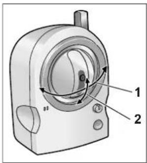
The camera can be panned from -50^ to +50^ from the center position, and tilted from -40^ to +10^ from the center position. If the [Pan/Tilt Range] button was used to limit the maximum pan and tilt range of the camera (see Page 17), the lens can only be moved to the maximum pan or tilt range allowed.
text_image
Technical diagram of a mechanical device with labeled parts 1 and 2, showing internal components and directional arrows.-
Pan: -50^ to +50^
-
Tilt: -40 ° to +10 °
There are several ways you can move the camera lens to view the desired image, as described in this section.
Note
- Do not apply pressure to the pan/tilt portion of the camera. Any forced movement can damage the camera.
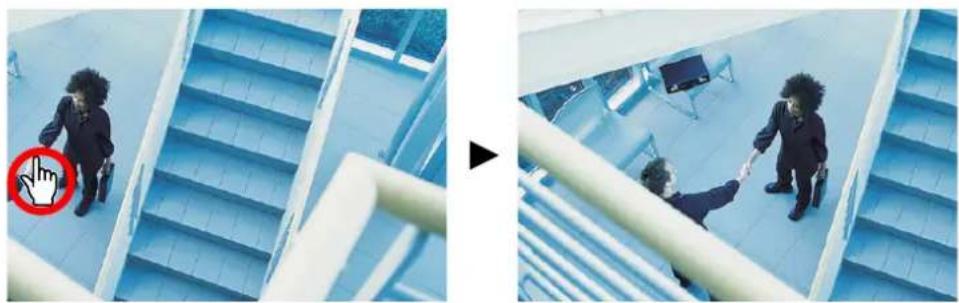
Click to center
Allows you to quickly and easily center the camera image on the desired point. Simply move the mouse cursor to the desired point in the camera image, and click. Note that the camera may not be able to center on the clicked point if it is outside of the pan and tilt range of the lens.
natural_image
Two-panel image showing a person walking on a blue staircase and another person shaking hands in a modern indoor space (no visible text or symbols)This feature can be disabled for general users (see Page 104) and for guest users (see Page 107). Note, however, that if the click to center feature is disabled, users can still use this feature when using the digital zoom feature. Users can click to center the image within the zoomed area, but the lens will not pan or tilt.
Pan and tilt scan buttons
Allow you to pan or tilt the lens to its maximum pan or tilt range. The lens returns to the original position when finished.
This feature can be disabled for general users (see Page 104) and for guest users (see Page 107).
Navigation buttons
Allow you to pan the lens left and right, and tilt the lens up and down. Click the center navigation button to move the lens to the home position.
- The camera lens moves to the home position when it is turned on. You can change the home position if necessary (see Page 22).
This feature can be disabled for general users (see Page 104) and for guest users (see Page 107).
Presets
Allow you to move the lens to a pre-programmed position (see Page 22). Click buttons 1–8 to move the lens to the corresponding preset, or select the desired preset from the pull-down menu. You can also move the lens to the home position by clicking the center navigation button.
This feature can be disabled for general users (see Page 104) and for guest users (see Page 107).
1.2.3 Limiting the Pan/Tilt Range
You can limit the maximum pan and tilt range of the camera's lens.
Note
- This feature is available to the camera administrator only.
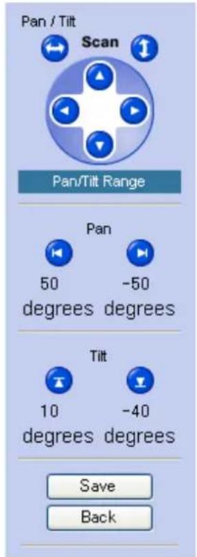
- Click the [Pan/Tilt Range] button in the operation bar.
text_image
Pan / Tilt Scan Pan/Tilt Range Pan 50 degrees -50 degrees Tilt 10 degrees -40 degrees Save Back- Aim the camera to the leftmost point you want to allow to be seen, then click
- Aim the camera to the rightmost point you want to allow to be seen, then click
- Aim the camera to the uppermost point you want to allow to be seen, then click
- Aim the camera to the lowermost point you want to allow to be seen, then click
- Click [Save].


Note
- You can aim the camera by clicking on the desired navigation button, or by using the click to center feature.
1.2.4 White Balance
While viewing camera images on the single camera page, you can use the [White Balance] selector to adjust the camera's image to match the environment of the camera. Change this setting to achieve the most natural looking colors.
The following settings are available.
– [Auto]: White balance is adjusted automatically according to the image being displayed
- [Indoor]: Electric bulb (2800 K)
- [Fluorescent (White)]: White type fluorescent light (4000 K)
- [Fluorescent (Daylight)]: Daylight type fluorescent light (4800 K)
– [Outdoor]: Solar light (6000 K)
– [Hold]: Maintains the current white balance setting
Note
- The current white balance setting is saved when you register a preset (see Page 22).
1.2.5 Video Images (MJPEG and MPEG-4) and Image Refresh Rate
Using the [Refresh Rate] selector in the operation bar, you can select whether video images ([MPEG-4] or [MJPEG]) are displayed, or still images that are refreshed periodically (3 seconds, 5 seconds, etc.) are displayed. You can change the default setting for [Refresh Rate] that is used each time the single camera page is accessed (see Page 110).
MJPEG
MJPEG (Motion JPEG) is a video format that displays a continuous series of still images. Because each MJPEG frame is a still image, this format offers high-quality images, but uses more bandwidth. To view images in MJPEG format, set the [Refresh Rate] selector to [MJPEG].
MPEG-4
MPEG-4 is a video format that updates images only when there is a variation in the image displayed, and as a result, requires less bandwidth. To view images in MPEG-4 format, set the [Refresh Rate] selector to [MPEG-4], then select the desired streaming format under [Streaming Method]. MPEG-4 images can be streamed using multicast, unicast, and HTTP (see Page 99).
- [Multicast] (Multicast RTP): Multicast allows you to stream the same data over the network to multiple parties, thus reducing the amount of data that is sent over the network. In order to use multicast, your router must be configured to allow multicast packets to be sent, and the camera must be configured for multicasting (see Page 99).
- [Unicast] (Unicast RTP): While no special settings are required to stream video using unicast, video is streamed to each individual user viewing MPEG-4 images, which creates more network traffic as more users access the camera.
- [HTTP] (RTP over HTTP): When streaming video using HTTP, data is sent using the commonly used TCP protocol, which means video can be viewed with fewer restrictions, as opposed to multicast and unicast, which use the UDP protocol. However, this streaming format requires more bandwidth than the other formats.
Still Images
Still images that are refreshed periodically can be displayed instead of video images by selecting the desired refresh rate. For example, selecting [3 s] will refresh the camera image once every 3 seconds.
1.2.6 Zooming
The camera has a digital zoom feature that allows you to zoom up to 10x (by area) and get a closer look. You can use your mouse to zoom in and out simply. There are 2 ways to use the zoom feature, as explained later in this section.
The zoom feature can be used when:
– Viewing video images on the single camera page
- Viewing video images from multiple cameras on the multi camera page
- Viewing buffered video images on the buffered image page
Note
- Zooming is not available for MPEG-4 images.
- Zooming is not available when viewing camera images on a mobile phone.
- The zoom magnification (×1.0–×10.0) is displayed briefly while zooming.
- As the magnification increases, image quality decreases.
- You can move the lens as normal (selecting a preset, using the navigation buttons, etc.) even when zooming.
- The digital zoom uses the ActiveX Controls installed on your PC; the lens itself does not zoom. This means that while you are looking at a zoomed image, for example, another user can be looking at the same image with no zoom.
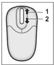
Zooming with the scroll wheel
With the cursor placed over the camera image, rotate the scroll wheel away from you to zoom in, and rotate the scroll wheel toward you to zoom out. Note that the zoom speed depends on your mouse performance and your PC's mouse settings.
text_image
1 2- Zoom in
- Zoom out
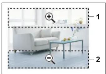
Zooming with the right mouse button
Right-click the upper part of the image to zoom in, and right-click the lower part of the image to zoom out.
natural_image
Interior scene with a white armchair and a table, both enclosed in dashed bounding boxes labeled 1 and 2 (no text or symbols on objects)- Zoom in
- Zoom out
1.2.7 Taking Snapshots
You can take snapshots while viewing camera images and save them on your PC.
- Click the snapshot button ( ).
- The camera image opens in a new window.
- Right-click the image, and select [Save Picture As...].
• The [Save as] dialog appears.
-
Enter a name for the file.
-
Specify where you want to save the file, then click [Save].
-
Click [Close].
Note
- Snapshots are saved in high-quality JPEG format automatically. The image quality of the saved snapshot will be higher than the actual image being viewed.
• This feature can be disabled for general users (see Page 104) and for guest users (see Page 107).
1.2.8 Registering and Changing Presets
Presets allow you to easily aim the camera lens in the desired direction. The following presets can be registered:
- Home position (the direction that the lens moves to when you turn the camera on or click the center navigator button)
- Sensor position
- Presets 1–8
Additionally, the first 4 presets are set by default.
• 1: Upper Left
• 2: Upper Right
• 3: Lower Left
• 4: Lower Right
Viewing a preset
You can move the lens to a preset position in the following ways:
- Click the center navigator button (to move the lens to the home position)
- Click [Preset] and select a preset from the pull-down menu
- Click a blue preset button (1–8) (Unregistered preset buttons are displayed in white.)
Registering or changing a preset
Note
- This feature is available to the camera administrator only.
- Confirm that you are logged in to the camera as the administrator.
- Click [Program].
- Aim the camera in the desired direction.
- Adjust the brightness and white balance settings if desired. The brightness and white balance settings will be registered to the preset.
- Under [Preset Number], select the desired preset from the pull-down menu.
-
Enter a name for the preset (max. 15 characters).
-
You cannot rename the home position or sensor position.
• See Page 147 for a list of valid characters. Note that [Space], ["], ['], &], [<] and [>] cannot be used. -
Click [Save] to register the preset, or click [Back] to cancel.
- When [Success!] is displayed, click [Back] to continue.
Deleting a preset
Note
- This feature is available to the camera administrator only.
- Confirm that you are logged in to the camera as the administrator.
- Click [Program].
- Under [Preset Number], select the desired preset from the pull-down menu.
- You cannot delete the home position or sensor position.
- Click [Delete] to delete the preset, or click [Back] to cancel.
- When [Success!] is displayed, click [Back] to continue.
1.2.9 Audio Features
While viewing live images from the camera, you can monitor the audio from the camera's built-in microphone.
- Confirm that the listen button () is displayed.
- You can mute the audio by pressing the listen button. It will change to the mute button ().

- Press the mute button to turn off the mute and monitor the audio again.
- Adjust the volume using the volume slider ( ).

Note
• This feature can be disabled for general users (see Page 104) and for guest users (see Page 107).
- By default the microphone is automatically muted when the lens is panning or tilting. You can change this setting if desired, as well as adjust the sensitivity of the microphone (see Page 98).
- The audio may be interrupted or delayed due to your PC's performance, the network environment, if you are running other applications, or if you have multiple windows open. Close other applications and windows or reduce the maximum bandwidth (see Page 82 or Page 133) for best performance.
- When the image is refreshed (such as during preset registration or when clicking your browser's refresh button), the volume is reset to the center position and the mute will be turned off (i.e., audio will be heard again).
- If you experience difficulty when using audio features, refer to 1.10 Audio Issues in the Troubleshooting Guide.
1.3 Viewing Multiple Camera Images
You can register other Panasonic Network Cameras to this camera (see Page 113) and use the multi camera page to view images from multiple cameras. After you have registered the other cameras to this camera (up to 16 cameras can be registered), follow the procedure below to view camera images.
- Access the camera (see Page 7).
- Click the [Multi] tab.
The multi camera screen
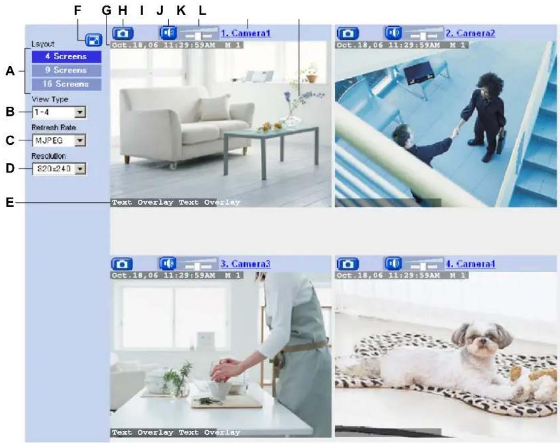
text_image
F G H I J K L Layout 4 Screens 9 Screens 16 Screens View Type 1-4 Refresh Rate MJPEG Resolution 820x240 E 1. Camera1 Oct.18,06 11:29:59AM M 1 2. Camera2 Oct.18,06 11:29:59AM M 1 3. Camera3 Oct.18,06 11:29:59AM M 1 4. Camera4 Oct.18,06 11:29:59AM M 1 Text Overlay Text OverlayA. Changes the number of cameras displayed
B. Switches the display to a different set of cameras
C. Determines the video format of images displayed, or how often the camera images are refreshed
D. Determines the resolution (i.e., the number of pixels) that are displayed for each image
E. Text overlay (see Page 110) ^4
F. Full-screen button (click to view the image in 4:3 full-screen mode; click 📋 to return to normal mode)
G. Date and time overlay, alarm status overlay (see Page 110) ^1
H. Snapshot button (see Page 21)
I. Listen button ^2 (see Page 23) ^2
J. Volume slider ^2 (see Page 23) ^2
K. Camera name (see Page 113; click to view the selected camera's image in a new window)
L. Camera image (click an area of the camera image to use the click to center feature (see Page 15) ^4 , or use your mouse to use the digital zoom feature when displaying MJPEG video)
Note
When a camera image is not displayed
2 Using Triggers to Buffer and Transfer Images
The camera can be configured to buffer its images, i.e., save camera images temporarily in its memory. You can view these images later when accessing the camera. The camera can also be configured to transfer camera images via E-mail, FTP, or HTTP.
Before you can configure the camera to buffer images, you need to decide what method the camera will use to buffer or transfer images. Buffering methods are called “triggers”. Camera images can be buffered or transferred based on the following triggers:
- Timer
Camera images can be buffered or transferred at specific times on specific days.
- Built-in sensor (pyroelectric infrared sensor)
Camera images can be buffered or transferred when the camera's built-in sensor is triggered. The active time of the camera's sensor can also be specified.
- Motion Detection
Camera images can be buffered or triggered when the camera detects motion in the camera image. The active time of the camera's motion detection feature can also be specified.
The camera can be configured to use up to 5 triggers, which means you could, for example:
— Buffer images by timer on weekdays from 9:00 AM to 9:10 AM, and play the images back later to see how many customers come into your shop around opening time.
- Transfer images by E-mail to your mobile phone anytime the camera's built-in sensor is triggered, i.e., anytime someone comes close to the area where the camera is installed.
- Buffer images all day on weekends using the camera's motion detection feature, and play the images back later to see if employees come in to work on their days off.
Note
- When privacy mode is turned on (see Page 118), camera images are not buffered or transferred.
- The image buffering and transferring features, the built-in sensor, and the motion detection feature are not designed to be used for security or surveillance. No responsibility will be taken by our company with respect to consequences resulting from the use of these features.
- Refer to Page 148 for the camera's memory capacity for buffering images.
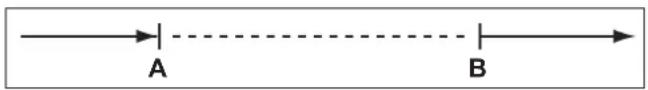
- If the camera is triggered and begins buffering or transferring images, it cannot be triggered again until the camera stops buffering or transferring images, as shown in the figure below.
— The camera can be triggered.
--- The camera is buffering or transferring images and cannot be triggered during this time.
flowchart
graph LR
    A["A"] --> B["B"]
A The camera is triggered. Buffering or transferring begins.
B Buffering or transferring ends.
Follow the procedures in this section to configure the camera to buffer or transfer images.
2.1 Configuring a Timer Trigger
- Click the [Setup] tab.
- On the left side of the screen under [Buffer/Transfer], click [Trigger].
- Click a trigger number (1–5).
Trigger
| No. | Status | Trigger | Sun | Mon | Tue | Wed | Thu | Fri | Sat | Active Time of Trigger | Transfer Method | N |
| 1 | OFF | Timer | X | X | X | X | X | X | X | Always | No Transfer, No Memory Overwrite | |
| 2 | OFF | Timer | X | X | X | X | X | X | X | Always | No Transfer, No Memory Overwrite | |
| 3 | OFF | Timer | X | X | X | X | X | X | X | Always | No Transfer, No Memory Overwrite | |
| 4 | OFF | Timer | X | X | X | X | X | X | X | Always | No Transfer, No Memory Overwrite | |
| 5 | OFF | Timer | X | X | X | X | X | X | X | Always | No Transfer, No Memory Overwrite |
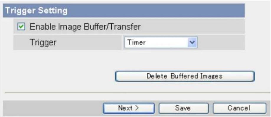
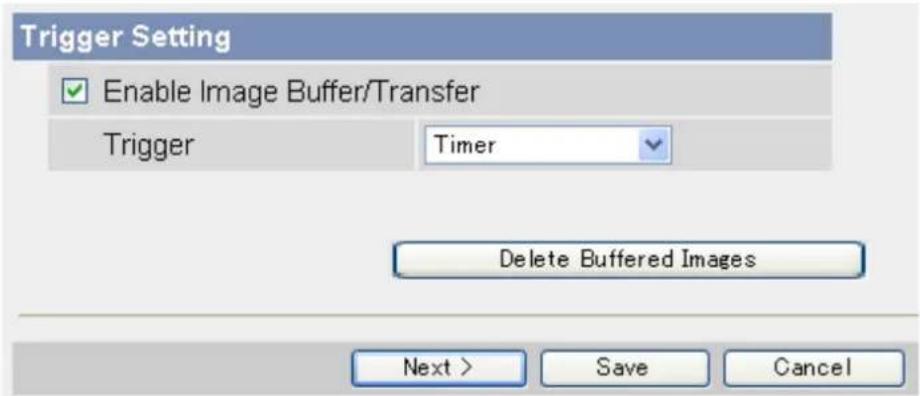
- Check [Enable Image Buffer/Transfer] to enable the trigger.
text_image
Trigger Setting Enable Image Buffer/Transfer Trigger Timer Delete Buffered Images Next > Save Cancel- Select [Timer] from the pull-down menu, then click [Next].
- Under [Time], select the days of the week when the trigger will be active.
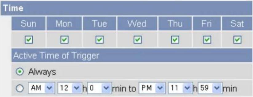
text_image
Time Sun Mon Tue Wed Thu Fri Sat ✓ ✓ ✓ ✓ ✓ ✓ ✓ Active Time of Trigger Always AM 12 h 0 min to PM 11 h 59 min- Select the time of day the trigger will be active, or click [Always] to enable the trigger for the full 24 hours of each day selected.
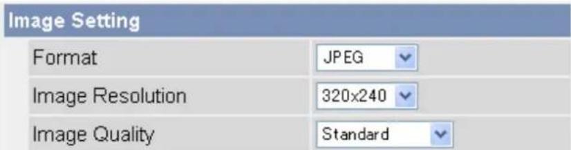
- Under [Image Setting], select the desired image format, image resolution, and image quality.
text_image
Image Setting Format JPEG Image Resolution 320x240 Image Quality Standard- The image quality setting is not available when [MPEG-4] is selected as the image format.
-
When configuring the trigger to transfer images to a mobile phone's E-mail address, set the image resolution to 192 × 144 , and set the image quality to [Favor Motion].
-
Under [Image Buffer Frequency], select the desired buffer or transfer rate.

text_image
Image Buffer Frequency Every 1 min , buffer 1 images.- Under [Transfer Method], select the desired transfer method.
- MPEG-4 images cannot be transferred.
| Transfer Method | |
| ○ No Transfer, No Memory Overwrite | |
| ○ No Transfer, Memory Overwrite | |
| ○ FTP | |
| ○ HTTP | |
- [No Transfer, No Memory Overwrite]: Images are not transferred. Images are buffered until the camera's memory is full.
- [No Transfer, Memory Overwrite]: Images are not transferred. Once the camera's memory is full, new images replace the old images.
- [FTP]: After an image is captured, it is transferred to the specified FTP site.
– [E-Mail]: After an image is captured, it is sent to the specified E-mail address. -
[HTTP]: After an image is captured, it is transferred to the specified website.
-
Follow the procedure below based on the settings you made under [Transfer Method].
a. If you selected to not transfer images (i.e., to buffer images only), click [Save] to finish.
- All buffered images for the selected trigger are deleted when you click [Save].
b. If you selected to transfer images by FTP, E-mail, or HTTP, click [Next].
- The appropriate transfer settings page is displayed.
- For FTP transfer, see Page 37.
- For E-mail transfer, see Page 39.
- For HTTP transfer, see Page 42.
Note
- In order for this feature to work as expected, make sure the camera's date and time setting is correct (see Page 95).
- When selecting the buffer or transfer rate, keep in mind that the actual rate may be slower depending on network conditions, the number of people accessing the camera, and the type of objects being viewed.
2.2 Configuring a Sensor or Motion Detection Trigger
- Click the [Setup] tab.
- On the left side of the screen under [Buffer/Transfer], click [Trigger].
- Click a trigger number (1–5).
| Trigger | ||||||||||||
| No. | Status | Trigger | Sun | Mon | Tue | Wed | Thu | Fri | Sat | Active Time of Trigger | Transfer Method | Notif |
| 1 | OFF | Timer | X | X | X | X | X | X | X | Always | No Transfer, No Memory Overwrite | - |
| 2 | OFF | Timer | X | X | X | X | X | X | X | Always | No Transfer, No Memory Overwrite | - |
| 3 | OFF | Timer | X | X | X | X | X | X | X | Always | No Transfer, No Memory Overwrite | - |
| 4 | OFF | Timer | X | X | X | X | X | X | X | Always | No Transfer, No Memory Overwrite | - |
| 5 | OFF | Timer | X | X | X | X | X | X | X | Always | No Transfer, No Memory Overwrite | - |
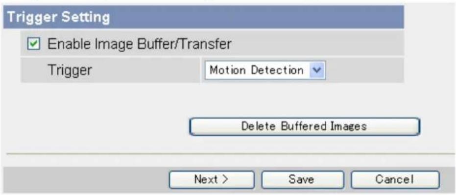
- Check [Enable Image Buffer/Transfer] to enable the trigger.
text_image
Trigger Setting Enable Image Buffer/Transfer Trigger Motion Detection Delete Buffered Images Next > Save Cancel- Select [Sensor] or [Motion Detection] from the pull-down menu, then click [Next].
• To adjust the sensitivity of the built-in sensor, see Page 56.
- For information on how the motion detection feature detects motion and how to adjust the sensitivity of the motion detection feature, see Page 57.
- The motion detection feature is disabled when panning and tilting the camera lens, i.e., moving the camera lens will not trigger the motion detection feature.
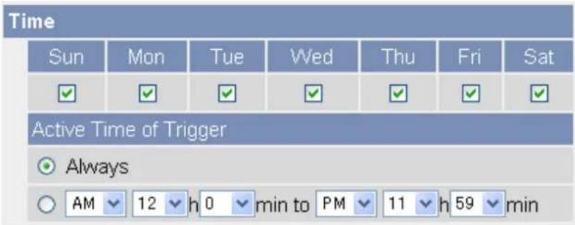
- Under [Time], select the days of the week when the trigger will be active.
text_image
Time Sun Mon Tue Wed Thu Fri Sat ✓ ✓ ✓ ✓ ✓ ✓ ✓ Active Time of Trigger Always AM 12 h 0 min to PM 11 h 59 min- Select the time of day the trigger will be active, or click [Always] to enable the trigger for the full 24 hours of each day selected.
- Under [Lens Position When Triggered], select [Do not move] or the desired preset. The lens will aim in the appropriate direction when triggered.

text_image
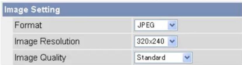
Lens Position When Triggered When triggered, Do not move- Under [Image Setting], select the desired image format, image resolution, and image quality.
text_image
Image Setting Format JPEG Image Resolution 320x240 Image Quality Standard- The image quality setting is not available when [MPEG-4] is selected as the image format.
-
When configuring the trigger to transfer images to a mobile phone's E-mail address, set the image resolution to 192 × 144 , and set the image quality to [Favor Motion].
-
Under [Image Buffer Frequency], select the desired buffer or transfer rate.
text_image
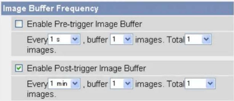
Image Buffer Frequency Enable Pre-trigger Image Buffer Every 1 s , buffer 1 images. Total 1 images. Enable Post-trigger Image Buffer Every 1 min , buffer 1 images. Total 1 images.When [MPEG-4] is selected
To configure the camera to save video from after the camera was triggered, click [Enable Post-trigger Image Buffer] and select how many seconds of video you would like to save. This setting allows you to see camera images beginning from when the camera was triggered.
When [JPEG] is selected
To configure the camera to buffer or transfer images from before the camera was triggered, click [Enable Pre-trigger Image Buffer] and select the image buffer or transfer rate and the total number of images to be buffered or transferred. This setting allows you to see camera images leading up to the moment when the camera was triggered.
To configure the camera to buffer or transfer images from after the camera was triggered, click [Enable Post-trigger Image Buffer] and select the image buffer or transfer rate and the total number of images to be buffered or transferred. This setting allows you to see camera images beginning from when the camera was triggered.
- Under [Sensor deactivation time setting], select the amount of time that must pass after a detection before this trigger can make another detection.
![PANASONIC BL-C131A - When [JPEG] is selected - 1](/content/2026/06/1244027/images/2d950c7d0392b94f45501cc76183cf240952513be8842061fe8e9414fac056a4.jpg)
text_image
Sensor deactivation time setting Sensor deactivation time None- If the camera is triggered often, many images will be buffered or transferred. If those images are transferred to a mobile phone by E-mail, for example, many messages will be sent and mobile phone charges may become expensive. It is therefore recommended to use this setting to help reduce the number of images that are buffered or transferred.
- Images will not be buffered or transferred during the deactivation time. As a result, pre-buffer images from the next detection may not be buffered or transferred. For example, if this parameter is set to [10 s], and if the camera is configured to buffer 1 image per second and store 10 images before detection (i.e., buffer images for 10 seconds), the camera will not buffer or transfer images if the sensor is triggered within 10 seconds of the previous trigger. Images can only be buffered or transferred 10 seconds after the previous trigger.
— The camera can be triggered.
--- The camera is buffering or transferring images and cannot be triggered during this time.
…… Deactivation time; the camera cannot be triggered.
![PANASONIC BL-C131A - When [JPEG] is selected - 2](/content/2026/06/1244027/images/ab51ea82cb871443a3e2897ec8bacb8ae7f4b9eb5bb772cea05de8c7437cbc9d.jpg)
text_image
A B CA The camera is triggered. Buffering or transferring begins. No new images will be buffered or transferred.
B Buffering or transferring ends, deactivation time starts. No new images will be buffered or transferred.
C Deactivation time ends. The camera can buffer or transfer images again.
- Under [Transfer Method], select the desired transfer method.
- MPEG-4 images cannot be transferred.
| Transfer Method | |
| ○ No Transfer, No Memory Overwrite | |
| ○ No Transfer, Memory Overwrite | |
| ○ FTP | |
| ○ HTTP | |
- [No Transfer, No Memory Overwrite]: Images are not transferred. Images are buffered until the camera's memory is full.
- [No Transfer, Memory Overwrite]: Images are not transferred. Once the camera's memory is full, new images replace the old images.
-
[FTP]: After the camera is triggered, it transfers images to the specified FTP site.
– [E-Mail]: After the camera is triggered, it sends images to the specified E-mail address.
– [HTTP]: After the camera is triggered, it transfers images to the specified website. -
Under [Send Notification When Triggered], select the desired method for receiving notification when the camera is triggered, or select [Disable].
| Send Notification When Triggered |
| Disable |
| Send E-mail Notification |
| Send HTTP Notification |
- Follow the procedure below based on the settings you made under [Transfer Method] and [Send Notification When Triggered].
a. If you selected to not transfer images and to not send notification when the camera is triggered, click [Save] to finish.
- All buffered images for the selected trigger are deleted when you click [Save].
b. If you selected to transfer images by FTP, E-mail, or HTTP, click [Next].
- The appropriate transfer settings page is displayed.
- For FTP transfer, see Page 37.
- For E-mail transfer, see Page 39.
- For HTTP transfer, see Page 42.
c. If you selected to not transfer images, but selected to send notification, click [Next].
- The appropriate notification settings page is displayed.
- For E-mail notification, see Page 45.
- For HTTP notification, see Page 48.
Note
- In order for this feature to work as expected, make sure the camera's date and time setting is correct (see Page 95).
- When selecting the buffer or transfer rate, keep in mind that the actual rate may be slower depending on network conditions, the number of people accessing the camera, and the type of objects being viewed.
2.3 Disabling and Enabling a Trigger
After configuring an image buffering trigger, you can later disable the trigger to temporarily turn it off, and enable it to turn it on again. While disabled, a trigger will not buffer images, transfer images, or send trigger notification.
- Click the [Setup] tab.
- On the left side of the screen under [Buffer/Transfer], click [Trigger].
- Click a trigger number (1–5).
text_image
Trigger Setting Enable Image Buffer/Transfer Trigger Timer Delete Buffered Images Next > Save Cancel- Uncheck [Enable Image Buffer/Transfer] to disable the trigger.
- To enable a trigger you disabled earlier, check [Enable Image Buffer/Transfer].
- Click [Save].
- All buffered images for the selected trigger are deleted when you click [Save].
2.4 Configuring the Camera to Transfer Images
When configuring the camera's timer, sensor, or motion detection triggers, you can set the camera to transfer the captured images by FTP (see Page 37), E-mail (see Page 39), or HTTP (see Page 42). Once images are successfully transferred, they are deleted.
2.4.1 Transferring Images by FTP
The following screen is displayed if you select to transfer images by FTP while configuring a timer, sensor, or motion detection trigger (see Page 27 or Page 30). Follow the procedure below to configure the camera to transfer images to an FTP site. Ask the FTP server administrator for the appropriate settings.
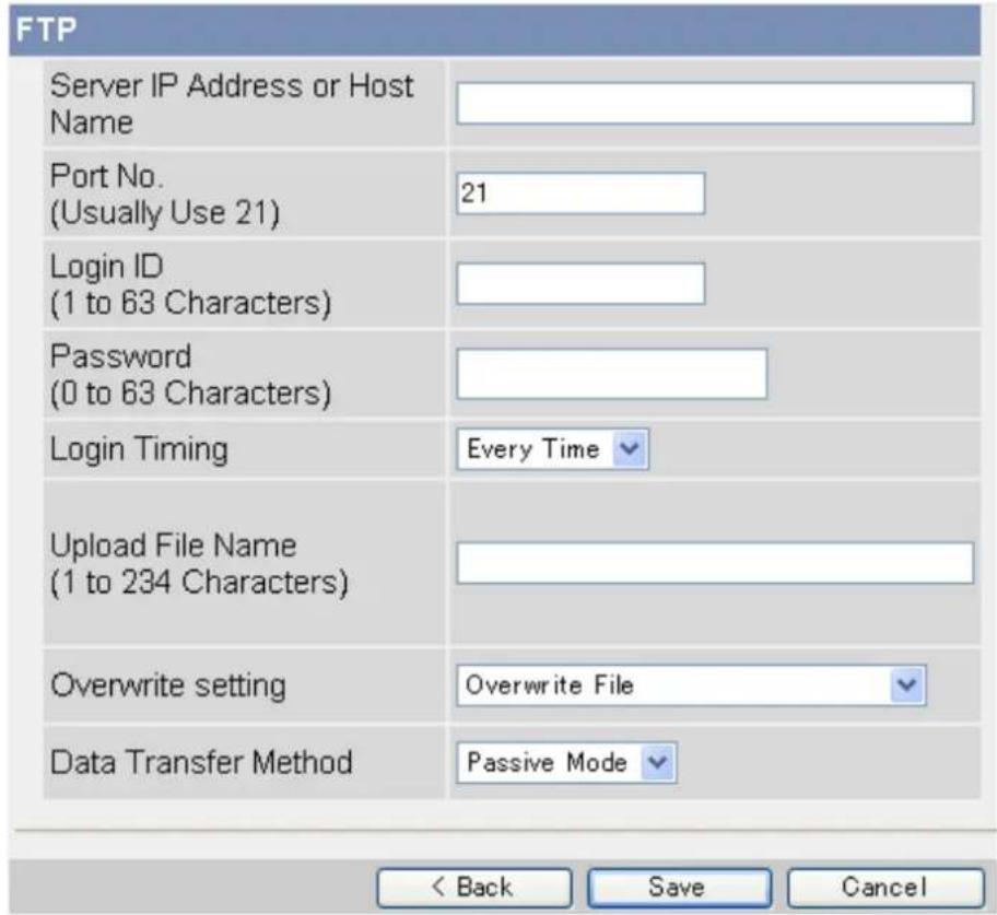
text_image
FTP Server IP Address or Host Name Port No. (Usually Use 21) 21 Login ID (1 to 63 Characters) Password (0 to 63 Characters) Login Timing Every Time Upload File Name (1 to 234 Characters) Overwrite setting Overwrite File Data Transfer Method Passive Mode < Back Save Cancel- Enter the IP address or host name ^1 of the FTP server.
- An IPv6 address can be entered.
-
Enter the port number used by the server. (Port 21 is normally used for FTP.)
-
Enter the login ID ^2 (user name) required to access the server (max. 63 characters).
-
Enter the password ^2 required to access the server (max. 63 characters).
-
Select the desired setting for [Login Timing]
-
[Every Time]: The camera logs in to the server every time it transfers an image to the server.
— [One Time]: The camera logs in to the server and stays connected for about 1 minute (unless a new transfer begins before this time expires). This can reduce transfer time when several images are transferred in a short time. -
Enter the desired name "1" for transferred files (max. 234 characters). Transferred files will be saved using this file name.
- You can specify existing directories on the server by entering “\” before the desired file name. For example, if you enter “Cameralimages\Image”, the camera will upload files to the directory “Cameralimages” and save the files using the name “Image”.
-
Select the desired setting for [Overwrite setting].
-
[Overwrite File]: The file on the server is replaced by the file uploaded by the camera, i.e., only 1 file is saved on the server.
- [Save as New File with Time Stamp]: A time stamp is added to the end of the file name, allowing multiple files to be saved on the server. For example, if you set the file name as "Image", an uploaded file may be saved as "Image20061231173020500".
The time stamp format is Year/Month/Date/24-hour time/Second/Millisecond.
Therefore, in this example, the file was captured on December 31, 2006, at 5:30 PM and 20 seconds and 500 milliseconds. Note that if you configure the camera to adjust its time setting for Daylight Saving Time (see Page 95), an "s" will be inserted between the date and time of the time stamp.
- Select the transfer method required to upload files to the server.
- Select [Passive Mode] normally. If files are not uploaded properly, change the setting to [Active Mode].
- Follow the procedure below based on the settings you made when configuring the trigger.
a. If you selected to not send notification when the camera is triggered, click [Save], then click [Go to Trigger page].
- All buffered images for the selected trigger are deleted when you click [Save].
b. If you selected to send notification when the camera is triggered, click [Next].
- The appropriate notification settings page is displayed.
- For E-mail notification, see Page 45.
- For HTTP notification, see Page 48.
^1 [Space], [“], [‘], [&], [<], and [>] cannot be entered.
^2 [“] cannot be entered.
2.4.2 Transferring Images by E-mail
The following screen is displayed if you select to transfer images by E-mail while configuring a timer, sensor, or motion detection trigger (see Page 27 or Page 30). Follow the procedure below to configure the camera to
send images to an E-mail address. Ask your Internet Service Provider (ISP) or network administrator for the appropriate settings.
| E-mail Transfer | |
| SMTP Server IP Address or Host Name | |
| Port No.(Usually Use 25) | 25 |
| Reply E-mail Address | |
| DestinationE-mail Address 1 | |
| DestinationE-mail Address 2 | |
| DestinationE-mail Address 3 | |
| Subject(Up to 44 Characters) | |
| Text(Up to 63 Characters) | |
| How to authenticate | |
| ○ No authentication | |
| ○ POP before SMTP authentication | |
| POP3 Server IP Address or Host Name | |
| Port No. (Usually Use 110) | 110 |
| Login ID (1 to 63 Characters) | |
| Password (0 to 63 Characters) | |
| ○ SMTP authentication | |
| Login ID (1 to 63 Characters) | |
| Password (0 to 63 Characters) | |

-
Under [E-mail Transfer], enter the IP address or the host name ^1 of the SMTP server (outgoing mail server).
-
An IPv6 address can be entered.
-
This feature cannot transfer images to web-based mail servers, such as Hotmail®.
-
Enter the port number used by the server. (Port 25 is normally used for sending E-mail.)
-
Enter the reply E-mail address ^2 that will be shown to the recipient as the sender of the E-mail.
- In an effort to reduce spam, many ISPs block E-mail sent through the SMTP server from an E-mail address that is not associated with the SMTP server, therefore, we recommend entering the E-mail assigned to you by your ISP.
-
Enter the destination E-mail address ^2 . Up to 3 addresses can be entered.
-
Enter the subject ^2 that will be displayed in E-mail messages sent by the camera (max. 44 characters).
- The date and time (24-hour format) is automatically attached to the subject.
For example, if you enter "Camera" as the subject, an E-mail may be sent with the subject "Camera:20061231173020500".
The time stamp format is Year/Month/Date/24-hour time/Second/Millisecond.
Therefore, in this example, the file was captured on December 31, 2006, at 5:30 PM and 20 seconds and 500 milliseconds. Note that if you configure the camera to adjust its time setting for Daylight Saving Time (see Page 95), an "s" will be inserted between the date and time of the time stamp.
- The date and time is also used as the sent file name (i.e., 20061231173020500.jpg).
- Enter the text ^2 that will be displayed in the body of E-mail messages sent by the camera (max. 63 characters).
• Line breaks cannot be entered.
-
Under [How to authenticate], select the authentication method your ISP requires for sending E-mail, and enter the appropriate settings if necessary.
-
[No authentication]: Select this option if the outgoing E-mail server does not require authentication when sending E-mail messages.
- [POP before SMTP authentication]: Select this option if the outgoing E-mail server requires POP before SMTP authentication when sending E-mail messages. The following settings are also necessary. Enter the settings as you would for receiving E-mail.
a. Enter the IP address or the host name ^1 of the POP3 server (incoming mail server).
- An IPv6 address can be entered.
b. Enter the port number used by the server. (Port 110 is normally used for POP3.)
c. Enter the login ID ^2 (user name) required to access the server (max. 63 characters).
d. Enter the password ^2 required to access the server (max. 63 characters).
- [SMTP authentication]: Select this option if the outgoing E-mail server requires SMTP authentication when sending E-mail messages. The following settings are also necessary. Enter the settings as you would for sending E-mail.
a. Enter the login ID ^2 (user name) required to access the server (max. 63 characters).
b. Enter the password ^2 required to access the server (max. 63 characters).
- The camera supports LOGIN, PLAIN, and CRAM-MD5 authentication.
- Follow the procedure below based on the settings you made when configuring the trigger.
a. If you selected to not send notification when the camera is triggered, click [Save], then click [Go to Trigger page].
- All buffered images for the selected trigger are deleted when you click [Save].
b. If you selected to send notification when the camera is triggered, click [Next].
- The appropriate notification settings page is displayed.
- For E-mail notification, see Page 45.
- For HTTP notification, see Page 48.
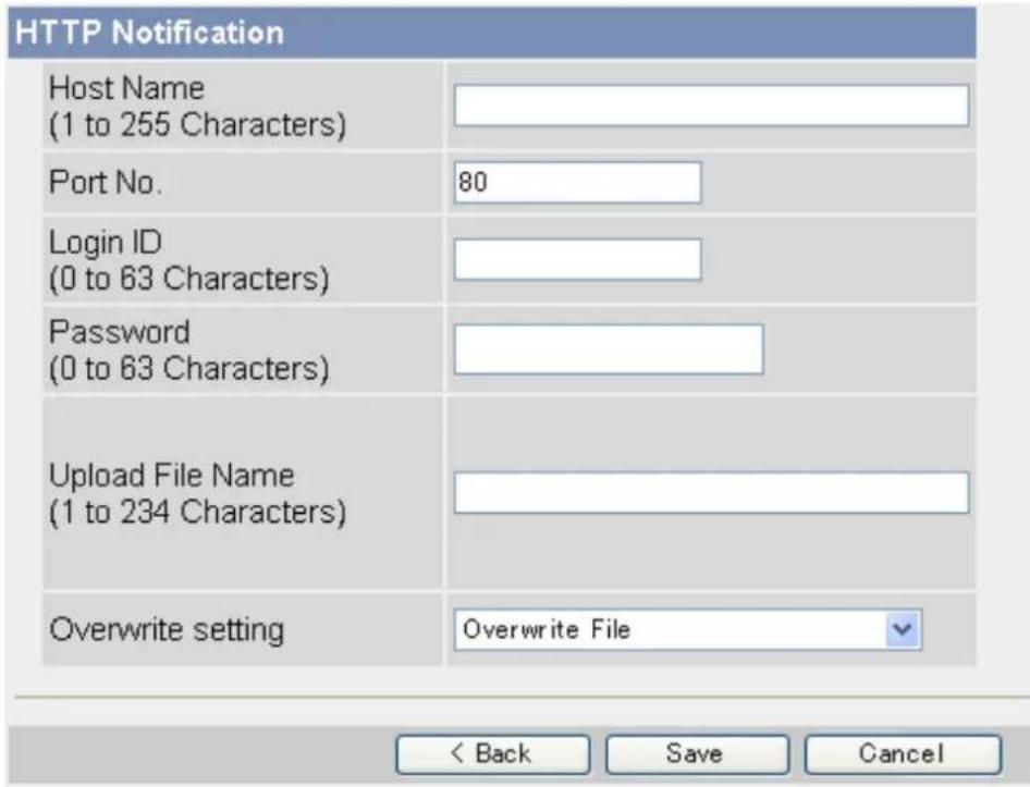
2.4.3 Transferring Images by HTTP
The following screen is displayed if you select to transfer images by HTTP while configuring a timer, sensor, or motion detection trigger (see Page 27 or Page 30). Follow the procedure below to configure the camera to transfer images to an HTTP site. Ask the HTTP server administrator for the appropriate settings.
Note
- If your computer network uses a proxy server, the appropriate proxy server settings must be made on the [Network (IPv4)] page in order for images to be transferred by HTTP (see Page 87).
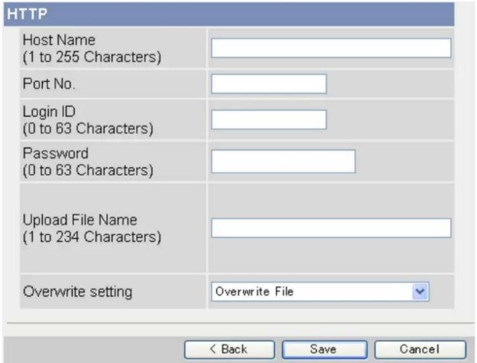
text_image
HTTP Host Name (1 to 255 Characters) Port No. Login ID (0 to 63 Characters) Password (0 to 63 Characters) Upload File Name (1 to 234 Characters) Overwrite setting Overwrite File < Back Save Cancel- Enter the URL of the HTTP server (max. 255 characters).
- An IPv6 address can be entered.
-
Enter the login ID ^1 (user name) required to access the server (max. 63 characters).
-
Enter the password ^1 required to access the server (max. 63 characters).
-
Enter the desired name ^2 for transferred files (max. 234 characters). Transferred files will be saved using this file name.
- You can specify existing directories on the server by entering “\” before the desired file name. For example, if you enter “Cameralimages\Image”, the camera will upload files to the directory “Cameralimages” and save the files using the name “Image”.
- Select the desired setting for [Overwrite setting].
- [Overwrite File]: The file on the server is replaced by the file uploaded by the camera, i.e., only 1 file is saved on the server.
— [Save as New File with Time Stamp]: A time stamp is added to the end of the file name, allowing multiple files to be saved on the server. For example, if you set the file name as "Image", an uploaded file may be saved as "Image20061231173020500".
The time stamp format is Year/Month/Date/24-hour time/Second/Millisecond.
Therefore, in this example, the file was captured on December 31, 2006, at 5:30 PM and 20 seconds and 500 milliseconds. Note that if you configure the camera to adjust its time setting for Daylight Saving Time (see Page 95), an "s" will be inserted between the date and time of the time stamp.
- Follow the procedure below based on the settings you made when configuring the trigger.
a. If you selected to not send notification when the camera is triggered, click [Save], then click [Go to Trigger page].
- All buffered images for the selected trigger are deleted when you click [Save].
b. If you selected to send notification when the camera is triggered, continue from the appropriate page.
- For E-mail notification, see Page 45.
- For HTTP notification, see Page 48.
“1” [“] cannot be entered.
^*2 [Space], [“], [’], [&], [<], and [>] cannot be entered.
2.5 Configuring the Camera to Send Trigger Notifications
When configuring the camera to buffer or transfer images by sensor or by the motion detection feature, you can configure the camera to send notifications via E-mail (see Page 45) or HTTP (see Page 48) when the camera is triggered.
Note
- Notifications cannot be sent when buffering or transferring images by timer.
You can also send a log of trigger notifications once a day (see Page 59).
2.5.1 Sending Trigger Notifications by E-mail
The following screen is displayed while configuring the camera to buffer or transfer images by sensor or by motion detection (see Page 30) if you select [Send E-mail Notification]. Follow the procedure below to send
trigger notifications via E-mail. Ask your Internet Service Provider (ISP) or network administrator for the appropriate settings.
E-mail Notification When Triggered
| SMTP Server IP Address or Host Name | |
| Port No.(Usually Use 25) | 25 |
| Reply E-mail Address | |
| DestinationE-mail Address 1 | |
| DestinationE-mail Address 2 | |
| DestinationE-mail Address 3 | |
| Subject(Up to 44 Characters) | |
| Text(Up to 63 Characters) |
How to authenticate
| ○ No authentication | |
| ○ POP before SMTP authentication | |
| POP3 Server IP Address or Host Name | |
| Port No.(Usually Use 110) | 110 |
| Login ID(1 to 63 Characters) | |
| Password(0 to 63 Characters) | |
| ○ SMTP authentication | |
| Login ID(1 to 63 Characters) | |
| Password(0 to 63 Characters) | |
- Under [E-mail Notification When Triggered], enter the IP address or the host name "1 of the SMTP server (outgoing mail server).
- An IPv6 address can be entered.
- This feature cannot transfer images to web-based mail servers, such as Hotmail.
-
Enter the port number used by the server. (Port 25 is normally used for sending E-mail.)
-
Enter the reply E-mail address ^2 that will be shown to the recipient as the sender of the E-mail.
- In an effort to reduce spam, many ISPs block E-mail sent through the SMTP server from an E-mail address that is not associated with the SMTP server, therefore, we recommend entering the E-mail address assigned to you by your ISP.
-
Enter the destination E-mail address ^2 . Up to 3 addresses can be entered.
-
Enter the subject ^2 that will be displayed in E-mail messages sent by the camera (max. 44 characters).
-
Enter the text ^2 that will be displayed in the body of E-mail messages sent by the camera (max. 63 characters).
• Line breaks cannot be entered.
- Under [How to authenticate], select the authentication method your ISP requires for sending E-mail, and enter the appropriate settings if necessary.
- [No authentication]: Select this option if the outgoing E-mail server does not require authentication when sending E-mail messages.
- [POP before SMTP authentication]: Select this option if the outgoing E-mail server requires POP before SMTP authentication when sending E-mail messages. The following settings are also necessary. Enter the settings as you would for receiving E-mail.
a. Enter the IP address or the host name ^1 of the POP3 server (incoming mail server).
- An IPv6 address can be entered.
b. Enter the port number used by the server. (Port 110 is normally used for POP3.)
c. Enter the login ID ^2 (user name) required to access the server (max. 63 characters).
d. Enter the password ^2 required to access the server (max. 63 characters).
- [SMTP authentication]: Select this option if the outgoing E-mail server requires SMTP authentication when sending E-mail messages. The following settings are also necessary. Enter the settings as you would for sending E-mail.
a. Enter the login ID ^2 (user name) required to access the server (max. 63 characters).
b. Enter the password ^2 required to access the server (max. 63 characters).
- The camera supports LOGIN, PLAIN, and CRAM-MD5 authentication.
- Click [Save], then click [Go to Trigger page].
- All buffered images for the selected trigger are deleted when you click [Save].
2.5.2 Sending Trigger Notifications by HTTP
The following screen is displayed while configuring the camera to buffer or transfer images by sensor or by motion detection (see Page 30) if you select [Send HTTP Notification]. Follow the procedure below to send trigger notifications via HTTP.
Note
- If your computer network uses a proxy server, the appropriate proxy server settings must be made on the [Network (IPv4)] page in order for images to be transferred by HTTP (see Page 87).
text_image
HTTP Notification Host Name (1 to 255 Characters) Port No. 80 Login ID (0 to 63 Characters) Password (0 to 63 Characters) Upload File Name (1 to 234 Characters) Overwrite setting Overwrite File < Back Save Cancel- Under [HTTP Notification], enter the URL of the HTTP server (max. 255 characters).
- An IPv6 address can be entered.
-
Enter the login ID ^*1 (user name) required to access the server (max. 63 characters).
-
Enter the password ^*1 required to access the server (max. 63 characters).
-
Enter the desired name ^2 for transferred files (max. 234 characters). Transferred files will be saved using this file name.
- Entering “\” allows you to specify existing directories on the server. For example, if you enter “CameraNotifications\Notification” as the file name, the camera will upload files to the directory “CameraNotifications” and save the files using the name “Notification”.
- Select the desired setting for [Overwrite setting].
- [Overwrite File]: The file on the server is replaced by the file uploaded by the camera, i.e., only 1 file is saved on the server.
- [Save as New File with Time Stamp]: A time stamp is added to the end of the file name, allowing multiple files to be saved on the server. For example, if you set the file name as "Notification", an uploaded file may be saved as "Notification20061231173020500".
The time stamp format is Year/Month/Date/24-hour time/Second/Millisecond.
Therefore, in this example, this notification was sent on December 31, 2006, at 5:30 PM and 20 seconds and 500 milliseconds. Note that if you configure the camera to adjust its time setting for Daylight Saving Time (see Page 95), an "s" will be inserted between the date and time of the time stamp.
- Click [Save], then click [Go to Trigger page].
- All buffered images for the selected trigger are deleted when you click [Save].
“1” [“] cannot be entered.
^2 [Space], [“], [“], [&], [<], and [>] cannot be entered.
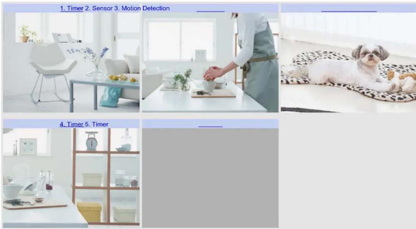
2.6 Viewing Buffered Images
If you have configured the camera to buffer images (see Page 27 or Page 30), you can access the camera and view the buffered images.
Note
- If you have configured the camera to transfer images by FTP, E-mail, or HTTP, images are deleted once they have been successfully transferred and you cannot view the images using the procedure described in this section.
-
Click the [Buffered Image] tab.
-
The oldest buffered image for triggers 1–5 are displayed.
• If a trigger is disabled, or if the trigger has not yet buffered images, a gray screen is displayed. - Date and time overlays, alarm state overlays, and text overlays may be displayed on buffered images according to the [Overlay Setting] (see Page 110). See Page 9 for an example of a camera image overlays.
text_image
1. Timer 2. Sensor 3. Motion Detection 4. Timer 5. Timer- Click the trigger title corresponding to buffered images you want to view.
Viewing and downloading buffered MPEG-4 videos
A. Start and end date and time when the image was buffered
B. Camera image
C. Playback controls (refer to the Windows Media® Player help file for details)
D. Click to save the video to your PC
Viewing and downloading buffered JPEG images (videos and still images)
A Nov.15.2006 10:57 PM - Nov.15.2006 10:57 PM

natural_image
Interior living room scene with white furniture, a glass coffee table, and potted plants near a window (no visible text or symbols)C—Nov.15 10:57:15.409 PM 1/10 Frame
D First <100 <10 <1 Play 1> 10> 100> Last
Download Buffered Images.
Download 1 images. Download
A. Start and end date and time when the image was buffered
B. Camera image
C. Date and time when the displayed image was buffered, current image number, and total number of images buffered
D. Playback controls (explained below)
E. Click to select how many images will be downloaded when [Download] is clicked
F. Click to download the selected number of images
Playing images
[Play]: All buffered images are displayed in sequence
[First] or [Last]: The first or last image is displayed
[<100], [<10], [<1]: "Rewinds" by the corresponding number of frames
[100>], [10>], [1>]: "Fast-forwards" by the corresponding number of frames
Note
- Date, time and image number are not displayed during playback.
- The digital zoom feature (see Page 20) can be used during JPEG image playback.
Downloading images
Select the number of frames you want to download, click [Download], and specify a location on your PC to save the images. Images are saved in JPEG (.jpg) format. You view them conveniently using the Network Camera Viewer program, which you can download from the Panasonic Network Camera website (http://panasonic.co.jp/pcc/products/en/netwkcam/).
You can also download a still image by right-clicking in the image area and selecting [Save Picture As...].
Note
- The maximum number of images that can be buffered in the camera's internal memory varies on image resolution, image quality and the content of the images being buffered. At the 320 × 240 pixels resolution and the standard quality, the camera can buffer a total of about xx250 frames (see Page 148). Note that the camera's internal memory is divided between the number of triggers that are configured. For example, if 5 triggers are set, each trigger can buffer about xx50 images.
- The camera allows up to 30 users to view live video images and buffered images simultaneously. Additional users will see a gray screen.
2.7 Deleting Buffered Images
You can delete all images buffered by a specific trigger.
- Click the [Setup] tab.
- On the left side of the screen under [Buffer/Transfer], click [Trigger].
- Click a trigger number (1–5).
| Trigger | ||||||||||||
| No. | Status | Trigger | Sun | Mon | Tue | Wed | Thu | Fri | Sat | Active Time of Trigger | Transfer Method | Notif |
| 1 | OFF | Timer | X | X | X | X | X | X | X | Always | No Transfer, No Memory Overwrite | - |
| 2 | OFF | Timer | X | X | X | X | X | X | X | Always | No Transfer, No Memory Overwrite | - |
| 3 | OFF | Timer | X | X | X | X | X | X | X | Always | No Transfer, No Memory Overwrite | - |
| 4 | OFF | Timer | X | X | X | X | X | X | X | Always | No Transfer, No Memory Overwrite | - |
| 5 | OFF | Timer | X | X | X | X | X | X | X | Always | No Transfer, No Memory Overwrite | - |
4. Click [Delete Buffered Images].
![PANASONIC BL-C131A - Click [Delete Buffered Images]. - 1](/content/2026/06/1244027/images/781cc0c9bc9f5fa14445517b4a19c5d3ff5cb5fdcd5cb2fc4edbf75fca3180f7.jpg)
text_image
Trigger Setting Enable Image Buffer/Transfer Trigger Timer Delete Buffered Images Next > Save CancelNote
- When restarting the camera (see Page 123), buffered images for all triggers are deleted.
-
The following operations also delete buffered images for all triggers.
-
Turning off the camera.
- Saving the Date and Time page.
- Restarting, updating firmware or resetting the camera to factory default.
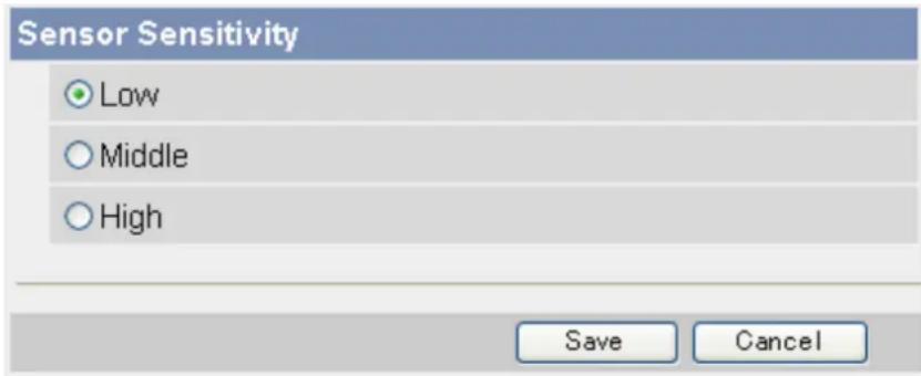
2.8 Adjusting Sensor Sensitivity
If using the camera's built-in sensor to buffer or transfer camera images, you may want to adjust the sensor's sensitivity for optimal results.
- Click the [Setup] tab.
- On the left side of the screen under [Buffer/Transfer], click [Sensor Sensitivity].
- Select the desired setting.
text_image
Sensor Sensitivity ● Low ○ Middle ○ High Save Cancel-
[Low]: The sensor is less sensitive to heat variations (default).
– [Middle]: The sensor is moderately sensitive to heat variations.
– [High]: The sensor is more sensitive to heat variations. -
Click [Save].
2.9 Adjusting Motion Detection Sensitivity
If using the motion detection feature to buffer or transfer camera images, you may want to adjust the motion detection sensitivity for optimal results.
- Click the [Setup] tab.
- On the left side of the screen under [Buffer/Transfer], click [Motion Detection].
- Observe the [Preview] area to confirm how the current settings detect motion.
• Any changes you make on this page will not be reflected in the [Preview] area until you click [Save].
- You can click on the image in the [Preview] area to use the click to center feature and aim the lens in the desired direction when confirming the current sensitivity settings.
-
If necessary, adjust the detection threshold by clicking the appropriate block.
-
If necessary, adjust the motion sensitivity by clicking the appropriate block.
- Click [Save], and then click [Go to Motion Detection page].
- Observe the [Preview] area to confirm how the new settings detect motion, and repeat from step 4 if necessary.
Understanding [Threshold] and [Sensitivity]
Motion detection threshold and sensitivity can be adjusted. Understanding how threshold and sensitivity interact will help you adjust the motion detection feature to suit your needs.
[Threshold]: Determines at what point the motion detection feature is triggered. A lower threshold means less motion is needed to trigger the motion detection feature. A higher threshold means more motion is needed to trigger the motion detection feature. Threshold is indicated in the [Preview] area by the light green area.
[Sensitivity]: Determines how easily the camera detects motion. Lower sensitivity means the camera is less likely to detect motion. Higher sensitivity means the camera is more likely to detect motion. Motion is indicated in the [Preview] area in dark green when it has not exceeded the detection threshold, and is indicated in dark red when it has exceeded the detection threshold.
[Preview]: Refer to this area to see how the current settings (effective after clicking [Save]) detect motion. The following examples show how [Threshold] and [Sensitivity] are represented in the [Preview] area.
Example 1
| Parameter Display Meaning | ||
| [Threshold] | ![PANASONIC BL-C131A - Understanding [Threshold] and [Sensitivity] - 1](/content/2026/06/1244027/images/b6138f556dde5c1c8eda1a17dfa8ca76ca64abbbd1f104268e9eafe45f18fbfb.jpg) | Low threshold (A) |
| [Sensitivity] | ![PANASONIC BL-C131A - Understanding [Threshold] and [Sensitivity] - 2](/content/2026/06/1244027/images/893917d33e2c5452d4ae827e7e3e00b3d197039b9de2b675e345f2a0e6f734d8.jpg) | Moderate sensitivity (B) |
| [Preview] | ![PANASONIC BL-C131A - Understanding [Threshold] and [Sensitivity] - 3](/content/2026/06/1244027/images/5660628fe287585d6a655dc2c7a6d603a12c9e1567c732b5909a0fb06e2af69c.jpg) | Low threshold (A), no motion is detected |
| [Preview] | ![PANASONIC BL-C131A - Understanding [Threshold] and [Sensitivity] - 4](/content/2026/06/1244027/images/c971f141bb924a46a240ea031a3c5fcdb826cbf398a3623f8252c7cbb8b59919.jpg) | Low threshold (A), low motion (C), motion detection is not triggered |
| [Preview] | ![PANASONIC BL-C131A - Understanding [Threshold] and [Sensitivity] - 5](/content/2026/06/1244027/images/b756cd6de512e2f72e7adf83a58913fcc0c2e2e062e9b010d5d02b2676c46bea.jpg) | Low threshold (A), moderate (D), motion detection is triggered |
Example 2
| Parameter Display Meaning | ||
| [Threshold] | ![PANASONIC BL-C131A - Understanding [Threshold] and [Sensitivity] - 6](/content/2026/06/1244027/images/052c9d1efe419add4e4e06ca7782314a8954d24442440cca0256baebc18468f1.jpg) | High threshold (A) |
| [Sensitivity] | ![PANASONIC BL-C131A - Understanding [Threshold] and [Sensitivity] - 7](/content/2026/06/1244027/images/bd609c01473466cc79bfca642af72d59e4a57f7fe61517d2f1ec2aa0d435cbf2.jpg) | Moderate sensitivity (B) |
| [Preview] | ![PANASONIC BL-C131A - Understanding [Threshold] and [Sensitivity] - 8](/content/2026/06/1244027/images/8924ad65a06b912ea502c55439b118a2ff6bd4b23f8d35349c8084eaa165ce8e.jpg) | High threshold (A), no motion is detected |
| [Preview] | ![PANASONIC BL-C131A - Understanding [Threshold] and [Sensitivity] - 9](/content/2026/06/1244027/images/ac87a7557cf7f6fa7e899c8df52d17bfd809ac8c4612ca9a91a66615e1813109.jpg) | High threshold (A), moderate motion (C), motion detection is not triggered |
| [Preview] | ![PANASONIC BL-C131A - Understanding [Threshold] and [Sensitivity] - 10](/content/2026/06/1244027/images/e57263022aaaca544d91edf9da1d01f21dafe9c7b5d21c1d2e6a5a1995c16c6c.jpg) | High threshold (A), high motion (D), motion detection is triggered |
Note
- Motion is detected by changes in the outline of objects and changes in object brightness, however, in some cases the camera may detect rapid brightness changes by artificial light sources (such as fluorescent lights) as motion.
- The camera's motion detection feature detects motion differently than the Network Camera Recorder software (sold separately).
- Motion may not be detected as desired if the object's color is similar to the color of the background.
- The motion detection feature is disabled when panning and tilting the camera lens, i.e., moving the camera lens will not trigger the motion detection feature.
- Motion detection can vary by the object, image resolution, or image quality. Refer to the [Preview] area to see how the current settings detect motion.
2.10 Sending Alarm Log Information
You can configure the camera to send a daily log by E-mail that reports the status of the sensor and motion detection triggers. This allows you to be notified by E-mail once a day and know whether or not there were any events that triggered the camera. Ask your Internet Service Provider (ISP) or network administrator for the appropriate settings.
- Click the [Setup] tab.
- On the left side of the screen under [Buffer/Transfer], click [Alarm Log].
- Under [A setup of operation], select the desired setting.
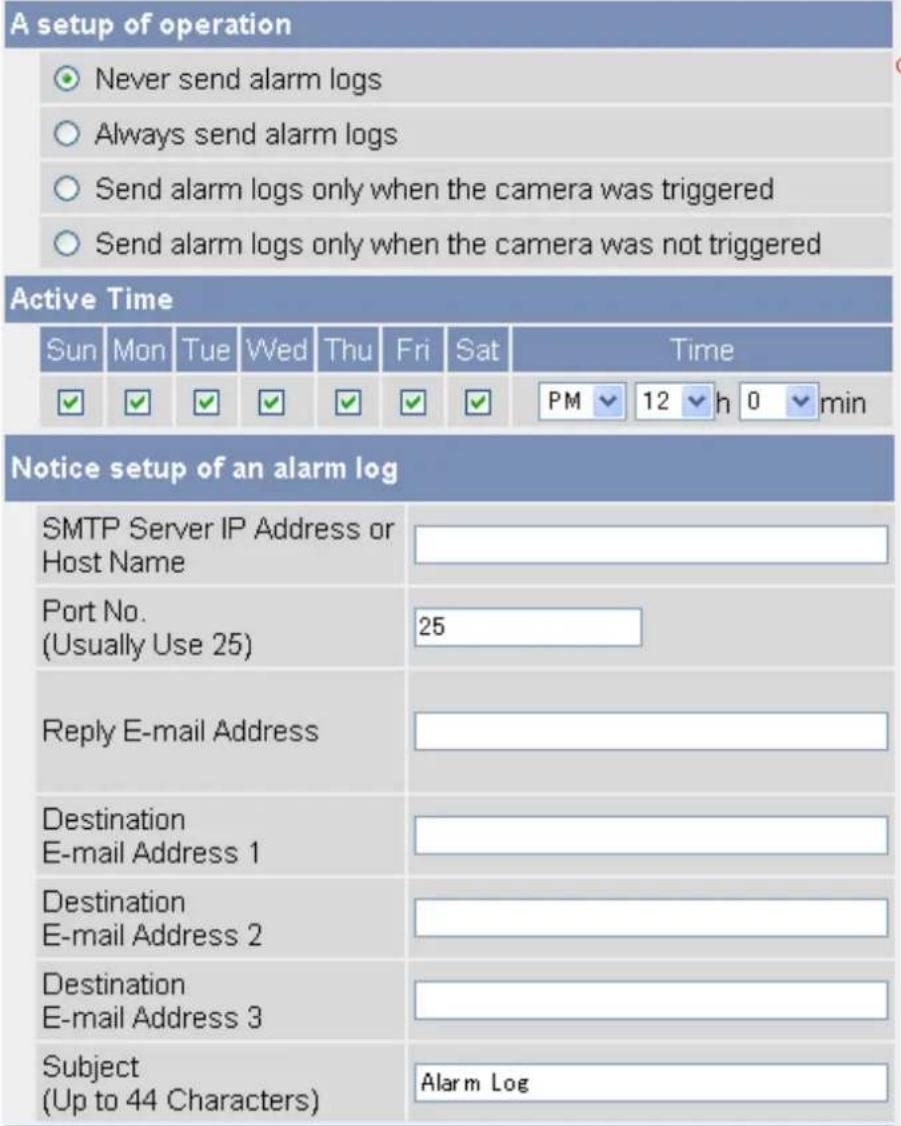
text_image
A setup of operation ○ Never send alarm logs ○ Always send alarm logs ○ Send alarm logs only when the camera was triggered ○ Send alarm logs only when the camera was not triggered Active Time Sun Mon Tue Wed Thu Fri Sat Time ✓ ✓ ✓ ✓ ✓ ✓ ✓ PM 12 h 0 min Notice setup of an alarm log SMTP Server IP Address or Host Name Port No. (Usually Use 25) Reply E-mail Address Destination E-mail Address 1 Destination E-mail Address 2 Destination E-mail Address 3 Subject (Up to 44 Characters) Alarm Log– [Never send alarm logs]: Alarm logs will not be sent.
- [Always send alarm logs]: Alarm logs will be sent, even if the camera was not triggered.
- [Send alarm logs only when the camera was triggered]: Alarm logs will be sent if the camera was triggered.
- [Send alarm logs only when the camera was not triggered]: Alarm logs will be sent only if the camera was not triggered.
-
Under [Active Time], select the days and the time you want the camera to send alarm logs.
-
Under [Notice setup of an alarm log], enter the IP address or the host name ^1 of the SMTP server (outgoing mail server).
-
An IPv6 address can be entered.
-
This feature cannot transfer images to web-based mail servers, such as Hotmail.
-
Enter the port number used by the server. (Port 25 is normally used for sending E-mail.)
-
Enter the reply E-mail address ^2 that will be shown to the recipient as the sender of the E-mail.
- In an effort to reduce spam, many ISPs block E-mail sent through the SMTP server from an E-mail address that is not associated with the SMTP server, therefore, we recommend entering the E-mail address assigned to you by your ISP.
- Enter the destination E-mail address ^2 . Up to 3 addresses can be entered.
- Enter the subject ^2 that will be displayed in E-mail messages sent by the camera (max. 44 characters).
- Under [How to authenticate], select the authentication method your ISP requires for sending E-mail, and enter the appropriate settings if necessary.
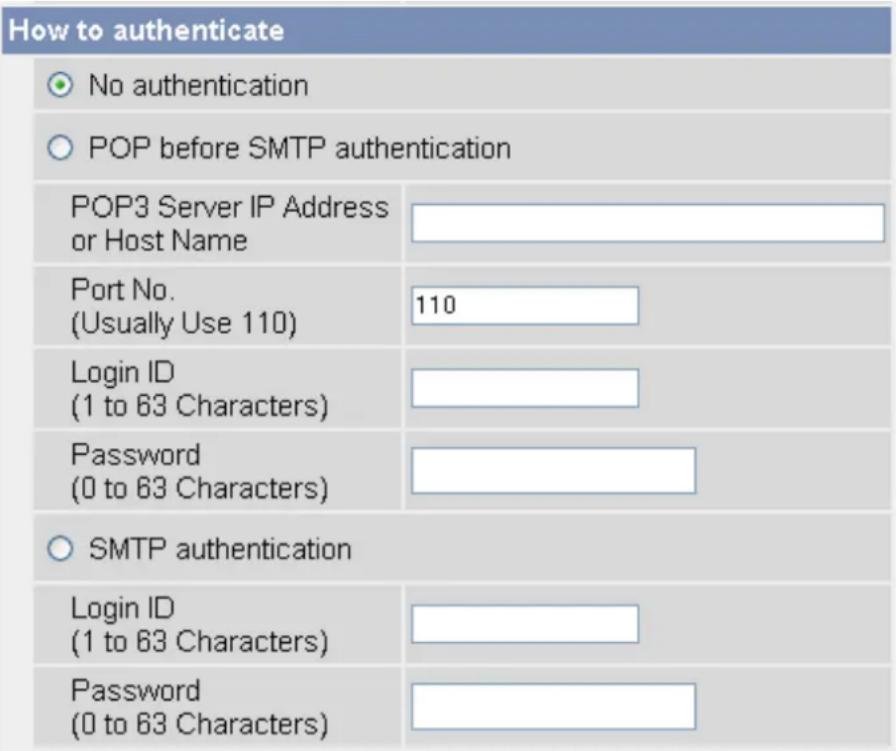
text_image
How to authenticate ○ No authentication ○ POP before SMTP authentication POP3 Server IP Address or Host Name Port No. (Usually Use 110) 110 Login ID (1 to 63 Characters) Password (0 to 63 Characters) ○ SMTP authentication Login ID (1 to 63 Characters) Password (0 to 63 Characters)- [No authentication]: Select this option if the outgoing E-mail server does not require authentication when sending E-mail messages.
- [POP before SMTP authentication]: Select this option if the outgoing E-mail server requires POP before SMTP authentication when sending E-mail messages. The following settings are also necessary. Enter the settings as you would for receiving E-mail.
a. Enter the IP address or the host name ^*1 of the POP3 server (incoming mail server).
- An IPv6 address can be entered.
b. Enter the port number used by the server. (Port 110 is normally used for POP3.)
c. Enter the login ID ^2 (user name) required to access the server (max. 63 characters).
d. Enter the password ^2 required to access the server (max. 63 characters).
- [SMTP authentication]: Select this option if the outgoing E-mail server requires SMTP authentication when sending E-mail messages. The following settings are also necessary. Enter the settings as you would for sending E-mail.
a. Enter the login ID ^2 (user name) required to access the server (max. 63 characters).
b. Enter the password ^2 required to access the server (max. 63 characters).
- The camera supports LOGIN, PLAIN, and CRAM-MD5 authentication.
- Click [Save], then click [Go to Alarm Log page].
Note
- When the settings are saved, the number of new alarm logs becomes 0.
^*1 [Space], [“], [“], [&], [<], and [>] cannot be entered.
^2 [“] cannot be entered.
3 Mobile Phone Features
This section describes the features available when using a mobile phone that is compatible with Panasonic Network Cameras. Before using any of these features, please read the following notes.
- Certain mobile phones are not compatible with Panasonic Network Cameras.
- Mobile phones that only allow the use of port number 80 or mobile phones that do not support password authentication are not compatible with Panasonic Network Cameras.
- Certain mobile phones may not display images correctly.
• Video images cannot be displayed on mobile phones. - The camera's audio features are not available with mobile phones.
3.1 Accessing the Camera from Your Mobile Phone
- Enter http://followed by the IP address of the camera and /mobile, then press [OK].
Example: http://***.***.***.***/mobile
If the camera's port number is a port number other than 80, enter “:” and the port number after the IP address.
Example: http://****.****.****.***:50001/mobile
If you have registered with a DNS service, such as Viewnetcam.com (see Page 75), enter the URL instead of the IP address.
Example: http://bob.viewnetcam.com
- If an authentication dialog is displayed, enter the user name and password.
- A still image from the camera is displayed.
- If the camera image is not displayed properly, try accessing the camera by entering one of the following instead of /mobile.
- /mobileh (for HTML)
- /mobilex (for XHTML)
Note
- If the camera is configured to allow access from guest users (i.e., anonymous users; see Page 107), users can access the camera's mobile phone pages using a mobile phone or PC without entering a user name or password.
3.2 Viewing Still Images on Your Mobile Phone
Still images from the camera can be viewed with a compatible mobile phone.
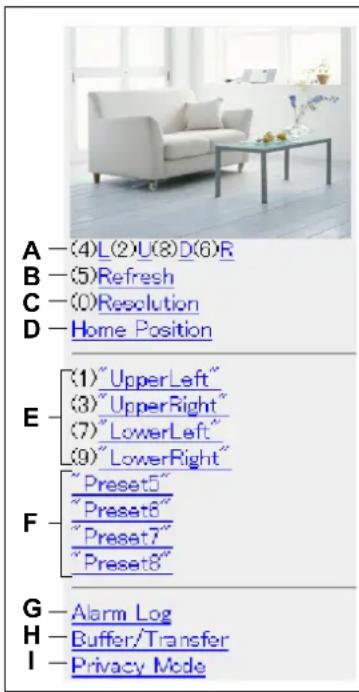
text_image
A —(4)L(2)U(8)D(6)R B —(5)Refresh C —(0)Resolution D —Home Position E —(1)"UpperLeft" (3)"UpperRight" (7)"LowerLeft" (9)"LowerRight" F —"Preset5" "Preset6" "Preset7" "Preset8" G —Alarm Log H —Buffer/Transfer I —Privacy ModeA. Press [4] or [6] to pan the lens left or right, respectively, or press [2] or [8] to tilt the lens up or down, respectively. When the lens has reached the end of its pan or tilt range, the corresponding number will not be displayed.
B. Press [5] to refresh the image.
C. Press [0] to toggle between the available image resolutions (192 × 144 and 320 × 240).
D. Select [Home Position] to move the lens to the home position.
E. Press [1], [3], [7] or [9] to move the lens to the first four presets (presets 1–4).
F. For presets 5–8, select the corresponding preset name to move the lens to the desired position.
G. Select [Alarm Log] to view the last 50 sensor and motion detection trigger logs (see Page 65).
- You must be logged in to the camera as an administrator to use this feature.
H. Select [Buffer/Transfer] to view the image buffer and transfer control page (see Page 66).
- You must be logged in to the camera as an administrator to use this feature.
I. Select [Privacy Mode] to turn privacy mode on. (You may be asked to enter the administrator user name and password.) To turn privacy mode off, access the camera again and select [Disable Privacy Mode].
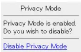
text_image
Privacy Mode Privacy Mode is enabled. Do you wish to disable? Disable Privacy Mode- You must be logged in to the camera as an administrator to use this feature.
Note
- When accessing the camera as a general user or as a guest user, certain features may be disabled according to the [Access Level] set for the user (see Page 104 and Page 107).
- If the camera is configured to allow access from guest users (i.e., anonymous users; see Page 107), users can access the camera's mobile phone pages using a mobile phone or PC without entering a user name or password. If guest user access is permitted, you can log in as the administrator by selecting [Alarm Log], [Buffer/Transfer], or [Privacy Mode], and then entering the user name and password when the authentication dialog is displayed.
- If you turn privacy mode on, camera images are not buffered even if the camera is configured to buffer images.
3.3 Viewing Alarm Logs on Your Mobile Phone
While accessing the camera from your mobile phone, select [Alarm Log] to view a record of the last 50 trigger events (sensor and motion detection). These logs allow you to confirm the date, time, and type (sensor or motion detection) of the last 50 times the camera was triggered.
Note
- You must be logged in to the camera as an administrator to use this feature.
- Access the camera with your mobile phone (see Page 63).
- Select [Alarm Log].
- Confirm the alarm logs as necessary.
- Select [Control Page] when finished to return to the previous screen.
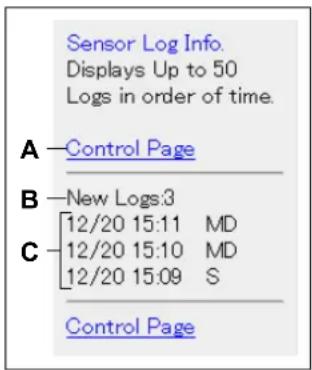
text_image
Sensor Log Info. Displays Up to 50 Logs in order of time. A — Control Page B — New Logs:3 C — [12/20 15:11 MD] [12/20 15:10 MD] [12/20 15:09 S] Control PageA. Returns to the previous screen.
B. The number of new alarm logs is displayed.
C. The date and time of each log, and the type of each trigger is displayed.
• MD indicates a motion detection.
- S indicates a sensor detection.
3.4 Enabling and Disabling Image Buffering Using Your Mobile Phone
While accessing the camera from your mobile phone, select [Buffer/Transfer] to display the image buffer and transfer control page on your mobile phone.
Note
- You must be logged in to the camera as an administrator to use this feature.
- Access the camera with your mobile phone (see Page 63).
- Select [Buffer/Trigger].
- Select the desired trigger number to turn the trigger on or off.
Buffer/Transfer
No.Status Trigger
(1) OFF Timer
(2) OFF Timer
(3) OFF Timer
(4) OFF Timer
(5) OFF Timer
Control Page
- Select [Save] to turn the selected trigger on or off.
Buffer/Transfer
The 1st setting will be changed to ON. If you press [Save], all buffered images are deleted.
Save Cancel
No.(1) Status:OFF -> ON Trigger:Timer Su Mo Tu We Th Fr Sa Active:Always No Transfer, No Memory Overwrite Notify :
- All buffered images for the selected trigger are deleted when you click [Save].
- Select [Control Page] when finished to return to the previous screen.
4 Configuring the Camera for Access from the Internet
You can configure the camera to be accessed over the Internet, allowing you to view camera images and change camera settings from anywhere—even using your mobile phone. This section explains the concepts and procedures for configuring your camera (and other network devices) to allow you to view camera images over the Internet.
Before you can configure the camera for access from the Internet, it is necessary to understand how IP addresses and Internet connections work.
Understanding local addresses
Each device connected to your computer network (PCs, router, network printers, network cameras, etc.) has an IP address. It probably looks something like this: 192.168.0.100. Each IP address on your network must be unique, as shown in the example below.
In this example, you would enter 192.168.0.253 or 192.168.0.252 in your web browser's address bar to access your cameras with your PC.
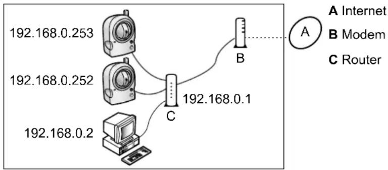
flowchart
graph TD
    A["192.168.0.253"] --> C["192.168.0.1"]
    B["192.168.0.252"] --> C
    C --> D["192.168.0.2"]
    E["192.168.0.2"] --> F["192.168.0.1"]
    G["192.168.0.1"] --> H["B"]
    I["A Internet"] --> J["B Modem"]
    K["C Router"] --> L["C"]
Although each IP address on your network must be unique, the addresses are unique only to your network. In other words, your cameras and your neighbor's cameras may have the same IP addresses. In the example below, the addresses of your devices (on the left) and the addresses of your neighbor's devices (on the right) are the same, but this is not a problem because the cameras are not connected to the same network.
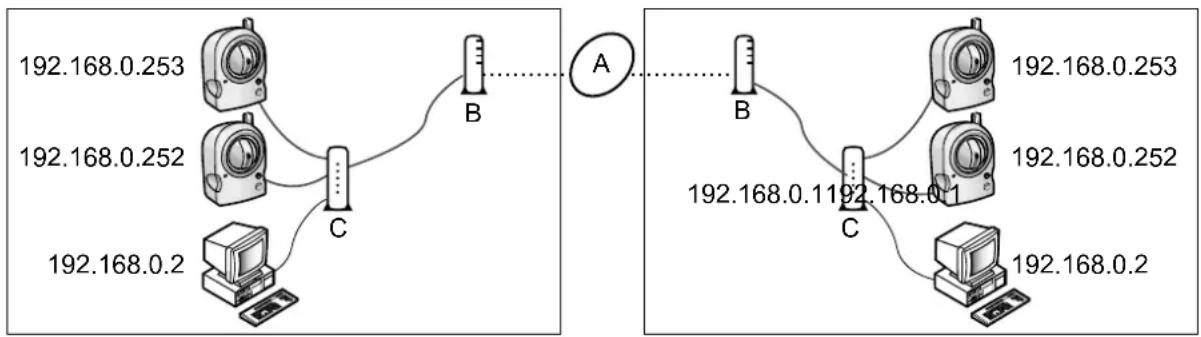
flowchart
graph TD
    subgraph_A["Network Diagram"]
        A1["IP地址 192.168.0.253"] --> A2["IP地址 192.168.0.252"]
        A2 --> A3["IP地址 192.168.0.2"]
        A3 --> A4["IP地址 192.168.0.253"]
        A4 --> A5["IP地址 192.168.0.252"]
        A5 --> A6["IP地址 192.168.0.253"]
        A6 --> A7["IP地址 192.168.0.253"]
        A7 --> A8["IP地址 192.168.0.252"]
        A8 --> A9["IP地址 192.168.0.253"]
        A9 --> A10["IP地址 192.168.0.253"]
        A10 --> A11["IP地址 192.168.0.253"]
        A11 --> A12["IP地址 192.168.0.253"]
        A12 --> A13["IP地址 192.168.0.253"]
        A13 --> A14["IP地址 192.168.0.253"]
        A14 --> A15["IP地址 192.168.0.253"]
        A15 --> A16["IP地址 192.168.0.253"]
        A16 --> A17["IP地址 192.168.0.253"]
        A17 --> A18["IP地址 192.168.0.253"]
        A18 --> A19["IP地址 192.168.0.253"]
        A19 --> A20["IP地址 192.168.0.253"]
        A20 --> A21["IP地址 192.168.0.253"]
        A21 --> A22["IP地址 192.168.0.253"]
        A22 --> A23["IP地址 192.168.0.253"]
        A23 --> A24["IP地址 192.168.0.253"]
        A24 --> A25["IP地址 192.168.0.253"]
        A25 --> A26["IP地址 192.168.0.253"]
        A26 --> A27["IP地址 192.168.0.253"]
        A27 --> A28["IP地址 192.168.0.253"]
        A28 --> A29["IP地址 192.168.0.253"]
        A29 --> A30["IP地址 192.168.0.253"]
        A30 --> A31["IP地址 192.168.0.253"]
        A31 --> A32["IP地址 192.168.0.253"]
        A32 --> A33["IP地址 192.168.0.253"]
        A33 --> A34["IP地址 192.168.0.253"]
        A34 --> A35["IP地址 192.168.0.253"]
        A35 --> A36["IP地址 192.168.0.253"]
        A36 --> A37["IP地址 192.168.0.253"]
        A37 --> A38["IP地址 192.168.0.253"]
        A38 --> A39["IP地址 192.168.0.253"]
        A39 --> A40["IP地址 192.168.0.253"]
        A40 --> A41["IP地址 192.168.0.253"]
        A41 --> A42["IP地址 192.168.0.253"]
        A42 --> A43["IP地址 192.168.0.253"]
        A43 --> A44["IP地址 192.168.0.253"]
        A44 --> A45["IP地址 192.168.0.253"]
        A45 --> A46["IP地址 192.168.0.253"]
        A46 --> A47["IP地址 192.168.0.253"]
        A47 --> A48["IP地址 192.168.0.253"]
        A48 --> A49["IP地址 192.168.0.253"]
        A49 --> A50["IP地址 192.168.0.253"]
        A50 --> A51["IP地址 192.168.0.253"]
        A51 --> A52["IP地址 192.168.0.253"]
        A52 --> A53["IP地址 192.168.0.253"]
        A53 --> A54["IP地址 192.168.0.253"]
        A54 --> A55["IP地址 192.168.0.253"]
        A55 --> A56["IP地址 192.168.0.253"]
        A56 --> A57["IP地址 192.168.0.253"]
        A57 --> A58["IP地址 192.168.0.253"]
        A58 --> A59["IP地址 192.168.0.253"]
        A59 --> A60["IP地址 192.168.0.253"]
        A60 --> A61["IP地址 192.168.0.253"]
        A61 --> A62["IP地址 192.168.0.253"]
        A62 --> A63["IP地址 192.168,0:"]
IP addresses that distinguish different devices on the same LAN (local area network, i.e., personal network) are called local IP addresses. The IP addresses in the examples above are local IP addresses.
So how can you access your camera when you are away from home if other people are using the same IP address as your camera?
Understanding global addresses
The answer is to access the camera by entering the unique IP address assigned to you by your Internet Service Provider (ISP). This address is called a global address, or a WAN (wide area network) address. In the example below, your global IP address is aaa.aaa.aaa.aaa and your neighbor's global IP address is zzz.zzz.zzz.zzz.
- Note that an actual IP address is made of numbers, not letters.
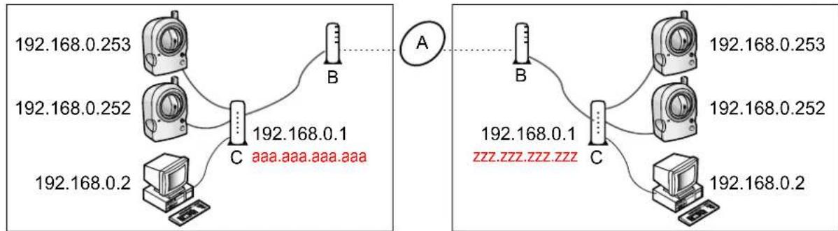
flowchart
graph TD
    subgraph_Left_Circuit_A["192.168.0.253"]
        A1["Device 1"] --> A2["Device 2"]
        A3["Device 3"] --> A4["Device 4"]
        A5["Device 5"] --> A6["Device 6"]
        A7["Device 7"] --> A8["Device 8"]
        A9["Device 9"] --> A10["Device 10"]
        A11["Device 11"] --> A12["Device 12"]
    end

    subgraph_Right_Circuit_B["192.168.0.253"]
        B1["Device 1"] --> B2["Device 2"]
        B3["Device 3"] --> B4["Device 4"]
        B5["Device 5"] --> B6["Device 6"]
        B7["Device 7"] --> B8["Device 8"]
        B9["Device 9"] --> B10["Device 10"]
    end

    A1 -.->|aaa.aaa.aaa.aaa| A2
    A2 -.->|zzz.zzz.zzz.zzz| B2
    B2 -.->|192.168.0.253| B3
    B3 -.->|192.168.0.252| B4
    B4 -.->|192.168.0.2| B5
    B5 -.->|192.168.0.2| B6
    B6 -.->|192.168.0.2| B7
    B7 -.->|192.168.0.2| B8
    B8 -.->|192.168.0.2| B9
When you are away from home, you can access your router by entering aaa.aaa.aaa.aaa. But now you have another problem—you don't want to access your router, you want to access the cameras connected to your routers.
Understanding port numbers
Data is sent between devices on a network using different ports depending on what kind of data is being sent. A port is not a physical object; it is a piece of information in the data that helps the data be directed to the intended device. In the example below, the port numbers 50000 and 50001 are assigned to your cameras.
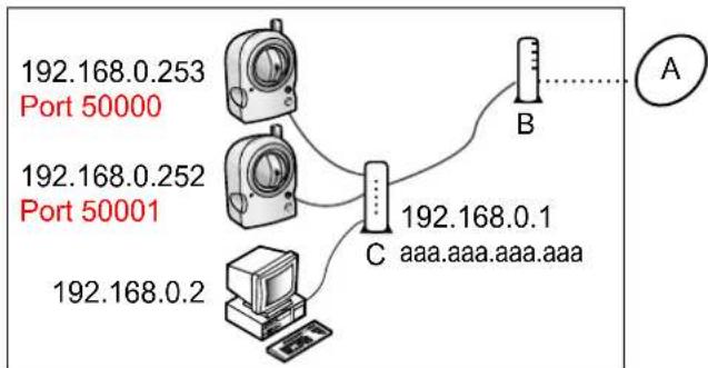
flowchart
graph TD
    A["Port 50000"] -->|192.168.0.253| B["Port 50001"]
    A -->|192.168.0.252| C["Port 50001"]
    A -->|192.168.0.2| D["Computer"]
    B -->|192.168.0.1| C
    C -->|192.168.0.2| D
    E["A"] --> F["Vertical Gauge"]
By assigning unique port numbers to your cameras, you can access your cameras when you are away from home by entering aaa.aaa.aaa.aaa:50000 or aaa.aaa.aaa.aaa:50001 in the web browser of a PC. When your router receives information via its global IP address, it passes it on to one of your cameras depending on which port number you entered after the global IP address.
But how does your router know which camera to pass information to?
Understanding port forwarding
If your router supports a feature called port forwarding (sometimes it's called address translation, static IP masquerade, virtual server, port mapping, or other names, depending on the router manufacturer), the router can be set up to take information it receives on specific ports and pass it on to a specific IP address. The port forwarding settings needed for the example above would look something like this:
| Port No. of Incoming Access Forwarding Destination | |
| 50000 192.168.0.253:50000 | |
| 50001 192.168.0.2 | 52:50001 |
Now you may be thinking, "do I have to do this programming by myself?"
Understanding UPnP ^TM
If your router does not support a feature called UPnP ^TM (Universal Plug and Play), you will have to manually configure your router for port forwarding. Refer to the operating instructions included with your router for more information.
If your router does support UPnP ^™ , your cameras and router can communicate with each other so that the router knows which ports are used by which camera. This means you will be able to access your cameras from the Internet without having to configure your router manually.
Understanding Dynamic DNS services
There is one last problem to solve. How do you find out the global address your ISP has assigned to you? The answer is to first contact them. If your provider has assigned you a static IP address (i.e., an IP address that never changes), you can use that static address to access your cameras from the Internet as long as your router is set up for port forwarding.
But most service providers use dynamic addresses, which means your global address may change monthly, weekly, or maybe even every day. If your provider uses dynamic addresses, you will need to register with a Dynamic DNS service in order to access your camera from the Internet.
A Dynamic DNS service allows you to use an easy-to-remember address (such as joe.camera.com) to access your camera from the Internet. If you have subscribed to a Dynamic DNS service and configured your camera to use that Dynamic DNS service, your camera will notify the Dynamic DNS service each time your provider changes your global IP address. This means your Dynamic DNS service always knows your current global address, so whenever you enter your easy-to-remember address, the Dynamic DNS service automatically passes the information on to your router, and ultimately, your camera.
Example of how a Dynamic DNS service helps you access your camera over the Internet

flowchart
graph TD
    A["User"] -->|1| B["B"]
    B -->|2| C["C"]
    C -->|3| D["D"]
    D -->|5| B
    B -->|4| E["Computer"]
    C -->|6| E
    style A fill:#f9f,stroke:#333
    style B fill:#ccf,stroke:#333
    style C fill:#cfc,stroke:#333
    style D fill:#fcc,stroke:#333
    style E fill:#cff,stroke:#333
A Internet
B ISP
C Dynamic DNS Service
D DNS Server
- Your ISP assigns a new global IP address to your Internet access account.
- The camera notifies your Dynamic DNS service of its new global IP address.
- The Dynamic DNS service notifies the DNS server of your new global IP address. The DNS server updates its information so that your URL (for example, joe.camera.com) is registered to your new global IP address.
- You try to access your camera from outside (i.e., over the Internet) by entering joe.camera.com.
- The computer contacts the DNS server and requests the global IP address registered to joe.camera.com. The DNS server looks up the global IP address of your URL.
- The computer receives your current global IP address from the DNS server and accesses the camera.
Summary
In order to access your camera over the Internet, you need to do the following.
-
Configure your router for port forwarding. If your router supports UPnP™, this can be done automatically. Refer to the operating instructions included with your router for information on UPnP™ support (the router's UPnP™ feature may be turned off by default) or for information on setting port forwarding.
-
If your ISP has assigned you a dynamic global IP address, register with a Dynamic DNS service. We recommend using Viewnetcam.com, a Dynamic DNS service that is designed for use with Panasonic Network Cameras. (For more information, refer to the Viewnetcam.com website at http://www.viewnetcam.com.)
-
After you have registered with a Dynamic DNS service, configure the camera to use that service.
4.1 Configuring Port Forwarding
In order to access your camera from the Internet, you will need to configure your router for port forwarding. If your router supports UPnP™ (Universal Plug and Play), the camera and router can communicate with each other and set port forwarding automatically. This can be done during initial configuration (as explained in the Setup Guide), or by following one of the procedures below.
There are two methods you can use to configure port forwarding via UPnP ^TM .
- Using the [Internet] tab (recommended)
Using this method, the camera's current port number may change. The camera will be assigned a port number that is not currently used by another device on the network. If port 80 is unavailable, the camera will be assigned the first available port number between 50000 and 50050.
To use this method, see Page 71.
- Using the [UPnP] page
Using this method, the camera's port number will not change.
To use this method, see Page 72.
Note
- If your router does not support UPnP™, you need to configure the router's port forwarding feature manually. See Page 73.
- If your router's UPnP™ feature is turned off (most routers have UPnP™ turned off by default), you need to turn it on in order to configure port forwarding automatically. Refer to the operating instructions included with your router and the Panasonic Network Camera website (http://panasonic.co.jp/pcc/products/en/netwkcam/) for more information.
- If you have a PPPoE or PPTP connection to your Internet Service Provider, disable your router's maximum idle time setting. Refer to the operating instructions included with your router for more information.
- UPnP™ features are available when using the camera in IPv4. The camera does not support UPnP™ for IPv6 connections.
Enabling [Auto Port Forwarding] using from the [Internet] tab
- Click the [Internet] tab.
- Under [Auto Port Forwarding], select [Enable].
![PANASONIC BL-C131A - Enabling [Auto Port Forwarding] using from the [Internet] tab - 1](/content/2026/06/1244027/images/290c439fe30648e8ac53f1db3676b029023264f0f80367a4a7ccce73cc5f9a80.jpg)
text_image
Auto Port Forwarding Enable Disable Viewnetcam.com Registration Register with Viewnetcam.com Do not register with Viewnetcam.com Save Cancel3. Click [Save].
- [Router configuration in progress to allow access from the Internet.] is displayed.
- If you want to register with Viewnetcam.com (visit http://www.viewnetcam.com for details), select [Register with Viewnetcam.com] before clicking [Save]. Click [Go to Viewnetcam.com Registration page] when this button is displayed. The Viewnetcam.com website will open in a new window. Follow the on-screen instructions to register with Viewnetcam.com.
- When [Setup completed] is displayed, the addresses for accessing the camera over the LAN and over the Internet are displayed.
4. Click [To Single Camera page].
Note
- If you have multiple cameras connected to the same network, only one of the cameras needs to be registered with Viewnetcam.com. All cameras connected to the network can be accessed from the Internet using your Viewnetcam.com URL (for example, bob.viewnetcam.com) and adding the desired camera's port number after the URL. Example: http://bob.viewnetcam.com:50000, http://bob.viewnetcam.com:50001, etc. Note, however, if the camera that is registered to Viewnetcam.com is turned off and your ISP-provided global IP address changes, you will not be able to access any of the cameras.
- To disable Viewnetcam.com service for this camera later, access the Viewnetcam.com website (http://www.viewnetcam.com) and cancel your registration.
Enabling [Auto Port Forwarding] using from the [UPnP] page
- Click the [Setup] tab.
- On the left side of the screen under [Basic], click [UPnP].
- Under [Auto Port Forwarding], select [Enable].
![PANASONIC BL-C131A - Enabling [Auto Port Forwarding] using from the [UPnP] page - 1](/content/2026/06/1244027/images/dcef1e64e7f0b51e3848ec7994e58ab65c8e3e4f2117cfbaf088bde30441ef62.jpg)
text_image
Auto Port Forwarding Enable Disable Display Shortcut Icon in My Network Places Enable Disable Save Cancel4. Click [Save].
- [Router configuration in progress to allow access from the Internet.] is displayed.
- When [Setup completed] is displayed, the addresses for accessing the camera over the LAN and over the Internet are displayed.
5. Click [To Single Camera page].
Confirming that UPnP ^TM port forwarding is configured correctly
To confirm that the UPnP ^™ port forwarding has been successfully configured, follow the procedure below.
-
Click the [Maintenance] tab.
-
On the left side of the screen, click [Status].
-
Under [UPnP], confirm that the status is [Enabled].
- If [Enabled] is not displayed, refer to the UPnP™ related items in 1.3 Camera Setup Issues and 1.5 Camera Access Issues in the Troubleshooting Guide.
Configuring port forwarding without using UPnP ^TM
If your router does not support UPnP™, you need to configure the router's port forwarding feature manually.
-
Click the [Setup] tab.
-
On the left side of the screen under [Basic], click [Network (IPv4)].
-
Under [Connection Mode], click [Static].
-
Make a note of the IP address and port number displayed here. You will need to know these settings when configuring the router for port forwarding.
-
Click [Save].
-
Click [Restart].
-
While referring to the operating instructions included with your router, configure the router's port forwarding feature.
- When configuring port forwarding, store the camera's IP address and port number that you noted above.
- Register the camera to use a Dynamic DNS service, such as Viewnetcam.com (see Page 75).
4.2 Configuring the Camera to Use a Dynamic DNS Service
You can configure the camera to use Viewnetcam.com (see Page 75) or a third-party Dynamic DNS service (see Page 78).
A Dynamic DNS service is a service that allows you to assign an easy-to-remember URL (web address) to the camera, such as joe.camera.com, allowing you to access the camera from the Internet using your personalized URL. A Dynamic DNS service also allows you to easily access the camera, even when your Internet Service Provider changes your IP address, because the camera periodically contacts the Dynamic DNS service and notifies the service of its current address.
If you are interested in accessing your camera over the Internet, we recommend using a Dynamic DNS service, such as Viewnetcam.com. For more information about Viewnetcam.com, please visit http://www.viewnetcam.com for details.
4.2.1 Configuring the Camera to Use Viewnetcam.com
If you are interested in accessing your camera over the Internet, we recommend using Viewnetcam.com. Viewnetcam.com is a Dynamic DNS service designed for use with Panasonic Network Cameras. For more information about Viewnetcam.com, please visit http://www.viewnetcam.com for details. There are two methods you can use to configure the camera to use Viewnetcam.com.
- Using the [Internet] tab (recommended)
To use this method, see Page 75.
- Using the [UPnP] page
To use this method, see Page 76.
Note
- If your router supports UPnP™ and you want to enable auto port forwarding as well as use Viewnetcam.com, use the procedure described in Page 71.
- If you have multiple cameras connected to the same network, only one of the cameras needs to be registered with Viewnetcam.com. All cameras connected to the network can be accessed from the Internet using your Viewnetcam.com URL (for example, bob.viewnetcam.com) and adding the desired camera's port number after the URL. Example: http://bob.viewnetcam.com:50000, http://bob.viewnetcam.com:50001, etc. Note, however, if the camera that is registered to Viewnetcam.com is turned off and your ISP-provided global IP address changes, you will not be able to access any of the cameras.
- To disable Viewnetcam.com service for this camera later, access the Viewnetcam.com website (http://www.viewnetcam.com) and cancel your registration.
- It may take up to 30 minutes before the camera can be accessed over the Internet.
Configuring the camera to use Viewnetcam.com from the [Internet] tab
- Click the [Internet] tab.
- Under [Viewnetcam.com Registration], select [Register with Viewnetcam.com].
![PANASONIC BL-C131A - Configuring the camera to use Viewnetcam.com from the [Internet] tab - 1](/content/2026/06/1244027/images/8aff08ad3557c336e8f351e05077dcc17f6f6e9494c17c81545bdf52e948e6f8.jpg)
text_image
Auto Port Forwarding Enable Disable Viewnetcam.com Registration Register with Viewnetcam.com Do not register with Viewnetcam.com Save Cancel- Click [Save].
- When [Setup completed] is displayed, click [Go to Viewnetcam.com Registration page].
- The Viewnetcam.com website is displayed. Follow the on-screen instructions to register with Viewnetcam.com.
- When [Setup completed] is displayed, the addresses for accessing the camera over the LAN and over the Internet are displayed.
- Click [To Single Camera page].
Configuring the camera to use Viewnetcam.com from the [UPnP] page
- Click the [Setup] tab.
- On the left side of the screen under [Basic], click [DynamicDNS].
- Select [Viewnetcam.com], then click [Next].
![PANASONIC BL-C131A - Configuring the camera to use Viewnetcam.com from the [UPnP] page - 1](/content/2026/06/1244027/images/950cac2fd15f9ed01992bf1b373232fde7df090a0fa57a73fb1a72e4b7378c44.jpg)
text_image
DynamicDNS Viewnetcam.com User-specified DynamicDNS Disable Next Save Cancel- Click [Save].
![PANASONIC BL-C131A - Configuring the camera to use Viewnetcam.com from the [UPnP] page - 2](/content/2026/06/1244027/images/1b4d9eaba4e0eabede07579c22f9225117264d4197ee0ec74682b8c21ef87c51.jpg)
text_image
Viewnetcam.com configuration Personal (Camera) URL Your Account Link Save Cancel- When setup is complete, [Success!] is displayed.
- Click [Go to Viewnetcam.com page].
- Click [Your Account Link].
![PANASONIC BL-C131A - Configuring the camera to use Viewnetcam.com from the [UPnP] page - 3](/content/2026/06/1244027/images/d9b576e01465c4aa3e3d994c4ed339269b8d819177eb701ebd8e330f3ecfa27a.jpg)
text_image
Viewnetcam.com configuration Personal (Camera) URL http://xxxxxxxxxxxxxx Your Account Link https://xxxxxxxxxxxxxx Save Cancel-
The Viewnetcam.com website is displayed. Follow the on-screen instructions to register with Viewnetcam.com.
-
If the Viewnetcam.com website is not displayed, confirm that your PC can access the Internet, then click your web browser's refresh button.
- When registration is complete, you can access the camera using the Viewnetcam.com URL you selected during registration. Note that you can access the camera using this URL only from a PC that is not connected to the same network (LAN) as the camera.
Note
- If you have already registered with Viewnetcam.com, your personalized URL is displayed. This is the address you can use to access the camera over the Internet. You can also access the URL displayed next to [Your Account Link] to view your Viewnetcam.com registration information.
- If [Your Account Link] is not displayed, confirm that you have registered with Viewnetcam.com and that your PC can access the Internet, then click your web browser's refresh button.
Confirming your Viewnetcam.com registration
You can confirm that the camera has been successfully registered to Viewnetcam.com.
- Click the [Maintenance] tab.
- On the left side of the screen under [Maintenance], click [Status].
- Under [Viewnetcam.com], confirm that [Enabled] is displayed.
Note
- If the status is displayed as [Expired], restart the camera and access this page again.
4.2.2 Configuring the Camera to Use a Third-party Dynamic DNS Service
Before configuring the camera to use a third-party Dynamic DNS service, you will first need to subscribe to the desired service. Ask the Dynamic DNS service provider for the settings required to use that service.
Note
- Certain third-party Dynamic DNS services may not be compatible with your camera. We cannot guarantee that your camera will be compatible with third-party Dynamic DNS services, and therefore we cannot take responsibility for any damage or performance issues that may occur when using a Dynamic DNS service other than Viewnetcam.com (see Page 75).
-
Please direct any questions you may have regarding the settings required to use a third-party Dynamic DNS service to the Dynamic DNS service provider.
• After configuring the camera to use a third-party Dynamic DNS service, it may take several minutes before the camera can be accessed over the Internet. -
Click the [Setup] tab.
- On the left side of the screen under [Basic], click [DynamicDNS].
- Select [User-specified DynamicDNS], then click [Next].
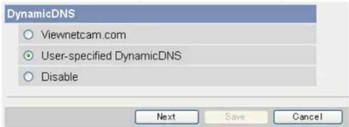
text_image
DynamicDNS Viewnetcam.com User-specified DynamicDNS Disable Next Save Cancel- Enter the URL (including http://) ^*1 provided or required by your Dynamic DNS service provider (max. 255 characters).
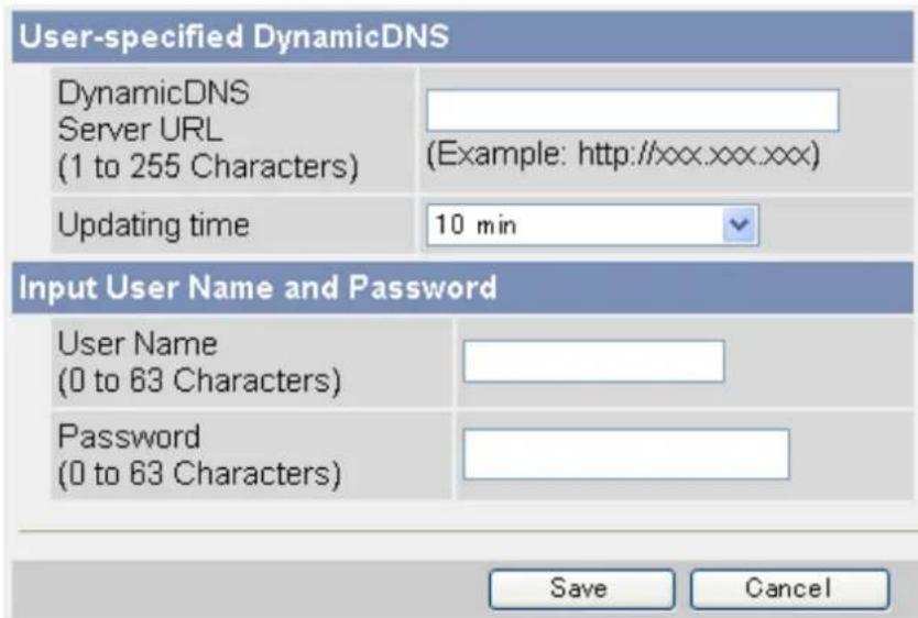
text_image
User-specified DynamicDNS DynamicDNS Server URL (1 to 255 Characters) (Example: http://xxx.xxx.xxx) Updating time 10 min Input User Name and Password User Name (0 to 63 Characters) Password (0 to 63 Characters) Save Cancel- Select how often the camera notifies the Dynamic DNS service of its current address.
- Enter the user name ^2 provided by the Dynamic DNS service provider (max. 63 characters).
- Enter the password ^2 provided by the Dynamic DNS service provider (max. 63 characters).
8. Click [Save].
" [Space] and ["] cannot be entered.
^2 [“] and [:] cannot be entered.
Canceling the camera's access to the Dynamic DNS service
Use the following procedure to stop the camera from notifying the Dynamic DNS service when your global IP address changes. Note that if you intend to stop using the Dynamic DNS service altogether, you may need to contact the Dynamic DNS service provider in order to cancel your subscription.
- Click the [Setup] tab.
- On the left side of the screen under [Basic], click [DynamicDNS].
- Select [Disable], then click [Save].
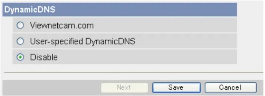
text_image
DynamicDNS Viewnetcam.com User-specified DynamicDNS Disable Next Save Cancel4.3 Confirming Internet Access
After configuring the camera to use a Dynamic DNS service and configuring your router for port forwarding, confirm that the camera can be accessed over the Internet.
Most routers will not allow you to access a camera over the Internet using a PC connected to the same LAN as the camera. To confirm that the camera can be accessed over the Internet, try accessing the camera using a PC connected to a different network or by using your mobile phone (see Page 63).
5 Changing Camera Settings
5.1 Network Settings
The camera's network settings are made when configuring the camera according to the instructions provided in the Setup Guide. You can change these settings later if necessary using the procedures described in this section.
Note
- You must log in to the camera as the administrator in order to change these settings.
• After changing network settings and clicking [Save], the camera must be restarted. All buffered images are deleted when the camera is restarted. - Ask your Internet Service Provider or network administrator for the appropriate network settings.
- If you cannot access the camera after changing certain network settings, use the Setup Program to confirm the camera's IP address (see Page 143) or reconfigure the camera as explained in the Setup Guide.
- If your network uses the IPv6 protocol, see Page 130.
5.1.1 Network (IPv4) Settings
- Click the [Setup] tab.
- On the left side of the screen under [Basic], click [Network (IPv4)].
- Select the desired connection mode, then make the appropriate settings as described in this section.
| Connection Mode | Current Setting | |
| Automatic Setup | X | |
| Static | ||
| DHCP | ||
- [Automatic Setup]: Allows the camera to automatically obtain the appropriate network settings from your broadband router or from your Internet Service Provider (ISP). The camera also searches for an unused IP address on your network.
- [Static]: Allows you to set all network settings manually.
- [DHCP]: Allows you to specify your network settings (if necessary), after which the camera obtains an IP address automatically from the DHCP feature of your broadband router or from your ISP.
[Automatic Setup]
- Under [Max. Bandwidth Usage], select the maximum bandwidth you want to allow the camera to use.
![PANASONIC BL-C131A - [Automatic Setup] - 1](/content/2026/06/1244027/images/eb0169870d9b5c7b15aff995574f4204e63bda375c95caf5040e5eb351eaab68.jpg)
text_image
Max. Bandwidth Usage Unlimited Connection Type Auto Negotiation Save Cancel- Under [Connection Type], select the appropriate connection type.
• Normally you can leave this setting at [Auto Negotiation].
- BL-C131A only: If using the camera in wireless mode, [Auto Negotiation] must be selected.
-
Click [Save].
-
When the [New settings are saved.] message is displayed, click [Restart].
Note
- If the camera's IP address was changed as a result of changing the network settings, use the Setup Program on the CD-ROM to find the camera's new IP address (see Page 143).
- The current network settings can be confirmed on the [Status] page (see Page 119).
[Static]
- Under [Network Configuration from Setup Program], select whether or not you want to allow the camera to be configured using the Setup Program on the CD-ROM.
![PANASONIC BL-C131A - [Static] - 1](/content/2026/06/1244027/images/9406407b8db7c0700862dcc43a53bc1dc5867e575b07c0e75040c9b6919475c7.jpg)
text_image
Network Configuration from Setup Program Enable Internet Connection Port No. 80 IP Address 192.168.0.253 Subnet Mask 255.255.255.0 Default Gateway Default Gateway ***.***.***. DNS Primary Server Address ***.***.***. Secondary Server Address ***.***.***. Max. Bandwidth Usage Unlimited ▼ Connection Type Auto Negotiation ▼ Save Cancel-
Under [Internet Connection], enter the port number to be assigned to the camera.
-
The default port number is 80, however, note that some ISPs do not allow access from the Internet using port 80. Ask your ISP or network administrator about which port numbers are available for access over the Internet.
-
Do not use the following port numbers:
-
20 and 21: used for FTP
- 23: used for Telnet
- 25: used for SMTP
- 53: used for DNS
- 110: used for POP3
- 443: used for HTTPS
- 4000: used for ICQ
- 6661–6667: used for IRC
- If you are connecting multiple cameras and plan on using port forwarding to allow Internet access to the cameras, assign a different port number to each camera. We recommend using port numbers in the 50000–50050 range.
- Enter the IP address to be assigned to the camera.
- Assign an IP address that belongs to the same class as other network devices (router, PCs, etc.) on the local area network. For example, if your router's address is 192.168.0.1, you can assign an IP address between 192.168.0.2 and 192.168.0.255 as long as the assigned address is not used by another network device.
- Enter the appropriate subnet mask.
- Confirm the subnet mask assigned to your router or PC. You can enter the same value here.
-
Under [Default Gateway], enter the IP address of your router or the default gateway IP address provided by your ISP or network administrator.
-
Under [DNS], enter the IP addresses of the primary and secondary DNS servers provided by your ISP or network administrator.
-
Under [Max. Bandwidth Usage], select the maximum bandwidth you want to allow the camera to use.
- This setting is effective for both IPv4 and IPv6 connections.
- Refer to the following file size information when restricting the maximum bandwidth. Note that these are estimated file sizes; the actual file size may vary depending on image quality, image brightness, etc.
- 192 × 144: 3.5 KB (28 Kbit)
- 320 × 240: 10 KB (80 Kbit)
- 640 × 480: 18 KB (144 Kbit)
- Under [Connection Type], select the appropriate connection type.
- Normally you can leave this setting at [Auto Negotiation].
- This setting is effective for both IPv4 and IPv6 connections.
- BL-C131A only: If using the camera in wireless mode, [Auto Negotiation] must be selected.
-
Click [Save].
-
When the [New settings are saved.] message is displayed, click [Restart].
- All buffered images are deleted when the camera is restarted.
Note
- To access the camera again, use the IP address you assigned to the camera in this procedure.
- The current network settings can be confirmed on the [Status] page (see Page 119).
[DHCP]
- Under [Network Configuration from Setup Program], select whether or not you want to allow the camera to be configured using the Setup Program on the CD-ROM.
![PANASONIC BL-C131A - [DHCP] - 1](/content/2026/06/1244027/images/c40204186679b379edcaed17aabc9344954ddcd830cb57c363c1255eba958182.jpg)
text_image
Network Configuration from Setup Program Enable Internet Connection Port No. 80 Host Name Default Gateway Default Gateway DNS Primary Server Address Secondary Server Address Max. Bandwidth Usage Unlimited Connection Type Auto Negotiation Save Cancel-
Under [Internet Connection], enter the port number to be assigned to the camera.
-
The default port number is 80, however, note that some ISPs do not allow access from the Internet using port 80. Ask your ISP or network administrator about which port numbers are available for access over the Internet.
-
Do not use the following port numbers:
-
20 and 21: used for FTP
- 23: used for Telnet
- 25: used for SMTP
- 53: used for DNS
- 110: used for POP3
- 443: used for HTTPS
- 4000: used for ICQ
- 6661–6667: used for IRC
- If you are connecting multiple cameras and plan on using port forwarding to allow Internet access to the cameras, assign a different port number to each camera. We recommend using port numbers in the 50000–50050 range.
- Enter the host name ^1 if required by your ISP or network administrator.
- If the camera is connected to a router, you can usually leave this field blank.
- Under [Default Gateway], enter the default gateway IP address if required by your ISP or network administrator.
- This field can normally be left empty.
- Under [DNS], enter the IP addresses of the primary and secondary DNS servers if required by your ISP or network administrator.
• These fields can normally be left empty.
- Under [Max. Bandwidth Usage], select the maximum bandwidth you want to allow the camera to use.
- This setting is effective for both IPv4 and IPv6 connections.
- Refer to the following file size information when restricting the maximum bandwidth. Note that these are estimated file sizes; the actual file size may vary depending on image quality, image brightness, etc.
- 192 × 144: 3.5 KB (28 Kbit)
- 320 × 240: 10 KB (80 Kbit)
- 640 × 480: 18 KB (144 Kbit)
- Under [Connection Type], select the appropriate connection type.
- Normally you can leave this setting at [Auto Negotiation].
- This setting is effective for both IPv4 and IPv6 connections.
- BL-C131A only: If using the camera in wireless mode, [Auto Negotiation] must be selected.
-
Click [Save].
-
When the [New settings are saved.] message is displayed, click [Restart].
- All buffered images are deleted when the camera is restarted.
*1 [Space], ["], ['], [&], [<], and [>] cannot be entered.
Note
- If the camera's IP address was changed as a result of changing the network settings, use the Setup Program on the CD-ROM to find the camera's new IP address (see Page 143).
- The current network settings can be confirmed on the [Status] page (see Page 119).
5.1.2 Proxy Server Settings
The following settings are necessary if your network uses a proxy server and you want to transfer images by HTTP or send trigger notifications via HTTP. If you do not use a proxy server, these settings are unnecessary.
Note
- Consult your Internet Service Provider (ISP) or network administrator to find out if your network uses a proxy server.
-
Click the [Setup] tab.
-
On the left side of the screen under [Basic], click [Network (IPv4)].
-
Under [Proxy Server Settings], enter the appropriate settings to use the proxy server.
- Ask your ISP or network administrator for the correct settings.
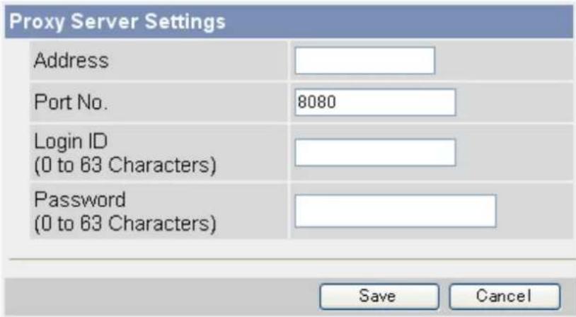
text_image
Proxy Server Settings Address Port No. 8080 Login ID (0 to 63 Characters) Password (0 to 63 Characters) Save Cancel- Click [Save].
5.2 Using the Camera in Wireless Mode (BL-C131A Only)
The BL-C131A can be used wirelessly. In this case, there is no need to connect a LAN cable to the camera. In order to use the camera wirelessly, you must:
a. Configure the camera for wired connection. Refer to the included Installation Guide and Setup Guide if you have not done this.
b. Configure the camera's wireless settings (see Page 89).
c. Restart the camera in wireless mode (see Page 93).
5.2.1 Configuring the Camera for Wireless Connection (BL-C131A Only)
Configure the camera for wireless access by configuring the corresponding camera settings to match the wireless settings of your wireless router. For more information, refer to the operating instructions included with your wireless router.
Note
- Encryption helps protect wireless communications from being accessed or intercepted by unauthorized parties. Using the encryption features on your wireless router and the camera is recommended.
- If your wireless router uses MAC address filtering, enter the MAC address of the camera and the MAC address of the camera's wireless module when setting your wireless router's MAC address filtering feature. You can confirm the camera's MAC address on the [Status] page (see Page 119) and the MAC address of the wireless module on the [Wireless Status] page (see Page 120).
- After changing and saving the camera's wireless settings, it takes about 1 minute for the new settings to become effective.
- Even if the camera is turned on in wired mode, it emits radio waves for about 5 minutes. During this time, the router's wireless indicator may light or flash.
-
To switch between wired and wireless connection (see Page 93), the camera must be restarted. Your router may also need to be restarted before the camera can access the router.
-
Click the [Setup] tab.
- On the left side of the screen under [Basic], click [Wireless].
- Under [Wireless Configuration], enter the SSID used by your wireless router (max. 32 characters).
| Wireless Configuration | |
| SSID | |
| Communication mode | ○ 802.11b○ 802.11b/g○ 802.11g exclusive |
- Select the wireless standard used by your wireless router.
- Even if your router supports the 802.11g standard (which is theoretically faster than 802.11b), wireless communication speed may decrease if there are other devices nearby which use the 2.4 GHz bandwidth, including devices that use the 802.11b standard.
- Under [Encryption], select the desired encryption method, make the appropriate settings (explained below), then click [Save].
When [No encryption] is selected
When [No encryption] is selected, encryption will not be used for wireless communications, and therefore wireless communication may not be secure. If you select [No encryption], click [Save] to finish.
![PANASONIC BL-C131A - When [No encryption] is selected - 1](/content/2026/06/1244027/images/2986dc616f8a3b12f1e3e6ebb1d6ce9f7e769330bda37a38cb1c2591340277cd.jpg)
text_image
Encryption Cipher No encryption WEP Key 1 ASCII 3 characters 128bit WEP Key 2 ASCII 3 characters 128bit WEP Key 3 ASCII 3 characters 128bit WEP Key 4 ASCII 3 characters 128bit Save CancelWhen [WEP] is selected
When [WEP] is selected, the WEP standard will be used for encryption. Refer to the settings of your wireless router, then select the WEP key (1–4) used by your wireless router, select the key format from the corresponding pull-down menu, enter the WEP key, then click [Save] to finish
![PANASONIC BL-C131A - When [WEP] is selected - 1](/content/2026/06/1244027/images/69924999717ce76d6ee809ff01349dc202a759b675835bb5b164339ff151fbd1.jpg)
text_image
Encryption Cipher WEP WEP Key 1 ASCII13characters 128bit WEP Key 2 ASCII13characters 128bit WEP Key 3 ASCII13characters 128bit WEP Key 4 ASCII13characters 128bit Save Cancel| Key Format No. of Characters Usable Characters | |
| [HEX, 10 characters, 64-bit] 10 | |
| [HEX, 26 characters, 128-bit] 26 | |
| [HEX, 32 characters, 152-bit] 32 | |
| [ASCII, 5 characters, 64-bit] 5 | |
| [ASCII, 13 characters, 128-bit] 13 | |
| [ASCII, 16 characters, 152-bit] 16 |
When [WPA-PSK (TKIP)] is selected
When [WPA-PSK (TKIP)] is selected, the WPA-PSK (TKIP) standard will be used for encryption. Refer to the settings of your wireless router, then enter the [Network Key], select the key format from the pull-down menu, and click [Save] to finish.
![PANASONIC BL-C131A - When [WPA-PSK (TKIP)] is selected - 1](/content/2026/06/1244027/images/11a846e02adcc356f7bc7adcc7d45e220dc908e013dbe2831b99b6fb6d31eaf7.jpg)
text_image
Encryption Cipher WPA-PSK (TKIP) Network Key ASCII 8 to 63 Characters Save Cancel| Key Format No. of Characters | Usable Characters | |
| [HEX, 64 Characters] 64 0–9, a–f | ||
| [ASCII, 8 to 63 Characters] 8–63 ASCII characters (see Page 147) |
When [WPA2-PSK (AES)] is selected
When [WPA2-PSK (AES)] is selected, the WPA2-PSK (AES) standard will be used for encryption. Refer to the settings of your wireless router, then enter the [Network Key], select the key format from the pull-down menu, and click [Save] to finish.
![PANASONIC BL-C131A - When [WPA2-PSK (AES)] is selected - 1](/content/2026/06/1244027/images/872c5a1feab28646cb417f0c55ba0dbb2c233500d4126ae3492ce75459bbc328.jpg)
text_image
Encryption Cipher WPA2-PSK (AES) Network Key ASCII 8 to 63 Characters Save Cancel| Key Format No. of Characters | Characters Usable Characters | |
| [HEX, 64 Characters] 64 0–9, a–f | ||
| [ASCII, 8 to 63 Characters] 8–63 ASCII characters (see Page 147) |
5.2.2 Restarting the Camera in Wireless Mode (BL-C131A Only)
After you have configured the camera for wireless connection, follow the procedure below to restart the camera in wireless mode.
- Turn off the camera by unplugging the AC plug from the power outlet.
- Set the WIRELESS/WIRED switch on the bottom of the camera to the WIRELESS position.
- Turn the camera on by plugging the AC plug into the power outlet.
- Confirm the camera's wireless settings are correct by accessing the camera (see Page 7).
Note
- To use the camera in wired mode again, repeat the procedure above and set the WIRELESS/WIRED switch on the bottom of the camera to the WIRED position.
- If you cannot access the camera, the camera's wireless settings may be incorrect. Repeat the procedure above and set the WIRELESS/WIRED switch on the bottom of the camera to the WIRED position. Access the camera in wired mode and confirm that all wireless settings are correct and match the settings of your wireless router.
- If your wireless router uses MAC address filtering, enter the MAC address of the camera and the MAC address of the camera's wireless module when setting your wireless router's MAC address filtering feature. You can confirm the camera's MAC address on the [Status] page (see Page 119) and the MAC address of the wireless module on the [Wireless Status] page (see Page 120).
- You may need to restart your router in order to access the camera in wireless mode.
- Even if the camera is turned on in wired mode, it emits radio waves for about 5 minutes. During this time, the router's wireless indicator may light or flash.
- If you still cannot access the camera in wireless mode, see 1.4 Wireless Connection Issues (BL-C131A Only) in the Troubleshooting Guide.
5.3 UPnP™ Settings
The camera supports UPnP ^™ (Universal Plug and Play) features, which allow you to do the following:
- Configure your router's port forwarding feature. (A UPnP™ compatible router is required.) This is useful if you want to access your camera from the Internet or using a mobile phone. See Page 67 for more information.
-
Create a shortcut to the camera in your computer's [My Network Places] folder that will be automatically updated even if the camera's IP address changes. (Windows XP is required.)
-
Click the [Setup] tab.
- On the left side of the screen under [Basic], click [UPnP].
- Under [Auto Port Forwarding], select [Enable] if you want to configure your router's port forwarding feature.
Auto Port Forwarding
○ Enable
Disable
Display Shortcut Icon in My Network Places
Enable
○ Disable
Save
Cancel
- In order to use this feature, your router must support UPnP™ and have its UPnP™ feature turned on.
-
This setting is not effective when the camera's network [Connection Mode] is set to [Automatic Setup] (see Page 82 or Page 133).
-
Under [Display Shortcut Icon in My Network Places], select [Enable] if you want to create a shortcut to the camera in your computer's [My Network Places] folder.
- In order to use this feature, your computer's UPnP™ feature must be enabled. See Page 140 for more information.
- Click [Save].
Note
- You can also configure your UPnP™ compatible router for port forwarding from the [Internet] tab (see Page 71).
5.4 Setting the Date and Time
Set the camera's date and time settings to ensure image buffering, image transferring, camera operation time, and time stamp features function as expected.
Note
- All buffered images are deleted when you click [Save] at the end of this procedure.
- Click the [Setup] tab.
- On the left side of the screen under [Basic], click [Date and Time].
- Under [Time Setting], select the current month, day, and year.
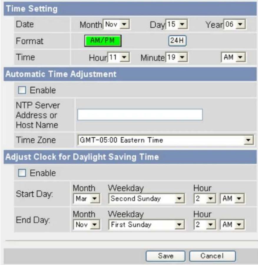
text_image
Time Setting Date Month Nov Day 15 Year 06 Format AM/PM 24H Time Hour 11 Minute 19 AM Automatic Time Adjustment Enable NTP Server Address or Host Name Time Zone GMT-05:00 Eastern Time Adjust Clock for Daylight Saving Time Enable Start Day: Month Weekday Hour Mar Second Sunday 2 AM End Day: Month Weekday Hour Nov First Sunday 2 AM Save Cancel- Select whether you want to use 12-hour or 24-hour time format.
- Select the current time.
- Under [Automatic Time Adjustment], select whether you want to enable automatic date and time adjustment.
a. If you select to enable this feature, enter the IP address or host name of the desired NTP (network time protocol) server that the camera will use to adjust its date and time.
- An IPv6 address can be entered.
b. Select your time zone.
- Under [Adjust Clock for Daylight Saving Time], select whether you want the camera to automatically adjust its date and time for Daylight Saving Time.
a. If you select to enable this feature, enter the month, day, and time when Daylight Saving Time begins. (The camera's clock moves forward one hour at the set date and time.)
b. Enter the month, day, and time when Daylight Saving Time ends. (The camera's clock moves back one hour at the set date and time.)
8. Click [Save].
- All buffered images for all triggers are deleted when you click [Save].
Note
- The camera will not synchronize to the NTP server if there is more than an 1 hour difference between the NTP server time and the camera's current time. This is to protect the camera's time setting from fraudulent NTP server tampering, incorrect time information, etc.
- The camera's clock becomes less accurate over time and can be affected when the camera's temperature changes. Using the [Automatic Time Adjustment] feature is recommended.
5.5 Changing Basic Camera Settings
The [Camera] page of the [Setup] tab allows you to adjust basic camera features.
- Click the [Setup] tab.
- On the left side of the screen under [Basic], click [Camera].
- Under [AC Power Source Frequency], select the desired setting.
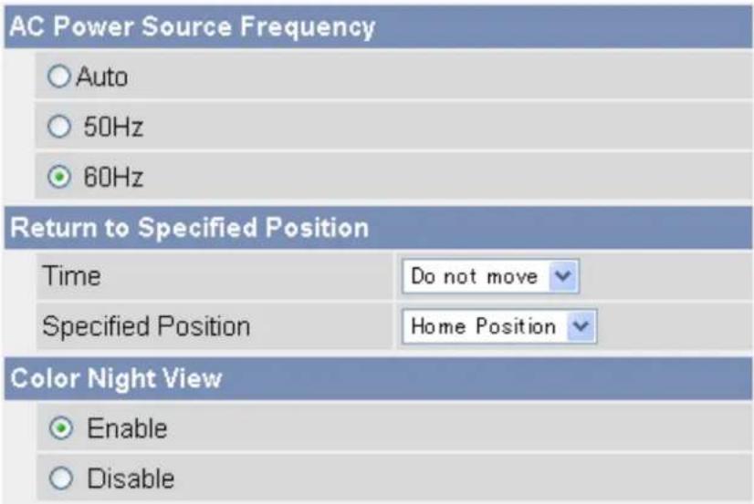
text_image
AC Power Source Frequency Auto 50Hz 60Hz Return to Specified Position Time Do not move Specified Position Home Position Color Night View Enable Disable- [Auto]: The power source frequency is selected automatically.
- [50 Hz]: Select this item if your AC power source operates at 50 Hz.
- [60 Hz]: Select this item if your AC power source operates at 60 Hz.
Note
• [60 Hz] is the default setting. This setting should not need to be changed.
- Under [Return to Specified Position], select whether you want the camera to move the lens to a specific preset position after a specified period of inactivity.
a. Select the length of time (inactivity) that passes before the camera moves the lens. If this setting is too short, you may have difficulty registering presets because the lens will return to the specified position before you have saved your new preset.
b. Select the desired preset position (see Page 22).
-
Under [Color Night View], select whether the camera's color night view mode feature is automatically activated when the camera image is dark.
-
When this feature is activated, the camera image becomes brighter when the camera image is dark (e.g., when the lights in a room are turned off), and deactivates when the image becomes bright again.
• This feature is enabled by default. - When this feature is activated, refresh rate decreases and images become blurry when the object or the lens is moving.
-
When this feature is activated, white or colored dots or horizontal lines may be displayed in the camera image. This is a characteristic of the camera's optical sensor, and is not a malfunction.
-
Click [Save].
5.6 Changing Audio Settings
The [Audio] page of the [Setup] tab allows you to adjust audio feature-related settings.
- Click the [Setup] tab.
- On the left side of the screen under [Basic], click [Audio].
- Under [Input], select whether the camera's built-in microphone is enabled or disabled.
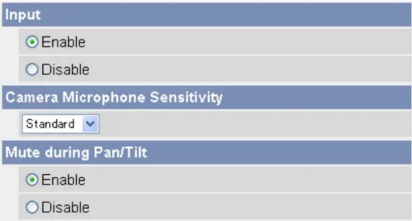
text_image
Input Enable Disable Camera Microphone Sensitivity Standard Mute during Pan/Tilt Enable Disable-
Under [Camera Microphone Sensitivity], select the desired setting.
-
[Minimum]: Sets the microphone to minimum sensitivity. Less sound is picked up by the microphone.
– [Standard]: Sets the microphone to standard sensitivity. -
[Maximum]: Sets the microphone to maximum sensitivity. More sound is picked up by the microphone.
-
Under [Mute during Pan/Tilt], select whether the camera's built-in microphone is automatically muted when the camera is panning or tilting.
-
This feature is disabled by default.
-
When this feature is set to [Disable], the microphone will be enabled when the camera pans or tilts. The sound of the lens moving may be picked up by the microphone.
-
Click [Save].
5.7 Changing Video Streaming Settings
The [Video Streaming] page of the [Setup] tab allows you to adjust video streaming feature-related settings.
- Click the [Setup] tab.
- On the left side of the screen under [Basic], click [Video Streaming].
- Under [MPEG-4 Max. Frame Rate], select the number of frames per second the camera streams for each resolution setting.
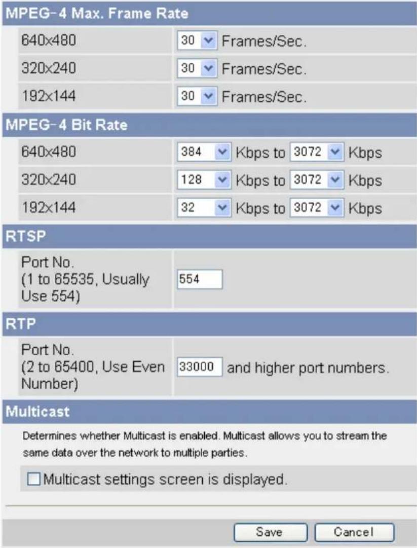
text_image
MPEG-4 Max. Frame Rate 640x480 30 Frames/Sec. 320x240 30 Frames/Sec. 192x144 30 Frames/Sec. MPEG-4 Bit Rate 640x480 384 Kbps to 3072 Kbps 320x240 128 Kbps to 3072 Kbps 192x144 32 Kbps to 3072 Kbps RTSP Port No. (1 to 65535, Usually Use 554) 554 RTP Port No. (2 to 65400, Use Even Number) 33000 and higher port numbers. Multicast Determines whether Multicast is enabled. Multicast allows you to stream the same data over the network to multiple parties. □ Multicast settings screen is displayed. Save Cancel- Under [MPEG-4 Bit Rate], select the minimum and maximum bit rate for each resolution setting.
- Under [RTSP], enter the port number used for RTSP. (Usually port number 554 is used.)
- Under [RTP], enter the first port number used for RTP.
- The port number above RTP is used for RTCP. For example, when port number 33000 is used for RTP, port number 33001 is used for RTCP.
- Under [Multicast], check [Multicast settings screen is displayed.] to configure the camera for multicasting, otherwise click [Save] to finish.
- When [Multicast] is enabled, [Multicast] becomes available in the [Streaming Method] selector on the single camera page.
Multicast
Determines whether Multicast is enabled. Multicast allows you to stream the same data over the network to multiple parties.
√ Multicast settings screen is displayed.
Packet Availability Time
TTL
(1 to 255, Usually Use 5)
5
Multicast (IPv4)
□ Use
Address
231.244.244.241
MPEG-4 Port No.
(2000 to 65520, Use Even Number)
30000 to 30006
Audio Port No.
(2000 to 65520, Use Even Number)
30020
Multicast (IPv6)
□ Use
Address
ff1e::0010
MPEG-4 Port No. (2000 to 65520, Use Even Number)
30100 to 30106
Audio Port No. (2000 to 65520, Use Even Number)
30120
Save
Cancel
- Under [Packet Availability Time], enter the desired setting.
- Under [Multicast (IPv4)], check [Use] to enable multicasting for IPv4. If used, the following settings are also necessary.
a. Enter the IP address of the multicast.
b. Enter the first port number to be used for MPEG-4 streaming. This port number must be an even number.
c. Enter the port number to be used for audio streaming. This port number must be an even number.
- Under [Multicast (IPv6)], check [Use] to enable multicasting for IPv6. If used, the following settings are also necessary.
a. Enter the IP address of the multicast. This address must be an IPv6 address.
b. Enter the first port number to be used for MPEG-4 streaming. This port number must be an even number.
c. Enter the port number to be used for audio streaming. This port number must be an even number.
11. Click [Save].
6 User Accounts
6.1 Understanding User Accounts
The camera supports 3 different types of users. Each type of user can use the camera in different ways, and the administrator can control which features each user can have access to.
| User Type No. | of Users Camera Configuration | Feature Access | |
| [Administrator] | 1 | Can access all pages and change all settings. | All features can be used. |
| [General Users] | 50 different users can be registered. | Cannot configure the camera. | The administrator controls which features each general user can access (see Page 104). |
| [Guest User](Anonymous users) | - | Cannot configure the camera. | The administrator controls which features each general user can access. Additionally, you can limit guest user access to the mobile phone page only (see Page 107). |
6.2 Changing the Administrator User Name and Password
For security, we recommend setting a user name and password that uses many characters and is difficult to guess. Change the password periodically for added security.
- Click the [Setup] tab.
- On the left side of the screen under [Account], click [Administrator].
- Under [Administrator Authentication], enter the user name and password, then re-enter the password for verification.
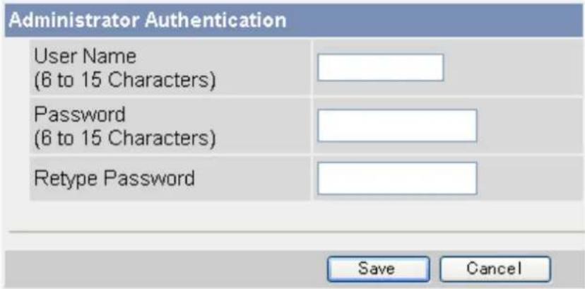
text_image
Administrator Authentication User Name (6 to 15 Characters) Password (6 to 15 Characters) Retype Password Save Cancel• See Page 147 for a list of valid characters. Note that [Space], ["], ['], (&], [<], [>], and [:] are not available. 4. Click [Save].
6.3 General Users
Up to 50 general user accounts can be created. Each user has his or her own user name and password, and you can control the camera features that are available to general users.
Note
- For security, we recommend setting user names and passwords that are difficult to guess. Change the passwords periodically for added security.
- When general users access the camera, the [Internet], [Setup], and [Maintenance] tabs are never displayed. The [Multi] and [Buffered Image] tabs will be displayed if you allow general users to access those pages.
Creating or modifying a general user account
- Click the [Setup] tab.
- On the left side of the screen under [Account], click [General User].
-
Under [User ID List], click [Create].
-
Up to 50 general user accounts can be created.
-
To modify an existing user account, select the general user account you want to modify, then click [Modify].
-
Under [Input User Name and Password], enter the user name and password, then re-enter the password for verification.
| Input User Name and Password | |
| User Name (6 to 15 Characters) | |
| Password (6 to 15 Characters) | |
| Retype Password | |
• See Page 147 for a list of valid characters. Note that [Space], ["], ['], [&], [<], [>], and [:] are not available.
- Under [Access Level], select the desired setting for [Video Display Time].

text_image
Access Level Video Display Time Not permitted Refresh Rate 3 s Level 1 (Camera viewing only) Change Refresh Rate Change Resolution Change Quality Capture Image Button View Multi-Camera page View Buffered Image page Level 2 (Camera viewing and preset control) Preset Level 3 (Camera viewing and all controls) Pan / Tilt Click to Center Brightness White Balance Listen Save Back- [Unlimited]: The user can view video images ([MPEG-4] or [MJPEG]) from the camera without restriction.
- [Not permitted]: The user can view only still images.
-
[10 s]–[60 min]: The user can view video images for the selected amount of time, after which the user can view only still images.
-
Select the desired setting for [Refresh Rate]. Still images viewed by the user will be refreshed at this rate.
-
Select the features the user is allowed to use.
- You can select features individually, or click [Level 1], [Level 2], or [Level 3] to enable/disable the corresponding group of features.
- Click [Save].
Note
- Users can click to center when using the digital zoom feature, even if the click to center feature is disabled. Users can click to center the image within the zoomed area, but the lens will not pan or tilt.
Deleting a general user account
- Click the [Setup] tab.
- On the left side of the screen under [Account], click [General User].
- Under [User ID List], select the general user account you want to modify, then click [Delete].
- Confirm that you have selected the desired general user account to be deleted, then click [Delete].
- Click [OK].
6.4 Guest Users
Guest users are anonymous users, and they do not need to enter a user name or password to access the camera. You can control the camera features that are available to guest users, and you can restrict guest user access altogether.
IMPORTANT
To prevent unauthorized access to the camera, it is important to manage who can access the camera through the use of user names and passwords. Because the camera can be accessed from the Internet, it is possible that the camera may be accessed by unknown individuals, including those who are commonly known as "hackers", to whom you do not want to allow access. If you choose to allow guest access (i.e., anonymous access), there is a risk that unknown individuals will access the camera and view camera images. You have the option of allowing guest access, but it is strongly recommended that you do not allow guest access, and rather create general user accounts and assign secret user names and passwords for use by known individuals only.
Allowing/restricting guest users to access the camera
- Click the [Setup] tab.
- On the left side of the screen under [Account], click [Administrator].
- Under [General Authentication], select the desired setting.
General Authentication
○ Permit access from guest users
○ Permit access from guest users (mobile only)
Do not permit access from guest users
- [Permit access from guest users]: Guest users can access the camera.
- [Permit access from guest users (mobile only)]: Guest users can access the camera's mobile phone page only.
-
[Do not permit access from guest users]: Guest users cannot access the camera.
-
Click [Save].
Note
- When [Permit access from guest users] is selected, no authentication dialog is displayed when you access the camera, and the [Login] tab is displayed on the top page. Click this tab to log in to the camera as the administrator or as a general user. For more information, see Page 109.
Changing the features available to guest users
- Make sure you configured the camera to allow guest users to access the camera (explained above).
- Click the [Setup] tab.
- On the left side of the screen under [Account], click [General User].
-
Under [User ID List], select [Guest User], then click [Modify].
-
Under [Access Level], select the desired setting for [Video Display Time].
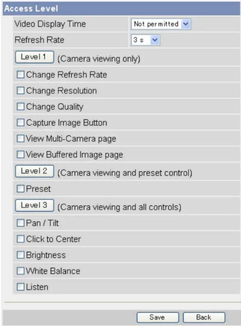
text_image
Access Level Video Display Time Not permitted Refresh Rate 3 s Level 1 (Camera viewing only) Change Refresh Rate Change Resolution Change Quality Capture Image Button View Multi-Camera page View Buffered Image page Level 2 (Camera viewing and preset control) Preset Level 3 (Camera viewing and all controls) Pan / Tilt Click to Center Brightness White Balance Listen Save Back- [Unlimited]: The user can view video images ([MPEG-4] or [MJPEG]) from the camera without restriction.
- [Not permitted]: The user can view only still images.
-
[10 s]–[60 min]: The user can view video images for the selected amount of time, after which the user can view only still images.
-
Select the desired setting for [Refresh Rate]. Still images viewed by the user will be refreshed at this rate.
-
Select the features the user is allowed to use.
- You can select features individually, or click [Level 1], [Level 2], or [Level 3] to enable/disable the corresponding group of features.
- Click [Save].
Note
- Users can click to center when using the digital zoom feature, even if the click to center feature is disabled. Users can click to center the image within the zoomed area, but the lens will not pan or tilt.
6.5 The Login Tab
When guest users are allowed to access the camera (see Page 107), no authentication dialog is displayed when you access the camera, and the [Login] tab is displayed on the top page. Click this tab to log in to the camera as the administrator or as a general user.
7 Advanced Settings
7.1 Changing Image Display Settings
You can change the camera name and the way camera images are displayed each time the camera is accessed. Use the procedure below to change the following settings:
- Camera name
- Refresh rate, image resolution, and image quality for the single camera page and for the multi camera page
- Overlay settings (control whether the date and time, a text message, and the camera's trigger status are displayed)
- Default display language
-
Banner settings (control whether a banner is displayed on the single camera page, and the properties of the banner)
-
Click the [Setup] tab.
-
On the left side of the screen under [Advanced], click [Image Display].
-
Under [Camera Name], change the camera name as desired (max. 15 characters).
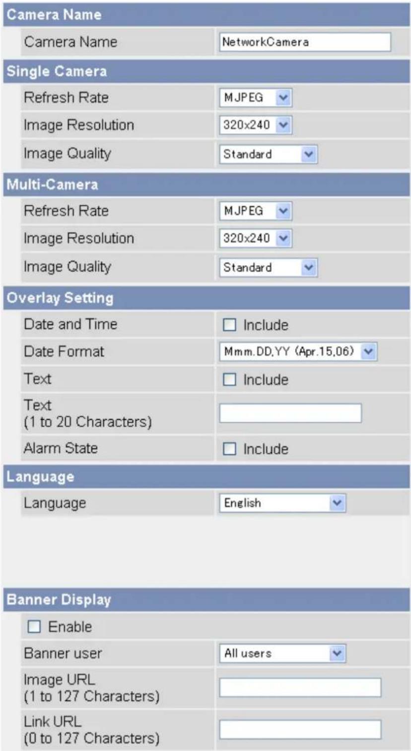
text_image
Camera Name Camera Name NetworkCamera Single Camera Refresh Rate MJPEG Image Resolution 320x240 Image Quality Standard Multi-Camera Refresh Rate MJPEG Image Resolution 320x240 Image Quality Standard Overlay Setting Date and Time Include Date Format Mmm.DD.YY (Apr.15,06) Text Include Text (1 to 20 Characters) Alarm State Include Language Language English Banner Display Enable Banner user All users Image URL (1 to 127 Characters) Link URL (0 to 127 Characters)• See Page 147 for a list of valid characters. Note that [Space], ["], ['], &], [<], and [>] are not available.
-
Under [Single Camera], select the desired default image resolution, image quality, and image refresh rate.
-
Under [Multi-Camera], select the desired default image resolution, image quality, and image refresh rate.
-
Under [Overlay Setting], select what information is displayed in the overlay displayed on the single camera page, multi camera page, and buffered images page. See Page 9 for an example of a camera image overlays.
a. Select whether you want to display a time stamp in the upper left corner of camera images, then select the desired format for the time stamp. To select 12-hour or 24-hour time format, see Page 95. b. Select whether you want to display a text message in the lower left corner of camera images, then enter the desired text (max. 20 characters).
- See Page 147 for a list of valid characters. Note that [Space], [""], ['], [&], [<], and [>] are not available.
c. Select whether you want to display trigger status in the upper left corner of camera images, after date and time overlay (if enabled).
• M will be displayed when the motion detection feature has been triggered.
- 1 will be displayed when the built-in sensor has been triggered.
-
Under [Language], select the camera's display language.
-
The user can change the display language on the top page if desired.
- If you select [English], [Japanese], [French] or [Simplified Chinese], the selected language is displayed on every page.
-
If select a language other than English, Japanese, French, or Simplified Chinese, the selected language is displayed as the initial language when clicking the [Top], [Single], [Multi], and [Buffered Image] tabs. All other pages are displayed in English.
-
Under [Banner Display], select the desired parameters for the banner displayed on the single camera page.
a. Select whether you want to display a banner.
b. Select which users the banner is displayed for.
c. Enter the URL (max. 127 characters ^1 ), including http://if necessary, of the banner image file. This specifies the location of the image file that is displayed as the banner.
Note
- If authentication is required to display the image URL, an authentication window will be displayed when you access the single camera page.
• Each time the single camera page is accessed, the camera accesses the URL of the banner image file and reads the file. Be aware that the computer/server that contains the banner image file may become burdened if the single camera page is accessed or refreshed frequently.
d. Enter the URL (max. 127 characters "1"), including http://if necessary, of the banner's link. This specifies the web page or image that is displayed when the user clicks the banner.
- Click [Save].
7.2 Registering Multiple Cameras
You can register other Panasonic Network Cameras to this camera's [Multi] tab. This allows you to view images from up to 16 cameras by simply accessing this camera and clicking the [Multi] tab.
Registering other cameras to this camera
- Click the [Setup] tab.
- On the left side of the screen under [Advanced], click [Multi-Camera].
- Click [Add].
| No. | Display | IP Address or Host Name | Port No. | Camera Name |
| 1 | On | selfcamera | -- | -- |
| Add | ||||
- Under [Add Camera], check [Display].
| Add Camera | |
| Display | ☑ On |
| IP Address or Host Name | |
| Port No.(1 to 65535) | |
| Camera Name(1 to 15 characters) | |
| Clicking this link, enters this camera's settings. | |
-
Enter the IP address or host name of the other camera.
-
To allow users to view cameras over the Internet, enter the camera's global IP address or host name here (i.e., the IP address or host name needed to access the other camera over the Internet).
- To allow users to view cameras from the LAN, enter the local IP address of the other camera here (i.e., the IP address needed to access the other camera over the LAN).
• See Page 147 for a list of valid characters. Note that [Space], ["], ['], (&], [<], [>], [#], [%], [=], [+], and [?] are not available. -
You can register this camera to the multi camera page by simply clicking [Clicking this link, enters this camera's settings.].
-
Enter the port number of the other camera.
-
Enter the camera's name (max. 15 characters). This is the camera name that is displayed on the [Multi] page and does not need to match the camera name set on the other camera.
- Only ASCII characters are available (see Page 147). Note that [Space], [""], ['], [&], [<], [>], [#], [%], [=], [+], [?], and [:] are not available.
- Click [Save].
Modifying previously registered cameras
- Click the [Setup] tab.
- On the left side of the screen under [Advanced], click [Multi-Camera].
-
Click the desired camera number.
-
Change the settings as desired.
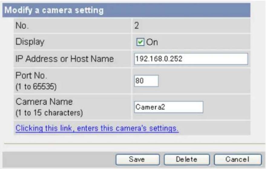
text_image
Modify a camera setting No. 2 Display ✓ On IP Address or Host Name 192.168.0.252 Port No. (1 to 65535) 80 Camera Name (1 to 15 characters) Camera2 Clicking this link, enters this camera's settings. Save Delete Cancel- Click [Save].
Deleting previously registered cameras
- Click the [Setup] tab.
- On the left side of the screen under [Advanced], click [Multi-Camera].
- Click the desired camera number.
- Click [Delete].
Changing the order of cameras on the [Multi] tab
- Click the [Setup] tab.
- On the left side of the screen under [Advanced], click [Multi-Camera].
- Under [Change Camera Order], select the number of the camera you would like to move, and select the number you would like to move the camera to.
![PANASONIC BL-C131A - Changing the order of cameras on the [Multi] tab - 1](/content/2026/06/1244027/images/5e2763e60da6340a0f615f7de90b91209537025c3bca4138efa2c8107d55b3d8.jpg)
text_image
Change Camera Order From No.2 To No.1 Move- For example, to move camera number 2 to position number 1, select [From No.] 2 [To No.] 1.
- Click [Move].
7.3 Specifying Operation Times
You can specify the days and times during which general users and guest users can view camera images (the administrator can always view camera images). When the camera is accessed outside of the operation time, the camera image on the single camera page, multi camera page, and buffered image page is displayed as a gray screen. Additionally, [The operation time has ended.] is displayed on the single camera page. Up to 7 different operation times can be set.
Note
- Your privacy may be compromised if you set this feature incorrectly. To confirm that you have made the correct settings, access the camera as a general user or guest user during a time the camera is outside of the operational time to confirm that camera images cannot be seen.
-
Make sure the camera's date and time setting is correct in order for this feature to function as desired.
-
Click the [Setup] tab.
- On the left side of the screen under [Advanced], click [Operation Time].
- Select the desired operation time setting number.
| Operation Time | |||||||||
| No. | Status | Sun | Mon | Tue | Wed | Thu | Fri | Sat | Operation Time |
| 1 | Disable | X | X | X | X | X | X | X | Always |
| 2 | Disable | X | X | X | X | X | X | X | Always |
| 3 | Disable | X | X | X | X | X | X | X | Always |
| 4 | Disable | X | X | X | X | X | X | X | Always |
| 5 | Disable | X | X | X | X | X | X | X | Always |
| 6 | Disable | X | X | X | X | X | X | X | Always |
| 7 | Disable | X | X | X | X | X | X | X | Always |
- If No. 1–7 are disabled, camera images can always be seen.
- Check [Enable] to enable this operating time setting number, then set the desired operation days and times.
| Operation Time | ||||||||
| Enable | Sun | Mon | Tue | Wed | Thu | Fri | Sat | Operation Time |
| ○ AM 12 h 0 min to AM 12 h 0 min | ||||||||
- Click [Always] to allow camera images to be seen at any time of day on the days which have a check mark under them.
- Click [Save].
Note
- If 2 operating time settings overlap, the [Enable] setting takes priority.
In the example below, the camera is set to be disabled on Mondays (in setting No. 1) and is set to be disabled on Tuesdays (in setting No. 2). However, the camera can be accessed on both Mondays and Tuesdays because these days are each enabled by one of the settings.
| Operation Time | |||||||||
| No. | Status | Sun | Mon | Tue | Wed | Thu | Fri | Sat | Operation Time |
| 1 | Enable | X | X | X | X | X | X | Always | |
| 2 | Enable | X | X | X | X | X | X | Always | |
7.4 Changing the Indicator Display
The camera's indicator can be used to indicate when the camera is being accessed, however you can set the camera so that the indicator is:
– Always on (green) during normal operation
- On (green) only when the camera is being accessed
- On (orange) only when the camera's built-in sensor is being triggered
This setting is useful when deciding where to mount the camera, because the indicator will indicate when the built-in sensor has been triggered, allowing you to change the location of the camera to a more appropriate location if necessary.
– Always off during normal operation
- Click the [Setup] tab.
- On the left side of the screen under [Advanced], click [Indicator Control].
- Select the desired setting.
Indicator Control
Turn indicator on when camera is on.
○ Turn indicator on during camera access.
Turn indicator on during pyroelectric sensor reaction.
○ Never turn indicator on.
4. Click [Save].
Note
- If the indicator lights in any color other than green, refer to 1.2 Camera Indicator Issues in the Troubleshooting Guide.
7.5 Privacy Mode
Privacy mode allows you to protect your privacy by hiding the lens inside the camera, preventing camera images from being seen. When privacy mode is activated:
- The indicator turns red so that you can easily see that privacy mode is activated.
- No camera images are buffered or transferred.
— The camera image changes to a gray screen if privacy mode is activated while viewing camera images. - If privacy mode is already activated when you try to access the camera, a dialog will be displayed asking if you want to disable privacy mode. In order to disable privacy mode, the administrator's user name and password must be entered.
Turning privacy mode on
You can turn privacy mode on by:
- Pressing the PRIVACY button on the front of the camera (the indicator will turn from green to red).
-
Accessing the camera with a PC as the administrator.
-
Click the [Setup] tab.
- On the left side of the screen under [Advanced], click [Privacy Mode].
- Under [Privacy Mode], select [Enable].
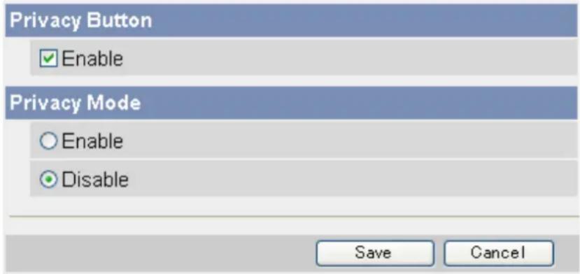
text_image
Privacy Button Enable Privacy Mode Enable Disable Save Cancel- Click [Save].
- Accessing the camera from a mobile phone (see Page 64) as the administrator.
Turning privacy mode off
You can turn privacy mode off by:
- Pressing the PRIVACY button on the front of the camera (the indicator will turn from red to green).
- Accessing the camera with a PC. When [Privacy Mode is enabled. Do you wish to disable?] is displayed, click [Disable Privacy Mode] and enter the administrator user name and password if prompted.
- Accessing the camera from a mobile phone (see Page 64) as the administrator.
Disabling the PRIVACY button
You can disable the PRIVACY button so that privacy mode cannot be turned on or off by pressing the PRIVACY button.
- Click the [Setup] tab.
- On the left side of the screen under [Advanced], click [Privacy Mode].
- Under [Privacy Button], uncheck [Enable].
- Click [Save].
8 Camera Administration and Maintenance
8.1 Confirming Camera Status
You can confirm various camera status information on the [Status] page such as:
– Detailed camera information, including the firmware version number and MAC address
– Detailed network information
– Dynamic DNS status
- UPnP ^TM status
- The status of various protocols (such as FTP, HTTP, SMTP, etc.) and whether or not there have been any errors
The information displayed on this page can help you when the camera is not functioning as you expect it to. Refer to this information for troubleshooting assistance.
- Click the [Maintenance] tab.
- On the left side of the screen under [Maintenance], click [Status].
- Confirm the desired information.
Note
• See the Panasonic Network Camera support site (http://panasonic.co.jp/pcc/products/en/netwkcam) for details about the information displayed on this page.
8.2 Confirming Wireless Status (BL-C131A Only)
You can confirm various wireless information on the [Wireless Status] page such as:
- The status of the wireless connection to the wireless router
- The MAC address of the camera's wireless module (i.e., the MAC address used when the camera is in wireless mode)
— The quality of the wireless communication between the camera and the wireless router
The information displayed on this page can help you when the camera is not functioning in wireless mode as you expect it to. Refer to this information for troubleshooting assistance.
- Click the [Maintenance] tab.
- On the left side of the screen under [Maintenance], click [Wireless Status].
- Confirm the desired information.
Note
- If your wireless router uses MAC address filtering, enter the MAC address of the camera and the MAC address of the camera's wireless module when setting your wireless router's MAC address filtering feature. The MAC address of the camera's wireless module is displayed on the [Wireless Status] page next to [MAC address of Wireless module]. You can confirm the camera's MAC address on the [Status] page (see Page 119).
- The signal strength of the wireless connection to the wireless router is displayed next to [Radio Condition] as follows:
– [Best]: When the signal strength is 50%–100%
– [Normal]: When the signal strength is 15%–49%
– [Weak]: When the signal strength is 1%–14%
- [No connection]: When there is no signal (0%)
• See the Panasonic Network Camera support site (http://panasonic.co.jp/pcc/products/en/netwkcam) for details about the information displayed on this page.
8.3 Confirming Session Status
You can confirm various client session information on the [Session Status] page such as:
– The number of active video (MPEG-4 and MJPG) and audio sessions
– Multicast session status
- Click the [Maintenance] tab.
- On the left side of the screen under [Maintenance], click [Session Status].
- Confirm the desired information.
Note
• Information for the following session types is not displayed:
- Mobile phone access
- Still image viewing
- Accessing the [Top], [Setup], [Internet], [Maintenance], and [Support] pages
8.4 Confirming Alarm Logs
You can view information about the last 50 image buffer triggers on the [Alarm Log] page.
- Click the [Maintenance] tab.
- On the left side of the screen under [Maintenance], click [Alarm Log].
- Confirm the desired information.
Note
- When the camera is restarted, the alarm log content is deleted.
- You can configure the camera to send a daily log by E-mail that reports the status of triggers 1–5 (see Page 59).
8.5 Restarting the Camera
You can restart the camera from the [Restart] page.
Note
- When the camera is restarted, all buffered images are deleted.
-
When the camera is restarted, the alarm log content is deleted.
-
Click the [Maintenance] tab.
- On the left side of the screen under [Maintenance], click [Restart].
- Click [Restart].
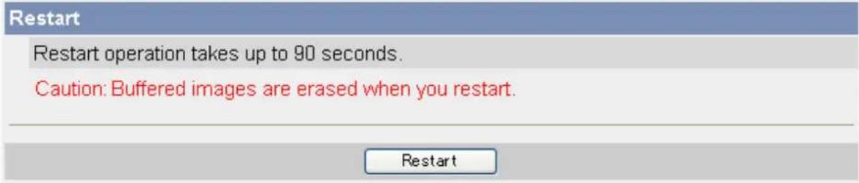
text_image
Restart Restart operation takes up to 90 seconds. Caution: Buffered images are erased when you restart.Automatically restarting the camera
You can set the camera restart itself automatically periodically.
- Click the [Maintenance] tab.
- On the left side of the screen under [Maintenance], click [Restart].
- Under [Scheduled Restart], click [Enable].
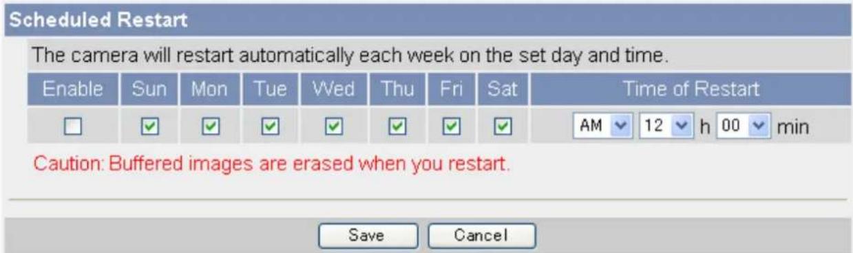
text_image
Scheduled Restart The camera will restart automatically each week on the set day and time. Enable Sun Mon Tue Wed Thu Fri Sat Time of Restart □ ✓ ✓ ✓ ✓ ✓ ✓ ✓ AM 12 h 00 min Caution: Buffered images are erased when you restart. Save Cancel- Select the days and times you would like the camera to automatically restart.
- Click [Save].
8.6 Updating the Camera Firmware
You can update the camera's firmware from the [Update Firmware] page.
- Download the latest firmware from the Panasonic Network Camera website (http://panasonic.co.jp/pcc/products/en/netwkcam/) and save it on your PC.
- Click the [Maintenance] tab.
- On the left side of the screen under [Maintenance], click [Update Firmware].
- Click [Update Firmware]. The camera will automatically restart.
- After the camera restarts, a dialog prompts you to select the firmware file.
- Click [Browse...]. A dialog prompts you to specify the location of the firmware file.
- Select the firmware file you downloaded from the Panasonic Network Camera website and click [Open]. The selected file name is displayed.
- Confirm the file name, then click [Update Firmware].
- The [Updating firmware.] screen is displayed, and then the [Restarting now...] screen is displayed. When the firmware update is complete, the camera's top page is displayed.
-
You can confirm the camera's firmware version on the top page.
-
Confirm the camera's new firmware version on the top page.
Note
- Do not turn off the power during a firmware update.
- All buffered images are deleted when the firmware is updated.
- All alarm logs are deleted when the firmware is updated.
- You can also use the Setup Program to update the camera's firmware (see Page 143).
- The camera's current firmware version can be confirmed on the [Top] page and the [Status] page.
8.7 Saving Settings in a Configuration File
You can save a configuration file (i.e., a backup of the camera's settings) on your PC and restore the settings later if desired (see Page 126).
- Click the [Maintenance] tab.
- On the left side of the screen under [Maintenance], click [Save Settings].
- Click [Save]. A dialog prompts you to specify a location to save the configuration file.
- Specify a location to save the file, then click [Save].
Note
- The saved configuration file contains user names, passwords, and other private information. You are responsible for storing the configuration file in a safe place where it cannot be retrieved by unauthorized parties.
- You can also use the Setup Program to save a configuration file (see Page 143).
- Buffered images are not saved in the configuration file.
- The configuration file's extension (.dat) must not be changed. If you change it, the saved settings cannot be restored.
- If you save a configuration file and then update the camera's firmware later, the configuration file may not be able to be restored properly. If you regularly save a configuration file of the camera's settings, remember to save a configuration file after you update the camera's firmware.
8.8 Restoring Settings from a Configuration File
If you have saved a configuration file (i.e., a backup of the camera's settings) on your PC, you can restore the settings later. If you reset the camera to factory default, the camera can load its settings from the configuration file.
- Click the [Maintenance] tab.
- On the left side of the screen under [Maintenance], click [Load Settings].
- Click [Browse...]. A dialog prompts you to specify the location of the saved configuration file.
- Specify the configuration file and click [Open].
- Confirm the file name and click [Load].
- Click [Restart]. The camera will restart and the saved settings will be restored.
Note
- The configuration file saves the camera's network settings. When the settings are loaded, the settings are restored as they were saved, therefore the camera's IP address may change. If you cannot access the camera after loading the configuration file, use the Setup Program to confirm the camera's IP address (see Page 143).
- The configuration file saves the camera's user names and passwords. When the settings are loaded, the settings are restored as they were saved, therefore the administrator user name and password may change. If you cannot remember the administrator user name or password, you will need to reset the camera and set the user name and password again.
- You can also use the Setup Program to restore a configuration file (see Page 143). Network settings and the administrator user name and password are not changed when you restore a configuration file using the Setup Program.
- Buffered images will be deleted when you load the saved configuration file and restart the camera.
- Alarm logs will be deleted when you load the saved configuration file and restart the camera.
- If you have updated the camera's firmware, you may not be able to restore a configuration file correctly if the configuration file was saved with the old camera firmware version.
8.9 Resetting the Camera
You can reset all of the camera's settings to their factory default settings.
-
Click the [Maintenance] tab.
-
On the left side of the screen under [Maintenance], click [Reset To Factory Default].
Reset To Factory Default
The Reset to Factory Default operation takes about 1 minute. This feature will be executed and all camera settings reset to factory default directly after the Execute button is clicked.
Caution: (1) Buffered images are erased when you execute this function. (2) Never turn off the power during the Reset to Factory Default. (3) All the network settings will be initialized, and must be reconfigured again.
Execute
- Click [Execute].
• The indicator blinks orange, and then turns off for a few seconds.
Note
- Do not turn off the camera while the camera is being reset. When the lens finishes panning and tilting, it is safe to turn off the camera.
-
When the camera is reset, the following information will be deleted:
-
All buffered images
- All alarm logs
- All camera settings (including the user name, password, IP address, subnet mask etc.)
The network connection mode changes to [Automatic Setup]. Reconfigure the camera by referring to the [Setup Guide].
- When the camera is reset, the internal clock will not be reset, but the time format will be set to AM/PM mode. Change the setting if necessary (see Page 95).
- See Page 149 for a list of the camera's default settings.
Resetting the camera using the FACTORY DEFAULT RESET button
You can also reset all of the camera's settings to their factory default settings by pressing the FACTORY DEFAULT RESET button for about one second with a pointed object. The camera must be turned on in order to reset it.
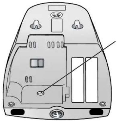
natural_image
Technical diagram of a device casing with internal components and a diagonal line indicating a measurement or alignment (no text or symbols present)FACTORY DEFAULT RESET
9 The [Support] Tab
The [Support] tab can be accessed by all users and provides access to the following pages.
The [Help] page
Displays basic help information.
The [Wireless Help] page (BL-C131A only)
Displays basic help information regarding wireless settings.
The [Product Information] page
Displays a link to the Panasonic Network Camera website where you can view product information.
The [Support Information] page
Displays a link to the Panasonic Network Camera website, where you can view technical files, download the latest firmware, etc.
10 Using IPv6
Your Panasonic Network Camera supports IPv6 (Internet Protocol Version 6). IPv6 is a next generation protocol and is expected to eventually replace IPv4, the current standard Internet protocol. As the Internet continues to expand and more and more IP-compatible devices are being introduced, the number of IP addresses supported by IPv4 is running out. While IPv4 supports just over 4 billion unique addresses, the number of addresses supported by IPv6 is virtually unlimited.
Although several Internet Service Providers (ISPs) do not support IPv6 yet, your Network Camera will be ready as IPv6 services become more widespread.
For more information regarding IPv6, visit http://www.ipv6.org/.
Note
- The following restrictions apply when using the camera in an IPv6-native network.
- Viewnetcam.com service cannot be used
- The Setup Program can be used to search for cameras only (other Setup Program features cannot be used)
Requirements for accessing the camera using IPv6
The following hardware and software is required to access the camera using IPv6.
- Windows XP Service Pack 1 or later
- Internet Explorer 6.0 or later
• An IPv6-compatible router - An IPv6-compatible Internet connection
Subscribe to your Internet Service Provider's "IPv4/IPv6 Dual-Stack" or "IPv6 over IPv4 Tunneling" service.
- A subscription to an IPv6-compatible domain name service or Dynamic DNS service
You cannot access the camera by entering its IPv6 address in your web browser, therefore, you need to subscribe to an IPv6-compatible domain name service or Dynamic DNS service. We recommend using Viewnetcam.com, a Dynamic DNS service designed for use with Panasonic Network Cameras. For more information about IPv6 access, ask your ISP about IPv6-compatible services.
Preparations for accessing the camera using IPv6
The following procedures are required before you can access the camera using IPv6.
- Configure your router for IPv6 (see Page 131).
- Configure your PC for IPv6 (see Page 132).
- Configure the camera for IPv6 (see Page 133).
10.1 Configuring Your Router for IPv6
Refer to your Internet Service Provider and the operating instructions included with your router for information on configuring the router for IPv6. If outside access (WAN access) is disabled on the router, use the router's packet filtering feature to allow the router to receive the desired TCP and UDP packets from the WAN side. See the Panasonic Network Camera website at http://panasonic.co.jp/pcc/products/en/netwkcam/ for information about the recommended routers.
10.2 Configuring Your PC for IPv6
Your PC must be running Windows XP Service Pack 1 or later to enable IPv6.
- Click [Start]→[All Programs]→[Accessories]→[Command Prompt].
- When the [Command Prompt] is displayed, enter ipv6 install. When installation is complete, [Succeeded.] will be displayed.
- Confirm that IPv6 was successfully enabled, enter ipconfig. If IPv6 addresses are displayed, installation was successful.
For Windows XP Service Pack 2 users
If you use Windows XP Service Pack 2, the following procedure is also necessary.
- Click [Start]→[Control Panel]→[Security Center]→[Windows Firewall]→[Advanced] tab.
- Click the [Settings...] button under [ICMP].
- Check [Allow incoming router request], then click [OK].
10.3 Configuring Your Camera for IPv6
When the [Connection Mode] on the [Network (IPv6)] page is set to [Automatic Setup], an IPv6 address is automatically assigned to the camera. To assign a static IPv6 address, follow the procedure below.
- Click the [Setup] tab.
- On the left side of the screen under [Basic], click [Network (IPv6)].
- Select the desired connection mode, then make the appropriate settings as described in this section.
| Connection Mode | |
| Connection Mode | Current Setting |
| Automatic Setup | X |
| Static | |
- [Automatic Setup]: The camera is automatically assigned an IPv6 prefix from the IPv6 router, and produces an original IPv6 address based on the IPv6 prefix.
- [Static]: Allows you to set all network settings manually.
[Automatic Setup]
- Under [DNS], enter the IP addresses of the primary and secondary DNS servers provided by your ISP.
![PANASONIC BL-C131A - [Automatic Setup] - 1](/content/2026/06/1244027/images/d080ec7382d229edca2dc5ed181bbe4e368e83aa0604428c127ff491ec447867.jpg)
text_image
DNS Primary Server Address Secondary Server Address Max. Bandwidth Usage Unlimited Connection Type Automatic Setup Save Cancel-
Under [Max. Bandwidth Usage], select the maximum bandwidth you want to allow the camera to use.
-
Under [Connection Type], select the appropriate connection type.
-
Normally you can leave this setting at [Auto Negotiation].
-
BL-C131A only: If using the camera in wireless mode, [Auto Negotiation] must be selected.
-
Click [Save].
-
When the [New settings are saved.] message is displayed, click [Restart].
Note
- The current network settings can be confirmed on the [Status] page (see Page 119). You can also confirm the camera's IPv6 address using the Setup Program.
[Static]
- Under [Internet Connection], enter the port number to be assigned to the camera.
![PANASONIC BL-C131A - [Static] - 1](/content/2026/06/1244027/images/6f036151e7825cc3e848f40cb0e2170c223d9f612a817a50ee60d2356e4daa8d.jpg)
text_image
Internet Connection Port No. 80 IP Address Default Gateway Default Gateway DNS Primary Server Address Secondary Server Address Max. Bandwidth Usage Unlimited Connection Type Automatic Setup- The default port number is 80, however, note that some ISPs do not allow access from the Internet using port 80. Ask your ISP or network administrator about which port numbers are available for access over the Internet.
- Enter the IP address to be assigned to the camera.
- Ask your ISP or network administrator for the correct settings.
- Under [Default Gateway], enter the IP address of your router or the default gateway IP address provided by your ISP.
- Under [DNS], enter the IP addresses of the primary and secondary DNS servers provided by your ISP.
- Under [Max. Bandwidth Usage], select the maximum bandwidth you want to allow the camera to use.
- This setting is effective for both IPv4 and IPv6 connections.
- Refer to the following file size information when restricting the maximum bandwidth. Note that these are estimated file sizes; the actual file size may vary depending on image quality, image brightness, etc.
- 192 × 144: 3.5 KB (28 Kbit)
- 320 × 240: 10 KB (80 Kbit)
-
640 × 480: 18 KB (144 Kbit)
-
Under [Connection Type], select the appropriate connection type.
-
Normally you can leave this setting at [Auto Negotiation].
- This setting is effective for both IPv4 and IPv6 connections.
-
BL-C131A only: If using the camera in wireless mode, [Auto Negotiation] must be selected.
-
Click [Save].
-
When the [New settings are saved.] message is displayed, click [Restart].
Note
- The current network settings can be confirmed on the [Status] page (see Page 119). You can also confirm the camera's IPv6 address using the Setup Program.
10.4 Accessing the Camera in IPv6 Mode
You will need to know the following information to access the camera in IPv6 mode.
- The URL assigned to you by the domain name service or Dynamic DNS service you registered the camera to (e.g., bob.viewnetcam.com).
- The port number of the camera, if it is not 80.
-
The user name and password required to access the camera, which were set during camera setup.
-
Start your PC's web browser.
-
In the browser's address bar, enter http:// followed by the IP address of the camera, then press [Enter] on the keyboard.
Example: http://bob.viewnetcam.com -
When the authentication dialog is displayed, enter the user name and password, then click [OK]. The top page is displayed.
Note
- For general information on accessing the camera, see Page 7.
11 PC Settings
11.1 Proxy Server Settings
A proxy server is used to protect computers when connecting to the Internet. If your computer network uses a proxy server (many corporate networks do; most home networks do not) and you are accessing the camera from a PC connected to the same LAN as the camera, you may experience the following issues.
– Camera cannot be accessed
- Slow image refresh rate
– Camera images cannot be seen
– Audio features cannot be used
If your network uses a proxy server, we recommend setting your web browser to bypass the proxy server when accessing the camera over the LAN.
Note
- Consult your Internet Service Provider or network administrator to find out if your network uses a proxy server and consult your network administrator before changing your PC's proxy server settings.
- The video and audio features cannot be used when the camera is accessed through a proxy server requiring authentication.
How to bypass the proxy server when accessing the camera
- Start Internet Explorer.
- From the [Tools] menu, select [Internet Options...].
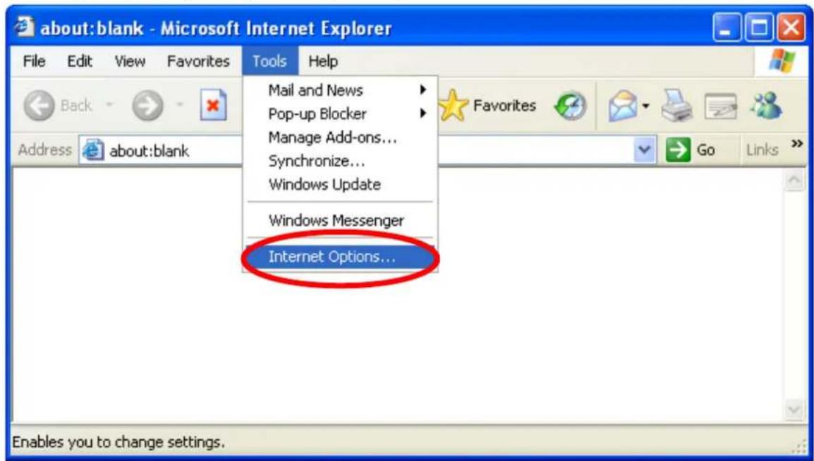
text_image
about:blank - Microsoft Internet Explorer File Edit View Favorites Tools Help Back Address about:blank Mail and News Pop-up Blocker Manage Add-ons... Synchronize... Windows Update Windows Messenger Internet Options... Enables you to change settings.- Click the [Connections] tab, then click [LAN Settings...].
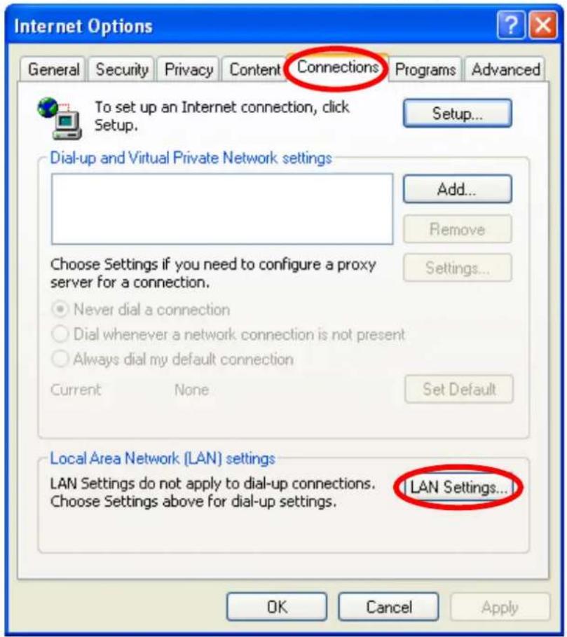
text_image
Internet Options General Security Privacy Content Connections Programs Advanced To set up an Internet connection, click Setup. Setup... Dial-up and Virtual Private Network settings Add... Remove Choose Settings if you need to configure a proxy server for a connection. Never dial a connection Dial whenever a network connection is not present Always dial my default connection Current None Set Default Local Area Network (LAN) settings LAN Settings do not apply to dial-up connections. Choose Settings above for dial-up settings. LAN Settings... OK Cancel Apply- If there is a check next to [Use a proxy server for your LAN], click [Advanced].
- If there is no check next to [Use a proxy server for your LAN], click [Cancel]. You do not need to change any settings.
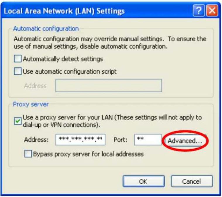
text_image
Local Area Network (LAN) Settings Automatic configuration Automatic configuration may override manual settings. To ensure the use of manual settings, disable automatic configuration. □ Automatically detect settings □ Use automatic configuration script Address Proxy server ✓ Use a proxy server for your LAN (These settings will not apply to dial-up or VPN connections). Address: ***,***,***,** Port: ** Advanced... □ Bypass proxy server for local addresses OK Cancel- Enter the camera's IP address in the field under [Do not use proxy server for addresses beginning with:].
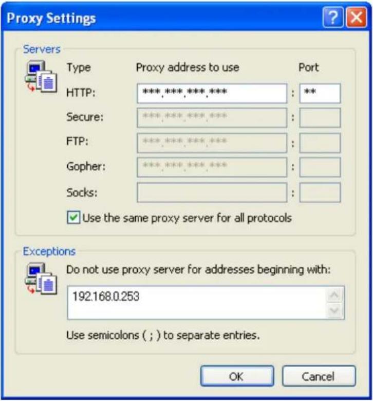
text_image
Proxy Settings Servers Type Proxy address to use Port HTTP: ***,***,***,*** Secure: **** FTP: **** Gopher: **** Socks: ✓ Use the same proxy server for all protocols Exceptions Do not use proxy server for addresses beginning with: 192.168.0.253 Use semicolons ( ; ) to separate entries. OK Cancel- Click [OK].
11.2 Creating a Shortcut to the Camera
If you are using Windows XP, you can create a shortcut to the camera in your computer's [My Network Places] folder that will be automatically updated even if the camera's IP address changes. In order to use this feature, you must first enable the UPnP™ component of Windows XP using the following procedure.
Note
- Windows 2000 does not support this feature.
- This feature is enabled for the camera by default. You can confirm the setting on the [UPnP] page if necessary (see Page 94).
When using Windows XP (Service Pack 2)
[Start]→([Settings])→[Control Panel]→[Add or Remove Programs]→ [Add/Remove Windows Components]→Select [Networking Services]→[Details]→ Check [Internet Gateway Device Discovery and Control Client] and [UPnP User Interface]→ [OK]→Complete
When using previous versions of Windows XP
[Start]→([Settings])→[Control Panel]→[Add or Remove Programs]→[Add/Remove Windows Components]→Select [Networking Services]→[Details]→Check [UPnP User Interface]→[OK]→[Next]→Complete
11.3 Changing the [Temporary Internet files] Setting
If old images are displayed when you access the camera, change the [Temporary Internet files] setting using the following procedure.
Start Internet Explorer→[Tools]→[Internet Options]→[General] tab→
Click [Settings] under [Temporary Internet files]→
Check [Every visit to the page] under [Check for newer versions of stored pages]→
[OK]→[OK]→Complete
11.4 About the MPEG-4 Viewer Program
The MPEG-4 viewer program is an ActiveX Control that is used to play MPEG-4 files within Internet Explorer. This software is installed automatically the first time you view MPEG-4 videos.
A software license for the MPEG-4 decoder is included with the MPEG-4 viewer program, and the license is valid for 1 PC. When installing the MPEG-4 viewer program on additional PCs, please purchase additional licenses.
Uninstalling the MPEG-4 viewer program
Follow the procedure below to uninstall the MPEG-4 viewer program.
Start Internet Explorer→[Tools]→[Internet Options]→[General] tab→
Click [Settings] under [Temporary Internet files]→
Click [View Objects]→Right-click on [pmpeg4cam Class]→[Delete]→Complete
12 Using the Setup Program
The Setup Program, found on the included CD-ROM, can be used to:
- Find cameras on the LAN and confirm information (IP address, firmware version, status, etc.) as needed (see Page 143).
- Configure a camera's network settings (see Page 143).
- Update a camera's firmware (see Page 144).
- Save a configuration file of a camera's settings to your PC (see Page 144).
- Restore the settings saved in a configuration file on your PC (see Page 144).
Note
- Although the above can be performed by accessing a camera directly, using the Setup Program is convenient when you want to configure several cameras because there is no need to access each camera individually with your web browser.
- When the camera is connected in IPv6 mode, the Setup Program can be used only to find and confirm cameras on the LAN (other Setup Program features are not available).
- If you are using firewall or antivirus software on your PC, the Setup Program may not be able to find any cameras on your network. If you cannot disable your firewall or antivirus software, you can find the camera by entering its MAC address. Click [Search by MAC Address], then enter the camera's MAC address. (The MAC address is printed on the camera and begins with 0080F0.)
Finding cameras on the LAN
- Insert the included CD-ROM into the CD-ROM drive of your PC.
• The Setup Program starts. If the program does not start, double-click Setup.exe found on the CD-ROM.
-
Click [Search for Cameras].
-
Wait for the Setup Program to find all cameras on the network and display their information.
- If the desired camera is not displayed, confirm it is turned on and connected to the network.
- If the desired camera is not displayed, you can find the camera by entering its MAC address. Click [Search by MAC Address], then enter the camera's MAC address. (The MAC address is printed on the camera and begins with 0080F0.)
- Confirm the information as needed.
Configuring a camera's network settings
- Find the camera on the LAN (see Page 143).
- Select the desired camera.
- Click [Network Settings].
- If more than 20 minutes have passed since the selected camera was turned on, you cannot configure the camera. Turn off the camera, then turn it on again. This restriction does not apply to cameras which have not been configured yet or have been reset to their factory default settings.
- Change the camera name as desired (max. 15 characters).
• See Page 147 for a list of valid characters. Note that [Space], ["], ['], (&], [<], and [>] are not available.
-
Select the desired connection mode, and enter the appropriate settings. See Page 82 for details about each setting.
-
[Automatic Setup]: Configures the camera automatically based on your network's settings.
- [Specify an IP Address]: Allows you to assign a static IP address. Refer to your ISP or network administrator for more information.
a. Specify an IP address corresponding to your network's settings.
b. Specify the subnet mask of your network.
c. Enter the default gateway (the IP address of your router).
d. Enter the IP address of the DNS server(s).
e. Specify the maximum bandwidth the camera is allowed to use.
- [DHCP]: Allows the camera to be configured automatically by your network's DHCP server (usually your router). Refer to your ISP or network administrator for more information.
a. Enter the host name if required by your ISP or network administrator.
b. Enter the default gateway if required by your ISP or network administrator.
c. Enter the IP address of the DNS server(s). Refer to your ISP or network administrator for more information.
d. Specify the maximum bandwidth the camera is allowed to use.
-
Click [Save].
-
Follow the on-screen prompts.
Updating a camera's firmware
- Download the latest firmware from the Panasonic Network Camera website (http://panasonic.co.jp/pcc/products/en/netwkcam/) and save it on your PC.
- Insert the included CD-ROM into the CD-ROM drive of your PC.
• The Setup Program starts. If the program does not start, double-click Setup.exe found on the CD-ROM.
- Click [Update Firmware]. A dialog prompts you to specify the location of the firmware file.
- Select the firmware file you downloaded from the Panasonic Network Camera website and click [Open].
-
Select the camera you would like to update, then click [Execute].
-
Only cameras which are compatible with the selected firmware file are displayed.
-
You can select multiple cameras if desired.
-
Enter the administrator user name and password when prompted, then click [OK].
-
Click [xxCONFIRM STRING Execute].
- [xxCONFIRM STRING] is displayed when the firmware has been updated.
- Click [xxCONFIRM STRING Save Log] to display a log of the firmware revision.
Saving settings in a configuration file
- Insert the included CD-ROM into the CD-ROM drive of your PC.
- The Setup Program starts. If the program does not start, double-click Setup.exe found on the CD-ROM.
- Click [Save Settings to PC/Save Settings to Camera].
- Select the desired camera, then click [Save Settings to PC].
- Enter the camera's administrator user name and password when prompted, then click [OK]. A dialog prompts you to specify a location to save the file.
- Specify a location to save the file, then click [Save].
- When [Settings were saved on the PC.] is displayed, click [OK].
Note
- Buffered images are not saved in the configuration file.
- The configuration file's extension (.dat) must not be changed. If you change it, the saved settings cannot be restored.
- If you save a configuration file and then update the camera's firmware later, the configuration file may not be able to be restored properly. If you regularly save a configuration file of the cameras settings, remember to save a configuration file after you update the camera's firmware.
Restoring settings from a configuration file
- Insert the included CD-ROM into the CD-ROM drive of your PC.
• The Setup Program starts. If the program does not start, double-click Setup.exe found on the CD-ROM.
- Click [Save Settings to PC/Save Settings to Camera].
- Click [Save Settings to Camera]. A dialog prompts you to specify the location of the saved configuration file.
- Specify the configuration file and click [Open].
- Select the desired camera, then click [Execute].
- Enter the camera's administrator user name and password when prompted, then click [OK]. A dialog displays the status.
- xxCONFIRM SPEC
- After the settings have been restored to the camera, the camera will restart automatically.
Note
- Network settings and the administrator user name and password are not changed when you restore a configuration file using the Setup Program.
13 Technical Information
13.1 Cleaning the Camera
For best performance, we recommend cleaning the camera periodically. Turn the camera off before cleaning it.
Cleaning the main unit
Clean the main unit with a dry and soft cloth.
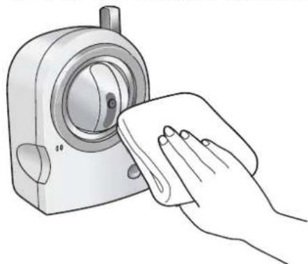
natural_image
Illustration of a hand cleaning a washing machine with a cloth (no text or symbols)Note
- Do not use alcohol, polishing powder, cleanser, benzine, thinner, wax, petroleum products, pesticides, glass cleaners, hair spray, or hot water when cleaning the camera, as they may cause a change in the shape or color of the camera.
- Do not apply pressure to the lens housing (pan/tilt mechanism) of the camera. Any forced movement can damage the internal mechanism.
• If the built-in sensor has dust on it, it may not make detections properly. Keep the built-in sensor clean.
Cleaning the lens
Clean the lens periodically to ensure clear, focused images.
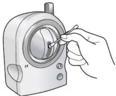
natural_image
Illustration of a hand using a tool to adjust or install a mechanical component (no text or symbols visible)Note
- Do not touch the lens directly. Fingerprints may cause an unclear image.
13.2 ASCII Character Table
| [Space] 0 @ P ` p | ||||
| !1A Q a q | ||||
| "2B R b r | ||||
| #3C S c s | ||||
| $4D T d t | ||||
| %5E U e u | ||||
| &6F V f v | ||||
| '7G W g w | ||||
| (8H X h | x | |||
| )9I Y i | y | |||
| * : J Z j | z | |||
| +;K[k{ | ||||
13.3 Internal Memory Specifications for Buffered Images
The camera's internal memory can buffer images according to the table below.
Note
- All values are approximate.
JPEG images (videos and still images)
| Resolution Specification Snapshot | Image Quality | ||||
| Favor Clarity Standard Favor Motion | |||||
| 640 × 480 | File Size 60 KB 50 KB 33 KB 20 KB | ||||
| No. of Images (Saved to PC) 80 120 | 200 | ||||
| 320 × 240 | File Size 30 KB 25 KB 16 KB 8 KB | ||||
| No. of Images (Saved to PC) 160 250 | 500 | ||||
| 192 × 144 | File Size 10 KB 7 KB 5 KB 3 KB | ||||
| No. of Images (Saved to PC) 570 800 | 1330 | ||||
MPEG-4 videos
| Resolution Specification Snapshot | Image Quality | |||||
| Favor Clarity | Standard | Favor Motion | Mobile Phone | |||
| 640 × 480 | File Size | 60 KB | 50 KB | 33 KB | 20 KB | - |
| No. of Images | (Saved to PC) | 80 | 120 | 200 | - | |
| 320 × 240 | File Size | 30 KB | 25 KB | 16 KB | 8 KB | 8 KB |
| No. of Images | (Saved to PC) | 160 | 250 | 500 | 500 | |
| 192 × 144 | File Size | 10 KB | 7 KB | 5 KB | 3 KB | 3 KB |
| No. of Images | (Saved to PC) | 570 | 800 | 1330 | 1330 | |
xxOLD SPEC
上記は全て未確認
13.4 Default Setting List
xxOLD SPEC
全て未確認
Basic
| Items Default Notes | |||
| Network Connection Mode | Automatic Setup – | ||
| Allow Access from the Internet (Automatic Setup only) | No | – | |
| Network Configuration from Setup Program (Static/DHCP only) | Enable – | ||
| Port No. (Static/DHCP only) | 80 20, 21, 25 and 110 are not available | ||
| IP address (Static only) | 192.168.0.253 – | ||
| Subnet Mask (Static only) | 255.255.255.0 – | ||
| Host Name (DHCP only) | (Blank) 0–63 characters | ||
| Default Gateway (Static/DHCP only) | (Blank) – | ||
| DNS Server 1 DNS Server 2 (Static/DHCP only) | (Blank) – | ||
| Max. Bandwidth Usage (Mbps) Unlimited – | |||
| Connection Type Auto Negotiation – | |||
| Wireless (BL-C131A only) | Communication Mode | 802.11 b/g | – |
| Channel | Auto | – | |
| SSID xxCONFIRM | – | ||
| xxSpeed | xxAuto | – | |
| Encryption | No encryption | – | |
| UPnPTM | Auto Port Forwarding | Disable | – |
| Display Shortcut Icon in My Network Places | Enable – | ||
| Viewnetcam.com | Enable | No check – | |
| Date and Time Time Setting | AM/PM – | ||
| Automatic Time Adjustment No check – | |||
| Time Zone GMT -05:00 – | |||
| Adjust Clock for Daylight Saving Time | No check – | ||
| Start Day Apr | First Sunday2 AM | – | |
| End Day Oct | Last Sunday2 AM | – | |
| Camera Camera Name | Network | Camera | 1–15 characters |
| White Balance Auto – | |||
| AC Power Source Frequency 60 Hz | – | ||
| Pan Range—MinimumPan Range—Home PositionPan Range—Maximum | -50°0°+50° | – | |
| Tilt Range—MinimumTilt Range—Home PositionTilt Range—Maximum | -40°0°+10° | – | |
Account
| Items Default Notes | |||
| Security: Administrator | General Authentication | Do not permit access from guest users | - |
| User Name | - | 6–15 characters | |
| Password | - | 6–15 characters | |
| Retype Password | - | 6–15 characters | |
| General User | User ID List | - | - |
| User Name | - | 6–15 characters | |
| Password | - | 6–15 characters | |
| Retype Password | - | 6–15 characters | |
| Access Level | Level 3 | - | |
Advanced
| Items Default Notes | |||
| Image Display Single Camera | mera Image Resolution | 320 × 240 | - |
| Single Camera Image Quality Standard - | |||
| Single Camera Refresh Interval Motion - | |||
| Multi Camera Image Resolution | 320 × 240 | - | |
| Multi Camera Image Quality Standard - | |||
| Multi Camera Refresh Interval Motion - | |||
| Limit Continuous Motion JPEG Unlimited - | |||
| Still Image Refresh Interval 30 s - | |||
| Language English - | |||
| Multi Camera Multi Camera | ra | - | - |
| Display | Checked | - | |
| IP Address or Host Name | - | Host name is 1–255 characters | |
| Port No. | - | 20, 21, 25 and 110 are not available | |
| Camera Name | - | 1–15 characters | |
| Buffer/Transfer | Status | Off | - |
| Trigger | Timer | - | |
| Active Time of Trigger | Always | - | |
| Transfer Method No Transfer, No Memory Overwrite | - | ||
| Notify | - | - | |
| Operation Time | Operation Time | Always | - |
| Indicator Control | Indicator Control Turn indicator on when camera is on | - | |
| Privacy Mode | Privacy Button | Checked | - |
| Privacy Mode | Disable | - | |
Preset Buttons
| Items Default Notes | |||
| Presets 1–20 Preset 1 Up | UpperLeft – | ||
| Preset 2 UpperRight – | |||
| Preset 3 LowerLeft – | |||
| Preset 4 LowerRight – | |||
13.5 Specifications
Camera Specifications
| Items Specifications | |
| Zoom | 10× (by area) digital zoom |
| Pan/Tilt Angle Pan: -50 ° to +50 °, Tilt: | -40 ° to +10 ° |
| Number of Pixels 1/6 inch CMOS Sensor 320,000 pixels | |
| Illuminance 10–100,000 lx (3–10,000 lx when in Color Night View mode) | |
| White Balance Auto/Manual/Hold | |
| Lens Brightness 9 steps | |
| Focus Fixed 0.3 m–Infinity | |
| Aperture (F No.) F2.8 | |
| Horizontal Viewing Angle 49 ° | |
| Vertical Viewing Angle – | |
| Exposure Auto | |
Other Specifications
| Items Specifications | |
| Image Compression JPEG (3 Levels), | MJPEG-4 |
| Image Resolution | 640 × 480, 320 × 240, 192 × 144 |
| Buffered Images*1 | About 250 frames (320 × 240, standard image quality) with time display |
| Audio Communication Camera to PC | |
| Audio Compression Format ADPCM 32 kbps | |
| Audio Bandwidth 300 Hz–3.4 KHz | |
| Audio Reception Method ActiveX | |
| Audio Reception Encoding | ActiveX |
| Audio Input Built-in microphone | |
| Frame Rate*2 | Max. 30 frames/second (640 × 480, 320 × 240, 192 × 144) |
| Communication Protocols | IPv4/IPv6 Dual-StackIPv4:TCP, UDP, IP, HTTP, FTP, SMTP, DHCP, DNS, ARP, ICMP, POP3, NTP, UPnPTM, SMTP Authentication, RTP, RTSP, RTCPIPv6:TCP, UDP, IP, HTTP, FTP, SMTP, DNS, ICMPv6, POP3, NDP, NTP, RTP, RTSP, RTCP |
| Image Buffer/Transfer Triggers Timer, | Sensor, Motion Detection |
| Image Transfer Method SMTP | ^3 , FTP, HTTP |
| Wired LAN Interface 10Base-T/100Base-TX Ethernet RJ-45 connector | |
| Sensor Detection Method Pyroelectric | Infrared Sensor |
| Sensor Detection Range ^4 | Horizontal: About 30 °Vertical: About 85 °Distance: About 5 m (16 feet 5 inches) |
| Indicator Display Power | Network CommunicationCamera OperationEthernet LinkSensor Detection |
| Dimensions (W×H×D) | 74 mm × 98 mm × 73 mm(2 15/16 inches × 3 7/8 inches × 2 7/8 inches) |
| Weight (Main Unit Only) BL-C111A: 180 (0.4 lb.) gBL-C131A: 210 g(0.46 lb.) | |
| Power Supply AC adaptor: Input 120 V | AC, 60 HzOutput 9 V DC, 750 mA |
| Power Consumption BL-C111A: About | 2.7 W (4.0 W during pan/tilt scan)BL-C131A: About 4.5 W (6.0 W during pan/tilt scan) |
| Operating Temperature Operation: +5 | °C (+41 °F) to +40 °C (+104 °F)Storage: +0 °C (+32 °F) to +50 °C (+122 °F) |
| Operating Humidity Operation: 20 %–80 % (no condensation)Storage: 20 %–90 % (no condensation) | |
Wireless Specifications (BL-C131A Only)
| Items Specifications | |
| Communication Standard IEEE 802.11b, 802.11b/g, 802.11g exclusive | |
| Data Transfer Mode IEEE 802.11b: Direct Sequence Spectrum Spread (DS-SS)IEEE 802.11g: Orthogonal Frequency Division Multiplexing (OFDM) | |
| Frequency Range 2.412–2.462 GHz | |
| Channel 1–11 | |
| Security SSID, WEP (64/128/152 bit), | WPA-PSK (TKIP), WPA2-PSK (AES) |
1 See Page 148 for details.
^2 Frame rate may slow down depending on the network environment, PC performance, image quality, when Color Night View mode is activated, etc.
^*3 The camera supports POP Before SMTP Authentication and SMTP Authentication. Only PLAIN and LOGIN SMTP Authentication is supported.
^4 When the temperature is 20 ^ ( 68 ^ )