Vigor 2130n - Router Draytek - Free user manual and instructions
Find the device manual for free Vigor 2130n Draytek in PDF.

User questions about Vigor 2130n Draytek
0 question about this device. Answer the ones you know or ask your own.
Ask a new question about this device
Download the instructions for your Router in PDF format for free! Find your manual Vigor 2130n - Draytek and take your electronic device back in hand. On this page are published all the documents necessary for the use of your device. Vigor 2130n by Draytek.
USER MANUAL Vigor 2130n Draytek
High Speed Gigabit Router

natural_image
White RoayTek 1130V4 wireless router with three white antennas against a red background (no visible text or symbols on the device body)Your reliable networking solutions partner
User's Guide
v 2.1
Vigor2130 Series High Speed Gigabit Router User's Guide
Version: 2.1
Firmware Version: V1.5.2
Date: 21/05/2012
Copyright Information
Copyright Declarations
Copyright 2012 All rights reserved. This publication contains information that is protected by copyright. No part may be reproduced, transmitted, transcribed, stored in a retrieval system, or translated into any language without written permission from the copyright holders.
Trademarks
The following trademarks are used in this document:
● Microsoft is a registered trademark of Microsoft Corp.
● Windows, Windows 95, 98, Me, NT, 2000, XP, Vista and Explorer are trademarks of Microsoft Corp.
● Apple and Mac OS are registered trademarks of Apple Inc.
● Other products may be trademarks or registered trademarks of their respective manufacturers.
Safety Instructions and Approval
Safety Instructions
- Read the installation guide thoroughly before you set up the router.
- The router is a complicated electronic unit that may be repaired only by authorized and qualified personnel. Do not try to open or repair the router yourself.
- Do not place the router in a damp or humid place, e.g. a bathroom.
● The router should be used in a sheltered area, within a temperature range of +5 to +40 Celsius. - Do not expose the router to direct sunlight or other heat sources. The housing and electronic components may be damaged by direct sunlight or heat sources.
- Do not deploy the cable for LAN connection outdoor to prevent electronic shock hazards.
- Keep the package out of reach of children.
- When you want to dispose of the router, please follow local regulations on conservation of the environment.
Warranty
We warrant to the original end user (purchaser) that the router will be free from any defects in workmanship or materials for a period of two (2) years from the date of purchase from the dealer. Please keep your purchase receipt in a safe place as it serves as proof of date of purchase. During the warranty period, and upon proof of purchase, should the product have indications of failure due to faulty workmanship and/or materials, we will, at our discretion, repair or replace the defective products or components, without charge for either parts or labor, to whatever extent we deem necessary tore-store the product to proper operating condition. Any replacement will consist of a new or re-manufactured functionally equivalent product of equal value, and will be offered solely at our discretion. This warranty will not apply if the product is modified, misused, tampered with, damaged by an act of God, or subjected to abnormal working conditions. The warranty does not cover the bundled or licensed software of other vendors. Defects which do not significantly affect the usability of the product will not be covered by the warranty. We reserve the right to revise the manual and online documentation and to make changes from time to time in the contents hereof without obligation to notify any person of such revision or changes.
Be a Registered Owner
Web registration is preferred. You can register your Vigor router via http://www.draytek.com.
Firmware & Tools Updates
Due to the continuous evolution of DrayTek technology, all routers will be regularly upgraded. Please consult the DrayTek web site for more information on newest firmware, tools and documents.
http://www.draytek.com
European Community Declarations
Manufacturer: DrayTek Corp.
Address: No. 26, Fu Shing Road, HuKou County, HsinChu Industrial Park, Hsin-Chu, Taiwan 303
Product: Vigor2130 Series Router
DrayTek Corp. declares that Vigor2130 Series of routers are in compliance with the following essential requirements and other relevant provisions of R&TTE Directive 1999/5/EEC.
The product conforms to the requirements of Electro-Magnetic Compatibility (EMC) Directive 2004/108/EC by complying with the requirements set forth in EN55022/Class B and EN55024/Class B.
The product conforms to the requirements of Low Voltage (LVD) Directive 2006/95/EC by complying with the requirements set forth in EN60950-1.
Regulatory Information
Federal Communication Commission Interference Statement
This equipment has been tested and found to comply with the limits for a Class B digital device, pursuant to Part 15 of the FCC Rules. These limits are designed to provide reasonable protection against harmful interference in a residential installation. This equipment generates, uses and can radiate radio frequency energy and, if not installed and used in accordance with the instructions, may cause harmful interference to radio communications. However, there is no guarantee that interference will not occur in a particular installation. If this equipment does cause harmful interference to radio or television reception, which can be determined by turning the equipment off and on, the use is encouraged to try to correct the interference by one of the following measures:
● Reorient or relocate the receiving antenna.
- Increase the separation between the equipment and receiver.
- Connect the equipment into an outlet on a circuit different form that to which the receiver is connected.
- Consult the dealer or an experienced radio/TV technician for help.
This device complies with Part 15 of the FCC Rules. Operation is subject to the following two conditions:
(1) This device may not cause harmful interference, and
(2) This device may accept any interference received, including interference that may cause undesired operation.
Please visit http://www.draytek.com/user/SupportDLRTTECE.php.


This product is designed for 2.4GHz WLAN network throughout the EC region and Switzerland with restrictions in France. Please see the user manual for the applicable networks on your product.
Table of Contents
1
Preface ....1
1.1 Features.... 1
1.2 Web Configuration Buttons Explanation .... 1
1.3 LED Indicators and Connectors 2
1.3.1 For Vigor2130 2
1.3.2 For Vigor2130n 4
1.3.3 For Vigor2130Vn....6
1.4 Hardware Installation 8
Stand Installation 9
1.5 Printer Installation 10
2
Basic Settings ....15
2.1 Accessing Web Page 15
2.2 Changing Password 16
2.3 Quick Start Wizard 17
2.3.1 Setting up the Password.... 18
2.3.2 Setting up the Time Zone 18
2.3.3 Setting up the Internet Connection 19
2.3.4 Setting up the Wireless Connection 23
2.3.5 Saving the Wizard Configuration 28
2.4 Online Status.... 28
2.5 Saving Configuration.... 29
2.6 Registering Vigor Router.... 30
3
Tutorials and Applications ....35
3.1 How to Configure Multi-VLAN in Vigor Router 35
3.2 LAN to LAN IPSec VPN between Vigor2130 and Vigor2820 using Main mode.... 39
Case 1: VPN direction from Vigor2130 to Vigor2820 39
Case 2: VPN direction from Vigor2820 to Vigor2130 43
3.3 LAN to LAN IPSec VPN between Vigor2130 and Vigor2820 using Aggressive mode 46
Case 1: VPN direction from Vigor2130 to Vigor2820 46
Case 2: VPN direction from Vigor2820 to Vigor2130 50
3.4 How to configure settings for DLNA Service in Vigor2130.... 53
3.5 How to download BT Torrent to USB Device via Vigor Router.... 57

Web Configuration....67
4.1 WAN 67
4.1.1 Internet Access 69
4.1.2 Multi-VLAN 84
4.1.3 Ports....88
4.1.4 Backup....90
4.2 LAN 93
4.2.1 General Setup....95
4.2.2 Ports....97
4.2.3 MAC Address Table....99
4.2.4 VLAN....100
4.2.5 Monitor Port 101
4.2.6 Static Route 102
4.2.7 Police Route 104
4.2.8 Bind IP to MAC 105
4.2.9 Web Portal 108
4.3 NAT 111
4.3.1 Hardware NAT 112
4.3.2 Open Ports....112
4.3.3 DMZ Host....114
4.4 Firewall....115
4.4.1 DoS Defense 115
4.4.2 Ports Configuration 116
4.4.3 Access Control List.... 119
4.4.4 Traffic Control 132
4.4.5 Time Object 135
4.5 CSM 136
4.5.1 URL Content Filter 136
4.5.2 Web Content Filter 138
4.5.3 APP Enforcement 143
4.6 Bandwidth Management 145
4.6.1 Session Limit 145
4.6.2 Bandwidth Limit 147
4.6.3 Port Rate Control 149
4.6.4 QoS Control List 149
4.6.5 Ports Priority 155
4.6.6 QoS Statistics 156
4.7 Applications....159
4.7.1 Dynamic DNS 159
4.7.2 Schedule 161
4.7.3 IGMP 163
4.7.4 IGMP Status 164
4.7.5 UPnP Configuration.... 164
4.7.6 Wake On LAN 166
4.7.7 Short Message Service.... 167
4.8 VPN and Remote Access.... 169
4.8.1 Remote Access Control 169
4.8.2 PPTP Remote Dial-in.... 170
4.8.3 IPSec Remote Dial-in 173
4.8.4 Remote Dial-in Status.... 175
4.8.5 LAN to LAN 176
4.9 Certificate Management.... 181
4.9.1 Trusted CA Certificate 182
4.9.2 Local Certificate 185
4.9.3 Issue Certificate 187
4.10 Wireless LAN 187
4.10.1 Basic Concepts.... 187
4.10.2 General Setup.... 189
4.10.3 Access Control.... 196
4.10.4 Station List.... 197
4.10.5 Access Point Discovery 198
4.10.6 WMM Configuration.... 199
4.10.7 WDS....201
4.11 USB Application....203
4.11.1 Disk Status....203
4.11.2 Format Disk (ext2/3) 204
4.11.3 File Explorer....205
4.11.4 FTP User Management 206
4.11.5 Disk Shares 207
4.11.6 Bit Torrent Download 209
4.11.7 iTunes Server 211
4.11.8 DLNA server 212
4.11.9 Temperature Sensor 213
4.12 VoIP 215
4.12.1 DialPlan 216
4.12.2 SIP Accounts 223
4.12.3 Phone Settings 226
4.12.4 Status.... 231
4.13 IPv6 232
4.13.1 IPv6 WAN Setup 232
4.13.2 IPv6 LAN Setup 237
4.13.3 IPv6 Firewall Setup 238
4.13.4 IPv6 Routing 242
4.13.5 IPv6 Neighbour 243
4.13.6 IPv6 TSPC Status 244
4.13.7 IPv6 Management....247
4.14 User 248
4.14.1 User Configuration.... 248
4.15 System Maintenance.... 251
4.15.1 System Status.... 251
4.15.2 TR-069 253
4.15.3 System Password 254
4.15.4 User Password 255
4.15.5 Configuration Backup 257
4.15.6 Syslog/Mail Alert 259
4.15.7 Time and Date 262
4.15.8 Management....263
4.15.9 Reboot System 264
4.15.10 Firmware Upgrade 264
4.16 Diagnostics....265
4.16.1 Ping....265
4.16.2 Trace Route 266
4.16.3 Routing Table 266
4.16.4 ARP Cache Table 267
4.16.5 System Log 268
4.16.6 Traffic Overview 269
4.16.7 Detailed Statistics 270
4.16.8 MAC Address Table.... 272
4.16.9 DHCP Table.... 273
4.16.10 Data Flow Monitor 274
4.16.11 Traffic Graph 275
4.16.12 Sessions Table 276
4.16.13 Ports State 277
5
Trouble Shooting....279
5.1 Checking If the Hardware Status Is OK or Not.... 279
5.2 Checking If the Network Connection Settings on Your Computer Is OK or Not 280
5.3 Pinging the Router from Your Computer 282
5.4 Checking If the ISP Settings are OK or Not.... 283
5.5 Forcing Vigor Router into TFTP Mode for Performing the Firmware Upgrade 284
5.6 Backing to Factory Default Setting If Necessary 287
5.7 Contacting Your Dealer 288
1
Preface
The Vigor2130 series are the routers with high speed in data transmission through WAN port and LAN ports. With hardware NAT acceleration, the rate of Vigor2130 series can be ideal for multi-media application.
With the development of NGN (Next Generation Network), you may recently hear the news about FTTx deployment in your local area or even have already subscribed the unbundling last mile service (e.g. VDSL2) from local ITSP for FTTx. As adopting FTTx, the main question for end users is whether your legacy router could fully utilize its bandwidth or not.
For example, you purchase a 120 Mbps Internet connection from your ISP but your existing router cannot support 90 Mbps throughput. That's why DrayTek launches Vigor2130 series – High speed Gigabit router, perfectly complied with VDSL2 environment including Vigor2130, Vigor2130n and Vigor2130Vn for speed-wanted customers. With high throughput performance and secured broadband connectivity provided by Vigor2130 series, you can simultaneously engage these bandwidth-intensive applications, such as high-definition video streaming, online gaming, and Internet telephony / access.
1.1 Features
- Gigabit WAN port and embedded hardware NAT deliver ultra-fast speed from WAN to LAN
● Gigabit LAN ports stream content to wired devices with unprecedented speeds
● 2 USB ports provides fast access to an external USB hard drive - Embedded DLNA server/iTune server supports stream content to Media Players
● Up to 800 Mpbs throughput for downstream
● Advanced QoS for Data, Music, VoIP and Video - Easy-to-use firewall
● VoIP facilities for low cost call (V model)
1.2 Web Configuration Buttons Explanation
Several main buttons appeared on the web pages are defined as the following:

Save and apply current settings.

Cancel current settings and recover to the previous saved settings.

Clear all the selections and parameters settings, including selection from drop-down list. All the values must be reset with factory default settings.

Add new settings for specified item.

Edit the settings for the selected item.

Delete the selected item with the corresponding settings.
Note: For the other buttons shown on the web pages, please refer to Chapter 4 for detailed explanation.
1.3 LED Indicators and Connectors
Before you use the Vigor router, please get acquainted with the LED indicators and connectors first.
1.3.1 For Vigor2130
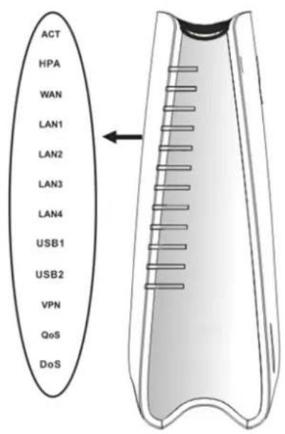
text_image
ACT HPA WAN LAN1 LAN2 LAN3 LAN4 USB1 USB2 VPN QoS DoS| LED | Status | Explanation |
| ACT(Activity) | Blinking The router is powered on and running normally. | |
| Off The router is powered off. | ||
| On Hardware NAT is enabled. HPA | ||
| Off Hardware NAT is disabled. | ||
| WAN | On (Orange) The port is connected with 100Mbps. | |
| On (Green) The port is connected with 1000Mbps. | ||
| Off The port is disconnected. | ||
| Blinking It will blink while transmitting data. | ||
| LAN1/2/3/4 | On (Orange) The port is connected with 100Mbps. | |
| On (Green) The port is connected with 1000Mbps. | ||
| Off The port is disconnected. | ||
| Blinking The data is transmitting. | ||
| On A USB device is connected and active.USB1/2 | ||
| Blinking The data is transmitting. | ||
| VPN On | The VPN tunnel is active. | |
| QoS | On The QoS function is active. | |
| DoS | On The DoS/DDoS function is active. | |
| Blinking It will blink while detecting an attack. | ||
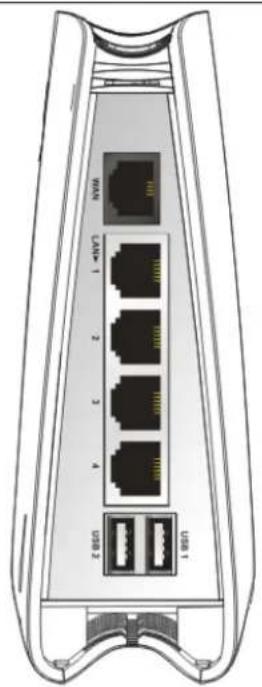
text_image
WAN LAM-1 2 3 4 USB 2 LAM-1| Interface | Description |
| WAN Connector for accessing the Internet. | |
| LAN(1/2/3/4) | Connectors for local networked devices. |
| USB(1/2) | Connector for USB storage device (Pen Driver/Mobile HD) or printer or 3G backup. |

text_image
Factory Reset PWR| Interface Description | |
| Factory Reset | Restore the default settings. Usage: Turn on the router (ACT LED is blinking). Press the hole and keep for more than 5 seconds. When you see the ACT LED begins to blink rapidly than usual, release the button. Then the router will restart with the factory default configuration. |
| PWR Connector | for a power adapter. |
| ON/OFF | Power Switch. |
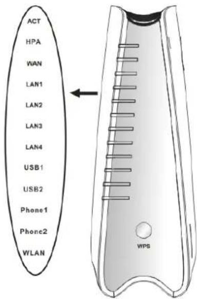
1.3.2 For Vigor2130n
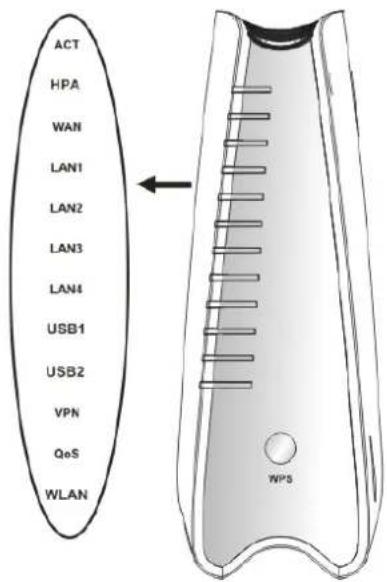
text_image
ACT HPA WAN LAN1 LAN2 LAN3 LAN4 USB1 USB2 VPN QoS WLAN WPS| LED | Status | Explanation |
| ACT(Activity) | Blinking The router is powered on and running normally. | |
| Off The router is powered off. | ||
| On Hardware NAT is enabled. HPA | ||
| Off Hardware NAT is disabled. | ||
| WAN | On (Orange) The port is connected with 100Mbps. | |
| On (Green) The port is connected with 1000Mbps. | ||
| Off The port is disconnected. | ||
| Blinking It will blink while transmitting data. | ||
| LAN1/2/3/4 | On (Orange) The port is connected with 100Mbps. | |
| On (Green) The port is connected with 1000Mbps. | ||
| Off The port is disconnected. | ||
| Blinking The data is transmitting. | ||
| On A USB device is connected and active.USB1/2 | ||
| Blinking The data is transmitting. | ||
| VPN On The VPN tunnel is active. | ||
| QoS | On The QoS function is active. | |
| On Wireless access point is ready. WLAN | ||
| Blinking It will blink while wireless traffic goes through. | ||
| WPSButton | On Press this button for 2 seconds to wait for client device making network connection through WPS. When the LED lights up, the WPS connection will be on. | |
| Off The WPS is off. | ||
| Blinking Waiting for wireless client sending requests for connection about two minutes. | ||
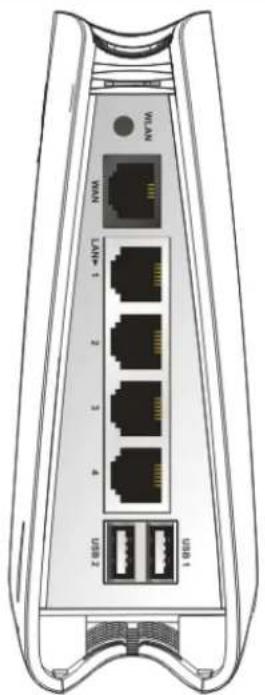
text_image
USB 1 USB 2 4 3 2 1 T-USB 1 USB 2 USB 3 USB 4 USB 5 USB 6 USB 7 USB 8 USB 9 USB 10 USB 11 USB 12 USB 13 USB 14 USB 15 USB 16 USB 17 USB 18 USB 19 USB 20 USB 21 USB 22 USB 23 USB 24 USB 25 USB 26 USB 27 USB 28 USB 29 USB 30 USB 31 USB 32 USB 33 USB 34 USB 35 USB 36 USB 37 USB 38 USB 39 USB 40 USB 41 USB 42 USB 43 USB 44 USB 45 USB 46 USB 47 USB 48 USB 49 USB 50 USB 51 USB 52 USB 53 USB 54 USB 55 USB 56 USB 57 USB 58 USB 59 USB 60 USB 61 USB 62 USB 63 USB 64 USB 65 USB 66 USB 67 USB 68 USB 69 USB 70 USB 71 USB 72 USB 73 USB 74 USB 75 USB 76 USB 77 USB 78 USB 79 USB 80 USB 81 USB 82 USB 83 USB 84 USB 85 USB 86 USB 87 USB 88 USB 89 USB 90 USB 91 USB 92 USB 93 USB 94 USB 95 USB 96 USB 97 USB 98 USB 99 USB100| Interface Description | |
| WLAN | Press the button once to enable (WLAN LED on) or disable (WLAN LED off) wireless connection. |
| WAN Connector for accessing the Internet. | |
| LAN(1/2/3/4) | Connectors for local networked devices. |
| USB (1/2) | Connector for USB storage device (Pen Driver/Mobile HD) or printer or 3G backup. |

text_image
Factory Reset PWRInterface Description
| Factory Reset | Restore the default settings. Usage: Turn on the router (ACT LED is blinking). Press the hole and keep for more than 5 seconds. When you see the ACT LED begins to blink rapidly than usual, release the button. Then the router will restart with the factory default configuration. |
| PWR Connector | for a power adapter. |
| ON/OFF | Power Switch. |
1.3.3 For Vigor2130Vn
text_image
ACT HPA WAN LAN1 LAN2 LAN3 LAN4 USB1 USB2 Phone1 Phone2 WLAN WPS
text_image
WLAN WLAN LAN+ 1 2 3 4 USB 2 USB 1| LED | Status | Explanation |
| ACT (Activity) | Blinking The router is powered on and running normally. | |
| Off The router is powered off. | ||
| On Hardware NAT is enabled. HPA | ||
| Off Hardware NAT is disabled. | ||
| WAN | On (Orange) The port is connected with 100Mbps. | |
| On (Green) The port is connected with 1000Mbps. | ||
| Off The port is disconnected. | ||
| Blinking It will blink while transmitting data. | ||
| LAN 1/2/3/4 | On (Orange) The port is connected with 100Mbps. | |
| On (Green) The port is connected with 1000Mbps. | ||
| Off The port is disconnected. | ||
| Blinking The data is transmitting. | ||
| On A USB device is connected and active. USB1/2 | ||
| Blinking The data is transmitting. | ||
| Phone1/ Phone2 | On | The phone connected to this port off-hook. |
| Off The phone connected to this port is on-hook. | ||
| Blinking A phone call comes. | ||
| On Wireless access point is ready. WLAN | ||
| Blinking It will blink while wireless traffic goes through. | ||
| WPS Button | On Press this button for 2 seconds to wait for client device making network connection through WPS. When the LED lights up, the WPS connection will be on. | |
| Off The WPS is off. | ||
| Blinking Waiting for wireless client sending requests for connection about two minutes. | ||
| Interface Description | ||
| WLAN | Press the button once to enable (WLAN LED on) or disable (WLAN LED off) wireless connection. | |
| WAN Connector for accessing the Internet. | ||
| LAN (1/2/3/4) | Connectors for local networked devices. | |
| USB (1/2) | Connector for USB storage device (Pen Driver/Mobile HD) or printer or 3G backup. | |

text_image
Phoset2 Phoset1 Peakery Panel PWRInterface Description
| Phone2/Phone1 | Connector of analog phone for VoIP communication. |
| Factory Reset | Restore the default settings. Usage: Turn on the router (ACT LED is blinking). Press the hole and keep for more than 5 seconds. When you see the ACT LED begins to blink rapidly than usual, release the button. Then the router will restart with the factory default configuration. |
| PWR Connector | for a power adapter. |
| ON/OFF | Power Switch. |
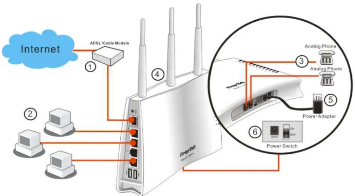
1.4 Hardware Installation
Before starting to configure the router, you have to connect your devices correctly.
- Connect this device to a modem with a RJ-45 cable.
- Connect one port of 4-port switch to your computer with a RJ-45 cable. This device allows you to connect 4 PCs directly.
- Connect Phone port to a conventional analog telephone.
- Connect detachable antennas to the router for Vigor2130 series (n model).
-
Connect one end of the power cord to the power port of this device. Connect the other end to the wall outlet of electricity.
-
Power on the router.
-
Check the ACT and WAN, LAN LEDs to assure network connections.
flowchart
graph TD
    A["Internet"] --> B["ADSL/Cable Modem"]
    B --> C["Router"]
    C --> D["Analog Phone ③"]
    C --> E["Analog Phone ⑤"]
    C --> F["Power Adapter ⑥"]
    C --> G["Power Switch ⑥"]
    style A fill:#f9f,stroke:#333
    style B fill:#ccf,stroke:#333
    style C fill:#cfc,stroke:#333
    style D fill:#fcc,stroke:#333
    style E fill:#fcc,stroke:#333
    style F fill:#fcc,stroke:#333
    style G fill:#fcc,stroke:#333
(For the detailed information of LED status, please refer to section 1.1.)
Caution: Each of the Phone ports can be connected to an analog phone only. Do not connect the phone ports to the land line jack. Such connection might damage your router.
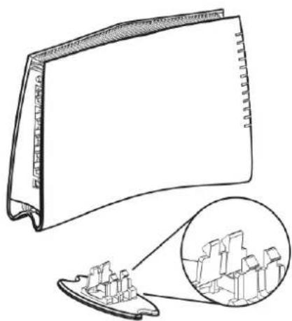
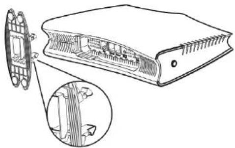
Stand Installation
The Vigor2130 must be placed erectly. Therefore you have to install a stand onto the router to make it standing firmly. Please follow the figures listed below to finish the installation.
①
natural_image
Technical line drawing of a mechanical component with an inset close-up showing internal components (no text or symbols)②
natural_image
Technical line drawing of a device showing internal structure and external components (no text or symbols)③ ④
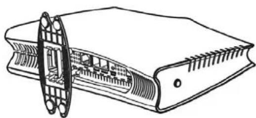
natural_image
Technical line drawing of a mechanical component with internal structure and mounting holes (no text or symbols)
natural_image
Line drawing of a flat, curved rectangular object with a textured top and base (no text or symbols)1.5 Printer Installation
You can install a printer onto the router for sharing printing. All the PCs connected this router can print documents via the router. The example provided here is made based on Windows XP/2000. For Windows 98/SE/Vista, please visit www.draytek.com.
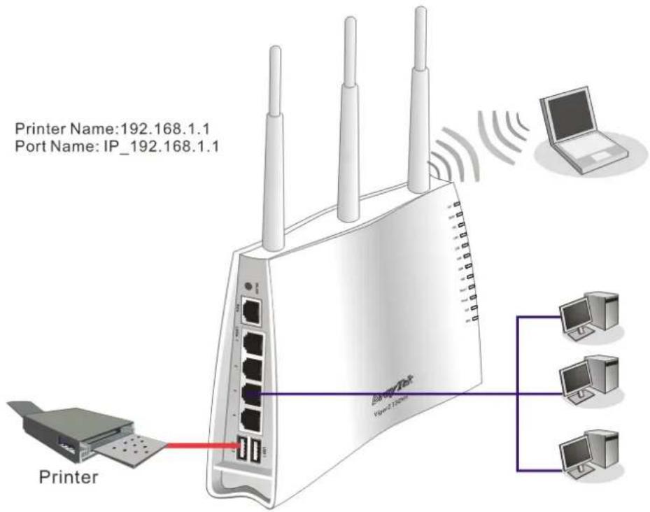
text_image
Printer Name:192.168.1.1 Port Name: IP_192.168.1.1 Printer VLAN 2.120000000 LaptopBefore using it, please follow the steps below to configure settings for connected computers (or wireless clients).
- Connect the printer with the router through USB/parallel port.
- Open Start->Settings->Printer and Faxes.

text_image
Documents Settings Search Help and Support Run... Log Off coco lee... Turn Off Computer... Control Panel Network Connections Printers and Faxes Taskbar and Start Menu- Open File->Add a New Computer. A welcome dialog will appear. Please click Next.

text_image
Add Printer Wizard Welcome to the Add Printer Wizard This wizard helps you install a printer or make printer connections. If you have a Plug and Play printer that connects through a USB port (or any other hot pluggable port, such as IEEE 1394, inferred, and so on), you do not need to use this wizard. Click Cancel to close the wizard, and then plug the printer's cable into your computer or point the printer toward your computer's infrared port, and turn the printer on. Windows will automatically install the printer for you To continue, click Next. < Back Next > Cancel- Click Local printer attached to this computer and click Next.
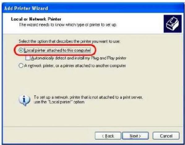
text_image
Add Printer Wizard Local or Network Printer The wizard needs to know which type of printer to set up. Select the option that describes the printer you want to use: ○ Local printer attached to this computer! □ Automatically detect and install my Plug and Play printer ○ A network printer, or a printer attached to another computer To set up a network printer that is not attached to a print server, use the "Local printer" option < Back Next > Cancel- In this dialog, choose Create a new port Type of port and use the drop down list to select Standard TCP/IP Port. Click Next.

text_image
Add Printer Wizard Select a Printer Port Computers communicate with printers through ports. Select the port you want your printer to use. If the port is not listed, you can create a new port. Use the following port: LPT1 (Recommended Printer Port) Note: Most computers use the LPT1 port to communicate with a local printer. The connector for this port should look something like this. Create a new port: Type of port: Standard TCP/IP Port < Back Next > Cancel- In the following dialog, type 192.168.1.1 (router's LAN IP) in the field of Printer Name or IP Address and type IP_192.168.1.1 as the port name. Then, click Next.

text_image
Add Standard TCP/IP Printer Port Wizard Add Port For which device do you want to add a port? Enter the Printer Name or IP address, and a port name for the desired device. Printer Name or IP Address: 192.168.1.1 Port Name: IP_192.168.1.1 < Back Next > Cancel- Click Standard and choose Generic Network Card.

text_image
Add Standard TCP/IP Printer Port Wizard Additional Port Information Required The device could not be identified. The detected device is of unknown type. Be sure that: 1. The device is properly configured. 2. The address on the previous page is correct. Either correct the address and perform another search on the network by returning to the previous wizard page or select the device type if you are sure the address is correct. Device Type Standard Generic Network Card Custom Settings... < Back Next > Cancel- Then, in the following dialog, click Finish.
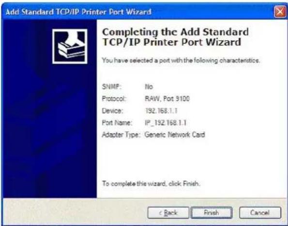
text_image
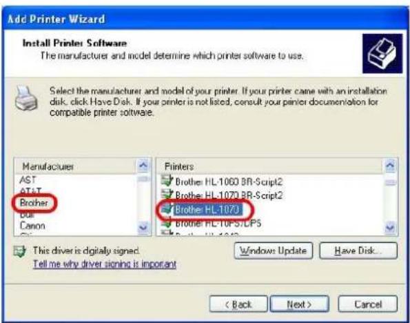
Add Standard TCP/IP Printer Port Wizard Completing the Add Standard TCP/IP Printer Port Wizard You have selected a port with the following characteristics. SNMP: No Protocol: RAW, Port 9100 Device: 192.168.1.1 Port Name: IP_192.168.1.1 Adapter Type: Generic Network Card To complete this wizard, click Finish.- Now, your system will ask you to choose right name of the printer that you installed onto the router. Such step can make correct driver loaded onto your PC. When you finish the selection, click Next.
text_image
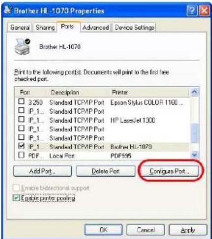
Add Printer Wizard Install Printer Software The manufacturers and model determine which printer software to use. Select the manufacturer and model of your printer. If your printer came with an installation disk, click Have Disk. If your printer is not listed, consult your printer documentation for compatible printer software. Manufacturer AST AT&T Brother Bus Canon Printers Brother HL-1060 BR-Script2 Brother HL-1070 BR-Script2 Brother HL-107J Brother HL-TOPS/CP5 This driver is digitally signed. Tell me why driver signing is important Windows Update Have Disk... < Back Next > Cancel- For the final stage, you need to go back to Control Panel-> Printers and edit the property of the new printer you have added.
text_image
Brother HL-1070 Properties General Sharing Ports Advanced Device Settings Brother HL-1070 Print to the following port(s). Documents will print to the first free checked port. Port Description Printer □ 3250 Standard TCP/MP Port Epson Stylus COLOR 1100 ... □ IP_1... Standard TCP/MP Port □ IP_1... Standard TCP/MP Port HP LaserJet 1300 □ IP_1... Standard TCP/MP Port □ IP_1... Standard TCP/MP Port ☑ IP_1... Standard TCP/MP Port Brother HL-1070 □ PDF... Local Port PDF995 Add Port... Delete Port Configure Port... Enable bidirectional support Enable printer pooling OK Cancel Apply- Select "LPR" on Protocol, type p1 (number 1) as Queue Name. Then click OK. Next please refer to the red rectangle for choosing the correct protocol and UPR name.

text_image
Configure Standard TCP/IP Port Monitor Port Settings Port Name: IP_192.168.1.1 Printer Name or IP Address: 192.168.1.1 Protocol Raw LPR Row Settings Port Number: 9100 LPR Settings Queue Name: p1 LPR Byte Counting Enabled SNMP Status Enabled Community Name: public SNMP Device Index: 1 OK CancelThe printer can be used for printing now. Most of the printers with different manufacturers are compatible with vigor router.
Note 1: Some printers with the fax/scanning or other additional functions are not supported. If you do not know whether your printer is supported or not, please visit www.draytek.com to find out the printer list. Open Support >FAQ; find out the link of Printer Server and click it; then click the What types of printers are compatible with Vigor router? link.
| About DrayTek Products Support Partners Contact Us | |
| Home > Support > FAQ | |
| FAQ - Basic | |
| 01. What are the differences among these firmware file formats? | Basic |
| 02. How could I get the telnet command for routers? | Advanced |
| 03. How can I backup/restore my configuration settings? | VPN |
| 04. How do I reset/clear the router's password? | DHCP |
| 05. How to bring back my router to its default value? | Wireless |
| 06. How do I tell the type of my Vigor Router is AnnexA or AnnexB? ( For ADSL model only ) | VoIP |
| 07. Ways for firmware upgrade | QoS |
| 08. Why is SNMP removed in firmware 2.3.6 and above for Vigor2200 Series routers? | ISDN |
| 09. I failed to upgrade Vigor Router's firmware from my Mac machine constantly, what should I do? | Firewall / IP Filter |
| 10. How to upgrade firmware of Vigor Router remotely? | Printer Servet |
| USB ISDN TA | |
| USB | |
FAQ - Printer Server
- How do I configure LPR printing on Windows2000/XP?
- How do I configure LPR printing on Windows98/Me?
- How do I configure LPR printing on Linux boxes?
- Why there are some strange print-out when I try to print my documents through Vigor210 4P / 2300's print server?
- What types of printers are compatible with Vigor router?
- What are the limitations in the USB Printer Port of Vigor Router?
- What is the printing buffer size of Vigor Router?
- How do I configure LPR printing on Mac OSX?
- How do I configure LPR printing on My Windows Vista?
Note 2: Vigor router supports printing request from computers via LAN ports but not WAN port.
2
Basic Settings
For using the router properly, it is necessary for you to change the password of web configuration for security and adjust primary basic settings.
This chapter explains how to setup a password for accessing into the web configurator of Vigor router and how to adjust settings for accessing Internet successfully.
2.1 Accessing Web Page
- Make sure your PC connects to the router correctly.

Notice: You may either simply set up your computer to get IP dynamically from the router or set up the IP address of the computer to be the same subnet as the default IP address of Vigor router 192.168.1.1. For the detailed information, please refer to the later section - Trouble Shooting of the guide.
- Open a web browser on your PC and type http://192.168.1.1. The following window will be open to ask for username and password.

text_image
Username Password Login Copyright© DrayTek Corp. All Rights Reserved. DrayTek- Please type "admin/admin" on Username/Password and click Login.

Notice: If you fail to access to the web configuration, please go to "Trouble Shooting" for detecting and solving your problem.
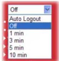
- The web page can be logged out according to the chosen condition. The default setting is Auto Logout, which means the web configuration system will logout after 5 minutes without any operation. Change the setting for your necessity.
text_image
Off Auto Logout Off 1 min 3 min 5 min 10 min2.2 Changing Password
Please change the password for the original security of the router.
- Open a web browser on your PC and type http://192.168.1.1. A pop-up window will open to ask for username and password.
- Please type "admin/admin" as Username/Password for accessing into the web configurator with admin mode.
- Now, the Main Screen will appear.

text_image
Vigor2130 Series High Speed Gigabit Router System Status Model : Vigor2130Vn Firmware Version : v1.5.2_RC3 Build Date/Time : Fri Mar 23 19:58:16 CST 2012 System Date : Fri Apr 6 03:32:38 2012 System Update : 8days 00:15:03 Auto-refresh □ Refresh! System CPU Usage : 41.6% Memory Usage : 35708K / 62784 K (56.87%) Cached Memory : 13276 K / 62784 K Clean LAN MAC Address : 00:50:7F:C9:59:78 IP Address : 192.168.1.1 IP Mask : 255.255.255.0 IPv6 Address : fe80::250:7fff:fec9:5978/64 (Link) DHCP Server : Yes WAN Connection Mode: Static Link Status : Connected MAC Address : 00:50:7F:C9:59:79 IP Address : 172.16.3.103 IP Mask : 255.255.0.0 IPv6 Address : fe80::250:7fff:fec9:5978/64 (Link) Default Gateway : 172.16.1.1 Primary DNS : 168.95.1.1 Secondary DNS : Support Area Application Note FAQ Product Registration Login All Rights Reserved. Admin mode Wireless MAC Address : 00:50:7F:C9:59:78 SSID : DrayTek Channel : 11Note: The home page will change slightly in accordance with the type of the router you have.
- Go to System Maintenance page and choose System Password.
System Maintenance >> System Password
System Password

text_image
Old Password New Password Confirm New PasswordOK
-
Type a new password in New Password and Confirm New Password fields. Then click OK to continue.
-
Now, the password has been changed. Next time, use the new password to access the Web Configurator for this router.

text_image
Username Password Login Copyright©, DrayTek Corp. All Rights Reserved. DrayTek2.3 Quick Start Wizard

Notice: Quick Start Wizard for user mode operation is the same as for admin mode operation.
If your router can be under an environment with high speed NAT, the configuration provide here can help you to deploy and use the router quickly. The first screen of Quick Start Wizard is welcome page, please click Next.
Quick Start Wizard
Welcome to the Quick Start Wizard!
The next steps will guide you through a basic setup of the device. If you want more advanced setup you should consider setting the device up manually.
- Step 1: Setup the Password
- Step 2: Setup the Timezone
- Step 3: Setup the Internet connection (WAN)
- Step 4: Setup the Wireless (Wi-Fi)
- Step 5: Save the configuration

2.3.1 Setting up the Password
The first screen of Quick Start Wizard is entering login password. After typing the password, please click Next.
Quick Start Wizard
System Password

text_image
New Password Confirm Password < Back Next > Finish Cancel2.3.2 Setting up the Time Zone
On the next page as shown below, please select the Time Zone for the router installed and specify the NTP server(s). Then click Next for next step.
Quick Start Wizard
Time Configuration

text_image
Time Zone UTC < Back Next > Finish Cancel2.3.3 Setting up the Internet Connection
On the next page as shown below, please select the appropriate connection type according to the information from your ISP. There are five types offered in this page. Each connection type will bring out different web page.
Quick Start Wizard
WAN IP Configuration
Connection Type
Clone MAC Address
Enable

DHCP
Static IP
DHCP
PPPoE
PPTP
L2TP

Static IP
You will receive a fixed public IP address or a public subnet, namely multiple public IP addresses from your DSL or Cable ISP service providers. In most cases, a Cable service provider will offer a fixed public IP, while a DSL service provider will offer a public subnet. If you have a public subnet, you could assign an IP address or many IP address to the WAN interface.
Quick Start Wizard
WAN IP Configuration
Connection Type
Static IP
IP Address
Subnet Mask
Gateway
Primary DNS Server
Secondary DNS Server
Static IP
172.16.3.229
255.255.0.0
172.16.3.4
0.0.0.0
0.0.0.0
Clone MAC Address
Enable

< Back
Next >
Finish
Cancel
Available settings are explained as follows:
| Item | Description |
| IP Address | Type the IP address. |
| Subnet Mask | Type the subnet mask. |
| Gateway | Type the gateway IP address. |
| Primary DNS Server | Type in the primary IP address for the router. |
| Secondary DNS Server | Type in secondary IP address for necessity in the future. |
| Enable | The router will detect the MAC address automatically. Or, check the box to enable MAC address cloning. |
| Clone MAC Address | It is available when the box of Enable is checked. Click Clone PC Address. The result will be displayed in the field of MAC Address. Enable ✅ Clone MAC Address MAC Address 00-0E-A6-2A-D5-A1 |
After finishing the settings here, please click Next.
DHCP
It is not necessary for you to type any IP address manually. Simply choose this type and the system will obtain the IP address automatically from DHCP server.
Quick Start Wizard
WAN IP Configuration
Connection Type
DHCP
Clone MAC Address
Enable

< Back
Next >
Finish
Cancel
Available settings are explained as follows:
| Item | Description |
| Enable | The router will detect the MAC address automatically. Or, check the box to enable MAC address cloning. |
| Clone MAC Address | It is available when the box of Enable is checked. Click Clone PC Address. The result will be displayed in the field of MAC Address. |
| Item | Description | |
| Enable | Clone MAC Address | |
| MAC Address | 00-0E-A6-2A-D5-A1 | |
After finishing the settings here, please click Next.
PPPoE
PPPoE stands for Point-to-Point Protocol over Ethernet. It relies on two widely accepted standards: PPP and Ethernet. It connects users through an Ethernet to the Internet with a common broadband medium, such as a single DSL line, wireless device or cable modem. All the users over the Ethernet can share a common connection.
PPPoE is used for most of DSL modem users. All local users can share one PPPoE connection for accessing the Internet. Your service provider will provide you information about user name, password, and authentication mode.
If your ISP provides you the PPPoE connection, please select PPPoE for this router. The following page will be shown:
Quick Start Wizard
WAN IP Configuration

text_image
Connection Type PPPoE Username Password Confirm Password Redial Policy Always On MTU Size Clone MAC Address Enable Clone MAC Address MAC Address
Available settings are explained as follows:
| Item | Description |
| User Name | Assign a specific valid user name provided by the ISP. |
| Password | Assign a valid password provided by the ISP. |
| Redial Policy | If you want to connect to Internet all the time, you can choose Always On. Otherwise, choose Connect on Demand. |
| Connect on DemandConnect on DemandAlways On | |
| Idle Time Out | Set the timeout for breaking down the Internet after passing through the time without any action. |
| MTU Size | It means Max Transmit Unit for packet. The default setting will be specified by the system automatically. Therefore, keep this field in blank. |
| Enable | The router will detect the MAC address automatically. Or, check the box to enable MAC address cloning. |
| Clone MAC Address | It is available when the box of Enable is checked. Click Clone PC Address. The result will be displayed in the field of MAC Address. Enable ✅ Clone MAC Address MAC Address 00-0E-A6-2A-D5-A1 |
After finishing the settings here, please click Next.
PPTP/L2TP
If you click PPTP/L2TP as the protocol, please manually enter the Username/Password provided by your ISP and all the required information.
Quick Start Wizard
WAN IP Configuration

text_image
Connection Type PPTP PPTP Settings Username Password Server Address WAN IP Network Settings Static IP IP Address 172.16.3.102 Subnet Mask 255.255.0.0 Redial Policy Always On MTU Size Clone MAC Address Enable Clone MAC Address MAC Address < Back Next > Finish CancelAvailable settings are explained as follows:
| Item | Description |
| User Name | Assign a specific valid user name provided by the ISP. |
| Password | Assign a valid password provided by the ISP. |
| Server Address | Specify the IP address of the PPTP server. |
| WAN IP Network Settings | You can choose Static IP or DHCP as WAN IP network setting. |
| IP Address | Type the IP address if you choose Static IP as the WAN IP network setting. |
| Subnet Mask | Type the subnet mask if you chose Static IP as the WAN IP. |
| Redial Policy | If you want to connect to Internet all the time, you can choose Always On. Otherwise, choose Connect on Demand. |
| Idle Time Out | Set the timeout for breaking down the Internet after passing through the time without any action. |
| MTU Size | It means Max Transmit Unit for packet. The default setting will be specified by the system automatically. Therefore, keep this field in blank. |
| Enable | The router will detect the MAC address automatically. Or, check the box to enable MAC address cloning. |
| Clone MAC Address | It is available when the box of Enable is checked. Click Clone PC Address. The result will be displayed in the field of MAC Address. Enable ✅ Clone MAC Address MAC Address 00-0E-A6-2A-D5-A1 |
After finishing the settings here, please click Next.
2.3.4 Setting up the Wireless Connection
Now, you have to set up the wireless connection. For the user of Vigor2130, please skip this step.
Quick Start Wizard
Wireless System Configuration
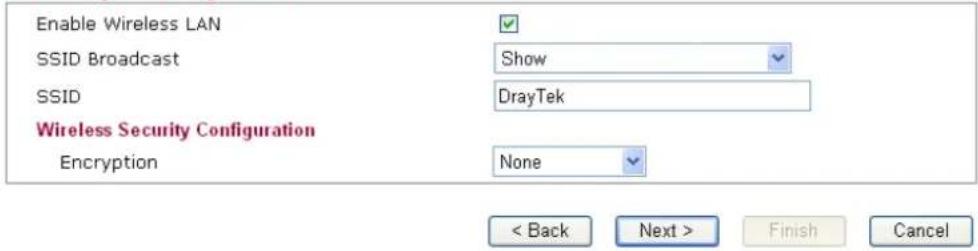
text_image
Enable Wireless LAN SSID Broadcast SSID Wireless Security Configuration Encryption Show DrayTek None < Back Next > Finish CancelAvailable settings are explained as follows:
| Item | Description |
| Enable Wireless LAN | Check the box to enable the wireless function. |
| SSID Broadcast | Choose Show to make the SSID being seen by wireless clients.Choose Hide to prevent from wireless sniffing and make it harder for unauthorized clients or STAs to join your wireless LAN. |