159 (2010) - Car ALFA ROMEO - Free user manual and instructions
Find the device manual for free 159 (2010) ALFA ROMEO in PDF.

User questions about 159 (2010) ALFA ROMEO
0 question about this device. Answer the ones you know or ask your own.
Ask a new question about this device
Download the instructions for your Car in PDF format for free! Find your manual 159 (2010) - ALFA ROMEO and take your electronic device back in hand. On this page are published all the documents necessary for the use of your device. 159 (2010) by ALFA ROMEO.
USER MANUAL 159 (2010) ALFA ROMEO
text_image
ALFA ROMEROOWNER'S MANUAL
ALFA 147

Dear Client,
Thank you for choosing Alfa Romeo.
Your Alfa 147 has been designed to guarantee the safety, comfort and driving pleasure typical of Alfa Romeo.
This booklet will help you to get to know the characteristics and operation of your car.
The following pages contain all the indications necessary for you to be able to maintain the high standards of performance, quality, safety and respect for the environment which characterize this Alfa 147.
The Warranty Booklet also contains the regulations, the warranty certificate and a guide to the services offered by Alfa Romeo.
Services which are essential and precious because, when you purchase an Alfa Romeo, you are not only acquiring a car, but the tranquillity that comes from knowing that an efficient, willing and widespread organisation is at your service for any assistance problems you may have.
Nature benefits in two ways: there's no pollution from waste disposal and the demand for raw materials is reduced.
Enjoy the reading and have a good trip.
This booklet describes all the versions of the Alfa 147, so you should only consider the information concerning the trim level, engine and version purchased by you.

VERY IMPORTANT!
FUEL CAPACITY

Petrol engines: only refuel with unleaded petrol with octane rating (RON) no less than 95.
Diesel engines: only refuel with diesel fuel conforming to the European specification EN590. The use of other products or mixtures may irreparably damage the engine with invalidation of the warranty due to the damage caused.
NOTE The use of Eurodiesel fuel is recommended only for markets/ versions where required. In case it is not available, use fuel conforming to EN590 European Specification.
STARTING THE ENGINE

Petrol engines with mechanical transmission: make sure that the handbrake is engaged; set the gearshift lever to neutral, fully depress the clutch without pressing the accelerator, then turn the ignition key to AVV and release it as soon as the engine has started.
Petrol engine with Selespeed transmission: keep the brake pedal fully depressed, turn the ignition key to AVV and release it as soon as the engine has started; the transmission sets to neutral automatically (the display shows position N).
JTD engines: make sure that the handbrake is engaged; set the gearshift lever to neutral, fully depress the clutch without pressing the accelerator, then turn the handbrake is engaged; set the gearshift lever to neutral, fully depress the clutch without pressing the accelerator, then turn the ignition key to MAR and wait for the and warning lights to go off; turn the ignition key to AVV and release it as soon as the engine starts.
PARKING ON FLAMMABLE MATERIAL

While working, the catalyst develops a very high temperature. Do not park the car over grass, dry leaves, pine needles or any other inflammable materials: risk of fire.
RESPECTING THE ENVIRONMENT

The car is fitted with a system that allows continuous diagnosis of the components correlated with emissions to ensure better respect for the environment.
ACCESSORY ELECTRICAL DEVICES

If after purchasing the car you wish to install accessories that need an electrical supply (with the risk of gradually draining the battery), contact Alfa Romeo Authorised Services who will assess the overall electrical absorption and check whether the car system is able to withstand the load required.
CODE CARD (for versions/markets where applicable)
Keep it in a safe place, not in the car. It is advisable to always keep the electronic code on the CODE card with you in case emergency starting is necessary.
SCHEDULED SERVICING

Correct maintenance makes it possible to preserve car performance levels and safety, respect for the environment and low running costs unaltered over the course of time.
THE OWNER HANDBOOK...

...you will find important information, advice and warnings for correct use, driving safety and car maintenance over time. Pay particular attention to the symbols ▲ (personal safety) ⚠ (protecting the environment) ▲ (car safety).
Any queries concerning servicing should be forwarded to the showroom from which the car was purchased, the subsidiary company or to our branch offices or any point of the Alfa Romeo Network.
Warranty Booklet
The Warranty Booklet is delivered together with every new car and contains the regulations tied to the services given by Alfa Romeo Services and to the warranty conditions.
Correctly carrying out the scheduled services specified by the manufacturer is the best way to maintain the performance, safety characteristics and low running costs of your car. It is also necessary to maintain warranty cover.
"Service" guide
This contains Alfa Romeo Authorised Services. The Services can be recognised by the presence of the Alfa Romeo badge and logo.
The Alfa Romeo organisation in Italy can be found in the telephone directory under the letter "A" Alfa Romeo.
Not all of the models described in this booklet are available in all countries. Only some of the fittings described in this booklet are fitted as standard to the car. The list of available accessories should be requested from the Alfa Romeo Dealers.
THE SYMBOLS USED IN THIS BOOKLET
The symbols illustrated in these pages show the subjects which should, in particular, be closely studied.

PERSONAL SAFETY
Warning. Partially or fully ignoring these rules may lead to serious injury.

PROTECTING THE ENVIRONMENT CAR SAFETY
This indicates the correct procedures to be followed to prevent the car from damaging the environment.

Warning. Partially or fully ignoring these rules may lead to serious damage being caused to the car which, in some circumstances, may cause forfeiture of the warranty cover.
The texts, illustrations and specifications given in this booklet refer to the car at the time of going to press.
As part of our ongoing striving to improve our products, Alfa Romeo may introduce technical changes during production, therefore the specifications and fittings may be altered without prior notice. For details on this subject, please apply to the manufacturer's sales network.
GETTING TO KNOW YOUR CAR
SYMBOLS
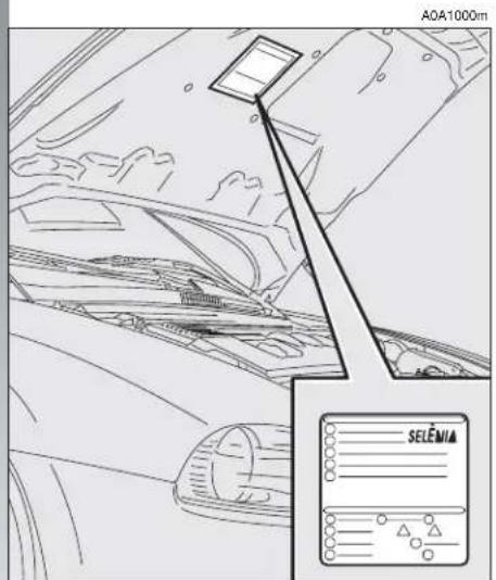
Special coloured labels have been attached near to or actually on some of the components making up your Alfa 147. These labels bear symbols that remind you of the precautions to be taken as regards that particular component. A summary list of the symbols (fig.1) is to be found under the bonnet.
text_image
A0A1000m SELEMAfig. 1
THE ALFA ROMEO CODE SYSTEM
To increase protection against attempted theft, the car is fitted with an electronic engine lock system (Alfa Romeo CODE) which is activated automatically when the key is removed from the ignition. In fact the grip of each key contains an electronic device which modulates the radio frequency signal transmitted when the engine is started by a special aerial incorporated in the ignition switch. This modulated signal is the "password" by which the control unit recognises the key and only in this condition can the engine be started.
text_image
A0A0736mfig. 2
KEYS
The car is delivered with a key with metal insert (upon request for models/markets where required) and a key with remote control. For models/markets where required two keys with remote control can be provided.
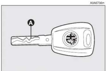
KEY WITHOUT REMOTE CONTROL (for versions/markets where applicable)
The fixed metallic insert A-fig. 2 operates:
— the ignition switch;
— the driver's door lock;
— the passenger's Air bag deactivation (upon request for versions/markets where applicable);
— the fuel filler cap lock.
IMPORTANT In order to ensure perfect efficiency of the electronic devices contained inside the keys, they should never be directly exposed to the rays of the sun.
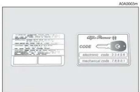
Together with the keys the CODE card is provided (for versions/markets where applicable) (fig. 3), bearing in print the key codes (both mechanical and electronic for emergency start up).
The code numbers on the CODE card must be kept in a safe place, not in the car.
The driver should always keep the electronic CODE card with him/her in the event of having to carry out emergency starting.

If the car changes owner, the new owner must be given all the keys and the ard.
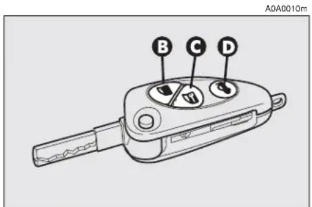
KEY WITH REMOTE CONTROL
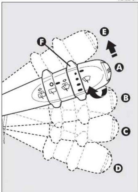
For versions/markets where applicable, the key is fitted with (fig. 4:
— a metal insert (A) that can be enclosed in the key grip
— button (B) for remote opening of the doors and turning the electronic alarm off
— button (C) for remote closing of the doors and turning the electronic alarm on
- button (D) for remote boot opening
-tow hook ring (E)
— button (F) for power-assisted opening of the metallic insert.
The metal insert (A) of the key operates:
— the ignition switch
— the driver's door lock
— the passenger's Air bag deactivation switch (on request for versions/markets where applicable)
— the fuel filler cap lock.
text_image
A0A0003m Alfa Remer 校 CODE electronic code: 2.3.4.5.6 mechanical code: 7.8.9.0.1fig. 3

text_image
Diagram showing a car key with labeled parts A through F, and a close-up of the key's internal mechanism with arrows indicating rotation.fig. 4
A0A0705m


WARNING
When button (F) is pressed, take the utmost care to prevent the metal insert from causing injury or damage when it comes out. Button (F) must only be pressed when the key is away from the body, in particular the eyes, and from objects that could be spoilt (e.g. clothes). Never leave the key unattended to prevent anyone, especially children, from holding it and pressing button (F) inadvertently.
To insert the metallic insert in the key grip, press the button (F) to release the insert and turn it in the direction of the arrow until it clicks. Once it clicks into position, release the button (F).
To open the doors by remote control, press the button (B), the doors will unlock and the direction indicators will flash twice. To close the doors by remote control, press the button (C), the doors will lock and the direction indicators will flash once. By pressing button (B) the doors unlock, if in the next 60 seconds neither a door or the boot open, the system will automatically lock them.
On cars fitted with electronic alarm system, pressing button (B) turns the alarm off, pressing button (C) turns the alarm on while the transmitter sends the code to the receiver. This rolling code changes at each transmission.
OPENING THE TAILGATE
The boot can be opened by remote control from outside pressing button (D), also when the electronic alarm is on. The boot opening is accompanied by a double flashing of the direction indicators; the boot closing is accompanied by a single flashing of the direction indicators.
If the electronic alarm is fitted, when the tailgate is opened the alarm system switches off volumetric protection and the tailgate control sensor, the system (with the exception of versions for certain markets) "beeps" twice.
Closing the tailgate again, the control functions are restored, the system (with the exception of versions for certain markets) "beeps" twice.
OPERATION
Each time the ignition key is turned to the STOP position the Alfa Romeo CODE system deactivates the functions of the engine electronic control unit.
Each time the car is started turning the ignition key to MAR, the Alfa Romeo CODE control unit sends a recognition code to the engine control unit to deactivate the inhibitor. The code is crypted and variable between over four billion possible combinations, and it is sent only if the system control unit has recognised the code transmitted from the key which contains an electronic transmitter, through an aerial wound around the ignition switch.
If the code has not been recognised correctly, the Alfa Romeo CODE warning light (☐) on the cluster turns on.
In this case, the key should be moved to the STOP position and then back to MAR; if the lock continues, possibly try again with the other key provided with the car. If it is still not possible to start the car, follow the instructions given in the "In an emergency" chapter and then contact Alfa Romeo Authorised Services.
IMPORTANT Every key has its own code, which must be memorised by the system control unit. To memorise new keys, up to a maximum of eight, apply solely to Alfa Romeo Authorised Services taking with you all the keys in your possession, the CODE card, a personal identity document and the car's ownership documents.

The codes of any keys not presented during the memorising procedure are The reason for this is to en- at any lost or stolen keys be used to start the engine.
IMPORTANT Turning on of the Alfa Romeo CODE warning light (💡) when travelling with the ignition key at MAR:
1) If the warning light turns on, this means that the system is running a self-test (for example for a voltage drop). At the first stop, it will be possible to test the system: switch off the engine turning the ignition key to STOP; then turn the ignition key to MAR: the warning light turns on and should go off in about one second. If the warning light stays on, repeat the procedure described previously leaving the key at STOP for over 30 seconds. Should the inconvenience persists, contact Alfa Romeo Authorised Services.
2) For versions without the reconfigurable multifunction display, the flashing of the warning light means that the car is not protected by the engine inhibitor device. This condition for cars with reconfigurable multifunction display is shown by the turning on of the warning light together with the display of the message: "CODE SYSTEM NOT PROGRAMMED". Contact Alfa Romeo Authorised Services immediately to have all the keys memorised.
If after about 2 seconds with the ignition key at MAR, for versions without reconfigurable multifunction display, the Alfa Romeo CODE warning light (💡) turns on again flashing, or for versions with reconfigurable multifunction display, the warning light turns on again together with the message "CODE SYSTEM NOT PROGRAMMED", this means that the code of the keys has not been stored, therefore the car is not protected by the Alfa Romeo CODE system against attempted theft. In this case contact Alfa Romeo Authorised Services to have the key codes stored.
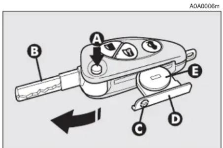
KEY BATTERY REPLACEMENT
If when the button (B C or D-fig. 4) is pressed, the command is rejected or not carried out, the battery may be replaced with other of an equivalent type available from normal outlets.
Dead batteries are harmful for the environment. They must be disposed of in special containers as specified by current regulations. Avoid exposure to naked flames and high temperatures. Keep out of reach of children.
text_image
A0A0006m A B C D Efig. 5
To change the battery:
— press button (A-fig. 5) and move the metal insert (B) to the open position;
— using a finely-tipped screwdriver, turn the opening device (C) and pull out the battery holder (D);
— replace the battery (E) making sure that the bias is correct;
— insert the holder back in the key and lock it, turning the device (C).
ELECTRONIC ALARM
DESCRIPTION
The system comprises: a transmitter, receiver, control unit with siren and volumetric sensors. The electronic alarm is controlled by the receiver incorporated in the instrument cluster and it is turned on and off by the remote control in the key which sends the crypted and variable code. The electronic alarm controls: the unlawful opening of doors, bonnet and boot (perimetral protection), operation of the ignition key, battery cable cutting, the presence of moving bodies in the passenger compartment (volumetric protection), any abnormal raising/sloping of the car (for versions/markets where applicable) and central door locking. It also makes it possible to cut off the volumetric protection.
IMPORTANT The engine inhibitor function is guaranteed by the Alfa Romeo CODE system which is activated automatically when the ignition key is removed.
REQUEST FOR ADDITIONAL KEYS WITH REMOTE CONTROL
The receiver can recognise up to 5 keys with incorporated remote control. Should a new key with remote control be necessary for any reason during the life of the car, contact directly Alfa Romeo Authorised Services, taking with you the CODE card, a personal identity document and the car's ownership documents.
ACTIVATING THE ALARM
With the doors, bonnet and boot shut and the ignition key in the STOP or PARK position (key removed), point the key with the remote control in the direction of the car, then press and release the button (C-fig. 6).
With the exception of certain markets, the system sounds a "beep" and the doors are locked.
Engagement of the alarm is preceded by a self-diagnosis phase characterised by a change in the frequency at which the deterrent led (A-fig. 7) on the dashboard flashes. If an anomaly is detected the system gives off a furtter beep.
Surveillance
After switching on, the flashing of the deterrent led (A-fig. 7) on the dashboard indicates the system surveillance mode. The led flashes throughout this period.
IMPORTANT Operation of the electronic alarm is adapted at the origin to the rules of the different countries.
Self-diagnostic functions and door, bonnet, boot control
If, after engaging the alarm, a second "beep" is sounded, switch off the system pressing the button (B-fig. 6), check that the doors, bonnet and tailgate are properly shut, then switch the system on again pressing the button (C).
Otherwise, the door, bonnet or tailgate that is not shut properly will be excluded from the alarm system control.
If the doors, bonnet and boot are shut correctly and the control signal is repeated, the system self-diagnostic has detected a system operating fault. It is therefore necessary to contact Alfa Romeo Authorised Services.
HOW TO DEACTIVATE THE ALARM
To deactivate the alarm press the button (B-fig. 6) of the key with remote control. The system will react as follows (with the exception of certain markets):
— two brief flashes of the direction indicators
— two brief "beeps" of the system
— door unlocking.
IMPORTANT If when the system is turned off the deterrent led (A-fig. 7) on the dashboard stays on (maximum 2 minutes or until the ignition key is set to MAR) the following should be borne in mind:

text_image
A0A0005m Afig. 7

— if the led continues flashing, but at different intervals than normal, this means that different attempts to break in have occurred. Through the number of flashes it is possible to identify the type of attempt:
1 flash: one or more doors
2 flashes: tailgate
3 flashes: bonnet
4 flashes: ultrasounds
5 flashes: abnormal car lifting/sloping (for versions/markets where applicable)
6 flashes: tampering with car starting cables
7 flashes: tampering with battery cables or cutting emergency key cables
8 flashes: connection line to sensors and siren
9 flashes: at least three causes of alarm.
WHEN THE ALARM IS TRIGGERED
When the system is on, the alarm comes into action in the following cases:
— opening of one of the doors, bonnet or tailgate;
— disconnection of the battery or sectioning of electric cables;
— intrusion in the passenger compartment, for example breakage of windows (volumetric protection);
— attempt to start the engine (key in MAR position);
— abnormal car lifting/sloping (for versions/markets where applicable).
Depending on the markets, the cutting in of the alarm causes operation of the siren and hazard warning ligths (for about 26 seconds). The ways of operating and the number of cycles may vary depending on the markets.
A maximum number of cycles is however envisaged.
Once the alarm cycle has ended, the system resumes its normal control function.
VOLUMETRIC PROTECTION
To make sure that the protection system works correctly the side windows and sun-roof (if fitted) must be properly shut.
The function can be cut off (if, for example, leaving animals in the car) carrying out the following operations in rapid succession: starting from the condition with the ignition key at MAR, move the key to STOP, then immediately back to MAR and then to STOP again, then remove the ignition key.
The deterrent led (A-fig. 7) on the dashboard lights up for about 2 seconds to confirm that the function has been cut off.
To restore volumetric protection, move the and keep the ignition key at MAR for over 30 seconds.
If, with the volumetric protection function deactivated, an electric control controlled by the ignition key at MAR (e.g. power windows) turn the ignition key to MAR, operate the control and move the key to STOP in a maximum time of 30 seconds. This way volumetric protection is not restored.
HOW TO CUT OFF THE ALARM SYSTEM
To deactivate the alarm system completely (for instance during prolonged inactivity of the car) simply lock the car turning the key in the lock.
MINISTERIAL CERTIFICATION
In accordance with the law in force in each country, on the subject of radio frequency, we wish to point out that for the markets in which the transmitter needs to be marked, the certification number is given on the component.
Depending on the versions/markets, the code may also be given on the transmitter and/or on the receiver.
IGNITION DEVICE
SWITCH (fig. 8)
The key can be turned to one of four positions:
— STOP: engine switched off, key can be removed, engine inhibitor engaged, steering lock engaged, services excluded apart from those supplied directly (e.g. hazard warning lights).
— MAR: drive position. The engine lock is deactivated and all electrical devices are powered.
IMPORTANT Do not leave the key in this position when the engine is stopped.
- AVV: unstable position for starting the engine.
IMPORTANT If the engine fails to start move the key back to STOP and repeat.
The ignition switch has a safety device which prevents passage to AVV when the engine is running.
— PARK: engine switched off, key can be removed, engine lock engaged, steering lock engaged, sidelights switched on automatically.
IMPORTANT To turn the key to the PARK position, button (A) on the switch must be pressed first.

text_image
MAR AVV STOP PARK A A0A0016mfig. 8


WARNING
When leaving the car, always remove the key from
the ignition to prevent any passenger in the car from inadvertently activating the controls. Never leave children unattended in the car. Remember to engage the hand-brake and if the car is facing uphill, first gear and if the car is facing downhill, reverse.

If the ignition device is tampered with (for example during an attempted
break-in) have it checked over by Alfa Romeo Authorized Services before travelling again.
STEERING LOCK
Engaging:
— move the key to STOP or PARK, then remove the key and turn the steering wheel slightly to facilitate the locking action.
Disengaging:
— turn the key to the MAR position and gently rock the steering wheel.

WARNING
Never remove the key with the car on the move.
The steering wheel would lock automatically the first time the steering wheel is turned. This also occurs if the car is towed.

WARNING
It is absolutely forbidden to carry out aftermarket oper-
ations on the car which would tamper with the steering wheel or column (for example the installation of the antitheft system) and might cause not only the system and warranty decay, but also serious safety problems and alter the car type-approval compliance.
DOORS

WARNING
Before opening a door, always make sure that it can
be done safely.
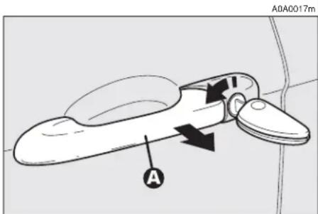
OPENING/CLOSING FROM OUTSIDE
Front door on driver's side
— To open the driver's door turn the key clockwise and then remove the key and pull the handle (A-fig. 9).
— To close the door turn the key counterclockwise.
text_image
A0A0017m Afig. 9
Front door on passenger's side
— To open the door, deactivate the centralized locking and pull the handle.
— To close the door, push the flap.
Rear doors (5-door versions)
— To open the door, deactivate the centralized locking and pull the handle (A-fig. 10).
— To close the door, push the flap.
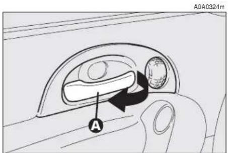
OPENING/CLOSING FROM INSIDE
Front doors
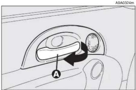
— To open the door, pull the handle (A-fig. 11).
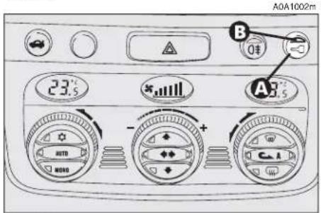
— To close the door, pull the flap. To prevent the door from being opened from outside press the button (A-fig. 12) on the dashboard, the deterrent led (B) on the button will turn on with a yellow light to confirm locking.
Rear doors (5-door versions)
text_image
A0A0324m Afig. 11

The rear doors can only be opened if the child safety lock has been released.
— To open the door pull the handle (A-fig. 13).
— To close the door pull the flap.

text_image
A0A1001m Afig. 10
text_image
A0A1002m 23.5 - + - AUTO MOYA A3.5 B 0€fig. 12
text_image
A0A0324m Afig. 13

CENTRAL LOCKING
This allows central locking of the door locks.
To engage central locking, the doors must be perfectly shut, otherwise locking is denied.
IMPORTANT With central locking engaged, pulling the inside lever for opening one of the front doors causes the unlocking of all the doors.
In the event of a power cut off (blown fuse, battery disconnected, etc.) it is still possible to work the lock by hand.
CHILD SAFETY LOCK (5-door versions)
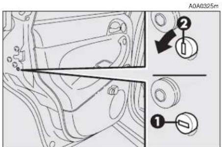
The rear doors are equipped with a special device (fig. 14) which prevents the door being opened from inside.
IMPORTANT Each device only acts on the door on which it is installed.
The device can only be engaged with the doors open:
position 1 - device engaged (door locked);
position 2 — device released (door can be opened from inside).

WARNING
Always use this device when carrying children.

WARNING
After activating the safety device on both rear doors, that it is working correctly using on the inner lever used in the door.
text_image
A0A0325m ① ②fig. 14

FRONT SEATS

WARNING
Any adjustments are to be carried out only with the tionary.
text_image
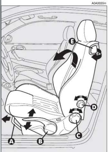
A0A0020m E D C A Bfig. 15

The car upholstery can resist wear resulting from the normal use of the car.
However, it is necessary to avoid excessive and/or prolonged friction with clothing accessories such as metal buckles, studs, velcro and similar material, as this friction, acting locally and with a high pressure over the knitted fabric, may cause some threads to break and thus damage the seat cover/lining.
LENGTHWISE ADJUSTMENT (fig. 15)
Raise the lever (A) and push the seat backwards or forwards; in the driving position the arms should be slightly flexed and the hands should rest on the rim of the steering wheel.

WARNING
After releasing the adjustment lever, always check
that the seat is locked on the runners, trying to move it to and fro. The lack of this clamping action could cause the seat to move unexpectedly and cause loss of car control.
ADJUSTING THE HEIGHT
(fig. 15) (upon request for versions/markets where applicable)
To raise the seat, pull the lever (B) upwards, then work the lever (up and down) until reaching the required height, then release it. To lower the seat, push the lever (B) downwards, then work the lever (up and down) until reaching the required height.
IMPORTANT Adjustment must be carried out only seated in the driver's seat.
BACK REST ANGLE ADJUSTMENT (fig. 15)
This can be done by turning the knob (C) until the desired position is reached.
BACK REST TILTING (fig. 15)
To gain access to the rear seats, pull the handle (E), the back rest folds and the seat is free to run forwards.
A recovery mechanism with memory makes it possible to take the seat back to its previous position.
Once the seat back has been returned to the travelling condition, make sure that it is correctly clamped, checking that the "red band" on the upper part of the handle (E) is concealed. In fact, this "red band" indicates that the seat back is not clamped.
Also check that the seat is firmly locked on the runners, trying to move it to and fro.
DRIVER'S SEAT LUMBAR ADJUSTMENT (fig. 15)
Adjustment is done by turning the knob (D) until reaching the most comfortable position.
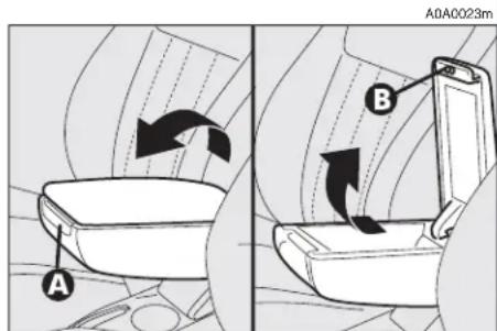
CENTRAL ARMREST (fig. 16) (upon request for versions/markets where applicable)
The armrest can be adjusted, raised and lowered.
To adjust, slightly raise the armrest, then press the the release device (A).
Inside the armrest there is an oddments compartment, to use it, raise the cover, pressing the device (B).
text_image
A A0A0023m Bfig. 16
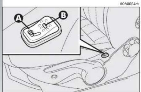
SEAT WARMING (fig. 17)
Seat warming, fitted on certain versions, is turned on and off through the switch (A) on the outer side of the seat.
Switching on is shown by the lighting up of the led (B) on the switch itself.
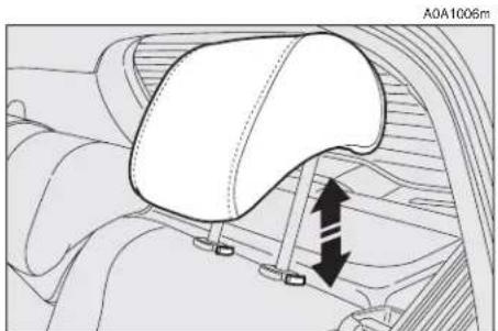
HEADREST ADJUSTMENT (fig. 18)
To increase passengers' safety, the head-rests are adjustable in height.
To adjust, press the button (A) and move the headrest up or down until it clicks into place.
IMPORTANT The configuration of the headrest cushion may vary depending on the versions and markets. The purpose of the illustration is only to show how it is adjusted.

WARNING
Remember that the head re- straints must be positioned
so that they are supporting the back of the head and not the neck. They will only be able to provide effective protection in the event of a collision if they are in this position.
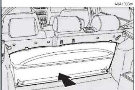
REAR POCKET (fig. 19)
(for versions/markets where applicable)
The front passenger's seat is provided with a pocket in the rear of the seat back.
text_image
A B A0A0024mfig. 17

text_image
A A0A0025mfig. 18

natural_image
Diagram of a vehicle's rear window with a black arrow pointing to the door panel (no text or symbols)fig. 19

REAR SEATS

The car upholstery can resist wear resulting from the normal use of the car. However, it is necessary to avoid excessive and/or prolonged friction with clothing accessories such as metal buckles, studs, velcro and similar material, as this friction, acting locally and with a high pressure over the knitted fabric, may cause some threads to break and thus damage the seat cover/lining.
EXTENDING THE LUGGAGE COMPARTMENT
The split of rear seat makes it possible to extend the luggage compartment totally or partially, acting separately on one of the two parts, thereby offering different possibilities of load depending on the number of rear passengers.

WARNING
If a particularly heavy load is placed in the boot, when ing at night, it is wise to the height of the high beams (headlamps" paragraph).
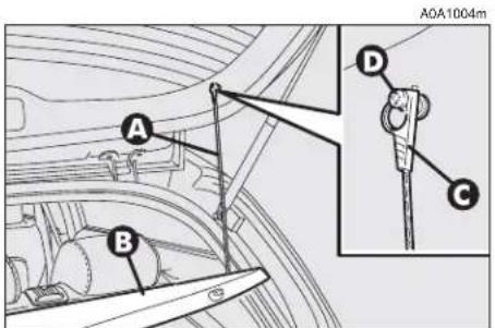
Removing the rear parcel shelf
Proceed as follows:
- free the ends of the two rods (A-fig. 20) supporting the parcel shelf (B) pulling the eyelets (C) off the pins (D);
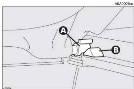
— release the pins (A-fig. 21) at the outside of the shelf from their housings (B) obtained in the side supports, then remove the shelf pulling it outwards.
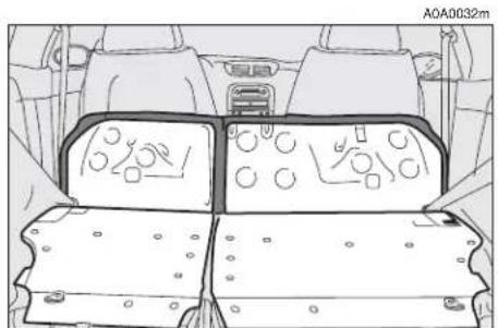
Once the shelf beneath the rear window has been removed, it can be arranged in two ways:
— across in the luggage compartment as illustrated in fig. 22;
— across between the front seat backs and the tilted cushions of the rear seats when the luggage compartment is completely extended (see fig. 26).
text_image
A0A1004m A B D Cfig. 20
text_image
A0A0028m A Bfig. 21

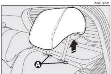
Total extension
Proceed as follows:
— fit the buckles of the seat belts (A-fig. 23) in their housings (B) on the cushion;
— pull the handles in the centre of the cushions, then tilt them forwards;
— raise the headrests to the maximum height and then press both the buttons (A-fig. 24) on the two supports side, then pull the headrests upwards and remove them;
— move the seat belts to the side extending them correctly without twisting;
— raise the levers (A-fig. 25) retaining the back rests and tilt them forwards to obtain a single loading surface (fig. 26).
natural_image
Technical line drawing of a vehicle rear compartment with no visible text or symbolsfig. 22

text_image
A0A0029m A B Bfig. 23
text_image
A0A1005m Afig. 24
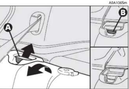
Partial extension
For partial extension, proceed as follows:
— tilt the cushion required pulling the handle at the centre of the cushion, then tilting the actual cushion;
— raise the headrest to the maximum height and then press both the buttons on the two supports side, then pull the headrest upwards and remove them;
— move the seat belt to the side extending it correctly without twisting;
— raise the lever (A-fig. 25) retaining the back rest and tilt.
text_image
A A0A1065m Bfig. 25

To restore the seat normal position
Proceed as follows:
— move the seat belts to one side extending them correctly without twisting;
— raise the back rests and push them backwards until you hear them click into position, then check that they are locked correctly by making sure that the "red band" (B-fig. 25) on the lever top side is no longer visible. If this "red band" is still visible it means that the seat is not locked correctly;
— put the cushions back into horizontal position keeping the central seat belt raised;
— refit the headrests in their housings.
HEADREST ADJUSTMENT (fig. 27)
The car is fitted with headrests for the side and central seats.
The headrests can be set in 2 positions (high/low) according to the passenger's height.
If needed, it is possible to remove the headrests operating as described above (see "Extension of luggage compartment").

WARNING
Remember that the head re- straints must be positioned
so that they are supporting the back of the head and not the neck. They will only be able to provide effective protection in the event of a collision if they are in this position.
CENTRAL ARMREST (fig. 28)
To use the armrest (A), present only on certain versions, lower it as illustrated.
natural_image
Top-down technical diagram of a vehicle's internal components, showing dashboard and seat layout (no text or labels)fig. 26
natural_image
Technical diagram of a car seatbelt mechanism with directional arrows indicating movement (no text or symbols)fig. 27

text_image
A0A0036mfig. 28

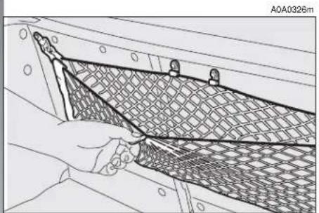
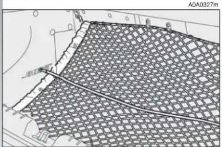
LUGGAGE RETAINING NET
Fitted only on some versions, the luggage retaining net is useful for the correct positioning of the load and/or the transport of light materials. The following figures 29, 30, 31 illustrate the different net fastening solutions in the luggage compartment.
STEERING WHEEL ADJUSTMENTS
The driver can adjust the steering wheel position in rake and height.
To do this, release the lever (A-fig. 32) pulling it towards the steering wheel.
After moving the steering wheel to the most suitable position, lock it pushing the lever fully forwards.
natural_image
Technical line drawing of a mesh netting or meshing process with a hand holding the net (no text or symbols present)fig. 29
text_image
A0A0327mfig. 30

text_image
A0A0328mfig. 31

WARNING
The steering wheel position must only be adjusted with
the car stationary.

WARNING
It is absolutely forbidden to carry out aftermarket oper-
ations on the car which would tamper with the steering wheel or column (for example the installation of the antitheft system) and might cause not only the system and warranty decay, but also serious safety problems and alter the car type-approval compliance.

text_image
A A0A1049mfig. 32

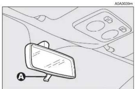
REAR-VIEW MIRROR ADJUSTMENT
INNER
The mirror, fitted with a safety device that causes it to be released in the event of a violent crash, can be moved using the lever (A-fig. 33) to two different positions, normal or antiglare.
On some versions/markets the mirror is automatically set in the position for the day/night use.
OUTER
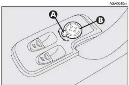
Electric adjustment (fig. 34)
— use the switch (A) to select the mirror required (right or left);
— pressing the button (B) in one of the four directions, move the mirror selected previously;
— position the switch (A) in the intermediate locking position.
IMPORTANT Adjustment is possible only with the ignition key at MAR.
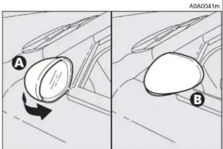
Folding (fig. 35)
— If necessary (for example when the size of the mirror causes difficulty in narrow spaces) the door mirror can be folded in towards the car from position (A) to position (B).

WARNING
When travelling the door mirrors must always be in (A).

WARNING
As the driver's door mirror is curved, it may slightly be perception of distance.
natural_image
Diagram of a car interior showing a mirror and dashboard with labeled points A and 0A (no text or symbols beyond labels)fig. 33
text_image
A B A0A0040mfig. 34
text_image
A0A0041m A Bfig. 35

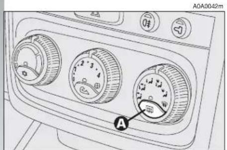
Defrosting/demisting (fig. 36)
The electric mirrors are fitted with heating coils which come into operation with rearscreen heating pressing the button (A) thereby defrosting and/or demisting the mirrors.
IMPORTANT The function is timed and automatically switched off after a few minutes.
POWER WINDOWS
IMPORTANT With the ignition key at STOP or removed, the power windows can be opened for about 3 minutes and immediately deactivate at opening of one of the doors.
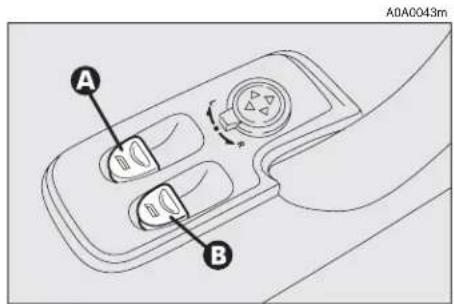
3-DOOR VERSIONS
Driver' side (fig. 37)
The driver's door panel contains the buttons that control the following windows, with the ignition key at MAR:
A - left front window
B - right front window.
Press the button to lower the window. Pull to raise it.
IMPORTANT The driver's power window is fitted with the "continuous automatic operation" device for both lowering and raising the window. A brief press on the upper or lower part of the button will cause it to move and continue automatically: the window stops in the required position by pressing either the upper or lower part of the button again.
text_image
A0A0042m Afig. 36
text_image
A0A0043m A Bfig. 37

Passenger's side (fig. 38)
The button (A) controls the passenger's side window.
IMPORTANT The passenger's window is fitted with a device for "continuous automatic operation" only for lowering it.

Do not keep the button pressed when the window is completely raised or
lowered.

WARNING
Incorrect use of the power windows can be dangerous. Before and during operation of them always make sure that the passengers are not exposed to the risk of harm caused either directly by the windows in motion or by personal objects drawn or knocked by them. When leaving the car always remove the ignition key to prevent passengers (especially children) from being injured by the power windows inadvertently operated.

text_image
A0A0044m Afig. 38
IMPORTANT On some versions after unlocking the doors, keeping the relevant button on the remote control pressed for about 2 seconds will cause the windows to open. It is necessary to keep the remote control button pressed until the windows have reached the full travel; releasing the button before the windows reach the limit switch, they will stop in the position they are at that moment.
5-DOOR VERSIONS
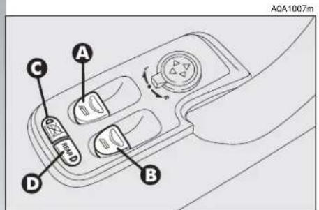
Front door on driver's side (fig. 39)
The driver's door panel plate contains the buttons which, with the ignition key at MAR, operate the following windows:
A - left front/rear window
B - right front/rear window.
Press the button to lower the window. Pull to raise it.
IMPORTANT The driver's power window is fitted with the "continuous automatic operation" device for both lowering and raising the window. A brief press on the upper or lower part of the button will cause it to move and continue automatically: the window stops in the required position by pressing either the upper or lower part of the button again.

Fitted only on some versions:
C — rear door window control inhibitor (with the inhibitor activated the button led is on, press again to renable the rear buttons).
D — (REAR) front/rear window control switch (with the button led on, the buttons (A) and (B) operate the rear windows, with the led off, they operate the front windows).
Front door on passenger's side and (on some versions) rear doors (fig. 38)
On each door panel plate there is a button (A) which controls the related window.
IMPORTANT The passenger's window is fitted with a device for "continuous automatic operation" only for lowering it.
SEAT BELTS
USING THE SEAT BELTS
The belt should be worn keeping the chest straight and rested against the seat back.
Fasten the belt by inserting the tab (A-fig. 40) into the clip (B), until hearing the locking click.
At removal, if it jams, let it rewind for a short stretch, then pull it out again without jerking.
To unfasten the seat belts, press button (C). Guide the seat belt with your hand while it is rewinding, to prevent it from twisting.

WARNING
Never press button (C) when travelling.
Through the reel, the belt automatically adapts to the body of the passenger wearing it, allowing freedom of movement.
When the car is parked on a steep slope the reel mechanism may block; this is normal. The reel mechanism prevents the weebing coming out when it is jerked or if the car brakes sharply, in a collision or when cornering at high speed.
Rear seat belts shall be worn as shown in fig. 41.
IMPORTANT The centre rear seatbelt is installed on request only for versions/markets on which it is required.
text_image
A0A1007m A C D Bfig. 39

text_image
A0A0045m B A Cfig. 40

natural_image
Diagram of car rear seats with three chairs and connecting hoses (no text or symbols)fig. 41


WARNING
To offer the highest level of protection, the rear seat belts should be fastened as shown in fig. 41.

WARNING
After putting the backrest into its normal position after tilting, make sure the seat belts are positioned correctly for use.

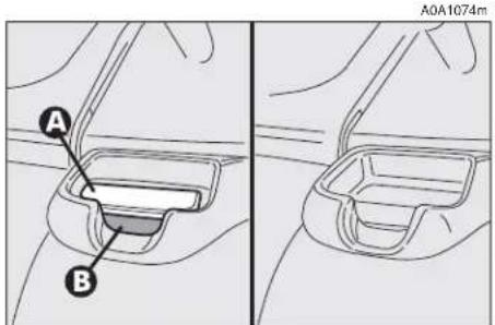
WARNING
Check that the backrest is correctly locked on both side ("red bands" (B-fig. 42) not visible) to prevent the backrest from tilting and injuring passengers.

WARNING
The correct locking of the backrest is ensured by the disappearance of the "red band" (B-fig. 42) on the backrest tilting levers (A). If the "red band" is still visible it means that the backrest is not correctly locked. When restoring its normal using position make sure you hear the backrest click into position.

WARNING
Remember that in the event of an accident, any passengers occupying the rear seats who are not wearing a seat belt not only subject themselves to great personal risk, but constitute a danger to the occupants of the front seats.
text_image
A B A0A1074mfig. 42
When the rear seats are not occupied the appropriate spaces between the backrest and cushion should be used to stow the seat belt clips neatly.

FRONT SEAT BELT HEIGHT ADJUSTMENT
(upon request for versions/markets where applicable)
The height of the seat belt attachment should always be adjusted to suit the height of the person wearing the seat belt. This precaution makes it possible to improve the efficiency of the seat belt which greatly reduces the risk of injury in the event of an accident.
The correct adjustment is obtained when the belt passes about half way between the tip of the shoulder and the neck.
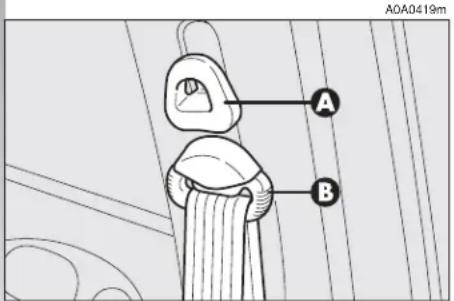
The ring attached to the front seat belts can be moved to several positions allowing the belts to be adjusted.
To adjust the attachment, raise or lower the grip (A-fig. 43) of the locking device, at the same time moving the ring (B) to the most appropriate of the allowed positions.

WARNING
After adjustment, always check that the slider (B-fig. 43) is anchored in one of the positions provided. To do this, with the grip (A-fig. 43) released, exert a further pressure to allow the anchor device to catch if release did not take place at one of the pre-set positions.
text_image
A B A0A0419mfig. 43

WARNING
The height of the seat belts shall always be adjusted
with the car stationary.
LOAD LIMITERS
To increase passive safety, the front seat belt reels contain a load limiter which allows controlled sag in such a way as to dose the force acting on the shoulder during the belt restraining action.

PRE-TENSIONING DEVICES
To increase the efficiency of the front seat belts, the car is fitted with pre-tensioning devices. These devices "feel" that the car is being subject to a violent impact by way of a sensor and rewind the seat belts a few centimetres. In this way they ensure that the seat belt adheres to the wearer before the restraining action begins.
The seat belt locks to indicate that the pretensioner has intervened; the seat belt cannot be drawn back up even when guiding it manually.
IMPORTANT The pretensioner will give maximum protection when the seat belt adheres snugly to wearer's chest and hips.
A small amount of smoke may be produced. This smoke is in no way toxic and presents no fire hazard.
The pretensioner needs no maintenance or lubrication. Any modification to its original features will nullify the retractor's effectiveness. If, due to unusual natural events (floods, high waves, etc.), the device has been affected by water and mud, it must be replaced.

WARNING
Pre-tensioning devices can only be used once. After they have been triggered contact Alfa Romeo Authorised Services to have them replaced. The validity of the device is shown on the plate fitted on the front left door near the lock; the pretensioners should be changed at an Alfa Romeo Authorised Service as this date approaches.

Operations involving banging, vibrations or heating (above 100°C for a maximum of 6 hours) in the area of the pretensioners may damage or trigger off the device. Vibrations from rough road surfaces or accidental jolting caused by mounting pavements etc. do not have any effect on the pretensioner. If, however, you need assistance, go to Alfa Romeo Authorised Services.

WARNING
Never disassemble or tam- per with the pretensioner components. All interventions must be carried out by qualified and authorised personnel. Always contact Alfa Romeo Authorised Services.
GENERAL INSTRUCTIONS FOR THE USE OF THE SEAT BELTS
All the occupants of the car are obliged to respect the local traffic laws regarding the wearing of seat belts.
Always fasten the seat belts before starting off.

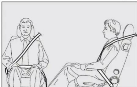
WARNING
The seat belt must not be twisted and should cling tightly to the body. The upper part must pass over the shoulder and diagonally across the chest. The lower part must rest across the pelvis (fig. 44) and not across the stomach. Do not use devices (clips, stoppers, etc.) which keep the belts away from the body.

WARNING
Under no circumstances should the components of the seat belts and pretensioner be tampered with or removed. Any operation should be carried out by qualified and authorised personnel. Always contact an Alfa Romeo Authorised Service.

WARNING
To ensure the highest degree of protection, you are recommended to keep the seat backrest in the straightest position possible, and the belt adhering well to the chest and pelvis.
Seat belts should always be worn in both the front and rear positions! Travelling without seat belt increases the risk of serious injury or death in the case of accident.
A0A0050m
natural_image
Line drawing of two people seated in chairs, one holding a rifle, no text or symbols presentfig. 44

WARNING
If the seat belt has been subjected to shock, for example during an accident, it must be completely replaced together with the attachments and their screws, and the pretensioning devices, even if visible defects are not detected as the belt may have lost its resilience.


WARNING
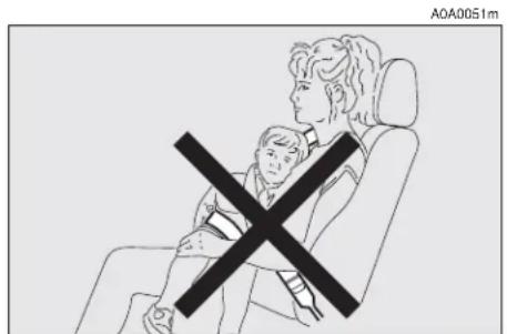
Each seat belt must be worn by one person only;
do not carry children on your knee using a single seat belt for both (fig. 45). Do not fasten other objects to the body.
Seat belts are also to be worn by expecting mothers: the risk of injury in the case of accident is greatly reduced for them and the unborn child if they are wearing a seat belt.
Pregnant women must of course position the lower part of the belt very low down so that it passes under the abdomen (fig. 46).
text_image
A0A0051mfig. 45
natural_image
Line drawing of a person seated in two chairs, wearing a seatbelt and carrying a belt (no text or symbols)fig. 46
HOW TO KEEP
THE SEAT BELTS
ALWAYS IN EFFICIENT
CONDITIONS
— Always use the belts with the tape well taut and never twisted; make sure that it is free to run without impediments.
— After a serious accident, replace the belt being worn at that time, even if it does not appear damaged. Always replace the seat belts if pretensioners have been activated.
— To clean the belts, wash by hand with natural soap, rinse and leave to dry in the shade. Never use strong detergents, bleach or dyes or any other chemical substance that might weaken the fibres.
— Prevent the reels from getting wet: correct operation of them is only guaranteed if water does not get inside.
— Replace the seat belt if it shows significant wear or cut signs.
CARRYING CHILDREN SAFELY

WARNING
Never place cradle child's seats on the front passenger's seat of cars equipped with passenger's air bag since the air bag activation could cause serious injuries, event mortal. You are advised to cary children always on the rear seat, as this is the most protected position in the case of a crash.


WARNING
SERIOUS DANGER! If it is necessary to car-
ry a child on the front passenger's seat with the cradle child's seat facing opposite the travelling direction, the passenger's air bag must be deactivated through the key switch and its deactivation must be checked through the related warning light on the instrument panel (see paragraph "Front passenger's air bag"). In addition, the front passenger's seat shall be adjusted in the most backward position to prevent any contact between the child's seat and the dashboard.
For the best level of protection in the event of a crash, all occupants must travel seated and secured by suitable restraint systems.
This is even more important for children.
This prescription is mandatory, according to directive 2003/20/EC, in every country of the European Union.
Compared with adults, a child's head is proportionately larger and heavier than the rest of the body, while muscles and bone structure are not completely developed. Therefore, in order to restrain them correctly in the event of a crash, different systems are needed than adult seat belts.

text_image
0-10 kg 9-18 kg 15-25 kg 22-36 kgfig. 47
The results of research on the best protection for a child are summarised in European Standard ECE-R44, which in addition to making them compulsory, subdivides restraint systems into five groups:
Group 0 - until 10 kg in weight
Group 0+ - until 13 kg in weight
Group 1 9-18 kg in weight
Group 2 15-25 kg in weight
Group 3 22-36 kg in weight
As it may be noted, the groups partially overlap and in fact, in commerce it is possible to find devices that cover more than one weight group (fig. 47).
All the restraint devices must bear the homologation data, together with the control brand, on a solidly fixed label which must absolutely not be removed.
Over 1.50 m in height, from the point of view of restraint systems, children are considered as adults and wear belts normally.
The Lineaccessori Alfa Romeo includes seats for each weight group, which are the recommended choice because they have been designed and specifically experimented for Alfa Romeo cars.
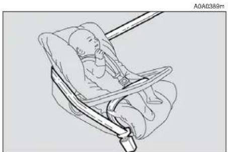
GROUP 0 and 0+
Babies up to 13 kg must be carried facing behind (fig. 48) on a cradle seat, which suppring the head, does not induce strain on the neck in the event of sharp deceleration.
The cradle is restrained by the car safety belts, as illustrated, and it should in turn restrain the child with the belts incorporated on it.

WARNING
The illustration is indicative only for assembly. Assem-
ble the seat according to the compulsory instructions provided with it.
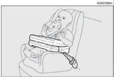
GROUP 1
Starting from 9 to 18 kg in weight, children may be carried facing forwards with seats fitted with front cushion (fig. 49), through which the car seat belts restrains both child and seat.

WARNING
The illustration is indicative only for assembly. Assem-
ble the seat according to the compulsory instructions provided with it.
natural_image
Line drawing of a fetus in a baby car seatbelt, no text or symbols presentfig. 48
natural_image
Line drawing of a baby in a baby car seat with a seatbelt, no text or symbols presentfig. 49


WARNING
Seats exist which are suitable for covering weight groups 0 and 1 with a rear connection to the car belts and its own belts to restrain the child. Because of their mass, they can be dangerous if installed incorrectly fastened to the car belts with a cushion. Strictly adhere to the assembly instructions provided.
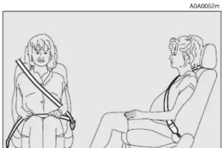
GROUP 2
Starting from 15 to 25 kg in weight, children may be restrained directly by the car seat belts. Child seats only have the function of positioning the child correctly in relation to the belts, so that the diagonal part adheres to the chest and never to the neck and that the horizontal part adheres to the child's pelvis and not to the abdomen (fig. 50).
GROUP 3
For children from 22 up to 36 kg the child's chest is thick enough not to need the spacer back rest any more.
Fig. 51 shows proper child's seat positioning on the rear seat.
Over 1.50 m in height, children may wear seat belts like adults.

WARNING
The illustration is indicative only for assembly. Assem-
ble the seat according to the compulsory instructions provided with it.

WARNING
The illustration is indicative only for assembly. Assem-
ble the seat according to the compulsory instructions provided with it.

natural_image
Illustration of a person seated in a chair using a seatbelt device (no text or symbols)fig. 50

natural_image
Line drawing of a person sitting on a chair wearing a seatbelt and high heels (no text or symbols)fig. 51

PASSENGER'S SEAT COMPLIANCE WITH REGULATIONS ON CHILD'S SEAT USE
Vehicle complies with the new EC Directive 2000/3 regulating child's seat assembling on the different car seats according to the following table:
Rear seat for 3 and 5-door versions
| Group Range of weight SEAT | ||||
| Front passenger Rear passenger side centre (inertial seat belt with three anchor points) | ||||
| Group 0,0+ | up to 13 kg | L | U | U |
| Group 1 | 9 -18 kg | L | U | U |
| Group 2 | 15 - 25 kg | L | U | U |
| Group 3 | 22 - 36 kg | L | U | U |
Key:
U = suitable for child's restraint systems of the "Universal" category, according to European Standard ECE-R44 for the specified "Groups" L = suitable for certain child's restraint systems at Lineaccessori Alfa Romeo for the specified group
Below is a summary of the safety rules to be observed when carrying children:
1) The recommended position for installing a child's seat is on the rear seat, as it is the most protected in the event of a crash;
2) If the passenger's Air bag is deactivated (upon request for versions/markets where applicable) always check the warning light ☐ on the cluster to make sure that it has actually been deactivated.
3) Carefully follow the instructions provided with the child's seat, which the supplier is obliged to attach. Keep them in the car together with the documents and this booklet. Do not use used seats without the instructions for use.
4) Always pull the tape to check that the belts are buckled.
5) All restraint systems are strictly for one child only: never use for two children at the same time.
6) Always make sure that the belts do not rest on the child's neck.
7) During the journey, do not allow the child to stay in abnormal positions or release the belts.
8) Do not carry children in your arms, not even small babies. No-one, however strong, can keep hold of them in a crash.
9) In the case of accidents, replace the child's seat with a new one.

WARNING
If the passenger's Air bag is activated, children should never travel on the front seat. The activation of the air bag in the event of a crash may cause mortal injuries to the child regardless of the crash severity. Therefore you are recommended to carry children always on the child's restraint system on the rear seat, as it is the most protected in the event of a crash.
FRONT AND SIDE AIR BAGS
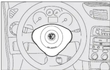
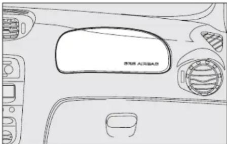
The car is fitted with front Air bags for the driver (fig. 52, for the passenger (fig. 53, side bags (fig. 54) and window bags (fig. 55)).
A0A1009m
natural_image
Line drawing of a car dashboard with steering wheel and air conditioners (no text or symbols)fig. 52
A0A0057m
Description and operation
The front Air bag (driver's and passenger's) is a safety device that comes into action in the event of a head-on collision.
text_image
SRS AIRBAS A0A1010mfig. 54
A0A1011m

text_image
BRS AIRBAGfig. 55
It is formed of an instantly-inflating cushion contained in a special recess:
— in the centre of the steering wheel for the driver;
— in the dahsboard and with a larger-sized cushion for the passenger.
The front Air bag (driver's and passenger's) is a device designed to protect the occupants in the event of a head-on collision of medium-high severity by the interposition of the cushion between the occupant and the steering wheel or dashboard.
In the event of a crash, the electronic control unit processes the signals leading from a deceleration sensor and when necessary triggers inflation of the cushion.
The cushion inflates instantly as a protective barrier between the occupants' bodies and the structures which could cause injury. The cushion deflates immediately afterwards.
The front Air bag (driver's and passenger's) does not replace but is complementary to the use of belts, which should always be worn, as specified by law in Europe and most non-European countries.
In the event of a crash a person that is not wearing the seat belt moves forwards and may come into contact with the cushion while it is still opening. Under these circumstances the protection offered by the cushion is reduced.
Front Air bags are designed to protect car's occupants in front crashes and therefore non-activation in other types of collisions (side collisions, rear-end shunts, roll-overs, etc...) is not a system malfunction.
In collisions against highly deformable or mobile objects (road signposts, heaps of ice or snow, etc.), rear collisions (hit from behind by another car), side collisions, wedging under other cars or protective barriers (for example under a lorry or guard rail) cutting in of the air bag is not activated as it does not offer any more protection than the seat belts, therefore activaton would be inappropriate.
Therefore the failure to be triggered does not mean that the system is not working.

WARNING
Never put stickers or other objects on the steering wheel,
on the cover of the passenger's Air bag or on the right side cover of the roof. Never put objects on the dashboard in front of the passenger (for example mobile phones) which might interfere with the correct inflation of the passenger's Air bag and therefore injure the car's occupants.
PASSENGER'S FRONT AIR BAG
The passenger's front Air bag has been designed to improve the protection of a person wearing a seat belt. Its volume at maximum inflation fills most of the space between the dashboard and the passenger.


WARNING
SERIOUS DANGER: The car is fitted with
front passenger's air bag. Never place cradle child's seats on the front passenger's seat of cars equipped with passenger's air bag since the air bag activation could cause serious injuries, even mortal. In the case of need, always deactivate the passenger's air bag when a child's seat is placed on the front seat. The front passenger's seat shall be adjusted in the most backward position to prevent any contact between child's seat and dashboard. Even if not ruled by law, for better protection of adults you are recommended to reactivate the air bag immediately as soon as a child transport is no longer necessary.
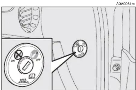
MANUAL DEACTIVATION OF PASSENGER'S FRONT AIR BAG
(upon request for versions/markets where applicable)
Should it be absolutely necessary to carry a child on the front seat, the passenger's front air bag can be deactivated.
Deactivation/reactivation takes place with ignition key at STOP and operating it in the special key switch on the right-hand side of the dashboard (fig. 56). Access to the switch is only possible with the door open.
text_image
A0A0061m ON OFF PASS AIR BAGfig. 56

WARNING
Use the switch only with the engine off and the ig-
nition key removed.
The key switch (fig. 56) has two positions:
1) Passenger's front Air bag active: (ON position Ⓧ) warning light on check panel off; it is absolutely prohibited to carry children on the front seat.
2) Passenger's front Air bag deactivated: (OFF position ⬇️) warning light on check panel on; it is possible to carry children protected by special restraint systems on the front seat.
The warning light 🖼️ on the check panel glows steadily until the passenger's Air bag is reactivated.
Deactivation of the front passenger's Air bag does not prevent operation of the side Air bags.
With the door open the key can be inserted and removed in both positions.
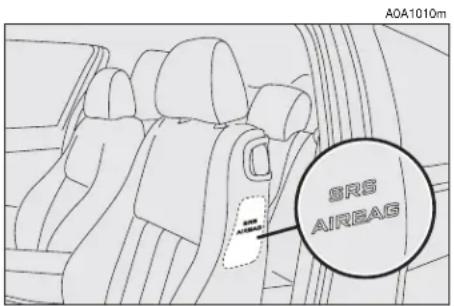
SIDE AIR BAGS (SIDE BAG - WINDOW BAG)
The side bag and window bag have the task of increasing protection of the occupants in the event of a side crash of medium-high severity.
They are formed of two types of instantaneously-inflating cushions:
— the side bag is housed in the back rest of the front seats; with this solution it is always possible to have the cushion in the optimum position in relation to the passenger, regardless of the adjustment of the seat;
— the window bags, which are "curtain" cushions, are housed in the side roof lining covered by a special trim, which makes it possible to extend the cushion downwards. This solution, designed to protect the head, makes it possible to offer the highest degree of protection to the front and rear occupants in the event of side crash, thanks to the wide cushion inflation surface.
In the event of a side crash, an electronic control unit processes the signals leading from a deceleration sensor and activates, when necessary, inflation of the bags.
The bags inflate instantaneously, setting themselves between the body of the front passengers and the car door. The bags deflate immediately afterwards.
In the event of minor side crashes (for which the restraining action of the seat belts is sufficient), the air bags are not deployed. Also in this case it is of vital importance to wear the seat belts since in case of side crash they guarantee proper positioning of the occupant and prevent the occupant to be pitched out of the car in case of violent crashes.
Therefore the side air bags do not replace but are complementary to the use of belts, which you are recommended to always wear, as specified by law in Europe and most non-European countries.
Operation of the side air bags and window bags is not disabled by the front air bag deactivation switch, as described in the previous paragraphs.
IMPORTANT In the event of side crash, you can obtain the best protection by the system keeping a correct position on the seat, thus allowing correct window bag unfolding.

WARNING
Never rest head, arms and elbows on the door, on the
windows and in the window bag area to prevent possible injuries during the inflation phase.
IMPORTANT The front and/or side air bags may be activated if the car is subjected to heavy shocks or accidents that involve the underbody area, such as for example violent bumps against steps, pavements or fixed obstacles on the ground, falling into big holes or bumpy roads.
IMPORTANT The triggering of air bags releases a small amount of powder. This powder is not harmful and does not indicate a start of fire; also the surfaces of the deployed bag and the car interior may be covered with dusty residue: this may irritate the skin and eyes. In the event of exposure, wash with neutral soap and water.

WARNING
Never lean head, arms and elbows out of the window.
The deadlines concerning the pyrotechnical charge and the twisted contact are shown on the label placed on the front doors (lock area). As these deadlines approach go to Alfa Romeo Authorized Services to have them replaced.
IMPORTANT If an accident has triggered the air bag, Alfa Romeo Authorized Services must be contacted to have the devices activated replaced and to have the whole system checked.
All operations involving checking, repairing and replacing components concerning the Air bag must be carried out by Alfa Romeo Authorized Services. If the car is to be demolished, Alfa Romeo Authorized Services should be contacted beforehand to have the system deactivated.
If the car changes ownership, the new owner must be informed of the instructions for use and of the above warnings and be given this "Owner's Manual".
IMPORTANT The triggering of the pretensioners, front air bags and side bags is decided by the electronic control unit in a differentiated manner depending on the type of crash. The failure to trigger one or more of them does not necessarily indicate a system malfunction.
GENERAL CAUTIONS

WARNING
If warning light does not come on turning the ig-key to MAR or stays on travelling, there might be a case in the restraining systems; case the air bags or pretens may not activate in the use of a crash or, in a more limumber of cases, may activate take. Before going on, ask Romeo Authorized Services to the whole system immedi-

WARNING
Do not cover the back rest of the front and rear seats rims or covers whose use is compatible with Side-bags.

WARNING
Never travel with objects on your lap, in front of the car with a pipe, pencil, etc. be your lips. Serious injury may in the case of the air bag be gered.

WARNING
Always keep your hands on the steering wheel rim when driving, so that if the Air bag is triggered, it can inflate without meeting any obstacles. Do not drive with the body bent forwards, keep the seat back rest in the erect position and lean your back well against it.

WARNING
If the car has been stolen or an attempt to steal it has been made, if it has been subjected to vandals or floods, have the Air bag system checked by Alfa Romeo Authorized Services.

WARNING
Never put stickers or other objects on the steering wheel, on the cover of the passenger's Air bag or on the right side cover of the roof. Never put objects on the dashboard in front of the passenger (for example mobile phones) which might interfere with the correct inflation of the passenger's Air bag and therefore injure the car's occupants.

WARNING
Your are reminded that when the ignition key is engaged and in the MAR position, the Air bags can be triggered also on a stationary car, if it is bumped by another moving car. Therefore, even with the car stationary, never allow children on the front seat. You are also reminded that with the car stationary, without the key engaged and turned, the Air bags are not triggered in the event of an impact; in this case the failure to trigger the air bags should not be considered a system failure.

WARNING
Turning the ignition key to MAR the warning light ✉
(with the passenger's front Air bag deactivation switch at ON) turns on for about 4 seconds, and then flashes for another 4 seconds to remind that the passenger's Air bag and corresponding side Air bags will be activated in the event of a crash, then it goes off.

WARNING
Do not wash the seat back with pressurised water or (by hand or at automatic ashing stations).

WARNING
The front Air bags are designed to be triggered for heavier crashes than the pretensioners. It is therefore normal for the pretensioners only to be triggered for crashes within the two activation thresholds.

WARNING
Do not hook rigid objects to the coat hooks and to the handles.

WARNING
The air bag does not replace the seat belts, but increases their effectiveness. Additionally, as the front air bags are not triggered for head-on collision at low speed, side crashes, crashes from behind or overturning, in these cases the occupants are protected only by the seat belts, which must, therefore, always be fastened.
STEERING WHEEL LEVERS
The devices and services controlled by the levers on the steering wheel can only be activated with the ignition key at MAR.
LEFT-HAND LEVER
The left-hand lever controls the outer lights except for the fog lamps and rear fog guards.
When the outer lights are switched on, the various controls on the dashboard are illuminated.
Only with the ignition key at PARK, regardless of the position of the knurled ring, the sidelights and number plate lights stay on.
Position (1 or 2-fig. 62) of the lever causes the turning on only of the sidelights (front and rear), on the right or left respectively.
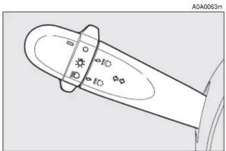
Lights switched off (fig. 57)
When the pointer in the knurled ring is opposite the symbol O, the outer lights are switched off.
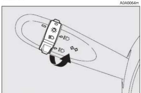
Sidelights (fig. 58)
The sidelights are switched on by turning the knurled ring from O to ⚙.
The ≥0≤ warning light on the instrument cluster will come on at the same time.
Dipped-beam headlights (fig. 59)
These are switched on by turning the knurled ring from ⚙ to ⏱.
natural_image
Technical line drawing of a mechanical component with no visible text or symbolsfig. 57
Main beams (fig. 60)
To turn the main beams on, set the knurled ring to position ☑ and push the lever towards the dashboard (stable position); warning light ☑ on the instrument panel will turn on.
To set dipped-beams back pull the lever towards the steering wheel.

text_image
A0A0065mfig. 59
text_image
A0A0064mfig. 58

text_image
A0A0066mfig. 60
When the dipped beam headlights and the fog lamps are switched on, the outer light control unit (integrated in the Body Computer) works according to the following log-ics:
— turning on the main beams, the dipped beams turn off while the fog lamps stay on, when restoring the starting condition at dipped beam setting;
or
— turning on the main beams, the fog lamps turn off and then turn on again automatically as the main beams are switched off.
Therefore, in the event of Body Computer replacement, the outer light operating logic may be different.
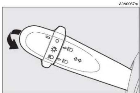
Flashing (fig. 61)
The headlights are flashed pulling the lever towards the steering wheel (instable position) regardless of the position of the knurled ring. The warning light on the cluster will come on at the same time.
IMPORTANT Only the main-beam lights are flashed. To avoid penalties follow local regulations.
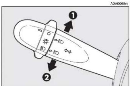
Direction indicators (fig. 62)
Regardless of the position of the knurled ring, moving the lever to the stable position will:
up, position (1) - engage the right-hand direction indicators.
down, position (2) - engage the left-hand direction indicators.
One of the warning lights ( or ) will come on on the instrument cluster at the same time.
The lever is returned to its position automatically and the indicators are switched off when the steering wheel is straightened.
IMPORTANT If you wish to signal a rapid change of direction involving only a minimal movement of the steering wheel, the lever can be removed up or down without it clicking (unstable position). When released, the lever will return to its home position.

text_image
A0A0067mfig. 61
text_image
A0A0068m ① ②fig. 62
text_image
A0A0067mfig. 63

"Follow me home" device (fig. 63)
This function allows the illumination of the space in front of the car for the length of time set, and is activated with the ignition key at STOP or removed, pulling the left-hand lever towards the steering wheel.
This function is activated pulling the lever within 2 minutes from when the engine is turned off. At each single movement of the lever, the staying on of the dipped beams and sidelights is extended by 30 seconds up to a maximum of 3.5 minutes; the lights switch off automatically after the time set.
Each time the lever is operated, the O warning light on the cluster turns on.
This function can be interrupted by keeping the lever pulled towards the steering wheel for more than 2 seconds.
RIGHT-HAND LEVER
The right-hand lever is used to operate the windscreen wiper and windscreen washer. The control used to activate the windscreen washers also activates the headlight washers, if fitted.
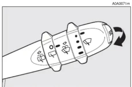
Windscreen wiper - Windscreen washer (fig. 64-65)
The lever can be moved to five different positions, corresponding to:
A - Windscreen wiper off.
B - Intermittent.
A0A0070m
text_image
F E A B C Dfig. 64
With the lever in position (B), turning the ring (F) four possible intermittent speeds are obtained:
■ = intermittent slow.
■■ = intermittent medium.
■■■ = intermittent medium-fast.
■■■■ = intermittent fast.
C - Continuous, slow.
D - Continuous, fast.
E - Fast, temporary (unstable position).
Operation in position (E) is limited to the time the lever is held in this position. When the lever is released, it returns to position (A) automatically stopping the wiper.
IMPORTANT When the wiper is on, engaging reverse gear automatically turns on the rearscreen wiper.
"SMART WASHING" FUNCTION
Pulling the lever towards the steering wheel (unstable position) operates the windscreen washer.
Keeping the lever pulled, with only one movement it is possible to operate the washer jet and the wiper at the same time; indeed, the latter comes into action automatically if the lever is pulled for more than half a second.
The wiper stops working a few strokes after releasing the lever; a further “cleaning stroke” after a few seconds completes the wiping operation.
Rain sensor (fig. 66)
The rain sensor (A), fitted only on certain versions, is an electronic device combined with the windscreen wiper which has the purpose of automatically adjusting the number of wipes during intermittent operation to the intensity of the rain.
All the other functions controlled by the right-hand lever remain unchanged.
The rain sensor is activated automatically moving the right-hand lever to position (B-fig. 64) and it has a range of adjustment that gradually varies between wiper stationary (no wiping) when the windscreen is dry, to wiper at first continuous speed (continuous, slow) with heavy rain.
Turning the knurled ring (F-fig. 64) it is possible to increase the sensitivity of the rain sensor, obtaining a quicker change from stationary, when the windscreen is dry, to first continuous speed (continuous, slow).
Operating the windscreen washer with the rain sensor activated (lever at position B) the normal washing cycle is performed at the end of which the rain sensor resumes its normal automatic function.
Turning the ignition key to STOP the rain sensor is deactivated and the next time the engine is started (MAR position) it will not be reactivated even if the lever has remained in position (B). In this case to activate the rain sensor, simply move the lever to (A) or (C) and then back to (B).
When the rain sensor is reactivated in this way, the wiper performs at least one stroke, even if the windscreen is dry, to indicate that reactivation has occurred.
The rain sensor is located behind the inner rear-view mirror in contact with the wind-screen and inside the area cleaned by the wiper and it controls an electronic control unit which in turn controls the wiper motor.
text_image
A0A0071m 593fig. 65

text_image
A0A1012m Afig. 66
At each start, the rain sensor automatically stabilises at a temperature of about 40^ C to eliminate any condensation from the control surface and prevent the formation of ice.
The rain sensor is able to detect and automatically adapt to the presence of the following particular conditions which require different sensitivity:
— impurities on the control surface (salt, dirt, etc.);
— streaks of water caused by worn wiper blades;
— difference between day and night (the human eye is more disturbed during the night by the wet glass surface).
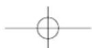
Rearscreen wiper - washer (fig. 67-68)
Pushing the lever towards the dashboard (unstable position) operates the rearscreen washer jet and continuous operation of the rearscreen wiper. Operation ends when the lever is released.
Turning the knurled ring (A) from position O to position □ operates the rearscreen wiper intermittently.
The activation of the rear windshield wiper occurs also with the front windshield wipe on and reverse gear inserted.
Headlamp washers (fig. 69)
These come into operation when the wind-screen washer is turned on with the dipped/main beam headlights on.
IMPORTANT On certain versions when the headlamp washer is operating, the climate control system automatically engages inside air re-circulation, to prevent the smell of liquid detergent from entering the passenger compartment.
text_image
A0A0073m A0A0073mfig. 67
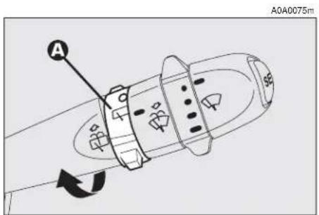
text_image
A040075m Afig. 68

natural_image
Line drawing of a car's front dashboard and steering wheel (no text or symbols)fig. 69
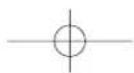
CRUISE CONTROL
GENERAL
The speed regulator (CRUISE CONTROL), with electronic control, makes it possible to drive the car at the required speed without pressing the accelerator pedal. This reduces driving fatigue during long journeys because the speed memorised is automatically maintained.
IMPORTANT The device can only be engaged at speeds between 30 and 190 km/h.

WARNING
Cruise Control must be activated only when the route and traffic allow a constant speed for a sufficiently long distance completely safely.
The device is disengaged automatically in any of the following cases:
— pressing the brake pedal;
— pressing the clutch pedal;
— if the ASR, MSR OR VDC systems cut in;
— with Selespeed transmission if a gear is changed;
— inadvertently moving the Selespeed gear control lever to N.
CONTROLS (fig. 70)
Cruise Control is controlled by the ON/OFF knurled ring (A), by the +/- ring (B) and by the RES button (C).
Ring (A) has two positions:
— OFF in this position the device is deactivated;
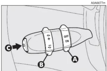
text_image
A0A0077m OFF ON C B Afig. 70
— ON is the normal operating position of the device. When the ring (A) is in this position, the warning light ☺ on the instrument cluster turns on.
Ring (B) serves for memorising and maintaining the car sped or for increasing or lowering the speed memorised.
Turn the ring (B) to (+) to memorise the speed reached or increase the speed memorised.
Turn the ring (B) to (−) to lower the speed memorised.
Each time the ring is actuated (B) the speed increases or lowers by about 1.5 km/h.
Keeping the ring turned the speed changes continuously. The new speed reached will be maintained automatically.
The RES button (C) resets the memorised speed.
IMPORTANT Turning the ignition key to STOP or the ring (A) to OFF, the speed memorised is cleared and the system is switched off.
TO MEMORISE THE SPEED
Move the ring (A) to ON and take the car to the required speed normally. Turn the ring (B) to (+) for at least three seconds, then release it. The car speed is memorised and it is therefore possible to release the accelerator pedal.
The car will continue to travel at the memorised constant speed until one of the following conditions takes place:
— pressing the brake pedal;
— pressing the clutch pedal;
— if the ASR, MSR or VDC systems cut in;
— with Selespeed transmission if a gear is changed;
— inadvertent movement of the Selespeed gear control lever to position N.
IMPORTANT In the case of need (when overtaking for instance) acceleration is possible simply pressing the accelerator pedal; later, releasing the accelerator pedal, the car will return to the speed memorised previously.
TO RESET THE MEMORISED SPEED
If the device has been disengaged for example pressing the brake or clutch pedal, the memorised speed can be reset as follows:
— accelerate gradually until reaching a speed approaching the one memorised;
— engage the gear selected at the time of speed memorising (4th, 5th or 6th speed);
— press the RES button (C).
TO INCREASE THE MEMORISED SPEED
The speed memorised can be increased in two ways:
1) pressing the accelerator and then memorising the new speed reached (turning the ring to (B) for more than three seconds);
or
2) momentaneously turning the ring (B) to (+): each pulse of the ring will correspond to a slight increase in speed (about 1.5 km/h), while pressing continuously wull correspond to a continuous speed increase. Releasing the ring (B) the new speed will be memorised automatically.
TO REDUCE THE MEMORISED SPEED
The speed memorised can be reduced in two ways:
1) disengaging the device (for instance pressing the brake pedal) and then memorising the new speed (turning the ring (B) to (+) for at least three seconds);
2) keeping the ring pressed (B) at (−) until reaching the new speed which will be memorised automatically.
RESETTING THE MEMORISED SPEED
The memorised speed is automatically reset turning off the engine or moving the ring (A) to OFF.

WARNING
Cruise control may only be engaged at speeds
between 30 and 190 km/h.
The ring (A) may be left constantly at ON without damaging the device. You are, however, advised to switch the device off when not in use, turning the ring to OFF, to avoid memorising speeds by accident.

WARNING
When travelling with the cruise control on, do not move the gearshift lever to neutral and do not move the Selespeed selector to N.
The device may only be engaged in 4th, 5th or 6th gear, depending on the speed of the car. Travelling downhill with the device engaged the car speed may increase more that the memorised one, due to the change in the engine load.
It is advisable to engage the cruise control only when the conditions of the traffic or roads so permit under completely safe conditions, i.e.: straight and dry roads, dual carriage ways or motorways, flowing traffic and smooth road surface. Do not engage the device in town or in heavy traffic conditions.

WARNING
If the device is faulty or not working, turn the ring
(A) to OFF and contact Alfa Romeo Authorised Services after checking that the protection is intact.
DASHBOARD

text_image
Diagram of a car dashboard with numbered parts for identification and assembly reference.fig. 71
A0A1115m
- Side swivel air vents - 2. Fixed side window air vents - 3. Outer light control lever - 4. Instrument panel - 5. Tailgate release button - 6. Card holder (upon request for versions/markets where applicable) - 7. Radio (upon request for versions/markets where applicable) - 8. Centre swivel air vents - 9. Fixed upper vent - 10. Glass holder (upon request for versions/markets where applicable) - 11. Fog lamp button (upon request for versions/markets where applicable) - 12. Hazard warning light switch - 13. Rear fog guard button - 14. Passenger's front Air bag - 15. Glove compartment - 16. Door locking button - 17. Controls for heating, ventilation and climate control - 18. Cigar lighter - 19. Ashtray - 20. Temperature sensor - 21. Windscreen/rearscreen wiper control lever - 22. Ignition key and switch - 23. Horn - 24. Steering wheel locking/release lever - 25. Driver's front Air bag - 26. Set of controls - 27. Bonnet opening lever.
INSTRUMENT PANEL
Versions with digital multifunction display
A. Fuel level gauge with reserve warning light - B. Engine coolant fluid temperature gauge with maximum temperature warning light - C. Speedometer - D. Odometer display (mileage recorder, trip recorder with headlamp position display) - E. Clock/outside temperature display - F. Rev counter
NOTE On JTDM versions the scale bottom is at 6000 revs.
A. Fuel level gauge with reserve warning light - B. Engine coolant fluid temperature gauge with maximum temperature warning light - C. Speedometer - D. Odometer display (mileage recorder, trip recorder with headlamp position display) - E. Clock/outside temperature display - F. Rev counter
NOTE On Q2 diesel versions the scale bottom is at 6000 revs.
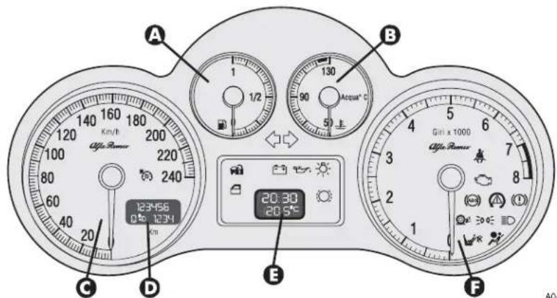
text_image
A 1/2 130 90 Acqua°C 5 B 120 140 160 180 200 100 220 80 240 60 40 20 C D 123456 0° 1234 E 20:30 20.5° Gin x 1000 Afee Power FA0A1111m
fig. 72 - petrol versions

text_image
A B 123456 0% 1234 C D E F 20:30 20:50 130 90 50 Benzins Arqua °C Gn x 1000 Gn x 1000 Alfa RamorA0A1127m
fig. 73 - Black Line petrol versions

Versions with reconfigurable multifunction display
A. Fuel level gauge with reserve warning light - B. Engine coolant fluid temperature gauge warning light - C. Speedometer - D. Odometer display (mileage recorder, trip recorder with headlamp position display) - E. Reconfigurable multifunction display - F. Rev counter
NOTE On JTDM versions the scale bottom is at 6000 revs.
A. Fuel level gauge with reserve warning light - B. Engine coolant fluid temperature gauge warning light - C. Speedometer - D. Odometer display (mileage recorder, trip recorder with headlamp position display) - E. Reconfigurable multifunction display F. Rev counter
NOTE On Q2 diesel versions the scale bottom is at 6000 revs.
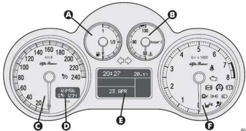
text_image
A 1 1/2 130 90 Acqui® C B 20:27 20.5°C 23 APR C D E F 240 123456 0% 1234 Gin x 1000 Alfa Power Alfa PowerA0A1112m
fig. 74 - petrol versions
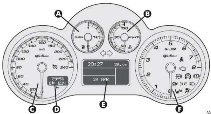
text_image
A 160 180 140 120 100 80 60 40 20 123456 0.50 12341 B 130 90 50 Anqua °C 20:27 20.5° 23 APR C D E F Gn x 1200 Gn x 1200 Gn x 1200 Gn x 1200 Gn x 1200 Gn x 1200 Gn x 1200 Gn x 1200 Gn x 1200 Gn x 1200 Gn x 1200 Gn x 1200A0A1129m
fig. 75 - Black Line petrol versions
Versions with reconfigurable multifunction display
A. Fuel level gauge with reserve warning light - B. Engine coolant fluid temperature gauge warning light - C. Speedometer - D. Odometer display (mileage recorder, trip recorder with headlamp position display) - E. Reconfigurable multifunction display - F. Rev counter
A. Fuel level gauge with reserve warning light - B. Engine coolant fluid temperature gauge warning light - C. Speedometer - D. Odometer display (mileage recorder, trip recorder with headlamp position display) - E. Reconfigurable multifunction display - F. Rev counter

text_image
A 1 1/2 90 Acqua® C B 20:27 3 23 APR 20.5T C D 123456 0 1234 Km/h Odds Power Gini x 1000 Odds Power E FA0A1113m
fig. 75a - 2.0 T. SPARK Selespeed versions

text_image
A 120 140 160 180 200 220 240 20 123456 0 km 1231 km/h B 130 90 Acqua °C 50 E 20:27 3 23 APR 20.5° C Gn x1000 Gn x1000 C F A0AA0A1130m
fig. 75b - 2.0 T. SPARK Selespeed Black Line versions
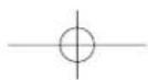
MILEAGE RECORDER
Odometer display with double meter (total and trip) and headlamp position display.
The display shows:
— the mileage on the first line (6 figures)
— the trip meter on the second line (4 figures)
— the position relating to the headlamp aiming device.
To reset the trip meter, keep the button (A-fig. 76) on the plate at the side of the steering column pressed for a few seconds.
IMPORTANT If the battery is disconnected the trip meter reading is not stored.

text_image
A 0.0 ASR OFF MODE 220 240 A0A1118mfig. 76
REV COUNTER
The danger zone (red, or white on certain versions) indicates excessively high engine speed. Do not drive for long periods with the pointer in this area.
IMPORTANT The electronic injection control system gradually shuts off the flow of fuel when the engine is "over-revving" resulting in a gradual loss of engine power.
When the engine is idling, the rev counter may indicate a gradual or sudden highering of the speed, this is normal as it takes place during normal operation, for example when engaging the climate control system or the fan. In particular a slow change in the speed preserves the battery charge.
FUEL LEVEL GAUGE WITH RESERVE INDICATOR
This shows the amount of fuel left in the fuel tank.
The warning light ☐ turns on to indicate that approx. 7 litres of fuel are left in the tank.
IMPORTANT Under certain conditions (heavy slopes, for instance), the reading on the gauge may differ from the actual amount of fuel in the tank and changes in level may be indicated late.
This condition falls within the operation logics of the electronic control circuit to avoid highly unstable readings due to swaying of the fuel when travelling.
IMPORTANT Refuelling shall always be performed with engine off and ignition key at STOP. If the engine is off but the key is at MAR, a wrong fuel level could temporarily be indicated. This is due to the internal system control logic and cannot be considered as a system malfunctioning.
ENGINE COOLANT FLUID TEMPERATURE GAUGE WITH MAXIMUM TEMPERATURE WARNING LIGHT
This shows the temperature of the engine coolant fluid and begins when the fluid temperature exceeds approx. 50°C.
Normally the pointer should be towards the middle of the scale. If the pointer reaches the higher temperatures of the scale (red section, or white on certain versions) the request for car performance should be decreased.
The turning on of the warning light (versions with digital multifunction display) or of the message + symbol (versions with reconfigurable multifunction display) indicates that the coolant fluid temperature is too high; in this case, stop the engine and contact Alfa Romeo Authorized Services.
IMPORTANT The temperature of the engine coolant may rise towards the maximum values (red section, or white on certain versions) when the car is driven at low speeds, especially when the ambient air temperature is high. In this case it is advisable to stop the car and switch off the engine for a few minutes, after which the journey can be resumed, preferably at a higher speed.
DIGITAL MULTIFUNCTION DISPLAY
The digital multifunction display shows the following: clock, outside temperature, buzzer setting (buzzer on/off), rheostat (light adjustment), condition of the inertial fuel cut-off switch (FPS on) and engine oil level (for JTD versions).
CONTROL BUTTONS (fig. 77)
To make use of the information the digital display (with the ignition key at MAR) is able to give, you should firstly familiarise with the control buttons on the plate at the side of the steering column, using them as described in the following paragraphs. Before doing anything at all, you are advised to read this chapter in full.
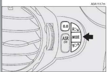
text_image
A0A1117m 0.0 ASR OFF MODEfig. 77

text_image
To increase the value displayed Press for less than 1 second (pulse), indicated with MODE 1 in the following descriptions, to access the various adjustments Press for more than 2 seconds, indicated with MODE 2 in the following descriptions, to confirm the choice required and return to the previous display To decrease the value displayed
CLOCK (fig. 78)
Adjusting the hours
Press the MODE button in MODE 1, the hours will flash. Set the hour required using button ▲ or ▼.
Every press on the button will increase by one unit.
Keeping the button pressed obtains automatic fast increase or decrease.
When you are near the value required, release the control and complete adjustment with single presses.
Then press the MODE button in MODE 2 to store.
clock and outside temperature display buzzer activated display A0A0009m
text_image
80:30 +20.9°Cfig. 78
Adjusting the minutes
Press the MODE button twice in MODE 1, the minutes will flash. Set the minutes required using button ▲ or ▼.
Every press on the button will increase by one unit.
Keeping the button pressed obtains automatic fast increase or decrease.
When you are near the value required, release the control and complete adjustment with single presses.
Then press the MODE button in MODE 2 to store.
OUTSIDE TEMPERATURE (fig. 79)
Outside temperature can be viewed on the display lower side, under the hour indication. When the outside temperature is below or 3^ C, the indicator starts flashing together with the buzzer, to warn the driver about the possible presence of ice on the road. The acoustic signal lasts about 2 seconds, while the outside temperature indicator flashes for about 10 seconds. The signal of possible presence of ice on the road is repeated only if the outside temperature is over 6^ C and then reaches again 3^ C.
BUZZER (fig. 79-80)
The buzzer which accompanies the controls may be activated (ON) or deactivated (OFF); proceed as follows:
Press the MODE button 3 times MODE 1, then use button ▲ or ▼ to turn the buzzer on or off.
The press the MODE button in MODE 2 to store the condition chosen.
ON)
A0A0083m

text_image
80:28 -68.8°8fig. 79
LIGHT RHEOSTAT (fig. 81-82)
This function makes it possible to adjust the lighting (dimming/increasing) of the instrument cluster, odometer display (total and trip meter, headlamp aiming device display) of the clock/outside temperature display and of the radio display.
To access the light rheostat, open the menu by pressing button MODE, select "IL-LU" (first option displayed) by pressing again button MODE and then set the required level using buttons ▲ or ▼).
"ILLU" function is available when at least the side/taillights on.
Partial lighting
Keeping the ▼ button pressed (on the plate at the side of the steering column) for more than 4 seconds the instrument cluster
buzzer deactivated display (OFF)

text_image
60:28 -88.8°8fig. 80
is turned off with the exception of the speedometer.
Keeping the ▲ button pressed (on the plate at the side of the steering column) for more than 4 seconds the compelte cluster lighting is turned on again.
display
with minimum brightness
A0A0012m
text_image
8.0000 8.0000fig. 81
display
with maximum brightness

text_image
AQA0013m 8 8 8 8 8 8 8 8 8 8 8 8 8 8 8 8 8 8 8 8 8 8 8 8 8 8 8 8 8 8 8 8 8 8 8 8 8 8 8 8 8 8 8 8 8 8 8 8 8 8 8fig. 82
INERTIAL FUEL CUT-OFF SWITCH ON DISPLAY (fig. 83) (for versions/markets where applicable)
The display shown appears automatically when the inertial fuel cut-off switch cuts in, following a crash of a certain magnitude.
The switch shuts off the supply of fuel.
IMPORTANT See the description in the Controls paragraph under the Inertial fuel cut-off switch.
inertial fuel cut-off switch on display

text_image
88:89 -88.8°8fig. 83

Engine oil level check (JTD versions)
Turning the ignition key to MAR the digital multifunction display shows the writing "OIL" for about 10 seconds.
Then, the engine oil level is detected for some seconds, during which the display shows six bars. At the end of this operation, the display will show the oil quantity (fig. 84) and then the information concerning the partial and total kilometres travelled.
Fig. 84 refers to the correct engine oil display. As the oil level gradually falls, the full bars go off.
IMPORTANT To make sure that the engine oil level displayed is correct, carry out the check with the car on the level ground.
Fig. 85 refers to the display with an oil level below the foreseen minimum. In this condition the display shows the flashing bars and the message "OIL" for about 10 seconds.
IMPORTANT In this case the correct engine oil level should be restored as soon as possible, see "Checking levels" in the "car maintenance" chapter.
In case of fuel system failure, after turning the ignition key to MAR, the display shows only the message "OIL" flashing for about 10 seconds (fig. 86).
Fig. 87 refers to the display with an oil level above the foreseen maximum. In this condition the display shows the message "HIGH OIL".
IMPORTANT In this case, contact Alfa Romeo Authorised Services who will restore the correct engine oil level.

text_image
A0A0713m 888888 8 D-88888fig. 86

text_image
A0A0711m 999988 8 D 0888fig. 84
text_image
A0A0712m 8 888.8 D D 888.8fig. 85
text_image
A0AC714m 8:00:00 8 D 00:00fig. 87
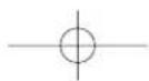
RECONFIGURABLE MULTIFUNCTION DISPLAY
The reconfigurable multifunction display is able to display all the useful and necessary information when driving, in particular:
INFORMATION ON STANDARD DISPLAY
- Clock (A-fig. 88);
- Outside temperature (B);
- Date (C).
INFORMATION ABOUT CAR CONDITION
- Trip computer;
- Lighting adjustment (rheostat);
- Display of failure messages with corresponding symbol;
- Display of warning messages with corresponding symbol (e.g.: possible ice on road);
- Gear selected (only for 2.0 T.SPARK Selespeed versions);
- Engine oil level (only JTD M versions).
CONTROL BUTTONS fig. 89
MODE
Short pressing of button to confirm the choice required and/or move to the next screen;
Long pressing of button to confirm the choice required and return to the standard screen;
▲/▼ to scroll up/down the "Setup menu" options or increase/decrease the value displayed.
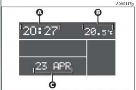
text_image
A 20:27 20.5°C 23 APR C A0A9117gfig. 88

text_image
A0A1117m 0.0 ASR OFF MODEfig. 89
"SETUP MENU"
In addition there is a "Setup Menu" which makes it possible, through the MODE and ▲/▼ (see fig. 89) buttons, to carry out the adjustments and/or setting described on the following pages. It can be activated by pressing shortly MODE and comprises a series of functions arranged in a "circular fashion" fig. 90.
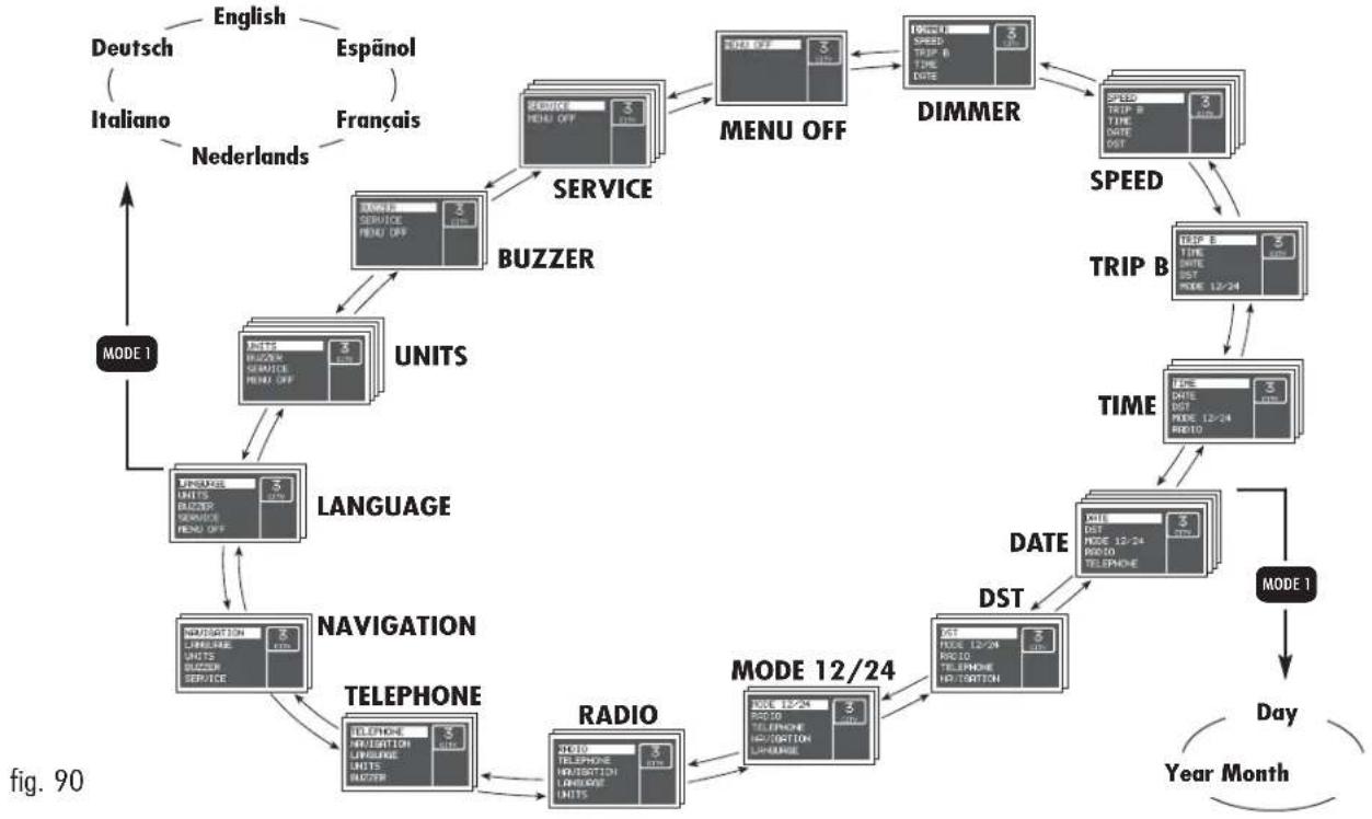
flowchart
graph TD
    A["Deutsch (Italiano)"] --> B["English"]
    C["Espänol"] --> D["Nederlands"]
    E["Français"] --> F["Netherlands"]
    G["SERVICE"] --> H["BUZZER"]
    H --> I["UNITS"]
    I --> J["LANGUAGE"]
    J --> K["NAVIGATION"]
    K --> L["TELEPHONE"]
    L --> M["RADIO"]
    M --> N["MODE 12/24"]
    N --> O["DATA"]
    O --> P["TIME"]
    P --> Q["SPEED"]
    Q --> R["Trip B"]
    R --> S["DIMMER"]
    S --> T["MENU OFF"]
    T --> U["MENU OFF"]
    U --> V["DST"]
    V --> W["DAY"]
    W --> X["Year Month"]
    Y["MODE 1"] --> Z["Language"]
    Z --> AA["NAVIGATION"]
    AA --> AB["TELEPHONE"]
    AB --> AC["RADIO"]
    AC --> AD["MODE 12/24"]
    AD --> AE["DATA"]
    AE --> AF["TIME"]
    AF --> AG["SPEED"]
    AG --> AH["Trip B"]
    AH --> AI["SPEED"]
    AI --> AJ["Trip B"]
    AJ --> AK["SPEED"]
    AK --> AL["SPEED"]
    AL --> AM["SPEED"]
    AM --> AN["SPEED"]
    AN --> AO["SPEED"]
    AO --> AP["SPEED"]
    AP --> AQ["SPEED"]
    AQ --> AR["SPEED"]
    AR --> AS["SPEED"]
From the standard screen to access navigation press the button MODE for a short time. To navigate inside the menu press the buttons ▲ or ▼. For safety reasons, when the car is moving, it is possible to access only the limited menu (adjustment of instrument panel lighting on "DIMMER" and setting at "SPEED"). When the car is stationary it is possible to access the extended menu.

Engine oil level check (JTDM versions)
Turning the ignition key to MAR the display shows the engine oil level for some seconds. During this phase, to clear the display and move to next screen, press the MODE button shortly.
IMPORTANT To make sure that the engine oil level displayed is correct, carry out the check with the car on a level ground.
Fig. 91 refers to the correct engine oil level display. As the oil level gradually falls, the full bars go off leaving room for the empty ones.
Fig. 92 refers to the display with an oil level below the foreseen minimum. In this condition the bars are all empty.
IMPORTANT In this case the correct engine oil level should be restored as soon as possible, see "Checking levels" in the "Car Maintenance" chapter.
Fig. 93 refers to the display with an oil level above the foreseen maximum. In this condition the bars are all full.
IMPORTANT In this case, contact Alfa Romeo Authorised Services who will restore the correct engine oil level.
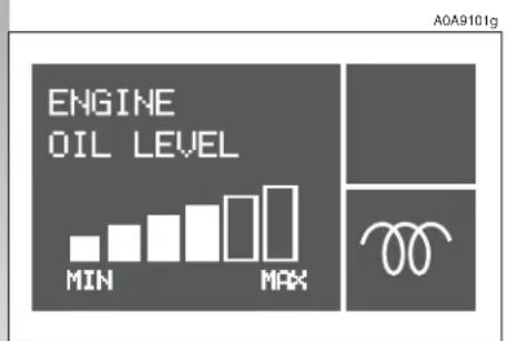
text_image
ENGINE OIL LEVEL MIN MAX A0A9101gfig. 91
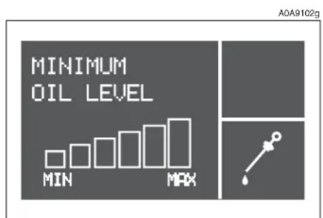
text_image
MINIMUM OIL LEVEL MIN MAX AOA9102gfig. 92
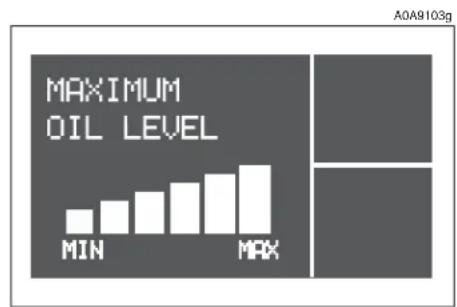
bar
MAXIMUM OIL LEVEL | Category | Value | |---|---| | MIN | 1.0 | | MAX | 2.5 |fig. 93

DIMMER
With this function it is possible to adjust the lighting (dimming/brightening) of the instrument cluster, odometer display (total and trip meter), headlamp aiming display, radio display, radio-navigator display (if fitted) and two-zone climate control (if fitted).
To adjust, proceed as follows:
☐ press the MODE button briefly: the display shows a graduated scale;
☐ press the buttons ▲/▼ to carry out adjustment.
☐ press the MODE button briefly to return to the menu screen or press the button for a longer time to return to the standard screen.
Partial lighting
Keeping the ▼ button pressed for more than 4 seconds, the rev counter lighting is turned off.
Keeping the ▲ button pressed for more than 4 seconds, the complete instrument cluster lighting is turned on again.
IMPORTANT In the event of any faults, lighting adjustment (rheostat) is not possible and the display is shown at its maximum brightness.
SPEED
With this function it is possible to set the car speed limit (km/h) (or mph) which, if exceeded, automatically sounds a buzzer and displays a specific message (see chapter "Warning lights and indications").
To set the limit speed, proceed as follows:
☐ press the MODE button briefly: the display shows ON;
☐ press the MODE button briefly and then use the ▲/▼ buttons to set the speed required (during setting operation, the value flashes on the screen).
☐ press the MODE button briefly to return to the menu screen or press the button for a longer time to return to the standard screen.
IMPORTANT The possible setting is between 30 and 250 km/h or between 20 and 150 mph depending on the unit set previously (see paragraph "UNITS" described later). Every press (pulse) of the ▲/▼ button increases or decreases by one unit. Keeping the ▲/▼ button pressed obtains fast increase or decrease. When you are near the required setting, release the button and complete adjustment with single presses.
To cancel the set value:
☐ press the MODE button briefly: the display shows OFF;
☐ press the ▼ button: the display shows OFF;
☐ press the MODE button briefly to return to the menu screen or press the button for a longer time to return to the standard screen.
TRIP B
With this option it is possible to turn ON/OFF the TRIP B function (partial trip) which displays the figures relating to: AVERAGE CONSUMPTION B, AVERAGE SPEED B, TRAVEL TIME B and TRAVEL DISTANCE B during a "partial mission" contained in the "general mission" (for further information see "Trip Computer").
To turn on/off this function, proceed as follows:
☐ press the MODE button briefly: the display shows ON;
☐ use buttons ▲/▼ to select activation or deactivation;
☐ press the MODE button briefly to return to the menu screen or press the button for a longer time to return to the standard screen.
TIME
With this function it is possible to adjust the clock (hours - minutes).
Proceed as follows:
☐ press the MODE briefly: the display shows the hour;
☐ press the ▲/▼ buttons to adjust;
☐ press the MODE button briefly to adjust the minutes (instead pressing the button for a longer time you return to the standard screen);
☐ press the ▲/▼ buttons to adjust;
☐ press the MODE button briefly to return to the menu screen or press the button for a longer time to return to the standard screen.
IMPORTANT Each press on the ▲/▼ button increases or decreases by one unit. Keeping the ▲/▼ button pressed obtains the automatic fast increase or decrease.
When you are near the required value, release the button and complete adjustment with single presses.
DATE
With this function it is possible to adjust the date (day - month - year).
Proceed as follows:
☐ press the MODE button briefly: the display shows the date;
☐ press the ▲/▼ buttons to adjust the day;
☐ press the MODE button briefly to adjust the month (or press the button for a longer time to return to the standard screen);
□ press the ▲/▼ buttons to adjust;
☐ press the MODE button briefly to adjust the year (or press the button for a longer time to return to the standard screen);
☐ press the ▲/▼ buttons to adjust;
☐ press the MODE button briefly to return to the menu screen or press the button for a longer time to return to the standard screen.
DST (SUMMER TIME)
With this option it is possible to turn ON/OFF the summer time function (which corresponds to +1 hour in relation to the daylight time).
Proceed as follows:
☐ press the MODE button briefly: the display shows ON;
☐ use the ▲/▼ buttons to select activation or deactivation;
☐ press the MODE button briefly to return to the menu screen or press the button for a longer time to return to the standard screen.
Selecting and activating the "DST ON" function, the display switches from daylight time and vice versa, with no need to intervene manually on the "TIME" function described previously.
MODE 12/24
This function is used to set the clock in the 12h or 24h mode.
To adjust proceed as follows:
☐ press the MODE button briefly: the display shows 12h;
☐ press the ▲/▼ buttons to set (12h or 24h);
☐ press the MODE button briefly to return to the menu screen or press the button for a longer time to return to the standard screen.
RADIO
With this function it is possible to turn ON/OFF the repetition of the information displayed by the radio front panel on the instrument cluster display.
To activate/deactivate this function, proceed as follows:
☐ press the MODE button briefly: the display shows ON;
☐ use the ▲/▼ buttons to select activation/deactivation;
☐ press the MODE button briefly to return to the menu screen or press the button for a longer time to return to the standard screen.
Selecting and activating the "RADIO DISPLAY ON" function, when the radio is turned on, the display repeats the display on the front panel of the radio itself.
NOTE For versions with CD MP3 sound system only, if the active radio source is "MP3", the RADIO function is disabled even if ON.
TELEPHONE
With this option it is possible to turn ON/OFF the function which shows the name (if listed) and phone number of the caller on the instrument panel display.
To activate/deactivate this function, proceed as follows:
☐ press the MODE button briefly: the display shows ON;
☐ use the ▲/▼ buttons to select activation/deactivation;
☐ press the MODE button briefly to return to the menu screen or press the button for a longer time to return to the standard screen.
Selecting and activating the "TELEPHONE DISPLAY ON" function, when a phone call arrives, the display shows the name (if listed) and phone number of the caller.
NAVIGATION
With this option it is possible, during use of the radionavigator, to turn ON/OFF the function to view the pictograms shown on the radionavigator display on the instrument cluster display.
To activate/deactivate proceed as follows:
☐ press the MODE button briefly: the display shows ON;
☐ use the ▲/▼ buttons to select activation or deactivation;
☐ press the MODE button briefly to return to the menu screen or press the button for a longer time to return to the standard screen.
Selecting and activating the "NAVIGATION DISPLAY ON" function, the instrument cluster display repeats the display (pictograms) on the radionavigator display itself.
LANGUAGE
With this function it is possible to select the language required for the texts and messages shown on the display.
Proceed as follows:
☐ press the MODE button briefly: the display shows the "language" set previously;
☐ press the ▲/▼ buttons to adjust;
☐ press the MODE button briefly to return to the menu screen or press the button for a longer time to return to the standard screen.
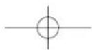
UNITS
With this function it is possible to set the unit of measurement for the travel distance (km or mi), the fuel consumption (l/100 km, km/l or mpg) and the temperature (°C or °F).
To set the units, proceed as follows:
☐ press the MODE button briefly, the display shows "km" or "mi" (depending on what set previously);
☐ press the ▲/▼ buttons to adjust;
☐ press the MODE button briefly to select the temperature unit (or press the button for a longer time to return to the standard screen): the display shows °C or °F (depending on what set previously);
☐ press the ▲/▼ buttons to adjust;
☐ press the MODE button briefly to select the fuel consumption unit (or press the button for a longer time to return to the standard screen);
☐ if the travel distance unit is "km", the display shows "l/100km" or "km/l": press the ▲/▼ buttons to adjust. Instead, if the travel distance unit is "mi" the display shows "mpg";
☐ press the MODE button briefly to return to the menu screen or press the button for a longer time to return to the standard screen.
IMPORTANT The temperature unit (°C or °F) set on the display is also shown on the bi-zone display (if fitted) and on the radion-avigator display (if fitted).
BUZZER
With this function it is possible to adjust the volume of the buzzer which accompanies the controls in the car and any failure signals shown on the display.
To adjust the volume, proceed as follows:
☐ press the MODE button briefly: the display shows the "level" of the volume previously set;
☐ press the ▲/▼ buttons to adjust;
☐ press the MODE button briefly to return to the menu screen or press the button for a longer time to return to the standard screen.
IMPORTANT In the buzzer OFF condition any buzzer failure warnings are maintained.
SERVICE
With this function it is possible to view the information connected with the correct car maintenance.
To consult this information, proceed as follows:
☐ press the MODE button briefly: the display shows the deadline in "km" or "mi" depending on what set previously (see paragraph "UNITS");
☐ press the ▲/▼ buttons to view the required information on the display;
☐ press the MODE button briefly to return to the menu screen or press the button for a longer time to return to the standard screen.
IMPORTANT The programmed Maintenance Schedule includes car maintenance every 20,000 km; this is shown automatically, with the ignition key at MAR, starting from 2,000 km (or miles) from this deadline and it is shown again every 200 km. This display can only be reset by Alfa Romeo Authorised Services.
MENU OFF
Selecting this function you return to the standard screen.
TRIP COMPUTER
General
The "Trip computer" function gives information relating to the operating status of the car on the display. This function comprises the GENERAL TRIP concerning the complete mission of the car and TRIP B concerning the partial car mission. This function (as shown in the graph below) is contained within the complete mission. Both functions are resettable (reset - start of a new mission).
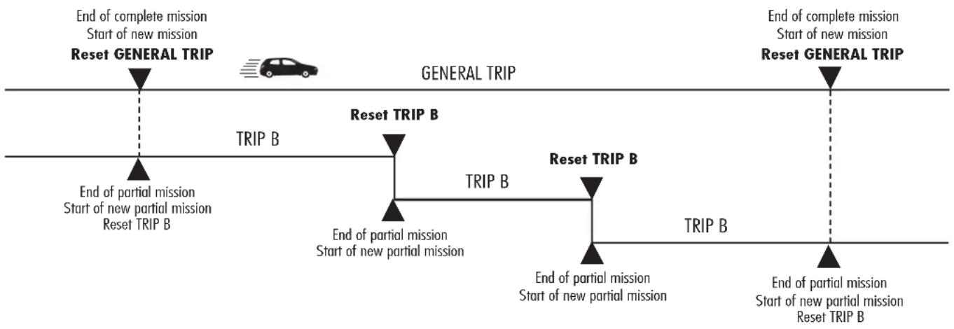
flowchart
graph LR
    A["End of complete mission\nStart of new mission\nReset GENERAL TRIP"] --> B["TRIP B"]
    B --> C["End of partial mission\nStart of new partial mission\nReset TRIP B"]
    C --> D["TRIP B"]
    D --> E["End of partial mission\nStart of new partial mission\nReset TRIP B"]
    E --> F["TRIP B"]
    F --> G["End of partial mission\nStart of new partial mission\nReset TRIP B"]
    G --> H["TRIP B"]
    H --> I["End of partial mission\nStart of new partial mission\nReset TRIP B"]
    I --> J["TRIP B"]
    J --> K["End of partial mission\nStart of new partial mission\nReset TRIP B"]
    K --> L["TRIP B"]
    L --> M["End of partial mission\nStart of new partial mission\nReset TRIP B"]
    M --> N["TRIP B"]
    N --> O["End of partial mission\nStart of new partial mission\nReset TRIP B"]
    O --> P["TRIP B"]
    P --> Q["End of partial mission\nStart of new partial mission\nReset TRIP B"]
    Q --> R["TRIP B"]
    R --> S["End of partial mission\nStart of new partial mission\nReset TRIP B"]
    S --> T["TRIP B"]
    T --> U["End of partial mission\nStart of new partial mission\nReset TRIP B"]
    U --> V["TRIP B"]
    V --> W["End of partial mission\nStart of new partial mission\nReset TRIP B"]
    W --> X["TRIP B"]
    X --> Y["End of partial mission\nStart of new partial mission\nReset TRIP B"]
    Y --> Z["TRIP B"]
    Z --> AA["End of partial mission\nStart of new partial mission\nReset TRIP B"]
    AA --> AB["TRIP B"]
    AB --> AC["End of partial mission\nStart of new partial mission\nReset TRIP B"]
    AC --> AD["TRIP B"]
    AD --> AE["End of partial mission\nStart of new partial mission\nReset TRIP B"]
    AE --> AF["TRIP B"]
    AF --> AG["End of partial mission\nStart of new partial mission\nReset TRIP B"]
    AG --> AH["TRIP B"]
    AH --> AI["End of partial mission\nStart of new partial mission\nReset TRIP B"]
    AI --> AJ["TRIP B"]
    AJ --> AK["End of partial mission\nStart of new partial mission\nReset TRIP B"]
    AK --> AL["TRIP B"]
    AL --> AM["End of partial mission\nStart of new partial mission\nReset TRIP B"]
    AM --> AN["TRIP B"]
    AN --> AO["End of partial mission\nStart of new partial mission\nReset TRIP B"]
    AO --> AP["TRIP B"]
    AP --> AQ["End of partial mission\nStart of new partial mission\nReset TRIP B"]
    AQ --> AR["TRIP B"]
    AR --> AS["End of partial mission\nStart of new partial mission\nReset TRIP B"]

The GENERAL TRIP displays the figures relating to:
□ Average consumption
□ Actual consumption
□ Average speed
Travel time
□ Range
□ Travel distance
TRIP B displays the figures relating to:
□ Average consumption B
□ Average speed B
□ Travel time B
□ Travel distance B
Displayed figures
Average consumption
Represents the indicative average of consumptions from the beginning of the new mission.
Actual consumption
It shows the variation of the fuel consumption updated constantly. If parking with engine running, the display will show “----”.
Average speed
It shows the car average speed according to the overall time elapsed from the start of the new mission.
Travel time
Time elapsed from the start of the new mission (travel time).
Range
It shows the distance the car can still cover before needing fuel if keeping the same driving conditions.
The display shows "----" when the following conditions occur:
- range value below 50 km (or 30 mi);
- car left parked with engine running for long.
IMPORTANT The variation of the autonomy value can be influenced by different factors: driving style (see what is described in paragraph "Driving style" in the chapter "Correct use of the car"), type of route (highways, urban, mountain, etc...), use conditions of the car (load transported, tire pressure, etc...). What was described previously must be taken in consideration when planning a trip.
Travel distance
It shows the distance travelled by the car from the start of a new mission.
At the beginning of a new mission, due to battery reconnection (reset), the display shows value "0.0".
New mission
It starts when the reset operation is carried out:
- "manually" by the user, through prolonged pressure of the SET button;
- "automatically" when the "travel distance" is equal to 9999.9 km (or mi), when the "travel time" is 99:59 (99 hours and 59 minutes) or after reconnecting the battery.
SET BUTTON
The button fitted on the right lever (fig. 94) makes it possible, with the ignition key at MAR, to access the GENERAL TRIP and TRIP B functions.
The SET button also makes it possible to reset the GENERAL TRIP and TRIP B functions to start a new mission:
- short pressing: to go to next screen view;
- long pressing: to reset and start a new journey.
Start of journey procedure (reset)
To start a new journey monitored by the GENERAL TRIP, with the ignition key at MAR, press the SET button for more than 2 seconds.
The reset operation (pressing the SET button for more than 2 seconds) in the presence of the screens concerning the GENERAL TRIP also makes it possible to reset TRIP B.
The reset operation (pressing the SET button for more than 2 seconds) in the presence of the screens concerning the TRIP B also makes it possible to reset only the information associated with this function.
IMPORTANT The RANGE and ACTUAL CONSUMPTION information cannot be reset.

text_image
A0A0021m 50°fig. 94

WARNING LIGHTS AND INDICATIONS
IMPORTANT The presence or absence of the warning lights depends on the type of engine and equipment with which the car is fitted.
Turning the ignition key to MAR the warning light turns on, but it should go off after a few seconds.
Low brake fluid
The warning light turns on (on some versions together with the message + symbol shown on the display) when the level of the brake fluid in the reservoir falls below the minimum level, due to a possible leak in the circuit.
Handbrake on
The warning light turns on when the hand-brake is engaged.

WARNING
If the Ⓑ warning light turns on when travelling check that the handbrake is not engaged. If the warning light stays on with the handbrake off, stop the car immediately and contact Alfa Romeo Authorised Services.
HIGH ENGINE COOLANT FLUID TEMPERATURE (red)
Turning the ignition key to MAR the warning light (if fitted) turns on, but it should go off after a few seconds.
The warning light turns on (on some versions together with the message + symbol shown on the display) when the engine is overheated. If it turns on when travelling, stop the car leaving the engine on and slightly accelerated to further activate the circulation of the coolant fluid.
If the warning light (on some versions together with the message + symbol shown on the display) does not go off within the next 2 or 3 minutes, stop the engine and contact Alfa Romeo Authorised Services.

AIR BAG FAILURE (red)
Turning the ignition key to MAR the warning light turns on, but it should go off after a few seconds.
The warning lights stays on glowing steadily if there is an operating failure in the Air bag system.

WARNING
If the ⚡ warning light does not switch on turning the ignition key to MAR or stays on when the car is travelling there might be a failure in the restraining systems; in this case the air bags or pretensioners may not activate in case of accident or, in a limited number of cases, they may activate by mistake. Before carrying on the journey, contact Alfa Romeo Authorised Services to have the system checked. The failure of the warning light (warning light off) is also indicated by the flashing for more than 4 seconds of the air bag warning light.

LOW ENGINE OIL PRESSURE (red)
Turning the ignition key to MAR the warning light (if fitted) turns on, but it should go off after a few seconds.

WARNING
If the warning light turns on when the car is travelling (on some versions there also the message + symbol shown on the display), stop the engine immediately and contact Alfa Romeo Authorised Services.

LOW BATTERY CHARGE (red)
Turning the ignition key to MAR the warning light (if fitted) turns on, but it should go out as soon as the engine is started (with the engine running at idle speed a brief delay in going out is allowed).
If the warning light (on some versions there is also the message + symbol shown on the display) stays on, contact immediately Alfa Romeo Authorised Services.

SEAT BELTS NOT FASTENED (red)
The warning light turns on glowing steadily when, with the ignition key at MAR, the driver's seat belt is not correctly fastened.

INCOMPLETE DOOR CLOSING (red)
The warning light (if fitted) turns on (on some versions there is also the message + symbol shown on the display) when one or more doors or the tailgate are not properly shut.

BRAKE PAD WEAR (red)
The warning light (if fitted) turns on with the brake pedal pressed (on some versions there is also the message + symbol shown on the display) if the front brake pads are worn; in this case have them changed as soon as possible.
IMPORTANT As the car is fitted with wear sensors for the front brake pads, when changing them, also check the rear brake pads
SELESPEED TRANSMISSION FAILURE (2.0 versions T.SPARK Selesp
Transmission failure

The message is shown on the display in case of transmission failure. In this case contact Alfa Romeo Authorised Services as soon as possible.
Reduction of gearshifting
The message is shown on the display to signal a transmission overuse by the driver.
The irregular use (by the driver) may start automatically a procedure for the protection of the system.

WARNING
If the message remains on the display, contact Alfa
Romeo Authorised Services.
Manual mode not available

The message is shown on the display when, with the engine running, it is not possible to select the MANUAL mode.

WARNING
If the message remains on the display, contact Alfa
Romeo Authorised Services.
Automatic mode not available

The message is shown on the display when, with the engine running, it is not possible to select the AUTO mode.

WARNING
If the message remains on the display, contact Alfa
Romeo Authorised Services.
Clutch overheating

The message is shown on the display accompanied by a buzzer when there is clutch overheating.
Press the brake - Delayed start-up


IMPORTANT The messages are shown only if start-up is carried out with any gear engaged but neutral (N).

WARNING
If the message remains on the display, contact Alfa Authorised Services.

WARNING
If parking or stopping the car uphill (e.g. at the traffic lights), do not use the accelerator to keep the car stopped, to prevent overheating and thus damaging the clutch. Instead, use the brake pedal and press the accelerator pedal only when about to leave off. If the message remains on the display, contact Alfa Romeo Authorised Services.
The messages are alternatively shown on the display, accompanied by a buzzer, when, during start up, the system recognises that the brake pedal is operating.
Under this condition, keep the key in the AVV position for at least 6 seconds, with the brake held down: the engine will start. The system is now in the recovery mode (maximum gear allowed: 2^nd ).
Gear not available
The message is shown on the display, accompanied by a buzzer, in the following cases:
- when, because of a system failure, it is not possible to change gear;
or - when, because of a system failure, it is possible only to engage 1^st(1) , 2^nd(2) or reverse (R).

WARNING
If the message remains on the display, contact Alfa
Romeo Authorised Services.
Operation not allowed
The message is shown on the display, accompanied by a buzzer, when the system does not accept the gearshift by the control lever as the necessary conditions for accepting the gearshift are not present.
Press the brake pedal - repeat operation

The message is shown on the display, accompanied by a buzzer, when in some conditions, due to safety reasons, there is an attempt to change gear without pressing the brake pedal first.
Engage N (neutral)

The message is shown on the display, accompanied by a buzzer, when the system asks the driver to carry out the manoeuvre.
Shifting the gear to (N) the message on the display must go off.

WARNING
If the message remains on the display, contact Alfa
Romeo Authorised Services.

WARNING
If the message remains on the display, contact Alfa
Romeo Authorised Services.

EOBD ENGINE CONTROL SYSTEM FAILURE (amber) (for versions/ markets where applicable)
In normal conditions, turning the ignition key to MAR, the warning light turns on, but it should go off when the engine has started. The initial turning on indicates that the warning light is working properly.
If the warning light stays on or turns on when travelling (on some versions the message + symbol are shown on the display):
glowing steadily - means a fault in the supply/ignition system which could cause high emissions at the exhaust, possible lack of performance, poor handling and high consumption levels. In these conditions it is possible to continue driving without however demanding heavy effort or high speeds. Prolonged use of the car with the warning light on may cause damage. Contact Alfa Romeo Authorised Services as soon as possible. The warning light goes off if the fault disappears, but it is still stored by the system;
a flashing - indicates the possibility of damage to catalyst (see "EOBD system" in this chapter). If the warning light flashes, it is necessary to release the accelerator pedal to lower the speed of the engine until the warning light stops flashing; continue the journey at moderate speed, tying to avoid driving conditions that may cause further flashing and contact Alfa Romeo Authorised Services as soon as possible.

If, turning the ignition key to MAR, the warning light does not turn on turns on glowing steadily or g when travelling, contact meo Authorised Services as is possible.


ALFA ROMEO CODE SYSTEM (amber)
Turning the ignition key to MAR the warning light (if fitted) flashes only once and then go off. If, with the ignition key at MAR, the warning light stays on, this indicates a possible failure (see "Alfa Romeo CODE system").
IMPORTANT The turning on at the same time of the 📋 and 🌐 warning lights indicates a failure of the Alfa Romeo CODE system.
For the versions equipped with reconfigurable multifunction display: if with the engine running the message + symbol are shown on the display, contact Alfa Romeo Authorised Services.
If, with the engine running, the warning light flashes (on some versions together with the message + symbol on the display), this means that the car is not protected by the engine inhibitor device (see "Alfa Romeo CODE system" in this chapter). Contact Alfa Romeo Authorised Services to have all the keys memorised.
GLOW PLUGS WARMING (diesel versions) (amber)
GLOW PLUGS WARNING FAILURE (diesel versions) (amber)
Glow plug warming
Turning the ignition key to MAR, the warning light turns on (on some versions it is shown on the reconfigurable multifunction display). The warning light turns off when the glow plugs have reached the pre-established temperature. Start the engine as soon as the warning light goes off.
IMPORTANT With a high environment temperature, the warning light may turn on for an imperceptible length of time.
Glow plug warming failure
The warning light (if fitted) turns on (on some versions the message + symbol are shown on the display) when there is a failure in the glow plug warming system. Contact Alfa Romeo Authorised Services as soon as possible to have the fault eliminated.
WATER IN FUEL OIL FILTER (diesel versions) (amber)
The warning light (if fitted) turns on (on some versions the message + symbol are shown on the display) when there is water in the fuel oil filter.
The presence of water in the supply circuit may cause serious damage to the entire injection system and cause irregular engine operation. If the warning light turns on (or, on some versions, the message + symbol are shown on the reconfigurable multifunction display) contact Alfa Romeo Authorised Services as soon as possible to have the system relieved. If the same warning is shown after refuelling, maybe some water was introduced in the reservoir: in this case turn the engine off immediately and contact Alfa Romeo Authorised Services.
DIESEL PARTICULATE FILTER CLOGGED (diesel versions) (amber)
The warning light (if fitted) turns on (on some versions the message + symbol are shown on the display) when the particulate filter is clogged and the driving profile does not make it possible to start automatically the regeneration procedure.
To allow the regeneration procedure and to clean the filter, it is advisable to keep the car travelling until the warning light goes off (or, on some versions, the symbol goes off on the display).

INERTIAL FUEL CUT-OFF SWITCH (for versions/markets where applicable)
The message on the display is shown when the inertial fuel cut-off switch is triggered, on some versions together with the warning light ☐.

WARNING
If, after the display of the message, the smell of fuel
or leaks from the supply system are noted, do not re-engage the switch to avoid the risk of fire.

INEFFICIENT ABS SYSTEM (amber)
Turning the ignition key to MAR the warning light (if fitted) turns on, but it should go off after a few seconds.
The warning light turns on (on some versions the message + symbol are shown on the display) when the system is inefficient. In this case, the braking system keeps its effectiveness unchanged, but without the potential offered by the ABS system.
Caution is advisable, particularly in all cases of less than perfect grip. It is also necessary to contact Alfa Romeo Authorised Services as soon as possible.
INEFFICIENT EBD (red) (amber)
The turning on at the same time of the Ⓐ and ⏻ warning lights (on some versions the message + symbol are shown on the display) with the engine
running indicates an EBD system failure; in this case heavy braking may cause rear wheels to lock before time, with the possibility of skidding.
Driving extremely carefully, immediately contact the nearest Alfa Romeo Authorised Service to have the system checked.

PASSENGER'S FRONT AIR BAG DEACTIVATED (amber)
(upon request for versions/markets where applicable)
With the passenger's Air bag engaged, turning the ignition key to MAR the warning light turns on, but it should go off after approximately 4 seconds.
The warning light turns on when the passenger's front Air bag is deactivated.

WARNING
The warning light 📊 also shows a failure of the 🌿
warning light. This condition is signalled by the flashing of the warning light over the normal 4 seconds. In this case the warning light may fail to signal possible faults in the restraining systems. Before going on, contact Alfa Romeo Authorised Services to have the system checked.

VDC SYSTEM (if fitted) (amber)
Turning the ignition key to MAR the warning light turns on, but it should go off after a few seconds.
If the warning light does not go out or stays on when travelling (on some versions together with the message + symbol shown on the display), contact Alfa Romeo Authorised Services.
The flashing of the warning light when travelling indicates the cutting in of the VDC system.
ASR SYSTEM (WHEEL ANTISKID SYSTEM) (if fitted) (amber)
Turning the ignition key to MAR, the warning light turns on, but it should go off after a few seconds.
The warning light turns on when the system is switched off. The warning light flashes when the system cuts in, to alert the driver that the system is adapting to the road surface grip conditions.
The turning on of the warning light (on some versions together with the message + symbol shown on the display) also indicates a failure of the ASR system. In this case contact Alfa Romeo Authorised Services as soon as possible.

LIGHT FAILURE (amber)
Turning the ignition key to MAR, the warning light (if fitted) turns on, but it should go off after a few seconds.
The warning light turns on (on some versions together with the message + symbol shown on the display) when a fault to anyone of the following lights is detected:
- sidelights
- braking lights and corresponding fuse
- rear fog lights
- number plate lights.
The failure referring to these lights could be: one or more blown bulbs, a blown protection fuse or a cut-off electric connection.
The the warning light turns on (on some versions together with the message + symbol shown on the display) when about 7 litres of fuel are left in the tank and on certain versions when autonomy is below 50 km.
LEFT-HAND DIRECTION INDICATOR (green)
The warning light turns on when the direction indicator control lever is moved downwards or, together with the right indicator, when the hazard warning light button is pressed.
RIGHT-HAND DIRECTION INDICATOR (green)
The warning light turns on when the direction indicator control lever is moved upwards or, together with the left indicator, when the hazard warning light button is pressed.
SIDE/TAILLIGHTS (green)
The warning light turns on when side/tail-lights or low beams are turned on.
CRUISE CONTROL (where provided) (green)
The warning light turns on when turning the Cruise Control knurled ring to ON.
MAIN BEAMS (blue)
The warning light turns on when the side-lights or dipped beams are turned on.

POSSIBLE PRESENCE OF ICE ON THE ROAD
On some versions the message + symbol are shown on the display ⚙ to warn the driver of the possible presence of ice on the road, together with a buzzer which sounds when the outside temperature reaches or falls below 3°C.
The buzzer sounds for about 2 seconds while the message is shown for about 10 seconds; after this time, only the symbol remains until the temperature exceeds 6°C or the engine turns off.
If, during travelling, after the displayed warning about the possible presence of ice on the road, the temperature exceeds 6^ C, the symbol ⚙ will go off and, if the temperature reaches again 3^ C, a new message will be shown (with the outside temperature flashing) + symbol ⚙ accompanied by a buzzer.
WARNING LIGHT FAILURE
On some versions the display shows a message when a fault is detected to one the following warning lights: ABS warning light, EBD warning light, ASR warning light, VDC warning light.
ENGINE OIL SENSOR FAILURE
On some versions the display shows a message when a fault is detected to one the following warning lights: ABS warning light, EBD warning light, ASR warning light, VDC warning light.
SPEED LIMIT EXCEEDED
On some versions the warning light turns on, together with the message + symbol on the display and the sounding of the buzzer, when the vehicle exceeds the speed limit set previously (see "Reconfigurable multifunction display").
RANGE (Trip Computer)
On some versions the message + symbol are shown on the display when range is below 50 km.
SCHEDULED MAINTENANCE
On some versions the message + symbol are shown on the display 2000 km from the deadline given in the Scheduled Maintenance Programme.
The message is shown again at timed intervals, turning the ignition key to MAR every 200 km.
086-109_Alfa147 Q2 GB 4-07-2008 12:00 Pagina 86
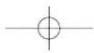
CLIMATE CONTROL SYSTEM
A0A1019m
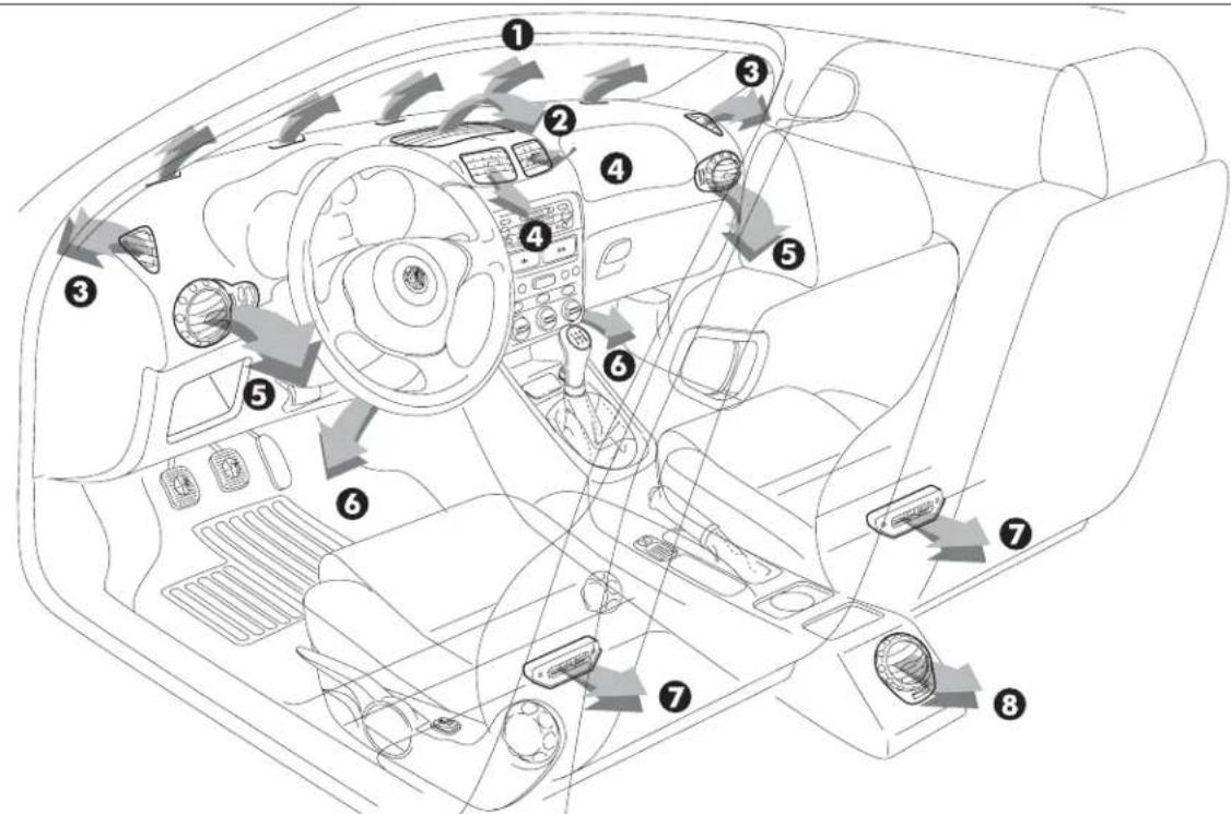
text_image
Diagram of car interior with numbered components and directional arrows indicating traffic or movementfig. 95
1 Upper stationary vent for defrosting or demisting windscreen - 2 Upper centre adjustable vent - 3 Stationary vents for defrosting or demisting side windows - 4 Adjustable centre, swivel vents - 5 Side adjustable and swivel outlets - 6 Front feet area fixed vents - 7 Rear feet area fixed vents - 8 Rear adjustable swivel outlet (upon request for versions/markets where applicable).
UPPER CENTRE VENT ADJUSTMENT (fig. 96)
The vent (1) has an opening/closing control (A).
● = Completely closed.
I = Completely open
CENTRE SWIVEL VENT ADJUSTMENT (fig. 96)
Each vent (2) has a lever (B) which makes it possible to direct the flow of air (in the 4 directions: up/down, right/left).
To adjust the air flow, use control (C):
● = Completely closed.
I = Completely open
SIDE SWIVEL OUTLET ADJUSTMENT (fig. 97)
To direct the flow of air, turn the knurled ring (A) and/or directly use control (B) as required.
To adjust the air flow, use control (C):
● = Completely closed.
I = Partially open.
II = Completely open
D - fixed vent for defrosting or demisting side windows.
REAR SWIVEL OUTLET ADJUSTMENT
(fig. 98) (upon request for versions/markets where applicable)
To direct the flow of air, turn the knurled ring (A) and/or directly use control (B) as required.
To adjust the air flow, use control (C):
● = Completely closed.
I = Partially open.
II = Completely open
A0A0085m A0A0086m A0A0087m
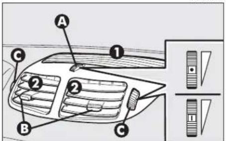
text_image
A ① ② ② B C ③fig. 96 fig. 97 fig. 98
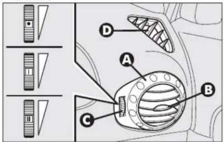
text_image
Diagram of car air vent system components with labeled parts A, B, C, D and directional indicators
text_image
A B C
MANUAL CLIMATE CONTROL SYSTEM (upon request for versions/markets where applicable)
Below is a brief description of the heating and manual climate control system (upon request for versions/markets where applicable). The only difference between the two systems is the climate control compressor button ⚙️, fitted only on the versions with manual climate control system. To obtain the maximum functions of both systems in the different conditions of use, set the pointer on the rings of the corresponding knobs as illustrated.

IMPORTANT An important feature of the manual climate control system is airdehumification. It is
always advisable to turn the climate control compressor on to prevent possible misting.

WARNING
With low external temperature the climate control compressor is unable to work. It is therefore inadvisable to use the inside air recirculation function with low outside temperature as windows may mist over quickly.
MAXIMUM COOLING POWER
A0A0139m

text_image
Diagram showing three circular gauges with directional arrows indicating rotation or adjustment, featuring icons and numbers.fig. 99
MAXIMUM COOLING POWER
A0A0107m

natural_image
Three circular industrial control dials with icons and labels, shown from top, side, and bottom (no readable text or symbols)fig. 100
MAXIMUM COOLING POWER
A0A0122m
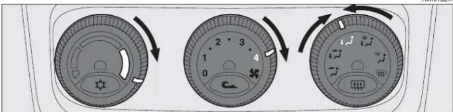
text_image
Diagram showing three circular car dashboard controls with directional arrows indicating rotation or adjustment.fig. 101
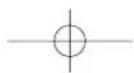
For more detailed information about the system and how to make the best use of it, read the instructions given in the following pages.
CONTROLS (fig. 102)
1 - Air temperature adjustment knob
2 - Fan speed adjustment knob
3 - Air distribution selector knob
4 - Climate control compressor on/off button (only versions with manual climate control system)
5 - Inside air re-circulation on /off button
6 - Rearscreen heating on/off button.


The coolant used for the climate control system is R134a which meets cur-
rent regulations and does not harm the environment in the event of accidental spillage.
Absolutely avoid the use of other fluids which are incompatible with the system components.

At any battery removal/reconnection wait for at least 3 minutes be-
fore starting the engine, to let the climate control unit reset the position of the electrical actuators controlling the temperature and the air distribution.
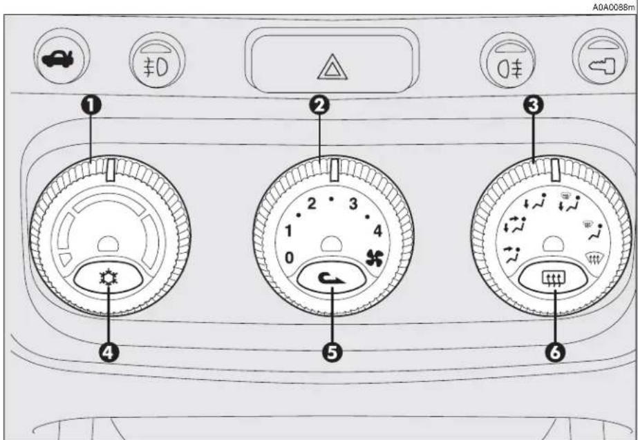
text_image
A0A0088m ① ② ③ ④ ⑤ ⑥fig. 102
AIR TEMPERATURE ADJUSTMENT KNOB
Turn the ring of knob (1-fig. 102) clockwise or counter-clockwise respectively to higher or lower the temperature of the air admitted to the passenger compartment.
FAN SPEED ADJUSTMENT KNOB
Turning th ring of knob (2-fig. 102) it is possible to select one of the fan speeds to personalise the amount of air admitted to the passenger compartment.
Position 0 turns off the fan and automatically engages inside air re-circulation (shown by the lighting up of the led next to the button 5) thereby shutting off the inlet of outside air to the car.
To switch off inside air re-circulation, press button (5) ▶.
If the fan is at 0 air recirculation will turn on automatically. When switching the engine off, at next restarting if the fan is at 0 yet, air recirculation will turn on again although previously turned off.

AIR DISTRIBUTION KNOB
Turning the knob ring (3-fig. 102), the following positions are selected in sequence:
Air flow towards the upper centre, front centre vents and from the front and rear outlets (if fitted) with the possibility of adjustment using the controls on the actual vents.
Splitting of air flow between the previous vents and the lower part of the passenger compartment.
Air flow to the lower part of the passenger compartment (front and rear). Splitting of air flow between the windscreen/front side windows and the lower part of the passenger compartment.
Air flow towards the windscreen and front side windows for demisting/defrosting.
Flow air to allow quick demisting/defrosting of the windscreen and front side windows, turning on rearscreen heating for defrosting/demisting (function called MAX-DEF)
CLIMATE CONTROL COMPRESSOR ON/OFF BUTTON (only versions with manual climate control system)
The climate control compressor is engaged pressing button (4-fig. 102) and the fan is also operated automatically at first speed even if the knob (2) is at position 0. When the system is operating the corresponding led next to the button turns on. The climate control compressor can only work with the engine running and external temperature not very low. If the climate control compressor is turned off, air re-circulation is engaged automatically, turning off the corresponding led, to prevent the windows from misting. Inside air re-circulation may also be engaged pressing the button (5). If the fan is at 0 the climate control system compressor will not turn on.

WARNING
Operation of the climate control compressor is necessary for cooling and dehumidifying the air; it is advisable to keep this function always on, to prevent window misting problems.
INSIDE AIR RE-CIRCULATION ON/OFF BUTTON
Pressing button (5-fig. 102) C activates inside air re-circulation and the led next to the button lights up.
In this case the climate control system directly treats the air contained in the passenger compartment, the fan is on.
To switch the air re-circulation feature off and withdraw air from outside, press the button again.

WARNING
The inside air re-circulation system makes it possible to reach the required "heating" or "cooling" conditions faster. It is however inadvisable to use it on rainy/cold days as it would considerably increase the possibility of the windows misting inside, especially if the climate control system is off.
IMPORTANT The condition and operating mode of the climate control compressor and inside air re-circulation, shown by the turning on of the leds next to the buttons (4) and (5), are also stored when the engine is off. Therefore, when the engine is started the selectionschosen before turning off are resumed.
REARSCREEN HEATING ON/OFF BUTTON
Pressing the button (6-fig. 102) turns on the demisting/defrosting of the rearscreen, and if present, the wing mirror heating coils; simultaneously the led next to the button turns on. This function is timed and switched off automatically after 20 minutes. To turn off earlier, press the button again.
IMPORTANT The system automatically turns on rearscreen heating if the temperature is below 3°C.
IMPORTANT Do not apply stickers on the inside of the rearscreen over the heating filaments to avoid damage which might cause it to stop working properly.

WARNING
With low external temperature the climate control compressor is unable to work. It is therefore inadvisable to use the inside air recirculation function with low outside temperature as windows may mist over quickly

WARNING
It is advisable to turn on the inside air re-circulation system in queues or tunnels to avoid admitting polluted air from outside. The prolonged use of this function should however be avoided, especially with several people on board, to avoid the possibility of the windows mistinginside.


When cleaning the inside of the rearscreen, take care not to damage the filaments.
AIR COOLING AND DEHUMIDIFYING (fig. 102/a)
To cool and dehumidify the air with the engine running and the windows shut, proceed as follows:
- temperature adjustment knob (1), pointer on blue sector.
- air quantity adjustment (2), knob pointer on the speed required to personalise the amount of air admitted
- air distribution (3), knob pointer at the required symbol.
- air vents completely open.
- compressor on enable button(4) pressed (for versions/markets where applicable) (led next to button on) (only for versions with manual climate control system).
Wishing to moderate the cooling action, increase the temperature turning the knob ring (1) towards the red sector, until obtaining the required temperature.

text_image
Diagram showing three circular gauges with numbered labels and directional arrows indicating rotation or adjustment.fig. 102/a
Proceed as follows to obtain the maximum cooling power:
- set the pointer of knob (1) as far as it will go counter-clockwise (minimum temperature blue sector);
- set the pointer of knob (2) to the maximum fan speed.
- press the inside air re-circulation on button (5)
-
set the pointer of the air distribution knob (3) to the required position (position is recommended).
-
air vents completely open.
- compressor on enable button (4) ✉ pressed (led next to button on) (only for versions with manual climate control system).
The use of the climate control system at minimum temperature should be restricted to short lengths of time and very hot climates, to avoid over-cooling the passenger compartment.
[Non-Text]

DEMISTING AND/OR DEFROSTING THE WINDSCREEN AND FRONT SIDE WINDOWS, REARSCREEN AND WING MIRRORS
( MAX-DEF function) (fig. 103)
Proceed as follows:
- turn the ring of the air distribution knob (3) to the symbol.
The climate control activates all the functions necessary to quicken demisting/defrosting of the windscreen and side windows with timing (switching off automatically after 3 minutes), as follows:
- it turns on the climate control compressor (only for versions with manual climate control system);
- switches off air re-circulation, if engaged;
- sets the maximum air temperature;
- operates the fan at a predefined speed;
- directs the flow of air towards the wind-screen and front side window vents;
- turns on rearscreen heating and, if present, the wing mirror coils.

text_image
Diagram showing six circular dial indicators with numbered labels and directional arrows indicating rotation or adjustment.fig. 103
When the max def function is on, the following are on: the led next to the rearscreen heating button (6) 📄, the led next to the climate control compressor on/off enable button (4) ✿ (only for versions with manual climate control system)
IMPORTANT If the engine is not hot enough, the function does not immediately engage the pre-established fan speed, to restrict the inlet of air to the passenger compartment that is not warm enough to demist the windows.
After demisting/defrosting, simply use the controls to maintain the optimum conditions of vision and comfort.
IMPORTANT The hotter the engine the more effective defrosting will be.
IMPORTANT In cases of heavy damp and/or rain and/or big differences in temperature between inside the car and outside, it is advisable to proceed as follows to demist the windows:
- air re-circulation off, led next to button (5) off;
- pointer of knob (2) at fan second speed at least;
- pointer of knob (3) on symbol √ with the possibility of passing to position ↗ if more misting is noted;
- climate control compressor button (4) pressed, led next to button on (only for versions with manual climate control system).
To defrost/demist the rearscreen, press button (6) [t], led next to button on.
HEATING (fig. 104)
To obtain the temperature required, proceed as follows:
- temperature adjustment knob pointer (1) on the red sector as required;
- air quantity adjustment knob pointer (2) on the fan speed required to personalise the amount of air admitted;
- air distribution knob pointer (3) on the required position.
To obtain the maximum heating power proceed as follows:
- knob pointer (1) as far as it will go clockwise (maximum temperature red sector);
- knob pointer (2) on maximum fan speed;
- air distribution knob pointer (3) on the required position (position √) is recommended.
To keep the air in the passenger compartment dehumidified, you are recommended to press the climate control compressor enable button (4) (for versions/markets where applicable) (only for versions with manual climate control system).
IMPORTANT To be able to obtain satisfactory passenger compartment warming, the engine should have reached normal operating temperature.
text_image
Diagram showing three circular device control panels with numbered labels and directional arrows indicating rotation or adjustment.fig. 104
A0A0222m
POLLEN FILTER
(for versions/markets where applicable)
The filter has the specific capability of filtering external air, thus admitting to the passenger compartment purified air, free from particles such as dust, pollen, etc.
In addition to the above mentioned functions, is also reduces the concentration of pollutants.
The filtering action is active in all air inlet conditions and it is clearly more effective with the windows closed.
Have the conditions of the filter checked at least once a year, preferably at the onset of summer by Alfa Romeo Authorised Services.
If the car is habitually used in dusty or polluted areas, the filter should be checked and replaced at shorter intervals than those specified in the Programmed Maintenance Schedule.

If the filter is not replaced the efficiency of the climate control system may
be seriously compromised up to blocking the air flow at the outlets and vents.
AUTOMATIC TWO-ZONE CLIMATE CONTROL SYSTEM (upon request for
versions/markets where applicable)
To start the system (fig. 105):
- turn the knob rings to set the required temperatures (driver's side - passenger's side).
- press the AUTO button.
IMPORTANT The climate control system makes it possible to personalise the temperatures required on the two side with a maximum difference of 7^ C between the driver's side and the passenger's side.
IMPORTANT The climate control compressor only works with the engine running and an outside temperature above 4°C.

WARNING
With low external temperature the climate control compressor is unable to work. It is therefore inadvisable to use the inside air recirculation function with low outside temperature as windows may mist over quickly
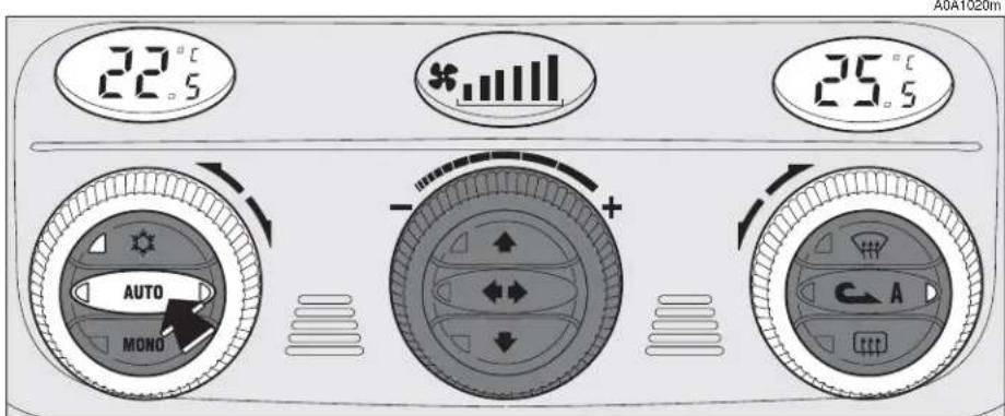
text_image
22.5 * 25.5 AUTO MONO C-Afig. 105
For more detailed information about the system and how to make the best use of it, read the instructions given in the following pages.

The coolant used for the climate control system is R134a which meets current regulations and does not harm the environment in the event of accidental spillage. Absolutely avoid the use of other fluids which are incompatible with the system components.

At any battery removal/reconnection wait for at least 3 minutes before starting the engine, to let the climate control unit reset the position of the electrical actuators controlling the temperature and the air distribution.
GENERAL
The car is fitted with a two-zone climate control system, controlled by an electronic control unit which makes it possible to separately adjust the air temperature on the driver's side and on the passenger's side. To obtain optimum temperature control in the two areas of the passenger's compartment, the system has an outside sensor, a passenger's compartment sensor and a two-zone sun ray sensor. On some versions the system is integrated with an incipient misting sensor installed behind the inside rear-view mirror, capable of "controlling" a predefined area of the windscreen inner surface which can automatically act on the system to prevent or reduce misting through a series of operations such as: opening air re-circulation, enabling the compressor, air flow to the windscreen, fan speed sufficient for demisting; in the case of heavy misting, enabling the MAX-DEF function.

To ensure correct operation of the incipient misting sensor, stickers must not be applied (road licence holder, time card, etc.) in the "control" area between the sensor and the windscreen. Care should also be given to cleaning the windscreen and the actual sensor, avoiding the accumulation of dust and other substances.

IMPORTANT The demisting procedure is enabled each time the ignition key is turned to MAR or pressing the AUTO button. When this procedure is working it can be turned off pressing one of the following buttons: compressor, air recirculation, air flow, air capacity. This operation inhibits the incipient misting sensor signal until the AUTO button is pressed again or the next time the ignition key is turned to MAR.
On certain versions, the system is integrated by an antipollution sensor capable of automatically switching on inside air re-circulation to lessen the harmful effects of polluted air in cities, queues, tunnels and operation of the windscreen washer (with the typical smell of spirit).
IMPORTANT The function of the anti-pollution sensor is subordinate to safety conditions; therefore disabling the climate control compressor or with low external temperature, the sensor is disabled. In any case, the sensor can be re-enabled pressing the recirculation button until taking it to the automatic mode.
Air quality control is also entrusted to a combined particle and activated carbon filter. The climate control system automatically controls and adjusts the following parameters and functions:
- inside temperature (separately on driver's side and passenger's side)
- fan speed
- air distribution
- inside air re-circulation on/off
- climate control compressor on/off enable.
It is possible to change the setting of the following functions manually:
- fan speed
- air distribution
- inside air re-circulation on/off
- climate control compressor on/off enable.
The control of functions not changed manually remains automatic and in any case the temperature of the air admitted to the passenger compartment is controlled automatically according to the temperatures set on the driver's and passenger's displays.
IMPORTANT Manual selections prevail over automatic ones and remain in storage until the user decides to resume automatic control. The settings selected manually are stored when the engine is switched off and resumed the next time it is started.

CONTROLS (fig. 106)
1 - Inside temperature set display (driver's side)
2 - Inside temperature adjustment knob (driver's side)
3 - Fan speed set and system off display (OFF)
4 - Knob for adjusting the fan speed and switching the system off
5 - Inside temperature set display (passenger's side)
6 - Inside temperature adjustment knob (passenger's side)
7 - Maximum defrosting/demisting on/off button for windscreen and front side windows, rearscreen heating and wing mirror coils (MAX-DEF function 117)
8 - Inside air re-circulation on/off button (manual/automatic)
9 - Rearscreen heating and wing mirror defrosting on/off button
10 - Air distribution selection buttons
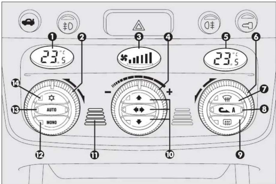
text_image
1 23.5 3 4 23.5 5 6 7 8 9 10 11 12 AUTO MONO -fig. 106
11 - Inside air temperature sensor
12 - Button for aligning the temperature set on the passenger's side with that on the driver's side MONO
13 - Button for selecting the system automatic mode AUTO
14 - Climate control compressor on/off enable button
HOW TO USE THE AUTOMATIC TWO-ZONE CLIMATE CONTROL SYSTEM (fig. 106)
IMPORTANT The knob rings do not have a mechanical stopper therefore, once the maximum or minimum value has been reached, they are free to turn in both directions.
The system can be started in different ways, but it is advisable to set the temperatures required on the displays; then press the (13) AUTO button.
This way the system will start working completely automatically to reach the temperatures set as quickly as possible and then maintain them.
During completely automatic system operation, the temperatures set can be changed at any time; the system will automatically change its settings to adjust to the new requirements.
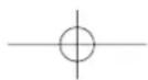
IMPORTANT To be able to be accepted by the system, the difference in the temperature between the driver's and passenger's side must be within a range of 7°C.
It is possible to personalise the choices made automatically by the system intervening manually on the following controls:
- fan speed adjustment knob (4)
- air distribution selection buttons (10)
- inside air re-circulation on/off button (8)

- climate control on enable button (14)
Manually selecting one or more of these functions turns off the right led on the button (13) AUTO.
With one or more functions engaged manually, the adjustment of the temperature of the air admitted to the passenger compartment continues to be controlled automatically by the system (left led on button 13 AUTO on) except with the climate control compressor off.
In fact, in this condition the air admitted to the passenger compartment cannot have a lower temperature than the outside air; this condition is indicated by the turning off of the two leds on button (13) AUTO and flashing on the display (1) and/or (5) related with the temperature rate that cannot be obtained.
AIR TEMPERATURE ADJUSTMENT KNOBS (fig. 107)
Turning the rings of knobs (2 or 6), clockwise or counter-clockwise, respectively highers or lowers the temperature of the air required respectively in the left zone (knob 2) or right zone (knob 6) of the passenger compartment. The temperatures set are shown on the displays (1) and (5) above the knobs.
Separate operation of the temperatures set is restored automatically using knob (6).
Turning the knob rings clockwise or counter-clockwise until they reach the extreme selections HI or LO, the maximum heating or cooling functions are respectively engaged:
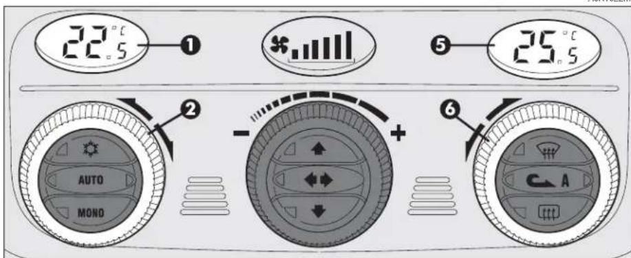
text_image
22.5°C ① * 25.5°C AUTO MOND + 6 Afig. 107
A0A1022m
HI function
(highest heating power - fig. 108)
This is turned on setting on the display a temperature above 32.5°C, and can be activated independently from the driver's or passenger's side or both; this setting brings the system to the "monozone" mode and is shown on both displays.
This function can be engaged when requiring to heat the passenger compartment as quickly as possible, exploiting the maximum potential of the system.
This function uses the maximum temperature of the coolant fluid, while air distribution and fan speed are controlled according to the system settings.
This function is unadvisable with the engine cold to prevent admitting air that is not warm enough to the passenger compartment.
All manual settings are possible with this function on.
To switch the system off, simply turn the ring of knob (2) or (6) of the temperature set to a value below 32.5°C; the opposite display will show 32.5°C.
A0A1023m
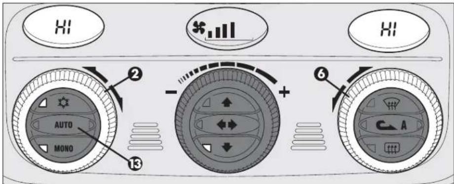
text_image
AUTO MONO ② ③ + 6 Afig. 108
Pressing key (13) AUTO the display will show a temperature of 32.5^ C and returns to an operating condition with automatic temperature adjustment.
LO function (highest cooling power - fig. 109)
This is turned on setting on the display a temperature below 16.5°C; this setting is shown on both displays.
This function can be engaged when requiring to cool the passenger compartment as quickly as possible, exploiting the maximum potential of the system.
The function cuts off air heating, engages inside air re-circulation (to prevent admitting hot air to the passenger compartment) and the climate control compressor, takes air distribution to and the fan speed as set by the system.
All manual settings are possible with this function on.
To switch the function off, simply turn the ring of knob (2) or (6) of the temperature set on a value above 16.5°C; the opposite display will show 16.5°C.
Pressing key (13) AUTO the display will show a temperature of 16.5^ C and returns to an operating condition with automatic temperature adjustment.

text_image
LO LO AUTO MONO + - ② ③ ⑥ Afig. 109
A0A1024m
MONO BUTTON FOR ALIGNMENT OF THE TEMPERATURE SET (fig. 110)
Pressing button (12) MONO automatically aligns the temperature on the passenger's side with that on the driver's side, therefore it is possible to set the same temperature between the two zones simply turning the ring of knob (2) on the driver's side.
This function is provided to simplify temperature adjustment of the whole passenger compartment when only the driver is on board.
Separate operation of the temperatures set is automatically restored when the passenger uses the ring on knob (6) or presses button (12) MONO.
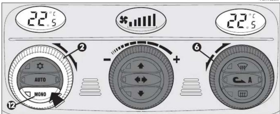
text_image
22.5 22.5 AUTO MONO + 6 C Afig. 110