Compass (2014) - Car JEEP - Free user manual and instructions
Find the device manual for free Compass (2014) JEEP in PDF.

User questions about Compass (2014) JEEP
0 question about this device. Answer the ones you know or ask your own.
Ask a new question about this device
Download the instructions for your Car in PDF format for free! Find your manual Compass (2014) - JEEP and take your electronic device back in hand. On this page are published all the documents necessary for the use of your device. Compass (2014) by JEEP.
USER MANUAL Compass (2014) JEEP
VEHICLESSOLDINCANADA
WithrespecttoanyVehiclesSoldinCanada,thenameFCA USLLCshallbedeemedtobedeletedandthenameFCA CanadaInc. usedinsubstitutiontherefore.
DRIVINGANDALCOHOL
Drunkendrivingisoneofthemostfrequentcausesof accidents.
Yourdrivingabilitycanbeseriouslyimpairedwithblood alcohollevelsfarbelowthelegalminimum.Ifyouare drinking,don'tdrive.Ridewithadesignatednon-drinkingdriver,callacab,afriend,orusepublictransportation.
WARNING!
Drivingafterdrinkingcanleadtoanaccident. Yourperceptionsarelesssharp,yourreflexesare slower,andyourjudgmentisimpairedwhenyou havebeendrinking.Neverdrinkandthendrive.
Thismanualillustratesanddescribestheoperationof featuresandequipmentthatareeitherstandardorop-tionalonthisvehicle. Thismanualmayalsoincludea descriptionoffeaturesandequipmentthatarenolonger availableorwerenotorderedonthisvehicle.Please disregardanyfeaturesandequipmentdescribedinthis manualthatarenotonthisvehicle.
FCAUSLLCreservestherighttomakechangesindesign andspecifications, and/ormakeadditionstoorimprovementstoitsproductswithoutimposinganyobligation uponitselftoinstallthemonproductspreviouslymanufactured.
Copyright©2016FCAUSLLC

SECTION PAGE
TABLE OF CONTENTS
1 INTRODUCTION....3
2 THINGSTOKNOWBEFORESTARTINGYOURVEHICLE. 9
3 UNDERSTANDINGTHEFEATURESOFYOURVEHICLE. 103
4 UNDERSTANDING YOUR INSTRUMENT PANEL. 213
5 STARTING AND OPERATING ....
6 WHAT TODOINEMERGENCIES....
7 MAINTAINING YOUR VEHICLE....
8 MAINTENANCESCHEDULES. 521
9 IFYOUNEEDCONSUMERASSISTANCE. 529
10 INDEX 5 10
INTRODUCTION
CONTENTS
■INTRODUCTION....4
■ROLLOVER WARNING....4
■HOW TO USE THIS MANUAL....5
■WARNINGS AND CAUTIONS....7
■VEHICLE IDENTIFICATION NUMBER ..... 7
■VEHICLE MODIFICATIONS/ALTERATIONS....8
4 INTRODUCTION
INTRODUCTION
Congratulations on selecting your new FCA US LLC vehicle. Be assured that it represents precision workmanship, distinctive styling, and high quality - all essentials that are traditional to our vehicles.
This Owner's Manual has been prepared with the assistance of service and engineering specialists to acquaint you with the operation and maintenance of your vehicle. It is supplemented by Warranty Information, and various customer-oriented documents. Please take the time to read these publications carefully. Following the instructions and recommendations in this manual will help assure safe and enjoyable operation of your vehicle.
NOTE: After reviewing the owner information, it should bestored in the vehicle for convenient referencing and remain with the vehicle when sold.
When it comes to service, remember that your authorized dealer knows your vehicle best, has factory-trained technicians and genuine parts, and cares about your satisfaction.
ROLLOVER WARNING
Utility vehicles have a significantly higher rollover rate than other types of vehicles. This vehicle has a higher ground clearance and a higher center of gravity than many passenger cars. It is capable of performing better in a wide variety of off-road applications. Driven in an unsafe manner, all vehicles can go out of control. Because of the higher center of gravity, if this vehicle is out of control it may roll over when some other vehicles may not.
Do not attempt sharp turns, abrupt maneuvers, or other unsafe driving actions that can cause loss of vehicle
control. Failure to operate this vehicle safely may result in a collision, rollover of the vehicle, and severe or fatal injury. Drive carefully.

text_image
WARNING: HIGHER ROLLOVER RISK Avoid Abrupt Maneuvers and Excessive Speed. Always Buckle Up. See Owner's Manual For Further Information80bfe0f0
RolloverWarningLabel
Failure to use the driver and passenger seat belts provided is a major cause of severe or fatal injury. In fact, the U.S. government notes that the universal use of existing
seat belts could cut the highway death toll by 10,000 or more each year and could reduce disabling injuries by two million annually. In a rollover crash, an unbelted person is significantly more likely to die than a person wearing a seat belt. Always buckle up.
HOW TO USE THIS MANUAL
Consult the Table of Contents to determine which section contains the information you desire.
Since the specification of your vehicle depends on the items of equipment ordered, certain descriptions and illustrations may differ from your vehicle's equipment.
The detailed index at the back of this Owner's Manual contains a complete listing of all subjects.
Consult the following table for a description of the symbols that may be used on your vehicle or throughout this Owner's Manual:

text_image
WATER IN FUEL REAR WINDOW WIPER WINDSHIELD WIPER INTERMITTENT EXTERIOR BULB FAILURE HIGH BEAR TURN SIGNALS UPPER AIR OUTLET HEATED SEAT LOW DOOR LOCK ADJUSTABLE PEDALS ELECTRONIC SPEED CONTROL ESP BAS ELECTROGIC STABILITY PROGRAM / BRAKE ASSIST SYSTEM FUEL REAR WINDOW INTERMITTENT WIPER WINDSHIELD WASHER MASTER LIGHTING SWITCH LOW BEAR KEY ACTIVATE (POWER OUTLET) UPPER AND LOWER AIR OUTLET HEATED SEAT HIGH WINDOW LIFT TIRE PRESSURE MONITOR HILL DESCENT CONTROL BRAKE SYSTEM WARNING PARKING BRAKE FUEL FILL SIDE REAR WINDOW WASHER WINDSHIELD WASHER FLUID LEVEL DOME LIGHT FRONT FOG LIGHT HOOD RELEASE LOWER AIR OUTLET RECIRCULATION CONVERTIBLE 4 WINDOW DOWN ELECTROIC STABILITY CONTROL AWD! ABS ENGINE OIL REAR WINDOW DEFROST WINDSHIELD D. ELECTRICALLY HEATED PARK LIGHTS REAR FOG LAMP LIFTGATE RELEASE AND LIFTGATE OPEN DEFROST AND LOWER AIR OUTLET VENTILATING FAN WINDOW LOCK ELECTROIC THROTTLE CONTROL 4WD! BRAKE SYSTEM WARNING PARKING BRAKE BATTERY CHARGING HEATED MIRROR WINDSHIELD DEFROST INSTRUMENT PANEL ILLUMINATION SEAT BELT SLIDING DOOR TRUNK / DECK RELEASE AIR CONDITIONING CHILDSEAT TETHER ANCHOR VOICE RECOGNITION BUTTON WARNING TOW/HAUL GLOW PLUG POWER STEERING PLUG WINDSHIELD WIPER AND WASHER SIDE AIRSAG AIRSAG SLIDING DOOR EMERGENCY RELEASE HANDLE LIGHTER LOWER ANCHORS AND TETHER FOR CHILDREN (LATCH) UCONNECT® BUTTON HAZAKD 4 LOW BALFUNCTION INDICATOR LIGHT TRANS OIL TEMP ENGINE COOLANT TEMPERATURE SRS AIRBAG SUPPLEMENTAL RESTRAINT SYSTEM PASSenger AIRBAG OFF DOOR AJAR CONVERTIBLE TOP DOWN CONVERTIBLE TOP UP HORN SEE OWNER'S MANUAL ID: 50 A/C PUSH ELECTRONIC STABILITY CONTROL OFF010533317
WARNINGS AND CAUTIONS
This Owners Manual contains WARNINGS against operating procedures that could result in a collision or bodily injury. It also contains CAUTIONS against procedures that could result in damage to your vehicle. If you do not read this entire Owners Manual, you may miss important information. Observe all Warnings and Cautions.
VEHICLE IDENTIFICATION NUMBER
The Vehicle Identification Number (VIN) is found on the left front corner of the instrument panel, visible through the windshield. This number also is stamped into the right front body, on the right front seat crossmember under the carpet and the vehicle registration and title.

natural_image
Close-up of a car's dashboard and side panel showing a black arrow pointing to a slot on the hood (no text or symbols visible)VehicleIdentificationNumber
8 INTRODUCTION
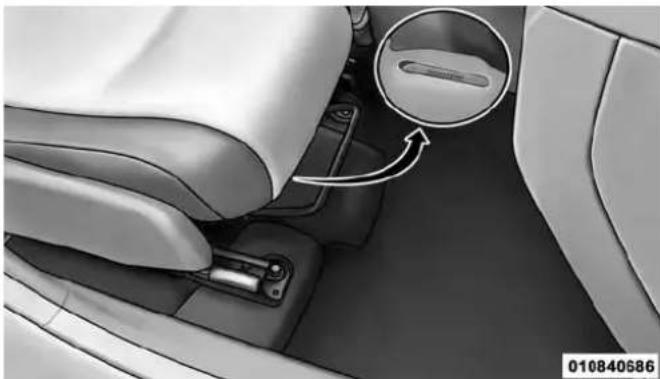
natural_image
Interior view of a car showing the dashboard and seatbelt mechanism with a circular inset highlighting a component (no text or symbols)RightFrontBodyVINLocation
NOTE: It is illegal to remove or alter the VIN.
VEHICLE MODIFICATIONS/ALTERATIONS
WARNING!
Anymodificationsoralterationstothisvehiclecould seriouslyaffectitsroadworthinessandsafetyand mayleadtoacollisionresultinginseriousinjuryor death.
THINGS TO KNOW BEFORE STARTING YOUR VEHICLE
CONTENTS
■A WORD ABOUT YOUR KEYS....12
□Ignition Key Removal....1 2
□Locking Doors With A Key. 14
□Key-In-Ignition Reminder....14
■SENTRY KEY®....15
□Replacement Keys....16
□Customer Key Programming....17
□General Information....18
■ VEHICLE SECURITY ALARM — IF EQUIPPED . . .18
□To Arm The System....18
□Rearming The System....19
□To Disarm The System....19
□ Vehicle Security Alarm Manual Override....19
■REMOTE KEYLESS ENTRY (RKE) — IF EQUIPPED....20
□To Unlock The Doors And Liftgate....20
□Remote Key Unlock, Driver Door/All First Press....20
□Illuminated Approach — If Equipped . . . . . . . 2 1
□ To Lock The Doors And Liftgate....22
10 THINGS TO KNOW BEFORE STARTING YOUR VEHICLE
□Sound Horn With Remote Key Lock....2 2
□Flash Lights With Remote Key Lock/Unlock . . .23
□Using The Panic Alarm....23
□Programming Additional Transmitters. . . . . . . 2 4
□Transmitter Battery Replacement....24
□General Information....25
■REMOTE STARTING SYSTEM — IF EQUIPPED....25
□How To Use Remote Start....26
■DOOR LOCKS....29
□Manual Door Locks....29
□Power Door Locks....30
□Child-Protection Door Lock System —
Rear Doors....3 3
■POWER WINDOWS — IF EQUIPPED ..... 3 5
□Power Window Switches....3 5
□Auto-Down 37
□Window Lockout Switch....37
■LIFTGATE....38
■OCCUPANT RESTRAINTS 39
□Lap/Shoulder Belts 43
□Adjustable Upper Shoulder Belt Anchorage . . .48
□Second Row Center Lap/Shoulder Belt Operating Instructions....49
□ Lap/Shoulder Belt Untwisting Procedure .....52
□ Seat Belts In Passenger Seating Positions .....52
□Automatic Locking Retractor Mode (ALR) — If Equipped....53
□Energy Management Feature....54
□Seat Belt Pretensioners....5 5
□Supplemental Active Head Restraints (AHR) . . .55
□Enhanced Seat Belt Use Reminder System (BeltAlert®) 59
□Seat Belt Extender....60
□Seat Belts And Pregnant Women . . . . . . . . . . 6 1
□Supplemental Restraint System (SRS) — Air Bags....6 1
□Advanced Front Air Bag Features ..... 6 3
□Air Bag Deployment Sensors And Controls . . . . 6 7
THINGS TO KNOW BEFORE STARTING YOUR VEHICLE 11
□Event Data Recorder (EDR) 74
□Child Restraints....75
■ENGINE BREAK-IN RECOMMENDATIONS....96
■SAFETY TIPS....97
□Transporting Passengers. 97
□Exhaust Gas 97
□Safety Checks You Should Make Inside The Vehicle....98
☐Periodic Safety Checks You Should Make Outside The Vehicle....100
12 THINGS TO KNOW BEFORE STARTING YOUR VEHICLE A WORD ABOUT YOUR KEYS
The authorized dealer that sold you your new vehicle has the key code numbers for your vehicle locks. These numbers can be used to order duplicate keys. Ask your authorized dealer for these numbers and keep them in a safe place.

natural_image
Top-down view of a black automotive key with visible buttons and control panel (no text or symbols)021410235
VehicleKey
Ignition Key Removal
- Place the shift lever in PARK (if equipped with an automatic transmission).
- Place the ignition in the ACC (Accessory) position.
- Push the key and cylinder inward and rotate the key to the LOCK position.
- Remove the key from the ignition switch lock cylinder.
text_image
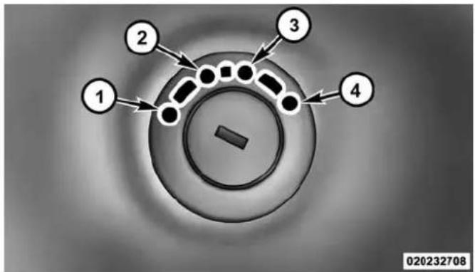
1 2 3 4 020232708IgnitionSwitchPositions
1—LOCK 3—ON/RUN
2 — ACC (ACCESSORY) 4 — START
THINGS TO KNOW BEFORE STARTING YOUR VEHICLE 13
NOTE: If you try to remove the key before you place the shift lever in PARK, the key may become trapped temporarily in the ignition switch cylinder. If this occurs, place the shift lever in PARK, rotate the key clockwise slightly, then remove the key as described above. If a malfunction occurs, the system will trap the key in the ignition cylinder to warn you that this safety feature is inoperable. The engine can be started and stopped but the key cannot be removed until you obtain service.
WARNING!
- Beforeexitingavehicle,alwaysapplytheparking brake,shiftthetransmissionintoPARKandremovetheKeyFobfromtheignition.Whenleaving thevehicle,alwayslockyourvehicle.
- Neverleavechildrenaloneinavehicle,orwith accesstoanunlockedvehicle.
(Continued)
14 THINGS TO KNOW BEFORE STARTING YOUR VEHICLE
WARNING!(Continued)
- Allowingchildrentobeinavehicleunattendedis dangerousforanumberofreasons.Achildor otherscouldbeseriouslyorfatallyinjured.Childrenshouldbewarnednottotouchtheparking brake,brakepedalortheshiftlever.
- DonotleavetheKeyFobinornearthevehicle, or inalocationaccessibletochildren. Achildcould operatepowerwindows, othercontrols, ormove thevehicle.
- Donotleavechildrenoranimalsinsideparked vehiclesinhotweather.Interiorheatbuild-upmay causeseriousinjuryordeath.
CAUTION!
Alwaysremovethekeyfromtheignitionandlockall doorswhenleavingthevehicleunattended.
Locking Doors With A Key
You can insert the key with either side up. To lock the door, turn the key to the right. To unlock the door, turn the key to the left. Refer to “Maintenance Procedures” in “Maintaining Your Vehicle” for further information.
Key-In-Ignition Reminder
Opening the driver's door when the key is in the ignition and the ignition position is LOCK or ACC, sounds a signal to remind you to remove the key.
NOTE: With the driver's door open and the key in the ignition, the power door locks will not lock and Remote Keyless Entry (RKE) transmitter will not function.
SENTRY KEY®
The Sentry Key® Immobilizer System prevents unauthorized vehicle operation by disabling the engine. The system does not need to be armed or activated. Operation is automatic, regardless of whether the vehicle is locked or unlocked.
The system uses ignition keys that have an embedded electronic chip (transponder) to prevent unauthorized vehicle operation. Therefore, only keys that are programmed to the vehicle can be used to start and operate the vehicle. The system will shut the engine off in two seconds if someone uses an invalid key to try to start the engine.
NOTE:A key that has not been programmed is also considered an invalid key, even if it is cut to fit the ignition switch lock cylinder for that vehicle.
THINGS TO KNOW BEFORE STARTING YOUR VEHICLE 15
During normal operation, after turning on the ignition switch, the Vehicle Security Light will turn on for three seconds for a bulb check. If the light remains on after the bulb check, it indicates that there is a problem with the electronics. In addition, if the Vehicle Security Light begins to flash after the bulb check, it indicates that someone used an invalid key to try to start the engine. Either of these conditions will result in the engine being shut off after two seconds.
If the Vehicle Security Light turns on during normal vehicle operation (vehicle running for longer than 10 seconds), it indicates that there is a fault in the electronics. Should this occur, have the vehicle serviced as soon as possible by an authorized dealer.
16 THINGS TO KNOW BEFORE STARTING YOUR VEHICLE
CAUTION!
The SentryKey® Immobilizersystemis not compatible with some aftermarket remotestartingsystems. Useofthesesystemsmayresultinvehiclestarting problemsandlossofsecurityprotection.
All of the keys provided with your new vehicle have been programmed to the vehicle electronics.
Replacement Keys
NOTE: Only keys that are programmed to the vehicle electronics can be used to start and operate the vehicle. Once a Sentry Key® is programmed to a vehicle, it cannot be programmed to any other vehicle.
CAUTION!
AlwaysremovetheSentryKeys®fromthevehicle andlockalldoorswhenleavingthevehicleunattended.
At the time of purchase, the original owner is provided with a four-digit Personal Identification Number (PIN). Keep the PIN in a secure location. This number is required for authorized dealer replacement of keys. Duplication of keys may be performed at an authorized dealer or by following the customer key programming procedure. This procedure consists of programming a blank key to the vehicle electronics. A blank key is one that has never been programmed.
NOTE: When having the Sentry Key® Immobilizer System serviced, bring all vehicle keys with you to an authorized dealer.
Customer Key Programming
If you have two valid Sentry Keys®, you can program new Sentry Keys® to the system by performing the following procedure:
- Cut the additional Sentry Key® Transponder blank(s) to match the ignition switch lock cylinder key code.
- Insert the first valid key into the ignition switch. Turn the ignition switch to the ON/RUN position for at least three seconds, but no longer than 15 seconds. Then, turn the ignition switch to the LOCK position and remove the first key.
- Insert the second valid key into the ignition switch. Turn the ignition switch to the ON/RUN position within 15 seconds. After 10 seconds, a chime will sound. In addition, the Vehicle Security Light will begin to flash. Turn the ignition switch to the LOCK position and remove the second key.
THINGS TO KNOW BEFORE STARTING YOUR VEHICLE
17
- Insert a blank Sentry Key® into the ignition switch. Turn the ignition switch to the ON/RUN position within 60 seconds. After 10 seconds, a single chime will sound. In addition, the Vehicle Security Light will stop flashing. To indicate that programming is complete, the Vehicle Security Light will turn on again for three seconds and then turn off.
The new Sentry Key® is programmed. The Remote KeylessEntry(RKE)transmitterwillalsobeprogrammedduringthisprocedure.
Repeat this procedure to program up to eight keys. If you do not have a programmed Sentry Key®, contact your authorized dealer for details.
18 THINGS TO KNOW BEFORE STARTING YOUR VEHICLE
NOTE: If a programmed key is lost, see your authorized dealer to have all remaining keys erased from the system's memory. This will prevent the lost key from starting your vehicle. The remaining keys must then be reprogrammed. All vehicle keys must be taken to an authorized dealer at the time of service to be reprogrammed.
General Information
The Sentry Key® system complies with FCC rules part 15 and with RSS-210 of Industry Canada. Operation is subject to the following conditions:
- This device may not cause harmful interference.
- This device must accept any interference that may be received, including interference that may cause undesired operation.
NOTE: Changes or modifications not expressly approved by the party responsible for compliance could void the user's authority to operate the equipment.
VEHICLE SECURITY ALARM — IF EQUIPPED
This Vehicle Security Alarm monitors the doors, liftgate, and ignition switch for unauthorized operation.
When the alarm is activated, the interior switches for door locks are disabled. The Vehicle Security Alarm provides both audio and visual signals, the horn will sound, the headlights, park lamps and/or turn signals will flash repeatedly for three minutes. If the disturbance is still present (driver's door, passenger door, other doors, ignition) after three minutes, the parking lights and tail lights will flash for an additional 15 minutes.
To Arm The System
- Remove the key from the ignition switch and get out of the vehicle.
-
Lock the door using either the power door LOCK switch or the Remote Keyless Entry (RKE) transmitter and close all doors.
-
The Vehicle Security Light in the instrument cluster will flash rapidly for approximately 16 seconds. This shows that the Vehicle Security Alarm is arming. During this period, if a door is opened, the ignition switch is turned to ON/RUN, or the power door locks are unlocked in any manner, the Vehicle Security Alarm will automatically disarm. After approximately 16 seconds, the Vehicle Security Light will flash slowly. This shows that the Vehicle Security Alarm is fully armed.
Rearming The System
If something triggers the alarm, and no action is taken to disarm it, the Vehicle Security Alarm will turn off the horn after three minutes, turn off all of the visual signals after 15 minutes, and then the Vehicle Security Alarm will rearm itself.
To Disarm The System
Press UNLOCK on the RKE transmitter, or insert the key into the ignition switch and turn the ignition switch to the ON/RUN position.
THINGS TO KNOW BEFORE STARTING YOUR VEHICLE 19
If something has triggered the Vehicle Security Alarm in your absence, the horn will sound three times and exterior lights blink three times when you unlock the doors. Check the vehicle for tampering. The Vehicle Security Alarm is designed to protect your vehicle; however, you can create conditions where the Vehicle Security Alarm will arm unexpectedly. If you remain in the vehicle and lock the doors with the RKE transmitter, once the Vehicle Security Alarm is armed (after 16 seconds), when you pull the door handle to exit, the alarm will sound. If this occurs, press the UNLOCK button on the RKE transmitter to disarm the Vehicle Security Alarm.
Vehicle Security Alarm Manual Override
The Vehicle Security Alarm will not arm if you lock the doors using the manual door lock plunger.
20 THINGS TO KNOW BEFORE STARTING YOUR VEHICLE REMOTE KEYLESS ENTRY (RKE) — IF EQUIPPED
This system allows you to lock or unlock the doors and liftgate or activate the Panic Alarm from distances up to approximately 66 ft (20 m) using a hand-held Remote Keyless Entry (RKE) transmitter. The RKE transmitter does not need to be pointed at the vehicle to activate the system.

natural_image
Top-down view of a black automotive key with visible buttons and control panel (no text or symbols)ThreeButtonRKETransmitter
021410235
NOTE: The line of transmission must not be blocked with metal objects.
To Unlock The Doors And Liftgate
Press and release the UNLOCK button on the RKE transmitter once to unlock the driver's door, or twice within five seconds to unlock all doors and liftgate. The turn signal lights will flash to acknowledge the unlock signal. The illuminated entry system will also turn on.
Remote Key Unlock, Driver Door/All First Press
This feature lets you program the system to unlock either the driver's door or all doors on the first press of the UNLOCK button on the RKE transmitter. To change the current setting, proceed as follows:
- For vehicles equipped with the Electronic Vehicle Information Center (EVIC), refer to "Electronic Vehicle Information Center (EVIC)/Personal Settings (Customer-Programmable Features)" in "Understanding Your Instrument Panel" for further information.
- For vehicles not equipped with the EVIC, perform the following steps:
- Press and hold the LOCK button on a programmed RKE transmitter for at least 4 seconds, but no longer than 10 seconds. Then, press and hold the UN-LOCK button while still holding the LOCK button.
- Release both buttons at the same time.
- Test the feature while outside of the vehicle by pressing the LOCK/UNLOCK buttons on the RKE transmitter with the ignition switch in the LOCK position and the key removed.
- Repeat these steps if you want to return this feature to its previous setting.
NOTE: Pressing the LOCK button on the RKE transmitter while you are inside the vehicle will activate the Vehicle Security Alarm. Opening a door with the Vehicle Security Alarm activated will cause the alarm to sound.
Press the UNLOCK button to deactivate the Vehicle Security Alarm.
Illuminated Approach — If Equipped
This feature activates the headlights for up to 90 seconds when the doors are unlocked with the RKE transmitter. The time for this feature is programmable on vehicles equipped with the EVIC. Refer to "Electronic Vehicle Information Center (EVIC)/Personal Settings (Customer-Programmable Features)" in "Understanding Your Instrument Panel" for further information.
NOTE: None of the courtesy lights will operate if the dimmer control is in the "defeat" position (extreme downward position), unless the overhead map/reading lights are turned on manually.
22 THINGS TO KNOW BEFORE STARTING YOUR VEHICLE
To Lock The Doors And Liftgate
Press and release the LOCK button on the RKE transmitter to lock all doors and liftgate. The turn signal lights will flash and the horn will chirp to acknowledge the signal.
Sound Horn With Remote Key Lock
This feature will cause the horn to chirp when the doors are locked with the RKE transmitter. This feature can be turned on or turned off. To change the current setting, proceed as follows:
- For vehicles equipped with the EVIC, refer to “Electronic Vehicle Information Center (EVIC)/Personal Settings (Customer-Programmable Features)” in “Understanding Your Instrument Panel” for further information.
- For vehicles not equipped with the EVIC, perform the following steps:
- Press the LOCK button on a programmed RKE transmitter for at least 4 seconds, but no longer than 10 seconds. Then, press the PANIC button while still holding the LOCK button.
- Release both buttons at the same time.
- Test the feature while outside of the vehicle by pressing the LOCK button on the RKE transmitter with the ignition switch in the LOCK position and the key removed.
- Repeat these steps if you want to return this feature to its previous setting.
NOTE: Pressing the LOCK button on the RKE transmitter while you are in the vehicle will activate the Vehicle Security Alarm. Opening a door with the Vehicle Security Alarm activated will cause the alarm to sound. Press the UNLOCK button to deactivate the Vehicle Security Alarm.
Flash Lights With Remote Key Lock/Unlock
This feature will cause the turn signal lights to flash when the doors are locked or unlocked with the RKE transmitter. This feature can be turned on or turned off. To change the current setting, proceed as follows:
- For vehicles equipped with the EVIC, refer to "Electronic Vehicle Information Center (EVIC)/Personal Settings (Customer-Programmable Features)" in "Understanding Your Instrument Panel" for further information.
-
For vehicles not equipped with the EVIC, perform the following steps:
-
Press and hold the UNLOCK button on a programmed RKE transmitter for at least 4 seconds, but no longer than 10 seconds. Then, press and hold the LOCK button while still holding the UNLOCK button.
-
Release both buttons at the same time.
THINGS TO KNOW BEFORE STARTING YOUR VEHICLE 23
- Test the feature while outside of the vehicle by pressing the LOCK/UNLOCK buttons on the RKE transmitter with the ignition switch in the LOCK position and the key removed.
- Repeat these steps if you want to return this feature to its previous setting.
NOTE: Pressing the LOCK button on the RKE transmitter while you are in the vehicle will activate the Vehicle Security Alarm. Opening a door with the Vehicle Security Alarm activated will cause the alarm to sound. Press the UNLOCK button to deactivate the Vehicle Security Alarm.
Using The Panic Alarm
To turn the Panic Alarm feature ON or OFF, press and hold the PANIC button on the RKE transmitter for at least one second and release. When the Panic Alarm is on, the headlights and park lights will flash, the horn will pulse on and off and the interior lights will turn on.
24 THINGS TO KNOW BEFORE STARTING YOUR VEHICLE
The Panic Alarm will stay on for three minutes unless you turn it off by pressing the PANIC button a second time or if the vehicle speed is 5 mph (8 km/h) or greater.
NOTE: When you turn off the Panic Alarm by pressing the PANIC button a second time, you may have to move closer to the vehicle due to the radio frequency noises of the system.
Programming Additional Transmitters
Refer to Sentry Key® "Customer Key Programming".
If you do not have a programmed RKE transmitter, contact your authorized dealer for details.
Transmitter Battery Replacement
NOTE: Perchlorate Material – special handling may apply. See www.dtsc.ca.gov/hazardouswaste/perchlorate
The recommended replacement battery is CR2032.
- If the RKE transmitter is equipped with a screw, remove the screw. With the RKE transmitter buttons facing down, use a flat blade screwdriver to pry the two halves of the RKE transmitter apart. Make sure not to damage the elastomer seal during removal.

natural_image
3D illustration of a pushpin with an arrow pointing to it (no text or symbols)021432709
SeparatingCaseHalves
- Remove and replace the battery. Avoid touching the new battery with your fingers. Skin oils may cause battery deterioration. If you touch a battery, clean it with rubbing alcohol.
- To reassemble the RKE transmitter case, snap the two halves together.
NOTE: If the RKE transmitter is equipped with a screw, reinstall and tighten the screw until snug.
General Information
This device complies with Part 15 of the FCC rules and RSS 210 of Industry Canada. Operation is subject to the following conditions:
- This device may not cause harmful interference.
- This device must accept any interference received, including interference that may cause undesired operation.
THINGS TO KNOW BEFORE STARTING YOUR VEHICLE 25
NOTE: Changes or modifications not expressly approved by the party responsible for compliance could void the user's authority to operate the equipment.
If your RKE transmitter fails to operate from a normal distance, check for these two conditions:
- A weak battery in the transmitter. The expected life of the battery is a minimum of three years.
- Closeness to a radio transmitter such as a radio station tower, airport transmitter, and some mobile or CB radios.
REMOTE STARTING SYSTEM — IF EQUIPPED

This system uses the Remote Keyless Entry (RKE) transmitter to start the engine conveniently from outside the vehicle while still maintaining security. The system has a range of
approximately 300 ft (91 m). Obstructions between the vehicle and RKE transmitter may reduce this range.
26 THINGS TO KNOW BEFORE STARTING YOUR VEHICLE
NOTE:
- The vehicle must be equipped with an automatic transmission to be equipped with Remote Start.
- Obstructions between the vehicle and the Key Fob may reduce this range.
How To Use Remote Start
All of the following conditions must be met before the engine will remote start:
- Shift lever in PARK
- Doors closed
- Hood closed
•Hazard switch off - Brake switch inactive (brake pedal not pressed)
-
Ignition key removed from ignition switch
-
Battery at an acceptable charge level
•RKE PANIC button not pressed - System not disabled from previous remote start event
• Vehicle theft alarm not active
WARNING!
- Donotstartorrunanengineinaclosedgarageor confinedarea.ExhaustgascontainsCarbonMonoxide(CO)whichisodorlessandcolorless.Carbon Monoxideispoisonousandcancauseseriousinjuryordeathwheninhaled.
- KeepRemoteKeylessEntry(RKE)transmitters awayfromchildren.OperationoftheRemoteStart System,windows,doorlocksorothercontrols couldcauseseriousinjuryordeath.
RemoteStartAbortMessageOnElectronicVehicle InformationCenter(EVIC)—IfEquipped
The following messages will display in the EVIC if the vehicle fails to remote start or exits remote start prematurely:
- Remote Start Aborted — Door Ajar
- Remote Start Aborted — Hood Ajar
- Remote Start Aborted — L/Gate Ajar
- Remote Start Aborted — Fuel Low
- Remote Start Aborted — System Fault
The EVIC message stays active until the ignition is turned to the ON/RUN position.
THINGS TO KNOW BEFORE STARTING YOUR VEHICLE 27
ToEnterRemoteStart

Press and release the REMOTE START button on the RKE transmitter twice within five seconds. The vehicle doors will lock, the parking lights will flash and the horn will chirp twice (if programmed). Then, the engine will start and the vehicle will remain in the Remote Start mode for a 15-minute cycle.
NOTE:
- The park lamps will turn on and remain on during Remote Start mode.
- For security, power window and power sunroof operation (if equipped) are disabled when the vehicle is in the Remote Start mode.
- If your power door locks were unlocked, Remote Start will automatically lock the doors.
28 THINGS TO KNOW BEFORE STARTING YOUR VEHICLE
- The engine can be started two consecutive times (two 15-minute cycles) with the RKE transmitter. However, the ignition switch must be cycled to the ON/RUN position before you can repeat the start sequence for a third cycle.
Remote start will also cancel if any of the following occur:
• The engine stalls or RPM exceeds 2500
- Any engine warning lamps come on
- Low Fuel Light turns on
•The hood is opened
• The hazard switch is pressed
• The transmission is moved out of PARK
• The brake pedal is pressed
ToExitRemoteStartModeWithoutDrivingThe Vehicle
Press and release the REMOTE START button one time or allow the engine to run for the entire 15-minute cycle.
NOTE: To avoid unintentional shut downs, the system will disable the one time press of the REMOTE START button for two seconds after receiving a valid Remote Start request.
ToExitRemoteStartModeAndDriveTheVehicle
Before the end of the 15-minute cycle, press and release the UNLOCK button on the RKE transmitter to unlock the doors and disarm the Vehicle Security Alarm (if equipped). Then, insert the key into the ignition switch and turn the switch to the ON/RUN position.
NOTE: The ignition switch must be in the ON/RUN position in order to drive the vehicle.
DOOR LOCKS
Manual Door Locks
Use the manual door lock knob to lock the doors from inside the vehicle. If the lock knob is down when the door is closed, the door will lock. Make sure the keys are not inside the vehicle before closing the door.

natural_image
Close-up of a car's side panel showing a screwdriver inserted into the dashboard, with no visible text or symbols.ManualDoorLockKnob
THINGS TO KNOW BEFORE STARTING YOUR VEHICLE 29
WARNING!
- Forpersonalsecurityandsafetyintheeventofan collision,lockthevehicledoorsasyoudriveas wellaswhenyouparkandleavethevehicle.
- Neverleavechildrenaloneinavehicle,orwith accesstoan unlocked vehicle. Allowingchildrento beinavehicleunattendedisdangerousfora numberofreasons.Achildorotherscouldbe seriouslyorfatallyinjured.Childrenshouldbe warnednottotouchtheparkingbrake,brakepedal ortheshiftlever.
- DonotleavetheKeyFobinornearthevehicle, or inalocationaccessibletochildren, achildcould operatepowerwindows, othercontrols, ormove thevehicle.
30 THINGS TO KNOW BEFORE STARTING YOUR VEHICLE
CAUTION!
An unlocked vehicle is an invitation to thieves. Always remove the key from the ignition and lock all of the doors when leaving the vehicle unattended.
Power Door Locks
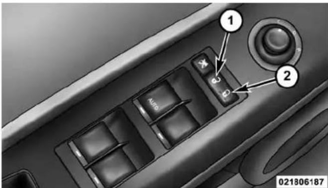
A power door lock switch is located on the driver's and front passenger's door panel. Press this switch to lock or unlock the doors and liftgate.
NOTE: To prevent from locking the key in the vehicle, the power door lock switch will not operate when the key is in the ignition and either front door is open. A chime will sound as a reminder to remove the key.
text_image
1 2 Auto 021806187DriverPowerDoorLockSwitch
1 — Unlock
2 — Lock
AutoLockDoors—IfEquipped
The auto door lock feature default condition is enabled. When enabled, the door locks will lock automatically when the vehicle's speed exceeds 15 mph (24 km/h).
AutoLockDoorsProgramming
The Automatic Door Locks feature can be enabled or disabled as follows:
- For vehicles equipped with the Electronic Vehicle Information Center (EVIC), refer to “Electronic Vehicle Information Center (EVIC) — If Equipped/Personal Settings (Customer Programmable Features)” in “Understanding Your Instrument Panel” for further information.
- For vehicles not equipped with the EVIC, perform the following procedure:
- Close all doors and place the key in the ignition switch.
THINGS TO KNOW BEFORE STARTING YOUR VEHICLE 31
- Within 15 seconds, cycle the ignition switch between LOCK and ON/RUN and then back to LOCK four times ending up in the LOCK position (do not start the engine).
- Within 30 seconds, press the power door LOCK switch to lock the doors.
- A single chime will indicate the completion of the programming.
- Repeat these steps if you want to return this feature to its previous setting.
NOTE:
- If you do not hear the chime it means that the system did not enter the programming mode and you will need to repeat the procedure.
- Use the Automatic Door Lock feature in accordance with local laws.
32 THINGS TO KNOW BEFORE STARTING YOUR VEHICLE
AutomaticUnlockDoorsOnExit
The doors will unlock automatically if:
- The Automatic Unlock Doors On Exit feature is enabled.
- The transmission was in gear and the vehicle speed returned to 0 mph (0 km/h).
- The transmission is in NEUTRAL or PARK.
- The driver's door is opened.
- The doors were not previously unlocked.
AutomaticUnlockDoorsOnExitProgramming
The Automatic Unlock Doors On Exit feature can be enabled or disabled as follows:
- For vehicles equipped with the EVIC, refer to “Electronic Vehicle Information Center (EVIC) — If Equipped/Personal Settings (Customer-Programmable Features)” in “Understanding Your Instrument Panel” for further information.
-
For vehicles not equipped with the EVIC, perform the following procedure:
-
Close all doors and place the key in the ignition.
-
Within 15 seconds, cycle the ignition switch between LOCK and ON/RUN and then back to LOCK five times ending up in the ON/RUN position (do not start the engine).
-
Within 30 seconds, press the power door UNLOCK switch to unlock the doors.
- A single chime will indicate the completion of the programming.
- Repeat these steps if you want to return this feature to its previous setting.
NOTE:
- If you do not hear the chime it means that the system did not enter the programming mode and you will need to repeat the procedure.
- Use the Automatic Unlock Doors On Exit feature in accordance with local laws.
THINGS TO KNOW BEFORE STARTING YOUR VEHICLE 33
Child-Protection Door Lock System — Rear Doors
To provide a safer environment for small children riding in the rear seats, the rear doors are equipped with Child-Protection Door Lock system.
ToEngageOrDisengageTheChild-Protection DoorLockSystem
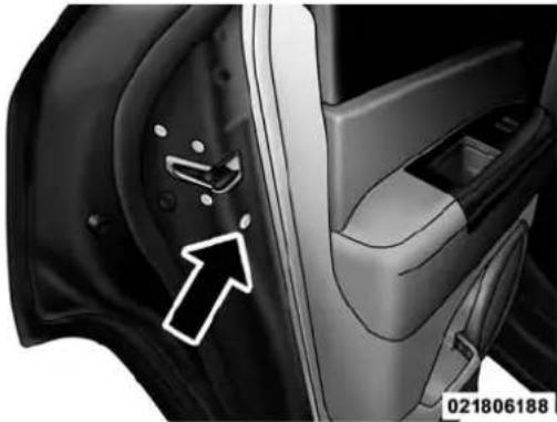
- Open the rear door.
- Insert the tip of the ignition key into the lock and rotate to the LOCK or UNLOCK position.
34 THINGS TO KNOW BEFORE STARTING YOUR VEHICLE
- Repeat steps 1 and 2 for the opposite rear door.
natural_image
Close-up of a car interior showing a white arrow pointing to a component, with no visible text or symbols.Child-Protection Door Lock Location
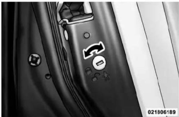
text_image
021806189Child-Protection Door Lock Function
WARNING!
Avoidtrappinganyoneinavehicleinacollision. Rememberthatthereardoorscanonlybeopened fromtheoutsidewhentheChild-Protectionlocksare engaged.
NOTE: For emergency exit with the system engaged, move the lock knob up (unlocked position), roll down the window and open the door with the outside door handle.
POWER WINDOWS — IF EQUIPPED
Power Window Switches
The window controls on the driver's door trim panel control all the door windows. There are single window controls on each passenger door trim panel, which operate the passenger door windows. The window controls will operate when the ignition switch is in the ON/RUN or ACC position.
THINGS TO KNOW BEFORE STARTING YOUR VEHICLE
NOTE:
- For vehicles not equipped with the Electronic Vehicle Information Center (EVIC), the power window switches will remain active for 45 seconds after the ignition switch is turned to the LOCK position. Opening either front door will cancel this feature.
- For vehicles equipped with the EVIC, the power window switches will remain active for up to 10 minutes after the ignition switch is turned to the LOCK position. Opening either front door will cancel this feature. The time for this feature is programmable. Refer to “Electronic Vehicle Information Center (EVIC)/Personal Settings (Customer-Programmable Features)” in “Understanding Your Instrument Panel” for further information.
36 THINGS TO KNOW BEFORE STARTING YOUR VEHICLE
WARNING!
Neverleavechildrenunattendedinavehicle, anddo notletchildrenplaywithpowerwindows. Donot leavetheKeyFobinornearthevehicle, orina locationaccessibletochildren. Occupants, particularlyunattendedchildren, canbecomeentrapped by thewindowswhileoperatingthepowerwindow switches. Suchentrapmentmayresultinserious injuryordeath.

text_image
Auto 021906196PowerWindowSwitchLocation
THINGS TO KNOW BEFORE STARTING YOUR VEHICLE 37
Auto-Down
The driver's door window switch has an Auto-Down feature. Push the window switch past the first detent, release, and the window will go down automatically. To cancel the Auto-Down movement, operate the switch in either the up or down direction and release the switch.
Window Lockout Switch
The window lockout switch on the driver's door allows you to disable the window control on the other doors. To disable the window controls on the other doors, press the window LOCKOUT switch. To enable the window controls, press the window LOCKOUT switch a second time.
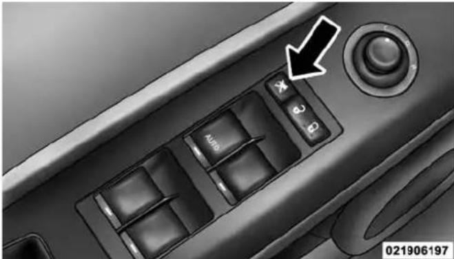
text_image
Auto 021906197WindowLockoutSwitch
38 THINGS TO KNOW BEFORE STARTING YOUR VEHICLE
LIFTGATE
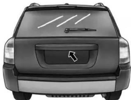
NOTE: The key that is used to start the vehicle is also used to lock or unlock the doors and open the liftgate.
To unlock the liftgate, insert the key into the lock and turn it to the right (manual lock models only). The liftgate can also be unlocked using the Remote Keyless Entry (RKE) transmitter or by activating the power door lock switches located on the front doors. The central locking/unlocking feature (if equipped) can also be activated from the liftgate key cylinder.
Once unlocked, the liftgate can be opened or closed without using the key. To open the liftgate, squeeze the liftgate release and pull the liftgate open with one fluid motion.
natural_image
Rear view of a black SUV with a white arrow pointing to the front grille (no text or symbols visible)022206146
LiftgateLatchLocation
NOTE:
- In the event of a power malfunction, or the RKE transmitter is inoperative, insert the key into the liftgate lock cylinder and turn to the right (manual lock models only). Using the liftgate handle, pull the lift-gate open with one fluid motion.
THINGS TO KNOW BEFORE STARTING YOUR VEHICLE 39
- Although the liftgate has no inside release mechanism, the liftgate trim panel includes an opening with a snap-in cap that provides access to release the latch in the event of an electrical system malfunction.
WARNING!
- Drivingwiththeliftgateopencanallowpoisonous exhaustgasesintoyourvehicle.Youandyour passengerscouldbeinjuredbythesefumes.Keep theliftgateclosedwhenyouareoperatingthe vehicle.
- If you are required to drive with the lift gate open, makes sure that all windows are closed, and the climate control blowers switch it at high speed. Donot usethere circulation mode.
Gas props support the liftgate in the open position. However, because the gas pressure drops with temperature, it may be necessary to assist the props when opening the liftgate in cold weather.
OCCUPANT RESTRAINTS
Some of the most important safety features in your vehicle are the restraint systems:
- Three-point lap and shoulder belts for all seating positions
- Advanced Front Air Bags for driver and front passenger
- Supplemental Active Head Restraints (AHR) located on top of the front seats (integrated into the head restraint)
40 THINGS TO KNOW BEFORE STARTING YOUR VEHICLE
- Supplemental Side Air Bag Inflatable Curtains (SABIC) for the driver and passengers seated next to a window
- Supplemental Seat-Mounted Side Air Bags (SAB) — if equipped
- An energy-absorbing steering column and steering wheel
- Knee bolsters/blockers for front seat occupants
- Front seat belts incorporate pretensioners that may enhance occupant protection by managing occupant energy during an impact event
- All seat belt systems (except the driver's) include Automatic Locking Retractors (ALRs), which lock the seat belt webbing into position by extending the belt all the way out and then adjusting the belt to the desired length to restrain a child seat or secure a large item in a seat — if equipped
Please pay close attention to the information in this section. It tells you how to use your restraint system properly, to keep you and your passengers as safe as possible.
If you will be carrying children too small for adult-sized seat belts, the seat belts or the Lower Anchors and Tether for CHildren (LATCH) feature also can be used to hold infant and child restraint systems. For more information on LATCH, see Lower Anchors and Tether for CHildren (LATCH).
NOTE: The Advanced Front Air Bags have a multistage inflator design. This allows the air bag to have different rates of inflation based on several factors, including the severity and type of collision.
Here are some simple steps you can take to minimize the risk of harm from a deploying air bag:
- Children12yearsoldandundershouldalwaysride buckledupinarearseat.
WARNING!
- Neverplacearearfacinginfantseatinfrontofan airbag.AdeployingPassengerAdvancedFrontAir Bagcancausedeathorseriousinjurytoachild12 yearsoryounger,includingachildinarearward facinginfantseat.
- Onlyusearearward-facingchildrestraintina vehiclewitharearseat.
Children that are not big enough to wear the vehicle seat belt properly (see section on Child Restraints) should be secured in the rear seat in child restraints or belt-positioning booster seats. Older children who do not use child restraints or belt-positioning booster seats should
THINGS TO KNOW BEFORE STARTING YOUR VEHICLE 41
ride properly buckled up in the rear seat. Never allow children to slide the shoulder belt behind them or under their arm.
If a child from 2 to 12 years old (not in a rear facing child seat) must ride in the front passenger seat, move the seat as far back as possible and use the proper child restraint. (Refer to "Child Restraints")
You should read the instructions provided with your child restraint to make sure that you are using it properly.
- Alloccupantsshouldalwaysweartheirlapand shoulderbeltsproperly.
- Thedriverandfrontpassengerseatsshouldbe movedbackasfaraspracticaltoallowtheAdvanced FrontAirBagsroomtoinflate.
42 THINGS TO KNOW BEFORE STARTING YOUR VEHICLE
-
Donotleanagainstthedoororwindow.If your vehiclehassideairbags,anddeploymentoccurs,the sideairbagswillinflateforcefullyintothespace betweenyouandthedoor.
-
If the air bagsystem in this vehicle need to be modified to accommodate a disabled person, contact the Customer Center. Phonenumbers are provided under "If You Need Assistance".
WARNING!
- Relyingontheairbagsalonecouldleadtomore severeinjuriesinacollision.Theairbagswork withyourseatbelttorestrainyouproperly.In somecollisions,theairbagswon'tdeployatall. Alwayswearyourseatbeltseventhoughyouhave airbags.
(Continued)
WARNING!(Continued)
- Beingtooclosetothesteeringwheelorinstrument panelduringAdvancedFrontAirBagdeployment couldcauseseriousinjury,includingdeath.Air bagsneedroomtoinflate.Sitback,comfortably extendingyourarmstoreachthesteeringwheelor instrumentpanel.
- SupplementalSideAirBagInflatableCurtain (SABIC)andSeat-MountedSideAirBags(SAB)also needroomtoinflate.Donotleanagainstthedooror window.Situprightinthecenteroftheseat.
- Inacollision, you and your passengers can suffer much greater injuries if you are not properly buckled up. You can strike the interior of your vehicle or other passengers, or you can be thrown out of the vehicle. Always besure you and others in your vehicle are buckled up properly.
(Continued)
WARNING!(Continued)
- BeingtooclosetotheSupplementalSideAirBag InflatableCurtain(SABIC)and/orSeat-Mounted SideAirBag(SAB)duringdeploymentcouldcause youtobeseverelyinjuredorkilled.
Buckle up even though you are an excellent driver, even on short trips. Someone on the road may be a poor driver and cause a collision that includes you. This can happen far away from home or on your own street.
Research has shown that seat belts save lives, and they can reduce the seriousness of injuries in a collision. Some of the worst injuries happen when people are thrown from the vehicle. Seat belts reduce the possibility of ejection and the risk of injury caused by striking the inside of the vehicle. Everyone in a motor vehicle should be belted at all times.
THINGS TO KNOW BEFORE STARTING YOUR VEHICLE 43
Lap/Shoulder Belts
All seating positions in your vehicle are equipped with lap/shoulder belts.
The belt webbing retractor is designed to lock during very sudden stops or collisions. This feature allows the shoulder part of the belt to move freely with you under normal conditions. However, in a collision the belt will lock and reduce the risk of you striking the inside of the vehicle or being thrown out.
WARNING!
- Itisdangeroustorideinacargoarea,insideor outsideofavehicle.Inacollision,peopleridingin theseareasaremorelikelytobeseriouslyinjured orkilled.
(Continued)
44 THINGS TO KNOW BEFORE STARTING YOUR VEHICLE
WARNING!(Continued)
- Donotallowpeopletorideinanyareaofyour vehiclethatisnotequippedwithseatsandseat belts.
- Besureeveryoneinyourvehicleisinaseatand usingaseatbeltproperly.
- Wearingaseatbeltincorrectlyisdangerous.Seat beltsaredesignedtogoaroundthelargebonesof yourbody.Thesearethestrongestpartsofyour bodyandcantaketheforcesofacollisionthebest.
- Wearingyourbeltinthewrongplacecouldmake yourinjuriesinacollisionmuchworse.Youmight sufferinternalinjuries,oryoucouldevenslideout ofpartofthebelt.Followtheseinstructionstowear yourseatbeltsafelyandtokeepyourpassengers safe,too.
WARNING!(Continued)
- Twopeopleshouldneverbebeltedintoasingle seatbelt.Peoplebeltedtogethercancrashintoone anotherinacollision,hurtingoneanotherbadly. Neverusealap/shoulderbeltorlapbeltformore thanoneperson,nomatterwhattheirsize.
Lap/ShoulderBeltOperatingInstructions
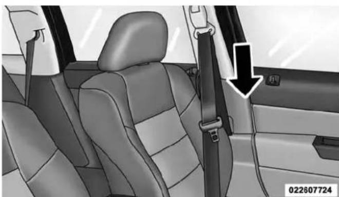
- Enter the vehicle and close the door. Sit back and adjust the seat.
- The seat belt latch plate is along side the pillar near the back of your seat. Grasp the latch plate and pull out the belt. Slide the latch plate up the webbing as far as necessary to allow the belt to go around your lap.
(Continued)
natural_image
Interior view of a car showing seatbelt and door panel, with a black arrow pointing to the side door (no text or symbols on the main subject)PullingOutTheLatchPlate
THINGS TO KNOW BEFORE STARTING YOUR VEHICLE 45
- When the belt is long enough to fit, insert the latch plate into the buckle until you hear a "click".
natural_image
Interior view of a car showing seatbelt and rearview side arm, with no visible text or symbolsInsertingLatchPlateIntoBuckle
46 THINGS TO KNOW BEFORE STARTING YOUR VEHICLE
WARNING!
- Abeltbuckledintothewrongbucklewillnot protectyouproperly. Thelapportioncouldridetoo highonyourbody,possiblycausinginternalinjuries. Alwaysbuckleyourbeltintothebuckle nearestyou.
- Abelthtatistooloosewillnotprotectyouproperly.Inasuddenstopyoucouldmovetoofar forward,increasingthepossibilityofinjury.Wear yourseatbeltsnugly.
(Continued)
WARNING!(Continued)
- Abeltthatiswornunderyourarmisdangerous. Yourbodycouldstriketheinsidesurfacesofthe vehicleinacollision,increasingheadandneck injury.Abeltwornunderthearmcancauseinternalinjuries.Ribsaren'tasstrongasshoulder bones.Wearthebeltoveryourshouldersothat yourstrongestboneswilltaketheforceinacollision.
-
Ashoulderbeltplacedbehindyouwillnotprotect youfrominjuryduringacollision.Youaremore likelytohityourheadinacollisionifyoudonot wearyourshoulderbelt.Thelapandshoulderbelt aremeanttobeusedtogether.
-
Position the lap belt across your thighs, below your abdomen. To remove slack in the lap belt portion, pull up on the shoulder belt. To loosen the lap belt if it is too tight, tilt the latch plate and pull on the lap belt. A snug belt reduces the risk of sliding under the belt in a collision.

natural_image
Interior view of a car showing seatbelt and seatbelt buckle assembly (no text or symbols)PositioningLapBelt
THINGS TO KNOW BEFORE STARTING YOUR VEHICLE 47
WARNING!
- Alapbeltworntoohighcanincreasetheriskof internalinjuryinacollision.Thebeltforceswon't beatthestronghipandpelvicbones,butacross yourabdomen.Alwayswearthelapbeltaslowas possibleandkeepitsnug.
- Atwistedbeltmaynotprotectyouproperly.Ina collision,itcouldevencutintoyou.Besurethebelt isstraight.Ifyoucan'tstraightenabeltinyour vehicle,takeittoyourauthorizeddealerimmediatelyandhaveitfixed.
-
Position the shoulder belt on your chest so that it is comfortable and not resting on your neck. The retractor will withdraw any slack in the belt.
-
To release the belt, push the red button on the buckle. The belt will automatically retract to its stowed position. If necessary, slide the latch plate down the webbing to allow the belt to retract fully.
48 THINGS TO KNOW BEFORE STARTING YOUR VEHICLE
WARNING!
Afrayedortornbeltcouldripapartinacollisionand leaveyouwithnoprotection.Inspectthebeltsystem periodically,checkingforcuts,frays,orlooseparts. Damagedpartsmustbereplacedimmediately.Donot disassembleormodifythesystem.Seatbeltassembliesmustbereplacedafteracollisioniftheyhave beendamaged(bentretractor,tornwebbing,etc.).
Adjustable Upper Shoulder Belt Anchorage
In the front seat, the shoulder belt can be adjusted upward or downward to position the belt away from your neck. Push the anchorage button to release the anchorage, and move it up or down to the position that fits you best.
NOTE: The adjustable upper shoulder belt anchorage is equipped with an Easy Up feature. This feature allows the shoulder belt anchorage to be adjusted in the upward position without pressing the release button. To verify the shoulder belt anchorage is latched, pull downward on the shoulder belt anchorage until it is locked into position.

natural_image
Interior view of a car seatbelt with a double-headed arrow indicating left side (no text or symbols)AdjustableAnchorage
As a guide, if you are shorter than average you will prefer a lower position, and if you are taller than average you will prefer a higher position. When you release the anchorage, try to move it down to make sure that it is locked in position.
In the rear seat, move toward the center of the seat to position the belt away from your neck.
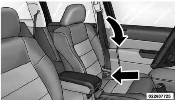
Second Row Center Lap/Shoulder Belt Operating Instructions
The second row center lap/shoulder belt features a three-point seat belt with a mini-latch and buckle, which allows the shoulder belt to detach from the lower anchor when the seat is folded. The mini-buckle and shoulder belt can then be stored out of the way in the right side trim panel for added convenience.
THINGS TO KNOW BEFORE STARTING YOUR VEHICLE 49
- Remove the mini-latch and regular latch from its stowed position in the right rear side trim panel.

natural_image
Mechanical component diagram showing a belt buckle with bidirectional arrow indicating movement (no text or symbols)Mini-LatchStowage
- Grasp the mini-latch plate and pull the belt over the seat.
50 THINGS TO KNOW BEFORE STARTING YOUR VEHICLE
- Route the shoulder belt to the inside of the right head restraint.
natural_image
Interior view of a car showing rear seats and dashboard (no visible text or symbols)RoutingTheRearCenterShoulderBelt
-
When the belt is long enough to fit, insert the mini-latch plate into the mini-buckle until you hear a "click".
-
Sit back in the seat. Slide the regular latch plate up the webbing as far as necessary to allow the belt to go around your lap.
- When the belt is long enough to fit, insert the latch plate into the buckle until you hear a "click".

natural_image
Close-up of a car seatbelt buckle assembly (no text or symbols visible)ConnectingMini-LatchToBuckle
- Position the lap belt across your thighs, below your abdomen. To remove slack in the lap belt portion, pull up on the shoulder belt. To loosen the lap belt if it is too tight, pull on the lap belt. A snug belt reduces the risk of sliding under the belt in a collision.

natural_image
Close-up of a mechanical joint or fracture surface with two black arrows pointing to specific features (no text or symbols present)RearCenterSeatBeltBuckled
THINGS TO KNOW BEFORE STARTING YOUR VEHICLE 51
- Position the shoulder belt on your chest so that it is comfortable and not resting on your neck. The retractor will withdraw any slack in the belt.
- To release the belt, push the red button on the buckle.

natural_image
Medical illustration showing a hand using a tool to adjust a car seatbelt, with an arrow pointing to the belt (no text or symbols present)DetachingMini-LatchAndBuckle
52 THINGS TO KNOW BEFORE STARTING YOUR VEHICLE
- To disengage the mini-latch from the mini-buckle for storage, insert the regular latch plate into the black button on the top of the mini-buckle. The belt will automatically retract to its stowed position. If necessary, slide the latch plate down the webbing to allow the belt to retract fully. Insert the mini-latch plate into the slot provided in the trim panel.
Lap/Shoulder Belt Untwisting Procedure
Use the following procedure to untwist a twisted lap/shoulder belt.
- Position the latch plate as close as possible to the anchor point.
- At about 6 to 12 in (15 to 30 cm) above the latch plate, grasp and twist the belt webbing 180 degrees to create a fold that begins immediately above the latch plate.
-
Slide the latch plate upward over the folded webbing. The folded webbing must enter the slot at the top of the latch plate.
-
Continue to slide the latch plate up until it clears the folded webbing.
Seat Belts In Passenger Seating Positions
The seat belts in the passenger seating positions are equipped with Automatic Locking Retractors (ALR) which are used to secure a child restraint system. For additional information, refer to Child Restraints under "Things To Know Before Starting Your Vehicle" for further information. The chart below defines the type of feature for each seating position.
| DriverCenter | Passenger | ||
| First Row | N/A | N/A | ALR |
| Second Row | ALR | ALR | ALR |
•N/A — Not Applicable
- ALR — Automatic Locking Retractor
If the passenger seating position is equipped with an ALR and is being used for normal usage:
Only pull the belt webbing out far enough to comfortably wrap around the occupant's mid-section so as to not activate the ALR. If the ALR is activated, you will hear a ratcheting sound as the belt retracts. Allow the webbing to retract completely in this case and then carefully pull out only the amount of webbing necessary to comfortably wrap around the occupant's mid-section. Slide the latch plate into the buckle until you hear a "click".
Automatic Locking Retractor Mode (ALR) — If Equipped
In this mode, the shoulder belt is automatically pre-locked. The belt will still retract to remove any slack in the shoulder belt. The Automatic Locking Mode is available on all passenger-seating positions with a combination lap/shoulder belt. Use the Automatic Locking Mode
THINGS TO KNOW BEFORE STARTING YOUR VEHICLE 53
anytime a child safety seat is installed in a seating position that has a belt with this feature. Children 12 years old and under should always be properly restrained in a vehicle with a rear seat.
HowToEngageTheAutomaticLockingMode
- Buckle the combination lap and shoulder belt.
- Grasp the shoulder portion and pull downward until the entire belt is extracted.
- Allow the belt to retract. As the belt retracts, you will hear a clicking sound. This indicates the safety belt is now in the Automatic Locking Mode.
54 THINGS TO KNOW BEFORE STARTING YOUR VEHICLE
HowToDisengageTheAutomaticLockingMode
Unbuckle the combination lap/shoulder belt and allow it to retract completely to disengage the Automatic Locking Mode and activate the vehicle sensitive (emergency) locking mode.
WARNING!
- Thebeltandretractorassemblymustbereplacedif theseatbeltassemblyAutomaticLockingRetractor (ALR)featureoranyotherseatbeltfunctionisnot workingproperlywhencheckedaccordingtothe proceduresintheServiceManual.
- Failuretoreplacethebeltandretractorassembly couldincreaseetheriskofinjuryincollisions.
Energy Management Feature
This vehicle has a safety belt system with an Energy Management feature in the front seating positions to help further reduce the risk of injury in the event of a head-on collision.
This safety belt system has a retractor assembly that is designed to release webbing in a controlled manner. This feature is designed to help reduce the belt force acting on the occupant's chest.
Seat Belt Pretensioners
The seat belts for both front seating positions are equipped with pretensioning devices that are designed to remove slack from the seat belt in the event of a collision. These devices may improve the performance of the seat belt by assuring that the belt is tight about the occupant early in a collision. Pretensioners work for all size occupants, including those in child restraints.
NOTE: These devices are not a substitute for proper seat belt placement by the occupant. The seat belt still must be worn snugly and positioned properly.
The pretensioners are triggered by the Occupant Restraint Controller (ORC). Like the air bags, the pretensioners are single use items. A deployed pretensioner or a deployed air bag must be replaced immediately.
THINGS TO KNOW BEFORE STARTING YOUR VEHICLE
Supplemental Active Head Restraints (AHR)
These head restraints are passive, deployable components, and vehicles with this equipment cannot be readily identified by any markings, only through visual inspection of the head restraint. The head restraint will be split in two halves, with the front half being soft foam and trim, the back half being decorative plastic.
HowTheActiveHeadRestraints(AHR)Work
The Occupant Restraint Controller (ORC) determines whether the severity, or type of rear impact will require the Active Head Restraints (AHR) to deploy. If a rear impact requires deployment, both the driver and front passenger seat AHRs will be deployed.
When AHRs deploy during a rear impact, the front half of the head restraint extends forward to minimize the gap between the back of the occupant's head and the AHR.
56 THINGS TO KNOW BEFORE STARTING YOUR VEHICLE
This system is designed to help prevent or reduce the extent of injuries to the driver and front passenger in certain types of rear impacts.
NOTE: The Active Head Restraints (AHR) may or may not deploy in the event of a front or side impact. However if during a front impact, a secondary rear impact occurs, the AHR may deploy based on the severity and type of the impact.
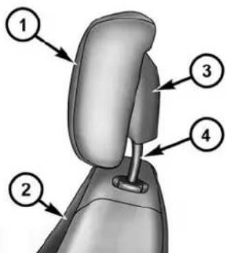
text_image
Diagram of a car seat with numbered parts labeled 1 to 4022607508
ActiveHeadRestraint(AHR)Components
1 — Head Restraint Front Half (Soft Foam and Trim)
2 — Seatback
3 — Head Restraint Back Half (Decorative Plastic Rear Cover)
4 — Head Restraint Guide Tubes
CAUTION!
Allooccupants, including the driver, should not operate vehicle or sitin a vehicle's seat until the head restraints are placed in their proper positions in order to minimize risk of neck injury in the event of a collision.
NOTE: For more information on properly adjusting and positioning the head restraint, refer to "Adjusting Active Head Restraints" in "Understanding The Features Of Your Vehicle".
ResettingActiveHeadRestraints(AHR)
If the Active Head Restraints are triggered in a collision, you must reset the head restraint on the driver's and front passenger's seat before driving. You can recognize when the Active Head Restraint has been triggered by the fact that they have moved forward (as shown in step three of the resetting procedure).
THINGS TO KNOW BEFORE STARTING YOUR VEHICLE 57
- Grasp the deployed AHR from the rear seat.

natural_image
3D illustration of a person sitting in a car seat with hands on head, no text or symbols presentHandPositioningPointsOnAHR
- Position the hands on the top of the deployed AHR at a comfortable position.
58 THINGS TO KNOW BEFORE STARTING YOUR VEHICLE
- Pull down then rearward towards the rear of the vehicle then down to engage the locking mechanism.

text_image
1 2022607497

natural_image
3D rendering of a car seatbelt with a black arrow pointing to the seat (no text or symbols)ReviewTableBelow
022607757
1 — Downward Movement
2 — Rearward Movement
3 — Final Downward Movement To Engage Locking Mechanism

natural_image
3D rendered image of a car seatbelt with a handle attachment (no text or symbols visible)AHRInResetPosition
022607494
- The AHR front soft foam and trim half should lock into the back decorative plastic half.
NOTE:
- If you have difficulties or problems resetting the Active Head Restraints, see an authorized dealer.
- For safety reasons, have the Active Head Restraints checked by a qualified specialist at an authorized dealer.
THINGS TO KNOW BEFORE STARTING YOUR VEHICLE
59
Enhanced Seat Belt Use Reminder System (BeltAlert®)
BeltAlert® is a feature intended to remind the driver and front passenger (if equipped with front passenger BeltAlert®) to fasten their seat belts. The feature is active whenever the ignition is on. If the driver or front seat passenger is unbelted, the Seat Belt Reminder Light will turn on and remain on until both front seat belts are fastened.
The BeltAlert® warning sequence begins after the vehicle speed is over 5 mph (8 km/h), by blinking the Seat Belt Reminder Light and sounding an intermittent chime. Once the sequence starts, it will continue for the entire duration or until the respective seatbelts are fastened. After the sequence completes, the Seat Belt Reminder Light remains illuminated until the respective seat belts are fastened. The driver should instruct all other occupants to fasten their seat belts. If a front seat belt is unbuckled while traveling at speeds greater than 5 mph (8 km/h), BeltAlert® will provide both audio and visual notification.
60 THINGS TO KNOW BEFORE STARTING YOUR VEHICLE
The front passenger seat BeltAlert® is not active when the front passenger seat is unoccupied. BeltAlert® may be triggered when an animal or heavy object is on the front passenger seat or when the seat is folded flat (if equipped). It is recommended that pets be restrained in the rear seat (if equipped) in pet harnesses or pet carriers that are secured by seat belts, and cargo is properly stowed.
BeltAlert® can be enabled or disabled by your authorized dealer. FCA US LLC does not recommend deactivating BeltAlert®.
NOTE: Although BeltAlert® has been deactivated, the Seat Belt Reminder Light will continue to illuminate while the driver's or front passenger (if equipped with BeltAlert®) seat belt remains unfastened.
Seat Belt Extender
If a seat belt is too short even when fully extended and when the adjustable upper shoulder belt anchorage (if equipped) is in its lowest position, your authorized dealer can provide you with a seat belt extender. This extender should be used only if the existing belt is not long enough. When it is not required, remove the extender and store it.
WARNING!
Usingaseatbeltextenderwhennotneededcan increasetheriskofinjuryinacollision.Onlyuse whentheseatbeltisnotlongenoughwhenitisworn lowandsnugandintherecommendedseatingpositions.Removeandstoretheextenderwhennot needed.
THINGS TO KNOW BEFORE STARTING YOUR VEHICLE 61
Seat Belts And Pregnant Women
We recommend that pregnant women use the seat belts throughout their pregnancy. Keeping the mother safe is the best way to keep the baby safe.
Pregnant women should wear the lap part of the belt across the thighs and as snug across the hips as possible. Keep the belt low so that it does not come across the abdomen. That way the strong bones of the hips will take the force if there is a collision.
Supplemental Restraint System (SRS) — Air Bags
This vehicle has Advanced Front Air Bags for both the driver and front passenger as a supplement to the seat belt restraint systems. The driver's Advanced Front Air Bag is mounted in the center of the steering wheel. The passenger's Advanced Front Air Bag is mounted in the instrument panel, above the glove compartment. The words SRS AIRBAG are embossed on the air bag covers.
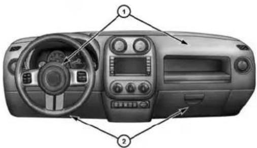
text_image
Top-down view of a car dashboard with labeled parts including steering wheel, dashboard, and air conditioners.027636273
AdvancedFrontAirBagAndKneeBolsterLocations
1 — Driver And Passenger Advanced Front Air Bags 2 — Knee Bolster
NOTE: The Driver and Passenger Advanced Front Air Bags are certified to new Federal regulations.
62 THINGS TO KNOW BEFORE STARTING YOUR VEHICLE
The Advanced Front Air Bags have a multistage inflator design. This allows the air bag to have different rates of inflation that are based on the severity and type of collision.
This vehicle may be equipped with a driver and/or front passenger seat belt buckle switch that detects whether the driver or front passenger seat belt is fastened. The seat belt buckle switch may adjust the inflation rate of the Advanced Front Air Bags.
This vehicle is equipped with Supplemental Side Air Bag Inflatable Curtains (SABIC) to protect the driver, front, and rear passengers sitting next to a window. The SABIC are located above the side windows. The trim covering the side air bags is labeled SRS AIRBAG.
This vehicle may be equipped with Supplemental Seat-Mounted Side Air Bags (SAB) to provide enhanced protection for an occupant during a side impact. The Supplemental Seat-Mounted Side Air Bags are located in the outboard side of the front seats.
NOTE:
- Air Bag covers may not be obvious in the interior trim, but they will open during air bag deployment.
- After any collision, the vehicle should be taken to an authorized dealer immediately.
AirBagSystemComponents
Your vehicle may be equipped with the following air bag system components:
•Occupant Restraint Controller (ORC)
• Air Bag Warning Light
•Steering Wheel and Column
- Instrument Panel
- Knee Impact Bolsters
- Driver Advanced Front Air Bag
- Passenger Advanced Front Air Bag
• Supplemental Seat-Mounted Side Air Bags (SAB)
• Supplemental Side Air Bag Inflatable Curtains (SABIC)
• Front and Side Impact Sensors - Front Seat Belt Pretensioners, Seat Belt Buckle Switch, and Seat Track Position Sensors
Advanced Front Air Bag Features
The Advanced Front Air Bag system has multistage driver and front passenger air bags. This system provides output appropriate to the severity and type of collision as determined by the Occupant Restraint Controller (ORC), which may receive information from the front impact sensors.
The first stage inflator is triggered immediately during an impact that requires air bag deployment. This low output
THINGS TO KNOW BEFORE STARTING YOUR VEHICLE
is used in less severe collisions. A higher energy output is used for more severe collisions.
WARNING!
- Noobjectsshouldbeplacedoverorneartheair bagontheinstrumentpanel, becauseanysuch objectscouldcauseharmifthevehicleisina collisionsevereenoughtocausetheairbagto inflate.
- Donotputanythingonoraroundtheairbag coversorattempttoopenthemmanually.Youmay damagetheairbagsandyoucouldbeinjured because the airbags may no longer be functional. The protective covers for the airbag cushions are designed to open only when the airbags are inflating.
(Continued)
64 THINGS TO KNOW BEFORE STARTING YOUR VEHICLE
WARNING!(Continued)
- Donotdrill, cutortamperwiththekneebolsterin anyway.
- Donotmountanyaccessoriestothekneebolster suchasalarmlights, stereos, citizenbandradios, etc.
SupplementalSeat-MountedSideAirBags(SAB) —IfEquipped
Supplemental Seat-Mounted Side Air Bags (SAB) may provide enhanced protection to help protect an occupant during a side impact. The SAB is marked with an air bag label sewn into the outboard side of the front seats.

text_image
SRS AIR BAG 022610242SupplementalSeat-MountedSideAirBagLabel
When the air bag deploys, it opens the seam between the front and side of the seat's trim cover. Each air bag deploys independently; a left side impact deploys the left air bag only and a right-side impact deploys the right air bag only.
THINGS TO KNOW BEFORE STARTING YOUR VEHICLE 65
SupplementalSideAirBagInflatableCurtain (SABIC)
SABIC air bags may offer side-impact and vehicle roll-over protection to front and rear seat outboard occupants in addition to that provided by the body structure. Each air bag features inflated chambers placed adjacent to the head of each outboard occupant that reduce the potential for side-impact head injuries. The SABIC air bags deploy downward, covering both windows on the impact side.
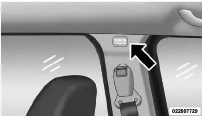
text_image
Diagram of a car seatbelt with a directional arrow and a logo, showing vehicle interior and seatbelt placement.SideCurtainAirBagLabelLocation
NOTE:
- Should a vehicle rollover occur, the pretensioners and/or SAB and SABIC curtains on both sides of the vehicle may deploy.
- Air Bag covers may not be obvious in the interior trim, but they will open during air bag deployment.
- Being too close to the Supplemental Side Air Bag Inflatable Curtain and/or Seat-Mounted Side Air Bag during deployment could cause you to be severely injured or killed.
The system includes side impact sensors that are calibrated to deploy the side air bags during impacts that require air bag occupant protection.
WARNING!
- Yourvehicleisequippedwithleftandright SABIC,donotstackluggageorothercargouphigh enoughtoblockthelocationoftheSABIC.The areawherethesidecurtainairbagislocated shouldremainfreefromanyobstructions.
WARNING!(Continued)
- Donotuseaccessoryseatcoversorplaceobjects betweenyouandtheSAB;theperformancecould beadverselyaffectedand/orobjectscouldbe pushedintoyou,causingseriousinjury.
- YourvehicleisequippedwithSABICairbags,do nothaveanyaccessoryitemsinstalledwhichwill altertheroof,includingaddingasunrooftoyour vehicle.Donotaddroofracksthatrequirepermanentattachments(boltsorscrews)forinstallation on the vehicle roof. Do not drill into the roof of the vehicleforanyreason.
SAB and SABIC air bags are a supplement to the seat belt restraint system. Occupants, including children who are up against or very close to SAB or SABIC air bags can be seriously injured or killed. Occupants, especially children, should not lean on or sleep against the door, side
(Continued)
windows, or area where the SAB or SABIC air bags inflate, even if they are in an infant or child restraint.
Always sit upright as possible with your back against the seat back, use the seat belts properly, and use the appropriate sized child restraint, infant restraint or booster seat recommended for the size and weight of the child.
KneeImpactBolsters
The Knee Impact Bolsters help protect the knees of the driver and front passengers, and position front occupants for the best interaction with the Advanced Front Air Bags.
Along with seat belts and pretensioners, Advanced Front Air Bags work with the knee impact bolsters to provide improved protection for the driver and front passenger.
THINGS TO KNOW BEFORE STARTING YOUR VEHICLE
Air Bag Deployment Sensors And Controls
OccupantRestraintController(ORC)
The ORC is part of a Federally regulated safety system required for this vehicle.
The ORC determines if deployment of the front and/or side air bags in a frontal or side collision is required. Based on the impact sensor's signals, a central electronic ORC deploys the Advanced Front Air Bags, SABIC air bags, Supplemental Seat-Mounted Side Air Bags, and front seat belt pretensioners, as required, depending on several factors, including the severity and type of impact.
Advanced Front Air Bags are designed to provide additional protection by supplementing the seat belts in certain frontal collisions depending on several factors, including the severity and type of collision. Advanced Front Air Bags are not expected to reduce the risk of injury in rear, side, or rollover collisions.
68 THINGS TO KNOW BEFORE STARTING YOUR VEHICLE
The Advanced Front Air Bags will not deploy in all frontal collisions, including some that may produce substantial vehicle damage — for example, some pole collisions, truck underrides, and angle offset collisions. On the other hand, depending on the type and location of impact, Advanced Front Air Bags may deploy in crashes with little vehicle front-end damage but that produce a severe initial deceleration.
The side air bags will not deploy in all side collisions. Side air bag deployment will depend on the severity and type of collision.
Because air bag sensors measure vehicle deceleration over time, vehicle speed and damage by themselves are not good indicators of whether or not an air bag should have deployed.
Seat belts are necessary for your protection in all collisions, and also are needed to help keep you in position, away from an inflating air bag.
The ORC monitors the readiness of the electronic parts of the air bag system whenever the ignition switch is in the START or ON/RUN position. If the key is in the OFF position, in the ACC position, or not in the ignition, the air bag system is not on and the air bags will not inflate.
The ORC contains a backup power supply system that may deploy the air bags even if the battery loses power or it becomes disconnected prior to deployment.

Also, the ORC turns on the Air Bag Warning Light in the instrument panel for approximately four to eight seconds for a self-check when the ignition is first turned on. After the self-check, the Air Bag Warning Light will turn off. If the ORC detects a malfunction in any part of the system, it turns on the Air Bag Warning Light, either momentarily or continuously. A single chime will sound if the light comes on again after initial startup.
It also includes diagnostics that will illuminate the instrument cluster Air Bag Warning Light if a malfunction is noted that could affect the air bag system. The diagnostics also record the nature of the malfunction.
WARNING!
IgnoringtheAirBagWarningLightinyourinstrumentpanelcouldmeanyouwon'thavetheairbags toprotectyouinacollision.Ifthelightdoesnotcome onasabulbcheckwhentheignitionisfirstturned on,staysonafteryoustartthevehicle,orifitcomes onasyoudrive,haveanauthorizeddealerservicethe airbagsystemimmediately.
DriverAndPassengerAdvancedFrontAirBag InflatorUnits
The Driver and Passenger Advanced Front Air Bag Inflator Units are located in the center of the steering wheel and on the right side of the instrument panel.
THINGS TO KNOW BEFORE STARTING YOUR VEHICLE
When the ORC detects a collision requiring the Advanced Front Air Bags, it signals the inflator units. A large quantity of non-toxic gas is generated to inflate the Advanced Front Air Bags. Different air bag inflation rates are possible, based on several factors, including the collision type and severity. The steering wheel hub trim cover and the upper right side of the instrument panel separate and fold out of the way as the air bags inflate to their full size. The air bags fully inflate in about 50 to 70 milliseconds. This is about half of the time it takes to blink your eyes. The air bags then quickly deflate while helping to restrain the driver and front passenger.
The Advanced Front Air Bag gas is vented through the vent holes in the sides of the air bag. In this way, the air bags do not interfere with your control of the vehicle.
70 THINGS TO KNOW BEFORE STARTING YOUR VEHICLE
SupplementalSeat-MountedSideAirBag(SAB) InflatorUnits
The Supplemental Seat-Mounted Side Air Bags (SAB) are designed to activate only in certain side collisions.
The ORC determines if a side collision requires the side air bags to inflate, based on the severity and type of collision.
Based on the severity and type of collision, the side air bag inflator on the crash side of the vehicle may be triggered, releasing a quantity of non-toxic gas. The inflating SAB exits through the seat seam into the space between the occupant and the door. The SAB fully inflate in about 10 milliseconds. The side air bag moves at a very high speed and with such a high force that it could injure you if you are not seated properly, or if items are positioned in the area where the side air bag inflates. This especially applies to children.
SupplementalSideAirBagInflatableCurtain (SABIC)InflatorUnits
During collisions where the impact is confined to a particular area of the side of the vehicle, the ORC may deploy the SABIC air bags, depending on the severity and type of collision. In these events, the ORC will deploy the SABIC only on the impact side of the vehicle.
A quantity of non-toxic gas is generated to inflate the side curtain air bag. The inflating side curtain air bag pushes the outside edge of the headliner out of the way and covers the window. The air bag inflates in about 30 milliseconds (about one-quarter of the time that it takes to blink your eyes) with enough force to injure you if you are not belted and seated properly, or if items are positioned in the area where the side curtain air bag inflates. This especially applies to children. The side curtain air bag is only about 3-1/2 in (9 cm) thick when it is inflated.
Because air bag sensors estimate deceleration over time, vehicle speed and damage are not good indicators of whether or not an air bag should have deployed.
NOTE: In a rollover the pretensioners and/or SAB and SABIC air bags may deploy on both sides of the vehicle.
FrontAndSideImpactSensors
In front and side impacts, impact sensors can aid the ORC in determining appropriate response to impact events.
EnhancedAccidentResponseSystem
In the event of an impact causing air bag deployment, if the communication network remains intact, and the power remains intact, depending on the nature of the event the ORC will determine whether to have the Enhanced Accident Response System perform the following functions:
- Cut off fuel to the engine.
THINGS TO KNOW BEFORE STARTING YOUR VEHICLE 71
- Flash hazard lights as long as the battery has power or until the ignition key is turned off.
- Turn on the interior lights, which remain on as long as the battery has power or until the ignition key is removed.
- Unlock the doors automatically.
In order to reset the Enhanced Accident Response System functions after an event, the ignition switch must be changed from IGN ON/RUN to IGN OFF.
IfADeploymentOccurs
The Advanced Front Air Bags are designed to deflate immediately after deployment.
NOTE: Front and/or side air bags will not deploy in all collisions. This does not mean something is wrong with the air bag system.
72 THINGS TO KNOW BEFORE STARTING YOUR VEHICLE
If you do have a collision, which deploys the air bags, any or all of the following may occur:
- The nylon air bag material may sometimes cause abrasions and/or skin reddening to the driver and front passenger as the air bags deploy and unfold. The abrasions are similar to friction rope burns or those you might get sliding along a carpet or gymnasium floor. They are not caused by contact with chemicals. They are not permanent and normally heal quickly. However, if you haven't healed significantly within a few days, or if you have any blistering, see your doctor immediately.
- As the air bags deflate, you may see some smoke-like particles. The particles are a normal by-product of the process that generates the non-toxic gas used for air bag inflation. These airborne particles may irritate the skin, eyes, nose, or throat. If you have skin or eye irritation, rinse the area with cool water. For nose or
throat irritation, move to fresh air. If the irritation continues, see your doctor. If these particles settle on your clothing, follow the garment manufacturer's instructions for cleaning.
Do not drive your vehicle after the air bags have deployed. If you are involved in another collision, the air bags will not be in place to protect you.
WARNING!
Deployedairbagsandseatbeltpretensionerscannot protectyouinanothercollision.Havetheairbags, seatbeltpretensioners,andthefrontseatbeltretractorassembliesreplacedbyanauthorizeddealerimmediately.Also,havetheOccupantRestraintControllerSystemservicedaswell.
MaintainingYourAirBagSystem
WARNING!
- Modificationstoanypartoftheairbagsystem couldcauseittofailwhenyouneedit.Youcould beinjurediftheairbagsystemisnotthereto protectyou.Donotmodifythecomponentsor wiring,includingaddinganykindofbadgesor stickerstothesteeringwheelhubtrimcoverorthe upperrightsideoftheinstrumentpanel.Donot modifythefrontbumper,vehiclebodystructure,or addaftermarketsidestepsorrunningboards.
- Itisdangeroustotrytorepairanypartoftheair bagsystemyourself.Besuretotellanyonewho worksonyourvehiclethatithasanairbagsystem.
THINGS TO KNOW BEFORE STARTING YOUR VEHICLE 73
WARNING!(Continued)
- Donotattempttomodifyanypartofyourairbag system. The airbag may inflate accidentally or may not function properly if modifications are made. Take your vehicle to an authorized dealer for any air bags systems service. If your seat, including your trim cover and cushion, need to be serviced in any way (including removal or loosening / tightening of seat attachment bolts), tak the vehicle to your authorized dealer. Only manufacturer approved seat accessories maybe used. If it is necessary to modify the airbag system for persons with disabilities, contact your authorized dealer.
(Continued)
74 THINGS TO KNOW BEFORE STARTING YOUR VEHICLE
AirBagWarningLight

You will want to have the air bags ready to inflate for your protection in a collision. The Air Bag Warning Light monitors the internal circuits and interconnecting wiring associated with air bag system electrical components. While the air bag system is designed to be maintenance free, if any of the following occurs, have an authorized dealer service the air bag system immediately.
- The Air Bag Warning Light does not come on during the four to eight seconds when the ignition switch is first turned on.
- The Air Bag Warning Light remains on after the four to eight second interval.
- The Air Bag Warning Light comes on intermittently or remains on while driving.
NOTE: If the speedometer, tachometer, or any engine related gauges are not working, the Occupant Restraint Controller (ORC) may also be disabled. The air bags may not be ready to inflate for your protection. Promptly check the fuse block for blown fuses. Refer to the label located on the inside of the fuse block cover for the proper air bag fuses. See your authorized dealer if the fuse is good.
Event Data Recorder (EDR)
This vehicle is equipped with an event data recorder (EDR). The main purpose of an EDR is to record, in certain crash or near crash-like situations, such as an air bag deployment or hitting a road obstacle, data that will assist in understanding how a vehicle's systems performed. The EDR is designed to record data related to vehicle dynamics and safety systems for a short period of time, typically 30 seconds or less. The EDR in this vehicle is designed to record such data as:
- How various systems in your vehicle were operating;
- Whether or not the driver and passenger safety belts were buckled/fastened;
- How far (if at all) the driver was depressing the accelerator and/or brake pedal; and,
- How fast the vehicle was traveling.
These data can help provide a better understanding of the circumstances in which crashes and injuries occur.
NOTE:EDR data are recorded by your vehicle only if a non-trivial crash situation occurs; no data are recorded by the EDR under normal driving conditions and no personal data (e.g., name, gender, age, and crash location) are recorded. However, other parties, such as law enforcement, could combine the EDR data with the type of personally identifying data routinely acquired during a crash investigation.
To read data recorded by an EDR, special equipment is required, and access to the vehicle or the EDR is needed.
THINGS TO KNOW BEFORE STARTING YOUR VEHICLE 75
In addition to the vehicle manufacturer, other parties, such as law enforcement, that have the special equipment, can read the information if they have access to the vehicle or the EDR.
Child Restraints
Everyone in your vehicle needs to be buckled up at all times, including babies and children. Every state in the United States, and every Canadian province, requires that small children ride in proper restraint systems. This is the law, and you can be prosecuted for ignoring it.
Children 12 years or younger should ride properly buckled up in a rear seat, if available. According to crash statistics, children are safer when properly restrained in the rear seats rather than in the front.
There are different sizes and types of restraints for children from newborn size to the child almost large enough for an adult safety belt. Always check the child seat Owner's Manual to make sure you have the correct
76 THINGS TO KNOW BEFORE STARTING YOUR VEHICLE
seat for your child. Carefully read and follow all the instructions and warnings in the child restraint Owner's Manual and on all the labels attached to the car seat.
Before buying any restraint system, make sure that it has a label certifying that it meets all applicable Safety Standards. You should also make sure that you can install it in the vehicle where you will use it.
NOTE:
- For additional information, refer to www.seatcheck.org or call 1–866–SEATCHECK. Canadian residents should refer to Transport Canada's website for additional information:
- http://www.tc.gc.ca/eng/roadsafety/safedrivers-childsafety-index-53.htm
WARNING!
Inacollision, an unrestrained child can become a projectile inside the vehicle. The forcerequired to holdeven an infant on your lap could become so great that you could no hold the child, no matter how strongly you are. The child and others could be badly injured. Any child riding in your vehicle should be in proper restraint for the child's size.
SummaryOfRecommendationsForRestrainingChildrenInVehicles
| ChildSize,Height,WeightOrAgeRecommendedTypeOfChildRestraint | ||
| Infants and Toddlers Children who are two years old or younger and who have not reached the height or weight limits of their child restraint | Either an Infant Carrier or a Convertible Child Restraint, facing rearward in the rear seat of the vehicle | |
| Small Children Children who are at least two years old or who have out-grown the height or weight limit of their rear-facing child restraint | Forward-Facing Child Restraint with a five-point Harness, facing forward in the rear seat of the vehicle | |
| Larger Children Children who have out-grown their forward-facing child restraint, but are too small to properly fit the vehicle's seat belt | Belt Positioning Booster Seat and the vehicle seat belt, seated in the rear seat of the vehicle | |
| Children Too Large for Child Restraints | Children 12 years old or younger, who have out-grown the height or weight limit of their booster seat | Vehicle Seat Belt, seated in the rear seat of the vehicle |
78 THINGS TO KNOW BEFORE STARTING YOUR VEHICLE
InfantsAndChildRestraints
Safety experts recommend that children ride rearward-facing in the vehicle until they are two years old or until they reach either the height or weight limit of their rear facing child safety seat. Two types of child restraints can be used rearward-facing: infant carriers and convertible child seats.
The infant carrier is only used rearward-facing in the vehicle. It is recommended for children from birth until they reach the weight or height limit of the infant carrier. Convertible child seats can be used either rearward-facing or forward-facing in the vehicle. Convertible child seats often have a higher weight limit in the rearward-facing direction than infant carriers do, so they can be used rearward-facing by children who have outgrown their infant carrier but are still less than at least two years old. Children should remain rearward-facing until they reach the highest weight or height allowed by their convertible child seat.
WARNING!
- Neverplacearearfacinginfantseatinfrontofan airbag.AdeployingPassengerAdvancedFrontAir Bagcancausedeathorseriousinjurytoachild12 yearsoryounger,includingachildinarearward facinginfantseat.
- Onlyusearearward-facingchildrestraintina vehiclewitharearseat.
OlderChildrenAndChildRestraints
Children who are two years old or who have outgrown their rear-facing convertible child seat can ride forward-facing in the vehicle. Forward-facing child seats and convertible child seats used in the forward-facing direction are for children who are over two years old or who have outgrown the rear-facing weight or height limit of their rear-facing convertible child seat. Children should
remain in a forward-facing child seat with a harness for as long as possible, up to the highest weight or height allowed by the child seat.
All children whose weight or height is above the forward-facing limit for the child seat should use a belt-positioning booster seat until the vehicle's seat belts fit properly. If the child cannot sit with knees bent over the vehicle's seat cushion while the child's back is against the seatback, they should use a belt-positioning booster seat. The child and belt-positioning booster seat are held in the vehicle by the seat belt.
WARNING!
- Improperinstallationcanleadtofailureofan infantorchildrestraint.Itcouldcomelooseina collision.Thechildcouldbebadlyinjuredor killed.Followthechildrestraintmanufacturer's
WARNING!(Continued)
directionsexactlywhen installinganinfant or childrestraint.
- Afterachildrestraintisinstalledinthevehicle,do notmovethevehicleseatforwardorrearward becauseitcanloosenthechildrestraintattachments.Removethechildrestraintbeforeadjusting thevehicleseatposition.Whenthevehicleseathas beenadjusted,reinstallthechildrestraint.
- When your child restraint is not in use, secure it in the vehicle with the seat belt or LATCH anchorages, or remove it from the vehicle. Donot leave it loose in the vehicle. In as sudden stop or accident, it could strik the occupants or seat backs and cause serious personal injury.
80 THINGS TO KNOW BEFORE STARTING YOUR VEHICLE
ChildrenTooLargeForBoosterSeats
Children who are large enough to wear the shoulder belt comfortably, and whose legs are long enough to bend over the front of the seat when their back is against the seatback, should use the seat belt in a rear seat. Use this simple 5-step test to decide whether the child can use the vehicle's seat belt alone:
- Can the child sit all the way back against the back of the vehicle seat?
- Do the child's knees bend comfortably over the front of the vehicle seat – while they are still sitting all the way back?
- Does the shoulder belt cross the child's shoulder between their neck and arm?
-
Is the lap part of the belt as low as possible, touching the child's thighs and not their stomach?
-
Can the child stay seated like this for the whole trip?
If the answer to any of these questions was “no,” then the child still needs to use a booster seat in this vehicle. If the child is using the lap/shoulder belt, check belt fit periodically and make sure the seat belt buckle is latched. A child’s squirming or slouching can move the belt out of position. If the shoulder belt contacts the face or neck, move the child closer to the center of the vehicle, or use a booster seat to position the seat belt on the child correctly.
WARNING!
Neverallowachildtoputtheshoulderbeltunderan armorbehindtheirback.Inacrash,theshoulderbelt willnotprotectachildproperly,whichmayresultin seriousinjuryordeath.Achildmustalwayswear boththelapandshoulderportionsoftheseatbelt correctly.
RecommendationsForAttachingChildRestraints
| RestraintType | Combined Weightofthe Child+Child Restraint | Useanyattachmentmethodshownwithan“X”Below | |||
| LATCH-LowerAnchors Only | SeatBeltOnly | LATCH-LowerAnchors+TopTether Anchor | SeatBelt+Top TetherAnchor | ||
| Rear-Facing Child Restraint | Up to 65 lbs (29.5 kg) | X | X | ||
| Rear-Facing Child Restraint | More than 65 lbs (29.5 kg) | X | |||
| Forward-Facing Child Restraint | Up to 65 lbs (29.5 kg) | X | X | ||
| Forward-Facing Child Restraint | More than 65 lbs (29.5 kg) | X | |||
82 THINGS TO KNOW BEFORE STARTING YOUR VEHICLE
LowerAnchorsAndTethersForChildren(LATCH) RestraintSystem

Anchor. Tether. LATCH
The next generation of child safety.
022668173
Your vehicle is equipped with the child restraint anchorage system called LATCH, which stands for Lower Anchors and Tethers for CHildren. The LATCH system has three vehicle anchor points for installing LATCH-equipped child seats. There are two lower anchorages located at the back of the seat cushion where it meets the seatback and one top tether anchorage located behind the seating position. These anchorages are used to install LATCH-equipped child seats without using the vehicle's seat belts. Some seating positions may have a top tether anchorage but no lower anchorages. In these seating positions, the seat belt must be used with the top tether anchorage to install the child restraint. Please see the following table for more information.
LATCHPositionsForInstallingChildRestraintsIn ThisVehicle
THINGS TO KNOW BEFORE STARTING YOUR VEHICLE 83
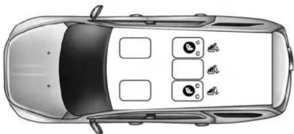
natural_image
Top-down architectural rendering of a car showing front, rear, and side panels with icons (no text or labels)022668566
- Lower Anchorage Symbol 2 anchorages per seating position
• Top Tether Anchorage Symbol
84 THINGS TO KNOW BEFORE STARTING YOUR VEHICLE
| What is the weight limit (child's weight + weight of the child restraint) for using the LATCH anchorage system to attach the child restraint? | 65 lbs (29.5 kg) Use the | LATCH anchorage system until the combined weight of the child and the child restraint is 65 lbs (29.5 kg).Use the seat belt and tether anchor instead of the LATCH system once the combined weight is more than 65 lbs (29.5 kg). |
| Can the LATCH anchorages and the seat belt be used together to attach a rear-facing or forward-facing child restraint? | No Do not use the | seat belt when you use the LATCH anchorage system to attach a rear-facing or forward-facing child restraint. |
| Can a child seat be installed in the center position using the inner LATCH lower anchorages? | Yes You can install child restraints with flexible lower anchors in the center position. The inner anchorages are 15.5 inches (390 mm) apart. Do not install child restraints with rigid lower anchors in the center position. | |
THINGS TO KNOW BEFORE STARTING YOUR VEHICLE 85
| Can two child restraints be attached using a common lower LATCH anchorage? | No Never “share” | a LATCH anchorage with two or more child restraints. If the center position does not have dedicated LATCH lower anchorages, use the seat belt to install a child seat in the center position next to a child seat using the LATCH anchorages in an outboard position. |
| Can the rear-facing child restraint touch the back of the front passenger seat? | Yes The child seat | may touch the back of the front passenger seat if the child restraint manufacturer also allows contact. See your child restraint owner’s manual for more information. |
| Can the head restraints be removed? No |
86 THINGS TO KNOW BEFORE STARTING YOUR VEHICLE
LocatingTheLATCHAnchorage

The lower anchorages are round bars that are found at the rear of the seat cushion where it meets the seatback. They are just visible when you lean into the rear seat to install the child restraint. You will easily feel them if you run your finger along the gap between the seatback and seat cushion.

natural_image
Interior view of a car showing seatbelt and seatbelt clamps with directional arrows indicating movement (no text or symbols)RearSeatLATCHAnchorage
LocatingTheLATCHAnchorage

In addition, there are tether strap anchorages behind each rear seating position located on the back of the seat.
THINGS TO KNOW BEFORE STARTING YOUR VEHICLE 87
LATCH-compatible child restraint systems will be equipped with a rigid bar or a flexible strap on each side. Each will have a hook or connector to attach to the lower anchorage and a way to tighten the connection to the anchorage. Forward-facing child restraints and some rear-facing infant restraints will also be equipped with a tether strap. The tether strap will have a hook at the end to attach to the top tether anchorage and a way to tighten the strap after it is attached to the anchorage.
CenterSeatLATCH
Do not install child restraints with rigid lower attachments in the center seating position. Only install this type of child restraint in the outboard seating positions. Child restraints with flexible, webbing mounted lower attachments can be installed in any rear seating position.
WARNING!
Neverusethesameloweranchoragetoattachmore thanonechildrestraint.IfyouareinstallingLATCH-compatiblechildrestraintsnexttoeachother,you mustusetheseatbeltforthecenterposition.Youcan thenuseeithertheLATCHanchorsorthevehicle's seatbeltforinstallingchildseatsintheoutboard positions.Pleasereferto"InstallingTheLATCH-CompatibleChildRestraintSystem"fortypicalinstallationinstructions.
Always follow the directions of the child restraint manufacturer when installing your child restraint. Not all child restraint systems will be installed as described here.
88 THINGS TO KNOW BEFORE STARTING YOUR VEHICLE
ToInstallALATCH-CompatibleChildRestraint
- If the selected seating position has a Switchable Automatic Locking Retractor (ALR) seat belt, stow the seat belt following the instructions below. See the section "Installing Child Restraints Using the Vehicle Seat Belt" to check what type of seat belt each seating position has.
- Loosen the adjusters on the lower straps and on the tether strap of the child seat so that you can more easily attach the hooks or connectors to the vehicle anchorages.
-
Place the child seat between the lower anchorages for that seating position. For some second row seats, you may need to recline the seat and/or raise the head restraint to get a better fit. If the rear seat can be moved forward and rearward in the vehicle, you may wish to move it to its rear-most position to make room for the child seat. You may also move the front seat forward to allow more room for the child seat.
-
Attach the lower hooks or connectors of the child restraint to the lower anchorages in the selected seating position.
- If the child restraint has a tether strap, connect it to the top tether anchorage. See the section "Installing Child Restraints Using the Top Tether Anchorage" for directions to attach a tether anchor.
- Tighten all of the straps as you push the child restraint rearward and downward into the seat. Remove slack in the straps according to the child restraint manufacturer's instructions.
- Test that the child restraint is installed tightly by pulling back and forth on the child seat at the belt path. It should not move more than 1 inch (25.4 mm) in any direction.
HowToStowAnUnusedALRSeatbelt
When using the LATCH attaching system to install a child restraint, stow all ALR seat belts that are not being used by other occupants or being used to secure child restraints. An unused belt could injure a child if they play with it and accidentally lock the seatbelt retractor. Before installing a child restraint using the LATCH system, buckle the seat belt behind the child restraint and out of the child's reach. If the buckled seat belt interferes with the child restraint installation, instead of buckling it behind the child restraint, route the seat belt through the child restraint belt path and then buckle it. Do not lock the seatbelt. Remind all children in the vehicle that the seat belts are not toys and that they should not play with them.
WARNING!
- Improperinstallationofachildrestrainttothe LATCHanchoragescanleadtofailureofaninfant orchildrestraint.Thechildcouldbebadlyinjured orkilled.Followthemanufacturer'sdirectionsexactlywheninstallinganinfantorchildrestraint.
- Childrestraintanchoragesaredesignedtowith-standonlythoseloadsimposedbycorrectly-fitted childrestraints.Undernocircumstancesaretheyto beusedforadultseatbelts,harnesses,orfor attachingotheritemsorequipmenttothevehicle.
90 THINGS TO KNOW BEFORE STARTING YOUR VEHICLE
InstallingChildRestraintsUsingTheVehicleSeat Belt
The seat belts in the passenger seating positions are equipped with a Switchable Automatic Locking Retractor (ALR) that is designed to keep the lap portion of the seat belt tight around the child restraint so that it is not necessary to use a locking clip. The ALR retractor can be "switched" into a locked mode by pulling all of the webbing out of the retractor and then letting the webbing retract back into the retractor. If it is locked, the ALR will make a clicking noise while the webbing is pulled back into the retractor. For additional information on ALR, refer to the "Automatic Locking Mode" description under "Occupant Restraints."
Lap/ShoulderBeltSystemsForInstallingChild RestraintsInThisVehicle

text_image
ALR ALR ALR ALR ALR022668725
| What is the weight limit (child's weight + weight of the child restraint) for using the Tether Anchor with the seat belt to attach a forward facing child restraint? | Weight limit of the Child Restraint | Always use the tether anchor when using the seat belt to install a forward facing child restraint, up to the recommended weight limit of the child restraint. |
| Can the rear-facing child restraint touch the back of the front passenger seat? | Yes Contact between | the front passenger seat and the child restraint is allowed, if the child restraint manufacturer also allows contact. |
| Can the head restraints be removed? | No | |
| Can the buckle stalk be twisted to tighten the seat belt against the belt path of the child restraint? | Yes In positions with | cinching latch plates (CINCH), the buckle stalk may be twisted up to 3 full turns. Do not twist the buckle stalk in a seating position with an ALR retractor. |
92 THINGS TO KNOW BEFORE STARTING YOUR VEHICLE
InstallingAChildRestraintWithASwitchable AutomaticLockingRetractor(ALR)
- Place the child seat in the center of the seating position. For some second row seats, you may need to recline the seat and/or raise the head restraint to get a better fit. If the rear seat can be moved forward and rearward in the vehicle, you may wish to move it to its rear-most position to make room for the child seat. You may also move the front seat forward to allow more room for the child seat.
- Pull enough of the seat belt webbing from the retractor to pass it through the seat belt path of the child restraint. Do not twist the belt webbing in the seat belt path.
- Slide the latch plate into the buckle until you hear a "click".
-
Pull on the webbing to make the lap portion tight against the child seat.
-
To lock the seat belt, pull down on the shoulder part of the seat belt until you have pulled all the seat belt webbing out of the retractor. Then, allow the webbing to retract back into the retractor. As the webbing retracts, you will hear a clicking sound. This means the seat belt is now in the Automatic Locking mode.
- Try to pull the webbing out of the retractor. If it is locked, you should not be able to pull out any webbing. If the retractor is not locked, repeat step 5.
- Finally, pull up on any excess webbing to tighten the lap portion around the child restraint while you push the child restraint rearward and downward into the vehicle seat.
-
If the child restraint has a top tether strap and the seating position has a top tether anchorage, connect the tether strap to the anchorage and tighten the tether strap. See the section "Installing Child Restraints Using the Top Tether Anchorage" for directions to attach a tether anchor.
-
Test that the child restraint is installed tightly by pulling back and forth on the child seat at the seat belt path. It should not move more than 1 inch (25.4 mm) in any direction.
Any seat belt system will loosen with time, so check the seat belt occasionally, and pull it tight if necessary.
Installing AChildRestraint With ACinching LatchPlate (CINCH)—If Equipped
- Place the child seat in the center of the seating position. For some second row seats, you may need to recline the seat and/or raise the head restraint to get a better fit. If the rear seat can be moved forward and rearward in the vehicle, you may wish to move it to its rear-most position to make room for the child seat. You may also move the front seat forward to allow more room for the car seat.
THINGS TO KNOW BEFORE STARTING YOUR VEHICLE 93
- Next, pull enough of the seat belt webbing from the retractor to pass it through the belt path of the child restraint. Do not twist the belt webbing in the belt path.
- Slide the latch plate into the buckle until you hear a "click".
- Finally, pull up on any excess webbing to tighten the lap portion around the child restraint while you push the child restraint rearward and downward into the vehicle seat.
- If the child restraint has a top tether strap and the seating position has a top tether anchorage, connect the tether strap to the anchorage and tighten the tether strap. Refer to "Installing Child Restraints Using The Top Tether Anchorage" for directions to attach a tether anchor.
94 THINGS TO KNOW BEFORE STARTING YOUR VEHICLE
- Test that the child restraint is installed tightly by pulling back and forth on the child seat at the belt path. It should not move more than 1 inch (25 mm) in any direction.
Any seat belt system will loosen with time, so check the belt occasionally, and pull it tight if necessary.
If the buckle or the cinching latch plate is too close to the belt path opening of the child restraint, you may have trouble tightening the seat belt. If this happens, disconnect the latch plate from the buckle and twist the short buckle-end belt up to three full turns to shorten it. Insert the latch plate into the buckle with the release button facing out, away from the child restraint. Repeat steps 4 to 6, above, to complete the installation of the child restraint.
If the belt still cannot be tightened after you shorten the buckle, disconnect the latch plate from the buckle, turn the buckle around one half turn, and insert the latch plate into the buckle again. If you still cannot make the child restraint installation tight, try a different seating position.
InstallingChildRestraintsUsingTheTopTether Anchorage
-
Look behind the seating position where you plan to install the child restraint to find the tether anchorage. You may need to move the seat forward to provide better access to the tether anchorage. If there is no top tether anchorage for that seating position, move the child restraint to another position in the vehicle if one is available.
-
Route the tether strap to provide the most direct path for the strap between the anchor and the child seat, routing it over the center of the head restraint.
- Attach the tether strap hook of the child restraint to the top tether anchorage as shown in the diagram.
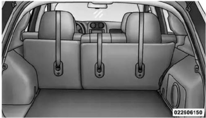
natural_image
Interior view of a car showing rear seats and seatbelt lockers (no text or symbols visible)TetherAnchorageLocations
THINGS TO KNOW BEFORE STARTING YOUR VEHICLE 95
- Remove slack in the tether strap according to the child restraint manufacturer's instructions.
WARNING!
- Anincorrectlyanchoredtetherstrapcouldleadto increasedheadmotionandpossibleinjurytothe child.Useonlytheanchoragepositiondirectly behindthechildseattosecureachildrestrainttop tetherstrap.
- If your vehicle is equipped with a split rearseat, makes sure the ether strap does not slip into the opening between these seat backs as you remove slack in the strap.
96 THINGS TO KNOW BEFORE STARTING YOUR VEHICLE
TransportingPets
Air Bags deploying in the front seat could harm your pet. An unrestrained pet will be thrown about and possibly injured, or injure a passenger during panic braking or in a collision.
Pets should be restrained in the rear seat in pet harnesses or pet carriers that are secured by seat belts.
ENGINE BREAK-IN RECOMMENDATIONS
A long break-in period is not required for the engine and drivetrain (transmission and axle) in your vehicle.
Drive moderately during the first 300 miles (500 km). After the initial 60 miles (100 km), speeds up to 50 or 55 mph (80 or 90 km/h) are desirable.
While cruising, brief full-throttle acceleration within the limits of local traffic laws contributes to a good break-in. Wide-open throttle acceleration in low gear can be detrimental and should be avoided.
The engine oil installed in the engine at the factory is a high-quality energy conserving type lubricant. Oil changes should be consistent with anticipated climate conditions under which vehicle operations will occur. For the recommended viscosity and quality grades, refer to “Maintenance Procedures” in “Maintaining Your Vehicle”.
CAUTION!
NeveruseNon-DetergentOilorStraightMineralOil intheengineordamagemayresult.
NOTE:A new engine may consume some oil during its first few thousand miles (kilometers) of operation. This should be considered a normal part of the break-in and not interpreted as an indication of difficulty.
SAFETY TIPS
Transporting Passengers
NEVER TRANSPORT PASSENGERS IN THE CARGO AREA.
WARNING!
- Donotleavechildrenoranimalsinsideparked vehiclesinhotweather.Interiorheatbuild-upmay causeseriousinjuryordeath.
- Itisextremelydangeroustorideinacargoarea, insideoroutsideofvehicle.Inacollision,people ridingintheseareasaremorelikelytobeseriously injuredorkilled.
- Donotallowpeopletorideinanyareaofyour vehiclethatisnotequippedwithseatsandseatbelts.
- Besureeveryoneinyourvehicleisinaseatand usingaseatbeltproperly.
THINGS TO KNOW BEFORE STARTING YOUR VEHICLE 97
Exhaust Gas
WARNING!
Exhaustgasescaninjureorkill. They contain carbon monoxide(CO), which is colorless and odorless.
Breathingitcanmakeyouunconsciousandcan eventuallypoisonyou.Toavoidbreathing(CO), followthesesafetytips:
- Donotruntheengineinaclosedgarageorin confinedareasanylongerthanneededtomove yourvehicleinoroutofthearea.
- If you are required to drivewith the trunk/lift gate/reardors open, makes sure that all windows are closed and the climate control BLOWER switch this set at high speed. DONOT usethere circulation mode.
(Continued)
98 THINGS TO KNOW BEFORE STARTING YOUR VEHICLE
WARNING!(Continued)
- Ifitisnecessarytositinaparkedvehiclewiththe engineerunning,adjustyourheatingorcooling controlstoforceoutsideairintothevehicle.Setthe blowerathighspeed.
The best protection against carbon monoxide entry into the vehicle body is a properly maintained engine exhaust system.
Whenever a change is noticed in the sound of the exhaust system, when exhaust fumes can be detected inside the vehicle, or when the underside or rear of the vehicle is damaged, have a competent mechanic inspect the complete exhaust system and adjacent body areas for broken, damaged, deteriorated, or mispositioned parts. Open seams or loose connections could permit exhaust fumes to seep into the passenger compartment. In addition, inspect the exhaust system each time the vehicle is raised for lubrication or oil change. Replace as required.
Safety Checks You Should Make Inside The Vehicle
SeatBelts
Inspect the seat belt system periodically, checking for cuts, frays, and loose parts. Damaged parts must be replaced immediately. Do not disassemble or modify the system.
Front seat belt assemblies must be replaced after a collision. Rear seat belt assemblies must be replaced after a collision if they have been damaged (i.e., bent retractor, torn webbing, etc.). If there is any question regarding seat belt or retractor condition, replace the seat belt.
AirBagWarningLight

The light should come on and remain on for four to eight seconds as a bulb check when the ignition switch is first turned ON. If the light is not lit during starting, see your authorized dealer. If the light stays on, flickers, or comes on while driving, have the system checked by an authorized dealer.
Defroster
Check operation by selecting the defrost mode and place the blower control on high speed. You should be able to feel the air directed against the windshield. See your authorized dealer for service if your defroster is inoperable.
THINGS TO KNOW BEFORE STARTING YOUR VEHICLE 99
FloorMatSafetyInformation
Always use floor mats designed to fit the footwell of your vehicle. Use only floor mats that leave the pedal area unobstructed and that are firmly secured so that they cannot slip out of position and interfere with the pedals or impair safe operation of your vehicle in other ways.
WARNING!
Pedalsthatcannotmovefreelycancauselossof vehiclecontrolandincreasetheriskofseriouspersonalinjury.
- Alwaysmakesurethatfloormatsareproperly attachedtothefloormatfasteners.
- Neverplaceorinstallfloormatsorotherfloorcoveringsinthevehiclethatcannotbeproperlysecuredto preventthemfrommovingandinterferingwiththe pedalsortheabilitytocontrolthevehicle.
(Continued)
WARNING!(Continued)
- Neverputfloormatsorotherfloorcoveringsontop ofalreadyinstalledfloormats.Additionalfloor matsandothercoveringswillreducethesizeofthe pedalareaandinterferewiththepedals.
- Checkmountingofmatsonaregularbasis.Always properlyreinstallandsecurefloormatsthathave beenremovedforcleaning.
- Alwaysmakesurethatobjectscannotfallintothe driverfootwellwhilethevehicleismoving. Objects canbecometrappedunderthebrakepedaland acceleratorpedalcausingalossofvehiclecontrol.
- If required, mountingpostsmustbeproperlyinstalled, if notequipped from the factory. Failuretoproperlyfollowfloormatinstallationor mountingcancauseinterference with the brake pedalandacceleratorpedaloperation causing loss of control of the vehicle.
Periodic Safety Checks You Should Make Outside The Vehicle
Tires
Examine tires for excessive tread wear and uneven wear patterns. Check for stones, nails, glass, or other objects lodged in the tread or sidewall. Inspect the tread for cuts and cracks. Inspect sidewalls for cuts, cracks and bulges. Check the wheel nuts for tightness. Check the tires (including spare) for proper cold inflation pressure.
Lights
Have someone observe the operation of brake lights and exterior lights while you work the controls. Check turn signal and high beam indicator lights on the instrument panel.
DoorLatches
Check for positive closing, latching, and locking.
THINGS TO KNOW BEFORE STARTING YOUR VEHICLE 101
FluidLeaks
Check area under vehicle after overnight parking for fuel, engine coolant, oil, or other fluid leaks. Also, if gasoline fumes are detected or if fuel, power steering fluid (if equipped), or brake fluid leaks are suspected, the cause should be located and corrected immediately.
UNDERSTANDING THE FEATURES OF YOUR VEHICLE
CONTENTS
■MIRRORS....108
□Inside Day/Night Mirror....108
□Automatic Dimming Mirror — If Equipped . . .109
□Outside Mirror — Driver Side . . . . . . . . . . . 1 1 0
□Outside Mirror — Passenger Side . . . . . . . . . 1 1 0
□Folding Outside Mirrors....1 1 0
□Power Mirrors....1 1 1
□Heated Mirrors — If Equipped . . . . . . . . . . . 1 1 1
□Vanity Mirrors — If Equipped . . . . . . . . . . . 1 1 2
□Sun Visor Sliding Feature....1 1 2
■ Uconnect® Phone — IF EQUIPPED .....112
□Operation 114
□Phone Call Features....122
□Uconnect® Phone Features .....125
□Advanced Phone Connectivity .....130
□Things You Should Know About Your Uconnect® Phone....132
□General Information....143
■VOICE COMMAND — IF EQUIPPED .....143
□Voice Command System Operation .....143
104 UNDERSTANDING THE FEATURES OF YOUR VEHICLE
□Commands....145
□Voice Training....149
SEATS
□Power Seats — If Equipped . . . . . . . . . . . . . . . . . . . . . . . . . . . . . . . . . . . . . . . . . . . . . . . . . . . . . . . 150
□Heated Seats — If Equipped . . . . . . . . . . . . . . . . . . . . . . . . . . . . . . . . . . . . . . . . . . . . . . . . . . . . . . . . . . . . .
□Manual Front Seat Adjustment....152
□Manual Seat Height Adjustment —
If Equipped....154
□Manual Lumbar — If Equipped . . . . . . . . . . . . . . . . . . . . . . . . . . . . . . . . . . . . . . . . . . . . . . . . . . . . . . .
□Driver's Seatback Recline .....155
□Fold-Flat Front Passenger Seat —
If Equipped....156
□Head Restraints....157
□Folding Rear Seat....160
□Reclining Rear Seat — If Equipped . . . . . . . . .161
■TO OPEN AND CLOSE THE HOOD .....162
■LIGHTS....164
□Multifunction Lever....164
□Headlights And Parking Lights....165
□Daytime Running Lights — If Equipped . . . . .165
□Lights-On Reminder....165
□Fog Lights — If Equipped . . . . . . . . . . . . . . . . . . . . . . . . . . . . . 166
□Turn Signals....167
□High/Low Beam Switch....167
□Flash-To-Pass....168
□Instrument Panel Dimming. . . . . . . . . . . . . . . . . . . . . . . . . . . . . . . . . . . . . . . . . . . . . . . . . 168
□Map/Reading Lights....169
■WINDSHIELD WIPERS AND WASHERS .....170
□Windshield Wiper Operation....171
□Intermittent Wiper System....172
□Windshield Washers....172
□Mist Feature....173
■ TILT STEERING COLUMN .....174
■ELECTRONIC SPEED CONTROL — IF EQUIPPED....175
□To Activate....176
□To Set A Desired Speed....176
□To Deactivate....177
□To Resume Speed....177
□To Vary The Speed Setting .....177
UNDERSTANDING THE FEATURES OF YOUR VEHICLE 105
□To Accelerate For Passing....178
■PARKVIEW® REAR BACK UP CAMERA — IF EQUIPPED....179
■GARAGE DOOR OPENER — IF EQUIPPED . . .181
□Before You Begin Programming HomeLink® . .182
□Programming A Rolling Code....183
□Programming A Non-Rolling Code .....185
□Canadian/Gate Operator Programming .....186
□Using HomeLink®....188
□Security....188
□Troubleshooting Tips....188
□General Information. . . . . . . . . . . . . . . . . . . . . . . . . . . . . . . . . . . . . . . . . . . . 189
106 UNDERSTANDING THE FEATURES OF YOUR VEHICLE
■POWER SUNROOF — IF EQUIPPED .....190
□Opening Sunroof — Express .....191
□Opening Sunroof — Manual Mode .....191
□Closing Sunroof — Express. . . . . . . . . . . . . . . . . . . . . . . . . . . . . . . . . . . . . . . . . . . . . . . . . . . . . . . . . . 192
□Closing Sunroof — Manual Mode .....192
□Pinch Protect Feature....192
□Venting Sunroof — Express .....192
□Sunshade Operation. . . . . . . . . . . . . . . . . . . . . . . . . . . . . . . . . . . . . . . . . . . . . 192
□Wind Buffeting....193
□Sunroof Maintenance....193
□Ignition Off Operation....193
■ELECTRICAL POWER OUTLETS....194
■POWER INVERTER — IF EQUIPPED. . . . . . . .196
■CUPHOLDERS. .198
■STORAGE....199
□Glove Compartment And Storage Bin .....199
□Door Storage. . . . . . . . . . . . . . . . . . . . . . . . . . . . . . . . . . . . . . . . . . . . . . . 200
■CONSOLE FEATURES....201
■CARGO AREA FEATURES....202
□Cargo Light/Removable Self-Recharging Flashlight....202
□Cargo Cover....204
□Removable Load Floor . . . . . . . . . . . . . . . . . . . . . . . . . . . . . . . . . . . . . . . . . . . 206
□Cargo Tie-Down Loops .....206
□Fold Down Speakers — If Equipped . . . . . . . .208
UNDERSTANDING THE FEATURES OF YOUR VEHICLE 107
■REAR WINDOW FEATURES....208
□Rear Window Wiper/Washer....208
□Rear Window Defroster....209
■ROOF LUGGAGE RACK — IF EQUIPPED . . .210
108 UNDERSTANDING THE FEATURES OF YOUR VEHICLE
MIRRORS
Inside Day/Night Mirror
A two-point pivot system allows for horizontal and vertical mirror adjustment. Adjust the mirror to center on the view through the rear window.
Headlight glare can be reduced by moving the small control under the mirror to the night position (toward the rear of vehicle). The mirror should be adjusted while set in the day position (toward the windshield).

natural_image
Side mirror with a black arrow pointing to the left side (no text or symbols on the mirror itself)InsideDay/NightMirror
UNDERSTANDING THE FEATURES OF YOUR VEHICLE 109
Automatic Dimming Mirror — If Equipped
This mirror automatically adjusts for headlight glare from vehicles behind you. You can turn the feature on or off by pressing the button at the base of the mirror. A light to the left of the button will illuminate to indicate when the dimming feature is activated. The sensor to the right of the button does not illuminate.
NOTE: This feature is disabled when the vehicle is moving in reverse.
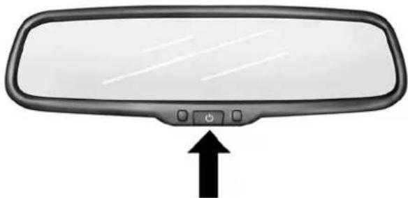
natural_image
Front view of a car rear mirror with a black arrow pointing upward (no text or symbols)030406002
AutomaticDimmingMirror
CAUTION!
Toavoiddamagetothemirrorduringcleaning,never sprayanycleaningsolutiondirectlyontothemirror. Applythesolutionontoacleanclothandwipethe mirrorclean.
110 UNDERSTANDING THE FEATURES OF YOUR VEHICLE
Outside Mirror — Driver Side
Adjust the flat outside mirror so you can just see the side of your vehicle in the part of the mirror closest to the vehicle with your head close to the door glass.
Outside Mirror — Passenger Side
Adjust the convex outside mirror so you can just see the side of your vehicle in the part of the mirror closest to the vehicle with your head close to the center of the vehicle.
WARNING!
Vehiclesandotherobjectsseeninthepassengerside convexmirrorwilllooksmallerandfartheraway thantheyreallyare.Relyingtoomuchonyour passengersidemirrorcouldcauseyoutocollidewith anothervehicleorotherobject.Useyourinside mirrorwhenjudgingthesizeordistanceofvehicle seeninthisconvexmirror.
Folding Outside Mirrors
The outside mirrors are hinged and may be moved, manually, either forward or rearward to resist damage. The hinges have three detent positions; full forward, full rearward and normal.
Power Mirrors
The power mirror control is located on the driver's door trim panel.

natural_image
Close-up of a car's air condition control panel with buttons and a dial, no visible text or symbols on the main component.PowerMirrorControl
UNDERSTANDING THE FEATURES OF YOUR VEHICLE 111
To adjust a mirror, turn the control wand toward the left or right mirror positions indicated. Tilt the control wand in the direction you want the mirror to move.
When you are finished adjusting the mirror, turn the control to the center position to prevent accidentally moving a mirror.
Heated Mirrors — If Equipped

These mirrors are heated to melt frost or ice. This feature is activated whenever you turn on the rear w defroster. Refer to "Rear Window Features" in understanding The Features Of Your Vehicle" for fur-formation.
112 UNDERSTANDING THE FEATURES OF YOUR VEHICLE
Vanity Mirrors — If Equipped
To use the vanity mirror, rotate the sun visor down and swing the mirror cover upward.

text_image
VanityMirror 030406199Sun Visor Sliding Feature
The sun visors may be extended out to provide more coverage of the side glass.
Uconnect® Phone — IF EQUIPPED
Uconnect® Phone is a voice-activated, hands-free, in-vehicle communications system. Uconnect® Phone allows you to dial a phone number with your mobile phone using simple voice commands (e.g., "Call" ... "Mike" ... "Work" or "Dial" ... "248-555-1212"). Your mobile phone's audio is transmitted through your vehicle's audio system; the system will automatically mute your radio when using the Uconnect® Phone.
NOTE: The Uconnect® Phone requires a mobile phone equipped with the Bluetooth® "Hands-Free Profile", Version 0.96 or higher. See the Uconnect® website for supported phones.
For Uconnect® customer support:
• U.S. residents - visit www.UconnectPhone.com or call 1-877-855-8400.
- Canadian Residents - visit www.UconnectPhone.com or call, 1-800-465-2001 (English) or 1-800-387-9983 (French).
Uconnect® Phone allows you to transfer calls between the system and your mobile phone as you enter or exit your vehicle and enables you to mute the system's microphone for private conversation.
The Uconnect® Phone is driven through your Bluetooth® "Hands-Free Profile" mobile phone. Uconnect® features Bluetooth® technology - the global standard that enables different electronic devices to connect to each other without wires or a docking station, so Uconnect® Phone works no matter where you stow your mobile phone (be it your purse, pocket, or briefcase), as long as your phone is turned on and has been paired to the vehicle's Uconnect® Phone. The Uconnect® Phone allows up to seven mobile phones to be linked to the system. Only one linked (or paired) mobile phone can be
UNDERSTANDING THE FEATURES OF YOUR VEHICLE
used with the system at a time. The system is available in English, Spanish, or French languages.
WARNING!
Any voice commanded system should be used only insafed driving conditions following all applicable laws, including laws regarding phone use. Your attentions should be focused on safely operating the vehicle. Failure todos may result in a collision causing serious injury or death.
Uconnect®PhoneButton

The radio or steering wheel controls (if equipped) will contain the two control buttons (Uconnect® Phone button and Voice Command button) that will enable you to
access the system. When you press the button you will hear the word Uconnect® followed by a BEEP. The beep is your signal to give a command.
114 UNDERSTANDING THE FEATURES OF YOUR VEHICLE
VoiceCommandButton

Actual button location may vary with the radio. The individual buttons are described in the "Operation" section.
The Uconnect® Phone can be used with any Hands-Free Profile certified Bluetooth® mobile phone. See the Uconnect® website for supported phones. Refer to your mobile service provider or the phone manufacturer for details.
The Uconnect® Phone is fully integrated with the vehicle's audio system. The volume of the Uconnect® Phone can be adjusted either from the radio volume control knob or from the steering wheel radio control (right switch), if so equipped.
The radio display will be used for visual prompts from the Uconnect® Phone such as "CELL" or caller ID on certain radios.
Operation
Voice commands can be used to operate the Uconnect® Phone and to navigate through the Uconnect® Phone menu structure. Voice commands are required after most Uconnect® Phone prompts. You will be prompted for a specific command and then guided through the available options.
- Prior to giving a voice command, one must wait for the beep, which follows the "Ready" prompt or another prompt.
- For certain operations, compound commands can be used. For example, instead of saying "Setup" and then "Pair a Device," the following compound command can be said: "Pair a Bluetooth Device."
- For each feature explanation in this section, only the compound form of the voice command is given. You can also break the commands into parts and say each
part of the command when you are asked for it. For example, you can use the compound form voice command "Phonebook New Entry," or you can break the compound form command into two voice commands: "Phonebook" and "New Entry." Please remember, the Uconnect® Phone works best when you talk in a normal conversational tone, as if speaking to someone sitting a few feet/meters away from you.
VoiceCommandTree
Refer to "Voice Tree" in this section.
HelpCommand
If you need assistance at any prompt, or if you want to know your options at any prompt, say "Help" following the beep. The Uconnect® Phone will play some of the options at any prompt if you ask for help.
UNDERSTANDING THE FEATURES OF YOUR VEHICLE
115
To activate the Uconnect® Phone, simply press the button and follow the audible prompts for directions. Uconnect® Phone sessions begin with a press of the button on the radio control head.
CancelCommand
At any prompt, after the beep, you can say "Cancel" and you will be returned to the main menu. However, in a few instances the system will take you back to the previous menu.
Pair(Link)Uconnect®PhoneToAMobilePhone
To begin using your Uconnect® Phone, you must pair your compatible Bluetooth® enabled mobile phone.
To complete the pairing process, you will need to reference your mobile phone Owner's Manual. The Uconnect® website may also provide detailed instructions for pairing.
116 UNDERSTANDING THE FEATURES OF YOUR VEHICLE
The following are general phone to Uconnect® Phone pairing instructions:
- Press the 📋 button to begin.
- After the "Ready" prompt and the following beep, say "Device Pairing."
- When prompted, after the beep, say "Pair a Device" and follow the audible prompts.
You will be asked to say a four-digit Personal Identification Number (PIN), which you will later need to enter into your mobile phone. You can enter any four-digit PIN. You will not need to remember this PIN after the initial pairing process.
For identification purposes, you will be prompted to give the Uconnect® Phone a name for your mobile phone. Each mobile phone that is paired should be given a unique phone name.
You will then be asked to give your mobile phone a priority level between one and seven, with one being the highest priority. You can pair up to seven mobile phones to your Uconnect® Phone. However, at any given time, only one mobile phone can be in use, connected to your Uconnect® System. The priority allows the Uconnect® Phone to know which mobile phone to use if multiple mobile phones are in the vehicle at the same time. For example, if priority three and priority five phones are present in the vehicle, the Uconnect® Phone will use the priority three mobile phone when you make a call. You can select to use a lower priority mobile phone at any time (refer to “Advanced Phone Connectivity” in this section).
DialBySayingANumber
- Press the 📋 button to begin.
-
After the "Ready" prompt and the following beep, say "Dial."
-
The system will prompt you to say the number you want to call.
- For example, you can say "151-1234-5555."
- The Uconnect® Phone will confirm the phone number and then dial. The number will appear in the display of certain radios.
CallBySayingAName
- Press the 📞 button to begin.
- After the "Ready" prompt and the following beep, say "Call."
- The system will prompt you to say the name of the person you want to call.
- After the "Ready" prompt and the following beep, say the name of the person you want to call. For example, you can say "John Doe," where John Doe is a previously stored name entry in the Uconnect® phonebook
UNDERSTANDING THE FEATURES OF YOUR VEHICLE 117
or downloaded phonebook. To learn how to store a name in the phonebook, refer to "Add Names to Your Uconnect® Phonebook."
- The Uconnect® system will confirm the name and then dial the corresponding phone number, which may appear in the display of certain radios.
AddNamesToYourUconnect®Phonebook
NOTE: Adding names to the Uconnect® Phonebook is recommended when the vehicle is not in motion.
- Press the 📋 button to begin.
- After the "Ready" prompt and the following beep, say "Phonebook New Entry."
- When prompted, say the name of the new entry. Use of long names helps the Voice Command and it is recommended. For example, say "Robert Smith" or "Robert" instead of "Bob."
118 UNDERSTANDING THE FEATURES OF YOUR VEHICLE
- When prompted, enter the number designation (e.g., "Home," "Work," "Mobile," or "Other"). This will allow you to store multiple numbers for each phone-book entry, if desired.
- When prompted, recite the phone number for the phonebook entry that you are adding.
After you are finished adding an entry into the phonebook, you will be given the opportunity to add more phone numbers to the current entry or to return to the main menu.
The Uconnect® Phone will allow you to enter up to 32 names in the phonebook with each name having up to four associated phone numbers and designations. Each language has a separate 32-name phonebook accessible only in that language. In addition, if equipped and supported by your phone, Uconnect® Phone automatically downloads your mobile phone's phonebook.
PhonebookDownload—AutomaticPhonebook TransferFromMobilePhone
If equipped and specifically supported by your phone, Uconnect® Phone automatically downloads names (text names) and number entries from your mobile phone's phonebook. Specific Bluetooth® Phones with Phone Book Access Profile may support this feature. See Uconnect® website for supported phones.
- To call a name from the Uconnect® Phonebook or downloaded Phonebook, follow the procedure in "Call by Saying a Name" section.
- Automatic download and update, if supported, begins as soon as the Bluetooth® wireless phone connection is made to the Uconnect® Phone, for example, after you start the vehicle.
UNDERSTANDING THE FEATURES OF YOUR VEHICLE 119
- A maximum of 1000 entries per phone will be downloaded and updated every time a phone is connected to the Uconnect® Phone.
- Depending on the maximum number of entries downloaded, there may be a short delay before the latest downloaded names can be used. Until then, if available, the previously downloaded phonebook is available for use.
- Only the phonebook of the currently connected mobile phone is accessible.
- Either the mobile phone's phonebook or the mobile phone's SIM card phonebook is downloaded.
- This downloaded phonebook cannot be edited or deleted on the Uconnect® Phone. These can only be edited on the mobile phone. The changes are transferred and updated to Uconnect® Phone on the next phone connection.
EditUconnect®PhonebookEntries
NOTE: Editing phonebook entries is recommended when the vehicle is not in motion. Automatic down-loaded phonebook entries cannot be deleted or edited.
- Press the 📞 button to begin.
- After the "Ready" prompt and the following beep, say "Phonebook Edit."
- You will then be asked for the name of the phonebook entry that you wish to edit.
- Next, choose the number designation (home, work, mobile, or other) that you wish to edit.
- When prompted, recite the new phone number for the phonebook entry that you are editing.
After you are finished editing an entry in the phonebook, you will be given the opportunity to edit another entry in the phonebook, call the number you just edited, or return to the main menu.
"Phonebook Edit" can be used to add another phone number to a name entry that already exists in the phonebook. For example, the entry John Doe may have a mobile and a home number, but you can add "John Doe's" work number later using the "Phonebook Edit" feature.
DeleteUconnect®PhonebookEntry
NOTE: Editing phonebook entries is recommended when the vehicle is not in motion.
- Press the 📞 button to begin.
- After the "Ready" prompt and the following beep, say "Phonebook Delete."
- After you enter the Phonebook Delete menu, you will then be asked for the name of the entry that you wish to delete. You can either say the name of a phonebook entry that you wish to delete or you can say "List Names" to hear a list of the entries in the phonebook from which you choose. To select one of the entries from the list, press the button while the Uconnect® Phone is playing the desired entry and say "Delete."
- After you enter the name, the Uconnect® Phone will ask you which designation you wish to delete: home, work, mobile, other, or all. Say the designation you wish to delete.
- Note that only the phonebook entry in the current language is deleted.
- Automatic downloaded phonebook entries cannot be deleted or edited.
Delete/Erase"All"Uconnect®PhonebookEntries
- Press the 📞 button to begin.
- After the "Ready" prompt and the following beep, say "Phonebook Erase All."
- The Uconnect® Phone will ask you to verify that you wish to delete all the entries from the phonebook.
- After confirmation, the phonebook entries will be deleted.
NOTE:
- Only the phonebook in the current language is deleted.
- Automatic downloaded phonebook entries cannot be deleted or edited.
UNDERSTANDING THE FEATURES OF YOUR VEHICLE 121
ListAllNamesInTheUconnect®Phonebook
- Press the 📋 button to begin.
- After the "Ready" prompt and the following beep, say "Phonebook List Names."
- The Uconnect® Phone will play the names of all the phonebook entries, including the downloaded phonebook entries, if available.
- To call one of the names in the list, press the 0€VR button during the playing of the desired name, and say "Call."
NOTE: The user can also exercise "Edit" or "Delete" operations at this point.
- The Uconnect® Phone will then prompt you as to the number designation you wish to call.
• The selected number will be dialed.
122 UNDERSTANDING THE FEATURES OF YOUR VEHICLE
Phone Call Features
The following features can be accessed through the Uconnect® Phone if the feature(s) are available on your mobile service plan. For example, if your mobile service plan provides three-way calling, this feature can be accessed through the Uconnect® Phone. Check with your mobile service provider for the features that you have.
AnswerOrRejectAnIncomingCall—NoCall CurrentlyInProgress
When you receive a call on your mobile phone, the Uconnect® Phone will interrupt the vehicle audio system, if on, and will ask if you would like to answer the call. Press the button to accept the call. To reject the call, press and hold the button until you hear a single beep, indicating that the incoming call was rejected.
AnswerOrRejectAnIncomingCall—Call CurrentlyInProgress
If a call is currently in progress and you have another incoming call, you will hear the same network tones for call waiting that you normally hear when using your mobile phone. Press the 📋 button to place the current call on hold and answer the incoming call.
NOTE: The Uconnect® Phone compatible phones in the market today do not support rejecting an incoming call when another call is in progress. Therefore, the user can only answer an incoming call or ignore it.
MakingASecondCallWhileCurrentCallsIn Progress
To make a second call while you are currently on a call, press the _E^v button and say "Dial" or "Call" followed by the phone number or phonebook entry you wish to call. The first call will be on hold while the second call is in progress. To go back to the first call, refer to "Toggling Between Calls" in this section. To combine two calls, refer to "Conference Call" in this section.
Place/RetrieveACallFromHold
To put a call on hold, press the button until you hear a single beep. This indicates that the call is on hold. To bring the call back from hold, press and hold the button until you hear a single beep.
TogglingBetweenCalls
If two calls are in progress (one active and one on hold), press the button until you hear a single beep,
UNDERSTANDING THE FEATURES OF YOUR VEHICLE 123
indicating that the active and hold status of the two calls have switched. Only one call can be placed on hold at a time.
ConferenceCall
When two calls are in progress (one active and one on hold), press and hold the button until you hear a double beep indicating that the two calls have been joined into one conference call.
Three-WayCalling
To initiate three-way calling, press the OEMR button while a call is in progress, and make a second phone call, as described under "Making a Second Call While Current Call is in Progress." After the second call has established, press and hold the button until you hear a double beep, indicating that the two calls have been joined into one conference call.
124 UNDERSTANDING THE FEATURES OF YOUR VEHICLE
CallTermination
To end a call in progress, momentarily press the button. Only the active call(s) will be terminated and if there is a call on hold, it will become the new active call. If the active call is terminated by the phone far end, a call on hold may not become active automatically. This is cell phone-dependent. To bring the call back from hold, press and hold the button until you hear a single beep.
Redial
- Press the 📞 button to begin.
- After the "Ready" prompt and the following beep, say "Redial."
- The Uconnect® Phone will call the last number that was dialed from your mobile phone.
NOTE: This may not be the last number dialed from the Uconnect® Phone.
CallContinuation
Call continuation is the progression of a phone call on the Uconnect® Phone after the vehicle ignition has been switched to OFF. Call continuation functionality available on the vehicle can be any one of three types:
- After the ignition is switched to OFF, a call can continue on the Uconnect® Phone either until the call ends, or until the vehicle battery condition dictates cessation of the call on the Uconnect® Phone and transfer of the call to the mobile phone.
- After the ignition is cycled to OFF, a call can continue on the Uconnect® Phone for a certain duration, after which the call is automatically transferred from the Uconnect® Phone to the mobile phone.
- An active call is automatically transferred to the mobile phone after the ignition is cycled to OFF.
Uconnect® Phone Features
LanguageSelection
To change the language that the Uconnect® Phone is using:
- Press the 📊 button to begin.
- After the "Ready" prompt and the following beep, say the name of the language you wish to switch to English, Espanol, or Francais.
- Continue to follow the system prompts to complete the language selection.
After selecting one of the languages, all prompts and voice commands will be in that language.
NOTE: After every Uconnect® Phone language change operation, only the language-specific 32-name phonebook is usable. The paired phone name is not language-specific and is usable across all languages.
UNDERSTANDING THE FEATURES OF YOUR VEHICLE 125
Emergency Assistance
If you are in an emergency and the mobile phone is reachable:
- Pick up the phone and manually dial the emergency number for your area.
If the phone is not reachable and the Uconnect® Phone is operational, you may reach the emergency number as follows:
- Press the 📞 button to begin.
- After the "Ready" prompt and the following beep, say "Emergency" and the Uconnect® Phone will instruct the paired mobile phone to call the emergency number. This feature is supported in the U.S., Canada, and Mexico.
126 UNDERSTANDING THE FEATURES OF YOUR VEHICLE
NOTE:
- The emergency number dialed is based on the country where the vehicle is purchased (911 for the U.S. and Canada and 060 for Mexico). The number dialed may not be applicable with the available mobile service and area.
- If supported, this number may be programmable on some systems. To do this, press the button and say "Setup," followed by "Emergency."
- The Uconnect® Phone does slightly lower your chances of successfully making a phone call as to that for the mobile phone directly.
WARNING!
TouseyourUconnect®PhoneSysteminanemergency,yourmobilephonemustbe:
• turnedon,
WARNING!(Continued)
•pairedtotheUconnect®System,
• andhavenetworkcoverage.
Roadside Assistance/Towing Assistance
If you need roadside assistance:
- Press the 📞 button to begin.
- After the "Ready" prompt and the following beep, say "Towing Assistance."
NOTE: You should program the desired Towing Assistance phone number using the Voice Command system. To do this, press the button and say "Setup," followed by "Towing Assistance." When prompted say 1-800-521-2779 for U.S./Canada, say 55-14-3454 for Mexico City and 1-800-712-3040 for outside Mexico City in Mexico.
(Continued)
Paging
To learn how to page, refer to “Working with Automated Systems.” Paging works properly except for pagers of certain companies, which time out a little too soon to work properly with the Uconnect® Phone.
VoiceMailCalling
To learn how to access your voice mail, refer to "Working with Automated Systems".
WorkingWithAutomatedSystems
This method is used in instances where one generally has to press numbers on the mobile phone keypad while navigating through an automated telephone system.
You can use your Uconnect® Phone to access a voice mail system or an automated service, such as a paging service or automated customer service line. Some services require immediate response selection. In some instances, that may be too quick for use of the Uconnect® Phone.
UNDERSTANDING THE FEATURES OF YOUR VEHICLE 127
When calling a number with your Uconnect® Phone that normally requires you to enter in a touch-tone sequence on your mobile phone keypad, you can press the @vnr button and say the sequence you wish to enter, followed by the word "Send." For example, if required to enter your PIN followed with a pound, (3 7 4 6 #), y o u c press the @vnr button and say, "3 7 4 6 # Send." Saying a number, or sequence of numbers, followed by "Send," is also to be used for navigating through an automated customer service center menu structure, and to leave a number on a pager.
You can also send stored Uconnect® phonebook entries as tones for fast and easy access to voice mail and pager entries. To use this feature, dial the number you wish to call and then press the 0€vm button and say, "Send." The system will prompt you to enter the name or number and say the name of the phonebook entry you wish to
128 UNDERSTANDING THE FEATURES OF YOUR VEHICLE
send. The Uconnect® Phone will then send the corresponding phone number associated with the phone-book entry, as tones over the phone.
NOTE:
- You may not hear all of the tones due to mobile phone network configurations. This is normal.
- Some paging and voice mail systems have system time out settings that are too short and may not allow the use of this feature.
BargeIn—OverridingPrompts
The "Voice Command" button can be used when you wish to skip part of a prompt and issue your voice command immediately. For example, if a prompt is asking "Would you like to pair a phone, clear a...," you could press the "OK" button and say, "Pair a Phone" to select that option without having to listen to the rest of the voice prompt.
TurningConfirmationPromptsON/OFF
Turning confirmation prompts off will stop the system from confirming your choices (e.g., the Uconnect® Phone will not repeat a phone number before you dial it).
- Press the 📋 button to begin.
- After the "Ready" prompt and the following beep, say one of the following:
- "Setup Confirmation Prompts On"
- "Setup Confirmation Prompts Off"
PhoneAndNetworkStatusIndicators
If available on the radio and/or on a premium display such as the instrument panel cluster, and supported by your mobile phone, the Uconnect® Phone will provide notification to inform you of your phone and network status when you are attempting to make a phone call using Uconnect® Phone. The status is given for network signal strength, phone battery strength, etc.
DialingUsingTheMobilePhoneKeypad
You can dial a phone number with your mobile phone keypad and still use the Uconnect® Phone (while dialing via the mobile phone keypad, the user must exercise caution and take precautionary safety measures). By dialing a number with your paired Bluetooth® mobile phone, the audio will be played through your vehicle's audio system. The Uconnect® Phone will work the same as if you dial the number using Voice Command.
NOTE: Certain brands of mobile phones do not send the dial ring to the Uconnect® Phone to play it on the vehicle audio system, so you will not hear it. Under this situation, after successfully dialing a number the user may feel that the call did not go through even though the call is in progress. Once your call is answered, you will hear the audio.
UNDERSTANDING THE FEATURES OF YOUR VEHICLE 129
Mute/Un-Mute(MuteON/OFF)
When you mute the Uconnect® Phone, you will still be able to hear the conversation coming from the other party, but the other party will not be able to hear you. To mute the Uconnect® Phone:
- Press the _^ button.
- Following the beep, say "Mute."
To un-mute the Uconnect® Phone: - Press the _^VR button.
- Following the beep, say "Mute off."
130 UNDERSTANDING THE FEATURES OF YOUR VEHICLE
Advanced Phone Connectivity
TransferCallToAndFromMobilePhone
The Uconnect® Phone allows ongoing calls to be transferred from your mobile phone to the Uconnect® Phone without terminating the call. To transfer an ongoing call from your Uconnect® Phone paired mobile phone to the Uconnect® Phone or vice versa, press the (eVR) button and say "Transfer Call."
ConnectOrDisconnectLinkBetweenThe Uconnect®PhoneAndMobilePhone
Your mobile phone can be paired with many different electronic devices, but can only be actively “connected” with one electronic device at a time.
If you would like to connect or disconnect the Bluetooth® connection between your mobile phone and the Uconnect® Phone System, follow the instructions described in your mobile phone User's Manual.
ListPairedMobilePhoneNames
- Press the 📊 button to begin.
- After the "Ready" prompt and the following beep, say "Setup Phone Pairing."
- When prompted, say "List Phones."
- The Uconnect® Phone will play the phone names of all paired mobile phones in order from the highest to the lowest priority. To "Select" or "Delete" a paired phone being announced, press the Ⓞvnr button and say "Select" or "Delete." Also, see the next two sections for an alternate way to "Select" or "Delete" a paired phone.
SelectAnotherMobilePhone
This feature allows you to select and start using another phone paired with the Uconnect® Phone.
- Press the 📞 button to begin.
- After the "Ready" prompt and the following beep, say "Setup Select Phone" and follow the prompts.
- You can also press the 📋 button at any time while the list is being played, and then choose the phone that you wish to select.
- The selected phone will be used for the next phone call. If the selected phone is not available, the Uconnect® Phone will return to using the highest priority phone present in or near (approximately within 30 ft. [9 m]) the vehicle.
UNDERSTANDING THE FEATURES OF YOUR VEHICLE 131
DeleteUconnect®PhonePairedMobilePhones
- Press the 📋 button to begin.
- After the "Ready" prompt and the following beep, say "Setup Phone Pairing."
- At the next prompt, say "Delete" and follow the prompts.
- You can also press the 📋 button at any time while the list is being played, and choose the phone you wish to delete.
132 UNDERSTANDING THE FEATURES OF YOUR VEHICLE
Things You Should Know About Your Uconnect® Phone
Uconnect®PhoneTutorial
To hear a brief tutorial of the system features, press the
button and say "Uconnect® Tutorial."
VoiceTraining
For users experiencing difficulty with the system recognizing their voice commands or numbers, the Uconnect® Phone Voice Training feature may be used. To enter this training mode, follow one of the two following procedures:
From outside the Uconnect® Phone mode (e.g., from radio mode):
- Press and hold the _^Cvr button for five seconds until the session begins, or,
- Press the ^OGEVR button and say the "Voice Training," "System Training," or "Start Voice Training" command.
You can either press the Uconnect® Phone button to restore the factory setting or repeat the words and phrases when prompted by the Uconnect® Phone. For best results, the Voice Training session should be completed when the vehicle is parked with the engine running, all windows closed, and the blower fan switched off.
This procedure may be repeated with a new user. The system will adapt to the last trained voice only.
Reset
- Press the 📞 button.
- After the "Ready" prompt, and the following beep, say "Setup," then "Reset."
This will delete all phone pairing, phone book entries, and other settings in all language modes. The System will prompt you before resetting to factory settings.
VoiceCommand
- For best performance, adjust the rearview mirror to provide at least 12 inch (1 cm) gap between the overhead console (if equipped) and the mirror.
• Always wait for the beep before speaking. - Speak normally without pausing, just as you would speak to a person sitting a few feet/meters away from you.
- Make sure that no one other than you is speaking during a Voice Command period.
Performance is maximized under:
- Low-to-medium blower setting
- Low-to-medium vehicle speed
- Low road noise
- Smooth road surface
UNDERSTANDING THE FEATURES OF YOUR VEHICLE
133
- Fully closed windows
• Dry weather condition
NOTE:
- Even though the system is designed for users speaking in North American English, French, and Spanish accents, the system may not always work for some.
- When navigating through an automated system such as voice mail, or when sending a page, at the end of speaking the digit string, make sure to say "Send."
- Storing names in the phonebook when the vehicle is not in motion is recommended.
- It is not recommended to store similar sounding names in the Uconnect® Phonebook.
- Phonebook (Downloaded and Uconnect® Phone Local) name recognition rate is optimized when the entries are not similar.
134 UNDERSTANDING THE FEATURES OF YOUR VEHICLE
- Numbers must be spoken in single digits. "800" must be spoken "eight-zero-zero" not "eight hundred."
- You can say "O" (letter "O") for "0" (zero).
- Even though international dialing for most number combinations is supported, some shortcut dialing number combinations may not be supported.
- In a convertible vehicle, system performance may be compromised with the convertible top down.
FarEndAudioPerformance
• Audio quality is maximized under:
- Low-To-Medium Blower Setting
- Low-To-Medium Vehicle Speed
- Low Road Noise
- Smooth Road Surface
- Fully Closed Windows
•Dry Weather Conditions
•Operation From The Driver's Seat - Performance, such as audio clarity, echo, and loudness to a large degree rely on the phone and network, and not the Uconnect® Phone
- Echo at the phone far end can sometimes be reduced by lowering the in-vehicle audio volume
- In a convertible vehicle, system performance may be compromised with the convertible top down
RecentCalls
If your phone supports "Automatic Phonebook Download," Uconnect® Phone can list your Outgoing, Incoming and Missed Calls.
VoiceTextReply
Uconnect® Phone can read or send new messages on your phone.
ReadMessages:
If you receive a new text message while your phone is connected to Uconnect® Phone, an announcement will be made to notify you that you have a new text message. If you wish to hear the new message:
- Press the 📋 button.
- After the "Ready" prompt and the following beep, say "SMS Read" or "Read Messages."
- Uconnect® Phone will play the new text message for you.
After reading a message, you can "Reply" or "Forward" the message using Uconnect® Phone.
UNDERSTANDING THE FEATURES OF YOUR VEHICLE 135
SendMessages:
You can send messages using Uconnect® Phone. To send a new message:
- Press the 📋 button.
- After the "Ready" prompt and the following beep, say "SMS Send" or "Send Message."
- You can either say the message you wish to send or say "List Messages." There are 20 preset messages.
To send a message, press the ^06 button while the system is listing the message and say "Send." Uconnect® Phone will prompt you to say the name or number of the person you wish to send the message to.
List of Preset Messages:
- Yes.
- No.
136 UNDERSTANDING THE FEATURES OF YOUR VEHICLE
- Where are you?
- I need more direction.
- LOL.
- Why?
- I love you.
- Call me.
- Call me later.
- Thanks.
- See You in 15 minutes.
- I am on my way.
- I'll be late.
- Are you there yet?
-
Where are we meeting?
-
Can this wait?
- Bye for now.
- When can we meet?
- Send number to call.
- Start without me.
TurnVoiceTextReplyIncomingAnnouncementON/OFF
Turning the Voice Text Reply Incoming Announcement OFF will stop the system from announcing the new incoming messages.
- Press the 📋 button.
- After the "Ready" prompt and the following beep, say "Setup, Incoming Message Announcement," you will then be given a choice to change it.
Bluetooth®CommunicationLink
Mobile phones have been found to lose connection to the Uconnect® Phone. When this happens, the connection can generally be reestablished by switching the phone off/on. Your mobile phone is recommended to remain in Bluetooth® ON mode.
UNDERSTANDING THE FEATURES OF YOUR VEHICLE 137
Power-Up
After switching the ignition key from OFF to either the ON or ACC position, or after a language change, you must wait at least 15 seconds prior to using the system.
138 UNDERSTANDING THE FEATURES OF YOUR VEHICLE

flowchart
graph TD
    A["Main Menu"] --> B["Recent Calls"]
    A --> C["Call"]
    A --> D["Dial"]
    A --> E["Redial"]
    A --> F["Towing Assistance"]
    A --> G["Emergency"]
    A --> H["English/ Espanol/ Francais"]
    A --> I["Phonebook"]
    A --> J["Setup"]
    A --> K["Uconnects Tutorial"]
    A --> L["SMS"]
    L --> M["Read Messages"]
    L --> N["Send Messages"]
    D --> O["Enter Name"]
    D --> P["Enter Number"]
    D --> Q["Number associated with entry is dialed"]
    D --> R["Number is Dialed"]
    H --> S["The 32 name language specific phonebook will be used. The phones paired are available across all languages."]
    I --> T["See Phonebook Flowchart"]
    J --> U["See Setup Flowchart"]
Note: Available Voice commands are shown in bold face and are underlined.
030772523
UNDERSTANDING THE FEATURES OF YOUR VEHICLE 139
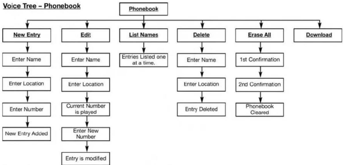
flowchart
graph TD
    A["Phonebook"] --> B["New Entry"]
    A --> C["Edit"]
    A --> D["List Names"]
    A --> E["Delete"]
    A --> F["Erase All"]
    A --> G["Download"]
    B --> H["Enter Name"]
    H --> I["Enter Location"]
    I --> J["Enter Number"]
    J --> K["New Entry Added"]
    C --> L["Enter Name"]
    L --> M["Enter Location"]
    M --> N["Current Number is played"]
    N --> O["Enter New Number"]
    O --> P["Entry is modified"]
    D --> Q["Entries Listed one at a time."]
    E --> R["Enter Name"]
    R --> S["Enter Location"]
    S --> T["Entry Deleted"]
    F --> U["1st Confirmation"]
    U --> V["2nd Confirmation"]
    V --> W["Phonebook Cleared"]
Note: Available Voice commands are shown in bold face and are underlined.
81c6bf80
140 UNDERSTANDING THE FEATURES OF YOUR VEHICLE
Voice Tree - Setup
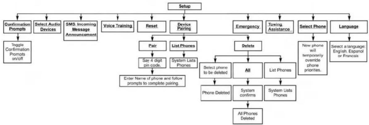
flowchart
graph TD
    A["Setup"] --> B["Confirmation Prompts"]
    A --> C["Select Audio Devices"]
    A --> D["SMS. Incoming Message Announcement"]
    A --> E["Voice Training"]
    A --> F["Reset"]
    A --> G["Device Pairing"]
    A --> H["Emergency"]
    A --> I["Towing Assistance"]
    A --> J["Select Phone"]
    A --> K["Language"]
    B --> L["Toggle Confirmation Prompts on/off"]
    C --> M["Say 4 digit pin code."]
    D --> N["Enter Name of phone and follow prompts to complete pairing."]
    E --> O["Pair"]
    F --> P["List Phones"]
    G --> Q["List Lists Phones"]
    H --> R["Delete"]
    I --> S["New phone will temporarily override phone priorities."]
    J --> T["All"]
    K --> U["Select a language: English, Espenol or Français"]
    L --> V["Phone Deleted"]
    M --> W["System confirms"]
    N --> X["System Lists Phones"]
    O --> Y["All Phones Deleted"]
Note: Available Voice commands are shown in bold face and are underlined.
030605540
UNDERSTANDING THE FEATURES OF YOUR VEHICLE 141
| Voice Commands | |
| Primary Alternate | (s) |
| zero | |
| one | |
| two | |
| three | |
| four | |
| five | |
| six | |
| seven | |
| eight | |
| nine | |
| star (*) | |
| plus (+) | |
| pound (#) | |
| add location | |
| Voice Commands | |
| all | |
| call | |
| cancel | |
| confirmation prompts | |
| continue | |
| delete | |
| dial | |
| download | |
| edit | |
| emergency | |
| English | |
| erase all | |
| Espanol | |
| Francais | |
| help | |
142 UNDERSTANDING THE FEATURES OF YOUR VEHICLE
| Voice Commands | |
| home | |
| language | |
| list names | |
| list phones | |
| mobile | |
| mute | |
| mute off | |
| new entry | |
| no | |
| other | |
| pair a phone | |
| phone pairing pairing | |
| phonebook phone book | |
| previous | |
| record again | |
| Voice Commands | |
| redial | |
| return to main menu return or main menu | |
| select phone select | |
| send | |
| set up phone settings or phone set up | |
| towing assistance | |
| transfer call | |
| Uconnect® Tutorial | |
| voice training | |
| work | |
| yes | |
General Information
This device complies with Part 15 of the FCC rules and RSS 210 of Industry Canada. Operation is subject to the following conditions:
- Changes or modifications not expressly approved by the party responsible for compliance could void the user's authority to operate the equipment.
- This device may not cause harmful interference.
- This device must accept any interference received, including interference that may cause undesired operation.
UNDERSTANDING THE FEATURES OF YOUR VEHICLE 143
VOICE COMMAND — IF EQUIPPED
Voice Command System Operation
The Uconnect® Voice Command system allows you to control your AM, FM radio, disk player, USB mass storage class device, iPod® family of devices, Bluetooth® Streaming Audio Device, satellite radio, disc player, and a memo recorder.
NOTE: Take care to speak into the Voice Interface System as calmly and normally as possible. The ability of the Voice Interface System to recognize user voice commands may be negatively affected by rapid speaking or a raised voice level.
WARNING!
Anyvoicecommandedsystemshouldbeusedonlyinsafedrivingconditionsfollowingallapplicable
(Continued)
144 UNDERSTANDING THE FEATURES OF YOUR VEHICLE
WARNING!(Continued)
laws, including laws regarding phone use. Your attentions should be focused on safely operating the vehicle. Failure to dosomay result in a collision causing serious injury or death.
When you press the Voice Command _vm button, you will hear a beep. The beep is your signal to give a command.
NOTE: If you do not say a command within a few seconds, the system will present you with a list of options.
If you would like to interrupt the system while it lists options, press the Voice Command (VR) button, listen for the beep, and say your command.
Pressing the Voice Command ⓄVR button while the system is speaking is known as "barging in." The system
will be interrupted, and after the beep, you can add or change commands. This will become helpful once you start to learn the options.
NOTE: At any time, you can say the words "Cancel," "Help" or "Main Menu."
These commands are universal and can be used from any menu. All other commands can be used depending upon the active application.
When using this system, you should speak clearly and at a normal speaking volume.
The system will best recognize your speech if the windows are closed, and the heater/air conditioning fan is set to low.
At any point, if the system does not recognize one of your commands, you will be prompted to repeat it.
To hear the first available Menu, press the Voice Command Ⓤ£vr button and say "Help" or "Main Menu."
Commands
The Voice Command system understands two types of commands, Universal commands and Local commands. Universal commands are available at all times. Local commands are available if the supported radio mode is active.
ChangingTheVolume
- Start a dialogue by pressing the Voice Command (OEVR) button.
- Say a command (e.g., "Help").
- Use the ON/OFF VOLUME rotary knob to adjust the volume to a comfortable level while the Voice Command system is speaking. Please note the volume setting for Voice Command is different than the audio system.
UNDERSTANDING THE FEATURES OF YOUR VEHICLE 145
MainMenu
Start a dialogue by pressing the Voice Command ⓄEVR button. You may say "Main Menu" to switch to the main menu.
In this mode, you can say the following commands:
- "Radio AM" (to switch to the radio AM mode)
- "Radio FM" (to switch to radio FM mode)
- "Sat" (to switch to Satellite radio mode)
- "Disc" (to switch to the disc mode)
- "USB" (to switch to USB mode)
- "Bluetooth Streaming" (to switch to Bluetooth® Streaming mode)
- "Memo" (to switch to the memo recorder)
- "System Setup" (to switch to system setup)
146 UNDERSTANDING THE FEATURES OF YOUR VEHICLE
RadioAM
To switch to the AM band, say "AM" or "Radio AM." In this mode, you may say the following commands:
- "Frequency #" (to change the frequency)
- "Next Station" (to select the next station)
- "Previous Station" (to select the previous station)
- "Radio Menu" (to switch to the radio menu)
- "Main Menu" (to switch to the main menu)
RadioFM
To switch to the FM band, say "FM" or "Radio FM." In this mode, you may say the following commands:
- "Frequency #" (to change the frequency)
- "Next Station" (to select the next station)
-
"Previous Station" (to select the previous station)
-
"Menu Radio" (to switch to the radio menu)
- "Main Menu" (to switch to the main menu)
SatelliteRadio
To switch to satellite radio mode, say "Sat" or "Satellite Radio." In this mode, you may say the following commands:
- "Channel Number" (to change the channel by its spoken number)
- "Next Channel" (to select the next channel)
- "Previous Channel" (to select the previous channel)
- "List Channel" (to hear a list of available channels)
- "Select Name" (to say the name of a channel)
- "Menu Radio" (to switch to the radio menu)
- "Main Menu" (to switch to the main menu)
DiscMode
To switch to the disc mode, say "Disc." In this mode, you may say the following commands:
- "Track" (#) (to change the track)
- "Next Track" (to play the next track)
- "Previous Track" (to play the previous track)
- "Main Menu" (to switch to the main menu)
USBMode
To switch to USB mode, say "USB." In this mode, you may say the following commands:
- "Next Track" (to play the next track)
- "Previous Track" (to play the previous track)
- "Play" (to play an Artist Name, Playlist Name, Album Name, Track Name, etc.)
UNDERSTANDING THE FEATURES OF YOUR VEHICLE 147
Bluetooth®Streaming(BT)Mode
To switch to Bluetooth® Streaming (BT) mode, say "Bluetooth Streaming." In this mode, you may say the following commands:
- "Next Track" (to play the next track)
- "Previous Track" (to play the previous track)
- "List" (to list an Artist, Playlist, Album, Track, etc.)
MemoMode
To switch to the voice recorder mode, say "Memo." In this mode, you may say the following commands:
- "New Memo" (to record a new memo) — During the recording, you may press the Voice Command (02VR) button to stop recording. You proceed by saying one of the following commands:
- "Save" (to save the memo)
148 UNDERSTANDING THE FEATURES OF YOUR VEHICLE
- "Continue" (to continue recording)
- "Delete" (to delete the recording)
- "Play Memos" (to play previously recorded memos) — During the playback you may press the Voice Command of a button to stop playing memos. You proceed by saying one of the following commands:
- "Repeat" (to repeat a memo)
- "Next" (to play the next memo)
- "Previous" (to play the previous memo)
- "Delete" (to delete a memo)
- "Delete All" (to delete all memos)
Setup
To switch to system setup, you may say one of the following:
- "Change to setup"
- "Switch to system setup"
- "Main menu setup"
- "Switch to setup"
In this mode, you may say the following commands:
- "Language English"
• "Language French" - "Language Spanish"
- "Tutorial"
- "Voice Training"
NOTE: Keep in mind that you have to press the Voice Command of "vm" button first and wait for the beep before speaking the "Barge In" commands.
Voice Training
For users experiencing difficulty with the system recognizing their voice commands or numbers the Uconnect® Voice "Voice Training" feature may be used.
- Press the Voice Command oSvm button, say "System Setup" and once you are in that menu then say "Voice Training." This will train your own voice to the system and will improve recognition.
- Repeat the words and phrases when prompted by Uconnect® Voice. For best results, the "Voice Training" session should be completed when the vehicle is parked, engine running, all windows closed, and the blower fan switched off. This procedure may be repeated with a new user. The system will adapt to the last trained voice only.
SEATS
Seats are a part of the Occupant Restraint System of the vehicle.
WARNING!
- Itisdangeroustorideinacargoarea,insideor outsideofavehicle.Inacollision,peopleridingin theseareasaremorelikelytobeseriouslyinjured orkilled.
- Donotallowpeopletorideinanyareaofyour vehiclethatisnotequippedwithseatsandseat belts.Inacollision,peopleridingintheseareasare morelikelytobeseriouslyinjuredorkilled.
- Besureeveryoneinyourvehicleisinaseatand usingaseatbeltproperly.
150 UNDERSTANDING THE FEATURES OF YOUR VEHICLE
Power Seats — If Equipped
Some models may be equipped with a power driver's seat. The power seat switch is located on the outboard side of the seat near the floor. Use the switch to move the seat up, down, forward, rearward, or to tilt the seat.
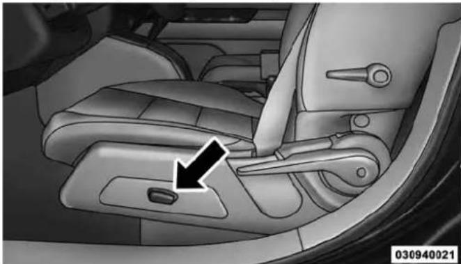
natural_image
Interior view of a car's seatbelt and dashboard compartment showing the left side with a black arrow pointing to the lower side (no text or symbols present)PowerSeatSwitch
WARNING!
- Adjustingaseatwhiledrivingmaybedangerous. Movingaseatwhiledrivingcouldresultinlossof controlwhichcouldcauseacollisionandserious injuryordeath.
- Seatsshouldbeadjustedbeforefasteningtheseat beltsandwhilethevehicleisparked.Serious injuryordeathcouldresultfromapoorlyadjusted seatbelt.
CAUTION!
Donotplaceanyarticleunderapowerseator impedeitsabilitytomoveasitmaycausedamageto theseatcontrols.Seattravelmaybecomelimitedif movementisstoppedbyanobstructionintheseat's path.
AdjustingTheSeatForwardOrRearward
The seat can be adjusted both forward and rearward. Push the seat switch forward or rearward, the seat will move in the direction of the switch. Release the switch when the desired position has been reached.
AdjustingTheSeatUpUpDown
The height of the seats can be adjusted up or down. Pull upward or push downward on the seat switch, the seat will move in the direction of the switch. Release the switch when the desired position is reached.
TiltingTheSeatUpUpDown
The angle of the seat cushion can be adjusted in four directions. Pull upward or push downward on the front or rear of the seat switch, the front or rear of the seat cushion will move in the direction of the switch. Release the switch when the desired position is reached.
UNDERSTANDING THE FEATURES OF YOUR VEHICLE 151
Heated Seats — If Equipped
On some models, the front driver and passenger seats may be equipped with heaters in both the seat cushions and seatbacks. The controls for the front heated seats are located on the center instrument panel area.
You can choose from HIGH, LOW or OFF heat settings. Amber indicator lights in each switch indicate the level of heat in use. Two indicator lights will illuminate for HIGH, one for LOW and none for OFF.

Press the switch once to select HIGH-level heating. Press the switch a second time to select LOW-level heating. Press the switch a third time to shut the heating elements OFF.
When the HIGH-level setting is selected, the heater will provide a boosted heat level during the initial stages of operation. Then, the heat output will drop to the normal HI-level. If the HI-level setting is selected, the system will automatically switch to LOW-level after approximately
152 UNDERSTANDING THE FEATURES OF YOUR VEHICLE
30 minutes of continuous operation. At that time, the display will change from HI to LO, indicating the change. When the LOW-level heating is selected, the system automatically turns the heater and the indicator light OFF after approximately 30 minutes of continuous operation.
NOTE: Once a heat setting is selected, heat will be felt within two to five minutes.
WARNING!
- Persons who are unable to feel in the skin because of advanced age, chronic illness, diabetes, spinal cord injury, medication, alcohol use, exhaustion or other physical condition must exercise care when using these at least a theater. It may cause burns even at low temperatures, especially if used for long period so time.
WARNING!(Continued)
- Donotplaceanythingontheseatorseatbackthat insulatesagainstheat,suchasablanketorcushion. Thismaycausetheseatheatertooverheat.Sitting inaseatthathasbeenoverheatedcouldcause seriousburnsduetotheincreasedsurfacetemperatureoftheseat.
Manual Front Seat Adjustment
On models equipped with manual seats, the adjusting bar is located at the front of the seats, near the floor. While sitting in the seat, lift up on the bar and move the seat forward or rearward. Release the bar once you have reached the desired position. Then, using body pressure, move forward and rearward on the seat to be sure that the seat adjusters have latched.
(Continued)

natural_image
Close-up of a car seat corner with a white arrow pointing to the side panel (no text or symbols visible)ManualSeatAdjustingBar
UNDERSTANDING THE FEATURES OF YOUR VEHICLE 153
WARNING!
- Adjustingaseatwhiledrivingmaybedangerous. Movingaseatwhiledrivingcouldresultinlossof controlwhichcouldcauseacollisionandserious injuryordeath.
- Seatsshouldbeadjustedbeforefasteningtheseat beltsandwhilethevehicleisparked.Serious injuryordeathcouldresultfromapoorlyadjusted seatbelt.
154 UNDERSTANDING THE FEATURES OF YOUR VEHICLE Manual Seat Height Adjustment — If Equipped
The driver's seat height can be raised or lowered by using a lever, located on the outboard side of the seat. Pull upward on the lever to raise the seat height or push downward on the lever to lower the seat height.

natural_image
Illustration of a car seat with a black arrow pointing to the seat area (no text or symbols present)030907660
Manual Lumbar — If Equipped
The lumbar adjustment handle is located on the outboard side of the driver's seatback. Rotate the lever downward to increase the lumbar support or rotate the lever upward to decrease the lumbar support.

natural_image
Interior view of a car seatbelt with a black arrow pointing to the side panel (no text or symbols on the interior)SeatHeightAdjustmentLeverLumbarAdjustmentLever
UNDERSTANDING THE FEATURES OF YOUR VEHICLE 155
Driver's Seatback Recline
To adjust the seatback, lift the lever located on the outboard side of the seat, lean back to the desired angle and release the lever. To return the seatback, lift the lever, lean forward and release the lever.
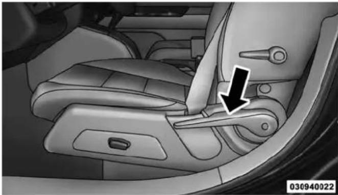
natural_image
Interior view of a car seatbelt with a black arrow pointing to the seatbelt component (no text or symbols visible)ReclineLever
WARNING!
Donotridewiththeseatbackreclinedsothatthe shoulderbeltisnolongerrestingagainstyourchest. Inacollisionyoucouldslideundertheseatbelt, whichcouldresultinseriousinjuryordeath.
156 UNDERSTANDING THE FEATURES OF YOUR VEHICLE Fold-Flat Front Passenger Seat — If Equipped
To fold the front passenger seat, lift the recliner handle to the full upward position and push the seatback forward until it rests on the seat cushion.

natural_image
Interior view of a car seatbelt with a black arrow pointing to the seat (no text or symbols visible)Fold-FlatLever
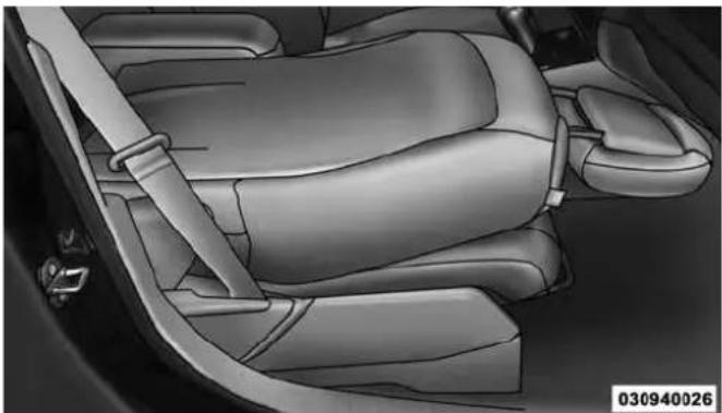
natural_image
Interior view of a car showing the seatbelt and rear seats (no text or symbols visible)Fold-FlatSeat
Head Restraints
Head restraints are designed to reduce the risk of injury by restricting head movement in the event of a rear impact. Head restraints should be adjusted so that the top of the head restraint is located above the top of your ear.
WARNING!
Theheadrestraintsforalloccupantsmustbeproperlyadjustedpriortooperatingthevehicleoroccupyingaseat.Headrestraintsshouldneverbeadjustedwhilethevehicleisinmotion.Drivinga vehiclewiththeheadrestraintsimproperlyadjusted orremovedcouldcauseseriousinjuryordeathinthe eventofacollision.
UNDERSTANDING THE FEATURES OF YOUR VEHICLE 157
ActiveHeadRestraints—FrontSeats
Active Head Restraints are passive, deployable components, and vehicles with this equipment cannot be readily identified by any markings, only through visual inspection of the head restraint. The head restraint will be split in two halves, with the front half being soft foam and trim, the back half being decorative plastic.
When AHRs deploy during a rear impact, the front half of the head restraint extends forward to minimize the gap between the back of the occupant's head and the AHR. This system is designed to help prevent or reduce the extent of injuries to the driver and front passenger in certain types of rear impacts. Refer to "Occupant Restraints" in "Things To Know Before Starting Your Vehicle" for further information.
158 UNDERSTANDING THE FEATURES OF YOUR VEHICLE
To raise the head restraint, pull upward on the head restraint. To lower the head restraint, press the push button, located at the base of the head restraint, and push downward on the head restraint.
the back of your head, pull forward on the bottom of the head restraint. Push rearward on the bottom of the head restraint to move the head restraint away from your head.

natural_image
3D model of a car headrest with a black arrow pointing to the lower side (no text or symbols on the object itself)
natural_image
3D rendered image of a car seat with neck and side arm (no text or symbols)PushButtonActiveHeadRestraint(NormalPosition)
For comfort the Active Head Restraints can be tilted forward and backward. To tilt the head restraint closer to
022607494
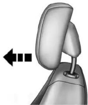
natural_image
3D rendered image of a car seat with a left-pointing arrow indicating direction (no text or symbols)ActiveHeadRestraint(TiltedPosition)
030907533
NOTE:
- The head restraints should only be removed by qualified technicians, for service purposes only. If either of the head restraints require removal, see your authorized dealer.
UNDERSTANDING THE FEATURES OF YOUR VEHICLE 159
- In the event of deployment of an Active Head Restraint, refer to "Occupant Restraints/Resetting Active Head Restraints (AHR)" in "Things To Know Before Starting Your Vehicle" for further information.
WARNING!
- DonotplaceitemsoverthetopoftheActiveHead Restraint,suchascoats,seatcoversorportable DVDplayers. Theseitemsmayinterferewiththe operationoftheActiveHeadRestraintintheevent ofacollisionandcouldresultinseriousinjuryor death.
- ActiveHeadRestraintsmaybedeployediftheyare struckbyanobjectsuchasahand,footorloose cargo.ToavoidaccidentaldeploymentoftheActiveHeadRestraintensurethatallcargoissecured,
(Continued)
160 UNDERSTANDING THE FEATURES OF YOUR VEHICLE
WARNING!(Continued)
asloosecargocouldcontacttheActiveHeadRestraintduringsuddenstops.Failuretofollowthis warningcouldcausepersonalinjuryiftheActive HeadRestraintisdeployed.
RearHeadRestraints
The head restraints in the rear are non adjustable. Refer to "Occupant Restraints" in "Things To Know Before Starting Your Vehicle" for information on Tether routing.
Folding Rear Seat
To provide additional storage area, each rear seatback can be folded forward. Pull the strap forward to fold the rear seatback flat.
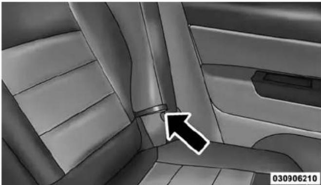
natural_image
Interior view of a car showing seatbelt and dashboard (no text or symbols visible)RearSeatReleaseStrap
UNDERSTANDING THE FEATURES OF YOUR VEHICLE 161

natural_image
Interior view of a car showing the dashboard and seat area (no text or symbols visible)FoldedRearSeat
To raise the seatback, pull the strap forward and lift the seatback into its upright position.
WARNING!
Becertainthattheseatbackissecurelylockedinto position.Iftheseatbackisnotsecurelylockedinto positiontheseatwillnotprovidetheproperstability forchildseatsand/orpassengers.Animproperly latchedseatcouldcauseseriousinjury.
Reclining Rear Seat — If Equipped
For additional comfort, pull the strap forward just enough to release the seatback latch. Then push the seatback to a reclined position, approximately 35 degrees maximum, and release the strap.
WARNING!
Donotridewiththeseatbackreclinedsothatthe shoulderbeltisnolongerrestingagainstyourchest.
(Continued)
162 UNDERSTANDING THE FEATURES OF YOUR VEHICLE
WARNING!(Continued)
Inacollisionyoucouldslideundertheseatbeltand beseriouslyorevenfatallyinjured. Usetherecliner onlywhenthevehicleisparked.
TO OPEN AND CLOSE THE HOOD
To open the hood, two latches must be released.
- Pull the hood release lever located on the left kick panel.

natural_image
Interior view of a car dashboard with a black arrow pointing to the left side panel (no text or symbols visible)HoodReleaseLever
- Move the safety latch, located outside the vehicle under the front edge of the hood, toward the center and raise the hood.

natural_image
Front view of a black car with a white arrow pointing downward on the grille (no text or symbols)HoodSafetyLatchLocation
031340027
UNDERSTANDING THE FEATURES OF YOUR VEHICLE 163
Lift the hood prop rod, clipped to the right side (left side facing hood) of the engine compartment to secure the hood in the open position. Place the hood prop at the location stamped into the inner hood surface.
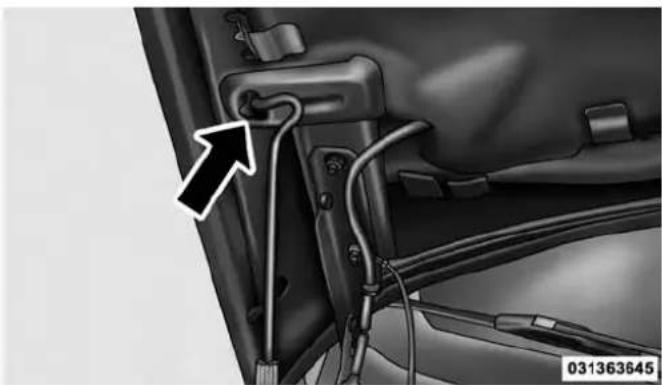
natural_image
Close-up of a car's front panel showing wiring and cable connections (no text or symbols visible)PropRodLocation
164 UNDERSTANDING THE FEATURES OF YOUR VEHICLE
CAUTION!
Topreventpossibledamage, donotslamthehood to closeit. Lowerthehood untilitisopen8in(20cm) approximately and thendropit. This should secure bothlatches. Never drive your vehicle unless the hood is fully closed, with both latches engaged.
WARNING!
Besurethehoodisfullylatchedbeforedrivingyour vehicle.Ifthehoodisnotfullylatched,itcouldopen whenthevehicleisinmotionandblockyourvision. Failuretofollowthiswarningcouldresultinserious injuryordeath.
LIGHTS
Multifunction Lever
The multifunction lever controls the operation of the headlights, parking lights, turn signals, headlight beam selection, instrument panel light dimming, interior lights, the passing lights, and the fog lights. The multifunction lever is located on the left side of the steering column.

natural_image
Close-up of a black handheld device with control buttons and display indicators (no readable text or symbols)MultifunctionLever
031407547
Headlights And Parking Lights
Turn the end of the multifunction lever to the first detent to turn on the parking lights. Turn the end of the lever to the second detent to turn on the headlights.

natural_image
Close-up of a black camera lens with adjustment knobs and control buttons (no readable text or symbols)031407548
HeadlightControl
UNDERSTANDING THE FEATURES OF YOUR VEHICLE 165
Daytime Running Lights — If Equipped
The high beam lights will come on as Daytime Running Lights (lower intensity), whenever the ignition is ON, the engine is running, the headlight switch is off, the parking brake is off, the turn signal is off, and the shift lever is in any position except PARK.
Lights-On Reminder
If the headlights or parking lights are left on after the ignition is turned OFF, a chime will sound to alert the driver when the driver's door is opened.
166 UNDERSTANDING THE FEATURES OF YOUR VEHICLE
Fog Lights — If Equipped

The front fog light switch is on the multifunction lever. To activate the front fog lights, turn on the parking lights or the low beam head-
lights and pull out the end of the multifunction lever.
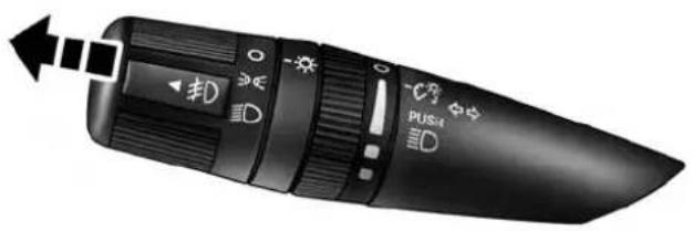
natural_image
Close-up of a black handheld device with control buttons and a left-pointing arrow indicator (no readable text or symbols)031407550
FrontFogLightOperation
NOTE: The fog lights will only operate with the headlights on low beam. Selecting high beam headlights will turn off the fog lights.
Turn Signals
Move the multifunction lever up or down and the arrows on each side of the instrument cluster flash to show proper operation of the front and rear turn signal lights.
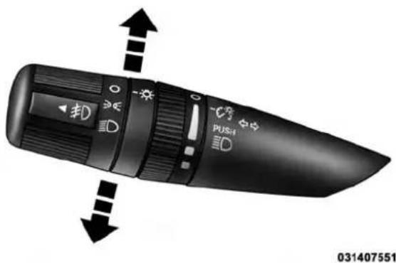
natural_image
Close-up of a black handheld device with directional arrows and control buttons (no readable text or symbols)TurnSignalOperation
UNDERSTANDING THE FEATURES OF YOUR VEHICLE 167
NOTE: If either light remains on and does not flash, or there is a very fast flash rate, check for a defective outside light bulb. If an indicator fails to light when the lever is moved, it would suggest that the indicator bulb is defective.
LaneChangeAssist
Tap the lever up or down once, without moving beyond the detent, and the turn signal (right or left) will flash three times then automatically turn off.
High/Low Beam Switch
Push the multifunction lever away from you to switch the headlights to high beam. Pull the multifunction lever toward you to switch the headlights back to low beam.
168 UNDERSTANDING THE FEATURES OF YOUR VEHICLE
Flash-To-Pass
You can signal another vehicle with your headlights by lightly pulling the multifunction lever toward you. This will turn on the high beam headlights until the lever is released.
NOTE: If the multifunction lever is held in the flash-to-pass position for more than 20 seconds, the high beams will shut off. If this occurs, wait 30 seconds for the next flash-to-pass operation.
Instrument Panel Dimming
Rotate the center portion of the lever to the extreme bottom position to fully dim the instrument panel lights and prevent the interior lights from illuminating when a door is opened.
Rotate the center portion of the lever up to increase the brightness of the instrument panel lights when the parking lights or headlights are on.
Rotate the center portion of the lever upward to the next detent position to brighten the odometer and radio when the parking lights or headlights are on.
Rotate the center portion of the lever upward to the last detent to turn on the interior lighting.
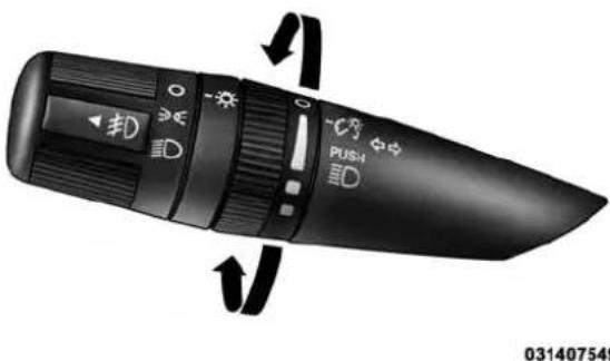
natural_image
Close-up of a black handheld device with control buttons and rotary arrows indicating rotation (no readable text or symbols)DimmerControl
UNDERSTANDING THE FEATURES OF YOUR VEHICLE 169
Map/Reading Lights
These lights are mounted between the sun visors above the rear view mirror. Each light is turned on by pressing the button. Press the button a second time to turn the light off. The lights also come on when a door is opened or the dimmer control is turned fully upward, past the second detent.
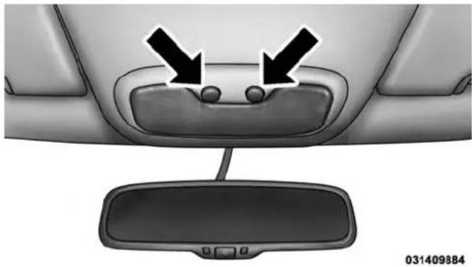
natural_image
Interior view of a car showing the rearview mirror and dashboard with two black arrows pointing to the dashboard (no text or symbols present)Map/ReadingLights
NOTE: The lights will remain on until the switch is pressed a second time, so be sure they have been turned off before leaving the vehicle. They will not turn off automatically.
170 UNDERSTANDING THE FEATURES OF YOUR VEHICLE WINDSHIELD WIPERS AND WASHERS

The windshield wiper/washer control lever is located on the right side of the steering column.
The front wipers are operated by rotating a switch, located on the end of the lever. For information on the rear wiper/washer, refer to "Rear Window Features" in "Understanding The Features Of Your Vehicle".
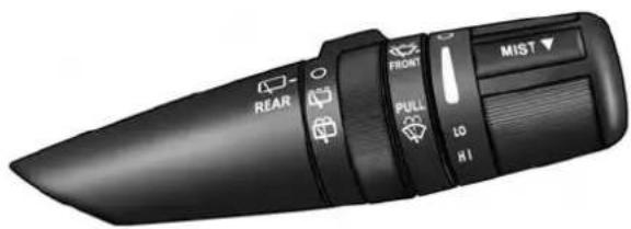
text_image
REAR FRONT PULL LO HI MIST036407502
Wiper/WasherControlLever
CAUTION!
- Turnthewindshieldwipersoffwhendriving throughanautomaticcarwash.Damagetothe windshieldwipersmayresultifthewipercontrol isleftinanypositionotherthanoff.
- Incoldweather, alwaysturnoffthewiperswitch andallowthewiperstoreturntothe "Park" positionbeforeturningofftheengine. If thewiper switchisleftonandthewipersfreezetothewindshield,damagetothewipermotormayoccur whenthevehicleisrestarted.
- Alwaysremoveanybuildupofsnowthatprevents thewindshieldwiperbladesfromreturningtothe offposition.Ifthewindshieldwipercontrolis turnedoffandthebladescannotreturntotheoff position,damagetothewipermotormayoccur.
UNDERSTANDING THE FEATURES OF YOUR VEHICLE 171
Windshield Wiper Operation
Rotate the end of the lever upward to the second detent past the intermittent settings for low-speed wiper operation. Rotate the end of the lever upward to the third detent past the intermittent settings for high-speed wiper operation.
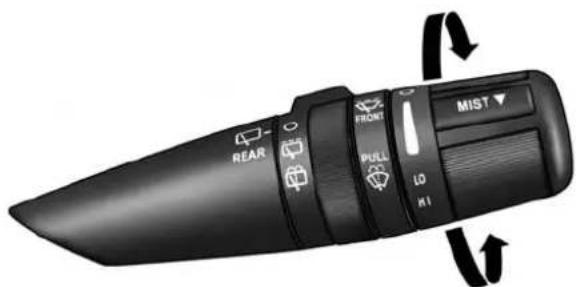
text_image
REAR PULL MIST FRONT LO HI031507503
WindshieldWiperOperation
172 UNDERSTANDING THE FEATURES OF YOUR VEHICLE
Intermittent Wiper System
Use the intermittent wiper when weather conditions make a single wiping cycle, with a variable pause between cycles, desirable. Select the delay interval by turning the end of the lever. Rotate the end of the lever upward (clockwise) to decrease the delay time and downward (counterclockwise) to increase the delay time. The delay can be regulated from a maximum of approximately 18 seconds between cycles, to a cycle every second.
NOTE: The wiper delay times depend on vehicle speed. If the vehicle is moving less than 10 mph (16 km/h), delay times will be doubled.
Windshield Washers
To use the washer, pull the control lever toward you and hold while spray is desired. If the lever is pulled while in the delay range, the wiper will operate in low-speed while the lever is pulled and for two wipe cycles after the lever is released, and then resume the intermittent interval previously selected.
If the lever is pulled while in the off position, the wipers will operate for two wipe cycles, then turn off.
WARNING!
Suddenlossofvisibilitythroughthewindshield couldleadtoacollision.Youmightnotseeother vehiclesorotherobstacles.Toavoidsuddenicingof thewindshieldduringfreezingweather,warmthe windshieldwiththedefrosterbeforeandduring windshieldwasheruse.
UNDERSTANDING THE FEATURES OF YOUR VEHICLE 173
Mist Feature
Push down on the control lever to activate a single wipe to clear the windshield of road mist or spray from a passing vehicle. As long as the lever is held down, the wipers will continue to operate.
NOTE: The mist feature does not activate the washer pump; therefore, no washer fluid will be sprayed on the windshield. The wash function must be used in order to spray the windshield with washer fluid.
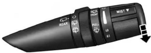
text_image
REAR FRONT PULL LO HI MIST ▼031507504
MistOperation
174 UNDERSTANDING THE FEATURES OF YOUR VEHICLE
TILT STEERING COLUMN
This feature allows you to tilt the steering column upward or downward. The tilt steering column lever is located on the left side of the steering column, below the turn signal lever.
Push down on the lever to unlock the steering column. With one hand firmly on the steering wheel, move the steering column up or down, as desired. Push the lever up to lock the steering column firmly in place.
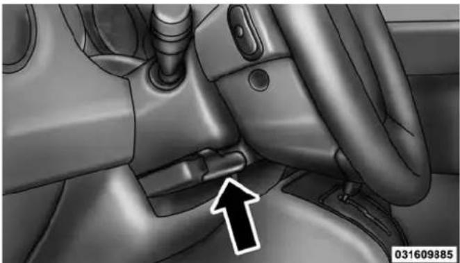
natural_image
Interior view of a car showing the seatbelt and dashboard (no text or symbols visible)TiltSteeringColumnLever
WARNING!
Donotadjustthesteeringcolumnwhiledriving. Adjustingthesteeringcolumnwhiledrivingordrivingwiththesteeringcolumnunlocked,couldcause
(Continued)
WARNING!(Continued)
thedrivertolosecontrolofthevehicle.Failureto followthiswarningmayresultinseriousinjuryor death.
ELECTRONIC SPEED CONTROL — IF EQUIPPED
When engaged, the Electronic Speed Control takes over accelerator operations at speeds greater than 25 mph (40 km/h).
The Electronic Speed Control buttons are located on the right side of the steering wheel.
UNDERSTANDING THE FEATURES OF YOUR VEHICLE 175

text_image
1 ON/OFF RES + CANCEL SET - 2 3 4 032209541ElectronicSpeedControlButtons
1—ON/OFF 3—SET-
2 — RES + 4 — CANCEL
176 UNDERSTANDING THE FEATURES OF YOUR VEHICLE
NOTE: In order to ensure proper operation, the Electronic Speed Control System has been designed to shut down if multiple Speed Control functions are operated at the same time. If this occurs, the Electronic Speed Control System can be reactivated by pushing the Electronic Speed Control ON/OFF button and resetting the desired vehicle set speed.
To Activate
Push the ON/OFF button. The Cruise Indicator Light in the instrument cluster will illuminate. To turn the system off, push the ON/OFF button a second time. The Cruise Indicator Light will turn off. The system should be turned off when not in use.
WARNING!
LeavingtheElectronicSpeedControlsystemon whennotinuseisdangerous.Youcouldaccidentally setthesystemorcauseittogofasterthanyouwant. Youcouldlosecontrolandhaveanaccident.Always leavethesystemOFFwhenyouarenotusingit.
To Set A Desired Speed
Turn the Electronic Speed Control ON. When the vehicle has reached the desired speed, press the SET (-) button and release. Release the accelerator and the vehicle will operate at the selected speed.
NOTE: The vehicle should be traveling at a steady speed and on level ground before pressing the SET (-) button.
To Deactivate
A soft tap on the brake pedal, pushing the CANCEL button, or normal brake pressure while slowing the vehicle will deactivate the Electronic Speed Control without erasing the set speed from memory.
Pressing the ON/OFF button or turning the ignition switch OFF erases the set speed from memory.
To Resume Speed
To resume a previously set speed, push the RES (+) button and release. Resume can be used at any speed above 20 mph (32 km/h).
To Vary The Speed Setting
ToIncreaseSpeed
When the Electronic Speed Control is set, you can increase speed by pushing the RES (+) button.
UNDERSTANDING THE FEATURES OF YOUR VEHICLE 177
The speed increment shown is dependant on the chosen speed unit of U.S. (mph) or Metric (km/h):
U.S.Speed(mph)
- Pressing the RES (+) button once will result in a 1 mph increase in set speed. Each subsequent tap of the button results in an increase of 1 mph.
- If the button is continually pressed, the set speed will continue to increase until the button is released, then the new set speed will be established.
MetricSpeed(km/h)
- Pressing the RES (+) button once will result in a 2 km/h increase in set speed. Each subsequent tap of the button results in an increase of 2 km/h.
- If the button is continually pressed, the set speed will continue to increase until the button is released, then the new set speed will be established.
178 UNDERSTANDING THE FEATURES OF YOUR VEHICLE
ToDecreaseSpeed
When the Electronic Speed Control is set, you can decrease speed by pushing the SET (-) button.
The speed decrement shown is dependant on the chosen speed unit of U.S. (mph) or Metric (km/h):
U.S.Speed(mph)
- Pressing the SET (-) button once will result in a 1 mph decrease in set speed. Each subsequent tap of the button results in a decrease of 1 mph.
- If the button is continually pressed, the set speed will continue to decrease until the button is released, then the new set speed will be established.
MetricSpeed(km/h)
- Pressing the SET (-) button once will result in a 2 km/h decrease in set speed. Each subsequent tap of the button results in a decrease of 2 km/h.
- If the button is continually pressed, the set speed will continue to decrease until the button is released, then the new set speed will be established.
To Accelerate For Passing
Press the accelerator as you would normally. When the pedal is released, the vehicle will return to the set speed.
UsingElectronicSpeedControlOnHills
The transmission may downshift on hills to maintain the vehicle set speed.
NOTE: The Electronic Speed Control system maintains speed up and down hills. A slight speed change on moderate hills is normal.
On steep hills, a greater speed loss or gain may occur so it may be preferable to drive without Electronic Speed Control.
WARNING!
ElectronicSpeedControlcanbedangerouswherethe systemcannotmaintainaconstantspeed.Yourvehiclecouldgotoofastfortheconditions,andyou couldlosecontrolandhaveanaccident.Donotuse ElectronicSpeedControlinheavytrafficoronroads thatarewinding,icy,snow-coveredorslippery.
PARKVIEW® REAR BACK UP CAMERA — IF EQUIPPED
Your vehicle may be equipped with the ParkView® Rear Back Up Camera that allows you to see an on-screen image of the rear surroundings of your vehicle whenever the shift lever is put into REVERSE. The image will be displayed on the touchscreen along with a caution note to "check entire surroundings" across the top of the screen.
UNDERSTANDING THE FEATURES OF YOUR VEHICLE
179
After five seconds this note will disappear. The ParkView® camera is located on the rear of the vehicle above the rear license plate.
When the vehicle is shifted out of REVERSE, the rear camera mode is exited and the last selected touchscreen appears again.
If your vehicle is equipped with the Camera Delay feature and it is turned On, the rear camera image will be displayed for up to 10 seconds when the vehicle is shifted out of REVERSE unless the forward vehicle speed exceeds 8 mph (13 km/h), the transmission is shifted into "PARK" or the vehicles ignition is cycled to the OFF position.
NOTE: The programmable features of the Parkview® Rear Backup Camera can be selected through the touchscreen. Refer to your "Uconnect® Supplement Manual" for further information.
When displayed, static grid lines will illustrate the width of the vehicle while a dashed center-line will indicate the center of the vehicle to assist with aligning to a hitch/receiver. The static grid lines will show separate zones
that will help indicate the distance to the rear of the vehicle. The following table shows the approximate distances for each zone:
| ZoneDistancetotherearofthevehicle | |
| Red 0 - 1 ft (0 - 30 cm) | |
| Yellow 1 ft - 3 ft (30 cm - 1 m) | |
| Green 3 ft or greater (1 m or greater) | |
WARNING!
Driversmustbecarefulwhenbackingupevenwhen usingtheParkView®RearBackUpCamera.Always checkcarefullybehindyourvehicle,andbesureto checkforpedestrians,animals,othervehicles,obstructions,orblindspotsbeforebackingup.Youare responsibleforthesafetyofyoursurroundingsand mustcontinuetopayattentionwhilebackingup. Failuretodosocanresultinseriousinjuryordeath.
CAUTION!
- Toavoidvehicledamage, ParkView® should only be used as a parking aid. The ParkView® camera is unable to view every obstacle object in your drivepath.
- To avoid vehicle damage, the vehicle must be drivenslowlywhenusingParkView®tobeableto
(Continued)
CAUTION!(Continued)
stopintimewhenanobstacleisseen.Itisrecommendedthatthedriverlookfrequentlyoverhis/her shoulderwhenusingParkView®.
NOTE: If snow, ice, mud, or any foreign substance builds up on the camera lens, clean the lens, rinse with water, and dry with a soft cloth. Do not cover the lens.
GARAGE DOOR OPENER — IF EQUIPPED
HomeLink® replaces up to three hand-held transmitters that operate devices such as garage door openers, motorized gates, lighting or home security systems. The HomeLink® unit is powered by your vehicles 12 Volt battery.
UNDERSTANDING THE FEATURES OF YOUR VEHICLE 181
The HomeLink® buttons, located on either the overhead console, headliner or sunvisor, designate the three different HomeLink® channels. The HomeLink® indicator is located above the center button.

text_image
034033576HomeLink®Buttons/OverheadConsoles
182 UNDERSTANDING THE FEATURES OF YOUR VEHICLE
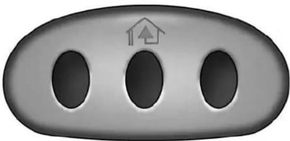
natural_image
Gray oval button with three circular holes and a small house icon on top (no text or symbols)034000355
HomeLink®Buttons/Sunvisor/Headliner
NOTE: HomeLink® is disabled when the Vehicle Security Alarm is active.
Before You Begin Programming HomeLink®
Be sure that your vehicle is parked outside of the garage before you begin programming.
For more efficient programming and accurate transmission of the radio-frequency signal it is recommended that a new battery be placed in the hand-held transmitter of the device that is being programmed to the HomeLink® system.
Erase all channels before you begin programming. To erase the channels place the ignition in the ON/RUN position and press and hold the two outside HomeLink® buttons (I and III) for up 20 seconds or until the red indicator flashes.
NOTE:
- Erasing all channels should only be performed when programming HomeLink® for the first time. Do not erase channels when programming additional buttons.
- If you have any problems, or require assistance, please call toll-free 1-800-355-3515 or, on the Internet at www.HomeLink.com for information or assistance.
Programming A Rolling Code
For programming garage door openers that were manufactured after 1995. These garage door openers can be identified by the "LEARN" or "TRAIN" button located where the hanging antenna is attached to the garage door opener. It is NOT the button that is normally used to open and close the door. The name and color of the button may vary by manufacturer.
UNDERSTANDING THE FEATURES OF YOUR VEHICLE 183
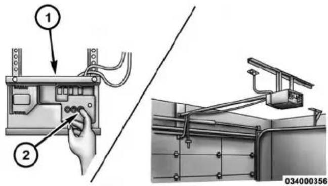
text_image
Technical diagram showing installation of a device with labeled components and a close-up view of the assembly.TrainingTheGarageDoorOpener
1 — Door Opener
2 — Training Button
- Cycle the ignition to the ON/RUN position.
184 UNDERSTANDING THE FEATURES OF YOUR VEHICLE
- Place the hand-held transmitter 1 to 3 in (3 to 8 cm) away from the HomeLink® button you wish to program while keeping the HomeLink® indicator light in view.
- Simultaneously press and hold both the HomeLink® button you want to program and the hand-held transmitter button.
- Continue to hold both buttons and observe the indicator light. The HomeLink® indicator will flash slowly and then rapidly after HomeLink® has received the frequency signal from the hand-held transmitter. Release both buttons after the indicator light changes from slow to rapid.
- At the garage door opener motor (in the garage), locate the "LEARN" or "TRAINING" button. This can usually be found where the hanging antenna wire is attached to the garage door opener/device motor.
Firmly press and release the "LEARN" or "TRAINING" button. On some garage door openers/devices there may be a light that blinks when the garage door opener/device is in the LEARN/TRAIN mode.
NOTE: You have 30 seconds in which to initiate the next step after the LEARN button has been pressed.
- Return to the vehicle and press the programmed HomeLink® button twice (holding the button for two seconds each time). If the garage door opener/device activates, programming is complete.
NOTE: If the garage door opener/device does not activate, press the button a third time (for two seconds) to complete the training.
To program the remaining two HomeLink® buttons, repeat each step for each remaining button. DO NOT erase the channels.
ReprogrammingASingleHomeLink®Button
To reprogram a channel that has been previously trained, follow these steps:
- Cycle the ignition to the ON/RUN position.
- Press and hold the desired HomeLink® button until the indicator light begins to flash after 20 seconds. Do not releasethebutton.
- Without releasing the button proceed with "Programming A Rolling Code" step 2 and follow all remaining steps.
Programming A Non-Rolling Code
For programming Garage Door Openers manufactured before 1995.
- Turn the ignition switch to the ON/RUN position.
UNDERSTANDING THE FEATURES OF YOUR VEHICLE 185
- Place the hand-held transmitter 1 to 3 in (3 to 8 cm) away from the HomeLink® button you wish to program while keeping the HomeLink® indicator light in view.
- Simultaneously press and hold both the Homelink® button you want to program and the hand-held transmitter button.
- Continue to hold both buttons and observe the indicator light. The Homelink® indicator will flash slowly and then rapidly after HomeLink® has received the frequency signal from the hand-held transmitter. Release both buttons after the indicator light changes from slow to rapid.
- Press and hold the programmed HomeLink® button and observe the indicator light.
- If the indicator light stays on constantly, programming is complete and the garage door/device should activate when the HomeLink® button is pressed.
186 UNDERSTANDING THE FEATURES OF YOUR VEHICLE
- To program the two remaining HomeLink® buttons, repeat each step for each remaining button. DO NOT erase the channels.
ReprogrammingASingleHomeLink®Button
To reprogram a channel that has been previously trained, follow these steps:
-
Cycle the ignition to the ON/RUN position.
-
Press and hold the desired HomeLink® button until the indicator light begins to flash after 20 seconds. Do not releasethebutton.
-
Withoutreleasingthebuttonproceed with "Programming A Non-Rolling Code" step 2 and follow all remaining steps.
Canadian/Gate Operator Programming
For programming transmitters in Canada/United States that require the transmitter signals to “time-out” after several seconds of transmission.
Canadian radio frequency laws require transmitter signals to time-out (or quit) after several seconds of transmission – which may not be long enough for HomeLink® to pick up the signal during programming. Similar to this Canadian law, some U.S. gate operators are designed to time-out in the same manner.
It may be helpful to unplug the device during the cycling process to prevent possible overheating of the garage door or gate motor.
- Cycle the ignition to the ON/RUN position.
-
Place the hand-held transmitter 1 to 3 in (3 to 8 cm) away from the HomeLink® button you wish to program while keeping the HomeLink® indicator light in view.
-
Continue to press and hold the HomeLink® button, while you press and release ("cycle"), your hand-held transmitter every two seconds until HomeLink® has successfully accepted the frequency signal. The indicator light will flash slowly and then rapidly when fully trained.
- Watch for the HomeLink® indicator to change flash rates. When it changes, it is programmed. It may take up to 30 seconds or longer in rare cases. The garage door may open and close while you are programming.
- Press and hold the programmed HomeLink® button and observe the indicator light.
- If the indicator light stays on constantly, programming is complete and the garage door/device should activate when the HomeLink® button is pressed.
- To program the two remaining HomeLink® buttons, repeat each step for each remaining button. DO NOT erase the channels.
UNDERSTANDING THE FEATURES OF YOUR VEHICLE 187
If you unplugged the garage door opener/device for programming, plug it back in at this time.
ReprogrammingASingleHomeLink®Button
To reprogram a channel that has been previously trained, follow these steps:
- Cycle the ignition to the ON/RUN position.
-
Press and hold the desired HomeLink® button until the indicator light begins to flash after 20 seconds. Do not releasethebutton.
-
Withoutreleasingthebuttonproceed with "Canadian/Gate Operator Programming" step 2 and follow all remaining steps.
188 UNDERSTANDING THE FEATURES OF YOUR VEHICLE
Using HomeLink®
To operate, press and release the programmed HomeLink® button. Activation will now occur for the programmed device (i.e., garage door opener, gate operator, security system, entry door lock, home/office lighting, etc.). The hand-held transmitter of the device may also be used at any time.
Security
It is advised to erase all channels before you sell or turn in your vehicle.
To do this, press and hold the two outside buttons for 20 seconds until the red indicator flashes. Note that all channels will be erased. Individual channels cannot be erased.
The HomeLink® Universal Transceiver is disabled when the Vehicle Security Alarm is active.
Troubleshooting Tips
If you are having trouble programming HomeLink®, here are some of the most common solutions:
- Replace the battery in the original hand-held transmitter.
- Press the LEARN button on the Garage Door Opener to complete the training for a Rolling Code.
- Did you unplug the device for programming and remember to plug it back in?
If you have any problems, or require assistance, please call toll-free 1-800-355-3515 or, on the Internet at www.HomeLink.com for information or assistance.
UNDERSTANDING THE FEATURES OF YOUR VEHICLE 189
WARNING!
Vehicleexhaustcontainscarbonmonoxide,adangerousgas.Donotrunyourvehicleinthegaragewhile programmingthetransceiver.Exhaustgascancause seriousinjuryordeath.
WARNING!(Continued)
useagaragedooropenerwithoutthesesafetyfeatures.Calltoll-free1-800-355-3515or,ontheInternetatwww.HomeLink.comforsafetyinformationorassistance.
WARNING!
Yourmotorizeddoororgatewillopenandclose whileyouareprogrammingtheuniversaltransceiver.Donotprogramthetransceiverifpeople,pets orotherobjectsareinthepathofthedoororgate. Onlyusethistransceiverwithagaragedooropener thathasa"stopandreverse"featureasrequired by Federalsafetystandards.Thisincludesmostgarage dooropenermodelsmanufacturedafter1982.Donot
General Information
This device complies with FCC rules Part 15 and Industry Canada RSS-210. Operation is subject to the following two conditions:
- This device may not cause harmful interference.
- This device must accept any interference that may be received including interference that may cause undesired operation.
(Continued)
190 UNDERSTANDING THE FEATURES OF YOUR VEHICLE NOTE:
- The transmitter has been tested and it complies with FCC and IC rules. Changes or modifications not expressly approved by the party responsible for compliance could void the user's authority to operate the device.
- The term IC before the certification/registration number only signifies that Industry Canada technical specifications were met.
POWER SUNROOF — IF EQUIPPED
The power sunroof switch is located on the overhead console.
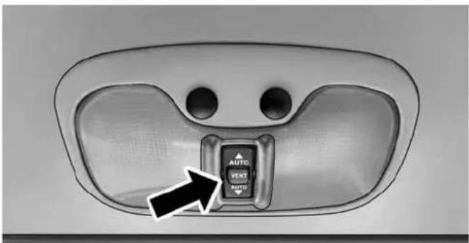
text_image
AUTO VENT AUTO034206938
PowerSunroofSwitch
UNDERSTANDING THE FEATURES OF YOUR VEHICLE 191
WARNING!
- Neverleavechildrenaloneinvehicle,orwith accesstoan unlocked vehicle. NeverleavetheKey Fobinornearthevehicle,orinalocationacces-sibletochildren.Occupants,particularlyunat-tendedchildren,canbecomeentrappedbythe powersunroofwhileoperatingthepowersunroof switch.Suchentrapmentmayresultinserious injuryordeath.
- Inacollision, thereisagreatarriskofbeingthrown from vehiclewithanopensunroof. You could also be seriously injuredorkilled. Always fasten your seatbeltproperly and makesureallpassengersareproperlysecured.
- Donotallowsmallchildrentooperatethesunroof. Neverallowyourfingers,otherbodyparts,orany objecttoprojectthroughthesunroofopening. Injurymayresult.
Opening Sunroof — Express
Press the switch rearward and release it within one-half second. The sunroof and sunshade will open automatically from any position. The sunroof and sunshade will open fully and stop automatically. This is called “Express Open”. During Express Open operation, any movement of the sunroof switch will stop the sunroof.
Opening Sunroof — Manual Mode
To open the sunroof, press and hold the switch rearward to full open. Any release of the switch will stop the movement. The sunroof and sunshade will remain in a partially opened condition until the switch is pushed and held rearward again.
192 UNDERSTANDING THE FEATURES OF YOUR VEHICLE
Closing Sunroof — Express
Press the switch forward and release it within one-half second and the sunroof will close automatically from any position. The sunroof will close fully and stop automatically. This is called “Express Close”. During Express Close operation, any movement of the switch will stop the sunroof.
Closing Sunroof — Manual Mode
To close the sunroof, press and hold the switch in the forward position. Any release of the switch will stop the movement and the sunroof will remain in a partially closed condition until the switch is pushed and held forward again.
Pinch Protect Feature
This feature will detect an obstruction in the opening of the sunroof during Express Close operation. If an obstruction in the path of the sunroof is detected, the sunroof will automatically retract. Remove the obstruction if this occurs. Next, press the switch forward and release to Express Close.
Venting Sunroof — Express
Press and release the Vent button within one half second and the sunroof will open to the vent position. This is called "Express Vent", and it will occur regardless of sunroof position. During Express Vent operation, any movement of the switch will stop the sunroof.
Sunshade Operation
The sunshade can be opened manually. However, the sunshade will open automatically as the sunroof opens.
NOTE: The sunshade cannot be closed if the sunroof is open.
Wind Buffeting
Wind buffeting can be described as the perception of pressure on the ears or a helicopter-type sound in the ears. Your vehicle may exhibit wind buffeting with the windows down, or the sunroof (if equipped) in certain open or partially open positions. This is a normal occurrence and can be minimized. If the buffeting occurs with the rear windows open, open the front and rear windows together to minimize the buffeting. If the buffeting occurs with the sunroof open, adjust the sunroof opening to minimize the buffeting or open any window.
Sunroof Maintenance
Use only a non-abrasive cleaner and a soft cloth to clean the glass panel.
UNDERSTANDING THE FEATURES OF YOUR VEHICLE 193
Ignition Off Operation
For Vehicles Not Equipped With The Electronic Vehicle Information Center (EVIC)
The power sunroof switch will remain active for 45 seconds after the ignition switch is turned to the LOCK position. Opening either front door will cancel this feature.
ForVehiclesEquippedWithTheEVIC
The power sunroof switch will remain active for up to approximately ten minutes after the ignition switch is turned to the LOCK position. Opening either front door will cancel this feature.
194 UNDERSTANDING THE FEATURES OF YOUR VEHICLE
ELECTRICAL POWER OUTLETS
There is a standard 12 Volt (13 Amp) power outlet located in the Integrated Center Stack (ICS) for added convenience. This power outlet can power mobile phones, electronics and other low power devices.
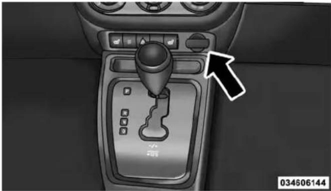
natural_image
Car gear shift control panel with a black arrow pointing to the left side (no text or symbols on the main component)12VoltPowerOutlet
Power is available when the ignition switch is in the ON or ACC position. Insert the cigar lighter or accessory plug into the outlet for use. Topreservetheheatingelement, donotholdthelighterintheheatingposition.
NOTE: To ensure proper operation a MOPAR® knob and element must be used.
CAUTION!
- Donotexceedthemaximumpowerof160Watts(13 Amps)at12Volts.Ifthe160Watt(13Amp)power ratingisexceededthefuseprotectingthesystem willneedtobereplaced.
- Poweroutletsaredesignedforaccessoryplugs only.Donotinsertanyotherobjectinthepower outletsasthiswilldamagetheoutletandblowthe fuse.Improperuseofthepoweroutletcancause damagenotcoveredbyyourNewVehicleLimited Warranty.
UNDERSTANDING THE FEATURES OF YOUR VEHICLE 195
natural_image
Interior view of a black electronic device showing internal components and a white arrow pointing to a specific component (no text or symbols visible)WARNING!
Toavoidseriousinjuryordeath:
- Onlydevicesdesignedforuseinthistypeofoutlet shouldbeinsertedintoany12Voltoutlet.
• Donottouchwithwethands. - Closethelidwhennotinuseandwhiledrivingthe vehicle.
- If this outletismishandled, it may cause an electric shock and failure.
034636797
PowerOutletFuseLocation
CAUTION!
- Manyaccessories that can be plugged in draw power from the vehicle's battery, even when not in use (i.e., cellular phones, etc.). Eventually, if plugged in longenough, the vehicle's battery will discharges sufficiently to degrade battery life and/or prevent the engine from starting.
- Accessories that draw higher power (i.e., coolers, vacuum cleaners, lights, etc.) will degrade the battery even more quickly. Only use these intermittently and with great caution.
- Aftertheuseofhighpowerdrawaccessories,or longperiodsofthevehiclenotbeingstarted(with accessoriesstillpluggedin),thevehiclemustbe drivenasufficientlengthoftimetoallowthe generatortorechargethevehicle'sbattery.
POWER INVERTER — IF EQUIPPED
A 115 Volt (150 Watt) AC power inverter is located on the front of the center console for added convenience. This outlet can power mobile phones, electronics and other low power devices requiring power up to 150 Watts. Certain high-end video games, such as PlayStation3 and XBox360 will exceed this power limit, as will most power tools.
The power inverter is designed with built-in overload protection. If the power rating of 150 Watts is exceeded, the power inverter will automatically shut down. Once the electrical device has been removed from the outlet the inverter should automatically reset. If the power rating exceeds approximately 170 Watts, the power inverter may have to be reset manually. To reset the inverter manually, unplug the device and plug it in again. To avoid overloading the circuit, check the power ratings on electrical devices prior to using the inverter.
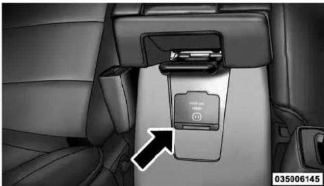
natural_image
Interior view of a car showing the rear seat with a close-up of the seatbelt (no text or symbols visible)115VoltPowerOutlet
UNDERSTANDING THE FEATURES OF YOUR VEHICLE 197
WARNING!
Toavoidseriousinjuryordeath:
- Donotuseathree-prongadaptor.
- Donotinsertanyobjectsintothereceptacles.
- Donottouchwithwethands.
• Closethelidwhennotinuse. - If this outletismishandled, it may cause an electric shock and failure.
CAUTION!
- Manyaccessoriesthatcanbepluggedindraw powerfromthevehicle'sbattery,evenwhennotin use(i.e.,cellularphones,etc.).Eventually,if pluggedinlongenough,thevehicle'sbatterywill dischargesufficientlytodegradebatterylifeand/or preventenginestarting.
(Continued)
198 UNDERSTANDING THE FEATURES OF YOUR VEHICLE
CAUTION!(Continued)
- Accessories that draw higher power (i.e., coolers, vacuum cleaners, lights, etc.) will degrade the battery even more quickly. Only us these intermittently and with great caution.
- Aftertheuseofhighpowerdrawaccessories,or longperiodsofthevehiclenotbeingstarted(with accessoriesstillpluggedin),thevehiclemustbe drivenasufficientlengthoftimetoallowthe generatortorechargethevehicle'sbattery.
CUPHOLDERS
Your vehicle is equipped with four cupholders. There are two illuminated cupholders located in the front.
natural_image
Interior view of a car dashboard with seatbelt and airway (no visible text or symbols)FrontCupholders
There are two cupholders located in the back for the rear passengers.

natural_image
Interior view of a car showing a car intake canal with an arrow pointing to the outlet (no text or symbols present)RearCupholders
UNDERSTANDING THE FEATURES OF YOUR VEHICLE 199
STORAGE
Glove Compartment And Storage Bin
Located on the passenger side of the instrument panel are an upper storage bin and a lower glove compartment.

text_image
Interior view of a car dashboard with labeled controls and a digital display showing the front panel.StorageBins
1 — Upper Storage Bin
2 — Lower Glove Compartment
200 UNDERSTANDING THE FEATURES OF YOUR VEHICLE
To open the lower glove compartment, pull outward on the release handle.
natural_image
Interior view of a vehicle showing a mechanical component with a downward arrow and mounting holes (no text or symbols)GloveCompartment
Door Storage
The interior door panels are equipped with lower storage areas.
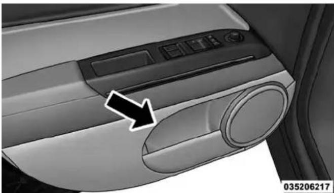
natural_image
Close-up of a car dashboard with a black arrow pointing to the left side (no visible text or symbols)FrontDoorStorage
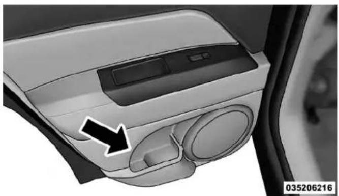
natural_image
Interior view of a car showing the dashboard and air vent with a black arrow pointing to the left side (no text or symbols on the main components)RearDoorStorage
UNDERSTANDING THE FEATURES OF YOUR VEHICLE 201
CONSOLE FEATURES
The floor console contains both an upper and lower storage compartment.
To open the upper storage compartment, push inward on the upper handle to unlatch the upper lid and lift the lid open.
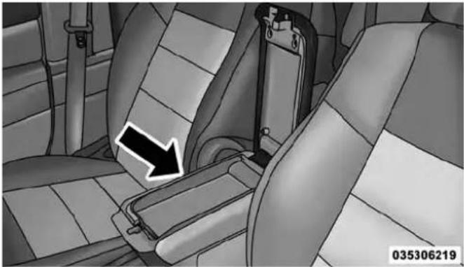
natural_image
Interior view of a car seatbelt with a black arrow pointing to the side panel (no text or symbols visible)UpperStorageCompartment
202 UNDERSTANDING THE FEATURES OF YOUR VEHICLE
To open the lower storage compartment, lift upward on the lower handle to unlatch the lower storage compartment and lift the lid open.

natural_image
Interior view of a car seatbelt with a black arrow pointing to the seatbelt (no text or symbols visible)LowerStorageCompartment
WARNING!
Donotoperatethisvehiclewithaconsolecompartmentlidintheopenposition.Drivingwiththeconsolecompartmentlidopenmayresultininjuryinacollision.
CARGO AREA FEATURES
Cargo Light/Removable Self-Recharging Flashlight
The dual-function light is mounted in the headliner above the cargo area to illuminate the cargo area, and part of it snaps out of the bezel to serve as a flashlight when needed. The flashlight features two bright LED light bulbs and is powered by rechargeable lithium batteries that recharge when snapped back into place for convenience.
UNDERSTANDING THE FEATURES OF YOUR VEHICLE 203
Press in on the flashlight to release it. To operate the flashlight, press the switch once for high,
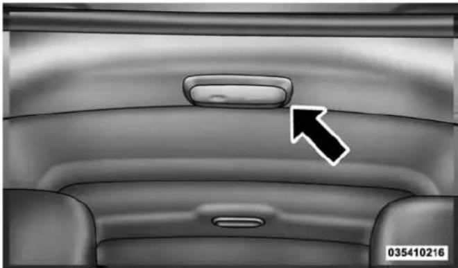
natural_image
Interior view of a car dashboard with a white arrow pointing to the top panel (no text or symbols on the dashboard itself)FlashlightLocation/PressToRelease
twice for low, and a third time to return to off.

natural_image
Close-up of a modern electronic device with a black arrow pointing to a button labeled 'RUSH' (no other text or symbols visible)035410217
ThreePressSwitch
204 UNDERSTANDING THE FEATURES OF YOUR VEHICLE
Cargo Cover
The cargo area trim panels include two notches for mounting the available tonneau cover that accommodates the reclining rear seat.
To install the Cargo Cover, insert either end of the cover into one of the two notches located in the rear trim panels. With one of the cover ends installed, push inward on the opposite end and install it into the same notch location of the rear trim panel.
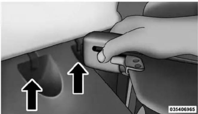
natural_image
Close-up of a hand adjusting a small mechanical component with two upward arrows indicating motion (no text or symbols)RearTrimNotches
Using the handle, pull the cover toward you and guide the rear cover posts into the guides located on both sides of the rear trim panel.
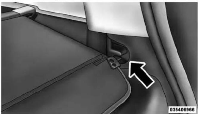
natural_image
Close-up of a car interior showing a seatbelt and attached vehicle (no visible text or symbols)CargoCoverGuides
UNDERSTANDING THE FEATURES OF YOUR VEHICLE 205
WARNING!
Inacollisionacargocoverlooseinthevehiclecould causeinjury.Itcouldflyaroundinasuddenstopand strikesomeoneinthevehicle.Donotstorethecargo coveronthecargofloororinthepassengercompartment.Removethecoverfromthevehiclewhentaken fromitsmounting.Donotstoreinthevehicle.
206 UNDERSTANDING THE FEATURES OF YOUR VEHICLE
Removable Load Floor
The cargo area load floor is removable and can be washed with mild soap and water.
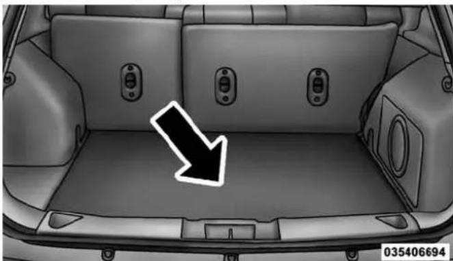
natural_image
Interior view of a car backhaul with a black arrow pointing to the rear compartment (no text or symbols on the vehicle itself)Cargo Tie-Down Loops
There are four tie-downs (D-rings) installed in the cargo area for securing cargo.
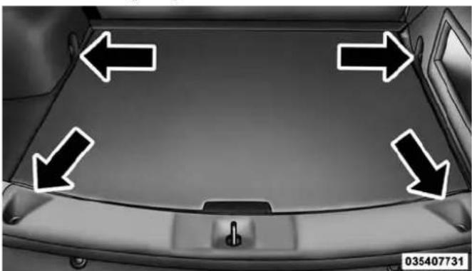
natural_image
Top-down view of a car's rear window with four directional arrows pointing inward (no text or symbols)RemovableLoadFloorCargoAreaTie-Downs
WARNING!
- Cargotie-downloopsarenotsafeanchorsfora childseattetherstrap.Inasuddenstoporcollision aloopcouldpullooseandallowthechildseatto comeloose.Achildcouldbebadlyinjured.Use onlytheanchorsprovidedforchildseattethers.
- Theweightandpositionofcargoandpassengers canchangethevehiclecenterofgravityandvehicle handling. To avoid loss of control resulting in personal injury, follow these guidelines for loading your vehicle:
- Alwaysplacecargoevenlyonthecargofloor.Put heavierobjectsaslowandasfarforwardaspossible.
WARNING!(Continued)
- Placeasmuchcargoaspossibleinfrontoftherear axle. Toomuchweightorimproperlyplacedweight overorbehindtherearaxlecancausetherearof thevehicletosway.
- Donotpile luggage or cargohigher than the top of these at back. This could impair visibility or become dangerous projectile in as sudden stop or collision.
- Tohelpprotectagainstpersonalinjury,passengers shouldnotbeseatedintherearcargoarea.Therear cargospaceisintendedforloadcarryingpurposes only,notforpassengers,whoshouldsitinseats anduseseatbelts.
208 UNDERSTANDING THE FEATURES OF YOUR VEHICLE Fold Down Speakers — If Equipped
When the liftgate is open, the speakers can swing down off the trim panel to face rearward, for tailgating and other activities.

natural_image
Top-down view of a car backrest with two large circular speakers and a black arrow pointing to the speaker area (no text or symbols)FoldDownSpeakers
REAR WINDOW FEATURES
Rear Window Wiper/Washer
The rear wiper/washer is controlled by a rotary switch located on the center portion of the control lever. The control lever is located on the right side of the steering column.
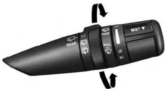
text_image
REAR O PULL LO HI FRONT MIST ▼031507505
RearWiper/WasherControlLever

Rotate the center portion of the lever upward to the first detent position for rear wiper operation.
NOTE: The rear wiper operates in an intermittent mode only.

Rotate the center portion of the lever past the first detent to activate the rear washer. The washer pump and the wiper will continue to operate as long as the switch is held (for a maximum of 10 seconds). Upon release, the wiper will continue to cycle two times before returning to the set position.
If the rear wiper is operating when the ignition is turned OFF, the wiper will automatically return to the "park" position if power accessory delay is active. Power accessory delay can be cancelled by opening the door, if this happens the rear wiper will stop at its current position and will not go to "park".
UNDERSTANDING THE FEATURES OF YOUR VEHICLE 209
Rear Window Defroster

The rear window defroster button is located on the bottom right-side of the blower control knob.
Press this button to turn on the rear window defroster and the heated outside mirrors (if equipped). An indicator in the button will illuminate when the rear window defroster is on. The rear window defroster automatically turns off after approximately 10 minutes. For an additional five minutes of operation, press the button a second time.
NOTE: To prevent excessive battery drain, use the rear window defroster only when the engine is operating.
CAUTION!
Failure to follow these cautions can cause damage to the heating elements:
- Usecarewhenwashingtheinsideoftherear window.Donotuseabrasivewindowcleanerson theinteriorsurfaceofthewindow.Useasoftcloth andamildwashingsolution,wipingparalleltothe heatingelements.Labelscanbepeeledoffafter soakingwithwarmwater.
- Donotusescrapers, sharpinstruments, or abrasive windowcleanersontheinteriorsurfaceofthe window.
- Keepallobjectsasafedistancefromthewindow.
ROOF LUGGAGE RACK — IF EQUIPPED
The crossbars and siderails are designed to carry the cargo on vehicles equipped with a luggage rack. The load must not exceed 150 lbs (68 kg), and should be uniformly distributed over the luggage rack crossbars.
NOTE: If not equipped with crossbars, your authorized dealer can order and install MOPAR® crossbars built specifically for this roof rack system.
Distribute cargo weight evenly on the luggage rack crossbars. The luggage rack does not increase the total load carrying capacity of the vehicle. Be sure the total load of cargo inside the vehicle plus that on the external rack does not exceed the maximum vehicle load capacity.
The crossbars must also be secured in one of the seven detent positions marked with an arrow on the siderails to prevent movement. To move the crossbars, loosen the thumb screws located at the upper edge of each crossbar approximately eight turns, then move the crossbar to the desired position, keeping the crossbars perpendicular to the luggage rack side rails. Once the crossbar is in one of the seven detent positions, retighten the thumb screws to lock the crossbar into position.
NOTE:
- To help control wind noise when the crossbars are not in use, place the front crossbar in the first detent from the front of the vehicle and the rear crossbar in the second detent from the rear of the vehicle.
UNDERSTANDING THE FEATURES OF YOUR VEHICLE 211
- If the rear crossbar (or any metallic object) is placed over the satellite radio antenna (if equipped), you may experience interruption of satellite radio reception. For improved satellite radio reception, place the rear crossbar in the second detent from the rear of the vehicle when not in use.
- The grab handles on the back of the vehicle (if equipped) are not to be used as a towing feature.
CAUTION!
- Topreventdamagetotheroofofyourvehicle,DO NOTcarryanyloadsontheluggagerackwithout crossbarsinstalled. Theloadshouldbesecuredand placedontopofthecrossbars,notdirectlyonthe roof. Ifitisnecessarytoplacetheloadontheroof, placeablanketorsomeotherprotectionbetween theloadandtheroofsurface.
(Continued)
212 UNDERSTANDING THE FEATURES OF YOUR VEHICLE
CAUTION!(Continued)
- To avoid damagetotheluggagerack and vehicle, donotexceed them a maximum luggagerack load capacity of 150 lb (68 kg). Always distribute heavy loads a seven ly as possible and secure the load appropriately.
- Longloadswhichextendoverthewindshield,such aswoodpanelsorsurfboards,orloadswithlarge frontalareashouldbesecuredtoboththefrontand rearofthevehicle.
- Travelatreducedspeedsandturncornerscarefully whencarryinglargeorheavyloadsontheroof rack.Windforces,duetonaturalcausesornearby trucktraffic,canaddsuddenupwardlifttoaload. Thisisespeciallytrueonlargeflatloadsandmay resultindamagetothecargooryourvehicle.
WARNING!
Cargomustbesecurelytiedbeforedrivingyour vehicle.Improperlysecuredloadscanflyoffthe vehicle,particularlyathighspeeds,resultinginpersonalinjuryorpropertydamage.Followtheroofrack cautionswhencarryingcargoonyourroofrack.
UNDERSTANDING YOUR INSTRUMENT PANEL
CONTENTS
■INSTRUMENT PANEL FEATURES....216
■INSTRUMENT CLUSTER....217
■INSTRUMENT CLUSTER DESCRIPTIONS . . . . .218
■MINI-TRIP COMPUTER — IF EQUIPPED . . . . .232
□Control Buttons....232
■ELECTRONIC VEHICLE INFORMATION CENTER (EVIC) — IF EQUIPPED .....234
☐Engine Oil Change Indicator System — If Equipped .....237
□EVIC Functions .....237
□Compass/Temperature/Audio....238
□Average Fuel Economy. . . . . . . . . . . . . . . . . . . . . . . . . . . . . . . . . . . . . . . 238
□Distance To Empty (DTE)....238
□Tire Pressure Monitor (TPM). . . . . . . . . . . . . . . . . . .239
□Elapsed Time....239
□Display Units Of Measure In . . . . . . . . . . . . . . . . . . . . . . . . 239
□Personal Settings (Customer-Programmable Features) .....239
■Uconnect® 230 – AM/FM STEREO RADIO AND 6-DISC CD/DVD CHANGER (MP3/WMA AUX JACK) .....245
□Operating Instructions — Radio Mode. . . . . . .245
214 UNDERSTANDING YOUR INSTRUMENT PANEL
☐Operation Instructions — DISC Mode For CD And MP3/WMA Audio Play, DVD – Video . . .254
□LIST Button — DISC Mode For MP3/WMA
Play....258
☐INFO Button — DISC Mode For MP3/WMA
Play....259
□Uconnect® (Satellite Radio) — If Equipped . . .261
■Uconnect® 730N/430/430N CD/DVD/HDD/NAV — IF EQUIPPED ....265
☐Operating Instructions (Voice Command System)
— If Equipped .....265
☐Operating Instructions (Uconnect® Phone) —
If Equipped. . . . . . . . . . . . . . . . . . . . . . . . . . . . . . . . . . . . . . . . . . . . . . . . . . . . . . . . . . . . . 265
■Uconnect® 130....266
□Operating Instructions — Radio Mode .....266
☐Operation Instructions — CD MODE For CD And MP3 Audio Play .....269
□Notes On Playing MP3 Files .....272
□Operation Instructions — Auxiliary Mode . . . .274
■Uconnect® 130 WITH SATELLITE RADIO . . . . .275
□Operating Instructions — Radio Mode . . . . . .275
☐Operation Instructions — CD MODE For CD And MP3 Audio Play .....281
□Notes On Playing MP3 Files .....284
□LIST Button — CD Mode For MP3 Play. . . . . .286
□INFO Button — CD Mode For MP3 Play . . . . .286
□Uconnect® (Satellite Radio) — If Equipped . . .287
UNDERSTANDING YOUR INSTRUMENT PANEL
215
■iPod®/USB/MP3 CONTROL — IF EQUIPPED....292
□Connecting The iPod® Or External USB Device....292
□Using This Feature. . . . . . . . . . . . . . . . . . . . . . . . . . . . . . . . . . . . . . . . . . . . . . 293
□Controlling The iPod® Or External USB Device Using Radio Buttons....293
□Play Mode....294
□List Or Browse Mode....295
□Bluetooth® Streaming Audio (BTSA)....297
■STEERING WHEEL AUDIO CONTROLS .....299
□Radio Operation....299
□CD Player....300
■CD/DVD DISC MAINTENANCE....300
text_image
Diagram of a car dashboard with numbered parts for identification and function keys040107732
1 — Air Outlet 5 — Storage Bin 9 — Heated Seat Switch – If Equipped
2 — Demisters 6 — Glove Compartment 10 — Hazard Warning Flasher
3 — Instrument Cluster 7 — Climate Controls 11 — ESC OFF Switch – If Equipped
4 — Radio 8 — Power Outlet 12 — Heated Seat Switch – If Equipped
INSTRUMENT CLUSTER

text_image
1 2 3 4 5 6 7 8 9 10 11 12 13 14 15 16 17 E F MPH 40 80 100 120 140 160 180 200 220 240 260 280 290 NW 80°F FM 101.9 P10 RPM 1000 P R N D 3 CRUSE AND BBB B B B TRIP C H O 21 20 19 18040335396
INSTRUMENT CLUSTER DESCRIPTIONS
1. FuelGauge/FuelDoorReminder

When the ignition switch is in the ON/RUN position, the pointer will show the level of fuel remaining in the fuel tank. The fuel pump symbol points to the side of the vehicle where
the fuel door is located.
2. ChargingSystemLight

This light shows the status of the electrical charging system. The light should come on when the ignition switch is first turned to ON/RUN and remain on briefly as a bulb check. If the light stays on or comes on while driving, turn off some of the vehicle's non-essential electrical devices or increase engine speed (if at idle). If the charging system light remains on, it means that the vehicle is experiencing a problem with the charging system. Obtain SERVICE IMMEDIATELY. See an authorized dealer.
If jump starting is required, refer to "Jump Starting Procedures" in "What To Do In Emergencies".
3. Electronic Throttle Control (ETC) Light

This light informs you of a problem with the Electronic Throttle Control (ETC) system. If a problem is detected, the light will come on while the engine is running. Cycle the ignition key when the vehicle has completely stopped and the shift lever is placed in the PARK position. The light should turn off. If the light remains lit with the engine running, your vehicle will usually be drivable; however, see an authorized dealer for service as soon as possible. If the light is flashing when the engine is running, immediate service is required and you may experience reduced performance, an elevated/rough idle or engine stall and your vehicle may require towing. The light will come on when the ignition is first turned to ON/RUN and remain on briefly as a bulb check. If the light does not come on during starting, have the system checked by an authorized dealer.
UNDERSTANDING YOUR INSTRUMENT PANEL 219
4.OilPressureWarningLight

This light indicates low engine oil pressure. The light should turn on momentarily when the engine is started. If the light turns on while driving, stop the vehicle and shut off the engine as soon as possible. A chime will sound when this light turns on.
Do not operate the vehicle until the cause is corrected. This light does not indicate how much oil is in the engine. The engine oil level must be checked under the hood.
5.LowFuelLight

When the fuel level reaches approximately 2.0 gal (7.8 L) this light will turn on, and remain on until added.
6.Speedometer
The Speedometer shows the vehicle speed in miles per hour (MPH) and kilometers per hour (km/h).
7.AirBagWarningLight

This light will turn on for four to eight seconds as a bulb check when the ignition switch is first turned to ON/RUN. If the light is either not on during starting, stays on, or turns on while driving, have the system inspected at an authorized dealer as soon as possible. Refer to "Occupant Restraints" in "Things To Know Before Starting Your Vehicle" for further information.
8. TurnSignalIndicators

The arrow will flash with the exterior turn signal when the turn signal lever is operated.
If the vehicle is driven more than 1 mile (1.6 km) with either turn signal on, a continuous chime will sound to alert you to turn the signals off. If either indicator flashes at a rapid rate, check for a defective outside light bulb.
9. HighBeamIndicator

This indicator shows that the high beam headlights are on. Push the multifunction lever forward to switch the headlights to high beam, and pull toward yourself (normal position) to return to low beam.
10.Anti-LockBrake(ABS)Light

This light monitors the Anti-Lock Brake System (ABS). The light will turn on when the ignition switch is turned to the ON/RUN position and may stay on for as long as four seconds.
If the ABS light remains on or turns on while driving, it indicates that the Anti-Lock portion of the brake system is not functioning and that service is required. However, the conventional brake system will continue to operate normally if the BRAKE warning light is not on.
If the ABS light is on, the brake system should be serviced as soon as possible to restore the benefits of Anti-Lock brakes. If the ABS light does not turn on when the ignition switch is turned to the ON/RUN position, have the light inspected by an authorized dealer.
11.SeatBeltReminderLight

When the ignition switch is first turned to ON/RUN, this light will turn on for four to eight seconds as a bulb check. During the bulb check, if
the driver's seat belt is unbuckled, a chime will sound.
After the bulb check or when driving, if the driver's seat belt remains unbuckled, the Seat Belt Reminder Light will illuminate and the chime will sound. Refer to
"Occupant Restraints" in "Things To Know Before Starting Your Vehicle" for further information.
12.Tachometer
The white area of the scale shows the permissible engine revolutions-per-minute (RPM x 1000) for each gear range. Before reaching the red area, ease up on the accelerator to prevent engine damage.
13. Engine Temperature Warning Light

This light warns of an overheated engine condition. As engine coolant temperatures rise and the gauge approaches H, this indicator will illuminate and a single chime will sound after reaching a set threshold.
Further overheating will cause the temperature gauge to pass H_r a continuous chime will occur until the engine is allowed to cool or the 4 minutes duration is expired, whichever come first.
If the light turns on while driving, safely pull over and stop the vehicle. If the A/C system is on, turn it off. Also, shift the transmission into NEUTRAL and idle the vehicle. If the temperature reading does not return to normal, turn the engine off immediately and call for service. Refer to "If Your Engine Overheats" in "What To Do In Emergencies" for further information.
14.BrakeWarningLight
BRAKE This light monitors various brake functions, including brake fluid level and parking brake application. If the brake light turns on it may indicate that the parking brake is applied, that the brake fluid level is low, or that there is a problem with the anti-lock brake system reservoir.
If the light remains on when the parking brake has been disengaged, and the fluid level is at the full mark on the master cylinder reservoir, it indicates a possible brake hydraulic system malfunction or that a problem with the Brake Booster has been detected by the Anti-Lock Brake System (ABS) / Electronic Stability Control (ESC) system. In this case, the light will remain on until the condition has been corrected. If the problem is related to the brake booster, the ABS pump will run when applying the brake and a brake pedal pulsation may be felt during each stop.
The dual brake system provides a reserve braking capacity in the event of a failure to a portion of the hydraulic system. A leak in either half of the dual brake system is indicated by the Brake Warning Light, which will turn on when the brake fluid level in the master cylinder has dropped below a specified level.
The light will remain on until the cause is corrected.
NOTE: The light may flash momentarily during sharp cornering maneuvers, which change fluid level conditions. The vehicle should have service performed, and the brake fluid level checked.
If brake failure is indicated, immediate repair is necessary.
WARNING!
Drivingvehiclewiththeredbrakelightonis dangerous.Partofthebrakesystemmayhavefailed. Itwilltakelongertostopthevehicle.Youcouldhave acollision.Havethevehiclecheckedimmediately.
Vehicles equipped with the Anti-Lock Brake System (ABS), are also equipped with Electronic Brake Force Distribution (EBD). In the event of an EBD failure, the Brake Warning Light will turn on along with the ABS Light. Immediate repair to the ABS system is required.
Operation of the Brake Warning Light can be checked by turning the ignition switch from the OFF position to the ON/RUN position. The light should illuminate for approximately two seconds. The light should then turn off unless the parking brake is applied or a brake fault is detected. If the light does not illuminate, have the light inspected by an authorized dealer.
The light also will turn on when the parking brake is applied with the ignition switch in the ON/RUN position.
NOTE: This light shows only that the parking brake is applied. It does not show the degree of brake application.
- Transmission Temperature Warning Light

This light indicates that the transmission fluid temperature is running hot. This may occur with severe usage, such as trailer towing. If this light turns on, safely pull over and stop them vehicle. Then, shift the transmission into NEUTRAL and run the engine at idle or faster until the light turns off.
CAUTION!
ContinuousdrivingwiththeTransmissionTemperatureWarningLightilluminatedwilleventuallycauseseveretransmissiondamageortransmissionfailure.
WARNING!
If you continue operating the vehicle when the Transmission Temperature Warning Light is illuminated you could cause the fluid to oil over, come in contact with hot engine exhaust components and cause a fire.
- VehicleSecurityLight—IfEquipped

This light will flash at a fast rate for approximately 16 seconds, when the vehicle security alarm is arming, and then will flash slowly until the vehicle is disarmed.
- Temperature Gauge
The temperature gauge shows engine coolant temperature. Any reading within the normal range indicates that the engine cooling system is operating satisfactorily.
224 UNDERSTANDING YOUR INSTRUMENT PANEL
The gauge pointer will likely indicate a higher temperature when driving in hot weather, up mountain grades, or when towing a trailer. It should not be allowed to exceed the upper limits of the normal operating range.
CAUTION!
Drivingwithahotenginecoolingsystemcould damageyourvehicle.Ifthetemperaturegaugereads "H"pulloverandstopthevehicle.Idlethevehicle withtheairconditionerturnedoffuntilthepointer dropsbackintothenormalrange.Ifthepointer remainsonthe"H"andyouhearcontinuouschimes, turntheengineoffimmediatelyandcallanaauthorizeddealerforservice.
WARNING!
Ahotenginecoolingsystemisdangerous.Youor otherscouldbebadlyburnedbysteamorboiling coolant.Youmaywanttocallanauthorizeddealer forserviceifyourvehicleoverheats.Ifyoudecideto lookunderthehoodyourself,see“MaintainingYour Vehicle”.FollowthewarningsundertheCooling SystemPressureCapparagraph.
- CruiseIndicator—IfEquipped
CRUISE This indicator shows that the Electronic Speed Control System is ON.
19.4WDIndicator—IfEquipped
This light indicates the vehicle is in the 4-Wheel Drive mode.
20.ShiftLeverIndicator
The Shift Lever Indicator is self-contained within the instrument cluster. It displays the gear position of the automatic transmission.
NOTE: You must apply the brakes before shifting from PARK.
21.Odometer/TripOdometerResetButton
Press this button to change the display from odometer to either of the two trip odometer settings. Trip A or Trip B will appear when in the trip odometer mode. Push in and hold the button for two seconds to reset the trip odometer to 0 miles or kilometers. The odometer must be in Trip mode to reset.
22. TirePressureMonitoringTelltaleLight

Each tire, including the spare (if provided), should be checked monthly when cold and inflated to the inflation pressure recommended by
the vehicle manufacturer on the vehicle placard or tire inflation pressure label. (If your vehicle has tires of a different size than the size indicated on the vehicle placard or tire inflation pressure label, you should determine the proper tire inflation pressure for those tires.)
As an added safety feature, your vehicle has been equipped with a Tire Pressure Monitoring System (TPMS) that illuminates a low tire pressure telltale when one or more of your tires is significantly under-inflated. Accordingly, when the low tire pressure telltale illuminates, you should stop and check your tires as soon as possible, and inflate them to the proper pressure. Driving on a significantly under-inflated tire causes the tire to overheat and can lead to tire failure. Under-inflation also reduces fuel efficiency and tire tread life, and may affect the vehicle's handling and stopping ability.
Please note that the TPMS is not a substitute for proper tire maintenance, and it is the driver's responsibility to maintain correct tire pressure, even if under-inflation has not reached the level to trigger illumination of the TPMS low tire pressure telltale.
Your vehicle has also been equipped with a TPMS malfunction indicator to indicate when the system is not operating properly. The TPMS malfunction indicator is combined with the low tire pressure telltale. When the system detects a malfunction, the telltale will flash for approximately one minute and then remain continuously illuminated. This sequence will continue upon subsequent vehicle start-ups as long as the malfunction exists. When the malfunction indicator is illuminated, the system may not be able to detect or signal low tire pressure as intended. TPMS malfunctions may occur for a variety of reasons, including the installation of replacement or alternate tires or wheels on the vehicle that prevent the TPMS from functioning properly. Always check the
TPMS malfunction telltale after replacing one or more tires or wheels on your vehicle, to ensure that the replacement or alternate tires and wheels allow the TPMS to continue to function properly.
CAUTION!
TheTPMShasbeenoptimizedfortheoriginal equipment tires and wheels. TPMS pressures and warninghavebeenestablishedforthetiresize equippedonyourvehicle.Undesirable systemoperation or sensor damage may result when using replacementequipmentthatisnotofthesamesize, type,and/orstyle.Aftermarketwheelscancause sensordamage.Donotusetiresealantfromacanor balance beads if your vehicle is equipped with a TPMS,asdamagetothesensorsmayresult.
23.OdometerDisplay/TripOdometerDisplayArea
This display indicates the total distance the vehicle has been driven.
NOTE: U.S. Federal regulations require that upon transfer of vehicle ownership, the seller certify to the purchaser the correct mileage that the vehicle has been driven. If your odometer needs to be repaired or serviced, the repair technician should leave the odometer reading the same as it was before the repair or service. If s/he cannot do so, then the odometer must be set at zero, and a sticker must be placed in the door jamb stating what the mileage was before the repair or service. It is a good idea for you to make a record of the odometer reading before the repair/service, so that you can be sure that it is properly reset, or that the door jamb sticker is accurate if the odometer must be reset at zero.
VehicleOdometerMessages
When the appropriate conditions exist, the following odometer messages will display:
door. . . . . . . . . . . . . . . . . . . . . . . . . . . . . . . . . . Door Ajar
gATE. Gate Ajar
gASCAP.... Fuel Cap Fault
LoWtirE. . . . . . . . . . . . . . . . . . . . . . . . . . . . . . . . . . . . . . . . . . . . Low Tire Pressure
CHANgEOIL. . . . . . . . . . . . . O i l Change Required
HOTOIL.... Engine Oil Temp Too Hot
228 UNDERSTANDING YOUR INSTRUMENT PANEL
NOTE: If the vehicle is equipped with the optional Electronic Vehicle Information Center (EVIC) in the instrument cluster, all warnings including "Door Ajar", and "Gate Ajar" will only be displayed in the EVIC display. For additional information, refer to "Electronic Vehicle Information Center — If Equipped".
gASCAP
If the vehicle diagnostic system determines that the fuel filler cap is loose, improperly installed, or damaged, a "gASCAP" message will display in the odometer display area. Tighten the fuel filler cap properly and press the TRIP ODOMETER button to turn off the message. If the problem continues, the message will appear the next time the vehicle is started.
A loose, improperly installed, or damaged fuel filler cap may also turn on the Malfunction Indicator Light (MIL).
LoWtirE
When tire pressure is low, the odometer display will toggle between LoW and tirE for three cycles.
HOTOIL
When this message is displayed there is a engine over-temperature condition. When this condition occurs, the "HOTOIL" message will be displayed in the odometer along with a chime.
Refer to "Engine Oil Overheating" under in "What To Do In Emergencies".
CHANgEOILMessage
Your vehicle is equipped with an engine oil change indicator system. The “CHANgE OIL” message will flash in the instrument cluster odometer for approximately 12 seconds after a single chime has sounded to indicate the next scheduled oil change interval. The engine oil change indicator system is duty-cycle based, which means the
engine oil change interval may fluctuate dependent upon your personal driving style. Unless reset, this message will continue to display each time you turn the ignition switch to the ON/RUN position. To turn off the message temporarily, press and release the Trip Odometer button on the instrument cluster. To reset the oil change indicator system (after performing the scheduled maintenance), refer to the following procedure:
- Turn the ignition switch to the ON/RUN position (do not start the engine).
- Fully depress the accelerator pedal, slowly, three times within 10 seconds.
- Turn the ignition switch to the OFF/LOCK position.
NOTE: If the indicator message illuminates when you start the engine, the oil change indicator system did not reset. If necessary, repeat this procedure.
24. MalfunctionIndicatorLight(MIL)

The Malfunction Indicator Light (MIL) is part of an Onboard Diagnostic system called OBD II that monitors emissions, engine, and automatic transmission control systems. The light will illuminate when the key is in the ON/RUN position before engine start. If the bulb does not come on when turning the key from OFF to ON/RUN, have the condition checked promptly.
Certain conditions, such as a loose or missing gas cap, poor fuel quality, etc., may illuminate the light after engine start. The vehicle should be serviced if the light stays on through several of your typical driving cycles. In most situations, the vehicle will drive normally and will not require towing.
CAUTION!
ProlongeddrivingwiththeMalfunctionIndicator Light(MIL)oncouldcausedamagetotheengine controlsystem.Italsocouldaffectfueleconomyand driveability.IftheMILisflashing,severecatalytic converterdamageandpowerlosswillsoonoccur. Immediateserviceisrequired.
WARNING!
Amalfunctioningcatalyticconverter, as referenced above, can reach high temperature than innormal operating conditions. This can cause a fire if you drive slowly or park over flammable substances such as dry plants, wood, cardboard, etc. This could result in deathor serious injury to the driver, occupants or others.
25.FrontFogLightIndicator—IfEquipped

This indicator will illuminate when the front fog lights are on.
- Electronic Stability Control (ESC) OFF Indicator Light—If Equipped

This light indicates the Electronic Stability Control system (ESC) has been turned off by the driver.
- Electronic Stability Control (ESC) Activation/Malfunction Indicator Light—If Equipped

The “ESC Activation/Malfunction Indicator Light” in the instrument cluster will come on when the ignition switch is turned to the ON/RUN position. It should go out with the ning. If the “ESC Activation/Malfunction Inght” comes on continuously with the engine
running, a malfunction has been detected in the ESC system. If this light remains on after several ignition cycles, and the vehicle has been driven several miles (kilometers) at speeds greater than 30 mph (48 km/h), see your authorized dealer as soon as possible to have the problem diagnosed and corrected.
NOTE:
- The "ESC Off Indicator Light" and the "ESC Activation/Malfunction Indicator Light" come on momentarily each time the ignition switch is turned to ON/RUN.
- Each time the ignition is turned to ON/RUN, the ESC system will be ON, even if it was turned off previously.
- The ESC system will make buzzing or clicking sounds when it is active. This is normal; the sounds will stop when ESC becomes inactive following the maneuver that caused the ESC activation.
UNDERSTANDING YOUR INSTRUMENT PANEL 231
28.4WD!WarningLight—IfEquipped
4WD!
This light monitors the 4-Wheel Drive (4WD) system. The light will come on, for a bulb check, when the ignition key is turned to the ON/RUN position and may stay on for as long seconds.
Whenlitsolid: There is a 4WD system fault. 4WD performance will be at a reduced level. Service the 4WD system soon.
Whenblinking:The 4WD system is temporarily disabled due to overload condition.
29. Electronic Vehicle Information Center (EVIC) Display—If Equipped
When the appropriate conditions exist, this display shows the EVIC messages.
For further information, refer to "Electronic Vehicle Information Center (EVIC)".
232 UNDERSTANDING YOUR INSTRUMENT PANEL
30.HillDescentIndicator—IfEquipped

The symbol illuminates (is armed) when the 4WD Lock switch is activated and the transmission range indicator is in LOW or REVERSE position (Off-Road Mode).
MINI-TRIP COMPUTER — IF EQUIPPED
The Mini-Trip Computer is located in the instrument cluster and features a driver-interactive trip information and temperature display.
NOTE: The system will display the last known outside temperature when starting the vehicle and may need to be driven several minutes before the updated temperature is displayed. Engine temperature can also affect the displayed temperature; therefore, temperature readings are not updated when the vehicle is not moving.
Control Buttons

text_image
STEP RESET 040541179 Mini-TripControlButtonsSTEPButton
Press the STEP button located on the steering wheel to scroll through sub menus (i.e., Temperature, Trip Functions: Odometer, Trip A, Trip B).
UNDERSTANDING YOUR INSTRUMENT PANEL 233
RESETButton
To reset the display shown, turn the ignition switch to the ON position, then press and hold the RESET button located on the steering wheel.
The following displays can be reset or changed:
- Trip A
- Trip B
TripOdometer(ODO)
This display shows the distance traveled since the last reset. Press and release the STEP button on the instrument cluster to switch from odometer, to Trip A or Trip B.
TripA
Shows the total distance traveled for Trip A since the last reset.
TripB
Shows the total distance traveled for Trip B since the last reset.
234 UNDERSTANDING YOUR INSTRUMENT PANEL
ELECTRONIC VEHICLE INFORMATION CENTER (EVIC) — IF EQUIPPED
The Electronic Vehicle Information Center (EVIC) features a driver-interactive display that is located in the instrument cluster.

text_image
041035271 041035271ElectronicVehicleInformationCenter(EVIC)
The EVIC consists of the following:
- System Status
- Units
• Vehicle Information Warning Message Displays - Personal Settings (Customer-Programmable Features)
- Compass Heading
• Outside Temperature Display - Trip Computer Functions
• Uconnect® Phone Displays (if equipped) - Audio Mode Display
• Tire Pressure Monitor (TPM)
The system allows the driver to select information by pressing the following buttons mounted on the steering wheel:

text_image
VR MENUEVICSteeringWheelButtons
041035449
UNDERSTANDING YOUR INSTRUMENT PANEL 235
MENUButton
MENU
Press and release the MENU button to scroll through the main menus (Fuel Economy, Warnings, Timer, Units, System, Personal Settings) or to exit sub-menus.
COMPASSButton

Press and release the COMPASS button to display one of eight compass readings and the outside temperature or to exit sub-menus.
SELECTButton

Press and release the SELECT button for access to main menus, sub-menus or to select a personal setting in the setup menu.
DOWNButton

Press and release the DOWN button to scroll downward through the sub-menus.
236 UNDERSTANDING YOUR INSTRUMENT PANEL
When the appropriate conditions exist, the EVIC displays the following messages:
- Turn Signal On (with a continuous warning chime after 1 mile (1.6 km) of distance travelled)
- Left Front Turn Signal Lamp Out (with a single chime)
- Left Rear Turn Signal Lamp Out (with a single chime)
- Right Front Turn Signal Lamp Out (with a single chime)
- Right Rear Turn Signal Lamp Out (with a single chime)
•RKE Battery Low (with a single chime) - Personal Settings Not Avail. — Vehicle not in PARK (automatic transmission) or vehicle is in motion (manual transmission).
-
Door Ajar (with vehicle graphic showing which door is open. A single chime sounds if the vehicle is in motion).
-
Doors Ajar (with vehicle graphic showing which doors are open. A single chime sounds if the vehicle is in motion).
- Gate (with vehicle graphic showing the Liftgate open and A single chime)
• Headlamps or Park Lamps On - Remote Start Aborted — Door Ajar
- Remote Start Aborted — Hood Ajar
- Remote Start Aborted — L/Gate Ajar
- Remote Start Aborted — Fuel Low
- Remote Start Aborted — System Fault
• Key In Ignition - Low Tire
- Low Tire Pressure Display for Premium TPM System
•Service TPM System
Engine Oil Change Indicator System — If Equipped OilChangeRequired
Your vehicle is equipped with an engine oil change indicator system. The “Oil Change Required” message will flash in the EVIC display for approximately five seconds after a single chime has sounded, to indicate the next scheduled oil change interval. The engine oil change indicator system is duty-cycle based, which means the engine oil change interval may fluctuate dependent upon your personal driving style.
Unless reset, this message will continue to display each time you turn the ignition switch to the ON/RUN position. To turn off the message temporarily, press and release the Trip Odometer button on the instrument cluster. To reset the oil change indicator system (after performing the scheduled maintenance) refer to the following procedure.
-
Turn the ignition switch to the ON position. Donot starttheengine.
-
Fully depress the accelerator pedal, slowly, three times within 10 seconds.
- Turn the ignition switch to the OFF/LOCK position.
NOTE: If the indicator message illuminates when you start the vehicle, the oil change indicator system did not reset. If necessary repeat this procedure.
EVIC Functions
- Compass/Temperature/Audio
• Average Fuel Economy
• Distance To Empty (DTE) - Units In
- Elapsed Time
• Tire Pressure Monitor (TPM) - Personal Settings
238 UNDERSTANDING YOUR INSTRUMENT PANEL
ToResetTheDisplay
Pressing and holding the SELECT button once will clear the function currently being displayed. Reset will only occur if a resettable function is currently being displayed. To reset all resettable functions, press and release the SELECT button a second time within three seconds of resetting the currently displayed function. Reset ALL will be displayed during this three-second window.
Compass/Temperature/Audio
Press and release the COMPASS button to display one of eight compass headings to indicate the direction the vehicle is facing, the outside temperature, and the current radio station.
For additional information regarding the compass, refer to Personal Settings (Customer-Programmable Features).
Average Fuel Economy
Shows the average fuel economy since the last reset. When the fuel economy is reset, the display will read "RESET" or show dashes for two seconds. Then, the history information will be erased, and the averaging will continue from the last fuel reading before the reset.
Distance To Empty (DTE)
Shows the estimated distance that can be traveled with the fuel remaining in the tank. This estimated distance is determined by a weighted average of the instantaneous and average fuel economy, according to the current fuel tank level. This is not resettable.
NOTE: Significant changes in driving style or vehicle loading will greatly affect the actual drivable distance of the vehicle, regardless of the DTE displayed value.
UNDERSTANDING YOUR INSTRUMENT PANEL 239
When the DTE value is less than 30 miles (48 km) estimated driving distance, the DTE display will change to a text display of "LOW FUEL". This display will continue until the vehicle runs out of fuel. Adding a significant amount of fuel to the vehicle will turn off the "LOW FUEL" text and a new DTE value will be displayed, based on the current values in the DTE calculation and the current fuel tank level.
Tire Pressure Monitor (TPM)
Refer to "Starting And Operating", "Tire Pressure Monitoring System (TPMS)" for system operation.
Elapsed Time
Shows the total elapsed time of travel since the last reset. Elapsed time will increment when the ignition switch is in the RUN/START position.
Elapsed time is displayed as follows:
hours:minutes:seconds
Elapsed time can be reset by pressing and holding the SELECT button (as prompted in the EVIC display). Upon reset all digits will change to zeros and time will start incrementing again if the ignition switch is in RUN or START.
Display Units Of Measure In
To make your selection, press and release the SELECT button until "ENGLISH" or "METRIC" appears.
Personal Settings (Customer-Programmable Features)
This allows the driver to set and recall features when the transmission is in PARK (automatic transmission) or the vehicle is stopped (manual transmission).
Press and release the MENU or DOWN buttons until "Personal Settings" is displayed in the EVIC then press the SELECT button.
240 UNDERSTANDING YOUR INSTRUMENT PANEL
Use the SELECT button to display one of the following choices:
Language
When in this display you may select different languages for all display nomenclature, including the trip functions. Pressing the SELECT button while in this display selects English, Espanol, Deutsch, Italiano, Francais or NL depending on availability. As you continue, the displayed information will be shown in the selected language.
NOTE:Uconnect® language will not change using the EVIC. Please refer to "Language Selection" in Uconnect® phone — If Equipped for details.
AutoLockDoors
When ON is selected, all doors lock automatically when the speed of the vehicle reaches 15 mph (24 km/h). Press and hold the SELECT button when in this display until "ON" or "OFF" appears to make your selection.
AutoUnlockOnExit
When ON is selected, all the vehicle's doors will unlock when the driver's door is opened, if the vehicle is stopped (manual transmission) or the vehicle is stopped and the transmission is in the PARK or NEUTRAL position (automatic transmission). Press and hold the SELECT button when in this display until "ON" or "OFF" appears to make your selection.
RKEUnlock
When Driver's Door 1st is selected only the driver's door will unlock on the first press of the Remote Keyless Entry (RKE) transmitter UNLOCK button and require a second press to unlock the remaining locked doors. When Remote Unlock All Doors is selected, all of the doors will unlock at the first press of the RKE transmitter UNLOCK button. Press and hold the SELECT button when in this display until "Driver's Door 1st" or "All Doors" appears to make your selection.
FlashLampsWithLock
When ON is selected, the front and rear turn signals will flash when the doors are locked or unlocked using the RKE transmitter. This feature may be selected with or without the sound horn with lock feature selected. Press and hold the SELECT button when in this display until "ON" or "OFF" appears to make your selection.
SoundHornWithLock
When ON is selected, a short horn sound will occur when the RKE transmitter LOCK button is pressed. This feature may be selected with or without the Flash Lights with Lock feature. Press and hold the SELECT button when in this display until "ON" or "OFF" appears to make your selection.
HeadlampOffDelay
When this feature is selected the driver can choose to have the headlights remain on for 0, 30, 60, or 90 seconds when exiting the vehicle. Press and hold the SELECT button when in this display until 0, 30, 60, or 90 appears to make your selection.
KeyOffPowerDelay
When this feature is selected the power window switches, radio, Uconnect® phone, power sunroof, and power outlets will remain active for up to 10 minutes after the ignition switch has been turned OFF. Opening either front vehicle door will cancel this feature. Press and hold the SELECT button when in this display until "OFF", "45 sec.", "5 min.", or "10 min." appears to make your selection.
242 UNDERSTANDING YOUR INSTRUMENT PANEL
IlluminatedApproach
When this feature is selected the headlights will activate and remain on for up to 90 seconds when the doors are unlocked using the RKE transmitter. Press and hold the SELECT button when in this display until "OFF", "30 sec.", "60 sec.", or "90 sec." appears to make your selection.
HillStartAssist(HSA)—IfEquipped
When on is selected, the HSA system is active. Refer to "Electronic Brake Control System" in "Starting And Operating" for system function and operating information. To make your selection, press and release the SELECT button until "On" or "Off" appears.
DisplayUnitsIn
The EVIC, odometer, and Uconnect® gps system units can be changed between English and Metric.
Press and hold the SELECT button when in this display until "ENGLISH" or "METRIC" appears to make your selection.
AutomaticCompassCalibration
This compass is self-calibrating, which eliminates the need to set the compass manually. When the vehicle is new, the compass may appear erratic and the EVIC will display "CAL" until the compass is calibrated. You may also calibrate the compass by completing one or more 360-degree turns (in an area free from large metal or metallic objects) until the "CAL" message displayed in the EVIC turns off. The compass will now function normally.
NOTE:A good calibration requires a level surface and an environment free from large metallic objects such as buildings, bridges, underground cables, railroad tracks, etc.
UNDERSTANDING YOUR INSTRUMENT PANEL 243
ManualCompassCalibration
If the compass appears erratic and the "CAL" indicator does not appear in the EVIC display, you must put the compass into the Calibration Mode manually as follows:
- Start the engine. Leave the shift lever in PARK in order to enter the EVIC Programming Menus.
- Press the MENU button until the Personal Settings (Customer-Programmable Features) menu displays in the EVIC.
- Press the DOWN button until "Calibrate Compass" displays in the EVIC.
-
Press and release the SELECT button to start the calibration. The "CAL" indicator will display in the EVIC.
-
Complete one or more 360-degree turns (in an area free from large metal or metallic objects) until the "CAL" indicator turns off. The compass will now function normally.
CompassVariance
Compass Variance is the difference between Magnetic North and Geographic North. To compensate for the differences, the variance should be set for the zone where the vehicle is driven, per the zone map. Once properly set, the compass will automatically compensate for the differences and provide the most accurate compass heading.
244 UNDERSTANDING YOUR INSTRUMENT PANEL
NOTE: Magnetic materials should be kept away from the top of the right rear quarter window. This is where the compass sensor is located.
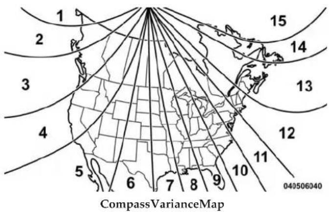
text_image
1 2 3 4 5 6 7 8 9 10 11 12 13 14 15 040506040 CompassVarianceMap- Turn the ignition switch ON.
- Press and hold the COMPASS button for approximately two seconds.
- Press the DOWN button until "Compass Variance" message and the last variance zone number displays in the EVIC.
- Press and release the SELECT button until the proper variance zone is selected according to the map.
- Press and release the COMPASS button to exit.
Uconnect® 230 – AM/FM STEREO RADIO AND 6-DISC CD/DVD CHANGER (MP3/WMA AUX JACK)
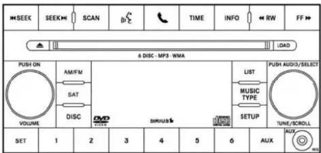
text_image
SEEK SEEK SCAN TIME INFO RW FF 6 DISC - MP3 - WMA PUSH ON AM/FM SAT DISC VOLUME LIST MUSIC TYPE SETUP TUNE/SCROLL SERIUS 1 2 3 4 5 6 AUX AUX042040029
Uconnect®230
UNDERSTANDING YOUR INSTRUMENT PANEL 245
Operating Instructions — Radio Mode
NOTE: The ignition switch must be in the ON or ACC position to operate the radio.
PowerSwitch/VolumeControl(Rotary)
Push the ON/VOLUME control knob to turn on the radio. Press the ON/VOLUME control knob a second time to turn off the radio.
ElectronicVolumeControl
The electronic volume control turns continuously (360 degrees) in either direction without stopping. Turning the ON/VOLUME control knob to the right increases the volume and to the left decreases it.
When the audio system is turned ON, the sound will be set at the same volume level as last played.
246 UNDERSTANDING YOUR INSTRUMENT PANEL
SEEKButtons
Press and release the SEEK buttons to search for the next listenable station in AM/FM mode. Press the right switch to seek up and the left switch to seek down. The radio will remain tuned to the new station until you make another selection. Holding either button will bypass stations without stopping, until you release it.
SCANButton
Pressing the SCAN button causes the tuner to search for the next listenable station in AM, FM or Satellite (if equipped) frequencies, pausing for five seconds at each listenable station before continuing to the next. To stop the search, press the SCAN button a second time.
VoiceCommandButtonUconnect®Phone—If Equipped
Press this button to operate the Uconnect® Phone feature (if equipped). Refer to "Voice Command" for further details.
If your vehicle is not equipped with or this feature is not available on your vehicle, a "Not Equipped With Uconnect Phone" message will display on the radio screen.
PhoneButtonUconnect®Phone—IfEquipped
Press this button to operate the Uconnect® Phone feature (if equipped). Refer to "Uconnect® Phone" for further details.
If your vehicle is not equipped with or this feature is not available on your vehicle, a "Not Equipped With Uconnect Phone" message will display on the radio screen.
TIMEButton
Press the TIME button to alternate locations of the time and frequency display.
ClockSettingProcedure
- Press and hold the TIME button until the hours blink.
- Adjust the hours by turning the right side TUNE/SCROLL control knob.
- After adjusting the hours, press the right side TUNE/SCROLL control knob to set the minutes. The minutes will begin to blink.
- Adjust the minutes using the right side TUNE/SCROLL control knob. Press the TUNE/SCROLL control knob to save the time change.
- To exit, press any button/knob or wait five seconds.
The clock can also be set by pressing the SETUP button and selecting the "SET HOME CLOCK" entry. Once in this display follow the above procedure, starting at step 2.
INFOButton
Press the INFO button for an RDS station (one with call letters displayed). The radio will return a Radio Text message broadcast from an FM station (FM mode only).
RW/FF
Pressing the RW (Rewind) or FF (Fast Forward) buttons causes the tuner to search for the next frequency in the direction of the arrows. This feature operates in AM, FM or Satellite (if equipped) frequencies.
TUNEControl
Turn the rotary TUNE/SCROLL control knob clockwise to increase or counterclockwise to decrease the frequency.
248 UNDERSTANDING YOUR INSTRUMENT PANEL
SettingTheTone, BalanceAndFade
Push the rotary TUNE/SCROLL control knob and BASS will display. Turn the TUNE/SCROLL control knob to the right or left to increase or decrease the bass tones.
Push the rotary TUNE/SCROLL control knob a second time and MID will display. Turn the TUNE/SCROLL control knob to the right or left to increase or decrease the mid-range tones.
Push the rotary TUNE/SCROLL control knob a third time and TREBLE will display. Turn the TUNE/SCROLL control knob to the right or left to increase or decrease the treble tones.
Push the rotary TUNE/SCROLL control knob a fourth time and BALANCE will display. Turn the TUNE/ SCROLL control knob to the right or left to adjust the sound level from the right or left side speakers.
Push the rotary TUNE/SCROLL control knob a fifth time and FADE will display. Turn the TUNE/SCROLL control knob to the left or right to adjust the sound level between the front and rear speakers.
Push the rotary TUNE/SCROLL control knob again to exit setting tone, balance, and fade.
MUSICTYPEButton
Pressing this button once will turn on the Music Type mode for five seconds. Pressing the MUSIC TYPE button or turning the TUNE/SCROLL control knob within five seconds will allow the program format type to be selected. Many radio stations do not currently broadcast Music Type information.
Toggle the MUSIC TYPE button to select the following format types:
| ProgramType | 16-DigitCharacter Display |
| No program type or undefined | None |
| Adult Hits Adlt Hit | |
| Classical Classicl | |
| Classic Rock Cls Rock | |
| College College | |
| Country Country | |
| Foreign Language Language | |
| Information Inform | |
| Jazz Jazz | |
| News News | |
| Nostalgia Nostalga |
| ProgramType | 16-DigitCharacter Display |
| Oldies Oldies | |
| Personality Persnity | |
| Public Public | |
| Rhythm and Blues R & B | |
| Religious Music | Rel Musc |
| Religious Talk | Rel Talk |
| Rock | Rock |
| Soft | Soft |
| Soft Rock | Soft Rck |
| Soft Rhythm and Blues | Soft R & B |
| Sports | Sports |
| Talk | Talk |
| Top 40 | Top 40 |
| Weather | Weather |
250 UNDERSTANDING YOUR INSTRUMENT PANEL
By pressing the SEEK button when the Music Type icon is displayed, the radio will be tuned to the next frequency station with the same selected Music Type name. The Music Type function only operates when in the FM mode.
If a preset button is activated while in the Music Type (Program Type) mode, the Music Type mode will be exited and the radio will tune to the preset station.
SETUPButton
Pressing the SETUP button allows you to select between the following items:
NOTE: Turn the TUNE/SCROLL control knob to scroll through the entries. Push the AUDIO/SELECT button to select an entry and make changes.
- DVDEnter—When the disc is in DVD Menu mode, selecting DVD Enter will allow you to play the current highlighted selection. Use the remote control to scroll up and down the menu (if equipped).
•DISCPlay/Pause—

You can toggle between playing the DVD and pausing the DVD by pushing the SELECT button (if equipped).
- DVD Play Options — Selecting the DVD Play Options will display the following:
- Subtitle — Repeatedly pressing SELECT will switch subtitles to different subtitle languages that are available on the disc (if equipped).
- Audio Stream — Repeatedly pressing SELECT will switch to different audio languages (if supported on the disc) (if equipped).
- Angle — Repeatedly pressing SELECT will change the viewing angle if supported by the DVD disc (if equipped).
UNDERSTANDING YOUR INSTRUMENT PANEL 251
NOTE:
- The available selections for each of the above entries varies depending upon the disc.
• These selections can only be made while playing a DVD. - VES™Power—Allows you to turn VES™ ON and OFF (if equipped).
- VES™Lock—Locks out rear VES™ remote controls (if equipped).
-
VESTMCH1/CH2—Allows the user to change the mode of either the IR1 or IR2 wireless headphones by pressing the AUDIO/SELECT button (if equipped).
-
SetHomeClock—Pressing the SELECT button allows you to set the clock. Turn the TUNE/SCROLL control knob to adjust the hours and then press and turn the TUNE/SCROLL control knob to adjust the minutes. Press the TUNE/SCROLL control knob again to save changes.
- PlayerDefaults—Selecting this item will allow the user to scroll through the following items and set defaults according to customer preference.
MenuLanguage—IfEquipped
Selecting this item will allow the user to choose the default startup DVD menu language (effective only if language supported by disc). If you want to select a language not listed, then scroll down and select "other." Enter the four-digit country code using the TUNE/ SCROLL control knob to scroll up and down to select the number and then push to select.
252 UNDERSTANDING YOUR INSTRUMENT PANEL
AudioLanguage—IfEquipped
Selecting this item allows you to choose a default audio language (effective only if the language is supported by the disc). You can select a language not listed by scrolling down and selecting "other." Enter the country code using the TUNE/SCROLL control knob to scroll up and down to select the number and then push to select.
SubtitleLanguage—IfEquipped
Selecting this item allows you to choose a default subtitle language (effective only if the language is supported by the disc). You can select a language not listed by scrolling down and selecting "other." Enter the country code using the TUNE/SCROLL control knob to scroll up and down to select the number and then push to select.
Subtitles—IfEquipped
Selecting this item allows you to choose between subtitle Off or On.
AudioDRC—IfEquipped
Selecting this item allows you to limit maximum audio dynamic range. The default is set to "High," and under this setting, dialogues will play at 11 db higher than if the setting is "Normal."
AspectRatio—IfEquipped
Selecting this item allows you to choose between wide screen, pan scan, and letter box.
AutoPlay—IfEquipped
When this is set to On and a DVD video is inserted, it will bypass the DVD menu screen and automatically play the movie. In some rare cases, the DVD player may not auto-play the main title. In such cases, use the MENU button on the remote control to select desired title to play.
UNDERSTANDING YOUR INSTRUMENT PANEL 253
NOTE: The user will have to set these defaults before loading a disc. If changes are made to these settings after a disc is loaded, changes will not be effective. Also, the defaults are effective only if the disc supports the customer-preferred settings.
AMandFMButtons
Press the buttons to select AM or FM mode.
SETButton—ToSetThePushbuttonMemory
When you are receiving a station that you wish to commit to pushbutton memory, press the SET button. The symbol SET 1 will now show in the display window. Select the button (1-6) you wish to lock onto this station and press and release that button. If a button is not selected within five seconds after pressing the SET button, the station will continue to play but will not be stored into pushbutton memory.
You may add a second station to each pushbutton by repeating the above procedure with this exception: Press the SET button twice and SET 2 will show in the display window. Each button can be set for SET 1 and SET 2 in both AM and FM. This allows a total of 12 AM, 12 FM, and 12 Satellite (if equipped) stations to be stored into pushbutton memory. The stations stored in SET 2 memory can be selected by pressing the pushbutton twice.
Every time a preset button is used, a corresponding button number will display.
Buttons 1 - 6
These buttons tune the radio to the stations that you commit to pushbutton memory {12 AM, 12 FM, and 12 Satellite (if equipped) stations}.
DISCButton
Pressing the DISC button will allow you to switch from AM/FM modes to Disc modes.
254 UNDERSTANDING YOUR INSTRUMENT PANEL
Operation Instructions — DISC Mode For CD And MP3/WMA Audio Play, DVD – Video
The radio DVD player and many DVD discs are coded by geographic region. These region codes must match for the disc to play. If the region code for the DVD disc does not match the region code for the radio DVD player, it will not play the disc. Customers may take their vehicle to an authorized dealer to change the region code of the player a maximum of five times.
CAUTION!
Theradiomayshutdownduringextremelyhot conditions. Whenthisoccurs, theradiowillindicate "DiscHot" and shutofffuntilasafetemperature is reached. This shutdownisnecessarytoprotectthe opticsoftheDVDplayerandotherradiointernal components.
NOTE: The ignition switch must be in the ON or ACC position to operate the radio.
LOADButton—LoadingCompactDisc(s)
Press the LOAD button and the pushbutton with the corresponding number (1-6) where the CD is being loaded. The radio will display PLEASE WAIT and prompt when to INSERT DISC. After the radio displays "INSERT DISC," insert the CD into the player.
Radio display will show "LOADING DISC" when the disc is loading and "READING DISC" when the radio is reading the disc.
CAUTION!
ThisCDplayerwillaccept4-3/4in(12cm)discsonly. TheuseofothersizeddiscsmaydamagetheCD playermechanism.
UNDERSTANDING YOUR INSTRUMENT PANEL 255
EjectButton—EjectingCompactDisc(s)

Press the EJECT button and the pushbutton with the corresponding number (1-6) where the CD was loaded and the disc will unload and move to the entrance for easy removal. Radio display will show "EJECTING DISC" when the disc is being ejected and prompt the user to remove the disc.
Press and hold the EJECT button for five seconds and all CDs will be ejected from the radio.
The disc can be ejected with the radio and ignition OFF.
SEEKButton(CDMODE)
Press the right SEEK button for the next selection on the CD. Press the left SEEK button to return to the beginning of the current selection, or return to the beginning of the previous selection if the CD is within the first second of
the current selection. Pressing and holding the SEEK button will allow you to scroll through the tracks faster in CD and MP3/MWA modes.
SCANButton(CDMODE)
Press the SCAN button to scan through each track on the CD currently playing.
TIMEButton(CDMODE)
Press this button to change the display from a large CD playing time display to a small CD playing time display.
RW/FF(CDMODE)
Press and hold FF (Fast Forward) and the CD player will begin to fast forward until FF is released, or RW or another CD button is pressed. The RW (Rewind) button works in a similar manner.
256 UNDERSTANDING YOUR INSTRUMENT PANEL
AMOrFMButton(CDMODE)
Switches the radio into the AM or FM radio mode.
NotesOnPlayingMP3/WMAFiles
The radio can play MP3/WMA files; however, acceptable MP3/WMA file recording media and formats are limited. When writing MP3/WMA files, pay attention to the following restrictions.
SupportedMedia(DiscTypes)
The MP3/WMA file recording media supported by the radio are CDDA, CD-R, CD-RW, MP3, WMA, DVD Video, DVD-R, DVD-RW, DVD+R, DVD+RW, and CDDA+MP3.
SupportedMediumFormats(FileSystems)
The medium formats supported by the radio are ISO 9660 Level 1 and Level 2 and includes the Joliet extension. When reading discs recorded using formats other than ISO 9660 Level 1 and Level 2, the radio may fail to read files properly and may be unable to play the file normally. UDF and Apple HFS formats are not supported.
The radio uses the following limits for file systems:
• Maximum number of directory levels: 8
• Maximum number of files: 255
• Maximum number of folders: 100
•Maximum number of characters in file/folder names:
- Level 1: 12 (including a separator "." and a three-character extension)
- Level 2: 31 (including a separator "." and a three-character extension)
Multisession disc formats are supported by the radio. Multisession discs may contain combinations of normal CD audio tracks and computer files (including MP3/WMA files). Discs created with an option such as "keep disc open after writing" are most likely multisession
discs. The use of multisession for CD audio or MP3/WMA playback may result in longer disc loading times.
If a disc contains multi-formats, such as CD audio and MP3/WMA tracks, the radio will only play the MP3/WMA tracks on that disc.
SupportedMP3/WMAFileFormats
The radio will recognize only files with the *.MP3/WMA extension as MP3/WMA files. Non-MP3/WMA files named with the *.MP3/WMA extension may cause playback problems. The radio is designed to recognize the file as an invalid MP3/WMA and will not play the file.
When using the MP3/WMA encoder to compress audio data to an MP3/WMA file, the bit rate and sampling frequencies in the following table are supported. In addition, variable bit rates (VBR) are also supported. The majority of MP3/WMA files use a 44.1 kHz sampling rate and a 192, 160, 128, 96 or VBR bit rates.
| MPEGSpecification | SamplingFrequency(kHz) | BitRate(kbps) |
| MPEG-1 Audio Layer 3 | 48, 44.1, 32 320 | 256, 224, 192, 160, 128, 112, 96, 80, 64, 56, 48 |
| MPEG-2 Audio Layer 3 | 24, 22.05, 16 160 | 128, 144, 112, 96, 80, 64, 56, 48 |
| WMASpecifi-cation | SamplingFre-quency(kHz) | BitRate(kbps) |
| WMA 44.1 and 48 48, 64, 96, 128, | 160, 192 VBR | |
ID3 Tag information for artist, song title, and album title are supported for ID3 version 1 tags. ID3 version 2 is not supported by the radios.
258 UNDERSTANDING YOUR INSTRUMENT PANEL
Playlist files are not supported. MP3 Pro files are not supported.
PlaybackOfMP3/WMAFiles
When a medium containing MP3/WMA data is loaded, the radio checks all files on the medium. If the medium contains a lot of folders or files, the radio will take more time to start playing the MP3/WMA files.
Loading times for playback of MP3/WMA files may be affected by the following:
• Media - CD-RW media may take longer to load than CD-R media
- Medium formats - Multisession discs may take longer to load than non-multisession discs
- Number of files and folders - Loading times will increase with more files and folders
To increase the speed of disc loading, it is recommended to use CD-R media and single-session discs. To create a single-session disc, enable the “Disc at Once” option before writing to the disc.
LIST Button — DISC Mode For MP3/WMA Play
Pressing the LIST button will bring up a list of all folders on the disc. Scrolling up or down the list is done by turning the TUNE/SCROLL control knob. Selecting a folder by pressing the TUNE/SCROLL control knob will begin playing the files contained in that folder (or the next folder in sequence if the selection does not contain playable files).
The folder list will time out after five seconds.
UNDERSTANDING YOUR INSTRUMENT PANEL 259
INFO Button — DISC Mode For MP3/WMA Play
Pressing the INFO button repeatedly will scroll through the following TAG information: Song Title, Artist, File Name, and Folder Name (if available).
Press the INFO button once more to return to "elapsed time" priority mode.
Press and hold the INFO button for three seconds or more and radio will display song titles for each file.
Press and hold the INFO button again for three seconds to return to "elapsed time" display.
OperationInstructions—AuxiliaryMode
The auxiliary (AUX) jack is an audio input jack which allows the user to plug in a portable device such as an MP3/WMA player, an ipod®, or a microphone and utilize the vehicles audio system to amplify the source and play through the vehicle speakers.
Pressing the AUX button will change the mode to auxiliary device if the AUX jack is connected.
NOTE: The AUX device must be turned on and the device's volume set to the proper level. If the AUX audio is not loud enough, turn the device's volume up. If the AUX audio sounds distorted, turn the device's volume down.
SEEKButton(AuxiliaryMode)
No function.
SCANButton(AuxiliaryMode)
No function.
EJECTButton(AuxiliaryMode)

No function.
260 UNDERSTANDING YOUR INSTRUMENT PANEL
TIMEButton(AuxiliaryMode)
Press the TIME button to change the display from elapsed playing time to time of day. The time of day will display for five seconds.
RW/FF(AuxiliaryMode)
No function.
SETButton(AuxiliaryMode)
No function.
OperatingInstructions(VoiceCommandSystem)—IfEquipped
Refer to "Voice Command" for further details.
OperatingInstructions(Uconnect®Phone)—If Equipped
Refer to "Uconnect® Phone" for further details.
OperatingInstructions—VideoEntertainment System(VES™)(IfEquipped)
Refer to "Video Entertainment System (VES™)" for further details.
Dolby®
Manufactured under license from Dolby® Laboratories. Dolby® and the double-D symbol are trademarks of Dolby® Laboratories.
Macrovision
This product incorporates copyright protection technology that is protected by U.S. patents and other intellectual property rights. Use of this copyright protection technology must be authorized by Macrovision, and is intended for home and other limited viewing uses only, unless otherwise authorized by Macrovision. Reverse engineering or disassembly is prohibited.
DTS™
"DTS ^TM and "DTS ^TM 2.0" are trademarks of Digital Theater Systems, Inc.
Uconnect® (Satellite Radio) — If Equipped
Satellite radio uses direct satellite-to-receiver broadcasting technology to provide clear digital sound, coast to coast. The subscription service provider is Sirius Satellite Radio. This service offers over 130 channels of music, sports, news, entertainment, and programming for children, directly from its satellites and broadcasting studios.
NOTE:Sirius service is not available in Hawaii and has limited coverage in Alaska.
SystemActivation
Sirius Satellite Radio service is pre-activated, and you may begin listening immediately to the one year of audio service that is included with the factory-installed satellite
radio system in your vehicle. Sirius will supply a welcome kit that contains general information, including how to setup your on-line listening account. For further information, call the toll-free number 888-539-7474, or visit the Sirius web site at www.sirius.com, or at www.siriuscanada.ca for Canadian residents.
ElectronicSerialNumber/SiriusIdentification Number(ESN/SID)
Please have the following information available when calling:
- The Electronic Serial Number/Sirius Identification Number (ESN/SID).
- Your Vehicle Identification Number.
262 UNDERSTANDING YOUR INSTRUMENT PANEL
To access the ESN/SID, refer to the following steps:
ESN/SIDAccess
With the ignition switch in the ON/RUN or ACC position and the radio on, press the SETUP button and scroll using the TUNE/SCROLL control knob until Sirius ID is selected. Press the TUNE/SCROLL control knob and the Sirius ID number will display. The Sirius ID number display will time out in two minutes. Press any button on the radio to exit this screen.
SelectingUconnect®(Satellite)Mode
Press the SAT button until "SAT" appears in the display. A CD may remain in the radio while in the Satellite radio mode.
SatelliteAntenna
To ensure optimum reception, do not place items on the roof around the rooftop antenna location. Metal objects placed within the line of sight of the antenna will cause decreased performance. Larger luggage items such as bikes should be placed as far rearward as possible, within the loading design of the rack. Do not place items directly on or above the antenna.
ReceptionQuality
Satellite reception may be interrupted due to one of the following reasons:
- The vehicle is parked in an underground parking structure or under a physical obstacle.
- Dense tree coverage may interrupt reception in the form of short audio mutes.
- Driving under wide bridges or along tall buildings can cause intermittent reception.
- Placing objects over or too close to the antenna can cause signal blockage.
OperatingInstructions—Uconnect®(Satellite) Mode
NOTE: The ignition switch must be in the ON/RUN or ACC position to operate the radio.
SEEKButtons
Press and release the SEEK buttons to search for the next channel in Satellite mode. Press the right switch to seek up and the left switch to seek down. The radio will remain tuned to the new channel until you make another selection. Holding either button will bypass channels without stopping until you release it.
SCANButton
Pressing the SCAN button causes the tuner to search for the next channel, pausing for eight seconds before continuing to the next. To stop the search, press the SCAN button a second time.
INFOButton
Pressing the INFO button will cycle the display information between Artist, Song Title, and Composer (if available). Also, pressing and holding the INFO button for an additional three seconds will make the radio display the Song Title all of the time (press and hold again to return to normal display).
RW/FF
Pressing the RW (Rewind) or FF (Fast Forward) buttons causes the tuner to search for the next channel in the direction of the arrows.
TUNEControl(Rotary)
Turn the rotary TUNE/SCROLL control knob clockwise to increase or counterclockwise to decrease the channel.
MUSICTYPEButton
Pressing this button once will turn on the Music Type mode for five seconds. Pressing the MUSIC TYPE button or turning the TUNE/SCROLL control knob within five seconds will allow the program format type to be selected.
Toggle the MUSIC TYPE button again to select the music type.
By pressing the SEEK button when the Music Type function is active, the radio will be tuned to the next channel with the same selected Music Type name.
If a preset button is activated while in the Music Type (Program Type) mode, the Music Type mode will be exited and the radio will tune to the preset channel.
SETUPButton
Pressing the SETUP button allows you to select the following items:
- Display Sirius ID number — Press the AUDIO/ SELECT button to display the Sirius ID number. This number is used to activate, deactivate, or change the Sirius subscription.
SET/RNDButton—ToSetThePushbutton Memory
When you are receiving a station that you wish to commit to pushbutton memory, press the SET/RND button. The symbol SET 1 will now show in the display window. Select the button (1–6) you wish to lock onto this station and press and release that button. If a button is not selected within five seconds after pressing the SET/RND button, the station will continue to play but will not be stored into pushbutton memory.
You may add a second station to each pushbutton by repeating the above procedure with this exception: Press the SET/RND button twice and SET 2 will show in the display window. Each button can be set for SET 1 and SET 2 in both AM and FM. This allows a total of 12 AM and 12 FM stations to be stored into pushbutton memory. The stations stored in SET 2 memory can be selected by pressing the pushbutton twice.
Every time a preset button is used, a corresponding button number will display.
Buttons 1 - 6
These buttons tune the radio to the channels that you commit to pushbutton memory (12 Satellite stations).
Uconnect® 730N/430/430N CD/DVD/HDD/NAV — IF EQUIPPED
Refer to your Uconnect® Supplement Manual for detailed operating instructions.
Operating Instructions (Voice Command System) — If Equipped
Refer to "Voice Command" for further details.
Operating Instructions (Uconnect® Phone) — If Equipped
Refer to "Uconnect® Phone" for further details.
266 UNDERSTANDING YOUR INSTRUMENT PANEL
Uconnect® 130 Operating Instructions — Radio Mode

text_image
SEEK SEEK AM/FM DISC AUX RW IF TIME SINGLE DISC - VPS TUSN ON VOLUME 1 2 3 4 5 6 PUSH AUDIO/SELECT TUNE/SCROLL SET END HES042305232
Uconnect®130
NOTE: The ignition switch must be in the ON or ACC position to operate the radio.
PowerSwitch/VolumeControl(Rotary)
Push the ON/VOLUME control knob to turn on the radio. Push the ON/VOLUME control knob a second time to turn off the radio.
ElectronicVolumeControl
The electronic volume control turns continuously (360 degrees) in either direction, without stopping. Turning the ON/VOLUME control knob to the right increases the volume, and to the left decreases it.
When the audio system is turned on, the sound will be set at the same volume level as last played.
SEEKButtons
Press and release the SEEK buttons to search for the next listenable station in AM/FM mode. Press the right switch to seek up and the left switch to seek down. The radio will remain tuned to the new station until you make another selection. Holding either button will bypass stations without stopping, until you release it.
TIMEButton
Press the TIME button to alternate display of the time and radio frequency.
ClockSettingProcedure
- Press and hold the TIME button until the hours blink.
- Adjust the hours by turning the right side TUNE/SCROLL control knob.
UNDERSTANDING YOUR INSTRUMENT PANEL 267
- After adjusting the hours, press the right side TUNE/SCROLL control knob to set the minutes. The minutes will begin to blink.
- Adjust the minutes using the right side TUNE/SCROLL control knob. Press the TUNE/SCROLL control knob to save time change.
- To exit, press any button/knob, or wait five seconds.
RW/FF
Pressing the RW (Rewind) or FF (Fast Forward) buttons causes the tuner to search for the next frequency in the direction of the arrows. This feature operates in either AM or FM frequencies.
TUNEControl
Turn the rotary TUNE/SCROLL control knob clockwise to increase or counterclockwise to decrease the frequency.
268 UNDERSTANDING YOUR INSTRUMENT PANEL
SettingTheTone,BalanceAndFade
Push the rotary TUNE/SCROLL control knob and BASS will display. Turn the TUNE/SCROLL control knob to the right or left to increase or decrease the bass tones.
Push the rotary TUNE/SCROLL control knob a second time and MID will display. Turn the TUNE/SCROLL control knob to the right or left to increase or decrease the mid-range tones.
Push the rotary TUNE/SCROLL control knob a third time and TREBLE will display. Turn the TUNE/SCROLL control knob to the right or left to increase or decrease the treble tones.
Push the rotary TUNE/SCROLL control knob a fourth time and BALANCE will display. Turn the TUNE/ SCROLL control knob to the right or left to adjust the sound level from the right or left side speakers.
Push the rotary TUNE/SCROLL control knob a fifth time and FADE will display. Turn the TUNE/SCROLL control knob to the left or right to adjust the sound level between the front and rear speakers.
Push the rotary TUNE/SCROLL control knob again to exit setting tone, balance, and fade.
AM/FMButton
Press the buttons to select either AM or FM mode.
SET/RNDButton—ToSetThePushbuttonMemory
When you are receiving a station that you wish to commit to pushbutton memory, press the SET/RND button. The symbol SET 1 will now show in the display window. Select the button (1 to 6) you wish to lock onto this station and press and release that button. If a button is not selected within five seconds after pressing the SET/RND button, the station will continue to play but will not be stored into pushbutton memory.
You may add a second station to each pushbutton by repeating the above procedure with this exception: Press the SET/RND button twice and SET 2 will show in the display window. Each button can be set for SET 1 and SET 2 in both AM and FM. This allows a total of 12 AM and 12 FM stations to be stored into pushbutton memory. The stations stored in SET 2 memory can be selected by pressing the pushbutton twice.
Every time a preset button is used, a corresponding button number will display.
Buttons 1 - 6
These buttons tune the radio to the stations that you commit to pushbutton memory (12 AM and 12 FM stations).
DISCButton
Pressing the DISC button will allow you to switch from AM/FM modes to Disc modes.
Operation Instructions — CD MODE For CD And MP3 Audio Play
NOTE:
- The ignition switch must be in the ON or ACC position to operate the radio.
- This radio is capable of playing compact discs (CD), recordable compact discs (CD-R), rewritable compact discs (CD-RW), compact discs with MP3 tracks and multisession compact discs with CD and MP3 tracks.
InsertingCompactDisc(s)
Gently insert one CD into the CD player with the CD label facing up. The CD will automatically be pulled into the CD player and the CD icon will illuminate on the radio display. If a CD does not go into the slot more than 1.0 in (2.5 cm), a disc may already be loaded and must be ejected before a new disc can be loaded.
270 UNDERSTANDING YOUR INSTRUMENT PANEL
If you insert a disc with the ignition ON and the radio ON, the unit will switch from radio to CD mode and begin to play when you insert the disc. The display will show the track number, and index time in minutes and seconds. Play will begin at the start of track 1.
CAUTION!
- ThisCDplayerwillaccept4–3/4in(12cm)discs only. Theuseofothersizeddiscsmaydamagethe CDplayermechanism.
- Donotuseadhesivelabels. Theselabelscanpeel awayandjamtheplayermechanism.
- TheUconnect®130isasingleCDplayer.Donot attempttoinsertasecondCDifoneisalready loaded.
(Continued)
CAUTION!(Continued)
- Dual-mediadisctypes(onesideisaDVD,the othersideisaCD)shouldnotbeused,andtheycan causedamagetotheplayer.
EJECTButton—EjectingACD

Press the EJECT button to eject the CD.
If you have ejected a disc and have not removed it within 10 seconds, it will be reloaded. If the CD is not removed, the radio will reinsert the CD but will not play it.
A disc can be ejected with the radio and ignition OFF.
NOTE:Ejecting with the ignition OFF is not allowed on convertible or soft-top models (if equipped).
SEEKButton
Press the right SEEK button for the next selection on the CD. Press the left SEEK button to return to the beginning of the current selection, or return to the beginning of the previous selection if the CD is within the first second of the current selection. Pressing and holding the SEEK button will allow faster scrolling through the tracks in CD and MP3 modes.
TIMEButton
Press this button to change the display from a large CD playing time display to a small CD playing time display.
RW/FF
Press and hold the FF (Fast Forward) button and the CD player will begin to fast forward until FF is released, or RW or another CD button is pressed. The RW (Reverse) button operates in a similar manner.
AM/FMButton
Press the button to select either AM or FM mode.
SET/RNDButton(RandomPlayButton)
Press this button while the CD is playing to activate Random Play. This feature plays the selections on the compact disc in random order to provide an interesting change of pace.
Press the right SEEK button to move to the next randomly selected track.
Press the RND button a second time to stop Random Play.
272 UNDERSTANDING YOUR INSTRUMENT PANEL
Notes On Playing MP3 Files
The radio can play MP3 files; however, acceptable MP3 file recording media and formats are limited. When writing MP3 files, pay attention to the following restrictions.
SupportedMedia(DiscTypes)
The MP3 file recording media supported by the radio are CDDA, CD-R, CD-RW, MP3, and CDDA+MP3.
SupportedMediumFormats(FileSystems)
The medium formats supported by the radio are ISO 9660 Level 1 and Level 2 and includes the Joliet extension. When reading discs recorded using formats other than ISO 9660 Level 1 and Level 2, the radio may fail to read files properly and may be unable to play the file normally. UDF and Apple HFS formats are not supported.
The radio uses the following limits for file systems:
• Maximum number of folder levels: 8
• Maximum number of files: 255
- Maximum number of folders. (The radio display of file names and folder names is limited. For large numbers of files and/or folders, the radio may be unable to display the file name and folder name, and will assign a number instead. With a maximum number of files, exceeding 20 folders will result in this display. With 200 files, exceeding 50 folders will result in this display.)
Maximum number of characters in file/folder names:
- Level 1: 12 (including a separator "." and a three-character extension)
- Level 2: 31 (including a separator "." and a three-character extension)
Multi-session disc formats are supported by the radio. Multi-session discs may contain combinations of normal CD audio tracks and computer files (including MP3 files). Discs created with an option such as "keep disc open after writing" are most likely multi-session discs. The use of multi-session for CD audio or MP3 playback may result in longer disc loading times.
SupportedMP3FileFormats
The radio will recognize only files with the *.MP3 extension as MP3 files. Non-MP3 files named with the *.MP3 extension may cause playback problems. The radio is designed to recognize the file as an invalid MP3 and will not play the file.
When using the MP3 encoder to compress audio data to an MP3 file, the bit rate and sampling frequencies in the following table are supported. In addition, variable bit rates (VBR) are also supported. The majority of MP3 files use a 44.1 kHz sampling rate and a 192, 160, 128, 96 or VBR bit rate.
| MPEGSpecification | SamplingFrequency(kHz) | BitRate(kbps) |
| MPEG-1 Audio Layer 3 | 48, 44.1, 32 320 | 256, 224, 192, 160, 128, 112, 96, 80, 64, 56, 48, 40, 32 |
| MPEG-2 Audio Layer 3 | 24, 22.05, 16 160 | 128, 144, 112, 96, 80, 64, 56, 48, 40, 32, 24, 16, 8 |
ID3 Tag information for artist, song title, and album title are supported for version 1 ID3 tags. ID3 version 2 is not supported by the radios.
Playlist files are not supported. MP3 Pro files are not supported.
274 UNDERSTANDING YOUR INSTRUMENT PANEL
PlaybackOfMP3Files
When a medium containing MP3 data is loaded, the radio checks all files on the medium. If the medium contains a lot of folders or files, the radio will take more time to start playing the MP3 files.
Loading times for playback of MP3 files may be affected by the following:
• Media - CD-RW media may take longer to load than CD-R media
- Medium formats - Multisession discs may take longer to load than non-multisession discs
- Number of files and folders - Loading times will increase with more files and folders
To increase the speed of disc loading, it is recommended to use CD-R media and single-session discs. To create a single-session disc, enable the “Disc at Once” option before writing to the disc.
Operation Instructions — Auxiliary Mode
The auxiliary (AUX) jack is an audio input jack, which allows the user to plug in a portable device, such as an MP3 player, or iPod®, and utilize the vehicle's audio system to amplify the source and play through the vehicle speakers.
Pressing the DISC/AUX button will change the mode to auxiliary device if the AUX jack is connected.
NOTE: The AUX device must be turned on and the device's volume set to proper level. If the AUX audio is not loud enough, turn the device's volume up. If the AUX audio sounds distorted, turn the device's volume down.
TIMEButton(AuxiliaryMode)
Press this button to change the display to time of day. The time of day will display for five seconds (when ignition is OFF).
Uconnect® 130 WITH SATELLITE RADIO Operating Instructions — Radio Mode

text_image
SEEK SEEK INFO RW TIME SINGLE DISC MP3 PUSH ON AM/FM SAT DISC AUX SIRRUS LIST MUSIC TYPE SETUP TUR/SCROLL AUX 1 2 3 4 5 6 SET END042340030
Uconnect®130
NOTE: The ignition switch must be in the ON or ACC position to operate the radio.
PowerSwitch/VolumeControl(Rotary)
Push the ON/VOLUME control knob to turn on the radio. Push the ON/VOLUME control knob a second time to turn off the radio.
ElectronicVolumeControl
The electronic volume control turns continuously (360 degrees) in either direction, without stopping. Turning the ON/VOLUME control knob to the right increases the volume, and to the left decreases it.
When the audio system is turned on, the sound will be set at the same volume level as last played.
276 UNDERSTANDING YOUR INSTRUMENT PANEL
SEEKButtons
Press and release the SEEK buttons to search for the next listenable station in AM/FM mode. Press the right switch to seek up and the left switch to seek down. The radio will remain tuned to the new station until you make another selection. Holding either button will bypass stations without stopping, until you release it.
VoiceCommandSystem(Radio)—IfEquipped
Refer to "Voice Command" in "Understanding The Features Of Your Vehicle".
VoiceCommandButtonUconnect®Phone—If Equipped
Press this button to operate the Uconnect® Phone feature (if equipped). Refer to "Uconnect® Phone" in "Understanding The Features Of Your Vehicle".
If your vehicle is not equipped with or this feature is not available on your vehicle, a "Not Equipped With Uconnect Phone" message will display on the radio screen.
PhoneButtonUconnect®Phone—IfEquipped
Press this button to operate the Uconnect® Phone feature (if equipped). Refer to "Uconnect® Phone" in "Understanding The Features Of Your Vehicle".
If your vehicle is not equipped with or this feature is not available on your vehicle, a “Not Equipped With Uconnect Phone” message will display on the radio screen.
TIMEButton
Press the TIME button to alternate display of the time and radio frequency.
ClockSettingProcedure
- Press and hold the TIME button until the hours blink.
- Adjust the hours by turning the right side TUNE/SCROLL control knob.
- After adjusting the hours, press the right side TUNE/SCROLL control knob to set the minutes. The minutes will begin to blink.
- Adjust the minutes using the right side TUNE/SCROLL control knob. Press the TUNE/SCROLL control knob to save time change.
- To exit, press any button/knob or wait five seconds.
The clock can also be set by pressing the SETUP button. For vehicles equipped with satellite radio, press the SETUP button, use the TUNE/SCROLL control to select SET CLOCK, and then follow the above procedure,
starting at step 2. For vehicles not equipped with satellite radio, press the SETUP button and then follow the above procedure, starting at step 2.
INFOButton
Press the INFO button for an RDS station (one with call letters displayed). The radio will return a Radio Text message broadcast from an FM station (FM mode only).
RW/FF
Pressing the RW (Rewind) or FF (Fast Forward) buttons causes the tuner to search for the next frequency in the direction of the arrows. This feature operates in either AM or FM frequencies.
TUNEControl
Turn the rotary TUNE/SCROLL control knob clockwise to increase or counterclockwise to decrease the frequency.
278 UNDERSTANDING YOUR INSTRUMENT PANEL
SettingTheTone,BalanceAndFade
Push the rotary TUNE/SCROLL control knob and BASS will display. Turn the TUNE/SCROLL control knob to the right or left to increase or decrease the bass tones.
Push the rotary TUNE/SCROLL control knob a second time and MID will display. Turn the TUNE/SCROLL control knob to the right or left to increase or decrease the mid-range tones.
Push the rotary TUNE/SCROLL control knob a third time and TREBLE will display. Turn the TUNE/SCROLL control knob to the right or left to increase or decrease the treble tones.
Push the rotary TUNE/SCROLL control knob a fourth time and BALANCE will display. Turn the TUNE/ SCROLL control knob to the right or left to adjust the sound level from the right or left side speakers.
Push the rotary TUNE/SCROLL control knob a fifth time and FADE will display. Turn the TUNE/SCROLL control knob to the left or right to adjust the sound level between the front and rear speakers.
Push the rotary TUNE/SCROLL control knob again to exit setting tone, balance, and fade.
MUSICTYPEButton
Pressing this button once will turn on the Music Type mode for five seconds. Pressing the MUSIC TYPE button or turning the TUNE/SCROLL control knob within five seconds will allow the program format type to be selected. Many radio stations do not currently broadcast Music Type information.
Toggle the MUSIC TYPE button to select the following format types:
| ProgramType | 16-DigitCharacter Display |
| No program type or undefined | None |
| Adult Hits Adlt Hit | |
| Classical Classicl | |
| Classic Rock Cls Rock | |
| College College | |
| Country Country | |
| Foreign Language Language | |
| Information Inform | |
| Jazz Jazz | |
| News News | |
| Nostalgia Nostalga |
| ProgramType | 16-DigitCharacter Display |
| Oldies Oldies | |
| Personality Persnity | |
| Public Public | |
| Rhythm and Blues R & B | |
| Religious Music | Rel Musc |
| Religious Talk | Rel Talk |
| Rock | Rock |
| Soft | Soft |
| Soft Rock | Soft Rck |
| Soft Rhythm and Blues | Soft R&B |
| Sports | Sports |
| Talk | Talk |
| Top 40 | Top 40 |
| Weather | Weather |
By pressing the SEEK button when the Music Type icon is displayed, the radio will be tuned to the next frequency station with the same selected Music Type name. The Music Type function only operates when in the FM mode.
If a preset button is activated while in the Music Type (Program Type) mode, the Music Type mode will be exited and the radio will tune to the preset station.
SETUPButton
Pressing the SETUP button allows you to select between the following items:
- SetClock—Pressing the SELECT button will allow you to set the clock. Adjust the hours by turning the TUNE/SCROLL control knob. After adjusting the hours, press the TUNE/SCROLL control knob to set the minutes. The minutes will begin to blink. Adjust the minutes using the right side TUNE/SCROLL control knob. Press the TUNE/SCROLL control knob to save time change.
AM/FMButton
Press the button to select either AM or FM mode.
SET/RNDButton—ToSetThePushbutton Memory
When you are receiving a station that you wish to commit to pushbutton memory, press the SET/RND button. The symbol SET 1 will now show in the display window. Select the button (1–6) you wish to lock onto this station and press and release that button. If a button is not selected within five seconds after pressing the SET/RND button, the station will continue to play but will not be stored into pushbutton memory.
You may add a second station to each pushbutton by repeating the above procedure with this exception: Press the SET/RND button twice and SET 2 will show in the display window. Each button can be set for SET 1 and SET 2 in both AM and FM. This allows a total of 12 AM
and 12 FM stations to be stored into pushbutton memory. The stations stored in SET 2 memory can be selected by pressing the pushbutton twice.
Every time a preset button is used, a corresponding button number will display.
Buttons 1 - 6
These buttons tune the radio to the stations that you commit to pushbutton memory (12 AM and 12 FM stations).
DISC/AUXButton
Pressing the DISC/AUX button will allow you to switch from AM/FM modes to DISC/AUX mode.
Operation Instructions — CD MODE For CD And MP3 Audio Play
NOTE:
- The ignition switch must be in the ON or ACC position to operate the radio.
- This radio is capable of playing compact discs (CD), recordable compact discs (CD-R), rewritable compact discs (CD-RW), compact discs with MP3 tracks and multisession compact discs with CD and MP3 tracks.
InsertingCompactDisc(s)
Gently insert one CD into the CD player with the CD label facing up. The CD will automatically be pulled into the CD player and the CD icon will illuminate on the radio display. If a CD does not go into the slot more than 1.0 in (2.5 cm), a disc may already be loaded and must be ejected before a new disc can be loaded.
282 UNDERSTANDING YOUR INSTRUMENT PANEL
If you insert a disc with the ignition ON and the radio ON, the unit will switch from radio to CD mode and begin to play when you insert the disc. The display will show the track number, and index time in minutes and seconds. Play will begin at the start of track 1.
CAUTION!
- ThisCDplayerwillaccept4–3/4in(12cm)discs only. Theuseofothersizeddiscsmaydamagethe CDplayermechanism.
- Donotuseadhesivelabels. Theselabelscanpeel awayandjamtheplayermechanism.
- TheUconnect®130isasingleCDplayer.Donot attempttoinsertasecondCDifoneisalready loaded.
(Continued)
CAUTION!(Continued)
- Dual-mediadisctypes(onesideisaDVD,the othersideisaCD)shouldnotbeused,andtheycan causedamagetotheplayer.
EJECTButton—EjectingACD

Press the EJECT button to eject the CD.
If you have ejected a disc and have not removed it within 10 seconds, it will be reloaded. If the CD is not removed, the radio will reinsert the CD but will not play it.
A disc can be ejected with the radio and ignition OFF.
NOTE: Ejecting with the ignition OFF is not allowed on convertible or soft-top models (if equipped).
SEEKButton
Press the right SEEK button for the next selection on the CD. Press the left SEEK button to return to the beginning of the current selection, or return to the beginning of the previous selection if the CD is within the first second of the current selection. Pressing and holding the SEEK button will allow faster scrolling through the tracks in CD and MP3 modes.
TIMEButton
Press this button to change the display from a large CD playing time display to a small CD playing time display.
RW/FF
Press and hold FF (Fast Forward) and the CD player will begin to fast forward until FF is released or RW or another CD button is pressed. The RW (Reverse) button works in a similar manner.
AM/FMButton
Press the button to select either AM or FM mode.
SET/RNDButton(RandomPlayButton)
Press this button while the CD is playing to activate Random Play. This feature plays the selections on the compact disc in random order to provide an interesting change of pace.
Press the right SEEK button to move to the next randomly selected track.
Press the SET/RND button a second time to stop Random Play.
284 UNDERSTANDING YOUR INSTRUMENT PANEL
Notes On Playing MP3 Files
The radio can play MP3 files; however, acceptable MP3 file recording media and formats are limited. When writing MP3 files, pay attention to the following restrictions.
SupportedMedia(DiscTypes)
The MP3 file recording media supported by the radio are CDDA, CD-R, CD-RW, MP3, and CDDA+MP3.
SupportedMediumFormats(FileSystems)
The medium formats supported by the radio are ISO 9660 Level 1 and Level 2 and includes the Joliet extension. When reading discs recorded using formats other than ISO 9660 Level 1 and Level 2, the radio may fail to read files properly and may be unable to play the file normally. UDF and Apple HFS formats are not supported.
The radio uses the following limits for file systems:
• Maximum number of folder levels: 8
• Maximum number of files: 255
- Maximum number of folders. (The radio display of file names and folder names is limited. For large numbers of files and/or folders, the radio may be unable to display the file name and folder name, and will assign a number instead. With a maximum number of files, exceeding 20 folders will result in this display. With 200 files, exceeding 50 folders will result in this display.)
Maximum number of characters in file/folder names:
- Level 1: 12 (including a separator "." and a three-character extension)
- Level 2: 31 (including a separator "." and a three-character extension)
Multi-session disc formats are supported by the radio. Multi-session discs may contain combinations of normal CD audio tracks and computer files (including MP3 files). Discs created with an option such as "keep disc open after writing" are most likely multi-session discs. The use of multi-session for CD audio or MP3 playback may result in longer disc loading times.
SupportedMP3FileFormats
The radio will recognize only files with the *.MP3 extension as MP3 files. Non-MP3 files named with the *.MP3 extension may cause playback problems. The radio is designed to recognize the file as an invalid MP3 and will not play the file.
When using the MP3 encoder to compress audio data to an MP3 file, the bit rate and sampling frequencies in the following table are supported. In addition, variable bit rates (VBR) are also supported. The majority of MP3 files use a 44.1 kHz sampling rate and a 192, 160, 128, 96 or VBR bit rates.
| MPEGSpecification | SamplingFrequency(kHz) | BitRate(kbps) |
| MPEG-1 Audio Layer 3 | 48, 44.1, 32 320 | 256, 224, 192, 160, 128, 112, 96, 80, 64, 56, 48, 40, 32 |
| MPEG-2 Audio Layer 3 | 24, 22.05, 16 160 | 128, 144, 112, 96, 80, 64, 56, 48, 40, 32, 24, 16, 8 |
ID3 Tag information for artist, song title, and album title are supported for version 1 ID3 tags. ID3 version 2 is not supported by the radios.
Playlist files are not supported. MP3 Pro files are not supported.
286 UNDERSTANDING YOUR INSTRUMENT PANEL
PlaybackOfMP3Files
When a medium containing MP3 data is loaded, the radio checks all files on the medium. If the medium contains a lot of folders or files, the radio will take more time to start playing the MP3 files.
Loading times for playback of MP3 files may be affected by the following:
• Media - CD-RW media may take longer to load than CD-R media
- Medium formats - Multisession discs may take longer to load than non-multisession discs
- Number of files and folders - Loading times will increase with more files and folders
To increase the speed of disc loading, it is recommended to use CD-R media and single-session discs. To create a single-session disc, enable the “Disc at Once” option before writing to the disc.
LIST Button — CD Mode For MP3 Play
Pressing the LIST button will bring up a list of all folders on the disc. Scrolling up or down the list is done by turning the TUNE/SCROLL control knob. Selecting a folder by pressing the TUNE/SCROLL control knob will begin playing the files contained in that folder (or the next folder in sequence if the selection does not contain playable files).
The folder list will time out after five seconds.
INFO Button — CD Mode For MP3 Play
Pressing the INFO button repeatedly will scroll through the following TAG information: Song Title, Artist, File Name, and Folder Name (if available).
Press the INFO button once more to return to "elapsed time" priority mode.
Press and hold the INFO button for three seconds or more and the radio will display song titles for each file.
Press and hold the INFO button again for three seconds to return to "elapsed time" display.
OperationInstructions—AuxiliaryMode
The auxiliary (AUX) jack is an audio input jack which allows the user to plug in a portable device such as an MP3 player or iPod® and utilize the vehicle's audio system to amplify the source and play through the vehicle speakers.
Pressing the AUX button will change the mode to auxiliary device if the AUX jack is connected.
NOTE: The AUX device must be turned on and the device's volume set to the proper level. If the AUX audio is not loud enough, turn the device's volume up. If the AUX audio sounds distorted, turn the device's volume down.
TIMEButton(AuxiliaryMode)
Press this button to change the display to time of day. The time of day will display for five seconds (when the ignition is OFF).
Uconnect® (Satellite Radio) — If Equipped
Satellite radio uses direct satellite-to-receiver broadcasting technology to provide clear digital sound, coast to coast. The subscription service provider is Sirius Satellite Radio. This service offers over 130 channels of music, sports, news, entertainment, and programming for children, directly from its satellites and broadcasting studios.
NOTE:Sirius service is not available in Hawaii and has limited coverage in Alaska.
SystemActivation
Sirius Satellite Radio service is pre-activated, and you may begin listening immediately to the one year of audio service that is included with the factory-installed satellite radio system in your vehicle. Sirius will supply a welcome kit that contains general information, including how to setup your on-line listening account. For further information, call the toll-free number 888-539-7474, or
288 UNDERSTANDING YOUR INSTRUMENT PANEL
visit the Sirius web site at www.sirius.com, or at www.siriuscanada.ca for Canadian residents.
ElectronicSerialNumber/SiriusIdentification Number(ESN/SID)
Please have the following information available when calling:
-
The Electronic Serial Number/Sirius Identification Number (ESN/SID).
-
Your Vehicle Identification Number.
To access the ESN/SID, refer to the following steps:
ESN/SIDAccess
With the ignition switch in the ON/RUN or ACC position and the radio on, press the SETUP button and scroll using the TUNE/SCROLL control knob until Sirius ID is selected. Press the TUNE/SCROLL control knob and the Sirius ID number will display. The Sirius ID number display will time out in two minutes. Press any button on the radio to exit this screen.
SelectingUconnect®(Satellite)Mode
Press the SAT button until "SAT" appears in the display. A CD may remain in the radio while in the Satellite radio mode.
SatelliteAntenna
To ensure optimum reception, do not place items on the roof around the rooftop antenna location. Metal objects placed within the line of sight of the antenna will cause decreased performance. Larger luggage items such as bikes should be placed as far rearward as possible, within the loading design of the rack. Do not place items directly on or above the antenna.
ReceptionQuality
Satellite reception may be interrupted due to one of the following reasons:
- The vehicle is parked in an underground parking structure or under a physical obstacle.
- Dense tree coverage may interrupt reception in the form of short audio mutes.
- Driving under wide bridges or along tall buildings can cause intermittent reception.
- Placing objects over or too close to the antenna can cause signal blockage.
OperatingInstructions—Uconnect®(Satellite) Mode
NOTE: The ignition switch must be in the ON/RUN or ACC position to operate the radio.
SEEKButtons
Press and release the SEEK buttons to search for the next channel in Satellite mode. Press the right switch to seek up and the left switch to seek down. The radio will remain tuned to the new channel until you make another selection. Holding either button will bypass channels without stopping until you release it.
SCANButton
Pressing the SCAN button causes the tuner to search for the next channel, pausing for eight seconds before continuing to the next. To stop the search, press the SCAN button a second time.
290 UNDERSTANDING YOUR INSTRUMENT PANEL
INFOButton
Pressing the INFO button will cycle the display information between Artist, Song Title, and Composer (if available). Also, pressing and holding the INFO button for an additional three seconds will make the radio display the Song Title all of the time (press and hold again to return to normal display).
RW/FF
Pressing the RW (Rewind) or FF (Fast Forward) buttons causes the tuner to search for the next channel in the direction of the arrows.
TUNEControl(Rotary)
Turn the rotary TUNE/SCROLL control knob clockwise to increase or counterclockwise to decrease the channel.
MUSICTYPEButton
Pressing this button once will turn on the Music Type mode for five seconds. Pressing the MUSIC TYPE button or turning the TUNE/SCROLL control knob within five seconds will allow the program format type to be selected.
Toggle the MUSIC TYPE button again to select the music type.
By pressing the SEEK button when the Music Type function is active, the radio will be tuned to the next channel with the same selected Music Type name.
If a preset button is activated while in the Music Type (Program Type) mode, the Music Type mode will be exited and the radio will tune to the preset channel.
SETUPButton
Pressing the SETUP button allows you to select the following items:
- Display Sirius ID number — Press the AUDIO/ SELECT button to display the Sirius ID number. This number is used to activate, deactivate, or change the Sirius subscription.
SETButton—ToSetThePushbuttonMemory
When you are receiving a channel that you wish to commit to pushbutton memory, press the SET button. The symbol SET 1 will now show in the display window. Select the button (1-6) you wish to lock onto this channel and press and release that button. If a button is not selected within five seconds after pressing the SET button, the channel will continue to play but will not be stored into pushbutton memory.
You may add a second channel to each pushbutton by repeating the above procedure with this exception: Press the SET button twice and SET 2 will show in the display window. Each button can be set for SET 1 and SET 2. This allows a total of 12 Satellite channels to be stored into pushbutton memory. The channels stored in SET 2 memory can be selected by pressing the pushbutton twice.
Every time a preset button is used, a corresponding button number will display.
Buttons 1 - 6
These buttons tune the radio to the channels that you commit to pushbutton memory (12 Satellite stations).
OperatingInstructions(Uconnect®Phone)—If Equipped
Refer to "Uconnect® Phone" in "Understanding The Features Of Your Vehicle".
292 UNDERSTANDING YOUR INSTRUMENT PANEL
iPod®/USB/MP3 CONTROL — IF EQUIPPED
This feature allows an iPod® or external USB device to be plugged into the USB port, located in the center console or glove compartment.
iPod® control supports Mini, 4G, Photo, Nano, 5G iPod® and iPhone® devices. Some iPod® software versions may not fully support the iPod® control features. Please visit Apple's website for software updates.
NOTE:
- If the radio has a USB port, refer to the appropriate Uconnect® Multimedia radio User's Manual for iPod® or external USB device support capability.
- Connecting an iPod® or consumer electronic audio device to the AUX port located in the radio faceplate, plays media, but does not use the iPod® /MP3 control feature to control the connected device.
Connecting The iPod® Or External USB Device
Use the connection cable to connect an iPod® or external USB device to the vehicle's USB/AUX connector port which is located in the center console or glove compartment.

text_image
AUXUSB/AUXConnectorPort
044136844
UNDERSTANDING YOUR INSTRUMENT PANEL 293
Once the audio device is connected and synchronized to the vehicle's iPod®/USB/MP3 control system (iPod® or external USB device may take a few minutes to connect), the audio device starts charging and is ready for use by pressing radio switches, as described below.
NOTE: If the audio device battery is completely discharged, it may not communicate with the iPod®/USB/MP3 control system until a minimum charge is attained. Leaving the audio device connected to the iPod®/USB/MP3 control system may charge it to the required level.
Using This Feature
By using an iPod® cable, or an external USB device to connect to the USB port:
- The audio device can be played on the vehicle's sound system, providing metadata (artist, track title, album, etc.) information on the radio display.
- The audio device can be controlled using the radio buttons to Play, Browse, and List the iPod® contents.
- The audio device battery charges when plugged into the USB/AUX connector (if supported by the specific audio device).
Controlling The iPod® Or External USB Device Using Radio Buttons
To get into the iPod®/USB/MP3 control mode and access a connected audio device, either press the "AUX" button on the radio faceplate or press the VR button and say "USB" or "Switch to USB." Once in the iPod®/USB/MP3 control mode, audio tracks (if available from audio device) start playing over the vehicle's audio system.
294 UNDERSTANDING YOUR INSTRUMENT PANEL
Play Mode
When switched to iPod®/USB/MP3 control mode, the iPod® or external USB device automatically starts Play mode. In Play mode, the following buttons on the radio faceplate may be used to control the iPod® or external USB device and display data:
- Use the TUNEcontrol knob to select the next or previous track.
- Turning it clockwise (forward) by one click, while playing a track, skips to the next track or press the VR button and say "Next Track."
- Turning it counterclockwise (backward) by one click, will jump to the previous track in the list or press the VR button and say "Previous Track."
-
Jump backward in the current track by pressing and holding the << RW button. Holding the << RW button long enough will jump to the beginning of the current track.
-
Jump forward in the current track by pressing and holding the FF>> button.
- A single press backward << RW or forward FF>> will jump backward or forward respectively, for five seconds.
- Use the << SEEK and SEEK >> buttons to jump to the previous or next track. Pressing the SEEK >> button during play mode will jump to the next track in the list, or press the VR button and say "Next or Previous Track."
-
While a track is playing, press the INFObutton to see the associated metadata (artist, track title, album, etc.) for that track. Pressing the INFObutton again jumps to the next screen of data for that track. Once all screens have been viewed, the last INFObutton press will go back to the play mode screen on the radio.
-
Pressing the REPEAT button will change the audio device mode to repeat the current playing track or press the VR button and say "Repeat ON" or "Repeat Off."
- Press the SCANbutton to use iPod®/USB/MP3 device scan mode, which will play the first ten seconds of each track in the current list and then forward to the next song. To stop SCAN mode and start playing the desired track, when it is playing the track, press the SCANbutton again. During Scan mode, pressing the << SEEK and SEEK >> buttons will select the previous and next tracks.
- RNDbutton (available on sales code RES radio only): Pressing this button toggles between Shuffle ON and Shuffle OFF modes for the iPod® or external USB device, or press the VR button and say "Shuffle ON" or "Shuffle Off." If the RND icon is showing on the radio display, then the shuffle mode is ON.
List Or Browse Mode
During Play mode, pressing any of the buttons described below, will bring up List mode. List mode enables scrolling through the list of menus and tracks on the audio device.
- TUNE control knob: The TUNE control knob functions in a similar manner as the scroll wheel on the audio device or external USB device.
- Turning it clockwise (forward) and counterclockwise (backward) scrolls through the lists, displaying the track detail on the radio display. Once the track to be played is highlighted on the radio display, press the TUNEcontrol knob to select and start playing the track. Turning the TUNEcontrol knob fast will scroll through the list faster. During fast scroll, a slight delay in updating the information on the radio display may be noticeable.
296 UNDERSTANDING YOUR INSTRUMENT PANEL
- During all List modes, the iPod® displays all lists in "wrap-around" mode. So if the track is at the bottom of the list, just turn the wheel backward (counterclockwise) to get to the track faster.
- In List mode, the radio PRESETbuttons are used as shortcuts to the following lists on the iPod® or external USB device:
- Preset 1 – Playlists
- Preset 2 – Artists
- Preset 3 – Albums
- Preset 4 – Genres
- Preset 5 – Audiobooks
-
Preset 6 – Podcasts
-
Pressing a PRESET button will display the current list on the top line and the first item in that list on the second line.
- To exit List mode without selecting a track, press the same PRESETbutton again to go back to Playmode.
- LIST button: The LIST button will display the top level menu of the iPod® or external USB device.
- Turn the TUNE control knob to list the top-menu item to be selected and press the TUNEcontrol knob. This will display the next sub-menu list item on the audio device, then follow the same steps to go to the desired track in that list. Not all iPod® or external USB device sub-menu levels are available on this system.
- MUSICTYPEbutton: The MUSICTYPEbutton is another shortcut button to the genre listing on your audio device.
CAUTION!
- LeavingtheiPod®orexternalUSBdevice(orany supporteddevice)anywhereinthevehicleinextremeheatorcoldcanaltertheoperationordamagethedevice.Followthedevicemanufacturer's guidelines.
- PlacingitemsontheiPod®orexternalUSBdevice, orconnectionstotheiPod®orexternalUSBdevice inthevehicle,cancausedamagetothedevice and/ortotheconnectors.
WARNING!
DonotpluginorremovetheiPod®orexternalUSB devicewhiledriving.Failureretofollowthiswarning couldresultinanaccident.
Bluetooth® Streaming Audio (BTSA)
Music can be streamed from your cellular phone to the Uconnect® phone system.
ControllingBTSAUsingRadioButtons
To enter BTSA mode, press either "AUX" button on the radio or press the VR button and say "Bluetooth Streaming Audio."
PlayMode
When switched to BTSA mode, some audio devices can start playing music over the vehicle's audio system, but some devices require the music to be initiated on the device first, then it will get streamed to the Uconnect® phone system. Seven devices can be paired to the Uconnect® phone system, but just one can be selected and played.
298 UNDERSTANDING YOUR INSTRUMENT PANEL
SelectingADifferentAudioDevice
- Press the PHONE button to begin.
- After the "Ready" prompt and following the beep, say "Setup", then say "Select Audio Devices."
- Say the name of the audio device or ask the Uconnect® phone system to list the audio devices.
NextTrack
Use the SEEK UP button, or press the VR button on the radio and say "Next Track," to jump to the next music track on your cellular phone.
PreviousTrack
Use the SEEK DOWN button, or press the VR button on the radio and say "Previous Track," to jump to the previous music track on your cellular phone.
Browse
Browsing is not available on a Bluetooth® Streaming Audio (BTSA) device. Only the current song that is playing will display info.
STEERING WHEEL AUDIO CONTROLS
The remote sound system controls are located on the rear surface of the steering wheel. Reach behind the wheel to access the switches.
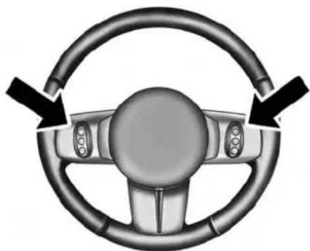
natural_image
Top-down view of a car steering wheel with two black arrows indicating clockwise direction (no text or symbols)RemoteSoundSystemControls (BackViewOfSteeringWheel)
045033001
UNDERSTANDING YOUR INSTRUMENT PANEL 299
The right-hand control is a rocker-type switch with a pushbutton in the center and controls the volume and mode of the sound system. Pressing the top of the rocker switch will increase the volume, and pressing the bottom of the rocker switch will decrease the volume.
Pressing the center button will make the radio switch between the various modes available (AM/FM/SAT/CD/HDD/AUX/VES, etc.).
The left-hand control is a rocker-type switch with a pushbutton in the center. The function of the left-hand control is different depending on which mode you are in.
The following describes the left-hand control operation in each mode.
Radio Operation
Pushing the top of the switch will "Seek" up for the next listenable station and pushing the bottom of the switch will "Seek" down for the next listenable station.
300 UNDERSTANDING YOUR INSTRUMENT PANEL
The button located in the center of the left-hand control will tune to the next preset station that you have programmed in the radio preset button.
CD Player
Pressing the top of the switch once will go to the next track on the CD. Pressing the bottom of the switch once will go to the beginning of the current track, or to the beginning of the previous track if it is within eight seconds after the current track begins to play.
If you press the switch up or down twice, it plays the second track; three times, it will play the third, etc.
The center button on the left side rocker switch has no function for a single-disc CD player. However, when a multiple-disc CD player is equipped on the vehicle, the center button will select the next available CD in the player.
CD/DVD DISC MAINTENANCE
To keep a CD/DVD in good condition, take the following precautions:
- Handle the disc by its edge; avoid touching the surface.
- If the disc is stained, clean the surface with a soft cloth, wiping from center to edge.
- Do not apply paper or tape to the disc; avoid scratching the disc.
- Do not use solvents such as benzene, thinner, cleaners, or anti-static sprays.
- Store the disc in its case after playing.
- Do not expose the disc to direct sunlight.
- Do not store the disc where temperatures may become too high.
NOTE: If you experience difficulty in playing a particular disc, it may be damaged (e.g., scratched, reflective coating removed, a hair, moisture or dew on the disc) oversized, or have protection encoding. Try a known good disc before considering disc player service.
Under certain conditions, the mobile phone being on in your vehicle can cause erratic or noisy performance from your radio. This condition may be lessened or eliminated by relocating the mobile phone antenna. This condition is not harmful to the radio. If your radio performance does not satisfactorily "clear" by the repositioning of the antenna, it is recommended that the radio volume be turned down or off during mobile phone operation when not using Uconnect® (if equipped).
CLIMATE CONTROLS
The air conditioning and heating system is designed to make you comfortable in all types of weather.
Manual Heating And Air Conditioning

text_image
PUSH A/C PUSH PUSH045607535
Manual Temperature Control
The Manual Temperature Controls consist of a series of outer rotary dials and inner push knobs.
BlowerControl

Rotate this control to regulate the amount of air forced through the ventilation system in any mode. The blower speed increases as you move the control to the right from the "O" (OFF) position. There are seven blower speeds.
NOTE: For vehicles equipped with Remote Start, the climate controls will not function during Remote Start operation if the blower control is left in the "O" (Off) position.
TemperatureControl

Rotate this control to regulate the temperature of the air inside the passenger compartment. Rotating the dial left into the blue area of the scale indicates cooler temperatures, while rotating right into the red area indicates warmer temperatures.
NOTE: If your air conditioning performance seems lower than expected, check the front of the A/C condenser located in front of the radiator for an accumulation of dirt or insects. Clean with a gentle water spray from behind the radiator and through the condenser. Fabric front fascia protectors may reduce airflow to the condenser, reducing air conditioning performance.
ModeControl(AirDirection)
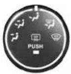
045607541
Rotate this control to choose from several patterns of air distribution. You can select either a primary mode as identified by the symbols on the control, or a blend of two of these modes. The closer the setting is to a particular symbol, the more air distribution you receive from that mode.
•Panel

Air is directed through the outlets in the instruairflow.
NOTE: The center instrument panel outlets can be aimed so that they are directed toward the rear seat passengers for maximum airflow to the rear.
UNDERSTANDING YOUR INSTRUMENT PANEL 303
•Bi-Level

Air is directed through the panel and floor outlets.
NOTE: For all settings, except full cold or full hot, there is a difference in temperature between the upper and lower outlets. The warmer air flows to the floor outlets. This feature gives improved comfort during sunny but cool conditions.
• Floor

Air is directed through the floor outlets with a small amount flowing through the defrost and side
•Mix

Air is directed through the floor, defrost, and side window demist outlets. This setting works best in cold or snowy conditions that require extra heat to the windshield. This setting is good for maintaining comfort while reducing moisture on the windshield.
304 UNDERSTANDING YOUR INSTRUMENT PANEL
•Defrost

Air is directed through the windshield and side window demist outlets. Use this mode with maximum blower and temperature settings for best wind-shield and side window defrosting.
NOTE:
- The air conditioning compressor operates in Mix, Defrost, or a blend of these modes, even if the Air Conditioning (A/C) button is not pressed. This dehumidifies the air to help dry the windshield. To improve fuel economy, use these modes only when necessary.
- For information on operating the Rear Defrost, refer to "Rear Window Features" in "Understanding The Features Of Your Vehicle".
• RecirculationControl

Pressing the Recirculation Control button will put the system in recirculation mode. This can be used when outside conditions such as smoke, odors, dust, or high humidity are present. Activating recirculation will cause the LED in the control button to illuminate.
NOTE:
- Continuous use of the Recirculation mode may make the inside air stuffy and window fogging may occur. Extended use of this mode is not recommended.
- The use of the Recirculation mode in cold or damp weather will cause windows to fog on the inside, because of moisture buildup inside the vehicle. Select the outside air position for maximum defogging.
UNDERSTANDING YOUR INSTRUMENT PANEL 305
- The A/C will engage automatically to prevent fogging when the recirculation button is pressed and the mode control is set to panel or panel / floor.
- The A/C can be deselected manually without disturbing the mode control selection.
- When the ignition switch is turned to the LOCK position, the recirculation feature will be cancelled.
AirConditioningControl

045607557
Press this button to engage the Air Conditioning. A light will illuminate when the Air Conditioning system is engaged. Rotating the dial left into the blue area of the scale indicates cooler temperatures, while rotating right into the red area indicates warmer temperatures.
NOTE: The air conditioning compressor will not engage until the engine has been running for about 10 seconds.
•MAXA/C
For maximum cooling use the A/C and recirculation buttons at the same time.
•ECONOMYMODE
If economy mode is desired, press the A/C button to turn OFF the indicator light and the A/C compressor. Then, select Panel, Bi-Level or Floor mode and move the temperature control to the desired temperature.
306 UNDERSTANDING YOUR INSTRUMENT PANEL
Automatic Temperature Control (ATC) — If Equipped
The Automatic Temperature Control system automatically maintains the climate in the cabin of the vehicle at the comfort levels desired by the driver and passenger.

text_image
AUTO PUSH 69 72 78 A/C PUSH 60 54 AUTO PUSH045640031
AutomaticTemperatureControl
AutomaticOperation
Operation of the system is quite simple.
- Turn the Mode Control knob (right knob) and the Blower Control knob (left knob) to AUTO.
NOTE: The AUTO position performs best for front seat occupants only.

045638695
- Dial in the temperature you would like the system to maintain by rotating the Temperature Control knob (center knob). Once the comfort level is selected, the system will maintain that level automatically using the heating system. Should the desired comfort level require air conditioning, the system will automatically make the adjustment.
UNDERSTANDING YOUR INSTRUMENT PANEL 307
You will experience the greatest efficiency by simply allowing the system to function automatically. Selecting the "O" (OFF) position on the blower control stops the system completely and closes the outside air intake.
The recommended setting for maximum comfort for the average person is 72^ F ( 22^ C); however, this may vary.
NOTE:
- The temperature setting can be adjusted at anytime without affecting automatic operation.
- Pressing the Air Conditioning Control button while in AUTO mode will cause the LED in the control button to flash three times and then turn off. This indicates that the system is in AUTO mode and requesting the air conditioning is not necessary.
- If your air conditioning performance seems lower than expected, check the front of the A/C condenser located in front of the radiator for an accumulation of dirt or insects. Clean with a gentle water spray from behind the radiator and through the condenser. Fabric front fascia protectors may reduce airflow to the condenser, reducing air conditioning performance.
BlowerControl

045607536
For full automatic operation or for automatic blower operation, turn the blower knob to the AUTO position. In manual mode there are seven blower speeds that can be individual selected. In off position the blower will shut off.
308 UNDERSTANDING YOUR INSTRUMENT PANEL
ManualOperationOverride
This system offers a full complement of manual override features, which consist of Blower Preferred Automatic, Mode Preferred Automatic, or Blower and Mode Preferred Automatic. This means the operator can override the blower, the mode, or both. There is a manual blower range for times when the AUTO setting is not desired.
The blower can be set to any fixed blower speed by rotating the Blower Control knob (on the left).
NOTE: Please read the Automatic Temperature Control Operation Chart that follows for details.
| Automatic Temperature Control Operation | The system will... | |||||
| Operation | How | Blower Control | Mode Control | Air Temperature Control | Air Recirculation Control | A/C Operation |
| Full Automatic Operation | Set blower knob to Auto. Set mode knob to Auto. Set temperature knobs for comfort. | Automatic | Automatic | Automatic | Automatic but can be overridden for 10 minutes at a time. | Automatic |
| Blower Preferred Automatic | Set blower knob to any desired airflow level other than Auto. Set mode knob to Auto. Set temperature knobs for comfort. | User selectable to any speed. | Automatic | Automatic | Automatic but can be overridden for 10 minutes at a time. | Automatic |
| Mode Preferred Automatic | Set mode knob to any desired air delivery point other than Auto. Set blower knob to Auto. Set temperature knobs for comfort. | Automatic | User selectable to any air delivery point. | Automatic | User selectable outside or recirculated.Not allowed in Defrost Mode | User selectable A/C on or off. |
| Blower and Mode Preferred Automatic | Set blower knob to any desired airflow level other than Auto. Set mode knob to any desired air delivery point other than Auto. Set temperature knobs for comfort. | User selectable to any speed. | User selectable to any air delivery point. | Automatic | User selectable outside or recirculated.Not allowed in Defrost Mode | User selectable A/C on or off. |
310 UNDERSTANDING YOUR INSTRUMENT PANEL
The operator can override the AUTO mode setting to change airflow distribution by rotating the Mode Control knob (on the right) to one of the following positions.
• Panel
Air is directed through the outlets in the instrument panel. These outlets can be adjusted to direct airflow.
NOTE: The center instrument panel outlets can be aimed so that they are directed toward the rear seat passengers for maximum airflow to the rear.
•Bi-Level
Air is directed through the panel and floor outlets.
NOTE: For all settings, except full cold or full hot, there is a difference in temperature between the upper and lower outlets. The warmer air flows to the floor outlets. This feature gives improved comfort during sunny but cool conditions.
• Floor
Air is directed through the floor outlets with a small amount flowing through the defrost and side window demist outlets.
•Mix
Air is directed through the floor, defrost, and side window demist outlets. This setting works best in cold or snowy conditions that require extra heat to the windshield. This setting is good for maintaining comfort while reducing moisture on the windshield.
•Defrost
Air is directed through the windshield and side window demist outlets. Use this mode with maximum blower and temperature settings for best windshield and side window defrosting.
• AirConditionerControl
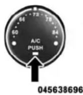
Press this button to turn on the air conditioning during manual operation only. When the air conditioning is turned on, cool dehumidified air will flow through the outlets selected with the Mode control dial. Press this button a second time to turn OFF the air conditioning. An LED in the button illuminates when manual compressor operation is selected.
• RecirculationControl

The system will automatically control recirculation. However, pressing the Recirculation Control button will put the system in recirculation mode. This can be used when outside conditions such as smoke, odors, dust, or high humidity are present. Activating recirculation will cause the LED in the control button to illuminate.
UNDERSTANDING YOUR INSTRUMENT PANEL
NOTE:
- When the ignition switch is turned to the LOCK position, the recirculation feature will be cancelled.
- In cold weather, use of the Recirculation mode may lead to excessive window fogging. The Recirculation mode is not allowed in the defrost mode in order to improve window clearing. Recirculation will be disabled automatically if these modes are selected.
- Extended use of recirculation may cause the windows to fog. If the interior of the windows begins to fog, press the Recirculation button to return to outside air. Some temp/humidity conditions will cause captured interior air to condense on windows and hamper visibility. For this reason, the system will not allow Recirculation to be selected while in defrost mode. Attempting to use the recirculation while in these modes will cause the LED in the control button to blink and then turn off.
312 UNDERSTANDING YOUR INSTRUMENT PANEL
- Most of the time, when in Automatic Operation, you can temporarily put the system into Recirculation Mode by pressing the Recirculation button. However, under certain conditions, while in Automatic Mode, the system is blowing air out the defrost vents. When these conditions are present, and the Recirculation button is pressed, the indicator will flash and then turn off. This tells you that you are unable to go into Recirculation Mode at this time. If you would like the system to go into Recirculation Mode, you must first move the Mode knob to Panel, Bi-Level, Mix, or Floor and then press the Recirculation button. This feature reduces the possibility of window fogging.
Operating Tips
NOTE: Refer to the chart at the end of this section for suggested control settings for various weather conditions.
SummerOperation
The engine cooling system must be protected with a high-quality antifreeze coolant to provide proper corrosion protection and to protect against engine overheating. A solution of 50% OAT (Organic Additive Technology) coolant that meets the requirements of Chrysler Material Standard MS-12106 and 50% water is recommended. Refer to “Maintenance Procedures” in “Maintaining Your Vehicle” for proper coolant selection.
UNDERSTANDING YOUR INSTRUMENT PANEL 313
WinterOperation
Use of the air Recirculation Mode during winter months is not recommended because it may cause window fogging.
VacationStorage
Anytime you store your vehicle, or keep it out of service (i.e., vacation) for two weeks or more, run the air conditioning system at idle for about five minutes in the fresh air and high blower settings. This will ensure adequate system lubrication to minimize the possibility of compressor damage when the system is started again.
WindowFogging
Interior fogging on the windshield can be quickly removed by turning the mode selector to Defrost. The Defrost/Floor mode can be used to maintain a clear
windshield and provide sufficient heating. If side window fogging becomes a problem, increase blower speed. Vehicle windows tend to fog on the inside in mild but rainy or humid weather.
NOTE: Recirculate without A/C should not be used for long periods as fogging may occur.
SideWindowDemisters
A side window demister outlet is located at each end of the instrument panel. These non-adjustable outlets direct air toward the side windows when the system is in the FLOOR, MIX, or DEFROST mode. The air is directed at the area of the windows through which you view the outside mirrors.
314 UNDERSTANDING YOUR INSTRUMENT PANEL
OutsideAirIntake
Make sure the air intake, located directly in front of the windshield, is free of obstructions such as leaves. Leaves collected in the air intake may reduce airflow, and if they enter the plenum, they could plug the water drains. In winter months, make sure the air intake is clear of ice, slush, and snow.
A/CAirFilter—IfEquipped
The A/C Filter prevents most dust and pollen from entering the cabin. The filter acts on air coming from outside the vehicle and recirculated air within the passenger compartment. Refer to “Maintenance Procedures” in “Maintaining Your Vehicle” for A/C Air Filter service information or see your authorized dealer for service. Refer to “Maintenance Schedules” for filter service intervals.
ControlSettingSuggestionsForVariousWeatherConditions
| WEATHER | CONTROL SETTINGS |
HOT WEATHER AND VEHICLE INTERIOR IS VERY HOT  | Open the windows, start the vehicle, press thebutton to turn recirculate off. Set the Fan control to the high position (full clockwise). Press the A/C button. Set the Mode control at or betweenand. Set the temperature control to full cool. After the hot air is pushed from the vehicle press thebutton to turn recirculate on and roll up the windows. Once you are comfortable, press thebutton to turn recirculate off and adjust the temperature control for comfort. |
WARM WEATHER[A066] | Press thebutton to turn recirculate off.If it's sunny, set the Mode control at or nearand turn the air conditioning on. If it's cloudy or dark, set the Mode control at or near. |
COOL OR COLD HI MID CONDITIONS [WEN] [WEN] | Press thebutton to turn recirculate off.If it's sunny, set the Mode control at or betweenandthen turn the air conditioning on. If it's cloudy or dark, set the Mode control at or nearand turn the air conditioning on. If the windows begin to fog, set Mode control at or betweenand. |
COLD DRY CON [IMAGE] [IMAGE] | Set the Mode control at or near. If it is sunny, you may want more upper air. In this case, set the Mode control at or betweenand.In very cold weather, if you need extra heat at the windshield, set the Mode control at or near the. |
STARTING AND OPERATING
CONTENTS
■STARTING PROCEDURES....322
□Manual Transmission — If Equipped . . . . . .322
□Automatic Transmission — If Equipped . . . . .323
□Normal Starting. . . . . . . . . . . . . . . . . . . . . . . . . . . . . . . . . . . . . . . . . . . . . . 323
☐Extreme Cold Weather (Below -20^ F Or -29^ C)....324
□If Engine Fails To Start....324
□After Starting . . . . . . . . . . . . . . . . . . . . . . . . . . . . . . . . . . . . . . . . . . 324
■ENGINE BLOCK HEATER — IF EQUIPPED . . .325
■MANUAL TRANSMISSION — IF EQUIPPED . .325
□Five-Speed Manual Transmission. . . . . . . . . . . . .325
□Recommended Shift Speeds....327
□Downshifting....328
■AUTOMATIC TRANSMISSION — IF EQUIPPED....328
□Key Ignition Park Interlock. . . . . . . . . . . . . . . . . . . . . . . . . . . . . 330
□Brake/Transmission Shift Interlock System . . .330
☐Six-Speed Automatic Transmission — If Equipped .....330
318 STARTING AND OPERATING
□Continuously Variable Automatic Transmission (CVT) — If Equipped....337
■AUTOSTICK® (SIX-SPEED AUTOMATIC TRANSMISSION) — IF EQUIPPED . . . . . . . . . . . . . . . . . . . . . . . . . . . . . . . . . . . . . . . . . . . . . . . . . . . . . . . .
□Operation....342
□AutoStick® (CVT) — If Equipped . . . . . . . . .344
□Operation....344
■FOUR-WHEEL DRIVE OPERATION — IF EQUIPPED....346
■ON-ROAD DRIVING TIPS....346
■OFF-ROAD DRIVING TIPS....347
□When To Use Low (L Off-Road) With The 4WD Lock Lever Engaged . . . . . . . . . . . . . . . . . . . . . . . . . . . . . . . . . . . . . . . . . . . . . . . . . . . . . . . . . . . . . . . . . . . . . . . . .
□Driving In Snow, Mud And Sand . . . . . . . . . . . . . . .348
□Hill Climbing....350
□Driving Through Water....353
□After Driving Off-Road . . . . . . . . . . . . . . . . . . . . . . . . . . . . . . 354
■POWER STEERING....356
□Power Steering Fluid Check . . . . . . . . . . . . . . . . . . . . . . . . . . . . 357
■PARKING BRAKE....358
□Anti-Lock Brake System (ABS)....361
□Anti-Lock Brake System (ABS)....364
□Traction Control System (TCS)....365
□Brake Assist System (BAS)....365
□Electronic Roll Mitigation (ERM)....366
STARTING AND OPERATING 319
□Hill Descent Control (HDC) — If Equipped . . .367
□Hill Start Assist (HSA)....368
□Electronic Stability Control (ESC)....370
□ESC Activation/Malfunction Indicator Light And ESC OFF Indicator Light . . . . . . . . . . . . . . . . . . . . . . . . . . . . . . . . . . . . . . . . . . . . . . . . . . . . . . . .
■TIRE SAFETY INFORMATION .....375
□Tire Markings....375
☐Tire Identification Number (TIN). . . . . . . . . . . . .379
□Tire Terminology And Definitions....381
□Tire Loading And Tire Pressure .....382
■TIRES — GENERAL INFORMATION .....386
□Tire Pressure....386
□Tire Inflation Pressures .....387
☐Tire Pressures For High Speed Operation . . . .389
□Radial Ply Tires....389
□All Season Tires — If Equipped. . . . . . . . . . . . . . . . . . . . . . . . . . . . . . . . . . . . . . . . . . . . . . . . . . . . . . . . . . . 390
□Summer Or Three Season Tires —
If Equipped....390
□Snow Tires....390
□Spare Tire Matching Original Equipped Tire And Wheel — If Equipped....391
□Compact Spare Tire — If Equipped . . . . . . . .391
□Full Size Spare — If Equipped . . . . . . . . . . . . . . . . . . . . . . . . . . . . . . . . . . . . . . . . . . . . . . . . . . . . . . . . . . . . . . . . .
□Limited-Use Spare — If Equipped . . . . . . . . .392
□Tire Spinning .393
□ Tread Wear Indicators .....394
□Life Of Tire....394
320 STARTING AND OPERATING
□Replacement Tires....395
■TIRE CHAINS (TRACTION DEVICES) .....396
■TIRE ROTATION RECOMMENDATIONS....397
■TIRE PRESSURE MONITORING SYSTEM (TPMS)....398
□Base System....401
□Premium System — If Equipped . . . . . . . . . . . . . . 403
□General Information....407
■FUEL REQUIREMENTS....408
□2.0L And 2.4L Engine .....408
□Reformulated Gasoline . . . . . . . . . . . . . . . . . . . . . . . . 408
□Gasoline/Oxygenate Blends....409
□E-85 Usage In Non-Flex Fuel Vehicles .....409
□MMT In Gasoline....410
□Materials Added To Fuel....410
□Fuel System Cautions. . . . . . . . . . . . . . . . . . . . . . . . . . . . . . . 410
□ Carbon Monoxide Warnings .....411
■ADDING FUEL....412
□Fuel Filler Cap (Gas Cap)....412
□Loose Fuel Filler Cap Message....414
■VEHICLE LOADING....414
□Vehicle Certification Label .....414
■TRAILER TOWING....416
□Common Towing Definitions....416
□Trailer Hitch Classification....419
STARTING AND OPERATING 321
□Trailer Towing Weights (Maximum Trailer Weight Ratings)....420
□Trailer And Tongue Weight....421
□Towing Requirements....422
□Towing Tips....427
■RECREATIONAL TOWING (BEHIND MOTORHOME, ETC.) . . . . . . . . . . . . . . . . . . . . . . . . . . . . . . . . . . . . . . . . . . . . . . . . . . . . . . . . . 429
□Towing This Vehicle Behind Another Vehicle....429
322 STARTING AND OPERATING
STARTING PROCEDURES
Before starting your vehicle, adjust your seat, adjust both inside and outside mirrors, and fasten your seat belts.
WARNING!
- Beforeexitingvehicle,alwaysapplytheparking brake,shiftthetransmissionintoPARK,andremovetheKeyFobfromtheignition.Whenleaving thevehicle,alwayslockyourvehicle.
- Neverleavechildrenaloneinavehicle,orwith accesstoanunlockedvehicle.
- Allowingchildrentobeinavehicleunattendedis dangerousforanumberofreasons.Achildor otherscouldbeseriouslyorfatallyinjured.Childrenshouldbewarnednottotouchtheparking brake,brakepedalortheshiftlever.
(Continued)
WARNING!(Continued)
- DonotleavetheKeyFobinornearthevehicle, or inalocationaccessibletochildren. Achild could operatepowerwindows, othercontrols, or move thevehicle.
Manual Transmission — If Equipped
Before starting the engine fully apply the parking brake, press the clutch pedal to the floor, and place the shift lever in NEUTRAL.
NOTE:
- The engine will not start unless the clutch pedal is pressed to the floor.
- If the key will not turn and the steering wheel is locked, rotate the wheel in either direction to relieve pressure on the locking mechanism and then turn the key.
Automatic Transmission — If Equipped
The shift lever must be in the PARK or NEUTRAL position before you can start the engine. Depress the brake pedal before shifting to any driving gear.
NOTE: You must press the brake pedal before shifting out of PARK.
TipStart
Donotpress the accelerator. Turn the ignition switch to the START position and release it as soon as the starter engages. The starter motor will continue to run, and it will disengage automatically when the engine is running. If the engine fails to start, the starter will disengage automatically in 10 seconds. If this occurs, turn the ignition switch to the LOCK position, wait 10 to 15 seconds, then repeat the “Normal Starting” procedure.
Normal Starting
Normal starting of either a cold or a warm engine does not require pumping or pressing the accelerator pedal. Simply turn the ignition switch to the START position and release when the engine starts. If the engine fails to start within 15 seconds, turn the ignition switch to the OFF position, wait 10 to 15 seconds, then repeat the "Normal Starting" procedure.
WARNING!
Donotattempttopushortowyourvehicletogetit started. Vehiclesequippedwithanautomatictransmissioncannotbestedthisway.Unburnedfuel couldenterthecatalyticconverterandoncethe enginehasstarted,igniteanddamagetheconverter andvehicle.Ifthevehiclehasadischargedbattery, boostercablesmaybeusedtoobtainastartfrom
(Continued)
324 STARTING AND OPERATING
WARNING!(Continued)
anothervehicle. This typeof start can be dangerous if done improperly, so follow the procedure carefully. Referto "Jump Starting" in "What ToDo In Emergencies" for further information.
Extreme Cold Weather (Below -20°F Or -29°C)
To ensure reliable starting at these temperatures, use of an externally powered electric engine block heater (available from your authorized dealer) is recommended.
If Engine Fails To Start
If the engine fails to start after you have followed the "Normal Starting" and "Extreme Cold Weather" procedures, it may be flooded. Push the accelerator pedal all the way to the floor and hold it there. Crank the engine for no more than 15 seconds. This should clear any excess fuel in case the engine is flooded. Leave the ignition key
in the ON position, release the accelerator pedal and repeat the "Normal Starting" procedure.
WARNING!
Neverpourfuelorotherflammableliquidintothe throttlebodyairinletopeninginanattempttostart thevehicle. This could result in flash fire causing serious personal injury.
CAUTION!
Topreventdamagetothestarter, donotcrank the engineformorethan15secondsatatime. Wait10to 15secondsbeforetryingagain.
After Starting
The idle speed is controlled automatically and it will decrease as the engine warms up.
ENGINE BLOCK HEATER — IF EQUIPPED
The engine block heater warms the engine, and permits quicker starts in cold weather. Connect the cord to a standard 110-115 Volt AC electrical outlet with a grounded, three-wire extension cord.
The engine block heater must be plugged in at least one hour to have an adequate warming effect on the engine.
WARNING!
Remembertodisconnecttheengineblockheater cordbeforedriving.Damagetothe110-115Volt electricalcordcouldcauseelectrocution.
MANUAL TRANSMISSION — IF EQUIPPED
Five-Speed Manual Transmission
WARNING!
Youorotherscouldbeinjuredifyouleavethe vehicleunattendedwithouthavingtheparking brakefullyapplied.Theparkingbrakeshouldalwaysbeappliedwhenthedriverisnotinthevehicle, especiallyonanincline.
326 STARTING AND OPERATING
Fully press the clutch pedal before you shift gears. As you release the clutch pedal, lightly press the accelerator pedal.
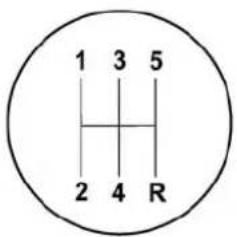
text_image
1 3 5 2 4 R80f7bc4b
ShiftPattern
Use each gear in numerical order, do not skip a gear. Be sure the transmission is in first gear, (not third), when starting from a standing position. Damage to the clutch can result from starting in a gear higher than first gear.
CAUTION!
- Launchinginanygearexcept1stgearwillresultin excessiveslippingoftheclutchandpotentially luggingorstallingtheengine.
- Useeachgearinnumericalorder, donotskipa gear. Besurethetransmissionisinfirstgear, (not third), when starting from a standing position. Damagetotheclutch can result from starting a gear higher than first gear.
For most city driving, you will find it easier to use only the lower gears. For steady highway driving with light accelerations, fifth gear is recommended.
Never drive with your foot resting on the clutch pedal, and never try to hold the vehicle on a hill with the clutch pedal partially engaged. This will cause abnormal wear on the clutch.
Never shift into REVERSE until the vehicle has come to a complete stop.
NOTE: During cold weather, until the transmission lubricant is warm, you may experience slightly higher shift efforts. This is normal and not harmful to the transmission.
Recommended Shift Speeds
To use your manual transmission for optimal fuel economy, it should be upshifted as listed in the following table.
| ManualTransmissionRecommendedShiftSpeeds | ||||
| Unitsinmph(km/h) | ||||
| Engine Size Acceleration Rate | 1 to 2 2 to 3 3 to 4 4 to 5 | |||
| All Engines Accel 14 (23) 23 (37) 29 | (47) 45 (72) | |||
| Cruise 12 (19) | 18 (29) 25 (40) 32 (52) | |||
328 STARTING AND OPERATING
Downshifting
Proper downshifting will improve fuel economy and prolong engine life.
CAUTION!
Ifyouskipagearwhiledownshiftingordownshift attoohighofavehiclespeed,theseconditionsmay causetheenginetooverspeediftoolowofagearis selectedandtheclutchpedalisreleased.Damageto theclutchandthetransmissioncanresultfrom skippingagearwhiledownshiftingordownshifting attoohighofavehiclespeedeveniftheclutchpedal isheldpressed(i.e.,notreleased).
To maintain a safe speed and prolong brake life, shift down to second or first gear when descending a steep grade.
When turning a corner or driving up a steep grade, downshift early so that the engine will not be overburdened.
AUTOMATIC TRANSMISSION — IF EQUIPPED
CAUTION!
Damagetothetransmissionmayoccurifthefollowingprecautionsarenotobserved:
- ShiftintooroutofPARKorREVERSEonlyafter thevehiclehascometoacompletestop.
- DonotshiftbetweenPARK, REVERSE, NEUTRAL, orDRIVEwhentheengineisaboveidle speed.
- Beforeshiftingintoanygear,makesureyourfoot isfirmlypressingthebrakepedal.
NOTE: You must press and hold the brake pedal while shifting out of PARK.
WARNING!
- Unintendedmovementofvehiclecouldinjure thoseinornearthevehicle.Aswithallvehicles, youshouldneverexitavehiclewhiletheengineis running.
- Beforeexitingvehicle,alwaysapplytheparking brake,shiftthetransmissionintoPARK,turnthe engineoff,andremovetheignitionkey.Oncethe keyisremoved,thetransmissionislockedin PARK,securingthevehicleagainstunwanted movement.Whenleavingthevehicle,alwaysremovetheignitionkeyfromthevehicleandlockthe vehicle.
- Neverleavechildrenaloneinavehicle,orwith accesstoanunlockedvehicle.
- Allowingchildrentobeinavehicleunattendedis dangerousforanumberofreasons.Achildor
WARNING!(Continued)
otherscouldbeseriouslyorfatallyinjured. Childrenshouldbewarnednottotouchtheparking brake,brakepedalorthetransmissiongearslector.
- Donotleavetheignitionkeyinornearthevehicle, orinalocationaccessibletochildren. Achildcould operatepowerwindows, othercontrols, ormove thevehicle.
- It is dangerous to shift out of PARK or NEUTRAL if the engines speed higher than needles speed. If your foot is not firmly pressing the brake pedal, the vehicle could accelerate quickly forward or reverse. You could lose control of the vehicle and hit someone or something. Only shift into gear when the engine is idling normally and your foot is firmly pressing the brake pedal.
(Continued)
330 STARTING AND OPERATING
Key Ignition Park Interlock
This vehicle is equipped with a Key Ignition Park Interlock which requires the transmission to be in PARK before the ignition switch can be turned to the LOCK position. The key can only be removed from the ignition when the ignition is in the LOCK position, and once removed the transmission is locked in PARK.
NOTE: If a malfunction occurs, the system will trap the key in the ignition switch to warn you that this safety feature is inoperable. The engine can be started and stopped but the key cannot be removed until you obtain service.
Brake/Transmission Shift Interlock System
This vehicle is equipped with a Brake Transmission Shift Interlock system (BTSI) that holds the shift lever in PARK unless the brakes are applied. To shift the transmission out of PARK, the ignition switch must be turned to the ON/RUN position (engine running or not) and the brake pedal must be pressed.
Six-Speed Automatic Transmission — If Equipped
The transmission gear position display (located in the instrument cluster) indicates the transmission gear range. You must press the brake pedal to move the shift lever out of PARK (refer to "Brake/Transmission Shift Interlock System" in this section). To drive, move the shift lever from PARK or NEUTRAL to the DRIVE position.
The electronically-controlled transmission provides a precise shift schedule. The transmission electronics are self-calibrating; therefore, the first few shifts on a new vehicle may be somewhat abrupt. This is a normal condition, and precision shifts will develop within a few hundred miles (kilometers).
Only shift from DRIVE to PARK or REVERSE when the accelerator pedal is released and the vehicle is stopped. Be sure to keep your foot on the brake pedal when shifting between these gears.
The transmission shift lever has only PARK, REVERSE, NEUTRAL, and DRIVE shift positions. Manual shifts can be made using the Autostick® shift control (refer to "AutoStick®" in this section). Moving the shift lever to the left or right (-/+) while in the DRIVE position will manually select the transmission gear, and will display the current gear in the instrument cluster as 6, 5, 4, 3, 2, 1.
GearRanges
DO NOT race the engine when shifting from PARK or NEUTRAL into another gear range.
NOTE: After selecting any gear range, wait a moment to allow the selected gear to engage before accelerating. This is especially important when the engine is cold.
PARK(P)
This range supplements the parking brake by locking the transmission. The engine can be started in this range. Never attempt to use PARK while the vehicle is in motion. Apply the parking brake when leaving the vehicle in this range.
When parking on a level surface, you may shift the transmission into PARK first, and then apply the parking brake.
When parking on a hill, apply the parking brake before shifting the transmission to PARK, otherwise the load on the transmission locking mechanism may make it difficult to move the shift lever out of PARK. As an added precaution, turn the front wheels toward the curb on a downhill grade and away from the curb on an uphill grade.
WARNING!
- NeverusethePARKpositionasasubstituteforthe parkingbrake.Alwaysapplytheparkingbrake fullywhenparkedtoguardagainstvehiclemovementandpossibleinjuryordamage.
- Yourvehiclecouldmoveandinjureyouandothers ifitisnotcompletelyinPARK.Checkbytryingto movetheshiftleveroutofPARKwiththebrake pedalreleased.Makesurethetransmissionisin PARKbeforeleavingthevehicle.
- ItisdangeroustoshiftoutofPARKorNEUTRAL iftheenginespeedishigherthanidlespeed.If yourfootisnotfirmlypressingthebrakepedal,the vehiclecouldacceleratequicklyforwardorinreverse.Youcouldlosecontrolofthevehicleandhit someoneorsomething.Onlyshiftintogearwhen theengineisidlingnormallyandyourfootis firmlypressingthebrakepedal.
WARNING!(Continued)
- Unintendedmovementofvehiclecouldinjure thoseinornearthevehicle.Aswithallvehicles, youshouldneverexitavehiclewhiletheengineis running.Beforeexitingavehicle,alwaysapplythe parkingbrake,shiftthetransmissionintoPARK, turntheengineoff,andremovetheignitionkey. Oncethekeyisremoved,theshiftleverislockedin PARK,securingthevehicleagainstunwanted movement.
- Whenleavingthevehicle,alwaysremovetheignitionkeyandlockyourvehicle.
- Neverleavechildrenaloneinavehicle,orwith accesstoanunlockedvehicle.
(Continued)
WARNING!(Continued)
- Allowingchildrentobeinavehicleunattendedis dangerousforanumberofreasons.Achildor otherscouldbeseriouslyorfatallyinjured.Childrenshouldbewarnednottotouchtheparking brake,brakepedalortheshiftlever.
- DonotleavetheKeyFobinornearthevehicle,orinalocationaccessibletochildren.Achildcouldoperatepowerwindows,othercontrols,ormovethevehicle.
CAUTION!
- BeforemovingtheshiftleveroutofPARK,you mustturntheignitionswitchfromtheLOCK/OFF positiontotheON/RUNposition,andalsopress thebrakepedal. Otherwise,damagetotheshift levercouldresult.
CAUTION!(Continued)
- DONOTracetheenginewhenshiftingfrom PARKorNEUTRALintoanothergearrange,asthis candamagethedrivetrain.
The following indicators should be used to ensure that you have engaged the transmission into the PARK position:
- When shifting into PARK, firmly move the shift lever all the way forward and to the left until it stops and is fully seated.
- Look at the transmission gear position display and verify that it indicates the PARK position.
- With brake pedal released, verify that the shift lever will not move out of PARK.
(Continued)
334 STARTING AND OPERATING
REVERSE(R)
This range is for moving the vehicle backward. Shift into REVERSE only after the vehicle has come to a complete stop.
NEUTRAL(N)
Use this range when the vehicle is standing for prolonged periods with the engine running. The engine may be started in this range. Apply the parking brake and shift the transmission into PARK if you must leave the vehicle.
NOTE: Do not coast in NEUTRAL and never turn off the ignition to coast down a hill. These are unsafe practices that limit your response to changing traffic or road conditions. You might lose control of the vehicle and have a collision.
CAUTION!
Towingthevehicle,coasting,ordrivingforanyother reasonwiththetransmissioninNEUTRALcancause severetransmissiondamage.Referto"Recreational Towing"in"StartingandOperating"and"Towinga DisabledVehicle"in"WhatToDoInEmergencies" forfurtherinformation.
DRIVE(D)
This range should be used for most city and highway driving. It provides the smoothest upshifts and downshifts, and the best fuel economy. The transmission automatically upshifts through underdrive first, second, third, and fourth gears, direct fifth gear and overdrive sixth gear. The DRIVE position provides optimum driving characteristics under all normal operating conditions.
When frequent transmission shifting occurs (such as when operating the vehicle under heavy loading conditions, in hilly terrain, traveling into strong head winds, or while towing heavy trailers), use the AutoStick® shift control (refer to "AutoStick®" in this section for further information) to select a lower gear. Under these conditions, using a lower gear will improve performance and extend transmission life by reducing excessive shifting and heat buildup.
If the transmission temperature exceeds normal operating limits, the transmission controller will modify the transmission shift schedule and expand the range of torque converter clutch engagement. This is done to prevent transmission damage due to overheating. If the transmission becomes extremely hot, the “Transmission Temperature Warning Light” may illuminate and the transmission may operate differently until the transmission cools down.
During very cold temperatures ( -4^ [-20^] or below), transmission operation may be modified depending on engine and transmission temperature as well as vehicle speed. Normal operation will resume once the transmission temperature has risen to a suitable level.
TransmissionLimpHomeMode
Transmission function is monitored electronically for abnormal conditions. If a condition is detected that could result in transmission damage, Transmission Limp Home Mode is activated. In this mode, the transmission remains in fourth gear regardless of which forward gear is selected. PARK, REVERSE, and NEUTRAL will continue to operate. The Malfunction Indicator Light (MIL) may be illuminated. Limp Home Mode allows the vehicle to be driven to an authorized dealer for service without damaging the transmission.
336 STARTING AND OPERATING
In the event of a momentary problem, the transmission can be reset to regain all forward gears by performing the following steps:
- Stop the vehicle.
- Shift the transmission into PARK.
- Turn the ignition switch to the LOCK/OFF position.
- Wait approximately 10 seconds.
- Restart the engine.
- Shift into the desired gear range. If the problem is no longer detected, the transmission will return to normal operation.
NOTE: Even if the transmission can be reset, we recommend that you visit your authorized dealer at your earliest possible convenience. Your authorized dealer has diagnostic equipment to determine if the problem could recur.
If the transmission cannot be reset, authorized dealer service is required.
OverdriveOperation
The automatic transmission includes an electronically controlled Overdrive (sixth gear). The transmission will automatically shift into Overdrive if the following conditions are present:
- The shift lever is in the DRIVE position.
- The transmission fluid has reached an adequate temperature.
- The engine coolant has reached an adequate temperature.
• The vehicle speed is sufficiently high.
- The driver is not heavily pressing the accelerator.
TorqueConverterClutch
A feature designed to improve fuel economy has been included in the automatic transmission on your vehicle. A clutch within the torque converter engages automatically at calibrated speeds. This may result in a slightly different feeling or response during normal operation in the upper gears. When the vehicle speed drops or during some accelerations, the clutch automatically disengages.
NOTE: Engagement of the torque converter clutch is inhibited at very cold temperatures. Because the engine speed is higher when the torque converter clutch is not engaged, it may seem as if the transmission is not shifting into Overdrive when cold. This is normal. The torque converter clutch will function normally once the transmission is sufficiently warm.
Continuously Variable Automatic Transmission (CVT) — If Equipped
The transmission gear position display (located in the instrument cluster) indicates the transmission gear range. You must press the brake pedal to move the shift lever out of PARK (refer to "Brake/Transmission Shift Interlock System" in this section). To drive, move the shift lever from PARK or NEUTRAL to the DRIVE position.
NOTE: The Continuously Variable Automatic Transmission (CVT) changes ratios in a continuous manner. This may sometimes "feel" as if it is slipping, but this is normal and does not harm anything.
Only shift from DRIVE to PARK or REVERSE when the accelerator pedal is released and the vehicle is stopped. Be sure to keep your foot on the brake pedal when shifting between these gears.
338 STARTING AND OPERATING
The transmission shift lever has PARK, REVERSE, NEUTRAL, and DRIVE shift positions. Manual shifts can be made using the Autostick® shift control (refer to "AutoStick®" in this section). Moving the shift lever to the left or right (-/+) while in the DRIVE position will manually select from a set of predefined transmission gear ratios, and will display the current gear in the instrument cluster as 6, 5, 4, 3, 2, 1.
GearRanges
DO NOT race the engine when shifting from PARK or NEUTRAL into another gear range.
NOTE: After selecting any gear range, wait a moment to allow the selected gear to engage before accelerating. This is especially important when the engine is cold.
PARK(P)
This range supplements the parking brake by locking the transmission. The engine can be started in this range. Never attempt to use PARK while the vehicle is in motion. Apply the parking brake when leaving the vehicle in this range.
When parking on a level surface, you may shift the transmission into PARK first, and then apply the parking brake.
When parking on a hill, apply the parking brake before shifting the transmission to PARK, otherwise the load on the transmission locking mechanism may make it difficult to move the shift lever out of PARK. As an added precaution, turn the front wheels toward the curb on a downhill grade and away from the curb on an uphill grade.
WARNING!
- NeverusethePARKpositionasasubstituteforthe parkingbrake.Alwaysapplytheparkingbrake fullywhenparkedtoguardagainstvehiclemovementandpossibleinjuryordamage.
- Yourvehiclecouldmoveandinjureyouandothers ifitisnotcompletelyinPARK.Checkbytryingto movetheshiftleveroutofPARKwiththebrake pedalreleased.Makesurethetransmissionisin PARKbeforeleavingthevehicle.
- ItisdangeroustoshiftoutofPARKorNEUTRAL iftheenginespeedishigherthanidlespeed.If yourfootisnotfirmlypressingthebrakepedal,the vehiclecouldacceleratequicklyforwardorinreverse.Youcouldlosecontrolofthevehicleandhit someoneorsomething.Onlyshiftintogearwhen theengineisidlingnormallyandyourfootis firmlypressingthebrakepedal.
WARNING!(Continued)
- Unintendedmovementofvehiclecouldinjure thoseinornearthevehicle.Aswithallvehicles, youshouldneverexitavehiclewhiletheengineis running.Beforeexitingavehicle,alwaysapplythe parkingbrake,shiftthetransmissionintoPARK, turntheengineoff,andremovetheignitionkey. Oncethekeyisremoved,theshiftleverislockedin PARK,securingthevehicleagainstunwanted movement.
- Whenleavingthevehicle,alwaysremovetheignitionkeyandlockyourvehicle.
- Neverleavechildrenaloneinavehicle,orwith accesstoanunlockedvehicle.
(Continued)
340 STARTING AND OPERATING
WARNING!(Continued)
- Allowingchildrentobeinavehicleunattendedis dangerousforanumberofreasons.Achildor otherscouldbeseriouslyorfatallyinjured.Childrenshouldbewarnednottotouchtheparking brake,brakepedalortheshiftlever.
- DonotleavetheKeyFobinornearthevehicle,orinalocationaccessibletochildren.Achildcouldoperatepowerwindows,othercontrols,ormovethevehicle.
CAUTION!
- BeforemovingtheshiftleveroutofPARK,you mustturntheignitionswitchfromtheLOCK/OFF positiontotheON/RUNposition,andalsopress thebrakepedal. Otherwise,damagetotheshift levercouldresult.
CAUTION!(Continued)
- DONOTracetheenginewhenshiftingfrom PARKorNEUTRALintoanothergearrange,asthis candamagethedrivetrain.
The following indicators should be used to ensure that you have engaged the transmission into the PARK position:
- When shifting into PARK, firmly move the shift lever all the way forward and to the left until it stops and is fully seated.
- Look at the transmission gear position display and verify that it indicates the PARK position.
- With brake pedal released, verify that the shift lever will not move out of PARK.
(Continued)
REVERSE(R)
This range is for moving the vehicle backward. Shift into REVERSE only after the vehicle has come to a complete stop.
NEUTRAL(N)
Use this range when the vehicle is standing for prolonged periods with the engine running. The engine may be started in this range. Apply the parking brake and shift the transmission into PARK if you must leave the vehicle.
NOTE: Do not coast in NEUTRAL and never turn off the ignition to coast down a hill. These are unsafe practices that limit your response to changing traffic or road conditions. You might lose control of the vehicle and have a collision.
CAUTION!
Towingthevehicle,coasting,ordrivingforanyother reasonwiththetransmissioninNEUTRALcancause severetransmissiondamage.Referto"Recreational Towing"in"StartingandOperating"and"Towinga DisabledVehicle"in"WhatToDoInEmergencies" forfurtherinformation.
DRIVE(D)
This range should be used for most city and highway driving. It provides the best fuel economy. The DRIVE position provides optimum driving characteristics under all normal operating conditions.
When frequent transmission shifting occurs (such as when operating the vehicle under heavy loading conditions, in hilly terrain, traveling into strong head winds, or while towing heavy trailers), use the AutoStick® shift control (refer to "AutoStick® (CVT)" in this section for
342 STARTING AND OPERATING
further information) to select a lower gear ratio. Under these conditions, using a lower gear ratio will improve performance and extend transmission life by reducing excessive shifting and heat buildup.
During sustained high speed driving or trailer towing up long grades on hot days, the automatic transmission oil may become too hot. If this happens, the transmission overheat indicator light will come on, and the vehicle will slow slightly until the transmission cools down enough to allow a return to the requested speed. This is done to prevent transmission damage due to overheating. If the high speed is maintained, the overheating may reoccur, as before, in a cyclic fashion.
LOW(L)
Use this range for engine braking when descending very steep grades. In this range, the transmission will downshift for maximum engine braking, and upshifts will occur only to prevent engine overspeed.
AUTOSTICK® (SIX-SPEED AUTOMATIC TRANSMISSION) — IF EQUIPPED
AutoStick® is a driver-interactive transmission feature providing manual shift control, giving you more control of the vehicle. AutoStick® allows you to maximize engine braking, eliminate undesirable upshifts and downshifts, and improve overall vehicle performance. This system can also provide you with more control during passing, city driving, cold slippery conditions, mountain driving, trailer towing, and many other situations.
Operation
When the shift lever is in the DRIVE position, the transmission will operate automatically, shifting between the six available gears. To engage AutoStick®, simply tap the shift lever to the right or left (+/-) while in the DRIVE position. Tapping (-) to enter AutoStick® mode will downshift the transmission to the next lower gear, while using (+) to enter AutoStick® mode will retain the
current gear. When AutoStick® is active, the current transmission gear is displayed in the instrument cluster.
In AutoStick® mode, the transmission will shift up or down when the driver moves the shift lever to the right (+) or left (-), unless an engine lugging or overspeed condition would result. It will remain in the selected gear until another upshift or downshift is chosen, except as described below:
- The transmission will automatically upshift when necessary to prevent engine over-speed.
- The transmission will automatically downshift as the vehicle slows (to prevent engine lugging) and will display the current gear.
-
The transmission will automatically downshift to first gear when coming to a stop. After a stop, the driver should manually upshift (+) the transmission as the vehicle is accelerated.
-
You can start out, from a stop, in first or second gear. Tapping (+) (at a stop) will allow starting in second gear. Starting out in second gear is helpful in snowy or icy conditions.
- If a requested downshift would cause the engine to overspeed, that shift will not occur.
- Avoid using speed control when AutoStick® is engaged.
- Transmission shifting will be more noticeable when AutoStick® is engaged.
- The system may revert to automatic shift mode if a fault or overheat condition is detected.
To disengage AutoStick® mode, hold the shift lever to the right (+) until "D" is once again displayed in the instrument cluster. You can shift in or out of the AutoStick® mode at any time without taking your foot off the accelerator pedal.
WARNING!
Donotdownshiftforadditionalenginebrakingona slipperysurface. Thedrivewheelscouldlosetheir gripandthevehiclecouldskid,causingacollisionor personalinjury.
AutoStick® (CVT) — If Equipped
AutoStick® is a driver-interactive transmission feature providing six manually selectable gear ratios, giving you more control of the vehicle. AutoStick® allows you to maximize engine braking, eliminate undesirable upshifts and downshifts, and improve overall vehicle performance. This system can also provide you with more control during passing, city driving, cold slippery conditions, mountain driving, trailer towing, and many other situations.
Operation
NOTE: AutoStick® is not available until the CVT warms up in cold weather.
When the shift lever is in the DRIVE position, AutoStick® is activated by moving the shift lever side-to-side. Moving the shift lever to the right (+) will activate AutoStick® and shift up to the next higher manual ratio, unless you are already operating in or near Overdrive, in which case sixth gear ratio will be selected. In like manner, moving the shift lever to the left (-) will activate AutoStick® and shift to the next lower manual ratio. The manually-selected gear will be displayed in the instrument cluster.
In AutoStick® mode, the transmission will shift up or down when (+/-) is manually selected by the driver, unless an engine lugging or overspeed condition would result. It will remain in the selected gear until another upshift or downshift is chosen, except as described below:
- The transmission will automatically upshift when necessary to prevent engine over-speed.
- The transmission will automatically downshift as the vehicle slows (to prevent engine lugging) and will display the current gear.
- The transmission will automatically downshift to first gear when coming to a stop. After a stop, the driver should manually upshift (+) the transmission as the vehicle is accelerated.
-
If a requested downshift would cause the engine to overspeed, that shift will not occur.
-
Transmission shifting will be more noticeable when AutoStick® is engaged.
- Heavy Anti-Lock Brake System (ABS) application will disengage AutoStick® mode.
- The system may revert to automatic shift mode if a fault or overheat condition is detected.
To disengage AutoStick® mode, hold the shift lever to the right (+) until "D" is once again displayed in the instrument cluster. You can shift in or out of the AutoStick® mode at any time without taking your foot off the accelerator pedal.
WARNING!
Donotdownshiftforadditionalenginebrakingona slipperysurface. Thedrivewheelscouldlosetheir gripandthevehiclecouldskid, causingacollisionor personalinjury.
346 STARTING AND OPERATING
This feature provides full time, on-demand, four-wheel drive (4WD).
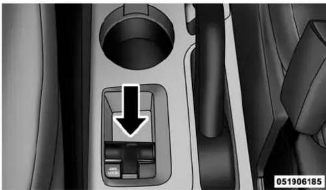
natural_image
Interior view of a car showing a car seatbelt with a downward arrow indicating a component (no text or symbols)Four-WheelDriveSwitch
Where one or more wheels have wheel spin or if additional traction is needed in sand, deep snow, or loose
traction surfaces, activate the "4WD LOCK" switch by pulling up once and releasing. This locks the center coupling allowing more torque to be sent to the rear wheels. The "4WD Indicator Light" will come on in the cluster. This can be done on the fly, at any vehicle speed. To deactivate, simply pull on the switch one more time. The "4WD Indicator Light" will then go out.
NOTE: Refer to "Electronic Brake Control System/Electronic Stability Control (ESC)" in "Starting and Operating" for further information.
ON-ROAD DRIVING TIPS
Utility vehicles have higher ground clearance and a narrower track to make them capable of performing in a wide variety of off-road applications. Specific design characteristics give them a higher center of gravity than ordinary cars.
An advantage of the higher ground clearance is a better view of the road, allowing you to anticipate problems. They are not designed for cornering at the same speeds as conventional two-wheel drive vehicles any more than low-slung sports cars are designed to perform satisfactorily in off-road conditions. If at all possible, avoid sharp turns or abrupt maneuvers. As with other vehicles of this type, failure to operate this vehicle correctly may result in loss of control or vehicle rollover.
OFF-ROAD DRIVING TIPS
You will encounter many types of terrain driving off-road. You should be familiar with the terrain and area before proceeding. There are many types of surface conditions: hard packed dirt, gravel, rocks, grass, sand, mud, snow and ice. Every surface has a different effect on your vehicle's steering, handling and traction. Controlling your vehicle is one of the keys to successful off-road driving, so always keep a firm grip on the steering wheel and maintain a good driving posture. Avoid sudden accelerations, turns or braking. In most cases there are no road signs, posted speed limits or signal lights. Therefore you will need to use your own good judgment on what is safe and what is not. When on a trail, you should always be looking ahead for surface obstacles and changes in terrain. The key is to plan your future driving route while remembering what you are currently driving over.
CAUTION!
Neverparkyourvehicleoverdrygrassorother combustiblematerials.Theheatfromyourvehicle exhaustsystemcouldcauseafire.
WARNING!
Alwayswearyourseatbeltandfirmlytiedown cargo.Unsecuredcargocanbecomeprojectilesinan off-roadsituation.
When To Use Low (L Off-Road) With The 4WD Lock Lever Engaged
When driving off-road, shift into low (L Off-Road) and activate the 4WD LOCK. This will provide additional traction and activates the numerous off-road features to improve handling and control on slippery or difficult terrain. Due to the sustained lower gearing, low (L Off-Road) with 4WD LOCK engaged will allow the engine to operate in a higher power range. This will allow you to cross over obstacles and descend hills, with improved control and less effort.
NOTE: For maximum off-road performance, premium fuel is recommended. While the vehicle will operate on regular fuel when in L Off-Road mode, the engine has been calibrated for maximum performance using premium fuel.
Driving In Snow, Mud And Sand
There is a drastic reduction in traction when driving in snow, mud or sand. The vehicle will be less responsive to steering, acceleration and braking inputs. Therefore, you should accelerate slowly, leave greater stopping distances and avoid abrupt vehicle maneuvers. You want to keep a slow constant steady pace. The key is to maintain the vehicle's momentum.
Snow
In heavy snow or for additional control and traction at slower speeds, activate the 4WD LOCK and shift the transaxle to low (L Off-Road) if necessary. Do not shift to a lower gear than necessary to maintain headway. Overrevving the engine can spin the wheels and traction will be lost. If you start to slow to a stop, try turning your steering wheel no more than a 1/4 turn quickly back and forth, while still applying throttle. This will allow the tires to get a fresh "bite" and help maintain your momentum.
CAUTION!
Onicyorslipperyroads, donotdownshiftathigh engineRPM'sorvehiclespeedsbecauseenginebrakingmaycauseskiddingandlossofcontrol.
Mud
Deep mud creates a great deal of suction around the tires and is very difficult to get through. You should use low (L Off-Road) with the 4WD LOCK engaged and maintain your momentum. If you start to slow to a stop, try turning your steering wheel no more than a 1/4 turn quickly back and forth for additional traction. Mud holes pose an increased threat of vehicle damage and getting stuck. They are normally full of debris from previous vehicles getting stuck. As a good practice before entering any mud hole, get out and determine how deep it is, if there are any hidden obstacles and if the vehicle can be safely recovered if stuck.
Sand
Soft sand is very difficult to travel through with full tire pressure. When crossing soft sandy spots in a trail maintain your vehicle's momentum and do not stop. The key to driving in soft sand is using the appropriate tire pressure, accelerating slowly, avoiding abrupt maneuvers and maintaining the vehicle's momentum. If you are going to be driving on large soft sandy areas or dunes, reduce your tire pressure to a minimum of 15 psi (103 kPa) to allow for a greater tire surface area. You should use low (L Off-Road) with the 4WD LOCK engaged and ESC turned off. Reduced tire pressure will drastically improve your traction and handling, while driving on the soft sand, but you must return the tires to normal air pressure before driving on pavement or other hard surfaces. Be sure you have a way to reinflate the tires prior to reducing the pressure.
CAUTION!
Reduced tire pressures may cause inflation and total loss of air pressure. Toreducether is a risk of inflation, while a reduced tire pressure, reduce your speed and avoid sharp turns or abrupt maneuvers.
Hill Climbing
Hill climbing requires good judgment and a good understanding of your abilities and your vehicle's limitations. Hills can cause serious problems. Some are just too steep to climb and should not be attempted. You should always feel confident with the vehicle and your abilities. You should always climb hills straight up and down. Never attempt to climb a hill on an angle.
BeforeClimbingASteepHill
As you approach a hill consider its grade or steepness. Determine if it is too steep. Look to see what the traction is on the hill side trail. Is the trail straight up and down? What is on top and the other side? Are there ruts, rocks, branches or other obstacles on the path? Can you safely recover the vehicle if something goes wrong? If everything looks good and you feel confident, then you should use low (L Off-Road) with the 4WD LOCK engaged and proceed with caution maintaining your momentum as you climb the hill.
DrivingUpHill
Once you have determined your ability to proceed and have shifted into the appropriate gear, line your vehicle up for the straightest possible run. Accelerate with an easy constant throttle and apply more power as you start up the hill. Do not race forward into a steep grade; the abrupt change of grade could cause you to lose control. If
the front end begins to bounce, ease off the throttle slightly to bring all four tires back on the ground. As you approach the crest of the hill, ease off the throttle and slowly proceed over the top. If the wheels start to slip as you approach the crest of a hill, ease off the accelerator and maintain headway by turning the steering wheel no more than a 1/4 turn quickly back and forth. This will provide a fresh "bite" into the surface and will usually provide enough traction to complete the climb. If you do not make it to the top, place the vehicle in REVERSE and back straight down the grade using engine resistance along with the vehicle brakes.
WARNING!
Neverattempttoclimbahillatanangleorturn aroundonasteepgrade. Drivingacrossanincline increasestheriskofarollover, whichmayresultin severeinjury.
DrivingDownHill
Before driving down a steep hill you need to determine if it is too steep for a safe descent. What is the surface traction? Is the grade too steep to maintain a slow controlled descent? Are there obstacles? Is it a straight descent? Is there plenty of distance at the base of the hill to regain control if the vehicle descends to fast? If you feel confident in your ability to proceed then make sure you are in low (L Off-Road) with the 4WD LOCK engaged and proceed with caution. Allow engine and hill descent braking to control the descent and apply your brakes if necessary, but do not allow the tires to lock.
WARNING!
DonotdescendasteepgradeinNEUTRAL.Use vehiclebrakesinconjunctionwithenginebraking. Descendingagradetoofastcouldcauseyoutolose controlandbeseriouslyinjuredorkilled.
352 STARTING AND OPERATING
DrivingAcrossAnIncline
If at all possible avoid driving across an incline. If it is necessary, know your vehicle's abilities. Driving across an incline places more weight on the down-hill wheels, which increases the possibilities of a down-hill slide or rollover. Make sure the surface has good traction with firm and stable soils. If possible transverse the incline at an angle heading slightly up or down.
WARNING!
Drivingacrossaninclineincreasetheriskofa rollover,whichmayresultinsevereinjury.
IfYouStallOrBeginToLoseHeadway
If you stall or begin to lose headway while climbing a steep hill, allow your vehicle to come to a stop and immediately apply the brake. Restart the engine and shift to REVERSE. Back slowly down the hill allowing engine
and hill descent braking to control the descent and apply your brakes if necessary, but do not allow the tires to lock.
WARNING!
Iftheenginestallsoryouloseheadwayorcannot makeittothetopofasteephillorgrade,never attempttoturnaround.Todosomayresultin tippingandrollingthevehicle,whichmayresultin severeinjury.Alwaysbackcarefullystraightdowna hillinREVERSEgear.Neverbackdownahillin NEUTRALusingonlythevehiclebrakes.Never drivediagonallyacrossahill,alwaysdrivestraight upordown.
Driving Through Water
Extreme care should be taken crossing any type of water. Water crossings should be avoided if possible, and only be attempted when necessary in a safe responsible manner. You should only drive through areas which are designated and approved. You should tread lightly and avoid damage to the environment. You should know your vehicles abilities and be able to recover it if something goes wrong. You should never stop or shut a vehicle off when crossing deep water unless you ingested water into the engine air intake. If the engine stalls, do not attempt to restart it. Determine if it has ingested water first. The key to any crossing is low and slow. You want to use low (L Off-Road) with the 4WD LOCK engaged and proceed very slowly with a constant slow speed (3-5 mph [5–8 km/h] maximum) and light throttle. Keep the vehicle moving; do not try to accelerate through the crossing. After crossing any water higher than the bottom of the axle differentials, you should inspect all of the vehicle fluids for signs of water ingestion.
CAUTION!
Wateringestionintothetransaxle,transfercase, engineorvehicleinteriorcanoccurifyoudrivetoo fastorthroughtoodeepofwater.Watercancause permanentdamagetoengine,drivelineorother vehiclecomponentsandyourbrakeswillbeless effectiveoncewetand/ormuddy.
BeforeYouCrossAnyTypeOfWater
As you approach any type of water, you need to determine if you can cross it safely and responsibly. If necessary, get out and walk through the water or probe it with a stick. You need to be sure of its depth, approach angle, current and bottom condition. Be careful of murky or muddy waters; check for hidden obstacles. Make sure
354 STARTING AND OPERATING
you will not be intruding on any wildlife, and you can recover the vehicle if necessary. The key to a safe crossing is the water depth, current and bottom conditions. On soft bottoms, the vehicle will sink in, effectively increasing the water level on the vehicle. Be sure to consider this when determining the depth and the ability to safely cross.
CrossingPuddles, Pools, FloodedAreas Or Other Standing Water
Puddles, pools, flooded or other standing water areas normally contain murky or muddy waters. These water types normally contain hidden obstacles and make it difficult to determine an accurate water depth, approach angle, and bottom condition. Murky or muddy water holes are where you want to hook up tow straps prior to entering. This makes for a faster, cleaner and easier vehicle recovery. If you are able to determine you can safely cross, than proceed using the low and slow method.
CAUTION!
Muddywaterscanreducethecoolingsystemeffectivenessbydepositingdebrisontotheradiator.
After Driving Off-Road
Off-road operation puts more stress on your vehicle than does most on-road driving. After going off-road, it is always a good idea to check for damage. That way you can get any problems taken care of right away and have your vehicle ready when you need it.
- Completely inspect the underbody of your vehicle. Check tires, body structure, steering, suspension, and exhaust system for damage.
-
Inspect the radiator for mud and debris and clean as required.
-
Check threaded fasteners for looseness, particularly on the chassis, drivetrain components, steering, and suspension. Retighten them, if required, and torque to the values specified in the Service Manual.
- Check for accumulations of plants or brush. These things could be a fire hazard. They might hide damage to fuel lines, brake hoses, axle pinion seals, and propeller shafts.
- After extended operation in mud, sand, water, or similar dirty conditions, have the radiator, fan, brake rotors, wheels, brake linings, and axle yokes inspected and cleaned as soon as possible.
WARNING!
Abrasivematerialinanypartofthebrakesmaycause excessivewearorunpredictablebraking.Youmight nothavefullbrakingpowerwhenyouneeditto preventacollision.Ifyouhavebeenoperatingyour vehicleindirtyconditions,getyourbrakeschecked andcleanedasnecessary.
- If you experience unusual vibration after driving in mud, slush or similar conditions, check the wheels for impacted material. Impacted material can cause a wheel imbalance and freeing the wheels of it will correct the situation.
356 STARTING AND OPERATING
POWER STEERING
The standard power steering system will give you good vehicle response and increased ease of maneuverability in tight spaces. The system will provide mechanical steering capability if power assist is lost.
If for some reason the power assist is interrupted, it will still be possible to steer your vehicle. Under these conditions, you will observe a substantial increase in steering effort, especially at very low vehicle speeds and during parking maneuvers.
NOTE:
- Increased noise levels at the end of the steering wheel travel are considered normal and do not indicate that there is a problem with the power steering system.
- Upon initial start-up in cold weather, the power steering pump may make noise for a short amount of time. This is due to the cold, thick fluid in the steering system. This noise should be considered normal, and it does not in any way damage the steering system.
CAUTION!
Prolongedoperationofthesteeringsystemattheend ofthesteeringwheeltravelwillincreasethesteering fluidtemperatureanditshouldbeavoidedwhen possible.Damagetothepowersteeringpumpmay occur.
Power Steering Fluid Check
Checking the power steering fluid level at a defined service interval is not required. The fluid should only be checked if a leak is suspected, abnormal noises are apparent, and/or the system is not functioning as anticipated. Coordinate inspection efforts through an authorized dealer.
CAUTION!
Donotusechemicalflushesinyourpowersteering systemasthechemicalscandamageyourpower steeringcomponents.Suchdamageisnotcoveredby theNewVehicleLimitedWarranty.
WARNING!
Fluidlevelshouldbecheckedonalevelsurfaceand withtheengineofftopreventinjuryfrommoving partsandtoensureaccuratefluidlevelreading.Do notoverfill.Useonlymanufacturer'srecommended powersteeringfluid.
If necessary, add fluid to restore to the proper indicated level. With a clean cloth, wipe any spilled fluid from all surfaces. Refer to “Fluids, Lubricants, and Genuine Parts” in “Maintaining Your Vehicle” for further information.
358 STARTING AND OPERATING
PARKING BRAKE
Before leaving the vehicle, make sure that the parking brake is fully applied. Also, be certain to leave an automatic transmission in PARK, or manual transmission in REVERSE or first gear.
The parking brake lever is located in the center console. To apply the parking brake, pull the lever up as firmly as possible. To release the parking brake, pull the lever up slightly, press the center button, then lower the lever completely.
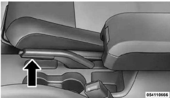
natural_image
Mechanical assembly diagram showing a lever mechanism with an upward arrow indicator (no text or symbols present)ParkingBrake
When the parking brake is applied with the ignition switch in the ON position, the "Brake Warning Light" in the instrument cluster will illuminate.
NOTE:
- When the parking brake is applied and the automatic transmission is placed in gear, the "Brake Warning Light" will flash. If vehicle speed is detected, a chime will sound to alert the driver. Fully release the parking brake before attempting to move the vehicle.
- This light only shows that the parking brake is applied. It does not show the degree of brake application.
When parking on a hill, it is important to turn the front wheels toward the curb on a downhill grade and away from the curb on an uphill grade. For vehicles equipped with an automatic transmission, apply the parking brake before placing the shift lever in PARK, otherwise the load on the transmission locking mechanism may make it difficult to move the shift lever out of PARK. The parking brake should always be applied whenever the driver is not in the vehicle.
WARNING!
- Whenleavingthevehicle,alwaysremovetheKey Fobfromtheignitionandlockyourvehicle.
- Neverleavechildrenaloneinavehicle,orwith accesstoanunlockedvehicle.
- Allowingchildrentobeinavehicleunattendedis dangerousforanumberofreasons.Achildor otherscouldbeseriouslyorfatallyinjured.Childrenshouldbewarnednottotouchtheparking brake,brakepedalortheshiftlever.
- DonotleavetheKeyFobinornearthevehicle, or inalocationaccessibletochildren. Achildcould operatepowerwindows, othercontrols, ormove thevehicle.
- Besuretheparkingbrakeisfullydisengaged beforedriving;failuretodosocanleadtobrake failureandacollision.
(Continued)
WARNING!(Continued)
- Alwaysfullyapplytheparkingbrakewhenleavingyourvehicleoritmayrollandcausedamageor injury. Also, becertaintoleaveanautomatictransmissioninPARK, amanualtransmissioninREVERSEorfirstgear. Failuretodosomaycausethe vehicletorollandcausedamageorinjury.
CAUTION!
If the Brake System Warning Lightremainson with the parkingbrakereleased, abrakesystemmalfunctionisindicated. Havethebrakesystemserviced by anauthorizeddealerimmediately.
BRAKE SYSTEM
Your vehicle is equipped with power assisted brakes as standard equipment. In the event power assist is lost for any reason (for example, repeated brake applications with the engine off), the brakes will still function. However, the effort required to brake the vehicle will be much greater than that required with the power system operating.
WARNING!
Ridingthebrakescanleadtobrakefailureand possiblyacollision.Drivingwithyourfootrestingor ridingonthebrakepedalcanresultinabnormally highbraketemperatures,excessiveliningwear,and possiblebrakedamage.Youwouldnothaveyourfull brakingcapacityinanemergency.
If either of the two hydraulic systems lose normal capability, the remaining system will still function with some loss of overall braking effectiveness. This will be evident by increased pedal travel during application and greater pedal force required to slow or stop. In addition, if the malfunction is caused by an internal leak, as the brake fluid in the master cylinder drops, the “Brake Warning Light” will light.
WARNING!
Drivingvehiclewiththe"BrakeWarningLight"on isdangerous.Asignificantdecreaseinbrakingperformanceorvehiclestabilityduringbrakingmay occur.Itwilltakeyoulongertostopthevehicleor willmakeyourvehiclehardertocontrol.Youcould haveacollision.Havethevehiclecheckedimmediately.
Anti-Lock Brake System (ABS)
The ABS provides increased vehicle stability and brake performance under most braking conditions. The system automatically “pumps” the brakes during severe braking conditions to prevent wheel lock-up.
WARNING!
- Pumpingoftheanti-lockbrakeswilldiminish theireffectivenessandmayleadtoacollision.
Pumpingmakethestoppingdistancelonger.Just pressfirmlyonyourbrakepedalwhenyouneedto slowdownorstop. - The ABScannotpreventthenaturallawsofphysicsfromactingonthevehicle,norcanitincrease brakingorsteeringefficiencybeyondthatafforded bytheconditionofthevehiclebrakesandtiresor thetractionafforded.
(Continued)
WARNING!(Continued)
- The ABS cannot prevent collisions, including those resulting from excessive speed inturns, following another vehicle to closely, or hydroplaning.
- The capabilities of an ABS-equipped vehicle must never be exploited in areckless or dangerous manner which could jeopardize the user's safety or the safety of others.

The “ABS Warning Light” monitors the ABS System. The light will come on when the ignition switch is turned to the ON position and may stay on for as long as four seconds.
If the “ABS Warning Light” remains on or comes on while driving, it indicates that the anti-lock portion of the brake system is not functioning and that service is
required. However, the conventional brake system will continue to operate normally if the "Brake Warning Light" is not on.
If the "ABS Warning Light" is on, the brake system should be serviced as soon as possible to restore the benefits of anti-lock brakes. If the "ABS Warning Light" does not come on when the ignition switch is turned to the ON position, have the bulb repaired as soon as possible.
If both the “Brake Warning Light” and the “ABS Warning Light” remain on, the ABS and Electronic Brake Force Distribution (EBD) systems are not functioning. Immediate repair to the ABS is required.
When the vehicle is driven over 7 mph (11 km/h), you may also hear a slight clicking sound as well as some related motor noises. These noises are the system performing its self-check cycle to ensure that the ABS working properly. This self-check occurs each time the vehicle is started and accelerated past 7 mph (11 km/h).
ABS is activated during braking under certain road or stopping conditions. ABS-inducing conditions can include ice, snow, gravel, bumps, railroad tracks, loose debris, or panic stops.
You may also experience the following when the brake system goes into anti-lock mode:
- The ABS motor running (it may continue to run for a short time after the stop).
- The clicking sound of solenoid valves.
- Brake pedal pulsations.
- A slight drop or fall away of the brake pedal at the end of the stop.
These are all normal characteristics of ABS.
WARNING!
The Anti-Lock Brake System (ABS) contains sophisticated electronicequipment that may be susceptible to interference caused by improperly installed or high output radiotransmitting equipment. This interference can cause possible loss of Anti-Lock braking capability. Installation of such equipments should be performed by qualified professionals.
All vehicle wheels and tires must be the same size and type and tires must be properly inflated to produce accurate signals for the computer.
Your vehicle may be equipped with an optional advanced electronic brake control system that includes Anti-Lock Brake System (ABS), Traction Control System (TCS), Brake Assist System (BAS), Electronic Roll Mitigation (ERM), Hill Descent Control (HDC), Hill Start Assist (HSA), and Electronic Stability Control (ESC). All systems work together to enhance vehicle stability and control in various driving conditions and are commonly referred to as ESC.
Anti-Lock Brake System (ABS)
This system aids the driver in maintaining vehicle control under adverse braking conditions. The system controls hydraulic brake pressure to prevent wheel lockup and help avoid skidding on slippery surfaces during braking. Refer to “Anti-Lock Brake System” in “Starting and Operating” for further information.
WARNING!
- Pumpingoftheanti-lockbrakeswilldiminish theireffectivenessandmayleadtoacollision. Pumpingmakethestoppingdistancelonger.Just pressfirmlyonyourbrakepedalwhenyouneedto slowdownorstop.
- The ABScannotpreventthenaturallawsofphysicsfromactingonthevehicle,norcanitincrease brakingorsteeringefficiencybeyondthatafforded bytheconditionofthevehiclebrakesandtiresor thetractionafforded.
- The ABScannotpreventcollisions, including those resulting from excessivespeedinturns, following another vehicle to closely, or hydroplaning.
- The capabilities of an ABS-equipped vehicle must never be exploited in areckless or dangerous manner which could jeopardize the user's safety or the safety of others.
Traction Control System (TCS)
This system monitors the amount of wheel spin of each of the driven wheels. If wheel spin is detected, brake pressure is applied to the slipping wheel(s) and engine power is reduced to provide enhanced acceleration and stability. A feature of the TCS system functions similar to a limited slip differential and controls the wheel spin across a driven axle. If one wheel on a driven axle is spinning faster than the other, the system will apply the brake of the spinning wheel. This will allow more engine torque to be applied to the wheel that is not spinning. This feature remains active even if TCS and ESC are in either the “Partial Off” or “Full Off” modes. Refer to “Electronic Stability Control (ESC)” in this section of this manual.
Brake Assist System (BAS)
The BAS is designed to optimize the vehicle's braking capability during emergency braking maneuvers. The system detects an emergency braking situation by sensing the rate and amount of brake application and then applies optimum pressure to the brakes. This can help reduce braking distances. The BAS complements the Anti-Lock Brake System (ABS). Applying the brakes very quickly results in the best BAS assistance. To receive the benefit of the system, you must apply continuous braking pressure during the stopping sequence (do not "pump" the brakes). Do not reduce brake pedal pressure unless braking is no longer desired. Once the brake pedal is released, the BAS is deactivated.
WARNING!
- The Brake Assist System (BAS) cannot prevent the naturallawsof physics from acting on the vehicle, nor canitin increasethetraction afforded by prevailing road conditions.
- The BAS cannot prevent collisions, including those resulting from excessive speed inturns, driving on very slipper surface, or hydroplaning.
- The capabilities of a BAS-equipped vehicle must never be exploited in areckless or dangerous manner which could jeopardize the user's safety or the safety of others.
Electronic Roll Mitigation (ERM)
This system anticipates the potential for wheel lift by monitoring the driver's steering wheel input and the speed of the vehicle. When ERM determines that the rate of change of the steering wheel angle and vehicles speed
are sufficient to potentially cause wheel lift, it applies the brake of the appropriate wheel and may also reduce engine power to lessen the chance that wheel lift will occur. ERM will only intervene during very severe or evasive driving maneuvers.
ERM can only reduce the chance of wheel lift occurring during severe or evasive driving maneuvers. It can not prevent wheel lift due to other factors such as road conditions, leaving the roadway or striking objects or other vehicles.
NOTE: Anytime the ESC system is in the "Full Off" mode, ERM is disabled. Refer to "Electronic Stability Control (ESC)" in this section for a complete explanation of the available ESC modes.
WARNING!
Many factors, such as vehicle loading, road conditions and driving conditions, influence the chance that wheel liftor rollover may occur. ERM cannot prevent all wheel liftor rollovers, especially those that involve leaving the roadway or striking objects or other vehicles. The capabilities of an ERM-equipped vehicle must never be exploited in areckless or dangerous manner which could jeopardize the user's safety or the safety of others.
Hill Descent Control (HDC) — If Equipped
This system maintains vehicle speed while descending hills during off-road driving situations. HDC will automatically apply the brakes to control downhill speed to between 4 mph (7 km/h) and 6 mph (9 km/h) depending on terrain. The system is activated by placing the vehicle in "Off-Road" mode and placing the shift lever in LOW or REVERSE. Refer to "Safe Off-Road Driving" in "Starting and Operating" for further information.

When HDC is properly enabled, the "Hill Decent Control Light" in the instrument cluster will be illuminated.
HDC has the capability to sense terrain and will only activate when the vehicle is descending a hill. It will not activate on level ground. If desired, HDC can be fully deactivated by putting the vehicle into ESC "Full Off" mode. This is done by pressing and holding the "ESC Off" button for five seconds. Refer to "Electronic Stability Control (ESC)" in this section of the manual.
HDC operation can be overridden with brake application to slow the vehicle down below the HDC control speed. Conversely, if more speed is desired during HDC control, the accelerator pedal will increase vehicle speed like normal. When either the brake or the accelerator is released, HDC will control the vehicle back to the original set speed.
368 STARTING AND OPERATING
HDC is only intended for low speed off-road driving. At vehicle speeds above 31 mph (50 km/h) HDC will no longer function. If the “HDC Indicator Light” begins to flash this indicates that the brakes are getting too hot and the vehicle should be stopped to allow the brakes to cool.
WARNING!
HDCisonlyintendedtoassistthedriverincontrollingvehiclespeedwhendescendinghills. Thedriver mustremainattentivetothedrivingconditionsand isresponsibleformaintainingasafevehiclespeed.
Hill Start Assist (HSA)
The HSA system is designed to assist the driver when starting a vehicle from a stop on a hill. HSA will maintain the level of brake pressure the driver applied for a short period of time after the driver takes their foot off of the brake pedal. If the driver does not apply the throttle
during this short period of time, the system will release brake pressure and the vehicle will roll down the hill. The system will release brake pressure in proportion to amount of throttle applied as the vehicle starts to move in the intended direction of travel.
HSAActivationCriteria
The following criteria must be met in order for HSA to activate:
- Vehicle must be stopped.
- Vehicle must be on a 7% (approximate) grade or greater hill.
- Gear selection matches vehicle uphill direction (i.e., vehicle facing uphill is in forward gear; vehicle backing uphill is in REVERSE gear).
WARNING!
Theremaybesituationsonminorhillswithloaded vehicle,orwhilepullingatrailer,whenthesystem willnotactivateandslightrollingmayoccur.This couldcauseacollisionwithanothervehicleorobject. Alwaysrememberthedriverisresponsibleforbrakingthevehicle.
Disabling/EnablingHSA
If you wish to turn on or off the HSA system, it can be done using the Customer Programmable Features in the Electronic Vehicle Information Center (EVIC). Refer to "Electronic Vehicle Information Center (EVIC)" in "Understanding Your Instrument Panel" for further information.
For vehicles not equipped with the EVIC, perform the following steps:
NOTE: You must complete Steps 1 through 8 within 90 seconds.
- Center the steering wheel (front wheels pointing straight forward).
- Shift the transmission into NEUTRAL.
- Apply the parking brake.
- Start the engine.
- Release the clutch pedal (if equipped).
- Rotate the steering wheel one-half turn to the left.
- Press the "ESC Off" switch (located in the lower switch bank below the climate controls) four times within 20 seconds. The "ESC Activation/Malfunction Indicator Light" should turn on and turn off two times.
370 STARTING AND OPERATING
- Rotate the steering wheel back to center and then an additional half-turn to the right.
- Turn the ignition switch to the OFF position and then back to the ON position. If the sequence was completed properly, the "ESC Activation/Malfunction Indicator Light" will blink several times to confirm HSA is disabled.
- Repeat these steps if you want to return this feature to it's previous setting.
Electronic Stability Control (ESC)
This system enhances directional control and stability of the vehicle under various driving conditions. ESC corrects for over-steering or under-steering of the vehicle by applying the brake of the appropriate wheel to assist in counteracting the over-steering or under-steering condition. Engine power may also be reduced to help the vehicle maintain the desired path. ESC uses sensors in the vehicle to determine the vehicle path intended by the driver and compares it to the actual path of the vehicle. When the actual path does not match the intended path, ESC applies the brake of the appropriate wheel to assist in counteracting the over-steer or under-steer condition
•Over-steer - when the vehicle is turning more than appropriate for the steering wheel position.
- Under-steer - when the vehicle is turning less than appropriate for the steering wheel position.
WARNING!
- The Electronic Stability Control (ESC) cannot prevent then natural law of physics from acting on the vehicle, nor can it increase the traction afforded by prevailing road conditions.
(Continued)
WARNING!(Continued)
- ESCcannotpreventaccidents,includingthoseresultingfromexcessivespeedinturns,drivingonveryslipperysurfaces,orhydroplaning.ESCalso cannotpreventcollisionsresultingfromlossofvehiclecontrolduetoinappropriatedriverinputfortheconditions.Onlyasafe,attentive,andskillfuldrivercanpreventcollisions.
- The capabilities of an ESC-equipped vehicle must never be exploited in areckless or dangerous manner, which could jeopardize the user's safety or the safety of others.
ESCOperatingModes
The ESC system has three available operating modes for four-wheel drive equipped vehicles and two available operating modes for two-wheel drive equipped vehicles.
FullOn(Four-WheelDriveModels)OrOn(Two-WheelDriveModels)
This is the normal operating mode for ESC. Whenever the vehicle is started the ESC system will be in this "On" mode. This mode should be used for most driving situations. ESC should only be turned to "Partial Off" or "ESC Off" for specific reasons as noted below.
PartialOff(Four-WheelDriveModels)OrOn(Two-WheelDriveModels)
This mode is entered by momentarily pressing the "ESC Off" switch. When in "Partial Off" mode, the TCS portion of ESC, except for the "limited slip" feature described in the TCS section, has been disabled and the "ESC OFF Indicator Light" will be illuminated. All other stability features of ESC function normally. This mode is intended to be used if the vehicle is in deep snow, sand or gravel conditions and more wheel spin than ESC would normally allow is required to gain traction.
372 STARTING AND OPERATING
To turn ESC on again, momentarily press the "ESC Off" switch. This will restore the normal "ESC On" mode of operation.
NOTE: To improve the vehicle's traction when driving with snow chains, or starting off in deep snow, sand or gravel, it may be desirable to switch to the "Partial Off" mode by pressing the "ESC Off" switch. Once the situation requiring ESC to be switched to the "Partial Off" mode is overcome, turn ESC back on by momentarily pressing the "ESC Off" switch. This may be done while the vehicle is in motion.
WARNING!
Whenin"PartialOff" mode, the TCS functionality of ESC (except forthelimited slip feature described in the TCS section) has been disabled and the "ESCOff
WARNING!(Continued)
IndicatorLight"willbeilluminated.Whenin"PartialOff"mode,theenginepowerreductionofTCSis disabled,andtheenhancedvehiclestabilityoffered bytheESCsystemisreduced.TrailerSwaycontrol (TSC)(ifequipped)isdisabledwhentheESCsystem isinthe"PartialOff"mode.
FullOff(Four-WheelDriveModelsOnly)
This mode is intended for off-highway or off-road use when ESC stability features could inhibit vehicle maneuverability due to trail conditions. This mode is entered by pressing and holding the "ESC Off" switch for five seconds when the vehicle is stopped and the engine is running. After five seconds, the "ESC OFF Indicator Light" will illuminate and the "ESC OFF" message will
(Continued)
appear in the odometer. Press and release the Trip Odometer button located on the instrument cluster to clear this message.
In this mode, ESC and TCS, except for the "limited slip" feature described in the TCS section, are turned off until the vehicle reaches a speed of 35 mph (56 km/h). At 35 mph (56 km/h) the system returns to "Partial Off" mode, as described above. TCS remains off. When the vehicle speed drops below 30 mph (48 km/h) the ESC system shuts off. ESC is deactivated at low vehicle speeds so that it will not interfere with off-road driving however, ESC function returns to provide the stability feature at speeds above 35 mph (56 km/h). The "ESC OFF Indicator Light" will always be illuminated when ESC is off.
To turn ESC on again, momentarily press the "ESC Off" switch. This will restore the "ESC On" mode of operation.
NOTE: The "ESC OFF" message will display and an audible chime will sound when the shift lever is placed into the PARK position from any other position, and then moved out of the PARK position. This will occur even if the message was previously cleared.
WARNING!
WiththeESCinthe"FullOff"mode,theengine torquereductionandstabilityfeaturesaredisabled. Inanemergencyevasivemaneuver,theESCsystem willnotengagetoassistinmaintainingstability. "ESCOff"modeisintendedforoff-highwayor off-roaduseonly.
374 STARTING AND OPERATING
ESC Activation/Malfunction Indicator Light And ESC OFF Indicator Light
The “ESC Activation/Malfunction Indicator Light” in the instrument cluster will come on when the ignition switch is cycled to the ON/RUN position. It should go out with the engine running. If the “ESC Activation/Malfunction Indicator Light” comes on continuously with the engine running, a malfunction has been detected in the ESC system. If this light remains on after several ignition cycles, and the vehicle has been driven several miles (kilometers) at speeds greater than 30 mph (48 km/h), see your authorized dealer as soon as possible to have the problem diagnosed and corrected.
The “ESC Activation/Malfunction Indicator Light” (located in the instrument cluster) starts to flash as soon as the tires lose traction and the ESC system becomes active. The “ESC Activation/Malfunction Indicator Light” also flashes when TCS is active. If the “ESC Activation/Malfunction Indicator Light” begins to flash during acceleration, ease up on the accelerator and apply as little throttle as possible. Be sure to adapt your speed and driving to the prevailing road conditions.
NOTE:
- The "ESC Off Indicator Light" and the "ESC Activation/Malfunction Indicator Light" come on momentarily each time the ignition switch is turned to the ON/RUN position.
• Each time the ignition is cycled to the ON/RUN position, the ESC system will be ON even if it was cycled off previously. - The ESC system will make buzzing or clicking sounds when it is active. This is normal; the sounds will stop when ESC becomes inactive following the maneuver that caused the ESC activation.

The "ESC OFF Indicator Light" indicates the Electronic Stability Control (ESC) is partially off or full off.
TIRE SAFETY INFORMATION
Tire Markings

text_image
TIRE NAME P215/65R15 95H MANUFACTURER TREEMAN 220 FRACCHIN A TEMPERATE 1 2 3 4 5 6054903773
1 — U.S. DOT Safety Standards 4 — Maximum Load Code (TIN)
2 — Size Designation 5 — Maximum Pressure
3 — Service Description 6 — Treadwear, Traction and Temperature Grade
376 STARTING AND OPERATING
NOTE:
- P (Passenger) — Metric tire sizing is based on U.S. design standards. P-Metric tires have the letter "P" molded into the sidewall preceding the size designation. Example: P215/65R15 95H.
- European — Metric tire sizing is based on European design standards. Tires designed to this standard have the tire size molded into the sidewall beginning with the section width. The letter "P" is absent from this tire size designation. Example: 215/65R15 96H.
-
LT (Light Truck) — Metric tire sizing is based on U.S. design standards. The size designation for LT-Metric tires is the same as for P-Metric tires except for the letters "LT" that are molded into the sidewall preceding the size designation. Example: LT235/85R16.
-
Temporary spare tires are designed for temporary emergency use only. Temporary high pressure compact spare tires have the letter "T" or "S" molded into the sidewall preceding the size designation. Example: T145/80D18 103M.
- High flotation tire sizing is based on U.S. design standards and it begins with the tire diameter molded into the sidewall. Example: 31x10.5 R15 LT.
TireSizingChart
| EXAMPLE: |
| SizeDesignation: |
| P= Passenger car tire size based on U.S. design standards"....blank....." = Passenger car tire based on European design standardsLT= Light truck tire based on U.S. design standardsT o r S = Temporary spare tire31= Overall diameter in inches (in) |
| 215= Section width in millimeters (mm) |
| 65= Aspect ratio in percent (%)– Ratio of section height to section width of tire10.5= Section width in inches (in) |
| R= Construction code- "R"means radial construction- "D"means diagonal or bias construction |
| 15= Rim diameter in inches (in) |
378 STARTING AND OPERATING
| EXAMPLE: |
| ServiceDescription: |
| 95= Load Index- A numerical code associated with the maximum load a tire can carry |
| H= Speed Symbol- A symbol indicating the range of speeds at which a tire can carry a load corresponding to its load index under certain operating conditions- The maximum speed corresponding to the speed symbol should only be achieved under specified operating conditions (i.e., tire pressure, vehicle loading, road conditions, and posted speed limits) |
| LoadIdentification: |
| "....blank..."" = Absence of any text on the sidewall of the tire indicates a Standard Load (SL) tire |
| ExtraLoad(XL)= Extra load (or reinforced) tire |
| LightLoad(LL)= Light load tire |
| C, D, E, F, G = Load range associated with the maximum load a tire can carry at a specified pressure |
| MaximumLoad- Maximum load indicates the maximum load this tire is designed to carry |
| MaximumPressure- Maximum pressure indicates the maximum permissible cold tire inflation pressure for this tire |
STARTING AND OPERATING 379
Tire Identification Number (TIN)
The TIN may be found on one or both sides of the tire, however, the date code may only be on one side. Tires with white sidewalls will have the full TIN, including the date code, located on the white sidewall side of the tire.
Look for the TIN on the outboard side of black sidewall tires as mounted on the vehicle. If the TIN is not found on the outboard side, then you will find it on the inboard side of the tire.
| EXAMPLE: |
| DOTMAL9ABCD0301 |
| DOT= Department of Transportation- This symbol certifies that the tire is in compliance with the U.S. Department of Transportation tire safety standards and is approved for highway use |
| MA= Code representing the tire manufacturing location (two digits) |
| L9= Code representing the tire size (two digits) |
| ABCD= Code used by the tire manufacturer (one to four digits) |
| 03= Number representing the week in which the tire was manufactured (two digits)- 03 means the 3rd week |
380 STARTING AND OPERATING
| EXAMPLE: |
| DOTMAL9ABCD0301 |
| 01= Number representing the year in which the tire was manufactured (two digits) - 01 means the year 2001 - Prior to July 2000, tire manufacturers were only required to have one number to represent the year in which the tire was manufactured. Example: 031 could represent the 3rd week of 1981 or 1991 |
Tire Terminology And Definitions
| TermDefinition | |
| B-PillarThe vehicle B-Pillar | is the structural member of the body located behind the front door. |
| ColdTireInflationPressureCold tire inflation | inflation pressure is defined as the tire pressure after the vehicle has not been driven for at least three hours, or driven less than 1 mile (1.6 km) after sitting for a three hour period. Inflation pressure is measured in units of PSI (pounds per square inch) or kPa (kilopascals). |
| MaximumInflationPressureThe maximum inflation pressure is the maximum permissible cold tire inflation pressure for this tire. The maximum inflation pressure is molded into the sidewall. | |
| RecommendedColdTireInflation Pressure | Vehicle manufacturer's recommended cold tire inflation pressure as shown on the tire placard. |
| TirePlacardA paper label permanently attached to the vehicle describing the vehicle's loading capacity, the original equipment tire sizes and the recommended cold tire inflation pressures. | |
382 STARTING AND OPERATING
Tire Loading And Tire Pressure
TireAndLoadingInformationPlacardLocation
NOTE: The proper cold tire inflation pressure is listed on the driver's side B-Pillar or the rear edge of the driver's side door.

natural_image
Interior view of a car showing the door, seat, and window (no text or symbols visible)B-PillarLocationForTireAndLoadingInformationPlacard
TireAndLoadingInformationPlacard

text_image
TIRE AND LOADING INFORMATION SEATING CAPACITY - TOTAL 5 FRONT 2 REAR 3 THE COMBINED WEIGHT OF OCCUPANTS AND CARGO SHOULD NEVER EXCEED XXX KG OF XXX LES TIRE FRONT REAR SPARE ORIGINAL TIRE SIZE P195/70R14 P195/70R14 T125/70D15 COLD TIRE INFLATION PRESSURE 200kPa, 29PSI 200kPa, 29PSI 420kPa, 60PSI SEE OWNER'S MANUAL FOR ADDITIONAL INFORMATION 4N109268811b5a9a
TireAndLoadingInformationPlacard
This placard tells you important information about the:
- Number of people that can be carried in the vehicle.
-
Total weight your vehicle can carry.
-
Tire size designed for your vehicle.
- Cold tire inflation pressures for the front, rear, and spare tires.
Loading
The vehicle maximum load on the tire must not exceed the load carrying capacity of the tire on your vehicle. You will not exceed the tire's load carrying capacity if you adhere to the loading conditions, tire size, and cold tire inflation pressures specified on the Tire and Loading Information placard and in the "Vehicle Loading" section of this manual.
NOTE: Under a maximum loaded vehicle condition, gross axle weight ratings (GAWRs) for the front and rear axles must not be exceeded. For further information on GAWRs, vehicle loading, and trailer towing, refer to "Vehicle Loading" in this section.
To determine the maximum loading conditions of your vehicle, locate the statement "The combined weight of occupants and cargo should never exceed XXX lbs or XXX kg" on the Tire and Loading Information placard. The combined weight of occupants, cargo/luggage and trailer tongue weight (if applicable) should never exceed the weight referenced here.
StepsForDeterminingCorrectLoadLimit
- Locate the statement "The combined weight of occupants and cargo should never exceed XXX lbs or XXX kg" on your vehicle's placard.
- Determine the combined weight of the driver and passengers that will be riding in your vehicle.
- Subtract the combined weight of the driver and passengers from XXX lbs or XXX kg.
384 STARTING AND OPERATING
- The resulting figure equals the available amount of cargo and luggage load capacity. For example, if "XXX" amount equals 1,400 lbs (635 kg) and there will be five 150 lb (68 kg) passengers in your vehicle, the amount of available cargo and luggage load capacity is 650 lbs (295 kg) (since 5 x 150 lbs (68 kg) = 750 lbs (340 kg), and 1400 lbs (635 kg) - 750 lbs (340 kg) = 650 lbs [295 kg]).
- Determine the combined weight of luggage and cargo being loaded on the vehicle. That weight may not safely exceed the available cargo and luggage load capacity calculated in step 4.
NOTE:
- If your vehicle will be towing a trailer, load from your trailer will be transferred to your vehicle. The following table shows examples on how to calculate total load, cargo/luggage, and towing capacities of your vehicle with varying seating configurations and number and size of occupants. This table is for illustration purposes only and may not be accurate for the seating and load carry capacity of your vehicle.
- For the following example, the combined weight of occupants and cargo should never exceed 865 lbs (392 kg).

text_image
Occupants TOTAL FRONT REAR Combined weight of occupants and cargo from Tire Placard MINUS Combined Occupant's weight = AVAILABLE Cargo/Luggage and Trailer Tongue Weight EXAMPLE 1 5 2 3 865 lbs minus 670 lbs = 195 lbs EXAMPLE 2 3 2 1 865 lbs minus 540 lbs = 325 lbs EXAMPLE 3 2 2 0 865 lbs minus 400 lbs = 465 lbs Occupant 1: 200 lbs Occupant 2: 180 lbs Occupant 3: 160 lbs Occupant 4: 100 lbs Occupant 5: 90 lbs TOTAL WEIGHT: 670 lbsB11add11
WARNING!
Overloading of your tires is dangerous. Overloading can cause it re failure, affect vehicle handling, and increase your stopping distance. Usetires of the recommended load capacity for your vehicle. Never overload them.
TIRES — GENERAL INFORMATION
Tire Pressure
Proper tire inflation pressure is essential to the safe and satisfactory operation of your vehicle. Three primary areas are affected by improper tire pressure:
•Safety
• Economy
• Ride Comfort And Vehicle Stability
Safety
WARNING!
- Improperlyinflatedtiresaredangerousandcan causecollisions.
- Under-inflationincreasestireflexingandcanresultinover-heatingandtirefailure.
• Over-inflationreducesatire'sabilitytocushion shock.Objectsontheroadandchuckholescan causedamagethatresultintirefailure.
• Over-inflated or under-inflated tirescan affect vehicle handling and can fails suddenly, resulting in loss of vehicle control. - Unequal tire pressures can cause steering problems. You could close control of your vehicle.
- Unequaltirepressuresfromonesideofthevehicle totheothercancausethevehicletodrifttotherightorleft.
(Continued)
WARNING!(Continued)
- Alwaysdrivewitheachtireinflatedtotherecommendedcoldtireinflationpressure.
Economy
Improper inflation pressures can cause uneven wear patterns to develop across the tire tread. These abnormal wear patterns will reduce tread life resulting in a need for earlier tire replacement. Under-inflation also increases tire rolling resistance resulting in higher fuel consumption.
RideComfortAndVehicleStability
Proper tire inflation contributes to a comfortable ride. Over-inflation produces a jarring and uncomfortable ride. Both underinflation and over-inflation affect the stability of the vehicle and can produce a feeling of sluggish response or over responsiveness in the steering.
NOTE:
- Unequal tire pressures from side to side may cause erratic and unpredictable steering response.
- Unequal tire pressure from side to side may cause the vehicle to drift left or right.
Tire Inflation Pressures
The proper cold tire inflation pressure is listed on the driver's side B-Pillar or rear edge of the driver's side door.
At least once a month:
- Check and adjust tire pressure with a good quality pocket-type pressure gauge. Do not make a visual judgement when determining proper inflation. Tires may look properly inflated even when they are under-inflated.
- Inspect tires for signs of tire wear or visible damage.
CAUTION!
Afterinspectingoradjustingthetirepressure,alwaysreinstallthevalvestemcap.Thiswillprevent moistureanddirtfromenteringthevalvestem, whichcoulddamagethevalvestem.
Inflation pressures specified on the placard are always “cold tire inflation pressure”. Cold tire inflation pressure is defined as the tire pressure after the vehicle has not been driven for at least three hours, or driven less than 1 mile (1.6 km) after a three hour period. The cold tire inflation pressure must not exceed the maximum inflation pressure molded into the tire sidewall.
Check tire pressures more often if subject to a wide range of outdoor temperatures, as tire pressures vary with temperature changes.
Tire pressures change by approximately 1 psi (7 kPa) per 12^ F ( 7^ C) of air temperature change. Keep this in mind when checking tire pressure inside a garage, especially in the winter.
Example: If garage temperature = 68^ F ( 20^ C) and the outside temperature = 32^ F ( 0^ C) then the cold tire inflation pressure should be increased by 3 psi (21 kPa), which equals 1 psi (7 kPa) for every 12^ F ( 7^ C) for this outside temperature condition.
Tire pressure may increase from 2 to 6 psi (13 to 40 kPa) during operation. DO NOT reduce this normal pressure build up or your tire pressure will be too low.
Tire Pressures For High Speed Operation
The manufacturer advocates driving at safe speeds and within posted speed limits. Where speed limits or conditions are such that the vehicle can be driven at high speeds, maintaining correct tire inflation pressure is very important. Increased tire pressure and reduced vehicle loading may be required for high-speed vehicle operation. Refer to your authorized tire dealer or original equipment vehicle dealer for recommended safe operating speeds, loading and cold tire inflation pressures.
WARNING!
Highspeeddrivingwithyourvehicleundermaximumloadisdangerous.Theaddedstrainonyour tirescouldcausethemtofail.Youcouldhavea seriouscollision.Donotdrivevehicleloadedtothe maximumcapacityatcontinuousspeedsabove 75mph(120km/h).
Radial Ply Tires
WARNING!
Combiningradialplytireswithothertypesoftires onyourvehiclewillcauseyourvehicletohandle poorly.Theinstabilitycouldcauseacollision.Alwaysuseradialplytiresinsetsoffour.Never combinethemwithothertypesoftires.
TireRepair
If your tire becomes damaged, it may be repaired if it meets the following criteria:
• The tire has not been driven on when flat.
- The damage is only on the tread section of your tire (sidewall damage is not repairable).
- The puncture is no greater than 14''(6~mm) .
390 STARTING AND OPERATING
Consult an authorized tire dealer for tire repairs and additional information.
Damaged Run Flat tires, or Run Flat tires that have experienced a loss of pressure should be replaced immediately with another Run Flat tire of identical size and service description (Load Index and Speed Code).
All Season Tires — If Equipped
All Season tires provide traction for all seasons (spring, summer, fall and winter). Traction levels may vary between different all season tires. All season tires can be identified by the M+S, M&S, M/S or MS designation on the tire sidewall. Use all season tires only in sets of four; failure to do so may adversely affect the safety and handling of your vehicle.
Summer Or Three Season Tires — If Equipped
Summer tires provide traction in both wet and dry conditions, and are not intended to be driven in snow or on ice. If your vehicle is equipped with summer tires, be aware these tires are not designed for winter or cold driving conditions. For more information, contact a authorized dealer. Summer tires do not contain the all season designation or mountain/snowflake symbol on the tire sidewall.
Use summer tires only in sets of four; failure to do so may adversely affect the safety and handling of your vehicle.
Snow Tires
Some areas of the country require the use of snow tires during the winter. Snow tires can be identified by a mountain/snowflake symbol on the tire sidewall.
If you need snow tires, select tires equivalent in size and type to the original equipment tires. Use snow tires only in sets of four; failure to do so may adversely affect the safety and handling of your vehicle.
Snow tires generally have lower speed ratings than what was originally equipped with your vehicle and should not be operated at sustained speeds over 75 mph (120 km/h). For speeds above 75 mph (120 km/h) refer to original equipment or an authorized tire dealer for recommended safe operating speeds, loading and cold tire inflation pressures.
While studded tires improve performance on ice, skid and traction capability on wet or dry surfaces may be poorer than that of non-studded tires. Some states prohibit studded tires; therefore, local laws should be checked before using these tire types.
Spare Tire Matching Original Equipped Tire And Wheel — If Equipped
Your vehicle may be equipped with a spare tire and wheel equivalent in look and function to the original equipment tire and wheel found on the front or rear axle of your vehicle. This spare tire may be used in the tire rotation for your vehicle. If your vehicle has this option, refer to an authorized tire dealer for the recommended tire rotation pattern.
Compact Spare Tire — If Equipped
The compact spare is for temporary emergency use only. You can identify if your vehicle is equipped with a compact spare by looking at the spare tire description on the Tire and Loading Information Placard located on the driver's side door opening or on the sidewall of the tire. Compact spare tire descriptions begin with the letter "T" or "S" preceding the size designation. Example: T145/80D18 103M.
$$ \mathrm{T}, \mathrm{S} = \text { Temporary Spare Tire } $$
Since this tire has limited tread life, the original equipment tire should be repaired (or replaced) and reinstalled on your vehicle at the first opportunity.
392 STARTING AND OPERATING
Do not install a wheel cover or attempt to mount a conventional tire on the compact spare wheel, since the wheel is designed specifically for the compact spare tire. Do not install more than one compact spare tire and wheel on the vehicle at any given time.
WARNING!
Compactsparesarefortemporaryemergencyuse only.Withthesespares,donotdrivemorethan 50mph(80km/h).Temporaryusespareshavelimited treadlife.Whenthetreadisworntothetreadwear indicators,thetemporaryusesparetireneedstobe replaced.Besuretofollowthewarnings,which applytoyourspare.Failureretodosocouldresultin sparetirefailureandlossofvehiclecontrol.
Full Size Spare — If Equipped
The full size spare is for temporary emergency use only. This tire may look like the originally equipped tire on the
front or rear axle of your vehicle, but it is not. This spare tire may have limited tread life. When the tread is worn to the tread wear indicators, the temporary use full size spare tire needs to be replaced. Since it is not the same as your original equipment tire, replace (or repair) the original equipment tire and reinstall on the vehicle at the first opportunity.
Limited-Use Spare — If Equipped
The limited-use spare tire is for temporary emergency use only. This tire is identified by a label located on the limited-use spare wheel. This label contains the driving limitations for this spare. This tire may look like the original equipped tire on the front or rear axle of your vehicle, but it is not. Installation of this limited-use spare tire affects vehicle handling. Since it is not the same as your original equipment tire, replace (or repair) the original equipment tire and reinstall on the vehicle at the first opportunity.
WARNING!
Limited-usesparesareforemergencyuseonly.Installationofthislimited-usesparetireaffectsvehicle handling.Withthistire,donotdrivemorethanthe speedlistedonthelimit-usesparewheel.Keep inflatedtothecoldtireinflationpressureslistedon yourTireandLoadingInformationPlacardlocated onthedriver'ssideB-Pillarortherearedgeofthe driver'ssidedoor.Replace(orrepair)theoriginal equipmenttireatthefirstopportunityandreinstallit onyourvehicle.Failureretodosocouldresultinloss ofvehiclecontrol.
Tire Spinning
When stuck in mud, sand, snow, or ice conditions, do not spin your vehicle's wheels above 30 mph (48 km/h) or for longer than 30 seconds continuously without stopping.
Refer to "Freeing A Stuck Vehicle" in "What To Do In Emergencies" for further information.
WARNING!
Fastspinningtirescanbedangerous. Forces generated by excessive wheel speeds may cause it damage or failure. Atire could explode and injures someone. Donotspinyour vehicle's wheels faster than 30 mph (48 km/h) form more than 30 seconds continuously when you are stuck, and donotlet any on near aspinning wheel, no matter what the speed.
394 STARTING AND OPERATING
Tread Wear Indicators
Tread wear indicators are in the original equipment tires to help you in determining when your tires should be replaced.

natural_image
Two views of a car tire showing tread pattern and texture (no text or symbols)055007576
1 — Worn Tire
2—New Tire
These indicators are molded into the bottom of the tread grooves. They will appear as bands when the tread depth becomes 1/16 in (2 mm). When the tread is worn to the tread wear indicators, the tire should be replaced. Refer to "Replacement Tires" in this section for further information.
Life Of Tire
The service life of a tire is dependent upon varying factors including, but not limited to:
- Driving style
- Tire pressure
- Distance driven
- Performance tires, tires with a speed rating of V or higher, and summer tires typically have a reduced tread life. Rotation of these tires per the vehicle maintenance schedule is highly recommended.
WARNING!
Tiresandthesparetireshouldbereplacedaftersix years,regardlessoftheremainingtread.Failureto followthiswarningcanresultinsuddentirefailure. Youcouldlosecontrolandhaveacollisionresulting inseriousinjuryordeath.
Keep dismounted tires in a cool, dry place with as little exposure to light as possible. Protect tires from contact with oil, grease, and gasoline.
Replacement Tires
The tires on your new vehicle provide a balance of many characteristics. They should be inspected regularly for wear and correct cold tire inflation pressure. The manufacturer strongly recommends that you use tires equivalent to the originals in size, quality and performance when replacement is needed. Refer to the paragraph on "Tread Wear Indicator." Refer to the Tire and Loading
Information placard or the Vehicle Certification Label for the size designation of your tire. The Load Index and Speed Symbol for your tire will be found on the original equipment tire sidewall. See the Tire Sizing Chart example found in the Tire Safety Information section of this manual for more information relating to the Load Index and Speed Symbol of a tire.
It is recommended to replace the two front tires or two rear tires as a pair. Replacing just one tire can seriously affect your vehicle's handling. If you ever replace a wheel, make sure that the wheel's specifications match those of the original wheels.
It is recommended you contact your authorized tire dealer or original equipment dealer with any questions you may have on tire specifications or capability. Failure to use equivalent replacement tires may adversely affect the safety, handling, and ride of your vehicle.
WARNING!
- Donotuseatire, wheelsizeorratingotherthan thatspecifiedforyourvehicle. Some combinations of unapprovedtiresandwheelsmaychangesuspensiondimensionsandperformancecharacteristics, resultinginchangestosteering, handling, and brakingofyourvehicle. This can cause unpredictablehandlingandstresstosteeringandsuspensioncomponents. You could lose control and have a collision resulting in serious injury or death. Use only the tire and wheelsizes with load ratings approved for your vehicle.
- Neveruseatirewithasmallerloadindexor capacity,otherthanwhatwasoriginallyequipped onyourvehicle.Usingatirewithasmallerload indexcouldresultintireoverloadingandfailure. Youcouldlosecontrolandhaveacollision.
WARNING!(Continued)
- Failuretoequipyourvehiclewithtireshaving adequatespeedcapabilitycanresultinsuddentire failureandlossofvehiclecontrol.
CAUTION!
Replacingoriginaltireswithtiresofadifferentsizemay resultinfalspeedometerandodometerreadings.
TIRE CHAINS (TRACTION DEVICES)
Due to limited clearance, tire chains or traction devices are not recommended.
CAUTION!
Damagetothevehiclemayresultiftirechainsare used.
STARTING AND OPERATING 397
TIRE ROTATION RECOMMENDATIONS
The tires on the front and rear of your vehicle operate at different loads and perform different steering, driving, and braking functions. For these reasons, they wear at unequal rates.
These effects can be reduced by timely rotation of tires. The benefits of rotation are especially worthwhile with aggressive tread designs such as those on all season type tires. Rotation will increase tread life, help to maintain mud, snow and wet traction levels, and contribute to a smooth, quiet ride.
Refer to the "Maintenance Schedule" for the proper maintenance intervals. The reasons for any rapid or unusual wear should be corrected prior to rotation being performed.
The suggested rotation method is the "rearward cross" shown in the following diagram. This rotation pattern does not apply to some directional tires that must not be reversed.
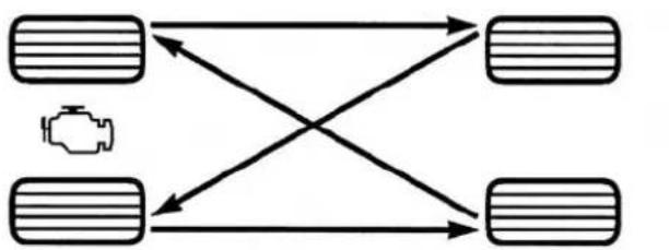
flowchart
graph TD
    A["Vehicle Icon"] --> B["Left Vehicle"]
    A --> C["Right Vehicle"]
    B --> D["Left Vehicle"]
    B --> E["Right Vehicle"]
    C --> F["Left Vehicle"]
    C --> G["Right Vehicle"]
TireRotation
398 STARTING AND OPERATING
TIRE PRESSURE MONITORING SYSTEM (TPMS)
The Tire Pressure Monitor System (TPMS) will warn the driver of a low tire pressure based on the vehicle recommended cold placard pressure.
The tire pressure will vary with temperature by about 1 psi (7.0 kPa) for every 12°F (6.5°C). This means that when the outside temperature decreases, the tire pressure will decrease. Tire pressure should always be set based on “cold inflation tire pressure”. This is defined as the tire pressure after the vehicle has not been driven for at least three hours, or driven less than 1 mile (1.6 km) after a three hour period. The cold tire inflation pressure must not exceed the maximum inflation pressure molded into the tire sidewall. Refer to “Tires – General Information” in “Starting and Operating” for information on how to properly inflate the vehicle’s tires. The tire pressure will also increase as the vehicle is driven - this is normal and there should be no adjustment for this increased pressure.
The TPMS will warn the driver of a low tire pressure if the tire pressure falls below the low-pressure warning limit for any reason, including low temperature effects, or natural pressure loss through the tire.
The TPMS will continue to warn the driver of low tire pressure as long as the condition exists, and will not turn off until the tire pressure is at or above the recommended cold placard pressure. Once the low tire pressure warning (Tire Pressure Monitoring Telltale Light) illuminates, you must increase the tire pressure to the recommended cold placard pressure in order for the Tire Pressure Monitoring Telltale Light to turn off. The system will automatically update and the Tire Pressure Monitoring Telltale Light will turn off once the system receives the updated tire pressures. The vehicle may need to be driven for up to 20 minutes above 15 mph (24 km/h) in order for the TPMS to receive this information.
For example, your vehicle may have a recommended cold (parked for more than three hours) placard pressure of 30 psi (207 kPa). If the ambient temperature is 68°F (20°C) and the measured tire pressure is 27 psi (186 kPa), a temperature drop to 20°F (-7°C) will decrease the tire pressure to approximately 23 psi (158 kPa). This tire pressure is sufficiently low enough to turn ON the Tire Pressure Monitoring Telltale Light. Driving the vehicle may cause the tire pressure to rise to approximately 27 psi (186 kPa), but the Tire Pressure Monitoring Telltale Light will still be ON. In this situation, the Tire Pressure Monitoring Telltale Light will turn OFF only after the tires are inflated to the vehicle's recommended cold placard pressure value.
CAUTION!
- TheTPMShasbeenoptimizedfortheoriginal equipmenttiresandwheels.TPMSpressuresand warninghavebeenestablishedforthetiresize equippedonyourvehicle.Undesirablesystemoperationorsensordamagemayresultwhenusing replacementequipmentthatisnotofthesamesize, type,and/orstyle.Aftermarketwheelscancause sensordamage.Usingaftermarkettiresealantsmay causetheTirePressureMonitoringSystem(TPMS) sensorobecomeinoperable.Afterusinganaftermarkettiresealantitisrecommendedthatyoutake yourvehicletoanauthorizeddealershiptohave yoursensorfunctionchecked.
(Continued)
CAUTION!(Continued)
- Afterinspectingoradjustingthetirepressure, alwaysreinstallthevalvestemcap.Thiswill preventmoistureanddirtfromenteringthevalve stem,whichcoulddamagetheTirePressureMonitoringSensor.
NOTE:
- The TPMS is not intended to replace normal tire care and maintenance or to provide warning of a tire failure or condition.
-
The TPMS should not be used as a tire pressure gauge while adjusting your tire pressure.
-
Driving on a significantly under-inflated tire causes the tire to overheat and can lead to tire failure. Under-inflation also reduces fuel efficiency and tire tread life, and may affect the vehicle's handling and stopping ability.
- The TPMS is not a substitute for proper tire maintenance, and it is the driver's responsibility to maintain correct tire pressure using an accurate tire gauge, even if under-inflation has not reached the level to trigger illumination of the Tire Pressure Monitoring Telltale Light.
- Seasonal temperature changes will affect tire pressure, and the TPMS will monitor the actual tire pressure in the tire.
Base System

This is the TPMS warning indicator located in the instrument cluster.
The TPMS uses wireless technology with wheel rim mounted electronic sensors to monitor tire pressure levels. Sensors, mounted to each wheel as part of the valve stem, transmit tire pressure readings to the Receiver Module.
NOTE: It is particularly important for you to check the tire pressure in all of the tires on your vehicle regularly and to maintain the proper pressure.
The TPMS consists of the following components:
- Receiver Module.
- Four Tire Pressure Monitoring Sensors.
•Tire Pressure Monitoring Telltale Light.
TirePressureMonitoringLowPressureWarnings
The Tire Pressure Monitoring Telltale Light will illuminate in the instrument cluster, a LOW TIRE message will be displayed for a minimum of five seconds, and an audible chime will be activated when one or more of the four active road tire pressures are low. Should this occur, you should stop as soon as possible, check the inflation pressure of each tire on your vehicle, and inflate each tire to the vehicle's recommended cold placard pressure value. The system will automatically update and the Tire Pressure Monitoring Light will extinguish and the LOW TIRE message will turn off once the updated tire pressures have been received. The vehicle may need to be driven for up to 20 minutes above 15 mph (24 km/h) to receive this information.
402 STARTING AND OPERATING
CheckTPMSWarnings
The Tire Pressure Monitoring Telltale Light will flash on and off for 75 seconds and remain on solid when a system fault is detected. The system fault will also sound a chime. If the ignition key is cycled, this sequence will repeat providing the system fault still exists. The Tire Pressure Monitoring Telltale Light will turn off when the fault condition no longer exists. A system fault can occur with any of the following scenarios:
- Jamming due to electronic devices or driving next to facilities emitting the same radio frequencies as the TPM sensors.
- Installing some form of aftermarket window tinting that affects radio wave signals.
- Snow or ice around the wheels or wheel housings.
-
Using tire chains on the vehicle.
-
Using wheels/tires not equipped with TPM sensors.
NOTE: Your vehicle is equipped with a compact spare wheel and tire assembly.
- The compact spare tire does not have a tire pressure monitoring sensor. Therefore, the TPMS will not monitor the tire pressure in the compact spare tire.
- If you install the compact spare tire in place of a road tire that has a pressure below the low-pressure warning limit, upon the next ignition key cycle, a chime will sound and the Tire Pressure Monitoring Telltale Light and LOW TIRE message will still turn ON due to the low tire.
-
However, after driving the vehicle for up to 20 minutes above 15 mph (24 km/h), the Tire Pressure Monitoring Telltale Light will flash on and off for 75 seconds and then remain on solid.
-
For each subsequent ignition key cycle, a chime will sound and the Tire Pressure Monitoring Telltale Light will flash on and off for 75 seconds and then remain on solid.
- Once you repair or replace the original road tire and reinstall it on the vehicle in place of the compact spare tire, the TPMS will update automatically and the Tire Pressure Monitoring Telltale Light will turn OFF, as long as no tire pressure is below the low-pressure warning limit in any of the four active road tires. The vehicle may need to be driven for up to 20 minutes above 15 mph (24 km/h) in order for the TPMS to receive this information.
Premium System — If Equipped
The TPMS uses wireless technology with wheel rim mounted electronic sensors to monitor tire pressure levels. Sensors, mounted to each wheel as part of the valve stem, transmit tire pressure readings to the receiver module.
NOTE: It is particularly important for you to check the tire pressure in all of your tires regularly and to maintain the proper pressure.
The TPMS consists of the following components:
- Receiver Module
• Four Tire Pressure Monitoring Sensors - Three Trigger Modules (mounted in three of the four wheel wells)
- Various Tire Pressure Monitoring System Messages, which display in the Electronic Vehicle Information Center (EVIC)
•Tire Pressure Monitoring Telltale Light
TirePressureMonitoringLowPressureWarnings
The Tire Pressure Monitoring Telltale Light will illuminate in the instrument cluster and an audible chime will be activated when one or more of the four active road tire pressures are low. The audible chime will sound once every ignition cycle for the first condition that it detects. In addition, the EVIC will display a "LOW TIRE" text message for a minimum of five seconds and a graphic of the pressure value(s) with the low tire(s) flashing.

Should a low tire condition occur on any of the four active road tire(s), you should stop as soon as possible and inflate all tires that are flashing on the graphic display to the vehicle's recommended cold placard pressure value. The system will automatically update, the "LOW TIRE" text message will no longer be displayed,
the graphic display of the pressure value(s) will stop flashing, and the Tire Pressure Monitoring Light will extinguish once the updated tire pressure(s) have been received. The vehicle may need to be driven for up to 20 minutes above 15 mph (24 km/h) to receive this information.
ServiceTPMSMessage
The Tire Pressure Monitoring Telltale Light will flash on and off for 75 seconds, and remain on solid when a system fault is detected. The system fault will also sound a chime. The EVIC will display a "SERVICE TPM SYSTEM" message for a minimum of five seconds. This text message is then followed by a graphic display, with "-" in place of the pressure value(s) indicating which Tire Pressure Monitoring Sensor(s) is not being received.
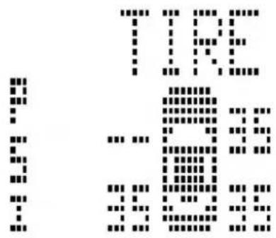
text_image
Pixelated text image showing fragmented characters and symbols, possibly from a document or form0558012401
TirePressureMonitoringDisplay
If the ignition key is cycled, this sequence will repeat, providing the system fault still exists. If the system fault no longer exists, the Tire Pressure Monitoring Telltale Light will no longer flash, the "SERVICE TPM SYSTEM" text message will not be present, and a pressure value
406 STARTING AND OPERATING
will be displayed instead of dashes. A system fault can occur with any of the following scenarios:
- Jamming due to electronic devices or driving next to facilities emitting the same radio frequencies as the TPM sensors.
- Installing some form of aftermarket window tinting that affects radio wave signals.
- Snow or ice around the wheels or wheel housings.
- Using tire chains on the vehicle.
- Using wheels/tires not equipped with TPM sensors.
The EVIC will also display a "SERVICE TPM SYSTEM" message for a minimum of five seconds when a system fault related to an incorrect sensor location fault is detected. In this case, the "SERVICE TPM SYSTEM" message is then followed with a graphic display with
pressure values still shown. This indicates that the pressure values are still being received from the TPM sensors but they may not be located in the correct vehicle position. The system still needs to be serviced as long as the "SERVICE TPM SYSTEM" message is displayed.
NOTE: Your vehicle is equipped with a compact spare wheel and tire assembly.
- The compact spare tire does not have a tire pressure monitoring sensor. Therefore, the TPMS will not monitor the tire pressure in the compact spare tire.
-
If you install the compact spare tire in place of a road tire that has a pressure below the low-pressure warning limit, upon the next ignition key cycle, a chime will sound and the Tire Pressure Monitoring Telltale Light will still turn ON due to the low tire. The "LOW TIRE" text message and the graphic with the low tire pressure flashing will be displayed.
-
However, after driving the vehicle for up to 20 minutes above 15 mph (24 km/h), the Tire Pressure Monitoring Telltale Light will flash on and off for 75 seconds and then remain on solid. In addition, the EVIC will display a "SERVICE TPM SYSTEM" message for a minimum of five seconds and then display dashes (- -) in place of the pressure values.
- For each subsequent ignition key cycle, a chime will sound and the Tire Pressure Monitoring Telltale Light will flash on and off for 75 seconds and then remain on solid, and the EVIC will display a "SERVICE TPM SYSTEM" message for a minimum of five seconds and then display dashes (- -) in place of the pressure values.
- Once you repair or replace the original road tire and reinstall it on the vehicle in place of the compact spare tire, the TPMS will update automatically and the Tire Pressure Monitoring Telltale Light will turn OFF, as long as no tire pressure is below the low-pressure
warning limit in any of the four active road tires. The vehicle may need to be driven for up to 20 minutes above 15 mph (24 km/h) in order for the TPMS to receive this information.
General Information
This device complies with Part 15 of the FCC rules and RSS 210 of Industry Canada. Operation is subject to the following conditions:
- This device may not cause harmful interference.
- This device must accept any interference received, including interference that may cause undesired operation.
The tire pressure sensors are covered under one of the following licenses:
| United States MRXC4N3MF9 | |
| Canada 2546A-C4N3MF9 | |
408 STARTING AND OPERATING
FUEL REQUIREMENTS
2.0L And 2.4L Engine
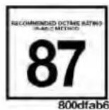
This engine is designed to meet all emissions regulations and provide excellent fuel economy and performance when using high-quality unleaded “regular” gasoline having an octane rating of 87. The use of premium gasoline will not provide any benefit over regular gasoline in these engines.
Light spark knock at low engine speeds is not harmful to your engine. However, continued heavy spark knock at high speeds can cause damage and immediate service is required. Poor quality gasoline can cause problems such as hard starting, stalling, and hesitations. If you experience these symptoms, try another brand of gasoline before considering service for the vehicle.
Over 40 auto manufacturers worldwide have issued and endorsed consistent gasoline specifications (the Worldwide Fuel Charter, WWFC) which define fuel properties necessary to deliver enhanced emissions, performance, and durability for your vehicle. The manufacturer recommends the use of gasolines that meet the WWFC specifications if they are available.
Reformulated Gasoline
Many areas of the country require the use of cleaner burning gasoline referred to as “Reformulated Gasoline.” Reformulated gasoline contain oxygenates and are specifically blended to reduce vehicle emissions and improve air quality.
The manufacturer supports the use of reformulated gasoline. Properly blended reformulated gasoline will provide excellent performance and durability of engine and fuel system components.
Gasoline/Oxygenate Blends
Some fuel suppliers blend unleaded gasoline with oxygenates such as Ethanol. Fuels blended with oxygenates may be used in your vehicle.
CAUTION!
DONOTusegasolinecontainingMethanolorgasolinecontainingmorethan10%Ethanol.Useofthese blendsmayresultinstartinganddrivabilityproblems,damagecriticalfuelsystemcomponents,cause emissionstoexceedtheapplicablestandard,and/or causethe"MalfunctionIndicatorLight"toilluminate.Pumplabelsshouldclearlycommunicateifa fuelcontainsgreaterthan10%Ethanol.
Problems that result from using gasoline containing Methanol or gasoline containing more than 10% Ethanol are not the responsibility of the manufacturer and may not be covered under New Vehicle Limited Warranty.
E-85 Usage In Non-Flex Fuel Vehicles
Non-Flex Fuel Vehicles (FFV) are compatible with gasoline containing 10% ethanol (E10). Gasoline with higher ethanol content may void the New Vehicle Limited Warranty.
If a Non-FFV vehicle is inadvertently fueled with E-85 fuel, the engine will have some or all of these symptoms:
- Operate in a lean mode.
- OBD II "Malfunction Indicator Light" on.
- Poor engine performance.
- Poor cold start and cold drivability.
- Increased risk for fuel system component corrosion.
To fix a Non-FFV vehicle inadvertently fueled once with E-85 perform the following:
- Drain the fuel tank (see your authorized dealer).
- Change the engine oil and oil filter.
410 STARTING AND OPERATING
- Disconnect and reconnect the battery to reset the engine controller memory.
More extensive repairs will be required for prolonged exposure to E-85 fuel.
MMT In Gasoline
Methylcyclopentadienyl Manganese Tricarbonyl (MMT) is a manganese-containing metallic additive that is blended into some gasoline to increase octane. Gasoline blended with MMT provides no performance advantage beyond gasoline of the same octane number without MMT. Gasoline blended with MMT reduces spark plug life and reduces emissions system performance in some vehicles. The manufacturer recommends that gasoline without MMT be used in your vehicle. The MMT content of gasoline may not be indicated on the gasoline pump, therefore, you should ask your gasoline retailer whether the gasoline contains MMT. MMT is prohibited in Federal and California reformulated gasoline.
Materials Added To Fuel
All gasoline sold in the United States is required to contain effective detergent additives. Use of additional detergents or other additives is not needed under normal conditions and they would result in additional cost. Therefore, you should not have to add anything to the fuel.
Fuel System Cautions
CAUTION!
Followtheseguidelinestomaintainyourvehicle's performance:
- The useofleadedgasisprohibitedbyFederallaw. Usingleadedgasolinecanimpairengineperformanceanddamagetheemissionscontrolsystem.
- Anout-of-tuneengineorcertainfuelorignition malfunctionscancausethecatalyticconverterto
(Continued)
CAUTION!(Continued)
overheat.Ifyounoticeapungentburningodoror somelightsmoke,yourenginemaybeoutoftune ormalfunctioningandmayrequireimmediateservice.Contactyourauthorizeddealerforservice assistance.
- The useoffueladditives, which are now being sold as octaneenhancers, is not recommended. Most of these products contain high concentrations of methanol. Fuelsystem damage or vehicle performance problems resulting from the use of such fuel soradditives is not the responsibility of the manufacturer.
NOTE: Intentional tampering with the emissions control system can result in civil penalties being assessed against you.
Carbon Monoxide Warnings
WARNING!
Carbonmonoxide(CO)inexhaustgasesisdeadly. Follow the precautions below to prevent carbon monoxide poisoning:
- Donotinhaleexhaustgases. They contain carbon monoxide, acolorless and odorless gas, which can kill. Never run the engine in a closed area, such as agarage, and never sit in a parked vehicle with the engineer running for an extended period. If the vehicle is stopped in an open area with the engine running form more than a short period, adjust the ventilation system to force fresh, outside air into the vehicle.
(Continued)
412 STARTING AND OPERATING
WARNING!(Continued)
- Guardagainstcarbonmonoxidewithpropermaintenance.Havetheexhaustsysteminspectedevery timethevehicleisraised.Haveanyabnormal conditionsrepairedpromptly.Untilrepaired,drive withallsidewindowsfullyopen.
ADDING FUEL
Fuel Filler Cap (Gas Cap)
The gas cap is behind the fuel filler door, on the left side of the vehicle. If the gas cap is lost or damaged, be sure the replacement cap is for use with this vehicle.
After removing the gas cap, place the gas cap tether cable over a hook on the inside of the fuel door. This keeps the gas cap suspended away from and protects the vehicle's surface.
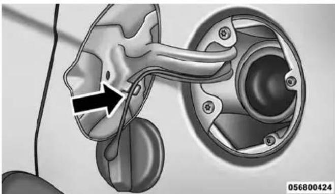
natural_image
Medical illustration of a pelvic device with a black arrow pointing to a specific anatomical structure (no text or symbols present)FuelFillerCap
CAUTION!
- Damagetothefuelsystemoremissioncontrol systemcouldresultfromusinganimproperfuel tankfillercap(gascap).Apoorlyfittingcapcould letimpuritiesintothefuelsystem.
- Apoorlyfittinggascapmaycausethe"MalfunctionIndicatorLight(MIL)"toturnon.
- To avoid fuel spillage and overfilling, donot "top off" the fueltank after filling.
WARNING!
- Neverhaveanysmokingmaterialslitinornearthe vehiclewhenthegascapisremovedorthetankis beingfilled.
(Continued)
WARNING!(Continued)
- Neveraddfuelwhentheengineisrunning. This is inviolationofmoststateandfederalfireregulationsandmaycausetheMILtoturnon.
- Afiremayresultifgasolineispumpedintoa portablecontainerthatisinsideofavehicle.You couldbeburned.Alwaysplacegascontainerson thegroundwhilefilling.
NOTE:
- When the fuel nozzle "clicks" or shuts off, the fuel tank is full.
- Tighten the gas cap about 1/4 turn until you hear one click. This is an indication that cap is properly tightened.
- If the gas cap is not tightened properly, the MIL will come on. Be sure the gas cap is tightened every time the vehicle is refueled.
414 STARTING AND OPERATING
Loose Fuel Filler Cap Message
If the vehicle diagnostic system determines that the fuel filler cap is loose or improperly installed, a "gASCAP" message will be displayed in the Odometer/Trip Odometer in the instrument cluster. Refer to "Instrument Cluster Description" in "Understanding Your Instrument Panel" for further information. Tighten the fuel filler cap properly and press the odometer/trip odometer RESET button to turn the message off. If the problem continues, the message will appear the next time the vehicle is started. Refer to "Onboard Diagnostic System" in "Maintaining Your Vehicle" for further information.
VEHICLE LOADING
As required by National Highway Traffic Safety Administration regulations, your vehicle has a certification label affixed to the driver's side door or B-Pillar.
Vehicle Certification Label
Your vehicle has a Vehicle Certification Label attached to the driver's door B-Pillar.
The label contains the following information:
• Name of manufacturer
•Month and year of manufacture
• Gross Vehicle Weight Rating (GVWR)
• Vehicle Identification Number (VIN)
- Type of Vehicle
• Month, Day and Hour of Manufacture (MDH)
The bar code allows a computer scanner to read the Vehicle Identification Number (VIN).
GrossVehicleWeightRating(GVWR)
The GVWR is the total allowable weight of your vehicle. This includes driver, passengers, and cargo. The total load must be limited so that you do not exceed the GVWR.
TireSize
The tire size on the Vehicle Certification Label represents the actual tire size on your vehicle. Replacement tires must be equal to the load capacity of this tire size.
RimSize
This is the rim size that is appropriate for the tire size listed.
InflationPressure
This is the cold tire inflation pressure for your vehicle for all loading conditions up to full GAWR.
CurbWeight
The curb weight of a vehicle is defined as the total weight of the vehicle with all fluids, including vehicle fuel, at full capacity conditions, and with no occupants or cargo loaded into the vehicle. The front and rear curb weight values are determined by weighing your vehicle on a commercial scale before any occupants or cargo are added.
Overloading
The load carrying components (springs, tires, wheels, etc.) of your vehicle will provide satisfactory service as long as you do not exceed the GVWR.
The best way to figure out the total weight of your vehicle is to weigh it when it is fully loaded and ready for operation. Weigh it on a commercial scale to ensure that it is not over the GVWR.
Overloading can cause potential safety hazards and shorten useful service life. Heavier suspension components do not necessarily increase the vehicle's GVWR.
Loading
To load your vehicle properly, first figure out its empty weight. Store heavier items down low and be sure you distribute their weight as evenly as possible. Stow all loose items securely before driving. Improper weight distribution can have an adverse effect on the way your vehicle steers and handles, and the way the brakes operate.
CAUTION!
Donotloadyourvehicleanyheavierthanthe GVWR.Ifyoudo,partsonyourvehiclecanbreak,or itcanchangethewayyourvehiclehandles.This couldcauseyoutolosecontrol.Also,overloadingcan shortenthelifeofyourvehicle.
TRAILER TOWING
In this section you will find safety tips and information on limits to the type of towing you can reasonably do with your vehicle. Before towing a trailer, carefully review this information to tow your load as efficiently and safely as possible.
To maintain the New Vehicle Limited Warranty coverage, follow the requirements and recommendations in this manual concerning vehicles used for trailer towing.
Common Towing Definitions
The following trailer towing related definitions will assist you in understanding the following information:
GrossVehicleWeightRating(GVWR)
The GVWR is the total allowable weight of your vehicle. This includes driver, passengers, cargo and tongue weight. The total load must be limited so that you do not
exceed the GVWR. Refer to "Vehicle Loading/Vehicle Certification Label" in "Starting and Operating" for further information.
GrossTrailerWeight(GTW)
The GTW is the weight of the trailer plus the weight of all cargo, consumables and equipment (permanent or temporary) loaded in or on the trailer in its "loaded and ready for operation" condition. The recommended way to measure GTW is to put your fully loaded trailer on a vehicle scale. The entire weight of the trailer must be supported by the scale.
GrossCombinationWeightRating(GCWR)
The GCWR is the total permissible weight of your vehicle and trailer when weighed in combination.
GrossAxleWeightRating(GAWR)
The GAWR is the maximum capacity of the front and rear axles. Distribute the load over the front and rear axles
evenly. Make sure that you do not exceed either front or rear GAWR. Refer to "Vehicle Loading/Vehicle Certification Label" in "Starting and Operating" for further information.
WARNING!
It is important that you donot exceed them maximum frontorrear GAWR. Adangerous driving condition can result if either rating is exceeded. You could lose control of the vehicle and have a collision.
TongueWeight(TW)
The tongue weight is the downward force exerted on the hitch ball by the trailer. In most cases it should not be less than 10% of the trailer load. You must consider this as part of the load on your vehicle.
418 STARTING AND OPERATING
FrontalArea
The frontal area is the maximum height multiplied by the maximum width of the front of a trailer.
TrailerSwayControl
The trailer sway control is a telescoping link that can be installed between the hitch receiver and the trailer tongue that typically provides adjustable friction associated with the telescoping motion to dampen any unwanted trailer swaying motions while traveling.
Weight-CarryingHitch
A weight-carrying hitch supports the trailer tongue weight, just as if it were luggage located at a hitch ball or some other connecting point of the vehicle. These kinds of hitches are the most popular on the market today and they are commonly used to tow small and medium sized trailers.
Weight-DistributingHitch
A weight-distributing system works by applying leverage through spring (load) bars. They are typically used for heavier loads to distribute trailer tongue weight to the tow vehicle's front axle and the trailer axle(s). When used in accordance with the manufacturer's directions, it provides for a more level ride, offering more consistent steering and brake control thereby enhancing towing safety. The addition of a friction/hydraulic sway control also dampens sway caused by traffic and crosswinds and contributes positively to tow vehicle and trailer stability. Trailer sway control and a weight distributing (load equalizing) hitch are recommended for heavier Tongue Weights (TW) and may be required depending on vehicle and trailer configuration/loading to comply with Gross Axle Weight Rating (GAWR) requirements. Weight Distribution hitched are recommended for loads in excess of 5,000 lbs (2,268 kg).
WARNING!
- AnimproperlyadjustedWeightDistributingHitch systemmayreducehandling,stability,braking performance,andcouldresultinacollision.
- WeightDistributingSystemsmaynotbecompatible withSurgeBrakeCouplers.Consultwithyourhitch andtrailermanufacturerorareputableRecreational Vehicledealerforadditionalinformation.
Trailer Hitch Classification
The following chart provides the industry standard for the maximum trailer weight a given trailer hitch class can tow and should be used to assist you in selecting the correct trailer hitch for your intended towing condition.
| TrailerHitchClassificationDefinitions | |
| ClassMax.TrailerHitchIndustryStandards | |
| Class I - Light Duty 2,000 lbs (907 kg) | |
| Class II - Medium Duty 3,500 lbs (1 587 kg) | |
| Class III - Heavy Duty 5,000 lbs (2 268 kg) | |
| Class IV - Extra Heavy Duty | 10,000 lbs (4 540 kg) |
| Refer to the “Trailer Towing Weights (Maximum Trailer Weight Ratings)” chart for the Maximum Gross Trailer Weight (GTW) towable for your given drivetrain. | |
| All trailer hitches should be professionally installed on your vehicle. | |
420 STARTING AND OPERATING
Trailer Towing Weights (Maximum Trailer Weight Ratings)
The following chart provides the maximum trailer weight ratings towable for your given drivetrain.
| Engine/TransmissionFrontalArea | MaximumGTW(GrossTrailerWt.) | MaximumTongueWt.(SeeNote) |
| 2.0L Auto/Man 22 sq ft (2.04 sq m) 1,000 lbs (450 kg) 150 lbs (68 kg) | ||
| 2.4L Auto/Man 22 sq ft (2.04 sq m) 1,000 lbs (450 kg) 150 lbs (68 kg) | ||
| 2.4L Auto/Man with Trailer Tow Prep Package (AHC) | 32 sq ft (3.0 sq m) 2,000 lbs (907 kg) 300 lbs (136 kg) | |
| 2.4L Auto With Freedom Drive II Off Road Pack-age (AWL) | 32 sq ft (3.0 sq m) 2,000 lbs (907 kg) 300 lbs (136 kg) | |
| Refer to local laws for maximum trailer towing speeds. | ||
NOTE: The trailer tongue weight must be considered as part of the combined weight of occupants and cargo, and should never exceed the weight referenced on the Tire and Loading Information placard. Refer to "Tire Safety Information" in "Starting and Operating" for further information.
Trailer And Tongue Weight
Always load a trailer with 60% to 65% of the weight in the front of the trailer. This places 10% to 15% of the Gross Trailer Weight (GTW) on the tow hitch of your vehicle. Loads balanced over the wheels or heavier in the rear can cause the trailer to sway severelyside to side which will cause loss of control of the vehicle and trailer. Failure to load trailers heavier in front is the cause of many trailer collisions.
Never exceed the maximum tongue weight stamped on your bumper or trailer hitch.
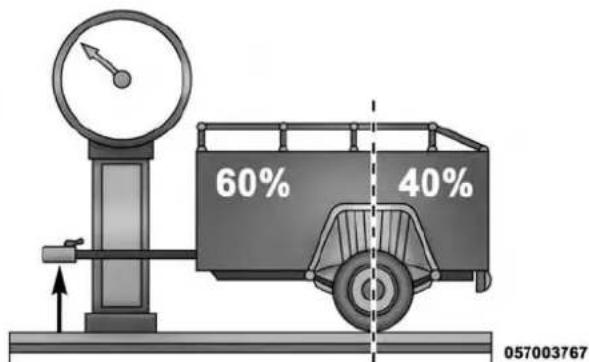
text_image
60% 40% 057003767Consider the following items when computing the weight on the rear axle of the vehicle:
• The tongue weight of the trailer.
- The weight of any other type of cargo or equipment put in or on your vehicle.
• The weight of the driver and all passengers.
422 STARTING AND OPERATING
NOTE: Remember that everything put into or on the trailer adds to the load on your vehicle. Also, additional factory-installed options or dealer-installed options must be considered as part of the total load on your vehicle. Refer to the "Tire and Loading Information" placard for the maximum combined weight of occupants and cargo for your vehicle.
Towing Requirements
To promote proper break-in of your vehicle drivetrain components, the following guidelines are recommended:
CAUTION!
- Donottowatraileratallduringthefirst500miles (805km)thenewvehicleisdriven.Theengine,axle orotherpartscouldbedamaged.
- Then, during the first 500 miles (805 km) that a traileristowed, donot drive over 50 mph (80 km/h)
(Continued)
CAUTION!(Continued)
anddonotmakestartsatfullthrottle. This helps the engine and other part of the vehicle wear in at the heavier loads.
Perform the maintenance listed in the “Maintenance Schedule”. Refer to “Maintenance Schedule” for further information. When towing a trailer, never exceed the GAWR, or GCWR, ratings.
WARNING!
Impropertowingcanleadtoacollision.Followthese guidelinestomakeyourtrailertowingassafeas possible:
- Make certain that the load dissecured in the trailer and will not shift during travel. When trailering cargothatis not fully secured, dynamic load shifts
(Continued)
WARNING!(Continued)
canoccurthatmaybedifficultforthedriverto control.Youcouldlosecontrolofyourvehicleand haveacollision.
- Whenhaulingcargoortowingatrailer, donot overloadyourvehicleortrailer. Overloading can causealossofcontrol, poorperformanceordamagetobrakes, axle, engine, transmission, steering, suspension, chassisstructureortires.
- Safetychainsmustalwaysbeusedbetweenyour vehicleandtrailer.Alwaysconnectthechainsto theframeorhookretainersofthevehiclehitch. Crossthechainsunderthetrailertongueandallow enoughslackforturningcorners.
- Vehicleswithtrailersshouldnotbeparkedona grade.Whenparking,applytheparkingbrakeon thetowvehicle.Putthetowvehicleautomatic
WARNING!(Continued)
transmissioninPARK.Alwaysblockor"chock"the trailerwheels.
• GCWRmustnotbeexceeded.
- Totalweightmustbedistributedbetweenthetow vehicleandthetrailersuchthatthefollowingfour ratingsarenotexceeded:
1.GVWR
2.GTW
3.GAWR
4. Tongueweightratingforthetrailerhitchutilized.
TowingRequirements—Tires
- Do not attempt to tow a trailer while using a compact spare tire.
- Proper tire inflation pressures are essential to the safe and satisfactory operation of your vehicle. Refer to "Tires – General Information" in "Starting And Operating" for proper tire inflation procedures.
- Check the trailer tires for proper tire inflation pressures before trailer usage.
- Check for signs of tire wear or visible tire damage before towing a trailer. Refer to "Tires – General Information" in "Starting And Operating" for the proper inspection procedure.
- When replacing tires, refer to "Tires – General Information" in "Starting And Operating" for the proper
tire replacement procedures. Replacing tires with a higher load carrying capacity will not increase the vehicle's GVWR and GAWR limits.
TowingRequirements—TrailerBrakes
- Do notinterconnect the hydraulic brake system or vacuum system of your vehicle with that of the trailer. This could cause inadequate braking and possible personal injury.
- An electronically actuated trailer brake controller is required when towing a trailer with electronically actuated brakes. When towing a trailer equipped with a hydraulic surge actuated brake system, an electronic brake controller is not required.
- Trailer brakes are recommended for trailers over 1,000 lbs (454 kg) and required for trailers in excess of 2,000 lbs (907 kg).
WARNING!
- Donotconnecttrailerbrakestoyourvehicle's hydraulicbrakelines.Itcanoverloadyourbrake systemandcauseittofail.Youmightnothave brakeswhenyouneedthemandcouldhavea collision.
- Towinganytrailerwillincreaseyourstopping distance. Whentowingyoushouldallowforadditionalspacebetweenyourvehicleandthevehicleinfrontofyou.Failurertodosocouldresultina collision.
CAUTION!
If the trailer weighsmorethan 1,000 lbs (454 kg) loaded, it should have its own brakes and they should be of adequate capacity. Failure to do this
CAUTION!(Continued)
couldleadtoacceleratedbrakeliningwear, higher brakepedaleffort, and longerstoppingdistances.
TowingRequirements—TrailerLightsAndWiring
Whenever you pull a trailer, regardless of the trailer size, stoplights and turn signals on the trailer are required for motoring safety.
The Trailer Tow Package may include a four- and seven-pin wiring harness. Use a factory approved trailer harness and connector.
NOTE: Do not cut or splice wiring into the vehicles wiring harness.
426 STARTING AND OPERATING
The electrical connections are all complete to the vehicle but you must mate the harness to a trailer connector. Refer to the following illustrations.
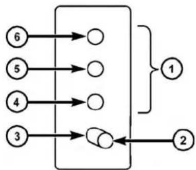
flowchart
graph TD
    A["6"] --> B(( ))
    C["5"] --> D(( ))
    E["4"] --> F(( ))
    G["3"] --> H(( ))
    B --> I["1"]
    D --> I
    F --> I
    H --> J["2"]
Four-PinConnector
057003766
1 — Female Pins 4 — Park
2 — Male Pin 5 — Left Stop/Turn
3 — Ground 6 — Right Stop/Turn

flowchart
graph TD
    A["1"] --> B["2"]
    B --> C["3"]
    C --> D["4"]
    D --> E["5"]
    E --> F["6"]
    F --> G["7"]
    G --> H["8"]
    H --> I["9"]
    I --> J["10"]
    J --> K["11"]
    K --> L["12"]
    L --> M["13"]
    M --> N["14"]
    N --> O["15"]
    O --> P["16"]
    P --> Q["17"]
    Q --> R["18"]
    R --> S["19"]
    S --> T["20"]
057003765
Seven-PinConnector
1 — Battery 5 — Ground
2 — Backup Lamps 6 — Left Stop/Turn
3 — Right Stop/Turn 7 — Running Lamps
4 — Electric Brakes
Towing Tips
Before setting out on a trip, practice turning, stopping, and backing up the trailer in an area located away from heavy traffic.
ManualTransmission—IfEquipped
If using a manual transmission vehicle for trailer towing, all starts must be in first gear to avoid excessive clutch slippage.
AutomaticTransmission
The DRIVE range can be selected when towing. However, if frequent shifting or changes in engine speed occur while in this range, use the AutoStick® shift control (if equipped) to select a lower gear ratio.
NOTE: Using a lower gear ratio while operating the vehicle under heavy loading conditions, will improve performance and extend transmission life by reducing excessive shifting and heat buildup. This action will also provide better engine braking.
If you REGULARLY tow a trailer for more than 45 minutes of continuous operation, then change the transmission fluid and filter as specified for "police, taxi, fleet, or frequent trailer towing". Refer to the "Maintenance Schedule" for the proper maintenance intervals.
AutoStick®—IfEquipped
When using the AutoStick® shift control, select the highest gear that allows for adequate performance and avoids frequent downshifts. For example, choose "4" if the desired speed can be maintained. Choose "3" or "2" if needed to maintain the desired speed.
428 STARTING AND OPERATING
To prevent excess heat generation, avoid continuous driving at high RPM. Reduce vehicle speed as necessary to avoid extended driving at high RPM. Return to a higher gear or vehicle speed when grade and road conditions allow.
ElectronicSpeedControl—IfEquipped
- Do not use in hilly terrain or with heavy loads.
- When using the speed control, if you experience speed drops greater than 10 mph (16 km/h), disengage until you can get back to cruising speed.
- Use speed control in flat terrain and with light loads to maximize fuel efficiency.
CoolingSystem
To reduce potential for engine and transmission overheating, take the following actions:
CityDriving
When stopped for short periods of time, shift the transmission into NEUTRAL and increase engine idle speed.
HighwayDriving
Reduce speed.
AirConditioning
Turn off temporarily.
RECREATIONAL TOWING (BEHIND MOTORHOME, ETC.)
Towing This Vehicle Behind Another Vehicle
| TowingConditionWheels | OFFtheGroundManualTransmissionAutomaticTransmission | ||
| Flat Tow None | • Transmission in NEUTRAL• Key in ACC Position | NOT ALLOWED | |
| Dolly Tow Front OK | (FWD Only) OK (FWD Only) | ||
| Rear NOT ALLOWED NOT ALLOWED | |||
| On Trailer All OK | OK | ||
NOTE: Vehicles equipped with manual transmissions may be recreationally towed (flat towed) at any legal highway speed, for any distance, if the manual transmission is in NEUTRAL and the ignition key is in the ACC position.
CAUTION!
- DONOTflattowanyvehicleequippedwithan automatictransmission.Damagethodrivetrain willresult.Ifthesevehiclesrequiretowing,make surealldrivewheelsareOFFtheground.
- DONOTdollytowany4WDvehicle.Internal damagetothetransmissionortransfercasewill occurifadollyisusedwhenrecreationaltowing.
WHAT TO DO IN EMERGENCIES
CONTENTS
■HAZARD WARNING FLASHERS....433
■IF YOUR ENGINE OVERHEATS .....433
■AUTOMATIC TRANSMISSION
OVERHEATING....434
■WHEEL AND TIRE TORQUE
SPECIFICATIONS....435
□Torque Specifications....435
■JACKING AND TIRE CHANGING....436
□Jack Location....437
□Spare Tire Stowage....437
□Preparations For Jacking....438
□Jacking Instructions....438
□Road Tire Installation . . . . . . . . . . . . . . . . . . . . . . . . . . . . . . . . . . . . . . . . . . . . 445
■TREFIT KIT — IF EQUIPPED .....447
□TREFIT Storage .....447
☐TREFIT Kit Components And Operation . . . . .447
□TREFIT Usage Precautions. . . . . . . . . . . . . . . . . . . . . . . . . . . . . . . . . . 449
□Sealing A Tire With TREFIT....451
■JUMP-STARTING PROCEDURES....457
□ Preparations For Jump-Start .....458
432 WHAT TO DO IN EMERGENCIES
□Jump-Starting Procedure....459
FREEING A STUCK VEHICLE....462
■SHIFT LEVER OVERRIDE....463
■TOWING A DISABLED VEHICLE....465
□With Ignition Key....466
HAZARD WARNING FLASHERS
The Hazard Warning flasher switch is located on the instrument panel below the climate controls.

Press the switch to turn on the Hazard Warning flasher. When the switch is activated, all direc-
tional turn signals will flash on and off to warn oncoming traffic of an emergency. Press the switch a second time to turn off the Hazard Warning flashers.
This is an emergency warning system and it should not be used when the vehicle is in motion. Use it when your vehicle is disabled and it is creating a safety hazard for other motorists.
When you must leave the vehicle to seek assistance, the Hazard Warning flashers will continue to operate even though the ignition is placed in the OFF position.
NOTE: With extended use the Hazard Warning flashers may wear down your battery.
IF YOUR ENGINE OVERHEATS
In any of the following situations, you can reduce the potential for overheating by taking the appropriate action.
- On the highways — slow down.
- In city traffic — while stopped, place the transmission in NEUTRAL, but do not increase engine idle speed.
NOTE: There are steps that you can take to slow down an impending overheat condition:
- If your air conditioner (A/C) is on, turn it off. The A/C system adds heat to the engine cooling system and turning the A/C off can help remove this heat.
- You can also turn the temperature control to maximum heat, the mode control to floor and the blower control to high. This allows the heater core to act as a supplement to the radiator and aids in removing heat from the engine cooling system.
434 WHAT TO DO IN EMERGENCIES
CAUTION!
Drivingwithahotcoolingsystemcoulddamage yourvehicle.IfthepointerrisestotheH(red)mark, theinstrumentclusterwillsoundachime.When safe,pulloverandstopthevehiclewiththeengineat idle.Turnofftheairconditioningandwaituntilthe pointeddropsbackintothenormalrange.Ifthe pointerremainsontheH(red)markformorethana minute,turntheengineoffimmediatelyandcallfor service.
WARNING!
Youorotherscanbebadlyburnedbyhotengine coolant(antifreeze)orsteamfromyourradiator.If youseeorhearsteamcomingfromunderthehood, donotopenthehooduntiltheradiatorhashadtime
WARNING!(Continued)
tocool.Nevertrytoopenacoolingsystempressure capwhentheradiatororcoolantbottleishot.
AUTOMATIC TRANSMISSION OVERHEATING
During sustained high speed driving or trailer towing up long grades on hot days, the automatic transmission oil may become too hot.

If this happens, the transmission overheat indicator light will come on, and the vehicle will slow slightly until the automatic transmission cools down enough to allow a return to the requested speed. If the high speed is maintained, the overheating may reoccur, as before, in a cyclic fashion.
(Continued)
WHEEL AND TIRE TORQUE SPECIFICATIONS
Proper lug nut/bolt torque is very important to ensure that the wheel is properly mounted to the vehicle. Any time a wheel has been removed and reinstalled on the vehicle the lug nuts/bolts should be torqued using a properly calibrated torque wrench.
Torque Specifications
| LugNut/BoltTorque**LugNut/ BoltSize | LugNut/ Bolt Socket Size |
| 100 Ft-Lbs (135 N·m) M12 x 1.25 19 mm |
**Use only your Authorized Dealer recommended lug nuts/bolts and clean or remove any dirt or oil before tightening.
Inspect the wheel mounting surface prior to mounting the tire and remove any corrosion or loose particles.
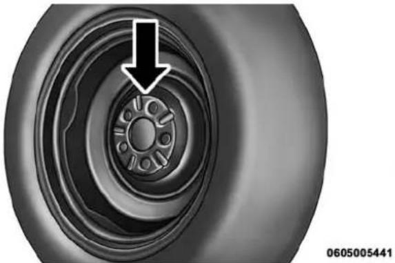
natural_image
Close-up of a tire wheel with a black arrow pointing to the center bull (no text or symbols on the wheel itself)WheelMountingSurface
436 WHAT TO DO IN EMERGENCIES
Tighten the lug nuts/bolts in a star pattern until each nut/bolt has been tightened twice.

flowchart
graph TD
    A["1"] --> B["2"]
    B --> C["3"]
    C --> D["4"]
    D --> A

flowchart
graph TD
    A["1"] --> B["2"]
    B --> C["3"]
    C --> D["4"]
    D --> A
    A --> C
    C --> D
    D --> A
0605006372
TorquePatterns
After 25 miles (40 km) check the lug nut/bolt torque to be sure that all the lug nuts/bolts are properly seated against the wheel.
WARNING!
To avoid the riskofforcing the vehicle off the jack, donottight enthelugnuts fully until the vehicle has been lowered. Failure to follow this warning may result in personal injury.
JACKING AND TIRE CHANGING
WARNING!
- Donotattempttochangeatireonthesideofthe vehicleclosetomovingtraffic.Pullfarenoughoff theroadtoavoidthedangerofbeinghitwhen operatingthejackorchangingthewheel.
- Beingunderajacked-upvehicleisdangerous. The vehiclecouldslipoffthejackandfallonyou. You couldbecrushed. Neverputanypartofyourbody
(Continued)
WARNING!(Continued)
undervehiclethatisonajack.Ifyouneedtoget underaraisedvehicle,takeittoaservicecenter whereitcanberaisedonalift.
- Neverstartorruntheenginewhilethevehicleis onajack.
- Thejackisdesignedtobeusedasatoolfor changingtiresonly.Thejackshouldnotbeusedto liftthevehicleforservicepurposes.Thevehicle shouldbejackedonafirmlevelsurfaceonly. Avoidiceorslipperyareas.
Jack Location
The jack and jack-handle are stowed under the load floor in the cargo area.
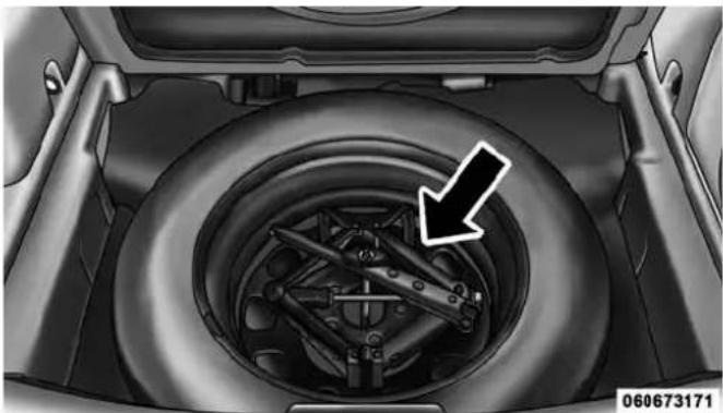
natural_image
Top-down view of a car wheel assembly with a black arrow pointing to the wheel (no text or symbols visible)SpareTireAndJackStowage
Spare Tire Stowage
The compact spare tire is stowed under the rear load floor in the cargo area.
SpareTireRemoval
Lift up the load floor cover and remove the hold down.
438 WHAT TO DO IN EMERGENCIES
Preparations For Jacking
- Park the vehicle on a firm level surface, avoiding ice or slippery areas.
WARNING!
Donotattempttochangeatireonthesideofthe vehicleclosetomovingtraffic,pullfarenoughoff theroadtoavoidthedangerofbeinghitwhen operatingthejackorchangingthewheel.
- Turn on the Hazard Warning flasher.
- Set the parking brake.
- Place the shift lever in PARK (automatic transmission) or REVERSE (manual transmission).
-
Turn OFF the ignition.
-
Block both the front and rear of the wheel diagonally
opposite of the jacking position. For example, if changing the right front tire, block the left rear wheel.
NOTE: Passengers should not remain in the vehicle while the vehicle is being jacked.
Jacking Instructions
WARNING!
Carefully follow the set of receiving warning to help prevent personal injury or damage to your vehicle:
- Alwaysparkonafirm, levelsurfaceasfarfrom the edgeoftheroadwayaspossiblebeforeraisingthe vehicle.
(Continued)
WARNING!(Continued)
• TurnontheHazardWarningflasher.
- Blockthewheeldiagonallyoppositethewheelto beraised.
- Settheparkingbrakefirmlyandsetanautomatic transmissioninPARK;amanualtransmissionin REVERSE.
- Neverstartorruntheenginewiththevehicleona jack.
- Donotletanyonesitinthevehiclewhenitisonajack.
- Donotgetunderthevehiclewhenitisonajack.If youneedtogetunderaraisedvehicle,takeittoa servicecenterwhereitcanberaisedonalift.
- Onlyusethejackinthepositionsindicatedandfor liftingthisvehicleduringatirechange.
- Ifworkingonorneararoadway,beextremely carefulofmotortraffic.
WARNING!(Continued)
• Toassurethatsparetires,flatorinflated,are securelystowed,sparesmustbestowedwiththe valvestemfacingtheground.
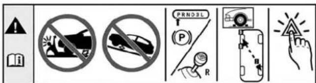
text_image
! i PRND3L P R ▲060600714
(Continued)
JackWarningLabel
440 WHAT TO DO IN EMERGENCIES
CAUTION!
Donotattempttoraisethevehiclebyjackingon locationsotherthanthoseindicatedintheJacking Instructionsforthisvehicle.
NOTE: Refer to "Tires — General Information" in "Starting And Operating" for further information about the spare tire, it's use, and operation.
- Remove the scissors jack and lug wrench from the spare wheel as an assembly. Turn the jack screw to the left to loosen the lug wrench and remove the wrench from the jack assembly.
NOTE: The jack handle attaches to the side of the jack with two attachment points. When the jack is partially expanded, the tension between the two attachment points holds the jack handle in place.

natural_image
Mechanical tool assembly diagram showing a clamp and handle with rotational arrows indicating motion (no text or symbols)060600626
RemovingJackHandleFromJack
WHAT TO DO IN EMERGENCIES 441
- Loosen, but do not remove, the wheel nuts by turning them to the left one turn while the wheel is still on the ground.
NOTE: There are front and rear jacking locations on each side of the body. The front locations are outlined by two triangular cutouts on one of the flanges in the sill flange assembly. The rear location is the same but with two rectangular cutouts. For vehicles equipped with plastic trim, the plastic has been cut away to expose the jacking locations in the body.

natural_image
Side view of a black SUV with two inset images showing mechanical components (no text or symbols)JackingLocations
442 WHAT TO DO IN EMERGENCIES
CAUTION!
Donotattempttoraisethevehiclebyjackington locationsotherthanthoseindicated.
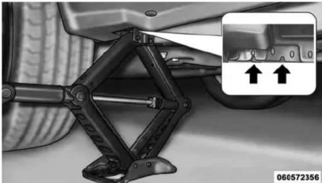
natural_image
Mechanical assembly diagram showing a linkage mechanism with two arrows pointing to a component (no text or symbols present)FrontJackingLocation
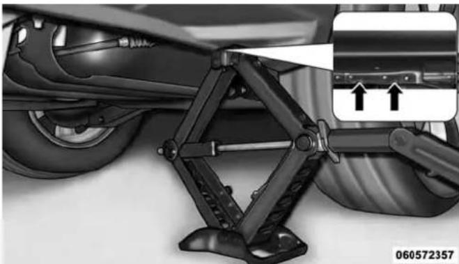
natural_image
Mechanical assembly diagram showing a vehicle suspension system with a hand operating the frame (no text or symbols visible)RearJackingLocation
Do not raise the vehicle until you are sure the jack is securely engaged.
- Turn the jack screw to the left until the jack can be placed under the jacking location. Once the jack is positioned, turn the jack screw to the right until the jack head is properly engaged with the lift area closest to the wheel to be changed.
WARNING!
Raisingthevehiclehigherthannecessarycanmake thevehiclelessstable.Itcouldslipoffthejackand hurtsomeonearit.Raisethevehicleonlyenough toremovethetire.
- Using the swivel wrench raise the vehicle by turning the jack screw to the right. Raise the vehicle only until the tire just clears the surface and enough clearance is obtained to install the spare tire. Minimum tire lift provides maximum stability.
- Remove the wheel nuts and pull the wheel and wheel covers, where applicable, off the hub. Install the spare wheel and wheel nuts with the cone shaped end of the nuts toward the wheel. Lightly tighten the nuts.
WARNING!
To avoid the riskofforcing the vehicle off the jack, donottightenthe wheel nuts fully until the vehicle has been lowered. Failure to follow this warning may result in personal injury.

natural_image
Close-up of hands adjusting a car tire component with an arrow pointing to the wheel (no text or symbols visible)MountingSpareTire
444 WHAT TO DO IN EMERGENCIES
CAUTION!
Besuretomountthesparetirewiththevalvestem facingoutward. Thevehiclecouldbedamagedifthe sparetireismountedincorrectly.
WARNING!
To avoid possible personal injury, handle the wheel covers with care to avoid contact with any sharp edges.
NOTE: The wheel cover is held on the wheel by the wheel nuts. When reinstalling the original wheel, properly align the wheel cover to the valve stem, place the wheel cover onto the wheel, then install the wheel nuts.
- Lower the vehicle by turning the jack screw to the left.
- Finish tightening the lug nuts. Push down on the wrench while at the end of the handle for increased
leverage. Tighten the lug nuts in a star pattern until each lug nut has been tightened twice. Refer to "Torque Specifications" in this section for proper lug nut torque.
- Remove the wheel blocks and lower the jack until it is free. Release the parking brake. Reassemble the lug wrench to the jack assembly and stow it in the spare tire area. Secure the assembly using the means provided.
WARNING!
Aloosetireorjackthrownforwardinacollisionor hardstopcouldendangertheoccupantsofthevehicle.Alwaysstowthejackpartsandthesparetirein theplacesprovided.
9. Place the deflated (flat) tire in the cargo area, have the tirerepairedorreplacedassoonaspossible.
WARNING!
Aloosetirethrownforwardinacollisionorhardstop could injuretheoccupantsinthevehicle.Havethe deflated(flat)tirerepairedorreplacedimmediately.
- Check the spare tire pressure as soon as possible. Correct the tire pressure as required.
- After 25 miles (40 km) check the lug nut torque with a torque wrench to ensure that all lug nuts are properly seated against the wheel.
Road Tire Installation
VehiclesEquippedWithWheelCovers
- Mount the road tire on the axle.
- Align the valve notch in the wheel cover with the valve stem on the wheel. Install the cover by hand. Do not use a hammer or excessive force to install the cover.

text_image
Technical diagram of a vehicle drivetrain showing labeled components including wheel, suspension, and drivetrain parts.060668307
TireAndWheelCoverOrCenterCap
1 — Valve Stem 4 — Wheel Cover
2 — Valve Notch 5 — Road Wheel
3 — Wheel Lug Nut
- Install the five wheel lug nuts with the cone shaped end of the nut toward the wheel. Lightly tighten the lug nuts.
WARNING!
To avoid the risk of forcing the vehicle off the jack, donottight enthe lugnuts fully until the vehicle has been lowered. Failure to follow this warning may result in personal injury.
- Lower the vehicle to the ground by turning the jack handle counterclockwise.
- Finish tightening the lug nuts. Push down on the wrench while at the end of the handle for increased leverage. Refer to "Torque Specifications" in this section for correct lug nut torque.
- After 25 miles (40 km) check the lug nut torque with a torque wrench to ensure that all lug nuts are properly seated against the wheel.
VehiclesWithoutWheelCovers
- Mount the road tire on the axle.
- Install the remaining lug nuts with the cone shaped end of the nut toward the wheel. Lightly tighten the lug nuts.
WARNING!
To avoid the riskofforcing the vehicle off the jack, donotfully tight enthe lugnuts until the vehicle has been lowered. Failure to follow this warning may result in personal injury.
- Lower the vehicle to the ground by turning the jack handle counterclockwise.
-
Finish tightening the lug nuts. Push down on the wrench while at the end of the handle for increased leverage. Refer to "Torque Specifications" in this section for correct lug nut torque.
-
After 25 miles (40 km) check the lug nut torque with a torque wrench to ensure that all lug nuts are properly seated against the wheel.
TREFIT KIT — IF EQUIPPED
Small punctures up to 14 " (6 mm) in the tire tread can be sealed with TIREFIT. Foreign objects (e.g., screws or nails) should not be removed from the tire. TIREFIT can be used in outside temperatures down to approximately -4°F (-20°C).
This kit will provide a temporary tire seal, allowing you to drive your vehicle up to 100 miles (160 km) with a maximum speed of 55 mph (90 km/h).
TREFIT Storage
The TREFIT kit is located under the load floor in the cargo area.
TREFIT Kit Components And Operation
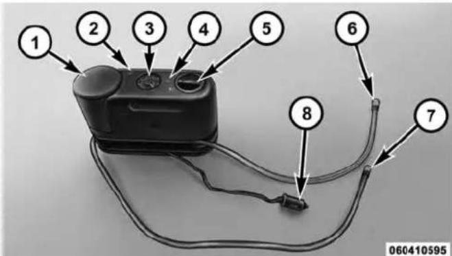
text_image
1 2 3 4 5 6 7 8 060410595TREFITComponents
1 — Sealant Bottle 5 — Mode Select Knob
2 — Deflation Button 6 — Sealant Hose (Clear)
3 — Pressure Gauge 7 — Air Pump Hose (Black)
4 — Power Button 8 — Power Plug (located on bottom side of TREFIT Kit)
448 WHAT TO DO IN EMERGENCIES
UsingTheModeSelectKnobAndHoses
Your TREFIT kit is equipped with the following symbols to indicate the air or sealant mode.
SelectingAirMode
Push in the Mode Select Knob (5) and turn to this position for air pump operation only. Use the Black Air Pump Hose (7) when selecting this mode.
SelectingSealantMode
Push in the Mode Select Knob (5) and turn to this position to inject the TREFIT Sealant and to inflate the tire. Use the Sealant Hose (clear hose) (6) when selecting this mode.
UsingThePowerButton
Push and release the Power Button (4) once to turn On the TREFIT kit. Push and release the Power Button (4) again to turn Off the TREFIT kit.
UsingTheDeflationButton
Press the Deflation Button (2) to reduce the air pressure in the tire if it becomes over-inflated.
WHAT TO DO IN EMERGENCIES 449
TREFIT Usage Precautions
- Replace the TIREFIT Sealant Bottle (1) and Sealant Hose (6) prior to the expiration date (printed at the lower right hand corner on the bottle label) to assure optimum operation of the system. Refer to "Sealing a Tire with TIREFIT" section (F) "Sealant Bottle and Hose Replacement".
natural_image
Illustration of a portable electronic device with cables and a control panel (no text or symbols visible)0604018634
TREFITExpirationDateLocation
- The Sealant Bottle (1) and Sealant Hose (6) are a one tire application use and need to be replaced after each use. Always replace these components immediately at your original equipment vehicle dealer.
- When the TREFIT sealant is in a liquid form, clean water, and a damp cloth will remove the material from the vehicle or tire and wheel components. Once the sealant dries, it can easily be peeled off and properly discarded.
- For optimum performance, make sure the valve stem on the wheel is free of debris before connecting the TREFIT kit.
450 WHAT TO DO IN EMERGENCIES
- You can use the TREFIT air pump to inflate bicycle tires. The kit also comes with two needles, located in the Accessory Storage Compartment (on the bottom of the air pump) for inflating sport balls, rafts, or similar inflatable items. However, use only the Air Pump Hose (7) and make sure the Mode Select Knob (5) is in the Air Mode when inflating such items to avoid injecting sealant into them. The TREFIT Sealant is only intended to seal punctures less than 14'' (6 mm) diameter in the tread of your vehicle.
- Do not lift or carry the TREFIT kit by the hoses.
WARNING!
- Donotattempttosealatireonthesideofthe vehicleclosesttotraffic.Pullfarenoughoffthe roadtoavoidthedangerofbeinghitwhenusing theTIREFITkit.
WARNING!(Continued)
- DonotuseTREFITordrivethevehicleunderthe followingcircumstances:
-Ifthepunctureinthetiretreadisapproximately 1/4"(6mm)orlarger.
-Ifthetirehasanysidewalldamage.
-If the tire has any damage from driving with extremely low tire pressure.
-If the tire has any damage from driving on a flat tire.
-Ifthewheelhasanydamage.
-If you are unsure of the condition of the tire or the wheel.
- KeepTREFITawayfromopenflamesorheat source.
(Continued)
(Continued)
WARNING!(Continued)
- AlooseTIREFITkitthrownforwardinacollision orhardstopcouldendangertheoccupantsofthe vehicle.AlwaysstowtheTIREFITkitintheplace provided.Failureretofollowthesewarningscan resultininjuriesthatareseriousorfataltoyou, yourpassengers,andothersaroundyou.
• TakecarenottoallowthecontentsofTIREFITto comeincontactwithhair,eyes,orclothing.TIREFIT isharmfulifinhaled,swallowed,orabsorbedthrough theskin.Itcausesskin,eye,andrespiratoryirritation. Flushimmediatelywithplentyofwaterifthereisany contactwitheyesorskin.Changeclothingassoonas possible,ifthereisanycontactwithclothing. - TIREFITSealantsolutioncontainslatex.Incaseof anallergicreactionorrash,consultaphysician immediately.KeepTIERFIToutofreachofchildren.
WARNING!(Continued)
Ifswallowed, rinsemouthimmediately with plenty of water and drink plenty of water. Donot induce vomiting! Consultaphysician immediately.
Sealing A Tire With TREFIT
(A)WheneverYouStopToUseTREFIT:
- Pull over to a safe location and turn on the vehicle's Hazard Warning flashers.
- Verify that the valve stem (on the wheel with the deflated tire) is in a position that is near to the ground. This will allow the TIREFIT Hoses (6) and (7) to reach the valve stem and keep the TIREFIT kit flat on the ground. This will provide the best positioning of the kit when injecting the sealant into the deflated tire and running the air pump. Move the vehicle as necessary to place the valve stem in this position before proceeding.
(Continued)
452 WHAT TO DO IN EMERGENCIES
- Place the transmission in PARK (auto transmission) or in Gear (manual transmission) and turn Off the ignition.
- Set the parking brake.
(B)SettingUpToUseTREFIT:
- Push in the Mode Select Knob (5) and turn to the Sealant Mode position.
- Uncoil the Sealant Hose (6) and then remove the cap from the fitting at the end of the hose.
- Place the TREFIT kit flat on the ground next to the deflated tire.
-
Remove the cap from the valve stem and then screw the fitting at the end of the Sealant Hose (6) onto the valve stem.
-
Uncoil the Power Plug (8) and insert the plug into the vehicle's 12 Volt power outlet.
NOTE: Do not remove foreign objects (e.g., screws or nails) from the tire.
(C)InjectingTREFITSealantIntoTheDeflatedTire:
- Always start the engine before turning ON the TIRE-FIT kit.
NOTE: Manual transmission vehicles must have the parking brake engaged and the shift lever in NEUTRAL.
- After pressing the Power Button (4), the sealant (white fluid) will flow from the Sealant Bottle (1) through the Sealant Hose (6) and into the tire.
NOTE: Sealant may leak out through the puncture in the tire.
If thesealant(whitefluid) does not flow within 0 - 1 0 secondsthroughtheSealantHose(6):
- Press the Power Button (4) to turn Off the TREFIT kit. Disconnect the Sealant Hose (6) from the valve stem. Make sure the valve stem is free of debris. Reconnect the Sealant Hose (6) to the valve stem. Check that the Mode Select Knob (5) is in the Sealant Mode position and not Air Mode. Press the Power Button (4) to turn On the TREFIT kit.
- Connect the Power Plug (8) to a different 12 Volt power outlet in your vehicle or another vehicle, if available. Make sure the engine is running before turning ON the TREFIT kit.
- The Sealant Bottle (1) may be empty due to previous use. Call for assistance.
NOTE: If the Mode Select Knob (5) is on Air Mode and the pump is operating, air will dispense from the Air Pump Hose (7) only, not the Sealant Hose (6).
If thesealant (whitefluid) does flow through the Sealant Hose(6):
- Continue to operate the pump until sealant is no longer flowing through hose (typically takes 30 - 70 seconds). As the sealant flows through the Sealant Hose (6), the Pressure Gauge (3) can read as high as 70 psi (5 Bar). The Pressure Gauge (3) will decrease quickly from approximately 70 psi (5 Bar) to the actual tire pressure when the Sealant Bottle (1) is empty.
- The pump will start to inject air into the tire immediately after the Sealant Bottle (1) is empty. Continue to operate the pump and inflate the tire to the pressure indicated on the tire pressure label on the driver-side latch pillar (recommended pressure). Check the tire pressure by looking at the Pressure Gauge (3).
454 WHAT TO DO IN EMERGENCIES
If the tired does not in flat to at least 26 psi (1.8 Bar) pressure within 15 minutes:
- The tire is too badly damaged. Do not attempt to drive the vehicle further. Call for assistance.
NOTE: If the tire becomes over-inflated, press the Deflation Button to reduce the tire pressure to the recommended inflation pressure before continuing.
If the tireinflatestotherecommended pressure or is at least 26 psi (1.8 Bar) pressure within 15 minutes:
- Press the Power Button (4) to turn off the TREFIT kit.
- Remove the Speed Limit sticker from the top of the Sealant Bottle (1) and place the sticker on the instrument panel.
- Immediately disconnect the Sealant Hose (6) from the valve stem, reinstall the cap on the fitting at the end of the hose, and place the TREFIT kit in the vehicle storage location. Quickly proceed to (D) "Drive Vehicle."
CAUTION!
- ThemetalendfittingfromPowerPlug(8)mayget hotafteruse,soitshouldbehandledcarefully.
- Failuretoreinstallthecaponthefittingattheend oftheSealantHose(6)canresultinsealantcontactingyourskin,clothing,andthevehicle'sinterior.ItcanalsoresultinsealantcontactinginternalTREFITkitcomponentswhichmaycausepermanentdamagetothekit.
(D)DriveVehicle:
Immediately after injecting sealant and inflating the tire, drive the vehicle 5 miles (8 km) or 10 minutes to ensure distribution of the TREFIT Sealant within the tire. Do not exceed 55 mph (90 km/h).
WARNING!
TREFITisnotapermanentflattirerepair.Havethe tireinspectedandrepairedorreplacedafterusing TREFIT.Donotexceed55mph(90km/h)untilthe tireisrepairedorreplaced.Failureretofollowthis warningcanresultininjuriesthatareseriousorfatal toyou,yourpassengers,andothersaroundyou.
(E)AfterDriving:
Pull over to a safe location. Refer to "Whenever You Stop to Use TREFIT" before continuing.
- Push in the Mode Select Knob (5) and turn to the Air Mode position.
-
Uncoil the power plug and insert the plug into the vehicle's 12 Volt power outlet.
-
Uncoil the Air Pump Hose (7) (black in color) and screw the fitting at the end of hose (7) onto the valve stem.
- Check the pressure in the tire by reading the Pressure Gauge (3).
Iftirepressureislessthan19psi(1.3Bar):
The tire is too badly damaged. Do not attempt to drive the vehicle further. Call for assistance.
Ifthetirepressureis19psi(1.3Bar)orhigher:
- Press the Power Button (4) to turn on TREFIT and inflate the tire to the pressure indicated on the tire and loading information label on the driver-side door opening.
NOTE: If the tire becomes over-inflated, press the Deflation Button to reduce the tire pressure to the recommended inflation pressure before continuing.
456 WHAT TO DO IN EMERGENCIES
- Disconnect the TREFIT kit from the valve stem, reinstall the cap on the valve stem and unplug from 12 Volt outlet.
- Place the TREFIT kit in its proper storage area in the vehicle.
- Have the tire inspected and repaired or replaced at the earliest opportunity at an authorized dealer or tire service center.
- Replace the Sealant Bottle (1) and Sealant Hose (6) assembly at your authorized dealer as soon as possible. Refer to (F) "Sealant Bottle and Hose Replacement".
NOTE: When having the tire serviced, advise the authorized dealer or service center that the tire has been sealed using the TREFIT service kit.
(F) Sealant Bottle And Hose Replacement:
- Uncoil the Sealant Hose (6) (clear in color).
- Locate the round Sealant Bottle release button in the recessed area under the sealant bottle.
- Press the Sealant Bottle release button. The Sealant Bottle (1) will pop up. Remove the bottle and dispose of it accordingly.
- Clean any remaining sealant from the TREFIT housing.
-
Position the new Sealant Bottle (1) in the housing so that the Sealant Hose (6) aligns with the hose slot in the front of the housing. Press the bottle into the housing. An audible click will be heard indicating the bottle is locked into place.
-
Verify that the cap is installed on the fitting at the end of the Sealant Hose (6) and return the hose to its storage area (located on the bottom of the air pump).
- Return the TREFIT kit to its storage location in the vehicle.
JUMP-STARTING PROCEDURES
If your vehicle has a discharged battery it can be jump-started using a set of jumper cables and a battery in another vehicle or by using a portable battery booster pack. Jump-starting can be dangerous if done improperly so please follow the procedures in this section carefully.
NOTE: When using a portable battery booster pack follow the manufacturer's operating instructions and precautions.
CAUTION!
Donotuseaportablebatteryboosterpackorany otherboostersourcewithasystemvoltagegreater than12Voltsordamagetothebattery, startermotor, alternatororelectricalsystemmayoccur.
WARNING!
Donotattemptjump-startingifthebatteryisfrozen. Itcouldruptureorexplodeandcausepersonalinjury.
458 WHAT TO DO IN EMERGENCIES
Preparations For Jump-Start
The battery in your vehicle is located in the front of the engine compartment below the air intake duct. To access the battery remove the air intake duct by turning the two finger screws, located on the radiator support.
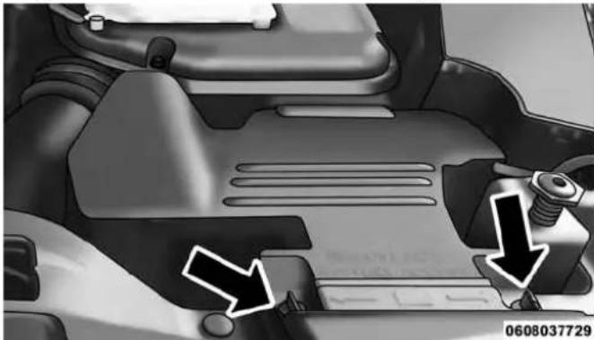
natural_image
Close-up of a car engine compartment with two arrows pointing to specific parts (no visible text or symbols)AirIntakeFingerScrews
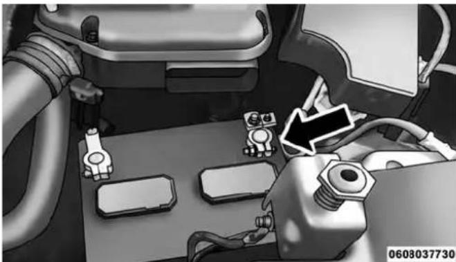
natural_image
Interior view of a vehicle battery pack with attached components and wiring (no visible text or symbols)PositiveBatteryPost
WARNING!
• Takecaretoavoidtheradiatorcoolingfanwhenever thehoodisraised.Itcanstartanytimetheignition switchisON.Youcanbeinjuredbymovingfanblades.
(Continued)
WARNING!(Continued)
- Removeanymetaljewelrysuchasrings, watch bandsandbraceletsthatcouldmakeaninadvertent electricalcontact. Youcouldbeseriouslyinjured.
-
Batteriescontainsulfuricacidthatcanburnyour skinoreyesandgeneratehydrogengaswhichis flammableandexplosive.Keepopenflamesor sparksawayfromthebattery.
-
Set the parking brake, shift the automatic transmission into PARK (manual transmission to NEUTRAL) and turn the ignition to LOCK.
- Turn off the heater, radio, and all unnecessary electrical accessories.
- If using another vehicle to jump-start the battery, park the vehicle within the jumper cables reach, set the parking brake and make sure the ignition is OFF.
WARNING!
Donotallowvehiclestotoucheachotherasthis couldestablishagroundconnectionandpersonal injurycouldresult.
Jump-Starting Procedure
WARNING!
Failuretofollowthisjump-startingprocedurecould resultinpersonalinjuryorpropertydamagedueto batteryexplosion.
CAUTION!
Failure to follow these procedures could result in damageto the charging system of the booster vehicle orthedischarged vehicle.
460 WHAT TO DO IN EMERGENCIES
NOTE: Remove Air Intake before proceeding with this Jump-Starting procedure.
ConnectingTheJumperCables
- Connect the positive (+) end of the jumper cable to the positive (+) post of the discharged vehicle.
- Connect the opposite end of the positive (+)jumper cable to the positive (+)post of the booster battery.
- Connect the negative end (-) of the jumper cable to the negative (-) post of the booster battery.
- Connect the opposite end of the negative (-)jumper cable to a good engine ground (exposed metal part of the discharged vehicle's engine) away from the battery and the fuel injection system.
WARNING!
Donotconnectthejumpercabletothenegative(-) postofthedischargedbattery. Theresultingelectricalsparkcouldcausethebatterytoexplodeand couldresultinpersonalinjury. Onlyusethespecific groundpoint, donotuseanyotherexposedmetal parts.
-
Start the engine in the vehicle that has the booster battery, let the engine idle a few minutes, and then start the engine in the vehicle with the discharged battery.
-
Once the engine is started, remove the jumper cables in the reverse sequence:
DisconnectingTheJumperCables
- Disconnect the negative (-)end of the jumper cable from the engine ground of the vehicle with the discharged battery.
- Disconnect the opposite end of the negative (-) jumper cable from the negative (-) post of the booster battery.
- Disconnect the positive (+)end of the jumper cable from the positive (+)post of the booster battery.
- Disconnect the opposite end of the positive (+) jumper cable from the positive (+) post of the vehicle with the discharged battery.
- Reinstall the air intake duct.
If frequent jump-starting is required to start your vehicle you should have the battery and charging system inspected at your authorized dealer.
CAUTION!
Accessoriespluggedintothevehiclepoweroutlets drawpowerfromthevehicle'sbattery,evenwhennot inuse(i.e.,cellularphones,etc.).Eventually,if pluggedinlongenoughwithoutengineoperation, thevehicle'sbatterywilldischargesufficiently to degradebatterylifeand/orpreventtheenginefrom starting.
FREEING A STUCK VEHICLE
If your vehicle becomes stuck in mud, sand or snow, it can often be moved using a rocking motion. Turn the steering wheel right and left to clear the area around the front wheels. Then shift back and forth between DRIVE and REVERSE (with automatic transmission) or 2nd gear and REVERSE (with manual transmission), while gently pressing the accelerator. Use the least amount of accelerator pedal pressure that will maintain the rocking motion, without spinning the wheels, or racing the engine.
CAUTION!
Racingtheengineorspinningthewheelsmayleadto transmissionoverheatingandfailure.AllowtheenginetoidlewiththetransmissioninNEUTRALforat leastoneminuteaftereveryfiverocking-motion cycles.Thiswillminimizeoverheatingandreduce theriskoftransmissionfailureduringprolonged effortstofreeastuckvehicle.
NOTE: Press the "ESC Off" switch, to place the Electronic Stability Control (ESC) system in "Partial Off" mode, before rocking the vehicle. Refer to "Electronic Brake Control" in "Starting And Operating" for further information. Once the vehicle has been freed, press the "ESC Off" switch again to restore "ESC On" mode.
CAUTION!
- When "rocking" astuckvehiclebyshiftingbetweenDRIVE/2ndgearandREVERSE, donotspin thewheelsfasterthan15mph(24km/h), ordrive-traindamagemayresult.
- Revvingtheengineorspinningthewheelstoofast mayleadtotransmissionoverheatingandfailure. Itcanalsodamagethetires.Donotspinthewheels above30mph(48km/h)whileingear(notransmissionshiftingoccurring).
WARNING!
Fastspinningtirescanbedangerous. Forcesgenerated by excessive wheels speeds may caused damage, or even failure, of the axle and tires. Atire could explode and injuresomeone. Donot spiny our vehicle's wheels faster than 30 mph (48 km/h) or for longer than 30 seconds continuously without stopping when you are stuck and donot let any one near aspinning wheel, no matter what the speed.
If a malfunction occurs and the shift lever cannot be moved out of the PARK position, you can use the following procedure to temporarily move the shift lever:
-
Turn the engine OFF.
-
Firmly apply the parking brake.
- Using a small screwdriver or similar tool, remove the shift lever override access cover (located on the right side of the shifter housing).
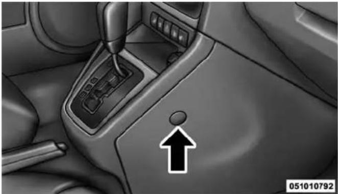
natural_image
Interior view of a car gear shift lever with an upward arrow indicator (no text or symbols on the diagram itself)ShiftLeverOverrideAccessCover
464 WHAT TO DO IN EMERGENCIES
- Turn the ignition switch to the ACC or ON/RUN position, but do not start the engine.
- Press and maintain firm pressure on the brake pedal.
-
Insert the screwdriver or similar tool into the access port, and push and hold the override release lever forward.
-
Move the shift lever to the NEUTRAL position.
- The vehicle may then be started in NEUTRAL.
- Reinstall the shift lever override access cover.
TOWING A DISABLED VEHICLE
This section describes procedures for towing a disabled vehicle using a commercial wrecker service.
| Towing Condition | WheelsOFF theGround | Manual Transmission | AutomaticTransmission (FWDOnly) | AutomaticTransmission 4WD |
| Flat Tow NONE | •Transmission in NEUTRAL•Key in ACC or ON/RUN position | Iftransmissionisoperable:•Transmission in NEUTRAL•25 mph (40 km/h)maxspeed•15 miles (24 km)maxdistance | Iftransmissionisoperable:•Transmission in NEUTRAL•25 mph (40 km/h)maxspeed•15 miles (24 km)maxdistance | |
| Wheel Lift or Dolly Tow | Rear NOT | ALLOWEDNOTALLOWED | ||
| Front FWD | Models ONLY | OKNOTALLOWED | ||
| Flatbed ALLBESTMETHODBESTMETHODBESTMETHOD | ||||
466 WHAT TO DO IN EMERGENCIES
With Ignition Key
AutomaticTransmission
- Front Wheel Drive (FWD) vehicles can be towed with the front wheels elevated, or on a flatbed truck (all four wheels OFFthe ground).
- Four-Wheel Drive (4WD) vehicles can be towed on a flatbed truck (all four wheels OFFthe ground).
If the transmission is operable, this vehicle may be flat towed (with all four wheels on the ground) under the following conditions:
• The transmission must be in NEUTRAL.
- The towing speed must not exceed 25 mph (40 km/h).
- The towing distance must not exceed 15 miles (24 km).
Front Wheel Drive (FWD) models may also be towed (under the same limitations shown above) with the rear wheels elevated.
CAUTION!
- Towing this vehicle using any other method could result in extensive damage to the transfer case and/or transmission.
- DamagefromimpropertowingisnotcoveredundertheNewVehicleLimitedWarranty.
If the vehicle's battery is discharged, refer to "Shift Lever Override" in this section for instructions on shifting the automatic transmission out of PARK for towing.
ManualTransmission
- Front Wheel Drive (FWD) or Four-Wheel Drive (4WD) vehicles can be flat towed (all four wheels on the ground) with the transmission in NEUTRAL.
- FWD vehicles can be towed with the front wheels elevated.
- FWD or 4WD vehicles can be towed on a flatbed truck (all wheels OFFthe ground).
CAUTION!
- DONOTflattowanydisabledvehicleifcondition isrelatedtoaclutch, transmissionordriveline component. Damagetothedrivetraincouldresult.
- Towing this vehicle inviolation of the above requirements can cause severe transmission damage. Damage from impropertowing is not covered under the New Vehicle Limited Warranty.
AllTransmissions
If you must use the accessories (wipers, defroster, etc.) while being towed, the key must be in the ON/RUN
position, not the ACC position. Make certain the transmission remains in NEUTRAL.
CAUTION!
- DONOTusesling-typeequipmentwhentowing. Vehicledamagemayoccur.
- Whensecuringthevehicletoaflatbedtruck, donot attachtofrontorrearsuspensioncomponents. Damagetoyourvehiclemayresultfromimproper towing.
WithoutTheIgnitionKey
Special care must be taken when the vehicle is towed with the ignition in the LOCK position. The only approved method of towing without the ignition key is with a flatbed truck. Proper towing equipment is necessary to prevent damage to the vehicle.
MAINTAINING YOUR VEHICLE
CONTENTS
■ENGINE COMPARTMENT — 2.0L . . . . . . . . . . .471
■ENGINE COMPARTMENT — 2.4L . . . . . . . . . . . . . . . . . . . . . . . . . . . . . . . . . . . . . . . . . . . . . . . . . . .
■ONBOARD DIAGNOSTIC SYSTEM — OBD II . .473
□Loose Fuel Filler Cap Message .....473
■EMISSIONS INSPECTION AND MAINTENANCE PROGRAMS....474
■REPLACEMENT PARTS....475
■DEALER SERVICE....476
■MAINTENANCE PROCEDURES....476
□Engine Oil....477
□Engine Oil Filter . . . . . . . . . . . . . . . . . . . . . . . . . . . . . . . . . . . . . . . . . . . . . . . . . . 480
□Engine Air Cleaner Filter .....480
□Maintenance-Free Battery .....481
□Air Conditioner Maintenance .....482
□Body Lubrication....484
□Windshield Wiper Blades .....485
□Adding Washer Fluid . . . . . . . . . . . . . . . . . . . . . . . . . . . . . . . . . . . . . . 485
□Exhaust System....486
□ Cooling System....488
□Brake System....494
470 MAINTAINING YOUR VEHICLE
□Automatic Transmission (Six-Speed) — If Equipped .....497
☐Automatic Transmission (CVT) — If Equipped .....499
□Manual Transmission — If Equipped . . . . . . .501
☐Rear Drive Assembly (RDA) — AWD/4WD Models Only . . . . . . . . . . . . . . . . . . . . . . . . . . . . . . . . . . . . . . . . . . . . . . . . . . . . . . . . . . . . . . . 501
□Power Transfer Unit (PTU) — AWD/4WD Models Only .502
□Appearance Care And Protection From Corrosion....502
■FUSES....510
□Integrated Power Module....5 1 1
■VEHICLE STORAGE....515
■REPLACEMENT BULBS....515
■BULB REPLACEMENT....516
□Headlamps....516
□Fog Lamps....517
□Rear Turn Signal And Backup Lamp . . . . . . . .517
□License Lamps....518
□Center High-Mounted Stoplamp .....518
■FLUID CAPACITIES....518
■FLUIDS, LUBRICANTS AND GENUINE PARTS .....519
□Engine....519
□Chassis .520
ENGINE COMPARTMENT — 2.0L
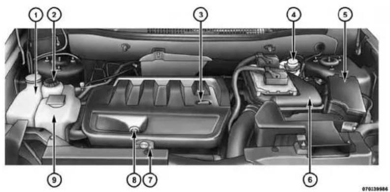
text_image
Labeled diagram of a car engine bay with numbered parts for identification1 — Washer Fluid Reservoir 6 — Air Cleaner Filter
2 — Power Steering Fluid Reservoir 7 — Coolant Pressure Cap
3 — Engine Oil Fill 8 — Engine Oil Dipstick
4 — Brake Fluid Reservoir 9 — Engine Coolant Reservoir
5 — Integrated Power Module (Fuses)
472 MAINTAINING YOUR VEHICLE
ENGINE COMPARTMENT — 2.4L
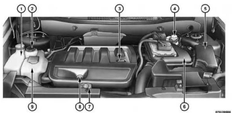
text_image
Labeled diagram of a car engine bay with numbered parts for identification1 — Washer Fluid Reservoir 6 — Air Cleaner Filter
2 — Power Steering Fluid Reservoir 7 — Coolant Pressure Cap
3 — Engine Oil Fill 8 — Engine Oil Dipstick
4 — Brake Fluid Reservoir 9 — Engine Coolant Reservoir
5 — Integrated Power Module (Fuses)
ONBOARD DIAGNOSTIC SYSTEM — OBD II
Your vehicle is equipped with a sophisticated onboard diagnostic system called OBD II. This system monitors the performance of the emissions, engine, and automatic transmission control systems. When these systems are operating properly, your vehicle will provide excellent performance and fuel economy, as well as engine emissions well within current government regulations.
If any of these systems require service, the OBD II system will turn on the “Malfunction Indicator Light” (MIL). It will also store diagnostic codes and other information to assist your service technician in making repairs. Although your vehicle will usually be drivable and not need towing, see your authorized dealer for service as soon as possible.
CAUTION!
- ProlongeddrivingwiththeMILoncouldcause furtherdamagetotheemissioncontrolsystem.It couldalsoaffectfueleconomyanddriveability. Thevehiclemustbeservicedbeforeanyemissions testscanbeperformed.
- If the MIL is flashing while the engine is running, severecatalytic converter damage and power loss will soon occur. Immediately service is required.
Loose Fuel Filler Cap Message
After fuel is added, the vehicle diagnostic system can determine if the fuel filler cap is possibly loose or improperly installed. A "gASCAP" message will be displayed in the instrument cluster. Tighten the gas cap until a "clicking" sound is heard. This is an indication that the gas cap is properly tightened. Press the trip odometer RESET button to turn off the message. If the problem
474 MAINTAINING YOUR VEHICLE
persists, the message will appear the next time the vehicle is started. This might indicate a damaged cap. If the problem is detected twice in a row, the system will turn on the MIL. Resolving the problem will turn the MIL light off.
EMISSIONS INSPECTION AND MAINTENANCE PROGRAMS
In some localities, it may be a legal requirement to pass an inspection of your vehicle's emissions control system. Failure to pass could prevent vehicle registration.

For states that require an Inspection and Maintenance (I/M), this check verifies the "Malfunction Indicator Light (MIL)" is functioning and is not on when the engine is running, and that the OBD II system is ready for testing.
Normally, the OBD II system will be ready. The OBD II system may not be ready if your vehicle was recently serviced, recently had a dead battery or a battery replacement. If the OBD II system should be determined not ready for the I/M test, your vehicle may fail the test.
Your vehicle has a simple ignition actuated test, which you can use prior to going to the test station. To check if your vehicle's OBD II system is ready, you must do the following:
- Cycle the ignition switch to the ON position, but do not crank or start the engine.
NOTE: If you crank or start the engine, you will have to start this test over.
-
As soon as you cycle the ignition switch to the ON position, you will see the MIL symbol come on as part of a normal bulb check.
-
Approximately 15 seconds later, one of two things will happen:
-
The MIL will flash for about 10 seconds and then return to being fully illuminated until you turn OFF the ignition or start the engine. This means that your vehicle's OBD II system is notready and you should not proceed to the I/M station.
- The MIL will not flash at all and will remain fully illuminated until you turn OFF the ignition or start the engine. This means that your vehicle's OBD II system is ready and you can proceed to the I/M station.
If your OBD II system is notready, you should see your authorized dealer or repair facility. If your vehicle was recently serviced or had a battery failure or replacement, you may need to do nothing more than drive your vehicle as you normally would in order for your OBD II system to update. A recheck with the above test routine may then indicate that the system is nowready.
Regardless of whether your vehicle's OBD II system is ready or not, if the MIL is illuminated during normal vehicle operation you should have your vehicle serviced before going to the I/M station. The I/M station can fail your vehicle because the MIL is on with the engine running.
REPLACEMENT PARTS
Use of genuine MOPAR® parts for normal/scheduled maintenance and repairs is highly recommended to ensure the designed performance. Damage or failures caused by the use of non-MOPAR® parts for maintenance and repairs will not be covered by the New Vehicle Limited Warranty.
476 MAINTAINING YOUR VEHICLE
DEALER SERVICE
Your authorized dealer has the qualified service personnel, special tools, and equipment to perform all service operations in an expert manner. Service Manuals are available which include detailed service information for your vehicle. Refer to these Service Manuals before attempting any procedure yourself.
NOTE: Intentional tampering with emissions control systems may void your warranty and could result in civil penalties being assessed against you.
WARNING!
Youcanbebadlyinjuredworkingonorarounda motorvehicle.Onlydoserviceworkforwhichyou havetheknowledgeandtheproperequipment.Ifyou haveanydoubtaboutyourabilitytoperformaservice job,takeyourvehicletoacompetentmechanic.
MAINTENANCE PROCEDURES
The pages that follow contain the required maintenance services determined by the engineers who designed your vehicle.
Besides those maintenance items specified in the fixed "Maintenance Schedule", there are other components which may require servicing or replacement in the future.
CAUTION!
- Failuretoproperlymaintainyourvehicleorperformrepairsandservicewhennecessarycould resultinmorecostlyrepairs,damagetoother componentsornegativelyimpactvehicleperformance.Immediatelyhavepotentialmalfunctions examinedbyanauthorizeddealerorqualified repaircenter.
(Continued)
CAUTION!(Continued)
- Yourvehiclehasbeenbuiltwithimprovedfluidsthat protecttheperformanceanddurabilityofyourvehicle andalsoallowextendedmaintenanceintervals.Donot usechemicalflushesinthesecomponentsasthe chemicalscandamageyouengine,transmission, powersteeringorairconditioning.Suchdamageisnot coveredbytheNewVehicleLimitedWarranty.Ifa flushisneededbecauseofcomponentmalfunction, useonlythespecifiedfluidfortheflushingprocedure.
Engine Oil
CheckingOilLevel
To assure proper engine lubrication, the engine oil must be maintained at the correct level. Check the oil level at regular intervals, such as every fuel stop. The best time to check the engine oil level is about five minutes after a fully warmed engine is shut off. Do not check oil level
before starting the engine after it has sat overnight. Checking engine oil level when the engine is cold will give you an incorrect reading.
Checking the oil while the vehicle is on level ground and only when the engine is hot, will improve the accuracy of the oil level readings. Maintain the oil level between the range markings on the dipstick. The range markings will consist of a crosshatch zone which depicts the MIN at the low end of the range and MAX at the high end of the range. Adding 1 qt (1L) of oil when the reading is at the low end of the indicated range will result in the oil level at the full end of the indicator range.
CAUTION!
Donotoverfilltheengine. Overfillingtheengine will cause oilaeration, which can lead to loss of oil pressure and an increase in oil temperature. This could damage your engine. Also, besure the oil fill cap is replaced and tightened after adding oil.
478 MAINTAINING YOUR VEHICLE
ChangeEngineOil
The oil change indicator system will remind you that it is time to take your vehicle in for scheduled maintenance. Refer to the "Maintenance Schedule" for further information.
NOTE: Undernocircumstances should oil change intervals exceed 10,000 miles (16,000 km) or twelve months, whichever occurs first.
EngineOilSelection
For best performance and maximum protection under all types of operating conditions, the manufacturer only recommends engine oils that are API Certified and meet the requirements of Chrysler Material Standard MS-6395.
AmericanPetroleumInstitute(API)EngineOil IdentificationSymbol

text_image
AMERICAN PETROLEUM INSTITUTE FOR GASOLINE ENGINES CERTIFIEDThis symbol means that the oil has been certified by the American Petroleum Institute (API). The manufacturer only recommends API Certified engine oils.
CAUTION!
Donotusechemicalflushesinyourengineoilasthe chemicalscandamageyourengine.Suchdamageis notcoveredbytheNewVehicleLimitedWarranty.
EngineOilViscosity(SAEGrade)
MOPAR® SAE 5W-20 engine oil or equivalent Pennzoil® or Shell Helix® is recommended for all operating temperatures. This engine oil improves low temperature starting and vehicle fuel economy. Your engine oil filler cap also states the recommended engine oil viscosity grade for your engine.
Lubricants which do not have both the engine oil certification mark and the correct SAE viscosity grade number should not be used.
SyntheticEngineOils
You may use synthetic engine oils provided the recommended oil quality requirements are met, and the recommended maintenance intervals for oil and filter changes are followed.
MaterialsAddedToEngineOil
The manufacturer strongly recommends against the addition of any additives (other than leak detection dyes) to the engine oil. Engine oil is an engineered product and its performance may be impaired by supplemental additives.
DisposingOfUsedEngineOilAndOilFilters
Care should be taken in disposing of used engine oil and oil filters from your vehicle. Used oil and oil filters, indiscriminately discarded, can present a problem to the environment. Contact your authorized dealer, service station or governmental agency for advice on how and where used oil and oil filters can be safely discarded in your area.
480 MAINTAINING YOUR VEHICLE
Engine Oil Filter
The engine oil filter should be replaced with a new filter at every engine oil change.
EngineOilFilterSelection
This manufacturer's engines have a full-flow type oil filter. Use a filter of this type for replacement. The quality of replacement filters varies considerably. Only high quality filters should be used to assure most efficient service. MOPAR® engine oil filters are a high quality oil filter and are recommended.
Engine Air Cleaner Filter
Refer to the "Maintenance Schedule" for the proper maintenance intervals.
WARNING!
Theairinductionsystem(aircleaner,hoses,etc.)can provideameasureofprotectioninthecaseofengine backfire.Donotremovetheairinductionsystem(air cleaner,hoses,etc.)unlesssuchremovalisnecessary forrepairormaintenance.Makesurethatnooneis neartheenginecompartmentbeforestartingthe vehiclewiththeairinductionsystem(aircleaner, hoses,etc.)removed.Failureretodosocanresultin seriouspersonalinjury.
EngineAirCleanerFilterSelection
The quality of replacement engine air cleaner filters varies considerably. Only high quality filters should be used to assure most efficient service. MOPAR® engine air cleaner filters are a high quality filter and are recommended.
Maintenance-Free Battery
Your vehicle is equipped with a maintenance-free battery. You will never have to add water, nor is periodic maintenance required.
WARNING!
- Batteryfluidisacorrosiveacidsolutionandcan burnorevenblindyou.Donotallowbatteryfluid tocontactyoureyes,skin,orclothing.Donotlean overabatterywhenattachingclamps.Ifacid splashesineyesoronskin,flushtheareimmediatelywithlargeamountsofwater.Referto "Jump-StartingProcedures"in"WhatToDoIn Emergencies"forfurtherinformation.
- Batterygasisflammableandexplosive.Keep flameorsparksawayfromthebattery.Donotuse aboosterbatteryoranyotherboostersourcewith
WARNING!(Continued)
anoutputgreaterthan12Volts.Donotallowcable clampstotoucheachother.
- Batteryposts, terminals, and related accessories contain lead and lead compounds. Washhands after handling.
- Thebatteryinthisvehiclehasaventhosethat shouldnotbedisconnectedandshouldonlybe replacedwithabatteryofthesametype(vented).
CAUTION!
- It is essential when replacing the cables on the battery that the positive cable is attached to the positive post and then negative cable is attached to the negative post. Battery posts are marked positive (+) and negative (-) and are identified on the
(Continued)
(Continued)
CAUTION!(Continued)
batterycase.Cableclampsshouldbetightonthe terminalpostsandfreeofcorrosion.
- Ifa "fastcharger" is used while the battery is in the vehicle, disconnect both vehicle battery cables before connecting the charger to the battery. Donot use a "fastcharger" to provide starting voltage.
Air Conditioner Maintenance
For best possible performance, your air conditioner should be checked and serviced by an authorized dealer at the start of each warm season. This service should include cleaning of the condenser fins and a performance test. Drive belt tension should also be checked at this time.
WARNING!
- Useonlyrefrigerantsandcompressorlubricants approvedbythemanufacturerforyourairconditioningsystem.Someunapprovedrefrigerantsare flammableandcanexplode,injuringyou.Other unapprovedrefrigerantsorlubricantscancausethe systemtofail,requiringcostlyrepairs.Referto WarrantyInformationBook,locatedontheDVD, forfurtherwarrantyinformation.
- The airconditioningsystem contains refrigerant underhigh pressure. To avoid risk of personal injury or damage to the system, adding refrigerant or any repair requiring linestobedisconnected should be done by an experienced technician.
CAUTION!
Donotusechemicalflushesinyourairconditioning systemasthechemicalscandamageyourairconditioningcomponents.Suchdamageisnotcoveredby theNewVehicleLimitedWarranty.
RefrigerantRecoveryAndRecycling
R-134a Air Conditioning Refrigerant is a hydrofluorocarbon (HFC) that is endorsed by the Environmental Protection Agency and is an ozone-saving product. However, the manufacturer recommends that air conditioning service be performed by authorized dealer or other service facilities using recovery and recycling equipment.
NOTE: Use only manufacturer approved A/C system PAG compressor oil and refrigerants.
A/CAirFilter
Refer to the “Maintenance Schedule” for the proper maintenance intervals.
WARNING!
DonotremovetheA/Cairfilterwhilethebloweris operatingorpersonalinjurymayresult.
The A/C air filter is located in the fresh air inlet behind the glove box. Perform the following procedure to replace the filter:
- Open the glove compartment and remove all contents.
- Push in on the sides of the glove compartment and lower the door.
- Pivot the glove compartment downward.
484 MAINTAINING YOUR VEHICLE
- Disengage the two retaining tabs that secure the filter cover to the HVAC housing, and remove the cover.

natural_image
Illustration of a vehicle's front wheel assembly with two upward arrows indicating components (no text or symbols)A/CAirFilterReplacement
-
Remove the A/C air filter by pulling it straight out of the housing.
-
Install the A/C air filter with the arrow on the filter pointing toward the floor. When installing the filter cover, make sure the retaining tabs fully engage the cover.
CAUTION!
TheA/Cairfilterisidentifiedwithanarrowto indicate airflowdirectionthroughthefilter.Failure toproperlyinstallthefilterwillresultintheneedto replaceitmoreoften.
- Rotate the glove compartment door back into position.
Body Lubrication
Locks and all body pivot points, including such items as seat tracks, door hinge pivot points and rollers, liftgate, tailgate, decklid, sliding doors and hood hinges, should be lubricated periodically with a lithium based grease, such as MOPAR® Spray White Lube to assure quiet, easy operation and to protect against rust and wear. Prior to the application of any lubricant, the parts concerned should be wiped clean to remove dust and grit; after lubricating excess oil and grease should be removed. Particular attention should also be given to hood latching
components to ensure proper function. When performing other underhood services, the hood latch, release mechanism and safety catch should be cleaned and lubricated.
The external lock cylinders should be lubricated twice a year, preferably in the Fall and Spring. Apply a small amount of a high quality lubricant, such as MOPAR® Lock Cylinder Lubricant directly into the lock cylinder.
Windshield Wiper Blades
Clean the rubber edges of the wiper blades and the windshield periodically with a sponge or soft cloth and a mild nonabrasive cleaner. This will remove accumulations of salt or road film.
Operation of the wipers on dry glass for long periods may cause deterioration of the wiper blades. Always use washer fluid when using the wipers to remove salt or dirt from a dry windshield.
Avoid using the wiper blades to remove frost or ice from the windshield. Keep the blade rubber out of contact with petroleum products such as engine oil, gasoline, etc.
NOTE: Life expectancy of wiper blades varies depending on geographical area and frequency of use. Poor performance of blades may be present with chattering, marks, water lines or wet spots. If any of these conditions are present, clean the wiper blades or replace as necessary.
Adding Washer Fluid
The washer fluid reservoir is located in the engine compartment, and the fluid level should be checked at regular intervals. Fill the reservoir with windshield washer solvent only (not radiator antifreeze).
When refilling the washer fluid reservoir, take some washer fluid and apply it to a cloth or towel and wipe clean the wiper blades, this will help blade performance. To prevent freeze-up of your windshield washer system
486 MAINTAINING YOUR VEHICLE
in cold weather, select a solution or mixture that meets or exceeds the temperature range of your climate. This rating information can be found on most washer fluid containers.
WARNING!
Commerciallyavailablewindshieldwashersolvents areflammable. They could ignite and burn you. Care must be exercised when filling or working around the washers solution.
Exhaust System
The best protection against carbon monoxide entry into the vehicle body is a properly maintained engine exhaust system.
If you notice a change in the sound of the exhaust system; or if the exhaust fumes can be detected inside the vehicle; or when the underside or rear of the vehicle is damaged; have an authorized technician inspect the complete exhaust system and adjacent body areas for broken, damaged, deteriorated, or mispositioned parts. Open seams or loose connections could permit exhaust fumes to seep into the passenger compartment. In addition, have the exhaust system inspected each time the vehicle is raised for lubrication or oil change. Replace as required.
WARNING!
- Exhaustgasescaninjureorkill. They contain carbonmonoxide(CO), which is colorless and odorless. Breathing it can make you unconscious and can eventually poison you. To avoid breathing CO, refer to "Safety Tips/ExhaustGas" in "Things To Know Before Starting Your Vehicle" for further information.
(Continued)
WARNING!(Continued)
- Ahotexhaustsystemcanstartafireifyoupark overmaterialsthatcanburn.Suchmaterialsmight begrassorleavescomingintocontactwithyour exhaustsystem.Donotparkoroperateyourvehicleinareaswhereyourehaustsystemcancontactanythingthatcanburn.
CAUTION!
- The catalytic converter requires the use of un-leaded fuel only. Leaded gasoline will destroy the effectiveness of the catalyst as an emissions control device and may seriously reduce engine performance and causes serious damage to the engine. - Damagethe catalytic converter can result in your vehicle is not kept in proper operating condition.
CAUTION!(Continued)
Intheeventofenginemalfunction, particularly involvingenginemisfireorotherapparentlossof performance, haveyourvehicleservicedpromptly. Continuedoperationofyourvehiclewithasevere malfunctioncouldcausetheconvertertooverheat, resultinginpossibledamagetotheconverterand vehicle.
Under normal operating conditions, the catalytic converter will not require maintenance. However, it is important to keep the engine properly tuned to assure proper catalyst operation and prevent possible catalyst damage.
NOTE: Intentional tampering with emissions control systems can result in civil penalties being assessed against you.
(Continued)
488 MAINTAINING YOUR VEHICLE
In unusual situations involving grossly malfunctioning engine operation, a scorching odor may suggest severe and abnormal catalyst overheating. If this occurs, stop the vehicle, turn off the engine and allow it to cool.
Service, including a tune-up to manufacturer's specifications, should be obtained immediately.
To minimize the possibility of catalytic converter damage:
- Do not shut off the engine or interrupt the ignition, when the transmission is in gear and the vehicle is in motion.
- Do not try to start the engine by pushing or towing the vehicle.
- Do not idle the engine with any spark plug wires disconnected or removed, such as when diagnostic testing, or for prolonged periods during very rough idle or malfunctioning operating conditions.
Cooling System
WARNING!
- When working near the radiator cooling fan, disconnect the fan motor lead or turn the ignition switch to the OFF position. The fan is temperature controlled and can start at any time the ignition switch in the ON position.
- Youorotherscanbebadlyburnedbyhotengine coolant(antifreeze)orsteamfromyourradiator.If youseeorhearsteamcomingfromunderthehood, donotopenthehooduntiltheradiatorhashad timetocool.Nevertrytoopenacoolingsystem pressurecapwhentheradiatorishot.
CoolantChecks
Check engine coolant (antifreeze) protection every 12 months (before the onset of freezing weather, where applicable). If the engine coolant (antifreeze) is dirty or rusty in appearance, the system should be drained, flushed, and refilled with fresh engine coolant (antifreeze). Check the front of the A/C condenser for any accumulation of bugs, leaves, etc. If dirty, clean by gently spraying water from a garden hose vertically down the face of the condenser.
Check the coolant recovery bottle tubing for brittle rubber, cracking, tears, cuts, and tightness of the connection at the bottle and radiator. Inspect the entire system for leaks.
CoolingSystem—Drain, Flush And Refill
If the engine coolant (antifreeze) is dirty or contains visible sediment, have an authorized dealer clean and flush with OAT coolant (antifreeze) (conforming to MS-12106).
Refer to the "Maintenance Schedule" for the proper maintenance intervals.
NOTE: Some vehicles require special tools to add coolant properly. Failure to fill these systems properly could lead to severe internal engine damage. If any coolant is needed to be added to the system please contact your local authorized dealer.
SelectionOfCoolant
Refer to "Fluids, Lubricants, and Genuine Parts" in "Maintaining Your Vehicle" for further information.
CAUTION!
- Mixingofenginecoolant(antifreeze)otherthan specifiedOrganicAdditiveTechnology(OAT)enginecoolant(antifreeze),mayresultinengine damageandmaydecreasecorrosionprotection.
(Continued)
CAUTION!(Continued)
OrganicAdditiveTechnology(OAT)enginecool-antisdifferentandshouldnotbemixedwith HybridOrganicAdditiveTechnology(HOAT)enginecoolant(antifreeze)orany"globallycompatible"coolant(antifreeze).Ifanon-OATengine coolant(antifreeze)isintroducedintothecooling systeminanemergency,thecoolingsystemwill needtobedrained,flushed,andrefilledwithfresh OATcoolant(conformingtoMS-12106),byan authorizeddealerassoonaspossible.
- Donotusewateraloneoralcohol-basedengine coolant(antifreeze)products.Donotuseadditional rustinhibitorsorantirustproducts,astheymaynot becompatiblewiththeradiatorenginecoolantand mayplugtheradiator.
CAUTION!(Continued)
- This vehicle has not been designed for use with propylene glycol-based engine coolant (antifreeze). Use of propylene glycol-based engine coolant (antifreeze) is not recommended.
AddingCoolant
Your vehicle has been built with an improved engine coolant (OAT coolant conforming to MS-12106) that allows extended maintenance intervals. This engine coolant (antifreeze) can be used up to ten years or 150,000 miles (240,000 km) before replacement. To prevent reducing this extended maintenance period, it is important that you use the same engine coolant (OAT coolant conforming to MS-12106) throughout the life of your vehicle.
(Continued)
Please review these recommendations for using Organic Additive Technology (OAT) engine coolant (antifreeze) that meets the requirements of Chrysler Material Standard MS-12106. When adding engine coolant (antifreeze):
- We recommend using MOPAR® Antifreeze/Coolant 10 Year/150,000 Mile Formula OAT (Organic Additive Technology) that meets the requirements of Chrysler Material Standard MS-12106.
- Mix a minimum solution of 50% OAT engine coolant that meets the requirements of Chrysler Material Standard MS-12106 and distilled water. Use higher concentrations (not to exceed 70% ) if temperatures below -34^ (-37^) are anticipated.
- Use only high purity water such as distilled or deionized water when mixing the water/engine coolant (antifreeze) solution. The use of lower quality water will reduce the amount of corrosion protection in the engine cooling system.
Please note that it is the owner's responsibility to maintain the proper level of protection against freezing according to the temperatures occurring in the area where the vehicle is operated.
NOTE:
- Some vehicles require special tools to add coolant properly. Failure to fill these systems properly could lead to severe internal engine damage. If any coolant is needed to be added to the system please contact your local authorized dealer.
- Mixing engine coolant (antifreeze) types is not recommended and can result in cooling system damage. If HOAT and OAT coolant are mixed in an emergency, have a authorized dealer drain, flush, and refill with OAT coolant (conforming to MS-12106) as soon as possible.
492 MAINTAINING YOUR VEHICLE
CoolingSystemPressureCap
The cap must be fully tightened to prevent loss of engine coolant (antifreeze), and to ensure that engine coolant (antifreeze) will return to the radiator from the coolant recovery bottle.
The cap should be inspected and cleaned if there is any accumulation of foreign material on the sealing surfaces.
WARNING!
- The warning words "DONOTOPENHOT" on the cooling system pressure cap areas safety precaution. Never add engine coolant (antifreeze) when the engine is overheated. Donot loosenor remove the captocoolan overheated engine. Heat causes pressure to build up in the cooling system. To prevent scalding or injury, donot remove the
WARNING!(Continued)
pressurecapwhilethesystemishotorunder pressure.
- Donotuseapressurecapotherthantheone specifiedforyourvehicle.Personalinjuryorenginedamagemayresult.
DisposalOfUsedEngineCoolant
Used ethylene glycol-based engine coolant (antifreeze) is a regulated substance requiring proper disposal. Check with your local authorities to determine the disposal rules for your community. To prevent ingestion by animals or children, do not store ethylene glycol-based engine coolant in open containers or allow it to remain in puddles on the ground. If ingested by a child or pet, seek emergency assistance immediately. Clean up any ground spills immediately.
(Continued)
CoolantLevel
The coolant bottle provides a quick visual method for determining that the coolant level is adequate. With the engine idling and warm to normal operating temperature, the level of the engine coolant (antifreeze) in the bottle should be between the "ADD" and "FULL" lines shown on the bottle.
The radiator normally remains completely full, so there is no need to remove the radiator cap unless checking for the coolant freeze point or replacing the engine coolant (antifreeze). Advise your service attendant of this. As long as the engine operating temperature is satisfactory, the coolant bottle need only be checked once a month.
When additional engine coolant (antifreeze) is needed to maintain the proper level, it should be added to the coolant bottle. Do not overfill.
PointsToRemember
NOTE: When the vehicle is stopped after a few miles/ kilometers of operation, you may observe vapor coming from the front of the engine compartment. This is normally a result of moisture from rain, snow, or high humidity accumulating on the radiator and being vaporized when the thermostat opens, allowing hot engine coolant (antifreeze) to enter the radiator.
If an examination of your engine compartment shows no evidence of radiator or hose leaks, the vehicle may be safely driven. The vapor will soon dissipate.
- Do not overfill the coolant expansion bottle.
- Check the coolant freeze point in the radiator and in the coolant expansion bottle. If engine coolant (anti-freeze) needs to be added, the contents of the coolant expansion bottle must also be protected against freezing.
494 MAINTAINING YOUR VEHICLE
- If frequent engine coolant (antifreeze) additions are required, the cooling system should be pressure tested for leaks.
- Maintain engine coolant (antifreeze) concentration at a minimum of 50% OAT coolant (conforming to MS-12106) and distilled water for proper corrosion protection of your engine which contains aluminum components.
- Make sure that the coolant expansion bottle overflow hoses are not kinked or obstructed.
- Keep the front of the radiator clean. If your vehicle is equipped with air conditioning, keep the front of the condenser clean.
- Do not change the thermostat for Summer or Winter operation. If replacement is ever necessary, install ONLY the correct type thermostat. Other designs may
result in unsatisfactory engine coolant (antifreeze) performance, poor gas mileage, and increased emissions.
Brake System
In order to assure brake system performance, all brake system components should be inspected periodically. Refer to the “Maintenance Schedule” for the proper maintenance intervals.
WARNING!
Ridingthebrakescanleadtobrakefailureand possiblyacollision.Drivingwithyourfootrestingor ridingonthebrakepedalcanresultinabnormally highbraketemperatures,excessiveliningwear,and possiblebrakedamage.Youwouldnothaveyourfull brakingcapacityinanemergency.
BrakeMasterCylinder
The fluid level in the master cylinder should be checked when performing under hood services, or immediately if the brake system warning light is on.
Be sure to clean the top of the master cylinder area before removing the cap. If necessary, add fluid to bring the fluid level up to the requirements described on the brake fluid reservoir. Fluid level can be expected to fall as the brake pads wear. The brake fluid level should be checked when the pads are replaced. However, low fluid level may be caused by a leak and a checkup may be needed.
NOTE: If your vehicle is equipped with a manual transmission, the brake fluid reservoir supplies fluid to both the brake system and the clutch release system. The two systems are separated in the reservoir, and a leak in one system will not affect the other system. The manual transmission clutch release system should not require fluid replacement during the life of the vehicle. If the brake fluid reservoir is low and the brake system does not indicate any leaks or other problems, it may be a result of a leak in the hydraulic clutch release system. See your local authorized dealer for service.
Use only manufacturer's recommended brake fluid. Refer to "Fluids, Lubricants, and Genuine Parts" in "Maintaining Your Vehicle" for further information.
WARNING!
- Useonlymanufacturer's recommended brakefluid. Referto "Fluids, Lubricants, and Genuine Parts" in "Maintaining Your Vehicle" for further information. Using the wrong type of brakefluid can severely damage your brakesystem and/or impair its performance. The property of brakefluid for your vehicle is also identified on the original factory installed hydraulic master cylinder reservoir.
(Continued)
WARNING!(Continued)
- To avoid contamination from foreign matter or moisture, use only new brake fluid or fluid that has been in at slightly closed container. Keep them master cylinder reservoir to secure data all times. Brake fluid in a open container absorbsmoisture from the air resulting in lower boiling point. This may cause it to oil unexpectedly during hard or prolonged braking, resulting in sudden brake failure. This could result in a collision.
• Overfillingthebrakefluidreservoircanresultin spillingbrakefluidonhotengineparts, causing thebrakefluidtocatchfire. Brakefluidcanalso damagepaintedandvinylsurfaces, careshouldbe takentoavoiditscontactwiththesesurfaces.
WARNING!(Continued)
- Donotallowpetroleumbasedfluidtocontaminate thebrakefluid.Brakesealcomponentscouldbe damaged,causingpartialorcompletebrakefailure. Thiscouldresultinacollision.
CAUTION!
Useofimproperbrakefluidswillaffectoverall clutchsystemperformance.Improperbrakefluids maydamagetheclutchsystemresultinginloss of clutchfunctionandtheabilitytoshiftthetransmission.
Automatic Transmission (Six-Speed) — If Equipped
SelectionOfLubricant(Six-SpeedTransmission)
It is important to use the proper transmission fluid to ensure optimum transmission performance and life. Use only the manufacturer's recommended transmission fluid. Refer to "Fluids, Lubricants, and Genuine Parts" in this section for fluid specifications. It is important to maintain the transmission fluid at the correct level using the recommended fluid.
No chemical flushes should be used in any transmission; only the approved lubricant should be used.
CAUTION!
Usingatransmissionfluidotherthanthemanufac-turer'srecommendedfluidmaycausedeterioration
CAUTION!(Continued)
intransmissionshiftquality, and will require more frequent fluid and filter changes. Referto "Fluids, Lubricants, and Genuine Parts" in this section for fluids specifications.
SpecialAdditives
The manufacturer strongly recommends against using any special additives in the transmission.
Automatic transmission fluid is an engineered product and its performance may be impaired by supplemental additives. Therefore, do not add any fluid additives to the transmission. The only exception to this policy is the use of special dyes for diagnosing fluid leaks. Avoid using transmission sealers as they may adversely affect seals.
(Continued)
498 MAINTAINING YOUR VEHICLE
CAUTION!
Donotusechemicalflushesinyourtransmissionas thechemicalscandamageyourtransmissioncomponents.SuchdamageisnotcoveredbytheNew VehicleLimitedWarranty.
FluidLevelCheck
The fluid level is preset at the factory and does not require adjustment under normal operating conditions. Routine fluid level checks are not required, therefore the transmission has no dipstick. Your authorized dealer can check your transmission fluid level using special service tools. If you notice fluid leakage or transmission malfunction, visit you authorized dealer immediately to have the fluid level checked. Operating the vehicle with an improper fluid level can cause severe transmission damage.
CAUTION!
Ifatransmissionfluidleakoccurs,visityourauthorizeddealerimmediately.Severetransmissiondamagemayoccur.Yourauthorizeddealerhastheproper toolstoadjustthefluidlevelaccurately.
FluidAndFilterChanges
Under normal operating conditions, the fluid installed at the factory will provide satisfactory lubrication for the life of the vehicle. However, if the vehicle is frequently driven on rough or unpaved roads, on mountain roads, on short trips, or in heavy city traffic during hot weather, or is used for frequent trailer towing, police, fleet, taxi, etc., change the fluid as indicated in the Maintenance Schedule. In addition, change the fluid and filter if the fluid becomes contaminated (with water, etc.), or if the transmission is disassembled for any reason.
Automatic Transmission (CVT) — If Equipped
SelectionOfLubricant(CVT)
It is important to use the proper transmission fluid to ensure optimum transmission performance and life. Use only the manufacturer's recommended transmission fluid which has the special friction coefficient additives necessary for proper steel belt traction on the drive and driven pulleys. Refer to "Fluids, Lubricants, and Genuine Parts" in this section for fluid specifications. It is important to maintain the transmission fluid at the correct level using the recommended fluid.
No chemical flushes should be used in any transmission; only the approved lubricant should be used.
CAUTION!
- Donotusechemicalflushesinyourtransmission asthechemicalscandamageyourtransmission components.Suchdamageisnotcoveredbythe NewVehicleLimitedWarranty.
- Usingatransmissionfluidotherthanthemanufac-turer'srecommendedfluidwillcausebeltslipand resultinacompletetransmissionfailure!Referto "Fluids,Lubricants,andGenuineParts" in "MaintainingYourVehicle" forfluidspecifications.
SpecialAdditives
The manufacturer strongly recommends against using any special additives in the transmission.
Automatic transmission fluid is an engineered product and its performance may be impaired by supplemental additives. Therefore, do not add any fluid additives to the transmission. The only exception to this policy is the
use of special dyes for diagnosing fluid leaks. Avoid using transmission sealers as they may adversely affect seals.
CAUTION!
Donotusechemicalflushesinyourtransmissionas thechemicalscandamageyourtransmissioncomponents.SuchdamageisnotcoveredbytheNew VehicleLimitedWarranty.
FluidLevelCheck
The fluid level is preset at the factory and does not require adjustment under normal operating conditions.
Routine fluid level checks are not required, therefore the transmission filler tube is capped and no dipstick is provided. Your authorized dealer can check your transmission fluid level using special service tools. If you notice fluid leakage or transmission malfunction, visit
your authorized dealer immediately to have the transmission fluid level checked. Operating the vehicle with an improper fluid level can cause severe transmission damage.
CAUTION!
Ifatransmissionfluidleakoccurs,visityourauthorizeddealerimmediately.Severetransmissiondamagemayoccur.Yourauthorizeddealerhastheproper toolstoadjustthefluidlevelaccurately.
FluidAndFilterChanges
Refer to the "Maintenance Schedule" for the proper maintenance intervals. In addition, change the fluid and filter if the transmission is disassembled for any reason.
Manual Transmission — If Equipped
LubricantSelection
Use only the manufacturers recommended transmission fluid. Refer to "Fluids, Lubricants, and Genuine Parts" in "Maintaining Your Vehicle" for further information.
FluidLevelCheck
Check the fluid level by removing the fill plug. The fluid level should be between the bottom of the fill hole and a point not more than 3/16 in (4.7 mm) below the bottom of the hole.
Add fluid, if necessary, to maintain the proper level.
FrequencyOfFluidChange
Under normal operating conditions, the fluid installed at the factory will give satisfactory lubrication for the life of the vehicle. Fluid changes are not necessary unless lubricant has become contaminated with water.
NOTE: If contaminated with water, the fluid should be changed immediately.
Rear Drive Assembly (RDA) — AWD/4WD Models Only
LubricantSelection
Use only the manufacturers recommended transmission fluid. Refer to "Fluids, Lubricants, and Genuine Parts" in "Maintaining Your Vehicle" for further information.
FluidLevelCheck
Visually inspect the unit at each oil change for leakage. If leakage is detected, check the fluid level by removing the fill plug. The fluid level should be maintained between the bottom of the fill hole to 1/8 in (4 mm) below the fill hole.
Add fluid, if necessary, to maintain the proper level.
FrequencyOfFluidChange
Refer to the "Maintenance Schedule" for the proper maintenance intervals.
502 MAINTAINING YOUR VEHICLE
Power Transfer Unit (PTU) — AWD/4WD Models Only
LubricantSelection
Use only the manufacturer's recommended fluid. Refer to "Fluids, Lubricants, and Genuine Parts" in "Maintaining Your Vehicle" for further information.
FluidLevelCheck
Visually inspect the unit at each oil change for leakage. If leakage is detected, Check the fluid level by removing the fill plug. The fluid level should be maintained between the bottom of the fill hole to 1/8 in (4 mm) below the fill hole.
Add fluid, if necessary, to maintain the proper level.
FrequencyOfFluidChange
Refer to the "Maintenance Schedule" for the proper maintenance intervals.
Appearance Care And Protection From Corrosion ProtectionOfBodyAndPaintFromCorrosion
Vehicle body care requirements vary according to geographic locations and usage. Chemicals that make roads passable in snow and ice and those that are sprayed on trees and road surfaces during other seasons are highly corrosive to the metal in your vehicle. Outside parking, which exposes your vehicle to airborne contaminants, road surfaces on which the vehicle is operated, extreme hot or cold weather and other extreme conditions will have an adverse effect on paint, metal trim, and under-body protection.
The following maintenance recommendations will enable you to obtain maximum benefit from the corrosion resistance built into your vehicle.
WhatCausesCorrosion?
Corrosion is the result of deterioration or removal of paint and protective coatings from your vehicle.
The most common causes are:
- Road salt, dirt and moisture accumulation.
- Stone and gravel impact.
- Insects, tree sap and tar.
- Salt in the air near seacoast localities.
- Atmospheric fallout/industrial pollutants.
Washing
- Wash your vehicle regularly. Always wash your vehicle in the shade using MOPAR® Car Wash, or a mild car wash soap, and rinse the panels completely with clear water.
- If insects, tar, or other similar deposits have accumulated on your vehicle, use MOPAR® Super Kleen Bug and Tar Remover to remove.
- Use a high quality cleaner wax, such as MOPAR® Cleaner Wax to remove road film, stains and to protect your paint finish. Take care never to scratch the paint.
- Avoid using abrasive compounds and power buffing that may diminish the gloss or thin out the paint finish.
CAUTION!
- Donotuseabrasiveorstrongcleaningmaterials suchassteelwoolorscouringpowderthatwill scratchmetalandpaintedsurfaces.
- Useofpowerwashersexceeding1,200psi(8274 kPa)canresultindamageorremovalofpaintand decals.
504 MAINTAINING YOUR VEHICLE
SpecialCare
- If you drive on salted or dusty roads or if you drive near the ocean, hose off the undercarriage at least once a month.
- It is important that the drain holes in the lower edges of the doors, rocker panels, and trunk be kept clear and open.
- If you detect any stone chips or scratches in the paint, touch them up immediately. The cost of such repairs is considered the responsibility of the owner.
- If your vehicle is damaged due to a collision or similar cause that destroys the paint and protective coating, have your vehicle repaired as soon as possible. The cost of such repairs is considered the responsibility of the owner.
- If you carry special cargo such as chemicals, fertilizers, de-icer salt, etc., be sure that such materials are well packaged and sealed.
- If a lot of driving is done on gravel roads, consider mud or stone shields behind each wheel.
- Use MOPAR® Touch Up Paint on scratches as soon as possible. Your authorized dealer has touch up paint to match the color of your vehicle.
WheelAndWheelTrimCare
All wheels and wheel trim, especially aluminum and chrome plated wheels, should be cleaned regularly using mild (neutral Ph) soap and water to maintain their luster and to prevent corrosion. Wash wheels with the same soap solution recommended for the body of the vehicle.
Your wheels are susceptible to deterioration caused by salt, sodium chloride, magnesium chloride, calcium chloride, etc., and other road chemicals used to melt ice or
control dust on dirt roads. Use a soft cloth or sponge and mild soap to wipe away promptly. Do not use harsh chemicals or a stiff brush. They can damage the wheel's protective coating that helps keep them from corroding and tarnishing.
NOTE: Many aftermarket wheel cleaners contain strong acids or strong alkaline additives that can harm the wheel surface.
CAUTION!
Avoidproductsorautomaticcarwashesthatuse acidicsolutionsorstrongalkalineadditivesorharsh brushes. Theseproductsandautomaticcarwashes maydamagethewheel'sprotectivefinish.Such damageisnotcoveredbytheNewVehicleLimited Warranty.Onlycarwashsoap,MOPARWheel Cleanerorequivalentisrecommended.
When cleaning extremely dirty wheels including excessive brake dust, care must be taken in the selection of tire and wheel cleaning chemicals and equipment to prevent damage to the wheels. Mopar Wheel Treatment or Mopar Chrome Cleaner or their equivalent is recommended or select a non-abrasive, non-acidic cleaner for aluminum or chrome wheels. Do not use any products on Dark Vapor or Black Satin Chrome Wheels. They will permanently damage this finish and such damage is not covered by the New Vehicle Limited Warranty.
CAUTION!
Donotusescouringpads,steelwool,abristlebrush, metalpolishesorovencleaner. Theseproductsmay damagethewheel'sprotectivefinish.Suchdamageis notcoveredbytheNewVehicleLimitedWarranty. Only car wash soap, MOPAR Wheel Cleaner or equivalentisrecommended.
506 MAINTAINING YOUR VEHICLE
NOTE: If you intend parking or storing your vehicle for an extended period after cleaning the wheels with wheel cleaner, drive your vehicle for a few minutes before doing so. Driving the vehicle and applying the brakes when stopping will reduce the risk of brake rotor corrosion.
DarkVaporOrBlackSatinChromeWheels
CAUTION!
If your vehicle is equipped with Dark Vapor or Black Satin Chromewheels DONOT USE wheel cleaners, abrasives or polishing compounds. They will permanently damage this finish and such damage is not covered by the New Vehicle Limited Warranty. USE ONLY MILD SOAP AND WATER WITH ASOFT CLOTH. Used on a regular basis; this is all that is required to maintain this finish.
StainRepelFabricCleaningProcedure—If Equipped
Stain Repel seats may be cleaned in the following manner:
- Remove as much of the stain as possible by blotting with a clean, dry towel.
- Blot any remaining stain with a clean, damp towel.
- For tough stains, apply MOPAR® Total Clean, or a mild soap solution to a clean, damp cloth and remove stain. Use a fresh, damp towel to remove soap residue.
- For grease stains, apply MOPAR® Multi-Purpose Cleaner to a clean, damp cloth and remove stain. Use a fresh, damp towel to remove soap residue.
- Do not use any harsh solvents or any other form of protectants on Stain Repel products.
InteriorCare
Use MOPAR® Total Clean to clean fabric upholstery and carpeting.
Use MOPAR® Total Clean to clean vinyl upholstery.
MOPAR® Total Clean is specifically recommended for leather upholstery.
Your leather upholstery can be best preserved by regular cleaning with a damp soft cloth. Small particles of dirt can act as an abrasive and damage the leather upholstery and should be removed promptly with a damp cloth. Stubborn soils can be removed easily with a soft cloth and MOPAR® Total Clean. Care should be taken to avoid soaking your leather upholstery with any liquid. Please do not use polishes, oils, cleaning fluids, solvents, detergents, or ammonia-based cleaners to clean your leather upholstery. Application of a leather conditioner is not required to maintain the original condition.
WARNING!
Donotusevolatilesolventsforcleaningpurposes. Manyarepotentiallyflammable,andifusedin closedareastheymaycauserespiratoryharm.
CAUTION!
DonotuseAlcoholandAlcohol-basedand/orKeton basedcleaningproductstocleanleatherseats,as damagetheseatmayresult.
CleaningHeadlights
Your vehicle has plastic headlights that are lighter and less susceptible to stone breakage than glass headlights.
Plastic is not as scratch resistant as glass and therefore different lens cleaning procedures must be followed.
To minimize the possibility of scratching the lenses and reducing light output, avoid wiping with a dry cloth. To remove road dirt, wash with a mild soap solution followed by rinsing.
Do not use abrasive cleaning components, solvents, steel wool or other aggressive material to clean the lenses.
GlassSurfaces
All glass surfaces should be cleaned on a regular basis with MOPAR® Glass Cleaner, or any commercial household-type glass cleaner. Never use an abrasive type cleaner. Use caution when cleaning the inside rear window equipped with electric defrosters or the right rear quarter window equipped with the radio antenna. Do not use scrapers or other sharp instrument that may scratch the elements.
When cleaning the rear view mirror, spray cleaner on the towel or rag that you are using. Do not spray cleaner directly on the mirror.
InstrumentPanelCover
The instrument panel cover has a low glare surface which minimizes reflections on the windshield. Do not use protectants or other products which may cause undesirable reflections. Use soap and warm water to restore the low glare surface.
InstrumentPanelBezels
CAUTION!
Wheninstallinghangingairfreshenersinyourvehicle,readtheinstallationinstructionscarefully. Someairfreshenerswilldamagethefinishof paintedordecoratedpartsifallowedtodirectly contactanysurface.
CleaningPlasticInstrumentClusterLenses
The lenses in front of the instruments in this vehicle are molded in clear plastic. When cleaning the lenses, care must be taken to avoid scratching the plastic.
- Clean with a wet soft rag. A mild soap solution may be used, but do not use high alcohol content or abrasive cleaners. If soap is used, wipe clean with a clean damp rag.
- Dry with a soft cloth.
SeatBeltMaintenance
Do not bleach, dye, or clean the belts with chemical solvents or abrasive cleaners. This will weaken the fabric. Sun damage can also weaken the fabric.
If the belts need cleaning, use MOPAR® Total Clean, a mild soap solution, or lukewarm water. Do not remove the belts from the vehicle to wash them. Dry with a soft cloth.
Replace the belts if they appear frayed or worn or if the buckles do not work properly.
WARNING!
Afrayedortornbeltcouldripapartinacollisionand leaveyouwithnoprotection.Inspectthebeltsystem periodically,checkingforcuts,frays,orlooseparts. Damagedpartsmustbereplacedimmediately.Do notdisassembleormodifythesystem.Seatbelt assembliesmustbereplacedafteracollisionifthey havebeendamaged(i.e.,bentretractor,tornwebbing,etc.).
510 MAINTAINING YOUR VEHICLE
FUSES
WARNING!
- Whenreplacingablownfuse,alwaysuseanappropriatereplacementfusewiththesameamp ratingastheoriginalfuse.Neverreplaceafuse withanotherfuseofhigheramprating.Never replaceablownfusewithmetalwiresoranyother material.Failuretouseproperfusesmayresultin seriouspersonalinjury,fireand/orpropertydamage.
WARNING!(Continued)
- Beforereplacingafuse, makesurethattheignition isoffandthatalltheotherservicesareswitchedoff and/ordisengaged.
- Ifthereplacedfuseblowsagain,contactanaauthorizeddealer.
- Ifageneralprotectionfuseforsafetysystems(air bagsystem,brakingsystem),powerunitsystems (enginesystem,gearboxsystem)orsteeringsystem blows,contactanauthorizeddealer.
(Continued)
Integrated Power Module
The Integrated Power Module is located in the engine compartment near the air cleaner assembly. This center contains cartridge fuses and mini-fuses. A label that identifies each component may be printed on the inside of the cover. Refer to "Engine Compartment" in "Maintaining Your Vehicle" for further information.

natural_image
Close-up of a car engine compartment showing internal components and a black arrow pointing to a component (no text or symbols visible)IntegratedPowerModule
| CavityCartridgeFuseMini-FuseDescription | |||
| 1 20 Amp Blue Trailer Tow – If Equipped | |||
| 2 15 Amp Lt Blue AWD/4WD Control Module – If Equipped | |||
| 3 | 10 Amp Red | Rear Center Brake Light Switch | |
| 4 | 10 Amp Red | Ignition Switch/Occupant Classification Module | |
| 5 15 Amp Lt Blue Battery Feed For Power Tech | |||
| 6 10 Amp Red Power Mirror/Steering Control Satellite Radio/Hands-Free Phone | |||
| 7 30 Amp Green Ignition Off Draw | |||
| 8 30 Amp Green Ignition Off Draw | |||
| 9 40 Amp Green Power Seats | |||
| 10 20 Amp Yellow Power Locks/Interior Lighting | |||
| 11 | 15 Amp Lt Blue | Power Outlet | |
| 12 20 Amp Yellow | 115V AC Inverter – If Equipped | ||
| 13 20 Amp Yellow | Cigar Lighter | ||
| 14 | 10 Amp Red | Instrument Cluster | |
| 15 | 40 Amp Green | Radiator Fan | |
| 16 | 15 Amp Lt Blue | Dome Lamp/Sunroof/Rear Wiper Motor | |
| 17 | 10 Amp Red | Wireless Control Module | |
| 18 | 40 Amp Green | Auto Shutdown Relay | |
| 19 20 Amp Yellow Radio Amplifiers | |||
| 20 15 Amp Lt Blue Radio | |||
| 21 10 Amp Red Intrusion Module/Siren – If Equipped | |||
| 22 10 Amp Red Heating, AC/Compass | |||
| 23 15 Amp Lt Blue Auto Shutdown Relay | |||
| 24 15 Amp Lt Blue Power Sunroof – If Equipped | |||
| 25 10 Amp Red | Heated Mirror – If Equipped | ||
| 26 15 Amp Lt Blue Auto Shutdown Relay | |||
| 27 10 Amp Red | Airbag Control Module | ||
| 28 10 Amp Red Airbag | Control Module/Occupant Classification Module | ||
| 29 | Hot Car (No Fuse Required) | ||
| 30 20 Amp Yellow | Heated Seat – If Equipped | ||
| 31 10 Amp Red | Headlamp Washer – If Equipped | ||
| 32 | 30 Amp Pink | Auto Shutdown Relay | |
| 33 10 Amp Red J1962 Conn/Powertrain Control Module | |||
| 34 30 Amp Pink Antilock Brake Valve | |||
| 35 40 Amp Green Antilock Brake Pump | |||
| 36 | 30 Amp Pink | Headlamp/Washer Control/Smart Glass – If Equipped | |
| 37 25 Amp Clear | Diesel Fuel Heater – If Equipped | ||
CAUTION!
- When installing the IPM cover, it is important to ensure the cover is properly positioned and fully latched. Failure to do so may allow water to get into the IPM, and possibly result in an electrical system failure.
CAUTION! (Continued)
- When replacing a blown fuse, it is important to use only a fuse having the correct amperage rating. The use of a fuse with a rating other than indicated may result in an dangerous electrical system overload. If a properly rated fuse continues to blow, it indicates a problem in the circuit that must be corrected.
(Continued)
VEHICLE STORAGE
If you will not be using your vehicle for more than 21 days, you may want to take steps to preserve your battery.
- Disengage the mini-fuse in the Power Distribution Center labeled IOD (Ignition Off-Draw).
- Or disconnect the negative cable from the battery.
- Anytime you store your vehicle, or keep it out of service (i.e., vacation) for two weeks or more, run the air conditioning system at idle for about five minutes in the fresh air and high blower setting. This will ensure adequate system lubrication to minimize the possibility of compressor damage when the system is started again.
REPLACEMENT BULBS
Interior Bulbs
| BulbNumber | |
| Front Header Lamp T578 | |
| Center Dome Lamp T578 | |
| Rear Cargo Lamp/Flashlight | 8-A35LFAA |
Exterior Bulbs
| BulbNumber | |
| Low Beam Headlamp H11 | |
| Premium Low Beam Headlamp | HIR2 |
| High Beam Headlamp 9005 | |
| Premium High Beam Headlamp | HIR2 |
516 MAINTAINING YOUR VEHICLE
| BulbNumber | |
| Daytime Running Light (DRL) | 3157K |
| Front Park/Turn Signal Lamp | 7444NA |
| Front Side Marker Lamp 194 | |
| Front Fog Lamp H11LL | |
| Center High Mounted Stop Lamp (CHMSL) | LED Assembly (Serviced at Authorized Dealer) |
| Rear Tail/Stop Lamp LED Assembly (Serviced at Authorized Dealer) | |
| Rear Turn Lamp 7440NA (WY21W) Amber | |
| Backup Lamp 7440 (W21W) | Crystal |
| License Lamp W5W |
BULB REPLACEMENT
NOTE:Lens fogging can occur under certain atmospheric conditions. This will usually clear as atmospheric conditions change to allow the condensation to change back into a vapor. Turning the lamps on will usually accelerate the clearing process.
Headlamps
- Raise the hood and locate the connector behind the headlamp.
- Reach into the engine compartment and pull the red lock out at the green connector.
- Remove green connector from back of bulb by pulling straight back.
-
Twist the bulb to the left.
-
Pull bulb outward from assembly.
NOTE: These are halogen bulbs. Take care not to touch the bulb with your fingers. Body oils from your fingers could cause excessive heat buildup which reduces bulb life.
Fog Lamps
- Access lamp through the lower fascia cutout.
- Remove electrical connector from bulb.
- Remove bulb from housing.
Rear Turn Signal And Backup Lamp
- Remove the two push-pins from the taillamp housing.
MAINTAINING YOUR VEHICLE 517

natural_image
Close-up of a car's rear window and side door, showing two black arrows pointing to the front panel (no text or symbols visible)TaillampPush-Pins
- Grasp the taillamp and pull firmly to disengage the lamp from the aperture panel.
- Twist and remove socket from lamp.
- Remove bulb from socket and replace.
518 MAINTAINING YOUR VEHICLE
License Lamps
- Use a screw driver to gently pry against the side of the snap tab to remove the lamp from the liftgate.
-
Rotate the socket 1/4 turn counterclockwise.
-
Pull bulb from socket.
Center High-Mounted Stoplamp
This light is an LED assembly. See your authorized dealer for replacement.
FLUID CAPACITIES
| U.S.Metric | ||
| Fuel(Approximate)13.6 Gallons 51.5 Liters | ||
| EngineOilwithFilter | ||
| 2.0L and 2.4L Engine (SAE 5W-20, API Certified) 4.5 Quarts 4.26 Liters | ||
| CoolingSystem* | ||
| 2.0L and 2.4L Engine (MOPAR® Antifreeze/Engine Coolant 10 Year/150,000 Mile Formula or equivalent) | 7.2 Quarts 6.8 Liters | |
| * Includes heater and coolant recovery bottle filled to MAX level. | ||
FLUIDS, LUBRICANTS AND GENUINE PARTS
Engine
| ComponentFluid,Lubricant,orGenuinePart | |
| Engine Coolant We recommend you use MOPAR® Antifreeze/Coolant 10 Year/150,000 Mile Formula OAT (Organic Additive Technology) or equivalent meeting the requirements of Chrysler Material Standard MS-12106. | |
| Engine Oil We recommend you use API Certified SAE 5W-20 Engine Oil, meeting the requirements of Chrysler Material Standard MS-6395 such as MOPAR®, Pennzoil®, and Shell Helix®. Refer to your engine oil filler cap for correct SAE grade. | |
| Engine Oil Filter We recommend you use MOPAR® Engine Oil Filter or equivalent. | |
| Spark Plugs We recommend you use MOPAR® Spark Plugs (Gap 0.043 in [1.1 mm]) | |
| Fuel Selection 87 Octane | |
Chassis
| ComponentFluid,Lubricant,orGenuinePart | |
| Automatic Transmission (CVT) — If Equipped We recommend | Ivend you use MOPAR® CVTF+4® Continuously Variable Transmission Fluid. |
| Automatic Transmission (Six-Speed) — If Equipped | We recommend you use SK Energy ATF SP-4 Transmission Fluid. |
| Manual Transmission — If Equipped We recommend you | Use MOPAR® ATF+4® Automatic Transmission Fluid. |
| Rear Drive Assembly (RDA) We recommend you use MOPAR® Gear & Axle Lubricant SAE 80W-90 API GL 5. | |
| Power Transfer Unit (PTU) We recommend you use MOPAR® Gear & Axle Lubricant SAE 80W-90 API GL 5. | |
| Brake Master Cylinder We recommend you use MOPAR® DOT 3, SAE J1703 should be used. If DOT 3, SAE J1703 brake fluid is not available, then DOT 4 is acceptable. | |
| Power Steering Reservoir | We recommend you use MOPAR® Power Steering Fluid +4, MOPAR® ATF+4® Automatic Transmission Fluid. |
MAINTENANCE SCHEDULES
CONTENTS
■ MAINTENANCE SCHEDULE .....522 □ Maintenance Chart.....524
MAINTENANCE SCHEDULE
Your vehicle is equipped with an automatic oil change indicator system. The oil change indicator system will remind you that it is time to take your vehicle in for scheduled maintenance.
Based on engine operation conditions, the oil change indicator message will illuminate. This means that service is required for your vehicle. Operating conditions such as frequent short-trips, trailer tow, extremely hot or cold ambient temperatures will influence when the "Change Oil" or "Oil Change Required" message is displayed. Severe Operating Conditions can cause the change oil message to illuminate as early as 3,500 miles (5,600 km) since last reset. Have your vehicle serviced as soon as possible, within the next 500 miles (805 km).
On Electronic Vehicle Information Center (EVIC) equipped vehicles, "Oil Change Required" will be displayed in the EVIC and a single chime will sound, indicating that an oil change is necessary.
On Non-EVIC equipped vehicles, "Change Oil" will flash in the instrument cluster odometer and a single chime will sound, indicating that an oil change is necessary.
Your authorized dealer will reset the oil change indicator message after completing the scheduled oil change. If a scheduled oil change is performed by someone other than your authorized dealer, the message can be reset by referring to the steps described under "Instrument Cluster Descriptions" or "Electronic Vehicle Information Center (EVIC)" in "Understanding Your Instrument Panel" for further information.
NOTE: Under no circumstances should oil change intervals exceed 10,000 miles (16,000 km) or twelve months, whichever comes first.
SevereDutyAllModels
Change Engine Oil at 4000 miles (6,500 km) if the vehicle is operated in a dusty and off road environment. This type of vehicle use is considered Severe Duty.
OnceAMonthOrBeforeALongTrip:
- Check engine oil level
- Check windshield washer fluid level
- Check the tire inflation pressures and look for unusual wear or damage
- Check the fluid levels of the coolant reservoir, brake master cylinder, power steering and fill as needed
- Check function of all interior and exterior lights
RequiredMaintenanceIntervals.
Refer to the maintenance schedules on the following page for the required maintenance intervals.
| AtEveryOilChangeIntervalAsIndicatedByOil ChangeIndicatorSystem: |
| •Change oil and filter. |
| •Rotate the tires. Rotate at the first sign of irregularwear,evenifitoccursbeforetheoilindicator systemturnson. |
| •Inspect battery and clean and tighten terminals as required. |
| •Inspect brake pads, shoes, rotors, drums, hoses and park brake. |
| •Inspect engine cooling system protection and hoses. |
| •Inspect exhaust system. |
| •Inspect engine air cleaner if using in dusty or off-road conditions. |
524 MAINTENANCE SCHEDULES
Maintenance Chart
Refer to the Maintenance Schedules on the following pages for the required maintenance intervals.
| Mileage or time passed (whichever comes first) | 20,000 | 30,000 | 40,000 | 50,000 | 60,000 | 70,000 | 80,000 | 90,000 | 100,000 | 110,000 | 120,000 | 130,000 | 140,000 | 150,000 |
| Or Years: | 2345 | 6789 | 1011 | 1213 | 1415 | |||||||||
| Or Kilometers: | 32,000 | 48,000 | 64,000 | 80,000 | 96,000 | 112,000 | 128,000 | 144,000 | 160,000 | 176,000 | 192,000 | 208,000 | 224,000 | 240,000 |
| Additional Inspections | ||||||||||||||
| InspecttheCVjoints.XXXXXXX | ||||||||||||||
| Inspectfrontsuspension,bootseals.tierodends,andreplaceifnecessary. | X | X | X | X | X | X | X | |||||||
| Inspectbrakelinings,replaceifnecessary.Checkparkbrakefunction,adjustifnecessary. | X | X | X | X | X | X | X | |||||||
MAINTENANCE SCHEDULES 525
| Mileage or time passed (whichever comes first) | 20,000 | 30,000 | 40,000 | 50,000 | 60,000 | 70,000 | 80,000 | 90,000 | 100,000 | 110,000 | 120,000 | 130,000 | 140,000 | 150,000 |
| Or Years: | 2345 | 6789 | 1011 | 1213 | 1415 | |||||||||
| Or Kilometers: | 32,000 | 48,000 | 64,000 | 80,000 | 96,000 | 112,000 | 128,000 | 144,000 | 160,000 | 176,000 | 192,000 | 208,000 | 224,000 | 240,000 |
| Additional Maintenance | ||||||||||||||
| Replaceengineaircleanerfilter.XXXXXX | ||||||||||||||
| Replaceairconditioning/cabinairfilter.XXXXXXX | ||||||||||||||
| Replacesparkplugs**XXXXX | ||||||||||||||
| Flushandreplacetheenginecoolantat10yearsor 150,000miles(240,000km)whichevercomesfirst. | X | X | ||||||||||||
| Replacereardriveassembly(RDA)fluid.XX | ||||||||||||||
| Replacepowertransferunit(PTU)fluid.XX | ||||||||||||||
| Changeautomatictransmissionfluidandfilterifusing yourvehicleforanyofthefollowing:police,taxi,fleet,or frequenttrailertowing.(CVTonly) | X | |||||||||||||
526 MAINTENANCE SCHEDULES
| Mileage or time passed (whichever comes first) | 20,000 | 30,000 | 40,000 | 50,000 | 60,000 | 70,000 | 80,000 | 90,000 | 100,000 | 110,000 | 120,000 | 130,000 | 140,000 | 150,000 |
| Or Years: | 2345 | 6789 | 1011 | 1213 | 1415 | |||||||||
| Or Kilometers: | 32,000 | 48,000 | 64,000 | 80,000 | 96,000 | 112,000 | 128,000 | 144,000 | 160,000 | 176,000 | 192,000 | 208,000 | 224,000 | 240,000 |
| Changetheautomatictransmissionfluidandfilter.(CVTonly) | X | |||||||||||||
| Changetheautomatictransmissionfluidandfilter(six-speedonly)ifyoufrequentlydrive:onroughorunpavedroads,onmountainroads,onshorttrips,inheavycitytrafficduringhotweather,orifyousethevehicleforpolice,taxi,fleet,orfrequenttrailertowing. | X | |||||||||||||
| Changethemanualtransmissionfluidifusingyourvehicleforanyofthefollowing:trailertowing,heavyloading,taxi,police,deliveryservice(commercialservice),off-road,desertoperationormorethan50%ofyourdriv-ingisatsustainedhighspeedsduringhotweather,above90°F(32°C).InspectandreplacePCVvalveifnecessary.X | X | X | X |
** The spark plug change interval is mileage based only, yearly intervals do not apply.
WARNING!
- You can be badly injured working on or around a motor vehicle. Do only service work for which you have the knowledge and the right equipment. If you have any doubt about your ability to perform a
WARNING!(Continued)
service job, take your vehicle to a competent mechanic.
- Failure to properly inspect and maintain your vehicle could result in a component malfunction and effect vehicle handling and performance. This could cause an accident.
(Continued)
IF YOU NEED CONSUMER ASSISTANCE
CONTENTS
■SUGGESTIONS FOR OBTAINING SERVICE FOR YOUR VEHICLE....531
□Prepare For The Appointment. . . . . . . . . . . . . . . . . . . . . . . . . . . . . . . . . . . . . . . . . . . . . . . . . . . . . . . . . . . . . . . 531
□Prepare A List....531
□Be Reasonable With Requests....531
■IF YOU NEED ASSISTANCE....531
□FCA US LLC Customer Center .....532
□FCA Canada Inc. Customer Center .....532
□In Mexico Contact:....532
□Customer Assistance For The Hearing Or Speech Impaired (TDD/TTY) .....533
□Service Contract....533
■WARRANTY INFORMATION....534
■ MOPAR® PARTS .....534
■REPORTING SAFETY DEFECTS....534
□ In The 50 United States And Washington, D.C. . .534
□In Canada....535
■PUBLICATION ORDER FORMS .....535
530 IF YOU NEED CONSUMER ASSISTANCE
■DEPARTMENT OF TRANSPORTATION UNIFORM TIRE QUALITY GRADES .....537
□Treadwear....537
□Traction Grades .....537
□Temperature Grades. . . . . . . . . . . . . . . . . . . . . . . . . . . . . . . . . . . . . . . . . . . . . 538
SUGGESTIONS FOR OBTAINING SERVICE FOR YOUR VEHICLE
Prepare For The Appointment
If you are having warranty work done, be sure to have the right papers with you. Take your warranty folder. All work to be performed may not be covered by the warranty. Discuss additional charges with the service manager. Keep a maintenance log of your vehicle's service history. This can often provide a clue to the current problem.
Prepare A List
Make a written list of your vehicle's problems or the specific work you want done. If you've had an accident or work done that is not on your maintenance log, let the service advisor know.
Be Reasonable With Requests
If you list a number of items and you must have your vehicle by the end of the day, discuss the situation with
IF YOU NEED CONSUMER ASSISTANCE 531
the service advisor and list the items in order of priority. At many authorized dealers, you may obtain a rental vehicle at a minimal daily charge. If you need a rental, it is advisable to make these arrangements when you call for an appointment.
IF YOU NEED ASSISTANCE
The manufacturer and its authorized dealer are vitally interested in your satisfaction. We want you to be happy with our products and services.
Warranty service must be done by an authorized dealer. We strongly recommend that you take the vehicle to an authorized dealer. They know your vehicle the best, and are most concerned that you get prompt and high quality service. The manufacturer's authorized dealer have the facilities, factory-trained technicians, special tools, and the latest information to ensure the vehicle is fixed correctly and in a timely manner.
532 IF YOU NEED CONSUMER ASSISTANCE
This is why you should always talk to an authorized dealer service manager first. Most matters can be resolved with this process.
- If for some reason you are still not satisfied, talk to the general manager or owner of the authorized dealer. They want to know if you need assistance.
- If an authorized dealer is unable to resolve the concern, you may contact the manufacturer's customer center.
Any communication to the manufacturer's customer center should include the following information:
- Owner's name and address
- Owner's telephone number (home and office)
- Authorized dealer name
• Vehicle Identification Number (VIN) - Vehicle delivery date and mileage
FCA US LLC Customer Center
P.O. Box 21-8004
Auburn Hills, MI 48321-8004
Phone: (877) 426-5337
FCA Canada Inc. Customer Center
P.O. Box 1621
Windsor, Ontario N9A 4H6
Phone: (800) 465-2001 English / (800) 387-9983 French
In Mexico Contact:
In Mexico City: 5081-7568
Outside Mexico City: 1-800-505-1300
Customer Assistance For The Hearing Or Speech Impaired (TDD/TTY)
To assist customers who have hearing difficulties, the manufacturer has installed special TDD (Telecommunication Devices for the Deaf) equipment at its customer center. Any hearing or speech impaired customer, who has access to a TDD or a conventional teletypewriter (TTY) in the United States, can communicate with the manufacturer by dialing 1-800-380-CHRY.
Canadian residents with hearing difficulties that require assistance can use the special needs relay service offered by Bell Canada. For TTY teletypewriter users, dial 711 and for Voice callers, dial 1-800-855-0511 to connect with a Bell Relay Service operator.
Service Contract
You may have purchased a service contract for a vehicle to help protect you from the high cost of unexpected repairs after the manufacturer's New Vehicle Limited
Warranty expires. The manufacturer stands behind only the manufacturer's service contracts. If you purchased a manufacturer's service contract, you will receive Plan Provisions and an Owner Identification Card in the mail within three weeks of the vehicle delivery date. If you have any questions about the service contract, call the manufacturer's Service Contract National Customer Hotline at 1-800-521-9922 (Canadian residents, call (800) 465–2001 English / (800) 387–9983 French).
The manufacturer will not stand behind any service contract that is not the manufacturer's service contract. It is not responsible for any service contract other than the manufacturer's service contract. If you purchased a service contract that is not a manufacturer's service contract, and you require service after the manufacturer's New Vehicle Limited Warranty expires, please refer to the contract documents, and contact the person listed in those documents.
534 IF YOU NEED CONSUMER ASSISTANCE
We appreciate that you have made a major investment when you purchased the vehicle. An authorized dealer has also made a major investment in facilities, tools, and training to assure that you are absolutely delighted with the ownership experience. You will be pleased with their sincere efforts to resolve any warranty issues or related concerns.
WARNING!
Engineexhaust, some of its constituents, and certain vehicle components contain, ormit, chemicals known to the State of Californiatocause cancer and birth defects, or other reproductive harm. In addition, certain fluids contained in vehicles and certain product of component wear contain, ormit, chemicals known to the State of Californiatocause cancer and birth defects, or other reproductive harm.
WARRANTY INFORMATION
See the Warranty Information Booklet, located on the DVD, for the terms and provisions of FCA US LLC warranties applicable to this vehicle and market.
MOPAR® PARTS
MOPAR® fluids, lubricants, parts, and accessories are available from an authorized dealer. They are recommended for your vehicle in order to help keep the vehicle operating at its best.
REPORTING SAFETY DEFECTS
In The 50 United States And Washington, D.C.
If you believe that your vehicle has a defect that could cause a crash or cause injury or death, you should immediately inform the National Highway Traffic Safety Administration (NHTSA) in addition to notifying the manufacturer.
IF YOU NEED CONSUMER ASSISTANCE 535
If NHTSA receives similar complaints, it may open an investigation, and if it finds that a safety defect exists in a group of vehicles, it may order a recall and remedy campaign. However, NHTSA cannot become involved in individual problems between you, your authorized dealer, and the manufacturer.
To contact NHTSA, you may either call the Auto Safety Hotline toll free at 1-888-327-4236 (TTY: 1-800-424-9153), or go to http://www.safercar.gov; or write to: Administrator, NHTSA, 1200 New Jersey Avenue, SE., West Building, Washington, D.C. 20590. You can also obtain other information about motor vehicle safety from http://www.safercar.gov.
In Canada
If you believe that your vehicle has a safety defect, you should contact the Customer Service Department immediately. Canadian customers who wish to report a safety
defect to the Canadian government should contact Transport Canada, Motor Vehicle Defect Investigations and Recalls at 1-800-333-0510 or go to http://www.tc.gc.ca/roadsafety/
PUBLICATION ORDER FORMS
To order the following manuals, you may use either the website or the phone numbers listed below. Visa, Mastercard, American Express, and Discover orders are accepted. If you prefer mailing your payment, please call for an order form.
NOTE:A street address is required when ordering manuals (no P.O. Boxes).
536 IF YOU NEED CONSUMER ASSISTANCE
ServiceManuals
These comprehensive Service Manuals provide the information that students and professional technicians need in diagnosing/troubleshooting, problem solving, maintaining, servicing, and repairing FCA US LLC vehicles. A complete working knowledge of the vehicle, system, and/or components is written in straightforward language with illustrations, diagrams, and charts.
DiagnosticProcedureManuals
Diagnostic Procedure Manuals are filled with diagrams, charts and detailed illustrations. These practical manuals make it easy for students and technicians to find and fix problems on computer-controlled vehicle systems and features. They show exactly how to find and correct problems the first time, using step-by-step troubleshooting and drivability procedures, proven diagnostic tests and a complete list of all tools and equipment.
Owner's Manuals
These Owner's Manuals have been prepared with the assistance of service and engineering specialists to acquaint you with specific FCA US LLC vehicles. Included are starting, operating, emergency and maintenance procedures as well as specifications, capabilities and safety tips.
Call toll free at:
•1-800-890-4038(U.S.)
•1-800-387-1143(Canada)
Or
Visit us on the Worldwide Web at:
- www.techauthority.com
DEPARTMENT OF TRANSPORTATION UNIFORM TIRE QUALITY GRADES
The following tire grading categories were established by the National Highway Traffic Safety Administration. The specific grade rating assigned by the tire's manufacturer in each category is shown on the sidewall of the tires on your vehicle.
All passenger car tires must conform to Federal safety requirements in addition to these grades.
Treadwear
The Treadwear grade is a comparative rating, based on the wear rate of the tire when tested under controlled conditions on a specified government test course. For example, a tire graded 150 would wear one and one-half times as well on the government course as a tire graded 100. The relative performance of tires depends upon the actual conditions of their use, however, and may depart significantly from the norm due to variations in driving habits, service practices, and differences in road characteristics and climate.
Traction Grades
The Traction grades, from highest to lowest, are AA, A, B, and C. These grades represent the tire's ability to stop on wet pavement, as measured under controlled conditions on specified government test surfaces of asphalt and concrete. A tire marked C may have poor traction performance.
WARNING!
Thetractiongradeassignedtothistireisbasedon straight-aheadbrakingtractiontests, and does not include acceleration, cornering, hydroplaning, or peaktraction characteristics.
538 IF YOU NEED CONSUMER ASSISTANCE
Temperature Grades
The temperature grades are A (the highest), B, and C, representing the tire's resistance to the generation of heat and its ability to dissipate heat, when tested under controlled conditions on a specified indoor laboratory test wheel. Sustained high temperature can cause the material of the tire to degenerate and reduce tire life, and excessive temperature can lead to sudden tire failure. The grade C corresponds to a level of performance, which all passenger car tires must meet under the Federal Motor Vehicle Safety Standard No. 109. Grades B and A represent higher levels of performance on the laboratory test wheel, than the minimum required by law.
WARNING!
Thetemperaturegradeforthistireisestablished for atirethatisproperlyinflatedandnotoverloaded. Excessivespeed,under-inflation,orexcessiveloading,eitherseparatelyorincombination,cancause heatbuildupandpossibletirefailure.
INDEX
540 INDEX
ABS (Anti-Lock Brake System) .....361
Adding Engine Coolant (Antifreeze) .....490
Adding Fuel . . . . . . . . . . . . . . . . . . . . . . . . . . . . . . . . . . . . . . . . . . . . . . . . . . . . . . . . . . 412
Adding Washer Fluid . . . . . . . . . . . . . . . . . . . . . . . . . . . . . . . . . . . . . . . . . 485
Additives, Fuel . . . . . . . . . . . . . . . . . . . . . . . . . . . . . . . . . . . . . . . . . . . . . . . . . 410
Airbag....61,70
Airbag Deployment....71
Airbag Light....68,74,99,219
Airbag Maintenance 73
Airbag, Side . . . . . . . . . . . . . . . . . . . . . . . . . . . . . . . . . . . . . . . . . . . . . . . . . . . . . . . . . . . . . . . . . . . . . 64, 67, 70
Airbag, Window (Side Curtain) .....65, 67, 70
Air Cleaner, Engine (Engine Air Cleaner Filter) . . . .480
Air Conditioner Maintenance .....482
Air Conditioning....301
Air Conditioning Controls....301
Air Conditioning Filter . . . . . . . . . . . . . . . . . . . . . . . . . . . . . . . . . . . . . . . . . . . . . . . . . 314, 483
Air Conditioning, Operating Tips .....315
Air Conditioning Refrigerant .....482, 483
Air Conditioning System....301, 306, 482
Air Pressure, Tires. 387
Alarm Light....223
Alarm System (Security Alarm) 18
Alterations/Modifications, Vehicle ..... 8
Antenna, Satellite Radio .....262, 288
Antifreeze (Engine Coolant). . . . . . . . . . . . . . . . . . . . . . . . . . . . . . 489, 518
Capacities....518
Disposal....492
Anti-Lock Brake System (ABS) .....361
Anti-Lock Warning Light . . . . . . . . . . . . . . . . . . . . . . . . . . . . . . . . . . . . . . . . . . . . . . . . 220
Appearance Care....502
Assistance Towing. 126
Automatic Dimming Mirror .....109
Automatic Door Locks....31, 32
Automatic Temperature Control (ATC) .....306
Automatic Transaxle. . . . . . . . . . . . . . . . . . . . . . . . . . . . . . . . . . . . . . . . 12, 434
Fluid Level Check . . . . . . . . . . . . . . . . . . . . . . . . . . . . . . . . . . . . . . . . . . . . . 500
Overheating.434
Automatic Transmission. . . . . . . . . . . . . . . . . . . . . . . . . . . . . . . . . . . . . . . . . . . . . . . . . . . . . . . . . . . . . . 328, 330, 497, 499
INDEX 541
Fluid and Filter Changes . . . . . . . . . . . . . . . . . . . . . . . . . . . . . . . . . . . . . . . . . . . . . . . . 498, 500
Fluid Level Check....498
Fluid Type . . . . . . . . . . . . . . . . . . . . . . . . . . . . . . . . . . . . . . . . . . . . . . . . . . . . . . . . . . . . . . 497, 499
Gear Ranges....331, 338
Special Additives....497, 499
Autostick. .342, 344
Battery. 481
Keyless Transmitter Replacement (RKE) ..... 2 4
Belts, Seat 98
Body Mechanism Lubrication .....484
B-Pillar Location....382
Brake Assist System....365
Brake Fluid .520
Brake, Parking....358
Brakes. 360
Brake System . . . . . . . . . . . . . . . . . . . . . . . . . . . . . . . . . . . . . . . . . . . . . 360, 494
Anti-Lock (ABS)....361, 364
Master Cylinder....495
Parking .358
Warning Light....221
Brake/Transmission Interlock. . . . . . . . . . . . . . . . . . . . . . . . . . . . . 330
Bulb Replacement. . . . . . . . . . . . . . . . . . . . . . . . . . . . . . . . . . . . . . . . . . . . . . . . . . . . . . . . . . . . . . . 515, 516
Bulbs, Light .....100, 515
Calibration, Compass .....243
Camera, Rear....179
Capacities, Antifreeze (Engine Coolant) .....518
Capacities, Fluid . . . . . . . . . . . . . . . . . . . . . . . . . . . . . . . . . . . . . . . . . . . . . . . . . . . . . . . . . . . . . . . . 518
Caps, Filler Fuel .... 412
Oil (Engine)....471, 472, 479
Power Steering....357
Radiator (Coolant Pressure) .....492
Carbon Monoxide Warning . . . . . . . . . . . . . . . . . . . . . . . . . . . . . . . . . . . . . . . . . . . . . . . . . . . . 97, 411
Cargo Area Cover 204
Cargo Area Features . . . . . . . . . . . . . . . . . . . . . . . . . . . . . . . . . . . . . . . . . . . . . . . . . . . 202
Cargo Compartment....202
542 INDEX
Light....202
Luggage Carrier....210
Cargo Light....202
Cargo Load Floor....206
Cargo Tie-Downs....206
Car Washes....503
Cellular Phone 112,
Center High Mounted Stop Light .....518
Chains, Tire .396
Changing A Flat Tire . . . . . . . . . . . . . . . . . . . . . . . . . . . . . . . . . . . . . . . . . . 436
Chart, Tire Sizing ..... 377
Check Engine Light (Malfunction Indicator Light) . .474
Checking Your Vehicle For Safety ..... 9
Checks, Safety 9
Child Restraint 7
Child Restraints
Child Seat Installation....9
Install A LATCH-compatible Child Restraint ..... 8
Installing Child Restraints Using The Vehicle
Seat Belt 90
Lower Anchors And Tethers For Children ..... 8 2
Child Safety Locks 3 3
Clean Air Gasoline....408
Cleaning
0 1Wheels....504
Climate Control....301
Clock....247,267,277
Clutch....495
Clutch Fluid . . . . . . . . . . . . . . . . . . . . . . . . . . . . . . . . . . . . . . . . . . . . . . . 495
Coin Holder....201
Cold Weather Operation . . . . . . . . . . . . . . . . . . . . . . . . . . . . . . . . . . . . . . . . . . . 324
Compact Disc (CD) Maintenance . . . . . . . . . . . . . . . . . . . . 300
Compact Spare Tire. . . . . . . . . . . . . . . . . . . . . . . . . . . . . . . . . . . . . . . . . . . . . . . . . . . . . 391
Compass....232
Compass Calibration .....243
Compass Variance. . . . . . . . . . . . . . . . . . . . . . . . . . . . . . . . . . . . . . . . . . . . . . . . . . . 243
INDEX 543
Connector
U C I....292
Universal Consumer Interface (UCI) .....292
Console....201
Contract, Service . . . . . . . . . . . . . . . . . . . . . . . . . . . . . . . . . . . . . . . . . . . . . . . . . . . . . . . . . . . . . . . . 533
Coolant (Antifreeze)....518
Coolant Pressure Cap (Radiator Cap) .....492
Cooling System. 488
Adding Coolant (Antifreeze)....490
Coolant Level . . . . . . . . . . . . . . . . . . . . . . . . . . . . . . . . . . . . . . . . . . . . . . . . . . 489, 493
Disposal of Used Coolant....492
Drain, Flush, and Refill .....489
Inspection....493
Points to Remember . . . . . . . . . . . . . . . . . . . . . . . . . . . . . . . . . . . . . . . . . . 493
Pressure Cap....492
Radiator Cap . . . . . . . . . . . . . . . . . . . . . . . . . . . . . . . . . . . . . . . . . . . . . 492
Selection of Coolant (Antifreeze) .....489
Corrosion Protection....502
Cruise Light....224
Cupholders....201
Customer Assistance....531
Data Recorder, Event 74
Dealer Service. 476
Defroster, Rear Window....209
Defroster, Windshield .....99, 303, 304, 310
Delay (Intermittent) Wipers .....172
Diagnostic System, Onboard .....473
Dimmer Switch, Headlight. 167
Dipsticks
Power Steering . . . . . . . . . . . . . . . . . . . . . . . . . . . . . . . . . . . . . . . . . . . . . . . . . . . . . . . . . . 357
Disposal
Antifreeze (Engine Coolant) .....492
Door Locks
Child-Protection Door Lock — Rear Doors ..... 3 3
Door Locks 29
Key Fob 29
Remote 29
544 INDEX
Remote Keyless Entry (RKE) 29
Door Locks, Automatic....3 1
Door Opener, Garage. . . . . . . . . . . . . . . . . . . . . . . . . . . . . . . . . . . . . . . . . . . . . . . . . 181
Downshifting....328
Driver's Seat Back Tilt .....155
Driving....346
Off-Pavement. . . . . . . . . . . . . . . . . . . . . . . . . . . . . . . . . . . . . . . . . . . . . . . . . 347
Off-Road 347
Electrical Power Outlets. . . . . . . . . . . . . . . . . . . . . . . . . . . . . . . . . . . . . . . . . . 194
Electric Remote Mirrors....1 1 1
Electronic Brake Control System . . . . . . . . . . . . . . . . . . . . . . . . . . . . . . . . . . . . . . . . . . 364
Anti-Lock Brake System . . . . . . . . . . . . . . . . . . . . . . . . . . . . . . . . . . . . . . . 364
Brake Assist System . . . . . . . . . . . . . . . . . . . . . . . . . . . . . . . . . . 365
Electronic Roll Mitigation....366
Traction Control System . . . . . . . . . . . . . . . . . . . . . . . . . . . . . . 365
Electronic Speed Control (Cruise Control) .....175
Electronic Stability Control (ESC) .....370
Electronic Vehicle Information Center (EVIC) .....234
Emergency, In Case of
Jacking....436
Jump Starting . . . . . . . . . . . . . . . . . . . . . . . . . . . . . . . . . . . . . . . . . . . . . . . 457
Towing....465
Emission Control System Maintenance .....474
Engine. . . . . . . . . . . . . . . . . . . . . . . . . . . . . . . . . . . . . . . . . . . . . . . . . . . . . . . . . . . . . . . 471, 472
Air Cleaner . . . . . . . . . . . . . . . . . . . . . . . . . . . . . . . . . . . . . . . . . . . . . . . 480
Block Heater....325
Break-In Recommendations 96
Checking Oil Level . . . . . . . . . . . . . . . . . . . . . . . . . . . . . . . . . . . . . . . . . . . . . . . . 477
Coolant (Antifreeze)....489
Cooling 488
Exhaust Gas Caution . . . . . . . . . . . . . . . . . . . . . . . . . . . . . . . . . . . . . . . . . . . . . 97, 411
Fuel Requirements 408
Jump Starting . . . . . . . . . . . . . . . . . . . . . . . . . . . . . . . . . . . . . . . . . . . . . . . . 457
Oil 477,518
Oil Filler Cap 471, 472, 479
Oil Selection . . . . . . . . . . . . . . . . . . . . . . . . . . . . . . . . . . . . . . . . . . . . . . . 478
Oil Synthetic....479
INDEX 545
Overheating....433
Temperature Gauge....223
Enhanced Accident Response Feature . . . . . . . . . . . . 7 1
Ethanol....409
Event Data Recorder 74
Exhaust Gas Caution....39, 97, 411
Exhaust System . . . . . . . . . . . . . . . . . . . . . . . . . . . . . . . . . . . . . . . . . . . . . . . . . . . . . 97, 486
Exterior Lights....100
Filters
Air Cleaner....480
Air Conditioning....314, 483
Engine Oil. 480
Engine Oil Disposal . . . . . . . . . . . . . . . . . . . . . . . . . . . . . . . . . . . . . 479
Flashers
Hazard Warning . . . . . . . . . . . . . . . . . . . . . . . . . . . . . . . . . . . . . . . . . . . 433
Turn Signal....100, 219, 517
Flooded Engine Starting . . . . . . . . . . . . . . . . . . . . . . . . . . . . . . . . . . . . . . . 324
Fluid, Brake .520
Fluid Capacities . . . . . . . . . . . . . . . . . . . . . . . . . . . . . . . . . . . . . . . . . . . . . . . . . . . . . . . . . . . 518
Fluid Leaks....101
Fluid Level Checks
Automatic Transaxle . . . . . . . . . . . . . . . . . . . . . . . . . . . . . . . . . . . . . . . . . . . 500
Automatic Transmission....498
Cooling System . . . . . . . . . . . . . . . . . . . . . . . . . . . . . . . . . . . . . . . . . . . . . . . . . . . . . . . . . 489
Power Steering . . . . . . . . . . . . . . . . . . . . . . . . . . . . . . . . . . . . . . . . . . . . . . 357
Fluids, Lubricants and Genuine Parts .....519
Fog Lights. . . . . . . . . . . . . . . . . . . . . . . . . . . . . . . . . . . . . . . . . . . . . . . . . . . 166, 230, 517
Folding Rear Seat....160
Folding Rear Seat (Sedan)....160
Four-Way Hazard Flasher . . . . . . . . . . . . . . . . . . . . . . . . . . . . . . . . . . . . . . . . . . 433
Four Wheel Drive....346
Systems 346
Four Wheel Drive Operation....346
Freeing A Stuck Vehicle . . . . . . . . . . . . . . . . . . . . . . . . . . . . . . . . . . . . . . . . . . 462
Fuel. 408
Adding .412
Additives....410
Capacity 518
Clean Air 408
Ethanol....409
Filler Cap (Gas Cap)....412
Gasoline....408
Gauge....218
Light.219
Materials Added . . . . . . . . . . . . . . . . . . . . . . . . . . . . . . . . . . . . . . . . . . 410
Methanol....409
Octane Rating . . . . . . . . . . . . . . . . . . . . . . . . . . . . . . . . . . . . . . . . . . . . . . . 408
Requirements. 408
Tank Capacity....518
Fueling. 412
Fuel System Caution....413
Fuses....510
Garage Door Opener (HomeLink®) .....181, 188
Gas Cap (Fuel Filler Cap) .....412, 414, 473
Gasoline, Clean Air .....408
Gasoline (Fuel). 408, 518
Gasoline, Reformulated .....408
Gauges
Coolant Temperature .....223
Fuel. 218
Odometer....227
Tachometer....220
Gear Ranges....331, 338
Gear Select Lever Override .....463
General Information .....143, 407
Glass Cleaning .508
Gross Axle Weight Rating . . . . . . . . . . . . . . . . . . . . . . . . . . . . . . . . . . . . . . . 417
Gross Vehicle Weight Rating . . . . . . . . . . . . . . . . . . . . 415, 416
GVWR....415
Hands-Free Phone (Uconnect®)....1 1 2
Hazard Warning Flasher .....433
Headlights....516
Cleaning .507
INDEX 547
High Beam/Low Beam Select Switch .....167
Passing....168
Replacing....516
Switch....165
Head Restraints....157
Heated Mirrors....1 1
Heated Seats. 151
Heater....301
Heater, Engine Block . . . . . . . . . . . . . . . . . . . . . . . . . . . . . . . . . . . . . . . . . . . . . . . . . . 325
High Beam/Low Beam Select (Dimmer) Switch . . . .167
Hill Descent Control . . . . . . . . . . . . . . . . . . . . . . . . . . . . . . . . . . . . . . . . . . . . . . . . . 232, 367
Hill Start Assist. . . . . . . . . . . . . . . . . . . . . . . . . . . . . . . . . . . . . . . . . . . . . . . . . . 368
Hitches
Trailer Towing . . . . . . . . . . . . . . . . . . . . . . . . . . . . . . . . . . . . . . . . . . . . . . . 419
HomeLink® (Garage Door Opener) .....181
Hood Release....162
Ignition Key Removal 12
Immobilizer (Sentry Key)....15
Infant Restraint 75
Information Center, Vehicle .....234
Inside Rearview Mirror .....108
Instrument Cluster .....218
Instrument Panel and Controls .....216
Instrument Panel Cover....508
Instrument Panel Lens Cleaning .....509
Integrated Power Module (Fuses) ..... 5 1 1
Interior Appearance Care....507
Intermittent Wipers (Delay Wipers)....172
Introduction 4
iPod®/USB/MP3 Control
Bluetooth® Streaming Audio .....147, 297
Jacking Instructions....438
Ignition....1
Key
Jack Location . . . . . . . . . . . . . . . . . . . . . . . . . . . . . . . . . . . . . . . . . . . . . . . . 437
Jack Operation....436, 438
Jump Starting . . . . . . . . . . . . . . . . . . . . . . . . . . . . . . . . . . . . . . . . . . . . . . . . . . . . . . . . . . 457
Key-In Reminder 14
Keyless Entry System (Sedan) 20
Key, Programming 17
Key, Replacement....16
Keys 12
Key, Sentry (Immobilizer) 15
Knee Bolster. 61
Lane Change and Turn Signals .....517
Lane Change Assist. 167
Lap/Shoulder Belts. 43
Latches....100
Hood....162
Lead Free Gasoline....408
Leaks, Fluid .....101
Life of Tires....394
Liftgate (Sedan) 38
Liftgate Window Wiper/Washer .....208
Light Bulbs....100,515
Lights....100,164
Airbag....68,74,99,219
Alarm 223
Anti-Lock....220
Back-Up....517
Brake Assist Warning....374
Brake Warning . . . . . . . . . . . . . . . . . . . . . . . . . . . . . . . . . . . . . . . . . . . . . . . . . . . . . . . . . . . . 221
Bulb Replacement .516
Cargo 202
Center Mounted Stop . . . . . . . . . . . . . . . . . . . . . . . . . . . . . . . . . . . . . . . . . . . . . . . . . . . . . 518
Daytime Running....165
Dimmer Switch, Headlight .....164, 167
Engine Temperature Warning. . . . . . . . . . . . . . . . . . . . . . . . . . . . . . . . . . . . . . . . . . . . . . . . 221
Exterior....100
Fog 166,230,517
Hazard Warning Flasher . . . . . . . . . . . . . . . . . . . . . . . . . . . . . . . . . . . . . . . . . . . 433
Headlights....165
INDEX 549
Headlight Switch....165
High Beam....167
High Beam Indicator .....220
High Beam/Low Beam Select .....167
Instrument Cluster .....165
License....518
Lights On Reminder....165
Low Fuel....219
Malfunction Indicator (Check Engine) .....229
Map Reading....169
Oil Pressure....219
Seat Belt Reminder....220
Security Alarm....19,223
Service....516
Tire Pressure Monitoring (TPMS) .....225
Traction Control . . . . . . . . . . . . . . . . . . . . . . . . . . . . . . . . . . . . . . . . . . . . 374
Turn Signal....100, 164, 167, 517
Voltage....218
Warning (Instrument Cluster Description) .....218
Loading Vehicle . . . . . . . . . . . . . . . . . . . . . . . . . . . . . . . . . . . . . . . . . . . . . . 414, 416
Capacities....416 Tires....382
Locks 29
Automatic Door 31
Child Protection 3 3
Door 29
Power Door....30
Lubrication, Body . . . . . . . . . . . . . . . . . . . . . . . . . . . . . . . . . . . . . . . . . . . . . . . . . . . . . . . . . . . 484
Luggage Rack (Roof Rack) .....210
Lug Nuts....435
Lumbar Support....154
Maintenance Free Battery....481
Maintenance Procedures....476
Maintenance Schedule . . . . . . . . . . . . . . . . . . . . . . . . . . . . . . . . . . . . . . . . . . . . . . . . 522
Malfunction Indicator Light (Check Engine)....229, 474
Manual, Service .535
550 INDEX
Manual Transaxle Fluid Level Check . . . . . . . . . . . . . . . . . . . . . . . . . . . . . . . . . . . . . . . . . . . . . . . . . . . . . . . . . . 501, 502
Lubricant Selection .....502
Manual Transmission....325, 501 Fluid Level Check....501
Frequency of Fluid Change .....501
Lubricant Selection . . . . . . . . . . . . . . . . . . . . . . . . . . . . . . . . . . . . . . . . . . . . . . . . . . . . . . . . . 501
Map/Reading Lights....169
Master Cylinder (Brakes) .....495
Methanol....409
Mini-Trip Computer .....232
Mirrors....108
Automatic Dimming .....109
Electric Powered 1 1
Exterior Folding....1 1
Heated....1
Outside....1 1
Rearview....108
Vanity....1 1
Modifications/Alterations, Vehicle 8
Monitor, Tire Pressure System .....398
Mopar Parts. . . . . . . . . . . . . . . . . . . . . . . . . . . . . . . . . . . . . . . . . . . . . . . . . . . 475, 534
MTBE/ETBE 409
Multi-Function Control Lever....164
New Vehicle Break-In Period....96
Occupant Restraints . . . . . . . . . . . . . . . . . . . . . . . . . . . . . . . . . . . . . . . . . . . . . . . . . . . . . . . . . . . . . . . . . 67, 71
Occupant Restraints (Sedan) .....39, 64, 65, 67, 70
Octane Rating, Gasoline (Fuel) .....408
Odometer....227
Tr i p . . . . . . . . . . . . . . . . . . . . . . . . . . . . . . . . . . . . . . . . . . . . . . . . . . . . . . . . . . . . . . . . . . . . . . . . 225, 227
Oil Change Indicator . . . . . . . . . . . . . . . . . . . . . . . . . . . . . . . . . . . . . . . . . . . . . . . . . . . . . 237
Oil Change Indicator, Reset . . . . . . . . . . . . . . . . . . . . . . . . . . . . . . . . . . . . . . . . . . . . . . . . 237
Oil, Engine . . . . . . . . . . . . . . . . . . . . . . . . . . . . . . . . . . . . . . . . . . . . . . . . . . . . . 477, 518
Capacity 518
Change Interval . . . . . . . . . . . . . . . . . . . . . . . . . . . . . . . . . . . . . . . . . . . . . 478
Checking.477
INDEX 551
Disposal....479
Filter....480
Filter Disposal....479
Identification Logo . . . . . . . . . . . . . . . . . . . . . . . . . . . . . . . . . . . . . . . . . . . . . 478
Materials Added to . . . . . . . . . . . . . . . . . . . . . . . . . . . . . . . . . . . . . . . . . . . . . . . 479
Recommendation....478,518
Synthetic....479
Viscosity....479
Oil Filter, Selection . . . . . . . . . . . . . . . . . . . . . . . . . . . . . . . . . . . . . . . . . . . . . . . 480
Onboard Diagnostic System . . . . . . . . . . . . . . . . . . . . . . . . . . . . . . . . . . . . . . . . . 473
Opener, Garage Door (HomeLink®) .....181
Operating Precautions . . . . . . . . . . . . . . . . . . . . . . . . . . . . . . . . . . . . . . . . . . . . 473
Operator Manual (Owner's Manual) 5
Overheating, Engine . . . . . . . . . . . . . . . . . . . . . . . . . . . . . . . . . . . . . . . . . . . . . . . . . . 224, 433
Owner's Manual (Operator Manual) ..... 5 , 5 3
Paint Care....502
Panic Alarm 2
Parking Brake. .358
Passing Light....168
Personal Settings. . . . . . . . . . . . . . . . . . . . . . . . . . . . . . . . . . . . . . . . . . . . . . . . . . . . . . . . . . . . 239
Pets. 96
Pets, Transporting. 9 6
Phone, Cellular 11 2
Phone, Hands-Free (Uconnect®)....112
Placard, Tire and Loading Information .....382
Power
Door Locks 30
Mirrors 111
Outlet (Auxiliary Electrical Outlet) .....194
Steering....356, 357
Sunroof....190
Transfer Unit .502
5 Windows 35
Power Steering Fluid. 520
Power Transfer Unit....502
Pregnant Women and Seat Belts....6 1
Preparation for Jacking....438
INDEX
Pretensioners
Seat Belts 55
Programmable Electronic Features .....239
Radial Ply Tires....389
Radiator Cap (Coolant Pressure Cap) .....492
Radio Operation. . . . . . . . . . . . . . . . . . . . . . . . . . . . . . . . . . . . . . . . . . . . . . . . . . . . 245, 301
Radio (Sound Systems) .....245
Rear Axle (Differential) .....501
Rear Camera....179
Rear Drive Assembly. . . . . . . . . . . . . . . . . . . . . . . . . . . . . . . . . . . . . . . . . . . . . . . . . . . . . . . . . . . 501
Rear Liftgate (Sedan) 38
Rear Seat, Folding....160
Rearview Mirrors....108
Rear Window Defroster....209
Rear Window Features .....208
Rear Wiper/Washer....208
Recorder, Event Data 7 4
Recreational Towing . . . . . . . . . . . . . . . . . . . . . . . . . . . . . . . . . . . . . . . . . . . . . . . . . . . . . . 429
Reformulated Gasoline . . . . . . . . . . . . . . . . . . . . . . . . . . . . . . . . . 408
Refrigerant....483
Reminder, Seat Belt. 5 9
Remote Control Door Locks 20 Security Alarm 18
Remote Keyless Entry (RKE) FCC General Information 2 5
Remote Keyless Entry (Sedan) 20
Remote Sound System (Radio) Controls .....299
Remote Starting System. 25
Replacement Bulbs....515
Replacement Keys 16
Replacement Parts. 475
Replacement Tires....395
Reporting Safety Defects . . . . . . . . . . . . . . . . . . . . . . . . . . . . . . . . . . . . . . . . . . . . 534
Restraint, Head. 157
Restraints, Child. 75
Retractable Cargo Area Cover .....204
INDEX 553
Roll Over Warning 4
Roof Type Carrier....210
Rotation, Tires .....397
Safety Checks Inside Vehicle....98
Safety Checks Outside Vehicle....100
Safety Defects, Reporting . . . . . . . . . . . . . . . . . . . . . . . . . . . . . . . . . . . . . . . . . . . . . . . . . . 534
Safety, Exhaust Gas. 97
Safety Information, Tire . . . . . . . . . . . . . . . . . . . . . . . . . . . . . . . . . . . . . . . . . . . . 375
Safety Tips 97
Satellite Radio Antenna .262, 288
Schedule, Maintenance .....522
Seat Belt Maintenance .....509
Seat Belt Reminder 59
Seat Belts 98
Adjustable Shoulder Belt 48
Adjustable Upper Shoulder Anchorage ..... 4 8
And Pregnant Women....6 1
Child Restraint....75
Extender 60
Front Seat 43
Inspection 98
Pretensioners 5 5
Rear Seat....43
Untwisting Procedure 52
Seat Belts (Sedan)....3 9
Seats....149
Adjustment .....149, 152
Heated....151
Lumbar Support....154
Rear Folding 160
Rear Folding (Sedan)....160
Seatback Release....155
Tilting .....155
Security Alarm....18
SENTRY KEY®
FCC General Information 18
Sentry Key (Immobilizer) 15
Sentry Key Programming....17
Sentry Key Replacement....16
Service Assistance....531
Service Contract....533
Service Manuals....535
Settings, Personal .....239
Setting the Clock....247, 267, 277
Shift Lever Override....463
Shift Speeds, Manual Transmission .....327
Shoulder Belts 43
Side Airbag 70
Side Window Demisters (Defrosters) .....313
Signals, Turn....100, 219, 517
Snow Chains (Tire Chains)....396
Snow Tires....390
Spare Tire . . . . . . . . . . . . . . . . . . . . . . . . . . . . . . . . . . . . . . . . . . . . . . . . . . . . 391, 392, 437
Speed Control (Cruise Control) .....175, 224
Speedometer. .219
Starting....322
Automatic Transmission .....323
Cold Weather....324
Engine Fails to Start . . . . . . . . . . . . . . . . . . . . . . . . . . . . . . . . . . . . . . 324
Manual Transmission....322
Remote 25
Starting Procedures....322
Steering
Power....356,357
Tilt Column....174
Steering Wheel Audio Controls .....299
Steering Wheel Mounted Sound System Controls . . .299
Storage....515
Storage Bin. 199
Storage, Vehicle. . . . . . . . . . . . . . . . . . . . . . . . . . . . . . . . . . . . . . . . . . . . . . . . . . 313
Stuck, Freeing....462
Sun Roof....190
Sun Visor Extension 11 2
Supplemental Restraint System - Airbag . . . . . . . . . 6 1
Synthetic Engine Oil . . . . . . . . . . . . . . . . . . . . . . . . . . . . . . . . . . . . . . . . . . . . . . . . . . 479
INDEX 555
System, Remote Starting 25
Tachometer. 220
Temperature Control, Automatic (ATC) .....306
Temperature Gauge, Engine Coolant .....223, 434
Tie Down Hooks, Cargo .....206
Tilt Steering Column....174
Tire and Loading Information Placard. . . . . . . . . . . . . 382
TREFIT....447
Tire Markings....375
Tires....100,386,537
Aging (Life of Tires)....394
Air Pressure....386
Chains 396
Changing....436
Compact Spare . . . . . . . . . . . . . . . . . . . . . . . . . . . . . . . . . . . . . . . . . . . . . . . . 391
General Information....386
High Speed 389
Inflation Pressures....387
Jacking....436
Life of Tires....394
Load Capacity . . . . . . . . . . . . . . . . . . . . . . . . . . . . . . . . . . . . . . . . . . . . . . . . . . . . . . . . . . . 382, 383
Pressure Monitor System (TPMS) .....398
Pressure Warning Light....225
Quality Grading ....537
Radial....389
Replacement....395
Rotation 397
Safety . . . . . . . . . . . . . . . . . . . . . . . . . . . . . . . . . . . . . . . . . . . . . . . . . . . . . . . . . . 375, 386
Sizes....377
Snow Tires....390
Spare Tire....437
Spinning 393
Trailer Towing 424
Tread Wear Indicators . . . . . . . . . . . . . . . . . . . . . . . . . . . . . . . . 394
Tire Safety Information . . . . . . . . . . . . . . . . . . . . . . . . . . . . . . . . . . . . . . . . . . . . 375
Tongue Weight/Trailer Weight. . . . . . . . . . . . . . . . . . . . . . . . . . . . . . . . . . . . . . . . . . . . 421
Towing....416
24-Hour Towing Assistance .....126
Disabled Vehicle . . . . . . . . . . . . . . . . . . . . . . . . . . . . . . . . . . . . . . . . . . . . . 465
Guide....420
Recreational....429
Weight....420
Towing Assistance....126
Towing Vehicle Behind a Motorhome .....429
Trailer Towing....416
Cooling System Tips....428
Hitches....419
Minimum Requirements . . . . . . . . . . . . . . . . . . . . . . . . . . . . . . . . . . . . . . . . . . . 422
Tips....427
Trailer and Tongue Weight....421
Wiring....425
Trailer Towing Guide. . . . . . . . . . . . . . . . . . . . . . . . . . . . . . . . . . . . . . . . . . . . . 420
Trailer Weight. 420
Transaxle
Automatic....12
Transmission
Automatic....328, 330, 497, 499
Fluid . . . . . . . . . . . . . . . . . . . . . . . . . . . . . . . . . . . . . . . . . . . . . . . . . . . . . . 497, 499
Manual 325
Transmitter Battery Service
(Remote Keyless Entry) 2 4
Transmitter, Garage Door Opener (HomeLink®). . . .181
Tread Wear Indicators 394
Trip Computer . . . . . . . . . . . . . . . . . . . . . . . . . . . . . . . . . . . . . . . . . . . . . . . . . . . . . . . . . . . . 232
Trip Odometer .....227
Trip Odometer Reset Button. . . . . . . . . . . . . . . . . . . . . . . . . . . . . . . . . . . . . . . . . . . 225
Turn Signals .....167, 219, 517
7
UCI Connector....292
Uconnect®
Advanced Phone Connectivity .....130
Operation 1 1 4
Phone Call Features 122
Phone Features .....125
INDEX 557
Things You Should Know About Your
Uconnect® Phone....132
Uconnect® 130
Operating Instructions Auxiliary Mode .....274
Operating Instructions CD Mode .....269
Operating Instructions Radio Mode .....266, 275
Playing MP3 Files .....272
Uconnect® 130 With Satellite Radio
Multimedia Satellite Radio . . . . . . . . . . . . . . . . . . . . . . . . . . . . . . . . . . . . . . . . . . . . . . . . . 261, 287
Operating Instructions CD Mode .....281
Operating Instructions Radio Mode .....275
Playing MP3 Files .....284
Uconnect® (Hands-Free Phone) ..... 1 1 2
Understanding Your Instrument Panel. . . . . . . . . . . . . . 216
Uniform Tire Quality Grades .....537
Universal Consumer Interface (UCI) Connector . . . .292
Universal Transmitter .....181
Unleaded Gasoline . . . . . . . . . . . . . . . . . . . . . . . . . . . . . . . . . . . . . . . . . . . . 408
Untwisting Procedure, Seat Belt . . . . . . . . . . . . . . . . . . 5 2
Vanity Mirrors....1 1 2
Variance, Compass .....243
Vehicle Certification Label . . . . . . . . . . . . . . . . . . . . . . . . . . . . . . . . . . . . . . . . . . . 414
Vehicle Identification Number (VIN)....7
Vehicle Loading....383, 414, 416
Vehicle Modifications/Alterations....8
Vehicle Security Alarm (Security Alarm) ..... 18
Vehicle Storage....313,515
Voice Command
Commands....145
System Operation....143
Voice Training 149
Voice Recognition System (VR)....143
Warning Lights (Instrument Cluster Description) . . .218
Warning, Roll Over . . . . . . . . . . . . . . . . . . . . . . . . . . . . . . . . . . . . . . . 4
Warnings and Cautions. 7
558 INDEX
Warranty Information . . . . . . . . . . . . . . . . . . . . . . . . . . . . . . . . . . . . . . . . . . . . . . 534
Washer
Adding Fluid . . . . . . . . . . . . . . . . . . . . . . . . . . . . . . . . . . . . . . . . . . . . . . . 485
Washers, Windshield .....172
Washing Vehicle . . . . . . . . . . . . . . . . . . . . . . . . . . . . . . . . . . . . . . . . . . . . . . . . . . . . . . . . . . . 503
Wheel and Wheel Trim....504
Wheel and Wheel Trim Care . . . . . . . . . . . . . . . . . . . . . . . . . . . . . . . . 504
Wind Buffeting....193
Window Fogging. . . . . . . . . . . . . . . . . . . . . . . . . . . . . . . . . . . . . . . . . . . . . . . . . . . . . . . . . . . 313
Windows 35
Power 35
Windshield Defroster .....99, 303, 304, 310
Windshield Washers....170, 172
Windshield Wiper Blades. . . . . . . . . . . . . . . . . . . . . . . . . . . . . . . . . . . . . . . . . . . 485
Windshield Wipers....170
Wiper Blade Replacement . . . . . . . . . . . . . . . . . . . . . . . . . . . . . . . 485
Wipers, Intermittent....172
INSTALLATIONOFRADIOTRANSMITTING EQUIPMENT
Specialdesignconsiderationsareincorporatedinto this vehicle'selectronicsystemtoprovideimmunitytoradio frequencysignals.Mobiletwo-wayradiosandtelephone equipmentmustbeinstalledproperlybytrainedpersonnel.Thefollowingmustbeobservedduringinstallation.
The positive power connections should be made directly to the battery and fused as close to the battery as possible. Then negative power connections should be made to body sheet metal adjacent to the negative battery connection. This connection should not be fused.
Antennasfortwo-wayradiosshouldbemountedonthe roofotherearareaofthevehicle.Careshouldbeused inmountingantennaswithmagnetbases.Magnetsmay affecttheaccuracyoroperationofthecompasson vehiclessoequipped.
Theantennacableshouldbeasshortaspracticaland routedawayfromthevehiclewiringwhenpossible.Use onlyfullyshieldedcoaxialcable.
Carefully match the antenna and cable to other radioto ensure a low standing wave ratio (SWR).
Mobileradioequipmentwithoutoutputpowergreaterthan normalmayrequirespecialprecautions.
Allinstallationsshouldbecheckedforpossibleinterferencebetweenthecommunicationsequipmentandthe vehicle'selectronicsystems.
Jeep®
SERVICE
STICK WITH THE SPECIALISTS®

FCA US LLC
14MK49-126-AF Sixth Edition Printed in U.S.A.