Golf Variant (2010) - Car VOLKSWAGEN - Free user manual and instructions
Find the device manual for free Golf Variant (2010) VOLKSWAGEN in PDF.

User questions about Golf Variant (2010) VOLKSWAGEN
0 question about this device. Answer the ones you know or ask your own.
Ask a new question about this device
Download the instructions for your Car in PDF format for free! Find your manual Golf Variant (2010) - VOLKSWAGEN and take your electronic device back in hand. On this page are published all the documents necessary for the use of your device. Golf Variant (2010) by VOLKSWAGEN.
USER MANUAL Golf Variant (2010) VOLKSWAGEN
List of Workshop Manual Repair GroupsList of Workshop Manual Repair GroupsList of Workshop Manual Repair Groups
Repair Group
91 - Radio, telephone, navigation

text_image
Volkswagen AG. Volkswagen AG does not guarantee or accept any liability with respect to the correctness of information in this occunal copyright party, which is not permitted unless authorised by Volkswagen AG. Protected by copyright party commercial purposes, in part or in whole, is not permitted unless authorised by Volkswagen AG. Volkswagen AG does not guarantee or accept any liability with respect to the correctness of information in this occunal copyright party, which is not permitted unless authorised by Volkswagen AG.Technical information should always be available to the foremen and mechanics, because their careful and constant adherence to the instructions is essential to ensure vehicle road-worthiness and safety. In addition, the normal basic safety precautions for working on motor vehicles must, as a matter of course, be observed.
All rights reserved.
No reproduction without prior agreement from publisher.
Contents
91 - Radio, telephone, navigation 1
1 Communication systems 1
1.1 Fault finding 1
2 2
2.1 General description 2
2.2 Overview of radio "Lowentry" 3
2.3 Removing and installing radio "Lowentry" 4
2.4 "Lowentry" connectors 7
2.5 Anti-theft coding 8
2.6 Adapting radio R components 10
3 11
3.1 General description 11
3.2 Overview of radio "Premium 7" 12
3.3 Removing and installing radio "Premium 7" 13
3.4 "Premium 7" connectors 16
3.5 Electronic anti-theft coding 18
3.6 Adapting radio R components 19
4 21
4.1 General description 21
4.2 Overview of radio "Premium 8" 22
4.3 Removing and installing radio "Premium 8" 23
4.4 "Premium 8" connectors 26
4.5 Activating and deactivating transport protection device 28
4.6 Electronic anti-theft coding 29
4.7 Adapting radio R components 30
5 31
5.1 General description 31
5.2 Overview of radio system "RCD 210" 32
5.3 Removing and installing radio "RCD 210" 33
5.4 "RCD 210" connectors 36
5.5 Electronic anti-theft coding 37
5.6 Adapting radio R components 39
6 40
6.1 General description 40
6.2 Overview of radio system "RCD 300" 41
6.3 Removing and installing radio "RCD 300" 42
6.4 "RCD 300" connectors 45
6.5 Electronic anti-theft coding 46
6.6 Adapting radio R components 48
7 49
7.1 General description 49
7.2 Overview of radio system "RCD 310" 50
7.3 Removing and installing radio "RCD 310" 51
7.4 "RCD 310" connectors 54
7.5 Electronic anti-theft coding 56
7.6 Adapting radio components "RCD 310" 57
8 59
8.1 General description 59
8.2 Overview of radio system "RCD 500" 60
8.3 Removing and installing radio "RCD 500" 61
8.4 "RCD 500" connectors 64
8.5 Activating and deactivating transport protection device 65
8.6 Electronic anti-theft coding 66
8.7 Adapting radio components "RCD 500" 67
9 69
9.1 General description 69
9.2 Overview of radio system "RCD 510" 70
9.3 Removing and installing radio "RCD 510" 71
9.4 "RCD 510" connectors 74
9.5 Activating and deactivating transport protection device 76
9.6 Electronic anti-theft coding 77
9.7 Adapting radio components "RCD 510" 78
10 CD changer R41 79
10.1 General notes 79
10.2 CD changer R41 connector 79
10.3 Removing and installing CD changer R41 79
11 iPod holder R192 82
11.1 General notes 82
11.2 Fault finding 82
11.3 Overview of iPod holder R192 83
11.4 Removing and installing adapter for iPod holder R192 83
11.5 Removing and installing iPod holder R192 84
11.6 iPod holder R192 connector 85
11.7 Fault finding procedure 85
12 USB connection retainer R193 86
12.1 General notes 86
12.2 Removing and installing USB connection retainer R193 88
12.3 USB connection retainer R193 connector 89
12.4 Fault finding procedure 89
13 Connection for external audio sources R199 91
13.1 Connector for connection for external audio sources R199 92
13.2 Removing and installing connection for external audio sources R199 92
14 Multimedia control unit J650 95
14.1 General notes 95
14.2 Overview of multimedia control unit J650 96
14.3 Removing and installing multimedia system control unit J650 96
14.4 Coding multimedia control unit J650 98
14.5 Multimedia control unit J650 final control diagnosis 98
15 Amplifier R12 100
15.1 General description 100
15.2 Removing and installing amplifier R12 100
15.3 Amplifier R12 connectors 101
15.4 Reading amplifier R12 measured values 105
16 Loudspeaker systems 106
16.1 Overview of loudspeaker systems 106
16.2 Removing and installing front bass loudspeakers 110
16.3 Removing and installing rear bass loudspeakers 111
16.4 Removing and installing front mid-range loudspeakers 112
16.5 Removing and installing front treble loudspeakers 113
16.6 Removing and installing rear treble loudspeakers 114
16.7 Removing and installing frequency switch 115
17 Satellite radio R146 117
17.1 General notes 117
17.2 Removing and installing satellite radio R146 (saloon) 117
17.3 Removing and installing satellite radio R146 (Variant) 118
17.4 Satellite radio R146 connectors 119
17.5 Activating satellite radio R146 119
18 121
18.1 General description 121
18.2 Overview of radio navigation system "RNS 300" 122
18.3 Removing and installing control unit with display for radio and navigation J503 123
18.4 "RNS 300" connectors 126
18.5 Electronic anti-theft coding 127
18.6 Adapting radio components "RNS 300" 129
19 130
19.1 General description 130
19.2 Overview of radio navigation system "RNS 310" 131
19.3 Removing and installing control unit with display for radio and navigation J503 132
19.4 "RNS 310" connectors 135
19.5 Electronic anti-theft coding 137
19.6 Adapting radio components "RNS 310" 138
20 140
20.1 General description 140
20.2 Overview of radio navigation system "RNS 315" 141
20.3 Removing and installing control unit with display for radio and navigation J503 142
20.4 "RNS 315" connectors 145
20.5 Electronic anti-theft coding 147
20.6 Adapting radio components "RNS 315" 148
21 150
21.1 General description 150
21.2 Overview of radio-navigation system 151
21.3 Removing and installing control unit with display for radio and navigation J503 152
21.4 Connectors 155
21.5 Electronic anti-theft coding 158
21.6 Adapting components "RNS MFD 2 DVD" 159
22 161
22.1 General description 161
22.2 Overview of radio navigation system "RNS 510" 162
22.3 Removing and installing control unit with display for radio and navigation J503 163
22.4 "RNS 510" connectors 166
22.5 Electronic anti-theft coding 169
22.6 Adapting radio components "RNS 510" 170
23 Aerial systems (saloon) 171
23.1 General notes 171
23.2 Overview of aerial system 172
23.3 Removing and installing aerial modules on rear window 173
23.4 Removing and installing satellite tuner aerial R172 176
23.5 Removing and installing frequency modulation (FM) frequency filter 177
23.6 Renewing aerial wires 178
24 Aerial systems (Variant) 179
24.1 General notes 179
24.2 Overview of aerial system up to MY2009 180
24.3 Overview of aerial system as of MY2010 181
24.4 Removing and installing aerial amplifier 181
24.5 Removing and installing roof aerial 182
24.6 Renewal of aerial wiring 183
25 Aerial systems (saloon) model year 2011. 184
25.1 General notes 184
25.2 Assembly overview 185
25.3 Removing and installing aerial amplifier 185
25.4 Removing and installing roof aerial 186
25.5 Renewal of aerial wiring 187
26 Telephone systems 188
26.1 General notes 188
26.2 Overview of telephone system 188
26.3 Overview of "UHV Low"/"UHV Premium Light" telephone system 190
26.4 Mobile telephone operating electronics control unit J412 connectors 191
26.5 Telephone transmitter and receiver unit R36 (UHV) connectors 191
26.6 Telephone fitting locations 193
26.7 Removing and installing telephone bracket R126 up to 06/2006 194
26.8 Removing and installing telephone bracket R126 as of 06/2006 194
26.9 Removing and installing mobile telephone operating electronics control unit J412 up to 06/2006 195
26.10 Removing and installing mobile telephone operating electronics control unit J412 as of 06/2006 196
26.11 Removing and installing telephone microphone R38 197
26.12 Removing and installing operating unit for preparation for mobile telephone E508 . . . . . 197
26.13 Adapting telephone transmitter and receiver unit R36 components 198
27 Multifunction steering wheel 199
27.1 General notes 199
27.2 Removing and installing steering wheel operating unit up to model year 2009 ..... 199
27.3 Removing and installing steering wheel operating unit up to model year 2010 ..... 200
27.4 Removing and installing multifunction steering wheel control unit J453 up to MY2009 . . . 201
27.5 Adapting multifunction steering wheel components 202
28 Compass system 203
28.1 General description 203
28.2 Removing and installing magnetic field sender for compass G197 (saloon) 203
28.3 Removing and installing magnetic field sender for compass G197 (Variant) 204
28.4 Removing and installing magnetic field sender for compass G197 (Jetta 2011) ..... 205
29 Suppression measures 207
29.1 Implementation of suppression measures 207
30 Notes on operating mobile telephones and two-way radios 208
30.1 General notes 208
30.2 Notes on performing repair work 208
30.3 Overview of battery A /radio transmitter unit/fuse/wiring harness 210
30.4 Transmitting power and aerial fitting locations 210
91 – Radio, telephone, navigation
1 Communication systems
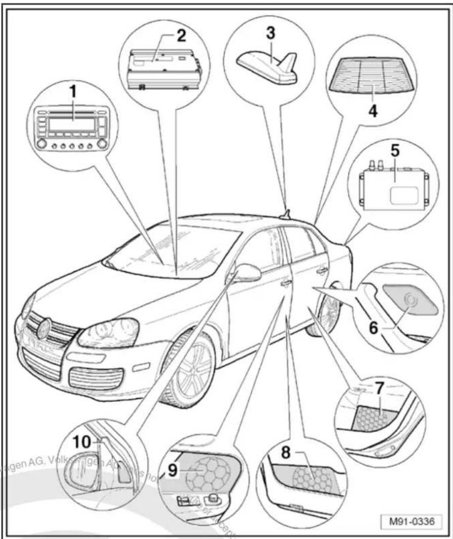
The communication systems include the radio systems, the navigation system, the aerial system, the loudspeaker systems, the digital sound package, the telephone system, the CD changer, the compass system and the multifunction steering wheel.
Some equipment is optional so not all systems are installed in every vehicle.
When dealing with complaints, it is absolutely necessary to understand the functions and the operation of the communication systems Instruction manual.
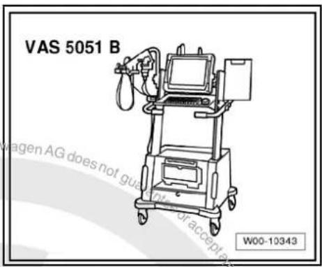
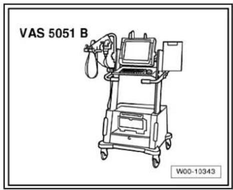
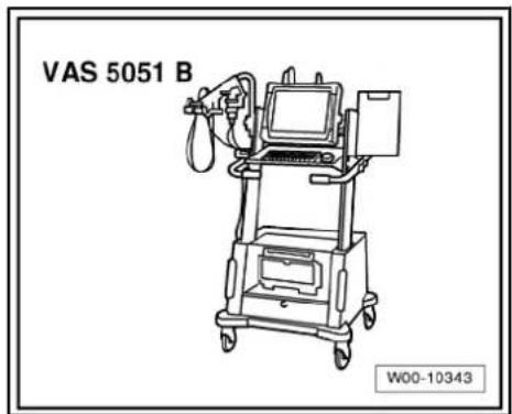
In the event of repair work or fault finding Vehicle diagnosis, testing and information system VAS 5051 use "Guided fault finding" mode.
1.1 Fault finding
The communication systems are self-diagnosing.
For fault finding, use the vehicle diagnosis, testing and information system -VAS 5051B- in "Guided fault finding" mode.

text_image
Protracted by copyright. Copyright granted commercial purposes, in part or in whole, is not permitted unless authorised by Volkswagen AG. Volkswagen AG does not guarantee or accept any liability with respect to the correctness of information in this document. Copyright by Volkswagen AG.2 Radio "Lowentry"
Radio Lowentry

Note
When dealing with complaints, it is absolutely necessary to understand the functions and the operation of the communication systems Instruction manual.
◆ The anti-theft coding system uses a fixed code. Deactivating → page 9.
In the event of repair work or fault finding Vehicle diagnosis, testing and information system VAS 5051.
When the battery -A- is reconnected, please remember to check vehicle equipment (radio, clock, convenience electronics, etc.) in accordance with the Electrical system; Rep. Gr. 27 workshop manual and/or the owner's manual.
text_image
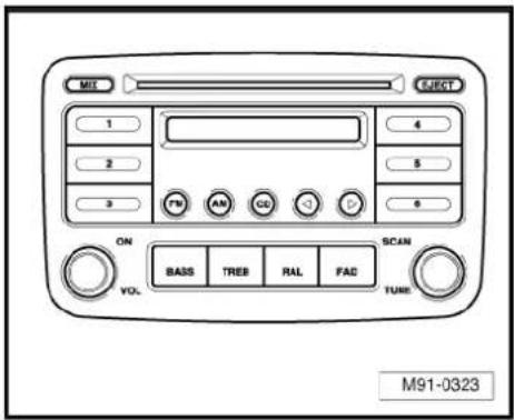
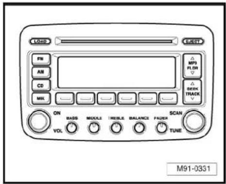
M91 EJECT 1 2 3 4 5 6 ON VOL BASS TREB RAL FAD SCAN TUBE M91-03232.1 General description
The "Lowentry" radio system consists of the radio -R- and the loudspeakers in the doors.
The radio -R- has a final output stage with an output power of 4 x 20 W.
The loudspeakers are designed as a 3-way system in the front and as a 2-way system in the rear.
The following is installed in the "Lowentry" radio system:
◆ A bass loudspeaker, a mid-range loudspeaker and a treble loudspeaker in each of the front doors.
◆ A bass loudspeaker and a treble loudspeaker in each of the rear doors.
The CD drive integrated in the radio -R- can play the following formats:
◆ Audio CD
◆ CD-R
◆ CD-RW
◆ MP3
The following formats cannot be played:
◆ CD with diameter of 8 cm
◆ “Mixed CD” (CD with data and audio files)
The aerial is a window aerial and is located in the rear window (saloon). In the Variant, the aerial is located in the roof aerial.
2.1.1 Fault finding
The radio -R- is equipped with self-diagnosis.
For fault finding, use the vehicle diagnosis, testing and information system -VAS 5051B- in "Guided fault finding" mode.

2.2 Overview of radio "Lowentry"
1 - Radio -R-
□ Connectors
⇒ page 7
☐ Removing and installing
⇒ page 4
2 - Aerial -R11-
☐ Aerial systems (saloon)
⇒ page 171
☐ Aerial systems (Variant)
⇒ page 179
3 - Rear left treble loudspeaker -R14- / rear right treble loudspeaker -R16-
□ Installed in the rear left and right door trims
☐ Loudspeaker systems
⇒ page 106
4 - Rear left bass loudspeaker -R15- / rear right bass loudspeaker -R17-
□ Installed in the rear left and right door trims
☐ Loudspeaker systems
⇒ page 106
5 - Front left bass loudspeaker -R21- / front right bass loudspeaker -R23-
□ Installed in the front left and right door trims
☐ Loudspeaker systems
⇒ page 106
6 - Front left mid-range loudspeaker -R103- / front right mid-range loudspeaker -R104-
☐ Installed in the front left and right door trims
☐ Loudspeaker systems → page 106
7 - Front left treble loudspeaker -R20- / front right treble loudspeaker -R22-
☐ Installed in mirror triangle of the right and left front doors
☐ Loudspeaker systems => page 106

text_image
1 2 3 4 5 6 7 M91-03282.3 Removing and installing radio "Lowentry"

Note
◆ The part number for the radio -R- can be found on a sticker on the radio -R- housing.
If the radio -R- has to be renewed, deactivate the anti-theft coding system page 9. The new code number should be given to the customer.
If the anti-theft code is not known it can be requested via the established systems. For this, you need the identification number of the radio -R-. It is located on a sticker on the side of the radio -R-. The identification number is also embossed in the material of the side panel of the radio -R-.
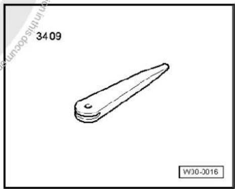
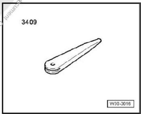
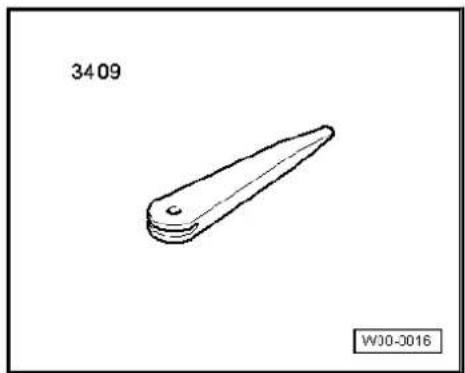
Special tools and workshop equipment required
◆ Removal wedge -3409-
natural_image
Simple line drawing of a mechanical part with no text or symbolsRemoving
- Remove CD from radio -R- Owner's manual.
- Switch off ignition and all electrical consumers and remove ignition key.
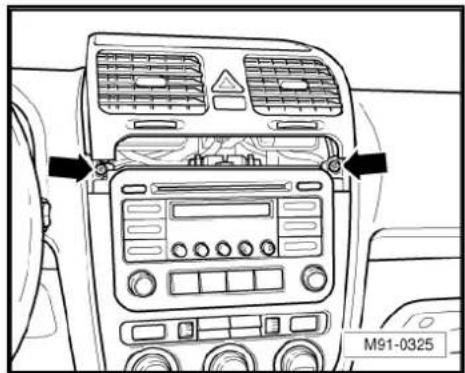
- Remove upper cover together with air vents out of the dash panel until the underneath bolts of the centre console cover can be reached, General body repairs, exterior; Rep. Gr. 68.
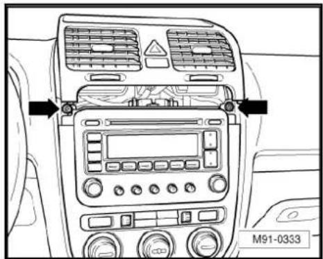
- Remove bolts -arrows- (1.5 Nm).
text_image
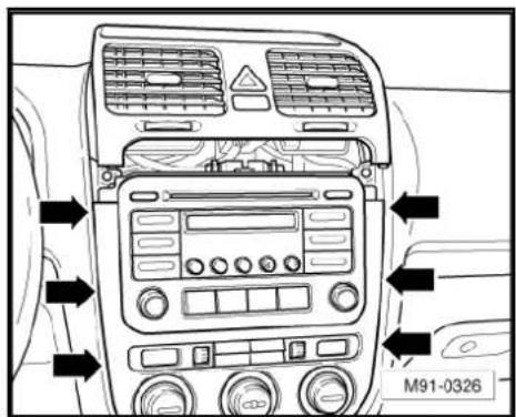
M91-0325- Carefully lever out cover of centre console using removal wedge -3409- -arrows- and take it off.
- Remove bolts -arrows- (1.5 Nm) on radio -R-.
- Pull the radio -R- out of the installation shaft until you can gain access to the connectors on the back of the radio -R-.
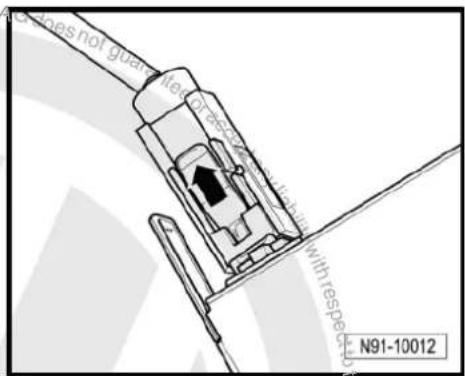
- Press together connector locking mechanism in direction of -arrows-.
- Then swing locking bar up in direction of -arrow- and disconnect connector.
text_image
M91-0326
text_image
M91-0327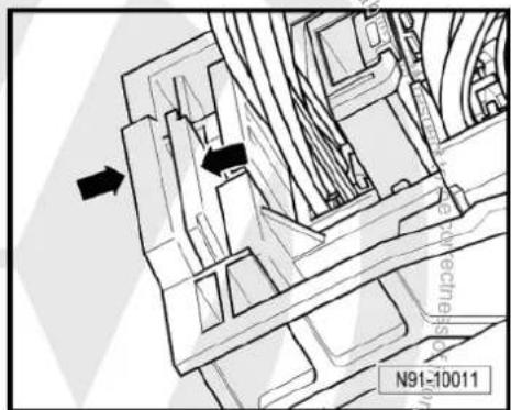
text_image
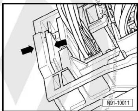
N91-10011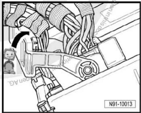
natural_image
Technical diagram of a mechanical assembly with no visible text or symbols- Release connector -arrow- on aerial connection and disconnect it.
Installing
- Fit connectors on the radio -R- and lock them.
- Push the radio -R- straight into the dash panel.

Note
Never press on the display or the operating buttons when fitting the radio -R-, as the radio -R- may be damaged.
- Fit the radio -R- with 4 bolts -arrows- (1.5 Nm).
- Install centre console cover.
- Deactivate anti-theft coding page 9.
- Check the radio -R- coding and recode the radio -R- page 10
text_image
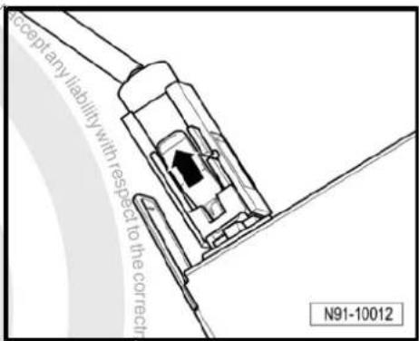
Accept any liability with respect to the correct N91-10012
text_image
M91-0327
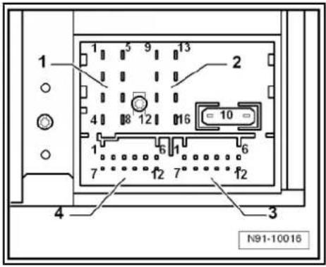
2.4 "Lowentry" connectors
1 - Multi-pin connector 1, 8-pin, loudspeaker outputs
☐ Pin assignment ⇒ page 7
2 - Multi-pin connector 2, 8-pin, CAN bus, telephone
☐ Pin assignment ⇒ page 8
3 - Multi-pin connector 3, 12-pin, telephone
☐ Pin assignment ⇒ page 8
4 - Multi-pin connector 4
□ Not assigned
5 - Aerial connection
☐ Connector colour, white
□ AM/FM
☐ Aerial systems (saloon)
⇒ page 171
☐ Aerial systems (Variant) ⇒ page 179
text_image
1 2 5 4 3 M91-03242.4.1 Multi-pin connector 1, 8-pin, loudspeaker outputs
1 - Rear right loudspeaker (+)
2 - Front right loudspeaker (+)
3 - Front left loudspeaker (+)
4 - Rear left loudspeaker (+)
5 - Rear right loudspeaker (-)
6 - Front right loudspeaker (-)
7 - Front left loudspeaker (-)
8 - Rear left loudspeaker (-)

text_image
1 2 3 4 N91-10015
2.4.2 Multi-pin connector 2, 8-pin, CAN bus, telephone
9 - CAN bus (high)
10 - CAN bus (low)
11 - Telephone mute
12 - Terminal 31
13 - Radio -R- on
14 - ATA terminal 30
15 - Terminal 30
16 - ATA (SAFE) terminal 30
2.4.3 Multi-pin connector 3, 12-pin, telephone
1-5 - Not assigned
6 - Telephone LF input signal (-)
7-11 - Not assigned
12 - Telephone LF input signal (+)
text_image
1 2 3 4 N91-10016
text_image
1 2 3 4 5 9 13 16 10 6 7 12 7" 12 4 Guarantee for acceptance N91-100162.5 Anti-theft coding
The "Lowentry" radio -R- is equipped with an anti-theft coding system which works in conjunction with the dash panel insert.
If the voltage supply for the radio -R- is disconnected and then reconnected, the radio will be still operational without the need to enter the anti-theft code again. A prerequisite is that the initial activation of the anti-theft coding takes place and that the radio -R- is reconnected in the same vehicle.
2.5.1 Functional notes
After initial activation of the anti-theft coding, an internal radio code is stored in the radio -R- and in the dash panel insert. If the radio -R- is now disconnected from the voltage supply due to repairs (e.g. radio -R- or battery -A-) removed and the voltage supply is then reconnected, data is transferred between the radio -R- and the dash panel insert.
When this is done, the internal code of the radio -R- is compared with the code in the dash panel insert. If the codes are identical with each other, the dash panel insert will recognise that the connected radio -R- belongs to the vehicle. The radio -R- is therefore immediately operational without the need to enter the anti-theft code again.
If the radio -R- is replaced, the radio code must be entered again.
Deactivating anti-theft coding page 9
Then after switching on the "S contact" via the ignition lock the code is automatically compared between the dash panel insert and the radio -R-.
Comparison takes approx. 5 seconds. It must be ensured that a diagnostic unit has not been connected or is not connected during this period of time.
After this time, the radio -R- of the vehicle will be ready for operation without the need to enter the radio code again even if the voltage supply has been cut off and then reconnected.
The anti-theft coding becomes effective and blocks the radio -R- when:
◆ The radio -R- is installed in another vehicle or
◆ The dash panel insert is changed.
A radio -R- which has been locked by the anti-theft coding is shown when "SAFE" and "1000" is shown in the display when switching the radio -R- on.
Deactivate the anti-theft coding to release the unit lock → page 9.
2.5.2 Deactivating anti-theft coding
A locked radio -R- will only work again if the correct radio code for the anti-theft coding system is entered.

Note
The anti-theft radio code is stuck on the radio card together with the unit number Instruction manual.
The radio card should not be kept in the vehicle for security reasons. Ask the customer for the radio code.
If a radio -R- is renewed, the numerical code of the replacement radio must be used.
◆ The customer must be informed that the radio code has changed.
- Obtain the code of the radio -R-.
- Switch on the radio -R-.

The radio -R- automatically displays "SAFE" and then "1000".
- Enter the radio code using station buttons 1 to 4. Use station button 1 to enter the first digit of the radio code and station 2 for the second digit etc.
- Then press the function button arrow and hold it down until the electronic anti-theft coding system is activated. This is indicated by a brief signal sound.
If the radio code has been entered correctly into the radio -R-, a radio frequency appears in the display.

Note
If an incorrect anti-theft code is entered, it can be immediately corrected with a further attempt. If an incorrect radio code is entered twice, the radio -R- will be blocked for one hour. During the locking period, the radio -R- must remain switched on and the ignition key must remain in the ignition lock. The process can then be repeated after one hour. Do not forget that only two attempts are allowed, after which the radio -R- will be blocked for one hour.
2.6 Adapting radio -R- components
Special tools and workshop equipment required
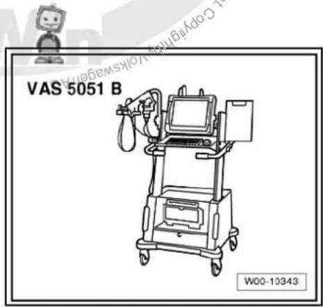
◆ Vehicle diagnostic, testing and information system -VAS 5051B-

text_image
VAS 5051 B W00-10343Procedure
- In vehicle diagnostic, testing and information system -VAS 5051B-, select "Guided fault finding".
- Using GoTo button, select "Functions/component" and the following menu options in succession:
Body
Electrical system
◆ 01 - On board diagnosis-capable systems
◆ Corresponding radio system
♦ Radio system functions

text_image
Protracted by copyright copyright granted AG LowerWen AG. Volkswagen AG does not guarantee or accept any liability with respect to the correctness of information in this document. Copyright by Volkswagen AG. Protracted by copyright granted AG.3 Radio "Premium 7"
Radio Premium 7

Note
When dealing with complaints, it is absolutely necessary to understand the functions and the operation of the communication systems. Instruction manual.
The anti-theft coding uses a fixed code, deactivating anti-theft coding page 19.
In the event of repair work or fault finding Vehicle diagnosis, testing and information system VAS 5051.
When the battery -A- is reconnected, please remember to check vehicle equipment (radio, clock, convenience electronics, etc.) in accordance with the Electrical system; Rep. Gr. 27 workshop manual and/or the instruction manual.
text_image
LOAD F& AM CO MIX ON VOL BASS MODULE IMBILE BALANCE FADEK TUNE EORTP MP3 FLOW SEEK TRACK SCAN M91-03313.1 General description
The radio system "Premium 7" comprises a radio -R-, an integrated 6-disc CD changer and loudspeakers in the doors.
The radio -R- has a final output stage with an output power of 4 x 20 W. The loudspeakers are designed as a 3-way system in the front and as a 2-way system in the rear.
The following is installed in the "Premium 7" radio system:
◆ A bass loudspeaker, a mid-range loudspeaker and a treble loudspeaker in each of the front doors.
◆ A bass loudspeaker and a treble loudspeaker in each of the rear doors.
To extend the functions, connection options are available for amplifier -R12-, telephone and satellite radio -R146-.
The 6-disc CD changer integrated in the radio -R- can play the following formats:
◆ Audio CD
◆ CD-R
◆ CD-RW
◆ MP3
The following formats cannot be played:
◆ CD with diameter of 8 cm
◆ “Mixed CD” (CD with data and audio files)
The aerial is a window aerial and is located in the rear window (saloon). In the Variant, the aerials are located in the rear right side window and in the roof aerial. The aerial system includes a "diversity function" integrated in the radio -R-.
3.1.1 Fault finding
The radio -R- is equipped with self-diagnosis.
For fault finding, use the vehicle diagnosis, testing and information system -VAS 5051B- in "Guided fault finding" mode.
3.2 Overview of radio "Premium 7"
1 - Radio -R-
Connectors page 16
☐ Removing and installing
⇒ page 13
2 - Amplifier -R12-
Optional
□ Under left front seat
☐ Amplifier -R12- page 100.
3 - Satellite tuner aerial -R172-
Optional
On roof rear side
☐ Aerial systems (saloon)
⇒ page 171
☐ Aerial systems (Variant) ⇒ page 179
4 - Aerial -R11- / Radio aerial 2 -R93-
☐ Aerial systems (saloon) ⇒ page 171
☐ Aerial systems (Variant) ⇒ page 179
5 - Satellite radio -R146-
Optional
☐ Under rear shelf in luggage compartment (sa-loon).
☐ Under right front seat (Variant).
☐ Satellite radio -R146-→ page 117.
text_image
1 2 3 4 5 6 7 8 9 10 M91-03366 - Rear left treble loudspeaker -R14- / rear right treble loudspeaker -R16-
☐ Installed in the rear left and right door trims
☐ Loudspeaker systems page 106
7 - Rear left bass loudspeaker -R15- / rear right bass loudspeaker -R17-
☐ Installed in the rear left and right door trims.
☐ Loudspeaker systems page 106.
8 - Front left bass loudspeaker -R21- / front right bass loudspeaker -R23-
□ Use Installed in the front left and right door trims
☐ Loudspeaker systems ⇒ page 106.
9 - Front left mid-range loudspeaker -R103- / front right mid-range loudspeaker -R104-
☐ Installed in the front left and right door trims
☐ Loudspeaker systems → page 106.
10 - Front left treble loudspeaker -R20- / front right treble loudspeaker -R22-
☐ Installed in mirror triangle of the right and left front doors
☐ Loudspeaker systems page 106.

3.3 Removing and installing radio "Premium 7"

Note
◆ The part number for the radio -R- can be found on a sticker on the radio -R- housing.
If the radio -R- has to be renewed, deactivate the electronic anti-theft coding system page 19. Please inform the customer of the new radio code.
If the radio code is not known, it can be requested via the established systems. For this, you need the identification number of the radio -R-. It is located on a sticker on the side of the radio -R-. The identification number is also embossed in the material of the side panel of the radio -R-.
Special tools and workshop equipment required
◆ Removal wedge -3409-

text_image
3409 with respect to the corners of information WJ0-2016Removing
- Remove CD from radio -R- Owner's manual.
- Switch off ignition and all electrical consumers and remove ignition key.
- Remove upper cover together with air vents out of the middle of the dash panel until the underneath bolts of the centre console cover can be reached, General body repairs, exterior; Rep. Gr. 68.
- Remove bolts -arrows- (1.5 Nm).
text_image
M91-0333- Carefully lever out cover of centre console using removal wedge -3409- -arrows- and take it off.
text_image
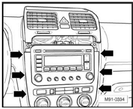
M91-0334- Remove bolts -arrows- (1.5 Nm) on radio -R-.
- Pull the radio -R- out of the installation shaft until you can gain access to the connectors on the back of the radio -R-.

text_image
M91-0335- Press together connector locking mechanism in direction of -arrows-.
natural_image
Technical diagram of a mechanical assembly with directional arrows and part number N91-10011 (no readable text or symbols)- Then swing locking bar up in direction of -arrow- and disconnect connector.
natural_image
Mechanical assembly diagram showing car wheel connections and a belt switch (no text or symbols)- Release connectors -arrows- from aerial connections and disconnect them.
Installing
- Fit connectors on the radio -R- and lock them.
- Push the radio -R- straight into the dash panel.

Note
Never press on the display or the operating buttons when fitting the radio -R-, as the radio -R- may be damaged.
- Fit the radio -R- with 4 bolts -arrows- (1.5 Nm).
- Install centre console cover.
- Deactivate the anti-theft coding page 19.
- Check the radio -R- coding and recode the radio -R- page 19.

natural_image
Technical line drawing of two electrical connectors with upward arrows, mounted on a support structure (no text or symbols)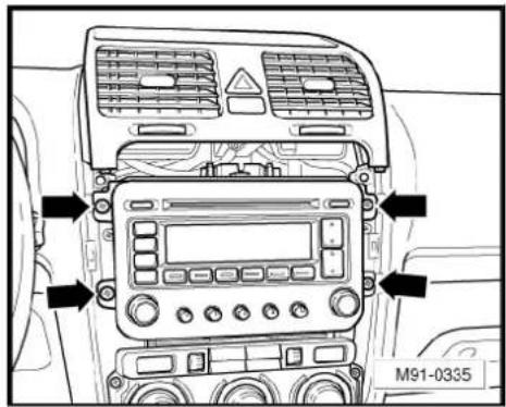
text_image
M91-0335
text_image
Volkswagen AG. Volkswagen AG does not guarantee or accept any liability with respect to the correctness of information in this document. Copyright by Volkswagen AG. Protected by copyright Creative Commercial purposes, in part or in whole, is not permitted unless authorised by Volkswagen AG.3.4 "Premium 7" connectors
1 - Multi-pin connector 1, 8-pin, loudspeaker outputs
☐ Pin assignment ⇒ page 16
2 - Multi-pin connector 2, 8-pin, CAN bus, telephone
☐ Pin assignment ⇒ page 17
3 - Multi-pin connector 3, 12-pin, telephone
☐ Pin assignment ⇒ page 17
4 - Multi-pin connector 4, 12-pin, satellite radio -R146-
☐ Pin assignment ⇒ page 17
5 - Aerial connection
☐ Connector colour beige
☐ Pin assignment ⇒ page 18
6 - Aerial connection
☐ Connector colour transparent
☐ Pin assignment ⇒ page 18

text_image
Proteled by copyright. Copying for principle. Copyright by Volkswagen AG. M91-0332 1 2 6 5 4 3 is not permitted unless authorised by Volkswagen AG. Volkswagen AG does not guarantee or accept any liability with respect to the correctness of information in this decumenal. Copyright by Volkswagen AG.3.4.1 Multi-pin connector 1, 8-pin, loudspeaker outputs
In combination with amplifier -R12-, audio signals from radio -R- are used as input signals for amplifier -R12-.
1 - Rear right loudspeaker (+)
2 - Front right loudspeaker (+)
3 - Front left loudspeaker (+)
4 - Rear left loudspeaker (+)
5 - Rear right loudspeaker (-)
6 - Front right loudspeaker (-)
7 - Front left loudspeaker (-)
8 - Rear left loudspeaker (-)

text_image
1 2 4 8 12 16 = 10 = 1 6 1 6 7 12 7 12 4 3 N91-100163.4.2 Multi-pin connector 2, 8-pin, CAN bus, telephone
9 - CAN bus (high)
10 - CAN bus (low)
11 - Telephone mute
12 - Terminal 31
13 - Radio -R- on
14 - ATA terminal 30
15 - Terminal 30
16 - ATA (SAFE) terminal 30
3.4.3 Multi-pin connector 3, 12-pin, telephone
1-5 - Not assigned
6- Telephone LF input signal (-)
7-11 - Not assigned
12 - Telephone LF input signal (+)
3.4.4 Multi-pin connector 4, 12-pin, satellite radio -R146-
1 - Audio left from satellite radio -R146-
2 - Not assigned
3 - Audio earth from satellite radio -R146-
4 - Not assigned
5 - Terminal 30 to satellite radio -R146-
6 - Not assigned
7 - Audio right from satellite radio -R146-
8 - 12 - Not assigned

text_image
1 2 3 4 N91-10016
text_image
1 2 3 4 5 9 13 6 12 16 = 10 = 7 12 7 12 N91-10016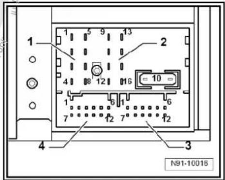
text_image
1 2 3 4 N91-100153.4.5 Aerial connections
1 - Connector colour white, saloon aerial systems page 171
- Connector colour white, Variant aerial systems page 179
2 - Connector colour beige, saloon aerial systems ⇒ page 171
- Connector colour beige, Variant aerial systems page 179

Note
The radio -R- has an aerial diversity function for terrestrial radio reception. Both aerial connections are signal inputs. The radio -R- analyses continuously which of the two connected aerials transmits the better reception signal. The aerial with the better reception signal is then selected. This switching process is not audible.
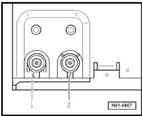
text_image
N91-04673.5 Electronic anti-theft coding
The "Premium 7" radio -R- is equipped with an electronic anti-theft coding system which works in conjunction with the dash panel insert.
If the voltage supply for the radio -R- is cut off and then reconnected, the radio will still be operational without the need to enter the radio code again. A prerequisite is that the electronic anti-theft coding system has already been activated for the first time and that the radio -R- is reconnected in the same vehicle.
3.5.1 Functional notes
After initial activation of the anti-theft coding, an internal radio code is stored in the radio -R- and in the dash panel insert. If the radio -R- is now disconnected from the voltage supply due to repairs (e.g. radio -R- or battery -A-) removed and the voltage supply is then reconnected, data is transferred between the radio -R- and the dash panel insert.
When this is done, the internal code of the radio -R- is compared with the code in the dash panel insert. If the codes are identical with each other, the dash panel insert will recognise that the connected radio -R- belongs to the vehicle. The radio -R- is therefore immediately operational without the need to enter the anti-theft code again.
If the radio -R- is replaced, the radio code must be entered.
Deactivating anti-theft coding → page 19
Then after switching on the "S contact" via the ignition lock the code is automatically compared between the dash panel insert and the radio -R-.
The comparison takes approx. 5 seconds. During this period no diagnostic unit may be connected.
After this time, the radio -R- of the vehicle will be ready for operation without the need to enter the radio code again even if the voltage supply has been cut off and then reconnected.
The anti-theft coding becomes effective and blocks the radio -R- when:
◆ The radio -R- is installed in another vehicle or
◆ The dash panel insert is changed.
A radio -R- which has been locked by the anti-theft coding is shown when "SAFE" and "1000" is shown in the display when switching the radio -R- on.
Deactivate the anti-theft coding to release the unit lock page 19.
3.5.2 Deactivating electronic anti-theft coding
A locked radio -R- will only work again if the correct radio code for the anti-theft coding system is entered.

Note
The anti-theft radio code is stuck on the radio card together with the unit number Instruction manual.
◆ The radio card should not be kept in the vehicle for security reasons. Ask the customer for the radio code.
If a radio -R- is renewed, the radio code of the replacement device must be used.
- The customer must be informed that the radio code has changed.
- Obtain the code of the radio -R-.
Switch on the radio -R-.
The radio -R- automatically displays "SAFE" and then "1000".
- Enter the radio code stuck on the radio card using station buttons 1 to 4. Use station button 1 to enter the first digit of the radio code and station 2 for the second digit etc.
- Then press the station button, which is located under "OK" on the display (normally it is the last station button) and hold the button down until the electronic anti-theft coding system is activated. This is indicated by a brief signal sound.
If the radio code has been entered correctly into the radio -R-, a radio frequency appears in the display.

Note
If the incorrect radio code is entered, it can be immediately corrected with a further attempt. If an incorrect radio code is entered twice, the radio -R- will be blocked for one hour. During the locking period, the radio -R- must remain switched on and the ignition key must remain in the ignition lock. The process of deactivating the anti-theft coding can then be repeated after one hour. Do not forget that only two attempts are allowed, after which the radio -R- will be blocked for one hour.
3.6 Adapting radio -R- components
Special tools and workshop equipment required
◆ Vehicle diagnosis, testing and information system -VAS 5051B-
text_image
VAS 5051 B W00-10343Procedure
- Select "guided fault finding" in the vehicle diagnosis, testing and information system -VAS 5051B-.
- Using GoTo button, select "Functions/component" and the following menu options in succession:
Body
Electrical system
◆ 01 - On board diagnosis-capable systems
◆ Corresponding radio system
♦ Radio system functions
4 Radio "Premium 8"
Radio Premium 8

Note
When dealing with complaints, it is absolutely necessary to understand the functions and the operation of the communication systems Instruction manual.
◆ The anti-theft coding uses a fixed code → page 77.
In the event of repair work or fault finding Vehicle diagnosis, testing and information system VAS 5051.
When the battery -A- is reconnected, please remember to check vehicle equipment (radio, clock, convenience electronics, etc.) in accordance with the Electrical system; Rep. Gr. 27 workshop manual and/or the owner's manual.
text_image
M91-100004.1 General description
The radio system "Premium 8" comprises a radio -R-, an integrated 6-disc CD changer and loudspeakers in the doors.
The radio -R- has a plug position for the use of SD storage cards for reproducing audio content and an output stage with 4 x 20 W output.
The loudspeakers are designed as a 3-way system in the front and as a 2-way system in the rear.
The radio system "Premium 8" is available in a version with loudspeakers operated via the 4 internal loudspeaker outputs or in a version with the amplifier -R12-. In this case, the loudspeakers are connected directly to the amplifier -R12- and the loudspeaker outputs of the radio -R- are used for amplifier -R12- input signals.
The following loudspeakers are installed with the radio system "Premium 8":
◆ A bass loudspeaker, a mid-range loudspeaker and a treble loudspeaker in each of the front doors.
◆ A bass loudspeaker and a treble loudspeaker in each of the rear doors.
To extend the functions, connection options are available for amplifier -R12-, CD changer -R41- and telephone.
An optional satellite radio -R146- is integrated into radio -R- "Premium 8".
The integrated 6-disc CD changer can play the following formats:
◆ Audio CD
◆ CD-R
◆ CD-RW
◆ MP3
The following formats cannot be played:
◆ CD with diameter of 8 cm
◆ “Mixed CD” (CD with data and audio files)

Note
The internal CD changer has a transport protection device which must be deactivated before installing a new radio -R-. The transport protection device must also be switched on before shipping a removed radio -R-. For this, the Radio -R- must still be connected to the voltage supply.
The aerial is a window aerial and is located in the rear window (saloon). In the Variant, the aerials are located in the rear side windows and in the roof aerial. The aerial system includes a "diversity function" integrated in the radio -R-.
4.1.1 Fault finding
The radio -R- is equipped with self-diagnosis.
For fault finding, use the vehicle diagnosis, testing and information system -VAS 5051B- in "Guided fault finding" mode.
4.2 Overview of radio "Premium 8"
1 - Radio -R-
☐ Connectors
⇒ page 26
☐ Activating and deactivating transport protection device → page 28
□ Removing and installing
⇒ page 23.
2 - Amplifier -R12-
□ Optional
□ Under left front seat
☐ Amplifier -R12-→ page 100.
3 - Multimedia system control unit -J650-
□ Optional
In centre console
☐ Multimedia system control unit -J650-→ page 95
☐ CD changer -R41-→ page 79
☐ Connection for external audio sources -R199-→ page 91
4 - Satellite tuner aerial -R172-
Roof aerial.
☐ Aerial systems (saloon) ⇒ page 171.
☐ Aerial systems (Variant) ⇒ page 179.
☐ Aerial systems in saloons from model year 2011 → page 179

text_image
1 2 3 4 5 6 7 8 9 10 PROCEDURE CAPRINQUITY PROCEED BY CAPRINQUITY PROPOSED CAPRINQUITY VOLKSWAGE M91-100015 - Aerial -R11- / Radio aerial 2 -R93-
☐ Aerial systems (saloon) ⇒ page 171.
☐ Aerial systems (Variant) ⇒ page 179.
☐ Aerial systems in saloons from model year 2011 → page 179
6 - Rear left treble loudspeaker -R14- / rear right treble loudspeaker -R16-
☐ Installed in the rear left and right door trims.
☐ Loudspeaker systems page 106.
7 - Rear left bass loudspeaker -R15- / rear right bass loudspeaker -R17-
☐ Installed in the rear left and right door trims
☐ Loudspeaker systems page 106
8 - Front left bass loudspeaker -R21- / front right bass loudspeaker -R23-
☐ Installed in the front left and right door trims
☐ Loudspeaker systems page 106
9 - Front left mid-range loudspeaker -R103- / front right mid-range loudspeaker -R104-
☐ Installed in the front left and right door trims
☐ Loudspeaker systems page 106
10 - Front left treble loudspeaker -R20- / front right treble loudspeaker -R22-
☐ Installed in mirror triangle of the right and left front doors
☐ Loudspeaker systems → page 106
4.3 Removing and installing radio "Premium 8"

Note
The part number for the radio -R- can be found on a sticker on the radio -R- housing.
If the radio -R- has to be renewed, deactivate the electronic anti-theft coding system page 29.
The integrated CD changer has a transport protection device which must be deactivated before installing a new radio -R-. The transport protection device must also be activated before shipping a removed radio -R-. For this, the radio -R- must still be connected to the voltage supply. Activating and deactivating transport protection device page 28.
Special tools and workshop equipment required
◆ Removal wedge -3409-
natural_image
Simple line drawing of a mechanical part with a pointed tip and rounded base, labeled '3409' and 'W00-0016' (no text or symbols on the object itself)Removing
- Remove CD from radio -R- Operating manual.
- Activate the transport protection device page 28.
- Switch off ignition and all electrical consumers and remove ignition key.
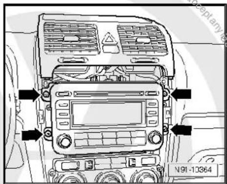
- Remove upper cover together with air vents out of the middle of the dash panel until the underneath bolts of the centre console cover can be reached, General body repairs, exterior; Rep. Gr. 68.
- Remove bolts -arrows- (1.5 Nm).

natural_image
Interior view of a car dashboard with air vent, control panel, and directional arrows (no text or symbols)- Carefully lever out cover of centre console using removal wedge -3409- -arrows- and take it off.

text_image
N91-10363- Remove bolts -arrows- (1.5 Nm) on radio -R- - Pull the radio -R- out of the installation shaft until you can gain access to the connectors on the back of the radio -R-.
text_image
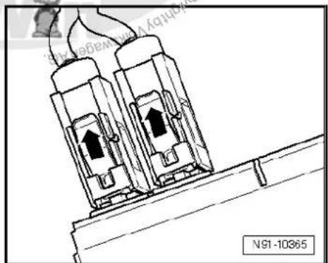
N91-10364- Press together connector locking mechanism in direction of -arrows-.

text_image
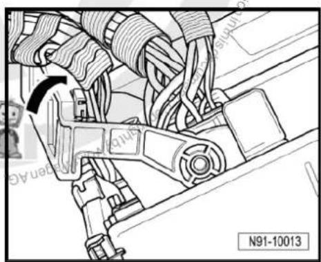
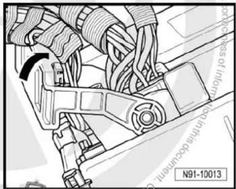
Svage AG does not with the inflow with the N91-10011- Then swing locking bar up indirection of -arrow- and pull out connectors.
text_image
N91-10013- Release connectors -arrows- of aerial connections and disconnect connectors.
natural_image
Technical line drawing of two electrical connectors with upward arrows, mounted on a support structure (no text or symbols)Installing
- Fit connectors on the radio -R- and lock them.
- Push the radio -R- straight into the dash panel.

Note
Never press on the display or the operating buttons when fitting the radio -R-, as the radio -R- may be damaged.
- Fit the radio -R- with 4 bolts -arrows- (1.5 Nm).
- Install centre console cover.
- Deactivate the anti-theft coding page 29.
- Deactivate the transport protection device page 28.
- Check the radio -R- coding and recode the radio -R- page 30.

text_image
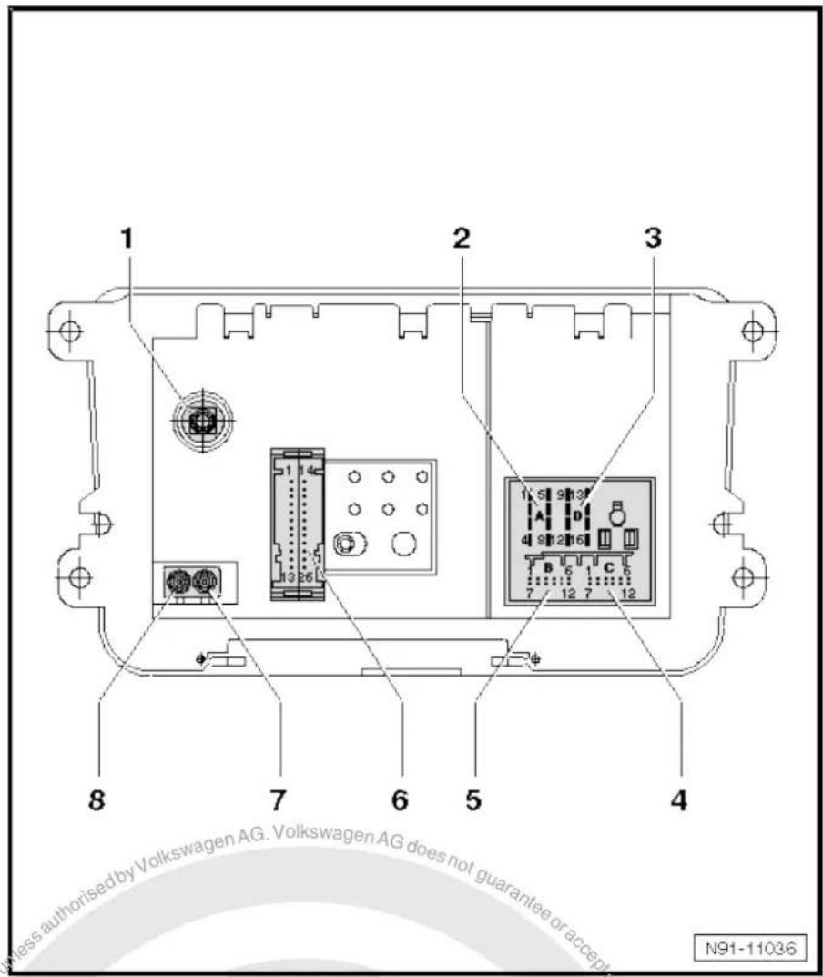
N91-103644.4 "Premium 8" connectors
1 - Aerial connection
☐ Connector colour, black
☐ SAT connection to roof aerial (saloon)
⇒ page 171.
☐ SAT connection to roof aerial (Variant)
⇒ page 179.
☐ Aerial systems in saloons from model year 2011 ⇒ page 179
2 - Multi-pin connector 1, 8-pin, loudspeaker outputs
☐ Pin assignment ⇒ page 27
3 - Multi-pin connector 2, 8-pin, CAN bus, telephone
☐ Pin assignment ⇒ page 27
4 - Multi-pin connector 3, 12-pin, telephone
☐ Pin assignment ⇒ page 27
5 - Multi-pin connector 4, 12-pin, CD changer -R41-
☐ Pin assignment ⇒ page 28
6 - Not fitted
7 - Aerial connection
☐ Connector colour, white
FM2
☐ Aerial systems (saloon) ⇒ page 171.
☐ Aerial systems (Variant) ⇒ page 179.
☐ Aerial systems in saloons from model year 2011 → page 179
8 - Aerial connection
☐ Connector colour, white
□ AM/FM
☐ Aerial systems (saloon) ⇒ page 171.
☐ Aerial systems (Variant) ⇒ page 179.
☐ Aerial systems in saloons from model year 2011 ⇒ page 179
text_image
1 2 3 8 7 6 5 4 N91-110364.4.1 Multi-pin connector 1, 8-pin, loudspeaker outputs
In combination with amplifier -R12-, audio signals from radio -R- are used as input signals for amplifier -R12-.
1 - Rear right loudspeaker (+)
2 - Front right loudspeaker (+)
3 - Front left loudspeaker (+)
4 - Rear left loudspeaker (+)
5 - Rear right loudspeaker (-)
6 - Front right loudspeaker (-)
7 - Front left loudspeaker (-)
8 - Rear left loudspeaker (-)

text_image
1 5 9 13 2 4 8 12 16 20 1 7 12 7 12 4 3 N91-109284.4.2 Multi-pin connector 2, 8-pin, CAN bus, telephone
9 - CAN bus (high)
10 - CAN bus (low)
11 - Telephone mute
12 - Terminal 31
13 - Not assigned
14 - Not assigned
15 - Terminal 30
16 - ATA (SAFE) terminal 30
4.4.3 Multi-pin connector 3, 12-pin, telephone
1–5 - Not assigned
6 - Telephone LF input signal (-)
7-11 - Not assigned
12 - Telephone LF input signal (+)

text_image
1 5 9 13 2 4 8 12 16 20 1 6 7 12 7 12 4 3 N91-10928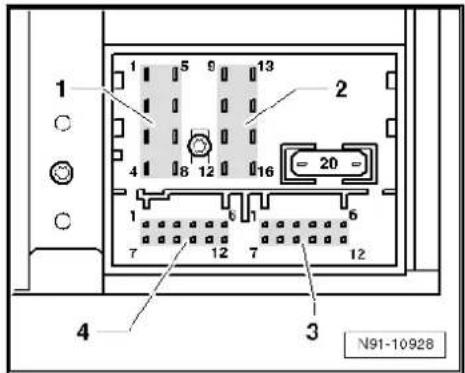
text_image
1 5 9 13 2 4 8 12 16 20 1 6 7 12 7 12 4 3 N91-109284.4.4 Multi-pin connector 4, 12-pin, CD changer -R41-
1 - Audio input left (+)
2 - Audio input earth
3 - Audio earth from CD changer -R41-
4 - Terminal 30 to CD changer -R41-
5 - Not assigned
6 - CD data out to CD changer -R41-
7 - Audio input right (+)
8 - Audio left from CD changer -R41-
9 - Audio right from CD changer -R41-
10 - Control signal to CD changer -R41-
11 - CD data in from CD changer -R41-
12 - CD clock from CD changer -R41-

text_image
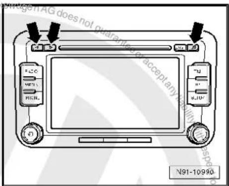
1 2 3 4 N91-109284.5 Activating and deactivating transport protection device
The transportation device must be activated before shipping a "Premium 8" and deactivated when installing a new radio -R-. This takes place electronically via the key pad of the radio -R-. When the transport protection device has been activated, the drive of the internal CD changer is brought to a "transport position".
Activating transport protection device:
Unit status: "ON" or "OFF". The radio -R- must be connected to the voltage supply.
- Press and hold keys marked with -arrows- simultaneously for at least 5 seconds.
Once the drive of the internal CD changer reaches the transport position, "CDC transport protection device activated" appears in the display.
Deactivating transport protection device:
- Connect and install the radio -R-
- Press and hold keys marked with -arrows- simultaneously for at least 5 seconds.
The following appears on the radio display: "CDC transport protection device activated".
A button with the word "Deactivate" is located under it.
- Press "Deactivate" button.
Transport protection device has now been deactivated.
text_image
Wage iAG does not guarantee accept any N91-10990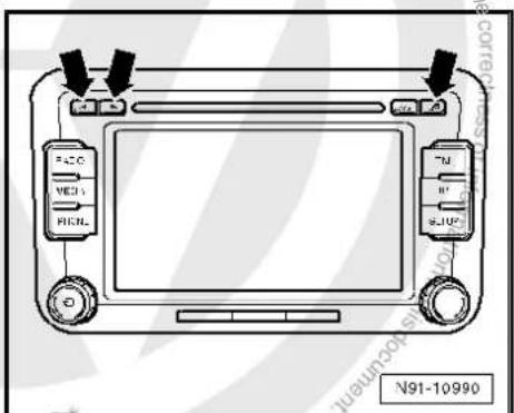
text_image
FAC MED HICNL TJ R JUP N91-109904.6 Electronic anti-theft coding
The radio -R- is equipped with an electronic anti-theft coding system which works in conjunction with the dash panel insert.
If the voltage supply for the radio -R- is cut off and then reconnected, the radio will still be operational without the need to enter the radio code again. A prerequisite is that the electronic anti-theft coding system has already been activated for the first time and that the radio -R- is reconnected in the same vehicle.
The radio code is determined by means of the vehicle diagnosis, testing and information system -VAS 5051B-. The radio card used in the past and the sticker on the radio -R- have been discontinued.

Note
In order to find out the numerical code, the vehicle diagnosis, testing and information system -VAS 5051B- must be connected "online" (network connection), and the user must possess valid rights to use the programme for requesting radio codes.
4.6.1 Deactivating electronic anti-theft coding
A locked radio -R- will only work again if the correct numerical code for the electronic anti-theft coding system is entered.
Using the VAS tester to find out the radio code:
- Select "guided fault finding" in the vehicle diagnosis, testing and information system -VAS 5051B-.
- Using GoTo button, select "Functions/component" and the following menu options in succession:
Body
Electrical system
◆ 01 - On board diagnosis-capable systems
◆ Corresponding radio system
◆ Radio system functions
◆ Radio code request

Your system rights are then determined. The operating data, the VIN and the unit number of the radio -R- are then read out automatically.

Note
When a new radio -R- is being installed, it is possible that the vehicle diagnosis, testing and information system -VAS 5051B-cannot read out the unit number of the radio -R-. In this case, please enter the unit number manually. It can be read on a sticker on the radio -R-unit and is also embossed on the side of the unit.
The radio code determined is then shown on the display of the vehicle diagnosis, testing and information system -VAS 5051B-.
The radio code must be entered in the radio -R- manually.
Deactivating anti-theft coding:
- Switch on the radio -R-.
An entry mask appears.
- Using the keypad, enter the right radio code in the entry mask.
- Confirm the entry by pressing the entry button.
The radio -R- will be released and is ready for use.

Note
If an incorrect radio code has been entered on deactivating the electronic lock, "SAFE" first flashes in the display, followed by "1000" again. The entire process can now be repeated again. The number of attempts is shown in the display. If an incorrect radio code is entered again, the radio -R- will be blocked for approx. one hour, i.e. it cannot be operated. This lock is indicated by the fact that "SAFE" is permanently shown in the display. The process of deactivating the anti-theft coding can then be repeated after one hour. Do not forget that only two attempts are allowed, after which the radio -R- will be blocked for one hour.
4.7 Adapting radio -R- components
Special tools and workshop equipment required
◆ Vehicle diagnosis, testing and information system -VAS 5051B-
text_image
VAS 5051 B W00-10343Procedure
- Select "guided fault finding" in the vehicle diagnosis, testing and information system -VAS 5051B-.
- Using GoTo button, select "Functions/component" and the following menu options in succession:
♦ Body
Electrical system
◆ 01 - On board diagnosis-capable systems
◆ Corresponding radio system
♦ Radio system functions
5 Radio system "RCD 210"
Radio RCD 210

Note
When dealing with complaints, it is absolutely necessary to understand the functions and the operation of the communication systems Instruction manual.
◆ The anti-theft coding uses a fixed code ⇒ page 37.
In the event of repair work or fault finding Vehicle diagnosis, testing and information system VAS 5051.
When the battery -A- is reconnected, please remember to check vehicle equipment (radio, clock, convenience electronics, etc.) in accordance with the Electrical system; Rep. Gr. 27 workshop manual and/or the instruction manual.

text_image
M91-04075.1 General description
The "RCD 210" radio system consists of the radio -R- and the loudspeakers in the doors.
The radio -R- has an output stage with 2 x 20 W output power; 4 x 20 W output power is also available as an option.
The loudspeakers are designed as a 2-way system. Depending on equipment, loudspeaker systems are installed in the front only (2 x 20 W) or front and rear (4 x 20 W).
The following is installed in the version with 2 x 20 W in the front doors:
◆ A bass loudspeaker, a mid-range loudspeaker and a treble loudspeaker on each side
In the version with 4 x 20 W, a bass loudspeaker and a treble loudspeaker are additionally installed in each rear door.
To extend the functionality, there is a connection for a CD changer -R41- and a telephone.
The CD drive integrated in the radio -R- can play the following formats:
◆ Audio CD
◆ CD-R
◆ CD-RW
◆ MP3

The following formats cannot be played:
◆ CD with diameter of 8 cm
◆ “Mixed CD” (CD with data and audio files)
The aerial is a window aerial and is located in the rear window (saloon). In the Variant, the aerial is located in the roof aerial. The aerial version comes without "diversity function".
5.1.1 Fault finding
The radio -R- is equipped with self-diagnosis.
For fault finding, use the vehicle diagnosis, testing and information system -VAS 5051B- in "Guided fault finding" mode.
5.2 Overview of radio system "RCD 210"
1 - Radio -R-
Connectors page 36
☐ Removing and installing
⇒ page 33
2 - Connection for external audio sources -R199-
In centre console
☐ Connection for external audio sources -R199-→ page 91
3 - Aerial -R11-
☐ Aerial systems (saloon) ⇒ page 171.
☐ Aerial systems (Variant) ⇒ page 179.
4 - Rear left treble loudspeaker -R14- / rear right treble loudspeaker -R16-
☐ Installed in the rear left and right door trims.
☐ Loudspeaker systems
⇒ page 106.
5 - Rear left bass loudspeaker -R15- / rear right bass loudspeaker -R17-
☐ Installed in the rear left and right door trims.
☐ Loudspeaker systems
⇒ page 106.
6 - Front left bass loudspeaker -R21- / front right bass loudspeaker -R23-
☐ Installed in the front left and right door trims
☐ Loudspeaker systems page 106.
7 - Front left mid-range loudspeaker -R103- / front right mid-range loudspeaker -R104-
☐ Installed in the front left and right door trims
☐ % Loudspeaker systems ⇒ page 106.
8 - Front left treble loudspeaker -R20- / front right treble loudspeaker -R22-
Installed in mirror triangle of the right and left front doors
Loudspeaker systems → page 106.
text_image
1 2 3 4 5 6 7 8 M91-04095.3 Removing and installing radio "RCD 210"

Note
◆ The part number for the radio -R- can be found on a sticker on the radio -R- housing.
If the radio -R- has to be renewed, deactivate the electronic anti-theft coding system page 38.
Special tools and workshop equipment required
◆ Removal wedge -3409-
natural_image
Simple line drawing of a mechanical part with a tapered end and rounded base, labeled '3409' and 'WJ0-0016' (no other text or symbols)Removing
- Remove CD from radio -R- Owner's manual.
- Switch off ignition and all electrical consumers and remove ignition key.
- Remove upper cover together with air vents out of the middle of the dash panel until the underneath bolts of the centre console cover can be reached, General body repairs, exterior; Rep. Gr. 68.
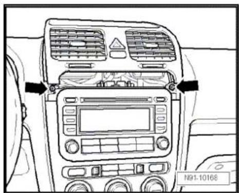
- Remove bolts -arrows- (1.5 Nm)

text_image
N91-10168
- Carefully lever out cover of centre console using removal wedge -3409- -arrows- and take it off.
- Remove bolts -arrows- (1.5 Nm) on radio -R-.
- Pull the radio -R- out of the installation shaft until you can gain access to the connectors on the back of the radio -R-.
- Press together connector locking mechanism in direction of -arrows-.
- Then swing locking bar up in direction of -arrow- and disconnect connector.

text_image
N91-10166
text_image
N91-10167
natural_image
Technical line drawing of a mechanical assembly with directional arrows (no text or symbols)
natural_image
Technical line drawing of a mechanical assembly with no visible text or symbols- Release connector -arrow- on aerial connection and pull it off. Installing
- Fit connectors on the radio -R- and lock them.
- Push the radio -R- straight into the dash panel.

Note
Never press on the display or the operating buttons when fitting the radio -R-, as the radio -R- may be damaged.
- Fit the radio -R- with 4 bolts -arrows- (1.5 Nm).
- Install centre console cover again.
- Deactivate the anti-theft coding page 38.
- Check the radio -R- coding and recode the radio -R- page 39.
text_image
Figures not guard Figure 3.1.1 with respect to N91-10012
text_image
N91-10167
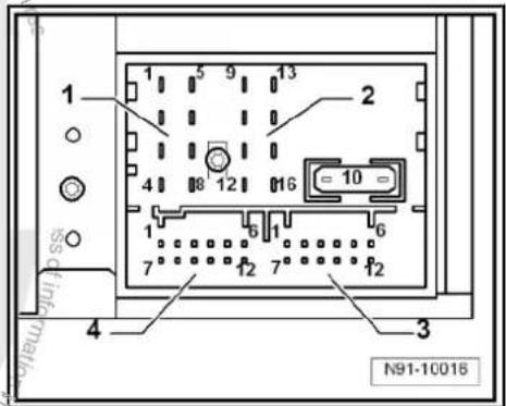
5.4 "RCD 210" connectors
1 - Aerial connection
☐ Connector colour, white
□ AM/FM
☐ Aerial system, saloon
⇒ page 171.
☐ Aerial system, Variant
⇒ page 179.
2 - Multi-pin connector 1, 8-pin, loudspeaker outputs
☐ Pin assignment ⇒ page 36
3 - Multi-pin connector 2, 8-pin, CAN bus, telephone
☐ Pin assignment ⇒ page 37
4 - Multi-pin connector 3, 12-pin, telephone
☐ Pin assignment ⇒ page 37
5 - Multi-pin connector 4, 12-pin, CD changer -R41-
☐ Pin assignment ⇒ page 37

text_image
1 2 3 4 5 M91-0405 Protracted copy screen Proteled by Uckswagen AG. Proteled by (G) smartly Uckswagen AG. Relation from dc using ability with respect to the correctness of or for pinable or cacc . M91-04055.4.1 Multi-pin connector 1, 8-pin, loudspeaker outputs
1 - Rear right loudspeaker (+)
2 - Front right loudspeaker (+)
3 - Front left loudspeaker (+)
4 - Rear left loudspeaker (+)
5 - Rear right loudspeaker (-)
6 - Front right loudspeaker (-)
7 - Front left loudspeaker (-)
8 - Rear left loudspeaker (-)

text_image
1 2 4 8 12 16 = 10 = 1 6 1 6 7 12 7 12 4 3 N91-100165.4.2 Multi-pin connector 2, 8-pin, CAN bus, telephone
9 - CAN bus (high)
10 - CAN bus (low)
11 - Telephone mute
12 - Terminal 31
13 - Not assigned
14 - Not assigned
15 - Terminal 30
16 - ATA (SAFE) terminal 30
5.4.3 Multi-pin connector 3, 12-pin, telephone
1–5 - Not assigned
6 - Telephone LF input signal (-)
7-11 - Not assigned
12 - Telephone LF input signal (+)
5.4.4 Multi-pin connector 4, 12-pin, CD changer -R41-
1 - Audio input left (+)
2 - Audio input earth
3 - Audio earth from CD changer -R41-
4 - Terminal 30 to CD changer -R41-
5 - Not assigned
6 - CD data out to CD changer -R41-
7 - Audio input right (+)
8 - Audio left from CD changer -R41-
9 - Audio right from CD changer -R41-
10 - Control signal to CD changer -R41-
11 - CD data in from CD changer -R41-
12 - CD clock from CD changer -R41-
5.5 Electronic anti-theft coding
The radio -R- is equipped with an electronic anti-theft coding system which works in conjunction with the dash panel insert.
If the voltage supply for the radio -R- is cut off and then reconnected, the radio will still be operational without the need to enter the radio code again. A prerequisite is that the electronic anti-theft coding system has already been activated for the first time and that the radio -R- is reconnected in the same vehicle.
The radio code is determined by means of the vehicle diagnosis, testing and information system -VAS 5051B-. The radio card
text_image
1 2 3 4 N91-10016
text_image
1 2 3 4 N91-10016
text_image
1 2 3 4 N91-10018used in the past and the sticker on the radio -R- have been discontinued.

Note
In order to find out the radio code, the vehicle diagnosis, testing and information system -VAS 5051B- must be connected "online" (network connection), and the user must possess valid rights to use the programme for requesting radio codes.
5.5.1 Deactivating electronic anti-theft coding
A locked radio -R- will only work again if the correct radio code for the anti-theft coding system is entered.
Using the VAS tester to find out the radio code:
- Select "guided fault finding" in the vehicle diagnosis, testing and information system -VAS 5051B-.
- Using GoTo button, select "Functions/component" and the following menu options in succession:
Body
Electrical system
◆ 01 - On board diagnosis-capable systems
◆ Corresponding radio system
♦ Radio system functions
◆ Radio code request

Your system rights are then determined. The operating data, the VIN and the unit number of the radio -R- are then read out automatically.

Note
When a new radio -R- is being installed, it is possible that the vehicle diagnosis, testing and information system -VAS 5051B-cannot read out the unit number of the radio -R-. In this case, please enter the unit number manually. It can be read off from the sticker affixed to the unit and is additionally stamped into the side of the unit.
The radio code determined is then shown on the display of the vehicle diagnosis, testing and information system -VAS 5051B-.
The radio code must be entered in the radio -R- manually.
Deactivating anti-theft coding:
- Switch on the radio -R-.
The word "SAFE" appears for approx. 10 seconds on the display and then number sequence "1000". - Enter the radio code by pressing the corresponding function buttons until the right number sequence appears.
After the four-digit radio code has been entered, "OK" appears on the display.
- Once you have entered the correct radio code, confirm it with the "OK" function button on the display.
The radio -R- will be released and is ready for use.

Note
If the incorrect radio code is entered, it can be immediately corrected with a further attempt. If an incorrect radio code is entered twice, the radio -R- will be blocked for one hour. Then leave the radio -R- and the ignition on. The process of deactivating the anti-theft coding can then be repeated after one hour. Do not forget that only two attempts are allowed, after which the radio -R- will be blocked for one hour.
5.6 Adapting radio -R- components
Special tools and workshop equipment required
◆ Vehicle diagnosis, testing and information system -VAS 5051B-
text_image
VAS 5051 B W00-10343Procedure
- Select "guided fault finding" in the vehicle diagnosis, testing and information system -VAS 5051B-.
- Using GoTo button, select "Functions/component" and the following menu options in succession:
Body
Electrical system
◆ 01 - On board diagnosis-capable systems
◆ Corresponding radio system
♦ Radio system functions

6 Radio system "RCD 300"
Radio RCD 300

Note
When dealing with complaints, it is absolutely necessary to understand the functions and the operation of the communication systems Instruction manual.
The anti-theft coding uses a fixed code, deactivating anti-theft coding page 47.
In the event of repair work or fault finding Vehicle diagnosis, testing and information system VAS 5051.
When the battery -A- is reconnected, please remember to check vehicle equipment (radio, clock, convenience electronics, etc.) in accordance with the Electrical system; Rep. Gr. 27 workshop manual and/or the instruction manual.
6.1 General description
The "RCD 300" radio system consists of the radio -R- and the loudspeakers in the doors.
The radio -R- has an output stage with 2 x 20 W output power; 4 x 20 W output power is also available as an option.
The loudspeakers are designed as a 3-way system in the front and as a 2-way system in the rear.
The following is installed in the version with 2 x 20 W in the front doors:
◆ A bass loudspeaker, a mid-range loudspeaker and a treble loudspeaker on each side
In the version with 4 x 20 W, a bass loudspeaker and a treble loudspeaker are additionally installed in each rear door.
To extend the functionality, there is a connection for a CD changer -R41- and a telephone.
The CD drive integrated in the radio -R- can play the following formats:
◆ Audio CD
◆ CD-R
◆ CD-RW
◆ MP3
The following formats cannot be played:
◆ CD with diameter of 8 cm
◆ "Mixed CD" (CD with data and audio files)
The aerial is a window aerial and is located in the rear window (saloon). In the Variant, the aerials are located in the rear right side window and in the roof aerial. The aerial system includes a "diversity function" integrated in the radio -R-.
6.1.1 Fault finding
The radio -R- is equipped with self-diagnosis.
For fault finding, use the vehicle diagnosis, testing and information system -VAS 5051B- in "Guided fault finding" mode.

text_image
N91-10'164
6.2 Overview of radio system "RCD 300"
1 - Radio -R-
Connectors page 45
☐ Removing and installing
⇒ page 42
2 - CD changer -R41-
6-pin
□ Below the hinged centre armrest
☐ CD changer -R41-→ page 79
3 - Aerial -R11- / Radio aerial 2 -R93-
☐ Aerial systems (saloon) ⇒ page 171.
☐ Aerial systems (Variant) ⇒ page 179.
4 - Rear left treble loudspeaker -R14- / rear right treble loudspeaker -R16-
☐ Installed in the rear left and right door trims.
☐ Loudspeaker systems
→ page 106.
5- Rear left bass loudspeaker -R15- / rear right bass loudspeaker -R17-
☐ Installed in the rear left and right door trims.
☐ Loudspeaker systems
⇒ page 106.
6 - Front left bass loudspeaker -R21- / front right bass loudspeaker -R23-
☐ Installed in the front left and right door trims
☐ Loudspeaker systems page 106.
7 - Front left mid-range loudspeaker -R103- / front right mid-range loudspeaker -R104-
☐ Installed in the front left and right door trims
☐ Loudspeaker systems page 106.
8- Front left treble loudspeaker -R20- / front right treble loudspeaker -R22-
☐ Installed in mirror triangle of the right and left front doors
☐ Loudspeaker systems → page 106.

text_image
1 2 3 4 5 6 7 8 M91-0385
6.3 Removing and installing radio "RCD 300"

Note
◆ The part number for the radio -R- can be found on a sticker on the radio -R- housing.
If the radio -R- has to be renewed, deactivate the electronic anti-theft coding system page 47. Please inform the customer of the new radio code.
If the radio code is not known, it can be requested via the established systems. For this, you need the identification number of the radio -R-. It is located on a sticker on the side of the radio -R-. The identification number is also embossed in the material of the side panel of the radio -R-.
Special tools and workshop equipment required
◆ Removal wedge -3409-

text_image
3409 WJ0-2016Removing
- Remove CD from radio -R- Owner's manual.
- Switch off ignition and all electrical consumers and remove ignition key.
- Remove upper cover together with air vents out of the middle of the dash panel until the underneath bolts of the centre console cover can be reached, General body repairs, exterior; Rep. Gr. 68.
- Remove bolts -arrows- (1.5 Nm).

natural_image
Line drawing of a car dashboard with air vent and control panel (no text or symbols)- Carefully lever out cover of centre console using removal wedge -3409- -arrows- and take it off.
- Remove bolts -arrows- (1.5 Nm) on radio -R-.
- Pull the radio -R- out of the installation shaft until you can gain access to the connectors on the back of the radio -R-.
- Press together connector locking mechanism in direction of -arrows-.
- Then swing locking bar up in direction of -arrow- and disconnect connector.

text_image
N91-10166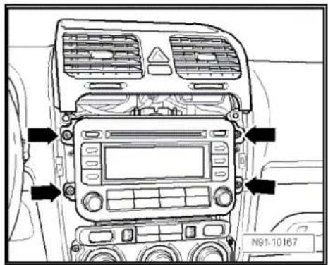
text_image
N91-10167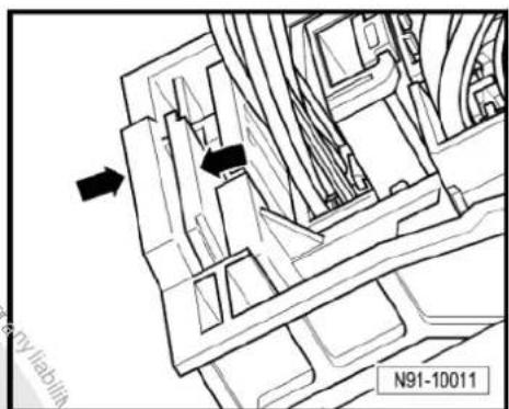
text_image
N91-10011
natural_image
Technical line drawing of a mechanical assembly with no visible text or symbols
- Release connectors -arrows- from aerial connections and disconnect them.
Installing
- Fit connectors on the radio -R- and lock them.
- Push the radio -R- straight into the dash panel.

Note
Never press on the display or the operating buttons when fitting the radio -R-, as the radio -R- may be damaged.
- Fit the radio -R- with 4 bolts -arrows- (1.5 Nm).
- Install centre console cover again.
- Deactivate the anti-theft coding page 47.
- Check the radio -R- coding and recode the radio -R- page 48.

natural_image
Technical line drawing of two electrical connectors with wires, no text or symbols present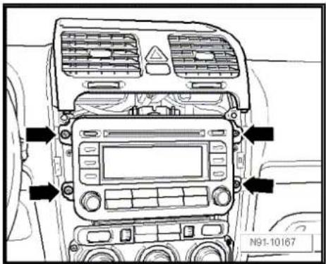
text_image
N91-10167
text_image
Protracted by copyright. Copyright for water commercial purposes, in part or in whole, is not permitted unless authorised by Volkswagen AG. Volkswagen AG does not guarantee or accept any liability with respect to the correctness of information in this document. Copyright by Volkswagen AG.6.4 "RCD 300" connectors
1 - Multi-pin connector 1, 8-pin, loudspeaker outputs
☐ Pin assignment ⇒ page 45
2 - Multi-pin connector 2, 8-pin, CAN bus, telephone
☐ Pin assignment ⇒ page 46
3 - Multi-pin connector 3, 12-pin, telephone
☐ Pin assignment ⇒ page 46
4 - Multi-pin connector 4, 12-pin, CD changer -R41-
☐ Pin assignment ⇒ page 46
5 - Aerial connection
☐ Connector colour beige
FM2
☐ Aerial system, saloon
⇒ page 171.
☐ Aerial system, Variant → page 179.
6 - Aerial connection
☐ Connector colour transparent
□ AM/FM
☐ Aerial system, saloon → page 171.
☐ Aerial system, Variant → page 179.

text_image
1 2 6 5 4 3 N91-101656.4.1 Multi-pin connector 1, 8-pin, loudspeaker outputs
1 - Rear right loudspeaker (+)
2 - Front right loudspeaker (+)
3 - Front left loudspeaker (+)
4 - Rear left loudspeaker (+)
5 - Rear right loudspeaker (-)
6. Front right loudspeaker (-)
7 - Front left loudspeaker (-)
8 - Rear left loudspeaker (-)
text_image
1 2 3 4 N91-10016
6.4.2 Multi-pin connector 2, 8-pin, CAN bus, telephone
9 - CAN bus (high)
10 - CAN bus (low)
11 - Telephone mute
12 - Terminal 31
13 - Not assigned
14 - Not assigned
15 - Terminal 30
16 - ATA (SAFE) terminal 30
6.4.3 Multi-pin connector 3, 12-pin, telephone
1-5 - Not assigned
6 - Telephone LF input signal (-)
7-11 - Not assigned
12 - Telephone LF input signal (+)
6.4.4 Multi-pin connector 4, 12-pin, CD changer -R41-
1 - Not assigned
2 - Audio earth from CD changer -R41-
3 - Not assigned
4 - Terminal 30 to CD changer -R41-
5 - Not assigned
6 - CD data out to CD changer -R41-
7 - Not assigned
8 - Audio left from CD changer -R41-
9 - Audio right from CD changer -R41-
10 - Control signal to CD changer -R41-
11 - CD data in from CD changer -R41-
12 - CD clock from CD changer -R41-
6.5 Electronic anti-theft coding
The radio -R- is equipped with an electronic anti-theft coding system which works in conjunction with the dash panel insert.
If the voltage supply for the radio -R- is cut off and then reconnected, the radio will still be operational without the need to enter the radio code again. A prerequisite is that the electronic anti-theft coding system has already been activated for the first time and that the radio -R- is reconnected in the same vehicle.

text_image
1 2 3 4 N91-10016
text_image
1 2 3 4 N91-10016
text_image
1 2 3 4 5 9 13 16 10 6 7 12 7 f12 N91-10016
6.5.1 Functional notes
After initial activation of the anti-theft coding, an internal radio code is stored in the radio -R- and in the dash panel insert. If the radio -R- is now disconnected from the voltage supply due to repairs (e.g. radio -R- or battery -A-) removed and the voltage supply is then reconnected, data is transferred between the radio -R- and the dash panel insert.
When this is done, the internal code of the radio -R- is compared with the code in the dash panel insert. If the codes are identical with each other, the dash panel insert will recognise that the connected radio -R- belongs to the vehicle. The radio -R- is therefore immediately operational without the need to enter the anti-theft code again.
If the radio -R- is replaced, the radio code must be entered.
Deactivating anti-theft coding page 47
Then after switching on the "S contact" via the ignition lock the code is automatically compared between the dash panel insert and the radio -R-.
Comparison takes approx. 5 seconds. It must be ensured that a diagnostic unit has not been connected or is not connected during this period of time.
After this time, the radio -R- of the vehicle will be ready for operation without the need to enter the radio code again even if the voltage supply has been cut off and then reconnected.
The anti-theft coding becomes effective and blocks the radio -R- when:
◆ The radio -R- is installed in another vehicle or
◆ The dash panel insert is changed.
A radio -R- which has been locked by the anti-theft coding is shown when "SAFE" and "1000" is shown in the display when switching the radio -R- on.
Deactivate the anti-theft coding to release the unit lock page 47.
6.5.2 Deactivating electronic anti-theft coding
A locked radio -R- will only work again if the correct radio code for the anti-theft coding system is entered.

Note
◆ The radio code is stuck on the radio card together with the unit number ⇒ Instruction manual.
The radio card should not be kept in the vehicle for security reasons. Ask the customer for the radio code.
If a radio -R- is renewed, the radio code of the replacement device must be used.
◆ The customer must be informed that the radio code has changed.
- Obtain the code of the radio -R-.
- Switch on the radio -R-.
The radio -R- automatically displays "SAFE" and then "1000".
Next to the four function buttons, the display shows the position of the radio code to be entered with an "X".
- Enter the code on the radio card in the correct sequence, using the four function buttons indicated. Press the relevant function button as many times as necessary until the correct number is shown in the centre of the display.
- Then press the function button next to the word "ENTER". The unit is then ready to operate again and switches to its last operating state.

Note
If you enter an incorrect radio code to deactivate the electronic lock, "SAFE" first flashes in the display, followed by "1000" again. The entire process can now be repeated again. The number of attempts is shown in the display. If an incorrect radio code is entered again, the radio -R- will be blocked for approx. one hour, i.e. it cannot be operated. This lock is indicated by the fact that "SAFE" is permanently shown in the display. The process of deactivating the anti-theft coding can then be repeated after one hour. Do not forget that only two attempts are allowed, after which the radio -R- will be blocked for one hour.
6.6 Adapting radio -R- components
Special tools and workshop equipment required
◆ Vehicle diagnosis, testing and information system-VAS 5051B-
natural_image
Line drawing of a medical device labeled VAS 5051 B, showing a cart with monitor and tubing (no readable text or symbols beyond label)Procedure
- Select "guided fault finding" in the vehicle diagnosis, testing and information system -VAS 5051B-.
- Using GoTo button, select "Functions/component" and the following menu options in succession:
Body
Electrical system
◆ 01 - On board diagnosis-capable systems
◆ Corresponding radio system
♦ Radio system functions
7 Radio system "RCD 310"
Radio RCD 310

Note
When dealing with complaints, it is absolutely necessary to understand the functions and the operation of the communication systems → Instruction manual.
◆ The anti-theft coding uses a fixed code → page 56
In the event of repair work or fault finding Vehicle diagnosis, testing and information system VAS 5051.
When the battery -A- is reconnected, please remember to check vehicle equipment (radio, clock, convenience electronics, etc.) in accordance with the Electrical system; Rep. Gr. 27 workshop manual and/or the instruction manual.
text_image
N91-110387.1 General description
The main features of the RCD 310 radio -R- are, among others, as follows:
◆ 4 x 20 watt loudspeaker channels
Monochrome display
◆ Control for external CD changer -R41-
◆ Telephone controls (hands-free system)
◆ Connection for external sound amplifier
◆ DAB operation possible
The "RCD 310" radio system consists of the radio -R- and the front and rear loudspeakers.
The CD drive integrated in the radio -R- can play the following CD formats:
◆ Audio CD
◆ CD-R
◆ CD-RW
◆ MP3
The following formats cannot be played:
◆ CD with diameter of 8 cm
◆ “Mixed CD” (CD with data and audio files)
The aerial is installed in the rear side windows. The aerial system includes a "diversity function" integrated in the radio -R-.
7.1.1 Fault finding
The radio -R- is equipped with self-diagnosis.
For fault finding, use the vehicle diagnosis, testing and information system -VAS 5051B- in "Guided fault finding" mode.
7.2 Overview of radio system "RCD 310"
1 - Radio -R-
Connectors page 54
☐ Removing and installing
⇒ page 51
2 - CD changer -R41-
Optional
In centre console
☐ CD changer -R41-→ page 79
3 - Multimedia system control unit -J650-
Optional
In centre console
☐ Multimedia system control unit -J650-→ page 95
4 - Connection for external audio sources -R199-
In centre console
☐ Connection for external audio sources -R199-→ page 91
5-Aerial -R11-/ Radio aerial 2 -R93-
Aerial systems (saloon) → page 171.
☐ Aerial systems (Variant)
page 179.
☐ Aerial systems in saloons from model year 2011 → page 179
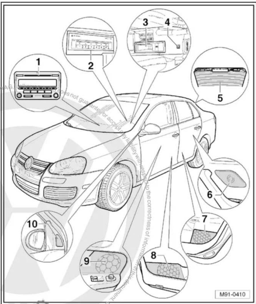
text_image
1 2 3 4 5 6 7 8 9 10 M91-04106 - Rear left treble loudspeaker
-R14- / rear right treble loudspeaker -R16-
☐ Installed in the rear left and right door trims
☐ Loudspeaker systems page 106
7 - Rear left bass loudspeaker -R15- / rear right bass loudspeaker -R17-
☐ Installed in the rear left and right door trims
☐ Loudspeaker systems page 106
8 - Front left bass loudspeaker -R21- / front right bass loudspeaker -R23-
☐ Installed in the front left and right door trims
☐ Loudspeaker systems page 106
9 - Front left mid-range loudspeaker -R103- / front right mid-range loudspeaker -R104-
☐ Installed in the front left and right door trims
☐ Loudspeaker systems page 106
10 - Front left treble loudspeaker -R20- / front right treble loudspeaker -R22-
☐ Installed in mirror triangle of the right and left front doors
☐ Loudspeaker systems page 106
7.3 Removing and installing radio "RCD 310"

Note
◆ The part number for the radio -R- can be found on a sticker on the radio -R- housing.
If the radio -R- has to be renewed, deactivate the electronic anti-theft coding system page 56.
Special tools and workshop equipment required
◆ Removal wedge -3409-
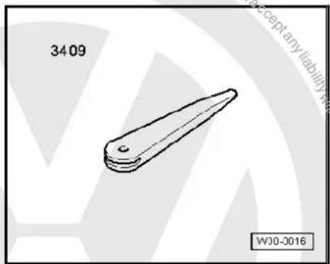
text_image
3409 WJ0-0016Removing
- Remove CD from radio -R- Owner's manual.
- Switch off ignition and all electrical consumers and remove ignition key.
- Remove upper cover together with air vents out of the middle of the dash panel until the underneath bolts of the centre console cover can be reached, General body repairs, exterior; Rep. Gr. 68.
- Remove bolts -arrows- (1.5 Nm).
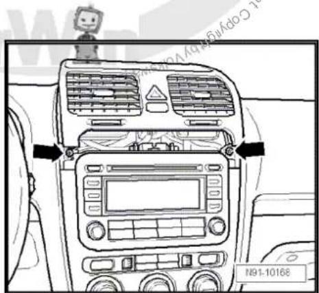
text_image
N91-10168- Carefully lever out cover of centre console using removal wedge -3409- -arrows- and take it off.
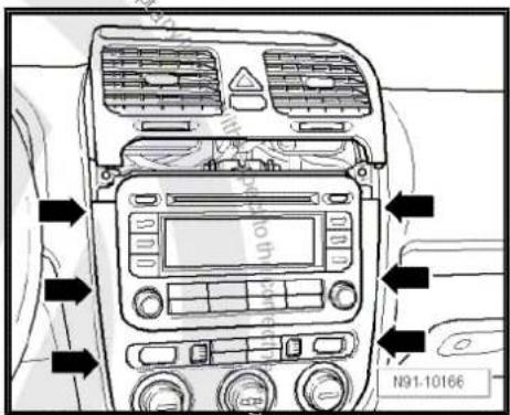
text_image
N91-10166- Remove bolts -arrows- (1.5 Nm).
- Pull the radio -R- out of the installation shaft until you can gain access to the connectors on the back of the radio.
text_image
N91-10167- Press together connector locking mechanism in direction of -arrows-.

natural_image
Technical line drawing of a mechanical assembly with directional arrows and part number N91-10011 (no readable text or symbols)- Then swing locking bar up in direction of -arrow- and disconnect connector.
natural_image
Mechanical assembly diagram showing hoses and brackets (no text or symbols)- Release connectors -arrows- of aerial connections and disconnect connectors.
Installing
- Fit connectors on radio -R-.
- Push radio -R- straight into the dash panel.

Note
Never press on the display or the operating buttons when fitting the radio -R- as the radio -R- may be damaged.
- Fit the radio -R- with 4 bolts -arrows- (1.5 Nm).
- Install centre console cover.
- Deactivate the anti-theft coding page 56.
- Check the radio -R-code and recode it page 57.

natural_image
Technical line drawing of two electrical connectors with upward arrows, mounted on a base (no text or symbols)
text_image
N91-10167
text_image
Volkswagen AG does not guarantee or accept any liability with respect to the correctness of information in this document. Copyright by Volkswagen AG. Copyright by Volkswagen AG.7.4 "RCD 310" connectors
1 - Aerial connection
☐ Connector colour, black
DAB
☐ Aerial system, saloon
⇒ page 171.
☐ Aerial system, Variant page 179.
☐ Aerial systems in saloons from model year 2011 → page 179
2 - Multi-pin connector 1, 8-pin, loudspeaker outputs
☐ Pin assignment ⇒ page 55
3 - Multi-pin connector 2, 8-pin, CAN bus, telephone
☐ Pin assignment ⇒ page 55
4 - Multi-pin connector 3, 12-pin, telephone
☐ Pin assignment ⇒ page 55
5 - Multi-pin connector 4, 12-pin, CD changer -R41-
☐ Pin assignment ⇒ page 56
6 - Aerial connection
☐ Connector colour, white
FM2
☐ Aerial system, saloon
⇒ page 171.
☐ Aerial system, Variant page 179.
☐ Aerial systems in saloons from model year 2011 ⇒ page 179
text_image
1 2 3 Volkswagen AG. Volkswagen AG does not guarantee one whole, is not permitted unless authorised by Commercial purposes, in part 1 S 9 3 A D 4 9 12 16 B 6 1 C 6 7 12 7 12 5 4 7 6 N91-110407 - Aerial connection
☐ Connector colour, white
□ AM/FM
☐ Aerial system, saloon ⇒ page 171.
☐ Aerial system, Variant page 179.
☐ Aerial systems in saloons from model year 2011 → page 179
7.4.1 Multi-pin connector 1, 8-pin, loudspeaker outputs
1 - Rear right loudspeaker (+)
2 - Front right loudspeaker (+)
3 - Front left loudspeaker (+)
4 - Rear left loudspeaker (+)
5 - Rear right loudspeaker (-)
6 - Front right loudspeaker (-)
7 - Front left loudspeaker (-)
8 - Rear left loudspeaker (-)
text_image
1 2 3 4 N91-109287.4.2 Multi-pin connector 2, 8-pin, CAN bus, telephone
9 - CAN bus (high)
10 - CAN bus (low)
11 - Telephone mute
12 - Terminal 31
13 - Not assigned
14 - Not assigned
15 - Terminal 30
16 - ATA (SAFE) terminal 30

text_image
1 5 9 13 4 8 12 16 20 1 7 12 7 12 4 3 N91-109287.4.3 Multi-pin connector 3, 12-pin, telephone
1–5 - Not assigned
6 - Telephone LF input signal (-)
7-11 - Not assigned
12 - Telephone LF input signal (+)


text_image
1 2 3 4 N91-109287.4.4 Multi-pin connector 4, 12-pin, CD changer -R41-
1 - Audio input left (+)
2 - Audio input earth
3 - Audio earth from CD changer -R41-
4 - Terminal 30 to CD changer -R41-
5 - Not assigned
6 - CD data out to CD changer -R41-
7 - Audio input right (+)
8 - Audio left from CD changer -R41-
9 - Audio right from CD changer -R41-
10 - Control signal to CD changer -R41-
11 - CD data in from CD changer -R41-
12 - CD clock from CD changer -R41-
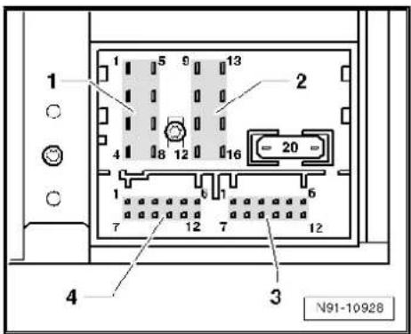
text_image
1 2 3 4 N91-109287.5 Electronic anti-theft coding
The radio -R- is equipped with an electronic anti-theft coding system which works in conjunction with the dash panel insert.
If the voltage supply for the radio -R- is cut off and then reconnected, the radio will still be operational without the need to enter the radio code again. A prerequisite is that the electronic anti-theft coding system has already been activated for the first time and that the radio -R- is reconnected in the same vehicle.
The radio code is determined by means of the vehicle diagnosis, testing and information system -VAS 5051B-. The radio card used in the past and the sticker on the radio -R- have been discontinued.

Note
In order to find out the radio code, the vehicle diagnosis, testing and information system -VAS 5051B- must be connected "online" (network connection), and the user must possess valid rights to use the programme for requesting radio codes.
7.5.1 Deactivating electronic anti-theft coding
A locked radio -R- will only work again if the correct radio code for the anti-theft coding system is entered.
Using the VAS tester to find out the radio code:
- Select "guided fault finding" in the vehicle diagnosis, testing and information system -VAS 5051B-.
- Using GoTo button, select "Functions/component" and the following menu options in succession:
♦ Body
Electrical system
◆ 01 - On board diagnosis-capable systems
◆ Corresponding radio system
♦ Radio system functions
♦ Radio code request
Your system rights are then determined. The operating data, the VIN and the unit number of the radio -R- are then read out automatically.

Note
When a new radio -R- is being installed, it is possible that the vehicle diagnosis, testing and information system -VAS 5051B-cannot read out the unit number of the radio -R-. In this case, please enter the unit number manually. It can be read on a sticker on the radio -R- and is also embossed on the radio -R-.
The radio code determined is then shown on the display of the vehicle diagnosis, testing and information system -VAS 5051B-.
The radio code must be entered in the radio -R- manually.
Deactivating anti-theft coding:
- Switch on the radio -R-.
The word "SAFE" appears for approx. 10 seconds on the display and then number sequence "1000".
- Enter the radio code by pressing the corresponding function buttons until the right number sequence appears.
After the four-digit radio code has been entered, "OK" appears on the display.
- Once you have entered the correct radio code, confirm it with the "OK" function button on the display.
The radio -R- will be released and is ready for use.

Note
If the incorrect radio code is entered, it can be immediately corrected with a further attempt. If an incorrect radio code is entered twice, the radio -R- will be blocked for one hour. Then leave the radio -R- and the ignition on. The process of deactivating the anti-theft coding can then be repeated after one hour. Do not forget that only two attempts to enter the code are allowed, after which the radio -R- will be blocked for one hour.
7.6 Adapting radio components "RCD 310"
Special tools and workshop equipment required
◆ Vehicle diagnostic, testing and information system -VAS 5051B-

natural_image
Line drawing of a medical device labeled VAS 5051 B, showing internal components and no readable text or symbols beyond label and identifier.Procedure
- In vehicle diagnostic, testing and information system -VAS 5051B-, select "Guided fault finding".
- Using GoTo button, select "Functions/component" and the following menu options in succession:
◆ Body
Electrical system
◆ 01 - On board diagnosis-capable systems
◆ Corresponding radio system
♦ Radio system functions

text_image
Protected by copyright rights. Copyrightilateral commercial purposes, in part or in whole, is not permitted. Copyright liability with respect to the correctness of information in this document. Copyright University of California, USA Protection of copyright law laws against Agg AG8 Radio system "RCD 500"
Radio RCD 500

Note
When dealing with complaints, it is absolutely necessary to understand the functions and the operation of the communication systems Instruction manual.
The anti-theft coding uses a fixed code, deactivating anti-theft coding page 67.
In the event of repair work or fault finding Vehicle diagnosis, testing and information system VAS 5051.
When the battery -A- is reconnected, please remember to check vehicle equipment (radio, clock, convenience electronics, etc.) in accordance with the Electrical system; Rep. Gr. 27 workshop manual and/or the instruction manual.
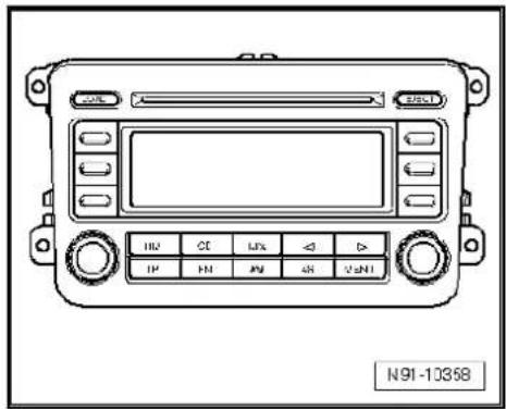
text_image
N91-103588.1 General description
The radio "RCD 500" consists of the radio -R-, the integrated 6-disc CD changer and the loudspeakers in the doors.
The radio -R- has a final output stage with an output power of 4 x 20 W. The loudspeakers are designed as a 3-way system in the front and as a 2-way system in the rear.
The radio system "RCD 500" is available in a version with loudspeakers operated via the 4 internal loudspeaker outputs or in a version with the amplifier -R12-. In this case, the loudspeakers are connected directly to the amplifier -R12- and the loudspeaker outputs of the radio -R- are used for amplifier -R12- input signals.
The following loudspeakers are installed with the radio system "RCD 500":
◆ A bass loudspeaker, a mid-range loudspeaker and a treble loudspeaker in each of the front doors.
◆ A bass loudspeaker and a treble loudspeaker in each of the rear doors.
To extend the functions, connection options are available for amplifier -R12-, CD changer -R41- and telephone.
The integrated 6-disc CD changer can play the following formats:
◆ Audio CD
◆ CD-R
◆ CD-RW
◆ MP3
The following formats cannot be played:
◆ CD with diameter of 8 cm
◆ "Mixed CD" (CD with data and audio files)


Note
The integrated CD changer has a transport protection device which must be deactivated before installing a new radio -R-. The transport protection device must also be activated before shipping a removed radio -R-. For this, the radio -R- must still be connected to the voltage supply.
The aerial is a window aerial and is located in the rear window (saloon). In the Variant, the aerials are located in the rear right side window and in the roof aerial. The aerial system includes a "diversity function" integrated in the radio -R-.
8.1.1 Fault finding
The radio -R- is equipped with self-diagnosis.
For fault finding, use the vehicle diagnosis, testing and information system -VAS 5051B- in "Guided fault finding" mode.
8.2 Overview of radio system "RCD 500"
1 - Radio -R-
Connectors page 64
☐ Activating and deactivating transport protection device → page 65
☐ Removing and installing
⇒ page 61
2 - CD changer -R41-
In centre console
☐ CD changer -R41-→ page 79
3 - Amplifier -R12-
Optional
□ Under left front seat
☐ Amplifier -R12- page 100.
4 - Aerial -R11- / Radio aerial 2 -R93-
☐ Aerial systems (saloon) → page 171.
☐ Aerial systems (Variant) ⇒ page 179.
5 - Rear left treble loudspeaker -R14- / rear right treble loudspeaker -R16-
☐ Installed in the rear left and right door trims.
☐ Loudspeaker systems
⇒ page 106.
6 - Rear left bass loudspeaker -R15- / rear right bass loudspeaker -R17-
☐ Installed in the rear left and right door trims.
☐ Loudspeaker systems page 106.

text_image
1 2 3 4 with respect to the correctness in 5 6 7 8 9 not rated by powering lot used unless authorised by Volkswagen AG. Volkswagen AG does not guarantee or accept any copyright or access M91-03847 - Front left bass loudspeaker -R21- / front right bass loudspeaker -R23-
☐ Installed in the front left and right door trims
☐ Loudspeaker systems page 106.
8 - Front left mid-range loudspeaker -R103- / front right mid-range loudspeaker -R104-
☐ Installed in the front left and right door trims
☐ Loudspeaker systems page 106.
9 - Front left treble loudspeaker -R20- / front right treble loudspeaker -R22-
☐ Installed in mirror triangle of the right and left front doors
☐ Loudspeaker systems ⇒ page 106.
8.3 Removing and installing radio "RCD 500"

Note
The part number for the radio -R- can be found on a sticker on the radio -R- housing.
If the radio -R- has to be renewed, deactivate the electronic anti-theft coding system page 67. Please inform the customer of the new radio code.
If the radio code is not known, it can be requested via the established systems. For this, you need the identification number of the radio -R-. It is located on a sticker on the side of the radio -R-. The identification number is also embossed in the material of the side panel of the radio -R-.
The CD changer in the radio -R- has a transport protection device which must be deactivated before installing a new radio -R-. The transport protection device must also be activated before shipping a removed radio -R-. For this, the Radio -R- must still be connected to the voltage supply. Activating and deactivating transport protection device page 65.
Special tools and workshop equipment required
◆ Removal wedge -3409-
natural_image
Simple line drawing of a mechanical part with no text or symbolsRemoving
- Remove CD from radio -R- Operating manual.
- Switch off ignition and all electrical consumers and remove ignition key.
-
Remove upper cover together with air vents out of the middle of the dash panel until the underneath bolts of the centre console cover can be reached, General body repairs, exterior; Rep. Gr. 68.
-
Remove bolts -arrows- (1.5 Nm).
- Carefully lever out cover of centre console using removal wedge -3409- -arrows- and take it off.
- Remove bolts -arrows- (1.5 Nm) on radio -R-.
- Pull the radio -R- out of the installation shaft until you can gain access to the connectors on the back of the radio -R-.
- Press together connector locking mechanism in direction of -arrows-.
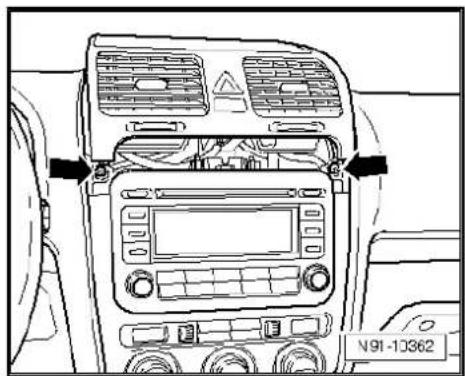
natural_image
Top-down line drawing of a car dashboard with air vent, control panel, and rear-mounted air conditioner (no text or symbols)
text_image
Volkswagen voltage at guarantee of N91-10363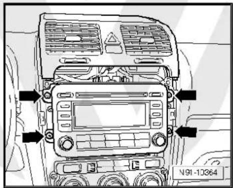
text_image
N91-10364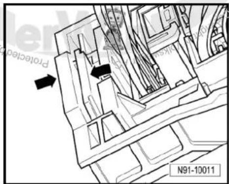
text_image
Protection N91-10011- Then swing locking bar up in direction of -arrow- and pull out connectors.
- Release connectors -arrows- of aerial connections and disconnect connectors.
Installing
- Fit connectors on the radio -R- and lock them.
- Push the radio -R- straight into the dash panel.

Note
Never press on the display or the operating buttons when fitting the radio -R-, as the radio -R- may be damaged.
- Fit the radio -R- with 4 bolts -arrows- (1.5 Nm).
- Install centre console cover.
- Deactivate the anti-theft coding page 66.
- Deactivate the transport protection device page 65.
- Check the radio -R- coding and recode the radio -R->page 67.


natural_image
Technical line drawing of a mechanical assembly with hoses and brackets (no text or symbols)
natural_image
Technical line drawing of two electrical connectors with upward arrows, mounted on a base (no text or symbols)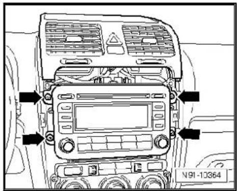
text_image
N91-103648.4 "RCD 500" connectors
1 - Multi-pin connector 1, 8-pin, loudspeaker outputs
☐ Pin assignment ⇒ page 64
2 - Multi-pin connector 2, 8-pin, CAN bus, telephone
☐ Pin assignment ⇒ page 65
3 - Multi-pin connector 3, 12-pin, telephone
☐ Pin assignment ⇒ page 65
4 - Multi-pin connector 4, 12-pin, CD changer -R41-
☐ Pin assignment ⇒ page 65
5 - Aerial connection
☐ Connector colour beige
FM2
☐ Aerial system, saloon ⇒ page 171.
☐ Aerial system, Variant ⇒ page 179.
6 - Aerial connection
☐ Connector colour transparent
□ AM/FM
☐ Aerial system, saloon ⇒ page 171.
☐ Aerial system, Variant → page 179.
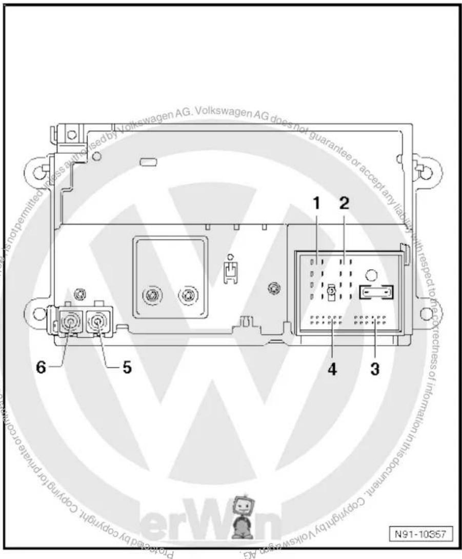
text_image
Volkswagen AG. Volkswagen AG does not guarantee or accept any liability is not permitted unless authorised by Volkswagen AG. 1 2 with respect to the correctness of information in this document. 6 5 4 3 Copyright by Volkswagen AG N91-103578.4.1 Multi-pin connector 1, 8-pin, loudspeaker outputs
In combination with amplifier -R12-, audio signals from radio -R- are used as input signals for amplifier -R12-.
1 - Rear right loudspeaker (+)
2 - Front right loudspeaker (+)
3 - Front left loudspeaker (+)
4 - Rear left loudspeaker (+)
5 - Rear right loudspeaker (-)
6 - Front right loudspeaker (-)
7 - Front left loudspeaker (-)
8 - Rear left loudspeaker (-)
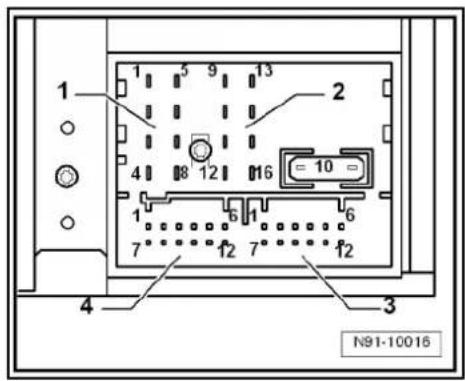
text_image
1 2 3 4 N91-100168.4.2 Multi-pin connector 2, 8-pin, CAN bus, telephone
9 - CAN bus (high)
10 - CAN bus (low)
11 - Telephone mute
12 - Terminal 31
13 - Not assigned
14 - Not assigned
15 - Terminal 30
16 - ATA (SAFE) terminal 30
8.4.3 Multi-pin connector 3, 12-pin, telephone
1-5 - Not assigned
6 - Telephone LF input signal (-)
7-11 - Not assigned
12 - Telephone LF input signal (+)


text_image
1 2 3 4 N91-10016
text_image
1 2 3 4 N91-100168.4.4 Multi-pin connector 4, 12-pin, CD changer -R41-
1 - Not assigned
2 - Audio earth from CD changer -R41-
3 - Not assigned
4 - Terminal 30 to CD changer -R41-
5 - Not assigned
6 - CD data out to CD changer -R41-
7 - Not assigned
8 - Audio left from CD changer -R41-
9 - Audio right from CD changer -R41-
10 - Control signal to CD changer -R41-
11 - CD data in from CD changer -R41-
12 - CD clock from CD changer -R41-

text_image
1 2 3 4 N91-100188.5 Activating and deactivating transport protection device
The transport protection device must be activated before shipping a "RCD 500" and deactivated before installing a new radio -R-. This takes place electronically via the key pad of the radio -R-. When the transport lock has been activated, the player of the CD changer is brought to a "transport position".
Activating transport protection device:
Unit status: "ON" or "OFF", wiring must be connected to the radio -R-.
- Press and hold keys marked with -arrows- simultaneously for at least 5 seconds.
The radio -R- unit display shows "TRANSPRT" when the player of the CD changer has moved into transport position.
Deactivating transport protection device:
- Connect and install the radio -R-.
- Press CANCEL key to deactivate transport protection device.
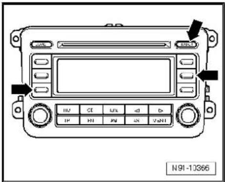
text_image
N91-103668.6 Electronic anti-theft coding
The radio -R- is equipped with an electronic anti-theft coding system which works in conjunction with the dash panel insert.
If the voltage supply for the radio -R- is cut off and then reconnected, the radio will still be operational without the need to enter the radio code again. A prerequisite is that the electronic anti-theft coding system has already been activated for the first time and that the radio -R- is reconnected in the same vehicle.
8.6.1 Functional notes
After initial activation of the anti-theft coding, an internal radio code is stored in the radio -R- and in the dash panel insert. If the radio -R- is now disconnected from the voltage supply due to repairs (e.g. radio -R- or battery -A-) removed and the voltage supply is then reconnected, data is transferred between the radio -R- and the dash panel insert.
When this is done, the internal code of the radio -R- is compared with the code in the dash panel insert. If the codes are identical with each other, the dash panel insert will recognise that the connected radio -R- belongs to the vehicle. The radio -R- is therefore immediately operational without the need to enter the anti-theft code again.
If the radio -R- is replaced, the radio code must be entered.
Deactivating anti-theft coding page 67
Then after switching on the "S contact" via the ignition lock the code is automatically compared between the dash panel insert and the radio -R-.
Comparison takes approx. 5 seconds. It must be ensured that a diagnostic unit has not been connected or is not connected during this period of time.
After this time, the radio -R- of the vehicle will be ready for operation without the need to enter the radio code again even if the voltage supply has been cut off and then reconnected.
The anti-theft coding becomes effective and blocks the radio -R- when:
◆ The radio -R- is installed in another vehicle or
◆ The dash panel insert is changed.
A radio -R- which has been locked by the anti-theft coding is shown when "SAFE" and "1000" is shown in the display when switching the radio -R- on.
Deactivate the anti-theft coding to release the unit lock page 67.
8.6.2 Deactivating electronic anti-theft coding
A locked radio -R- will only work again if the correct radio code for the anti-theft coding system is entered.

Note
The radio code is stuck on the radio card together with the unit number Instruction manual.
◆ The radio card should not be kept in the vehicle for security reasons. Ask the customer for the radio code.
If a radio -R- is renewed, the radio code of the replacement device must be used.
◆ The customer must be informed that the radio code has changed.
- Obtain the code of the radio -R-.
- Switch on the radio -R-.
The radio -R- automatically displays "SAFE" and then "1000".
Next to the four function buttons, the display shows the position of the radio code to be entered with an "X".
- Enter the radio code in the correct sequence, using the four function buttons indicated. Press the relevant function button as many times as necessary until the correct number is shown in the centre of the display.
- Then press the function button next to the word "ENTER". The radio -R- is ready for operation again and switches to the last operating mode.

Note
If you enter an incorrect radio code to deactivate the electronic lock, "SAFE" first flashes in the display, followed by "1000" again. The entire process can now be repeated again. The number of attempts is shown in the display. If an incorrect radio code is entered again, the radio -R- will be blocked for approx. one hour, i.e. it cannot be operated. This lock is indicated by the fact that "SAFE" is permanently shown in the display. The process of deactivating the anti-theft coding can then be repeated after one hour. Do not forget that only two attempts are allowed, after which the radio -R- will be blocked for one hour.
8.7 Adapting radio components "RCD 500"
Special tools and workshop equipment required
◆ Vehicle diagnostic, testing and information system -VAS 5051B-

text_image
VAS 5051 B W00-10343Procedure
- In vehicle diagnostic, testing and information system -VAS 5051B-, select "Guided fault finding".
- Using GoTo button, select "Functions/component" and the following menu options in succession:
◆ Body
Electrical system
◆ 01 - On board diagnosis-capable systems
◆ Corresponding radio system
♦ Radio system functions

text_image
s-capable systems stem Pre-teracted by copyright copyright granted commercial purposes, in part or in whole, is not permitted unless authorised by Volkswagen AG. Volkswagen AG does not guarantee a accept any liability with respect to the correctness of information in his current copyright law at a gap AG.9 Radio system "RCD 510"
Radio RCD 510

Note
When dealing with complaints, it is absolutely necessary to understand the functions and the operation of the communication systems Instruction manual.
◆ The anti-theft coding uses a fixed code ⇒ page 77.
In the event of repair work or fault finding Vehicle diagnosis, testing and information system VAS 5051.
When the battery -A- is reconnected, please remember to check vehicle equipment (radio, clock, convenience electronics, etc.) in accordance with the Electrical system; Rep. Gr. 27 workshop manual and/or the owner's manual.
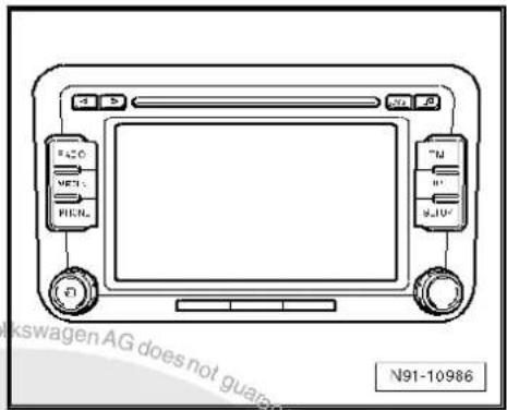
text_image
N91-109869.1 General description
The radio "RCD 510" consists of the radio -R-, the integrated 6-disc CD changer and the loudspeakers in the doors.
The radio -R- has a plug position for the use of SD storage cards for reproducing audio content and an output stage with 4 x 20 W output.
The loudspeakers are designed as a 3-way system in the front and as a 2-way system in the rear.
The radio system "RCD 510" is available in a version with loudspeakers operated via the 4 internal loudspeaker outputs or in a version with the amplifier -R12-. In this case, the loudspeakers are connected directly to the amplifier -R12- and the loudspeaker outputs of the radio -R- are used for amplifier -R12- input signals.
The following loudspeakers are installed with the radio system "RCD 510":
◆ A bass loudspeaker, a mid-range loudspeaker and a treble loudspeaker in each of the front doors.
◆ A bass loudspeaker and a treble loudspeaker in each of the rear doors.
To extend the functions, connection options are available for amplifier -R12-, CD changer -R41- and telephone.
The integrated 6-disc CD changer can play the following formats:
◆ Audio CD
◆ CD-R
◆ CD-RW
◆ MP3
The following formats cannot be played:
◆ CD with diameter of 8 cm
◆ "Mixed CD" (CD with data and audio files)


Note
The internal CD changer has a transport protection device which must be deactivated before installing a new radio -R-. The transport protection device must also be switched on before shipping a removed radio -R-. For this, the radio -R- must still be connected to the voltage supply.
The aerial is a window aerial and is located in the rear window (saloon). In the Variant, the aerials are located in the rear right side window and in the roof aerial. The aerial system includes a "diversity function" integrated in the radio -R-.
9.1.1 Fault finding
The radio -R- is equipped with self-diagnosis.
For fault finding, use the vehicle diagnosis, testing and information system -VAS 5051B- in "Guided fault finding" mode.
9.2 Overview of radio system "RCD 510"
1 - Radio -R-
Connectors
⇒ page 74
☐ Activating and deactivating transport protection device → page 76
☐ Removing and installing
⇒ page 71
2 - CD changer -R41-
□ Optional
In centre console
☐ CD changer -R41-→ page 79
3 - Multimedia system control unit -J650-
□ Optional
In centre console
☐ Multimedia system control unit -J650-→ page 95
4 - Connection for external audio sources -R199-
In centre console
☐ Connection for external audio sources -R199-→ page 91
5 - Amplifier -R12-
Optional
□ Under left front seat
☐ Amplifier -R12- page 100.
6 - Aerial -R11- / Radio aerial 2 -R93-
☐ Aerial systems (saloon) ⇒ page 171.
☐ Aerial systems (Variant) → page 179.
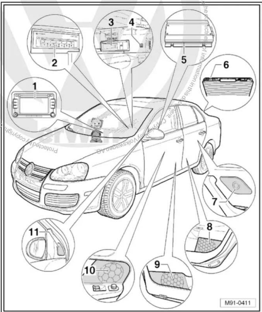
text_image
1 2 3 4 5 6 7 8 9 10 11 Protected by copyright M91-0411☐ Aerial systems in saloons from model year 2011 → page 179
7 - Rear left treble loudspeaker -R14- / rear right treble loudspeaker -R16-
☐ Installed in the rear left and right door trims
☐ Loudspeaker systems page 106
8 - Rear left bass loudspeaker -R15- / rear right bass loudspeaker -R17-
☐ Installed in the rear left and right door trims
☐ Loudspeaker systems → page 106
9 - Front left bass loudspeaker -R21- / front right bass loudspeaker -R23-
☐ Installed in the front left and right door trims
☐ Loudspeaker systems page 106
10 - Front left mid-range loudspeaker -R103- / front right mid-range loudspeaker -R104-
☐ Installed in the front left and right door trims
☐ Loudspeaker systems page 106
11 - Front left treble loudspeaker -R20- / front right treble loudspeaker -R22-
☐ Installed in mirror triangle of the right and left front doors
☐ Loudspeaker systems page 106
9.3 Removing and installing radio "RCD 510"

Note
The part number for the radio -R- can be found on a sticker on the radio -R- housing.
If the radio -R- has to be renewed, deactivate the electronic anti-theft coding system page 29.
The integrated CD changer has a transport protection device which must be deactivated before installing a new radio -R-. The transport protection device must also be activated before shipping a removed radio -R-. For this, the radio -R- must still be connected to the voltage supply. Activating and deactivating transport protection device page 76.
Special tools and workshop equipment required
◆ Removal wedge -3409-

text_image
3409 © Copyright © WJ0-2016Removing
- Remove CD from radio -R- Operating manual.
-
Activate the transport protection device page 76.
-
Switch off ignition and all electrical consumers and remove ignition key.
- Remove upper cover together with air vents out of the middle of the dash panel until the underneath bolts of the centre console cover can be reached, General body repairs, exterior; Rep. Gr. 68.
- Remove bolts -arrows- (1.5 Nm).

text_image
N91-10362- Carefully lever out cover of centre console using removal wedge -3409- -arrows- and take it off.
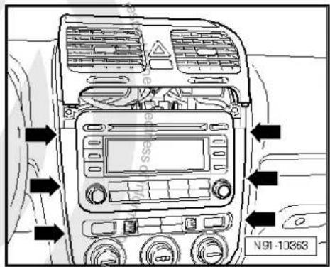
text_image
N91-10363- Remove bolts -arrows- (1.5 Nm) on radio -R-.
- Pull the radio -R- out of the installation shaft until you can gain access to the connectors on the back of the radio -R-.

text_image
N91-10364- Press together connector locking mechanism in direction of -arrows-.

natural_image
Technical line drawing of a mechanical assembly with directional arrows and label N91-10011 (no readable text or symbols)- Then swing locking bar up in direction of -arrow- and pull out connectors.
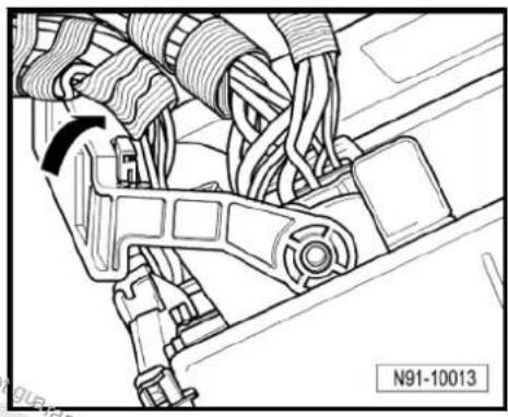
natural_image
Technical line drawing of a mechanical assembly with no visible text or symbols- Release connectors -arrows- of aerial connections and disconnect connectors.
Installing
- Fit connectors on the radio -R- and lock them.
- Push the radio -R- straight into the dash panel.

Note
Never press on the display or the operating buttons when fitting the radio -R-, as the radio -R- may be damaged.

natural_image
Technical diagram of two industrial equipment units with directional arrows, mounted on a base (no text or symbols present)- Fit the radio -R- with 4 bolts -arrows- (1.5 Nm).
- Install centre console cover.
- Deactivate the anti-theft coding page 29.
- Deactivate the transport protection device page 76.
- Check the radio -R-coding and recode the radio -R- page 78.
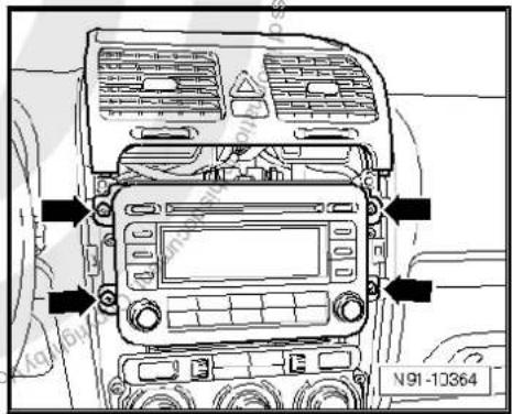
text_image
N91-10364
9.4 "RCD 510" connectors
1 - Aerial connection
☐ Connector colour, black
DAB
☐ Aerial system, saloon
⇒ page 171.
☐ Aerial system, Variant page 179.
☐ Aerial systems in saloons from model year 2011 → page 179
2 - Multi-pin connector 1, 8-pin, loudspeaker outputs
☐ Pin assignment ⇒ page 27
3 - Multi-pin connector 2, 8-pin, CAN bus, telephone
☐ Pin assignment ⇒ page 27
4 - Multi-pin connector 3, 12-pin, telephone
☐ Pin assignment ⇒ page 27
5 - Multi-pin connector 4, 12-pin, CD changer -R41-
☐ Pin assignment ⇒ page 28
6 - Not fitted
7 - Aerial connection
☐ Connector colour, white
FM2
☐ Aerial system, saloon
⇒ page 171.
☐ Aerial system, Variant page 179.
☐ Aerial systems in saloons from model year 2011 → page 179
8 - Aerial connection
☐ Connector colour, white
□ AM/FM
☐ Aerial system, saloon page 171.
☐ Aerial system, Variant page 179.
☐ Aerial systems in saloons from model year 2011 ⇒ page 179

text_image
1 2 3 1 5 9 13 A D 4 8 2 16 B 6 1 C 6 7 12 7 12 8 7 6 5 4 N91-110369.4.1 Multi-pin connector 1, 8-pin, loudspeaker outputs
In combination with amplifier -R12-, audio signals from radio -R- are used as input signals for amplifier -R12-.
1 - Rear right loudspeaker (+)
2 - Front right loudspeaker (+)
3 - Front left loudspeaker (+)
4 - Rear left loudspeaker (+)
5 - Rear right loudspeaker (-)
6 - Front right loudspeaker (-)
7 - Front left loudspeaker (-)
8 - Rear left loudspeaker (-)

text_image
1 2 3 4 N91-109289.4.2 Multi-pin connector 2, 8-pin, CAN bus, telephone
9 - CAN bus (high)
10 - CAN bus (low)
11 - Telephone mute
12 - Terminal 31
13 - Not assigned
14 - Not assigned
15 - Terminal 30
16 - ATA (SAFE) terminal 30
9.4.3 Multi-pin connector 3, 12-pin, telephone
1-5 - Not assigned
6 - Telephone LF input signal (-)
7-11 - Not assigned
12 - Telephone LF input signal (+)

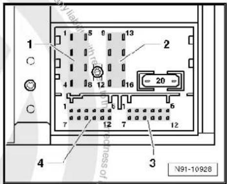
text_image
1 2 3 4 N91-10928
text_image
1 2 3 4 N91-109289.4.4 Multi-pin connector 4, 12-pin, CD changer -R41-
1 - Audio input left (+)
2 - Audio input earth
3 - Audio earth from CD changer -R41-
4 - Terminal 30 to CD changer -R41-
5 - Not assigned
6 - CD data out to CD changer -R41-
7 - Audio input right (+)
8 - Audio left from CD changer-R41-
9 - Audio right from CD changer-R41-
10 - Control signal to CD changer -R41-
11 - CD data in from CD changer -R41-
12 - CD clock from CD changer -R41-
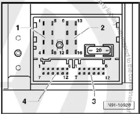
text_image
1 2 3 4 5 6 7 8 9 10 11 12 13 14 15 16 17 18 19 20 N91-109289.5 Activating and deactivating transport protection device
The transport protection device must be activated before shipping a "RCD 510" and deactivated before installing a new radio -R-. This takes place electronically via the key pad of the radio -R-. When the transport protection device has been activated, the drive of the internal CD changer is brought to a "transport position".
Activating transport protection device:
Unit status: "ON" or "OFF". The radio -R- must be connected to the voltage supply.
- Press and hold keys marked with -arrows- simultaneously for at least 5 seconds.
Once the drive of the internal CD changer reaches the transport position, "CDC transport protection device activated" appears in the display.
Deactivating transport protection device:
- Connect and install the radio -R-.
- Press and hold keys marked with -arrows- simultaneously for at least 5 seconds.
The following appears on the radio display: "CDC transport protection device activated".
A button with the word "Deactivate" is located under it.
- Press "Deactivate" button.
Transport protection device has now been deactivated.

text_image
N91-10990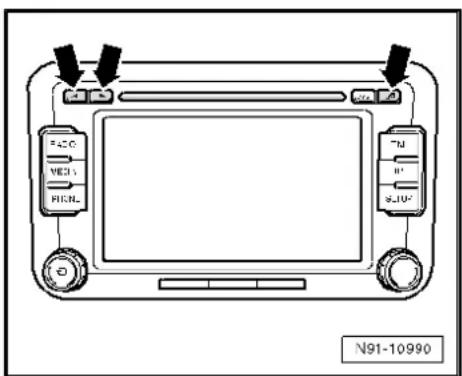
text_image
FACO VECS FICNL N91-109909.6 Electronic anti-theft coding
The radio -R- is equipped with an electronic anti-theft coding system which works in conjunction with the dash panel insert.
If the voltage supply for the radio -R- is cut off and then reconnected, the radio will still be operational without the need to enter the radio code again. A prerequisite is that the electronic anti-theft coding system has already been activated for the first time and that the radio -R- is reconnected in the same vehicle.
The radio code is determined by means of the vehicle diagnosis, testing and information system -VAS 5051B-. The radio card used in the past and the sticker on the radio -R- have been discontinued.

Note
In order to find out the radio code, the vehicle diagnosis, testing and information system -VAS 5051B- must be connected "online" (network connection), and the user must possess valid rights to use the programme for requesting radio codes.
9.6.1 Deactivating electronic anti-theft coding
A locked radio-R-will only work again if the correct radio code for the anti-theft coding system is entered.
Using the VAS tester to find out the radio code:
- Select "guided fault finding" in the vehicle diagnosis, testing and information system -VAS 5051B-.
- Using GoTo button, select "Functions/component" and the following menu options in succession:
Body
Electrical system
◆ 01 - On board diagnosis-capable systems
◆ Corresponding radio system
♦ Radio system functions
♦ Radio code request
Your system rights are then determined. The operating data, the VIN and the unit number of the radio -R- are then read out automatically.

Note
When a new radio -R- is being installed, it is possible that the vehicle diagnosis, testing and information system -VAS 5051B-cannot read out the unit number of the radio -R-. In this case, please enter the unit number manually. It can be read on a sticker on the radio -R-unit and is also embossed on the side of the unit.
The radio code determined is then shown on the display of the vehicle diagnosis, testing and information system -VAS 5051B-.
The radio code must be entered in the radio -R- manually.
Deactivating anti-theft coding:
- Switch on the radio -R-.
An entry mask with a 10-digit keypad and an ENTER button appear.
- Using the keypad, enter the right radio code in the entry mask.
– Confirm the entry by pressing the entry button.
The radio -R- will be released and is ready for use.

Note
If you enter an incorrect radio code to deactivate the electronic lock, "SAFE" first flashes in the display, followed by "1000" again. The entire process can now be repeated again. The number of attempts is shown in the display. If an incorrect radio code is entered again, the radio -R- will be blocked for approx. one hour, i.e. it cannot be operated. This lock is indicated by the fact that "SAFE" is permanently shown in the display. The process of deactivating the anti-theft coding can then be repeated after one hour. Do not forget that only two attempts are allowed, after which the radio -R- will be blocked for one hour.
9.7 Adapting radio components "RCD 510"
Special tools and workshop equipment required
◆ Vehicle diagnostic, testing and information system -VAS 5051B-
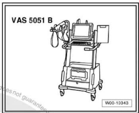
text_image
VAS 5051 B W00-10343Procedure
- In vehicle diagnostic, testing and information system -VAS 5051B-, select "Guided fault finding".
- Using GoTo button, select "Functions/component" and the following menu options in succession:
Body
Electrical system
◆ 01 - On board diagnosis-capable systems
◆ Corresponding radio system
♦ Radio system functions
10 CD changer -R41-

Note
When dealing with complaints, it is absolutely necessary to understand the functions and the operation of the communication systems Instruction manual.
When the battery -A- is reconnected, please remember to check vehicle equipment (radio clock, convenience electronics, etc.) in accordance with the Electrical system; Rep. Gr. 27 workshop manual and/or the owner's manual.
10.1 General notes
If the CD changer -R41- plays commercially available CDs but will not play copies of CDs, there is no fault with the CD changer -R41-. Exchanging a CD changer -R41- for this reason is not permitted.
The following formats cannot be played:
◆ CD with diameter of 8 cm
◆ "Mixed CD" (CD with data and audio files)
◆ MP3
When retrofitting a CD changer -R41- the radio -R- must be re-coded.
10.2 CD changer -R41- connector
Multi-pin connector, 12-pin
1 - CD data in
2 - CD clock
3 - CD earth
4 - CD data out
5 - Not assigned
6 - Terminal 30
7 - Audio output right
8 - Control cable
9 - Audio earth
10 - Audio output left
11 - Not assigned
12 - Terminal 58d
10.3 Removing and installing CD changer - R41-
The CD changer -R41- is located under the hinged centre arm-rest.
Special tools and workshop equipment required
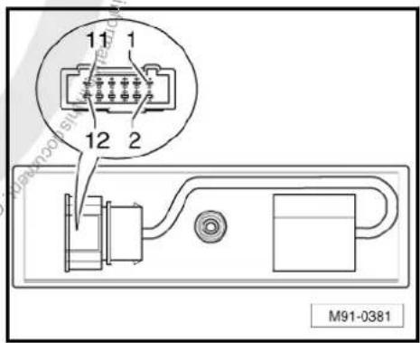
text_image
11 1 12 2 M91-0381◆ Radio release tool -VAS 3316-
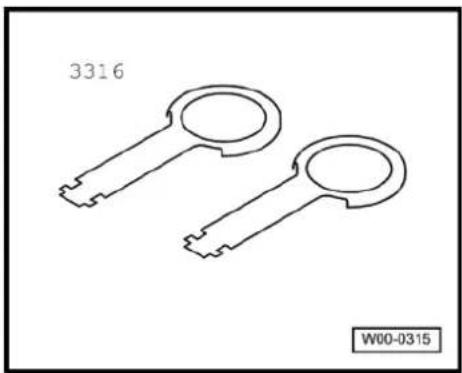
natural_image
Line drawing of two key-shaped mechanical parts (no text or symbols)Removing
- Switch off ignition and all electrical consumers and remove ignition key.
- Open hinged centre armrest completely.
- Take CD out of the CD changer -R41- Operating manual.
- Place radio release tools -VAS 3316- into the provided slots on left and front side of the CD changer -R41- until they audibly engage.
- Using radio release tools -VAS 3316-, pull out CD changer -R41- -arrows-.
- Release connector at points indicated by -arrows- and pull it off.
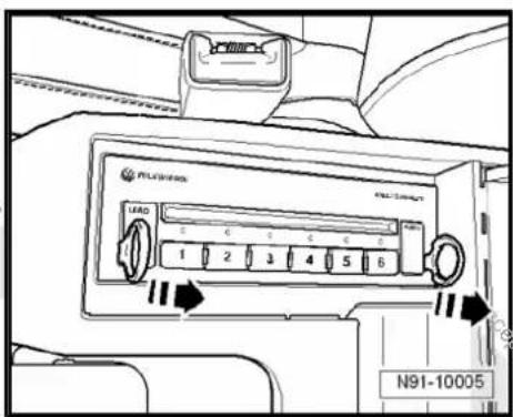
text_image
AIR CONDITION LOAD 1 2 3 4 5 6 N91-10005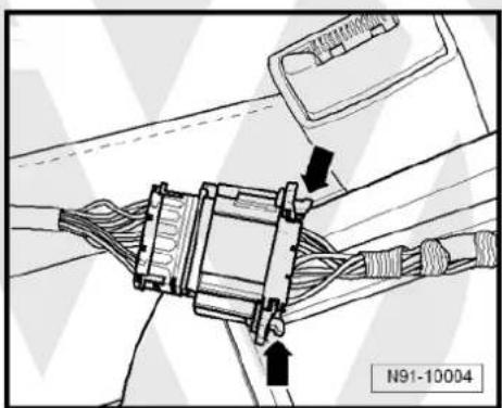
natural_image
Technical line drawing of a mechanical assembly with no visible text or symbols- Press locking clip -arrow- while pulling radio release tools - VAS 3316- out.
Installing
Installation is carried out in reverse order of removal.

natural_image
Mechanical assembly diagram showing internal components with a black arrow pointing to a specific part (no text or symbols present)
text_image
Protracted by copyright copying for patent or commercial purposes, in part or in whole, is not permitted unless authorised by Volkswagen AG. Volkswagen AG does not guarantee a acceptance liability with respect to the correctness of information in its current copyright by Volkswagen AG.11 iPod holder -R192-

Note
When dealing with complaints, it is absolutely necessary to understand the functions and the operation of the iPod holder -R192- Operating manual.
When the battery -A- is reconnected, please remember to check vehicle equipment (radio, clock, convenience electronics, etc.) in accordance with the Electrical system; Rep. Gr. 27 workshop manual and/or the instruction manual.
11.1 General notes
An iPod holder -R192- can be ordered as optional equipment.
The iPod is available in different versions. The iPod holder -R192-can be used with the following iPods:
◆ 3rd and 4th generation iPods
◆ iPod mini
◆ iPod photo
The iPod is inserted into the iPod holder -R192- ; the contents of the iPod can now be displayed and selected on the radio or radio navigation system display. The iPod is supplied with voltage via the iPod holder -R192-.
All of the iPod's audio data can be played via the radio system; however, photos and ID3 tags cannot be shown. Only the sequential number of the files (track xx) is shown on the radio or radio navigation system display.
The files are transferred in the same way from the iPod to the radio or radio navigation system.
11.2 Fault finding
The iPod holder -R192- is not capable of self-diagnosis.
Fault finding procedure page 85.

11.3 Overview of iPod holder -R192-
1 - iPod
2 - Adapter
Adapting holder to iPod
☐ Removing and installing adapter page 83
3 - iPod holder -R192-
☐ In the centre console storage compartment
☐ Removing and installing
⇒ page 84
4 - Electronics
□ Cannot be replaced as single part
☐ Connector page 85
5 - Loudspeaker system
6 - Radio -R- / control unit with display for radio and navigation -J503-

text_image
1 2 3 4 5 6 Volkswagen AG, Volkswagen AG guarantee or accept at liability with respect to the N91-1065411.4 Removing and installing adapter for iPod holder -R192-
To adapt the iPod holder -R192- to the different unit sizes, certain adapters which can be individually inserted into the iPod holder -R192- are available.
Installing
iPod and iPod photo:
- Insert adapter -A- in direction of -arrow- to stop into adapter -B-.

Note
The adapter -A- is available in various thicknesses. Refer to the instruction manual to find out exactly which is to be used for which unit.
iPod mini
- Insert adapter in direction of -arrow- to stop into iPod holder -R192-.
Removing
Removal is carried out in the reverse sequence.
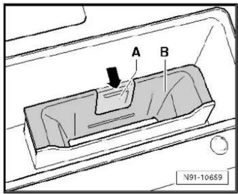
text_image
A B N91-10659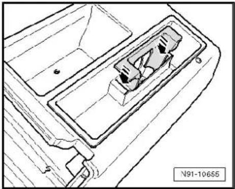
natural_image
Technical line drawing of a mechanical component with no visible text or symbols11.5 Removing and installing iPod holder - R192-
The iPod holder -R192- is installed in the hinged centre armrest.
Removing
- Grip iPod holder -R192- and pull out iPod holder -R192- in direction of -arrow-.
- Disconnect connector underneath iPod holder -R192-.
Installing
- Reconnect connector.
- First insert iPod holder -R192- in centre console at -A-, then press it in the direction of -B- until iPod holder -R192- engages in centre console.
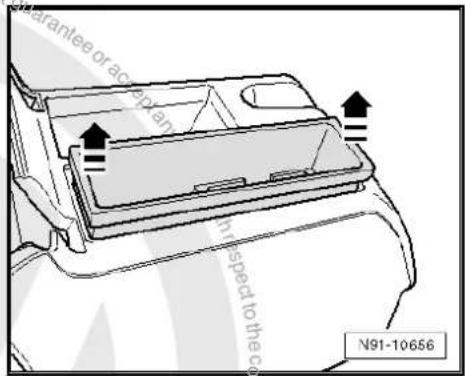
text_image
Guarantee or access in respect to the co N91-10656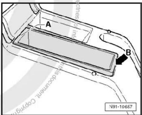
text_image
A B millis decumenal Copyright N91-10657
11.6 iPod holder -R192- connector
Multi-pin connector, 12-pin
1 - DATA in
2 - DATA clock
3 - Terminal 31
4 - DATA out
5 - Not assigned
6 - Terminal 30
7 - Audio right
8 - Control signal from radio -R-
9 - Audio earth
10- Audio left
11 - Not assigned
12 - Not assigned
11.7 Fault finding procedure
Special tools and workshop equipment required
◆ Hand multimeter -V.A.G 1526C-
◆ Auxiliary measuring set -V.A.G 1594C-
The iPod holder -R192- is not capable of self-diagnosis.
The voltage supply to the connector can be checked.
Test conditions
◆ iPod OK ⇒ Instruction manual
◆ iPod "RESET" ⇒ instruction manual.
◆ Lock OK ⇒ Current flow diagrams, Electrical fault finding and Fitting locations
◆ Radio and radio navigation system no errors ⇒ Vehicle diagnosis, testing and information system VAS 5051
Procedure
- Remove iPod holder -R192- page 84.
- Disconnect connector underneath iPod holder -R192-.
- Switch on the radio -R-.
- Using hand-held multimeter -V.A.G 1526C- and auxiliary cables from auxiliary measuring set -V.A.G 1594C- measure voltage between contacts 3 and 6, as well as 3 and 8 of connector to wiring harness.
Specification: approx. 12 V
- Switch off the radio -R-.
Voltage values not OK:
- Check wiring/connections between radio -R- and iPod holder -R192- referring to current flow diagram Current flow diagrams, Electrical fault finding and Fitting locations.
Voltage values OK:
- Renew iPod holder -R192-.

text_image
1 3 5 7 9 11 2 4 6 8 10 12 N91-1066812 USB connection retainer -R193-

Note
When dealing with complaints, it is absolutely necessary to understand the functions and the operation of the communication systems Instruction manual.
When the battery -A- is reconnected, please remember to check vehicle equipment (radio, clock, convenience electronics, etc.) in accordance with the Electrical system; Rep. Gr. 27 workshop manual and/or the owner's manual.
12.1 General notes
Located in hinged centre armrest
A USB connection retainer -R193- to connect USB memory media (USB stick or MP3 player) is available as an option.
The USB memory medium is connected to the USB connection retainer -R193-; the contents of the USB memory medium can now be displayed and selected on the radio or radio navigation system display. The USB memory medium is supplied with voltage via the USB connection retainer -R193-.
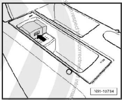
text_image
N91-10784 with respect to correctness in millions12.1.1 Fault finding
The USB connection retainer -R193- is not capable of self-diagnosis.
Fault finding procedure page 89

12.1.2 Supported music file formats
Only music files in the following formats can be played:
◆ "mp3" (MPEG1 Layer 3 of 32 to 320 kbps)
◆ "wma" (from 8 to 192 kbps)
◆ "wav" (16 kHz sampling frequency with 16 bit encoding, stereo)
◆ “ogg vorbis” (up to q10, 48 kHz, stereo)
DMR music formats are not supported!
12.1.3 Supported memory media
Flawless operation can only be guaranteed if memory sticks, MP3 players and radios -R- approved by Volkswagen are used. The function cannot be guaranteed if other memory sticks or MP3 players of other manufactures are used. The memory medium must have one of the two USB certificates as a minimum requirement, see illustration.
The following memory media are supported:
Approved MP3 players:
◆ Manufacturer "Cebop", model "Run XL", memory size 1024 MB, connected via USB-A
◆ Manufacturer "Maxfield", model "MayRobot", memory size 512 MB, connected via USB-A
◆ Manufacturer "Philips", model "SA 177", memory size 512 MB, connected via USB-A
◆ Manufacturer "Grundig", model "MP 500", memory size 256 MB, connected via USB-A
◆ Manufacturer "Mambox", model "Color", memory size 256 MB, connected via USB-A
◆ Manufacturer "Trekstor", model "Musik Stick 100", memory size 256 MB, connected via USB-A
◆ Manufacturer "Trekstor", model "21617, i-Beat", memory size 512 MB, connected via mini USB
◆ Manufacturer "Time", model "DPA-20 FL+", memory size 128 MB, connected via USB
Approved memory sticks:
Manufacturer "Blue Pearl", model "Cn Memory", memory size 64 MB, connected via USB-A
Manufacturer "Buffalo", model "Firestix", memory size 2 GB, connected via USB-A
Manufacturer "Lexar Media", model "Jump Drive", memory size 128 MB, connected via USB-A
Manufacturer "LG", model "Mirror USB Drive", memory size 128 MB, connected via USB-A
Manufacturer "Silver Pearl", model "Micro X", memory size 1024 MB, connected via USB-A
Manufacturer "Pretec", model "I-Disk Tiny 2.0", memory size 128 MB, connected via USB-A
Approved radio -R- :
Perfect operation is only guaranteed if a VW radio was installed in the factory. Flawless function cannot be guaranteed if other merchandise is used.
12.1.4 Notes on operation
◆ Never remove the memory medium as long as you have selected the USB connection retainer -R193- as the source (CD). This may destroy the memory medium.
- Never connect an MP3 player directly into the USB connection retainer -R193- ; this could damage the connection. Always use a USB extension cable.
◆ Never connect anything other than a USB stick or MP3 player to this USB connection retainer -R193-. Hard drives and USB

text_image
is not guaranteed ACCEPTED accept any HIGH-SPEED CERTIFIED USB N91-10789hubs cannot be used with the USB connection retainer - R193-.
◆ The maximum power consumption of the USB memory medium must not exceed 2.5 W (500 mA/5 V).
◆ Never insert metal objects into the USB connection retainer - R193-. This can cause short circuits and damage the unit.
If the memory medium is not detected by the USB connection retainer -R193- within 15 seconds, remove the memory medium and re-insert it into the USB connection retainer -R193-.
- Some MP3 players must be activated by a button before inserting into a USB connection ⇒ Instruction manual.
The permitted temperature range of USB sticks and MP3 players is limited and often lies between 0°C and 40°C. Inform the customer that for this reason the memory medium may not remain in the vehicle over a longer period.
12.2 Removing and installing USB connection retainer -R193-
The USB connection retainer -R193- is installed in the hinged centre armrest.
Special tools and workshop equipment required
♦ Radio release tool -3316-

natural_image
Line drawing of two key-shaped mechanical parts (no text or symbols)Removing
- Switch off ignition and all electrical consumers and remove ignition key.
- Open hinged centre armrest completely.
- Remove memory medium and cables from USB connection retainer -R193- if fitted.
- Insert the radio release tool -3316- in the slot -arrow- in the USB connection retainer -R193-.
For greater clarity during the following procedures the USB connection retainer -R193- is shown removed.
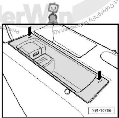
text_image
Pro N91-10786- Push the radio release tool -3316- apart in direction of -arrow- to flawlessly release the locking mechanism. Use the radio release tools -3316- to pull the USB connection retainer -R193- out of the centre armrest.
- Disconnect connector on USB connection retainer -R193-.
- On removed USB connection retainer -R193- press spring in direction of -arrow-, pulling out radio release tool -3316- in direction of -arrow A-.
Installing
- Insert USB connection retainer -R193- in centre armrest so that USB connection is at rear.
Remainder of installation is carried out in reverse order of removal.
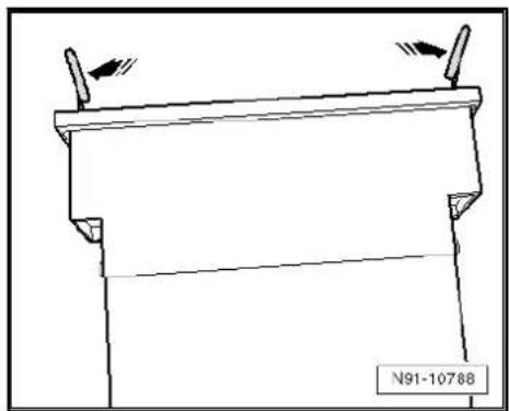
natural_image
Technical line drawing of a mechanical component with two protruding pins and a base plate (no text or symbols)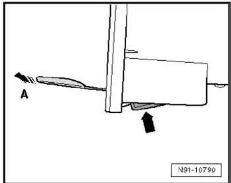
text_image
A N91-1079012.3 USB connection retainer -R193- connector
Multi-pin connector, 12-pin
1 - DATA in
2 - DATA clock
3 Terminal 31
4- DATA out
5- Not assigned
6 Terminal 30
7 Audio right
8- Control signal from radio -R-
9 - Audio earth
10 - Audio left
11 - Not assigned
12 - Not assigned
12.4 Fault finding procedure
Special tools and workshop equipment required
◆ Hand multimeter -V.A.G 1526C-
◆ Auxiliary measuring set -V.A.G 1594C-
The USB connection has no self-diagnostic capability.
The voltage supply to the connector can be checked.
Test conditions
◆ USB stick/MP3 player OK ⇒ Instruction manual
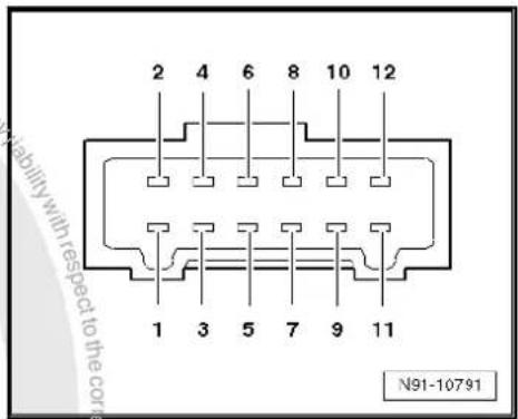
text_image
2 4 6 8 10 12 1 3 5 7 9 11 N91-10791◆ Lock OK ⇒ Current flow diagrams, Electrical fault finding and Fitting locations
◆ Radio and radio navigation system no errors ⇒ Vehicle diagnosis, testing and information system VAS 5051
Procedure
- Remove USB connection retainer -R193- page 88.
- Disconnect connector underneath USB connection retainer - R193-.
- Switch on the radio -R-.
- Using hand-held multimeter -V.A.G 1526C- and auxiliary cables from auxiliary measuring set -V.A.G 1594C- measure voltage between contacts 3 and 6, as well as 3 and 8 of connector to wiring harness.
Specification: approx. 12 V
- Switch off the radio -R-.
Voltage values not OK:
- Check wiring/connections between radio -R- unit and USB connection retainer -R193- referring to current flow diagram Current flow diagrams, Electrical fault finding and Fitting locations.
Voltage values OK:
- Renew USB connection retainer -R193-.

13 Connection for external audio sources -R199-

Note
When dealing with complaints, it is absolutely necessary to understand the functions and the operation of the communication systems Instruction manual.
When the battery -A- is reconnected, please remember to check vehicle equipment (radio, clock, convenience electronics, etc.) in accordance with the Electrical system; Rep. Gr. 27 workshop manual and/or the instruction manual.
The connection for external audio sources -R199- is provided in the form of a 3.5 mm jack socket.
Location of connection for external audio sources -R199- up to model year 2008
The connection for external audio sources -R199- is installed in the glove compartment in place of the glove compartment light -W6-.

Location of connection for external audio sources -R199- -2- from model year 2009
The connection for external audio sources -R199- -2- is installed in the centre console.
Installation location of connection for external audio sources - R199- -1- from model year 2011
The connection for external audio sources -R199- -1- is installed in storage compartment of centre console.
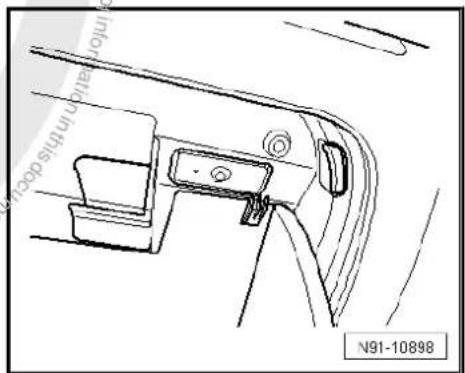
text_image
inflow in this door N91-10898
text_image
1 2 M91-0414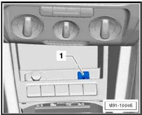
text_image
1 M91-10005Installation location of connection for external audio sources - R199- for RNS 310/RNS 315.
The connection for external audio sources -R199- -1- is installed in the device. The connection is at the bottom right on the front.
The connection for external audio sources -R199- works with the radio/radio-navigation system where the "AUX" source can be selected.
On the connection for external audio sources -R199-, the audio signals (generally the headphone output signals) of MP3 players as well as portable CD and cassette players can be fed into the radio/radio-navigation system with a corresponding connection. These can then be played via the vehicle loudspeakers.
For further information, see Instruction manual.
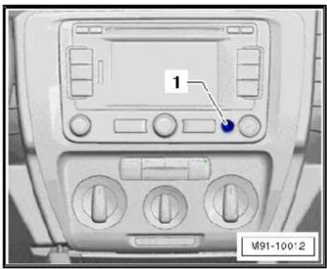
text_image
1 M91-100'213.1 Connector for connection for external audio sources -R199-
Multi-pin connector, 3-pin
1 - Audio signal, right
2 - Audio earth
3 - Audio signal, right
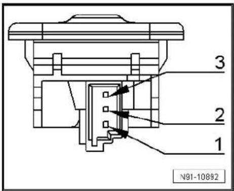
text_image
3 2 1 N91-1089213.2 Removing and installing connection for external audio sources -R199-
13.2.1 Removing and installing from/in glove compartment
Special tools and workshop equipment required
◆ Pin -T40011-
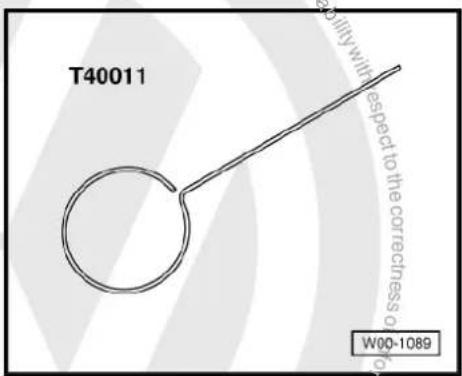
text_image
T40011 W00-1089Removing
- Open the glove compartment lid.
- Push the pin -T40011- into the opening provided -arrow- until it audibly engages.
- Unclip the connection for external audio sources -R199- from the glove compartment trim using a small screwdriver.
- Release connector and disconnect.
Installing
Installation is carried out in reverse order of removal.

natural_image
Technical line drawing of a car interior panel with no visible text or symbols13.2.2 Removing and installing centre console
Special tools and workshop equipment required
Removal wedge -VAS 3409-
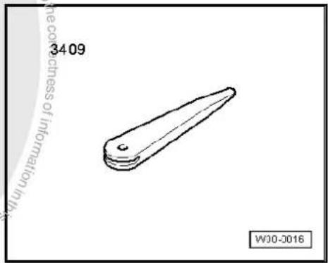
text_image
3409 WJ0-0016Removal
- Remove centre console General body repairs, interior; Rep. Gr. 68.
- Press clips -arrows- on connection for external audio sources -R199- using wedge -3409- and push out connection for external audio sources -R199-.
- Release connector -arrows-) and disconnect.
Installing
Installation is carried out in reverse order of removal.

natural_image
Diagram of a container with handles and side panels, showing directional arrows (no text or symbols)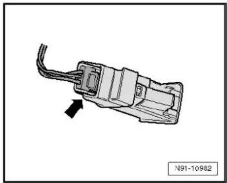
natural_image
Diagram of an electrical connector with wires and a black arrow indicating direction (no text or symbols)13.2.3 Removing and installing from/in storage compartment in centre console
- Carefully lever gear lever gaiter out of centre console -arrows-.
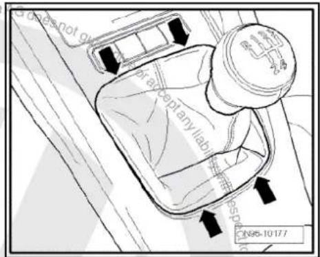
text_image
does not go braceptanyllabir 10-10-177- Remove securing bolts -arrows-.
- Take stowage compartment out of centre console.

text_image
Portresses N96-10178- Release connectors -arrows-) and disconnect.
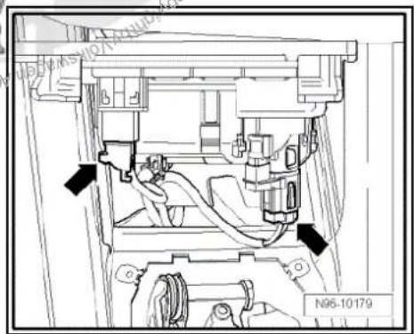
text_image
N95-10179- Press clips -arrows- on connection for external audio sources -R199- using wedge -3409- and push out connection for external audio sources -R199-.
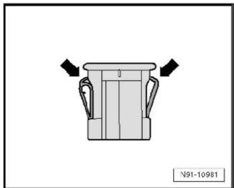
natural_image
Diagram of a container with handles and side panels, no text or symbols presentInstalling
Installation is carried out in reverse order of removal.
14 Multimedia control unit -J650-
14.1 General notes
Thanks to the multimedia system control unit -J650- analogue (via AUX-IN entry) as well as digital (via USB or iPod entry) audio contents can be played via the radio or the radio navigation system. Units connected via USB or iPod connections can also be operated via the radio/radio navigation system. ID3-TAG and titles also appear on the radio or radio/navigation system display.

Note
Since the display capability of ID3 tags and titles on the radio or radio/navigation system display depends on the "characteristics" of the audio files used, refer to the owner's manual of the radio unit or radio/navigation system and to the owner's manual of your MP3 player or iPod.
The multimedia system control unit -J650- provides an audio input (AUX-IN), an USB input, and an iPod connection (power supply, signal and AUDIO-IN) as an interface. To connect the mobile unit to the USB or iPod interface of the multimedia control unit -J650-, a relevant specific adapter cable is used. A storage compartment for the mobile unit is integrated into the multimedia control unit -J650-. Charging is possible via USB or iPod connection.

Note
If no 1DIN slot is available in the vehicle, the multimedia system control unit -J650- can also be installed separately. The user can although have access to the universal interface (Mitsumi socket) via a Mitsumi-Mitsumi extension. For this purpose, the Mitsumi socket must be integrated in the inside of the vehicle. Line length of Mitsumi-Mitsumi extension must not exceed 1500 mm.
14.2 Overview of multimedia control unit -J650-
1 - Loudspeaker system
2 - Radio -R- / control unit with display for radio and navigation -J503-
3 - Multifunction steering wheel
4 - CAN bus
5 - LF wire
☐ Connection for external audio sources -R199-
6 - Connection for external audio sources -R199-
☐ Further information ⇒ page 91
7 - Input devices
□ MP3 player
□ Data sticks
iPod player
8 - Adapter line
☐ Depending on the device to be connected
9 - Multimedia system control unit -J650-
☐ Removing and installing ⇒ page 96
10 - Voltage supply connection
11 - LF wire
☐ Multimedia system control unit -J650- to radio/RNS
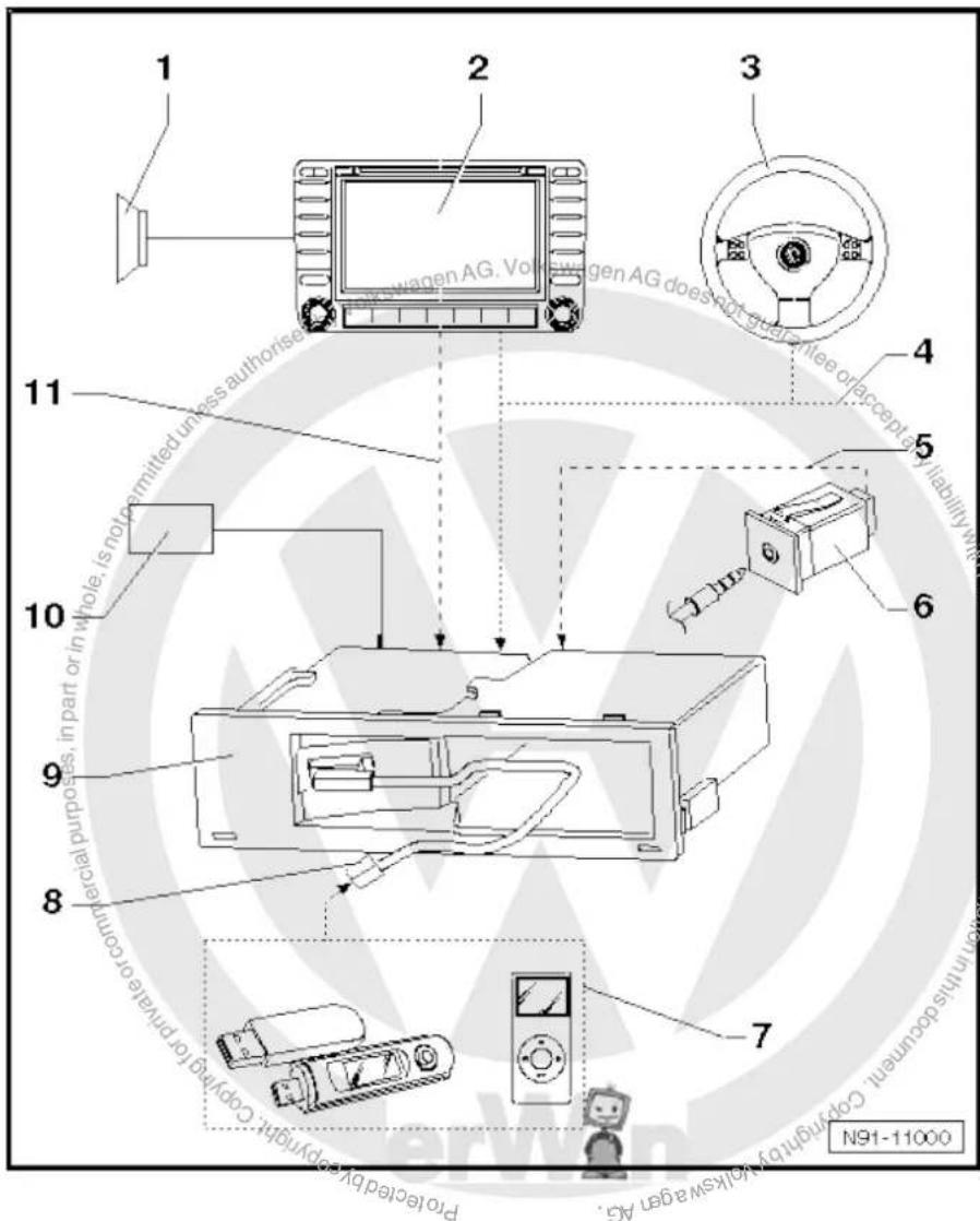
text_image
1 2 3 4 5 6 7 8 9 10 11 Proteled by always a ger AG. Pwagen AG. Volkswagen AG does not guarantee or accept any liability with the other purposes, in part or in whole, is not permitted unless authorise Remainable or acceptable for principle or control.14.3 Removing and installing multimedia system control unit -J650-
The multimedia control unit -J650- is installed in centre console or glove compartment.
14.3.1 Removing and installing multimedia system control unit -J650- (centre console)
Special tools and workshop equipment required
◆ Radio release tool -T10057-
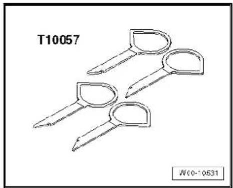
natural_image
Technical line drawing of two sets of key-shaped tools labeled T10057 and Wc0-10531 (no text or symbols on the tools themselves)Removal
- Remove devices connected to the multimedia system control unit -J650-.
- Place radio release tools -VAS 3316- into the slots provided on left and front side of the multimedia system control unit -J650- -1- until they audibly engage.
- Pull multimedia system control unit -J650- -1- upwards out of centre console -2- using radio release tools -T10057-.
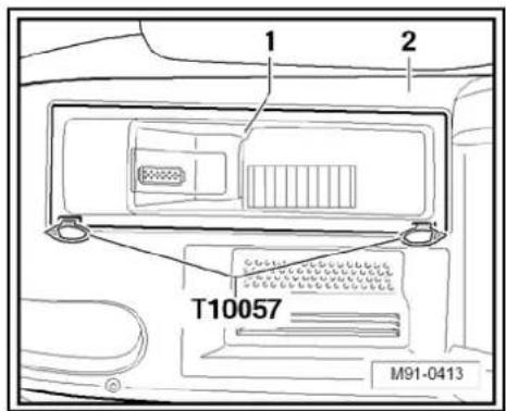
text_image
1 2 T10057 M91-0413- Unclip connector -arrow- and remove connector -A- on multi-media system control unit -J650-.
- Press locking clip on multimedia system control unit -J650-pulling out radio release tool -VAS 3316- at the same time.

text_image
A N91-11003Installing
Installation is carried out in reverse order of removal.
14.3.2 Removing and installing multimedia system control unit -J650- (glove compartment)
Removal
- Remove devices connected to the multimedia system control unit -J650-.
- Remove glove compartment General body repairs, interior; Rep. Gr. 68.

- Release connector -2- by unscrewing bolt -5-.
- Remove bolt -4- from the inside.
- Push multimedia control unit -J650- -3- together with connector -2- towards the rear out of glove compartment -1-.
- Remove connector -2- at multimedia control unit -J650- -3-.
Installing
Installation is carried out in reverse order of removal.
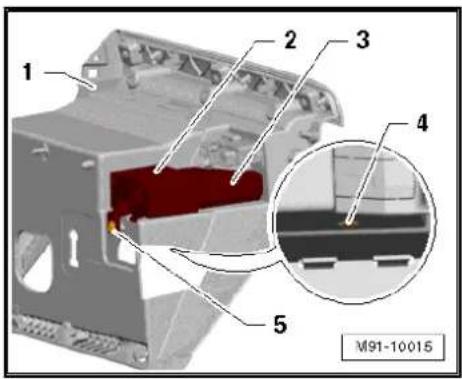
text_image
1 2 3 4 5 M91-1001514.4 Coding multimedia control unit -J650-
Special tools and workshop equipment required
◆ Vehicle diagnostic, testing and information system -VAS 5051B-
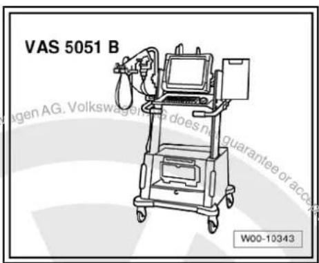
text_image
VAS 5051 B W00-10343Procedure
- In vehicle diagnostic, testing and information system -VAS 5051B-, select "Guided fault finding".
- Using GoTo button, select "Functions/component" and the following menu options in succession:
Body
Electrical system
◆ 01 - On board diagnosis-capable systems
◆ Multimedia control unit
◆ Multimedia control unit functions
◆ Coding multimedia control unit
14.5 Multimedia control unit -J650- final control diagnosis
Special tools and workshop equipment required

◆ Vehicle diagnostic, testing and information system -VAS 5051B-

natural_image
Line drawing of a medical device labeled VAS 5051 B, showing internal components and no readable text or symbols beyond label and page number.Procedure
- In vehicle diagnostic, testing and information system -VAS 5051B-, select "Guided fault finding".
- Using GoTo button, select "Functions/component" and the following menu options in succession:
Body
Electrical system
◆ 01 - On board diagnosis-capable systems
◆ Multimedia control unit
◆ Multimedia control unit functions
◆ Left and right audio channel final control diagnosis

text_image
Volkswagen AG. Volkswagen AG does not guarantee or accept any liability with respect to the correctness of information in this document. Copyright © 2017 Volkswagen AG. Proprietated by copyright copy/registration commercial purposes, in part or in whole, is not permitted unless authorised by Volkswagen AG.15 Amplifier -R12-

Note
When dealing with complaints, it is absolutely necessary to understand the functions and the operation of the communication systems Instruction manual.
In the event of repair work or fault finding Vehicle diagnosis, testing and information system VAS 5051.
When the battery -A- is reconnected, please remember to check vehicle equipment (radio, clock, convenience electronics, etc.) in accordance with the Electrical system; Rep. Gr. 27 workshop manual and/or the owner's manual.
15.1 General description
Amplifier -R12- view
Amplifier -R12- serves to extend sound of radio/RNS.
Amplifier -R12- is designed in 8-channel technology.
Signal input activation on amplifier -R12- is carried out via loudspeaker outputs of radio/RNS.
Amplifier -R12- is installed under left front seat.

natural_image
Technical line drawing of a device casing with mounting feet and internal components (no text or symbols)15.1.1 Fault finding
Amplifier -R12- is equipped with self-diagnosis.
For fault finding, use the vehicle diagnosis, testing and information system -VAS 5051B- in "Guided fault finding" mode.
15.2 Removing and installing amplifier -R12-
Amplifier -R12- is installed under left front seat.
Removing
- Switch off ignition and all electrical consumers and remove ignition key.
- Move front left seat to the very back and the highest position.
- Unclip cover -arrow- under seat.

natural_image
Technical diagram showing a mechanical component with a highlighted section and a label N91-10361 (no readable text or symbols beyond the label)- Unscrew bolts -arrows- (6 Nm) on amplifier -R12-.
-
Remove amplifier -R12- until connectors are accessible.
-
Release connectors -arrows- on amplifier -R12- and disconnect them.
- Remove amplifier -R12-.
Installing
- Make sure that amplifier -R12- is correctly pushed into fold on mounting when installing it.
Remainder of installation is carried out in reverse order of removal.

text_image
N91-10359
natural_image
Technical line drawing of a mechanical assembly with no visible text or symbols15.3 Amplifier -R12- connectors
15.3.1 Amplifier -R12- with 23/24-pin connector
Amplifier -R12-
1 - Multi-pin connector B, 23-pin
2 - Multi-pin connector A, 24-pin
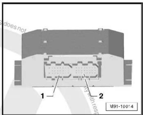
text_image
does not 1 2 M91-100*4
Multi-pin connector A, 24-pin
1 - Rear left treble loudspeaker -R14- (+)
2 - Rear right bass loudspeaker -R17- (-)
3 - Rear right bass loudspeaker -R17- (-)
4 - Rear left bass loudspeaker -R15- (+)
5 - Rear right treble loudspeaker -R16- (-)
6 - Rear right treble loudspeaker -R16- (+)
7 - Rear left treble loudspeaker -R14- (-)
8 - Front left bass loudspeaker -R21- (-)
9 - Front left bass loudspeaker -R21- (+)
10 - Rear left bass loudspeaker -R15- (-)
11 - Front right mid-range loudspeaker -R104- (-)
12 - Front right mid-range loudspeaker -R104- (-)
13 - Not assigned
14 - Signal input rear left (-)
15 - Signal input rear left (±)
16 - Not assigned
17 - Signal input rear right (-)
18 - Signal input rear right (+)
19 - Control in (optional)
20 - Signal input front left (a)
21 - Signal input front left (+)
22 - Not assigned
23 - Signal input front right (-)
24 - Signal input front right (+)
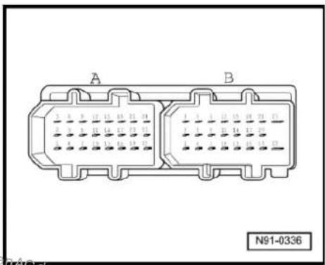
natural_image
Diagram of two connected electrical connectors labeled A and B, with no visible text or symbols beyond labelsMulti-pin connector B, 23-pin
1 - CAN bus (low)
2 - Front left mid-range loudspeaker -R103- (-)
3 - Front left mid-range loudspeaker -R103- (+)
4 - CAN bus (high)
5 - Not assigned
6 - Front left treble loudspeaker -R20- (-)
7 - Not assigned
8 - Not assigned
9 - Front left treble loudspeaker -R20- (+)
10 - Not assigned
11 - Front right bass loudspeaker -R23- (+)
12 - Front right bass loudspeaker -R23- (+)
13 - Not assigned
14 - Not assigned
15 - Front right treble loudspeaker -R22- (+)
16 - Terminal 31
17 - Not assigned
18 - Front right treble loudspeaker -R22- (-)
19 - Terminal 31
20 - Terminal 30
21 - Terminal 30
22 - Terminal 31
23 - Terminal 30

text_image
A B N91-033615.3.2 Amplifier -R12- with 38-pin connector
Amplifier -R12-
1 - Multi-pin connector, 38-pin


natural_image
Technical diagram of a mechanical component with labeled part 1, no readable text or symbols beyond label and reference number M91-10013Multi-pin connector, 38-pin
1 - Terminal 31
2 - Terminal 30
3 - Front right bass loudspeaker -R23- (-)
4 - Not assigned
5 - Not assigned
6 - Front left bass loudspeaker -R21- (-)
7 - Front right treble loudspeaker -R22- (-)
8 - Front left treble loudspeaker -R20- (+)
9 - Rear left bass loudspeaker -R15- (+)
10 - Rear right bass loudspeaker -R17- (-)
11 - Front right mid-range loudspeaker -R104- (-)
12 - Front right mid-range loudspeaker -R104- (+)
13 - Front left mid-range loudspeaker -R103- (+)
14 - Front left mid-range loudspeaker -R103- (-)
15 - Front right bass loudspeaker -R23- (+)
16 - Not assigned
17 - Not assigned
18 - Front left bass loudspeaker -R21- (+)
19 - Front right treble loudspeaker -R22- (+)
20 - Front left treble loudspeaker -R20- (-)
21 - Rear left bass loudspeaker -R15- (-)
22 - Rear right bass loudspeaker -R17- (+)
23 - CAN bus (low)
24 - Not assigned
25 - Not assigned
26 - Not assigned
27 - Signal input rear left (-)
28 - Signal input rear right (-)
29 - Signal input front left (-)
30 - Signal input front right (-)
31 - CAN bus (high)
32 - Not assigned
33 - Not assigned
34 - Not assigned
35 - Signal input rear left (+)
36 - Signal input rear right (+)
37 - Signal input front left (+)
38 - Signal input front right (+)

text_image
36 31 22 11 30 23 10 1 A91-1156315.4 Reading amplifier -R12- measured values
Special tools and workshop equipment required
◆ Vehicle diagnostic, testing and information system -VAS 5051B-
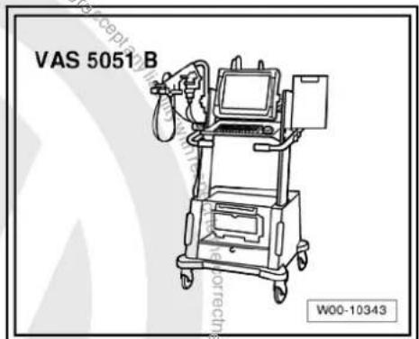
text_image
VAS 5051 B W00-10343Procedure
- In vehicle diagnostic, testing and information system -VAS 5051B-, select "Guided fault finding".
- Using GoTo button, select "Functions/component" and the following menu options in succession:
Body
Electrical system
◆ 01 - On board diagnosis-capable systems
◆ Corresponding sound system
◆ Sound system functions
◆ Sound system measured values

16 Loudspeaker systems
In conjunction with all radios/radio-navigation systems, the front loudspeaker system consists of a 3-way system with one bass loudspeaker, a mid-range loudspeaker in the left and right front doors and one treble loudspeaker in the left and right front A-pillar trims. Depending on the version, the front loudspeakers of the 3-way system are connected with a frequency switch.
Depending on the equipment, a two-way system with a bass loudspeaker and a treble loudspeaker is installed in each of the rear doors.
All loudspeakers are passive loudspeakers.
16.1 Overview of loudspeaker systems
4 loudspeaker system
1 - Radio -R-
2 - Front right treble loudspeaker -R22- / front left treble loudspeaker -R20- in front doors/A-pillars.
3 - Front right bass loudspeaker -R23- / front left bass loudspeaker -R21-

text_image
Pro-tercled by copyright to copy/for Prin 3 M91-0372 Pro-tercled by copyright to copy/for Prin 3 1 2 36 loudspeaker system
1 - Radio -R-
2 - Front right treble loudspeaker -R22- / front left treble loudspeaker -R20- in front doors/A-pillars.
3 - Front right bass loudspeaker -R23- / front left bass loudspeaker -R21-
4 - Front right mid-range loudspeaker -R104- / front left mid-range loudspeaker -R103-
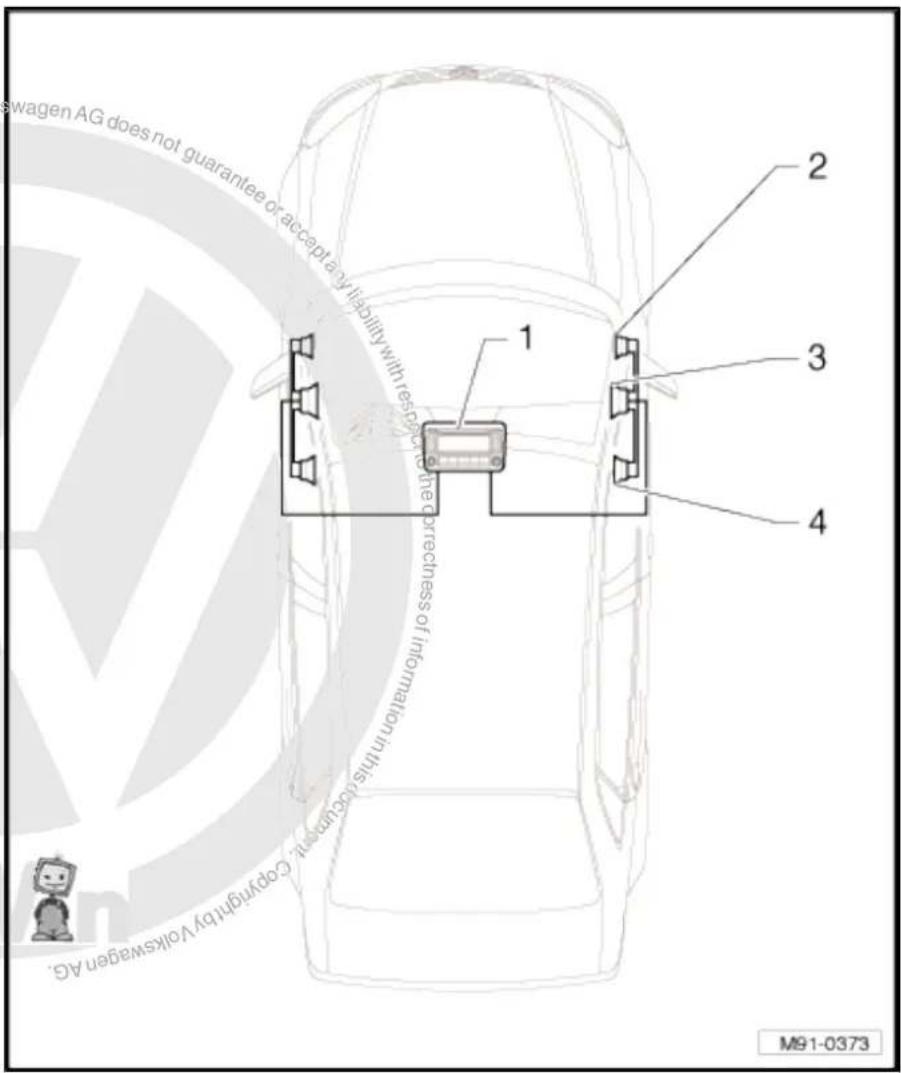
text_image
swagen AG does not guarantee or accept any liability with rest in the correctness of internalization in this case, copyright by Volkswagen AG. 1 2 3 4 M91-03738 loudspeaker system
1 - Radio -R-
2 - Front right treble loudspeaker -R22- / front left treble loudspeaker -R20- in front doors/A-pillars.
3 - Front right bass loudspeaker -R23- / front left bass loudspeaker -R21-
4 - Rear right bass loudspeaker -R17- / rear left bass loudspeaker -R15-
5 - Rear right treble loudspeaker -R16- / rear left treble loudspeaker -R14-

text_image
1 2 3 4 5 M91-0374 is unless authorised by Volkswagen AG. Volkswagen AG does not guarantee it accept any liability with respect to the vehicle.10 loudspeaker system

text_image
Protracted by copyright. Copyright paper matter commercial purposes, in part Wenken the correctness of information in this decumenant. Copyright by Volkswagen has been held on the following: Copyright © 2015 Copyright © 2016 Copyright © 2017 Copyright © 2018 Copyright © 2019 Copyright © 2020 Copyright © 2021 Copyright © 2022 Copyright © 2023 Copyright © 2024 Copyright © 2025 Copyright © 2026 Copyright © 2027 Copyright © 2028 Copyright © 2029 Copyright © 2030 Copyright © 2031 Copyright © 2032 Copyright © 2033 Copyright © 2034 Copyright © 2035 Copyright © 2036 Copyright © 2037 Copyright © 2038 Copyright © 2039 Copyright © 2040 Copyright © 2041 Copyright © 2042 Copyright © 2043 Copyright © 2044 Copyright © 2045 Copyright © 2046 Copyright © 2047 Copyright © 2048 Copyright © 2049 Copyright © 2050 Copyright © 2051 Copyright © 2052 Copyright © 2053 Copyright © 2054 Copyright © 2055 Copyright © 2056 Copyright © 2057 Copyright © 2058 Copyright © 2059 Copyright © 2060 Copyright © 2061 Copyright © 2062 Copyright © 2063 Copyright © 2064 Copyright © 2065 Copyright © 2066 Copyright © 2067 Copyright © 2068 Copyright © 2069 Copyright © 2070 Copyright © 2071 Copyright © 2072 Copyright © 2073 Copyright © 2074 Copyright © 2075 Copyright © 2076 Copyright © 2077 Copyright © 2078 Copyright © 2079 Copyright © 2080 Copyright © 2081 Copyright © 2082 Copyright © 2083 Copyright © 2084 Copyright © 2085 Copyright © 2086 Copyright © 2087 Copyright © 2088 Copyright © 2089 Copyright © 2090 Copyright © 2091 Copyright © 2092 Copyright © 2093 Copyright © 2094 Copyright © 2095 Copyright © 2096 Copyright © 2097 Copyright © 2098 Copyright © 2099 Copyright © 21001 - Radio -R-
2 - Front right treble loudspeaker -R22- / front left treble loudspeaker -R20- in front doors/A-pillars.
3 - Front right bass loudspeaker -R23- / front left bass loudspeaker -R21-
4 - Right frequency switch - R19- / left frequency switch - R18- in the front doors
5 - Front right mid-range loudspeaker -R104- / front left mid-range loudspeaker -R103-
6 - Rear right bass loudspeaker -R17- / rear left bass loudspeaker -R15-
7 - Rear right treble loudspeaker -R16- / rear left treble loudspeaker -R14-
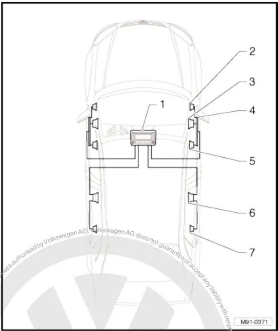
text_image
1 2 3 4 5 6 7 less authorised by Volkswagen AG, Volkswagen AG does not guarantee or accept any liability with res pres M91-0371DSP loudspeaker system
1 - Radio -R-
2 - Front right treble loudspeaker -R22- / front left treble loudspeaker -R20- in front doors/A-pillars.
3 - Front right bass loudspeaker -R23- / front left bass loudspeaker -R21-
4 - Front right mid-range loudspeaker -R104- / front left mid-range loudspeaker -R103-
5 - Rear right bass loudspeaker -R17- / rear left bass loudspeaker -R15-
6 - Rear right treble loudspeaker -R16- / rear left treble loudspeaker -R14-
7 - Amplifier -R12- under left front seat

text_image
Volkswagen AG, Volkswagen AG does not guarantee or accept any liability with respect to the cost of information in this case. Copyright © Volkswagen AG. Committed unless authorised by Volkswagen AG does not guarantee or accept any liability with respect to the cost of information in this case. Copyright © Volkswagen AG. Copyright by copyright. Copying for printing M91-037516.2 Removing and installing front bass loud-speakers
Removal and installation is performed in the same manner on the left and right sides.
Removing
- Switch off ignition and all electrical consumers and remove ignition key.
- Remove front door trim General body repairs, interior; Rep. Gr. 70.
- Release locking mechanism on connector -arrows- and disconnect connector.
- Drill out rivets -arrows- using suitable drill bit and remove loudspeaker.

Note
It is essential that all swarf be removed from the door because otherwise corrosion damage will occur.
- Immediately rectify any damage to paintwork caused when drilling out rivets.
Installing
- When installing new loudspeaker, secure with special pop rivets (note part number!)
Remainder of installation is carried out in reverse order of removal.
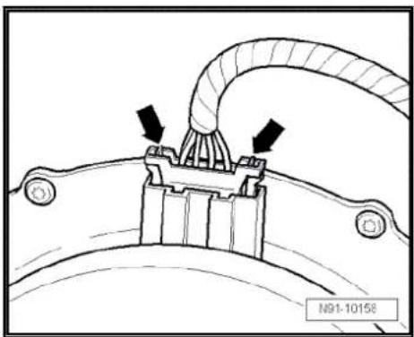
natural_image
Technical diagram of a mechanical component with arrows indicating assembly or connection (no text or symbols present)
natural_image
Technical line drawing of a mechanical component with arrows indicating motion or assembly (no text or symbols)16.3 Removing and installing rear bass loud-speakers
Removal and installation is performed in the same manner on the left and right sides.
Removing
- Switch off ignition and all electrical consumers and remove ignition key.
- Remove rear door trim General body repairs, interior; Rep. Gr. 70.
- Release locking mechanism on connector -arrows- and disconnect connector.

text_image
respect to the correctness of normalization N91-10158- Drill out rivets -arrows- using suitable drill bit and remove loudspeaker.

Note
It is essential that all swarf be removed from the door because otherwise corrosion damage will occur.
- Immediately rectify any damage to paintwork caused when drilling out rivets.
Installing
- When installing new loudspeaker, secure with special pop rivets (note part number!)
Remainder of installation is carried out in reverse order of removal.
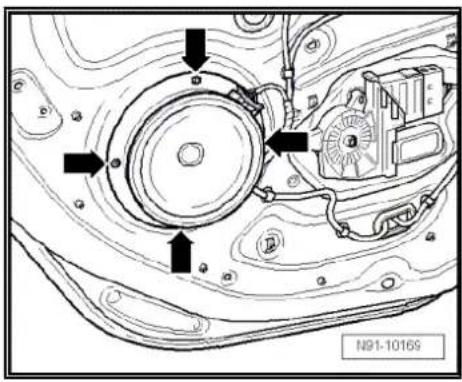
text_image
N91-1016916.4 Removing and installing front mid-range loudspeakers
The front right mid-range loudspeaker -R104- / front left mid-range loudspeaker -R103- are secured to the door trim from the rear.
Removal and installation is performed in the same manner on the left and right sides.
Removing
- Switch off ignition and all electrical consumers and remove ignition key.
- Remove front door trim General body repairs, interior; Rep. Gr. 70.
- Release locking mechanism on connector -arrows- and disconnect connector.

text_image
Accept any liability the correctness N91-10158- Remove bolts narrows- (1.5 Nm) and take loudspeaker off. Installing
Installation is carried out in reverse order of removal.

text_image
N91-10 16316.5 Removing and installing front treble loudspeakers
The front right treble loudspeaker -R22- / front left treble loudspeaker -R20- are installed in mirror triangular plate trims or in the left and right A-pillars.
◆ Removing and installing loudspeakers in mirror triangular plate trims → page 113
◆ Removing and installing loudspeakers in A-pillars ⇒ page 114
16.5.1 Removing and installing loudspeakers in mirror triangular plate trims
The front right treble loudspeaker -R22- / front left treble loudspeaker -R20- are installed in mirror triangular plate trim in both front doors.
Removal and installation is performed in the same manner on the left and right sides.
Removing
- Switch off ignition and all electrical consumers and remove ignition key.
- Remove front door trim → General body repairs, interior; Rep. Gr. 70.
-
Disconnect connector -arrows- in wiring to loudspeaker -arrows-.
-
Remove bolt -arrow-.
- Unclip trim together with the loudspeaker.
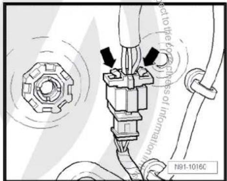
text_image
act to the 40% thickness of information N91-1016C

text_image
N91-10162- If the plastic clip -arrow- is still on trim panel after removing, take it off and fit it in the appropriate position in the door.
Otherwise the mirror triangular plate trim cannot be refitted correctly.
The loudspeaker can only be fitted in conjunction with mirror triangular plate trim.
Installing
Installation is carried out in reverse order of removal.
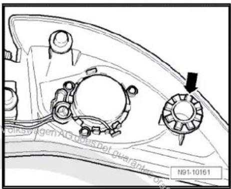
text_image
Volkswagen AG does not guarantee N91-1016116.5.2 Removing and installing loudspeakers in A-pillars
Front right treble loudspeaker -R22- / front left treble loudspeaker -R20- are installed in A-pillars.
Removal and installation is performed in the same manner on the left and right sides.
Front right treble loudspeaker -R22- / front left treble loudspeaker -R20- are permanently connected to the trims of the A-pillars and cannot be replaced individually. In the event of a defect, the A-pillar trim must be replaced.

Note
Note trim colour number when ordering spare part.
Removing
- Switch off ignition and all electrical consumers and remove ignition key.
- Remove the A-pillar trim General body repairs, interior; Rep. Gr. 70.
- Release and disconnect connector -arrow- at A-pillar.
Installing
Installation is carried out in reverse order of removal.

Note
Note trim colour number when ordering spare part.

text_image
Copyright by Volkswing N91-1123516.6 Removing and installing rear treble loudspeakers
The rear right treble loudspeaker -R16- / rear left treble loudspeaker -R14- are secured to the door trim from the rear.
The treble loudspeaker and the loudspeaker trim plate form one component.
Removal and installation is performed in the same manner on the left and right sides.
Removing
- Switch off ignition and all electrical consumers and remove ignition key.
- Remove rear door trim General body repairs, interior; Rep. Gr. 70.
- Release locking mechanism on connector -arrows- and disconnect connector.
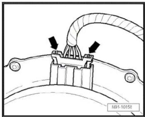
natural_image
Technical diagram of a mechanical component with arrows indicating assembly or connection (no text or symbols present)- Cut off the welded plastic nipples on loudspeaker trim -arrows-.
- Remove trim plate and loudspeaker together from door panel trim

text_image
NB1-10253Installing
- Fit loudspeaker trim plate together with loudspeaker into door trim panel.
- Weld plastic nipples -arrows- with a soldering iron.
Remainder of installation is carried out in reverse order of removal.
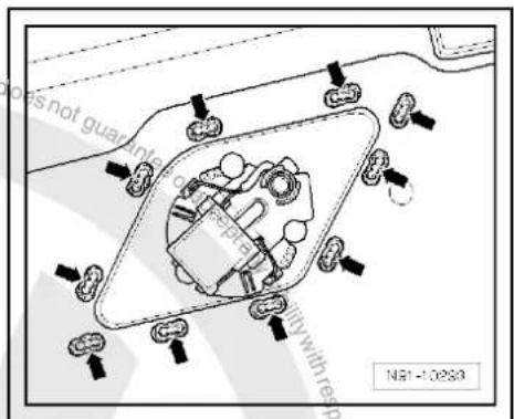
text_image
does not guarantee with res pate duty with res N81-1025316.7 Removing and installing frequency switch part
The left frequency switch -R18- / right frequency switch -R19- are installed in the door trims between the front left bass loudspeaker -R21- / front right bass loudspeaker -R23- and driver door control unit -J386- / front passenger door control unit -J387-.
Removal and installation is performed in the same manner on the left and right sides.
Removal
- Switch off ignition and all electrical consumers and remove ignition key.

- Remove front door trim General body repairs, interior; Rep. Gr. 70.
- Detach connector -1- from frequency switch -2-.
- Remove bolts -3- (1.5 Nm) and remove frequency switch.
Installing
Installation is carried out in reverse order of removal.
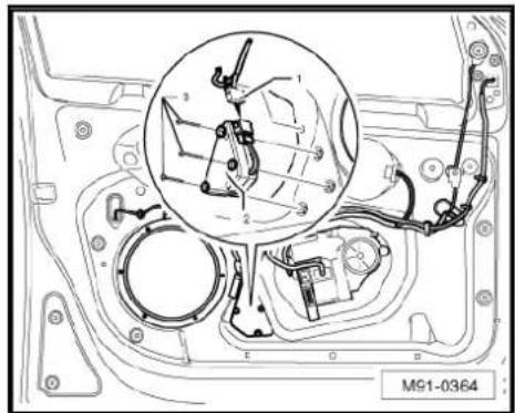
text_image
M91-0364
text_image
Protected by copyright copying/priather commercial purposes, in part or in whole, is not permitted unless authorised by Volkswagen AG. Volkswagen AG does not guarantee or accept any liability with respect to the correctness of information in this become copyright hereby Volkswagen AG.17 Satellite radio -R146-
17.1 General notes
Depending on which vehicle radio or radio navigation system is installed, the installation of a satellite radio -R146- may extend the reception to radio satellite programmes (XM/Sirius). The radio satellite programmes are limited to North America.
When dealing with complaints, it is absolutely necessary to know the functions of and how to operate the radio/radio-navigation system and the satellite radio -R146- Operating instructions.
To operate the satellite radio -R146- there is installed satellite tuner aerial -R172- on the rear of the roof.
The satellite radio -R146- is installed under the rear shelf in the luggage compartment (saloon). In the Variant, the satellite radio -R146- is installed under the right front seat.
As of MY2010, the satellite radio -R146- is integrated into the relevant radio/radio-navigation system.

Note
In the event of repair work or fault finding Vehicle diagnosis, testing and information system VAS 5051.
When the battery -A- is reconnected, please remember to check vehicle equipment (radio, clock, convenience electronics, etc.) in accordance with the Electrical system; Rep. Gr. 27 workshop manual and/or the instruction manual.
17.1.1 Fault finding
The satellite radio -R146- is equipped with self-diagnosis.
For fault finding, use the vehicle diagnosis, testing and information system -VAS 5051B- in "Guided fault finding" mode.
17.2 Removing and installing satellite radio - R146- (saloon)
The satellite radio -R146- is located under the rear shelf.
Removing
- Remove rear shelf General body repairs, interior; Rep. Gr. 68.
- Remove 4 bolts -arrows- (4 Nm).

text_image
M91-0329- Remove connectors -arrows- on satellite radio -R146-.
Installing
Installation is carried out in reverse order of removal.

text_image
M91-033017.3 Removing and installing satellite radio - R146- (Variant)
The satellite radio -R146- is located under the right front seat.
Removing
- Slide right front seat cover out in -direction of arrow-.

text_image
liability with respect to the correct N91-10783- Disconnect connectors -A- and remove the four screws -arrows-.
- Remove satellite radio -R146- together with retainer.

text_image
NOVA A N91-10782- Remove bolts -arrows-, counterhold nuts under retainer, otherwise these will also turn.
Installing
Installation is carried out in reverse order of removal.

natural_image
Technical diagram of an electrical contactor or relay component with no visible text or symbols17.4 Satellite radio -R146- connectors
Connectors
A - 8-pin connector
B - 8-pin connector
C - TER connection (brown) of satellite tuner aerial -R172- (up to model year 2006)
D - Connection SAT (green) of satellite tuner aerial -R172-
Connector A, 8-pin
1 - CAN bus (high)
2 - CAN bus (low)
3 - Not assigned
4 - Not assigned
5 - Signal earth to radio -R-
6 - Signal left to radio -R-
7 - Signal right to radio -R-
8 - Not assigned
Connector B, 8-pin
1 - Terminal 31
2 - Terminal 30

text_image
A B 7 1 C D 1 8 B 2 A91-1007
text_image
A B 7 1 C D 1 8 B 2 A91-1007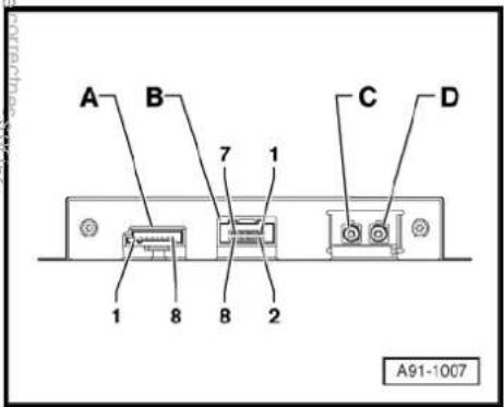
text_image
A B 7 1 C D 1 8 B 2 A91-100717.5 Activating satellite radio -R146-
Special tools and workshop equipment required
◆ Vehicle diagnostic, testing and information system -VAS 5051B-

text_image
VAS 5051 B W00-10343Procedure
- In vehicle diagnostic, testing and information system -VAS 5051B-, select "Guided fault finding".
- Using GoTo button, select "Functions/component" and the following menu options in succession:
♦ Body
Electrical system
◆ 01 - On board diagnosis-capable systems
◆ Digital radio tuner
◆ Digital radio tuner functions
◆ Digital radio tuner activation

text_image
Proteceived copy rights. Copyright Prereto commercial purposes, in part or in whole, is not permitted unless authorised by Volkswagen AG. Volkswagen AG does not guarantee or accept any liability with respect to the correctness of information in this current copyright. Copyright Volkswagen AG.18 Radio navigation system "RNS 300"
Radio navigation system RNS 300

Note
When dealing with complaints, it is absolutely necessary to understand the functions and the operation of the communication systems Instruction manual;
The anti-theft coding uses a fixed code, deactivating anti-theft coding page 128.
In the event of repair work or fault finding Vehicle diagnosis, testing and information system VAS5051 use "Guided fault finding" mode.
For perfect operation of the navigation system, the turn angle sensor in the unit has to be adjusted according to the installation position of the unit in the vehicle. Therefore, always note the part number when exchanging equipment. Incorrect installation could lead to a malfunction in the navigation system.
When the battery -A- is reconnected, please remember to check vehicle equipment (radio, clock, convenience electronics, etc.) in accordance with the Electrical system; Rep. Gr. 27 workshop manual and/or the owner's manual.
The use of magnetic-base aerials may lead to permanent magnetisation of the vehicle roof, resulting in a malfunction in the compass module. If confronted with complaints about inaccurate or incorrect directional indication of the compass module, ask the customer if a magnetic-base aerial has been used before carrying out any repair work.

text_image
J3 INFO RADIO CO NAV TRAFFIC SETUP N91-1050218.1 General description
The "RNS 300" combines the functions of a navigation system with those of a high-quality RDS radio.
The following is installed in the double DIN housing of the "RNS 300":
◆ An RDS radio
◆ A 5.8-inch monochrome display
◆ A navigation system with GPS satellite receiver
◆ A CD drive for the audio and navigation system
The "RNS 300" has 4 loudspeaker outputs.
The CD drive can read the CD-ROM for the navigation and can also play audio CDs. Whilst an audio CD is playing, only restricted operation of the navigation system is possible.
The following formats cannot be played:
◆ CD with diameter of 8 cm
◆ "Mixed CD" (CD with data and audio files)
◆ MP3
To extend the functionality, there is a connection for a CD changer -R41- and a telephone.
The aerial used is the aerial system in the rear window for the radio -R- and the navigation system aerial -R50- on the rear win-
dow (saloon). In the Variant, the aerials are located in the roof aerial. The aerial version comes without "diversity function".
18.1.1 Fault finding
The "RNS" is self-diagnosing.
For fault finding, use the vehicle diagnosis, testing and information system -VAS 5051B- in "Guided fault finding" mode.
18.2 Overview of radio navigation system "RNS 300"
1 - Control unit with display unit for radio and navigation -J503-
☐ Connectors
⇒ page 126
☐ Removing and installing
⇒ page 123
2 - CD changer -R41-
□ Optional
In centre console
☐ CD changer -R41-→ page 79
3 - Aerial -R11-
☐ Aerial systems (saloon) ⇒ page 171.
☐ Aerial systems (Variant) ⇒ page 179.
4 - GPS aerial -R50-
☐ Aerial systems (saloon) → page 171.
☐ Aerial systems (Variant) ⇒ page 179.
5 - Rear left treble loudspeaker -R14- / rear right treble loudspeaker -R16-
☐ Installed in the rear left and right door trims.
☐ Loudspeaker systems
⇒ page 106.
6 - Rear left bass loudspeaker -R15- / rear right bass loudspeaker -R17-
☐ Installed in the rear left and right door trims.
☐ Loudspeaker systems page 106.

text_image
1 2 3 4 5 6 7 8 9 not permitted unless with respect to the correct M91-03837 - Front left bass loudspeaker -R21- / front right bass loudspeaker -R23-
□ Installed in the front left and right door trims
☐ Loudspeaker systems → page 106.
8 - Front left mid-range loudspeaker -R103- / front right mid-range loudspeaker -R104-
☐ Installed in the front left and right door trims
☐ Loudspeaker systems page 106.
9 - Front left treble loudspeaker -R20- / front right treble loudspeaker -R22-
☐ Installed in mirror triangle of the right and left front doors
☐ Loudspeaker systems page 106.
18.3 Removing and installing control unit with display for radio and navigation -J503-

Note
The part number for the radio/navigation system is printed on a sticker on the radio/navigation system housing.
If the radio navigation system is replaced, the electronic anti-theft system must be deactivated, page 128. Please inform the customer of the new radio code.
If the radio code is not known, it can be requested via the established systems. You need the identification number of the radio navigation system in order to make the request. It is located on a sticker on the side of the radio-navigation system. In addition, the identification number is also stamped into the material of the side wall of the radio navigation system.
If a radio navigation unit from one vehicle is fitted into another vehicle, it is essential that the part number of the replacement unit is the same as that of the unit previously installed. Otherwise faults will occur with the navigation because the turn angle sensor setting in the radio navigation system will not be compatible with the vehicle.
Special tools and workshop equipment required
◆ Removal wedge -3409-
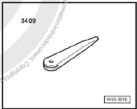
text_image
34.06 Copyright in this document. Copyright WJ0-2016Removing
- Take CD out of the unit Operating manual.
- Switch off ignition and all electrical consumers and remove ignition key.
- Remove upper cover together with air vents out of the middle of the dash panel until the underneath bolts of the centre console cover can be reached, General body repairs, exterior; Rep. Gr. 68.
- Remove bolts -arrows- (1.5 Nm).
- Carefully lever out cover of centre console using removal wedge -3409- -arrows- and take it off.
- Remove bolts -arrows- (1.5 Nm).
Pull control unit with display unit for radio navigation -J503- out of installation aperture sufficiently to gain access to the connectors on the rear.
- Press together connector locking mechanism in direction of -arrows-.
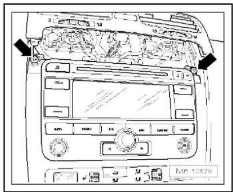
text_image
Diagram of car dashboard with labeled controls and directional arrows indicating engine or vehicle movement
text_image
Diagram of car dashboard with labeled control panels and directional arrows indicating engine or system components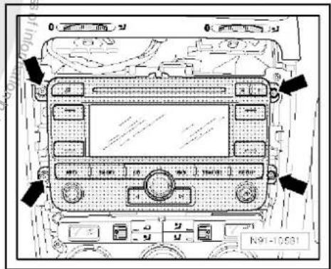
text_image
0 0 N91-10531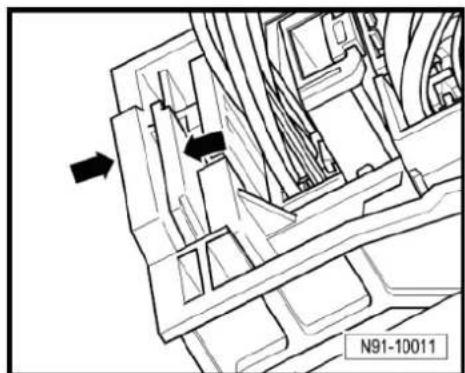
natural_image
Technical line drawing of a mechanical assembly with directional arrows (no text or symbols)- Then swing locking bar up in direction of -arrow- and disconnect connector.
- Release the connectors from the aerial connection for radio reception -1- and from the aerial connection for the navigation system -2- and disconnect them.
Installing
- Fit connectors on control unit with display for radio and navigation -J503-.
- Push control unit with display for radio and navigation -J503-straight into dash panel.

Note
When inserting the control unit with display for radio and navigation -J503- never press against the display or operating buttons, as otherwise the control unit with display for radio and navigation -J503- could become damaged.
- Fit the control unit with display for radio and navigation -J503-with 4 bolts -arrows- (1.5 Nm).
Install centre console cover. - Deactivate the anti-theft coding page 128.
- Check coding of control unit with display for radio and navigation -J503- and recode it page 129.


natural_image
Technical line drawing of a mechanical assembly with hoses and brackets (no text or symbols)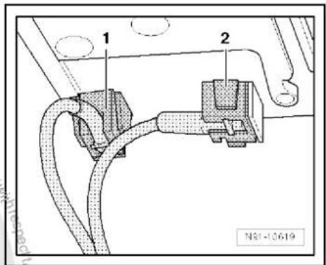
text_image
1 2 N81-10619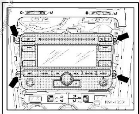
text_image
N91-1058118.4 "RNS 300" connectors
1 - Multi-pin connector 1, 8-pin, loudspeaker outputs
☐ Pin assignment ⇒ page 126
2 - Multi-pin connector 2, 8-pin, CAN bus, telephone
☐ Pin assignment ⇒ page 127
3 - Multi-pin connector 3, 12-pin, telephone
☐ Pin assignment ⇒ page 127
4 - Multi-pin connector 4, 12-pin, CD changer -R41-
☐ Pin assignment ⇒ page 127
5 - Aerial connection navigation system aerial -R50-
☐ Connector colour, blue
GPS
☐ Aerial system, saloon ⇒ page 171.
☐ Aerial system, Variant ⇒ page 179.
6 - Aerial connection aerial - R11-
☐ Connector colour, white
□ AM/FM
☐ Aerial system, saloon ⇒ page 171.
☐ Aerial system, Variant → page 179.
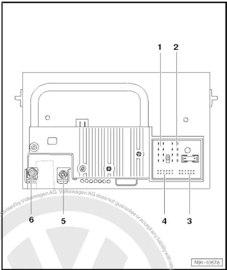
text_image
1 2 6 5 4 3 N91-1057818.4.1 Multi-pin connector 1, 8-pin, loudspeaker outputs
1 - Rear right loudspeaker (+)
2 - Front right loudspeaker (+)
3 - Front left loudspeaker (+)
4 - Rear left loudspeaker (+)
5 - Rear right loudspeaker (-)
6 - Front right loudspeaker (-)
7 - Front left loudspeaker (-)
8 - Rear left loudspeaker (-)

text_image
1 2 3 4 N91-1001618.4.2 Multi-pin connector 2, 8-pin, CAN bus, telephone
9 - CAN bus (high)
10 - CAN bus (low)
11 - Telephone mute
12 - Terminal 31
13 - S-contact
14 - ATA terminal 30 (optional)
15 - Terminal 30
16 - ATA (SAFE) terminal 30
18.4.3 Multi-pin connector 3, 12-pin, telephone
1-5 - Not assigned
6 - Telephone LF input signal (-)
7-11 - Not assigned
12 - Telephone LF input signal (+)
18.4.4 Multi-pin connector 4, 12-pin, CD changer -R41-
1 - Not assigned
2 - Audio earth from CD changer -R41-
3 - Not assigned
4 - Terminal 30 to CD changer -R41-
5 - Not assigned
6 - CD data out to CD changer -R41-
7 - Not assigned
8 - Audio left from CD changer -R41-
9 - Audio right from CD changer -R41-
10 - Control signal to CD changer -R41-
11 - CD data in from CD changer -R41-
12 - CD clock from CD changer -R41-
18.5 Electronic anti-theft coding
The radio navigation system is equipped with an electronic anti-theft system which works in combination with the dash panel insert.
After disconnection of the radio-navigation system's voltage supply, the system becomes operational again when the supply voltage is reconnected without the need to enter the radio code again. The prerequisite is that initial activation of the anti-theft coding has been performed and the radio navigation system is reconnected in the same vehicle.

text_image
1 2 3 4 N91-10016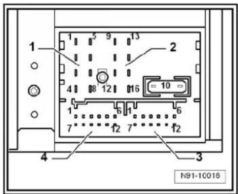
text_image
1 2 3 4 N91-10016
text_image
1 2 3 4 N91-10018
18.5.1 Functional notes
After the initial activation of the electronic anti-theft system, an internal radio code is stored in the radio-navigation system and in the dash panel insert. If the voltage supply for the radio-navigation system is cut off due to installation work, an exchange of data between the radio-navigation system and the dash panel insert takes place when the supply voltage is reconnected.
When this is done, the internal radio code of the radio-navigation system is compared to the code in the dash panel insert. If the code numbers are identical, the dash panel insert accepts that the connected radio navigation system belongs to the vehicle. The radio-navigation system is then immediately operational without the need to enter the radio code again.
If the radio navigation system is replaced, the new radio code must be entered.
Deactivating anti-theft coding page 128
Then after switching on the "S contact" via the ignition lock the code is automatically compared between the dash panel insert and the radio navigation system.
The comparison takes approx. 5 seconds. During this period no diagnostic unit may be connected.
Even after disconnection and reconnection of the voltage supply, the radio-navigation system of this vehicle will now be operational without the need to enter the radio code again.
The electronic anti-theft system is switched on and blocks the radio navigation system when:
◆ The radio navigation system is installed in another vehicle or
◆ The dash panel insert is changed.
A radio navigation system which has been locked by the electronic anti-theft system is shown when "SAFE" and "1000" appears in the display when switching the system on.
Deactivate the anti-theft coding to release the unit lock page 128.
18.5.2 Deactivating electronic anti-theft coding
A locked radio-navigation system will only work again if the correct radio code for the electronic anti-theft coding system is entered.

Note
◆ The anti-theft radio code is stuck on the radio card together with the unit number ⇒ Instruction manual.
◆ The radio card should not be kept in the vehicle for security reasons. Ask the customer for the radio code.
If a radio-navigation system is renewed, the radio code of the replacement unit also must be used.
◆ The customer must be informed that the radio code has changed.
- Obtain the radio code.
- Switch on the radio navigation system.
The radio navigation system automatically displays "SAFE" and then "1000".
Next to the four function buttons, the display shows the position of the radio code to be entered with an "X".
- Enter the code on the radio card in the correct sequence, using the four function buttons indicated. Press the relevant function button as many times as necessary until the correct number is shown in the centre of the display.
- Then press the function button next to the word "ENTER". The unit is then ready to operate again and switches to its last operating state.

Note
If you enter an incorrect radio code to deactivate the electronic lock, "SAFE" first flashes in the display, followed by "1000" again. The entire process can now be repeated again. The number of attempts is shown in the display. If an incorrect radio code is entered again, the radio-navigation system will be blocked for approx. one hour, i.e. it cannot be operated. This lock is indicated by the fact that "SAFE" is permanently shown in the display. The process of deactivating the anti-theft coding can then be repeated after one hour. Do not forget that only two attempts are allowed, after which the radio-navigation system will be blocked for one hour.
18.6 Adapting radio components "RNS 300"
Special tools and workshop equipment required
◆ Vehicle diagnostic, testing and information system -VAS 5051B-
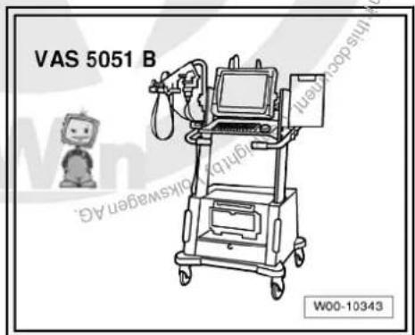
text_image
VAS 5051 B W00-10343Procedure
- In vehicle diagnostic, testing and information system -VAS 5051B-, select "Guided fault finding".
- Using GoTo button, select "Functions/component" and the following menu options in succession:
◆ Body
Electrical system
◆ 01 - On board diagnosis-capable systems
◆ Corresponding radio/navigation system
◆ Radio/navigation system functions
19 Radio navigation system "RNS 310"
Radio navigation system RNS 310

Note
When dealing with complaints, it is absolutely necessary to understand the functions and the operation of the communication systems Instruction manual.
◆ The anti-theft coding uses a fixed code ⇒ page 137.
In the event of repair work or fault finding Vehicle diagnosis, testing and information system VAS 5051.
For perfect operation of the navigation system, the turn angle sensor in the unit has to be adjusted according to the installation position of the unit in the vehicle. Therefore, always note the part number when exchanging equipment. Incorrect installation could lead to a malfunction in the navigation system.
When the battery -A- is reconnected, please remember to check vehicle equipment (radio, clock, convenience electronics, etc.) in accordance with the Electrical system; Rep. Gr. 27 workshop manual and/or the owner's manual.
The use of magnetic-base aerials may lead to permanent magnetisation of the vehicle roof, resulting in a malfunction in the compass module. If confronted with complaints about inaccurate or incorrect directional indication of the compass module, ask the customer if a magnetic-base aerial has been used before carrying out any repair work.
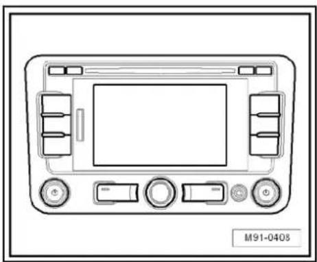
natural_image
Front view diagram of a vehicle dashboard with control buttons and display screen (no text or symbols)19.1 General description
The "RNS 310" combines the functions of a navigation system with those of a high-quality RDS radio. It is a further development of "RNS 300".
The following is installed in the double DIN housing of the "RNS 310":
◆ An RDS radio
◆ A 5.8-inch monochrome display
◆ A navigation system with GPS satellite receiver
◆ A CD drive for the audio and navigation system
The "RNS 310" has 4 loudspeaker outputs.
The CD drive can read the CD-ROM for the navigation and play audio CDs. Whilst an audio CD is playing, only restricted operation of the navigation system is possible.
The following formats cannot be played:
◆ CD with diameter of 8 cm
◆ "Mixed CD" (CD with data and audio files)
◆ MP3
To extend the functionality, there is a connection for a CD changer -R41- and a telephone.
The aerial used is the aerial system in the rear window for the radio -R- and the navigation system aerial -R50- (saloon). In the Variant, the GPS aerials -R50- are located in the roof aerial.

19.1.1 Fault finding
The radio navigation system is equipped with self-diagnosis.
For fault finding, use the vehicle diagnosis, testing and information system -VAS 5051B- in "Guided fault finding" mode.
19.2 Overview of radio navigation system "RNS 310"
1 - Control unit with display unit for radio and navigation -J503-
☐ Connectors
⇒ page 135
□ Removing and installing → page 132
2 - CD changer -R41-
□ Optional
In centre console
☐ CD changer -R41-→ page 79
3 - Multimedia system control unit -J650-
□ Optional
In centre console
☐ Multimedia system control unit -J650-→ page 95
4 - Connection for external au- dio sources -R199-
In centre console
☐ Connection for external audio sources -R199-→ page 91
5 - Aerial -R11- / Radio aerial 2 -R93-
Aerial systems (saloon) page 171.
☐ Aerial systems (Variant) → page 179.
6 - GPS aerial -R50-
☐ On the rear window (sa-loon)
☐ Roof aerial (Variant)
☐ Aerial systems (saloon) ⇒ page 171.
☐ Aerial systems (Variant) ⇒ page 179.
7 - Rear left treble loudspeaker -R14- / rear right treble loudspeaker -R16-
☐ Installed in the rear left and right door trims.
☐ Loudspeaker systems page 106.
8 - Rear left bass loudspeaker -R15- / rear right bass loudspeaker -R17-
☐ Installed in the rear left and right door trims.
☐ Loudspeaker systems page 106
9 - Front left bass loudspeaker -R21- / front right bass loudspeaker -R23-
☐ Installed in the front left and right door trims
☐ Loudspeaker systems page 106.
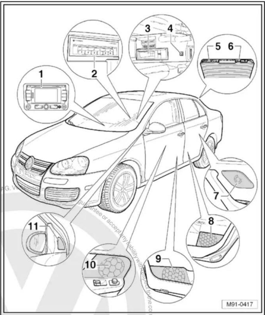
text_image
1 2 3 4 5 6 7 8 9 10 11 guarantee or accept any liability with respect to the co M91-041710 - Front left mid-range loudspeaker -R103- / front right mid-range loudspeaker -R104-
☐ Installed in the front left and right door trims
☐ Loudspeaker systems page 106.
11 - Front left treble loudspeaker -R20- / front right treble loudspeaker -R22-
☐ Installed in mirror triangle of the right and left front doors
☐ Loudspeaker systems page 106.
19.3 Removing and installing control unit with display for radio and navigation -J503-

Note
The part number for the radio/navigation system is printed on a sticker on the radio/navigation system housing.
If the radio navigation system is replaced, the electronic anti-theft system must be deactivated. → page 137.
Special tools and workshop equipment required
◆ Removal wedge -3409-

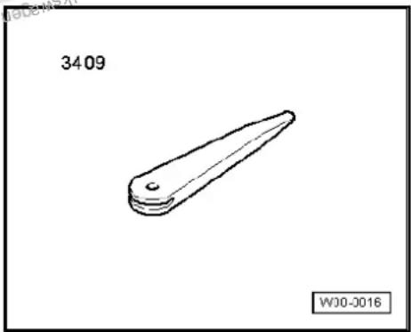
natural_image
Simple line drawing of a mechanical part with a pointed tip and rounded base, labeled '3409' and 'WJ0-2016' (no text or symbols on the object itself)Removing
- Take CD out of the unit Operating manual.
- Switch off ignition and all electrical consumers and remove ignition key.
- Remove upper cover together with air vents out of the middle of the dash panel until the underneath bolts of the centre console cover can be reached, General body repairs, exterior; Rep. Gr. 68.
- Remove bolts -arrows- (1.5 Nm).

text_image
Diagram of car air conditioning system with labeled controls and navigation arrows- Carefully lever out cover of centre console using removal wedge -3409- -arrows- and take it off.
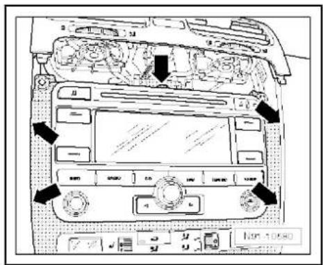
text_image
Diagram of car dashboard with labeled controls and directional arrows indicating engine or system components- Remove bolts -arrows- (1.5 Nm).
- Pull control unit with display unit for radio navigation -J503- out of installation aperture sufficiently to gain access to the connectors on the rear.
- Press together connector locking mechanism in direction of -arrows-.
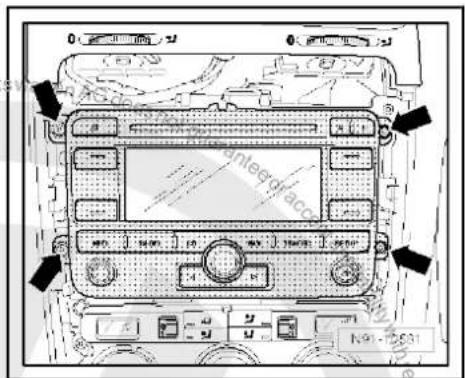
text_image
Antebrac 1.9 - 2.631- Then swing locking bar up in direction of -arrow- and disconnect connector.
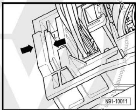
text_image
N91-10011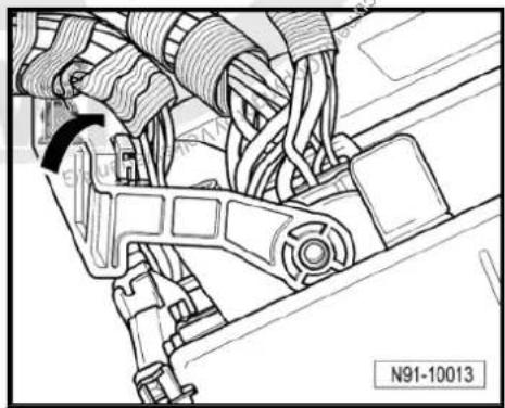
natural_image
Technical line drawing of a mechanical assembly with no visible text or symbols- Release connectors -arrows- of aerial connections and disconnect connectors.
Installing
- Fit connectors on control unit with display for radio and navigation -J503-.
- Push control unit with display for radio and navigation -J503-straight into dash panel.

Note
When inserting control unit with display for radio and navigation - J503- never press against the display or operating buttons, as otherwise the control unit with display for radio and navigation - J503- could become damaged.
- Fit the control unit with display for radio and navigation -J503-with 4 bolts -arrows- (1.5 Nm).
- Install centre console cover.
- Deactivate the anti-theft coding page 137.
- Check coding of control unit with display for radio and navigation -J503- and recode it page 138.

natural_image
Technical line drawing of two electrical connectors with wires, no text or symbols present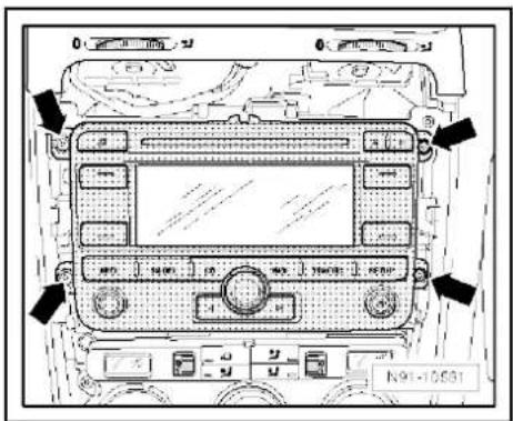
text_image
Diagram of a car dashboard with labeled buttons and indicators, showing status indicators and function keys.
text_image
Proteced by copyright. Copyright Practice Commercial purposes, in part or in whole, is not permitted unless authorised by Volkswagen AG. Volkswagen AG does not guarantee a accept any liability with respect to the correctness of information in this document. Copyright by Volkswagen AG.19.4 "RNS 310" connectors
1 - Multi-pin connector 1, 8-pin, loudspeaker outputs
☐ Pin assignment ⇒ page 136
2 - Multi-pin connector 2, 8-pin, CAN bus, telephone
☐ Pin assignment ⇒ page 136
3 - Multi-pin connector 3, 12-pin, telephone
☐ Pin assignment ⇒ page 136
4 - Multi-pin connector 4, 12-pin, CD changer -R41-
☐ Pin assignment ⇒ page 137
5 - Aerial connection navigation system aerial -R50-
☐ Colour of connector; blue
GPS
☐ Aerial system, saloon
⇒ page 171.
☐ Aerial system, Variant
⇒ page 179.
6 - Aerial connection
☐ Connector colour, white
FM2
☐ Aerial system, saloon
⇒ page 171:
☐ Aerial system, Variant page 179.
7 - Aerial connection
☐ Connector colour, white
□ AM/FM
☐ Aerial system, saloon page 171.
☐ Aerial system, Variant page 179.

text_image
Kswagen AG does not guarantee or accept any liability with respect. 1 2 7 6 5 4 3 Copyright by Volkswagen AG. M91-040619.4.1 Multi-pin connector 1, 8-pin, loudspeaker outputs
1 - Rear right loudspeaker (+)
2 - Front right loudspeaker (+)
3 - Front left loudspeaker (+)
4 - Rear left loudspeaker (+)
5 -hok Rear right loudspeaker (-)
6 Front right loudspeaker (-)
7 Part Front left loudspeaker (-)
8 _s Rear left loudspeaker (-)
19.4.2 Multi-pin connector 2, 8-pin, CAN bus, telephone
9 - CAN bus (high)
10 - CAN bus (low)
11 - Telephone mute
12 - Terminal 31
13 - Not assigned
14 - Not assigned
15 - Terminal 30
16 - ATA (SAFE) terminal 30
19.4.3 Multi-pin connector 3, 12-pin, telephone
1–5 - Not assigned
6 - Telephone LF input signal (-)
7-11 - Not assigned
12 - Telephone LF input signal (+)

text_image
1 2 3 4 N91-10928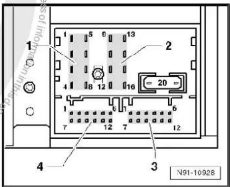
text_image
1 2 3 4 N91-10928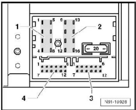
text_image
1 2 3 4 N91-1092819.4.4 Multi-pin connector 4, 12-pin, CD changer -R41-
1 - Audio input left (+)
2 - Audio input earth
3 - Audio earth from CD changer -R41-
4 - Terminal 30 to CD changer -R41-
5 - Not assigned
6 - CD data out to CD changer -R41-
7 - Audio input right (+)
8 - Audio left from CD changer -R41-
9 - Audio right from CD changer -R41-
10 - Control signal to CD changer -R41-
11 - CD data in from CD changer -R41-
12 - CD clock from CD changer -R41-
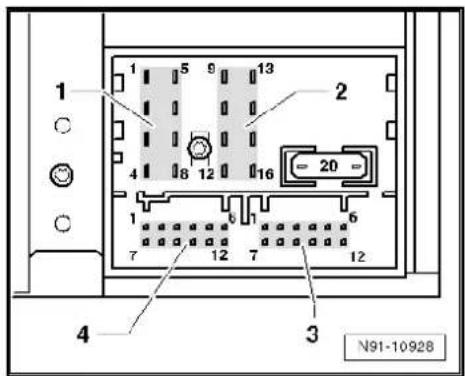
text_image
1 5 9 13 2 4 8 12 16 1 7 12 7 12 4 3 N91-1092819.5 Electronic anti-theft coding
The radio navigation system is equipped with an electronic anti-theft system which works in combination with the dash panel insert.
After disconnection of the radio-navigation system's voltage supply, the system becomes operational again when the supply voltage is reconnected without the need to enter the radio code again. The prerequisite is that initial activation of the anti-theft coding has been performed and the radio navigation system is reconnected in the same vehicle.
The radio code is determined by means of the vehicle diagnosis, testing and information system -VAS 5051B-. The radio card used in the past and the sticker on the radio-navigation system have been discontinued.

Note
In order to find out the radio code, the vehicle diagnosis, testing and information system -VAS 5051B- must be connected "online" (network connection), and the user must possess valid rights to use the programme for requesting radio codes.
19.5.1 Deactivating electronic anti-theft coding
A locked radio-navigation system will only work again if the correct radio code for the electronic anti-theft coding system is entered.
Using the VAS tester to find out the radio code:
- Select "guided fault finding" in the vehicle diagnosis, testing and information system -VAS 5051B-.
- Using GoTo button, select "Functions/component" and the following menu options in succession:
♦ Body
Electrical system
◆ 01 - On board diagnosis-capable systems
◆ Corresponding radio/navigation system

◆ Radio/navigation system functions
◆ Radio code request
Your system rights are then determined. The operating data, the VIN and the unit number of the radio or radio-navigation system are then read out automatically.

Note
When a new radio-navigation system is being installed, it is possible that the vehicle diagnosis, testing and information system - VAS 5051B- cannot read out the unit number of the radio-navigation system. In this case, please enter the unit number manually. It can be read on a sticker on the radio-navigation system and is also embossed on the radio-navigation system.
The radio code determined is then shown on the display of the vehicle diagnosis, testing and information system -VAS 5051B-.
The anti-theft code must now be entered manually into the radio navigation system.
Deactivating anti-theft coding:
- Switch on the radio navigation system.
The word "SAFE" appears for approx. 10 seconds on the display and then number sequence "1000".
- Enter the radio code by pressing the corresponding function buttons until the right number sequence appears.
After the four-digit radio code has been entered, "OK" appears on the display.
- Once you have entered the correct radio code, confirm it with the "OK" function button on the display.
The unit will be released and is ready for use.

Note
If the incorrect radio code is entered, it can be immediately corrected with a further attempt. If the incorrect radio code is entered twice, the radio-navigation system is blocked for one hour. Leave ignition and radio navigation unit switched on. The process of deactivating the anti-theft coding can then be repeated after one hour. Do not forget that only two attempts are allowed, after which the radio-navigation system will be blocked for one hour.
19.6 Adapting radio components "RNS 310"
Special tools and workshop equipment required
◆ Vehicle diagnostic, testing and information system -VAS 5051B-
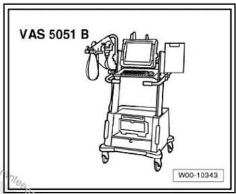
text_image
VAS 5051 B W00-10343Procedure
- In vehicle diagnostic, testing and information system -VAS 5051B-, select "Guided fault finding".
- Using [GoTo] button, select "Functions/component" and the following menu options in succession:
Body
Electrical system
◆ 01 - On board diagnosis-capable systems
◆ Corresponding radio/navigation system
◆ Radio/navigation system functions

20 Radio navigation system "RNS 315"
Radio navigation system RNS 315

Note
When dealing with complaints, it is absolutely necessary to understand the functions and the operation of the communication systems Instruction manual.
◆ The anti-theft coding uses a fixed code → page 137.
In the event of repair work or fault finding Vehicle diagnosis, testing and information system VAS 5051.
For perfect operation of the navigation system, the turn angle sensor in the unit has to be adjusted according to the installation position of the unit in the vehicle. Therefore, always note the part number when exchanging equipment. Incorrect installation could lead to a malfunction in the navigation system.
When the battery -A- is reconnected, please remember to check vehicle equipment (radio, clock, convenience electronics, etc.) in accordance with the Electrical system; Rep. Gr. 27 workshop manual and/or the owner's manual.
The use of magnetic-base aerials may lead to permanent magnetisation of the vehicle roof, resulting in a malfunction in the compass module. If confronted with complaints about inaccurate or incorrect directional indication of the compass module, ask the customer if a magnetic-base aerial has been used before carrying out any repair work.
20.1 General description
The "RNS 315" combines the functions of a navigation system with those of a high-quality RDS radio. It is a further development of "RNS 310".
The following is installed in the double DIN housing of the "RNS 315":
◆ An RDS radio
◆ A 5.8-inch monochrome display
◆ A navigation system with GPS satellite receiver
◆ A CD drive for the audio and navigation system
The "RNS 315" has 4 loudspeaker outputs.
The CD drive can read the CD-ROM for the navigation and play audio CDs. Whilst an audio CD is playing, only restricted operation of the navigation system is possible.
The following formats cannot be played:
◆ CD with diameter of 8 cm
◆ "Mixed CD" (CD with data and audio files)
To extend the functionality, there is a connection for a CD changer -R41- and a telephone.
The aerial used is the aerial system in the rear window for the radio -R- and the navigation system aerial -R50- in the roof aerial.
20.1.1 Fault finding
The radio navigation system is equipped with self-diagnosis.

natural_image
Front view diagram of a vehicle dashboard with control buttons and display screen (no text or symbols)For fault finding, use the vehicle diagnosis, testing and information system -VAS 5051B- in "Guided fault finding" mode.
20.2 Overview of radio navigation system "RNS 315"
1 - Front left treble loudspeaker -R20- / front right treble loudspeaker -R22-
☐ In mirror triangle/A-pillar on the left and right
☐ Loudspeaker systems
⇒ page 106
2 - Multifunction buttons on left in steering wheel -E440-
☐ For further information, refer to chapter Multifunction steering wheel page 199.
3 - Control unit with display unit for radio and navigation -J503-
☐ Connectors
⇒ page 145
☐ Removing and installing
⇒ page 142
4 - Connection for external au-dio sources -R199-
☐ Integrated in front of unit of "RNS 315"
☐ For further information, see operating manual of "RNS 315".
5 - Multimedia system control unit -J650-
Optional
In glove compartment
□ Multimedia system control unit -J650-→ page 95
6 - GPS aerial -R50-
□ Roof aerial
☐ Aerial systems (saloon) model year 2011 → page 179.
7 - Aerial -R11- / Radio aerial 2 -R93-
☐ Aerial systems (saloon) model year 2011 → page 179.
8 - Rear left bass loudspeaker -R15- / rear right bass loudspeaker -R17-
☐ Installed in the rear left and right door trims
☐ Loudspeaker systems page 106
9 - Front left bass loudspeaker -R21- / front right bass loudspeaker -R23-
☐ Installed in the front left and right door trims
☐ Loudspeaker systems page 106
20.3 Removing and installing control unit with display for radio and navigation -J503-

Note
◆ The part number for the radio/navigation system is printed on a sticker on the radio/navigation system housing.
If the radio navigation system is replaced, the electronic anti-theft system must be deactivated, page 137.
Special tools and workshop equipment required
◆ Removal wedge -3409-

text_image
3409 or accept any liability WJ0-0016Removing
- Take CD out of the unit => Operating manual.
- Switch off ignition and all electrical consumers and remove ignition key.
- Remove upper cover together with air vents out of the middle of the dash panel until the underneath bolts of the centre console cover can be reached, General body repairs, exterior; Rep. Gr. 68.
- Remove bolts -arrows- (1.5 Nm).
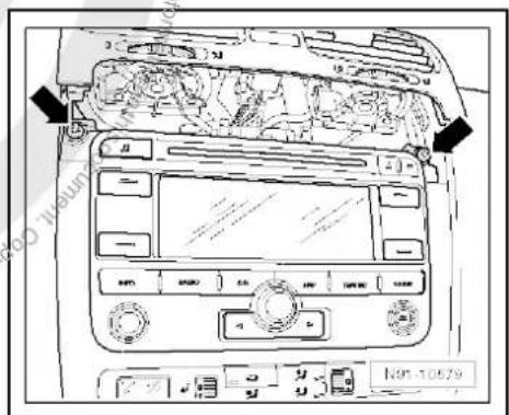
text_image
Diagram of car air conditioning system with labeled controls and directional arrows indicating airflow or movement- Carefully lever out cover of centre console using removal wedge -3409- -arrows- and take it off.

text_image
Diagram of car dashboard with labeled controls and directional arrows indicating engine or system components- Remove bolts -arrows- (1.5 Nm).
- Pull control unit with display unit for radio navigation -J503- out of installation aperture sufficiently to gain access to the connectors on the rear.
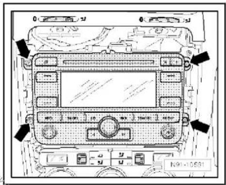
text_image
N91-10531- Press together connector locking mechanism in direction of -arrows-.
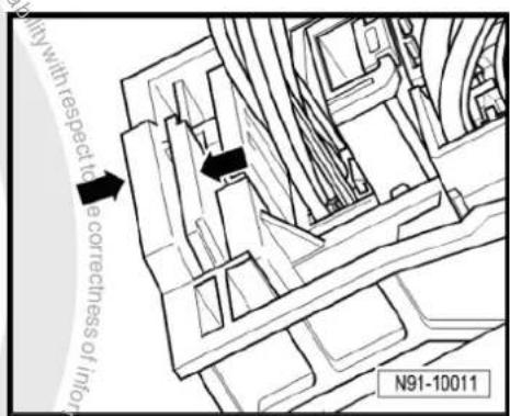
text_image
with respect to a correctness of infty N91-10011- Then swing locking bar up in direction of -arrow- and disconnect connector.
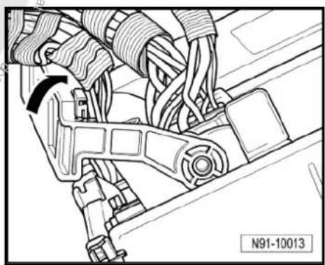
natural_image
Technical line drawing of a mechanical assembly with hoses and brackets (no text or symbols)
- Release connectors -arrows- of aerial connections and disconnect connectors.
Installing
- Fit connectors on control unit with display for radio and navigation -J503-.
- Push control unit with display for radio and navigation -J503-straight into dash panel.

Note
When inserting control unit with display for radio and navigation - J503- never press against the display or operating buttons, as otherwise the control unit with display for radio and navigation - J503- could become damaged.
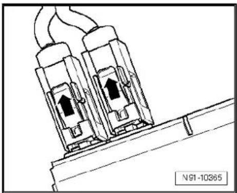
natural_image
Technical line drawing of two electrical connectors with wires, no text or symbols present- Fit the control unit with display for radio and navigation -J503-with 4 bolts -arrows- (1.5 Nm).
- Install centre console cover.
- Deactivate the anti-theft coding page 137.
- Check coding of control unit with display for radio and navigation -J503- and recode it page 138.
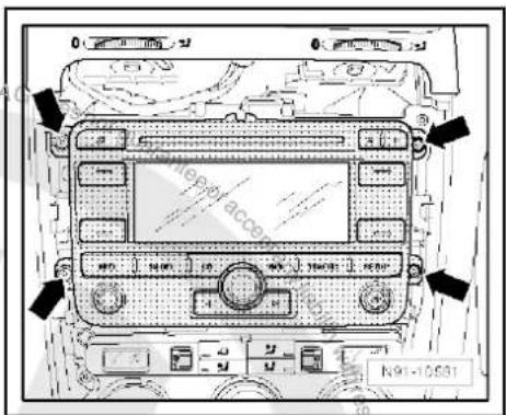
text_image
N91-1053120.4 "RNS 315" connectors
1 - Multi-pin connector 1, 8-pin, loudspeaker outputs
☐ Pin assignment ⇒ page 145
2 - Multi-pin connector 2, 8-pin, CAN bus, telephone
☐ Pin assignment ⇒ page 146
3 - Multi-pin connector 3, 12-pin, telephone
☐ Pin assignment ⇒ page 146
4 - Multi-pin connector 4, 12-pin, CD changer -R41-
☐ Pin assignment ⇒ page 146
5 - Aerial connection navigation system aerial -R50-
GPS
☐ Aerial systems in sa-loons from model year 2011 ⇒ page 179
6 - Aerial connection
FM2
☐ Aerial systems in sa-loons from model year 2011 ⇒ page 179
7 - Aerial connection
□ AM/FM
☐ Aerial systems in saloons from model year 2011 → page 179
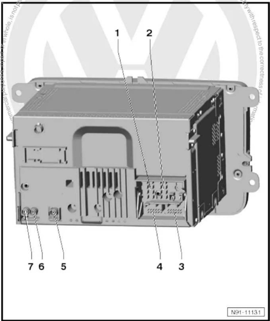
text_image
1 2 7 6 5 4 3 N91-1113120.4.1 Multi-pin connector 1, 8-pin, loudspeaker outputs
1 - Rear right loudspeaker (+)
2 - Front right loudspeaker (+)
3 - Front left loudspeaker (+)
4 - Rear left loudspeaker (+)
5 - Rear right loudspeaker (-)
6 - Front right loudspeaker (-)
7 - Front left loudspeaker (-)
8 - Rear left loudspeaker (-)

text_image
1 2 3 4 N91-1092820.4.2 Multi-pin connector 2, 8-pin, CAN bus, telephone
9 - CAN bus (high)
10 - CAN bus (low)
11 - Telephone mute
12 - Terminal 31
13 - Not assigned
14 - Not assigned
15 - Terminal 30
16 - ATA (SAFE) terminal 30
20.4.3 Multi-pin connector 3, 12-pin, telephone
1–5 - Not assigned
6 - Telephone LF input signal (-)
7-11 - Not assigned
12 - Telephone LF input signal (+)
20.4.4 Multi-pin connector 4, 12-pin, CD changer -R41-
1 - Audio input left (+)
2 - Audio input earth
3 - Audio earth from CD changer -R41-
4 - Terminal 30 to CD changer -R41-
5 - Not assigned
6 - CD data out to CD changer -R41-
7 - Audio input right (+)
8 - Audio left from CD changer -R41-
9 - Audio right from CD changer -R41-
10 - Control signal to CD changer -R41-
11 - CD data in from CD changer -R41-
12 - CD clock from CD changer -R41-

text_image
1 2 3 4 N91-10928
text_image
1 2 3 4 N91-10928
text_image
1 2 3 4 N91-10928
20.4.5 Aerial connections
1 - Aerial connection (AM/FM) of aerial amplifier 2 -R111-
2 - Aerial connection (FM2) of aerial amplifier -R24-
3 - Aerial connection (GPS) of navigation system aerial -R50-
text_image
1 2 3 M91-1001020.5 Electronic anti-theft coding
The radio navigation system is equipped with an electronic anti-theft system which works in combination with the dash panel insert.
After disconnection of the radio-navigation system's voltage supply, the system becomes operational again when the supply voltage is reconnected without the need to enter the radio code again. The prerequisite is that initial activation of the anti-theft coding has been performed and the radio navigation system is reconnected in the same vehicle.
The radio code is determined by means of the vehicle diagnosis, testing and information system -VAS 5051B-. The radio card used in the past and the sticker on the radio-navigation system have been discontinued.

Note
In order to find out the radio code, the vehicle diagnosis, testing and information system -VAS 5051B- must be connected "online" (network connection), and the user must possess valid rights to use the programme for requesting radio codes.
20.5.1 Deactivating electronic anti-theft coding
A locked radio-navigation system will only work again if the correct radio code for the electronic anti-theft coding system is entered.
Using the VAS tester to find out the radio code:
- Select "guided fault finding" in the vehicle diagnosis, testing and information system -VAS 5051B-.
- Using GoTo button, select "Functions/component" and the following menu options in succession:
Body
Electrical system
◆ 01 - On board diagnosis-capable systems
◆ Corresponding radio/navigation system
◆ Radio/navigation system functions
◆ Radio code request
Your system rights are then determined. The operating data, the VIN and the unit number of the radio or radio-navigation system are then read out automatically.

Note
When new radio-navigation systems are being installed, it is possible that the vehicle diagnosis, testing and information system - VAS 5051B- cannot read out the unit number of the radio-navigation system. In this case, please enter the unit number manually. It can be read on a sticker on the radio-navigation system and is also embossed on the radio-navigation system.
The radio code determined is then shown on the display of the vehicle diagnosis, testing and information system -VAS 5051B-.
The radio code must now be entered manually into the radio navigation system.
Deactivating anti-theft coding:
- Switch on the radio navigation system.
The word "SAFE" appears for approx. 10 seconds on the display and then number sequence "1000".
- Enter the radio code by pressing the corresponding function buttons until the right number sequence appears.
After the four-digit radio code has been entered, "OK" appears on the display.
- Once you have entered the correct radio code, confirm it with the "OK" function button on the display.
The unit will be released and is ready for use.

Note
If the incorrect radio code is entered, it can be immediately corrected with a further attempt. If the incorrect radio code is entered twice, the radio-navigation system is blocked for one hour. Leave ignition and radio navigation unit switched on. The process of deactivating the anti-theft coding can then be repeated after one hour. Do not forget that only two attempts are allowed, after which the radio-navigation system will be blocked for one hour.
20.6 Adapting radio components "RNS 315"
Special tools and workshop equipment required
◆ Vehicle diagnosis, testing and information system -VAS 5051B-
text_image
VAS 5051 B W00-10343Procedure
- Select "guided fault finding" in the vehicle diagnosis, testing and information system -VAS 5051B-.
- Using GoTo button, select "Functions/component" and the following menu options in succession:
♦ Body
Electrical system
◆ 01 - On board diagnosis-capable systems
◆ Corresponding radio/navigation system
◆ Radio/navigation system functions

text_image
Protected by copyright. Copyright water commercial purposes, in part or in whole, is not permitted unless authorised by Volkswagen AG. Volkswagen AG does not guarantee raced any liability with respect to the coreness of information in this document. Copyrightly Volkswagen AG.21 Radio/navigation system "RNS MFD 2 DVD"
Radio/navigation system RNS MFD 2 DVD

Note
When dealing with complaints, it is absolutely necessary to understand the functions and the operation of the communication systems Instruction manual.
◆ The anti-theft coding uses a fixed code, deactivating anti-theft coding ⇒ page 158.
In the event of repair work or fault finding Vehicle diagnosis, testing and information system VAS 5051 use "Guided fault finding" mode.
For perfect operation of the navigation system, the turn angle sensor in the unit has to be adjusted according to the installation position of the unit in the vehicle. Therefore, always note the part number when exchanging equipment. Incorrect installation could lead to a malfunction in the navigation system.
When the battery -A- is reconnected, please remember to check vehicle equipment (radio, clock, convenience electronics, etc.) in accordance with the Electrical system; Rep. Gr. 27 workshop manual and/or the owner's manual.
The use of magnetic-base aerials may lead to permanent magnetisation of the vehicle roof, resulting in a malfunction in the compass module. If confronted with complaints about inaccurate or incorrect directional indication of the compass module, ask the customer if a magnetic-base aerial has been used before carrying out any repair work.
21.1 General description
The "RNS MFD 2 DVD" combines the functions of a navigation system with that of a high quality RDS radio.
The following is installed in the double DIN housing of the "RNS MFD 2 DVD":
◆ An RDS radio
◆ A 6.5-inch colour display as 16:9 format
◆ A navigation system with GPS satellite receiver
◆ A DVD drive for the navigation system
The following loudspeakers are installed with the "RNS MFD 2 DVD":
◆ A bass loudspeaker, a mid-range loudspeaker and a treble loudspeaker in each of the front doors.
◆ A bass loudspeaker and a treble loudspeaker in each of the rear doors.
The "RNS MFD 2 DVD" is available in a version with loudspeakers operated via the 4 internal loudspeaker outputs or in a version with amplifier -R12-. In this case, the loudspeakers are connected directly to the amplifier -R12- and the loudspeaker outputs of the radio/navigation system are used for amplifier -R12- signal input.

text_image
INFO RADIO CO ROUTE REST NAV MAP M91-0348

Note
◆ Audio CDs can only be played with a separate CD changer - R41-.
In connection with the "RNS MFD 2 DVD" a CD changer -R41-is always installed in the centre console.
To extend the functionality, there is a connection for a CD changer -R41-, TV tuner -R78-, satellite radio -R146-, telephone part of the equipment.
The aerial used is an aerial system in the rear window (saloon) with diversity function and with satellite radio -R146- an additional roof aerial. In the Variant, the aerials are located in the rear right side window and in the roof aerial.
21.1.1 Fault finding
The radio navigation system is equipped with self-diagnosis.
For fault finding, use the vehicle diagnosis, testing and information system -VAS 5051B- in "Guided fault finding" mode.
21.2 Overview of radio-navigation system
1 - Amplifier -R12-
□ Optional
Under left front seat
☐ Amplifier -R12-→ page 100.
2 - CD changer -R41-
□ Optional
In centre console
☐ CD changer -R41-→ page 79
3 - Control unit with display unit for radio and navigation -J503-
Connectors
⇒ page 155
□ Removing and installing
⇒ page 152
4 - Front left mid-range loudspeaker -R103- / front right mid-range loudspeaker -R104-
□ Installed in the front left and right door trims
☐ Loudspeaker systems
⇒ page 106
5 - Satellite tuner aerial -R172-
Optional
On roof rear side
☐ Aerial systems (saloon) ⇒ page 171
☐ Aerial systems (Variant) → page 179
6 - Aerial -R11- / radio aerial 2
text_image
1 2 3 4 5 6 7 8 9 10 11 M91-0319-R93- / navigation system aerial -R50-
☐ Aerial systems (saloon) ⇒ page 171
☐ Aerial systems (Variant) ⇒ page 179
7 - Satellite radio -R146-
□ Optional
☐ Under the rear shelf in luggage compartment
☐ Satellite radio -R146- → page 117
8 - Rear left treble loudspeaker -R14- / rear right treble loudspeaker -R16-
☐ Installed in the rear left and right door trims
☐ Loudspeaker systems page 106
9 - Rear left bass loudspeaker -R15-/rear right bass loudspeaker -R17-
☐ Installed in the rear left and right door trims
☐ Loudspeaker systems => page 106
10 - Front left bass loudspeaker -R21- / front right bass loudspeaker -R23-
☐ Installed in the front left and right door trims
☐ Loudspeaker systems => page 106
11 - Front left treble loudspeaker -R20- / front right treble loudspeaker -R22-
☐ Installed in mirror triangle of the right and left front doors
☐ Loudspeaker systems ⇒ page 106
21.3 Removing and installing control unit with display for radio and navigation -J503-

Note
The part number for the radio/navigation system is printed on a sticker on the radio/navigation system housing.
If the radio navigation system is replaced, the electronic anti-theft system must be deactivated, page 158. Please inform the customer of the new radio code.
If the radio code is not known, it can be requested via the established systems. In order to request the code, you need the identification number of the radio-navigation system. It is located on a sticker on the side of the radio-navigation system. In addition, the identification number is also stamped into the material of the side wall of the radio navigation system.
If a radio navigation unit from one vehicle is fitted into another vehicle, it is essential that the part number of the replacement unit is the same as that of the unit previously installed. Otherwise faults will occur with the navigation because the turn angle sensor setting in the radio navigation system will not be compatible with the vehicle.

Special tools and workshop equipment required
◆ Removal wedge -3409-

text_image
3409 Does not guarantee or accept liability with respect W00-0016Removing
- Take CD/DVD out of the unit Operating manual.
- Switch off ignition and all electrical consumers and remove ignition key.
- Remove upper cover together with air vents out of the middle of the dash panel until the underneath bolts of the centre console cover can be reached, General body repairs, exterior; Rep. Gr. 68.
- Remove bolts -arrows- (1.5 Nm).
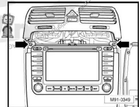
text_image
M91-0349- Carefully lever out cover of centre console using removal wedge -3409- -arrows- and take it off.

text_image
M91-0350- Remove bolts -arrows- (1.5 Nm) on control unit with display for radio and navigation -J503-.
- Pull control unit with display unit for radio navigation -J503- out of installation aperture sufficiently to gain access to the connectors on the rear.
- Press together connector locking mechanism in direction of -arrows-.
- Then swing locking bar up in direction of -arrow- and disconnect connector.
- Release connectors -arrows- of aerial connections and disconnect connectors.
Installing
- Fit connectors on control unit with display for radio and navigation -J503-.
- Push control unit with display for radio and navigation -J503-straight into dash panel.

Note
When inserting control unit with display for radio and navigation - J503- never press against the display or operating buttons, as otherwise the control unit with display for radio and navigation - J503- could become damaged.

text_image
M91-0351
text_image
AG. Volkswagen, A. Grobe N91-10011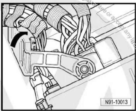
text_image
N91-10013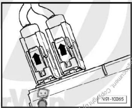
natural_image
Technical illustration of two connected electrical connectors with arrows indicating internal components (no text or symbols)- Fit the control unit with display for radio and navigation -J503-with 4 bolts -arrows- (1.5 Nm).
- Install centre console cover.
- Deactivate the anti-theft coding page 158.
- Check coding of control unit with display for radio and navigation -J503- and recode it page 159.

text_image
M91-035121.4 Connectors
1 - Multi-pin connector 1, 18-pin, for video and LF input
☐ Pin assignment ⇒ page 156
2 - Connection navigation system aerial -R50-
☐ Colour of connector; blue
GPS
☐ Aerial system, saloon
⇒ page 171.
☐ Aerial system, Variant
⇒ page 179.
3 - Multi-pin connector 3, 8-pin, loudspeaker outputs
☐ Pin assignment → page 156
4 - Multi-pin connector 4, 8-pin, voltage supply, CAN bus
☐ Pin assignment ⇒ page 157
5 - Multi-pin connector 5, 12-pin, telephone, amplifier
☐ Pin assignment ⇒ page 157
6 - Multi-pin connector 6, 12-pin, CD changer -R41- / satellite radio -R146-
☐ Pin assignment ⇒ page 157
7 - Aerial connection
☐ Connector colour, white
FM2
☐ Aerial system, saloon page 171.
☐ Aerial system, Variant page 179.
8 - Aerial connection
☐ Connector colour, white
□ AM/FM
☐ Aerial system, saloon ⇒ page 171.
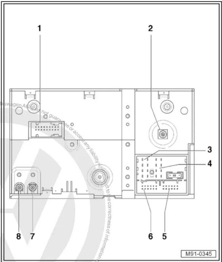
text_image
1 2 3 4 6 5 8 7 M91-0345☐ Aerial system, Variant page 179.
21.4.1 Multi-pin connector 1, 18-pin, for video and LF input
This connector is only assigned if the respective TV tuner -R78-is part of the equipment.
1 - Not assigned
2 - Video input LF earth
3 - Video input LF earth
4 - Video input LF earth
5 - Video input earth
6 - Video switch signal
7 - Video input earth
8 - Video input earth
9 - Video input earth
10 - Not assigned
11 - Video input LF left
12 - Video input LF right
13 - Screening, earth
14 - Video input sync
15 - 50 Hertz/60 Hertz
16 - Video input blue
17 - Video input green
18 - Video input red
21.4.2 Multi-pin connector 3, 8-pin, loudspeaker outputs
1 - Rear right loudspeaker (+)
2 - Front right loudspeaker (+)
3 - Front left loudspeaker (+)
4 - Rear left loudspeaker (+)
5 - Rear right loudspeaker (-)
6 - Front right loudspeaker (-)
7 - Front left loudspeaker (-)
8 - Rear left loudspeaker (-)
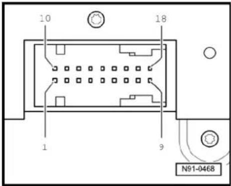
text_image
10 18 1 9 N91-0468
text_image
3 1 5 9 13 4 4 8 12 16 = 10 = 1 6 1 6 7 12 7 12 6 5 N91-046921.4.3 Multi-pin connector 4, 8-pin, CAN bus
9 - CAN bus (high)
10 - CAN bus (low)
11 - Telephone mute
12 - Terminal 31
13 - Radio -R- on
14 - Not assigned
15 - Terminal 30
16 - ATA (SAFE) terminal 30
21.4.4 Multi-pin connector 5, 12-pin, telephone, amplifier
1 - Not assigned
2 - Not assigned
3 - Line out, left
4 - Not assigned
5 - Navigation language (+)
6 - Telephone LF input signal (-)
7 - Not assigned
8 - Line out earth
9 - Line out'right
10 - Not assigned
11 - Navigation language (-)
12 - Telephone LF input signal (+)
21.4.5 Multi-pin connector 6, 12-pin, CD changer -R41- / satellite radio -R146-
This connection is for the satellite radio -R146- and is only assigned if a satellite radio -R146- is installed. The CD changer -R41- is fitted as standard.
1 - Audio left from satellite radio -R146-
2 - Audio earth from CD changer -R41-
3 - Audio earth from satellite radio -R146-
4 - Terminal 30 to CD changer -R41-
5 - Terminal 30 to satellite radio -R146-
6 - CD data out to CD changer -R41-
7 - Audio right from satellite radio -R146-
8 - Audio left from CD changer -R41-
9 - Audio right from CD changer -R41-
10 - Control signal to CD changer -R41-
11 - CD data in from CD changer -R41-
12 - CD clock from CD changer -R41-

text_image
3 1 5 9 13 4 4 6 12 16 = 10 = 1 6 1 6 7 12 7 12 6 5 N91-0469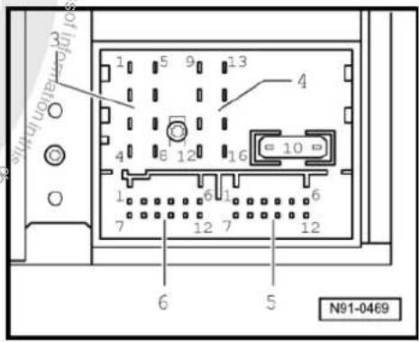
text_image
1 5 9 13 4 8 12 16 10 1 6 1 6 7 12 7 12 6 5 N91-0469
text_image
3 1 5 9 13 4 4 8 12 16 = 10 = 1 6 1 6 7 12 7 12 6 5 N91-046921.5 Electronic anti-theft coding
The radio navigation system is equipped with an electronic anti-theft system which works in combination with the dash panel insert.
After disconnection of the radio-navigation system's voltage supply, the system becomes operational again when the supply voltage is reconnected without the need to enter the radio code again. The prerequisite is that initial activation of the anti-theft coding has been performed and the radio navigation system is reconnected in the same vehicle.
21.5.1 Functional notes
After the initial activation of the electronic anti-theft system, an internal radio code is stored in the radio-navigation system and in the dash panel insert. If the voltage supply for the radio-navigation system is cut off due to installation work, an exchange of data between the radio-navigation system and the dash panel insert takes place when the supply voltage is reconnected.
When this is done, the internal radio code of the radio-navigation system is compared to the code in the dash panel insert. If the code numbers are identical, the dash panel insert accepts that the connected radio navigation system belongs to the vehicle. The radio-navigation system is then immediately operational without the need to enter the radio code again.
If the radio navigation system is replaced, the new radio code must be entered.
Deactivating anti-theft coding page 158
Then after switching on the "S contact" via the ignition lock the code is automatically compared between the dash panel insert and the radio navigation system.
Comparison takes approx. 5 seconds. It must be ensured that a diagnostic unit has not been connected or is not connected during this period of time.
Even after disconnection and reconnection of the voltage supply, the radio-navigation system of this vehicle will now be operational without the need to enter the radio code again.
The electronic anti-theft system is switched on and blocks the radio navigation system when:
◆ The radio navigation system is installed in another vehicle or
◆ The dash panel insert is changed.
A radio navigation system which has been locked by the electronic anti-theft system is shown when "SAFE" and "1000" appears in the display when switching the system on.
Deactivate the anti-theft coding to release the unit lock page 158.
21.5.2 Deactivating electronic anti-theft coding
A locked radio-navigation system will only work again if the correct radio code for the electronic anti-theft coding system is entered.

Note
The anti-theft radio code is stuck on the radio card together with the unit number Instruction manual.
◆ The radio card should not be kept in the vehicle for security reasons. Ask the customer for the radio code.
If a radio-navigation system is renewed, the radio code of the replacement unit also must be used.
◆ The customer must be informed that the radio code has changed.
- Obtain the radio code.
- Switch radio navigation system on.
The word "SAFE" and the number sequence "0000" appear in the display.
- Enter the radio code stuck onto the radio card by selecting the relevant numbers from the letters and numbers selection box one after another and confirming.

Note
Entering the 1st number overwrites the row of figures "0000".
- Confirm the radio code by pressing the right rotary pushbutton.
- Once you have entered the correct radio code, confirm it with the "OK" function button on the display.
The unit will be released and is ready for use.

Note
If you have entered the wrong radio code, it can be immediately corrected in two further attempts. If the incorrect radio code is entered twice, the radio-navigation system is blocked for one hour. In this case, leave the radio navigation system switched on, and the ignition key inserted into the ignition lock. The process of deactivating the anti-theft coding can then be repeated after one hour. Do not forget that only two attempts are allowed, after which the radio-navigation system will be blocked for one hour.
21.6 Adapting components "RNS MFD 2 DVD"
Special tools and workshop equipment required

◆ Vehicle diagnostic, testing and information system -VAS 5051B-
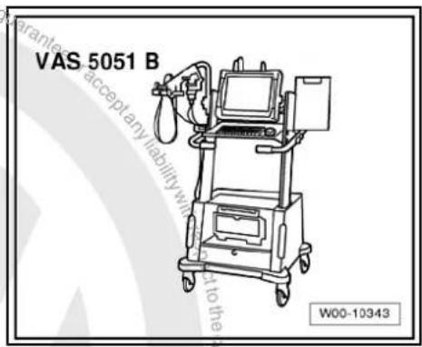
text_image
VAS 5051 B W00-10343Procedure
- In vehicle diagnostic, testing and information system -VAS 5051B-, select "Guided fault finding".
- Using GoTo button, select "Functions/component" and the following menu options in succession:
Body
Electrical system
◆ 01 - On board diagnosis-capable systems
◆ Corresponding radio/navigation system
◆ Radio/navigation system functions

22 Radio navigation system "RNS 510"
Radio navigation system RNS 510

Note
When dealing with complaints, it is absolutely necessary to understand the functions and the operation of the communication systems Instruction manual.
◆ The anti-theft coding uses a fixed code ⇒ page 169.
In the event of repair work or fault finding Vehicle diagnosis, testing and information system VAS 5051.
For perfect operation of the navigation system, the turn angle sensor in the unit has to be adjusted according to the installation position of the unit in the vehicle. Therefore, always note the part number when exchanging equipment. Incorrect installation could lead to a malfunction in the navigation system.
When the battery -A- is reconnected, please remember to check vehicle equipment (radio, clock, convenience electronics, etc.) in accordance with the Electrical system; Rep. Gr. 27 workshop manual and/or the owner's manual.
The use of magnetic-base aerials may lead to permanent magnetisation of the vehicle roof, resulting in a malfunction in the compass module. If confronted with complaints about inaccurate or incorrect directional indication of the compass module, ask the customer if a magnetic-base aerial has been used before carrying out any repair work.
22.1 General description
The "RNS 510" combines the functions of a navigation system with those of a high-quality RDS radio. It is a further development of "RNS 500".
The following is installed in the double DIN housing of the "RNS 510":
◆ An RDS radio
◆ A 6.5-inch multicolour display with touch screen
◆ A navigation system with GPS satellite receiver
◆ Integrated DAB tuner for digital radio reception
◆ A DVD player for navigation, video and audio
◆ An SD memory card reader
◆ A hard disc integrated in the unit for saving data
◆ Corridor function
◆ MP3 and WMA playback formats
The following loudspeakers are installed with the "RNS 510":
◆ A bass loudspeaker, a mid-range loudspeaker and a treble loudspeaker in each of the front doors.
◆ A bass loudspeaker and a treble loudspeaker in each of the rear doors.
The "RNS 510" is available in a version with loudspeakers operated via the 4 internal loudspeaker outputs or in a version with amplifier -R12-. In this case, the loudspeakers are connected
text_image
LAMD MILK P.01 TONE FLU N1 R.01% SETUP N91-10922directly to the amplifier -R12- and the loudspeaker outputs of the radio/navigation system are used for amplifier -R12- signal input.
The "RNS 510" can be extended with the following components:
◆ CD changer
◆ Multifunction steering wheel
TV tuner
◆ Sound amplifier
◆ Universal preparation for mobile telephone (UHV Premium Light)
◆ Rear seat entertainment system
The aerial used is the aerial system in the rear window for the radio -R- and the navigation system aerial -R50- (saloon). In the Variant, the GPS aerials -R50- are located in the roof aerial.
22.1.1 Fault finding
The radio navigation system is equipped with self-diagnosis.
For fault finding, use the vehicle diagnosis, testing and information system -VAS 5051B- in "Guided fault finding" mode.
22.2 Overview of radio navigation system "RNS 510"
1 - Control unit with display unit for radio and navigation -J503-
□ Connectors
⇒ page 166
☐ Removing and installing
⇒ page 163
2 - CD changer -R41-
Optional
In centre console
☐ CD changer -R41-→ page 79
3 - Multimedia system control unit -J650-
□ Optional
In centre console
□ Multimedia system control unit -J650-→ page 95
4 - Connection for external audio sources -R199-
In centre console
☐ Connection for external audio sources -R199-→ page 91
5 - Amplifier -R12-
Optional
□ Under left front seat
☐ Amplifier -R12- page 100.
6 - Aerial -R11- / radio aerial 2 -R93- / navigation system aer-

text_image
1 2 3 4 5 6 7 8 9 10 11 v policed by M91-0412ial -R50-
☐ Aerial systems (saloon) ⇒ page 171
☐ Aerial systems (Variant) ⇒ page 179
☐ Aerial systems in saloons from model year 2011 → page 179
7 - Rear left treble loudspeaker -R14- / rear right treble loudspeaker -R16-
☐ Installed in the rear left and right door trims
☐ Loudspeaker systems → page 106
8 - Rear left bass loudspeaker -R15- / rear right bass loudspeaker -R17-
☐ Installed in the rear left and right door trims
☐ Loudspeaker systems page 106
9 - Front left bass loudspeaker -R21- / front right bass loudspeaker -R23-
☐ Installed in the front left and right door trims
☐ Loudspeaker systems ⇒ page 106
10 - Front left mid-range loudspeaker -R103- / front right mid-range loudspeaker -R104-
☐ Installed in the front left and right door trims
☐ Loudspeaker systems page 106
11 - Front left treble loudspeaker -R20- / front right treble loudspeaker -R22-
☐ Installed in mirror triangle of the right and left front doors
☐ Loudspeaker systems page 106
22.3 Removing and installing control unit with display for radio and navigation -J503-

Note
The part number for the radio/navigation system is printed on a sticker on the radio/navigation system housing.
If the radio navigation system is replaced, the electronic anti-theft system must be deactivated, page 169.
Special tools and workshop equipment required
◆ Removal wedge -3409-

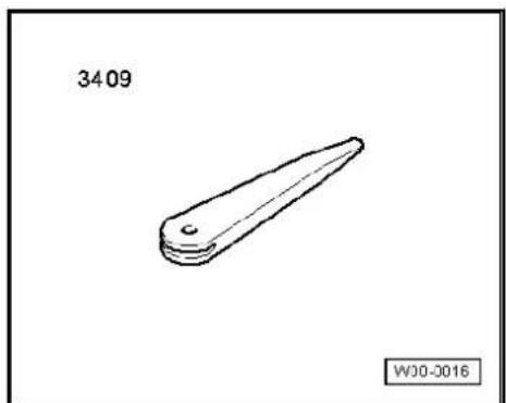
natural_image
Simple line drawing of a mechanical part with a tapered end and rounded base, labeled '3409' and 'WJ0-0016' (no other text or symbols)Removing
- Take CD/DVD out of the unit Operating manual.
- Switch off ignition and all electrical consumers and remove ignition key.
- Remove upper cover together with air vents out of the middle of the dash panel until the underneath bolts of the centre con-
sole cover can be reached, General body repairs, exterior; Rep. Gr. 68.
- Remove bolts -arrows- (1.5 Nm).
- Carefully lever out cover of centre console using removal wedge -3409- -arrows- and take it off.
- Remove bolts -arrows- (1.5 Nm) on control unit with display for radio and navigation -J503-.
Pull control unit with display unit for radio navigation -J503- out of installation aperture sufficiently to gain access to the connectors on the rear.
- Press together connector locking mechanism in direction of -arrows-.

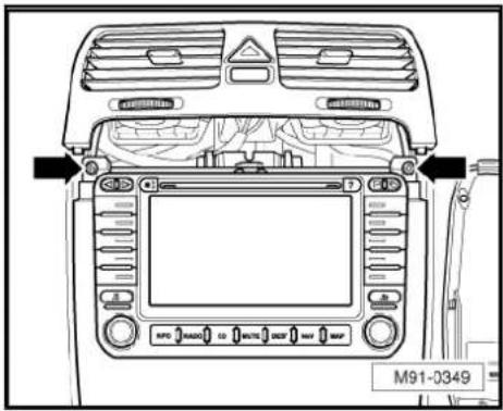
text_image
M91-0349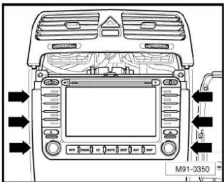
text_image
M91-0350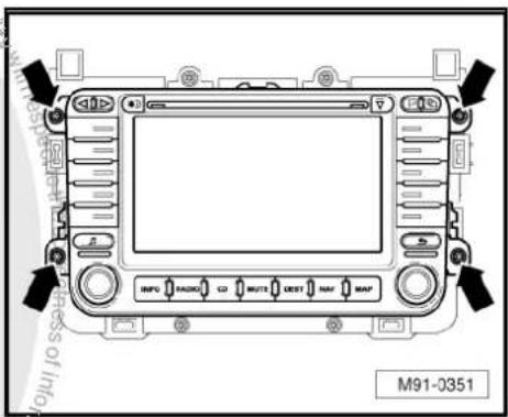
text_image
M91-0351
natural_image
Technical diagram of a mechanical assembly with directional arrows and label N91-10011 (no readable text or symbols)- Then swing locking bar up in direction of -arrow- and disconnect connector.
- Release connectors -arrows- of aerial connections and disconnect connectors.
Installing
- Fit connectors on control unit with display for radio and navigation -J503-.
- Push control unit with display for radio and navigation -J503-straight into dash panel.

Note
When inserting control unit with display for radio and navigation - J503- never press against the display or operating buttons, as otherwise the control unit with display for radio and navigation - J503- could become damaged.

natural_image
Technical line drawing of a mechanical assembly with no visible text or symbols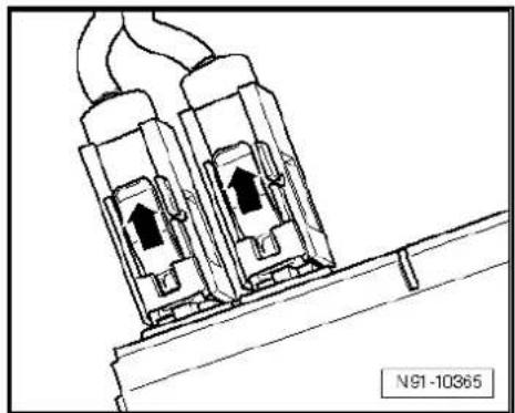
natural_image
Technical line drawing of two electrical connectors with upward arrows, mounted on a support structure (no text or symbols)- Fit the control unit with display for radio and navigation -J503-with 4 bolts -arrows- (1.5 Nm).
- Install centre console cover.
- Deactivate the anti-theft coding page 169.
- Check coding of control unit with display for radio and navigation -J503- and recode it page 170.
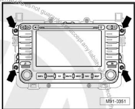
text_image
M91-0351 Accept any liability No. 12 No. 13 No. 14 No. 15 No. 16 No. 17 No. 18 No. 19 No. 20 No. 21 No. 22 No. 23 No. 24 No. 25 No. 26 No. 27 No. 28 No. 29 No. 30 No. 31 No. 32 No. 33 No. 34 No. 35 No. 36 No. 37 No. 38 No. 39 No. 40 No. 41 No. 42 No. 43 No. 44 No. 45 No. 46 No. 47 No. 48 No. 49 No. 50 No. 51 No. 52 No. 53 No. 54 No. 55 No. 56 No. 57 No. 58 No. 59 No. 60 No. 61 No. 62 No. 63 No. 64 No. 65 No. 66 No. 67 No. 68 No. 69 No. 70 No. 71 No. 72 No. 73 No. 74 No. 75 No. 76 No. 77 No. 78 No. 79 No. 80 No. 81 No. 82 No. 83 No. 84 No. 85 No. 86 No. 87 No. 88 No. 89 No. 90 No. 91 No. 92 No. 93 No. 94 No. 95 No. 96 No. 97 No. 98 No. 99 No.10022.4 "RNS 510" connectors
1 - Connection for navigation, Japan
□ Not assigned
2 - Aerial connection
☐ Colour of connector; black
DAB
☐ Aerial system, saloon
⇒ page 171.
☐ Aerial system, Variant page 179.
☐ Aerial systems in saloons from model year 2011 → page 179
3 - Multi-pin connector 1, 8-pin, loudspeaker outputs
☐ Pin assignment ⇒ page 167
4 - Multi-pin connector 2, 8-pin, CAN bus, telephone
☐ Pin assignment ⇒ page 167
5 - Multi-pin connector 3, 12-pin, telephone
☐ Pin assignment ⇒ page 167
6 - Multi-pin connector 4, 12-pin, CD changer -R41-
☐ Pin assignment ⇒ page 168
7 - Multi-pin connector 5, 26-pin, for video and LF input
☐ Pin assignment ⇒ page 168
8 - Aerial connection navigation system aerial -R50-
☐ Colour of connector; blue
GPS
☐ Aerial system, saloon page 171.
☐ Aerial system, Variant page 179.
☐ Aerial systems in saloons from model year 2011 → page 179
9 - Aerial connection
☐ Connector colour, white
FM2
☐ Aerial system, saloon ⇒ page 171.
☐ Aerial system, Variant page 179.
☐ Aerial systems in saloons from model year 2011 ⇒ page 179
10 - Aerial connection
☐ Connector colour, white
AM/FM
☐ Aerial system, saloon page 171.
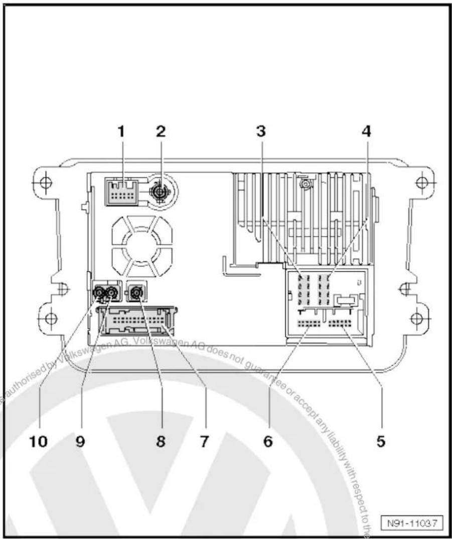
text_image
1 2 3 4 authorised by Volkswagen AG, Volkswagen AG does not guarantee or accept any liability with respect to the N91-11037☐ Aerial system, Variant page 179.
☐ Aerial systems in saloons from model year 2011 ⇒ page 179
22.4.1 Multi-pin connector 1, 8-pin, loudspeaker outputs
1 - Rear right loudspeaker (+)
2 - Front right loudspeaker (+)
3 - Front left loudspeaker (+)
4 - Rear left loudspeaker (+)
5 - Rear right loudspeaker (-)
6 - Front right loudspeaker (-)
7 - Front left loudspeaker (-)
8 - Rear left loudspeaker (-)

text_image
1 2 3 4 5 6 7 8 9 10 11 12 13 14 15 16 17 18 19 20 N91-1092822.4.2 Multi-pin connector 2, 8-pin, CAN bus
9 - CAN bus (high)
10 - CAN bus (low)
11 - BOSE pin
12 - Terminal 31
13 - Not assigned
14 - Not assigned
15 - Terminal 30
16 - ATA (SAFE) terminal 30
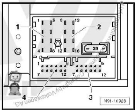
text_image
1 5 6 13 2 4 8 12 16 20 1 6 7 12 7 12 4 3 N91-1092822.4.3 Multi-pin connector 3, 12-pin, telephone, microphone
1 - Microphone input (-)
2 - Not assigned
3 - Not assigned
4 - Microphone output (-)
5 - Telephone LF input signal left (-)
6 - Telephone LF input signal right (-)
7 - Microphone input (+)
8 - Not assigned
9 - Microphone output (+)
10 - Telephone mute
11 - Telephone LF input signal left (+)
12 - Telephone LF input signal right (+)

text_image
1 2 3 4 N91-1092822.4.4 Multi-pin connector 4, 12-pin, CD changer -R41-
1 - Audio input left (+)
2 - Audio input earth
3 - Audio earth from CD changer -R41-
4 - Terminal 30 to CD changer -R41-
5 - Not assigned
6 - CD data out to CD changer -R41-
7 - Audio input right (+)
8 - Audio left from CD changer -R41-
9 - Audio right from CD changer -R41-
10 - Control signal to CD changer -R41-
11 - CD data in from CD changer -R41-
12 - CD clock from CD changer -R41-

text_image
1 2 3 4 N91-1092822.4.5 Multi-pin connector 5, 26-pin, for video and LF input
1-3 - Not assigned
4 - Screening, earth
5 - Video output LF right
6 - Video output earth
7 - Video output sync
8 - Video output green
9 - Screening, earth
10 - Video input LF right
11 - Video input earth
12 - Video input sync
13 - Video input green
14-16 - Not assigned
17 - Video output LF earth
18 - Video output LF left
19 - Video output RGBS (-)
20 - Video output blue
21 - Video output red
22 - Video input LF (-)
23 - Video input LF left
24 - Video input RGBS (-)
25 - Video input blue
26 - Video input red

text_image
13 1 26 14 N91-10930
text_image
N91-1093 Protected by copyright rights copy-in capital company purposes, in part or in whole, is not permitted unless authorised by Volkswagen AG. Volkswagen AG does not guarantee a correct any liability with respect to the correctness of information in his occupant copyright website. Copyright: Volkswagen AG.22.5 Electronic anti-theft coding
The radio navigation system is equipped with an electronic anti-theft system which works in combination with the dash panel insert.
After disconnection of the radio-navigation system's voltage supply, the system becomes operational again when the supply voltage is reconnected without the need to enter the radio code again. The prerequisite is that initial activation of the anti-theft coding has been performed and the radio navigation system is reconnected in the same vehicle.
The radio code is determined by means of the vehicle diagnosis, testing and information system -VAS 5051B-. The radio card used in the past and the sticker on the radio-navigation system have been discontinued.

Note
In order to find out the radio code, the vehicle diagnosis, testing and information system -VAS 5051B- must be connected "online" (network connection), and the user must possess valid rights to use the programme for requesting radio codes.
22.5.1 Deactivating electronic anti-theft coding
A locked radio-navigation system will only work again if the correct radio code for the electronic anti-theft coding system is entered.
Using the VAS tester to find out the radio code:
- Select "guided fault finding" in the vehicle diagnosis, testing and information system -VAS 5051B-.
- Using GoTo button, select "Functions/component" and the following menu options in succession:
Body
Electrical system
◆ 01 - On board diagnosis-capable systems
◆ Corresponding radio/navigation system
◆ Radio/navigation system functions
◆ Radio code request
Your system rights are then determined. The operating data, the VIN and the unit number of the radio or radio-navigation system are then read out automatically.

Note
When new radio-navigation systems are being installed, it is possible that the vehicle diagnosis, testing and information system - VAS 5051B- cannot read out the unit number of the radio-navigation system. In this case, please enter the unit number manually. It can be read on a sticker on the radio-navigation system and is also embossed on the side of the unit.
The radio code determined is then shown on the display of the vehicle diagnosis, testing and information system -VAS 5051B-.
The radio code must now be entered manually into the radio navigation system.
Deactivating anti-theft coding:
- Enter the radio code previously determined in the radio-navigation system number block shown on the display and confirm.
The radio-navigation system is then released and is ready for use.

Note
If the incorrect radio code is entered, it can be immediately corrected with a further attempt. If the incorrect radio code is entered twice, the radio-navigation system is blocked for one hour. Leave ignition and radio navigation unit switched on. The remaining time is shown on the radio/navigation system display. The process of deactivating the anti-theft coding can then be repeated after one hour. Do not forget that only two attempts are allowed, after which the radio-navigation system will be blocked for one hour.
22.6 Adapting radio components "RNS 510"
Special tools and workshop equipment required
◆ Vehicle diagnostic, testing and information system -VAS 5051B-

text_image
VAS 5051 B W00-10343Procedure
- In vehicle diagnostic, testing and information system -VAS 5051B-, select "Guided fault finding".
- Using GoTo button, select "Functions/component" and the following menu options in succession:
♦ Body
Electrical system
◆ 01 - On board diagnosis-capable systems
◆ Corresponding radio/navigation system
◆ Radio/navigation system functions
23 Aerial systems (saloon)
23.1 General notes
The aerial system consists of the following components:
◆ Aerial -R11- / radio aerial 2 -R93- in rear window
◆ Frequency modulation (FM) frequency filter in negative wire - R178- / frequency modulation (FM) frequency filter in positive wire -R179- on C-pillars
◆ Right aerial module -R109- on rear window
◆ Optional satellite tuner aerial -R172- (roof aerial)
◆ Optional navigation system aerial -R50- on rear window
◆ Optional telephone aerial -R65- on rear window
The diversity aerial system optimises and improves the quality of reception in the vehicle. It is not installed in connection with the radio -R- "Lowentry", "RCD 210" and "RNS 300".

Note
When dealing with complaints, it is absolutely necessary to understand the functions and the operation of the communication systems Instruction manual.
When the battery -A- is reconnected, please remember to check vehicle equipment (radio, clock, convenience electronics, etc.) in accordance with the Electrical system; Rep. Gr. 27 workshop manual and/or the owner's manual.
23.2 Overview of aerial system
1 - Satellite tuner aerial -R172-
□ Optional
On roof rear side
☐ Removing and installing
⇒ page 176
2 - Satellite radio -R146-
Up to MJ2009.
Optional
☐ Satellite radio -R146-→ page 117
3 - Control unit with display unit for radio and navigation -J503-
☐ RNS MFD 2 DVD.
RNS 510
☐ "RNS MFD 2 DVD"
⇒ page 150
☐ "RNS 510" ⇒ page 161
4 - Control unit with display unit for radio and navigation -J503-
RNS 300
RNS 310
☐ "RNS 300" => page 121
☐ "RNS 310" ⇒ page 130
5 - Radio -R-
□ Premium 7
□ Premium 8
☐ "Premium 7" ⇒ page 11
☐ "Premium 8" ⇒ page 69.
6 - Radio -R-
□ RCD 300
□ RCD 310
□ RCD 500
□ RCD 510
☐ "RCD 300" → page 40
☐ "RCD 310" ⇒ page 49
☐ "RCD 500" ⇒ page 59
☐ "RCD 510" ⇒ page 69
7 - Radio -R-
Lowentry
□ RCD 210
☐ "Lowentry" => page 2
☐ "RCD 210" ⇒ page 31
8 - Connection heated rear window relay -J9-
9 - Frequency modulation (FM) frequency filter in positive wire -R179-
☐ In wiring harness connected to heated rear window -Z1-
☐ Removing and installing ⇒ page 177
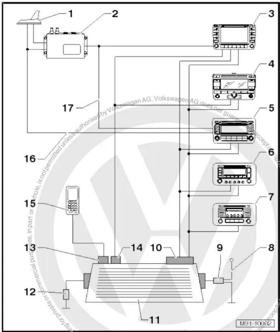
text_image
1 2 3 4 5 6 7 8 9 10 11 12 13 14 15 16 17 M91-10002
10 - Right aerial module -R109- (AM/FM/FM2)
☐ Removing and installing ⇒ page 173
11 - Rear window with aerial -R11- / radio aerial 2 -R93- / heated rear window -Z1-
12 - Frequency modulation (FM) frequency filter in negative wire -R178-
☐ In wiring harness connected to heated rear window -Z1-
☐ Removing and installing ⇒ page 178
13 - Telephone aerial -R65-
Optional
☐ Removing and installing page 175
14 - GPS aerial -R50-
Optional
☐ Removing and installing page 174
15 - Mobile phone
□ Optional
☐ Telephone systems page 188
16 - Aerial line (SAT)
☐ From satellite tuner aerial -R172- to the Premium 8.
As of MJ2010.
17 - Connection
From satellite radio -R146- to the Premium 7.
□ Up to MJ2009.
23.3 Removing and installing aerial modules on rear window
Fitting locations of aerial modules:
1 - Removing and installing right aerial module -R109-→ page 173
2 - Additional brake light
3 - Removing and installing navigation system aerial -R50-→ page 174
4 - Removing and installing telephone aerial -R65-→ page 175
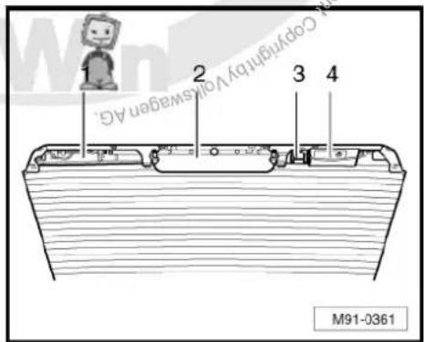
text_image
1 2 3 4 Copyright by Volkswagen AG. M91-036123.3.1 Removing and installing right aerial module -R109-
Removing
- Switch off ignition and all electrical consumers and remove ignition key.
-
Remove strip roof leading edge General body repairs, interior; Rep. Gr. 70.
-
Release connectors -1-, -2- and -3- and disconnect them.
- Release front retaining clips -arrows- and swing right aerial module -R109- downwards.
- Release rear retaining clips -arrows- and carefully take right aerial module -R109- -4- off.
Installing

text_image
Volkswagen AG does not guarantee accept any liability with 1 2 3 4 M91-0370- Fit the right aerial module -R109-4- into the rear retaining clips -arrows-.
- Swing the right aerial module -R109- -4- upwards and lock it in the front retaining clips -arrows-.
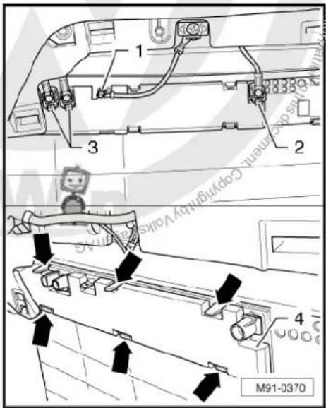
text_image
1 2 3 4 M91-0370
Note
The contacts on the right aerial module -R109- -arrows- are not allowed to be bent and the metal must be clean in order to avoid reception problems.
Remainder of installation is carried out in reverse order of removal.
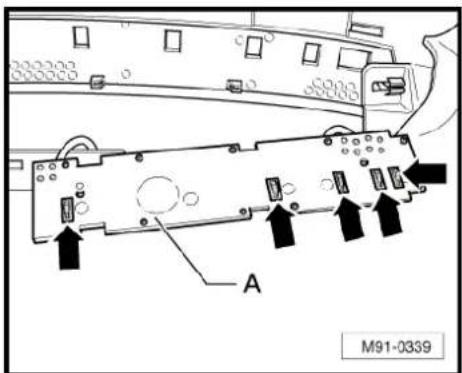
text_image
A M91-033923.3.2 Removing and installing navigation system aerial -R50-
Removing
- Switch off ignition and all electrical consumers and remove ignition key.
- Remove strip roof leading edge General body repairs, interior; Rep. Gr. 70.
-
Disconnect blue connector navigation system aerial -R50-arrow-.
-
Release front retaining clips first -arrows 1-.
- Swing the navigation system aerial -R50- downwards and take it off the lower retaining clips -arrow 2-.
Installing
Installation is carried out in reverse order of removal.
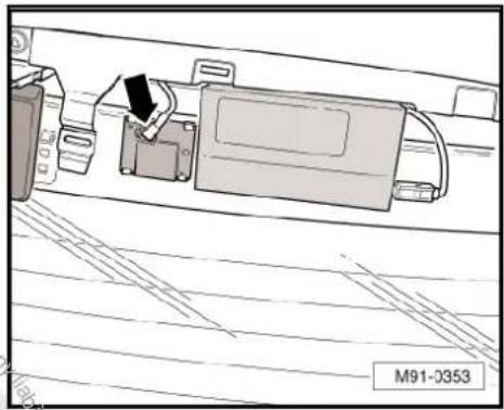
natural_image
Technical line drawing of a mechanical assembly with no visible text or symbols
text_image
with respect of information M91-037923.3.3 Removing and installing telephone aerial -R65-
Removing
- Switch off ignition and all electrical consumers and remove ignition key.
Remove strip roof leading edge → General body repairs, interior; Rep. Gr. 70.
- Disconnect connector -A- from telephone aerial -R65-.

text_image
A M91-0401- Release holding clips -arrows-.
- Swing telephone aerial -R65- backwards and remove carefully.
Installing
Installation is carried out in reverse order of removal.

text_image
1 2 M91-037723.4 Removing and installing satellite tuner aerial -R172-
Removing
- Switch off ignition and all electrical consumers and remove ignition key.
- Remove strip roof leading edge and both trims on the C-pillar General body repairs, interior; Rep. Gr. 70.
- Lower rear section of moulded headliner General body repairs, interior; Rep. Gr. 70°
Depending on the equipment the satellite tuner aerial -R172- has 2 or 4 aerial wires. These are fixed on the roof cross member.
- Remove foamed pad -5-.
- Remove connectors -1- to -4- and lie aerial wiring up to the satellite tuner aerial -R172- -6- to side.
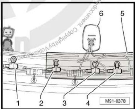
text_image
1 2 3 4 5 6 document. Copyright by Volksberg M91-0378- Remove nut -2- (7 Nm) and take the satellite tuner aerial -R172- out upwards.
Installing
Installation is carried out in the reverse order. When installing observe the following:
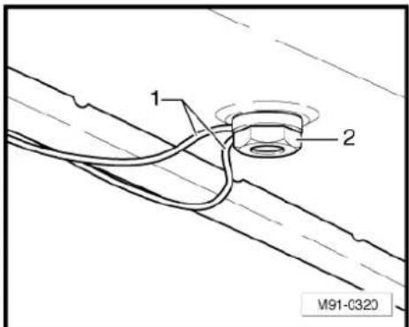
text_image
1 2 M91-C320- When positioning the roof aerial for installation, ensure that the seal is seated correctly. The two guide lugs of the seal must be located in the relevant holes -arrows- of the aerial base.
- After installing the roof aerial, ensure that the aerial cables are routed correctly -1- through the hole in the securing nut -2-.
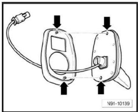
natural_image
Line drawing of a device with labeled ports and connectors (no text or symbols beyond labels)
text_image
1 2 M91-C32023.5 Removing and installing frequency modulation (FM) frequency filter
Frequency filters are clipped on the right and left upper part of the C-pillar.
23.5.1 Frequency modulation (FM) frequency filter in positive wire -R179-
Removing
- Switch off ignition and all electrical consumers and remove ignition key.
- Remove the left C-pillar trim General body repairs, interior; Rep. Gr. 70.
- Release connector -2- and unscrew earth wiring -3- (2 Nm).
- Unclip the frequency modulation (FM) frequency filter in positive wire -R179- -4- on the C-pillar.
The positive wire runs in the wiring harness to the onboard supply control unit -J519- Current flow diagrams, Electrical fault finding and Fitting locations.
- Disconnect the positive wire at a suitable point.

text_image
1 2 3 4 M91-0363
The wire of the connector -2- to the rear window is soldered to the rear window -1-.
Installing
- Connect the positive wire of the frequency filter for frequency modulation (FM) in positive wire -R179- to the positive wire in the wiring harness. To do this, use the wiring harness repair set -VAS 1978/-.

Note
The positive wire of the new frequency filter for frequency modulation (FM) in positive wire -R179- may be cut at an appropriate point.
Installation is carried out in reverse order of removal.
23.5.2 Frequency modulation (FM) frequency filter in negative wire -R178-
Removing
Switch off ignition and all electrical consumers and remove ignition key.
- Remove the right C-pillar trim General body repairs, interior; Rep. Gr. 70.
- Disconnect connector -2-.
- Unclip the frequency modulation (FM) frequency filter in negative wire -R178- -1- on the C-pillar.
The negative wire (earth) runs in the wiring harness to the earth point "61" Current flow diagrams, Electrical fault finding and Fitting locations.
- Disconnect the earth wire at a suitable point.
The wire of the connector -2- to the rear window is soldered to the rear window -3-.
Installing
- Connect the negative wire of the frequency filter for frequency modulation (FM) in negative wire -R178- to the negative wire in the wiring harness. To do this use wiring harness repair set -VAS 1978-.

Note
The negative wire of the new frequency filter for frequency modulation (FM) in negative wire -R178- may be cut at an appropriate point.
Installation is carried out in reverse order of removal.
23.6 Renewing aerial wires
⇒ Electrical system; Rep. Gr. 97 ; Wiring; Renewal of aerial wiring .
text_image
1 2 3 4 M91-0363
text_image
1 2 3 M91-0362
text_image
1 2 3 M91-036224 Aerial systems (Variant)
24.1 General notes
In the Variant, the aerials are integrated into the rear side windows and the roof aerial.
The aerial system consists of the following components:
◆ Aerial -R11- (AM/FM) in the roof aerial (up to MY2009)
◆ Aerial amplifier 2 -R111- (AM/FM) on the rear right side window (as of MY2010)
◆ Aerial amplifier -R24- (FM2) on the rear right side window (up to MY2009)
◆ Aerial amplifier -R24- (FM2) on the left right side window (as of MY2010)
◆ Optional satellite tuner aerial -R172- (rSAT) in the roof aerial
◆ Optional navigation system aerial -R50- (GPS) in the roof aerial
♦ Optional telephone aerial -R65- (GSM) in the roof aerial
The diversity aerial system optimises and improves the quality of reception in the vehicle. It is not installed in connection with the radio -R- "Lowentry", "RCD 210" and "RNS 300".

Note
When dealing with complaints, it is absolutely necessary to understand the functions and the operation of the radio/RNS Instruction manual.
When the battery -A- is reconnected, please remember to check vehicle equipment (radio, clock, convenience electronics, etc.) in accordance with the Electrical system; Rep. Gr. 27 workshop manual and/or the owner's manual.
24.2 Overview of aerial system up to MY2009
1 - Roof aerial
□ AM/FM/GSM/GPS/SAT
☐ Removing and installing
⇒ page 182
2 - Control unit with display unit for radio and navigation -J503-
☐ RNS MFD 2 DVD.
RNS 510
☐ "RNS MFD 2 DVD" ⇒ page 150
☐ "RNS 510" ⇒ page 161
3 - Control unit with display unit for radio and navigation -J503-
RNS 300
RNS 310
☐ "RNS 300" ⇒ page 121
☐ "RNS 310" ⇒ page 130
4 - Radio -R-
□ Premium 7
☐ "Premium 7" ⇒ page 11
5 - Radio -R-
□ RCD 300
□ RCD 310
□ RCD 500
□ RCD 510
☐ "RCD 300" ⇒ page 40
☐ "RCD 310" → page 49
☐ "RCD 500" ⇒ page 59
☐ "RCD 510" → page 69
text_image
11 10 8 7 Mass authorised by Volkswagen AG. VolkswagenAG does not guarantee or accept any M91-03966 - Radio -R-
□ Lowentry
□ RCD 210
☐ "Lowentry" → page 2
☐ "RCD 210" → page 31
7 - Side window with radio aerial 2 -R93-
8 - Aerial amplifier -R24-
FM2
□ Removing and installing ⇒ page 181
9 - Satellite radio -R146-
□ Optional
☐ Satellite radio -R146- → page 117.
10 - Mobile phone
□ Optional
☐ Telephone systems page 188
11 - Connection for remote control receiver for auxiliary heater -R64-
24.3 Overview of aerial system as of MY2010
1 - Roof aerial.
□ GSM/GPS/SAT.
☐ Removing and installing
⇒ page 182.
2 - Control unit with display unit for radio and navigation -J503-
RNS 510.
☐ "RNS 510" ⇒ page 161.
3 - Control unit with display unit for radio and navigation -J503-
RNS 310.
☐ "RNS 310"⇒page 130.
4 - Radio -R-
□ Premium 8.
□ RCD 510.
☐ "Premium 8" ⇒ page 69.
☐ "RCD 510" ⇒ page 69
5 - Radio -R-
□ RCD 310.
□ RCD 210.
☐ "RCD 210" ⇒ page 31
☐ "RCD 310" ⇒ page 49
6 - Aerial amplifier 2 -R111-
□ AM/FM
□ Removing and installing → page 181.
7 - Aerial amplifier -R24-
FM2
☐ Removing and installing page 181.
8 - Right side window with aerial -R11-
9 - Left side window with radio aerial 2 -R93-
10 - Mobile phone
□ Optional
☐ Telephone systems page 188
24.4 Removing and installing aerial amplifier
The aerial amplifier -R24- / aerial amplifier 2 -R111- are located on left and right C-pillars. Removal and installation are identical.
Removing
- Switch off ignition and all electrical consumers and remove ignition key.
-
Remove the C-pillar trim General body repairs, interior; Rep. Gr. 70.
-
Release connectors -1- and -2- and disconnect them.
- Unscrew bolt -4- (2 Nm) and remove aerial amplifier -3- from C-pillar.
Installing
Installation is carried out in reverse order of removal.

text_image
1 2 3 4 M91-039524.5 Removing and installing roof aerial
Removing
- Switch off ignition and all electrical consumers and remove ignition key.
- Remove strip roof leading edge and both trims on the C-pillars General body repairs, interior; Rep. Gr. 70.
- Lower rear section of moulded headliner General body repairs, interior; Rep. Gr. 70.
Depending on the equipment, the roof aerial has 1 to 5 aerial wires. These are fixed on the roof cross member -arrow-.
- Release connectors -arrow- and lie aerial wires up to the roof aerial -1- to side.
Depending on the equipment, the roof aerial has 1 to 5 aerial wires. These are fixed on the roof cross member -arrow-. - Release connectors -arrow- and lie aerial wires up to the roof aerial -1- to side.
text_image
1 with respect to it M91-0397- Unscrew bolts -2- (7 Nm) and remove roof aerial upwards.
Installing
Installation is carried out in the reverse order. When installing observe the following:
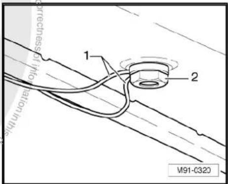
text_image
1 2 M91-0320
- When positioning the roof aerial for installation, ensure that the seal is seated correctly. The two guide lugs of the seal must be located in the relevant holes -arrows- of the aerial base.

natural_image
Line drawing of a handheld electronic device with ports and wiring, no text or symbols present- After installing the roof aerial, ensure that the aerial cables are routed correctly -1- through the hole in the securing nut -2-.

text_image
1 2 M91-C32024.6 Renewal of aerial wiring
⇒ Electrical system; Rep. Gr. 97 ; Wiring; Renewal of aerial wiring .

text_image
Volkswagen AG. Volkswagen AG does not guarantee a accept any liability with respect to the correctness of the limitation in this case that is not permitted unless authorised by Volkswagen AG. The related copyright litigation is not permitted unless authorised by Volkswagen AG. This case is not permitted unless authorised by Volkswagen AG. The other matters are not permitted unless authorised by Volkswagen AG. The other matters are not permitted unless authorised by Volkswagen AG. The other matters are not permitted unless authorised by Volkswagen AG. The other matters are not permitted unless authorised by Volkswagen AG. The other matters are not permitted unless authorised by Volkswagen AG. The other matters are not permitted unless authorised by Volkswagen AG. The other matters are not permitted unless authorised by Volkswagen AG. The other matters are not permitted unless authorised by Volkswagen AG. The other matters are not permitted unless authorized by Volkswagen AG. The other matters are not permitted unless authorized by Volkswagen AG. The other matters are not permitted unless authorized by Volkswagen AG. The other matters are not permitted unless authorized by Volkswagen AG. The other matters are not permitted unless authorized by Volkswagen AG. The other matters are not permitted unless authorized by Volkswagen AG. The other matters are not permitted unless authorized by Volkswagen AG. The other matters are not permitted unless authorized by Volkswagen AG. The other matters are not permitted unless authorized by Volkswagen AG.25 Aerial systems (saloon) model year 2011.
25.1 General notes
In the Jetta 2011, the aerials are integrated in the rear window and the roof aerial.
The aerial system consists of the following components:
◆ Aerial amplifier 2 -R111- (AM/FM) on rear window on right (C-pillar)
◆ Aerial amplifier -R24- (FM2) on rear window on left (C-pillar)
◆ Optional satellite tuner aerial -R172- (SAT) in the roof aerial
◆ Optional navigation system aerial -R50- (GPS) in the roof aerial
◆ Optional telephone aerial -R65- (GSM) in the roof aerial
The diversity aerial system optimises and improves the quality of reception in the vehicle. It is not installed in connection with the radio -R- "Lowentry", "RCD 210" and "RNS 300".

Note
When dealing with complaints, it is absolutely necessary to understand the functions and the operation of the radio/RNS Instruction manual.
When the battery -A- is reconnected, please remember to check vehicle equipment (radio, clock, convenience electronics, etc.) in accordance with the Electrical system; Rep. Gr. 27 workshop manual and/or the owner's manual.

25.2 Assembly overview
1 - Aerial amplifier -R24-
FM2
☐ Removing and installing
⇒ page 185
2 - Bolt
□ 2 Nm
3 - Roof aerial
□ GSM/GPS/SAT.
□ Removing and installing → page 186
4 - Nut
7 Nm
5 - Bolt
2Nm
6 - Aerial amplifier 2 -R111-
□ AM/FM
☐ Removing and installing → page 185
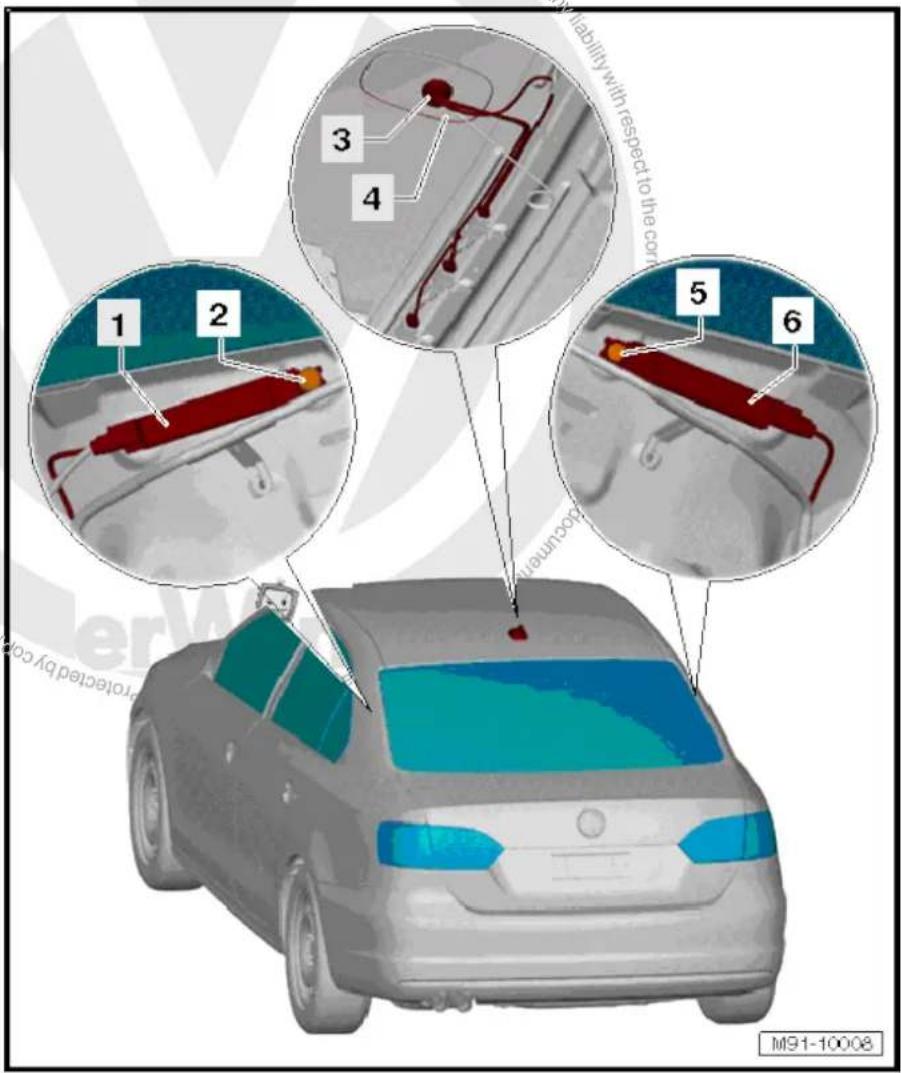
text_image
M91-10008 1 2 3 4 5 6 Liability with respect to the cor occurring protracted by co25.3 Removing and installing aerial amplifier
Aerial amplifier -R24-/aerial amplifier 2 -R111- are located on left and right C-pillars. Removal and installation are identical.
Removing
- Switch off ignition and all electrical consumers and remove ignition key.
-
Remove the C-pillar trim General body repairs, interior; Rep. Gr. 70.
-
Release connectors -3- and -4- and disconnect them.
- Unscrew bolt -1- and remove aerial amplifier -2- from C-pillar.
Installing
Installation is carried out in the reverse order. When installing observe the following:
- Tighten threaded connections to specified torque page 185.
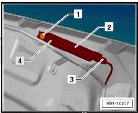
text_image
1 2 3 4 M91-1000725.4 Removing and installing roof aerial
Removing
- Switch off ignition and all electrical consumers and remove ignition key.
- Remove strip roof leading edge General body repairs, interior; Rep. Gr. 70.
- Lower rear section of moulded headliner General body repairs, interior; Rep. Gr. 70.
Depending on the equipment, the roof aerial has 1 to 3 aerial wires. These are fixed on the roof cross member -1- to -4-.
- Release connectors -2 to 4- and expose aerial wires up to the roof aerial -5-.
- Unscrew bolts -1- and remove roof aerial -5- upwards.
Installing
Installation is carried out in the reverse order. When installing observe the following:
- When positioning the roof aerial for installation, ensure that the seal is seated correctly. The two guide lugs of the seal must be located in the relevant holes -arrows- of the aerial base.

text_image
1 2 3 4 5 M91-10006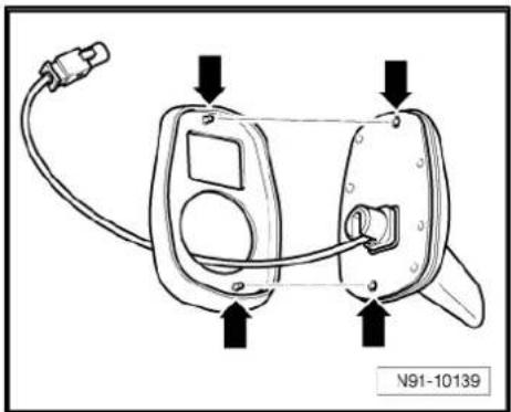
natural_image
Diagram of a device with labeled ports and wiring, no readable text or symbols present- After installing the roof aerial, ensure that the aerial cables are routed correctly -1- through the hole in the securing nut -2-
- Tighten threaded connections to specified torque page 185.

text_image
guarantee orator liability with respect 1 2 M91-C32025.5 Renewal of aerial wiring
⇒ Electrical system; Rep. Gr. 97 ; Wiring; Renewal of aerial wiring .
26 Telephone systems
26.1 General notes
Two versions of the telephone system are possible. Either as a complete telephone system or a preparation for mobile telephone.
The telephone system or the system as preparation for a mobile phone is available only in conjunction with a radio/RNS.
It is possible to retrofit a mobile telephone if the vehicle is prepared for installation of a telephone.
The mobile telephone operating electronics control unit -J412- is factory-fitted in vehicles with preparation for mobile telephone.
The only item that is required is an adapter for the telephone bracket -R126-. Which adapter is used depends on the mobile telephone (accessories).
In vehicles with telephone system, the whole system is installed including the mobile telephone.
From model year 2009, the "UHV Low" and "UHV Premium Light" preparations for mobile telephone will be used.
The "UHV Low" preparation for mobile telephone comes in the version "universal preparation for mobile telephone" with a telephone bracket in the centre console.
The Bluetooth function of the mobile telephone is not supported. Control takes place via the bracket for the telephone. The telephone aerial -R65- is connected to telephone bracket.
The preparation for mobile telephone "UHV Premium Light" is available as a "universal preparation for mobile telephone Premium" with Bluetooth technology and optional telephone bracket in the centre console. The telephone aerial -R65- is connected to the preparation for mobile telephone.
The "UHV Premium Light" is a fixed telephone with cordless access to stored telephone data of a mobile telephone registered with the vehicle system via Bluetooth.
The "UHV Premium Light" absolutely requires that the mobile telephone to connect has a Bluetooth function and supports "remote SIM access profile" (rSAP).
rSAP enables e.g. access to the directory entries on the SIM card of the mobile telephone.
For further information and notes on operation, refer to the operating manual.
26.1.1 Fault finding
The telephone systems are equipped with self-diagnosis.
For fault finding, use the vehicle diagnosis, testing and information system -VAS 5051B- in "Guided fault finding" mode.
26.2 Overview of telephone system
The only significant difference between a vehicle fitted with complete telephone system and one with preparation for mobile telephone is the factory-fitted mobile telephone. Therefore, only the complete telephone system is shown in the following overview.
1 - Telephone aerial -R65-
☐ On rear window upper left (saloon)
☐ Roof aerial (Variant)
☐ Roof aerial (saloon) from model year 2011
☐ Aerial systems (saloon) → page 171
☐ Aerial systems (Variant) → page 179
☐ Aerial systems in saloons from model year 2011 → page 179
2 - Telephone bracket -R126- with mobile telephone
Right on dash panel
☐ Removing and installing up to 06/2006
⇒ page 194.
☐ Removing and installing as of 06/2006
⇒ page 194.
3 - Mobile telephone operating electronics control unit -J412-
□ Under right front seat
☐ Removing and installing up to 06/2006
⇒ page 195.
☐ Removing and installing as of 06/2006
⇒ page 196.
4 - Telephone microphone - R38-
☐ In front interior light - W1-
☐ Removing and installing page 197
5 - Radio -R- / control unit with display for radio and navigation -J503-
6 - Loudspeaker system
7 - Steering column electronics control unit -J527-
8 - Multifunction steering wheel
□ Optional
☐ Multifunction steering wheel page 199
9 - CAN bus
10 - Dash panel insert

text_image
1 2 3 4 5 10 commercial purposes, in part or in whole is not permitted authorised by Volkswagen AG/Volkswagen AG does not guarantee or accept any liability 6 7 8 9 10 discontinued copyright. Copyright for private or commercial purposes.26.3 Overview of "UHV Low"/"UHV Premium Light" telephone system
1 - Dash panel insert
2 - Multifunction steering wheel
Optional
☐ Multifunction steering wheel page 199
3 - Steering column electronics control unit -J527-
4 - Telephone aerial -R65-
☐ On rear window upper left (saloon)
☐ Roof aerial (Variant)
☐ Roof aerial (saloon) from model year 2011
☐ Aerial systems (saloon)
⇒ page 171
☐ Aerial systems (Variant) ⇒ page 179
☐ Aerial systems in saloons from model year 2011 → page 179
5 - Operating unit for preparation for mobile telephone - E508-
☐ In front interior light - W1-
☐ Removing and installing
⇒ page 197
6 - Telephone transmitter and receiver unit -R36-
Under right front seat
□ Removing and installing as of 06/2006
⇒ page 196.
7 - Telephone bracket -R126
Right on dash panel
☐ Removing and installing as of 06/2006 ⇒ page 194.
8 - Mobile phone
□ Optional
9 - Headset
□ Not part of standard equipment
☐ Additional information ⇒ instruction manual
10 - Notebook
☐ Not part of standard equipment
☐ Additional information ⇒ instruction manual
11 - Telephone microphone -R38-
☐ In front interior light -W1-
☐ Removing and installing page 197
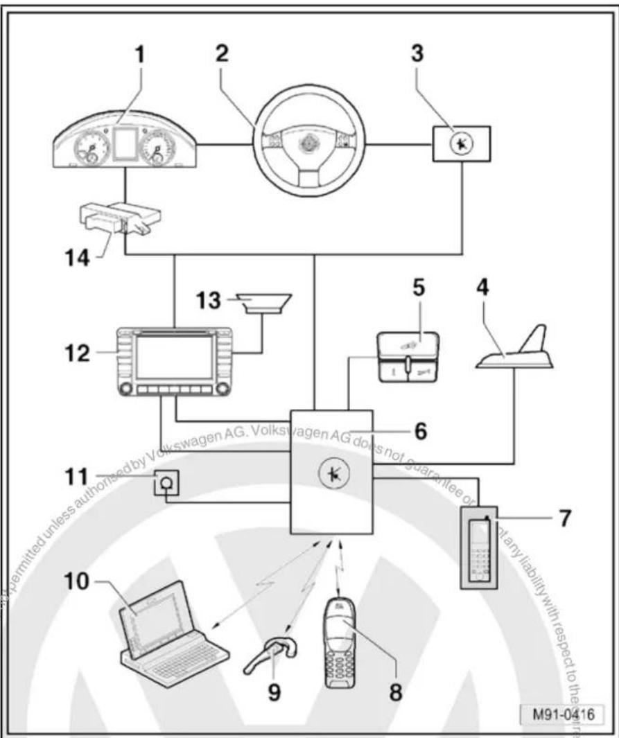
flowchart
graph TD
    A["1"] --> B["2"]
    B --> C["3"]
    C --> D["4"]
    D --> E["5"]
    E --> F["6"]
    F --> G["7"]
    G --> H["8"]
    H --> I["9"]
    I --> J["10"]
    J --> K["11"]
    K --> L["12"]
    L --> M["13"]
    M --> N["14"]
    style A fill:#f9f,stroke:#333
    style B fill:#f9f,stroke:#333
    style C fill:#f9f,stroke:#333
    style D fill:#f9f,stroke:#333
    style E fill:#f9f,stroke:#333
    style F fill:#f9f,stroke:#333
    style G fill:#f9f,stroke:#333
    style H fill:#f9f,stroke:#333
    style I fill:#f9f,stroke:#333
    style J fill:#f9f,stroke:#333
    style K fill:#f9f,stroke:#333
    style L fill:#f9f,stroke:#333
    style M fill:#f9f,stroke:#333
    style N fill:#f9f,stroke:#333
12 - Radio -R- / control unit with display for radio and navigation -J503-
13 - Loudspeaker system
14 - Data bus diagnostic interface -J533-
26.4 Mobile telephone operating electronics control unit -J412- connectors
Connectors
A - Mobile telephone operating electronics control unit -J412-
B - Multi-pin connector, 12-pin, red, to telephone bracket -R126-
C - Multi-pin connector, 18-pin, black

text_image
10 1 20 11 B 1 9 10 18 C A M91-0386Multi-pin connector, 18-pin
1 - Terminal 31
2-3 - Not assigned
4 - Telephone mute to radio -R-
5-6 - Not assigned
7 - LF (-) to radio -R-
8 - CAN bus (low)
9 - Telephone microphone -R38- (-)
10 - Terminal 15
11 - Terminal 30
12 - Terminal 58d
13-15 - Not assigned
16 - LF (+) to radio -R-
17 - CAN bus (high)
18 - Telephone microphone -R38- (+)
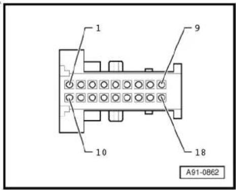
text_image
1 9 10 18 A91-086226.5 Telephone transmitter and receiver unit -R36- (UHV) connectors
Connectors
A - Connection (GSM) telephone aerial -R65- only for "UHV Premium Light"
B - Multi-pin connector, 54-pin
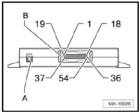
text_image
B 19 1 18 37 54 36 A A91-10026B - Multi-pin connector, 54-pin
1 - Terminal 30
2 - Terminal 31
3 - Not assigned
8 - LF (+) to radio -R-
9 - LF (-) to radio -R-
10 - Not assigned
11 - Telephone microphone -R38- (+)
12 - Telephone microphone -R38- (-)
13-16 - Not assigned
17 - CAN bus (high)
18 - CAN bus (low)
19-26 - Not assigned
27 - Operating unit for preparation for mobile telephone -E508-
28 - Operating unit for preparation for mobile telephone -E508-
29 - Not assigned
30 - Operating unit for preparation for mobile telephone -E508-
31 - Operating unit for preparation for mobile telephone -E508-
32-36 - Not assigned
37 - Telephone bracket -R126-
38 - Telephone bracket -R126-
39 - Telephone bracket -R126-
40 - Telephone bracket -R126-
41-43 - Not assigned
44 - Telephone bracket -R126-
45-46 - Not assigned
47 - Telephone bracket -R126-
48 - Telephone bracket -R126-
49-54 - Not assigned
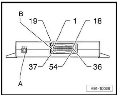
text_image
B 19 1 18 37 54 36 A A91-1002626.6 Telephone fitting locations
1 - Telephone bracket -R126-
Right on dash panel
☐ Removing and installing up to 06/2006
⇒ page 194.
☐ Removing and installing as of 06/2006
⇒ page 194.
2 - Mobile telephone operating electronics control unit -J412-
□ Under right front seat
☐ Connectors ⇒ page 191
☐ Removing and installing up to 06/2006
⇒ page 195.
☐ Removing and installing as of 06/2006
⇒ page 196.
- Telephone transmitter and receiver unit -R36-
□ Under right front seat
☐ Connectors (UHV) ⇒ page 191.
☐ Removing and installing as of 06/2006
⇒ page 196.
3 - Front interior light -W1-
☐ Telephone microphone -R38- i
☐ Operating unit for preparation for mobile telephone -E508-
□ Removing and installing telephone microphone - R38- → page 197
☐ Removing and installing operating unit for preparation for mobile telephone -E508-→ page 197.
4 - Telephone aerial -R65-
☐ On rear window upper left (saloon)
☐ Roof aerial (Variant)
☐ Roof aerial (saloon) from model year 2011
☐ Aerial systems (saloon) ⇒ page 171
☐ Aerial systems (Variant) ⇒ page 179
☐ Aerial systems in saloons from model year 2011 ⇒ page 179
5 - Loudspeaker system
6 - Radio -R- / control unit with display for radio and navigation -J503-
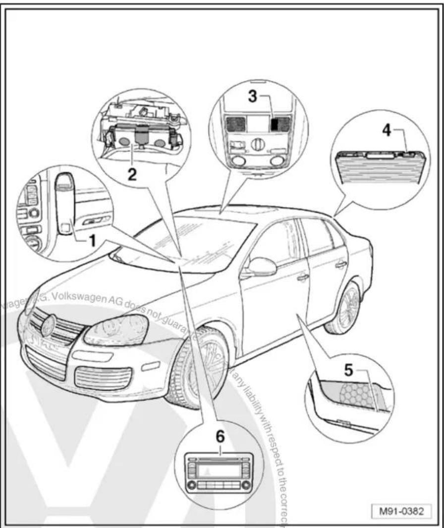
text_image
1 2 3 4 5 6 M91-038226.7 Removing and installing telephone bracket -R126- up to 06/2006
Removing
- Switch off ignition and all electrical consumers and remove ignition key.
- Remove the mobile telephone from the telephone bracket - R126-.
- Unclip the cover -arrows- from the telephone bracket -R126-.

text_image
M91-0367- Lever contact plate -1- off main support -2- using an appropriate screwdriver -arrow-.
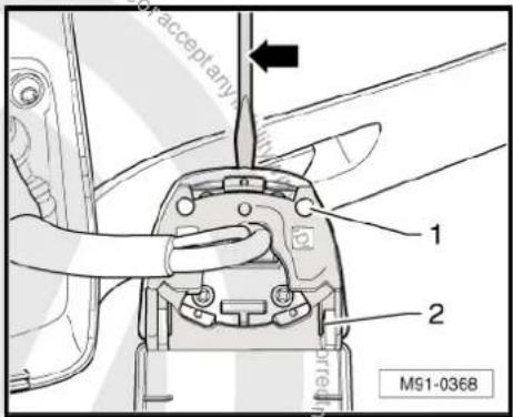
text_image
acceptany 1 2 M91-0368- Remove bolts -1-, -3- and -5- (2 Nm) from the contact plate -2-.
- Remove wiring harness -4-.
Installing
Installation is carried out in reverse order of removal.
- When installing the telephone bracket -R126- on the dash panel observe that the counterhold in the dash panel does not fall out downwards.
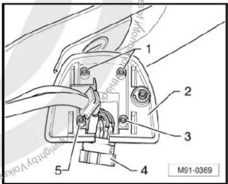
text_image
1 2 3 4 5 M91-036926.8 Removing and installing telephone bracket -R126- as of 06/2006
Removing
- Switch off ignition and all electrical consumers and remove ignition key.
- Remove the mobile telephone from the telephone bracket - R126-.
- Turn telephone bracket -R126- -1- clockwise -arrow- and remove telephone bracket.
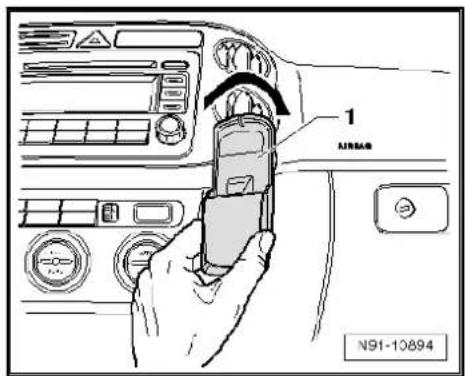
text_image
1 AIRSAB N91-10894- Remove the two bolts -arrow- (2 Nm).
– Pull out wiring harness. - Disconnect connector.
Installing
Installation is carried out in reverse order of removal.
- Push connector together and guide wiring harness into dash panel again.
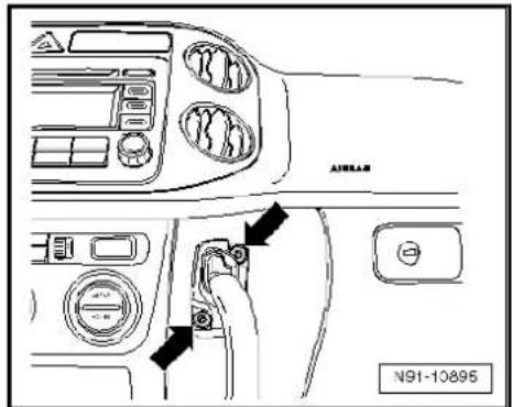
text_image
AIRLAR N91-10895- Screw mounting for telephone bracket -R126- back on -arrows- (2 Nm).
- Clip telephone bracket onto holder.
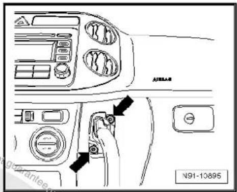
text_image
AJ85AB N91-1089526.9 Removing and installing mobile telephone operating electronics control unit -J412- up to 06/2006
The mobile telephone operating electronics control unit -J412- is installed under the front left seat.
Removing
- Switch off ignition and all electrical consumers and remove ignition key.
- Remove front right seat General body repairs, interior; Rep. Gr. 72.
-
Raise slightly the carpet in the area of the coupling station and you will see the mobile telephone operating electronics control unit -J412-.
-
Unclip both latches -arrows- and swing the flap downwards.
- Remove mobile telephone operating electronics control unit - J412- -2- along with connected wiring.
- Release connectors -1- and -3- and disconnect them.
Installing
Installation is carried out in reverse order of removal.
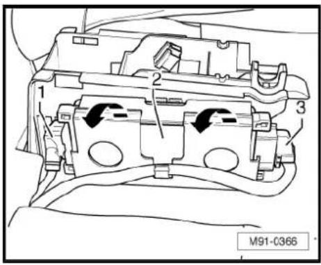
text_image
1 2 3 M91-C36626.10 Removing and installing mobile telephone operating electronics control unit -J412- as of 06/2006
The mobile telephone operating electronics control unit -J412- is installed under the front left seat.
Removing
- Switch off ignition and all electrical consumers and remove ignition key.
- Push front right seat back fully.
- Push foam insert forwards in direction of -arrow-.
-
Turn foam insert around.
-
Remove mobile telephone operating electronics control unit - J412- -1- from foam insert -2-.
- Remove connector -3- on mobile telephone operating electronics control unit -J412- -1-.
Installing
Installation is carried out in reverse order of removal.

text_image
M91-0399 or acceptor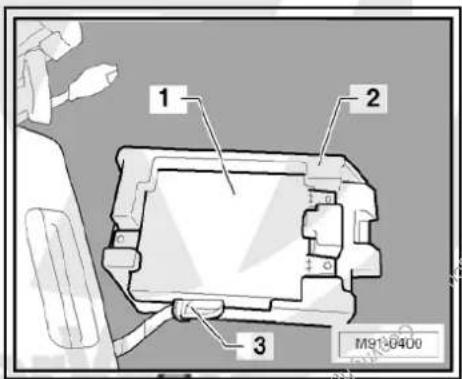
text_image
1 2 3 M91-040026.11 Removing and installing telephone microphone -R38-
The telephone microphone -R38- is installed in the front interior light -W1- -arrow-.
Removing
- Switch off ignition and all electrical consumers and remove ignition key.
- Remove front interior light -W1- Electrical system; Rep. Gr. 96.
- Unclip connector -3- and disconnect it.
The telephone microphone -R38- is locked with the three locking lugs in the front interior light -W1--1-.

- Operate the three locking lugs -arrows- and take the telephone microphone -R38- out.
Installing
Installation is carried out in reverse order of removal.

natural_image
Front view of a car dashboard with vent and grille (no text or symbols)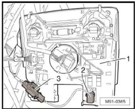
text_image
M91-0365
natural_image
Technical diagram of a mechanical or electrical component with arrows indicating directional flow (no text or symbols)26.12 Removing and installing operating unit for preparation for mobile telephone - E508-
Operating unit for preparation for mobile telephone -E508- fitting location -arrow-
Removing
- Switch off ignition and all electrical consumers and remove ignition key.
- Remove front interior light -W1- Electrical system; Rep. Gr. 96.

natural_image
Close-up of a car air conditioner control panel with a green indicator light and an arrow pointing to the left side (no readable text or symbols)- Press the three locking lugs -arrows- and take the operating unit for preparation for mobile telephone -E508- out.
- Disconnect connector to operating unit for preparation for mobile phone -E508-.
Installing
Installation is carried out in reverse order of removal.
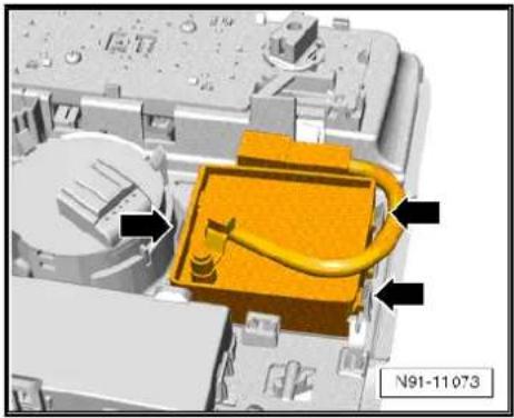
natural_image
3D mechanical assembly diagram showing a yellow component with black arrows pointing to features, no readable text or symbols present.26.13 Adapting telephone transmitter and receiver unit -R36- components
Special tools and workshop equipment required
◆ Vehicle diagnostic, testing and information system -VAS 5051B-

text_image
VAS 5051 B W00-10343Procedure
- In vehicle diagnostic, testing and information system -VAS 5051B-, select "Guided fault finding".
- Using GoTo button, select "Functions/component" and the following menu options in succession:
Body
Electrical system
◆ 01 - On board diagnosis-capable systems
◆ Corresponding preparation for car telephone
◆ Telephone functions

27 Multifunction steering wheel
27.1 General notes
The multifunction steering wheel allows some functions of the communication system and the cruise control system to be selected from the steering wheel.
text_image
AG. Volkswagen AG does not have a vehicle N91-1017027.1.1 Fault finding
The multifunction steering wheel control unit -J453- only communicates with the steering column electronics control unit -J527-. There the digital commands are prepared for further communication.
The multifunction steering wheel is equipped with self-diagnosis.
For fault finding, use the vehicle diagnosis, testing and information system -VAS 5051B- in "Guided fault finding" mode.
The multifunction steering wheel comprises the following components:
◆ Operating unit in steering wheel with two sets of buttons on left and right with integrated electronics.
◆ Multifunction steering wheel control unit -J453-
text_image
No 1-10/170 Copyright: C#P45628 Volkswagen
Note
When dealing with complaints, it is absolutely necessary to understand the functions and the operation of the multifunction steering wheel Operating manual.
When the battery -A- is reconnected, please remember to check vehicle equipment (radio, clock, convenience electronics, etc.) in accordance with the Electrical system; Rep. Gr. 27 workshop manual and/or the instruction manual.
27.2 Removing and installing steering wheel operating unit up to model year 2009
Removal and installation are performed in the same manner for the right and left set of buttons.
Removing
- Remove driver airbag unit General body repairs, interior; Rep. Gr. 69.
- Pull off connector -1-.
- Remove bolt -arrow- (2 Nm).
- Remove button set.
Installing
Installation is carried out in reverse order of removal.
- Coding steering column electronics control unit page 202.

natural_image
Technical diagram of a mechanical assembly with labeled parts (no readable text or symbols)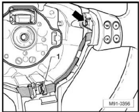
natural_image
Technical diagram of a mechanical assembly with labeled parts (no readable text or symbols)27.3 Removing and installing steering wheel operating unit up to model year 2010
Removal and installation are performed in the same manner for the right and left set of buttons.
Removing
- Remove driver airbag unit General body repairs, interior; Rep. Gr. 69.
- Unscrew bolt -arrow-.
- Remove button set.
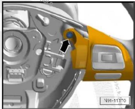
natural_image
Close-up of a camera's internal components with a yellow and black component, no visible text or symbols- Disconnect connector -arrow- on button set.
Installing
Installation is carried out in reverse order of removal.
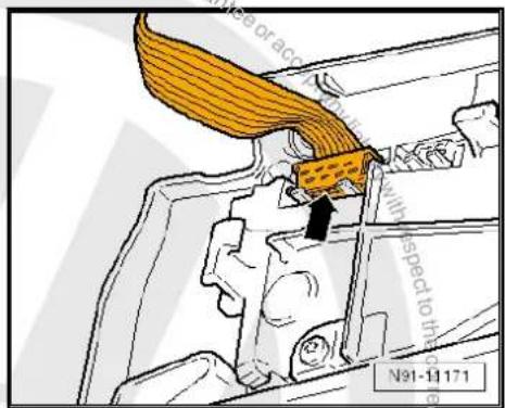
text_image
Mide or acrobatic with speed to the N91-11171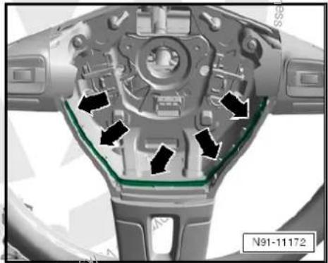
natural_image
Close-up of a mechanical component with arrows indicating directional flow or movement, no visible text or symbols.
Note
◆ Ensure that lines between both button sets of steering wheel are routed as shown in illustration -arrows-.
◆ Ensure that black connector on left button set -arrow- is inserted.
- Coding steering column electronics control unit page 202.

natural_image
Mechanical assembly diagram showing a green component inserted into a housing, with no visible text or symbols.27.4 Removing and installing multifunction steering wheel control unit -J453- up to MY2009
Removing
- Remove driver airbag unit General body repairs, interior; Rep. Gr. 69.
- Pull both connectors on multifunction steering wheel control unit -J453- off.
- Carefully lever multifunction steering wheel control unit -J453-out using a suitable screwdriver -arrow-.
Installing
Installation is carried out in reverse order of removal.
- Code the multifunction steering wheel control unit -J453-→ page 202.
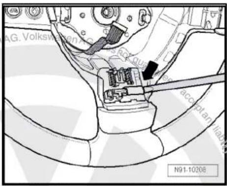
text_image
AG. Volkswagen N91-1020627.5 Adapting multifunction steering wheel components
Special tools and workshop equipment required
◆ Vehicle diagnostic, testing and information system -VAS 5051B-

natural_image
Medical device labeled VAS 5051 B, showing a multi-plate with control panel and wheels (no readable text or symbols beyond label)Procedure
- In vehicle diagnostic, testing and information system -VAS 5051B-, select "Guided fault finding".
- Using GoTo button, select "Functions/component" and the following menu options in succession:
Body
Electrical system
◆ 01 - On board diagnosis-capable systems
♦ Steering wheel electronics
♦ Steering wheel electronics functions
28 Compass system

Note
When dealing with complaints it is absolutely necessary to know the functions of and the operations of the compass system Operating manual.
In the event of repair work or fault finding Vehicle diagnosis, testing and information system VAS 5051 use "Guided fault finding" mode.
When the battery -A- is reconnected, please remember to check vehicle equipment (radio, clock, convenience electronics, etc.) in accordance with the Electrical system; Rep. Gr. 27 workshop manual and/or the instruction manual.
The use of magnetic-base aerials may lead to permanent magnetisation of the vehicle roof, resulting in a malfunction in the compass module. If confronted with complaints about inaccurate or incorrect directional indication of the compass module, ask the customer if a magnetic-base aerial has been used before carrying out any repair work.
28.1 General description
The compass equipment includes the dash panel insert display unit -arrow-, as well as the magnetic field sender (compass) -G197- under the rear shelf.
The compass display indicates with up to 2 letters the direction in which the vehicle is pointing (N = north, NW = northwest). 8 directions can be displayed.
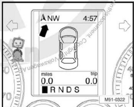
text_image
ANW 4:57 miles trip 0.0 0.0 ■ R N D S M91-032228.2 Removing and installing magnetic field sender for compass -G197- (saloon)
The magnetic field sender for compass -G197- is fitted on the rear shelf plate. It is accessible from the luggage compartment.
Removing
- Switch off ignition and all electrical consumers and remove ignition key.
- Unclip the magnetic field sender for compass -G197-arrows-.
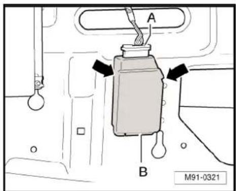
text_image
A B M91-0321- Disconnect connector -A- and take magnetic field sender for compass -G197- off.
Installing
Installation is carried out in reverse order of removal.
- Recalibrate compass system.
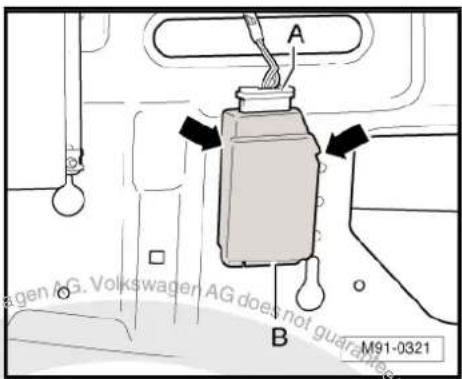
text_image
A B M91-032128.3 Removing and installing magnetic field sender for compass -G197- (Variant)
The magnetic field sender for compass -G197- is secured on the rear of the roof near the roof end strip.
Removing
- Switch off ignition and all electrical consumers and remove ignition key.
- Lower rear section of headliner General body repairs, interior; Rep. Gr. 70.
- Remove magnetic field sender for compass -G197--1- from roof using a small screwdriver.
- Disconnect connector -2- and remove magnetic field sender for compass -G197--1-.
Installing
The magnetic field sender for compass -G197- is delivered with adhesive film.
– Clean adhesive film on roof.
- Connect connector -2- to magnetic field sender for compass -G197--1-.
- Remove adhesive film on magnetic field sender for compass -G197-.
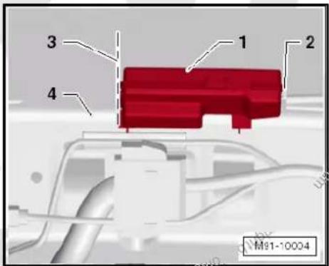
text_image
1 2 3 4 M91-10004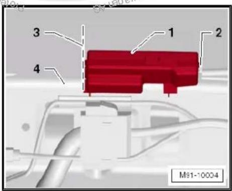
text_image
3 1 2 4 M91-10004Magnetic field sender for compass -G197- must be aligned with edge of roof end strip -4- and marking -3-.
- Press magnetic field sender for compass -G197--1- firmly on-to adhesive film.
Remainder of installation is carried out in reverse order of removal.
- Recalibrate compass system.
28.4 Removing and installing magnetic field sender for compass -G197- (Jetta 2011)
The magnetic field sender for compass -G197- is secured on the rear of the roof near the roof end strip/roof aerial.
Removing
Switch off ignition and all electrical consumers and remove ignition key.
- Lower rear section of headliner General body repairs, interior; Rep. Gr. 70.
- Remove magnetic field sender for compass -G197--1 from roof using a small screwdriver.
- Disconnect connector -2- and remove magnetic field sender for compass -G197- -1-.
Installing
The magnetic field sender for compass -G197- is delivered with adhesive film.
– Clean adhesive film on roof.
- Connect connector -2- to magnetic field sender for compass -G197--1-.
- Remove adhesive film on magnetic field sender for compass -G197-.

text_image
1 2 3 4 M91-10004
text_image
1 2 3 4 M91-10004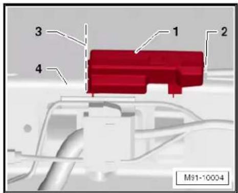
text_image
1 2 3 4 M91-10004Magnetic field sender for compass -G197- must be aligned with edge of roof end strip -4- and marking -3-.
- Press magnetic field sender for compass -G197--1- firmly on-to adhesive film.
Remainder of installation is carried out in reverse order of removal.
- Recalibrate compass system.
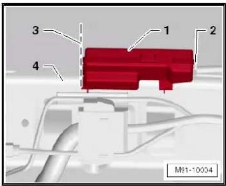
text_image
1 2 3 4 M91-10004
text_image
Pro-tertiendy copyright rights copyright granted AG. Volkswagen AG does not guarantee or accept any liability with respect to the correctness of information in their current copyright Volkswagen AG. Pro-tertiendy copyright rights copyright granted AG.29 Suppression measures
29.1 Implementation of suppression measures
All electrical consumers in the vehicle are individually suppressed at factory.
This includes all sensors, actuators and all electrical motors in the vehicles as well as the controllers in the control units which might create high-frequency interference.
To suppress interference, electrical components such as capacitors, coils and diodes are directly installed in the electrical components.
Interference-suppressing components are also installed in the connector housings of electrical consumers.
The earth cables formerly employed for noise suppression are no longer used because noise suppression measures now need to be applied as close as possible to the sources of interference.

text_image
Protracted by copyright copyright granted commercial purposes, in part or in whole, is not permitted unless authorised by Volkswagen AG. Volkswagen AG does not guarantee or accept any liability with respect to the correctness of information in his occupant copyright when Volkswagen is not allowed unless authorised by Volkswagen AG.30 Notes on operating mobile telephones and two-way radios
30.1 General notes
Mobile telephones or mobile two-way radios may not be used in the vehicle without a separate external aerial
◆ Remote controls (e.g. for garage door opener) and wireless units (keyboard or PC mouse) may be used in the vehicle only if the maximum transmitting power does not exceed 100 mW.
◆ An “e identification” is required for mobile two-way radios (applies for Europe only).
◆ Mobile telephones or other transmitting equipment (business equipment) which are not original vehicle equipment parts must have “CE identification” (applies to Europe only).
It is absolutely necessary to observe the manufacturer's operating and installation instructions for mobile telephones, two-way radios and aerials.
◆ The optimum unit range can be attained only by using an external aerial.
When telephone and two-way radio systems are properly installed, there is no danger to safety systems such as ABS or airbags. However, it is a prerequisite that there has been no modification of their installation. Routing wiring parallel to such systems must be avoided.
When mobile telephones or two-way radios are used, excessive electromagnetic fields may occur in the vehicle interior whether or not the external aerial has been properly installed. In this case, detrimental effects to health as well as malfunctions of vehicle electronics cannot be ruled out.
The installation and operation of two-way radios with a transmitting power above 10 W for the radio communication services listed in the table are permitted only under the following conditions:
- The transmitting power at the point of the aerial base (see unit manufacturer's specifications) must not exceed the relevant maximum values.
- No deviation from aerial locations listed in the table is permitted.
Transmitting power and aerial fitting locations table page 210
30.2 Notes on performing repair work
The battery -A- must be disconnected before repair work is begun! Electrical system; Rep. Gr. 27
Use valid current flow diagram Current flow diagrams, Electrical fault finding and Fitting locations.
For removing and installing trim General body repairs, interior; Rep. Gr. 70.
Observe manufacturer's operating and installation instructions for mobile telephones, two-way radios and aerials Operating instructions.
Secure wiring harnesses with cable ties. Wrap connectors with foam tubes to avoid rattling noises.
30.2.1 Transmitting power and possible fitting locations
Volkswagen permits the installation and operation of radio transmitter units if the transmitted power at the point of the aerial base listed in the table is not exceeded. Prescribed aerial fitting locations can also be found in the table.
The limits according to VDE 0848 part 2 (maximum permitted radiation strength for human safety) must be adhered to by reducing the transmitting power.
30.2.2 Voltage supply
When a radio transmitter unit is retrofitted in the vehicle, the battery -A- is used for connecting the positive and negative wires.
In addition, the wiring harness must be manufactured:
◆ Positive voltage supply via a red wire with 2.5 mm ^4 cross section.
◆ Negative voltage supply via a brown wire with 2.5 mm² cross section.
The positive wire must have a fuse located in the immediate vicinity of the battery -A-. For this purpose, a fuse holder must be secured next to the battery -A-. Both wires must be enclosed in an insulating tube.
Appropriate connections must be attached to wires on the battery side.
Proceed according to unit's Instruction manual on side of unit.
The additional wiring must be routed separately from vehicle wiring, and a distance of at least 10 cm must be maintained.
Some telephone systems and two-way radios require an additional terminal 15. In this case, a black wire with 1.5mm^2 cross-section must be laid from the transmitter/receiver unit to terminal 15a Current flow diagrams, Electrical fault finding and Fitting locations.
When laying the wiring, ensure that wiring is not routed parallel to factory wiring.
30.2.3 Aerial and aerial wiring
A shielded wire must be used between the radio transmitter unit and the aerial. The shield must contact both the unit and the aerial.
At the same time, ensure a good and continuous earth connection between the aerial base point cable and the vehicle body.
The transmitter must be used only when all components are properly matched with each other to prevent interference in the aerial wiring. To be sure, perform an output test to check and to match the system.
30.2.4 Further additional installations
The installation of further electronic equipment like business equipment (TV, fax) or household equipment (electric cooler box) is permitted only if these appliances are marked with a "CE" or an "e" sign (applies only in Europe).
Voltage supply is likewise to be provided via a separate wiring harness and equipped with a fuse.
30.3 Overview of battery -A-/radio transmitter unit/fuse/wiring harness
1 - Positive connection
☐ Red wire with appropriate connection
2 - To terminal 15a
☐ Connection to terminal 15a ⇒ Current flow diagrams, Electrical fault finding and Fitting locations
☐ Ensure that this wire is protected by a fuse.
☐ Fuse: max. 15A
3 - Aerial earth
☐ Ensure good earth connection to body.
☐ Treat fitting location of aerial with appropriate corrosion protection.
4 - Transmitter and receiver aerial
☐ Fitting locations ⇒ page 210.
5 - Shielded aerial wire
Cable with coaxial connector
6 - Radio transmitter unit
7 - Wiring harness
☐ Positive voltage supply via a red wire 2.5 mm ^4 cross section
☐ Negative voltage supply via a brown wire 2.5 mm ^4 cross section
☐ Black wire with 1.5 mm ^2 cross section to terminal 15a
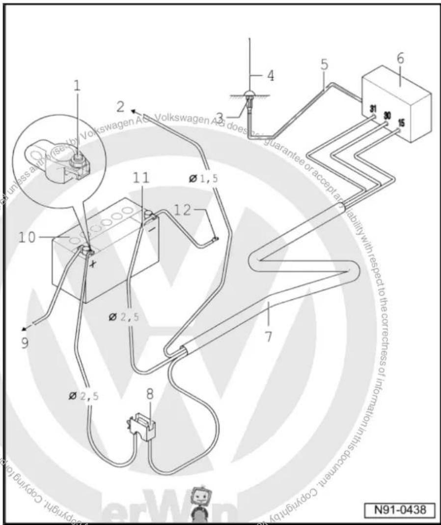
text_image
unless a or more by Volkswagen AG, Volkswagen AG does guarantee or accept any liability with respect to the correctness of information in this document. Copyright is N91-04388 - Fuse holder
☐ Install in immediate vicinity of battery -A-
9 - To starter -B-
10 - Battery -A-
☐ Fitting location in engine compartment
11 - Negative wire
12 - Body earth
30.4 Transmitting power and aerial fitting locations
| Designation | Pmax (watts) | Prescribed aerial fitting locations |
| Short wave< 54 MHZ | 100 (PEAK)1) | Front centre of roofCentre of roofRear centre of roofRear bumper |
| 4 m frequency band | 20 (effective)2) | All locations on vehicle exterior |
| 2 m frequency band | 20 (effective) | Front wingFront centre of roof |
| 2 m frequency band | 50 (effective) | Centre of roofRear centre of roofRear wing |
| 70 cm | 50 (effective) | Front centre of roofCentre of roofRear centre of roof |
| 23 cm | 20 (effective) | All locations on vehicle exterior |
| TETRA/TETRAPOL | 25 (effective) | All locations on vehicle exterior |
| D network/GSM 900 | 20 (PEAK) | All locations on vehicle exterior |
| E network/GSM 1800 GSM 1900/UMTS | 10 (PEAK) | All locations on vehicle exterior |
1) PEAK = peak envelope power (max. carrier power)
2) effective = effective transmitting power
Deviations from these specifications (aerial fitting location, frequency, power) are permitted only in specially justified exceptions following a single-case test performed by the EMC Centre of the VW AG in Wolfsburg
EMC = electromagnetic compatibility