SR8500 - Receiver MARANTZ - Free user manual and instructions
Find the device manual for free SR8500 MARANTZ in PDF.

User questions about SR8500 MARANTZ
0 question about this device. Answer the ones you know or ask your own.
Ask a new question about this device
Download the instructions for your Receiver in PDF format for free! Find your manual SR8500 - MARANTZ and take your electronic device back in hand. On this page are published all the documents necessary for the use of your device. SR8500 by MARANTZ.
USER MANUAL SR8500 MARANTZ
AV Surround Receiver
ENGLISH
WARRANTY
For warranty information, contact your local Marantz distributor.
RETAIN YOUR PURCHASE RECEIPT
Your purchase receipt is your permanent record of a valuable purchase. It should be kept in a safe place to be referred to as necessary for insurance purposes or when corresponding with Marantz.
IMPORTANT
When seeking warranty service, it is the responsibility of the consumer to establish proof and date of purchase. Your purchase receipt or invoice is adequate for such proof.
FOR U.K. ONLY
This undertaking is in addition to a consumer's statutory rights and does not affect those rights in any way.
FRANÇAIS
GARANTIE
The SR7500/SR8500 is in conformity with the EMC directive and low-voltage directive.
Français
- Do not expose the equipment to rain or moisture.
- Do not remove the cover from the equipment.
- Do not insert anything into the equipment through the ventilation holes.
- Do not handle the mains lead with wet hands.
- Do not cover the ventilation with any items such as tablecloths, newspapers, curtains, etc.
- No naked flame sources, such as lighted candles, should be placed on the equipment.
- When disposing of used batteries, please comply with governmental regulations or environmental public instruction's rules that apply in your country or area.
- Do not place anything about 0.2 meter above the top panel.
- Make a space of about 0.2 meter around the unit.
Français
AVERTISSEMENTS
FL DISPLAY AND INDICATER 6
REAR PANEL 7
REMOTE CONTROLLER RC8500SR ..8
NAMES AND FUNCTIONS 8
LCD INDICATORS 9
REMOTE CONTROL RANGE 10
LOADING BATTERIES 10
BATTERY REPLACEMENT INTERVAL 10
SETTING THE TIME 10
GENERAL INFORMATION OF RC8500SR
TO SR7500 11
CONNECTIONS.... 12
SPEAKER PLACEMENT 12
CONNECTING SPEAKERS 12
CONNECTING AUDIO COMPONENTS 13
CONNECTING VIDEO COMPONENTS 14
ADVANCED CONNECTING 15
CONNECTING THE REMOTE CONTROL JACKS ..... 15
CONNECTING THE ANTENNA TERMINALS .... 16
CONNECTING FOR THE MULTI ROOM 17
SETUP 18
(ASSIGNABLE DIGITAL INPUT) 19
2 SPEAKER SETUP 19
3 PREFERENCE 22
4 PL II (PRO LOGIC III) MUSIC PARAMETER ..... 22
5 CS II (CIRCLE SURROUND III) PARAMETER ..... 22
6 MULTI ROOM 23
7 7.1 CH INPUT LEVEL 23
8 DC TRIGGER SETUP 23
ADJUSTING THE MAIN VOLUME 24
ADJUSTING THE TONE
(BASS & TREBLE) CONTROL 24
TEMPORARILY TURNING OFF THE SOUND 25
USING THE SLEEP TIMER 25
NIGHT MODE 25
SURROUND MODE.... 25
OTHER FUNCTION 29
TV AUTO ON/OFF FUNCTION 29
ATTENUATION TO ANALOG INPUT SIGNAL 29
LISTENING THROUGH HEADPHONES 29
DOLBY HEADPHONE MODE 29
VIDEO ON/OFF 29
DISPLAY MODE 29
SELECTING ANALOG AUDIO INPUT
OR DIGITAL AUDIO INPUT 30
RECORDING AN ANALOG SOURCE 30
SPEAKER A:B 30
7.1 CH INPUT 30
AUX2 INPUT 31
LIP.SYNC 31
BASIC OPERATION (TUNER) ...... 32
LISTENING TO THE TUNER 32
PRESET MEMORY 33
RDS OPERATION 35
MULTI ROOM SYSTEM.... 36
MULTI ROOM PLAYBACK
USING THE MULTI ROOM OUT TERMINALS ..... 36
MULTI ROOM PLAYBACK
USING THE MULTI SPEAKER TERMINALS .... 36
PROGRAMMING MACROS 42
CLONE MODE 44
SETUP 45
TROUBLESHOOTING 46
TECHNICAL SPECIFICATIONS ..... 47
DIMENSIONS 47
This section must be read before any connection is made to the mains supply.
This user guide covers the SR7500 and SR8500, though the SR7500 is given for the title. Explanations of features belonging only to the SR8500 are indicated as "SR8500 only".
EQUIPMENT MAINS WORKING SETTING
Your Marantz product has been prepared to comply with the household power and safety requirements that exist in your area.
SR7500 can be powered by 230V AC only.
COPYRIGHT
Recording and playback of any material may require consent. For further information refer to the following:
— Copyright Act 1956
— Dramatic and Musical Performers Act 1958
— Performers Protection Acts 1963 and 1972
— Any subsequent statutory enactments and orders
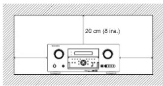
CAUTIONS ON INSTALLATION
For heat dispersal, leave at least 20 cm/8 inch of space between the top, back and sides of this unit and the wall or other components.
- Do not obstruct the ventilation holes.
text_image
20 cm (8 ins.)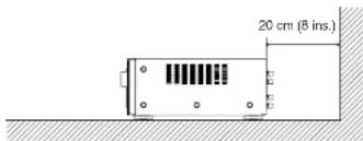
text_image
20 cm (8 ins.)INTRODUCTION
Thank you for purchasing the Marantz SR7500 Surround receiver.
This remarkable component has been engineered to provide you with many years of home theater enjoyment. Please take a few minutes to read this manual thoroughly before you connect and operate the SR7500.
As there are a number of connection and configuration options, you are encouraged to discuss your own particular home theater setup with your Marantz A/V specialist dealer.
DESCRIPTION

THX ^6 is an exclusive set of standards and technologies established by the world-renowned film production company, Lucasfilm Ltd. THX resulted from George Lucas' desire to reproduce the movie soundtrack as faithfully as possible both in the movie theater and in the home theater.
THX engineers developed patented technologies to accurately translate the sound from a movie theater environment into the home, correcting the tonal and spatial errors that occur.
When the THX mode of the SR7500 is on, three distinct THX technologies are automatically added:
Re-Equalization-restores the correct tonal balance for watching a movie in a home environment.
These sounds are otherwise mixed to be brighter for a large movie theater. Re-EQ compensates for this and prevents the soundtracks from being overly bright and harsh when played in a home theater.
Timbre Matching-filters the information going to the surround speakers so they more closely match the tonal characteristics of the sound coming from the front speakers.
This ensures seamless panning between the front and surround speakers.
Adaptive Decorrelation slightly changes one surround channel's time and phase relationship with respect to the other surround channel.
This expands the listening position and creates with only two surround speakers the same spacious surround experience as in a movie theater with multiple surround speakers.
The Marantz SR7500 was required to pass a rigorous series of quality and performance tests, in addition to incorporating the technologies explained above, in order to be THX certified by Lucasfilm Ltd.
THX requirements cover every aspect of performance including pre-amplifier and power amplifier performance and operation, and hundreds of other parameters in both the digital and analog domain.
Movies which have been encoded in Dolby Digital, DTS, Dolby Pro Logic, stereo and Mono will all benefit from the THX mode when being viewed.
The THX mode should only be activated when watching movies which were originally produced for a movie theater environment.
THX need not be activated for music, movies made especially for TV, or shows such as sports programming, talk shows, etc.
This is because they were originally mixed for a small room environment.
THX is a trademark or registered trademark of THX Ltd. Surround EX is a jointly developed technology of THX and Dolby Laboratories, Inc. and is a trademark of Dolby Laboratories, Inc. Used under authorization. All rights reserved.
THX SURROUND EX
THX Surround EX—Dolby Digital Surround EX is a joint development of Dolby Laboratories and THX Ltd.
In a movie theater, film soundtracks that have been encoded with Dolby Digital Surround EX technology are able to reproduce an extra channel which has been added during the mixing of the program. This channel, called Surround Back, places sounds behind the listener in addition to the currently available front left, front center, front right, surround right, surround left and subwoofer channels. This additional channel provides the opportunity for more detailed imaging behind the listener and brings more depth, spacious ambience and sound localization than ever before. Movies that were created using the Dolby Digital Surround EX technology, when released into the home consumer market may exhibit wording to that effect on the packaging. A list of movies created using this technology can be found on the Dolby web site at www.dolby.com. A list of available DVD software titles encoded with this technology can be found at www.thx.com.
Only receiver and controller products bearing the THX Surround EX logo, when in the THX Surround EX mode, faithfully reproduce this new technology in the home. This product may also engage the THX Surround EX mode during the playback of 5.1 channel material that is not Dolby Digital Surround EX econded. In such case, the information delivered to the Surround Back channel will be program dependent and may or may not be very pleasing depending on the particular soundtrack and the tastes of the individual listener.
"SURROUND EX™" is a trademark of Dolby Laboratories. Used under authorization.

DTS was introduced in 1994 to provide 5.1 channels of discrete digital audio into home theater systems.
DTS brings you premium quality discrete multichannel digital sound to both movies and music.
DTS is a multichannel sound system designed to create full range digital sound reproduction.
The no compromise DTS digital process sets the standard of quality for cinema sound by delivering an exact copy of the studio master recordings to neighborhood and home theaters.
Now, every moviegoer can hear the sound exactly as the moviemaker intended.
DTS can be enjoyed in the home for either movies or music on of DVD's, LD's, and CD's.
"DTS" and "DTS Digital Surround" are registered trademarks of Digital Theater Systems, Inc.

The advantages of discrete multichannel systems over matrix are well known.
But even in homes equipped for discrete multichannel, there remains a need for high-quality matrix decoding. This is because of the large library of matrix surround motion pictures available on disc and on VHS tape; and analog television broadcasts.
The typical matrix decoder of today derives a center channel and a mono surround channel from two-channel matrix stereo material. It is better than a simple matrix in that it includes steering logic to improve separation, but because of its mono, band-limited surround it can be disappointing to users accustomed to discrete multichannel.
Neo:6 offers several important improvements as follow,
Neo:6 provides up to six full-band channels of matrix decoding from stereo matrix material. Users with 6.1 and 5.1 systems will derive six and five separate channels, respectively, corresponding to the standard home-theater speaker layouts.
- Neo:6 technology allows various sound elements within a channel or channels to be steered separately, and in a way which follows naturally from the original presentation.
- Neo:6 offers a music mode to expand stereo nonmatrix recordings into the five- or six-channel layout, in a way which does not diminish the subtlety and integrity of the original stereo recording.

DTS-ES Extended Surround is a new multichannel digital signal format developed by Digital Theater Systems Inc. While offering high compatibility with the conventional DTS Digital Surround format, DTS-ES Extended Surround greatly improves the 360-degree surround impression and space expression thanks to further expanded surround signals. This format has been used professionally in movie theaters since 1999.
In addition to the 5.1 surround channels (FL, FR, C, SL, SR and LFE), DTS-ES Extended Surround also offers the SB (Surround Back) channel for surround playback with a total of 6.1 channels. DTS-ES Extended Surround includes two signal formats with different surround signal recording methods, as DTS-ES Discrete 6.1 and DTS-ES Matrix 6.1.
"DTS", "DTS-ES and "Neo:6" are trademarks of Digital Theater Systems, Inc.

The stereo CD is a 16-bit medium with sampling at 44.1kHz . Professional audio has been 20- or 24-bit for some time, and there is increasing interest in higher sampling rates both for recording and for delivery into the home. Greater bit depths provide extended dynamic range. Higher sampling rates allow wider frequency response and the use of anti-alias and reconstruction filters with more favorable aural characteristics.
DTS 96/24 allows for 5.1 channel sound tracks to be encoded at a rate of 96kHz/24blts on DVD-Video titles.
When DVD-video appeared, it became possible to deliver 24-bit, 96 kHz audio into the home, but only in two channels, and with serious limitations on picture. This capability has had little use.
DVD-audio allows 96/24 in six channels, but a new player is needed, and only analog outputs are provided, necessitating the use of the D/A converters and analog electronics provided in the player.
DTS 96/24 offers the following:
- Sound quality transparent to the original 96/24 master.
- Full backward compatibility with all existing decoders. (Existing decoders will output a 48 kHz signal)
- No new player required: DTS 96/24 can be carried on DVD-video, or in the video zone of DVD-audio, accessible to all DVD players.
- 96/24 5.1-channel sound with full-quality full-motion video, for music programs and motion picture soundtracks on DVD-video.
"DTS" and "DTS 96/24" are trademarks of Digital Theater Systems, Inc.
DOLBY
DIGITAL·EX
PRO LOGIC IIx
Dolby Digital identifies the use of Dolby Digital audio coding for such consumer formats as DVD and DTV. As with film sound, Dolby Digital can provide up to five full-range channels for left, center, and right screen channels, independent left and right surround channels, and a sixth (".1") channel for low-frequency effects.
Dolby Surround Pro Logic II is an improved matrix decoding technology that provides better spatiality and directionality on Dolby Surround program material; provides a convincing three-dimensional soundfield on conventional stereo music recordings; and is ideally suited to bring the surround experience to automotive sound. While conventional surround programming is fully compatible with Dolby Surround Pro Logic II decoders, soundtracks will be able to be encoded specifically to take full advantage of Pro Logic II playback, including separate left and right surround channels. (Such material is also compatible with conventional Pro Logic decoders.)
Dolby Digital EX creates six full-bandwidth output channels from 5.1-channel sources. This is done using a matrix decoder that derives three surround channels from the two in the original recording. For best results, Dolby Digital EX should be used with movies soundtracks recorded with Dolby Digital Surround EX.
About Dolby Pro Logic IIx
Dolby Pro Logic IIx technology delivers a natural and immersing 7.1-channel listening experience to the home theater environment. A product of Dolby's expertise in surround sound and matrix decoding technologies, Dolby Pro Logic IIx is a complete surround sound solution that maximizes the entertainment experience from stereo as well as 5.1-channel encoded sources.
Dolby Pro Logic IIx is fully compatible with Dolby Surround Pro Logic technology and can optimally decode the thousands of commercially available Dolby Surround encoded video cassettes and television programs with enhanced depth and spatiality. It can also process any high-quality stereo or Advanced Resolution 5.1-channel music content into a seamless 6.1- or 7.1-channel listening experience.

The Dolby Headphone technology provides a surround sound listening experience over headphones. When listening to multichannel content such as DVD movies over headphones, the listening experience is fundamentally different than listening to speakers. Since the headphone speaker drivers are covering the pinna of the ear, the listening experience differs greatly from traditional speaker playback. Dolby utilizes patented headphone perspective curves to solve this problem and provides a non-fatiguing, immersive, home theater listening experience. Dolby Headphone also delivers exceptional 3D audio from stereo material.
Manufactured under license from Dolby Laboratories. "Dolby", "Pro Logic", and the double-D symbol are trademarks of Dolby Laboratories.
SRS(●)
Circle Surround II
Circle Surround II (CS-II) is a powerful and versatile multichannel technology. CS-II is designed to enable up to 6.1 multichannel surround sound playback from mono, stereo, CS encoded sources and other matrix encoded sources. In all cases the decoder extends it into 6 channels of surround audio and a LFE/subwoofer signal. The CS-II decoder creates a listening environment that places the listener "inside" music performances and dramatically improves both hi-fi audio conventional surround-encoded video material. CS-II provides composite stereo rear channels to greatly improve separation and image positioning—adding a heightened sense of realism to both audio and A/V productions.
CS-II is packed with other useful feature like dialog clarity (SRS Dialog) for movies and cinema-like bass enrichment (TruBass). CS-II can enable the dialog to become clearer and more discernable in movies and it enables the bass frequencies contained in the original programming to more closely achieve low frequencies—overcoming the low frequency limitations of the speakers by full octave.
Circle Surround II, Dialog Clarity, TruBass, SRS and Symbol are trademarks of SRS Labs, Inc.
Circle Surround II, Dialog Clarity and TruBass technology are incorporated under license from SRS Labs, Inc.

(SR8500 only)
HDCD ^® (High Definition Compatible Digital ^® ) is a patented process for delivering on Compact Disc the full richness and details of the original microphone feed.
HDCD encoded CDs sound better because they are encoded with 20-bits of real musical information as compared to 16-bits for all other CDs.
HDCD overcomes the limitation of the 16-bit CD format by using a sophisticated system to encode the additional four bits onto the CD while remaining completely compatible with the CD format.
When listening to HDCD recordings, you hear more dynamic range, a focused 3-D sound stage, and extremely natural vocal and musical timbre. With HDCD, you get the body, depth and emotion of the original performance not a flat, digital imitation.
HDCD system manufactured under license from Microsoft. This product is covered by one or more of the following: In the United States 5,479,168 5,638,074 5,640,161 5,808,574 5,838,274 5,854,600 5,864,311 5,872,531 and in Australia 669,114 with other patents pending.
FEATURES
The SR7500 Incorporates the latest generation of digital surround sound decoding technology such as Dolby Digital EX, Dolby Digital, DTS ES (Discrete 6.1 and Matrix 6.1), DTS Neo:6 (Cinema, Music), Dolby Pro-Logic II (Movie, Music and Game), Dolby Pro-Logic III (Movie, Music and Game), Circle Surround II (Cinema, Music and Mono).
In addition, Marantz has focused on the future. By utilizing pre-out jacks, 7.1 direct inputs and a RS-232C communication port, the SR7500 is tomorrow's technology, today!
• THX Select certified
7ch amplifiers have enough power for even the most difficult conditions found in large rooms.
Enormous power reserves endow the system with substantial dynamic ability at high sound levels.
105 watts (SR7500) / 110 watts (SR8500) to each of the 7 main channels the power amp section features an advanced, premium high-storage power supply capacitors, and fully discrete output stages housed in cast aluminum heat sinks.
The SR7500 incorporates the most advanced Digital Signal Processing circuitry, along with a Crystal® 192 kHz/24 bit D/A converter in each of the 7 channels. Independent power supply circuits are incorporated for the FL display, audio and video sections for maximum separation, clarity and dynamic range. Together with hand-selected customized components, all elements work in harmony to recreate the emotion, exactly as the artist had intended.
The SR7500 is designed and engineered with extensive feedback from custom installation experts, dealers and consumers. It features multi-room/multisource, assignable DC trigger, a RS-232C communication port, Flasher input, heavy duty speaker binding posts and an extensive array of both analog and digital inputs / outputs. With 6 assignable digital inputs (7 total), 4 component Inputs. SACD Multi Channel (7.1 channel) direct inputs video convert system and a speaker-B and OSD output versatility is taken to a stunning new level. Furthermore, the SR7500 can output the OSD information through the Y/C (S-video) and composite video outputs.
An easy-to-use programmable, learning remote control allows full access to all of the operating functions and can be used for system operation as well.
The new generation of Marantz Receivers is stylish and completely symmetrical. On the front panel of the SR7500, buttons are kept to a minimum. Source selectors and volume controls are intuitively placed. The SR7500 is here to perform in your unrivaled home entertainment setup.
• THX / THX Surround EX
• Dolby Digital EX, Dolby Digital, DTS ES (Discrete 6.1, Matrix 6.1, Neo:6)
• Dolby Pro Logic II (Movie, Music, Game)
• Dolby Pro Logic IIx (Movie, Music, Game)
• Circle Surround II (Cinema, Music, Mono)
- MRAC (Marantz Room Acoustic Calibration) - 7 × 10⁵ Watts (8 Ohms), Discrete Amplifiers (SR8500: 7 × 110 Watts)
• High Power Current Feedback Circuitry
• Massive Energy Power Supply, Huge El
Transformer, Large ELCO's
• 192 kHz/24 bit Crystal® DAC for all 8 Channels
• 32 bit Digital Surround Processing Chipsets
- Video Off Mode
• Large Heavy Duty Speaker Terminals for all Channels
• RS-232C Terminal for Future Upgrade or System Control
- Set Up Menu via all Video Output
(Composite, S-Video and Component video)
• Auto Input Signal Detection
- Improved Station Name Input Method, 50 Presets
- Auto Adjust Function for Speaker Distance Settings (Delay Time)
- Front Optical AUX Input
(Digital Camera, Portable DVD)
- Assignable DC Trigger Output
• Programmable, learning remote control
- Flasher Input
• Video convert system (Composite Video ↔
S Video → Component Video)
- Assignable DVI-D INPUT (SR8500 only)
- HDCD (SR8500 only)
• Copper Plate Chassis (SR8500 only)
• Troidal Core Transformer (SR8500 only)
ACCESSORIES
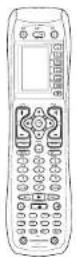
Remote Controller RC8500SR
Microphone MC-10

AC cable

AAA-size batteries × 3

AM Loop Antenna

FM Antenna

Front AUX Jack Cover

User Guide
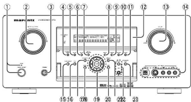
FRONT PANEL
text_image
① ② ③ ④ ⑤ ⑥ ⑦ ⑧ ⑨ ⑩ ⑪ ⑫ ⑬ ⑭ ⑮ ⑯ ⑰ ⑱ ⑲ ⑳ ㉑ ㉒ ㉓ ㉔ ㉕ ㉖ ㉗ ㉘ ㉙ ㉚ ㉛ ㉜ ㉝ ㉞ ㉟ ㉳ ㉴ ㉵ ㉶ ㉇ ㉐ ㉒ ㉓ ㉔ ㉕ ㉖ ㉗ ㉘ ㉙ ㉚ ㉛ ㉜ ㉝ ㉞ ㉟ ㉞a ㉞b ㉞c ㉞d ㉞e ㉞f ㉞g ㉞h ㉞i ㉞j ㉞k ㉞l ㉞m ㉞n ㉞o ㉞p ㉞q ㉞r ㉞s ㉞t ㉞u ㉞v ㉞w ㉞x ㉞y ㉞z ㉞c ㉞d ㉞e ㉞f ㉞g ㉞h ㉞i ㉞j ㉞k ㉞l ㉞m ㉞n ㉞o ㉞p ㉞q ㉞r ㉞s ㉞t ㉞u ㉞v ㉞w ㉞i ㉞j ㉞k ㉞l ㉞m ㉞n ㉞o ㉞p ㉞q ㉞r ㉞s ㉞t ㉞u ㉞v ㉞w ㉞i ㉞o ㉞p ㉞q ㉞r ㉞s① POWER switch and STANDBY indicator
Press the button to turn the power ON, and press again to turn it OFF. If the POWER switch is in the ON position, the power of this unit can be turned ON/OFF by pressing the POWER button on the remote control unit.
When this unit is in the standby mode with the POWER switch set to the ON position, pressing the ENTER button also allows to turn the power on. The STANDBY indicator lights up when this unit is the standby mode (power OFF) by the remote control unit.
② INPUT SELECTOR knob (AUDIO/VIDEO)
This knob is used to select the input sources. The video function selectors, such as TV, DVD, VCR1, DSS and AUX1 select video and audio simultaneously.
Audio function sources such as CD, TAPE, CD-R/MD, TUNER and AUX2 may be selected in conjunction with a Video source.
This feature (Sound Injection) combines a sound from one source with a picture from another.
Choose the video source first, and then choose a different audio source to activate this function.
③ HEADPHONE jack for stereo headphones
This jack may be used to listen to the SR7500's output through a pair of headphones. Be certain that the headphones have a standard 1/4" stereo phono plug. Note that the main room speakers will automatically be turned off when the headphone jack is in use.
Notes:
- When using headphones, the surround mode will change to STEREO and Dolby Headphone by MENU and Cursor button.
- The surround mode returns to the previous setting as soon as the headphone plug is removed from the jack.
④ SURROUND MODE button
You can select the surround mode by pressing this button.
⑤ AUTO (Auto surround) button
Press this button to select the AUTO mode from the surround modes. When this mode is selected, the receiver determines the surround mode corresponding to a digital input signal automatically.
⑥ MULTI (Multi Room) button
Press this button to activate the Multiroom system. "MULTI" indicator will be illuminated in the display.
⑦ MULTI SPEAKER button
Press this button to activate the Multiroom Speaker system. "MULTI" indicator will be illuminated in the display. (See page 36)
⑧ BAND button
Press this button to switch between FM and AM in the TUNER mode.
⑨ T-MODE button
Press this button to select the auto stereo mode or mono mode when the FM band is selected. The "AUTO" indicator lights in the auto stereo mode. (See page 32)
⑩ MEMORY button
Press this button to enter the tuner preset memory numbers or station names. (See page 33)
⑪ CLEAR button
Press this button to cancel the station-memory setting mode or preset scan tuning. (See page 33)
⑫ INFRARED receiving sensor window
This window receives infrared signals for the remote control.
⑬ VOLUME control knob
Adjusts the overall sound level. Turning the control clockwise increases the sound level.
⑭ AUX1 INPUT jacks
These auxiliary video/audio input jacks accept the connections of a camcorder, portable DVD, game etc. When not using these jacks, protect with the included jack covers.
How to Attach the Front AUX Jack Cover

natural_image
Diagram of a computer interface showing ports and a USB cable (no text or symbols)Front AUX Jack Cover
⑮ PURE DIRECT button
When this button is pressed, the tone control circuitry is bypassed as well as Bass Management. "PURE DIRECT" indicator will be illuminated in the display.
Notes:
• The surround mode is automatically switched to
AUTO when the pure direct function is turned on.
- Additionally, Speaker Configurations are fixed automatically as follows.
Front SPKR = Large, Center SPKR = Large,
Surround SPKR = Large, Sub woofer = On
⑯ THX button
Press this button to select THX processing for input source.
⑰ 7.1CH INPUT button
Press this button to select the output of an external multichannel player.
⑱ MENU button
This button is used to enter the SETUP MAIN MENU.
⑲ Cursor (◀, ▶) ▼ ENTER button
Use these buttons when operating the SETUP MAIN MENU and TUNER function.
⑳ EXIT button
This button is used to exit from the SETUP MAIN MENU.
②1 DISPLAY button
When this button is pressed, the FL display mode is changed as Surround Mode → Auto-display Off → Display Off → Input Function and the display off indicator (DISP) lights up in condition of DISPLAY OFF.
22 MRAC button / MIC jack
Press to automatically measure speaker characteristics using the included microphone (MC-10). (See page 21)
Press this button to select speaker systems A and/or B.
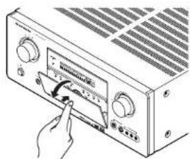
Opening and closing the front panel door
When you want to use the controls behind the front panel door, open the door by gently pressing on the lower part of the panel. Keep the door closed when not using these controls.
text_image
Diagram of an electronic device with a hand pointing to its screen displaying a measurement or calibration device.Notes:
- Be careful not to pinch your fingers between the door and the panel.
FL DISPLAY AND INDICATER

flowchart
graph TD
    A["THX"] --> B["(17)(18)(15)"]
    C["PURE DIRECT"] --> D["(1)"]
    C --> E["(2)"]
    C --> F["(3)"]
    C --> G["(5)"]
    C --> H["(6)(8)"]
    C --> I["(7)"]
    C --> J["(9)"]
    C --> K["(11)"]
    C --> L["(13)"]
    C --> M["(14)"]
    C --> N["(16)"]
    C --> O["(19)"]
    D --> P["SLEEP"]
    E --> Q["AUTO SURR"]
    F --> R["ST V"]
    G --> S["DISC 6.1"]
    H --> T["NIGHT PEAK ANAL OKT"]
    I --> U["TX 6.1 SPKR AB"]
    J --> V["Digital"]
    K --> W["PCM"]
    L --> X["SURROUND"]
    M --> Y["DIGITAL EX"]
    N --> Z["L C R"]
    N --> AA["LFE"]
    N --> AB["R S#"]
(1) DISP (Display Off) indicator
This indicator is illuminated when the SR7500 is in the display off condition.
(2) SLEEP timer indicator
This indicator is illuminated when the sleep timer function in the main-room is in use.
(3) Multi-room system indicator
This indicator is illuminated when the multi-room system is active.
(4) AUTO SURR (Auto Surround mode) indicator
This indicator is illuminated to show that the AUTO SURROUND mode is in use.
(5) TUNER's indicators
AUTO: This indicator illuminates when the tuner's Auto mode is in use.
TUNED: This indicator illuminates when a station is being received with sufficient signal strength to provide acceptable listening quality.
ST(Stereo) : This indicator illuminates when an FM station is being tuned into stereo condition.
(6) DTS-ES mode indicators (DISC6.1, MTX6.1)
These indicators will illuminate to show the DTS-ES decoding mode (Discrete 6.1 or Matrix 6.1).
(7) V (video)-OFF mode indicator
This indicator is illuminated when the Video-OFF function is active.
(8) NIGHT mode indicator
This indicator is illuminated when the SR7500 is in the Night mode, which reduces the dynamic range of digital program material at low volume levels.
(9) SPKR (speaker) AB indicator
Active speaker system will be illuminated by this indicator.
(10) PEAK indicator
This indicator is a monitor for an analog audio input signal. If the selected analog audio input signal is greater than the capable level of internal processing, this will illuminate. If this happens, you should press the ATT button on the remote.
(11) ATT (Attenuation) indicator
This indicator is illuminated when the attenuation function is active.
(12) DIGITAL Input Indicator
This indicator lights when a digital input has been selected.
(13) ANALOG input indicator
This indicator is illuminated when an analog input source has been selected.
(14) SIGNAL FORMAT indicators
☐ DIGITAL, EX, ☐ SURROUND, dts, ES, 96/24, PCM
When the selected input is a digital source, some of these indicators will be illuminated to display the specific type of signal in use.
(15) ENCODED CHANNEL STATUS INDICATORS
These indicators display the channels that are encoded with a digital
input signal. If the selected digital input signal is Dolby Digital 5.1ch or DTS 5.1ch, "L", "C", "R", "SL", "SR" and "LFE" will be illuminated. If the digital input signal is 2 channel PCM audio, "L" and "R" will be displayed.
If Dolby Digital 5.1ch signal with Surround EX flag or DTS-ES signal comes in, "L", "C", "R", "SL", "S", "SR" and "LFE" will be illuminated.
(16) Main Information Display
This display shows messages relating to the status, input source, surround mode, tuner, volume level or other aspects of unit's operation.
(17) THX indicator
This indicator illuminated when the SR7500 is in the THX mode.
(18) PURE DIRECT indicator
This indicator is illuminated when the SR7500 is in the PURE DIRECT mode.
(19) HDCD indicator (SR8500 only)
When HDCD signal is decoded, this indicator will light up.
REAR PANEL

text_image
Labeled diagram of an electronic device rear panel showing numbered components and connectors1 VIDEO IN/OUT (TV, DVD, VCR1, DSS/VCR2) These are the video inputs and outputs. There are 4 video inputs and 2 video outputs and each one includes both composite video and S-video configurations. Connect VCRs, DVD players, and other video components to the video inputs. The 2 video output channels can be used to be connected to video tape recorders for making recordings.
② FM antenna terminal (75 ohms) Connect an external FM antenna with a coaxial cable, or a cable network FM source.
AM antenna and ground terminals Connect the supplied AM loop antenna. Use the terminals marked "AM" and "GND". The supplied AM loop antenna will provide good AM reception in most areas. Position the loop antenna until you hear the best reception.
③ COMPONENT VIDEO INPUT/OUTPUT
If your DVD player or other device has component video connectors, be sure to connect them to these component video connectors on the SR7500. The SR7500 has 4 component video input connectors to obtain the color information (Y, C8, Cr9) directly from the recorded DVD signal or other video component and one component video output connector to output it directly into the matrix decoder of the display device. By sending the pure DVD component video signal directly, the DVD signal forgoes the extra processing that normally would degrade the image. The result is vastly increased image quality, with incredibly life like colors and crisp detail.
4 FLASHER IN (Flasher input terminal)
These terminals are to control the unit from each zone. Connect the control signal from a Keypad, etc.
5 MONITOR OUT
These are monitor outputs and each one includes both composite video and S-video configurations. When connecting two video monitors or televisions, be aware that the OSD interface can be used with both MONITOR OUT connections.
6 RS-232C
The RS-232C port is to be used in conjunction with an external controller to control the operation of the SR7500 by using an external device. The RS-232C port may also be used in the future to update the operating software of the SR7500 so that it will be able to support new digital audio formats and the like as they are introduced.
7 Preamp Outputs
(L, R, SL, SR, SBL, SBR, C)
Jacks for L(front left), R (front right), C (Center), SL (surround left), SR (surround right), SBL (surround back left) and SBR (surround back right). Use these jacks for connection to external power amplifiers.
8 AC INLET
Plug the supplied power cord into this AC INLET and then into the power outlet on the wall. SR7500 can be powered by 230V AC only.
9 AC OUTLETS
Connect the AC power cable of component such as a DVD or CD player to this outlet. The marked SWITCHED provides power only when the SR7500 is turned on and is useful for components which you use every time you play your system.
Caution:
- In order to avoid potential turn-off thumps, anything plugged into these outlets should be powered up before the SR7500 is turned on.
The capacity of this AC outlet is 100W. Do not connect devices that consume electricity more than the capacity of these AC outlet. If the total power consumption of the connected devices exceeds the capacity, the protection circuit shuts down the power supply.
10 Speaker outputs terminals
Seven terminals are provided for the front (A) left, front (A) right, front (B) left, front (B) right, front center, surround left and surround right speakers.
⑪ Speaker outputs terminals (SURROUND BACK / MULTI SPEAKER / SPEAKER C)
Two terminals are provided for the front left, and right speakers for multi room ( 2^nd zone) or surround back. The terminals can be used to connect a third set of speakers by setting the SPEAKER C selector switch to ON. For connection and use, see page 17.
⑫ Subwoofer Output
Connect this jack to the line level input of a powered subwoofer. If an external subwoofer amplifier is used, connect this jack to the subwoofer amplifier input. If you are using two subwoofer, either powered or with a 2 channel subwoofer amplifier, connect a "Y" connector to the subwoofer output jack and run one cable from it to each subwoofer amplifier.
13 7.1 CHANNEL or AUX2 INPUT
By connecting a DVD Audio player, SACD multichannel player, or other components that has a multichannel port, you can playback the audio with 5.1 channel or 7.1 channel outputs.
14 DC TRIGGER output terminal
Connect a device that needs to be triggered by DC under certain conditions (screen, power strip, etc...)
Use the system OSD setup menu to determine the conditions by which these jack will be active.
Note:
This output voltage is for (status) control only, It is not sufficient for drive capability.
15 Multiroom Outputs (Audio L&R, Video)
These are the audio and video output jacks for the Multi zone (Multi room).
Connect these jacks to optional audio power amplifiers or video display devices to listen and view the source selected by the multiroom system in a remote room.
16 MULTI ROOM REMOTE IN/OUT terminals
IN: Connect to a multi-room remote control device, available from your Marantz dealer. OUT: Connect to the Marantz component equipped with remote control (RC-5) terminals in Multi zone (Multi room).
17 REMOTE CONT. IN/OUT terminals
Connect to a Marantz component equipped with remote control (RC-5) terminals.
18 AUDIO IN/OUT (CD, TAPE, CD-R, TV, DVD, VCR1, DSS/VCR2)
These are the analog audio inputs and outputs. There are 7 audio inputs (4 of which are linked to video inputs) and 4 audio outputs (2 of which are linked to video outputs). The audio jacks are nominally labeled for cassette tape decks, compact disc players, DVD players and etc.... The audio inputs and outputs require RCA-type connectors.
19 DIGITAL INPUT (Dig.1 - 6) / OUTPUT (coaxial, optical)
These are the digital audio inputs and outputs. There are 3 digital inputs with coaxial jacks, 3 with optical jacks.
The inputs accept digital audio signals from a compact disc, LD, DVD, or other digital source component.
For digital output, there is 1 coaxial output and 1 optical output.
The digital outputs can be connected to MD recorders, CD recorders, DAT decks, or other similar components.
20 DVI-D INPUT / OUTPUT (SR8500 only)
This unit has two DVI-D Inputs and one DVI-D output. The input function can be selected from the SETUP MAIN MENU.
REMOTE CONTROLLER RC8500SR
NAMES AND FUNCTIONS

text_image
Diagram of a mobile phone control panel with numbered labels pointing to various function keys and buttons.1 Infrared Transmitter and Learning Sensor
This transmitter emits infrared light. Press the buttons while pointing the transmitter towards the infrared receiver window of the SR7500 or other AV equipment. Be sure to also point towards other remote controls when using the learning function.
2 POWER ON and OFF buttons
(When AMP mode is selected)
These buttons are used to turn the SR7500 on or off.
3 SOURCE ON/OFF button
This button is used to turn a specific source (such as a DVD player) on or off independently from the rest of the system.
4 M (Mode) button
This button is used to program Macros. Pressing this button switches between Normal mode and Macro mode.
The > button is used to move to the next page. Up to 20 programs (4 pages) can be made. Holding down the M button for three seconds or more switches to the Setup mode, where the Setup menu is shown on the LCD. The Setup menu has four pages, and the > button is used to move to the next page. Pressing the > button from page 4 returns you to page 1.
5 D1 to D5 (Direct) buttons
Five types of direct operations can be performed for each of the 12 source buttons such as the DVD, television, amplifier, and other AV equipment. The pages can be switched, so 4 pages × 5 types = 20 operations can be performed for a single source. The text display can also be changed.
6 > (Page) button
This button is used to switch pages for the Direct button. The current page is shown on the LCD.
7 VOL (Volume) button
This button is used to adjust the volume for the amplifier and television.
Note:
- Set the AMP mode to use this button with the SR7500.
8 MUTE button
This button is used to mute the audio for the SR7500 and television.
Note:
Set the AMP mode to use this button with the SR7500.
9 GUIDE button
This button is used to display the menus for the DVD player, DSS (satellite broadcasting tuner), or other AV equipment.
(when AMP mode is selected)
This button is used to select the LIP.SYNC mode.
10 EXIT button
(when AMP mode is selected)
This button is used to cancel settings in the setup menu.
11 Numeric buttons
These buttons are used to switch between 0 to 9 of the source components. If the source is set to the amplifier, these buttons are used to perform operations.
(when AMP mode is selected)
(1) TEST button
Used to enter the test tone menu.
(2) CH SEL. (channel select) button
Used to call up SETUP MAIN MENU and adjust speaker levels or 7.1 ch input level.
(3) SURR (surround) button
Used to select the surround mode.
(4) 7.1CH button
Press this button to select the output of an external multi channel decoder.
(5) ATT button
When the input signal is too high and the voice distorts even by throttling the SR7500 VOLUME control, turn on this function. "ATT" is indicated when this function is activated.
The input level is reduced. Attenuator is invalid for use with the output signal of "REC OUT".
Note:
This function is unavailable during the digital input is selected.
(6) SPK-AB button
Speaker mode is switched in the following sequence.
A → B → A+B → off
(7) DISP. button
Selects the display mode for the front display of the SR7500.
(8) OSD button
When this button is pressed, the current setting are displayed on the TV monitor.
(9) SLEEP (sleep timer) button
This button is used for setting the sleep timer. It can be operated the same way as the button in unit.
(0) THX button
Use this button to select the THX mode.
12 MEMO button
This button is used to store settings to memory or program a source.
13 CONTROL button
Thses buttons are used when operating the PLAY, STOP, PAUSE, and other commands of a source.
Note:
- This button is unavailable for the SR7500.
14 SOURCE button
Thses buttons are used to switch the source of your A/V Receiver / amplifier. Each time a source button is pressed, the remote control changes to the source which was pressed.
This remote control can control 12 types of equipment. To change the A/V Receiver / amplifier source, press this button twice within two seconds. The signal is sent when it is pressed the second time.
Note:
- Select the AMP as the source to use this remote controll with the SR7500.
15 LIGHT 1 and 2 buttons
Pressing these buttons will light up the LCD and its buttons. This lighting time can be set. If the lighting time is set to 0 seconds, the backlight turns on only while this button is pressed. The operations for LIGHT 1 and 2 are identical.
16 CLEAR button
This button is used to erase the memory or program of a source.
17 MENU button
(when AMP mode is selected)
This button is used to call up the SETUP MAIN MENU of the SR7500.
18 PREV (Previous) button
This button is used to return to the previous channel on the television or other device.
Note:
• This button is unavailable for SR7500.
19 CH (Channel) button
This is used to change channels.
20 CURSOR buttons
These buttons are used when controlling the cursor of the SR7500, DVD, or other AV equipment.
21 LCD
Information about the sources and modes are shown on the LCD.
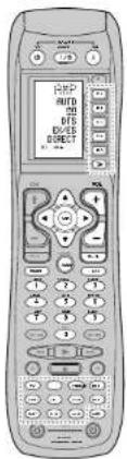
LCD INDICATORS
Information about currently selected source and direct code names are displayed on the LCD.

text_image
TUNER A F M AM LW MODE BAND B C D J E I J H G F E SP1 VAR RUM G VW PNG1 2 3 4Source Name indicator
This displays the name of the selected source, such as DVD, television, or other AV equipment (up to five characters).
⑧ Direct Button Name indicator
This displays up to 20 types of button names for each source. (up to six characters)
© Page indicator
This displays the current page position.
© Transmission indicator
This lights up when the remote control is sending a signal.
USE indicator
This is displayed under normal operation.
Battery Level indicator
This is displayed when the battery level is low.
G TIMER indicator
This is displayed when the macro timer is set.
⑧ MACRO indicator
This is displayed when the remote control is in macro programming mode.
① NAME indicator
This is displayed when the remote control is in renaming mode.
① LEARN indicator
This is displayed when the remote control is in learning mode.
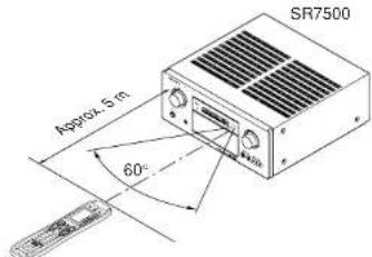
REMOTE CONTROL RANGE
The distance between the transmitter of the remote control and the IR SENSOR of the SR7500 should be less than 5 meters. If the remote control is pointed in a direction other than the IR SENSOR or if there is an obstacle between them, use of the remote control may not be possible.
Remote-controllable range
text_image
SR7500 Approx. 5 m 60° 40mRemote control unit (RC8500SR)
LOADING BATTERIES
The life of the batteries used with the remote control is about 4 months with normal use. Also be sure to replace batteries earlier when you notice that they are getting weak.
- Remove the back cover.

- Insert the new batteries (AAA type) with correct and polarity.

- Close the cover until it clicks.

CAUTIONS ON BATTERIES
- Use "AAA" type batteries in this remote control unit.
- If the remote control unit does not operate from close to the main unit, replace the batteries with new ones, even if less then a year has passed.
• The included battery is only for verifying operation. Replace it with a new battery as soon as possible. - When inserting the batteries, be careful to do so in the proper direction, following the + and - marks in the remote control unit's battery compartment.
• To prevent damage or battery fluid leakage:
- Do not use a new battery with an old one.
- Do not use two different types of batteries.
- Do not short-circuit, disassemble, heat or dispose of batteries in flames.
- Remove the batteries when not planning to use the remote control unit for a long period of time.
- If the batteries should leak, carefully wipe off the fluid from the inside of the battery compartment, then insert new batteries.
- When disposing of used batteries, please comply with governmental regulations or environmental public instruction's rules that apply in your country or area.
BATTERY REPLACEMENT INTERVAL
Under normal usage, alkaline batteries last approximately four months. When the batteries wear out, a battery mark is displayed on the LCD. Although the remote control can still be used when the battery mark is displayed, the batteries should be replaced as soon as possible. The LCD eventually starts to flash when buttons are pressed, the remote control will be unable to transmit signals or learn codes.
- This remote control uses non-volatile memory so that the learned codes and macro programs are retained even if the batteries are removed.
Reset the clock after replacing the batteries.
Safety Precautions for Batteries
Be sure to always observe the following precautions to prevent fluid leakage, overheating, fire, breakage, accidental ingestion, and other accidents.
- If the batteries are left unused for a long period of time, the battery fluid may leak or the batteries may corrode.
- Do not use the batteries in the remote control with the plus and minus polarity reversed.
- Do not attempt to recharge, heat, or disassemble the batteries. Do not put the batteries in a fire.
- Do not use the remote control with old batteries or worn-out batteries inserted.
- Do not use different types of batteries or mix old and new batteries in the remote control.
- If the remote control is not operating properly, replace the batteries with new ones.
- If any of the batteries are leaking, completely wipe up all leaked battery fluid, and then replace the batteries with new ones.
SETTING THE TIME
Example: Setting to 6:20PM (18:20)

text_image
1 2 3 MENU PRESET LEARN NAME HRCRO ERASE SETUP LIGHT 3-TIME CLOCK 4 5. 6. 7. 8:00 9. 10 CLOCK 11 12 TV INPUT ALT-CH IBES OSD CINEMAWhen you bought this remote control and insert the batteries to the remote control at first, the steps 1 to 3 are skipped.
Starts from step 4 to set the time.
- Hold down the M button for three seconds or more.
The menu is displayed. - Press the > button once.
This displays second page (SETUP). - Press the D4 (CLOCK) direct button. The *.* indicator blinks and the clock indicator displays "0:00".
- Press the 1 and 8 numeric button to set the hour indicator.
The hour indicator displays "18".
The minute indicator blinks * *
- Press the 2 and 0 numeric button to set the minute indicator.
The minute indicator displays "20".
The hour indicator blinks. - Press the OK cursor button to start the clock. The clock starts from 0 second at the time that was set and return to normal (USE) mode.
Whenever the batteries are replaced, the clock shows 00:00. Please reset the clock. (The time setting is not backed up.)
CHECKING THE TIME
To check the time, hold down the > button for three seconds or more. The current time is displayed for five seconds.
Note:
- Although the remote control uses a quartz clock, the time may become out of sync over the course of operation. Be sure to correct the clock from time to time.
GENERAL INFORMATION OF RC8500SR TO SR7500
To control the SR7500 by your RC8500SR, you have to select the device AMP or TUNER by pressing the function selector button. Please refer below for the details in AMP and TUNER mode.
AMP MODE
text_image
RFP RMTD OOS OOS DIRECT| SOURCE ON/OFF Turns the SR7500 on and off | |
| POWER ON Turns the SR7500 on | |
| POWER OFF Turns the SR7500 off | |
| D1 - D5 / >(Page) (Refer to page vi) | |
| VOL +/- Adjust the over all sound level | |
| MUTE Decreases the sound temporarily | |
| Cursor | Move the cursor for setting in "On screen display" mode |
| OK | Enter the "On screen display" |
| Confirms the setting in "On screen display" mode | |
| MENU Displays the current setting on the monitor | |
| EXIT Exits from SETUP MENU | |
| TEST (1) Enter the test tone menu | |
| CH.SEL (2) Call up SETUP MENU and adjusts speaker levels or 7.1ch input level | |
| SURR (3) | Selects the surround mode |
| 7.1CH (4) | Selects the 7.1CH IN |
| ATT (5) | Reduces the input level |
| SPK-AB (6) Selects the speaker system | |
| DISP (7) | Changes the front display mode |
| OSD (8) | Selects the "On screen display" on and off |
| SLEEP (9) | Sets the sleep timer function |
| THX (0) | Selects the THX mode |
| Function selector | Selects a particular source component |
| GUIDE / LIP.SYNC | Selects the LIP.SYNC mode |
TUNER MODE

text_image
TUNFF N M L U B D R S T B D R S T B D R S T B D R S T B D R S T B D R S T B D R S T B D R S T B D R S T B D R S T B D R S U B D R S T B D R S T B D R S T B D R S T B D R S T B D R S T B D R S T B D R S T B D R S T B D R s| D1 - D5 / >(Page) (Refer to page vi) | |
| CH +/- Selects a preset station up and down | |
| GUIDE | Selects the "Frequency direct input" |
| 0-9 | Input the numeric |
| MEMO | Enter the tuner preset memory numbers |
| CLEAR | Clears the inputting |
| TUNER | Selects a frequency band |
CONNECTIONS
SPEAKER PLACEMENT
The ideal surround speaker system for this unit is 7-speaker systems, using front left and right speakers, a center speaker, surround left and right speakers, a surround back left and right speakers, and a subwoofer.
For best results we recommend that all front speakers be of the same type, with identical or similar driver units. This will deliver smooth pans across the front sound stage as the action moves from side to side.
Your center channel speaker is very important as over 80 % of the dialog from a typical motion picture emanates from the center channel.
It should possess similar sonic characteristics to the main speakers. Surround channel speakers need not be identical to the front channel speakers, but they should be of high quality.
The surround center speaker is useful for playback of Dolby Digital Surround EX or DTS-ES. One of the benefits of both Dolby Digital and DTS is that surround channels are discrete full range, while they were frequency limited in earlier "Pro Logic" type systems.
Bass effects are an important part of home theater. For optimal enjoyment a subwoofer should be used as it is optimized for low frequency reproduction. If you have full range front speakers, however, they may be used in place of a subwoofer with proper setting of the switches in the menu system.
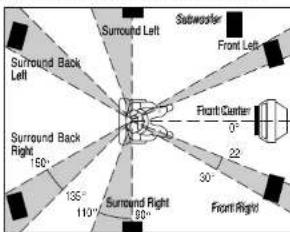
text_image
Surround Back Left Surround Left Subwoofer Front Left Front Center 0° 22° 30° Front Right 150° 135° 110° 100° Surround Right 90°Front left and right speakers
We recommend to set the front L and R speakers with 45-60 degrees from the listening position.
Center speaker
Align the front line of the center speaker with the front L/R speakers. Or place the center speaker a little backward from the line.
Surround left and right speakers
When the SR7500 is used in surround operation, the preferred location for surround speakers is on the side walls of the room, at or slightly behind the listening position.
The center of the speaker should face into the room.
Surround back left and right speakers
Surround back speakers are required when a full 7.1-channel system is installed.
Speakers should be placed on a rear wall, behind the listening position.
The center of the speaker should face into the room.
Subwoofer
We recommend using a sub-woofer to have maximum bass effect. Sub-woofer bears only low frequency range so you can place it any where in the room.
HEIGHT OF THE SPEAKER UNITS
Front left and right speakers, and a center speaker Align the tweeters and mid-range drivers on the three front speakers at the same height, as best as possible.
Surround left and right speakers, and surround back speaker
Place the surround left, right and surround back speakers higher than your ears by about 70cm-1m. Also place the speakers at the same height, sa best as possible.

text_image
70cm ~ 1mNote:
- Use magnetically-shielded speakers for front left, right and the center speakers when the speakers are installed near the TV and the TV is a monitor type.
CONNECTING SPEAKERS

flowchart
graph TD
    A["PASSIVE SUBWOOFER"] --> B["POWER AMPLIFIER"]
    B --> C["POWERED SUBWOOFER"]
    C --> D["OR"]
    D --> E["SURROUND BACK"]
    E --> F["RIGHT"]
    E --> G["LEFT"]
    E --> H["SURROUND"]
    H --> I["RIGHT"]
    H --> J["LEFT"]
    H --> K["SURROUND"]
    K --> L["RIGHT"]
    K --> M["LEFT"]
    K --> N["SURROUND"]
    N --> O["RIGHT"]
    N --> P["LEFT"]
    N --> Q["SURROUND"]
    Q --> R["RIGHT"]
    Q --> S["LEFT"]
    Q --> T["SURROUND"]
    T --> U["RIGHT"]
    T --> V["LEFT"]
    T --> W["SURROUND"]
    W --> X["RIGHT"]
    W --> Y["LEFT"]
    W --> Z["SURROUND"]
    Z --> AA["RIGHT"]
    Z --> AB["LEFT"]
    Z --> AC["SURROUND"]
    AC --> AD["RIGHT"]
    AC --> AE["LEFT"]
    AC --> AF["SURROUND"]
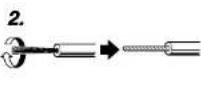
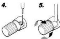
CONNECTING SPEAKER WIRE
- Strip away approx. 3/8 inch (10 mm) of wire insulation.
- Twist the bared wire ends tight, to prevent short circuits.
- Loosen the knob by turning it counterclockwise.
- Insert the bare part of the wire into the hole in side of each terminal.
- Tighten the knob by turning it clockwise to secure the wire.


Caution:
- Be sure to use speakers with the specified impedance as shown on the rear panel of this unit.
• To prevent damage to circuitry, do not let the bare speaker wires touch each other and do not let them touch any metal part of this unit.
- Do not touch the speaker terminals when the power is on. It may cause you to receive an electric shocks.
- Do not connect more than one speaker cable to one speaker terminal. Doing so may damage this unit.
Note:
- Be sure to connect the positive and negative cables for the speaker properly. If they are miss-connected, the signal phase will be reversed and the signal quality will be corrupted.
CONNECTING A SUBWOOFER
Use the PRE OUT SUBWOOFER jack to connect a powered subwoofer (power amplifier built in). If your subwoofer is a passive type (power amplifier is not built in), connect a monaural power amplifier to the PRE OUT SUBWOOFER jack and connect the subwoofer to the amplifier.

CONNECTING AUDIO COMPONENTS
flowchart
graph TD
    A["CD RECORDER / MD DECK"] --> B["OUT IN"]
    A --> C["DIGITAL INPUT"]
    A --> D["DIGITAL OUTPUT"]
    E["CD PLAYER"] --> F["OUT IN"]
    E --> G["DIGITAL OUTPUT"]
    E --> H["OUT IN"]
    I["TAPE DECK"] --> J["OUT IN"]
    I --> K["DIGITAL AUDIO (COAXIAL)"]
    I --> L["DIGITAL AUDIO (OPTICAL)"]
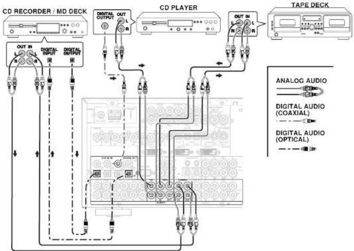
The output audio signal from the TAPE OUT jack and the CD-R/MD OUT jack is the same signal which is currently selected.
Caution:
- Do not connect this unit and other components to mains power until all connections between components have been completed.
Notes:
- Insert all plugs and connectors securely. Incomplete connections may make noise.
- Be sure to connect the left and right channels properly.
Red connectors are for the R (right) channel, and white connectors are for the L (left) channel.
- Be sure to connect input and output properly.
- Refer to the instructions for each component that is connected to this unit.
- Do not bind audio/video connection cables with power cords and speaker cables this will result in generating a hum or other noise.
CONNECTING DIGITAL AUDIO COMPONENTS
- There are 6 digital inputs, 3 coaxial jacks and 3 optical jacks, on the rear panel. You can use these jacks to input PCM, Dolby Digital and DTS bitstream signals from a CD, DVD, or other digital source components.
- There is one digital output coaxial jack and one optical output jack on the rear panel. These jacks can be connected to a CD recorder-, or a MD deck inputs, respectively.
- Refer to the instructions for each component. To setup the digital audio format of DVD player, or other digital source's connected to digital input jacks.
- Use fiber optical cables (optical) for DIG-1,2,3 input jacks. Use 75 ohms coaxial cables (for digital audio or video) for DIG-4, 5, 6 input jacks.
- You can designate the input for each digital input/output jacks according to your component. See page 19.
Notes:
- There is no Dolby Digital RF input jack. Please use an external RF demodulator Dolby Digital decoder when connecting the Dolby Digital RF output jack of the video disc player to the digital input jack.
- The digital signal jacks on this unit conform to the EIA standard. If you use a cable that does not conform to this standard, this unit may not function properly.
• Each type of audio jack works independently. Signals input through the digital and analog jacks are output through the corresponding digital and analog jacks, respectively.
CONNECTING VIDEO COMPONENTS
text_image
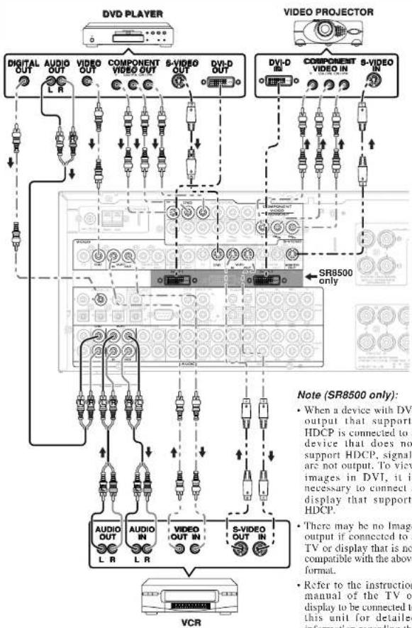
DVD PLAYER VIDEO PROJECTOR DIGITAL AUDIO VIDEO COMPONENT S-VIDEO DVI-D OUT DVI-D COMPONENT S-VIDEO OUT L R OUT OUT OUT OUT OUT OUT COMPONENT VIDEO OUT DV1-D OUT SR8500 only VCR Note (SR8500 only): • When a device with DV1 output that supports HDCP is connected to a device that does not support HDCP, signals are not output. To view images in DVI, it is necessary to connect a display that supports HDCP. • There may be no Image output if connected to a TV or display that is not compatible with the above format. • Refer to the instruction manual of the TV or display to be connected to this unit for details information regarding theNote (SR8500 only):
- When a device with DVI output that supports HDCP is connected to a device that does not support HDCP, signals are not output. To view images in DVI, it is necessary to connect a display that supports HDCP.
- There may be no Image output if connected to a TV or display that is not compatible with the above format.
- Refer to the instruction manual of the TV or display to be connected to this unit for detailed information regarding the DVI-D terminal.
*HDCP: High-bandwidth Digital Content Protection

flowchart
graph TD
    A["SATELLITE TUNER"] --> B["TV"]
    B --> C["VIDEO"]
    B --> D["AVOID"]
    B --> E["VIDEO OUT"]
    B --> F["VIDEO OUT"]
    B --> G["S-VIDEO OUT"]
    C --> H["Analog Audio"]
    D --> I["Analog Audio (COAXIAL)"]
    E --> J["Analog Audio (COAXIAL)"]
    F --> K["Analog Audio (COAXIAL)"]
    G --> L["Analog Audio (COAXIAL)"]
    C --> M["VIDEO OUT"]
    D --> N["VIDEO OUT"]
    E --> O["VIDEO OUT"]
    F --> P["VIDEO OUT"]
    G --> Q["VIDEO OUT"]
There are 3 types of video jacks on the rear panel.
VIDEO jack
The video signal for the VIDEO jacks is the conventional composite video signal.
S-VIDEO Jack
The video signal is separated into luminance (Y) and color (C) signals for the S-VIDEO jack. The S-VIDEO signals enable high-quality color reproduction. If your video component has an S-VIDEO output, we recommend to use it. Connect the S-VIDEO output jack on your video component to the S-VIDEO input jack on this unit.
Component jack
Make component video connections to a TV or monitor with component inputs to produce higher quality video images. Use a component video cable or 3 video cords to connect the component video out jacks on the SR7500 to the monitor.
DVI-D jack (SR8500 only)
This unit has two DVI-D inputs and one DVI-D output. It can send digital signals from DVDs and other sources directly to a display. It minimizes signal degradation caused by analog conversion so that high quality Images can be enjoyed. Select an Input source from the SETUP MAIN MENU. (See page 19.)
Notes:
- Be sure to connect the left and right audio channels properly.
Red connectors are for the R (right) channel, and white connectors are the for L (left) channel. - Be sure to connect the inputs and outputs of the video signals properly.
- If you connect the S-VIDEO or component signal to the S-VIDEO or component jack on this unit, it is not necessary to connect the conventional video signal to the VIDEO (composite) jack. If you use both video inputs, this unit gives priority to the S-VIDEO signal.
• Each type of video jack works independently. Signals input to the VIDEO (composite) and S-VIDEO jacks or component are output to the corresponding VIDEO (composite) and S-VIDEO or component jacks, respectively. - This unit has the "TV-AUTO ON/OFF" function to turn the TV ON or OFF automatically, by sensing the incoming video signal from the VIDEO jacks.
- You may need to setup the digital audio output format of your DVD player, or other digital source components. Refer to the instructions of the each component connected to the digital input jacks.
- There is no Dolby Digital RF input jack. Please use an external RF demodulator with a Dolby Digital decoder to connect a video disc player which has a Dolby Digital RF output jack to the digital input jack on this unit.
ADVANCED CONNECTING
flowchart
graph TD
    A["DVD AUDIO PLAYER OF SACD MULTI CHANNEL PLAYER"] --> B["Power Amplifier"]
    B --> C["Subwoofer"]
    C --> D["Central"]
    C --> E["Front Left"]
    C --> F["Center"]
    C --> G["Surround Back Left"]
    C --> H["Surround Back Right"]
    B --> I["Power Amplifier"]
    I --> J["Subwoofer"]
    J --> K["Central"]
    J --> L["Front Right"]
    J --> M["Surround Right"]
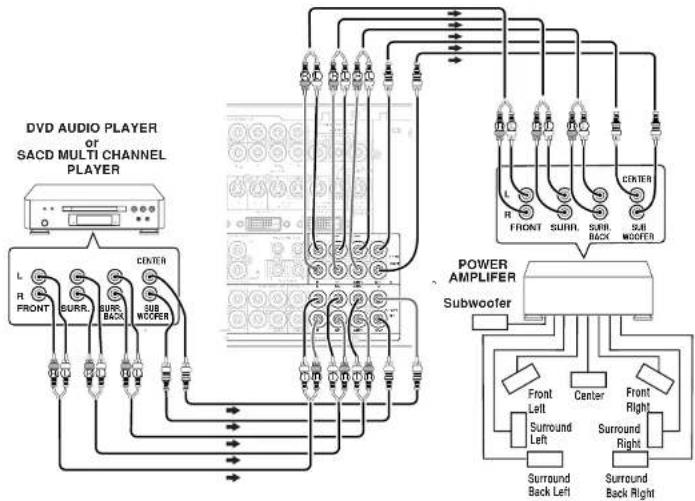
CONNECTING MULTI CHANNEL AUDIO SOURCE
The 7.1CH INPUT jacks are for multichannel audio source such as a SACD multichannel player, DVD audio player or external decoder.
If you use these jacks, switch on the 7.1CH INPUT and set the 7.1CH INPUT level by using the SETUP MAIN MENU. See page 23.
CONNECTING AN EXTERNAL POWER AMPLIFIER
The PREOUT jacks are for connecting external power amplifiers.
Be sure to connect each speaker to the corresponding external power amplifier.
CONNECTING THE REMOTE CONTROL JACKS

flowchart
graph TD
    A["CD PLAYER"] -->|IN/OUT| B["MD DECK"]
    B -->|IN/OUT| C["CD RECORDER"]
    C -->|IN/OUT| D["OPTION"]
    D -->|IN/OUT| E["RC OUT"]
    E --> F["2"]
    F --> G["Radio"]
    G --> H["Radio Control"]
    H --> I["Radio In"]
    I --> J["Radio Out"]
①
You can control other Marantz products through this unit with the remote control by connecting the REMOTE CONTROL terminals on each unit. The signal transmitted from the remote control is received by the remote sensor on this unit. Then the signal is sent to the connected device through this terminal. Therefore you need to aim the remote signal only to the unit. Also, if a Marantz power amplifier (some models excluded) is connected to one of these terminals, the power amplifier's, power switch is synchronized with this unit's power switch.
Set the REMOTE CONTROL SWITCH on the units, other than the main unit to EXT.(EXTERNAL) for this feature.
②
Whenever external infrared sensors or similar devices are connected to RC-5 IN of the SR7500, be sure to always disable operation of the infrared sensor on the main unit by using the following procedure.
- Hold down the MULTI button and the MENU button on the front panel at the same time for five seconds.
- The setting "IR=ENABLE" is shown on the FL DISPLAY.
- Press the CURSOR buttons (◀, ▶) to change this to "IR=DISABLE".
- Press the ENTER button. Once this setting is made, the infrared sensor on the main unit is disabled.
Note:
- Be sure to set to "IR=ENABLE" when external infrared sensors or similar devices are not connected. Otherwise, the main unit will be unable to receive remote control commands.
- To restore the original setting, perform steps 1 to 4 to set to "IR=ENABLE".
CONNECTING THE ANTENNA TERMINALS
text_image
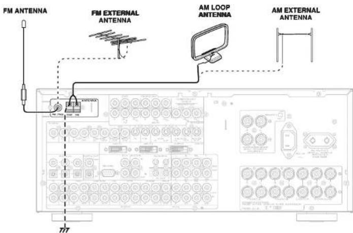
FM ANTENNA FM EXTERNAL ANTENNA AM LOOP ANTENNA AM EXTERNAL ANTENNA 777ASSEMBLING THE AM LOOP ANTENNA
-
Release the vinyl tie and take out the connection line.

-
Bend the base part in the reverse direction.

-
Insert the hook at the bottom of the loop part into the slot at the base part.
-
Place the antenna on stable surface.

CONNECTING THE SUPPLIED ANTENNAS
Connecting the supplied FM antenna
The supplied FM antenna is for indoor use only. During use, extend the antenna and move it in various directions until the clearest signal is received.
Fix it with push pins or similar implements in the position that will cause the least amount of distortion.
If you experience poor reception quality, an outdoor antenna may improve the quality.
Connecting the supplied AM loop antenna
The supplied AM loop antenna is for indoor use only.
Set it in the direction and position it to where you receive the clearest sound. Put it as far away as possible from the unit, televisions, speaker cables, and power cords.
If you experience poor reception quality, an outdoor antenna may improve the quality.
-
Press and hold down the lever of the AM antenna terminal.
-
Insert the bare wire into the antenna terminal.
- Release the lever.
CONNECTING AN FM OUTDOOR ANTENNA
Notes:
- Keep the antenna away from noise sources (neon signs, busy roads, etc.).
- Do not put the antenna close to power lines. Keep it well away from power lines, transformers, etc.
• To avoid the risk of lightning and electrical shock, grounding is necessary.
CONNECTING AN AM OUTDOOR ANTENNA
An outdoor antenna will be more effective if it is stretched horizontally above a window or outside.
Notes:
- Do not remove the AM loop antenna.
- To avoid the risk of lightning and electrical shock, grounding is necessary.
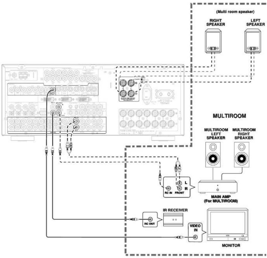
CONNECTING FOR THE MULTI ROOM
flowchart
graph TD
    A["Multi room speaker"] --> B["RIGHT SPEAKER"]
    A --> C["LEFT SPEAKER"]
    B --> D["MULTIROOM"]
    C --> D
    D --> E["MULTIROOM LEFT SPEAKER"]
    D --> F["MULTIROOM RIGHT SPEAKER"]
    E --> G["MAIN AMP (For MULTIROOM)"]
    F --> G
    G --> H["MONITOR"]
    I["IR RECEIVER"] --> J["RC OUT"]
    J --> K["Monitor"]
    L["PCB"] --> M["PCB"]
    N["PCB"] --> O["PCB"]
    P["PCB"] --> Q["PCB"]
    R["PCB"] --> S["PCB"]
    T["PCB"] --> U["PCB"]
    V["PCB"] --> W["PCB"]
    X["PCB"] --> Y["PCB"]
    Z["PCB"] --> AA["PCB"]
CONNECTING FOR SPEAKER C USE
Bi-wire Connection
A bi-wire connection is possible with speakers that have two sets of inputs (for treble and bass).
This allows you to drive the treble and bass units with separate channel amps, which enables better sound quality. Connect the speakers as shown in the figure. Set the SPEAKER C selector switch on the rear panel to ON.
Notes:
- If incorrectly connected, a protective circuit in the receiver will trip and set the receiver to standby. (The STANDBY indicator will flash.) In such case, recheck the connections between the speakers and the receiver.
- Turn power to the receiver off before changing the setting of the SPEAKER C selector switch.
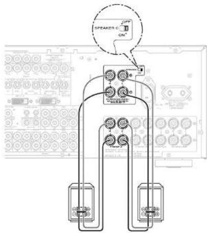
text_image
SPEAKER C OFF ONNote:
- You can use surround back speaker terminals as multi room speaker terminals or speaker C terminal when you use no surround back speaker.
SETUP
After all components are connected, initial setup must be performed.
The SR7500 incorporates an on-screen menu system, which makes various operations possible by using the cursor (▲,▼,◀) and ENTER buttons on the remote control or on the front panel.
Note:
• To view the on-screen displays, make certain you have made a connection from the Monitor Out jack on the rear panel to the composite, S-Video, component video input of your TV or projector. (see page 14)
- Press the AMP button of the remote control. (This step is not needed when operating the setup menus from the receiver itself.)
- Press the MENU button on the remote control or set to display the "SETUP MAIN MENU" of the OSD menu system.
There are 8 items in the SETUP MAIN MENU. - Select a desired sub-menu with the ▲ or ▼ cursor buttons, and press the ENTER button to enter. The display will change to the selected sub-menu. You can lock the condition of setup to each sub-menu with the ◀ or ▶ or cursor buttons.
Note:
- If you desire to adjust any sub-menu, you need to set it to UNLOCKED.
- If you desire to exit from this menu system, press the EXIT button, or move the cursor to EXIT and press the ENTER button.
Note:
- Settings are entered with the ENTER button on the unit or the OK button on the remote controller. When using the remote control, use the OK button as if it were the ENTER button.
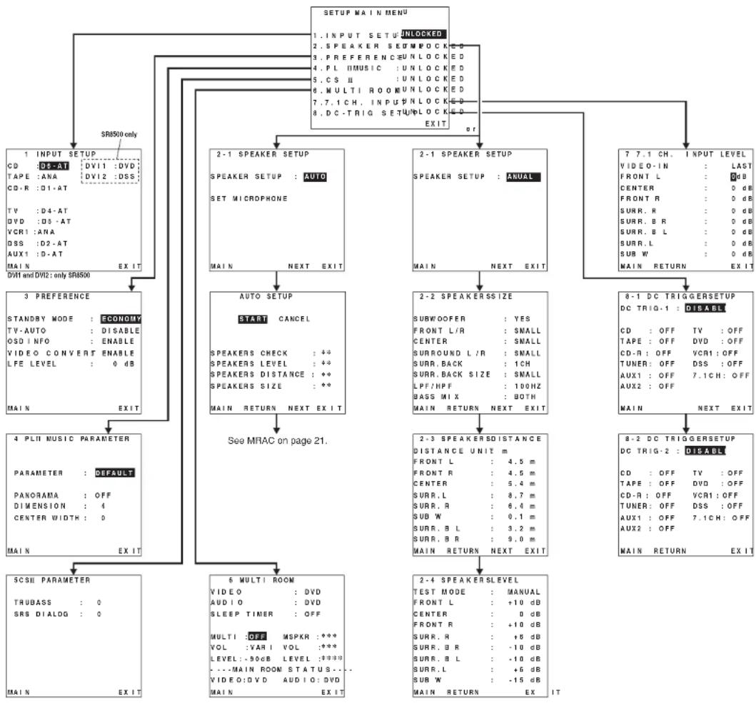
flowchart
graph TD
    A["1 INPUT SETUP"] --> B["2-1 SPEAKER SETUP"]
    B --> C["2-2 SPEAKER SETUP"]
    C --> D["8-1 DC TRIGGERSSETUP"]
    A --> E["3 PREFERENCE"]
    E --> F["4 PLII MUSIC PARAMETER"]
    F --> G["5CSII PARAMETER"]

    A --> H["1 INPUT SETUP UNLOCKED"]
    A --> I["2-1 SPEAKER SETUP UNLOCKED"]
    A --> J["7-7.1 CH. INPUT LEVEL"]

    B --> K["2-1 SPEAKER SETUP ANUAL"]
    B --> L["2-2 SPEAKERSSIZE"]

    C --> M["2-3 SPEAKERSDISTANCE"]
    C --> N["2-4 SPEAKERSLEVEL"]

    A --> O["3 PREFERENCE"]
    O --> P["4 PLII MUSIC PARAMETER"]

    A --> Q["5CSII PARAMETER"]

    A --> R["6 MULTI ROOM"]

    A --> S["8-2 DC TRIGGERSSETUP"]

    style A fill:#f9f,stroke:#333
    style B fill:#ccf,stroke:#333
    style C fill:#cfc,stroke:#333
    style D fill:#fcc,stroke:#333
    style E fill:#ffc,stroke:#333
    style F fill:#cfc,stroke:#333
    style G fill:#cfc,stroke:#333
    style H fill:#cfc,stroke:#333
    style I fill:#cfc,stroke:#333
    style J fill:#cfc,stroke:#333
    style K fill:#cfc,stroke:#333
    style L fill:#cfc,stroke:#333
    style M fill:#cfc,stroke:#333
    style N fill:#cfc,stroke:#333
    style O fill:#cfc,stroke:#333
    style P fill:#cfc,stroke:#333
    style Q fill:#cfc,stroke:#333
    style R fill:#cfc,stroke:#333
1 INPUT SETUP (ASSIGNABLE DIGITAL INPUT)
6 digital inputs can be assigned to a desired source.
With the SR8500, DVI-D input can be assigned to a preferred source.
Use this menu to select the digital Input jack to be assigned to the input source.
- Select "INPUT SETUP" in SETUP MAIN MENU with ▲ or ▼ cursor button, and press the ENTER button.
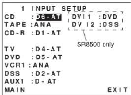
text_image
1 INPUT SETUP CD :D6-AT [DV1 1 :DVD] TAPE :ANA [DV 2 :DSS] CD-R :D1-AT TV :D4-AT DVD :D5-AT VCR1 :ANA DSS :D2-AT AUX1 :D-AT MAIN EXIT-
To select the input source, press the ▲or ▼ cursor buttons.
-
To select the digital input jack, press the ◀ or ▶ cursor buttons.
Select "Dx-AT" for input sources, for automatic detection of the digital input signal condition. If there is not a digital signal present, but there is an analog signal present, the analog signal will be played.
Select "Dig x", when only a digital signal will be used. Select "ANA" for input sources for which no digital input jacks are used.
-
To select the video source, select "DVI1" or "DVI2" by pressing the ▲or ▼cursor buttons, and press the ◀or ▼cursor buttons to select the video source to be assigned .(SR8500 only)
-
After you complete this portion of the set up, move the cursor to MAIN with the ▲ or ▼ cursor buttons and press the ENTER button.
Notes:
- The TUNER and AUX2 are fixed to the analog input, and cannot be selected for any digital input.
- When a DTS-LD or DTS-CD is playing, this setup is not available. This is to avoid noise being generated from the analog input.
- If "Dx-AT" is selected and a DVD, compact disc or LD is fast-forwarded during playback, decoded signals may produce a skipping sound. In such cases, change the setting to DIGITAL.
2 SPEAKER SETUP
After you have installed the SR7500, connected all the components, and determined the speaker layout, it is now time to perform the settings in the Speaker Setup menu for the optimum sound acoustics for your environment and speaker layout.
Before you perform the following settings, it is important that you first determine the following characteristics:
2-1 SPEAKER SETUP
Speakers are set up by selecting either MANUAL or AUTO using the ◀ and ▶ cursor buttons. For operation when AUTO has been selected, see MRAC on page 21.
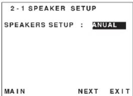
text_image
2 - 1 SPEAKER SETUP SPEAKERS SETUP : ANUAL MAIN NEXT EXIT2-2 SPEAKERS SIZE
When setting the speaker size in the SPEAKER SIZE sub-menu, use the guidelines given below.
LARGE:
The complete frequency range for the channel you are setting will be output from the speaker. SMALL:
Frequencies of the channel you are setting lower than approx. 100 Hz will be output from the subwoofer.
If the Subwoofer is set to "NONE" and the front speakers are set to "LARGE," then the sound will be output from both the left and right speakers.
| 2-2 SPEAKERS SIZE | |
| SUBWOOFER: YES | |
| FRONT L/R: SMALL | |
| CENTER: SMALL | |
| SURROUND L/R: SMALL | |
| SURR.BACK: 1CH | |
| SURR.BACK SIZE: SMALL | |
| LPF/HPF: 100 HZ | |
| BASS MIX: BOTH | |
| MAIN RETURN NEXT EXIT |
- Select 2. SPEAKER SETUP on the SETUP MAIN MENU, then select MANUAL for 2-1 SPEAKER SETUP.
- To select the each speaker, press the ▲ or ▼ cursor buttons.
- To select the setting of each speaker size, press the or cursor buttons.
- After you complete this portion of the set up, move the cursor to "NEXT" with the ▲ or ▼ cursor buttons and then press the ENTER button to go to the next page.
THX SPEAKER SYSTEM
If you use full THX speaker systems which are approved by THX Ltd. the front, the center and surround speaker size should be "Small" and the subwoofer should be "Yes".
You need to set number of surround back speaker only.
SUBWOOFER
YES:
Select when a subwoofer is connected.
NONE:
Select when a subwoofer is not connected.
FRONT L/R
LARGE:
Select if the front speakers are large.
SMALL:
Select if the front speakers are small.
- If "NONE" is selected for the Subwoofer setting.
then this setting is fixed to "LARGE."
CENTER
NONE:
Select If no center speaker is connected.
LARGE:
Select if the center speaker is large.
SMALL:
Select If the center speaker is small.
SURROUND L/R
NONE:
Select if no surround left and right speakers are
conne
LARGE:
Select if the surround left and right speakers are
large.
SMALL
Select if the surround left and right speakers are small.
SURR. BACK
NONE:
Select if no surround back left and right speakers are connected.
2CH:
Select if the surround back left and right speakers are connected.
1CH:
Select if the one surround back speaker is connected. In this case, the audio signal is emitted from the Surround L output terminal.
Notes:
- If "NONE" is selected for the Surround L/R setting, then this setting is fixed to "NONE."
- You can use surround back speaker terminals as multi room speaker terminals when you use no surround back speaker. (See page 17)
SURR. BACK SIZE
LARGE:
Select if the surround back speaker is large.
SMALL:
Select if the surround back speaker is small.
Note:
- If "NONE" is selected for the Surround L/R setting, then this setting is not available.
LPF/HPF
When you use a subwoofer, you can select the cutoff frequency for the small speakers used. Select one of the crossover frequency levels according to the size of the small speaker connected.
80Hz
Select this when the bass speaker is about 12 cm (4 3/4 inches).
100Hz:
Select this when the bass speaker is about 10 cm (3 15/16 inches).
120Hz:
Select this when the bass speaker is about 8 cm
(3 3/16 inches)
Notes:
- Use the above comments as reference when adjusting.
- If Pure-Direct mode, 7.1CH Input is in use, this function does not take effect.
BASS MIX
The bass mix setting is only valid when "LARGE" is set for the front speakers and "YES" is set for the subwoofer during stereo playback. This setting has effect only during playback of PCM or analog stereo sources.
When "BOTH" is selected, the low frequencies will be played through the main L&R, as well as the subwoofer.
In this playback mode, the low frequency range expand more uniformly through the room, but depending on the size and shape of the room, interference may result in a decrease of the actual volume of the low frequency range.
- By selecting "MIX", the low frequencies will play through the main L&R ONLY.
Note:
• LFE signals during playback of Dolby Digital or DTS, will be played through the subwoofer.
2-3 SPEAKERS DISTANCE
Use this parameter to specify the distance of each speaker's position from the listening position. The delay time is automatically calculated according to these distances.
Begin by determining the ideal or most commonly used seating position in the room.
This is important for the timing of the acoustics to create the proper sound space that the SR7500 and today's sound systems are able to produce.
Note:
For speakers that you have selected "NONE" the Speaker Configuration sub-ment will not appear here. (There are several useful books and special DVD and LD's available to guide you through proper home theater configuration. If you are unsure, have your Marantz dealer perform the installation for you. They are trained professionals familiar with even the most sophisticated custom installations. Marantz recommends the WWW.CEDIA.ORG website for further information about this).
| 2-3 SPEAKERS DISTANCE | ||
| DISTANCE UNIT : m | ||
| FRONT L : 4.5 m | ||
| FRONT R : 4.5 m | ||
| CENTER : 5.4 m | ||
| SURR.L : 8.7 m | ||
| SURR.R : 6.4 m | ||
| SUB W : 0.1 m | ||
| SURR.B L : 3.2 m | ||
| SURR.B R : 9.0 m | ||
| MAIN RETURN NEXT EXIT |
- Select either m (meters) or ft (feet) for DISTANCE UNIT.
- To select each speaker, press the ▲ or ▼ cursor buttons.
- To set the distance for each speaker, press the or cursor buttons.
- After you complete this portion of the set up, move the cursor to "NEXT" with the ▲or▼ cursor buttons and then press the ENTER button to go to the next page.
FRONT L:
Set the distance from the front left speaker to your normal listening position.
FRONT R:
Set the distance from the front right speaker to your normal listening position.
CENTER:
Set the distance from the center speaker to your normal listening position.
SUBB. L
Set the distance from the surround left speaker to your normal listening position.
SURR. R:
Set the distance from the surround right speaker to your normal listening position.
SUB W:
Set the distance from the subwoofer to your normal listening position.
SURR. B L
Set the distance from the surround back left speaker to your normal listening position.
SURR. B R:
Set the distance from the surround back right speaker to your normal listening position.
Notes:
- Set the distance to each speaker in meters (m) or feet (ft) as follows.
m: 0.1 - 9.0 m in .01 m steps
ft: 0.3 - 30.0 ft in 0.3 ft steps - For the speakers that you have selected "NONE" the Speaker Size menu will not appear.
- The setting for Surr, Back L and Surr, Back R appears if you set for it to, two surround back speakers in the Speaker Size menu.
• The setting of Surr.Back appears if it is set for one surround back speaker in the Speaker Size menu.
2-4 SPEAKERS LEVEL
Here you will set the volume for each speaker so that they are all heard by the listener at the same level. We recommend using a SPL (Sound Pressure Level) meter, when available.
Note:
- The speaker level settings are not available in 7.1 channel input mode and Pure-Direct mode.
| 2 - 4 SPEAKERS LEVEL | |
| TEST MODE : MANUAL | |
| FRONT L : +10 dB | |
| CENTER : 0 dB | |
| FRONTR : +10 dB | |
| SURR.R : +6 dB | |
| SURR.B R : -10 dB | |
| SURR.B L : -10 dB | |
| SURR.L : +6 dB | |
| SUB W : -15 dB | |
| MAIN RETURN EXIT |
TEST MODE:
Selects "MANUAL" or "AUTO" for generating the mode of the test tone with the ◀or cursor buttons.
If you select "AUTO", the test tone will be cycled through in a circular pattern which is Left → Center → Right → Surround Right → Surround Back Right → Surround Back Left → Surround Left → Subwoofer → Left →.. increments of 3 seconds for each channel. Using the ◄ or ▶ursor buttons, adjust the volume level of the noise from the speaker so that it is the same level for all the speakers.
If you select "MANUAL", adjust the output level of each speaker as listed below.
-
When you move the cursor to FRONT L by pressing the ▼cursor button, the SR7500 will emit a pink noise from the front left speaker. Remember the level of this noise and then press the ▼cursor button.
(Note that this can be adjusted to any level between -10 and +10 dB in 1 dB intervals except the subwoofer settling. The subwoofer can be adjusted to any level between -15 and +10 dB in 1 dB intervals.)
The SR7500 will now emit the pink noise from the center speaker. -
Using the ◀ and ▶ursor buttons, adjust the volume level of the noise from the center speaker so that it is the same level as the front left speaker.
-
Press the ▼cursor button again. The SR7500 will now emit the pink noise from the front right speaker.
- Repeat steps 2 and 3 above for the front right and other speakers until all speakers are adjusted to the same volume level.
After you complete this portion of the set up, press the ENTER button, the cursor will move to "MAIN" and then press the ENTER button to go to SETUP MAIN MENU.
Notes:
- Speakers that you selected "NONE" for in the Speaker Size menu will not appear.
• The setting of Surr.Back L and Surr.Back R appears if you have set it for two surround back speakers in the Speaker Size menu. - The setting of Surr.Back appears if you have set it for one surround back speaker in the Speaker Size menu.
• To adjust the speaker levels for 7.1-channel input sources, you will need to use the 7.1CH-INPUT sub menu. (See page 23).
MRAC (Marantz Room Acoustic Calibration)
Speaker settings that were difficult by MANUAL setup can now be made by automatically measuring speaker characteristics using the including microphone.
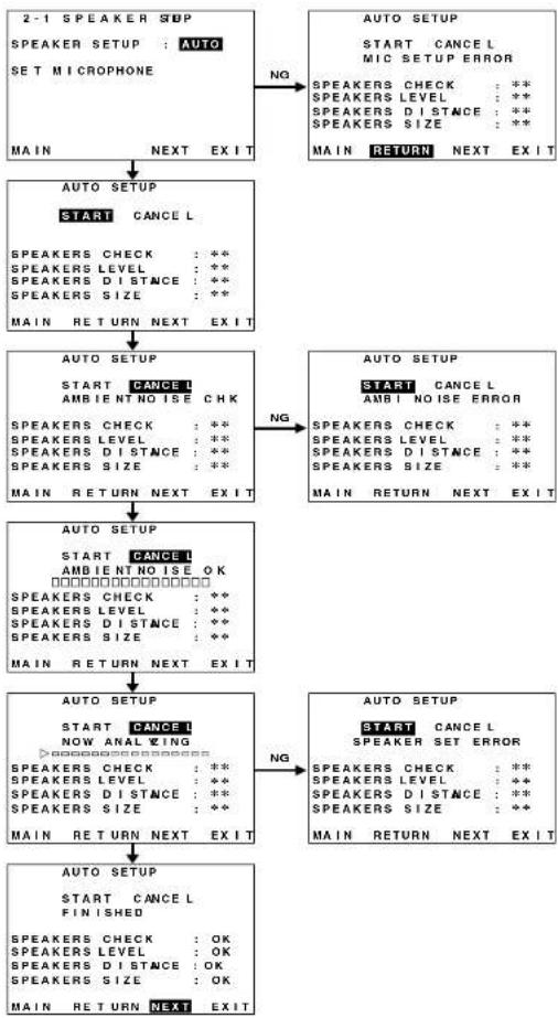
flowchart
graph TD
    A["2-1 SPEAKER STOP<br>SPEAKER SETUP : AUTO<br>SET MICROPHONE<br>MAIN NEXT EXIT"] -->|NG| B["AUTO SETUP<br>START CANCEL<br>SPEAKERS CHECK : **<br>SPEAKERS LEVEL : **<br>SPEAKERS DISTANCE : **<br>SPEAKERS SIZE : **<br>MAIN RETURN NEXT EXIT"]
    B -->|NG| C["AUTO SETUP<br>START CANCEL<br>AMBIENT NOISE CHK<br>SPEAKERS CHECK : **<br>SPEAKERS LEVEL : **<br>SPEAKERS DISTANCE : **<br>SPEAKERS SIZE : **<br>MAIN RETURN NEXT EXIT"]
    C -->|NG| D["AUTO SETUP<br>START CANCEL<br>AMBIENT NOISE OK<br>SPEAKERS CHECK : **<br>SPEAKERS LEVEL : **<br>SPEAKERS DISTANCE : **<br>SPEAKERS SIZE : **<br>MAIN RETURN NEXT EXIT"]
    D -->|NG| E["AUTO SETUP<br>START CANCEL<br>NOW ANALYZING<br>SPEAKERS CHECK : **<br>SPEAKERS LEVEL : **<br>SPEAKERS DISTANCE : **<br>SPEAKERS SIZE : **<br>MAIN RETURN NEXT EXIT"]
    E -->|NG| F["AUTO SETUP<br>START CANCEL<br>FINISHED<br>SPEAKERS CHECK : OK<br>SPEAKERS LEVEL : OK<br>SPEAKERS DISTANCE : OK<br>SPEAKERS SIZE : OK<br>MAIN RETURN NEXT EXIT"]
Measurement
During measurement, a test tone is output from the speakers, which is then measured and analyzed though the microphone. The measurement flow and items are as follows.
Microphone connection check: MIC CHECK Ambient noise measurement: AMBIENT NOISE Speaker connected/not connected check:
SPEAKER CHECK Speaker output level check: SPEAKER LEVEL Distance from speaker (delay time) check: SPEAKER DISTANCE
Speaker characteristics check: SPEAKER SIZE
How to Operate
Settings are displayed on the monitor during setup, therefore turn the monitor on.
- Connect the included microphone to the MRAC jack of the unit.

natural_image
Front view of a silver analog oscilloscope with control panel and connected dials (no visible text or labels)2.
Set the microphone at ear height as in the actual listening position. Use a stand or tripod to position the microphone.
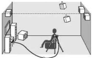
natural_image
Interior view of a room with a person seated on a tripod, surrounded by hanging boxes and cables (no text or symbols visible)Notes:
- Remove any obstructions between the speakers and the microphone.
- Keep the room quiet during measurement.
- The test tone emitted during measurement is loud. Take considerations for neighboring homes and children.
- Step away from the listening position during measurement and operate the unit with the remote controller from outside the speaker path.
- About surround back speakers: When the surround back speaker is set to NONE in the SPEAKER SETUP, it is skipped in the AUTO setup. To use the surround back speaker, set it to YES by MANUAL setup before using the MRAC feature. - The MRAC feature is available except in the following modes: - 7.1 CH INPUT - PURE-DIRECT
- Either press the MRAC button on the front panel of the unit or select "2. SPEAKER SETUP" on the SETUP MAIN MENU, then select AUTO for "2-1 SPEAKER SETUP". Move the cursor to "NEXT" with the ▲ or ▼cursor buttons and then press the ENTER button.

text_image
2-1 SPEAKER SETUP SPEAKERS SETUP : Unto SET MICROPHONE MAIN NEXTEXIT- Select START on the AUTO SETUP display and press the ENTER button to start measurements.

text_image
AUTO SETUP START CANCEL SPEAKERS CHECK : ** SPEAKERS LEVEL : ** SPEAKERS DISTANCE : ** SPEAKERS SIZE : ** MAIN RETURN NEXT EXIT- For measurement items, see "Measurement".
- When measurements are completed, "FINISHED" appears on the monitor.
- Once finished, disconnect the microphone from the unit.
- Measurement results can be seen by selecting "NEXT" and press the ENTER button or selecting "2. SPEAKER SETUP" on the SETUP MAIN MENU. Then select MANUAL for "2-1 SPEAKER SETUP".
Notes:
• The measured speaker distance may differ from the actual distance from speakers. Nevertheless, the measured value is suitable for the speakers.
• To make changes to individual speakers, select 2. SPEAKER SETUP on the SETUP MAIN MENU, then select MANUAL for 2-1 SPEAKER SETUP.
• The included microphone is designed specifically for this receiver. Other microphones do not guarantee suitable measurement results. Use the included microphone to conduct measurements.
- During measurement, press the ENTER or EXIT button to cancel measurement.
• In some rooms, an error may occur during auto speaker setup or it may not be possible to set Speaker distance correctly because of room acoustics. In such case, set the speaker distance by MANUAL setup.
Error Indications During Measurement
If trouble occurs during measurement, an error message is displayed on the monitor screen and FL display. Those errors and their remedies are described below. The message appearing on the FL display is given in ( ).
| MIC SETUP ERROR (MIC SET ERROR) |
| The microphone (MC-10) is not properly connected.→ Check the microphone connection. |
| AMBI NOISE ERROR (AMBI NOISE ER) |
| Measurement cannot be done correctly because of excessive ambient noise.→ Either temporarily turn off power to noisy devices such as air conditioning or move them out of the room.→ Retry measurement when the room is quiet. |
| SPEAKER SET ERROR (SPK SET ERROR) |
| The speakers are not properly connected.→ Recheck speaker layout and connections. |
3 PREFERENCE
| 3 PREFERENCE | |
| STANDBY MODE | : ECONOMY |
| TV-AUTO | : DISABLE |
| OSD INFO | : ENABLE |
| VIDEO CONVERT | : ENABLE |
| LFE LEVEL | : 0 dB |
| MAIN | EXIT |
- Select "PREFERENCE" in the SETUP MAIN MENU with the ▲ or ▼cursor buttons, and press the ENTER button.
- To select a desired content, press the ▲ or ▼ cursor buttons.
STANDBY MODE:
When this function is set to "ECONOMY", you can reduce the power consumption when the unit is in the standby mode.
Note:
• TV-AUTO and RS-232C are disabled in the "ECONOMY" setting.
TV AUTO:
Select the TV AUTO ON/OFF function to enable or disable with the <or cursor buttons. (refer to page 29)
OSD Info
Select the OSD information function to enable or disable with the ▶r ▶ursor buttons. If you select "ENABLE", the SR7500 will display the status of the feature (Volume up/down, input select, etc...) on the TV monitor. But if you do not desire this information, select "DISABLE".
VIDEO CONVERT:
Select the VIDEO CONVERT function to enable or disable with the <or cursor buttons. (Video cable connection: Refer to page 24)
LFE LEVEL:
Select the output level of the LFE signal included in the Dolby Digital signal or the DTS signal. Select 0 dB, -10 dB or OFF with the ◀or ▶ cursor buttons.
After you complete this portion of the set up, move the cursor to "MAIN" with the ▲ or ▼ cursor buttons and press the ENTER button.
4 PL II (PRO LOGIC II) MUSIC PARAMETER
Pro Logic II-Music mode creates a rich and enveloping surround ambience from stereo sources such as CDs. In this mode, SR7500 includes three controls to fine-tune the soundfield as follows.
| 4 P L | IIMUSIC PARAMETER |
| PARAMETER: | JLT |
| PANORAMA: OFF | |
| DIMENSION | : 4 |
| CENTER WIDTH: | 0 |
| MAIN | EXIT |
Select "PL II MUSIC" in the SETUP MAIN MENU with the ▲ or ▼cursor buttons, and press the ENTER button.
PARAMETER:
Select "DEFAULT" or "CUSTOM" with the ◀ or ▶ cursor buttons. If you select "CUSTOM", you can adjust three parameters as listed below.
PANORAMA:
Select the Panorama mode On or Off with the ▶or ▶cursor buttons. Panorama wraps the sound of the front left and right speakers around you, for an exciting perspective.
DIMENSION:
Set the Dimension level between 0 and 6 level in 1 level intervals with the or cursor buttons. Adjust the soundfield either towards the front or towards the rear. This can be useful to help achieve a more suitable balance from all the speakers with certain recordings.
CENTER WIDTH:
Set the Center width level between 0 and 7 in 1 level intervals with the ▶ or ▶ursor buttons. Center Width allows you to gradually spread the center channel sound into the front left and right speakers. At its widest setting, all the sound from the center is mixed into the left and right. This control may help achieve a more spacious sound or a better blend for the front image. If "NONE" was selected for the Center speaker setting, in the Speaker size set up menu, then this setting will not appear.
After you complete this portion of the set up, move cursor to "MAIN" with the ▲ or ▼ cursor buttons and press the ENTER button.
5 CS II (CIRCLE SURROUND II) PARAMETER
| 5 C S II PARAMETER | |
| TRUBASS | : 0 |
| SRS DIALOG | : 0 |
- Select "CS II" in the SETUP MAIN MENU with the ▲ or ▼ cursor buttons, and press the ENTER button.
- To Select desired contents as below, press the ▲ or ▼ cursor buttons.
TRUBASS:
Set the TRUBASS level between 0 and 6 level in 1 level interval with the ◀ or ▶ cursor buttons. TRUBASS produced by the speakers are an octave below the actual physical capabilities of the speakers adding exciting, deeper bass effects.
SRS DIALOG:
Set the SRS DIALOG level between 0 and 6 in 1 level intervals with the ◀ or ▶ cursor buttons. This can be popped out of the surround audio effects, allowing the listener to easily discern what the actors say. If "NONE" was selected for the Center speaker setting, in the Speaker size set up menu, then this setting will not appear.
Alter you complete this portion of the set up, move cursor to "MAIN" with the ▲ or ▼ cursor buttons and press the ENTER button.
6 MULTI ROOM
SR7500 has features in MULTI ROOM SYSTEM such as source selector, sleep timer, Multi Room Speaker output and remote control.
You can set these feature in this sub-menu.
| 6 MULTI ROOM | |
| VIDEO | : DVD |
| AUDIO | : DVD |
| SLEEP TIMER | : OFF |
| MULTI :OFF | MSPKR : *** |
| VOL :VARI | VOL : *** |
| LEVEL : -90dB | LEVEL : *** |
| - - - MAIN-ROOM STATUS - - - | |
| VIDEO : DVD | AUDIO : DVD |
| MAIN | EXIT |
-
Select "MULTI ROOM" in the SETUP MAIN MENU with ▲or ▼cursor button, and press the ENTER button.
-
To Select desired contents, press ▲ or ▼ cursor button
VIDEO: Select the video source of the Multi-room output with ◄ or ▶ursor buttons.
AUDIO:
Select the audio source of the Multi-room output with ◄ or ▶ cursor buttons.
SLEEP TIMER:
SLEEP timer function is available during the multiroom is active, set the time with ◀ or ▶ cursor buttons.
MULTI (MULTI ROOM)
To switch on the Multi-room output ON or OFF, press <or cursor button.
VOL (VOLUME SETUP)
Select whether the Multi-room output level is variable or fixed with a
LEVEL (VOLUME LEVEL):
Adjust the Multi-room output level with ◀ or ▶ cursor buttons.
MSPKR (MULTI SPEAKER):
To switch on the Multi-speaker output ON or OFF, press or cursor buttons.
Note:
- This setting can be changed when the Surr Back is set "NONE" in 2-1 SPEAKER SIZE menu and select "SPEAKER C" switch OFF position in REAR PANEL. When this setting is unavailable, "***" is displayed.
VOL (VOLUME SETUP):
Select whether the Multi-speaker output level is variable or fixed with <or cursor buttons.
Note:
This setting can be changed when the Surr Back is set "NONE" in 2-1 SPEAKER SIZE menu. When this setting is unavailable, "***" is displayed
LEVEL (VOLUME LEVEL):
Adjust the Multi-speaker output level with ◀ or ▶ cursor button.
Note:
- This setting can be changed when the Surr Back is set "NONE" in 2-1 SPEAKER SIZE menu. When this setting is unavailable, "***" is displayed.
MAIN ROOM STATUS:
Selected input source in the main room will be displayed.
Note:
- If "VOLUME" is set to "FIXED", the multi-room output level cannot be adjusted from the second zone.
After you complete this portion of the set up, move the cursor to "MAIN" with ▲ or ▼ cursor buttons and press ENTER button.
7 7.1 CH INPUT LEVEL
This sub-menu is to adjust the speaker levels for 7.1-channel input sources.
Here you will adjust the volume for each channel so that they are all heard by the listener at the same level.
| 7 7.1 CH INPUT LEVEL | |
| VIDEO IN | LAST |
| FRONT L | 0 dB |
| CENTER | 0 dB |
| FRONT R | 0 dB |
| SURR.R | 0 dB |
| SURR.B R | 0 dB |
| SURR.B L | 0 dB |
| SURR.L | 0 dB |
| SUB W | 0 dB |
| MAIN | EXIT |
- Select "7.1CH INPUT" in the SETUP MAIN MENU with the ▲ or ▼ cursor buttons, and press the ENTER button.
- To select "VIDEO IN", press ◀ or ▶ cursor button.
- Using the ◀or ▶cursor buttons, select the video Input source which is emitted from Monitor out in the 7.1 CH INPUT function. The Input source is switched by pressing the ◀or ▶cursor buttons as follows; LAST ↔ TV ↔ DVD ↔ VCR1 ↔ DSS ↔ AUX1 ↔ V-OFF ↔ LAST ↔
Notes:
- When select LAST, the source is set previous source before 7.1 CH INPUT function is activated. - When select V-OFF, no signal is emitted from monitor out terminal.
- To Select desired channel, press the ▲or ▼ cursor buttons.
- Using the ◀ or ▶cursor buttons, adjust the volume level of each channel.
- After you complete this portion of the set up, move the cursor to "MAIN" with the ▲ or ▼ cursor buttons and press the ENTER button.
Notes:
- These settings will be memorized to 7.1CH INPUT source. - This feature can be directly selected with the CH.SEL button of the remote controller.
8 DC TRIGGER SETUP
This unit has 2 DC trigger control jacks, these are selectable to link with input functions for the main room or multi room.
Each trigger can be set up separately.
- Select "DC-TRIG SETUP" in the SETUP MAIN MENU with ▲ or ▼ cursor button, and press the ENTER button.
- You can select MAIN ROOM, MULTI ROOM, REMOTE or DISABLE by pressing ◀or ▶ cursor buttons.
Note:
- REMOTE is available for the external control. The RC8500SR cannot operate this function.
- To select desired input source, press ▲ or ▼ cursor button.
- To set ON or OFF press or cursor button.
- After you complete this portion of the set up, move the cursor to "MAIN" with the ▲ or ▼ cursor buttons and press the ENTER button.

SELECTING AN INPUT SOURCE
Before you can listen to any input media, you must first select the input source on the SR7500.
Example : DVD
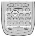
To select DVD, turn the INPUT FUNCTION SELECTOR knob on the front panel or simply press the DVD button on the remote. After you have selected DVD, simply turn on the DVD player and play the DVD.
- As the input source is changed, the new input name will appear momentarily an OSD information on the video display. The input name will also appear in the display, on the front-panel.
- As the input is changed, the SR7500 will automatically switch to the digital input, surround mode, attenuation, and night mode status which were entered during the configuration process for that source.
- When an audio source is selected, the last video input used remains routed to the VCR1 & DSS/VCR2 Outputs and Monitor Output. This permits simultaneous viewing and listening to different sources.
- When a Video source is selected, the video signal for that input will be routed to the Monitor Output jacks and will be viewable on a TV monitor connected to the SR7500. If a component video input is connected to the DVD or DSS component inputs, it will be routed to the Component Video Output. Make certain that your TV is set to the proper input to view the signal.
DVI-D INPUT (SR8500 only)
When DVI-D is set as the input source, monitor output is DVI-D as well.
VIDEO CONVERT
When this function is activated, the video or S-video signal can be emitted from the video, S-video or component video output terminal. To activate this function, select VIDEO CONVERT in PREFERENCE menu and set ENABLE.
Notes:
- The component video signal is emitted only from component video output terminal.
When the video equipment is connected by component terminal, connect the monitor and SR7500 by the component terminal.
- This function is unavailable for the REC out terminal.
- This function is unavailable for the still picture, fast forward and reverse playing of the video component.
If, while attempting to use the video convert feature, the SR7500 cannot synchronize with the display device. "NO SIGNAL" appears on the monitor, or noise is generated, this feature cannot be used. All of these signs are caused by equipment incompatibility; there is nothing wrong with the SR7500.
In such case, set VIDEO CONVERT in the PREFERENCE menu to DISABLE. Also, connect the video input signal to the display device via the MONITOR OUT terminal under VIDEO and the S-video input signal to the display device via the MONITOR OUT terminal under S-VIDEO.
Example:
Monitor is connected with the component.
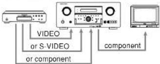
text_image
VIDEO or S-VIDEO or component componentMonitor is connected with the video or S-video.
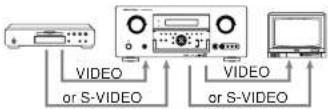
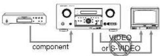
The signal cannot be converted from the component to the video or S-video.
Notes of OSD menu:
- The setup menu can be displayed through all video out (COMPONENT, S-VIDEO, VIDEO).
- The setting informations (e.g. volume setting) are displayed through all video out when the VIDEO CONVERT function are set ENABLE.
Note:
No setting information is displayed when the signal is emitted from the COMPONENT IN to COMPONENT OUT.
- The setting informations (e.g. volume setting) are displayed through the S-VIDEO or VIDEO out when the VIDEO CONVERT function are set DISABLE. When the S-VIDEO and VIDEO outputs are used simultaneously, the setting informations are displayed through the S-VIDEO out only.
To select the surround mode during playback, press the AUTO button on the front panel.
(Using the remote control unit)
To select the surround mode, press the AMP button and press the > button until PAGE1 is displayed. Press the AUTO (D1) button.
ADJUSTING THE MAIN VOLUME


Adjust the volume to a comfortable level using the VOLUME control knob on the front panel or VOL ▲ /▼ buttons on the remote.
To increase the volume, turn the VOLUME knob clockwise or press VOL ▲button on the remote, to decrease the volume, turn counterclockwise or press VOL ▼button on the remote.
Notes:
- The volume can be adjusted within the range of - to 18 dB, in steps of 1 dB.
• However, when the channel level is set as described on page 20, if the volume for any channel is set at +1 dB or greater, the volume cannot be adjusted up to 18 dB.
(In this case the maximum volume adjustment range is "18 dB - Maximum value of channel level)
ADJUSTING THE TONE (BASS & TREBLE) CONTROL

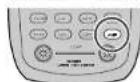
During a listening session you may wish to adjust the Bass and Treble Control to suit your listening tastes or room acoustics.
(Using the remote control unit)
To adjust the tone, press the AMP button and press the > button PAGE3 is displayed.
To adjust the bass effect, press BASS+ (D2) or BASS- (D3).
To adjust the treble effect, TREB+ (D4) or TREB-(D5).
Note:
• The tone control function can work in the AUTO Surround, Stereo, Dolby Pro Logic IIx, DTS, DTS-ES, and Multi Ch. Stereo mode.
TEMPORARILY TURNING OFF THE SOUND
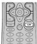
To temporarily silence all speaker outputs such as when interrupted by a phone call, press the MUTE button on the remote.
This will interrupt the output to all speakers and the head-phone jack, but it will not affect any recording or dubbing that may be in progress.
When the system is muted, the display will show "MUTE".
Press the MUTE button again to return to normal operation.
USING THE SLEEP TIMER

To program the SR7500 for automatic standby, press the SLEEP button on the remote. Each press of the button will increase the time before shut down in the following sequence.

The sleep time will be shown for a few seconds in the display on the front panel, and it will count down until the time has elapsed.
When the programmed sleep time has elapsed, the unit will automatically turn off.
Note that the SLEEP indicator on the display will illuminate when the Sleep function is programmed. To cancel the Sleep function, press the SLEEP button until the display shows "SLEEP OFF" and the SLEEP indicator will disappear.
NIGHT MODE
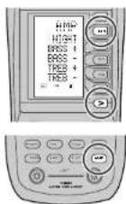
To select the NIGHT mode, press the AMP button and press the > button until PAGE3 is displayed. Press the NIGHT (D1) button.
Selecting the Night Mode ON is effective in Dolby Digital only, and it compresses the dynamic range. This softens loud passages such as sudden explosions, to help prevent disturbing others late at night.
To turn off the Night mode, press the NIGHT button again.
SURROUND MODE
The SR7500 is equipped with many surround modes. These are provided to reproduce a variety of surround sound effects, according to the content of the source to be played.
The available surround modes may be restricted depending on the input signal and speaker setup.
AUTO
When this mode is selected, the receiver determines whether the digital input signal is Dolby Digital, Dolby Digital Surround EX, DTS, DTS-ES, DTS 96/24 or PCM-audio.
Surround EX & DTS-ES will operate for multichannel source that has a Dolby Digital Surround EX or DTS-ES auto trigger flag in the digital signal.
When a Dolby Digital or DTS signal is input, the number of channels for which the corresponding signal is encoded will be played.
Inputting a Dolby Digital two channel signal with Dolby surround status automatically subjects that signal to Pro Logic IIx movie processing before play.
PCM 96 kHz source material can be played in this mode.
Notes:
- When you use this mode with certain DVD and CD players, performing operations such as "Skip" or "Stop" may momentarily interrupt the output.
- When the signal is not decoded, the mode is changed to AUTO mode automatically. Refer to page 24 to confirm the available decoding mode.
THX
THX mode applies additional processing to Dolby Digital, DTS, and Dolby Pro Logic multi-channel, surround sources. The THX processing was developed by Lucasfilm Ltd. to recreated the sound of top-quality theater.
Use the THX mode for all movies on disc, tape or broadcast. In this mode, THX Surround EX will not operate in this mode.
THX SURROUND EX
In a movie theater, film soundtracks that have been encoded with Dolby Digital surround EX technology are able to reproduce an extra channel which has been added during the mixing of the program.
This channel, called Surround Back, places sounds behind the listener in addition to the currently available front left, front center, front right, surround right, surround left and subwoofer channels.
This additional channel provides the opportunity for more detailed imaging behind the listener and brings more depth, spacious ambience and sound localization than ever before.
THX Surround EX will operate for any 5.1 channel source whenever THX is active.
THX Surround EX is not available in the system without surround back speaker(s).
Note:
- When playing Dolby Digital Surround EX-encoded software in 6.1 channels, it is required to set the TIIX Surround EX mode.
DO MODE
(Dolby Digital, Pro Logic IIx MOVIE, Pro Logic IIx MUSIC, Pro Logic IIx GAME)
This mode is used with source materials encoded in Dolby Digital and Dolby Surround.
DOLBY DIGITAL
This mode is enabled when playing source materials encoded in Dolby Digital.
Playing multichannel encoded 6.1 or 7.1-channel Dolby Digital sources provides five main audio channels (left, center, right, surround left and surround right) and Low Frequency Effect channel.
Dolby Digital EX decoding is not available in this mode.
Dolby Pro Logic IIx brings the excitement of surround sound to any stereo mix, while making existing Dolby Surround mixes sound more like discrete 5.1 channels Surround sound.
Dolby Pro Logic IIX has 3 modes. Please see below.
Pro Logic IIx MOVIE
This mode provides 6.1 or 7.1 channel surround sound from Dolby Surround encoded stereo movie sound tracks.
Pro Logic IIx MUSIC
This mode provides 6.1 or 7.1 channel surround sound from conventional stereo sources, analog or digital, such as CD, Tape, FM, TV, Stereo VCR, etc.
Pro Logic IIx GAME
Game mode restores the impact low-frequency surround effects by routing them to the system's subwoofer.
Notes:
• Pro Logic IIx mode will decode as Pro Logic II mode when the SURROUND BACK SPEAKER is set NONE in SPEAKER SETUP menu. (See SPEAKER SETUP, page 19)
• Pro Logic IIx mode is available for a 2ch input signal which is encoded in Dolby Digital or PCM format.
- PCM-audio signals can be subjected to Pro Logic processing when the sampling frequency is 32 kHz, 44.1 kHz or 48 kHz.
EX/ES
This mode provides 6.1 channel surround for DOLBY DIGITAL EX, DTS-ES encoded source material such as DVD.
This mode cannot be used when an analog input has been selected.
Dolby Digital EX
In a movie theater, film soundtracks that have been encoded with Dolby Digital surround EX technology are able to reproduce an extra channel which has been added during the mixing of the program.
This channel, called Surround Back, places sounds behind the listener in addition to the currently available front left, front center, front right, surround right, surround left and subwoofer channels.
This additional channel provides the opportunity for more detailed imaging behind the listener and brings more depth, spacious ambience and sound localization than ever before.
Dolby Digital EX is not available in the system without surround back speaker(s).
DTS-ES (Discrete 6.1, Matrix 6.1)
DTS-ES adds the surround center channel audio to the DTS 5.1-channel format to improve the acoustic positioning and makes acoustic image movement more natural with the 6.1-channel reproduction.
This receiver incorporates a DTS-ES decoder, which can handle DTS-ES Discrete-encoded and DTS-ES Matrix-encoded program sources from DVD, etc..
DTS-ES Discrete 6.1 features digital discrete recording of all channels including the surround back channel(s) and higher quality of audio reproduction.
DTS-ES is not available in the system without a surround back speaker.
dts MODE
(dts, Neo:6 Cinema, Neo:6 Music)
This mode is for DTS encoded source materials such as LASER DISC, CD, and DVD. Neo:6 is for some 2 channel sources.
dts : This mode is enabled when playing source materials encoded in dts multichannel.
Playing multichannel encoded 5.1-channel dts sources provides five main audio channels (left, center, right, surround left and surround right) and Low Frequency Effect channel.
dts-ES decoding is not available in this mode. The DTS mode cannot be used when an analog input has been selected.
Neo:6 Cinema, Neo:6 Music
This mode decodes 2-channel signals into 6-channel signals using high-accuracy digital matrix technology.
The DTS NEO:6 decoder has near-discrete properties in the frequency characteristics of the channels as well as in channel separation.
According to the signals to be played back, DTS NEO:6 uses either the NEO:6 CINEMA mode optimized for movie playback or the NEO:6 MUSIC mode optimized for music playback.
Notes:
- Neo:6 mode is available to 2ch input signals which are encoded in Dolby Digital or PCM format.
- PCM-audio signals can be subjected to Pro Logic processing when the sampling frequency is 32 kHz, 44.1 kHz or 48 kHz.
MULTI CH. ST
This mode is used to create a wider, deeper and more natural soundstage from two channel source material. This is done by feeding the left channel signal to both left front and left surround speaker and the right channel signal to both right front and right surround speaker. Additionally, the center channel reproduces a mix of the right and left channel.
CIRCLE SURROUND II
(CSII-CINEMA, CSII-MUSIC, CSII-MONO)
Circle Surround is designed to enable multichannel surround sound playback of non-encoded and multichannel encoded material.
Backward compatibility provides listeners with up to 6.1 channels of surround performance from entire collection of music and film, including broadcast, videotape and stereo recorded music. Depending on source material, you can select CSII-Cinema mode, CSII-Music mode or CSII-Mono mode.
Notes:
• CS II mode is available for 2ch input signals which are encoded in Dolby Digital or PCM format.
• PCM-audio signals can be subjected to Pro Logic processing when the sampling frequency is 32 kHz, 44.1 kHz or 48 kHz.
VIRTUAL
This mode creates a virtualized surround sound experience from a two-speaker (front L and R) playback system playing any multichannel audio source (such as found on DVDs and digital broadcasts), including Dolby Digital, Dolby Pro Logic or DTS.
STEREO
This mode bypasses all surround processing. In stereo program sources, the left and right channels play normally when PCM-audio or analog stereo is input.
With Dolby Digital and DTS sources, the 5.1 multichannels are converted to two channel stereo. 96 kHz PCM source material can be played back in stereo mode.
PURE DIRECT
In the pure direct mode, the tone control circuit and bass management configuration are bypassed for full range frequency response and the purist audio reproduction.
96 kHz PCM source material can be played back in this mode.
Notes:
- Internal speaker size is setup to front L/R = LARGE, Center = LARGE, Surround L/R = LARGE and Subwoofer = YES automatically. Tone controls and additional processing are also defeated.
- When you use this mode with certain DVD and CD players, performing operations such as "Skip" or "Stop" may momentarily interrupt the output.
CAUTION
NOTE for DTS signal
Connected DVD-player, laser-disc player or CD-player needs to support DTS-digital output. You may not be able to play some DTS source signals from certain CD players and LD players even if you connect the player to the SR7500 digitally. This is because the digital signal has been processed (such as the output level, sampling frequency, or frequency response) and the SR7500 cannot recognize the signal as DTS data.
* Depending on the player used, DTS play may produce a short noise. This is not a malfunction.
* While signals from DTS-laser disc or CD are playing in another Surround mode, you cannot switch to digital input or from digital input to analog input by INPUT SETUP in SETUP MAIN MENU or the A/D button.
* You can not listen to DTS-encorded course in Multi room.
* The outputs for the VCR 1 OUT, DSS/VCR 2 OUT, TAPE OUT, and CD-R OUT output analog audio signals. Do not record from CDs or LDs that support DTS using these outputs. If you do, the DTS-encoded signal will be recorded as noise.
NOTE for Dolby Digital Surround EX signal
* When playing Dolby Digital Surround EX-encoded software in 6.1 channels, it is required to set the EX/ES mode.
* Note that some of Dolby Digital Surround EX-encoded software does not contain the Identification signal. In this case, set the EX/ES mode manually.
NOTE for 96kHz PCM audio
* AUTO, PURE DIRECT, and STEREO modes can be used when playing PCM signals with a sampling frequency of 96 kHz (such as from DVD-Video discs that contain 24 bit, 96 kHz audio). If such signals are input during playback in one of the other surround modes, output from SR7500 will be muted.
* Certain DVD player models inhibit digital output. For details, refer to the player's operation manual.
* Some DVD formatted discs feature copy protection. When using such disc, 96 kHz PCM signal is not output from the DVD player. For details, refer to the player's operation manual.
NOTE for HDCD signal (SR8500 only)
* HDCD is effective only at the time of digital input.
* AUTO. PURE DIRECT, and STEREO modes can be used when playing HDCD signals (such as from CD discs that contain HDCD).
* You may not be able to play some HDCD source signals from certain CD players if you connect the player to the SR8500 digitally. This is because the digital signal has been processed (such as the output level, sampling frequency, or frequency response) and the SR8500 cannot recognize the signal as HDCD data.
The relation between the selected surround mode and the input signal
The surround mode is selected with the surround mode selector on SR7500 or the remote control unit. However, the sound you hear is subject to the relationship between the selected surround mode and input signal. That relationship is as follows;
| Surround Mode Input Signal Decoding | Output Channel From information display | |||||||||
| L/R | C | SL SR SBR | SBR | SrCW | Signal formal indicators Channel status | |||||
| AUTO Dolby Sum | EX Dolby Digital EX | O | O | O | O | O | DIGITAL EX L, C, R, SL, SR, S, LFE | |||
| Dolby D (5.1ch) Dolby Digital 5.1 | O | O | O | - | O | DIGITAL L, C, R, SL, SR, LFE | ||||
| Dolby D(2ch) Dolby Digital 2.0 | O | - | - | - | - | DIGITAL L R | ||||
| Dolby D (2ch Surr) | Pro Logic IIx movie | O | O | O | O | - | DIGITAL, SURROUND | L, R, S | ||
| DTS-ES | DTS-ES | O | O | O | O | O | dls ES | L, C, R, SL, SR, S, LFE | ||
| DTS 36/24 | DTS 96/24 | O | O | O | - | O | dls 96/24 | L, C, R, SL, SR, LFE | ||
| DTS (5.1ch) | DTS 5.1 | O | O | O | - | O | dls | L, C, R, SL, SR, LFE | ||
| PCM (Audio) | PCM (Stereo) | O | - | - | - | - | PCM | L, R | ||
| PCM 96kHz PCM (58Hz Stereo) | O | - | - | - | - | PCM | L, R | |||
| HDCD * | Stereo | O | - | - | - | - | PCM, HDCD | L, R | ||
| Analog | Stereo | O | - | - | - | - | ANALOG | - | ||
| PURE DIRECT | Dolby D Surr. EX | Dolby Digital EX | O | O | O | O | O | DIGITAL EX L, C, R, SL, SR, S, LFE | ||
| Dolby D (5.1ch) Dolby Digital 5.1 | O | O | O | - | O | DIGITAL L, C, R, SL, SR, LFE | ||||
| Dolby D (2ch) | Dolby Digital 2.3 | O | - | - | - | - | DIGITAL L R | |||
| Dolby D (2ch Surr) | Pro Logic IIx movie | O | O | O | O | - | DIGITAL, SURROUND | L, R, S | ||
| DTS-ES | DTS-ES | O | O | O | O | O | dls ES | L, C, R, SL, SR, .S, LFE | ||
| DTS 36/24 | DTS 96/24 | O | O | O | - | O | dls 96/24 | L, C, R, SL, SR, LFE | ||
| DTS (5.1ch) | DTS 5.1 | O | O | O | - | O | dls | L, C, R, SL,SR, LFE | ||
| PCM (Audio) | PCM (Stereo) | O | - | - | - | - | PCM | L, R | ||
| PCM 96kHz PCM (58Hz Stereo) | O | - | - | - | - | PCM | L, R | |||
| HDCD * | Stereo | O | - | - | - | - | PCM, HDCD | L, R. | ||
| Analog | Stereo | O | - | - | - | - | ANALOG | - | ||
| EX/ES Dolby D Sum. EX Dolby Digital EX | O | O | O | O | O | DIGITAL EX L, C, R, SL, SR, S, LFE | ||||
| O | O | O | O | O | DIGITAL L, C, R, SL, SR, LFE | |||||
| DTS-ES | DTS-ES | O | O | O | O | dls , ES | ||||
| DTS 36/24 | DTS-ES | O | O | O | O | dls 96/24 | ||||
| DTS (5.1ch) DTS-ES | O | O | O | O | dts | |||||
| DOLBY (PL IIIx movie) (PL IIIx music) (PL IIIx game) | Dolby D Surr. EX | Dolby Digital 5.1 | O | O | O | O | O | DIGITAL EX L, C, R, SL, SR, S, LFE | ||
| Dolby D (5.1ch) Dolby Digital 5.1 | O | O | O | O | O | DIGITAL L, C, R, SL, SR, LFE | ||||
| Dolby D (2ch) | Pro Logic IIx | O | O | O | O | - | DIGITAL L R | |||
| Dolby D (2ch Surr) | Pro Logic IIx | O | O | O | O | - | DIGITAL, SURROUND | L, R, S | ||
| PCM (Audio) | Pro Logic IIx | O | O | O | O | - | PCM | L, R | ||
| HDCD * | Pro Logic IIx | O | O | O | O | - | PCM, HDCD L R | |||
| Analog | Pro Logic IIx | O | O | O | O | - | ANALOG | - | ||
| DTS (Nec:6 Cinema) (Nec:6 Music) | DTS-ES | DTS 5.1 | O | O | O | - | O | dls ES | L, C, R, SL, SR, S, LFE | |
| DTS 96/24 | DTS 96/24 | O | O | O | - | O | dls 96/24 | L, C, R, SL, SR, LFE | ||
| DTS (5.1ch) | DTS 5.1 | O | O | O | - | O | dls | L, C, R, SL, SR, LFE | ||
| PCM (Audio). | Neo:6 | O | O | O | O | - | PCM | L, R | ||
| Analog | Neo:6 | O | O | O | O | - | ANALOG | - | ||
| Dolby D (2ch) | Neo:6 | O | O | O | O | - | DIGITAL L R | |||
| Dolby D (2ch Surr) | Neo:6 | O | O | O | O | - | DIGITAL, SURROUND | L, R, S | ||
| CS III Cinema CS III Music CS III Mono | PCM (Audio) | CS II | O | O | O | O | O | PCM | L R | |
| HDCD * | CS II | O | O | O | O | O | PCM, HDCD L R | |||
| Analog | CS II | O | O | O | O | O | ANALOG | - | ||
| Dolby D (2ch) | CS II | O | O | O | O | O | DIGITAL L R | |||
| Dolby D (2ch Surr) | CS II | O | O | O | O | O | DIGITAL, SURROUND | L, R, S | ||
| STEREO | Dolby Surr. EX Stereo | O | - | - | - | O | DIGITAL EX L, C, R, SL, SR, S, LFE | |||
| Dolby D (5.1ch) Stereo | O | - | - | - | O | DIGITAL L, C, R, SL, SR, LFE | ||||
| Dolby D (2ch) | Stereo | O | - | - | - | - | DIGITAL L R | |||
| Dolby D (2ch Surr) | Stereo | O | - | - | - | O | DIGITAL, SURROUND | L, R, S | ||
| DTS-ES | Stereo | O | - | - | - | O | dls ES | L, C, R, SL, SR, S, LFE | ||
| DTS 96/24 | Stereo | O | - | - | - | O | dls 96/24 | L, C, R, SL, SR, LFE | ||
| DTS (5.1ch) | Stereo | O | - | - | - | O | dls | L, C, R, SL, SR, LFE | ||
| PCM (Audio) | Stereo | O | - | - | - | - | PCM | L, R | ||
| PCM 96kHz Stereo | O | - | - | - | - | PCM | L, R | |||
| HDCD * | Stereo | O | - | - | - | - | PCM, HDCD | L, R | ||
| Analog | Stereo | O | - | - | - | - | ANALOG | - | ||
*: SR8500 only
| Surround Mode Input Signal Decoding | Output Channel From information display | ||||||||
| L/R | C | SL SR BR | SBL SRBR | Sub/M | Signal format indicators Channel status | ||||
| Virtual Dolby Sur | EX Virtual | O | - | - | - | - | ☐ DIGITAL EX L, C. R, SL, SR. S, LFE | ||
| Doby D (5.1ch) Virtua | O | - | - | - | - | ☐ DIGITAL L. C. R, SL, SR. LFE | |||
| Doby D (2ch) Virtual | O | - | - | - | - | ☐ DIGITAL L. R | |||
| Doby D (2ch Surr) | Virtual | O | - | - | - | - | ☐ DIGITAL, ☐ SURROUND | L. R, S | |
| DTS-ES | Virtual | O | - | - | - | - | dts, ES | L, C. R, SL, SR, LFE | |
| DTS (5.1ch) | Virtual | O | - | - | - | - | dts | L, C. R, SL, SR, LFE | |
| PCM (Audio) | Virtual | O | - | - | - | - | PCM | L, R | |
| HDCD* | Virtual | O | - | - | - | - | PCM, HDCD | L, R | |
| Analog | Virtual | O | - | - | - | - | ANALOG | - | |
| Multi Ch. Stereo Dolby D (5.1ch) | Doby Surr. EX Multi Channel Stereo | O | O | O | O | O | ☐ DIGITAL EX L, C. R, SL, SR. S, LFE | ||
| Doby D (2ch) Multi Channel Stereo | O | O | O | - | O | ☐ DIGITAL L. C. R, SL, SR. LFE | |||
| Doby D (2ch Surr) | Multi Channel Stereo | O | O | O | O | - | ☐ DIGITAL L. R | ||
| DTS-ES | DTS-ES | O | O | O | O | O | dts, ES | L, C. R, SL, SR, S, LFE | |
| DTS (5.1ch) | DTS 5.1 | O | O | O | - | O | dts | L, C. R, SL, SR, LFE | |
| PCM (Audio) | Multi Channel Stereo | O | O | O | O | - | PCM | L, R | |
| HDCD* | Multi Channel Stereo | O | O | O | O | - | PCM, HDCD L, R | ||
| Analog | Multi Channel Stereo | O | O | O | O | - | ANALOG | - | |
| THX | Doby Surr. EX THX Surround EX - Dolby Digital | O | O | O | O | O | ☐ DIGITAL EX L, C. R, SL, SR. S, LFE | ||
| Doby D (5.1ch) THX + Dolby Digital | O | O | O | - | O | ☐ DIGITAL L. C. R, SL, SR. LFE | |||
| Doby D (2ch) THX + Pro Logic IIIx | O | O | O | O | - | ☐ DIGITAL L. R | |||
| Doby D (2ch Surr) | THX + Pro Logic IIIx | O | O | O | O | - | ☐ DIGITAL, ☐ SURROUND | L, R, S | |
| DTS-ES | THX + DTS-ES | O | O | O | O | O | dts, ES | L, C. R, SL, SR, S, LFE | |
| DTS 36/24 | THX + DTS | O | O | O | - | O | dts 36/24 | L, C. R, SL, SR, LFE | |
| DTS (5.1ch) | THX + DTS | O | O | O | - | O | dts | L, C. R, SL, SR, LFE | |
| PCM (Audio) | THX + Pro Logic IIIx | O | O | O | O | - | PCM | L, R | |
| HDCD* | THX + Pro Logic IPx | O | O | O | O | - | PCM, HDCD L, R | ||
| Analog | THX + Pro Logic IIx | O | O | O | O | - | ANALOG | - | |
*: SR8500 only
Notes:
• Dolby Digital (2 ch: Lt/Rt): signal with Dolby Surround flag Speakers are full set.
- No sound outputs from the surround speaker, center speaker and subwoofer if the DVD disc has no surround data.
Abbreviations
L/R : Front speakers
C : Center speaker
SL/SR : Surround speakers
SBL/SBR: Surround Back speakers
SubW : Sub woofer speaker
OTHER FUNCTION
TV AUTO ON/OFF FUNCTION
This function allows the component connected to the TV-VIDEO in jack to control the power (ON/OFF) to the SR7500.
AUTO POWER ON
- Be sure the TV auto mode is ENABLED. (Refer to page 22: PREFERENCE)
- Connect your TV TUNER (etc) to the TV-VIDEO in terminal. Be sure to connect the VIDEO input.
- Turn OFF the power to the TV TUNER and the SR7500.
- Turn ON the TV TUNER and tune in a receivable station.
- When the station is received, the SR7500 turns ON and TV is selected automatically.
AUTO POWER OFF
- In the above situation, turn the TV TUNER OFF or select a channel that does not contain any broadcast.
- The power to the SR7500 switches to STANDBY after approx. 5 minutes.
Notes:
- AUTO POWER OFF is canceled if the SR7500 is set to a source other than TV.
The function reactivates when TV is selected again. - Some TV broadcasts may cause the TV AUTO FUNCTION to turn ON.
- The S-Video terminal does not support "TV AUTO ON/OFF" function.
ATTENUATION TO ANALOG INPUT SIGNAL
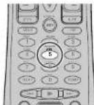
If the selected analog audio input signal is greater than the capable level of internal processing, the "PEAK" indicator will light up on the front display. If this happens, you should press the ATT button on the remote.
"ATT" indicator will be illuminated when this function is activated. The signal-Input level is reduced by about half. Attenuation will not work with the output signal of TAPE-OUT, CD-R/MD-OUT, VCR1-OUT and DSS/VCR2-OUT.
This function is memorized for each individual input source.
LISTENING THROUGH HEADPHONES
This jack may be used to listen to the SR7500's output through a pair of headphones. Bo certain that the headphones have a standard 1/4" stereo phono plug. (Note that the speakers will automatically be turned off when the headphone jack is in use.)
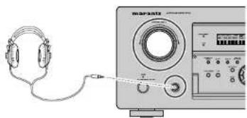
natural_image
Line drawing of a headset connected to an electronic device (no text or symbols visible)Note:
- The surround mode returns to the previous setting as soon as the plug is removed from the jack.
DOLBY HEADPHONE MODE
This feature simulates the waveforms of the actual sounds heard from the speakers. When headphones are used, the MENU button automatically switches to the Dolby headphone mode.
The OSD that appears when the MENU button is pressed is shown below.

text_image
HEAD PHONE DOLBY HP MODE : BYPASS SURROUND : *** L LEVEL : 0dB R LEVEL : 0dBDOLDBY HP (Headphone) MODE can be selected with the left and right cursor buttons.
BYPASS: Bypasses the Dolby headphone mode and delivers ordinary 2-channel stereo.
DH1: The size of a typical living room space is simulated.
DH2: The expansiveness of a structure as large as a music hall is simulated.
DH3: A large space such as that found in a movie theater is simulated.
When the PURE DIRECT mode is selected, Dolby surround processing is bypassed and “***” is displayed as the mode indication.
L/R LEVEL can be set in the ±10 dB range.
Notes:
• The surround mode returns to the previous setting as soon as the plug is removed from the jack.
- TONE cannot be set when any of the modes in DH1, DH2, or DH3 is selected.
• The Dolby Headphone function will not work when 32 or 96 kHz PCM digital signals are input.
VIDEO ON/OFF
When no video signal is connected to the SR7500 or a DVD, etc., is connected directly to your TV, the unnecessary video circuit can be turned off by selecting the "VIDEO OFF" setting.
To select video off, press the AMP button and press the > button until PAGE 4 is displayed. Press the V-OFF button.


DISPLAY MODE


You can select the display mode for the front display of the SR7500.
To select this mode, press the DISPLAY on the remote control or the front panel.
When this button is pressed, the display mode is switched in the following sequence.
→ Surround Mode → Auto-display Off → Display Off → Input Function → Surround Mode....
In Auto display off mode, the display is off. But, if you make a change to the unit such as input or surround mode, the display will show that change, then go back to off after about 3 seconds. When changing the volume, it is not displayed.
In Display off mode, the display is off completely.
Note:
- Only the DISP indicator will be illuminated on the front display in display off condition.
SELECTING ANALOG AUDIO INPUT OR DIGITAL AUDIO INPUT

If you have already assigned the digital inputs, you can temporarily select the audio input mode for each input source as following procedures.
Press the AMP button and press the > button until PAGE4 is displayed. Press the A/D (D3) button. When this button is pressed, the input mode is switched in the following sequence.
→ Digital Auto → Digital → Analog → Digital Auto.... In Digital Auto mode, the types of signals being Input to the digital and analog Input jacks for the selected input source are detected automatically. If no digital signal is being input, the analog input jacks are selected automatically.
In Digital mode, input is fixed to an assigned digital input terminal.
In analog mode, the analog input jacks are selected. This selecting is temporary, so the result will not be stored in memory.
If you need to change the input mode completely, use INPUT SETUP in OSD menu system. (see page 19)
RECORDING AN ANALOG SOURCE
In normal operation, the audio or video source selected for listening through the SR7500 is sent to the record outputs.
This means that any program you are watching or listening to may be recorded simply by placing machines connected to the outputs for TAPE OUT, CD-R/MD OUT, VCR1 OUT, and DSS/VCR2 OUT in the record mode.
To record the input source signal you are currently watching or listening to

text_image
Diagram showing front and side views of a device with labeled parts, including a control panel and keypad.- Select the input source to record by turning the INPUT FUNCTION SELECTOR knob on the front panel or simply press the input selector buttons on the remote.
The input source is now selected and you may watch or listen to it as desired. - The currently selected input source signal is output to the TAPE OUT, CD-R/MD OUT, VCR1 OUT, and DSS/VCR2 OUT outputs for recording.
- Start recording to the recording component as desired.
Recording the video from one source and the audio from another
You can add the sound from one source to the video of another source to make your own video recordings.
Below is an example of recording the sound from a compact disc player connected to CD IN and the video from a video camera connected to VCR1 to video cassette recorder connected to the DSS/VCR2 OUT jack.

- Switch the video output source to VCR1 by simply pressing the input selector buttons on the remote.
- Switch the audio input source to CD by simply pressing the input selector buttons on the remote.
- Now "CD" has been selected as the audio input source and "VCR1" as the video input source.
Notes:
- If you change the input source during recording, you will record the signals from the newly selected input source.
- You cannot record the surround effects.
- Digital input signals are only output to the digital outputs. There is no conversion from digital to analog.
When connecting CD players and other digital components, do not connect only the digital terminals, but the analog ones as well.
SPEAKER A/B
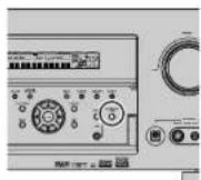

SR7500 has speaker system - A and speaker system - B for front L/R channels.
You can select these systems by pressing SPEAKERS A/B button on the front panel or SPK-AB on the remote.
7.1 CH INPUT
The SR7500 is equipped for future expansion through the use of Multi channel SACD multichannel player or DVD-Audio player.
When this is selected, the input signals connected to the L(front left), R (front right), CENTER, SL (surround left), SR (surround right) and SBL (surround back left) and SBR (surround back right) channels of the 7.1 CH. In jacks are output directly to the front (left and right), center, surround (left and right) and surround back speaker systems as well as the pre-out jacks without passing through the surround circuitry.
In addition, the signal input to the SW (subwoofer) jack is output to the PRE OUT SW (subwoofer) jack.
When 7.1 CH. INPUT is selected, the last video input used remains routed to the Monitor Outputs. This permits simultaneous viewing with video sources
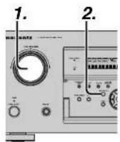
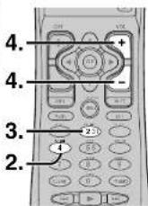

- Select a desired Video source to decide the routed video signal to the Monitor Outputs.
- Press the 7.1 CH INPUT button on the front panel or press 7.1 CH on the remote to switch the 7.1 channel input.
- If it is necessary to adjust the output level of each channel, press the CH.SEL button on the remote.
Adjust the speaker output levels so that you can hear the same sound level from each speaker at the listening position. For the front left, front right, center, surround left, surround right and surround back speakers, the output levels can be adjusted between -10 to +10 dB.
The subwoofer can be adjusted between -15 and +10 dB.
These adjustments result will be stored to 7.1 CH. INPUT memory.
- Adjust the main volume with the MAIN VOLUME knob or the VOL buttons on the remote.
To cancel the 7.1 CH. INPUT setting, press the 7.1 CH INPUT button on the front panel or press 7.1 CH on the remote.
Notes:
- When the 7.1 CH. Input is in use, you may not select a surround mode, as the external decoder determines processing.
- In addition, there is no signal at the record outputs when the 7.1 CH. Input is in use.
AUX2 INPUT
If you don't need to connect 7.1 Ch. input terminals with multi channel decoder,
L(front left) and R (front right) inputs terminals are available as AUX2 input.
In this case, You can connect additional audio source to AUX2 as other audio input terminals.

LIP.SYNC
Depending on the image device (TV, monitor, projector, etc.) connected to the SR7500, a time lag can occur between image signal processing and audio signal processing. Though minor, this time lag can interfere with movie and music enjoyment. The LIP.SYNC feature delays the audio signal with respect to the image signal output from the SR7500 to correct the time lag between the sound and image. It can be operated with the "LIP.SYNC" and ▶ and ▶ cursor buttons of the remote controller. Set the remote controller to the AMP mode before operating the LIP.SYNC feature. The initial setting is OFF (0 ms).The time lag can be adjusted in 10 ms steps up to 200 ms. Watch the picture on the image device (i.e., TV, monitor, projector, etc.) as you adjust the time lag.
Note:
The LIP.SYSNC feature turns OFF (0 ms) in the PURE DIRECT mode. When the PURE DIRECT mode is deactivated, the set value of the LIP.SYSNC feature is automatically restored.

To operate the unit from the remote control, press the TUNER button on the remote control so that the tuner mode is engaged.
LISTENING TO THE TUNER
Frequency scan step for AM is selectable. Default setup is 9 kHz step, if your country's standard is 10 kHz step, Press TUNER button on the remote more than 6 seconds. Scan step will change.
Note:
- Preset memory for the tuner will clear by changing this setup.
AUTO TUNING

text_image
2. 1. TUNER SONH + SONH - F-NDIE P-0334 P-INF 3. 3. 2. 1.(Using the SR7500)
- To select tuner and desired band (FM or AM), press the BAND button on the front panel.
- Press the ▲ or ▼cursor buttons on the front panel for more than 1 second to start the auto tuning function.
- Automatic searching begins then stops when a station is tuned in.
(Using the remote control unit)
- To select tuner and desired band (FM or AM), press the TUNER button twice within two seconds on the remote.
- Press the > button until PAGE2 is displayed.
- Press and hold the SCAN+ (D1) or SCAN-(D2) button for 1 second or more.
- Automatic searching begins then stops when a station is tuned in.
If tuning does not stop at the desired station, use to the "Manual tuning" operation.
MANUAL TUNING

text_image
2. 1. 3. 3. 2. 1.(Using the SR7500)
- To select tuner and desired band (FM or AM), press the BAND button on the front panel
- Press the ▲ or ▼cursor buttons on the front panel to select the desired station.
(Using the remote control unit)
- To select tuner and desired band (FM or AM), press the TUNER button twice within two seconds on the remote.
- Press the > button until PAGE2 is displayed
- Press the SCAN+ (D1) or SCAN- (D2) button to tune in the desired station.
DIRECT FREQUENCY CALL
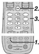
- To select tuner and desired band (FM or AM), press the TUNER button twice within two seconds on the remote.
- Press the GUIDE on the remote, display will show "FREQ----".
- Input your desired station's frequency with the ten numbered keypad on the remote.
- The desired station will automatically be tuned.
(FM) TUNING MODE (AUTO STEREO OR MONO)

natural_image
Two electronic devices: one with a control panel and buttons, the other with a display screen (no visible text or symbols)When in the auto stereo mode, AUTO indicator will be illuminated on the display.
The "ST" indicator is illuminated when a stereo broadcast is tuned in.
At open frequencies, the noise is muted and the "TUNED" and "ST" indicators are not illuminated.
If the signal is weak, it may be difficult to tune into the station in stereo. In such a case, press the MODE button on the front panel. Or press the TUNER button and press the > button until PAGE1 is displayed. Press the T-MODE (D4) button.
"AUTO" indicator is not illuminated, if FM stereo broadcasts are received in monaural and the "ST" indicator is not illuminated.
To return to auto stereo mode, press the MODE button or press T-MODE button on the remote again. AUTO indicator is illuminated the display.
PRESET MEMORY
With this unit you can preset up to 50 FM/AM stations in any order.
For each station, you can memorize the frequency and reception mode if desired.
AUTO PRESET MEMORY
This function automatically scans the FM and AM band and enters all stations with proper signal strength into the memory.

text_image
2.4.1.3.2.5.-
To select FM, press the BAND button on the front panel.
-
While pressing the MEMORY button, press the ◀cursor button.
"AUTO PRESET" will appear on the display, and scanning starts from the lowest frequency.
- Each time the tuner finds a station, scanning will pause and the station will be played for five seconds.
During this time, the following operations are possible.
- The band can be changed by the BAND button. If no button is pressed during this period, the current station is memorized in location Preset 02.
If you wish to skip the current station, press the ▲ cursor button during this period, this station is skipped and auto presetting continues.
- Operation stops automatically when all 50 preset memory positions are filled or when auto scanning attains the highest end of all bands. If you desire to stop the auto preset memory at anytime, press the CLEAR button.
MANUAL PRESET MEMORY

text_image
3. 2. 4. 3. 2.(Using the SR7500)
-
Tune into the radio station you desire (Refer to the "MANUAL TUNING" or "AUTO TUNING" section).
-
Press the MEMORY button on the front panel. “--” (preset number) starts blinking on the display.
-
Select the preset number by pressing the ◀ or ▶ cursor buttons, while this is still blinking (approx. 5 seconds)
-
Press the MEMORY button again to enter. The display stops blinking.
The station is now stored in the specified preset memory location.
(Using the remote control unit)
-
Tune into the radio station you desire (Refer to the "MANUAL TUNING" or "AUTO TUNING" section).
-
Press the MEMO button on the remote. "-" (preset number) starts blinking on the display.
-
Enter the desired preset number by pressing the numeric buttons.
Note
- When entering a single digit number (2 for example), either input "02" or just input "2" and wait for a few seconds.
RECALLING A PRESET STATION
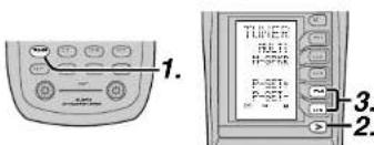
text_image
1. TUNER MULTI H-SPIK P-SET- P-SET- 3. 2.(Using the SR7500)
- Select the desired preset station by pressing the ◀br ▶ cursor buttons on the front panel
(Using the remote control unit)
-
Press the TUNER button twice within two seconds on the remote.
-
Press the > button until PAGE4 is displayed
- Press the P-SET+ (D4) or P-SET- (D5) button to tune in the desired preset station.
Or enter the preset station number with the numeric buttons.
PRESET SCAN
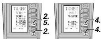
text_image
TUNER SCFH + SCFH T-500E P-SCFH P-190 2. 5. 2. TUNER MULTI H-GPHR P-SET+ P-SET- 4. 4.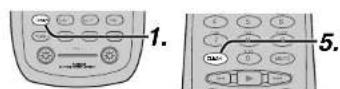
(Using the remote control unit)
-
Press the TUNER button twice within two seconds on the remote.
-
Press the > button until PAGE2 is displayed and press the P-SCAN (D4) on the remote. "PRESET SCAN" appears on the front display and then the preset station with the lowest preset number is recalled first.
-
Preset stations are recalled in sequence (No.1 → No.2 → etc.) for 5 seconds each. No stored preset number will be skipped.
-
You can fast forward the preset stations, press the > button until PAGE4 is displayed and press the P-SET+ (D4) continuously.
-
When the desired preset station is received, cancel the preset scan operation by pressing the CLEAR button or P-SCAN (D4) on the remote.

CLEARING STORED PRESET STATIONS
You can remove preset stations from the memory using the following procedure.
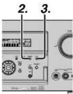

- Recall the preset number to be cleared with the method described in "Recalling" a preset station.
- Press the MEMORY button on the front panel or press the MEMO button on the remote.
- The stored preset number blinks in the display for 5 seconds. While blinking, press the CLEAR button on the front panel or the remote.
- "xx CLEAR" appears on the display to indicate that the specified preset number has been cleared.
Note:
• To clear all stored preset stations, press and hold the CLEAR and the ENTER buttons for two seconds.
SORTING PRESET STATIONS
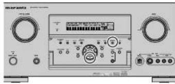
text_image
Marantz MARZARENTS 10000000000000000000000000000000000000000000000000000000000000000000000000000000000000000000000If you have stations memorized, and there is a gap in the sequential order:
I.e. the stations are stored as follows
1) 87.1 MHz
2) 93.1 MHz
3194.7 MHz
10) 105.9 MHz
(notice there is no stations programmed for pre sets for 4-9), you can have pre set 10 become pre set 5:
To sort the numbers, press and hold the MEMORY and the ▼cursor buttons.
"PRESET SORT" will appear on the display and sorting will be done.
NAME INPUT OF THE PRESET STATION.
This function allows the name of each preset channel to be entered using alphanumeric characters.
Before name inputting, you need to store preset stations with the preset memory operation.
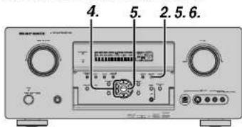
text_image
4. 5. 2.5.6.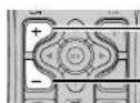
-5
5.
-
-5.

12
15

- Recall the preset number to be inputted name with the method described in "Recalling" a preset station.
- Press the MEMORY button on the front panel or press the MEMO button on the remote for more than 3 seconds.
- The left most column of the station name indicator flashes, indicating the character entry ready status.
- When you press the ▲ or ▼ cursor buttons on the front panel or the ▲ or ▼ buttons on the remote, alphabetic and numeric characters will be displayed in the following order:
UP → ← DOWN
$$ \begin{array}{l}\mathsf {A} \rightarrow \mathsf {B} \rightarrow \mathsf {C} \dots \mathsf {Z} \rightarrow 1 \rightarrow 2 \rightarrow 3 \dots .. 0 \rightarrow - \rightarrow +\\rightarrow / \rightarrow (\text { Blank }) \rightarrow \mathsf {A}\end{array} $$
- After selecting the first character to be entered, press the MEMORY or ENTER button, or press the MEMO button on the remote.
The entry in this column is fixed and the next column starts to flash. Fill the next column the same way.
To move back and forth between the characters, press the ◀/▶cursor buttons or press CH+ or CH- button on the remote.
Note:
- Unused columns should be filled by entering blanks.
- To save the name, press the MEMORY or ENTER button on the front panel, or press the MEMO button on the remote for more than 2 seconds.
| Ten keypad Press, press again, press again, etc. | |
| 1 | A→B→C→1→A |
| 2 | D→E→F→2→D |
| 3 | G→H→I→3→G |
| 4 | J→K→L→4→J |
| 5 | M→N→O→5→M |
| 6 | P→Q→R→6→P |
| 7 | S→T→U→7→S |
| 8 | V→W→X→B→V |
| 9 | Y→Z→space→9→Y |
| 0- | →+→/→0 |
RDS OPERATION
Now in use in many countries, RDS (Radio Data System) is a description of the station's programming hidden space in the FM signal.
Your new receiver is equipped with RDS to assist in the selection of FM stations using station and network names, rather than broadcast frequencies. Additional RDS functions include the ability to search for programme types.
RADIO TEXT
Some RDS stations broadcast RADIO TEXT, which is additional information on the station and programme being broadcast.
RADIO TEXT information appears as 'running' text in the display. RADIO TEXT is transmitted character by the radio station. As a result of that it may take some time until the entire text has been completely received.
RDS DISPLAY
When a receiver is tuned to an FM station that is transmitting RDS data, the Front Panel Information Display will automatically show the station name or RDS TEXT in place of the typical display of the station's broadcast frequency.
To change the display, press the TUNER button and press the the > button until PAGE3 is displayed. Press the DISP (D1) button.

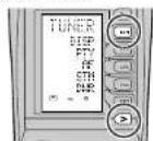
PROGRAMME TYPE (PTY) DISPLAY
The RDS system categorizes programmes according to their genre into different programme type (PTY) groups. To display the programme type information of the current station, press the TUNER button and press the the > button until PAGE3 is displayed. Press the PTY (D2) button.

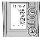
PS (Program Service Name) → RT (RADIO TEXT) → Frequency
PTY AUTO SEARCH
Your receiver is equipped to automatically search for stations transmitting any of 29 different programme types. To search for a PTY, follow these procedures:

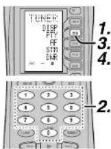
- Press the PTY button in the TUNER MODE on the remote controller. The current station's PTY will be displayed, or the currently selected PTY group will be displayed in blinking if no station or RDS data is present.
- To change to a new PTY type, press the TUNING ▲ or ▼ button on the front panel or numeric buttons on the remote until the desired PTY is shown in the display.
- Once the desired PTY group or type has been selected, press the PTY button while the display blink (approx. 5 seconds). The PTY Auto search will start, and the tuner will pause at each station broadcasting RDS PTY information corresponding to the selected choice.
- To advance to the next RDS station with the desired PTY, press the PTY button again within 5 seconds.
| NUMBER DISPLAY PROGRAMME TYPE | |
| 1 POP Pop Music | |
| 2 ROCK Rock Music | |
| 3 MOR M. O. R. Music | |
| 4 LIGHT Light classics | |
| 5 CLASSIC Serious classical | |
| 6 NEWS News | |
| 7 AFFAIR Current Affairs | |
| 8 INFO Information | |
| 9 SPORT Sport | |
| 10 EDUCATE Education | |
| 11 DRAMA Drama | |
| 12 CULTURE Culture | |
| 13 SCIENCE Science | |
| 14 OTHERS Varied | |
| 15 OTHER Other Music | |
| 16 WEATHER Weather | |
| 17 FINANCE Finance | |
| 18 CHILDREN Children's programmes | |
| 19 SOCIAL Social Affairs | |
| 20 RELIGION Religion | |
| 21 PHONE IN Phone In | |
| 22 TRAVEL Travel | |
| 23 HOBBIES Hobbies | |
| 24 JV/2 Jazz Music | |
| 25 COUNTRY Country Music | |
| 26 NATION National Music | |
| 27 OLIVES Oldies Music | |
| 28 FOLK Folk Music | |
| 29 DOCUMENT Documentary | |
MULTI ROOM SYSTEM
The Multi Room system is a function which allows you to listen to the same or a different source in a room other than the room in which the SR7500 is located.
To use this function, a multi room remote unit and remote control signal receiver available from your Marantz dealer are necessary.
The operations possible with the multi room function are explained briefly below.
For details, refer to the instruction manual supplied with the multi room remote control unit and receiver.
When the outputs of the MULTI OUT terminals are wired and connected to amplifiers installed in other rooms or MULTI SPEAKER OUT terminals are wired and connected to L&R speakers in other room, different sources can be played in rooms other than the main room in which this unit and the playback devices are Installed.
SR7500 has some feature to MULTI ROOM SYSTEM as source selector, OSD information, sleep timer, Multi Room Speaker output and remote control.
MULTI ROOM PLAYBACK USING THE MULTI ROOM OUT TERMINALS
The SR7500 is equipped with audio pre-out terminals for which the volume is adjustable and composite video output terminals as the MULTI ROOM output terminals.
A separately sold stereo power amplifier can be connected to enjoy multi room playback.
Operation to MULTI ROOM OUT without the remote controller.

text_image
2. 1.-
Press the MULTI button. The unit enters multi room mode and the display indicates "SELECT SOURCE" and flashes the "MULTI" indicator for approx. 10 seconds.
-
In this time, you can select the input source by turning the input selector knob. Then, the display indicates "MULTI VOLUME" "MULTI VOL. xx" for approx. 5 seconds.
- During this time, you can set the volume level in the multi room as desired.
This will only set the volume in the second room.
MULTI ROOM PLAYBACK USING THE MULTI SPEAKER TERMINALS
The SR7500 allows you to connect another set of speakers and place them in a different room or separated area for listening to music. Operation to MULTI ROOM SPEAKER without the remote controller.

text_image
2. 1.- Press the MULTI SPEAKER button. The unit enters multi room mode and the display indicates "SELECT SOURCE" and flashes the "MULTI" indicators for approx. 10 seconds.
- In this time, you can select the input source by tuning the input selector knob.
- Then, the display indicates "MSPKR VOLUME" "MSPKR VOL.-xx" for approx. 5 seconds. During this time, you can set the volume level in the multi room as desired. This will only set the volume in the multi room.
Notes for Multi Room Speaker
- MULTI ROOM SPEAKER On/ Off is available in main room only.
- MULTI ROOM SPEAKER output terminals can be used when the SURROUND BACK SPEAKER is set NONE in SPEAKER SETUP menu. (See SPEAKER SETUP, page 19)
- "The Surr. Back Speakers are in use" is displayed by pressing the MULTI SPEAKER button when the SURROUND BACK SPEAKER is set except NONE in SPEAKER SETUP menu. (See SPEAKER SETUP, page 19)
- The multi speaker feature cannot be used at the same time as the SPEAKER C feature. When connecting for multi room use, set the SPEAKER C selector switch on the rear panel to OFF.
- The multi speaker system cannot be used in the 7.1 input channel mode.
OPERATION OF THE MULTI ROOM OUTPUTS WITH THE REMOTE CONTROL FROM A SECOND ROOM


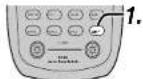
- Press MULTI on the multi room remote control from the MULTI ROOM.
(Press the AMP button and press the > button until PAGE4 is displayed. Press the MULTI (D1) button.)
This operations will put the SR7500 into multi room mode and "MULTI" will be illuminated on the display.
MULTI ROOM Video output will show OSD information for the MULTI ROOM setup.
| MULTI ROOM | |
| VIDEO: [IMAGE] | |
| AUDIO: FM 102.00 | |
| SLEEP TIMER: 90 min | |
| MULTI:OFF | MSPKR:OFF |
| VOL:VARI | VOL:VARI |
| LEVEL:-90dB | LEVEL:-90dB |
| ----MAIN-ROOM STATUS---- | |
| VIDEO:DVD | AUDIO:DVD |
| MAIN | EXIT |
- Press the VOL + or VOL - button on the multi room remote control to set the desired volume.
- In multi room mode, the multi room remote control can be used in the multiroom to operate the following functions.
General:
Controlling volume level, sleep timer, and muting. Selecting input audio and video source
Tuner:
Selecting band, controlling preset channel up and down, tuning up and down, direct frequency call.
Notes for the Multi Room System
- The MULTI ROOM OUT (MULTI OUT/MULTI SPEAKER) has analog outputs.
This does not support digital input signals. - If the Tuner (FM or AM) is active in the main room, you can not control any function of the tuner.
In this case, You must listen to the same station as the main room.
• The selected function name and USE are displayed in the LCD.
-
Press the desired operation buttons to play the selected component.
-
For details, refer to the component's user guide.
- It may not be possible to operate some models.
CONTROLLING A MARANTZ DVD PLAYER (DVD MODE)
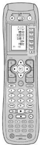
text_image
Scanned image of a mobile phone with Chinese text labels on the screen and keypad| SOURCE ON/OFF | Turns the DVD player on and off |
| POWER ON Turns | the DVD player on |
| POWER OFF Turns | the DVD player off |
| D1 - D5 =>Page() | Refer to page v/y |
| Cursor/OK Move the | cursor, enters the setting |
| MENU Calls up the | menu of DVD disc |
| 0-9 Input the numero | |
| MEMO Call up the | programming menu |
| CLEAR Clears the | putting |
| ▶ | Play |
| ◀◀ / ▶◀ | Skip forward or previous chapter/track |
| ■ | Stop |
| II | Pause |
CONTROLLING A MARANTZ CD PLAYER (CD MODE)
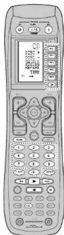
text_image
CD-ROM + 1200 + 1200 + 1200 + 1200 + 1200 + 1200 + 1200 + 1200 + 1200 + 1200 + 1200 + 1200 + 1200 + 1200 + 1200 + - - - - - - - - - - - - - - - - - - - - - - - - - - - - - - - - - - - - - - - - - - - - - - - - - - - - - - - - - - - - - - - - - - - - - - - - - - - - - - - - - - - - - - - - - - - - - - - -| SOURCE ON/OFF | Turns the CD player on and off |
| POWER ON Turns | the CD player on |
| POWER OFF Turns | the CD player off |
| D1 - D5 / (×)Page) (Refer to page vi) | |
| MENU Switches the | display information |
| 0-9 Input the numeric | |
| MEMO Programs | |
| CLEAR Clears the | Inputting |
| ▶ | Play |
| I←→I→I | Skip forward or previous track |
| ■ | Stop |
| III | Pause |
CONTROLLING A MARANTZ VCR (VCR MODE)

text_image
UCO TAXES SPX SUN STILL ESET 12.0| SOURCE ON/OFF | Turns the VCR on and off |
| D1 - D5 / >(Page) | (Reler to page vi) |
| MENU Call up the menu | |
| EXIT Exits the programming menu | |
| 0-3 Input the numerc | |
| ▶ | Play |
| |◀| / ▶ | Skip forward or previous track |
| ■ | Stop |
| || | Pause |
| ● | Record |
CONTROLLING A MARANTZ CD RECORDER (CDR MODE)
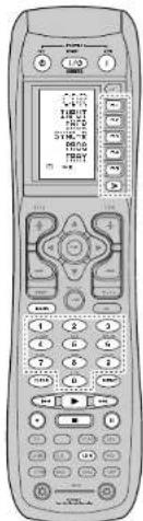
text_image
Front panel of a mobile phone with control buttons and display screen showing Chinese text| SOURCE ON/OFF | Turns the CD recorder on and off |
| POWER ON | Turns the CD recorder on |
| POWER OFF | Turns the CD recorder off |
| D1 - D5 / =>Page] | [Refer to page 6] |
| MENU | Switches the display information |
| 0-9 | Input the numeric |
| MEMO | Programs |
| CLEAR | Clears the inputting |
| ▶ | Play |
| ◀◀ / ▶◀ | Skip forward or previous track |
| ■ | Stop |
| || | Pause |
| ● | Record |
CONTROLLING A MARANTZ MD DECK (MD MODE)

text_image
REPORT SAMPLES DIRECT DIRECT SELECT| SOURCE ON/OFF | Turns the MD deck on and off |
| POWER ON | Turns the MD deck on |
| POWER OFF | Turns the MD deck off |
| D1 - D5 / (Page) | (Refer to page vt) |
| MENU | Switches the display information |
| 0-3 | Input the numeric |
| MEMO | Programs |
| CLEAR | Clears the Inputting |
| ▶ | Play |
| |◀/▶▶ | Skip forward or previous track |
| ■ | Stop |
| || | Pause |
| ● | Record |
CONTROLLING A MARANTZ TAPE DECK (TAPE MODE)
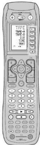
text_image
TIME TIME-TIME TIME-TIME TIME-TIME| SOURCE ON/OFF | Turns the TAPE deck on and off |
| POWER ON | Turns the TAPE deck on |
| POWER OFF | Turns the TAPE deck off |
| D1 - D5 / =>Page) | (Refer to page v) |
| 0-9 | Input the numeric |
| MEMO | Programs |
| CLEAR | Clears the inputting |
| ▶ | Play |
| ◀◀ / ▶◀ | Skip forward or previous track |
| ■ | Stop |
| II | Pause |
| ● | Record |
BASIC OPERATION
USE MODE
(Normal operation status)
This remote control is preset with a total of 12 types of remote codes, including Marantz TV (television), DVD, VCR (VCR deck), DSS (satellite broadcasting tuner), TUNER, CD, CD-R, MD, TAPE (tape deck), AUX1, AUX2, and AMP (amplifier).
Learning is not necessary for Marantz products. You can use these products without setting any codes.
1. Press the SOURCE button.
For this example, press DVD.
DVD is shown on the LCD, and the remote control is set for DVD.
Pressing the source button once changes the remote control to the settings for the source that was pressed.
To change the amplifier or other source, press the SOURCE button twice (double-click). The code is sent, and then the amplifier source changes to DVD.
2. Press the buttons to operate the DVD.
The indicator is shown on the LCD while the remote control codes are being transmitted. It is not displayed when buttons without stored code are pressed.
- The direct buttons can be used to perform up to 20 operations for each of the 12 sources, including DVD, TV, AMP, and other AV equipment.
The buttons consist of the D1 to D5 buttons, and the equipment is operated by pressing the buttons corresponding to the indicators on the LCD.
Four pages are available, and press the > button to select a page. The current page position is displayed on the LCD.
PRESET MODE
(When operating non-Marantz AV equipment products)
This remote control is preset with remote control codes from AV equipment by other manufacturers. The preset codes are TV, VCR, LD, CABLE, DSS, DVD, TAPE, TUNER, CD, CD-R, MD and AMP. Settings can be made in one of two ways.
When the preset codes are set, the following codes are contained in the source button of the remote control.
See the attached manufacturer number list for the preset manufacturers, devices, preset numbers, and other settings.
| Remote control Corresponding Device name | ||
| source name preset code | ||
| TV TV Television | ||
| DVD DVD DVD player | ||
| VCR VCR Video deck | ||
| DSS SATELLITE | Satellite broadcasting | |
| TUNER | RECEIVER/TUNER | AM FM TUNER |
| CD | CD/CD-R PLAYER | CD player |
| CD-R | CD/CD-R PLAYER | CD recorder |
| MD | CD/CD-R PLAYER | MD deck |
| TAPE | TAPE | Cassette clock |
| AUX1 | GABLE | Cable television |
| AUX2 | LASER DISC | Laser disc player |
| AMP | AMPLIFIER | Amplifier or receiver |
| RECEIVER/TUNER | ||
- When using Marantz products, TV and DVD can be set to TV1 (TV/VDP: Projector) and TV2 (PDP: Plasma display), and DVD1 (first DVD player) and DVD2 (second DVD player), respectively, to match the customer's operating environment. These settings are made in PRESET mode.
In the factory default state, the remote control is set to TV1 and DVD1. To make the presets, enter the numbers below while referring to the section "Entering and Setting the Manufacturer Number Directly".
TV1:0001, TV2:0002
DVD1:0001, DVD2:0002
Entering and Setting the Manufacturer Number Directly
Refer to the manufacturer number list. This example shows how to set a SAMSUNG DVD player.
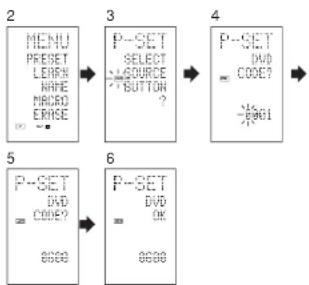
flowchart
graph LR
    A["2 MENU PRESET LEARN HAVE MICRO ERISE"] --> B["3 P-SET SELECT SOURCE BUTTON ?"]
    B --> C["4 P-SET DVD CODE? -1981"]
    C --> D["5 P-SET DVD CODE? 8688"]
    D --> E["6 P-SET DVD OK 8688"]
-
View the supplied manufacturer number list, and find the number of the manufacturer for the device that you are using.
-
Hold down the M button for three seconds or more.
The menu is displayed.
-
Press the D1 (PRESET) direct button. The Preset setting (P-SET) is displayed.
-
Press the DVD source button.
-
Press the numeric buttons to enter the four-digit manufacturer number.
Example: To enter "0600" from the manufacturer number list.
To correct the entered number, use the ◀ or ▶ cursor button to enter the correct number.
- If no button is pressed for over one minute during the setting process, any settings that were made are cancelled.
-
Press the OK cursor button.
-
Confirm the OK is displayed and then the display returns to the Preset Setting (P-SET). When the manufacturer number is entered correctly, OK is displayed momentarily on the screen.
- If you enter a number not in the manufacturer number list, WRONG CODE is displayed, and then you return to the preset setting again
Check the manufacturer number list, and either set a different number or use the sequence function to set.
-
To set the manufacturer number for another source device, repeat the procedure in steps 4 to 6.
-
After the settings are completed, press the M button.
-
Press the buttons on the remote control to check that the DVD can be operated correctly.
Setting Equipment Not Appearing in Manufacturer Number List
Use the sequence function to set equipment not appearing in the manufacturer number list. You may still be unable to set some equipment even when using the sequence function. In this case, the remote control can be programmed with codes individually.
In the sequence function, the power ON/OFF codes are transmitted by pressing the remote control buttons in order.
If the power for the equipment is left on, hold down the button until the equipment is turned off, and then release. This completes the setting.
This example shows how to set a DVD player.

flowchart
graph LR
    A["P-SET\nDUD\nCODE?"] --> B["P-SET\nDUD\nSEEK\n0550"]
    B --> C["P-SET\nDUD\nOK\n0560"]
- Turn on the power of the DVD player.
- Hold down the M button for three seconds or more.
The menu is displayed.
- Press the D1 (PRESET) direct button.
The Preset setting (P-SET) is displayed.
-
Press the DVD source button
-
Hold down the CH+ or CH- button for one second or more.
-
Press the CH+ button repeatedly in the interval for one second.
The signal is transmitted, and the display cycles through the code number.
Press the CH-button to go back to a number screen. 7. Release the button once the DVD player turns off.
-
Press the OK cursor button.
-
Confirm the OK is displayed and then the display returns to the Preset Setting (P-SET).
-
To set the manufacturer number for another source device, repeat the procedure in steps 4 to 8.
-
After the settings are completed, press the M button.
-
Press the buttons on the remote control to check that the DVD can be operated correctly.
Check the following points if the equipment which was set does not operate properly.
- If there is more than one number in the manufacturer number list, try setting a different number.
- There may be some buttons which cannot be used. Program the codes to the required buttons.
LEARN MODE
Programming the ▶(PLAY) and Other Control Buttons and Numeric Buttons
This remote control is capable of learning and storing codes used by other remote controls that you already own.
For codes which are not learned, the remote control will transmit either the Marantz preset codes from the initial settings, or remote codes from another manufacturer's AV equipment which is set by the customer.
The receiver sensor for the remote control signals is located at the top of the remote control.
This example shows how to learn the codes from the remote control of a DVD player.

flowchart
graph LR
    A["1: HINTU<br>PRESET<br>LEARN<br>LIFE<br>MACRO<br>ERASE"] --> B["2: TV<br>INPUT<br>LNT-CH<br>100S<br>DSD<br>CINERA"]
    B --> C["4: DVD<br>PLAY<br>HOW<br>LEARN"]
6 (When OK) (failed) (codes are full)
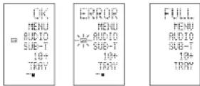
- Hold down the M button for three seconds or more. The menu is displayed.
- Press the D2 (LEARN) direct button. The LEARN setting (LEARN) is displayed. The LEARN indicator then blinks.
- Press the DVD source button.
- Press the ▶(PLAY) button.
The LEARN indicator blinks, and then displays to indicate that learning is ready. -
Place the receiver sensor of the remote control (top) so that it is facing the transmitter of the DVD remote control (top) at a distance of about 5 cm (2 inches).
-
Press and hold down the ▶(PLAY) button of the transmitting DVD remote control, and check that OK is displayed on the LCD. The remote control has finished learning when OK is displayed on the LCD.
If ERROR is displayed on the LCD, some error has prevented the command from being learned. If this happens, repeat the procedure for steps 4 and 5. In some rare cases, ERROR may be displayed repeatedly during the learning operation. In this case, the transmitting remote control may have special signal codes. These codes cannot be learned by this remote control.
-
Follow the same procedure to make the remote control learn the other buttons
-
Repeat the procedure in steps 3 to 6 to have the remote control learn the signal codes from a TV, CD player, or other AV equipment.
-
When no buttons are pressed for approximately one minute during the learning operation, the remote control automatically returns to USE mode.
-
When programming the source buttons, switch to the source in step 3, and then press the source button again.
-
When you have finished programming the codes for each button, press the M button. The USE indicator is displayed on the LCD, and the newly stored codes can be used.
- If FULL is displayed on the LCD, the memory cannot hold any more learned codes in LEARN mode.
If FULL is displayed no matter how many times you try the learning operation, the remote control cannot accept any more new codes until some of the previously learned codes are deleted from the memory. Delete some of the learned buttons from the sources.
The M button and > button cannot be taught. Only each one code can be learned for the LIGHT buttons 1 and 2, regardless of the source.
Programming the Direct Buttons and Rewriting Names
This example shows how to program codes from other manufacturer products to the DVD MENU button (D1) and change the display to OSD.

flowchart
graph LR
    A["6"] --> B["OK"]
    B --> C["RENU"]
    C --> D["AUDIO"]
    D --> E["SUB-1"]
    E --> F["10+"]
    F --> G["TRHY"]
    G --> H["■"]

    I["7"] --> J["OK"]
    J --> K["RENU"]
    K --> L["AUDIO"]
    L --> M["SUB-1"]
    M --> N["10+"]
    N --> O["TRHY"]
    O --> P["■"]

    Q["8"] --> R["OK"]
    R --> S["OSD"]
    S --> T["AUDIO"]
    T --> U["SUB-1"]
    U --> V["10+"]
    V --> W["TRHY"]
- Hold down the M button for three seconds or more.
The menu is displayed.
- Press the D2 (LEARN) direct button. The LEARN setting (LEARN) indicator is displayed. The LEARN indicator then blinks.
- Press the DVD source button. The first page of the direct button screen is displayed. There are four available pages. Pressing the > buttons cycles through the pages in this order 1 → 2 → 3 → 4 → 1.
- Press the D1 (MENU) direct button. The EARN indicator blinks, and then displays to indicate that learning is ready.
- Place the receiver sensor of the remote control (top) so that it is facing the transmitter of the DVD remote control (top) at a distance of about 5 cm (2 inches).
- Press and hold down the OSD button of the transmitting DVD remote control, and check that OK is displayed on the LCD.
The remote control has finished learning when OK is displayed on the LCD.
If ERROR is displayed on the LCD, some error has prevented the command from being learned. If this happens, repeat the procedure for steps 4 and 5.
- After learning is completed, the remote control automatically switches to name rewriting mode. The left end "": indicator on the MENU blinks to indicate that the blinking part can be rewritten.
- If no names will be rewritten, press the OK cursor button. The display returns to learning standby mode by pressing the OK cursor button.
- To change the name, press the numeric buttonsto enter the text.
- Use the cursor buttons ◀▶to move to the sections to be rewritten on the LCD.
• To change MENU to OSD, press the 5 numeric button.
Each time the button is pressed, the display cycles through M → N → O → 5 → M.
- After rewriting of the text is completed, press the OK cursor button.
To delete text that is already entered, press the 0 button to insert a space. - In this example, MENU is changed to "OSD (space) (space)" in this step, and then OSD is displayed in the right side by pressing the OK button.
For details, refer to the section "Rewriting Names". - In the same way, use the > button to select the page, and then press the direct button to program the codes.
- After programming the codes for each of the buttons, press the M button.
The USE indicator displays on the LCD, and the newly stored codes can be transmitted.
REWRITING NAMES
This remote control allows the rewriting of names for the sources and direct buttons. This operation is performed for each individual source.
This example shows how to change the source name from DVD to AVD and AUDIO to SOUND.

flowchart
graph LR
    A["3: DVD"] --> B["4: Digital"]
    B --> C["5: Audio"]

flowchart
graph LR
    A["7"] --> B["8"]
    B --> C["9"]
    C --> D["10+"]
    D --> E["TRAY"]
    style A fill:#f9f,stroke:#333
    style B fill:#f9f,stroke:#333
    style C fill:#f9f,stroke:#333
    style D fill:#f9f,stroke:#333
    style E fill:#f9f,stroke:#333
- Hold down the M button for three seconds or more.
The menu is displayed. -
Press the D3 (NAME) direct button
-
Press the DVD source button.
The NAME indicator blinks.
The '*' blinks to indicate that the letter can be changed. - Press the ▶cursor button twice.
The D in DVD blinks to indicate that the letter can be changed. - Press the 1 numeric button to select A.
Each time the numeric buttons are pressed, the button cycles through the alphanumeric characters shown below.
1: A → B → C → 1 → A
2: D → E → F → 2 → D
3: G > H > I > 3 > G - J K L 4 J 5. M + N + O + S + N
- M → N → O → S → M
-
P → O → B → 6 → P
7: S → T → II → Z → S
8: V → W → X → 8 → V
9: Y → Z → / → 9 → Y
0: SPACE (") → + → — → , →' → < → > → ? → 0 → SPACE (") -
Press the ◀ or ▶ursor button .
The letter is changed to "A".
- The ▲ and cursor buttons can be used to move the blinking indicator of the section to be rewritten.
-
Press the ▲or ▼cursor buttons to select AUDIO on the direct button indicator. The A flashes to indicate that the name can be changed.
-
Press the 7 numeric button to select S.
Each time the button is pressed, the button cycles through S → T → U → 7 → S.
-
Press the ▶cursor button to move the flashing section.
-
Press the 5 numeric button to select O.
-
Follow the same procedure to enter U, N, and D.
-
When finished entering the text, press the OK cursor button.
-
Press the M button.
The USE indicator displays on the LCD, and the
newly stored codes can be used.
The input is overwritten, and so the currently displayed text is erased.
Up to six characters can be entered for the direct button indicator.
ERASING PROGRAMMED CODES (RETURNING TO INITIAL SETTINGS)
Codes can be erased in five ways: by buttons, direct buttons, direct button pages, sources, and by all memory contents.
Erasing Buttons and Erasing Direct Buttons
This example shows how to erase the code learned from the PLAY button of the DVD player and the AUTO code of the AMP direct button.
Erasing buttons
| 1 | MENU PRESET LEIRS WRITE RHOOD ERASE | → | 3 | DVD MENU GND TO SUB-T LED TRY | → | ERASE CORE? YES NO |
- Hold down the M button for three seconds or more.
The menu is displayed. - Press the D5 (ERASE) direct button.
- Press the DVD source button.
The USE and LEARN indicators blink. - Press the button ▶(PLAY) that you want to erase while holding down the CLEAR button. A message is displayed on the LCD.
- Press the D4 (YES) direct button to erase. The code programmed to the ▶(PLAY) button is erased.
When the code is cleared, the code for this button
resets to the factory default code or becomes blank.
• To cancel the erasing operation, press the
D5 (NO) button to return to the previous display.
To erase codes programmed for the CLEAR button, simply press the CLEAR button twice.
To erase codes programmed for the SOURCE button, simply press the SOURCE button twice.
Erasing direct buttons
| 6PHPAUTODTSEX/ESDIRECT | → | 8ERASEAUTODTSEN/ESDIRECT | → | 9ERASECODE?YESNO |
- Press the AMP source button
- Press the > button to display the first page for AMP.
- Press the D1 (AUTO) direct button to be erased while holding down the CLEAR button
- Press the D4 (YES) direct button to erase.
The code programmed to the AUTO button is erased.
When the code is cleared, the code for this button resets to the factory default code or becomes blank. The rewritten name returns to the original name.
• To cancel the erasing operation, press the D5 (NO) button to return to the previous screen. - When the erasing operation is finished, press the M button.
The USE Indicator displays to indicate that the remote control can now be operated.
Erasing Direct Button Pages
This example shows how to erase the entire direct button second page learned from the DVD player.
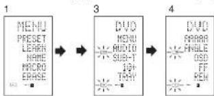
flowchart
graph LR
    A["1 MENU PRESET LEARN NAME MICRO EASE"] --> B["3 DVD MENU AUDIO SUB-1 10+ THY"]
    B --> C["4 DVD ARAB FNDLE OSB FF REM"]

- Hold down the M button for three seconds or more.
The menu is displayed. - Press the D5 (ERASE) direct button
- Press the DVD source button.
The USE and LEARN indicators blink. - Press the > button to display the second page.
-
Press the > button while holding down the CLEAR button.
-
Press the D4 (YES) direct button to erase. All codes and names programmed to page 2 are erased. When the codes are cleared, the codes for this button reset to the factory default code or become blank. Any rewritten names return to the original name.
-
To cancel the erasing operation, press the D5 (NO) button to return to the previous screen.
-
When the erasing operation is finished, press the M button.
The USE indicator lights up to indicate that the remote control can now be operated.
Erasing Sources
This procedure clears all codes and names programmed to the DVD, TV, or other sources. All codes and names in the four direct button pages are also erased.
This example shows how to erase the names and codes learned from the DVD player.
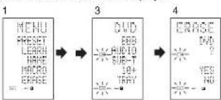
flowchart
graph LR
    A["1 MENU"] --> B["3 DWORD"]
    B --> C["4 END"]
    style A fill:#f9f,stroke:#333
    style B fill:#ccf,stroke:#333
    style C fill:#cfc,stroke:#333
- Hold down the M button for three seconds or more.
The menu is displayed.
-
Press the D5 (ERASE) direct button.
-
Press the DVD source button
The USE and LEARN indicators blink.
-
Press the DVD source button while holding down the CLEAR button.
-
Press the D4 (YES) direct button to erase. All codes and names programmed to the DVD source are erased. When the codes are cleared, the codes for this button reset to the factory default code or become blank. Any rewritten names return to the original name.
• To cancel the erasing operation, press the D5 (NO) button to return to the previous display.
- When the erasing operation is finished, press the M button.
The USE indicator displays to indicate that the remote control can now be operated.
Erasing All
This procedure clears (resets) all programmed codes and names. Once all the data is cleared, the memory is returned to the factory default status. The programmed macros are also erased.
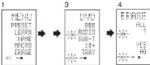
flowchart
graph LR
    A["MENU"] --> B["DVD"]
    C["PRESET"] --> B
    D["LEARN"] --> B
    E["NAME"] --> B
    F["MACRO"] --> B
    G["ERASE"] --> B
    B --> H["ERASE ALL ?"]
    B --> I["BUDI"]
    B --> J["SUB-T"]
    B --> K["18+"]
    B --> L["TRAY"]
    B --> M["?"]
    B --> N["?"]
    B --> O["?"]
- Hold down the M button for three seconds or more.
The menu is displayed. 2. Press the D5 (ERASE) direct button. The LRS and UVRS indicators blink
-
Press the CLEAR button while holding down the POWER ON and OFF buttons at the same time.
-
Press the D4 (YES) direct button to erase. All programmed codes and names are erased and reset to the factory default settings.
-
To cancel the erasing operation, press the D5 (NO) button to return to the previous screen.
• To erase all operation takes a few seconds after the D4 (YES) button is pressed.
PROGRAMMING MACROS
This remote control can program a series of button operations in sequence.
Macros are a function that makes it possible to use a single button operation to perform a complex series of button operations any number of times. A single button can be programmed to perform up to 20 steps in sequence. A total of 20 buttons can be programmed with macros.
- For example, the following sequence of operations can be programmed to a macro. Switch amplifier to DVD source → Set amplifier mode to AUTO → Play DVD player → Switch TV to video input
The factory default for the transmission interval (time) between macro operations is one second, but these signal transmission intervals can be set between approximately 0.5 seconds and 5 seconds in the Setup mode. Each transmission interval can be adjusted independently when programming or revising a macro.
Note:
- If the signal transmission interval (interval time) is changed using the Setup mode (described later), this transmission interval is applied to all macro programs. To change individual signal transmission intervals, use the procedures in this section for programming macros and revising macros.
- No signals are transmitted while programming a macro.
- The M button, > button, cursor buttons, MEMO button, CLEAR button, and VOL buttons cannot be programmed.
- If no button is pressed for approximately one minute during programming, the remote control returns to the state before macro mode. In this case, the macro program is not stored.
- When executing macro mode, performing the source switching operation two or more times only changes the remote control mode and does not transmit any signals. (Switching of the source selector of the amplifier is valid only once.)
PROGRAMMING MACROS
This example shows how to program a macro to the M-01 button.
(The screens shown in the example are the default factory states. If the names of direct buttons were rewritten, these modified names would be displayed.)
Switch amplifier to DVD source → Play DVD player → Set the interval to 2 seconds until the next signal is sent → Switch TV to video input → Set the amplifier mode to AUTO

text_image
1 PRESET LEARN NAME MACRO ERASE 2 MACRO M-01 M-02 M-03 M-04 M-05 3 MACRO M-01 M-02 M-03 M-04 M-05 3 MACRO M-01 M-02 M-03 M-04 M-05 3 EDITION ?? NAME EDIT- Hold down the M button for three seconds or more.
The menu is displayed.
2. Press the D4 (MACRO) direct button.
The macro menu is displayed.
The MACRO indicator displays and LEARN blinks.
3. Press the D1 (M-01) direct button.
The menu has four pages, and so use the > button to select the page when programming other buttons.
- Press the buttons in the sequence that you want the operations performed.
The actual program starts here.
Each time a button is pressed, the name of the button is displayed on the LCD.
4-1 4-2 4-3
| DVDMENU/ SUB-T= 18+TRAY- n | PLAY MENU/ SUB-T= 19+TRAY- n | TIME= 2.0= SEC/ CANCEL- n |
4-1. Press the DVD source button.
4-2. Press the ▶(PLAY) button
4-3. Press the ▲ or ▼ cursor buttons
The interval time is displayed on the LCD.
4-4. Press the ▲ or ▼ cursor buttons and set to 2.0 (seconds).
- Use the ▲cursor button to increase the time and the ▼button to decrease the time. The interval time can be set from 0.5 seconds to 5 seconds.
• To stop the time adjustment, press the D5 (CANCEL) direct button.
4-5. Press the OK cursor button
4-6. Press the TV source button
4-7. Press the > button to display the first page.
4-8. Press the D1 (INPUT) direct button.
4-9. Press the AMP source button
4-10. Press the > button to display the first page.
4-11. Press the D1 (AUTO) direct button.
4-12. Press the OK cursor button
The LCD displays END to indicate that programming is completed.
-
To program another macro, repeat the procedure in steps 3 to 4-12.
-
To exit macro programming, press the M button.
The USE indicator displays to indicate that the remote control can now be operated.
When the macro are programmed 20 operations or more, the display returns macro menu.
Edit the macro so that it has 20 operations or less.
EXECUTING MACRO PROGRAMS
| 1 | MACRON=01N=02N=03N=04N=05- | → | 2 | DVD□□□□□□ | → | PLAY□□□□□ |
- Press the M button shortly. The macro menu is displayed.
- Press the D1 (M-01) direct button
- Check that the operations of the program are executed step by step.
The name of the operation button is displayed on the LCD. - The programmed section is indicated by . The bar indicator moves to indicate the progress of the program.
Select DVD source → PLAY transmit → Interval time: 2 seconds → Select TV → TV INPUT transmit → Select AMP → AUTO transmit → End
• To cancel transmission of the program while it is in progress, press any button.
CHANGING NAMES OF MACRO PROGRAMS
Under the factory default settings, the names of the macro programs are set from M-01 to M-20, but you can change them to any desired name.
The text can have up to six characters, and it is entered using the numeric buttons.
This example shows how to change the M-01 name to MOVIE.

flowchart
graph LR
    A["1 MENU PROSET LERN HARE PHORU GRASE"] --> B["2 MACRO N-01 H-02 H-03 H-04 H-05"]
    B --> C["3 MACRO N-01 BUTTON HARE EDIT"]
    C --> D["4 NAME N-01"]
    D --> E["5 NAME N-01"]
    E --> F["6 NAME N-01"]
- Hold down the M button for three seconds or more.
The menu is displayed.
- Press the D4 (MACRO) direct button. The macro menu is displayed. The MACRO indicator displays and LEARN blinks.
- Press the D1 (M-01) direct button The NAME is displayed.
- Press the D3 (NAME) direct button. The “...” blinks to indicate that rewriting is possible.
- Press the 5 numeric button to select M.
- Press the ▶cursor button to next. The “ ^12 ” blinks to indicate that rewriting is possible.
- Press the 5 numeric button to select O.
- Repeat steps 6 and 7, and then enter V, I, E and ^** (space)".
- To make changes in the text while entering it, use the ◀ or ▶ursor buttons to move to the blinking section.
- After making the changes, press the OK cursor button.
• To change the names of other macro programs, repeat the procedure in steps 3 to 9. - To exit, press the M button.
ERASING STEPS OF MACRO PROGRAMS
This example shows how to delete the TV and INPUT steps from the following macro programmed to M-01.
The program is changed from
DVD → PLAY → TIME → TV → INPUT → AMP → AUTO
to DVD → PLAY → TIME → AMP → AUTO.
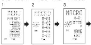
flowchart
graph LR
    A["1 MENU<br>PRESET<br>LEARN<br>HOME<br>MACRO<br>ORASE"] --> B["2 MACRO<br>R-B1<br>R-B2<br>R-B3<br>R-B4<br>R-B5"]
    B --> C["3 MACRO<br>R-B1<br>R-BUTTON<br>R-N<br>HOME<br>EDIT"]
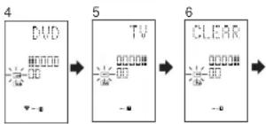
flowchart
graph LR
    A["DUD"] --> B["TV"]
    B --> C["CLEAR"]
-
Hold down the M button for three seconds or more. The menu is displayed.
-
Press the D4 (MACRO) direct button. The macro menu is displayed. The MACRO indicator displays and LEARN blinks.
- Press the D1 (M-01) direct button.
- Press the D5 (EDIT) direct button.
The LCD displays DVD, and the step position is indicated by ■.
The programmed section is indicated by □. - Press the ▶cursor button to display TV.
- Press the CLEAR button
The LCD displays CLEAR, and TV and INPUT are deleted.
When deleting steps from a macro program, the operations performed for a source after switching to the source are also deleted.
If the CLEAR button is pressed at the INPUT position, only the INPUT step is deleted.
The □ indicator for the step is also changed. - To check the modified steps, press the or ▶cursor button.
- To exit, press the M button.
When finished, to change another macro program, press the OK cursor button to return to the menu, and then repeat the procedure for steps 3 to 6.
OVERWRITING STEPS IN MACRO PROGRAMS
This example shows how to change the macro programmed to M-01 from
DVD → PLAY → AMP → AUTO
to
DVD → PLAY → TV → INPUT.
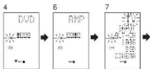
flowchart
graph LR
    A["4"] --> B["6"]
    B --> C["7"]
- Hold down the M button for three seconds or more.
The menu is displayed. - Press the D4 (MACRO) direct button.
The macro menu is displayed. The MACRC Indicator displays and LEARN blinks. - Press the D1 (M-01) direct button.
- Press the D5 (EDIT) direct button.
The LCD displays DVD, and the step position is indicated by ■.
The programmed section is indicated by □. - Press the ▶cursor button so that AMP is displayed.
-
Press the TV source button.
TV blinks for 0.5 seconds. -
Press the D1 (INPUT) direct button. INPUT blinks for 0.5 seconds. TV and INPUT are overwritten.
- To check the modified steps, press the or ▶cursor button.
- To exit, press the M button.
When finished, to change another macro program, press the OK cursor button to return to the menu, and then repeat the procedure for steps 3 to 8.
INSERTING STEPS IN MACRO PROGRAMS
This example shows how to change the macro programmed to M-01 from
DVD → PLAY → AMP → AUTO
to
DVD → PLAY → TV → INPUT → AMP → AUTO
4

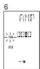
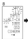
- Hold down the M button for three seconds or more.
The menu is displayed.
- Press the D4 (MACRO) direct button.
The macro menu is displayed.
The MACRO indicator displays and LEARN blinks.
-
Press the D1 (M-01) direct button
-
Press the D5 (EDIT) direct button
The LCD displays DVD, and the step position is indicated by ■.
The programmed section is indicated by □.
-
Press the ▶cursor button so that AMP is displayed.
-
Press the MEMO button.
-
Press the TV source button.
TV blinks for 0.5 seconds
- Press the D1 (INPUT) direct button.
INPUT blinks for 0.5 seconds.
TV and INPUT are inserted.
- Press the OK cursor button
- To check the modified steps, press the or ▶cursor button.
- To exit, press the M button.
When finished, to change another macro program, press the OK cursor button to return to the menu, and then repeal the procedure for steps 3 to 9.
CLEARING MACRO PROGRAMS
When clearing macros, the macros programmed to the button are erased. Modified macro names are also returned to the factory default settings. This example shows how to clear a macro with the name MOVIE programmed to M-02.

flowchart
graph LR
    A["1"] --> B["4"]
    B --> C["5"]
    A --> D["MACRO\nH-01\nMOVIE\nH-03\n= H-04\nH-05\n→"]
    B --> E["MACRO\nMOVIE\nCLEAR\n→ YES\nNO\n→"]
    C --> F["MACRO\nH-01\nH-02\n= H-03\n= H-04\nH-05\n→"]
-
Press the M button for three second or more. The macro menu is displayed
-
Press the D4 (MACBO) direct button
The macro menu is displayed.
-
Press the D2 (MOVIE) direct button while holding down the CLEAR button.
-
Press the D4 (YES) direct button to clear the macro. To cancel the clearing operation, press the NO (D5 button).
-
To exit, press the M button.
When finished, to change another macro program, press the OK cursor button to return to the menu, and then repeat the procedure for steps 2 to 4.
SETTING THE MACRO TIMER
Setting the macro timer enables the macro program to automatically turn the power for a device on or off or perform other operations.
In the settings, you can select to execute the macro timer everyday or only once.
Be sure to set the clock to the correct time before using the timer. The macro timer can only be set for one program a day.
This example shows how to use the timer only once at 20:35 to execute a macro programmed to M-01.

flowchart
graph LR
    A["TIMER\nDAILY\nOKEE"] --> B["M-TMR\nM-01\nM-02\nM-03\nM-04\nM-05"]
    B --> C["M-01\nTIMER\SET"]
    C --> D["ONCE"]
    D --> E["M-01\nTIMER\SET"]
    E --> F["ONCE"]
    F --> G["M-01\nTIMER\SET"]
    G --> H["ONCE"]
- Hold down the M button for three seconds or more.
The menu is displayed. - Press the > button to display the third page TIMER menu.
- Press the D2 (ONCE?) direct button. The M-TMR menu is displayed on the LCD. • To cancel timer operation, press CANCEL.
- Press the D1 (M-01) direct button
The time which is set previously is displayed. - Press the 2 and 0 numeric button to set the hour indicator to 20.
- Press the 3 and 5 numeric button to set the minute indicator to 35.
- Press the OK cursor button. This finalizes the time.
- To exit, press the M button. To cancel the macro timer, return to the TIMER menu and press the D5 (CANCEL) and then press D1 (M-01).
EXECUTING THE MACRO TIMER
The macro program starts when the time that was set is reached. The TIMER Indicator lights up whenever the macro timer is activated.
Note:
• To execute the macro timer, place the remote control facing the infrared sensor of the device to be operated. If the remote control is not in a suitable position, it may not operate the device properly.
CLONE MODE
CREATING COPIES USING CLONE MODE
All of the codes programmed to the RC8500SR remote control can be copied to another RC8500SR using a few simple operations.
- The remote control can copy the entire contents or the contents for specific source buttons.
- When copying the entire contents, all programmed codes, modified names, programmed macros, and signal transmission intervals are copied.
When copying the contents for source buttons, the programmed codes and modified names are copied.
Note:
- The clone function can only be used for copying when using the same model (RC8500SR) for both the transmitting and receiving remote control.
COPYING ENTIRE CONTENTS
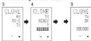
flowchart
graph LR
    A["3\nCLOSE RX RX-S TX"] --> B["4\nCLOSE TX READY ?"]
    B --> C["9\nCLOSE TX OK\nOK\nOK"]
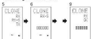
flowchart
graph LR
    A["CLONE\nRX\nRX-S\nTX"] --> B["→"]
    B --> C["CLONE\nRX-S\n000000\n→"]
    C --> D["→"]
    D --> E[CLONE\nRX\CK\n■■■■■■■■■■■■■■■■■■■■■■■■■■■■■■■■■■■■■■■■■■■■■■■■■■■■■■■■■■■■■■■■■■■■■■■■■■■■■■■■■■■■■■■■■■■■■■■■■■■■
- Place the receiver sensor of the receiving remote control (top) so that it is facing the transmitter of the transmitting remote control (top) at a distance of about 5 cm (2 inches).
- Hold down the M button of the transmitting remote control for three seconds or more. The menu is displayed.
- Press the > button to display the fourth page CLONE menu.
- Press the D3 (TX) direct button. The transmitting side is now ready.
- Hold down the M button of the receiving remote control for three seconds or more. The menu is displayed.
- Press the > button to display the fourth page CLONE menu.
- Press the D1 (RX) direct button. The receiving side is now ready.
- Press the OK cursor button on the receiving remote control.
- Press the OK cursor button on the transmitting remote control.
When copying is started, the bar indicators on both LCDs start to move from the left to the right. - When the copying operation is completed, TX OK is displayed on the LCD of the transmitting remote control, and RX OK is displayed on the LCD of the receiving remote control.
- Do not touch either of the remote controls during the copying operation. Doing so could cause copying to fail.
- If the copying fails in the middle of the copying process, RX ERROR is displayed on the receiving remote control. Check and perform steps 1 to 7 again.
- Copying takes about three minutes to complete when the transmitting remote control has been programmed to 100% capacity.
- Once copying is completed, press the M button on both remote controls.
COPYING BY SOURCE
The 12 sources can be copied on a source by source basis. You can select from up to 12 source types.
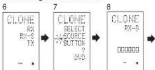
flowchart
graph LR
    A["CLONE RX-RX-S TX"] --> B["CLONE SELECT SOURCE BUTTON ?"]
    B --> C["CLONE RX-S D00000"]
-
Place the receiver sensor of the receiving remote control (top) so that it is facing the transmitter of the transmitting remote control (top) at a distance of about 5 cm (2 inches).
-
Hold down the M button of the transmitting remote control for three seconds or more. The menu is displayed.
-
Press the > button to display the fourth page CLONE menu.
-
Press the D3 (TX) direct button. The transmitting side is now ready.
-
Hold down the M button of the receiving remote control for three seconds or more.
-
Press the > button to display the fourth page CLONE menu.
-
Press the D2 (RX-S) direct button.
- Press the source button to be copied. The receiving side is now ready.
The name of the source which was pressed is displayed on the LCD.
• Each time the source button is pressed, the name is displayed on the LCD.
-
Press the OK cursor button on the receiving remote control.
-
Press the OK cursor button on the transmitting remote control. When copying is started, the bar indicators on both LCDs start to move from the left to the right.
-
When the copying operation is completed, TX OK is displayed on the LCD of the transmitting remote control, and RX OK is displayed on the LCD of the receiving remote control.
- Do not touch either of the remote controls during the copying operation. Doing so could cause copying to fail.
- If the copying fails in the middle of the copying process, ERROR is displayed on the remote control.
Check and perform steps 1 to 7 again.
- Once copying is completed, press the M button on both remote controls.
SETUP
SETTING THE LIGHTING TIME
- The LCD lights up when the LIGHT buttons are pressed. The LCD remains lit while the pressed button is held down, and it goes off when the button is released.
- The LCD continues to light up if another button is pressed while it is lit or if pressed within two seconds after the light goes off.
- The lighting time can be set in one-second units from 0 to 60 seconds.
The LIGHT buttons have light-absorbing properties that enable them to store light. If the buttons are no longer illuminated in a dimly lit environment, bring the buttons near a fluorescent lamp or other light source for a sufficient amount of time. This should illuminate the buttons again.
- The LIGHT buttons consist of a LIGHT1 and LIGHT2 button, and they both perform the same operation.
The factory default lighting time is set to 15 seconds.
This example shows how to set the lighting time to 20 seconds.

flowchart
graph LR
    A["SETUP LIGHT 1-TIME CONT CLOCK"] --> B["LIGHT TIME 15/SEC ?"]
    B --> C["LIGHT TIME 28/SEC ?"]
- Hold down the M button for three seconds or more.
The menu is displayed.
-
Press the > button to display the second page SETUP menu.
-
Press the D1 (LIGHT) direct button.
The LIGHT is displayed on the LCD
-
Press the ▲ or ▼ cursor button to set the lighting time.
-
Press the OK cursor button to enter the lighting time.
- Once the setting is finished, press the M button.
SETTING THE MACRO INTERVAL TIME
When a macro program is executed, control signals are transmitted in sequence. This transmission interval (interval time) can be set in 0.5-seconds units from 0.5 to 5 seconds. If the interval time is set in this Setup mode, the interval times for all programmed macros are changed. If necessary, use EDIT (see page 43) in the macro program to change the individual transmission times.
The factory default setting for the transmission interval is 1 second.
This example shows how to set the interval time to 5 seconds.
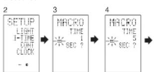
flowchart
graph LR
    A["SETUP<br>LIGHT<br>1-TIME<br>CONT<br>CLOCK<br>-"] --> B["MACRO<br>TIME<br>1<br>SEC ?"]
    B --> C["MACRO<br>TIME<br>5<br>SEC ?"]
- Hold down the M button for three seconds or more. The menu is displayed.
- Press the > button to display the second page SETUP menu.
- Press the D2 (I-TIME) direct button.
- Press the ▲or ▼cursor button to set the interval time. Holding down the cursor button fast-forwards the time indicator.
- Press the OK cursor button to enter the interval time.
- Once the setting is finished, press the M button.
ADJUSTING THE DISPLAY CONTRAST
The contrast of the LCD can be adjusted. Adjust for maximum visibility according to your viewing environment.
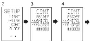
flowchart
graph LR
    A["SETUP<br>LIGHT<br>1-TIME<br>CONT<br>CLOCK"] --> B["CONT<br>ABCDEF<br>ASHLJKL<br>HNDPOR<br>#####000"]
    B --> C["CONT<br>ABCDEF<br>ASHLJKL<br>HNDPOR<br>#####000"]
- Hold down the M button for three seconds or more.
The menu is displayed. - Press the > button to display the second page SETUP menu.
- Press the D3 (CONT) direct button.
- Press the ▲ or ▼ cursor button and set the display contrast for maximum visibility.
The adjustment has 10 levels.
The factory default setting for the contrast is the fifth level. - Press the OK cursor button to enter the display contrast.
- Once the setting is finished, press the M button.
TROUBLESHOOTING
In case of trouble, check the following before calling for service:
- Are the connections made properly?
- Are you operating the unit properly following the user's guide?
- Are the power amplifiers and speaker working properly?
If the unit does not operate properly, check items shown in the following table.
If your trouble cannot be recovered with the remedy actions listed in the following table, malfunction of the internal circuitry is suspected; immediately unplug the power cable and contact your dealer, nearest Marantz authorized dealer or the Marantz Service Center in your country.
| SYMPTOM | CAUSE | REMEDY |
| SR7500 cannot be turned up. | The power plug is not connected. | Connect the power plug to the outlet. |
| No sound and picture are output even when power is on. | Mute is on. | Cancel mute using the remote control unit. |
| The input cable is not connected correctly. | See the connection diagram and connect the cables correctly. | |
| The master volume control is turned all the way down. | Adjust the master volume. | |
| The function selector position is wrong. | Select correct position. | |
| No speaker output. | The headphones are connected to the headphone jack. | Disconnect the headphones. (Speakers will not output sound when headphones are connected.) |
| Incorrect Audio or Video for selected source. | Input cable connected incorrectly. | Connect the cable correctly by referring to the connection diagram. |
| Incorrect Audio from a channel. | Speaker cable connected incorrectly. | Connect the cable correctly by referring to the connection diagram. |
| No Audio output from the center channel speaker. | The center speaker cable connection is incomplete. | Connect the cable correctly. |
| STEREO has been selected for Surround mode. | When STEREO is selected for Surround mode, no sound will be output from the center speaker. Set another Surround mode. | |
| Center = NONE has been selected in SETUP mode. | Make the correct setting. | |
| No Audio output from the surround speakers. | The surround speaker cable connection is incomplete. | Connect the cable correctly. |
| STEREO has been selected for Surround mode. | When STEREO has been selected for Surround mode, no sound will be output from the surround speaker. Set another Surround mode. | |
| Surround = NONE has been selected in SETUP mode. | Make the correct setting. | |
| No Audio output from the surround back speakers. | The surround back speaker cable connection is incomplete. | Connect the cable correctly. |
| Surround mode is not EX/ES mode. | Set surround mode EX/ES. | |
| Surround back = NONE has been selected in SPEAKERS SIZE SETUP | Make the correct setting. |
| SYMPTOM | CAUSE | REMEDY |
| Can not select EX/ES mode. | Surround center= NONE has been selected in SPEAKERS SIZE SETUP | Make the correct setting. |
| Input signal is Incompatible. | Use 5.1channel source. | |
| Can not select Pro Logic Tlx mode. | Input signal is Incompatible. | Use 2 channel Dolby Digital input signal, PCM input signal or analog input signal. |
| Can not select Neo:6 mode. | Input signal is incompatible. | Use 2 channel Dolby Digital input signal, PCM input signal or analog input signal. |
| Can not select CSII mode. | Input signal is incompatible. | Use 2 channel Dolby Digital input signal, PCM input signal or analog input signal. |
| No output to Subwoofer Out. | Subwoofer = NONE has been selected in SETUP mode. | Select Subwoofer = YES. |
| Noise is produced during DTS-encoded CD or laser disc play. | Analog has been selected for input. | Be sure to perform digital connection, select digital input, then play. |
| A specific channel does not produce output. | Nothing recorded on source. | Check the encoded channel on the source side. |
| FM or AM reception fails. | Antenna connection is incomplete. | Correctly connect the indoor FM and AM antennas to FM and AM antenna outlets. |
| Noise is heard during AM reception. | Reception is affected by other electrical fields. | Try changing location where the AM Indoor antenna is set up. |
| Noise is heard during FM reception. | The radio waves from the broadcasting station are weak. | Install an FM outdoor antenna. |
| Cannot get programmed station when the PRESET button is pressed. | Preset data has been erased. | Disconnecting power plug for long periods of time will erase preset data. If that happens, input the preset data again. |
| Control with the remote control unit fails. | Batteries are consumed. | Replace all the batteries with new ones. |
| Remote controller's function-key setting is wrong. | Select different position from which equipment will be controlled. | |
| The distance between this SR7500 and the remote commander is too far. | Move closer to this SR7500. | |
| Something is blocking SR7500 and the remote commander. | Remove offending object. | |
| MRAC is not working. | Headphones are connected. | Disconnect the headphones. |
Note:
- After "PROTECT" appears on the unit's display, the standby indicator may start flashing. If it does, there is a problem in the unit or the connection. If this problem reoccurs even when power is activated from the remote control unit, call for servicing.
GENERAL MALFUNCTION
If the equipment malfunctions, this may be because an electrostatic discharge or AC line interference has corrupted the information in the equipment memory circuits. Therefore:
- disconnect the plug from the AC line supply
- after waiting at least three minutes, reconnect the plug to the AC line supply
- re-attempt to operate the equipment
Memory backup
- In case a power outage occurs or the power cord is accidentally unplugged, the SR7500 is equipped with a backup function to prevent memory data such as the preset memory from being erased.
HOW TO RESET THE UNIT

text_image
Front panel of a vintage analog oscilloscope with display, control knobs, and rotary buttonsShould the operation or display seem to be abnormal, reset the unit with the following procedure.
The SR7500 is turned on, press and hold the MULTI + SPEAKERS A/B buttons simultaneously for 3 seconds or more.
Remember that the procedure will reset the settings of the function selector. Surround mode, delay time, TUNER PRESET etc., to their initial settings.
TECHNICAL SPECIFICATIONS
FM TUNER SECTION
| Frequency Range | 87.5 - 108.0 MHz |
| Usable Sensitivity | IHF 1.8 μV/16.4 dB |
| Signal to Noise Ratio | Mono:Stereo 75/70 dB |
| Distortion | Mono:Stereo 0.2/0.3 % |
| Stereo Separation | 1 kHz 45 dB |
| Alternate Channel Selectivity | ±300 kHz 60 dB |
| Image Rejection | 98 MHz 70 dB |
| Tuner Output Level | 1 kHz, ±75 kHz Dev 800 mV |
AM TUNER SECTION
| Frequency Range | 531 - 1602 kHz |
| Signal to Noise Ratio | 50 dB |
| Usable Sensitivity | Loop 40QμV |
| Distortion | 400Hz, 30 % Mod. 0.5 % |
| Selectivity | ±20 kHz 70 dB |
AUDIO SECTION
SR7500
| Power Output (20 Hz - 20 kHz/THD=0.08%) | |
| Front L&R | 8 ohms 105 W / Ch |
| Center | 8 ohms 105 W / Ch |
| Surround L&R | 8 ohms 105 W / Ch |
| Surround Back L&R | 8 ohms 105 W / Ch |
| Front L&R | 6 ohms 135 W / Ch |
| Center | 6 ohms 135 W / Ch |
| Surround L&R | 6 ohms 135 W / Ch |
| Surround Back L&R | 6 ohms 135 W / Ch |
SR8500
| Power Output (20 Hz - 20 kHz/THD=0.08%) | |
| Front L&R | 8 ohms 125 W / Ch |
| Center | 8 ohms 125 W / Ch |
| Surround L&R | 8 ohms 125 W / Ch |
| Surround Back L&R | 8 ohms 125 W / Ch |
| Front L&R | 6 ohms 160 W / Ch |
| Center | 6 ohms 160 W / Ch |
| Surround L&R | 6 ohms 160 W / Ch |
| Surround Back L&R | 6 ohms 160 W / Ch |
Input Sensitivity/Impedance .... 168 mV; 47 Kohms Signal to Noise Ratio/Analog Input / Pure Direct) .... 105 dB Frequency Response
(Analog Input / Pure Direct)
8 Hz - 100 kHz (±3 dB)
(Digital Input: 96 kHz PCM) 8 Hz - 45 kHz (±3 dB)
VIDEO
| Television Format | NTSC/PAL |
| Input Level/Impedance | 1 Vp-p/75 ohms |
| Output Level/Impedance | 1 Vp-p/75 ohms |
| Video Frequency Response | 5 Hz to 8 MHz (-1 dB) |
| Video Frequency (Component) | 5 Hz to 80 MHz (-1 dB) |
| S/N | 60 dB |
GENERAL
| Power Requirement | AC 230 V 50 Hz |
| Power Consumption | 600 W(SR7500) |
| 620 W(SR8500) | |
| Weight | 14.8 Kg (SR7500) |
| 15.0 kg (SR8500) |
ACCESSORIES
| Remote Control Unit RC8500SR | 1 |
| Microphone MC-10 | 1 |
| AAA-size batteries | 3 |
| FM Antenna | 1 |
| AM Loop Antenna | 1 |
| Front AUX Jack Cover | 1 |
| AC cable | 1 |
Specifications subject to change without prior notice.
DIMENSIONS
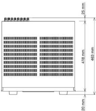
text_image
25 mm 418 mm 463 mm 20 mm
text_image
440 mm 170 mm 184 mm 1.4 mmSETUP CODES
AMPLIFIER
Source button name : AMP
| Brand name Setup code | |
| Anstrad 0105 | |
| Arcam 0296 | |
| Audiola 0296 | |
| Carver 0296 | |
| CE 0105 | |
| Genexxa 0422 | |
| Grundig 0296 | |
| Harman/Kardon 0919 | |
| JVC 0358 | |
| Left Coast 0919 | |
| Linn 0296 | |
| Magnavox 0296 | |
| Marantz 0919, 0296 | |
| Micromega 0296 | |
| Myryed 0296 | |
| Optimus 0422 | |
| Panasonic 0335 | |
| Philips 0919, 0296 | |
| Pioneer | 0040 |
| Polk Audio | 0818, 0296 |
| Realistic | 0422 |
| Revax | 0296 |
| Sony | 0247 |
| Soundesign | 0105 |
| Technics 0335 | |
| Thorems | 0296 |
| Victor | 0358 |
| Wards 0105, 0040 | |
| Yamaha 0381 | |
RECEIVER/TUNER
Source button name : AMP, TUNER
| Brand name Setup code | |
| ADC | 0558 |
| Atina | 1432, 0185, 1116, 1415, 1668 |
| Aico | 1417 |
| Altain | 1636 |
| Apex Digital 1284 | |
| Audiolat 1216 | |
| Audiotronic | 1216 |
| Audiovox | 1417 |
| Bose | 1256 |
| Cambridge | 1397 |
| Soundworks | |
| Capetronic | 0558 |
| Canver 1216, 1116 | |
| Centrex | 1284 |
| Deton 1387 | |
| Ferguson | 0558 |
| Fine Arts 1216 | |
| Grundig 1216 | |
RECEIVER/TUNER
Source button name : AMP, TUNER
| Brand name Sotyo code | |
| Harman/ Kardon | 0137, 1331 |
| Integra | 0162, 1325 |
| JBL | 0137, 1333 |
| JVC 0101, 0558, 1401, 1522 | |
| KLH | 1417, 1439 |
| Kenwood | 1340, 1054 |
| MCS | 0366 |
| Magravox 1216, 1289, 0558, 1116 | |
| Marantz 1216, 0069, 1116, 1316 | |
| Micromega 1216 | |
| Musicmagic | 1118 |
| Myryad 1216 | |
| NAD | 0347 |
| Norcent | 1418 |
| Onkyo 0162, 0869, 1325 | |
| Optimus 1050, 0558 | |
| Panasonic 1545, 0066, 1315, 1793 | |
| Phillips 1216, 1236, 1116, 1293, 1295, 1310, 1316 | |
| Pioneer | 1050, 0041, 0558, 1411 |
| Polk Audio | 1316 |
| Proscan | 1281 |
| Quasar 0066 | |
| RCA | 1050, 1636, 1281, 0558, 1417 |
| Saba | 0558 |
| Sansul | 1118 |
| Schneider | 0558 |
| Sony | 1085, 0165, 1185, 1685, 1785 |
| Sterephonics | 1050 |
| Sunfire | 1342 |
| Teac | 1417 |
| Technics 1335, 1545, 0066, 1336 | |
| Telefunkan 0558 | |
| Thomson | 1281 |
| Thorens | 1218 |
| Uber | 0558 |
| Vanturer | 1417 |
| Victor | 0101 |
| Wards 0165, 0041 | |
| Yamaha 0203, 1203, 1358 | |
CABLE
Source button name : AUX1
| Brand name Setup code | |
| ABC | 0230, 0235 |
| Americast | 0826 |
| Bell South 0266 | |
| Birmingham Cable Communications | 0303 |
| British Telecom | 0030 |
| Cable & Wireless | 1795 |
| Daesyung | 0904, 1904, 0504, 0335 |
| Director | 0503 |
| Filmnet 0470 | |
| General 0533, 0837, 0303, | |
CABLE
Source button name : AUX1
| Brand name Setup code | |
| GoldStar | 0171 |
| Hamlin | 0036, 0300 |
| Instrument | 0030 |
| Jemoid | 0503, 0837, 0303, 0030 |
| LG | 0171 |
| MNet | 0470 |
| Mamorex | 0027 |
| Motorola 0503, 0837, 0303, 1133 | |
| NTL 1095 | |
| Ncos | 0844 |
| One 1095 | |
| PVP Stereo | 0030 |
| Visual Matrix | |
| Face | 0264, 1087, 1095 |
| Panasonic 0027, 0035, 0134 | |
| Paragon | 0027 |
| Phillips 0332, 0344 | |
| Pioneer | 0904, 1904, 0171, 0560 |
| Pulsar | 0027 |
| Quasar 0027 | |
| Regal | 0306, 0300 |
| Runco 0027 | |
| Sagem | 0844 |
| Samsung | 0027, 0171 |
| Scientific Allantia | 0904, 1904, 0504, 0035 |
| Sony | 1033 |
| Starcom 0030 | |
| Supercable | 0303 |
| TS | 0030 |
| Tele+1 | 0470 |
| Telewest 1095 | |
| Topx | 0030 |
| Toshiba 0027 | |
| Trans PX | 0303 |
| United Cable | 0030 |
| Zenith | 0027, 0552, 0926 |
SATELLITE
Source button name: TAPE
| PAGE Command Note | ||
| PAGE 1 1 | TAPE-A | SELECT TAPE DECK A |
| 2 TAPE-B | SELECT TAPE DECK B | |
| 3 DIR | AUTO REVERSE DIRECTION | |
| 4 TIME | TIME DISPLAY | |
| 5 TRAY | TRAY OPEN/CLOSE | |
| PAGE 2 1 | AMS | AUTO MUSIC SCAN |
| 2 | ||
| 3 | ||
| 4 FF | FAST FORWARD | |
| 5 REW | REWIND | |
Source button name : MD
| PAGE Command Note | ||
| PAGE 1 1 | REPEAT SELECTS REPEAT MODE | |
| 2 SHUFLE | SELECTS SHUFFLE PLAY | |
| 3 DISP | SELECTS DISPLAY MODE | |
| 4 EDIT | SELECT EDIT MODE | |
| 5 EJECT ELECT | ||
| PAGE 2 1 | SP/LP SELECTS SP/LP MODE | |
| 2 DELETE SELECTS DELETE | ||
| 3 ENTER | SELECTS ENTER | |
| 4 FF | FAST FORWARD | |
| 5REW | REWIND | |
| PAGE 3 1 | MARKER SELECTS AUTO MARKER | |
| 2 PROG SELECTS PROGRAM MODE | ||
| 3 SYNC-R | SYNCRO REC | |
| 4 CHAR | SELECTS CHARACTER MODE | |
| 5 | ||
www.marantz.com
You can find your nearest authorized distributor or dealer on our website.
JAPAN Marantz Japan, Inc. 35-1 Sagami Ohno 7-Chome, Sagamihara-shi, Kanagawa 228-8505, Japan
U.S.A. Marantz America, Inc. 1100 Maplewood Drive, Itasca, IL 60143, U.S.A.
EUROPE Marantz Europe B.V. P.O. Box 8744, 5605 LS Eindhoven, The Netherlands
Manufactured under license from Dolby Laboratories. "Dolby", "Pro Logic" and the double-D symbol are trademarks of Dolby Laboratories. Confidential Unpublished Works. © 1992-1997 Dolby Laboratories, Inc. All rights reserved.
marantz®
is a registered trademark.
