Pick your language and provide your email: we'll send you a specifically translated version.
This manual is not available in your language
User questions about PM7004 MARANTZ
0 question about this device. Answer the ones you know or ask your own.
Ask a new question about this device
No questions yet. Be the first to ask one.
Download the instructions for your Receiver in PDF format for free! Find your manual PM7004 -
MARANTZ and take your electronic device back in hand. On this page are published all the documents necessary for the use of your device. PM7004 by MARANTZ.
USER MANUAL PM7004 MARANTZ
natural_image
Pure electrical circuit lines without any symbols
ENGLISHDEUTSCHF
marantz®
Integrated Amplifier
PM-KI-PEARL-LITE
PM7004
User Guide
SAFETY PRECAUTIONS
CAUTION RISK OF ELECTRIC SHOCK DO NOT OPEN
CAUTION:
TO REDUCE THE RISK OF ELECTRIC SHOCK, DO NOT REMOVE COVER (OR BACK). NO USER-SERVICEABLE PARTS INSIDE REFER SERVICING TO QUALIFIED SERVICE PERSONNEL.
The lightning flash with arrowhead symbol, within an equilateral triangle, is intended to alert the user to the presence of uninsulated "dangerous voltage" within the product's enclosure that may be of sufficient magnitude to constitute a risk of electric shock to persons.
The exclamation point within an equilateral triangle is intended to alert the user to the presence of important operating and maintenance (servicing) instructions in the literature accompanying the appliance.
WARNING:
TO REDUCE THE RISK OF FIRE OR ELECTRIC SHOCK, DO NOT EXPOSE THIS APPLIANCE TO RAIN OR MOISTURE.
Hot
surface
mark
CAUTION:
The top surface over the internal heat sink may become hot when operating this product continuously.
Do not touch hot areas, especially around the "Hot surface mark" and the top panel.
VORSICHT:
Read these instructions.
Keep these instructions.
Heed all warnings.
Follow all instructions.
Do not use this apparatus near water
Clean only with dry cloth.
Do not block any ventilation openings.
Install in accordance with the manufacturer's instructions.
Do not install near any heat sources such as radiators, heat registers,
stoves, of other apparatus (including amplifiers) that produce heat.
Do not defeat the safety purpose of the polarized or grounding-type plug. A polarized plug has two blades with one wider than the other. A grounding type plug has two blades and a third grounding prong. The wide blade or the third prong are provided for your safety. If the provided plug does not fit into your outlet, consult an electrician for replacement of the obsolete outlet.
Protect the power cord from being walked on or pinched particularly at plugs, convenience receptacles, and the point where they exit from the apparatus.
Only use attachments/accessories specified by the manufacturer
Use only with the cart, stand, tripod, bracket, or tabl specified by the manufacturer, or sold with the apparatus. When a cart is used, use caution when moving the cart/ apparatus combination to avoid injury from tip-over.
Unplug this apparatus during lightning storms or when unused for long periods of time.
Refer all servicing to qualified service personnel. Servicing is required when the apparatus has been damaged in any way, such as power-supply cord or plug is damaged, liquid has been spilled or objects have fallen into the apparatus, the apparatus has been exposed to rain or moisture, does not operate normally, or has been dropped.
Batteries shall not be exposed to excessive heat such as sunshine, fire or the like.
PRECAUCIÓN:
SUPERFICIE CALIENTE. NO TOCAR.
To completely disconnect this product from the mains, disconnect the plug from the wall socket outlet.
The mains plug is used to completely interrupt the power supply to the unit and must be within easy access by the user.
VORSICHT:
• DECLARATION OF CONFORMITY
We declare under our sole responsibility that this product, to which this declaration relates, is in conformity with the following standards: EN60065, EN55013, EN55020, EN61000-3-2 and EN61000-3-3.
Following the provisions of Low Voltage Directive 2008/95/EC and EMC Directive 2004/108/EC, the EC regulation 1275/2008 and its frame work Directive 2009/125/EC for Energy-related Products (ERP).
A division of D&M Europe B.V.
A NOTE ABOUT RECYCLING:
This product's packaging materials are recyclable and can be reused. Please dispose of any materials in accordance with the local recycling regulations. When discarding the unit, comply with local rules or regulations. Batteries should never be thrown away or incinerated but disposed of in accordance with the local regulations concerning battery disposal. This product and the supplied accessories, excluding the batteries, constitute the applicable product according to the WEEE directive.
HINWEIS ZUM RECYCLING:
* For proper heat dispersal, do not install this unit in a confined space, such as a bookcase or similar enclosure.
■ More than 0.3 m is recommended.
- Do not place any other equipment on this unit.
Thank you for purchasing this MARANTZ product. To ensure proper operation, please read this owner's manual carefully before using the product.
After reading the manual, be sure to keep it for future reference.
Contents
Getting started
Accessories
About this manual
Main features
Features of the PM7004 and PM-KI-PEARL-LITE
Features of the PM-KI-PEARL-LITE
Cautions on handling
About the remote control
Inserting the batteries
Operating range of the remote control
Part names and functions
Front panel
Rear panel
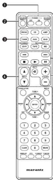
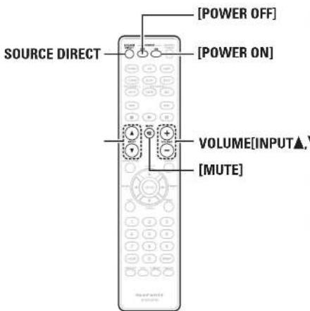
Remote control
Basic connections
Preparations
Connecting cables
Connecting the audio equipment
Connecting the speakers
Connecting the speakers cables
Speaker connections
Connecting players
Connecting recorders
Connecting the power cord
Basic operation
Before use
Turning the power on
Turning the power standby
Turning the power off
Starting playback
Direct playback using a source audio component
Muting sound
Using headphone set
Starting Recording
Advanced connections
Connecting P.DIRECT connectors
Connecting pre out connectors
Connecting the remote control connectors
Advanced operations
Setting Auto standby mode
Troubleshooting
Specifications
Explanation terms
Index
Accessories
Check that the following parts are supplied with the product.
① Owner's manual
② Power cord (Cord length: Approx. 1.8 m)
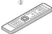
③ Remote control (RC003PM)
④ R03/AAA batteries
About this manual
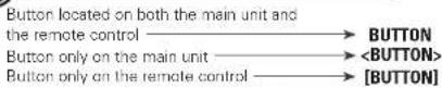
Operation buttons
The operations described in this manual are based mainly on remote control operation.
Symbols
This symbol indicates a reference page on which related information is described.
This symbol indicates a supplementary information and tips for operations.
NOTE
This symbol indicates points to remember operations or function limitations.
□ Illustrations
Note that the illustrations in these instructions are for explanation purposes and may differ from the actual unit.
ENGLISH
Main features
Feautures of the PM-KI-PEARL-LITEFeautures of the PM7004 and PM-KI-PEARL-LITE
Tri-tone control
This unit has a 3-tone control function for adjusting the midrange sound in addition to the bass and treble sounds so that you can make a more variable sound adjustment according to source and system.
All-discrete current-feedback amplifi er
Marantz' proprietary current-feedback circuit, using discrete components, is adopted in the pre amplifi er and power amplifi er. It is a high-speed amplifi er using the latest technology developed for the higher-grade amplifiers.
HDAM-SA3 Technology
The VI converter circuit, which is the key block of the current feedback pre-amplifier and power amplifier, is equivalent to the HDAM-SA3 ampmodule developed for such higher-grade models as the PM-11S2.
CD direct buffer amplifi er
An input buffer amplifier exclusive for CD is mounted near the CD input jacks. This is a high-speed buffer amplifier made with discrete components, which avoids interference between right and left channels and can send the signals to the pre-amplifier with very high fidelity.
Improved momentary current supply ability
It is generally known that the sound quality is not necessarily the same even if amplifiers have the same specifications. Marantz considers the cause to be the power to drive speakers. The power amplifier of this unit has the ability to momentarily supply current of 25 A or more to drive speakers strongly.
Short-power-line layout
For strong momentary current supply, a short power-line layout unifies the power circuit and output stage of the power amplifi er section. This layout allows connecting the large-current lines via the shortest route while to arranging the left and right channels symmetrically.
All-Discrete current-feedback phono equalizer
As a phono equalizer amplifier for MM cartridges, a constant current-feedback PHONO equalizer of quality equal to that of the higher-grade model PM-11S2 is used.
Double-shielded triodal transformer
The unit is equipped with a toroidal power transformer to minimize vibration and leakage flux specific to the transformer. Especially to reduce leakage flux, which affects sound quality, the periphery is double-shielded, using a core ring and a short ring.
Block condenser of large capacity
A large-capacity condenser of 18,000μF is used in the power circuit of the power amplifier. In the preamplifier, a 4700μF condenser is used.
High-performance volume
Capacitor for high quality sound
Double-layered and Copper-fi nished chassis
High-grade speaker terminals
Cautions on handling
• Before turning the power switch on
Check once again that all connections are correct and that there are no problems with the connection cables.
- Power is supplied to some of the circuitry even when the unit is set to the standby mode. When leaving home for long periods of time, be sure to unplug the power cord from the power outlet.
- About condensation
If there is a major difference in temperature between the inside of the unit and the surroundings, condensation may form on parts inside the unit, causing the unit to fail to operate properly. If this happens, let the unit sit for an hour or two with the power off and wait until there is little difference in temperature before using the unit.
• Cautions on using mobile phones
Using a mobile phone near this unit may result in noise. If that occurs, move the mobile phone away from the unit when it is in use.
- Moving the unit
Turn off the power and unplug the power cord from the power outlet.
Next, disconnect the cables connected to other system units before moving the unit.
About the remote control
Inserting the batteries
① Remove the rear cover of the remote control.
② Set two R03/AAA batteries in the battery compartment in the indicated direction.
③ Put the rear cover back on.
NOTE
Replace the batteries with new ones if the unit does not operate even when the remote control is operated close to the unit.
• The supplied batteries are only for verifying operation.
Insert the batteries in the proper direction, following the "⊕" and "⊖" marks in the battery compartment.
• To prevent damage or leakage of battery fluid:
Do not use a new battery with an old one.
Do not use two different types of batteries.
Do not attempt to charge dry batteries.
Do not short-circuit, disassemble, heat or dispose of batteries in a fire.
Do not keep the battery in a place exposed to direct sunlight or in places with extremely high temperatures, such as near a heater.
If the battery fluid leaks, carefully wipe the fluid off the inside of the battery compartment and insert new batteries.
Remove the batteries from the remote control if it will not be used for a long time.
• Used batteries in accordance with local regulations on battery disposal.
Operating range of the remote control
operate the remote control while pointing it at the remote sensor.
text_image
Approx. 5 m
30°
30°
NOTE
The unit may function improperly or the remote control may not operate if the remote control sensor is exposed to direct sunlight, or strong artificial light from a fluorescent or infrared light.
ENGLISH
Part names and functions
For buttons not explained here, see the page indicated in parentheses ( ).
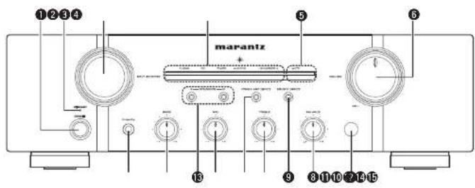
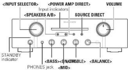
Front panel
text_image
①②③④
marantz
⑤
⑥
⑧
⑨
⑩
⑪⑫⑬⑭⑮
① Power switch (ON/OFF) ..... (8)
② STANDBY indicator ...... (B)
Indicates the status of the unit's as follows:
- Power "ON": Off
When the protection circuit is activated
Red (blinking) ...... (6)
Standby: Red
• Power "OFF" - Off
③ INPUT SELECTOR knob ...... (9)
④ Input indicators .....(8)
⑤ MUTE indicator (MUTE) ..... (9)
⑥ VOLUME control knob (8, 9)
⑦ Remote control sensor ……(3, 10)
⑧ BALANCE control knob …… (8, 9)
⑨ SOURCE DIRECT switch/indicator ..... (9)
⑩ TREBLE control knob ..... (8, 9)
⑪ POWER AMP DIRECT switch/indicator ..... (9)
12 MID control knob (8, 9)
13 SPEAKERS A/B switch/indicators ..... (9)
14 BASS control knob (8, 9)
15 Headphone jack (PHONES) ...... (9)
NOTE
You can adjust the ⑧ BALANCE, ⑩ TREBLE, ⑫
MID and 14 BASS control knobs only when 9
SOURCE DIRECT switch is turned off.
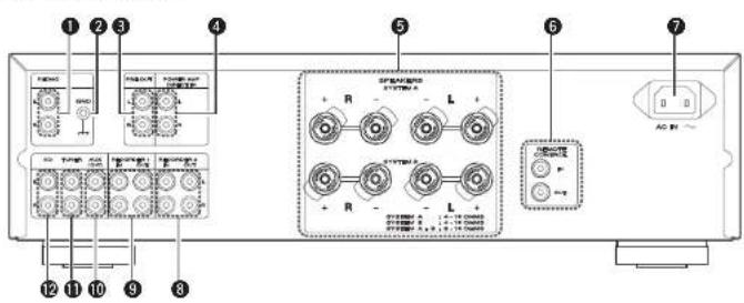
Rear panel
PM-KI-PEARL-LITE
text_image
Diagram of a device front panel with labeled ports and internal components including buttons, relays, and indicator lights.
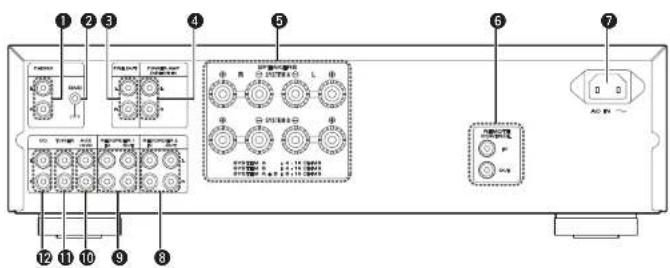
PM7004
text_image
Diagram of a device control panel with labeled ports and buttons, showing various function blocks and indicator lights.
① PHONO input connectors ..... (7)
② PHONO GND terminal ..... (7)
③ PRE OUT connectors ..... (10)
4 POWER AMP DIRECT IN connectors ..... (9)
⑤ Speaker system terminals (SPEAKERES SYSTEM A/B) …… (6, 7)
6 REMOTE CONTROL
input/output connectors ..... (10)
You can use the supplied remote control to operate this unit and Marantz audio components such as CD players, tuners, DVD players, and tape decks. See "Operating Marantz audio components" page 51.
① POWER ON/STANDBY buttons ...... (8)
• POWER ON button
• POWER OFF button
- SOURCE POWER button
You can press this button to switch the mode of Marantz audio components (provided with a power standby function) between power-on and standby.
② SOURCE DIRECT button ...... (9)
③ Input selector buttons ...... (5)
④ INPUT ▲/▼ buttons ...... (9)
⑤ Component operating buttons
6 VOLUME adjustment buttons....(8, 9)
- MUTE Button
• VOLUME + / - Button
☐ Operating Marantz audio components
Operation
1 Press the corresponding ③ Input selector button of the audio component for selecting the input source to be used in playback and recording.
- The remote control operation is switched to operation mode of the selected input source.
- This unit's function will be switched accordingly.
2 Operate the audio component.
• See the table on the right for the buttons you can use.
The remote control ③ Input selector buttons are used to select the input source for this unit and switch the remote control operation mode at the same time.
You can operate the remote control of this unit regardless of the remote control mode setting.
To use the remote control correctly, also refer to the operating instructions of other components.
NOTE
Some input terminals of this unit and corresponding input selector buttons on the remote control have different names, as shown below.
Remote control buttons
The unit input terminals
AUX, DVD
AUX/DVD
CD-R
RECORDER1
TAPE, MD
RECORDER2
Operation buttons
Function
|◀◀▶▶|
Skip
■
Stop
▶
Playback
||
Pause
0 – 9 Track selection
T.MODE Sound mode selection
□ Tuner operation
Operation buttons
Function
P.SCAN/A.TUNE preset scan
▲/TUNE+
Tuning up
▼/TUNE-
Tuning down
◀/PRESET-
Preset channel selection
▶/PRESET+
Preset channel selection
BAND
FM/AM switching
0 - 9 Enter number
CLEAR
Clear memory or input data
MEMO
Save preset station number
F.DIRECT
Direct frequency tuning
T.MODE
Auto stored/monaural switching
The remote control buttons may not function properly for some Marantz tuners.
DVD operation
Operation buttons
Function
|◀◀ ▶▶|
Skip
■
Stop
▶
Playback
||
Pause
MENU Menu
▲▼◀▶
Cursor operation
ENTER Entorsetting
0-9 Enter number
DISPLAY
Display disc information
□ Cassette deck operation
Operation buttons
Function
|◀◀
Fast-rewind
▶▶|
Fast-forward
■
Stop
▶
Playback
||
Pause
CLEAR Counter reset
ENGLISH
Basic connections
NOTE
Do not plug in the power cord until all connections have been completed.
When making connections, also refer to the operating instructions of the other components.
Be sure to connect the left and right channels properly (left with left, right with right).
Do not bundle power cords with connection cables. Doing so can result in humming or noise.
Do not turn up the volume without a turntable connected to the PHONO input terminals. Doing so will cause humming or noise.
Preparations
Connecting cables
Select the cables according to the equipment being connected.
When regular speakers not compatible with SA sources (DVD Audio discs, Super Audio CDs and other sources, including treble components above the audible range), set the properties of the player (DVD Audio player, Super Audio CD player, etc.) for use with regular speakers (or amplifiers).
The speakers may be damaged if the volume is set too high when playing SA sources. For instructions on player settings, refer to the operating instructions included with the player.
Connecting the speakers
Connecting the speakers cables
Carefully check the left ILI and right (RI) channels and + (red) and - (PM-KI-PEARL-LITE/white) (PM7004(black)) polarities on the speakers being connected to the unit, and be sure to connect the channels and polarities correctly.
1 Peel off about 10 mm of sheathing from the tip of the speaker cable, then either twist the core wire tightly or apply solder to it.
2 Turn the speaker terminal counterclockwise to loosen it.
3 Insert the speaker cable's core wire to all the way into the speaker terminal.
4 Turn the speaker terminal clockwise to tighten it.
NOTE
- Connect the speaker cables so they do not stick out of the speaker terminals. The protection circuit may be activated if the wires touch the rear panel or if the + and - sides touch each other ("Protection circuit").
- Never touch the speaker terminals while the power supply is connected. Doing so could result in electric shock.
□ Protection circuit
The protection circuit is be activated in the following situations:
- If the speaker cable wire touches the rear panel or screws or if the speaker cable wire touches the speaker cable's + and - sides are touching
- If the surrounding temperature is extremely high
- If the inside of the amplifier gets hot to extended use at a high output
If the protection circuit is activated, the speaker output is blocked and the power indicator flashes in red. If this happens, unplug the power cord, then check the connections of the speaker cables and input cables. If the unit becomes very hot, wait for it to cool off and improve the ventilation around it. After doing this, plug the power cord back in.
If the protection circuit is activated even though there are no problems with the ventilation around the unit or in connections, the unit may be damaged. Turn off the power and then contact a Marantz service center.
Connecting the speakers
Speaker connections
• The same signal is output from the SPEAKERS A and B terminals.
- When only one set of speakers is to be connected, use either the SYSTEM A or B terminals.
text_image
Speakers A Speakers B
R L
R L
R L
R L
R L
R L
R L
☐ Speaker impedance
Use speakers with impedances within the ranges shown below to suit how they are used.
Speakers used Impedance
A 4 - 16 Ω
B 4 - 16 Ω
A and B
8 - 16 Ω
ENGLISH
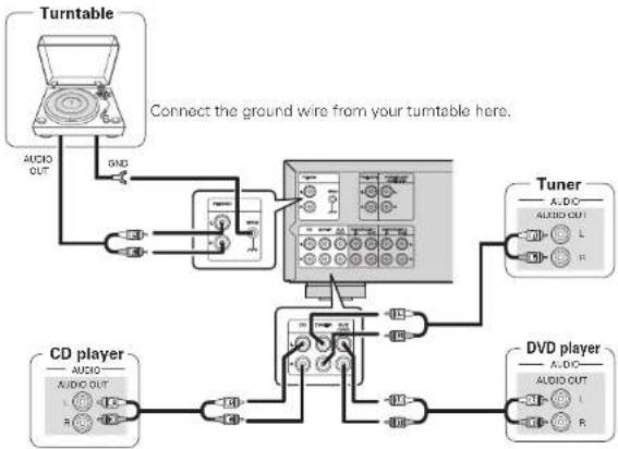
Connecting players
A turntable with an MM type cartridge can be connected to this unit. To use an MC cartridge, please install a step-up transformer.
- If humming or other noise is generated when the ground wire is connected, disconnect it.
flowchart
graph TD
    A["Turntable"] -->|USB| B["Connect the ground wire from your turntable here."]
    B --> C["CD player"]
    C --> D["USB"]
    D --> E["USB"]
    E --> F["USB"]
    F --> G["USB"]
    G --> H["USB"]
    H --> I["USB"]
    I --> J["USB"]
    J --> K["USB"]
    K --> L["USB"]
    L --> M["USB"]
    M --> N["USB"]
    N --> O["USB"]
    O --> P["USB"]
    P --> Q["USB"]
    Q --> R["USB"]
    R --> S["USB"]
    S --> T["USB"]
    T --> U["USB"]
    U --> V["USB"]
    V --> W["USB"]
    W --> X["USB"]
    X --> Y["USB"]
    Y --> Z["USB"]
    Z --> AA["USB"]
    AA --> AB["USB"]
    AB --> AC["USB"]
    AC --> AD["USB"]
    AD --> AE["USB"]
    AE --> AF["USB"]
    AF --> AG["USB"]
    AG --> AH["USB"]
    AH --> AI["USB"]
    AI --> AJ["USB"]
    AJ --> AK["USB"]
    AK --> AL["USB"]
    AL --> AM["USB"]
    AM --> AN["USB"]
    AN --> AO["USB"]
    AO --> AP["USB"]
    AP --> AQ["USB"]
    AQ --> AR["USB"]
    AR --> AS["USB"]
    AS --> AT["USB"]
    AT --> AU["USB"]
    AU --> AV["USB"]
    AV --> AW["USB"]
    AW --> AX["USB"]
    AX --> AY["USB"]
    AY --> AZ["USB"]
    AZ --> BA["USB"]
    BA --> BB["USB"]
    BB --> BC["USB"]
    BC --> BD["USB"]
    BD --> BE["USB"]
    BE --> BF["USB"]
    BF --> BG["USB"]
    BG --> BH["USB"]
    BH --> BI["USB"]
    BI --> BJ["USB"]
    BJ --> BK["USB"]
    BK --> BL["USB"]
    BL --> BM["USB"]
    BM --> BN["USB"]
    BN --> BO["USB"]
    BO --> BP["USB"]
    BP --> BQ["USB"]
    BQ --> BR["USB"]
    BR --> BS["USB"]
    BS --> BT["USB"]
    BT --> BU["USB"]
    BU --> BV["USB"]
    BV --> BW["USB"]
    BW --> BX["USB"]
    BX --> BY["USB"]
    BY --> BZ["USB"]
    BZ --> CA["USB"]
    CA --> CB["USB"]
    CB --> CC["USB"]
    CC --> CD["USB"]
    CD --> CE["USB"]
    CE --> CF["USB"]
    CF --> CG["USB"]
    CG --> CH["USB"]
    CH --> CI["USB"]
    CI --> CJ["USB"]
    CJ --> CK["USB"]
    CK --> CR["USB"]
    CR --> CS["USB"]
    CS --> CT["USB"]
    CT --> CU["USB"]
    CU --> CV["USB"]
    CV --> CW["USB"]
    CW --> CX["USB"]
    CX --> CY["USB"]
    CY --> CZ["USB"]
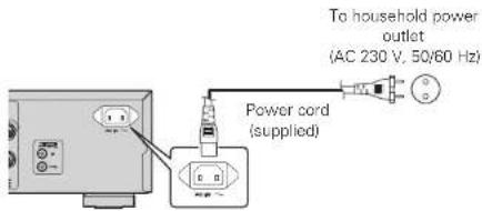
Wait until all connections have been completed before connecting the power cord.
text_image
To household power outlet
(AC 230 V, 50/60 Hz)
Power cord
(supplied)
NOTE
Insert the plugs securely. Loose connections will result in the generation of noise.
Do not use any cord other than the provided power cord.
Basic operation
Symbols used to indicate buttons in this manual
text_image VOLUME
Input indicators
SOURCE DIRECT
STANDBY
indicator
PHONES jack
text_image
SOURCE DIRECT
[POWER OFF]
[POWER ON]
VOLUME[INPUT▲,▼]
[MUTE]
Before use
1 Turn the VOLUME all the way down.
2 Set , , and to the center positions.
Turning the power on
Press .
• Power is turned on
- Input indicator for the selected source lights.
• The unit will be ready to start playback after several seconds.
Turning the power standby
Press [POWER OFF].
• The power is set to the standby mode.
• The STANDBY indicator lights in red.
Press [POWER ON] to turn on power from standby mode.
You can also turn on power by using either from standby mode.
NOTE
Power continues to be supplied to some of the circuitry even when the power is in the standby mode. When leaving home for long periods of time or when going on vacation, either press to turn off the power, or unplug the power cord from the power outlet.
Turning the power off
Press
• Power is turned off.
- All indicators will turn off.
Starting playback
text_image
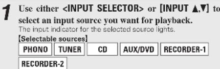
1 Use either or [INPUT ▲,▼] to
select an input source you want for playback.
The input indicator for the selected source lights.
[Selectable sources]
PHONO TUNER CD AUX/DVD RECORDER-1
RECORDER-2
You can also select an input source by pressing the Input selector buttons of the remote control.
The input source you select is stored in memory even after you turn off power, and the same source is selected when power is turned on again.
□ Adjusting the tone
• Adjusts the bass sound.
• Adjusts the midrange sound.
- Adjusts the treble sound.
• Adjusts the left and right output balance.
Direct playback using a source audio component
Since the audio signals bypass the tone control circuits IBASS/MID/TREBLE/BALANCE), the music reproduction is more faithful to the original sound.
Press SOURCE DIRECT.
The SOURCE DIRECT indicator lights.
To adjust the tone, turn off SOURCE DIRECT
Muting sound
This function mutes the sound by stopping audio output.
Press [MUTE].
The MUTE indicator lights.
- To cancel the mute operation, press the button again.
You can also cancel the mute operation by operating VOLUME of the remote control.
Using headphone set
Plug headphones into PHONES jack.
• To listen with headphones, turn speaker output OFF.
□ Adjusting the volume
Adjust the VOLUME to the desired level.
NOTE
To prevent hearing loss, do not raise the volume level excessively when using headphones.
Starting Recording
1 Use either or [INPUT ▲,▼] to select the input source you want to record.
2 Set the recorder to recording mode.
3 Start playback of the source you want to record.
- Recording will start in sync with the playback operation of the source.
Advanced connections
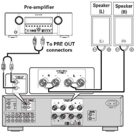
Connecting P.DIRECT connectors
If you use a preamplifier, connect it as shown below, and then you can use this unit as a power amplifier.
To switch the POWER AMP DIRECT mode, press and hold for at least 3 seconds.
Switching "ON", allows the device connected to the Power Amp Direct connector on the rear panel to be played. When ON, the input indicator turns off.
Switching "OFF", allows the program source selected using the INPUT SELECTOR knob to be played. When OFF, the input indicator lights up.
For details on operations of the preamplifier, refer to the instruction manual supplied with the preamplifier to be used.
flowchart
graph TD
    A["Pre-amplifier"] --> B["To PRE OUT connectors"]
    B --> C["Speaker (L)"]
    B --> D["Speaker (R)"]
    C --> E["Speaker (L)"]
    D --> F["Speaker (R)"]
NOTE
When the POWER AMP DIRECT is "ON", adjustment of the volume, balance and tone on the main unit has no effect. Adjust the volume on the input device.
When the POWER AMP DIRECT is "ON", the main unit outputs at maximum volume. Check the output level on the input device before playing it and adjust the volume accordingly.
ENGLISH
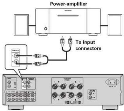
Connecting pre out connectors
If you use a power amplifier, connect it as shown below, and then you can use this unit as a preamplifier.
For connecting speaker systems, refer to the instruction manual supplied with the power amplifier to be used.
text_image
Power-amplifier
To input
connectors
NOTE
NEVER insert the short-circuiting pin plug into the PRE OUT terminals. Doing so could result in damage.
Signals are output from the PRE OUT terminals even when using headphones.
Connecting the remote control connectors
When you use this unit connected to Marantz audio components, it sends control signals to operate each component.
Connection
Use the remote connection cable (supplied with a Marantz audio component you want to connect) to connect the REMOTE CONTROL OUT terminal of this unit to the REMOTE CONTROL IN terminal of the component to be connected.
Setting
Set the remote control switch located on the rear panel of the connected audio component to "EXTERNAL" or "EXT." to use this feature.
- This setting will disable remote sensor reception of the connected audio component.
• To operate the connected audio component, point the remote control at the remote sensor of this unit.
text_image
SPRABERS
SYSTEM A
L +
SYSTEM B
L +
SYSTEM A 1.4-18 CHMS
SYSTEM B 1.4-18 CHMS
SYSTEM A 0.9-16 CHMS
AC IN ~
REMOTE
CONTROL
OUT
IN OUT
OUTPUTINPUT
CD player
RC OUT
Option unit
(such as remote control receiver unit)
Advanced operations
Setting Auto standby mode
With the Auto standby mode ON, this unit will automatically enter the Auto standby mode after about 30 continuous minutes of no output from the speakers or headphones.
SOURCE DIRECT
natural_image
Front panel of a audio amplifier with two knobs and a control unit (no visible text or labels)
Press and hold for at least 5 seconds.
• Auto standby mode is switched between On and Off.
NOTE
Perform the operation using the buttons on the unit. You cannot perform the operation using [SOURCE DIRECT] on the remote control.
The default setting for the Auto standby mode is OFF.
This unit will automatically enter Auto standby mode after about continuous 30 minutes in the following conditions.
No output from the selected input source.
• No operation performed on the remote control.
No operation of , , or .
ENGLISH
Troubleshooting
If a problem occurs, first check the following:
Are the connections correct?
Is the unit being operated as described in the owner's manual?
Are the other components operating properly?
If this unit does not operate properly, check the items listed in the table below. If the problem persist there may be a malfunction. In that case, disconnect the power immediately and contact your retail outlet.
Symptom Cause Countermeasure Page
Power is not turned on.
The power cord's plug is not plugged in firmly.The unit is in standby mode.The protection circuit is activated.
Make sure that the power cord is plugged in properly.Either turn the INPUT SELECTOR knob of this unit or press POWER ON of the remote control.If the STANDBY indicator is blinking, turn off power, wait 1 minute or longer, and turn on power again.
886
When power is turned on but there is no sound.
The speaker cables are not properly connected.The input cable is not properly connected.The INPUT SELECTOR knob setting position is incorrect.The VOLUME control knob is set to minimum.The SPEAKERS A/B switches are turned off.The incorrect SPEAKERS A/B switch is turned on.The mute function activated.
Make sure the speakers are connected properly.Make sure the input cables are connected properly.Set the INPUT SELECTOR knob at the correct setting position.Use the VOLUME control knob to turn volume up to an appropriate level.Tum on the SPEAKERS A/B switch corresponding to the speaker system terminals (SYSTEM A or SYSTEM BI) to which the speakers are connected.Tum on the SPEAKERS A/B switch corresponding to the speaker system terminals (SYSTEM A or SYSTEM BI) to which the speakers are connected.If the MUTE indicator is lit, press MUTE on the remote control to cancel muting.
779999
The volume drops automatically.
The protection circuit is activated.
Turn off power, wait 1 minute or longer, and turn on power again.
6
Sound is produced from either one speaker only.
The speaker cables are not properly connected.The BALANCE control knob setting position is inappropriate.
Make sure that the speakers are connected properly.Set the BALANCE control knob at the appropriate position.
79
The left and right channels are reversed.
Either the left/right speaker or left/right input cable connections are reversed.
Make sure that the speakers are connected correctly.
7
Noise is produced during a record playback.
The ground wire from the turntable is disconnected.The PHONO input terminals are not properly connected.A TV set near the turntable is causing the noise.
Make sure that the PHONO GND terminal is connected properly.Make sure that the PHONO input terminal is connected properly.Relocate the TV set or turntable in another place.
77-
An audio feedback occurs when you turn up the volume during a record playback.
The turntable and speakers are too close to each other.The turntable is placed on a rack or floor that vibrates easily.
Install the speakers as far away from the turntable as possible.If the turntable is not supplied with an insulating pad, use insulating pad available in the market.
--
The unit does not function when a remote control button is pressed.
Batteries are low.You are operating the remote control outside of the specified range.There is an obstacle between the main unit and remote control.You have pressed the wrong button.Batteries are not inserted in the proper direction as indicated by polarity markers (⊕ and ⊖) in the battery compartment.
Replace with new batteries.Operate within the specified range.Remote the obstacle.Press the correct button.Insert the batteries in the proper direction in accordance with the polarity markers in the battery compartment.
33353
ENGLISH
Specifications
• Power output
(20 Hz - 20 kHz simultaneous drive of both channels): 70 W x 2 (8 Ω load) 100 W x 2 (4 Ω load)
• Total harmonic distortion
(20Hz - 20kHz simultaneous drive of both channels, 80 load): 0.02%
• Output band width
(8Ω load, 0.05%): 5Hz - 60kHz
• Frequency response
(CD, 1W, BO load): 5Hz - 100kHz ±3dB
- Dumping factor
(80 load, 20Hz - 20kHz): 100
- Input sensitivity/Input impedance
PHONO (MM): 2mW/47kΩ
CD, TUNER, AUX/DVD, RECORDER: 200mV/20kΩ
MAIN IN 1.6V/15kΩ
• Output voltage/Output impedance
PRE OUT 1.6V/600Ω
• Maximum allowable PHONO input level (1kHz)
MM 100mV
• RIAA deviation (20Hz \~ 20kHz) ±0.5dB
Bass (50Hz)
Mid (900Hz)
Treble (15kHz)
• Power requirement
• Power consumption
(EN60065) 200W
Standby power consumption 0.3W
• Weight
PM-KI-PEARL-LITE 11.2kg
PM7004 10.5kg
For the purpose of improvement, the specifications and design are subject to change without notice.
Explanation terms
P
Protection Circuit
This is a function to prevent damage to components within the power supply when an abnormality such as an overload or excess voltage occurs for any reason.
In this unit, the STANDBY indicator blinks and the unit enters standby mode when an abnormality occurs.
s
Speaker impedance
This is certain-rated resistance of the speaker set to an alternating current and expressed in ohms. The smaller the impedance, the greater the output. However, load on the amplifier is increased. Use speakers whose impedance is supported by this unit.
💬 Hi! I'm your manual assistant.I know your MARANTZ PM7004.
How can I help you? (use, settings, error codes, maintenance, explaining a step from the manual, etc.)💡 Examples :
• How do I use it ?
• Error code E3 ?
• How do I clean it ?