Vivaro (2010) - Car OPEL - Free user manual and instructions
Find the device manual for free Vivaro (2010) OPEL in PDF.

User questions about Vivaro (2010) OPEL
0 question about this device. Answer the ones you know or ask your own.
Ask a new question about this device
Download the instructions for your Car in PDF format for free! Find your manual Vivaro (2010) - OPEL and take your electronic device back in hand. On this page are published all the documents necessary for the use of your device. Vivaro (2010) by OPEL.
USER MANUAL Vivaro (2010) OPEL
Keys, doors and windows ..... 18
Seats, restraints .... 30
Storage 51
Instruments and controls .... 56
Lighting 73
Climate control 78
Driving and operating 83
Vehicle care 105
Service and maintenance ..... 135
Technical data 139
Customer information 153
Index 154
2 Introduction
Introduction
| Fuel | Designation | ||
| Engine oil | Grade | ||
| Viscosity | |||
| Tyre pressure | Tyre size | Front | Rear |
| Summer tyres | |||
| Winter tyres | |||
| Weights | Gross vehicle weight rating | ||
| - Kerb weight, basic model | |||
| - Additional weight | |||
| - Heavy accessories | |||
| = Loading |
Vehicle specific data
Please enter your vehicle's data on the previous page to keep it easily accessible. This information is available under the sections "Service and maintenance" and "Technical data" as well as on the identification plate.
Introduction
Your vehicle is a designed combination of advanced technology, safety, environmental friendliness and economy.
This Owner's Manual provides you with all the necessary information to enable you to drive your vehicle safely and efficiently.
Make sure your passengers are aware of the possible risk of accident and injury which may result from improper use of the vehicle.
You must always comply with the specific laws and regulations of the country that you are in. These laws may differ from the information in this Owner's Manual.
When this Owner's Manual refers to a workshop visit, we recommend your Opel Service Partner.
All Opel Service Partners provide first-class service at reasonable prices. Experienced mechanics trained by Opel work according to specific Opel instructions.
The customer literature pack should always be kept ready to hand in the vehicle.
Using this manual
■ The "In brief" section will give you an initial overview.
■ The table of contents at the beginning of this manual and within each section shows where the information is located.
■ The index will enable you to search for specific information.
■ This Owner's Manual depicts left-hand drive vehicles. Operation is similar for right-hand drive vehicles.
■ The Owner's Manual uses the factory engine designations. The corresponding sales designations can be found in the section "Technical data".
■ Directional data, e.g. left or right, or front or back, always relate to the direction of travel.
■ The display may not support your language.
■ Depending on the model variant, country variant, integrated special equipment and accessories, the scope of equipment in the vehicle can differ from the items mentioned in this Owner's Manual.
■ Display messages and interior labelling are written in bold letters.
4 Introduction
Danger, Warnings and Cautions

Danger
Text marked △Danger provides information on risk of fatal injury. Disregarding this information may endanger life.

Warning
Text marked △Warning provides information on risk of accident or injury. Disregarding this information may lead to injury.
Caution
Text marked Caution provides information on possible damage to the vehicle. Disregarding this information may lead to vehicle damage.
Symbols
Page references are indicated with ➔. ➔ means "see page".
We wish you many hours of pleasurable driving.
Adam Opel GmbH
Introduction 5
In brief
Initial drive information
Vehicle unlocking Unlocking with key
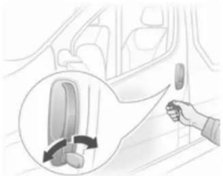
natural_image
Illustration of a hand pressing down an airplane seatbelt on a car door, with a magnified inset showing the seatbelt being adjusted (no text or symbols present)Turn the key in the driver's door lock. Open the doors by pulling the handles.
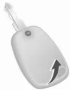
Unlocking with radio remote control

natural_image
Two identical gray car key holders with lock icons, shown from different angles (no text or symbols visible)Press button ☑, pull door handle. Radio remote control ✦ 18, Central locking system ✦ 20, Load compartment ✦ 23.
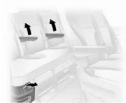
Seat adjustment
Seat positioning

natural_image
Illustration of a vehicle with directional arrows indicating traffic flow (no text or symbols)Pull handle, slide seat, release handle.
Seat position ➔ 31, Seat adjustment ➔ 32.
Danger
Do not sit nearer than 25 cm from the steering wheel, to permit safe airbag deployment.
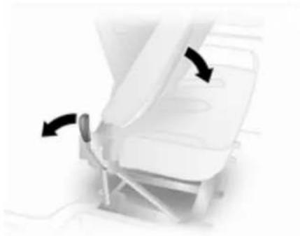
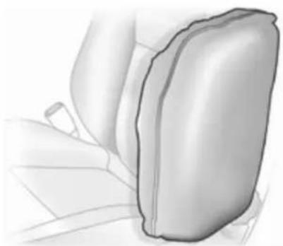
Seat backrests

natural_image
Diagram of a car seatbelt mechanism with directional arrows indicating rotation (no text or symbols)Pull lever, adjust inclination and release lever. Allow the seat to engage. Do not lean on backrest when adjusting.
Seat position 31, Seat adjustment 32.
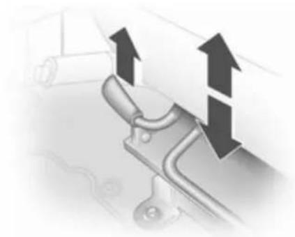
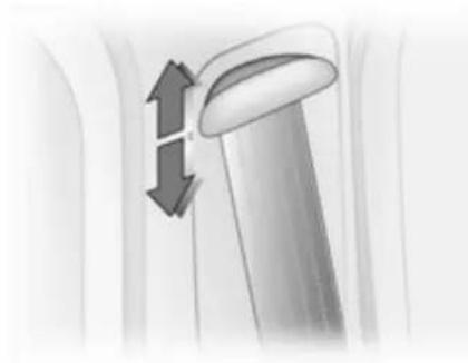
Seat height

natural_image
Close-up of a mechanical component with two upward-pointing arrows indicating motion or force (no text or symbols visible)Lift lever and adjust body weight on seat to raise or lower it.
Seat position 31, Seat adjustment 32.
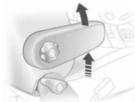
Head restraint adjustment

natural_image
Illustration of a stylized object with two vertical arrows indicating upward and downward motion (no text or symbols)Raise or lower head restraint to the desired height.
Head restraints 30.
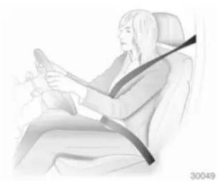
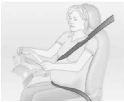
Seat belt
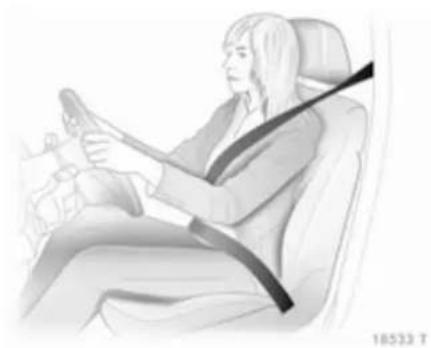
natural_image
Illustration of a person sitting in a car, wearing a seatbelt and holding the steering wheel (no text or symbols visible)Pull out the seat belt and engage in belt buckle. The seat belt must not be twisted and must fit close against the body. The backrest must not be tilted back too far (maximum approx. 25°).
To release belt, press red button on belt buckle.
Seat position 31, Seat belts 37, Airbag system 40.
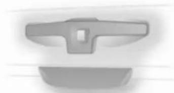
Mirror adjustment
Interior mirror

natural_image
Close-up of a white car front panel with a black rectangular cover and a curved handle (no text or symbols visible)To reduce dazzle, adjust the lever on the underside of the mirror housing. Interior mirror 28.
Exterior mirrors
Manual adjustment

natural_image
Interior view of a car dashboard and steering wheel (no text or symbols visible)Swivel mirror in required direction. Exterior mirrors 26.
Electric adjustment
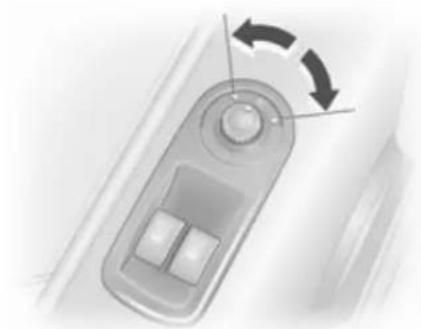
natural_image
Close-up of a car's side panel with a scroll wheel and two buttons, showing a rotational arrow (no text or symbols)Select the relevant exterior mirror and adjust it.
Convex exterior mirrors 26, Electric adjustment 27, Folding exterior mirrors 27, Heated exterior mirrors 27.
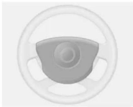
Steering wheel adjustment
natural_image
Interior view of a car seatbelt mechanism with a magnified inset showing the mechanism (no text or symbols visible)Unlock the lever, adjust the steering wheel, then engage the lever and ensure it is fully locked.
Do not adjust the steering wheel unless vehicle is stationary and the steering wheel lock has been released.
Airbag system 40, Ignition positions 84.
10 In brief
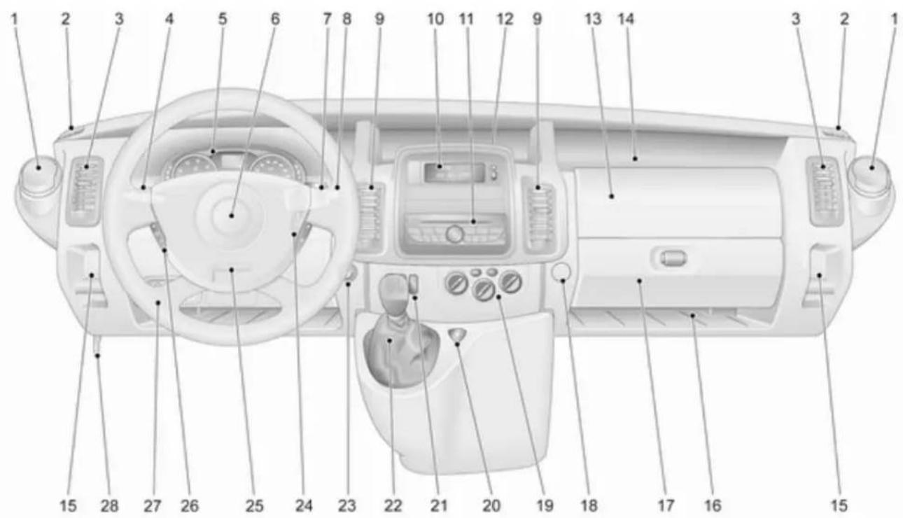
text_image
Diagram of a car interior with numbered labels pointing to various components such as steering wheel, dashboard, and airway.Instrument panel overview
1 Ashtray 61
Cupholders 51
Fuse box 119
2 Fixed air vents 81
3 Side air vents 81
4 Light switch .... 73 Rear fog light .... 75 Front fog lights .... 75 Exit lighting .... 77 Turn and lane-change signals, sidelights, headlight flash, low beam and high beam .... 75
5 Instruments .... 61 Driver Information Centre .... 69 Transmission display .... 63
8 Windscreen wiper, windscreen washer system .... 57 Rear window wiper, rear window washer system .... 59 Trip computer .... 70
9 Centre air vents 81
13 Front passenger airbag ..... 41
14 Storage tray 51
15 Coin tray 51
16 Storage tray 51
17 Glovebox 51
18 Utility hook 10
19 Climate control system ..... 78
20 Hazard warning flashers ..... 75
21 Central locking system .... 20 Heated exterior mirrors .... 27 Heated rear window .... 29 Manual transmission automated, Winter and Laden modes .... 89 Cruise control and speed limiter .... 95
22 Gear lever, Manual transmission .... 87 Manual transmission automated .... 87
24 Ignition switch with steering wheel lock 84
25 Steering wheel adjustment .... 56
26 Remote control on steering wheel .... 56 Cruise control .... 95
27 Ultrasonic parking assist ..... 98 Headlight range adjustment ..... 74 Electronic Stability Program ..... 94
28 Bonnet release lever ..... 106
12 In brief
Exterior lighting
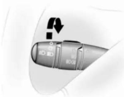
natural_image
Close-up of a car's side panel with directional arrows and control buttons (no readable text or symbols)Turn light switch
0 = Off
= Sidelights
DED = Headlights
≠D = Front fog lights
≠DQ≠ = Front and rear fog lights
Lighting 73, Headlight warning device 70.
Front and rear fog lights

natural_image
Close-up of a metallic cylindrical object with a curved arrow indicating rotation or movement (no text or symbols visible)Turn light switch
≠D = Front fog lights
≠DQ≠ = Front and rear fog lights
Headlight flash, high beam and low beam

natural_image
Abstract 3D rendering of a capsule-shaped object with an arrow pointing upward (no text or symbols)Pull lever.
High beam 74, Headlight flash 74.
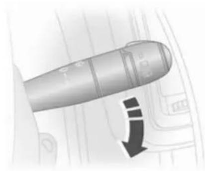
Turn and lane-change signals
natural_image
3D diagram of a bullet with directional arrows indicating motion or force (no text or symbols)lever up = right turn signal
lever down = left turn signal
Turn and lane-change signals 75.
Hazard warning flashers
natural_image
Close-up of a car's wheel with a triangular button labeled 'F' (no other text or symbols visible)Operated with the ▲ button. Hazard warning flashers ➔ 75.
Horn
natural_image
Top-down view of a car steering wheel with three spokes (no text or symbols)Press ▶.
14 In brief
Washer and wiper systems Windscreen wiper
natural_image
Close-up of a mechanical component with a downward arrow indicator (no text or symbols visible)= timed interval wiping
1 = slow
2 = fast
Windscreen wiper 57, Wiper blade replacement 113.
Windscreen and headlight washer systems
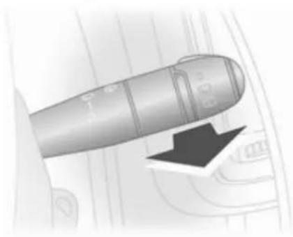
natural_image
Close-up of a metallic cylindrical object with a black arrow pointing to it, against a blurred background (no text or symbols visible)Pull lever.
short = wiper swipes once pull
long = wiper swipes for a few pull strokes and washer fluid is sprayed onto the windscreen
Windscreen and headlight washer system 57, Wiper blade replacement 113, Washer fluid 111.
Rear window wiper and washer system

natural_image
Close-up of a metallic cylindrical object with a black arrow pointing to it, overlaid on a faint architectural floor plan (no text or symbols)Turn lever.
0 = off
= wiper
= washer
Rear window wiper and washer system 59, Wiper blade replacement 113, Washer fluid 111.
Climate control
Heated rear window, heated exterior mirrors
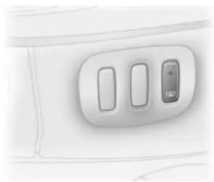
natural_image
Close-up of a white airplane cabin interior with three rectangular slots and a small screen (no visible text or symbols)Heating is operated by pressing the button.
Heated exterior mirrors 27, Heated rear window 29.
Demisting and defrosting the windows
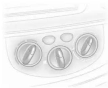
natural_image
Close-up of a car air conditioner panel with three buttons and ovals (no text or symbols visible)Air distribution to 📂.
Set temperature control to warmest level.
Set fan speed to highest level.
Cooling AC on.
Climate control system ↗ 78.
Transmission
Manual transmission
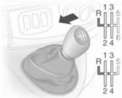
text_image
R 1 3 5 2 4 R 1 3 5 2 4Reverse: with the vehicle stationary, wait 3 seconds after depressing clutch pedal and then pull up the collar on the selector lever and engage the gear.
If the gear does not engage, set the lever to neutral, release the clutch pedal and depress again; then repeat gear selection.
Manual transmission ➔ 87.
Manual transmission automated
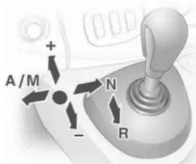
text_image
A/M + - N RN = neutral
● = drive
+ = higher gear
- = lower gear
A/M = switch between automatic and manual mode
R = reverse gear
Manual transmission automated 87.
Starting off
Check before starting off
■ Tyre pressure and condition ◇ 121, ◇ 151.
■ Engine oil level and fluid levels 107.
■ All windows, mirrors, exterior lighting and number plates are free from dirt, snow and ice and are operational.
■ Proper position of mirrors, seats and seat belts 27, 31, 38.
■ Brake function at low speed, particularly if the brakes are wet.
Starting the engine

natural_image
Diagram showing curved arrows and a circular object with internal flow arrows (no text or symbols)■ Turn key to position A
■ move the steering wheel slightly to release the steering wheel lock
■ operate clutch and brake
■ do not operate accelerator pedal
■ diesel engines: turn the key to position M for preheating and wait until control indicator 00 extinguishes in the Driver Information Centre.
■ turn key to position D and release. Starting the engine 84.
Parking
■ Always apply parking brake without pushing the release button. Apply as firmly as possible on a downhill or uphill slope. Depress foot brake at the same time to reduce operating force.
■ Switch off the engine. Turn the ignition key to position St and remove it. Turn the steering wheel until the steering wheel lock is felt to engage.
■ If the vehicle is on a level surface or uphill slope, engage first gear before switching off the ignition. On an uphill slope, turn the front wheels away from the kerb.
If the vehicle is on a downhill slope, engage reverse gear before switching off the ignition. Turn the front wheels towards the kerb.
■ Lock the vehicle and activate the anti-theft alarm system ➔ 24 with button ⏻ on the radio remote control.
■ Do not park the vehicle on an easily ignitable surface. The high temperature of the exhaust system could ignite the surface.
■ Close the windows.
■ The engine cooling fans may run after the engine has been switched off 106.
■ After running at high engine speeds or with high engine loads, operate the engine briefly at a low load or run in neutral for approx. 30 seconds before switching off, in order to protect the turbocharger.
Keys, locks 18, Laying the vehicle up for a long period of time 105.
Keys, doors and windows
Keys, locks 18
Doors 22
Vehicle security 24
Exterior mirrors 26
Interior mirrors 28
Windows 28
Keys, locks
Keys
Replacement keys
The key number is specified on the key or on a detachable tag.
The key number must be quoted when ordering replacement keys as it is a component of the immobiliser system.
Locks 132.
Car Pass
The Car Pass contains security related vehicle data and should therefore be kept in a safe place.
When the vehicle is taken to a workshop, this vehicle data is needed in order to perform certain operations.
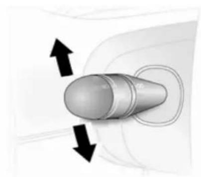
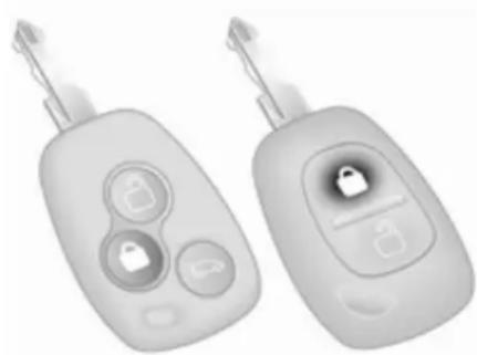
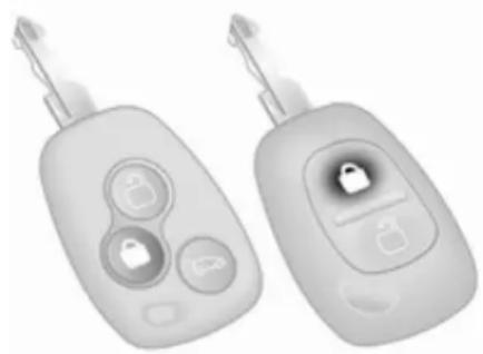
Radio remote control
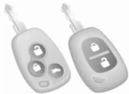
natural_image
Two gray key-shaped objects with internal lock icons, one with a car icon and the other with a padlock (no text or symbols visible)Used to operate:
■ Central locking system
■ Anti-theft locking system
■ Anti-theft alarm system
Depending on model the vehicle may use a remote control with two or three buttons (selective door locking).
The radio remote control has a range of approx. 5 metres. This range can be affected by outside influences.
The hazard warning flashers confirm operation.
Handle with care, protect it from moisture and high temperatures and avoid unnecessary operation.
Fault
If the central locking system cannot be operated with the radio remote control, it may be due to the following:
■ Range exceeded.
■ Battery voltage too low.
■ Frequent, repeated operation of the radio remote control while not in range, which will require reprogramming by a workshop.
■ Interference from higher-power radio waves from other sources.
Unlocking ➔ 20.
Radio remote control battery replacement
Replace the battery as soon as the range reduces.
Batteries do not belong in household waste. They must be disposed of at an appropriate recycling collection point.
Two function remote control

natural_image
Two views of a car key showing front and side views (no text or symbols)Open battery compartment by inserting a coin into the slot and twisting.
Replace the battery (battery type CR 2016), paying attention to the installation position.
Reattach both halves of cover ensuring it engages correctly.
Selective door locking remote control
natural_image
White car key with a black lightning bolt symbol on its side (no text or labels)Remove screw and open battery compartment by inserting a coin into the slot and twisting.
Replace the battery (battery type CR 2016), paying attention to the installation position.
Reattach both halves of cover ensuring it engages correctly.
20 Keys, doors and windows
Replace screw and tighten.
Central locking system
Unlocks and locks doors, load compartment and fuel filler flap.
With selective door locking, the passenger compartment and load compartment are unlocked and locked separately.
For safety reasons, the vehicle cannot be locked if the key is in the ignition switch.
Unlocking
Central locking system with key activation
Turn the key in the driver's door lock to the front.
Central locking system with radio remote control

natural_image
Two identical gray car key-shaped devices with internal lock icons, shown from different angles (no text or symbols visible)Press button ⓐ.
On vehicles with selective door locking only the passenger compartment doors are unlocked.
If no door is opened within approx. 30 seconds after the vehicle has been unlocked via the remote control the vehicle is re-locked automatically.
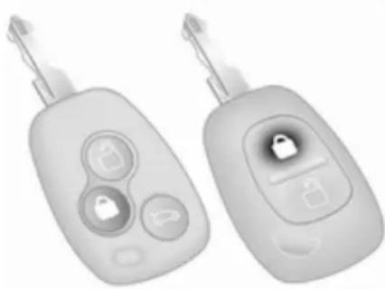
Locking
Close doors, load compartment and fuel filler flap. If the doors are not closed properly, the central locking system will not work.
Central locking system with key activation
Turn the key in the driver's door lock rearwards.
Central locking system with radio remote control
natural_image
Two identical white car keys with circular buttons and key handles, one with a lock icon (no text or symbols visible)Press button 🔒.
On vehicles with selective door locking only the passenger compartment doors are locked.
Load compartment
With two function remote control all doors are locked or unlocked in conjunction with each other.

natural_image
Close-up of a car key with three buttons and a small car icon (no text or symbols visible)With selective door locking the load compartment is locked or unlocked independently.
Press button 📄.
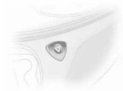
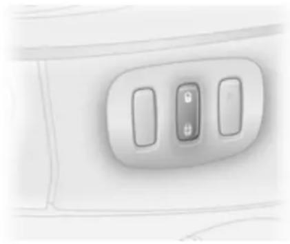
Central locking button
Locks or unlocks doors, the load compartment and fuel filler flap from the passenger compartment.
natural_image
Close-up of a car air conditioner control panel with two buttons and a lock icon (no text or symbols visible)Press button.
$$ \begin{array}{l} ⓜ = \text { lock } \ ⓜ = \text { unlock } \ \end{array} $$
Slam door locks
Certain models feature load compartment locks which are isolated for added security.
While the front doors are locked and unlocked using the radio remote control, load compartment must be manually opened by turning the key in the lock.
Automatic locking
This security feature can be configured to automatically lock all doors, load compartment and fuel filler flap as soon as the vehicle is driven.
To activate:
With the ignition switched on, press 📋 on the central locking button and hold for approx. 5 seconds until an audible confirmation is heard.
To deactivate:
With the ignition switched on, press 📋 on the central locking button and hold for approx. 5 seconds until an audible confirmation is heard.
22 Keys, doors and windows
Child locks

natural_image
Close-up of a door handle mechanism with circular buttons and a black arrow indicating rotation (no text or symbols)
Warning
Use the child locks whenever children are occupying the rear seats.
The child safety lock for the sliding door is located on its rearward facing edge.
Using a key or suitable screwdriver, turn the child lock in the rear door to the horizontal position. The door
cannot be opened from the inside. For deactivation, turn the child lock to the vertical position.
Doors
Sliding door

natural_image
Close-up of a car door handle with a circular opening and two small buttons (no text or symbols visible)Ensure the side door is fully closed and secure before driving the vehicle. The door can be locked from inside the vehicle with the interior lock switch.
Rear doors
To open the left hand rear door pull the outside handle. The door is opened from inside the vehicle by pulling the interior handle.

natural_image
Close-up of a mechanical component with a black arrow pointing to a specific part (no visible text or symbols)The right hand rear door is released using the lever.
⚠ Warning
The rear lights may be obscured if the rear doors are open and the vehicle is parked on the roadside.
Make other road users aware of the vehicle, by using a warning triangle or other equipment specified in the road traffic regulations.
natural_image
Abstract 3D rendering of a curved, oval-shaped object with a small circular feature on its surface (no text or symbols)The doors are retained in the 90° position by locking stays. To open the doors to 180° or further, pull the door release handles and swing open to the desired position.
⚠ Warning
Ensure extended opening doors are secured when fully opened.
Opened doors may slam closed due to the force of the wind!
Always close the right hand door before the left hand door.
Load compartment
Tailgate
Opening
natural_image
Simple grayscale illustration of a mechanical component with two blades and a central slot (no text or symbols)After unlocking with radio remote control, press tailgate button and lift tailgate to fully open position.
In very cold climates, the opening assistance provided by the tailgate hydraulic struts may be reduced.
The tailgate can be also opened from inside the vehicle by pushing down the tailgate interior release.
24 Keys, doors and windows
Closing
Close tailgate using the interior strap.
Ensure tailgate is fully closed.
General hints for operating tailgate

Warning
Do not drive with the tailgate open or ajar, e.g. when transporting bulky objects, since toxic exhaust gases, could enter the vehicle.
Caution
Ensure there is adequate clearance both above (at least 2.15 m) and behind when opening tailgate.
Vehicle security
Anti-theft locking system

Warning
Do not use the system if there are people in the vehicle! The doors cannot be unlocked from the inside.
The system deadlocks all the doors. All doors must be closed or the system cannot be activated.
Unlocking the doors with the radio remote control or the key disables the mechanical anti-theft locking system. Unlocking is not possible with the central locking button.
When the hazard warning flashers or sidelights are switched on, the system cannot be activated.
Activating
natural_image
Two identical gray car key holders with three buttons and a lock icon, shown from different angles (no text or symbols visible)Press 📋 on the radio remote control twice within 10 seconds.
- or -
Turn key in driver's door lock towards front of vehicle twice within 10 seconds, turn it back to the vertical position and remove.
Anti-theft alarm system
The anti-theft alarm system is operated in conjunction with the central locking system.
It monitors:
■ Doors, tailgate, bonnet
■ Passenger compartment including adjoining load compartment
■ Interruption of alarm siren power supply
Activation
natural_image
Two white car key-shaped objects with circular buttons and a lock icon, shown from different angles (no text or symbols visible)All doors and the bonnet must be closed.
Press button 🔒.
If the hazard warning flashers do not flash upon activation, a door or the bonnet is not fully closed.
Activation without monitoring of passenger compartment

natural_image
Two identical white car key-shaped devices with three buttons and a central lock icon, shown side by side (no text or symbols visible)Switch off monitoring of the passenger compartment when people or animals are being left in the vehicle:
Press and hold button 📋. An audible beep will sound to confirm that the function has been disabled.
The status will remain until the anti-theft alarm system is deactivated or the doors are unlocked.
Deactivation
Unlocking the vehicle deactivates the anti-theft alarm system. Turn signal lights flash once upon deactivation.
If the alarm has been triggered, the hazard warning flashers will not flash upon deactivation.
When unlocking the vehicle using the key, the alarm siren will sound. To stop the siren, switch on the ignition.
Alarm
When triggered, the alarm sounds via a separate battery-backed power sounder, and the hazard warning lights flash simultaneously. The number and duration of alarm signals are stipulated by legislation.
In the event of its power supply being disconnected or disconnection of the vehicle battery, the alarm siren will sound. If vehicle battery is to be disconnected, first deactivate the anti-theft alarm system. To silence the alarm siren if activated, reconnect vehicle battery and unlock vehicle with radio remote control.
The siren is silenced and the anti-theft alarm system is deactivated by pressing button ☑ or by switching on the ignition.
Immobiliser
The system is part of the ignition switch and checks whether the vehicle is allowed to be started with the key being used.
The immobiliser is activated automatically after the key has been removed from the ignition lock and also if the key is left in the ignition switch when the engine is turned off.
If the engine cannot be started, switch off the ignition and remove key, wait approx. 2 seconds and then repeat the start attempt. If start attempt is unsuccessful, attempt to start the engine using the spare key and seek the assistance of a workshop.
Note
The immobiliser does not lock the doors. You should always lock the vehicle after leaving it and switch on the anti-theft alarm system 20, 24.
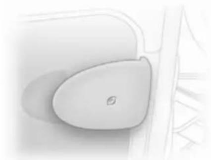
Exterior mirrors
Convex shape
The convex exterior mirror reduces blind spots. The shape of the mirror makes objects appear smaller, which will affect the ability to estimate distances.
Manual adjustment

natural_image
Interior view of a car showing steering wheel, dashboard, and steering wheel (no text or symbols)Adjust mirrors by swivelling in required direction.
The lower mirrors are not adjustable.
Electric adjustment
natural_image
Close-up of a car's side panel with a circular button and two buttons, showing a rotation arrow (no text or symbols)Select the relevant exterior mirror by turning the control to left or right. In the central position no mirror is selected.
Then swivel the control to adjust the mirror.
The lower mirrors are not adjustable.
Folding

natural_image
Abstract 3D graphic of a stylized object with a curved handle and directional arrow, no text or symbols present.For pedestrian safety, the exterior mirrors will swing out of their normal mounting position if they are struck with sufficient force. Reposition the mirror by applying slight pressure to the mirror housing.
Heated

natural_image
Close-up of a white airplane cabin interior with three vertical slots and a small screen (no text or symbols visible)Operated by pressing the 📄 button. Heating functions with the engine running. It is switched off automatically after a short time. Climate control system ➔ 78.
Interior mirrors
Manual anti-dazzle
natural_image
Close-up of a white car front panel with a dark rectangular cover and a curved handle (no text or symbols visible)To reduce dazzle, adjust the lever on the underside of the mirror housing.
Windows
Manual windows
The door windows can be opened or closed with the window winders.
Power windows
Warning
Take care when operating the power windows. Risk of injury, particularly to children.
Keep a close watch on the windows when closing them. Ensure that nothing becomes trapped in them as they move.
Power windows can be operated with the ignition on.

natural_image
3D rendered image of a remote control device with two buttons (no text or symbols visible)Operate the control to open or close the window.
For vehicles with automatic feature pull or press the switch again to stop window movement.
In the event of closing difficulties due to frost or the like, operate the switch several times to close the window in stages.
Rear windows
Sliding side windows
natural_image
Pure mechanical assembly diagram showing two vertical components with downward arrows indicating force or movement (no text or symbols)To open, pull up catch and slide open. To close, pull up catch and slide window until catch engages.
Note
During window opening or closing, keep the catch raised to allow the glass sufficient clearance.
Heated rear window

natural_image
Close-up of a white airplane cabin with three vertical control buttons and a small illuminated screen (no text or symbols visible)Operated by pressing the 📄 button.
Heating functions with the engine running and is switched off automatically after a short time.
Climate control system ➔ 78.
Sun visors
The sun visors can be folded down or swivelled to the side to prevent dazzling.
If the sun visors have integral mirrors, the mirror covers should be closed when driving.
Seats, restraints
Head restraints 30
Front seats 31
Rear seats 34
Seat belts 37
Airbag system 40
Child restraints 44
Head restraints
Position
Warning
Only drive with the head restraint set to the proper position.
natural_image
Side profile illustration of a person wearing a car seatbelt, showing head and neck alignment (no text or symbols)The middle of the head restraint should be at eye level. If this is not possible for extremely tall people, set to highest position, and set to lowest position for small people.
Adjustment

natural_image
Illustration of a stylized object with two legs and an upward arrow, no text or symbols present.Pull the head restraint upwards or push the head restraint downwards.
Note
Approved accessories may only be attached to the front passenger seat head restraint if the seat is not in use.
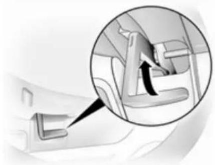
Head restraint removal
natural_image
Illustration of a hand pressing down on two identical cylindrical legs (no text or symbols)To remove the head restraints, pull lock tab and pull the restraint upwards.
Stow head restraints securely in load compartment. Do not drive with head restraints removed if the seat is occupied.
Front seats
Seat position
Warning
Only drive with the seat correctly adjusted.
natural_image
Illustration of a person sitting in a car steering wheel, viewed from the side (no text or symbols)■ Sit with buttocks as far back against the backrest as possible. Adjust the distance between the seat and the pedals so that legs are slightly angled when pressing the pedals. Slide the front passenger seat as far back as possible.
- Sit with shoulders as far back against the backrest as possible. Set the backrest rake so that it is possible to reach the steering wheel with arms slightly bent. Maintain contact between shoulders and the backrest when turning the steering wheel. Do not angle the backrest too far back. We recommend a maximum rake of approx. 25°.
■ Adjust the steering wheel ➔ 56.
■ Set seat height high enough to have a clear field of vision on all sides and of all display instruments. There should be at least one hand of clearance between head and the roof frame. Thighs should rest lightly on the seat without pressing into it.
■ Adjust the head restraint ➔ 30.
■ Adjust the height of the seat belt ➔ 38.
■ Adjust the lumbar support so that it supports the natural shape of the spine ➔ 32.
32 Seats, restraints
Seat adjustment

Danger
Do not sit nearer than 25 cm from the steering wheel, to permit safe airbag deployment.

Warning
Never adjust seats while driving as they could move uncontrollably.
Seat positioning
natural_image
Illustration of a vehicle with directional arrows indicating road or traffic flow (no text or symbols)Pull handle, slide seat, release handle.
Seat backrests
natural_image
Illustration of a car seatbelt with directional arrows indicating rotation (no text or symbols)Pull lever, adjust inclination and release lever. Allow the backrest to engage audibly.
Do not lean on seat when adjusting.
Seat height
natural_image
Mechanical component with upward arrows indicating motion or force (no text or symbols)Lift lever and adjust body weight on seat to adjust height.
Lumbar support

natural_image
Diagram of a car interior showing a steering wheel and gear shift (no text or labels)Adjust lumbar support using handwheel to suit personal requirements.
Rotate handwheel to increase and decrease support.
Armrest
natural_image
Mechanical component diagram showing a knob and directional arrows (no text or symbols)Adjust armrest support to suit personal requirements.
■ Raise armrest in increments to desired height.
■ To reposition, fully raise armrest before lowering.
Heating

natural_image
Close-up of a medical device with a bulb and connector (no visible text or symbols)Press the ⏻ button for the respective seat. Press the ⏻ button again to switch off.
Seat heating is thermostatically controlled and switches off automatically when seat temperature is sufficient.
Control indicator in the button illuminates when the system is on, not just when heating is active.
Prolonged use of the highest setting for people with sensitive skin is not recommended.
34 Seats, restraints
Seat heating is operational when the engine is running.
Rear seats Second row seats
natural_image
Interior view of a vehicle cabin with seats and overhead conveyor belt (no visible text or symbols)When folding or removing the rear seat ensure the armrests are folded away in their most upright position.
Also remove the lower seat trim side pocket by disconnecting it from the fixings.

natural_image
Interior view of a car seatbelt with visible seat covers and a small vehicle (no text or symbols)To enable long items to be stored under the seats the centre seat trim cover can be unclipped.
Rear seat access
natural_image
Close-up of a white ergonomic seat with black arrows indicating clockwise motion (no text or symbols)To facilitate access to the rear seats, fold the seat backrest forwards. If necessary release the two-latch seat belt from its buckles.
⚠ Warning
Ensure that the backrest returns to its correct position and the seat belt buckles engage securely.
Fitting seat belt ➔ 38.
Folding seats
On some variants, the cargo area can be increased by folding up the rear seats.
natural_image
Person operating a medical examination chair with directional arrows indicating movement (no text or symbols visible)Remove the head restraints 30. Pull the side handle to release the backrest and fold forward onto the seat base, if necessary releasing the two-latch seat belts from their buckles.
Release both locking bars at the rear base of the seat by pulling rearwards. Lift and fold the seat assembly, until the seat frame rests in place.
Warning
When folding the seat use caution - beware of moving parts. Ensure the seat is secure when completely folded.
natural_image
Technical diagram of a mechanical assembly with two downward arrows indicating force or movement (no text or symbols present)To return the folding seat to the upright position, support the seat assembly and release the bar by pulling the bar directly towards you. Gradually lower the seat assembly, allowing the rear support legs to fold down. Lower the seat completely, ensuring the rear support legs are located, and latched.
36 Seats, restraints
Raise the backrest, reinstall head restraints and connect the seat belts.

Warning
When installing the seat, ensure that the seat is properly located on the anchor points and that the locking catches are fully engaged, the backrest is returned to the correct position and the seat belts are engaged securely.
Removable rear seats
On some variants, the cargo area can be increased by removing the rear seats.
natural_image
Diagram of a bathroom fixture with a toilet and metal railing, showing directional arrows indicating movement (no text or symbols)Release the seats by pressing down and sliding forward the locking catch located on the left and right hand seat mountings.
natural_image
Mechanical assembly diagram showing a lever mechanism with a rotating component (no text or symbols)With both catches raised, push the seat unit towards the rear and release them from the floor anchor points. The seat can then be lifted out.
The seats must be removed through the sliding door only.

Warning
Removable seats are heavy! Do not attempt to remove without assistance.
When installing the seats, ensure that the seats are properly located on the anchor points and that the locking catches are fully engaged.

text_image
A BWarning
When re-installing seats always ensure that the row with the folding access seat B is positioned correctly in front of the fixed seat row A.
If the seats are incorrectly positioned, access for passengers is seriously impeded.
Seat belts
natural_image
Illustration of a person sitting in a car, wearing a seatbelt and holding a steering wheel (no text or symbols visible)The seat belts are locked during heavy acceleration or deceleration of the vehicle holding the occupants in the sitting position. Thereby the risk of injury is considerably reduced.
⚠ Warning
Fasten seat belt before each trip. In the event of an accident, people not wearing seat belts endanger their fellow occupants and themselves.
Seat belts are only designed for use by one person at a time. They are not suitable for people younger than 12 years of age or smaller than 150 cm.
Periodically check all parts of the belt system for damage and proper functionality.
Have damaged components replaced. After an accident, have the belts and triggered belt tensioners replaced by a workshop.
Note
Make sure that the belts are not damaged by shoes or sharp-edged objects or trapped. Prevent dirt from getting into the belt retractors.
Belt force limiters
On the front seats, stress on the body is reduced by the gradual release of the belt during a collision.
Belt tensioners
In the event of a head-on or rear-end collision of a certain severity, the front seat belts are tightened.
38 Seats, restraints

Warning
Incorrect handling (e.g. removal or fitting of belts) can trigger the belt tensioners with risk of injury.
Deployment of the belt tensioners is indicated by continuous illumination of control indicator 65.
Triggered belt tensioners must be replaced by a workshop. Belt tensioners can only be triggered once.
Note
Do not affix or install accessories or other objects that may interfere with the operation of the belt tensioners. Do not make any modifications to belt tensioner components as this will invalidate the vehicle type approval.
Three-point seat belt
Fitting

natural_image
Illustration of a person adjusting a belt using a sword (no text or symbols present)Withdraw the belt from the retractor, guide it untwisted across the body and insert the latch plate into the buckle. Tighten the lap belt regularly whilst driving by pulling the shoulder belt.

natural_image
Close-up of hands adjusting a car seatbelt with a downward arrow symbol (no text or symbols present)Loose or bulky clothing prevents the belt from fitting snugly. Do not place objects such as handbags or mobile phones between the belt and your body.

Warning
The belt must not rest against hard or fragile objects in the pockets of your clothing.
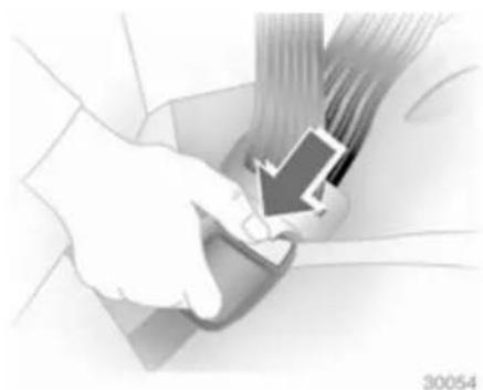
Height adjustment
natural_image
Diagram of a mechanical component with bidirectional arrows indicating movement (no text or symbols)- Pull belt out slightly.
- Press button.
- Slide adjuster up or down to desired position.
Adjust the height so that the belt lies across the shoulder. It must not lie across the throat or upper arm.
Do not adjust while driving.
Removing
natural_image
Medical illustration showing a hand inserting a device into a car seat (no text or symbols visible)To release belt, press red button on belt buckle.
Seat belts on the rear seats
Two-latch belt
natural_image
Illustration of a hand using a belt buckle to lift a seatbelt (no text or symbols visible)Before fitting the belt, first insert lower latch plate into the buckle on the outside of the seat.
The belt can now be used in the same way as a standard seat belt.

Warning
The seat belt will not be effective in the event of an accident if the lower latch is not correctly fitted.
When releasing the seat belt, ensure that the central buckle is always released before the buckle on the side of the seat.
Always remove the lower latch plate from the outside buckle before removing seats from the vehicle or to facilitate access to the rear seats.
Second row seats 34.
Using the seat belt while pregnant
natural_image
Illustration of a pregnant woman seated in a car seat, wearing a seatbelt and holding a belt (no text or symbols visible)
Warning
The lap belt must be positioned as low as possible across the pelvis to prevent pressure on the abdomen.
Airbag system
The airbag system consists of a number of individual systems depending on the scope of equipment.
When triggered the airbags inflate within milliseconds. They also deflate so quickly that it is often unnoticeable during the collision.

Warning
If handled improperly the airbag systems can be triggered in an explosive manner.
Note
The airbag systems and belt tensioner control electronics are located in the centre console area. Do not put any magnetic objects in this area.
Do not stick anything on the airbag covers and do not cover them with other materials.
Each airbag is triggered only once. Have deployed airbags replaced by a workshop.
Do not make any modifications to the airbag system as this will invalidate the vehicle type approval.
In the event of airbag deployment have the steering wheel, the instrument panel, all panelling parts, the door seals, the handles and the seats removed by a workshop.
When the airbags inflate escaping hot gases may cause burns.
Control indicator ✿ for airbag systems ✿ 65.
Front airbag system
The front airbag system consists of one airbag in the steering wheel and one in the instrument panel on the front passenger side. These can be identified by the word AIRBAG.
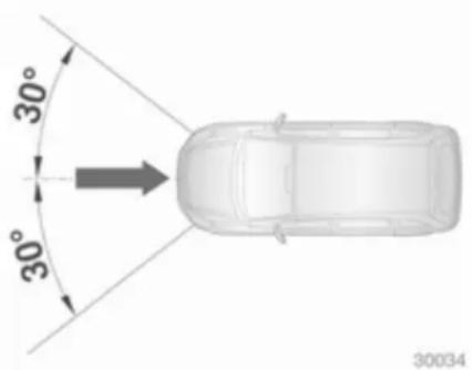
natural_image
Top-down diagram of a car with 30-degree angles and an arrow indicating direction (no text or symbols)The front airbag system is triggered in the event of an accident of a certain severity in the depicted area. The ignition needs to be switched on.
The inflated airbags cushion the impact, thereby reducing the risk of injury to the upper body and head of the front seat occupants considerably.
⚠ Warning
Optimum protection is only provided when the seat is in the proper position 31.
Keep the area in which the airbag inflates clear of obstructions.
Fit the seat belt correctly and engage securely. Only then the airbag is able to protect.
Side airbag system
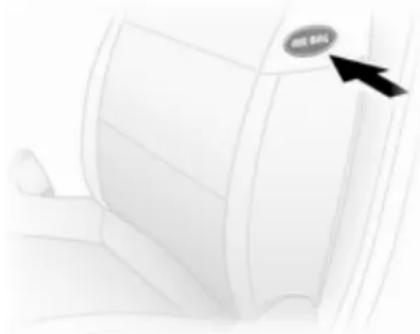
natural_image
Close-up of a car interior with a black arrow pointing to the 'NE BAG' button (no other text or symbols)42 Seats, restraints
The side airbag system consists of an airbag in each front seat backrest. This can be identified by the word AIRBAG.
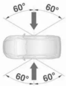
text_image
60° 60° 60° 60°The side airbag system is triggered in the event of an accident of a certain severity in the depicted area. The ignition needs to be switched on.
natural_image
Illustration of a car seatbelt with a side arm, showing no text or symbolsThe inflated airbags cushion the impact, thereby reducing the risk of injury to the upper body and pelvis in the event of a side-on collision considerably.
Warning
Keep the area in which the airbag inflates clear of obstructions.
Note
Only use protective seat covers that have been approved for the vehicle. Be careful not to cover the airbags.
Curtain airbag system

text_image
AIR BAGThe curtain airbag system consists of an airbag in the roof frame on each side. This can be identified by the word AIRBAG on the headlining trim.

text_image
60° 60° 60° 60° 30035The curtain airbag system is triggered in the event of an accident of a certain severity in the depicted area. The ignition needs to be switched on.
The inflated airbags cushion the impact, thereby reducing the risk of injury to the head in the event of a side-on impact considerably.
Warning
Keep the area in which the airbag inflates clear of obstructions.
Airbag deactivation
Front airbag and side airbag systems for the front passenger seat have to be deactivated if a child restraint system is to be fitted on this seat. The curtain airbag system, the belt tensioners and all driver airbag systems will remain active.

text_image
ON AIRBAG OFFThe airbag deactivation system is indicated by a label on the side of the instrument panel, visible when the front passenger door is open.

natural_image
Diagram of a car interior showing a door, vent, and directional arrows indicating rotation (no text or symbols)Front passenger airbag system can be deactivated via a switch located on the front passenger door.
With the front passenger door open, press switch in and rotate anti-clockwise to the OFF position.
Front passenger seat airbags are deactivated and will not inflate in the event of a collision. Control indicator _2 illuminates continuously in the instrument cluster. A child restraint system can be installed in accordance with the installation locations chart 46.
44 Seats, restraints

Danger
Risk of fatal injury for a child using a child restraint system together with activated front passenger airbag.
Risk of fatal injury for an adult person with deactivated front passenger airbag.
As long as control indicator _2 is not illuminated, the airbag systems for the front passenger seat will inflate in the event of a collision.
Change status only when the vehicle is stopped with the ignition off. Status remains until the next change.
If control indicator 2 remains illuminated together with 3 , this indicates a fault within the system. Seek the assistance of a workshop.
Control indicator for airbag deactivation 65.
Child restraints
Child restraint systems
We recommend the Opel child restraint system which is tailored specifically to the vehicle.
When a child restraint system is being used, pay attention to the following usage and installation instructions and also those supplied with the child restraint system.
Always comply with local or national regulations. In some countries, the use of child restraint systems is forbidden on certain seats.

Warning
When using a child restraint system on the front passenger seat, the airbag systems for the front passenger seat must be deactivated; if not, the triggering of the airbags poses a risk of fatal injury to the child.
This is especially the case if rear-facing child restraint systems are used on the front passenger seat.
Selecting the right system
Children should travel in a rear-facing child restraint until as old as possible. It is appropriate to change the system when the child's head can no longer be properly supported at eye height.
In the event of an accident, the child's backbone, which is still very weak, is under less strain in the semi-prone rearward position than when sitting upright.
Children under 12 years or under 150 cm tall should only travel in an appropriate child restraint system.
Since a proper position of the seat belt is rarely possible with a child that is smaller than 150 cm, we strongly advise the use of an appropriate child restraint system, even though this might, due to the age of the child, no longer be legally binding.
Never hold a child whist travelling in the vehicle. The child will become too heavy to be held in the event of a collision.
When transporting children, use the child restraint system suitable for the child's weight.
Ensure that the child restraint system to be installed is compatible with the vehicle type.
Ensure that the mounting location of the child restraint system within the vehicle is correct.
Only allow children to enter and exit the vehicle at the side facing away from the traffic.
When the child restraint system is not in use, secure the seat with a seat belt or remove it from the vehicle.
Note
Do not stick anything on the child restraint systems and do not cover them with any other materials.
A child restraint system which has been subjected to stress in an accident must be replaced.
Child restraint installation locations
Permissible options for fitting a child restraint system
Front seats - all variants
Weight and age class Single seat - front passenger
1)
Bench seat - front passenger
| without airbag with airbag without airbag with airbag | ||||
| centre outer centre outer | ||||
| Group 0: up to 10 kg or approx. 10 months Group 0+: up to 13 kg or approx. 2 years | U | U^2) | X U X | U^2) |
| Group I: 9 to 18 kg or approx. 8 months to 4 years | U | U^2) | UF U UF | U^2) |
| Group II: 15 to 25 kg or approx. 3 to 7 years Group III: 22 to 36 kg or approx. 6 to 12 years | U | U^2) | UF U UF | U^2) |
1) If adjustable, ensure seat is in its rearmost position. Make sure vehicle seat belt is as straight as possible between shoulder and upper anchorage point.
2) Ensure the front passenger airbag system is deactivated when installing a child restraint in this position.
U = Suitable for universal category restraint systems for use in this weight and age class, in conjunction with three-point seat belt.
UF = Suitable for universal category forward-facing restraint systems for use in this weight and age class, in conjunction with three-point seat belt.
X = Seat position not suitable for children of this weight and age class.
Combi - rear seats
Weight and age class 2nd row bench seat 3rd row bench seat
3)
| Outer Centre Outer Centre | ||||
| Group 0: up to 10 kgor approx. 10 monthsGroup 0+: up to 13 kgor approx. 2 years | U | U,+ | X | X |
| Group I: 9 to 18 kgor approx. 8 months to 4 years | U | U,+ | X | X |
| Group II: 15 to 25 kgor approx. 3 to 7 yearsGroup III: 22 to 36 kgor approx. 6 to 12 years | U U X X | |||
3) It is permissible to install a universal child seat to the third seat row if the second row seats have been removed and the seat belts are of sufficient length for the child seat type. Similarly, on left hand drive models with a 2 seat bench in the second row, it is permissible to install a universal child restraint on the third seat row but only on the right hand outboard side, due to increased clearance in front of it.
48 Seats, restraints
U = Suitable for universal category restraint systems for use in this weight and age class, in conjunction with three-point seat belt.
+ = Seat with ISOFIX mounting available. When mounting an ISOFIX child restraint system, only systems that have been approved for the vehicle may be used.
X = Seat position not suitable for children in this weight and age class.
Tour - rear seats
Weight and age class 2nd row bench seat 3rd row bench seat 3)
| Outer Centre Outer Centre | ||||
| Group 0: up to 10 kgor approx. 10 monthsGroup 0+: up to 13 kgor approx. 2 years | U | U, + | X | X |
| Group I: 9 to 18 kgor approx. 8 months to 4 years | U | U, + | X | X |
| Group II: 15 to 25 kgor approx. 3 to 7 yearsGroup III: 22 to 36 kgor approx. 6 to 12 years | U U X X | |||
3) It is permissible to install a universal child seat to the third seat row if the second row seats have been removed and the seat belts are of sufficient length for the child seat type. Similarly, on left hand drive models with a 2 seat bench in the second row, it is permissible to install a universal child restraint on the third seat row but only on the right hand outboard side, due to increased clearance in front of it.
U = Suitable for universal category restraint systems for use in this weight and age class, in conjunction with three-point seat belt.
+ = Seat with ISOFIX mounting available. When mounting an ISOFIX child restraint system, only systems that have been approved for the vehicle may be used.
X = Seat position not suitable for children in this weight and age class.
50 Seats, restraints
Isofix child restraint systems
Fasten vehicle-approved ISOFIX child restraint systems to the ISOFIX mounting brackets.
When using ISOFIX mounting brackets for seat mounting, universally approved child restraint systems for ISOFIX may be used.
Permissible mounting location positions for ISOFIX child restraint systems are marked in the tables by +.
Storage
Storage compartments .... 51
Load compartment 52
Roof rack system 54
Loading information 54
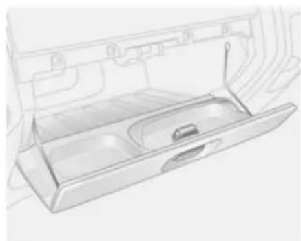
Storage compartments Instrument panel storage
Storage compartments, pockets and trays are located in the instrument panel.
A coin holder and a phone pocket are located on the top of the instrument panel.
Glovebox
natural_image
Line drawing of a car front drawer with handle and vent (no text or symbols)The glovebox features a pen holder. The glovebox should be closed whilst driving.
Glovebox cooler 82.
Cupholders
natural_image
Close-up of a car wheel handle with a cylindrical component, no visible text or symbolsCupholders are located at either end of the instrument panel.
To use cupholders remove the ashtray unit.
Front storage
Two coat hooks are located on the cabin bulkhead.
The front door pockets contain bottle holders.
52 Storage
Overcab storage

natural_image
Illustration of a mechanical component or bracket with no visible text or symbolsThe total weight in this compartment must not exceed 30 kg.
Load compartment
Load compartment cover
Do not place any objects on the cover.
Removing

natural_image
Diagram of a metal plate with an upward arrow, no text or symbols presentLift cover and disconnect from the side guides.
Load rails and hooks
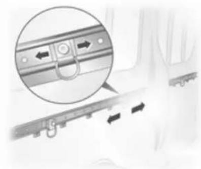
natural_image
Close-up of a mechanical component with directional arrows indicating movement, no visible text or symbolsLoad anchorage rails mounted in the load compartment provide adjustable anchorage points for securing cargo.
■ Release centre pin of the anchorage point by pulling out against spring tension,
■ slide the anchorage point to the required position, directly over a suitable locking hole,
■ release the centre pin of the anchorage point, ensuring the pin is located correctly and the anchorage point is securely locked,
■ cargo can then be secured in position using lashing straps attached to the anchorage point.
The maximum load of each anchorage point is 75 kg. To prevent the possibility of exceeding this maximum, the use of ratchet type lashing straps is to be avoided.
Lashing eyes
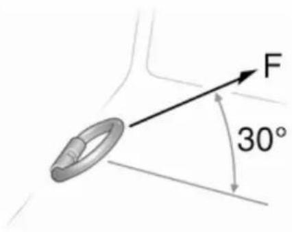
text_image
F 30°The lashing eyes are designed to secure items against slippage, e.g. using lashing straps or a luggage floor net.
The maximum force applied to the lashing eyes should not exceed 5000 N at 30°.
Safety net
The safety net can be installed behind the front seats or the rear seats.
Passengers must not be transported behind the safety net.
Installing (front or rear position)
Lift the covers to access the mountings, insert the load compartment net rod into the mounts and secure. Attach the straps to the lashing eyes behind the front seats; or to the rings on the rear seat frame, then tension the straps.
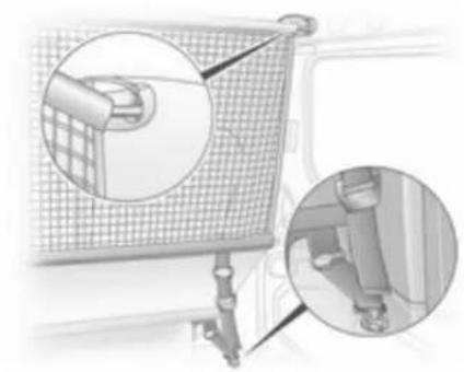
natural_image
Diagram of a mobile phone with grid screen and attached cable, showing two magnified views (no text or symbols)Removal
Tilt strap length adjuster upwards and unhook strap.
Warning triangle
The warning triangle can be accommodated in the space under the front seats.
First aid kit
The first aid kit can be accommodated in the space under the front seats.
Roof rack system
Roof rack
For safety reasons and to avoid damage to the roof, the vehicle approved roof rack system is recommended.
Note
The front roof rack fixing points located above the cab area are for installation of the full roof rack system only and must not be used to attach roof bars.
Follow the installation instructions and remove the roof rack when not in use.
Further information ➔ 54.
Loading information
■ Heavy objects in the load compartment should be placed as far forward as possible. If objects can be stacked, the heavier objects should be placed at the bottom.
■ Secure objects with lashing straps attached to lashing eyes.
■ Secure loose objects in load compartment to prevent sliding.
■ Do not place any objects on the load compartment cover or the instrument panel.
■ The load must not obstruct the operation of the pedals, parking brake and gear selector, or hinder the freedom of movement of the driver. Do not place any unsecured objects in the interior.
■ Do not drive with an open load compartment. In addition, the number plate is only distinguishable and illuminated correctly if the doors are closed.
■ The payload is the difference between the permitted gross
vehicle weight (see identification plate 140) and the EC kerb weight.
To calculate the EC kerb weight, enter the data for your vehicle in the Weights table at the front of this manual.
The EC kerb weight includes weights for the driver (68 kg), luggage (7 kg) and all fluids (tank 90 % full).
Optional equipment and accessories increase the kerb weight.
- Driving with a roof load increases the sensitivity of the vehicle to cross-winds and has a detrimental effect on vehicle handling due to the vehicle's higher centre of gravity. Distribute the load evenly and secure it properly with retaining straps. Adjust the tyre pressure and vehicle speed according to the load conditions. Check and retighten the straps frequently.
The permissible roof load (which includes the weight of the roof rack) is 280 kg for standard roof variants
and 210 kg for high roof variants (excludes Platform cab conversions). The roof load is the combined weight of the roof rack and the load.
The permissible roof load on the approved full length roof rack system is 210 kg for standard roof variants and 140 kg for high roof variants (excludes Platform cab conversions). The roof load is the combined weight of the roof rack and the load.
Instruments and controls
Controls 56
Warning lights, gauges and indicators 61
Information displays 69
Vehicle messages 69
Trip computer 70
Tachograph 72
Controls
Steering wheel adjustment

natural_image
Interior view of a car seatbelt mechanism with a magnified inset showing the mechanism (no text or symbols visible)Unlock lever, adjust steering wheel, then engage lever and ensure it is fully locked.
Do not adjust steering wheel unless vehicle is stationary and steering wheel lock has been released.
Steering wheel controls
natural_image
Top-down view of a white circular steering wheel with three blades (no text or symbols)The cruise control and speed limiter can be operated via the controls on the steering wheel.
Cruise control and speed limiter 95.
Horn
natural_image
Top-down view of a car steering wheel with three spokes (no text or symbols)Press ▶.
The horn will sound regardless of ignition switch position.
Steering column controls

text_image
SOURCE AUDIO MODE OKThe Infotainment system can be operated via the controls on the steering column.
Further information is available in the Infotainment manual.
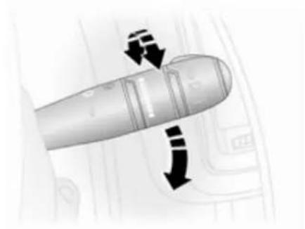
Windscreen wiper/washer
Windscreen wiper

natural_image
Illustration of a missile with a downward arrow indicating motion (no text or symbols)= timed interval wipe
1 = slow
2 = fast
Do not use if the windscreen is frozen.
Switch off in car washes.
58 Instruments and controls
Automatic wiping with rain sensor
natural_image
Illustration of a stylized aircraft fuselage with directional arrows indicating flight or movement (no text or symbols)= automatic wiping with rain sensor
The rain sensor detects the amount of water on the windscreen and automatically regulates the frequency of the windscreen wipers.
Upon starting the engine, automatic wiping will need to be reselected.
Adjustable sensitivity of the rain sensor Turn the adjuster wheel to adjust the sensitivity:
low = turn adjuster wheel sensitivity downwards high = turn adjuster wheel sensitivity upwards

natural_image
Diagram of a hand holding a small object with an arrow pointing to it, on a device panel (no text or symbols present)Keep the sensor free from dust, dirt and ice.
Windscreen washer

natural_image
Close-up of a metallic cylindrical object with a black arrow pointing to it, against a background of curved lines and a small boat (no text or symbols visible)Pull lever. Washer fluid is sprayed onto the windscreen.
short pull = wiper swipes once long pull = wiper swipes for a few strokes
Rear window wiper/washer

natural_image
Close-up of a pen tip with a black arrow pointing to it, overlaid on a map or diagram (no readable text or symbols)Turn:
0 = off
□ = wiper operation
= washer fluid is sprayed onto the rear window
Outside temperature
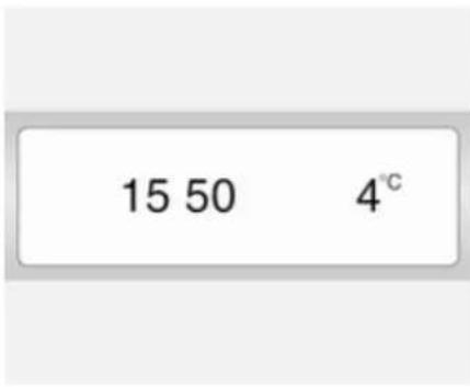
text_image
15 50 4℃A drop in temperature is indicated immediately and a rise in temperature after a time delay.
If outside temperatures drop to 3 °C, the °C flashes in the information display as a warning for icy road conditions. This will continue to flash until temperatures rise above 3 °C.
Warning
The road surface may already be icy even though the display indicates a few degrees above 0 °C.
Clock

text_image
15 50 4℃Depending on vehicle, hours and minutes can be adjusted by pressing the buttons alongside the display or with the Infotainment system controls.
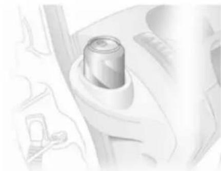
Power outlets

natural_image
Close-up of a metallic cylindrical object on a textured surface (no visible text or symbols)12 V power outlets are located in the instrument panel and in the rear of the vehicle.
natural_image
Close-up of a bathroom sink with a wall-mounted shower icon (no text or symbols visible)Connecting electrical accessories while the engine is off will discharge the battery. Do not exceed the maximum power consumption of 120 watts. Do not connect any current-delivering accessories, e.g. electrical charging devices or batteries.
Electrical accessories that are connected must comply with the electromagnetic compatibility requirements laid down in DIN VDE 40 839.
Do not connect any current-delivering accessories, e.g. electrical charging devices or batteries.
Caution
Do not damage the outlet by using unsuitable plugs.
Cigarette lighter
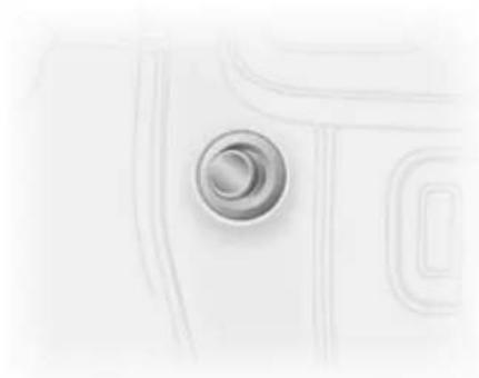
natural_image
Close-up of a metallic circular button on a white surface, no text or symbols visibleThe cigarette lighter is located in the instrument panel.
Press in cigarette lighter. It switches off automatically once the element is glowing. Pull out lighter.
Ashtrays
Caution
To be used only for ash and not for combustible rubbish.
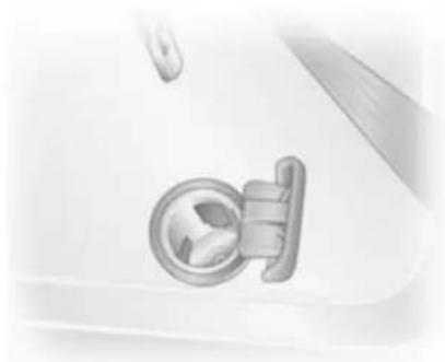
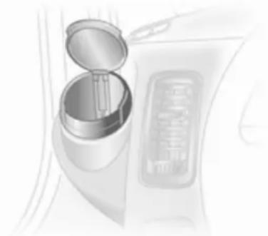
Portable ashtray
natural_image
Illustration of a car interior showing a cylindrical container with an open lid and a rectangular button (no text or symbols)Ashtray container for mobile use in the vehicle. To use, open cover.
Warning lights, gauges and indicators
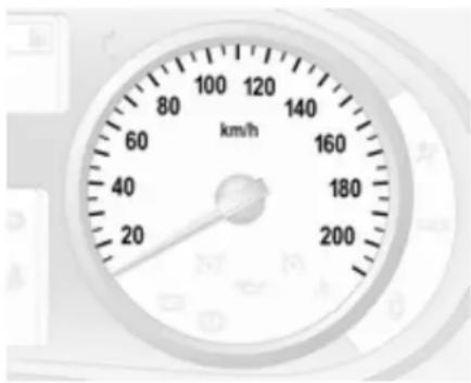
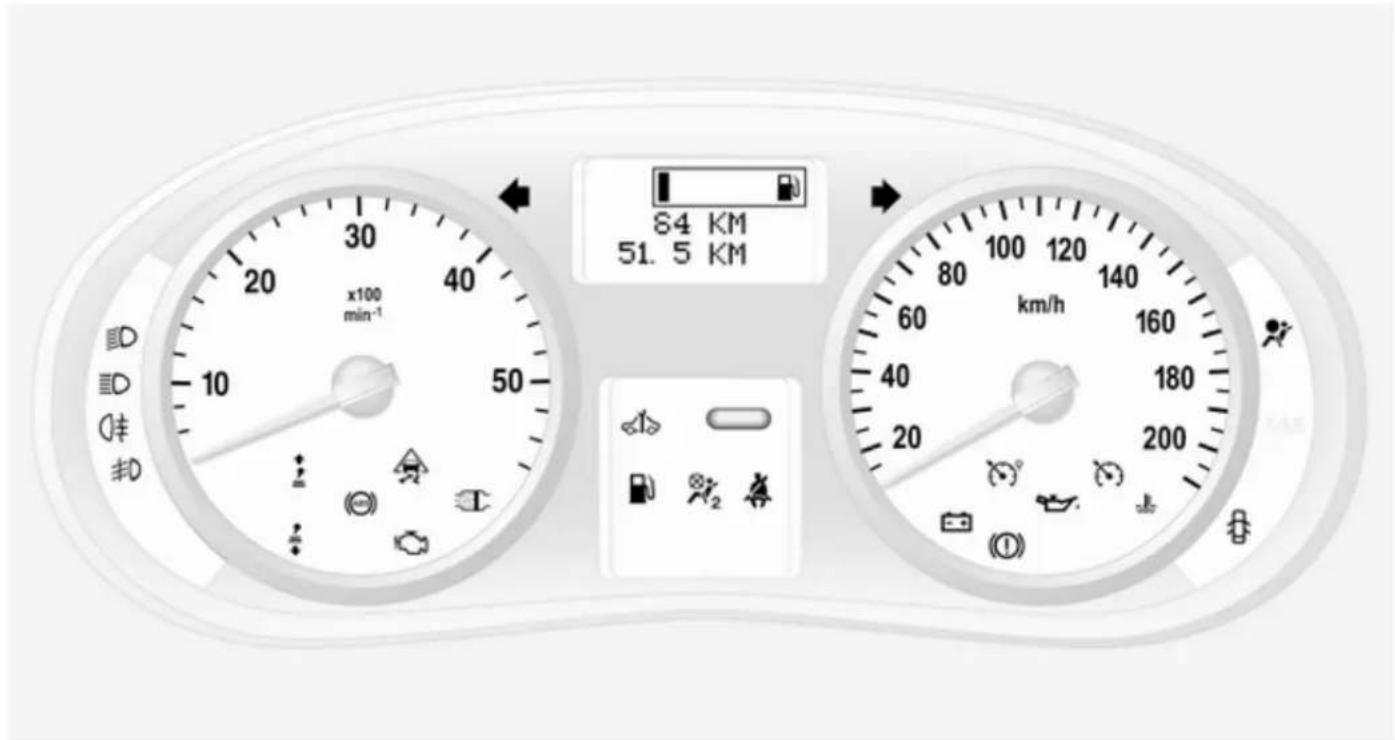
Speedometer
text_image
80 100 120 140 160 180 200 km/hIndicates vehicle speed.
Maximum speed may be restricted by a speed regulator. As a visible indication of this, a warning label is located on the instrument panel.
A warning buzzer will sound for 10 seconds if the vehicle briefly exceeds the set limit.
Note
Under certain conditions (e.g. steep inclines) the vehicle speed may exceed the set limit.
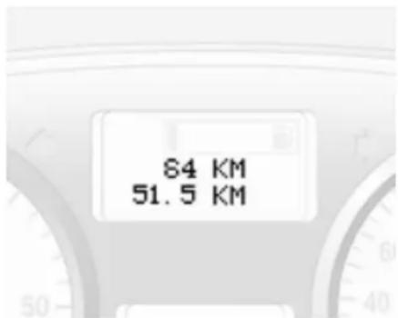
Odometer
text_image
84 KM 51.5 KMDisplays the recorded distance.
Trip odometer
The trip odometer appears below the odometer and displays the distance travelled since the last reset.
To reset, with the trip odometer displayed, press and hold the button on the end of the wiper lever for a few
seconds with the ignition on. The display will flash and the value will reset to zero.
Tachometer

natural_image
Close-up of a analog pressure gauge with scale markings (no readable text or symbols beyond measurement)Displays the engine speed.
Drive in a low engine speed range for each gear as much as possible.
Caution
If the needle is in the red warning zone, the maximum permitted engine speed is exceeded. Engine at risk.
Fuel gauge

text_image
84 KM 51, 5 KMDisplays the fuel level in the tank.
Illumination of bars displays fuel level.
Control indicator 📋 illuminates in the instrument cluster if the level in the tank is low. Refuel immediately 101.
Never run the tank dry.
Because of the fuel remaining in the tank, the top-up quantity may be less than the specified tank capacity.
Engine oil level monitor
The engine oil level monitor is correct only if the vehicle is parked on a level surface with a cold engine.
If the minimum engine oil level is reached, OIL is displayed for 30 seconds after the ignition is switched on in the Driver Information Centre. Check and top up engine oil 107.
If the engine oil level is correct when the ignition is switched on OIL LEVEL CORRECT appears briefly in the Driver Information Centre.
If the engine oil is above the minimum level, press the trip computer button on the end of the wiper lever within 30 seconds of the ignition being switched on. OIL LEVEL is displayed in combination with the squares in the Driver Information Centre to indicate the oil level. As the oil level diminishes, the squares in the display are replaced with dashes:
□□□□□□ = Maximum level □□□ _ _ _ = Intermediate level ____ = Minimum level.
To exit the oil level monitor display, press the trip computer button.
Trip computer 70.
Service display
When the ignition is switched on, the remaining distance before the next service is due may be shown briefly in the Driver Information Centre. Based on driving conditions, the interval at which a service will be indicated can vary considerably.
When the remaining distance before the next service is less than 3000 km or two months, SERVICE IN appears in the Driver Information Centre.
When the distance reaches 0 km or the service date is due, control indicator ⬆ and ⬇ illuminate in the instrument cluster and the Driver Information Centre respectively, and the corresponding message SERVICE DUE appears in the Driver Information Centre.
The vehicle needs a service. Seek the assistance of a workshop.
Resetting the service display
Select the distance before service interval display in the trip computer.
Press and hold the trip computer button on the end of the wiper lever until the distance before service is displayed continuously.
Trip computer 70.
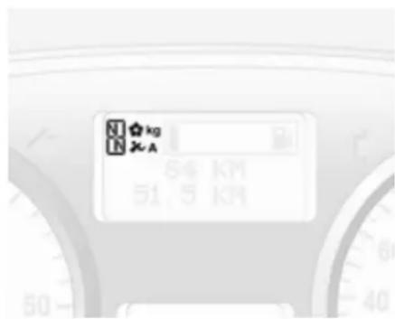
Transmission display
text_image
N ★ kg N ★ A 84 KM 51.5 KMThe mode or selected gear of the manual transmission automated is shown in the Driver Information Centre.
R = Reverse gear
N = Neutral
A = Automatic mode
kg = Laden mode
☀ = Winter mode
### = Apply foot brake
= Transmission electronics
Manual transmission automated 87.
Control indicators
The control indicators described are not present in all vehicles. The description applies to all instrument versions. When the ignition is switched on, most control indicators will illuminate briefly as a functionality test.
The control indicator colours mean:
red = danger, important
reminder
yellow = warning, information, fault green = confirmation of activation
blue = confirmation of activation
64 Instruments and controls
Control indicators in the instrument cluster
text_image
84 KM 51.5 KM km/hTurn signal
←→ flashes green.
Flashes if a turn signal or the hazard warning flashers are activated.
Rapid flashing: failure of a turn signal light or associated fuse.
An audible warning can be heard when the turn signals are on. When towing a trailer, the pitch of the audible warning changes.
Bulb replacement ➔ 114.
Fuses 118.
Turn signals ↩ 75.
Seat belt reminder
illuminates in red.
May illuminate or flash until the seat belt has been fastened.
Airbag and belt tensioners
illuminates yellow.
When the ignition is switched on, the control indicator illuminates briefly. If it does not illuminate or illuminates
whilst driving, there is a fault in the belt tensioner or the airbag system. The airbags and belt tensioners may fail to trigger in the event of an accident.
Deployment of the belt tensioners or airbags is indicated by continuous illumination of ⚠.
⚠ Warning
Have the cause of the fault remedied immediately by a workshop.
Belt tensioners, airbag system 37, 40.
Airbag deactivation
K_2 illuminates yellow when the ignition is switched on and remains illuminated when the front passenger airbag has been deactivated.
If control indicator 2 is illuminated in conjunction with 3 or 4 , seek the assistance of a workshop.
Danger
Risk of fatal injury for a child using a child restraint system together with activated front passenger airbag.
Risk of fatal injury for an adult person with deactivated front passenger airbag.
Airbag system ➔ 40, belt tensioners ➔ 37, airbag deactivation ➔ 43.
Charging system
- + illuminates red.
Illuminates when the ignition is switched on and goes out shortly after the engine starts.
Illuminates when the engine is running
Stop, switch off engine. Battery is not charging. Engine cooling may be interrupted. Power to the brake servo unit may be cut. Seek the assistance of a workshop.
Malfunction indicator light
illuminates or flashes yellow.
Illuminates when the ignition is switched on and goes out shortly after the engine starts.
Illuminates when the engine is running
Fault in the emission control system. The permitted emission limits may be exceeded. Seek the assistance of a workshop immediately.
Flashes when the engine is running
Fault that could lead to catalytic converter damage. Ease up on the accelerator until the flashing stops. Seek the immediate assistance of a workshop.
Service vehicle soon
illuminates in yellow.
Illuminates when the ignition is switched on and goes out shortly after the engine starts.
May illuminate in combination with another control indicator or a message in the Driver Information Centre. Seek the assistance of a workshop immediately.
Stop engine
STOP illuminates in red.
Illuminates together with ☐, ☑, or Ⓔ; stop engine immediately and seek the assistance of a workshop.
Brake system
(1) illuminates red.
Illuminates when the parking brake is released if the brake fluid level is too low 111.
⚠ Warning
Stop. Do not continue your journey. Consult a workshop.
Illuminates after the ignition is switched on if the parking brake is applied 92.
If the message BRAKING FAULT appears in the Driver Information Centre there is a fault in the braking system. Seek the assistance of a workshop immediately.
Brake system ↩ 91.
Antilock brake system (ABS)
(ABS) illuminates yellow.
Illuminates briefly after the ignition is switched on. The system is ready for operation when (ABS) goes out.
If control indicator (ABS) does not go out after a few seconds, or if it illuminates while driving, there is a fault in the ABS. Control indicator ◄ may also illuminate in the instrument cluster together with the messages CHECK ABS and CHECK ESP in the Driver Information Centre. The brake system remains operational but without ABS regulation.
If control indicators (AB), _A , (I) and STOP illuminate, the ABS and ESP are deactivated and the message BRAKING FAULT appears in the
Driver Information Centre. Seek the assistance of a workshop immediately.
Antilock brake system ↩ 92.
Upshift
or illuminates.
It is recommended to shift gear when illuminated for economical reasons.
Electronic Stability Program
flashes or illuminates yellow.
Illuminates for a few seconds when the ignition is switched on.
Flashing during driving
The system is actively engaged. Engine output may be reduced and the vehicle may be braked automatically to a small degree.
Illuminates while driving
The system is switched off. The message ESP OFF will also appear in the Driver Information Centre.
ESP®Plus ↩ 94.
Engine coolant temperature
illuminates red.
Illuminates when the engine is running
Stop, switch off engine.
Caution
Coolant temperature too high.
Check coolant level 110.
If there is sufficient coolant, consult a workshop.
Preheating
illuminates yellow.
Preheating is activated. Only activates when outside temperature is low.
Diesel particle filter
illuminates yellow.
Illuminates when the diesel particle filter requires cleaning 85.
Engine oil pressure
illuminates red.
Illuminates when the ignition is switched on and goes out shortly after the engine starts.
Illuminates when the engine is running
Caution
Engine lubrication may be interrupted. This may result in damage to the engine and/or locking of the drive wheels.
- Depress clutch.
-
Select neutral gear, set selector lever to N.
-
Move out of the flow of traffic as quickly as possible without impeding other vehicles.
- Switch off ignition.

Warning
When the engine is off, considerably more force is needed to brake and steer. Do not remove key until vehicle is stationary, otherwise the steering wheel lock could engage unexpectedly.
Check oil level before seeking assistance of a workshop 107.
Low fuel
illuminates yellow.
Illuminates when level in fuel tank is too low.
Catalytic converter 86.
Bleeding the diesel fuel system 113.
Exterior light
ID illuminates green.
Illuminated when the exterior lights are on 73.
High beam
ID illuminates blue.
Illuminated when high beam is on and during headlight flash 74.
Fog light
≠D illuminates green.
Illuminated when the front fog lights are on 75.
Rear fog light
illuminates yellow.
Illuminated when the rear fog light is on 75.
Cruise control
^① , ^② illuminates green.
illuminates green when a certain speed is stored.
^9 illuminates green when the system is on.
Speed limiter
illuminates orange.
^2 illuminates orange when the system is on.
Cruise control, Speed limiter 95.
Door open
illuminates red.
May illuminate when a door is not fully closed.
Information displays
Driver Information Center
The Driver Information Centre is located in the instrument cluster between speedometer and tachometer.
84 KM 51.5 KM
■ Odometer 61
■ Fuel gauge ➔ 62
■ Engine oil level monitor ➔ 62
■ Service display ↩ 63
■ Transmission display ➔ 63
■ Vehicle messages ↩ 69
- Trip computer ➔ 70
Triple-Info-Display
Displays time, outside temperature and Infotainment system information.
15 50 4 ^°C
■ Outside temperature 59
■ Clock ↩ 59
Vehicle messages
Messages are shown in the Driver Information Centre, in combination with illumination of control indicator or STOP in the instrument cluster.
Information messages
Information messages
BATTERY MODE: ECONOMY
ESP OFF
AUTO LIGHTS DEACTIVATED
OIL LEVEL CORRECT
Fault messages
Will be displayed in combination with control indicator ⬇. Drive with caution and seek the assistance of a workshop.
To remove fault message, press the button on the end of the wiper lever. After a few seconds the message may disappear automatically and
remains illuminated. The fault will then be stored in the on board system.
Fault messages
CHECK ESP
CHECK FUEL FILTER
CHECK GEARBOX
CHECK AUTO LIGHTS
Warning messages
These appear with control indicator STOP. Stop engine immediately and seek the assistance of a workshop.
Warning messages
INJECTION FAULT
ENGINE OVERHEATING
GEARBOX OVERHEATING
Warning chimes
When starting the engine or whilst driving
■ During operation of the turn and lane-change signals.
■ If the low fuel control indicator illuminates.
■ If seat belt is not fastened.
■ If the vehicle has manual transmission automated and the clutch temperature is too high.
■ If the vehicle speed briefly exceeds a set limit.
When the vehicle is parked and the driver's door is opened
■ With exterior lights on.
■ If the vehicle has manual transmission automated, and the parking brake is not applied, neutral not selected or foot brake not depressed.
Trip computer
The trip computer provides information on driving data, which is continually recorded and evaluated electronically.
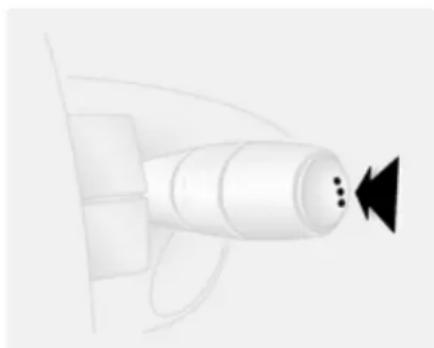
natural_image
Illustration of a white robotic arm with three black buttons pointing left (no text or symbols)The functions can be selected by pressing the button repeatedly on the end of the wiper lever.
Press the button to select one of the functions:
■ Fuel used
■ Average consumption
■ Instantaneous consumption
■ Range
■ Distance travelled
■ Average speed
■ Distance before service
■ Cruise control and speed limiter stored speed
■ Fault and information messages shown in the Driver Information Centre
Fuel used
Displays the amount of fuel consumed since the last reset.
The measurement can be restarted at any time by pressing and holding the button.
Average consumption
The value is displayed after driving a distance of 400 metres.
Average consumption is displayed, taking into consideration the distance travelled and the fuel used since the last reset.
The measurement can be restarted at any time.
Instantaneous consumption
The value is displayed after reaching a speed of 30 km/h.
Range
The value is displayed after driving a distance of 400 metres.
The range is calculated from the current contents of the fuel tank and the average consumption since the last reset.
The range will not display if control indicator ☐ is illuminated in the instrument cluster 68.
The measurement can be restarted at any time.
Distance travelled
Displays the distance driven since the last reset.
The measurement can be restarted at any time.
Average speed
The value is displayed after driving a distance of 400 metres.
The average speed is displayed, since the last reset.
The measurement can be restarted at any time.
Interruptions in the journey with the ignition off are not included in the calculations.
Reset trip computer information
To reset the trip computer, select one of its functions then press and hold the button on the end of the wiper lever.
The following trip computer information will be reset:
■ Fuel used
■ Average consumption
■ Range
■ Distance travelled
■ Average speed
The trip computer will reset automatically when the maximum value of any of the parameters is exceeded.
72 Instruments and controls
Interruption of power supply If the power supply has been interrupted or if the battery voltage has dropped too low, the values stored in the trip computer will be lost.
Tachograph
text_image
10 ≤23.85 (OK/Hz) 0.0kΩThe tachograph is operated as described in the operating instructions supplied. Observe regulations regarding use.
Lighting
Exterior lighting 73
Interior lighting 76
Lighting features 77
Exterior lighting Light switch

natural_image
Close-up of a metallic connector with directional arrows indicating rotation (no text or symbols)Turn light switch:
0 = Off
☀️ = Sidelights
DED = Headlights
High beam control indicator 68.
Low beam control indicator 68.
Automatic light control
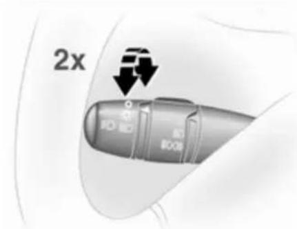
text_image
2xWhen the engine is running, headlights are switched on when external light conditions are poor.
To activate:
- Switch on the ignition.
- Turn light switch to ⚙ and return to 0.
- Repeat step 2 within approx. 5 seconds.
- A double acoustic signal sounds for confirmation.
Repeat the operation to deactivate.
74 Lighting
For reasons of safety, it is advisable to have the function activated.
During poor lighting conditions, e.g. fog or mist, manually switch on the headlights.
High beam

natural_image
Abstract 3D rendering of a curved object with an arrow, no text or symbols presentTo change between low and high beam, pull lever until a click is felt.
Headlight flash
To activate the headlight flash, pull lever.
Headlight range adjustment
Manual headlight range adjustment
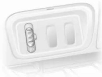
natural_image
Illustration of a stylized door with a scroll inside, mounted on a stand (no text or symbols)Adapt the headlight range to suit the vehicle load to prevent dazzling of oncoming traffic.
Turn knurled wheel to required position:
0 = No load
4 = Loaded up to permissible maximum weight
Headlights when driving abroad
The asymmetrical headlight beam extends visibility at the edge of the road at the passenger side.
However, when driving in countries where traffic drives on the opposite side of the road, adjust the headlights to prevent dazzling.
Have the headlights adjusted by a workshop.
Daytime running lights
Daytime running lights increase visibility of the vehicle during daylight.
When the ignition is on, the headlights come on and instrument illumination is subdued.
The daytime running lights switch off when the ignition is switched off.
Hazard warning flashers
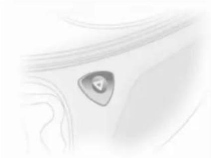
natural_image
Close-up of a metallic tool tip with a triangular button, no visible text or symbolsOperated with the △ button.
Turn and lane-change signals
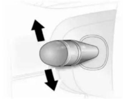
natural_image
3D diagram of a bullet-shaped object with bidirectional arrows indicating movement or force (no text or symbols)Lever up = right turn signal Lever down = left turn signal
When the steering wheel is turned back, the lever automatically returns to its original position and the indicator is deactivated. This will not happen when making a minor steering manoeuvre such as lane changing.
When lane changing, move lever part way to first stop. When released, lever will spring back.
If the lever is moved past the first stop, the indicator is switched on constantly. Switch the indicator off manually by moving the lever to its original position.
Front fog lights

natural_image
Close-up of a mechanical component with arrows indicating direction (no readable text or symbols)Turn inner switch to position #0. Front fog lights will only operate when the ignition and headlights are switched on.
Rear fog lights
Turn inner switch to position ≠00#.
76 Lighting
Rear fog light comes on in conjunction with front fog lights and will only operate when the ignition and headlights are switched on.
Reversing lights
The reversing lights come on when the ignition is on and reverse gear is selected.
Misted light covers
The inside of the light covers may mist up briefly in poor, wet and cold weather conditions, in heavy rain or after washing. The mist disappears quickly by itself; to help, switch on the headlights.
Interior lighting Interior lights

natural_image
Close-up of a white airplane seat with an upward arrow and double-headed arrow symbol (no text or labels)Operated by tilting the lens.
With the lens in its central position, the light functions as a courtesy light and illuminates when the front doors are opened. Once the front doors are closed, the courtesy light goes out after approx. 15 seconds.
The interior light extinguishes immediately when the ignition is switched on.
Load compartment lighting The lighting can be switched on when the load compartment is opened.

natural_image
Traffic sign with curved arrows on a grid-patterned surface (no text or symbols)Operated by tilting the lens.
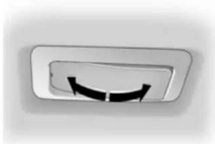
natural_image
Close-up of a circular mechanical component with a curved black arrow, no visible text or symbolsOperated by tilting the lens to one of 3 positions:
■ On constantly
■ Controlled by the function of the interior light
■ Off constantly
Lighting features
Exit lighting
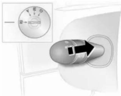
text_image
T50 20Headlights come on for approx. 30 seconds after the vehicle is parked and the system is activated.
Activating
- Switch off ignition.
- Remove ignition key.
- Open driver's door.
- Pull turn signal lever towards steering wheel.
This action can be repeated up to four times to a maximum period of 2 minutes.
The lighting is turned off immediately by switching on the ignition or turning the light switch.
Climate control
Climate control systems .... 78
Air vents 81
Maintenance 82
Climate control systems Heating and ventilation system

natural_image
Top-down view of a car air conditioner panel with three rotary buttons (no text or symbols visible)Controls for:
■ Temperature
■ Fan speed
■ Air distribution
Heated rear window ➞ 29.
Temperature
red = warm
blue = cold
Heating will not be fully effective until the engine has reached normal operating temperature.
Fan speed
Adjust the air flow by switching the fan to the desired speed.
Air distribution
= to head area
→ = to head area and foot well
↓ = to foot well
= to windscreen, front door windows and foot well
= to windscreen and front door windows
Intermediate settings are possible.
Demisting and defrosting the windows
■ Set temperature control to warmest level.
■ Set fan speed to highest level.
■ Set air distribution control to 📌.
■ Switch on heated rear window ☐.
■ Open side air vents as required and direct them towards door windows.
■ For simultaneous warming of the foot well, set air distribution control to 📞.
Air conditioning system

natural_image
Close-up of a car air conditioner panel with three circular buttons and a central knob (no text or symbols visible)Additional to the heating and ventilation system, the air conditioning system has:
AC = cooling
= air recirculation
Cooling (AC)
Operated with the AC button and functional only when the engine and fan are running.
The air conditioning system cools and dehumidifies (dries) the air when outside temperature is a little above the freezing point. Therefore condensation may form and drip from under the vehicle.
If no cooling or drying is required, switch the cooling system off to save fuel.
Air recirculation system
Operated with the 📄 button.
⚠ Warning
The exchange of fresh air is reduced in air recirculation mode. In operation without cooling the air humidity increases, so the windows may mist up. The quality of the passenger compartment air deteriorates, which may cause the vehicle occupants to feel drowsy.
Maximum cooling
Briefly open the windows so that hot air can disperse quickly.
■ Cooling AC on.
■ Air recirculation system 📄 on.
■ Set air distribution control to 21.
■ Set temperature control to coldest level.
■ Set fan speed to highest level.
■ Open all air vents.
Rear heating system

natural_image
Illustration of a handheld electronic device with ports and a screen (no text or symbols visible)The rear passenger compartment heating fan assists air flow to the rear passenger compartment via the rear air vents.
Note
Country-specific version: Heating will cease to operate if the vehicle fuel level drops below 11 litres.
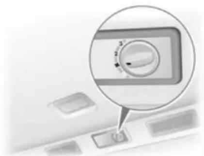
natural_image
Close-up of a control knob with a magnified view showing the dial (no text or symbols visible)The rate of air flow is determined by the fan. Air temperature is controlled using the temperature control on the instrument panel.
The fan has 3 speeds:
0 = off
3 = high speed
Rear air conditioning system
The rear air conditioning system is actuated in conjunction with the front passenger compartment air conditioning system.
Rear air conditioning fan switch
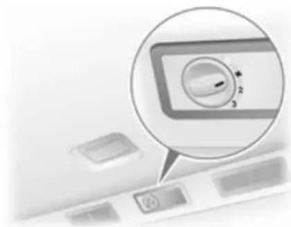
natural_image
Close-up of a computer control panel with a magnified view showing a dial indicator (no text or symbols visible)The rear air conditioning fan assists air flow to the rear passenger compartment via the rear air vents.
Switch on the fan while the air conditioning system is operating to allow cooled and dehumidified (dried) air to be distributed.
The rate of air flow is determined by the fan.
The fan has 3 speeds:
0 = off
3 = high speed
Air vents
Adjustable air vents
At least one air vent must be open while cooling is on in order to prevent the evaporator from icing up due to lack of air movement.
Centre air vents

natural_image
Cross-sectional diagram of a mechanical component with directional arrows indicating assembly or force (no text or symbols)To open or close the vent, turn the adjuster wheel left or right.
Direct the flow of air by tilting and swivelling the slats.
Side air vents

natural_image
Diagram of a mechanical spring assembly with directional arrows indicating force or movement (no text or labels)To open or close the side air vents, turn the adjuster wheel left or right.
Direct the flow of air by tilting and swivelling the slats.
Depending upon the position of the temperature control, air will be directed into the vehicle via the side air vents.
Fixed air vents
Additional air vents are located beneath the windscreen and door windows and in the foot wells.
Rear passenger compartment air vents
natural_image
Close-up of a white plastic ventilation grille with ventilation slots and a small inset image (no text or symbols visible)The air flow is biased towards the central and right hand air vents for optimum distribution.
Glovebox cooler
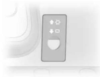
natural_image
Close-up of a flight simulator interface with control buttons and a window (no text or symbols visible)Slide the control upwards to allow the air conditioning system to also keep the contents of the glovebox cool.
Maintenance
Air intake
The air intake in front of the windscreen in the engine compartment must be kept clear to allow air intake. Remove any leaves, dirt or snow.
Pollen filter
The pollen filter cleans dust, soot, pollen and spores from the air entering the vehicle through the air intake.
Air conditioning regular operation
In order to ensure continuously efficient performance, cooling must be operated for a few minutes once a month, irrespective of the weather and time of year. Operation with cooling is not possible when outside temperature is too low.
Service
For optimal cooling performance, it is recommended that the climate control system be checked annually, starting three years after initial vehicle registration, including:
■ Functionality and pressure test
■ Heating functionality
■ Leakage check
■ Check of drive belts
■ Cleaning of condenser and evaporator drainage
■ Performance check
Driving and operating
Driving hints 83
Starting and operating 83
Engine exhaust 85
Manual transmission 87
Manual transmission automated 87
Brakes 91
Ride control systems 93
Cruise control 95
Object detection systems ..... 98
Fuel 100
Towing 103
Driving hints
Control of the vehicle
Never coast with engine not running
Many systems will not function in this situation (e.g. brake servo unit, power steering). Driving in this manner is a danger to yourself and others.
Pedals
To ensure the pedal travel is uninhibited, there must be no mats in the area of the pedals.
Power steering
Never leave the steering wheel on full lock when the vehicle is stationary as this may damage the power steering pump.
Starting and operating
New vehicle running-in
Do not brake unnecessarily hard for the first few journeys and after new disc brake pads have been fitted.
During the first drive, smoke may occur because of wax and oil evaporating off the exhaust system. Park the vehicle in the open for a while after the first drive and avoid inhaling the fumes.
Fuel and engine oil consumption may be higher during the running-in period.
84 Driving and operating
Ignition switch positions
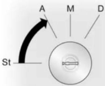
text_image
A M D StSt = Ignition off
A = Steering wheel lock released, ignition off
M = Ignition on, for diesel engine: preheating
D = Starting
Starting the engine

natural_image
Diagram showing curved arrows and a circular cross-section with directional arrows, no text or symbols present.Manual transmission: operate clutch.
Manual transmission automated: operate brake; transmission automatically shifts to N.
Do not accelerate.
Diesel engines: turn the key to position M for preheating until control indicator 00 extinguishes from the Driver Information Centre.
Turn key to position D and release.
The increased engine speed automatically returns to normal idling speed as the engine temperature rises.
Start attempts should not last longer than 15 seconds. If engine does not start, wait 15 seconds before repeating starting procedure. If necessary, depress accelerator before repeating starting procedure.
Before restarting or to switch off the engine, turn key back to St.
Overrun cut-off
The fuel supply is automatically cut off during overrun, i.e. when the vehicle is driven with a gear engaged but accelerator is released.
Parking
■ Do not park the vehicle on an easily ignitable surface. The high temperature of the exhaust system could ignite the surface.
■ Always apply parking brake without pressing release button. Apply as firmly as possible on a downhill or uphill slopes. Operate the foot brake at the same time to reduce operating force.
■ Switch off the engine and ignition. Turn the steering wheel until the steering wheel lock is felt to engage.
■ If the vehicle is on a level surface or uphill slope, engage first gear before switching off the ignition. On an uphill slope, turn the front wheels away from the kerb.
If the vehicle is on a downhill slope, engage reverse gear before switching off the ignition. Turn the front wheels towards the kerb.
■ Lock the vehicle and activate the anti-theft locking and anti-theft alarm systems.
Engine exhaust
Danger
Engine exhaust gases contain poisonous carbon monoxide, which is colourless and odourless and could be fatal if inhaled. If exhaust gases enter the interior of the vehicle, open the windows. Have the cause of the fault rectified by a workshop. Avoid driving with an open load compartment, otherwise exhaust gases could enter the vehicle.
Diesel particle filter
The diesel particle filter system filters harmful soot particles out of the exhaust gases. The system includes a self-cleaning function that runs automatically during driving. The filter is cleaned by burning off the soot particles at high temperature. This process takes place automatically under set driving conditions and may take up to 20 minutes. Fuel
consumption may be higher during this period. The emission of smells and smoke during this process is normal.

natural_image
Close-up of a analog clock face showing time near 10:30 (no text or symbols visible)Under certain driving conditions, e.g. short distances, the system cannot clean itself automatically.
If control indicator 📄 illuminates, continue driving, and as soon as the road and traffic situation permits it, increase speed to more than 60 km/h and diesel particle filter cleaning will start.
Stopping the journey or switching off the engine during cleaning is not recommended.
Caution
If the cleaning process is interrupted more than once, there is a great risk of provoking severe engine damage.
Cleaning takes place quickest at high engine speeds and loads.
The control indicator 📄 extinguishes as soon as the self-cleaning operation is complete.
If control indicator 📋 fails to extinguish or 📋 illuminates in conjunction with ⬇, consult a workshop to have the cause of the fault remedied.
Control indicator ↩ 66.
Catalytic converter
The catalytic converter reduces the amount of harmful substances in the exhaust gases.
Caution
Fuel grades other than those listed on pages 100, 142 could damage the catalytic converter or electronic components.
Unburnt petrol will overheat and damage the catalytic converter. Therefore avoid excessive use of the starter, running the fuel tank dry and starting the engine by pushing or towing.
In the event of misfiring, uneven engine running, a reduction in engine performance or other unusual problems, have the cause of the fault rectified by a workshop as soon as possible. In an emergency, driving can be continued for a short period, keeping vehicle speed and engine speed low.
If control indicator 📋 flashes, the permitted emission limits may be exceeded. Lift your foot off the accelerator until 📋 stops flashing and is steadily illuminated. Contact a workshop immediately.
Malfunction indicator light ➔ 66
Manual transmission
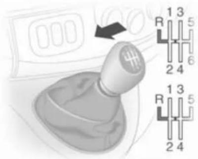
text_image
Diagram of a car gear shift lever with labeled parts and an arrow indicating rotation directionTo engage reverse, with the vehicle stationary depress the clutch pedal, pull up the collar on the selector lever and engage the gear against the resistance.
If the gear does not engage, set the lever in neutral, release the clutch pedal and depress again; then repeat gear selection.
Do not grind the clutch unnecessarily. When operating, depress the clutch pedal completely. Do not use the pedal as a foot rest.
Caution
It is inadvisable to drive with hand resting on the selector lever.
Manual transmission automated
The Easytronic transmission permits manual (manual mode) or automatic gear shifting (automatic mode), both with automatic clutch control.
Transmission display

text_image
N kg N A 54 KM 51.5 KMShows the mode and current gear.
Starting the engine
Depress the foot brake when starting the engine. If the foot brake is not depressed, 📋 illuminates in the transmission display and the engine cannot be started.
When the foot brake is depressed, the transmission automatically shifts to N (neutral); "N" appears in the transmission display and the engine can be started. There may be a slight delay.
Selector lever

text_image
A/M + - N RAlways move the selector lever in the appropriate direction as far as it will go. Upon release, it automatically returns to the centre position.
N = Neutral.
A/ = Switch between automatic
M and manual mode.
The transmission display shows "A" when in automatic mode.
R = Reverse gear.
Engage only when vehicle is stationary. The transmission display shows "R" when reverse gear is engaged.
+ = Shift to a higher gear.
- = Shift to a lower gear.
Starting off
When the engine is started, the transmission is in automatic mode. Depress the foot brake and move the selector lever towards + to engage 1st gear. If R is selected, reverse gear is engaged. The vehicle starts to move when the foot brake is released. To
start off quickly, release the foot brake and accelerate immediately after engaging a gear.
In automatic mode the transmission shifts to other gears automatically, dependent on driving conditions.
To engage manual mode, move the selector lever towards A/M. The current gear will appear in the transmission display. To engage 1st gear, depress foot brake and move selector lever towards + or -. Shift to a higher or lower gear by moving selector lever to + or -. Gears can be skipped by moving the selector lever repeatedly at short intervals.
Stopping the vehicle
In automatic or manual mode, first gear is engaged and the clutch is released when the vehicle is stopped. In R, reverse gear remains engaged.
When stopping on gradients, engage parking brake or depress the foot brake. To prevent overheating of the clutch, an intermittent audible
warning may sound as a signal to depress the foot brake or apply the parking brake.
Switch off engine if stopping for a lengthy period, e.g. in traffic jams.
Engine braking
Automatic mode
When driving downhill, the manual transmission automated does not shift into higher gears until a fairly high engine speed has been reached. It shifts down in good time when braking.
Manual mode
To utilise the engine braking effect, select a lower gear in good time when driving downhill.
Rocking the vehicle
Rocking the vehicle is only permissible if the vehicle is stuck in sand, mud, snow or a hole. Move the selector lever between R and A/M (or between + and -) in a repeat pattern, while applying light pressure to the accelerator pedal. Do not race the engine and avoid sudden acceleration.
Parking
Apply the parking brake. The most recently engaged gear (see transmission display) remains engaged. With N, no gear is engaged. When the ignition is switched off, the transmission no longer responds to movement of the selector lever.
Manual mode
If a higher gear is selected when the engine speed is too low, or a lower gear when the speed is too high, the shift is not executed. This prevents the engine from running at too low or too high an engine speed.
If engine speed is too low, the transmission automatically shifts to a lower gear.
If engine speed is too high, the transmission only switches to a higher gear via kickdown.
Electronic driving programmes
Winter mode
natural_image
Illustration of a car interior with a hand holding a plug and a control panel (no text or symbols)Activate the Winter mode if you have problems starting off on a slippery road surface.
90 Driving and operating
Activation
Press the ⚙ button. ⚙ is shown in the transmission display. The transmission switches to automatic mode and the vehicle starts off in a suitable gear.
Deactivation
The Winter mode is switched off by:
■ pressing the ⚙ button again,
■ turning off the ignition,
■ switching to manual mode.
In order to protect the transmission at extremely high clutch temperatures, an intermittent audible warning may sound. In such cases, depress the foot brake, select "N" and apply the parking brake to allow the clutch to cool down.
Laden mode kg
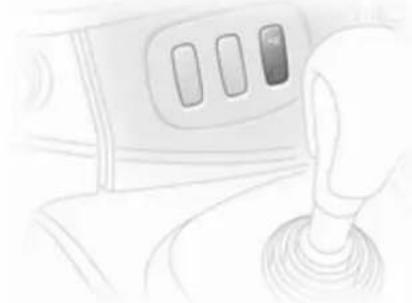
natural_image
Line drawing of a car interior showing a hand gripping a lever (no text or symbols)It is possible to use the Laden mode in both manual and automatic modes. In both cases, the gear shifting patterns are adapted automatically for carrying an increased payload.
Activation
Press the kg button. kg is shown in the transmission display. The transmission will then select optimized gear shift patterns.
Deactivation
The Laden mode is switched off by:
■ pressing the kg button again,
■ turning off the ignition.
Kickdown
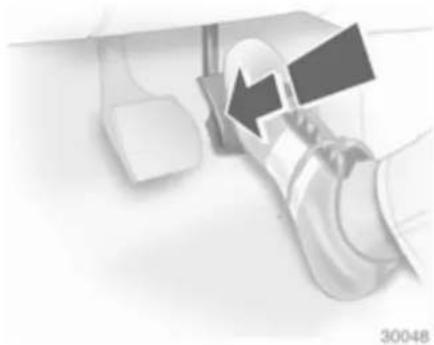
natural_image
Close-up of a robotic arm holding a tool, with no visible text or symbolsIf the accelerator pedal is pressed past the pressure point, the transmission shifts to a lower gear depending on engine speed. Full engine power is available for acceleration.
If engine speed is too high the transmission switches to a higher gear, even in manual mode. Without kickdown this automatic shift is not effected in manual mode.
Fault
In the event of a fault, is shown in the transmission display. Continued driving is possible provided the vehicle is driven with care and anticipation.
Have the cause of the fault remedied by a workshop.
Interruption of power supply
The clutch is not disengaged if there is an interruption of the power supply when a gear is engaged. The vehicle cannot move.
If the battery is discharged, start the vehicle using jump leads 128.
If the cause of the fault is not a discharged battery, seek the assistance of a workshop.
If neutral cannot be selected, the vehicle must only be towed with the drive wheels raised off the ground.
Towing the vehicle ↩ 131.
Brakes
The brake system comprises two independent brake circuits.
If a brake circuit fails, the vehicle can still be braked using the other brake circuit. However, braking effect is achieved only when you depress the brake pedal firmly. You need to use considerably more force for this. The braking distance is extended. Seek the assistance of a workshop before continuing your journey.
When the engine is not running, the support of the brake servo unit disappears once the brake pedal has been depressed once or twice. Braking effect is not reduced, but braking requires significantly greater force. It is especially important to bear this in mind when being towed.
If control indicator Ⓑ illuminates in the instrument cluster while driving and the message BRAKING FAULT appears in the Driver Information Centre there is a fault in the braking system. Seek the assistance of a workshop immediately.
92 Driving and operating
Control indicator ( ! ) 66.
Vehicle messages 69.
Antilock brake system
Antilock brake system (ABS) prevents the wheels from locking.
ABS starts to regulate brake pressure as soon as a wheel shows a tendency to lock. The vehicle remains steerable, even during hard braking.
ABS control is made apparent through a pulse in the brake pedal and the noise of the regulation process.
For optimum braking, keep the brake pedal fully depressed throughout the braking process, despite the fact that the pedal is pulsating. Do not reduce the pressure on the pedal.
Control indicator (ABS) 66.
Fault
If control indicator (ABS) does not go out a few seconds after the ignition is switched on, or if it illuminates while driving, there is a fault in the ABS. Control indicator may also
illuminate in the instrument cluster together with the messages CHECK ABS and CHECK ESP in the Driver Information Centre. The brake system remains operational but without ABS regulation.
⚠ Warning
If there is a fault in the ABS, the wheels may be liable to lock due to braking that is heavier than normal. The advantages of ABS are no longer available. During hard braking, the vehicle can no longer be steered and may swerve.
If control indicators (③), ④, ⑤ and STOP illuminate, the ABS and ESP are deactivated and the message BRAKING FAULT is shown in the Driver Information Centre. Seek the assistance of a workshop.
Have the cause of the fault remedied by a workshop.
Vehicle messages ↩ 69.
Parking brake
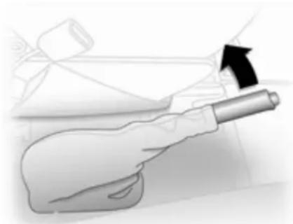
natural_image
Illustration of a hand holding a tool, with an arrow indicating direction (no text or symbols present)Always apply parking brake firmly without operating the release button, and apply as firmly as possible on a downhill or uphill slope.
To release the parking brake, pull the lever up slightly, press the release button and fully lower the lever.
To reduce the operating forces of the parking brake, depress the foot brake at the same time.
Control indicator (①) 66.
Brake assist
If the brake pedal is depressed quickly and forcefully, maximum brake force is automatically applied (full braking).
Maintain steady pressure on the brake pedal for as long as full braking is required. Maximum brake force is automatically reduced when the brake pedal is released.
Ride control systems
Traction Control system
The Traction Control system (TC) is a component part of the Electronic Stability Program (ESP®Plus) which improves driving stability when necessary, regardless of the type of road surface or tyre grip, by preventing the drive wheels from spinning.
As soon as the drive wheels starts to spin, engine output is reduced and the wheel spinning the most is braked individually. This considerably improves the driving stability of the vehicle on slippery road surfaces.
TC is operational as soon as the ignition is switched on and control indicator ⚙️ extinguishes in the instrument cluster.
When TC is active 🔊 flashes.
⚠ Warning
Do not let this special safety feature tempt you into taking risks when driving.
Adapt speed to the road conditions.
Control indicator ⚠️ 67.
Deactivation
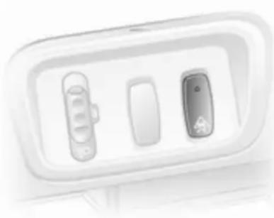
natural_image
Close-up of a white appliance panel with two compartments and a small icon (no text or symbols visible)When spinning of the drive wheels is required TC can be deactivated:
94 Driving and operating
Press the ⚙ button. Control indicator ⚙ illuminates in the instrument cluster and the message ESP OFF appears in the Driver Information Centre.
TC is reactivated by pressing the button again. Control indicator extinguishes in the instrument cluster. TC is also reactivated the next time the ignition is switched on.
When vehicle speed reaches 50 km/h the TC function will be restored automatically.
Fault
If the system detects a fault, control indicator ⬇ illuminates in the instrument cluster 66 and the message CHECK ESP appears in the Driver Information Centre.
Have the cause of the fault remedied by a workshop.
Vehicle messages ↩ 69.
Electronic stability program
The Electronic Stability Program (ESP®Plus) improves driving stability when necessary, regardless of the type of road surface or tyre grip. It also prevents the drive wheels from spinning.
As soon as the vehicle starts to swerve (understeer/oversteer), engine output is reduced and the wheels are braked individually. This considerably improves the driving stability of the vehicle on slippery road surfaces.
ESP®Plus is operational as soon as the ignition is switched on and control indicator ⚠️ extinguishes in the instrument cluster.
When ESP®Plus comes into action ★ flashes.
Warning
Do not let this special safety feature tempt you into taking risks when driving.
Adapt speed to the road conditions.
Control indicator ⚠️ 67.
Deactivation

natural_image
Close-up of a white appliance front panel with two buttons and a small icon on the side (no text or symbols visible)When spinning of the drive wheels is required ESP®Plus can be deactivated:
Press the ⚙ button. Control indicator ⚙ illuminates in the instrument cluster and the message ESP OFF appears in the Driver Information Centre.
ESP®Plus is reactivated by pressing the 🔒 button again. Control indicator 🔒 extinguishes in the instrument cluster. ESP®Plus is also reactivated the next time the ignition is switched on.
When vehicle speed reaches 50 km/h the ESP®Plus function will be restored automatically.
Fault
If the system detects a fault, control indicator ⬇ illuminates in the instrument cluster 66 and the message CHECK ESP appears in the Driver Information Centre.
Have the cause of the fault remedied by a workshop.
Vehicle messages ↩ 69.
Cruise control
The cruise control can store and maintain speeds of 30 km/h and above. Deviations from the stored speeds may occur when driving uphill or downhill.
For safety reasons the cruise control cannot be activated until the foot brake has been operated once.
Do not use the cruise control if it is not advisable to maintain a constant speed.
With manual transmission automated, only activate cruise control in automatic mode.
Control indicators 📍 and 📍 ^9 → 68.
Activation

natural_image
Close-up of a control panel with three buttons (no visible text or symbols)Press switch Ⓧ, control indicator Ⓧ illuminates green in the instrument cluster.
Cruise control is now in standby mode and a corresponding message appears in the Driver Information Centre.
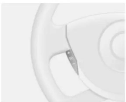
natural_image
Close-up of a white circular object with concentric rings and a small rectangular cutout (no text or symbols visible)Accelerate to the desired speed and press switch + or - . The current speed is now stored and maintained and the accelerator pedal can be released.
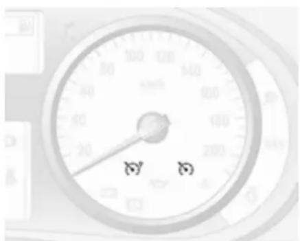
text_image
お おControl indicator 📋 illuminates green in the instrument cluster together with 🌐 and a corresponding message appears in the Driver Information Centre.
Vehicle speed can be increased by depressing the accelerator pedal. The stored speed flashes in the instrument cluster. When the accelerator pedal is released, the previously stored speed is resumed. The speed is saved until the ignition is switched off.
Increase speed
With cruise control active, the vehicle speed can be increased continuously or in small increments by holding down or tapping switch + repeatedly.
When the switch is released the current speed is stored and maintained.
Alternatively, accelerate to the desired speed and store by pressing switch +.
Reduce speed
With cruise control active, the vehicle speed can be decreased continuously or in small increments by holding down or tapping switch — repeatedly.
When the switch is released the current speed is stored and maintained.
Deactivation
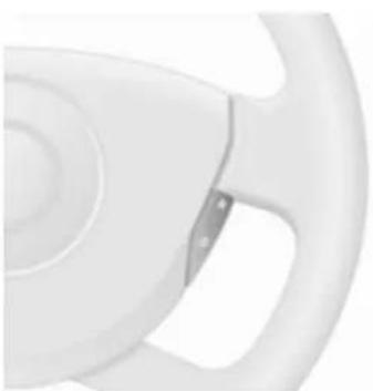
natural_image
Close-up of a white plastic steering wheel (no text or symbols visible)Press switch O: cruise control is deactivated and the green control indicator 2 extinguishes in the instrument cluster.
Automatic deactivation:
■ Vehicle speed drops below 30 km/h,
■ The brake pedal is depressed,
■ The clutch pedal is depressed,
■ Selector lever in N.
The speed is stored and a corresponding message appears in the Driver Information Centre.
Resume stored speed
Press switch R at a speed above 30 km/h.
If the stored speed is much higher than the current speed, the vehicle will accelerate powerfully until the stored speed is obtained.
Deleting the stored speed
Press switch ⚙: Green control indicators ⚙° and ⚙° extinguish in the instrument cluster.
Cruise control speed limiter
The speed limiter prevents the vehicle exceeding a preset maximum speed above 30 km/h.
Activation
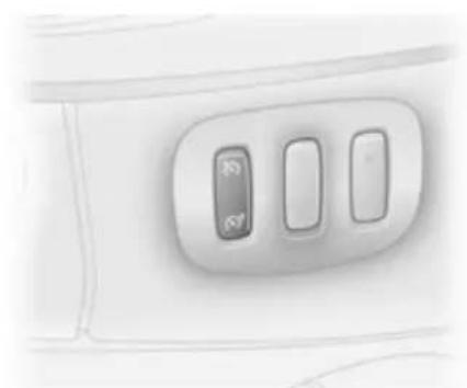
natural_image
Close-up of a white airplane cabin with three control buttons (no text or symbols visible)Press switch 📋, control indicator 📋 illuminates orange in the instrument cluster.
Cruise control speed limiter function is now in standby mode and a corresponding message appears in the Driver Information Centre.
Accelerate to the desired speed and press switch + or - . The current speed is recorded.
The vehicle can be driven normally but it will not be possible to exceed the programmed speed limit except in an emergency.
Where the limit speed cannot be maintained, e.g. when driving on a steep decline, the limit speed will flash in the Driver Information Centre.
Increase limit speed
The limit speed can be increased continuously or in small increments by holding down or tapping switch + repeatedly.
Reduce limit speed
The limit speed can be decreased continuously or in small increments by holding down or tapping switch — repeatedly.
Exceeding the limit speed
In the event of an emergency it is possible to exceed the limit speed by depressing the accelerator pedal firmly beyond the point of resistance.
The limit speed will flash in the Driver Information Centre during this period.
Release the accelerator pedal and the speed limiter function is reactivated once a speed lower than the limit speed is obtained.
Deactivation
Press switch O: speed limiter is deactivated and the vehicle can be driven normally.
The limit speed is stored and a corresponding message appears in the Driver Information Centre.
Reactivation
Press switch R. The speed limiter function is reactivated.
Deleting the limit speed
Press switch 📋.
Orange control indicator 📋 extinguishes in the instrument cluster.
Object detection systems
Parking assist
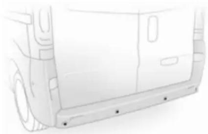
natural_image
Side profile sketch of a white van with side panels and mounting brackets (no text or symbols)The parking assist makes reverse parking easier by measuring the distance between the rear of the vehicle and obstacles. It is the driver, however, who bears full responsibility for parking.
The system consists of four ultrasonic parking sensors in the rear bumper.
Note
Attached parts in the detection area cause system malfunction.
Activation
When reverse gear is engaged, the system switches itself on automatically. Readiness for operation is indicated by a brief acoustic alarm.
An obstacle is indicated by buzzers. The interval between the buzzers becomes shorter as the vehicle gets closer to the obstacle. When the distance is less than 30 cm, the buzzer is continuous.
Warning
Under certain circumstances, various reflective surfaces on objects or clothing as well as external noise sources may cause the system to fail to detect obstacles.
Deactivation
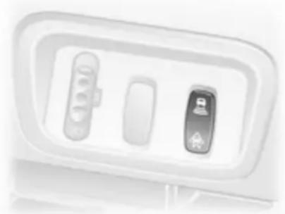
natural_image
Close-up of a white electronic device with two buttons and a small display (no visible text or symbols)It is possible to permanently or temporarily deactivate the system.
Temporary deactivation
Temporarily deactivate the system by pressing the 🔒 button on the instrument panel with the ignition on and reverse gear engaged. When reverse gear is selected no acoustic signal will sound, indicating deactivation.
The function is reactivated by pressing button 📁 again or the next time the ignition is switched on.
Permanent deactivation
Permanently deactivate the system by pressing and holding the 📁 button on the instrument panel for approx. 3 seconds with the ignition on and reverse gear engaged. The system is deactivated and will not operate. When reverse gear is selected no acoustic signal will sound, indicating deactivation.
The function is reactivated by pressing and holding button ≡ for approx. 3 seconds.
Fault
If the system detects an operating fault, a continuous acoustic alarm will sound for approx. 5 seconds when selecting reverse gear. Consult a workshop to have the cause of the fault remedied.
Caution
When reversing, the area should be free from obstacles which could impact on the underside of the vehicle.
Impact to the rear axle, which may not be visible, could lead to uncharacteristic changes in the vehicle handling. In the event of such an impact, consult a workshop.
Fuel
Fuel for petrol engines
Only use unleaded fuel that complies with DIN EN 228.
Fuels with ethanol content greater than 5 % may only be used if the vehicle has been specifically developed and approved for these fuels.
Use fuel with the recommended octane rating 142. Use of fuel with too low an octane rating can reduce engine power and torque and slightly increases fuel consumption.
Caution
Use of fuel with too low an octane rating could lead to uncontrolled combustion and engine damage.
Fuel for diesel engines
Only use diesel fuel that complies with DIN EN 590. The fuel must have low sulphur content (max. 50 ppm). Equivalent standardised fuels with
a biodiesel (= FAME according to EN14214) content of max. 10% by volume (like DIN 51628 or equivalent standards) may be used.
Do not use marine diesel oils, heating oils or entirely plant-based diesel fuels, such as rape seed oil or bio diesel, Aquazole and similar diesel-water emulsions. Diesel fuels must not be diluted with fuels for petrol engines.
The flow and filterability of diesel fuels are temperature-dependent. When temperatures are low, refuel with diesel fuel with guaranteed winter properties.
Refuelling
Danger
Before refuelling, switch off engine and any external heaters with combustion chambers (identified by sticker on fuel filler flap). Switch off any mobile phones.
Follow the operating and safety instructions of the filling station when refuelling.
Danger
Fuel is flammable and explosive. No smoking. No naked flames or sparks.
If you can smell fuel in your vehicle, have the cause of this remedied immediately by a workshop.
The fuel tank filler neck with bayonet cap is located on the left hand side of the vehicle.
The fuel filler flap can only be opened if the vehicle is unlocked.
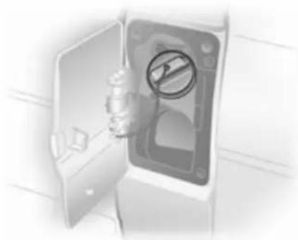
natural_image
Illustration of a door with a valve symbol inside, no text or labels presentTo unlock and open the fuel filler cap, insert key and turn anticlockwise. When refuelling is complete, replace the filler cap and turn key clockwise as far as it will go.
Caution
Wipe off any overflowing fuel immediately.
Fault
Should an interruption to the power supply occur, central locking will not unlock the fuel filler flap. In such cases release manually.

natural_image
Hand holding a device with a black arrow pointing to a rectangular panel (no text or symbols visible)102 Driving and operating
To open

natural_image
Illustration of a printer with an upward arrow indicating motion or operation (no text or symbols present)■ Reposition left front seat to access the release cover.
■ Remove the release cover and position the seat belt to one side.
■ Raise fuel filler release to unlock the fuel filler flap.
To close
■ Close the fuel filler flap and lower fuel filler release to lock the fuel filler flap.
■ Replace the release cover.
■ Reposition left front seat.
If the cause of the interruption to the power supply is not a discharged battery, consult a workshop.
Fuel consumption - CO _2 -Emissions
The determination of fuel consumption is regulated by European directive 80/1268/EEC (latest edition 2004/3/EC).
The directive is oriented to actual driving practices: Urban driving is rated at approx. 13 and extra urban driving with approx. 23 . Cold starts and acceleration phases are also taken into consideration.
The specification of CO_2 emission is also a constituent of the directive.
Fuel consumption is dependent on personal driving style as well as road and traffic conditions.
The calculation of fuel consumption takes account of the vehicle's kerb weight, ascertained in accordance with the regulations. Optional equipment may result in slightly
higher fuel consumption and CO_2 emission levels and a lower maximum speed.
Towing
General information
Only use towing equipment that has been approved for your vehicle.
Entrust retrofitting of towing equipment to a workshop. It may be necessary to make changes that affect the cooling system, heat shields or other equipment.
Installation dimensions of factory-fitted towing equipment ➔ 152.
Driving characteristics and towing tips
In the case of trailers with brakes, attach the breakaway stopping cable.
Before attaching a trailer, lubricate the coupling ball. However, do not do so if a stabiliser, which acts on the coupling ball, is being used to reduce snaking movements. For trailers with low driving stability the use of a stabiliser is recommended.
A maximum speed of 80 km/h must not be exceeded, even in countries where higher speeds are permitted.
If the trailer starts snaking, drive more slowly, do not attempt to correct the steering and brake sharply if necessary.
When driving downhill, drive in the same gear as if driving uphill and drive at a similar speed.
Adjust tyre pressure to the value specified for full load ➔ 151.
Trailer towing
Trailer loads
The permissible trailer loads are vehicle and engine-dependent maximum values which must not be exceeded. The actual trailer load is the difference between the actual gross weight of the trailer and the actual coupling socket load with the trailer coupled.
The permissible trailer loads are specified in the vehicle documents. In general, they are valid for gradients up to max. 12 %.
The permitted trailer load applies up to the specified incline and up to an altitude of 1000 metres above sea level. Since engine power decreases as altitude increases due to the air becoming thinner, therefore reducing climbing ability, the permissible gross train weight also decreases by 10 % for every 1000 metres of additional altitude. The gross train weight does not have to be reduced when driving on roads with slight inclines (less than 8 %, e.g. motorways).
The permissible gross train weight must not be exceeded. This weight is specified on the identification plate 140.
Vertical coupling load
The vertical coupling load is the load exerted by the trailer on the coupling ball. It can be varied by changing the weight distribution when loading the trailer.
104 Driving and operating
The maximum permissible vertical coupling load is specified on the towing equipment identification plate and in the vehicle documents. Always aim for the maximum load, especially in the case of heavy trailers. The vertical coupling load should never fall below 25 kg.
In the case of trailer loads of 1200 kg or more, the vertical coupling load should not be less than 50 kg.
Rear axle load
When the trailer is coupled and the towing vehicle fully loaded (including all occupants), the permissible rear axle load (see identification plate or vehicle documents) must not be exceeded.
Towing equipment
| Caution |
| When operating without a trailer, remove the coupling ball bar. |
Towing equipment audible warning
For vehicles fitted with towing equipment, when connected to a trailer the pitch of the audible warning changes upon operation of the turn signals.
The pitch of the audible warning will change if a turn signal light on the trailer or the towing vehicle fails.
Vehicle care
General Information 105
Vehicle checks 106
Bulb replacement 114
Electrical system 118
Vehicle tools 120
Wheels and tyres 121
Towing 131
Appearance care 132
General Information
Accessories and vehicle modifications
We recommend the use of Genuine Parts and Accessories and factory approved parts specific for your vehicle type. We cannot assess or guarantee reliability of other products - even if they have a regulatory or otherwise granted approval.
Do not make any modifications to the electrical system, e.g. changes of electronic control units (chip tuning).
Vehicle storage
Storage for a long period of time
The following tasks must be carried out if the vehicle is to be stored for several months:
■ Wash and wax the vehicle.
■ Have the wax in the engine compartment and underbody checked.
■ Clean and preserve rubber seals.
■ Change engine oil.
■ Drain washer fluid reservoir.
■ Check coolant antifreeze.
■ Adjust tyre pressure to the value specified for full load.
■ Park vehicle in a dry, well ventilated place. Engage first or reverse gear. Prevent the vehicle from rolling.
■ Do not apply parking brake.
■ Open bonnet, close all doors and lock the vehicle.
■ Disconnect the clamp from the negative terminal of the vehicle battery. Beware that all systems are not functional, e.g. anti-theft alarm system.
Putting back into operation
The following tasks must be carried out if the vehicle is being put back into operation:
■ Connect the clamp to the negative terminal of the vehicle battery. Activate the electronics of the power windows.
■ Check tyre pressure.
■ Fill up the washer fluid reservoir.
■ Check the engine oil level.
■ Check the coolant level.
■ Fit the number plate, if necessary.
End-of-life vehicle recovery
Information on end-of-life vehicle recovery centres and the recycling of end-of-life vehicles is available on our website. Only entrust this work to an authorised recycling centre.
Vehicle checks Performing work
⚠ Warning
Only perform engine compartment checks when the ignition is off. The cooling fan may start operating even if the ignition is off.
Danger
The ignition system generates extremely high voltages. Do not touch.
The caps for topping up the engine oil, the coolant, the washer fluid and the oil dipstick handle are yellow for ease of identification.
Bonnet Opening

natural_image
Close-up of a door handle with a downward arrow indicating compression or disassembly (no text or symbols)Pull the release lever and return it to its original position.

natural_image
Hand holding a small object with a downward arrow, against a blurred background (no text or symbols)Pull the safety catch and open the bonnet.

natural_image
Diagram showing a curved line with an arrow pointing downward, overlaid on a background of architectural or mechanical layout (no text or symbols)Secure the bonnet support.
Closing
Before closing the bonnet, press the support into the holder.
Lower the bonnet and allow it to drop into the catch. Check that the bonnet is engaged.
Engine oil
It is advisable to check the engine oil level manually before embarking on a long journey. Ensure that the correct specification of oil is used. Recommended fluids and lubricants 137.
Check with the vehicle on a level surface. The engine must be at operating temperature and switched off for at least 10 minutes.
Pull out the dipstick, wipe it clean, insert it to the stop on the handle, pull out and read the engine oil level.
Caution
It is the owner's responsibility to maintain the proper level of an appropriate quality oil in the engine.

text_image
A B F48Different dipsticks are used depending on engine variant. The illustrations show checking and replenishing the engine oil in the petrol and diesel engines respectively.
108 Vehicle care

text_image
A BOn F9Q engines, the dipstick is mounted on the oil filler cap which must be rotated anticlockwise to open.
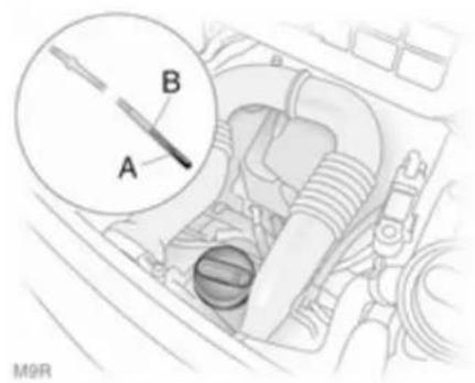
text_image
A B M9RFor M9R engines, rotate cap anticlockwise, remove the dipstick, wipe it clean and re-insert it as far as it will go.
text_image
A B G9UWhen the engine oil level has dropped to the "add oil" mark A, top up engine oil.
Caution
Do not allow the engine oil level to drop below the minimum level!
natural_image
Mechanical component being poured into a housing (no visible text or symbols)We recommend the use of the same type of engine oil that was used at the last change.
The engine oil level must not exceed the maximum mark B on the dipstick.
Caution
Overfilled engine oil must be drained or suctioned out.
natural_image
Mechanical component with a bucket and pipe assembly (no visible text or symbols)To prevent spillage when replenishing the engine oil on F9Q engines, use the funnel stored in the front of the engine compartment.
To release the funnel, raise the plastic catch on the funnel and lift upwards.
natural_image
Illustration of a funnel pouring liquid into a car intake manifold (no text or symbols)Remove the caps and ensure funnel is securely located onto the filler pipe.
Ensure the funnel is replaced securely together with both end caps fitted.
A stabilization of the engine oil consumption will not take place until the vehicle has been driven several thousand kilometres. Only then can the actual degree of consumption be established.
If consumption exceeds more than 0.5 litres every 1000 km after this running-in period, consult a workshop.
Capacities 150, Engine oil level monitor 62.
Fit the cap on straight and tighten it.
Engine air filter
Engine air flow indicator

natural_image
Close-up of a mechanical component with no visible text or symbolsOn certain models, an indicator is located in the engine induction system and indicates if the air-intake to the engine is restricted.
Clear = No restriction
Red tell-tale = Restricted
110 Vehicle care
If the red tell-tale is displayed when the engine is running, consult a workshop.
Engine coolant
The coolant provides freeze protection down to approx. -28 °C.
| Caution |
| Only use approved antifreeze. |
Coolant level
| Caution |
| Too low a coolant level can cause engine damage. |

text_image
MAX MINIf the cooling system is cold, the coolant level should be just above the MIN mark. Top up if the level is low.
⚠ Warning
Allow the engine to cool before opening the cap. Carefully open the cap, relieving the pressure slowly.
Top up with antifreeze. If no antifreeze is available, use clean tap water or distilled water. Install the cap tightly. Have the antifreeze
concentration checked and have the cause of the coolant loss remedied by a workshop.
If a substantial amount of coolant is required, it will be necessary to bleed any trapped air from the cooling system. Seek the assistance of a workshop.
If the coolant temperature is too high, control indicator 📁 illuminates red in the instrument cluster, together with STOP 67. Consult a workshop if coolant level is sufficient.
Power steering fluid
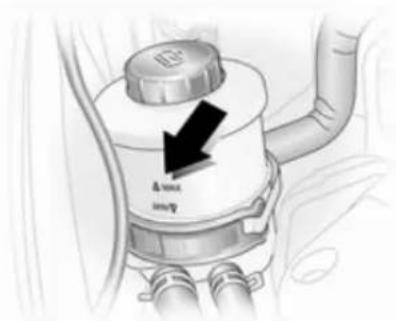
text_image
Δmm mmIf the fluid level in the reservoir falls below the MIN mark consult a workshop.
Washer fluid

natural_image
Illustration of a car interior with a hand holding a device (no text or symbols visible)Fill with clean water mixed with a suitable quantity of windscreen washer fluid which contains antifreeze.
Brakes
A squealing noise indicates that the brake lining is at its minimum thickness. Continued driving is possible but have the brake lining replaced as soon as possible.
Once new brake linings are installed, do not brake unnecessarily hard for the first few journeys.
Brake fluid
Warning
Brake fluid is poisonous and corrosive. Avoid contact with eyes, skin, fabrics and painted surfaces.
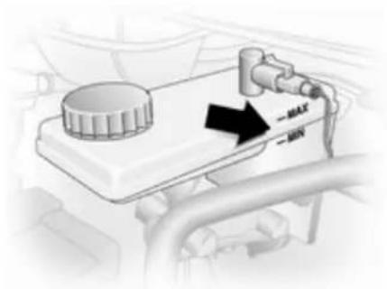
natural_image
Diagram of a vehicle fuel meter with a black arrow pointing to the valve (no text or symbols present)The brake fluid level must be between the MIN and MAX marks.
When topping up, ensure maximum cleanliness as contamination of the brake fluid can lead to brake system malfunctions. Have the cause of the loss of brake fluid remedied by a workshop.
Only use high-performance brake fluid approved for your vehicle.
Brake and clutch fluid 137.
Battery
The vehicle battery is maintenance-free.
112 Vehicle care
Batteries do not belong in household waste. They must be disposed of at an appropriate recycling collection point.
Laying up the vehicle for more than 4 weeks can lead to battery discharge. Disconnect the clamp from the negative terminal of the vehicle battery.
Ensure the ignition is switched off before connecting or disconnecting the vehicle battery.
Battery access
The battery is located beneath the front left hand seat floor panel 128.
Battery maintenance

Danger
Ensure adequate ventilation when charging the battery. There is a risk of explosion if gases generated during charging are allowed to accumulate!
Replacing the battery
When the battery is being replaced, please ensure that there are no open ventilation holes in the vicinity of the positive terminal. If a ventilation hole is open in this area, it must be closed off with a dummy cap, and the ventilation in the vicinity of the negative terminal must be opened. We recommend that you have the battery replaced by a workshop.
Additional battery
Depending on the vehicle's auxiliary equipment certain models may have an additional battery located next to the vehicle battery.
Diesel fuel filter

natural_image
Technical illustration of a mechanical device with hoses and components (no text or symbols)Drain diesel fuel filter of residual water at every engine oil change.
Place a container underneath the filter housing. Loosen the knurled screws on the filter cover and on the lower part of the filter by approx. one turn, to drain off the water.
The filter is drained as soon as diesel fuel emerges from the knurled screw at the bottom. Retighten the two screws.
Check diesel fuel filter at shorter intervals if the vehicle is subjected to extreme operating conditions.
Diesel fuel system bleeding
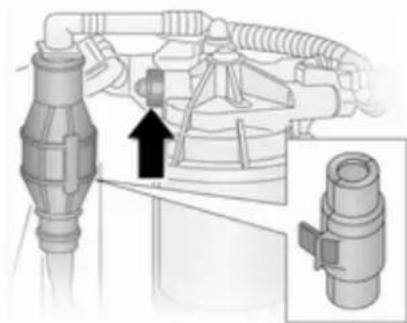
natural_image
Mechanical assembly diagram showing a connector with a directional arrow and magnified detail (no text or symbols)If the fuel tank has been run dry, it will be necessary to air vent or bleed the diesel fuel system.
Fill the tank with fuel and proceed as follows:
- Remove the protective cover from the in-line supply pump.
- Place a suitable container underneath the fuel filter vent screw to collect fuel.
-
Loosen the vent screw (arrowed) by one turn.
-
Manually operate the in-line supply pump slowly and steadily until fuel discharging from the loosened vent screw is free of air bubbles.
- Retighten the vent screw.
- Refit the protective cover to the in-line supply pump.
Wiper blade replacement
Wiper blades on the windscreen
natural_image
Pure diagram of a road or pipeline with directional arrows and a black arrow pointing to a specific section (no text or symbols)Lift wiper arm, press retaining clip towards wiper arm and detach wiper blade.
Wiper blade on the rear window Lift wiper arm, rotate wiper blade and detach.
114 Vehicle care
Bulb replacement
Switch off the ignition and turn off the relevant switch or close the doors.
Only hold a new bulb at the base! Do not touch the bulb glass with bare hands.
Use only the same bulb type for replacement.
Headlights
Low beam and high beam
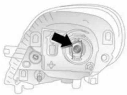
natural_image
Mechanical component diagram showing a central hub with an arrow pointing to a circular feature (no text or symbols present)- Remove harness connector.
- Remove rubber seal.
- Release retaining clip and remove bulb.
- Renew bulb and install retaining clip ensuring that bulb is in correct orientation.
- Install rubber seal and harness connector.
Sidelights
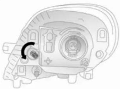
natural_image
Technical line drawing of a mechanical component with no visible text or symbols-
Remove bulb holder from reflector housing by rotating through 90°.
-
Renew bulb.
-
Install bulb holder in reflector housing.
Fog lights
Have bulbs replaced by a workshop.
Front turn signal lights
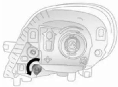
natural_image
Technical line drawing of a mechanical component with no visible text or symbols- Remove bulb holder from reflector housing by rotating through 90°.
- Renew bulb.
- Install bulb holder in reflector housing.
Tail lights
Rear brake, turn signal and tail lights
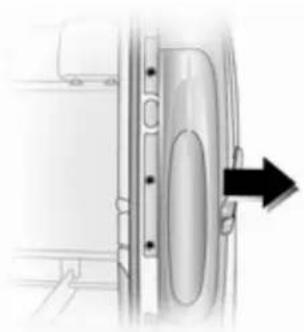
natural_image
Diagram of a vehicle door with an arrow indicating direction (no text or symbols present)- Remove 3 screws (using the tool supplied).
- Carefully pull lamp assembly from retaining pins on the outer side and remove.
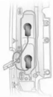
natural_image
Technical line drawing of a mechanical component with internal parts and mounting holes (no text or symbols)- Twist bulb holder to separate from lamp assembly.
- Renew bulb.
- Push to install the bulb holder into the lamp assembly - then twist to secure.
- Check that the wiring harness is located correctly.
- Replace lamp assembly into original position, ensuring that it is seated correctly.
- Fit lamp assembly onto retaining pins and replace 3 screws.
Side turn signal lights

natural_image
Illustration of a hand holding a small electronic component next to a wire rod (no text or symbols visible)- Release clips from wing using a flat blade screwdriver and lift out lamp assembly from aperture.
- Remove bulb holder from lamp assembly by rotating through 90° and renew bulb.
- Install bulb holder in lamp assembly and install lamp assembly into aperture.
Centre high-mounted brake light
Have bulbs replaced by a workshop.
Reversing light
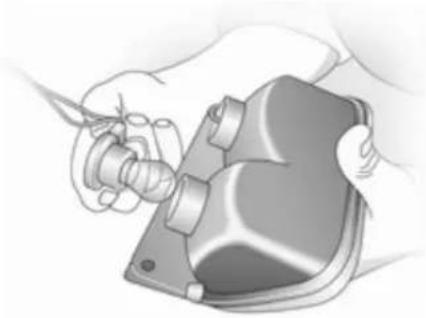
natural_image
Illustration of hands using a tool to adjust or install a mechanical component (no text or symbols visible)- Remove 2 screws (using the tool supplied) and remove lamp assembly.
- Twist bulb housing to separate from lamp assembly.
- Renew bulb.
- Push to install the bulb holder into the lamp assembly - then twist to secure.
- Install lamp assembly with 2 screws.
Number plate light
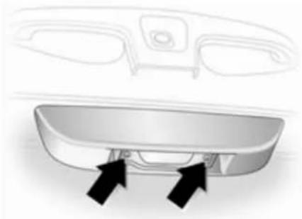
natural_image
3D rendering of a car rear bumper with two black arrows pointing to the side panel (no text or symbols)- Remove 2 screws (arrowed) and remove lens.
- Renew bulb.
- Re-install lens and replace screws.
Fog tail light

natural_image
Illustration of a hand using a tool to adjust or install a mechanical component (no text or symbols visible)- Remove 2 screws (using the tool supplied) and remove lamp assembly.
- Twist bulb housing to separate from lamp assembly.
- Renew bulb.
- Push to install the bulb holder into the lamp assembly - then twist to secure.
- Install lamp assembly with 2 screws.
Interior lights
Front courtesy light

natural_image
Illustration of a car interior showing a hand holding a bicycle and a mechanical component (no text or symbols visible)- Remove lens using a flat blade screwdriver.
- Renew bulb.
- Reinstall lens assembly.
Load compartment light

natural_image
Illustration of a rectangular object with a handle and textured surface, emitting smoke or vapor (no text or symbols)- Remove lamp assembly using a flat blade screwdriver.
- Gain access to bulb by removing rear cover on lamp assembly.
- Renew bulb and install rear cover.
- Reinstall lamp assembly.
Rear courtesy lights
Have bulbs replaced by a workshop.
Glovebox light
Have bulbs replaced by a workshop.
Instrument panel illumination
Have bulbs replaced by a workshop.
Electrical system
Fuses
Data on the replacement fuse must match the data on the defective fuse.
The fuse box is located on the left-hand side of the instrument panel, below the cupholder.
Before replacing a fuse, turn off the respective switch and the ignition.

natural_image
Three views of a small electronic component with internal structure and mounting holes (no text or symbols)
30041
A blown fuse can be recognised by its melted wire. Do not replace the fuse until the cause of the fault has been remedied.
It is advisable to carry a full set of fuses. Provision is made in the fuse box for the storing of spare fuses.
Some functions are protected by several fuses.
Fuses may also be inserted without existence of a function.
Fuse extractor

natural_image
Two-step diagram showing a mechanical component being folded, with arrows indicating direction (no text or symbols)
natural_image
Diagram showing a device being processed into a plastic housing, with no visible text or symbols.30044
To help in replacing fuses, a fuse extractor is located in the fuse box. Place the fuse extractor on the various types of fuse from the top or side, and withdraw fuse.
Instrument panel fuse box
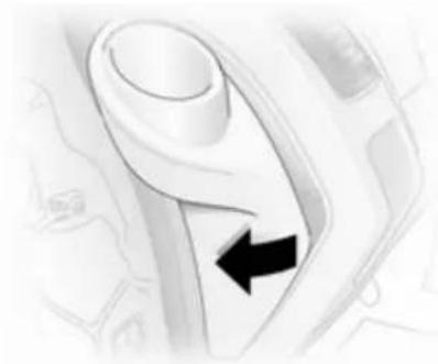
natural_image
Close-up of a white mechanical lever handle with a black arrow pointing to the left side (no text or symbols visible)Located on the left-hand side of the instrument panel, below the cupholder.
Remove the ashtray from the left-hand cup holder and pull open the fuse box cover. Do not store any objects behind the cover.
Some circuits may be protected by several fuses.
Symbol Application
Air conditioning
Heated exterior mirrors
Heated front seats
Power windows
Left-hand high beam
Right-hand high beam
Windscreen wiper
Radio/Infotainment system
Cigarette lighter
Boiler Rear passenger compartment heater
Horn
Left-hand low beam
Right-hand low beam
Instrument panel
Symbol Application
| Heating | |
| Interior lamp | |
| Antilock brake system | |
| Heated rear windows | |
| Clock, interior lights, radio, Infotainment system | |
| UCH INJ | Fuel injection system |
| Rear window washer | |
| Rear widow wiper | |
| Left-hand sidelight | |
| Right-hand sidelight | |
| Central locking | |
| Electrically adjustable exterior mirrors | |
| STOP | Stop control indicator, daytime running lights |
| Q‡ | Rear fog lights |
Symbol Application
| #D | Front fog lights |
| ◎ | Power outlet |
| T Tachograph | |
Vehicle tools
Tools
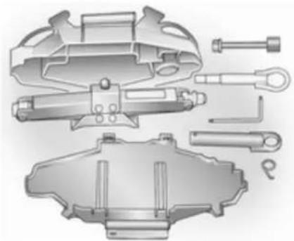
natural_image
Technical illustration of automotive brake components (no text or labels)The jack, adapters, ratchet, torx key, hub cap hook, towing eye and spare wheel security tool are contained in a unit, stowed under the driver's seat. Spare wheel 127.
Vehicles with a tyre repair kit: The towing eye and torx key are stored within the tyre repair kit case, stowed under the front seat. Tyre repair kit ➔ 123.
Wheels and tyres
Tyre condition, wheel condition Drive over edges slowly and at right angles if possible. Driving over sharp edges can cause tyre and wheel damage. Do not trap tyres on the kerb when parking.
Regularly check the wheels for damage. Seek the assistance of a workshop in the event of damage or unusual wear.
Tyres
Factory-fitted tyres are matched to the chassis and offer optimum driving comfort and safety.
Winter tyres
Winter tyres improve driving safety at temperatures below 7 °C and should therefore be fitted on all wheels.
In accordance with country-specific regulations, a notice indicating the maximum permissible speed for the tyres must be affixed within the driver's field of vision.
Tyre designations
E.g. 195/65 R 16 C 88 Q
195 = Tyre width, mm
65 = Cross-section ratio (tyre height to tyre width), %
R = Belt type: Radial
RF = Type: RunFlat
16 = Wheel diameter, inches
C = Cargo or commercial use
88 = Load index e.g. 88 is equivalent to 567 kg
Q = Speed code letter
Speed code letter:
Q = up to 160 km/h
S = up to 180 km/h
T = up to 190 km/h
H = up to 210 km/h
V = up to 240 km/h
W = up to 270 km/h
Tyre pressure
Check the pressure of cold tyres at least every 14 days and before any long journey. Do not forget the spare wheel.
Tyre pressures 151.
The tyre pressure data refers to cold tyres. It applies to summer and winter tyres.
Always inflate the spare tyre to the pressure specified for full load.
Incorrect tyre pressures will impair safety, vehicle handling, comfort and fuel economy and will increase tyre wear.
⚠ Warning
If the pressure is too low, this can result in considerable tyre warm-up and internal damage, leading to tread separation and even to tyre blow-out at high speeds.
Tread depth
Check tread depth at regular intervals.
122 Vehicle care
Tyres should be replaced for safety reasons at a tread depth of 2-3 mm (4 mm for winter tyres).
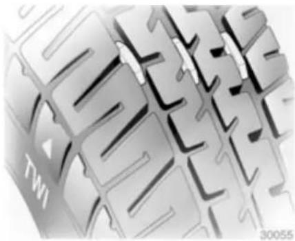
natural_image
Close-up of a stylized 3D keyboard layout with no visible text or symbolsThe legally permissible minimum tread depth (1.6 mm) has been reached when the tread has worn down as far as one of the tread wear indicators (TWI). Their position is indicated by markings on the sidewall.
If there is more wear at the front than the rear, swap round front wheels and rear wheels. Ensure that the direction of rotation of the wheels is the same as before.
Tyres age, even if they are not used. We recommend tyre replacement every 6 years.
Changing tyre and wheel size
If tyres of a different size than those fitted at the factory are used, it may be necessary to reprogramme the speedometer and make other vehicle modifications.
⚠ Warning
Use of unsuitable tyres or wheels may lead to accidents and will invalidate the vehicle type approval.
Wheel covers
Wheel covers and tyres that are factory approved for the respective vehicle and comply with all of the relevant wheel and tyre combination requirements must be used.
If the wheel covers and tyres used are not factory approved, the tyres must not have a rim protection ridge.
Wheel covers must not impair brake cooling.
Warning
Use of unsuitable tyres or wheel covers could lead to sudden pressure loss and thereby accidents.
Tyre chains

natural_image
Two circular diagrams showing internal structures with arrows indicating direction, no text or symbols presentTyre chains are only permitted on the front wheels.
Always use fine mesh chains that add no more than 15 mm to the tyre tread and the inboard sides (including chain lock).
For tyre size 215/65 R16, consult a workshop.
⚠ Warning
Damage may lead to tyre blowout.
Wheel covers on steel wheels may come into contact with parts of the chains. In such cases, remove the wheel covers.
Tyre chains may only be used at speeds up to 50 km/h and, when travelling on roads that are free of snow, they may only be used for brief periods since they are subject to rapid wear on a hard road and may snap.
Tyre repair kit
Minor damage to the tyre tread or sidewall can be repaired with the tyre repair kit.
Do not remove foreign bodies from the tyres.
Tyre damage exceeding 4 mm or that is at tyre sidewall near the rim cannot be repaired with the tyre repair kit.
⚠ Warning
Do not drive faster than 80 km/h. Do not use for a lengthy period. Steering and handling may be affected.
If the vehicle has a flat tyre:
Apply the parking brake and engage first gear or reverse gear.
The tyre repair kit is located under the front seat.
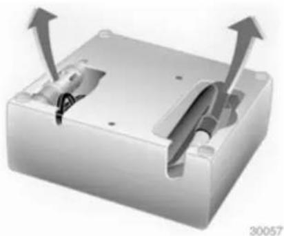
natural_image
3D rendering of a mechanical housing with two arrows indicating upward motion (no text or symbols)-
Remove the compressor from the tyre repair kit.
-
Remove the electrical connection cable and air hose from the compartments on the underside of the compressor.
124 Vehicle care
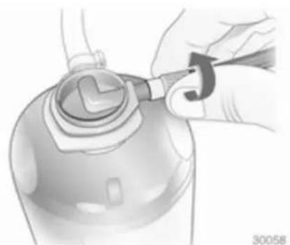
natural_image
Illustration of a hand using a tool to adjust or install a mechanical component (no text or symbols visible)- Screw the compressor air hose to the connection on the sealant bottle.
- Fit the sealant bottle into the retainer on the compressor. Set the compressor near the tyre in such a way that the sealant bottle is upright.
- Unscrew valve cap from defective tyre.

natural_image
Illustration of a mechanical device connected to a circular component with a tool, no text or symbols present.- Screw the filler hose to the tyre valve.
- The switch on the compressor must be set to O.
- Connect the compressor plug to the power outlet or cigarette lighter socket.
To avoid discharging the battery, we recommend running the engine.

natural_image
Close-up of a mechanical switch with a magnified inset showing a button and pointer (no text or symbols)- Set the rocker switch on the compressor to I. The tyre is filled with sealant.
- The compressor pressure gauge briefly indicates up to 6 bar (600 kPa/87 psi). Then the pressure starts to drop.
- All of the sealant is pumped into the tyre. Then the tyre is inflated.

natural_image
Illustration of a medical or laboratory device with a pressure gauge and tubing (no text or symbols)- The prescribed tyre pressure should be obtained within 10 minutes. Tyre pressure 151. When the correct pressure is obtained, switch off the compressor.
If the prescribed tyre pressure is not obtained within 10 minutes, remove the tyre repair kit. Move the vehicle one tyre rotation (approx. 2 metres). Reattach the tyre repair kit and continue the filling procedure for 10 minutes. If the prescribed tyre pressure is still not obtained, the tyre is too badly
damaged. Seek the assistance of a workshop.
Drain excess tyre pressure with the button above the pressure indicator.
Do not run the compressor for longer than 10 minutes.
-
Detach the tyre repair kit. Screw the tyre inflation hose to the free connection on the sealant bottle. This prevents sealant from escaping. Stow tyre repair kit under the front seat.
-
Remove any excess sealant using a cloth.
-
Take the label indicating maximum permitted speed from the tyre repair kit and affix in the driver's field of view.

natural_image
Pure electrical circuit lines without any symbols-
Continue driving immediately so that the sealant is evenly distributed throughout the tyre. After driving approx. 10 km, but no more than 10 minutes, stop and check tyre pressure using the compressor. Screw compressor air hose directly onto tyre valve and compressor when doing this.
-
If the tyre pressure is more than 3.1 bar (310 kPa/45 psi), set it to the correct value. Repeat the procedure until there is no more loss of pressure.
If the tyre pressure has fallen below 3.1 bar (310 kPa/45 psi),
the vehicle must not be driven.
Seek the assistance of a workshop.
- Stow tyre repair kit under the front seat.

Warning
Do not allow the sealant to contact skin, eyes or clothing. If swallowed seek medical assistance immediately.
Note
The driving characteristics of the repaired tyre is severely affected, therefore have this tyre replaced.
If unusual noise is heard or the compressor becomes hot, turn compressor off for at least 30 minutes.
The built-in safety valve opens at a pressure of 7 bar.
Note the expiry date of the kit. After this date its sealing capability is no longer guaranteed. Pay attention to storage information on sealant bottle.
Replace the used sealant bottle. Dispose of the bottle as prescribed by applicable laws.
The compressor and sealant can be used from approx. -30 °C.
The adapters supplied can be used to pump up other items e.g. footballs, air mattresses, inflatable dinghies etc. They are located on the underside of the compressor. To remove, screw on compressor air hose and withdraw adapter.
Wheel changing
Some vehicles are equipped with a tyre repair kit instead of a spare wheel 123.
Make the following preparations and observe the following information:
■ Park the vehicle on a level, firm and non-slippery surface. The front wheels must be in the straight-ahead position.
■ Apply the parking brake and engage first gear or reverse gear.
■ Remove the spare wheel ➔ 127.
■ Never change more than one wheel at a time.
■ Use the jack only to change wheels in case of puncture, not for seasonal winter or summer tyre change.
■ If the ground on which the vehicle is standing is soft, a solid board (max. 1 cm thick) should be placed under the jack.
■ No people or animals may be in the vehicle when it is jacked-up.
■ Never crawl under a jacked-up vehicle.
■ Do not start the engine when the vehicle is raised on the jack.
■ Before screwing in the wheel bolts, clean them and lightly coat the taper of each wheel bolt with commercially available grease.
- Pull off the wheel cover 120.
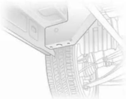
natural_image
Technical sketch of a mechanical component with visible teeth and internal components (no text or symbols)- Loosen each of the wheel bolts by half a turn using the ratchet and adapter. The ratchet should turn anticlockwise to loosen the bolts. Invert the ratchet if necessary.

natural_image
Technical line drawing of a mechanical component or bracket assembly (no visible text or symbols)- Raise vehicle by placing lifting pad spigot of the jack under the jacking hole located nearest the wheel concerned.
Ensure the jack is positioned correctly. The jack base must be on the ground directly below the jacking hole in a manner that prevents it from slipping.
-
Install adapter onto the jack and raise the vehicle by turning the ratchet until the wheel is clear of the ground.
-
Unscrew wheel bolts completely by turning anticlockwise and wipe clean with a cloth.
Put wheel bolts somewhere where the threads will not be soiled.
- Change the wheel.
- Screw in the wheel bolts.
- Lower vehicle.
- Tighten each wheel bolt in a crosswise sequence. Tightening torque is 140 Nm.
- Refit wheel cover
- Change the wheel.
- Stow the replaced wheel 127 and the vehicle tools 120.
- Have the new wheel balanced on the vehicle. Check the tyre pressure of the installed tyre 151 and also the wheel bolt torque as soon as possible.
Have the defective tyre renewed or repaired.
Spare wheel
Some vehicles are equipped with a tyre repair kit instead of a spare wheel 123.
128 Vehicle care
Use of a spare wheel that is smaller than the other wheels or together with winter tyres could affect driveability. Have the defective tyre replaced as soon as possible.
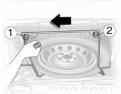
text_image
Diagram showing a hand holding a fan or switch with labeled parts 1 and 2, indicating a mechanical or electrical component assembly.The spare wheel is mounted under the rear underbody and may be secured using a security bolt that can only be removed using the tool supplied.
⚠ Warning
Due to the weight of the tyre assembly, exercise caution when releasing the spare wheel carrier. Do not fully remove bolt 1.
Support the spare wheel with a suitable object to prevent the wheel falling suddenly when loosening the carrier bolts - risk of injury!
It may be necessary to jack the vehicle up to gain access to the spare wheel on a fully loaded vehicle with a flat rear tyre.
To release the spare wheel carrier, loosen bolt 1, ensuring it is not fully removed. Fully remove bolt 2, then pull the carrier to the left, until it clears bolt 1, and lower the carrier assembly. When installing the wheel ensure that the spare wheel carrier is correctly positioned before tightening the bolts.
Summer and winter tyres
If you use winter tyres, the spare wheel may still be fitted with a summer tyre.
If you use the spare wheel when it is fitted with a summer tyre the vehicle's driveability may be affected, especially on slippery road surfaces.
Directional tyres
Fit directional tyres such that they roll in the direction of travel. The rolling direction is indicated by a symbol (e.g. an arrow) on the sidewall.
The following applies to tyres fitted opposing the rolling direction:
■ Driveability may be affected. Have the defective tyre renewed or repaired as soon as possible.
■ Do not drive faster than 80 km/h.
■ Drive particularly carefully on wet and snow-covered road surfaces.
Jump starting
Do not start with a quick charger.
A vehicle with a discharged battery can be started using jump leads and the battery of another vehicle.
Warning
Be extremely careful when starting with jump leads. Any deviation from the following instructions can lead to injuries or damage caused by battery explosion or damage to the electrical systems of both vehicles.
■ Never expose the battery to naked flames or sparks.
■ A discharged battery can already freeze at a temperature of 0 °C . Defrost the frozen battery before connecting jump leads.
■ Avoid contact with eyes, skin, fabrics and painted surfaces. The fluid contains sulphuric acid which can cause injuries and damage in the event of direct contact.
■ Wear eye protection and protective clothing when handling a battery.
■ Use a booster battery with the same voltage (12 volts). Its capacity (Ah) must not be much less than that of the discharged battery.
■ Use jump leads with insulated terminals and a cross section of at least 16 mm ^2 (25 mm ^2 for diesel engines).
■ Do not disconnect the discharged battery from the vehicle.
■ Switch off all unnecessary electrical consumers.
■ Do not lean over the battery during jump starting.
■ Do not allow the terminals of one lead to touch those of the other lead.
■ The vehicles must not come into contact with each other during the jump starting process.
■ Apply the parking brake, transmission in neutral.
Battery access
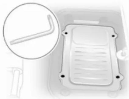
natural_image
Diagram of a vehicle interior showing a rectangular component with internal ridges and a magnified inset highlighting a small protrusion (no text or symbols)The battery is located beneath the front left hand seat floor panel. Lift the floor covering and use the tool supplied in the tool kit (or the tyre repair kit) to loosen the 4 screws.
Note the position of the arrow facing forwards on the battery cover when replacing.
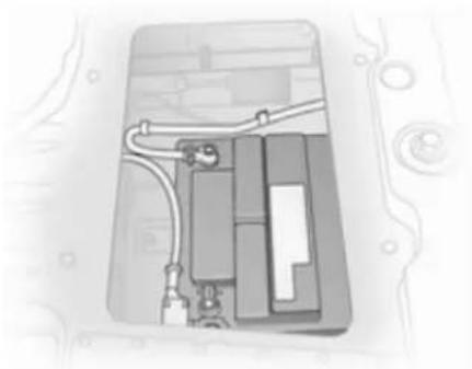
natural_image
Diagram of an electronic device showing internal components and wiring (no text or symbols)Remove cover plate to access the battery.
Jump starting procedure

text_image
Diagram showing labeled points (1, 2, 3, 4) with plus/minus signs and curved lines, likely indicating positions or connections in a vehicle interior.Lead connection order:
- Connect the red lead to the positive terminal of the booster battery.
- Connect the other end of the red lead to the positive terminal of the discharged battery.
- Connect the black lead to the negative terminal of the booster battery.
- Connect the other end of the black lead to a vehicle grounding point, such as the engine block or an engine mounting bolt. Connect as far away from the discharged battery as possible.
Route the leads so that they cannot catch on rotating parts in the engine compartment.
To start the engine:
- Start the engine of the vehicle providing the jump start.
-
After 5 minutes, start the other engine. Start attempts should be made for no longer than 15 seconds at an interval of 1 minute.
-
Allow both engines to idle for approx. 3 minutes with the leads connected.
- Switch on electrical consumers (e.g. headlights, heated rear window) of the vehicle receiving the jump start.
- Reverse above sequence exactly when removing leads.
Towing
Towing the vehicle
natural_image
Illustration of a metallic hook with a curved handle and circular port, mounted on a wall (no text or symbols)The towing eye is stowed with the vehicle tools 120.
Screw the towing eye fully into the front towing point.
Attach a tow rope - or better still a tow rod - to the towing eye, never to the bumper or front suspension units.
Do not tow the vehicle from the rear. The front towing eye must only be used for towing and not recovering a vehicle.
Switch on ignition to release steering wheel lock and to permit operation of brake lights, horn and windscreen wipers.
Transmission in neutral.
If neutral cannot be selected on vehicles with MTA transmission, the vehicle must only be towed with the drive wheels raised off the ground.
Caution
Drive slowly. Do not drive jerkily. Excessive tractive force can damage the vehicle.
When the engine is not running, considerably more force is needed to brake and steer.
To prevent the entry of exhaust fumes from the towing vehicle, switch on the air recirculation system and close the windows.
Seek the assistance of a workshop.
Towing another vehicle
natural_image
Close-up of a metallic mechanical component with a circular end cap, mounted on a curved surface (no visible text or symbols)The fixed towing eye is located under the rear bumper.

natural_image
Exterior view of a modern office building (no signage)Vehicles with a towing hitch have a socket for the detachable towing eye. Screw the towing eye, supplied with the vehicle tools, fully into the socket.
Attach a tow rope - or better still a tow rod - to the rear towing eye, never to the rear axle and suspension units.
The rear towing eye must only be used for towing and not recovering a vehicle.
Caution
Drive slowly. Do not drive jerkily. Excessive tractive force can damage the vehicle.
Appearance care
Exterior care
Locks
The locks are lubricated at the factory using a high quality lock cylinder grease. Use de-icing agent only when absolutely necessary, as this has a degreasing effect and impairs lock function. After using de-icing agent, have the locks regreased by a workshop.
Washing
The paintwork of your vehicle is exposed to environmental influences. Wash and wax your vehicle regularly. When using automatic vehicle washes, select a programme that includes waxing.
Bird droppings, dead insects, resin, pollen and the like should be cleaned off immediately, as they contain aggressive constituents which can cause paint damage.
If using a vehicle wash, comply with the vehicle wash manufacturer's instructions. The windscreen wipers and rear window wiper must be switched off. Remove antenna and external accessories such as roof racks etc.
If you wash your vehicle by hand, make sure that the insides of the wheel housings are also thoroughly rinsed out.
Clean edges and folds on opened doors and the bonnet as well as the areas they cover.
Have the door hinges of all doors greased by a workshop.
Do not clean the engine compartment with a steam-jet or high-pressure jet cleaner.
Thoroughly rinse and leather-off the vehicle. Rinse leather frequently. Use separate leathers for painted and glass surfaces: remnants of wax on the windows will impair vision.
Do not use hard objects to remove spots of tar. Use tar removal spray on painted surfaces.
Exterior lights
Headlight and other light covers are made of plastic. Do not use any abrasive or caustic agents, do not use an ice scraper, and do not clean them dry.
Polishing and waxing
Wax the vehicle regularly (at the latest when water no longer beads). Otherwise, the paintwork will dry out.
Polishing is necessary only if the paint has become dull or if solid deposits have become attached to it.
Paintwork polish with silicone forms a protective film, making waxing unnecessary.
Plastic body parts must not be treated with wax or polishing agents.
Windows and windscreen wiper blades
Use a soft lint-free cloth or chamois leather together with window cleaner and insect remover.
When cleaning the rear window, make sure the heating element inside is not damaged.
For mechanical removal of ice, use a sharp-edged ice scraper. Press the scraper firmly against the glass so that no dirt can get under it and scratch the glass.
Clean smearing wiper blades with a soft cloth and window cleaner.
Wheels and tyres
Do not use high-pressure jet cleaners.
Clean rims with a pH-neutral wheel cleaner.
Rims are painted and can be treated with the same agents as the body.
Paintwork damage
Rectify minor paintwork damage with a touch-up pen before rust forms. Have more extensive damage or rust areas repaired by a workshop.
Underbody
Some areas of the vehicle underbody have a PVC undercoating while other critical areas have a durable protective wax coating.
After the underbody is washed, check the underbody and have it waxed if necessary.
Bitumen/rubber materials could damage the PVC coating. Have underbody work carried out by a workshop.
Before and after winter, wash the underbody and have the protective wax coating checked.
Engine compartment
It is advisable to wash the engine compartment before and after winter and preserve it with wax. Protect the alternator and brake fluid reservoir with plastic sheets before washing the engine.
When washing the engine with a steam-jet cleaner, do not direct the steam jet towards components of the antilock brake system, air conditioning system or the belt drive and its components.
After an engine wash, have all engine compartment components preserved thoroughly by a workshop using protective wax.
134 Vehicle care
Do not use high-pressure jet cleaners.
Towing equipment
Do not clean the coupling ball bar with a steam-jet or high-pressure jet cleaner.
Interior care
Interior and upholstery
Only clean the vehicle interior, including the instrument panel fascia and panelling, with a dry cloth or interior cleaner.
The instrument panel should only be cleaned using a soft damp cloth.
Clean fabric upholstery with a vacuum cleaner and brush.
Remove stains with an upholstery cleaner.
Clean seat belts with lukewarm water or interior cleaner.
Caution
Close Velcro fasteners as open Velcro fasteners on clothing could damage seat upholstery.
Plastic and rubber parts
Plastic and rubber parts can be cleaned with the same cleaner as used to clean the body. Use interior cleaner if necessary. Do not use any other agent. Avoid solvents and petrol in particular. Do not use high-pressure jet cleaners.
Service and maintenance
General information 135
Recommended fluids, lubricants and parts 137
General information
Service information
In order to ensure economical and safe vehicle operation and to maintain the value of your vehicle, it is of vital importance that all maintenance work is carried out at the proper intervals as specified.
The detailed, up-to-date service schedule for the vehicle is available at the workshop.
Service display ➔ 63.
Engine identification ➔ 140.
European service intervals - except M9R 630 engine
Maintenance of your vehicle is required every 30,000 km or after 1 year, whichever occurs first, unless otherwise indicated by the service display.
European service intervals - M9R 630 engine only
Maintenance of your vehicle is required every 40,000 km or after 1 year, whichever occurs first, unless otherwise indicated by the service display.
The European service intervals are valid for the following countries:
Andorra, Austria, Belgium, Croatia, Czech Republic, Denmark, Estonia, Finland, France, Germany, Greece, Hungary, Iceland, Ireland, Israel, Italy, Latvia, Liechtenstein, Lithuania, Luxembourg, Netherlands, Norway, Poland, Portugal, Slovakia, Slovenia, Spain, Sweden, Switzerland, United Kingdom.
International service intervals Romania, Bulgaria M9R and G9U engines:
Maintenance of your vehicle is required every 20,000 km or after 1 year, whichever occurs first, unless otherwise indicated by the service display.
Romania, Bulgaria F9Q engines, International petrol engines, Turkey, Russia, Ukraine:
Maintenance of your vehicle is required every 15,000 km or after 1 year, whichever occurs first, unless otherwise indicated by the service display.
International diesel engines, International+ petrol engines, Algeria, Morocco, Tunisia, U.A.E:
Maintenance of your vehicle is required every 10,000 km or after 1 year, whichever occurs first, unless otherwise indicated by the service display.
International+ diesel engines:
Maintenance of your vehicle is required every 8,000 km or after 1 year, whichever occurs first, unless otherwise indicated by the service display.
International++ diesel engines:
Maintenance of your vehicle is required every 5,000 km or after 1 year, whichever occurs first, unless otherwise indicated by the service display.
International++ petrol engines:
Maintenance of your vehicle is required every 5,000 km or after 6 months, whichever occurs first, unless otherwise indicated by the service display.
The International service intervals are valid for: Albania, Australia, Bosnia-Herzegovina, Cyprus, Kosovo, Macedonia, Malta, Montenegro, New Zealand, Serbia, Singapore, South Africa.
The International+ service intervals are valid for: Belarus, Moldova.
The International++ service intervals are valid for: Hong Kong, Kazakhstan.
Confirmations
Confirmation of service is recorded in the Service and Warranty Booklet. The date and mileage is completed with the stamp and signature of the servicing workshop.
Make sure that the Service and Warranty Booklet is completed correctly as continuous proof of service is essential if any warranty or goodwill claims are to be met, and is also a benefit when selling the vehicle.
Service interval with remaining engine oil life duration
The service interval is based on several parameters depending on usage.
The service display lets you know when to change the engine oil.
Service display ➔ 63.
Recommended fluids, lubricants and parts
Recommended fluids and lubricants
Only use products that have been tested and approved. Damage resulting from the use of non-approved materials will not be covered by the warranty.
Warning
Operating materials are hazardous and could be poisonous. Handle with care. Pay attention to information given on the containers.
Engine oil
Engine oil is identified by its quality and its viscosity. Quality is more important than viscosity when selecting which engine oil to use.
The quality specification indicates its ability to protect the engine from wear, whilst the viscosity grade indicates its fluidity within a temperature range.
The new oil quality specification for both petrol and diesel engines is Dexos 2 ^TM . If it is not available, an alternative listed quality must be used.
Engine oil quality
Dexos 2 ^TM = All petrol and diesel engines
Alternative qualities if Dexos 2 ^TM is not available:
GM-LL-A-025 = Petrol engines GM-LL-B-025 = Diesel engines
Alternative qualities if GM-LL-A-025 or GM-LL-B-025 are not available:
ACEA-A3/B3 = Petrol engines ACEA-A3/B4 = Diesel engines without DPF
ACEA-C3 = Diesel engines with DPF
Topping up engine oil
Engine oils of different manufacturers and brands can be mixed as long as they comply with the required engine oil quality and viscosity.
Use of engine oil of only ACEA A1/B1 or only A5/B5 quality is prohibited, since it can cause long-term engine damage under certain operating conditions.
Additional engine oil additives
The use of additional engine oil additives could cause damage and invalidate the warranty.
Engine oil viscosity
For diesel engines use SAE viscosity 0W-30, 0W-40, 5W-30 or 5W-40.
For petrol engines use SAE viscosity 0W-30, 0W-40, 5W-30, 5W-40 or 10W-40.
The SAE viscosity grade defines the ability of an oil to flow. When cold, oil is more viscous than when hot.
138 Service and maintenance
Multigrade oil is indicated by two figures. The first figure, followed by a W, indicates the low temperature viscosity and the second figure the high temperature viscosity.
Select the appropriate viscosity grade depending on the minimum ambient temperature.
■ down to -25°C:
SAE 5W-30 or SAE 5W-40
■ below -25°C:
SAE 0W-30 or SAE 0W-40
Coolant and antifreeze
Use only silicate-free long life coolant (LLC) antifreeze.
The system is factory filled with coolant designed for excellent corrosion protection and frost protection down to approx. -28 °C.
This concentration should be maintained all year round.
The use of additional coolant additives that intend to give additional corrosion protection or seal against minor leaks can cause function
problems. Liability for consequences resulting from the use of additional coolant additives will be rejected.
Brake and clutch fluid
Use DOT4 brake fluid.
Over time, brake fluid absorbs moisture which will reduce braking effectiveness. The brake fluid should therefore be replaced at the specified interval.
Brake fluid should be stored in a sealed container to avoid water absorption.
Ensure brake fluid does not become contaminated.
Technical data
Vehicle identification ..... 139
Vehicle data 142
Vehicle identification Vehicle Identification Number
natural_image
Close-up of a white car door panel with a small black label on the side (no readable text or symbols)The Vehicle Identification Number is visible through the windscreen.
text_image
YUFAETMBSO PUNUCOThe VIN is also displayed behind a removable plastic cover on the right hand side door step.
Identification plate

natural_image
Close-up of a car interior with a magnified inset showing a small electronic component (no visible text or symbols)The identification plate is located on the right hand door pillar.
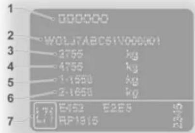
text_image
000000 WOLJ7ABCS1V000001 2755 kg 4755 kg 1-1550 kg 2-1550 kg E452 E285 RP1815Information on identification plate ^1) :
1 = Manufacturer, type approval number
2 = Vehicle Identification Number
3 = Permissible gross vehicle weight rating
4 = Permissible gross combination weight
5 = Maximum permissible front axle load
6 = Maximum permissible rear axle load
7 = Vehicle-specific or country specific data
The combined total of front and rear axle loads must not exceed the permissible gross vehicle weight. For example, if the front axle is bearing its maximum permissible load, the rear axle can only bear a load that is equal to the gross vehicle weight minus the front axle load.
The technical data is determined in accordance with European Community standards. We reserve the right to make modifications.
Specifications in the vehicle documents always have priority over those given in this manual.
Engine identification
It is possible, using the Vehicle Identification Number (VIN), to determine the engine type that is installed in your vehicle. The seventh digit denotes the engine type:
Digit Engine
P or S: 2.0 Diesel, M9R 630
L, N or W: 2.0 Petrol, F4R 820
C: 1.9 Diesel, F9Q 760
E, H, M or T: 2.0 Diesel, M9R 786
U: 2.0 Diesel, M9R 788
J, R or V: 2.5 Diesel, G9U 630
Engine identifier code and engine number
Stamped on the lower rear of the engine block on an identification plate.
142 Technical data
Vehicle data
Engine data
Sales designation 2.0 1.9 2.0
| Engine identifier code | F4R 820 F9Q 760 | M9R 630 ^2) | ||
| Number of cylinders 4 4 4 | ||||
| Piston displacement [cm ^3 ] | 1998 1870 1995 | |||
| Engine power [kW] 86 74 66 / 84at rpm 4700 3500 3500 | ||||
| Torque [Nm] 186 240at rpm 3750 1800 1500 | 260 / 300 | |||
| Fuel type | Petrol | Diesel | Diesel | |
| Octane rating RON | ||||
| recommended | 95 | |||
| possible | 98 | |||
| possible | 91 ^3) | |||
2) Low / High output.
3) If no unleaded premium-grade fuels are available, 91 RON can be used, taking care to avoid severe engine loads and driving at full throttle.
| Sales designation 2.0 2.0 2.5 | |||
| M9R 7864) | M9R 7865) | ||
| Engine identifier code | M9R 788 G9U 630 | 6) | |
| Number of cylinders 4 4 4 | |||
| Piston displacement [cm3] | 1995 1995 2464 | ||
| Engine power [kW] 66 84 84 / 107at rpm 3500 3500 3500 | |||
| Torque [Nm] 290 310 290 / 310at rpm 1600 2100 1600 / 2100 | |||
| Fuel type Diesel Diesel Diesel | |||
4) Low output.
5) High output.
6) Low / High output.
144 Technical data
Vehicle weight
Kerb weight, basic model
| Model | Wheelbase | Roof | Payload Class | Engine | Kerb weight ^7) |
| Van Short Standard 1000 F4R 1660 | |||||
| F9Q 1660 | |||||
| M9R 1678 | |||||
| G9U 1736 | |||||
| Standard 1200 F4R 1660 | |||||
| F9Q 1669 | |||||
| M9R 1688 | |||||
| G9U 1737 | |||||
| High 1200 F4R 1695 | |||||
| F9Q 1713 | |||||
| M9R 1760 | |||||
| G9U 1810 | |||||
7) Kerb weight and gross vehicle weight increase on models fitted with bad road equipment package - refer to VIN plate.
Technical data 145
| Model | Wheelbase | Roof | Payload Class | Engine | Kerb weight ^7) |
| Van Long Standard 1200 F4R 1660 | |||||
| F9Q 1676 | |||||
| M9R 1724 | |||||
| G9U 1772 | |||||
| High 1200 F4R 1745 | |||||
| F9Q 1761 | |||||
| M9R 1810 | |||||
| G9U 1860 | |||||
7) Kerb weight and gross vehicle weight increase on models fitted with bad road equipment package - refer to VIN plate.
146 Technical data
| Model | Wheelbase | Roof | Payload Class | Engine | Kerb weight7) |
| Combi Short Standard 1000 F4R 1818 | |||||
| F9Q 1835 | |||||
| M9R 1883 | |||||
| G9U 1940 | |||||
| Standard 1200 F4R 1829 | |||||
| F9Q 1846 | |||||
| M9R 1893 | |||||
| G9U 1942 | |||||
| Long Standard 1200 F4R 1890 | |||||
| F9Q 1906 | |||||
| M9R 1954 | |||||
| G9U 2003 | |||||
7) Kerb weight and gross vehicle weight increase on models fitted with bad road equipment package - refer to VIN plate.
Technical data 147
| Model | Wheelbase | Roof | Payload Class | Engine | Kerb weight ^7) |
| Platform cab Long Standard 1200 F4R | 1449 ^8) | ||||
| F9Q | 1467 ^8) | ||||
| M9R | 1515 ^8) | ||||
| G9U | 1563 ^8) | ||||
| Tour Short Standard 900 F4R 1879 | |||||
| F9Q - | |||||
| M9R 1944 | |||||
| G9U 2018 | |||||
7) Kerb weight and gross vehicle weight increase on models fitted with bad road equipment package - refer to VIN plate.
8) Vehicle without body conversion.
148 Technical data
Vehicle dimensions
| Type Van Combi/Tour | 9) | Platform cab |
| Wheelbase Short Long Short Long Long | ||
| Length [mm] 4782 5182 4782 5182 5130 | ||
| Width without exterior mirrors [mm] 1904 1904 1904 1904 1904 | ||
| Width with two exterior mirrors [mm] 2232 2232 2232 2232 | 2232/2434^10) | |
| Height - unladen (without antenna) [mm] ^11) | ||
| Standard roof 1968 1968 1968 1968 1981 | ||
| High roof 2492 2492 -- | - | |
| Wheelbase [mm] | 3098 3498 3098 3498 3498 | |
| Track width [mm] | ||
| Front | 1615 1615 1615 1615 1615 | |
| Rear | 1630 1630 1630 1630 1630 |
9) Tour available with short wheel base only.
^10) With wide arm exterior mirrors.
11) Vehicle height without body conversion.
Loadspace dimensions
| Wheelbase | VanShort Long |
| Roof height Standard High Standard High | |
| Maximum rear door aperture height [mm] 1335 1818 1335 1818 | |
| Rear door aperture width (at floor) [mm] 1390 1390 1390 1390 | |
| Maximum load area height [mm] 1387 1913 1387 1913 | |
| Maximum load area width [mm] 1690 1690 1690 1690 | |
| Width between wheel arches [mm] 1268 1268 1268 1268 | |
| Maximum load floor length [mm] 2400 2400 2800 2800 | |
| Loading height unladen [mm] 543 547 542 548 | |
| Sliding side door aperture width [mm] | 1000 1000 1000 1000 |
| Sliding side door aperture height [mm] | 1285 1285 1285 1285 |
150 Technical data
Capacities
Engine oil
Engine F4R F9Q M9R G9U
Engine oil including filter [I] 5.4 4.7 7.7 7.5
between MIN and MAX [I] 1.5 - 2.0 1.5 - 2.0 1.5 - 2.0 1.5 - 2.0
Fuel tank
Engine F4R F9Q M9R G9U
Fuel tank, nominal capacity [l] 90 90 90 90
Tyre pressures
| Tyre | Tyre pressure with full load12) | |
| Front[kPa/bar] (psi) | Rear[kPa/bar] (psi) | |
| 195/65 R16 C 340/3.4 (49) 370/3.7 (54) | ||
| 195/75 R16 C 380/3.8 (55) 420/4.2 (61) | ||
| 205/65 R16 C 380/3.8 (55) 420/4.2 (61) | ||
| 215/65 R16 C 310/3.1 (45) 340/3.4 (49) | ||
Towing hitch installation dimensions

text_image
933 392 289,1 59 57 1032 337 55Customer information
Vehicle data recording and privacy 153
Vehicle data recording and privacy
Event data recorders
The vehicle has a number of sophisticated systems that monitor and control several vehicle data. Some data may be stored during regular operation to facilitate repair of detected malfunctions, other data is stored only in a crash or near crash event by systems commonly called event data recorders (EDR).
The systems may record data about the condition of the vehicle and how it was operated (e.g. engine speed, brake application, seat belt usage). To read this data special equipment and access to the vehicle is required. This will take place when the vehicle is serviced in a workshop. Some data is electronically fed into GM global diagnostic systems. The manufacturer will not access information about a crash event or share it with others except
■ with the consent of the vehicle owner or, if the vehicle is leased, with the consent of the lessee,
■ in response to an official request of police or similar government office,
■ as part of the manufacturer's defense in case of legal proceedings,
■ as required by law.
In addition, the manufacturer may use the collected or received data
■ for the manufacturer's research needs,
■ to make it available for research needs where appropriate confidentiality is maintained and need is shown,
■ to share summary data which is not tied to a specific vehicle with other organisations for research purposes.
Index
A
Accessories and vehicle modifications 105
Adjustable air vents 81
Airbag and belt tensioners ..... 65
Airbag deactivation 43,65
Airbag system 40
Air conditioning regular operation 82
Air conditioning system 79
Air intake 82
Antilock brake system 92
Antilock brake system (ABS) ..... 66
Anti-theft alarm system 24
Anti-theft locking system 24
Armrest 33
Ashtrays 61
Automatic light control 73
Automatic locking 21
B
Battery 111
Bonnet 106
Brake assist 93
Brake fluid 111
Brakes 91, 111
Brake system 66
Bulb replacement 114
C
Capacities 150
Car Pass 18
Catalytic converter 86
Central locking system 20
Centre high-mounted brake light 115
Changing tyre and wheel size ... 122
Charging system 65
Child locks 22
Child restraint installation locations 46
Child restraint systems 44
Cigarette lighter 60
Climate control 15
Clock 59
Control indicators.... 63
Control of the vehicle 83
Convex shape 26
Cruise control 68, 95
Cupholders 51
Curtain airbag system 42
D
Danger, Warnings and Cautions ...4
Daytime running lights 74
Diesel fuel filter 112
Diesel fuel system bleeding ..... 113
Diesel particle filter.... 67, 85
Door open 68
Driver Information Center...... 69
Driving characteristics and towing tips 103
E
Electric adjustment 27
Electronic driving programmes .... 89
Electronic Stability Program .. 67, 94
End-of-life vehicle recovery ..... 106
Engine air filter.... 109
Engine coolant 110
Engine coolant temperature ..... 67
Engine data 142
Engine exhaust 85
Engine oil 107
Engine oil level monitor.... 62
Engine oil pressure 67
Event data recorders.... 153
Exit lighting 77
Exterior care 132
Exterior light 68
Exterior lighting 12
F
Fault 91
First aid kit 53
Fixed air vents 81
Fog light 68
Fog lights 114
Fog tail light 116
Folding 27
Front airbag system 41
Front fog lights 75
Front storage.... 51
Front turn signal lights 114
Fuel consumption - CO _2 - Emissions 102
Fuel for diesel engines 100
Fuel for petrol engines 100
Fuel gauge 62
Fuses 118
G
General information 103
Glovebox 51
Glovebox cooler 82
H
Hand brake - see Parking brake... 92
Hazard warning flashers ..... 75
Headlight flash 74
Headlight range adjustment ..... 74
Headlights 114
Headlights when driving abroad ..74
Head restraint adjustment 8
Head restraints 30
Heated 27
Heated exterior mirrors.... 27
Heated rear window 29
Heating 33
Heating and ventilation system ...78
High beam 68,74
Horn 13,57
|
Identification plate 140
Ignition switch positions 84
Immobiliser 26
Instrument panel fuse box ..... 119
Instrument panel illumination ..... 117
Instrument panel overview ..... 11
Instrument panel storage...... 51
Interior care 134
Interior lights 76, 117
Interruption of power supply ..... 91
Introduction 3
Isofix child restraint systems ..... 50
J
Jump starting 128
K
Keys 18
L
Lashing eyes 53
Light switch 73
Load compartment 23
Load compartment cover 52
Load compartment lighting...... 76
Loading information 54
Load rails and hooks 52
Low fuel 68
M
Malfunction indicator light 66
Manual adjustment 26
Manual anti-dazzle 28
Manual mode 89
Manual transmission 87
Manual transmission automated . 87
Manual windows 28
Mirror adjustment 8
Misted light covers 76
N
New vehicle running-in 83
Number plate light 116
O
Odometer 61
Oil level.... 62
Outside temperature 59
Overcab storage 52
Overrun cut-off 84
P
Parking 17,84
Parking assist 98
Parking brake 92
Performing work 106
Pollen filter 82
Power outlets 60
Power steering fluid.... 110
Power windows 28
Preheating 67
R
Radio remote control 18
Rear air conditioning system ..... 80
Rear doors 22
Rear fog light 68
Rear fog lights 75
Rear heating system 79
Rear windows 29
Rear window wiper/washer ..... 59
Recommended fluids and lubricants 137
Refuelling 101
Reversing light 116
Reversing lights 76
Roof rack 54
S
Safety net 53
Seat adjustment 7,32
Seat belt 8
Seat belt reminder 65
Seat belts 37
Seat position 31
Second row seats 34
Selector lever 88
Service 82,135
Service display 63
Service information 135
Service vehicle soon 66
Side airbag system 41
Side turn signal lights 115
Sliding door 22
Spare wheel 127
Speedometer 61
Starting off 16
Starting the engine 84, 88
Steering column controls...... 57
Steering wheel adjustment ..... 9, 56
Steering wheel controls 56
Stop engine.... 66
Sunvisors 29
Symbols 4
T
Tachograph.... 72
Tachometer 62
Tail lights 115
Three-point seat belt 38
Tools 120
Towing another vehicle 131
Towing equipment 104
Towing hitch installation dimensions 152
Towing the vehicle 131
Traction Control system 93
Trailer towing 103
Transmission 15
Transmission display 63, 87
Tread depth 121
Trip computer 70
Triple-Info-Display 69
Turn and lane-change signals ..... 75
Turn signal 65
Tyre chains 122
Tyre designations 121
Tyre pressure 121
Tyre pressures 151
Tyre repair kit 123
Tyres 121
U
Upshift.... 67
Using this manual 3
V
Vehicle dimensions .... 148
Vehicle Identification Number .... 139
Vehicle messages 69
Vehicle specific data 3
Vehicle storage.... 105
Vehicle unlocking 6
Vehicle weight 144
W
Warning chimes .... 70
Warning triangle 53
Washer and wiper systems ..... 14
Washer fluid 111
Wheel changing 126
Wheel covers 122
Wheels and tyres 121
Windscreen wiper/washer 57
Winter tyres 121
Wiper blade replacement ..... 113