
IHP 9.5 C M IX - Range hood INDESIT - Free user manual and instructions
Find the device manual for free IHP 9.5 C M IX INDESIT in PDF.


| Brand | Indesit |
| Model | IHP 9.5 C M IX |
| Product Type | Cooker hood |
| Color / Finish | Stainless steel |
| Dimensions (W x D x H) | 89.9 x 50 x 61-82 cm (adjustable height) |
| Air outlet diameter | 150 mm (15 cm) |
| Total absorbed power | 160 W |
| Lighting | 2 x halogen 25 W (socket G9) |
| Supply voltage | 230 V ~ |
| Number of speeds | 3 |
| Control type | Mechanical (push buttons) |
| Grease filter | Metal, dishwasher safe (monthly cleaning) |
| Charcoal filter | Optional, replacement every 20 months (not washable) |
| Installation version | External exhaust (recyclable with accessory kit) |
| Minimum safety distance (cooking surface) | 65 cm (gas) / 55 cm (electric) |
| Material | Stainless steel |
| Grease filter maintenance | At least once a month, by hand or in dishwasher (low temperature cycle) |
| Charcoal filter replacement | Every 20 months, remove by turning 90° |
| Bulb replacement | Disconnect the appliance, remove the filter, pry with a screwdriver, replace with identical bulb (G9 25 W) |
| Safety | Unplug before cleaning; do not use without filter; do not flambé under the hood |
Frequently Asked Questions - IHP 9.5 C M IX INDESIT
User questions about IHP 9.5 C M IX INDESIT
0 question about this device. Answer the ones you know or ask your own.
Ask a new question about this device
Download the instructions for your Range hood in PDF format for free! Find your manual IHP 9.5 C M IX - INDESIT and take your electronic device back in hand. On this page are published all the documents necessary for the use of your device. IHP 9.5 C M IX by INDESIT.
USER MANUAL IHP 9.5 C M IX INDESIT
Operating Instructions
COOKER HOOD
Contents
Operating Instructions,1
Warnings,10
Assistance,28
Installation,35
PYRAMID controls,36
Maintenance and care,37
Troubleshooting,38
PT
Portuges
natural_image
Line drawing of two gloves with a warning symbol (no text or labels)







IT
Avvertenze
! Keep this manual for reference. If you sell, transfer or move the unit to another location, make sure to keep the manual with the product.
! Read the instructions carefully - they contain important installation, user and safety information.
! Do not tamper with the electrical or mechanical equipment of the product or its exhaust ducts.
General safety information
- The distance between the cookware support surface on top of the cooking appliance and the lowest part of the cooker hood must be at least:
65 cm if the hood is installed over a gas cooktop
55 cm if the hood is installed over an electric cooktop.
If the installation instruction manual for the gas cooking appliance specifies a greater distance, this measurement should be taken into account.
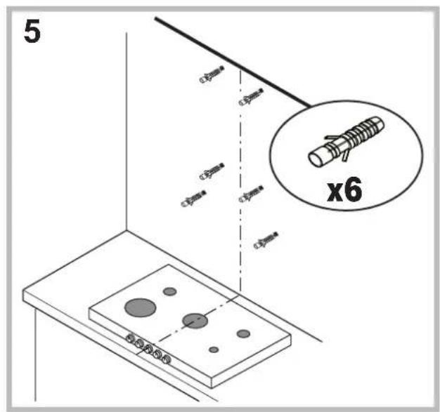
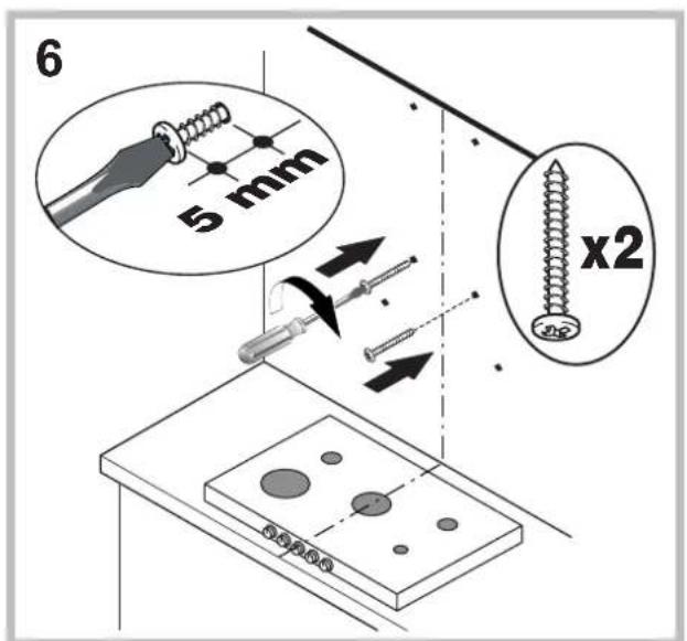
- The cooker hood comes with anchor plugs which are suitable for use with most walls/ceilings.
However, you must contact a qualified technician to check the suitability of the materials in relation to the type of wall/ceiling, which must be strong enough to support the weight of the unit.
- Caution! Do not hook the unit up to its electrical power supply until the installation has been completed.
- Before cleaning or servicing the unit, disconnect it from the mains by pulling the power plug or disconnecting the main circuit breaker.
- Always wear work gloves when installing and servicing the unit.
- It is not intended for use by children or persons with sensory or mental disability and lack of experience or familiarity, except under the supervision or instruction of a person responsible for their safety.
- Make sure children do not play with the unit.
- Never operate the unit without its grease filter installed!
- NEVER use the hood as a support, unless expressly instructed to do so.
- The room must be adequately ventilated if the hood is used at the same time with other equipment burning gas or other fuels.
- Extracted air must not be conveyed into a duct used for exhausting combustion fumes from gas or other fuel-fired equipment.
- Observe all regulations in relation to air extraction.
-
NEVER cook food with an open flame under the hood; open flames will damage the filters and may cause fires. Never do this.
• Always supervise frying to make sure the heated oil does not catch fire. -
Strictly observe all local regulations in relation to the technical and safety measures to be employed in fumes extraction.
- Clean the product frequently, inside and out (AT LEAST ONCE A MONTH, and in observance of the maintenance instruction given in this manual).
- Failure to observe the hood cleaning and filter cleaning/replacement instructions can result in fires.
- Never use the hood without its bulbs properly installed - electrocution hazard.
- The manufacturer is not liable for any inconvenience, damage or fire caused by the unit as a result of failure to observe the instructions given in this manual.
- Caution! The unit's accessible parts can get very hot when used with cooking equipment.
FR
Avertissements
! Never use the services of an unauthorised technician.
Please have the following information to hand:
• The type of problem encountered.
• The appliance model (Mod.).
• The serial number (S/N).
The latter two pieces of information can be found on the data plate located on the appliance.
FR
Assistance
• "Low voltage" Directive 2006/95/EC (12-12-2006)
• "EMC" Directive 2004/108/EC (15-12-2004)

IHP 6.5F C M K - IHP 9.5F C M IX
IHP 9.5 C M IX - IHP 7.5 C M IX
T1 Reset motore
natural_image
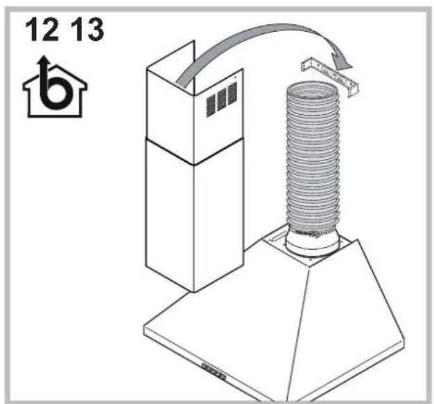
Diagram showing a mechanical assembly with a central circular component and directional arrows, no text or symbols present.The installation procedure is illustrated in the first pages of this manual.
The installation must be done by a qualified technician.
Electrical hook up
The mains voltage must match that given on the ratings label inside the hood itself. If the hood has a power plug, connect the hood to an easily accessible regulatory power socket. If it does not (direct connection to the mains), or the socket is not easily accessible, install a two-pole regulatory switch to enable total disconnection from the mains in case of category III overvoltage, as required by the installation regulations.
Caution! Always check that the mains cable is hooked up properly and check that it operates correctly before reconnecting the hood to the mains.
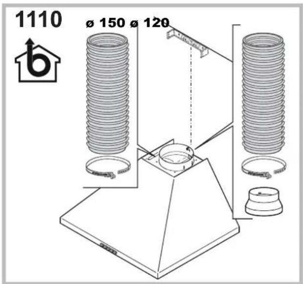
Air exhaust (for ducted units)
Connect the hood to a duct and wall exhaust hole of a diameter equal to that of the air outlet flange. Using a smaller diameter tube and exhaust hole reduces the extraction capacity of the hood and also increases its running noise. The manufacturer is not liable for any consequences of doing so.
! Use the shortest duct required to achieve the purpose.
! Use a duct with as few bends as possible
! Avoid suddenly changing the diameter of the duct.
! The duct must have as smooth an inner surface as possible.
! The duct must be made of regulatory material.
! Do not connect the hood to flues carrying combustion fumes from other equipment (boilers, chimneys, stoves, etc.).
! Observe the instructions of the competent authorities in relation to the air exhaust. The air being exhausted may not be exhausted into a wall cavity unless the cavity in question is specifically intended for this purpose.
! Equip the room with air intakes to prevent the hood creating suction pressure in the interior (this must not exceed 0.04 mbar).
! The manufacturer is not liable for any consequences of failure to observe these instructions.
Filter or ducted?
! Your hood is supplied as a ducted unit.
If you wish to use it as a filter unit, you must install the proper ACCESSORY KIT.
Note: If supplied with the hood, the accessory active charcoal filter unit may already be installed.
Instructions for transforming the hood from the ducted to the filter version are given in this manual (see "Filter version").

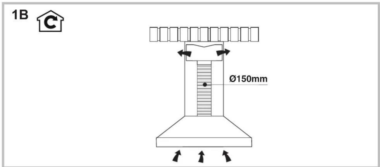
Ducted version
GB
The hood purifies the air and expels it outdoors via an exhaust duct (dia. 150mm) connected to its outlet flange. The diameter of the exhaust tube must be equal to that of the outlet flange.
Caution! The exhaust duct is not supplied and must be purchased separately.
When routed horizontally, the tube must be angled slightly upwards (around 10^ ) to enable the air to be conveyed outdoors more easily. If the hood is fitted with charcoal filters, they must first be removed.

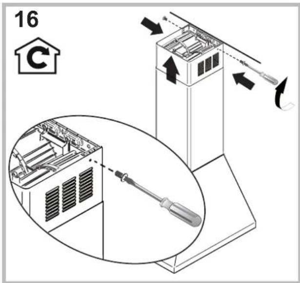
Filter version
The hood purifies the air and returns it to the room. This version of the hood requires installation of an accessory active charcoal filter unit.
This version requires an air deflector, a reduction adapter and the charcoal filter/s. The top tube must have its air outlet slots uppermost.
Technical data
| Model | Height (cm) | Width (cm) | Depth (cm) | dia. of exhaust tube (cm) |
| PYRAMID 60cm 61-82 | 59.8 50 | 15/12 | ||
| PYRAMID 70cm 61-82 | 69.8 50 | 15/12 | ||
| PYRAMID 90cm 61-82 | 89.9 50 | 15/12 |
| Model code Bulb (V) Bulb draw (W) Total draw (W) | |||
| IHP 6.5 C M IX | Halogen 2 | x 25 160 | |
| IHP 6.5F C M IX | |||
| IHP 6.5F C M K | |||
| IHP 9.5F C M IX | |||
| IHP 9.5 C M IX | |||
| IHP 7.5 C M IX | |||
| Power | Voltage Cap | Dimensions | ||
| Halogen 25 W | 2 x 25 W | 230 V | G9 | L40x∅14 |
| Halogen 20 W | 2 x 20 W | 12 V | G4 | L30x∅10 |
| LED * | Risk Group 1 according to Standard EN 62471 |
| CE | The hoods are conforming to the following EC Directives:“Low voltage” Directive 2006/95/EC (12-12-2006)“EMC” Directive 2004/108/EC (15-12-2004) |
GB
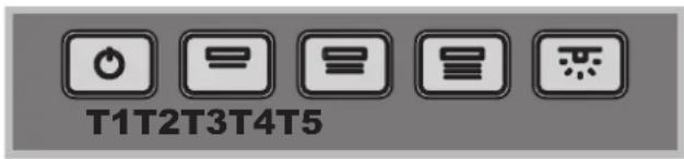
PYRAMID controls
Models with mechanical keypad
IHP 6.5 C M IX - IHP 6.5F C M IX
IHP 6.5F C M K - IHP 9.5F C M IX
IHP 9.5 C M IX - IHP 7.5 C M IX

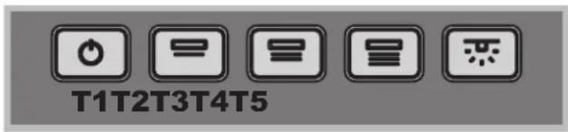
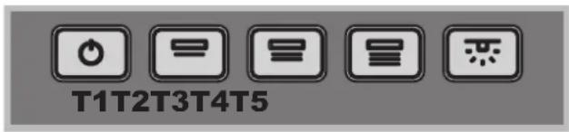
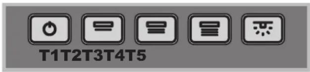
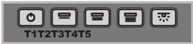
T1T2T3T4T5
T1 Motor reset
Pressing the button while the hood is in operation turns it OFF.
T2 Speed 1
Pressing the button sets the hood to speed 1.
T3 Speed 2
Pressing the button sets the hood to speed 2.
T4 Speed 3
Pressing the button sets the hood to speed 3.
T5 Lights ON/OFF
Maintenance and care
Caution! Before cleaning or servicing the unit, disconnect it from the mains by pulling the power plug or disconnecting the main circuit breaker.
First cleaning
- Remove the protective film
- Clean with a damp sponge and a little neutral soap
- Rinse off with a damp cloth
- Dry with a soft cloth; if the hood is stainless steel, dry along the metal's grain
Periodic cleaning
The hood must be cleaned frequently (at least as often as you service the grease filter), inside and out. Use a damp cloth and a neutral liquid detergent with lukewarm water. Do not use abrasive or corrosive products.
Warning: Failure to observe the hood cleaning and filter cleaning/replacement instructions can result in fires. Follow the instructions carefully. The manufacturer is not liable for any damage to the motor or fires caused by incorrect care or failure to follow the above instructions.
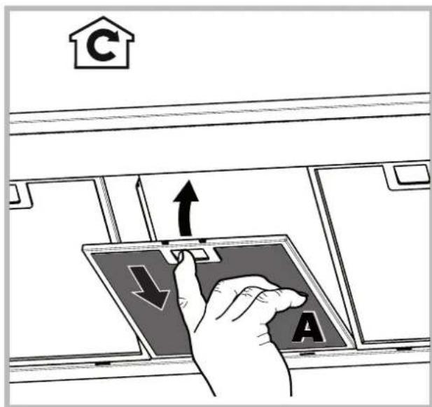
Servicing the grease filter (A)
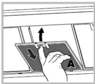
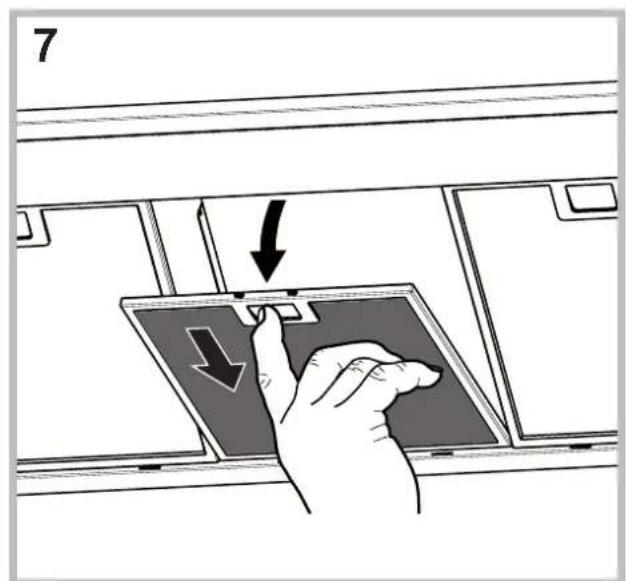
The grease filter retains the particles of grease produced during cooking; it must be cleaned at least once a month with a non-aggressive detergent, either by hand or with a low temperature, short dishwasher cycle.
To extract the grease filter, pull the spring loaded handle.
If washed in a dishwasher, the metal filter may change colour, but this does not affect its performance.
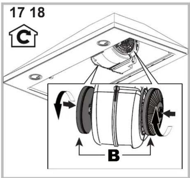
Servicing the charcoal filter (B)

The charcoal filter retains unpleasant cooking odours. The filter saturates after a variable time, depending on the type of cooking and how often the grease filter is cleaned. The cartridge must be replaced at least once every twenty months.
This filter can NOT be washed
or regenerated
Disassembly: Rotate the filter 90^ to remove it from the suction assembly.
Assembly: Fit the active-carbon filter into the suction assembly and rotate it 90^ to secure it in place.
Replacing the bulbs
Disconnect the unit from the mains and remove the grease filter.
Caution! Make sure the bulbs are cool before touching them.
-
Extract the guard by prising it out with a small flat head screwdriver or something similar.
-
Replace the faulty bulb. Use only bulbs of the same type (for details, see the technical data in the following manual).
-
Refit the guard (push it in).

natural_image
Technical diagram showing a circular component with an arrow pointing to it, mounted on a platform (no text or symbols present)Replacing the lights LED \*
The hood is fitted with a lighting system based on LED technology. The LEDs ensure optimal lighting, longer life and lower consumption compared with traditional lights. To replace them please contact the assistance service.
Electrical cable
If the power cable is damaged, it can be replaced by the manufacturer or his technical service, to prevent any attendant risks.
* Only available in certain models
SCRAPPING
The unit is marked for conformity with European Directive 2012/19/EC, Waste Electrical and Electronic Equipment (WEEE). By ensuring that the unit is scrapped properly, the user contributes to safeguarding the environment and public health.

The symbol on the product or on its accompanying documents indicates that the product may not be treated as domestic waste but must be handed over to a sorting centre for electrical and electronic waste. Dispose of it in accordance with local waste disposal regulations. For further information on the handling, recovery and recycling of this product, contact the local authority, domestic waste disposal service or the reseller from whom you purchased it
Troubleshooting
If something does not work, make the following simple checks before contacting Technical Service:
If the hood does not operate:
Check that:
• the unit is powered up.
- a speed has been set.
If the hood is not working effectively:
Check that:
- the selected motor speed is sufficient to handle the amount of smoke and steam being produced.
- the kitchen is adequately ventilated for the unit to take air in.
- the charcoal filter is not exhausted (filter version).
If the hood turns off during normal operation:
Check that:
• the unit is powered up.
- the circuit breaker has not tripped.
In case of faulty operation, before contacting Technical service, first disconnect the machine from the mains for at least 5 seconds by pulling its plug, then reconnect it. If the fault persist, contact Technical Service.
FR
Installation
IHP 6.5F C M K - IHP 9.5F C M IX
IHP 9.5 C M IX - IHP 7.5 C M IX

natural_image
Technical diagram showing a circular component with an arrow pointing to it, surrounded by structural elements (no text or symbols)IHP 6.5F C M K - IHP 9.5F C M IX
IHP 9.5 C M IX - IHP 7.5 C M IX

T1T2T3T4T5
T1 Reset motor
natural_image
Mechanical diagram showing a rotating fan assembly with labeled component B (no text or symbols present)natural_image
Technical diagram showing a circular component with an arrow pointing to it, surrounded by mechanical components (no text or symbols)IHP 6.5F C M K - IHP 9.5F C M IX
IHP 9.5 C M IX - IHP 7.5 C M IX
T1 Reset motor
natural_image
Technical diagram showing a mechanical assembly with an inset view of a circular component (no text or symbols)IHP 6.5F C M K - IHP 9.5F C M IX
IHP 9.5 C M IX - IHP 7.5 C M IX

T1T2T3T4T5
T1 Reset-Modus
natural_image
Mechanical diagram showing a rotating component with labeled parts B and directional arrows (no text or symbols beyond labels)natural_image
Diagram of a mechanical assembly with a central circular component and directional arrows (no text or symbols)IHP 6.5F C M K - IHP 9.5F C M IX
IHP 9.5 C M IX - IHP 7.5 C M IX
T1 Reset motor
natural_image
Mechanical assembly diagram showing a rotating component with labeled parts B and directional arrows (no text or symbols beyond labels)natural_image
Technical diagram showing a mechanical assembly with a circular component and an arrow indicating direction (no text or symbols present)NL
IHP 6.5F C M K - IHP 9.5F C M IX
IHP 9.5 C M IX - IHP 7.5 C M IX

T1 Reset silnika
natural_image
Technical diagram showing a mechanical assembly with a central circular component and directional arrows (no text or labels)IHP 6.5F C M K - IHP 9.5F C M IX
IHP 9.5 C M IX - IHP 7.5 C M IX
T1 Motor sifirlama
natural_image
Technical diagram showing a circular component with an arrow and surrounding components (no text or symbols)IHP 6.5F C M K - IHP 9.5F C M IX
IHP 9.5 C M IX - IHP 7.5 C M IX

T1T2T3T4T5
natural_image
Technical diagram showing a circular component with an arrow pointing to it, mounted on a platform (no text or symbols present)IHP 6.5F C M K - IHP 9.5F C M IX
IHP 9.5 C M IX - IHP 7.5 C M IX
natural_image
Technical diagram showing a circular component with an arrow pointing to it, mounted on a platform (no text or symbols present)IHP 6.5F C M K - IHP 9.5F C M IX
IHP 9.5 C M IX - IHP 7.5 C M IX

T1T2T3T4T5
natural_image
Mechanical diagram showing a rotating component with labeled parts B and directional arrows (no text or symbols beyond labels)natural_image
Diagram of a ceiling-mounted air duct system with an arrow pointing to a circular component (no text or symbols present)• "Low voltage" Directive 2006/95/EC (12-12-2006)
Smernica o nízkom napátí 2006/95/ES (z 12.12.2006)
• „EMC“ Directive 2004/108/EC (15-12-2004) - Smernica
o elektromagnetickej kompatibilite 2004/108/ES (z 15.12.2004)
IHP 6.5F C M K - IHP 9.5F C M IX
IHP 9.5 C M IX - IHP 7.5 C M IX

T1 Vynulovanie motora
natural_image
Technical diagram showing a mechanical assembly with a central circular component and directional arrows (no text or symbols)SK
IHP 6.5F C M K - IHP 9.5F C M IX
IHP 9.5 C M IX - IHP 7.5 C M IX

T1T2T3T4T5
T1 Моторды токтату
natural_image
Technical diagram showing a circular component with an arrow pointing to it, mounted on a platform (no text or symbols present)natural_image
Technical diagram showing a circular component with an arrow pointing to it, surrounded by structural beams and supports (no text or symbols present)IHP 6.5F C M K - IHP 9.5F C M IX
IHP 9.5 C M IX - IHP 7.5 C M IX


T1T2T3T4T5
T1 إعادة ضبط المحرك


- Operating Instructions
- COOKER HOOD
- Contents
- PT
- Portuges
- IT
- Avvertenze
- General safety information
- FR
- Avertissements
- Assistance
- T1 Reset motore
- Electrical hook up
- Air exhaust (for ducted units)
- Filter or ducted?
- Ducted version
- Filter version
- GB
- PYRAMID controls
- Models with mechanical keypad
- T1 Motor reset
- T2 Speed 1
- T3 Speed 2
- T4 Speed 3
- T5 Lights ON/OFF
- Maintenance and care
- First cleaning
- Periodic cleaning
- Servicing the grease filter (A)
- Servicing the charcoal filter (B)
- Replacing the bulbs
- Replacing the lights LED \*
- Electrical cable
- SCRAPPING
- Troubleshooting
- If the hood does not operate:
- Check that:
- If the hood is not working effectively:
- If the hood turns off during normal operation:
- Installation
- T1 Reset motor
- T1 Reset-Modus
- NL
- T1 Reset silnika
- T1 Motor sifirlama
- T1 Vynulovanie motora
- SK
- T1 Моторды токтату
Brand : INDESIT
Model : IHP 9.5 C M IX
Category : Range hood