Spirit E-210 Classic - Barbecue WEBER - Free user manual and instructions
Find the device manual for free Spirit E-210 Classic WEBER in PDF.

User questions about Spirit E-210 Classic WEBER
0 question about this device. Answer the ones you know or ask your own.
Ask a new question about this device
Download the instructions for your Barbecue in PDF format for free! Find your manual Spirit E-210 Classic - WEBER and take your electronic device back in hand. On this page are published all the documents necessary for the use of your device. Spirit E-210 Classic by WEBER.
USER MANUAL Spirit E-210 Classic WEBER
Thank you for purchasing a Weber® grill. Take a few minutes and protect it by registering your product online at www.weber.com.
natural_image
Silhouette of a traditional tripod-mounted cauldron with a ball on top (no text or symbols)YOU MUST READ THIS OWNER'S GUIDE BEFORE OPERATING YOUR GAS GRILL.
⚠️ DANGER
If you smell gas:
1) Shut off gas to the appliance.
2) Extinguish any open flames.
3) Open lid.
4) If odour continues, keep away from the appliance and immediately call your gas supplier or your fire service.
Leaking gas may cause a fire or explosion which can cause serious bodily injury, death, or damage to property.
⚠ WARNING
1) Do not store or use petrol or other flammable liquids or vapours in the vicinity of this or any other appliance.
2) A gas supply cylinder not connected for use shall not be stored in the vicinity of this or any other appliance.
⚠ WARNING: Carefully follow all leak-check procedures in this Owner's Guide prior to grill operation. Do this even if the grill was dealer-assembled.
⚠ WARNING: Do not ignite this appliance without first reading the BURNER IGNITION sections of this Owner's Guide.
OUTDOOR USE ONLY.
NOTICE TO INSTALLER: These instructions must be left with the owner, who should keep them for future use.
WARNINGS
DANGER
Failure to follow the DANGERS, WARNINGS and CAUTIONS contained in this Owner's Guide may result in serious bodily injury or death, or may result in a fire or an explosion causing damage to property.
WARNINGS:
⚠ Improper assembly of grill may be dangerous. Please follow the assembly instructions carefully.
Do not use this grill unless all parts are in place. The grill must be properly assembled according to the assembly instructions.
Your Weber gas grill should never be used by children. Accessible parts of the grill may be very hot. Keep young children, elderly and pets away while grill is in use.
Exercise caution when using your Weber® gas grill. It will be hot during cooking or cleaning, and should never be left unattended, or moved while in operation.
⚠ Do not use charcoal, briquettes or lava rock in your Weber® gas grill.
⚠ While igniting the grill or cooking, never lean over open grill.
△ Never place hands or fingers on the front edge of the cookbox when the grill is hot or the lid is open.
The entire cookbox gets hot when in use. Do not touch.
△ Under no circumstances should you attempt to disconnect the gas regulator or any gas fitting while your grill is in operation.
⚠ Use heat-resistant barbecue mitts or oven gloves when operating grill.
⚠ Follow regulator connection instructions for your type of gas grill.
Should the burners go out while grill is in operation, turn all gas valves off. Open the lid and wait five minutes before attempting to relight grill, using the igniting instructions.
△ Flammable materials should not be present within approximately 60 cm of the grill. This includes the top, bottom, back or sides of the grill.
Do not build this model of grill in any built-in or slide-in construction. Ignoring this WARNING could cause a fire or an explosion that can damage property and cause serious bodily injury or death.
Do not store an extra (spare) or disconnected gas supply cylinder under or near this grill.
After a period of storage and/or non-use, the Weber® gas grill should be checked for gas leaks and burner obstructions before use. See instructions in this Owner's Guide for correct procedures.
⚠ Do not operate your Weber ^® gas grill if there are any leaking gas connections.
⚠ Do not use a flame to check for gas leaks.
Do not put a grill cover or anything flammable on or in the storage area under the grill while grill is in operation or is hot.
△ Liquid propane gas is not natural gas. The conversion or attempted use of natural gas in a liquid propane gas unit or liquid propane gas in a natural gas unit is dangerous and will void your warranty.
⚠️ Keep electrical mains lead and the fuel supply hose away from heated surfaces.
Do not enlarge valve orifices or burner ports when cleaning the valves or burners.
The Weber ^® gas grill should be thoroughly cleaned on a regular basis.
A dented or rusty gas supply cylinder may be hazardous and should be checked by your gas supplier. Do not use a gas supply cylinder with a damaged valve.
Although your gas supply cylinder may appear to be empty, gas may still be present, and the cylinder should be transported and stored accordingly.
Should a grease fire occur, turn off all burners and leave lid closed until fire is out.
Should an uncontrolled flare-up occur, move food away from the flames until flaring subsides.
WARRANTY TABLE OF CONTENTS
Thank you for purchasing a WEBER ^® product. Weber-Stephen Products LLC, 200 East Daniels Road, Palatine, Illinois 60067-6266 ("Weber") prides itself on delivering a safe, durable, and reliable product.
This is Weber's Voluntary Warranty provided to you at no extra charge. It contains the information you will need to have your WEBER® product repaired in the unlikely event of a failure or defect.
Pursuant to applicable laws, the customer has several rights in case the product is defective. Those rights include supplementary performance or replacement, abatement of the purchasing price and compensation. In the European Union, for example, this would be a two-year statutory warranty starting on the date of the handover of the product.
These and other statutory rights remain unaffected by this warranty provision. In fact, this warranty grants additional rights to the Owner that are independent from statutory warranty provisions.
WEBER'S VOLUNTARY WARRANTY
Weber warrants, to the purchaser of the WEBER® product (or in the case of a gift or promotional situation, the person for whom it was purchased as a gift or promotional item), that the WEBER® product is free from defects in material and workmanship for the period(s) of time specified below when assembled and operated in accordance with the accompanying Owner's Guide. (Note: If you lose or misplace your WEBER® Owner's Guide, a replacement is available online at www.weber.com, or such country-specific website to which Owner may be redirected.) Under normal, private single family home or apartment use and maintenance, Weber agrees within the framework of this warranty to repair or replace defective parts within the applicable time periods, limitations, and exclusions listed below. TO THE EXTENT ALLOWABLE BY APPLICABLE LAW, THIS WARRANTY IS EXTENDED ONLY TO THE ORIGINAL PURCHASER AND IS NOT TRANSFERABLE TO SUBSEQUENT OWNERS, EXCEPT IN THE CASE OF GIFTS AND PROMOTIONAL ITEMS AS NOTED ABOVE.
OWNER'S RESPONSIBILITIES UNDER THIS WARRANTY
To ensure trouble-free warranty coverage, it is important (but it is not required) that you register your WEBER® product online at www.weber.com, or such country-specific website to which Owner may be redirected). Please also retain your original sales receipt and/or invoice. Registering your WEBER® product confirms your warranty coverage and provides a direct link between you and Weber in case we need to contact you.
The above warranty only applies if the Owner takes reasonable care of the WEBER® product by following all assembly instructions, usage instructions, and preventative maintenance as outlined in the accompanying Owner's Guide, unless the Owner can prove that the defect or failure is independent of non-compliance with the above mentioned obligations. If you live in a coastal area, or have your product located near a pool, maintenance includes regular washing and rinsing of the exterior surfaces as outlined in the accompanying Owner's Guide.
WARRANTY HANDLING / EXCLUSION OF WARRANTY
If you believe that you have a part which is covered by this Warranty, please contact Weber Customer Service using the contact information on our website (www.weber.com, or such country-specific website to which Owner may be redirected). Weber will, upon investigation, repair or replace (at its option) a defective part that is covered by this Warranty. In the event that repair or replacement are not possible, Weber may chose (at its option) to replace the grill in question with a new grill of equal or greater value. Weber may ask you to return parts for inspection, shipping charges to be pre-paid.
This WARRANTY lapses if there are damages, deteriorations, discolorations and/or rust for which Weber is not responsible caused by:
- Abuse, misuse, alteration, modification, misapplication, vandalism, neglect, improper assembly or installation, and failure to properly perform normal and routine maintenance;
- Insects (such as spiders) and rodents (such as squirrels), including but not limited to damage to burner tubes and/or gas hoses;
- Exposure to salt air and/or chlorine sources such as swimming pools and hot tubs/spas;
- Severe weather conditions such as hail, hurricanes, earthquakes, tsunamis or surges, tornadoes or severe storms.
The use and/or installation of parts on your WEBER ^® product that are not genuine Weber parts will void this Warranty, and any damages that result hereby are not covered by this Warranty. Any conversion of a gas grill not authorized by Weber and performed by a Weber authorized service technician will void this Warranty.
The grills illustrated in this Owner's Guide may vary slightly from the model purchased.
PRODUCT WARRANTY PERIODS
Cookbox: 10 years, no rust through/burn through (2 years paint excluding fading or discoloration)
Lid assembly: 10 years, no rust through/burn through
Stainless steel
burner tubes: 10 years, no rust through/burn through
Stainless steel
cooking grates: 5 years, no rust through/burn through
Stainless steel
Flavorizer® bars: 5 years, no rust through/burn through
Porcelain-enameled
cast iron cooking grates: 5 years, no rust through/burn through
All remaining parts: 2 years
DISCLAIMERS
APART FROM THE WARRANTY AND DISCLAIMERS AS DESCRIBED IN THIS WARRANTY STATEMENT, THERE ARE EXPLICITLY NO FURTHER WARRANTY OR VOLUNTARY DECLARATIONS OF LIABILITY GIVEN HERE WHICH GO BEYOND THE STATUTORY LIABILITY APPLYING TO WEBER. THE PRESENT WARRANTY STATEMENT ALSO DOES NOT LIMIT OR EXCLUDE SITUATIONS OR CLAIMS WHERE WEBER HAS MANDATORY LIABILITY AS PRESCRIBED BY STATUTE.
NO WARRANTIES SHALL APPLY AFTER THE APPLICABLE PERIODS OF THIS WARRANTY. NO OTHER WARRANTIES GIVEN BY ANY PERSON, INCLUDING A DEALER OR RETAILER, WITH RESPECT TO ANY PRODUCT (SUCH AS ANY "EXTENDED WARRANTIES"), SHALL BIND WEBER. THE EXCLUSIVE REMEDY OF THIS WARRANTY IS REPAIR OR REPLACEMENT OF THE PART OR PRODUCT.
IN NO EVENT UNDER THIS VOLUNTARY WARRANTY SHALL RECOVERY OF ANY KIND BE GREATER THAN THE AMOUNT OF THE PURCHASE PRICE OF THE WEBER PRODUCT SOLD.
YOU ASSUME THE RISK AND LIABILITY FOR LOSS, DAMAGE, OR INJURY TO YOU AND YOUR PROPERTY AND/OR TO OTHERS AND THEIR PROPERTY ARISING OUT OF THE MISUSE OR ABUSE OF THE PRODUCT OR FAILURE TO FOLLOW INSTRUCTIONS PROVIDED BY WEBER IN THE ACCOMPANYING OWNER'S GUIDE.
PARTS AND ACCESSORIES REPLACED UNDER THIS WARRANTY ARE WARRANTED ONLY FOR THE BALANCE OF THE ABOVE MENTIONED ORIGINAL WARRANTY PERIOD(S).
THIS WARRANTY APPLIES TO PRIVATE SINGLE FAMILY HOME OR APARTMENT USE ONLY AND DOES NOT APPLY TO WEBER GRILLS USED IN COMMERCIAL, COMMUNAL OR MULTI-UNIT SETTINGS SUCH AS RESTAURANTS, HOTELS, RESORTS, OR RENTAL PROPERTIES.
WEBER MAY FROM TIME TO TIME CHANGE THE DESIGN OF ITS PRODUCTS. NOTHING CONTAINED IN THIS WARRANTY SHALL BE CONSTRUED AS OBLIGATING WEBER TO INCORPORATE SUCH DESIGN CHANGES INTO PREVIOUSLY MANUFACTURED PRODUCTS, NOR SHALL SUCH CHANGES BE CONSTRUED AS AN ADMISSION THAT PREVIOUS DESIGNS WERE DEFECTIVE.
Refer to International Business Units list at the end of this Owner's Guide for additional contact information.
WARNINGS....2
WARRANTY....3
TABLE OF CONTENTS.... 3
E-210™ ORIGINAL EXPLODED VIEW 4
E-310 ^™ ORIGINAL EXPLODED VIEW ..... 6
E-320™ ORIGINAL EXPLODED VIEW 8
IMPORTANT INFORMATION ABOUT LPG GAS & GAS CONNECTIONS.... 10
WHAT IS LIQUID PROPANE GAS?....10
SAFE HANDLING TIPS FOR
LIQUID PROPANE GAS CYLINDERS....10
STORAGE 10
LPG CYLINDER REQUIREMENTS....10
REGULATOR CONNECTIONS & REQUIREMENTS....10
LPG CYLINDER INSTALLATION
INSIDE CABINET 12
WHERE DOES THE LPG CYLINDER GO? 12
INSIDE CABINET REQUIREMENTS 12
INSIDE CABINET INSTALLATION 13
LPG CYLINDER INSTALLATION
OUTSIDE CABINET 14
OUTSIDE CABINET REQUIREMENTS....14
GROUND PLACEMENT INSTALLATION 14
CONNECTING THE REGULATOR 15
WHAT IS A REGULATOR? 15
CONNECTING THE REGULATOR TO THE CYLINDER....15
PREPARING TO USE YOUR GRILL.... 16
WHAT IS A LEAK CHECK? 16
PARTIAL DISASSEMBLY OF YOUR GRILL
FOR A LEAK CHECK 16
CHECKING FOR GAS LEAKS....17
DISCONNECTING THE REGULATOR 19
REFILLING THE LPG CYLINDER....19
RECONNECT THE LPG CYLINDER....19
GRILLING TIPS & HELPFUL HINTS....20
TIPS & HINTS....20
COVERED COOKING....20
FLAVORIZER® SYSTEM 20
DRIPPINGS AND GREASE 20
SAFETY CHECKS BEFORE USING YOUR GRILL . 21
SAFETY FIRST 21
SLIDE-OUT GREASE TRAY 21
CATCH PAN AND DISPOSABLE DRIP PAN 21
HOSE INSPECTION 21
MAIN BURNER IGNITION & USAGE....22
METHODS OF BURNER IGNITION 22
MAIN BURNER IGNITION 22
TO EXTINGUISH BURNER....22
SIDE BURNER IGNITION & USAGE
[320 MODELS] 24
ON THE SIDE....24
SIDE BURNER IGNITION 24
TO EXTINGUISH SIDE BURNER 24
TROUBLESHOOTING 26
GENERAL TROUBLESHOOTING 26
SIDE BURNER TROUBLESHOOTING [320 MODEL]....26
ANNUAL MAINTENANCE....27
KEEPING YOUR WEBER® GAS GRILL IN TIP-TOP SHAPE ..... 27
BURNER FLAME PATTERN....27
WEBER® SPIDER/INSECT SCREENS....27
BURNER TUBE PORTS 27
BURNER TUBE CLEANING OR REPLACEMENT....28
STORAGE 32
ROUTINE MAINTENANCE....33
BEAUTIFUL—INSIDE AND OUT 33
CLEANING THE OUTSIDE OF THE GRILL 33
CLEANING THE INSIDE OF THE GRILL 33
HOSE INSPECTION 33
MAINTAINING THE ELECTRONIC
* Cooking Grate may vary depending on the model purchased.
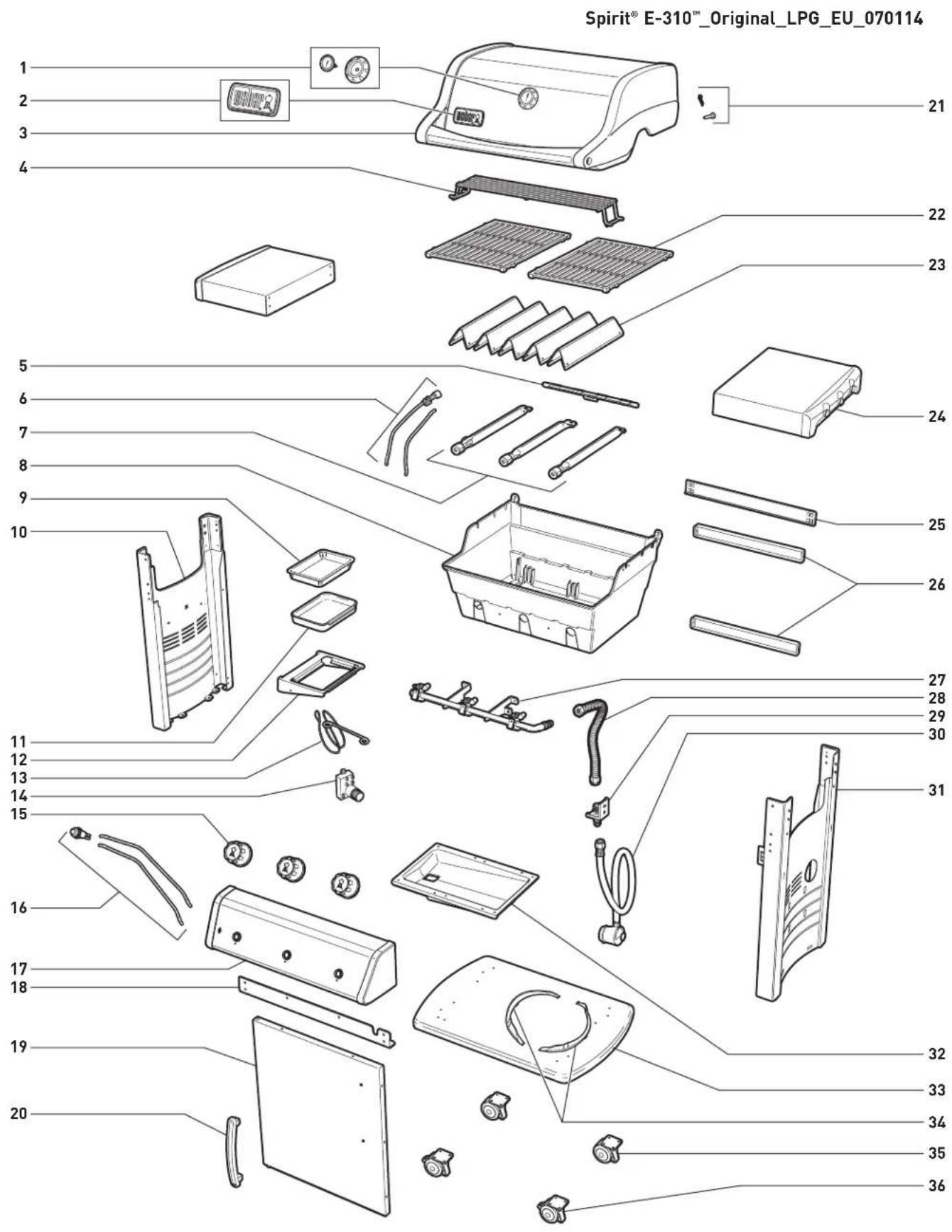
SPIRIT® E-310™ ORIGINAL EXPLODED VIEW
text_image
Spirit® E-310™_Original_LPG_EU_070114 1 2 3 4 5 6 7 8 9 10 11 12 13 14 15 16 17 18 19 20 21 22 23 24 25 26 27 28 29 30 31 32 33 34 35 36SPIRIT® E-310™ ORIGINAL EXPLODED VIEW
SPIRIT® E-310™ORIGINAL LPG EXPLODED VIEW LIST
- Thermometer and Bezel
- Logo Plate
- Shroud Assembly
- Warming Rack
- Crossover ^® Burner Tube
- Igniter Electrode
- Burner Tube
- Cookbox
- Disposable Drip Pan
- Left Frame Panel
- Catch Pan
- Catch Pan Holder
- Matchstick Holder
- Igniter Module
- Control Knob
- Igniter Button
- Control Panel
- Front Cross Brace
- Door
- Door Handle
- Shroud Hardware
- Cooking Grate*
- Flavorizer ^® Bar
- Side Table
- Rear Cross Brace
- Rear Frame Support
- Manifold
- Manifold Hose
- Bulkhead
- Hose & Regulator
- Right Frame Panel
- Slide-Out Grease Tray
- Bottom Panel
- Cylinder Bracket
- Caster
- Locking Caster
* Cooking Grate may vary depending on the model purchased.
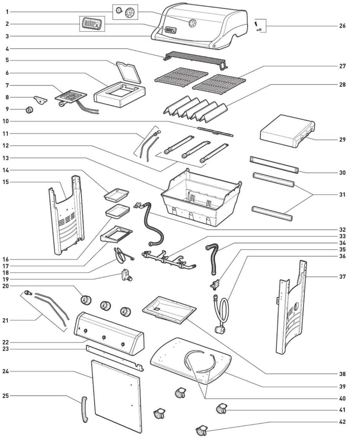
SPIRIT® E-320™ ORIGINAL EXPLODED VIEW
Spirit ^® E-320 ^™ _Original_LPG_EU_070114
text_image
Exploded view diagram of a household appliance with numbered parts for identificationSPIRIT® E-320™ ORIGINAL EXPLODED VIEW
SPIRIT® E-320™ ORIGINAL LPG EXPLODED VIEW LIST
- Thermometer and Bezel
- Logo Plate
- Shroud Assembly
- Warming Rack
- Side Burner Lid
- Side Burner Table
- Side Burner Assembly
- Side Burner Valve Plate
- Side Burner Control Knob
- Crossover ^® Burner Tube
- Igniter Electrode
- Burner Tube
- Cookbox
- Disposable Drip Pan
- Left Frame Panel
- Catch Pan
- Catch Pan Holder
- Matchstick Holder
- Igniter Module
- Control Knob
- Igniter Button
- Control Panel
- Front Cross Brace
- Door
- Door Handle
- Shroud Hardware
- Cooking Grate*
- Flavorizer ^® Bar
- Side Table
- Rear Cross Brace
- Rear Frame Support
- Side Burner Gas Line Assembly
- Manifold
- Manifold Hose
- Bulkhead
- Hose & Regulator
- Right Frame Panel
- Slide-Out Grease Tray
- Bottom Panel
- Cylinder Bracket
- Caster
- Locking Caster
* Cooking Grate may vary depending on the model purchased.
IMPORTANT INFORMATION ABOUT LPG GAS & GAS CONNECTIONS
Liquid propane gas (LPG) is the flammable, petroleum-based product used to fuel your grill. It is a gas at moderate temperatures and pressure when it is not contained. But at moderate pressure inside a container, such as a cylinder, LPG is a liquid. As pressure is released from the cylinder, the liquid readily vapourises and becomes liquid propane gas.
- LPG has an odour similar to natural gas. You should be aware of this odour.
- LPG is heavier than air. Leaking liquid propane gas may collect in low areas and resist dispersion.
SAFE HANDLING TIPS FOR LIQUID PROPANE GAS CYLINDERS
There are various guidelines and safety factors that you need to keep in mind when using liquid propane gas (LPG). Carefully follow these instructions before using your Weber ^® gas grill.
• Always close the cylinder valve before disconnecting regulator.
- Do not use a damaged LPG cylinder. A dented or rusty LPG cylinder or an LPG cylinder with a damaged valve may be hazardous and should be replaced with a new cylinder immediately.
- Treat "empty" LPG cylinders with the same care as you treat full cylinders. Even when an LPG cylinder is empty of liquid, there may still be gas pressure inside the cylinder.
- LPG cylinders must be installed, transported, and stored in an upright position. LPG cylinders should not be dropped or handled roughly.
- Never store or transport the LPG cylinder where temperatures can reach 51^ (the cylinder will become too hot to hold by hand). For example: do not leave the LPG cylinder in a car on a hot day.
- Leak-test the joint where the regulator connects to the LPG cylinder each time a reconnection occurs. For example: test each time the LPG cylinder is refilled and reinstalled.
- LPG cylinders must be kept out of reach of children.
- Do not connect to natural gas supply (city gas). The valves and orifices are designed exclusively for liquid propane gas.
- The areas around the LPG cylinder must be free and clear from debris.
- The LPG cylinder should not be changed in the proximity of an ignition source.
STORAGE
For grills that have been stored for a while, it is important to follow these guidelines:
- The gas must be turned off at the LPG cylinder when the Weber ^ gas grill is not in use.
⚠ WARNING: Make sure that the LPG cylinder valve is closed when the grill is not in use.
- If storing the Weber ^ gas grill indoors, first DISCONNECT the gas supply and store the LPG cylinder outdoors in a well-ventilated space.
- Do not store a disconnected LPG cylinder in a building, garage, or any other enclosed area.
- If you do not disconnect the LPG cylinder from the Weber ^ gas grill, be sure to keep both the grill and the cylinder outdoors in a well-ventilated area.
- Check that the areas under the control panel and the slide-out grease tray are free from debris that might obstruct the flow of combustion or ventilation air.
LPG CYLINDER REQUIREMENTS
• Use only a 3kg-13kg LPG cylinder.
REGULATOR CONNECTIONS & REQUIREMENTS
- In the United Kingdom, this appliance must be fitted with a regulator complying with BS 3016, having a nominal output of 37 millibars. (Supplied with grill.)
- The length of hose must not exceed 1.5 metres.
- Avoid kinking the hose.
- We recommend that you replace the gas hose on your Weber ^® gas grill every five years. Some countries may have requirements that the gas hose be replaced within less than five years, in which case that country's requirement would take precedence.
- Any parts sealed by the manufacturer must not be altered by the user.
- Any modification of the appliance may be dangerous.
- Only a nationally approved low-pressure hose and regulator must be used.
- Replacement pressure regulators and hose assemblies must be those specified by the outdoor cooking gas appliance manufacturer.
- Be sure the regulator is mounted with the small vent hole pointed downward so that it will not collect water. This vent should be free of dirt, grease, bugs, etc.
IMPORTANT INFORMATION ABOUT LPG GAS & GAS CONNECTIONS
| Bulgaria, Cyprus, Czech Republic, Denmark, Estonia, Finland, Hungary, Iceland, Latvia, Lithuania, Malta, Netherlands, Norway, Romania, Slovak Republic, Slovenia, Sweden, Turkey | I_3B/P - 30 mbar |
| Belgium, France, Greece, Ireland, Italy, Luxembourg, Portugal, Spain, Switzerland, United Kingdom | I_3+ - 28-30 / 37 mbar |
| Poland I | _3P - 37 mbar |
| Austria, Germany I | _3B/P - 50 mbar |
CONSUMPTION DATA
| Propane kW | Butane kW | Propane g/h | Butane g/h | ||
| Spirit ^® 210 Classic | 7,8 | 8,8 | 558 640 | ||
| Spirit ^® 220 Classic | 11,3 | 12,9 | 808 | 939 | |
| Spirit ^® 310 Classic | 9,4 | 10,6 | 672 771 | ||
| Spirit ^® 320 Classic | 12,9 | 14,7 | 922 | 1070 | |
| Spirit ^® 210 Original | 7,8 | 8,8 | 558 640 | ||
| Spirit ^® 310 Original | 9,4 | 10,6 | 672 771 | ||
| Spirit ^® 320 Original | 12,9 | 14,7 | 922 | 1070 | |
| Spirit ^® 210 Premium | 7,8 | 8,8 | 558 640 | ||
| Spirit ^® 310 Premium | 9,4 | 10,6 | 672 771 | ||
| Spirit ^® 320 Premium | 12,9 | 14,7 | 922 | 1070 | |
VALVE ORIFICE SIZE
| MAIN BURNER VALVES | |||||
| LPG Gas | Methane Gas | ||||
| I_3B/P - 30 mbar | I_3+ - 28-30 / 37 mbar | I_3B/P - 50 mbar | G (20) | G (25) | |
| Spirit® 2 Burner | 0.99 mm | 0.97 mm | 0.90 mm | 1.40 mm | 1.50 mm |
| Spirit® 3 Burner | 0.90 mm | 0.86 mm | 0.79 mm | 1.25 mm | 1.35 mm |
| SIDE BURNER VALVE | |||||
| LPG Gas | Methane Gas | ||||
| Spirit® 220 | 0.98 mm | 0.90 mm | 0.84 mm | 1.39 mm | 1.50 mm |
| Spirit® 320 | 0.98 mm | 0.90 mm | 0.84 mm | 1.39 mm | 1.50 mm |
REPLACEMENT HOSE,
REGULATOR AND VALVE ASSEMBLY
IMPORTANT NOTICE:
We recommend that you replace the gas hose assembly on your Weber ^® gas grill every five years. Some countries may have requirements that the gas hose be replaced within less than five years, in which case that country's requirement would take precedence.
For replacement hose, regulator, and valve assemblies, contact the Customer Service Representative in your area using the contact information on our web site. Log on to www.weber.com.
LPG CYLINDER INSTALLATION INSIDE CABINET
WHERE DOES THE LPG CYLINDER GO?
The type and size of cylinder you purchase will determine if the cylinder can be located inside or outside the base cabinet. There are two location options: inside the cabinet within the cylinder brackets, or outside the cabinet on the ground.
text_image
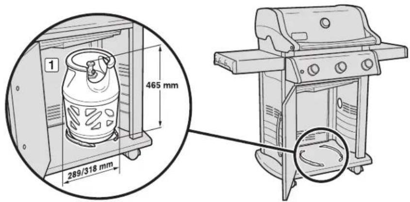
1 465 mm 289/318 mmINSIDE CABINET REQUIREMENTS
The LPG cylinder can be placed inside the grill cabinet if the cylinder does not exceed the maximum size requirements. The maximum size requirements for cylinders installed inside the cabinet are:
Cylinder Capacity: 6 kg maximum
Cylinder Height: 465 mm maximum
Cylinder Width: 289 mm maximum (rectangular footprint) or
318 mm maximum
[round
footprint)
Also, the base of the cylinder must fit between the cylinder brackets and rest flat on the bottom panel [1].
⚠ WARNING: If the LPG cylinder does not meet the cylinder size requirements for placing inside the cabinet, do not attempt to place or connect the cylinder inside the cabinet. Place and connect the cylinder outside the cabinet. Failure to do so could cause damage to the hose resulting in a fire or explosion, which can cause serious bodily injury or death, and damage to property.
Several possible cylinder models approved for installation inside the cabinet are illustrated, with dimensions included.
5 kg


text_image
282 mm 68 mm 287 mm5.2 kg
natural_image
Technical line drawing of a mechanical component with no visible text or symbols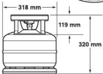
text_image
318 mm 119 mm 320 mm5 kg
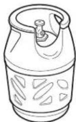
6 kg
natural_image
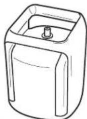
Line drawing of a rectangular container with a side port and a small cylindrical object on top (no text or symbols)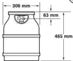
text_image
306 mm 63 mm 465 mm
text_image
283 mm 37 mm 339 mmMaximum LPG cylinder capacity INSIDE cabinet is 6 kg.
The length of hose must not exceed 1.5 metres.
LPG CYLINDER INSTALLATION INSIDE CABINET
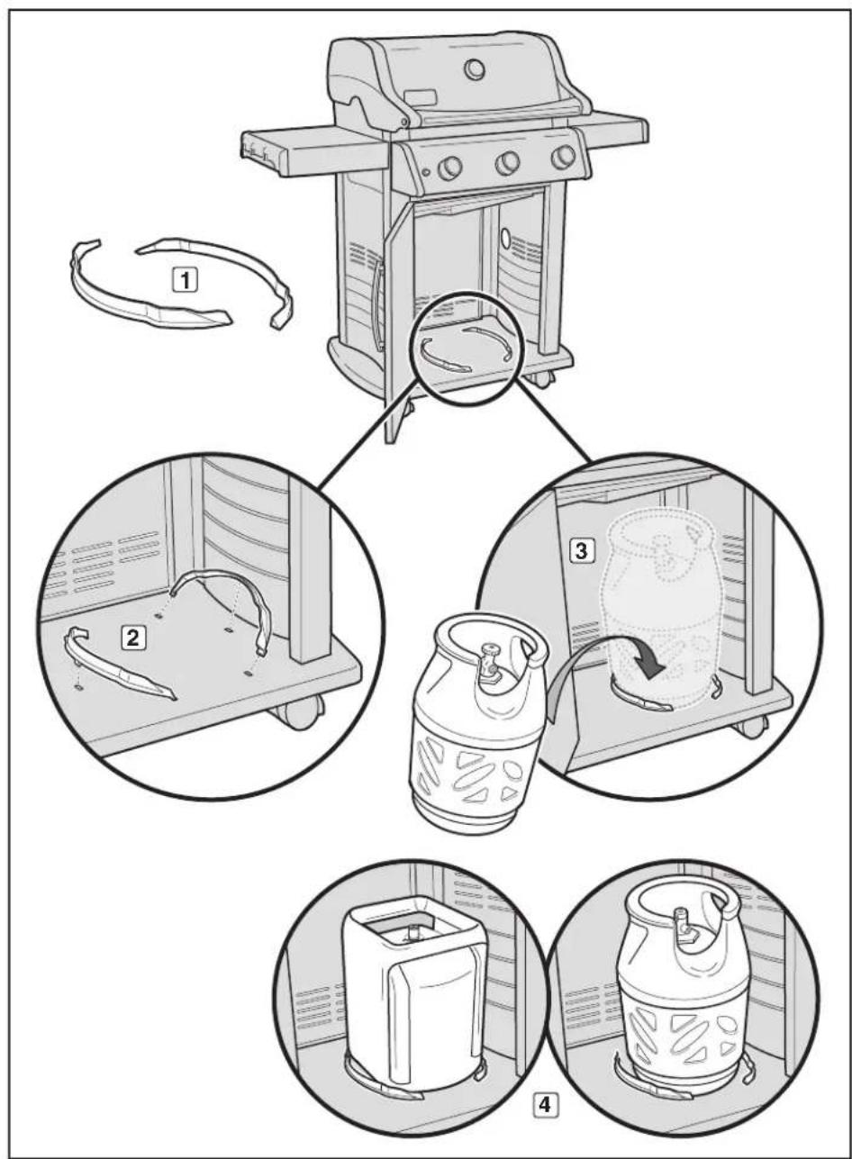
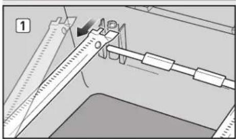
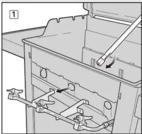
INSIDE CABINET INSTALLATION
You will need: cylinder brackets (1).
A) Open the grill cabinet. The cylinder brackets snap into the mounting holes in the bottom panel as shown in the illustration (2). Insert cylinder bracket tabs into rectangular slots. Secure brackets in place by pivoting them down to lock centre tab in place.
B) Lift and place the cylinder between the cylinder brackets (3) on the bottom panel. The base of the cylinder must fit between the cylinder brackets (4).
C) Turn the cylinder so the valve opening faces the front of the grill.
D) Connect the regulator to the LPG cylinder. Refer to "CONNECTING THE REGULATOR."
text_image
Diagram illustrating four steps of a gas stove setup with labeled components and component illustrations.LPG CYLINDER INSTALLATION OUTSIDE CABINET
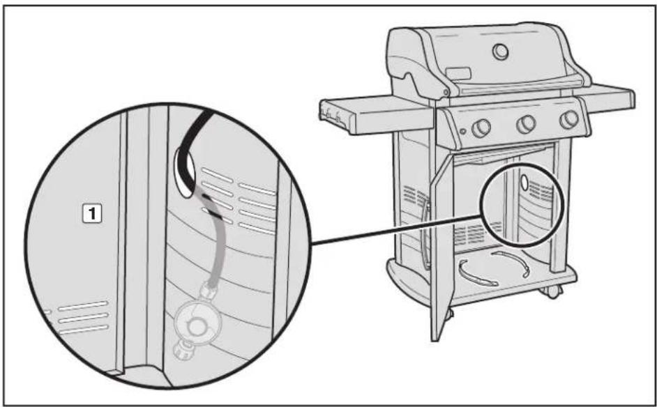
OUTSIDE CABINET REQUIREMENTS
If the cylinder you have does not meet the size requirements for placement inside the cabinet, the cylinder must be placed on the ground outside and to the right of the cabinet. The maximum size requirements for cylinders installed outside the cabinet are:
Cylinder Capacity: 13 kg maximum
Cylinder Height: 587 mm maximum
Cylinder Width: 306 mm maximum
GROUND PLACEMENT INSTALLATION
A) Pass the regulator hose (1) out through the side panel opening.
B) Place the cylinder on the ground, outside the cabinet, on the right side of the grill.
C) Turn the LPG cylinder so the opening of the valve is facing forward.
D] Connect the regulator to the LPG cylinder. Refer to "CONNECTING THE REGULATOR."
text_image
Technical diagram showing a gas stove with labeled components and a magnified inset detail viewMaximum LPG cylinder capacity OUTSIDE cabinet is 13 kg.
The length of hose must not exceed 1.5 metres.
CONNECTING THE REGULATOR
WHAT IS A REGULATOR?
Your Weber ^® gas grill is equipped with a pressure regulator, which is a device to control and maintain uniform gas pressure as gas is released from the LPG cylinder.
CONNECTING THE REGULATOR TO THE CYLINDER
A) Connect regulator to LPG cylinder.
⚠ WARNING: Make sure that the LPG cylinder or regulator valve is closed.
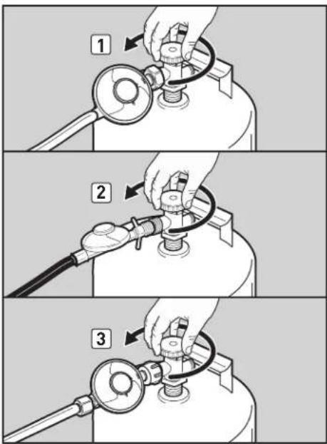
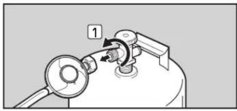
Some regulators push ON to connect and pull OFF to disconnect; others have a nut with a left-hand thread that connects to the cylinder valve. Identify your regulator type and follow one of the connection instructions specific to that regulator.
Connect by Turning Clockwise
Screw regulator onto cylinder by turning fitting clockwise (1). Position the regulator so that the vent hole (2) faces down.
Connect by Turning Anti-Clockwise
Screw regulator onto cylinder by turning fitting anti-clockwise [3] [4].
Connect by Turning Lever/Snapping into Position
Turn regulator lever (5) clockwise to the off position. Push regulator down on cylinder valve until regulator snaps into position (6).
Connect by Sliding Collar
Make sure regulator lever is in the off position (7) (10). Slide the collar of the regulator up (8) (11). Push the regulator down onto the cylinder valve and maintain pressure. Slide collar down to close (9) (12). If regulator does not lock, repeat procedure.

text_image
Diagram of a mechanical device with labeled parts, showing a valve and adjustment mechanism.
text_image
Diagram showing two-step installation of a fuel pump with labeled components and directional arrows
text_image
5 6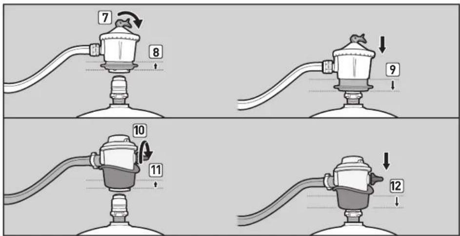
text_image
7 8 9 10 11 12PREPARING TO USE YOUR GRILL
WHAT IS A LEAK CHECK?
The fuel system in your grill features connections and fittings. A leak check is a reliable way to make sure that no gas is escaping from any of the connections or fittings.
Although all factory-made connections have been thoroughly checked for gas leaks, it's important to perform a leak check before using your grill for the first time, as well as anytime you disconnect and reconnect a fitting and each time you perform routine maintenance.
PARTIAL DISASSEMBLY OF YOUR GRILL FOR A LEAK CHECK
In order to perform the leak check, you need to have access to the gas valves, which will require some simple grill disassembly.
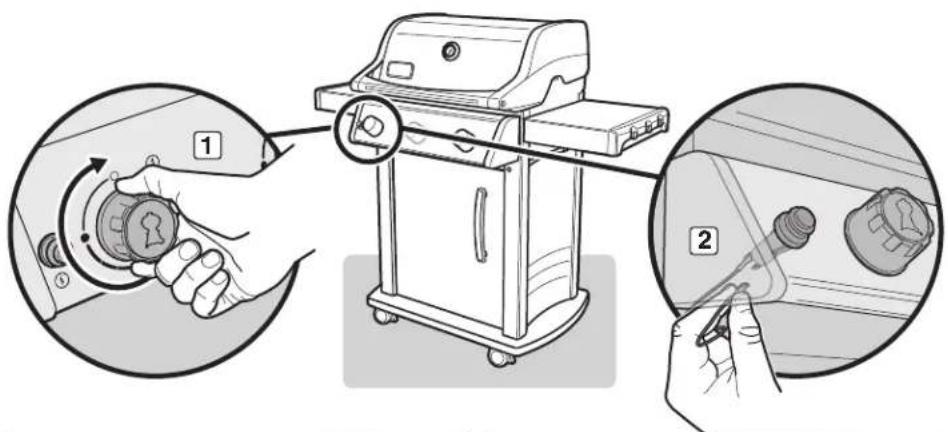
Confirm that Grill is Off
Al Turn gas supply off at source.
B) Check that ALL burner control knobs are in the off (Φposition [1]). Control knobs are shipped in the off (Φposition, but you should check to be sure that they are turned off. Check by pushing control knobs in and turning them clockwise. If they do not turn, they are off. If they do turn, continue turning them clockwise until they stop; then they are off. If your grill has a side burner, make sure the side burner control knob is turned off.
Remove Control Panel
You will need: A Phillips screwdriver.
A) Disconnect the wires from the igniter button located on the underside of the control panel (2). NOTE: Pull from terminals at ends of wires.
B) Remove control knobs (3).
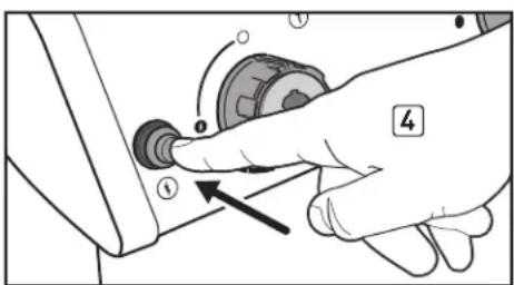
C) Remove the screws from the front of the control panel with a Phillips screwdriver [4].
D) Carefully lift control panel up and then pull forward away from frame (5).
Your grill is now ready for a leak check. Proceed to "CHECKING FOR GAS LEAKS."
text_image
Diagram illustrating the step-by-step installation of a portable gas stove, showing hand positioning and tool path.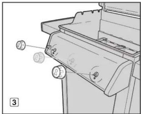
text_image
Technical diagram of a mechanical device with labeled components and directional arrows indicating motion or movement.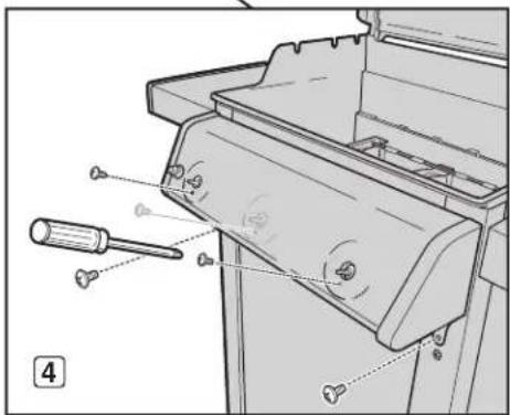
text_image
Technical diagram of a mechanical device with labeled parts and a numbered annotation (4)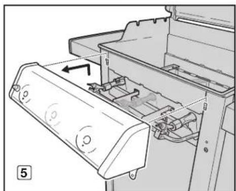
natural_image
Diagram of a printer's internal structure showing paper feed, paper tray, and paper holder (no text or symbols)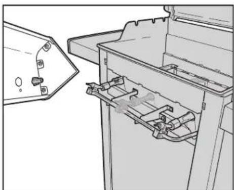
natural_image
Technical line drawing of a mechanical device with internal components and mounting bracket (no text or symbols)PREPARING TO USE YOUR GRILL
DANGER
Do not use an open flame to check for gas leaks. Be sure there are no sparks or open flames in the area while you check for leaks. Sparks or open flames will result in a fire or explosion, which can cause serious bodily injury or death and damage to property.
⚠ WARNING: The gas connections of your gas grill have been factory-tested. We do, however, recommend that you leak-check all gas connections before operating your gas grill.
⚠ WARNING: Perform these leak checks even if your grill was dealer- or store-assembled.
⚠ WARNING: You should check for gas leaks every time you disconnect and reconnect a gas fitting.
NOTE: All factory-made connections have been thoroughly checked for gas leaks and the burners have been flame-tested. As a safety precaution, however, you should check all fittings for leaks before using your Weber® gas grill. Shipping and handling may loosen or damage a gas fitting.
CHECKING FOR GAS LEAKS
You will need: A spray bottle or brush or rag and a soap-and-water solution. (You can make your own soap-and-water solution by mixing 20% liquid soap with 80% water; or, you can purchase solution in the plumbing section of any hardware store.)
A) Turn gas supply on at source.
⚠ WARNING: Do not ignite burners when leak-checking
Identify your regulator type. Follow the instructions for that regulator.
Turn Valve
Turn cylinder valve anti-clockwise (1) (2) (3).
Move Lever
Move regulator lever to the on position (4) (5) (6).
text_image
Three-step diagram showing a hand using a valve to adjust the valve position, labeled 1, 2, and 3.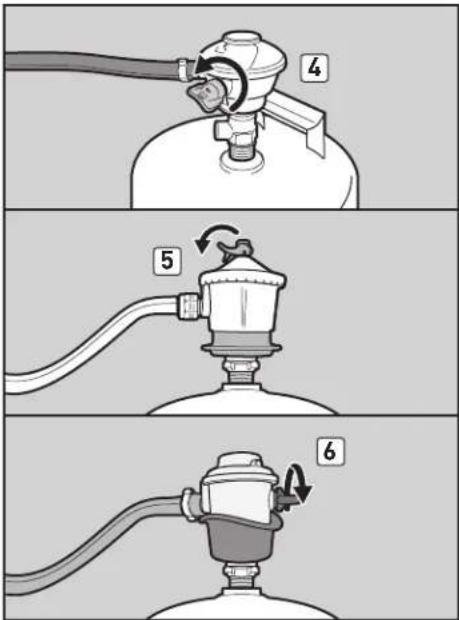
text_image
Diagram showing three-step instructions for a gasifier with labeled parts and rotation arrowsPREPARING TO USE YOUR GRILL
CHECKING FOR GAS LEAKS (continued)
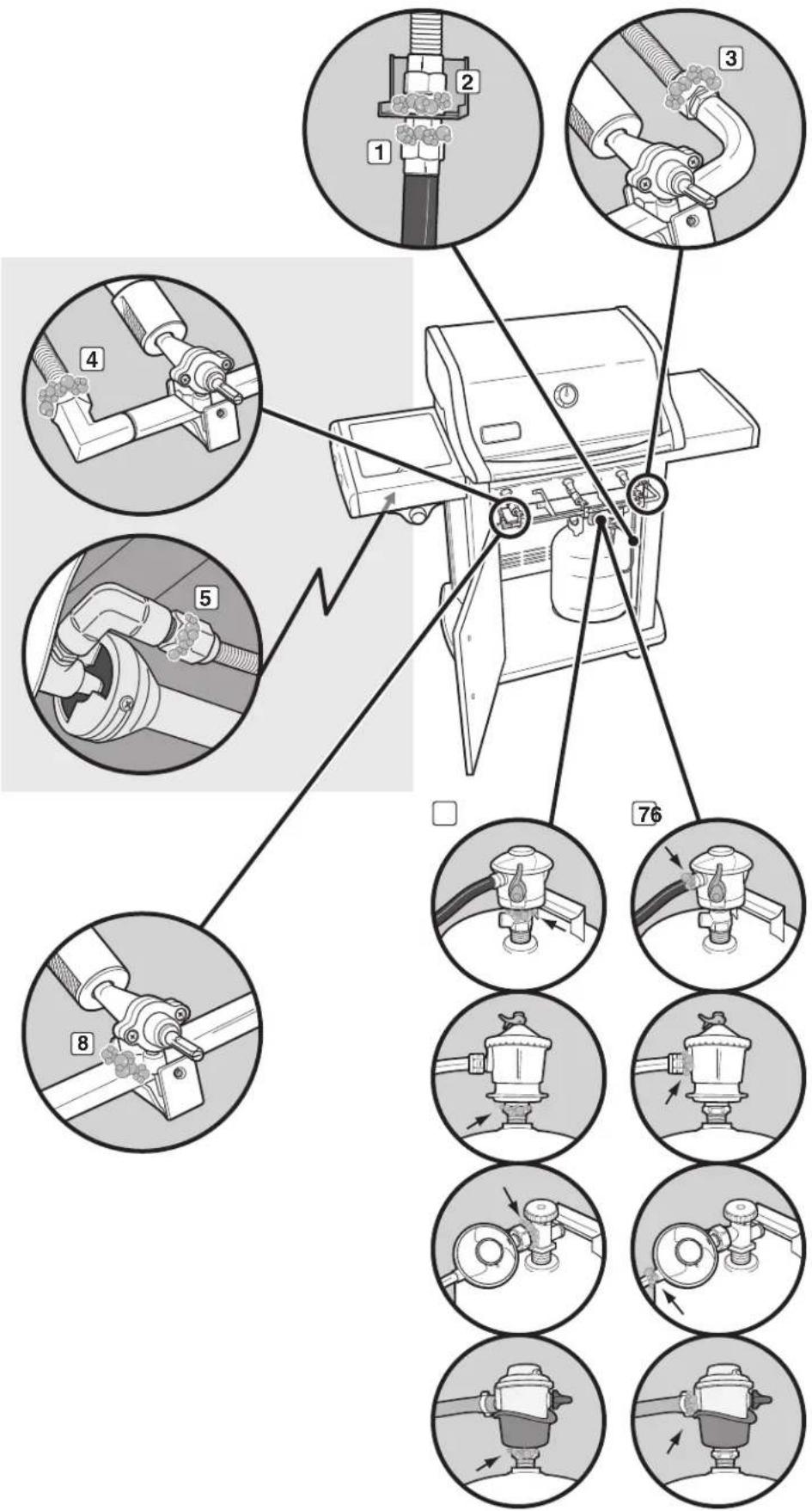
B) To check for leaks, wet fittings with the soap-and-water solution,, using a spray bottle, brush or rag. If bubbles form, or if a bubble grows, there is a leak. Apply the soap-and-water solution, to the following connections:
a) Regulator hose-to-bulkhead connection (1).
b) Corrugated manifold hose-to-bulkhead connection [2].
c) Corrugated manifold hose-to-manifold connection [3].
For Spirit ^® grills with side burners (320 models):
d) Side burner hose-to-manifold connection (4). e) Side burner hose-to-valve connection (5).
⚠ WARNING: If there is a leak at connections (1, 2, 3, 4 or 5), turn off the gas, tighten the fitting with a spanner, and recheck for leaks with soap-and-water solution. If a leak persists after tightening the fitting, turn off the gas. DO NOT OPERATE THE GRILL. Contact the Customer Service Representative in your area using the contact information on our web site. Log onto www.weber.com.
f) Regulator-to-cylinder connection (6).
g) Regulator hose-to-regulator connection (7).
h) Valves-to-manifold connections (8).
⚠ WARNING: If there is a leak at connections (6, 7, or 8), turn off the gas. DO NOT OPERATE THE GRILL. Contact the Customer Service Representative in your area using the contact information on our web site.
Log onto www.weber.com.
C) When leak checking is complete, turn gas supply off at the source and rinse connections with water.
NOTE: Since some leak test solutions, including soap and water, may be slightly corrosive, all connections should be rinsed with water after checking for leaks.
Reinstall Control Panel
You will need: A Phillips screwdriver.
A) Align valve stems with holes in control panel. Position top edge of control panel on tabs of frame assembly. Push control panel down into position.
B) Fasten control panel with screws.
C) Place control knobs onto valve stems.
D] Connect the wires to the igniter button.
⚠ WARNING: Make sure that all parts are assembled and hardware is fully tightened before operating the grill. Your actions, if you fail to follow this product warning, may cause a fire, an explosion, or structural failure resulting in serious personal injury or death as well as damage to property.
Now you are ready to use your grill.
text_image
Technical diagram showing a pump assembly with numbered components and their corresponding exploded views.PREPARING TO USE YOUR GRILL
DISCONNECTING THE REGULATOR FROM THE LPG CYLINDER
A) Remove the LPG cylinder by shutting off the gas supply and disconnecting the hose and regulator assembly from the cylinder.
⚠ WARNING: Make sure that the cylinder or regulator valve is closed.
Identify your regulator type. Follow the disconnection instructions for that regulator.
Disconnect by Turning Anti-Clockwise
Unscrew regulator from cylinder by turning fitting anti-clockwise (1).
Disconnect by Turning Clockwise
Unscrew regulator from cylinder by turning fitting clockwise (2) (3).
Disconnect by Turning Lever
Turn regulator lever clockwise (4) to the off position. Push in on regulator lever (5) until it releases from cylinder (6).
Disconnect by Sliding Collar
Make sure regulator lever is in the off position (7) (9). Slide the collar of the regulator up (8) (10) to disconnect from the cylinder.
B) Exchange empty cylinder for a full cylinder.
REFILLING THE LPG CYLINDER
We recommend that you refill the LPG cylinder before it is completely empty. To refill, take LPG cylinder to a "Gas Propane" dealer.
RECONNECTING THE LPG CYLINDER
Refer to "CONNECTING THE REGULATOR TO THE LPG CYLINDER."
natural_image
Mechanical diagram showing a valve assembly with a stethoscope and a numbered component (no text or symbols)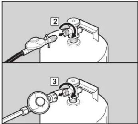
text_image
Technical diagram showing two-step installation of a gas pump device with labeled components and directional arrows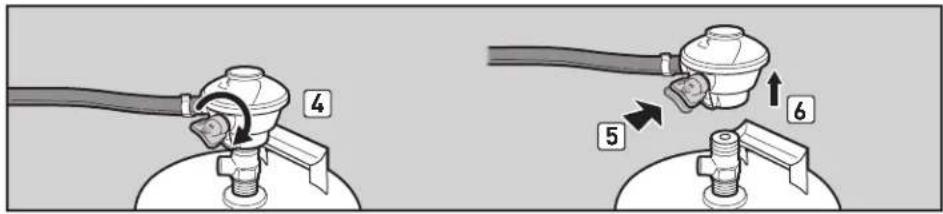
text_image
Diagram showing two mechanical setups with labeled parts and directional arrows indicating motion or assembly.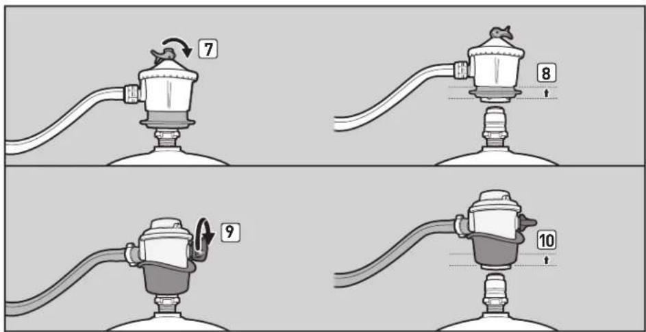
text_image
7 8 9 10TIPS & HINTS
- Always preheat the grill before cooking. Set all burners on high heat and close lid; preheat for 10 minutes, or until thermometer registers 500^ - 550^ (260° - 290°C).
- The temperature of your gas grill may run hotter than normal for the first few uses.
- Recipe grilling times are based on outside temperatures of 70°F (20°C) and little or no wind. Allow for more cooking time on cold or windy days, or at higher altitudes. Allow for less cooking time in extremely hot weather.
- Grilling conditions may require adjustment of the burner controls to attain the correct cooking temperatures.
- Sear meats and cook with the lid down for perfectly grilled food every time.
- Crowding food onto a cooking grate means more time will be required to cook the food.
- Trim excess fat from steaks, chops, and roasts, leaving no more than a scant 1 / 4 inch (6.4 mm) of fat. Less fat makes cleanup easier, and is a virtual guarantee against unwanted flare-ups.
-
In general, large pieces of meat will require more cooking time per pound than small pieces of meat.
-
Some foods, such as a casserole or thin fish fillets, will require a container for grilling. Disposable foil pans are very convenient, but any metal pan with ovenproof handles can also be used.
- Foods in containers, such as baked beans, will require more time if grilled in a deep casserole than in a shallow baking pan.
- Foods placed on the cooking grate directly above burners may require turning or moving to a less hot area.
- Use tongs rather than a fork for turning and handling meats to avoid losing natural juices. Use two spatulas for handling large whole fish.
• Always be sure the slide-out grease tray and catch pan are clean and free from debris. - Do not line the slide-out grease tray with foil. This could prevent the grease from flowing into the catch pan.
- If an unwanted flare-up should occur, turn all burners off and move food to another area of the cooking grate. Any flames will quickly subside. After flames subside, relight the grill. NEVER USE WATER TO EXTINGUISH FLAMES ON A GAS GRILL.
- Using a timer will help to alert you when “well done” is about to become “overdone.”
PREHEATING
Preheating the grill before grilling is important. To preheat: Light your grill according to the instructions in the Owner's Guide; then turn all burners to start/high (f) position, close the lid, and preheat until the temperature reaches between 500° and 550°F (260° and 290°C), the recommended broiling temperature. This will take 10 to 15 minutes depending on conditions such as air temperature and wind. After preheating, you can adjust the individual burners as desired.
⚠ WARNING: Should the burners go out while grill is in operation, turn all gas valves off. Open the lid and wait five minutes before attempting to relight grill, using the igniting instructions.
COVERED COOKING
All grilling is done with the lid down to provide uniform, evenly circulated heat. With the lid closed, the gas grill cooks much like a convection oven. The thermometer in the lid indicates the cooking temperature inside the grill. All preheating and grilling is done with the lid down. No peeking — heat is lost every time you lift the lid.
FLAVORIZER® SYSTEM
The closed lid and Flavorizer® bars produce that "outdoor" flavour in the food. When meat juices drip from the food onto the specially angled Flavorizer® bars, they create smoke that gives foods an irresistible grilled flavour. Thanks to the unique design of the burners, the Flavorizer® bars, and the flexible temperature controls, uncontrolled flare-ups are virtually eliminated, because YOU control the flames.
DRIPPINGS AND GREASE
Because of the special design of the Flavorizer ^® bars and burners, excess fats are directed down the slide-out grease tray and into the catch pan. Disposable drip pans that fit the catch pan are available.
SAFETY CHECKS BEFORE USING YOUR GRILL
SAFETY FIRST
It's a good idea to get in the habit of performing a few safety checks before grilling.
Safety must be considered when you are deciding where to place and operate your grill. Be sure to read the following warnings before installing or using your grill.
WARNINGS:
This appliance is intended for outdoor use only and should never be used in garages and roofed or enclosed porches or verandas.
⚠️ Your Weber® gas grill must never be used under an unprotected combustible roof or overhang.
⚠️ Your Weber® gas grill is not intended to be installed in or on caravans and/or boats.
△ Flammable materials should not be present within approximately 60 cm of the grill. This includes the top, bottom, back or sides of the grill.
△ Keep the cooking area clear of flammable vapours and liquids such as petrol, alcohol, etc., and combustible materials.
⚠️ Keep ventilation openings for cylinder enclosure free and clear from debris.
This appliance gets very hot. Take special care when children or elderly people are present.
⚠ Do not move the appliance when it is alight.
When you are getting ready to grill, your first thought should always be safety. Set out below are a few safety checks that you should perform each time you grill.
SLIDE-OUT GREASE TRAY
Your grill was built with a grease collection system, which funnels grease away from food and into removable containers.
Check the slide-out grease tray for grease build-up each time you use your grill. Remove excess grease with a plastic scraper (1). Wash the grease tray with a soap-and-water solution and rinse with water.
⚠️ CAUTION: Do not line the slide-out grease tray with aluminium foil.
CATCH PAN AND DISPOSABLE DRIP PAN
Grease from the slide-out grease tray funnels into a catch pan. Cleaning the catch pan is just as important as cleaning the slide-out grease tray.
Check the catch pan for grease build-up each time you use your grill. Remove excess grease with a plastic scraper (2). Wash the catch pan with warm, soapy water and rinse with water. To keep the catch pan cleaner longer, you can line it with a Weber ^8 disposable drip pan or with aluminium foil.
⚠ WARNING: Check the slide-out grease tray and catch pan for grease build-up each time before using. Remove excess grease to avoid a grease fire. A grease fire can cause serious bodily injury or damage to property.
HOSE INSPECTION
The hose should be inspected routinely for any signs of cracking (3).
⚠ WARNING: Check hose each time before using grill for nicks, cracking, abrasions or cuts. If the hose is found to be damaged in any way, do not use the grill. Replace using only Weber® authorised replacement hose. Contact the Customer Service Representative in your area using the contact information on our web site. Log onto www.weber.com.

text_image
Diagram illustrating a gas stove operation with labeled steps: adding air to a tray, cleaning the dish, and using a tool.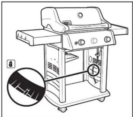
natural_image
Line drawing of a gas stove with a magnified inset showing internal components (no text or symbols)MAIN BURNER IGNITION & USAGE
METHODS OF BURNER IGNITION
There are two ways to ignite burner 1. The first is by using the electronic Crossover® ignition system built into your grill. The second is with a match.
Next are the steps for igniting your grill using the electronic Crossover® ignition system. The following page sets out steps for igniting your grill with a match.
MAIN BURNER IGNITION
Electronic Crossover ^® Ignition System
The electronic Crossover ^ ignition system ignites burner 1 with a spark from the igniter electrode inside the Gas Catcher ^TM ignition chamber. You generate the energy for the spark by pushing the igniter button. You will hear the igniter clicking. Burner(s) 2 (and 3) can be lit after burner 1 is lit.
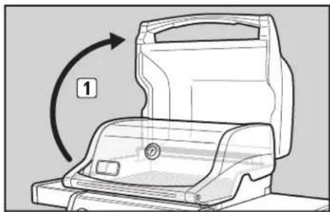
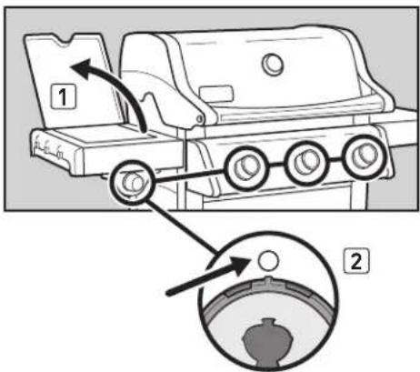
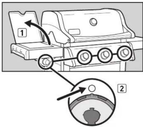
A) Open the grill lid (1).
DANGER
Failure to open the lid before igniting the grill's burners, or not waiting five minutes to allow the gas to clear if the grill does not light, may result in an explosive flare-up, which can cause serious bodily injury or death.
B] Make sure ALL burner control knobs are turned off (2). Check by pushing control knobs in and turning them clockwise until they stop.
⚠ WARNING: The burner control knobs must be in the off Ⓓposition before you turn on the LPG cylinder valve.
C) Turn on the cylinder valve using one of the appropriate options based on your cylinder and regulator type. Refer to "A") in "CHECKING FOR GAS LEAKS."
D) Push burner 1 control knob in and turn it anti-clockwise to start/high (i) position (3).
IMPORTANT: Always ignite burner 1 first. The other burner(s) ignite from burner 1.
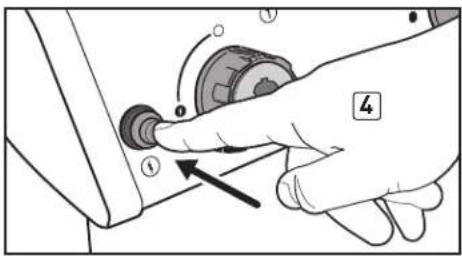
E] Push and hold in the igniter button [4]. You will hear the igniter clicking.
F) Check that burner 1 is lit by looking through the cooking grates. You should see a flame.
⚠ WARNING: While igniting the grill or cooking, never lean over open grill.
⚠ WARNING: If burner 1 fails to ignite within five seconds, stop, turn the burner control knob to off and wait five minutes to allow the gas to clear before you try again or light with a match.
G) After burner 1 is lit, you can turn on burner 2 (and burner 3).
TO EXTINGUISH BURNER
Push each burner control knob in and turn it clockwise to the off position. Turn gas supply off at the source.

natural_image
Diagram of a mechanical device with an open lid and a curved arrow indicating rotation (no text or symbols)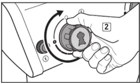
natural_image
Illustration of a hand holding a rotary knob with directional arrows indicating rotation (no text or symbols)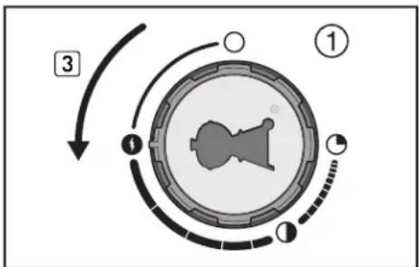
flowchart
graph TD
    A["Step 1"] --> B["Step 2"]
    B --> C["Step 3"]
    C --> D["Step 4"]
    D --> E["Step 5"]
    E --> F["Step 6"]
    F --> G["Step 7"]
    G --> H["Step 8"]
    H --> I["Step 9"]
    I --> J["Step 10"]
    J --> K["Step 11"]
    K --> L["Step 12"]
    L --> M["Step 13"]
    M --> N["Step 14"]
    N --> O["Step 15"]
    O --> P["Step 16"]
    P --> Q["Step 17"]
    Q --> R["Step 18"]
    R --> S["Step 19"]
    S --> T["Step 20"]
text_image
Diagram showing a hand pressing a button on a device with labeled parts and an arrow indicating directionSome batteries have a plastic protective wrap around them. This plastic must be removed before you attempt to ignite your grill with the electronic Crossover® ignition system. Do not confuse this plastic with the battery label.
MAIN BURNER IGNITION & USAGE
MAIN BURNER IGNITION
Lighting with a Match
A) Open the grill lid (1).
DANGER
Failure to open the lid before igniting the grill's burners, or not waiting five minutes to allow the gas to clear if the grill does not light, may result in an explosive flare-up, which can cause serious bodily injury or death.
B) Make sure ALL burner control knobs are turned off [2]. Check by pushing control knobs in and turning them clockwise until they stop.
⚠ WARNING: The burner control knobs must be in the off (○) position before you turn on the LPG cylinder valve.
C) Turn on the cylinder valve using one of the appropriate options based on your cylinder and regulator type Refer to "A" in "CHECKING FOR GAS LEAKS."
D) Put match in the matchstick holder and strike match. Insert matchstick holder with lit match down through the cooking grates, past the Flavorizer ^® bars and next to burner 1 (3).
E) Push burner 1 control knob in and turn it anti-clockwise to start/high (1) position (4).
IMPORTANT: Always ignite burner 1 first. The other burner(s) ignite from burner 1.
F] Check that burner 1 is lit by looking through the cooking grates. You should see a flame.
⚠ WARNING: While igniting the grill or cooking, never lean over open grill.
△ WARNING: If burner 1 fails to ignite within five seconds, stop, turn the burner control knob to off and wait five minutes to allow the gas to clear before you try again.
G) After burner 1 is lit, you can turn on burner 2 (and burner 3).
TO EXTINGUISH BURNER
Push each burner control knob in and turn it clockwise to the off (O) position. Turn gas supply off at the source.
natural_image
Diagram of a mechanical device with a circular component and an arrow indicating rotation (no text or symbols)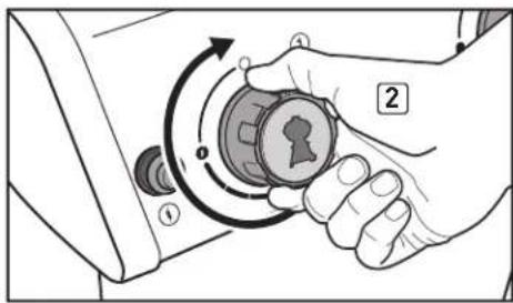
natural_image
Illustration of a hand holding a device with a knob and scroll, showing motion arrows (no text or symbols)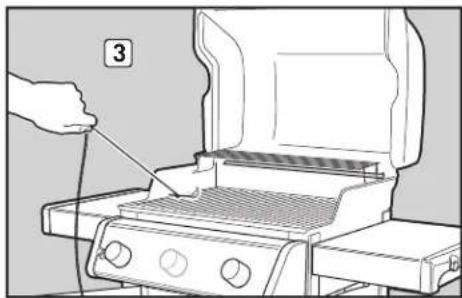
natural_image
Line drawing of a grating machine with a hand inserting a cable (no text or symbols)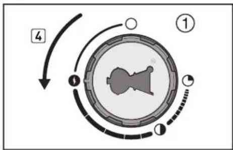
flowchart
graph TD
    A["Step 1"] --> B["Step 2"]
    B --> C["Step 3"]
    C --> D["Step 4"]
    D --> E["Step 5"]
    E --> F["Step 6"]
    F --> G["Step 7"]
    G --> H["Step 8"]
    H --> I["Step 9"]
    I --> J["Step 10"]
    J --> K["Step 11"]
    K --> L["Step 12"]
    L --> M["Step 13"]
    M --> N["Step 14"]
    N --> O["Step 15"]
    O --> P["Step 16"]
    P --> Q["Step 17"]
    Q --> R["Step 18"]
    R --> S["Step 19"]
    S --> T["Step 20"]
SIDE BURNER IGNITION & USAGE (320 MODELS)
ON THE SIDE...
To maximise your cooking space and to help you multitask, your grill was designed with a side burner. Igniting the side burner is easy. It uses the same igniter button as the main burners, but it ignites independently.
Lighting with the Igniter Button
Unlike the main burners, the side burner does not ignite from burner 1. Below are the steps that apply to igniting the side burner using the igniter button.
A) Open the side burner lid (1).
DANGER
Failure to open the lid before igniting the side burner, or not waiting five minutes to allow the gas to clear if the side burner does not light, may result in an explosive flare-up, which can cause serious bodily injury or death.
B) Check that the side burner valve is turned off by pushing side burner control knob in and turning it clockwise until it stops (2). Turn all burners not being used to the off (①position by pushing all control knobs in and turning them clockwise until they stop.
C) If it is not already on, turn on the cylinder valve using one of the appropriate options based on your cylinder and regulator type. Refer to "A") in "CHECKING FOR GAS LEAKS."
D) Push in and turn side burner control knob anticlockwise to start/high (1) position (3).
E] Push and hold in the igniter button [4]. You will hear the igniter clicking. You should see a flame.
⚠️ CAUTION: Side burner flame may be difficult to see on a bright, sunny day.
⚠ WARNING: If the side burner does not light in five seconds:
a) Turn off the side burner and main burner control knobs and gas supply at source.
b) Wait five minutes to let the gas clear before you try again or try lighting with a match (refer to "Lighting with a Match").
TO EXTINGUISH SIDE BURNER
Push side burner control knob in and turn it clockwise to the off I position. Be sure the side burner is off and cool before closing the side burner lid.
text_image
Diagram showing a device with labeled parts and directional arrows, including numbered annotations 1 and 2.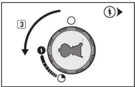
flowchart
graph TD
    A["Device Icon"] -->|3| B["Arrow to Right"]
    B --> C["Electrical Symbol"]
    style A fill:#f9f,stroke:#333
    style B fill:#ccf,stroke:#333
    style C fill:#cfc,stroke:#333
text_image
Diagram showing a hand operating a button labeled with numbers ① and ④, indicating a step or operation.SIDE BURNER IGNITION & USAGE (320 MODELS)
Lighting with a Match
A) Open the side burner lid (1).
DANGER
Failure to open the lid before igniting the side burner, or not waiting five minutes to allow the gas to clear if the side burner does not light, may result in an explosive flare-up, which can cause serious bodily injury or death.
B) Check that the side burner valve is turned off by pushing side burner control knob in and turning it clockwise until it stops (2). Turn all burners not being used to the off (Φposition by pushing all control knobs in and turning them clockwise until they stop.
C) If it is not already on, turn on the cylinder valve using one of the appropriate options based on your cylinder and regulator type. Refer to "A" in "CHECKING FOR GAS LEAKS."
D) Put match in the matchstick holder and strike match. Place matchstick holder with lit match close to side burner (3).
E) Push in and turn side burner control knob anticlockwise to start/high (1) position (4). You should see a flame.
⚠️ CAUTION: Side burner flame may be difficult to see on a bright, sunny day.
⚠ WARNING: If the side burner does not light in five seconds:
a) Turn off the side burner and main burner control knobs and gas supply at source.
b) Wait five minutes to let the gas clear before you try again.
TO EXTINGUISH SIDE BURNER
Push side burner control knob in and turn it clockwise to the off (Φposition. Be sure the side burner is off and cool before closing the side burner lid.
text_image
Diagram showing a mechanical device with labeled parts and directional arrows, including numbered annotations 1 and 2.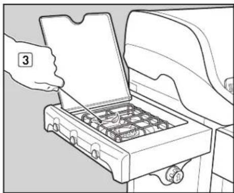
natural_image
Line drawing of a hand inserting a component into a portable stove (no text or symbols)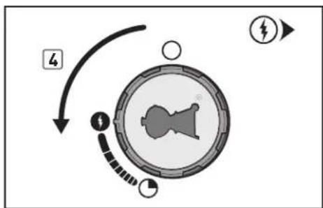
flowchart
graph TD
    A["Start"] --> B{Condition}
    B -->|Yes| C["Process Step"]
    B -->|No| D["End"]
TROUBLESHOOTING
GENERAL TROUBLESHOOTING
| PROBLEMS SOLUTIONS | |
| Burner does not ignite when you push the igniter button. | Be sure that there is gas flow to the burners by attempting to match-light your burners. Refer to "MAIN BURNER IGNITION—Lighting with a Match." If match-lighting is successful, the problem lies in the ignition system. Refer to "MAINTAINING THE ELECTRONIC CROSSOVER® IGNITION SYSTEM." |
| Be sure that wires are correctly inserted into terminals on igniter module. Check that the wires are connected to terminals on igniter button under the control panel. Refer to "IGNITER MODULE WIRE GUIDE." | |
| If a new battery is installed, confirm that battery's plastic wrapping has been removed. Verify that the battery is in good condition and has been installed correctly. Refer to "MAINTAINING THE ELECTRONIC CROSSOVER® IGNITION SYSTEM." | |
| Burners do not ignite.Burners have a small flickering flame when burner control knobs are in the high (1) position.Grill temperature only reaches 250° to 300° F in the high (1) position. | Some countries have regulators with an excess gas flow safety device. The excess flow safety device, which is part of the grill-to-cylinder connection, may have been activated. To reset the excess flow safety device, close the LPG cylinder valve and turn all burner control knobs to the off (O) position. Open the grill lid. Wait at least five minutes for the gas to clear before attempting to light the grill.SLOWLYturn the LPG cylinder valve until it is completely open. Wait several seconds; then ignite your grill. Refer to "MAIN BURNER IGNITION & USAGE." |
| Burner does not ignite, or flame is low when set to high (1) position. | LPG fuel could be low or empty. Refill LPG cylinder. |
| Fuel hose could be bent or kinked. Straighten fuel hose. | |
| Burner flame pattern is erratic.Flame is low when burner is set to high (1) position.Flames do not run the whole length of the burner tube. | Clean burner ports that run down the entire length of burner tube. Refer to "ANNUAL MAINTENANCE." |
| Burners burn with a yellow or orange flame, combined with the smell of gas. | Inspect spider/insect screens for possible obstructions. (Blockage of holes.) Clean spider/insect screens. Refer to "ANNUAL MAINTENANCE." |
| Experiencing flare-ups.△CAUTION: Do not line the slide-out grease tray with aluminium foil. | Grill must be preheated with all burners on high for 10 to 15 minutes.Clean the cooking grates and Flavorizer® bars thoroughly to remove grease. Refer to "ROUTINE MAINTENANCE." |
| The slide-out grease tray may be dirty and is not allowing grease to flow into catch pan. Clean slide-out grease tray. | |
| Inside of lid appears to be "peeling."(Resembles paint peeling.) | The inside of the lid is porcelain enamel or stainless steel. It is not painted. It cannot "peel." What you are seeing is baked-on grease that has turned to carbon and is flaking off.THIS IS NOT A DEFECT. Clean thoroughly. Refer to "ROUTINE MAINTENANCE." |
If problems cannot be corrected by using these methods, please contact the Customer Service Representative in your area using the contact information on our web site. Log onto www.weber.com.
SIDE BURNER TROUBLESHOOTING (320 MODEL)
| PROBLEMS SOLUTIONS | |
| Side burner does not ignite when you push the igniter button. | Be sure that there is gas flow to the burner by attempting to match-light your side burner. Refer to “SIDE BURNER IGNITION—Lighting with a Match.” If match-lighting is successful, the problem lies in the ignition system. Refer to “MAINTAINING THE ELECTRONIC CROSSOVER® IGNITION SYSTEM.” |
| Be sure that wires are correctly inserted into terminals on igniter module. Check that the wires are connected to terminals on igniter button under the control panel. Refer to “IGNITER MODULE WIRE GUIDE.” | |
| If a new battery is installed, confirm that battery’s plastic wrapping has been removed. Verify that the battery is in good condition and has been installed correctly. Refer to “MAINTAINING THE ELECTRONIC CROSSOVER® IGNITION SYSTEM.” | |
| Side burner does not ignite. Be sure that gas supply is on. | |
| Some countries have regulators with an excess gas flow safety device. The excess flow safety device, which is part of the grill-to-cylinder connection, may have been activated. To reset the excess flow safety device, close the LPG cylinder valve and turn all burner control knobs to the off [O] position. Open the grill lid. Wait at least five minutes for the gas to clear before attempting to light the grill.SLOWLYturn the LPG cylinder valve until it is completely open. Wait several seconds; then ignite your grill. Refer to “MAIN BURNER IGNITION & USAGE.” | |
| Side burner does not ignite, or flame is low when burner is on high (1) position. | LPG fuel could be low or empty. Refill LPG cylinder. |
| Fuel hose could be bent or kinked. Straighten fuel hose. |
If problems cannot be corrected by using these methods, please contact the Customer Service Representative in your area using the contact information on our web site. Log onto www.weber.com.
ANNUAL MAINTENANCE
KEEPING YOUR WEBER® GAS GRILL IN TIP-TOP SHAPE
DANGER
Failure to correct any problems described on this page may result in a fire, which can cause serious bodily injury or death, and cause damage to property.
To keep your Weber ^® gas grill performing as safely and efficiently as on day one, we strongly recommend that you inspect and clean the spider/insect screen(s) and burner tube(s) at least once a year. Below is important information about these two areas of the grill that should undergo annual maintenance.
If you observe an incorrect flame pattern or blocked burner port, proceed to the "BURNER TUBE CLEANING OR REPLACEMENT" instructions on the following page.
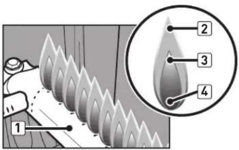
BURNER FLAME PATTERN
The burner tube(s) in your Weber ^® gas grill was/were factory set for the correct air and gas mixture. The correct flame pattern is shown in illustration and described below:
- Burner tube(s) [1]
- Tips occasionally flicker yellow (2)
• Light blue (3) - Dark blue (4)
Check burner flame pattern. If the flames do not match the above description, it could be an indication that the spider/insect screen(s) has/have become dirty or blocked.
WEBER® SPIDER/INSECT SCREEN(S)
The combustion air opening(s) of the burner tube(s) [5] is/are fitted with stainless steel screen(s) to help prevent spiders and other insects from spinning webs and building nests inside the venturi section [6] of the burner tube(s). These nests can obstruct the normal gas flow, and can cause gas to flow back out of the combustion air opening(s) [7]. Symptoms of this kind of obstruction include the odour of gas in conjunction with burner flames that appear yellow and lazy. This obstruction could result in a fire in and around the gas valve(s), causing serious damage to your grill [8].
NOTE: If a spider/insect screen becomes damaged or cannot be cleaned, please contact the Customer Service Representative in your area using the contact information on our web site. Log onto www.weber.com.
BURNER TUBE PORTS
Over time, from repeated use of the grill, the burner tube ports will become dirty. Blocked and dirty ports can restrict full gas flow. Following are ways to determine whether burner tube ports are dirty or blocked.
- Grill does not reach desired temperature
- Grill heats unevenly
• One or more of the burner(s) do not ignite
text_image
1 2 3 4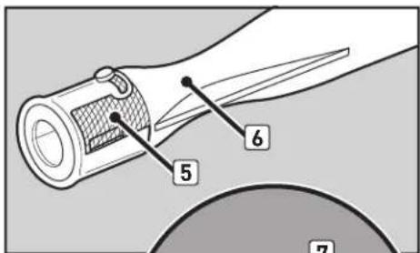
text_image
5 6 7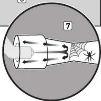
natural_image
Diagram of a funnel-shaped device emitting particles with spiderweb and spider (no text or symbols)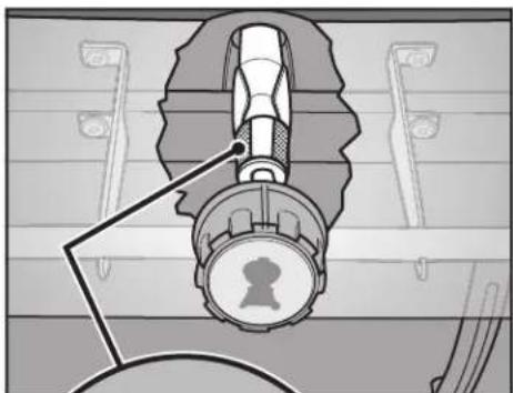
natural_image
Illustration of a mechanical device with a central knob and attached lever (no text or symbols)
natural_image
Illustration of a hand pouring liquid into a cylindrical container with flame inside, enclosed in a circular frame (no text or symbols)ANNUAL MAINTENANCE
BURNER TUBE CLEANING OR REPLACEMENT
Confirm that Grill is Off
A) Turn gas supply off at source and disconnect gas fitting.
B) Check that all burner control knobs are in the off I position. Check by pushing control knobs in and turning them clockwise until they stop. If they do not turn, they are already off. If they do turn, continue turning them clockwise until they stop; then they are off. If your grill has a side burner, make sure the side burner control knob is turned off.
Remove Control Panel
You will need: A Phillips screwdriver.
A) Open cabinet door. Remove igniter wires from wire clips on the inside left panel (1). Disconnect wires from igniter module inside the cabinet (2).
NOTE: Do not disconnect by pulling on wires; pull from terminals at ends of wires.
B) Remove cookbox components (3).
C) Remove control knobs [4].
D] Remove screws from the front of the control panel with a Phillips screwdriver (5).
E] Carefully lift control panel up and then pull forward and away from cookbox (6).
Remove Manifold
You will need: A Phillips screwdriver, two 7/16" spanners.
A) With the Phillips screwdriver, remove two screws and two washers attaching manifold to front cross brace (7).
B) Using two 7/16" spanners, remove two bolts and two nuts attaching manifold to cookbox [8]. Pull manifold forward and away from burner tubes [9]. Manifold will remain attached to corrugated gas line[s]. Be careful not to let manifold scratch frame or door or kink the attached corrugated gas line[s].

text_image
Diagram illustrating how to switch a gas stove via cable and switch, showing step-by-step installation from wire to battery.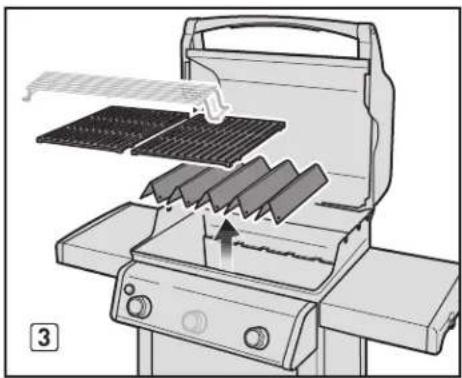
natural_image
Diagram of a grill with grating and heat transfer process, showing blade arrangement and heat sink (no text or symbols)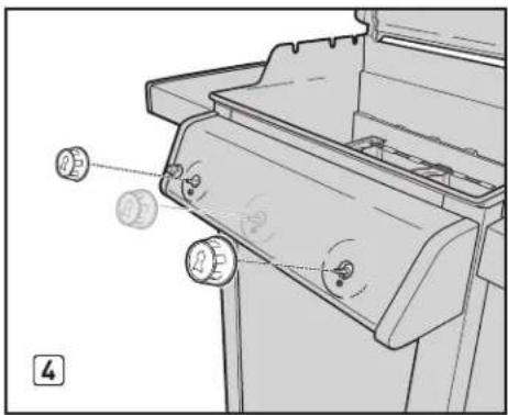
natural_image
Technical line drawing of a mechanical component with adjustment knobs and a numbered label (no text or symbols present)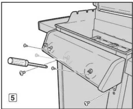
text_image
Technical diagram of a mechanical device with labeled parts and tool indicators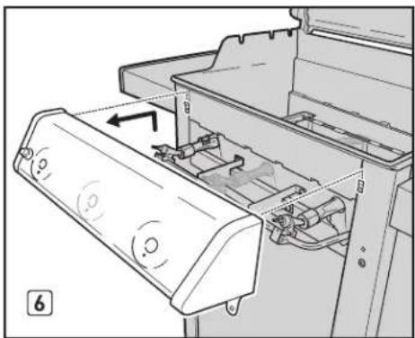
natural_image
Diagram of a printer's internal structure showing paper feed, paper tray, and paper holder (no text or symbols)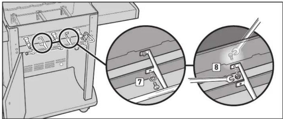
text_image
Technical diagram showing mechanical assembly with numbered components and magnified detail view
natural_image
Mechanical assembly diagram showing pipe connections and a labeled component (no readable text or symbols)ANNUAL MAINTENANCE
BURNER TUBE CLEANING OR REPLACEMENT (continued)
Remove Burner Tubes
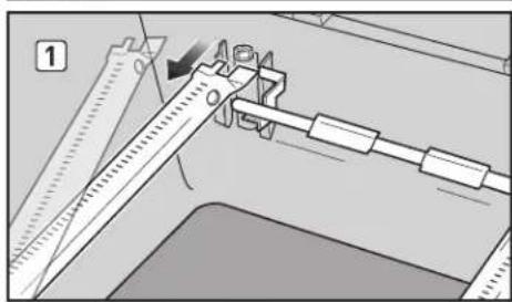
For Spirit ^® grills with 2 burners (210 model):
A) Slide burner tube 1 out from under the guide screw and washer. Move burner tube 1 slightly to the left to detach it from Crossover® tube (1).
B) Remove Crossover ^® tube (2).
C) Lift burner tube 1 up and out of cookbox while guiding the wires through the hole in the cookbox [3].
D) Slide burner tube 2 out from under the guide screw and washer. Lift burner tube 2 up and out of the cookbox (4).
For Spirit ^® grills with 3 burners (310 and 320 models):
A) Slide burner tube 1 out from under the guide screw and washer. Move burner tube 1 slightly to the left to detach it from Crossover® tube (1).
B) Lift burner tube 1 up and out of cookbox while guiding the wires through the hole in the cookbox [2].
C) Slide burner tube 3 out from under the guide screw and washer. Move burner tube 3 slightly to the right to detach it from Crossover® tube. Lift burner tube 3 up and out of cookbox.
D) Slide burner tube 2 out from under the guide screw and washer. Remove the Crossover® tube by moving it toward back of cookbox (3). Lift burner tube 2 up and out of cookbox.
210/220
natural_image
Mechanical assembly diagram showing a tool interacting with a spring scale and bracket (no text or symbols visible)
natural_image
Technical diagram showing mechanical assembly with tool and ruler (no text or symbols)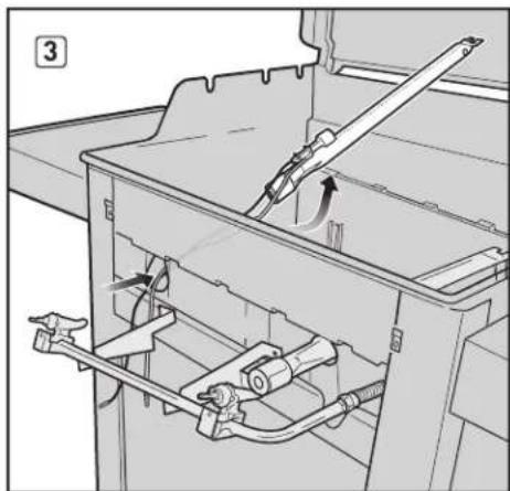
natural_image
Mechanical assembly diagram showing a container with hoses and a lever mechanism (no text or symbols)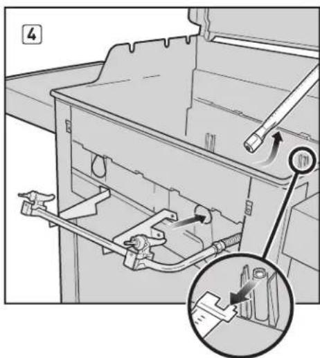
natural_image
Diagram of a mechanical assembly inside a container with an inset showing a close-up of a tool inserted into a component (no text or symbols present)310/320
natural_image
Mechanical assembly diagram showing a caliper measuring a workpiece (no text or symbols visible)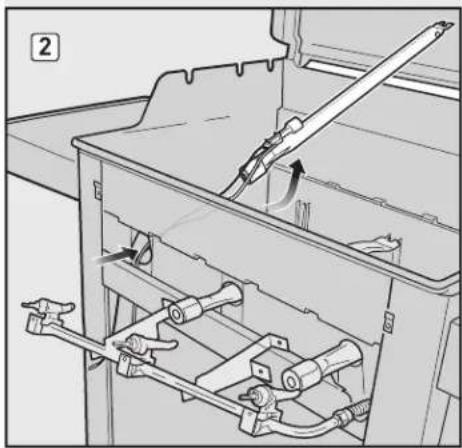
natural_image
Mechanical assembly diagram showing a tool inserted into a container with internal components (no text or symbols visible)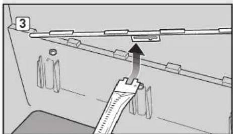
text_image
3ANNUAL MAINTENANCE
BURNER TUBE CLEANING OR REPLACEMENT (continued)
Clean Burner Tubes
You will need: A torch, a wire (a straightened-out coat hanger), a suitable stainless steel bristle brush, and a soft bristle brush (toothbrush).
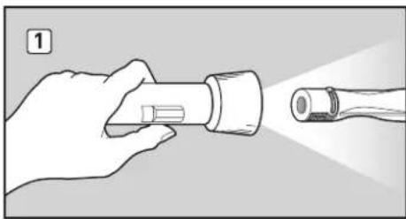
A) Look inside each burner tube and Crossover ^® tube with a torch (1).
B] Clean any debris or blockage from the inside of the tubes with the wire [2].
C) Check spider/insect screens at the ends of the burner tubes and clean them using the soft bristle brush [3].
△ CAUTION: Do not clean the spider/insect screens with hard or sharp tools. Do not dislodge the spider/insect screens or enlarge the screen openings.
D) Use the steel bristle brush to clean the outside of the burner tubes and the Crossover® tube. This is done to make sure all burner ports (openings) running along the length of the tubes are fully open. When cleaning burner tube 1, avoid damaging the igniter electrode by carefully brushing around it (4).
⚠️ CAUTION: Do not enlarge the burner ports when cleaning.
natural_image
Illustration of a hand holding a flashlight with a lit fuse (no text or symbols)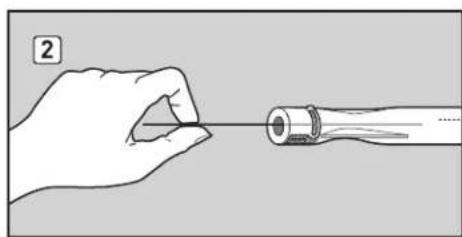
natural_image
Illustration of a hand holding a pen tip, with a cylindrical object inserted (no text or symbols)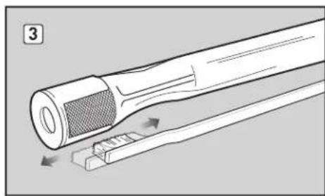
natural_image
Diagram of a tool with a textured grip and a base, showing directional arrows indicating movement or force (no text or symbols present)
text_image
Diagram illustrating a mechanical tool with warning symbol and labeled parts, showing gear meshing and stress indicators.ANNUAL MAINTENANCE
BURNER TUBE CLEANING OR REPLACEMENT (continued)
Reinstall Burner Tubes
For Spirit ^® grills with 2 burners (210 model):
A) Put burner tube 2 inside cookbox and pass the front end of tube out through burner tube 2 opening. Note: Single row of burner ports should be facing up. Slide burner tube 2 under the guide screw and washer [1].
B) Put burner tube 1 inside cookbox and pass igniter wires and the front end of tube out through burner tube 1 opening [2]. Guide wires from burner tube 1 between front cross brace and cookbox and down into cabinet [3].
C) While holding burner tube 1, insert left side of Crossover ^ tube into Crossover ^ burner hole (4). Guide right side of Crossover ^ tube into Crossover ^ burner hole in burner tube 2 (not pictured). Note: The Crossover ^ tube burner ports should face the front of the cookbox.
D) Slide burner tube 1 under the guide screw and washer (5).
For Spirit ^® grills with 3 burners (310 and 320 models):
A) Put burner tube 2 inside cookbox and pass the front end of tube out through burner tube 2 opening (1). Note: Single row of burner ports should be facing up.
B) Slide Crossover ^® tube alignment guide over the end of burner tube 2 [2]. Note: The Crossover ^® tube burner ports should face the front of the cookbox. With Crossover ^® tube attached, slide burner tube 2 under the guide screw and washer [3].
C) Put burner tube 3 inside cookbox and pass the front end of tube out through burner tube 3 opening (not pictured). Insert right side of Crossover ^® tube into Crossover ^® burner hole in burner tube 3. Slide burner tube 3 under the guide screw and washer (4).
D) Put burner tube 1 inside cookbox and pass igniter wires and the front end of tube out through burner tube 1 opening (5). Guide wires from burner tube 1 between front cross brace and cookbox and down into cabinet (6).
E) While holding burner tube 1, insert left side of Crossover® tube into Crossover® burner hole. Slide burner tube 1 under the guide screw and washer [7].
210/220

natural_image
Mechanical assembly diagram showing a container with pipes and a valve, plus an inset view of a tool inserted into a housing (no text or symbols present)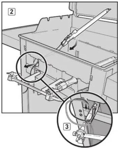
text_image
Technical diagram showing mechanical assembly with labeled parts and magnified views of internal components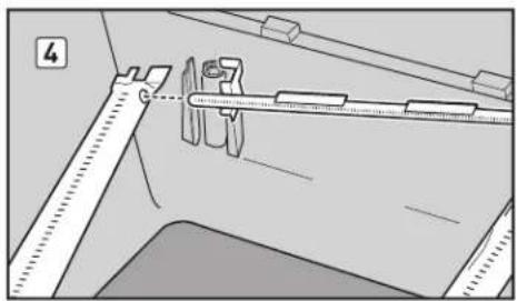
natural_image
Technical diagram showing mechanical assembly with alignment tools and a ruler (no text or symbols)
natural_image
Mechanical assembly diagram showing a lever mechanism with a tool and pivot point (no text or symbols)310/320
natural_image
Mechanical assembly diagram showing a container with internal components and a tool inserted (no text or symbols visible)
text_image
2 1.000mm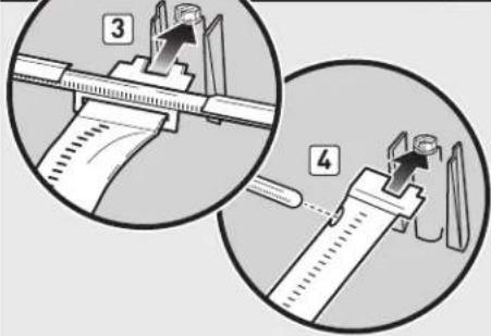
text_image
Diagram illustrating a mechanical assembly process with numbered steps 3 and 4 showing tool positioning and alignment.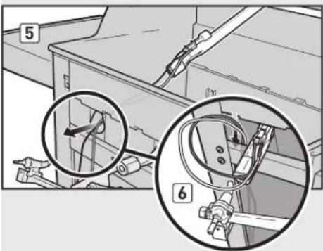
text_image
Technical diagram showing mechanical assembly with numbered components and magnified views of a component detail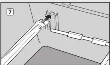
text_image
7ANNUAL MAINTENANCE
BURNER TUBE CLEANING OR REPLACEMENT (continued)
Reinstall Manifold
You will need: A Phillips screwdriver, two 7/16" spanners.
A) Align valves with burner tubes. Using two 7/16" spanners, install bolts and nuts that secure manifold to cookbox [1].
B) With a Phillips screwdriver, install screws and washers that secure manifold to front cross brace (2). If manifold was properly reinstalled, valves will now be fully seated inside burner tubes.
⚠️ CAUTION: The burner tube openings (3) must be positioned properly over the valve orifices (4).
⚠ WARNING: You should check for gas leaks every time you disconnect and reconnect a gas fitting. Refer to CHECKING FOR GAS LEAKS.
C) Replace cookbox components (not pictured).
Reinstall Control Panel
You will need: A Phillips screwdriver.
A) Guide the two wires on back of control panel over front cross brace and down into cabinet [5].
B) Align valve stems with holes in control panel. Position top edge of control panel on tabs of frame assembly. Push control panel down into position.
C) Fasten control panel with screws.
D] Place control knobs onto valve stems.
EI Connect the wires to the igniter module. Snap wires back into wire clips on inside left panel. Refer to "MAINTAINING THE ELECTRONIC CROSSOVER ^ IGNITION SYSTEM" for proper positioning.
⚠ WARNING: Make sure that all parts are assembled and hardware is fully tightened before operating the grill. Your actions, if you fail to follow this product warning, may cause a fire, an explosion, or structural failure resulting in serious personal injury or death as well as damage to property.

text_image
Technical diagram showing mechanical assembly steps with numbered instructions for tool installation
natural_image
Illustration of a medical or laboratory procedure showing a tool interacting with a device (no text or symbols visible)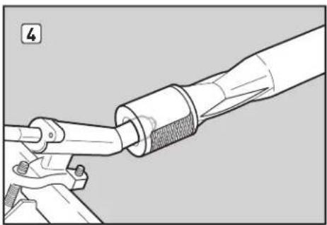
natural_image
Technical illustration of a mechanical assembly with a tool and pipe connection (no text or symbols)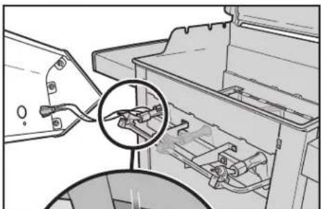
natural_image
Mechanical assembly diagram showing a bracket with internal components and a magnified inset of a component detail (no text or symbols)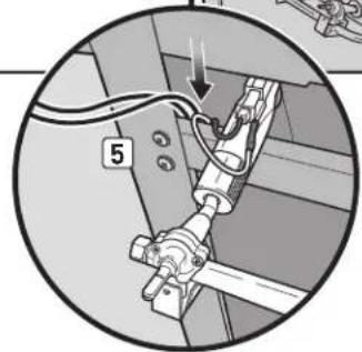
natural_image
Mechanical assembly diagram showing a lever mechanism with labeled component '5' (no text or symbols beyond label)STORAGE
For grills that have been stored for a while, it is important to follow these guidelines:
- The gas must be turned off at the LPG cylinder when the Weber ^1 gas grill is not in use.
- If storing the Weber ^ gas grill indoors, first DISCONNECT the gas supply and store the LPG cylinder outdoors in a well-ventilated space.
- Do not store a disconnected LPG cylinder in a building, garage, or any other enclosed area.
- If you do not disconnect the LPG cylinder from the Weber ^® gas grill, be sure to keep both the grill and the cylinder outdoors in a well-ventilated area.
- Check that the areas under the control panel and the slide-out grease tray are free from debris that might obstruct the flow of combustion or ventilation air.
ROUTINE MAINTENANCE
BEAUTIFUL— INSIDE AND OUT
Weber® grill owners take a lot of pride in their grills. Flaunt your pride and joy. Keep your grill clean and beautiful—inside and out—by following these routine maintenance steps.
CLEANING THE OUTSIDE OF THE GRILL
To keep the outside of your grill looking its best, use the following guidelines for safe cleaning.
⚠ WARNING: Turn your Weber® gas grill off and wait for it to cool before cleaning it.
Painted, Enamelled and Plastic Surfaces
Use a warm, soapy water solution to clean outside surfaces; then rinse with water.
IMPORTANT: Do not use cleaners that contain acid, mineral spirits or xylene. Do not use oven cleaner, abrasive cleaning agents (kitchen cleaning agents), cleaners that contain citrus products, or abrasive cleaning pads on grill or cart surfaces.
Stainless Steel Surfaces
Your grill or its cabinet, lid, and control panel may be made of stainless steel. Wash outside surfaces with a soft cloth and a soap-and-water solution, rinse with water, and wipe dry.
For stubborn particles, a non-metallic brush can be used. Scrub stainless steel surfaces in the direction of the grain.
IMPORTANT: Rinse surfaces well after cleaning. Do not use a wire brush or abrasive cleaners on the stainless steel surfaces of your grill as this will cause scratches. When cleaning stainless steel, be sure to rub/wipe in the direction of the grain.
CLEANING THE INSIDE OF THE GRILL
To keep your grill performing safely and efficiently, it is important to remove any debris and excess grease that may have accumulated on the inside of the grill. Use the following guidelines for safe cleaning.
Inside Lid
Flaking, built-up grease resembles paint flakes. Wipe inside lid with paper towel to prevent grease build-up. Wash inside lid with warm, soapy water; then rinse with water.
Cookbox
Wash inside cookbox with warm, soapy water; then rinse with water.
Cookbox Components
You will need: A stainless steel bristle brush, stiff plastic scraper.
A) Scrape and brush the cooking grates with the scraper and brush. Remove the cooking grates and set aside.
B) Scrape and brush the Flavorizer® bars with the scraper and brush. As needed, wash them with warm, soapy water; then rinse with water. Remove Flavorizer® bars and set aside.
⚠️ CAUTION: Do not clean Flavorizer® bars or cooking grates in a self-cleaning oven.
C) Brush any debris off burner tubes and Crossover® tube. Do not enlarge burner ports (openings) running along length of burner and Crossover® tubes (1). NOTE: When cleaning burner tube 1, avoid damaging the igniter electrode by carefully brushing around it.
D) When cleaning is complete, replace the Flavorizer® bars and cooking grates.
Slide-Out Grease Tray
Your grill was built with a grease collection system, which funnels grease away from food and into removable containers.
Check the slide-out grease tray for grease build-up each time you use your grill. Remove excess grease with a plastic scraper [2]. Wash the grease tray with a soap-and-water solution and rinse with water.
⚠️ CAUTION: Do not line the slide-out grease tray with aluminium foil.
Catch Pan and Disposable Drip Pan
Grease from the slide-out grease tray funnels into a catch pan. Cleaning the catch pan is just as important as cleaning the slide-out grease tray.
Check the catch pan for grease build-up each time you use your grill. Remove excess grease with a plastic scraper (3). Wash the catch pan with warm, soapy water and rinse with water. To keep the catch pan cleaner longer, you can line the catch pan with a Weber® disposable drip pan or with aluminium foil.
⚠ WARNING: Check the slide-out grease tray and catch pan for grease build-up each time before using. Remove excess grease to avoid a grease fire. A grease fire can cause serious bodily injury or damage to property.
HOSE INSPECTION
The hose should be inspected routinely for any signs of cracking (4).
⚠ WARNING: Check hose each time before using grill for nicks, cracking, abrasions or cuts. If the hose is found to be damaged in any way, do not use the grill. Replace using only Weber® authorised replacement hose. Contact the Customer Service Representative in your area using the contact information on our web site. Log onto www.weber.com.
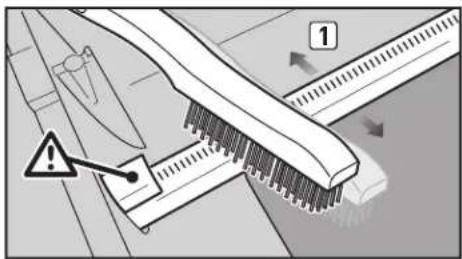
text_image
Diagram showing a mechanical component with warning symbol and numbered label '1'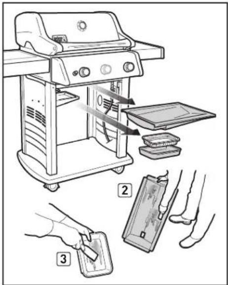
text_image
Illustration showing a grill setup with labeled steps: cleaning, cleaning, and cleaning of a tray.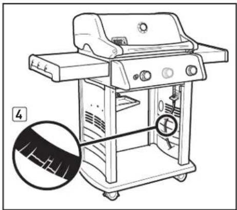
natural_image
Line drawing of a portable electric grill with control panel and fan (no text or symbols)To obtain replacement disposable drip pans, cooking grates and Flavorizer® bars, contact the Customer Service Representative in your area using the contact information on our website. Log onto www.weber.com.
ROUTINE MAINTENANCE
The igniter module supplies power to the electronic Crossover® ignition system and the side burner with one igniter button. Whether you are performing routine maintenance or a troubleshooting check on the ignition system, read the following to keep your ignition system working properly.
If the electronic Crossover® ignition system fails to ignite, you'll need to pinpoint where the problem is occurring: with the gas flow or with the electronic ignition system. Begin by attempting to match-light your burners. Refer to "MAIN BURNER IGNITION - Lighting with a Match." If match-lighting is successful, the problem lies in the ignition system.
- Verify that the AA battery (alkaline only) is in good condition and is installed correctly [1]. Some batteries have a plastic protective wrap around them. This plastic must be removed before installing battery. Do not confuse this plastic with the battery label.
- Make sure the igniter wires are properly attached to the igniter module. Refer to the "IGNITER MODULE WIRE GUIDE" chart on this page.
- Make sure the ceramic igniter assembly is fully inserted into burner tube igniter channel [2]. If properly positioned, you will hear a snap [3].
- Make sure the electronic igniter button is working by listening for clicking and looking for sparks at burner.
If the electronic Crossover® ignition system still fails to ignite, contact the Customer Service Representative in your area using the contact information on our web site. Log onto www.weber.com.

text_image
Technical diagram of a gas stove with labeled components and wiring details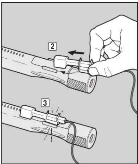
text_image
Diagram illustrating a cable installation procedure with labeled steps 2 and 3 showing tool positioning and cable connection.IGNITER MODULE WIRE CHART

text_image
210/310 2 1 5 6 + 320 4 3 6 5 2 1 BURNER 1 SIDE BURNER IGNITER BUTTON Black Terminal (1) Blue Terminal (3) Black Terminal (5) Yellow Terminal (2) Green Terminal (4) Black Terminal (6)ROUTINE MAINTENANCE (320 MODELS)
CLEANING SIDE BURNER TUBE (320 MODEL)
Remove Side Burner Valve
You will need: A Phillips screwdriver.
A) Remove the two screws that secure the side burner valve plate to the side burner table (1).
B) Release the side burner valve from burner tube by gently pulling the assembly forward (2). Exercise care not to kink the corrugated gas line (3).
Clean the Burner Tube
You will need: A torch, a wire [a straightened-out coat hanger], a suitable stainless steel bristle brush.
A) Look inside the burner tube with a torch [4].
B) Clean any debris or blockage from the inside of the tube with the wire (5).
Reinstall Side Burner Valve
You will need: A Phillips screwdriver.
A) Align side burner valve with side burner tube opening.
△ CAUTION: The side burner tube opening (6) must be positioned properly over the side burner valve orifice (7).
B) Secure the side burner valve plate to the side burner table using two screws.
⚠ WARNING: All gas controls and supply valves should be in the off (○) position.
- Make sure black igniter wire and white ground wire are attached to the igniter module inside the base cabinet. Refer to the "IGNITER MODULE WIRE GUIDE."
- Check that the wires are not kinked.
• Make sure the electronic igniter button is working by listening for clicking and looking for sparks at burner.
• The sparks should be a white/blue colour, not yellow.
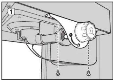
natural_image
Mechanical device diagram showing a rotary knob and adjustment knobs (no text or symbols)
natural_image
Mechanical assembly diagram showing a valve mechanism with no visible text or symbols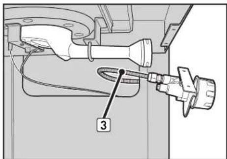
text_image
3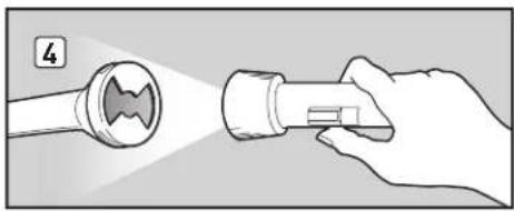
natural_image
Illustration of a hand holding a flashlight with a flashlight emitting light (no text or symbols present)
natural_image
Illustration of a hand holding a tool interacting with a circular component (no text or symbols)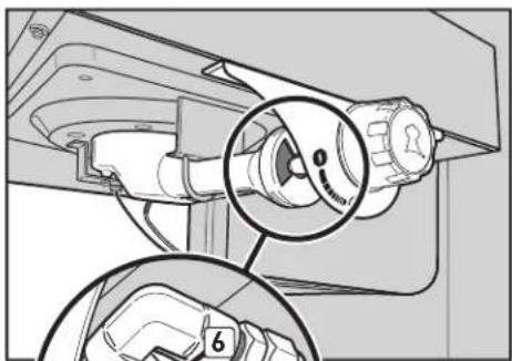
natural_image
Technical diagram showing a mechanical component with a magnified inset view of a circular component (no text or symbols present)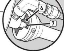
text_image
Diagram showing a hand holding a valve with numbered parts labeled 6 and 7, likely illustrating a mechanical or electrical component.SIDE BURNER EXPLODED VIEW
Side Burner Grate
Side Burner Head
Side Burner Tray
Side Burner Table
Side Burner Control Knob
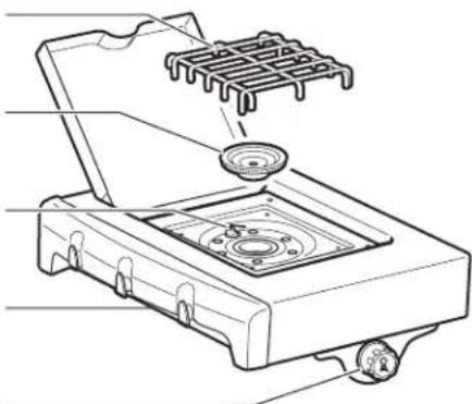
natural_image
Line drawing of a portable stove with a grater and a circular component (no text or symbols)ATTENTION: This product has been safety-tested and is only certified for use in a specific country. Refer to country designation located on outside of box.
These parts may be gas-carrying or gas-burning components. Please contact Weber-Stephen Products LLC Customer Service Department for genuine Weber-Stephen Products LLC replacement part(s) information.
⚠ WARNING: Do not attempt to make any repair to gas-carrying or gas-burning components without contacting Weber-Stephen Products LLC Customer Service Department. Your actions, if you fail to follow this product warning, may cause a fire or an explosion resulting in serious personal injury or death and damage to property.
This symbol indicates that the product cannot be disposed of with household refuse. For instructions regarding proper disposal of this product in Europe, please visit www.weber.com, and contact the importer listed for your country. If you do not have internet access, contact your dealer for the importer's name, address and telephone number.
When you decide to dispose of or discard your grill, all electrical components (e.g., rotisserie motor, batteries, ignition module, handle lights) must be removed and disposed of properly according to WEEE. They should be disposed of separately from the grill.
WEBER-STEPHEN PRODUCTS LLC
R. McDonald Co. PTY. LTD.
A.C.N. 007 905 384
104 South Terrace
Adelaide, 54 5000
AUSTRALIA
Tel: +61.8.8221.6111
WEBER-STEPHEN PRODUCTS BELGIUM Sprl
Blarenberglaan 6 Bus 4
Industriezone Noord
BE-2800 Mechelen
BELGIUM
Tel: +32 015 28 30 90; infobelux@weberstephen.com
WEBER-STEPHEN CZ & SK spol. s r.o.
U Hajovny 246
25243 Průhonice
CZECH REPUBLIC
Tel: +42 267 312 973; info-cz@weberstephen.com
WEBER-STEPHEN NORDIC ApS
Bøgildsmindevej 23
DK-9400 Nørresundby
DANMARK
Tel: +45 99 36 30 10; info@weberstephen.dk
WEBER-STEPHEN FRANCE
C.S. 80322 - Eragny sur Oise
95617 Ceray Pontoise Cedex
FRANCE
Tél: +33 810 19 32 37; service.consonmateurs@weberstephen.com
WEBER-STEPHEN MAGYARORSZÁG KFT.
WEBER-STEPHEN PRODUCTS ITALIA Srl
WEBER-STEPHEN PRODUCTS S.A. de C.V.
Calle José Guadalupe Zuno #2302 P.H.
Col. Americana, Guadalajara, Jalisco C.P. 44160
MEXICO
RFC-WPR030919ND4
Tel: +01800-00-Weber [93237] Ext. 105
WEBER-STEPHEN NETHERLANDS B.V.
Tsjükemarwei 12
8521 NA Sint Nicolaasga
Postbus 18
8520 AA Sint Nicolaasga
NETHERLANDS
Tel: +31 513 4333 22; info@weberbarbecues.nl
WEBER-STEPHEN PRODUCTS LLC
Supreme Barbecues LTD.
6 Maurice Road
Penrose, Auckland 1643
NEW ZEALAND
Tel: +64.579.6630
WEBER-STEPHEN POLSKA Sp. z o.o.
Ul. Trakt Lubelski 153
04-766 Warszawa
POLSKA
Tel: +48 22 392 04 69; info-pl@weberstephen.com
000 WEBER-STEPHEN Vostok
142784 Moscow Region,
Leninskiy Distric
Rumyantsevo Village, Building 1
RUSSIA
Tel: +7 495 989 56 34; info.ru@weberstephen.com
WEBER-STEPHEN PRODUCTS
(South Africa) (Pty) Ltd.
141-142 Hertz Draai
Meadowdale, Edenvale
Gauteng
SOUTH AFRICA
Tel: +27 11 454 2369; info@weber.co.za
WEBER-STEPHEN IBERICA Srl
Avda. de les Corts Catalanes 9-11
Despacho 10 B
WEBER-STEPHEN NORDIC MIDDLE EAST
Ras Al Khaimah FTZ
P.O. Box 10559
UNITED ARAB EMIRATES
Tel: +971 4 360 9256; info@weberstephen.ae
WEBER-STEPHEN PRODUCTS
(U.K.) LIMITED
Griffin House, First Floor,
Broughton Hall Business Park,
Skipton, North Yorkshire BD23 3AN
UNITED KINGDOM
Tel: +44 01756 692611; customerservicenwe@weberstephen.com
WEBER-STEPHEN PRODUCTS LLC
200 East Daniels Road
Palatine, IL 60067-6266
USA
Tel: 847 934 5700; support@weberstephen.com
For Republic of Ireland, please contact:
Weber-Stephen Products (U.K.) Limited.
For other eastern European countries,
such as ROMANIA, SLOVENIA,
CROATIA, or GREECE, please contact:
For Baltic states, please contact:
Weber-Stephen Nordic ApS.

WEBER-STEPHEN PRODUCTS LLC
www.weber.com®