Deco MHR 940.1 (AN)/HA - Oven HOTPOINT - Free user manual and instructions
Find the device manual for free Deco MHR 940.1 (AN)/HA HOTPOINT in PDF.

User questions about Deco MHR 940.1 (AN)/HA HOTPOINT
0 question about this device. Answer the ones you know or ask your own.
Ask a new question about this device
Download the instructions for your Oven in PDF format for free! Find your manual Deco MHR 940.1 (AN)/HA - HOTPOINT and take your electronic device back in hand. On this page are published all the documents necessary for the use of your device. Deco MHR 940.1 (AN)/HA by HOTPOINT.
USER MANUAL Deco MHR 940.1 (AN)/HA HOTPOINT
Italiano, 1 FranEragidis2413


Espanol, 35 Portuges, 46


Nederlands, 57

Deutsch, 68
MHR 940.1 /HA
Sommario
Installazione, 2-4
natural_image
Diagram showing a screwdriver inserted into a component, with an inset magnified view of the component (no text or symbols present)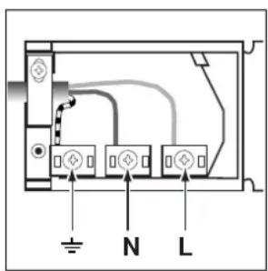
text_image
N Ltext_image
Technical diagram showing a mechanical assembly with labeled parts A, B, D and a close-up of a tilted component with directional arrows.natural_image
Pure technical diagram of a mechanical assembly with no text, numbers, or symbolsASSISTENZA, RICAMBI, ACCESSORI 199.199.199
NUMERO UNICO
Installation of Built-in Ovens
Fastening the oven
Electrical connection
Description of the appliance, 17
Overall view
Start-up and use, 18-21
Using the oven
Clock with Country Style timer
Cooking modes
Practical cooking advice
Cooking advice table
Precautions and tips, 22
General safety
Disposal
Respecting and conserving the environment
Care and maintenance, 23
Switching the appliance off
Cleaning the appliance
Cleaning the oven door
Replacing the oven light bulb
Assistance
Important: The power supply to the appliance must be cut off before any adjustments or maintenance work is done on it.
Installation of Built-in Ovens
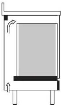
To ensure the proper working order of the built-in appliance, the kitchen unit must be of a suitable size.
The sizes of the unit for installing the cooker under a worktop or in a column unit are shown in figure. To provide adequate ventilation, there must be appropriate ventilation openings in the front bottom and the top part of the cabinet (an intake opening on the bottom of at least 200 cm2, and an exhaust opening of at least 90 cm2).
The unit panels next to the cooker must be heat resistant. In the case of veneered wood units, glues must be resistant to a temperature of 120 °C . In accordance with safety standards, once the appliance has been mounted, there must be no possible contact with electrical parts. Any protective parts must be secured so that they can only be removed with the use of tools.
natural_image
Simple diagram of a mechanical or architectural component with arrows indicating direction (no text or symbols)
text_image
B D C C B D D A A D
text_image
860 mm 585 mm min. 550 mm 580 mm 76 447 mm 525 mm 22 mm 840 mm 162 mm 895 mm 595 mmFastening the oven
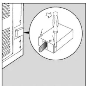
Before inserting the oven into the cabinet, loosen the 4 rear screws "D" - which fasten the side panels - if necessary. This will make it easier to move the oven vertically. The oven should be fastened to the cabinet through the 4 holes situated on the frame, using the screws and spacers provided. Once the oven has been fastened to the cabinet by inserting and screwing the screws in holes "A" tightly, proceed as follows:
1) With the oven door open, loosen the six screws "C" (this way the side panels can slide down);
2) Lower the side panels as much as necessary to gain access to the 2 holes "B" to fix the oven permanently;
3) Put the side panels back in place and fasten the 6 screws "C" tightly.
Electrical Connection
Those ovens equipped with a three-pole power supply cable are designed to operate with an alternating current with the voltage and frequency indicated on the data plate (located on the appliance) and in the instruction manual. The wire for earthing the appliance is yellow-green in colour. Replacing the cable Use a rubber cable of the type H05VV-F with a suitable cross section 3 x 1.5 mm².
The yellow-green earth wire must be 2-3 cm longer than the other wires.
Opening the terminal board:
- Using a screwdriver, prise on the side tabs of the terminal board cover;
- Pull open the cover of the terminal board.
To install the cable, proceed as follows: - Remove the wire clamp screw and the three contact screws L-N-
- Fasten the wires beneath the screwheads using the following colour scheme: Blue (N) Brown (L) Yellow-Green
- Fasten the supply cable in place with the clamp and close the cover of the terminal board.
natural_image
Diagram showing a screwdriver inserted into a component, with an inset magnified view of the component (no text or symbols present)
text_image
N LConnecting the supply cable to the mains
Install a standardised plug corresponding to the load indicated on the data plate. When connecting the cable directly to the mains, install an omnipolar circuit-breaker with a minimum contact opening of 3 mm between the appliance and the mains. The omnipolar circuit breaker should be sized according to the load and should comply with current regulations (the earth wire should not be interrupted by the circuit breaker).
The supply cable should be positioned so that it does not reach a temperature of more than 50^ C with respect to the room temperature, anywhere along its length.
Before making the connection, check that:
- The electrical safety of this appliance can only be guaranteed if the cooker is correctly and efficiently earthed, in compliance with regulations on electrical safety. Always ensure that the earthing is efficient; if you have any doubts call in a qualified technician to check the system. The manufacturer declines all responsibility for damage resulting from a system which has not been earthed.
- Before plugging the appliance into the mains, check that the specifications indicated on the date plate (on the appliance and/or packaging) correspond to those of the electrical mains system of your home.
- Check that the electrical capacity of the system and sockets will support the maximum power of the appliance, as indicated on the data plate. If you have any doubts, call in a qualified technician.
- If the socket and appliance plug are not compatible, have the socket replaced with a suitable model by a qualified technician. The latter, in particular, will also have to ensure that the cross section of the socket cables are suitable for the power absorbed by the appliance. The use of adapters, multiple sockets and/or extensions, is not recommended. If their use cannot be avoided, remember to use only single or multiple adapters and extensions which comply with current safety regulations. In these cases, never exceed the maximum current capacity indicated on the single adapter or extension and the maximum power indicated on the multiple adapter.
! Once the appliance has been installed, the power supply cable and the electrical socket must be easily accessible.
! The cable must not be bent or compressed.
! The cable must be checked regularly and replaced by authorised technicians only (see Assistance).
! The manufacturer declines any liability shouldThe manufacture these safety measures not be observed.these safety measures
This appliance conforms with the following European Economic Community directives:
- 2006/95/EEC of 12/12/06 (Low Voltage) and subsequent modifications;
- 2004/108/EEC of 15/12/04 (Electromagnetic Compatibility) and subsequent modifications;
- 93/68/EEC of 22/07/93 and subsequent modifications.
- 2002/96/CEE and subsequent modifications.
- 1275/2008 stand-by/offmode.
ENERGY LABELENERGY LABEL
Directive 2002/40/EC on the label of electric ovens Norm EN 50304
Declared energy consumption for Forced convection Class
heating mode: BAKING
Description of the appliance
Overall view

text_image
SELECTOR knob COUNTRY STYLE TIMER knob THERMOSTAT knob Indicator light THERMOSTAT Glass oven doorGB
Using the oven
! The first time you use your appliance, heat the empty oven with its door closed at its maximum temperature for at least half and hour. Ensure that the room is well ventilated before switching the oven off and opening the oven door. The appliance may emit a slightly unpleasant odour caused by protective substances used during the manufacturing process burning away.
- Select the desired cooking mode by turning the SELECTOR knob.
- Select the desired temperature with the THERMOSTAT knob. See the Cooking advice table for cooking modes and the suggested cooking temperatures (see Cooking Modes).
- When lit, the THERMOSTAT indicator light indicates that the oven is heating up to the temperature set.
- You may do the following during cooking:
- change the cooking mode by turning the SELECTOR knob.
- change the temperature by turning the THERMOSTAT knob.
- stop cooking by turning the SELECTOR knob to the "0" position.
! There is no preheating stage for the BARBECUE mode.
! Never put objects directly on the bottom of the oven; this will prevent the enamel coating from being damaged.
! Always place cookware on the rack(s) provided.
Cooling ventilation
In order to cool down the external temperature of the oven, some models are fitted with a cooling fan which blows air out between the control panel and the oven door.
Once cooking has been completed, the cooling fan remains on until the oven has cooled down sufficiently. In the BAKING mode, the cooling fan is only activated when the oven is hot.
! Once cooking has been completed, the cooling fan continues to operate until the oven has cooled down sufficiently.
Oven light
This is switched on by selecting 📋 using the SELECTOR knob. It remains lit when a cooking mode is selected.
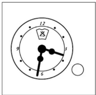
Clock with Country Style timer
How to reset the correct time
The oven must be plugged in.
Pull the knob and turn it clockwise until you set the correct time.
! The programmer is electrically powered, therefore in the event of a power shortage, it will stop working for the entire duration of the same. Following this power failure, the correct time will have to be reset.
Timer Feature
The timer feature allows you to enter a given amount of time from which the timer begins to count down.
This feature does not turn the oven on or off; it merely sounds when the time has elapsed.
How to set the timer
Turn the knob clockwise until the marker lines up with the desired time (internal scale), which can be seen in the "window".
The time countdown will begin immediately.
To interrupt the timer buzzer, or to use only the clock feature, set the marker to the ⚙ symbol.
text_image
12 9 3 6Cooking modes
! A temperature value between 60^ C and MAX can be set for all cooking modes except the following:
- BARBECUE (recommended: set only to MAX power level)
• GRATIN (recommended: do not exceed 200°C).
TRADITIONAL OVEN mode
When using this traditional cooking mode, it is best to use one cooking rack only. if more than one rack is used, the heat will be distributed unevenly.
BAKING mode
This mode is ideal for baking temperature sensitive foods (such as cakes, which need to rise) and for the preparation of "bitesize pastries" on 3 shelves simultaneously.
FAST COOKING mode
This mode is particularly suitable for cooking pre-packed food quickly (frozen or pre-cooked). The best results are achieved using one cooking rack only.
MULTILEVEL mode
Since the heat remains constant throughout the oven, the air cooks and browns food in a uniform manner. A maximum of two racks may be used at the same time.
PIZZA mode
This combination heats the oven rapidly by producing a considerable amount of heat, particularly from the element at the bottom. If you use more than one rack at a time, switch the position of the dishes halfway through the cooking process.
BARBECUE mode
The high and direct temperature of the grill is recommended for food which requires a high surface temperature. Always cook in this mode with the oven door closed.
GRATIN mode
This combination of features increases the effectiveness of the unidirectional thermal radiation provided by the heating elements through forced circulation of the air throughout the oven. This helps prevent food from burning on the surface and allows
the heat to penetrate right into the food. Always cook in this mode with the oven door closed.
DEFROSTING mode
The fan located on the bottom of the oven makes the air circulate at room temperature around the food. This is recommended for the defrosting of all types of food, but in particular for delicate types of food which do not require heat, such as for example: ice cream cakes, cream or custard desserts, fruit cakes. By using the fan, the defrosting time is approximately halved. In the case of meat, fish and bread, it is possible to accelerate the process using the "multi-cooking" mode and setting the temperature to 80° - 100°C.
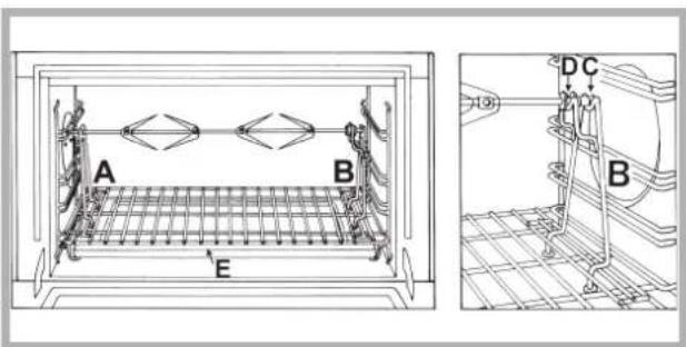
Spit roast
This accessory should only be used when cooking with the grill. Proceed as follows: thread the meat you wish to cook onto the rod positioned across the oven lengthwise, fixing it in place with the adjustable forks supplied. Position supports "A" and "B" in the relevant holes in dripping pan "E", rest the groove on the rod in slot "C" and use the guide rail to place the rack in the lowest position in the oven; next position the rod in the rotisserie spit hole, sliding the groove forwards to slot "D" (see figures). Start the rotisserie using the SELECTOR knob set to cooking mod or
text_image
A B E DC BPractical cooking advice
! Do not place racks in position 1 and 5 during fan-assisted cooking. This is because excessive direct heat can burn temperature sensitive foods.
! In the BARBECUE and GRATIN cooking modes, particularly when using the rotisserie, place the dripping pan in position 1 to collect cooking residues (fat and/or grease).
MULTILEVEL
- Use positions 2 and 4, placing the food which requires more heat on 2.
- Place the dripping pan on the bottom and the rack on top.
BARBECUE
- Place the rack in position 3 or 4. Position the food in the centre of the rack.
- We recommend that the power level is set to maximum. The top heating element is regulated by a thermostat and may not always operate constantly.
PIZZA
- Use a light aluminium pizza pan. Place it on the rack provided.
For a crispy crust, do not use the dripping pan as it prevents the crust from forming by extending the total cooking time. - If the pizza has a lot of toppings, we recommend adding the mozzarella cheese on top of the pizza halfway through the cooking process.
Cooking advice table
| Cooking modes | Weight (Kg) | Rack poYestionFoods | Preheating | Recommended Temperature (°C) | Cooking duration (minutes) | ||
| standard guide rails | sliding guide rails | ||||||
| Convection Oven | Anatra | 1,5 | 2 | 1 | Yes | 200-210 | 70-80 |
| Pollo | 1,5 | 2 | 1 | Yes | 200-210 | 60-70 | |
| Arrosto di vitello o manzo | 1 | 2 | 1 | Yes | 200 | 70-75 | |
| Arrosto di maiale | 1 | 2 | 1 | Yes | 200-210 | 70-80 | |
| Biscotti (di frolla) | - | 2 | 1 | Yes | 180 | 15-20 | |
| Crostate | 1 | 2 | 1 | Yes | 180 | 30-35 | |
| Baking mode | Crostate | 0,5 | 2 or 3 | 1 or 2 | Yes | 180 | 25-35 |
| Torta di frutta | 1 | 2 or 3 | 1 or 2 | Yes | 180 | 40-50 | |
| Plum-cake | 0,7 | 2 or 3 | 1 or 2 | Yes | 170-180 | 45-55 | |
| Cake piccoli su 2 ripiani | 0,7 | 2 and 4 | 1 and 3 | Yes | 180-190 | 20-25 | |
| Pan di spagna | 0,6 | 2 or 3 | 1 or 2 | Yes | 160-170 | 30-40 | |
| Bignè su 3 ripiani | 0,7 | 1, 3 and 5 | 1, 2 and 4 | Yes | 180-190 | 20-25 | |
| Biscotti su 3 ripiani | 0,7 | 1, 3 and 5 | 1, 2 and 4 | Yes | 180 | 20-25 | |
| Crêpes farcite | 0,8 | 2 | 1 | Yes | 200 | 30-35 | |
| Meringhe su 3 ripiani | 0,5 | 1, 3 and 5 | 1, 2 and 4 | Yes | 90 | 180 | |
| Salatini di sfoglia al formaggio | 0,5 | 2 | 1 | Yes | 210 | 20-25 | |
| Fast cooking | Surgelati | ||||||
| Pizza | 0,3 | 2 | 1 | - | 250 | 12 | |
| Misto zucchine e gamberi in pastella | 0,4 | 2 | 1 | - | 200 | 20 | |
| Torta rustica di spinaci | 0,5 | 2 | 1 | - | 220 | 30-35 | |
| Panzerotti | 0,3 | 2 | 1 | - | 200 | 25 | |
| Lasagne | 0,5 | 2 | 1 | - | 200 | 35 | |
| Panetti dorati | 0,4 | 2 | 1 | - | 180 | 25-30 | |
| Bocconcini di pollo | 0,4 | 2 | 1 | - | 220 | 15-20 | |
| Precotti | |||||||
| Ali di pollo dorate | 0,4 | 2 | 1 | - | 200 | 20-25 | |
| Cibi Freschi | |||||||
| Biscotti (di frolla) | 0,3 | 2 | 1 | - | 200 | 15-18 | |
| Plum-cake | 0,6 | 2 | 1 | - | 180 | 45 | |
| Salatini di sfoglia al formaggio | 0,2 | 2 | 1 | - | 210 | 10-12 | |
| Multilevel | Pizza su 2 ripiani | 2 and 4 | 1 and 3 | Yes | 220-230 | 20-25 | |
| Crostate su 2 ripiani/torte su 2 ripiani | 2 and 4 | 1 and 3 | Yes | 180 | 30-35 | ||
| Pan di spagna su 2 ripiani (su leccarda) | 2 and 4 | 1 and 3 | Yes | 170 | 20-25 | ||
| Pollo arrosto + palate | 1+1 | 1 and 2/3 | 1 and 3 | Yes | 200-210 | 65-75 | |
| Agnello | 1 | 2 | 1 | Yes | 190-200 | 45-50 | |
| Sgombro | 1 | 1 or 2 | 1 | Yes | 180 | 30-35 | |
| Lasagne | 1 | 2 | 1 and 3 | Yes | 190-200 | 35-40 | |
| Bignè su 2 ripiani | 2 and 4 | 1 and 3 | Yes | 190 | 20-25 | ||
| Biscotti su 2 ripiani | 2 and 4 | 1 and 3 | Yes | 190 | 10-20 | ||
| Salatini di sfoglia al formaggio su 2 ripiani | 2 and 4 | 1 and 3 | Yes | 210 | 20-25 | ||
| Torte salate | 1 and 3 | 1 | Yes | 200 | 20-30 | ||
| Pizza Mode | Pizza | 0,5 | 2 | 1 | Yes | 220 | 15-20 |
| Focacce | 0,5 | 2 | 3 | Yes | 200 | 20-25 | |
| Barbecue | Sgombri | 1 | 4 | 3 | no | Max | 15-20 |
| Sogliole e seppie | 0,7 | 4 | 3 | no | Max | 10-15 | |
| Spiedini di calamari e gamberi | 0,7 | 4 | 3 | no | Max | 8-10 | |
| Filetto di merluzzo | 0,7 | 4 | 2 or 3 | no | Max | 10-15 | |
| Verdure alla griglia | 0,5 | 3 or 4 | 3 | no | Max | 15-20 | |
| Bistecca di vitello | 0,8 | 4 | 3 | no | Max | 15-20 | |
| SalYescce | 0,7 | 4 | 3 | no | Max | 15-20 | |
| Hamburger | n°4 or 5 | 4 | 3 | no | Max | 10-12 | |
| Toast (o pane tostato) | n°4 or 6 | 4 | 3 | no | Max | 3-5 | |
| Pollo allo spiedo con girarrosto (ove presente) | 1 | - | - | no | Max | 70-80 | |
| Agnello allo spiedo con girarrosto (ove presente) | 1 | - | - | no | Max | 70-80 | |
| Gratin | Pollo alla griglia | 1,5 | 2 | 2 | no | 210 | 55-60 |
| Seppie | 1 | 2 | 2 | no | 200 | 30-35 | |
| Pollo allo spiedo con girarrosto (ove presente) | 1,5 | - | - | no | 210 | 70-80 | |
| Anatra allo spiedo con girarrosto (ove presente) | 1,5 | - | - | no | 210 | 60-70 | |
| Arrosto di vitello o manzo | 1 | 2 | 2 | no | 210 | 60-75 | |
| Arrosto di maiale | 1 | 2 | 2 | no | 210 | 70-80 | |
| Agnello | 1 | 2 | 2 | no | 210 | 40-45 | |
* The cooking times listed above are intended as guidelines only and may be modified according to personal tastes.
Oven preheating times are set as standard and may not be modified manually.
! This appliance has been designed and manufactured in compliance with international safety standards.
The following warnings are provided for safety reasons and must be read carefully.
General safety
- The appliance was designed for domestic use inside the home and is not intended for commercial or industrial use.
- The appliance must not be installed outdoors, even in covered areas. It is extremely dangerous to leave the appliance exposed to rain and storms.
- Do not touch the appliance with bare feet or with wet or damp hands and feet.
- The appliance must be used by adults only for the preparation of food, in accordance with the instructions outlined in this booklet. Any other use of the appliance (e.g. for heating the room) constitutes improper use and is dangerous. The manufacturer may not be held liable for any damage resulting from improper, incorrect and unreasonable use of the appliance.
- Do not touch the heating elements or certain parts of the oven door when the appliance is in use; these parts become extremely hot. Keep children well away from the appliance.
- Make sure that the power supply cables of other electrical appliances do not come into contact with the hot parts of the oven.
- The openings used for the ventilation and dispersion of heat must never be covered.
• Always use oven gloves when placing cookware in the oven or when removing it. - Do not use flammable liquids (alcohol, petrol, etc...) near the appliance while it is in use.
- Always make sure the knobs are in the • position when the appliance is not in use.
- When unplugging the appliance, always pull the plug from the mains socket; do not pull on the cable.
- Never perform any cleaning or maintenance work without having disconnected the appliance from the electricity mains.
- If the appliance breaks down, under no circumstances should you attempt to perform the repairs yourself. Repairs carried out by inexperienced persons may cause injury or further malfunctioning of the appliance. Contact Assistance.
-
Do not rest heavy objects on the open oven door.
-
The appliance should not be operated by people (including children) with reduced physical, sensory or mental capacities, by inexperienced individuals or by anyone who is not familiar with the product. These individuals should, at the very least, be supervised by someone who assumes responsibility for their safety or receive preliminary instructions relating to the operation of the appliance.
- Do not let children play with the appliance.
- The appliance is not intended to be operated by means of an external timer or separate remote-control system.
Disposal
- When disposing of packaging material: observe local legislation so that the packaging may be reused.
- The European Directive 2002/96/EC relating to Waste Electrical and Electronic Equipment (WEEE) states that household appliances should not be disposed of using the normal solid urban waste cycle. Exhausted appliances should be collected separately in order to optimise the cost of re-using and recycling the materials inside the machine, while preventing potential damage to the atmosphere and to public health. The crossed-out dustbin is marked on all products to remind the owner of their obligations regarding separated waste collection.
For further information relating to the correct disposal of exhausted household appliances, owners may contact the public service provided or their local dealer.
Respecting and conserving the environment
- You can help to reduce the peak load of the electricity supply network companies by using the oven in the hours between late afternoon and the early hours of the morning. The cooking mode programming options, the "delayed cooking" mode (see Cooking modes) and "delayed automatic cleaning" mode (see Care and Maintenance) in particular, enable the user to organise their time efficiently.
- Always keep the oven door closed when using the BARBECUE and GRATIN modes: this will achieve improved results while saving energy (approximately 10%).
- Check the door seals regularly and wipe them clean to ensure they are free of debris so that they adhere properly to the door, thus avoiding heat dispersion.
Switching the appliance off
Disconnect your appliance from the electricity supply before carrying out any work on it.
Cleaning the appliance
- The stainless-steel or enamel-coated external parts as well as the rubber seals may be cleaned using a sponge that has been soaked in lukewarm water and neutral soap. If these stains are difficult to remove, use only specialised products. After cleaning, rinse and dry thoroughly. Do not use abrasive powders or corrosive substances.
- Ideally, the inside of the oven should be cleaned after each use, when it is still lukewarm. Use hot water and detergent, rinse and dry with a soft cloth. Do not use abrasive products.
- All accessories can be washed like everyday crockery, and are even dishwasher safe.
- Never use steam cleaners or pressure cleaners on the appliance.
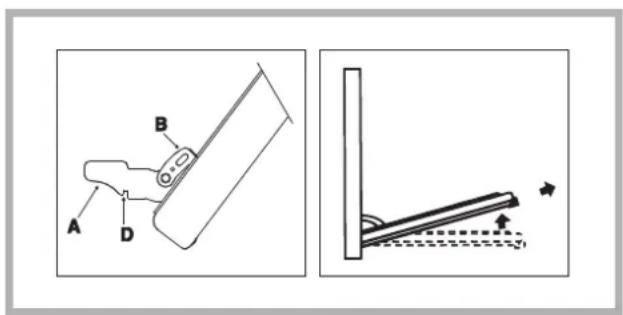
Cleaning the oven door
Clean the glass part of the oven door using a sponge and a non-abrasive cleaning product, then dry thoroughly with a soft cloth. Do not use rough abrasive material or sharp metal scrapers as these could scratch the surface and cause the glass to crack. To clean more thoroughly, you can remove the oven door.
- Open the door fully and lift up the two small levers "B";
- Now, when the door is closed slightly, it can be lifted out by removing hooks "A" as shown in figure.
To replace the door:
- With the door in an upright position, insert the 2 hooks "A" into the vents;
- Make sure that slot "D" is perfectly fastened to the edge of the vent (move the door forwards and backwards slightly);
- Keep the door completely open, shift the 2 levers "B" downwards, then close the door.
text_image
Technical diagram showing a mechanical assembly with labeled parts A, B, D and an angled component with directional arrows.Inspecting the seals
Check the door seals around the oven periodically. If the seals are damaged, please contact your nearest After-sales Service Centre (see Assistance). We recommend not using the oven until the seals have been replaced.
Replacing the light bulb
To replace the oven light bulb:
- Remove the glass cover of the lamp-holder.
- Remove the light bulb and replace it with a similar one: Wattage 25 W, cap E 14.
- Replace the glass cover (see diagram).

natural_image
Pure technical line drawing of a pipe fitting with no text or symbolsAssistance
! Never use the services of an unauthorised technician.
Please have the following information to hand:
• The type of problem encountered.
• The appliance model (Mod.).
• The serial number (S/N).
The latter two pieces of information can be found on the data plate located on the appliance.
FR

Italiano, 1 Français,2413

IT


Espanol, 35 Portuges, 46


Nederlands, 57

Deutsch, 68
MHR 940.1 /HA
Sommaire
Installation, 25-27
natural_image
Pure diagram of a mechanical or architectural component with no text, numbers, or symbols
text_image
B D C C B D D A D A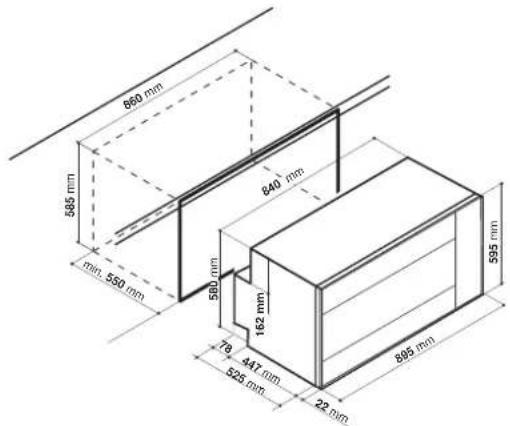
text_image
650 mm 585 mm min. 550 mm 580 mm 162 mm 78 mm 447 mm 525 mm 22 mm 840 mm 595 mm 895 mmFixation
natural_image
Diagram showing a device with a plug inserted into a container, with an inset magnified view of the insertion (no text or symbols present)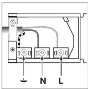
text_image
Diagram of an electronic device rear panel with labeled ports N and L and grounding symbolstext_image
Technical diagram showing a mechanical assembly with labeled parts A, B, D and a close-up of a structural detail with dashed lines indicating motion or force.Contrôle des joints
natural_image
Pure technical diagram of a mechanical assembly with no text, numbers, or symbolsAssistance
text_image
Technical diagram showing a device with labeled parts A, B, D and an angled component with directional arrows indicating motion or force.
Italiano, 1 Francaiglis24,13


Espanol,35 Portuges, 46


Nederlands, 57

Deutsch, 68
MHR 940.1 /HA
Sumario
Instalación, 36-38
natural_image
Simple diagram of a mechanical or electrical component with arrows indicating direction (no text or symbols)
text_image
860 mm 585 mm 840 mm min. 550 mm 580 mm 162 mm 78 447 mm 525 mm 22 mm 895 mm 595 mmClavado
natural_image
Diagram showing a screwdriver inserted into a component, with an inset magnified view of the component (no text or symbols present)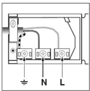
text_image
N Lnatural_image
Simple line drawing of a ladder leaning against a vertical wall, with motion arrows indicating direction (no text or symbols)Controle las juntas
natural_image
Pure mechanical assembly diagram showing pipe connection without any text, numbers, or symbolsnatural_image
Simple diagram of a mechanical or electrical component with arrows indicating direction (no text or symbols)
text_image
860 mm 585 mm min 550 mm 840 mm 595 mm 162 mm 78 mm 447 mm 325 mm 22 mm 885 mm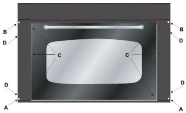
text_image
B D C C B D D A AFixação
natural_image
Diagram showing a screwdriver inserted into a component, with an inset magnified view of the tool (no text or symbols present)
text_image
Diagram of an electrical panel with labeled terminals and connections, including symbols for N and L.text_image
Technical diagram showing a mechanical assembly with labeled parts A, B, D and a close-up of a lever mechanism with motion arrows.natural_image
Pure technical diagram of a mechanical or electrical component with no text, numbers, or symbolsAssistência técnica
text_image
Technical diagram showing a device with labeled parts A, B, D and an angled component with directional arrows indicating motion or force.
Italiano, 1 Françaisian, 13


Espanol, 35 Portuges, 46


Nederlands, 57

Deutsch, 68
MHR 940.1 /HA
Samenvatting
natural_image
Simple diagram of a mechanical or electrical component with arrows indicating direction (no text or symbols)
text_image
860 mm 585 mm min. 550 mm 580 mm 162 mm 76 447 mm 525 mm 22 mm 840 mm 595 mm 895 mm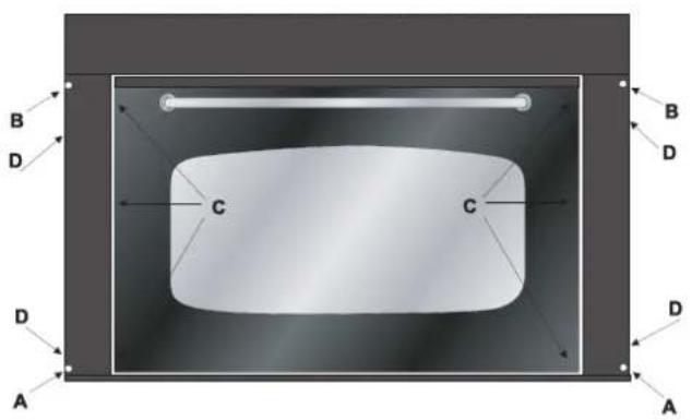
text_image
B D C C B D D A AHet bevestigen
natural_image
Diagram showing a mechanical component inserted into a housing, with an inset magnified view of the component (no text or symbols present)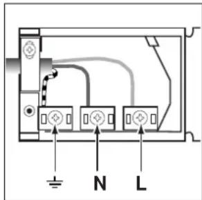
text_image
Diagram of an electrical panel with labeled terminals and connections, including symbols for N and L.text_image
Technical diagram showing a mechanical assembly with labeled parts A, B, D and an angled component with directional arrows.natural_image
Pure technical line drawing of a mechanical component with no text or symbolsServicedienst
natural_image
Simple line drawing of a mechanical or architectural component with arrows indicating motion (no text or symbols)
text_image
860 mm 585 mm min. 550 mm 590 mm 162 mm 76 447 mm 525 mm 22 mm 840 mm 595 mm 695 mm
text_image
B D C C B D D A ABefestigung
natural_image
Diagram showing a device with a tool inserted into a box, with an inset magnified view of the component (no text or symbols present)
text_image
N Ltext_image
Technical diagram showing a mechanical assembly with labeled parts A, B, D and a close-up of a lever mechanism with motion arrows.natural_image
Pure technical diagram of a mechanical component with no text or symbolsKundendienst
text_image
Technical diagram showing a mechanical assembly with labeled parts A, B, D and an angled component with directional arrows.DE
DE