V70 (2000) - Car VOLVO - Free user manual and instructions
Find the device manual for free V70 (2000) VOLVO in PDF.

User questions about V70 (2000) VOLVO
0 question about this device. Answer the ones you know or ask your own.
Ask a new question about this device
Download the instructions for your Car in PDF format for free! Find your manual V70 (2000) - VOLVO and take your electronic device back in hand. On this page are published all the documents necessary for the use of your device. V70 (2000) by VOLVO.
USER MANUAL V70 (2000) VOLVO
This manual deals with the operation and care of your Volvo.
natural_image
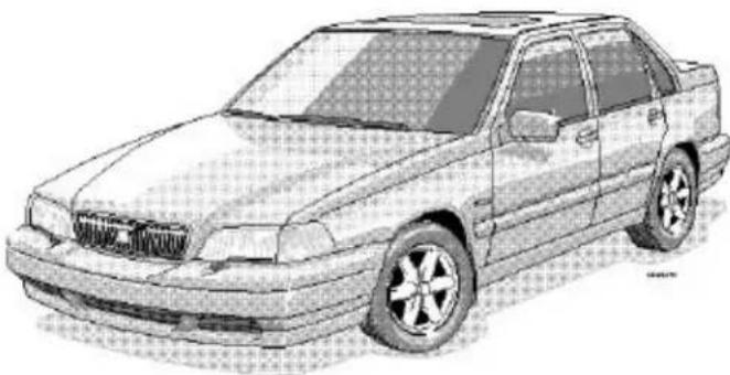
Line drawing of a sedan car with grille and alloy wheels (no text or symbols)Welcome to the world-wide family of Volvo owners. We trust that you will enjoy many years of safe driving in your Volvo, an automobile designed with your safety and comfort in mind. To help ensure your satisfaction with this vehicle, we encourage you to familiarize yourself with the equipment descriptions, operating instructions and maintenance requirements/recommendations in this manual. We also urge you and your passengers to wear seat belts at all times in this (or any other) automobile. And, of course, please do not operate a vehicle if you may be affected by alcohol, medication or any impairment that could hinder your ability to drive.
Your Volvo is designed to meet all applicable safety and emission standards, as evidenced by the certification labels attached to the driver's door opening and on the left wheel housing in the engine compartment.
For further information please contact your retailer, or:
In the USA: In Canada:
Volvo Cars of North America Volvo Canada Ltd.
Customer Relations 175 Gordon Baker Road
P.O. Box 914 Willowdale, Ontario M2H 2N7
Rockleigh, New Jersey 07647-0914 800-663-8255
800-458-1552
We also invite you to visit our Home Page on the Internet at:
http://www.yolvocars.com
Contents
Contents
Chapter 1 - Occupant safety
Chapter 2 - Instruments, switches and controls
Chapter 3 - Body and interior
Chapter 4 - Starting and driving
Chapter 5 - Wheels and tires
Chapter 6 - In case of an emergency
Chapter 7 - Car care
Chapter 8 - Volvo Service
Chapter 9 - Specifications
Chapter 10 - Audio systems
HomeLink® Universal Transceiver (option)
Index
General information
Important
Before you operate your car for the first time, please familiarize yourself with the BREAK-IN information on page 66. You should also be familiar with the information in the first three chapters of this manual.
Information contained in the balance of the manual is extremely useful and should be read after operating the vehicle for the first time.
The manual is structured so that it can be used for reference. For this reason, it should be kept in the car for ready access.
Do not export your Volvo to another country before investigating that country's applicable safety and exhaust emission requirements. In some cases it may be difficult or impossible to comply with these requirements. Modifications to the emission control system(s) may render your Volvo not certifiable for legal operation in the U.S., Canada and other countries.
All information, illustrations and specifications contained in this manual are based on the latest product information available at the time of publication. Please note that some vehicles may be equipped differently, depending on special legal requirements and that optional equipment described in this manual may not be available in all markets.
Volvo reserves the right to make model changes at any time, or to change specifications or design, without notice and without incurring obligation.
CAUTION: Certain models have reduced ground clearance due to the design of the front spoiler. Please observe caution when e.g., driving onto garage hoists, through drifted snow or when other road debris is encountered, or when parking near curbs.
© 1998 Volvo Cars of North America Inc.
Shiftlock (automatic transmission only)
When your car is parked, the gear selector is locked in the (P)ark position. To release the selector from this position, turn the ignition key to position II (or start the engine), depress the brake pedal, press the button on the front side of the gear selector and move the selector from (P)ark.
If it is necessary to manually override the shiftlock system:
- Turn the starting (ignition) key to position I
- Press firmly on the "SHIFTLOCK OVERRIDE" button located to the right of the base of the gear selector
- While holding the override button down, press the button on the front of the gear selector
- Move the selector from the (P)ark position.
Keylock (automatic transmission only)
This means that when you switch off the ignition, the gear selector must be in the (P)ark position before the starting (ignition) key can be removed from the ignition switch.
Clutch interlock (manual transmission only)
The clutch must be fully depressed before you can start you car. If the clutch is not depressed, it will not be possible to start the engine.
Anti-lock Brake System (ABS)
The ABS system in your car performs a self-diagnostic test when the vehicle first reaches the speed of approximately 12 mph (20 km/h). The brake pedal will pulsate several times and a sound may be audible from the ABS control module. This is normal.
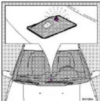
Fuel tank cover
The fuel tank cover is locked and must be popped open using the control on the driver's door (see illustration on page 16).
Volvo and the environment
Volvo is committed to the well being of our customers. As a natural part of this commitment, we care about the environment in which we all live. Caring for the environment means an everyday involvement in reducing our environmental impact.
Volvo's environmental activities are based on a holistic view, which means we consider the overall environmental impact of a product throughout its complete life cycle. In this context, design, production, product use, and recycling are all important considerations.
In production, Volvo has partly or completely phased out several chemicals including freons, lead chromates, naphtanates, asbestos, mercury and cadmium; and reduced the amount of chemicals used in our plants 50% since 1991.
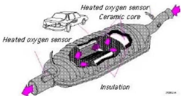
In use, Volvo was the first in the world to introduce into production a three-way catalytic converter with a Lambda sond, now called oxygen sensor, in 1976. The current version of this highly efficient system reduces emissions of harmful substances (CO, HC, NOx) from the exhaust pipe by approximately 95% and the search to eliminate the remaining emissions continues. Volvo is the only automobile manufacturer to offer CFC-free retrofit kits for the air conditioning system for all models as far back as the M/Y 1975 240. Advanced electronic engine controls, refined purification systems and cleaner fuels are bringing us closer to our goal.
After Volvo cars and parts have fulfilled their use, recycling is the next critical step in completing the life cycle. The metal content is about 75% of the total weight of a car, which makes the car among the most recycled industrial products. In order to have efficient and well controlled recycling, many Volvo variants have printed dismantling
manuals, indicating the weight and material of individual components. For Volvo, all homogeneous plastic parts weighing more than 1.7 oz. (50 grams) are marked with international symbols that indicate how the component is to be sorted for recycling.
In addition to continuous environmental refinement of conventional gasoline-powered internal combustion engines, Volvo is actively looking at advanced technology alternative-fuel vehicles.
When you drive a Volvo, you become our partner in the work to lessen the car's impact on the environment.
To reduce your vehicle's environmental impact, you can:
- Maintain proper air pressure in your tires. Tests have shown decreased fuel economy with improperly inflated tires
· Follow the recommended maintenance schedule - Drive at a constant speed
- See an authorized Volvo retailer as soon as possible for inspection if the check engine (malfunction indicator) lamp illuminates, or stays on after the vehicle has started
· Properly dispose of any vehicle related waste such as used motor oil, used batteries, brake pads, etc. - When cleaning your car, use Volvo's own car care products, all of which have systematically been adapted to the environment
For additional information regarding the environmental activities in
which Volvo Cars of North America, Inc. and Volvo Car Corporation are involved, visit our Internet Home Page at:
http://www.volvocars.com
Three-way catalytic converter
text_image
Heated oxygen sensor Ceramic core Heated oxygen sensor InsulationThree-way catalytic converter cautions
- Keep your engine properly tuned. Certain engine malfunctions, particularly involving the electrical, fuel or distributor ignition systems, may cause unusually high three-way catalytic converter temperatures. Do not continue to operate your vehicle if you detect engine misfire, noticeable loss of power or other unusual operating conditions, such as engine overheating or backfiring. A properly tuned engine will help avoid malfunctions that could damage the three-way catalytic converter.
- Do not park your car over combustible materials, such as grass or leaves, which can come into contact with the hot exhaust system and cause such materials to ignite under certain wind and weather conditions.
- Excessive starter cranking (in excess of one minute), with an intermittently firing or flooded engine, can cause three-way catalytic converter or exhaust system overheating.
- Remember that tampering or unauthorized modifications to the engine or the vehicle may be illegal and can cause three-way catalytic converter or exhaust system overheating. This includes:
2000 Volvo S & V70
- Altering fuel injection setting or components.
- Altering emission system components or location or removing components.
- Repeated use of leaded fuel.
NOTE: Unleaded fuel is required for cars with three-way catalytic converters.

Top of Page
2000 VOLVO S & V70
Chapter 1 - Occupant safety
pg. 1 Occupant safety
Despite our strongest recommendations, and your best intentions, not wearing a seat belt is like believing "It'll never happen to me!". Volvo, the inventor of the three-point seat belt, urges you and all adult occupants of your car to wear seat belts and ensure that children are properly restrained, using an infant, car or booster seat determined by age, weight and height. Volvo also believes no child should sit in the front seat of a car.
Fact: In every state and province, some type of child-restraint legislation has been passed. Additionally, most states and provinces have already made it mandatory for occupants of a car to use seat belts.
So, urging you to "buckle up" is not just our recommendation - legislation in your state or province may mandate seat belt usage. The few seconds it takes to buckle up may one day allow you to say, "It's a good thing I was wearing my seat belt".
SEAT&BELTS
Seat belts 2_
Volvo SRS 4_
Side Impact Protection System - (SIPS) air bag 8
Whiplash Protection System (WHIPS) 9_
Child safety 10
Occupant safety 16
Reporting Safety Defects 16
pg. 2 Seat belts
Seat belts
Always fasten the seat belts before you drive or ride.
Two lights above the rear view mirror will be illuminated for 4-8 seconds after the starting (ignition) key is turned to the driving position. A chime will sound at the same time if the driver has not fastened his seat belt. The rear seats are provided with self-retracting inertia
reel belts. The front seats are provided with single roller belts with tensioners.
To buckle:
Pull the belt out far enough to insert the latch plate into the receptacle (buckle for rear seats)
until a distinct snapping sound is heard. The seat belt retractor is normally "unlocked" and
you can move freely, provided that the shoulder belt is not pulled out too far. The retractor will lock up as follows:
· if the belt is pulled out rapidly
· during braking and acceleration
· if the vehicle is leaning excessively
- when driving in turns
For the seat belt to provide maximum protection in the event of an accident, it must be worn correctly. When wearing the seat belt remember:
· The belt should not be twisted or turned.
· The lap belt must be positioned low on the hips (not pressing against the abdomen).
· The shoulder section of the front seat belts adjusts automatically to the driver's height.
Make sure that the shoulder belt is rolled up into its retractor and that the shoulder and lap
belts are taut.
Before exiting the car, check that the seat belt retracts fully after being unbuckled. If necessary, guide the belt back into the retractor slot.
NOTE: Legislation in your state or province may mandate seat belt usage.
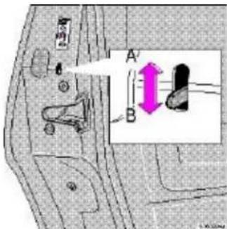
Adjusting the shoulder belt

natural_image
Illustration of a hand holding a tool with purple arrows indicating movement or force, no visible text or symbolsLap portion of the seat belt should sit low
WARNING!
Any device used to induce slack into the shoulder belt portion of the three-point belt system will have a detrimental effect on the amount of protection available to you in the event of a collision. The seat back should not be tilted too far back. The shoulder belt must be taut in order to function properly.
Spool-out
To make child seat installation easier, each seat belt buckle (except for the driver's belt) is equipped with a locking mechanism to help keep the lap section of the seat belt taut. Please refer to page 13 for more information on this function.
WARNING!
Do not use child safety seats or child booster cushions/backrests in the front passenger's seat. We also recommend that children who have outgrown these devices sit in the rear seat with the seat belt properly fastened.
pg. 3 Seat belts, Center head restraint

natural_image
Illustration of a woman seated in a car, wearing a purple belt and seatbelt (no text or symbols visible)During pregnancy
Pregnant women should always wear seat belts. Remember that the belt should always be positioned in such a way as to avoid any possible pressure on the abdomen. The lap portion of the belt should be located low, as shown in the above illustration.
WARNING!
Never use a seat belt for more than one occupant. Never wear the shoulder
portion of the belt under the arm, behind the back or otherwise out of position. Such use could cause injury in the event of an accident. As the seat belts lose much of their strength when exposed to violent stretching, they should be replaced after any collision, even if they appear to be undamaged. Never repair the belt on your own; have this work done by an authorized Volvo retailer only.

text_image
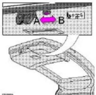
Diagram showing car seatbelting with arrows indicating movement, alongside a profile sketch of the head.Center head restraint
The center head restraint can be adjusted according to the passenger's height. The restraint should be carefully adjusted to support the occupant's head.
To raise: Pull straight up
To lower: Pull forward and push down
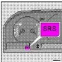
pg. 4 Volvo SRS

natural_image
Top-down view of a car steering wheel (no text or symbols visible)
Passenger side SRS hatch
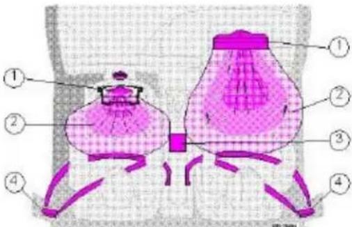
As an enhancement to the three-point seat belt system, your Volvo is equipped with a Supplemental Restraint System (SRS). The Volvo SRS consists of an airbag (2) on both the driver's and passenger's sides and seat belt tensioners in both front door pillars (4). The system is designed to supplement the protection provided by the three-point seat belt system.
The SRS system is indicated by the "SRS" embossed on the steering wheel pad and above the glove compartment, and by decals on both sun visors and on the far right side of the dash.
The airbags are folded and located in the steering wheel hub and above the glove compartment. They are designed to deploy during certain frontal or front-angular collisions, impacts, or decelerations, depending on the crash severity, angle, speed and object impacted. The airbags may also deploy in certain non-frontal collisions where rapid deceleration occurs.
The airbag system includes gas generators (1) surrounded by the airbags (2) and front seat belt tensioners for both of the front seats (4). To deploy the system, the sensor (3) activates the gas generators causing the airbags to be inflated with nitrogen gas. As the movement of the seats' occupants compresses the airbags, some of the gas is expelled at a controlled rate to provide better cushioning. Both seat belt tensioners also deploy, minimizing any seat belt slack.
text_image
Diagram of a hair follicle with numbered parts labeled 1 to 4, showing internal structure and hair follicles.The entire process, including inflation and deflation of the airbags, takes approximately two-tenths of a second.
WARNING!
- As its name implies, SRS is designed to be a SUPPLEMENT to - not a replacement for - the three-point belt system. For maximum protection, wear seat belts at all times. Be aware that no system can prevent all possible injuries that may occur in an accident.
- When installing any optional equipment, make sure that the SRS system is not damaged. Do not attempt to service any component of the SRS yourself. Attempting to do so may result in serious personal injury. If a problem arises, take your car to the nearest authorized Volvo retailer for inspection as soon as possible.
pg. 5 Volvo SRS
text_image
SRS 2A self-diagnostic system incorporated in the sensor monitors the SRS. If a fault is detected, the "SRS" warning light will illuminate. The light is included in the warning/indicator light cluster in the instrument panel. Normally, the SRS warning lamp should light up when the ignition is switched on and should go out after 5 seconds or when the engine is started. Check that this light is functioning properly every time the car is started.
The following items are monitored by the self-diagnostic system:
- Sensor unit
· Cable harness
· Gas generator igniters
WARNING!
Never drive an SRS equipped car with your hands on the steering wheel pad / airbag housing.
No objects, accessory equipment or stickers may be placed on, attached to or installed near the SRS cover in the center of the steering wheel, the SRS cover above the glove compartment or the area affected by airbag deployment.
If the SRS warning light stays on after the engine has started or if it comes on while you are driving, drive the car to the nearest authorized Volvo retailer for inspection as soon as possible.
text_image
XKOKO GLICE BELTIC M4p 4.0m FELI 13 HUBA COT WALSHAO WALSHAO WALSHAO WALSHAOThe above is a sample of the label found on all seat belts equipped with tensioners, located on the front seat belts near the lower anchorage point.

text_image
ATTENTION! THE POSTS 1. The POSTS 2. The POSTS 3. The POSTS 4. The POSTS 5. The POSTS 6. The POSTS 7. The POSTS 8. The POSTS 9. The POSTS 10. The POSTS 11. The POSTS 12. The POSTS 13. The POSTS 14. The POSTS 15. The POSTS 16. The POSTS 17. The POSTS 18. The POSTS 19. The POSTS 20. The POSTS 21. The POSTS 22. The POSTS 23. The POSTS 24. The POSTS 25. The POSTS 26. The POSTS 27. The POSTS 28. The POSTS 29. The POSTS 30. The POSTS 31. The POSTS 32. The POSTS 33. The POSTS 34. The POSTS 35. The POSTS 36. The POSTS 37. The POSTS 38. The POSTS 39. The POSTS 40. The POSTS 41. The POSTS 42. The POSTS 43. The POSTS 44. The POSTS 45. The POSTS 46. The POSTS 47. The POSTS 48. The POSTS 49. The POSTS 50. The POSTS 51. The POSTS 52. The POSTS 53. The POSTS 54. The POSTS 55. The POSTS 56. The POSTS 57. The POSTS 58. The POSTS 59. The POSTS 60. The POSTSThe above is a sample of the decal which can be found on the driver's door pillar.
There is no maintenance to perform on the SRS yourself. The month and year shown on the decal on the door pillar indicate when you should contact your Volvo retailer for specific servicing or replacement of airbags and seatbelt tensioners. This service must be performed by an authorized Volvo retailer.
Should you have any questions about the SRS system, please contact
your authorized Volvo retailer or Volvo Customer Support:
Customer Relations
In the USA: In Canada:
Volvo Cars of North America Volvo Canada Ltd.
175 Gordon Baker Road
P.O. Box 914 Willowdale, Ontario M2H 2N7
Rockleigh, New Jersey 07647-0914 800-663-8255
800-458-1552
pg. 6 Volvo SRS
text_image
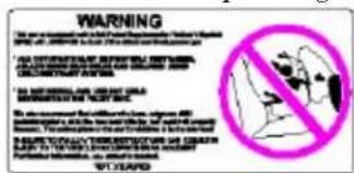
WARNING DISATE OR MEROUS BEAUTY ON OCCUP * CHINA 12 countries' rights reserved on a bag * THE BACK, SRAVIT IS THE SAFETY piece for making * PAPAYI get something could need to be the * Will be sure as possible from the or bag * SWITCH ON BARRY SLAHS AND CHILD'S BEAUTY'S WHOLE!SRS texts on inside of both sun visors
text_image
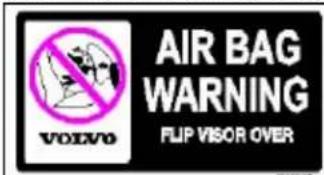
AIR BAG WARNING FLIP VISOR OVERSRS texts on outside of both sun visors
text_image
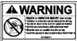
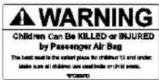
WARNING Children Can Be KILLED or INJURED by Passenger Air Bag The best seat is the earliest place for children 12 and under. Made sure all children are used before or child seats.SRS texts on the passenger's dash
text_image
WARNING • The first warning is to prevent the death of a child. • All other things are not allowed to prevent the death. • The information is provided by the WHO, WHO, WHO, WHO, WHO, WHO, WHO, WHO, WHO, WHO, WHO, WHO, WHO, WHO, WHO, WHO, WHO, WHO, WHO, WHO, WHO, WHO, WHO, WHO, WHO, WHO, WHO, WHO, WHO, WHO, WHO, WHO, WHO, WHO, WHO, WHO, WHO, WHO, WHO, WHO, WHO, WHO, WHO, WHO, WHO, WHO, WHO, WHO, WHO, WHO, WHO, • The information is provided by the WHO. • The information is provided by the WHO. • The information is provided by the WHO. • The information is provided by the WHO. • The information is provided by the WHO. • The information is provided by the WHO. • The information is provided by the WHO. • The information is provided by the WHO. • The information is provided by the WHO. • The information is provided by the WHO. • The information is provided by the WHO.SRS text at far right of instrument panel
WARNING!
Do not use child safety seats or child booster cushions/backrests in the front passenger's seat. We also recommend that children who have outgrown these devices sit in the rear seat with the seat belt properly fastened.
NOTE: Deployment of SRS components occurs only one time during an accident. In a collision where deployment occurs, the air bags and seat belt tensioners activate. Some noise occurs and a small amount of powder is released. The
release of the powder may appear as smoke-like matter. This is a normal characteristic and does not indicate fire.
NOTE: NOTE: Volvo's dual-threshold air bags use special sensors that are integrated with the front seat buckles. The point at which the air bag deploys is determined by whether or not the seat belt is being used, as well as, the severity of the collision. Collisions can occur where only one of the airbags deploys.
WARNING!
- Children must never be allowed in the front passenger seat. Volvo recommends that ALL occupants (adults and children) shorter than 4 feet 7 inches (140 cm) be seated in the back seat of any vehicle with a front passenger side airbag. See page 12 for guidelines.
· Occupants in the front passenger's seat must never sit on the edge of the seat, sit leaning toward the instrument panel or otherwise sit out of position. The occupant's back must be as upright as comfort allows and be against the seat back with the seat belt properly fastened. - Feet must be on the floor, e.g. not on the dash, seat or out of the window.
- No objects or accessory equipment, e.g. dash covers, may be placed on, attached to or installed near the SRS hatch (the area above the glove compartment) or the area affected by airbag deployment (see illustration).
- There should be no loose articles, e.g. coffee cups, on the floor, seat or dash area.
· Never try to open the SRS cover on the steering wheel or the passenger side SRS seam. This should only be done by an authorized Volvo service technician. - Failure to follow these instructions can result in injury to the vehicle occupants in an accident.
pg. 7 Volvo SRS
NOTE: The information on this page does not pertain to the Side Impact Protection System airbags.
When are the airbags deployed? The SRS system is designed to deploy during certain frontal or frontangular collisions, impacts, or decelerations, depending on the crash severity, angle, speed and object impacted. The SRS sensor is designed to react to both the impact of the collision and the inertial forces generated by it and to determine if the intensity of the collision is sufficient for the airbags to be deployed.
WARNING!
The SRS is designed to help prevent serious injury. Deployment occurs very quickly and with considerable force. During normal deployment and depending on variables such as seating position, one may experience abrasions, bruises, swellings, or other injuries as a result of airbag(s) deployment.
If the airbags have been deployed, we recommend the following:
· Have the car towed to an authorized Volvo retailer. Never drive with the airbags deployed.
- Have an authorized Volvo retailer replace the SRS system components.
- Use only new, Genuine Volvo Parts when replacing SRS components (airbags, seat belts, tensioners, etc.).
When are the airbags NOT deployed?
Not all frontal collisions activate the SRS system. If the collision involves a nonrigid object (e.g., a snow drift or bush), or a rigid, fixed object at a low speed, the SRS system will not necessarily deploy. Front airbags do not normally deploy in a side impact collision, in a collision from the rear or in a rollover situation. The amount of damage to the bodywork does not reliably indicate if the airbags should have deployed or not.
Seat belts the heart of the Volvo safety system
The heart of the Volvo safety system is the threepoint seat belt (a Volvo invention)! In order for the SRS system to provide the protection intended, seat belts must be worn at all times by everyone in the car.
The SRS system is a supplement to the seat belts.
WARNING!
If your car has been subjected to flood conditions (e.g. soaked carpeting/standing water on the floor of the vehicle) or if your car has become flooddamaged in any way, do not attempt to start the vehicle or put the key in the ignition before disconnecting the battery (see below). This may cause airbag deployment which could result in personal injury. Have the car towed to an authorized Volvo retailer for repairs.
Automatic transmission only:
Before attempting to tow the car, use the following procedure to override the shiftlock system to move the gear selector to the neutral position.
Disconnect the battery
Wait at least one minute
Insert the key in the ignition and turn it to position 1
Press firmly on the shiftlock override button (located near the base of the gear selector).
While holding the override button down, move the gear selector from the park position.
WARNING!
Never drive with the airbags deployed. The fact that they hang out can impair the steering of your car. Other safety systems can also be damaged. The smoke and dust formed when the airbags are deployed can cause skin and eye irritation in the event of prolonged exposure.
pg. 8 Volvo Side Impact Protection System (SIPS) airbag

text_image
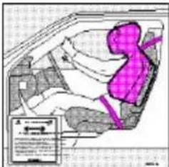
Diagram of a road intersection with numbered components, highlighting a highlighted section with pink overlay.1 - Airbag, 2 - cable, 3 - sensor unit,
SIPS airbag
As an enhancement to the structural Side Impact Protection System built into your car, the car is also equipped with Side Impact Protection System (SIPS) airbags. The SIPS airbag system consists of airbag modules built into the sides of both front seat backrests (1), cables (2) from these modules to the electronic sensor units (3).
The SIPS airbag system is designed to help increase occupant protection in the event of certain side impact collisions. The SIPS airbags are designed to deploy only during certain sideimpact collisions, depending on the crash severity, angle, speed and point of impact. The airbags are not designed to deploy in all side impact situations.
NOTE: SIPS airbag deployment (one airbag) occurs only on the side of the vehicle affected by the impact.
WARNING!
- The SIPS airbag system is a supplement to the Side Impact Protection System and the threepoint seat belt system. It is not designed to deploy during collisions from the front or rear of the car or in rollover situations.
The use of seat covers on the front seats may impede SIPS airbag deployment.
- No objects, accessory equipment or stickers may be placed on, attached to or installed near, the SIPS airbag system or in the area affected by SIPS airbag deployment (see illustration to the right above).
- Never try to open or repair any components of the SIPS airbag system. This should only be done by an authorized Volvo service technician.
- For best protection from the SIPS airbag system, both front seat occupants should sit in an upright position with the seat belt properly fastened.
natural_image
Interior view of a car showing a highlighted purple object inside the dashboard (no text or symbols visible)SIPS airbag decal
WARNING!
· Never drive with the airbags deployed. The fact that they hang out can impair the steering of your car. Other safety systems can also be damaged. The smoke and dust formed when the airbags are deployed can cause skin and eye irritation in the event of prolonged exposure.
· If your car has been subjected to flood conditions (e.g. soaked carpeting/standing water on the floor of the vehicle) or if your car has become flooddamaged in any way, do not attempt to start the vehicle or put the key in the ignition before disconnecting the battery. This may cause airbag deployment which could result in personal injury. Have the car towed to an authorized Volvo retailer for repairs.
pg. 9 Whiplash Protection System (WHIPS)
natural_image
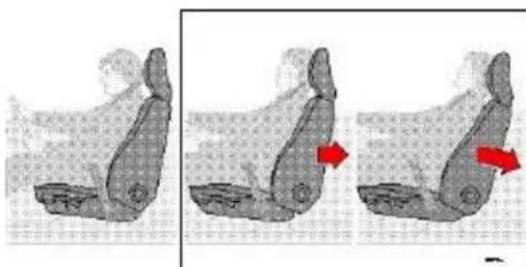
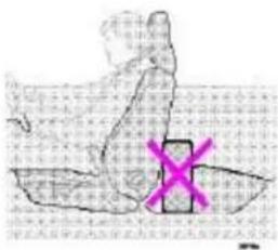
Three-step illustration of a car seat with red arrows indicating motion direction (no text or symbols)Whiplash Protection System (WHIPS) - front seats only
The WHIPS system consists of specially designed hinges and brackets on the front seat backrests and head restraints designed to help absorb some of the energy generated in a collision from the rear ("rear-ended").
In the event of a collision of this type, the hinges and brackets of the front seat backrests are designed to change position slightly to allow the backrest/head restraint to help support the occupant's head before moving slightly rearward. This movement helps absorb some of the forces that could result in the whiplash effect.
text_image
Handwritten Chinese text with a pink 'X' symbol overlaying the image, likely indicating a placeholder or error message.Do not wedge boxes, suitcases, etc. behind front seats
WARNING!
- Boxes, suitcases, etc. wedged behind the front seats (see illustration above) could impede the function of the WHIPS system.
· The WHIPS system is designed to supplement the other safety systems in your car. For this system to function properly, the three-point seat belt must be worn. Please be aware that no system can prevent all possible injuries that may occur in an accident. - If your car has been involved in a collision, the front seat backrests must be inspected by an authorized Volvo retailer even if the seats appear to be undamaged. Certain components in the WHIPS system may need to be replaced. Do not attempt to service any component in the WHIPS system yourself.
- If the rear seat backrests are folded down, cargo must be secured to prevent it from sliding forward against the front seat backrests in the event of a collision from the rear. This could interfere with the action of the WHIPS system.
- The WHIPS system is designed to function in certain collisions from the rear, depending on the crash severity, angle and speed.
· Occupants in the front seats must never sit out of position. The occupant's back must be as upright as comfort allows and be against the seat back with the seat belt properly fastened.

Contents | Top of Page
2000 VOLVO S & V70
Chapter 2 - Instruments, switches and controls
pg. 18 Instruments, switches and controls

text_image
Technical diagram of a car dashboard with numbered parts for identification and assembly reference.
text_image
Technical diagram of a vehicle or enclosure with numbered components and labeled partspg. 19 Instruments, switches and controls
The pages in this section provide detailed descriptions of the vehicle's instruments and controls. Note that vehicles may be equipped differently, depending on special legal requirements.
Page
1 Air vents 37
2 Headlights, parking lights 24
3 Instrument illumination 26
4 Rear fog light 26
5 Front fog lights (optional) 26
6 Space for additional equipment
7 Space for additional equipment
8 Instruments 19-20
9 TRACS/STC (optional) 27
10 Trip computer (optional) 30-32
11 Electrically operated sun roof (optional) 54
12 Rear window demister/heated door mirrors 27
13 Air mix 37
14 Air vents 37
15 Passenger side air bag (SRS) hatch 4-6
16 Air vents 37
17 Hood release 55
18 Turn signals, high/low beams/exterior courtesy lights 24
Cruise control 33
19 Adjustable steering wheel 36
20 Windshield wiper/washer 25
Tailgate wiper/washer (wagons) 28
21 Heated front seats (optional) 34
22 Auxiliary socket 35
23 Audio systems 141
24 Heating and ventilation controls 37-41
25 Hazard warning flashers 27
26 Ashtray 35
27 Coin holder
28 Shiftlock release button (automatic transmission only) 110
29 Gear selector shift positions 72-76
30 Winter mode selector 74,76
31 Parking brake 34
32 Horn/SRS 4-7
33 Trunk/tailgate open control 49
34 Power window controls 42
35 Power mirror controls 52
36 Fuel tank open control 69
37 Central locking button 45
Some of the items listed on this page are available on certain models only.
pg. 20 Instruments

text_image
1 2 3 4 5 6 7 81 Fuel gauge
Fuel tank capacity:
18 US gal. (68 liters) - Front Wheel Drive
17.4 US gal (66 liters) - All Wheel Drive When the warning light comes on there is approximately 1.8 US gal. (8 liters) of fuel remaining. See "Refueling" for additional information.
2 Temperature gauge
Do not drive the car with the pointer in the red range. The pointer should be approximately midway on the gauge face when driving. If the pointer approaches the red range repeatedly, check coolant level.
3 Speedometer
4 Clock, ambient temperature sensor, trip computer (certain models)
5 Trip odometer
Used for measuring shorter distances. The last digit indicates 1/10 mile/kilometer.
6 Odometer
7 Trip odometer reset button
8 Tachometer
Reads thousands of engine rpm. Do not drive for long with the needle in the red section. The engine has an inbuilt function preventing too high a rotation speed. When this function operates, you may discern some pulsation, which in that case is quite normal.
NOTE: Digital displays showing Clock, Trip Odometer and Odometer will go off 30 minutes after the ignition has been switched off. To view these displays again, turn the ignition key to position I.
pg. 21 Indicator and warning lights

text_image
1 2 3 4 5 6 7 8 9 10 11 12 13 14 15 16 17 18 19 20 21 221 Turn signal, left
2 Turn signal, right
3 Cruise control
4 Low washer fluid level
If the lamp glows continuously when the engine is running, there is only about 1/2 - 1 US qt. remaining in the washer fluid reservoir.
5 Low fuel level
When the lamp glows, only about 1.8 US gals. (8 liters) of fuel remain. If the ignition is switched on while refuelling, the gauge may read inaccurately for up to 45 minutes.
6 Rear fog light
7 High beams
8 Trunk/tailgate open
9 Bulb failure warning sensor
10 (Not in use)
11 Electronic Throttle System (ETS)
12 SRS
13 Generator not charging
14 Low engine oil pressure
15 Brake warning light
16 Parking brake applied
17 ABS-system
18 Transmission mode: Indicates "W" if winter/wet driving mode is active, or indicates currently selected low gear.
19 Low coolant level
20 Traction Control (TRACS)/ Stability and Traction Control (STC) Systems (option)
21 Malfunction indicator lamp
(See page 22 for more information)
22 Service reminder indicator
pg. 22 Warning lights
The warning lights described on pages 20 and 21 should never stay on when driving
When the ignition key is turned on and before the engine starts, all of the warning lights should go on to test the function of the bulbs. Should a light not go off after the engine has started, the system indicated should be inspected. However, the parking brake reminder light will not go off until the parking brake has been fully released.

Supplemental Restraint System (SRS)
If the light comes on (or stays on after the vehicle has started), the SRS diagnostic system has detected a fault. Drive to an authorized Volvo retailer for an inspection of the system. See the SRS section for more information.

Malfunction indicator lamp
If the lamp comes on (or stays on after the vehicle has started), the engine diagnostic system has detected a possible fault in the emission control system. Although driveability may not be affected, see an authorized Volvo retailer as soon as possible for inspection.
NOTE: If the fuel filler cap is not closed tightly or if the engine is running when the car is refueled, the Malfunction Indicator Lamp may indicate a fault. However, your vehicle's performance will not be affected. Use only Volvo original or approved fuel filler caps.

Oil pressure warning light
If the light comes on while driving, stop the car and then stop the engine immediately and check the engine oil level. See page 124. If the light stays on after restart, have the car towed to the nearest authorized Volvo retailer. After hard driving, the light may come on occasionally when the engine is idling. This is normal, provided it goes off when the engine speed is increased.

Parking brake reminder light
This light will be on when the parking brake (hand brake) is applied. The parking brake lever is situated between the front seats.
Canadian models are equipped with this warning light:


Cruise Control
This light will be on when cruise control is engaged. Cruise control will automatically disengage when the ignition is switched off.

Brake failure warning light
If the light comes on while driving or braking, stop immediately, open the hood and check the brake fluid level in the reservoir. See page 131 for reservoir position.
Canadian models are equipped with this warning light:

WARNING!
If the fluid level is below the MIN mark in either section of the reservoir: DO NOT DRIVE. Tow the car to a Volvo retailer and have the brake system checked and any leakage repaired.

Fault in ETC (Electronic Throttle Control system)
If this lamp comes on, there is a fault in the engine control system and driveability will be affected. Switch the ignition off and then on again. If the light remains on, the system should be inspected by an authorized Volvo retailer.
pg. 23 Warning lights

TRACS disengaged (option)
If the TRACS (TRAction Control System) is manually disengaged with the switch on the dashboard (see page 27), the warning light will come on. This will also come on to indicate a TRACS malfunction, and when the brakes overheat, although it goes out again at the normal temperature level. If the lamp remains on, the system should be checked by an authorized Volvo retailer. This lamp should not be confused with the ON/OFF indicator lamp above the switch.

STC disengaged (option)
The indicator light () in the instrument panel will be ON when you have switched the Stability and Traction Control system (STC) OFF using the button on the dashboard (see page 25). The light will also come on if there is a fault in the STC system or to indicate that the brakes have overheated. The light will go out when the brake temperature returns to normal.
The symbol will flash when STC is actively regulating power to the drive wheels. Normal power may be reduced at this time. This is normal as power is momentarily reduced to help keep the drive wheels from losing traction and spinning.

Coolant level sensor
If this light comes on while driving, the coolant level is low. The coolant level in the expansion tank should be checked immediately and topped up if necessary. The cooling system should be inspected by an authorized Volvo retailer.

Mode "W" engaged
The lamp will light up when the Winter/Wet starting mode is engaged or if gears "4-1" or "L" are selected.
If the warning lamp begins to flash, this means that there is a fault in the automatic gearbox. Contact Your Volvo
retailer.

Generator warning light
If the light comes on while the engine is running, have the charging system checked.

Service reminder indicator
This light will come on at 7,500 mile (12,000 km) intervals, after 750 hours of driving or after 12 months, whichever occurs first. It is a reminder to the driver that the service interval has been exceeded. The light will stay on for 2 minutes after start until reset by the servicing retailer.

Bulb failure warning light
The light will come on if any of the following bulbs are defective:
· one of the low beam headlights
- one of the tail lights
- one of the brake lights when the brake pedal is depressed.
Check the fuse and bulb. See sections "Replacing bulbs" and "fuses."
Should the warning light come on after a defective outside bulb has been replaced, the corresponding bulb on the other side of the car should also be replaced.

Anti-lock Brake system (ABS)
If the warning lamp lights up there is a malfunction of the ABS system (the standard braking system will however function). The vehicle should be driven to a Volvo retailer for inspection.
See page 83 for additional information.
Canadian models are equipped with this warning light:

pg. 24 Headlights, Parking lights, Exterior courtesy lights, Turn signals
Headlights and parking lights
○ All lights off *
Parking lights on *
Headlights and parking lights are on if starting (ignition) switch is in positions I or II.
If the headlight switch is in the position all lights will go out when the starting switch is switched off.
With the headlight switch in position the parking lights will stay on (headlights off) with the daytime running light
screw (A) in position □
The high beams can only be switched on if the headlight switch is in position

Switch from high to low beams and vice versa by moving the turn signal switch lever on the left side of steering column towards the steering wheel.
* See page 26 for information on Daytime running lights.
Exterior courtesy lights
When you leave your car at night, you can make use of the exterior courtesy lighting function:
- Remove the key from the ignition switch.
- Pull the direction indicator lever towards the steering wheel (as when using the headlight flasher function).
The low beam headlights will now remain on for 30 seconds to light your way.

natural_image
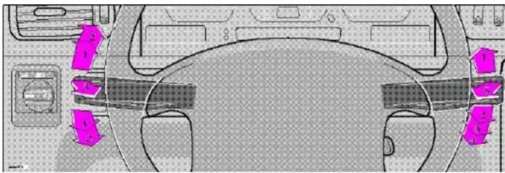
Top-down view of a car interior with visible seats, dashboard, and steering wheel (no text or symbols)Turn signals
1 Lane change position. In maneuvers such as lane changing, the driver can flash the turn signals by moving the turn signal lever to the first stop and holding it there. The lever will return to the neutral position when released.
2 Signal lever engaged for normal turns.
3 High beam/low beam switch (headlights on).
Move the lever towards the steering wheel and release it.
Headlight flasher (headlights off).
Move the lever towards the steering wheel. The headlight high beam will be on until the lever is released.
NOTE: A defective turn signal bulb will cause the turn signal indicator and remaining signal lights to flash more rapidly than normal.
pg. 25 Windshield wipers/washers, Ignition switch/steering wheel lock

natural_image
Top-down view of a car interior with highlighted dashboard and steering wheel (no text or symbols)Windshield wipers/washers
1 Intermittent wiper
With the switch in this position, the wipers will sweep approximately every seventh second.
2 "Single sweep" position:
The switch returns automatically when released.
3 Wipers, normal speed
4 Wipers, high speed
5 Windshield wiper/washer, headlight wiper/washer (certain models)
The wipers will make 23 sweeps across the windshield and headlights (certain models) after the lever is released.
O Locked position:
Remove the key to lock the steering wheel*
WARNING! Never turn the key to position O while driving or when the car is being towed.
I Intermediate position:
Certain accessories, radio, etc. on, daytime running lights off.
II Drive position:
Key position when engine is running.
III Starting position:
Release the key when the engine starts. The key returns automatically to the Drive position.
* On cars equipped with an automatic transmission the gear selector must also be in the (P)ark position.
Starting (ignition) switch/steering wheel lock
If you find it difficult to insert the key in the ignition or to move the steering wheel, the steering wheel lock might be under tension. Turn the wheel back and forth slightly to free the ignition key.
In order to reduce car theft, make sure the steering wheel locks before leaving the car.
A chime will sound if the starting key is left in the ignition lock and the front door on the driver's side is opened.
pg. 26 Instrument illumination, Fog lights
1 - Instrument illumination
To increase the brightness: move the thumbwheel up.
To decrease the brightness: move the thumbwheel down.
2 - Rear fog light *
The rear fog light (located in the driver's side tail light cluster) is considerably brighter than the normal tail lights and should be used only when the atmospheric conditions, such as fog, rain, snow, smoke or dust reduce the daytime or nighttime visibility of other vehicles to less than 500 ft (150 meters).
For the rear fog light to function, the low beam headlights must be switched on.
* By design, there is one rear fog light only, located in the driver's side tail light cluster.
3 - Front fog lights (option)
The front fog lights, located in the front spoiler, will only function in combination with the low beam headlights.
4 - Space for optional equipment
5 - Space for optional equipment

text_image
1 2 3 4 5 6 7 8 9
Contents | Top of Page
2000
VOLVO
S & V70
Chapter 3 - Body and interior
pg. 43 Body and interior
The seats, sun roof, mirrors, etc. are described on the following pages.
Keys 44
Doors and locks 45
Remote keyless entry system 46
Alarm 47
Trunk/tailgate 49
Child safety locks 50
Front seats 51-52
Rear/side view mirrors 52
Interior lights, Vanity mirror 53
Sun roof 54
Hood 55
Storage compartments 56
Trunk light, Spare tire, Jack 57
Cargo space lighting, Spare tire, Jack (wagon) 58
Folding rear seat (sedan) 59
Folding rear seat (wagon) 60-61
Removing seat cushions 61
Concealed storage bin/Bumper cover (wagon), Avoiding battery drain 62
Luggage net/Side cargo net (wagon) 63
Securing cargo 64
Folding front seat, Long load storage 65
pg. 44 Keys
text_image
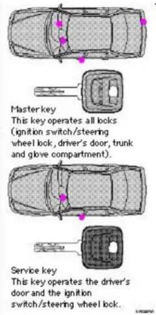
Masterkey This key operates all locks (ignition switch/steering wheel lock, driver's door, trunk and glove compartment). Service key This key operates the driver's door and the ignition switch/steering wheel lock.NOTE:
- As an added anti-theft measure, new keys have been developed which may take slightly longer to copy or replace if the original keys are misplaced. Duplicate keys may be ordered from your Volvo retailer.
- The key number codes are stamped on a separate tag supplied with the keys. This tag should be separated from the key ring and kept in a safe place.
Immobilizer (start inhibitor)
Each of the keys supplied with your car contains a coded transmitter and receiver (transponder). The code in the key is transmitted to an antenna in the ignition switch where it is compared to the code stored in the start inhibitor module. The car can only be started if a properly coded key is used.
If you misplace a key, take the other keys to an authorized Volvo retailer. The existing code in the start inhibitor module and all the keys will be erased as an antitheft measure and a new code will be programmed in.
NOTE:
Not more than one of the keys for your car should be kept on the same key ring. This could cause conflicting signals to be transmitted to the ignition switch, making it impossible to start the car.
This device complies with part 15 of the FCC rules. Operation is subject to the following condition: (1) This device may not cause harmful interference, and (2) this device must accept any interference received, including interference that may cause undesired operation.
pg. 45 Doors and locks
Doors and locks
Your car is equipped with a central locking system.
The key, used on the driver's door, the remote control, or central locking button, will lock/unlock all doors, trunk/tailgate.
Turn the key once to unlock the driver's door only.
Turn the key again (within 10 seconds) to unlock all doors, trunk/tailgate.
One turn with the key towards lock in the drivers door locks all doors, trunk/tailgate.
Use the switch on the front door armrests to lock/unlock the car from the inside.
Check the action of the buttons on the other doors to verify their correct function (lock/ unlock).
WARNING!
If the doors are locked while driving, this may hinder rapid access to the occupants of the car in the event of an accident. (Also see information on "Child safety locks").
natural_image
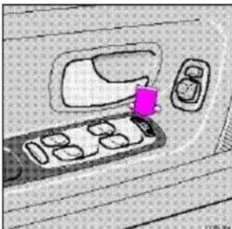
Interior view of a car showing the dashboard with a pink object inserted, no visible text or symbolsCentral locking button (on both front doors)
Central locking button
The central locking buttons on both front door armrests can be used to lock or unlock all doors and trunk/tailgate and set the alarm if your car is so equipped. This switch functions even if a door/trunk/tailgate is open.
Lock: Press the left side of the button.
Unlock: Press the right side of the button.
Note: To help prevent accidentally locking the keys in the car, the central locking system is designed to unlock the driver's door immediately if the key is left in the ignition switch and the car is locked using the lock button on the door. A sound from the lock will be audible at this time.
Please note that this function will not unlock the doors if the engine is running.
pg. 46 Remote keyless entry system

natural_image
Illustration of a car and a hand holding a remote control device, with an inset showing a hand holding a vehicle (no text or symbols present)Remote keyless entry system
Your car is equipped with a remote control transmitter. This transmitter uses a radio frequency which will allow "keyless" entry into the passenger compartment or the trunk. You will be supplied with two coded key ring transmitters, which will enable you to lock/unlock all doors and the trunk/tailgate from a distance of 10-15 feet (3-5 meters).
On vehicles equipped with an alarm, the alarm will also be activated/deactivated by this system.
The car can also be locked/unlocked with the key.
As an extra security precaution in certain situations (valet parking, etc.), Volvo recommends that the transmitter not be included when the keys are given to anyone. The service key can be used instead. If one of the transmitters is misplaced, contact the nearest authorized Volvo retailer for assistance.

text_image
Unlock Open trunk / tailgate LockUsing the remote control
- Press the LOCK button once to lock all doors and trunk/tailgate.
- Press the UNLOCK button once to unlock the driver's door only. Press this button again (within 10 seconds) to unlock all doors, trunk/tailgate.
- Press the OPEN trunk/tailgate button twice within 3 seconds to pop open the trunk or unlock the tailgate. NOTE: To avoid leaving your keys in the car, make a habit of always locking the car with the remote control. This device complies with FCC rules Part 15. Operation is subject to the following two conditions: (1) This device may not cause harmful interference and (2) this device must accept any interference that may be received, including interference that may cause undesired operation.
NOTE: If only the driver's door is unlocked, the lock will automatically reengage (re-lock) and the alarm will reset after 2 minutes unless the door has been opened.
The lock/unlock and alarm features can also be utilized by using the keys. See section: Doors and Locks on page 45.
If the alarm LED glows continuously for 5 seconds, this indicates a fault in the system or that a door is not properly closed.
WARNING!
Volvo does not recommend using the transmitter to lock the doors from inside the car. On cars equipped with an alarm, the alarm would be activated and would sound when one of the doors is opened. The doors must not be locked using the remote transmitter while the vehicle is occupied. In case of an accident, this may hinder rapid access to the occupants of the vehicle. The alarm will also sound on models equipped with this feature.
pg. 47 Alarm (certain models)
text_image
Diagram illustrating a device with a magnified view of its internal structure, labeled with Chinese text and a page number.LED alarm status indicator
Alarm
The radio signal emitted from the transmitter, which is used to set/unset the alarm, is a "rolling code" signal. This means that the signal is changed randomly for each transmission and is intended to help prevent unauthorized recording of the code.
When armed (set), the alarm continuously monitors a number of points on the car. The following conditions will set off the alarm:
· The hood is opened
· The trunk/tailgate is opened
· A door is opened
· The ignition switch is tampered with
· The car is lifted or towed (if the car is equipped with the optional inclination sensor)
- The battery is disconnected (if the car is equipped with the optional backup battery siren). The alarm will sound for ten 30 second intervals, with a 5 second pause between intervals. This function cannot be interrupted.
Arming (setting) the alarm
Press the LOCK button on the remote control, lock the car using the key in the driver's door or press the central lock button on one of the front doors with the door open. One long flash of the turn signals will confirm that the alarm is set.
Disarming the alarm
Press the UNLOCK button on the remote control or unlock the doors with the key.
Turning off (stopping) the alarm
If the alarm is sounding, it can be stopped by pressing the UNLOCK button on the remote control or by unlocking the driver's door with the key.
If the alarm is stopped with the remote control, this will be confirmed by two short flashes from the turn signals.
Visual alarm signal
The visual alarm signal is given by flashing all turn signals and turning on the interior lighting for approximately 5 minutes.
Audible alarm signal
An audible alarm signal is given either by a separate alarm horn or by the optional back-up siren. One alarm cycle lasts for 30 seconds.

"Panic" function
In an emergency situation, this feature can be used to attract attention.
Activate the "panic" function by pressing the red panic button on the remote control for at least 3 seconds or by pressing this button twice within 3 seconds. The turn signals will flash, the interior lights will go on and the alarm will sound.
The function can be turned off by pressing any of the buttons on the remote control or will stop automatically after 25 seconds.
NOTE: This button will NOT unlock the car.
pg. 48 Alarm
LED alarm status signals
The status of the alarm system is indicated by the red LED at the top center of the dash:
- LED off - the alarm is not armed (set)
- LED flashes once per second - the alarm is armed (set)
· LED flashes rapidly before the ignition is switched on - the alarm has been triggered - LED flashes rapidly for 15 seconds after the ignition has been switched on - a fault has been detected in the alarm system. Contact a Volvo retailer.
Automatic reset function
If only the driver's door is unlocked with the remote control, the lock will automatically reengage (re-lock) and the alarm will reset after 2 minutes unless the door has been opened.
Temporarily disconnecting the alarm sensor(s)
In certain situations it may be desirable to disconnect the optional alarm sensors, particularly the inclination sensor, if, for example, you drive your car onto a ferry where the rocking of the boat could trigger the alarm.
To temporarily disconnect the sensor(s) from the alarm system:
- With all doors closed, switch off the ignition and remove the key from the ignition switch
- Press the locking (left) side of the central locking button on the driver's door for at least 3 seconds
· The doors will first lock and then unlock after 3 seconds to confirm that the sensors have been disconnected
The car can then be locked in the usual way to set the alarm.
NOTE: The sensors will automatically be reconnected to the alarm system the next time the ignition is switched on.
natural_image
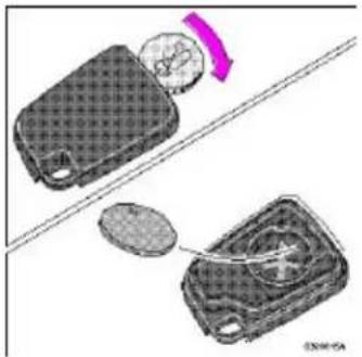
Diagram showing two 3D objects with patterns and a curved arrow, no text or symbols presentBatteries
Each remote transmitter is powered by a three-volt battery, type CR 2016. If the range of the transmitter is noticeably reduced, this indicates that the battery is weak and should be replaced.
Replacement: Remove the battery cover on the back of the transmitter with a coin. Replace the battery. Reinstall the cover, making sure it is secured tightly to help protect the transmitter.
CAUTION: Do not attempt to service or repair any components of the alarm system yourself. This should only be done by an authorized Volvo retailer.
pg. 49 Trunk/Tailgate
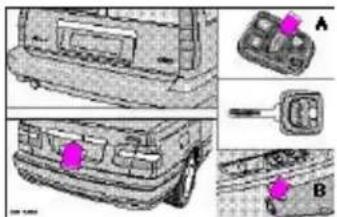
text_image
Technical diagram of a vehicle rear bumper with labeled parts A and B, showing internal components and highlighted areas.Unlocking the trunk/tailgate
The trunk/tailgate locks are incorporated in the central locking system and are locked or unlocked when the driver's door is locked/unlocked.
The trunk can be unlocked by:
- Pressing the button on the remote control (A) twice
· Using the master key in the trunk - Using the trunk/tailgate control on the driver's door (B)
Refer to page 44 for information on the remote control locking system.
Disconnecting the trunk lock
The trunk lock can also be disconnected from the central locking system by turning the key counterclocKwise as shown below:
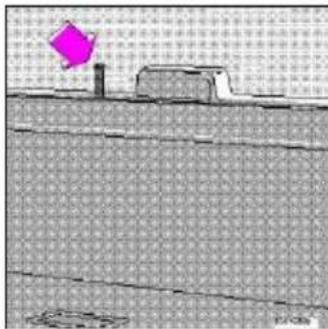
natural_image
Simple line drawing of a building with a pink diamond-shaped object on top, set against a grid background (no text or symbols)Withdraw the key in the horizontal position ***
The trunk is now always locked. The optional folding rear seatback can also be locked from the trunk (see page 57). This feature can be used for e.g., valet parking. If you give only the service key to the driver, it will not be possible to gain access to the trunk. Please be aware that this setting may preclude access to the spare tire and jack.
To reconnect the lock to the central locking system:

Withdraw the key in the vertical position
*** In this position, the trunk cannot be opened with the control on the driver's door or the remote control.

Unlocking tailgate from the inside
Tailgate lock button
If the doors and tailgate are locked, the tailgate can be unlocked from the inside by pulling up the lock button (see illustration). This unlocks the tailgate only. Please note that this button will only function if the child safety lock in the tailgate is disengaged (see page 50).
WARNING!
Do not drive with the tailgate open! Poisonous exhaust gases may enter via the open tailgate.
pg. 50 Child safety locks (sedan/wagon)
text_image
A BLocation and setting of child safety lock
Child safety locks (sedan/wagon)
The controls are located on the rear door jambs.
A The door cannot be opened from the inside. Normal operation from the outside.
B The door lock functions normally.
WARNING!
Remember, in the event of an accident, the rear seat passengers cannot open the doors from the inside with the buttons in position A.
text_image
A BChild safety lock in tailgate
Child safety lock (wagon - certain models)
The tailgate incorporates a safety catch which is located to the side of the lock.
A The tailgate cannot be opened from the inside.
B The tailgate functions normally.
NOTE: You must use the end of a key, screwdriver, etc. to move the child safety lock.
WARNING!
Remember, in the event of an accident, the tailgate cannot be opened from the inside when the safety catch is in position A.

Contents | Top of Page
2000 VOLVO S & V70
Chapter 4 - Starting and driving
pg. 67 Starting and driving
This section on starting and driving contains items such as starting the engine, operating the gear selector, towing, trailers, etc.
| Fuel requirements, Refueling 68-69 | — |
| Driving economy 70 | — |
| Starting the engine 71 | — |
| Manual transmission 72 | — |
| Automatic transmission, All Wheel Drive (AWD) 74-77 | |
| Points to remember 78-79 | — |
| Emergency towing 80 | — |
| Vehicle towing information 81 | — |
| Jump starting 82 | — |
| Brake system, ABS 83 | — |
| TRACS/STC 84 | — |
| Winter driving 85 | — |
| Trailer towing 86 | — |
pg. 68 Fuel requirements
NOTE ENGINE OIL:
Although some oil consumption occurs during normal engine operation, more oil is consumed when the engine is new as the internal parts generate higher friction while wearing in to each other. From the time the engine is new until the first service is performed, the oil consumption could be higher than normal. For this reason, it is especially important to check the oil every time you refuel your car during this period. See page 126.
In general, the rate of oil consumption depends on such factors as: engine temperature, length of trip, driving conditions, oil viscosity and quality, engine speed and acceleration/deceleration.
Checking your engine oil level each time the car is refueled is one of the most important items you can perform to help keep your car in good running order.
Deposit control gasoline (detergent additives)
Volvo recommends the use of gasoline containing deposit control additives. These additives have shown to be efficient in keeping injectors and intake valves clean. Consistent use of deposit control gasolines will help ensure good driveability and fuel economy. If you are not sure whether the gasoline contains deposit control additives, check with the service station operator.
Unleaded fuel
Each Volvo has a three-way catalytic converter and must use only unleaded gasoline. U.S. and Canadian regulations require that pumps delivering unleaded gasoline be labelled "UNLEADED". Only these pumps have nozzles which fit your car's filler inlet. It is unlawful to dispense leaded fuel into a vehicle labelled "unleaded gasoline only". Leaded gasoline damages the three-way catalytic converter and the heated oxygen sensor system. Repeated use of leaded gasoline will lessen the effectiveness of the emission control system and could result in loss of emission warranty coverage. State and local vehicle inspection programs will make detection of misfueling easier, possibly resulting in emission test failure for misfueled vehicles.
NOTE: Some U.S. and Canadian gasolines contain an octane enhancing additive called methy-cyclopentadienyl manganese tricarbonyl (MMT). If such fuels are used, your Emission Control System performance may be affected, and the Malfunction Indicator Lamp located on your instrument panel may light. If this occurs, please return your vehicle to an authorized Volvo retailer for service.
pg. 69 Fuel requirements, Refueling
Octane rating
Volvo engines are designed for optimum performance on unleaded premium gasoline with an octane rating. AKI of 91, or above. AKI (ANTI KNOCK INDEX) is an average of the Research Octane Number, RON, and the Motor Octane Number, MON. (RON + MON/2).
The minimum octane requirement is AKI 87 (RON 91).
Gasoline containing alcohol and ethers
"Oxygenated fuels"
Some fuel suppliers sell gasoline containing "oxygenates" which are usually alcohols or ethers. In some areas, state or local laws require that the service pump be marked indicating use of alcohols or ethers. However, there are areas in which the pumps are unmarked. If you are not sure whether there is alcohol or ethers in the gasoline you buy, check with the service station operator. To meet seasonal air quality standards, some areas require the use of "oxygenated" fuel.
Volvo allows the use of the following "oxygenated fuels; however, the octane ratings listed on this page must still be met.
Alcohol — Ethanol
Fuels containing up to 10% ethanol by volume may be used.
Ethanol may also be referred to as Ethyl alcohol, or "Gasohol".
Ethers — MTBE
Fuels containing up to 15% MTBE may be used.
Refueling
The fuel tank is designed to hold approximately:
18 US gal. (68 liters) - Front Wheel Drive
17.4 US gal (66 liters) - All Wheel Drive
with sufficient volume left over to accommodate possible expansion of the fuel in hot weather. Be aware that the "usable" tank capacity will be somewhat less than the specified maximum. When the fuel level is low, such factors as ambient temperature, the fuel's "Reid vapor pressure" characteristics, and terrain can affect the fuel pumps' ability to supply the engine with an adequate supply of fuel. Therefore, it is advisable to refuel as soon as possible when the needle nears the red zone, or when the fuel warning light comes on.
Fuel tank cover
The fuel tank cover (on the right rear fender) is locked and must be popped open using the control on the driver's door.
Open fuel filler cap slowly during hot weather conditions.
CAUTION:
- Do not refuel with the engine running *. Turn the ignition off or to position 1. If the ignition is on, an incorrect reading could occur in the fuel gauge.
- After refueling, close the fuel filler cap by turning it clocK Wise until it clicks into place *.
- Allow for fuel expansion by not overfilling the tank. Overfilling could also cause damage to the emission control systems.
- Avoid spilling gasoline during refueling. Gasolines containing alcohol can cause damage to painted surfaces, which may not be covered under the New Vehicle Limited Warranty.
- Do not use gasolines containing methanol (methyl alcohol, wood alcohol). This practice can result in vehicle performance deterioration and can damage critical parts in the fuel system. Such damage may not be covered under the New Vehicle Limited Warranty.
* If the fuel filler cap is not closed tightly or if the engine is running when the car is refueled, the Malfunction Indicator Lamp may indicate a fault. However, your vehicle's performance will not be affected. Use only Volvo original or approved fuel filler caps.
pg. 70 Driving economy
Economical driving conserves natural resources
Better driving economy may be obtained by thinking ahead, avoiding rapid starts and stops and adjusting the speed of your vehicle to immediate traffic conditions. Observe the following rules:
- Bring the engine to normal operating temperature as soon as possible by driving with a light foot on the accelerator pedal for the first few minutes of operation. A cold engine uses more fuel and is subject to increased wear.
- Whenever possible, avoid using the car for driving short distances. This does not allow the engine to reach normal operating temperature.
- Drive carefully and avoid rapid acceleration and hard braking.
- Do not exceed posted speed limits.
- Avoid carrying unnecessary items (extra load) in the car.
- Maintain correct tire pressure. Check tire pressure regularly (check when tires are cold).
- Remove snow tires when threat of snow or ice has ended.
- Note that roof racks, ski racks, etc., increase air resistance and thereby fuel consumption.
- Avoid using automatic transmission kickdown feature unless necessary.
- Avoid using the air conditioning when it is not required. When engaged, the air conditioner's compressor places an additional load on the engine. However, please note that fuel consumption is lower with the air conditioning on than it is when driving with the air conditioning switched off and the windows down.
- If your car is equipped with the optional Trip Computer, utilizing the fuel consumption modes can help you "learn" how to drive more economically.
Other factors which decrease gas mileage are:
· Worn or dirty spark plugs
- Incorrect spark plug gap
· Dirty air cleaner
- Dirty engine oil and clogged oil filter
· Dragging brakes
· Incorrect front end alignment
Some of the above mentioned items and others are checked at the standard Maintenance Service intervals.
NOTE: (D)rive or 5th gear (manual transmissions) should be used as often as possible to help improve fuel economy.
Before a long distance trip
It is always worthwhile to have your car checked at a Volvo retailer before driving long distances. Your retailer will also be able to supply you with bulbs, fuses, spark plugs and wiper blades for your use in the event that problems occur.
If you prefer to check the car yourself, please note the following:
- Check that engine runs smoothly and that fuel consumption is normal.
- Check engine oil, coolant levels, and for possible fuel leakage.
- Check transmission oil level.
- Check condition of drive belts.
- Check state of charge of battery.
- Examine tires carefully (the spare tire as well), and replace those that are worn. Check tire pressures.
· The brakes, front wheel alignment, and steering gear should be checked by your Volvo retailer only. - Check all lights, including high beams.
· Reflective warning triangles are legal requirement in some countries. - Have a word with your Volvo retailer if you intend to drive in countries where it may be difficult to obtain correct fuel.
- Consider your destination. If you will be driving through an area where snow or ice are likely to occur, consider snow tires.
pg. 71 Starting the engine
Starting and stopping
- Fasten the seat belt.
WARNING!
Before starting, check that the seat, steering wheel and mirrors are adjusted properly. Make sure the brake pedal can be depressed completely. Move the seat closer if necessary. Refer to section "front seats".
- Apply the parking brake, if not already set. The gear selector (automatic transmission) is locked in the (P)ark position (SHIFT LOCK).
Manual transmission: the clutch must be fully depressed.
- Without touching the accelerator pedal, turn the ignition key to the starting position. Allow the starter to operate for up to 5 seconds (turbo: 10 seconds). Release the key as soon as the engine starts. If the engine fails to start, repeat step 3.
For cold starts at altitudes above 6000 ft (1800 meters), depress the accelerator pedal halfway and turn the key to the starting position. Release the pedal slowly when the engine starts.
- To release the gear selector from the (P)ark position (automatic transmission), the ignition key must be in position II and the brake pedal must be depressed. See page 108 for instructions on manually releasing the SHIFTLOCK system.
Do not race a cold engine immediately after starting. Oil flow may not reach some lubrication points fast enough to prevent engine damage.
NOTE: (Automatic transmission only)
Your car is equipped with a KEYLOCK system. When the engine is switched off, the gear selector must be in the (P)ark position before the starting key can be removed from the ignition switch.
- Select the desired gear. The gear engages after a slight delay (automatic transmission) which is especially noticeable when selecting R.
CAUTION: (Automatic transmission only)
The engine should be idling; never accelerate until after you feel the gear engage! Toorapid acceleration immediately after selecting a gear will cause harsh engagement and premature transmission wear.
NOTE: Selecting P or N (automatic transmission) when idling at a standstill for prolonged periods of time will help prevent overheating of transmission oil.
WARNING!
Always place the gear selector (automatic transmission) in Park and apply the parking brake before leaving the vehicle. Never leave the car unattended with the engine running.
Always open the garage doors fully before starting the engine inside a garage to ensure adequate ventilation. The exhaust gases contain carbon monoxide, which is invisible and odorless but very poisonous.
CAUTION:
Never race the engine immediately after starting. Oil flow may not reach some lubricating points fast enough to prevent engine damage.
Do not race the engine just prior to switching off!
Hydraulic valve lifters
This engine features hydraulic valve lifters which means that valve clearance is adjusted automatically. It is possible that the valve lifters will produce a ticking sound for the first few seconds after the engine is started, while the oil pressure is increasing.
If the car has not been used for a long period of time, this ticking sound may last for up to 15 minutes. This is entirely normal.
Do not exceed 3000 rpm until the ticking sound disappears.

Contents | Top of Page
2000 VOLVO S & V70
Chapter 5 - Wheels and tires
pg. 87 Wheels and tires
The handling and riding comfort of the vehicle is dependent on the inflation pressure and the type of tires fitted. Read the following pages carefully.
General information, Wear indicator, Tire economy, Flat spots 88
Snow chains, Winter tires 89
Inflation pressure 90
Uniform tire quality grading 91
pg. 88 Wheels and tires
General information
Your vehicle is equipped with tires according to the tire information label located on the rear facing side of the right front door.
The following is an example of a tire designation code 195/60R15:
195 = tire width in mm.
60 = tire profile. This is the relationship (in percent) between the section height and width of the tire.
R = radial tires.
15 = diameter in inches.
The tires have good road holding characteristics and offer good handling on dry and wet surfaces. It should be noted however that the tires have been developed to give these features on snow/icefree surfaces. Certain models are equipped with "all-season" tires, which provide a somewhat higher degree of road holding on slippery surfaces than tires without the "all-season" rating. However, for optimum road holding on icy or snow covered roads we recommend suitable winter tires on all four wheels. When replacing tires, be sure that the new tires are the same size designation, type (radial) and preferably from the same manufacturer, on all four wheels. Otherwise there is a risk of altering the car's roadholding and handling characteristics.
NOTE: When storing wheel/tire assemblies (e.g. winter tires and wheels), either stand the assemblies upright, or suspend them off the ground. Laying wheel/tire assemblies on their sides for prolonged periods can cause wheel and/or tire damage.
Wear indicator
The tires have a so-called "wear indicator" in the form of a number of narrow strips running across or parallel to the tread. When approx. 1/16" (1.6 mm) is left on the tread, these strips become visible and indicate that the tire should be replaced.
Tires with less than 1/16" (1.6 mm) tread have a very poor grip in rain or snow.
When replacing worn tires, it is recommended that the tire be identical in type (radial) and size as the one being replaced. Using a tire of the same make (manufacturer) will prevent alteration of the driving characteristics of the vehicle.
To improve tire economy:
- Maintain correct tire pressure. See the tire pressure label on the inside of the fuel tank cover.
- Drive smoothly: avoid fast starts, hard braking and tire screeching.
- Tire wear increases with speed.
- Correct front wheel alignment is very important.
- Unbalanced wheels impair tire economy and driving comfort.
- If the wheels are rotated, they should be kept on the same side of the car so that they revolve in the same direction as prior to rotation.
- Hitting curbs or potholes can damage the tires and/or wheels permanently.
Flat spots
All tires become warm during use. After cooling, when the vehicle is parked, the tires have a tendency to distort slightly, forming flat spots. These flat spots can cause vibrations similar to the vibrations caused by unbalanced wheels. They do, however, disappear when the tire warms up. The degree to which flat spots form depends on the type of cord used in the tire. Remember that, in cold weather, it takes longer for the tire to warm up and consequently longer for the flat spot to disappear.
CAUTION: The car must not be driven with wheels of different dimensions or with a spare tire other than the one that came with the car. The use of different size wheels can seriously damage your car's transmission *.
* This also applies to models equipped with All Wheel Drive (AWD)
pg. 89 Wheels and tires
Snow chains
Snow chains can be used on your Volvo with the following restrictions:
- Snow chains should be installed on front wheels only (this applies to cars with front wheel drive and to cars equipped with All Wheel Drive). Use only Volvo approved snow chains.
- Snow chains can be mounted on the following tire dimensions:
Front wheel drive: 185/65 R15 and 195/60 R15. Tire dimension
205/55 R15 and 205/50 R16 require a special type of snow chain. Chains cannot be used on front wheel drive models equipped with 205/55 R16 tires.
All Wheel Drive: Special snow chains are available for AWD models equipped with 195/65 R15 and 205/55 R16 tires.
Chains cannot be used on V 70 XC AWD models equipped with 205/65 R15 tires. Consult your Volvo retailer.
If accessory, aftermarket or "custom" tires and wheels are installed and are of a size different than the original tires and wheels, chains in some cases CANNOT be used. Sufficient clearances between chains and brakes, suspension and
body components must be maintained.
- Some strapon type chains will interfere with brake components and therefore CANNOT be used.
Consult your Volvo retailer for additional snow chain information.
CAUTION:
- Check local regulations regarding the use of snow chains before installing.
- Always follow the chain manufacturer's installation instructions carefully. Install chains as tightly as possible and retighten periodically.
- Never exceed the chain manufacturer's specified maximum speed limit. (Under no circumstances should that limit be higher than 30 mph (45 km/h).
- Avoid bumps, holes or sharp turns when driving with snow chains.
- The handling of the vehicle can be adversely affected when driving with chains. Avoid fast or sharp turns as well as locked wheel braking.
Snow tires, studded tires *
Tires for winter use:
Owners who live in or regularly commute through areas with sustained periods of snow or icy driving conditions are strongly advised to fit suitable winter tires to help retain the highest degree of traction.
It is important to install winter tires on all four wheels to help retain traction during cornering, braking, and accelerating. Failure to do so could reduce traction to an unsafe level or adversely affect handling. Do not mix tires of different design as this could also negatively affect overall tire road grip. Volvo recommends 185/65 R15 winter tires on 15" wheels on all front wheel drive S/V 70 models** including models equipped with 16" or 17" wheels.
Winter tires wear more quickly on dry roads in warm weather. They should be removed when the winter driving season has ended.
Studded tires should be runin 300600 miles (5001000 km) during which the car should be driven as smoothly as possible to give the studs the opportunity to seat properly in the tires. The car tires should have the same rotational direction throughout their entire lifetime. In other words, if you wish to rotate the wheels, make sure that the same wheels are always on the same side of the car.
NOTE: Please consult state or provincial regulations restricting the use of studded winter tires before installing such tires.
* Where permitted.
** All Wheel Drive models, including the AWD XC should be equipped with 195/65 R15 winter tires.
pg. 90 Wheels and tires
Checking and correcting tire pressure
- Check the tire pressure when refuelling.
- The tire pressure should be corrected only when the tires are cold.
- With warm tires, correct only when the pressure is too low. The tire temperature rises after driving just a few miles.
Vehicle loading
The tires on your Volvo will perform to specifications at all normal loads when inflated as recommended on the tire information label* located on the inside of the fuel filler flap. This label lists both tire and vehicle design limits.
Do not load your car beyond the load limits indicated.
*Please note that the tire information label indicates pressure for both comfort and fuel economy.

natural_image
Technical line drawing of a mechanical component with no visible text or symbolsTire pressure label
pg. 91 Wheels and tires
Uniform tire quality grading
All passenger car tires must conform to Federal Safety Requirements in addition to these grades
TREADWEAR
The treadwear grade is a comparative rating based on the wear rate of the tire when tested under controlled conditions on a specified government test course. For example, a tire graded 150 would wear one and one half (1 1/2) times as well on the government course as a tire graded 100. The relative performance of tires depends upon the actual conditions of their use, however, and many depart significantly from the norm due to variation in driving habits, service practices and differences in road characteristics and climate.
TRACTION
The traction grades, from highest to lowest, are AA, A, B, and C, as measured under controlled conditions on specified government test surfaces of asphalt and concrete. A tire marked C may have poor traction performance.
WARNING!
The traction grade assigned to this tire is based on braking (straight-ahead) traction tests and does not include cornering (turning) traction.
TEMPERATURE
The temperature grades are AA (the highest), A, B, and C, representing the tire's resistance to the generation of heat and its ability to dissipate heat when tested under controlled conditions on a specified indoor laboratory test wheel. Sustained high temperature can cause the material of the tire to degenerate and reduce tire life, and excessive temperature can lead to sudden tire failure. The grade C corresponds to a level of performance which all passenger car tires must meet under the Federal Motor Safety Standard No. 109. Grades B and A represent higher levels of performance on the laboratory test wheel than the minimum required by law.
WARNING!
The temperature grade for this tire is established for a tire that is properly inflated and not overloaded. Excessive speed, underinflation, or excessive loading, either separately or in combination, can cause heat buildup and possible tire failure.
pg. 92

Contents | Top of Page
2000 VOLVO S & V70
Chapter 6 - In case of an emergency
pg. 93 In case of an emergency
Even if you maintain your car in good running condition, there is always the possibility that something might go wrong and prevent you from driving, such as a punctured tire, blown fuse or bulb, etc. For additional information, see section "ON CALL Road Assistance".
Wheel changing 94-95
Spare tire 96
Replacing bulbs 97-103
Replacing fuses 104-106
Installation of accessories 107
Replacing wiper blades 108-109
In case of emergency 110
pg. 94 Wheel changing

natural_image
Mechanical assembly diagram showing two views of a car wheel with highlighted components (no text or symbols)Loosen wheel bolts
Changing a wheel
The spare wheel is located under the carpet on the trunk floor. The jack and crank are secured in the wheel recess.
· Engage the parking brake.
- Put the gear selector in (P)ark (automatic) or in Reverse (manual).
- Remove the wheel cap (where applicable) using the lug wrench in the tool kit.
- With the car still on the ground, use the lug wrench to loosen the wheel bolts 1/2 1 turn. Turn the bolts counterclocKWise to loosen.

natural_image
Illustration of hands cleaning a car tire with a tool, no text or symbols presentInsert flat end of lug wrench and turn/Pull straight out
- Fold out the crank handle on the jack by pressing the knob on the handle downward. To attach the jack, refer to the illustration on the following page.
NOTE: To avoid excessive wear and the necessity of rebalancing, mark and reinstall wheels in the same location and position as before removal. To lessen the chance of imbalance, each wheel hub is equipped with a guide stud to ensure that a removed wheel can be reinstalled in its original position (as when changing over to winter tires/wheels).
CAUTION:
· The car must not be driven with wheels of different dimensions or with a spare tire other than the one that came with the car. The use of different size wheels can seriously damage your car's transmission.
- Correct tightening torque on wheel bolts must be observed. The wheel bolts should never be greased or lubricated. The extended, chromed wheel bolts must not be used with steel rims, as they make it impossible to fit the hub caps.
WARNING!
- The jack (see the following page) must correctly engage the bar in the jack attachment (A). The car's weight must not rest on the jack attachment (B).
- Be sure the jack is on a firm, level, non-slippery surface.
· Never allow any part of your body to be extended under a car supported by a jack. - Use the jack intended for the car when replacing a wheel. For any other job, use stands to support the side of the car being worked on. -
· Apply the parking brake, select position P (automatic transmission) or Reverse gear (manual transmission). - Block the wheels standing on the ground, use rigid wooden blocks or large stones.
· The jack should be kept well-greased.
pg. 95 Wheel changing
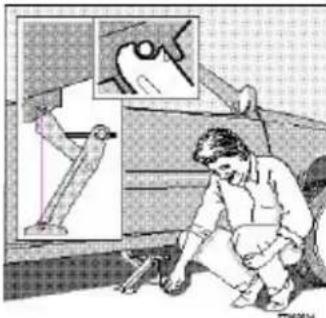
natural_image
Illustration of a person kneeling beside a vehicle with an inset showing a hand holding a leg (no text or symbols present)Jack attachment - front wheel drive models
Attaching the jack
There is a jack attachment located in the center on each side of the car. Position the jack on the bar in the attachment and crank while simultaneously guiding the base of the jack to the ground. The base of the jack must be flat on a level, firm, non-slippery surface. Before raising the car, check that the jack is still correctly positioned in the attachment. Raise the vehicle until both wheels on the side of the car where the jack is attached are lifted off the ground. Unscrew the wheel bolts completely and carefully remove the wheel so as not to damage the thread on the studs.

natural_image
Side profile and close-up of a car showing front wheel, dashboard, and engine components (no text or symbols)Additional rear jack attachment on All Wheel Drive cars
Attaching the jack on cars with All Wheel Drive (AWD)
Due to the greater weight of AWD-equipped cars, these models have an additional jack attachment point located directly in front of the rear axle. When using a workshop floor jack, make sure that the correct attachment is used and that the jack does not damage the fuel tank.
The attachment is, of course, also intended for use with the standard jack supplied with the car.

natural_image
Mechanical linkage diagram showing a robotic arm with pivot point and base, no text or symbols presentProper jack attachment on AWD cars
Installing the wheel
Clean the contact surfaces on the wheel and hub. Lift the wheel and place it on the hub. Make sure that you align the wheel with the guide stud on the wheel hub prior to installation. Install the wheel bolts crosswise (see illustration) and tighten by turning lightly clocKWise. Lower the vehicle to the ground and alternately tighten the bolts to 100 ft. lbs. (130 Nm). Install the wheel cap (where applicable).

Correct tightening order for wheel bolts
pg. 96 Spare tire
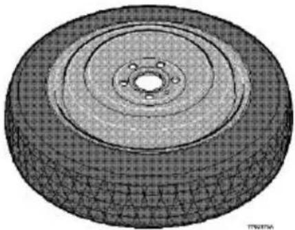
natural_image
3D rendered tire cross-section showing concentric rings and central bore (no text or symbols)Temporary Spare (certain models)
The spare tire in your car is called a "Temporary Spare". It has the following designation: T115/70 R15 or T125/80 R17.
Recommended tire pressure (see decal on fuel filler flap) should be maintained irrespective of which position on the car the Temporary Spare tire is used on.
In the event of damage to this tire, a new one can be purchased from your Volvo retailer.
CAUTION: The car must not be driven with wheels of different dimensions or with a spare tire other than the one that came with the car. The use of different size wheels can seriously damage your car's transmission.
WARNING!
Current legislation prohibits the use of the "Temporary Spare" tire other than as a temporary replacement for a punctured tire. In other words, it must be replaced as soon as possible by a standard tire. Roadholding, etc., may be affected with the "Temporary Spare" in use. Do not, therefore, exceed 50 mph (80 km/h).
NOTE: Certain models are equipped with a full-size spare wheel.
pg. 97 Replacing bulbs
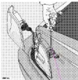
natural_image
Technical line drawing of a mechanical assembly or tool, possibly a cutting or fastening tool, with no visible text or symbols.catch
Parking light/direction indicator
-
From the front of the car, use a screwdriver to press down on the silver catch (located in the space between the inside of the fender and the headlight unit) to release the lamp housing from the front fender.
-
Turn the bulb holder 1/4 turn clocKwise (viewed from the front) and withdraw it from the from the lamp housing. Leave the connector with its wires in the bulb holder.
-
Remove the bulb from the holder by pulling it straight out.
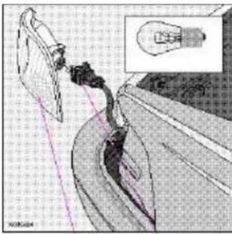
natural_image
Diagram of an electric vehicle charging plug with a light bulb, showing wiring and battery connections (no text or symbols)Lamp housing Bulb holder,br> Bulb- 3357NA, 26/7W/30/2.2cp
- Press a new bulb into the holder and reinstall the unit in the reverse order.
Bulb holder
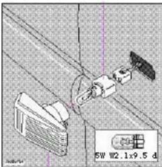
natural_image
Technical diagram showing mechanical components and a 5W W2.1x9.5 d label (no readable text or symbols beyond labels)Side direction indicator
- Slide the lens forward and pull out the rear edge.
- Pull out the entire lens/bulb unit.
- With the lens toward you, turn the bulb holder 1/4 turn (the wires should not be disconnected from the holder) and pull out the bulb holder from the lens unit.
- Pull the old bulb straight out and press a new one into place.
- Replace the entire unit in the reverse order.
pg. 98 Replacing bulbs

text_image
Guide lugs A BBulbs (high and low beams) - H7 A - Low beam B - High beam
Low beam headlight bulb (A) replacement
- Turn the plastic cover counterclocKwise and remove it.
- Press the wire catches on the retaining clamp (1 in inset illustration above) together and push out (2) to release the bulb and connector from the headlight housing.
- Pull the bulb out of the connector.
- Insert a new bulb into the connector.
- Reinsert the bulb and connector into the headlight housing. The guide lug must be up to ensure proper positioning.
- Press the retaining clamp back into position.
- Reinstall the plastic cover.
Headlight adjustment
The height of the headlight beams can be adjusted according to vehicle load. The headlights should be reaimed if heavy loads are carried in the trunk/cargo area or rear seat, or when towing a trailer.
To adjust the headlights:
- Park the car on a level surface and open the hood.
- The headlights are equipped with a level which can be seen by looking through the clear "window" on the top of the headlight lens.
- Turn the height adjustment knob until the bubble in the level aligns with the "0" marks or within the dark marking lines.
Lateral headlight adjustment should only be carried out by an authorized Volvo retailer. The lateral adjustment scale should be preset at "0".
High beam headlight bulb (B) replacement
- Pull the catch on the lower edge of the cover upward and remove the plastic cover.
- Press the wire catches on the retaining clamp (1 in inset illustration above) together and push out (2) to release the bulb and connector from the headlight housing.
- Pull the bulb out of the connector.
- Insert a new bulb into the connector.
- Reinsert the bulb and connector into the headlight housing. The guide lug must be up to ensure proper positioning.
- Press the retaining clamp back into position.
- Reinstall the plastic cover. Catch B should snap into position.
pg. 99 Replacing bulbs
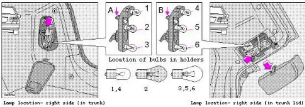
text_image
A 1 2 3 B 4 5 6 Location of bulbs in holders 1,4 2 3,5,6 Lamp location- right side (in trunk) Lamp location- right side (in trunk lid)Tail light bulbs (sedans)
- Tail light
- Direction indicator
- Brake light
- Tail light
- Backup light
- Rear fog light (left side only)
All the bulbs in the tail light unit are replaced from inside the trunk as follows:
- Turn the two plastic screws and open the cover over the rear lamp unit in the trunk (or depress the catch on the cover on the trunk lid).
- Press catch A or B and remove the bulb holder.
- Let the connector with its wires remain attached to the bulb holder.
- Remove the bulb by pressing in and turning counterclocKWise.
- Insert a new bulb into the holder and reinstall the holder into the tail light assembly.
- Close the cover.
Bulbs 1,4:
5W/4 cp BA 15 s
Bulb 2:
21W BAU 15 s (amber)
Bulbs 3,5,6:
21W/32 cp BA 15 s
pg. 100 Replacing bulbs

Removing speaker from upper section
Tail light bulbs (wagons)
-
Direction indicator
-
Brake light
-
Tail light
- Back-up light
- Tail light / Rear fog light (left side only)

text_image
21W BAU 15 s (amber) 21W/32 cp BA 15 s 21/4W BAZ 15 d 21W/32 cp BA 15 s 21/4W BAZ 15 dAll the bulbs in the tail light unit are replaced from inside the cargo space as follows:
· Turn the ignition key to position 0 and switch off the lights.
- Remove the upper panel of the tail light unit by using a screwdriver (1) and/or the lower panel by first removing the side floor cover and turning the plastic screw at the bottom of the panel to release it.
- Press down catch A (upper section) * or press catches B toward each other (lower section) and take out the bulb holder.
- Leave the connector and cables connected to the bulb holder.
- Remove the bulb by pressing it inwards and turning it slightly counter-clocKWise.
- Insert a new bulb into the bulb holder and reinstall the holder in the tail light assembly.
- Check that the bulb works. Reinstall the cover.
* The optional speaker (see illustrations 2, 3)) must be removed first to gain access to the upper bulb holder.
pg. 101 Replacing bulbs
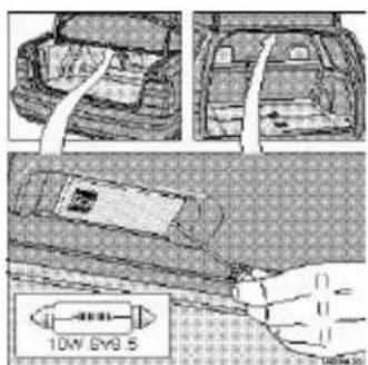
text_image
10W BY9.5Insert screwdriver and turn
Trunk light (sedans)/Rear courtesy light (wagons)
- Switch off the lights.
- Press in the catch with a screwdriver and remove the bulb holder.
- Replace the bulb and reinstall the bulb holder.

text_image
XLT 213 SW W2.1 x 9.5d XTL 332Torx screwdriver for glass lens
License plate lights (sedans and wagons)
- Switch off the lights.
- Unscrew the screw*.
- Insert the screwdriver and turn gently to loosen the glass lens.
- Replace the bulb and reinstall the glass lens.
* Two screws on wagons
pg. 102 Replacing bulbs

text_image
5W 8A 9s 600000Insert screwdriver, turn and pull downward
Front courtesy lights
- Switch off the ignition.
- Insert a screwdriver and turn carefully to loosen the glass lens.
- Replace the bulb and press the glass lens back into place.
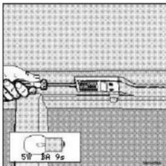
text_image
5W 18 9sInsert a screwdriver and turn
Rear reading lights
· Switch off the ignition.
- Insert a screwdriver and turn to loosen the lamp unit.
- Replace the bulb and press the lamp unit back into place.
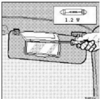
text_image
1.2 WInsert a screwdriver and turn
Vanity mirror
- Switch off the ignition.
- Insert a screwdriver under the lower edge and turn to loosen the glass lens.
- Push out the bulb and replace it.
- Press the lower edge of the lens into place above the four catches.
- Press the upper edge of the lens into place.
pg. 103 Replacing bulbs
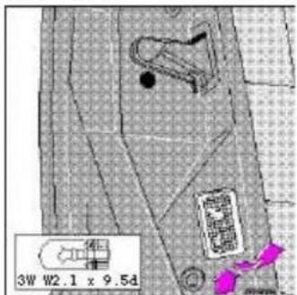
text_image
3W W2.1 x 9.5dInsert the screwdriver and turn gently (rear door)
Door warning lights
- Slide the lamp unit upward and pull out the lower edge.
- Twist off the bulb holder.
· Pull the bulb straight out. - Replace the bulb.
- Reinstall the holder and lamp unit in reverse order.

text_image
5W W2.1 x 9.5dInsert a screwdriver
Door step courtesy lights
- Insert a screwdriver and pry out the glass lens.
-
Withdraw the lamp unit, bend back the tabs and remove the plate.
-
Replace the bulb.
- Reinstall the plate.
- Press the lamp unit back into place.
NOTE: Other bulbs may be difficult for the owner to replace. Let your Volvo retailer replace these bulbs if necessary.
text_image
Technical diagram showing mechanical assembly with labeled components and a magnified inset of a 55W H1 component.Front fog lights in spoiler
Front fog lights (option)
- Switch off the lights
- Turn the plastic cover counter-clocK Wise to remove it.
- Press the spring toward the lamp unit to release it and move it to the side.
- Replace the bulb.
- Reinstall in reverse order.
pg. 104 Replacing fuses

text_image
Relay/Main fuse box Supplementary fuse boxReplacing fuses
If an electrical component fails to function, it is likely that a fuse has blown due to a temporary circuit overload.
The fuse boxes are located in the engine compartment (see illustration) and can be opened by pressing the catches and lifting the cover (Relay/Main fuse box) or by lifting the cover (supplementary fuse box).
A label on the inside of each cover indicates the amperage and the electrical components that are connected to each fuse.
The easiest way to see if a fuse is blown is to remove it *. Pull the fuse straight out. From the side, examine the curved metal wire to see if it is broken. If so, put in a new fuse of the same color and amperage (written on the fuse). Spare fuses are stored in a compartment in the Supplementary fuse box. If fuses burn out repeatedly, have the electrical system tested at a Volvo retailer. If you find it difficult to remove a fuse, you will find a special fuse tool clipped in the fuse box.

text_image
Fuse removal tool Defective fuse Intact fuse* Fuses in the Relay/Main fuse box should only be changed by an authorized Volvo service technician.
pg. 105 Fuses

text_image
Technical diagram of a mechanical or electrical component with numbered parts for identificationRelay/Main fuse box
Fuses in the main fuse box protect the entire electrical system. If one of the fuses blows, there is a serious electrical fault. Do not change any of these fuses. Contact your nearest Volvo workshop for a closer analysis.
Relays
15 System relay
16 Air pump relay
17 Starter motor
18 Air conditioning
Fuses in Relay/Main fuse box (main system fuses)
Location \* Amperage
1 Electric cooling fan 60A
2 Fuses in Supplementary fuse box 50A
3 Starter motor, air pump 50A
4 ABS, STC, TRACS 50A
5 Headlights 50A
6 Fuses in Supplementary fuse box 60A
7 Fuses in Supplementary fuse box 60A
8 Control modules - engine/automatic transmission 60A
9 Electrically operated windows 60A
10 Ignition switch, Control modules - engine/automatic transmission 10A
11 Fuel injectors, A/C relay 10A
12 Fuel pump, fuel injection system 20A
13 Control module - automatic transmission 10A
14 A/C relay, emissions systems 10A
* Some of the equipment/systems listed may be available on certain models only.
pg. 106 Fuses (supplementary fuse box)
Location \* Amperage
1 -
2 Central locking, driving mode selectors (aut. trans.) 10A
3 ABS 10A
4 Immobilizer (Canada only) 10A
5 Climate systems, Onboard diagnostics OBDII 15A
6 -
7 Audio system 15A
8 Immobilizer (Canada only), trip computer, headlight switch 15A
9 Electrically heated rear seat (certain models) 20A
10 Ignition switch 15A
11 Brake lights 10A
12 -
13 Hazard warning flashers, headlight flashers, remote operated central locking system 15A
14 Heated rear window and door mirrors 30A
15 Courtesy lights, door open warning lights, trunk/cargo space light, seat belt reminder, glove compartment light 10A
16 Power antenna, electrical connector for trailer, accessories 30A
17 Front fog lights 20A
18 Key reminder 10A
19 Left high beam 15A
20 Right high beam, high beam indicator light 15A
21 Left low beam 15A
22 Right low beam 15A
23 Left front/rear parking lights, left tail light, license plate lights 10A
24 Right front/rear parking lights, right tail light 10A
25 Rear fog light, rear fog light indicator lamp 10A
26 Headlight switch 15A
27 Backup lights, turn signals 15A
28 Heated seats - front/rear (certain models) 25A
29 Heated rear window, shiftlock, seat belt reminder, cruise control, heated door mirrors, bulb failure warning sensor 10A
30 -
31 Passenger compartment blower-climate systems 25A
32 Audio system 10A
33 Tailgate wiper/washer 15A
34 Windshield wipers/washers, horn 25A
35 Instrument lighting, accessories, power sun roof 10A
36 Rear auxiliary socket, power seats 15A
37 Power windows, power sun roof AUT/CB**
38 -
39 Power seat (driver's side) AUT/CB**
40 Power seat (passenger's side) AUT/CB**
* Some of the equipment/systems listed may be available on certain models only.
** This is an automatic circuit breaker located in the fuse box and does not normally need to be replaced.
For more detailed information concerning function and location of relays, fuses, etc., refer to the Volvo Service Manuals. These can be purchased through your Volvo retailer.
pg. 107 Installation of accessories
natural_image
Technical line drawing of a mechanical component with no visible text or symbolsInstallation of accessories
In order to help avoid interference and damage to your car's electrical system, the car is equipped with an accessory connector located under the instrument panel on the driver's side.
Please consult your Volvo retailer if you have any questions before connecting accessory or optional equipment to the vehicle's electrical system.
Connector (for accessories)
Position Connection Max. load
1 Battery +(30) 20 A
2 X Supply 0,5 A
3 High beam 1 A
4 - 1 A
5 - 1 A
6 Rheostat 0,5 A
7 - 2 A
8 Earth (31) -
pg. 108 Replacing wiper blades
Replacing wiper blades
Lift the wiper arm off the windshield and hold the blade at right angles to the arm. Pinch the end of the plastic clip located at the back of the arm.

natural_image
Three-panel illustration showing hands using a tool to adjust a mechanical part, with no visible text or symbols.Slide the wiper blade along the arm to release it from the hook.
Install the new blade (installation is the reverse of removal) and make sure that it is properly attached to the wiper arm.
NOTE: For reasons of safety, you should change the windshield wiper blades as soon as they start to leave marks on the windshield or fail to wipe efficiently and cleanly.
To obtain maximum lifetime from a set of wiper blades, clean them with a stiffbristle brush and warm, soapy water as part of a normal car wash.
pg. 109 Replacing headlight wiper blades
natural_image
Diagram of two elongated mechanical components with a highlighted pink arrow (no text or symbols)Replacing headlight wiper blades (certain models)
Pull the wiper blade in the direction indicated by the arrow in the illustration to remove it. Press the new wiper blade into place. Check that the new blade is properly attached to the wiper arm.
Cleaning the outside of the windshield and wiper blades
If the windshield/tailgate is not clear after using the wiper(s) or if the blade chatters when running, wax or other material may be on the blade or on the surface of the glass.
Clean the glass with a suitable cleaning agent. The glass is clean if beads do not form when you rinse it with water.
Clean the wiper blade by wiping vigorously with a cloth soaked in full strength windshield washer solvent. Then rinse
the blade with water.
Wiper blades should be checked on a regular basis and replaced when worn.
pg. 110 In case of emergency

natural_image
Technical illustration of a mechanical component with a magnified inset showing a highlighted section (no text or symbols)Shiftlock release (automatic transmission only)
The gear selector is locked in the (P)ark position. To manually release the shiftlock:
· Turn the starting (ignition) key to position I
- Press firmly on the "SHIFTLOCK OVERRIDE" button located to the right of the base of the gear selector
- While holding the override button down, press the button on the front of the gear selector
- Move the selector from the (P)ark position.
Electrically operated windows
The electrically operated window motors have an overload protecting circuit breaker (fuse no. 37) which is activated when an object blocks a window. Should this occur, remove the object and wait 20 seconds for the circuit breaker to reset.
The electrically operated windows should then function.
Sun roof
The electrically operated sun roof has an overload protecting circuit breaker (fuse no. 37) which is activated when an object blocks the sun roof. Should this occur, remove the object and wait 20 seconds for the circuit breaker to reset. The sun roof should then function normally. Also check fuse no. 35.
Electrically operated front seats
The electrically operated front seats have overload protecting circuit breakers (fuses no. 39 and 40) which are activated when an object blocks one of the seats. Should this occur, remove the object and wait 20 seconds for the circuit breaker to reset. The seat should then function normally.

Contents | Top of Page
2000 VOLVO S & V70
Chapter 7 - Car care
pg. 111 Car care
Car care includes not only maintaining the appearance of the car, but also protecting the car exterior from the effects of air pollution, rain, mud or road salt. The paintwork should also be touched up immediately, if damaged, to prevent rust formation.
| Paint touchup 112-113 | ___ |
| Washing 114 | ___ |
| Automatic car washing, Polishing and waxing 115 | ___ |
| Cleaning the upholstery 116 | ___ |
pg. 112 Paint touch up
Paint touchup
Paint damage requires immediate attention to avoid rusting. Make it a habit to check the finish regularly when washing the car for instance. Touchup if necessary.
Paint repairs require special equipment and skill. Contact your Volvo retailer for any extensive damage.
Minor scratches can be repaired by using Volvo touchup paint.
NOTE: When ordering touchup paint from your Volvo retailer, use the paint code indicated on the model plate. The plate is located in the engine compartment, on the inside of the left front fender.
text_image
VOLVO CARCOMP A B C1 C2 C3 C4 Extra Paint code for two-tone XC AWD models Paint codeMinor stone chips and scratches
Material:
Primer can
Paint touchup bottle
Brush
Masking tape
NOTE: When touching up the car, it should be clean and dry. The surface temperature should be above 60^ F (15°C).
Scratches on the surface
If the stone chip has not penetrated down to the metal and an undamaged layer of paint remains, the touchup paint can be applied as soon as the spot has been cleaned.
pg.113 Paint touch up
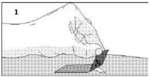
text_image
1
text_image
2 01980000
natural_image
Close-up of a brush applying material to a textured surface, no visible text or symbolsDeep scratches
- Place a strip of masking tape over the damaged surface. Pull the tape off so that any loose flakes of paint adhere to it.
- Thoroughly mix the primer and apply it with a small brush.
When the primer surface is dry, the paint can be applied using a brush. Mix the paint thoroughly; apply several thin paint coats and let dry after each application.
- If there is a longer scratch, you may want to protect surrounding paint by masking it off.
pg. 114 Washing
Washing the car
- The car should be washed at regular intervals since dirt, dust, insects and tar spots adhere to the paint and may cause damage.
NOTE: It is particularly important to wash the car frequently in the wintertime to prevent corrosion, when salt has been used on the roads.
- When washing the car, do not expose it to direct sunlight. Use lukewarm water to soften the dirt before you wash with a sponge, and plenty of water, to avoid scratching.
· Bird droppings: Remove from paintwork as soon as possible. Otherwise the finish may be permanently damaged.
· A detergent can be used to facilitate the softening of dirt and oil.
· A water-soluble grease solvent may be used in cases of sticky dirt. However, use a wash place equipped with a drainage separator. -
Dry the car with a clean chamois and remember to clean the drain holes in the doors and rocker panels *.
· The power radio antenna (sedans) must be dried after washing. -
Tar spots can be removed with kerosene or tar remover after the car has been washed.
- A stiff-bristle brush and lukewarm soapy water can be used to clean the wiper blades. Frequent cleaning improves visibility considerably.
- Wash off the dirt from the underside (wheel housings fenders, etc.).
- In areas of high industrial fallout, more frequent washing is recommended.
CAUTION: During high pressure washing, the spray mouthpiece must never be closer to the vehicle than 13" (30 cm). Do not spray into the locks.
- When washing or steam cleaning the engine, avoid spraying water or steam directly on the electrical components or toward the rear side of the engine.
- After cleaning the engine, the spark plug wells should be inspected for water and blown dry if necessary.
Suitable detergents
Special car washing detergents should be used. A suitable mixture is about 2.5 fl. oz. (8.5 cl) of detergent to 2.6 US gal. (10 liters) of warm water. After washing with a detergent the car should be well rinsed with clean water.
WARNING!
- When the car is driven immediately after being washed, apply the brakes several times in order to remove any moisture from the brake linings.
· Engine cleaning agents should not be used when the engine is warm. This constitutes a fire risk.
natural_image
Side profile line drawing of a car with visible suspension and wheel alignment (no text or symbols)NOTE: When washing the car, remember to remove dirt from the drain holes in the doors and sills. Bumpers: Wash the bumpers with the same cleaning agent used on the rest of the car. Never clean the bumpers with gasoline or paint thinner. Difficult spots can be removed with denatured alcohol. To avoid scratches, do not dry the bumpers with paper.
* Pay special attention to the drain holes near the base of the windshield, under the rear edge of the hood.
pg. 115 Automatic car washing, Polishing and waxing
Automatic washing simple and quick
An automatic wash is a simple and quick way to clean your car, but it is worth remembering that it may not be as thorough as when you yourself go over the car with sponge and water. Keeping the underbody clean is most important, especially in the winter. Some automatic washers do not have facilities for washing the underbody.
Before driving into an automatic wash, make sure that side view mirrors, auxiliary lamps, etc., are secure, otherwise there is risk of the machine dislodging them. You should also lower the antenna (sedans).
We do NOT recommend washing your car in an automatic wash during the first six months (because the paint will not have hardened sufficiently).
Polishing and waxing
Normally, polishing is not required during the first year after delivery, however, waxing may be beneficial.
Before applying polish or wax the car must be washed and dried. Tar spots can be removed with kerosene or tar remover. Difficult spots may require a fine rubbing compound.
After polishing use liquid or paste wax.
Several commercially available products contain both polish and wax.
Waxing alone does not substitute for polishing of a dull surface.
A wide range of polymerbased car waxes can be purchased today. These waxes are easy to use and produce a longlasting, highgloss finish that protects the bodywork against oxidation, road dirt and fading.
pg. 116 Cleaning the upholstery
Cleaning the upholstery
The fabric can be cleaned with soapy water or a detergent. For more difficult spots caused by oil, ice cream, shoe polish, grease, etc., use a clothing/fabric stain remover.
The plastic in the upholstery can be cleaned with a soft cloth and mild soap solution.
Leather upholstery/suede-like upholstery (alcantera™) can be cleaned with a soft cloth and mild soap solution. For more difficult spots, Volvo offers a leather care kit.
On no account must gasoline, naphtha or similar cleaning agents be used on the plastic or the leather since these can cause damage.
Cleaning the seat belts
Clean only with lukewarm water and mild soap solution.
Cleaning floor mats
The floor mats should be vacuumed or brushed clean regularly, especially during winter when they should be taken out for drying. Spots on textile mats can be removed with a mild detergent.
Bear in mind
· Take extra care when removing stains such as ink or lipstick since the coloring can spread.
- Use solvents sparingly. Too much solvent can damage the seat padding.
- Start from the outside of the stain and work toward the center.

Contents | Top of Page
2000
VOLVO
S & V70
Chapter 8 - Volvo Service
pg. 117 Service an investment
An investment which will pay dividends in the form of improved reliability, durability and resale value.
| Label information 118 | — |
| Maintenance service, Warranty 119 | — |
| Maintenance schedule 120-121 | — |
| Servicing 122-123 | — |
| Fuel/emissions systems 124 | — |
| Lubrication 125 | — |
| Engine oil 126-127 | — |
| Power steering fluid, Brake/clutch system fluid reservoir 128 | |
| Windshield washer nozzle, Washer fluid reservoir 129 | — |
| Coolant 130 | — |
| Engine compartment 131 | — |
| Battery maintenance 132 | — |
pg. 118 Label information
1 Vehicle Emission Control Information
Your Volvo is designed to meet all applicable emission standards, as evidenced by the certification label on the underside of the hood. For further information regarding these regulations, please consult your Volvo retailer.
2 Vacuum hose routing
(underside of hood)
3 Loads and Tire Pressures
(on inside of fuel tank cover)
4 Model plate
Vehicle Identification Number (VIN). Codes for color and upholstery, etc. The plate is located in the engine compartment, on the inside of the left front fender.
5 Vehicle Identification Number (VIN) \*
The VIN plate is located on the top left surface of the dashboard. The VIN is also stamped on the right hand door pillar.
6 Federal Motor Vehicle Safety Standards (FMVSS) specifications (USA) and Ministry of Transport (CMVSS) standards (Canada)
Your Volvo is designed to meet all applicable safety standards, as evidenced by the certification label on the facing side of the driver's door. For further information regarding these regulations, please consult your Volvo retailer.
7 Child safety latch label
text_image
1 2 3 4 5 6 7 ON OFF CAN TOMATO WORSO 2014 01-09/2014 0.00 0.00 1.00 2.00 1.00 WORSO WORSO WORSO WORSO WORSO WORSO WORSO WORSO WORSO WORSO WORSO WORSO WORSO WORSO WORSO WORSO WORSO WORSO WORSO WORSO WORSO WORSO WORSO WORSO WORSO WORO* The Vehicle Identification Number (VIN) should always be quoted in all correspondence concerning your vehicle with the retailer and when ordering parts.
** These decals are located on the underside of the hood.
All specifications are subject to change without notice.
pg. 119 Maintenance service, Warranty
Maintenance service
Volvo advises you to follow the service program which is outlined in the "Maintenance Records Manual". This maintenance program contains inspections and services necessary for the proper function of your car. The maintenance services contain several checks which require special instruments and tools and therefore must be performed by a qualified technician. To keep your Volvo in top condition, specify time tested and proven Genuine Volvo Parts and Accessories.
The Federal Clean Air Act U.S.
The Clean Air Act requires vehicle manufacturers to furnish written instructions to the ultimate purchaser to assure the proper functioning of those components that control emissions. The maintenance instructions listed in the "Servicing" section of this Manual represent the minimum maintenance required. These services are not covered by the warranty. You will be required to pay for labor and material used. Refer to your Warranty booklet for further details.
Maintenance services
Your Volvo has passed several major inspections before being delivered to you, according to Volvo specifications. The maintenance services outlined in this book should be performed as indicated. The extended maintenance service intervals make it even more advisable to follow this program. Inspection and service should also be performed any
time a malfunction is observed or suspected. It is recommended that receipts for vehicle emission services be retained in the event that questions arise concerning maintenance. See your "Maintenance Records Manual".
Applicable warranties U.S.
In accordance with U.S. Federal Regulations, the following list of applicable U.S. warranties is provided. For Canadian specification vehicles, see your separate warranty booklet.
· New Car Limited Warranty
- Parts and Accessories Limited Warranty
· Corrosion Protection Limited Warranty
- Seat belt and Supplemental Restraint Systems Limited Warranty
· Emission Design and Defect Warranty
· Emission Performance Warranty
These are the Federal warranties; other warranties are provided as required by state law. Refer to your separate Warranty booklet for detailed information concerning each of the warranties.
pg. 120 Maintenance schedule
2000 MAINTENANCE SCHEDULE S & 70
For complete maintenance information, please refer to your Warranty and Service Records Information Booklet.
$$ \begin{array}{l} \mathbf {A} = \text { Adjust (Correct if necessary) } \ \mathbf {R} = \text { Replace } \ \mathbf {I} = \text { Inspect (Correct or Replace if necessary) } \ \mathbf {L} = \text { Lubricate } \ \end{array} $$
| Maintenance Operation | thousand miles | 7.5 | 15 | 22.5 | 30 | 37.5 | 45 | 52.5 | 60 | 67.5 | 75 | 82.5 | 90^2 | ||
| (thousand km) (12) (24) (36) | (48) (60) (72) (84) | (96) | (108) | (120) | (132) | (144) | |||||||||
| EMISSION SYSTEM MAINTENANCE | |||||||||||||||
| Engine oil and filter ^1 | R | R | R | R | R | R | R | R | R | R | R | R | R | R | |
| Engine drive belt (accessory belt)2 | R | ||||||||||||||
| Air cleaner filter | R | R | R | ||||||||||||
| Spark plugs | R | R | R | ||||||||||||
| Automatic transmission fluid | I | I | I | I | I | I | |||||||||
| Timing belt - all engines ^3 | |||||||||||||||
1) See section "Engine oil" for detailed information.
NOTE: The oil should be changed at these intervals, after 750 hours of driving or after 12 months, whichever occurs first.
2) For services beyond 90,000 miles (144,000 km), please refer to the Warranty and Service Records Information Booklet".
3) For proper functioning of the vehicle and its emission control systems, the timing belt and tensioner must be
replaced every 105,000 miles (168,000 km).
pg. 121 Maintenance schedule
2000 MAINTENANCE SCHEDULE S & V70
A = Adjust (Correct if necessary)
R = Replace
I = Inspect (Correct or Replace if necessary)
L = Lubricate
| Maintenance Operation | thousand miles | 7.5 | 15 | 22.5 | 30 | 37.5 | 45 | 52.5 | 60 | 67.5 | 75 | 82.5 | 90 |
| (thousand km) | (12) | (24) | (36) | (48) | (60) | (72) | (84) | (96) | (108) | (120) | (132) | (144) | |
| EMISSION SYSTEM MAINTENANCE | |||||||||||||
| Engine | |||||||||||||
| Fuel line filter^1 | |||||||||||||
| PCV nipple (orifice)/hoses, clean | I | I | |||||||||||
| Battery (check charge and electrolyte level) | I | I | I | I | I | I | I | I | I | I | I | I | |
| Brakes | |||||||||||||
| Inspect brake pads, replace components as necessary | I | I | I | I | I | I | I | I | I | I | I | ||
| Brake fluid level^2 - check | I | I | I | I | I | I | |||||||
| Steering/suspension | |||||||||||||
| Tires^3 , check pressure, wear and condition | I | I | I | I | I | I | I | I | I | I | I | I | |
| Check power steering fluid level | I | I | I | I | I | ||||||||
| Body | |||||||||||||
| Power antenna (clean) | L | L | L | L | L | L | |||||||
| Trunk/hood, hinges and latches | L | L | L | ||||||||||
| Cabin air filter (see page 121 | R | R | R | R | R | R | |||||||
1) Replace at 105,000 miles (168,000 km)
2) Brake fluid should be changed at owner request every second year or 30,000 miles (48,000 km). The fluid should be replaced once a year or every 15,000 miles (24,000 km) when driving under extremely hard conditions (mountain driving, etc.).
3) Rotate tires at owner request.
The following items should be checked weekly by the driver (it takes only a few minutes):
Engine oil level, brake fluid level, radiator coolant level, operation of all lights, horns, windshield wipers, tire pressure (all five tires), windshield washer fluid level
The following should also be carried out at regular intervals:
Washing (check all drain holes), polishing, cleaning
pg. 122 Servicing
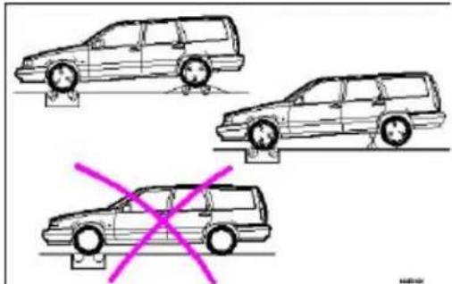
natural_image
Three cartoon-style cars with wheels and a pink X symbol, no text or labels presentRolling road (spin) test (models with AWD and viscous coupling)
When checking brakes using a rolling road (spin) test, or when balancing the wheels directly on the car, the other wheels must be free to roll, see illustration. This ensures that the viscous coupling is not damaged. The drive power is transferred automatically by the viscous coupling to the car's other drive wheels. If you are unsure, consult your nearest Volvo retailer.
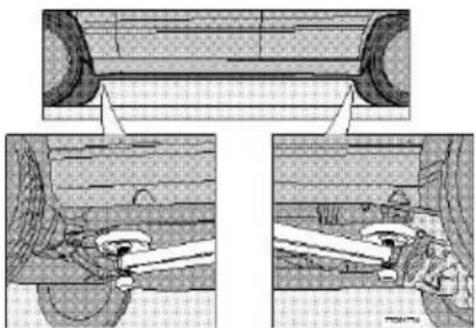
natural_image
Technical diagram showing mechanical assembly with cross-sectional views (no text or labels)Hoisting the car
If a garage jack is used to lift the car, the two jack attachments points should be used. They are specially reinforced to bear the weight of the car. A garage jack can also be placed under the front of the engine support frame and under the reinforced plate in the spare wheel well. Take care not to damage the splash guard under the engine. Ensure that the jack is positioned so that the car cannot slide off it. Always use axle stands or similar structures.
If a twopost hoist is used to lift the car, the front and rear lift arm pads should be centered under the reinforced lift plates on the inboard edge of the sill rail. The position of these plates is marked with arrows molded into the bottom of the sill rail.
CAUTION: Certain models have reduced ground clearance due to the design of the front spoiler. Please observe caution when driving the car onto a garage hoist.
pg. 123 Servicing
Air cleaner
Replace the air cleaner cartridge with a new one every 30,000 miles (48,000 km). The cartridge should be replaced more often when driving under dirty and dusty conditions. The filter cannot be cleaned and therefore should always be replaced with a new one.
Timing belt
For proper functioning of the vehicle and its emission control systems, the timing belt and tensioner must be replaced every 105,000 miles (168,000 km). Engine damage will occur if the belt fails.
Fuel system cap, tank and lines and connections
The effectiveness of the fuel system to contain hydrocarbons is dependent largely on a leakfree system. Check for proper sealing of the fuel filler cap which contains "O" ring type seals.
NOTE: If the fuel filler cap is not closed tightly or if the engine is running when the car is refueled, the Malfunction Indicator Lamp ("Check Engine") may indicate a fault. However, your vehicle's performance will not be affected. Use only Volvo original or approved fuel filler caps.
Fuel (line) filter
For proper functioning of the vehicle and its emission control systems, the fuel line filter should be replaced at 105,000 miles (168,000 km). The filter is replaced as one complete unit. Replace more frequently if contaminated fuel is introduced into the tank (or if there is reason to suspect that this has occurred).
PCV system
The orifice nipple in the intake manifold and the filter at the end of the PCV hose in the air cleaner should be inspected at 60,000 miles (96,000 km) and thereafter, at 30,000 mile (48,000 km) intervals.
Cabin air filter
Replace the cabin air filter with a new one at 15,000 mile (24,000 km) intervals. Volvo recommends replacing the filter more often if the car is driven under dirty and dusty conditions. The filter cannot be cleaned and therefore should always be replaced with a new one.

Contents | Top of Page
2000 VOLVO S & V70
Chapter 9 - Specifications
pg. 133 Service an investment
This chapter contains facts and figures pertaining to the technical specifications of your car.
| Oil/fluids specifications 134 | — |
| Engine specifications 135 | — |
| Cooling/fuel/distributor ignition systems 136 | — |
| Front/rear suspensions 136 | — |
| Transmission, Capacities, Vehicle loading 137 | — |
| Electrical system/bulbs 138 | — |
| Weights 139 | — |
| Dimensions, Service manuals, Road assistance 140 | |
pg. 134 Oil/fluid specifications
Oil quality
Meeting API specification SJ, SJ/CF, or SJ/Energy Conserving.
For best fuel economy and engine protection, consult your authorized Volvo retailer for recommended oils. Oil with a different quality rating may not provide adequate engine protection.
Synthetic oils complying with oil quality requirements are recommended for: driving in areas of sustained temperature extremes (hot or cold), when towing a trailer over long distances or for prolonged driving in mountainous areas.
Extra oil additives must not be used unless advised by an authorized Volvo retailer.
Viscosity (stable ambient temperatures):
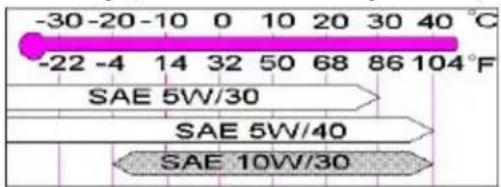
text_image
-30-20-10 0 10 20 30 40 °C -22 -4 14 32 50 68 86 104°F SAE 5W/30 SAE 5W/40 SAE 10W/30Engine oil
Quality: Meeting API specification SJ, SJ/CF, or SJ/Engergy Conserving
Capacity (incl. filter): 6.1 US qts (5.8 liters).*
Automatic transmission fluid
Quality: AW4: ATF Dexron III and Mercon. AW5: Only Volvo gearbox oil (1161540-8). Do
Capacity: 8 US qts. (7.6 liters)
not mix with other oils.
Manual transmission fluid Quality: Volvo synthetic gearbox oil 1161423
Power steering fluid Quality: ATF
Brake fluid Quality: DOT 4+
All specifications are subject to change without notice.
Capacity: 8 US qts. (7.5 liters)
Capacity: 2.2 US qts. (2.1 liters)
Capacity: 0.95 US qts. (0.9 liters)
Capacity: 0.64 US qts. (0.6 liters)
* Turbo-charged models: Add 0.95 qts. (0.9 liters) if the oil cooler has been drained
pg. 135 Engine
Engine
Liquid-cooled gasoline, 5cylinder, inline engine. Aluminum alloy cylinder block with castiron cylinder liners cast directly into the block. Aluminum alloy cylinder head with double overhead camshafts and separate intake and outlet channels.
Engine lubrication is provided by an eccentric pump driven from the crankshaft. Fullflow type oil filter. Exhaust emission control is accomplished by multiport fuel injection, heated oxygen sensor(s) and threeway catalytic converter.
Designation: Volvo B 5244 S
Output 168 hp at 6100 rpm (125 KW 102 rps)
Max torque 170 ft. lbs. at 4800 rpm (230 Nm/80 rps)
Number of cylinders 5
Bore 3.27" (83 mm)
Stroke 3.54" (90 mm)
Displacement 2.4 liters
Compression ratio 10.3:1
Number of valves 20
Designation: Volvo B 5244 T
Output 190 hp at 5100 rpm (142 KW/85 rps)
Max torque 199 ft. lbs. at 1600-5000 rpm (270 Nm/27-83 rps)
Number of cylinders 5
Bore 3.27" (83 mm)
Stroke 3.54" (90 mm)
Displacement 2.4 liters
Compression ratio 9.0:1
Number of valves 20
Designation: Volvo B 5234 T3
Output 236 hp at 5400 rpm (176 KW/90 rps)
Max. torque 243 ft. lbs. at 2400-5100 rpm (330 Nm/4092 rps)
Number of cylinders 5
Bore 3.19" (81 mm)
Stroke 3.54" (90 mm)
Displacement 2.3 liters
Compression ratio 8.5:1
Number of valves 20
Designation: Volvo B 5244 T2
Output 261 hp at 5700 rpm (195 KW/95 rps)
Max. torque 258 ft. lbs. at 2400-5100 rpm (350 Nm/4085 rps)
Number of cylinders 5
Bore 3.19" (81 mm)
Stroke 3.54" (90 mm)
Displacement 2.3 liters
Compression ratio 8.5:1
Number of valves 20
All specifications are subject to change without notice.
pg. 136 Specifications
Cooling system
Type: Positive pressure, closed system
Thermostat begins to open at 186°F (90°C)
Turbo-charged models 180° F (87° C)
Coolant: Volvo original coolant/antifreeze
Capacity: 7.6 US qts. (7.2 liters)
Turbo-charged models 7.4 US qts. (7.0 liters)
Fuel system
The engine is equipped with a multiport fuel injection system.
Distributor ignition system
Firing order: 12453
Distributor ignition setting: Not adjustable
Spark plugs: Bosch FR7DC or Champion RC9YC
Spark plug gap: 0.028" (0.7 mm)
Turbo-charged models: Champion RC8PYP (or equivalent)
Spark plug gap: 0.03" (0.75 mm)
Tightening torque: 18.4 ft. lbs. +/ 3.7 ft. lbs. (25 Nm +/ 5 Nm)
WARNING!
The distributor ignition system operates at very high voltages. Special safety precautions must be followed to prevent injury. Always turn the ignition off when:
- Replacing distributor ignition components e.g. plugs, coil, etc.
· Do not touch any part of the distributor ignition system while the engine is running. This may result in unintended movements and body injury.
Replacing spark plugs
The spark plugs should be changed every 30,000 miles (48,000 km). However, city driving or fast highway driving may necessitate changing after 15,000 miles (24,000 km) of driving. When installing new plugs, be sure to fit the right type and use correct torque, see "Specifications". When changing the plugs, check that the suppressor connectors are in good condition. Cracked or damaged connectors should be replaced. When changing the spark plugs, clean the terminals and the rubber seals.
Front suspension
Spring strut suspension with integrated shock absorbers and control arms linked to the support frame. Powerassisted rack and pinion steering. Safety type steering column.
The alignment specifications apply to an unladen car but include fuel, coolant and spare wheel.
Toe-in measured on the wheel rims: 2.4 mm +/- 0.7 mm
Toe-in measured on tire sides: 2.9 +/ 0.9 mm
Rear suspension
Deltalink individual rear wheel suspension with longitudinal support arms, double link arms and track rods.
Toein measured on the tire sides: 4^ + / 10^
All specifications are subject to change without notice.
pg. 137 Specifications
Power transmission
Manual transmission: M 56 H
Singledisc dry plate clutch. Allsynchronmesh on all gears including reverse; integrated final drive. Operation via a floor mounted gear lever.
Final drive ratio 4.00:1
Reduction ratios
1st gear 3.07:1
2nd gear 1.77:1
3rd gear 1.19:1
4th gear 0.87:1
5th gear 0.70:1
Reverse 2.99:1
Automatic transmission: AW 5050 LE and AW 50-42 LE
4 or 5speed automatic electronically controlled gearbox comprising a hydraulic torque converter with a lockup function; planetary gear, integrated final drive.
Operation via a floor mounted gear selector lever. Drive shafts with symmetrical joint location. Overdrive.
Final drive ratio 2.76:1 (Turbocharged models: 2.56:1)
Reduction ratios AW5 AW4
1st gear 4.77:1 3.61:1
2nd gear 2.10:1 2.06:1
3rd gear 1.96:1 1.37:1
4th gear 1.32:1 0.98:1
5th gear 1.02:1
Reverse 3.23:1 3.95:1
All specifications are subject to change without notice.
All Wheel Drive, automatic transmission
4 or 5 speed automatic electronically controlled gearbox comprising a hydraulic torque converter with a lockup function; planetary gear, integrated final drive. Bevel drive, propeller shaft, viscous coupling and freewheel to final drive/rear axle. Operation via a floor mounted gear selector lever. Overdrive.
Capacities
Fuel tank 18 US gal. (68 liters) - Front Wheel Drive
17.4 US gal (66 liters) - All Wheel Drive
Cooling system 7.4 US qts. (7.0 liters)
Engine oil (incl. filter) 6.1 US qts. (5.8 liters) *
Automatic transmission 2 US gals (7.6 liters)
Manual transmission 2.2 US qts. (2.1 liters)
Power steering fluid 0.8 US qts (0.8 liters)
Washer fluid reservoir 3.2 US qts. (3.0 liters)
Brake/clutch system 0.6 US qts (0.6 liters)
* Turbo-charged models: Add 0.95 US qt. (0.9 liters) if the oil cooler has been drained.
Vehicle loading
The tires on your Volvo should perform to specifications at all normal loads when inflated as recommended on the tire information label. The label is located on the inside of the fuel filler flap. The label lists both tire and vehicle design limits. Do not load your car beyond the load limits indicated.
WARNING!
Improperly inflated tires will reduce tire life, adversely affect vehicle handling and can possibly lead to failure resulting in loss of vehicle control without prior warning.
pg. 138 Specifications
Electrical system
12 Volt, negative ground.
Voltagecontrolled generator. Singlewire system with chassis and engine used as conductors.
Battery
Voltage: 12 Volt, capacity: 520 A/100 min (certain markets 420 A/75 min
The battery contains corrosive and poisonous acids. It is of the utmost importance that old batteries are disposed of correctly. Your Volvo retailer can assist you in this matter.
Generator
Rated output: 1400 W, max. current: 100 A
Bulbs
Bulb US no. Power Socket No/bulbs
Headlights
High beam H7 55W - 2
Low beam H7 55W - 2
Front parking lights/turn signals 3357NA 26/7W/30/2.2cp W 2.5 x 15 q 2
Turn signals, rear - 21W BAU 15 s 2
Side direction indicators - 5W W 2.1x9.5 d 2
Tail lights (sedan) 67 5W/4cp BA 15 s 4
Tail lights (wagon) - 21/4W BAZ 15 d 4
Brake lights 1156 21W/32cp BA 15 s 2
Backup lights 1156 21W/32cp BA 15 s 2
Rear fog light (sedan) 1156 21W/32cp BA 15 s 1
Rear fog light (wagon) - 21/4W BAZ 15 d 1
Front fog lights H1 55 W -2
License plate light -5W W 2.1x9.5d 2
Door open warning light - 3 W W 2.1x9.5 d 4
Door step courtesy lights - 5W W 2.1x9.5 d 2
Trunk light -10W SV8.51
Glove compartment light -2W BA9s1
Vanity mirror lights -1.2 W -2
Instrument lighting -3 W W 2.1x9.5 d 3
Illumination, control panel - 1.2 W W 2x4.6 d
gear selector (automatic trans.) - 1.2 W W 2x4.6 d 1
rear ashtray - 1.2 W W 2x4.6 d 1
Instrument warning/indicator lights - 1.2 W W 2x4.6 d
Front courtesy lights - 5 W BA 9 s 2
Rear reading lights - 5 W BA 9 s 2
All specifications are subject to change without notice.
pg. 139 Specifications
Gross Vehicle Weight (GVW):
FWD (sedan) 4180 lbs (1896 kg) 1900 kg
FWD (wagon) 4340 lbs (1969 kg) 1970 kg
FWD Turbo (sedan) 4250 lbs (1928 kg) 1930 kg
FWD Turbo (wagon) man 4340 lbs (1969 kg) 1970 kg
FWD Turbo (wagon) aut 4360 lbs (1978 kg) 1980 kg
AWD Turbo (sedan) 4580 lbs (2077 kg) 2080 kg
AWD Turbo (wagon) 4670 lbs (2118 kg) 2120 kg
Capacity Weight:
| FWD (sedan) | 930 lbs (422 kg) 425 kg |
| FWD (wagon) | 965 lbs (438 kg) 440 kg |
| FWD Turbo (sedan) | 930 lbs (422 kg) 415 kg |
| FWD Turbo (wagon) | 965 lbs (438 kg) 440 kg |
| AWD (sedan) | 975 lbs (442 kg) 440 kg |
| AWD (wagon) | 975 lbs (442 kg) 440 kg |
| AWD Turbo (sedan) | 960 lbs (435 kg) 435 kg |
| AWD Turbo (wagon) | 960 lbs (435kg) 435 kg |
Permissible axle weight, front:
| FWD (sedan, wagon) man | 2240 lbs (1016 kg) 1020 kg |
| FWD (sedan, wagon) aut | 2290 lbs (1039 kg) 1040 kg |
| FWD Turbo (sedan, wagon) man | 2310 lbs (1048 kg) 1050 kg |
| FWD Turbo (sedan, wagon) aut | 2350 lbs (1066 kg) 1070 kg |
| AWD Turbo (sedan, wagon) aut | 2400 lbs (1089 kg) 1090 kg |
Permissible axle weight, rear:
| FWD (sedan) | 2020 lbs (916 kg) | 920 kg |
| FWD (wagon) | 2220 lbs (1007 kg) | 1010 kg |
| AWD (sedan) | 2290 lbs (1039 kg) | 1040 kg |
| AWD (wagon) | 2470 lbs (1120 kg) | 1120 kg |
Curb weight USA
Canada
(sedan FWD) 3140-3320 lbs (1424-1506 kg) 1425-1515 kg
(wagon FWD) 3230-3395 lbs (1465-1540 kg) 1465-1540 kg
(sedan AWD) 3530-3605 lbs (1601-1635 kg) 1600-1635 kg
(wagon AWD) 3695-3760 lbs (1676-1706 kg) 1695-1705 kg
Max roof load ** 220 lbs (100 kg) 100 kg
Max trailer weight
(w/o brakes) 1100 lbs (500 kg) 500 kg
(with brakes)
2" ball 3300 lbs (1500 kg) 1500 kg
1 7/8" ball 2000 lbs (908 kg) 900 kg
Max tongue weight *** 165 lbs (75 kg) 75 kg
* The max permissible axle loads or the gross vehicle weight must not be exceeded.
** For permanent roof racks, check the manufacturer's weight specifications.
*** Please refer to section "Trailer towing"
WARNING!
When adding accessories, equipment, luggage and other cargo to your vehicle, the total loaded weight capacity of the vehicle must not be exceeded.
All specifications are subject to change without notice.
pg. 140 Dimensions, Road Assistance
Dimensions
FWD=Front Wheel Drive, AWD=All Wheel Drive
Length S 70 FWD 185.8 in. (472 cm)
V 70 FWD/AWD 186.2 in. (473 cm)
S 70 AWD 185.8 in. (472 cm)
V 70 XC AWD 186.2 in. (473 cm)
Width (all models) 69.3 in. (176 cm)
Height S 70 FWD 54.7 in. (139 cm)
V 70 FWD 55.5 in. (141 cm)
S 70 AWD 56.3 in. (143 cm)
V 70 AWD 57 in. (145 cm)
V 70 XC AWD 58.3 in. (148 cm)
Wheel base S/V 70 FWD 104.7 in. (266 cm)
S/V 70 AWD 104.3 in. (265 cm)
V 70 XC AWD 104.7 in. (266 cm)
Track, front S/V 70 FWD 59.8 in. (152 cm)
S/V 70 AWD 59.8 in. (152 cm)
AWD/V 70 XC AWD 59.8 in. (152 cm)
Track, rear S/V 70 FWD 57.9 in. (147 cm)
S/V 70 AWD 58.7 in. (149 cm)
V 70 XC AWD 58.7 in. (149 cm)
Turning circle (between curbs):
S/V 70 FWD 33.5-34.8 ft. (10.2-10.6 m)
S/V 70 AWD 37.1 ft. (11.3 m)
V 70 XC AWD 37.1 ft. (11.3 m)
Cargo capacity: S 70 (seat up) 15.2 cu. ft. (0.43m ^3 )
V 70 (seat up) 37.8 cu. ft. (0.90 m ^4 )
V 70 (seat down) 69.2 cu. ft. (1.96 m ^3 )

Your new Volvo comes with a four year road assistance program named ONCALL. Additional information, features, and benefits are described in a separate information package in your glove compartment.
If you have misplaced your package, dial:
In the U.S.A.
1-800-63-VOLVO (1-800-638-6586)
In Canada:
1-800-263-0475

Volvo supports Voluntary Mechanic Certification by the A.S.E.(pertains to the USA only). Certified mechanics have demonstrated a high degree of competence in specific areas. Besides passing exams each mechanic must also have worked in the field for two or more years before a certificate is issued. These professional mechanics are fully able to analyze vehicle problems and perform the necessary service procedures to keep your Volvo at peak operating condition.
All specifications are subject to change without notice.

Contents | Top of Page
2000 VOLVO S & V70
Chapter 10 - Audio systems
pg. 141 Audio systems
This chapter describes the audio system in your car.
SC-813 142
SC-816 155
SC-901 171
General information 194
pg. 142 Audio system SC813 (certain models)
The following pages describe the use of your SC813 Cassette radio and CD remote control

text_image
1 2 3 4 5 6 7 8 9 10 11 12 13 14 15 16 17 18 20 21 22 23 24 25 26 27 28 29 30 31 32 33 34 35 36 37 38 39 40 41 42 43 44 45 46 47 48 49 50 51 52 53 54 55 56 57 58 59 60 61 62 63 64 65 66 67 68 69 70 71 72 73 74 75 76 77 78 79 80- Tape direction selector PROG
-
Bass control
-
Treble control
- Fader control
- · Preset buttons · CD-Disc No. selector
-
PROG - Reversing the tape
-
Dolby B NR button
-
Cassette eject
-
Not in use
-
Scan
-
Auto seek memory
-
· Seek tuning up/down · TP-Next/Previous song · CD-Next UP/Previous DOWN track
-
· Manual tuning · TP-fast forward/Rewind · CD-Music searchUP/DOWN
-
RND button
-
Cassette slot
-
Display
-
Waveband selector (AM)
- Waveband selectors (FM)
- Anti-theft LED
TP = Applicable only in Tape Mode
CD = Applicable only when in CD mode and connected to a CD changer.
pg. 143 Anti-theft code
The radio features anti-theft circuitry. If the set is removed from the vehicle or if the battery power is disconnected, a special code must be entered to enable operation of the set.
Refer to the radio code card supplied with your vehicle or ask your Volvo retailer for the correct code.
When the car is parked with the ignition key removed, the anti-theft LED will flash.
Anti-theft LED
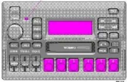
text_image
Control panel interface with labeled buttons and display screen, showing motor control buttons and a highlighted screen.To enter the code
After installation or when the set has been disconnected from power, the set displays "COdE" when it is switched on.
Enter the 4-digit code using the preset buttons.
If the correct code is entered, "on" is displayed and the set is ready to use.
If you enter an incorrect code you must enter the correct code again from the beginning.

Incorrect code
If an incorrect code has been entered "rPt" is displayed. Enter the correct code.
After three unsuccessful coding attempts the set will lock and remain locked for two hours. "OFF" is displayed.
During this waiting period:
· the battery must be connected
· the ignition key must be turned to position I
· the unit must be turned on
Make sure the headlights are turned off to help prevent battery drain (please refer to page 26 for information on turning the headlights off).
Enter the code again once this time has elapsed.
pg. 144 Radio SC-813
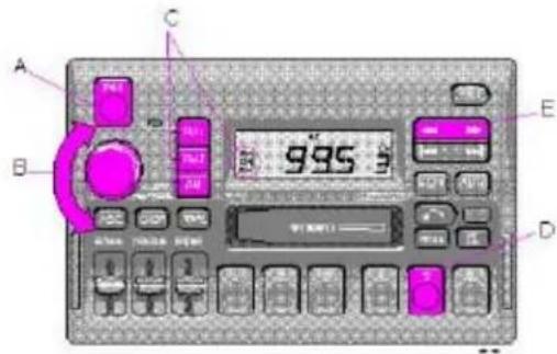
text_image
A B C D E 995 800A - On/off switch
Push the button to switch on the radio. Press the button slightly longer to turn the radio off.
B - Volume control
Turn the button clockwise to increase the volume. The volume control is electronic and has no end stop.
C - Waveband selector
The desired waveband is set by pressing one of the waveband selector buttons. The frequency and waveband is shown on the display.
NOTE: There are two FM wavebands and one
AM waveband. This makes it possible to store 2 x 6 FM stations and 6 AM stations in memory.
D - Setting frequency selection
The radio can be used in most parts of the world by changing the frequency selection intervals as follows:
Depress and hold preset button 5 and turn the radio ON. "USA" will flash on the display.
Each time button 5 is pressed, the frequency selection will change from "USA" to "AUS", etc. When the correct country name is displayed, wait 5 seconds and the radio will be ready for use.
E - Manual tuning
Press the left side tune button to tune to lower frequencies and the right side to tune to higher frequencies. The tuned frequency is displayed.
ST will be displayed to indicate stereo FM reception.
pg. 145 Radio SC-813

text_image
995Ω A BKCA - Seek tuning up/down
Press the left side tune button to tune to lower frequencies and the right side to tune to higher frequencies. The radio seeks the next audible station and stops there. If you wish to continue the seek tuning, press the tune button again.
B - Preset programming
- Tune to the desired frequency.
- Depress and hold a preset button. The audio will cut out. Keep the button depressed until the audio comes on again (approx. 2 seconds).
- The frequency is now stored on this preset button.
C- Preset buttons
To select a pre-programmed radio frequency, depress the preset button. The set frequency will be displayed.
pg. 146 Radio SC-813
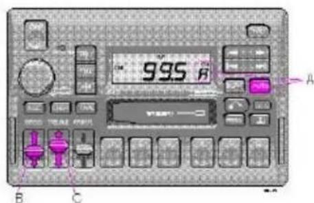
text_image
995 A B CA - Automatic programming (Auto)
Please note that this function will not interfere with pre-stored stations on buttons 1-6.
This function automatically seeks and stores up to 8 strong AM or FM stations.
This is especially useful when travelling in areas where radio stations are unfamiliar.
- Depress and hold the "AUTO" button for at least 1 second. A number of strong stations (max. 8) on the chosen waveband are now automatically stored in the memory.
If there are no audible stations, "----" is displayed.
- Press the "AUTO" button (for less than 1 second) to obtain another autostored station.
A new station will be selected each time the button is pressed momentarily.
B - Bass control
Adjust the bass by sliding the control up or down (up to increase, down to decrease).
A "detent" indicates "equalized" bass.
C- Treble control
Adjust the treble by sliding the control up or down (up to increase, down to decrease).
A "detent" indicates "equalized" treble.
pg. 147 Radio SC-813
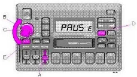
text_image
B C E A PAUSE DA - Fader control
Adjust front/rear speaker balance by sliding the control up or down.
(Up to direct more sound to the front speakers, Down to direct more sound to the rear speakers).
The "detent" indicates "equalized" front /rear balance position.
B - Pause function
Press the "volume" knob to temporarily mute the sound. "PAUSE" is displayed.
C- Balance control
Pull out the "volume" knob and adjust the left/right balance by turning the knob counter-clockwise or clockwise.
D- Scan
Press this button to listen to each station for five seconds. Press it again to stop scanning. "Scan" will be displayed during scanning.
E- Active sound control (ASC)
The ASC function automatically adjusts the volume level of the audio system according to driving speed. To deactivate ASC depress the "ASC" button.
To activate ASC, depress the "ASC" button until "ASC" is displayed.
pg. 148 Cassette deck
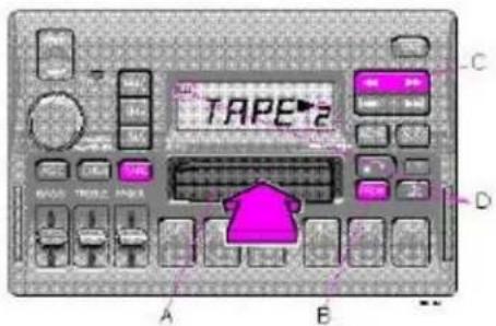
text_image
TAPE2 A B C DA - Cassette slot
The cassette is inserted with the open side to the right (side 1 or A of the cassette upwards).
When the cassette is inserted, the radio is disengaged and the cassette will start to play automatically. "TAPE" or "TAPE" is displayed to indicate which side of the tape is being played. When one side of the tape has been played the unit will automatically play the other side (auto-reverse). The cassette can be inserted or ejected even when the unit is switched off.
B - Reversing the tape (PROG)
Press the button to play the other side of the tape.
The side of the tape being played will be displayed.
C- Fast winding
The tape is advanced with " —" and rewound with " "—
Fast winding can be stopped by pressing either the button again or the "TAPE" button.
D- Dolby B NR button
Press this button when you use tapes recorded with the Dolby B noise reduction system.
The Dolby symbol will be indicated in the display.
pg. 149 Cassette deck

text_image
TAPE C B A DA - Next selector
Press the " " button and the tape will automatically advance to the next song.
There must be a pause of approx. 5 seconds between songs for this function to operate.
B - Previous selector
Press the " " button and the tape will automatically rewind to the previous song.
There must be a pause of approx. 5 seconds between songs for this function to operate.
C- Pause
If you press the "volume" knob the tape is stopped, the unit is silent and "PAUSE" is displayed. To restart the tape press the knob again.
D- Scan
Press this button to listen to the first five seconds of each song. Press this button or the "TAPE" button to stop scanning. During scanning "SCAN" will be displayed.
pg. 150 Cassette deck

text_image
B D C 1059 i A BA - Cassette eject
If the button is pressed the tape will stop and the cassette will be ejected. The radio will be automatically engaged. The radio or CD changer will engage automatically (depending on which mode was activated before the tape was played).
B - To re-enter Radio mode
Push one of the waveband selector buttons
When the unit re-enters Radio mode, the cassette will not be ejected.
C- To re-enter Tape mode
If the Tape function has been disconnected and the cassette has not been ejected, the Tape mode can be re-entered by pressing the "TAPE" button.
D- To re-enter CD changer mode
If the CD changer function has been disconnected, the CD changer mode can be re-entered by pressing the "CHGR" button.
pg. 151 CD - Changer (option)
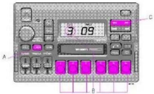
text_image
3 09 A B CA - CD changer mode selector
Press "CHGR" to actuate the CD changer mode. The disc/track last listened to will continue to play. If the CD-changer cartridge* is empty, "--" will be displayed.
If a selected disc does not exist, the disc number and "5--" will be displayed and the next disc will be automatically selected.
B - Disc number selector
Depress one of the preset buttons (1-6) to select the disc number desired. The selected disc number and track number will be displayed.
C- Music search
Press the " = " or " = " button to search within a track. While the button is depressed the playing time for this track will be displayed.
*The functions pertaining to the CD-changer are only applicable if the unit has been connected to the Volvo CD-changer, which is sold separately as an accessory, or on certain models, standard on the car. If no CD-changer is connected to the unit "EEEE" will be displayed if you happen to choose CHGR mode.
pg. 152 CD - Changer (option)

text_image
2 07 A B CA - Changing the selected track number
Press " — " for forward selection or " — " for backWard selection. The chosen disc number and track number will be displayed.
B - Playing-time display
When the "CHGR" button is pressed the playing time for the current track is displayed for 5 seconds.
C- Scan
Press this button to listen to the first ten seconds of each track. Press it again to stop scanning. During scanning "SCAN" will be displayed.
pg. 153 CD - Changer (option)

text_image
C B -1039 s A C E DA - Random choice
Press "RND" to actuate the random mode. From a disc chosen at random, 4 tracks will be played (also chosen at random). A new disc will then be played in the same way. "RND" will be displayed when this function is engaged.
B - Pause
If you press the "volume" knob the disc is stopped, the unit is silent and "PAUSE" is displayed. To restart the disc press the knob again.
C- To re-enter Radio mode
Push one of the waveband selector buttons.
D- To re-enter Tape mode
If a cassette is already inserted, the tape deck will re-engage if the "TAPE" button is pressed.
E- To re-enter CD changer mode
If the CD changer function has been disconnected, the CD changer mode can be re-entered by pressing the "CHGR" button.
pg. 154 Technical specifications
SC-813
Radio
System: PLL (Phase Lock Loop) system with tuned RF (Radio Frequency) front and end automatic wide band gain control. Electronic suppression circuitry (noise killer).
This Radio is equipped with FM-Diversity.
Power output: 4 x 25 W (10% dist.)
2000 Volvo S & V70
Output impedance: 4 Ohms
System voltage: 12 Volts, negative ground
Frequency range:
AM 530 -1710 kHz
FM 87.9 - 107.9 MHz
Sensitivity:
AM 1.1μV
FM 20μV
Stereo separation: 35 dB
Cassette deck
4track, 2 channel stereo
Full logic electronic tape transport
Tape speed: 4.76 cm/sec.
Channel separation 53 dB
Frequency range 3015000 hz
S/N (120 μV) 56 dB without Dolby B NR
S/N (120 μV) 66 dB with Dolby B NR
Wow and Flutter < 0.06%
Pinch off
"Dolby" and the double D symbol are the trademarks of Dolby Laboratories Licensing Corporation. Dolby noise reduction manufactured under license from Dolby Laboratories Licensing Corporation.

Contents | Top of Page
2000 VOLVO S & V70
HomeLink® Universal Transceiver (option)
pg. 198 HomeLink® Universal Transceiver (option)
Indicator light
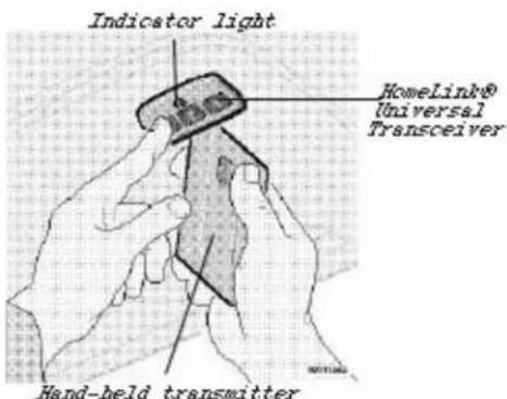
text_image
Indicator light HomeLink® Universal Transceiver Hand-held transmitterHomeLink® Universal Transceiver
This transceiver allows you to replace 3 hand-held transmitters with a single built-in device which can be installed in your car on a sun visor or overhead console. This feature "learns" the radio frequency codes of most current transmitters to operate garage doors, driveway gates, security lighting and home security systems. This transceiver is powered by your car's electrical system.
NOTE: As a security precaution, the HomeLink® Universal Transceiver is designed to not function if the car has been locked from the outside.
Programming the transceiver
- Begin by erasing all 3 factory default channels by holding down the two outside buttons (buttons 1 and 3 in the illustration above) on the HomeLink® Universal Transceiver until the indicator light on the transceiver begins to flash, after approximately 20 seconds. Release the buttons.
- Hold the end of your hand-held transmitter 2 to 5 in. (5 to 12 cm) away from the HomeLink® surface, keeping the indicator light in view. For placement questions, please contact HomeLink® at 1-800-355-3515 (Internet: www.HomeLink.jci.com).
- Using both hands, simultaneously push the hand-held transmitter button and the HomeLink® button to be programmed. Do not release the buttons until this step has been completed. The HomeLink® indicator light will begin to flash, first slowly, then rapidly. When the indicator light flashes rapidly (indicating that the HomeLink® button has been successfully programmed), both buttons may be released.
The remaining two HomeLink® buttons can be programmed in the same way.
If, after several attempts, you do not successfully program the HomeLink® Universal Transceiver to learn the signal of the hand-held transmitter, refer to the section "Programming rolling codes" or call the toll-free customer assistance number: 1-800-355-3515 (Internet: www.HomeLink.jci.com).
WARNING!
- If you use the HomeLink® Universal Transceiver to open a garage door or gate, be sure that no one is near the gate or door while it is in motion.
· Do not use the HomeLink® Universal Transceiver with any garage door opener that lacks safety "stop" and "reverse" features as required by federal safety standards. (This includes any garage door opener model manufactured before April 1, 1982). A garage door opener which cannot "detect" an object, signalling the door to "stop" and "reverse" does not meet current federal safety standards. Using a garage door opener without these features increases the risk of serious injury or death. For more information on this matter, call toll-free 1-800-355-3515 (Internet: www.HomeLink.jci.com).
pg. 199 HomeLink® Universal Transceiver (option)
NOTE - Canadian residents:
During programming, your hand-held transmitter may automatically stop transmitting. To train your hand-held transmitter, continue to hold the HomeLink® button (see steps 2, 3 under "Programming the transceiver") while you press and repress ("cycle") your hand-held transmitter button every two seconds until the frequency signal has been learned. The HomeLink® indicator light will flash slowly and then rapidly to indicate that the HomeLink® button has been successfully programmed.
Programming rolling codes
Determine, in one of the following ways, if your garage door uses a rolling code system and is manufactured after 1996:
- Refer to the garage door opener's owner's manual for verification.
- The hand-held transmitter appears to program the HomeLink® Universal Transceiver but the transceiver does not activate the garage door.
- Press the programmed HomeLink® button. The garage door opener has the rolling code feature if the HomeLink® indicator light flashes rapidly and then glows steadily after approximately 2 seconds.
To train a garage door opener with the rolling code feature, follow these instructions after the transceiver has been programmed (the aid of a second person may make the training quicker and easier):
- Locate the training button on the garage door opener motor head unit. The exact location and color of the button may vary. If you encounter difficulty, refer to the garage door opener owner's manual or call: 1-800-355-3515 (Internet: www.HomeLink.jci.com).
- Press the "training" button on the garage door opener motor head unit until the "training" light comes on.
- Firmly press and release the programmed HomeLink® button. Press and release the HomeLink® button a second time to complete the training process.
Some garage door openers may require you to do this procedure a third time to complete the training.
The programmed button on your HomeLink® Universal Transceiver
should now operate your garage door opener. The original hand-held transmitter can also be used, if necessary, to operate the garage door.
The remaining two buttons can be programmed in the same way. In the event of any problems in programming the HomeLink® Universal Transceiver, call 1-800-355-3515 (Internet: www.HomeLink.jci.com).
Operating the HomeLink® Universal Transceiver
Once programmed, the HomeLink® Universal Transceiver can be used in place of hand-held transmitters.
To operate, press the programmed HomeLink® button to activate the garage door, driveway gate, security lighting, home security system, etc.
The original hand-held transmitter can, of course, be used at any time.
Erasing programmed buttons
Individual buttons cannot be erased. To erase all three programmed buttons:
-
Hold down the two outside buttons on the HomeLink® Universal Transceiver until the indicator light begins to flash, after approximately 20 seconds.
-
Release both buttons.
The HomeLink® buttons can be reprogrammed using the procedures described on the previous page.
(HomeLink® information is continued on the next page)
pg. 200 HomeLink® Universal Transceiver (option)
Reprogramming a single HomeLink® button
- Press and hold the desired HomeLink® button. Do not release the button until step 3 has been completed.
- When the indicator light begins to flash slowly (after approximately 20 seconds), position the hand-held transmitter 2 to 5 in. (5 to 12 cm) away from the HomeLink® surface.
- Press and hold the hand-held transmitter button.
The HomeLink® indicator light will begin to flash, first slowly then rapidly. When the indicator light flashes rapidly, release both buttons.
The previously programmed device has now been erased and the new device can be activated by pressing the HomeLink® button that has just been programmed. This procedure will not affect any other programmed HomeLink® buttons.
NOTE:
- Retain the original transmitter(s) for future programming procedures (i.e., if you purchase a new car).
- It is also suggested that if you sell your car, the programmed channels on the HomeLink® Universal Transceiver be erased for security purposes.
Contents | Top of Page
2000
VOLVO
S & V70
Index
pg. 201 Index
| A | |
| ABS 21,23,83 | — — — |
| Accessories - installing 107 | — |
| Adjustable steering wheel 36 | — |
| Adjusting headlights 98 | — |
| Air conditioning 38,39,41 | — — — |
| Air mix 37 | — |
| Air vents 37 | — |
| Airbag (SIPS) 8 | — |
| Airbag (SRS) 4 | — |
| Alarm 47 | — |
| All Wheel Drive (AWD) 77,122 | — — |
| changing wheels 95 | — |
| snow chains 89 | — |
| towing 81 | — |
| wheel dimension caution 88 | — |
| Ambient temperature sensor | 29 |
| Anti-lock Brake System (ABS) | 21,23,83 |
| Antifreeze | 85,130 |
| Ashtrays | 35 |
| Audio systems | |
| General information | 194 |
| SC-813 | 142 |
| SC-816 | 155 |
| SC-900/901 171 | — |
| Automatic car washing | 115 |
| Automatic daytime running | 28 |
| Automatic transmission | 73,74,75,76,77,137 |
| Kickdown | 74,76 |
| Automatic transmission fluid | 134 |
| Auxiliary seat | 12 |
| Auxiliary socket 35 | — |
B
Battery 85,138 ——
Battery drain - avoiding 62
Battery maintenance 132
Booster cushion 10,
Brake failure warning light 21,22 ____
Brake fluid 128,134
Brake fluid warning light 22
Brake system 83,84
Bulb failure warning 23
Bulb failure warning light 21
Bulbs 138
Bumper cover 62
C
Capacities 137
Cargo eyelets 64
Cargo net - side 63
Cargo space lighting (wagon) 58
Center head restraint 3
Central locking button 45
Chains - winter driving 89
Changing a wheel 94
Child auxiliary seat (wagon) 12
Child booster cushion 10,15
Child Restraint Anchorages 14
Child safety 15
Child safety locks - rear doors 50
Clock 20
Clock - resetting 29
Clutch fluid 128
Clutch interlock 72
Concealed storage bin (wagon) 62
Coolant - checking/changing 130
Coolant level sensor 23
Coolant level warning light 21
Cooling system 78,136
Courtesy lights - exterior 24
Cross bars (AWD XC) 79
Cruise control 33
D
Daytime running lights 28
Demister - rear window 27
Dimensions 140
Diversity antenna 197
Doors and locks 45
Driving economy 70
Driving mode W 74,76 ____
E
EBD (Electronic Brake-force Distribution) 84
ECC - Electronic Climate Control 40,41 ____
Electrical system 78,138
Electrically operated driver's seat 52
Electrically operated front seats 51,110 ____
Electrically operated sun roof 54
Electrically operated windows 42,110 ____
Electronic Brake Distribution (EBD) 84
Electronic Brake-force Distribution (EBD) 84
Emergency towing 80
Emergency warning flashers 27
Emissions systems 124
Engine 135
Engine compartment 131
Engine oil 127,134
Engine oil - checking/changing 126
Engine oil pressure 21
Exterior courtesy lights 24
F
Fog light - rear 21,26
Fog lights - front 26
Folding front seat (sedans/wagons) 65
Folding rear seat (sedan) 59
Folding rear seat (wagon) 60,61
Four wheel drive 77,122 ____
changing wheels 95
snow chains 89
towing 81
Front courtesy lights 53
Front seats 51
Front seats - heated 34
Front suspension 136
Fuel gauge 20
Fuel level 21
Fuel system 124,136
Fuel tank cover - opening 69
Fuses 104,105,106
G
Gas tank cover - opening 69
Generator 21,138
Generator warning light 23
H
Hand brake 34
Handling 79
Hazard warning flashers 27
Headlight adjustment 98
Headlight wiper blades - replacing 109
Headlights 24
Heated front seats 34
Heated side-view mirrors 27
Heating 38,39,41 ____
Heating and air conditioning 37
High beams 21
HomeLink® 198,199,200 ____ ____
Hood 55
I
Ignition switch 25
Immobilizer (start inhibitor) 44
Instrument illumination 26
Instruments 18.
Integrated booster cushion 10
J
Jack (sedan) 57
Jack (wagon) 58
Jump starting 82
K
Keyless entry system 46
Keylock 71
Keys 44
Kick-down 73.75
Kickdown 74,76
L
Label information 118
Lock button - tailgate 49
Locking button - central 45
Locks 45
Long load storage (sedans) 65
Lubrication 125
Luggage net - wagon 63
Lumbar support 51
M
Maintenance schedule 120
Maintenance service 119
Malfunction indicator lamp 21,22
| Manual transmission 72,137 | — — |
| Manual transmission fluid 134 | — |
| Memory function - front seats 51 | — |
| Mirrors - rear/side view 52 | — |
0
| Occupant safety 16 | — |
| Octane rating 69 | — |
| Odometer 20 | — |
| Oil pressure warning light 22 | — |
| On-call 140 | — |
P
| Paint touchup 112 | — |
| Parking brake 21,34 | — — |
| Parking brake reminder light 22 | — |
| Parking lights 24 | — |
| Polishing 115 | — |
| Power seats 51,110 | — — |
| Power steering fluid | 128,134 |
| Power windows | 42,110 |
R
| Radio | |
| SC-813 | 142 |
| SC-816 | 155 |
| SC-900/901 | 171 |
| Radio Data System - RDS | 176 |
| Rails (roof) | 79 |
| Reading lights | 53 |
| Rear fog light | 21,26 |
| Rear suspension | 136 |
| Rear window demister | 27 |
| Rear/side-view mirrors | 52 |
| Refueling | 69 |
| Remote control (central locking system) | 46 |
| Remote keyless entry system | 46 |
| Removing seat cushions (wagon) | 61 |
| Replacing bulbs | 98,99 |
| Replacing fuses | 104 |
| Reporting safety defects | 16 |
| Road Assistance | 140 |
| Roadholding | 79 |
| Roof rails/racks | 79 |
| S | |
| Safety defects - reporting | 16 |
| Safety locks - child | 50 |
| Seat belt maintenance 16 | — |
| Seat belts 2,3,13 | — — — |
| Seat belts - cleaning 116 | — |
| Seats 51 | — |
| Securing cargo 64 | — |
| Service reminder indicator 21,23 | — — |
| Servicing 122,123 | — — — |
| Shift lock 71 | — |
| Shiftlock 73,75 | — — |
| Shiftlock release (override) 110 | — |
| Side cargo net 63 | — |
| Side Impact Protection System (SIPS) 8 | — |
| Side-view mirrors - heated 27 | — |
| SIPS 8 | — |
| Snow chains | 89 |
| Snow tires | 89 |
| Spare tire 96 | — |
| Spare tire (sedan) | 57 |
| Spare tire (wagon) | 58 |
| Spark plugs | 136 |
| Specifications | 133 |
| Spool-out (seat belt) | 13 |
| SRS | 5,6,7 |
| SRS diagnostic system | 22 |
| SRS warning light | 5,21,22 |
| Stability and Traction Control (STC) | 21,23,27,84 |
| Start inhibitor (immobilizer) | 44 |
| Starting the engine | 71 |
| Steering wheel adjustment | 36 |
| Steering wheel lock | 25 |
| Storage compartments | 56 |
| Studded tires | 89 |
| Sun roof | 27,54,110 |
| T | |
| Tachometer | 20 |
| Tailgate (opening/locking) | 49 |
| lock button | 49 |
| Tailgate wiper/washer | 28 |
| Temperature gauge | 20 |
| Temporary spare tire | 96 |
| Tire pressure | 90 |
| Tires | 88 |
| Tires - changing | 94 |
| Towing | 80,81 |
Towing a trailer 86
Traction Control System (TRACS) 21,23,27,84
Trailer towing 86
Trip computer 27,30,31,32
Trip odometer 20
Trunk (opening/locking) 49
Trunk light 57
Turn signals 21,24
U
Uniform tire quality grading 91
Upholstery - cleaning 116
V
Vanity mirrors 53
Vehicle Identification Number (VIN) 118
Vehicle loading 137
Whiplash Protection System (WHIPS) 9
WHIPS 9
Winter/Wet driving mode 74,76 ____
Volvo On Call 140
W
Warning flashers 27
Warning lights 22,23 ____
Warranty 119
Washer fluid level 21
Washer fluid reservoir 129
Washing 114
Waxing 115
Wheel changing 94,95 ____
Wheels and tires 88
Windows - electrically-operated 42
Windshield washer nozzles 129
Windshield wiper blades - replacing 108
Winter driving 85

Contents | Top of Page