Astra Twintop (2011) - Car OPEL - Free user manual and instructions
Find the device manual for free Astra Twintop (2011) OPEL in PDF.

User questions about Astra Twintop (2011) OPEL
0 question about this device. Answer the ones you know or ask your own.
Ask a new question about this device
Download the instructions for your Car in PDF format for free! Find your manual Astra Twintop (2011) - OPEL and take your electronic device back in hand. On this page are published all the documents necessary for the use of your device. Astra Twintop (2011) by OPEL.
USER MANUAL Astra Twintop (2011) OPEL
Keys, doors and windows ..... 20
Seats, restraints 47
Storage 67
Instruments and controls 86
Lighting 117
Infotainment system 124
Climate control 127
Driving and operating 135
Vehicle care 162
Service and maintenance ..... 209
Technical data 213
Customer information 263
Index 266
2 Introduction
Introduction
| Fuel | Designation | ||
| Engine oil | Grade | ||
| Viscosity | |||
| Tyre pressure | Tyre size | Front | Rear |
| Summer tyres | |||
| Winter tyres | |||
| Weights | Gross vehicle weight rating | ||
| - Kerb weight, basic model | |||
| - Additional weight | |||
| - Heavy accessories | |||
| = Loading |
Vehicle specific data
Please enter your vehicle's data on the previous page to keep it easily accessible. This information is available in the sections "Service and maintenance" and "Technical data" as well as on the identification plate.
Introduction
Your vehicle is a designed combination of advanced technology, safety, environmental friendliness and economy.
This Owner's Manual provides you with all the necessary information to enable you to drive your vehicle safely and efficiently.
Make sure your passengers are aware of the possible risk of accident and injury which may result from improper use of the vehicle.
You must always comply with the specific laws and regulations of the country that you are in. These laws may differ from the information in this Owner's Manual.
When this Owner's Manual refers to a workshop visit, we recommend your Opel Service Partner.
All Opel Service Partners provide first-class service at reasonable prices. Experienced mechanics trained by Opel work according to specific Opel instructions.
The customer literature pack should always be kept ready to hand in the vehicle.
Using this manual
■ This manual describes all options and features available for this model. Certain descriptions, including those for display and menu functions, may not apply to your vehicle due to model variant, country specifications, special equipment or accessories.
■ The "In brief" section will give you an initial overview.
■ The table of contents at the beginning of this manual and within each section shows where the information is located.
■ The index will enable you to search for specific information.
■ This Owner's Manual depicts left-hand drive vehicles. Operation is similar for right-hand drive vehicles.
■ The Owner's Manual uses the factory engine designations. The corresponding sales designations can be found in the section "Technical data".
■ Directional data, e.g. left or right, or front or back, always relate to the direction of travel.
■ The vehicle display screens may not support your specific language.
■ Display messages and interior labelling are written in bold letters.
Danger, Warnings and Cautions
Danger
Text marked △Danger provides information on risk of fatal injury. Disregarding this information may endanger life.
4 Introduction
⚠ Warning
Text marked △Warning provides information on risk of accident or injury. Disregarding this information may lead to injury.
Caution
Text marked Caution provides information on possible damage to the vehicle. Disregarding this information may lead to vehicle damage.
Symbols
Page references are indicated with ↗.
means "see page".
We wish you many hours of pleasurable driving.
Adam Opel AG
Introduction 5
In brief
Initial drive information
Vehicle unlocking
Radio remote control

natural_image
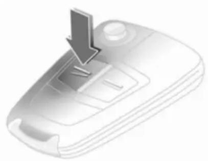
Illustration of a remote control device with a downward arrow pointing to the button (no text or symbols)Press button ≥ to unlock the vehicle.
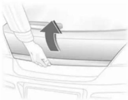
Open the doors by pulling the handles.
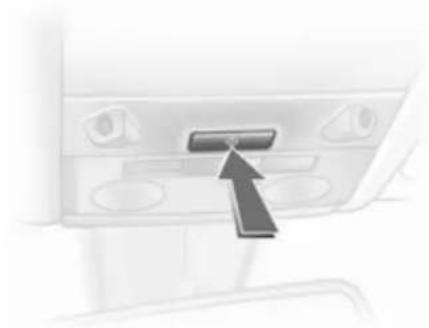
To open the tailgate, push the touchpad below the handle.
Saloon 4-door: Press button ≥ on the remote control for at least 2 seconds, the boot lid opens slightly.
Radio remote control 20, Central locking system 25, Load compartment 28.
Electronic key
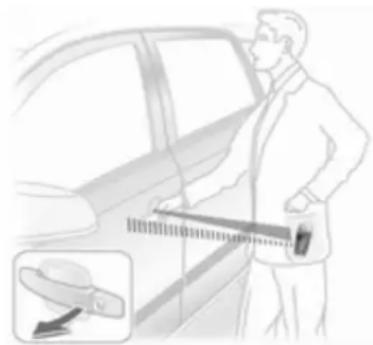
natural_image
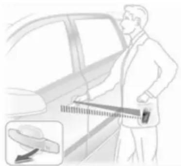
Illustration of a person measuring a car with a tape measure, showing the magnified view of the car's side profile (no text or symbols present)When in possession of the electronic key, simply pulling the door handle will unlock the vehicle and open the door. To open the tailgate, press the button under the moulding.
Open&Start system ↩ 22.
Seat adjustment
Seat positioning

natural_image
Illustration of a car seatbelt with directional arrows indicating rotation (no text or symbols)Pull handle, slide seat, release handle.
Seat adjustment 50, Seat position 49.
Danger
Do not sit nearer than 25 cm from the steering wheel, to permit safe airbag deployment.
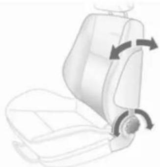
Seat backrests

natural_image
Line drawing of a car seat with directional arrows indicating rotation (no text or symbols)Turn handwheel. Do not lean on seat when adjusting.
Seat adjustment 50, Seat position 49, Folding front passenger seat backrest 52.
Seat height
natural_image
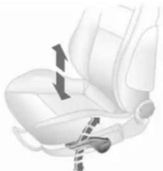
Interior view of a car seatbelt with arrows indicating seat movement (no text or symbols)Lever pumping motion
up = higher
down = lower
Seat adjustment ↩ 50, Seat position ↩ 49.
8 In brief
Seat inclination
natural_image
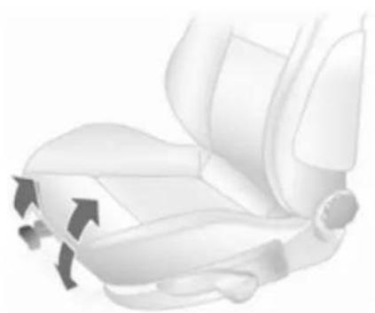
Illustration of a car seatbelt with directional arrows indicating movement or force (no text or symbols)Pull lever, adjust inclination by shifting body weight. Release lever and audibly engage seat in position. Seat adjustment 50, Seat position 49.
Head restraint adjustment
natural_image
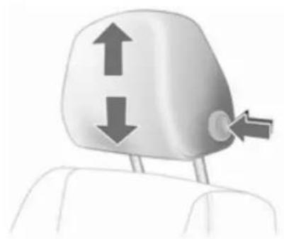
Illustration of a car head with two directional arrows indicating upward and downward motion (no text or symbols)Press release button, adjust height, engage.
Head restraints 47.
Seat belt

natural_image
Illustration of a person sitting in a car, wearing a seatbelt and holding a steering wheel (no text or symbols visible)Pull out the seat belt and engage in belt buckle. The seat belt must not be twisted and must fit close against the body. The backrest must not be tilted back too far (maximum approx. 25°). To release belt, press red button on belt buckle.
Seat belts 54, Airbag system 57, Seat position 49.
Mirror adjustment
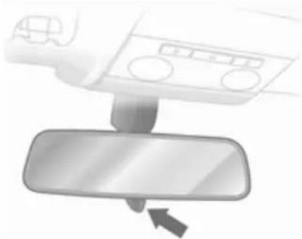
Interior mirror

natural_image
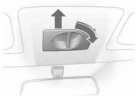
Diagram showing a car interior panel with a downward arrow pointing to the mirror (no text or symbols present)Swivel the lever on the underside to reduce dazzle.
Interior mirror ➔ 34, Automatic anti-dazzle interior mirror ➔ 34.
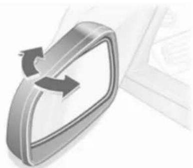
Exterior mirrors
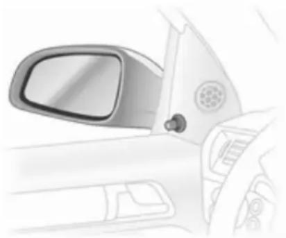
Electric adjustment
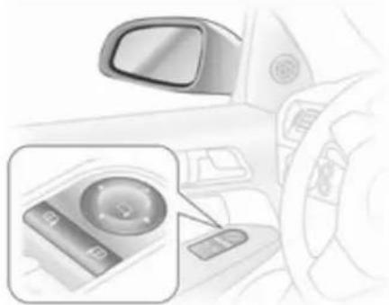
natural_image
Interior view of a car dashboard with a close-up of the steering wheel (no text or symbols visible)Select the relevant exterior mirror and adjust.
Electric adjustment 33, Convex exterior mirrors 32, Folding exterior mirrors 33, Heated exterior mirrors 34.
Steering wheel adjustment

natural_image
Diagram of a car steering wheel with directional arrows indicating rotation (no text or symbols)Unlock lever, adjust steering wheel, then engage lever and ensure it is fully locked. Do not adjust steering wheel unless vehicle is stationary and steering wheel lock has been released.
Airbag system ↩ 57, Ignition positions ↩ 136.
10 In brief
text_image
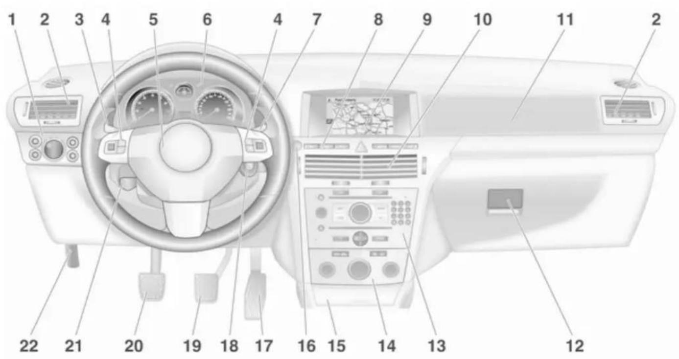
Diagram of a car dashboard with numbered parts for identificationInstrument panel overview
1 Light switch 117
Instrument illumination ..... 121
Rear fog light 120
Front fog lights 120
Headlight range
adjustment 118
2 Side air vents 133
3 Turn and lane-change signals, headlight flash, low beam and high beam ... 120 Exit lighting .... 123 Parking lights .... 120 Cruise control .... 102
4 Steering wheel controls ..... 86
5 Horn 87 Driver airbag 57
6 Instruments 93
7 Windscreen wiper, windscreen washer system, headlight washer system 87
8 Left heated seat 53
Deflation detection system .. 194
Tyre pressure monitoring system 193
Load compartment
unlocking 28
Ultrasonic parking sensors ... 98
Hazard warning flashers ..... 119
Central locking system ..... 25
Sport mode 98
Right heated seat 53
9 Info-Display .... 102 Trip computer .... 112 Electronic climate control system .... 130
10 Centre air vents 133
11 Front passenger airbag ..... 57
12 Glovebox 67
13 Infotainment system ...... 124
14 Climate control system ..... 127
15 Ashtray 91
16 Start/Stop button 22
17 Accelerator pedal 135
18 Ignition switch with steering wheel lock .... 136
Sensor panel for emergency operation of Open&Start system .... 22
19 Brake pedal 149
20 Clutch pedal 135
21 Steering wheel adjustment ...86
22 Bonnet release lever 163
12 In brief
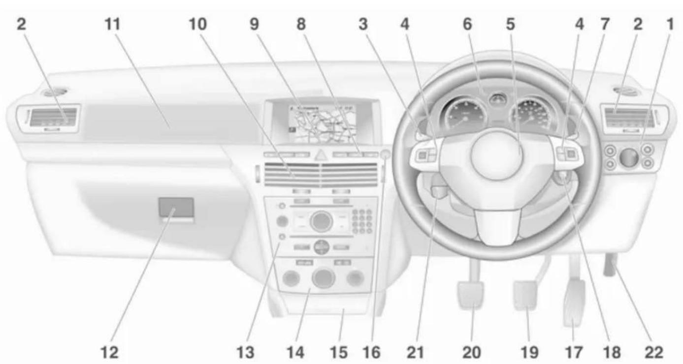
text_image
Diagram of car interior with numbered labels pointing to various components such as dashboard, steering wheel, and air conditioner.Exterior lighting
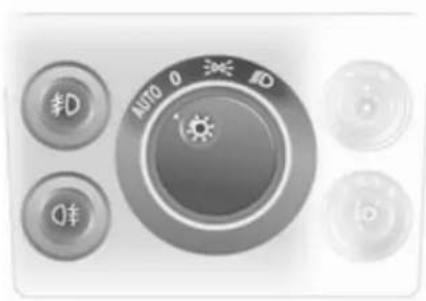
natural_image
Close-up of a gray industrial control panel with buttons and dials (no readable text or symbols)Turn light switch
0 = Off
D = Sidelights
≡D = Headlights
AUTO = Automatic light control
Press light switch
≠D = Front fog lights
O‡ = Rear fog light
Lighting 117.
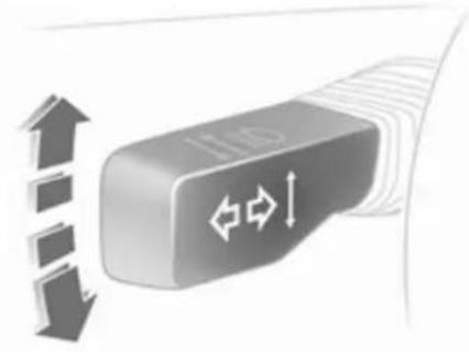
Headlight flash, high beam and low beam
natural_image
Illustration of a USB flash drive with directional arrows indicating motion (no text or symbols)Headlight flash = Pull lever
High beam = Push lever
Low beam = Push or pull lever
High beam 118, Headlight flash 118.
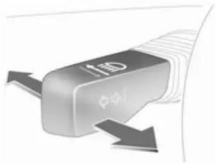
Turn and lane-change signals
natural_image
Close-up of a gray USB flash drive with directional arrows indicating left and right motion (no text or symbols)To the right = Lever up
To the left = Lever down
Turn and lane-change signals 120.
14 In brief
Hazard warning flashers
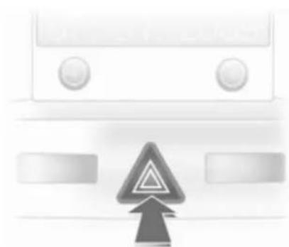
natural_image
Front view of a vehicle front with a warning sign and upward arrow (no readable text or symbols)Operated with the △ button.
Hazard warning flashers ➔ 119.
Horn
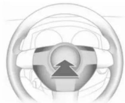
natural_image
Interior view of a car steering wheel with an upward arrow indicating direction (no text or symbols)Press ▶.
Washer and wiper systems
Windscreen wiper

natural_image
Close-up of a mechanical component with directional arrows indicating motion or force (no text or symbols)== = fast
— = slow
-- = timed interval wipe or automatic wiping with rain sensor
O = off
For a single wipe when the windscreen wiper is off, press the lever down.
Windscreen wiper 87, Wiper blade replacement 167.
Windscreen and headlight washer systems
natural_image
Close-up of a computer mouse with a black downward arrow indicating compression (no text or symbols visible)Pull lever.
Windscreen and headlight washer system ➔ 87, Washer fluid ➔ 166.
Rear window wiper and washer systems
natural_image
Close-up of a mechanical component with a curved arrow indicating motion (no text or symbols visible)Wipers on = push lever Wipers off = push lever again Wash = push lever and hold
Rear window wipers and washer system 88, Wiper blade replacement 167, Washer fluid 166.
Climate control
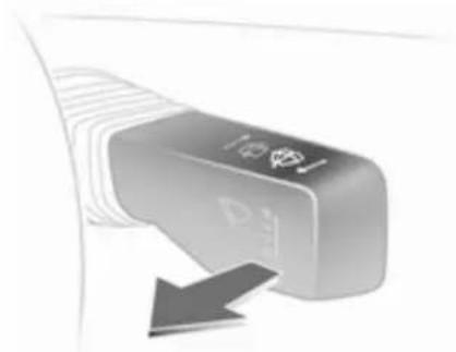
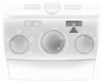
Heated rear window, heated exterior mirrors
natural_image
Front view of a white air conditioner unit with control knobs and a digital display (no visible text or symbols)Heating is operated by pressing the 📄 button.
Heated rear window ➔ 37.
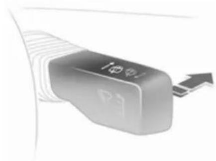
Demisting and defrosting the windows
natural_image
Close-up of a white industrial air conditioner control panel with three rotary buttons and a small icon (no text or symbols visible)Air distribution to 📄.
Set temperature control to warmest level.
Set fan speed to highest level or to A.
Cooling ⚙ on.
Press button.
Climate control system ↗ 127.
Transmission
Manual transmission
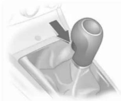
natural_image
Close-up of a mechanical gear shift lever with a black arrow indicating the direction (no text or symbols visible)Reverse: with the vehicle stationary, wait 3 seconds after depressing clutch pedal and then pull up the button on the selector lever and engage the gear.
If the gear does not engage, set the lever to neutral, release the clutch pedal and depress again; then repeat gear selection.
Manual transmission ➔ 144.
Manual transmission automated

text_image
Diagram of a mechanical device with labeled components A, N, R and directional arrows indicating motion or forceN = neutral
● = drive
+ = higher gear
- = lower gear
A = switch between Automatic and Manual mode
R = reverse gear (with selector lever lock)
Manual transmission automated ◇ 145.
Automatic transmission
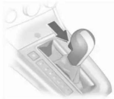
natural_image
Close-up of a car intake manifold with a black arrow pointing to the mode (no text or symbols visible)P = park
R = reverse
N = neutral
D = drive
The selector lever can only be moved out of P or N when the ignition is on and the foot brake is depressed (selector lever lock). To engage P or R, push button on selector lever.
The automatic transmission is available in two versions 139.
Starting off
Check before starting off
■ Tyre pressure and condition ➔ 192, ➔ 244.
■ Engine oil level and fluid levels 164.
■ All windows, mirrors, exterior lighting and number plates are free from dirt, snow and ice and are operational.
■ Proper position of seats, seat belts and mirrors 49, 55, 33.
■ Brake function at low speed, particularly if the brakes are wet.
Starting engine with ignition switch

text_image
1 2 3 0 30047Turn key to position 1. Move the steering wheel slightly to release the steering wheel lock. Operate clutch and brake, automatic transmission in P or N, do not accelerate; for diesel engines, turn the key to position 2 for preheating and wait until control indicator ☐ goes out; turn key to position 3 and release key when engine is running.
Starting engine with Start/Stop button

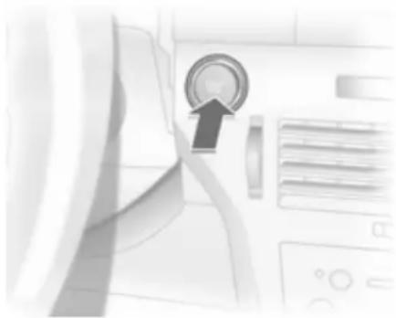
natural_image
Close-up of a mechanical component with a circular dial indicator and control panel (no visible text or symbols)The electronic key must be inside the vehicle. Operate clutch and brake, automatic transmission in P or N, do not accelerate, for diesel engines; press the button briefly to start preheating, move the steering wheel slightly to release the steering wheel lock, wait until control indicator 00 goes out and then press button for 1 second and release when the engine is running.
Open&Start system ↩ 22.
Parking
■ Always apply the parking brake without pressing the release button. Apply as firmly as possible on a downhill slope or uphill slope. Depress the foot brake at the same time to reduce operating force.
■ Switch off the engine. Turn the ignition key to position 0 and remove it or, with the vehicle stationary, press the Start/Stop button and open the driver's door. Turn the steering wheel until the steering wheel lock is felt to engage.
For vehicles with automatic transmission, the key can only be removed when the selector lever is in the P position. If P is not engaged or the parking brake is not applied, "P" flashes for a few seconds in the transmission display.
■ If the vehicle is on a level surface or uphill slope, engage first gear or set the selector lever to P before switching off the ignition. On an uphill slope, turn the front wheels away from the kerb.
If the vehicle is on a downhill slope, engage reverse gear or set the selector lever to P before switching off the ignition. Turn the front wheels towards the kerb.
■ Lock the vehicle with button = on the radio remote control or with the sensor in a front door handle.
To activate the anti-theft locking system and the anti-theft alarm system, press button = twice or touch the sensor in a front door handle twice.
■ Do not park the vehicle on an easily ignitable surface. The high temperature of the exhaust system could ignite the surface.
■ On vehicles with manual transmission automated, control indicator Ⓐ flashes for a few seconds after the ignition is switched off if the parking brake has not been applied ➔ 109.
■ Close windows and sunroof or TwinTop.
In brief 19
■ The engine cooling fans may run after the engine has been switched off 163.
■ After running at high engine speeds or with high engine loads, operate the engine briefly at a low load or run in neutral for approx. 30 seconds, before switching off in order to protect the turbocharger.
Keys, locking 20, Laying the vehicle up for a long period of time 162, TwinTop roof operation 40.
Keys, doors and windows
Keys, locks 20
Doors 28
Vehicle security 30
Exterior mirrors 32
Interior mirrors 34
Windows 35
Roof 38
Keys, locks
Keys
Replacement keys
The key number is specified in the Car Pass or on a detachable tag.
The key number must be quoted when ordering replacement keys as it is a component of the immobiliser system.
Locks 205, Open&Start system, electronic key 22.
Key with foldaway key section

natural_image
3D illustration of a handheld device with a downward arrow pointing to its top component (no text or symbols)Press button to extend. To fold the key, first press the button.
Car Pass
The Car Pass contains security related vehicle data and should therefore be kept in a safe place.
When the car is taken to a workshop, this vehicle data is needed in order to perform certain operations.
Radio remote control
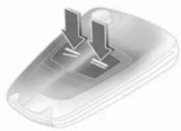
natural_image
Illustration of a computer mouse with two downward arrows indicating motion or force (no text or symbols)Used to operate:
■ Central locking system
■ Anti-theft locking system
■ Anti-theft alarm system
■ Power windows
■ Electric roof on Astra TwinTop
The radio remote control has an approximate range of up to 5 metres. This range can be affected by outside influences. The hazard warning flashers confirm operation.
Handle with care, protect from moisture and high temperatures and avoid unnecessary operation.
Fault
If the central locking system cannot be operated with the radio remote control, it may be due to the following:
■ Range exceeded
■ Battery voltage too low
■ Frequent, repeated operation of the radio remote control while not in range, which will require re-synchronisation
■ Overload of the central locking system by operating at frequent intervals, the power supply is interrupted for a short time
■ Interference from higher-power radio waves from other sources Unlocking ➔ 25.
Radio remote control battery replacement
Replace the battery as soon as the range reduces.
Batteries do not belong in household waste. They must be disposed of at an appropriate recycling collection point.
Key with foldaway key section

natural_image
Illustration of a hand holding a device with an arrow indicating upward motion (no text or symbols)Extend the key and open the unit. Replace the battery (battery type CR 2032), paying attention to the installation position. Close the unit and synchronise.
Key with fixed key section Have the battery replaced by a workshop.
22 Keys, doors and windows
Radio remote control synchronisation
After replacing the battery, unlock the door with the key in the driver's door lock. The radio remote control will be synchronised when you switch on the ignition.
Memorised settings
Whenever the key is removed from the ignition switch, the following settings are automatically remembered by the key:
■ Electronic climate control
■ Info-Display
■ Infotainment system
■ Instrument panel illumination
The saved settings are automatically used next time that key is used for unlocking.
Open&Start system
natural_image
Illustration of a person measuring a car's height with a magnified inset showing the tool (no text or symbols)Makes operation of the following possible without the use of the mechanical key:
■ Central locking system
■ Anti-theft locking system
■ Anti-theft alarm system
■ Power windows
■ Ignition and starter
The electronic key simply needs to be in the driver's possession.
natural_image
Interior view of a washing machine with a circular dial indicator and control panel (no visible text or symbols)Press the Start/Stop button. The ignition is switched on. The electronic immobiliser and steering wheel lock are deactivated.
To start the engine press and hold the Start/Stop button whilst applying both the brake and clutch pedals.
Automatic transmission: the engine can only be started with the selector lever in P or N.
The engine and the ignition are switched off by pressing the Start/Stop button again. The vehicle must be stationary. The immobiliser is activated at the same time.
If the ignition has been switched off and the vehicle is stationary, the steering wheel lock activates automatically when the driver's door is opened or closed.
Control indicator ☑) 101.
Note
Do not put the electronic key in the load compartment or in front of the Info-Display.
The sensor fields in the door handles must be kept clean to ensure unrestricted functionality.
If the battery is discharged, the vehicle must not be towed, tow-started or jump-started as the steering wheel lock cannot be disengaged.
Radio remote control
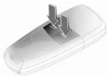
natural_image
Illustration of a mobile phone with two downward arrows indicating download or download process (no text or symbols)The electronic key likewise has a radio remote control feature.
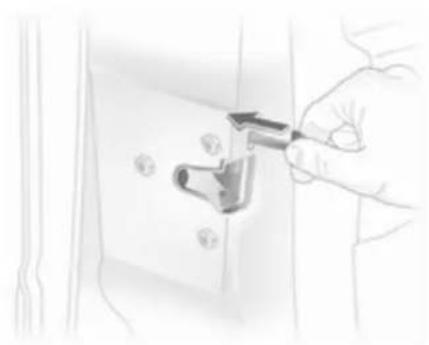
Emergency operation

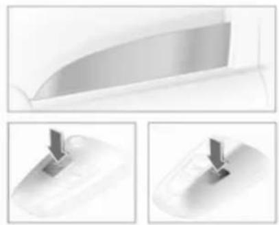
text_image
Diagram showing two steps of a medical or laboratory procedure: step 1 indicates a device being inserted, and step 2 indicates a hand holding a tool.If the radio remote control also fails, the driver's door can be locked or unlocked with the emergency key contained in the electronic key: press locking mechanism and remove the cap by applying light pressure. Push the emergency key outwards over the detent and remove.
24 Keys, doors and windows

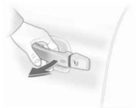
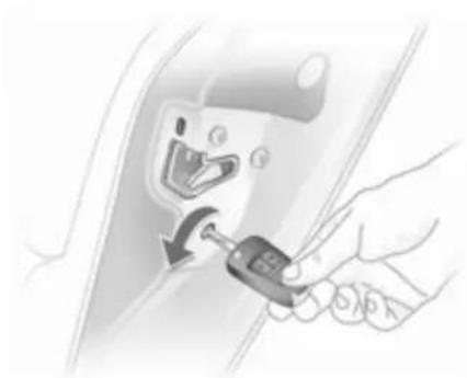
natural_image
Illustration of a door handle with a curved arrow indicating rotation (no text or symbols)The emergency key can only lock or unlock the driver's door. Unlocking the entire vehicle 25. On vehicles with anti-theft alarm system, the alarm may be triggered when the vehicle is unlocked. Deactivate the alarm by switching on the ignition.

natural_image
Hand inserting a device into a control panel with an arrow indicating left-side action (no text or symbols visible)Hold the electronic key at the marked position and press the Start/Stop button.
To switch off the engine, press the Start/Stop button for at least 1 second.
Lock the driver's door with the emergency key. Locking the entire vehicle ➔ 25.
This option is intended for emergencies only. Seek the assistance of a workshop.
Replacing battery in electronic key
Replace the battery as soon as the system no longer operates properly or the range is reduced. The need for battery replacement is indicated by InSP3 in the service display or by a check control message in the Info-Display.
Service display ↩ 94, Info-Display ↩ 110.
Batteries do not belong in household waste. They must be disposed of at an appropriate recycling collection point.

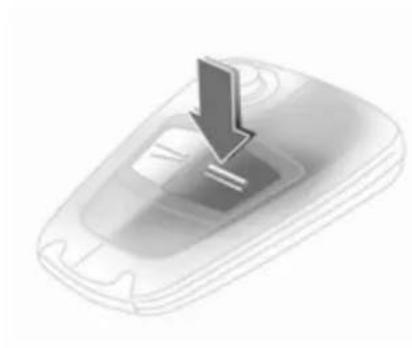
natural_image
Illustration of a hand holding a flip-flop device (no text or symbols visible)To replace the battery, press the locking mechanism and remove the cap by applying light pressure. Press the cap on the other side outwards.
Replace the battery (battery type CR 2032), noting the installation position. Engage caps.
Radio remote control synchronisation
The radio remote control synchronises itself automatically during every starting procedure.
Fault
If the central locking cannot be operated or the engine cannot be started, the cause may be one of the following:
■ fault in remote control ➔ 20
■ electronic key out of reception range
To rectify the cause of the fault, change the position of the electronic key.
Central locking system
Unlocks and locks doors, load compartment and fuel filler flap.
A pull on an interior door handle unlocks the entire vehicle and opens the door.
Note
In the event of an accident of a certain severity, the vehicle unlocks automatically.
Note
A short time after unlocking with the remote control the doors are locked automatically if no door has been opened.
Unlocking
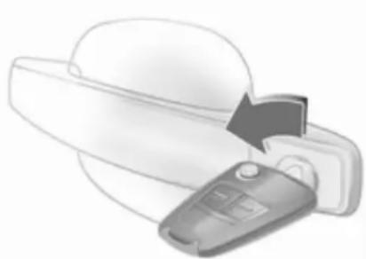
Radio remote control

natural_image
Illustration of a remote control switch with a downward arrow (no text or symbols)Press button ≥ .
26 Keys, doors and windows
Electronic key
natural_image
Illustration of a hand holding a medical or surgical tool, with no visible text or symbolsPull a door handle or press the button under the tailgate moulding.
The electronic key must be outside the vehicle, within a range of approximately 1 metre.
Locking
Close doors, load compartment and fuel filler flap. If the driver's door is not closed properly, the central locking system will not work.
Radio remote control
natural_image
3D illustration of a download icon on a device (no text or symbols)Press button =.
Electronic key

natural_image
Hand holding a pen or stylus, no visible text or symbolsTouch the sensor field in the door handle of one of the front doors.
The electronic key must be outside the vehicle, within a range of approximately 1 metre. The other electronic key must not be inside the vehicle.
2 seconds must pass before the vehicle can be unlocked. Within this time, it is possible to check that the vehicle is locked.
Note
The vehicle is not automatically locked.
Central locking button

natural_image
Pure electrical circuit lines without any symbolsPress the 📄 button: the doors are locked or unlocked.
The LED in the button 📄 illuminates for approx. 2 minutes after locking with the radio remote control.
If the doors are locked from the inside whilst driving, the LED remains lit.
If the key is in the ignition switch, locking is only possible if all doors are closed.
Fault in remote control or Open&Start system
Unlocking
natural_image
Illustration of a hand holding a car with a door handle, showing the door and phone (no text or symbols)Turn key or emergency key ➔ 22 in the driver's door lock as far as it will go. The entire vehicle is unlocked when the driver's door is opened.
For Astra TwinTop with open roof - after opening the driver's door, press the central locking button 📄. The vehicle will then be unlocked, provided the anti-theft locking system is not engaged. Switch on the ignition to deactivate the anti-theft alarm system. Open&Start system ➔ 22.
Locking
Close the driver's door, open the passenger door, press central locking button 📄. The vehicle is locked. Close the passenger door.
Fault in central locking system
Unlocking
Turn key or emergency key ➔ 22 in the driver's door lock as far as it will go. The other doors can be opened by using the interior handle (not possible if the anti-theft locking system is active). The load compartment and
fuel filler flap remain locked. To deactivate the anti-theft locking system, switch on the ignition ➔ 30.
Manual unlocking of boot lid Folding the rear seat backrests 52.
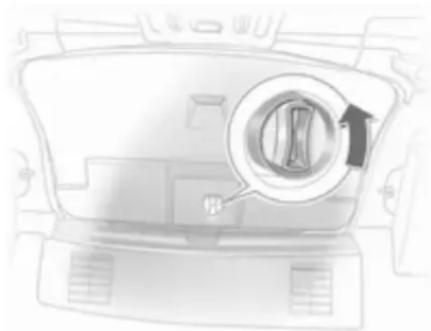
natural_image
Top-down view of a car backhaul with a circular inset showing a gear mechanism (no text or symbols)From the interior, turn the rotary knob on the inside of the boot lid anticlockwise, this unlocks the boot lid and opens it slightly.
28 Keys, doors and windows
Locking
natural_image
Hand holding a tool interacting with a white electrical outlet (no text or symbols visible)Insert key or emergency key ➔ 22 into opening above lock on inside of door and operate lock by pressing until it clicks. Then close the door. The procedure must be carried out for each door. The driver's door can also be locked from the outside with the key. The fuel filler flap and tailgate/boot lid cannot be locked.
Child locks
natural_image
Illustration of a hand inserting a key into a car's seat panel (no text or symbols visible)⚠ Warning
Use the child locks whenever children are occupying the rear seats.
Using a key or suitable screwdriver, turn button on rear door lock to the horizontal position: door cannot be opened from inside.
Doors
Load compartment
Opening
natural_image
Illustration of a hand pressing down on a car's side panel with an upward arrow (no text or symbols)Push the button under the tailgate moulding.
⚠ Warning
Do not drive with the tailgate open or ajar, e.g. when transporting bulky objects, since toxic exhaust gases could enter the vehicle.
Note
The installation of certain heavy accessories onto the tailgate may affect its ability to remain open.
Central locking system ↩ 25
Saloon 4-door

natural_image
Close-up of a white industrial fan grille with a traffic sign icon and warning symbols (no readable text)To unlock the boot lid, press button or press button ≥ of the remote control for at least 2 seconds, the boot lid is opened slightly.
natural_image
3D rendered image of a remote control device with a downward arrow pointing to the button (no text or symbols visible)With the doors centrally locked, the boot lid cannot be unlocked with button 📄.
Closing
natural_image
Diagram of a car rear bumper with an arrow indicating direction (no text or symbols present)Use the interior handle.
Do not press the button under the moulding while closing as this will unlock it again.
Close boot lid. The closed boot lid is always locked. To lock the doors, press button = on the remote control.
Vehicle security
Anti-theft locking system
⚠ Warning
Do not use the system if there are people in the vehicle! The doors cannot be unlocked from the inside.
The system deadlocks all doors. All doors must be closed or the system cannot be activated.
If the ignition was on, the driver's door must be opened and closed once so that the vehicle can be secured.
Unlocking the vehicle disables the mechanical anti-theft locking system. This is not possible with the central locking button.
Activating with the radio remote control

text_image
2xPress = twice within 15 seconds.
Activating with the electronic key

natural_image
Illustration of a hand holding a tool, no text or symbols visibleTouch the sensor field in the front door handle twice within 15 seconds. The electronic key must be outside the vehicle, within a range of approx. 1 metre.
Anti-theft alarm system
The anti-theft alarm system incorporates and is operated in conjunction with the anti-theft locking system.
It monitors:
■ Doors, load compartment, bonnet,
■ Passenger compartment,
■ Vehicle inclination, e.g. if it is raised,
■ Ignition.
Unlocking the vehicle deactivates both systems simultaneously.
Note
Changes to the vehicle interior, such as the use of seat covers, could impair the function of passenger compartment monitoring.
Activation without monitoring of passenger compartment and vehicle inclination
natural_image
Close-up of a mechanical component with a button labeled 'T' and an arrow pointing to it (no text or symbols visible)Switch off the monitoring of passenger compartment and vehicle inclination, when people or animals are being left in the vehicle, because of high volume ultrasonic signals, movements triggering the alarm and when the vehicle is on a ferry or train.
- Close load compartment and bonnet
- Press button ①. The LED in button
flashes for maximum 10 seconds
3. Close doors
- Activate the anti-theft alarm system. The LED illuminates. After approx. 10 seconds, the system is armed. The LED flashes until the system is deactivated
For Astra TwinTop, passenger compartment monitoring is deactivated if the roof is open to prevent false alarms.
Light-emitting diode (LED)

natural_image
Pure electrical circuit lines without any symbols32 Keys, doors and windows
During the first 10 seconds of anti-theft alarm system activation:
LED = Test, ignition delay illuminates
LED = Door, load
flashes compartment or quickly bonnet open, or system fault
After the first 10 seconds of anti-theft alarm system activation:
LED flashes = System active slowly
LED comes on for = Switch off approx. 1 second function
Seek the assistance of a workshop in the event of faults.
Alarm
When triggered, the alarm gives off an acoustic signal (horn) and a visual signal (hazard warning flashers). The number and duration of which are stipulated by legislation.
The alarm siren can be silenced by pressing a button of the radio remote control or by switching on the ignition. The anti-theft alarm system is deactivated at the same time.
Immobiliser
The system checks whether the vehicle is allowed to start with the key being used. If the transponder in the key is recognised, the engine can be started.
The electronic immobiliser activates itself automatically after the key has been removed from the ignition switch or when the engine is switched off by pressing the Start/Stop button.
Control indicator ↙ 97.
Note
The immobiliser does not lock the doors. You should always lock the vehicle after leaving it and switch on the anti-theft alarm system 25, 30.
Exterior mirrors
Convex shape
The convex exterior mirror contains an aspherical area and reduces blind spots. The shape of the mirror makes objects appear smaller, which will affect the ability to estimate distances.
Manual adjustment
natural_image
Side view of a car's front and rear dashboard showing the mirror and steering wheel (no text or symbols visible)Adjust mirrors by swivelling lever in required direction.
Electric adjustment

natural_image
Interior view of a car dashboard with a close-up inset showing the dashboard dial (no text or symbols visible)First select the relevant exterior mirror then swivel the control to adjust.
Folding
natural_image
3D icon of a car with a curved arrow indicating rotation or refresh, no text or symbols presentFor pedestrian safety, the exterior mirrors will swing out of their normal mounting position if they are struck with sufficient force. Reposition the mirror by applying slight pressure to the mirror housing.
Manual folding
The exterior mirrors can be folded in by pressing gently on the outer edge of the housing.
Electric folding

natural_image
Interior view of a car showing a camera and steering wheel (no text or symbols visible)Press the 🔒 button and both exterior mirrors will fold.
Press button 📋 again - both exterior mirrors return to their original position. If an electrically folded mirror is manually extended, pressing the 📋 button will only electrically extend the other mirror.
34 Keys, doors and windows
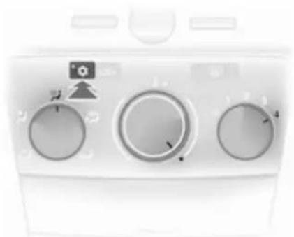
Heated
natural_image
Front view of a washing machine control panel with rotary dials and a digital display (no visible text or symbols)Operated by pressing the 📄 button. Heating functions with the engine running and is switched off automatically after a short time.
Interior mirrors
Manual anti-dazzle
natural_image
Diagram showing a car interior with a vehicle and a mirror, no text or symbols presentTo reduce dazzle, adjust the lever on the underside of the mirror housing.
Automatic anti-dazzle

natural_image
Side view of a car dashboard and air conditioner unit (no text or symbols visible)Dazzle from following vehicles at night is automatically reduced.
Windows
Power windows
⚠ Warning
Take care when operating the power windows. Risk of injury, particularly to children.
If there are children on the rear seats, switch on the child safety system for the electric windows.
Keep a close watch on the windows when closing them. Ensure that nothing becomes trapped in them as they move.
Power windows can be operated
■ with ignition on
■ within 5 minutes of switching ignition off
■ within 5 minutes of switching ignition key to position 1
After switching off the ignition, the standby feature ceases when the driver's door is opened.

natural_image
Close-up of a white electronic device with a control panel and indicator lights (no visible text or symbols)Operate the control to open or close the window.
For vehicles with automatic feature pull or press the switch again to stop window movement.
Astra TwinTop: when a door is opened the window opens slightly and closes automatically when the door is closed.
Safety function
If the window glass encounters resistance above the middle of the window during automatic closing, it is immediately stopped and opened again.
In the event of closing difficulties due to frost or the like, operate the switch several times to close the window in stages.
Central switch for electric windows, Astra TwinTop

natural_image
Interior view of a car dashboard with a touchscreen display and control panel (no text or symbols visible)Press 4 or 4 to open or close all windows.
36 Keys, doors and windows
Child safety system for rear windows

natural_image
Interior view of a car air conditioner unit (no text or symbols visible)Switch 📋 can be used to activate or deactivate the switches in the rear doors.
Operating windows from outside
The windows can be operated remotely from outside the vehicle.
Radio remote control
natural_image
Three-panel image showing a curved metallic object with three views of a mechanical component (no text or symbols visible)Press ≥ or = until all windows have opened or closed.
Open&Start system

natural_image
Hand holding a flat tool, no visible text or symbolsTo close, touch the sensor field in the door handle until all windows are completely closed.
The electronic key must be outside the vehicle, within a range of approx. 1 metre.
Overload
If the windows are repeatedly operated within short intervals, the window operation is disabled for some time.
Fault
If the windows cannot be opened or closed automatically, activate the window electronics as follows:
- Close doors
- Switch on ignition
- Close the window completely and operate the button for a further 5 seconds
- Open the window completely and operate the button for a further 1 second
- Repeat for each window
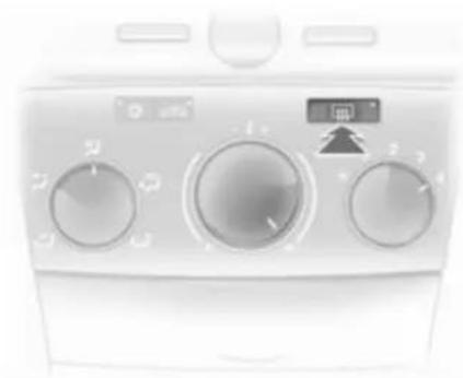
Heated rear window

natural_image
Front view of a white appliance front panel with three circular gauges and a digital display (no visible text or symbols)Operated by pressing the ☐ button.
Heating functions with the engine running and is switched off automatically after a short time.
Astra TwinTop: The heated rear window and heated exterior mirrors are deactivated when the roof is open.
Depending on the engine type, the heated rear window comes on automatically when the diesel particle filter is being cleaned.
Sun visors
The sun visors can be folded down or swivelled to the side to prevent dazzling.
If the sun visors have integral mirrors, the mirror covers should be closed when driving.
Panoramic windscreen
natural_image
Interior view of a car showing a dashboard with an upward arrow and a curved panel, no text or symbols present.To open roof lining: Turn handle to the right and move roof lining rearward to a suitable position.
38 Keys, doors and windows

natural_image
Simple diagram showing a downward arrow pointing to a container with a handle, no text or symbols present.To close roof lining: Move forward to a suitable position. When moved all the way forward, the roof lining engages in position.
Note
Close the sun visors before sliding the roof lining.
Roof
Sunroof
⚠ Warning
Take care when operating the sunroof. Risk of injury, particularly to children.
Keep a close watch on the movable parts when operating them. Ensure that nothing becomes trapped in them as they move.
Sunroof can be operated with ignition on.
natural_image
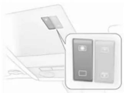
Illustration of a laptop with a card attached to its screen, alongside a close-up of two bank cards (no text or symbols visible)Operated via a rocker switch in the roof console.
Press the button briefly for activation in steps. Hold down the button for longer for automatic opening.
Raise
With the sunroof closed, press 📄. The sunroof is raised at the rear.
Open
Press ✉ again with the sunroof in the raised position. The sunroof opens automatically until it reaches its end position.
Caution
When using a roof rack, check the free movement of the sunroof in order to avoid damage. It is only permitted to raise the sunroof.
Note
If the top of the roof is wet, tilt sunroof, allow water to run off and then open sunroof.
Do not affix any stickers to sunroof.
Close
Hold down □ until the sunroof is completely closed.
For safety reasons, the roof closes from its open position to approx. 20 cm. Hold □ depressed to close completely.
Saloon 4-door
natural_image
Close-up of a stylized icon with a battery and megaphone inside a rounded square (no text or symbols)Open
Press 📋, sunroof opens to comfort position.
To open beyond comfort position: press 📄 again.
Close
Press ↗. until the sunroof is closed.
Raise
When the roof is closed, press ↗, the roof is tilted at the rear.
Lowering
Press button 📋 until the sunroof is closed.
Operating sunroof from outside
Keep button = of the remote control depressed until the sunroof is fully closed.
Sunblind
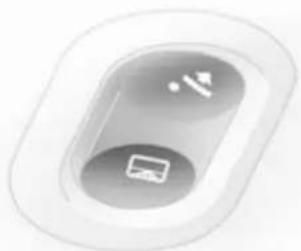
natural_image
Illustration of a laptop with a screen and two connected buttons, no text or symbols present.The sunblind is power operated.
The sunblind opens when the sunroof opens.
Close or open the sunblind by pressing button 📋 or 📋.
Hold □ depressed to close completely.
Saloon 4-door
The sunblind is manually operated.
Close or open the sunblind by sliding. When the sunroof is open, the sunblind is always open.
Overload
If the system is overloaded, the power supply is automatically cut off for a short time.
Initialising the sunroof
If the sunroof and sunblind cannot be operated (e.g. after disconnecting the vehicle battery), activate the electronics as follows:
- Switch on ignition
- Close sunroof and hold button □ depressed at least 10 seconds
- Close sunblind and hold button □ depressed at least 10 seconds
Retractable hardtop
⚠ Warning
Take care when operating the convertible hardtop. Risk of injury. Monitor the action zone above, to the side and to the rear of the vehicle during roof operation.
Make sure that nothing could become pinched. Make sure no one is in the action zone of the roof or boot lid during roof operation. Risk of injury.
Check the amount height, length and width of available space before operating the roof, e. g. in a garage, parking garage or when a bicycle rack is fitted.
Vehicle passengers should be informed accordingly.
Before leaving the vehicle, remove the ignition key in order to prevent unauthorised operation of the windows and sunroof.
Stand-by with key in ignition switch from position 1, or for Open&Start-System switch on ignition.
Requirements:
■ Vehicle is stationary or driving no more than 30 km/h
■ Load compartment blind is closed and engaged 73
■ Boot lid is closed
If any of these requirements are not fulfilled, a warning buzzer sounds when the switch is actuated and the roof does not open or close.
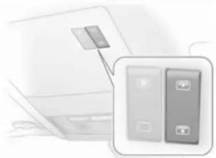
Open

text_image
Diagram showing car interior control panel with a directional arrow and vehicle icon pointing to the dashboard area.There must be no objects in front of the rear window or in the pivot area of the roof and boot lid.
Hold button ⬆—☐ in the roof console depressed until the roof is completely open and the boot lid is closed.
An acoustic signal sounds at the end of the opening procedure.
The door windows are opened slightly before the roof is opened. If button ☐—☐ is pressed again after the acoustic signal sounds, the door windows will close.
Open with remote control
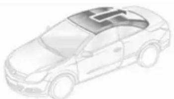
natural_image
Illustration of a modern sedan with a logo on the roof (no text or symbols visible)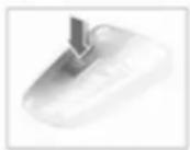
With vehicle stationary unlock the vehicle. Press button ≥ again and keep pressed until the roof has opened fully and the boot lid has closed.
During operation with the remote control, the door windows are opened completely.
Close

natural_image
Interior view of a car dashboard with a car icon and directional arrow (no text or symbols)Hold button 📄 in the roof console depressed until the roof and boot lid are completely closed.
An acoustic signal sounds at the end of the closing procedure.
The door windows are opened slightly before the roof is closed. If button
is pressed again after the acoustic signal sounds, the door windows will close.
Close with remote control
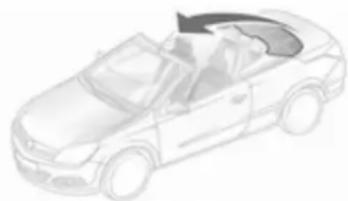
natural_image
Line drawing of a convertible car in motion (no text or symbols)
With vehicle stationary, lock the vehicle. Press button = again and keep pressed until the roof and boot lid have closed completely.
Note
■ Do not open the load compartment until the acoustic signal indicating the end of the roof opening or closing procedure has sounded.
42 Keys, doors and windows
■ The load compartment blind must always be closed during roof operation.
■ There must be no one and no objects at the covers behind the rear head restraints.
■ The roof can only be operated at temperatures above -20 °C. If the temperature is below this limit, a gong will sound three times when roof operation is requested.
■ Frequent operation of the roof with the engine off discharges the battery.
■ Repeated operation of the roof without breaks can cause overloading and therefore malfunctions.
■ The roof can be held in an intermediate position for 9 minutes to facilitate cleaning of roof spaces. This is done by disengaging the actuation switch. One minute before the end of this period, a continuous buzzer sounds as a warning that the hold period is almost over and the roof could start to move.
■ Activating the roof on uneven ground can lead to malfunctions and damage.
■ To prevent and remedy squeaking noises of the roof seals a special maintenance kit is available at your service partner. It is recommended to apply this product once a year for prevention.
Fault
The automatic drive of the roof is only operational if the roof is in the proper open or closed position.
Check if:
■ Load compartment blind is engaged in closed position
■ Boot lid is completely closed
■ Outside temperature is above -20 °C
■ There is sufficient battery voltage
■ There is a system overload
If the automatic drive is not operational, two persons are required to manually close the roof. See the
accompanying instructions for Astra TwinTop. Professional assistance is recommended.
Rollover protection system
The Astra TwinTop is equipped with rollover protection with reinforced windscreen frame and anti-roll bars behind the rear seat head restraints. Depending on the variant, the anti-roll bars are either fixed or deploy automatically in the event of an impact of a certain severity.
Fixed anti-roll bars

natural_image
Diagram of a car interior showing two downward arrows indicating movement or change, with no visible text or symbols.Fixed anti-roll bars are secured to the vehicle bodywork.
Deployable anti-roll bars
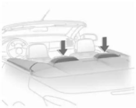
natural_image
Diagram of a car interior showing dashboard and seat compartments with two downward arrows indicating features (no text or symbols present)Deployable anti-roll bars are located between the rear head restraints and the boot lid. In the event of a rollover, head-on collision or side impact, the anti-roll bars deploy upwards within milliseconds. They also deploy together with the front and side airbag systems.
The system deploys with the roof open or closed.
The convertible roof must not be operated if the anti-roll bars have been deployed. A continuous warning will sound if the switch is actuated.
The airbag control indicator 🌿 illuminates if the anti-roll bars have been deployed.
Note
Do not place any objects on the covers of the anti-roll bars behind the head restraints.
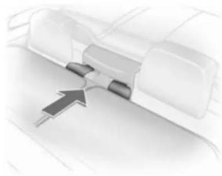
Extended anti-roll bars can be retracted (e.g. in order to close the roof after a collision).
Press the lever between the rods of an anti-roll bar to unlock the system. Push the anti-roll bar all the way down until it engages. Fit the cover.
Repeat the procedure on the other anti-roll bar.
Control indicator ⚡ will remain illuminated and the anti-roll bars will not deploy in the event of another collision. Seek the assistance of a workshop.
⚠ Warning
The roof cannot be closed or opened if the anti-roll bars are extended. The anti-roll bars must first be retracted.
After deployment of the anti-roll bar, have the system repaired by a workshop immediately.
Manually retracted anti-roll bars will not deploy in the event of a collision.
Load compartment
natural_image
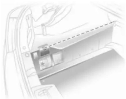
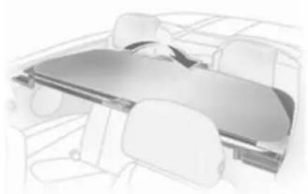
Diagram of a car interior showing a vehicle door and dashboard with a dashed line indicating a distance or alignment (no text or symbols present)44 Keys, doors and windows
The roof can only be opened if the load in the load compartment does not exceed the height of the load compartment blind or protrude sideways. The load height must not be exceeded. The load compartment blind must be flat; objects below it must not press it upwards. Otherwise the roof and load may be damaged.
Blockage of boot lid

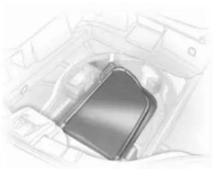
natural_image
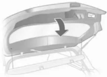
Diagram of a car interior with a highlighted vehicle component (no text or symbols)To avoid damage to the open roof, boot lid or load, the boot lid can only be closed if the electric load aid is in the lower end position 77.
Failure of electric drive Push locking lever forward.
Wind deflector
natural_image
Illustration of a hand holding a folder or tablet device over a vehicle dashboard (no text or symbols visible)The rear seats cannot be occupied when the wind deflector is in place. Do not place any objects on the wind deflector.
With tyre repair kit, the wind deflector is folded down into a storage compartment in the load compartment below the loading floor cover.
For the version with spare wheel, the wind deflector is folded away in the load compartment.
Fitting

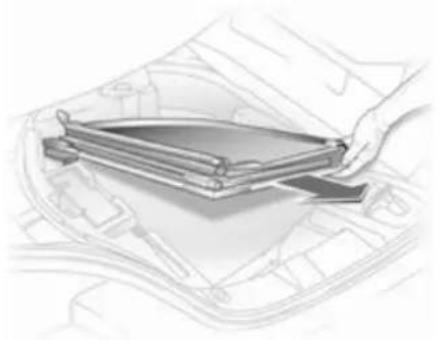
natural_image
Two-step folding or folding process diagram showing curved arrows indicating rotation (no text or symbols)Expand the collapsed wind deflector.

natural_image
Illustration of a mechanical assembly with a magnified inset showing a close-up of a component (no text or symbols present)Join together the unfolded ends of the wind deflector: Press in the pin at the slider, guide the hinge over the pin and release the slider so that the pin engages in the hinge.
natural_image
Diagram of a vehicle's internal components with an arrow indicating direction (no text or symbols)Insert the guide clips of the wind deflector in the seat belt recesses between the rear head restraints.

natural_image
Diagram of a door lock mechanism with directional arrows indicating movement (no text or symbols)Pull the toggle of the right and left locking pin and turn to lock.
Straighten out the wind deflector, turn the toggle back and engage the locking pin in the recess in the side trim.
natural_image
Interior view of a car showing the dashboard and seat area (no text or symbols visible)The wind deflector can be folded back when not in use.
If the wind deflector is folded and the rear seats are unoccupied, the wind deflector can remain mounted in the vehicle when the roof is closed.
46 Keys, doors and windows
Removing
natural_image
Interior view of a car gear shift lever (no text or symbols visible)Remove in reverse order, wind deflector is completely folded down in the load compartment:
■ for tyre repair kit in the compartment below the loading floor cover
■ for version with spare wheel, place in load compartment
The wind deflector must never protrude upwards or sideways above the permissible loading height.
Seats, restraints
Head restraints 47
Front seats 49
Rear seats 53
Seat belts 54
Airbag system 57
Child restraints 60
Head restraints
Position
⚠ Warning
Only drive with the head restraint set to the proper position.
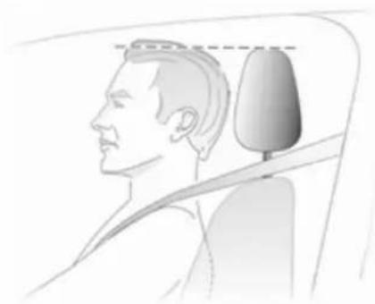
natural_image
Side profile illustration of a person wearing a seatbelt, showing head and neck alignment (no text or symbols)The upper edge of the head restraint should be at upper head level. If this is not possible for extremely tall people, set to highest position, and set to lowest position for small people.
Adjustment
Front and rear outboard head restraints

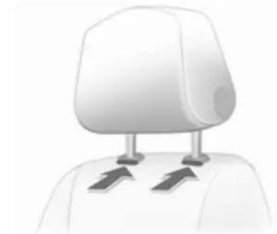
natural_image
Illustration of a person's head with a double-headed arrow indicating vertical motion (no text or symbols)Press the button, adjust height and engage.
48 Seats, restraints
Rear centre head restraint

natural_image
Diagram of a vehicle seat with directional arrows indicating movement or force (no text or symbols)Pull the head restraint upwards or press the catch to release and push the head restraint downwards.
Adjusting the rear head restraints, Astra TwinTop

natural_image
3D rendered mechanical component with directional arrows, no visible text or symbolsPull the head restraint up or press both catches to release and then push the head restraint downwards.
Do not place any objects on the cover behind the head restraints or between the head restraints and the anti-roll bars.
Removing
natural_image
Illustration of a humanoid robot head with two sensors attached (no text or symbols)Press the catches and pull up the head restraint.
Active head restraints
In the event of a rear-end impact, the active head restraints tilt slightly forwards. The head is more effectively supported so the risk of whiplash injury is reduced.
Active head restraints are identified by the lettering ACTIVE on the head restraint guide sleeves.
Note
Approved accessories may only be attached to the front passenger seat head restraint if the seat is not in use.
Front seats
Seat position
⚠ Warning
Only drive with the seat correctly adjusted.

natural_image
Illustration of a person sitting in a car, holding a steering wheel and headboard (no text or symbols visible)- Sit with buttocks as far back against the backrest as possible. Adjust the distance between the seat and the pedals so that legs are slightly angled when pressing the pedals. Slide the front passenger seat as far back as possible.
- Sit with shoulders as far back against the backrest as possible. Set the backrest rake so that it is possible to easily reach the steering wheel with arms slightly bent. Maintain contact between shoulders and the backrest when turning the steering wheel. Do not angle the backrest too far back. We recommend a maximum rake of approx. 25°.
■ Adjust the steering wheel ➔ 86.
■ Set seat height high enough to have a clear field of vision on all sides and of all display instruments. There should be at least one hand of clearance between head and the roof frame. Your thighs should rest lightly on the seat without pressing into it.
■ Adjust the head restraint ➔ 47.
■ Adjust the height of the seat belt ➔ 55.
■ Adjust the thigh support so that there is a space approx. two fingers wide between the edge of the seat and the hollow of the knee.
50 Seats, restraints
■ Adjust the lumbar support so that it supports the natural shape of the spine.
Seat adjustment
Danger
Do not sit nearer than 25 cm from the steering wheel, to permit safe airbag deployment.
⚠ Warning
Never adjust seats while driving as they could move uncontrollably.
Seat positioning

natural_image
Illustration of a car seat with directional arrows indicating motion (no text or symbols)Pull handle, slide seat, release handle.
Seat backrests
natural_image
Line drawing of a car seat with directional arrows indicating motion (no text or symbols)Turn handwheel. Do not lean on backrest when adjusting.
Seat height

natural_image
Car seat assembly diagram showing seatbelt and seatbelt fastening mechanism (no text or labels)Lever pumping motion up = seat higher down = seat lower
Seat inclination

natural_image
Illustration of a car seatbelt with directional arrows indicating movement (no text or symbols)Pull lever, adjust inclination by shifting body weight. Release lever and audibly engage seat in position.
Lumbar support

natural_image
Diagram of a car seatbelt with directional arrows indicating rotation or movement (no text or symbols)Turn handwheel. Do not lean on backrest when adjusting.
52 Seats, restraints
Adjustable thigh support

natural_image
Close-up of a car seatbelt buckle with two arrows indicating compression (no text or symbols)Press the button and slide the thigh support.
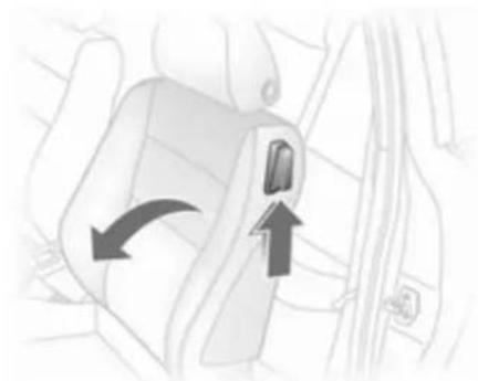
Seat folding
natural_image
Diagram of a car seatbelt with directional arrows indicating movement (no text or symbols)Lift release lever and fold backrest forwards. Slide seat forwards.
To restore, slide the seat backwards. If the seat has a memory function it engages in its original position, otherwise engage seat in desired position. Move the backrest back to upright and engage.
Folding the backrest forwards is only possible when the backrest is in an upright position.
Do not operate handwheel to adjust backrest with backrest tilted forward.
In vehicles with a panoramic window: to tilt seats forward, push head restraints down and lift up sun visors.
Armrest

natural_image
Illustration of a mechanical component with directional arrows indicating motion (no text or symbols)Push raised armrest backward against resistance and fold down.
The armrest can be moved to different positions in stages by lifting it.
Under the armrest there is a storage compartment.
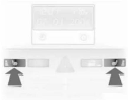
Heating
text_image
12:00 1:30, 9:7 9:1 20:00Adjust heating to the desired setting by pressing the ⏻ button for the respective seat one or more times with the ignition on. The control indicator in the button indicates the setting.
Prolonged use of the highest setting for people with sensitive skin is not recommended.
Seat heating is operational when the engine is running.
Rear seats
Armrest
Saloon and Station wagon
natural_image
Interior view of a car seatbelt with white frame and gray cushion (no text or symbols)Fold down the armrest, pulling the strap obliquely down (45°).
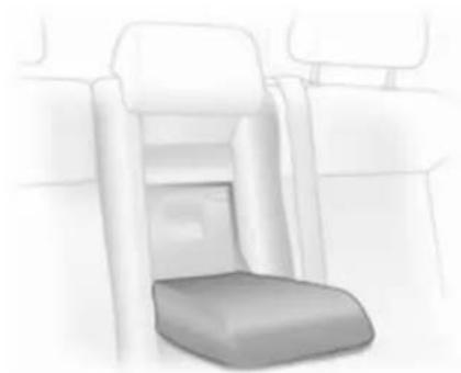
TwinTop

natural_image
Line drawing of a car seatbelt with a flat seat and handle, no text or symbols presentPull the armrest by the strap, pivot it down and position on the sit with the flat side up.
The armrest is held in place on the backrest with a retaining strap. To fully remove the armrest, disengage the bracket at the retaining strap.
Seat belts

natural_image
Illustration of a person seated in a car seat, wearing a seatbelt (no text or symbols visible)The seat belts are locked during heavy acceleration or deceleration of the vehicle holding the occupants in the sitting position. Thereby the risk of injury is considerably reduced.
⚠ Warning
Fasten seat belt before each trip. In the event of an accident, people not wearing seat belts endanger their fellow occupants and themselves.
Seat belts are designed to be used by only one person at a time. They are not suitable for people smaller than 150 cm. Child restraint system ✦ 60.
Periodically check all parts of the belt system for damage and proper functionality.
Have damaged components replaced. After an accident, have the belts and triggered belt pretensioners replaced by a workshop.
Note
Make sure that the belts are not damaged by shoes or sharp-edged objects or trapped. Prevent dirt from getting into the belt retractors.
Seat belt reminder ↗ 96.
Belt force limiters
Stress on the body is reduced by the gradual release of the belt during a collision.
Belt pretensioners
In the event of a head-on or rear-end collision of a certain severity, the front seat belts are tightened.
Warning
Incorrect handling (e.g. removal or fitting of belts) can trigger the belt pretensioners.
Deployment of the belt pretensioners is indicated by continuous illumination of control indicator ➡ 96.
Triggered belt pretensioners must be replaced by a workshop. Belt pretensioners can only be triggered once.
Note
Do not affix or install accessories or other objects that may interfere with the operation of the belt pretensioners. Do not make any modifications to belt pretensioner components as this will invalidate the vehicle type approval.
Three-point seat belt
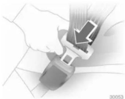
Fastening seat belt
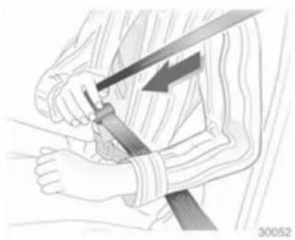
natural_image
Illustration of a person using a bandage to tighten the shoulder (no text or symbols present)Withdraw the belt from the retractor, guide it untwisted across the body and insert the latch plate into the buckle. Tighten the lap belt regularly whilst driving by pulling the shoulder belt.
Seat belt reminder 96.
natural_image
Close-up of a hand using a belt buckle to adjust the seat (no text or symbols visible)Loose or bulky clothing prevents the belt from fitting snugly. Do not place objects such as handbags or mobile phones between the belt and your body.
⚠ Warning
The belt must not rest against hard or fragile objects in the pockets of your clothing.
Height adjustment

natural_image
Close-up of a car door handle with two directional arrows indicating movement (no text or symbols)- Pull belt out slightly.
- Press button.
- Adjust height and engage.

natural_image
Illustration of a person seated in a car seat, wearing a seatbelt and holding the steering wheel (no text or symbols visible)Adjust the height so that the belt lies across the shoulder. It must not lie across the throat or upper arm. Do not adjust while driving.
Removing seat belt
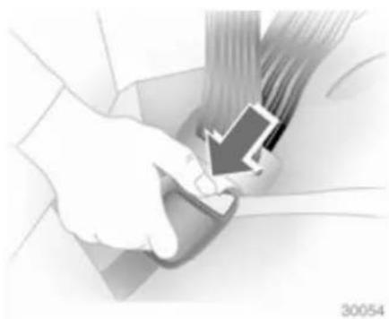
natural_image
Close-up of a hand adjusting a car seatbelt with a black arrow pointing to the seat (no text or symbols visible)To release belt, press red button on belt buckle.
Seat belts on rear seats
Lead seat belts of the outer seats through holders at the side if they are not being used.
The seat belt for the middle seat can only be withdrawn from the retractor if the backrests are upright and are engaged in their retainers.
TwinTop
To prevent the seat belts from making flapping noise when the sun roof and/or the windows are open, the seat belts of unoccupied rear seats can be secured behind the armrest.
Using the seat belt while pregnant

natural_image
Illustration of a woman seated in a car seat, wearing a seatbelt and holding the steering wheel (no text or symbols visible)
Warning
The lap belt must be positioned as low as possible across the pelvis to prevent pressure on the abdomen.
Airbag system
The airbag system consists of a number of individual systems depending on the scope of equipment.
When triggered the airbag inflates within milliseconds. They also deflate so quickly that it is often unnoticeable during the collision.
⚠ Warning
If handled improperly the airbag systems can be triggered in an explosive manner.
Note
The control electronics of the airbag systems, belt pretensioners and deployable anti-roll bars are located in the centre console area. Do not put any magnetic objects in this area.
Do not stick anything on the airbag covers and do not cover them with other materials.
Each airbag/anti-roll bar is triggered only once. Have deployed airbags/anti-roll bars replaced by a workshop. Furthermore, it might be necessary to have the steering wheel, the instrument panel, parts of the panelling, the door seals, handles and the seats replaced.
Do not make any modifications to the airbag system/anti-roll bars as this will invalidate the vehicle type approval.
When the airbags inflate, escaping hot gases may cause burns.
Control indicator ✦ for airbag systems and anti-roll bars ➔ 96.
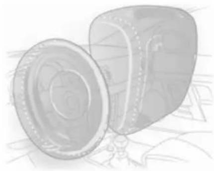
Front airbag system
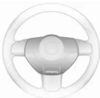
natural_image
Top-down view of a car steering wheel with visible brand logo (no text or symbols on the diagram itself)The front airbag system consists of one airbag in the steering wheel and one in the instrument panel on the front passenger side. These can be identified by the word AIRBAG.
58 Seats, restraints

text_image
AIRBAG 30036There is also a warning label on the side of the instrument panel, visible when the front passenger door is open.
The front airbag system is triggered in the event of a front-end impact of a certain severity. The ignition needs to be switched on.
natural_image
Illustration of a mechanical component with a circular housing and a flanged side (no text or symbols)The inflated airbags cushion the impact, thereby reducing the risk of injury to the upper body and head of the front seat occupants considerably.
⚠ Warning
Optimum protection is only provided when the seat is in the proper position 49.
Keep the area in which the airbag inflates clear of obstructions.
Fit the seat belt correctly and engage securely. Only then the airbag is able to protect.
Side airbag system
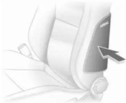
natural_image
Close-up of a car seatbelt buckle with a black arrow pointing to the side panel (no text or symbols visible)The side airbag system consists of an airbag in each front seat backrest. This can be identified by the word AIRBAG.
The side airbag system is triggered in the event of a side impact of a certain severity. The ignition needs to be switched on.
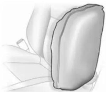
natural_image
Illustration of a car seatbelt with a side arm, shown in grayscale (no text or symbols)The inflated airbags cushion the impact, thereby reducing the risk of injury to the upper body and pelvis in the event of a side-on collision considerably.
⚠ Warning
Keep the area in which the airbag inflates clear of obstructions.
Note
Only use protective seat covers that have been approved for the vehicle. Be careful not to cover the airbags.
Curtain airbag system
The curtain airbag system consists of an airbag in the roof frame on each side. This can be identified by the word AIRBAG on the roof pillars.
The curtain airbag system is triggered in the event of a side-on impact of a certain severity. The ignition needs to be switched on.

natural_image
Side profile illustration of a car's dashboard and steering wheel (no text or symbols)The inflated airbags cushion the impact, thereby reducing the risk of injury to the head in the event of a side-on impact considerably.
Warning
Keep the area in which the airbag inflates clear of obstructions.
The hooks on the handles in the roof frame are only suitable for hanging up light articles of clothing, without coat hangers. Do not keep any items in these clothes.
Seat occupancy recognition

text_image
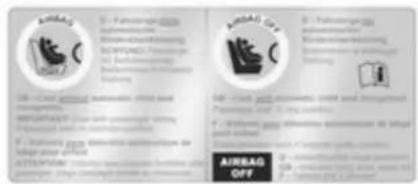
ACHTUNG / WARNING / DANGER Was Kindelsliche Einkommen schleuht! Konzernliche Ertrag abgegeben! Bitte Bedition und Anhang fest! Only child number is 10000000000000000000000000000000000000000000000000000000000000000000000000000000000000000000000000000 Please refer to the following: Please note that you are not able to read about your own information. You can't have any information on your information. Your person is / or another, 45% 2-7Identified by a label on the lower panel of the front passenger seat and by control indicator ☐, which illuminates for approx. 4 seconds when the ignition is switched on.
The seat occupancy recognition system deactivates the passenger front and side airbag if the front passenger seat is not occupied or is fitted with an Opel child restraint system with transponders. The curtain airbag system remains activated.
Danger
Only Opel child restraint systems with transponders should be fitted on the front passenger seats. Use of systems without transponders poses a risk of fatal injury.
Control indicator ➔ 96.
Note
Anyone weighing less than 35 kg should only travel on the rear seats.
Do not place any heavy objects on the front passenger seat. Otherwise the seat will register as occupied and the airbag system for the front passenger seat will not be deactivated.
Do not use protective covers or seat cushions on the front passenger seat.
Note
On the Astra TwinTop, there may be interference in radio reception of certain frequencies in the medium waveband when the roof is open and the front passenger seat is unoccupied.
Child restraints
Child restraint systems
We recommend the Opel child restraint system which is tailored specifically to the vehicle.
When a child restraint system is being used, pay attention to the following usage and installation instructions and also those supplied with the child restraint system.
Always comply with local or national regulations. In some countries, the use of child restraint systems is forbidden on certain seats.
Selecting the right system
The rear seats are the most convenient location to fasten a child restraint system.
Children should travel facing rearwards in the vehicle as long as possible. This makes sure that the child's backbone, which is still very weak, is under less strain in the event of an accident.
Children under the age of 12 years that are smaller than 150 cm are only allowed to travel in a restraint system that is suitable for the child. Suitable are restraint systems that comply with ECE 44-03 or ECE 44-04. Since a proper position of the belt is rarely possible with a child that is smaller than 150 cm, we strongly advise to use an appropriate child restraint system, even though this might, due to the age of the child, no longer be legally binding.
Ensure that the child restraint system to be installed is compatible with the vehicle type.
Ensure that the mounting location of the child restraint system within the vehicle is correct.
Allow children to enter and exit the vehicle only on the side facing away from the traffic.
When the child restraint system is not in use, secure the seat with a seat belt or remove it from the vehicle.
Note
Do not stick anything on the child restraint systems and do not cover them with any other materials.
A child restraint system which has been subjected to stress in an accident must be replaced.
62 Seats, restraints
Child restraint installation locations
Permissible options for fitting a child restraint system
| Weight and age class On front passenger seat | 1) On outer rear seats | On centre rear seat2) | |
| Group 0: up to 10 kg or approx. 10 months | B^1 , ++ | U, + U | |
| Group 0+: up to 13 kg or approx. 2 years | |||
| Group I: 9 to 18 kg or approx. 8 months to 4 years | B^2 , ++ | U, + U | |
| Group II: 15 to 25 kg or approx. 3 to 7 years | X U U | ||
| Group III: 22 to 36 kg or approx. 6 to 12 years | |||
B^1 = Limited, only with seat occupancy recognition and Opel child restraint system with transponders.
If the child restraint system is being secured using a three-point seat belt, move seat height adjustment to uppermost position. Move front passenger seat as far back as possible and move front passenger seat belt anchorage point to lowest position.
B^2 = Limited, only with seat occupancy recognition and Opel child restraint system with transponders.
If the child restraint system is being secured using a three-point seat belt, move seat height adjustment to uppermost position. Move front passenger seat as far back as possible so that vehicle safety belt runs from anchorage point towards the front.
U = Universal suitability in conjunction with three-point seat belt.
+ = Seat available with ISOFIX and Top-tether mounting brackets.
++ = Seat available with ISOFIX mounting brackets.
X = No child restraint system permitted in this weight class.
1) Not allowed on Saloon 4-door.
2) Not allowed on Astra TwinTop.
Permissible options for fitting an ISOFIX child restraint system
| Weight class | Size class | Fixture | On front passenger seat | On rear outboard seats | On rear centre seat |
| Group 0: up to 10 kg E ISO/R1 IL IL X | |||||
| Group 0+: up to 13 kg E ISO/R1 IL IL X | |||||
| D ISO/R2 IL IL X | |||||
| C ISO/R3 X | IL^3) | X | |||
| Group I: 9 to 18 kg D ISO/R2 IL IL X | |||||
| C ISO/R3 X | IL^3) | X | |||
| B ISO/F2 IL IL, IUF X | |||||
| B1 | ISO/F2X | IL IL, IUF X | |||
| A ISO/F3 X | IL, IUF X | ||||
IL = Suitable for particular ISOFIX restraint systems of the 'specific-vehicle', 'restricted' or 'semi-universal' categories. The ISOFIX restraint system must be approved for the specific vehicle type.
IUF = Suitable for ISOFIX forward-facing child restraint systems of universal category approved for use in this weight class.
X = No ISOFIX child restraint system approved in this weight class.
ISOFIX size class and seat device
A - ISO/F3 = Forward-facing child restraint system for children of maximum size in the weight class 9 to 18 kg.
B - ISO/F2 = Forward-facing child restraint system for smaller children in the weight class 9 to 18 kg.
B1 - ISO/F2X = Forward-facing child restraint system for smaller children in the weight class 9 to 18 kg.
C - ISO/R3 = Rear-facing child restraint system for children of maximum size in the weight class up to 13 kg.
D - ISO/R2 = Rear-facing child restraint system for smaller children in the weight class up to 13 kg.
E - ISO/R1 = Rear-facing child restraint system for young children in the weight class up to 13 kg.
Isofix child restraint systems
natural_image
Interior view of a modern vehicle with multiple seats and connecting wires, no visible text or symbolsFasten vehicle-approved ISOFIX child restraint systems to the ISOFIX mounting brackets. Specific vehicle ISOFIX child restraint system positions are marked in the table by IL.
ISOFIX mounting brackets are indicated by a label on the backrest.
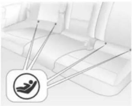
Top-tether child restraint systems
Top-tether fastening eyes are located under a cover marked with the symbol ⚠ for a child seat. Fold up cover after usage.

natural_image
Top-down view of a car backseat with a logo and two hanging clips (no text or symbols)In addition to the ISOFIX mounting, fasten the Top-tether strap to the Top-tether fastening eyes. The strap must run between the two guide rods of the head restraint.
ISOFIX child restraint systems of universal category positions are marked in the table by IUF.
Child restraints with transponders
text_image
Ampal 2017 B - Pekingumgarh Pekingumgarh Sri Lanka Sri Lanka Buchunbanan Buchunbanan Kazakhstan Buchunbanan Kazakhstan Buchunbanan Kazakhstan Buchunbanan Kazakhstan Buchunbanan Kazakhstan Buchunbanan Kazakhstan Buchunbanan Kazakhstan Buchunbanan Kazakhstan Buchunbanan Kazakhstan Buchunbanan Kazakhstan Buchunbanan Kaz Kazakhstan Buchunbanan Kaz Kazakhstan Buchunbanan Kaz Kazakhstan Buchunbanan Kaz Kazakhstan Buchunbanan Kaz Kazakhstan Buchunbanan Kaz Kazakhstan Buchunbanan Kaz Kazakhstan Buchunbanan Kaz Kazakhstan Buchunbanan Kaz Kazakhstan Buchunbanan Kaz Kazakhstan Buchunbanan Kaz Koz Koz Koz Koz Koz Koz Koz Koz Koz Koz Koz Koz Koz Koz Koz Koz Koz Koz Koz Koz Koz Koz Koz Koz Koz Koz Koz Koz Koz Koz Koz Koz Koz Koz Koz Koz Koz Koz Koz Koz Koz Koz Koz Koz Koz Koz Koz Koz Koz Koz Kuz Koz Koz Koz Koz Koz Koz Koz Koz Koz Koz Koz Koz Koz Koz Koz Koz Koz Koz Koz Koz Koz Koz Koz Koz Koz Koz Koz Koz Koz Koz Koz Koz Koz Koz Koz Koz Koz Koz Koz Koz Koz Koz Koz Koz Koz Koz Koz Koz Koz KAZ Buchunbanan, Buchunbanan, Buchunbanan, Buchunbanan, Buchunbanan, Buchunbanan, Buchunbanan, Buchunbanan, Buchunbanan, Buchunbanan, Buchunbanan, Buchunbanan, Buchunbanan, Buchunbanan, Buchunbanan, Buchunbanan, Buchunbanan, Buchunbanon, Buchunbanan, Buchunbanan, Buchunbanan, Buchunbanan, Buchunbanan, Buchunbanan, Buchunbanan, Buchunbanan, Buchunbanan, Buchunbanan, Buchunbanan, Buchunbanan, Buchunbanan, Buchunbanan, Buchunbanan, Buchunbanan, Buchin, Buchunbanan, Buchunbanan, Buchunbanan, Buchunbanan, Buchunbanan, Buchunbanan, Buchunbanan, Buchunbanan, Buchunbanan, Buchunbanan, Buchunbanan, Buchunbanan, Buchunbanan, Buchunbanan, Buchin, Buchunbanan, Buchunbanan, Ampal 2017 (H) Buchunbanan, Ampal 2017 (H) Buchunbanan, Ampal 2017 (H) Buchunbanan, Ampal 2017 (H) Buchunbanan, Ampal 2017 (H) Buchunbanan, Ampal 2017 (H) Buchunbanan, Ampal 2017 (M) Buchunbanan, Ampal 2017 (M) Buchunbanan, Ampal 2017 (M) Buchunbanan, Ampal 2017 (M) Buchunbanan, Ampal 2017 (M) Buchunbanan, Ampal 2017 (M) Buchunbanan, Ampal 2016 (M) Buchunbanan, Ampal 2016 (M) Buchunbanan, Ampal 2016 (M) Buchunbanan, Ampal 2016 (M) Buchunbanan, Ampal 2016 (M) Buchunbanan, Ampal 2016 (M) Buchunbanan, Ampal 219 (M) Buchunbanan, Ampal 219 (M) Buchunbanan, Ampal 219 (M) Buchunbanan, Ampal 219 (M) Buchunbanan, Ampal 219 (M) Buchunbanan, Ampal 219 (M) Buchunbanan, Ampal 218 (M) Buchunbanan, Ampal 218 (M) Buchunbanan, Ampal 218 (M) Buchunbanan, Ampal 218 (M) Buchunbanan, Ampal 218 (M) Buchunbanan, Ampal 218 (M) Buchunbanan, Ampal 218 (M) Ampal 2016 (H) Ampal 2016 (H) Ampal 2016 (H) Ampal 2016 (H) Ampal 2016 (H) Ampal 2016 (H) Ampal 2016 (H) Ampal 2015 (H) Ampal 2015 (H) Ampal 2015 (H) Ampal 2015 (H) Ampal 2015 (H) Ampal 2015 (H) Ampal 2014 (H) Ampal 2014 (H) Ampal 2014 (H) Ampal 2014 (H) Ampal 2013 (H) Ampal 2013 (H) Ampal 2013 (H) Ampal 2013 (H) Ampal 2012 (H) Ampal 2012 (H) Ampal 2012 (H) Ampal 2011 (H) Ampal 2011 (H) Ampal 2010 (H) Ampal 2010 (H) Ampal 2009 (H) Ampal 2009 (H) Ampal 2008 (H) Ampal 2008 (H) Ampal 2007 (H) Ampal 2006 (H) Ampal 2006 (H) Ampal 2005 (H) Ampal 2004 (H) Ampal 2003 (H) Ampal 2002 (H) Ampal 2001 (H) Ampal 2000 (H) Ampal 2009 (O) OFFA label on the child restraint system indicates that it is fitted with transponders.
Opel child restraint systems with transponders are automatically detected if correctly installed to the front passenger seat with seat occupancy recognition.
66 Seats, restraints
Note
There must be no objects (e.g. plastic sheet or heating mats) between the seat and the child restraint system.
Seat occupancy recognition ↩ 59.
Storage
Storage compartments ...... 67
Load compartment 68
Roof rack system 83
Loading information 84
Storage compartments Glovebox

natural_image
Illustration of a printer with paper lid open, showing internal components (no text or symbols)The glovebox features a pen holder and a place to store coins.
The glovebox shelf can be removed: Disengage the shelf by pulling on the front edge.
Refit the shelf by sliding it into the side guide strips and engage it in the rear panel by pushing.
The glovebox should be closed whilst driving.
Lockable glovebox, Astra TwinTop with Open&Start system
In addition to the electronic key of the Open&Start system, there is a standard key without remote control for the glovebox lock.
Cupholders
Cupholders are located in the centre console and in the door pockets of the rear doors.
Additional cupholders are located in the fold-down tables on the back of the front seat backrests.
Sunglasses storage
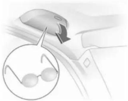
natural_image
Illustration of a car interior with a hand holding a device and an inset showing eyeglasses (no text or symbols)Fold down and open.
Do not use for storing heavy objects.
Armrest storage
Storage in the front armrest
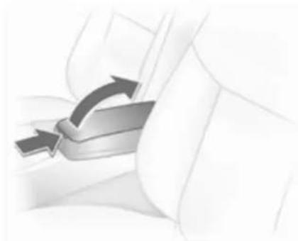
natural_image
Close-up of a metallic belt buckle with two curved arrows indicating direction (no text or symbols)To open, press button and open upper part of armrest.
Load compartment
Load compartment extension, Saloon 3-door / 5-door
Folding down rear backrests
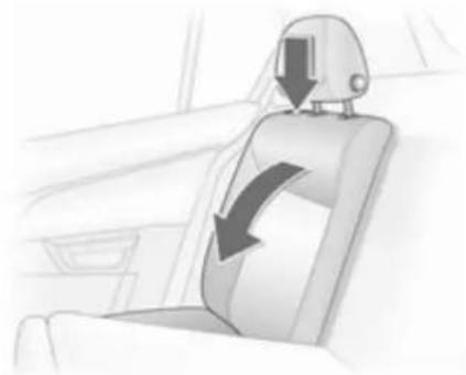
natural_image
Interior view of a car seat with a curved arrow indicating clockwise motion (no text or symbols)Push head restraints all the way down or remove ➔ 47.
Slide front seat forward slightly.
Disengage the backrest (single or split) using the release button on one or both sides and fold it down onto the seat cushion.
Folding down centre backrests
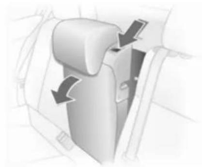
natural_image
Diagram of a car seatbelt mechanism showing directional arrows (no text or symbols)Push head restraint down as far as possible ➔ 47.
Disengage backrest using lever and fold onto seat cushion.
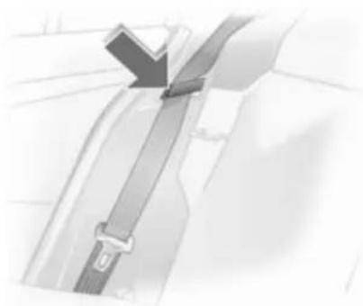
natural_image
Close-up of a car seatbelt buckle with a checkmark arrow pointing to the buckle (no text or symbols visible)Before restoring backrest to an upright position, guide the seat belt through the belt guides to protect against damage.
Move rear seat backrests upright and allow locking mechanisms to engage audibly.
The three-point seat belt for the centre rear seat can only be pulled from the reel if the backrest is properly engaged.
Load compartment extension, Saloon 4-door
Folding down rear backrests

natural_image
Interior view of a car seat with a car head-mounted device and directional arrow indicating rotation (no text or symbols)Push head restraints all the way down or remove ➔ 47.
Slide front seat forward slightly.
70 Storage

natural_image
Close-up of a car seatbelt buckle with a black arrow pointing to the buckle (no text or symbols visible)To prevent damage, put the seat belts in the guides by the release button. When the backrests are folded, the seat belts are extended with them.
Disengage the backrest (single or split) using the release button on one or both sides and fold it down onto the seat cushion.
If the vehicle is to be loaded from a rear door, remove safety belt from the guide and retract.
To fold up, raise backrests and guide them into upright position until they engage audibly.
Do not trap safety belts when erecting seat backrests.
The three-point seat belt for the centre rear seat can only be pulled from the reel if the backrest is properly engaged.
Load compartment extension, Station wagon
Folding down rear backrests

natural_image
Diagram of a car interior showing a seat with a curved arrow indicating rotation (no text or symbols present)Push head restraints all the way down or remove ➔ 47.
Unhook hooks of load compartment cover from head restraints 73.
Slide front seat forward slightly.
Disengage the backrest (single or split) using the release button on one or both sides and fold it down onto the seat cushion.
Raise the seat cushion and fold the backrest

natural_image
Illustration of a car interior with hand positioning and a magnified inset showing a textured object (no text or symbols)Pull the strap on the seat cushion and lift the rear of the cushion forwards (split or one-piece).
Unhook hooks of load compartment cover from head restraints ➔ 73.
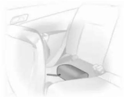
natural_image
Interior view of a car seatbelt and dashboard (no text or symbols visible)Remove rear outer head restraints and push centre head restraint all the way down ➔ 47. Stow the removed head restraints in the cavity below the raised seat cushions.
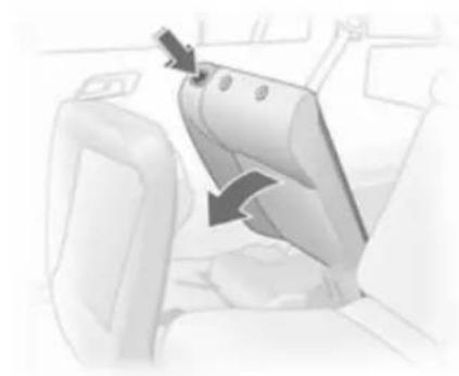
natural_image
Interior view of a vehicle seatbelt mechanism with a directional arrow indicating rotation (no text or symbols)Disengage backrest (one-piece or split) using release button, fold forward and engage.
Folding down centre backrests
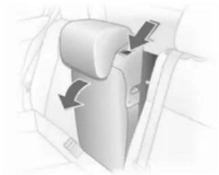
natural_image
Diagram of a car seatbelt mechanism with directional arrows indicating movement (no text or symbols)Push head restraint down as far as possible 47. Disengage backrest using lever and fold onto seat cushion. If the seat cushion is raised, fold it forward until it engages.
72 Storage

natural_image
Close-up of a metallic mechanical component with a black clip, no visible text or symbolsBefore restoring backrest to an upright position, guide the seat belt through the belt guides to protect against damage. Press release button and move rear seat backrests upright, ensuring locking mechanisms engage audibly.
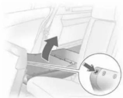
natural_image
Interior view of a car gear shift lever with an arrow indicating clockwise motion (no text or symbols)With the seat cushions raised: insert head restraints in backrests and adjust 47. Fold back seat cushions, making sure the belt buckles are properly positioned.
Attach hooks of load compartment cover to head restraints ➔ 73.
The three-point seat belt for the centre rear seat can only be pulled from the reel if the backrest is properly engaged.
Load compartment extension, TwinTop
Loading area between rear seats
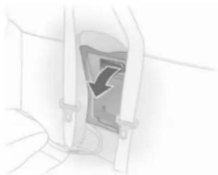
natural_image
Illustration of a mechanical component with a downward arrow indicating force or direction (no text or symbols)Pull out the armrest by the strap.
The armrest is held in place on the backrest with a retaining strap. To fully remove the armrest, disengage the bracket at the retaining strap.
Pull the handle and fold down the cover.

natural_image
Close-up of a mechanical component with a curved arrow indicating rotation or direction (no text or symbols visible)The cover behind the armrest can be locked from load compartment:
horizontal position = locked vertical position = unlocked
Stowage in the load compartment, Station wagon
There is a stowage compartment at the right side of the load compartment.
The fuse box is on the left side behind the cover in the load compartment side panelling ➔ 187
Cargo box ➔ 75.
The tyre repair kit is on the right side behind the cover ➔ 196.
Load compartment cover
Saloon 3-door / 5-door
Removing
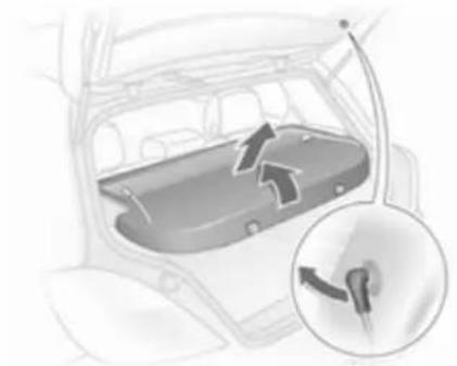
natural_image
Interior view of a car showing the rear compartment with directional arrows indicating flow or movement (no text or symbols present)Unhook retaining straps from tailgate. Pull cover from the side guides.
Fitting
Engage cover in side guides and fold downwards. Attach retaining straps to tailgate.
Station wagon
Do not place any heavy or sharp-edged objects on the load compartment cover.

natural_image
Close-up of a car seatbelt buckle with a downward arrow indicating compression (no text or symbols)Opening
Press handle on load compartment cover rearwards; the cover automatically engages in its end position.
Closing
Remove load compartment cover from side brackets. It rolls up automatically.
74 Storage
Pull the cover towards the rear using the handle and engage it in the retainers at the sides.

natural_image
Diagram of a car interior showing a vehicle with a magnified inset highlighting the seat area (no text or symbols present)To cover the gap between the load compartment cover and the rear backrests, there is a cover on the cartridge. Attach the two hooks of the cover to the head restraint guide rods. If the safety net is mounted, run the hooks through the net mesh.
Removing
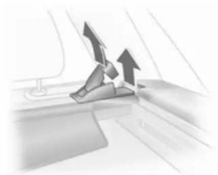
natural_image
Illustration of a car seatbelt mechanism with upward arrows indicating motion (no text or symbols)Open the load compartment cover and detach the hooks from the head restraints.
Pull the release lever. Lift right side of cover first, then pull left side out of recess.
Fitting
Insert the left side of the load compartment cover in the recess, pull the release lever, insert the right side of the load compartment cover and engage.
Attach the hooks on the head restraints.
TwinTop
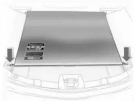
natural_image
Top-down view of a car's front bumper with a flat panel and two arrows indicating side indicators (no text or symbols)Opening
Release load compartment blind from recesses on left and right, blind rolls up automatically.
Closing
Pull the cover towards the rear using the handle and engage it in the retainers at the sides.
Do not place any objects on the load compartment cover.
There must be no objects outside of or on top of the cover when the roof is open or in the process of opening.
The roof can only be operated with the blind engaged in the recess.
Load rails and hooks
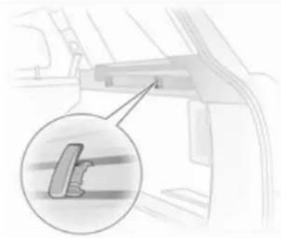
natural_image
Mechanical component diagram showing a bracket with a magnified inset highlighting a specific part (no text or symbols present)On Station wagon, install the hooks in the desired position in the rails: insert the hook in the upper groove on the rail and press in the lower groove.
Lashing eyes
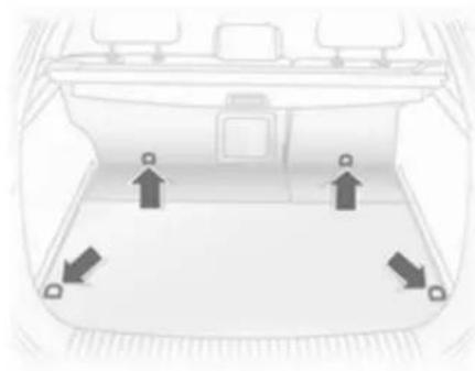
natural_image
Top-down view of a car backseat with directional arrows indicating movement or navigation (no text or symbols)The lashing eyes are designed to secure items against slippage, e.g. using lashing straps, luggage net or safety net.
Cargo management system
The FlexOrganizer is a flexible system for dividing the load compartment or securing loads in a Station wagon.
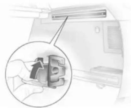
natural_image
Illustration of a hand inserting a device into a computer (no text or symbols visible)The system consists of
■ adapters
■ variable partition net
■ mesh pockets
■ hooks
The components are fitted in two rails in the side panels using adapters and hooks. The partitioning net can also be fitted directly in front of the tailgate.
76 Storage
Variable partition net
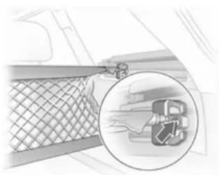
natural_image
Illustration of a truck inside a mesh fence with a magnified inset showing the vehicle's wheel (no text or symbols)Insert an adapter into each rail: fold open the handle plate, insert adapter into upper and lower groove of rail and move to required position. Turn handle plate upwards to lock the adapter. The rods of the net must be extended before inserting into the adapters: pull out all of the end pieces and lock by rotating clockwise.
To install, push rods together a little and insert into the relevant openings in the adapters. The longer rod must be inserted into the upper adapter.
To remove, press the net rod together and remove from the adapters. Fold open the adapter handle plate, disengage from lower groove and then from upper groove.
Hooks and net pocket
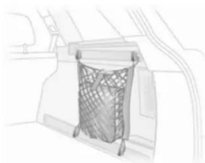
natural_image
Sketch of a car interior showing a mesh net hanging from a canopy (no text or symbols)Net pocket can be suspended from the luggage hooks.
Cargo box

natural_image
Cross-sectional diagram of a vehicle battery pack showing internal compartments and casing (no text or labels)Foldable box under the floor cover used to divide the load compartment.
The cargo box may only be loaded when the backrests are engaged in an upright position.
To remove the cargo box floor cover, remove first the right half then the left half. For models with towing equipment, first release the coupling ball bar fixing strap and thread this through the eye.
Install in reverse order.
Loading assist
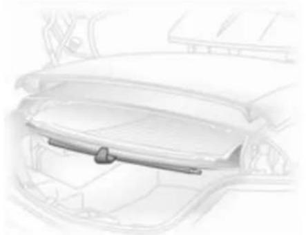
natural_image
Technical line drawing of a car interior showing the dashboard and rear seats (no text or symbols)On TwinTop: The loading aid Easy Load makes it possible to comfortably load the load compartment when the roof is open. Pressing the loading aid button will raise the roof folded up in the load compartment 25 cm. This enlarges the load opening of the load compartment.
■ Open the boot lid
■ Unhook load compartment blind and attach to rear window frame with holder
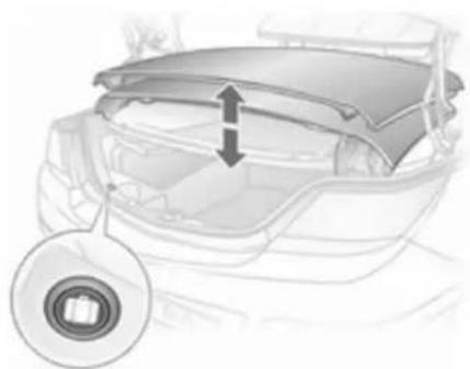
natural_image
Diagram of a car's rear bumper showing the lid and side panel, with an inset close-up of the front wheel (no text or symbols present)■ Briefly press loading aid button: The folded roof is raised. The roof remains in this end position for approx. 9 minutes

natural_image
Technical line drawing of a mechanical component with dashed alignment line (no text or symbols)■ Observe marked maximum load height
■ Suspend the load compartment blind from the rear window frame and engage in the recesses. The load compartment blind must be flat; objects underneath it must not push it upwards.
■ Briefly press loading aid button: The folded roof is lowered.
■ Close the boot lid only after the confirmation signal has sounded. Otherwise the roof could be damaged.
⚠ Warning
Take care when operating the loading aid. Risk of injury.
Make sure that nothing can become trapped.
Make sure no one is in the action zone during operation. Risk of injury.
This is especially important for children. Inform passengers accordingly.
78 Storage
Note
■ Do not place objects on or near the load compartment blind
■ The folded roof can only be lowered when the blind is closed.
Otherwise, a warning buzzer will sound three times
■ The movement of the tilted roof can be stopped by pressing the loading aid button and another longer press reverses the direction of the movement
■ A confirmation buzzer is heard in the upper and lower roof end positions when the roof is tilted
■ Only close the tailgate once the confirmation signal has sounded to indicate that the loading aid is in its lower end position
■ If the loading aid is not in its lower end position when the boot lid is closed, a warning tone sounds or the tailgate is blocked mechanically 40
■ Do not touch moving parts
■ One minute before the end of the hold time for the raised loading aid, a warning buzzer will sound to remind you to lower the roof
■ The loading aid is only operable when the vehicle is unlocked
■ Frequent operation of the loading aid with the engine off discharges the battery
■ Repeated operation of the loading aid can cause malfunctions
Safety net
The safety net is available on the Station wagon and can be installed behind the rear seats or, if the rear seat backrests are folded and the seat cushions raised, behind the front seats.
Passengers must not be transported behind the safety net.
Installation

natural_image
Interior view of a car showing the roof, window, and exhaust pipe (no text or symbols)There are two installation openings in the roof frame: suspend and engage rod of net at one side, compress rod and suspend and engage at other side.
Behind the rear seats

natural_image
Illustration of a car seatbelt buckle being inserted into a seat (no text or symbols)Adjust strap length on safety net by attaching the upper hook to the eye of the strap and attach to eyes in the right and left of the floor.
Behind front seats

natural_image
Close-up of a mechanical component with a black arrow pointing to a detail (no visible text or symbols)Adjust strap length on safety net by attaching the upper hook to the eye of the strap and attach to eyes in the right and left of the floor.
Remove rear outer head restraints and fold backrests forward.
Removal
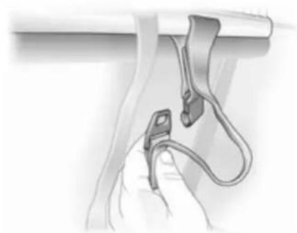
natural_image
Illustration of a hand holding a cable with a clip attached, no text or symbols presentTilt length adjuster of the net tensioning belt upwards and detach the belt. Unhook the safety net rods from the brackets in the roof frame. Roll up the net and secure with a strap.
Load compartment grille
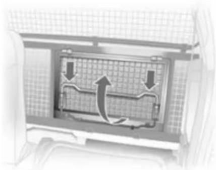
natural_image
Diagram of a car air vent system with directional arrows indicating airflow or flow (no text or labels)To transport long objects, part of the load compartment grille behind the passenger seat can be opened:
Release passenger seat back and fold forward.
Press bracket down and fold grille section up.

natural_image
Diagram of a vehicle interior with a grid-patterned panel and two downward arrows indicating motion or force (no text or symbols)Lock grille in open position.
To close the grille section from the open position, push bracket down, fold down grille and engage.
Check that the closed grille is properly locked.
Folding tray
Located in the front seat backrests.
Open by pulling upward until it engages.
Fold away by pressing down past the resistance point.
Do not place any heavy objects on the folding tray.
Warning triangle
Saloon 3-door / 5-door, TwinTop

natural_image
Diagram of a car back panel with an inset showing a battery component (no text or symbols present)Store warning triangle in rear load compartment wall: first fit warning triangle into recess on left and then insert in guide on right.
To remove the warning triangle, lift to the right and pull out to the right.
For vehicles with cargo box: Lift the warning triangle with the right half of the cargo box. Pull out the warning triangle to the right.
Saloon 4-door

natural_image
Diagram of a mechanical component inside a vehicle door frame (no text or symbols visible)Attach the warning triangle and first aid kit in the load compartment against the panel on the right using two straps.
Station wagon, Van

natural_image
Line drawing of a car rear view showing the side panel and window (no text or symbols)Stow the warning triangle in the space in the tailgate and fasten with the right and left straps.
First aid kit
Saloon 3-door / 5-door

natural_image
Interior view of a vehicle showing a mounted device with a logo (no readable text or symbols)Secure the first-aid kit to the right load compartment wall using the retaining strap.
82 Storage
Saloon 4-door
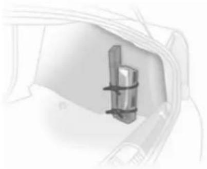
natural_image
Diagram of a mechanical component inside a vehicle (no text or symbols visible)Attach the warning triangle and first aid kit in the load compartment against the panel on the right using two straps.
Station wagon

natural_image
Interior view of a vehicle showing a battery pack inside a car (no text or symbols visible)Fasten the first-aid kit to the left load compartment wall with a retaining strap.
Van

natural_image
Interior view of a vehicle showing a mounted digital display with a logo (no readable text or symbols)Place first aid kit in stowage compartment behind the driver's seat. To open the cover, press the locking tab.
TwinTop

natural_image
Illustration of a car interior with a monitor displaying '7' and a camera, no visible text or symbolsStore the first-aid kit in the recess behind the strap in the left load compartment wall.
Roof rack system
Roof rack
For safety reasons and to avoid damage to the roof, the vehicle approved roof rack system is recommended.
Roof loads are not permitted on the Astra TwinTop.
Follow the installation instructions and remove the roof rack when not in use.
Version without roof railing

natural_image
Diagram showing a vehicle's side profile with an arrow indicating direction (no text or symbols present)Lift the covers from the fitting openings.
Fasten the roof rack at the fastening points.
Version with roof railing
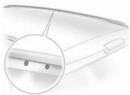
natural_image
Close-up of a laptop keyboard with a magnified inset showing the keyboard handle (no text or symbols visible)To fasten the roof rack, insert the mounting bolts in the holes indicated in the figure.
Loading information

natural_image
Interior view of a car trunk with internal compartments and directional arrows indicating movement (no text or symbols)■ Heavy objects in the load compartment should be placed against the seat backrests. Ensure the backrests are securely engaged. If objects can be stacked, the heavier objects should be placed at the bottom.
■ Secure objects with lashing straps attached to lashing eyes ➔ 75.
■ Secure loose objects in load compartment to prevent sliding.
■ When transporting objects in the load compartment, the backrests of the rear seats must not be angled forward.
■ Do not allow the load to protrude above the upper edge of the backrests.
■ Do not place any objects on the load compartment cover or the instrument panel.
■ The load must not obstruct the operation of the pedals, parking brake and gear selector, or hinder the freedom of movement of the driver. Do not place any unsecured objects in the interior.
■ Do not drive with an open load compartment.
■ Station wagon: fit safety net when objects are being transported in the load compartment. Close load compartment cover.
■ Astra TwinTop: pay attention to maximum loading height with roof open. Do not place objects on top of or next to the load compartment
blind, on the cover of the deployable anti-roll bars or behind the rear head restraints.
■ The payload is the difference between the permitted gross vehicle weight (see identification plate 214) and the EC kerb weight.
To calculate the EC kerb weight, enter the data for your vehicle in the Weights table at the front of this manual.
The EC kerb weight includes weights for the driver (68 kg), luggage (7 kg) and all fluids (tank 90 % full).
Optional equipment and accessories increase the kerb weight.
- Driving with a roof load increases the sensitivity of the vehicle to cross-winds and has a detrimental effect on vehicle handling due to the vehicle's higher centre of gravity. Distribute the load evenly and secure it properly with retaining straps. Adjust the tyre pressure and vehicle speed according to the load
conditions. Check and retighten the straps frequently.
The permissible roof load is 75 kg and 100 kg for Station wagon with roof railing. The roof load is the combined weight of the roof rack and the load.
Instruments and controls
Controls 86
Warning lights, gauges and indicators 93
Information displays 102
Vehicle messages 109
Trip computer 112
Controls
Steering wheel adjustment
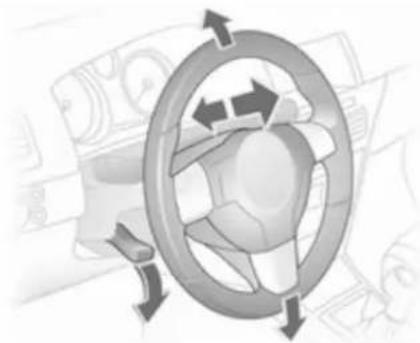
natural_image
Diagram of a car wheel with directional arrows indicating rotation or cycle (no text or symbols)Unlock lever, adjust steering wheel, then engage lever and ensure it is fully locked.
Do not adjust steering wheel unless vehicle is stationary and steering wheel lock has been released.
Steering wheel controls

natural_image
Interior view of a car steering wheel with a close-up of the dashboard (no visible text or symbols)The Infotainment system and the Info-Display can be operated via the controls on the steering wheel.
Further information is available in the Infotainment system manual.
Horn

natural_image
Interior view of a car steering wheel with a circular head and steering wheel (no text or symbols visible)Press ▶.
Windscreen wiper/washer
Windscreen wiper
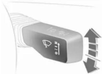
natural_image
Close-up of a USB flash drive with directional arrows indicating motion (no text or symbols)The lever always springs back to its original position.
= = fast
— = slow
-- = adjustable timed interval wipe
O = Off
For a single wipe when the windscreen wiper is off, press the lever down.
Run through the windscreen wiper stages by pushing the lever past the resistance point and holding. An acoustic signal sounds at O.
Do not use if the windscreen is frozen. Switch off in car washes.
Adjustable wiper interval

natural_image
Close-up of a car's license switch with directional arrows indicating left and right motion (no text or symbols)To set the wiper interval to a value between 2 and 15 seconds: Switch on ignition, move lever down from position O, wait desired time interval and raise lever to --.
88 Instruments and controls
After turning on the ignition and setting the lever to --, the interval is set to 6 seconds.
Automatic wiping with rain sensor
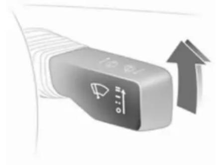
natural_image
Close-up of a car's steering wheel with directional arrows indicating upward motion (no text or symbols)-- = Automatic wiping with rain sensor
The rain sensor detects the amount of water on the windscreen and automatically regulates the frequency of the windscreen wipers.
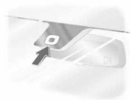
natural_image
Close-up of a computer monitor with an open button and a cursor pointing at it (no visible text or symbols)Keep the sensor free from dust, dirt and ice.
Windscreen washer

text_image
快安!Pull lever. Washer fluid is sprayed on the windscreen and the wiper wipes for a few strokes.
If the lights are on, washer fluid is also sprayed on the headlights. The headlight washer system is then inoperable for 2 minutes.
Rear window wiper/washer
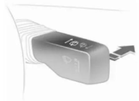
natural_image
Close-up of a button with directional arrows and icons, no readable text or symbols presentPush lever forwards. The rear window wiper wipes in interval mode. Switch off by pushing lever forwards again.
If the lever is held forwards, washer fluid is sprayed on the rear window.
Do not use if the rear window is frozen.
Switch off in car washes.
The rear screen wiper comes on automatically when the windscreen wiper is switched on and reverse gear is engaged.
Outside temperature

text_image
8:56 -5.5°C 07.04.200820001
A drop in temperature is indicated immediately and a rise in temperature after a time delay.
If outside temperatures drop to 3 °C, the symbol ⚙ illuminates in the Triple-Info-Display or the
Board-Info-Display as a warning for icy road conditions. ✦ remains illuminated until temperatures reach at least 5 °C.

text_image
Slippery road -2.5°C OKIn vehicles with Graphic-Info-Display or Color-Info-Display, a warning message appears in the display as a warning for icy road conditions. There is no message below -5 °C.
Warning
The road surface may already be icy even though the display indicates a few degrees above 0 °C.
Clock
Date and time are shown in the Info-Display.
Set date and time in Triple-Info-Display
8:56
5.5°C
07.04.2008
20003
To set time, hold the setting button in the instrument panel depressed for approx. 2 seconds. A brief press will set the flashing value. Hold the button depressed for 2 seconds again to switch to the next unit and to exit setting mode.
Automatic time synchronisation The RDS signal of most VHF transmitters automatically sets the time, identified by _rms in the display.
Some transmitters do not send a correct time signal. In such cases, we recommend to switch off automatic time synchronisation.
Activate setting mode and set it to year setting. Hold the ⏻ button depressed about 3 seconds until ⏻ flashes in the display and "RDS TIME" appears. The function is activated (RDS TIME 1) or deactivated (RDS TIME 0) with the ⏻ button. Exit setting mode using the ⏻ button.
Power outlets
Some vehicles have a power outlet for the connection of electrical accessories instead of a cigarette lighter.
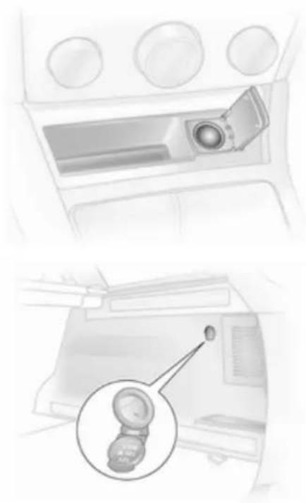
natural_image
Interior view of a car dashboard and infotainment panel showing the camera and two buttons (no text or symbols visible)Station wagons have an additional accessory socket in the load compartment.
Connecting electrical accessories while the engine is off will discharge the battery.
Do not exceed the maximum power consumption of 120 Watts.
Electrical accessories connected to the socket must comply with the electromagnetic compatibility requirements laid down in DIN VDE 40 839.
Do not connect any current-delivering accessories, e.g. electrical charging devices or batteries.
Do not damage the power outlets by using unsuitable plugs.
Cigarette lighter

natural_image
Pure diagram of a car interior with a downward arrow, no text or symbols presentThe cigarette lighter is located behind the ashtray cover. Press ashtray cover to open.
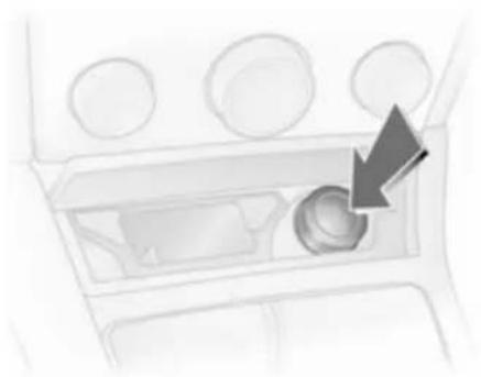
natural_image
Interior view of a car dashboard with a highlighted arrow pointing to the bottom-left component (no text or symbols visible)Press in cigarette lighter. Switches off automatically once the element is glowing. Pull out lighter.
Ashtrays
Caution
To be used only for ash and not for combustible rubbish.
92 Instruments and controls
Ashtray, front
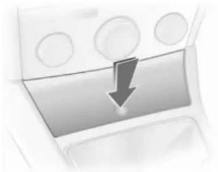
natural_image
Close-up of a car's front panel with a downward arrow indicating compression or drag (no text or symbols)Press ashtray cover to open.
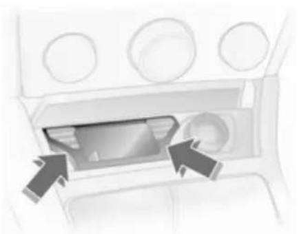
natural_image
Interior view of a car showing a vehicle's intake compartment with arrows pointing to the interior (no text or symbols visible)To empty, grip both sides of the ashtray insert and pull upwards.
Ashtray, rear

natural_image
Illustration of a printer with two arrows indicating flow or movement (no text or symbols)Pull out by pushing on one of the sides.
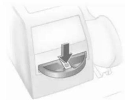
natural_image
Illustration of a showerhead with a downward arrow indicating water level (no text or symbols)To empty, press spring and pull the ashtray straight out rearwards.
Warning lights, gauges and indicators
Instrument cluster
In some versions, the needles of the instruments briefly rotate to the end position when the ignition is switched on.
Speedometer

text_image
60 100 120 140 160 180 50 40 30 20 10 0 km/h 200 220 240 260Indicates vehicle speed.
Odometer
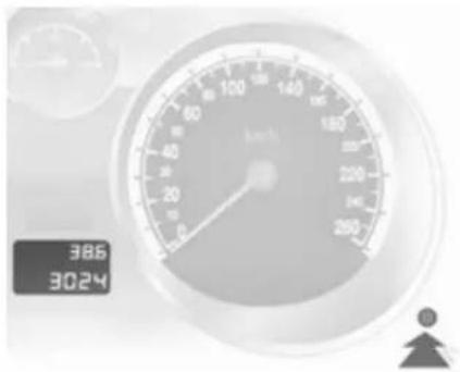
text_image
386 3024The bottom line displays the recorded distance.
Trip odometer
The top line displays the counted kilometres since the last reset.
To reset, hold the reset knob depressed for a few seconds with the ignition on.
Tachometer
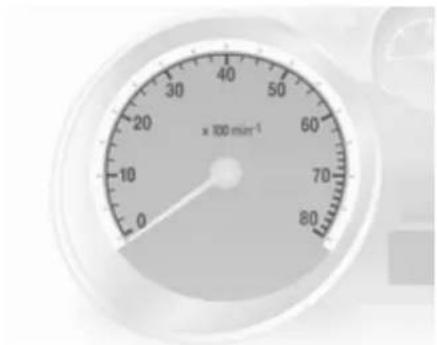
gauge
| Current (x 100 min⁻¹) | | --------------------- | | 0 |Displays the engine speed.
Drive in a low engine speed range for each gear as much as possible.
Caution
If the needle is in the red warning zone, the maximum permitted engine speed is exceeded. Engine at risk.
Fuel gauge
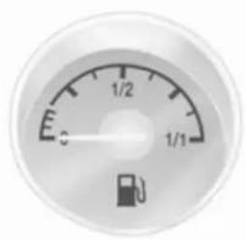
text_image
E 1/2 1/1 cDisplays the fuel level in the tank depending on the operation mode.
Control indicator ▼ illuminates if the level in the tank is low. Refuel immediately if it flashes.
Never run the tank dry.
Because of the fuel remaining in the tank, the top-up quantity may be less than the specified tank capacity.
Service display
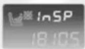
The message InSP appears when it is time for servicing. Further information 209.
Control indicators
The control indicators described are not present in all vehicles. The description applies to all instrument versions. When the ignition is switched on, most control indicators will illuminate briefly as a functionality test.
The control indicator colours mean:
Red = Danger, important reminder,
Yellow = Warning, information, fault,
Green = Confirmation of activation, Blue = Confirmation of activation.
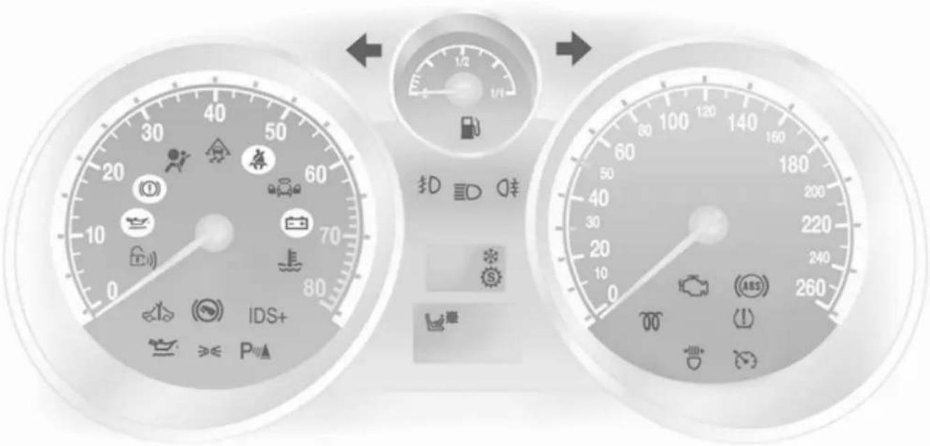
text_image
IDS+ 1/2 1/1 30 40 50 60 70 80 90 100 110 120 130 140 150 160 170 180 190 200 210 220 230 240 250 260Turn signal
◇◇ illuminates or flashes green.
Illuminates
The control indicator illuminates briefly when the parking lights are switched on.
Flashes
The control indicator flashes if a turn signal or the hazard warning flashers are activated.
Rapid flashing: failure of a direction indicator lamp or associated fuse, failure of direction indicator lamp on trailer.
Bulb replacement 168. Fuses 183.
Turn signals 120.
Seat belt reminder
illuminates or flashes red.
Illuminates
After the ignition is switched on until the seat belt is fastened.
Flashes
After starting off until the seat belt is fastened.
Fastening the seat belt ↩ 55.
Airbag, belt tensioners and anti-roll bars
illuminates red.
When the ignition is switched on, the control indicator illuminates for approx. 4 seconds. If it does not illuminate, does not go out after 4 seconds or illuminates whilst driving, there is a fault in the belt tensioner, the airbags, the deployable anti-roll bars or the seat occupancy recognition system. The systems may fail to trigger in the event of an accident.
Deployment of the belt tensioners, airbags or deployable anti-roll bars is indicated by continuous illumination of ♂.
Warning
Have the cause of the fault remedied immediately by a workshop.
Airbag system, belt tensioners 57, 54.
Seat occupancy recognition
illuminates or flashes yellow.
Illuminated
If the vehicle is equipped with seat occupancy recognition, 📊 illuminates for approx. 4 seconds after the ignition is switched on.
If a child restraint system with transponders is detected, ☐ remains illuminated. Only then a child restraint system with transponders may be used on the front passenger seat as the front passenger airbag systems are deactivated ☑ 59.
Danger
If a child restraint system is fitted and the control indicator is not illuminated while driving, the front and side airbag for the front passenger seat are not deactivated.
Flashes
Fault in system or child restraint system with transponders defective or improperly fitted 59.
Danger
Flashing of the control indicator while driving indicates a fault. Have the cause of the fault remedied by a workshop immediately.
Child restraint system with transponders 65.
Charging system
-+ illuminates red.
Illuminates when the ignition is switched on and goes out shortly after the engine starts.
Illuminates when the engine is running
Stop, switch off engine. Battery is not charging. Engine cooling may be interrupted. In diesel engines, power to the brake servo unit may be cut. Seek the assistance of a workshop.
Malfunction indicator light
illuminates or flashes yellow.
Illuminates when the ignition is switched on and goes out shortly after the engine starts.
Illuminates when the engine is running
Fault in the emission control system. The permitted emission limits may be exceeded. Immediately seek the assistance of a workshop.
Flashes when the engine is running
Fault that could lead to catalytic converter damage. Ease up on the accelerator until the flashing stops. Seek the immediate assistance of a workshop.
Service vehicle soon
illuminates or flashes yellow.
Illuminates when the engine is running
Fault in engine or transmission electronics 143, 147. The electronics switch to an emergency running programme. Fuel consumption may be increased and the vehicle handling may be impaired. If the fault persists after restarting the vehicle, consult a workshop.
Illuminates together with InSP4 in the service display
Seek the assistance of a workshop for draining the diesel fuel filter 110.
Flashes with switched on ignition
Fault in the immobiliser system. The engine cannot be started 32.
Switch off the ignition and repeat the start attempt.
If the control indicator continues flashing, attempt to start the engine using the spare key and seek the assistance of a workshop.
Brake and clutch system
(1) illuminates or flashes red.
Illuminated
Illuminates after the ignition is switched on if the parking brake is applied 150.
Illuminates when the parking brake is released if the brake and clutch fluid level is too low ➔ 166.

Warning
Stop. Do not continue your journey. Consult a workshop.
Flashes
On vehicle with automated manual transmission, flashes for a few seconds when the ignition is switched off if the parking brake is not applied.
On vehicles with automated manual transmission, flashes when the driver's door is opened if no gear is engaged and the parking brake is not applied.
Antilock brake system (ABS)
(ABS) illuminates red.
Illuminates for a few seconds after the ignition is turned on. The system is ready for operation when the control indicator goes out.
If the control indicator does not go out after a few seconds, or if it illuminates while driving, there is a fault in the ABS. The brake system remains operational but without ABS regulation.
Antilock Brake System ↩ 149.
Sport mode
S illuminates yellow.
The symbol is illuminated when Sport mode is on 142, 146.
Winter mode
※ illuminates yellow.
The symbol is illuminated when
Winter mode is on 142, 146.
Ultrasonic parking assist
P illuminates or flashes yellow.
Illuminates
Fault in system. Have the cause of the fault remedied by a workshop.
Flashes
Fault due to sensors that are dirty or covered by ice or snow.
or
Interference due to external sources of ultrasound. Once the source of interference is removed, the system will operate normally.
Ultrasonic parking sensors ↩ 153.
Electronic Stability Program
flashes or illuminates yellow.
Illuminates for a few seconds when the ignition is switched on.
Flashes whilst driving
The system is actively engaged. Engine output may be reduced and the vehicle may be braked automatically to a small degree 150.
Illuminates whilst driving
The system is switched off or a fault is present. Continued driving is possible. Driving stability, however, may deteriorate depending on road surface conditions.
Have the cause of the fault remedied by a workshop.
ESP®Plus 150.
Engine coolant temperature
illuminates red.
Illuminates when the engine is running
Stop, switch off engine.
Caution
Coolant temperature too high.
Check coolant level immediately 165.
If there is sufficient coolant, consult a workshop.
Preheating and diesel particle filter
willuminates or flashes yellow.
Illuminates
Preheating activated. Only activates when outside temperature is low.
Flashes
in vehicles fitted with a diesel particle filter.
Control indicator 00 flashes if the filter requires cleaning and previous driving conditions did not permit automatic cleaning. Continue driving and if possible do not allow engine speed to drop below 2000 rpm.
The control indicator 00 goes off as soon as the self-cleaning operation is complete.
Diesel particle filter ➔ 138.
Deflation detection system and tyre pressure monitoring system
(1) illuminates or flashes red or yellow.
Control indicator illuminates red Tyre pressure loss. Stop immediately and check tyre pressure. A maximum speed of 80 km/h is permitted for run-flat tyres 191.
Control indicator illuminates yellow
Fault in system or tyre without pressure sensor mounted (e.g. spare wheel). Consult a workshop.
Flashes
Flashes three times to indicate system initialisation.
Deflation detection system ➔ 194, tyre pressure monitoring system ➔ 193.
Interactive driving system, continuous damping control, sport mode
IDS+ illuminates yellow.
Illuminates when the ignition is switched on and goes out shortly after the engine starts. Illumination whilst driving indicates a fault in the system. Have the cause of the fault remedied by a workshop.
IDS ^Plus 151, CDC 152, Sport mode 151.
Engine oil pressure
illuminates red.
Illuminates when the ignition is switched on and goes out shortly after the engine starts.
Illuminates when the engine is running
Caution
Engine lubrication may be interrupted. This may result in damage to the engine and/or locking of the drive wheels.
- Depress clutch.
- Select neutral gear, set selector lever to N.
- Move out of the flow of traffic as quickly as possible without impeding other vehicles.
- Switch off ignition.
Warning
When the engine is off, considerably more force is needed to brake and steer.
Do not remove key until vehicle is stationary, otherwise the steering wheel lock could engage unexpectedly.
Check oil level before seeking the assistance of a workshop ➔ 164.
Low engine oil level
illuminates yellow.
Engine oil level is checked automatically.
Illuminates when the engine is running
Low engine oil level. Check engine oil level and top up as necessary ◇ 164.
Low fuel
illuminates or flashes yellow.
Illuminates
Level in fuel tank too low.
Flashes
Fuel used up. Refuel immediately. Never run the tank dry. Catalytic converter 139.
Bleeding the diesel fuel system 167.
Open&Start system
illuminates or flashes yellow.
Flashes
The electronic key is no more within the reception range of the vehicle interior. The engine cannot be started. Hold the Start/Stop button depressed a bit longer to switch off the ignition.
or
Failure of the electronic key. Operation is yet only possible via emergency operation.
Illuminates
Fault in system. Try to operate with the spare key, the remote control or through emergency operation. Hold the Start/Stop button depressed a bit longer to switch off the ignition. Seek the assistance of a workshop.
or
The steering wheel lock is still engaged. Move the steering wheel slightly and press the Start/Stop button.
Open&Start System ↩ 22.
Apply footbrake
illuminates yellow.
The engine with manual transmission automated can only be started if the foot brake is depressed. If the foot brake is not depressed, the control indicator illuminates 145.
Exterior light
illuminates green. Illuminates when the exterior lights are on 117.
High beam
ID illuminates blue.
Illuminates when high beam is on and during headlamp flash ➔ 118.
Adaptive forward lighting
illuminates or flashes yellow.
Illuminates
Fault in system.
If the swivelling device for curve lighting fails, the corresponding low beam lamp is deactivated and the fog lamp is switched on.
Seek the assistance of a workshop.
Flashes
Fault in system. Consult a workshop immediately.
Control indicator ◇ flashes for approx. 4 seconds after the ignition is switched on as a reminder that the system has been switched ➔ 118.
Adaptive Forward Lighting (AFL) 119.
Fog light
D illuminates green.
Illuminates when the front fog lights are on 120.
Rear fog light
O‡ illuminates yellow.
Illuminates when the rear fog light is on 120.
Cruise control
illuminates green.
Illuminates when the system is on 152.
Door open
illuminates red.
Illuminates when a door or the tailgate is open.
Information displays Triple-Info-Display
12:01 17.0°C
FM 3 90.6MHz
20004
Displays time, outside temperature and date or Infotainment system when it is on.
When the ignition is off, time, date and outside temperature can be displayed by briefly pressing one of the two buttons below the display.
Board-Info-Display
11:25⊕ 21.5℃
Range
257km
20005
Displays time, outside temperature and date or Infotainment system information.
Selecting functions
Functions and settings of the Infotainment system can be accessed via the board information display.
This is done using the menus and buttons of the Infotainment system.
If nothing is operated within 5 seconds, the menus are automatically exited.
Select using the Infotainment system buttons

natural_image
Diagram of a mechanical or electronic component with directional arrows indicating movement or force (no text or symbols present)In the Settings menu, use the OK button to call up the required function. Use the arrow buttons to change settings.
In the BC menu, use the OK button to call up the required function. Use the OK button to operate the stop watch or restart measurement and calculation.
Select using the left adjuster wheel on the steering wheel
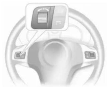
natural_image
Interior view of a car steering wheel with a digital display showing a document icon (no text or symbols present)Press the adjuster wheel to open the BC menu. In the BC menu press to operate the stop watch or restart measurement and calculation.
Turn the adjuster wheel to call up the required function.
System settings
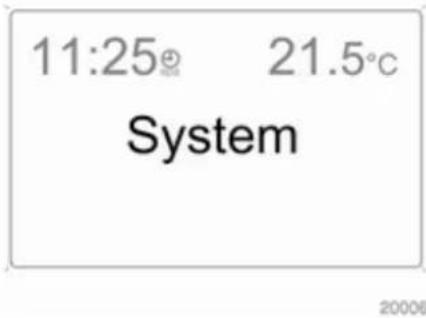
text_image
11:25° 21.5°C System 20006Press the Settings button of the Infotainment system. Menu item Audio then opens.
Call up System with the left arrow button and select with the OK button.
104 Instruments and controls
Automatic time synchronisation
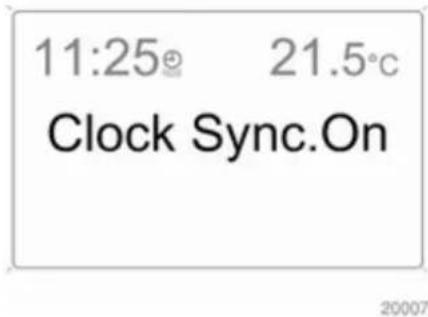
text_image
11:25 21.5°C Clock Sync.OnThe RDS signal of most VHF transmitters automatically sets the time. This can be identified by ⏻ in the display.
Some transmitters do not send a correct time signal. In such cases, we recommend to switch off automatic time synchronisation.
Deactivate (Clock Sync.Off) or activate (Clock Sync.on) automatic time synchronisation with the arrow buttons.
Setting date and time
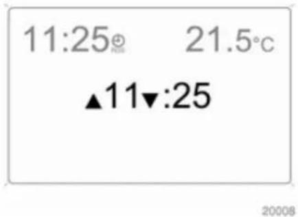
text_image
11:25° 21.5°C ▲11▼:25 2008The value ready for modification is marked with arrows. Use the arrow buttons to make the required setting.
Ignition logic
See Infotainment system manual.
Language selection

text_image
11:25® 21.5°C Deutsch 2009The display language for some functions can be selected.
Select the required language with the arrow buttons.
Setting units of measure

text_image
11:25® 21.5° Unit Europe-SI 20010Select the required unit of measurement with the arrow buttons.
Graphic-Info-Display, Colour-Info-Display
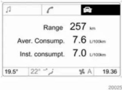
text_image
Range 257 km Aver. Consump. 7.6 L/100km Inst. consumpt. 7.0 L/100km 19.5° 22° A 19.36Displays time, outside temperature, date or Infotainment system (when it is on) and electronic climate control system.
The Color-Info-Display displays the information in colour.
The type of information and how it is displayed depend on the equipment of the vehicle and the settings made.
Selecting functions
Functions and settings of the Infotainment system and electronic climate control system are accessed via the display.
Selections are made via the menus and buttons, the multifunction control of the Infotainment system or the left adjuster wheel of the steering wheel.
Selecting with the Infotainment system buttons
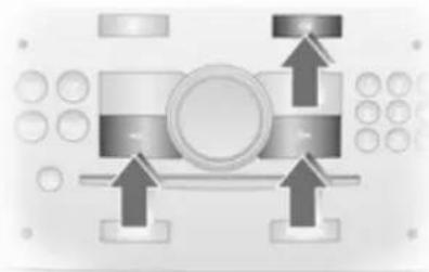
natural_image
Pure mechanical assembly diagram without any text, numbers, or symbols106 Instruments and controls
Select menu items via the menus and using the Infotainment system buttons. The OK button is used to select the highlighted item or confirm a command.
To exit a menu, press the right or left arrow button until Return or Main appear and select.
Selecting with the multifunction control
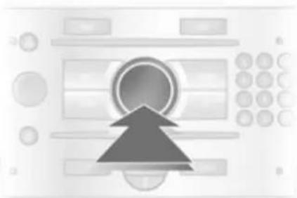
natural_image
Abstract diagram with a central circular element and an upward-pointing arrow, surrounded by rectangular panels (no text or symbols)Turn the multifunction control to highlight menu items or commands and to select function areas.
Press the multifunction control to select the highlighted item or confirm a command.
To exit a menu, turn the multifunction control until Return or Main appear and select.
Selecting with the left adjuster wheel on the steering wheel
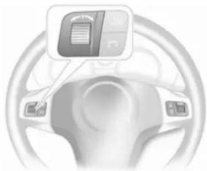
natural_image
Interior view of a car steering wheel with a digital display showing a document icon (no text or symbols present)Turn to select a menu item.
Press the adjuster wheel to select the highlighted item or confirm a command.
Function areas
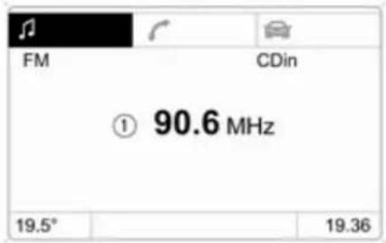
text_image
FM CDin ① 90.6 MHz 19.5° 19.36For each function area there is a main page (Main), which is selected at the top edge of the display (not with Infotainment system CD 30 or the Mobile Phone Portal):
■ Audio,
■ Navigation,
■ Telephone,
- Trip computer.
System settings
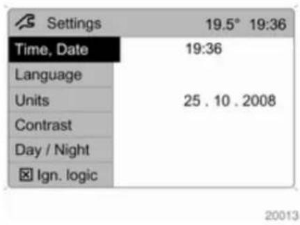
text_image
Settings 19.5° 19:36 Time, Date 19:36 Language Units 25 . 10 . 2008 Contrast Day / Night Ign. logicPress the Main button of the Infotainment system.
Press the Settings button on the Infotainment system. For Infotainment system CD 30, no menu may be selected.
Setting date and time

text_image
Time, Date 19.5° 19:36 Time 19:36 Date 25.10.2008 Synchron. clock automatical.Select menu item Time, Date from the Settings menu.
Select the required menu items and make settings.
Automatic time synchronisation The RDS signal of most VHF transmitters automatically sets the time.
Some transmitters do not send a correct time signal. In such cases, we recommend to switch off automatic time synchronisation.
On Infotainment systems with navigation, time and date are also harmonised upon receipt of a GPS satellite signal.
The function is activated by ticking the field in front of Synchron. clock automatical. in the Time, Date menu.
Language selection
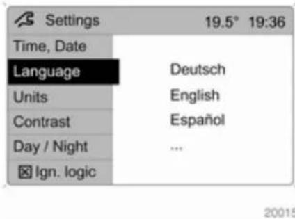
text_image
Settings 19.5° 19:36 Time, Date Language Deutsch Units English Contrast Español Day / Night ... Ign. logicThe display language for some functions can be selected.
Select menu item Language from the Settings menu.
Select the desired language.
108 Instruments and controls

text_image
13 Languages 19.5° 19:36 ► Deutsch English Español Nederlands Français ItalianoSelection is indicated by a ▶ in front of the menu item.
In systems with voice output, when the language setting of the display is changed the system will ask whether the announcement language should also be changed - see Infotainment system manual.
Setting units of measure

text_image
Settings 19.5° 19:36 Time, Date Language Units Contrast Day / Night Ign. logic Europe-SI Japan Great Britain USA 20017Select menu item Units from the Settings menu.
Select the desired unit.
Selections are indicated by a ● in front of the menu item.
Adjusting contrast (Graphic-Info-Display)
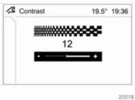
text_image
Contrast 19.5° 19:36 12 20018Select menu item Contrast from the Settings menu.
Confirm the required setting.
Setting display mode
Display brightness is dependent of vehicle lighting. Additional settings can be made as follows:
Select menu item Day/Night from the Settings menu.
Automatic: The colours are adapted to the exterior lights.
Always day design: black or coloured text on light background.
Always night design: white or coloured text on dark background.
Selection is indicated by a ● in front of the menu item.
Ignition logic
See Infotainment system manual.
Vehicle messages
Messages are given via the instrument panel display or as warning and signal buzzers. Check control messages appear on the Info-Display. Some appear in an abbreviated form. Confirm warning messages with the multifunction knob 102, 105.
Warning chimes
When starting the engine or whilst driving
■ If the electronic key is not present or is not recognised.
■ If seat belt is not fastened.
■ If a door or the tailgate is not fully closed when starting off.
■ If a certain speed is exceeded with the parking brake applied.
■ If the speed programmed at the factory is exceeded.
■ If the vehicle has automated manual transmission and the driver's door is opened when the engine is running, a gear is engaged and the foot brake is not depressed.
When the vehicle is parked and the driver's door is opened
■ When the key is in the ignition switch.
■ With exterior lights on.
■ With Open&Start system and automatic transmission, if the selector lever is not in P.
■ For automated manual transmission, if the parking brake is not applied and no gear is engaged when the engine is switched off.
When operating the retractable hardtop
■ Indicator buzzer upon completed opening or closing of the convertible hardtop.
■ Indicator buzzer upon completed raising or lowering of the electric load compartment loading aid.
110 Instruments and controls
■ Gong tone if the tailgate is not closed during roof operation.
■ Gong tone if the tailgate is not fully open during operation of the load compartment loading aid.
■ Gong tone during roof operation if vehicle speed exceeds 30 km/h.
■ Gong tone when vehicle speed exceeds 30 km/h if the roof is not fully open or closed.
■ Three gong tones during roof or loading aid operation if the load compartment blind is not attached.
■ Three gong tones during roof operation if outside temperature is below -20 °C, vehicle battery voltage is too low or the system is overloaded.
■ Continuous warning buzzer during roof operation if the anti-roll bars have been triggered.
■ Continuous warning buzzer starting one minute before the end of the 9-minute standby time with the roof in an intermediate position or the loading aid in a raised position.
■ Persistent warning buzzer when closing the tailgate, if the lowering process of the electric load aid is not complete or has been interrupted.
Battery voltage
Low battery voltage in radio remote control or electronic key. On vehicles without check control, the message InSP3 appears in the instrument panel display. Replace the battery 20, 22.
Brake light switch
Brake light does not come on during braking. Have the cause of the fault remedied immediately by a workshop.
Engine cooling level
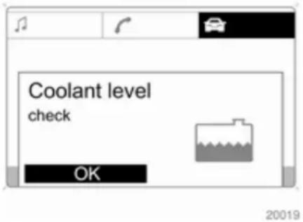
text_image
Coolant level check OK 20019Low fluid level in engine cooling system. Check coolant immediately 165.
Drain diesel fuel filter
If there is water in the diesel fuel filter, the message InSP4 appears in the instrument panel. Consult a workshop.
Lighting
Important exterior lights, including cables and fuses, are monitored. In trailer mode, trailer lighting is also monitored. Trailers with LED lighting must have an adapter that enables light monitoring as with conventional bulbs.
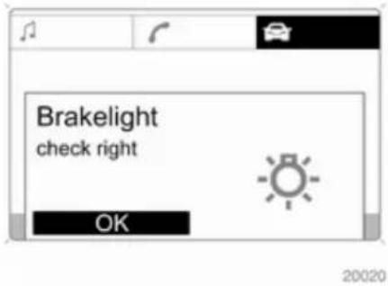
text_image
Brakelight check right OKThe failed lighting will be indicated in the information display or the message InSP2 will appear in the instrument panel display.
Anti-theft alarm system
System fault in anti-theft alarm system. Have the cause of the fault remedied by a workshop.
Tyre pressure

text_image
Navi active 19.5° 19:36 Tyre pressure check rear left (value in bar) OK 2.2 20021On vehicles with tyre pressure monitoring system, if there is low tyre pressure, information which tyre to check appears on the display.
Reduce speed and check tyre pressure at the next opportunity. Tyre pressure monitoring system 193. Check tyre pressure 192, 244.
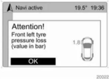
text_image
Navi active 19.5° 19:36 Attention! Front left tyre pressure loss (value in bar) 1.8 OK 20022If there is a considerable loss of pressure, a corresponding message appears indicating the tyre.
Steer out of flow of traffic as quickly as possible without endangering other vehicles. Stop and check the tyres. Mount the spare wheel 198. If run-flat tyres are fitted, maximum speed is 80 km/h. Information 191. Tyre pressure monitoring system 193.
Washer fluid level
Low washer fluid level. Top up washer fluid ➔ 166.
Trip computer
Trip computer in Board-Info-Display
Access the data by pressing the BC button on the Infotainment system or the left adjuster wheel on the steering wheel.
Some information appears in the display in an abbreviated form.
Once an audio function has been selected, the lower row of the trip computer function is displayed furthermore.
Instantaneous consumption
11:25 ^⊕ 21.5 ^°C
Inst. Consumpt. 7.6l/100km
20023
Displays the instantaneous consumption. At low speeds, consumption per hour is displayed.
Average consumption
Displays average consumption. The measurement can be reset at any time.
Absolute consumption
Displays fuel consumed. The measurement can be reset at any time.
Average speed
Displays average speed. The measurement can be reset at any time.
Stoppages in the journey with the ignition off are not included in the calculations.
Distance
Displays distance travelled. The measurement can be reset at any time.
Range
11:25 ^⊕ 21.5°C
Range
257km
20005
Range is calculated from current fuel tank content and current consumption. The display shows average values.
After refuelling, the range updates automatically after a brief delay.
When the fuel level in the tank is low, the message Range appears in the display.
When the fuel tank is nearly empty, the message Refuel! appears in the display.
Stop watch
11:25 ^⊕ 21.5 ^°C
Stop Watch
01:22:32h
Select the function. Press the OK button or the left adjuster wheel on the steering wheel to start or stop the stop watch.
Restart trip computer
The measurement or calculation of the following trip computer information can be restarted:
■ Average consumption,
■ Absolute consumption,
■ Average speed,
■ Distance,
■ Stop watch.
Select the desired trip computer information ➕ 102. To restart, press the OK button or the left adjuster wheel on the steering wheel for approx. 2 seconds.
Trip computer in Graphic-Info-Display or Colour-Info-Display
The main page of the trip computer provides information on range, current consumption and average consumption of BC 1.
To display other trip computer data, press the BC button on the infotainment system, select the trip computer menu from the display or press the left adjuster wheel on the steering wheel.
Select BC 1 or BC 2 from the trip computer menu.
114 Instruments and controls
Range
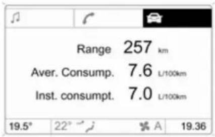
text_image
Range 257 km Aver. Consump. 7.6 L/100km Inst. consumpt. 7.0 L/100km 19.5° 22° A 19.3620025
Range is calculated from current fuel tank content and current consumption. The display shows average values.
After refuelling, the range is updated automatically after a brief delay.
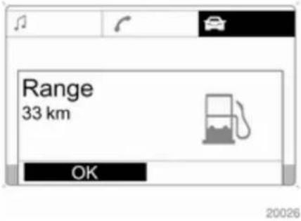
text_image
Range 33 km OKWhen the fuel level in the tank is low, the message Range appears in the display.
When the fuel tank is nearly empty, the message Please refuel! appears in the display.
The navigation system will support you in finding the nearest filling station. See Infotainment manual for further information.
Instantaneous consumption
Display of the instantaneous consumption. At low speeds, consumption per hour is displayed.

text_image
Board Computer 19.5° 19:36 BC 1 All values BC 2 257.0 km Timer Ø 40 km/h 31.0 Ltr. Ø 7.0 L/100km 20027Distance
Displays distance travelled. The measurement can be reset at any time.
Average speed
Displays average speed. The measurement can be reset at any time.
Stoppages in the journey with the ignition off are not included in the calculations.
Absolute consumption
Displays fuel consumed. The measurement can be reset at any time.
Average consumption
Displays average consumption. The measurement can be reset at any time.
Restart trip computer
The measurement or calculation of the following trip computer information can be restarted:
■ Distance,
■ Average speed,
■ Absolute consumption,
■ Average consumption.
Select BC 1 or BC 2 from the Board computer menu.
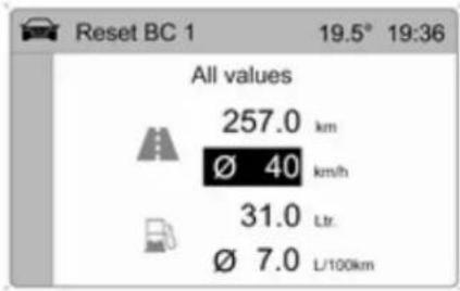
text_image
Reset BC 1 19.5° 19:36 All values 257.0 km Ø 40 km/h 31.0 Ltr. Ø 7.0 L/100km20028
The information of the two trip computers can be reset separately, making it possible to evaluate data from different time periods.
Select the required trip computer information and confirm.
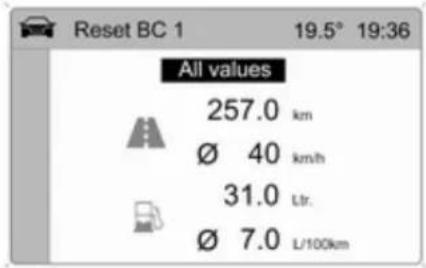
text_image
Reset BC 1 19.5° 19:36 All values 257.0 km Ø 40 km/h 31.0 Ltr. Ø 7.0 L/100km20029
To reset all information of a trip computer, select menu item All values.
Stop watch
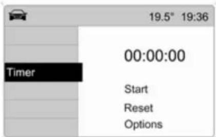
text_image
19.5° 19:36 Timer 00:00:00 Start Reset OptionsSelect menu item Timer from the Board Computer menu.
To start, select menu item Start. To stop, select menu item Stop.
To reset, select menu item Reset.
The relevant stop watch display can be selected in the Options menu:
Driving Time excl. Stops
The time the vehicle is in motion is recorded. Stationary time is not included.
Driving Time incl. Stops
The time the vehicle is in motion is recorded. The time the vehicle is stationary with the ignition switched on is included.
Travel Time
Measurement of the time from manual activation via Start to manual deactivation via Reset.
Tyre pressures

text_image
Board Computer 19.5° 19:36 BC 1 BC 2 Stop Watch Tyres 2.0 2.0 2.0 2.0 20031Select menu Tyres from the Board Computer menu.
The current pressure of each tyre is displayed.
Further information ➔ 193.
Lighting
Exterior lighting 117
Interior lighting 121
Lighting features 122
Exterior lighting Light switch
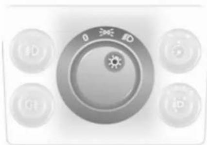
natural_image
Close-up of a gray industrial control knob with four buttons (labeled ID, pH, b) and a central gear symbol (no readable text or numbers)Turn light switch:
0 = Off
= Sidelights
ID = Headlights
Control indicator 101.
If the ignition is switched off with the headlights on, only the sidelights remain illuminated.
Automatic light control

natural_image
Close-up of a gray industrial control knob with four rotary buttons labeled (10, 10', 10', 10') and a central sun icon (no readable text or symbols beyond basic labels)Light switch set to AUTO: When the engine is running, headlights are switched on when external light conditions are poor.
For reasons of safety, the light switch should always remain in the AUTO position.
Move light switch to if visibility is poor because of fog or mist.
High beam

natural_image
Close-up of a metallic USB flash drive with directional arrows indicating motion (no text or symbols)To switch from low to high beam, push lever.
To switch to low beam, push lever again or pull.
Headlight flash
To activate the headlight flash, pull lever.
Headlight range adjustment
Manual headlight range adjustment
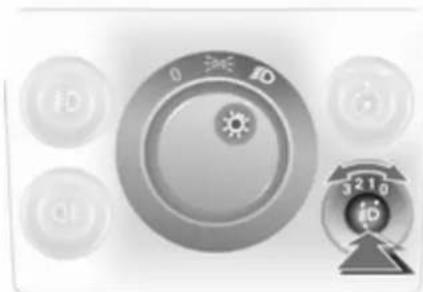
natural_image
Close-up of a rotary control knob with four buttons and a numeric display (no readable text or symbols)To adapt headlight range to the vehicle load to prevent dazzling: Press knob to disengage and turn to required position.
Vehicles without automatic level control system
0 = front seats occupied
1 = all seats occupied
2 = all seats occupied and load compartment laden
3 = driver's seat occupied and load compartment laden
Vehicles with automatic level control system
0 = front seats occupied
1 = all seats occupied
1 = all seats occupied and load compartment laden
2 = driver's seat occupied and load compartment laden
Automatic headlight range adjustment
Headlight range is automatically adjusted based on vehicle load.
Headlights when driving abroad
The asymmetrical headlight beam extends visibility at the edge of the road on the passenger side.
However, when driving in countries where traffic drives on the opposite side of the road, adjust the headlights to prevent dazzling of oncoming traffic.
Vehicles with halogen headlight system
Have the headlights adjusted by a workshop.
Vehicles with adaptive forward lighting
Adapting the aim of the headlight beam:
- Pull lever and hold.
- Switch on ignition.
- An acoustic signal sounds after approx. 3 seconds.
Control indicator ➕ 101.
Daytime running lights
With the ignition on and the light switch set to 0 or AUTO, the sidelights are switched on. When the engine is running, headlights illuminate.
On vehicle without automatic light control, must be switched on when it gets dark for illumination of the instrument panel.
The daytime running lights switch off when the ignition is switched off.
Adaptive forward lighting
Adaptive forward lighting with Bi-Xenon headlights improves lighting in curves and increases headlight range.
Curve lighting
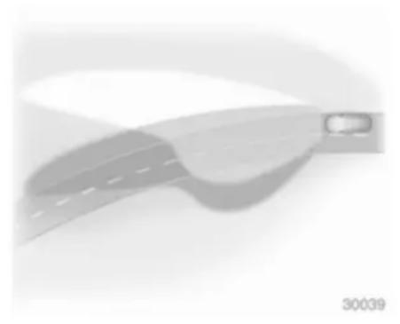
natural_image
Illustration of a curved road with a car icon, no text or symbols presentThe light beam pivots based on steering wheel position and speed.
Motorway lighting
At higher speeds and continuous straight ahead travel, the beam automatically raises slightly, thereby increasing headlight range.
Control indicator ➕ 101.
Hazard warning flashers
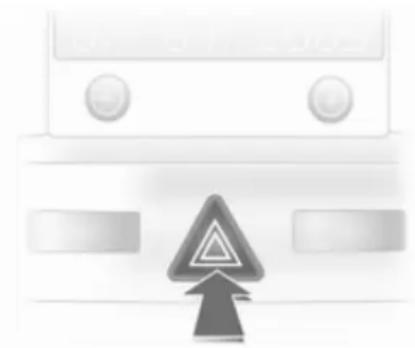
natural_image
Front view of a vehicle with a warning sign and upward arrow (no readable text or symbols)Operated with the △ button.
The hazard warning flashers activate automatically if the airbags deploy.
Turn and lane-change signals
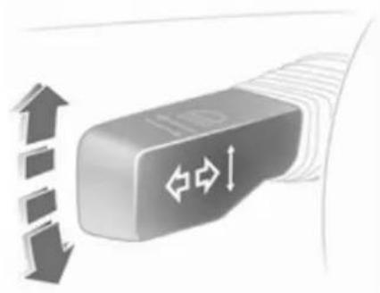
natural_image
Close-up of a USB flash drive with directional arrows indicating speed (no text or symbols)Lever up = right turn signal Lever down = left turn signal
The lever always springs back to its original position.
If the lever is moved past the resistance point, the turn signal is switched on constantly. When the steering wheel moves back, the turn signal is automatically deactivated.
For three flashes, e.g. when changing lanes, press the lever until resistance is felt and then release.
Move the lever to the resistance point and hold for longer indication.
Switch the turn signal off manually by moving the lever slightly.
Front fog lights
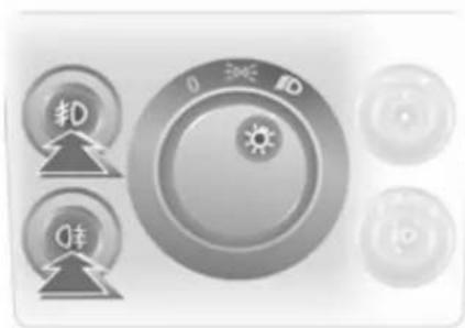
natural_image
Close-up of a control panel with buttons and a central rotary knob (no readable text or symbols)The front fog lights can only be switched on when both the ignition and headlights or sidelights are on. Operated with the #D button.
Rear fog lights
The rear fog light can only be switched on when both the ignition and headlights or sidelights (with front fog lights) are on.
Operated with the ⏻ button. The vehicle rear fog light is deactivated when towing.
Parking lights

text_image
0 ←→↓When parked, the parking light on one side can be activated:
- Set light switch to 0 or AUTO.
- Ignition off.
- Move turn signal lever all the way up (right parking light) or down (left parking light).
Confirmed by a signal and the corresponding turn signal control indicator.
To switch it off, switch on the ignition or move the turn signal lever in the opposite direction.
Reversing lights
The reversing lights come on when the ignition is on and reverse gear is selected.
Misted light covers
The inside of the light covers may mist up briefly in poor, wet and cold weather conditions, in heavy rain or after washing. The mist disappears quickly by itself; to help, switch on the headlights.
Interior lighting
Instrument panel illumination control

natural_image
Close-up of a control knob with dials and a rotary dial indicator (no text or symbols)Brightness can be adjusted when the exterior lights are on: Press knob ⚙ to disengage and then turn it and hold until the desired brightness is obtained.
Interior lights
During entry and exit of the vehicle, the front and centre courtesy lights automatically come on and then switch off after a delay.
Front courtesy light
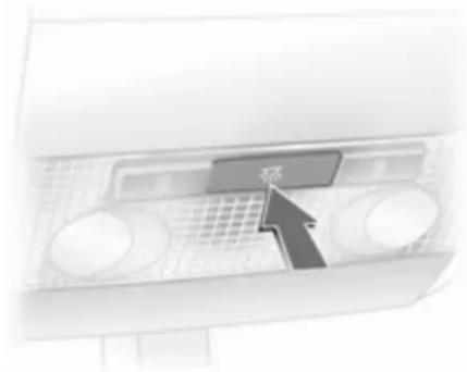
text_image
Diagram showing a computer monitor with a labeled button and arrow pointing to the screen areaOperated with the ☑ button.
Courtesy lights and rear reading lights

natural_image
Close-up of a mechanical component with two arrows pointing to features (no text or symbols visible)Operated with switch.
I = on
0 = off
centre = automatic
Reading lights

natural_image
Close-up of a computer control panel with two buttons and a grid-patterned screen (no visible text or symbols)Operated with 留 buttons or switch.
I = on
0 = off
centre = automatic
Sunvisor lights
The lighting switches on when the cover is opened.
Lighting features
Centre console lighting
Spotlight in interior mirror housing. Daylight-dependent, automatically regulated centre console lighting.
Entry lighting
After unlocking the vehicle, the instrument panel lighting and the number plate lights come on for a few seconds.
Starting off 17.
Exit lighting

text_image
0 1/30Headlights and reversing lights come on for approx. 30 seconds after the system is activated and the driver's door is closed.
Activating
- Switch off ignition.
- Remove ignition key.
- Open driver's door.
- Pull turn signal lever.
- Close driver's door.
If the driver's door is not closed the lights switch off after two minutes.
The lighting is switched off immediately if the turn signal lever is pulled while the driver's door is open.
Battery discharge protection
To prevent the battery from becoming discharged, all the interior lighting is switched off automatically after 10 minutes, when the ignition is switched off.
124 Infotainment system
Infotainment system
Introduction 124
Radio 124
Audio players 125
Rear seat infotainment 125
Phone 125
Introduction
Operation
The Infotainment system is operated as described in the Infotainment system manual.
Radio
Radio reception
Radio reception may be disrupted by static, noise, distortion due to
■ changes in distance from the transmitter,
■ multi-path reception due to reflection,
■ shadowing.
Audio players Auxiliary devices

natural_image
Close-up of a car seatbelt mechanism with a downward arrow indicating force or pressure (no text or symbols present)An external audio source such as a portable CD player can be connected using a 3.5 mm jack plug via the AUX input.
Always keep the AUX input clean and dry.
Rear seat infotainment Rear seat audio system

text_image
TUNER QI COTwin Audio allows the choice between the audio source played on the Infotainment system or another audio source. Only an audio source that is not currently active on the Infotainment system can be controlled.
Two headphone connections are available, with separate volume controls.
Phone
Mobile phones and CB radio equipment
Installation instructions and operating guidelines
The vehicle specific installation instructions and the operating guidelines of the mobile phone and handsfree manufacturer must be observed when installing and operating a mobile telephone. Failure to do so could invalidate the vehicle type approval (EU directive 95/54/EC).
Recommendations for fault-free operation:
■ Professionally installed exterior antenna to obtain the maximum range possible,
■ Maximum transmission power 10 Watts,
■ Installation of the phone in a suitable spot, consider relevant Note ➔ 57.
126 Infotainment system
Seek advice on predetermined installation points for the external antenna or equipment holder and ways of using devices with a transmission power exceeding 10 Watts.
Use of a handsfree attachment without external antenna with mobile telephone standards GSM 900/1800/1900 and UMTS is only permitted if the maximum transmission power of the mobile telephone is 2 Watts for GSM 900 or 1 Watt for the other types.
For reasons of safety, do not use the phone while driving. Even use of a handsfree set can be a distraction while driving.
⚠ Warning
Operation of radio equipment and mobile telephones which fail to meet above mentioned mobile telephone standards is only permitted using an antenna located outside of the vehicle.
Caution
Mobile telephones and radio equipment may lead to malfunctions in the vehicle electronics when operated inside the vehicle with no exterior antenna, unless the above mentioned regulations are observed.
Climate control
Climate control systems .... 127
Air vents 133
Maintenance 134
Climate control systems Heating and ventilation system

natural_image
Front view of a washing machine control panel with three rotary dials and a digital display (no visible text or symbols)Controls for:
■ Air distribution
■ Temperature
■ Fan speed
Heated rear window ➕ 37.
Air distribution
j = to head area and foot well
= to head area
j = to windscreen and front door windows
= to windscreen, front door windows and foot well
= to foot well
Intermediate settings are possible.
Temperature
red = warm
blue = cold
Heating will not be fully effective until engine has reached normal operating temperature.
Fan speed
Adjust the air flow by switching the fan to the desired speed.
Demisting and defrosting the windows
■ Set air distribution control to 📂.
■ Set temperature control to warmest level.
■ Set fan speed to highest level.
■ Switch on heated rear window 📄.
128 Climate control
■ Open side air vents as required and direct them towards door windows.
■ For simultaneous warming of the foot well, set air distribution control to ↓.
Air conditioning system
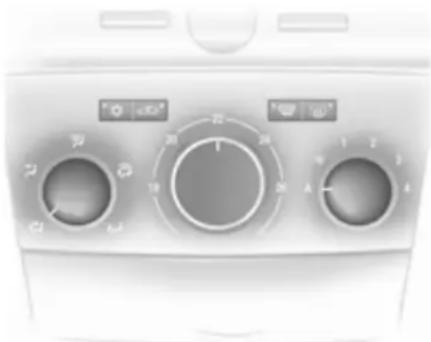
natural_image
Front view of a kitchen air conditioner unit with rotary dials and indicator lights (no visible text or symbols)In addition to the heating and ventilation system, the air conditioning system has:
☀ = Cooling
= Air recirculation
Cooling
Operated with the ⚙ button and is functional only when the engine and fan are running.
The air conditioning system cools and dehumidifies (dries) as soon as the outside temperature is slightly above freezing point. Therefore condensation may form and drip from under the vehicle.
If no cooling or drying is required, switch the cooling system off to save fuel.
Air recirculation system
Operated with the 📄 button.
⚠ Warning
The exchange of fresh air is reduced in air recirculation mode. In operation without cooling the air humidity increases, so the windows may mist up. The quality of the passenger compartment air deteriorates, which may cause the vehicle occupants to feel drowsy.
Air distribution to 📋: Air recirculation is deactivated.
Maximum cooling
Briefly open the windows so that hot air can disperse quickly.
■ Cooling ⚙ on.
■ Air circulation system 📄 on,
■ Set air distribution control to ↗.
■ Set temperature control to coldest level.
■ Set fan speed to highest level.
■ Open all vents.
Demisting and defrosting the windows
■ Cooling ⚙ on.
■ Set air distribution control to 📄.
■ Set temperature control to warmest level.
■ Set fan speed to highest level.
■ Switch on heated rear window 📄.
■ Open side air vents as required and direct them towards door windows.
■ For simultaneous warming of the foot well, set air distribution control to ↓.
Automatic climate control system
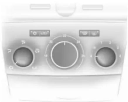
natural_image
Front view of a washing machine control panel with rotary dials and indicator lights (no visible text or symbols)Controls for:
■ Air distribution
■ Temperature
■ Fan speed
☀ = Cooling
= Air recirculation
_1 = Demisting and defrosting
Heated rear window ➞ 37.
The preselected temperature is automatically regulated. In the automatic mode the fan speed automatically regulates the air flow.
Automatic mode
Basic setting for maximum comfort:
■ Set fan control to A.
■ Set the air distribution control to the desired setting.
■ Preset temperature to the desired level.
■ Cooling ⚙ on.
■ Open all of the air vents.
Air distribution
j = to head area and foot well
= to head area
j = to windscreen and front door windows
= to windscreen, front door windows and foot well
↓ = to foot well
Intermediate settings are possible.
Temperature preselection
Set the temperature control to the required position. Intermediate settings are possible.
For reasons of comfort, change temperature only in small increments.
At the end positions, there is no temperature regulation. The air conditioning system works with maximum cooling or heating.
Heating will not be fully effective until engine has reached normal operating temperature.
Fan speed
In the automatic mode A the fan speed automatically regulates the air flow. If required the air flow can be manually adjusted.
Cooling
Operated with the ⚙ button and is functional only when the engine and fan are running.
130 Climate control
The air conditioning system cools and dehumidifies (dries) when outside temperature is above a specific level. Therefore condensation may form and drip from under the vehicle.
If no cooling or drying is required, switch the cooling system off to save fuel.
Air recirculation system
The air recirculation mode is operated with the 📄 button.
⚠ Warning
The exchange of fresh air is reduced in air recirculation mode. In operation without cooling the air humidity increases, so the windows may mist up. The quality of the passenger compartment air deteriorates, which may cause the vehicle occupants to feel drowsy.
Maximum cooling
Briefly open the windows so that the heated air can disappear quickly.
■ Cooling ⚙ on.
■ Set air distribution control to ✦.
■ Set temperature control to required temperature value.
■ Set fan control to A.
■ Open all vents.
The automatic climate control automatically cools to the specified value with the maximum cooling power.
With the temperature control turned to its minimum setting, the system continually runs at maximum cooling. The system is automatically set to air recirculation when the air conditioning is on.
Demisting and defrosting the windows
■ Cooling ⚙ on.
■ Press button 📋: in position A, fan automatically switches to maximum speed, the air distribution is directed towards the windscreen.
■ Set temperature control to warmest level.
■ Switch on heated rear window 📄.
Electronic climate control system
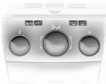
natural_image
Close-up of a white industrial air conditioner unit with three circular control knobs and indicator lights (no readable text or symbols)Controls for:
■ Temperature
■ Air distribution and menu selection
■ Fan speed
AUTO = Automatic mode
= air recirculation
= demisting and defrosting
Heated rear window ➞ 37.
The preselected temperature is automatically regulated. In the automatic mode the fan speed and air distribution automatically regulate the air flow.
The system can be manually adapted by use of air distribution and air flow controls.

text_image
FM AS CDin MP3 ① 90.6 MHz 19.5° 22° A 19.36 20032Data is shown on the Info-Display. Setting modifications are briefly shown in the Info-Display, superimposing over the currently displayed menu.
The electronic climate control system is only fully operational when the engine is running.
Do not cover the sensor on the instrument panel for correct operation.
Automatic mode
Basic setting for maximum comfort:
■ Press AUTO button.
■ Open all air vents.
■ Air conditioning on.
■ Set desired temperature.
Temperature preselection
Temperatures can be set to the desired value.
For reasons of comfort, change temperature only in small increments.
If the minimum temperature is set, Lo appears in the display and the electronic climate control system runs at maximum cooling.
If the maximum temperature is set, Hi appears in the display and the electronic climate control system runs at maximum heating.
Fan speed
The selected fan speed is indicated with ✕ and a number in the display.
If the fan is switched off the air conditioning is also deactivated.
To return to automatic mode: Press AUTO button.
Demisting and defrosting the windows
Press the 🎨 button. 🎨 appears in the display.
Temperature and air distribution are set automatically and the fan runs at a high speed.
To return to automatic mode: press button 📋 or AUTO.
Switch on heated rear window ☐.
Manual settings in climate menu Climate control system settings can be changed via the centre control, the buttons and the menus shown on the display.
To view the menu, press the centre control. The Climate menu appears in the display.
132 Climate control
Individual menu items are marked by turning the centre control and selected by pressing it.
To exit a menu, turn the centre control until Return or Main appear and select.
Air distribution
Turn the centre control. The Air distribut. menu is activated, showing the possible air distribution settings:
Top = to windscreen and front door windows.
Centre = to vehicle occupants.
Bottom = to foot well.
The Air distribut. menu can also be called up via the Climate menu.
Return to automatic air distribution: Deactivate corresponding setting or press button AUTO.
Cooling
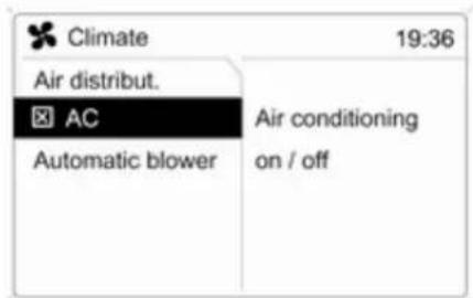
text_image
Climate 19:36 Air distribut. AC Automatic blower Air conditioning on / off20210
In the Climate menu, select menu item AC and activate or deactivate cooling.
The air conditioning system cools and dehumidifies (dries) when outside temperature is above a specific level. Therefore condensation may form and drip from under the vehicle.
If no cooling or drying is required, switch the cooling system off to save fuel, Eco appears in the display.
Fan regulation in automatic mode
Fan regulation in automatic mode can be adapted.
Select menu item Automatic blower from the Climate menu and select the desired fan regulation.
Manual air recirculation mode
The manual air recirculation mode is operated with the 📄 button.
⚠ Warning
The exchange of fresh air is reduced in air recirculation mode. In operation without cooling the air humidity increases, so the windows may mist up. The quality of the passenger compartment air deteriorates, which may cause the vehicle occupants to feel drowsy.
Air conditioning with the engine not running
When ignition is off, the residual heat or cooling in the system can be used for climate control in passenger compartment.
Press the AUTO button with the ignition off. Residual air conditioning on will appear briefly in the display.
Residual climate control can only operate for a limited period of time. To cancel, press the AUTO button.
Auxiliary heater
Air heater
Quickheat is an electric auxiliary air heater which warms up the passenger compartment more quickly.
Coolant heater
Diesel-engined vehicles have a fuel-powered auxiliary heater.
Air vents
Adjustable air vents
At least one air vent must be open while cooling is on in order to prevent the evaporator from icing up due to lack of air movement.

text_image
1To open vent, turn the adjuster wheel to l.

text_image
Diagram of a car air intake system with labeled components and directional arrows indicating airflow or movement.Direct the flow of air by tilting and swivelling the slats.
To close the vent, turn the adjuster wheel to 0.
⚠ Warning
Do not attach any objects to the slats of the air vents. Risk of damage and injury in case of an accident.
Fixed air vents
Additional air vents are located beneath the windscreen and door windows and in the foot wells.
Maintenance Air intake

natural_image
Close-up of a mechanical component with a curved central section and flanged base (no visible text or symbols)The air intakes in front of the windscreen in the engine compartment must be kept clear to allow air intake. Remove any leaves, dirt or snow.
Pollen filter
The pollen filter cleans dust, soot, pollen and spores from the air entering the vehicle through the air intake.
Air conditioning regular operation
In order to ensure continuously efficient performance, cooling must be operated for a few minutes once a month, irrespective of the weather and time of year. Operation with cooling is not possible when outside temperature is too low.
Service
For optimal cooling performance, it is recommended to annually check the climate control system, starting three years after initial vehicle registration, including:
■ Functionality and pressure test
■ Heating functionality
■ Leakage check
■ Check of drive belts
■ Cleaning of condenser and evaporator drainage
■ Performance check
Driving and operating
Driving hints 135
Starting and operating 135
Engine exhaust 138
Automatic transmission ...... 139
Manual transmission 144
Manual transmission automated 145
Brakes 149
Ride control systems .... 150
Cruise control 152
Object detection systems ..... 153
Fuel 154
Towing 157
Driving hints
Control of the vehicle
Never coast with engine not running
Many systems will not function in this situation (e.g. brake servo unit, power steering). Driving in this manner is a danger to yourself and others.
Pedals
To ensure the pedal travel is uninhibited, there must be no mats in the area of the pedals.
Starting and operating
New vehicle running-in
Do not brake unnecessarily hard for the first few journeys.
During the first drive, smoke may occur because of wax and oil evaporating off the exhaust system. Park the vehicle in the open for a while after the first drive and avoid inhaling the fumes.
Fuel and engine oil consumption may be higher during the running-in period.
Ignition switch positions
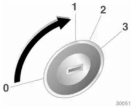
text_image
0 1 2 3 300510 = Ignition off
1 = Steering wheel lock released, ignition off
2 = Ignition on, for diesel engine: preheating
3 = Starting
Starting the engine
Starting engine with ignition switch
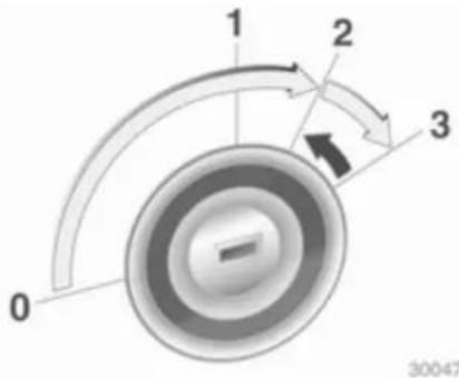
text_image
1 2 3 0 30047Operate clutch and brake, automatic transmission in P or N, do not accelerate; for diesel engines, turn the key to position 2 for preheating until control indicator 00 goes out; turn key briefly to position 3 and release key when engine is running.
Before restarting or to switch off the engine, turn key back to position 0.
Starting engine with the Start/Stop button

natural_image
Close-up of a kitchen air conditioner unit with a circular dial indicator (no visible text or symbols)The electronic key must be inside the vehicle. Operate clutch and brake, automatic transmission in P or N, do not accelerate, for diesel engines, press the button briefly to start preheating, move the steering wheel slightly to release the steering wheel lock, wait until control indicator 00 goes out and then press button for 1 second and release when the engine is running.
To repeat the starting procedure or to switch off the engine, press the button again.
Starting the vehicle at low temperatures
The start of the engine without additional heaters is possible down to -25 °C for diesel engines and -30 °C for petrol engines. Required is an engine oil with the correct viscosity, the correct fuel, performed services and a sufficiently charged battery. With temperatures below -30 °C the automatic transmission and the manual transmission automated need a warming phase of approx. 5 minutes. The selector lever must be in position P respectively N.
Overrun cut-off
The fuel supply is automatically cut off during overrun, i.e. when the vehicle is driven with a gear engaged but accelerator is released.
Parking
■ Do not park the vehicle on an easily ignitable surface. The high temperature of the exhaust system could ignite the surface.
■ Always apply parking brake without pressing release button. Apply as firmly as possible on downhill or uphill slopes. Depress the foot brake at the same time to reduce operating force.
■ Switch off the engine and ignition. Turn the steering wheel until the steering wheel lock engages.
■ If the vehicle is on a level surface or uphill slope, engage first gear or set the selector lever to P before switching off the ignition. On an uphill slope, turn the front wheels away from the kerb.
If the vehicle is on a downhill slope, engage reverse gear or set the selector lever to P before switching off the ignition. Turn the front wheels towards the kerb.
■ Lock the vehicle and activate the anti-theft locking system and the anti-theft alarm system.
Engine exhaust
Danger
Engine exhaust gases contain poisonous carbon monoxide, which is colourless and odourless and could be fatal if inhaled.
If exhaust gases enter the interior of the vehicle, open the windows. Have the cause of the fault rectified by a workshop.
Avoid driving with an open load compartment, otherwise exhaust gases could enter the vehicle.
Diesel particle filter
The diesel particle filter system filters harmful soot particles out of the exhaust gases. The system includes a self-cleaning function that runs automatically during driving. The filter is cleaned by burning off the soot particles at high temperature. This process takes place automatically under set driving conditions and may take up to 25 minutes. Fuel
consumption may be higher during this period. The emission of smells and smoke during this process is normal.
text_image
00Under certain driving conditions, e.g. short distances, the system cannot clean itself automatically.
If the filter requires cleaning and previous driving conditions did not enable automatic cleaning, control indicator 700 flashes. Continue driving, keeping engine speed above 2000 revolutions per minute. Shift down if necessary. Diesel particle filter cleaning is then started.
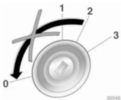
text_image
1 2 3 0 30046Stopping the journey or switching off the engine during cleaning is not recommended.
Caution
If the cleaning process is interrupted more than once, there is a great risk of provoking severe engine damage.
Cleaning takes place quickest at high engine speeds and loads.
natural_image
Close-up of a circular gauge or speedometer with a pointer at 100 degrees (no visible text or numerical markings)The control indicator extinguishes as soon as the self-cleaning operation is complete.
Catalytic converter
The catalytic converter reduces the amount of harmful substances in the exhaust gases.
Caution
Fuel grades other than those listed on pages 154, 218 could damage the catalytic converter or electronic components.
Unburnt petrol will overheat and damage the catalytic converter. Therefore avoid excessive use of the starter, running the fuel tank dry and starting the engine by pushing or towing.
In the event of misfiring, uneven engine running, a reduction in engine performance or other unusual problems, have the cause of the fault rectified by a workshop as soon as possible. In an emergency, driving can be continued for a short period, keeping vehicle speed and engine speed low.
Automatic transmission
The automatic transmission makes automatic shifting possible (automatic mode) and the version with ActiveSelect also makes manual shifting possible (manual mode).
Transmission display
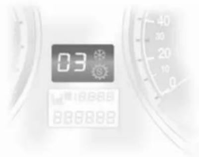
text_image
03 18888 888888The mode or selected gear is shown in the transmission display.
Selector lever
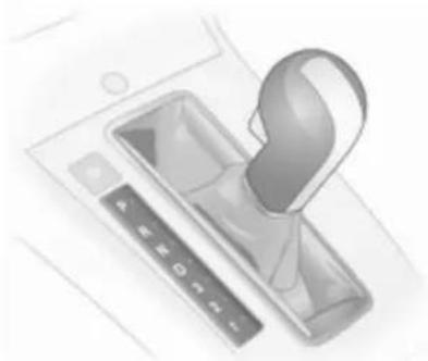
natural_image
Illustration of a handbag device with control panel and keyboard (no text or symbols)P = park position, Front wheels locked, engage only when the vehicle is stationary and the parking brake is applied
R = reverse gear, engage only when vehicle is stationary
N = neutral
D = automatic mode with all gears

natural_image
Illustration of a hand holding a device with control buttons and a pen, no visible text or symbolsThe selector lever can only be moved out of P or N when the ignition is on and the foot brake is depressed (selector lever lock).
When the selector lever is in N, the selector lever lock is activated after a delay and only if the vehicle is stationary.

natural_image
Illustration of a hand tool interacting with a car gear shift register (no text or symbols visible)When the selector lever is in the P or N position, control indicator Ⓞ in the gear indicator strip illuminates red when the selector lever is locked. If the selector lever is not in the P position when the ignition is switched off, control indicator Ⓞ and P in the gear indicator strip flash.
To engage P or R, push button on selector lever.
When position N is selected, press foot brake or engage parking brake before starting.
Do not accelerate while engaging a gear. Never depress the accelerator pedal and brake pedal at the same time.
When a gear is engaged, the vehicle slowly begins to creep when the brake is released.
Gears 3, 2, 1
3, 2, 1 = Transmission does not shift above the selected gear.
Press button on selector lever to engage 3 or 1.
Only select 3, 2 or 1 to prevent automatic upshifting or as an aid in engine braking.
Engine braking
To utilise the engine braking effect, select a lower gear in good time when driving downhill.
Rocking the vehicle
Rocking the vehicle is only permissible if the vehicle is stuck in sand, mud or snow. Move the selector lever between D and R in a repeat pattern. Do not race the engine and avoid sudden acceleration.
Parking
Apply the parking brake and engage P.
The ignition key can only be removed when the selector lever is in position P.
Manual mode
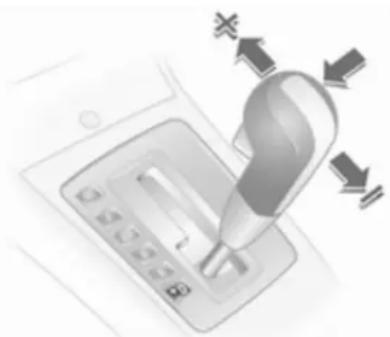
natural_image
Illustration of a hand inserting a card into a mobile payment terminal, with currency symbols (no text or labels)Move selector lever out of position D towards the left and then forwards or backwards.
+ = Shift to a higher gear.
- = Shift to a lower gear.
If a higher gear is selected when vehicle speed is too low, or a lower gear when vehicle speed is too high, the shift is not executed.
If engine speed is too low, the transmission automatically shifts to a lower gear above a specific vehicle speed.
142 Driving and operating
No automatic shifting to a higher gear takes place at a high engine speed.
For reasons of safety, kickdown is also available in manual mode.
Electronic driving programmes
■ Following a cold start, the operating temperature programme increases engine speed to quickly bring the catalytic converter to the required temperature.
■ The automatic neutral shift function automatically shifts to idling when the vehicle is stopped with a forward gear engaged.
■ The adaptive programme tailors gearshifting to the driving conditions, e.g. greater load or gradients.
■ When Sport mode is engaged, the vehicle shifts at higher engine speeds (unless cruise control is on). Sport mode ➔ 151.
Winter programme ✉

natural_image
Illustration of a car interior with a hand cursor pressing down the seat (no text or symbols)Activate the Winter programme to assist starting off on a slippery road surface.
Activation on vehicles without manual mode
Press the ✉ button with P, R, N, D or 3 engaged. The vehicle starts off in 3rd gear.
Activation on vehicles with manual mode
In automatic mode, press the ✿ button. Depending on road conditions, the vehicles starts off in 2nd or 3rd gear.
Deactivation
The Winter programme is switched off by:
■ pressing the ✕ button again
■ manually selecting 2 or 1
■ changing to manual mode
■ turning off the ignition
■ or if the transmission oil temperature is too high
Kickdown

natural_image
Close-up of a robotic arm with a hand holding a tool, no visible text or symbolsIf the accelerator pedal is pressed past the pressure point, the transmission shifts to a lower gear depending on engine speed.
Fault
In the event of a fault, 📋 illuminates. The transmission no longer shifts automatically. Continued travel is possible with manual shifting.
Have the cause of the fault remedied by a workshop.
Version without manual mode
2nd gear is not available. Manual shifting:
1 = 1st gear
2 = 3rd gear
3, D = 4th gear
Version with manual mode
Only the highest gear is available. Depending on the fault, 2nd gear may also be available in manual mode.
Interruption of power supply
In the event of an interruption of power supply, the selector lever cannot be moved out of the P or N position.
If the battery is discharged, start the vehicle using jump leads 202.
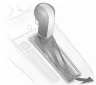
natural_image
Illustration of a mechanical lever mechanism with a curved handle and directional arrow (no text or symbols)If the battery is not the cause of the fault, release selector lever:
- Apply parking brake.
- Release selector lever trim from centre console at rear, fold upwards and rotate to the left.
144 Driving and operating

natural_image
Illustration of a light bulb pressing down on a device (no text or symbols visible)- Push the yellow catch forward with a screwdriver and move the selector lever out of P.
- Mount selector lever trim on centre console and refit.
Reselecting P causes locking again. Have a workshop eliminate the cause of the power loss.
Manual transmission
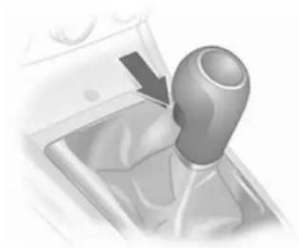
natural_image
Close-up of a car gear shift lever mechanism (no text or symbols visible)To engage reverse, with the vehicle stationary wait 3 seconds after depressing the clutch pedal and then pull up the button on the selector lever and engage the gear.
If the gear does not engage, set the lever to neutral, release the clutch pedal and depress again; then repeat gear selection.
Do not grind the clutch unnecessarily.
When operating, depress the clutch pedal completely. Do not use the pedal as a foot rest.
Caution
It is inadvisable to drive with hand resting on the selector lever.
Manual transmission automated
The Easytronic transmission permits manual (manual mode) or automatic gear shifting (automatic mode), both with automatic clutch control.
Transmission display
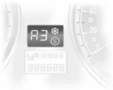
text_image
R3 S 18669 888888Shows the mode and current gear.
The display flashes for a few seconds when A, M or R is selected with the engine running and the foot brake not activated.
If the Winter programme is activated, ✉ is illuminated.
Starting the engine
Depress the foot brake when starting the engine. If the foot brake is not depressed, Ⓤ illuminates in the instrument cluster, "N" flashes in the transmission display and the engine cannot be started.
Starting is not possible if all brake lights fail.
When the foot brake is depressed, the transmission automatically shifts to N upon start. There may be a slight delay.
Selector lever

text_image
A N RAlways move the selector lever in the appropriate direction as far as it will go. Upon release, it automatically returns to the centre position.
N = Neutral.
A = Switch between automatic and manual mode. The transmission display shows A or M.
R = Reverse gear. Engage only when vehicle is stationary.
+ = Shift to a higher gear.
- = Shift to a lower gear.
Starting off
Depress the foot brake and move the selector lever to A, + or -. The transmission is in automatic mode and first gear is engaged. If R is selected, reverse gear is engaged.
The vehicle starts to move when the brake is released.
To start off without depressing the foot brake, accelerate immediately after engaging a gear.
If neither the accelerator nor the brake pedal are depressed, no gear is engaged and A or R flashes for a brief time in the display.
Stopping the vehicle
In A, first gear is engaged and the clutch is released when the vehicle is stopped. In R, reverse gear remains engaged.
Engine braking
Automatic mode
When driving downhill, the manual transmission automated does not shift into higher gears until a fairly
high engine speed has been reached. It shifts down in good time when braking.
Manual mode
To utilise the engine braking effect, select a lower gear in good time when driving downhill.
Rocking the vehicle
Rocking the vehicle is only permissible if the vehicle is stuck in sand, mud or snow. Move the selector lever between R and A in a repeat pattern. Do not race the engine and avoid sudden acceleration.
Parking
Apply the parking brake. The most recently engaged gear (see transmission display) remains engaged. With N, no gear is engaged.
When the ignition is switched off the transmission no longer responds to movement of the selector lever.
Manual mode
If a higher gear is selected when the engine speed is too low, or a lower gear when the speed is too high, the shift is not executed. This prevents the engine from running at too low or too high an engine speed.
If engine speed is too low, the transmission automatically shifts to a lower gear.
If engine speed is too high, the transmission only switches to a higher gear via kickdown.
When + or - is selected in automatic mode, the transmission switches to manual mode and shifts accordingly.
Electronic driving programmes
■ Following a cold start, the operating temperature programme increases engine speed to quickly bring the catalytic converter to the required temperature.
■ The adaptive programme tailors gearshifting to the driving conditions, e.g. greater load or gradients.
■ When Sport mode is engaged, shift times are reduced and the transmission shifts at higher engine speeds (unless cruise control is on). Sport mode 151.
Winter programme ✿
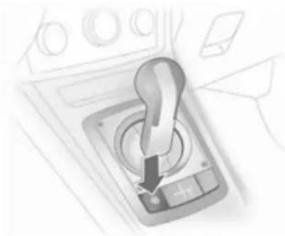
natural_image
Illustration of a car gear shift lever with a downward arrow indicating motion (no text or symbols)Activate the Winter programme if you have problems starting off on a slippery road surface.
Activation
Press the ✕ button. The transmission switches to automatic mode. The vehicle starts off in 2nd gear. Sport mode is deactivated.
Deactivation
The Winter programme is switched off by:
■ pressing the ✿ button again
■ turning off the ignition,
■ switching to manual mode (when switched back to automatic mode, the Winter programme is again active)
■ when clutch temperature is too high
Kickdown
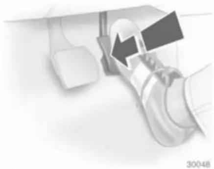
natural_image
Close-up of a robotic arm with a tool and mechanical components, no visible text or symbolsIf the accelerator pedal is pressed past the pressure point, the transmission shifts to a lower gear depending on engine speed.
During kickdown no manual gear shifting is possible.
Fault
To prevent damage to the manual transmission automated, the clutch is engaged automatically at high clutch temperatures.
148 Driving and operating
illuminates in the event of a fault. Continued driving is possible. Manual mode cannot be used for shifting.
If F appears in the transmission display, continued driving is not possible.
Have the cause of the fault remedied by a workshop.
Interruption of power supply
The clutch is not disengaged if there is an interruption of the power supply when a gear is engaged. The vehicle cannot move.
If the battery is discharged, start the vehicle using jump leads ➔ 202.
If the cause of the fault is not a discharged battery, seek the assistance of a workshop.
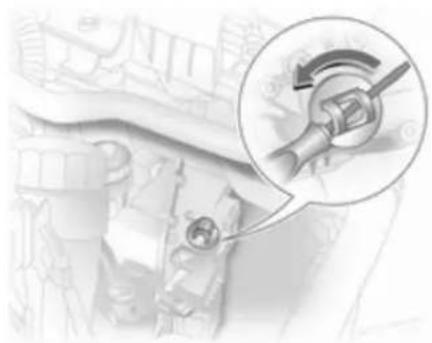
natural_image
Mechanical component diagram with a magnified inset showing rotational motion (no text or symbols)If the vehicle must be moved out of the flow of traffic, disengage the clutch as follows (for vehicles with 5-speed manual transmission automated only):
- Apply parking brake and switch off ignition.
- Open the bonnet 163.
- Clean the transmission around the cap so that no dirt can get into the opening when the cap is removed.
-
Rotate cap to slacken and remove by lifting upwards.
-
Using a flat-head screwdriver, turn the adjusting screw under the cap clockwise until clear resistance can be felt. The clutch has now been disengaged.
- Refit cleaned cap. The cap must be in full contact with the housing.
On vehicles with 6-speed manual transmission automated, the clutch cannot be released; if the vehicle must be moved, raise the vehicle at the front to tow.
Caution
Do not turn beyond the resistance since this could damage the transmission.
Caution
Towing the vehicle and starting the engine is not permitted when the clutch has been disengaged in this way, although the vehicle can be moved a short distance.
Seek the immediate assistance of a workshop.
Brakes
The brake system comprises two independent brake circuits.
If a brake circuit fails, the vehicle can still be braked using the other brake circuit. However, braking effect is achieved only when you depress the brake pedal firmly. Considerably more force is needed for this. The braking distance is extended. Seek the assistance of a workshop before continuing your journey.
When the engine is not running, the support of the brake servo unit disappears once the brake pedal has been depressed once or twice. Braking effect is not reduced, but braking requires significantly greater force. It is especially important to bear this in mind when being towed.
Control indicator Ⓔ 98.
Antilock brake system
Antilock brake system (ABS) prevents the wheels from locking.
ABS starts to regulate brake pressure as soon as a wheel shows a tendency to lock. The vehicle remains steerable, even during hard braking.
ABS control is made apparent through a pulse in the brake pedal and the noise of the regulation process.
For optimum braking, keep the brake pedal fully depressed throughout the braking process, despite the fact that the pedal is pulsating. Do not reduce the pressure on the pedal.
After starting off the system performs a self-test which may be audible.
Control indicator (ABS) 98.
Adaptive brake lamp
During full braking, all three brake lamps flash for the duration of ABS control.
Fault
⚠ Warning
If there is a fault in the ABS, the wheels may be liable to lock due to braking that is heavier than normal. The advantages of ABS are no longer available. During hard braking, the vehicle can no longer be steered and may swerve.
Have the cause of the fault remedied by a workshop.
Parking brake
Always apply parking brake firmly without operating the release button, and apply as firmly as possible on a downhill or uphill slope.
To release the parking brake, pull the lever up slightly, press the release button and fully lower the lever.
To reduce the operating forces of the parking brake, depress the foot brake at the same time.
Control indicator (①) 98.
Brake assist
If the brake pedal is depressed quickly and forcefully, maximum brake force is automatically applied (full braking).
Maintain steady pressure on the brake pedal for as long as full braking is required. Maximum brake force is automatically reduced when the brake pedal is released.
Hill start assist
The system helps prevent unintended movement when driving away on inclines.
When releasing the foot brake after stopping on an incline, the brakes remain on for a further two seconds. The brakes release automatically as soon as the vehicle begins to accelerate.
Ride control systems
Electronic stability program
Electronic stability program (ESP®Plus) improves driving stability when necessary, regardless of the type of road surface or tyre grip. It also prevents the drive wheels from spinning.
As soon as the vehicle starts to swerve (understeer/oversteer), engine output is reduced and the wheels are braked individually. This considerably improves the driving stability of the vehicle on slippery road surfaces.
ESP®Plus is operational as soon as control indicator ⚠ extinguishes.
When ESP®Plus comes into action ★ flashes.
⚠ Warning
Do not let this special safety feature tempt you into taking risks when driving.
Adapt speed to the road conditions.
Control indicator ↗ 99.
Deactivation
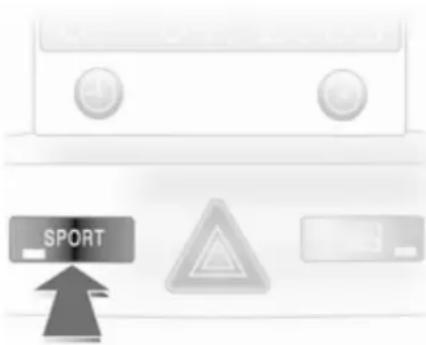
natural_image
Close-up of a white electronic device with buttons and three labeled icons (SPORT, warning triangle, and battery) — no readable text or symbols beyond basic design elements.ESP®Plus can be deactivated when Sport mode is engaged for high-performance driving:
Hold the SPORT button depressed for about 4 seconds. Control indicator illuminates. ESPoff also appears in the service display.
⚠ Warning
Do not deactivate ESP®Plus if a run-flat tyre has lost pressure.
ESP®Plus is reactivated by pressing the SPORT button. ESPon appears in the service display. ESP®Plus is also reactivated the next time the ignition is switched on.
Sport mode 151.
Interactive driving system
Interactive driving system (IDS ^Plus ) combines the electronic stability program (ESP ^Plus ) with the antilock brake system (ABS) and continuous damping control (CDC) to improve driving dynamics and vehicle safety.
Sport mode
Suspension and steering become more direct and provide better contact with the road surface. The engine reacts more quickly to accelerator pedal movements.
Automatic gear changing is also more responsive.
Control indicator IDS+ 100.
Activation

text_image
SPORTPress SPORT button.
Control indicator Ⓧ 98.
152 Driving and operating
Winter programme activation not possible.
Deactivation
Briefly press the SPORT button. Sport mode is deactivated the next time the ignition is switched on or if the Winter programme is activated.
Continuous damping control
Continuous damping control (CDC) changes suspension with damping adaptation of each shock absorber to the current driving situation and road conditions.
When Sport mode is engaged, the damping control is adapted to a sportier driving style.
Control indicator IDS+ 100.
Automatic level control
The rear level of the vehicle is automatically adjusted to the load conditions while driving. Suspension and ground clearance are increased, which improves driving conditions.
The automatic level control is activated after the vehicle has been driven for some distance, depending on the vehicle loading and the road conditions.
Do not use full payload in the event of a fault. Have the cause of the fault remedied by a workshop.
Cruise control
The cruise control can store and maintain speeds of approx. 30 to 200 km/h. Deviations from the stored speeds may occur when driving uphill or downhill.
For safety reasons the cruise control cannot be activated until the foot brake has been operated once.
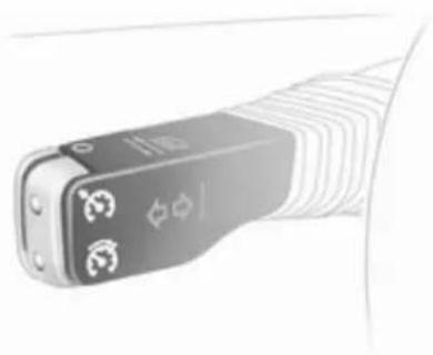
natural_image
Close-up of a handheld electronic device with three buttons and a textured surface (no visible text or symbols)Do not use the cruise control if it is not advisable to maintain a constant speed.
With automatic transmission or manual transmission automated, only activate cruise control in automatic mode.
Control indicator ➕ 102.
Activation
Briefly press the ⚙ button: the current speed is stored and maintained.
Vehicle speed can be increased by depressing the accelerator pedal.
When the accelerator pedal is released, the previously stored speed is resumed.
The speed is saved until the ignition is switched off.
To resume the saved speed, briefly press the ⚙ button at a speed above 30 km/h.
Increase speed
With cruise control active, hold down button ⏻ or briefly press it repeatedly: speed is increased continuously or in small increments.
When button ⚙ is released the current speed is stored and maintained.
Reduce speed
With cruise control active, hold down button ⏻ or briefly press it repeatedly: speed is reduced continuously or in small increments.
When button ⚙ is released the current speed is stored and maintained.
Deactivation
Briefly press the O button: cruise control is deactivated.
Automatic deactivation:
■ Vehicle speed below approx. 30 km/h
■ The brake pedal is depressed
■ The clutch pedal is depressed
- Selector lever in N.
Object detection systems
Parking assist

natural_image
Front view of a white car with visible side grille and wheels (no text or symbols)The parking assist makes parking easier by measuring the distance between the vehicle and obstacles. It is the driver, however, who bears full responsibility for parking.
The system consists of four ultrasonic parking sensors in each of the front and rear bumpers.
Control indicator P↔98.
154 Driving and operating
Note
Attached parts in the detection area cause system malfunction.
Activation
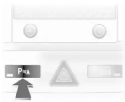
natural_image
Close-up of a white electronic device with control buttons and three gray warning symbols (no readable text or labels)When reverse gear is engaged, the system switches itself on automatically.
The system can also be activated at low speed by pressing the P▲ button.
An obstacle is indicated by buzzers. The interval between the buzzers becomes shorter as the vehicle gets closer to the obstacle. When the distance is less than 30 cm, the buzzer is continuous.
⚠ Warning
Under certain circumstances, various reflective surfaces on objects or clothing as well as external noise sources may cause the system to fail to detect obstacles.
Deactivation
Deactivate the system by pressing the P▲ button.
The system deactivates automatically when reverse gear is disengaged.
Towing equipment
The system automatically detects factory-fitted towing equipment.
When towing, plugging the trailer cable into the socket automatically switches the parking assist off.
Fuel
Fuel for petrol engines
Only use unleaded fuel that complies with DIN EN 228 ^1) .
Equivalent standardised fuels with an ethanol content of max. 10 % by volume may be used. In this case only use fuel that complies with DIN 51625.
Use fuel with the recommended octane rating 218. Use of fuel with too low an octane rating can reduce engine power and torque and slightly increases fuel consumption.
Caution
Use of fuel with too low an octane rating could lead to uncontrolled combustion and engine damage.
Fuel for diesel engines
Only use diesel fuel that complies with DIN EN 590 ^2) . The fuel must have low sulphur content (max. 10 ppm). Equivalent standardised
fuels with a biodiesel (= FAME according to EN14214) content of max. 7% by volume (like DIN 51628 or equivalent standards) may be used.
Do not use marine diesel oils, heating oils or entirely or partially plant-based diesel fuels, such as rape seed oil or bio diesel, Aquazole and similar diesel-water emulsions. Diesel fuels must not be diluted with fuels for petrol engines.
Refuelling

text_image
13 158 754Danger
Before refuelling, switch off engine and any external heaters with combustion chambers (identified by sticker on fuel filler flap). Switch off any mobile phones.
Follow the operating and safety instructions of the filling station when refuelling.
Danger
Fuel is flammable and explosive. No smoking. No naked flames or sparks.
If you can smell fuel in your vehicle, have the cause of this remedied immediately by a workshop.
Caution
In case of misfuelling, do not switch on ignition.
Fuel filler flap is located at right rear side of vehicle.
The fuel filler flap can only be opened if the vehicle is unlocked.
1) Russia only: Usage of fuel with quality, not complying to the Technical Regulations in effect (Decree No 118 of 27.02.2008 with amendments of 30.12.2008 No 1076) can lead to engine damage and loss of all warranty obligations.
2) Russia only: Usage of fuel with quality, not complying to the Technical Regulations in effect (Decree No 118 of 27.02.2008 with amendments of 30.12.2008 No 1076) can lead to engine damage and loss of all warranty obligations.
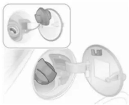
natural_image
Illustration of a medical device with an inset showing a close-up of the internal components (no text or symbols visible)The fuel filler cap can be retained in the bracket on the fuel filler flap.
Caution
Wipe off any overflowing fuel immediately.
Fuel filler cap
Only a genuine fuel filler cap provides full functionality. Diesel-engined vehicles have special fuel filler caps.
Fuel consumption - CO _2 -Emissions
The determination of fuel consumption is regulated by European directive 80/1268/EEC (latest edition 2004/3/EC).
The directive is oriented to actual driving practices: Urban driving is rated at approx. 13 and extra urban driving with approx. 23 . Cold starts and acceleration phases are also taken into consideration.
The specification of CO_2 emission is also a constituent of the directive.
The figures given must not be taken as a guarantee for the actual fuel consumption of a particular vehicle. Furthermore, fuel consumption is dependent on personal driving style as well as road and traffic conditions.
All values are based on the EU base model with standard equipment.
The calculation of fuel consumption takes into account the vehicle's kerb weight, ascertained in accordance with the regulations. Optional
equipment may result in slightly higher fuel consumption and CO_2 emission levels and a lower maximum speed.
Fuel consumption, CO_2 emissions 227.
Towing
General information
Only use towing equipment that has been approved for your vehicle.
Entrust retrofitting of towing equipment to a workshop. It may be necessary to make changes that affect the cooling system, heat shields or other equipment.
Do not mount towing equipment to vehicles with Z 20 LEH engine.
Fitting of towing equipment could cover the opening of the towing eye. If this is the case use the coupling ball bar for towing. Always keep the coupling ball bar in the vehicle.
Installation dimensions of factory-fitted towing equipment 260.
Driving characteristics and towing tips
Before attaching a trailer, lubricate the coupling ball. However, do not do so if a stabiliser, which acts on the coupling ball, is being used to reduce snaking movements.
For trailers with low driving stability and trailers with a permitted gross vehicle weight of more than 1300 kg (Saloon) /1200 kg (Station wagon) a speed of 80 km/h must not be exceeded; the use of a stabiliser is recommended.
If the trailer starts snaking, drive more slowly, do not attempt to correct the steering and brake sharply if necessary.
When driving downhill, drive in the same gear as if driving uphill and drive at a similar speed.
Adjust tyre pressure to the value specified for full load ➔ 244.
Trailer towing
Trailer loads
The permissible trailer loads are vehicle and engine-dependent maximum values which must not be exceeded. The actual trailer load is the difference between the actual gross weight of the trailer and the actual coupling socket load with the trailer coupled.
The permissible trailer loads are specified in the vehicle documents. In general, they are valid for gradients up to max. 12 %.
The permitted trailer load applies up to the specified incline and up to an altitude of 1000 metres above sea level. Since engine power decreases as altitude increases due to the air becoming thinner, therefore reducing climbing ability, the permissible gross train weight also decreases by 10 % for every 1000 metres of additional altitude. The gross train weight does not have to be reduced when driving on roads with slight inclines (less than 8 %, e. g. motorways).
The permissible gross train weight must not be exceeded. This weight is specified on the identification plate 214.
Vertical coupling load
The vertical coupling load is the load exerted by the trailer on the coupling ball. It can be varied by changing the weight distribution when loading the trailer.
The maximum permissible vertical coupling load (75 kg) is specified on the towing equipment identification plate and in the vehicle documents. Always aim for the maximum load, especially in the case of heavy trailers. The vertical coupling load should never fall below 25 kg.
Rear axle load
When the trailer is coupled and the towing vehicle fully loaded, the permissible rear axle load (see identification plate or vehicle documents) may be exceeded by 65 kg and the permissible gross vehicle weight by 45 kg for the Saloon. For the Station wagon, the permissible rear axle load may be exceeded by 60 kg and the permissible gross vehicle weight by 30 kg. If the permissible rear axle load is exceeded, a maximum speed of 100 km/h applies.
Towing equipment
Caution
When operating without a trailer, remove the coupling ball bar.
Stowage of coupling ball bar

natural_image
Architectural floor plan sketch showing a pipe fitting on a building facade (no text or labels)In Saloons, the coupling ball bar is in a pouch, fastened in the load compartment cargo box with a strap. In Station wagons, the coupling ball bar is fastened with a strap in a compartment in the spare wheel well of the load compartment.
Fitting the coupling ball bar

natural_image
Mechanical assembly diagram showing a valve mechanism with directional arrows (no text or symbols)Fold down the socket. Remove the sealing plug from the hole for the coupling ball bar and stow it in the load compartment.
Checking the tensioning of the coupling ball bar
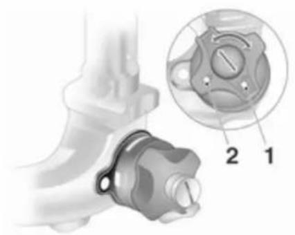
natural_image
Mechanical component diagram showing a valve assembly with labeled parts 1 and 2 (no text or symbols beyond labels)■ Red marking on rotary knob must point towards white marking on coupling ball bar.
■ The gap between the rotary knob and the coupling ball bar must be approx. 4 millimetres.
■ Key must be at position 📋 (1).
Otherwise, the coupling ball bar must be tensioned before being inserted:
■ Unlock coupling ball bar by turning key to position ☐ (1)

natural_image
Illustration of hands using a tool to adjust or install a mechanical component (no text or symbols visible)■ Pull out rotary knob and turn clockwise as far as it will go.
Inserting the coupling ball bar

natural_image
Close-up of a hand holding a mechanical component with a knob and arrow indicator (no text or symbols)Insert the tensioned coupling ball bar in the opening and push firmly upwards until it audibly engages.
The rotary handle snaps back into its original position resting against the coupling ball bar without a gap.
⚠ Warning
Do not touch rotary handle during insertion.

natural_image
Illustration of a hand holding a valve with an arrow pointing to the handle (no text or symbols present)Lock the coupling ball bar by turning the key to position ⏻ (2). Remove the key and close the protective flap.
Eye for break-away stopping cable Attach break-away stopping cable to eye.
Check that the coupling ball bar is correctly installed
■ Green marking on rotary knob must point towards white marking on coupling ball bar.
■ There must be no gap between the rotary handle and the coupling ball bar.
■ The coupling ball bar must be firmly engaged in the opening.
■ The coupling ball bar must be locked and the key removed.
⚠ Warning
Towing a trailer is permitted only when a coupling ball bar is fitted correctly. If the coupling ball bar does not engage correctly, seek the assistance of a workshop.
Dismounting the coupling ball bar
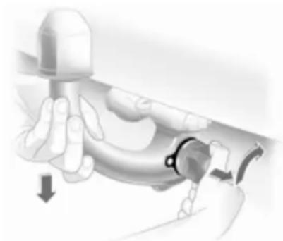
natural_image
Illustration of a hand holding a tool with a curved mechanical component and a downward arrow indicating motion (no text or symbols)Open the protective flap and turn the key to position ⏻ (1) to unlock the coupling ball bar.
Pull out rotary handle and turn clockwise as far as it will go. Pull out coupling ball bar downwards.
Insert sealing plug in opening. Fold away socket.
Driving and operating 161
Trailer stability assist
If the system detects snaking movements, engine power is reduced and the vehicle/trailer combination is selectively braked until the snaking ceases.
Trailer stability assistant (TSA) is a function of the Electronic Stability Program (ESP®Plus) 150.
Vehicle care
General Information 162
Vehicle checks 163
Bulb replacement 168
Electrical system 183
Vehicle tools 190
Wheels and tyres 190
Jump starting 202
Towing 203
Appearance care 205
General Information
Accessories and vehicle modifications
We recommend using genuine parts and accessories and factory approved parts specific for your vehicle type. We cannot assess or guarantee reliability of other products - even if they have a regulatory or otherwise granted approval.
Do not make any modifications to the electrical system, e.g. changes of electronic control units (chip tuning).
Caution
When transporting the vehicle on a train or on a recovery vehicle, the mud flaps might be damaged.
Vehicle storage
Storage for a long period of time The following must be done if the vehicle should be stored for several months:
■ Wash and wax the vehicle.
■ Have the wax in the engine compartment and underbody checked.
■ Clean and preserve rubber seals.
■ Change engine oil.
■ Drain washer fluid reservoir.
■ Check coolant antifreeze.
■ Adjust tyre pressure to the value specified for full load.
■ Park vehicle in dry, well ventilated place. Engage first or reverse gear or set selector lever to P. Prevent the vehicle from rolling.
■ Do not apply parking brake.
■ Open bonnet, close all doors and lock the vehicle.
■ Disconnect the clamp from the negative terminal of the vehicle battery. Be aware that all systems are non-operational, e.g. the anti-theft alarm system.
Putting back into operation
The following must be done if the vehicle is put back into operation:
■ Connect the clamp to the negative terminal of the vehicle battery. Activate the electronics of the power windows.
■ Check tyre pressure.
■ Fill up the washer fluid reservoir.
■ Check the engine oil level.
■ Check the coolant level.
■ Fit the number plate if necessary.
End-of-life vehicle recovery
Information about end-of-life vehicle recovery centres and the recycling of end-of-life vehicles is available on our website. Only entrust this work to an authorised recycling centre.
Vehicle checks Performing work

natural_image
Interior view of a car dashboard with hand operating controls and a cross symbol (no text or labels visible)⚠ Warning
Only perform engine compartment checks when the ignition is off.
The cooling fan may start operating even if the ignition is off.
Danger
The ignition system and Xenon headlights use extremely high voltage. Do not touch.
The caps for topping up the engine oil, the coolant, the washing fluid and the oil dipstick handle are yellow for ease of identification.
Bonnet
Opening
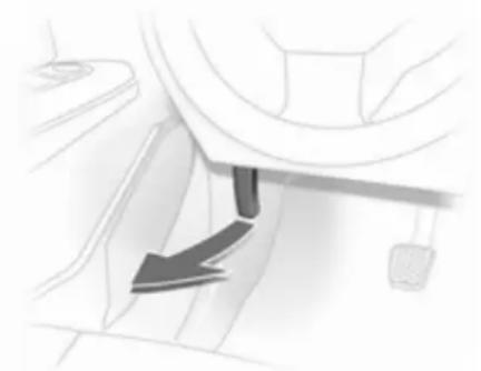
natural_image
Close-up of a mechanical component with a downward arrow indicating motion or force (no visible text or symbols)164 Vehicle care
Pull the release lever and return it to its original position.
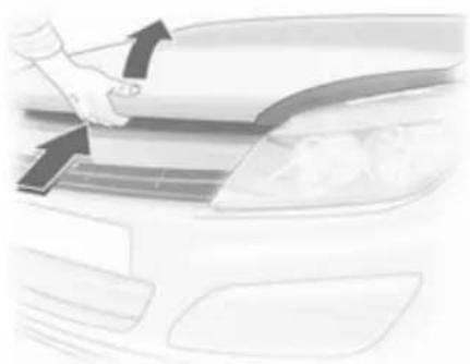
natural_image
Close-up of a hand cleaning a car's dashboard with arrows indicating direction (no text or symbols visible)Lift the safety catch upwards and open the bonnet.
Air intake ↩ 134.
Secure the bonnet support.
Closing
Before closing the bonnet, press the support into the holder.
Lower the bonnet and allow it to drop into the catch. Check that the bonnet is engaged.
Engine oil
Check the engine oil level manually on a regular basis to prevent damage to the engine. Ensure that the correct specification of oil is used.
Recommended fluids and lubricants 210.
Check with the vehicle on a level surface. The engine must be at operating temperature and switched off for at least 5 minutes.
Pull out the dipstick, wipe it clean, insert it to the stop on the handle, pull it out and read the engine oil level.
Insert the dipstick to the stop on the handle and make half a turn.
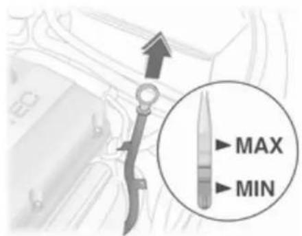
text_image
MAX MINDifferent dipsticks are used depending on engine variant.

text_image
MAX MIN
text_image
MAX MINWhen the engine oil level has dropped to the MIN mark, top up engine oil.

natural_image
Hand pouring liquid into a car engine compartment labeled 'ECOTEC' (no other text or symbols visible)We recommend the use of the same grade of engine oil that was used at last change.
The engine oil level must not exceed the MAX mark on the dipstick.
Caution
Overfilled engine oil must be drained or suctioned out.
Capacities ↩ 243.
Fit the cap on straight and tighten it.
Engine coolant
The coolant provides freeze protection down to approx. -28 °C.
Caution
Only use approved antifreeze.
Coolant level
Caution
Too low a coolant level can cause engine damage.
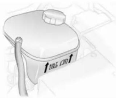
natural_image
Illustration of a portable water heater with a handle and outlet tube (no text or symbols)When the cooling system is cold, the coolant level should be just above the KALT/COLD mark. Top up if the level is low.
⚠ Warning
Allow the engine to cool before opening the cap. Carefully open the cap, relieving the pressure slowly.
Top up with antifreeze. If no antifreeze is available, use clean tap water or distilled water. Install the cap tightly. Have the antifreeze concentration checked and have the cause of the coolant loss remedied by a workshop.
Washer fluid
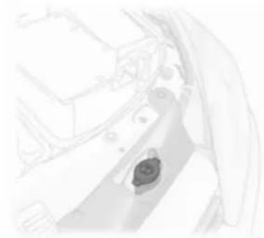
natural_image
Close-up of a mechanical component with a circular feature, possibly a valve or knob (no visible text or symbols)Fill with clean water mixed with a suitable quantity of windscreen washer fluid which contains antifreeze.
Brakes
A squealing noise indicates that the brake lining is at its minimum thickness. Continued driving is possible but have the brake lining replaced as soon as possible.
Once new brake linings are installed, do not brake unnecessarily hard for the first few journeys.
Brake fluid
⚠ Warning
Brake fluid is poisonous and corrosive. Avoid contact with eyes, skin, fabrics and painted surfaces.
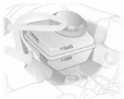
natural_image
Illustration of a medical device with a cap and tubing, no visible text or symbolsThe brake fluid level must be between the MIN and the MAX marks.
When topping up, ensure maximum cleanliness as contamination of the brake fluid can lead to brake system malfunctions. Have the cause of the loss of brake fluid remedied by a workshop.
Only use high-performance brake fluid approved for the vehicle. Brake and clutch fluid ➔ 166.
Battery
The vehicle battery is maintenance-free provided that the driving profile allows sufficient charging of the battery. Short distance driving and frequent engine starts can discharge the battery. Avoid the use of unnecessary electrical consumers.

Batteries do not belong in household waste. They must be disposed of at an appropriate recycling collection point.
Laying up the vehicle for more than 4 weeks can lead to battery discharge. Disconnect the clamp from the negative terminal of the vehicle battery.
Ensure the ignition is switched off before connecting or disconnecting the vehicle battery. Battery discharge protection ➔ 123.
Diesel fuel system bleeding
If the tank has been run dry, the diesel fuel system must be bled. Switch on the ignition three times for 15 seconds at a time. Then crank the engine for a maximum of 40 seconds. Repeat this process after no less than 5 seconds. If the engine fails to start, seek the assistance of a workshop.
Wiper blade replacement
Service setting for front windscreen wipers
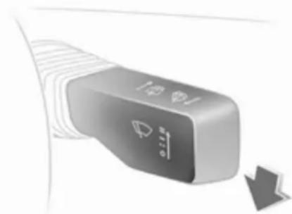
natural_image
Close-up of a handheld electronic device with a scroll wheel and indicator lights (no visible text or symbols)Switch off the ignition but do not remove ignition key or open driver's door.
Within 4 seconds, push the wiper lever down and release as soon as the wipers are vertical.
Wiper blades on the windscreen
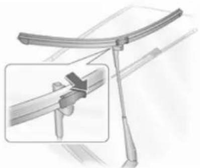
natural_image
Mechanical assembly diagram showing a lever mechanism with a close-up inset of the handle (no text or symbols)Lift the wiper arm, tilt wiper blade at a 90° to the wiper arm and remove to the side.
Wiper blade on the rear window
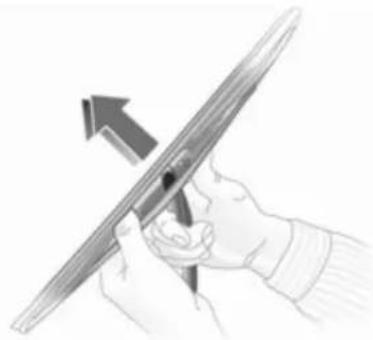
natural_image
Illustration of hands holding a pen with an arrow indicating direction (no text or symbols)Lift the wiper arm. Disengage the wiper blade and remove.
Bulb replacement
Switch off the ignition and switch off the relevant switch or close the doors.
Only hold a new bulb at the base! Do not touch the bulb glass with bare hands.
Use only the same bulb type for replacement.
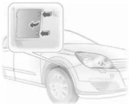
natural_image
Illustration of a car front view with a small inset showing a vehicle's door panel (no text or symbols)The bulbs of the front outer lights are replaced through openings in the front wheel housing: turn wheels in a way that allows access, release catch and remove cover.
To replace bulbs on the right side of the engine compartment, detach the air hose from the air filter. On the left side, detach the plug to the fuse box.
Halogen headlights
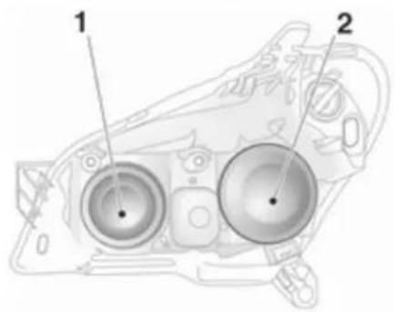
text_image
Technical diagram of a vehicle head with labeled components, showing two circular parts and a central hub.Headlights have separate systems for high beam 1 (inner bulbs) and low beam 2 (outer bulbs).
Low beam
- Replace bulbs through the opening in the wheel housing.

natural_image
Illustration of a camera with a circular button and arrow, no text or symbols present- Remove protective cover 2.

natural_image
Technical illustration of a mechanical device with a circular component and directional arrow (no text or symbols)- Rotate the bulb holder anti-clockwise to disengage. Withdraw the bulb holder from the reflector.
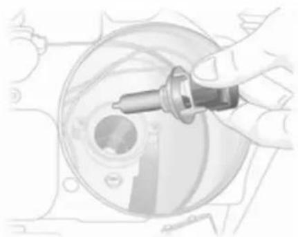
natural_image
Hand holding a dropper over a mechanical component (no visible text or symbols)- Detach bulb from bulb holder and renew the bulb.

natural_image
Illustration of hands assembling a mechanical component with directional arrows indicating assembly (no text or symbols)170 Vehicle care
- Insert the bulb holder, engaging the two lugs into the reflector and rotate clockwise to secure.
- Rotate bulb carrier to the right as far as it will go.
- Install protective cover.
- Close the opening in the wheel housing with the cover.
High beam
- Access to the bulbs is through the engine compartment.
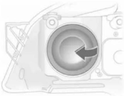
natural_image
Diagram of a camera lens assembly with a circular aperture and an arrow indicating direction (no text or symbols)- Remove protective cover 1.
- Detach wiring plug from bulb.

natural_image
Abstract diagram with circular arrow and central symbol, no readable text or labels- Disengage spring clip from retainer by pressing forward and then swinging downwards.
- Withdraw the bulb from reflector housing.
- When installing the new bulb, insert lugs in the reflector recesses and engage the spring clip.
- Install the wiring plug onto bulb.
- Install protective cover.
Side lights
- Access to the bulbs is through the engine compartment.

natural_image
Diagram of a camera aperture with an arrow indicating direction (no text or symbols present)- Remove protective cover 1.
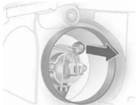
natural_image
Diagram of a washing machine showing internal components and airflow direction (no text or labels)- Withdraw parking light bulb holder from reflector.
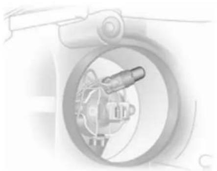
natural_image
Illustration of a mechanical device inside a circular frame, showing a lever and gear mechanism (no text or symbols)- Remove bulb from socket and renew the bulb.
- Insert holder in reflector. Install the headlamp protective cover.
Xenon headlights
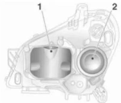
text_image
Technical diagram of a mechanical component with labeled parts 1 and 2Headlamps have separate systems for low beam 1 (inner bulbs) and high beam 2 (outer bulbs).
Low beam
Danger
Low beam works under extremely high electrical voltage. Do not touch. Have bulbs replaced by a workshop.
High beam
- Replace bulbs through the openings in the wheel arches.

natural_image
Abstract mechanical component illustration with a circular arrow pointing left (no text or symbols)- Remove protective cover.
172 Vehicle care
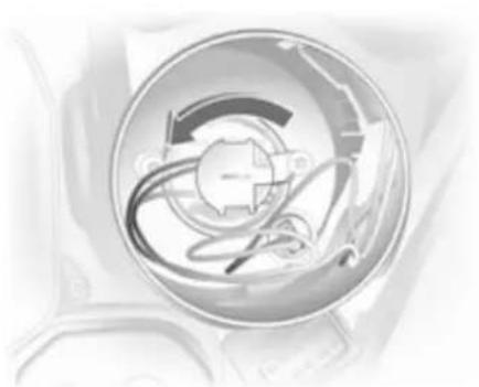
natural_image
Close-up of a circular mechanical component with internal curved lines and a central hub (no visible text or symbols)- Rotate left bulb holder and disengage.
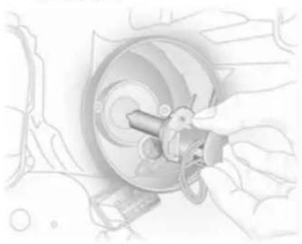
natural_image
Illustration of hands operating a mechanical device with a circular component and a key (no text or symbols visible)- Remove the bulb holder with bulb from the reflector.
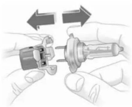
natural_image
Illustration of hands assembling a mechanical component with directional arrows indicating motion (no text or symbols)- Detach bulb from bulb holder.
- Insert new bulb so that the two lugs on the bulb holder engage in the recesses in the reflector.
- Rotate bulb holder to the right as far as it will go.
- Place protective cover in position and close.
Side lights

natural_image
Mechanical component illustration with a circular arrow pointing left (no text or symbols)- Replace bulbs through the openings in the wheel arches.
- Remove main beam headlight protective cover.
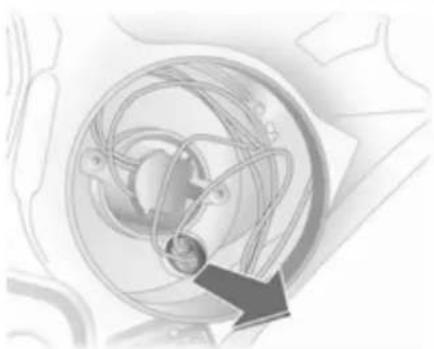
natural_image
Abstract illustration of a mechanical or orbital system with a circular component and directional arrow (no text or symbols)- Remove parking light socket from reflector.

natural_image
Medical illustration of a medical device with tubing and central connector (no text or symbols)- Remove bulb from socket and renew bulb.
- Insert holder in reflector. Place protective cap in position and close.
Fog lights
Have bulbs replaced by a workshop.
Front turn signal lights
- Replace the bulbs through the opening in the wheel housing.
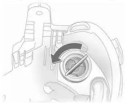
natural_image
Mechanical component diagram showing a rotating dial with a hammer and screw, no text or symbols present- Rotate bulb holder anti-clockwise and disengage.
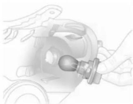
natural_image
Illustration of hands operating a mechanical component with a bulb (no text or symbols visible)- Push bulb slightly into the socket, rotate anti-clockwise, remove and renew bulb.
- Insert bulb holder in the reflector, rotate clockwise and engage.
174 Vehicle care
Tail lights
Saloon 5-door
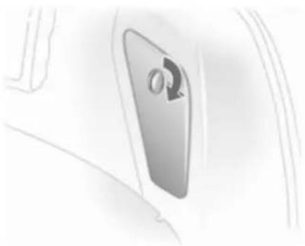
natural_image
Close-up of a door handle with a circular button, no visible text or symbols- To change the bulbs on the right side, use a coin to open the lock and fold down the cover.
To change bulbs on the left side, use a coin to turn both locks and fold down the cover 187.
- Detach plug connector from bulb holder.
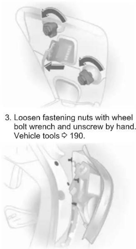
-
Loosen fastening nuts with wheel bolt wrench and unscrew by hand. Vehicle tools 190.
-
Detach bulb housing towards the rear.

natural_image
Diagram of a mechanical component with directional arrows indicating movement or force (no text or symbols present)- Unscrew the three screws using a screwdriver. Press the locking tabs on the outside of the bulb holder inwards and remove the bulb holder.
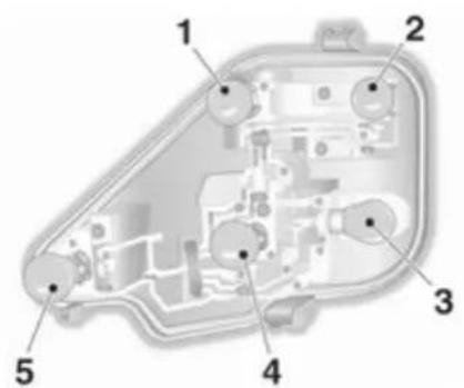
text_image
Technical diagram of a device interior with numbered components labeled 1 through 5- Remove and renew the bulb.
Reverse light (1)
Turn signal light (2)
Reverse light/brake light (3)
Reverse light (4)
Fog light, may be only on one side (5) - Engage bulb holder in bulb housing, ensuring that it properly engages.
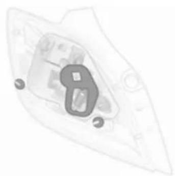
natural_image
Abstract diagram of a mechanical or architectural component with no visible text or symbols-
Ensure that the seals are applied to the bulb holder and fixing screws.
-
Insert the bulb housing in the body, engaging the lug and the ball pin in the recesses. Tighten the fastening nuts using a wheel bolt wrench. Attach the plug connector. Close and engage the flap.
Saloon 3-door
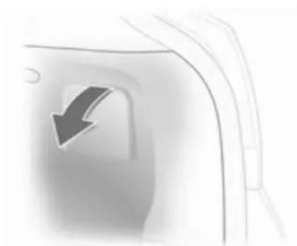
natural_image
Close-up of a car door handle with a black arrow pointing downward (no text or symbols)- To change the bulbs, fold down the cover.
- Detach plug connector from bulb holder.
176 Vehicle care

natural_image
Diagram of a device interior with directional arrows indicating movement or flow (no text or symbols)- Loosen fastening nuts with wheel bolt wrench and unscrew by hand. Vehicle tools 190.

natural_image
Medical illustration showing anatomical structures with no visible text or labels- Detach bulb housing towards the rear.
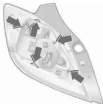
natural_image
Diagram of a mechanical component with directional arrows indicating movement or force (no text or symbols present)- Remove seal from the fastening bolt. Press the locking tabs on the outside of the bulb holder outward and remove the bulb holder.
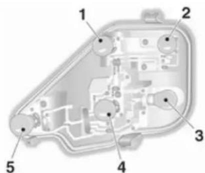
text_image
Technical diagram of an internal mechanical or electronic component with numbered parts labeled 1 through 5.- Remove and renew the bulb.
Reverse light (1)
Turn signal light (2)
Reverse light/brake light (3)
Reverse light (4)
Fog light, may be only on one side (5)
- Engage bulb holder in bulb housing, ensuring that it properly engages.
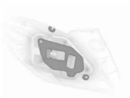
natural_image
Close-up of a mechanical component with mounting holes and a central slot (no visible text or symbols)- Ensure that the seals are applied to the bulb holder and fixing screws.
- Insert the bulb housing in the body, engaging the lug and the ball pin in the recesses. Tighten the fastening nuts using a wheel bolt wrench. Attach the plug connector. Close and engage the flap.
Saloon 4-door
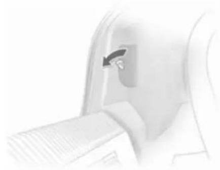
natural_image
Close-up of a medical device with a metallic clip inserted, showing no visible text or symbols.- To replace bulbs, fold up cover in load compartment after twisting the catch.
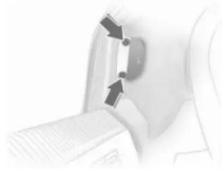
natural_image
Close-up of a mechanical component with two arrows pointing to a central component (no visible text or symbols)- Release the bolts behind the cover using a conventional bolt wrench, and remove.

natural_image
Technical line drawing of a mechanical component or bracket (no text or symbols visible)- Unscrew the three screws with a screwdriver and remove the bulb holder. Vehicle tools ➔ 190.
178 Vehicle care
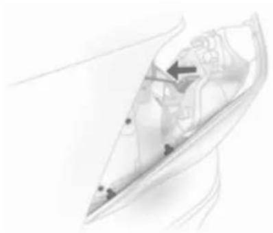
natural_image
Abstract diagram with curved lines and a central arrow, no readable text or symbols- Press tail lights back, holding the bulb housing from the outside. Remove plug from bulb carrier.

natural_image
Technical line drawing of a vehicle interior frame with no visible text or symbols- Press out six locking catches on the bulb housing and remove bulb carrier.
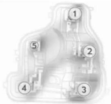
text_image
Diagram of a vehicle interior with numbered components, likely for road or navigation instructions.- Remove and renew the bulb. Brake light (1)
Reverse light (2)
Fog light, may be only on one side (3)
Turn signal light (4)
Reverse light (5)
-
Engage bulb holder in bulb housing. Ensure the seal is applied correctly and the carrier has engaged properly.
-
Attach the plug connector. Place bulb housing in body, clipping the round-head bolts into the recesses. Attach bulb housing to the body with four screws. Close cover and lock.
Station wagon, Van
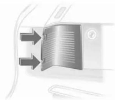
natural_image
Close-up of a metallic door panel with directional arrows indicating flow or movement (no text or symbols)- Disengage cover by pressing retaining lugs and remove.
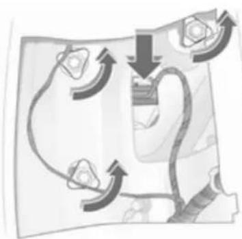
natural_image
Diagram of a robotic arm with curved arrows indicating motion or feedback (no text or symbols)- Detach plug connector from bulb holder.
- Loosen fastening nuts and remove the bulb housing rearwards.

natural_image
Diagram of a vehicle's internal structure with arrows indicating components (no text or symbols)- Unscrew the three screws with a screwdriver and remove the bulb holder. Vehicle tools 190.
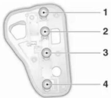
text_image
1 2 3 4- Remove and renew the bulb.
Reverse light/brake light (1)
Turn signal light (2)
Reverse light (3)
Fog light, may be only on one side (4)
- Engage bulb holder in bulb housing and screw in place. Insert the bulb housing into the body and tighten the fastening nuts by hand.
Attach the plug connector.
Close and engage the cover.
TwinTop

natural_image
Close-up of a car's side window with two eyes highlighted by arrows (no text or symbols visible)- Unscrew retaining nuts.

natural_image
Illustration of a hand inserting a cable into a car seatbelt, with an inset showing the cable being inserted (no text or symbols present)- Remove bulb housing from outside. Disengage plug by pressing on flap and remove from bulb holder.
- Detach seal from bulb holder.
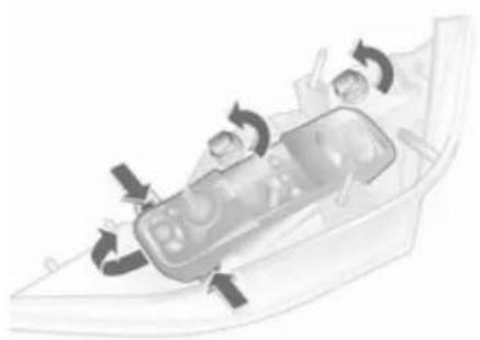
natural_image
Diagram of a car interior with directional arrows indicating movement or flow (no text or symbols)- Disengage sockets by turning and remove. Press locking tabs on the long sides of the bulb holder outwards; lift bulb holder at front end and remove.

text_image
Labeled diagram of a mechanical device with numbered components for identification- Remove and renew the bulb.
Reverse light/brake light (1)
Reverse light (2)
Fog light, may be only on one side (3)
Reverse light (4)
Turn signal light (5)
- Insert bulb holder in bulb housing by first inserting the lug at the front of the plug. Fold together bulb holder, ensuring that it engages properly. Insert sockets and engage by turning.

natural_image
Line drawing of a small boat with a tag attached (no text or symbols)- Fit seal on bulb holder. Ensure that the seal is flat in the area of the screws.
- Engage plug. Insert bulb housing in body, ensuring proper positioning of the ball pins in the recesses. Tighten the retaining nuts.
Side turn signal lights
Have the bulbs replaced by a workshop.
Number plate light
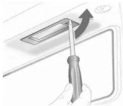
natural_image
Illustration of a hand using a screwdriver to press down a device panel (no text or symbols visible)- Insert a screwdriver in the housing, press to the side and release spring.
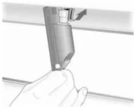
natural_image
Hand holding a mechanical component, possibly a tool or device, with no visible text or symbols.- Remove bulb housing downwards, taking care not to pull on the cable.
- Lift flap and disconnect wiring plug from bulb holder.
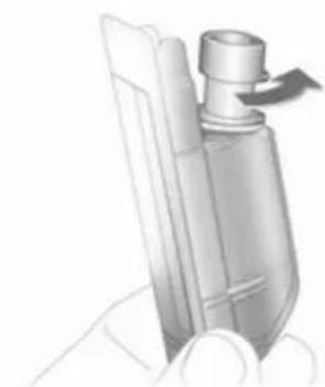
natural_image
Illustration of a hand holding a cylindrical device with a handle and arrow indicating rotation (no text or symbols)- Rotate bulb holder anti-clockwise to disengage.
- Remove bulb from holder and renew bulb.
- Insert bulb holder in bulb housing and rotate clockwise.
- Connect wiring plug to bulb holder.
- Insert and engage bulb housing.
Interior lights
Front courtesy light, reading lights
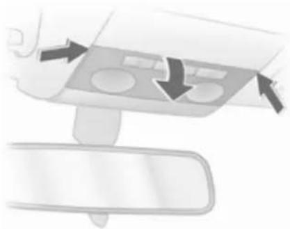
natural_image
Diagram of a car interior showing airflow direction arrows and control panel (no text or symbols)- Disengage lens, press it slightly downwards and remove at a downward angle.
- Remove bulb and renew.
- Engage lens.
Rear courtesy light and reading lights
Have bulbs replaced by a workshop.
Glovebox light, load compartment light, foot well light

natural_image
Illustration of a rectangular device with a grid pattern and an arrow pointing to it (no text or symbols)- Prise the lamp out with a screwdriver.

natural_image
3D illustration of a mechanical component with internal parts (no text or symbols visible)- Press bulb slightly towards spring clip and remove.
- Insert new bulb.
- Install lamp.
Instrument panel illumination
Have bulbs replaced by a workshop.
Electrical system
Fuses
Data on the replacement fuse must match data on the defective fuse.
The vehicle has two fuse boxes: one behind a cover on the left side of the load compartment and one in the front left of the engine compartment.
Store spare fuses in the load compartment fuse box version B. Open the cover ➔ 187.
Before replacing a fuse, turn off the respective switch and the ignition.
A blown fuse can be recognised by its melted wire. Do not replace the fuse until the cause of the fault has been remedied.
Some functions are protected by several fuses.
Fuses may also be inserted without existence of a function.
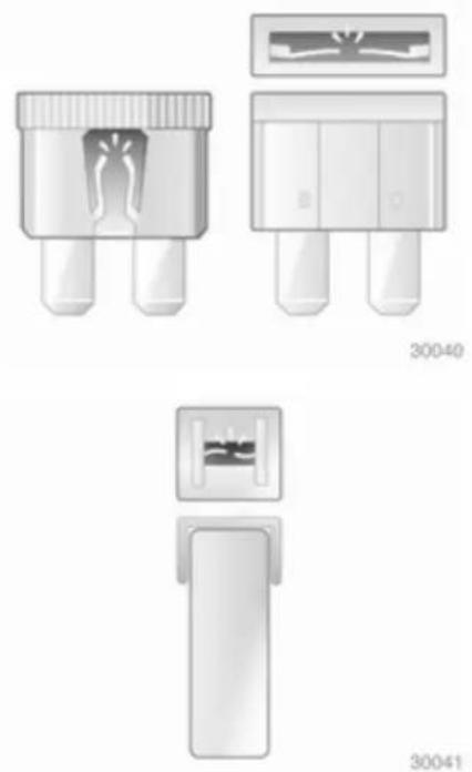
natural_image
Four technical diagrams of a connector component with labeled parts, no text or symbols present.Fuse extractor
A fuse extractor may be located in the fuse box in the load compartment.
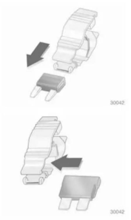
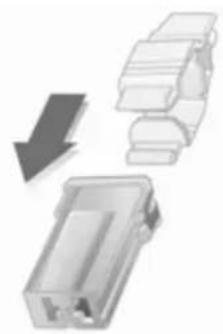
natural_image
Diagram showing a device component being processed with a downward arrow (no text or symbols present)30044
Place the fuse extractor on the various types of fuse from the top or side, and withdraw fuse.
Engine compartment fuse box
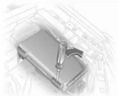
natural_image
Illustration of a mechanical device with a tool inserted into a housing (no text or symbols visible)Insert a screwdriver into the opening as far as it will go and tilt it sideways. Open the cover upwards and remove. The fuse box has two different fuse assignments depending on the load compartment fuse box variant, 187.
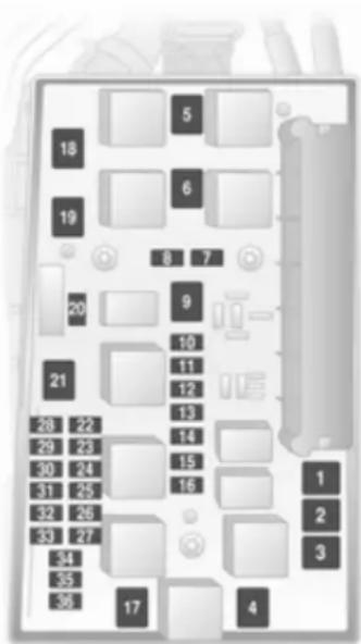
text_image
Diagram of a device layout with numbered compartments and labeled buttons, likely for electronics or control panel design.Fuse assignments in conjunction with load compartment fuse box version A
No. Circuit
1 ABS
2 ABS
3 Interior fan climate control system
4 Interior fan, heating, air conditioning system
5 Radiator fan
6 Radiator fan
7 Central locking system
8 Windscreen washer system, tailgate
9 Heated rear window, heated exterior mirror
10 Diagnostics plug
11 Instruments
No. Circuit
12 Mobile telephone, Infotainment system, display
13 Courtesy light
14 Windscreen wiper
15 Windscreen wiper
16 Horn, ABS, brake light switch, air conditioning system
17 Diesel fuel filter or air conditioning system
18 Starter
19 -
20 Horn
21 Engine electronics
22 Engine electronics
23 Headlight range adjustment
24 Fuel pump
25 -
26 Engine electronics
No. Circuit
27 Heating, air conditioning system
28 -
29 Power steering
30 Engine electronics
31 Rear window wiper
32 Brake light switch
33 Headlight range adjustment, light switch, clutch switch, instrument, driver's door module
34 Control unit, steering column module
35 Infotainment system
36 Cigarette lighter, front power outlet
Fuse assignments in conjunction with load compartment fuse box version B
No. Circuit
1 ABS
2 ABS
3 Interior fan electronic climate control
4 Interior fan heating and air conditioning system
5 Radiator fan
6 Radiator fan
7 Windscreen washer system
8 Horn
9 Headlight washer system
10 -
11 -
12 -
13 Fog light
No. Circuit
14 Windscreen wiper
15 Windscreen wiper
16 Control module electronics, Open&Start system, ABS, brake light switch, TwinTop
17 Diesel fuel filter heating
18 Starter
19 Transmission electronics
20 Air conditioning system
21 Engine electronics
22 Engine electronics
23 Adaptive forward lighting, headlight range adjustment
24 Fuel pump
25 Transmission electronics
26 Engine electronics
27 Power steering
28 Transmission electronics
No. Circuit
29 Transmission electronics
30 Engine electronics
31 Adaptive forward fighting, headlight range adjustment
32 Brake system, air conditioning system, clutch switch
33 Adaptive forward lighting, headlight range adjustment, light switch
34 Control unit, steering column module
35 Infotainment system
36 Mobile telephone, Infotainment system, display
Load compartment fuse box
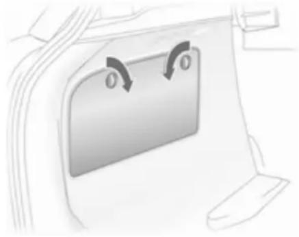
natural_image
Diagram of a car interior showing a door with a mounted panel and two curved arrows indicating rotation (no text or symbols)The fuse box is behind a cover.
Do not store any objects behind the cover.
Depending on the equipment, there are two different fuse boxes.
Saloon 5-door, Caravan, Van
To open, turn both catches with a coin and fold down cover.
Saloon 3-door
To open, fold the cover upwards.
Saloon 4-door
To open, twist catch anti-clockwise and fold down cover.
TwinTop
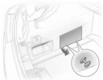
natural_image
Interior view of a car showing a monitor and gear shift (no text or symbols visible)To open, pull the two knobs, remove the clips and fold the cover upwards.
Fuse box version A
To replace a fuse, remove the relevant protective cap.

natural_image
3D illustration of a mechanical component with numbered pins (1–8) arranged in a cluster (no text or symbols)No. Circuit
1 Fog light
2-
3 Load compartment power outlet
4 Reversing lights
5 Rear power windows
6 Air conditioning system
7 Front power windows
8 Heated exterior mirrors
Fuse box version B
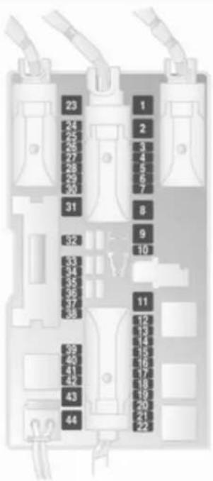
text_image
23 24 25 26 27 28 29 30 31 32 33 34 35 36 37 38 39 40 41 42 43 44 1 2 3 4 5 6 7 8 9 10 11 12 13 14 15 16 17 18 19 20 21 22No. Circuit
1 Front power windows
2-
3 Instruments
4 Heating, air conditioning system, electronic climate control
5 Airbags
6 -
7-
8 -
9-
10 -
11 Heated rear window
12 Rear window wiper
13 Parking assist
14 Heating, air conditioning system
15-
No. Circuit
16 Seat occupancy recognition, Open&Start system
17 Rain sensor, tyre pressure monitoring system, interior mirror
18 Instruments, switches
19 -
20 CDC
21 Heated exterior mirrors
22 Sun roof
23 Rear power windows
24 Diagnostics plug
25 -
26 Electrical foldable exterior mirrors
27 Ultrasonic sensor, anti-theft alarm system
28 -
No. Circuit
29 Cigarette lighter, front power outlet
30 Rear power outlet
31 -
32 -
33 Open&Start system
34 Sun roof, TwinTop
35 Rear power outlet
36 Socket for towing equipment
37 -
38 Central locking system, terminal 30
39 Left seat heating
40 Right seat heating
41 -
42 -
No. Circuit
43 -
44 –
Vehicle tools
Tools
Vehicles with tyre repair set
The tool kit and tyre repair set are in a storage compartment below the floor cover in the load compartment.
Vehicles with spare wheel
natural_image
Circular diagram with mechanical tools and symbols, no readable text or labelsThe jack and tool kit are in a stowage compartment in the boot below the spare wheel. Spare wheel ➔ 200
TwinTop
The tools for emergency operation of the convertible hardtop are stowed in the glove compartment.
Wheels and tyres
Tyre condition, wheel condition
Drive over edges slowly and at right angles if possible. Driving over sharp edges can cause tyre and wheel damage. Do not trap tyres on the kerb when parking.
Regularly check the wheels for damage. Seek the assistance of a workshop in the event of damage or unusual wear.
Tyres
Tyres of size 225/45 R 17 are only permitted if the vehicle is equipped with electronic stability program.
Astra OPC "Nürburgring Edition" with tyres 225/40 ZR 18
This model is factory-fitted with high-performance sports tyres, size 225/40 ZR 18. These tyres are approved for use on public roads but have typical racing characteristics and a correspondingly shallow tread. The tyres provide sportily oriented and experienced drivers with better performance at faster speeds on dry road surfaces but can cause the vehicle to break away without warning if this limit is exceeded. Avoid adopting a risky driving style because of this improved performance. In wet conditions adapt your driving style and speed to the shallow tread.
Winter tyres
Winter tyres improve driving safety at temperatures below 7 °C and should therefore be fitted on all wheels.
Tyres of size 185/65 R 15, 195/60 R 15, 195/65 R 15 and 205/55 R 16 can be used as winter tyres.
Tyres of size 205/50 R17 must only be used as winter tyres.
Tyres of size 215/45 R 17, 225/45 R 17, 225/40 R 18 ^1) , 225/40 ZR18 and 235/35 R 19 must not be used as winter tyres.
Saloon, Station wagon, Van: tyres of size 215/45 R 17 are only approved as winter tyres if the vehicle was equipped with 18-inch wheels in the factory.
Winter tyres may only be used on the Astra OPC on special alloy wheels approved by Opel.
Run-flat winter tyres may only be used on factory approved alloy wheels.
In accordance with country-specific regulations, affix the speed sticker in the driver's field of view.
Run-flat tyres
Run-flat tyres have reinforced, self-supporting sidewalls, which ensure that the tyres always have a certain amount of driveability, even when there is no pressure.
Run-flat tyres are only permitted on vehicles with electronic stability program and tyre pressure monitoring system or deflation detection system.
Caution
Check tyre pressures regularly even if run-flat tyres are fitted.
Depending on tyre manufacturer, run-flat tyres can be identified from a marking on the tyre wall. E.g.
ROF = RunonFlat for Goodyear or
SSR = Self Supporting Runflat Tyre for Continental.
Use of run-flat tyres is only permitted in combination with factory approved alloy wheels.
Do not use a tyre repair kit.
The ECO tyre pressure must not be used.
Run-flat tyres must not be combined with standard tyres.
If converting to standard tyres, note that the vehicle is not equipped with a spare wheel or tyre repair kit.
Driving with a damaged tyre
A loss in tyre pressure is indicated by the tyre pressure monitoring system or the deflation detection system.
If a tyre has no pressure, continued driving is possible
■ at a speed of max. 80 km/h
■ up to a distance of 80 km
⚠ Warning
The vehicle will be more difficult to steer and handle. Braking distance will be longer.
Adapt driving style and speed to the changed conditions.
Tyre designations
E.g. 195/65 R 15 91 H
195 = Tyre width, mm
65 = Cross-section ratio (tyre height to tyre width), %
R = Belt type: Radial
RF = Type: RunFlat
15 = Wheel diameter, inches
91 = Load index e.g. 91 is equivalent to 618 kg
H = Speed code letter
Speed code letter:
Q = up to 160 km/h
S = up to 180 km/h
T = up to 190 km/h
H = up to 210 km/h
V = up to 240 km/h
W = up to 270 km/h
Tyre pressure
Check the pressure of cold tyres at least every 14 days and before any long journey. Do not forget the spare wheel. This also applies to vehicles with tyre pressure monitoring.
natural_image
Illustration of a hand using a tool to clean or repair a car tire, with a magnified inset showing the device (no text or symbols visible)Remove the valve cap key from the fuel filler flap and use it to unscrew the valve cap.

natural_image
Close-up of a medical device with a magnified inset showing internal components (no visible text or symbols)On vehicles with tyre pressure monitoring system, screw the adapter to the valve.
Tyre pressure ➔ 244 and on the label on the inside of the fuel filler flap.
The tyre pressure data refer to cold tyres. It applies to summer and winter tyres.
Always inflate the spare wheel to the pressure specified for full load.
The ECO tyre pressure serves to achieve the smallest amount of fuel consumption possible. It must not be used with run-flat tyres.
Incorrect tyre pressures will impair safety, vehicle handling, comfort and fuel economy and will increase tyre wear.
⚠ Warning
If the pressure is too low, this can result in considerable tyre warm-up and internal damage, leading to tread separation and even to tyre blow-out at high speeds.
Tyre pressure monitoring system
The tyre pressure monitoring system continually checks the pressure of all four wheels when vehicle speed exceeds a certain limit.
All wheels must be equipped with pressure sensors and the tyres must have the prescribed pressure.
Otherwise, the tyre pressure will be monitored by the deflation detection system 194.
The current tyre pressures can be shown in the Info-Display 116.
Vehicle messages, tyre pressure 111.
Control indicator ⚠️ 99.
If a complete set of wheels without sensors is mounted (e.g. four winter tyres), no error message will be displayed. The tyre pressure monitoring system is not operational.
Retrofitting of sensors is possible.
The use of commercially available liquid tyre repair kits can impair the function of the system. Factory approved systems can be used.
External high-power radio equipment could disrupt the tyre pressure monitoring system.
natural_image
Pure electrical circuit lines without any symbolsAfter a wheel change, the system must be initialised: inflate the tyres to the prescribed pressure, switch on the ignition, press and hold the DDS button for approx. 4 seconds, control indicator (↓) flashes three times.
Tyre deflation detection system
The tyre deflation detection system continually checks the rotation speed of all four tyres.
If a tyre loses pressure the control indicator (↓) illuminates red. Stop immediately and check tyre pressure.
Control indicator ⏻ 99.
natural_image
Pure electrical circuit lines without any symbolsAfter tyre pressure correction or wheel change, the system must be initialised: Switch on the ignition,
press and hold the DDS button for approx. 4 seconds, control indicator ⏻ flashes three times.
Tread depth
Check tread depth at regular intervals.
Tyres should be replaced for safety reasons at a tread depth of 2-3 mm (4 mm for winter tyres).

natural_image
Close-up of a metallic keyboard with visible teeth and control buttons (no text or symbols)The legally permissible minimum tread depth (1.6 mm) has been reached when the tread has worn down as far as one of the tread wear
indicators (TWI). Their position is indicated by markings on the sidewall.
If there is more wear at the front than the rear, swap round front wheels and rear wheels periodically.
Tyres age, even if they are not used. We recommend tyre replacement every 6 years.
Changing tyre and wheel size
If tyres of a different size than those fitted at the factory are used, it may be necessary to reprogram the speedometer and make other vehicle modifications.
After converting to a different tyre size, have the label with tyre pressures replaced.
⚠ Warning
Use of unsuitable tyres or wheels may lead to accidents and will invalidate the vehicle type approval.
Wheel covers
Wheel covers and tyres that are factory approved for the respective vehicle and comply with all of the relevant wheel and tyre combination requirements must be used.
If the wheel covers and tyres used are not factory approved, the tyres must not have a rim protection ridge.
Wheel covers must not impair brake cooling.
Remove the wheel covers if tyre chains are to be installed.
⚠ Warning
Use of unsuitable tyres or wheel covers could lead to sudden pressure loss and thereby accidents.
Tyre chains
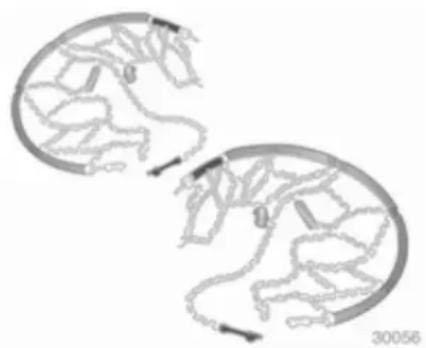
natural_image
Two circular diagrams with internal branching structures and directional arrows, no text or symbols presentTyre chains are only permitted on the front wheels.
Always use fine mesh chains that add no more than 10 mm to the tyre tread and the inboard sides (including chain lock).
⚠ Warning
Damage may lead to tyre blowout.
Tyre chains are permitted on tyres of size 185/65 R 15, 195/60 R 15, 195/65 R 15, 205/55 R 16 and 205/50 R17.
Tyre chains are not permitted on tyres of size 225/45 R 17, 225/40 R 18, 225/40 ZR18 and 235/35 R 19 ^2) .
Saloon, Station wagon, Van: tyre chains are only approved on tyres of size 215/45 R 17 if the vehicle was equipped with 18-inch wheels in the factory.
The use of tyre chains is not permitted on the temporary spare wheel.
Tyre repair kit
Minor damage to the tyre tread can be repaired with the tyre repair kit.
Do not remove foreign bodies from the tyres.
Tyre damage exceeding 4 mm or that is near the rim cannot be repaired with the tyre repair kit.
⚠ Warning
Do not drive faster than 80 km/h.
Do not use for a lengthy period.
Steering and handling may be affected.
If you have a flat tyre:
Apply parking brake and engage first gear, reverse gear or P.
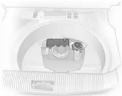
natural_image
Top-down view of a medical CT scanner with internal components (no visible text or labels)The tyre repair kit is in the stowage compartment under the floor cover in the load compartment.
-
Take the pouch with the tyre repair kit from the compartment. Carefully remove the components from the pouch.
-
Remove the compressor.
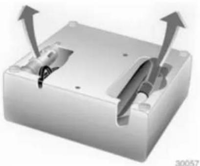
natural_image
3D rendering of a mechanical housing with two internal components and upward arrows indicating motion (no text or symbols)- Remove the electrical connection cable and air hose from the stowage compartments on the underside of the compressor.
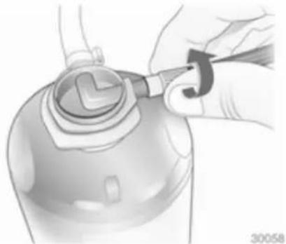
natural_image
Illustration of a hand using a tool to adjust or install a mechanical component (no text or symbols visible)- Screw the compressor air hose to the connection on the sealant bottle.
- Fit the sealant bottle into the retainer on the compressor. Set the compressor near the tyre in such a way that the sealant bottle is upright.

natural_image
Illustration of a mechanical device with a cable and connector, no visible text or symbols- Unscrew valve cap from defective tyre.
- Screw tyre inflation hose to valve.
-
The switch on the compressor must be set to O.
-
Connect the compressor plug to the accessory socket or cigarette lighter socket.
To avoid discharging the battery, we recommend running the engine.

natural_image
Close-up of a mechanical switch with a magnified inset showing a button and pointer (no text or symbols visible)- Set the rocker switch on the compressor to I. The tyre is filled with sealant.
-
The compressor pressure gauge briefly indicates up to 6 bar whilst the sealant bottle is emptying (approx. 30 seconds). Then the pressure starts to drop.
-
All of the sealant is pumped into the tyre. Then the tyre is inflated.
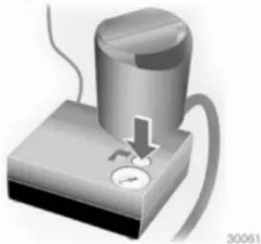
natural_image
Illustration of a pressure measurement device with a valve and probe inserted (no text or symbols)- The prescribed tyre pressure should be obtained within 10 minutes. Tyre pressure 244. When the correct pressure is obtained, switch off the compressor.
If the prescribed tyre pressure is not obtained within 10 minutes, remove the tyre repair kit. Move the vehicle one tyre rotation.
Reattach the tyre repair kit and continue the filling procedure for 10 minutes. If the prescribed tyre pressure is still not obtained, the
tyre is too badly damaged. Seek the assistance of a workshop.
Drain excess tyre pressure with the button over the pressure indicator.
Do not run the compressor longer than 10 minutes.
- Detach the tyre repair kit. Screw the filler hose to the free connection on the sealant bottle.
This prevents sealant leakage.
Stow the tyre repair kit in the load compartment.
-
Remove any excess sealant using a cloth.
-
Take the label indicating maximum permitted speed from the sealant bottle and affix in the driver's field of view.
-
Continue driving immediately so that sealant is evenly distributed in the tyre. After driving approx.
10 km (but no more than 10 minutes), stop and check tyre pressure. Screw compressor air hose directly onto tyre valve and compressor when doing this.
If tyre pressure is more than 1.3 bar, set it to the correct value. Repeat the procedure until there is no more loss of pressure.
If the tyre pressure has fallen below 1.3 bar, the vehicle must not be used. Seek the assistance of a workshop.
- Stow away tyre repair kit in load compartment.
Note
The driving characteristics of the repaired tyre is severely affected, therefore have this tyre replaced.
If unusual noise is heard or the compressor becomes hot, turn compressor off for at least 30 minutes.
The built-in safety valve opens at a pressure of 7 bar.
Note the expiry date of the kit. After this date its sealing capability is no longer guaranteed. Pay attention to storage information on sealant bottle.
Replace the used sealant bottle. Dispose of the bottle as prescribed by applicable laws.
The compressor and sealant can be used from approx. -30 °C.
The adapters supplied can be used to pump up other items e.g. footballs, air mattresses, inflatable dinghies etc. They are located on the underside of the compressor. To remove, screw on compressor air hose and withdraw adapter.
Wheel changing
Some vehicles are equipped with a tyre repair kit instead of a spare wheel 196.
Make the following preparations and observe the following information:
■ Park the vehicle on a level, firm and non-skid surface. The front wheels must be in the straight-ahead position.
■ Apply the parking brake and engage first gear, reverse gear or P.
■ Remove the spare wheel ➔ 200.
■ On the Astra TwinTop, the roof must be closed before the vehicle is raised.
■ Never change more than one wheel at once.
■ Use the jack only to change wheels.
■ If the ground on which the vehicle is standing is soft, a solid board (max. 1 cm thick) should be placed under the jack.
■ No people or animals may be in the vehicle when it is jacked-up.
■ Never crawl under a jacked-up vehicle.
■ Do not start the vehicle when it is raised on the jack.
■ Before screwing in the wheel bolts, clean them and lightly coat the taper of each wheel bolt with commercially available grease.
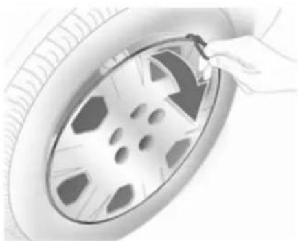
natural_image
Illustration of a hand adjusting a car tire with a clip (no text or symbols visible)- Pull off the wheel cover with the hook. Vehicle tools ➔ 190. For wheel covers with visible wheel bolts: The cover can remain on the wheel. Do not remove the retaining rings on the wheel bolts. Alloy wheels: Disengage wheel bolt caps with a screwdriver and remove. To protect the wheel, place a soft cloth between the screwdriver and the alloy wheel.
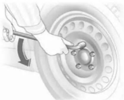
natural_image
Illustration of a car tire being adjusted for a wheel rim, showing the wheel and tire (no text or symbols)- Install the wheel wrench ensuring that it locates securely and slacken each bolt by half a turn.

natural_image
Diagram showing a car under load with overhead crane and a close-up of a vehicle on pavement (no text or symbols)- Ensure the jack is positioned correctly with the vehicle jacking points.

natural_image
Mechanical linkage diagram showing a vehicle with a magnified inset of the wheel (no text or symbols)- Set the jack to the necessary height before positioning it directly below the jacking point in a manner that prevents it from slipping.
Attach jack handle and with the jack correctly aligned rotate handle until wheel is clear of the ground.
- Unscrew the wheel bolts.
- Change the wheel.
-
Screw in the wheel bolts.
-
Lower vehicle.
- Install the wheel wrench ensuring that it locates securely and tighten each bolt in a crosswise sequence. Tightening torque is 110 Nm.
- Align the valve hole in the wheel cover with the tyre valve before installing. Install wheel nut caps.
- Stow the replaced wheel 196 and the vehicle tools 190.
- Check the tyre pressure of the installed tyre and also the wheel bolt torque as soon as possible.
Have the defective tyre renewed or repaired.
Spare wheel
Some vehicles are equipped with a tyre repair kit instead of a spare wheel.
The spare wheel can be classified as a temporary spare wheel depending on the size compared to the other mounted wheels and country regulations.
The spare wheel has a steel rim. Use of a spare wheel that is smaller than the other wheels or together with winter tyres could affect driveability. Have the defective tyre replaced as soon as possible.

natural_image
Close-up of a car wheel assembly with a highlighted component and arrow indicator (no text or symbols)The spare wheel is in the load compartment beneath the floor covering. It is secured in the recess with a wing nut.
The spare wheel well is not designed for all permitted tyre sizes. If a wheel wider than the spare must be stowed in the spare wheel well after changing wheels, the floor cover can be placed on the projecting wheel.
This must be taken into consideration when the load compartment is being loaded, particularly with the Astra TwinTop 40.
Station wagon
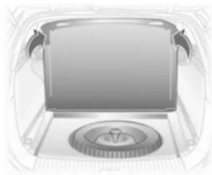
natural_image
Illustration of a vintage car front panel with a circular vent and handle (no text or symbols)Take adapter and hooks from the rails in the load compartment walls. Raise the rear lashing eyes and lift the floor cover to the vertical position so that it rests on the roof lining. When closing, guide the lashing eyes through the slots in the floor cover. Vehicles with cargo box: removal 75.
TwinTop
Accessing the spare wheel when the roof is open: Engage load compartment cover on the rear window frame and activate the loading aid 77. Raise the floor cover in the load compartment.
Temporary spare wheel
Use of the temporary spare wheel could affect driveability. Have the defective tyre renewed or repaired as soon as possible.
Only mount one temporary spare wheel. Do not drive faster than 80 km/h. Take curves slowly. Do not use for a long period of time.
The use of the temporary spare wheel on the rear axle is not permitted while towing another vehicle. Therefore mount the temporary spare wheel on the front axle and a full-size tyre on the rear axle.
Tyre chains ↩ 195.
Directional tyres
Fit directional tyres such that they roll in the direction of travel. The rolling direction is indicated by a symbol (e.g. an arrow) on the sidewall.
The following applies to tyres fitted opposing the rolling direction:
■ Driveability may be affected. Have the defective tyre renewed or repaired as soon as possible.
■ Drive particularly carefully on wet and snow-covered road surfaces.
Jump starting
Do not start with quick charger.
A vehicle with a discharged battery can be started using jump leads and the battery of another vehicle.
⚠ Warning
Be extremely careful when starting with jump leads. Any deviation from the following instructions can lead to injuries or damage caused by battery explosion or damage to the electrical systems of both vehicles.
⚠ Warning
Avoid contact with eyes, skin, fabrics, and painted surfaces. The fluid contains sulphuric acid which can cause injuries and damage in the event of direct contact.
■ Never expose the battery to naked flames or sparks.
■ A discharged battery can already freeze at temperatures of 0 °C . Defrost the frozen battery before connecting jump leads.
■ Wear eye protection and protective clothing when handling a battery.
■ Use a booster battery with the same voltage (12 Volts). Its capacity (Ah) must not be much less than that of the discharged battery.
■ Use jump leads with insulated terminals and a cross section of at least 16 mm ^2 (25 mm ^2 for diesel engines).
■ Do not disconnect the discharged battery from the vehicle.
■ Switch off all unnecessary electrical consumers.
■ Do not lean over the battery during jump starting.
■ Do not allow the terminals of one lead to touch those of the other lead.
■ The vehicles must not come into contact with each other during the jump starting process.
■ Apply the parking brake, transmission in neutral, automatic transmission in P.
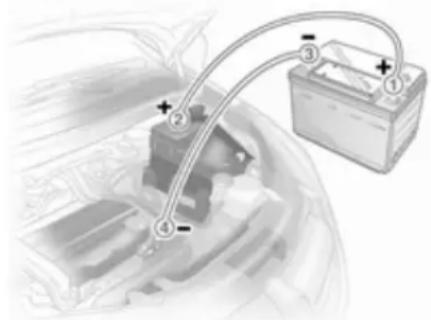
natural_image
Diagram of a car battery connected to a car trunk, showing wiring and polarity indicators (no text or symbols present)Lead connection order:
- Connect the red lead to the positive terminal of the booster battery.
-
Connect the other end of the red lead to the positive terminal of the discharged battery.
-
Connect the black lead to the negative terminal of the booster battery.
- Connect the other end of the black lead to a vehicle grounding point, such as the engine block or an engine mounting bolt. Connect as far away from the discharged battery as possible, however at least 60 cm.
Route the leads so that they cannot catch on rotating parts in the engine compartment.
To start the engine:
- Start the engine of the vehicle providing the jump.
- After 5 minutes, start the other engine. Start attempts should be made for no longer than 15 seconds at an interval of 1 minute.
-
Allow both engines to idle for approx. 3 minutes with the leads connected.
-
Switch on electrical consumers (e.g. headlights, heated rear window) of the vehicle receiving the jump start.
- Reverse above sequence exactly when removing leads.
Towing
Towing the vehicle
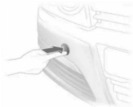
natural_image
Hand inserting a plug into a car's side panel (no text or symbols visible)Disengage the cover at the bottom and remove downwards.
The towing eye is stowed with the vehicle tools ➔ 190.
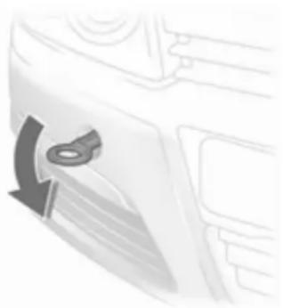
natural_image
Close-up of a car's front panel showing the door handle and seatbelt (no text or symbols visible)Screw in the towing eye as far as it will go until it stops in a horizontal position.
Attach a tow rope – or better still a tow rod – to the towing eye.
The towing eye must only be used for towing and not recovering the vehicle.
Switch on ignition to release steering wheel lock and to permit operation of brake lights, horn and windscreen wiper.
Open&Start system ➔ 22.
Transmission in neutral.
Switch on the hazard warning flashers on both vehicles.
Caution
Drive slowly. Do not drive jerkily. Excessive tractive force can damage the vehicle.
When the engine is not running, considerably more force is needed to brake and steer.
To prevent the entry of exhaust gases from the towing vehicle, switch on the air recirculation and close the windows.
Vehicles with automatic transmission must be towed facing forwards, not faster than 80 km/h nor further than 100 km. In all other cases and when the transmission is defective, the front axle must be raised off the ground.
Seek the assistance of a workshop.
Manual transmission automated 145.
After towing, unscrew the towing eye and refit the cover.
Towing another vehicle

natural_image
Hand inserting a plug into a car wheel (no text or symbols visible)Disengage cap at bottom and remove downwards.

natural_image
Diagram of a vehicle air vent with hexagonal airflow indicators (no text or symbols)For other models unclip locking tabs downward and pull off the cover upwards.
The towing eye is stowed with the vehicle tools ↩ 190.
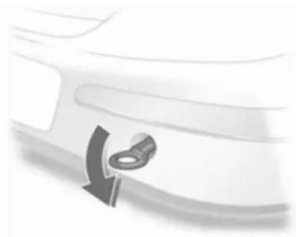
natural_image
Close-up of a car's side panel with a curved arrow pointing to the front wheel (no text or symbols visible)Screw in the towing eye as far as it will go until it stops in a horizontal position.
The lashing eye at the rear underneath the vehicle must never be used as a towing eye.
Attach a tow rope – or better still a tow rod – to the towing eye.
The towing eye must only be used for towing and not recovering a vehicle.
Caution
Drive slowly. Do not drive jerkily. Excessive tractive force can damage the vehicle.
After towing, unscrew the towing eye and refit the cover.
Version with cover: install by inserting the bottom lugs of the cover in the bumper, folding and then press the lugs at the top into place.
Appearance care
Exterior care
Locks
The locks are lubricated at the factory using a high quality lock cylinder grease. Use de-icing agent only when absolutely necessary, as this has a degreasing effect and impairs lock function. After using de-icing agent, have the locks regreased by a workshop.
Washing
The paintwork of your vehicle is exposed to environmental influences. Wash and wax your vehicle regularly. When using automatic car washes, select a programme that includes waxing.
Bird droppings, dead insects, resin, pollen and the like should be cleaned off immediately, as they contain aggressive constituents which can cause paint damage.
If using a car wash, comply with the car wash manufacturer's instructions. The windscreen wipers and rear window wiper must be switched off. Remove antenna and external accessories such as roof racks etc.
If you wash your vehicle by hand, make sure that the insides of the wheel housings are also thoroughly rinsed out.
Clean edges and folds on opened doors and the bonnet as well as the areas they cover.
Do not clean the engine compartment with a steam-jet or high-pressure jet cleaner.
Thoroughly rinse and leather-off the vehicle. Rinse leather frequently. Use separate leathers for painted and glass surfaces: remnants of wax on the windows will impair vision.
Do not use hard objects to remove spots of tar. Use tar removal spray on painted surfaces.
Exterior lights
Headlight and other light covers are made of plastic. Do not use any abrasive or caustic agents, do not use an ice scraper, and do not clean them dry.
Polishing and waxing
Wax the vehicle regularly (at the latest when water no longer beads). Otherwise, the paintwork will dry out.
Polishing is necessary only if the paint has become dull or if solid deposits have become attached to it.
Paintwork polish with silicone forms a protective film, making waxing unnecessary.
Plastic body parts must not be treated with wax or polishing agents.
Windows and windscreen wiper blades
Use a soft lint-free cloth or chamois leather together with window cleaner and insect remover.
When cleaning the rear window, make sure the heating element inside is not damaged.
For mechanical removal of ice, use a sharp-edged ice scraper. Press the scraper firmly against the glass so that no dirt can get under it and scratch the glass.
Clean smearing wiper blades with a soft cloth and window cleaner.
Sun roof
Never clean with solvents or abrasive agents, fuels, aggressive media (e.g. paint cleaner, acetone-containing solutions etc.), acidic or highly alkaline media or abrasive pads. Do not apply wax or polishing agents to the middle part of the sun roof.
Wheels and tyres
Do not use high-pressure jet cleaners.
Clean rims with a pH-neutral wheel cleaner.
Rims are painted and can be treated with the same agents as the body.
Paintwork damage
Rectify minor paintwork damage with a touch-up pen before rust forms. Have more extensive damage or rust areas repaired by a workshop.
Underbody
Some areas of the vehicle underbody have a PVC undercoating while other critical areas have a durable protective wax coating.
After the underbody is washed, check the underbody and have it waxed if necessary.
Bitumen/rubber materials could damage the PVC coating. Have underbody work carried out by a workshop.
Before and after winter, wash the underbody and have the protective wax coating checked.
Engine compartment
Areas of the engine compartment that are painted in the same colour as the vehicle must be looked after like any other painted surface.
It is advisable to wash the engine compartment before and after winter and preserve it with wax. Protect the alternator and brake fluid reservoir with plastic sheets before washing the engine.
When washing the engine with a steam-jet cleaner, do not direct the steam jet towards components of the antilock brake system, air conditioning system or the belt drive and its components.
After an engine wash, have all engine room components preserved thoroughly by a workshop using protective wax.
Do not use high-pressure jet cleaners.
TwinTop
Clean all seals with a damp soft lint-free cloth. Allow to dry completely. Treat all seals, e. g. on the roof and windscreen frame, with the special maintenance kit (available at your service partner) from time to time.
Good contact between the fine rubber lips and the sealing surfaces prevents leaks and reduces clamping forces. Intermediate roof position for cleaning 40.
Do not use high-pressure jet cleaners.
Towing equipment
Do not clean the coupling ball bar with a steam-jet or high-pressure jet cleaner.
Interior care
Interior and upholstery
Only clean the vehicle interior, including the instrument panel fascia and panelling, with a dry cloth or interior cleaner.
Clean the leather upholstery with clear water and a soft cloth. In case of heavy soiling, use leather care.
The instrument panel should only be cleaned using a soft damp cloth.
208 Vehicle care
Clean fabric upholstery with a vacuum cleaner and brush. Remove stains with an upholstery cleaner.
Clean seat belts with lukewarm water or interior cleaner.
Caution
Close Velcro fasteners as open Velcro fasteners on clothing could damage seat upholstery.
Plastic and rubber parts
Plastic and rubber parts can be cleaned with the same cleaner as used to clean the body. Use interior cleaner if necessary. Do not use any other agent. Avoid solvents and petrol in particular. Do not use high-pressure jet cleaners.
Service and maintenance
General information 209
Recommended fluids, lubricants and parts 210
General information
Service information
In order to ensure economical and safe vehicle operation and to maintain the value of your vehicle, it is of vital importance that all maintenance work is carried out at the proper intervals as specified.
The detailed, up-to-date service schedule for your vehicle is available at the workshop.
Service display ↩ 94.
European service intervals
Service is due every 30.000 km or 1 year, whichever occurs first.
The European schedule is valid for the following countries:
Andorra, Austria, Belgium, Bosnia-Herzegovina, Bulgaria, Croatia, Cyprus, Czech Republic, Denmark, Estonia, Finland, France, Germany, Greece, Greenland, Hungary, Iceland, Ireland, Israel, Italy, Latvia, Lithuania, Luxembourg, Macedonia, Malta, Montenegro, Netherlands,
Norway, Poland, Portugal, Romania, Slovakia, Slovenia, Spain, Sweden, Switzerland, United Kingdom. Service display ➔ 94.
International service intervals
Service is due every 15.000 km or 1 year, whichever occurs first.
The international service intervals are valid for the countries which are not listed at the european service intervals.
Service display ➔ 94.
Confirmations
Confirmation of service is recorded in the Service and Warranty Booklet. The date and mileage is completed with the stamp and signature of the servicing workshop.
Make sure that the Service and Warranty Booklet is completed correctly as continuous proof of service is essential if any warranty or goodwill claims are to be met, and is also a benefit when selling the vehicle.
Fixed service interval
When service is due, InSP appears in the service display for approx.
10 seconds when the ignition is switched on. Have the next service performed by a workshop within one week or 500 km (whichever occurs first).
Service display ➔ 94.
Flexible service interval
The service interval is based on several parameters depending on usage and is calculated using these parameters.
If the remaining distance is less than 1500 km, InSP is displayed with a remaining distance of 1000 km when the ignition is switched on and off. If less than 1000 km remain, InSP is displayed for several seconds. Have the next service performed by a workshop within one week or 500 km (whichever occurs first).
Display of remaining distance:
- Switch off ignition.
- Briefly press the trip odometer reset button. The odometer reading is shown.
- Press and hold the reset button for about 2 seconds. InSP and the remaining distance are displayed.
Service display ➔ 94.
Recommended fluids, lubricants and parts
Recommended fluids and lubricants
Only use products that have been tested and approved. Damage resulting from the use of non-approved materials will not be covered by the warranty.
Warning
Operating materials are hazardous and could be poisonous. Handle with care. Pay attention to information given on the containers.
Engine oil
Engine oil is identified by its quality and its viscosity. Quality is more important than viscosity when selecting which engine oil to use. The oil quality ensures e.g. engine cleanliness, wear protection and oil
aging control, whereas viscosity grade gives information on the oil's thickness over a temperature range.
Dexos is the newest engine oil quality that provides optimum protection for gasoline and diesel engines. If it is unavailable, engine oils of other listed qualities have to be used.
Recommendations for gasoline engines are also valid for Compressed Natural Gas (CNG), Liquified Petroleum Gas (LPG) and Ethanol (E85) fueled engines.
Select the appropriate engine oil based on its quality and on the minimum ambient temperature 215.
Topping up engine oil
Engine oils of different manufacturers and brands can be mixed as long as they comply with the required engine oil quality and viscosity.
Use of engine oil with only ACEA A1/B1 or only A5/B5 quality is prohibited, since it can cause long-term engine damage under certain operating conditions.
Select the appropriate engine oil based on its quality and on the minimum ambient temperature 215.
Additional engine oil additives
The use of additional engine oil additives could cause damage and invalidate the warranty.
Engine oil viscosity grades
The SAE viscosity grade gives information of the thickness of the oil.
Multigrade oil is indicated by two figures, e.g. SAE 5W-30. The first figure, followed by a W, indicates the low temperature viscosity and the second figure the high temperature viscosity.
Select the appropriate viscosity grade depending on the minimum ambient temperature 215.
All of the recommended viscosity grades are suitable for high ambient temperatures.
Coolant and antifreeze
Use only silicate-free long life coolant (LLC) antifreeze.
The system is factory filled with coolant designed for excellent corrosion protection and frost protection down to approx. -28 °C. This concentration should be maintained all year round. The use of additional coolant additives that intend to give additional corrosion protection or seal against minor leaks can cause function problems. Liability for consequences resulting from the use of additional coolant additives will be rejected.
Brake and clutch fluid
Only use high-performance brake fluid approved for the vehicle, consult your workshop.
Over time, brake fluid absorbs moisture which will reduce braking effectiveness. The brake fluid should therefore be replaced at the specified interval.
212 Service and maintenance
Brake fluid should be stored in a sealed container to avoid water absorption.
Ensure brake fluid does not become contaminated.
Technical data
Vehicle identification 213
Vehicle data 215
Vehicle identification Vehicle Identification Number
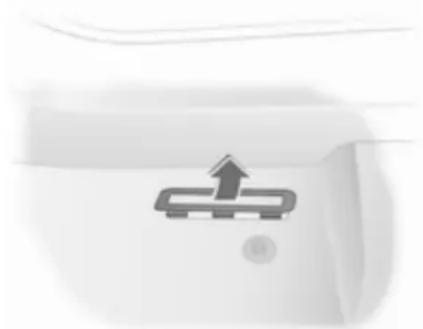
natural_image
Simple icon of a computer monitor with an upward arrow, no text or symbols presentThe Vehicle Identification Number is stamped on the identification plate and on the floor pan, under the floor covering, visible under a cover.

natural_image
Abstract grayscale graphic with diagonal lines and a central arrow shape (no text or symbols)The Vehicle Identification Number may be embossed on the instrument panel visible through the windscreen.
214 Technical data
Identification plate
natural_image
Close-up of a curved surface with a small inset image showing a dark rectangular object and a black arrow pointing to it (no text or symbols visible)The identification plate is located on the front right door frame.

Information on identification plate:
1 = Manufacturer
2 = Type approval number
3 = Vehicle Identification Number
4 = Permissible gross vehicle weight rating in kg
5 = Permissible gross train weight in kg
6 = Maximum permissible front axle load in kg
7 = Maximum permissible rear axle load in kg
8 = Vehicle-specific or country-specific data
The combined total of front and rear axle loads must not exceed the permissible gross vehicle weight. For example, if the front axle is bearing its maximum permissible load, the rear axle can only bear a load that is equal to the gross vehicle weight minus the front axle load.
The technical data is determined in accordance with European Community standards. We reserve the right to make modifications.
Specifications in the vehicle documents always have priority over those given in this manual.
Vehicle data
Recommended fluids and lubricants
European service schedule
Required engine oil quality
All European countries
(except Belarus, Moldova, Russia, Serbia, Turkey) Only Israel
| Engine oil quality Petrol engines(including CNG, LPG, E85) | Diesel engines Petrol engines(including CNG, LPG, E85) | Diesel engines |
dexos 1 -- √ -
dexos 2 √ √ - √
In case dexos quality is unavailable you may use max. 1 litre engine oil quality ACEA C3 once between each oil change.
Engine oil viscosity grades
All European countries and Israel
(except Belarus, Moldova, Russia, Serbia, Turkey)
Ambient temperature Petrol and diesel engines
down to -25 °C SAE 5W-30 or SAE 5W-40
below -25 °C SAE 0W-30 or SAE 0W-40
216 Technical data
International service schedule
Required engine oil quality
All countries outside Europe
except Israel Only Belarus, Moldova, Russia, Serbia, Turkey
| Engine oil quality Petrol engines(including CNG, LPG, E85) | Diesel engines Petrol engines(including CNG, LPG, E85) | Diesel engines |
| dexos 1 √ --- | ||
| dexos 2 - √ √ √ |
In case dexos quality is unavailable you may use the oil qualities listed below:
All countries outside Europe
except Israel Only Belarus, Moldova, Russia, Serbia, Turkey
| Engine oil quality Petrol engines(including CNG, LPG, E85) | Diesel engines Petrol engines(including CNG, LPG, E85) | Diesel engines |
| GM-LL-A-025 √ - √ - | ||
| GM-LL-B-025 - √ - √ | ||
| All countries outside Europeexcept Israel Only Belarus, Moldova, Russia, Serbia, Turkey | ||
| Engine oil quality Petrol engines(including CNG, LPG, E85) | Diesel engines Petrol engines(including CNG, LPG, E85) | Diesel engines |
| ACEA A3/B3 √ - √ - | ||
| ACEA A3/B4 √ √ √ √ | ||
| ACEA C3 √ √ √ √ | ||
| API SM √ - √ - | ||
| API SN √ - √ - | ||
| Engine oil viscosity gradesAll countries outside Europe (except Israel),including Belarus, Moldova, Russia, Serbia, Turkey | ||
| Ambient temperature Petrol and diesel engines | ||
| down to -25 °C SAE 5W-30 or SAE 5W-40 | ||
| below -25 °C SAE 0W-30 or SAE 0W-40 | ||
| down to -20 °C | SAE 10W-30 ^1) or SAE 10W-40 ^1) | |
1) Permitted, but usage of SAE 5W-30 or SAE 5W-40 with dexos quality is recommended.
218 Technical data
Engine data
Sales designation 1.2 1.4 1.6 1.6 1.8
| Engine identifier code | Z 12 XEP Z 14 XEP Z 16 XER, | Z 16 LET, A 16 LET | Z 18 XER, A 18 XER | ||
| A 16 XER | |||||
| Number of cylinders 4 4 4 4 4 | |||||
| Piston displacement [cm3] | 1229 1364 1598 1598 1796 | ||||
| Engine power [kW] 59 66 85 132 at rpm | 103 | ||||
| 5600 5600 6000 5500 6300 | |||||
| Torque [Nm] | 110 | 125 | 155 | 230 | 175 |
| at rpm | 4000 4000 4000 1980-5500 | 3800 | |||
| Fuel type | Petrol | Petrol | Petrol | Petrol | Petrol |
| Octane rating RON | |||||
| recommended | 95 95 95 95 | 95 | |||
| possible | 98 98 98 98 | 98 | |||
| possible | 91 91 91 – | 91 | |||
| Oil consumption [l/1000 km] | 0.6 0.6 0.6 0.6 0.6 | ||||
Technical data 219
| Sales designation | 2.0 Turbo | 2.0 Turbo | 1.3 CDTI | 1.7 CDTI | 1.7 Z 17 DTJ, A 17 DTJ |
| Engine identifier code Z 20 LER Z 20 LEH Z 13 DTH Z 17 DTH | |||||
| Number of cylinders 4 4 4 4 4 | |||||
| Piston displacement [cm3] | 1998 1998 1248 1686 | 1686 | |||
| Engine power [kW] | 147 | 177 | 66 | 74 | 81 |
| at rpm | 5400 5600 4000 4400 | 3800 | |||
| Torque [Nm] | 262 | 320 | 200 | 240 | 260 |
| at rpm | 4200 | 2400-5000 | 1750-2500 | 2300 | 2300 |
| Fuel type | Petrol | Petrol | Diesel | Diesel | Diesel |
| Octane rating RON | |||||
| recommended | 95 | 98 | |||
| possible | 98 | 95 | |||
| possible | 912) | 912) | |||
| Oil consumption [l/1000 km] | 0.6 | 0.6 | 0.6 | 0.6 | 0.6 |
2) Possible only if high engine load, full load or driving in mountainous terrain with a caravan/trailer or high payload is avoided.
220 Technical data
| Sales designation 1.7 1.9 CDTI 1.9 CDTI 1.9 CDTI | |||||
| Engine identifier code | Z 17 DTR, A 17 DTR Z 19 DTL Z 19 DT Z 19 DTH | ||||
| Number of cylinders 4 4 4 4 | |||||
| Piston displacement [cm3] | 1686 1910 1910 1910 | ||||
| Engine power [kW] 92 74 88 110at rpm 4000 3500 3500 4000 | |||||
| Torque [Nm] | 280 | 260 280 320 | |||
| at rpm 2300 1700-2500 | 2000-2750 | 2000-2750 | |||
| Fuel type | Diesel | Diesel | Diesel | Diesel | |
| Oil consumption [l/1000 km] | 0.6 0.6 0.6 0.6 | ||||
Performance
Saloon 5-door
| Engine Z12XEP Z14XEP | Z16XER,A16XER Z16LET Z18XER |
Maximum speed ^3) [km/h]
Manual transmission 171 178 191 221 208
Manual transmission automated - 176 192 --
Automatic transmission - - - - 188
| Engine | Z20LER | Z13DTH | Z17DTH | Z17DTJ | Z17DTR |
| Maximum speed [km/h] | |||||
| Manual transmission | 230 172 | 180 | 185 / 188 | 4) | 195 |
| Manual transmission automated | - | 171 | - | - | - |
| Automatic transmission | - | - | - | - | - |
3) The maximum speed indicated is achievable at kerb weight (without driver) plus 200 kg payload. Optional equipment could reduce the specified maximum speed of the vehicle.
4) For model with pollutant reduction.
222 Technical data
Engine A17DTJ A17DTR Z19DTL Z19DT Z19DTH
| Maximum speed [km/h] |
| Manual transmission 186 195 180 194 208 |
| Manual transmission automated - - - - - |
| Automatic transmission - - - 188 - |
Saloon 3-door
| Engine Z14XEP | Z16XER,A16XER | Z16LET,A16LET | Z18XER,A18XER Z20LER | ||
| Maximum speed [km/h] | |||||
| Manual transmission | 180 | 193 | 223 | 210 | 234 |
| Manual transmission automated | 178 | 194 | - | - | - |
| Automatic transmission | - | - | - | 190 | - |
Engine Z20LEH Z13DTH Z17DTH Z17DTJ
Z17DTR,
A17DTR
Maximum speed [km/h]
Manual transmission 244 174 182 187 / 188 197
Manual transmission automated - 174 ---
Automatic transmission ----
Engine A17DTJ Z19DTL Z19DT Z19DTH
| Maximum speed [km/h] | ||||
| Manual transmission | 188 | 182 | 196 | 210 |
| Manual transmission automated | - | - | - | - |
| Automatic transmission | - | - | 190 | - |
224 Technical data
| Saloon 4-door | ||||
| Z16XER, A16XER | Z18XER, A18XER Z13DTH Z17DTH Z17DTJ | |||
| Engine | ||||
| Maximum speed [km/h] | ||||
| Manual transmission 191 207 172 180 188 | ||||
| Manual transmission automated 192 - - - - | ||||
| Automatic transmission - 188 - - - | ||||
| Station wagon | ||||
| Z16XER, A16XER | Z16LET, A16LET | Z18XER, A18XER | ||
| Engine Z14XEP | ||||
| Maximum speed [km/h] | ||||
| Manual transmission 178 191 221 207 | ||||
| Manual transmission automated - | 192 - | - | ||
| Automatic transmission | - | - | - | 188 |
Engine Z20LER Z13DTH A17DTJ Z17DTH Z17DTJ
| Maximum speed [km/h] |
| Manual transmission 230 172 185 180 185 / 188 |
| Manual transmission automated - - - - - |
| Automatic transmission - - - - - |
| Engine | Z17DTR,A17DTR Z19DTL Z19DT Z19DTH | ||
| Maximum speed [km/h] | |||
| Manual transmission | 195 | 180 | 193 207 |
| Manual transmission automated | - | - | -- |
| Automatic transmission | - | - | 187 - |
Van
| Engine | Z14XEP | Z13DTH | Z17DTH | Z17DTJ |
| Maximum speed [km/h] | ||||
| Manual transmission | 178 | 172 180 185 | ||
| Manual transmission automated | - | - | - | - |
| Automatic transmission | - | - | - | - |
226 Technical data
Engine Z17DTR Z19DTL Z19DT Z19DTH
| Maximum speed [km/h] |
| Manual transmission 195 180 193 207 |
| Manual transmission automated - - - - |
| Automatic transmission -- 187 - |
TwinTop
| Engine | Z16XER,A16XER Z16XEP | Z16LET,A16LET | ||
| Maximum speed [km/h] | ||||
| Manual transmission 192 | 192 | 228 | ||
| Manual transmission automated | - | - | ||
| Automatic transmission | - | - | - | |
| Engine | A18XERZ18XER Z19DTH Z20LER |
| Maximum speed [km/h] | |
| Manual transmission 209 213 237 | |
| Manual transmission automated --- | |
| Automatic transmission 189 -- |
Fuel consumption - CO _2 -emissions
Saloon 5-door
Tyre width up to 205 mm with manual transmission / manual transmission automated / automatic transmission ^4 .
| Engine | Z12XEP | Z14XEP | Z16XER | A16XER | A16LET | A18XER | Z18XER | Z13DTH |
| urban [l/100 km] | 8.0/-/- | 8.0/7.7/- | 8.7/8.5/- | 8.4/8.1/- | 9.7/-/- | 9.1/-/9.6 | 9.7/-/10.4 | 6.3 |
| extra-urban [l/100 km] | 5.0/-/- | 5.0/4.9/- | 5.2/5.0/- | 5.1/5.1/- | 6.1/-/- | 5.3/-/5.7 | 5.6/-/6.1 | 4.1/4.2/- |
| total [l/100 km] | 6.1/-/- | 6.1/5.9/- | 6.5/6.3/- | 6.3/6.2/- | 7.4/-/- | 6.8/-/7.2 | 7.1/-/7.7 | 4.9/5.0/- |
| CO _2 [g/km] | 146/-/- | 146/141/- | 155/151/- | 146/143/- | 174/-/- | 156/-/166 | 169/-/184 | 130 ^7) /133 ^8) /- |
5) For engine A17DTJ, Z13DTH, Z17DTH, Z17DTR and Z17DTJ without pollutant reduction tyre width up to 195 mm.
6) In vehicles with diesel particle filter, fuel consumption increased by 0.2 l/100 km.
7) In vehicles with diesel particle filter, CO2 emissions increased by 7g / km .
8) In vehicles with diesel particle filter, CO2 emissions increased by 5g / km .
228 Technical data
Engine Z17DTH A17DTJ Z17DTJ Z17DTR
| urban [l/100 km] 6.4/-/- 6.8/-/- | 5.6 (6.6)9)/-/- | 6.6/-/- |
| extra-urban [l/100 km] 4.2/-/- 4.4/-/- 3.9 (4.4)/-/- 4.4/-/- | ||
| total [l/100 km] 5.0/-/- 5.4/-/- 4.5 (5.2)/-/- 5.2/-/- | ||
| CO2[g/km] 135/-/- 143/-/- 119 (138)/-/- 138/-/- |
Tyre width up to 225 mm with manual transmission / manual transmission automated / automatic transmission.
| Engine | Z12XEP | Z14XEP | Z16XER | Z16LET | Z18XER | Z20LER | Z17DTH |
| urban [l/100 km] | 8.2/-/- | 8.1/7.8/- | 8.8/8.6/- | 10.3/-/- | 9.8/-/10.5 | 13.1/-/- | 6.5/-/- |
| extra-urban [l/100 km] | 5.2/-/- | 5.1/5.0/- | 5.3/5.1/- | 6.2/-/- | 5.7/-/6.2 | 7.1/-/- | 4.3/-/- |
| total [l/100 km] | 6.3/-/- | 6.2/6.0/- | 6.6/6.4/- | 7.7/-/- | 7.2/-/7.8 | 9.3/-/- | 5.1/-/- |
| CO_2 [g/km] | 151/-/- | 148/143/- | 158/153/- | 185/-/- | 172/-/186 | 223/-/- | 138/-/- |
9) For model without pollutant reduction.
Technical data 229
| Engine | A17DTJ | A17DTR | Z17DTJ | Z17DTR | Z19DTL | Z19DT | Z19DTH |
| urban [l/100 km] | 6.9/-/- | 6.9/-/- | 6.8/-/- | 7.2/-/- | 7.2/-/9.6 | 7.2/-/- | |
| extra-urban [l/100 km] | 4.7/-/- | 4.7/-/- | 4.6/-/- | 4.6/-/- | 4.7/-/- | 4.7/-/5.3 | 4.7/-/- |
| total [l/100 km] | 5.5/-/- | 5.5/-/- | 5.4/-/- | 5.4/-/- | 5.6/-/- | 5.6/-/6.9 | 5.6/-/- |
| CO2[g/km] | 146/-/- | 146/-/- | 143/-/- | 143/-/- | 149/-/- | 149/-/186 | 149/-/- |
Saloon 3-door
Tyre width up to 205 mm with manual transmission / manual transmission automated / automatic transmission ^10) .
| Engine | Z14XEP | Z16XER | Z18XER | Z13DTH | Z17DTH |
| urban [l/100 km] | 8.0/7.7/- | 8.7/8.5/- | 9.7/-/10.4 | 6.3/6.4/- | 6.4/-/- |
| extra-urban [l/100 km] | 5.0/4.9/- | 5.2/5.0/- | 5.6/-/6.1 | 4.1/4.2/- | 4.2/-/- |
| total [l/100 km] | 6.1/5.9/- | 6.5/6.3/- | 7.1/-/7.7 | 4.9/5.0/- | 5.0/-/- |
| CO2[g/km] | 146/141/- | 155/151/- | 169/-/184 | 130/133/- | 135/-/- |
^10) For engine A17DTJ, A17DTR, Z17DTR and Z17DTJ without pollutant reduction tyre width up to 195 mm.
Engine A17DTJ A17DTR Z17DTJ Z17DTR
| urban [l/100 km] 6.8/-/- 6.8/-/- 5.6 (6.6)/-/- 6.6/-/- |
| extra-urban [l/100 km] 4.6/-/- 4.6/-/- 3.9 (4.4)/-/- 4.4/-/- |
| total [l/100 km] 5.4/-/- 5.4/-/- 4.5 (5.2)/-/- 5.2/-/- |
| CO2 [g/km] 143/-/- 143/-/- 119 (138)/-/- 138/-/- |
Tyre width up to 225 mm with manual transmission / manual transmission automated / automatic transmission.
| Engine | Z14XEP | Z16XER | Z16LET | Z18XER | Z20LER | Z20LEH | Z17DTH |
| urban [l/100 km] | 8.1/7.8/- | 8.8/8.6/- | 10.3/-/- | 9.8/-/10.5 | 13.1/-/- | 13.0/-/- | 6.5/-/- |
| extra-urban [l/100 km] | 5.1/5.0/- | 5.3/5.1/- | 6.2/-/- | 5.7/-/6.2 | 7.1/-/- | 7.0/-/- | 4.3/-/- |
| total [l/100 km] | 6.2/6.0/- | 6.6/6.4/- | 7.7/-/- | 7.2/-/7.8 | 9.3/-/- | 9.2/-/- | 5.1/-/- |
| CO2[g/km] | 148/143/- | 158/153/- | 185/-/- | 172/-/186 | 223/-/- | 221/-/- | 138/-/- |
| Engine | A17DTJ | A17DTR | Z17DTJ | Z17DTR | Z19DTL | Z19DT | Z19DTH |
| urban [l/100 km] | 6.9/-/- | 6.9/-/- | 6.8/-/- | 6.8/-/- | 7.2/-/- | 7.2/-/9.6 | 7.2/-/- |
| extra-urban [l/100 km] | 4.7/-/- | 4.7/-/- | 4.6/-/- | 4.6/-/- | 4.7/-/- | 4.7/-/5.3 | 4.7/-/- |
| total [l/100 km] | 5.5/-/- | 5.5/-/- | 5.4/-/- | 5.4/-/- | 5.6/-/- | 5.6/-/6.9 | 5.6/-/- |
| CO2[g/km] | 146/-/- | 146/-/- | 143/-/- | 143/-/- | 149/-/- | 149/-/186 | 149/-/- |
Saloon 4-door
Tyre width up to 205 mm with manual transmission / manual transmission automated / automatic transmission ^11 .
Engine Z16XER Z18XER Z13DTH Z17DTH Z17DTJ
| urban [l/100 km] 8.8/8.6/- 9.7/-/10.5 6.5/-/- 6.4/-/- 5.6/-/- | |
| extra-urban [l/100 km] 5.3/5.1/- 5.6/-/6.2 4.3/-/- 4.2/-/- 3.9/-/- | |
| total [l/100 km] 6.6/6.4/- 7.1/-/7.8 5.1/-/- 5.0/-/- 4.5/-/- | |
| CO2[g/km] | 158/153/- 169/-/186 137/-/- 135/-/- 119/-/- |
Tyre width up to 225 mm with manual transmission / manual transmission automated / automatic transmission.
Engine Z16XER Z18XER Z17DTH
| urban [l/100 km] 8.9/8.7/- 9.8/-/10.6 6.5/-/- | |
| extra-urban [l/100 km] | 5.4/5.2/- 5.7/-/6.3 4.3/-/- |
| total [l/100 km] | 6.7/6.5/- 7.2/-/7.9 5.1/-/- |
| CO2[g/km] | 159/154/- 172/-/189 138/-/- |
232 Technical data
Station wagon
Tyre width up to 205 mm with manual transmission / manual transmission automated / automatic transmission ^12 .
Engine Z14XEP Z16XER Z18XER Z13DTH
| urban [l/100 km] 8.0/-/- 8.8/8.6/- 9.7/-/10.5 6.3/-/- |
| extra-urban [l/100 km] 5.0/-/- 5.3/5.1/- 5.6/-/6.2 4.1/-/- |
| total [l/100 km] 6.1/-/- 6.6/6.4/- 7.1/-/7.8 4.9/-/- |
| CO2[g/km] 146/-/- 158/ |
Engine A17DTJ Z17DTH Z17DTJ Z17DTR
| urban [l/100 km] | 6.9/-/- | 6.4/-/- | 5.6 (6.7)/-/- | 6.7/-/- |
| extra-urban [l/100 km] | 4.7/-/- | 4.2/-/- | 3.9 (4.5)/-/- | 4.5/-/- |
| total [l/100 km] | 5.5/-/- | 5.0/-/- | 4.5 (5.3)/-/- | 5.3/-/- |
| CO2[g/km] | 146/-/- | 135/-/- | 119 (139)/-/- | 139/-/- |
Tyre width up to 225 mm with manual transmission / manual transmission automated / automatic transmission.
Technical data 233
| Engine | Z14XEP | Z16XER | Z18XER | Z16LET | Z20LER | A17DTJ | A17DTR |
| urban [l/100 km] | 8.1/-/- | 8.9/8.7/- | 9.8/-/10.6 | 10.3/-/- | 13.2/-/- | 7.0/-/- | 7.0/-/- |
| extra-urban [l/100 km] | 5.1/-/- | 5.4/5.2/- | 5.7/-/6.3 | 6.2/-/- | 7.2/-/- | 4.8/-/- | 4.8/-/- |
| total [l/100 km] | 6.2/-/- | 6.7/6.5/- | 7.2/-/7.9 | 7.7/-/- | 9.4/-/- | 5.6/-/- | 5.6/-/- |
| CO2[g/km] | 148/-/- | 159/154/- | 172/-/189 | 185/-/- | 226/-/- | 149/-/- | |
| Engine | Z17DTH | Z17DTJ | Z17DTR | Z19DTL | Z19DT | Z19DTH | |
| urban [l/100 km] | 6.5/-/- | 6.9/-/- | 6.9/-/- | 7.2/-/- | 7.2/-/9.7 | 7.2/-/- | |
| extra-urban [l/100 km] | 4.3/-/- | 4.7/-/- | 4.7/-/- | 4.7/-/- | 4.7/-/5.4 | 4.7/-/- | |
| total [l/100 km] | 5.1/-/- | 5.5/-/- | 5.5/-/- | 5.6/-/- | 5.6/-/7.0 | 5.6/-/- | |
| CO2[g/km] | 138/-/- | 145/-/- | 145/-/- | 149/-/- | 149/-/189 | 149/-/- |
234 Technical data
Van
Tyre width up to 205 mm with manual transmission / manual transmission automated / automatic transmission ^13) .
Engine Z14XEP Z13DTH Z17DTH Z17DTJ Z17DTR
| urban [l/100 km] 8.0/-/- 6.3/-/- 6.4/-/- 6.6/-/- 6.6/-/- |
| extra-urban [l/100 km] 5.0/-/- 4.1/-/- 4.2/-/- 4.4/-/- 4.4/-/- |
| total [l/100 km] 6.1/-/- 4.9/-/- 5.0/-/- 5.2/-/- 5.2/-/- |
| CO2[g/km] 146/-/- 130/-/- 135/-/- 138/-/- 138/-/- |
Tyre width up to 225 mm with manual transmission / manual transmission automated / automatic transmission.
| Engine | Z14XEP | Z17DTH | Z17DTJ | Z17DTR | Z19DTL | Z19DT | Z19DTH |
| urban [l/100 km] | 8.1/-/- | 6.5/-/- | 6.8/-/- | 6.8/-/- | 7.2/-/- | 7.2/-/9.7 | 7.2/-/- |
| extra-urban [l/100 km] | 5.1/-/- | 4.3/-/- | 4.6/-/- | 4.6/-/- | 4.7/-/- | 4.7/-/5.4 | 4.7/-/- |
| total [l/100 km] | 6.2/-/- | 5.1/-/- | 5.4/-/- | 5.4/-/- | 5.6/-/- | 5.6/-/7.0 | 5.6/-/- |
| CO_2 [g/km] | 148/-/- | 138/-/- | 143/-/- | 143/-/- | 149/-/- | 149/-/189 | 149/-/- |
TwinTop
Tyre width up to 225 mm with manual transmission / manual transmission automated / automatic transmission.
Engine Z16XER Z16LET Z18XER Z20LER Z19DTH
| urban [l/100 km] 9.0/-/- 10.5/-/- 10.0/-/10.7 13.3/-/- 7.6/-/- | ||||
| extra-urban [l/100 km] 5.5/-/- 6.4/-/- 5.9/-/6.4 7.3/-/- 5.1/-/- | ||||
| total [l/100 km] 6.8/-/- 7.9/-/- 7.4/-/8.0 9.5/-/- 6.0/-/- | ||||
| CO2[g/km] | 163/-/- 190/-/- | 177/-/191 | 228/-/- | 159/-/- |
Vehicle weight
Kerb weight, basic model, Saloon, 5-door
| Astra Engine Manual transmission Manual transmission | automated | Automatic transmission | |
| without/with air conditioning [kg] | Z12XEP 1240/1260 -/- -/- | ||
| Z14XEP 1240/1260 1240/1260 -/- | |||
| Z16XER 1270/1290 1270/1290 -/- | |||
| Z16LET -/1355 -/- -/- | |||
| Z18XER 1278/1298 -/- 1278/1298 | |||
| Z20LER -/1385 -/- -/- | |||
| Z13DTH 1340/1355 1340/1355 -/- | |||
| A17DTJ, A17DTR 1385/1400 -/- -/- | |||
| Z17DTH 1365/1380 -/- -/- | |||
| Z17DTJ, Z17DTR 1385/1400 -/- -/- | |||
| Z19DTL 1395/1410 -/- -/- | |||
| Z19DT 1395/1410 -/- 1425/1440 (1393/1408) | 14) | ||
| Z19DTH 1393/1408 -/- -/- | |||
14) Reduced-weight, country-specific models.
Kerb weight, basic model, Saloon, 3-door
| Astra Engine Manual transmission Manual transmission | automated | Automatic transmission | |
| without/with air conditioning [kg] | Z14XEP 1220/1240 1220/1240 -/- | ||
| Z16XER 1250/1270 1250/1270 -/- | |||
| Z16LET -/1335 -/- -/- | |||
| Z18XER 1265/1285 -/- 1278/1298 | |||
| Z20LER -/1365 -/- -/- | |||
| Z20LEH -/1393 -/- -/- | |||
| Z13DTH 1278/1293 1278/1293 -/- | |||
| A17DTJ, A17DTR 1365/1380 -/- -/- | |||
| Z17DTH 1345/1360 -/- -/- | |||
| Z17DTJ, Z17DTR 1365/1380 -/- -/- | |||
| Z19DTL 1375/1390 -/- -/- | |||
| Z19DT -/- -/- 1393/1408 | |||
| Z19DTH 1390/1405 -/- -/- | |||
238 Technical data
| Kerb weight, basic model, Saloon 4-door | ||
| Astra Engine Manual transmission Manual transmission | automated | Automatic transmission |
| without/with air conditioning [kg] | Z16XER 1278/1296 1278/1296 -/- | |
| Z18XER 1278/1296 -/- 1349/1367 | ||
| Z13DTH 1365/1383 -/- -/- | ||
| Z17DTH, Z17DTJ 1386/1404 -/- -/- | ||
Kerb weight, basic model, Station wagon
| Astra Engine Manual transmission Manual transmission | automated | Automatic transmission | |
| without/with air conditioning [kg] | Z14XEP 1278/1298 -/- -/- | ||
| Z16XER 1278/1298 1278/1298 -/- | |||
| Z16LET -/1395 -/- -/- | |||
| Z18XER 1278/1298 -/- 1350/1370 | |||
| Z20LER -/1393 -/- -/- | |||
| Z13DTH 1380/1395 -/- -/- | |||
| A17DTJ, A17DTR 1393/1408 -/- -/- | |||
| Z17DTH 1393/1408 -/- -/- | |||
| Z17DTJ, Z17DTR 1393/1408 -/- -/- | |||
| Z19DTL 1393/1408 -/- -/- | |||
| Z19DT 1393/1408 -/- 1465/1480 | |||
| Z19DTH 1393/1408 -/- -/- | |||
240 Technical data
| Kerb weight, basic model, Van | ||
| Astra Engine Manual transmission Manual transmission | Automatic transmission | |
| automated | ||
| without/with air conditioning [kg] | Z14XEP 1235/1250 -/- -/- | |
| Z13DTH 1335/1350 -/- -/- | ||
| Z17DTH 1365/1380 -/- -/- | ||
| Z17DTJ, Z17DTR 1385/1400 -/- -/- | ||
| Z19DT 1385/1400 -/- 1420/1435 | ||
| Z19DTL 1385/1400 -/- -/- | ||
| Z19DTH 1395/1410 -/- -/- | ||
| Kerb weight, basic model, TwinTop | ||||
| Astra | Engine | Manual transmission | Manual transmission automated | Automatic transmission |
| without/with air conditioning [kg] | Z16XER | 1495/1515 -/- -/- | ||
| Z16LET | -/1575 | -/- -/- | ||
| Z18XER | 1500/1520 -/- 1503/1523 | |||
| Z20LER | -/1605 | -/- -/- | ||
| Z19DTH | 1613/1628 -/- -/- | |||
Additional weight, Saloon 3-door / 5-door, Station wagon
| Engine | Z14XEP, Z16XER, Z16LET, Z18XER | Z13DTH, A17DTJ, A17DTR, Z17DTH | Z17DTJ, Z17DTR |
| Edition/Enjoy [kg] | 2.9 2.9 2.9 | ||
| Cosmo [kg] | 12 12 12 | ||
| Sport [kg] | 24.5 24.5 24.5 |
Engine Z20LER Z19DTL, Z19DT Z19DTH
| Edition/Enjoy [kg] – | 2.9 | 2.9 | ||
| Cosmo [kg] | – | 12 | 12 | |
| Sport [kg] | 12.6 | 12.6 | 12.6^15) |
Additional weight, Saloon 4-door
| Engine | Z16XER, Z18XER, Z13DTH, Z17DTH |
| Edition/Enjoy [kg] | 8.7 |
| Cosmo [kg] | 16 |
242 Technical data
Additional weight, Van
| Engine | Z14XEP, Z13DTH | A17DTJ, A17DTR, Z17DTH, Z17DTJ, Z17DTR, Z19DTL, Z19DT, Z19DTH |
Edition/Enjoy [kg] --
Cosmo [kg] --
Sport [kg] 19.3 10.5
Heavy accessories
| Accessories Sun roof | Towing equipment | Split rear seat backrest | Headlamp washer system |
| Weight [kg] 23 (not on Saloon 4-door) | 21 (not on TwinTop) | 20 (Station wagon) | 2 (Saloon 4-door / 5-door) |
| 17 (Saloon 4-door) | 26 (TwinTop) | 9 (Saloon 3-door / 5-door) |
Vehicle dimensions
| Saloon 5-door | Saloon 3-door | Saloon 4-door | Station wagon | Van | TwinTop | |
| Length [mm] 4249 4290 4587 4515 | 4515 4476 | |||||
| Width without exterior mirrors [mm] 1753 | 1753 1753 1753 | 1753 1759 | ||||
| Width with two exterior mirrors [mm] | 2032 | 2032 | 2033 | 2032 | 2032 | 2021 |
| Height (without antenna) [mm] | 1460 | 1435 | 1458 | 1500 | 1500 | 1411 |
| Length of load compartment floor [mm] | 819 | 819 | 905 | 1085 | 1825 | 805 |
Saloon 5-door Saloon 3-door Saloon 4-door Station wagon Van TwinTop
| Load compartment width [mm] 944 944 1027 1088 1103 734 |
| Height of load compartment opening [mm] 614 555 – 766 775 – |
| Wheelbase [mm] 2614 2614 2703 2703 2703 2614 |
| Turning circle diameter [m] 11.20 11.20 11.50 11.50 11.50 11.20 |
Capacities
| Engine oil | |||||||
| Engine | Z12XEP, Z14XEP | Z16XER, Z16LET, Z18XER, A16XER, A16LET, A18XER | Z20LER | Z13DTH | Z20LEH, Z17DTH | Z17DTJ, Z17DTR, A17DTR, A17DTJ | Z19 DTL, Z19DT, Z19DTH |
| including Filter [I] | 3.5 | 4.5 | 4.25 | 3.2 | 5.0 | 5.4 | 4.3 |
| between MIN and MAX [I] | 1.0 | 1.0 | 1.0 | 1.0 | 1.0 | 1.0 | 1.0 |
244 Technical data
Fuel tank
Petrol/diesel, nominal capacity [l] 52
Tyre pressures
Saloon 3-door / 5-door
| Comfort with up to 3 people ECO with up to 3 people With full load | |||||||
| Engine | Tyres | front | rear | front | rear | front | rear |
| [kPa/bar](psi) | [kPa/bar](psi) | [kPa/bar](psi) | [kPa/bar](psi) | [kPa/bar](psi) | [kPa/bar](psi) | ||
| Z12XEP | 195/65 R 15, 200/2.0 (29) | 200/2.0 (29) | 250/2.5 (36) | 250/2.5 (36) | 210/2.1 (30) | 250/2.5 (36) | |
| 205/55 R 16 | |||||||
| Z14XEP | 185/65 R 15, 230/2.3 (33) | 210/2.1 (30) | - - 250/2.5 (36) | 290/2.9 (42) | |||
| 195/60 R 15 | |||||||
| 195/65 R 15, 200/2.0 (29) | 200/2.0 (29) | 250/2.5 (36) | 250/2.5 (36) | 210/2.1 (30) | 250/2.5 (36) | ||
| 205/55 R 16 | |||||||
| Engine | Tyres | Comfort with up to 3 people ECO with up to 3 people With full load | |||||
| front | rear | front | rear | front | rear | ||
| [kPa/bar](psi) | [ks/bar](psi) | [ks/bar](psi) | [ks/bar](psi) | [ks/bar](psi) | [ks/bar](psi) | ||
| Z16XER | 185/65 R 15, 230/2.3 (33) | 210/2.1 (30) -- 250/2.5 (36) | 290/2.9 (42) | ||||
| 195/60 R 15, | |||||||
| 215/45 R 17, | |||||||
| 225/40 R 18 | |||||||
| 195/65 R 15, 200/2.0 (29) | 200/2.0 (29) | 250/2.5 (36) | 250/2.5 (36) | 210/2.1 (30) | 250/2.5 (36) | ||
| 205/55 R 16, | |||||||
| 225/45 R 17 | |||||||
| Z16LET | 205/55 R 16, 230/2.3 (33) | 210/2.1 (30) | 270/2.7 (39) | 250/2.5 (36) | 250/2.5 (36) | 290/2.9 (42) | |
| 225/45 R 17 | |||||||
| 215/45 R 17, 270/2.7 (39) | 250/2.5 (36) -- 280/2.8 (41) | 310/3.1 (45) | |||||
| 225/40 R 18 | |||||||
246 Technical data
| Engine | Tyres | Comfort with up to 3 people ECO with up to 3 people With full load | |||||
| front | rear | front | rear | front | rear | ||
| [kPa/bar](psi) | [kPa/bar](psi) | [kPa/bar](psi) | [kPa/bar](psi) | [kPa/bar](psi) | [kPa/bar](psi) | ||
| Z18XER | 185/65 R 15, 230/2.3 (33) | 210/2.1 (30) – – 250/2.5 (36) | 290/2.9 (42) | ||||
| 195/60 R 15, | |||||||
| 215/45 R 17, | |||||||
| 225/40 R 18 | |||||||
| 195/65 R 15, 200/2.0 (29) | 200/2.0 (29) | 250/2.5 (36) | 250/2.5 (36) | 210/2.1 (30) | 250/2.5 (36) | ||
| 205/55 R 16, | |||||||
| 225/45 R 17 | |||||||
| Z20LER | 205/55 R 16, 230/2.3 (33) | 210/2.1 (30) | 270/2.7 (39) | 250/2.5 (36) | 250/2.5 (36) | 290/2.9 (42) | |
| 225/45 R 17 | |||||||
| 215/45 R 17, 270/2.7 (39) | 250/2.5 (36) – – 280/2.8 (41) | 310/3.1 (45) | |||||
| 225/40 R 18 | |||||||
Technical data 247
| Engine | Tyres | Comfort with up to 3 people ECO with up to 3 people With full load | |||||
| front | rear | front | rear | front | rear | ||
| [kPa/bar](psi) | [ kPa/bar](psi) | [ kPa/bar](psi) | [ kPa/bar](psi) | [ kPa/bar](psi) | [ kPa/bar](psi) | ||
| Z20LEH | 205/50 R 17^16 ,225/40 ZR 18,235/35 ZR 19,225/45 R 17^16 ^17 | 240/2.4 (35) | 240/2.4 (35) – – | 250/2.5 (36) | 290/2.9 (42) | ||
| 225/40 R 18 260/2.6 (38) | 240/2.4 (35) – – | 280/2.8 (41) | 320/3.2 (46) | ||||
| Z13DTH | 185/65 R 15, 230/2.3 (33) | 210/2.1 (30) – – | 250/2.5 (36) | 290/2.9 (42) | |||
| 195/60 R 15 | |||||||
| 195/65 R 15, 210/2.1 (30) | 210/2.1 (30) | 250/2.5 (36) | 250/2.5 (36) | 250/2.5 (36) | 290/2.9 (42) | ||
| 205/55 R 16 | |||||||
16) Only permitted as winter tyres.
^17) To guarantee a correct speed display, the electronic speedometer must be reprogrammed.
248 Technical data
| Engine | Tyres | Comfort with up to 3 people ECO with up to 3 people With full load | |||||
| front | rear | front | rear | front | rear | ||
| [kPa/bar](psi) | [kPa/bar](psi) | [kPa/bar](psi) | [kPa/bar](psi) | [kPa/bar](psi) | [kPa/bar](psi) | ||
| Z17DTH | 195/65 R 15, 210/2.1 (30) | 210/2.1 (30) | 250/2.5 (36) | 250/2.5 (36) | 250/2.5 (36) | 290/2.9 (42) | |
| 205/55 R 16, | |||||||
| 225/45 R 17 | |||||||
| 215/45 R 17, 250/2.5 (36) | 230/2.3 (33) | - - 260/2.6 (38) | 300/3.0 (43) | ||||
| 225/40 R 18 | |||||||
| A17DTJ | 195/65 R 15, 230/2.3 (33) | 210/2.1 (30) | 270/2.7 (39) | 250/2.5 (36) | 250/2.5 (36) | 290/2.9 (42) | |
| 205/55 R 16, | |||||||
| 225/45 R 17 | |||||||
| 215/45 R 17, 250/1.5 (36) | 230/2.3 (33) | - - 260/2.6 (38) | 300/3.0 (43) | ||||
| 225/40 R 18 | |||||||
| A17DTR | 205/55 R 16 | 230/2.3 (33) | 210/2.1 (30) | 270/2.7 (39) | 250/2.5 (36) | 250/2.5 (36) | 290/2.9 (42) |
| 225/45 R 17 | |||||||
| 215/45 R 17, 250/2.5 (36) | 230/2.3 (33) | - - 260/2.6 (38) | 300/3.0 (43) | ||||
| 225/40R 18 | |||||||
Technical data 249
| Engine | Tyres | Comfort with up to 3 people ECO with up to 3 people With full load | |||||
| front | rear | front | rear | front | rear | ||
| [kPa/bar](psi) | [ kPa/bar](psi) | [ kPa/bar](psi) | [ kPa/bar](psi) | [ kPa/bar](psi) | [ kPa/bar](psi) | ||
| Z17DTJ | 195/65 R 15, 230/2.3 (33) | 210/2.1 (30) | 290/2.9 (42) | 270/2.7 (39) | 250/2.5 (36) | 290/2.9 (42) | |
| 205/55 R 16, 230/2.3 (33) | 210/2.1 (30) | 270/2.7 (39) | 250/2.5 (36) | 250/2.5 (36) | 290/2.9 (42) | ||
| 225/45 R 17 | |||||||
| 215/45 R17, 250/2.5 (36) | 230/2.3 (33) | -- 260/2.6 (38) | 300/3.0 (43) | ||||
| 225/40 R 18 | |||||||
| Z17DTR | 205/55 R 16, 230/2.3 (33) | 210/2.1 (30) | 270/2.7 (39) | 250/2.5 (36) | 250/2.5 (36) | 290/2.9 (42) | |
| 225/45 R 17 | |||||||
| 215/45 R 17, 250/2.5 (36) | 230/2.3 (33) | -- 260/2.6 (38) | 300/3.0 (43) | ||||
| 225/40 R 18 | |||||||
| Z17DTJ^18) | 185/65 R 15, 230/2.3 (33) | 210/2.1 (30) | 290/2.9 (42) | 270/2.7 (39) | 250/2.5 (36) | 290/2.9 (42) | |
| 195/60 R 15, | |||||||
| 195/65 R 15, | |||||||
| 205/55 R 16 | |||||||
^18) Model with pollutant reduction.
250 Technical data
| Engine | Tyres | Comfort with up to 3 people ECO with up to 3 people With full load | |||||
| front | rear | front | rear | front | rear | ||
| [kPa/bar](psi) | [kPa/bar](psi) | [kPa/bar](psi) | [kPa/bar](psi) | [kPa/bar](psi) | [kPa/bar](psi) | ||
| Z19DTL, Z19DT, Z19DTH | 205/55 R 16, 230/2.3 (33) | 210/2.1 (30) | 270/2.7 (39) | 250/2.5 (36) | 250/2.5 (36) | 290/2.9 (42) | |
| 225/45 R 17 | |||||||
| 215/45 R 17, 270/2.7 (39) | 250/2.5 (36) | - - 280/2.8 (41) | 310/3.1 (45) | ||||
| 225/40 R 18 | |||||||
| all Temporary spare wheel | 420/4.2 (61) | 420/4.2 (61) | - - 420/4.2 (61) | 420/4.2 (61) | |||
Saloon 4-door
| Engine | Tyres | Comfort with up to 3 people ECO with up to 3 people With full load | |||||
| front [kPa/bar](psi) | rear [kPa/bar] (psi) | front [kPa/bar] (psi) | rear [kPa/bar] (psi) | front [kPa/bar] (psi) | rear [kPa/bar] (psi) | ||
| Z16XER, Z18XER | 195/65 R 15,205/55 R 16 | 220/2.2 (32) | 220/2.2 (32) | - | - | 230/2.3 (33) | 280/2.8 (41) |
| 215/45 R 17 | 240/2.4 (35) | 240/2.4 (35) | - | - | 250/2.5 (36) | 320/3.2 (46) | |
Technical data 251
| Engine | Tyres | Comfort with up to 3 people ECO with up to 3 people With full load | ||||||
| front [kPa/bar](psi) | rear [kPa/bar] (psi) | front [kPa/bar] (psi) | rear [kPa/bar] (psi) | front [kPa/bar] (psi) | rear [kPa/bar] (psi) | |||
| Z13DTH, Z17DTH | 195/65 R 15, 220/2.2 (32) | 220/2.2 (32) | - - 230/2.3 (33) | 280/2.8 (41) | ||||
| 205/55 R 16 | ||||||||
| 215/45 R 17 | 240/2.4 (35) | 240/2.4 (35) | - - 250/2.5 (36) | 320/3.2 (46) | ||||
| all Temporary spare wheel | 420/4.2 (61) | 420/4.2 (61) | - - 420/4.2 (61) | 420/4.2 (61) | ||||
| Station wagon | ||||||||
| Engine | Tyres | Comfort with up to 3 people ECO with up to 3 people | With full load | |||||
| front [kPa/bar](psi) | rear [kPa/bar] (psi) | front [kPa/bar] (psi) | rear [kPa/bar] (psi) | front [kPa/bar] (psi) | rear [kPa/bar] (psi) | |||
| Z14XEP | 185/65 R 15, 195/60 R 15 | 230/2.3 (33) | 210/2.1 (30) | - | - | 250/2.5 (36) | 290/2.9 (42) | |
| 195/65 R 15, 205/55 R 16 | 200/2.0 (29) | 200/2.0 (29) | 250/2.5 (36) | 250/2.5 (36) | 210/2.1 (30) | 260/2.6 (38) | ||
252 Technical data
| Engine | Tyres | Comfort with up to 3 people ECO with up to 3 people With full load | |||||
| front [kPa/bar](psi) | rear [kPa/bar] (psi) | front [kPa/bar] (psi) | rear [kPa/bar] (psi) | front [kPa/bar] (psi) | rear [kPa/bar] (psi) | ||
| Z16XER | 185/65 R 15, 230/2.3 (33) | 210/2.1 (30) | - - 250/2.5 (36) | 290/2.9 (42) | |||
| 195/60 R 15, | |||||||
| 215/45 R 17, | |||||||
| 225/40 R 18 | |||||||
| 195/65 R 15, 200/2.0 (29) | 200/2.0 (29) | 250/2.5 (36) | 250/2.5 (36) | 210/2.1 (30) | 260/2.6 (38) | ||
| 205/55 R 16, | |||||||
| 225/45 R 17 | |||||||
| Z16LET | 205/55 R 16, 230/2.3 (33) | 210/2.1 (30) | 270/2.7 (39) | 250/2.5 (36) | 250/2.5 (36) | 290/2.9 (42) | |
| 225/45 R 17 | |||||||
| 215/45 R 17, 270/2.7 (39) | 250/2.5 (36) | - - 280/2.8 (41) | 310/3.1 (45) | ||||
| 225/40 R 18 | |||||||
Technical data 253
| Engine | Tyres | Comfort with up to 3 people ECO with up to 3 people With full load | |||||
| front [kPa/bar](psi) | rear [kPa/bar] (psi) | front [kPa/bar] (psi) | rear [kPa/bar] (psi) | front [kPa/bar] (psi) | rear [kPa/bar] (psi) | ||
| Z18XER | 185/65 R 15, 230/2.3 | (33) 210/2.1 | (30) -- 250/2.5 | (36) 290/2.9 | (42) | ||
| 195/60 R 15, | |||||||
| 215/45 R 17, | |||||||
| 225/40 R 18 | |||||||
| 195/65 R 15, 200/2.0 | (29) 200/2.0 | (29) 250/2.5 | (36) 250/2.5 | (36) 210/2.1 | (30) 260/2.6 | (38) | |
| 205/55 R 16, | |||||||
| 225/45 R 17 | |||||||
| Z20LER | 205/55 R 16, 230/2.3 | (33) 210/2.1 | (30) 270/2.7 | (39) 250/2.5 | (36) 250/2.5 | (36) 290/2.9 | (42) |
| 225/45 R 17 | |||||||
| 215/45 R 17, 270/2.7 | (39) 250/2.5 | (36) -- 280/2.8 | (41) 310/3.1 | (45) | |||
| 225/40 R 18 | |||||||
254 Technical data
| Engine | Tyres | Comfort with up to 3 people ECO with up to 3 people With full load | |||||
| front | rear | front | rear | front | rear | ||
| [kPa/bar](psi) | [kPa/bar] (psi) | [kPa/bar] (psi) | [kPa/bar] (psi) | [kPa/bar] (psi) | [kPa/bar] (psi) | ||
| Z13DTH | 185/65 R 15, 230/2.3 (33) | 210/2.1 (30) | - - 250/2.5 (36) | 290/2.9 (42) | |||
| 195/60 R 15 | |||||||
| 195/65 R 15, 210/2.1 (30) | 210/2.1 (30) | 250/2.5 (36) | 250/2.5 (36) | 250/2.5 (36) | 290/2.9 (42) | ||
| 205/55 R 16 | |||||||
| Z17DTH | 195/65 R 15, 210/2.1 (30) | 210/2.1 (30) | 250/2.5 (36) | 250/2.5 (36) | 250/2.5 (36) | 290/2.9 (42) | |
| 205/55 R 16, | |||||||
| 225/45 R 17 | |||||||
| 215/45 R 17, 250/2.5 (36) | 230/2.3 (33) | - - 260/2.6 (38) | 300/3.0 (43) | ||||
| 225/40 R 18 | |||||||
| A17DTJ | 195/65 R 15, 230/2.3 (33) | 210/2.1 (30) | 270/2.7 (39) | 250/2.5 (36) | 250/2.5 (36) | 290/2.9 (42) | |
| 205/55 R 16, | |||||||
| 225/45 R 17 | |||||||
| 215/45 R 17, 250/1.5 (36) | 230/2.3 (33) | - - 260/2.6 (38) | 300/3.0 (43) | ||||
| 225/40 R 18 | |||||||
Technical data 255
| Engine | Tyres | Comfort with up to 3 people ECO with up to 3 people With full load | |||||
| front [kPa/bar](psi) | rear [kPa/bar] (psi) | front [kPa/bar] (psi) | rear [kPa/bar] (psi) | front [kPa/bar] (psi) | rear [kPa/bar] (psi) | ||
| A17DTR | 205/55 R 16 | 230/2.3 (33) | 210/2.1 (30) | 270/2.7 (39) | 250/2.5 (36) | 250/2.5 (36) | 290/2.9 (42) |
| 225/45 R 17 | |||||||
| 215/45 R 17, 250/2.5 (36) | 230/2.3 (33) | -- 260/2.6 (38) | 300/3.0 (43) | ||||
| 225/40 R 18 | |||||||
| Z17DTJ, Z17DTR | 195/65 R 15, 230/2.3 (33) | 210/2.1 (30) | 270/2.7 (39) | 250/2.5 (36) | 250/2.5 (36) | 290/2.9 (42) | |
| 205/55 R 16, | |||||||
| 225/45 R 17 | |||||||
| 215/45 R 17, 250/2.5 (36) | 230/2.3 (33) | -- 260/2.6 (38) | 300/3.0 (43) | ||||
| 225/40 R18 | |||||||
| Z17DTJ^18) | 185/65 R 15, 230/2.3 (33) | 210/2.1 (30) | 290/2.9 (42) | 270/2.7 (39) | 250/2.5 (36) | 290/2.9 (42) | |
| 195/60 R 15, | |||||||
| 195/65 R 15, | |||||||
| 205/55 R 16 | |||||||
^18) Model with pollutant reduction.
256 Technical data
| Engine | Tyres | Comfort with up to 3 people ECO with up to 3 people With full load | |||||
| front [kPa/bar](psi) | rear [kPa/bar] (psi) | front [kPa/bar] (psi) | rear [kPa/bar] (psi) | front [kPa/bar] (psi) | rear [kPa/bar] (psi) | ||
| Z19DTL, Z19DT, Z19DTH | 205/55 R 16, 230/2.3 (33) | 210/2.1 (30) | 270/2.7 (39) | 250/2.5 (36) | 250/2.5 (36) | 290/2.9 (42) | |
| 225/45 R 17 | |||||||
| 215/45 R 17, 270/2.7 (39) | 250/2.5 (36) | - - 280/2.8 (41) | 310/3.1 (45) | ||||
| 225/40 R 18 | |||||||
| all Temporary spare wheel | 420/4.2 (61) | 420/4.2 (61) | - - 420/4.2 (61) | 420/4.2 (61) | |||
| Van | |||||||
| Engine | Tyres | Comfort with up to 3 people ECO with up to 3 people | With full load | ||||
| front [kPa/bar](psi) | rear [kPa/bar] (psi) | front [kPa/bar] (psi) | rear [kPa/bar] (psi) | front [kPa/bar] (psi) | rear [kPa/bar] (psi) | ||
| Z14XEP | 185/65 R 15, 195/60 R 15 | 230/2.3 (33) | 210/2.1 (30) | - | - | 250/2.5 (36) | 290/2.9 (42) |
| 195/65 R 15, 205/55 R 16 | 200/2.0 (29) | 200/2.0 (29) | 250/2.5 (36) | 250/2.5 (36) | 210/2.1 (30) | 260/2.6 (38) | |
Technical data 257
| Engine | Tyres | Comfort with up to 3 people ECO with up to 3 people With full load | ||||||
| front | rear | front | rear | front | rear | |||
| [kPa/bar](psi) | [kPa/bar] (psi) | [kPa/bar] (psi) | [kPa/bar] (psi) | [kPa/bar] (psi) | [kPa/bar] (psi) | |||
| Z13DTH | 185/65 R 15, 230/2.3 (33) | 210/2.1 (30) | - - 250/2.5 (36) | 290/2.9 (42) | ||||
| 195/60 R 15 | ||||||||
| 195/65 R 15, 210/2.1 (30) | 210/2.1 (30) | 250/2.5 (36) | 250/2.5 (36) | 250/2.5 (36) | 290/2.9 (42) | |||
| 205/55 R 16 | ||||||||
| Z17DTH | 195/65 R 15, 210/2.1 (30) | 210/2.1 (30) | 250/2.5 (36) | 250/2.5 (36) | 250/2.5 (36) | 290/2.9 (42) | ||
| 205/55 R 17 | ||||||||
| 215/45 R 17, 250/2.5 (36) | 230/2.3 (33) | - - 260/2.6 (38) | 300/3.0 (43) | |||||
| 225/40 R 18 | ||||||||
| Z17DTJ, Z17DTR | 195/65 R 15, 230/2.3 (33) | 210/2.1 (30) | 270/2.7 (39) | 250/2.5 (36) | 250/2.5 (36) | 290/2.9 (42) | ||
| 205/55 R 16 | ||||||||
| Z19DTL, Z19DT, Z19DTH | 205/55 R 16, 230/2.3 (33) | 210/2.1 (30) | 270/2.7 (39) | 250/2.5 (36) | 250/2.5 (36) | 290/2.9 (42) | ||
| 225/45 R 17 | ||||||||
| 215/45 R 17, 270/2.7 (39) | 250/2.5 (36) | - - 280/2.8 (41) | 310/3.1 (45) | |||||
258 Technical data
| Engine | Tyres | Comfort with up to 3 people ECO with up to 3 people With full load | ||||||
| front [kPa/bar](psi) | rear [kPa/bar] (psi) | front [kPa/bar] (psi) | rear [kPa/bar] (psi) | front [kPa/bar] (psi) | rear [kPa/bar] (psi) | |||
| 225/40 R 18 | ||||||||
| all Temporary spare wheel | 420/4.2 (61) | 420/4.2 (61) | - - 420/4.2 (61) | 420/4.2 (61) | ||||
| TwinTop | ||||||||
| Engine | Tyres | Comfort with up to 3 people ECO with up to 3 people With full load | ||||||
| front [kPa/bar](psi) | rear [kPa/bar] (psi) | front [kPa/bar] (psi) | rear [kPa/bar] (psi) | front [kPa/bar] (psi) | rear [kPa/bar] (psi) | |||
| Z16XER | 225/40 R 18 | 230/2.3 (33) | 210/2.1 (30) | - - 240/2.4 (35) | 280/2.8 (41) | |||
| 205/55 R 16, 225/45 R 17 | 210/2.1 (30) | 210/2.1 (30) | 250/2.5 (36) | 250/2.5 (36) | 220/2.2 (32) | 260/2.6 (38) | ||
| Z16LET | 205/55 R 16, 225/45 R 17 | 230/2.3 (33) | 210/2.1 (30) | - | - | 240/2.4 (35) | 280/2.8 (41) | |
| 225/40 R 18 | 250/2.5 (36) | 230/2.3 (33) | - - 260/2.6 (38) | 300/3.0 (43) | ||||
Technical data 259
| Engine | Tyres | Comfort with up to 3 people ECO with up to 3 people With full load | ||||||
| front | rear | front | rear | front | rear | |||
| [kPa/bar](psi) | [kPa/bar] (psi) | [kPa/bar] (psi) | [kPa/bar] (psi) | [kPa/bar] (psi) | [kPa/bar] (psi) | |||
| Z18XER | 205/55 R 16, 210/2.1 | (30) | 210/2.1 (30) | 250/2.5 (36) | 250/2.5 (36) | 220/2.2 (32) | 260/2.6 (38) | |
| 225/45 R 17 | ||||||||
| 225/40 R 18 | 230/2.3 | (33) | 210/2.1 (30) | - - 240/2.4 | (35) | 280/2.8 (41) | ||
| Z19DTH | 205/55 R 16, 230/2.3 | (33) | 210/2.1 (30) | - - 240/2.4 | (35) | 280/2.8 (41) | ||
| 225/45 R 17 | ||||||||
| 225/40 R 18 | 250/2.5 | (36) | 230/2.3 (33) | - - 260/2.6 | (38) | 300/3.0 (43) | ||
| Z20LER | 205/55 R 16, 250/2.5 | (36) | 230/2.3 (33) | - - 260/2.6 | (38) | 300/3.0 (43) | ||
| 225/45 R 17 | ||||||||
| 225/40 R 18 | 260/2.6 | (38) | 240/2.4 (35) | - - 270/2.7 | (39) | 310/3.1 (45) | ||
| all Temporary spare wheel | 420/4.2 (61) | 420/4.2 (61) | - - 420/4.2 (61) | 420/4.2 (61) | ||||
Towing hitch installation dimensions
Saloon
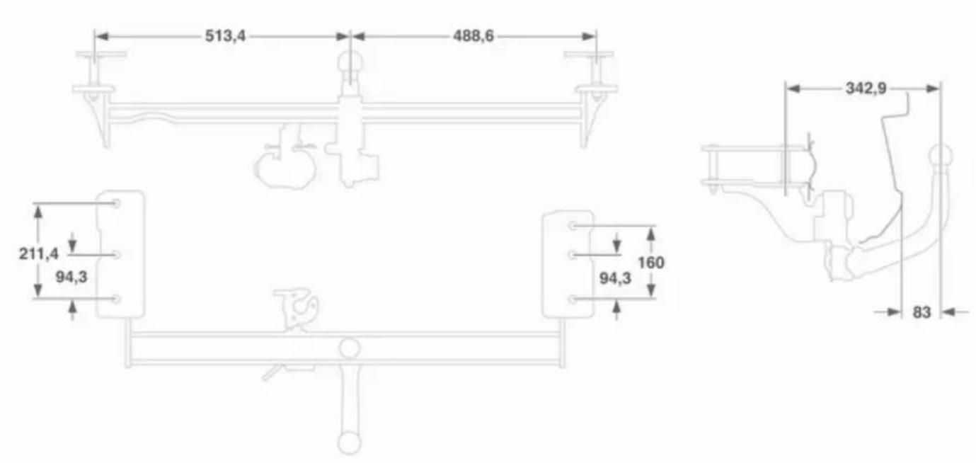
Station wagon, Van
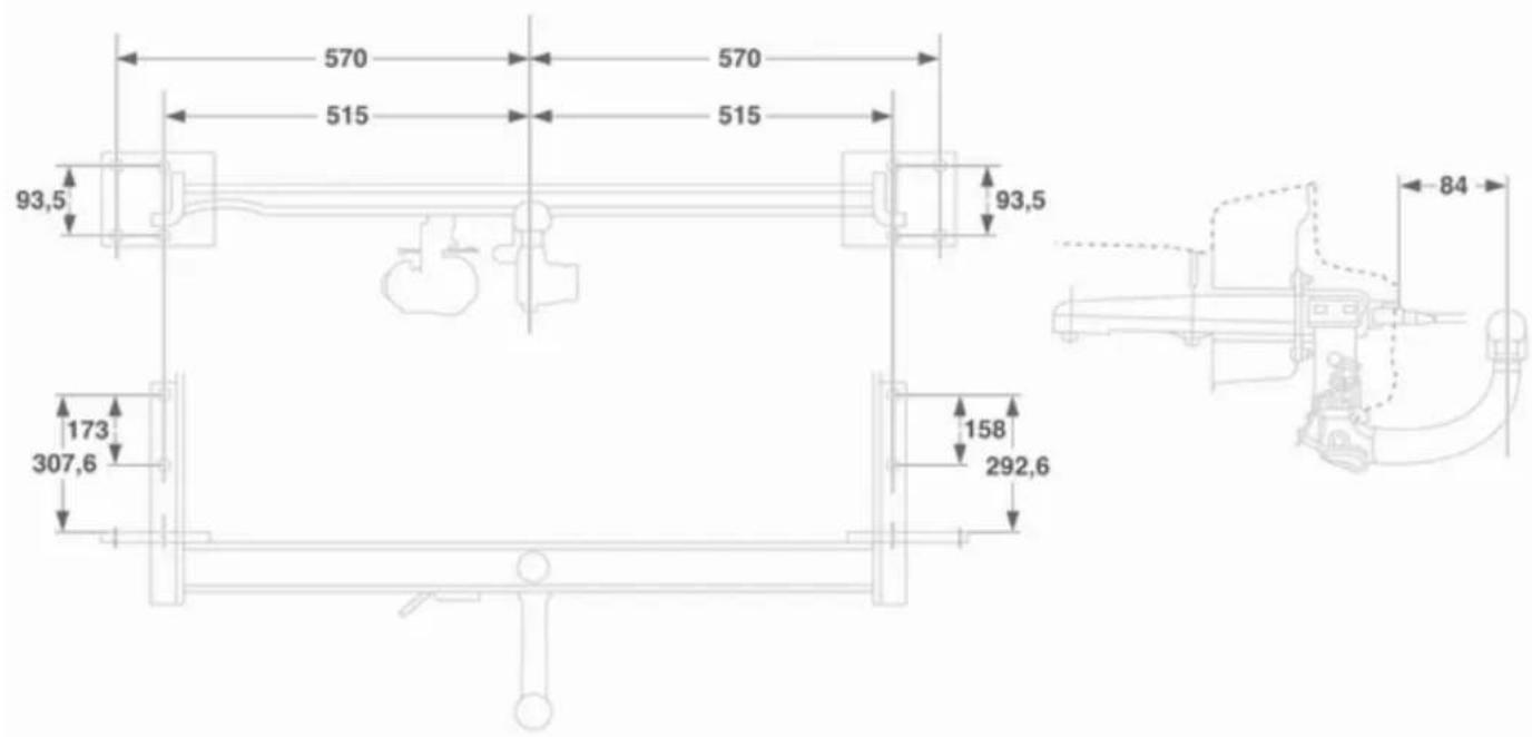
text_image
570 570 515 515 93,5 93,5 173 307,6 158 292,6 84TwinTop
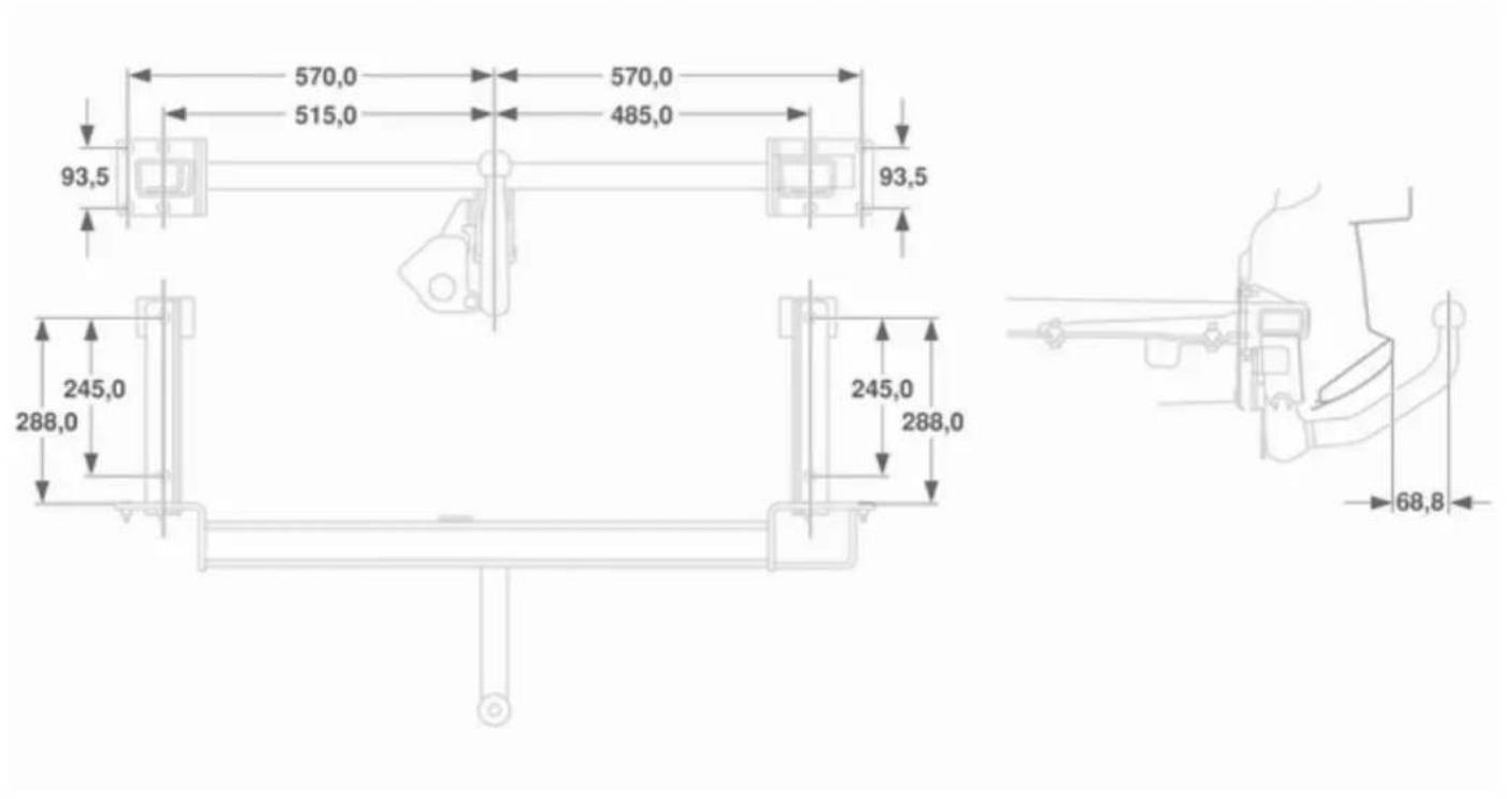
text_image
570,0 570,0 515,0 485,0 93,5 93,5 245,0 245,0 288,0 288,0 68,8Customer information
Vehicle data recording and privacy 263
Vehicle data recording and privacy
Event data recorders
The vehicle has a number of sophisticated systems that monitor and control several vehicle data. Some data may be stored during regular operation to facilitate repair of detected malfunctions, other data is stored only in a crash or near crash event by systems commonly called event data recorders (EDR).
The systems may record data about the condition of the vehicle and how it was operated (e.g. engine speed, brake application, seat belt usage). To read this data special equipment and access to the vehicle is required. This will take place when the vehicle is serviced in a workshop. Some data is electronically fed into global diagnostic systems. The manufacturer will not access information about a crash event or share it with others except
■ with the consent of the vehicle owner or, if the vehicle is leased, with the consent of the lessee,
■ in response to an official request of police or similar government office,
■ as part of the manufacturer's defense in case of legal proceedings,
■ as required by law.
In addition, the manufacturer may use the collected or received data
■ for the manufacturer's research needs,
■ to make it available for research needs where appropriate confidentiality is maintained and need is shown,
■ to share summary data which is not tied to a specific vehicle with other organisations for research purposes.
Radio Frequency Identification (RFID)
RFID technology is used in some vehicles for functions such as tyre pressure monitoring and ignition system security. It is also used in connection with conveniences such as radio remote controls for door locking/unlocking and starting, and in-vehicle transmitters for garage door openers. RFID technology in Opel vehicles does not use or record personal information or link with any other Opel system containing personal information.
Customer information 265
Index
A
Accessories and vehicle modifications 162
Active head restraints.... 48
Adaptive forward lighting ... 101, 119
Adjustable air vents 133
Airbag, belt tensioners and anti-roll bars.... 96
Airbag system 57
Air conditioning regular operation 134
Air conditioning system 128
Air intake 134
Antilock brake system 149
Antilock brake system (ABS) ..... 98
Anti-theft alarm system ..... 30, 111
Anti-theft locking system 30
Apply footbrake 101
Armrest 52, 53
Armrest storage 68
Ashtrays 91
Automatic anti-dazzle 34
Automatic climate control system 129
Automatic level control 152
Automatic light control 117
Automatic transmission 139
Auxiliary devices 125
Auxiliary heater.... 133
B
Battery 167
Battery discharge protection ..... 123
Battery voltage 110
Brake and clutch system 98
Brake assist 150
Brake fluid 166
Brake light switch 110
Brakes 149, 166
Bulb replacement 168
C
Capacities 243
Cargo management system ..... 75
Car Pass 20
Catalytic converter 139
Central locking system 25
Centre console lighting 122
Changing tyre and wheel size ... 194
Charging system 97
Child locks 28
Child restraint installation locations 62
Child restraints with transponders .... 65
Child restraint systems 60
Cigarette lighter 91
Climate control 15
Clock 89
Continuous damping control ..... 152
Control indicators.... 94
Control of the vehicle 135
Convex shape 32
Coolant and antifreeze.... 210
Cruise control 102, 152
Cupholders 67
Curtain airbag system 59
D
Danger, Warnings and Cautions ...3
Daytime running lights 119
Deflation detection system and tyre pressure monitoring system.... 99
Diesel fuel system bleeding ..... 167
Diesel particle filter 138
Door open 102
Drain diesel fuel filter 110
Driving characteristics and towing tips 157
E
Easytronic.... 145
Electric adjustment 33
Electronic climate control system 130
Electronic driving programmes. 142, 146
Electronic Stability Program 99, 150
End-of-life vehicle recovery ..... 163
Engine compartment fuse box ... 184
Engine coolant 165
Engine coolant temperature ..... 99
Engine cooling level 110
Engine data 218
Engine exhaust 138
Engine oil 164, 210, 215
Engine oil pressure 100
Entry lighting 122
Event data recorders.... 263
Exit lighting 123
Exterior care 205
Exterior light 101
Exterior lighting 13
F
Fault 143, 147
First aid kit 81
Fixed air vents 133
Fog light 102
Fog lights 173
Folding 33
Folding tray 80
Front airbag system 57
Front fog lights 120
Front turn signal lights 173
Fuel consumption - CO _2 - Emissions 156, 227
Fuel for diesel engines 154
Fuel for petrol engines 154
Fuel gauge 94
Fuses 183
G
General information 157
Glovebox 67
Graphic-Info-Display, Colour-Info-Display 105
H
Halogen headlights 169
Hand brake.... 150
Hazard warning flashers 119
Headlight flash 118
Headlight range adjustment ..... 118
Headlights when driving abroad 118
Head restraint adjustment 8
Head restraints 47
Heated 34
Heated rear window 37
Heating 53
Heating and ventilation system . 127
High beam 101, 118
Hill start assist 150
Horn 14,87
|
Identification plate 214
Ignition switch positions ..... 136
Immobiliser 32
Instrument cluster 93
Instrument panel illumination ..... 183
Instrument panel illumination control 121
Instrument panel overview ..... 11
Interactive driving system...... 151
Interactive driving system, continuous damping control, sport mode.... 100
Interior care 207
Interior lights 121, 182
Interruption of power supply .... 143, 148
Introduction 3
Isofix child restraint systems ..... 65
J
Jump starting 202
K
Keys 20
L
Lashing eyes .... 75
Lighting .... 111
Light switch .... 117
Load compartment 28,68
Load compartment cover 73
Load compartment fuse box ..... 187
Load compartment grille.... 80
Loading assist 77
Loading information 84
Load rails and hooks 75
Low engine oil level 100
Low fuel 100
M Malfunction indicator light ..... 97 Manual adjustment ..... 32 Manual anti-dazzle ..... 34 Manual mode ..... 141, 146 Manual transmission ..... 144 Manual transmission automated 145 Memorised settings..... 22 Mirror adjustment ..... 9 Misted light covers ..... 121 Mobile phones and CB radio equipment ..... 125
N New vehicle running-in .... 135 Number plate light .... 181
O Odometer 93 Oil, engine 210, 215
Open&Start system ...... 22, 101
Operation 124
Outside temperature 89
Overrun cut-off 137
P
Parking 18, 137
Parking assist 153
Parking brake 150
Parking lights 120
Particle filter.... 138
Performance 221
Performing work 163
Pollen filter 134
Power outlets 90
Power windows 35
Preheating and diesel particle filter 99
Q
Quickheat.... 133
R
Radio Frequency Identification (RFID).... 264
Radio reception 124
Radio remote control 20
Reading lights 122
Rear fog light 102
Rear fog lights 120
Rear seat audio system 125
Rear window wiper/washer 88
Recommended fluids and lubricants 210, 215
Refuelling 155
Retractable hardtop 40
Reversing lights 121
Roof rack 83
Run-flat tyres 191
S
Safety net 78
Seat adjustment 7,50
Seat belt 8
Seat belt reminder 96
Seat belts 54
Seat folding 52
Seat occupancy recognition .. 59, 96
Seat position 49
Selector lever 140, 145
Service 134,209
Service display 94
Service information 209
Service vehicle soon 97
Side airbag system 58
Sidelights.... 117
Side turn signal lights 181
Spare wheel 200
Speedometer 93
Sport mode 98, 151
Starting off 17
Starting the engine 136, 145
Steering wheel adjustment ..... 9, 86
Steering wheel controls 86
Stop watch 116
Sunglasses storage 68
Sunroof 38
Sunvisor lights 122
Sun visors 37
Symbols 4
T
Tachometer 93
Tail lights 174
Three-point seat belt 55
Tools 190
Top-tether child restraint systems 65
Towing.... 157
Towing another vehicle 204
Towing equipment 158
Towing hitch installation dimensions 260
Towing the vehicle 203
Trailer stability assist 161
Trailer towing 157
Transmission 16
Transmission display ..... 139, 145
Tread depth 194
Trip computer in Board-Info-Display 112
Trip computer in Graphic-Info- Display or Colour-Info- Display 113
Turn and lane-change signals ... 120
Turn signal 96
Tyre chains 195
Tyre deflation detection system . 194
Tyre designations 192
Tyre pressure 111, 192
Tyre pressure monitoring system 193
Tyre pressures 116, 244
Tyre repair kit 196
Tyres 190
U
Ultrasonic parking assist 98
Using this manual 3
V
Vehicle dimensions 242
Vehicle Identification Number .... 213
Vehicle messages 109
Vehicle specific data 3
Vehicle storage.... 162
Vehicle unlocking 6
Vehicle weight 236
Ventilation.... 127
W
Warning chimes 109
Warning triangle 80
Washer and wiper systems ..... 14
Washer fluid 166
Washer fluid level 111
Wheel changing 198
Wheel covers 195
Wheels and tyres 190
Windscreen wiper/washer 87
Winter mode 98
Winter tyres 191
Wiper blade replacement ..... 167
X
Xenon headlights 171