CT 200h (2011) - Car LEXUS - Free user manual and instructions
Find the device manual for free CT 200h (2011) LEXUS in PDF.

User questions about CT 200h (2011) LEXUS
0 question about this device. Answer the ones you know or ask your own.
Ask a new question about this device
Download the instructions for your Car in PDF format for free! Find your manual CT 200h (2011) - LEXUS and take your electronic device back in hand. On this page are published all the documents necessary for the use of your device. CT 200h (2011) by LEXUS.
USER MANUAL CT 200h (2011) LEXUS
natural_image
Front view of a white Lexus sedan with a black grille and headlights on, against a clear blue sky (no text or symbols visible)
LEXUS
2011
CT 200h
OWNER'S MANUAL
TABLE OF CONTENTS
| 1 | Before driving | Information on the hybrid system and adjusting and operating features such as door locks, mirrors, and steering column | |
| 2 | When driving | Driving, stopping and safe-driving information | |
| 3 | Interior features | Air conditioning and audio systems, as well as other interior features for a comfortable driving experience | |
| 4 | Maintenance and care | Cleaning and protecting your vehicle, performing do-it-your-self maintenance, and maintenance information | |
| 5 | When trouble arises | What to do if the vehicle needs to be towed, gets a flat tire, or is involved in an accident | |
| 6 | Vehicle specifications | Detailed vehicle information | |
| 7 | For owners | Reporting safety defects for U.S. owners, and seat belt and SRS airbag instructions for Canadian owners | |
| Index | Alphabetical listing of information contained in this manual |
For vehicles with a navigation system, refer to the "Navigation System Owner's Manual" for information regarding the equipment listed below.
- Navigation system
- Air conditioning
• Windshield wiper de-icer - Rear view monitor system
• Audio/video system
- Rear window and outside rear view mirror defogging
• Climate control
1 Before driving
1-1. Hybrid system
Hybrid system features..... 24
Hybrid system precautions...... 29
Energy monitor/
consumption screen 35
Hybrid vehicle driving tips...... 41
1-2. Key information
Keys 43
1-3. Opening, closing and locking the doors
Smart access system with push-button start.... 49
Wireless remote control...... 61
Side doors 66
Back door....70
1-4. Adjustable components
(seats, mirrors, steering wheel)
Front seats....75
Rear seats....78
Driving position memory 80
Head restraints....83
Seat belts 86
Steering wheel....94
Inside rear view mirror.... 95
Outside rear view mirrors...... 97
1-5. Opening and closing
the windows and moon roof
Power windows....100
Moon roof....103
1-6. Refueling
Opening the fuel tank cap...... 107
1-7. Theft deterrent system
Immobilizer system 111
Alarm....113
Theft prevention labels (for U.S.A.)....116
1-8. Safety information
Correct driving posture...... 117
SRS airbags 119
Front passenger occupant classification system....133
Child restraint systems .... 139
Installing child restraints...... 144
2 When driving
2-1. Driving procedures
Driving the vehicle....156
Power (ignition) switch...... 169
EV drive mode 174
Hybrid transmission....177
Turn signal lever 185
Parking brake....186
Horn....187
2-2. Instrument cluster
Gauges and meters 188
Indicators and warning lights....194
Multi-information display...... 198
2-3. Operating the lights and windshield wipers
Headlight switch.... 202
Fog light switch 207
Windshield wipers and washer 208
Rear window wiper and washer 214
Headlight cleaner switch...... 215
2-4. Using other driving systems
Cruise control.... 216
Dynamic radar cruise control....220
Intuitive parking assist .... 233
Rear view monitor system..... 239
Driving assist systems...... 250
Hill-start assist control...... 254
Pre-Collision System...... 256
2-5. Driving information
Cargo and luggage.... 264
Vehicle load limits.... 269
Winter driving tips 270
Trailer towing.... 274
Dinghy towing 275
3 Interior features
3-1. Using the air conditioning system and defogger
Automatic air conditioning system.... 278
Rear window defogger switch 289
Windshield wiper de-icer..... 290
3-2. Using the audio system
Audio system types.... 291
Using the radio.... 295
Using the CD player.... 307
Playing MP3 and WMA discs 318
Operating an iPod...... 329
Operating a USB memory...... 341
Optimal use of the audio system.... 352
Using the AUX port 355
Using the steering wheel audio switches.... 356
3-3. Using the Bluetooth ^® audio system
Bluetooth ^® audio system ..... 360
Using the Bluetooth ^® audio system.... 363
Operating a Bluetooth ^® enabled portable player.... 370
Setting up a Bluetooth ^® enabled portable player.... 375
Bluetooth ^® audio system setup.... 384
3-4. Using the hands-free phone system (for cellular phones)
Hands-free system for cellular phones.... 385
Using the hands-free system (for cellular phones).... 389
Making a phone call.... 398
Setting a cellular phone...... 403
Security and system setup...... 410
Using the phone book...... 415
3-5. Using the interior lights
Interior lights list...... 425
- Personal/interior light main switch 426
- Front personal/interior lights 426
- Rear interior light 427
3-6. Using the storage features
List of storage features ...... 428
• Glove box 429
- Console box.... 430
• Cup holders...... 431
- Bottle holders 432
• Auxiliary boxes 433
3-7. Other interior features
Sun visors.... 435
Vanity mirrors...... 436
Clock 437
Power outlet 438
Heated steering wheel 440
Seat heaters.... 442
Floor mat...... 444
Luggage compartment features...... 446
4 Maintenance and care
4-1. Maintenance and care
Cleaning and protecting the vehicle exterior 474
Cleaning and protecting the vehicle interior.... 479
4-2. Maintenance
Maintenance requirements .... 482
General maintenance...... 484
Emission inspection and maintenance (I/M) programs 488
4-3. Do-it-yourself maintenance
Do-it-yourself service precautions.... 489
Hood 494
Positioning a floor jack...... 496
Engine compartment...... 498
12-volt battery....511
Tires 518
Tire inflation pressure.... 530
Wheels....534
Air conditioning filter.... 537
Electronic key battery...... 539
Checking and replacing fuses....542
Light bulbs.... 554
5 When trouble arises
5-1. Essential information
Emergency flashers...... 570
If your vehicle needs to be towed.... 571
If you think something is wrong.... 577
Event data recorder.... 578
5-2. Steps to take in an emergency
If a warning light turns on or a warning buzzer sounds ..... 580
If a warning message is displayed.... 593
If you have a flat tire.... 615
If the hybrid system will not start....629
If you lose your keys...... 631
If the electronic key does not operate properly.... 632
If the 12-volt battery is discharged ....635
If your vehicle overheats...... 640
If the vehicle becomes stuck....645
If your vehicle has to be stopped in an emergency..... 647
6 Vehicle specifications
6-1. Specifications
Maintenance data (fuel, oil level, etc.)...... 650
Fuel information...... 665
Tire information...... 668
6-2. Customization
Customizable features ...... 684
6-3. Initialization
Items to initialize 705
7 For owners
Reporting safety defects for U.S. owners.... 708
Seat belt instructions for Canadian owners (in French)....709
SRS airbag instructions for Canadian owners (in French)....711
Index
Abbreviation list 722
Alphabetical index...... 724
What to do if....736
Pictorial index
Exterior

text_image
Windshield wipers P.208 Hood P.494 Moon roof* P.103 Outside rear view mirrors P.97 Headlight cleaner* P.215 Fog lights* P.207 Turn signal lights P.185 Headlights P.202 Parking lights and daytime running lights P.202, 205 Side marker lights P.202 Turn signal lights P.185
text_image
Rear window defogger P.289 Turn signal lights P.185 Fuel filler door P.107 Side doors P.66 Tires Rotation P.518 Replacement P.615 Inflation pressure P.661 Information P.668 Rear window wiper* P.214 Back door P.70 License plate lights P.202 Tail lights P.202 Side marker lights P.202*: If equipped
Pictorial index
Interior

text_image
Seat belts P. 86 Head restraints P. 83 A SRS driver airbag P. 119 SRS knee airbags P. 119 SRS front passenger airbag P. 119 B C Rear seats P. 78 SRS side airbags P. 119 Floor mat P. 444 Front seats P. 75 Console box P. 430A

tree
| Item | Value | | :--- | :--- | | Anti-glare inside rear view mirror | 95 | | Compass* | 459 | | Sun visors | 435 | | Moon roof switches* | 103 | | "SOS" button* | 466 | | Garage door opener switches * | 451 | | Interior light | 426 | | SRS curtain shield airbags | 119 | | Vanity mirrors | 436 | | Interior lights | 426 | | Personal lights | 426 |*: If equipped
B

text_image
Inside door lock button P.66 Driving position memory switches* P.80 Window lock switch P.100 Door lock switch P.66 Power window switches P.100C

text_image
P position switch P.180 Shift lever P.177 Security indicator P.111, 113 AUX port*2 P.355 USB port*2 P.329, 341 Power outlet P.438 EV drive mode switch P.174 Cup holders P.431 Seat heater switches* P.442 Driving mode select switch P.179*: If equipped
*2: For vehicles with a navigation system, refer to "Navigation System Owner's Manual".
Pictorial index
Instrument panel

text_image
Gauges and meters P.188 Multi-information display P.198 Headlight switch P.202 Turn signal lever P.185 Fog light switch* P.207 Instrument panel light control dial P.190 Outside rear view mirror switches P.97 Hood lock release lever P.494 Windshield wipers and washer switch P.208 Rear window wiper and washer switch* P.214 Power (ignition) switch P.169 Clock*2 P.437 Emergency flasher switch P.570 Navigation system*1 Audio system*2 P.291 Air conditioning system*2 P.278 Glove box P.429 Rear window and outside rear view mirror defoggers P.289 Tilt and telescopic steering control lever P.94 Pre-collision braking off switch* P.257 Parking brake pedal P.186A

text_image
Audio remote control switches*2 P.356 Talk switch*2 P.390 "DISP" button P.199 Telephone switches*2 P.390 Horn P.187 Vehicle-to-vehicle distance button* P.220 Cruise control switch* P.216 Dynamic radar cruise control switch* P.220*: If equipped
^*1 : Refer to "Navigation System Owner's Manual".
*2: For vehicles with a navigation system, refer to "Navigation System Owner's Manual".
Pictorial index
Instrument panel
B

text_image
Headlight cleaner switch* P.215 Windshield wiper de-icer switch* P.290 Intuitive parking assist switch* P.233 Heated steering wheel switch* P.440 Fuel filler door opener P.107C

text_image
Remote touch* *1 Auxiliary box P.433 TILT switch* *1 OPEN CLOSE switch* *1*: If equipped
*1: Refer to "Navigation System Owner's Manual".
For your information
Main Owner's Manual
Please note that this manual applies to all models and explains all equipment, including options. Therefore, you may find some explanations for equipment not installed on your vehicle.
All specifications provided in this manual are current at the time of printing. However, because of the Lexus policy of continual product improvement, we reserve the right to make changes at any time without notice.
Depending on specifications, the vehicle shown in the illustrations may differ from your vehicle in terms of color and equipment.
The manuals for this vehicle can be stored in the auxiliary box beneath the luggage compartment. ( P. 450)
Noise from under vehicle after turning off the hybrid system
Approximately five hours after the hybrid system is turned off, you may hear sound coming from under the vehicle for several minutes. This is the sound of a fuel evaporation leakage check and, it does not indicate a malfunction.
Accessories, spare parts and modification of your Lexus
A wide variety of non-genuine spare parts and accessories for Lexus vehicles are currently available in the market. You should know that Toyota does not warrant these products and is not responsible for their performance, repair, or replacement, or for any damage they may cause to, or adverse effect they may have on, your Lexus vehicle.
This vehicle should not be modified with non-genuine Lexus products. Modification with non-genuine Lexus products could affect its performance, safety or durability, and may even violate governmental regulations. In addition, damage or performance problems resulting from the modification may not be covered under warranty.
Installation of a mobile two-way radio system
As the installation of a mobile two-way radio system in your vehicle could affect electronic systems such as the multiport fuel injection system/sequential multiport fuel injection system, cruise control system, anti-lock brake system, SRS airbag system and seat belt pretensioner system, be sure to check with your Lexus dealer for precautionary measures or special instructions regarding installation.
High voltage parts and cables on the hybrid vehicles emit approximately the same amount of electromagnetic waves as the conventional gasoline powered vehicles or home electronic appliances despite of their electromagnetic shielding.
Unwanted noise may occur in the reception of the mobile two-way radio.
Scrapping of your Lexus
The SRS airbag and seat belt pretensioner devices in your Lexus contain explosive chemicals. If the vehicle is scrapped with the airbags and seat belt pretensioners left as they are, this may cause an accident such as fire. Be sure to have the systems of the SRS airbag and seat belt pretensioner removed and disposed of by a qualified service shop or by your Lexus dealer before you scrap your vehicle.
Perchlorate Material
Special handling may apply, See www.dtsc.ca.gov/hazardouswaste/perchlorate.
Your vehicle has components that may contain perchlorate. These components may include airbag, seat belt pretensioners, and wireless remote control batteries.

CAUTION
■General precautions while driving
Driving under the influence: Never drive your vehicle when under the influence of alcohol or drugs that have impaired your ability to operate your vehicle. Alcohol and certain drugs delay reaction time, impair judgment and reduce coordination, which could lead to an accident that could result in death or serious injury.
Defensive driving: Always drive defensively. Anticipate mistakes that other drivers or pedestrians might make and be ready to avoid accidents.
Driver distraction: Always give your full attention to driving. Anything that distracts the driver, such as adjusting controls, talking on a cellular phone or reading can result in a collision with resulting death or serious injury to you, your occupants or others.
General precaution regarding children's safety
Never leave children unattended in the vehicle, and never allow children to have or use the key.
Children may be able to start the vehicle or shift the vehicle into neutral. There is also a danger that children may injure themselves by playing with the windows or other features of the vehicle. In addition, heat build-up or extremely cold temperatures inside the vehicle can be fatal to children.
■Disposal of the hybrid battery (traction battery)
If your vehicle is disposed of without the hybrid battery having been removed, there is a danger of serious electric shock if high voltage parts, cables and their connectors are touched. In the event that your vehicle must be disposed of, the hybrid battery must be disposed of by your Lexus dealer or a qualified service shop hybrid battery is not disposed of properly, it may cause electric shock that can result in death or serious injury.
Symbols used throughout this manual
Cautions & Notices

CAUTION
This is a warning against something which, if ignored, may cause death or serious injury to people. You are informed about what you must or must not do in order to reduce the risk of death or serious injury to yourself and others.

NOTICE
This is a warning against something which, if ignored, may cause damage to the vehicle or its equipment. You are informed about what you must or must not do in order to avoid or reduce the risk of damage to your Lexus and its equipment.
Symbols used in illustrations

Safety symbol
The symbol of a circle with a slash through it means "Do not", "Do not do this", or "Do not let this happen".

natural_image
Close-up of a car dashboard with a left-side control panel and a red arrow indicating a directional change (no text or symbols present)Arrows indicating operations

Indicates the action (pushing, turning, etc.) used to operate switches and other devices.

Indicates the outcome of an operation (e.g. a lid opens).
1-1. Hybrid system
Hybrid system features...... 24
Hybrid system precautions.... 29
Energy monitor/
consumption screen...... 35
Hybrid vehicle driving tips ..... 41
1-2. Key information
Keys 43
Before driving
1
1-3. Opening, closing and locking the doors
Smart access system with push-button start.... 49
Wireless remote control...... 61
Side doors....66
Back door 70
1-4. Adjustable components (seats, mirrors, steering wheel)
Front seats....75
Rear seats....78
Driving position memory...... 80
Head restraints.... 83
Seat belts 86
Steering wheel....94
Inside rear view mirror ..... 95
Outside rear view mirrors..... 97
1-5. Opening and closing the windows and moon roof
Power windows....100
Moon roof 103
1-6. Refueling
Opening the fuel tank cap ... 107
1-7. Theft deterrent system
Immobilizer system 111
Alarm.... 113
Theft prevention labels (for U.S.A.) 116
1-8. Safety information
Correct driving posture ..... 117
SRS airbags 119
Front passenger occupant classification system......133
Child restraint systems ..... 139
Installing child restraints..... 144
1-1. Hybrid system
Hybrid system features
Your vehicle is a hybrid vehicle. It has characteristics different from conventional vehicles. Be sure you are closely familiar with the characteristics of your vehicle, and operate with care.
The hybrid system combines the use of a gasoline engine and an electric motor (traction motor) according to driving conditions, improving fuel efficiency and reducing exhaust emissions.

text_image
Technical diagram of a sedan with labeled components, showing engine and battery assembly parts1 Gasoline engine
2 Electric motor (traction motor)
■When stopped/during start off
The gasoline engine stops* when the vehicle is stopped. During start off, the electric motor (traction motor) drives the vehicle. At slow speeds or when traveling down a gentle slope, the engine is stopped* and the motor is used.
When shift position is in N, the hybrid battery (traction battery) will not be charged. Thus, shift to P when the vehicle is stopped. In addition, when driving in heavy traffic, use D or B.
*: However, when the hybrid battery (traction battery) need to be charged or while the engine is being warmed up, the gasoline engine may not stop automatically.
During normal driving
The gasoline engine is predominantly used. The electric motor (traction motor) charges the hybrid battery as necessary.
When accelerating sharply
The power of the hybrid battery (traction battery) is added to that of the gasoline engine via the electric motor (traction motor).
■When braking (regenerative braking)
The electric motor (traction motor) charges the hybrid battery (traction battery).
■Regenerative braking
In the following situations, kinetic energy is converted to electric energy and deceleration force can be obtained in conjunction with the recharging of the hybrid battery (traction battery).
● The accelerator pedal is released while driving with the shift position in D or B.
● The brake pedal is depressed while driving with the shift position in D or B.
EV indicator

text_image
Close-up of a car dashboard with green EV logo and speedometer, showing fuel efficiency and distance measurementThe EV indicator comes on when driving the vehicle using only the electric motor (traction motor).
■ Conditions in which the gasoline engine may not stop
The gasoline engine starts and stops automatically. However, it may not stop automatically in the following conditions:
● During gasoline engine warm-up
●During hybrid battery (traction battery) charging
●When the temperature of the hybrid battery (traction battery) is high or low
●When the heater is switched on
- Charging the battery
As the gasoline engine charges the hybrid battery (traction battery), the battery does not need to be charged from an outside source. However, if the vehicle is left parked for a long time the hybrid battery will slowly discharge. For this reason, sure to drive the vehicle at least once every few months for at least 30 minutes or 10 miles (16 km). If the hybrid battery becomes fully discharged and you are unable to jump-start the vehicle with the 12-volt battery, contact your Lexus dealer.
■ After the 12-volt battery has discharged or has been changed or removed
The gasoline engine may not stop even if the vehicle is running on the hybrid battery (traction battery). If this continues for a few days, contact your Lexus dealer.
■ Sounds and vibrations specific to a hybrid vehicle
There may be no engine sounds or vibration even though the vehicle is able to move. For safety, apply the parking brake and make sure to shift the shift position to P when parked.
The following sounds or vibrations may occur when the hybrid system is operating and are not a malfunction:
●Motor sounds may be heard from the engine compartment.
● Sounds may be heard from the hybrid battery (traction battery) behind the rear seats when the hybrid system starts or stops.
● Sounds may be heard from the transmission when the gasoline engine starts or stops, when driving at low speeds, or during idling.
●Engine sounds may be heard when accelerating sharply.
1-1. Hybrid system
● Sounds may be heard due to regenerative braking when the brake pedal is depressed and accelerator is loosened.
●Other sounds, such as motors and mechanical noises, may be heard from the brake system when the brake pedal is depressed.
●Vibration may be felt when the gasoline engine starts or stops.
●Cooling fan sounds may be heard from the air intake vent on the side of rear right seatback.
■Maintenance, repair, recycling, and disposal
Contact your Lexus dealer regarding maintenance, repair, recycling and disposal. Do not dispose of the vehicle yourself.
Customization
Settings (e.g. on/off operation of the EV drive mode indicator) can be changed. (Customizable features → P.684)
1-1. Hybrid system
Hybrid system precautions
Take care when handling the hybrid system, as it contains a high voltage system (about 650V at maximum) as well as parts that become extremely hot when the hybrid system is operating. Obey the caution labels attached to the vehicle.

text_image
1 2 3 4 5 6 7 WARNING 警告 AVERTISSEMENT HIGH VOLTAGE INSIDE 内部高電圧 内部高電圧 HAUTE TENSION A L'INTERIEUR1 Air conditioning compressor
2 Power control unit
3 Hybrid battery (traction battery)
4 Service plug
5 High voltage cables (orange)
6 Electric motor (traction motor)
7 Caution label
Hybrid battery air vent

natural_image
Interior view of a vehicle showing a curved panel and a dark rectangular patch, with no visible text or symbols.There is an air intake vent on the side of the rear right seatback for the purpose of cooling the hybrid battery (traction battery). If the vent become blocked, the hybrid battery may overheat, leading to a reduction in hybrid battery output.
Emergency shut off system
When a certain level of impact is detected by the impact sensor, the emergency shut off system blocks off the high voltage current and stops the fuel pump to minimize the risk of electrocution and fuel leakage. If the emergency shut off system activates, your vehicle will not restart. To restart the hybrid system, contact your Lexus dealer.
Hybrid warning message
A message is automatically displayed when a malfunction occurs in the hybrid system or an improper operation is attempted.

text_image
CHECK HYBRID SYSTEMIf a warning message is shown on the multi-information display, read the message and follow the instructions. ( P. 593)
If a warning light comes on, a warning message is displayed, or the 12-volt battery is disconnected
The hybrid system may not start. In that case, try to start the system again. If the "READY" indicator does not come on, contact your Lexus dealer.
Running out of fuel
When the vehicle has run out of fuel and the hybrid system cannot be started, refuel the vehicle with at least enough gasoline to make the low fuel level warning light ( P. 584) go off. If there is only a small amount of fuel, the hybrid system may not be able to start. (The minimum amount of fuel to add to make the low fuel level warning light go out is about 3.1 gal. [11.8 L, 2.6 Imp.gal.], when the vehicle is on a level surface. This value may vary when the vehicle is on a slope.)
1-1. Hybrid system
Electromagnetic waves
● High voltage parts and cables on the hybrid vehicles incorporate electromagnetic shielding, and therefore emit approximately the same amount of electromagnetic waves as conventional gasoline powered vehicles or home electronic appliances.
- Your vehicle may cause sound interference in some third party-produced radio parts.
■Hybrid battery (traction battery)
The hybrid battery (traction battery) has a limited service life. The lifespan of the hybrid battery (traction battery) can change in accordance with driving style and driving conditions.

CAUTION
■High voltage precautions
The vehicle has high voltage DC and AC systems as well as a 12-volt system. DC and AC high voltage is very dangerous and can cause severe burns and electric shock that may result in death or serious injury.
●Never touch, disassemble, remove or replace the high voltage parts, cables on their connectors.
● The hybrid system will become hot after starting as the system uses high voltage. Be careful of both the high voltage and the high temperature, and always obey the caution labels attached to the vehicle.

natural_image
Interior view of a car showing the trunk and rear compartment with an inset close-up of internal components (no visible text or symbols)● Never try to open the service plug access hole located in the luggage compartment. The service plug is used only when the vehicle is serviced and is subject to high voltage.

CAUTION
Road accident cautions
If your vehicle is involved in an accident, observe the following precautions to reduce the risk of death or serious injury:
- Stop the vehicle in a safe place, apply the parking brake while depressing the brake pedal, shift the shift position to P and turn the hybrid system off. Then, slowly release the brake pedal.
- Do not touch the high voltage parts, cables and connectors.
- If electric wires are exposed inside or outside your vehicle, an electric shock may occur. Never touch exposed electric wires.
- If a fluid leak occurs, do not touch the fluid as it may be strong alkaline electrolyte from the hybrid battery (traction battery). If it comes into contact with your skin or eyes, wash it off immediately with a large amount of water or, if possible, boric acid solution. Seek immediate medical attention.
- If a fire occurs in the hybrid vehicle, leave the vehicle as soon as possible. Never use a fire extinguisher that is not meant for electric fires. Using even a small amount of water may be dangerous.
- If your vehicle needs to be towed, do so with front wheels raised. I connected to the electric motor (traction motor) are on the ground when towing, the motor may continue to generate electricity. This may cause an electricity leakage leading to a fire. ( P. 571)
- Carefully inspect the ground under the vehicle. If you find that liquid has leaked onto the ground, the fuel system may have been damaged. Leave the vehicle as soon as possible.
■Hybrid battery (traction battery)
Your vehicle contains a sealed nickel-metal hydride battery. If disposed of improperly, it is hazardous to the environment and there is a risk of severe burns and electrical shock that may result in death or serious injury.

NOTICE
Hybrid battery air vent
- Do not put foreign objects near the air vent. The hybrid battery (traction battery) may overheat and be damaged.
- Clean the air vent regularly to prevent the hybrid battery (traction battery) from overheating.
- Do not wet or allow foreign substances to enter the air vent as this may cause a short circuit and damage the hybrid battery (traction battery).
- Do not carry large amounts of water such as water cooler bottles in the vehicle. If water spills onto the hybrid battery (traction battery), the battery may be damaged. Have the vehicle inspected by your Lexus dealer.
1-1. Hybrid system
Energy monitor/consumption screen
You can view the status of your hybrid system on the multi-information display and the navigation system screen.

text_image
Car dashboard interior with numbered arrows indicating directional changes or system flow, labeled 1 and 2.1 Navigation system screen (if equipped)
2 Multi-information display

text_image
1 2 3 ENTER JY1H018Remote Touch*
1 "MENU" button
2 Remote Touch knob
3 "ENTER" button
*: For use of the Remote Touch, refer to "Navigation System Owner's Manual".
Energy monitor
Navigation system (if equipped)

text_image
STEP MELK MELK MELK ILY114035Press the "MENU" button on the Remote Touch.

text_image
STEP2 Start Destination Info. Setup Climate AudioSelect

the
screen
and press the "ENTER" button on the Remote Touch.

text_image
STEP3 Information Phone Fuel Consumption Map Data Calendar LEXUS Insider XM Sports XM Stocks XM NavWeatherSelect

press the
"ENTER" button.
If the
Consumption
Past Record
screen is displayed, select
Energy
and press the "ENTER" button.
Multi-information display

natural_image
Interior view of a car dashboard with steering wheel and dashboard, showing close-up of left-side dial (no text or symbols visible)Push the "DISP" button on the steering wheel several times to select the energy monitor display.
| Navigation screen | Multi-information display | |||||
| When the vehicle is powered by the electric motor (traction motor) |  |  | ||||
| When the vehicle is powered by both the gasoline engine and the electric motor (traction motor) |  |  | ||||
| When the vehicle is powered by the gasoline engine |  |  | ||||
| When the vehicle is charging the hybrid battery (traction battery) |  |  | ||||
 |  | |||||
| When there is no energy flow |  |  | ||||
| Hybrid battery (traction battery) status | Low Full Low Full | |||||
 |  |  |  |  |  | |
These images are examples only, and may vary slightly from actual conditions.
Consumption (vehicles with a navigation system)
STEP □ Press the "MENU" button and select


STEP2 Select and press the "ENTER" button.
consumption
If the Conception does not appear, select and press the "ENTER" button.
Consumption

bar
| Time (min) | Regenerated (MPG) | Total (MPG) | |---|---|---| | 30 | 10 | 20 | | 25 | 20 | 30 | | 20 | 25 | 35 | | 15 | 20 | 30 | | 10 | 15 | 25 | | 5 | 40 | 45 | | 0 | 10 | 20 | Consumption Clear: 330 miles Past Record Energy: SLY11AA0711 Fuel consumption in the past 30 minutes
2 Regenerated energy in the past 30 minutes
One symbol indicates 50 Wh. Up to 4 symbols are shown.
3 Cruising range ( P.40)
Past record (vehicles with a navigation system)
STEP □ Press the "MENU" button and select

STEP2 Select and press the "ENTER" button. consumption
If the Paste Reclores not appear, select and press the "ENTER" button.
Past Record

bar
Past Record | Date | NPG | |---|---| | 09/28/08 (Download/yy) | 15 | | 01/29/08 | 20 | | 06/30/08 | 25 | | 10/01/08 | 20 | | 10/02/08 | 15 | | 10/03/08 | 20 | | Today | 0 | Consumption Energy Best 28.0 MPG SLY11AA0701 Best past fuel consumption
② Average fuel consumption
Displays the average fuel consumption between each reset of the total average fuel consumption on the multi-information display.
When resetting, if the total average fuel consumption is better than the best past fuel consumption, the best past fuel consumption will be updated.
These images are examples only, and may vary slightly from actual conditions.
■ Resetting the consumption data
Selecting on the screen consumption the average fuel consump-
tion. Selecting the screen Past Record the past records.
Selecting will confirm resetting of all the data (except cruising range).
Cruising range
Displays the estimated maximum distance that can be driven with the quantity of fuel remaining.
This distance is computed based on your average fuel consumption.
As a result, the actual distance that can be driven may differ from that displayed.
For economical and ecological driving, pay attention to the following points:
Using Eco drive mode
When using Eco drive mode, the torque corresponding to the accelerator pedal depression amount can be generated more smoothly than it is in normal conditions. In addition, the operation of the air conditioning system (heating/cooling) will be minimized, improving the fuel economy. (→P. 179)
■ Use of Hybrid System Indicator
The Eco-friendly driving is possible by keeping the indicate of Hybrid System Indicator within Eco area. ( P.191)
When braking the vehicle
Make sure to operate the brakes gently and in good time. A greater amount of electrical energy can be retained when slowing down.
Delays
Repeated acceleration and deceleration, as well as long waits at traffic lights, will lead to bad fuel consumption. Check traffic reports before leaving and avoid delays as much as possible. When encountering a delay, gently release the brake pedal to allow the vehicle to move forward slightly while avoiding overuse of the accelerator pedal. Doing so can help control excessive gasoline consumption.
Highway driving
Control your speed and keep at a constant speed. Also, before stopping at a toll booth or similar, allow plenty of time to release the accelerator and gently apply the brakes. A greater amount of electrical energy can be retained when slowing down.
Air conditioning
Use the air conditioning only when necessary. Doing so can help control excessive gasoline consumption.
In summer: In high temperatures, use the recirculated air mode. Doing so will help to reduce the burden on the air conditioner and reduce fuel consumption as well.
In winter: Because the gasoline engine will not automatically cut out until the gasoline engine and the interior of the vehicle are warm, it will consume fuel. Also, fuel consumption can be improved by avoiding overuse of the heater.
- Checking tire inflation pressure
Make sure to check the tire inflation pressure frequently. Improper tire inflation pressure can cause poor fuel consumption.
Also, as snow tires can cause large amounts of friction, their use on dry roads can lead to poor fuel consumption. Use a tire that is appropriate for the season.
Luggage
Carrying heavy luggage can lead to poor fuel consumption. Avoid carrying unnecessary luggage. Installing a large roof rack can also cause poor fuel consumption.
■ Warming up before driving
Since the gasoline engine starts up and cuts out automatically when cold, warming up the engine is unnecessary. Moreover, frequently driving short distances will cause the engine to repeatedly warm up, which can lead to poor fuel consumption.
1-2. Key information
Keys
The following keys are provided with the vehicle.

text_image
1 2 3 4 2 SLY12A0011 Electronic keys
- Operating the smart access system with push-button start (→P. 49)
- Operating the wireless remote control function (→P. 61)
2 Mechanical keys
3 Key number plate
4 Card key (electronic key) (if equipped)
Operating the smart access system with push-button start ( P.49)
Using the mechanical key

natural_image
Two-step diagram showing a car key being inserted into a lock, with red arrows indicating the process (no text or symbols present)To take out the mechanical key:
Electronic keys: Slide the release lever and take the key out.
Card key: Press the lock release button and take the key out.
The mechanical key can only be inserted in one direction, as the key only has grooves on one side. If the key cannot be inserted in a lock cylinder, turn it over and re-attempt to insert it.
After using the mechanical key, store it in the electronic key. Carry the mechanical key together with the electronic key. If the electronic key battery is depleted or the entry function does not operate properly, you will need the mechanical key.
(→P. 632)
Card key
● The mechanical key that is stored inside the card key should be used only if a problem arises, such as when the card key does not operate properly.
- If it is difficult to take out the mechanical key, push down the lock release button using a pen tip etc. If it is still difficult to pull it out, use a coin etc.

natural_image
Diagram of a black electronic device with red arrows indicating assembly or disassembly, no text or symbols present.● To store the mechanical key in the card key, insert it while pressing the lock release button.

natural_image
Diagram showing a car's internal components being processed into a plastic disc, with red arrows indicating movement (no text or symbols)- If the battery cover is not installed and the battery falls out or if the battery was removed because the key got wet, reinstall the battery with the positive terminal facing the Lexus emblem.
●The card key is not waterproof.
1-2. Key information
- When required to leave the vehicle's key with a parking attendant
Lock the glove box as circumstances demand. (→P. 429)
Remove the mechanical key for your own use and provide the attendant with the electronic key only.
■Key number plate
Keep the plate in a safe place such as your wallet, not in the vehicle. In the event that a mechanical key is lost, a new key can be made at your Lexus dealer using the key number plate. ( P. 631)
■When riding in an aircraft
When bringing an electronic key onto an aircraft, make sure you do not press any buttons on the electronic key while inside the aircraft cabin. If you are carrying an electronic key in your bag etc., ensure that the buttons are not likely to be pressed accidentally. Pressing a button may cause the electronic key to emit radio waves that could interfere with the operation of the aircraft.

NOTICE
■To prevent key damage
Observe the following:
- Do not drop the keys, subject them to strong shocks or bend them.
- Do not expose the keys to high temperatures for long periods of time.
- Do not get the keys wet or wash them in an ultrasonic washer etc.
- Do not attach metallic or magnetic materials to the keys or place the keys close to such materials.
- Do not disassemble the keys.
- Do not attach a sticker or anything else to the surface of the electronic key.
- Do not place the keys near objects that produce magnetic fields, such as TVs, audio systems and glass top ranges, or medical electrical equipment, such as low-frequency therapy equipment.
- Carrying the electronic key on your person
Carry the electronic key 3.9 in. (10 cm) or more away from electric appliances that are turned on. Radio waves emitted from electric appliances within 3.9 in. (10 cm) of the electronic key may interfere with the key, causing the key to not function properly.
In case of a smart access system with push-button start malfunction or other key-related problems
Take your vehicle with all the electronic keys provided with your vehicle, including the card key, to your Lexus dealer.
■When a vehicle key is lost
If the key remains lost, the risk of vehicle theft increases significantly. Visit your Lexus dealer immediately with all remaining electronic keys and the card key that was provided with your vehicle.

NOTICE
■Precautions for handling the card key
- Do not apply excess force when inserting the mechanical key into the card key. Doing so may damage the card key.
- If the battery or card key terminals get wet, the battery may corrode and the card key may stop working.
If the key is dropped into water, or if drinking water etc. is spilled on the key, immediately remove the battery cover and wipe the battery and terminals. (To remove the battery cover, lightly grasp and pull it.) If the battery is corroded, have your Lexus dealer replace the battery.
- Do not crush the battery cover or use a screwdriver to remove the battery cover. Forcibly removing the battery cover may bend or damage the key.
- If the battery cover is frequently removed, the battery cover may become loose.
-
When installing the battery, make sure to check the direction of the battery. Installing the battery in the wrong direction may cause the battery to deplete rapidly.
● The surface of the card key may be damaged, or its coating may peel off in the following situations: -
The card key is carried together with hard objects, such as coins and keys.
- The card key is scraped with a sharp object, such as the tip of a mechanical pencil.
- The surface of the card key is wiped with thinner or benzene.
1-3. Opening, closing and locking the doors Smart access system with push-button start
The following operations can be performed simply by carrying the electronic key (including the card key) on your person, for example in your pocket.
(The driver should always carry the electronic key.)

text_image
Diagram illustrating car safety instructions with labeled steps and icons for cleaning, opening, and adjusting a power button.1 Locks and unlocks the doors ( P. 50)
2 Starts and stops the hybrid system ( P.169)
Unlocking and locking the doors
Front door handles

text_image
Illustration showing a person cleaning a car with labeled tool tips and two key holders holding keys, one pointing at the hand.
text_image
Diagram illustrating car cleaning steps with labeled parts and a person using a tool to adjust the car's interior.Grip the handle to unlock the doors.
Make sure to touch the sensor on the back of the handle.
The doors cannot be unlocked for 3 seconds after the doors are locked.
Touch the lock sensor (the indentation on the upper part of the door handle) to lock the doors.
Back door

text_image
Diagram showing a person disinfecting a car with two labeled car doors, one pointing upward and the other with a red arrow.Press the unlock button to unlock the all the doors.
The doors cannot be unlocked for 3 seconds after the doors are locked.

text_image
Diagram showing a person disinfecting a car with a red arrow pointing to the rear panel, alongside two labeled car seats.Press the lock button to lock the all the doors.
Antenna location and effective range
Antenna location

text_image
1 2 3 4 1 2 3 4 JY134021e1 Antennas outside the cabin
② Antennas inside the cabin
3 Antenna inside the luggage compartment
4 Antenna outside the luggage compartment
■ Effective range (areas within which the electronic key is detected)

natural_image
Top-down view of a car with visible interior layout and surrounding vehicle (no text or symbols)
When locking or unlocking the doors
The system can be operated when the electronic key is within about 2.3 ft. (0.7 m) of either of the outside front and back door handles. (Only the doors detecting the key can be operated.)

When starting the hybrid system or changing "POWER" switch modes
The system can be operated when the electronic key is inside the vehicle.
Operation signals
A buzzer sounds and the emergency flashers flash to indicate that the doors have been locked/unlocked. (Locked: Once; Unlocked: Twice)
■ When the door cannot be locked by the lock sensor on the upper part of the door handle

text_image
Diagram illustrating car cleaning steps with labeled components and a person using a toolIf the door will not lock even when the topside sensor area is touched, try touching both the topside and underside sensor areas at the same time.
■Alarms and warning indicators
A combination of exterior and interior alarms as well as warning messages shown on the multi-information display is used to prevent theft of the vehicle and accidents resulting from erroneous operation. Take appropriate measures in response to any warning message on the multi-information display. ( P. 593)
The following table describes circumstances and correction procedures when only alarms are sounded.
| Alarm Situation Correction procedure | ||
| Exterior alarm sounds once for 10 seconds. | An attempt was made to lock the vehicle while a door was open. | Close all of the doors and lock the doors again. |
| Interior alarm pings repeatedly | The “POWER” switch was turned to ACCESSORY mode while the driver’s door was open (The driver’s door was opened when the “POWER” switch was in ACCESSORY mode.) | Turn the “POWER” switch off and close the driver’s door. |
■Security feature
→P.62
Battery-saving function
The battery-saving function will be activated in order to prevent the electronic key battery and the 12-volt battery from being discharged while the vehicle is not in operation for a long time.
- In the following situations, the smart access system with push-button start may take some time to unlock the doors.
- The electronic key has been left in an area of approximately 6 ft. (2 m) of the outside of the vehicle for 10 minutes or longer.
- The smart access system with push-button start has not been used for 5 days or longer.
- If the smart access system with push-button start has not been used for 14 days or longer, the doors cannot be unlocked at any doors except the driver's door. In this case, take hold of the driver's door handle, or use the wireless remote control or the mechanical key, to unlock the doors.
■ Conditions affecting operation
→P.63
■Note for the entry function
● Even when the electronic key is within the effective range (detection areas), the system may not operate properly in the following cases:
- The electronic key is too close to the window or outside door handle, near the ground, or in a high place when the doors are locked or unlocked.
- The electronic key is on the instrument panel, luggage room, floor, or in the door pockets or glove box when the hybrid system is started or "POWER" switch modes are changed.
- Do not leave the electronic key on top of the instrument panel or near the door pockets when exiting the vehicle. Depending on the radio wave reception conditions, it may be detected by the antenna outside the cabin and the door will become lockable from the outside, possibly trapping the electronic key inside the vehicle.
- As long as the electronic key is within the effective range, the doors may be locked or unlocked by anyone.
● Even if the electronic key is not inside the vehicle, it may be possible to start the hybrid system if the electronic key is near the window.
- The doors may unlock if a large amount of water splashes on the door handle, such as in the rain or in a car wash when the electronic key is within the effective range. (The door will automatically be locked after approximately 60 seconds if the doors are not opened and closed.)
- If the wireless remote control is used to lock the doors when the electronic key is near the vehicle, there is a possibility that the door may not be unlocked by the entry function. (Use the wireless remote control to unlock the doors.)
■Note for locking the doors
●Touching the door lock sensor while wearing gloves may delay or prevent lock operation. Remove the gloves and touch the lock sensor again.
- When the lock operation is performed using the lock sensor, recognition signals will be shown up to two consecutive times. After this, no recognition signals will be given.
- If the door handle becomes wet while the electronic key is within the effective range, the door may lock and unlock repeatedly. Place the key in a position 6 ft. (2 m) or more separate from the vehicle while the vehicle is being washed. (Take care to ensure that the key is not stolen.)
- If the electronic key is inside the vehicle and a door handle becomes wet during a car wash, a message may be shown on the multi-information display and a buzzer will sound outside the vehicle. To turn off the alarm, lock all the doors.
- The lock sensor may not work properly if it comes into contact with ice, snow, mud, etc. Clean the lock sensor and attempt to operate it again, or use the lock sensor on the lower part of the door handle.
● Fingernails may scrape against the door during operation of the door handle. Be careful not to injure fingernails or damage the surface of the door.
■Note for the unlocking function
● A sudden approach to the effective range or door handle may prevent the doors from being unlocked. In this case, return the door handle to the original position and check that the doors unlock before pulling the door handle again.
●Gripping the door handle when wearing a glove may not unlock the door. Remove the gloves and touch the sensor on the back of the handle again.
- If the door handle becomes wet while the electronic key is within the effective range, the door may lock and unlock repeatedly. Place the key in a position 6 ft. (2 m) or more separate from the vehicle while the vehicle is being washed. (Take care to ensure that the key is not stolen.)
- If there is another electronic key in the detection area, it may take slightly longer to unlock the doors after the door handle is gripped.
● Fingernails may scrape against the door during operation of the door handle. Be careful not to injure fingernails or damage the surface of the door.
■ When the vehicle is not driven for extended periods
- To prevent theft of the vehicle, do not leave the electronic key within 6 ft. (2 m) of the vehicle.
● The smart access system with push-button start can be deactivated in advance. (→P.684)
Alarm
Using the smart access system with push-button start to lock the doors will set the alarm system. (→P.113)
■ To operate the system properly
Make sure to carry the electronic key when operating the system. Do not get the electronic key too close to the vehicle when operating the system from the outside of the vehicle.
Depending on the position and holding condition of the electronic key, the key may not be detected correctly and the system may not operate properly. (The alarm may go off accidentally, or the door lock prevention may not operate.)
1-3. Opening, closing and locking the doors
If the smart access system with push-button start does not operate properly
- Locking and unlocking the doors: Use the mechanical key. (→P. 632)
● Starting the hybrid system: →P. 633
Electronic key battery depletion
$$ \rightarrow \mathrm{P}. 6 4 $$
■When the electronic key battery is fully depleted
$$ \rightarrow \mathrm{P}. 5 3 9 $$
Customization
Settings (e.g. smart access system with push-button start) can be changed. (Customizable features → P.684)
■Certification for the smart access system with push-button start
For vehicles sold in the U.S.A.
FCC ID: HYQ14ACX FCC ID: HYQ14ADF
FCC ID: HYQ14AEB FCC ID: HYQ14AEF
This device complies with part 15 of the FCC Rules. Operation is subject to the following two conditions: (1) This device may not cause harmful interference, and (2) this device must accept any interference received, including interference that may cause undesired operation.
FCC WARNING:
Changes or modifications not expressly approved by the party responsible for compliance could void the user's authority to operate the equipment.
FCC ID: NI4TMLF8-24
This device complies with Part 15 of the FCC Rules. Operation is subject to the following two conditions: (1) this device may not cause harmful interference, and (2) this device must accept any interference received, including interference that may cause undesired operation.
Changes or modifications not expressly approved by the party responsible for compliance could void the user's authority to operate the equipment.
For vehicles sold in Canada
NOTE:
Operation is subject to the following two conditions: (1) this device may not cause interference, and (2) this device must accept any interference, including interference that may cause undesired operation of the device.

CAUTION
■Caution regarding interference with electronic devices
●People with implanted pacemakers or cardiac defibrillators should keep away from the smart access system antennas. (→P.52)
The radio waves may affect the operation of such devices. If necessary, the entry function can be disabled. Ask your Lexus dealer for details, such as the frequency of radio waves and timing of emitting the radio waves. Then, consult your doctor to see if you should disable the entry function.
- Users of any electrical medical device other than implanted pacemakers and implanted cardiac defibrillators should consult the manufacturer of the device for information about its operation under the influence of radio waves.
Radio waves could have unexpected effects on the operation of such medical devices.
Ask your Lexus dealer for details on disabling the entry function.
1-3. Opening, closing and locking the doors
Wireless remote control
The wireless remote control can be used to lock and unlock the vehicle.

text_image
1 2 3 4 Y13H0611 Locks all the doors
② Unlocks all the doors
Pressing the button unlocks the driver's door. Pressing the button again within 3 seconds unlocks the other doors.
3 Opens the windows (press and hold)*
4 Sounds the alarm (press and hold) ( P.62)
*: This setting must be customized at your Lexus dealer.
Operation signals
Doors: A buzzer sounds and the emergency flashers flash to indicate that the doors have been locked/unlocked. (Locked: Once; Unlocked: Twice)
Windows: A buzzer sounds to indicate that the windows are opening.
■Door lock buzzer
If an attempt to lock the doors is made when a door is not fully closed, a buzzer sounds continuously for 10 seconds. Fully close the door to stop the buzzer, and lock the vehicle once more.
Panic mode

natural_image
Illustration of a car accident with a person running away from the vehicle, surrounded by lightning and motion lines (no text or symbols)When (i) pressed for longer than about one second, an alarm will sound intermittently and the vehicle lights will flash to deter any person from trying to break into or damage your vehicle.
To stop the alarm, press any button on the electronic key.
■Security feature
If a door is not opened within approximately 60 seconds after the vehicle is unlocked, the security feature automatically locks the vehicle again.
Alarm
Using the wireless remote control to lock the doors will set the alarm system. (→P. 113)
■Conditions affecting operation
The smart access system with push-button start, wireless remote control and immobilizer system use weak radio waves. In the following situations, the communication between the electronic key and the vehicle may be affected, preventing the smart access system with push-button start, wireless remote control and immobilizer system from operating properly.
(Ways of coping: →P.632)
- When the electronic key battery is depleted
● Near a TV tower, electric power plant, gas station, radio station, large display, airport or other facility that generates strong radio waves or electrical noise - When carrying a portable radio, cellular phone, cordless phone or other wireless communication devices
-
When the electronic key is in contact with, or is covered by the following metallic objects
-
Cards to which aluminum foil is attached
• Cigarette boxes that have aluminum foil inside
• Metallic wallets or bags - Coins
• Hand warmers made of metal
• Media such as CDs and DVDs
- When other wireless key (that emit radio waves) is being used nearby
- When carrying the electronic key together with the following devices that emit radio waves
- Another vehicle's electronic key or a wireless key that emits radio waves
• Personal computers or personal digital assistants (PDAs) - Digital audio players
- Portable game systems
- If window tint with a metallic content or metallic objects are attached to the rear window
If the wireless remote control does not operate properly
Locking and unlocking the doors: Use the mechanical key. (→P. 632)
Electronic key battery depletion
● The standard battery life is 1 to 2 years. (The card key battery life is about a year and a half.)
- If the battery becomes low, an alarm will sound in the cabin when the hybrid system stops. (→P. 606)
As the electronic key always receives radio waves, the battery will become depleted even if the electronic key is not used. The following symptoms indicate that the electronic key battery may be depleted. Replace the battery when necessary. (→P.539)
- The smart access system with push-button start or the wireless remote control does not operate.
• The detection area becomes smaller.
• The LED indicator on the key surface does not turn on.
- To avoid serious deterioration, do not leave the electronic key within 3 ft. (1 m) of the following electrical appliances that produce a magnetic field:
• TVs
- Personal computers
• Cellular phones, cordless phones and battery chargers
- Recharging cellular phones or cordless phones
• Glass stop ranges
- Table lamps
■When the electronic key battery is fully depleted
→P.539
Customization
Settings (e.g. door unlocking function) can be changed.
(Customizable features → P.684)
■Certification for wireless remote control
For vehicles sold in the U.S.A.
FCC ID: HYQ14ACX FCC ID: HYQ14ADF
FCC ID: HYQ14AEB FCC ID: HYQ14AEF
This device complies with part 15 of the FCC Rules. Operation is subject to the following two conditions: (1) This device may not cause harmful interference, and (2) this device must accept any interference received, including interference that may cause undesired operation.
FCC WARNING:
Changes or modifications not expressly approved by the party responsible for compliance could void the user's authority to operate the equipment.
FCC ID: NI4TMLF8-24
This device complies with Part 15 of the FCC Rules. Operation is subject to the following two conditions: (1) this device may not cause harmful interference, and (2) this device must accept any interference received, including interference that may cause undesired operation.
Changes or modifications not expressly approved by the party responsible for compliance could void the user's authority to operate the equipment.
For vehicles sold in Canada
NOTE:
Operation is subject to the following two conditions: (1) this device may not cause interference, and (2) this device must accept any interference, including interference that may cause undesired operation of the device.
1-3. Opening, closing and locking the doors
Side doors
The vehicle can be locked and unlocked using the entry function, wireless remote control or door lock switch.
Entry function
$$ \rightarrow \mathrm{P.49} $$
Wireless remote control
$$ \rightarrow \mathrm{P.61} $$
Door lock switch

text_image
Car interior photo with visible dashboard and red-labeled buttons, showing a key adjustment panel1 Locks all the doors
2 Unlocks all the doors
Inside lock buttons

natural_image
Interior view of a car showing the seatbelt and dashboard with a Lexus logo, no visible text or symbols.The front doors can be opened by pulling the inside handle even if the lock buttons are in the lock position.
Locking the front doors from the outside without a key
STEP □ Move the inside lock button to the lock position.
STEP2 Close the door.
The door cannot be locked if the "POWER" switch is in ACCESSORY or ON mode, or the electronic key is left inside the vehicle.
The key may not be detected correctly and the door may be locked.
Rear door child-protector lock

natural_image
Side-by-side comparison of a car's internal components, showing part with red arrow and dashed outline (no text or symbols)The door cannot be opened from inside the vehicle when the lock is set.
These locks can be set to prevent children from opening the rear doors. Push down on each door switch to lock doors.
■Impact detection door lock release system
In the event that the vehicle is subject to a strong impact, all the doors are unlocked. Depending on the force of the impact or the type of accident, however, the system may not operate.
■ Using the mechanical key
The doors can also be locked and unlocked with the mechanical key. ( P. 632)
If a wrong key is used
The key cylinder rotates freely to isolate inside mechanism.
Customization
Settings (e.g. unlocking function using a key) can be changed. (Customizable features → P.684)

CAUTION
■To prevent an accident
Observe the following precautions while driving the vehicle.
Failure to do so may result in a door opening and an occupant falling out, resulting in death or serious injury.
●Always use a seat belt.
●Always lock all the doors.
●Ensure that all doors are properly closed.
- Do not pull the inside handle of the doors while driving.
The doors may be opened and the passengers are thrown out of the vehicle and it may result in serious injury or death.
Be especially careful for the front doors, as the doors may be opened even if the inside lock buttons are in locked position.
- Set the rear door child-protector locks when children are seated in the rear seats.
■When opening or closing a door
Check the surroundings of the vehicle such as whether the vehicle is on an incline, whether there is enough space for a door to open and whether a strong wind is blowing. When opening or closing the door, hold the door handle tightly to prepare for any unpredictable movement.
1-3. Opening, closing and locking the doors
Back door
The back door can be locked/unlocked and opened by the following procedures.
■Locking and unlocking the back door
Entry function
→P.49
Wireless remote control
→P.61
Door lock switch
→P.66
■ Opening the back door from outside the vehicle

natural_image
Side view of a white Lexus sedan with red arrows pointing to the front panel (no text or symbols visible)Raise the back door while push- ing up the back door opener switch.
■ When closing the back door using the back door handle

natural_image
Top-down view of a car trunk with open lid and two black arrows pointing to the opening area (no text or symbols)Lower the back door using the back door handle, and make sure to push the back door down from the outside to close it.
Luggage compartment light
The luggage compartment light turns on when the back door is opened with the luggage compartment light switch on.

text_image
1 2 BY13H0291 Off
2 On
■If the back door opener is inoperative
The back door can be opened from the inside.

natural_image
Interior view of a vehicle showing a mechanical component with a red arrow pointing to a specific area (no visible text or symbols)Lift the center deck board and then push down the lever in the hole.

CAUTION
■Caution while driving
- Keep the back door closed while driving.
If the back door is left open, it may hit near-by objects while driving or luggage may be unexpectedly thrown out, causing an accident.
In addition, exhaust gases may enter the vehicle, causing death or a serious health hazard. Make sure to close the back door before driving. - Before driving the vehicle, make sure that the back door is fully closed. If the back door is not fully closed, it may open unexpectedly while driving, causing an accident.
● Never let anyone sit in the luggage compartment. In the event of sudden braking, sudden swerving or a collision, they are susceptible to death or serious injury.
■When children are in the vehicle
Observe the following precautions.
Failure to do so may result in death or serious injury.
- Do not leave children alone in the luggage compartment.
If a child is accidentally locked in the luggage compartment, they could have heat exhaustion. - Do not allow a child to open or close the back door.
Doing so may cause the back door to move unexpectedly, or cause the child's hands, head, or neck to be caught by the closing back door.

CAUTION
■Operating the back door
Observe the following precautions.
Failure to do so may cause parts of the body to be caught, resulting in death or serious injury.
- Remove any heavy loads, such as snow and ice, from the back door before opening it. Failure to do so may cause the back door to fall closed again after it is opened.
- When opening or closing the back door, thoroughly check to make sure the surrounding area is safe.
- If anyone is in the vicinity, make sure they are safe and let them know that the back door is about to open or close.
- Use caution when opening or closing the back door in windy weather as it may move abruptly in strong wind.

text_image
Cartoon illustration showing a person bending over a car with a 'No' symbol, likely indicating no pollution or hazard.The back door may fall if it is not opened fully. It is more difficult to open or close the back door on an incline than on a level surface, so beware of the back door unexpectedly opening or closing by itself. Make sure that the back door is fully open and secure before using the luggage compartment.

text_image
LEXUS CT2006 BY12H033- When closing the back door, take extra care to prevent your fingers etc. from being caught.
- When closing the back door, make sure to press it lightly on its outer surface. If the back door handle is used to fully close the back door, it may result in hands or arms being caught.
CAUTION
■Operating the back door
- Do not pull on the back door damper stay to close the back door, and do not hang on the back door damper stay.
Doing so may cause hands to be caught or the back door damper stay to break, causing an accident.
- If a bicycle carrier or similar heavy object is attached to the back door, it may fall closed again after opened, causing the user's hands, head or neck to be caught and injured. When installing an accessory part to the back door, using a genuine Lexus part is recommended.
NOTICE
■Back door damper stays
The back door is equipped with damper stays that hold the back door in place.
Observe the following precautions.
Failure to do so may cause damage to the back door damper stay, resulting in malfunction.
Damper stays
- Do not attach any foreign objects, such as stickers, plastic sheets, or adhesives to the damper stay rod.
- Do not touch the damper stay rod with gloves or other fabric items.
- Do not attach any accessories other than genuine Lexus parts to the back door.
- Do not place your hand on the damper stay or apply lateral forces to it.
1-4. Adjustable components (seats, mirrors, steering wheel)
Front seats
Manual seat

text_image
1 2 31 Seat position adjustment lever
2 Seatback angle adjustment lever
3 Vertical height adjustment lever (for driver's side)
Power seat (if equipped)

text_image
Diagram showing a car seat with numbered instructions for foot movement or adjustment, labeled 1 to 5.1 Seat position adjustment switch
2 Seat cushion (front) angle adjustment switch
3 Vertical height adjustment switch
4 Seatback angle adjustment switch
5 Lumbar support adjustment switch

CAUTION
Seat adjustment
● To reduce the risk of sliding under the lap belt during a collision, do not recline the seat more than necessary.
If the seat is too reclined, the lap belt may slide past the hips and apply restraint forces directly to the abdomen, or your neck may contact the shoulder belt, increasing the risk of death or serious injury in the event of an accident.
Adjustments should not be made while driving as the seat may unexpectedly move and cause the driver to lose control of the vehicle.
● After adjusting the seat, make sure that the seat is locked in position. (manual seat)
1-4. Adjustable components (seats, mirrors, steering wheel)
Rear seats
The seatbacks of the rear seats can be folded down.

natural_image
Interior view of a car seat with side panels and a close-up of the seat cover showing a red arrow (no text or symbols)Pull up the seatback lock release lever until the lock is released.
Returning the seatbacks

text_image
Seat belt guide ILY14H097To avoid trapping the seat belt between the seat and the inside of the vehicle, pass the seat belt inside the seat belt guide and then return the seatback securely to the locked position.

CAUTION
■When folding the rear seatbacks down
Observe the following precautions. Failure to do so may result in death or serious injury.
- Do not fold the seatbacks down while driving.
- Stop the vehicle on level ground, set the parking brake and shift the shift position to P.
- Do not allow anyone to sit on a folded seatback or in the luggage compartment while driving.
- Do not allow children to enter the luggage compartment.
■When returning the rear seatback to the upright position
Do not put your hand on the seat belt guide.
Doing so may cause you to trap your hand between the guide and the pillar, causing an injury.
■After returning the rear seatback to the upright position
Observe the following precautions. Failure to do so may result in death or serious injury.

text_image
Diagram showing car backrest with red arrows indicating direction and a no-smoking symbol, alongside a vehicle interior view.● Make sure that the seatback is securely locked in position by lightly pushing it back and forth.
If the seatback is not securely locked, the red marking will be visible behind the seat-back lock release lever. Make sure that the red marking is not visible.
- Check that the seat belts are not twisted or caught in the seatback.
1-4. Adjustable components (seats, mirrors, steering wheel)
Driving position memory\*
Your preferred driving position (the position of the driver's seat and outside rear view mirrors) can be memorized and recalled with the touch of a button. It is also possible to set this function to activate automatically when the doors are unlocked.
Three different driving positions can be entered into memory.
Entering a position to memory
STEP1 □ Turn the "POWER" switch to ON mode.
STEP2 Adjust the driver's seat and outside rear view mirrors to the desired positions.

text_image
STEP3 SET ILY-14H08DWhile pressing the "SET" button, or within 3 seconds after the "SET" button is pressed, press button 1, 2 or 3 until the signal beeps.
If the selected button has already been preset, the previously recorded position will be overwritten.
| Recalling the memorized position
STEP1 □ Turn the "POWER" switch to ON mode.

text_image
STEP2 ILY14H061Press button 1, 2 or 3 to recall the desired position.
Linking driving position memory with door unlock operation (driver's seat only)
Record your driving position to button 1, 2 or 3 before performing the following:
Carry only the key (including the card key) to which you want to link the driving position. If 2 or more keys are in the vehicle, the driving position cannot be linked properly.
STEP □ Close the driver's door and turn the "POWER" switch to OFF mode.

text_image
STEP2 ILY14-1067Press the desired button (1, 2 or 3) to recall the position. Then, while keep pressing the button, press the driver's door lock switches (either lock or unlock) until the signal beeps.
The driving position is recalled when the driver's door is unlocked using the entry function or wireless remote control and the driver's door is opened.
- Operating the driving position memory after turning the "POWER" switch off
Memorized positions can be activated up to 180 seconds after the driver's door is opened and another 60 seconds after it is closed again, even after turning the "POWER" switch off.
■ Canceling the linked door unlock operation
STEP □ Turn the "POWER" switch to ON mode and close the driver's door.
STEP2 While pressing the "SET" button, press the driver's door lock switches (either lock or unlock) until the signal beeps.
■Stopping seat position operation part-way through
Perform any of the following operations:
- Press the "SET" button.
- Press button 1, 2 or 3.
- Adjust the seat using the switches (only cancels seat position recall).
■ Correct seat position
When the seat is in the most forward or most backward position, and the seat is being moved in those directions, the system may not correctly recognize the current position and the memorized position will not be correctly recalled.

CAUTION
■Seat adjustment caution
Take care during seat adjustment so that the seat does not strike the rear passenger or squeeze your body against the steering wheel.
1-4. Adjustable components (seats, mirrors, steering wheel)
Head restraints
Head restraints are provided for all seats.
Front seats

text_image
Lock release button 1 2 JY14-039Vertical adjustment

Up
Pull the head restraints up.

Down
Push the head restraint down while pushing the lock release button.
Rear center seat

text_image
1 2 Lock release buttonVertical adjustment

Up
Pull the head restraints up.

Down
Push the head restraint down while pushing the lock release button.
Rear outboard seats

text_image
1 2 Lock release button
To fold
Pull up the head restraint while pressing the lock release button.

To use
Lift up and push down the head restraint to the lowest lock position.
■Removing the head restraints
Front and rear center seats

text_image
Lock release button ILY14H041Rear outboard seats

text_image
Lock release buttons■Installing the head restraints
Front and rear center seats

text_image
Lock release button BY14H080Rear outboard seats

natural_image
3D rendered image of a gray car headrest with a red downward arrow indicating motion or change (no text or symbols)Pull the head restraint up while pressing the lock release button.
Pull the head restraint up while pressing the lock release buttons.
Align the head restraint with the installation holes and push it down to the lock position.
Press and hold the lock release button when lowering the head restraint.
Align the head restraint with the installation holes and push it down to the lowest lock position.
■Adjusting the height of the head restraints (front seats)

natural_image
Side profile illustration of a person wearing a headchair, showing head alignment lines (no text or symbols)Make sure that the head restraints are adjusted so that the center of the head restraint is closest to the top of your ears.
■Adjusting the rear center seat head restraint
Always raise the head restraint one level from the stowed position when using.

CAUTION
■Head restraint precautions
Observe the following precautions regarding the head restraints. Failure to do so may result in death or serious injury.
● Use the head restraints designed for each respective seat.
- Adjust the head restraints to the correct position at all times.
● After adjusting the head restraints, push down on them and make sure they are locked in position.
- Do not drive with the head restraints removed.
1-4. Adjustable components (seats, mirrors, steering wheel)
Seat belts
Make sure that all occupants are wearing their seat belts before driving the vehicle.
■ Correct use of the seat belts

natural_image
Illustration of a person in a suit sitting on a chair with a bandage, no text or symbols present●Extend the shoulder belt so that it comes fully over the shoulder, but does not come into contact with the neck or slide off the shoulder.
●Position the lap belt as low as possible over the hips.
- Adjust the position of the seatback. Sit up straight and well back in the seat.
●Do not twist the seat belt.
Fastening and releasing the seat belt

text_image
1 2 Release button1 To fasten the seat belt, push the plate into the buckle until a click sound is heard.
2 To release the seat belt, press the release button.
■Adjusting the seat belt shoulder anchor height (front seats)

text_image
1 2 BY14-0701 Push the seat belt shoulder anchor down while pressing the release button.
② Push the seat belt shoulder anchor up.
Move the height adjuster up and down as needed until you hear a click.
Seat belt pretensioners (front seats)

natural_image
Interior view of a car showing a driver and passenger seated in the back seat, with no visible text or symbols.The pretensioner helps the seat belt to quickly restrain the occupant by retracting the seat belt when the vehicle is subjected to certain types of severe frontal collision.
The pretensioner may not activate in the event of a minor frontal impact, a side impact, a rear impact or a vehicle rollover.
Pre-collision seat belts (front seats of vehicles with pre-collision system)
If the pre-collision sensor detects that a collision is unavoidable, the pre-collision system will retract the seat belt, thus enhancing the effectiveness of the seat belt pretensioner in a crash.
The same will happen if the driver makes an emergency braking or loses control of the vehicle. ( P. 256)
After using the rear center seat belt

natural_image
Interior view of a car seatbelt with a red arrow indicating clockwise motion (no text or symbols)Store the buckle into the storage location in the seat cushion.
Emergency locking retractor (ELR)
The retractor will lock the belt during a sudden stop or on impact. It may also lock if you lean forward too quickly. A slow, easy motion will allow the belt to extend so that you can move around fully.
■Automatic locking retractor (ALR)
When a passenger's shoulder belt is completely extended and then retracted even slightly, the belt is locked in that position and cannot be extended. This feature is used to hold the child restraint system (CRS) firmly. To free the belt again, fully retract the belt and then pull the belt out once more. ( P.144)
■ Pregnant women

natural_image
Illustration of a pregnant woman seated in a car seat with a crosswalk symbol, no text or symbols presentObtain medical advice and wear the seat belt in the proper way. ( P. 86)
Women who are pregnant should position the lap belt as low as possible over the hips in the same manner as other occupants. Extend the shoulder belt completely over the shoulder and position the belt across the chest. Avoid belt contact over the rounding of the abdominal area.
If the seat belt is not worn properly, not only the pregnant woman, but also the fetus could suffer death or serious injury as a result of sudden braking or a collision.
■ People suffering illness
Obtain medical advice and wear the seat belt in the proper way. (→P. 86)
■Child seat belt usage
The seat belts of your vehicle were principally designed for persons of adult size.
- Use a child restraint system appropriate for the child, until the child becomes large enough to properly wear the vehicle's seat belt. (→P.139)
- When the child becomes large enough to properly wear the vehicle's seat belt, follow the instructions on P. 86 regarding seat belt usage.
■Replacing the belt after the pretensioner has been activated
If the vehicle is involved in multiple collisions, the pretensioner will activate for the first collision, but will not activate for the second or subsequent collisions.
1-4. Adjustable components (seats, mirrors, steering wheel)
Seat belt extender

natural_image
Close-up of a hand adjusting a car seatbelt with a black arrow indicating motion (no text or symbols)If your seat belts cannot be fastened securely because they are not long enough, a personalized seat belt extender is available from your Lexus dealer free of charge.

CAUTION
Observe the following precautions to reduce the risk of injury in the event of sudden braking, sudden swerving or an accident.
Failing to do so may cause death or serious injury.
■Wearing a seat belt
●Ensure that all passengers wear a seat belt.
●Always wear a seat belt properly.
● Each seat belt should be used by one person only. Do not use a seat belt for more than one person at once, including children.
- Lexus recommends that children be seated in the rear seat and always use a seat belt and/or an appropriate child restraint system.
● To achieve a proper seating position, do not recline the seat more than necessary. The seat belt is most effective when the occupants are sitting up straight and well back in the seats.
●Do not wear the shoulder belt under your arm.
●Always wear your seat belt low and snug across your hips.

CAUTION
■Seat belt pretensioners
- Do not place anything, such as a cushion, on the front passenger's seat. Doing so will disperse the passenger's weight, which prevents the sensor from detecting the passenger's weight properly. As a result, the seat belt pretensioner for the front passenger's seat may not activate in the event of a collision.
- If the pretensioner has activated, the SRS warning light will come on. In that case, the seat belt cannot be used again and must be replaced at your Lexus dealer.
■Adjustable shoulder anchor
Always make sure the shoulder belt is positioned across the center of your shoulder. The belt should be kept away from your neck, but not falling off your shoulder. Failure to do so could reduce the amount of protection in an accident and cause death or serious injuries in the event of a sudden stop, sudden swerve or accident. ( P.87)
■Child restraint lock function belt precaution
Do not allow children to play with the child restraint lock function belt. If the belt becomes twisted around a child's neck, it will not be possible to pull the belt out leading to choking or other serious injuries that could result in death.
If this occurs and the buckle cannot be unfastened, scissors should be used to cut the belt.

CAUTION
■Seat belt damage and wear
- Do not damage the seat belts by allowing the belt, plate, or buckle to be jammed in the door.
- Inspect the seat belt system periodically. Check for cuts, fraying, and loose parts. Do not use a damaged seat belt until it is replaced. Damaged seat belts cannot protect an occupant from death or serious injury.
- Ensure that the belt and plate are locked and the belt is not twisted. If the seat belt does not function correctly, immediately contact your Lexus dealer.
- Replace the seat assembly, including the belts, if your vehicle has been involved in a serious accident, even if there's no obvious damage.
- Do not attempt to install, remove, modify, disassemble or dispose of the seat belts. Have any necessary repairs carried out by your Lexus dealer. Inappropriate handling of the pretensioner may prevent it from operating properly, resulting in death or serious injury.
■ Using a seat belt extender
- Do not wear the seat belt extender if you can fasten the seat belt without the extender.
- Do not use the seat belt extender when installing a child restraint system because the belt will not securely hold the child restraint system, increasing the risk of death or serious injury in the event of an accident.
●The personalized extender may not be safe on another vehicle, when used by another person, or at a different seating position other than the one originally intended.

NOTICE
■When using a seat belt extender
When releasing the seat belt, press on the buckle release button on the extender, not on the seat belt.
This helps prevent damage to the vehicle interior and the extender itself.
1-4. Adjustable components (seats, mirrors, steering wheel)
Steering wheel
The steering wheel can be adjusted to a comfortable position.

natural_image
Interior view of a car dashboard with steering wheel and dashboard, showing a close-up of the seatbelt switch (no text or symbols visible)Hold the steering wheel and push the lever down.

text_image
STEP2 BY14H074Adjust to the ideal position by moving the steering wheel horizontally and vertically.
After adjustment, pull the lever up to secure the steering wheel.

CAUTION
While driving
Do not adjust the steering wheel while driving.
Doing so may cause the driver to mishandle the vehicle and cause an accident, resulting in death or serious injury.
■After adjusting the steering wheel
Make sure that the steering wheel is securely locked.
Otherwise, the steering wheel may move suddenly, possibly causing an accident, and resulting in death or serious injury.
1-4. Adjustable components (seats, mirrors, steering wheel)
Inside rear view mirror
Glare from the headlights of vehicles behind can be reduced by using the following functions:
Manual anti-glare inside rear view mirror

natural_image
Close-up of a car rear mirror showing two red directional arrows indicating rotation (no text or symbols)1 Normal position
2 Anti-glare position
Auto anti-glare inside rear view mirror
In "AUTO" mode, sensors are used to detect the headlights of vehicles behind and the reflected light is automatically reduced.

text_image
Indicator ILY14-H091Turns automatic mode on/ off
The indicator comes on when automatic mode is turned on.
The mirror will revert to automatic mode each time the "POWER" switch is turned to ON mode.
Adjusting the height of rear view mirror

natural_image
3D model of a mechanical component with red double-headed arrow indicating vertical displacement (no text or symbols)Adjust the height of the rear view mirror by moving it up and down.
■ To prevent sensor error (vehicles with auto anti-glare inside rear view mirror)

natural_image
Two gray plastic containers with arrows pointing to a small opening, no visible text or symbolsTo ensure that the sensors operate properly, do not touch or cover them.

CAUTION
While driving
Do not adjust the position of the mirror while driving.
Doing so may lead to mishandling of the vehicle and cause an accident, resulting in death or serious injury.
1-4. Adjustable components (seats, mirrors, steering wheel)
Outside rear view mirrors
Mirror angle can be adjusted using the switch.

text_image
STEP 1 L R 2 I Y14-H076To select a mirror to adjust, press the switch.
1 Left
2 Right

text_image
STEP2 L R 1 4 2 3 B.Y14-077To adjust the mirror, press the switch.
1 Up
2 Right
3 Down
4 Left
Folding the mirrors

natural_image
Close-up of a car side mirror with a red arrow pointing to the edge (no text or symbols visible)Push the mirror back in the direction of the vehicle's rear.
■Mirror angle can be adjusted when
The "POWER" switch is in ACCESSORY or ON mode.
- Linked mirror function when reversing (vehicles with driving position memory)
The outside rear view mirrors will automatically angle downwards when the vehicle is reversing in order to give a better view of the ground. However, this function will not operate when the mirror select switch is in the neutral position (between "L" and "R").
■When the mirrors are fogged up
Turn on the mirror defoggers to defog the mirrors. ( P. 289)
■ Automatic adjustment of the mirror angle (vehicles with driving position memory)
A desired mirror face angle can be entered to memory and recalled automatically by the driving position memory. ( P. 80)
■ Auto anti-glare function (if equipped)
When the anti-glare inside rear view mirror is set to automatic mode, the outside rear view mirrors will activate in conjunction with the anti-glare inside rear view mirror to reduce reflected light. ( P.95)

CAUTION
■When driving the vehicle
Observe the following precautions while driving.
Failing to do so may result in loss of control of the vehicle and cause an accident, resulting in death or serious injury.
- Do not adjust the mirrors while driving.
- Do not drive with the mirrors folded.
●Both the driver and passenger side mirrors must be extended and properly adjusted before driving.
■When a mirror is moving
To avoid personal injury and mirror malfunction, be careful not to get your hand caught by the moving mirror.
■When the mirror defoggers are operating
Do not touch the rear view mirror surfaces, as they can become very hot and burn you.
1-5. Opening and closing the windows and moon roof Power windows
The power windows can be opened and closed using the switches.
Operating the switch moves the windows as follows:

text_image
2 1 3 4 BY15H0121 Closing
2 One-touch closing*
3 Opening
4 One-touch opening*
*: Pushing the switch in the opposite direction will stop window travel partway.
Window lock switch

natural_image
Interior view of a car showing the dashboard, steering wheel, and a red arrow pointing to a key (no text or symbols visible)Press the switch down to lock the passenger window.
Use this switch to prevent children from accidentally opening or closing a passenger window.
■The power windows can be operated when
The "POWER" switch is in ON mode.
■Operating the power windows after turning the hybrid system off
The power windows can be operated for approximately 43 seconds even after the "POWER" switch is turned to ACCESSORY mode or turned off. They cannot, however, be operated once either front door is opened.
Jam protection function
If an object becomes caught between the window and the window frame, window travel is stopped and the window is opened slightly.
■When the power window does not close normally
If the jam protection function is operating abnormally and a window cannot be closed, perform the following operations using the power window switch on the relevant door.
- After stopping the vehicle, the window can be closed by holding the power window switch in the one-touch closing position while the "POWER" switch is turned to ON mode.
- If the window still cannot be closed even by carrying out the operation explained above, initialize the function by performing the following procedure.
STEP □ Hold the power window switch in the one-touch closing position. Continue holding the switch for a further 6 seconds after the window has closed.
STEP2 Hold the power window switch in the one-touch opening position. Continue holding the switch for a further 2 seconds after the window has opened completely.
STEP3 Hold the power window switch in the one-touch closing position once again. Continue holding the switch for a further 2 seconds after the window has closed.
If you release the switch while the window is moving, start again from the beginning. If the window continues to close but then re-open slightly even after performing the above procedure correctly, have the vehicle inspected by your Lexus dealer.
■Door lock linked window operation
- The power windows can be opened and closed using the mechanical key. ^ (→P. 632)
● The power windows can be opened using the wireless remote control. ^ ( P.61)
*: This setting must be customized at your Lexus dealer.
Customization
Setting (e.g. linked door lock operation) can be changed.
(Customizable features → P.684)

CAUTION
Closing the windows
Observe the following precautions.
Failing to do so may result in death or serious injury.
- Check to make sure that all passengers do not have any part of their body in a position where it could be caught when a window is being operated.
- Do not allow children to operate the power windows. Closing a power window on someone can cause serious injury, and in some instances, even death.
Jam protection function
● Never use any part of your body to intentionally activate the jam protection function.
● The jam protection function may not work if something gets caught just before the window fully closes.
1-5. Opening and closing the windows and moon roof Moon roof\*
Use the overhead switches to open and close the moon roof and tilt it up and down.
Opening and closing

text_image
OPEN 1 ↑ ↑ 2 OFF JY19-0141 Opens the moon roof*
Push and hold "OPEN". The moon roof tilts up and then opens automatically.
2 Closes the moon roof*
Push and hold "CLOSE". The moon roof closes automatically to the tilt up position. Push and hold "CLOSE" again to fully close the moon roof.
*: Lightly press either of the moon roof switches to stop the moon roof partway.
- Tilting up and down

text_image
1 2 BY1940151 Tilts the moon roof up*
2 Tilts the moon roof down*
*: Lightly press either of the moon roof switches to stop the moon roof partway.
■The moon roof can be operated when
The "POWER" switch is in ON mode.
■Operating the moon roof after turning the hybrid system off
The moon roof can be operated for approximately 43 seconds even after the "POWER" switch is turned to ACCESSORY mode or turned off. It cannot, however, be operated once either front door is opened.
Jam protection function
If an object is detected between the moon roof and the frame while the moon roof is closing or tilting down, travel is stopped and the moon roof opens slightly.
Sunshade
The sunshade can be opened and closed manually. However, the sunshade will open automatically to slightly before the fully open position when the moon roof is opened.
■When the moon roof does not close normally
Perform the following procedure:
- If the moon roof closes but then re-opens slightly
STEP □ Stop the vehicle.
STEP2 Press and hold the "CLOSE" switch.*1
The moon roof will close, reopen and pause for approximately 10 seconds. ^*2 Then it will close again and tilt down. Finally it will be adjusted slightly and then stop.
STEP3 Check to make sure that the moon roof completely stops and then release the switch.
- If the moon roof tilts down but then tilts back up
STEP □ Stop the vehicle.
STEP2 Press and hold the "DOWN" switch.*1
The moon roof will close, reopen and pause for approximately 10 seconds in the tilt up position. ^*2 Then it will close again and tilt down. Finally it will be adjusted slightly and then stop.
STEP3 Check to make sure that the moon roof has completely stopped and then release the switch.
^*1 : If the switch is released at the incorrect time, the procedure will have to be performed again from the beginning.
*2: If the switch is released after the above mentioned 10 second pause, automatic operation will be disabled. In that case, press and hold the “CLOSE” or “DOWN” switch, and the moon roof will close, be adjusted slightly and then stop. Check to make sure that the moon roof has completely stopped and then release the switch.
If the moon roof does not fully close even after performing the above procedure correctly, have the vehicle inspected by your Lexus dealer.
■Moon roof open warning buzzer
The buzzer sounds and a message is shown on the multi-information display in the instrument cluster when the "POWER" switch is turned off and the driver's door is opened with the moon roof open.

CAUTION
■ Opening the moon roof
Observe the following precautions.
Failing to do so may cause death or serious injury.
- Do not allow any passengers to put their hands or heads outside the vehicle while it is moving.
- Do not sit on top of the moon roof.
Closing the moon roof
Observe the following precautions.
Failing to do so may result in death or serious injury.
- Check to make sure that all passengers do not have any part of their body in a position where it could be caught when the moon roof is being operated.
- Do not allow children to operate the moon roof.
Closing the moon roof on someone can cause death or serious injury.
Jam protection function
● Never use any part of your body to intentionally activate the jam protection function.
● The jam protection function may not work if something gets caught just before the moon roof fully closes.
1-6. Refueling
Opening the fuel tank cap
Perform the following steps to open the fuel tank cap:
Before refueling the vehicle
Turn the "POWER" switch off and close all the doors and windows.
Opening the fuel tank cap

text_image
STEP ILY16H01Press the opener to open the fuel filler door.

text_image
STEP2 JLY16H007Turn the fuel tank cap slowly to open.

text_image
STEP3 ILY16H008Hang the fuel tank cap on the back of the fuel filler door.
Closing the fuel tank cap

natural_image
Close-up of a mechanical component with a red arrow indicating rotation, no visible text or symbolsAfter refueling, turn the fuel tank cap until you hear a click. Once the cap is released, it will turn slightly in the opposite direction.
■If the fuel filler door opener is inoperable

natural_image
Close-up of a car's side profile with a red arrow pointing to a component, no visible text or symbolsThe lever can be used to open the fuel filler door if the fuel filler door cannot be opened using the inside switch.
Fuel types
Use unleaded gasoline. (Octane rating 87 [Research Octane Number 91] or higher)
Fuel tank capacity
Approximately 11.9 gal. (45 L, 9.9 Imp. gal.)

CAUTION
■When refueling the vehicle
Observe the following precautions while refueling the vehicle. Failure to do so may result in death or serious injury.
● After exiting the vehicle and before opening the fuel door, touch an unpainted metal surface to discharge any static electricity. It is important to discharge static electricity before refueling because sparks resulting from static electricity can cause fuel vapors to ignite while refueling.
● Always hold the grips on the fuel tank cap and turn it slowly to remove it. A whooshing sound may be heard when the fuel tank cap is loosened. Wait until the sound cannot be heard before fully removing the cap. In hot weather, pressurized fuel may spray out of the filler neck and cause injury.
- Do not allow anyone that has not discharged static electricity from their body to come close to an open fuel tank.
- Do not inhale vaporized fuel.
Fuel contains substances that are harmful if inhaled.
- Do not smoke while refueling the vehicle.
Doing so may cause the fuel to ignite and cause a fire.
- Do not return to the vehicle or touch any person or object that is statically charged.
This may cause static electricity to build up, resulting in a possible ignition hazard.
When refueling
Securely insert the fuel nozzle into the fuel filler neck. If fuel is added with the nozzle slightly lifted away from the fuel filler neck, the automatic shut off function may not operate, resulting in fuel overflowing from the tank.
■When replacing the fuel cap
Do not use anything but a genuine Lexus fuel tank cap designed for your vehicle. Doing so may cause a fire or other incident which may result in death or serious injury.

NOTICE
Refueling
Do not spill fuel during refueling.
Doing so may damage the vehicle, such as causing the emission control system to operate abnormally or damaging fuel system components or the vehicle's painted surface.
1-7. Theft deterrent system
Immobilizer system
The vehicle's keys have built-in transponder chips that prevent the hybrid system from starting if a key has not been previously registered in the vehicle's on-board computer.
Never leave the keys inside the vehicle when you leave the vehicle.

text_image
PASSENGER AIR BAG AIR BAGThe indicator light flashes after the "POWER" switch has been turned off to indicate that the system is operating.
The indicator light stops flashing after the "POWER" switch has been turned to ACCESSORY or ON mode to indicate that the system has been canceled.
System maintenance
The vehicle has a maintenance-free type immobilizer system.
■ Conditions affecting operation
Depending on the surrounding environment and conditions, the immobilizer system may not operate properly. This may prevent the hybrid system from starting. ( P. 63)
■Certifications for the immobilizer system
For vehicles sold in the U.S.A.
FCC ID: NI4TMIMB-1
This device complies with Part 15 of the FCC Rules. Operation is subject to the following two conditions: (1) this device may not cause harmful interference, and (2) this device must accept any interference received, including interference that may cause undesired operation.
Changes or modifications not expressly approved by the party responsible for compliance could void the user's authority to operate the equipment.
For vehicles sold in Canada
Operation is subject to the following two conditions: (1) this device may not cause interference, and (2) this device must accept any interference, including interference that may cause undesired operation of the device.

NOTICE
■ To ensure the system operates correctly
Do not modify or remove the system. If modified or removed, the proper operation of the system cannot be guaranteed.
1-7. Theft deterrent system
Alarm
The system sounds the alarm and flashes the lights when forced entry is detected.
Triggering of the alarm
The alarm is triggered in the following situations when the alarm is set:
●A locked door is unlocked or opened in any way other than using the entry function, wireless remote control or mechanical key. (The doors will lock again automatically.)
●The hood is opened.
Setting the alarm system

text_image
PASSENGER AIR BAG AIR BAGClose the doors and hood, and lock all the doors. The system will be set automatically after 30 seconds.
The indicator light changes from being on to flashing when the system is set.
■Deactivating or stopping the alarm
Do one of the following to deactivate or stop the alarms:
●Unlock the doors.
●Turn the "POWER" switch to ACCESSORY or ON mode, or start the hybrid system. (The alarm will be deactivated or stopped after a few seconds.)
System maintenance
The vehicle has a maintenance-free type alarm system.
Items to check before locking the vehicle
To prevent unexpected triggering of the alarm and vehicle theft, make sure of the following:
●Nobody is in the vehicle.
●The windows and moon roof are closed before the alarm is set.
● No valuables or other personal items are left in the vehicle.
Triggering of the alarm
The alarm may be triggered in the following situations: (Stopping the alarm deactivates the alarm system.)

natural_image
Black-and-white illustration of a man inside a car, looking out the side (no text or symbols visible)● A person inside the vehicle opens a door or hood.

natural_image
Person handling a mechanical component, possibly a device or tool, in a warehouse setting (no visible text or symbols)●The 12-volt battery is recharged or replaced when the vehicle is locked.
■Alarm-operated door lock
- When the alarm is operating, the doors are locked automatically to prevent intruders.
- Do not leave the key inside the vehicle when the alarm is operating, and make sure the key is not inside the vehicle when recharging or replacing the 12 volt battery.

NOTICE
■To ensure the system operates correctly
Do not modify or remove the system. If modified or removed, the proper operation of the system cannot be guaranteed.
1-7. Theft deterrent system
Theft prevention labels (for U.S.A.)

text_image
XXXXXXXXXXXXXX XXXThese labels are attached to the vehicle to reduce vehicle theft by facilitating the tracing and recovery of parts from stolen vehicles. Do not remove under penalty of law.
Drive with a good posture as follows:

text_image
2 4 5 1 3 6 BY18-0781 Sit upright and well back in the seat. (→P.75)
2 Adjust the position of the seat forward or backward to ensure the pedals can be reached and easily depressed to the extent required. (→P. 75)
3 Adjust the seatback so that the controls are easily operable. (→P.75)
4 Adjust the tilt and telescopic positions of the steering wheel downward so the air-bag is facing your chest. (→P.94)
5 Lock the head restraint in place with the center of the head restraint closest to the top of your ears. (→P. 83)
6 Wear the seat belt correctly.
(→P.86)

CAUTION
While driving
- Do not adjust the position of the driver's seat.
Doing so could cause the driver to lose control of the vehicle. - Do not place a cushion between the driver or passenger and the seatback.
A cushion may prevent correct posture from being achieved, and reduce the effectiveness of the seat belt and head restraint, increasing the risk of death or serious injury to the driver or passenger. - Do not place anything under the front seats.
Objects placed under the front seats may become jammed in the seat tracks and stop the seat from locking in place. This may lead to an accident, resulting in death or serious injury. The adjustment mechanism may also be damaged.
■Adjusting the seat position
● Take care when adjusting the seat position to ensure that other passengers are not injured by the moving seat.
- Do not put your hands under the seat or near the moving parts to avoid injury. Fingers or hands may become jammed in the seat mechanism.
1-8. Safety information
SRS airbags
The SRS airbags inflate when the vehicle is subjected to certain types of severe impacts that may cause significant injury to the occupants. They work together with the seat belts to help reduce the risk of death or serious injury.

text_image
Diagram of car interior with numbered anatomical labels pointing to different body parts, likely for medical or diagnostic reference.SRS front airbags
1 SRS driver airbag/front passenger airbag
Can help protect the head and chest of the driver and front passenger from impact with interior components
2 SRS knee airbags
Can help provide driver and front passenger protection
SRS side and curtain shield airbags
3 SRS side airbags
Can help protect the torso of the front seat occupants
4 SRS curtain shield airbags
Can help protect primarily the head of occupants in the outer seats
SRS airbag system components

text_image
1 2 3 4 5 6 7 8 4 3 6 14 9 12 15 14 13 12 11 10 9 LY18H17a1 Front passenger airbag
2 "AIR BAG ON" and "AIR BAG OFF" indicator lights
3 Side airbags
4 Curtain shield airbags
5 Occupant detection system (ECU and sensors)
6 Curtain shield airbag sensors
7 SRS warning light
8 Driver airbag
9 Side and curtain shield airbag sensors
10 Driver's seat belt buckle switch
11 Driver's seat position sensor
12 Knee airbags
13 Front passenger's seat belt buckle switch
14 Front airbag sensors
15 Airbag sensor assembly
Your vehicle is equipped with ADVANCED AIRBAGS designed based on the US motor vehicle safety standards (FMVSS208). The airbag sensor assembly (ECU) controls airbag deployment based on information obtained from the sensors etc. shown in the system components diagram above. This information includes crash severity and occupant information. As the airbags deploy, a chemical reaction in the inflators quickly fills the airbags with nontoxic gas to help restrain the motion of the occupants.
■If the SRS airbags deploy (inflate)
- Bruising and slight abrasions may result from contact with a deploying (inflating) SRS airbag.
●A loud noise and white powder will be emitted.
● Parts of the airbag module (steering wheel hub, airbag cover and inflator) as well as the front seats, parts of the front and rear pillars, and roof side rails, may be hot for several minutes. The airbag itself may also be hot.
●The windshield may crack.
For Safety Connect subscribers, if the SRS airbags deploy or in the event of a severe rear-end collision, the system is designed to send an emergency call to the response center, notifying them of the vehicle's location (without needing to push the "SOS" button) and an agent will attempt to speak with the occupants to ascertain the level of emergency and assistance required. If the occupants are unable to communicate, the agent automatically treats the call as an emergency and helps to dispatch the necessary emergency services. (→P. 466)
■ SRS airbag deployment conditions (SRS front airbags)
● The SRS front airbags will deploy in the event of an impact that exceeds the set threshold level (the level of force corresponding to an approximately 12-18 mph [20-30 km/h] frontal collision with a fixed wall that does not move or deform).
However, this threshold velocity will be considerably higher if the vehicle strikes an object, such as a parked vehicle and sign pole, which can move or deform on impact, or if the vehicle is involved in an underride collision (e.g. a collision in which the front of the vehicle “underrides”, or goes under, the bed of a truck, etc.).
It is possible that in some collisions where the forward deceleration of the vehicle is very close to the designed threshold level, the SRS front airbags and the seat belt pretensioners may not activate together.
- The SRS front airbags for front passenger will not activate if there is no passenger sitting in the front passenger seat. However, the SRS front airbags for front passenger may deploy if luggage is put in the seat, or the seat belt is fastened, even if the seat is unoccupied. (→P.133)
■ SRS airbag deployment conditions (SRS side and curtain shield airbags)
The SRS side and curtain shield airbags will deploy in the event of an impact that exceeds the set threshold level (the level of force corresponding to the impact force produced by an approximately 3300 lb. [1500 kg] vehicle colliding with the vehicle cabin from a direction perpendicular to the vehicle orientation at an approximate speed of 12 -18 mph [20 -30 km/h]).
■ Conditions under which the SRS airbags may deploy (inflate), other than a collision
The SRS front airbags may also deploy if a serious impact occurs to the underside of your vehicle. Some examples are shown in the illustration.

natural_image
Four silver cars with a red arrow indicating motion, showing different positions (no text or symbols)●Hitting a curb, edge of pavement or hard surface
●Falling into or jumping over a deep hole
● Landing hard or falling
■ Types of collisions that may not deploy the SRS airbags (SRS front airbags)
The SRS front airbags do not generally inflate if the vehicle is involved in a side or rear collision, if it rolls over, or if it is involved in a low-speed frontal collision. But, whenever a collision of any type causes sufficient forward deceleration of the vehicle, deployment of the SRS front airbags may occur.

natural_image
Diagram showing car damage reduction process with arrows indicating impact direction (no text or symbols)- Collision from the side
- Collision from the rear
● Vehicle rollover
■Types of collisions that may not deploy the SRS airbags (SRS side and curtain shield airbags)
The SRS side and curtain shield airbags may not activate if the vehicle is subjected to a collision from the side at certain angles, or a collision to the side of the vehicle body other than the passenger compartment.

natural_image
Two identical car diagrams with red arrows pointing downward to the front, no text or symbols present.- Collision from the side to the vehicle body other than the passenger compartment
●Collision from the side at an angle
The SRS side and curtain shield airbags do not generally inflate if the vehicle is involved in a frontal or rear collision, if it rolls over, or if it is involved in a low-speed side collision.

natural_image
Diagram showing car exterior and side views of a vehicle, with red arrows indicating motion direction (no text or symbols)- Collision from the front*
- Collision from the rear
● Vehicle rollover
*: Depending on the conditions and type of accident, there are times when the curtain shield airbags may deploy (inflate) in a front impact.
■When to contact your Lexus dealer
In the following cases, contact your Lexus dealer as soon as possible.
● Any of the SRS airbags has been inflated.

●The front of the vehicle is damaged or deformed, or was involved in an accident that was not severe enough to cause the SRS airbags to inflate.
● A portion of a door is damaged or deformed, or the vehicle was involved in an accident that was not severe enough to cause the SRS side and curtain shield airbags to inflate.
●The pad section of the steering wheel, dashboard near the front passenger airbag or lower portion of the instrument panel is scratched, cracked, or otherwise damaged.
●The surface of the seats with the side airbag is scratched, cracked, or otherwise damaged.
●The portion of the front pillars, rear pillars or roof side rail garnishes (padding) containing the curtain shield airbags inside is scratched, cracked, or otherwise damaged.

CAUTION
■SRS airbag precautions
Observe the following precautions regarding the SRS airbags.
Failure to do so may cause death or serious injury.
● The driver and all passengers in the vehicle must wear their seat belts properly. The SRS airbags are supplemental devices to be used with the seat belts.
●The SRS driver airbag deploys with considerable force, and can cause death or serious injury especially if the driver is very close to the airbag. The National Highway Traffic Safety Administration (NHTSA) advises:
Since the risk zone for the driver's airbag is the first 2 - 3 in. (50 - 75 mm) of inflation, placing yourself 10 in. (250 mm) from your driver airbag provides you with a clear margin of safety. This distance is measured from the center of the steering wheel to your breastbone. If you sit less than 10 in. (250 mm) away now, you can change your driving position in several ways:
- Move your seat to the rear as far as you can while still reaching the pedals comfortably.
- Slightly recline the back of the seat.
Although vehicle designs vary, many drivers can achieve the 10 in. (250 mm) distance, even with the driver seat all the way forward, simply by reclining the back of the seat somewhat. If reclining the back of your seat makes it hard to see the road, raise yourself by using a firm, non-slippery cushion, or raise the seat if your vehicle has that feature.
- If your steering wheel is adjustable, tilt it downward. This points the airbag toward your chest instead of your head and neck.
The seat should be adjusted as recommended by NHTSA above, while still maintaining control of the foot pedals, steering wheel, and your view of the instrument panel controls.

CAUTION
■SRS airbag precautions

text_image
ILY#SHORE- If the seat belt extender has been connected to the driver's seat belt buckle but the seat belt extender has not also been fastened to the latch plate of the driver's seat belt, the SRS front airbags for the driver will judge that the driver is wearing the seat belt even though the seat belt has not been connected. In this case, the SRS front airbags for the driver may not activate correctly in a collision, resulting in death or serious injury in the event of a collision. Be sure to wear the seat belt with the seat belt extender.
●The SRS front passenger airbag also deploys with considerable force, and can cause death or serious injury especially if the front passenger is very close to the airbag. The front passenger seat should be as far from the airbag as possible with the seatback adjusted, so the front passenger sits upright.
- Improperly seated and/or restrained infants and children can be killed or seriously injured by a deploying airbag. An infant or child who is too small to use a seat belt should be properly secured using a child restraint system. Lexus strongly recommends that all infants and children be placed in the rear seats of the vehicle and properly restrained. The rear seats are safer for infants and children than the front passenger seat. (→P.139)

CAUTION
■SRS airbag precautions

- Do not sit on the edge of the seat or lean against the dashboard.
- Do not allow a child to stand in front of the SRS front passenger airbag unit or sit on the knees of a front passenger.
- Do not allow the front seat occupants to hold items on their knees.
- Do not lean against the door, the roof side rail or the front, side and rear pillars.
- Do not allow anyone to kneel on the passenger seats toward the door or put their head or hands outside the vehicle.

CAUTION
■SRS airbag precautions

text_image
ILY19H086 ILY19H087- Do not attach anything to or lean anything against areas such as the dashboard, steering wheel pad and lower portion of the instrument panel.
These items can become projectiles when the SRS driver, front passenger and knee airbags deploy.
- Do not attach anything to areas such as a door, windshield glass, side door glass, front or rear pillar, roof side rail, and assist grip.
- Do not hang coat hangers or other hard objects on the coat hooks. All of these items could become projectiles and may cause death or serious injury, should the SRS curtain shield airbags deploy.
- If a vinyl cover is put on the area where the SRS knee airbags will deploy, be sure to remove it.
- Do not use seat accessories which cover the parts where the SRS side airbags inflate as they may interfere with inflation of the airbags. Such accessories may prevent the side airbags from activating correctly, disable the system or cause the side airbags to inflate accidentally, resulting in death or serious injury.
- Do not strike or apply significant levels of force to the area of the SRS airbag components.
Doing so can cause the SRS airbags to malfunction.

CAUTION
■SRS airbag precautions
- Do not touch any of the component parts immediately after the SRS airbags have deployed (inflated) as they may be hot.
- If breathing becomes difficult after the SRS airbags have deployed, open a door or window to allow fresh air in, or leave the vehicle if it is safe to do so. Wash off any residue as soon as possible to prevent skin irritation.
- If the areas where the SRS airbags are stored, such as the steering wheel pad and front and rear pillar garnishes, are damaged or cracked, have them replaced by your Lexus dealer.
- Do not place anything, such as a cushion, on the front passenger's seat. Doing so will disperse the passenger's weight, which prevents the sensor from detecting the passenger's weight properly. As a result, the SRS front airbags for the front passenger may not deploy in the event of a collision.

CAUTION
■ Modification and disposal of SRS airbag system components
Do not dispose of your vehicle or perform any of the following modifications without consulting your Lexus dealer.
The SRS airbags may malfunction or deploy (inflate) accidentally, causing death or serious injury.
●Installation, removal, disassembly and repair of the SRS airbags
● Repairs, modifications, removal or replacement of the steering wheel, instrument panel, dashboard, seats or seat upholstery, front, side and rear pillars or roof side rails
● Repairs or modifications of the front fender, front bumper, or side of the occupant compartment
● Installation of snow plows, winches, etc. to the front grille (bull bars or kangaroo bar etc.)
Modifications to the vehicle's suspension system
● Installation of electronic devices such as mobile two-way radios and CD players
●Modifications to your vehicle for a person with a physical disability
1-8. Safety information
Front passenger occupant classification system\*
Your vehicle is equipped with a front passenger occupant classification system. This system detects the conditions of the front passenger seat and activates or deactivates the devices for the front passenger.

text_image
Interior view of a car with visible dashboard controls and a red indicator box labeled '1' pointing to a person silhouette.1 SRS warning light
2 "AIR BAG OFF" indicator light
3 "AIR BAG ON" indicator light
Condition and operation in the front passenger occupant classification system
Adult ^* 1
| Indicator/warning light | “AIR BAG ON” and “AIR BAG OFF” indicator lights | “AIR BAG ON” |
| SRS warning light Off | ||
| Front passenger's seat belt reminder light | Flashing^*2 | |
| Devices | Front passenger airbag | Activated |
| Side airbag on the front passenger seat | ||
| Curtain shield airbag in the front passenger side | ||
| Front passenger knee airbag | ||
| Front passenger's seat belt pretensioner |
Child ^3 or child restraint system ^4
| Indicator/warning light | “AIR BAG ON” and “AIR BAG OFF” indicator lights | “AIR BAG OFF”*5 |
| SRS warning light Off | ||
| Front passenger's seat belt reminder light | Flashing^*2 | |
| Devices | Front passenger airbag Deactivated | |
| Side airbag on the front passenger seat | Activated | |
| Curtain shield airbag in the front passenger side | ||
| Front passenger knee airbag Deactivated | ||
| Front passenger's seat belt pretensioner A | Activated | |
Unoccupied
| Indicator/warning light | “AIR BAG ON” and “AIR BAG OFF” indicator lights | Not illuminated |
| SRS warning light | Off | |
| Front passenger's seat belt reminder light | ||
| Devices | Front passenger airbag Deactivated | |
| Side airbag on the front passenger seat | Activated | |
| Curtain shield airbag in the front passenger side | ||
| Front passenger knee airbag | Deactivated | |
| Front passenger's seat belt pretensioner | ||
1
Before driving
There is a malfunction in the system
| Indicator/warning light | “AIR BAG ON” and “AIR BAG OFF” indicator lights | “AIR BAG OFF” |
| SRS warning light On | ||
| Front passenger's seat belt reminder light Off | ||
| Devices | Front passenger airbag Deactivated | |
| Side airbag on the front passenger seat | Activated | |
| Curtain shield airbag in the front passenger side | ||
| Front passenger knee airbag Deactivated | ||
| Front passenger's seat belt pretensioner Activated | ||
^1 : The system judges a person of adult size as an adult. When a smaller adult sits in the front passenger seat, the system may recognize him/her as a child depending on his/her physique and posture.
^2 : In the event the front passenger does not wear a seat belt.
*3: When a larger child who has outgrown a child restraint system sits in the front passenger seat, the system may recognize him/her as an adult depending on his/her physique or posture.
*4: Never install a rear-facing child restraint system on the front passenger seat. A forward-facing child restraint system should only be installed on the front passenger seat when it is unavoidable. (→P.139)
^*5 : In case the indicator light is not illuminated, consult this manual on how to install the child restraint system properly. ( P.144)

CAUTION
■Front passenger occupant classification system precautions
Observe the following precautions regarding front passenger occupant classification system.
Failure to do so may cause death or serious injury.
●Wear the seat belt properly.
Make sure the front passenger's seat belt plate has not been left inserted into the buckle before someone sits in the front passenger seat.
Make sure the "AIR BAG OFF" indicator light is not illuminated when using the seat belt extender for the front passenger seat. If the "AIR BAG OFF" indicator light is illuminated, disconnect the extender tongue from the seat belt buckle, and reconnect the seat belt. Reconnect the seat belt extender after making sure the "AIR BAG ON" indicator light is illuminated. If you use the seat belt extender while the "AIR BAG OFF" indicator light is illuminated, the SRS airbags for the passenger may not activate correctly, which could cause death or serious injury in the event of a collision.
- Do not apply a heavy load to the front passenger seat or equipment (e.g. seat-back pocket).
- Do not put weight on the front passenger seat by putting your hands or feet on the front passenger seat seatback from the rear passenger seat.
- Do not let a rear passenger lift the front passenger seat with their feet or press on the seatback with their legs.
- Do not put objects under the front passenger seat.

CAUTION
■Front passenger occupant classification system precautions
- Do not recline the front passenger seatback so far that it touches a rear seat. This may cause the “AIR BAG OFF” indicator light to be illuminated, which indicates that the passenger’s airbags will not deploy in the event of a severe accident. If the seatback touches the rear seat, return the seatback to a position where it does not touch the rear seat. Keep the front passenger seatback as upright as possible when the vehicle is moving. Reclining the seatback excessively may lessen the effectiveness of the seat belt system.
- If an adult sits in the front passenger seat, the "AIR BAG ON" indicator light is illuminated. If the "AIR BAG OFF" indicator is illuminated, ask the passenger to sit up straight, well back in the seat, feet on the floor, and with the seat belt worn correctly. If the "AIR BAG OFF" indicator still remains illuminated, either ask the passenger to move to the rear seat, or if that is not possible, move the front passenger seat fully rearward.
- When it is unavoidable to install a forward-facing child restraint system on the front passenger seat, install the child restraint system on the front passenger seat in the proper order. (→P.144)
- Do not modify or remove the front seats.
- Do not kick the front passenger seat or subject it to severe impact. Otherwise, the SRS warning light may come on to indicate a malfunction of the detection system. In this case, contact your Lexus dealer immediately.
● Child restraint systems installed on the rear seat should not contact the front seat-backs. - Do not use a seat accessory, such as a cushion and seat cover, that covers the seat cushion surface.
- Do not modify or replace the upholstery of the front seat.
1-8. Safety information
Child restraint systems
A child restraint system for a small child or baby must itself be properly restrained on the seat with the lap portion of the lap/shoulder belt.
The laws of all 50 states of the U.S.A. and Canada now require the use of child restraint systems.
Points to remember
Studies have shown that installing a child restraint on a rear seat is much safer than installing one to the front passenger seat.
- Choose a child restraint system that suits your vehicle and is appropriate to the age and size of the child.
●For installation details, follow the instructions provided with the child restraint system.
General installation instructions are provided in this manual. ( P.144)
Types of child restraints
Child restraint systems are classified into the following 3 types according to the age and size of the child.
Rear facing — Infant seat/convertible seat

natural_image
Illustration of a child lying in a seatbelt, no text or symbols presentForward facing—Convertible seat

natural_image
Illustration of a child wearing a seatbelt sitting in a car seat (no text or symbols visible)Booster seat

natural_image
Illustration of a child sitting in a car seat with a bandage, no text or symbols present■When installing a child restraint system on the front passenger seat

natural_image
3D illustration of a car seat with red directional arrows indicating motion (no text or symbols)When you have to use a child restraint system on the front passenger seat, adjust the following:
●The seatback to the most upright position
●The seat cushion to the fully rearward position
■Selecting an appropriate child restraint system
- Use a child restraint system appropriate for the child until the child becomes large enough to properly wear the vehicle's seat belt.
- If the child is too large for a child restraint system, sit the child on a rear seat and use the vehicle's seat belt. (→P.86)

CAUTION
■Child restraint precautions
For effective protection in automobile accidents and sudden stops, a child must be properly restrained, using a seat belt or child restraint system depending on the age and size of the child. Holding a child in your arms is not a substitute for a child restraint system. In an accident, the child can be crushed against the windshield, or between you and the vehicle's interior.
- Lexus strongly urges the use of a proper child restraint system that conforms to the size of the child, installed on the rear seat. According to accident statistics, the child is safer when properly restrained in the rear seat than in the front seat.
- Never install a rear-facing child restraint system on the front passenger seat even if the "AIR BAG OFF" indicator light is illuminated. In the event of an accident, the force of the rapid inflation of the front passenger airbag can cause death or serious injury to the child if the rear-facing child restraint system is installed on the front passenger seat.
A forward-facing child restraint system may be installed on the front passenger seat only when it is unavoidable. A child restraint system that requires a top tether strap should not be used in the front passenger seat since there is no top tether strap anchor for the front passenger seat. Adjust the seatback as upright as possible and always move the seat as far back as possible even if the "AIR BAG OFF" indicator light is illuminated, because the front passenger airbag could inflate with considerable speed and force. Otherwise, the child may be killed or seriously injured.
- Do not use the seat belt extender when installing a child restraint system on the front or rear passenger seat. If installing a child restraint system with the seat belt extender connected to the seat belt, the seat belt will not securely hold the child restraint system, which could cause death or serious injury to the child or other passengers in the event of a sudden stop, sudden swerve or accident.

CAUTION
■Child restraint precautions
- Do not allow the child to lean his/her head or any part of his/her body against the door or the area of the seat, front and rear pillars or roof side rails from which the SRS side airbags or SRS curtain shield airbags deploy even if the child is seated in the child restraint system. It is dangerous if the SRS side airbags and curtain shield airbags inflate, and the impact could cause death or serious injury to the child.
● Make sure you have complied with all installation instructions provided by the child restraint manufacturer and that the system is properly secured. If it is not secured properly, it may cause death or serious injury to the child in the event of a sudden stop, sudden swerve or accident.
■Child restraint lock function belt precaution
Do not allow children to play with the child restraint lock function belt. If the belt becomes twisted around a child's neck, it will not be possible to pull the belt out leading to choking or other serious injuries that could result in death. If this occurs and the buckle cannot be unfastened, scissors should be used to cut the belt.
■When the child restraint system is not in use
- Keep the child restraint system properly secured on the seat even if it is not in use. Do not store the child restraint system unsecured in the passenger compartment.
- If it is necessary to detach the child restraint system, remove it from the vehicle or store it securely in the luggage compartment. This will prevent it from injuring passengers in the event of a sudden stop, sudden swerve or accident.
1-8. Safety information Installing child restraints
Follow the child restraint system manufacturer's instructions. Firmly secure child restraints to the seats using the LATCH anchors or a seat belt. Attach the top tether strap when installing a child restraint.
The lap/shoulder belt can be used if your child restraint system is not compatible with the LATCH (Lower Anchors and Tethers for Children) system.

natural_image
Interior view of a car backseat with visible seat covers and three inset close-ups showing engine controls (no text or symbols)Child restraint LATCH anchors LATCH anchors are provided for the outer rear seats. (Buttons displaying the location of the anchors are attached to the seats.)

natural_image
3D rendering of a car seat with a seatbelt, no visible text or symbolsSeat belts equipped with a child restraint locking mechanism (ALR/ELR belts except driver's seat belt) (→P. 86)

text_image
Diagram showing car seatbelt switch mechanism with red arrows indicating clockwise rotation and rotation directionAnchor brackets (for top tether strap)
An anchor bracket is provided for each rear seat.
Installation with LATCH system
TypeA

text_image
STEP 1 I.Y184096Open the fasteners on the lower part of the seatback.

text_image
STEP2 Canada onlyLatch the hooks of the lower straps onto the LATCH anchors. If the child restraint has a top tether strap, the top tether strap should be latched onto the top tether strap anchor.
For owners in Canada:
The symbol on a child restraint system indicates the presence of a lower connector system.
Type B

text_image
STEP1 1 IL Y184096Open the fasteners on the lower part of the seatback.

text_image
STEP2 Canada onlyLatch the buckles onto the LATCH anchors. If the child restraint has a top tether strap, the top tether strap should be latched onto the top tether strap anchor.
For owners in Canada:
The symbol on a child restraint system indicates the presence of a lower connector system.
Installing child restraints using a seat belt (child restraint lock function belt)
■ Rear facing — Infant seat/convertible seat

natural_image
3D rendered image of a car seat with a side panel, no visible text or symbolsPlace the child restraint system on the rear seat facing the rear of the vehicle.

natural_image
Close-up of a gray car seatbelt buckle with a red arrow indicating the left side (no text or symbols on the suit itself)Run the seat belt through the child restraint system and insert the plate into the buckle. Make sure that the belt is not twisted.

natural_image
Close-up of a car seatbelt buckle with a red arrow indicating a specific point (no text or symbols on the suit itself)Fully extend the shoulder belt and then allow it to retract slightly in order to activate the ALR lock mode.
Lock mode allows the seat belt to retract only.

text_image
STEP4 JLY18H102While pushing the child restraint system down into the rear seat, allow the shoulder belt to retract until the child restraint system is securely in place.
After the shoulder belt has retracted to a point where there is no slack in the belt, pull the belt to check that it cannot be extended.
■ Forward-facing— Convertible seat

natural_image
3D rendered image of a car seat with a visible seatbelt, no text or symbols presentPlace the child restraint system on the seat facing the front of the vehicle.

natural_image
3D rendering of a car seat with a red arrow pointing to the seat area, labeled STEP2 (no text or symbols on the diagram itself)Run the seat belt through the child restraint system and insert the plate into the buckle. Make sure that the belt is not twisted.

natural_image
3D rendered image of a car seat with a red arrow indicating direction, no text or symbols presentFully extend the shoulder belt and then allow it to retract slightly in order to activate the ALR lock mode.
Lock mode allows the seat belt to retract only.

natural_image
3D illustration of a car seat with red arrows indicating seatbelting and movement (no text or symbols)While pushing the child restraint system into the rear seat, allow the shoulder belt to retract until the child restraint system is securely in place.
After the shoulder belt has retracted to a point where there is no slack in the belt, pull the belt to check that it cannot be extended.
STEP5 If the child restraint has a top tether strap, the top tether strap should be latched onto the top tether strap anchor. (→P.151)
Booster seat

natural_image
Interior view of a car backseat with seatbelt and side armrest (no visible text or symbols)Place the booster seat on the seat facing the front of the vehicle.

text_image
STEP2 BY18H108Sit the child in the booster seat. Fit the seat belt to the booster seat according to the manufacturer's instructions and insert the plate into the buckle. Make sure that the belt is not twisted.
Check that the shoulder belt is correctly positioned over the child's shoulder and that the lap belt is as low as possible. (→P. 86)
Removing a child restraint installed with a seat belt

natural_image
Close-up of a car seatbelt buckle with a red arrow pointing to the buckle (no text or symbols visible)Press the buckle release button and fully retract the seat belt.
Child restraint systems with a top tether strap

text_image
STEP ILY18H130Secure the child restraint system using the seat belt or the LATCH anchors, press the lock release button, and raise the head restraint.

text_image
STEP2 ILY14H111Open the anchor bracket cover, latch the hook onto the anchor bracket and tighten the top tether strap.
Make sure the top tether strap is securely latched.

text_image
STEP3 ILY18H112Outside only: Adjust the head restraint to the downmost position.
■Laws and regulations pertaining to anchors
The LATCH system conforms to FMVSS225 or CMVSS210.2.
Child restraint systems conforming to FMVSS213 or CMVSS213 specifications can be used.
This vehicle is designed to conform to the SAE J1819.

CAUTION
■When installing a booster seat
To prevent the belt from going into ALR lock mode, do not fully extend the shoulder belt. ALR mode causes the belt to tighten only. This could cause injury or discomfort to the child. (→P. 88)
■When installing a child restraint system
Follow the directions given in the child restraint system installation manual and fix the child restraint system securely in place.
If the child restraint system is not correctly fixed in place, the child or other passengers may be seriously injured or even killed in the event of sudden braking, sudden swerving or an accident.

text_image
Illustration showing a person in pain and another person lying on the ground, with a red prohibition symbol indicating no violations.
natural_image
Illustration of a child sitting in a car seat, wearing a seatbelt, with no visible text or symbols.- If the driver's seat interferes with the child restraint system and prevents it from being attached correctly, attach the child restraint system to the right-hand rear seat.
- Adjust the front passenger seat so that it does not interfere with the child restraint system.
- Only put a forward-facing child restraint system on the front seat when unavoidable. When installing a forward-facing child restraint system on the front passenger seat, move the seat as far back as possible even if the "AIR BAG OFF" indicator light is illuminated. Failure to do so may result in death or serious injury if the airbags deploy (inflate).

CAUTION
■When installing a child restraint system
- When a booster seat is installed, always ensure that the shoulder belt is positioned across the center of the child's shoulder. The belt should be kept away from the child's neck, but not so that it could fall off the child's shoulder. Failing to do so may result in death or serious injury in the event of sudden braking, sudden swerving or an accident.
- Ensure that the belt and plate are securely locked and the seat belt is not twisted.
- Push and pull the child restraint system from side to side and forward to be sure it is secure.
●After securing a child restraint system, never adjust the seat. - Follow all installation instructions provided by the child restraint system manufacturer.
■ Do not use a seat belt extender
If a seat belt extender is used when installing a child restraint system, the seat belt will not securely hold the child restraint system, which could cause death or serious injury to the child or other passengers in the event of sudden braking, sudden swerving or an accident.
■To correctly attach a child restraint system to the anchors
When using the LATCH anchors, be sure that there are no foreign objects around the anchors and that the seat belt is not caught behind the child restraint system. Make sure the child restraint system is securely attached, or it may cause death or serious injury to the child or other passengers in the event of a sudden braking, sudden swerve or accident.
1-8. Safety information
When driving
2
2-1. Driving procedures
Driving the vehicle.... 156
Power (ignition) switch ..... 169
EV drive mode.... 174
Hybrid transmission ...... 177
Turn signal lever......185
Parking brake.... 186
Horn 187
2-2. Instrument cluster
Gauges and meters...... 188
Indicators and warning lights 194
Multi-information display..... 198
2-3. Operating the lights and windshield wipers
Headlight switch 202
Fog light switch.... 207
Windshield wipers and washer....208
Rear window wiper and washer.... 214
Headlight cleaner switch ..... 215
2-4. Using other driving systems
Cruise control.... 216
Dynamic radar cruise control.... 220
Intuitive parking assist...... 233
Rear view monitor system... 239
Driving assist systems...... 250
Hill-start assist control ..... 254
Pre-Collision System...... 256
2-5. Driving information
Cargo and luggage 264
Vehicle load limits...... 269
Winter driving tips...... 270
Trailer towing 274
Dinghy towing.... 275
The following procedures should be observed to ensure safe driving:
Starting the hybrid system
→P.169
Driving
STEP □ With the brake pedal depressed, select the D position. (→P.177)
Check that the shift position indicator shows D.
STEP2 Release the parking brake. (→P.186)
STEP3 Gradually release the brake pedal and gently depress the accelerator pedal to accelerate the vehicle.
Stopping
STEP □ With the shift position in D, depress the brake pedal.
STEP2 If necessary, set the parking brake.
When the vehicle will be stopped for an extended period of time, select the P position. ( P.177)
Parking the vehicle
STEP □ Stop the vehicle completely.
STEP2 Set the parking brake. (→P.186)
STEP3 Select the P position. (→P.180)
Check that the shift position indicator shows P. (→P. 177)
STEP4 Press the "POWER" switch to stop the hybrid system.
STEP5 Slowly release the brake pedal.
STEP6 Lock the door, making sure that you have the electronic key on your person.
When parking on a hill, block the wheels as needed.
Starting off on a uphill
STEP Firmly set the parking brake with the brake pedal depressed, and then select the D position.
STEP2 Release the brake pedal and gently depress the accelerator pedal.
STEP3 Release the parking brake.
■When starting off on a uphill
The hill-start assist control is available. ( P.254)
- Driving in the rain
- Drive carefully when it is raining, because visibility will be reduced, the windows may become fogged-up, and the road will be slippery.
- Drive carefully when it starts to rain, because the road surface will be especially slippery.
●Refrain from high speeds when driving on an expressway in the rain, because there may be a layer of water between the tires and the road surface, preventing the steering and brakes from operating properly.
■Breaking in your new Lexus
To extend the life of the vehicle, observing the following precautions is recommended:
●For the first 200 miles (300 km):
Avoid sudden stops.
●For the first 1000 miles (1600 km):
- Do not drive at extremely high speeds.
- Avoid sudden acceleration.
- Do not drive at a constant speed for extended periods.
■ Operating your vehicle in a foreign country
Comply with the relevant vehicle registration laws and confirm the availability of the correct fuel. ( P.653)
For efficient use
●Shift the shift position to D when driving.
In the N position, the gasoline engine operates but electricity cannot be generated. The hybrid battery (traction battery) will discharge, requiring unnecessary engine power to recharge.
●Drive your vehicle smoothly.
Avoid abrupt acceleration and deceleration. Gradual acceleration and deceleration will make more effective use of the electric motor (traction motor) without having to use gasoline engine power.
●Avoid repeated acceleration.
Repeated acceleration consumes hybrid battery (traction battery) power, resulting in poor acceleration. Battery power can be restored by driving with the accelerator pedal slightly released.
●Shift the shift position to P when parking.
In the N position, the hybrid battery (traction battery) does not recharge.
Leaving the shift position in the N position for an extended period of time may discharge the hybrid battery (traction battery). The vehicle cannot run if the hybrid battery (traction battery) is discharged.

CAUTION
■When starting the vehicle
Always keep your foot on the brake pedal while stopped with the hybrid system operating. This prevents the vehicle from creeping.
■When driving the vehicle
- Do not drive if you are unfamiliar with the location of the brake and accelerator pedals to avoid depressing the wrong pedal.
- Accidentally depressing the accelerator pedal instead of the brake pedal will result in sudden acceleration that may lead to an accident that could result in death or serious injury.
- When backing up, you may twist your body around, leading to a difficulty in operating the pedals. Make sure to operate the pedals properly.
- Make sure to keep a correct driving posture even when moving the vehicle only slightly. This allows you to depress the brake and accelerator pedals properly.
- Depress the brake pedal using your right foot. Depressing the brake pedal using your left foot may delay response in an emergency, resulting in an accident.
- The driver should pay extra attention to pedestrians when the vehicle is powered only by the electric motor (traction motor). Because there is no engine noise, the pedestrians may misjudge the vehicle's movement.
- Do not drive the vehicle over or stop the vehicle near flammable materials. The exhaust system and exhaust gases can be extremely hot. These hot parts may cause a fire if there is any flammable material nearby.
- Do not let the vehicle roll backward while a forward driving position is selected, or roll forward while the shift position is in R. Doing so may result in an accident or damage to the vehicle.

CAUTION
- If the smell of exhaust is noticed inside the vehicle, open the windows and check that the back door is closed. Large amounts of exhaust in the vehicle can cause driver drowsiness and an accident, resulting in death or a serious health hazard. Have the vehicle inspected by your Lexus dealer immediately.
- Do not press the P position switch while the vehicle is moving. Doing so can damage the transmission and may result in a loss of vehicle control.
- Do not shift the shift position to R while the vehicle is moving forward. Doing so can damage the transmission and may result in a loss of vehicle control.
- Do not shift the shift position to D while the vehicle is moving backward. Doing so can damage the transmission and may result in a loss of vehicle control.
- Shifting the shift position to N while the vehicle is moving will disengage the hybrid system. Engine braking is not available with the hybrid system disengaged and the transmission may be damaged.
During normal driving, do not turn off the hybrid system. Turning the hybrid system off while driving will not cause loss of steering or braking control, but the power assist to these systems will be lost. This will make it more difficult to steer and brake, so you should pull over and stop the vehicle as soon as it is safe to do so.
However, in the event of an emergency, such as if it becomes impossible to stop the vehicle in the normal way: →P. 647 - Use engine braking (shift position B) to maintain a safe speed when driving down a steep hill.
Using the brakes continuously may cause the brakes to overheat and lose effectiveness. ( P.177) - Do not adjust the positions of the steering wheel, the seat, or the inside or outside rear view mirrors while driving.
Doing so may result in a loss of vehicle control that can cause accidents, resulting in death or serious injury.
● Always check that all passengers' arms, heads or other parts of their body are not outside the vehicle, as this may result in death or serious injury.

CAUTION
- Do not drive in excess of the speed limit. Even if the legal speed limit permits it, do not drive over 85 mph (140 km/h) unless your vehicle has high-speed capability tires. Driving over 85 mph (140 km/h) may result in tire failure, loss of control and possible injury. Be sure to consult a tire dealer to determine whether the tires on your vehicle are high-speed capability tires or not before driving at such speeds.
■When driving on slippery road surfaces
●Sudden braking, acceleration and steering may cause tire slippage and reduce your ability to control the vehicle, resulting in an accident.
- Abrupt changes from shift position D to B and rapid changes in the engine speed could cause the vehicle to skid, resulting in an accident.
● After driving through a puddle, lightly depress the brake pedal to make sure that the brakes are functioning properly. Wet brake pads may prevent the brakes from functioning properly. If the brakes on only one side are wet and not functioning properly, steering control may be affected, resulting in an accident.
■When changing the shift position
Be careful not to change the shift position with the accelerator pedal depressed. Changing the shift position to any positions other than P or N may cause the vehicle to accelerate abruptly, causing an accident and resulting in death or serious injury. After changing the shift position, make sure to confirm the current shift position displayed on the shift position indicator inside the meter.

CAUTION
If you hear a squealing or scraping noise (brake pad wear limit indicators)
Have your Lexus dealer check and replace the brake pads as soon as possible. Rotor damage may result if the pads are not replaced when needed.
It is dangerous to drive the vehicle when the wear limits of the brake pads and/or those of the brake discs are exceeded.
■When the vehicle is stopped
- Do not depress the accelerator pedal unnecessarily.
If the vehicle is in any shift position other than P or N, the vehicle may accelerate suddenly and unexpectedly, causing an accident. - Do not leave the vehicle with the hybrid system on for a long time.
If such a situation cannot be avoided, park the vehicle in an open space and check that exhaust fumes do not enter the vehicle interior. - In order to prevent accidents due to the vehicle rolling away, always keep depressing the brake pedal while the "READY" indicator is on. Apply the parking brake as necessary.
- If the vehicle is stopped on an incline, in order to prevent accidents caused by the vehicle rolling forward or backward, always depress the brake pedal and securely apply the parking brake as needed.
● Avoid revving or racing the engine.
Running the engine at high speed while the vehicle is stopped may cause the exhaust system to overheat, which could result in a fire if combustible material is nearby.

CAUTION
■When the vehicle is parked
● Make sure to firmly apply the parking brake and select the P position.
Failure to do so may cause the vehicle to move, or the vehicle to accelerate suddenly if the accelerator pedal is accidentally depressed. Also, when leaving the vehicle, make sure to turn off the hybrid system and lock the vehicle.
Sound or shuddering may not be noticed even when the hybrid vehicle is ready to drive (when the "READY" indicator is illuminated).
- Do not leave glasses, cigarette lighters, spray cans, or soft drink cans in the vehicle when it is in the sun.
Doing so may result in the following:
• Gas may leak from a cigarette lighter or spray can, and may lead to a fire.
- The temperature inside the vehicle may cause the plastic lenses and plastic material of glasses to deform or crack.
- Soft drink cans may fracture, causing the contents to spray over the interior of the vehicle, and may also cause a short circuit in the vehicle's electrical components.
- Do not leave cigarette lighters in the vehicle. If a cigarette lighter is in a place such as the glove box or on the floor, it may be lit accidentally when luggage is loaded or the seat is adjusted, causing a fire.
- Do not attach adhesive discs to the windshield or windows. Do not place containers such as air fresheners on the instrument panel or dashboard. Adhesive discs or containers may act as lenses, causing a fire in the vehicle.
- Do not leave a door or window open if the curved glass is coated with a metallized film such as a silver-colored one. Reflected sunlight may cause the glass to act as a lens, causing a fire.

CAUTION
- Do not touch the exhaust pipe while the hybrid system is operating or immediately after turning the hybrid system off. Doing so may cause burns.
- Do not leave the hybrid system operating in an area with snow build-up, or where it is snowing. If snowbanks build up around the vehicle while the hybrid system is operating, exhaust gases may collect and enter the vehicle. This may lead to death or a serious health hazard.
Exhaust gases
Exhaust gases include harmful carbon monoxide (CO), which is colorless and odorless. Inhaling exhaust gases may lead to death or a serious health hazard.
- If the vehicle is in a poorly ventilated area, stop the hybrid system. In a closed area, such as a garage, exhaust gases may collect and enter the vehicle. This may lead to death or a serious health hazard.
● The exhaust system should be checked occasionally. If there is a hole or crack caused by corrosion, damage to a joint or abnormal exhaust noise, be sure to have the vehicle inspected and repaired by your Lexus dealer. Failure to do so may allow exhaust gases to enter the vehicle, resulting in death or a serious health hazard.

CAUTION
■When taking a nap in the vehicle
Always turn the hybrid system off. Otherwise, if you accidentally move the shift lever or depress the accelerator pedal, this could cause an accident or fire due to hybrid system overheating. Additionally, if the vehicle is parked in a poorly ventilated area, exhaust gases may collect and enter the vehicle, leading to death or a serious health hazard.
When braking
●When the brakes are wet, drive more cautiously.
Braking distance increases when the brakes are wet, and this may cause one side of the vehicle to brake differently than the other side. Also, the parking brake may not securely hold the vehicle.
- If the electronically controlled assist function does not operate, do not follow other vehicles closely and avoid downhill or sharp turns that require braking.
In this case, braking is still possible, but the brake pedal should be depressed more firmly than usual. Also, the braking distance will increase.
The brake system consists of 2 individual hydraulic systems; if one of the systems fails, the others will still operate. In this case, the brake pedal should be depressed more firmly than usual and the braking distance will increase. If this happens, do not continue to drive the vehicle. If the brake system warning light (red indicator) comes on together with the buzzer sound while driving, immediately stop the vehicle in a safe place and contact your Lexus dealer.

NOTICE
■When driving the vehicle
- Do not depress the accelerator and brake pedals at the same time during driving. If the brake pedal is depressed while driving with the accelerator pedal depressed, driving torque may be restrained.
- Do not use the accelerator pedal or depress the accelerator and brake pedals at the same time to hold the vehicle on a hill.
■ Avoiding damage to vehicle parts
- Do not turn the steering wheel fully in either direction and hold it there for an extended period of time.
Doing so may damage the power steering motor. - When driving over bumps in the road, drive as slowly as possible to avoid damaging the wheels, underside of the vehicle, etc.
If you get a flat tire while driving
A flat or damaged tire may cause the following situations. Hold the steering wheel firmly and gradually depress the brake pedal to slow down the vehicle.
- It may be difficult to control your vehicle.
●The vehicle will make abnormal sounds or vibrations.
●The vehicle will lean abnormally.
Information on what to do in case of a flat tire ( P. 615)
NOTICE
■When encountering flooded roads
Do not drive on a road that has flooded after heavy rain etc. Doing so may cause the following serious damage to the vehicle:
Engine stalling
●Short in electrical components
●Engine damage caused by water immersion
In the event that you drive on a flooded road and the vehicle is flooded, be sure to have your Lexus dealer check the following:
Brake function
● Changes in quantity and quality of engine oil, transmission fluid for the hybrid system etc.
- Lubricant condition for the bearings and suspension joints (where possible), and the function of all joints, bearings, etc.
If the P position control system is damaged by flooding, it may not be possible to shift the shift position to P, or from P to other positions. When the shift position cannot be changed from P to any other position, the front wheels will lock, and you will be unable to tow the vehicle with the front wheels on the ground.
Performing the following operations when carrying the electronic key on your person starts the hybrid system or changes "POWER" switch modes.
Starting the hybrid system
STEP □ Check that the parking brake is set.
STEP2 Firmly depress the brake pedal.
Check that the "POWER" switch indicator turns green. If the indicator does not turn green, the hybrid system cannot be started.
When the shift position is N, the hybrid system cannot start. Select the P position when starting the hybrid system. ( P.180)
STEP3

text_image
READY POWER I.Y21H074Press the "POWER" switch.
Continue depressing the brake pedal until the hybrid system is completely started.
The hybrid system can be started from any "POWER" switch mode.
STEP4 Check that the "READY" indicator is on.
If the "READY" indicator changes from a flashing light to a solid light and the buzzer sounds, the hybrid system is starting normally.
The vehicle will not move when the "READY" indicator is off.
The vehicle can move when the "READY" indicator is on even if the engine is stopped. (The gasoline engine starts or stops automatically in accordance with the state of the vehicle.)
■ Stopping the hybrid system
STEP □ Stop the vehicle completely.
STEP2 Set the parking brake. (→P.186)
STEP8 Select the P position. (→P.180)
Check that the shift position indicator shows P. ( P. 177)
STEP4 Press the "POWER" switch.
The hybrid system will stop, and the meter display will be extinguished (the shift position indicator will be extinguished a few seconds after the meter display).
STEP5 Slowly release the brake pedal and check that the indicator on the "POWER" switch is off.
- Changing "POWER" switch modes
Modes can be changed by pressing the "POWER" switch with the brake pedal released. (The mode changes each time the switch is pressed.)

flowchart
graph TD
    A["1 POWER"] --> B["2 POWER"]
    B --> C["3 POWER"]
    C --> D["Top Power Switch"]
1 Off
The emergency flashers can be used.
2 ACCESSORY mode
Some electrical components such as the audio system can be used.
The "POWER" switch indicator turns amber.
3 ON mode
All electrical components can be used.
The "POWER" switch indicator turns amber.
■ Auto power off function
If the vehicle is left in ACCESSORY or ON mode (the hybrid system is not operating) for more than an hour with the shift position in P, the "POWER" switch will automatically turn off. However, this function cannot entirely prevent the 12-volt battery from discharging. Do not leave the vehicle with the "POWER" switch in ACCESSORY or ON mode for long periods of time when the hybrid system is not operating.
■ Sounds and vibrations specific to a hybrid vehicle
→P. 27
Electronic key battery depletion
→P. 64
■When the ambient temperature is low, such as during winter driving conditions
It may take time until the "READY" indicator to come on.
■ Conditions affecting operation
→P. 63
■ Notes for the entry function
→P. 55
■If the hybrid system does not start
The immobilizer system may not have been deactivated. ( P. 111)
■When the "POWER" switch indicator flashes in amber
The system may be malfunctioning. Have the vehicle inspected by your Lexus dealer immediately.
■If the "READY" indicator does not come on
If the "READY" indicator does not come on when you press the "POWER" switch with the shift position in P and the brake pedal depressed, contact your Lexus dealer immediately.
■If the hybrid system is malfunctioning
→P. 582
■If the electronic key battery is depleted
→P. 539
Operation of the "POWER" switch
- When operating the "POWER" switch, one short, firm press is enough. If the switch is pressed improperly, the hybrid system may not start or the "POWER" switch mode may not change. It is not necessary to press and hold the switch.
- If attempting to restart the hybrid system immediately after turning the "POWER" switch off, the hybrid system may not start in some cases. After turning the "POWER" switch off, please wait a few seconds before restarting the hybrid system.
■ Automatically P position selection function
→P.182
■When the P position control system malfunctions
The "POWER" switch will not be able to be turned off. In such a case, the switch can be turned off after applying the parking brake.
Have the vehicle inspected by your Lexus dealer immediately.

CAUTION
■When starting the hybrid system
Always start the hybrid system while sitting in the driver's seat. Do not depress the accelerator pedal while starting the hybrid system under any circumstances.
Doing so may cause an accident resulting in death or serious injury.
■Stopping the hybrid system in an emergency
If you want to stop the hybrid system in an emergency while driving the vehicle, press and hold the "POWER" switch for more than 3 seconds, or press it briefly 3 times or more in succession.
However, do not touch the "POWER" switch while driving except in an emergency. Turning the hybrid system off while driving will not cause loss of steering or braking control, but the power assist to these systems will be lost. This will make it more difficult to steer and brake, so you should pull over and stop the vehicle as soon as it is safe to do so.

NOTICE
■ To prevent 12-volt battery discharge
- Do not leave the "POWER" switch in ACCESSORY or ON mode for long periods of time without the hybrid system on.
- If the hybrid system is off, but the indicator on the "POWER" switch is illuminated, this indicates that the "POWER" switch is still turned on. When exiting the vehicle, always check that the "POWER" switch is off.
■ Symptoms indicating a malfunction with the "POWER" switch
If the "POWER" switch seems to be operating somewhat differently than usual, such as the switch sticking slightly, there may be a malfunction. Contact your Lexus dealer immediately.
2-1. Driving procedures
EV drive mode
In EV drive mode, the electric motor (traction motor), powered by the hybrid battery (traction battery), is used to drive the vehicle.
This mode allows you to drive in residential areas late at night, or in indoor parking lots etc. without concern for noises and exhaust gas emissions.

text_image
EV MODE EV H06 BY21H026Turns EV drive mode on/off
When EV drive mode is turned on, the EV drive mode indicator will come on. switch when in EV drive mode will return the vehicle to normal driving (using the gasoline engine and electric motor [traction motor]).
■ Situations in which EV drive mode cannot be turned on
It may not be possible to turn EV drive mode on in the following situations. If it cannot be turned on, a buzzer will sound and a message will be shown on the multi-information display.
●The temperature of the hybrid system is high.
The vehicle has been left in the sun, driven on a hill, driven at high speeds, etc.
●The temperature of the hybrid system is low.
The vehicle has been left in temperatures lower than about 68^ F ( 20^ C) for a long period of time etc.
● The gasoline engine is warming up.
●The hybrid battery (traction battery) is low.
An "Energy Monitor" display of level 3 or lower may indicate a low battery level. (→P.35)
● Vehicle speed is high.
●The accelerator pedal is depressed firmly or the vehicle is on a hill etc.
● The windshield defogger is in use.
■Automatic cancellation of EV drive mode
When driving in EV drive mode, the gasoline engine may automatically restart in the following situations. When EV drive mode is canceled, a buzzer will sound and the EV drive mode indicator will flash and go off.
●The hybrid battery (traction battery) becomes low.
The remaining battery level indicated in the “Energy Monitor” display is level 2 or lower. ( P.35)
● Vehicle speed becomes high.
●The accelerator pedal is depressed firmly or the vehicle is on a hill etc.
When it is possible to inform the driver of automatic cancelation in advance, a prior notice screen will appear on the multi-information display.
■ Possible driving distance when driving in EV drive mode
In EV drive mode, it is possible to drive up to about 1/2 mile (1 km) if driving at a speed of about 25 mph (40 km/h) or less. (The distance that is possible depends on the hybrid battery [traction battery] level and driving conditions.)
Fuel economy
CT200h is designed to achieve the best possible fuel economy during normal driving (using the gasoline engine and electric motor [traction motor]). Driving in EV drive mode more than necessary may lower fuel economy.

CAUTION
While driving
When driving in EV drive mode, pay special attention to the area around the vehicle. Because there is no engine noise, pedestrians, people riding bicycles or other people and vehicles in the area may not be aware of the vehicle starting off or approaching them, so take extra care while driving.
Select a shift position appropriate for the driving conditions.
■ Shifting the shift lever

text_image
2 R N D B P 1 N D B1 Shift lever
Operate the shift lever gently and ensure correct shifting operation.

natural_image
Four directional arrows (red, gray, white, gray) with no text or symbols, arranged horizontally (no text or labels)When shifting to the D or R positions, move the shift lever along the shift gate.
To shift to the N position, slide the shift lever to the left and hold it. The shift position will change to N.
Shifting to B is only possible when shift position D is selected.
The shift lever will always return to this original position after a shifting operation.
When shifting from P to N, D or R, from D to R, or from R to D, ensure that the brake pedal is being depressed and the vehicle is stationary.
2 Shift position indicator
The current shift position is illuminated.
When any shift position other than D or B is selected, the arrow toward B disappears from the shift position indicator.
When selecting the shift position, make sure that the shift position has been changed to the desired position by checking the shift position indicator provided on the instrument cluster.
Shift position purpose
| Shift position Function | |
| P Parking the vehicle/starting the hybrid system | |
| R Reversing | |
| N Neutral | |
| D Normal driving* | |
| B | Applying engine braking or strong braking when the accelerator pedal has been released on steep downward slopes etc. |
*: For good fuel economy and noise reduction, the D position should usually be used.
■ Selecting a driving mode
The following modes can be selected to suit driving conditions:

text_image
ECO MODE SPORT MODE 2 PART FORMAL ECO SPORT 1 3 ILY21H0291 Normal mode
2 Eco drive mode
Use Eco drive mode to help achieve low fuel consumption during trips that involve frequent accelerating and braking.
When the driving mode select switch is turned left, the "ECO MODE" indicator comes on in the instrument cluster.
Press the switch to change the driving mode to normal mode.
3 Sport mode
Use when high levels of response and feeling are desirable, such as when driving in mountainous regions or when overtaking.
When the driving mode select switch is turned right, the "SPORT MODE" indicator comes on in the instrument cluster.
Press the switch to change the driving mode to normal mode.
P position switch
■When shifting the shift position to P

text_image
R N D P P ILY21H078Fully stop the vehicle and set the parking brake, and then press the P position switch.
When the shift position is changed to P, the switch indicator comes on.
Check that the P position is illuminated on the shift position indicator.
■ Shifting the shift position from P to other positions
●While depressing the brake pedal firmly, operate the shift lever. If the shift lever is operated without depressing the brake pedal, the buzzer will sound and the shifting operation will be disabled.
- When selecting the shift position, make sure that the shift position has been changed to the desired position by checking the shift position indicator provided on the instrument cluster.
●The shift position cannot be changed from P to B directly.
Operation of the air conditioning system in Eco drive mode (without navigation system)
Eco drive mode controls the heating/cooling operations and fan speed of the air conditioning system to enhance fuel efficiency. ( P. 286) To improve air conditioning performance, adjust the fan speed or turn off Eco drive mode.
Operation of the air conditioning system in Eco drive mode (with navigation system)
Eco drive mode controls the heating/cooling operations and fan speed of the air conditioning system to enhance fuel efficiency. To improve air conditioning performance, adjust the fan speed or turn off Eco drive mode. (Refer to the “Navigation System Owner’s Manual”.)
For the shift positions
- When the "POWER" switch is off, the shift position cannot be changed.
- When the "POWER" switch is in ON mode (the hybrid system is not operating), the shift position can only be changed to N.
- When the "READY" indicator is on, the shift position can be changed from P to D, N or R.
●The shift position can only be changed to B directly from D.
In addition, if the shift position is changed in any of the following situations, the buzzer will sound and the shifting operation will be disabled or the shift position will automatically change to N. When this happens, select an appropriate shift position.
- Situations where the shifting operation will be disabled:
- When the shift position is changed from P to another position without depressing the brake pedal.
- When the shift position is changed from P or N to B.
- Situations where the shift position will automatically change to N:
- When the P position switch is pressed while the vehicle is running. *
- When shift position R is selected when the vehicle is moving forward.
- When shift position D is selected when the vehicle is moving in reverse.
- When the shift position is changed from R to B .
^* : Shift position may be changed to P when driving at extremely low speeds.
■Reverse warning buzzer
When shifting into R, a buzzer will sound to inform the driver that the shift position is in R.
■ About engine braking
When shift position B is selected, releasing the accelerator pedal will apply engine braking.
- When the vehicle is driven at high speeds, compared to ordinary gasoline-fueled vehicles, the engine braking deceleration is felt less than that of other vehicles.
- The vehicle can be accelerated even when shift position B is selected.
If the vehicle is driven continuously in the B position, fuel efficiency will become low. Usually, select the D position.
■ Automatically P position selection function
When the "POWER" switch is in ON mode while the shift position is in a position other than P and the vehicle is stopped completely, pressing the "POWER" switch will cause the automatically P position selection function to operate together with the "POWER" switch being turned to off.
■If the shift position cannot be shifted from P
There is a possibility that the 12-volt battery is discharged. Check the 12-volt battery in this situation. ( P.635)
■Sport mode automatic deactivation
Sport mode is automatically deactivated if the "POWER" switch is turned off after driving in sport mode.
■ After recharging/reconnecting the 12-volt battery
→P.514
Customization
Settings (e.g. Reverse warning buzzer) can be changed.
(Customizable features → P.684)

CAUTION
■When driving on slippery road surfaces
Do not accelerate or shift the shift position suddenly.
Sudden changes in engine braking may cause the vehicle to spin or skid, resulting in an accident.
For the shift lever
Do not remove the shift lever knob or use anything but a genuine Lexus shift lever knob. Also, do not hang anything on the shift lever.
Doing so could prevent the shift lever from returning to position, causing unexpected accidents to occur when the vehicle is in motion.
P position switch
Do not press the P position switch while the vehicle is moving.
If the P position switch is pressed when driving at very low speeds (for example, directly before stopping the vehicle), the vehicle may stop suddenly when the shift position switches to P, which could lead to an accident.

NOTICE
■Hybrid battery (traction battery) charge
If the shift position is in N, the hybrid battery (traction battery) will not be charged. To help prevent the battery from discharging, avoid leaving the N position selected for an extended period of time.
■ Situations where P position control system malfunctions are possible
If any of the following situations occurs, P position control system malfunctions are possible.
Immediately stop the vehicle in a safe place on level ground, apply the parking brake, and then contact your Lexus dealer.
- When the "P LOCK MALFUNCTION" appears on the multi-information display. (→P. 595)
- When the shift position indicator remains off.
Notes regarding shift lever and P position switch operation
Avoid repeatedly operating the shift lever and P position switch in quick succession. The system protection function may activate and it will not be temporarily possible to shift the shift position other than P. If this happens, please wait for a while before attempting to change the shift position again.
2-1. Driving procedures
Turn signal lever
The turn signal lever can be used to show the following intention of the driver:

natural_image
Close-up of a car interior showing a hand holding a black object with red directional arrows, alongside a close-up of the dashboard and steering wheel (no visible text or symbols)
text_image
1 3 4 2 太阳 Auto P250x LV21H0301 Right turn
2 Left turn
3 Lane change to the right (push and hold the lever part-way)
The right hand signals will flash until you release the lever.
4 Lane change to the left (push and hold the lever partway)
The left hand signals will flash until you release the lever.
■Turn signals can be operated when
The "POWER" switch is in ON mode.
■If the indicator flashes faster than usual
Check that a light bulb in the front or rear turn signal lights has not burned out.
2-1. Driving procedures
Parking brake

text_image
BRAKE U.S.A. Canada PION ON/OFF ILY21H031To set the parking brake, fully depress the parking brake pedal with your left foot while depressing the brake pedal with your right foot.
(Depressing the pedal again releases the parking brake.)
■ Parking brake engaged warning buzzer
The buzzer sounds to indicate that parking brake is still engaged (with the vehicle having reached a speed of 3 mph [5 km/h]). (→P. 599)
■ Usage in winter time
See "Winter driving tips" for parking brake usage in winter time. (→P. 270)

NOTICE
Before driving
Fully release the parking brake.
Driving the vehicle with the parking brake set will lead to brake components overheating, which may affect braking performance and increase brake wear.
2-1. Driving procedures
Horn

natural_image
Interior view of a car dashboard with steering wheel and red arrow indicator (no visible text or symbols)To sound the horn, press on or close to the mark.
■ After adjusting the steering wheel
Make sure that the steering wheel is securely locked.
The horn may not sound if the steering wheel is not securely locked. (→P. 94)
2-2. Instrument cluster
Gauges and meters

text_image
1 2 POWER 6 7 ECO 4 3 2 1 0 CHARGE 5 MPH 40 80 100 120 km/h 140 160 180° 200 220 140 F E 000 123456 mi 75°F 9 8 7 6 ILY22H033RThe following gauges and meters and display illuminate when the "POWER" switch is in ON mode:
1 Hybrid System Indicator
Displays hybrid system output or regeneration level
2 Tachometer (if equipped)
Displays the engine speed in revolutions per minute
3 Speedometer
Displays the vehicle speed
4 ECO lamp and SPORT lamp (if equipped)
Changes colors according to driving mode
5 Fuel gauge
Displays the quantity of fuel remaining in the tank
6 Multi-information display →P.198
7 Outside temperature
The temperature range that can be displayed is from -40 °F (-40 °C) to 122 °F (50 °C)
8 Odometer and trip meter display
Odometer: Displays the total distance that the vehicle has been driven
Trip meter: Displays the distance the vehicle has been driven since the meter was last reset. Trip meters “A” and “B” can be used to record and display different distances independently.
9 Odometer/trip meter display change button
Changing the display

text_image
1 000 12345 m: 75T 2 189A 12345 m: 75T 3 189B 12345 m: 75T ILY22-030Switches between odometer and trip meter displays. When the trip meter is displayed, pressing and holding the button will reset the trip meter.
Instrument panel light control
The brightness of the instrument panel lights can be adjusted by turning the dial.

natural_image
Interior view of a car dashboard with a control panel and directional arrow indicator (no readable text or symbols)1 Brighter
2 Darker
When the headlight switch is turned to ON, the brightness will be reduced slightly unless the control dial is turned fully up.
Hybrid System Indicator

text_image
1 POWER 2 3 ECO CHARGE 4 ILY22+032#1 Power area Shows that an Eco-friendly driving range is being exceeded (during full power driving etc.)
2 Eco area Shows that the vehicle is being driven in an Eco-friendly manner.
3 Hybrid Eco area Shows that gasoline engine power is not being used very often. The gasoline engine will automatically stop and restart under various conditions.
4 Charge area Shows that energy is being recovered via the regenerative brake.
● Hybrid System Indicator is displayed when the driving mode is other than the sport mode.
- By keeping the indicator needle within Eco area, more Eco-friendly driving can be achieved.
- Charge area indicates regeneration* status. Regenerated energy will be used to charge the battery.
*: When used in this manual, "regeneration" refers to the conversion of energy created by the movement of the vehicle into electrical energy.
■ ECO lamp and SPORT lamp
- When sport mode is selected, the SPORT lamp (red) will illuminate.
-
When all of the following conditions are satisfied and the Eco-friendly driving, the ECO lamp (blue) will illuminate:
-
When driving with the shift position in D
- When either normal mode or Eco mode are selected, and EV drive mode is not in use
• The vehicle speed is 80 mph (130 km/h) or below.
Tachometer
Hybrid System Indicator automatically switches to the tachometer when the driving mode is set to the sport mode. However, while the cruise control or dynamic radar cruise control is active, Hybrid System Indicator will not automatically switch to the tachometer. When the cruise control or dynamic radar cruise control is activated while the tachometer is displayed, the tachometer will automatically switch to Hybrid System Indicator.
Engine speed
On hybrid vehicles, engine speed is precisely controlled in order to help improve fuel efficiency and reduce exhaust emissions etc.
There are times when the engine speed that is displayed may differ even when vehicle operation and driving conditions are the same.
■ Outside temperature display
In the following situations, the correct outside temperature may not be displayed, or the display may take longer than normal to change.
- When stopped, or driving at low speeds (less than 12 mph [20 km/h])
- When the outside temperature has changed suddenly (at the entrance/exit of a garage, tunnel, etc.)
Customization
Settings (e.g. on/off operation of the ECO lamp) can be changed.
(Customizable features → P.684)

NOTICE
■ To prevent damage to the engine and its components
- Do not let the indicator needle of the tachometer enter the red zone, which indicates the maximum engine speed.
The engine may be overheating if the high coolant temperature warning light comes on or flashes. In this case, immediately stop the vehicle in a safe place, and check the engine after it has cooled completely. (→P. 640)
2-2. Instrument cluster Indicators and warning lights
The indicator and warning lights on the instrument cluster and center panel inform the driver of the status of the vehicle's various systems.
Instrument cluster

text_image
POWER R 6 7 N D B 5 4 3 2 1 0 ECO P VDDB EPA CHARGI ECO SWE RED RED MPH 60 80 40 20 0 100 120 600 mmH 140 160° 180° 210° 220° 120° 140° F E P4 PCS BRATE ABS ILY22H029Center panel

text_image
PASSENGER AIR BAG OFF AIR BAG ONIndicators
The indicators inform the driver of the operating state of the vehicle's various systems.

Turn signal indicator ( P. 185)

"ECO MODE" indicator ( P. 179)

Headlight indicator ( P. 202)

"SPORT MODE" indicator (→P. 179)

Tail light indicator ( P.202)

Cruise control indicator ( P. 216, 220)

Headlight high beam indicator ( P. 204)

Radar cruise control indicator ( P. 220)

Front fog light indicator ( P. 207)

Intuitive parking assist indicator ( P.233)

"READY" indicator (→P. 169)

Slip indicator ( P. 251, 254)

EV indicator ( P. 26)

"PCS" warning (→P. 257)

EV drive mode indicator (→P. 174)

Shift position indicators ( P.177)

SRS airbag on-off indicator (→P. 133)
*1: These lights turn on when the "POWER" switch is turned to the ON mode to indicate that a system check is being performed. They will turn off after the hybrid system is on, or after a few seconds. There may be a malfunction in a system if a light does not come on, or if the lights do not turn off. Have the vehicle inspected by your Lexus dealer.
^2 : The light flashes to indicate that the system is operating.
^3 : The light comes on when the system is turned off. The light flashes faster than usual to indicate that the system is operating.
Warning lights
Warning lights inform the driver of malfunctions in any of the vehicle's systems. (→P. 580)

text_image
*1 *1 *1 *1 *1 *1 *1 *1 (!) (-) CHECK (U.S.A.) (Canada) (U.S.A.) (Canada) (BRAKE) (!) (!) (U.S.A.) (Canada) (U.S.A.) (Canada) *1 *1 *1 *1 *1 *1 *1 2 ABS (ABS) (U.S.A.) (Canada) (U.S.A.) (Canada) PCS (if equipped) *1 *1 *1 *1 *1 *1 (!) (=) (=) (if equipped)*1: These lights turn on when the "POWER" switch is turned to ON mode to indicate that a system check is being performed. They will turn after the hybrid system is on, or after a few seconds. There may be a malfunction in a system if a light does not come on, or if the lights do not turn off. Have the vehicle inspected by your Lexus dealer.
*2: The light flashes to indicate a malfunction.

CAUTION
If a safety system warning light does not come on
Should a safety system light such as the ABS and SRS airbag warning light not come on when you start the hybrid system, this could mean that these systems are not available to help protect you in an accident, which could result in death or serious injury. Have the vehicle inspected by your Lexus dealer immediately if this occurs.
The multi-information display presents the driver with a variety of driving-related data including the current outside air temperature.

text_image
000 123456 mi 75°F JLY22H035a●Energy monitor (→P.35)
Displays the status of the hybrid system.
● Trip information (→P.199)
Displays driving range, fuel consumption and other cruising related information.
●Instrument cluster setting (→P.684)
Changes instrument cluster display settings
●Intuitive parking assist display (if equipped) (→P.233)
Automatically displayed when the system is used
● Dynamic radar cruise control display (if equipped) ( P.220)
Automatically displayed when the system is used
●Warning messages (→P. 593)
Automatically displayed when a malfunction occurs in one of the vehicle's systems
Switching the display

natural_image
Interior view of a car dashboard with a red arrow pointing to a component, showing no visible text or symbols.Items displayed can be switched by pressing the "DISP" button.
Trip information
■ Current fuel consumption/Average fuel consumption after refueling

bar
CURRENT | Category | Value (MPG) | | :--- | :--- | | Current | 28.5 | BAVG. | 28.5 |Displays the instant fuel consumption and average fuel consumption after refueling.
Use the displayed average fuel consumption as a reference.
Average fuel consumption

text_image
AVERAGE 30.0 MPGDisplays the average fuel consumption since the function was reset.
- The function can be reset by pressing the "DISP" button for longer than 1 second when the average fuel consumption is displayed.
- Use the displayed average fuel consumption as a reference.
Cruising range

text_image
CRUISING RANGE 000 miDisplays the estimated maximum distance that can be driven with the quantity of fuel remaining.
• This distance is computed based on your average fuel consumption.
As a result, the actual distance that can be driven may differ from that displayed.
- When only a small amount of fuel is added to the tank, the display may not be updated.
Elapsed time

text_image
ELAPSED TIME 00:00Displays the elapsed time since the hybrid system was started or the function was reset.
The function can be reset by pressing the "DISP" button for longer than 1 second when the elapsed time is displayed.
Average vehicle speed

text_image
AVERAGE SPEED 38 MPHDisplays the average vehicle speed since the function was reset.
The function can be reset by pushing the "DISP" button for longer than 1 second when the average vehicle speed is displayed.
■When disconnecting and reconnecting 12-volt battery terminals
The following information will be reset:
●Average fuel consumption after refueling
●Average fuel consumption
Cruising range
●Elapsed time
●Average vehicle speed

NOTICE
■The multi-information display at low temperatures
Allow the interior of the vehicle to warm up before using the liquid crystal information display. At extremely low temperatures, the information display monitor may respond slowly, and display changes may be delayed.
2-3. Operating the lights and windshield wipers
Headlight switch
The headlights can be operated manually or automatically.
Turning the end of the lever turns on the lights as follows:
U.S.A.

natural_image
Close-up of a hand holding a tool next to a car engine component, with a small icon showing a sun symbol (no text or symbols present)
text_image
1 2 3 4 Auto Air1 AUTO The headlights, parking lights, daytime running lights and so on turn on and off automatically (when the "POWER" switch is in ON mode).
2 D O The side marker, parking, tail, license plate, daytime running lights and instrument panel lights turn on.
3 ID The headlights and all the lights listed above (except daytime running lights) turn on.
4 DFL OFF The daytime running lights turn off
Canada

1 O The daytime running lights turn on.
2 The side marker, parking, tail, license plate, daytime running lights and instrument panel lights turn on.
3 The headlights and all the lights listed above (except daytime running lights) turn on.
4 AUTO The headlights, parking lights, daytime running lights and so on turn on and off automatically (when the "POWER" switch is in ON mode).
Turning on the high beam headlights

text_image
1 2 ILY23H0321 With the headlights on, push the lever away from you to turn on the high beams.
Pull the lever toward you to the center position to turn the high beams off.
2 Pull the lever toward you and release it to flash the high beams once.
You can flash the high beams with the headlights on or off.
■Daytime running light system
- To make your vehicle more visible to other drivers, the parking lights turn on automatically (at an increased intensity) whenever the hybrid system is started and the parking brake is released. Daytime running lights are not designed for use at night.
For the U.S.A.: Daytime running lights can be turned off by operating the switch.
- Compared to turning on the headlights, the daytime running light system offers greater durability and consumes less electricity, so it can help improve fuel economy.
■Headlight control sensor

natural_image
Close-up of a car's front panel with a circular button on the side (no visible text or symbols)The sensor may not function properly if an object is placed on the sensor, or anything that blocks the sensor is affixed to the windshield.
Doing so interferes with the sensor detecting the level of ambient light and may cause the automatic headlight system to malfunction.
■Automatic light off system
- When the headlights come on: The headlights and tail lights turn off 30 seconds after a door is opened and closed if the "POWER" switch is turned to ACCESSORY mode or turned off. (The lights turn off immediately if 📄 on the key is pressed after all the doors are locked.)
- When only the tail lights come on: The tail lights turn off automatically if the "POWER" switch is turned to ACCESSORY mode or turned off and the driver's door is opened.
To turn the lights on again, turn the "POWER" switch to ON mode, or turn the light
switch off once and then back to


■Automatic headlight leveling system (if equipped)
The level of the headlights is automatically adjusted according to the number of passengers and the loading condition of the vehicle to ensure that the headlights do not interfere with other road users.
Customization
Settings (e.g. light sensor sensitivity) can be changed. (Customizable features → P.684)

NOTICE
■To prevent 12-volt battery discharge
Do not leave the lights on longer than necessary when the hybrid system is off.
2-3. Operating the lights and windshield wipers
Fog light switch\*
The fog lights secure excellent visibility in difficult driving conditions, such as in rain and fog.

1 ○ Turns the front fog lights off
2 和 Turns the front fog lights on
■Fog lights can be used when
The headlights are on in low beam.

NOTICE
■To prevent 12-volt battery discharge
Do not leave the lights on longer than necessary when the hybrid system is off.
2-3. Operating the lights and windshield wipers
Windshield wipers and washer
Intermittent windshield wipers with interval adjuster (if equipped)
The wiper operation is selected by moving the lever as follows.
When intermittent windshield wiper operation is selected, wiper intervals can be also adjusted.

natural_image
Illustration of a car steering wheel and hand holding a black lever, with red arrows indicating clockwise motion (no text or symbols)1 Intermittent windshield wiper operation
2 Low speed windshield wiper operation
3 High speed windshield wiper operation
4 Temporary operation

text_image
4 1 2 3 ILY23H035
text_image
5 6 SLY23AA0145 Increases the intermittent windshield wiper frequency
6 Decreases the intermittent windshield wiper frequency

natural_image
Illustration of a hand holding a black speaker with a red arrow pointing to the speaker's head (no text or symbols present)7 Washer/wiper dual operation The wipers will automatically operate a couple of times after the washer squirts.
Rain-sensing windshield wipers (if equipped)
When "AUTO" is selected, the wipers will operate automatically when the sensor detects falling rain. The system automatically adjusts wiper timing in accordance with rain volume and vehicle speed.
When "AUTO" is selected, the sensor sensitivity can be adjusted as follows by turning the switch ring:

natural_image
Illustration of a car steering wheel and hand holding a black mechanical component, with red directional arrows indicating rotation (no text or symbols)1 Rain-sensing wiper operation
2 Low speed wiper operation
3 High speed wiper operation
4 Temporary operation

text_image
4 1 2 3 ILY23H036
text_image
5 6 SLY23AA0175 Increases the sensitivity
6 Decreases the sensitivity

natural_image
Hand holding a black device with a red arrow pointing to the button number 7 (no text or symbols on the device itself)7 Washer/wiper dual operation The wipers will automatically operate a couple of times after the washer squirts.
■The windshield wipers and washer can be operated when
The "POWER" switch is in ON mode.
■ Raindrop sensor (vehicles with rain-sensing windshield wipers)

natural_image
Side view of a car with a visible flame or smoke trail on the windshield (no text or symbols)●The raindrop sensor judges the amount of raindrops.
An optical sensor is adopted. It may not operate properly when sunlight from the rising or setting of the sun intermittently strikes the windshield, or if bugs etc. are present on the windshield.
- If the wiper switch is turned to the "AUTO" position while the "POWER" switch is in ON mode, the wipers will operate once to show that AUTO mode is activated.
- If the temperature of the raindrop sensor is 194 °F (90 °C) or higher, or 5 °F (-15 °C) or lower, automatic operation may not occur. In this case, operate the wipers in any mode other than "AUTO".
■If no windshield washer fluid sprays
Check that the washer nozzles are not blocked if there is washer fluid in the washer fluid tank.

CAUTION
■Caution regarding the use of windshield wipers in "AUTO" mode (vehicles with rain-sensing windshield wipers)
The windshield wipers may operate unexpectedly if the sensor is touched or the windshield is subject to vibration in "AUTO" mode. Take care that your fingers etc. do not become caught in the windshield wipers.

NOTICE
■When the windshield is dry
Do not use the wipers, as they may damage the windshield.
■When the washer fluid tank is empty
Do not operate the switch continually as the washer fluid pump may overheat.
■When a nozzle becomes blocked
In this case, contact your Lexus dealer.
Do not try to clear it with a pin or other object. The nozzle will be damaged.
■To prevent 12-volt battery discharge
Do not leave the wipers on longer than necessary when the hybrid system is off.
2-3. Operating the lights and windshield wipers
Rear window wiper and washer\*
The wiper operation is selected by moving the lever as follows:

natural_image
Close-up of a car dashboard and steering wheel, with a hand adjusting the lever handle (no visible text or symbols)1 Intermittent window wiper operation
2 Normal window wiper operation
3 Washer/wiper dual operation
4 Washer/wiper dual operation

text_image
3 2 1 4 ILY23H038■The rear window wiper and washer can be operated when
The "POWER" switch is in ON mode.

NOTICE
When the rear window is dry
Do not use the wiper, as it may damage the rear window.
■When the washer fluid tank is empty
Do not operate the switch continually as the washer fluid pump may overheat.
2-3. Operating the lights and windshield wipers Headlight cleaner switch\*
Washer fluid can be sprayed on the headlights.

natural_image
Interior view of a car dashboard with steering wheel and dashboard, showing the steering wheel (no visible text or symbols)Press the switch to clean the headlights.
■The headlight cleaners can be operated when
The "POWER" switch is in ON mode and the headlight switch is turned on.
■Windshield washer linked operation
Only for the first time when the windshield washer is operated with the "POWER" switch in ON mode and the headlights on, the headlight cleaners will operate once. (→P.208)

NOTICE
■When the washer fluid tank is empty
Do not press the switch continually as the washer fluid pump may overheat.
2-4. Using other driving systems
Cruise control\*
Use the cruise control to maintain a set speed without depressing the accelerator pedal.

text_image
1 2 3 + RES - SET JLY24H0251 Indicator
2 Display
3 Cruise control switch
Setting the vehicle speed

text_image
STEP1 CANCEL + RES - SETPress the "ON-OFF" button to activate the cruise control.
Press the button again to deactivate the cruise control.

natural_image
Two-panel scientific image showing a circular object with green markings and a rectangular device (no visible text or symbols)
text_image
STEP2 CANCEL + RES - SET
natural_image
Two-panel image showing a circular device with a green icon and a labeled SET button (no readable text or symbols)Accelerate or decelerate the vehicle to the desired speed, and push the lever down to set the speed.
"SET" will be displayed.
Adjusting the set speed
To change the set speed, operate the lever until the desired set speed is obtained.

text_image
CANCEL + RES - SET 1 2 ILY24H0381 Increases the speed
2 Decreases the speed
Fine adjustment: Momentarily move the lever in the desired direction.
Large adjustment: Hold the lever in the desired direction.
The set speed will be increased or decreased as follows:
Fine adjustment: By approximately 1 mph (1.6 km/h) each time the lever is operated.
Large adjustment: The set speed can be increased or decreased continually until the lever is released.
- Canceling and resuming the constant speed control

text_image
CANCEL + RES SET 1 2 ILY24H0391 Pulling the lever toward you cancels the constant speed control.
The speed setting is also canceled when the brakes are applied.
2 Pushing the lever up resumes the constant speed control.
Resuming is available when the vehicle speed is more than approximately 25 mph (40 km/h).
Cruise control can be set when
●The shift position is in D.
● Vehicle speed is above approximately 25 mph (40 km/h).
Accelerating
The vehicle can be accelerated normally. After acceleration, the set speed resumes.
■Automatic cruise control cancellation
Cruise control will stop maintaining the vehicle speed in any of the following situations.
● Actual vehicle speed falls more than approximately 10 mph (16 km/h) below the preset vehicle speed.
At this time, the memorized set speed is not retained.
● Actual vehicle speed is below approximately 25 mph (40km/h).
●Enhanced VSC is activated.

CAUTION
■To avoid operating the cruise control by mistake
Switch the cruise control off using the "ON-OFF" button when not in use.
■Situations unsuitable for cruise control
Do not use cruise control in any of the following situations.
Doing so may result in loss of control and could cause an accident resulting in death or serious injury.
In heavy traffic
●On roads with sharp bends
On winding roads
●On slippery roads, such as those covered with rain, ice or snow
On steep hills
Vehicle speed may exceed the set speed when driving down a steep hill.
- When emergency towing
2-4. Using other driving systems
Dynamic radar cruise control\*
Dynamic radar cruise control supplements conventional cruise control with a vehicle-to-vehicle distance control. In vehicle-to-vehicle distance control mode, the vehicle automatically accelerates or decelerates in order to maintain a set following distance from vehicles ahead.

text_image
1 2 3 50 MINI SET 4 5 JLY24H0761 Indicators
2 Display
3 Set speed
4 Vehicle-to-vehicle distance button
5 Cruise control switch
Setting the vehicle speed (vehicle-to-vehicle distance control mode)

text_image
STEP CANCEL + RES - SET RADAR READY ILY24H041Press the "ON-OFF" button to activate the cruise control.
Press the button again to deactivate the cruise control.

text_image
STEP2 CANCEL + RES - SET 60 MPH SETAccelerate or decelerate the vehicle to the desired speed, and push the lever down to set the speed.
"SET" will be displayed.
Adjusting the set speed
To change the set speed, operate the lever until the desired set speed is displayed.

text_image
1 CANCEL + RES - SET 2 HY24H0441 Increases the speed
2 Decreases the speed
Fine adjustment: Momentarily move the lever in the desired direction.
Large adjustment: Hold the lever in the desired direction.
In the vehicle-to-vehicle distance control mode, the set speed will be increased or decreased as follows:
When the set speed is shown in "MPH"
Fine adjustment: By approximately 1 mph (1.6 km/h) each time the lever is operated
Large adjustment: By approximately 5 mph (8 km/h) for each 0.75 seconds the lever is held
When the set speed is shown in "km/h"
Fine adjustment: By approximately 0.6 mph (1 km/h) each time the lever is operated
Large adjustment: By approximately 3.1 mph (5 km/h) for each 0.75 seconds the lever is held
In the constant speed control mode ( P. 226), the set speed will be increased or decreased as follows:
Fine adjustment: By approximately 1 mph (1.6 km/h) each time the lever is operated
Large adjustment: The set speed can be increased or decreased continually until the lever is released.
■ Changing the vehicle-to-vehicle distance

text_image
Preceding vehicle mark 1 2 3Pressing the button changes the vehicle-to-vehicle distance as follows:
1 Long
2 Medium
3 Short
The vehicle-to-vehicle distance is set automatically to long mode when the "POWER" switch is turned to ON mode.
If a vehicle is running ahead of you, the preceding vehicle mark will also be displayed.
- Canceling and resuming the speed control

text_image
CANCEL CANCEL + RES - SET 1 2 ILY24H0451 Pulling the lever toward you cancels the cruise control.
The speed setting is also canceled when the brakes are applied.
2 Pushing the lever up resumes the cruise control and returns vehicle speed to the set speed.
Resuming is available when the vehicle speed is more than approximately 25 mph (40 km/h).
Driving in vehicle-to-vehicle distance control mode
This mode employs a sensor to detect the presence of vehicles up to approximately 400 ft. (120 m) ahead and to judge the distance between your vehicle and those the vehicle ahead of you.
Note that vehicle-to-vehicle distance will close in when traveling on long downhill slopes.

text_image
1 2 3 41 Example of constant speed cruising
When there are no vehicles ahead
The vehicle travels at the speed set by the driver. The desired vehicle-to-vehicle distance can also be set by operating the vehicle-to-vehicle distance control.
2 Example of deceleration cruising
When the vehicle ahead is driving slower than the set speed
When a vehicle is detected running ahead of you, the system automatically decelerates your vehicle. When a greater reduction in vehicle speed is necessary, the system applies the brakes. A warning tone warns you when the system cannot decelerate sufficiently to prevent your vehicle from closing in on the vehicle ahead.
Example of follow-up cruising
When following a vehicle driving slower than the set speed
The system continues follow-up cruising while adjusting for changes in the speed of the vehicle ahead in order to maintain the vehicle-to-vehicle distance set by the driver.
4 Example of acceleration
When there are no longer any vehicles ahead driving slower than the set speed
The system accelerates until the set speed is reached. The system then returns to constant speed cruising.
Approach warning
When your vehicle is too close to a vehicle ahead, and sufficient automatic deceleration via the cruise control is not possible, the display will flash and the buzzer will sound to alert the driver. An example of this would be if another driver cuts in front of you while you are following a vehicle. Apply the brakes to ensure an appropriate vehicle-to-vehicle distance.
Selecting conventional constant speed control mode
Dynamic radar cruise control can be used as conventional cruise control if you select constant speed control mode.

text_image
CANCEL + RES SET 2 ON-OK 1 OUTSIDE ILY24H0781 Press the "ON-OFF" button to activate the cruise control.
Press the button again to deactivate the cruise control.
Vehicle-to-vehicle distance control mode is always reset when the "POWER" switch is turned to ON mode.
2 Switch to constant speed control mode.
(Push the lever forward and hold for approximately one second.)
Cruise control indicator will come on.
Adjusting the speed setting: →P. 222
Canceling and resuming the speed setting: →P.223
■ Dynamic radar cruise control can be set when
●The shift position is in D.
● Vehicle speed is above approximately 30 mph (50 km/h).
■Switching modes
The mode cannot be switched to constant speed control mode if vehicle-to-vehicle distance control mode has been used. The mode also cannot be switched from constant speed control to vehicle-to-vehicle distance control mode. Turn the system off by pressing the "ON-OFF" button, and turn it on again.
Accelerating
The vehicle can accelerate normally. After acceleration, the set speed resumes. However, during vehicle-to-vehicle distance control mode, the vehicle speed may decrease below the set speed in order to maintain the distance to the vehicle ahead.
Set speed
The set speed may be unsustainable depending on driving circumstances.
■Automatic cancelation of vehicle-to-vehicle distance control
Vehicle-to-vehicle distance control driving is automatically canceled in the following situations:
●Actual vehicle speed falls below approximately 25 mph (40 km/h).
●Enhanced VSC is activated.
●The sensor cannot operate correctly because it is covered in some way.
●The windshield wipers are operating at high speed.
If vehicle-to-vehicle distance control driving is automatically canceled for any other reason, there may be a malfunction in the system. Contact your Lexus dealer.
■ Automatic cancelation of constant speed control
The cruise control will stop maintaining the vehicle speed in the following situations:
● Actual vehicle speed is more than approximately 10 mph (16 km/h) below the set vehicle speed.
At this time, the memorized set speed is not retained.
● Vehicle speed falls below approximately 25 mph (40 km/h).
●Enhanced VSC is activated.
■ Vehicle-to-vehicle distance settings
Select a distance from the table below. Note that the distances shown correspond to a vehicle speed of 50 mph (80 km/h). Vehicle-to-vehicle distance increases/decreases in accordance with vehicle speed.
Distance options Vehicle-to-vehicle distance
| Long Approximately 160 ft. (50 m) |
| Medium Approximately 130 ft. (40 m) |
| Short Approximately 100 ft. (30 m) |
■Radar sensor and grille cover
Always keep the sensor and grille cover clean to ensure that the vehicle-to-vehicle distance control operates properly. (Some obstructions, such as snow, ice and plastic objects, cannot be detected by the obstruction sensor.)
Dynamic radar cruise control is canceled if an obstruction is detected.

natural_image
Front view of a sedan with grille and headlights, showing no visible text or symbols1 Grille cover
2 Radar sensor
■Warning messages and buzzers for dynamic radar cruise control
Warning messages and buzzers are used to indicate a system malfunction or to inform the driver of the need for caution while driving. ( P. 593)
■ Approach warning
In the following instances, there is a possibility that the warnings will not occur:
- When the speed of the vehicle ahead matches or exceeds your vehicle speed
- When the vehicle ahead is traveling at an extremely slow speed
- Immediately after the cruise control speed was set
- At the instant the accelerator is applied
Certification
For vehicles sold in the U.S.A.
FCC ID: HYQDNMWR005
This device complies with part 15 of the FCC Rules. Operation is subject to the following two conditions: (1) This device may not cause harmful interference, and (2) this device must accept any interference received, including interference that may cause undesired operation.
FCC WARNING
Changes or modifications not expressly approved by the party responsible for compliance could void the user's authority to operate the equipment.
Radiofrequency radiation exposure Information:
This equipment complies with FCC radiation exposure limits set forth for an uncontrolled environment.
This equipment should be installed and operated with minimum distance of 20 cm between the radiator (antenna) and your body.
This transmitter must not be co-located or operating in conjunction with any other antenna or transmitter.
For vehicles sold in Canada
Operation is subject to the following two conditions: (1) this device may not cause interference, and (2) this device must accept any interference, including interference that may cause undesired operation of the device.

CAUTION
■Before using dynamic radar cruise control
Do not overly rely on vehicle-to-vehicle distance control.
Be aware of the set speed. If automatic deceleration/acceleration is not appropriate, adjust the vehicle speed, as well as the distance between your vehicle and vehicles ahead by applying the brakes etc.
■ Cautions regarding the driving assist systems
Observe the following precautions.
Failure to do so may cause an accident resulting in death or serious injury.
●Assisting the driver to measure following distance
The dynamic radar cruise control is only intended to help the driver in determining the following distance between the driver's own vehicle and a designated vehicle traveling ahead. It is not a mechanism that allows careless or inattentive driving, and it is not a system that can assist the driver in low-visibility conditions. It is still necessary for driver to pay close attention to the vehicle's surroundings.
●Assisting the driver to judge proper following distance
The dynamic radar cruise control determines whether the following distance between the driver's own vehicle and a designated vehicle traveling ahead is appropriate or not. It is not capable of making any other type of judgement. Therefore, it is absolutely necessary for the driver to remain vigilant and to determine whether or not there is a possibility of danger in any given situation.
●Assisting the driver to operate the vehicle
The dynamic radar cruise control has no capability to prevent or avoid a collision with a vehicle traveling ahead. Therefore, if there is ever any danger, the driver must take immediate and direct control of the vehicle and act appropriately in order to ensure the safety of all involved.
■To avoid inadvertent cruise control activation
Switch the cruise control off using the "ON-OFF" button when not in use.

CAUTION
■Situations unsuitable for dynamic radar cruise control
Do not use dynamic radar cruise control in any of the following situations.
Doing so may result in inappropriate speed control and could cause an accident resulting in death or serious injury.
In heavy traffic
●On roads with sharp bends
On winding roads
●On slippery roads, such as those covered with rain, ice and snow
●On steep downhills, or where there are sudden changes between sharp up and down gradients
Vehicle speed may exceed the set speed when driving down a steep hill.
●At entrances to expressways
- When weather conditions are bad enough that they may prevent the sensors from functioning correctly (fog, snow, sandstorm, heavy rain, etc.)
●When an approach warning buzzer is heard often
- When emergency towing
■ When the sensor may not be correctly detecting the vehicle ahead
Apply the brakes as necessary when any of the following types of vehicles are in front of you.
As the sensor may not be able to correctly detect these types of vehicles, the approach warning ( P. 229) will not be activated, and a fatal or serious accident may result.
● Vehicles that cut in suddenly
● Vehicles traveling at low speeds
● Vehicles that are not moving
● Vehicles with small rear ends (trailers with no load on board etc.)
●Motorcycles traveling in the same lane

CAUTION
■ Conditions under which the vehicle-to-vehicle distance control may not function correctly
Apply the brakes as necessary in the following conditions as the radar sensor may not be able to correctly detect vehicles ahead, and a fatal or serious accident may result:
- When water or snow thrown up by the surrounding vehicles hinders the functioning of the sensor
- When your vehicle is pointing upwards (caused by a heavy load in the luggage compartment etc.)
- When the road curves or when the lanes are narrow
- When steering wheel operation or your position in the lane is unstable
- When the vehicle ahead of you decelerates suddenly
■Handling the radar sensor
Observe the following to ensure the cruise control system can function effectively. Otherwise, the system may not function correctly and could result in an accident.
- Keep the sensor and front grille cover clean at all times. Clean the sensor and front grille cover with a soft cloth so you do not mark or damage them.
- Do not subject the sensor or surrounding area to a strong impact. If the sensor moves even slightly off position, the system may malfunction. If the sensor or surrounding area is subject to a strong impact, always have the area inspected and adjusted by a Lexus dealer.
- Do not disassemble the sensor.
- Do not attach accessories or stickers to the sensor, grille cover or surrounding area.
- Do not modify or paint the sensor and grille cover.
- Do not replace them with non-genuine parts.
2-4. Using other driving systems Intuitive parking assist\*
The distance from your vehicle to nearby obstacles when parallel parking or maneuvering into a garage is measured by the sensors and communicated via the multi-information display, touch screen and a buzzer. Always check the surrounding area when using this system.
Types of sensors

text_image
1 2 3 2 JY75-01491 Front corner sensors
2 Rear corner sensors
3 Rear center sensors
Intuitive parking assist switch

text_image
P P̄Turns the intuitive parking assist on/off
When on, the indicator light comes on to inform the driver that the system is operational.
Display
When the sensors detect an obstacle, a graphic is shown on the multi information display depending on the position and distance to the obstacle.
Multi-information display

text_image
1 1 2 3 2 BY24H0801 Front corner sensor operation
② Rear corner sensor operation
3 Rear center sensor operation
Touch screen

text_image
LEXUS Park Assist Check surroundings for safety.When the vehicle is moving forward
A graphic is automatically displayed when an obstacle is detected. The screen can be set so that the graphic is not displayed. Refer to the "Navigation System Owner's Manual".

natural_image
Top-down view of a car on a road with lane markings (no text or symbols)When the vehicle is moving backward
A simplified image is displayed on the right upper corner of the touch screen when an obstacle is detected.
The distance display and buzzer
When a sensor detects an obstacle, the direction of and the approximate distance to the obstacle are displayed and the buzzer sounds.
Distance display
Corner sensors
The system operates when the vehicle approaches within approximately 1.6 ft. (50 cm) of an obstacle.

text_image
1 2 31 Approximately 1.2 ft. (37.5 cm) to 1.6 ft. (50 cm) from the obstacle
② Approximately 0.8 ft. (25 cm) to 1.2 ft. (37.5 cm) from the obstacle
3 Flashing: Within 0.8 ft. (25 cm) of the obstacle
Rear center sensors
The system operates when the vehicle approaches within approximately 4.9 ft. (150 cm) of an obstacle.

text_image
1 2 3 41 Approximately 2.0 ft. (60 cm) to 4.9 ft. (150 cm) from the obstacle
② Approximately 1.5 ft. (45 cm) to 2.0 ft. (60 cm) from the obstacle
3 Approximately 1.1 ft. (35 cm) to 1.5 ft. (45 cm) from the obstacle
4 Flashing: Within 1.1 ft. (35 cm) of the obstacle
Buzzer operation and distance to an obstacle
A buzzer sounds when the corner sensors and rear center sensor are operating.
●The buzzer beeps faster as the vehicle approaches an obstacle. When the vehicle comes within the following distance of the obstacle, the buzzer sounds continuously:
• Corner sensors: Approximately 0.8 ft. (25 cm)
- Rear sensors: Approximately 1.1 ft. (35 cm)
- When 2 or more obstacles are detected simultaneously, the buzzer system responds to the nearest obstacle.
Detection range of the sensors

text_image
1 1 2 3 3 JY24H0071 Approximately 1.6 ft. (50 cm)
② Approximately 4.9 ft. (150 cm)
③ Approximately 1.6 ft. (50 cm)
The diagram shows the detection range of the sensors. Note that the sensors cannot detect obstacles that are extremely close to the vehicle.
The range of the sensors may change depending on the shape of the object etc.
■Sensor detection information
● Certain vehicle conditions and the surrounding environment may affect the ability of a sensor to correctly detect an obstacle. Particular instances where this may occur are listed below.
• There is dirt, snow or ice on a sensor.
• A sensor is frozen.
• A sensor is covered in any way.
• The vehicle is leaning considerably to one side.
- On an extremely bumpy road, on an incline, on gravel, or on grass
- The vicinity of the vehicle is noisy due to vehicle horns, motorcycle engines, air brakes of large vehicles, or other loud noises producing ultrasonic waves.
- There is another vehicle equipped with parking assist sensors in the vicinity.
- A sensor is coated with a sheet of spray or heavy rain.
• The vehicle is equipped with a fender pole or radio antenna.
- Towing eyelets are installed.
- A bumper or sensor receives a strong impact.
- The vehicle is approaching a tall or right-angled curb.
• In harsh sunlight or intense cold weather
- A non-genuine Lexus suspension (lowered suspension etc.) is installed.
In addition to the examples above, there are instances in which, because of their shape, signs and other objects may be judged by a sensor to be closer than they are.
- The shape of the obstacle may prevent a sensor from detecting it. Pay particular attention to the following obstacles:
- Wires, fences, ropes, etc.
• Cotton, snow and other materials that absorb sound waves - Sharply-angled objects
- Low obstacles
- Tall obstacles with upper sections projecting outwards in the direction of your vehicle
If the display flashes and a message is displayed
→P.593
Customization
Settings (e.g. buzzer volume) can be changed. (Customizable features → P. 684)
Certification
For vehicles sold in the U.S.A.
This device complies with Part 15 of the FCC Rules. Operation is subject to the following two conditions; (1) This device may not cause harmful interference, and (2) this device must accept any interference received, including interference that may cause undesired operation.
For vehicles sold in Canada
This ISM device complies with Canadian ICES-001.
■Caution when using the intuitive parking assist-sensor
Observe the following precautions.
Failure to do so may result in the vehicle being unable to be driven safely and possibly cause an accident.
- Do not use the sensor at speeds in excess of 6 mph (10 km/h).
- Do not attach any accessories within the sensor range.

NOTICE
Notes when washing the vehicle
Do not apply intensive bursts of water or steam to the sensor area.
Doing so may result in the sensor malfunctioning.
2-4. Using other driving systems Rear view monitor system\*
The rear view monitor system assists the driver by displaying an image of the view behind the vehicle while reversing. The image is displayed in reverse on the screen. This allows the image to appear in the same manner as that of the rear view mirror.

text_image
Check surroundings for safety 11V28-4053The rear view image is displayed when the shift position is in R and the "POWER" switch is in ON mode.
This reversed image is a similar image to the one on the inside rear view mirror.
If you shift the shift position to any positions other than R, the screen is turned off.
■ Switching the screen

natural_image
Close-up of a car rear mirror with a small inset showing a curved surface and a red arrow pointing to the side (no text or symbols)● To temporarily turn off the monitor when it is on.
Push the "AUTO" button. The indicator should turn orange.
The monitor will automatically turn on again after the "POWER" switch is turned OFF and ON.
● To manually turn on the monitor when it is turned off.
Push the "AUTO" button. The indicator should turn green.
■When using the rear view monitor system
The anti-glare function of the inside rear view mirror will be canceled.
■Automatic shut off
The display will be turned off automatically after 5 minutes.
■Display mode
The rear view monitor display mode can be adjusted when the "POWER" switch is in ON mode and the shift position is in R.
● To select a display language (English, French or Spanish).
STEP ☐ Push and hold the "AUTO" button for 6 to 12 seconds. The monitor should turn on and the indicator should turn green.
STEP2 Push the "AUTO" button.
STEP3 Each time the "AUTO" button is pushed and released, the language will change. The warning message should flash 5 seconds after the button is released, indicating that the change has been completed.
● To permanently disable the monitor.
Push and hold the "AUTO" button for 12 to 15 seconds.
The monitor will turn off and on after 6 seconds. Continue holding the button down until the display turns back off.
The indicator should flash orange.
The monitor will not automatically turn on again after the "POWER" switch is turned OFF and ON.
●To manually turn on the monitor when it is turned off.
Push the "AUTO" button. The indicator should turn green.
2-4. Using other driving systems
■Displayed area

natural_image
Top-down diagram of a car with lane markings and a parking garage, showing structural details (no text or symbols)The area covered by the camera is limited. Objects which are close to either corner of the bumper or under the bumper cannot be seen on the screen.
The area displayed on the screen may vary according to vehicle orientation or road conditions.

text_image
Corners of bumper JLY24H006■Rear view monitor guide lines

text_image
Check surroundings for safetyGuide lines are displayed on the screen.
Guide lines shown differ from those shown on the actual screen.
1 Vehicle width extension guide lines (blue)
These lines indicate the estimated vehicle width extension.
2 Distance guide line (blue)
This line indicates a position on the ground about 3 ft. (1 m) behind on the ground of the rear bumper of your vehicle.
3 Distance guide line (red)
This line indicates a position on the ground about 1.5 ft. (0.5 m) behind on the ground of the rear bumper of your vehicle.
4 Vehicle center guide lines (blue)
These lines indicate the estimated vehicle center on the ground.
2-4. Using other driving systems
■Driving precautions

text_image
Best surveillance by safety N24H097 Check surroundings by safety N24H098When the grade behind the vehicle slopes up sharply, objects appear to be farther away than they actually are.
When the grade behind the vehicle slopes down sharply, objects appear to be closer than they actually are.

text_image
Approx. 1.5 ft. (0.5 m) C A B C B A Black snowshops for safety JLN-4H099The distance that appears on the screen between three-dimensional objects (such as vehicles) and flat surfaces (such as the road) and the actual distance differ as follows.
In reality, C = A < B (C and A are equally far away; B is farther than C and A). However, on the screen, the situation appears to be A < B < C.
On the screen, it appears that a truck is parking about 1.5 ft. (0.5 m) away. However, in reality if you back up to point A, you will hit the truck.
■Rear view monitor system camera

natural_image
Side view of a silver sedan with open door panel, showing structural details (no visible text or symbols)●The camera uses a special lens. The distance of the image that appears on the screen differs from the actual distance.
In the following cases, it may be difficult to see the images on the screen, even when the system is functioning correctly.
• In the dark (e.g. at night).
- If the temperature near the lens is extremely high or low.
- If water droplets get on the camera, or when humidity is high (e.g. rains).
- If foreign matter (e.g. snow or mud) get on the camera lens.
• If the sun or headlights are shining directly into the camera lens.
- When the camera has scratches or dirt on it.
- A bright object such as a white wall is reflected in the mirror surface over the monitor.
- When the camera is used under fluorescent light, sodium lights, or mercury lights etc., the lights and the illuminated areas may appear to flicker.
Smear effect

text_image
Check surroundings for safety.If a bright light (e.g. sunlight reflected off the vehicle body) is picked up by the camera, a smear effect ^* peculiar to the camera may occur.
*: Smear effect – A phenomenon that occurs when a bright light (for example, sunlight reflected off the vehicle body) is picked up by the camera; when transmitted by the camera, the light source appears to have a vertical streak above and below it.
Flicker effect
When the camera is used under fluorescent lights, sodium lights, mercury lights, etc., the lights and the illuminated areas may appear to flicker.

CAUTION
■When using the rear view monitor system
Observe the following precautions to avoid an accident that could result in death or serious injuries.
●Never depend solely on the monitor system when reversing.
● Always check visually and with the mirrors to confirm your intended path is clear.
● Depicted distances between objects and flat surfaces differ from actual distances.
- Do not use the system if the back door is not completely closed.
● Never back up while looking only at the screen. The image on the screen is different from actual conditions. Depicted distances between objects and flat surfaces will differ from actual distance. If you back up while looking only at the screen, you may hit a vehicle, a person or an object. When backing up, be sure to check behind and all around the vehicle visually and with mirrors before proceeding.
● Always check the vehicle surrounding area, because the guide lines are ancillary.
● The guide lines are ancillary lines and does not change even if the steering wheel is turned.

CAUTION
■Conditions which may affect the rear view monitor system
- If the back of the vehicle has been hit, the camera's position and mounting angle may have been changed. Have the vehicle inspected by your Lexus dealer.
●Rapid temperature changes, such as when hot water is poured on the vehicle in cold weather, may cause the system to function abnormally. - If the camera lens is dirty, it cannot transmit a clear image. Rinse with water and wipe with a soft cloth. If the camera lens is extremely dirty, wash with a mild cleanser and rinse.
●The displayed image may be darker and moving images may be slightly distorted when the system is cold. - When washing the vehicle, do not apply intensive bursts of water to the camera or camera area. Doing so may result in the camera malfunctioning.
- Do not allow organic solvent, car wax, window cleaner or glass coat to adhere to the camera. If this happens, wipe it off as soon as possible.
●As the camera has a water proof construction, do not detach, disassemble or modify it. This may cause incorrect operation. - Do not hit the camera or subject it to strong impacts as this may cause its position and mounting angle to change.
- Do not scrub the camera lens roughly or clean it with a hard brush or abrasive cleaner. Doing so may damage the lens and adversely affect the image.
2-4. Using other driving systems
Driving assist systems
To help enhance driving safety and performance, the following systems operate automatically in response to various driving situations. Be aware, however, that these systems are supplementary and should not be relied upon too heavily when operating the vehicle.
ABS (Anti-lock Brake System)
Helps to prevent wheel lock when the brakes are applied suddenly, or if the brakes are applied while driving on a slippery road surface
Brake assist
Generates an increased level of braking force after the brake pedal is depressed when the system detects a panic stop situation
VSC (Vehicle Stability Control)
Helps the driver to control skidding when swerving suddenly or turning on slippery road surfaces
TRAC (Traction Control)
Helps to maintain drive power and prevent the drive wheels from spinning when starting the vehicle or accelerating on slippery roads
EPS (Electric Power Steering)
Employs an electric motor to reduce the amount of effort needed to turn the steering wheel
■Enhanced VSC (Enhanced Vehicle Stability Control)
Provides cooperative control of the ABS, TRAC, VSC and EPS.
Helps to maintain directional stability when swerving on slippery road surfaces by controlling steering performance.
Hill-start assist control
→P. 254
■ PCS (Pre-Collision System) (if equipped)
→P. 256
When the VSC/TRAC systems are operating

text_image
Car safety warning sign showing a car accident with a yellow warning symbol and Chinese textIf the vehicle is in danger of slipping or if any of the drive wheels spins, the slip indicator light flashes to indicate that the VSC/TRAC systems are operating.
■ Sounds and vibrations caused by the ABS, brake assist, VSC and TRAC
● A sound may be heard from the engine compartment when the hybrid system is started, just after the vehicle begins to move, if the brake pedal is depressed forcefully or repeatedly, or 1-2 minutes after the hybrid system is stopped. This sound does not indicate that a malfunction has occurred in any of these systems.
● Any of the following conditions may occur when the above systems are operating. None of these indicates that a malfunction has occurred.
- Vibrations may be felt through the vehicle body and steering.
- A motor sound may be heard after the vehicle comes to a stop.
• The brake pedal may pulsate slightly after the ABS is activated. - The brake pedal may move down slightly after the ABS is activated.
EPS operation sound
When the steering wheel is operated, a motor sound (whirring sound) may be heard. This does not indicate a malfunction.
■Reduced effectiveness of the EPS system
The effectiveness of the EPS system is reduced to prevent the system from overheating when there is frequent steering input over an extended period of time. The steering wheel may feel heavy as a result. Should this occur, refrain from excessive steering input or stop the vehicle and turn the hybrid system off. The EPS system should return to normal within 10 minutes.

CAUTION
■The ABS does not operate effectively when
● Tires with inadequate gripping ability are used (such as excessively worn tires on a snow covered road).
●The vehicle hydroplanes while driving at high speed on wet or slick road.
■ Stopping distance when the ABS is operating may exceed that of normal conditions
The ABS is not designed to shorten the vehicle's stopping distance. Always maintain a safe distance from the vehicle in front of you in the following situations:
- When driving on dirt, gravel or snow-covered roads
●When driving with tire chains
●When driving over bumps in the road - When driving over roads with potholes or roads with uneven surfaces
■TRAC may not operate effectively when
Directional control and power may not be achievable while driving on slippery road surfaces, even if the TRAC system is operating.
Do not drive the vehicle in conditions where stability and power may be lost.
■When the VSC is activated
The slip indicator light flashes. Always drive carefully. Reckless driving may cause an accident. Exercise particular care when the indicator light flashes.

CAUTION
Replacing tires
Make sure that all tires are of the specified size and of the same brand, tread pattern and total load capacity. In addition, make sure that the tires are inflated to the recommended tire inflation pressure level.
The ABS and VSC systems will not function correctly if different tires are installed on the vehicle.
Contact your Lexus dealer for further information when replacing tires or wheels.
■Handling of tires and the suspension
Using tires with any kind of problem or modifying the suspension will affect the driving assist systems, and may cause a system to malfunction.
2-4. Using other driving systems
Hill-start assist control
Hill-start assist control helps to prevent the vehicle from rolling backwards when starting on an incline or slippery slope.

text_image
Car dashboard with visible warning sign and car icon, indicating a traffic hazard or accident detection.To engage hill-start assist control, further depress the brake pedal when the vehicle is stopped completely.
A buzzer will sound once to indicate the system is activated. The slip indicator will also start flashing.
■Hill-start assist control can be operated when
●The shift position is in a position other than P.
●The parking brake is not applied.
●The accelerator pedal is not depressed.
Hill-start assist control
● While hill-start assist control is operating, the brakes remain automatically applied after the driver releases the brake pedal. The stop lights and the high mounted stoplight turn on.
- Hill-start assist control operates for about 2 seconds after the brake pedal is released.
- If the slip indicator does not flash and the buzzer does not sound when the brake pedal is further depressed, slightly reduce the pressure on the brake pedal (do not allow the vehicle to roll backward) and then firmly depress it again. If the system still does not operate, check if the operating conditions explained above have been met.
■ Hill-start assist control buzzer
- When hill-start assist control is activated, the buzzer will sound once.
-
In the following situations, hill-start assist control will be canceled and the buzzer will sound twice.
-
No attempt is made to drive the vehicle within approximately 2 seconds of releasing the brake pedal.
- Push the P position switch.
• The parking brake is applied.
• The brake pedal is depressed again.
• The brake pedal has been depressed for more than approximately 3 minutes.
■ If the slip indicator comes on
It may indicate a malfunction in the system. Contact your Lexus dealer.

CAUTION
Hill-start assist control
- Do not overly rely on hill-start assist control. Hill-start assist control may not operate effectively on extremely steep inclines or roads covered in ice.
● Unlike the parking brake, hill-start assist control is not intended to hold the vehicle stationary for an extended period of time. Do not attempt to use hill-start assist control to hold the vehicle on an incline for an extended period of time, as doing so may lead to an accident.
When the radar sensor detects possibility of a frontal collision, the pre-collision system such as the brakes and seat belts are automatically engaged to lessen impact and injuries to occupants as well as vehicle damage.
■ Pre-collision seat belts (front seat belts only)
If the pre-collision sensor detects that a collision is unavoidable, the pre-collision system will retract the seat belt before the collision occurs.
The same will happen if the driver makes an emergency braking or loses control of the vehicle. ( P. 88)
However, when the VSC system is disabled, the system will not operate in the event of skidding.
■ Pre-collision brake assist
When there is a high possibility of a frontal collision, the system applies greater braking force in relation to how strongly the brake pedal is depressed.
■ Pre-collision braking
When there is a high possibility of a frontal collision, the system warns the driver using a warning light, warning display and buzzer. If the system determines that a collision is unavoidable, the brakes are automatically applied to reduce the collision speed. Pre-collision braking can be disabled using the pre-collision braking off switch.
Disabling pre-collision braking

text_image
PRE CRASH OFF PCS 1 2 BY24-0741 Pre-collision braking disabled 2 Pre-collision braking enabled The "PCS" warning light will turn on when pre-collision braking is disabled.
Radar sensor

natural_image
Front view of a sedan with a logo on the grille and a close-up inset showing the logo (no text or symbols visible)The radar sensor detects vehicles or other obstacles on or near the road ahead and determines whether a collision is imminent based on the position, speed, and heading of the obstacles.
■The pre-collision system is operational when
● Pre-collision seat belts (type A)
• Vehicle speed is greater than about 19 mph (30 km/h).
- The system detects sudden braking or skidding.
• The front occupants are wearing a seat belt.
● Pre-collision seat belts (type B)
• Vehicle speed is greater than about 4 mph (5 km/h).
- The speed at which your vehicle is approaching the obstacle or oncoming vehicle is greater than about 19 mph (30 km/h).
• The front occupants are wearing a seat belt.
●Pre-collision brake assist:
• Vehicle speed is greater than about 19 mph (30 km/h).
- The speed at which your vehicle is approaching the obstacle or the vehicle running ahead of you is greater than about 19 mph (30 km/h).
• The brake pedal is depressed.
●Pre-collision braking:
- The pre-collision braking off switch is not pressed.
• Vehicle speed is greater than about 10 mph (15 km/h). - The speed at which your vehicle is approaching the obstacle or the vehicle running ahead of you is greater than about 10 mph (15 km/h).
■ Conditions that may trigger the system even if there is no possibility of a collision
- When there is an object by the roadside at the entrance to a curve
- When passing an oncoming vehicle on a curve
- When driving over a narrow iron bridge
- When there is a metal object on the road surface
- When driving on an uneven road surface
- When passing an oncoming vehicle on a left-turn
- When your vehicle rapidly closes on the vehicle in front
- When a grade separation/interchange, sign, billboard, or other structure appears to be directly in the vehicle's line of travel
- When the steep angle of the road causes a metal object located beneath the road surface to be seen ahead of the vehicle
When the system is activated in the situations described above, there is also a possibility that the seat belts will retract quickly and the brakes will be applied with a force greater than normal. When the seat belt is locked in the retracted position, stop the vehicle in a safe place, release the seat belt and refasten it.
- When an extreme change in vehicle height occurs
- When the axis of the radar is out of adjustment
- When passing through certain toll gates
- When passing through an overpass
Obstacles not detected
The sensor cannot detect plastic obstacles such as traffic cones. There may also be occasions when the sensor cannot detect pedestrians, animals, bicycles, motorcycles, trees, or snowdrifts.
■When there is a malfunction in the system
Warning lights and/or warning messages will turn on or flash. ( P. 580, 593)
■ Situations in which the pre-collision system does not function properly
The system may not function effectively in situations such as the following:
●On roads with sharp bends or uneven surfaces
- If a vehicle suddenly moves in front of vehicle, such as at an intersection
- If a vehicle suddenly cuts in front of vehicle, such as when overtaking
● In inclement weather such as heavy rain, fog, snow or sand storms
- When your vehicle is skidding with the VSC system off
- When an extreme change in vehicle height occurs
- When the axis of the radar is out of adjustment
■Automatic cancelation of the pre-collision system
When a malfunction occurs due to sensor contamination, etc. that results in the sensors being unable to detect obstacles, the pre-collision system will be automatically disabled. In this case, the system will not activate even if there is a collision possibility.
Certification
For vehicles sold in the U.S.A.
FCC ID: HYQDNMWR005
This device complies with part 15 of the FCC Rules. Operation is subject to the following two conditions: (1) This device may not cause harmful interference, and (2) this device must accept any interference received, including interference that may cause undesired operation.
FCC WARNING
Changes or modifications not expressly approved by the party responsible for compliance could void the user's authority to operate the equipment.
Radiofrequency radiation exposure Information:
This equipment complies with FCC radiation exposure limits set forth for an uncontrolled environment.
This equipment should be installed and operated with minimum distance of 20 cm between the radiator (antenna) and your body.
This transmitter must not be co-located or operating in conjunction with any other antenna or transmitter.
For vehicles sold in Canada
Operation is subject to the following two conditions: (1) this device may not cause interference, and (2) this device must accept any interference, including interference that may cause undesired operation of the device.

CAUTION
■Limitations of the pre-collision system
Do not overly rely on the pre-collision system. Always drive safely, taking care to observe your surroundings and checking for any obstacles or other road hazards. Failure to do so may cause an accident resulting in death or serious injury.
■Cautions regarding the assist contents of the system
By means of alarms and brake control, the pre-collision system is intended to assist the driver in avoiding collisions through the process of LOOK-JUDGE-ACT. There are limits to the degree of assistance the system can provide, so please keep in mind the following important points.
●Assisting the driver in watching the road
The pre-collision system is only able to detect obstacles directly in front of the vehicle, and only within a limited range. It is not a mechanism that allows careless or inattentive driving, and it is not a system that can assist the driver in low-visibility conditions. It is still necessary for the driver to pay close attention to the vehicle's surroundings.
●Assisting the driver in making correct judgement
When attempting to estimate the possibility of a collision, the only data available to the pre-collision system is that from obstacles it has detected directly in front of the vehicle. Therefore, it is absolutely necessary for the driver to remain vigilant and to determine whether or not there is a possibility of collision in any given situation.
●Assisting the driver in taking action
The pre-collision system's braking assist feature is designed to help reduce the severity of a collision, and so only acts when the system has judged that a collision is unavoidable. This system by itself is not capable of automatically avoiding a collision or bringing the vehicle to a stop safely. For this reason, when encountering a dangerous situation the driver must take direct and immediate action in order to ensure the safety of all involved.

CAUTION
■ When the sensor may not be correctly detecting the vehicle ahead
Apply the brakes as necessary in any of the following situations.
- When water or snow thrown up by the surrounding vehicles hinders the functioning of the sensor
- When your vehicle is pointing upwards (caused by a heavy load in the luggage compartment etc.)
● Vehicles that cut in suddenly
● Vehicles with small rear ends (trailers with no load on board etc.)
●Motorcycles traveling in the same lane
■Handling the radar sensor
Observe the following to ensure the pre-collision system can function effectively:
- Keep the sensor and front grille cover clean at all times.
Clean the sensor and front grille cover with a soft cloth so you do not mark or damage them. - Do not subject the sensor or surrounding area to a strong impact.
If the sensor moves even slightly off position, the system may malfunction. If the sensor or surrounding area is subject to a strong impact, always have the area inspected and adjusted by your Lexus dealer.
- Do not disassemble the sensor.
- Do not attach accessories or stickers to the sensor, grille cover or surrounding area.
- Do not modify or paint the sensor and grille cover.
2-5. Driving information
Cargo and luggage
Take notice of the following information about storage precautions, cargo capacity and load:
●Stow cargo and luggage in the luggage compartment whenever possible.
●Be sure all items are secured in place.
● To maintain vehicle balance while driving, position luggage evenly within the luggage compartment.
●For better fuel economy, do not carry unnecessary weight.
Capacity and distribution
Cargo capacity depends on the total weight of the occupants.
(Cargo capacity) = (Total load capacity) - (Total weight of occupants)
Steps for Determining Correct Load Limit—
(1) Locate the statement "The combined weight of occupants and cargo should never exceed XXX kg or XXX lbs." on your vehicle's placard.
(2) Determine the combined weight of the driver and passengers that will be riding in your vehicle.
(3) Subtract the combined weight of the driver and passengers from XXX kg or XXX lbs.
(4) The resulting figure equals the available amount of cargo and luggage load capacity.
For example, if the "XXX" amount equals 1400 lbs. and there will be five 150 lb passengers in your vehicle, the amount of available cargo and luggage load capacity is 650 lbs. (1400 - 750 (5 × 150) = 650 lbs.)
(5) Determine the combined weight of luggage and cargo being loaded on the vehicle. That weight may not safely exceed the available cargo and luggage load capacity calculated in Step 4.
(6) If your vehicle will be towing a trailer, load from your trailer will be transferred to your vehicle. Consult this manual to determine how this reduces the available cargo and luggage load capacity of your vehicle. (→P.269)
Lexus does not recommend towing a trailer with your vehicle. Your vehicle is not designed for trailer towing.
Example based on your vehicle

flowchart
graph TD
    A["Human Population"] --> B["Group of People"]
    B --> C["Step 1: Grouped Population"]
    C --> D["Step 2: Grouped Population"]
    D --> E["Step 1: Grouped Population"]
    style A fill:#f9f,stroke:#333
    style B fill:#ccf,stroke:#333
    style C fill:#cfc,stroke:#333
    style D fill:#fcc,stroke:#333
    style E fill:#ffc,stroke:#333
1 Cargo capacity
2 Total load capacity
When 2 people with the combined weight of 366 lb. (166 kg) are riding in your vehicle, which has a total load capacity of 825 lb. (370 kg), the available amount of cargo and luggage load capacity will be as follows:
$$ 8 2 5 \mathrm{lb.} - 3 6 6 \mathrm{lb.} = 4 5 9 \mathrm{lb.} (3 7 0 \mathrm{kg} - 1 6 6 \mathrm{kg} = 2 0 4 \mathrm{kg}) $$
In this condition, if 3 more passengers with the combined weight of 388 lb. (176 kg) get on, the available cargo and luggage load will be reduced as follows:
$$ 4 5 9 \mathrm{lb.} - 3 8 8 \mathrm{lb.} = 7 1 \mathrm{lb.} (2 0 4 \mathrm{kg} - 1 7 6 \mathrm{kg} = 2 8 \mathrm{kg}) $$
As shown in the example above, if the number of occupants increases, the cargo and luggage load will be reduced by an amount that equals the increased weight due to the additional occupants. In other words, if an increase in the number of occupants causes an excess of the total load capacity (combined weight of occupants plus cargo and luggage load), you must reduce the cargo and luggage on your vehicle.

CAUTION
■Things that must not be carried in the luggage compartment
The following things may cause a fire if loaded in the luggage compartment:
●Receptacles containing gasoline
Aerosol cans
Storage precautions
Observe the following precautions.
Failure to do so may result in death or serious injury.
●Stow cargo and luggage in the luggage compartment whenever possible.
- Do not stack cargo and luggage in the luggage compartment higher than the seatbacks.
Such items may be thrown about and possibly injure people in the vehicle in the event of sudden braking or in an accident.
- Do not place cargo or luggage in or on the following locations as the item may get under the brake or accelerator pedal and prevent the pedals from being depressed properly, block the driver's vision, or hit the driver or passengers, causing an accident:
- At the feet of the driver
- On the front passenger or rear seats (when stacking items)
- On the luggage cover
- On the instrument panel
-
On the dashboard
-
Secure all items in the occupant compartment, as they may shift and injure someone in the event of an accident or sudden braking.
- When you fold down the rear seats, long items should not be place directly behind the front seats.
● Never allow anyone to ride in the luggage compartment. It is not designed for passengers. They should ride in their seats with their seat belts properly fastened. Otherwise, they are much more likely to suffer death or serious bodily injury, in the event of sudden braking or an accident.

CAUTION
■ Capacity and distribution
- Do not exceed the maximum axle weight rating or the total vehicle weight rating.
Even if the total load of occupant's weight and the cargo load is less than the total load capacity, do not apply the load unevenly. Improper loading may cause deterioration of steering or braking control which may cause death or serious injury.
Vehicle load limits include total load capacity, seating capacity, towing capacity and cargo capacity.
■ Total load capacity: 825 lb. (370 kg)
Total load capacity means the combined weight of occupants, cargo and luggage.
■ Seating capacity: 5 occupants (Front 2, Rear 3)
Seating capacity means the maximum number of occupants whose estimated average weight is 150 lb. (68 kg) per person.
Towing capacity
Lexus does not recommend towing a trailer with your vehicle.
Cargo capacity
Cargo capacity may increase or decrease depending on the weight and the number of occupants.
■ Total load capacity and seating capacity
These details are also described on the tire and loading information label. ( P.530)

CAUTION
■Overloading the vehicle
Do not overload the vehicle.
It may not only cause damage to the tires, but also degrade steering and braking ability, resulting in an accident.
Carry out the necessary preparations and inspections before driving the vehicle in winter. Always drive the vehicle in a manner appropriate to the prevailing weather conditions.
■Pre-winter preparations
● Use fluids that are appropriate to the prevailing outside temperatures.
- Engine oil
• Engine/power control unit coolant - Washer fluid
●Have the vehicle fitted with four snow tires or purchase a set of tire chains for the front tires.
Ensure that all tires are the same size and brand, and that chains match the size of the tires.
Before driving the vehicle
Perform the following according to the driving conditions:
- Do not try to forcibly open a window or move a wiper that is frozen. Pour warm water over the frozen area to melt the ice. Wipe away the water immediately to prevent it from freezing.
●To ensure proper operation of the climate control system fan, remove any snow that has accumulated on the air inlet vents in front of the windshield. - Remove any ice that has accumulated on the vehicle chassis.
●Periodically check for and remove any excess ice or snow that may have accumulated in the wheel well or on the brakes.
When driving the vehicle
Accelerate the vehicle slowly and drive at a reduced speed suitable to the road conditions.
When parking the vehicle
Park the vehicle and select the P position and block the wheel under the vehicle without setting the parking brake. The parking brake may freeze up, preventing it from being released. If necessary, block the wheels to prevent inadvertent sliding or creeping.
Selecting tire chains
Use the correct tire chain size when mounting the tire chains. Chain size is regulated for each tire size.

text_image
Diagram illustrating chain link assembly with two labeled components and directional arrows indicating movement or force.Side chain:
1 0.12 in. (3 mm) in diameter Cross chain:
2 0.16 in. (4 mm) in diameter
Regulations on the use of tire chains
Regulations regarding the use of tire chains vary depending on location and type of road. Always check local regulations before installing chains.
Tire chain installation
Observe the following precautions when installing and removing chains:
● Install and remove tire chains in a safe location.
● Install tire chains on the front tires only. Do not install tire chains on the rear tires.
- Install tire chains on front tires as tightly as possible. Retighten chains after driving 1/4 - 1/2 mile (0.5 - 1.0 km).
● Install tire chains following the instructions provided with the tire chains.

CAUTION
■Driving with snow tires
Observe the following precautions to reduce the risk of accidents.
Failure to do so may result in a loss of vehicle control and cause death or serious injury.
- Use tires of the size specified.
●Maintain the recommended level of air pressure. - Use snow tires on all, not just some wheels.
- Do not drive in excess of 75 mph (120 km/h), regardless of the type of snow tires being used.
■Driving with tire chains
Observe the following precautions to reduce the risk of accidents.
Failure to do so may result in the vehicle being unable to be driven safely, and may cause death or serious injury.
- Do not drive in excess of the speed limit specified for the tire chains being used, or 30 mph (50 km/h), whichever is lower.
●Avoid driving on bumpy road surfaces or over potholes. - Avoid sudden turns and braking, as use of chains may adversely affect vehicle handling.
- Slow down sufficiently before entering a curve to ensure that vehicle control is maintained.

CAUTION
■When parking the Vehicle
When parking the vehicle without applying the parking brake, make sure to chock the wheels. If you do not chock the wheels, the vehicle may move unexpectedly, possibly resulting in an accident.

NOTICE
■Repairing or replacing snow tires
Request repairs or replacement of snow tires from Lexus dealers or legitimate tire retailers.
This is because the removal and attachment of snow tires affects the operation of the tire pressure warning valves and transmitters.
■Fitting tire chains
The tire pressure warning valves and transmitters may not function correctly when tire chains are fitted.
2-5. Driving information
Trailer towing
Lexus does not recommend towing a trailer with your vehicle. Lexus also does not recommend the installation of a tow hitch or the use of a tow hitch carrier for a wheelchair, scooter, bicycle, etc. Your vehicle is not designed for trailer towing or for the use of tow hitch mounted carriers.

text_image
ILY25H0032-5. Driving information
Dinghy towing
Your vehicle is not designed to be dinghy towed (with 4 wheels on the ground) behind a motor home.

text_image
ILY25H004
NOTICE
■To avoid serious damage to your vehicle
Do not tow your vehicle with the four wheels on the ground.
3-1. Using the air conditioning system and defogger
Automatic air conditioning
system.... 278
Rear window defogger
switch....289
Windshield wiper de-icer.... 290
3-2. Using the audio system
Audio system types 291
Using the radio 295
Using the CD player...... 307
Playing MP3 and WMA
discs.... 318
Operating an iPod...... 329
Operating a USB
memory.... 341
Optimal use of the audio
system.... 352
Using the AUX port...... 355
Using the steering wheel
audio switches...... 356
Interior features
3
3-3. Using the Bluetooth ^® audio system
Bluetooth® audio system .... 360
Using the Bluetooth ^® audio system....363
Operating a Bluetooth® enabled portable player.... 370
Setting up a Bluetooth® enabled portable player.... 375
Bluetooth® audio system setup.... 384
3-4. Using the hands-free phone system (for cellular phones)
Hands-free system for cellular phones.... 385
Using the hands-free system (for cellular phones) ...... 389
Making a phone call 398
Setting a cellular phone ..... 403
Security and system setup.... 410
Using the phone book...... 415
3-5. Using the interior lights
Interior lights list 425
• Personal/interior light main switch 426
- Front personal/interior lights 426
- Rear interior light 427
3-6. Using the storage features
List of storage features...... 428
• Glove box 429
- Console box 430
• Cup holders 431
• Bottle holders...... 432
• Auxiliary boxes...... 433
3-7. Other interior features
Sunvisors 435
Vanity mirrors 436
Clock 437
Power outlet 438
Heated steering wheel ..... 440
Seat heaters 442
Floor mat 444
Luggage compartment features...... 446
3-1. Using the air conditioning system and defogger
Automatic air conditioning system
Air outlets and fan speed are automatically adjusted according to the temperature setting.
Vehicles with a navigation system
Refer to the "Navigation System Owner's Manual".
Vehicles without a navigation system
Driver's side temperature control buttons Passenger's side temperature control buttons

text_image
Driver's side temperature display Windshield defogger button Fan speed display Air outlet display Passenger's side temperature display Micro dust and pollen filter button 8:00 19:00 8:00 DUAL Automatic mode button "OFF" button Fan speed control buttons Dual mode button Cooling and dehumidification function on/off button Outside/recirculated air mode button Air outlet selector button
Using automatic air conditioning system

Press

The air conditioning system begins to operate. Air outlets and fan speed are automatically adjusted according to the temperature setting.

Press “^” on

to increase the temperature and "v" on

to decrease the temperature.
When is pressed (the indicator on is on) or the passen-
ger's side temperature control button is pressed, the temperature for the driver and passenger seats can be adjusted separately.
Adjusting the settings manually
Basic setting
STEP To turn on the air conditioning system and adjust the fan speed, press “^” on to increase the fan speed and “∨” on

to decrease the fan speed.
Press to turn the fan off.
STEP2 To adjust the temperature setting, press “^” on to increase
the temperature and "v" on to decrease the temperature.
When is pressed (the indicator on is on) or the passen-
ger's side temperature control button is pressed, the temperature for the driver and passenger seats can be adjusted separately.
STEP3 To change the air outlets, press

The air outlets used are switched each time the button is pressed. The air flow shown on the display indicates the following:

natural_image
Close-up of a mechanical component with directional arrows indicating movement, no visible text or symbolsAir flows to the upper body.

natural_image
Interior view of a car dashboard with directional arrows indicating movement, no visible text or symbolsAir flows to the upper body and feet.
3-1. Using the air conditioning system and defogger

natural_image
Interior view of a car dashboard with directional arrows indicating movement or flow, no visible text or symbolsAir flows to the feet.

natural_image
Interior view of a car dashboard with directional arrows indicating airflow or movement, and a small inset showing a person's head down with a downward arrow (no text or symbols)Air flows to the feet and the wind-shield defogger operates.
■ Switching between outside air and recirculated air modes
Press

The mode switches between (recirculated air mode) and (outside air mode) modes each time the button is pressed.

Defogging the windshield

text_image
FRONT EY31H007Defogging
The air conditioning system operates automatically.
Recirculated air mode will automatically switch to outside air mode. It is not possible to return to recirculated air mode when the switch is on.
Micro dust and pollen filter button

text_image
Car interior control panel with navigation icon and red arrow indicating directionOperates micro dust and pollen filter on/off.
Outside air mode switches to (recirculated air) mode. Pollen is removed from the air and the air flows to the upper part of the body.
Usually the system will turn off automatically after approximately 3 minutes.
Adjusting the position of and opening and closing the air outlets
Front center outlets

text_image
1 2 1 2 ILY31H0091 Direct air flow to the left or right, up or down.
2 Turn the knob to open or close the vent.
Front side outlets

text_image
Car interior photo with visible LAX logo and numbered UI elements showing directional arrows and text labels1 Direct air flow to the left or right, up or down.
2 Turn the knob to open or close the vent.
■ Air conditioning system settings
When the "POWER" switch is turned on, the air conditioning system settings will be set to those that were in use the last time the "POWER" switch was turned off.
Air conditioning system settings are memorized individually on each electronic key, so the settings reproduced will be specific to the key that is used.
■ Using automatic mode
Fan speed is adjusted automatically according to the temperature setting and ambient conditions. As a result, the following may occur:
- Immediately after the button is pressed, the fan may stop for a while until warm or cool air is ready to flow.
●Cool air may flow to the area around the upper body when the heater is on.
■ Humidity sensor (Canada only)

natural_image
Close-up of a hand holding a black plastic object, possibly a tool or device (no visible text or symbols)A sensor, which detects humidity inside the vehicle and the temperature of the windshield, is provided to detect fog on the front windscreen. Due to the sensor, when automatic mode is set the air conditioning may make the following controls:
●Changing the amount of air flow
- Changing the amount of air introduced from outside when in outside air mode with the air vents in the position
●Changing the settings of the air vents to when the set
■ Using the system in recirculated air mode
The windows will fog up more easily if recirculated air mode is used.
■ Switching between outside air and recirculated air modes
Recirculated air mode or outside air mode may be automatically switched to in accordance with the temperature setting and the inside temperature.
■ Window defogger feature
Recirculated air mode may automatically switch to (outside air) mode in situations where the windows need to be defogged.
■Micro dust and pollen filter
- In order to prevent the windshield from fogging up when the outside air is cold, the following may occur:
- Outside air mode does not switch to (recirculated air) mode.
• The air conditioning system operates automatically.
• The operation cancels after 1 minute.
● In rainy weather, the windows may fog up. Press

■ When outside air temperature is below 32^ F ( 0^ C)
The cooling and dehumidification function may not operate even when is pressed.
Operation of the air conditioning system in Eco drive mode
In the Eco drive mode, the air conditioning system is controlled as follows to prioritize fuel efficiency:
● Engine speed and compressor operation controlled to restrict heating/cooling capacity
●Fan speed restricted when automatic mode is selected
To improve air conditioning performance, perform the following operations:
●Turn off Eco drive mode
- Customize the air conditioning control of Eco drive mode. (→P. 684)
Air conditioning odors
● During use, various odors from inside and outside the vehicle may enter into and accumulate in the air conditioning system. This may then cause odor to be emitted from the vents.
● To reduce potential odors from occurring:
- It is recommended that the air conditioning system be set to outside air mode prior to turning the vehicle off.
- The start timing of the blower may be delayed for a short period of time immediately after the air conditioning system is started in AUTO mode.
Customization
Settings (e.g. enable/disable automatic operation of the air conditioning compressor when the "AUTO" switch ON) can be changed.
(Customizable features → P.684)

CAUTION
■To prevent the windshield from fogging up
Do not use

during cool air operation in extremely humid weather.
Then dif
ference between the temperature of the outside air and that of the windshield can cause the outer surface of the windshield to fog up, blocking your vision.

NOTICE
■To prevent 12-volt battery discharge
Do not leave the air conditioning system on longer than necessary when the hybrid system is off.
■ Humidity sensor (Canada only)
Follow these points to avoid damaging the sensor.
- Do not disassemble the sensor
- Do not spray the glass cleaner on the sensor or subject it to strong impacts
- Do not stick anything on the sensor
3-1. Using the air conditioning system and defogger
Rear window defogger switch
Defoggers are used to defog the rear window, and to remove raindrops, dew and frost from the outside rear view mirrors.

text_image
REAR ILY31H011Turns the rear window and outside rear view mirror defoggers on/off
The defoggers will automatically turn off after 15 minutes.
Operating conditions
The "POWER" switch is in ON mode.
■The outside rear view mirror defoggers
Turning the rear window defogger on will turn the outside rear view mirror defoggers on.

CAUTION
■ When the outside rear view mirror defoggers are on
Do not touch the outside surface of the rear view mirrors, as they can become very hot and burn you.
3-1. Using the air conditioning system and defogger Windshield wiper de-icer\*
This feature is used to prevent ice from building up on the windshield and wiper blades.

natural_image
Interior view of a car dashboard with control buttons and a highlighted 'f greenhouse' button (no text or symbols on the main subject)Turns the windshield wiper de-icer on/off
The windshield wiper de-icer will automatically turn off after approximately 15 minutes.
Operating conditions
The "POWER" switch is in ON mode.

CAUTION
■When the windshield wiper de-icer is on
Do not touch the lower part of the windshield or the side of the front pillars, as the surfaces can become very hot and burn you.
3-2. Using the audio system
Audio system types
Vehicles with a navigation system
Refer to the "Navigation System Owner's Manual".
Vehicles without a navigation system
Type A: CD player and AM/FM radio
Type B and C: CD player with changer and AM/FM radio
TypeA

text_image
TEXT LEXUS SCAN iPod DISC FLDART TR SCAN AUTO-P ST 58800 RAND RPT HVDISCAD VFOLDERA 1 2 3 4 5 6 PWR-VOL AM-SAT FM1 FM2 CD-AUX TUNE-SEL SEEK-TRACK TYPE-FOLDER MAIN MENU ENTERType B

text_image
LOAD LEXUS TEXT TRAF iPod DISC RDS FLD ART TR MSG SCAN TRAF RAND RPT VFOLDERA 1 2 3 4 5 6 PWR-VOL AM-FM SAT CD-AUX SCAN TUNE-SEL SEEK TRACK TYPE-DISC HUSH MENU-ENTER11.2324003
TypeC

text_image
LEXUS LOAD SCAN TEXT iPod DISC FLD ART TR SCAN AUTO-P RAND RPT HIVDISCAD VFOLDERA 1 2 3 4 5 6 PWR-VOL AM FM CD AUX-USB TUNE-SEL VSEEK-TRACK CH-DISC MUNT-ENTERJY32H004
| TitlePage | |
| Using the radio P.295 | |
| Using the CD player P.307 | |
| Playing MP3 and WMA discs P.318 | |
| Operating an iPod P.329 | |
| Operating a USB memory P.341 | |
| Optimal use of the audio system P.352 | |
| Using the AUX port P.355 | |
| Using the steering wheel audio switches | P.356 |
■ Using cellular phones
Interference may be heard through the audio system's speakers if a cellular phone is being used inside or close to the vehicle while the audio system is operating.

CAUTION
Certification
● Part 15 of the FCC Rules
FCC Warning:
Any unauthorized changes or modifications to this equipment will void the user's authority to operate this device.
● Laser products
- Do not take this unit apart or attempt to make any changes by yourself.
This is an intricate unit that uses a laser pickup to retrieve information from the surface of compact discs. The laser is carefully shielded so that its rays remain inside the cabinet. Therefore, never try to disassemble the player or alter any of its parts since you may be exposed to laser rays and dangerous voltages.
• This product utilizes a laser.
Use of controls or adjustments or performance of procedures other than those specified herein may result in hazardous radiation exposure.

NOTICE
■To prevent 12-volt battery discharge
Do not leave the audio system on longer than necessary with the hybrid system is not operating.
■To avoid damaging the audio system
Take care not to spill drinks or other fluids over the audio system.
3-2. Using the audio system
Using the radio
TypeA

text_image
Displaying text message Scanning for receivable stations TEXT SCAN LEXUS iPod DISC FLDART TR: SCAN AUTO-P BRAND RPT HIVDISCAD VFOLDER 1 2 3 4 5 6 PWR-VOL AM-SAT FM1 FM2 CD AUX TUNE-SEL SEEK TRACK TYPE-FOLDER Power Volume AM-SAT/FM mode buttons Changing the program type Station selector Seeking the frequency Adjusting the frequency PWR-VOL PWR-VOLTypeB

text_image
Station selector Displaying text message Traffic information button LOAD LEXUS TEXT TRAF PWR-VOL AM-FM SAT CD-AUX SCAN TUNE-SEL Power Volume AM-FM/SAT mode buttons Changing the program type Adjusting the frequency Seeking the frequency Scanning for receivable stationsTypeC

text_image
Station selector Scanning for receivable stations Displaying text message LOAD LEXUS SCAN TEXT PWR-VOL AM FM CD AUX-USB TUNE-SEL PWR-VOL AM/FM mode buttons Station selector Adjusting the frequency Seeking the frequency Power Volume PWR-VOL PWR-VOLSetting station presets (excluding XM® Satellite Radio)
STEP Search for the desired stations by turning

or "V" on .\~SEEK-TRACK\~
STEP2 Press and hold the button (from to1) the station is to be set to until you hear a beep.
Scanning radio stations (excluding XM® Satellite Radio)
Scanning the preset radio stations
STEP □ Press and hold until you hear a beep.
STEP2 When the desired station is reached, press the button again.
Scanning all the radio stations within range
STEP □ Press SCAN .
All the stations with reception will be played for 5 seconds each.
STEP2 When the desired station is reached, press the button again.
RDS (Radio Data System) (type A and B)
This feature allows your radio to receive station identification information and program information (classical, jazz, etc.) from radio stations which broadcast this information.
■Receiving RDS broadcasts
STEP □ Press “^” or “∨” on \~TYPE-FOLDER\~ (type A) or ▼ TYPE-DISC △ (type B) during FM reception.
The type of program changes each time the button is pressed.
●"ROCK"
●“EASYLIS” (Easy listening)
●“CLS/JAZZ” (Classical music and Jazz)
●“R & B” (Rhythm and Blues)
●"INFORM" (Information)
●"RELIGION"
●“MISC” (Miscellaneous)
●“ALERT” (Emergency messages)
If the system receives no RDS stations, "NO PTY" appears on the display.
STEP2 Press SCAN, or "^" or "∨" on \~SEEK-TRACK\~.
The radio seeks or scans for stations of the relevant program type.
■Displaying radio station names
Press TEXT.
■Displaying radio text messages
Press TEXT twice.
A text message is displayed when "MSG" is shown on the screen.
If the text continues past the end of the display, ▶ is displayed. Press and hold until you hear a beep.
XM® Satellite Radio (type A and B)
■Receiving XM® Satellite Radio
STEP1 □ Press (A) or (type B).
The display changes as follows each time the button is pressed.
Type A: "AM" → "SAT1" → "SAT2" → "SAT3"
Type C: “SAT1” → “SAT2” → “SAT3”
STEP2 Turn to select the desired channel in all the categories or
press “^” or “∨” on \~SEEK-TRACK\~ to select the desired channel in the current category.
Setting XM® Satellite Radio channel presets
Select the desired channel. Press and hold the button (from 1 to 6) the channel is to be set to until you hear a beep.
■Changing the channel category
Press “^” or “∨” on ▼TYPE·FOLDER (type A) or ▼TYPE·DISC (type B).
■ Scanning the XM ^® Satellite Radio channels
●Scanning the channels in the current category
STEP1 Press SCAN
STEP2 When the desired channel is reached, press the button again.
●Scanning the preset channels
STEP1 Press and hold until you hear a beep.
STEP2 When the desired channel is reached, press the button again.
■Displaying text information
Press TEXT.
The display will show up to 10 characters.
The display changes as follows each time the button is pressed:
●CH NAME
●TITLE (SONG/PROGRAM TITLE)
●NAME (ARTIST NAME/FEATURE)
●CH NUMBER
■When the 12-volt battery is disconnected
All preset stations are erased.
■Reception sensitivity
- Cargo loaded on the roof luggage carrier, especially metal objects, may adversely affect the reception of XM® Satellite Radio.
- Maintaining perfect radio reception at all times is difficult due to the continually changing position of the antenna, differences in signal strength and surrounding objects, such as trains, transmitters, etc.
- When is used, automatic station selection may not be possible.
●The radio antenna is mounted on the rear roof. The antenna can be removed from the base by turning.
■Receiving XM® Satellite Radio
An XM ^® Satellite Radio is a tuner designed exclusively to receive broadcasts provided under a separate subscription. Availability is limited to the 48 contiguous states and 10 Canadian provinces.
XM® subscriptions
For detailed information about XM® Satellite Radio or to subscribe:
U.S.A.—
Visit on the web at www.xmradio.com or call 1-877-515-3987.
Canada—
Visit on the web at www.xmradio.ca or call 1-877-515-3987.
Radio ID
You will need the radio ID when activating XM ^® service or reporting a problem.
Select "CH000" using , and the receiver's 8-character ID number will
appear.
Satellite tuner
The tuner supports only Audio Services (Music and Talk) and the accompanying Text Information of XM ^® Satellite Radio.
If the satellite radio does not operate normally
If a problem occurs with the XM ^® tuner, a message will appear on the display. Refer to the table below to identify the problem, and take the suggested corrective action.
| ANTENNA | The XM® antenna is not connected. Check whether the XM® antenna cable is attached securely. |
| There is a short-circuit in the antenna or the surrounding antenna cable. See a Lexus certified dealer. | |
| UNAUTH | You have not subscribed to the XM® Satellite Radio. The radio is being updated with the latest encryption code. Contact the XM® Satellite Radio for subscription information. When a contract is canceled, you can choose the “CH000” and all the free-to-air channels. |
| The premium channel you selected is not authorized. Wait for about 2 seconds until the radio returns to the previous channel or “CH001”. If it does not change automatically, select another channel. If you want to listen to the premium channel, contact the XM® Satellite Radio. | |
| NO SIGNAL | The XM® signal is too weak at the current location. Wait until your vehicle reaches a location with a stronger signal. |
| LOADING | The unit is acquiring audio or program information. Wait until the unit has received the information. |
| OFF AIR | The channel you selected is not broadcasting any programming. Select another channel. |
| ---- | There is no song/program title or artist name/feature associated with the channel at that time. No action needed. |
| CH UNAVL | The channel you selected is no longer available. Wait for about 2 seconds until the radio returns to the previous channel or “CH001”. If it does not change automatically, select another channel. |
Contact the XM ^® Listener Care Center at 1-877-515-3987.
■Certifications for the radio tuner
This equipment has been tested and found to comply with the limits for a class B digital device, pursuant to Part 15 of the FCC Rules. These limits are designed to provide reasonable protection against harmful interference in a residential installation. This equipment generates, uses and can radiate radio frequency energy and, if not installed and used in accordance with the instructions, may cause harmful interference to radio communications. However, there is no guarantee that interference will not occur in a particular installation.
If this equipment does cause harmful interference to radio or television reception, which can be determined by turning the equipment off and on, the user is encouraged to try to correct the interference by trying one or more of the following:
●Reorienting or relocate the receiving antenna.
- Increasing the separation between the equipment and receiver.
- Connecting the equipment into an outlet on a circuit different from that to which the receiver is connected.
Consulting the dealer or an experienced radio/TV technician for help.

NOTICE
■To prevent damage, remove the antenna in the following cases
●The antenna will touch the ceiling of a garage.
● A cover will be put on the roof.
- When driving through an automatic car wash.
● Any other cases where there is a risk of touching surrounding parts.
3-2. Using the audio system
Using the CD player
TypeA

text_image
CD eject Displaying text message Repeat play Search play TEXT LEXUS SCAN iPod DISC FLDART TR: SCAN AUTO-P 5.8880 RAND 5.8880 HIVDISCAS VFOLDERA 2 3 4 5 6 PWR-VOL AM-SAT FM1 FM2 CD-AUX TUNE-SEL ~SEEK-TRACK~ ~TYPE-FOLDER~ Power Volume Random playback Selecting a track Playback PWR-VOL PWR-VOLTypeB

text_image
CD insert CD eject Repeat play Playback/pause Displaying text message LOAD LEXUS TEXT TRAF iPod DISC RE S FLD ART TR MSG SCAN TRAF 2 3 4 5 6 PWR-VOL AM-FM SAT CD-AUX SCAN TUNE-SEL SEEK-TRACK TYPE-DISC Search playPlayback Power Volume Random playback Selecting a track CD selectionTypeC

text_image
CD insert CD eject Repeat play Playback/pause Search play Displaying text message LOAD LEXUS SCAN TEXT iPod DISC FLDART TR SCAN AUTO-P RAND 201 VFDISCAD VFOLDERA 2 3 4 5 6 PWR-VOL AM FM CD AUX-USB TUNE-SEL ~SEEK-TRACK~ CH-DISC LISH MENU-ENTER Power Volume PWR-VOL PWR-VOL Random playback Selecting a track Playback CD selectionLoading a CD
Loading a CD
Type A
Insert a CD.
Type B and C
STEP1 Press LOAD
"WAIT" is shown on the display.
STEP2 When the indicator on the slot turns from amber to green, insert a CD.
The display changes from "WAIT" to "LOAD".
■ Loading multiple CDs (type B and C)
STEP1 Press and hold until you hear a beep.
"WAIT" is shown on the display.
STEP2 When the indicator on the slot turns from amber to green, insert a CD.
The display changes from "WAIT" to "LOAD".
The indicator on the slot turns to amber when the CD is being inserted.
STEP3 When the indicator on the slot turns from amber to green, insert the next CD.
Repeat the procedure for the remaining CDs.
To cancel the operation, press . If you do not insert a disc within 15 seconds, loading will be canceled automatically.
Ejecting CDs
Ejecting a CD
TypeA
Press and remove the CD.
Type B and C

text_image
STEP CD IN 123456 BY32F017To select the CD to be ejected, press “^” or “∨” on TYPE-DISC
(type B) or

The selected disc number is shown on the display.
STEP2 Press and remove the CD.
■Ejecting all the CDs (type B and C)
Press and hold until you hear a beep, and then remove the CDs.
Selecting, fast-forwarding, reversing and scanning tracks
■Selecting a track
Press “^” to move up or “∨” to move down using \~SEEK-TRACK\~ until the desired track number appears on the displayed.
■Fast-forwarding and reversing tracks
To fast-forward or reverse, press and hold “^” or “∨” on until you hear a beep.
Scanning tracks
STEP1 Press SCAN.
The first 10 seconds of each track will be played.
To cancel, press again.
STEP2 Press the button again when the desired track is reached.
Selecting a CD (type B and C)
■Selecting a CD to play
To select the desired CD, press “^” or “∨” on ▼ TYPE-DISC ▲ (type B) or

■ Scanning loaded CDs
STEP □ Press and hold until you hear a beep.
The first 10 seconds of the first track on each CD will be played.
To cancel, press again.
STEP2 Press the button again when the desired CD is reached.
Playing and pausing tracks (type B and C)
To play or pause a track, press . 3
Random playback
Current CD
Press 1.
Songs are played in random order.
To cancel, press again.
All CDs (type B and C)
Press and hold until you hear a beep.
Tracks on all loaded CDs are played in random order.
To cancel, press again.
Repeat play
■Repeating a track
Press 2.
To cancel, press again.
■Repeating all of the tracks on a CD (type B and C)
Press and hold until you hear a beep.
To cancel, press again.
Switching the display
Press TEXT.
Each time the button is pressed, the display changes in the following order: Elapsed time → CD title → Track title
■CD player protection feature
To protect the internal components, playback is automatically stopped when a problem is detected.
Display
Up to 12 characters can be displayed at a time.
If there are 13 or more characters, pressing and holding for 1 second or more enables to display the remaining characters.
A maximum of 24 characters can be displayed.
If is expressed for more than 1 second again or has not been operated for more than 6 seconds, the display will return to the first 12 characters.
Depending on the contents recorded, the characters may not be displayed properly or may not be displayed at all.
■When "ERROR" or "WAIT" is shown on the display
"ERROR": This indicates a trouble either in the CD or inside the player. The CD may be dirty, damaged, or inserted up-side down.
"WAIT": This indicates that operation is stopped due to a high temperature inside the player. Wait for a while and then press COJY (be A and B) or
CD (type C). If the CD still cannot be played back, contact your Lexus dealer.
■ Discs that can be used
Discs with the marks shown below can be used.
Playback may not be possible depending on recording format or disc features, or due to scratches, dirt or deterioration.

text_image
COMPACT DISC DIGITAL AUDIO COMPACT DISC DIGITAL AUDIO TEXT COMPACT DISC DIGITAL AUDIO Recordable COMPACT DISC DIGITAL AUDIO ReWritableCDs with copy-protection features may not be used.
Lens cleaners
Do not use lens cleaners. Doing so may damage the CD player.
If discs are left inside the CD player or in the ejected position for extended periods of time
The discs may be damaged and may not play properly.

NOTICE
■ CDs and adapters that cannot be used
Do not use the following types of CDs, 3 in. (8 cm) CD adapters or Dual Discs. Doing so may damage the CD player and/or the CD load/eject function.

natural_image
Three metallic discs with a red prohibition symbol overlay (no text or symbols on discs)- CDs that have a diameter that is not 4.7 in. (12 cm)

text_image
Diagram illustrating optical fiber cutting process with labeled components and prohibition symbol● Low-quality and deformed CDs

natural_image
Three CD drives with a red prohibition symbol (no text or labels on the discs)- CDs with a transparent or translucent recording area

text_image
SI Y376A007- CDs that have had tape, stickers or CD-R labels attached to them, or that have had the label peeled off

NOTICE
CD player precautions
Failure to follow the precautions below may result in serious damage to the CDs or the player itself.
- Do not insert anything other than CDs into the CD slot.
- Do not apply oil to the CD player.
- Store CDs away from direct sunlight.
●Never try to disassemble any part of the CD player.

natural_image
Interior view of an ATM with two CDs and a red prohibition symbol (no readable text or labels)- Do not insert more than one CD at a time.
3-2. Using the audio system Playing MP3 and WMA discs
TypeA

text_image
Displaying text message CD eject Repeat play Search play TEXT iPod DISC FLOART TR SCAN AUTO-P RAND 2015 HIVDISCAS VFOLDERA 2 3 4 5 6 PWR-VOL AM-SAT FM1 FM2 CD-AUX TUNE-SEL ~SEEK-TRACK~ ~TYPE-FOLDER~ Power Volume PWR-VOL PWR-VOL Random playback Selecting a file Playback File selection Folder selectionTypeB

text_image
CD insert CD eject Repeat play Playback/pause Displaying text message LOAD LEXUS TEXT TRAF Folder selection 2 3 4 5 6 PWR-VOL AM-FM SAT CD-AUX SCAN TUNE-SEL SEEK-TRACK TYPE-DISC RASH MENU ENTER Power Volume PWR-VOL PWR-VOL Random playback Playback Search play File selection Selecting a file CD selectionTypeC

text_image
CD insert CD eject Repeat play Playback/pause Search play Displaying text message LOAD LEXUS SCAN TEXT Folder selection iPod DISC FLDART TR. SCAN AUTO-P RAND DISCA3 VFOLDERA 2 3 4 5 6 PWR-VOL AM FM CD AUX-USB TUNE-SEL PULSE-TRACK CH-DISC RUSH MENU ENTER Power Volume Random playback Playback File selection PWR-VOL PWR-VOL Selecting a file CD selectionLoading and ejecting MP3 and WMA discs
→P. 310, 311
Selecting MP3 and WMA discs
→P. 313
Selecting and scanning a folder
■Selecting a folder one at a time
Type A
Press “^” or “∨” on \~TYPE-FOLDER to select the desired folder.
Type B and C
Press or 5 to select the desired folder.
■ Returning to the first folder
Type A
Press and hold "√" on \~TYPE-FOLDER\~ until you hear a beep.
Type B and C
Press and hold until you hear a beep.
■ Scanning the first file of all the folders
STEP1 Press and hold until you hear a beep. The first 10 seconds of the first file in each folder will be played.
STEP2 When the desired folder is reached, press again.
Fast-forwarding and reversing files
To fast-forward or reverse, press and hold “^” or “∨” on ←SEEK-TRACK→ until you hear a beep.
Selecting and scanning files
Selecting file
Turn or press “^” or “∨” on SEEK-TRACK to select the desired file.
■ Scanning the files in a folder
Press SCAN.
The first 10 seconds of each file will be played.
To cancel, press again.
When the desired file is reached, press again.
Playing and pausing files (type B and C)
To play or pause a file, press . 3
Random playback
■Playing files from a folder in random order
Press 1.
To cancel, press again.
■Playing all the files from a disc in random order
Press and hold until you hear a beep.
To cancel, press again.
Repeat play
■ Repeating a file
Press 2.
To cancel, press again.
■Repeating all the files in a folder
Press and hold until you hear a beep.
To cancel, press again.
Switching the display
Press TEXT.
Each time the button is pressed, the display changes in the following order: Folder no./File no./Elapsed time → Folder name → File name → Album title (MP3 only) → Track title → Artist name
■ CD player protection feature
→P.314
Display
→P.314
■When "ERROR", "WAIT" or "NO MUSIC" is shown on the display
"ERROR": This indicates a problem either in the CD or inside the player. The CD may be dirty, damaged, or inserted up-side down.
"WAIT": This indicates that operation is stopped due to a high temperatures inside the player. Wait for a while and then press (type A and B) or
CD (type C). If the CD still cannot be played back, contact your Lexus dealer.
"NO MUSIC": This indicates that an MP3/WMA file is not included in the CD.
■Discs that can be used
→P.315
Lens cleaners
→P.315
If discs are left inside the CD player or in the ejected position for extended periods of time
→P.315
■MP3 and WMA files
MP3 (MPEG Audio LAYER 3) is a standard audio compression format.
Files can be compressed to approximately 1/10 of their original size by using MP3 compression.
WMA (Windows Media Audio) is a Microsoft audio compression format.
This format compresses audio data to a size smaller than that of the MP3 format.
There is a limit to the MP3 and WMA file standards that can be used and to the media/formats on which the files are recorded.
●MP3 file compatibility
- Compatible standards MP3 (MPEG1 LAYER3, MPEG2 LSF LAYER3)
- Compatible sampling frequencies MPEG1 LAYER3: 32, 44.1, 48 (kHz) MPEG2 LSF LAYER3: 16, 22.05, 24 (kHz)
- Compatible bit rates (compatible with VBR) MPEG1 LAYER3: 64, 80, 96, 112, 128, 160, 192, 224, 256, 320 (kbps) MPEG2 LSF LAYER3: 64, 80, 96, 112, 128, 144, 160 (kbps)
- Compatible channel modes: stereo, joint stereo, dual channel and monaural
●WMA file compatibility
• Compatible standards
WMA Ver. 7, 8, 9
• Compatible sampling frequencies 32, 44.1, 48 (kHz)
- Compatible bit rates (only compatible with 2-channel playback)
Ver. 7, 8: CBR 48, 64, 80, 96, 128, 160, 192 (kbps)
Ver. 9: CBR 48, 64, 80, 96, 128, 160, 192, 256, 320 (kbps)
- Compatible media
Media that can be used for MP3 and WMA playback are CD-Rs and CD-RWs.
Playback in some instances may not be possible if the CD-R or CD-RW is not finalized. Playback may not be possible or the audio may jump if the disc is scratched or marked with fingerprints.
● Compatible disc formats
The following disc formats can be used:
• Disc formats: CD-ROM Mode 1 and Mode 2
CD-ROM XA Mode 2, Form 1 and Form 2
- File formats: ISO9660 Level 1, Level 2, (Romeo, Joliet)
MP3 and WMA files written in any format other than those listed above may not play correctly, and their file names and folder names may not be displayed correctly.
Items related to standards and limitations are as follows:
• Maximum directory hierarchy: 8 levels (including the root)
• Maximum length of folder names/file names: 32 characters
• Maximum number of folders: 192 (including the root)
• Maximum number of files per disc: 255
- File names
The only files that can be recognized as MP3/WMA and played are those with the extension .mp3 or .wma.
●Discs containing multi-session recordings
As the audio system is compatible with multi-sessions, it is possible to play discs that contain MP3 and WMA files. However, only the first session can be played.
ID3 and WMA tags
ID3 tags can be added to MP3 files, making it possible to record the track title, artist name, etc.
The system is compatible with ID3 Ver. 1.0, 1.1, and Ver. 2.2, 2.3 ID3 tags. (The number of characters is based on ID3 Ver. 1.0 and 1.1.)
WMA tags can be added to WMA files, making it possible to record the track title and artist name in the same way as with ID3 tags.
●MP3 and WMA playback
When a disc containing MP3 or WMA files is inserted, all files on the disc are first checked. Once the file check is finished, the first MP3 or WMA file is played. To make the file check finish more quickly, we recommend you do not write in any files other than MP3 or WMA files or create any unnecessary folders.
Discs that contain a mixture of music data and MP3 or WMA format data cannot be played.
•Extensions
If the file extensions .mp3 and .wma are used for files other than MP3 and WMA files, they will be mistakenly recognized and played as MP3 and WMA files. This may result in large amounts of interference and damage to the speakers.
●Playback
- To play MP3 files with steady sound quality, we recommend a fixed bit rate of at least 128 kbps and a sampling frequency of 44.1kHz .
- CD-R or CD-RW playback may not be possible in some instances, depending on the characteristics of the disc.
- There is a wide variety of freeware and other encoding software for MP3 and WMA files on the market, and depending on the status of the encoding and the file format, poor sound quality or noise at the start of playback may result. In some cases, playback may not be possible at all.
- When files other than MP3 or WMA files are recorded on a disc, it may take more time to recognize the disc and in some cases, playback may not be possible at all.
- Microsoft, Windows, and Windows Media are the registered trademarks of Microsoft Corporation in the U.S.A. and other countries.

NOTICE
■ CDs and adapters that cannot be used
→P.316
CD player precautions
→P.317
3-2. Using the audio system
Operating an iPod
Connecting an iPod enables you to enjoy music from the vehicle speakers.
■ Connecting an iPod

text_image
STEP JLY234037pPress down and release the lid.

text_image
STEP2 ILY32H033aOpen the cover and connect an iPod using an iPod cable.
Turn on the power of the iPod if it is not turned on.
STEPB Press (type A and B) or (type AUX-USB

text_image
Control panel TypeA Displaying text message Playback/pause Repeat play Go back iPod DISC FLOART TR SCAN AUTO-P RAND FLOART V FOLDER 2 3 4 5 6 PWR-VOL AM-SAT FM1 FM2 CD-AUX TUNE-SEL ~SEEK-TRACK~ TYPE-FOLDER Power Volume PWR-VOL PWR-VOL Shuffle playback Song selection Playback iPod menu/Song selectionTypeB

text_image
Playback/pause Repeat play Go back Displaying text message LOAD LEXUS TEXT TRAF iPod DISC RE S FLD ART TI MSG SCAN TRAF 2 3 4 5 6 PWR-VOL AM-FM SAT CD-AUX SCAN TUNE-SEL SEEK-TRACK TYPE-DISC PISH MENU ENTER Power Volume PWR-VOL PWR-VOL Shuffle playback Song selection Playback iPod menu/Song selectionTypeC

text_image
Playback/pause Repeat play Go back Displaying text message LOAD LEXUS SCAN TEXT iPod DISC FLDART TR SCAN AUTO P 2 3 4 5 6 PWR-VOL AM FM CD AUX-USB TUNE-SEL ~SEEK TRACK CH-DISC iPod menu/Song selection PowerVolume PWR-VOL PWR-VOL Shuffle playback Song selection Playback iPod menu/Song selectionSelecting a play mode
STEP Press

STEP2 Turning

changes the play mode in the following order:
"PLAYLISTS" → "ARTISTS" → "ALBUMS" → "SONGS" → "PODCASTS" → "GENRES" → "COMPOSERS" → "AUDIOBOOKS"
STEP3 Press

select the desired play mode.
Play mode list
| Play mode | First selection | Second selection | Third selection | Fourth selection |
| “PLAYLISTS” | Playlists select | Songs select | - | - |
| “ARTISTS” | Artists select | Albums select | Songs select | - |
| “ALBUMS” | Albums select | Songs select | - | - |
| “SONGS” | Songs select | - | - | - |
| “PODCASTS” | Albums select | Songs select - - | ||
| “GENRES” | Genre select | Artists select | Albums select | Songs select |
| “COMPOSERS” | Composers select | Albums select | Songs select - | |
| “AUDIOBOOKS” | Songs select - | - - |
■Selecting a list
STEP □ Turn to display the first selection list.
STEP2 Press to select the desired item.
Pressing the knob changes to the second selection list.
STEP3 Repeat the same procedure to select the desired song name. To return to the previous selection list, select "GO BACK" or press
Selecting songs
Turn

or press “^” or “∨” on

to select the desired
song.
Playing and pausing songs
To play or pause a song, press

Fast-forwarding and rewinding songs
To fast-forward or rewind, press and hold “^” or “∨” on you hear a beep.

until
Shuffle playback
■Playing songs from one playlist or album in random order
Press 1.
To cancel, press again.
■Playing songs from all the playlists or albums in random order
Press and hold until you hear a beep.
To cancel, press again.
Repeat play
Press 2.
To cancel, press again.
Switching the display
Press TEXT.
Each time the button is pressed, the display changes in the following order: Elapsed time → Album title → Track title → Artist name
Adjusting sound quality and volume balance
STEP Press

STEP2 Pressing

About iPod
- Apple is not responsible for the operation of this device or its compliance with safety and regulatory standards.
- iPod is a trademarks of Apple, Inc., registered in the U.S. and other countries.
■iPod functions
- When an iPod is connected and the audio source is changed to iPod mode, the iPod will resume play from the same point in which it was last used.
● Depending on the iPod that is connected to the system, certain functions may not be available. Disconnecting the device and reconnecting it once again may resolve some malfunctions.
■iPod problems
To resolve most problems encountered when using your iPod, disconnect your iPod from the vehicle iPod connection and reset it. For instructions on how to reset your iPod, refer to your iPod Owner's Manual.
Display
→P.314
Error messages
"ERROR": This indicates a problem in the iPod or its connection.
"NO MUSIC": This indicates that there is no music data in the iPod.
"EMPTY": This indicates that an empty playlist is selected.
"UPDATE": This indicates that the version of the iPod is not compatible. Upgrade your iPod software to the latest version.
■Compatible models
| Model Generation Software version* | ||
| iPod 5G Ver.1.20 or higher | ||
| iPod nano | 1G Ver.1.0.0 or higher | |
| 2G Ver. 1.1.3 or higher | ||
| 3G Ver.1.0.0 or higher | ||
| 4G Ver.1.0.2 or higher | ||
| 5G Ver.1.0.1 or higher | ||
| iPod touch | 1G Ver. 1.1.0 or higher | |
| 2G Ver. 2.1.1 or higher | ||
| 3G Ver. 3.1.3 or higher | ||
| iPod classic | 1G (80GB, 160GB) Ver.1.0.0 or higher | |
| 2G (120GB) Ver.20.0 or higher | ||
| 2009 160GB | Ver. 20.3 or higher | |
| iPhone | iPhone | Ver. 21.0 or higher |
| iPhone 3G | Ver. 21.0 or higher | |
| iPhone 3GS | Ver. 3.0.0 or higher | |
| iPhone 4 | Ver. 4.0.0 or higher | |
Depending on differences between models or software version etc., some models listed above might be incompatible with this system.
iPod 4G and earlier models are not compatible with this system.
iPod mini, iPod shuffle and iPod photo are not compatible with this system.
*: It is recommended to update your iPod/iPhone to the newest software version.
Items related to standards and limitations are as follows:
●Maximum number of lists in device: 9999
●Maximum number of songs in device: 65535
●Maximum number of songs per list: 65535

CAUTION
■Caution while driving
Do not connect iPod or operate the controls.

NOTICE
■To prevent damage to iPod
- Do not leave iPod in the vehicle. The temperature inside the vehicle may become high, resulting in damage to the player.
- Do not push down on or apply unnecessary pressure to the iPod while it is connected as this may damage the iPod or its terminal.
- Do not insert foreign objects into the port as this may damage the iPod or its terminal.
3-2. Using the audio system
Operating a USB memory
Connecting a USB memory enables you to enjoy music from the vehicle speakers.
■ Connecting a USB memory

text_image
STEP JY32H032aPress down and release the lid.

text_image
STEP2 ILY32H033mOpen the cover and connect a USB memory.
Turn on the power of the USB memory if it is not turned on.
STEP3 Press (type A and B) or (type AUX-USB)
Control panel
TypeA

text_image
Displaying text message Repeat play Search play TEXT LEXUS SCAN iPod DISC FLDART TR SCAN AUTO-P 2 3 4 5 6 PWR-VOL AM-SAT FM1 FM2 CD-AUX TUNE-SEL ~SEEK-TRACK~ ~TYPE-FOLDER~ Power Volume Random playback Selecting a file Playback File selection PWR-VOL PWR-VOL Folder selection


TypeB

text_image
Playback/pause Repeat play Displaying text message LOAD TEXUS TEXT TRAF Folder selection 2 3 4 5 6 PWR-VOL AM-FM SAT CD-AUX SCAN TUNE-SEL SEEK-TRACK TYPE-DISC Power Volume Random playback Selecting a file Search play File selection PWR-VOL PWR-VOLTypeC

text_image
Playback/pause Search play Repeat play Displaying text message LOAD SCAN TEXT LEXUS iPod DISC FLDART TR SCAN AUTO-P 2 3 4 5 6 PWR-VOL AM FM CD AUX-USE TUNE-SEL ~SEEK-TRACK~ CH-DISC LIGHT MENU ENTER Power Volume Random playback Selecting a file Playback File selection PWR-VOL PWR-VOLSelecting and scanning a folder
■Selecting folders one at a time
Type A
Press “^” or “∨” on \~TYPE-FOLDER\~ to select the desired folder.
Type B and C
Press or ^5 to select the desired folder.
■ Returning to the first folder
Type A
Press and hold "v" on until you hear a beep.
Type B and C
Press and hold until you hear a beep.
■ Scanning the first file of all the folders
STEP □ Press and hold until you hear a beep.
The first ten seconds of the first file in each folder will be played.
STEP2 When the desired folder is reached, press again.
Selecting and scanning files
■Selecting a file
Turn

or press “∧” or “∨” on

to select the desired
file.
■ Scanning the files in a folder
Press SCAN.
The first ten seconds of each file will be played.
To cancel, press again.
When the desired file is reached, press again.
Playing and pausing files (type B and C)
To play or pause a file, press . 3
Fast-forwarding and rewinding files
To fast-forward or rewind, press and hold “^” or “∨” on ∼SEEK-TRACK until you hear a beep.
Random playback
■Playing files from a folder in random order
Press 1.
To cancel, press again.
■Playing all the files from a USB memory in random order
Press and hold until you hear a beep.
To cancel, press again.
Repeat play
■Repeating a file
Press 2.
To cancel, press again.
■Repeating all the files in a folder
Press and hold until you hear a beep.
To cancel, press again.
Switching the display
Press TEXT.
Each time the button is pressed, the display changes in the following order: Elapsed time → Folder name → File name → Album title → Track title → Artist name
USB memory functions
Depending on the USB memory that is connected to the system, certain functions may not be available. Disconnecting the device and reconnecting it once again may resolve some malfunctions.
Display
→P.314
Error messages
"ERROR": This indicates a problem in the USB memory or its connection.
"NO MUSIC": This indicates that no MP3/WMA files are included in the USB memory.
USB memory
- Compatible devices
USB memory that can be used for MP3 and WMA playback
●Compatible device formats
The following device formats can be used:
• USB communication formats: USB2.0 FS (12mbps)
- File formats: FAT16/32 (Windows)
• Correspondence class: Mass storage class
MP3 and WMA files written in any format other than those listed above may not play correctly, and their file names and folder names may not be displayed correctly.
Items related to standards and limitations are as follows:
• Maximum directory hierarchy: 8 levels
• Maximum number of folders in a device: 999 (including the root)
• Maximum number of files in a device: 65025
• Maximum number of files per folder: 255
●MP3 and WMA files
MP3 (MPEG Audio LAYER 3) is a standard audio compression format.
Files can be compressed to approximately 1/10 of their original size using MP3 compression.
WMA (Windows Media Audio) is a Microsoft audio compression format.
This format compresses audio data to a size smaller than that of the MP3 format.
There is a limit to the MP3 and WMA file standards that can be used and to the media/formats on which the files are recorded.
●MP3 file compatibility
- Compatible standards MP3 (MPEG1 AUDIO LAYERII, III, MPEG2 AUDIO LAYERII, III, MPEG2.5)
- Compatible sampling frequencies MPEG1 AUDIO LAYERII, III: 32, 44.1, 48 (kHz) MPEG2 AUDIO LAYERII, III: 16, 22.05, 24 (kHz) MPEG2.5: 8, 11.025, 12 (kHz)
- Compatible bit rates (compatible with VBR) MPEG1 AUDIO LAYERII, III: 32-320 (kbps) MPEG2 AUDIO LAYERII, III: 32-160 (kbps) MPEG2.5: 32-160 (kbps)
- Compatible channel modes: stereo, joint stereo, dual channel and monaural
●WMA file compatibility - Compatible standards
WMA Ver. 9
• Compatible sampling frequencies HIGH PROFILE 32, 44.1, 48 (kHz) - Compatible bit rates HIGH PROFILE 32-320 (kbps, VBR)
- File names
The only files that can be recognized as MP3/WMA and played are those with the extension .mp3 or .wma.
ID3 and WMA tags
ID3 tags can be added to MP3 files, making it possible to record the track title, artist name, etc.
The system is compatible with ID3 Ver. 1.0, 1.1, and Ver. 2.2, 2.3, 2.4 ID (The number of characters is based on ID3 Ver. 1.0 and 1.1.)
WMA tags can be added to WMA files, making it possible to record the track title and artist name in the same way as with ID3 tags.
●MP3 and WMA playback
- When a device containing MP3 or WMA files is connected, all files in the USB memory device are checked. Once the file check is finished, the first MP3 or WMA file is played. To make the file check finish more quickly, we recommend that you do not include any files other than MP3 or WMA files or create any unnecessary folders.
- When the USB device is connected and the audio source is changed to USB memory mode, the USB device will start playing the first file in the first folder. If the same device is removed and reinserted (and the contents have not been changed), the USB device will resume play from the same point in which it was last used.
• Extensions
If the file extensions .mp3 and .wma are used for files other than MP3 and WMA files, they will be mistakenly recognized and played as MP3 and WMA files. This may result in large amounts of interference and damage to the speakers.
●Playback
- To play MP3 files with steady sound quality, we recommend a fixed bit rate of at least 128 kbps and a sampling frequency of 44.1kHz .
- There is a wide variety of freeware and other encoding software for MP3 and WMA files on the market, and depending on the status of the encoding and the file format, poor sound quality or noise at the start of playback may result. In some cases, playback may not be possible at all.
- Microsoft, Windows, and Windows Media are registered trademarks of Microsoft Corporation in the U.S.A. and other countries.

CAUTION
Caution while driving
Do not connect USB memory or operate the controls.

NOTICE
■To prevent damage to USB memory
- Do not leave USB memory in the vehicle. The temperature inside the vehicle may become high, resulting in damage to the player.
- Do not push down on or apply unnecessary pressure to the USB memory while it is connected as this may damage the USB memory or its terminal.
- Do not insert foreign objects into the port as this may damage the USB memory or its terminal.
3-2. Using the audio system
Optimal use of the audio system

text_image
6 TUNE·SEL PUSH MENO·ENTER
text_image
6 2 TUNE SEL PUSH MENU·ENTER JY32H011a1 Displays the current mode
② Changes the following settings:
• Sound quality and volume balance
$$ \rightarrow \mathrm{P.353} $$
The sound quality and balance setting can be changed to produce the best sound.
• Automatic Sound Levelizer on/off
$$ \rightarrow \mathrm{P.354} $$
Adjusting sound quality and volume balance
■Changing sound quality modes
Press

Pressing the button changes sound modes in the following order:
“BAS”→“MID”→“TRE”→“FAD”→“BAL”→“ASL”
■Adjusting sound quality
Turning

the level.
| Mode displayed | Sound quality mode | Level | Turn counter-clockwise | Turn clockwise |
| “BAS” Bass* | -5 to 5 | Low | High | |
| “MID” | Mid-range* | -5 to 5 | ||
| “TRE” | Treble* | -5 to 5 | ||
| “FAD” | Front/rear volume balance | F7 to R7 | Shifts to rear | Shifts to front |
| “BAL” | Left/right volume balance | L7 to R7 | Shifts to left | Shifts to right |
*: The sound quality level is adjusted individually in each audio mode.
Turning the Automatic Sound Levelizer (ASL) on/off
Turning

coun-

terclockwise turns off the ASL.
ASL automatically adjusts the volume and tone quality according to the noise level as you drive your vehicle.
3-2. Using the audio system
Using the AUX port
This port can be used to connect a portable audio device and listen to it through the vehicle's speakers.

text_image
STEP ILY32H032aPress down and release the lid.

text_image
STEP2 ILY32H033aOpen the cover and connect the portable audio device.
STEPB Press (type A and B) or (type AUX·USB
■Operating portable audio devices connected to the audio system
The volume can be adjusted using the vehicle's audio controls. All other adjustments must be made on the portable audio device itself.
■ When using a portable audio device connected to the power outlet
Noise may occur during playback. Use the power source of the portable audio device.
3-2. Using the audio system
Using the steering wheel audio switches
Some audio features can be controlled using the switches on the steering wheel.

text_image
1 2 3 BY32H0121 Turns the power on, selects an audio source
2 Increases/decreases volume
3 Radio mode: Selects a radio station
CD mode: Selects a track, file (MP3 and WMA) and disc
Bluetooth® audio mode: Selects a track and album
iPod mode: Selects a song
USB memory mode: Selects a file and folder
Turning the power on
Press when the audio system is turned off.
The audio system can be turned off by holding the switch down for 1 second or more.
Changing the audio source
Press when the audio system is turned on. The audio source changes as follows each time the button is pressed. If no discs are inserted in the player, that mode will be skipped.
TypeA
$$ \begin{array}{l} \mathrm{FM1} \rightarrow \mathrm{FM2} \rightarrow \mathrm{SAT1(ifequipped)} \rightarrow \mathrm{SAT2(ifequipped)} \rightarrow \ \text { SAT3 (if equipped) } \rightarrow \text { CD player } \rightarrow \text { iPod or USB memory } \rightarrow \ \text {Bluetooth} ^ {\circledR} \text {audio} \rightarrow \text {AUX} \rightarrow \text {AM} \rightarrow \text {FM1} \ \end{array} $$
Type B and C
$$ \begin{array}{l} \mathrm{FM1} \rightarrow \mathrm{FM2} \rightarrow \mathrm{SAT1(ifequipped)} \rightarrow \mathrm{SAT2(ifequipped)} \rightarrow \ \text {SAT3 (if equipped)} \rightarrow \text {CD player} \rightarrow \text {Bluetooth} ^ {\text {®}} \text {audio} \rightarrow \ \mathrm{AUX} \rightarrow \mathrm{iPodorUSBmemory} \rightarrow \mathrm{AM} \rightarrow \mathrm{FM1} \ \end{array} $$
Adjusting the volume
Press “+” on to increase the volume and “-” to decrease the volume.
Hold down the button to continue increasing or decreasing the volume.
Selecting a radio station
STEP1 Press to select radio mode.
STEP2 Press “^” or “∨” on to select a radio station.
To scan for receivable stations, press and hold “^” or “∨” on the button until you hear a beep.
Selecting a track/file or song
STEP1 Press to select CD, Bluetooth ory mode.
® audio, iPod or USB mem-
STEP2 Press "^" or "∨" on
to select the desired track/file or song.
Selecting an album
STEP ☐ Press to select Bluetooth
® audio mode.
STEP2 Press and hold “^” or “∨” on

until you hear a beep.
Selecting a folder
STEP ☐ Press to select USB memory mode.
STEP2 Press and hold “^” or “∨” on

until you hear a beep.
Selecting a disc in the CD player
STEP Press to select CD mode.
STEP2 Press and hold “^” or “∨” on until you hear a beep.
■ Canceling automatic selection of a radio station
Press again.
CAUTION
■To reduce the risk of an accident
Exercise care when operating the audio switches on the steering wheel.
The Bluetooth ^® audio system enables you to enjoy music played on a portable digital audio player (portable player) from the vehicle speakers via wireless communication.
This audio system supports Bluetooth ^® , a wireless data system capable of playing portable audio music without cables. If your portable player does not support Bluetooth ^® , the Bluetooth ^® audio system will not function.
Vehicles with a navigation system:
Refer to the "Navigation System Owner's Manual".
Vehicles without a navigation system:
| TitlePage | |
| Using the Bluetooth® audio system P.363 | |
| Operating a Bluetooth® enabled portable player P.370 | |
| Setting up a Bluetooth® enabled portable player P.375 | |
| Bluetooth® audio system setup P.384 |
■Conditions under which the system will not operate
- If using a portable player that does not support Bluetooth ^
- If the portable player is switched off
- If the portable player is not connected
- If the portable player's battery is low
- If the portable player is behind the seat or in the glove box or console box
- If metal is covering or touching the portable player
■When transferring ownership of the vehicle
Be sure to initialize the system to prevent personal data from being improperly accessed. (→P. 414)
About Bluetooth®

text_image
Bluetooth®Bluetooth is a registered trademark of Bluetooth SIG. Inc.
■ Compatible models
- Bluetooth ^® specifications:
Ver. 1.2, or higher (Recommended: Ver. 2.0+EDR or higher)
Following Profiles:
• A2DP (Advanced Audio Distribution Profile) Ver. 1.0 or higher
• AVRCP (Audio/Video Remote Control Profile) Ver. 1.0 or higher (Ver. 1.3 or higher recommended)
Portable players must correspond to the above specifications in order to be connected to the Bluetooth ^® audio system. However, please note that some functions may be limited depending on the type of portable player.
■Certification for the Bluetooth ^® audio system
FCC ID: ACJ932C5ZZZ035
IC ID: 216J-C5ZZZ035
MADE IN JAPAN
FCC ID: AJDK018
IC ID: 775E-K018
MADE IN JAPAN
This device complies with Part 15 of FCC Rules and RSS-Gen of IC Rules. Operation is subject to the following two conditions: (1) this device may not cause interference, and (2) this device must accept any interference, including interference that may cause undesired operation of this device.

CAUTION
FCC WARNING
Alteration or modifications carried out without appropriate authorization may invalidate the user's right to operate the equipment.
This equipment complies with FCC/IC radiation exposure limits set forth for an uncontrolled equipment and meets the FCC radio frequency (RF) Exposure Guidelines in Supplement C to OET65 and RSS-102 of the IC radio frequency (RF) Exposure rules. This equipment has very low level deemed to comply without maximum permissive exposure evaluation (MPE). But it is desirable that it should be installed and operated keeping the radiator at least 20cm or more away from person's body (excluding extremities: hands, wrists, feet and ankles).
This transmitter must not be co-located or operated in conjunction with any other antenna or transmitter.
Caution while driving
Do not connect portable players or operate the controls.

NOTICE
■To prevent damage to portable players
Do not leave portable players in the vehicle. The temperature inside the vehicle may become high, resulting in damage to the player.
3-3. Using the Bluetooth® audio system
Using the Bluetooth ^® audio system
Audio unit
TypeA

text_image
2 TEXT LEXUS 1 PWR VOL AM-SAT FM1 FM2 CD-HUX ✓ SEEK TRACK ✓ TYPE FOLDER TUNE SEL 4 BT 3 ILY33H008TypeB

text_image
4 BT LEXUS 2 TEXT TRAF BT 1 2 3 4 5 6 PWM VOL AM FM SAT CD AUX SCAN TUNE SEL SEE TRACK TYPE DISC Play MODE/ENTER ILY33H001TypeC

text_image
4 BT LEXUS SCAN TEXT 2 1 PWR-VOL AM FM CD AUX ~SEEK-TRACK ~ CH-DISC TUNE-SEL 3 MAX. 100% 00% 00% 00% 00% 00% 00% 00% 00% 00% 00% 00% 00% 00% 00% 00% 00% 00% 00% 00% 00% 00% 00% 00% 00% 00%1 Display
A message, name, number, etc. is displayed.
Lower-case characters and special characters cannot be displayed.
② Displays information that is too long to be displayed at one time on the display (press and hold)
3 Selects items such as menu and number
Turn: Selects an item
Press: Inputs the selected item
4 Bluetooth® connection condition
If "BT" is not displayed, the Bluetooth ^® audio system cannot be used.
■ Steering wheel switches

natural_image
Close-up of a car steering wheel with a black arrow pointing to the control panel (no visible text or symbols)Talk switch
Turns the voice command system on (press)/turns the voice command system off (press and hold)
Microphone

natural_image
Interior view of a car ceiling with a mounted touchscreen panel and a close-up of the control panel (no visible text or symbols)Operating the system using voice commands
By following voice guidance instructions output from the speaker, voice commands enable to the operation of the Bluetooth ^® audio system with-
out the need to check the display or operate

Operation procedure when using voice commands
Press the talk switch and follow voice guidance instructions.
■Auxiliary commands when using voice commands
The following auxiliary commands can be used when operating the system using a voice command:
"Cancel": Exits the Bluetooth® audio system
"Repeat": Repeats the previous voice guidance instruction
"Go back": Returns to the previous procedure
"Help": Reads aloud the function summary if a help comment is registered for the selected function
Using the Bluetooth® audio system for the first time
Before using the Bluetooth ^® audio system, it is necessary to register a Bluetooth ^® enabled portable player in the system. Follow the procedure below to register (pair) a portable player:
STEP □ Press □ type A and B) or (type buy-and select "BTA
MENU" using .
STEP2 Press the talk switch or select "BTA Setup" using

The introductory guidance and portable player name registration instructions are heard.
STEP\$ Select "Pair Audio Player (Pair Audio)" using a voice command

STEP4 Register a portable player name by either of the following methods:
a. Select "Record Name" using , and say the name to be registered.
b. Press the talk switch and say the name to be registered. A voice guidance instruction to confirm the input is heard.
STEP5 Select "Confirm" using a voice command or

A passkey is displayed and heard, and a voice guidance instruction for inputting the passkey into the portable player is heard.
STEP6 Input the passkey into the portable player.
Refer to the manual that comes with the portable player for the operation of the portable player.
Guidance for registration completion is heard.
If the portable player has a Bluetooth ^® phone, the phone can be registered at the same time. A voice guidance instruction to register a Bluetooth ^® phone is heard.
STEP7 Select "Yes" or "No" using a voice command or (Bluetooth® phone → P. 387)

Menu list of the Bluetooth® audio system
Normal operation
| First menu | Second menu | Third menu Operation detail |
| “BTA MENU” | “BTA Setup” | “Pair Audio” Registering a portable player |
| “Select Audio” Selecting a portable player to be used | ||
| “Change Name” Changing the registered name of a portable player | ||
| “List Audios” Listing the registered portable players | ||
| “Set Passkey” Changing the passkey | ||
| “Delete Audio” Deleting a registered portable player | ||
| “System Setup” | “Guidance Vol” Setting voice guidance volume | |
| “Device Name” Displaying the Bluetooth® device address and name | ||
| “Initialize” Initializing the system |
■When using a voice command
For numbers, say a combination of single digits from zero to nine.
Say the command correctly and clearly.
■ Situations that the system may not recognize your voice
- When driving on rough roads
- When driving at high speeds
- When air is blowing out of the vents onto the microphone
- When the air conditioning fan emits a loud noise
■ Operations that cannot be performed while driving
●Operating the system with

●Registering a portable player to the system
■Changing the passkey
→P. 381
3-3. Using the Bluetooth ^® audio system
Operating a Bluetooth® enabled portable player
TypeA

text_image
Displaying text message Repeat play Playback/pause Search play TEXT LEXUS SCAN iPod DISC FLDART TR SCAN AUTO-P 2 3 4 5 6 PWR-VOL AM-SAT FM1 FM2 CD-AUX TUNE-SEL ~SEEK-TRACK~ ~TYPE-FOLDER~ High MENU-ENTER Power Volume Random playback Selecting a track Playback BT·A menu knob PWR-VOL PWR-VOLTypeB

text_image
Playback/pause Repeat play Displaying text message LOAD TEXUS TEXT TRAF Selecting an album PWR-VOL 2 3 4 5 6 AM-FM SAT CO-AUX SCAN TUNE-SEL SEEK-TRACK TYPE-DISC Power Volume Random playback Playback Search play BT-A menu knob Selecting a trackTypeC

text_image
Playback/pause Repeat play Search play Displaying text message LOAD LEXUS SCAN TEXT iPod DISC FLOART TR: SCAN AUTO-P RAND EDIT VFOLDERA 2 3 4 5 6 PWR-VOL AM FM CD AUX-USB TUNE-SEL ~SEEK-TRACK CH-DISC Power Volume Random playback Selecting a track Playback BT-A menu knob RASH MENU-ENTERSelecting an album
TypeA
Press “^” or “∨” on \~TYPE-FOLDER to select the desired album.
Type B and C
To select the desired album, press or 5.
Selecting tracks
Press “^” or “∨” on SEEK-TRACK to select the desired track.
Playing and pausing tracks
To play or pause a track, press . 3
Fast-forwarding and rewinding tracks
To fast-forward or rewind, press and hold “^” or “∨” on \~SEEK-TRACK\~ until you hear a beep.
Random playback
Press 1.
To cancel, press again.
Repeat play
Press 2.
To cancel, press again.
Scanning tracks
Press SCAN.
To cancel, press again.
Switching the display
Press TEXT.
Each time the button is pressed, the display changes in the following order: Elapsed time → Album title → Track title → Artist name
Using the steering wheel audio switches
→P.356
Bluetooth ^® audio system functions
Depending on the portable player that is connected to the system, certain functions may not be available.
Display
→P.314
Error messages
"Memory Error": This indicates a problem in the system.
Registering a portable player in the Bluetooth ^® audio system allows the system to function. The following functions can be used for registered portable players:
■Functions and operation procedures
Pattern A
To enter the menu for each function, follow the steps below using a
voice command or

●Registering a portable player
- "Setup" → 2. "Bluetooth Audio Setup (BT•A Setup)" →
- "Pair Audio Player (Pair Audio)"
- Selecting a portable player to be used
- "Setup" → 2. "Bluetooth Audio Setup (BT•A Setup)" →
- "Connect Audio Player (Connect)"
●Changing the registered name of a portable player
- "Setup" → 2. "Bluetooth Audio Setup (BT•A Setup)" →
- "Change Name"
●Listing the registered portable players
- "Setup" → 2. "Bluetooth Audio Setup (BT•A Setup)" →
- "List Audio Players (List Audios)"
●Changing the passkey
- "Setup" → 2. "Bluetooth Audio Setup (BT•A Setup)" →
- "Set Passkey"
●Deleting a registered portable player
- "Setup" → 2. "Bluetooth Audio Setup (BT•A Setup)" →
- "Delete Audio Player (Delete Audio)"
Pattern B
STEP Press

Press to select "BTA MENU".
STEP2 Press the talk switch or select "BTA Setup" using

STEP3 Select one of the following functions using a voice command
or

●Registering a portable player "Pair Audio Player (Pair Audio)"
- Selecting a portable player to be used "Connect Audio Player (Connect)"
●Changing the registered name "Change Name"
●Listing the registered portable players "List Audio Players (List Audios)"
●Changing the passkey "Set Passkey"
- Deleting a registered portable player "Delete Audio Player (Delete Audio)"
Registering a portable player
Select "Pair Audio Player (Pair Audio)" using a voice command or

(→P.366)
Selecting a portable player to be used
STEP □ Select "Connect Audio Player (Connect)" using a voice com-
mand or

Pattern A
STEP2 Select the portable player to be used by either of the following methods, and select "Confirm" by using a voice command or

a. Press the talk switch and say the name of the desired portable player.
b. Press the talk switch and say "List Audio Players". When the name of the desired portable player is read aloud, press the talk switch.
Pattern B
STEP2 Select the portable player to be used using

Pattern A
STEP3 Press the talk switch and say "From Car" or "From Audio player",
and select "Confirm" by using a voice command or

Pattern B
STEP3 Select "From Car" or "From Audio", using

If "From Car" is selected, the portable player will be automatically connected whenever the "POWER" switch is in either ACCESSORY or ON mode.
Changing the registered name of a portable player
STEP □ Select "Change Name" using a voice command or

Pattern A
STEP2 Select the name of the portable player to be changed by either of the following methods, and select "Confirm" using a voice com-
mand or

a. Press the talk switch and say the name of desired portable player.
b. Press the talk switch and say "List Audio Players". When the name of the desired portable player is read aloud, press the talk switch.
Pattern B
STEP2 Select the desired portable player name to be changed using

STEP3 Press the talk switch or select "Record Name" using

say the new name.
STEP4 Select "Confirm" using a voice command or

Listing the registered portable players
Select "List Audio Players (List Audios)" using a voice command or

. The list of registered portable players will be read aloud.
When listing is complete, the system returns to "BTA Setup".
Pressing the talk switch while the name of a portable player is being read aloud selects the portable player, and the following functions will become available:
- Selecting a portable player: "Connect Audio Player (Connect)"
●Changing a registered name: "Change Name"
●Deleting a portable player: "Delete Audio Player (Delete Audio)"
Changing the passkey
STEP □ Select "Set Passkey" using a voice command or

Pattern A
STEP2 Press the talk switch, say a 4 to 8-digit number, and select
"Confirm" using a voice command or

The number should be input 1 digit at a time.
Pattern B
STEP2 Select a 4 to 8-digit number using

The number should be input 1 digit at a time.
STEP\$ When the entire number to be registered as a passkey has been
input, press

If the number to be registered has 8 digits, pressing of the knob is not necessary.
Deleting a registered portable player
STEP Select "Delete Audio Player (Delete Audio)" using a voice com-
mand or

Pattern A
STEP2 Select the portable player to be deleted by either of the following methods and select "Confirm" using a voice command or

a. Press the talk switch and say the name of the desired portable player.
b. Press the talk switch and say "List Audio Players". When the name of the desired portable player is read aloud, press the talk switch.
Pattern B
STEP2 Select the desired portable player to be deleted using

If the portable player to be deleted is paired as a Bluetooth ^® phone, the registration of the cellular phone can be deleted at the same time. A voice guidance instruction to delete a cellular phone is heard.
STEP3 Select "Yes" or "No" using a voice command or

(Bluetooth ^® phone → P. 387)
■The number of portable players that can be registered
Up to 2 portable players can be registered in the system.
System setup items and operation procedures
Pattern A
To enter the menu for each function, follow the steps below using a
voice command or

(→P.410)
Pattern B
STEP Press

to select "BTA MENU".
STEP2 Select "System Setup" using

STEP3 Select one of the following items using

- Setting voice guidance volume "Guidance Vol" (→P.412)
●Displaying the Bluetooth ^® device address and name "Device Name" (→P. 413)
●Initializing the system "Initialize" (→P.413)
3-4. Using the hands-free phone system (for cellular phones)
Hands-free system for cellular phones
The hands-free system is a function that allows you to use your cellular phone without touching it.
This system supports Bluetooth ^® cellular phones. Bluetooth ^® is a wireless data system that allows the cellular phone to wirelessly connect to the hands-free system and make/receive calls.
Vehicles with a navigation system:
Refer to the "Navigation System Owner's Manual".
Vehicles without a navigation system:
| TitlePage | |
| Using the hands-free system P. 389 | |
| Making a phone call P.398 | |
| Setting a cellular phone P.403 | |
| Security and system setup P.410 | |
| Using the phone book P.415 |
■Conditions under which the system will not operate
- If using a cellular phone that does not support Bluetooth®
- If the cellular phone is switched off
- If you are outside service range
● If the cellular phone is not connected - If the cellular phone's battery is low
- If the cellular phone is behind the seat or in the glove box or console box
- If metal is covering or touching the phone
Signal status
This display may not correspond exactly with the cellular phone itself.
■When using the hands-free system
●The audio system and voice guidance are muted when making a call.
- If both parties speak at the same time, it may be difficult to hear.
- If the incoming call volume is overly loud, an echo may be heard.
●Try to face toward the microphone as much as possible when speaking.
In the following circumstances, it may be difficult to hear the other party:
- When driving on unpaved roads
- When driving at high speeds
- When a window is open
- When the air conditioning is blowing directly on the microphone
- When the air conditioning is set to high
■When transferring ownership of the vehicle
Be sure to initialize the system to prevent personal data from being improperly accessed. ( P. 414)
For detailed information about Handsfree Phone System
For assistance with pairing and operating your cell phone, go to the website www.lexus.letstalk.com.
About Bluetooth®

text_image
Bluetooth®Bluetooth is a registered trademark of Bluetooth SIG. Inc.
■ Compatible models
Compatible with HFP (Hands Free Profile) Ver. 1.5 and OPP (Object Push Profile) Ver. 1.1.
If your cellular phone does not support HFP, you cannot enter the Bluetooth ^® phone. If your cellular phone supports OPP alone, you cannot use the Bluetooth ^® phone.
■Certification for the hands-free system
FCC ID: ACJ932C5ZZZ035
IC ID: 216J-C5ZZZ035
MADE IN JAPAN
FCC ID: AJDK018
IC ID: 775E-K018
MADE IN JAPAN
This device complies with Part 15 of FCC Rules and RSS-Gen of IC Rules. Operation is subject to the following two conditions: (1) this device may not cause interference, and (2) this device must accept any interference, including interference that may cause undesired operation of this device.

CAUTION
FCC WARNING
Alteration or modifications carried out without appropriate authorization may invalidate the user's right to operate the equipment.
This equipment complies with FCC/IC radiation exposure limits set forth for an uncontrolled equipment and meets the FCC radio frequency (RF) Exposure Guidelines in Supplement C to OET65 and RSS-102 of the IC radio frequency (RF) Exposure rules. This equipment has very low level deemed to comply without maximum permissive exposure evaluation (MPE). But it is desirable that it should be installed and operated keeping the radiator at least 20cm or more away from person's body (excluding extremities: hands, wrists, feet and ankles).
This transmitter must not be co-located or operated in conjunction with any other antenna or transmitter.
Caution while driving
Do not use a cellular phone or connect the Bluetooth ^® phone.

NOTICE
■ To prevent damage to cellular phones
Do not leave cellular phones in the vehicle. The temperature inside the vehicle may become high, resulting in damage to the phone.
3-4. Using the hands-free phone system (for cellular phones)
Using the hands-free system (for cellular phones)
Audio unit
TypeA

text_image
2 TEXT LEXUS 5 6 BT 1 3 1 2 3 4 5 6 PWM VOL AM-SAT FM1 TM2 CO-AUX TUNE-SEL 4 BLY33H01DType B

text_image
5 6 BT 2 TEXT TRAF 077 1 3 1 2 3 4 5 6 PWM-VOL AIFM SAT CD-AUX SCAN ASEX-TRACK TYPE OISC TUNE-SEL New MENU ENTER IL Y33H006Type C

text_image
5 6 BT LEXUS SCAN TEXT 2 BT1 1 3 1 2 3 4 5 6 PWM VOL AM FM CD AUX TUNE SEL SEEV TRACK CHDSC Power MAIN/ENGLISH BY33H0111 Display
A message, name, phone number, etc. is displayed.
Lower-case characters and special characters cannot be displayed.
② Displays information that is too long to be displayed at one time on the display (press and hold)
3 Selects speed dials
4 Selects items such as menu and number
Turn: Selects an item
Press: Inputs the selected item
5 Bluetooth® connection condition
If "BT" is not displayed, the hands-free phone system cannot be used.
6 Reception level
■ Steering wheel switches

text_image
1 2 3 4 JL Y33H0071 Volume
The voice guidance volume cannot be adjusted using this button.
2 Off-hook switch
Turns the hands-free system on/starts a call
3 On-hook switch
Turns the hands-free system off/ends a call/refuses a call
4 Talk switch
Turns the voice command system on (press)/turns the voice command system off (press and hold)
Microphone

natural_image
Interior view of a car ceiling with a mounted touchscreen panel and a close-up of the screen (no visible text or symbols)Operating the system using voice commands
By following voice guidance instructions output from the speaker, voice commands enable to the operation of the hands-free phone system with-
out the need to check the display or operate

Operation procedure when using voice commands
Press the talk switch and follow voice guidance instructions.
■Auxiliary commands when using voice commands
The following auxiliary commands can be used when operating the system using a voice command:
"Cancel": Exits the hands-free phone system
"Repeat": Repeats the previous voice guidance instruction
"Go back": Returns to the previous procedure
"Help": Reads aloud the function summary if a help comment is registered for the selected function
Using the hands-free phone system for the first time
Before using the hands-free phone system, it is necessary to register a cellular phone in the system. The system will enter phone registration mode automatically when starting the system with no cellular phone registered. Follow the procedure below to register (pair) a cellular phone:
STEP □ Press the off-hook switch or the talk switch.
The introductory guidance and phone name registration instructions are heard.
STEP2 Select "Pair Phone" using a voice command or

STEP3 Register a phone name by either of the following methods:
a. Select "Record Name" using registered.

b. Press the talk switch and say the name to be registered. A voice guidance instruction to confirm the input is heard.
STEP4 Select "Confirm" using a voice command or

A passkey is displayed and heard, and a voice guidance instruction for inputting the passkey into the cellular phone is heard.
STEP5 Input the passkey into the cellular phone.
Refer to the manual that comes with the cellular phone for the operation of the phone.
Guidance for registration completion is heard.
If the cellular phone has a Bluetooth ^® audio player, the audio player can be registered at the same time. A voice guidance instruction to register a Bluetooth ^® audio player is heard.
STEP6 Select "Yes" or "No" using a voice command or (Bluetooth® audio player →P. 361)

Menu list of the hands-free phone system
Normal operation
| First menu | Second menu | Third menu Operation detail |
| "Callback" - - | Dialing a number stored in the incoming call history memory | |
| "Redial" - - | Dialing a number stored in the outgoing call history memory | |
| "Add Entry" - Adding a new phone number | ||
| "Phonebook" | "Change Name" | Changing the registered name in the phone book |
| "Delete Entry" | - Deleting the registered data | |
| "Del Spd Dial" | - Deleting speed dials | |
| "List Names" | - Listing the registered data | |
| "Speed Dial" | - Setting speed dials | |
| First menu | Second menu | Third menu Operation detail | |
| “Setup” | “Security” | “Set PIN” Setting a PIN code | |
| “Phbk Lock” Locking the phone book | |||
| “Phbk Unlock” Unlocking the phone book | |||
| “Phone Setup” | “Pair Phone” | Registering the cellular phone to be used | |
| “Connect” | Selecting a cellular phone to be used | ||
| “Change Name” | Changing a registered name of a cellular phone | ||
| “List Phones” | Listing the registered cellular phones | ||
| “Set Passkey” Changing the passkey | |||
| “Delete Phone” | Deleting a registered cellular phone | ||
| “System Setup” | “Guidance Vol” Setting voice guidance volume | ||
| “Device Name” | Displaying the Bluetooth® device address and name | ||
| “Initialize” Initializing the system | |||
■ Using a short cut key
| First menu Second menu Operation detail | ||
| “Dial XXX (name)” - | Dialing a name registered in the phone book | |
| “Phone book add Entry” | - Adding a new phone number | |
| “Phone book Change name” | - | Changing a registered name in the phone book |
| “Phone book Delete Entry” | - Deleting the registered data | |
| “Phone book List names” | - Listing the registered data | |
| “Phone book Set Speed Dial” | - Setting speed dials | |
| “Phone book Delete Speed Dial” | - Deleting speed dials | |
| “Dial XXX (number)” - | Dialing by inputting a number | |
| “Phonebook” | “Phonebook Unlock” Unlocking the phone book | |
| “Phonebook Lock” Locking the phone book | ||
■Automatic volume adjustment
When vehicle speed reaches 50 mph (80 km/h) or more, the volume automatically increases. The volume returns to the previous volume setting when vehicle speed drops to 43 mph (70 km/h) or less.
■When using a voice command
For numbers, say a combination of single digits from zero to nine, # (pound), * (star), and + (plus).
Say the command correctly and clearly.
■ Situations that the system may not recognize your voice
- When driving on rough roads
- When driving at high speeds
- When air is blowing out of the vents onto the microphone
- When the air conditioning fan emits a loud noise
■ Operations that cannot be performed while driving
- Operating the system with

●Registering a cellular phone to the system
■Changing the passkey
→P. 407
3-4. Using the hands-free phone system (for cellular phones)
Making a phone call
■Making a phone call
●Dialing by inputting a number "Dial by number"
●Dialing by inputting a name "Dial by name"
●Speed dialing
- Dialing a number stored in the outgoing history memory "Redial"
- Dialing a number stored in the incoming history memory "Call back"
■Receiving a phone call
●Answering the phone
●Refusing the call
■Transferring a call
Call waiting
■ Using the call history memory
●Dialing
●Storing data in the phone book
- Deleting
Dialing by inputting a number
STEP □ Press the talk switch and say "Dial by number".
STEP2 Press the talk switch and say the phone number.
STEP3 Dial by one of the following methods:
a. Press the off-hook switch.
b. Press the talk switch and say "Dial".
c. Select "Dial" using

Dialing by inputting a name
STEP □ Press the talk switch and say "Dial by name".
STEP2 Select a registered name to be input by either of the following methods:
a. Press the talk switch and say a registered name.
b. Press the talk switch and say "List Names". Press the talk switch when the desired name is read aloud.
STEP3 Dial by one of the following methods:
a. Press the off-hook switch.
b. Press the talk switch and say "Dial".
c. Select "Dial" using

Speed dialing
STEP □ Press the off-hook switch.
STEP2 Press the preset button in which the desired number is registered.
STEP3 Press the off-hook switch.
When receiving a phone call
Answering the phone
Press the off-hook switch.
■Refusing the call
Press the on-hook switch.
Transferring a call
A call can be transferred between the cellular phone and system while dialing, receiving a call, or during a call. Use one of the following methods:
a. Operate the cellular phone.
Refer to the manual that comes with the cellular phone for the operation of the phone.
b. Press the off-hook switch ^* 1.
c. Press the talk switch and say "Call Transfer"* 2.
^*1 : This operation can be performed only when transferring a call from the cellular phone to the system during a call.
*2: While the vehicle is in motion, calls cannot be transferred from the system to the cellular phone.
Call waiting
When a call is interrupted by an incoming call from a third party, the following options will become available:
●Answer the incoming call: Press the off-hook switch. (Press the off-hook switch again as necessary to switch back and forth between calls.)
●Refuse the incoming call: Press the on-hook switch.
Using the call history memory
Follow the procedure below to use a number stored in the call history memory:
STEP □ Press the talk switch and say "Redial" (when using a number stored in the outgoing call history memory) or "Call back" (when using a number stored in the incoming call history memory).
STEP2 Select the number by either of the following methods:
a. Say "Previous" or "Go back" until the desired number is displayed.
b. Select the desired number using

STEP3 The following operations can be performed:
Dialing: Press the off-hook switch or select "Dial" using a voice com-
mand or

Storing the number in the phone book: Select "Store" and then
"Confirm" using a voice command or

Deleting: Select "Delete" and then "Confirm" using a voice command
or

Call waiting
- If your phone does not support HFP Ver. 1.5, this function cannot be used.
- Call waiting operation may differ depending on your cellular phone and service provider.
Call history
Up to 5 numbers can be stored in each of the outgoing and incoming call history memories.
■When talking on the phone
- Do not talk simultaneously with the other party.
- Keep the volume of the received voice down. Otherwise, voice echo will increase.
3-4. Using the hands-free phone system (for cellular phones)
Setting a cellular phone
Registering a cellular phone in the hands-free phone system allows the system to function. The following functions can be used for registered cellular phones:
■ Functions and operation procedures
To enter the menu for each function, follow the steps below using a
voice command or

●Registering a cellular phone
1. "Setup" → 2. "Phone Setup" → 3. "Pair Phone"
- Selecting a cellular phone to be used
1. "Setup" → 2. "Phone Setup" → 3. "Connect Phone (Connect)"
●Changing the registered name of a cellular phone
1. "Setup" → 2. "Phone Setup" → 3. "Change Name"
●Listing the registered cellular phones
1. "Setup" → 2. "Phone Setup" → 3. "List Phones"
●Changing the passkey
1. "Setup" → 2. "Phone Setup" → 3. "Set Passkey"
●Deleting a registered cellular phone
1. "Setup" → 2. "Phone Setup" → 3. "Delete Phone"
Registering a cellular phone
Select "Pair Phone" using a voice command or , and perform the procedure for registering a cellular phone. (→P. 392)

Selecting a cellular phone to be used
STEP Select "Connect Phone (Connect)" using a voice command or

Pattern A
STEP2 Select the cellular phone to be used by either of the following methods, and select "Confirm" by using a voice command or

a. Press the talk switch and say the name of the desired cellular phone.
b. Press the talk switch and say "List Phones". When the name of the desired cellular phone is read aloud, press the talk switch.
Pattern B
STEP2 Select the cellular phone to be used using

Changing the registered name of a cellular phone
STEP □ Select "Change Name" using a voice command or

Pattern A
STEP2 Select the name of the cellular phone to be changed by either of the following methods, and select "Confirm" using a voice com-
mand or

a. Press the talk switch and say the name of the desired cellular phone.
b. Press the talk switch and say "List Phones". When the name of the desired cellular phone is read aloud, press the talk switch.
Pattern B
STEP2 Select the desired cellular phone name to be changed using

STEP3 Press the talk switch or select "Record Name" using

say the new name.
STEP4 Select "Confirm" using a voice command or

Listing the registered cellular phones
Select "List Phones" using a voice command or

tered cellular phones will be read aloud.
When listing is complete, the system returns to "Phone Setup".
Pressing the talk switch while the name of a cellular phone is being read aloud selects the cellular phone, and the following functions will become available:
- Selecting a cellular phone: "Connect Phone (Connect)"
●Changing a registered name: "Change Name"
●Deleting a cellular phone: "Delete Phone"
Changing the passkey
STEP □ Select "Set Passkey" using a voice command or

Pattern A
STEP2 Press the talk switch, say a 4 to 8-digit number, and select
"Confirm" using a voice command or

Pattern B
STEP2 Select a 4 to 8-digit number using

The number should be input 1 digit at a time.
STEP3 When the entire number to be registered as a passkey has been
input, press

If the number to be registered has 8 digits, pressing of the knob is not necessary.
Deleting a registered cellular phone
STEP □ Select "Delete Phone" using a voice command or

Pattern A
STEP2 Select the cellular phone to be deleted by either of the following methods and select "Confirm" using a voice command or

a. Press the talk switch and say the name of the desired cellular phone.
b. Press the talk switch and say "List Phones". When the name of the desired cellular phone is read aloud, press the talk switch.
Pattern B
STEP2 Select the desired cellular phone to be deleted using

If the cellular phone to be deleted is paired as a Bluetooth ^® audio player, the registration of the audio player can be deleted at the same time. A voice guidance instruction to delete a Bluetooth ^® audio player is heard.
STEP3 Select "Yes" or "No" using a voice command or

(Bluetooth ^® audio player → P. 361)
■The number of cellular phones that can be registered
Up to 6 cellular phones can be registered in the system.
■ Security setting items and operation procedures
To enter the menu for each function, follow the steps below using a
voice command or

●Setting or changing the PIN (Personal Identification Number)
- "Setup" → 2. "Security" → 3. "Set PIN"
●Locking the phone book
- "Setup" → 2. "Security" → 3. "Phonebook Lock (Phbk Lock)"
●Unlocking the phone book
- "Setup" → 2. "Security" → 3. "Phonebook Unlock (Phbk Unlock)"
System setup items and operation procedures
To enter the menu for each function, follow the steps below using

●Setting voice guidance volume
- "Setup" → 2. "System Setup" → 3. "Guidance Vol"
●Displaying the Bluetooth ^® device address and name
- "Setup" → 2. "System Setup" → 3. "Device Name"
●Initializing the system
- "Setup" → 2. "System Setup" → 3. "Initialize"
Setting or changing the PIN
Setting a PIN
STEP □ Select "Set PIN" using a voice command or

STEP2 Enter a PIN using a voice command or

When using , input the code 1 digit at a time.
Changing the PIN
STEP □ Select "Set PIN" using a voice command or

STEP2 Enter the registered PIN using a voice command or

STEP3 Enter a new PIN using a voice command or

When using , input the code 1 digit at a time.
Locking or unlocking the phone book
STEP1 Select "Phonebook Lock (Phbk Lock)" or "Phonebook Unlock
(Phbk Unlock)" using a voice command or

STEP2 Input the PIN by either of the following methods and select
"Confirm" using a voice command or

a. Press the talk switch and say the registered PIN.
b. Input a new PIN using

Setting voice guidance volume
STEP1 Select "Guidance Vol" using

STEP2 Change the voice guidance volume.
To decrease the volume: Turn counterclockwise.

To increase the volume: Turn clockwise.

Displaying the Bluetooth ^® device address and name
STEP Select "Device Name" using

STEP2 Turn

splay the Bluetooth
® device address and
name.
STEP3 Select "Go Back" using

to return to "System Setup".
Initializing the system
STEP □ Select "Initialize" and then "Confirm" using

STEP2 Select "Confirm" again using


■ Initialization
●The following data in the system can be initialized:
- Phone book
- Outgoing and incoming call history
- Speed dials
- Registered cellular phone data
- Security code
• Passkey for the cellular phones
• Passkey for the Bluetooth ^® audio players - Guidance volume
- Receiver volume
• Ringtonevolume
- Registered Bluetooth ^ enabled portable player data
- Once the initialization has been completed, the data cannot be restored to its original state.
■When the phone book is locked
The following functions cannot be used:
- Dialing by inputting a name
●Speed dialing
●Dialing a number stored in the call history memory
● Using the phone book
3-4. Using the hands-free phone system (for cellular phones)
Using the phone book
To enter the menu for each function, follow the steps below using a
voice command or

●Adding a new phone number
- "Phonebook" → 2. "Add Entry"
●Changing the registered name in the phone book
- "Phonebook" → 2. "Change Name"
●Listing the registered data
- "Phonebook" → 2. "List Names"
- Setting speed dials
- "Phonebook" → 2. "Set Speed Dial (Speed Dial)"
●Deleting the registered data
- "Phonebook" → 2. "Delete Entry"
●Deleting speed dials
- "Phonebook" → 2. "Delete Speed Dial (Del Spd Dial)"
Adding a new phone number
The following methods can be used to add a new phone number:
●Inputting a phone number using a voice command
●Transferring data from the cellular phone
●Inputting a phone number using

- Selecting a phone number from outgoing or incoming call history
■ Adding procedure
STEP1 Select "Add Entry" using a voice command or

STEP2 Use one of the following methods to input a telephone number: Inputting a telephone number using a voice command:
STEP2-1 Select "By Voice" using a voice command or

STEP2-2 Press the talk switch, say the desired number, and select "Confirm" using a voice command.
Transferring data from the cellular phone:
STEP2-1 Select "By Phone" and then "Confirm" using a voice
command or

STEP2-2 Transfer the data from the cellular phone.
Refer to the manual that comes with the cellular phone for the details of transferring data.
STEP2-3 Select the data to be registered by either of the following methods:
a. Say "Previous" or "Next" until the desired data is displayed, and select "Confirm" using a voice command.
b. Select the desired data using

Inputting a phone number using

STEP2-1 Select "Manual Input" using .

STEP2-2 Input a phone number using

press

again.
Input the phone number 1 digit at a time.
Selecting a phone number from outgoing or incoming call history:
STEP2-1 Select "Call History" using a voice command or

STEP2-2 Select "Outgoing" or "Incoming" using a voice com-
mand or

STEP2-3 Select the data to be registered by either of the following methods:
a. Say "Previous" or "Go back" until the desired data is displayed, and select "Confirm" using a voice command.
b. Select the desired data using

STEP3 Select the name to be registered by either of the following meth-
ods, and select "Confirm" using a voice command or

a. Press the talk switch and say the desired name.
b. Select "Record Name" using and say the desired name.
STEP4 Select "Confirm" using a voice command or .
In STEP-Selecting "Set Speed Dial (Speed Dial)" instead of "Confirm" registers the newly added phone number as a speed dial.
Changing the registered name in the phone book
STEP □ Select "Change Name" using a voice command or

Pattern A
STEP2 Select the name to be changed by either of the following meth-
ods, and select "Confirm" using a voice command or

a. Press the talk switch, say the desired name.
b. Press the talk switch, and say "List Names". When the desired name is read aloud, press the talk switch.
Pattern B
STEP2 Select the desired name to be changed using

STEP3 Press the talk switch or select "Record Name" using say the new name.

STEP4 Select "Confirm" using a voice command or

Listing the registered data
Select "List Names" using a voice command or

st of the
registered data will be read aloud.
When listing is complete, the system returns to the "Phonebook".
Pressing the talk switch while the desired data is being read aloud selects the data, and the following function will become available:
●Dialing: "Dial"
●Changing a registered name: "Change Name"
●Deleting an entry: "Delete Entry"
●Setting a speed dial: "Set Speed Dial (Speed Dial)"
Setting speed dials
STEP1 Select "Set Speed Dial (Speed Dial)" using a voice command or

Pattern A
STEP2 Select the data to be registered as a speed dial by either of the following methods, and select "Confirm" using a voice command

a. Press the talk switch, say the desired name.
b. Press the talk switch, and say "List Names". When the desired name is read aloud, press the talk switch.
Pattern B
STEP2 Select the desired data using

STEP3 Select the desired preset button, and register the data into speed dial by either of the following methods:
a. Press the desired preset button, and select "Confirm" by using
a voice command or

b. Press and hold the desired preset button.
Deleting the registered data
STEP □ Select "Delete Entry" using a voice command or

Pattern A
STEP2 Select the data to be deleted by either of the following methods,
and select "Confirm" using a voice command or

a. Press the talk switch, and say the name of the desired phone number.
b. Press the talk switch, say "List Names". When the name of the desired phone number is read aloud, press the talk switch.
Pattern B
STEP2 Select the desired data to be deleted using

Deleting speed dials
STEP Select "Delete Speed Dial (Del Spd Dial)" using a voice com-

text_image
mand or . TUNE-SEL PUSH MOBILE ENTERSTEP2 Press the preset button to which the desired speed dial is regis-
tered, and select "Confirm" using a voice command or

■Limitation of number of digits
A phone number that exceeds 24 digits cannot be registered.
3-5. Using the interior lights
Interior lights list

text_image
Interior view of a car with numbered annotations pointing to the dashboard and interior features, including a close-up inset of a white car's side view.1 Cup holder light (when the "POWER" switch is in ACCESSORY or ON mode)
2 Front personal/interior lights ( P.426)
3 Rear interior light ( P.427)
4 Footwell lights
5 Outer foot lights
3-5. Using the interior lights
Personal/interior light main switch and front personal/interior lights
Personal/interior light main switch

text_image
OFF 1 2 31 Turns the lights off
② Turns the door position on
3 Turns the lights on
Front personal/interior lights

text_image
Diagram showing a car interior with a mounted control panel and red arrows indicating directional changes or movement.Turns the lights on/off
Rear interior light

1 Turns the light on
*: When the personal/interior light main switch is in the off position, the rear interior light will not turn on even if the door is opened with the rear interior light switch in door position.
■Illuminated entry system
The lights automatically turn on/off according to "POWER" switch mode, the presence of the electronic key, whether the doors are locked/unlocked, and whether the doors are opened/closed.
■ To prevent 12-volt battery discharge
If the interior lights remain on when the door is not fully closed and the interior light switch (door position on/off) is on, the lights will go off automatically after 20 minutes.
Customization
Settings (e.g. the time elapsed before the lights turn off) can be changed. (Customizable features → P. 684)
3-6. Using the storage features
List of storage features

text_image
1 2 3 4 5 3 JY36H001b1 Console box
2 Bottle holders
3 Auxiliary boxes
4 Glove box
5 Cup holders

CAUTION
■Items that should not be left in the storage spaces
Do not leave glasses, lighters or spray cans in the storage spaces, as this may cause the following when cabin temperature becomes high:
●Glasses may be deformed by heat or cracked if they come into contact with other stored items.
● Lighters or spray cans may explode. If they come into contact with other stored items, the lighter may catch fire or the spray can may release gas, causing a fire hazard.
Glove box
The glove box can be opened by pressing the lock release button and locked and unlocked using the mechanical key.

text_image
1 2 3 ILY36H0041 Open
2 Lock
3 Unlock

CAUTION
Caution while driving
Keep the glove box closed when not in use. In the event of sudden braking, an accident may occur due to an occupant being struck by the open glove box or the items stored inside.
Console box

natural_image
Close-up of a car headrest lever mechanism with red arrows indicating direction (no text or symbols)Lift the lid while pushing the knob to release the lock.
■Tray in the console box

natural_image
Interior view of a car gear shift lever with a curved arrow indicating motion (no text or symbols visible)The tray slides forward/backward and can be removed.
CAUTION
Caution while driving
Keep the console box closed when not is use. In the event of sudden braking, an accident may occur due to an occupant being struck by the open console box or the items stored inside.
Cup holders

natural_image
Close-up of a car gear shift lever mechanism (no visible text or symbols)Cup holder partition

natural_image
Close-up of a car interior showing three circular components with a black arrow pointing to one (no text or symbols visible)The partition in the cup holder can also be used to store a small cup or can.

CAUTION
Items unsuitable for the cup holder
Do not place anything other than cups or aluminum cans in the cup holders. Other items may be thrown out of the holders in the event of an accident or sudden braking, causing injury. If possible, cover hot drinks to prevent burns.
Bottle holders

natural_image
Interior view of a car dashboard and steering wheel, showing the steering wheel and dashboard (no visible text or symbols)■When using the bottle holder
- When storing a bottle, close the cap.
●The bottle may not be stored depending on its size or shape.

NOTICE
Items that should not be stowed in the bottle holders
Put the cap on before stowing a bottle. Do not place open bottles in the bottle holders, or glasses and paper cups containing liquid. The contents may spill and glasses may break.
Auxiliary boxes
TypeA

natural_image
Interior view of a vehicle ceiling with a mounted device and a red arrow indicating motion (no text or symbols)Press in the lid.
This box is useful for temporarily storing sunglasses and similar small items.
Type B

natural_image
Close-up of a car dashboard with control buttons and a digital display (no visible text or symbols)Type C (if equipped)

natural_image
Close-up of a car dashboard with a black arrow pointing to the left side (no visible text or symbols)Type D (if equipped)

natural_image
Close-up of a car air intake control panel with a black arrow pointing to the mode (no text or symbols visible)
CAUTION
■Caution while driving (type A)
Keep the auxiliary boxes closed when not in use. In the event of sudden braking, an accident may occur due to an occupant being struck by an open auxiliary box or the items stored inside.
■Items unsuitable for storing (type A)
Do not store items heavier than 0.44 lb. (200 g).
Doing so may cause the auxiliary box to open and the items inside may fall out, resulting in an accident.
3-7. Other interior features
Sun visors

text_image
1 2 BY37-H001a1 To set the visor in the forward position, flip it down.
2 To set the visor in the side position, flip down, unhook, and swing it to the side.
3-7. Other interior features
Vanity mirrors

natural_image
Close-up of a car rearview side panel with a red arrow pointing to the left side (no text or symbols visible)Slide the cover to open.
The light turns on when the cover is opened.

NOTICE
■To prevent 12-volt battery discharge
Do not leave the vanity lights on for extended periods while the hybrid system is off.
Vehicles with a navigation system
Refer to the "Navigation System Owner's Manual".
Vehicles without navigation system

text_image
1 H M 2 F NT :00 3 JLY3740051 Adjusts the hours
2 Adjusts the minutes
3 Rounds to the nearest hour*
*:e.g. 1:00 to 1:29→1:00 1:30 to 1:59→2:00
■The clock is displayed when
The "POWER" switch is in ACCESSORY or ON mode.
3-7. Other interior features
Power outlet
The power outlet can be used for 12 V accessories that run on less than 10 A.

text_image
STEP1 JY37H008Press down and release the lid.

text_image
STEP2 BY37H010Open the cover.
■The power outlet can be used when
The "POWER" switch is in ACCESSORY or ON mode.

NOTICE
■ To avoid damaging the power outlet
Close the power outlet lid when the power outlet is not in use.
Foreign objects or liquids that enter the power outlet may cause a short circuit.
■To prevent blown fuse
Do not use an accessory that uses more than 12 V 10 A.
■To prevent 12-volt battery discharge
Do not use the power outlet longer than necessary when the hybrid system is off.
3-7. Other interior features Heated steering wheel\*
The heated steering wheel heats the side grips of the steering wheel.

text_image
Car interior control panel with indicator lights and a red arrow pointing to the left panel, showing vehicle status indicators.Turns the heater on/off
The indicator light comes on when the heater is operating.
■The heated steering wheel can be used when
The "POWER" switch is in ON mode.
Timer
The heated steering wheel will automatically turn off after about 30 minutes.
■ If the indicator light flashes
Press the button to turn the heated steering wheel off and then press the button again. If the indicator light still flashes, a malfunction may be occurring. Turn the heated steering wheel off and have the vehicle inspected by your Lexus dealer.

CAUTION
Burns
●Care should be taken to prevent injury if anyone in the following categories comes in contact with the steering wheel when the heated steering wheel is on:
• Babies, small children, the elderly, the sick and the physically challenged
- Persons with sensitive skin
- Persons who are fatigued
- Persons who have taken alcohol or drugs that induce sleep (sleeping drugs, cold remedies, etc.)
- Do not use the heated steering wheel more than necessary. Doing so may cause minor burns or overheating.

NOTICE
■ To prevent 12-volt battery discharge
Turn the heater off when the hybrid system is off.
3-7. Other interior features
Seat heaters\*

text_image
1 2 3 1 2 OFF OFF L K JY37H015a1 Pops the knob out
2 Turns the seat heater on
The indicator light comes on.
3 Adjusts the seat temperature
The further you turn the knob clockwise, the warmer the seat becomes.
■The seat heaters can be used when
The "POWER" switch is in ON mode.
When not in use
Turn the knob fully counterclockwise. The indicator light goes off.
Press the knob into the recessed position.

CAUTION
Burns
- Use caution when seating the following persons in a seat with the seat heater on to avoid the possibility of burns:
• Babies, small children, the elderly, the sick and the physically challenged - Persons with sensitive skin
- Persons who are fatigued
- Persons who have taken alcohol or drugs that induce sleep (sleeping drugs, cold remedies, etc.)
- Do not cover the seat with anything when using the seat heater.
Using the seat heater with a blanket or cushion increases the temperature of the seat and may lead to overheating. - Do not use the seat heater more than necessary. Doing so may cause minor burns or overheating.

NOTICE
■To prevent seat heater damage
Do not put heavy objects that have an uneven surface on the seat and do not stick sharp objects (needles, nails, etc.) into the seat.
■To prevent 12-volt battery discharge
Turn the seat heaters off when the hybrid system is off.
3-7. Other interior features
Floor mat
Use only floor mats designed specifically for vehicles of the same model and model year as your vehicle. Fix them securely in place onto the carpet.

text_image
STEP ILY33H027aInsert the retaining hooks (clips) into the floor mat eyelets.

text_image
STEP2 SI Y37AA036Turn the upper knob of each retaining hook (clip) to secure the floor mats in place.
*: Always align the marks.
The shape of the retaining hooks (clips) may differ from that shown in the illustration.

CAUTION
Observe the following precautions.
Failure to do so may cause the driver's floor mat to slip, possibly interfering with the pedals while driving. An unexpectedly high speed may result or it may become difficult to stop the vehicle, leading to a serious accident.
- When installing the driver's floor mat
- Do not use floor mats designed for other models or different model year vehicles, even if they are Lexus Genuine floor mats.
- Only use floor mats designed for the driver's seat.
● Always install the floor mat securely using the retaining hooks (clips) provided. - Do not use two or more floor mats on top of each other.
●Do not place the floor mat bottom-side up or upside-down.
Before driving

natural_image
Close-up of a mechanical component with a red prohibition symbol and an inset showing textured surface (no readable text or symbols)- Check that the floor mat is securely fixed in the correct place with all the provided retaining hooks (clips). Be especially careful to perform this check after cleaning the floor.
With the hybrid system stopped and the shift position in P, fully depress each pedal to the floor to make sure it does not interfere with the floor mat.
3-7. Other interior features Luggage compartment features
Cargo hooks

natural_image
Interior view of a car showing the rear door, seat, and cable attachment (no text or symbols visible)Raise the hook to use.
The cargo hooks are provided for securing loose items.
Auxiliary boxes
Center

natural_image
3D rendering of a car interior showing a plastic tray and door, with red arrows indicating rotation or movement (no text or symbols)Lift the center deck board.
Right side

natural_image
Exterior view of a car trunk with a red arrow pointing to the side panel (no text or symbols visible)Lift the right side deck board.
Left side (if equipped)

natural_image
Exterior view of a car trunk with a red arrow pointing to the side panel (no text or symbols visible)Lift the left side deck board.
Luggage cover (if equipped)

natural_image
Interior view of a car showing the rear seat and side arm, with red arrows indicating movement or adjustment (no text or symbols present)Pull out the luggage cover and secure it to the hook brackets.
Removing the luggage cover

natural_image
Close-up of a car seatbelt with a red arrow pointing to the side panel (no text or symbols visible)Retract the cover and release both ends, then lift it out.
Stowing the luggage cover

natural_image
Top-down view of a car backrest with red arrows indicating motion direction (no text or symbols)Remove the side deck boards and open the center auxiliary box.

natural_image
Interior view of a car trunk with a white panel and an arrow pointing to the side panel (no text or symbols on the panel itself)Adjust the cover so that the information label is facing up.

natural_image
Interior view of a car trunk with a red arrow pointing to the side panel (no text or symbols visible)Fold the rear edge of the cover over, replace the side deck boards and close the center auxiliary box.
Owner's Manual holder

natural_image
Interior view of a vehicle showing a car trunk with a black arrow pointing to the side panel (no text or symbols visible)A part of the center auxiliary box can be used as an Owner's Manual holder.

CAUTION
■When the cargo hooks are not in use
To avoid injury, always return the cargo hooks to their stowed positions.
Deck boards
If the deck boards are removed, return them to their original positions before driving. In the event of sudden braking, an accident may occur due to an occupant being struck by the deck boards or the items stored in the auxiliary box.
■Caution for the luggage cover
Do not allow children to climb on the luggage cover. Climbing on the luggage cover could result in damage to the luggage cover, possibly causing death or serious injury to the child.
3-7. Other interior features
The garage door opener can be programmed to operate garage doors, gates, entry doors, door locks, home lighting systems, security systems, and other devices.
The garage door opener (HomeLink ^® Universal Transceiver) is manufactured under license from HomeLink ^® .
Programming the HomeLink ^® (for U.S.A. owners)
The HomeLink ^® compatible transceiver in your vehicle has 3 buttons which can be programmed to operate 3 different devices. Refer to the programming method below appropriate for the device.

text_image
CLOSE DOWN 1 2 3 2 ILY-07-H04-3a1 Indicator light
2 Buttons
Programming HomeLink®

text_image
STEP1 OPEN UP CLOSE DOWN 1 2 3 Safety Connect SOS OFF LY37H044aPoint the remote control transmitter for the device 1 to 3 in. (25 to 75 mm) from the HomeLink® buttons.
Keep the HomeLink ^® indicator light in view while programming.

text_image
STEP2 OPEN UP CLOSE DOWN 1 2 3 Safety Connect SOS OFF Y37H045aPress and hold one of the HomeLink® buttons and the transmitter button. When the HomeLink® indicator light changes from a slow to a rapid flash, you can release both buttons.
If the HomeLink ^® indicator light comes on but does not flash, or flashes rapidly for 2 seconds and remains lit, the HomeLink ^® button is already programmed. Use the other buttons or follow the “Reprogramming a HomeLink ^® button” instructions. (→P.456)

text_image
STEP3 OPEN UP CLOSE DOWN 1 2 3 Safety Connection SOS OFF BY37H046aTest the HomeLink ^® operation by pressing the newly programmed button.
If a HomeLink® button has been programmed for a garage door, check to see if the garage door opens and closes. If the garage door does not operate, see if your garage transmitter is of the rolling code type. Press and hold the programmed HomeLink® button. The remote control transmitter is of the rolling code type if the HomeLink® indicator light flashes rapidly for 2 seconds and then remains lit. If your transmitter is the rolling code type, proceed to the heading "Programming a rolling code system".
STEP4 Repeat the steps above to program another device for any of the remaining HomeLink® buttons.
■ Programming a rolling code system (for U.S.A. owners)
If your device is rolling code equipped, follow the steps under the heading “Programming HomeLink®” before proceeding with the steps listed below.
STEP1 Locate the training button on the ceiling mounted garage door opener motor. The exact location and color of the button may vary by brand of garage door opener motor.
Refer to the operation manual supplied with the garage door opener for the location of the training button.
STEP2 Press the training button.
Following this step, you have 30 seconds in which to initiate step 3 below.
STEP3 Press and hold the vehicle's programmed HomeLink® button for 2 seconds and release it. Repeat this step once again. The garage door may open.
If the garage door opens, the programming process is complete. If the door does not open, press and release the button a third time. This third press and release will complete the programming process by opening the garage door.
The ceiling mounted garage door opener motor should now recognize the HomeLink ^® signal and operate the garage door.
STEP4 Repeat the steps above to program another rolling code system for any of the remaining HomeLink® buttons.
■Programming an entry gate (for U.S.A. owners)/Programming a devices in the Canadian market
STEP □ Place the remote control transmitter 1 to 3 in. (25 to 75 mm) away from the HomeLink® buttons.
Keep the HomeLink ^® indicator light in view while programming.
STEP2 Press and hold the selected HomeLink® button.
STEP3 Repeatedly press and release (cycle) the remote control transmitter for 2 seconds each until step 4 is completed.
STEP4 When the HomeLink ^® indicator light starts to flash rapidly, release the buttons.
STEP5 Test the HomeLink® operation by pressing the newly programmed button. Check to see if the gate/device operates correctly.
STEP6 Repeat the steps above to program another device for any of the remaining HomeLink® buttons.
■ Programming other devices
To program other devices such as home security systems, home door locks and lighting, contact your Lexus dealer for assistance.
■Reprogramming a button
The individual HomeLink ^® buttons cannot be erased but can be reprogrammed. To reprogram a button, follow the “Reprogramming a HomeLink ^® button” instructions.
Operating HomeLink®
Press the appropriate HomeLink ^® button. The HomeLink ^® indicator light should come on.
The HomeLink ^® compatible transceiver in your vehicle continues to send a signal for up to 20 seconds as long as the button is pressed.
Reprogramming a HomeLink® button
Press and hold the desired HomeLink ^® button. After 20 seconds, the HomeLink ^® indicator light will start flashing slowly. Keep pressing the HomeLink ^® button and press and hold the transmitter button until the HomeLink ^® indicator light changes from a slow to a rapid flash. Release the buttons.
Erasing the entire HomeLink ^® memory (all three programs)

text_image
OPEN UP CLOSE DOWN 1 2 3 Safety Connect SOS OFF LY37H047aPress and hold the 2 outside buttons for 10 seconds until the indicator light flashes.
If you sell your vehicle, be sure to erase the programs stored in the HomeLink ^® memory.
Before programming
● Install a new battery in the remote control transmitter.
- The battery side of the remote control transmitter must be pointed away from the HomeLink® button.
■Certification for the garage door opener
For vehicles sold in the U.S.A.
FCC ID: CB2070AHL4
NOTE:
This device complies with Part 15 of the FCC Rules.
Operation is subject to the following two conditions: (1) this device may not cause harmful interference, and (2) this device must accept any interference received, including interference that may cause undesired operation.
FCC WARNING:
Changes or modifications not expressly approved by the party responsible for compliance could void the user's authority to operate the equipment.
For vehicles sold in Canada
NOTE:
Operation is subject to the following two conditions: (1) this device may not cause interference, and (2) this device must accept any interference, including interference that may cause undesired operation of the device.
■When support is necessary
Visit on the web at www.homelink.com or call 1-800-355-3515.

CAUTION
■When programming a garage door or other remote control device
The garage door or other device may operate, so ensure people and objects are out of danger to prevent potential harm.
■Conforming to federal safety standards
Do not use the HomeLink ^® compatible transceiver with any garage door opener or device that lacks safety stop and reverse features as required by federal safety standards.
This includes any garage door that cannot detect an interfering object. A door or device without these features increases the risk of death or serious injury.
3-7. Other interior features
Compass\*
The compass on the inside rear view mirror indicates the direction in which the vehicle is heading.
Operation
TypeA

text_image
N AUTO ILY374053aTo turn the compass on or off, press "AUTO" button for more than 3 seconds.
TypeB

text_image
N N AUTO TLY37H054aDisplays and directions
| Display Direction | |
| “N” North | |
| “NE” Northeast | |
| “E” East | |
| “SE” Southeast | |
| “S” South | |
| “SW” Southwest | |
| “W” West | |
| “NW” Northwest |
Calibrating the compass

text_image
1 2 3 4 5 6 7 8 9 10 11 12 13 14 15 SLY37AA027The direction display deviates from the true direction determined by the earth's magnetic field. The amount of deviation varies depending on the geographic position of the vehicle.
If you cross over one of the map boundaries shown in illustration, the compass will deviate.
To obtain higher precision or perfect calibration, refer to "Deviation calibration".
■Deviation calibration
STEP1 Stop the vehicle.
STEP2 Press and hold "AUTO" button for 6 seconds. A number (1 to 15) appears on the compass display.
Type A

text_image
10 AUTO 10 JLY37H055mType B

text_image
10 10 AUTOSTEP3 Referring to the map above, press "AUTO" button to select the number of the zone you are in.
If the direction is displayed several seconds after adjustment, the calibration is complete.
Circling calibration
STEP □ Stop the vehicle in a place where it is safe to drive in a circle.
STEP2 Press and hold "AUTO" button for 9 seconds.
"C" appears on the compass display.
TypeA

text_image
AUTO C ILY37H059aTypeB

text_image
C C AUTO JLY27.H0963a
text_image
STEP3 ILY37H057Drive the vehicle at 5 mph (8 km/h) or less in a circle until a direction is displayed.
If there is not enough space to drive in a circle, drive around the block until a direction is displayed.
■ Conditions unfavorable to correct operation
The compass may not show the correct direction in the following conditions:
●The vehicle is stopped immediately after turning.
●The vehicle is on an inclined surface.
- The vehicle is in a place where the earth's magnetic field is subject to interference by artificial magnetic fields (underground car park/parking lot, under a steel tower, between buildings, roof car park/parking lot, near an intersection, near a large vehicle, etc.).
●The vehicle has become magnetized. (There is a magnet or metal object near the inside rear view mirror.)
●The battery has been disconnected.
●A door is open.

CAUTION
■While driving the vehicle
Do not adjust the display. Adjust the display only when the vehicle is stopped.
■When doing the circling calibration
Secure a wide space, and watch out for people and vehicles in the vicinity. Do not violate any local traffic rules while performing circling calibration.

NOTICE
■To avoid compass malfunctions
Do not place magnets or any metal objects near the inside rear view mirror. Doing this may cause the compass sensor to malfunction.
■To ensure normal operation of the compass
- Do not perform a circling calibration of the compass in a place where the earth's magnetic field is subject to interference by artificial magnetic fields.
- During calibration, do not operate electric systems (moon roof, power windows, etc.) as they may interfere with the calibration.
Safety Connect is a subscription-based telematics service that uses Global Positioning System (GPS) data and embedded cellular technology to provide safety and security features to subscribers. Safety Connect is supported by Lexus' designated response center, which operates 24 hours per day, 7 days per week.
Safety Connect service is available by subscription on select, telematics hardware-equipped vehicles.
By using the Safety Connect service, you are agreeing to be bound by the Telematics Subscription Service Agreement and its Terms and Conditions, as in effect and amended from time to time, a current copy of which is available at Lexus.com. All use of the Safety Connect service is subject to such then-applicable Terms and Conditions.
System components

text_image
1 2 31 Microphone
2 LED light indicators
3 "SOS" button
Services
Subscribers have the following Safety Connect services available:
●Automatic Collision Notification *
Helps drivers receive necessary response from emergency service providers. (→P.469)
*: U.S. Patent No. 7,508,298 B2
●Stolen Vehicle Location Helps drivers in the event of vehicle theft. (→P.470)
●Emergency Assistance Button (SOS) Connects drivers to response-center support. (→P.470)
●Enhanced Roadside Assistance Provides drivers various on-road assistance. (→P.470)
Subscription
After you have signed the Telematics Subscription Service Agreement and are enrolled, you can begin receiving services.
A variety of subscription terms is available for purchase. Contact your Lexus dealer, call 1-800-25-LEXUS (1-800-255-3987) or push the "SOS" button in your vehicle for further subscription details.
■Safety Connect Services Information
- Phone calls using the vehicles Bluetooth ^ technology will not be possible during Safety Connect.
● Safety Connect is available beginning Fall 2009 on select Lexus models. Contact with the Safety Connect response center is dependent upon the telematics device being in operative condition, cellular connection availability, and GPS satellite signal reception, which can limit the ability to reach the response center or receive emergency service support. Enrollment and Telematics Subscription Service Agreement required. A variety of subscription terms is available; charges vary by subscription term selected.
●Automatic Collision Notification, Emergency Assistance and Stolen Vehicle Location will function in the United States, including Hawaii and Alaska, and in Canada, and Enhanced Roadside Assistance will function in the United States (except Hawaii) and in Canada. No Safety Connect services will function outside of the United States in countries other than Canada.
● Safety Connect services are not subject to section 255 of the Telecommunications Act and the device is not TTY compatible.
Languages
The Safety Connect response center will offer support in multiple languages. T Safety Connect system will offer voice prompts in English and Spanish. Please indicate your language of choice when enrolling.
■When contacting the response center
You may be unable to contact the response center if the network is busy.
Safety Connect LED light Indicators
When the “POWER” switch is turned to ON mode, the red indicator light comes on for 2 seconds then turns off. Afterward, the green indicator light comes on, indicating that the service is active.
The following indicator light patterns indicate specific system usage conditions:
●Green indicator light on = Active service
●Green indicator light flashing = Safety Connect call in process
●Red indicator light (except at vehicle start-up) = System malfunction (contact your Lexus dealer)
●No indicator light (off) = Safety Connect service not active
Safety Connect services
■Automatic Collision Notification
In case of either airbag deployment or severe rear-end collision, the system is designed to automatically call the response center. The responding agent receives the vehicle's location and attempts to speak with the vehicle occupants to assess the level of emergency. If the occupants are unable to communicate, the agent automatically treats the call as an emergency, contacts the nearest emergency services provider to describe the situation, and requests that assistance be sent to the location.
■Stolen Vehicle Location
If your vehicle is stolen, Safety Connect can work with local authorities to assist them in locating and recovering the vehicle. After filing a police report, call the Safety Connect response center at 1-800-25-LEXUS (1-800-255-3987) and follow the prompts for Safety Connect to initiate this service.
In addition to assisting law enforcement with recovery of a stolen vehicle, Safety-Connect-equipped vehicle location data may, under certain circumstances, be shared with third parties to locate your vehicle. Further information is available at Lexus.com.
Emergency Assistance Button ("SOS")
In the event of an emergency on the road, push the “SOS” button to reach the Safety Connect response center. The answering agent will determine your vehicle’s location, assess the emergency, and dispatch the necessary assistance required.
If you accidentally press the "SOS" button, tell the response-center agent that you are not experiencing an emergency.
■Enhanced Roadside Assistance
Enhanced Roadside Assistance adds GPS data to the already included warranty-based Lexus roadside service.
Subscribers can press the "SOS" button to reach a Safety Connect response-center agent, who can help with a wide range of needs, such as: towing, flat tire, fuel delivery, etc. For a description of the Roadside Assistance services and their limitations, please see the Safety Connect Terms and Conditions, which are available at Lexus.com.
Safety information for Safety Connect
Important! Read this information before using Safety Connect.
■ Exposure to radio frequency signals
The Safety Connect system installed in your vehicle is a low-power radio transmitter and receiver. It receives and also sends out radio frequency (RF) signals.
In August 1996, the Federal Communications Commission (FCC) adopted RF exposure guidelines with safety levels for mobile wireless phones. Those guidelines are consistent with the safety standards previously set by the following U.S. and international standards bodies.
● ANSI (American National Standards Institute) C95.1 [1992]
●NCRP (National Council on Radiation Protection and Measurement) Report 86 [1986]
●ICNIRP (International Commission on Non-Ionizing Radiation Protection) [1996]
Those standards were based on comprehensive and periodic evaluations of the relevant scientific literature. Over 120 scientists, engineers, and physicians from universities, and government health agencies and industries reviewed the available body of research to develop the ANSI Standard (C95.1).
The design of Safety Connect complies with the FCC guidelines in addition to those standards.
License
Licensed by QUALCOMM Incorporated under one or more of the following United States Patents and/or their counterparts in other nations:
4,901,307 5,490,165 5,056,109 5,504,773 5,101,501
5,506,865 5,109,390 5,511,073 5,228,054 5,535,239
5,267,261 5,544,196 5,267,262 5,568,483 5,337,338
5,600,754 5,414,796 5,657,420 5,416,797 5,659,569
5,710,784 5,778,338
■Certification for Lexus Enform with Safety Connect
FCC ID: O9EGTM1
NOTE:
This device complies with Part 15 of the FCC Rules. Operation is subject to the following two conditions: (1) This device may not cause harmful interference, and (2) this device must accept any interference received, including interference that may cause undesired operation.
FCC WARNING:
Changes or modifications not expressly approved by the party responsible for compliance could void the user's authority to operate the equipment.
Maintenance and care
4
4-1. Maintenance and care
Cleaning and protecting the vehicle exterior...... 474
Cleaning and protecting the vehicle interior...... 479
4-2. Maintenance
Maintenance requirements.... 482
General maintenance..... 484
Emission inspection and maintenance (I/M) programs 488
4-3. Do-it-yourself maintenance
Do-it-yourself service precautions.... 489
Hood 494
Positioning a floor jack ..... 496
Engine compartment ...... 498
12-volt battery 511
Tires....518
Tire inflation pressure...... 530
Wheels....534
Air conditioning filter...... 537
Electronic key battery...... 539
Checking and replacing fuses 542
Light bulbs.... 554
4-1. Maintenance and care
Cleaning and protecting the vehicle exterior
Perform the following to protect the vehicle and maintain it in prime condition:
● Working from top to bottom, liberally apply water to the vehicle body, wheel wells and underside of the vehicle to remove any dirt and dust.
●Wash the vehicle body using a sponge or soft cloth, such as a chamois.
●For hard-to-remove marks, use car wash soap and rinse thoroughly with water.
●Wipe away any water.
●Wax the vehicle when the waterproof coating deteriorates.
If water does not bead on a clean surface, apply wax when the vehicle body is cool.
■Automatic car washes
- Fold the mirrors and remove the antenna before washing the vehicle. Start washing from the front of the vehicle. Make sure to re-install the antenna and extend the mirrors before driving.
- Brushes used in automatic car washes may scratch the vehicle surface and harm your vehicle's paint.
● Roof antenna, rear spoiler may not be washable in some automatic car washes. There may also be an increased risk of damage to vehicle.
■High pressure car washes
- Do not allow the nozzles of the car wash to come within close proximity of the windows.
●Before using the car wash, check that the fuel filler door on your vehicle is closed properly.
■When using a car wash
If the door handle becomes wet while the electronic key is within the effective range, the door may lock and unlock repeatedly. Place the key in a position 6 ft. (2 m) or more separate from the vehicle while the vehicle is being washed. (Take care to ensure that the key is not stolen.)
Aluminum wheels
- Remove any dirt immediately by using a neutral detergent. Do not use hard brushes or abrasive cleaners. Do not use strong or harsh chemical cleaners. Use the same mild detergent and wax as used on the paint.
- Do not use detergent on the wheels when they are hot, for example after driving for long distance in the hot weather.
● Wash detergent from the wheels immediately after use.
Bumpers
Do not scrub with abrasive cleaners.
■Front side windows water-repellent coating
● The following precautions can extend the effectiveness of the water-repellent coating.
- Remove any dirt, etc. from the front side windows regularly.
- Do not allow dirt and dust to accumulate on the windows for a long period. Clean the windows with a soft, damp cloth as soon as possible.
- Do not use wax or glass cleaners that contain abrasives when cleaning the windows.
- Do not use any metallic objects to remove condensation build up.
- When the water-repellent performance has become insufficient, the coating can be repaired. Contact your Lexus dealer.

CAUTION
■When washing the vehicle
Do not apply water to the inside of the engine compartment. Doing so may cause the electrical components etc. to catch fire.
■ When cleaning the windshield (vehicles with rain-sensing windshield wipers)

text_image
Off I.Y41H001Set the wiper switch to off.
If the switch is in "AUTO", the wipers may operate unexpectedly in the following situations, and may result in hands being caught or other serious injuries and cause damage to the wiper blades.
- When the upper part of the windshield where the raindrop sensor is located is touched by hand
- When a wet rag or similar is held close to the raindrop sensor
- If something bumps against the windshield
- If you directly touch the raindrop sensor body or if something bumps into the raindrop sensor
■Precautions regarding the exhaust pipe
Exhaust gasses cause the exhaust pipe to become quite hot.
When washing the vehicle, be careful not to touch the pipe until it has cooled sufficiently, as touching a hot exhaust pipe can cause burns.

NOTICE
To prevent paint deterioration and corrosion on the body and components (aluminum wheels etc.)
●Wash the vehicle immediately in the following cases:
• After driving near the sea coast
• After driving on salted roads
- If coal tar or tree sap is present on the paint surface
- If dead insects, insect droppings or bird droppings are present on the paint surface
• After driving in an area contaminated with soot, oily smoke, mine dust, iron powder or chemical substances
- If the vehicle becomes heavily soiled with dust or mud
- If liquids such as benzene and gasoline are spilled on the paint surface
- If the paint is chipped or scratched, have it repaired immediately.
- To prevent the wheels from corroding, remove any dirt and store in a place with low humidity when storing the wheels.
■Cleaning the exterior lights
- Wash carefully. Do not use organic substances or scrub with a hard brush. This may damage the surfaces of the lights.
- Do not apply wax to the surfaces of the lights. Wax may cause damage to the lenses.

NOTICE
■ Antenna installation and removal precautions
● Before driving, ensure that the antenna is installed.
- When the antenna is removed, such as before entering an automatic car wash, make sure to store it in a suitable place so as not to lose it. Also, before driving, make sure to reinstall the antenna in its original position.
- When using an automatic car wash (vehicles with rain-sensing windshield wipers)
Set the wiper switch to the off position.
If the wiper switch is in "AUTO", the wipers may operate and the wiper blades may be damaged.
The following procedures will help protect your vehicle's interior and keep it in top condition:
■ Protecting the vehicle interior
Remove dirt and dust using a vacuum cleaner. Wipe dirty surfaces with a cloth dampened with lukewarm water.
Cleaning the leather areas
- Remove dirt and dust using a vacuum cleaner.
● Wipe off any excess dirt and dust with a soft cloth dampened with diluted detergent.
Use a diluted water solution of approximately 5% neutral wool detergent.
● Wring out any excess water from the cloth and thoroughly wipe off all remaining traces of detergent.
●Wipe the surface with a dry, soft cloth to remove any remaining moisture. Allow the leather to dry in a shaded and ventilated area.
- Cleaning the synthetic leather areas
- Remove loose dirt using a vacuum cleaner.
- Apply a mild soap solution to the synthetic leather using a sponge or soft cloth.
- Allow the solution to soak in for a few minutes. Remove the dirt and wipe off the solution with a clean, damp cloth.
Caring for leather areas
Lexus recommends cleaning the interior of the vehicle at least twice a year to maintain the quality of the vehicle's interior.
■Shampooing the carpets
There are several commercial foaming-type cleaners available. Use a sponge or brush to apply the foam. Rub in overlapping circles. Do not use water. Wipe dirty surfaces and let them dry. Excellent results are obtained by keeping the carpet as dry as possible.
Seat belts
Clean with mild soap and lukewarm water using a cloth or sponge. Also check the belts periodically for excessive wear, fraying or cuts.

CAUTION
Water in the vehicle
- Do not splash or spill liquid in the vehicle, such as on the floor, in the hybrid battery (traction battery) air vents, and in the luggage compartment.
Doing so may cause the hybrid battery, electrical components, etc. to malfunction or catch fire.
- Do not get any of the SRS components or wiring in the vehicle interior wet. (→P. 121)
An electrical malfunction may cause the airbags to deploy or not function properly, resulting in death or serious injury.
■Cleaning the interior (especially instrument panel)
Do not use polish wax or polish cleaner. The instrument panel may reflect off the windshield, obstructing the driver's view and leading to an accident, resulting in death or serious injury.

NOTICE
■Cleaning detergents
- Do not use the following types of detergent, as they may discolor the vehicle interior or cause streaks or damage to painted surfaces:
• Non-seat portions: Organic substances such as benzene or gasoline, alkaline or acidic solutions, dye, and bleach - Seats: Alkaline or acidic solutions, such as thinner, benzene, and alcohol
- Do not use polish wax or polish cleaner. The instrument panel's or other interior part's painted surface may be damaged.
■Preventing damage to leather surfaces
Observe the following precautions to avoid damage to and deterioration of leather surfaces:
- Remove any dust or dirt from leather surfaces immediately.
- Do not expose the vehicle to direct sunlight for extended periods of the vehicle in the shade, especially during summer.
- Do not place items made of vinyl, plastic, or containing wax on the upholstery, as they may stick to the leather surface if the vehicle interior heats up significantly.
Water on the floor
Do not wash the vehicle floor with water.
Vehicle systems such as the audio system may be damaged if water comes into contact with electrical components such as the audio system above or under the floor of the vehicle. Water may also cause the body to rust.
■Cleaning the inside of the rear window
- Do not use glass cleaner to clean the rear window, as this may cause damage to the rear window defogger heater wires or antenna. Use a cloth dampened with lukewarm water to gently wipe the window clean. Wipe the window in strokes running parallel to the heater wires or antenna.
- Be careful not to scratch or damage the heater wires or antenna.
To ensure safe and economical driving, day-to-day care and regular maintenance are essential. It is the owner's responsibility to perform regular checks. Lexus recommends performing the following maintenance:
General maintenance
General maintenance should be performed on a daily basis. This can be done by yourself or by a Lexus dealer.
Scheduled maintenance
Scheduled maintenance should be performed at specified intervals according to the maintenance schedule.
For details about maintenance items and schedules, refer to the "Warranty and Service Guide", "Owner's Manual Supplement" or "Scheduled Maintenance".
Do-it-yourself maintenance
You can perform some maintenance procedures by yourself.
Please be aware that do-it-yourself maintenance may affect warranty coverage.
The use of Lexus repair manuals is recommended.
For details about warranty coverage, refer to the separate "Owner's Guide", "Warranty and Service Guide", "Owner's Manual Supplement" or "Warranty Booklet".
■Repair and replacement
It is recommended that genuine Lexus parts be used for repairs to ensure performance of each system. If non-Lexus parts are used in replacement or if a repair shop other than a Lexus dealer performs repairs, confirm the warranty coverage.
■ Allow inspection and repairs to be performed by a Lexus dealer
- Lexus technicians are well-trained specialists and are kept up to date with the latest service information. They are well informed about the operation of all systems on your vehicle.
- Keep a copy of the repair order. It proves that the maintenance that has been performed is under warranty coverage. If any problem should arise while your vehicle is under warranty, your Lexus dealer will promptly take care of it.

CAUTION
■If your vehicle is not properly maintained
Improper maintenance could result in serious damage to the vehicle and possible serious injury or death.
■Handling of the 12-volt battery
● Engine exhaust, some of its constituents, and a wide variety of automobile components contain or emit chemicals known to the State of California to cause cancer and birth defects and other reproductive harm. Work in a well ventilated area
- Oils, fuels and fluids contained in vehicles as well as waste produced by component wear contain or emit chemicals known to the State of California to cause cancer and birth defects or other reproductive harm. Avoid exposure and wash any affected area immediately.
- 12-volt battery posts, terminals and related accessories contain lead and lead compounds which are known to cause brain damage. Wash your hands after handling. (→P. 511)
Listed below are the general maintenance items that should be performed at the intervals specified in the "Warranty and Service Guide" or "Owner's Manual Supplement". It is recommended that any problem you notice should be brought to the attention of your Lexus dealer or qualified service shop for advice.
Engine compartment
| Items Check points | |
| Brake fluid | Is the brake fluid at the correct level? (→P.508) |
| Engine/power control unit coolant | Is the engine/power control unit coolant at the correct level? (→P.504) |
| Engine oil | Is the engine oil at the correct level? (→P.500) |
| Exhaust system | There should not be any fumes or strange sounds. |
| Radiator/condenser | The radiator and condenser should be free from foreign objects. (→P.507) |
| Washer fluid | Is there sufficient washer fluid? (→P.510) |
Luggage compartment
| Items Check points | |
| 12-volt battery | Check the connections. (→P. 511) |
Vehicle interior
| Items Check points | |
| Accelerator pedal | ·The accelerator pedal should move smoothly (without uneven pedal effort or catching). |
| Hybrid transmission “Park” mechanism | ·When parked on a slope and the shift position is in P, is the vehicle securely stopped? |
| Brake pedal | ·Does the brake pedal move smoothly? ·Does the brake pedal have appropriate clearance from the floor? (→P. 660) ·Does the brake pedal have the correct amount of free play? (→P. 660) |
| Brakes | ·The vehicle should not pull to one side when the brakes are applied. ·The brakes should work effectively. ·The brake pedal should not feel spongy. ·The brake pedal should not get too close to the floor when the brakes are applied. |
| Head restraints | ·Do the head restraints move smoothly and lock securely? |
| Indicators/buzzers | ·Do the indicators and buzzers function properly? |
| Lights · Do all the lights come on? | |
| Parking brake | ·Does the parking brake pedal move smoothly? ·When parked on a slope and the parking brake is on, is the vehicle securely stopped? |
| Seat belts | ·Do the seat belts operate smoothly? ·The seat belts should not be damaged. |
| Seats | ·Do the seat controls operate properly? |
| Steering wheel | ·Does the steering wheel rotate smoothly? ·Does the steering wheel have the correct amount of free play? ·There should not be any strange sounds coming from the steering wheel. |
Vehicle exterior
| Items Check points | |
| Doors • Do the doors operate smoothly? | |
| Engine hood | • Does the engine hood lock system work properly? |
| Fluid leaks | • There should not be any signs of fluid leakage after the vehicle has been parked. |
| Tires | • Is the tire inflation pressure correct?• The tires should not be damaged or excessively worn.• Have the tires been rotated according to the maintenance schedule?• The wheel nuts should not be loose. |

CAUTION
■If the hybrid system is operating
Turn the hybrid system off and ensure that there is adequate ventilation before performing maintenance checks.
Some states have vehicle emission inspection programs which include OBD (On Board Diagnostics) checks. The OBD system monitors the operation of the emission control system.
If the malfunction indicator lamp comes on
The OBD system determines that a problem exists somewhere in the emission control system. Your vehicle may not pass the I/M test and may need to be repaired. Contact your Lexus dealer to service the vehicle.
- Your vehicle may not pass the I/M test in the following situations:
●When the 12-volt battery is disconnected or discharged
Readiness codes that are set during ordinary driving are erased.
Also, depending on your driving habits, the readiness codes may not be completely set.
●When the fuel tank cap is loose
The malfunction indicator lamp comes on indicating a temporary malfunction and your vehicle may not pass the I/M test.
When the malfunction indicator lamp still remains on after several driving trips
The error code in the OBD system will not be cleared unless the vehicle is driven 40 or more times.
If your vehicle does not pass the I/M test
Contact your Lexus dealer to prepare the vehicle for re-testing.
If you perform maintenance by yourself, be sure to follow the correct procedure as given in these sections.
| Items Parts and tools | |
| 12-volt battery condition (→P. 511) | • Grease• Conventional wrench (for terminal clamp bolts) |
| Brake fluid level (→P.508) | • FMVSS No.116 DOT 3 or SAE J1703 brake fluid• Rag or papertowel• Funnel (used only for adding brake fluid) |
| Engine/power control unit coolant level (→P.504) | • “Toyota Super Long Life Coolant” or a similar high quality ethylene glycol-based non-silicate, non-amine, non-nitrite and non-borate coolant with long-life hybrid organic acid technology For the U.S.A.: “Toyota Super Long Life Coolant” is pre-mixed with 50% coolant and 50% deionized water. For Canada: “Toyota Super Long Life Coolant” is pre-mixed with 55% coolant and 45% deionized water. • Funnel (used only for adding coolant) |
| Engine oil level (→P. 500) | • “Toyota Genuine Motor Oil” or equivalent• Rag or papertowel• Funnel (used only for adding engine oil) |
| Fuses (→P. 542) | • Fuse with same amperage rating as original |
| Light bulbs (→P.554) | • Bulb with same number and watt-age rating as original• Phillips-head screwdriver• Flathead screwdriver• Wrench |
| Radiator and condenser ( →P.507 ) | — |
| Tire inflation pressure (→P. 530) | • Tire pressure gauge• Compressed air source |
| Washer fluid (→P. 510) | • Water or washer fluid containing antifreeze (for winter use)• Funnel (used only for adding water or washer fluid) |

CAUTION
The engine compartment contains many mechanisms and fluids that may move suddenly, become hot, or become electrically energized. To avoid death or serious injury, observe the following precautions.
■When working on the engine compartment
● Make sure that the indicator on the "POWER" switch and the "READY" indicator are both off.
- Keep hands, clothing and tools away from the moving fan and engine drive belt.
- Be careful not to touch the engine, power control unit, radiator, exhaust manifold, etc. right after driving as they may be hot. Oil and other fluids may also be hot.
- Do not leave anything that may burn easily, such as paper and rags, in the engine compartment.
- Do not smoke, cause sparks or expose an open flame to fuel. Fuel fumes are flammable.
■When working near the electric cooling fans or radiator grille
Be sure the "POWER" switch is off.
With the "POWER" switch in ON mode, the electric cooling fans may automatically start to run if the air conditioning is on and/or the coolant temperature is high. (→P. 507)
Safety glasses
Wear safety glasses to prevent flying or falling material, fluid spray, etc. from getting in your eyes.

NOTICE
If you remove the air cleaner filter
Driving with the air cleaner filter removed may cause excessive engine wear due to dirt in the air. Also, a backfire could cause a fire in the engine compartment.
4-3. Do-it-yourself maintenance
Hood
Release the lock from the inside of the vehicle to open the hood.

text_image
STEP1 ILY42H001Pull the hood release lever.
The hood will pop up slightly.

text_image
STEP2 LY43H004aPull up the auxiliary catch lever and lift the hood.

text_image
STEP3 ILY43H06aHold the hood open by inserting the supporting rod into the slot.

CAUTION
■Pre-driving check
Check that the hood is fully closed and locked.
If the hood is not locked properly, it may open while the vehicle is in motion and cause an accident, which may result in death or serious injury.
■After installing the support rod into the slot
Make sure the rod supports the hood securely from falling down on to your head or body.

NOTICE
■When closing the hood
Be sure to return the support rod to its clip before closing the hood. Closing the hood without returning the support rod properly could cause the hood to bend.
4-3. Do-it-yourself maintenance
Positioning a floor jack
When raising your vehicle with a floor jack, position the jack correctly. Improper placement may damage your vehicle or cause injury.
Front

natural_image
Exterior view of a Lexus sedan with attached suspension sensors and a mechanical component (no visible text or symbols)Rear

natural_image
Side-by-side technical illustration of a car undercarriage with a tool, showing structural components and a close-up of the engine (no text or symbols present)
CAUTION
■When raising your vehicle
Make sure to observe the following precautions to reduce the possibility of death or serious injury:

natural_image
3D rendering of a gray manual pallet jack with a vertical rod and handle (no text or symbols visible)- Lift up the vehicle using a floor jack such as the one shown in the illustration.
- When using a floor jack, follow the instructions of the manual provided with the jack.
- Do not use the jack that was supplied with your vehicle.
- Do not put any part of your body underneath the vehicle when it is supported only by the floor jack.
● Always use floor jack and/or automotive jack stands on a solid, flat, level surface. - Do not start the hybrid system while the vehicle is supported by the floor jack.
- Stop the vehicle on level, firm ground, firmly set the parking brake and shift the shift position to P.
● Make sure to set the floor jack properly at the jack point.
Raising the vehicle with an improperly positioned floor jack will damage the vehicle and may cause the vehicle to fall off the floor jack.
- Do not raise the vehicle while someone is in the vehicle.
- When raising the vehicle, do not place any object on top of or underneath the floor jack.

text_image
1 2 3 4 5 6 10 9 8 7 ILY43H011a1 Engine coolant reservoir (→P.504)
② Engine oil level dipstick
(→P.500)
3 Engine oil filler cap ( P. 500)
4 Power control unit coolant reservoir ( P. 504)
5 Brake fluid reservoir
(→P.508)
6 Fuse box (→P.542)
7 Radiator ( P.507)
8 Condenser ( P.507)
9 Electric cooling fans
10 Washer fluid tank ( P.510)
■12-volt battery
→P.511
Engine compartment cover
■Removing the engine compartment cover

natural_image
Top-down view of a car engine bay with attached components and two labeled buttons (no text or symbols visible)Installing the clips

text_image
1 2 31 Push up center portion
2 Insert
3 Press
NOTICE
■ After installing an engine compartment cover
Make sure that the cover is securely installed in its original position.
Engine oil
With the engine at operating temperature and turned off, check the oil level on the dipstick.
- Checking the engine oil
STEP Park the vehicle on level ground. After warming up the engine and turning off the hybrid system, wait more than 5 minutes for the oil to drain back into the bottom of the engine.

natural_image
Close-up of a mechanical component with an inset showing a red arrow pointing to a detail (no readable text or symbols)Holding a rag under the end, pull the dipstick out.
STEP3 Wipe the dipstick clean.
STEP4 Reinsert the dipstick fully.
STEP5 Holding a rag under the end, pull the dipstick out and check the oil level.
STEP6 Wipe the dipstick and reinsert it fully.

text_image
1 2 B:400057
■ Adding engine oil

natural_image
Close-up of a Lexus Hybrid Drive component with visible branding and mounting bracket (no readable text beyond branding)If the oil level is below or near the low level mark, add engine oil of the same type as that already in the engine.
Make sure to check the oil type and prepare the items needed before adding oil.
| Engine oil selection →P. 654 | |
| Oil quantity (Low → Full) | 1.6 qt. (1.5 L, 1.3 Imp.qt.) |
| Items Clean funnel | |
STEP □ Remove the oil filler cap by turning it counterclockwise.
STEP2 Add engine oil slowly, checking the dipstick.
STEP B Install the oil filler cap by turning it clockwise.
■Engine oil consumption
● The amount of engine oil consumed depends on the oil viscosity, the quality of the oil and the way the vehicle is driven.
- More oil is consumed under driving conditions such as high speeds and frequent acceleration and deceleration.
● A new engine consumes more oil.
- When judging the amount of oil consumption, keep in mind that the oil may have become diluted, making it difficult to judge the true level accurately.
●Oil consumption: Max. 1.1 qt./600 miles (1.0 L/1000 km, 0.9 Imp.qt./600 miles)
- If your vehicle consumes more than 1.1 qt. (1.0 L, 0.9 Imp.qt.) every 600 miles (1000 km), contact your Lexus dealer.
■ After changing the engine oil (U.S.A. only)
The engine oil maintenance data should be reset. Perform the following procedures:
STEP1 Switch the display to the trip meter "A" (→P.188) when the hybrid system is operating.
STEP2 Turn the "POWER" switch off.
STEP3 While pressing the trip meter reset button ( P.188), turn the "POWER" switch to ON mode (do not start the hybrid system because otherwise the reset mode will be canceled). Continue to press and hold the button until the trip meter displays "000000" and the multi-information display indicates that the reset is complete.

CAUTION
Used engine oil
● Used engine oil contains potentially harmful contaminants which may cause skin disorders such as inflammation and skin cancer, so care should be taken to avoid prolonged and repeated contact. To remove used engine oil from your skin, wash thoroughly with soap and water.
- Dispose of used oil and filters only in a safe and acceptable manner. Do not dispose of used oil and filters in household trash, in sewers or onto the ground. Call your Lexus dealer, service station or auto parts store for information concerning recycling or disposal.
- Do not leave used engine oil within the reach of children.

NOTICE
■To prevent serious engine damage
Check the oil level on a regular basis.
■When replacing the engine oil
- Be careful not to spill engine oil on the vehicle components.
● Avoid overfilling, or the engine could be damaged. - Check the oil level on the dipstick every time you refill the vehicle.
- Be sure the engine oil filler cap is properly tightened.
Coolant
The coolant level is satisfactory if it is between the "FULL" and "LOW" lines on the reservoir when the hybrid system is cold.
Engine coolant reservoir

text_image
1 FULL LOW 2 FULL 3 LOW B I.Y43H016s1 Reservoir cap
② "FULL" line
3 "LOW" line
If the level is on or below the "LOW" line, add coolant up to the "FULL" line. (→P.657)
Power control unit coolant reservoir

text_image
FULL 2 LOW 31 Reservoir cap
2 "FULL" line
3 "LOW" line
If the level is on or below the "LOW" line, add coolant up to the "FULL" line. (→P.657)
Coolant selection
Only use “Toyota Super Long Life Coolant” or a similar high quality ethylene glycol based non-silicate, non-amine, non-nitrite, and non-borate coolant with long-life hybrid organic acid technology.
U.S.A.: "Toyota Super Long Life Coolant" is a mixture of 50% coolant and 50% deionized water. (Minimum temperature: -31°F [-35 °C])
Canada: "Toyota Super Long Life Coolant" is a mixture of 55% 45% deionized water. (Minimum temperature: -44 °F [-42 °C])
For more details about coolant, contact your Lexus dealer.
If the coolant level drops within a short time of replenishing
Visually check the radiator, hoses, engine/power control unit coolant reservoir caps, drain cock and water pump.
If you cannot find a leak, have your Lexus dealer test the cap and check for leaks in the cooling system.

CAUTION
■When the hybrid system is hot
Do not remove the engine/power control unit coolant reservoir caps.
The cooling system may be under pressure and may spray hot coolant if the cap is removed, causing serious injuries, such as burns.

NOTICE
■When adding coolant
Coolant is neither plain water nor straight antifreeze. The correct mixture of water and antifreeze must be used to provide proper lubrication, corrosion protection and cooling. Be sure to read the antifreeze or coolant label.
If you spill coolant
Be sure to wash it off with water to prevent it from damaging parts or paint.
Radiator and condenser
Check the radiator and condenser and clear away any foreign objects. If either of the above parts is extremely dirty or you are not sure of their condition, have your vehicle inspected by your Lexus dealer.

CAUTION
■When the hybrid system is hot
Do not touch the radiator or condenser as they may be hot and cause serious injuries, such as burns.
■When the electric cooling fans are operating
Do not touch the engine compartment.
The electric cooling fans may keep rotating for about 3 minutes even after the "POWER" switch is off.
With the “POWER” switch in ON mode, the electric cooling fans may automatically start to run if the air conditioning is on and/or the coolant temperature is high. Be sure the “POWER” switch is off when working near the electric cooling fans or radiator grille.
Brake fluid
Checking fluid level

text_image
MAX MINThe brake fluid level should be between the "MAX" and "MIN" lines on the tank.
■ Adding fluid
Make sure to check the fluid type and prepare the necessary item.
Fluid type FMVSS No.116 DOT 3 or SAE J1703 brake fluid
Items Clean funnel
■Brake fluid can absorb moisture from the air
Excess moisture in the brake fluid can cause a dangerous loss of braking efficiency. Use only newly opened brake fluid.

CAUTION
■When filling the reservoir
Take care as brake fluid can harm your hands and eyes and damage painted surfaces.
If fluid gets on your hands or in your eyes, flush the affected area with clean water immediately.
If you still experience discomfort, see a doctor.

NOTICE
If the fluid level is low or high
It is normal for the brake fluid level to go down slightly as the brake pads wear out or when the fluid level in the accumulator is high.
If the reservoir needs frequent refilling, there may be a serious problem.
Washer fluid

natural_image
Close-up of a car's engine compartment with a funnel pouring liquid into it, no visible text or symbolsIf any washer does not work or the warning message appears on the multi-information display, the washer tank may be empty. Add washer fluid.

CAUTION
■When adding washer fluid
Do not add washer fluid when the hybrid system is hot or operating as washer fluid contains alcohol and may catch fire if spilled on the engine etc.

NOTICE
Do not use any fluid other than washer fluid
Do not use soapy water or engine antifreeze instead of washer fluid. Doing so may cause streaking on the vehicle's painted surfaces.
Diluting washer fluid
Dilute washer fluid with water as necessary. Refer to the freezing temperatures listed on the washer fluid tank.
4-3. Do-it-yourself maintenance
12-volt battery
Location

natural_image
Exterior view of a silver car showing its open hood and internal battery compartment (no visible text or symbols)The 12-volt battery is located in the right-hand side of luggage compartment.
■Removing the 12-volt battery cover
STEP □ Open the center and right side auxiliary boxes. (→P.447)
STEP2 Remove the center auxiliary box. (→P.616)

natural_image
Close-up of a mechanical component with a dashed line indicating a step, no visible text or symbolsRemove the right side auxiliary box.

text_image
STEP4 ILY43H031Remove the 12-volt battery maintenance cover.
Exterior
Make sure that the 12-volt battery terminals are not corroded and that there are no loose connections, cracks, or loose clamps.

text_image
Black-and-white photo of a battery pack with numbered labels pointing to components1 Terminals
2 Hold-down clamp
Installing the 12-volt battery maintenance cover

natural_image
Close-up of a mechanical component with red arrows indicating movement or force direction (no text or symbols)Insert the 2 tabs on the far side of the cover into the holes.

text_image
STEP2 ILY43-059Hook on the 2 tabs on the near side of the cover.

text_image
STEP3 JLY42H100Hook on the 2 tabs on the upper side of the cover.
Before recharging
When recharging, the 12-volt battery produces hydrogen gas which is flammable and explosive. Therefore, observe the following precautions before recharging:
- If recharging with the 12-volt battery installed on the vehicle, be sure to disconnect the ground cable.
● Make sure the power switch on the charger is off when connecting and disconnecting the charger cables to the 12-volt battery.
■After recharging/reconnecting the 12-volt battery
- Unlocking the doors using the smart access system with push-button start may not be possible immediately after reconnecting the 12-volt battery. If this happens, use the wireless remote control or the mechanical key to lock/unlock the doors.
- Start the hybrid system with the "POWER" switch in ACCESSORY mode. The hybrid system may not start with the "POWER" switch turned OFF. However, the hybrid system will operate normally from the second attempt.
- The “POWER” switch mode is recorded by the vehicle. If the battery is reconnected, the vehicle will return the “POWER” switch mode to the status it was in before the battery was disconnected. Make sure to turn off the power before disconnect the battery. Take extra care when connecting the battery if the “POWER” switch mode prior to discharge is unknown.
- Restart the hybrid system, depress the brake pedal, and confirm that it is possible to shift into each shift position.
If the system will not start even after multiple attempts at all methods above, contact your Lexus dealer.

CAUTION
■Chemicals in the 12-volt battery
The 12-volt battery contains poisonous and corrosive sulfuric acid and may produce hydrogen gas which is flammable and explosive. To reduce the risk of death or serious injury, take the following precautions while working on or near the 12-volt battery:
- Do not cause sparks by touching the 12-volt battery terminals with tools.
- Do not smoke or light a match near the 12-volt battery.
● Avoid contact with eyes, skin and clothes.
●Never inhale or swallow electrolyte.
● Wear protective safety glasses when working near the 12-volt battery. - Keep children away from the 12-volt battery.
■Where to safely charge the 12-volt battery
Always charge the 12-volt battery in an open area. Do not charge the 12-volt battery in a garage or closed room where there is insufficient ventilation.
■How to recharge the 12-volt battery
Only perform a slow charge (4.2 A or less). The 12-volt battery may explode if charged at a quicker rate.

CAUTION
Emergency measures regarding electrolyte
●If electrolyte gets in your eyes
Flush your eyes with clean water for at least 15 minutes and get immediate medical attention. If possible, continue to apply water with a sponge or cloth while traveling to the nearest medical facility.
●If electrolyte gets on your skin
Wash the affected area thoroughly. If you feel pain or burning, get medical attention immediately.
●If electrolyte gets on your clothes
It can soak through clothing on to your skin. Immediately take off the clothing and follow the procedure above if necessary.
●If you accidentally swallow electrolyte
Drink a large quantity of water or milk. Follow with milk of magnesia, beaten raw egg or vegetable oil. Get emergency medical attention immediately.
■When replacing the 12-volt battery
Use a 12-volt battery designed for this vehicle. Failure to do so may cause gas (hydrogen) to enter the passenger compartment, causing a fire or explosion.
For replacement of the 12-volt battery, contact your Lexus dealer.

CAUTION
■When disconnecting the 12-volt battery

text_image
Street photo with visible store signboards and a red prohibition symbolDo not disconnect the negative (-) terminal on the body side as shown. The disconnected negative (-) terminal may touch the positive (+) terminal, which may cause a short and result in death or serious injury.

NOTICE
■When recharging the 12-volt battery
Never recharge the 12-volt battery while the hybrid system is operating. Also, be sure all accessories are turned off.
Replace or rotate tires in accordance with maintenance schedules and treadwear.
Checking tires

text_image
1 2 3 ILY43H0341 New tread
2 Treadwear indicator
3 Worn tread
The location of treadwear indicators is shown by the "TWI" or "Δ" marks, etc., molded on the sidewall of each tire.
Check spare tire condition and pressure if not rotated.
Tire rotation

text_image
Front FLY43AA020Rotate the tires in the order shown.
To equalize tire wear and extend tire life, Lexus recommends that tire rotation is carried out at the same interval as tire inspection.
Do not fail to initialize the tire pressure warning system after tire rotation.
Tire pressure warning system
Your vehicle is equipped with a tire pressure warning system that uses tire pressure warning valves and transmitters to detect low tire inflation pressure before serious problems arise.
(→P.585)
The compact spare tire is not equipped with a tire pressure warning valve and transmitter.
Installing tire pressure warning valves and transmitters
When replacing tires or wheels, tire pressure warning valves and transmitters must also be installed.
When new tire pressure warning valves and transmitters are installed, new ID codes must be registered in the tire pressure warning computer and the tire pressure warning system must be initialized. Have tire pressure warning valve and transmitter ID codes registered by your Lexus dealer. ( P.522)
Initializing the tire pressure warning system
The tire pressure warning system must be initialized in the following circumstances:
●Vehicles with 17 inch tires: When rotating front and rear tires which have different tire inflation pressures
●When changing the tire size
When the tire pressure warning system is initialized, the current tire inflation pressure is set as the benchmark pressure.
How to initialize the tire pressure warning system
STEP Park the vehicle in a safe place and turn the "POWER" switch off. Initialization cannot be performed while the vehicle is moving.
STEP2 Adjust the tire inflation pressure to the specified cold tire inflation pressure level. (→P.661)
Make sure to adjust the tire pressure to the specified cold tire inflation pressure level. The tire pressure warning system will operate based on this pressure level.
STEP3 Turn the "POWER" switch to ON mode.

text_image
STEP4 SETPress and hold the tire pressure warning reset button until the tire pressure warning light blinks slowly 3 times.
STEP5 Wait for a few minutes with the "POWER" switch in ON mode and then turn the "POWER" switch off.
Registering ID codes
The tire pressure warning valve and transmitter is equipped with a unique ID code. When replacing a tire pressure warning valve and transmitter, it is necessary to register the ID code. Have the ID code registered by your Lexus dealer.
- When to replace your vehicle’s tires
Tires should be replaced if:
- You have tire damage such as cuts, splits, cracks deep enough to expose fabric, and bulges indicating internal damage.
● A tire goes flat repeatedly or cannot be properly repaired due to the size or location of a cut or other damage.
If you are not sure, consult with your Lexus dealer.
■Replacing tires and wheels
If the ID code of the tire pressure warning valve and transmitter is not registered, the tire pressure warning system will not work properly. After driving for about 20 minutes, the tire pressure warning light blinks for 1 minute and stays on to indicate a system malfunction.
Tire life
Any tire over 6 years old must be checked by a qualified technician even if it has seldom or never been used or damage is not obvious.
■Routine tire inflation pressure checks
The tire pressure warning system does not replace routine tire inflation pressure checks. Make sure to check tire inflation pressure as part of your routine of daily vehicle checks.
■ Low profile tires (vehicles with 17 inch tires)
Generally, low profile tires will wear more rapidly and tire grip performance will be reduced on snowy and/or icy roads when compared to standard tires. Be sure to use snow tires or tire chains on snowy and/or icy roads and drive carefully at a speed appropriate for road and weather conditions.
■Maximum load of tire
Check that the maximum load of the replacement tire is greater than 1/2 of the Gross Axle Weight Ratings (GAWR) of either the front axle or the rear axle, whichever is greater.

natural_image
Close-up of a car interior showing a black arrow pointing to a component, with no visible text or symbols.For the GAWR, see the Certification Label. For the maximum load of the tire, see the load limit at maximum cold tire inflation pressure mentioned on the sidewall of the tire. (→P. 668)
Tire types
●Summer tires
Summer tires are high-speed performance tires best suited to highway driving under dry conditions. Since summer tires do not have the same traction performance as snow tires, summer tires are inadequate for driving on snow-covered or icy roads. For driving on snow-covered roads or icy roads, the use of snow tires is recommended. When installing snow tires, be sure to replace all four tires.
All season tires
All season tires are designed to provide better traction in snow and to be adequate for driving in most winter conditions as well as for use year-round. All season tires, however, do not have adequate traction performance compared with snow tires in heavy or loose snow. Also, all season tires fall short in acceleration and handling performance compared with summer tires in highway driving.
●Snow tires
For driving on snow-covered roads or icy roads, we recommend using snow tires. If you need snow tires, select tires of the same size, construction and load capacity as the originally installed tires. Since your vehicle has radial tires as original equipment, make sure your snow tires also have radial construction. Do not install studded tires without first checking local regulations for possible restrictions. Snow tires should be installed on all wheels. ( P.270)
■ Initializing the tire pressure warning system
Initialize the system with the tire inflation pressure adjusted to the specified level.
■ If the tread on snow tires wears down below 0.16 in. (4 mm)
The effectiveness of the tires as snow tires is lost.
If you press the tire pressure warning reset button accidentally
If initialization is performed, adjust the tire inflation pressure to the specified level and initialize the tire pressure warning system again.
■When initialization of the tire pressure warning system has failed
Initialization can be completed in a few minutes. However, in the following cases, the settings have not been recorded and the system will not operate properly. If repeated attempts to record tire inflation pressure settings are unsuccessful, have the vehicle inspected by your Lexus dealer.
- When operating the tire pressure warning reset button, the tire pressure warning light does not blink 3 times.
● After carrying out the initialization procedure, the tire pressure warning light blinks for 1 minute then stays on after driving for 20 minutes.
■Tire pressure warning system certification
For vehicles sold in the U.S.A.
MODEL/FCC IDs:
Transmitter: PAXPMV107J
Receiver: HYQ13BDE
This device complies with Part 15 of the FCC Rules. Operation is subject to the following two conditions: (1) this device may not cause harmful interference, and (2) this device must accept any interference received, including interference that may cause undesired operation.
FCC WARNING:
Changes or modifications not expressly approved by the party responsible for compliance could void the user's authority to operate the equipment.
For vehicles sold in Canada
Operation is subject to the following two conditions; (1) this device may not cause interference, and (2) this device must accept any interference, including interference that may cause undesired operation of the device.

CAUTION
■When inspecting or replacing tires
Observe the following precautions to prevent accidents.
Failure to do so may cause damage to parts of the drive train as well as dangerous handling characteristics, which may lead to an accident resulting in death or serious injury.
- Do not mix tires of different makes, models or tread patterns. Also, do not mix tires of remarkably different treadwear.
- Do not use tire sizes other than those recommended by Lexus.
- Do not mix differently constructed tires (radial, bias-belted or bias-ply tires).
- Do not mix summer, all season and snow tires.
- Do not use tires that have been used on another vehicle. Do not use tires if you do not know how they were used previously.
■When initializing the tire pressure warning system
Do not operate the tire pressure warning reset button without first adjusting the tire inflation pressure to the specified level. Otherwise, the tire pressure warning light may not come on even if the tire inflation pressure is low, or it may come on when the tire inflation pressure is actually normal.

NOTICE
■ Repairing or replacing tires, wheels, tire pressure warning valves, transmitters and tire valve caps
- When removing or fitting the wheels, tires or the tire pressure warning valves and transmitters, contact your Lexus dealer as the tire pressure warning valves and transmitters may be damaged if not handled correctly.
- When replacing tire valve caps, do not use tire valve caps other than those specified. The cap may become stuck.
■ To avoid damage to the tire pressure warning valves and transmitters
When a tire is repaired with liquid sealants, the tire pressure warning valve and transmitter may not operate properly. If a liquid sealant is used, contact your Lexus dealer or other qualified service shop as soon as possible. Make sure to replace the tire pressure warning valve and transmitter when replacing the tire. (→P.520)
■Driving on rough roads
Take particular care when driving on roads with loose surfaces or potholes. These conditions may cause losses in tire inflation pressure, reducing the cushioning ability of the tires. In addition, driving on rough roads may cause damage to the tires themselves, as well as the vehicle's wheels and body.

NOTICE
■Low profile tires (vehicles with 17 inch tires)
Low profile tires may cause greater damage than usual to the tire wheel when sustaining impact from the road surface. Therefore, pay attention to the following:
- Be sure to use proper tire inflation pressure. If tires are under-inflated, they may be damaged more severely.
- Avoid potholes, uneven pavement, curbs and other road hazards. Failure to do so may lead to severe tire and wheel damage.
If tire inflation pressure of each tire becomes low while driving
Do not continue driving, or your tires and/or wheels may be ruined.
4-3. Do-it-yourself maintenance
Tire inflation pressure
Tire inflation pressure
The recommended cold tire inflation pressure and tire size are displayed on the tire and loading information label. ( P. 661)

natural_image
Close-up of a car interior showing the wheel and seat area, with no visible text or symbols.
text_image
TIME AND LOADING INFORMATION SEATING CAPACITY: TOTAL X FRONT X: REAR X The combined weight of occupants end cargo shaft never added 1000 kg or 1000 lb. TIRE SIZE COO TRE PRESSURE PNEU DIMENSIONS PRESSION DES PREUS & FROOD FRONT XXXXXXXX XXXPS XXXPS XXXPS XXXPS XXXPS XXXPS XXXPS XXXPS XXXPS XXXPS XXXPS XXXPS XXXPS XXXPS XXXPS XXXPS XXXPS XXXPS XXXPS XXXPS XXXPS XXXPS XXXPS XXXPS XXXPS XXXPS XXXPS XXXPS XXXPS XXXPS XXXPS XXXPS XXXPS XXXPS XXXPS XXXPS XXXPS XXXPS XXXPS XXXPS XXXPS XXXPS XXXPS XXXPS XXXPS XXXPS XXXPS XXXPS XXXPS XXXPS XXXP SET OWNER'S MANUAL FOR ADDITIONAL INFORMATIONILY43H038a
■ Inspection and adjustment procedure

text_image
Diagram showing car tire repair procedure with labeled parts and directional arrow1 Tire valve
2 Tire pressure gauge
STEP Remove the tire valve cap.
STEP2 Press the tip of the tire pressure gauge onto the tire valve.
STEP3 Read the pressure using the gauge gradations.
STEP4 If the tire inflation pressure is not at the recommended level, adjust the pressure. If you add too much air, press the center of the valve to deflate.
STEP5 After completing the tire inflation pressure measurement and adjustment, apply soapy water to the valve and check for leakage.
STEP6 Put the tire valve cap back on.
■Tire inflation pressure check interval
You should check tire inflation pressure every two weeks, or at least once a month. Do not forget to check the spare.
■Effects of incorrect tire inflation pressure
Driving with incorrect tire inflation pressure may result in the following:
●Reduced fuel efficiency
●Reduced driving comfort and tire life
●Reduced safety
●Damage to the drive train
If a tire needs frequent inflating, have it checked by your Lexus dealer.
■ Instructions for checking tire inflation pressure
When checking tire inflation pressure, observe the following:
- Check only when the tires are cold.
If your vehicle has been parked for at least 3 hours or has not been driven for more than 1 mile or 1.5 km, you will get an accurate cold tire inflation pressure reading.
● Always use a tire pressure gauge. The appearance of the tire can be misleading. In addition, tire inflation pressure that is even just a few pounds off can affect ride quality and handling.
- Do not reduce tire inflation pressure after driving. It is normal for tire inflation pressure to be higher after driving.
● Never exceed the vehicle capacity weight. Passengers and luggage weight should be placed so that the vehicle is balanced.

CAUTION
■Proper inflation is critical to save tire performance
Keep your tires properly inflated. Otherwise, the following conditions may occur and result in an accident causing death or serious injury:
Excessive wear
Uneven wear
Poor handling
●Possibility of blowouts resulting from overheated tires
●Poor sealing of the tire bead
●Wheel deformation and/or tire separation
●A greater possibility of tire damage from road hazards

NOTICE
■ When inspecting and adjusting tire inflation pressure
Be sure to put the tire valve caps back on.
Without the valve caps, dirt or moisture could get into the valve and cause air leakage, which could result in an accident. If the caps are lost, replace them as soon as possible.
If a wheel is bent, cracked or heavily corroded, it should be replaced. Otherwise, the tire may separate from the wheel or cause a loss of handling control.
Wheel selection
When replacing wheels, care should be taken to ensure that they are equivalent to those removed in load capacity, diameter, rim width and inset*.
Replacement wheels are available at your Lexus dealer.
*: Conventionally referred to as "offset".
Lexus does not recommend using the following:
●Wheels of different sizes or types
●Used wheels
●Bent wheels that have been straightened
Aluminum wheel precautions
●Use only Lexus wheel nuts and wrenches designed for use with your aluminum wheels.
- When rotating, repairing or changing your tires, check that the wheel nuts are still tight after driving 1000 miles (1600 km).
●Be careful not to damage the aluminum wheels when using tire chains.
●Use only Lexus genuine balance weights or equivalent and a plastic or rubber hammer when balancing your wheels.
■When replacing wheels
The wheels of your vehicle are equipped with tire pressure warning valves and transmitters that allow the tire pressure warning system to provide advance warning in the event of a loss in tire inflation pressure. Whenever wheels are replaced, tire pressure warning valves and transmitters must be installed. (→P. 520)

CAUTION
■When replacing wheels
- Do not use wheels that are a different size from those recommended in the Owner's Manual, as this may result in a loss of handling control.
● Never use an inner tube in a leaking wheel which is designed for a tubeless tire. Doing so may result in an accident, causing death or serious injury.
■When installing the wheel nuts

text_image
Tapered portion JLY4%107- Be sure to install the wheel nuts with the tapered end facing inward. Installing the nuts with the tapered end facing outward can cause wheel to break and eventually cause a wheel to come off while driving, which could lead to an accident resulting in death or serious injury.
●Never use oil or grease on the wheel bolts or wheel nuts.
Oil and grease may cause the wheel nuts to be excessively tightened, leading to bolt or disc wheel damage. In addition, the oil or grease can cause the wheel nuts to loosen and the wheel may fall off, causing an accident and resulting in death or serious injury. Remove any oil or grease from the wheel bolts or wheel nuts.

NOTICE
■Replacing tire pressure warning valves and transmitters
Because tire repair or replacement may affect the tire pressure warning valves and transmitters, make sure to have tires serviced by your Lexus dealer or other qualified service shop. In addition, make sure to purchase your tire pressure warning valves and transmitters at your Lexus dealer.
- Ensure that only genuine Lexus wheels are used on your vehicle.
Tire pressure warning valves and transmitters may not work properly with non-genuine wheels.
4-3. Do-it-yourself maintenance
Air conditioning filter
The air conditioning filter must be changed regularly to maintain air conditioning efficiency.
Removal method
STEP □ Turn the "POWER" switch off.

text_image
STEP2 1 2 3Open the glove box. Lift and remove the partition.

text_image
STEP3 I.Y43-H041Remove the glove box cover.

text_image
STEP4 11.43-042Remove the filter cover.

text_image
STEP$ UP ILY43H043Slide and pull out the filter. Replace it with a new one.
The “↑UP” marks shown on the filter should be pointing up.
- Checking interval
Inspect and replace the air conditioning filter according to the maintenance schedule. In dusty areas or areas with heavy traffic flow, early replacement may be required. (For scheduled maintenance information, please refer to the "Owner's Manual Supplement" or "Scheduled Maintenance".)
If air flow from the vents decreases dramatically
The filter may be clogged. Check the filter and replace if necessary.

NOTICE
■ When using the air conditioning system
Make sure that a filter is always installed.
Using the air conditioning system without a filter may cause damage to the system.
Replace the battery with a new one if it is depleted.
You will need the following items:
●Flathead screwdriver
●Lithium battery CR1632
Replacing the battery

natural_image
Black car key with BMW logo and red directional arrows indicating motion (no text or symbols)Take out the mechanical key.

natural_image
Close-up of a black car key with a red arrow indicating a turning point, no text or symbols present.Remove the cover.
To prevent damage to the key, cover the tip of the screwdriver with a rag.

text_image
STEP3 ILY43E028Remove the depleted battery.
Insert a new battery with the "+" terminal facing up.
■ Use a CR1632 lithium battery
●Batteries can be purchased at your Lexus dealer, local electrical appliance shops or camera stores.
- Replace only with the same or equivalent type recommended by the manufacturer.
● Dispose of used batteries according to local laws.
■When the card key battery needs to be replaced (if equipped)
The battery for the card key is available only at Lexus dealers. Your Lexus dealer can replace the battery for you.
■If the electronic key battery is depleted
The following symptoms may occur:
- The smart access system with push-button start and wireless remote control will not function properly.
●The operational range will be reduced.

CAUTION
■Removed battery and other parts
Keep away from children. These parts are small and if swallowed by a child, they can cause choking. Failure to do so could result in death or serious injury.

NOTICE
For normal operation after replacing the battery
Observe the following precautions to prevent accidents:
●Always work with dry hands.
Moisture may cause the battery to rust.
- Do not touch or move any other component inside the remote control.
- Do not bend either of the battery terminals.
4-3. Do-it-yourself maintenance
Checking and replacing fuses
If any of the electrical components do not operate, a fuse may have blown. If this happens, check and replace the fuses as necessary.
STEP1 □ Turn the "POWER" switch off.
STEP2 Open the fuse box cover.
Engine compartment

natural_image
Close-up of a car engine compartment showing battery and housing components (no visible text or symbols)Push the tab in and lift the lid off.
Left side instrument panel

text_image
Close-up of a car interior showing a red arrow pointing to a vehicle's license plate with Chinese text and a logo.Remove the lid.
STEP3 After a system failure, see "Fuse layout and amperage ratings" (→P. 545) for details about which fuse to check.
STEP4 Remove the fuse.

natural_image
Close-up of a car engine bay with visible internal components and a black arrow pointing to a component (no text or symbols)Only type A fuse can be removed using the pullout tool.
STEP5 Check if the fuse is blown.
Type A

natural_image
Two identical mechanical component diagrams labeled 1 and 2, showing internal channels (no text or symbols on the components themselves)1 Normal fuse
② Blown fuse
Replace the blown fuse with a new fuse of an appropriate amperage rating. The amperage rating can be found on the fuse box lid.
Type B

natural_image
Two identical 3D-rendered white trash bins with no text or symbols, labeled 1 and 2 (no additional signage or symbols)1 Normal fuse
2 Blown fuse
Replace the blown fuse with a new fuse of an appropriate amperage rating. The amperage rating can be found on the fuse box lid.
Type C
1

natural_image
Close-up of a black plastic mechanical component with internal cavities (no visible text or symbols)2

natural_image
Close-up of a black plastic electrical connector (no visible text or symbols)S1Y42AA037
Type D
1

natural_image
Close-up of a small rectangular electronic component with three internal compartments (no visible text or symbols)2

natural_image
Close-up of a rectangular plastic component with three internal cavities (no text or symbols visible)S1Y43AA02B
1 Normal fuse
2 Blown fuse
Replace the blown fuse with a new fuse of an appropriate amperage rating. The amperage rating can be found on the fuse box lid.
1 Normal fuse
2 Blown fuse
Replace the blown fuse with a new fuse of an appropriate amperage rating. The amperage rating can be found on the fuse box lid.
Fuse layout and amperage ratings
Engine compartment

text_image
1 2 3 4 5 6 7 8 9 10 11 12 13 14 15 16 17 18 19 20 21 22 23 24 25 26 27 28 29 30 31 32 33 34 35 36 37 38 39 40 41 42 43 44 45| Fuse Ampere Circuit | |||
| 1 | DC/DC 125 A Inverter and converter | ||
| 2 | HTR 50 A Air conditioning system | ||
| 3 | RDI 30 A Electric cooling fans | ||
| 4 | CDS 30 A Electric cooling fans | ||
| 5 | RAD NO.115 A Audio system, navigation system | ||
| 6 | S-HORN 10 A Navigation system | ||
| 7 | ENG W/P | 30 A | Cooling system |
| 8 | ABS MAIN NO.2 | 7.5 A | Electronically controlled brake system |
| 9 | H-LP CLN | 30 A Headlight cleaner | |
| 10 | P CON MTR | 30 A | P position control system |
| Fuse | Ampere | Circuit | |
| 11 | AMP NO.2 30 A | Audio system | |
| 12 | ETCS 10 A | Multiport fuel injection system/sequential multiport fuel injection sys-tem | |
| 13 | IGCT 30 A PCU, IGCT NO.2, IGCT NO.3 | ||
| 14 | DC/DC-S 5 A Inverter and converter | ||
| 15 | P CON MAIN 75A | P position control system, P position switch | |
| 16 | AM2 7.5 A Power management system | ||
| 17 | ECU-B2 75A | Smart access system with push-button start | |
| 18 | MAYDAY 10 A MAYDAY | ||
| 19 | ECU-B3 10 A Air conditioning system | ||
| 20 | TURN & HAZ | 10 A | Turn signal lights, emergency flashers |
| 21 | AMP NO.1 | 30 A | Audio system |
| 22 | ABS MAIN NO.1 | 20 A | Electronically controlled brake system |
| 23 | P/I 2 | 40 A | P position control system, horn, head-lights (low beam), back-up lights |
| 24 | ABS MTR 1 | 30 A | Electronically controlled brake system |
| 25 | ABS MTR 2 | 30 A | Electronically controlled brake system |
| 26 | H-LP HI MAIN 20 | A H-LP RH | HI, H-LP LH HI |
| 27 | DRL 75 A Daytime | running light | system |
| 28 | DOOR NO.2 25 | A Power door lock system | |
| 29 | P/I160 A IG2, EFI | MAIN, BATT FAN | |
| 30 | EPS 60 A Electric | power steering system | |
| 31 | PCU 10 A Hybrid system | ||
| 32 | IGCT NO.2 10 A | Hybrid system, P position control sys-tem, power management system | |
| 33 | IGCT NO.3 10 A | Cooling system | |
| 34 | DOME | 10 A | Luggage compartment light, over-head module, interior lights, personal lights, vanity lights, footwell lights |
| 35 | ECU-B | 75 A | Smart access system with push-button start, front passenger occupant classi-fication system, gauges and meters, outside rear view mirrors, air condi-tioning system, driving position mem-ory system, electric power steering system, clock |
| 36 | H-LP LH HI | 10 A | Left-hand headlight (high beam) |
| 37 | H-LP RH HI | 10 A | Right-hand headlight (high beam) |
| 38 | EFI NO. 2 10 A | Multiport fuel injection system/ sequential multiport fuel injection sys- tem, exhaust system, key off pump module, electric cooling fans | |
| 39 | M-HTR 10 A Outside rear view | mirror defoggers | |
| 40 | SPARE 30 A Spare fuse | ||
| 41 | SPARE 10 A Spare fuse | ||
| 42 | SPARE 7.5 A Spare fuse | ||
| 43 | EFI MAIN 20 A | Multiport fuel injection system/ sequential multiport fuel injection sys- tem, cooling system, EFI NO.2 | |
| 44 | BATT FAN 10 A Battery cooling fan | ||
| 45 | IG2 20 A | Hybrid system, multiport fuel injec- tion system/sequential multiport fuel injection system, MET, IGN, power management system | |
Left side instrument panel

text_image
1 2 3 4 5 6 7 8 9 10 11 12 13 14 15 16 17 18 19 20 21 22 23 24 25 26 27 28 29 30 31 32| Fuse Ampere Circuit | |||
| 1 | TAIL10 A | ||
| 2 | PANEL10 A | ||
| Fuse Ampere | Circuit | ||
| 3 | IGN 10 A | Electronically controlled brake system, smart access system with push-button start, multiport fuel injection system/sequential multiport fuel injection system, stop/tail lights, SRS air-bags | |
| 4 | MET 75A Gauges and meters | ||
| 5 | WIP 30 A Windshield wipers | ||
| 6 | RR WIP 20 A Rear window wiper and washer | ||
| 7 | WASHER | 15 A | Windshield washer |
| 8 | A/C 10 A Air conditioning system | ||
| 9 | GAUGE 10 A | Windshield wiper de-icer switch, automatic headlight leveling system | |
| 10 | ECU-IG NO.2 | 10 A | Windshield wipers, intuitive parking assist, electronically controlled brake system, navigation system, electric power steering system, turn signal lights, emergency flashers, yaw rate and G sensor, headlight cleaner, outside rear view mirrors, driving mode select switches, overhead module, pre-collision seat belts, seat heater switches, heated steering wheel switch, tire pressure warning system, dynamic radar cruise control |
| Fuse | Ampere | Circuit | |
| 11 | ECU-IG NO.110 A No circuit | ||
| 12 | S/ROOF 30 A Moon roof | ||
| 13 | DOOR RL 25 A Power windows | ||
| 14 | DOOR RR 25 A Power windows | ||
| 15 | D FR DOOR 25 A | Power windows, outside rear view mirrors | |
| 16 | P FR DOOR 25 A | Power windows, outside rear view mirrors | |
| 17 | STOP 10 A | Stop/tail lights, electronically controlled brake system, pre-collision system | |
| 18 | RR FOG 75 A Stop/tail lights | ||
| 19 | FUEL OPEN | 7.5 A | Fuel filler door opener |
| 20 | OBD | 7.5 A | On-board diagnosis system |
| 21 | PWR SEAT | 30 A Power seat | |
| 22 | FR FOG | 15 A | Front fog lights |
| 23 | DBL LOCK | 25 A No circuit | |
| 24 | PSB | 30 A Pre-collision seat belts | |
| 25 | STRG HTR 10 A Heated steering wheel | ||
| 26 | DOOR NO.1 | 25 A Power door lock system | |
| Fuse Ampere | Circuit | ||
| 27 | SEAT HTR FL 10 A Seat heaters | ||
| 28 | SEAT HTR FR 10 A Seat heaters | ||
| 29 | RAD NO.2 75A | Audio system, navigation system, overhead module | |
| 30 | PWR OUTLET 15 A Power outlet | ||
| 31 | ECU-ACC 10 A | Air conditioning system, outside rear view mirror switches | |
| 32 | PWR OUTLET2 15 A No circuit | ||
■ After a fuse is replaced
- If the lights do not turn on even after the fuse has been replaced, a bulb may need replacement. (→P. 554)
- If the replaced fuse blows again, have the vehicle inspected by your Lexus dealer.
If there is an overload in a circuit
The fuses are designed to blow, protecting the wiring harness from damage.
■When replacing light bulbs
Lexus recommends that you use genuine Lexus products designed for this vehicle. Because certain bulbs are connected to circuits designed to prevent overload, non-genuine parts or parts not designed for this vehicle may be unusable.

CAUTION
■To prevent system breakdowns and vehicle fire
Observe the following precautions.
Failure to do so may cause damage, and possibly a fire or injury.
●Never use a fuse of a higher amperage rating than that indicated, or use any other object in place of a fuse.
●Always use a genuine Lexus fuse or equivalent.
Never replace a fuse with a wire, even as a temporary fix.
This can cause extensive damage or even fire.
- Do not modify the fuses or fuse boxes.
■Fuse box near the power control unit
Never check or replace the fuses as there are high voltage parts and wiring near the fuse box.
Doing so may cause electric shock, resulting in death or serious injury.

NOTICE
■Before replacing fuses
Have the cause of electrical overload determined and repaired by your Lexus dealer as soon as possible.
4-3. Do-it-yourself maintenance
Light bulbs
You may replace the following bulbs by yourself. The difficulty level of replacement varies depending on the bulb. If necessary bulb replacement seems difficult to perform, contact your Lexus dealer.
For more information about replacing other light bulbs, contact your Lexus dealer.
■Preparing for light bulb replacement
Check the wattage of the light bulb to be replaced. (→P. 664)
■ Removing the engine compartment covers
→P.499
Front bulb locations
Halogen headlights

text_image
Front turn signal lightHeadlight low I Headlight high beam Front fog lightLED headlights

text_image
Headlight high beam Front turn signal light Front fog lightRear bulb locations

text_image
Rear turn signal light Back-up light License plate lightsReplacing light bulbs
■Headlight low beams (halogen headlights)

text_image
STEP1 ILY43H090For the right side only: Remove the securing clips and unclip the engine coolant reservoir hose. Then lift up the air cleaner inlet duct.

natural_image
Close-up of a car's headlight showing a mechanical component and a red arrow indicating a step, with no visible text or symbols.Unplug the connector while pressing the lock release.

text_image
STEP3 ILY47H009Turn the bulb base counterclockwise.
Headlight high beams (halogen headlights)

natural_image
Close-up of a car engine component with red arrows indicating parts of the valve and handle (no text or symbols visible)For the right side only: Move the washer fluid filler opening.

text_image
STEP2 ILY47H010Unplug the connector while pressing the lock release.

text_image
STEP3 ILY42H011Turn the bulb base counterclockwise.
■Headlight high beams (LED headlights)
STEP For the right side only: Remove the securing clips and unclip the engine coolant reservoir hose. Then lift up the air cleaner inlet duct. (→P.556)

text_image
STEP2 Y43H05sTurn the cover counterclockwise and remove it.

natural_image
Close-up of a mechanical component with a red arrow indicating rotational motion, no visible text or symbolsTurn the bulb base counterclockwise.

natural_image
3D mechanical component with red directional arrows indicating motion or force, no visible text or symbolsUnplug the connector while pulling the lock release.
Front fog lights (if equipped)

text_image
STEP ILY42H014bRemove 2 screws, a bolt and clip, and pull down the engine under cover.
Pull the cover down slowly, being careful not to dislodge any fixed components.

text_image
STEP2 ILY42HD15Unplug the connector while pressing the lock release.

text_image
STEP3 BY47H016Turn the bulb base counterclockwise.
Front turn signal lights (halogen headlights)
STEP For the right side only: Remove the securing clips and unclip the engine coolant reservoir hose. Then lift up the air cleaner inlet duct. (→P.556)

text_image
STEP2 11Y43H070Turn the bulb base counterclockwise.

text_image
STEP3 ILY42H020Remove the light bulb.
Front turn signal lights (LED headlights)
Left side

text_image
STEP ILY42H018Remove the power control unit cover.

text_image
STEP2 ILY43H071aTurn the bulb base counterclockwise.

text_image
STEP3 ILY43HD72Remove the light bulb.
Right side
STEP □ Move the washer fluid filler opening. (→P.557)

text_image
STEP2 ILY42H021Turn the bulb base counterclockwise.

text_image
STEP3 SLY434A077Remove the light bulb.
Rear turn signal lights

text_image
STEP ILY43H092Open the back door and remove the covers and bolts, and remove the lamp assembly by pulling it directly backward from the rear of the vehicle.
Use a flathead screwdriver wrapped in a cloth.

natural_image
Close-up mechanical assembly showing internal components and a red arrow indicating a specific part (no text or symbols present)Turn the bulb base counterclockwise.

text_image
STEP3 SLY434077Remove the light bulb.
Back-up lights

natural_image
Close-up of a car hood with an inset showing a red-handled tool interacting with a component (no text or symbols visible)Open the back door and remove the cover.
Use a flathead screwdriver wrapped in a cloth.

text_image
STEP2 ILY43H095Turn the bulb base counterclockwise.

natural_image
Illustration of a light bulb connected to a plug, with a red arrow indicating direction (no text or symbols on the bulb itself)Remove the light bulb.
License plate lights

natural_image
Close-up of a car trunk with a small rectangular object inserted, showing a red arrow indicating motion or change (no text or symbols)Open the back door and remove the cover.
Use a flathead screwdriver wrapped in a cloth.

natural_image
Top-down view of a car rear bumper with a red arrow indicating a component, no visible text or symbolsTurn the bulb base counterclockwise.

natural_image
Close-up of a metallic electrical plug with a red arrow pointing to its tip, labeled 'STEP3' (no other text or symbols)Remove the light bulb.
■Lights other than the above
If any of the lights listed below has burnt out, have it replaced by your Lexus dealer.
●Headlight low beams (LED type)
●Parking lights and daytime running lights
●Front side marker lights
●Side turn signal lights
- Stop/tail lights
●Rear side marker lights
●High mounted stoplight
●Outer foot light
■ After replacing the bulbs

text_image
1 2 3After lifting up the air cleaner duct or removing the power control unit cover, return the duct or the cover to their original positions with the clips.
1 Push up center portion
2 Insert
3 Press
LED lights
The headlight low beams (LED type), parking lights, front side marker lights, day-time running lights, side turn signal lights, rear side marker lights, stop/tail lights and high mounted stoplight consist of a number of LEDs. If any of the LEDs burn out, take your vehicle to your Lexus dealer to have the light replaced.
■Condensation build-up on the inside of the lens
Contact your Lexus dealer for more information in the following situations. Temporary condensation build-up on the inside of the headlight lens does not indicate malfunction.
● Large drops of water have built up on the inside of the lens.
●Water has built up inside the headlight.
■When replacing light bulbs
→P.552

CAUTION
■Replacing light bulbs
- Turn off the lights. Do not attempt to replace the bulb immediately after turning off the lights.
The bulbs become very hot and may cause burns. - Do not touch the glass portion of the light bulb with bare hands. Hold the bulb by the plastic or metal portion.
If the bulb is scratched or dropped, it may blow out or crack.
● Fully install light bulbs and any parts used to secure them. Failure to do so may result in heat damage, fire, or water entering the headlight unit. This may damage the headlights or cause condensation to build up on the lens.
■To prevent damage or fire
Make sure bulbs are fully seated and locked.
When trouble arises
5
5-1. Essential information
Emergency flashers...... 570
If your vehicle needs to be towed 571
If you think something is wrong 577
Event data recorder .... 578
5-2. Steps to take in an emergency
If a warning light turns on or a warning buzzer sounds....580
If a warning message is displayed.... 593
If you have a flat tire.... 615
If the hybrid system will not start 629
If you lose your keys 631
If the electronic key does not operate properly...... 632
If the 12-volt battery is discharged....635
If your vehicle overheats ..... 640
If the vehicle becomes stuck.... 645
If your vehicle has to be stopped in an emergency....647
5-1. Essential information Emergency flashers
Use the emergency flashers if the vehicle malfunctions or is involved in an accident.

text_image
Car dashboard interface with directional indicators and traffic sign showing green and red arrowsPress the switch to flash all the turn signal lights. To turn them off, press the switch once again.

NOTICE
■To prevent 12-volt battery discharge
Do not leave the emergency flashers on longer than necessary when the hybrid system is not operating.
5-1. Essential information
If your vehicle needs to be towed
If towing is necessary, we recommend having your vehicle towed by your Lexus dealer or a commercial towing service, using a lift-type truck or flat bed truck.
Use a safety chain system for all towing, and abide by all state/provincial and local laws.
Before towing
The following may indicate a problem with your hybrid transmission. Contact your Lexus dealer before towing.
●The hybrid system is operating but the vehicle will not move.
●The vehicle makes an abnormal sound.
If there is a malfunction in the P position control system, the smart access system with push-button start or the immobilizer system, or if the 12-volt battery is discharged, the vehicle cannot be towed with the front wheels on the ground, as the front wheels may be locked. In this case, transport the vehicle with both front wheels or all four wheels lifted.
Emergency towing

natural_image
Front view of a silver sedan with black exhaust grilles and decorative tassels (no visible text or symbols)If a tow truck is not available in an emergency, your vehicle may be temporarily towed using a cable or chain secured to the emergency towing eyelet(s). This should only be attempted on hard surfaced roads for short distances at under 18 mph (30 km/h).
A driver must be in the vehicle to steer and operate the brakes. The vehicle's wheels, drive train, axles, steering and brakes must be in good condition.
Installing towing eyelets

text_image
STEP IL Y51H005aRemove the eyelet cover using a flathead screwdriver.
To protect the bodywork, place a rag between the screwdriver and the vehicle body as shown in the illustration.

text_image
STEP2 ILY51H2068Insert the towing eyelet into the hole and tighten partially by hand.

text_image
STEP3 ILY51H207aTighten down the towing eyelet securely using a wheel nut wrench.
Towing with a sling-type truck

text_image
I.V.S1H008Do not tow with a sling-type truck to prevent body damage.
Towing with a wheel-lift type truck
From the front

natural_image
Silhouette illustration of a truck and a car, no text or symbols presentRelease the parking brake.
From the rear

natural_image
Silhouette illustration of a truck and a car, no text or symbols presentUse a towing dolly under the front wheels.
Using a flat bed truck

If your Lexus is transported by a flat bed truck, it should be tied down at the locations shown in the illustration.
If you use chains or cables to tie down your vehicle, the angles shaded in black must be 45^ .
Do not overly tighten the tie downs or the vehicle may be damaged.
■ Before emergency towing
STEP □ Turn the "POWER" switch to ON mode. Do not turn the "POWER" switch to ACCESSORY mode.
STEP2 Shift the shift position to N.
STEP3 Release the parking brake.
Emergency towing eyelet location
→P. 615

CAUTION
Caution while towing
● Use extreme caution when towing the vehicle.
Avoid sudden starts or erratic driving maneuvers which place excessive stress on the emergency towing eyelets and the cables or chains. Always be cautious of the surroundings and other vehicles while towing.
- Do not turn the "POWER" switch off.
This may lead to an accident as the front wheels will be locked by the parking lock.
- If the hybrid system is off, the power assist for the brakes and steering will not function, making steering and braking more difficult.
■Installing towing eyelets to the vehicle
Make sure that towing eyelets are installed securely.
If not securely installed, towing eyelets may come loose during towing. This may lead to accidents that cause serious injury or even death.

NOTICE
■ To prevent damaging the vehicle
When raising the vehicle, ensure adequate ground clearance for towing at the opposite end of the raised vehicle. Without adequate clearance, the vehicle could be damaged while being towed.
To prevent causing serious damage to the hybrid transmission when towing using a wheel-lift type truck
Never tow this vehicle from the front with the rear wheels on the ground.
To prevent body damage when towing with a sling-type truck
Do not tow with a sling-type truck, either from the front or rear.
■ To prevent causing serious damage to the hybrid transmission in emergency towing
Never tow a vehicle from the rear with four wheels on the ground. This may cause serious damage to the hybrid transmission.
5-1. Essential information
If you think something is wrong
If you notice any of the following symptoms, your vehicle probably needs adjustment or repair. Contact your Lexus dealer as soon as possible.
Visible symptoms
●Fluid leaks under the vehicle.
(Water dripping from the air conditioning after use is normal.)
●Flat-looking tires or uneven tire wear
●High coolant temperature warning light flashes or comes on.
Audible symptoms
●Changes in exhaust sound
●Excessive tire squeal when cornering
●Strange noises related to the suspension system
●Pinging or other noises related to the hybrid system
Operational symptoms
●Engine missing, stumbling or running roughly
●Appreciable loss of power
●Vehicle pulls heavily to one side when braking
●Vehicle pulls heavily to one side when driving on a level road
- Loss of brake effectiveness, spongy feeling, pedal almost touches the floor
Your vehicle has computers that monitor and control certain aspects of your vehicle. These computers assist in driving and maintaining optimal vehicle performance.
Besides storing data useful for troubleshooting, there is an event data recorder (EDR) that records data in a crash or near crash event.
In a crash or near crash event
The SRS airbag sensor assembly contains the EDR. In a crash or near crash event, this device may record the following information:
●Engine speed
●Whether the brake pedal was depressed or not
● Vehicle speed
●To what extent the accelerator pedal was depressed
●Hybrid transmission shift position
●Whether the driver and front passenger wore seat belts or not
- Driver's seat position
●SRS airbag deployment data
●SRS airbag system diagnostic data
- Front passenger's occupant classification
The information above is intended to be used for the purpose of improving vehicle safety performance. Unlike general data recorders, the EDR does not record sound data such as conversation between passengers.
Disclosure of the data
Lexus will not disclose the data recorded in an EDR to a third party except when:
- An agreement from the vehicle's owner (or the leasing company for a leased vehicle) is obtained
●Officially requested to by the police or other authorities
●Necessary, to be used as a defense for Lexus in a law suit
●Ordered to by a court of law
However, if necessary, Lexus will:
●Use the data for research on Lexus vehicle safety performance
●Disclose the data to a third party for research purposes without disclosing details of the vehicle owner, and that only when deemed necessary
●Disclose summarized data cleared of vehicle identification information to a non-Lexus organization for research purposes
5-2. Steps to take in an emergency
If a warning light turns on or a warning buzzer sounds
Calmly perform the following actions if any of the warning lights comes on or flashes. If a light comes on or flashes, but then goes off, this does not necessarily indicate a malfunction in the system. However, if this continues to occur, have the vehicle inspected by your Lexus dealer.
Stop the vehicle immediately. Continuing to drive the vehicle may be dangerous.
The following warning indicates a possible problem in the brake system. Immediately stop the vehicle in a safe place and contact your Lexus dealer.
Warning light Warning light/Details

(U.S.A.)

(Canada)
Brake system warning light and warning buzzer (red indicator)\*
- Low brake fluid
- Malfunction in the brake system
This light also comes on when the parking brake is not released. If the light turns off after the parking brake is fully released the system is operating normally.
*: Brake system warning buzzer:
When there is a possible problem that could affect braking performance, the warning light will come on and a warning buzzer will sound.
Parking brake engaged warning buzzer:
→P.599
Stop the vehicle immediately.
The following warning indicates the possibility of damage to the vehicle that may lead to an accident. Immediately stop the vehicle in a safe place and contact your Lexus dealer.
| Warning light Warning light/Details | |
 | Charging system warning lightIndicates a malfunction in the vehicle's charging system |
 | Low engine oil pressure warning lightIndicates that the engine oil pressure is too low |
 | High coolant temperature warning lightChanges from a flashing to a solid light when the engine coolant temperature increases |
Have the vehicle inspected by your Lexus dealer immediately.
Failure to investigate the cause of the following warnings may lead to the system operating abnormally and possibly cause an accident. Have the vehicle inspected by your Lexus dealer immediately.
| Warning light Warning light/Details | |
 | Malfunction indicator lampIndicates a malfunction in:The hybrid system;The electronic engine control system;The electronic throttle control system; orThe hybrid transmission control system |
| (U.S.A.) | |
 | |
| (Canada) | |
 | SRS warning lightIndicates a malfunction in:The SRS airbag system;The front passenger occupant classification system; orThe seat belt pretensioner system |
 | ABS warning lightIndicates a malfunction in:The ABS; orThe brake assist system |
| (U.S.A.) | |
 | |
| (Canada) | |
 | Electric power steering system warning light (warning buzzer)Indicates a malfunction in the EPS system |
 (Flashes) (Flashes) | Pre-collision system warning light (if equipped)Indicates a malfunction in the pre-collision system |
 | Slip indicator lightIndicates a malfunction in:• Vehicle stability control;• Traction control;• Hill-start assist control |
 | Brake system warning light (yellow indicator)Indicates a malfunction in:• The regenerative brake system; or• The electronically controlled brake system |
 | Automatic headlight leveling system warning light (if equipped)Indicates a malfunction in the automatic headlight leveling system |
Follow the correction procedures.
After taking the specified steps to correct the suspected problem, check that the warning light goes off.
| Warning light Warning light/Details Correction procedure | ||
 | Open door warning light (warning buzzer)*1Indicates that a door is not fully closed | Check that all the doors are closed. |
 | Low fuel level warning lightIndicates remaining fuel is approximately 1.8 gal. (6.8 L, 1.5 lmp.gal.) or less | Refuel the vehicle. |
 | Seat belt reminder light (warning buzzer)*2Warns the driver and/or front passenger to fasten their seat belts. | Fasten the seat belt.If the front passenger's seat is occupied,the front passenger's seat belt also needs to be fastened to make the warning light (warning buzzer) off. |
 | Master warning lightThe warning light comes on and flashes to indicate that the master warning system has detected a malfunction. | →P. 593 |
| Warning light | Warning light/Details Correction | procedure |
| Tire pressure warning light | ||
 | When the light comes on:Low tire inflation pressure such asNatural causes (→P.587)Flat tire (→P.615) | Adjust the tire inflation pressure to the specified level.The light will turn off after a few minutes. In case the light does not turn off even if the tire inflation pressure is adjusted, have the system checked by your Lexus dealer. |
| When the light comes on after blinking for 1 minute:Malfunction in the tire pressure warning system(→P.589) | Have the system checked by your Lexus dealer. | |
*2: Driver's seat belt buzzer:
The driver's seat belt buzzer sounds to alert the driver that his or her seat belt is not fastened. Once the "POWER" switch is turned to ON mode, the buzzer sounds for 6 seconds. If the vehicle reaches a speed of 12mph (20 km/h), the buzzer sounds once. If the seat belt is still unfastened after 30 seconds, the buzzer will sound intermittently for 10 seconds. Then, if the seat belt is still unfastened, the buzzer will sound in a different tone for 20 more seconds.
Front passenger's seat belt buzzer:
The front passenger's seat belt buzzer sounds to alert the front passenger that his or her seat belt is not fastened. The buzzer sounds once if the vehicle reaches a speed of 12 mph (20 km/h). If the seat belt is still unfastened after 30 seconds, the buzzer will sound intermittently for 10 seconds. Then, if the seat belt is still unfastened, the buzzer will sound in a different tone for 20 more seconds.
■SRS warning light
This warning light system monitors the airbag sensor assembly, front airbag sensors, side and curtain shield airbag sensors, curtain shield airbag sensors, driver's seat position sensor, driver's seat belt buckle switch, front passenger occupant classification system, "AIR BAG ON" indicator light, "AIR BAG OFF" indicator light, front passenger's seat belt buckle switch, seat belt pretensioner assemblies, inflators, interconnecting wiring and power sources. (→P.119)
■ Front passenger detection sensor, seat belt reminder and warning buzzer
- If luggage is placed on the front passenger seat, the front passenger detection sensor may cause the warning light to flash and the warning buzzer to sound even if a passenger is not sitting in the seat.
- If a cushion is placed on the seat, the sensor may not detect a passenger, and the warning light may not operate properly.
Electric power steering system warning light (warning buzzer)
When the 12-volt battery charge becomes insufficient or the voltage temporarily drops, the electric power steering system warning light may come on and the warning buzzer may sound.
If the malfunction indicator lamp comes on while driving
First check the following:
●Is the fuel tank empty?
If it is, fill the fuel tank immediately.
●Is the fuel tank cap loose?
If it is, tighten it securely.
The malfunction indicator lamp will go off after several driving trips.
If the malfunction indicator lamp does not go off even after several trips, contact your Lexus dealer as soon as possible.
■Changing the engine oil (U.S.A. only)
Make sure to reset the oil change system. ( P.502)
■When the tire pressure warning light comes on
Check the tire inflation pressure and adjust to the appropriate level. Pushing the tire pressure warning reset switch will not turn off the tire pressure warning light.
The tire pressure warning light may come on due to natural causes
The tire pressure warning light may come on due to natural causes such as natural air leaks and tire inflation pressure changes caused by temperature. In this case, adjusting the tire inflation pressure will turn off the warning light (after a few minutes).
■When a tire is replaced with a spare tire
The compact spare tire is not equipped with a tire pressure warning valve and transmitter. If a tire goes flat, the tire pressure warning light will not turn off even though the flat tire has been replaced with the spare tire. Replace the spare tire with the repaired tire and adjust the tire inflation pressure. The tire pressure warning light will go off after a few minutes.
If the tire pressure warning system is not functioning
The tire pressure warning system will be disabled in the following conditions:
(When the condition becomes normal, the system will work properly.)
- If tires not equipped with tire pressure warning valves and transmitters are used
- If the ID code on the tire pressure warning valves and transmitters is not registered in the tire pressure warning computer
- If the tire inflation pressure is 73 psi (500 kPa, 5.1 kgf/cm or bar) or higher
The tire pressure warning system may be disabled in the following conditions:
(When the condition becomes normal, the system will work properly.)
- If electronic devices or facilities using similar radio wave frequencies are nearby
- If a radio set at a similar frequency is in use in the vehicle
- If a window tint that affects the radio wave signals is installed
- If there is a lot of snow or ice on the vehicle, particularly around the wheels or wheel housings
- If non-genuine Lexus wheels are used (Even if you use Lexus wheels, the tire pressure warning system may not work properly with some types of tires.)
- If tire chains are used
If the tire pressure warning light frequently comes on after blinking for 1 minute
If the tire pressure warning light frequently comes on after blinking for 1 minute when the "POWER" switch is turned to ON mode, have it checked by your Lexus dealer.
■ Customization that can be configured at Lexus dealer
The vehicle speed linked seat belt reminder buzzer can be disabled.
(Customizable features → P.684)
However, Lexus recommends that the seat belt reminder buzzer be operational to alert the driver and front passenger when seat belts are not fastened.

CAUTION
If both the ABS and the brake system warning lights remain on
Stop your vehicle in a safe place immediately and contact your Lexus dealer. The vehicle will become extremely unstable during braking, and the ABS system may fail, which could cause an accident resulting in death or serious injury.
■When the electric power steering system warning light comes on
The steering wheel may become extremely heavy.
If the steering wheel becomes heavier than usual when operating, hold firmly and operate using more force than usual.
■If the tire pressure warning light comes on
Be sure to observe the following precautions. Failure to do so could cause a loss of vehicle control and result in death or serious injury.
- Stop your vehicle in a safe place as soon as possible. Adjust the tire inflation pressure immediately.
- If the tire pressure warning light comes on even after tire inflation pressure adjustment, it is probable that you have a flat tire. Check the tires. If a tire is flat, change it with the spare tire and have the flat tire repaired by the nearest Lexus dealer.
- Avoid abrupt maneuvering and braking. If the vehicle tires deteriorate, you could lose control of the steering wheel or the brakes.
If a blowout or sudden air leakage should occur
The tire pressure warning system may not activate immediately.

CAUTION
■Maintenance of the tires
Each tire, including the spare (if provided), should be checked monthly when cold and inflated to the inflation pressure recommended by the vehicle manufacturer on the vehicle placard or tire inflation pressure label (tire and load information label). (If your vehicle has tires of a different size than the size indicated on the vehicle placard or tire inflation pressure label [tire and load information label], you should determine the proper tire inflation pressure for those tires.)
As an added safety feature, your vehicle has been equipped with a tire pressure monitoring system (TPMS-tire pressure warning system) that illuminates a low tire pressure telltale (tire pressure warning light) when one or more of your tires is significantly under-inflated. Accordingly, when the low tire pressure telltale (tire pressure warning light) illuminates, you should stop and check your tires as soon as possible, and inflate them to the proper pressure. Driving on a significantly under-inflated tire causes the tire to overheat and can lead to tire failure. Under-inflation also reduces fuel efficiency and tire tread life, and may affect the vehicle's handling and stopping ability.
Please note that the TPMS (tire pressure warning system) is not a substitute for proper tire maintenance, and it is the driver's responsibility to maintain correct tire pressure, even if under-inflation has not reached the level to trigger illumination of the TPMS low tire pressure telltale (tire pressure warning light).
Your vehicle has also been equipped with a TPMS (tire pressure warning system) malfunction indicator to indicate when the system is not operating properly. The TPMS (tire pressure warning system) malfunction indicator is combined with the low tire pressure telltale (tire pressure warning light). When the system detects a malfunction, the telltale will flash for approximately one minute and then remain continuously illuminated. This sequence will continue upon subsequent vehicle start-ups as long as the malfunction exists. When the malfunction indicator is illuminated, the system may not be able to detect or signal low tire pressure as intended.

CAUTION
TPMS (tire pressure warning system) malfunctions may occur for a variety of reasons, including the installation of replacement or alternate tires or wheels on the vehicle that prevent the TPMS (tire pressure warning system) from functioning properly. Always check the TPMS (tire pressure warning system) malfunction tell-tale after replacing one or more tires or wheels on your vehicle to ensure that the replacement or alternate tires and wheels allow the TPMS (tire pressure warning system) to continue to function properly.

NOTICE
■Precaution when installing a different tire
When a tire of a different specification or maker is installed, the tire pressure warning system may not operate properly.
5-2. Steps to take in an emergency
If a warning message is displayed
If a warning is shown on the multi-information display, stay calm and perform the following actions:

text_image
Interior view of a car dashboard with a control panel showing two labeled buttons and a warning triangle1 Master warning light
The master warning light also comes on or flashes in order to indicate that a message is currently being displayed on the multi-information display.
2 Multi-information display
If any of the warning light comes on again after the following actions have been performed, contact your Lexus dealer.
Stop the vehicle immediately.
A buzzer sounds and a warning message is shown on the multi-information display. The following warning indicates the possibility of damage to the vehicle that may lead to an accident. Immediately stop the vehicle in a safe place and contact your Lexus dealer.
Warning message Details

text_image
CHECK HYBRID SYSTEM
Indicates a malfunction in the hybrid system
Have the vehicle inspected immediately.
A buzzer sounds and a warning message is shown on the multi-information display. Failure to investigate the cause of the following warnings may lead to the system operating abnormally and possibly cause an accident. Have the vehicle inspected by your Lexus dealer.
Warning message Details

text_image
P LOCK MALFUNCTION WHEN PARKING, PARK IN FLAT PLACE AND APPLY PARKING BRAKE SECURELY
Indicates a malfunction in the P position control system
In this situation, there is a possibility that the parking lock mechanism will not work.
When parking, park the vehicle on a flat surface and apply the parking brake securely. Also, it may not be possible to turn the "POWER" switch off. If this happens, applying the parking brake will enable the switch to be turned off.
CHECK HEADLIGHT SYSTEM

(Flashes)
(If equipped)
Indicates a malfunction in the LED headlight system
| Waming message Details | |
 | Indicates a malfunction in the pre-collision system |
 (Flashes) (Flashes) | |
 | |
| (If equipped) | |
 | Indicates a malfunction in the intuitive parking assistThe malfunctioning assist-sensor is flashing. |
 | |
| (If equipped) | |
 | Indicates a malfunction in the radar cruise control system (if equipped) or the cruise control systemPress the “ON-OFF” button once to deactivate the system, and then press the button again to reactivate the system. |
 |
Follow the correction procedures.
A buzzer sounds and a warning message is shown on the multi-information display. After taking the specified steps to correct the suspected problem, check that the warning message goes off.
| Warning message Details | Correction procedure | ||
 | Indicates that one or more of the doors is not fully closedThe system also indicates which doors are not fully closed.If the vehicle reaches a speed of 3 mph (5 km/h), a buzzer sounds to indicate that the door(s) are not yet fully closed. | Make sure that all the doors are closed. | |
 | |||
 | |||
 | |||
 | |||
| Waming message Details | Correction procedure | ||
 | Indicates that the hood is not fully closed | Close the hood. | |
 | Indicates that the back door is not fully closedIf the vehicle reaches a speed of 3 mph (5 km/h), a buzzer sounds to indicate that the back door is not yet fully closed. | Close the back door. | |
 | |||
 | Indicates that the moon roof is not fully closed (with the “POWER” switch off, and the driver's door open) | Close the moon roof. | |
 (Flashes) (Flashes) | |||
 | Indicates, if the vehicle reaches a speed of 3 mph (5 km/h), that the parking brake is still engaged | Release the parking brake. | |
 | |||
 (Flashes) (Flashes) | |||
| OIL MAINTENANCE REQUIRED SOON(U.S.A. only) | Indicates that the engine oil is scheduled to be changedComes on approximately 4500 miles (7200 km) after the engine oil is changed.(The indicator will not work properly unless the oil maintenance data has been reset.) | Check the engine oil, and change if necessary. After changing the engine oil, the oil change system should be reset.(→P. 502) | |
| OIL MAINTENANCE REQUIRED(U.S.A. only) | Indicates that the engine oil should be changedComes on approximately 5000 miles (8000 km) after the engine oil is changed (and the oil maintenance data has been reset). | Have the engine oil and filter checked by your Lexus dealer. After changing the engine oil, the oil change system should be reset.(→P. 502) | |
[XYZT] CLEAN SONAR (If equipped) (If equipped) | Indicates that intuitive parking assist sensor is dirty or covered with ice | Clean the sensor. | |
  (If equipped) (If equipped) | Indicates that the radar cruise control sensor is dirty or covered with ice | Clean the sensor. | |
  (If equipped) (If equipped) | Indicates that the radar cruise control system is unable to judge vehicle-to-vehicle distance | If the windshield wipers are on, turn them off or set them to either intermittent or slow mode. | |
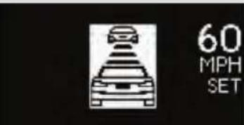 (Flashes)(If equipped) (Flashes)(If equipped) | Indicates that your vehicle is nearing the vehicle ahead (in vehicle to vehicle distance control mode) | Slow the vehicle by applying the brakes. | |
| Warning message Details | Correction procedure | ||
  (Flashes)(If equipped) (Flashes)(If equipped) | Indicates that there is a high possibility of a frontal collision, or that the pre-collision braking function is operating | Slow the vehicle by applying the brakes. | |
HYBRID SYSTEM OVERHEAT | Indicates that the hybrid system has overheated | Stop and check.(→P. 640) | |
  (Flashes) (Flashes) | Indicates that the traction battery is low | When stopping the vehicle for a long period of time, shift the shift position to P. The battery cannot be charged with the shift position in N. | |
  (Flashes) (Flashes) | Indicates that the traction battery power has dropped because a long period of time has elapsed after shifting the shift position to N | Restart the hybrid system when starting the vehicle. | |
 | Indicates that the driver's door was opened with the shift position in any position other than P | Shift the shift position to P. | |
 | (Flashes) | ||
 | Indicates that the accelerator pedal is depressed while the shift position is in N. | Release the accelerator pedal and shift the shift position to D or R. | |
 | (Flashes) | ||
 | Indicates that the EV drive mode is not available*The reason the EV drive mode is not available (the vehicle is idling, battery charge is low, speed is higher than the EV drive mode operating speed range, accelerator pedal is depressed too much) may be displayed. | Use the EV drive mode when it becomes available. | |
| Waming message Details | Correction procedure | ||
 | Indicates that the EV drive mode has been automatically cancelled*The reason the EV drive mode is not available (the battery charge is low, speed is higher than the EV drive mode speed range, accelerator pedal is depressed too much) may be displayed. | Drive the vehicle for a while. | |
 (Flashes 3 times) (Flashes 3 times) | |||
*: For the EV drive mode operating conditions ( P.174).
Follow the correction procedures.
A warning message is shown on the multi-information display. After taking the specified steps to correct the suspected problem, check that the warning message goes off.
| Warning message Details | Correction procedure | |
| LOW WASHER FLUID | Indicates that the washer fluid level is low | Add washer fluid. |
| PCS TEMPORARILY NOT AVAILABLE | Indicates that the pre-collision system is not currently functional because the grille or the sensor is dirtyThis message also appears when the pre-collision system is not functional due to overheating. | ·Check the grille and the sensor and clean them if they are dirty.·In case of overheating, the system will become functional once the sys-tem cools down. |
| PCS(If equipped) |
Have the malfunction repaired immediately.
After taking the specified steps to correct the suspected problem, check that the warning message and light go off.
| Interior buzzer | Exterior buzzer | Warning message Details | Correction procedure | ||
| Once— |  | The electronic key is not detected when an attempt is made to start the hybrid system. | Start the hybrid system with the electronic key present. | ||
 | (Flashes) | ||||
| Interior buzzer | Exterior buzzer | Warning message Details | Correction procedure | |
| Once | 3 times |  | The electronic key was carried outside the vehicle and a door other than the driver's door was opened and closed while the "POWER" switch was in a mode other than off. | Bring the electronic key back into the vehicle. |
 (Flashes) (Flashes) | The electronic key was carried outside the vehicle and the driver's door was opened and closed while the shift position P was selected without turning off the "POWER" switch. | Turn the "POWER" switch off or bring the electronic key back into the vehicle. | ||
| Interior buzzer | Exterior buzzer | Warning message Details | Correction procedure | |
| Once | Continuous |  | An attempt was made to exit the vehicle with the electronic key and lock the doors without first turning the "POWER" switch off. | |
(Displayed alternately)  (Flashes) (Flashes) | ||||
| Once— |  | An attempt was made to start the hybrid system without the electronic key being present, or the electronic key was not functioning normally. An attempt was made to drive when the regular key was not inside the vehicle. | ||
 (Flashes) (Flashes) | ||||
| Interior buzzer | Exterior buzzer | Warning message Details | Correction procedure | ||
| Continuous | — |  | The driver's door was opened while any shift position other than P was selected without turning off the "POWER" switch. | Shift the shift position to P. | |
 | (Flashes) | ||||
| Continuous | Continuous |  | The electronic key was carried outside the vehicle and the driver's door was opened and closed while any shift position other than P was selected without turning off the "POWER" switch. | Shift the shift position to P.Bring the electronic key back into the vehicle. | |
 | |||||
| (Displayed alternately) | |||||
 | (Flashes) | ||||
| Interior buzzer | Exterior buzzer | Warning message Details | Correction procedure | |
| Once | Continuous |  | An attempt was made to lock the doors using the smart access system with push-button start while the electronic key was still inside the vehicle.A n at t e m p t w aRetrieve the elec-tronic key from the vehicle and lock the doors again. | |
 (Flashes) (Flashes) | ||||
| Interior buzzer | Exterior buzzer | Warning message Details | Correction procedure | |
| Once— |   (Flashes) (Flashes) | ·When the doors were unlocked with the mechanical key and then the “POWER” switch was pressed, the electronic key could not be detected in the vehicle. ·The electronic key could not be detected in the vehicle even after the “POWER” switch was pressed two consecutive times. | Touch the electronic key to the “POWER” switch while depressing the brake pedal. | |
| Once— |   (Flashes) (Flashes) | An attempt was made to start the hybrid system with the shift position in N. | Shift the shift position to P and start the hybrid system. | |
| Interior buzzer | Exterior buzzer | Warning message Details | Correction procedure | |
| — | — |  | Power was turned off due to the automatic power off function. | Next time when starting the hybrid system, increase the engine speed slightly and maintain that level for approximately 5 minutes to recharge the 12-volt battery. |
| Once— |  | The electronic key has a low battery. | Replace the electronic key battery. (→P. 539) | |
 | ||||
| Interior buzzer | Exterior buzzer | Warning message Details | Correction procedure | |
| Once— |  | The driver's door was opened and closed with the "POWER" switch turned off and then the "POWER" switch was put in ACCESSORY mode twice without the hybrid system being started. | Press the "POWER" switch while depressing the brake pedal. | |
 (Flashes) (Flashes) | During a hybrid system starting procedure in the event that the electronic key was not functioning properly (→P. 632), the "POWER" switch was touched with the electronic key. | Press the "POWER" switch within 10 seconds of the buzzer sounding. | ||
■ Warning message in radar cruise mode
In the following cases, the warning message may not be displayed even if vehicle-to-vehicle distance decreases:
- When your vehicle and the vehicle ahead are traveling at the same speed or the vehicle ahead is traveling more quickly than your vehicle
- When the vehicle ahead is traveling at a very low speed
- Immediately after cruise control speed is set
- At the instant the accelerator pedal is depressed
■ After changing the engine oil (U.S.A. only)
Make sure to reset the oil maintenance data. (→P.502)
Remove the flat tire and replace it with the spare tire provided.
■ Before jacking up the vehicle
- Stop the vehicle on a hard, flat surface.
- Set the parking brake.
●Shift the shift position to P. - Stop the hybrid system.
●Turn on the emergency flashers.
■ Location of the spare tire, jack and tools

text_image
Center auxiliary box Wheel nut wrench Towing eyelet Jack handle JackSpare tireTaking out the jack

natural_image
Interior view of a car trunk with a highlighted component and an inset showing a 3D mechanical part (no text or symbols)Remove the center deck board.

natural_image
Top-down view of a car trunk with a red arrow pointing to the rear compartment (no text or symbols on the main body)Remove the center auxiliary box.

text_image
STEP3 1 2 BY52H011Take out the jack.
1 For loosening
② For tightening
Taking out the spare tire
STEP Remove the center deck board and center auxiliary box. (See "Taking out the jack" for details.)

natural_image
Interior view of a car showing a mechanical assembly with a red circular arrow indicating rotation (no text or symbols on the diagram itself)Loosen the center fastener that secures the spare tire.
Replacing a flat tire

natural_image
3D rendering of a car with motion arrows indicating speed or impact (no text or symbols)Chock the tires.
| Flat tire Wheel chock positions | |
| Front | Left-hand side Behind the rear right-hand side tire |
| Right-hand side Behind the rear left-hand side tire | |
| Rear | Left-hand side In front of the front right-hand side tire |
| Right-hand side In front of the front left-hand side tire | |

text_image
STEP2 ILY53H017For vehicles with 15 inch wheels, remove the wheel ornament using the wrench.
To protect the wheel ornament, place a rag between the wrench and the wheel ornament.

natural_image
Close-up of a car wheel rim with a red arrow indicating direction, no visible text or symbolsSlightly loosen the wheel nuts (one turn).

text_image
STEP4 A ILY52H019Turn the tire jack portion "A" by hand until the notch of the jack is in contact with the jack point.
The jack point guides are located under the rocker panel. They indicate the jack point positions.

text_image
STEP 5 ILY52H020Raise the vehicle until the tire is slightly raised off the ground.

natural_image
Close-up of hands installing or adjusting a car tire on a lift, no visible text or symbolsRemove all the wheel nuts and the tire.
When resting the tire on the ground, place the tire so that the wheel design faces up to avoid scratching the wheel surface.
Installing the spare tire

natural_image
Two-step photo showing hands cleaning a car wheel rim and disc (no text or symbols visible)
text_image
STEP 2 Tapered portion Disc wheel seat
text_image
STEP3 ILY52H078Remove any dirt or foreign matter from the wheel contact surface.
If foreign matter is on the wheel contact surface, the wheel nuts may loosen while the vehicle is in motion, causing the tire to come off.
Install the spare tire and loosely tighten each wheel nut by hand by approximately the same amount.
Tighten the wheel nuts until the tapered portion comes into loose contact with the disc wheel seat.
Lower the vehicle.

text_image
STEP4 1 3 4 2 5 ILY52H077Firmly tighten each wheel nut two or three times in the order shown in the illustration.
Tightening torque: 76 ft·lbf (103 N·m, 10.5 kgf·m)
STEP5 Stow the flat tire, tire jack and all tools.
Stowing the flat tire

natural_image
3D rendering of a car wheel with a red arrow pointing to the center (no text or symbols on the wheel itself)Vehicles with a 16 or 17 inch wheel: Before stowing the flat tire, remove the center wheel ornament by pushing from the reverse side.

text_image
STEP2 ILY52H02RaPlace the flat tire on the deck board, and pass the belt through the lower-right cargo hook and then through the hole in the center of the tire.

natural_image
Top-down view of a car's rear wheel assembly with black guide lines and a red 'B' marking (no text or symbols on the diagram itself)Pass the belt through the lower-left cargo hook.

text_image
STEP4 ILY52H32aPass the belt through the buckle and secure the tire firmly. Check that the belt is securely held by the buckle.
The belt cannot be fastened securely if the buckle is facing the wrong direction.
The compact spare tire
- The compact spare tire is identified by the label "TEMPORARY USE ONLY" on the tire sidewall.
Use the compact spare tire temporarily, and only in an emergency.
● Make sure to check the tire inflation pressure of the compact spare tire. (→P. 661)
■ After completing the tire change
The tire pressure warning system must be reset. ( P. 520)
■When using the compact spare tire
As the compact spare tire is not equipped with a tire pressure warning valve and transmitter, low inflation pressure of the spare tire will not be indicated by the tire pressure warning system. Also, if you replace the compact spare tire after the tire pressure warning light comes on, the light remains on.
If you have a flat front tire on a road covered with snow or ice
Install the compact spare tire on one of the rear wheels of the vehicle. Perform the following steps and fit tire chains to the front tires:
STEP ☐ Replace a rear tire with the compact spare tire.
STEP2 Replace the flat front tire with the tire removed from the rear of the vehicle.
STEP3 Fit tire chains to the front tires.

CAUTION
■When using the compact spare tire
- Remember that the spare tire provided is specifically designed for use with your vehicle. Do not use your spare tire on another vehicle.
- Do not use more than one spare tires simultaneously.
- Replace the spare tire with a standard tire as soon as possible.
- Avoid sudden acceleration, deceleration and braking, as well as sharp cornering.
■When storing the compact spare tire
Be careful not to catch fingers or other body parts between the compact spare tire and the body of the vehicle.

CAUTION
■When the compact spare tire is attached
The vehicle speed may not be correctly detected, and the following systems may not operate correctly:
●ABS & Brake assist
•VSC
TRAC
● Cruise control (if equipped)
● Dynamic radar cruise control (if equipped)
●Pre-collision system (if equipped)
EPS
●Rear view monitor system (if equipped)
●Intuitive parking assist (if equipped)
●Navigation system (if equipped)

CAUTION
■Speed limit when using the compact spare tire
Do not drive at speeds in excess of 50 mph (80 km/h) when a compact spare tire is installed on the vehicle.
The compact spare tire is not designed for driving at high speeds. Failure to observe this precaution may lead to an accident causing death or serious injury.
Using the tire jack
Improper use of the tire jack may cause the vehicle to suddenly fall off the jack, leading to death or serious injury.
- Do not use the tire jack for any purpose other than replacing tires or installing and removing tire chains.
- Only use the tire jack that comes with this vehicle for replacing a flat tire. Do not use it on other vehicles, and do not use other tire jacks for replacing tires on this vehicle.
●Always check that the tire jack is securely set to the jack point.
- Do not put any part of your body under the vehicle while it is supported by the jack.
- Do not start or run the hybrid system while your vehicle is supported by the jack.
- Do not raise the vehicle while someone is inside.
- When raising the vehicle, do not put an object on or under the jack.
- Do not raise the vehicle to a height greater than that required to replace the tire.
- Use a jack stand if it is necessary to get under the vehicle.
Take particular care when lowering the vehicle to ensure that no one working on or near the vehicle may be injured.

CAUTION
■Replacing a flat tire
- Do not touch the disc wheels or the area around the brakes immediately after the vehicle has been driven.
After the vehicle has been driven the disc wheels and the area around the brakes will be extremely hot. Touching these areas with hands, feet or other body parts while changing a tire, etc. may result in burns.
● Failure to follow these precautions could cause the wheel nuts to loosen and the tire to fall off, resulting in death or serious injury.
- Have the wheel nuts tightened with a torque wrench to 76 ft·lbf (103 N·m, 10.5 kgf·m) as soon as possible after changing wheels.
- When installing a tire, only use wheel nuts that have been specifically designed for that wheel.
- If there are any cracks or deformations in the bolt screws, nut threads or bolt holes of the wheel, have the vehicle inspected by your Lexus dealer.
- When installing the wheel nuts, be sure to install them with the tapered ends facing inward. (→P.535)

CAUTION
■After using the tools and jack
Before driving, make sure all the tools and jack are securely in place in their storage location to reduce the possibility of personal injury during a collision or sudden braking.
■When stowing the flat tire
●Make sure the rear seatbacks are in their original position.
- Secure it using a tire tie-down belt. Otherwise, the flat tire may fly out in case of sudden braking or an accident, resulting in death or serious injury.

NOTICE
- Do not drive the vehicle with a flat tire.
Do not continue driving with a flat tire.
Driving even a short distance with a flat tire can damage the tire and the wheel beyond repair.
- Be careful when driving over bumps with the compact spare tire installed on the vehicle.
The vehicle becomes lower when driving with the compact spare tire compared to when driving with standard tires. Be careful when driving over uneven road surfaces.
- Driving with tire chains and the compact spare tire
Do not fit tire chains to the compact spare tire.
Tire chains may damage the vehicle body and adversely affect driving performance.
■When replacing the tires
When removing or fitting the wheels, tires or the tire pressure warning valve and transmitter, contact your Lexus dealer as the tire pressure warning valve and transmitter may be damaged if not handled correctly.
■ To avoid damage to the tire pressure warning valves and transmitters
When a tire is repaired with liquid sealants, the tire pressure warning valve and transmitter may not operate properly. If a liquid sealant is used, contact your Lexus dealer or other qualified service shop as soon as possible. Make sure to replace the tire pressure warning valve and transmitter when replacing the tire. (→P. 520)
Reasons for the hybrid system not starting vary depending on the situation. Check the following and perform the appropriate procedure:
The hybrid system will not start even though the correct starting procedure is being followed. ( P. 169)
One of the following may be the cause of the problem:
● The electronic key may not be functioning properly.* (→P. 632)
- There may not be sufficient fuel in the vehicle's tank. Refuel the vehicle.
● There may be a malfunction in the immobilizer system.* (→P. 111)
● There may be a malfunction in the P position control system.* (→P.172, 595)
*: It may not be possible to shift the shift position other than P.
The interior lights and headlights are dim, or the horn does not sound or sounds at a low volume.
One of the following may be the cause of the problem:
● The 12-volt battery may be discharged. (→P. 635)
●The 12-volt battery terminal connections may be loose or corroded.
The interior lights and headlights do not turn on, or the horn does not sound.
One of the following may be the cause of the problem:
●One or both of the 12-volt battery terminals may be disconnected.
● The 12-volt battery may be discharged. (→P. 635)
Contact your Lexus dealer if the problem cannot be repaired, or if repair procedures are unknown.
Emergency start function
When the hybrid system does not start, the following steps can be used as an interim measure to start the hybrid system if the "POWER" switch is functioning normally:
STEP1 Set the parking brake.
STEP2 Turn the "POWER" switch to ACCESSORY mode.
STEP3 Press and hold the "POWER" switch for about 15 seconds while depressing the brake pedal firmly.
Even if the hybrid system can be started using the above steps, the system may be malfunctioning. Have the vehicle inspected by your Lexus dealer.
5-2. Steps to take in an emergency
If you lose your keys
New genuine keys can be made by your Lexus dealer using the other key and the key number stamped on your key number plate.
5-2. Steps to take in an emergency
If the electronic key does not operate properly
If communication between the electronic key and vehicle is interrupted ( P. 63) or the electronic key cannot be used because the battery is depleted, the smart access system with push-button start and wireless remote control cannot be used. In such cases, the doors can be opened and the hybrid system can be started by following the procedure below.
Locking and unlocking the doors and key linked functions

text_image
1 2 3 4Use the mechanical key ( P.44) in order to perform the following operations:
1 Locks all the doors
2 Closes the windows* (turn and hold)
3 Unlocks the door
Turning the key rearward unlock the driver's door. Turning the key once again within 3 seconds unlocks the other doors.
4 Opens the windows* (turn and hold)
*: This setting must be customized at your Lexus dealer.
Changing "POWER" switch modes and starting the hybrid system
STEP □ Depress the brake pedal.

text_image
STEP2 POWER POWER JLYS2-1066Touch the Lexus emblem side of the electronic key to the "POWER" switch.
If any of the doors is opened or closed while the key is being touched to the switch, an alarm will sound to indicate that the start function cannot detect the electronic key.
STEP3 To change "POWER" switch modes: Within 10 seconds of the buzzer sounding, release the brake pedal and press the "POWER" switch. Modes can be changed each time the switch is pressed. (→P.170)
To start the hybrid system: Press the "POWER" switch within 10 seconds of the buzzer sounding, keeping the brake pedal depressed.
In the event that the hybrid system still cannot be operated, contact your Lexus dealer.
■Stopping the hybrid system
Set the parking brake, shift the shift position to P and press the "POWER" switch as you normally do when stopping the hybrid system.
■Replacing the key battery
As the above procedure is a temporary measure, it is recommended that the electronic key battery be replaced immediately when the battery is depleted. (→P. 539)
5-2. Steps to take in an emergency
If the 12-volt battery is discharged
The following procedures may be used to start the hybrid system if the vehicle's 12-volt battery is discharged.
You can also call your Lexus dealer or a qualified repair shop.
If you have a set of jumper (or booster) cables and a second vehicle with a 12-volt battery, you can jump start your vehicle by following the steps below.

text_image
STEP 11.54.24 HNSRmOpen the hood and fuse block cover.

text_image
STEP2 ILY52H065cmOpen the exclusive jump starting terminal cover.
STEP\$

text_image
Diagram showing automotive battery charging system with labeled components and wiring connectionsConnect the jumper cables according to the following procedure:
1 Connect a positive jumper cable clamp to the exclusive jump starting terminal on your vehicle.
2 Connect the clamp on the other end of the positive cable to the positive (+) battery terminal on the second vehicle.
3 Connect a negative cable clamp to the negative (-) battery terminal on the second vehicle.
4 Connect the clamp at the other end of the negative cable to a solid, stationary, unpainted metallic point away from the exclusive jump starting terminal and any moving parts, as shown in the illustration.
STEP4 Start the engine of the second vehicle. Increase the engine speed slightly and maintain at that level for approximately 5 minutes to recharge the battery of your vehicle.
STEP5 Open and close any of the doors of your vehicle with the "POWER" switch off.
STEP6 Maintain the engine speed of the second vehicle and start the hybrid system of your vehicle by turning the "POWER" switch to ON mode.
STEP7 Make sure the "READY" indicator light comes on. If the indicator light does not come on, contact your Lexus dealer.
STEP\$ Once the hybrid system has started, remove the jumper cables in the exact reverse order from which they were connected.
STEP9 To install the engine cover, conduct the removal procedure in reverse. After installing, check that the fixed pins are inserted securely.
Once the hybrid system starts, have the vehicle inspected at your Lexus dealer as soon as possible.
■ Starting the hybrid system when the 12-volt battery is discharged
The hybrid system cannot be started by push-starting.
■To prevent 12-volt battery discharge
●Turn off the headlights and the audio system while the hybrid system is off.
- Turn off any unnecessary electrical components when the vehicle is running at a low speed for an extended period, such as in heavy traffic.
■When the 12-volt battery is removed or discharged
● The hybrid system may not start. (→P. 514)
- If the 12-volt battery discharges while the shift position is in P, it may not be possible to shift the shift position to other positions. In this case, the vehicle cannot be towed without lifting both front wheels because the front wheels will be locked. (→P. 571)
- When the 12-volt battery is reconnected, start the hybrid system and confirm that the shift position can be changed to each position using the shift position indicator.

CAUTION
■Avoiding 12-volt battery fires or explosions
Observe the following precautions to prevent accidentally igniting the flammable gas that may be emitted from the 12-volt battery:
● Make sure each jumper cable is connected to the correct terminal and that it is not unintentionally in contact with any other than the intended terminal.
- Do not allow the other end of the jumper cable connected to the “+” terminal to come into contact with any other parts or metal surfaces in the area, such as brackets or unpainted metal.
- Do not allow the + and - clamps of the jumper cables to come into contact with each other.
- Do not smoke, use matches, cigarette lighters or allow open flame near the 12-volt battery.

CAUTION
■12-volt battery precautions
The 12-volt battery contains poisonous and corrosive acidic electrolyte, while related parts contain lead and lead compounds. Observe the following precautions when handling the 12-volt battery:
- When working with the 12-volt battery, always wear safety glasses and take care not to allow any battery fluids (acid) to come into contact with skin, clothing or the vehicle body.
●Do not lean over the 12-volt battery. - In the event that battery fluid comes into contact with the skin or eyes, immediately wash the affected area with water and seek medical attention. Place a wet sponge or cloth over the affected area until medical attention can be received.
● Always wash your hands after handling the battery support, terminals, and other battery-related parts.
●Do not allow children near the 12-volt battery.

NOTICE
■When handling jumper cables
When connecting the jumper cables, ensure that they do not become entangled in the cooling fans or belt.
■ To prevent damaging the vehicle
The exclusive jump starting terminal is to be used when charging the 12-volt battery from another vehicle in an emergency. It cannot be used to jump start another vehicle.
The following may indicate that your vehicle is overheating:
●The high coolant temperature warning light comes on or flashes: The engine may be overheating.
●“HYBRID SYSTEM OVERHEAT” is shown on the multi-information display:
The power control unit may be overheating.
Correction procedures
If the high coolant temperature warning light comes on or flashes
STEP1 Stop the vehicle in a safe place and turn off the air conditioning system.
STEP2 Check to see if steam is coming out from the engine area.
If you see steam:
Stop the hybrid system. Carefully lift the hood after the steam subsides and then restart the hybrid system.
If you do not see steam:
Leave the hybrid system operating and carefully lift the hood.
STEP3 Check to see if the cooling fans are operating.
If the fans are operating:
Wait until the high coolant temperature warning light goes off and then stop the hybrid system.
If the fans are not operating:
Stop the hybrid system immediately and call your Lexus dealer.

natural_image
Front view of a car's head and windshield showing engine compartment (no visible text or symbols)After the hybrid system has cooled down sufficiently, check the engine coolant level and inspect the cooling system for leaks.
If the engine compartment cover needs to be removed: →P. 499

natural_image
Close-up of a car hood with a funnel pouring liquid into a container (no visible text or symbols)Add engine coolant if necessary.
Water can be used in an emergency if engine coolant is unavailable. (→P.657)
Have the vehicle inspected at the nearest Lexus dealer as soon as possible.
If "HYBRID SYSTEM OVERHEAT" is shown on the multi-information display
STEP1 Stop the vehicle in a safe place and turn off the air conditioning system.
STEP2 Leave the hybrid system operating and carefully lift the hood.
STEP3 Check if the cooling fans are operating.
If the fans are operating:
Wait until the "HYBRID SYSTEM OVERHEAT" message disappears and then stop the hybrid system.
If the message does not disappear, call your Lexus dealer.
If the fans are not operating:
Stop the hybrid system immediately and call your Lexus dealer.

natural_image
Front view of a car's head and windshield (no visible text or symbols)After the hybrid system has cooled down, check the power control unit coolant level and inspect the cooling system for leaks.
If the engine compartment cover needs to be removed: →P. 499

natural_image
Close-up of a mechanical component with a funnel and valve, no visible text or symbolsAdd power control unit coolant if necessary.
Water can be used in an emergency if power control unit coolant is unavailable. (→P.657)
Have the vehicle inspected at the nearest Lexus dealer as soon as possible.
Overheating
The following symptoms may occur when your vehicle is overheating:
● Hybrid system output decreases.
●Steam comes out from under the hood.

CAUTION
■ To prevent an accident or injury when inspecting under the hood of your vehicle
- If steam is seen coming from under the hood, do not open the hood until the steam has subsided. The engine compartment may be very hot, causing serious injuries such as burns.
- Check that the indicator on the "POWER" switch and the "READY" indicator are off.
For vehicles with a hybrid system, there are times when the gasoline engine automatically starts to run or the cooling fans suddenly start to operate. Do not touch or approach the rotating parts of the belt or fans. Doing so may lead to fingers, clothes or tools getting caught, resulting in injury. - Do not loosen the radiator cap, or the coolant reservoir cap while the hybrid system and radiator are hot.
Serious injury, such as burns, may result from hot coolant and steam released under pressure.

NOTICE
■ When adding engine/power control unit coolant
Wait until the hybrid system has cooled down before adding engine/power control unit coolant.
When adding coolant, do so slowly. Adding cool coolant to a hot hybrid system too quickly can cause damage to the hybrid system.
Carry out the following procedures if the tires spin or the vehicle becomes stuck in mud, dirt or snow:
STEP □ Stop the hybrid system. Set the parking brake and shift the shift position to P.
STEP2 Remove the mud, snow or sand from around the stuck tire.
STEP3 Place wood, stones or some other material under the tires to help provide traction.
STEP4 Restart the hybrid system.
STEP5 Shift the shift position to D or R, release the parking brake and carefully apply the accelerator to free the vehicle.

CAUTION
■When attempting to free a stuck vehicle
If you choose to push the vehicle back and forth to free it, make sure the surrounding area is clear to avoid striking other vehicles, objects or people. The vehicle may also lunge forward or lunge back suddenly as it becomes free. Use extreme caution.
■When changing the shift position
Be careful not to change the shift position with the accelerator pedal depressed. Changing the shift position to any positions other than P or N may cause the vehicle to accelerate abruptly, causing an accident and resulting in death or serious injury.

NOTICE
■ To avoid damage to the hybrid transmission and other components
- Avoid spinning the wheels and depressing the accelerator pedal more than necessary.
- If the vehicle remains stuck even after these procedures are performed, the vehicle may require towing to be freed.
5-2. Steps to take in an emergency
If your vehicle has to be stopped in an emergency
Only in an emergency, such as if it becomes impossible to stop the vehicle in the normal way, stop the vehicle using the following procedure:
STEP □ Steadily step on the brake pedal with both feet and firmly depress it. Do not pump the brake pedal repeatedly as this will increase the effort required to slow the vehicle.
STEP2 Shift the shift position to N.
If the shift position is shifted to N
STEP3 After slowing down, stop the vehicle in a safe place by the road.
STEP4 Stop the hybrid system.
If the shift position cannot be shifted to N
STEP3 Keep depressing the brake pedal with both feet to reduce vehicle speed as much as possible.

text_image
STEP4 Power Press and hold for 3 seconds or more, or press briefly 3 times or moreTo stop the hybrid system, press and hold the "POWER" switch for 3 consecutive seconds or more, or press it briefly 3 times or more in succession.
STEP5 Stop the vehicle in a safe place by the road.

CAUTION
If the hybrid system has to be turned off while driving
Power assist for the brakes and steering wheel will be lost, making the brake pedal harder to depress and the steering wheel heavier to turn. Decelerate as much as possible before turning off the hybrid system.
Vehicle specifications
6
6-1. Specifications
Maintenance data
(fuel, oil level, etc.) 650
Fuel information...... 665
Tire information...... 668
6-2. Customization
Customizable features ..... 684
6-3. Initialization
Items to initialize 705
Dimensions and weight
| Overall length 170.1 in. (4320 mm) | ||
| Overall width 69.5 in. (1765 mm) | ||
| Overall height*1 | 56.7 in. (1440 mm) | |
| Wheelbase 102.4 in. (2600 mm) | ||
| Tread | Front | 60.0 in. (1525 mm)*260.4 in. (1535 mm)*3 |
| Rear | 59.8 in. (1520 mm)*260.2 in. (1530 mm)*3 | |
| Vehicle capacity weight(Occupants + luggage) | 825 lb. (370 kg) | |
*1: Unladen vehicle
*2: Vehicles with 16-inch and 17-inch tires
*3: Vehicles with 15-inch tires
Vehicle identification
■ Vehicle identification number
The vehicle identification number (VIN) is the legal identifier for your vehicle. This is the primary identification number for your Lexus. It is used in registering the ownership of your vehicle.

natural_image
Side view of a car with a black arrow pointing to the side of the window, no visible text or symbols.This number is stamped on the top left of the instrument panel.

natural_image
Close-up of a car interior showing a black arrow pointing to the side panel (no text or symbols visible)This number is also on the Certification Label.

text_image
FROADE ILY614003This number is also stamped under the right-hand front seat.
Engine number

natural_image
Technical line drawing of a mechanical engine component with no visible text or symbolsThe engine number is stamped on the engine block as shown.
Engine
| Model 1.8 L 4-cylinder (2ZR-FXE) | |
| Type4-cylinder in line, 4-cycle, gasoline | |
| Bore and stroke | 3.17 × 3.48 in. (80.5 × 88.3 mm) |
| Displacement 109.7 cu.in. (1798 cm 3) | |
| Valve clearance (engine cold) | Automatic adjustment |
Fuel
Fuel type Unleaded gasoline only
Octane Rating 87 (Research Octane Number 91) or higher
Fuel tank capacity (Reference)
11.9 gal. (45 L, 9.9 Imp.gal.)
Electric motor (traction motor)
TypePermanent magnet motor
Maximum output 60 kW
Maximum torque 153 ft·lbf (207 N·m, 21.1 kgf·m)
Hybrid battery (traction battery)
| TypeNickel-Metal hydride battery | |
| Voltage72 V/module | |
| Capacity 6.5 Ah (3HR) | |
| Quantity 28 modules | |
| Overall voltage 201.6 V | |
Lubrication system
| Oil capacity(Drain and refill – reference) | |
| With filter | 4.4 qt. (4.2 L, 3.7 Imp.qt.) |
| Without filter | 4.1 qt. (3.9 L, 3.4 Imp.qt.) |
Engine oil selection
"Toyota Genuine Motor Oil" is used in your Lexus vehicle. Use Lexus approved "Toyota Genuine Motor Oil" or equivalent to satisfy the following grade and viscosity.
Oil grade: ILSAC multigrade engine oil
Recommended viscosity: SAE OW-20

text_image
0W-20 C-29 -18 -7 4 16 27 38 F-20 0 20 40 60 80 100 Outside temperature BY VCE 095SAE OW-20 is the best choice for good fuel economy and good starting in cold weather.
If SAE 0W-20 is not available, SAE 5W-20 oil may be used. However, it must be replaced with SAE 0W-20 at the next oil change.
Oil viscosity (0W-20 is explained here as an example):
●The OW in OW-20 indicates the characteristic of the oil which allows cold startability. Oils with a lower value before the W allow for easier starting of the engine in cold weather.
●The 20 in OW-20 indicates the viscosity characteristic of the oil when the oil is at high temperature. An oil with a higher viscosity (one with a higher value) may be better suited if the vehicle is operated at high speeds, or under extreme load conditions.
6-1. Specifications
How to read oil container label:
The ILSAC (International Lubricant Standardization and Approval Committee) Certification Mark is added to some oil containers to help you select the oil you should use.

text_image
AMERICAN PETROLEUM INSTITUTE FOR GASOLINE ENGINES CERTIFIEDCooling system
| Capacity | Gasoline engine | With an exhaust heat recirculator system7.3 qt. (6.9 L, 6.1 Imp. qt.)Without exhaust heat recirculator system6.9 qt. (6.5 L, 5.7 Imp. qt.) |
| Power control unit | 2.2 qt. (2.1 L, 1.8 Imp. qt.) | |
| Coolant type | Use either of the following:“Toyota Super Long Life Coolant”Similar high-quality ethylene glycol-based non-silicate, non-amine, non-nitrite, and non-borate coolant with long-life hybrid organic acid technologyDo not use plain water alone. | |
Ignition system
Spark plug
Make DENSO SC20HR11
Gap 0.043 in. (1.1 mm)

NOTICE
■Iridium-tipped spark plugs
Use only iridium-tipped spark plugs. Do not adjust the spark plug gap.
Electrical system
12-volt battery
Open voltage at 68 °F (20 °C):
12.6—12.8 V Fully charged
12.2—12.4 V Half charged
11.8—12.0 V Discharged
(Voltage is checked 20 minutes after the hybrid system and all lights are turned off.)
Charging rates 4.2 A max.
Transmission
Fluid capacity ^* 3.6 qt. (3.4L, 3.0 Imp.qt.)
Fluid type Toyota Genuine ATFWS
*: The fluid capacity is the quantity of reference. If replacement is necessary, contact your Lexus dealer.

NOTICE
Transmission fluid type
Using transmission fluid other than “Toyota Genuine ATF WS” may cause deterioration in shift quality, locking up of your transmission accompanied by vibration, and ultimately damage the transmission of your vehicle.
Brakes
| Pedal clearance* 1 | With Aluminum pedal3.11 in. (79 mm) Min.Without Aluminum pedal3.03 in. (77mm) Min. |
| Pedal free play | 0.04—0.24 in. (1.0—6.0 mm) |
| Brake pad wear limit 0.04 in. (1.0 mm) | |
| Parking brake lining wear limit 0.04 in. (1.0 mm) | |
| Parking brake pedal travel*2 | 8—11 clicks |
| Fluid type SAE J1703 or FMVSS No. 116 DOT 3 | |
^*1 : Minimum pedal clearance when depressed with a force of 44.1 lbf (196 N, 20.0 kgf) while the hybrid system is operating.
^*2 : Parking brake pedal travel when depressed with a force of 67.5 lbf (300 N, 30.6 kgf).
Steering
| Free play Less than 1.2 in. (30 mm) |
Tires and wheels
Type A
| Tire size | P215/45R17 87V |
| Tire inflation pressure(Recommended cold tireinflation pressure) | Front tire33 psi (230 kPa, 2.3 kgf/cm2 or bar)Rear tire32 psi (220 kPa, 2.2 kgf/cm2 or bar) |
| Wheel size | 17 × 7 J |
| Wheel nut torque | 76 ft·lbf (103 N·m, 10.5 kgf·m) |
Type B
| Tire size P205/55R16 89H | |
| Tire inflation pressure(Recommended cold tireinflation pressure) | Front tire32 psi (220 kPa, 2.2 kgf/cm2 or bar)Rear tire32 psi (220 kPa, 2.2 kgf/cm2 or bar) |
| Wheel size 16 × 6J | |
| Wheel nut torque 76 ft·lbf | (103 N·m, 10.5 kgf·m) |
TypeC
| Tiresize P195/65R15 89S | |
| Tire inflation pressure(Recommended cold tireinflation pressure) | Front tire39 psi (270 kPa, 2.7 kgf/cm2 or bar)Rear tire39 psi (270 kPa, 2.7 kgf/cm2 or bar) |
| Wheel size 15 × 5 1/2J | |
| Wheel nut torque 76 ft·lbf | (103 N·m, 10.5 kgf·m) |
TypeD
| Tiresize 205/55R16 91V | |
| Tire inflation pressure(Recommended cold tireinflation pressure) | Front tire32 psi (220 kPa, 2.2 kgf/cm2 or bar)Rear tire32 psi (220 kPa, 2.2 kgf/cm2 or bar) |
| Wheel size 16 × 6J | |
| Wheel nut torque 76 ft·lbf | (103 N·m, 10.5 kgf·m) |
Compact spare tire
| Tire size | T125/70D17 98M |
| Spare tire inflation pressure (Recommended cold tire inflation pressure) | 60 psi (420 kPa, 4.2 kgf/cm2 or bar) |
| Wheel size | 17 × 4 T |
| Wheel nut torque | 76 ft·lbf (103 N·m, 10.5 kgf·m) |
Light bulbs
| Light Bulbs Bulb No. W Type | ||||
| Exterior | HeadlightsLow beam (halogen bulbs)*High beam | —— | 5565 | AB |
| Front fog lights* — 55 A | ||||
| Front turn signal lights | 7444NA | 28/8 | D | |
| Rear turn signal lights | WY21W | 21 | D | |
| Back-up lights | W16W | 16 | C | |
| License plate lights | W5W | 5 | C | |
| Interior | Personal/interior lights | — | 5 | C |
| Rear interior lights | — | 8 | E | |
| Vanity lights | — | 8 | C | |
| Luggage compartment light | — | 5 | E | |
A: H11 halogen bulbs
B: H9 halogen bulbs
C: Wedge base bulbs (clear)
D: Wedge base bulbs (amber)
E: Double end bulbs
*: If equipped
You must only use unleaded gasoline in your vehicle.
Select octane rating 87 (Research Octane Number 91) or higher. Use of unleaded gasoline with an octane rating lower than 87 may result in engine knocking. Persistent knocking can lead to engine damage.
At minimum, the gasoline you use should meet the specifications of ASTM D4814 in the U.S.A. and CGSB3.5-M93 in Canada.
■Fuel tank opening for unleaded gasoline
To help prevent incorrect fueling, your vehicle has a fuel tank opening that only accommodates the special nozzle on unleaded fuel pumps.
Gasoline quality
In very few cases, driveability problems may be caused by the brand of gasoline you are using. If driveability problems persist, try changing the brand of gasoline. If this does not correct the problem, consult your Lexus dealer.
If your engine knocks
- Consult your Lexus dealer.
- You may occasionally notice light knocking for a short time while accelerating or driving uphill. This is normal and there is no need for concern.
Gasoline quality standards
● Automotive manufacturers in the U.S.A., Europe and Japan have developed a specification for fuel quality called the World-Wide Fuel Charter (WWFC), which is expected to be applied worldwide.
●The WWFC consists of four categories that are based on required emission levels. In the U.S., category 4 has been adopted.
●The WWFC improves air quality by lowering emissions in vehicle fleets, and improves customer satisfaction through better performance.
■ Recommendation of the use of gasoline containing detergent additives
- Lexus recommends the use of gasoline that contains detergent additives to avoid the build-up of engine deposits.
● All gasoline sold in the U.S.A. contains detergent additives to clean and/or keep clean intake systems.
■ Recommendation of the use of cleaner burning gasoline
Cleaner burning gasoline, including reformulated gasoline that contains oxygenates such as ethanol or MTBE (Methyl Tertiary Butyl Ether) is available in many areas.
Lexus recommends the use of cleaner burning gasoline and appropriately blended reformulated gasoline. These types of gasoline provide excellent vehicle performance, reduce vehicle emissions and improve air quality.
■ Non-recommendation of the use of blended gasoline
- Lexus allows the use of oxygenate blended gasoline where the oxygenate content is up to 10% ethanol or 15% MTBE.
- If you use gasohol in your vehicle, be sure that it has an octane rating no lower than 87.
●Lexus does not recommend the use of gasoline containing methanol.
■Non-recommendation of the use of gasoline containing MMT
Some gasoline contains an octane enhancing additive called MMT (Methylcyclopentadienyl Manganese Tricarbonyl).
Lexus does not recommend the use of gasoline that contains MMT. If fuel containing MMT is used, your emission control system may be adversely affected.
The malfunction indicator lamp on the instrument cluster may come on. If this happens, contact your Lexus dealer for service.

NOTICE
■Notice on fuel quality
- Do not use improper fuels. If improper fuels are used, the engine will be damaged.
- Do not use leaded gasoline.
Leaded gasoline can cause damage to your vehicle's three-way catalytic converters causing the emission control system to malfunction. - Do not use gasohol other than the type previously stated.
Other gasohol may cause fuel system damage or vehicle performance problems. - Using unleaded gasoline with an octane number or rating lower than the level previously stated will cause persistent heavy knocking.
At worst, this will lead to engine damage.
■Fuel-related poor driveability
If poor driveability is encountered after using a different type of fuel (poor hot starting, vaporization, engine knocking, etc.), discontinue the use of that type of fuel.
■When refueling with gasohol
Take care not to spill gasohol. It can damage your vehicle's paint.
Typical tire symbols
Full-size tire

text_image
10 9 8 7 MAX-LOD XXX RS (XXX (S.) AT XXX KPA (XXPS)) MAX(###) P215/45R17 8.7V SINSMALL 2 PLUS XXX COWI MAXL TINSEER 2 6 5 3 4 LIFE UNDER TRAD LXXX COROPI + ZXXXX CORN MAXL TINSEERILYB1H005
Compact spare tire

text_image
TEMPORARY USE ONLY T13580D16 101M RASSAGE RADUAL MANUFACTURER'S VALUE INDAFLI 70 XXX RP4 (XXPSI) ITEMS NOT TO MAXXXXXXXX ITEMS NOT TO MAXXXXXXXX ITEMS NOT TO MAXXXXXXXX ITEMS NOT TO MAXXXXXXXX ITEMS NOT TO MAXXXXXXXX ITEMS NOT TO MAXXXXXXXX ITEMS NOT TO MAXXXXXXXX ITEMS NOT TO MAXXXXXXXX ITEMS NOT TO MAXXXXXXXX ITEMS NOT TO MAXXXXXXXX ITEMS NOT TO MAXXXXXXXX ITEMS NOT TO MAXXXXXXXX ITEMS NOT TO MAXXXXXXXX ITEMS NOT COO XXXXXX ITEMS NOT COO XXXXXX ITEMS NOT COO XXXXXX ITEMS NOT COO XXXXXX ITEMS NOT COO XXXXXX ITEMS NOT COO XXXXXX ITEMS NOT COO XXXXXX ITEMS NOT COO XXXXXX ITEMS NOT COO XXXXXX ITEMS NOT COO XXXXXX ITEMS NOT COO XXXXXX ITEMS NOT COO XXXXXX ITEMS NOT COO XXXXXX ITEM S ITEM S ITEM S ITEM S ITEM S ITEM S ITEM S ITEM S ITEM S ITEM S ITEM S ITEM S ITEM S ITEM S ITEM S ITEM S ITEM S ITEM S ITEM S ITEM S ITEM S ITEM S ITEM S ITEM S ITEM S ITEM S ITEM S ITEM S ITEM S ITEM S ITEM S ITEM S ITEM S ITEM SJLYS1H006
1 Tire size ( P. 671)
2 DOT and Tire Identification Number (TIN) ( P.670)
3 Location of treadwear indicators ( P.518)
4 Tire ply composition and materials
Plies are layers of rubber-coated parallel cords. Cords are the strands which form the plies in a tire.
5 Radial tires or bias-ply tires
A radial tire has "RADIAL" on the sidewall. A tire not marked "RADIAL" is a bias-ply tire.
6 TUBELESS or TUBE TYPE
A tubeless tire does not have a tube and air is directly put into the tire. A tube type tire has a tube inside the tire and the tube maintains the air pressure.
7 Load limit at maximum cold tire inflation pressure ( P. 523)
8 Maximum cold tire inflation pressure ( P.661)
This means the pressure to which a tire may be inflated.
9 Uniform tire quality grading
For details, see "Uniform Tire Quality Grading" that follows.
10 Summer tires or all season tires ( P.524)
An all season tire has "M+S" on the sidewall. A tire not marked "M+S" is a summer tire.
11 "TEMPORARY USE ONLY"
A compact spare tire is identified by the phrase "TEMPORARY USE ONLY" molded on its sidewall. This tire is designed for temporary emergency use only.
Typical DOT and Tire Identification Number (TIN)

text_image
DOT B93F MK6X4208 1 3 4 5 6 7 2 SLYR1AAD081 DOT symbol*
2 Tire Identification Number (TIN)
3 Tire manufacturer's identification mark
4 Tire size code
5 Manufacturer's optional tire type code (3 or 4 letters)
6 Manufacturing week
7 Manufacturing year
*: The DOT symbol certifies that the tire conforms to applicable Federal Motor Vehicle Safety Standards.
Tire size
■Typical tire size information
The illustration indicates typical tire size.

text_image
P 215/45 R 17 87 V 1 2 3 4 5 6 71 Tire use
② Section width (millimeters)
3 Aspect ratio (tire height to section width)
4 Tire construction code (R = Radial, D = Diagonal)
5 Wheel diameter (inches)
6 Load index (2 digits or 3 digits)
7 Speed symbol (alphabet with one letter)
$$ \begin{array}{l} (P = P _ {\text { passenger car }}, \ T = T _ {\text { temporary use }}) \end{array} $$
Tire dimensions

text_image
1 2 3 B.V6140081 Section width
② Tire height
3 Wheel diameter
Tire section names

text_image
1 2 3 4 5 6 7 8 9 10 11 BYE1-0111 Bead
2 Sidewall
3 Shoulder
4 Tread
5 Belt
6 Inner liner
7 Reinforcing rubber
8 Carcass
9 Rim lines
10 Bead wires
11 Chafer
Uniform Tire Quality Grading
This information has been prepared in accordance with regulations issued by the National Highway Traffic Safety Administration of the U.S. Department of Transportation.
It provides the purchasers and/or prospective purchasers of Lexus vehicles with information on uniform tire quality grading.
Your Lexus dealer will help answer any questions you may have as you read this information.
DOT quality grades
All passenger vehicle tires must conform to Federal Safety Requirements in addition to these grades. Quality grades can be found where applicable on the tire sidewall between tread shoulder and maximum section width.
For example: Treadwear 200 Traction AA Temperature A
Treadwear
The treadwear grade is a comparative rating based on the wear rate of the tire when tested under controlled conditions on a specified government test course.
For example, a tire graded 150 would wear one and a half (1 - 1/2) times as well on the government course as a tire graded 100.
The relative performance of tires depends upon the actual conditions of their use. Performance may differ significantly from the norm due to variations in driving habits, service practices and differences in road characteristics and climate.
Traction AA, A, B, C
The traction grades, from highest to lowest, are AA, A, B and C, and they represent the tire's ability to stop on wet pavement as measured under controlled conditions on specified government test surfaces of asphalt and concrete.
A tire marked C may have poor traction performance.
Warning: The traction grade assigned to this tire is based on braking (straight ahead) traction tests and does not include cornering (turning) traction.
Temperature A, B, C
The temperature grades are A (the highest), B, and C, representing the tire's resistance to the generation of heat and its ability to dissipate heat when tested under controlled conditions on a specified indoor laboratory test wheel.
Sustained high temperature can cause the material of the tire to degenerate and reduce tire life, and excessive temperature can lead to sudden tire failure.
Grade C corresponds to a level of performance which all passenger car tires must meet under the Federal Motor Vehicle Safety Standard No. 109.
Grades B and A represent higher levels of performance on the laboratory test wheel than the minimum required by law.
Warning: The temperature grades of a tire assume that it is properly inflated and not overloaded.
Excessive speed, underinflation, or excessive loading, either separately or in combination, can cause heat buildup and possible tire failure.
Glossary of tire terminology
| Tire related term Meaning | |
| Cold tire inflation pressure | Tire pressure when the vehicle has been parked for three hours or more, or has not been driven more than 1 mile or 1.5 km under that condition |
| Maximum inflation pressure | The maximum cold inflated pressure to which a tire may be inflated, shown on the sidewall of the tire |
| Recommended inflation pressure | Cold tire inflation pressure recommended by a manufacturer |
| Accessory weight | The combined weight (in excess of those standard items which may be replaced) of automatic transmission, power steering, power brakes, power windows, power seats, radio and heater, to the extent that these items are available as factory-installed equipment (whether installed or not) |
| Curb weight | The weight of a motor vehicle with standard equipment, including the maximum capacity of fuel, oil and coolant, and if so equipped, air conditioning and additional weight optional engine |
| Maximum loaded vehicle weight | The sum of:(a) Curb weight(b) Accessory weight(c) Vehicle capacity weight(d) Production options weight |
| Normal occupant weight | 150 lb. (68 kg) times the number of occupants speci-fied in the second column of Table 1* that follows |
| Occupant distribution | Distribution of occupants in a vehicle as specified in the third column of Table 1* below |
| Production options weight | The combined weight of installed regular production options weighing over 5 lb. (2.3 kg) in excess of the standard items which they replace, not previously considered in curb weight or accessory weight, including heavy duty brakes, ride levelers, roof rack, heavy duty 12-volt battery, and special trim |
| Rim | A metal support for a tire or a tire and tube assembly upon which the tire beads are seated |
| Rim diameter(Wheel diameter) | Nominal diameter of the bead seat |
| Rim size designation Rim diameter and width | |
| Rim type designation | The industry manufacturer's designation for a rim by style or code |
| Rim width Nominal distance between rim flanges | |
| Vehicle capacity weight (Total load capacity) | The rated cargo and luggage load plus 150 lb. (68 kg) times the vehicle's designated seating capacity |
| Vehicle maximum load on the tire | The load on an individual tire that is determined by distributing to each axle its share of the maximum loaded vehicle weight, and dividing by two |
| Vehicle normal load on the tire | The load on an individual tire that is determined by distributing to each axle its share of curb weight, accessory weight, and normal occupant weight (distributed in accordance with Table † below), and dividing by two |
| Weather side | The surface area of the rim not covered by the inflated tire |
| Bead | The part of the tire that is made of steel wires, wrapped or reinforced by ply cords and that is shaped to fit the rim |
| Bead separation | A breakdown of the bond between components in the bead |
| Bias ply tire | A pneumatic tire in which the ply cords that extend to the beads are laid at alternate angles substantially less than 90 degrees to the centerline of the tread |
| Carcass | The tire structure, except tread and sidewall rubber which, when inflated, bears the load |
| Chunking The breaking away of pieces of the tread or sidewall | |
| Cord The strands forming the plies in the tire | |
| Cord separation | The parting of cords from adjacent rubber compounds |
| Cracking | Any parting within the tread, sidewall, or innerliner of the tire extending to cord material |
| CT | A pneumatic tire with an inverted flange tire and rim system in which the rim is designed with rim flanges pointed radially inward and the tire is designed to fit on the underside of the rim in a manner that encloses the rim flanges inside the air cavity of the tire |
| Extra load tire | A tire designed to operate at higher loads and at higher inflation pressures than the corresponding standard tire |
| Groove The space between two adjacent tread ribs | |
| Innerliner | The layer(s) forming the inside surface of a tubeless tire that contains the inflating medium within the tire |
| Innerliner separation | The parting of the innerliner from cord material in the carcass |
| Intended outboard side-wall | (a) The sidewall that contains a whitewall, bears white lettering, or bears manufacturer, brand, and/or model name molding that is higher or deeper than the same molding on the other side-wall of the tire, or(b) The outward facing sidewall of an asymmetrical tire that has a particular side that must always face outward when mounted on a vehicle |
| Light truck (LT) tire | A tire designated by its manufacturer as primarily intended for use on lightweight trucks or multipurpose passenger vehicles |
| Load rating | The maximum load that a tire is rated to carry for a given inflation pressure |
| Maximum load rating | The load rating for a tire at the maximum permissible inflation pressure for that tire |
| Maximum permissible inflation pressure | The maximum cold inflation pressure to which a tire may be inflated |
| Measuring rim | The rim on which a tire is fitted for physical dimension requirements |
| Open splice | Any parting at any junction of tread, sidewall, or innerliner that extends to cord material |
| Outer diameter The overall diameter of an inflated new tire | |
| Overall width | The linear distance between the exteriors of the side-walls of an inflated tire, including elevations due to labeling, decorations, or protective bands or ribs |
| Passenger car tire | A tire intended for use on passenger cars, multipurpose passenger vehicles, and trucks, that have a gross vehicle weight rating (GVWR) of 10,000 lb. or less. |
| Ply A layer of rubber-coated parallel cords | |
| Ply separation | A parting of rubber compound between adjacent plies |
| Pneumatic tire | A mechanical device made of rubber, chemicals, fabric and steel or other materials, that, when mounted on an automotive wheel, provides the traction and contains the gas or fluid that sustains the load |
| Radial ply tire | A pneumatic tire in which the ply cords that extend to the beads are laid at substantially 90 degrees to the centerline of the tread |
| Reinforced tire | A tire designed to operate at higher loads and at higher inflation pressures than the corresponding standard tire |
| Section width | The linear distance between the exteriors of the sidewalls of an inflated tire, excluding elevations due to labeling, decoration, or protective bands |
| Sidewall That portion of a tire between the tread and bead | |
| Sidewall separation | The parting of the rubber compound from the cord material in the sidewall |
| Snow tire | A tire that attains a traction index equal to or greater than 110, compared to the ASTM E-1136 Standard Reference Test Tire, when using the snow traction test as described in ASTM F-1805-00, Standard Test Method for Single Wheel Driving Traction in a Straight Line on Snow-and Ice-Covered Surfaces, and which is marked with an Alpine Symbol ( on at least one sidewall on at least one sidewall |
| Test rim | The rim on which a tire is fitted for testing, and may be any rim listed as appropriate for use with that tire |
| Tread | That portion of a tire that comes into contact with the road |
| Tread rib | A tread section running circumferentially around a tire |
| Tread separation Pulling away of the tread from the tire carcass | |
| Treadwear indicators (TWI) | The projections within the principal grooves designed to give a visual indication of the degrees of wear of the tread |
| Wheel-holding fixture | The fixture used to hold the wheel and tire assembly securely during testing |
*: Table 1—Occupant loading and distribution for vehicle normal load for various designated seating capacities
| Designated seating capacity, Number of occupants | Vehicle normal load, Number of occupants | Occupant distribution in a normally loaded vehicle |
| 2 through 4 2 2 in front | ||
| 5 through 10 3 2 in front, 1 in second seat | ||
| 11 through 15 5 | 2 in front, 1 in second seat, 1 in third seat, 1 in fourth seat | |
| 16 through 20 7 | 2 in front, 2 in second seat, 2 in third seat, 1 in fourth seat |
6-2. Customization Customizable features
Your vehicle includes a variety of electronic features that can be personalized to suit your preferences. Programming these preferences requires specialized equipment and may be performed by your Lexus dealer.
It is also possible to customize certain vehicle features yourself using the "DISP" switch and the navigation screen.
For instructions on customizing vehicle features using the navigation screen, refer to the "Navigation System Owner's Manual".
Some function settings are changed simultaneously with other functions being customized. Contact your Lexus dealer for further details.
Customizing vehicle features
It is possible to customize certain vehicle features using the "DISP" switch.
When customizing vehicle features, ensure that the vehicle is parked in a safe place with the shift position in P and the parking brake set.

text_image
STEP1 SETTINGS PRESS AND HOLD 000 123456 mi 75°F BY67H01UPress the "DISP" switch to display the "SETTINGS" screen while the vehicle is stopped, and then press and hold the "DISP" switch to display the customize mode screen.

text_image
METER VEHICLE EXITVehicles without a navigation system:
Press the "DISP" switch and select the "METER" or "VEHICLE" and press and hold the "DISP" switch.

text_image
STEP2 TACHO METER ECO LAMP SPORT LAMPPress the "DISP" switch and select the item, and then press and hold the "DISP" switch.

text_image
STEP3 TACHO METER AUTO KEEP ON OFFPress the "DISP" switch and select the desired setting, and then press and hold the "DISP" switch.
To go back to the previous screen or exit the customize mode, press the "DISP" switch to select the "EXIT", and then press and hold the "DISP" switch.
1 Vehicles with a navigation system: Settings that can be changed using the screen of the navigation system
2 Vehicles with a navigation system: Settings that can be changed using the "DISP" switch
3 Vehicles without a navigation system: Settings that can be changed using the "DISP" switch
4 Settings that can be changed by your Lexus dealer
Definition of symbols: O = Available, - = Not available
| Item Function | Default setting | Customized setting | 1 | 2 | 3 | 4 | |
| Door lock (→P. 66, 632) | Unlock on Second Key Turn (Allows all doors to be unlocked by turning the mechanical key once in the driver's door)*1 | On (Driver's door unlocked in first step, all doors unlocked in second step) | Off (All doors unlocked in first step) | O--O | |||
| Item Function | Default setting | Customized setting | 1 | 2 | 3 | 4 | |
| Door lock (→P. 66, 632) | SPEED SENSITIVE AUTO. LOCK(All doors are automatically locked when vehicle speed is approximately 12 mph [20 km/h] or higher) | Off On O - O O | |||||
| SHIFT-LINKED AUTOMATIC LOCK(All doors are automatically locked when shifting the shift position to other than P) | On Off O - O O | ||||||
| Door lock (→P.66, 632) | SHIFT-LINKED AUTOMATIC UNLOCK(All doors are automatically unlocked when shifting the shift position to P) | On Off O - O O | |||||
| DRIVER DOOR-LINKED UNLOCK(All doors are automatically unlocked when driver's door is opened) | Off On O - O O | ||||||
| Item Function | Default setting | Customized setting | 1 | 2 | 3 | 4 | |
| Smart access system with push-button start and wireless remote control (→P. 49, 61) | LOCK FEED-BACK VOLUME(Adjust the volume of buzzer sounds) | 7 | Off | O - O O | |||
| 1 to 6 | |||||||
| LOCK/ UNLOCK ANSWER BACK(Enable/disable the operation of the emergency flashers when the vehicle is locked or unlocked) | On Off O - O O | ||||||
| Smart access sys-tem with push-but-ton start and wire-less remote control (→P.49, 61) | AUTO.RELOCK TIME ADJUSTMENT(Adjust the time elapsed before the automatic door lock func-tion is activated if a door is not opened after being unlocked) | 60 seconds | Off | O - O O | |||
| 30 seconds | |||||||
| 120 seconds | |||||||
| Operation buzzer (when the vehicle is lock or unlocked) | On Off - - - O | ||||||
| Open door reminder buzzer (When locking the vehicle) | On Off - - - O | ||||||
| Smart access system with push-button start (→P. 49) | SELECT DOORS TO UNLOCK (The doors that are unlocked using the smart access system with push button start can be selected) | Driver's door | All the doors | ○ - ○ ○ | |||
| ACCESS SYSTEM WITH ELEC. KEY (Smart access system with push button start can be disabled) | On Off ○ - ○ ○ | ||||||
| Number of consecutive door lock operations | 2 times | As many as desired | --- ○ | ||||
| Item | Function | Default setting | Customized setting | 1 | 2 | 3 | 4 |
| Wireless remote control (→P.61) | Wireless remote control | On Off - - - O | |||||
| REMOTE 2-PRESS UNLOCK (Allows all doors to be unlocked by pressing the electronic key once) | On (Driver's door unlocked in first step, all doors unlocked in second step) | Off (All doors unlocked in first step) | O - O O | ||||
| Panic function On | Off - - - O | ||||||
| Automatic light con- trol system (→P.202) | HEADLIGHT OFF TIME ADJUSTMENT (Adjust the time elapsed before the headlights automatically turn off) | 30 seconds | Off | O - O O | |||
| 90 seconds | |||||||
| Item Function | Default setting | Customized setting | 1 | 2 | 3 | 4 | |
| Automatic light control system (→P. 202) | LIGHT SEN-SOR SENSI-TIVITY(Adjust the sen-sitivity of the ambient light sensor) | Standard -2 to 2 O - O O | |||||
| DAYTIME RUNNING LIGHTS(Daytime run-ning lights can be disabled)*2 | On Off O - O O | ||||||
| Illumination (→P.425) | INTERIOR LIGHTS OFF TIME ADJUSTMENT(Adjust the time elapsed before the interior lights automatically turn off) | 15 seconds | Off | O - O O75 seconds | |||
| 30 seconds | |||||||
| EXT. LIGHTS OFF TIME ADJUSTMENT(Adjust the time elapsed before the exterior illumination automatically turn off) | 15 seconds | Off | O - O O75 seconds | ||||
| 30 seconds | |||||||
| Item Function | Default setting | Customized setting | 1 | 2 | 3 | 4 |
| Illumination (→P. 425) | Operation after the “POWER” switch is turned to OFF | On Off - - - O | ||||
| Operation when the doors are unlocked with the smart access system with push-but- ton start or the wireless remote control function or the mechani- cal key*3 | On Off - - - O | |||||
| Operation when you approach the vehicle with the electronic key on your per- son*4 | On Off - - - O |
| Item Function | Default setting | Customized setting | 1 | 2 | 3 | 4 | |
| Footwell lighting | On Off --- O | ||||||
| Foot lights operation when the vehicle is running | On Off --- O | ||||||
| Illumination (→P.425) | Cup holder light | On Off --- O | |||||
| Enable/disable operation of the outer foot lights when the doors are unlocked with the power door lock switch | On Off --- O | ||||||
| Instrument cluster (→P. 188) | TACHO METER(Display of the tachometer and Hybrid System Indicator) | AUTO | KEEP ON*7 | - | ○ | ○ | ○ |
| OFF | |||||||
| ECO LAMP(On/off operation of the Eco lamp) | ECO DRIVE SUPPORT | KEEP ON | - | ○ | ○ | ○ | |
| OFF | |||||||
| SPORT LAMP(On/off operation of the sport lamp) | AUTO OFF - ○ ○ ○ | ||||||
| LAMP BRIGHTNESS(Brightness of ECO lamp and SPORT lamp) | STAN-DARD | BRIGHT - ○ ○ ○ | |||||
| Instrument cluster (→P.188) | EV INDICATOR(On/off operation of the EV drive mode indicator) | AUTO OFF - O O O | |||||
| LANGUAGE(Language displayed on the screen) | ENGLISH*4 | FRENCH*4 | - O O O | ||||
| SPANISH*4 | |||||||
| UNITS(Unit displayed on the screen) | miles(MPG)*4 | km (km/L)*4 | - O O O | ||||
| km(L/100km)*4 | |||||||
| Automatic air conditioning system (→P.278) | Efficient Ventilation Mode(Enable/disable switching of the air intake control mode to automatic when the “AUTO” switch ON)*1 | On Off O -- O | |||||
| Automatic air conditioning sys-tem (→P. 278) | AUTO A/C MODE(Enable/disable automatic operation of the air conditioning compressor when the “AUTO” switch ON) (vehicles without a humidity sen-sor) | On Off O - O O | |||||
| AUTO A/C MODE(Enable/disable automatic operation of the air conditioning compressor when the “AUTO” switch ON) (vehicles with a humidity sensor) | Off On O - O O | ||||||
| Automatic air conditioning system (→P.278) | Air conditioning control of Eco drive mode | On Off --- O | |||||
| Power windows (→P.100) | Mechanical key linked operation | Off On --- O | |||||
| Wireless remote control linked operation | Off | On (Open only) | --- O | ||||
| Buzzer sounds if operated using wireless remote control*5 | On Off --- O | ||||||
| Alert Volume (Alert volume can be adjusted) | 31 to 5 O -- O | ||||||
| Intuitive parking assist-sensor*1,6(→P.233) | Display (Automatic display off the LEXUS Park Assist graphic can be enabled/disabled) | On Off O -- O | |||||
| Distance (Distance mode can be selected) (Front or rear individually) | Long Short O -- O | ||||||
| Item Function | Default setting | Customized setting | 1 | 2 | 3 | 4 | |
| Seat belt reminder (→P.584) | Vehicle speed linked seat belt reminder buzzer | On Off --- O | |||||
| Reverse buzzer (→P.182) | Signal (buzzer) when the shift position is in R | Intermittent Single --- O | |||||
*1: Refer to the "Navigation System Owner's Manual".
*2: This function cannot be customized for vehicles sold in Canada.
*3: Interior or exterior illumination can be set separately.
*4: The default setting varies according to countries.
*5: This function cannot be customized unless power window operation using the wireless remote control is enabled.
*6: If equipped.
*7: Except when using the cruise control or dynamic radar cruise control.
Vehicle customization
- When "SPEED SENSITIVE AUTO LOCK" and "SHIFT-LINKED AUTOMATIC LOCK" are both on, the door lock operates as follows.
- When shifting the shift position to any position other than P, all the doors will be locked.
- If the vehicle is started with all the doors locked, "SPEED SENSITIVE AUTO LOCK" would not operate.
-
If the vehicle is started with any door unlocked, "SPEED SENSITIVE AUTO LOCK" will operate.
-
When "ACCESS SYSTEM WITH ELEC. KEY" is off, "SELECT DOORS TO UNLOCK" cannot be customized.
- When the doors remain closed after unlocking the doors and "AUTO.RELOCK TIME ADJUSTMENT" activates, the signals will be generated in accordance with the "LOCK/ FEEDBACK VOLUME" and the "LOCK/ UNLOCK ANSWER BACK" settings.
In the following situations, customize mode in which the settings can be changed through the "DISP" switch will automatically be turned off.
● A warning message appears after the customize mode screen is displayed.
●The "POWER" switch is turned off.
●The vehicle begins to move while the customize mode screen is displayed.

CAUTION
■ Cautions during customization
As the hybrid system needs to be running during customization, ensure that the vehicle is parked in a place with adequate ventilation. In a closed area such as a garage, exhaust gases including harmful carbon monoxide (CO) may collect and enter the vehicle. This may lead to death or a serious health hazard.

NOTICE
During customization
To prevent 12-volt battery discharge, ensure that the hybrid system is running while customizing features.
The following items must be initialized for normal system operation after such cases as the 12-volt battery being reconnected, or maintenance being performed on the vehicle.
| Item When to initialize Reference | ||
| Engine oil maintenance data | After changing engine oil P.502 | |
| Tire pressure warning system | ·When rotating the tires on vehicles with differing front and rear tire inflation pressures·When changing the tire size | P. 520 |
6-3. Initialization
For owners
7
Reporting safety defects for U.S. owners....708
Seat belt instructions for Canadian owners (in French).... 709
SRS airbag instructions for Canadian owners (in French)....711
If you believe that your vehicle has a defect which could cause a crash or could cause injury or death, you should immediately inform the National Highway Traffic Safety Administration (NHTSA) in addition to notifying the Lexus Division of Toyota Motor Sales, U.S.A., Inc. (Toll-free: 1-800-25-LEXUS).
If NHTSA receives similar complaints, it may open an investigation, and if it finds that a safety defect exists in a group of vehicles, it may order a recall and remedy campaign. However, NHTSA cannot become involved in individual problems between you, your dealer, or the Lexus Division of Toyota Motor Sales, U.S.A., Inc.
To contact NHTSA, you may call the Vehicle Safety Hotline toll-free at 1-888-327-4236 (TTY: 1-800-424-9153); go to http://www.safercar.gov; or write to: Administrator, NHTSA, 1200 New Jersey Ave, S.E., Washington, DC 20590. You can also obtain other information about motor vehicle safety from http://www.safercar.gov
The following is a French explanation of seat belt instructions extracted from the seat belt section in this manual.
See the seat belt section for more detailed seat belt instructions in English.
natural_image
Illustration of a person in a suit sitting on a chair with a diagonal band crossing the seat (no text or symbols)The following is a French explanation of SRS airbag instructions extracted from the seat belt section in this manual.
See the SRS airbag section for more detailed seat belt instructions in English.

text_image
Diagram of car interior with numbered parts labeled 1 to 4, likely indicating a vehicle's seat or dashboard layout.text_image
Illustration of a person sitting in a car seat with a red prohibition symbol nearbytext_image
Street photo with visible car interior and traffic symbols including a red prohibition sign over the dashboardtext_image
Street photo showing a car with traffic lights and a red prohibition sign, indicating no traffic restriction.What to do if... 736
For vehicles with a navigation system, refer to the "Navigation System Owner's Manual" for information regarding the equipment listed below.
- Navigation system
- Audio/video system
- Air conditioning
- Rear window and outside rear view mirror defogging
• Windshield wiper de-icer
• Climate control - Rear view monitor system
| ABBREVIATIONS MEANING | |
| A/C Air Conditioning | |
| ABS Anti-lock Brake System | |
| ALR Automatic Locking Retractor | |
| ASL Automatic Sound Levelizer | |
| CRS Child Restraint System | |
| DISP Display | |
| ECO Economy/Ecology | |
| ECU Electronic Control Unit | |
| EDR Event Data Recorder | |
| EFI Electronic Fuel Injection | |
| ELR Emergency Locking Retractor | |
| EPS Electric Power Steering | |
| EV Electric Vehicle | |
| GAWR | Gross Axle Weight Ratings |
| GPS | Global Positioning System |
| GVWR | Gross Vehicle Weight Rating |
| I/M | Emission Inspection and Maintenance |
| LATCH | Lower Anchors and Tethers for Children |
| LED | Light Emitting Diode |
| MMT | Methylcyclopentadienyl Manganese Tricarbonyl |
| M + S | Mud and Snow |
| MTBE | Methyl Tertiary Butyl Ether |
| ABBREVIATIONS | MEANING |
| OBD On Board Diagnostics | |
| PCS Pre-Collision System | |
| PWR Power | |
| RDS Radio Data System | |
| SRS Supplemental Restraint System | |
| TIN Tire Identification Number | |
| TPMS Tire Pressure Warning System | |
| TRAC Traction Control | |
| TWI Treadwear Indicator | |
| VIN Vehicle Identification Number | |
| VSC Vehicle Stability Control | |
A
A/C
Air conditioning filter 537
Automatic air conditioning system ^* 278
ABS....250
Air conditioning filter ....537
Air conditioning system ^*
Air conditioning filter 537
Automatic air conditioning system....278
Airbags
Airbag operating conditions....123
Airbag precautions for your child....127
Airbag warning light 582
Curtain shield airbag operating conditions....124
Curtain shield airbag precautions ....127
Front passenger occupant classification system....133
General airbag precautions ..... 127
Locations of airbags....119
Modification and disposal of airbags....132
Proper driving posture .....117
Side airbag operating conditions....124
Side airbag precautions....127
Side and curtain shield airbags operating conditions ....124
Side and curtain shield airbags precautions....127
SRS airbags 119
Alarm....113
Antenna....302
Anti-lock brake system....250
Audio input....355
Audio remote control switches*
Audio system
Antenna 302
Audio input....355
AUX port....355
CD player/changer....307
MP3/WMA disc....318
Optimal use 352
Portable music player....355
Radio 295
Steering wheel audio switches... 356
Audio/video system*
Automatic air conditioning system
Air conditioning filter....537
Air conditioning system......278
Automatic air conditioning system....278
Automatic headlight leveling
system 206
Automatic light control system.....202
AUX port....355
Auxiliary box 433,447
B
Back door
Back door....70
Smart access system with push-button start ....49
Wireless remote control 61
Back-up lights
Replacing light bulbs....554
Wattage....664
Battery
Checking....511
If the vehicle has a discharged
12-volt battery....635
Preparing and checking
before winter....270
Bluetooth®*
Bottle holders
Brake
Fluid....660
Parking brake....186
Brake assist...
Break-in tips ..
Brightness control
Instrument panel light
control 190
Care
Exterior 474
Interior 479
Seat belts 480
Cargo capac
Cargo hooks..
CD changer*
CD player ^* ....
Chains......
Child restraint system
Booster seats, definition 139
Booster seats, installation .....147
Convertible seats, definition..... 139
Convertible seats,
installation....147
Front passenger occupant
classification system....133
Infant seats, definition....139
Infant seats, installation .....147
Installing child restraint system
with LATCH anchors .....145
Installing child restraint system
with seat belts....147
Installing child restraint system
with top tether strap....151
Child safety
Airbag precautions....127
Back door precautions....72
Child restraint system....139
Child-protectors 67
How your child should wear
the seat belt 89
Installing child restraints.....144
Moon roof precautions.....106
Power window lock switch.....100
Power window precautions.....102
Removed electronic key battery
precautions....541
Seat belt extender precautions.....92
Seat belt precautions 90
Seat heater precautions......443
12-volt battery precautions......515
Child-protectors......67
Cleaning
Exterior 474
Interior......479
Seat belts 480
Clock ^* 437
Compass 459
Condenser 507
Console box 430
Cooling system
Engine overheating 640
Hybrid system overheating......640
Cruise control
Cruise control 216
Dynamic radar cruise control.....220
Cup holders 431
Curtain shield airbags....119
Customizable features ......684
D
Daytime running light system .....205
Defogger
Rear window....289
Side mirrors....289
Dimensions....650
Dinghy towing....275
Display
Dynamic radar cruise control....220
Multi-information display......198
Trip information....199
Warning message....593
Do-it-yourself maintenance .....489
Door lock
Back door....70
Side doors....66
Smart access system with push-button start ....49
Wireless remote control 61
Doors
Back door....70
Door glasses....100
Door lock.... 49, 61, 66
Rear door child protector......67
Side doors....70
Driver's seat belt reminder light.....584
Driver's seat position memory......80
Driving
Break-in tips....158
Correct posture....117
Procedures....156
Winter driving tips....270
Driving position memory......80
E
Electric power steering.....250
Electronic key
Replacing battery....539
If the electronic key does not operate properly....632
Emergency, in case of
If a warning buzzer sounds...... 580
If a warning light turns on..... 580
If a warning message is displayed....593
If the electronic key does not operate properly....632
If the hybrid system will not start....629
If the 12-volt battery is discharged....635
If you have a flat tire 615
If you lose your keys 631
If you think something is wrong....577
If your vehicle becomes stuck ....645
If your vehicle has to be stopped in an emergency.... 647
If your vehicle needs to be towed....571
If your vehicle overheats......640
Emergency flashers 570
Engine
Accessory mode....170
Compartment......498
Hood....494
How to start the hybrid system 169
Identification number...... 651
If the hybrid system will not start....629
Ignition switch....169
Overheating....640
"POWER" switch.....169
Engine compartment cover .....499
Engine coolant
Capacity....657
Checking 504
Preparing and checking before winter 270
Engine/power control unit coolant
Capacity......657
Checking 504
Preparing and checking before winter 270
F
Engine oil
Capacity......654
Checking....500
Preparing and checking before winter....270
Engine oil maintenance data.....502
Engine switch....169
Enhanced VSC....250
EPS 250
EV drive mode switch....174
Event data recorder 578
Floor mat 444
Fluid
Brake 660
Washer 510
Fog lights
Replacing light bulbs....554
Switch 207
Wattage....664
Foot light 425
Foot well lighting 425
Front fog lights
Replacing light bulbs....554
Switch 207
Wattage....664
Front passenger occupant
classification system....133
Front passenger's seat belt
reminder light 584
Front seats
Adjustment....75
Driver's seat position memory......80
Front side marker light
Replacing light bulbs....554
Wattage 664
Front turn signal lights
Replacing light bulbs....554
Switch....185
Wattage 664
Fuel
Capacity 653
Fuel gauge....188
Information 665
Refueling....107
Type 665
Fuel door....107
Fuel filler door....107
Fuses....542
G
Garage door opener....451
Gauges....188
Glove box.... 429
H
Hands-free system
(for cellular phone) ^* 385
Head restraints
Adjustment 83
Headlight cleaner......215
Headlights
Replacing light bulbs....554
Switch....202
Wattage 664
Heaters
Automatic air conditioning
system ^* 278
Seat heaters 442
Side mirrors.... 289
Hill-start assist control 254
Hood 494
Hooks
Cargo 446
Horn....187
Hybrid system
Emergency shut off system......30
Energy monitor/ consumption screen .... 35
Engine switch 169
High voltage components.....29
Hybrid System Indicator.....191
Ignition switch....169
"POWER" switch.....169
|
I/M test....488
Identification
Engine 652
Vehicle....651
Ignition switch....169
Illuminated entry system ....425
Immobilizer system 111
Indicator lights....194
Initialization
Items to initialize....705
Inside rear view mirror....95
Instrument panel light control.....190
Interior lights
Interior lights 425
Switch 426
Wattage 664
Intuitive parking assist 233
J | Jack
Positioning a floor jack...... 496
Engine switch....169
If the electronic key does not operate properly ....632
If you lose your keys.... 631
Key number 43
Keyless entry 61
Keys 43
Mechanical key....44
"POWER" switch.....169
Wireless remote control key ......61
Knee airbags....119
L Language
Multi-information display......698
License plate lights
Replacing light bulbs.... 554
Wattage....664
Light bulbs
Replacing....554
Wattage 664
Lights
Cup holder light 425
Emergency flasher switch......570
Fog light switch.... 207
Footwell lights 425
Hazard light switch....570
Headlight switch 202
Interior lights....426
Outer foot lights 425
Personal lights 426
Replacing light bulbs....554
Turn signal lever....185
Turn signal light switch....185
Vanity lights....436
Wattage....664
Luggage compartment light
Switch 71
Wattage664
Luggage cover 448
Load capacity......269
Maintenance
Do-it-yourself maintenance .....489
General maintenance......484
Maintenance data....650
Maintenance requirements.....482
Meter
Instrument panel light control ..... 190
Meters....188
Micro dust and pollen filter......283
Mirrors
Inside rear view mirror 95
Side mirror heater....289
Side mirrors....97
Vanity mirrors.... 436
Moon roof....103
MP3 disc.... 318
Multi-information display......198
N
Navigation system ^*
Noise from under vehicle ....18
O
Odometer 188
Oil
Engine oil....500
Opener
Back door....70
Fuel filler door....107
Hood 494
OPEN CLOSE switch*
Outer foot lights
Outer foot lights.... 425
Wattage 664
Outside rear view mirrors
Adjusting and folding......97
Driving position memory 80
Mirror position memory......80
Outside rear view mirror
defogger switch ^* 289
Outside temperature display .....188
Overhead console....433
Overheating, Engine 640
Overheating, Hybrid system......640
P
Parking brake 186
Parking lights Switch....202
PCS 256
Personal lights Switch....426 Wattage....664
Power outlet...... 438
"POWER" switch.....169
Power windows....100
Pre-collision system.... 256
R
Radar cruise control system...... 220
Radiator....507
Radio 295
Radio data system....299
RDS 299
Rear turn signal lights Replacing light bulbs ....554 Wattage ....664
Rear view mirror Compass....459
Rear view monitor system ^* 239
Rear window defogger ^* 289
Rear window wiper and washer 214
Remote Touch*
Replacing
Electronic key battery.... 539
Fuses....542
Light bulbs....554
Tires 615
Reporting safety defects for
U.S. owners....708
S
Safety connect 466
Seat belt reminder light....584
Seat belts
Adjusting the seat belt....87
Automatic Locking Retractor (ALR) 88
Child restraint system installation.....144
Cleaning and maintaining the seat belt ....480
Emergency Locking Retractor (ELR) 88
How to wear your seat belt......86
How your child should wear the seat belt 89
Pre-collision seat belts .....256
Pregnant women, proper seat belt use....89
Reminder light 584
Seat belt extenders 90
Seat belt pretensioners 87
Seat heaters 442
Seat position memory....80
Seating capacity....269
Seats
Adjustment 75,78
Adjustment precautions ....77, 79
Child seats/child restraint system installation ....144
Cleaning......479
Driver's seat position memory....80
Head restraint....83
Properly sitting in the seat......117
Seat heaters 442
Seat position memory....80
Service reminder indicators ..... 194
Shift lever
Transmission 177
Side airbags....119
Side marker lights
Switch 202
Side mirrors
Adjusting and folding 97
Mirror position memory 80
Smart access system
with push-button start
Antenna location.... 52
Entry functions 49
Starting the hybrid system......169
SOS button 466
Spare tire
Inflation pressure....661
Storage location.... 615
Spark plug....658
Specifications 650
Speedometer....188
Steering wheel
Adjustment 94
Audio switches....356
Storage feature 428
Stuck
If your vehicle becomes stuck 645
Sun visors....435
Sunshade
Roof....103
Switch
Audio remote control switch ^* Driving mode select switch.....179
Emergency flasher switch......570
Engine switch....169
Fog light switch 207
Ignition switch 169
Light switches....202
OPEN CLOSE switch*
Power door lock switch....66
"POWER" switch.....169
Power window switch .....100
Talk switch ^* 364, 390
Telephone switch ^* 390
TILT switch ^*
Tire pressure warning reset switch....521
Window lock switch....100
Wipers and washer switch......208
T Tail lights
Switch....202
Talk switch ^* 364, 390
Telephone switch ^* 390
Theft deterrent system
Alarm....113
Immobilizer system 111
Theft prevention labels 116
TILT switch*
Tire inflation pressure....530
Tire information
Glossary 675
Size....671
Tire identification number......670
Uniform Tire Quality Grading... 673
Tires
Chains.... 271
Checking.... 518
Compact spare tire....615
If you have a flat tire....615
Inflation pressure 530
Inflation pressure sensor....520
Information......668
Replacing....615
Rotating tires.... 518
Size....661
Snow tires....270
Spare tire 615
Tire pressure warning
system....518, 584
Tonneau cover......448
Tools....615
Total load capacity 269
Towing
Dinghy towing....275
Emergency towing....572
Trailer towing....274
TRAC....250
Traction control....250
Trailer towing 274
Transmission
Hybrid transmission....177
"P" position switch.....180
Trip information....199
Trip meter 188
Turn signal lights
Replacing light bulbs.... 554
Switch....185
Wattage 664
V Vanity lights
Vanity lights 436
Wattage....664
Vanity mirrors 436
Vehicle identification number...... 651
Vehicle stability control......250
VIEW switch\*
VSC....250
W
Warning buzzers
Brake system 580
Open door 584
Seat belt reminder....584
Warning lights
Anti-lock brake system (ABS) 582
Automatic headlight leveling system....583
Brake system 580, 583
Charging system 581
Electric power steering system....582
High coolant temperature ..... 581
Low engine oil pressure 581
Low fuel level....584
Low tire pressure.... 585
Malfunction indicator lamp......582
Master warning light ....584
Open door 584
Pre-collision system....583
Seat belt reminder light 584
Slip indicator 583
SRS airbags 582
Tire pressure warning light...... 585
Warning messages
Back door....598
Cruise control....596
Dynamic radar cruise control.... 596,601
Engine oil maintenance......600
EV drive mode....603
Headlight....595
Hood 598
Hybrid system....594
Hybrid system overheat 602
Intuitive parking assist...... 596, 601
Key......606
Moon roof....599
Open door 597
Parking brake....599
Pre-collision system......596, 602, 605
Smart access system with push-button start ....606
Washer fluid 605
Washer
Checking....510
Preparing and checking before winter....270
Switch....208
Washing and waxing...... 474
Weight
Cargo capacity 269
Load limits....269
Weight......650
Wheels....534
Window glasses....100
Window lock switch....100
Windows
Power windows 100
Rear window defogger.....289
Washer....208
Windshield wiper de-icer ^* 290
Windshield wipers......208
Winter driving tips....270
Wireless remote control key
Locking/Unlocking....61
Replacing the battery....539
WMA disc....318

A tire punctures
P. 615
If you have a flat tire

The hybrid system does not start
P. 629
If the hybrid system will not start
P.11
Immobilizer system
P.635
If the vehicle 12-volt battery is discharged

The high coolant temperature warning light flashes or come on
P.640
If your vehicle overheats

Steam can be seen coming from under the hood

The key is lost
P. 631
If you lose your keys

The 12-volt battery runs out
P.635
If the vehicle 12-volt battery is discharged

The doors cannot be locked
P.66
Side doors
P.70
Back door

The horn begins to sound
P.113
Alarm

The vehicle is stuck in mud or sand
P. 645
If the vehicle becomes stuck

A warning light or indicator light comes on
P.580
If a warning light turns on or a warning buzzer sounds...

text_image
Car dashboard display showing speedometer, car number, and function buttons with Chinese labels■Warning lights

Brake system warning light (red indicator)

Electric power steering system warning light P.582

P.580P.583

Pre-collision system warning light*

Charging system warning light P.581P.583

Slip indicator light

Low engine oil pressure warning light P.581P.583

Brake system warning light (yellow indicator)

High coolant temperature warning light P.581P.583

Automatic headlight level- ing system warning light

Malfunction indicator lamp Open d

ng light P.584

P.582P.584

Low fuel level warning light

SRS warning light Seat belt reminde P.582P.584

The Ground Truth image displays a single, solid horizontal line. According to Rule 2 (UNDERSCORE & LINE RULES), this is a stylistic or background line, not a placeholder underscore. Therefore, the OCR result must ignore it and output nothing or only meaningful text. The provided OCR content is "____", which consists of four underscores. This is an incorrect interpretation of the line as a placeholder, violating the rule that stylistic lines must be ignored. The OCR has hallucinated underscores where none should exist based on the GT's visual context. Hence, the OCR result is inconsistent with the Ground Truth.

"ABS" warning light Master warning

P.584

P.582P.585

Tire pressure warning light

GAS STATION INFORMATION

text_image
Auxiliary catch lever P.494 Fuel filler door P.107 Hood lock release lever P.494 Fuel filler door opener P.107 Tire inflation pressure P.661 ILYP042| Fuel tank capacity(Reference) | 11.9 gal. (45 L, 9.9 Imp.gal.) |
| Fuel type Unleaded gasoline only P. 653 | |
| Cold tire inflation pressure | P.661 |
| Engine oil capacity(Drain and refill—reference) | qt. (L, Imp.qt.)With filter 4.4 (4.2, 3.7)Without filter 4.1 (3.9, 3.4) |
| Engine oil type | Toyota Genuine Motor Oil or equivalentOil grade: ILSAC multigrade engine oil P. 654Recommended oil viscosity: SAE-0W-20 |

LEXUS
Owner's Manual:
Publication No. OM76004U
Part No. 01999-76004
Printed in Japan 04-1104-03 C
CT 200h (北米U)