C1 (2005) - Car CITROEN - Free user manual and instructions
Find the device manual for free C1 (2005) CITROEN in PDF.

User questions about C1 (2005) CITROEN
0 question about this device. Answer the ones you know or ask your own.
Ask a new question about this device
Download the instructions for your Car in PDF format for free! Find your manual C1 (2005) - CITROEN and take your electronic device back in hand. On this page are published all the documents necessary for the use of your device. C1 (2005) by CITROEN.
USER MANUAL C1 (2005) CITROEN
As the booklet is constantly re-edited, this one only covers vehicles for this particular model year.
It is therefore necessary to order a new booklet each year and RETAIN THE OLD ONES.
CITROËN
AC/QCAV/MTD
2: The intellectual property rights relating to the technical information contained in this document being exclusively to the manufacturer. Reproduction, translation or distribution in whole or in part without prior written authorisation from the manufacturer is forbidden.
PRIVATE CARS
PRIVATE CARS
CITROËN C1
The technical information contained in this document is intended for the exclusive use of the trained personnel of the motor vehicle repair tracks. In some instance, this information could concern the security and safety of the vehicle. The information is to be used by the professional vehicle repairers for whom it is intended and they alone would assume full responsibility to the exclusion of that of the manufacturers.
The technical information appearing in this brochure is subject to upholding as the characteristics of each model in the range evolve. Motor vehicle repairers are invited to contact the CITIGEN network periodically for further information and to obtain any possible updates.
2005
CAR 000 022
2005

PRESENTATION
THIS HANDBOOK summarises the specifications, adjustments, checks and special features concerning CITROËN C1.
The handbook is divided into groups representing the main functions :
GENERAL - ENGINE - INJECTION - IGNITION - CLUTCH, GEARBOX, DRIVESHAFTS - AXLES, SUSPENSION, STEERING - BRAKES - AIR CONDITIONING.
IMPORTANT
If you find that this handbook does not always meet your requirements, we invite you to send us your suggestions which we will take into account when preparing future publications. For example :
- INSUFFICIENT INFORMATION
– SUPERFLUOUS INFORMATION - NEED FOR MORE DETAILS
Please send your comments and suggestions to :
CITROEN U.K. Ltd.
221, Bath Road,
SLOUGH,
SL1 4BA.
U.K.
| CONTENTS | |||||
| GENERAL | Exhaust specifications | 78 - 82 | IGNITION | ||
| Vehicle identification 1 - 4 | Cooling system specifications | 83 - 86 | Sparking plugs 125 | ||
| Specifications & dimensions 5 - 6 | Checking the oil pressure | 87 | CLUTCH-GEARBOX-TRANSMISSION | ||
| Weight specifications 7 | Valve clearances | 88 | Clutch specifications | 127 | |
| Operations to be performed following 8 | Draining, filling and bleeding the cooling circuit | 89 - 92 | Tightening torques : clutch | 128 | |
| Towing specifications 9 - 12 | |||||
| Lifting and supporting the vehicle 13 - 15 | INJECTION | Checking and adjusting clutch pedal travel | 129 - 130 | ||
| Capacities 16 - 17 | BOSCH ME 7.9.5 injection | 93 - 105 | Specifications :MT (TOYOTA) manual gearbox | 131 - 132 | |
| Lubrication system 18 | Air filter on CFA engine | 106 | |||
| Lubricants 19 - 21 | Fuel supply system | 107 - 110 | Tightening torques : MT(TOYOTA) manual gearbox | 133 - 136 | |
| ENGINES | Injectors | 111 | |||
| Specifications 22 | Safety requirements : HDi direct injection | 112 - 113 | Recommendations - precautions :MMT piloted manual gearbox | 137 - 140 | |
| Presentation of CFA engine 23 - 32 | Prohibited operations : HDi direct injection | 114 - 115 | |||
| Tightening torques on CFA engine 33 - 37 | Pre-postheating system | 116 | Specifications :MMT piloted manual gearbox | 141 - 144 | |
| Tightening torques on 8HT engine 38 - 41 | Checking the low pressure fuel supply circuit | 117 - 118 | |||
| Tightening torques : cylinder head : all types 42 | Tightening torques :MMT piloted manual gearbox | 145 - 147 | |||
| Auxiliary drive belt 44 | Checking turbo pressure 119 - 121 | ||||
| Checking and setting the valve timing 51 | Air supply circuit | 122 - 124 | Driveshafts | 148 | |
| CONTENTS | ||||
| AXLES-SUSPENSION-STEERING | Checking the vacuum pump 177 - 178 | |||
| Wheels and tyres 149 | Adjusting the handbrake 179 | |||
| Axle geometry 150 - 152 | Draining, filling, bleeding the braking 180 - 183 | |||
| Front axle 153 - 154 | AIR CONDITIONING | |||
| Tightening torques: front axle 155 | R134.a capacity 184 | |||
| Rear axle 156 | Air conditioning circuit | 185 - 186 | ||
| Tightening torques : rear axle 157 | Pollen filter | 187 | ||
| Suspension 158 | Filtering cartridge | 188 - 189 | ||
| Tightening torques: suspension 159 - 160 | Aircon circuit : CFA engine | 190 | ||
| Manual steering 161 | Aircon circuit : 8HT engine | 191 | ||
| Power steering 162 - 163 | ||||
| Setting the steering rack mid-point | 165 | |||
| BRAKES | ||||
| Brake specifications 166 - 168 | ||||
| Tightening torques: brakes 169 - 171 | ||||
| Checking the brake pedal 172 - 174 | ||||
| Checking the braking amplifier 175 - 176 | ||||
IDENTIFICATION OF VEHICLES

natural_image
Side view of a silver compact car with labeled points A and B (no text or symbols on the car itself)
natural_image
Illustration of a compact car with labeled parts A and B (no text or symbols beyond labels)
natural_image
Side view of a silver compact car with labeled points C and D (no text or symbols on the car body)
natural_image
Illustration of a silver car with labeled point C (no text or symbols on body)A - Manufacturer's plate
(On the centre pillar : 3-door version)
(On the rear door aperture : 5-door version)
A - AS/RP No. and RP paint code.
B - Chassis stamp
(Cold stamp on the crossmember, under the front RH seat).
C - Tyre pressures and tyre type
(Label on the front pillar on driver's side).
E1A2004D
| IDENTIFICATION OF VEHICLES | |||||
| Type approval | |||||
| Structure Version (Depollution gearbox) (4) | |||||
| PN CFAC/T CFA | P Family (1) Gearbox | Depollution | |||
| N Bodywork (2) V | 5-speed gearbox | E5 | |||
| A Engine (3) C E4 | |||||
| C Version (4) Variants | (5) | ||||
| T Variant (5) IF Fiscal incentives | |||||
| Family (1) T | Entreprise van-convertible | ||||
| P C1 | P | Piloted manual gearbox | |||
| Body shape (2) | |||||
| M | 3-door saloon (4 seats) | ||||
| N | 5-door saloon (4 seats) | ||||
| Engine (3) | |||||
| CFA | 1.0i | 384F/E4 | |||
| 8HT | 1.4 HDi DV4TD/E4 | ||||
| IDENTIFICATION OF VEHICLES | |||
| Petrol Diesel | |||
| 1.0i 1.4 HDi | |||
| Emission standard E4 | |||
| Type code PN CFAC PN 8HTC | |||
| Engine type CFA 8HT | |||
| Cubic capacity (cc) 1.0 | 1.4 HDi | ||
| Fiscal rating (hp) 4 | 3 | ||
| Gearbox type MT MMT | MMT | ||
| Gearbox ident. plate | C 551 (m) (*) | C 551A (mp) (**) | C 552 (m) (*) |
| (*) = Manual gearbox(**) = Piloted manual gearbox | |||
GENERAL
| IDENTIFICATION OF VEHICLES | |
| Manufacturer's plate. | |
 | The manufacturer's plate carries the following information : (a) Type approval number (*). (b) Type serial number (VIN). (c) Gross vehicle weight (*). (d) Gross vehicle weight (*). (e) Maximum weight on front axle (*). (f) Maximum weight on rear axle (*). (g) Manufacturer identification. (*) = according to marketing country |
GENERAL SPECIFICATION : DIMENSIONS
Exterior dimensions (mm)

text_image
E G
text_image
C A D B
text_image
H FE1A2001D
GENERAL SPECIFICATION : DIMENSIONS
| Exterior dimensions (mm) | ||
| Vehicles All types | ||
| Wheelbase A 2340 | ||
| Length overall B 3429 | ||
| Front overhang C 653 | ||
| Rear overhang D 436 | ||
| Rear track at ground level E 1410 | ||
| Front track at ground level F 1420 | ||
| Width overall * G 1630 | ||
| Height overall * H 1460 | ||
| Height with longitudinal roof bars | ||
ODM = Vehicle in running order (vehicle empty, levels topped up).
Interior dimensions and volumes (mm)
| 3-door version 5-door version | ||
| Elbow width, front 1379 1377 | ||
| Elbow width, rear | 1336 1358 | |
| Boot | ||
| Height of boot below shelf (between boot carpet and parcel shelf) | 436 | |
| Minimum floor width | 510 | |
| Volume of boot below parcel shelf (dm ^3 ) | 199 | |
| GENERAL SPECIFICATION : WEIGHTS | ||||||
| 3-door 5-door | ||||||
| Petrol Diesel Petrol Diesel | ||||||
| 1.0i 1.4 HDi 1.0i 1.4 HDi | ||||||
| Engine type 384F E4 DV4TD E4 384F E4 DV4TD E4 | ||||||
| Gearbox type C551 C551A C552 C551 C551A | C552 | |||||
| Payload | 370 | 355 | 355 | 370 | 355 | 355 |
| Weight empty in running order | 790 | 825 | 880 | 800 | 835 | 890 |
| Gross Vehicle weight | 1160 | 1180 | 1235 | 1170 | 1190 | 1245 |
| Gross Train weight | 1160 | 1180 | 1235 | 1170 | 1190 | 1245 |
| Max. trailer weight with brakes: 8% incline | ||||||
| Max. trailer weight with brakes: 10% incline | ||||||
| Max. trailer weight with brakes: 12% incline | ||||||
| Max. trailer weight without brakes | ||||||
| Maximum nose weight | ||||||
| Maximum weight on roof bars (kg) | 50 | |||||
GENERAL
| OPERATION TO BE CARRIED OUT FOLLOWING A RECONNECTION OF THE BATTERY | |
| Radio | |
| GENERAL | Before disconnecting the battery, make a note of the customer's rado stations.After reconnecting the battery, reprogramme the radio stations. |
| GENERAL SPECIFICATION : TOWING THE VEHICLE | |
| Vehicle towing | |
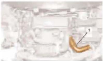
| Towing eye | WARNING: When the engine is not running, steering and braking are no longer power-assisted.The towing eye (1) is to be found in the vehicle toolkit.NOTE: The vehicle toolkit is stowed in the boot |
 | |
| E2A200CD | |
 | |
| E2A200DD | |
| Vehicle towing : Precautions to be taken | |
| Manual gearbox Piloted manual gearbox | |
| ESSENTIAL : Never tow the vehicles with wheels hanging(towing by the wheels). | Vehicle equipped with a piloted manual gearboxIMPERATIVE : It is necessary to lift the front of the vehicle in order to tow it, having placed the gear selector in neutral.If there is a gearbox malfunction or fault, the vehicle may remain immobilised depending on the seriousness of the fault.If a gear is engaged, the conditions for immobilisation of the vehicle may be :- engine stopped (no starting)- clutch open (clutched)IMPERATIVE : If a gear is engaged and it is impossible to disengage it, it is compulsory to tow the vehicle with the front wheels lifted.If it not possible to lift the front of the vehicle, there is more than one way of unjamming the gearbox :- engaging "N" with the aid of a diagnostic tool- engaging "N" without the aid of a diagnostic tool |
| Piloted manual gearbox | |
| Engaging "N" with the aid of a diagnostic toolPreliminary operations :- Vehicle stationary, engine stopped- Battery voltage higher than 12.5 volts- Ignition switched on- Gear selector on position "N"Connect the diagnostic tool to the vehicle's diagnostic socket.Using the diagnostic tool menus, select :- "DIAGNOSIS"- MMT piloted manual gearbox- Actuator tests- Gearbox actuator test- Engaging NeutralNOTE: The letter "N" should appear in the instrument panel. If not, see the following solution: engage "N"; without the help of a diagnostic tool. | Engaging "N" without the aid of a diagnostic toolIn this configuration, the gearbox actuator is jammed, gear engaged.IMPERATIVE: This emergency solution is to be used only where the above solutions for setting the gearbox actuators using the diagnostic tool have failed (destruction of the gearbox actuator).Preliminary operations:Disconnect the negative terminal of the battery.Remove the blank on the gearbox actuator |
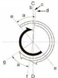
GENERAL SPECIFICATION : TOWING THE VEHICLE
Vehicle towing : Precautions to be taken
Piloted manual gearbox

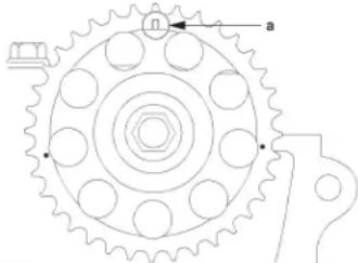
natural_image
Three sequential images (a, b, c) showing a circular object with internal patterns, no visible text or symbols.
natural_image
Close-up mechanical assembly showing internal components and wiring (no visible text or symbols)B2C201TD
"a" Neutral.
"b" 1 ^st , 3 ^rd , 5 ^th .
"c" 2 ^rd , 4 ^th , reverse gear.
Using a large screwdriver, move the screw (3) to bring the gearbox actuator to the neutral position.
When this position is reached, "N" is engaged.
Driving
IMPERATIVE : Never drive with the ignition switched off. Never push the vehicle to attempt to start it (impossible with a piloted manual gearbox).
GENERAL SPECIFICATION : LIFTING AND SUPPORTING THE VEHICLE
Lifting and supporting the vehicle

text_image
Technical diagram of a car with labeled components and structural elements, including a circular component and support structure.E2A2000D
Note on status of the vehicle before lifting
The vehicle should be unloaded before any lifting operation. Never place a loaded vehicle on a jack or on a lift.
When you remove a heavy component, such as the engine or the gearbox, the vehicle's centre of gravity moves.
Note on use of a 4-column lift
Respect the safety requirements set out in the user instructions.
Immobilise the vehicle with wheel locks.
Note on use of jacks and axle stands
Work on a flat surface and always use wheel blocks.
Use axle stands with rubber blocks "a", as indicated.
Place the jack and the axle stands on the prescribed lifting points on the vehicle. Do not use the jack without axle stands.
To raise the front wheels, release the parking brake and place blocks at the rear of the rear wheels only. To raise the rear wheels, place blocks at the front of the front wheels only.
To raise the front wheels only, or the rear wheels only, place blocks on either side of the wheels that are in contact with the ground.
To relower a vehicle raised at the front, release the parking brake and place blocks at the front of the rear wheels only. To relower a vehicle raised at the rear, place blocks at the rear of the front wheels only.
"b": jacking point.
"c": pantograph jacking point lugs.
"d": centre of gravity of the vehicle (excluding load).
A:
3-door
: OFFSET 331 mm
LEVEL 1370 mm
5-door
: OFFSET 349 mm
LEVEL 1387 mm

text_image
Technical diagram of a car's rearview assembly with labeled components and a magnified inset showing internal structure.E2A2001D

text_image
[1]E2A200BD
GENERAL SPECIFICATION : LIFTING AND SUPPORTING THE VEHICLE
Lifting and supporting the vehicle
Note on use of a 4-point lift with moving arms
IMPERATIVE : Position the safety straps, if placing the vehicle on a lift supported from the jacking points (risk of the vehicle overbalancing when a heavy component is removed).
Equip the moving arms with rubber blocks as indicated.
To use this lift, align the middle of it as far as possible with the centre of gravity of vehicle.
Present the vehicle as far as possible in the axis of the moving arms. Adjust the moving arms to the vehicle's jacking points.
WARNING: Do not raise the vehicle too high, to avoid all risk of instability.
Lock the moving arms while the repairs are being carried out.
Raise the vehicle just off the ground and check that it is stable.
Example :
2-column lift
Place the safety straps [1] under the lift arm and criss-crossing the vehicle
| GENERAL SPECIFICATION : LIFTING AND SUPPORTING THE VEHICLE | |
| Lifting and supporting the vehicle | |
B 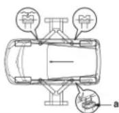 C C 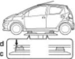 D D  | Note on use of a platform liftRespect the safety requirements set out in the user instructions.Use blocks for a platform lift.B : lift with moving arms.C : platform lift."a" rubber blockDimensions of block D : "e" : 85 mm"f" : 70 mm"g" : 200 mm"h" : 100 mmUse the following table in order to position the vehicle correctly |
| Right/left adjustment Place the vehicle in the middle of the lift | |
| Front/rear adjustment «i» and «j»Align the bottom of the blocks on the extreme edges of the platform rubberAlign the top of the blocks on one of the blocks «k» on the front jacking point lug. | |
| Raise the vehicle just off the ground and check that it is stable. | |
| CAPACITIES (in litres) | |
| Draining methods. | |
| Oil capacities are defined according to the following methods. | |
| Draining of the engine lubrication system by GRAVITY | Draining of the engine lubrication system by SUCTION. |
| Place the vehicle on horizontal ground (in the high position if hydro-pneumatic suspension).The engine should be hot (oil temperature 80^ ).Drain the sump by gravityRemove the oil filter cartridge (time for draining and drip-drip = 15 minutes approx.).Refit the cap with a new sealRefit a new oil filter cartridgeRefill the engine with oil (see table for oil capacity).Start the engine to fill the oil filter cartridge.Stop the engine (allow to stabilise for 5 minutes). | Place the vehicle on horizontal ground (in the high position if hydro-pneumatic suspension).The engine should be hot (oil temperature 80^ ).Remove the oil by suction through the dipstick tube.Remove the oil filter cartridge.Maintain the suction of oil in the sump ( 15 minutes approx.).Refit a new oil filter cartridgeRefill the engine with oil (see table for oil capacity).Start the engine to fill the oil filter cartridge.Stop the engine (allow to stabilise for 5 minutes).WARNING: Remove the suction container before starting the engine |
| ESSENTIAL: Systematically check the oil level using the oil dipstick. | |
| CAPACITIES (in litres) | ||
| Petrol Diesel | ||
| 1.0i 1.4 HDi | ||
| Engine plate | CFA 8HT | |
| Draining by gravity : engine with filter change | 3,1 3,75 | |
| Between min. and max. | 1 1,8 | |
| MT 5-speed gearbox | 1.7 | |
| MMT piloted 5-speed gearbox | ||
| Braking circuit | ||
| Cooling system | 4 4,4 | |
| Fuel tank capacity | 35 | |
| ESSENTIAL : Systematically check the oil level using the oil dipstick. | ||
GENERAL
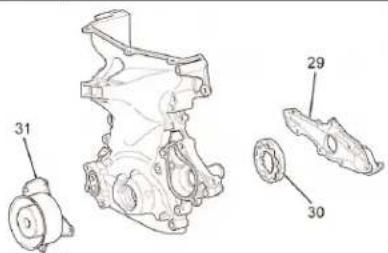
LUBRICATION CIRCUIT SPECIFICATIONS
Engine : CFA

natural_image
Technical line drawing of an internal combustion engine cylinder assembly (no text or labels)B1B202CD
Lubrication system
The lubrication circuit is fully pressurised and all of the oil passes through the oil filter.
The rotary oil pump (30) is driven directly by the crankshaft.
Oil capacity (in litres)
With oil filter : 3,1
Without oil filter : 2,9
| RECOMMENDED LUBRICANTS | ||||||
| Engine oil | ||||||
| TOTAL ACTIVA or TOTAL ACTIVA QUARTZ | ||||||
| Commercial description S | synthetic 9000 Semi-synthetic 7000 Mineral 5000 | |||||
| S.A.E. norms 0 W 40 5 W | 30 5 W 40 10 W 40 | 15 W 50 15 W 40 | ||||
| Climate Cold Hot Temperate | Cold Temperate | Hot | Cold | |||
| Temperate Hot | ||||||
| Petrol engines (**) | ACEA : A3 | ACEA : A5 | ACEA : A3 | ACEA : A3 | ACEA : A2/B2 | |
| API : SJ | API : SL | API : SL/CF | ||||
| Diesel engines (*) | Prohibited | ACEA : B3 | ACEA : 33 ou B4 | ACEA : B3 | Prohibited | |
| API : CF | ||||||
| (*) (*) In winter, on the HDi engine, it is advised to use 5 W 30 or 5 W 40 oil instead of 10 W 40 oil, this to enhance starting from cold. (**) Oil filter specific to C1 petrol with a "U.S." fixing step.For more information, refer to the lubricants bulletin for the model year in Laser under PDI/MAINTENANCE.NOTE : For C1 petrol, use of TOTAL 15 W 40 ACTIVA 5000 : norm API SL/CF or ACEA A2/B2 is recommended.WARNING : For vehicles with a maintenance interval of 30 000 km (20 000 miles), use exclusively TOTAL ACTIVA/QUARTZ 7000 or TOTAL ACTIVA/QUARTZ FUTURE 9000 or any other oil with specifications equivalent to these. Failing this, you can follow the maintenance intervals for severe operating conditions.NOTE : These oils have specifications higher than those defined by norms ACEA A3 or API SJ/SL. | ||||||
GENERAL
RECOMMENDED LUBRICANTS
GEARBOX OIL
| All countries All Types of gearbox ExxonMobil LV 75 W GL.4 |
ENGINE COOLANT : PETROL ENGINE
| Packs | Part No | ||
| All countries | S-LLC pink fluid | 1 Litre | 9735 Y5 |
| 5 Litres | 9735 Y6 | ||
WARNING : Never use PSA coolant (G33) on C1 petrol engines.
ENGINE COOLANT : DIESEL ENGINE
| Packs | CITROËN Part No. | |||
| REVKOGEL 2000GLY | ||||
| All countries | CITROËN fluid Protection : - 35C° | 2 Litres | 9979 70 | 9979 72 |
| 5 Litres | 9979 71 | 9979 73 | ||
| 20 Litres | 9979 76 | 9979 74 | ||
| 210 Litres | 9979 77 | 9979 75 | ||
RECOMMENDED LUBRICANTS
BRAKE FLUID
Synthetic brake fluid
| Packs | CITROËN Part No. | ||
| All countries | CITROËN fluid | 0,5 Litre | 9979 05 |
| 1 Litre | 9979 06 | ||
| 5 Litres | 9979 07 | ||
LIQUIDE LAVE-VITRES
| Packs | CITROËN Part No. | ||||
| All countries | Concentrate : 250 ml | 9980 33 | ZC 9875 953U | 9980 56 | |
| Fluid ready-to-use | 1 Litre | 9980 06 | ZC 9875 784U | ||
| 5 Litres | 9980 05 | ZC 9885 077U | ZC 9875 279U | ||
| ENGINE SPECIFICATIONS | ||
| Petrol Diesel | ||
| 1.0i 1.4 HDi | ||
| Engine type | CFA 8HT | |
| Cubic capacity (cc) | 998 1398 | |
| Bore / Stroke | 71/84 73,7/85 | |
| Compression ratio | 10,5/1 18/1 | |
| Power ISO or EEC KW - rpm | 50-6000 40-3000 | |
| Maximum power DIN (hp-rpm) | 68-6000 54-3000 | |
| Torque ISO or EEC (m.daN - rpm) | 9,3-3600 13-3000 | |
| PRESENTATION OF ENGINE 384 F ( CFA) | ||
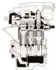
 | Engine : CFA | |
| Description.The petrol engine 384F used on the new vehicle has been developed recently. This is a 1.0 engine with 3 cylinders in line, with 12 overhead valves.This engine is light and compact, giving good fuel economy.It uses DIS (Direct Ignition System) and VVT-i (Variable Valve Timing-intelligent).The search for high performance, silence in operation, reduced fuel consumption and low emissions were all decisive in its design | ||
| B1B201XD | ||

natural_image
Cross-sectional diagram of a mechanical engine showing internal components and shafts (no text or labels)B1B201XD
PRESENTATION OF ENGINE 384 F (CFA)
Engine : CFA
Number of cylinders and arrangement : 3 cylinders in line
Timing : 12 valves, overhead camshaft driven
by chain (with VVT-i)
Combustion chamber : Wedge-shaped
Manifolds
Fuel delivery system : Electronic injection
Ignition system : DIS
Cylindrical capacity (cc) : 998
Bore/Travel (mm) : 71 x 84
Compression ratio : 10.5 : 1
Maximum power (SAE-NET) : 50 kW at 6000 rpm
Maximum torque (SAE-NET) : 93 Nm at 3600 rpm
| PRESENTATION OF ENGINE 384 F ( CFA) | |
 | Engine : CFA |
| Adjustment of inlet valves (opening) : 40° after TDC - 5° after TDCAdjustment of inlet valves (closing) : 10° after BDC - 55° after BDCAdjustment of exhaust valves (opening) : 40° before BDCAdjustment of exhaust valves (closing) : 2° after TDCIgnition sequence : 1-2-3Fuel : Unleaded petrolOctane : 95 or aboveOil quality : API SJ, SL, EC or ILSACEmission standard : EURO 4Weight, empty in running order kg) : 75 kg (approx.) (*)(*) : weight full of oil and coolant. | |
 B1B201YD B1B201YD | Engine : CFAValve adjustments.A: angle of opening of inlet valve.B: angle of opening of exhaust valveC: TDCD: BDC."a" operating range of VVT-i."b" 0°"c" 2°"d" 5°"e" 40°"f" 10°Engine blockValve coverThe valve cover (1) is made of plastic and incorporates the air filter housing, so reducing weight. The valve cover gasket (2) is made of acrylic rubber. This material is known for its resistance to heat as well as for long life. |
 B1B201ZD B1B201ZD | |
| Engine : CFA | |
| Cylinder head gasketA-A : transversal section.(3) : shim.The cylinder head gasket used is in laminated steel.The gasket surface is coated with NBR in order to make the cylinder head more air-tight. | |
 | NOTE : NBR (Nitrile Butadiene Rubber) : rubber material known for its resistance to heat, oil and wear. |
 | Cylinder headThe sparking plugs are placed at the centre of the combustion chambers so as to make the engine less subject to knock.The angle formed between the inlet valves and the exhaust valves is more closed. It has been fixed at 33.5° "h" to permit a cylinder head of a more compact construction.The combustion chambers are double wedge-shaped "k".The shape of the inlet ducts has been optimised for improved combustion.The cylinder head is fixed with extended tension bolts.The extension of the coolant channels "j" into the cylinder head has been optimised for better cooling. |
 | Pistons."m" resin coating.(8) compression ring N°1(9) compression ring N°2(10) scraper ring.The pistons are in aluminium alloy.The piston crowns are conical for enhanced combustion.A new LFA coating (low friction resin and aluminium oxide) is used on the piston skirts.The low tension piston rings give lower friction and thus reduced fuel consumption |
| B1B2023D | |
| Engine : CFATiming chain and tensioner(19) chain guide.(27) chain damper.(28) timing pinion on crankshaft.A high-resistance roller chain (18) with a pitch of 8 mm gives reliability and makes the engine more compact.The chain tensioner (20) uses a spring and hydraulic pressure system to retain the correct tension at all times. The chain tensioner (20) suppresses the noise generated by the chain.An oil jet "x" lubricates the chain as well as the timing pinion on the crankshaft.Timing coverThe cover (29) of the oil pump (30) is incorporated in the timing cover (made of aluminium) on which the water pump (31) is mounted. | |
 B1B202BD B1B202BD | |
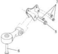
| TIGHTENING TORQUES : ENGINE SUSPENSION | ||||
| Engine/gearbox suspension | ||||
| Engine : CFA | ||||
| RH engine support LH engine support | ||||
 | 1 5 2 ± 0,5 |   | 3 5 2 ± 0,5 | |
| 2 2 4 ± 0,2 | A = Screw on boxB = Screw on body | |||
| Lower suspension | ||||
 | 4 5 2 ± 0,5 | |||
| 5 1 2 ± 1,2 | ||||
| TIGHTENING TORQUES : PETROL ENGINE | |||
| Engine : CFA | |||
| B1B201DD |  | Crankshaft | |
| 1 Crankshaft bearing cap screws 5,9 ± 0,6 | |||
| 2 Tightening 1,5 ± 0,1Angular tightening 9 0° ± 5° | |||
| 3 Crankshaft pulley screw 17 ± 1,7 | |||
| 4 Seal carrier plate screw 1 ± 0,1 | |||
| B1B201ED |  | Cylinder head bolts5 Tightening 3,2 ± 0,3Angular tightening 180° ± 5° | |
| 6 Camshaft bearing cap cover screws (assembly) | 1,5 ± 0,1 | ||
| 7 Camshaft bearing cap cover screws 1,3 ± 0,1 | |||
| 8 Exhaust manifold screws 2,4 ± 0,2 | |||
| 9 Valve cover screws 0,8 ± 0,1 | |||
| 10 Camshaft pulley screws 4,7 ± 0,4 | |||
| Crankshaft | |||
| 11 | RH engine supportTightening of screws on blockTightening of screws on body 5,2 ± 0,5 | 2,4 ± 0,2 | |
| 12 Timing chain cover screw 2,4 ± 0,2 | |||
| 13 Timing chain cover screw 4 ± 0,4 | |||
ENIGNE
| TIGHTENING TORQUES : PETROL ENGINE | |||
| Engine : CFA | |||
 B1B201GD B1B201GD | Lubrication | ||
| Oil pump 0,9 ± 0,1 | |||
| 14 Sump screws 1 ± 0,1 | |||
| 15 Sump screws 2,4 ± 0,2 | |||
| Flywheel /clutch | |||
| 16 Flywheel screws 7,8 ± 0,8 | |||
| 17 Clutch plate screws 1,9 ± 0,2 | |||
 B1B2015D B1B2015D | |||
 | Injection circuit | ||
| 18 Injection rail screw on block 2,7 ± 0,3 | |||
| Cooling circuit | |||
| 19 Coolant pump screws 2,8 ± 0,3 | |||
| 20 Coolant inlet housing screws 0,7 ± 0,1 | |||
| Accessories | |||
| 21 Alternator screw 4,9 ± 0,5 | |||
| 22 Tensioner screw 3,4 ± 0,4 | |||
| 23 Aircon compressor screw 2,4 ± 0,2 | |||
| B1B201HD | 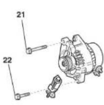  | ||
  | |||
| B1B201XD | D1A2004D | ||
| TIGHTENING TORQUES : ENGINE SUSPENSION | ||||
| Engine/gearbox assembly suspension | ||||
| Engine : 8HT | ||||
| RH engine support Lower RH engine support | ||||
 B1B201AD B1B201AD | 1 5,2 ± 0,5 | 4 5|7 ± 0,6 | ||
| 2 5,2 ± 0,5 | ||||
| 3 5,2 ± 0,5 | ||||
| Torque reaction rod LH engine support on gearbox | ||||
 B1B201BD B1B201BD | 5 5,2 ± 0,5 |  | 8 5|2 ± 0,5 | |
| 6 | 12 ± 1,2 | 9 5|2 ± 0,5 | ||
| 7 | 10 5,2 ± 0,5 | |||
| TIGHTENING TORQUES : DIESEL ENGINE | |
| Engine 8HT | |
| Crankshaft | |
| Bearing cap fixing screwsPre-tightening 1 ± 0,1 Slackening 180^ ± 5^ Tightening 3 ± 0,3 Angular tightening 140^ ± 5^ | |
| Con rod screwsTightening 1 ± 0,1 Angular tightening 100^ ± 5^ | |
| Accessories drive pulleyTightening 3 ± 0,3 Angular tightening 180^ ± 5^ | |
| Cylinder block | |
| Oil sump 1,3 ± 0,1 | |
| Timing belt guide roller 3,7 ± 0,3 | |
| Timing belt tensioner roller 2,3 ± 0,2 | |
| Cylinder head | |
| Camshaft bearing cap coversPre-tightening 0,3 ± 0,1 Tightening 1 ± 0,1 | |
| Fixing of camshaft sub-assemblies on cylinder headPre-tightening 0,3 ± 0,1 Tightening 1 ± 0,1 | |
| Exhaust manifold 3 ± | |
| Camshaft pulleysPre-tightening 2 ± 0,2 Angular tightening 50^ ± 5^ | |
| Cylinder headPre-tightening 2 ± 0,2 Tightening 4 ± 0,4 Angular tightening 230^ ± 5^ | |
| EGR valve 1 ± 0,1 | |
| Flywheel | |
| FlywheelPre-tightening 1,7 ± 0,2 Angular tightening 70^ ± 5^ | |
| Clutch mechanism 2 ± 0,2 | |
| Lubrication circuit | |
| Oil pump assemblyPre-tightening 0,5 ± 0,1 Tightening 0,9 ± 0,1 | |
| Oil/coolant heat exchanger 1 ± 0,1 | |
| Turbocharger lubrication pipe 3 ± 0,3 | |
| Diesel injection circuit | |
| Spherical base screw for diesel injection fixing fork 2,5 ± 0,2 | |
| Fuel high pressure common injection rail on engine block 2,2 ± 0,2 | |
| Unions on fuel high pressure common injection railPre-tightening 1,7 ± 0,1 Tightening 2,2 ± 0,2 | |
| Diesel injection pump on support 2,2 ± 0,2 | |
| Union on diesel injectorPre-tightening 1,7 ± 0,1 Tightening 2,2 ± 0,2 | |
| Diesel injection pump pulley 5 ± 0,5 | |
| Union on diesel high pressure pumpPre-tightening 1,7 ± 0,1 Tightening 2,2 ± 0,2 | |
| Cooling circuit | |
| Coolant pumpPre-tightening 0,3 ± 0,1 Tightening 0,9 ± 0,1 | |
| Coolant outlet housingPre-tightening 0,3 ± 0,1 Tightening 0,7 ± 0,1 | |
| TIGHTENING TORQUES : CYLINDER HEAD | |||||
| Petrol and Diesel engines | |||||
| Operation to be performed prior to refitting the cylinder headClean the seal faces with the CITROËN-approved product.Do not use abrasives or cutting tools on the seal faces.The seal faces must not show any traces of impacts or scratches.Pass a tap into the threads in the cylinder block that receive the cylinder head bolts.Brush the threads of the cylinder head bolts.Coat the threads and under the heads withMOLYKOTE G.RAPIDE PLUS. | |||||
| B1D2028D |  | Engines Tightening | Cylinder head bolts(Max. re-usable length i'n mm) | ||
| CFA | Tightening 3,2 ± 0,3 Angular tightening 1 8 0^ ± 5^ | 123,5 | |||
 | 8HT | Pre-tightening 2 ± 0,2 Tightening 4 ± 0,4 149 Angular tightening 2 3 0^ ± 5^ | |||
| B1D2019D | - - - - - - | ||||
| BELT TENSION/SEEM UNITS CORRESPONDENCE TABLE | |||||||||||||||||||||
| ↓4099-T (C.TRONIC.105) | ← Tools → 4122-T (C.TRONIC.105.5) ↓ | ||||||||||||||||||||
| 1 daN = 1 Kg / TYPE DE COURROIES | 5 | 10 | 15 | 20 | 25 | 30 | 35 | 40 | 45 | 50 | 55 | 60 | 65 | 70 | 75 | 80 | 85 | 90 | 95 | 100 | |
| S | 18 | 28 | 36 | 44 | 51 | 58 | 64 | 70 | 76 | 82 | 88 | 94 | 100 | 106 | 112 | ||||||
| 18 | 28 | 36 | 44 | 51 | 58 | 64 | 70 | 76 | 82 | 88 | 94 | 100 | 106 | 112 | |||||||
| P | E5 | 18 | 23 | 27 | 31 | 34 | 37 | 40 | 43 | 46 | 49 | 52 | 54 | 56 | 58 | 60 | 62 | 64 | 66 | 68 | |
| E6 | 25 | 32 | 39 | 45 | 50 | 54 | 58 | 62 | 66 | 70 | 74 | 78 | 81 | 84 | 86 | 88 | 89 | 90 | 91 | ||
| 32 | 41 | 48 | 55 | 62 | 69 | 76 | 83 | 90 | 96 | 102 | 108 | 114 | 120 | 126 | 132 | 138 | 144 | 150 | |||
| P | E6 | 27 | 36 | 43 | 49 | 55 | 61 | 66 | 71 | 76 | 80 | 84 | |||||||||
| 32 | 41 | 49 | 57 | 63 | 69 | 75 | 81 | 87 | 93 | 99 | |||||||||||
| P | E6 | 26 | 35 | 42 | 48 | 53 | 58 | 63 | 68 | 73 | 78 | 82 | |||||||||
| 30 | 40 | 47 | 54 | 61 | 68 | 75 | 81 | 87 | 93 | 99 | |||||||||||
| P | E7 | 45 | 55 | 65 | 74 | 83 | 89 | 95 | 101 | 107 | 113 | 119 | |||||||||
| 36 | 49 | 52 | 64 | 73 | 80 | 86 | 92 | 98 | 104 | 110 | |||||||||||
| T | E7 | 28 | 34 | 39 | 44 | 48 | 52 | 56 | 60 | 64 | 68 | 71 | |||||||||
| 34 | 41 | 48 | 55 | 62 | 69 | 76 | 83 | 89 | 96 | 102 | |||||||||||
| T | E8 | 32 | 39 | 45 | 51 | 56 | 61 | 66 | 71 | 76 | 79 | 81 | |||||||||
| 37 | 43 | 51 | 59 | 66 | 73 | 80 | 86 | 92 | 98 | 104 | |||||||||||
| T | E9 | 52 | 60 | 67 | 74 | 81 | 88 | 94 | 100 | 106 | 110 | 114 | |||||||||
| 49 | 57 | 63 | 69 | 75 | 81 | 87 | 93 | 99 | 105 | 111 | |||||||||||
| AUXILIARY EQUIPMENT DRIVE BELT | ||
| Petrol Diesel | ||
| 1.0i 1.4 HDi | ||
| Engine plate | CFA 8HT | |
| C1 | X | X |
| See pages : | 46 to 47 48 to 49 | |
AUXILIARY EQUIPMENT DRIVE BELT
Engines : Petrol and Diesel
TOOLS
Belt tension measuring instrument : 4122 - T (C.TRONIC 105.5)
WARNING : If using tool 4099-T (C.TRONIC 105)
ESSENTIAL.
Before refitting the auxiliary equipment drive belt, check that:
1) The roller(s) rotate freely (no play or stiffness)
2) The belt is correctly engaged in the grooves of the various pulleys.
| AUXILIARY EQUIPMENT DRIVE BELT | ||
| Engine : CFA | ||
 |  | Removing"a" Tension pulley"b" Alternator pulley"c" Compressor pulley."d" Crankshaft pulley.B: With airconC: Without aircon.Slacken the screw (1).Slacken the screw (2).Do up the screw (2) without tightening it, until there is no more play A.Slacken the screw (3).Remove the trapezoidal belt from the ventilator and from the alternator. |
| B1B2000D | ||
AUXILIARY EQUIPMENT DRIVE BELT
Engine : CFA

text_image
B1B2000D A b 3 2 a c d B CRefitting
Refit the trapezoidal belt on the ventilator and on the alternator.
"a" Tension pulley
"b" Alternator pulley.
"c" Compressor pulley
"d" Crankshaft pulley.
B : With aircon
C : Without aircon.
Do up the screw (2) without tightening it, until there is no more play A. Tighten the screw (3) to tension the trapezoidal belt on the ventilator and on the alternator. Check the trapezoidal belt on the ventilator and on the alternator.
Tighten the screw (2)
Tightening torque : 3,4 ± 0,3 m.daN.
Tighten the screw (1).
Tightening torque between : 4,3 and 5,5 m.daN.
Visually check the cabling of the alternator and listen for any abnormal noise.
Check the circuit of the discharge alert warning lamp
AUXILIARY EQUIPMENT DRIVE BELT
Engine : 8HT

text_image
Technical diagram showing mechanical assembly with labeled parts a and b, including circular insets for detail views.B1E200AD
Tools.
[1] Compression lever for dynamic tensioner : (-).0194.E3
[2] Peg for dynamic tensioner roller : (-).0194.F
References on the dynamic tensioner roller
"b" Nominal position.
"a" Position for "maximum wear" of the auxiliary drive belt.
Removing.
Disconnect the battery negative cable.
Raise and support the vehicle, wheels hanging.
Lock the front wheels on full RH lock.
Move aside the splash-shield.
IMPERATIVE : In the case of belt re-use, mark the direction of rotation of the belt. If the index on the tensioner roller is outside the marks, change the auxiliary equipment drive belt.

text_image
A 1 2 3 B 4 5 6B1B2010D
A : Vehicle with air conditioning
B : Vehicle without air conditioning
1 and 4 Alternator pulley.
3 and 6 Auxiliary drive belt pulley.
5 Guide roller.
2 Aircon compresseur pulley
AUXILIARY EQUIPMENT DRIVE BELT
Engine : 8HT

text_image
[2] [1] 7B1B2011D
Compress the dynamic tensioner roller, using tool [1].
Position the peg [2]
Remove the auxiliary drive belt (7).
Refitting
NOTE : Check that the tensioner roller moves freely (no tight spot). If this is not the case, replace the tensioner roller.
Respect the direction of fitting of the drive belt.
Position the auxiliary drive belt.
Move the tool [2] on the tensioner roller to remove the peg [3].
Make sure that the drive belt is correctly positioned in the «V» grooves of the various pulleys.
Refit the splash-shield.
Reconnect the battery negative cable.
IMPERATIVE : Carry out the operations that are necessary following a reconnection of the battery (see corresponding operation).

| CHECKING AND SETTING THE VALVE TIMING | ||
| Petrol Diesel | ||
| 1.0i 1.4 HDi | ||
| Engine plate | CFA 8HT | |
| C1 | X | X |
| See pages : | 53 to 69 70 to 77 | |
ENIGNE
RECOMMENDATIONS : TIMING BELT
Engines : All Types
Recommendations
IMPERATIVE : After any repair involving removal of the timing belt, systematically replace :
The timing belt,
The tensioner roller fixing nut.
| CHECKING AND SETTING THE VALVE TIMING | |
 B1D201MD B1D201MD | Engine : CFA |
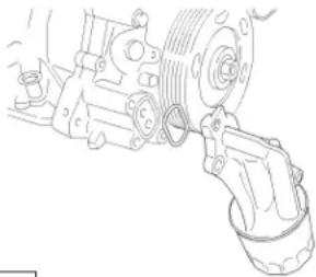
| MPERATIVE : Respect the safety and cleanliness requirements.Removing.Raise and support the vehicle, wheels hanging.Disconnect the battery negative cable (see corresponding operation).Drain the engine oil (see corresponding operation).Drain the gearbox oil (see corresponding operation).Drain the cooling circuit (see corresponding operation).Remove the auxiliary drive belt (see corresponding operation).Remove the sump.Remove the driveshafts (see corresponding operation).Remove the engine-gearbox assembly (see corresponding operation).Move aside the elastic clip on the coolant pump.Remove the alternator (see corresponding operation).Remove the screw and the guide-tube of the oil gauge.Remove the O-ring seal on the guide-tube of the oil gauge. | |
 B1D201ND B1D201ND | |
 B1D201QD B1D201QD | Engine : CFA |
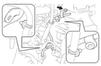
| Disconnect the camshaft position sensor.Remove the screw and the crankshaft position sensorRemove the 13 screws and the 2 nuts in the sequence indicated. | |
 B1D201RD B1D201RD | Remove the valve cover with its gasket.Remove the valve cover gasket |
 B1D201SD B1D201SD | Engine : CFA |
| Remove the 3 screws, the support for the oil filter and its sealRemove the 5 screws, the coolant pump and its seal. | |
 B1D201TD B1D201TD | |
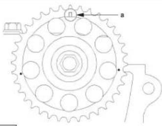
 B1D201UD B1D201UD | Engine : CFATurn the crankshaft pulley clockwise in order to align the setting mark "a" on the toothed wheel (0 degrees) with those on the timing cover.Make sure that the setting mark "a" on the camshaft pulley is on top as indicated.NOTE: Failing this, turn the crankshaft pulley by one full turn (360 degrees) to bring the setting mark to the top.Lock the crankshaft pulley, using tool [1] and remove it. |
 B1D201VD B1D201VD | [1] : C.0132.AARemove the timing cover. |
| B1D201WD | Engine : CFA |
| Turn the chain tensioner stop plate clockwise and compress the piston.Insert peg into the hole in the stop plate so as to lock the tensioner with the thrust piston in the compressed position.Remove the 2 screws and the chain tensioner.Remove the screw, the chain tensioner guide and the timing chain. | |
| B1D201XD | |
 B1D201YD B1D201YD | Engine : CFARemove the 2 screws, the chain guide and the crankshaft toothed wheel.Remove the keyway. |
 B1D201ZD B1D201ZD | |
 B1D201ZD B1D201ZD | |
 B1D202HD B1D202HD | |
 B1D202JD B1D202JD | Engine : CFA |
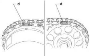
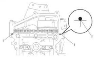
| To refit the timing chain, align the link "c" (yellow in colour) with the setting mark "b" on the crankshaft pinion as indicated.To complete the refitting of the timing chain, align the 2 links "d" (orange in colour) with the setting marks "a" on the camshaft pulleys as indicated. | |
 B1D202KD B1D202KD | Refit the chain tensioner guide with the screw.Tightening torque : 1,9 ± 0,2 m.daN. |
 B1D202LD B1D202LD | Engine : CFA |
| Turn the hexagonal part of the inlet camshaft anti-clockwise in order to detension the timing towards the tensioner.Refit the tensioner with the 2 screws. | |
 B1D202MD B1D202MD | Tightening torque between : 0,8 and 1,3 m.daN.Remove the peg, rotate the crankshaft by 2 full turns and unlock the chain tensioner.. |
 B1D202ND B1D202ND | Engine : CFA |
| Check that the setting mark "a" on the camshaft pulley is on top with the chain in tension.Refit the timing cover. | |
 B1D202PD B1D202PD | Coat the lip of a new lip seal with engine oil. |
CHECKING AND SETTING THE VALVE TIMING

text_image
B1E200HD [2]
text_image
B1D202RDEngine : CFA
Fit the new crankshaft seal using tool [2].
[2] : 0196.B
Degrease the sealing faces of the cylinder block and of the timing cover.
| References Dimensions (mm) References Dimensions (mm) | |||
| B | 3 | G | 3 |
| C | 3 | H | 3 |
| D 3,5 to 4,5 | 3 to 3,5 | ||
| E 4,5 to 5,5 | 3,5 to 4,5 | ||
| F 4,5 to 5,5 | |||
Apply a strip of seal paste on the cylinder block at «g» and on the timing cover at «h» as indicated, and refit the timing cover «h».
WARNING : Refit the timing cover within 3 minutes following the application of the strips of seal paste.
| CHECKING AND SETTING THE VALVE TIMING | |
  B1D202SD B1D202SD | Engine : CFA |
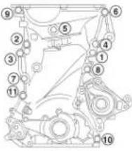
| Tighten the 11 screws in the sequence indicated.Tightening torque for screws (1) : 2,4 ± 0,2m.daN .Tightening torque for screws (2) : 4 ± 0,4 m.daN .Remove the excess seal paste.Fit a new coolant pump seal on the timing cover and refit the coolant pump. | |
 B1D201TD B1D201TD | |
 B1D202TD B1D202TD | Engine : CFA |
| Tighten the 5 screws in the sequence indicated.Tightening torque : 2,8 ± 0,3 m.daN.Lock the crankshaft pulley using tool [1] and tighten the screw.[1] : C.0132.AATightening torque : 17 ± 1,7 m.daN. | |
 B1D202UD B1D202UD | |
 B1D201SD B1D201SD | Engine : CFA |
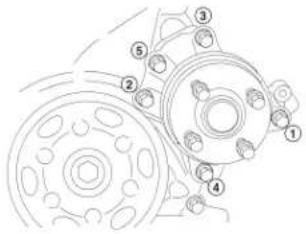
| Refit the oil filter seal on the timing cover and refit the oil filter support.Tighten the 3 screws in the sequence indicated. | |
 B1D202VD B1D202VD | Tightening torque : between 1,9 and 2,9 m.daN. |
 B1D202WD B1D202WD | Engine : CFA |
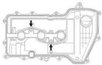
| Refit the valve cover gasket in the groove of the valve cover and on the centring bosses indicated by the arrows.WARNING: Check the positioning of the gasket, which must be well seated around the bases of the bosses."k" : 3 to 4 mm. | |
 B1D200VD B1D200VD | Apply a strip of seal paste "j" on the sealing faces of the cylinder head and of the timing cover.Seal paste : AUTOJOINT OR.WARNING: Refit the valve cover within 3 minutes and tighten the screws and nuts within 15 minutes following application of the strip of seal paste "j". |
CHECKING AND SETTING THE VALVE TIMING

text_image
Technical diagram of a mechanical assembly with numbered components for identificationB1D202XD
Engine : CFA
Tighten the 13 bolts and 2 nuts to the correct torque in the sequence indicated.
Tightening torque : 0,8 m.daN.
After tightening all the screws and nuts, check that "1" and "2" are tightened to the correct torque.
Refit the crankshaft position sensor.
WARNING: Do not use any component that has been dropped or knocked.

natural_image
Mechanical assembly diagram showing a gear and wheel assembly (no text or labels)B1D201QD
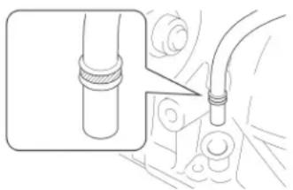
WARNING: Check the condition of the O-ring seal before refitting it.
Coat the O-ring seal with a thin layer of engine oil.
Refit the crankshaft position sensor with the screw.
Tightening torque : 0,8 m.daN.
Connect the connector of the crankshaft position sensor.
| CHECKING AND SETTING THE VALVE TIMING | |
 B1D201ND B1D201ND | Engine : CFA |
| Fit a new O-ring seal on the guide-tube of the oil level gauge.Coat the O-ring seal with a thin layer of engine oil.Refit the guide-tube of the oil level gauge with the screw.Tightening torque : 1 ± 0,1 m.daN.Refit the alternator (see corresponding operation).Position the elastic clip for the coolant pump.Apply seal paste (AUTOJOINT OR) on the surround of the sump.Refit the engine-gearbox assembly (see corresponding operation).Refit the driveshafts (see corresponding operation).Refit the sump. | |
 B1D201MD B1D201MD | Refit the auxiliary drive belt (see corresponding operation).Fill and top up the engine and the gearbox (see corresponding operation).Fill and bleed the engine cooling circuit (see corresponding operation).Check all the levels.Reconnect the battery negative terminal.IMPERATIVE : Perform the operations that are required following a battery reconnection (see corresponding operation). |
CHECKING AND SETTING THE VALVE TIMING

text_image
B 1C4A2003D
Engine : 8HT
Tools.
[1] Engine flywheel setting peg : (-).0194.C
[2] Camshaft setting peg : (-).0194.B
[3] Crankshaft setting peg : (-).0194.A
[4] Movable mirror
[5] Tool for removing exhaust clips
[6] Hose clamp : (-).0188.AD
Removing.

text_image
2 4 f 3 e d c bC4A2004D
Preliminary operations
Disconnect the battery negative terminal.
Place the vehicle on a 2-column lift.
Remove the screws (1).
Move aside the bumper at "a".
Remove the plastic rivet (4).
Apply a force upwards at "f".
Detach in the sequence "b", "c", "d", "e".
Move aside the bumper (3).
Remove the headlamp (2).
| CHECKING AND SETTING THE VALVE TIMING | |
 | Engine: 8HT |
| In the engine compartmentRemove the screw (9).Disconnect the connector at "g".Move aside the header tank (8).Detach the harness (6) on the timing cover (5).Refit:- the screws (7)- the upper timing cover (5)Put the header tank (8) back in its initial position.Remove the accessories drive belt (see corresponding operation). | |
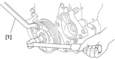
| [B1B2009D] | Under the vehicleRemove the exhaust clip (10) using tool [5].Uncouple the exhaust line.NOTE:Removing the exhaust clip prevents the front flexible pipe from being damaged. Twisting, pulling and bending reduces the life of the front flexible exhaust pipe.Rotae the engine by means of the crankshaft pulley screw to bring it to the flywheel locking position, using tool [1].NOTE:The locking hole is under the engine |
 | |
| [B1J2002D] | |
  B1E2000D B1E2000D | Engine:8HTRemove:- the screw (12)- the accessories drive pulley (14)Refit the screw (12).Remove the peg [1].Disconnect the connector at "h".Slacken the screws (13).Remove the lower timing cover (11).IMPERATIVE: The magnetic track "j" of the crankshaft pinion should show no signs of damage and should not be approached by any other source of magnetism.Remove:- the engine speed sensor (16)- the belt retaining stop (15) |
 B1E2004D B1E2004D | |
CHECKING AND SETTING THE VALVE TIMING

natural_image
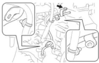
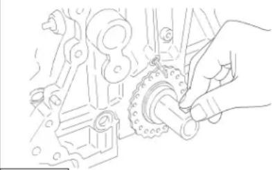
Close-up of a mechanical component with numbered annotation (17), no readable text or symbols beyond labelEngine : 8HT
Remove the nut (17).
In the engine compartment
Move aside the header tank.
Support the engine with a roller jack equipped with a block.

text_image
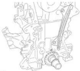
20 19 18Remove :
- the bottom support of the expansion chamber (20)
- the engine support (19)
- the intermediate engine support (18)
Lower the engine by 3 cm.
WARNING : Operate the jack with care. Do not leave the engine without support. Take care with the routing of the header tank hose. Check for any interference between the lower crossmember and the heat shield of the catalytic converter.
B1B200GD

text_image
[3] [2] k 21 [3] 12B1E2006D
CHECKING AND SETTING THE VALVE TIMING
Engine : 8HT
NOTE : The engine has to be lowered by 3 cm so that you can position the crankshaft by means of the peg.
Rotate the engine by means of the crankshaft pinion screw (12) clockwise, to bring it to the pegging position.
Position :
- the camshaft pinion, using the peg [2]
- the fuel high pressure pump, using the peg [3]
- the crankshaft pinion, using the peg [3]
Hold the tensioner roller in place, by means of a hexagonal spanner at "k".
Slacken the screw (21).
Detension the timing belt by pivoting the tensioner roller clockwise at "k".
Remove the timing belt.
CHECKING AND SETTING THE VALVE TIMING

text_image
1 22 23 m 24 27 n 26 25B1E2007D
Engine : 8HT
Refitting
Preliminary operations
IMPERATIVE :
Check the condition of the seals for the camshaft and the crankshaft pinion. If in doubt don't hesitate to change the seals.
Check that there are no leaks at the coolant pump. If in doubt don't hesitate to change it. Check that both the tensioner roller and the guide roller can turn freely (no tight spots). If this is not the case, replace the rollers.
Refitting the belt
IMPERATIVE : Replace the belt as well as the crankshaft pinion screw (12) with new at each removal. Do not twist or bend the belt.
NOTE : Pegging the high pressure pump serves to increase the life of the timing belt.
NOTE : Use of the tool [6] on the camshaft pinion (23) makes the operation to fit the timing belt easier. WARNING : The setting pegs have to be in place on the engine.
NOTE : If the belt sections "l", "m" and "n" are not kept taut during the tensioning of the belt, the timing becomes offset. The engine suffers damage.
Reposition the timing belt, sections "l", "m" and "n" kept taut, on the following components:
- Crankshaft pinion (25), guide roller (24), camshaft pinion (23), fuel high pressure pump pulley (22), coolant pump pinion (26), tensioner roller (27).
CHECKING AND SETTING THE VALVE TIMING

text_image
A P k 21B1E2008D
Engine : 8HT
NOTE : The tensioning operation is made easier by use of a mirror.
Move the tensioner roller at "k" anti-clockwise by means of a hexagonal spanner.
Rotate the tensioner roller to bring the index "p" to position "q".
-Tighten the screw (21) of the tensioner roller to : 3 ± 0,3 m.daN.
Remove the pegs [2] and [3].
IMPERATIVE: Check that the crankshaft pinion is firmly on the crankshaft.
Rotate the engine 10 turns.
Check the pegging of the camshaft, the pegging of the crankshaft pinion, the
pegging of the fuel high pressure pump and the correct positioning of the index on the dynamic tensioner (see diagram) ; use a mirror.
If these are not correct, restart the operation to position the timing belt.
In the engine compartment
Raise the engine back to its initial position.
Refit :
the intermediate engine support (18)
- tighten the screws to : 5,7 ± 0,5 m.daN.
the RH engine support (19), the bottom support of the expansion chamber (20) and the screws (29)
and (28) without tightening them
Remove the jack.
Tighten
-the screws (29) to
-the screws (30) to
: 6 ± 0,6 m.daN.
: 5,2 ± 0,5 m.daN.

text_image
28 20 19 18 29B1B200HD
| CHECKING AND SETTING THE VALVE TIMING | ||
 | Engine : 8HTUnder the vehicle.Refit the nut (17), tighten to : 6 ± 0,6 m.daN.Refit :- the engine speed sensor (16)- the belt retaining stop (15), tighten to : 0,7 ± 0,1 m.daN.- the lower timing cover (11)Lock the engine flywheel, using tool [1].Remove the screw (12).Refit : the accessories drive pulley (14), the screw (12) (new).Tighten the screw of the accessories drive pulley (12) :- Pre-tightening : 3 ± 0,3 m.daN.- Angular tightening : 180° ± 5°.Remove tool [1].Refit the exhaust clip, using tool [5].In the engine compartmentRefit :- the upper timing cover (5)- the expansion chamber (8)- the accessories drive belt (see corresponding operation)Proceed in the reverse order to the removal operations.Reconnect the battery negative terminal.IMPERATIVE : Perform the operations that are required following a battery reconnection (see corresponding operation). | |
| B1E2005D | ||
 | ||
| B1E2004D | ||
| EXHAUST LINE SPECIFICATIONS | ||
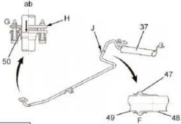
 | Engine : CFA | |
| Inlet and exhaust systemGeneral(37) Silencer.An inlet manifold (36) made of plastic to reduce weight.The butterfly body (40) is of plastic.The valve cover (1) is of plastic. It incorporates the air filter housing (38).The exhaust manifold (39) and piping are of stainless steel. These reduce weight and have better resistance to corrosion. | ||
| B1B202FDB1B202GD | Inlet manifold | |
 | The inlet manifold (43) is of plastic to reduce weight and the quantity of the heat transmitted by the cylinder head. This solution reduces the temperature of the inlet air and increases the inlet performance by volume.The inlet manifold comprises a depressiometer (44) for measurement of inlet vacuum and a sensor for measurement of inlet air temperature. | |
 B1B202KD B1B202KD | Engine : CFA | |
| Exhaust manifold"aa" view from above."ab" front view.The exhaust manifold (39) made of stainless steel is designed both to enhance the rise in temperature of the 3-way catalytic converter and to reduce weight.The catalytic converter uses ceramics with ultra-thin walls with high cell density. The optimisation of cell density of the catalytic converter serves to reduce pollutant emissions .Exhaust pipe"ac" from the exhaust manifold.(47) tightening clip(48) front pipe.(49) rear pipe(50) gasket.The silencer (37) has been optimised with the aim of making it both compact and light.The junction between the front and rear parts H of the exhaust pipe is by means of the insertion E, making a gasket no longer necessary.The junction of the exhaust pipe to the exhaust manifold G uses a spherical seal F. This solution simplifies the construction and improves reliability. | ||
 B1B202LD B1B202LD | ||
EXHAUST LINE SPECIFICATIONS
Engine : CFA

text_image
Labeled diagram of a mechanical device with numbered components for identification| (1) (2) (3) Exhaust manifold oxy | (4) (5) (6) (7) Upstream gen sensor oxyg | Clip gen sensor converter | Rear | silencer | Downstream | Screws | |
| Tightening (m.daN) | 2,4 ± 0,2 | 4,4 ± 0,4 | 3,2 ± 0,3 | 4,4 ± 0,4 | 4,5 ± 0,4 |
EXHAUST LINE SPECIFICATIONS
Engine : 8HT

text_image
1 2 3 4 5 6 7 aB1J2001D
| (1) (2) (3) (4) (5) (6) (7)Rubbersuspension suspension | Silencersuspension converter pipe | Rubber | Clip | Catalytic | Intermediate | Clip | |
| Tightening (m.daN) | 2,5 ± 0,2 | 2 ± 0,2 | 3,2 ± 0,3 | ||||
| Reference | TR PSA K278 |
| COOLING SYSTEM SPECIFICATIONS | ||
| 1.0i 1.4 HDi | ||
| Engine type | CFA 8HT | |
| Capacity | 4 4,4 | |
| Radiator surface | 12,2 dm ^2 | |
| Pressurisation | 1,4 bars | |
| Opening of thermostatic regulator | 82°C | |
| Cooling fan (Triggering threshold) | 93°C 97°C | |
| Without aircon | 1 x 100 Watt | |
| With aircon | 1 x 300 Watt | |
| Aircon cut-off | 115°C | |
| Alert | 118°C | |
| Post cooling | 105°C (for 6 minutes) | |
| Coolant temperature sensor and alert : located on the coolant outlet housing. | Green connector | |
| Engine coolant level sensor | On the expansion chamber | |
| Temperature sensor : tightening torque : 2 ± 0,2 m.daN. | ||
| COOLING SYSTEM SPECIFICATIONS | |
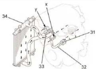 B1B202DD B1B202DD | Engine : CFACooling circuit"y" towards the heater unit. "z" from the heater unit.(32) bypass pipe. (34) radiatorA thermostat (33) with bypass valve is fitted at the inlet end of the coolant pump (31) on the cooling circuit.The engine uses a specific coolant that has very long life.Specifications :Thermostat with opening temperature : 82°C.- Coolant fluidType : Coolant with very long life for petrol orequivalent engine.Capacity (litres) : 4. System diagram(35) heater unit.Specifications of coolant fluid :- Type : Coolant with very long life for petrol orequivalent engine- Colour : Pink.- 1streplacement of fluid : 150 000 km (100 000 miles).Subsequent replacements : Every 60 000 km (40 000 miles).WARNING : The coolant is already a blended product (50 % coolant and 50 % de-ionised water), therefore no further mixing mut be done when topping up or replacing coolant. |
 B1B202ED B1B202ED | |
| Engine : CFA | |
| (1) Coolant pump.(2) Thermostat.(3) Heater matrix.(4) Cylinder block drain screw.(5) Cooling radiator.(6) Top hose | |
 | Engine:8HT |
| (1) Bleed screw.(2) Exhaust gas recycling (EGR) heat exchange (EURO 4 version). | |
| CHECKING THE OIL PRESSURE | ||
| Petrol Diesel | ||
| Engines CFA 8HT | ||
| Temperature (°C) | 90°C | |
| Pressure (Bars) 1.3 | ||
| Rpm 1000 | ||
| Pressure (Bars) 3.7 | ||
| Rpm 2000 | ||
| Pressure (Bars) | ||
| Rpm | ||
| Pressure (Bars) 5 | 3,5 | |
| Rpm 4000 4000 | ||
| Tools | ||
| 4386-T X | ||
| 4601-T X | ||
| 1503-L X | ||
| 2279-T.Bis X | ||
| 4103-T X | ||
| (-).1503.J | X | |
| NOTE: The oil pressure should be checked with the engine hot, after the oil level has been checked. | ||
VALVE CLEARANCES
CFA petrol engine
Adjust by change of cam followers (See presentation of 384F engine).
8HT diesel engine
Hydraulic compensator
DRAINING, FILLING AND BLEEDING THE ENGINE COOLING CIRCUIT
Engine : CFA

text_image
B1G200ND
text_image
B1G200PDIMPERATIVE: Respect the safety and cleanliness requirements.
WARNING : To avoid all risk of burns, do not remove the radiator cap while the engine and the radiator are hot. Thermal expansion may cause coolant fluid and steam to escape from the radiator. Slacken the drain screw (1) and drain the coolant fluid.
NOTE : The drain screw (1) is situated close to the lower edge of the timing cover.
Remove the radiator cap «a».
Uncouple the radiator outlet hose to drain the coolant fluid.
Couple the radiator outlet hose on the engine side.
Refit the drain screw (1).
Tightening torque : 2 ± 0,2 m.daN.
Fill the radiator with engine coolant fluid until it overflows.
WARNING : Do not replace coolant fluid with water.
NOTE : Use of coolant fluid that is inappropriate may damage the cooling system.
NOTE : Use only «Toyota Super Long Life Coolant» engine coolant fluid or any other similar high quality coolant fluid based on ethylene glycol, without silicate, without amine, without nitrite and without borate, but with hybrid organic acid properties that guarantee long life (this type of fluid is a blend of organic acids and phosphates in low concentration).
DRAINING, FILLING AND BLEEDING THE ENGINE COOLING CIRCUIT
Engine : CFA

natural_image
Technical line drawing of a mechanical component with no visible text or symbolsB1G200ND
Press the radiator inlet and outlet hoses several times to test the level of coolant in the radiator. If the level goes down, add more coolant fluid.
Screw the radiator cap "a" back on securely.
Slowly pour engine coolant into the expansion chamber up to the maximum mark.
Warm up the engine, until the cooling fan triggers.
Adjust the air conditioning as indicated during the rise in engine temperature.
Manual air conditioning system
Adjust the controls as indicated
Speed of cooling fan : all adjustments except temperature in position "OFF" : button turned towards hot air, air conditioning control in position "OFF"
Maintain the engine speed between 2000 and 2500 rpm until the cooling fan triggers.
Press several times on the radiator inlet and outlet hoses several times during the rise in engine temperature.
Stop the engine and wait for the coolant temperature to come down.
If the coolant level is below the maximum mark, repeat the 10 previous stages until the coolant level is up to add more coolant fluid.
Again check the level of engine coolant in the expansion chamber. If it is below the maximum mark, add more coolant fluid.
Fill the radiator with coolant fluid and fix on it a radiator cap tester.
Pump to obtain a pressure of 1.37 bar and check that there is no leak.
DRAINING, FILLING AND BLEEDING THE ENGINE COOLING CIRCUIT
Engine : 8HT

text_image
[1] [3] [2]B1G200TD
Tools.
[1] Filling cylinder : 4520-T
[2] Adaptor for filling cylinder : 4222-T
[3] Control rod for filling cylinder : 4370-T
Draining
Disconnect the negative terminal of the battery.
Remove the header tank cap with care.
Place a draining tray under the cooling radiator.
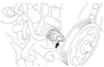
Drain the radiator by uncoupling the bottom hose.
Place a draining tray under the engine.
Drain the engine by removing the plug (1). (accessible from above the engine).
Refit the drain plug (1). (with a new O-ring seal and clip).
DRAINING, FILLING AND BLEEDING THE ENGINE COOLING CIRCUIT
Engine : 8HT

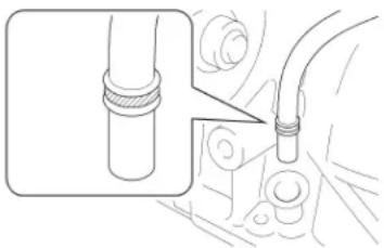
text_image
[1] [2] [3]B1G200TD

text_image
a 2B1B2013D
Filling and bleeding the circuit
Fit the filling cylinder [1], plug [3] and adaptor [2] assembly on the filling aperture.
Slowly fill the cooling circuit [1] with coolant fluid, up to the "1 litre" mark, to pressurise the circuit.
Remove the clip (2) from the tube.
Uncouple the tube at "a".
Couple the tube at "a" when the fluid flows out clean and without air bubbles.
Reconnect the negative terminal of the battery.
Start the engine.
Maintain an engine speed of 1500 rpm, up to the first cooling cycle (starting and stopping of the cooling fan).
Plug the filling cylinder [1] with the plug [3].
Remove the filling cylinder [1], plug [3] and adaptor [2] assembly.
Stop the engine and wait for it to cool down.
If necessary, top up the level to the maximum mark (with the engine cold).
Refit the header tank cap.
IMPERATIVE : Carry out the operations that are necessary following a reconnection of the battery (see corresponding operation).
BOSCH ME 7.9.5 INJECTION SPECIFICATIONS
Engine : CFA
Presentation : BOSCH ME 7.9.5 Injection
Introduction
Application.
This principle of operation for injection - ignition applies to the 384F engine.
the BOSCH injection system satisfies the following norms :
Depollution norm L5
EOBD depollution
NOTE : EOBD : European On Board Diagnosis, for diagnosis of depollution equipment.
Features
Features of the injection system:
This ECU is of the "Engine speed pressure" type
This injection system controls the engine injection and ignition thanks notably to the information on inlet air pressure and engine speed.
Multipoint injection (3 electromechanical injectors)
Sequential injection
Integral electronic ignition
Depollution L5 (European norm EURO4)
Marketing of vehicles respecting the depollution norm IFL5 (according to country of marketing).
The new depollution norm L5 is more severe than the previous norm (depollution L4):
The maximum pollution rate is reduced.
Impregnation of precious metals is increased.
BOSCH ME 7.9.5 INJECTION SPECIFICATIONS
Engine : CFA
System of on-board diagnosis (EOBD)
This diagnostic system informs the driver when the depollution equipment is no longer fulfilling its role.
Faults in the system causing polluting emissions are memorised in the injection ECU.
The "engine diagnosis" warning lamp, in addition to its usual functions, signals any faults in the depollution function (EOBD).
NOTE : EOBD : European On Board Diagnosis, for diagnosis of depollution equipment.
The on-board diagnosis system monitors
- Combustion misfiring
- Efficiency of the catalytic converter
- Deterioration of the oxygen sensors
EOBD requires the installing of an oxygen sensor (downstream of the catalytic converter).
Features
Features of the injection system:
- Engine phase detector : camshaft position sensor
- Camshaft dephaser (VVT)
- Sequential injection
- Air temperature sensor incorporated in the air pressure sensor in the inlet manifold
- Engine cooling function (integral to the injection ECU)
- Dialogue between the injection ECU and the piloted manual gearbox ECU, type MMT : CAN network
- Accelerator pedal sensor incorporated in the accelerator pedal
- Motorised butterfly housing (with the MMT piloted manual gearbox)
Features of the fuel circuit:
- Injection rail without fuel return
- Fuel pump/gauge module with integral fuel filter
GENERAL SYNOPSIS : BOSCH ME 7.9.5 INJECTION SYSTEM
Engine : CFA

flowchart
graph TD
    A["1"] --> B["115"]
    A --> C["120"]
    A --> D["1220"]
    A --> E["1261"]
    A --> F["1312"]
    A --> G["1313"]
    A --> H["1330"]
    A --> I["1331"]
    A --> J["2120"]
    A --> K["1240"]
    A --> L["8009"]

    M["2"] --> N["1320"]
    O["3"] --> N
    P["4"] --> N
    Q["5"] --> N
    R["6"] --> N
    S["7"] --> N
    T["8"] --> N
    U["9"] --> N
    V["10"] --> N
    W["11"] --> N

    X["12"] --> Y["1215"]
    Z["13"] --> AA["1262"]
    AB["14"] --> AC["1268"]
    AD["15"] --> AE["1510"]
    AF["16"] --> AG["315 1131"]
    AH["17"] --> AI["315 1132"]
    AJ["18"] --> AK["315 1133"]
    AL["19"] --> AM["1331"]
    AN["20"] --> AO["1333"]
    AP["21"] --> AQ["1332"]
D4E2002D
| GENERAL SYNOPSIS : BOSCH ME 7.9.5 INJECTION SYSTEM | |||
| Engine : CFA | |||
| Components Components | |||
| 1115 | Cylinder reference sensor | 1313 | Engine speed sensor |
| 1120 Knock sensor 1320 Engine ECU | |||
| 1131 | Ignition coil : cylinder 1 | 1331 | Injector : cylinder N°1 |
| 1132 | Ignition coil : cylinder 2 | 1332 | Injector : cylinder N°2 |
| 1133 | Ignition coil : cylinder 3 | 1333 | Injector : cylinder N°3 |
| 1215 | Canister purge electrovalve | 1350 | Downstream oxygen sensor |
| 1220 | Engine coolant temperature sensor | 1351 | Upstream oxygen sensor |
| 1240 Inlet air temperature sensor 1510 Cooling fan | |||
| 1261 | Accelerator pedal position sensor (MMT piloted manual gearbox) | 2120 Brake dual-function switch | |
| 1262 Motorised butterfly housing 8009 | Linear pressure sensor for the coolant fluid (with aircon) | ||
| 1268 Variable valve timing electrovalve (VVT) | |||
| 1312 Inlet air pressure sensor | |||
| GENERAL SYNOPSIS : BOSCH ME 7.9.5 INJECTION SYSTEM | |||||
| Engine : CFA | |||||
| Link N° | Signal | Nature of the signal | Nature of the Link N° | Signal | signal1 |
| 1 Information on the position of the camshaft | Open cycle ratio (OCR) pressure | 11 | Information on the cooling circuit | Analogue | |
| 2 | Information on the noise of combustion | Analogue | 12 | Control of the canister purge electrovalve | Open cycle ratio (OCR) |
| 3 Information on the engine coolant temperature | 13 | Control of the motorised butterfly (MMT piloted manual gearbox) | |||
| 4 | Information on the position of the accelerator pedal timing electrovalve | 14 | Control of the variable valve | ||
| 5 | Information on the inlet air pressure | 15 | Control of the cooling fan | ||
| 6 Information on engine speed | Open cycle ratio (OCR) All | 16 Supply or nothing | Supply of the ignition coils | ||
| 7 | Information on the oxygen content of the exhaust gases (after the cat. converter) | Analogue | 17 Control of the petrol injectors | ||
| 8 | Information on the oxygen content of the exhaust gases (before the cat. converter) | ||||
| 9 Information on the brake switch All or nothing | |||||
| 10 Information on the inlet air temperature Analogue | |||||
OPERATING PHASES : BOSCH ME 7.9.5 INJECTION SYSTEM
Engine : CFA
Engine management
The engine ECU manages the injection on the basis of the information on engine torque :
The engine ECU calculates the need for engine torque from the accelerator pedal sensor
The engine torque requested takes account of various corrections
The engine torque requested is obtained by acting on the following components :
- Butterfly angle (motorised butterfly housing)
- Ignition advance (knock regulation)
- Injection time
Cycle of ignition and injection
Sequential injection: the injectors are commanded separately in the order of injection (3-2-1), just prior to the inlet phase.
Static ignition: one coil per cylinder.
The ECU manages the injection and the ignition simultaneously (metering of the petrol/air mixture).
The quantity of fuel injected is proportional to the time of opening of the injectors which is determined as a function of 3 main parameters :
- Engine load
- Speed of rotation of the engine (TDC sensor)
- The information from the oxygen sensor
Numerous other corrections are also applied during operation, in order to take account of the variations :
- In the heat status of the engine (coolant temperature sensor)
- In the operating conditions (idle phase, stable phase, full load phase, transitory engine speed phases, injection cut-off phase)
- In the atmospheric pressure (altimetric correction)
Injection.
Correction of starting : engine cold
The injection ECU corrects the flow from the injectors during the action of the starter motor.
This quantity is injected in asynchronous mode, thus constant in time, depending only on the temperature of the coolant fluid.
The engine once started receives an injected quantity, synchronous with the ignition which varies in permanence with its thermal evolution.
OPERATING PHASES : BOSCH ME 7.9.5 INJECTION SYSTEM
Engine : CFA
Regulation of the idling speed
The engine is equipped with an idle regulation stepper motor :
Important variations in the engine idling speed due to the different accessories on the vehicles, depending on their operating status (aircon, alternator)
Variations in engine idling speed due to the ageing of the engine
This device enables a progressive return to idling speed.
Role of the idle regulation function:
- To regulate the idling speed
- To obtain a fast idle speed that decreases with the warming up of the engine
- To improve the idling speed for the vehicle in motion
Engine starting
Entry into starting phase occurs as soon as the injection ECU is powered.
During starting the injection ECU commands the following components:
- Priming pump (low pressure) (cut-off after 3 seconds, provided the starter motor has not operated)
- The electrical supply of the oxygen sensors
Functioning of the transitory engine speeds
Command of the injectors is corrected as a function of the following variations:
- Butterfly position
- Pressure in the inlet manifold
The detection of these engine speeds (accelerations/decelerations) is by intermediary of the butterfly potentiometer or of the pressure sensor.
In these operating modes the quantity of fuel injected depends on the variation of the butterfly angle or on the variation of the pressure
Correction for full load
Approaching full load, the air/fuel mixture has to be made richer in order to obtain optimum engine performance.
In the case of a system with an oxygen sensor loop, the information on this is not taken into account by the ECU.
The ECU then controls the injection in open loop.
OPERATING PHASES : BOSCH ME 7.9.5 INJECTION SYSTEM
Engine : CFA
Air supply function
Motorised butterfly housing for MMT piloted manual gearbox.
The torque requested by the injection ECU determines an angle of opening of the butterfly:
The angle of opening of the butterfly varies with the demand coming from the driver.
Engine load is commanded by the butterfly housing.
Injection function :
The quantity of fuel to be injected is calculated from the following parameters :
- Position of the accelerator pedal
- Point of engine operation (engine speed, temperatures, pressures)
As a function of the quantity of fuel to be injected, the injection ECU determines the following parameters :
- Start of injection
- Time of injection
The injection ECU draws on the specific strategies for starting and stopping of the engine.
Determination of the quantity of fuel to be injected
The quantity of fuel to be injected is calculated from the demand coming from the driver, provided by the position of the accelerator pedal.
To determine the quantity of fuel to be injected, the injection ECU takes account of the following elements:
- Demand from the driver (after filtering)
- Quantity of air entering the engine (calculation)
The quantity of fuel to be injected is transformed into an injection time.
Cut-off in deceleration
During deceleration with the engine hot, gas butterfly closed (foot off), the injection of fuel is cut off in order to :
- Reduce fuel consumption
- Minimise pollution
- Prevent the temperature of the catalytic converter from rising
OPERATING PHASES : BOSCH ME 7.9.5 INJECTION SYSTEM
Engine : CFA
Correction by oxygen sensor
At idling speed, engine hot, stable with partial load, the signal emitted by the sensor causes an adjustment of the flow from the injector, so as to remain on stoechiometric richness R = 1/15 or lambda = 1.
Altimetric correction
The mass of air absorbed by the engine varies according to the atmospheric pressure, thus with altitude.
The altimetric corrector takes account of this variation in pressure and proportionally corrects the injection command time (quantity of fuel injected).
This measure of pressure occurs as the ignition is switched on and when the engine is operating at low engine speed.
Ignition function
The ignition advance is determined from the following information :
- Engine speed
- Engine load
- Engine temperature
This correction stabilises the engine by varying the advance from one TDC to the next, positively or negatively relative to the mapping value.
Corrections in injection advance are also applied during the transitory phases.
Synchronisation of ignition is achieved by the cylinder reference sensor N°1.
Petrol vapour recycling (canister) function
Engine stopped : the electrovalve is closed ; the canister absorbs the fuel vapours coming from the tank.
The electrovalve, piloted by the injection ECU, recycles the petrol vapours stored in the canister.
The quantity of petrol stored in the canister is determined by the injection ECU.
As soon as the canister has to be purged, the ECU temporarily makes the engine operate on a homogeneous mixture.
Overspeed protection
The injection ECU permanently monitors the engine speed.
As soon as the engine speed exceeds the maximum value (6 400 rpm), there is an injection cut-off.
OPERATING PHASES : BOSCH ME 7.9.5 INJECTION SYSTEM
Engine : CFA

line
| t | U_i | |---|---| | 0 | 0.5 | | 2 | 0.6 | | 4 | 0.7 | | 6 | 0.6 | | 8 | 0.5 | | 10 | 0.6 | | 12 | 0.7 | | 14 | 0.6 | | 16 | 0.5 | | 18 | 0.6 |
line
| t | U | |----|------| | 2 | 0.5 | | 4 | 0.5 | | 6 | 0.5 | | 8 | 0.5 | | 10 | 0.5 | | 12 | 0.5 | | 14 | 0.5 | | 16 | 0.5 | | 18 | 0.5 |B1H2029D
EOBD diagnostic function
EOBD : European On Board Diagnosis, for diagnosis of depollution equipment.
This diagnosis informs the driver if the depollution equipment is no longer fulfilling its role.
The on-board diagnosis system monitors :
- Elements of the injection system (polluting emissions, destruction of the catalytic converter)
- The efficiency of the catalytic converter
K : Catalytic converter in good condition.
L : Catalytic converter in poor condition.
"a": Upstream oxygen sensor.
"b": Downstream oxygen sensor.
The efficiency of the catalytic converter is determined by comparing the signals coming from the upstream and downstream oxygen sensors.
The detection is performed 6 minutes after the starting of the engine.
Conditions of detection :
- Engine operating for at least 6 minutes
- No fault in the oxygen sensors (downstream oxygen sensor, upstream oxygen sensor)
- No combustion misfirings
Outside the fixed limit, a fault is recorded in the injection ECU and the diagnostic warning lamp comes on.
| OPERATING PHASES : BOSCH ME 7.9.5 INJECTION SYSTEM | |
| Engine : CFA | |
| Display of faultsThe engine diagnosis warning lamp lights up if there is a fault on any of the following components or types of information :Control of the variable valve timing electrovalveInlet air temperature sensorEngine coolant temperature sensorMotorised butterfly signal (1,2)Heating of the upstream oxygen sensorHeating of the downstream oxygen sensorRichness regulationCommand of injector for a given cylinder (1,2,3)Ignition misfiring, cylinder undeterminedIgnition misfiring for a given cylinder (1,2,3)Knock sensor signalEngine speed sensor signalCamshaft sensor | Ageing of the catalytic converterVehicle speed sensor signalIdle stepper motor signalSupply of sensorsBattery voltage too lowBattery voltage too highBrake switch signal (MMT gearbox)Inlet manifold pressure sensorSignal internal to the ECUControl of the motorised butterfly (MMT gearbox)Jamming of the motorised butterfly (MMT gearbox)Position of the motorised butterfly (MMT gearbox)Incoherent information coming from the accelerator pedal sensor (MMT gearbox)Accelerator pedal position sensor signal (1,2) (MMT gearbox)Absence of communication with the immobiliser control module |
OPERATING PHASES : BOSCH ME 7.9.5 INJECTION SYSTEM
Engine : CFA
Driver's information function
Lighting of engine diagnosis (EOBD) warning lamp
The engine diagnosis warning lamp indicates a failure of a component or of a system relating to emissions if it is causing an increase in emissions, to exceed the legal limits.
Ignition misfirings, which carry the risk of destroying the catalytic converter, cause the engine diagnosis warning lamp to flash.
The engine diagnosis warning lamp is not used for any other purpose, except if there a risk of destruction of the engine or a risk for the safety of the vehicle occupants.
Access to the EOBD fault codes
Access to the memorised fault codes is open to any trained person equipped with a normalised diagnostic tool known as SCANTOOL with which the ECU permits dialogue.
Access to the diagnostic codes is as follows :
Mode 1 : reading of the number of fault codes and of the engine speed (dynamic)
Mode 2 : reading of the fixed datastream (associated variables)
Mode 3 : reading of the fault codes
Mode 4 : deletion of fault codes
OPERATING PHASES : BOSCH ME 7.9.5 INJECTION SYSTEM
Engine : CFA
MMT piloted manual gearbox
The injection ECU dialogues with the automatic gearbox ECU in order to guarantee optimal functioning of the gearbox as well as of the engine.
WARNING : Following any incident concerning the injection, it is essential to read the faults in the injection ECU and the piloted manual gearbox ECU.
The piloted manual gearbox ECU receives the following information from the injection ECU:
- Engine load (as a function of the position of the accelerator pedal)
- Engine speed
- Engine temperature
The piloted manual gearbox ECU sends the following information from the injection ECU: - Information on request for torque reduction
- Information on request for compensation of idling speed
Gear changing quality is enhanced by an order to reduce engine torque given by the gearbox ECU to the injection ECU.
When there a change of gear, the gearbox ECU: - Pilots the engine ECU in terms of engine torque and engine speed in making the change of gear
- Pilots the changing of the gear inside the gearbox
| AIR FILTER SPECIFICATION | |
| Engine : CFA | |
 | Air filter(45) air filter cartridge.(46) air filter cover.The valve cover (1) incorporating the air filter housing (38) is made of plastic to reduce weight. |
| B1B202JD | |
| FUEL SUPPLY SYSTEM SPECIFICATIONS | |
| Engine : CFA | |
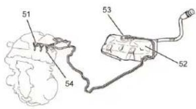 B1B202MD B1B202MD | GeneralInjectors (54) with 4 holes are used in order to enhance the spraying of the fuel.The non-return fuel supply system reduces emissions by evaporation.The fuel tank (52) is made of plastic.The fuel pump module (53) is compact and light, comprising the fuel gauge which incorporates a carbon fuel vapour absorber.The fuel supply rail (51) is made of plastic.. |
 | Fuel tank"af" : HDPE (high density polyethylene).The fuel tank (52) is made of plastic. The interior "ag" and exterior "ad" surfaces are coated with a layer of flourate polyethylene "ae" to prevent any penetration of fuel. |
 B1B202PD B1B202PD | Fuel tankA marking indicates the lowest point of the fuel tank (52). During dismantling (destruction) of the vehicle, drill a hole at the spot indicated "ah" in order to drain the fuel.Fuel filler pipingThe fuel filler piping (55) includes the tank breather pipe for greater compactness and saving of actual space. |
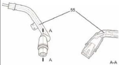 B1B202QD B1B202QD | |
| Fuel pump module(56) : fuel pump stop ring.(58) : pump.(59) : reserve cup.(60) : fuel filter.(61) : pressure regulator.(62) : cut-off valve.(63) : foam filter for venting the canister. | |
 | The fuel pump module includes the carbon fuel vapour absorber (57) for saving of actual space. |
| Fuel supply railThe fuel supply rail (51) is made of plastic to reduce weight. | |
| B1B202SD | |
 | Non-return fuel supply system(64) pulse damper.(65) fuel pump module.This type of fuel supply system reduces emissions by evaporation. The diagram shows that by integration of the fuel filter (60), the pressure regulator (61) and the fuel gauge with the fuel pump (53), there is no return of fuel from the engine and an increase of temperature inside the fuel tank is avoided. |
| B1B202TD | |
| INJECTOR SPECIFICATIONS | |||
| Engine : CFA | |||
 | InjectorsInjectors (54) with 4 holes are used in order to enhance the spraying of the fuel.Ignition systemThis is a Direct Ignition System (DIS). It enhances the precision of the point of ignition, reduces the loss of voltage and increases the general reliability of the ignition system thanks to the elimination of the distributor. The direct ignition system (DIS) on this engine is an independent ignition system with an ignition coil for each cylinder.Ignition coil(66) secondary coil.(67) primary coil.(69) iron core.The DIS system has 3 ignition coils, one for each cylinder.The caps (68) which establish contact with the sparking plugs are integral to the coils.With a view to simplification of the system, an igniter (70) is also incorporated in each coil. | ||
| B1B202UD | |||
 | |||
| B1B202VD | |||
SAFETY REQUIREMENTS : HDi DIRECT INJECTION SYSTEM
Engine : 8HT
SAFETY REQUIREMENTS
Preamble
All interventions on the injection system must be carried out to conform with the following requirements and regulations :
- Competent health authorities.
- Accident prevention
- Environmental protection.
WARNING : Repairs must be carried out by specialised personnel informed of the safety requirements and of the precautions to be taken
Safety requirements
IMPERATIVE : Take into account the very high pressures in the high pressure fuel circuit (1350 bars), and respect the requirements below :
- No smoking in proximity to the high pressure circuit when work is being carried out.
- Do not work close to flame or sparks.
- Always stay clear of the trajectory of any possible jet of fuel, which could cause serious injuries.
- Do not place your hand close to any leak in the high pressure fuel circuit.
- After the engine has stopped, wait 30 seconds before any intervention.
NOTE : This waiting time is necessary in order to allow the high pressure fuel circuit to return to atmospheric pressure.
Catalytic converter :
Make sure that there are no aerosols or inflammable products in the vehicle boot.
Protect yourself with high temperature gloves.
Connect the vehicle to an approved gas extractor for this type of operation.
SAFETY REQUIREMENTS : HDI DIRECT INJECTION SYSTEM
Engine : 8HT
Cleanliness Requirements
Preliminary operations
IMPERATIVE : The technician should wear clean overalls.
Before working on the injection system, it may be necessary to clean the apertures of the following sensitive components: (refer to corresponding procedures).
- Low pressure circuit
- Fuel filter
- Fuel gauge
- Unions on fuel pipes
- High pressure circuit
- Fuel high pressure pump
- Fuel high pressure injection common rail.
- Fuel high pressure pipes
- Diesel injector carriers.
IMPERATIVE : After dismantling, immediately block the apertures of sensitive components with plugs, to avoid the entry of impurities.
Work area.
- The work area must be clean and free of clutter.
- Components being worked on must be protected from dust contamination.
PROHIBITED OPERATIONS: HDi DIRECT INJECTION SYSTEM
Engine : 8HT

text_image
a 1 bB1H200ZD
Cleaning
- The use of high pressure cleaners is prohibited.
Fuel supply circuit
- Required fuel : diesel.
Electrical circuit
- Swapping injection ECUs between two vehicles will render it impossible to start either vehicle. - It is forbidden to supply a diesel injector with 12 volts.
Fuel high pressure pump
Do not separate the fuel high pressure pump (1) from the following components: - Sealing ring (a) (no replacement parts). - High pressure outlet connector (b) (will cause a malfunction).
| PROHIBITED OPERATIONS: HDi DIRECT INJECTION SYSTEM | |
| Engine : 8HT | |
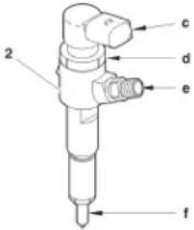 B1H2010D B1H2010D | Diesel injectorsWARNING: Diesel and ultrasonic cleaners are prohibited.Do not separate the diesel injector carrier (2) from the following components :- Diesel injector (f) (no replacement parts).- Electromagnetic component (c) (no replacement parts).Do not move the nut «d» (will cause a malfunction). |
 B1H2011D B1H2011D | Do not separate the union «e» from a diesel injector.It is forbidden to clean the carbon deposits from the diesel injector nozzle.Fuel high pressure common injection railDo not separate the pressure regulator "g" from the common injection rail (3) (will cause a malfunction). |
| SPECIFICATIONS : PRE-POSTHEATING CIRCUIT | |
| Engine : 8HT | |
 | The pre-heating time varies as a function of the engine coolant temperatureThe pre-postheating control unit is piloted by the engine ECU.Pre-postheating control unitSupplier/Reference:NAGARES:96 456 686 80.CARTIER:96 456 692 80.Pre-heater plugs"a":Marking zone.Supplier/Reference:NGK:YE04.BERU:0 100 276 004.Tightening torques (m.daN)Plugs on cylinder head:tighten to:0,85 ± 0,08 m.daN.Bar on plugs:tighten to:0,12 ± 0,03 m.daN. |
| B1H200YD | |
CONTROLE : CIRCUIT D'ALIMENTATION CARBURANT BASSE PRESSION
Engine : 8HT

text_image
1 b a B1B200LDTools.
[1] ∅ 10 mm low pressure connector : 4215-T.
[2] Pressure gauge for testing boost pressure : 4073-T.A Toolkit 4073-T
IMPERATIVE : Respect the safety and cleanliness specific to high pressure diesel injection engines.
B1B200LD
Disconnect the battery.
Remove the engine cover.

text_image
[2] [1] B1B200MDIMPERATIVE : Clean the unions before uncoupling them (if necessary) (see corresponding operation).
Detach the pipe at "a".
Move aside the diesel fuel filter top cover (1).
Checks
Uncouple the clickfit union at "b".
ESSENTIAL : Make sure that the tool [2] is clean.
Link tools [1] and [2] in series between the fuel high pressure pump and the fuel filter.
Prime the circuit using the manual priming pump so as not to falsify the measurement.
Normal vacuum values :
CHECKS : LOW PRESSURE FUEL SUPPLY CIRCUIT
Engine : 8HT

text_image
1 b a B1B200LDNormal vacuum values:
| Vacuum Observations | |
| 10 ± 05 cmhg Engine driven by the starter motor | |
| 20 ± 20 cmhg Engine running under full load | |
| 60 ± 05 cmhg | Supply circuit obstructed(full tank strainer, piping, fuel filter). |

text_image
[2] [1] B1B200MDRefitting
Remove tools [1] and [2].
Proceed in the reverse order to removal.
Action the manual priming pump for 120 seconds in order to prime the fuel circuit.
Checking the sealing
Reconnect the negative terminal of the battery.
Start the engine.
Let the engine run at idle for 2 minutes.
Check that there is no leak.
Check that there are no air bubbles in the return circuit.
IMPERATIVE : Perform the operations that are required following a battery reconnection
(see corresponding operation).
CHECKS : TURBO PRESSURE
Engine : 8HT

text_image
a [2] 1 3 2 B1B2007DTools.
[1] Pressure gauge for checking boost pressure
: 4073-T.A
[2] Sleeve for checking boost pressure
: (-).0171.F
[3] Manual pressure/vacuum pump
: FACOM DA 16
[4] Pliers for removing clic clips
: (-).0172.Z
IMPERATIVE : Respect the safety requirements.

text_image
C5F2002D [a] [1]Checks
IMPERATIVE : Respect the following test conditions:
- Engine at operating temperature, vehicle in running order, engine under full load.
Preparation
Remove the engine cover.
IMPERATIVE : Do not disconnect the air temperature sensor (3).
If the warning lamp in the instrument panel should come on, delete the faults using the diagnostic tool.
Remove the clips (1).
Move aside the duct (2) without disconnecting the air temperature sensor (3).
Fit the tool [2] in the place of the duct (2).
Couple the pressure gauge [2] on the sleeve [1] using the tube «a».
CHECKS : TURBO PRESSURE
Engine : 8HT

text_image
(1) aC5F2002D
Mode of operation
Position tool [1] in the vehicle.
Start the engine.
Engage first gear, start the vehicle.
Engage the gears up to third gear.
Decelerate to an engine speed of 1000 rpm.
Check the pressure : 0,6 ± 0,05 bar (1500 rpm).
Accelerate freely (change from fourth gear to third gear)
Check the pressure: 0,9 ± 0,05 bar (between 2500 and 3500 rpm).
Remove tools [1], [2].
Reposition the tube (2)
Tighten the clips (1).

text_image
Technical diagram with labeled components A and B, likely illustrating a mechanical or architectural assembly.B1B2008D
NOTE : Confirm the measurement with the aid of the diagnostic tool (parameter measures).
Parameter measures (diagnostic tool)
Checks on the inlet manifold pressure sensor
Remove the engine cover.
(4) inlet manifold pressure sensor
CHECKS : TURBO PRESSURE
Engine .6HT

text_image
C5F2002DNOTE : The engine has to be switched off.
Uncouple the tube at "b" using tool [4].
Couple tool [3] on the tube at "b".
Check the inlet manifold pressure sensor using the diagnostic tool.
Make the following selections in the diagnostic tool :
Menu :
"PARAMETER MEASURES"
"INJECTION INFO"
"TURBO PRESSURE"
Apply a pressure on the pressure sensor by means of tool [3].
Check the pressure value in parameter measures by means of the diagnostic tool.
Checks
IMPERATIVE : Respect the following test conditions:
- Engine at operating temperature, vehicle in running order, engine under full load.
NOTE : Carry out the checks either during a road test or on a roller test bed.
Perform the checking with the aide of a diagnostic tool.
Start the engine.
Stage A :
Engage first gear, start the vehicle.
Engage the gears up to third gear.
Decelerate to an engine speed of 1000 rpm.
Check the pressure : 0.6 ± 0.05 bar (1500 rpm).
Stage B :
Accelerate freely (change from fourth gear to third gear)
Check the pressure: 0.9 ± 0.05 bar (between 2500 and 3500 rpm).

text_image
4 bB1B2008D
| AIR SUPPLY CIRCUIT SPECIFICATIONS | |
| Engine : 0HT | |
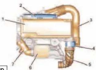 B1H201JW B1H201JW | IdentificationUpper integrated air inlet manifoldThe upper integrated air inlet system is composed of the following components:(1) Air filter cover(2) Air filter housing(3) Air duct(4) Flowmeter(5) Turbocharger inlet elbow(6) Resonator(7) Turbocharger outlet elbow |
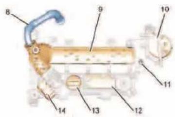 B1H201KD B1H201KD | Lower integrated air inlet manifoldThe lower integrated air inlet system is composed of the following components :(8) EGR upper pipe(9) Inlet distributor(10) Diesel fuel filter with heater and water detector (according to country)(11) Diesel fuel filter support(12) Oil separator(13) Oil filler cap(14) Air meter housing (EURO 4)FeaturesWARNING: At each removal it is essential to replace the seals on the components that have been removed, lubricating the new seals prior to fitting. |
| AIR SUPPLY CIRCUIT SPECIFICATIONS | |||
| Engine : 8HT | |||
 B1H201LD B1H201LD | Tightening torques (m.daN)Lower integrated air inlet manifold | ||
| Description Tightening sequence Tightening | |||
| Oil separator fixing screw 1 to 8 1 ± 0,1 | |||
| Diesel fuel filter support fixing screw 9 to 10 1 ± 0,1 | |||
| Diesel fuel filter support fixing screw 11 0,5 | |||
| Integrated air inlet distributor screw 12 to 13 1 ± 0,1 | |||
| Upper integrated air inlet manifold | |||
 B1H201MD B1H201MD | Ref. Description Tightening | ||
| 15 Air filter housing fixing screw | |||
| 16 Air filter cover fixing screw 0,5 | |||
| 17 Air inlet neck fixing screw | |||
| 18 Screw fixing the resonator on the turbocharger | 0,75 | ||
| 19 Screw fixing the resonator on the oil separator | |||
| CHECKING THE AIR SUPPLY CIRCUIT | ||
| Engine : 8HT | ||
| INJECTION |  | Tools[1] Manual pressure-vacuum pump : FACOM DA 16IMPERATIVE : Respect the safety and cleanliness requirements.ChecksVacuum pumpConnect the tool [1] onto the vacuum pump (1).Start the engine.Wait 30 seconds.The vacuum value should be 0.9 ± 0.1 bar at idling speed.NOTE : The exhaust gas recycling valve is not linked to the air supply circuit.The exhaust gas recycling electrovalve is controlled by the engine ECU.Turbocharging pressure regulation valve- Connect the tool [1] on the valve (2) (tube identified by the colour grey)..- Appy a vacuum of approx. 0.8 bar.- Rod "a" should move 12 ± 2 mm.. |
[B1H201GD] | ||
| [B1H201HD] | ||
| SPARKING PLUGS | |
| Engine : CFA | |
 | "ak" conventional type.The sparking plugs are of the long thread type"aj". This permits an increased thickness of the cylinder head in the zone where the sparking plugs are situated. The coolant liners "j" can thus be extended around the combustion chambers to improve cooling.Specifications:CITROËN : DENSO 596086.PEUGEOT : DENSO 596085.Electrode gap : 1,1.Charging systemThe charging system uses an alternator that is compact and light, but of conventional type.Specifications :Type : A115I.Supplier : DMIT.Nominal voltage : 12V.Nominal output voltage : 70 A/80 A (*).Initial output starting speed : 1300 rpm (maximum).Starting systemThe starter motor used is of the controlled pinion type.Specifications :Type : D7E : R70M (*).Supplier : VALEO : BOSCH.Output power : 1,0 kW : 1,1 kW.Nominal voltage : 12V : 12V.Weight (grammes) : 3000 : 2760.(*) option. |
 | |
| B1B202WD | |
SPEEDOMETER
An E.E.C. decree of 25 June 1976, regulates the speed displayed by the speedmeter in relation to the actual speed travelled.
This decree stipulates :
- The speed indicated by a speedometer must never be lower than the actual vehicle speed.
- Between the speed displayed «SD» and the speed travelled «ST», there must always be the following relationship :
ST < SD < 1.10 ST + 4 Kph
Example : For an actual speed of 100 Kph the speed displayed by the speedometer may be between 100 and 114 Kph. The speed indicated by the speedometer may be influenced by :
- The speedometer.
- The tyres fitted to the vehicle.
- The final drive ratio.
- The speedometer drive ratio.
Any of these components can be checked without removing them from the vehicle. (See information note N° 78-85 TT of 19 October 1978. NOTE : Before replacing the speedometer, check the conformity of the following points :
- The tyres fitted to the vehicle.
- The gearbox final drive ratio.
- The speedometer drive ratio.
| CLUTCH SPECIFICATIONS | |||
| 1.0i 1.4 HDi | |||
| Engine type CFA 8HT | |||
| Gearbox type | MT (*) | MMT (**) | MT (*) |
| Gearbox make LUK ASIN | LUCK | ||
| Mechanism /Type 200 CPXV | |||
| Ext./Int. lining ∅ 181/133 | 90/133 200/134 | ||
| Disc lining type | |||
| (*) MT = Manual gearbox(**) MMT = Piloted manual gearbox | |||
CLUTCH
GEARBOX
TRANSMISSION
| CLUTCH TIGHTENING TORQUES | ||||
 | Tightening torques (m.daN) | |||
| Ref. Description Number of screws Tightening | ||||
| 1 | Screws for clutch Position the mechanism using mechanism on flywheel the top screw “a” | Align the reference “b” | ||
| Tightening 1,9 ± 0,1 | ||||
| 2 Screws for flywheel 7,8 ± 0,7 | ||||
 | ||||
| B21 | ||||
| CHECKING AND ADJUSTING THE CLUTCH PEDAL TRAVEL | |
 | Move aside the floor carpet."a" : Pedal height adjustment point.Height A of the pedal in relation to the floor : between 135 and 145 mm.Adjust the height A of the pedal.Slacken the locking nut and turn the stop screw until you obtain the correct height.Tighten the locking nut.Tightening torque : 2,5 ± 0,2 m.daN.Press on the pedal until you feel the start of resistance.Play B in the pedal : 18 to 28 mm. |
 | |
CLUTCH
GEARBOX
TRANSMISSION
CHECKING AND ADJUSTING THE CLUTCH PEDAL TRAVEL

text_image
Technical diagram showing a screw fastener with labeled component 'b' and directional arrowB2B2002D
Turn the clutch adjustment nut "b" until you obtain the correct play B in the pedal.
After adjusting the play B in the pedal, check the height A of the pedal.
Tighten the parking brake lever and fit a wheel chock.
Start the engine and let it run at idle.
Without pressing the clutch pedal, bring the gear lever slowly into reverse gear until the gearing meets a resistance from the clutch.
Progressively press on the clutch pedal and measure the travel from the point where the gear noise disappears (point of release "c") to the position of maximum travel "d".

text_image
B2B2003D25 mm or more (from the position of maximum travel "d" to the point of release "c"
If the travel is not correct, proceed to the following operations:
Check the height A of the pedal
Check the play B in the pedal
Check the clutch mechanism and disc
Check the travel C of the pedal
Travel C of the pedal : 148 mm.
| SPECIFICATIONS OF MT (TOYOTA) MANUAL GEARBOX | |||||
| Vehicle Engine Gearbox type | Gearbox identification | Torque ratio Drive | ratio | ||
| C1 MMT | CFA(**) C 551.A 20 x 71 | MT (*) C 551 | |||
| 8HT MT (*) C 551 | |||||
| (*) MT = Manual gearbox(**) MMT = Piloted manual gearbox | |||||
CLUTCH
GEARBOX
TRANSMISSION
| SPECIFICATIONS OF MT (TOYOTA) MANUAL GEARBOX | ||
| TRANSMISSIONCLUTCHGEARBOX |  | Identification"a" identification zone for gearbox no. |
| Reference:C 551: Petrol engine versionC 552: Diesel engine version | ||
| B2C2011D | Description(1) 5th gear synchroniser.(2) 3rd/4th gear synchroniser.(3) Gearbox casing.(4) Reverse gear motor pinion.(5) Clutch housing.(6) Primary shaft.(7) Secondary shaft.(8) Planet pinions.(9) Satellite pinions.(10) Differential gearwheels.(11) 1st gear driven pinion.(12) 1st/2nd gear synchroniser.(13) Reverse gear driven pinion.(14) 2nd gear driven pinion.(15) 3rd gear driven pinion.(16) 4th gear driven pinion.(17) 5th gear driven pinion. | |
 | ||
| B2C2 | ||
| TIGHTENING TORQUES FOR MT (TOYOTA) MANUAL GEARBOX | ||||
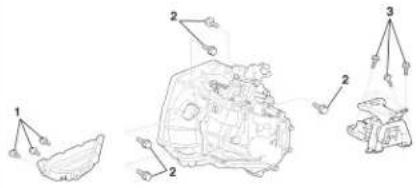 B2C201DD B2C201DD | Tightening torques (m.daN) | |||
| Ref. Description Number of screws Tightening | ||||
| 1 Closing plate fixing 4 ± 0,4 | ||||
| 2 Fixing of gearbox on engine 6,4 ± 0,6 | ||||
| 3 | Fixing of gearbox support on body | 5,2 ± 0,5 | ||
| 4 | Fixing of clutch fork support | 3,3 ± 0,3 | ||
| 5 | Fixing of gear controls plate | 1,1 ± 0,1 | ||
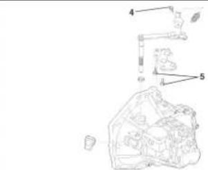 B2C201ED B2C201ED | ||||
CLUTCH
GEARBOX
TRANSMISSION
| TIGHTENING TORQUES FOR MT (TOYOTA) MANUAL GEARBOX | |||||
 | Tightening torques (m.daN) | ||||
| Ref. Description Number of screws Tightening | |||||
| 6 | Fixing of gear controls plate | ||||
| 7 Reverse gear switch 4 ± 0,4 | |||||
| 8 Drain plug 2,9 ± 0,3 | |||||
| 9 Filler plug 3,9 ± 0,4 | |||||
| 10 Locking finger 3,7 ± 0,4 | |||||
| 11 | Fixing of engagement finger | ||||
| B2C201FD | |||||
| TRANSMISSION | CLUTCH |  | |||
| GEARBOX | |||||
| B2C201GL | |||||
| TIGHTENING TORQUES FOR MT (TOYOTA) MANUAL GEARBOX | ||||
| Tightening torques (m.daN) | ||||
| Ref De | scription Number of screws Tightening | |||
| 12 | Fixings of gearbox casing and clutch housing | 12 2,9 ± 0,3 | ||
CLUTCH
GEARBOX
TRANSMISSION
| DRAINING AND FILLING : MT (TOYOTA) MANUAL GEARBOX | |
 | Presentation(1) gearbox drain plug.(2) filler and level plug.Oil qualityRefer to the manufacturer's instructions.Oil quantityAfter draining : 1.7 litres. |
| B2C2000D | |
RECOMMENDATIONS / PRECAUTIONS : MMT PILOTED MANUAL GEARBOX

text_image
Technical diagram of a mechanical assembly with labeled parts 1 and 2B2C201SD
Safety requirements
ESSENTIAL : Given the special features of the MMT piloted manual gearbox, observe the requirements detailed below.
IMPERATIVE : Always disconnect the battery negative terminal before operating on the actuators (*).
NOTE : (*) After disconnecting the battery, never try to remove the clutch actuator on the vehicle before having checked that it is in the closed position (rod pushed in).
IMPERATIVE : After Sales checks done with the engine running must be performed with «Neutral» engaged and the handbrake on (unless there is a clear mention otherwise in the repair procedures)
IMPERATIVE : The area of movement of the clutch fork must always be kept free during the actuator operating phases.
IMPERATIVE : When initialising the clutch actuator and/or gearbox actuator, do not allow any person to walk or stand in front of the vehicle.
WARNING: When the engine is running, it is forbidden to perform repairs on the clutch and gearbox actuators on the vehicle (whether manually or using a diagnostic tool).
RECOMMENDATIONS / PRECAUTIONS : MMT PILOTED MANUAL GEARBOX

text_image
Technical diagram of a mechanical assembly with labeled parts 1 and 2B2C201SD
Repairs on the gearbox
Gearbox removed : position a block (1) so as not to damage the gear sensor (2).
Operations on electrical components :
Do not disconnect :
- The battery when the engine is running.
- The ECU with the ignition switched on.
- The clutch and gearbox actuators with the ignition switched on.
When carrying out electrical checks :
- The battery must be correctly charged.
- Never use a voltage source higher than 16V.
- Never use a warning lamp.
- Never supply an actuator directly.
Before reconnecting a connector, check :
- The condition of the various contacts (for deformation, corrosion etc.)
- The presence and the status of the mechanical unlocking.
IMPERATIVE : Never swap two gearbox ECUs between two vehicles.
RECOMMENDATIONS / PRECAUTIONS : MMT PILOTED MANUAL GEARBOX

natural_image
Transparent mechanical component with labeled part 'a' (no text or symbols beyond label)B2C201TD
Driving
Never push the vehicle to attempt to start it (impossible with a piloted manual gearbox. Towing
Conditions for towing:
It is necessary to lift the front of the vehicle to tow it, after having positioned the gear lever in neutral. If there is a gearbox fault or malfunction, the vehicle can remain immobilised depending on the seriousness of the fault.
If a gear is engaged, the conditions for immobilisation of the vehicle are: Engine stopped (the engine should not be started).
The clutch is open (clutched).
If these conditions are met, you can lift the front of the vehicle to tow it.
If it should not be possible to lift the front of the vehicle, there are ways to unblock it :
- Engage «N», using a diagnostic tool.
- Engage «N», without using a diagnostic tool.
Engaging of «N», using a diagnostic tool.
Preliminary operations:
- Vehicle and engine stopped
- Battery voltage higher than 12.5 volts
- Ignition switched on.
- Gear selector on position "N"
- Connect the diagnostic tool to the vehicle's diagnostic socket.
RECOMMENDATIONS / PRECAUTIONS : MMT PILOTED MANUAL GEARBOX

natural_image
3D rendering of a mechanical engine component with labeled part 'a' (no text or symbols beyond label)B2C201TD
From the diagnostic tool menus, select :
« DIAGNOSIS »
MMT piloted manual gearbox.
Actuator test.
Gearbox actuator test.
Engage N (neutral).
NOTE : The letter «N» should appear on the instrument panel. If not, see the following solution:
Engaging of «N», without using a diagnostic tool..
Engaging of «N», without using a diagnostic tool.
In this configuration, the gearbox actuator is blocked, gear engaged.
NOTE : This recovery solution is to be used solely in a case where the attempt to make the gearbox actuator engage b via the diagnostic tool has failed.
Preliminary operation:
Disconnect the battery negative terminal.
Remove the plug on the gearbox actuator.
"a" neutral.
"b" 1st, 3rd, 5th.
"c" 2nd, 4th, reverse gear.
Using a large screwdriver, move the screw (3) to place the gearbox actuator in the neutral position.
When this position is reached, position "N" is engaged.
SPECIFICATIONS OF MMT (TOYOTA) PILOTED MANUAL GEARBOX

natural_image
Mechanical assembly diagram showing internal components and wiring (no visible text or labels)B2C201JD
Identification
"a" gearbox no. identification zone.
Ref. C 551-A (piloted).
Presentation
(1) 5th gear synchroniser.
(2) 3rd/4th gear synchroniser.
(3) Gearbox casing.
(4) Reverse gear motor pinion.
(5) Clutch housing.
(6) Primary shaft.
(7) Secondary shaft.
(8) Speedometer.
(9) Planet pinions.
(10) Satellite pinions.
(11) Differential gearwheels.
(12) 1st gear driven pinion.
(13) 1st/2nd gear synchroniser.
(14) Reverse gear driven pinion.
(15) 2nd gear driven pinion.
(16) 3rd gear driven pinion.
(17) 4th gear driven pinion.
(18) 5th gear driven pinion.

text_image
P2C3013DB2C2012D
CLUTCH
GEARBOX
TRANSMISSION
| SPECIFICATIONS OF MMT (TOYOTA) PILOTED MANUAL GEARBOX | |
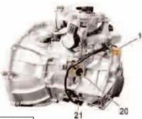 B2C201KD B2C201KD | Description(19) Reversing lamps sensor.(20) Gear engaged sensor.(21) Gearbox input speed sensor.(22) Gearbox actuator. |
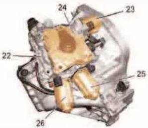 B2C201LD B2C201LD | (23) Electric motor for clutch actuator.(24) Clutch actuator.(25) Electric motor for gearbox actuator selection.(26) Electric motor for gearbox actuator engagement.Clutch actuatorDescription(27) Declutch angular sensor.(28) Electric motor for clutch actuator.(29) Push rod.(30) Clutch actuator body.(31) Declutch fork.FeaturesIMPERATIVE: Before each removal and after each refitting of the gearbox actuator, use a diagnostic tool to perform an initialisation (see corresponding operation). |
 | IMPERATIVE: At each refitting of the clutch actuator, perform a position adjustment (pre-loading) (see corresponding operation).Gearbox actuatorDescription(32) Electric motor for gearbox actuator selection.(33) Electric motor for gearbox actuator engagement.(34) Gearbox actuator body.(35) Engagement angular sensor.(36) Selection angular sensor. |
| B2C201ND | |
CLUTCH
GEARBOX
TRANSMISSION
| SPECIFICATIONS OF MMT (TOYOTA) PILOTED MANUAL GEARBOX | |
 | "b" Selection."c" Engagement.FeaturesIMPERATIVE: Perform an initialisation of the gearbox actuator after refitting (see corresponding operation).(37) Gear engagement screw."d" Neutral."e" 1st, 3rd, 5th."f" 2nd, 4th, Reverse. |
 | IMPERATIVE: Before refitting a gearbox actuator, check that it is in "neutral" position.Piloted manual gearbox ECUThe gearbox ECU decides on the changing of gear.It is located in the vehicle dashboard on the front LH side. |
| TIGHTENING TORQUES FOR MMT (TOYOTA) PILOTED MANUAL GEARBOX | ||||
 B2C202KD B2C202KD | Tightening torques (m.daN) | |||
| Ref. D | Description Number of screws Tightening | |||
| 1 | Clutch actuator fixing screws | 3 | 1,7 ± 0,1 | |
| 2 | Gearbox actuator fixing screws | 6 | 1,8 ± 0,1 | |
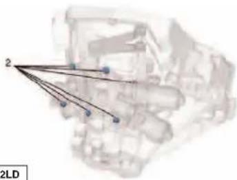 B2C20 B2C20 | ||||
CLUTCH
GEARBOX
TRANSMISSION
| TIGHTENING TORQUES FOR MMT (TOYOTA) PILOTED MANUAL GEARBOX | ||||
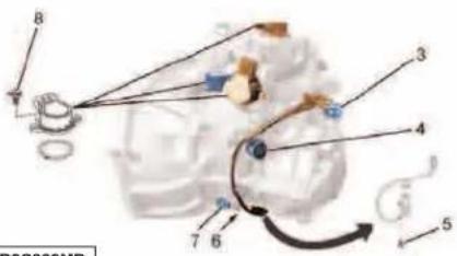 B2C202MD B2C202MD | Tightening torques (m.daN) | |||
| Ref. Description Number of screws Tightening | ||||
| 3 Reversing lamps sensor | 1 | 4 ± 0,4 | ||
| 4 Gear engaged sensor | ||||
| 5 | Fixing screw for gearbox input speed sensor | 0,8 ± 0,1 | ||
| 6 Drain plug 2,9 ± 0,3 | ||||
| 7 Oil level plug 3,9 ± 0,4 | ||||
| 8 Angular sensor fixing screw 6 0,2 | ||||
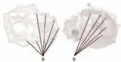 B2C202ND B2C202ND | 9 | Fixing screw for clutch housing on gearbox casing | 13 2,9 ± 0,3 | |
| TIGHTENING TORQUES FOR MMT (TOYOTA) PILOTED MANUAL GEARBOX | ||||
 | Tightening torques (m.daN) | |||
| Ref. | Description Number of screws Tightening | |||
| 10 | Differential gearwheel fixing screws | 6 | 12,4 ± 1,2 | |
| 11 Fork fixing screws | 2 | 1,6 ± 0,2 | ||
| 12 | Fixing screw for reverse gear shaft plate | 1,7 ± 0,2 | ||
| 13 Closing panel fixing screw 3 4 ± 0,4 | ||||
| 14 | Fixing screw for coupling of engine on gearbox | 4 6,4 ± 0,6 | ||
 | ||||
| B2C202QD | ||||
CLUTCH
GEARBOX
TRANSMISSION
| DRIVESHAFTS - GEARBOX | |||||||||
| Tightening torques (m.daN) | Gearbox oil seal mandrels | ||||||||
| Vehicles | Gearbox | Engines | Driveshaft bearing nut | Driveshaft | RH side LH | side Toolkit | |||
| C1 MMT 21. | MT | CFA6 ± 0,5 (-).0345.A (-).0345.B | |||||||
| MT 8HT | |||||||||
| Tightening torque (m.daN) for wheel bolts : C1 = 10 m.daN. | |||||||||
| WHEELS AND TYRES | |||||||||
| Standard fit | |||||||||
| Engines | Tyres(Circumference) | Rims Wheels | Spare wheel | ||||||
| Tyre Rim Wheel | |||||||||
| All types | 155/65 R14 75T 155/65 R14 75T1,699 m | Steel 4 1/2 J14 H2 | 1,699 m | Steel 4 1/2 J14 H2 | |||||
| Inflation pressures | |||||||||
| Normal operating pressure under load (maximum) | |||||||||
| Tyre dimensions | Pressure (Bars) Pressure | Bars) Tyre dimension | |||||||
| Front Rear | Spare wheel wheel | Front Rear | Spare | ||||||
| 155/65 R14 75T | 2,2 | 2,2 | 2,6 | 155/65 R14 75T | 2,3 | 2,3 | 2,6 | ||
| Tightening torquesTighten the wheel bolts to 10 m.daN. | |||||||||
AXLES SUSPENSION STEERING
| AXLE GEOMETRY | |
| Conditions for checking and adjusting | |
| Tyres inflated to correct pressures. Vehicle at reference height.Steering rack locked at mid point (see corresponding operation). | |
| Vehicle heights at reference height | |
 | |
| B3B200ED | |
| Rear heightFront height | |
| L1 | L2 |
| H1 = R1 - L1 | H2 = R2 - L2 |
| H1 = Measurement between the measuring zone underneath the front sub-frame and the ground.R1 = Front wheel radius under load.L1 = Distance between the wheel axis and the measuring zone underneath the front subframe. | H2 = Measurement between the measuring zone underneath the rear sill and the ground.R2 = Rear wheel radius under load.L2 = Distance between the wheel axis and the measuring zone underneath the rear sill. |
| AXLE GEOMETRY | |||
 | |||
| B3B200DD | |||
| Measuring front height Measuring rear height | |||
| [1] Gauge for measuring the wheel radius, 4 bolts, tool 4801-T | |||
| Value at reference V height L1 = 88 mm ( + 6 - 8 mm) (+ 10 - 6 mm) | value at referencemm height L2 = 22 mm | ||
| Compress the suspension to obtain the calculated values.The height difference between the two axle dimensions should be less than 10 mm. | |||
AXLES SUSPENSION STEERING
| AXLE GEOMETRY | ||||||||
| Front axle Rear axle | ||||||||
| Dissymmetry of lower castor at 0°30'.Dissymmetry of lower camber at 0°30'. | Dissymmetry of lower camber at 0°30'. | |||||||
| All Types | ||||||||
| CFA - 8HT CFA - 8HT | ||||||||
| Tyres 155/65 R 14 | ||||||||
| Vehicule Tracking | Castor Camber±0°18' ±0°30' | Pivot angle Trac±0°30' | Tracking Camber | |||||
| Adjustable Non adjustable | Non adjustable | |||||||
| All types | mm | 0 ± 2 | 3,6 ± 2,2 | |||||
| 0° | 0° ± 0°12' | 2°47' | 0°47' | 9°33' | 0°24' ± 0°15' | 0°53' | ||
| Angle of steering full lock | 38°55' ± 2° | |||||||
 | NOTE | |||||||
| A < B = Positive figure : + = TOE-IN | ||||||||
| A > B = Negative figure : - = TOE-OUT | ||||||||
| B3C200SD | ||||||||
SPECIAL FEATURES : FRONT AXLE

text_image
B3B200FDTracking adjustment
IMPERATIVE : Distribute the total tracking value symmetrically between the LH wheel and the RH wheel.
Remove the clip (1).
Slacken the nut (3).
Adjust the rod (2).
| SPECIFICATIONS : FRONT AXLE | |
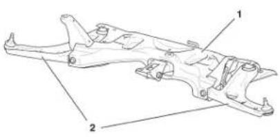 B3C200UD B3C200UD | Subframe(1) subframe.(2) suspension arm.Subframe in two steel shells, fixed by means of six screws on the body, with a yoke for the lower engine suspension rod and lateral yokes (2 LH + 2 RH) for the suspension arm fixings.The two rear fixing points for the subframe, under the floorpan, are via two link brackets (LH/RH) welded on the subframe.Pivot.Pivot type: "pinched".Pivot bearing diameter: 69 mmBearing with double row of balls, with integral magnetic wheelSuspension legFront suspension with independent wheels, type pseudo: "Mac Pherson".Travel stop: height A96 mm.Anti-roll barAll engine types: ∅ 22 mm |
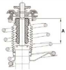 B3C200VD B3C200VD | |
| TIGHTENING TORQUES : FRONT AXLE | ||
| Tightening torques (m.daN) | ||
| Ref. Description Tightening | ||
| 1 Damper upper cup fixing nut 5,5 ± 0,5 | ||
| 2 Damper | ||
| 3 Anti-roll bar bearing fixing | 1,8 ± 0,2 | |
| 4 Anti-roll bar | ||
| 5 Pivot lower ball-joint nut 9,8 ± 1 | ||
| 6 Hub nut 21,6 ± 2 | ||
| 7 Steering ball-joint on pivot | 3,3 ± 0,3 | |
| 8 Suspension leg fixing on pivot | 4,8 ± 0,5 | |
| 9 Suspension lower arm screw 11 ± 1,1 | ||
| 10 Suspension lower arm screw | 12,8 ± 1,2 | |
| 11 Screw - fixing of subframe on body | 8,5 ± 0,8 | |
| 12 Screw - torque reaction rod on body | 5,2 ± 0,5 | |
| 13 Screw - fixing of subframe on body | 12,8 ± 1,2 | |
| 14 Screw - fixing of subframe on body | 4,8 ± 0,5 | |
AXLES
SUSPENSION
STEERING
| SPECIFICATIONS : REAR AXLE | |
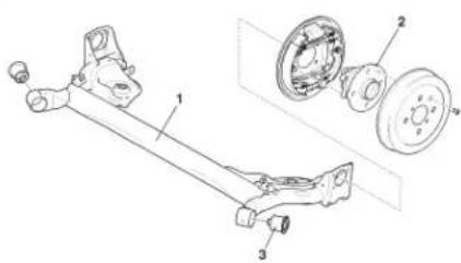 B3D200DD B3D200DD | Rear axle.(1) Rear axle crossmember.(2) Rear hub.(3) Rear axle rubber bush.Machine-welded rear axle, of trailing arm type with deformable axle crossmember.Engines all typesThickness of crossmember panel : 5,5 mmRear hub(2) Rear hub.Union on rear axle, fixing 4 screws (4).Vehicle geometryNOTE: The geometry specifications are given with the values for checking and adjusting the axle geometries. |
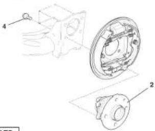 B3D200ED B3D200ED | |
| TIGHTENING TORQUES : REAR AXLE | ||
| Tightening torques (m.daN) | ||
| Ref. Description Tightening | ||
| 1 Damper upper fixing 2,5 ± 0,2 | ||
| 2 Damper lower fixing 4,8 ± 0,4 | ||
| 3 Fixing of yoke on rear axle | 12,3 ± 1,2 | |
| 4 Fixing of rear hub on rear axle | 6 ± 0,6 | |
AXLES
SUSPENSION
STEERING
| SUSPENSION SPECIFICATIONS | |
 | Front axleAnti-roll barsEngines all types : 22 mmTravel stopTravel stop height A : 96 mm.Rear axleRear axle crossmemberMachine-welded rear axle, of trailing arm type with deformable axle crossmember.Engines all types : 5,5 mmSuspension springDuring a repair on a suspension spring.IMPERATIVE : Check the presence and condition of the rubber protections on the fixed and sliding cups of the spring compressor.IMPERATIVE: Do not put a suspension spring in direct contact with a metallic object or tool.IMPERATIVE: Check the condition of the suspension springs (absence of signs of impacts, scratches or rust spots). The paint coating on the suspension springs should not be damaged, no bare metal. |
| SUSPENSION TIGHTENING TORQUES | |||
 B3B200MD B3B200MD | Tightening torques (m.daN) | ||
| Ref. Description Tightening | |||
| 1 Damper upper cup fixing nut 5,5 ± 0,5 | |||
| 2 Anti-roll bar fixing 1,8 ± 0,2 | |||
| 3 Pivot lower ball-joint nut 9,8 ± 0,9 | |||
| 4 Hub nut 21,6 ± 2,1 | |||
| 5 | Steering ball-joint on pivot | 3,3 ± 0,3 | |
| 6 | Suspension leg fixing on pivot | 4,8 ± 0,4 | |
| 7 | Screw fixing subframe on body | 8,5 ± 0,8 | |
| 8 | Screw fixing subframe on body | 12,8 ± 1,2 | |
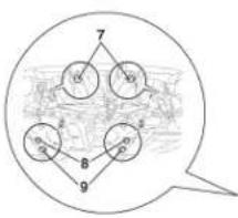  B3B200ND B3B200ND | 9 | Screw fixing subframe on body | 4,8 ± 0,4 |
| 10 | Anti-roll bar bearing fixing on subframe | 1,8 ± 0,1 | |
| 11 | Screws - steering mechanism on subframe | 8,7 ± 0,8 | |
| 12 Indexed nuts - steering mechanism on subframe | |||
 | Tightening torques (m.daN) | ||
| Ref. Description Tightening | |||
| 13 Damper upper fixing 2,5 ± 0,2 | |||
| 14 Damper lower fixing 4,8 ± 0,4 | |||
| 15 | Fixing of rear axle on body | 12,3 ± 1,2 | |
| 16 | Fixing of rear hub on rear axle | 6 ± 0,6 | |
MANUAL STEERING SPECIFICATIONS

text_image
Technical diagram of a mechanical assembly with numbered components for identificationB3E2006D

natural_image
Technical line drawing of a mechanical assembly with no visible text or symbolsB3E200WD
Manual steering
(5) steering wheel fixing.
(6) fixing of steering column on support.
(7) fixing of upper steering cardan.
(8) fixing of lower steering cardan.
Steering mechanism
Number of turns of the steering wheel : 3,27
Steering rack travel (mm) : 2 x 70,2
Steering ratio : 1/43
Inside angle of full lock : 36°55' to 40°55'
Outside angle of full lock : 32°23'
| POWER STEERING SPECIFICATIONS | |
 | Top of column(1) driver's airbag.(2) steering wheel.(3) rotary switch.(4) controls under steering wheel.Steering columnElectric power steering(5) steering wheel fixing.(6) fixing of steering column on support.(7) fixing of upper steering cardan.(8) fixing of lower steering cardan. |
 | |
| B3E2004D | |
| B3E2005D | |
 B3E200XD B3E200XD | Steering assistanceSupplier : KOYO.Electric motor : 33 A.The steering assistance is provided by the electric assistance motor (9), controlled by an ECU.Power delivered to the electric assistance motor (9) depends on:- Vehicle speed.- Engine speed.- Torque applied on the steering wheel. |
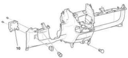 B3E200YD B3E200YD | Electric power steering ECUOnly one ECU version, whatever the engine-type.The electric power steering ECU (10) is linked to the following connectors:- Electric assistance motor supply.- Electric power steering ECU supply.- Signals from the torque sensor.- Information on engine speed and vehicle speedNOTE: After changing the electric power steering ECU, it is necessary to perform a configuration (see corresponding operation). |
| POWER STEERING TIGHTENING TORQUES | ||||
| B3E2002D |  | Tightening torques (m.daN) | ||
| Ref. Description Tightening | ||||
| 1 Steering wheel fixing 5 ± 0,5 | ||||
| 2 Fixing of steering column on support | 2,5 ± 0,2 | |||
| 3 Fixing of upper steering cardan | 3,5 ± 0,3 | |||
| 4 Fixing of lower steering cardan | 3,5 ± 0,3 | |||
| 5 Fixing of ball-joint on pivot | 3,3 ± 0,3 | |||
| 6 Locking nut for adjusting the steering track rods | 4,7 ± 0,4 | |||
| 7 Fixing of mechanism on subframe | 8,9 ± 0,8 | |||
| 8 Fixing of mechanism on subframe (indexed nut) | ||||
| B3E2003D |  | |||
SETTING THE STEERING RACK MID-POINT

text_image
B3E2000D
text_image
B3E2001DIMPERATIVE : Respect the precautions that must be taken prior to a repair.
Preliminary operation
Raise and support the vehicle on a 2-column lift.
Remove the clips (1) and (2).
Detach the steering rack protection gaiter.
Setting
Turn the steering wheel to full LH lock.
Measure the dimension X.
Turn the steering wheel to full RH lock.
Measure the dimension Y.
Calculate the dimension L = (Y - X) : 2 .
Position the steering rack to the dimension "L" (steering rack mid-point).
Additional operation
Refit the protection gaiter.
In order to be able to fit the clip (1), remove :
- The steering ball-joint gudgeon pin
- The steering ball-joint nut.
Uncouple the steering ball-joint from the pivot.
Fit a new clip (1).
Refit :
- The clip (2)
- The new clip (1)
- The steering ball-joint
- The steering ball-joint nut
- The steering ball-joint gudgeon pin
| BRAKE SPECIFICATIONS | |||||
| 1.0i 1.4 HDi | |||||
| Engine type | CFA 8HT | ||||
| FT Dlmm | ∅ mm | Master Cylinder | 20,64 | ||
| Master vac | 228,6 | ||||
| Caliper make / piston | BOSCH 48 | ||||
| Disc | Plain | ||||
| Ventilated | 247 | ||||
| Disc thickness/minimum thickness | 20/18 | ||||
| Brake pad supplier / grade | JURID 682 | ||||
| ∅ mm | DrumOriginal/maximum/width | 200/201 | |||
| Lining supplier / grade | FERODO 3627 F | ||||
BRAKE SPECIFICATIONS

natural_image
Pure electrical circuit lines without any symbolsBraking system
Braking circuit in the form of an X.
Ventilated disc brakes at the front, drum brakes at the rear.
NOTE : The front brake pads have no wear warning lamp.
Handbrake lever controlled by cables acting on the rear wheels.
The compensator and main brake limiter functions are assured by the ABS REF systems.
NOTE : REF = Electronic Brakeforce Distribution (EBD.
BRAKE SPECIFICATIONS

natural_image
3D rendering of a mechanical component with mounting holes and housing (no visible text or symbols)B3F2020D
Hydraulic valve block
Make : BOSCH.
Type : ABS REF 8.0.
Installed on the master cylinder
| TIGHTENING TORQUES : BRAKES | |||
| Front brakes | Tightening torques (m.daN) | ||
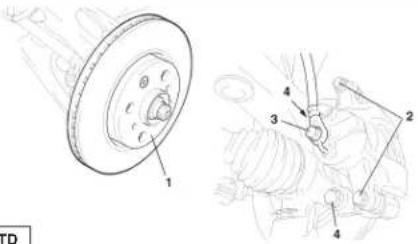 B3F201' B3F201' | Ref. Description Tightening | ||
| 1 Front brake disc 0,5 | |||
| 2 Yoke on brake caliper 3 ± 0,3 | |||
| 3 Brake pipe unions 3 ± 0,3 | |||
| 4 Front brake caliper 8,9 ± 0,9 | |||
| 5 | ABS hydraulic valve block support | 1,9 ± 0,2 | |
| 6 Front wheel sensor 0,8 ± 0,1 | |||
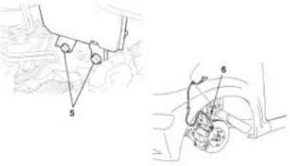 B3F201VD B3F201VD | |||
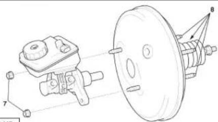 B3F201XD B3F201XD | Ref. Description Tightening | ||
| 7 Master-cylinder 2 ± 0,2 | |||
| 8 Braking amplifier 2 ± 0,2 | |||
| 9 Handbrake lever 2,2 ± 0,2 | |||
| Handbrake | |||
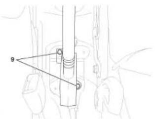 B3F201YD B3F201YD | |||
| TIGHTENING TORQUES : BRAKES | ||||
| Rear brakes | Tightening torques (m.daN) | |||
 | Ref. D | Description Tightening | ||
| 10 Rear brake drum 0,5 | ||||
| 11 Rear hub support 5,5 ± 0,5 | ||||
| 12 Brake pipe unions 1,5 ± 0,1 | ||||
| 13 Wheel cylinder 0,8 ± 0,1 | ||||
| 14 Rear wheel sensor 0,8 ± 0,1 | ||||
| [B3F201] | ||||
 | ||||
| [B3F201WD] | ||||
| CHECKING THE BRAKE PEDAL | ||||
 | IMPERATIVE : Respect the safety and cleanliness requirements.Height A of the brake pedal in relation to the floor (engine running) :135,8 to 145,8 mm for left hand drive models121,6 to 131,6 mm for right hand drive modelsIf the pedal height is not correct, adjust it.Disconnect the connector of the stoplamps switch (1).Unscrew the stoplamps switch (1).Remove the stoplamps switch (1).Slacken the push-rod locking nut (2).Adjust the height relative to the floor A of the brake pedal by rotating the push-rod (2).Tighten the push-rod locking nut (2).Tightening torque : 2,2 ± 0,2 m.daN. | |||
| B3F2010D | ||||
 B3F2011D B3F2011D | Do up the stoplamps switch (1) in its support (3) until it is flush with the brake pedal (4).IMPORTANT: Do not press on the brake pedal."a": shaft.Make a quarter turn to secure the stoplamps switch (1) in place.IMPORTANT: Do not press on the brake pedal.NOTE: Rotational torque for refitting the stoplamps switch (1): 0,15 m.daN maximum. | |||
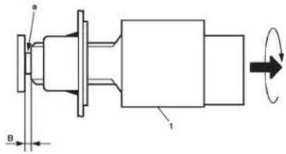 B3F2012D B3F2012D | Check the gap of the stoplamps switch.B: 1,5 to 2,5 mm.Connect the connector of the stoplamps switch (1). | |||
 | Press several times on the brake pedal until any vacuum in the braking amplifier disappears totally (engine stopped).Press on the pedal until you feel the start of resistance. Measure the play as indicated in the diagram.Play C of the brake pedal : 1,0 to 6,0 mm.If it is not in conformity, check the braking circuit.Slacken the handbrake. With the engine running, press on the brake pedal. Measure the reserve travel D of the pedal, as indicated in the diagram. | |||
| [B3F2013D] | ||||
 | Reserve travel D of the brake pedal relative to the floor : more than 48 mm at 490 N.If it is not in conformity, check the braking circuit.Slacken the handbrake. With the engine running, press on the brake pedal. Measure the reserve travel D of the pedal, as indicated in the diagram.Reserve travel D of the brake pedal relative to the floor : more 48 mm at 490 N.If it is not in conformity, check the braking circuit. | |||
| [B3F2014D] | ||||
CHECKING THE BRAKING AMPLIFIER


IMPERATIVE : Respect the safety and cleanliness requirements.
A: in conformity.
B : not in conformity.
Check the air-tightness.
Start the engine. Stop the engine 1 or 2 minutes later. Press several times but slowly on the brake pedal.
NOTE : If the brake pedal descends to the floor "a" at the 1st press, but does not descend as far as "b" at the 2nd press and as far as "c" at the 3rd press, the braking amplifier is air-tight.
With the engine running, press on the brake pedal. Keep the pedal pressed down and stop the engine.
NOTE : If the reserve travel does not change after 30 seconds of keeping the pedal pressed down, the braking amplifier is air-tight.
Check the operation of the brakes.
Ignition switched off, press several times on the brake pedal.
Check the reserve travel of the brake pedal.
Press on the brake pedal and start the engine.
NOTE: If the pedal goes down a few millimetres, it is working normally.
Check the vacuum valve.
Remove the vacuum hose.
Confirm that air is circulating in the direction from the amplifier to the engine, but not in the opposite direction from the engine to the amplifier.
| CHECKING THE BRAKING AMPLIFIER | |
 | C: circulation of air.D: absence of circulation of air.In the event of a fault, replace the vacuum hose.Refit the vacuum hose. |
| B3F201AD | |
[1] Pressure tester
[2] Pressure take-off union : (-).1602.B
Checks
Remove :
The windscreen wiper arm mounting cap
The windscreen wiper arm
The upper seal between bonnet and scuttle panel
The top scuttle panel ventilation grilles
The wiper motor
The scuttle panel
Locate the vacuum pipe (1) between the vacuum pump and the braking amplifier.
Remove the screw (2).
Uncouple the vacuum pipe at "a".

text_image
[1] [2]B3F202FD
Insert the union [2] between the vacuum pump and the braking amplifier.
Connect the tool [1] on the union [2].
Run the engine at idling speed.
Check the vacuum value.
Remove the tools.
Uncouple the vacuum pipe at "a".
Refit
The screw (2)
The scuttle panel
The wiper motor
The top scuttle panel ventilation grilles
The upper seal between bonnet and scuttle panel
The windscreen wiper arm
The windscreen wiper arm mounting cap
Values to check
NOTE : The vacuum value should be higher than or equal to 0.850 bar.
| Engine oil temperature Minimum | Maximum time (in seconds)vacuuml to attain the minimum vacuum |
| 80^ ± 5^ | 500 mbar 4,5 |
| 800 mbar 18 |
If the value is outside the tolerance :
Check the vacuum pump directly.
Check the sealing of the circuit on the link pipes as well as on the braking amplifier.
natural_image
Mechanical assembly diagram showing a linkage mechanism with an inset close-up of a mechanical component (no text or symbols)The handbrake adjustment is under the central console.
IMPERATIVE: Respect the safety and cleanliness requirements.
Adjust the handbrake shoe clearance.
Check the travel of the handbrake lever.
Slowly pull the handbrake lever to the maximum high position, counting the number of clicks.
Travel of the handbrake lever : 5 to 8 clicks at 196 N.
Remove the central console.
Turn the adjustment nut until the handbrake lever travel corresponds to the value indicated.
Travel of the handbrake lever : 5 to 8 clicks at 196 N.
Action the handbrake lever 3 to 4 times and check its travel.
Check that the handbrake is not rubbing when it is in the released position.
Check that the handbrake warning lamp lights up when the handbrake is applied.
Standard operation: the handbrake warning lamp always lights up from the first click.
Refit the central console

natural_image
Technical line drawing of a mechanical component with two vertical posts and a central threaded feature (no text or symbols)| DRAINING, FILLING AND BLEEDING THE BRAKING SYSTEM | |
 | Tools[1] Generic bleeding apparatus «LURO» or similarIMPERATIVE : Respect the safety and cleanliness requirements.NOTE : Bleeding of the secondary braking circuit is done with the aid of a diagnostic tool..DrainingDisconnect the negative terminal of the battery.Remove:The windscreen wiper arm mounting capThe windscreen wiper armThe upper seal between bonnet and scuttle panelThe top scuttle panel ventilation grillesThe wiper motorThe scuttle panelDrain the brake fluid reservoir (1) to the maximum(if necessary, use a clean syringe).Disconnect the connector at "a". |
text_image
Technical diagram of a mechanical device with labeled parts and directional arrows indicating assembly or movement.B3F202BD
Drain the brake fluid reservoir (1) to the maximum
(if necessary, use a clean syringe).
Disconnect the connector at "a".
Remove the brake fluid reservoir (1), by moving aside the tabs at "b" of the pins (2).
Clean the brake fluid reservoir (1).
Refit the brake fluid reservoir (1).
Reconnect the connector at "a".
Refit : the windscreen wiper arm mounting cap, the windscreen wiper arm, the upper seal between bonnet and scuttle panel, the top ventilation grilles of the scuttle panel, the wiper motor, the scuttle panel.
Reconnect the negative terminal of the battery.
IMPERATIVE : Carry out the operations that are necessary following a reconnection of the battery (see corresponding operation).
Filling the braking circuit
WARNING: Use only the approved and recommended hydraulic fluids.
IMPERATIVE : Only use new brake fluid that has not emulsified; avoid any introduction of impurities into the hydraulic circuit.
Fill the brake fluid reservoir (1).
Bleeding the primary braking circuit
WARNING: During the bleed operations: take care to maintain the level of the brake fluid in the reservoir, keep it topped up.
WARNING: The ABS system must not be in action during the bleed operation.
WARNING: Respect the sequence for the opening of the bleed screws.
text_image
Anatomical diagram of a mechanical device with labeled parts, likely for a robotic or mechanical assembly.B3F202CD
Front brake caliper : Bleed screw (3).
Rear brake caliper : Bleed screw (4).
Bleed each brake cylinder, proceeding in the following sequence :
Front LH wheel.
Front RH wheel.
Rear LH wheel.
Rear RH wheel.

text_image
4B3F202DD
Bleeding the braking circuit with the bleed apparatus
Connect the bleed apparatus [1] on the brake fluid reservoir (1).
Adjust the apparatus pressure to 2 bars.
For each brake circuit:
Couple a transparent tube on the bleed screw.
Submerge the other end of the tube in a clean container.
Open the bleed screw.
Wait until the brake fluid flows out without air bubbles.
Close the bleed screw.
Remove the bleed apparatus [1].
Check the level of the brake fluid (between the « MINI » level and the « MAXI » level).
Fill if necessary with the approved and recommended synthetic brake fluid.
text_image
Technical diagram showing mechanical assembly with labeled component '3'B3F202CD

text_image
4B3F202DD
Bleeding the braking circuit without the bleed apparatus
NOTE: Two operators are necessary.
For each brake circuit:
Apply the brake pedal to place the circuit under pressure.
Couple a transparent tube on the bleed screw.
Submerge the other end of the tube in a clean container.
Open the bleed screw.
Wait until the fluid flows out without air bubbles.
Close the bleed screw
NOTE: Recommence the process a second time if that is necessary.
Check the level of the brake fluid (between the «MINI» level and the «MAXI» level).
Fill if necessary with the approved and recommended synthetic brake fluid.
Bleeding the secondary braking circuit
WARNING: During the bleed operations: take care to maintain the level of the brake fluid in the reservoir, keep it topped up.
NOTE: The bleed apparatus [1] is still connected on the brake fluid reservoir (1).
Use a diagnostic tool.
Select the ABS menu.
Follow the instructions of the diagnostic tool.
At the end of the bleed programme, check the level of the brake fluid, top up if necessary.
Check the travel of the brake pedal: it must not be excessive. If it is, restart the bleed procedure
| AIR CONDITIONING R 134 a (HFC) | ||||||
| Vehicle | Engines Date | Refrigerant refill(±30 gr) | Compressor | |||
| FixedCapacity (fan) | Oilquantity cc | Oilreference | ||||
| C1 06/05 | 384/F 450 | → | VALEO/ZEXEL 80 VALEO/ZEXEL | |||
| DV4TD 500 DKV-06R ZXL 200PG | ||||||
| SPECIFICATIONS OF AIR CONDITIONING CIRCUIT (R 134.a) | ||||||
 | Compressor/condenser | |||||
| C5H2021D | (1) Air conditioning compressor drive plate.(2) Connector.(3) Seals. | |||||
 | (3) Seals.(4) Condenser.(5) Filtering cartridge.(6) Condenser inlet.(7) Condenser outlet. | |||||
| C5H2022D | ||||||

text_image
Technical diagram showing labeled components of a mechanical or electronic component, including parts 8, 9, and numbered parts.C5H2023D
SPECIFICATIONS OF AIR CONDITIONING CIRCUIT (R 134.a)
Pressure reducer
(8) Pressure reducer inlet.
(9) Pressure reducer outlet.
(3) Seals.
Lubricant
WARNING : As these oils have a pronounced tendency to absorb moisture, avoid stocking them in containers that have been opened.
Type of oil used : ZXL 200PG.
IMPERATIVE : Never use any other type of oil.
It is not obligatory to check the level of oil in the compressor when you fill the air conditioning circuit.
NOTE : The oil level must be checked in cases of leaks in the air conditioning circuit (see corresponding operation).
Pressostat
Linear pressure sensor.
Filler valves
Type of valves : clickfit (with protection cap).
NOTE : The high pressure and low pressure valves have different diameters to avoid any error in fitting.
Seal
O-ring seal.
| SPECIAL FEATURES : AIR CONDITIONING CIRCUIT (R 134.a) | |
| Pollen filter | |
 | The pollen filter is located in the passenger compartment under the dashboard (on RH side).Remove the pollen filter (1).RefittingClean the pollen filter housing.Fit a new pollen filter.Check the flow of air through the air blower, operating it at its different speeds. |
| C5H202HD | |
 | |
| C5H202JD | |
| Filtering/drying cartridge | |
 | RemovingRemove the condenser(see corresponding operation).Remove the screw and the support. |
 | Remove the screw and the filtering/drying cartridge.Remove the 4 O-ring seals from the condenser. |
| C5H2006D | |
 C5H2008D C5H2008D | RefittingLubricate 4 new O-ring seals, as well as the contact surface of the filtering/drying cartridge, using compressor oil.Compressor oil : ZXL 200PG or equivalent.Fit the 4 O-ring seals on the condenser.Refit the filtering/drying cartridge, with the screw.Tightening torque : 1,3 ± 0,1m.daN.Refit the support with the screw.Refit the condenser (see corresponding operation). |
 C5H2009D C5H2009D | |
| AIR CONDITIONING CIRCUIT R 134.a | |
| Engine : 384F | |
 | (10) Low pressure valve.(11) High pressure valve.(12) Pressostat.a) Pressure reducer outlet : 1 ± 0,1 b) Pressure reducer inlet : 1 ± 0,1 c) Condenser outlet : 1 ± 0,1 d) Aircon compressor inlet : 1 ± 0,1 e) Aircon compressor outlet : 1 ± 0,1 f) Condenser inlet : 1 ± 0,1 |
| Engine : DV4TD | |
 | (10) Low pressure valve.(11) High pressure valve.(12) Pressostat“a” Pressure reducer outlet : 1 ± 0,1 “b” Pressure reducer inlet : 1 ± 0,1 “c” Condenser outlet : 1 ± 0,1 “d” Aircon compressor inlet : 1 ± 0,1 “e” Aircon compressor outlet : 1 ± 0,1 “f” Condenser inlet : 1 ± 0,1 |
| C5H2025D | |