MiTo (2009) - Car ALFA ROMEO - Free user manual and instructions
Find the device manual for free MiTo (2009) ALFA ROMEO in PDF.

User questions about MiTo (2009) ALFA ROMEO
0 question about this device. Answer the ones you know or ask your own.
Ask a new question about this device
Download the instructions for your Car in PDF format for free! Find your manual MiTo (2009) - ALFA ROMEO and take your electronic device back in hand. On this page are published all the documents necessary for the use of your device. MiTo (2009) by ALFA ROMEO.
USER MANUAL MiTo (2009) ALFA ROMEO
text_image
ALFA ROMATOOWNER HANDBOOK
MTO

WHY CHOOSING GENUINE PARTS
We really know your car because we invented, designed and built it: we really know every single detail.
At Alfa Romeo Service authorised workshops you can find technicians directly trained by us, offering quality and professionalism for all service operations.
Alfa Romeo workshops are always close to you for the regular servicing operations, season checks and practical recommendations by our experts.
With Alfa Romeo Genuine Parts you keep the reliability, comfort and performance features of your new car unchanged in time: that's why you bought it for.
Always ask for Genuine Parts for the components used on our cars; we recommend them because they come from our steady commitment in research and development of highly innovative technologies.
For all these reasons: rely on Genuine Parts, because they are the only ones designed by Alfa Romeo for your car.
SAFETY:
BRAKING SYSTEM
ENVIRONMENT: PARTICULATE FILTERS,
CLIMATE CONTROL MAINTENANCE
COMFORT: SUSPENSION
AND WINDSCREEN WIPERS
PERFORMANCE: SPARK PLUGS,
INJECTORS AND BATTERIES
LINEACCESSORI
ROOF RACK BARS, WHEEL RIMS
CHOOSING GENUINE PARTS IS THE MOST NATURAL CHOICE
natural_image
Abstract graphic of a car with barcode pattern (no text or symbols)


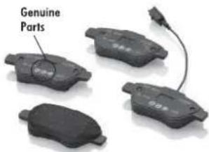
HOW TO RECOGNISE GENUINE PARTS
To recognise a Genuine Part, check that the component bears our brands, always clearly visible on Genuine Parts, from the braking system to windscreen wipers, from shock absorbers to pollen filter.
All Genuine Parts undergo strict controls, both during design and manufacturing stages, by specialists using vanguard materials, to test the component reliability.
This to guarantee performance and safety for you and your passengers on board, for a long time.
Always ask for and make sure a Genuine Part has been used.

text_image
Genuine PartsPollen filter

text_image
Genuine PartsShock absorber
text_image
Genuine PartsBrake pads
Dear Customer,
we would like to congratulate and thank you for choosing Alfa Romeo.
We have written this handbook to help you get to know all the features of your car and use it in the best possible way. Please read it all the way through before taking your car on the road for the first time.
Here you will find information, tips and important warnings regarding use of your car and how to achieve the best performance from the technological features of your Alfa Romeo. The handbook also provides a description of special features and tips as well as essential information for correct care, maintenance, safety of car driving and use and preservation of your Alfa Romeo over time.
Carefully read the warnings and indications marked with the following symbols:

personal safety;

car safety;

environmental protection.
The enclosed Warranty Booklet lists the services that Alfa Romeo offers to its Customers:
□ the Warranty Certificate with terms and conditions for maintaining its validity;
□ the range of additional services available to Alfa Romeo Customers.
We are confident that these instructions will help you become familiar with your new car and the Alfa Romeo after-sales staff who will be at your service.
Enjoy reading. Happy motoring!
This Owner Handbook describes all versions of the Alfa MiTo; please consider only the information relevant to your version, engine and configuration. All data contained in this publication are purely indicative. Fiat Group Automobiles can modify the specifications of the vehicle model described in this publication at any time, for technical or marketing purposes. For further information, contact an Alfa Romeo Dealership.
VERYIMPORTANT
REFUELLING

Petrol engines: only refuel with unleaded petrol with octane rating (RON) not less than 95 in compliance with the European Standard EN228.
Diesel engines: refuel only with diesel fuel conforming to the European specification EN590. The use of other products or mixtures may damage the engine beyond repair and consequently invalidate the warranty, due to the damage caused.
STARTINGTHEENGINE

Petrol engines: make sure that the handbrake is engaged, set the gear lever to neutral, fully depress the clutch without depressing the accelerator, then turn the ignition key to AVV and release it as soon as the engine has started.
Diesel engines: turn the ignition key to MAR and wait for the warning lights 📋 and fogo out; then turn the ignition key to AVV and release it as soon as the engine has started.
PARKINGONFLAMMABLEMATERIAL

The catalytic converter develops high temperatures during operation. Do not park the car on grass, dry leaves, pine needles or other flammable material: fire hazard.
RESPECTINGTHEENVIRONMENT

The car is fitted with a system that carries out a continuous diagnosis of the emission-related components in order to help protect the environment.
ELECTRICALACCESSORIES

If after having purchased the car you decide to add accessories requiring electricity (with the risk of gradually draining the battery), contact Alfa Romeo Authorized Services. They can calculate the overall electric requirement and check that the car's electric system can support the required load.
CODEcard
(for versions/markets, where provided)

Keep it in a safe place, not in the car. We recommend that you always carry the electronic code provided on the CODE card with you, in case you need to perform an emergency start.
SCHEDULEDSERVICING

Correct maintenance of the car is essential for ensuring that it maintains its performance and its safety features, its environmental friendliness and low running costs for a long time to come.
THEOWNERMANUALCONTAINS...

...important information, advice and warnings for correct use, driving safety and maintenance of your car over time. Particular attention should be paid to information marked with the following symbols: (personal safety) (environmental protection) (car integrity).
GETTINGTOKNOWYOURCAR
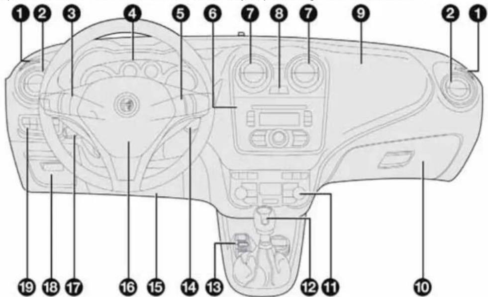
DASHBOARD
The presence and position of the controls, instruments and indicators may vary according to the different versions.
text_image
Labeled diagram of a camera interior with numbered parts for identificationA0J0330
1. Diffuser for directing air to the side windows 2. Adjustable air vent 3. Exterior light control lever 4. Instrument panel 5. Windscreen wiper/rear window wiper/trip computer control lever 6. Car radio (for versions/markets, where provided) 7. Adjustable air diffusers 8. Hazard warning lights, door locking/unlocking button 9. Passenger front airbag 10. Glove compartment 11. Heating/ventilation/climate control system controls 12. Gear lever 13. "Alfa DNA" system 14. Ignition device 15. Driver side front knee bag (for versions/markets, where provided) 16. Driver front airbag 17. Cruise Control lever (for versions/markets, where provided) 18. Fuse box access flap 19. Panel with various controls.
CONTROLPANEL ANDINSTRUMENTS
VERSIONSWITHMULTIFUNCTIONDISPLAY

text_image
A B C D E Mon 10 Mar 240 123456 km 20°C 8:30A0J1540
fig. 2
A. Speedometer (speed indicator) B. Multifunction display C. Rev counter D. Fuel level gauge with reserve warning light E. Engine coolant temperature gauge with overheating warning light
Warning lights available on diesel versions only. On diesel versions, the end of scale for the rev counter is 6000 rpm
IMPORTANT The illumination of the instrument panel graphics may vary according to version.
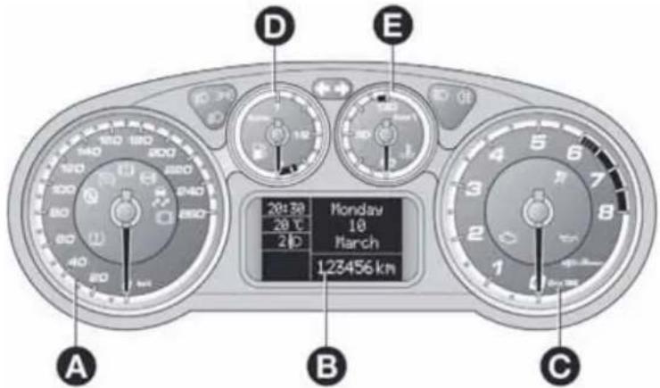
VERSIONSWITHRECONFIGURABLEMULTIFUNCTIONALDISPLAY
text_image
A B C D E 20:30 Monday 20℃ 10 March 20D 123456 kmfig. 3
A0J1541
A. Speedometer (speed indicator) B. Reconfigurable multifunction display C. Rev counter D. Fuel level gauge with reserve warning light E. Engine coolant temperature gauge with overheating warning light
Warning lights available on diesel versions only. On diesel versions, the end of scale for the rev counter is 6000 rpm.
IMPORTANT The illumination of the instrument panel graphics may vary according to version.
SPEEDOMETER(SPEEDINDICATOR)
This shows the speed of the car.
REVCOUNTER
This indicates the engine rpm.
FUELLEVELGAUGE
This shows the amount of fuel left in the fuel tank.
The warning light in the gauge switches on when there are 5 to 7 litres of fuel remaining in the tank; if this happens, refuel as soon as possible.
Do not travel with the fuel tank almost empty: any gaps in fuel delivery could damage the catalytic converter.
The needle shows the temperature of the engine coolant and starts supplying indications when the fluid temperature exceeds approx. 50°C.
Under normal conditions, the needle assumes different positions within the scale depending on the usage conditions.
The warning light switches on to indicate an excessive increase of the coolant temperature; in this case, stop the engine and contact Alfa Romeo Authorized Services.
On some versions, the warning light switching-on is combined with specific messages on the display and/or acoustic warnings.
These indications are brief and precautionary and as such must not be considered as exhaustive and/or alternative to the information contained in this Owner's Handbook, which you are recommended to read carefully in all cases.
Always refer to the information in this paragraph in the event of a failure indication.
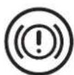
Lowbrakefluidlevel(red)
Turning the key to the MAR position illuminates the warning light, but it should switch off after a few seconds.
The warning light (or symbol on the display) comes on when the level of the brake fluid in the reservoir falls below the minimum level, possibly due to leaks in the circuit.
The display will show the dedicated message.

If the warning light turn son when driving stop the car immediately and contact Alfa Romeo Authorized Services.
Handbrakeon(red)
Turning the key to the MAR position illuminates the warning light, but it should switch off after a few seconds.
The warning light (or symbol on the display) switches on when the handbrake is engaged. If the car is moving the buzzer will also sound.
IMPORTANT If the warning light turns on when driving, check that the handbrake is not engaged.
EBDfailure
The simultaneous switching on of the ⚠️ (red) and ⏻ (amber) warning lights with the engine on, indicates either a failure of the EBD system or that the system is not available. In this case, the rear wheels may suddenly lock and the vehicle may swerve when braking sharply. The display will show the dedicated message.
Drive with extreme caution straight to the nearest Alfa Romeo Authorized Service to have the system checked.
ABSFAILURE(amber)
Turning the key to the MAR position illuminates the warning light, but it should switch off after a few seconds.
The warning light (or symbol on the display) lights up when the system is inefficient. Under these circumstances the braking system will work as normal without the extra performance offered by the ABS system.
Proceed with caution and contact Alfa Romeo Authorized Services as soon as possible.
The display will show the dedicated message.

Brakepadwear(amber)
(for versions/markets, where provided)
The warning light (or symbol on the display) switches on when the front and rear brake pads are worn. In this situation, replace as soon as possible.
The display will show the dedicated message.

Airbagfailure(red)
Turning the key to the MAR position illuminates the warning light, but it should switch off after a few seconds.
If the warning light switches on constantly, this indicates a fault in the airbag system.
The display will show the dedicated message.
If,whenturningthekeytoMAR-ON,thewarninglight doesnotturnon,orifitstaysonconstantlywhen driving(togetherwiththemessageonthedisplay),therecouldbeafailureintherestraintsystems.Inthiscase airbagsorpretensionersmaynotbedeployedintheeventofan impactor,inalowernumberofcases,theydeploymay accidentally.Beforeproceeding,contactAlfaRomeoAuthorized Servicestohavethesystemcheckedimmediately.
In the case of warning light failure, despite the flashing of the warning light in the trim located on the internal rear view mirror and the deactivating (where provided) of the passenger's airbag, on the versions with multifunction display on the instrument panel, the warning light will also flash and dedicated messages will be displayed. On the versions with reconfigurable multifunction display the symbol will instead be displayed, together with a message.

Lowbatterycharge(red)
(for versions/markets, where provided)
When the ignition key is turned to MAR, the warning light switches on but should switch off as soon as the engine is started (with the engine idling, a brief delay is acceptable).
Contact Alfa Romeo Authorized Services if the warning light (or symbol on the display) remains on or flashes.

Electricpowersteeringfailure (red)
(for versions/markets, where provided)
Turning the key to the MAR position illuminates the warning light, but it should switch off after a few seconds.
If the warning light (or symbol on the display) stays on, you will not have steering assistance and the effort required to operate the steering wheel will be significantly increased; steering is, however, possible.
The display will show the dedicated message.
In this case, contact Alfa Romeo Authorized Services.

Start&Stopsystem deactivation(amber)
The warning light switches on when the Start&Stop system is deactivated by pressing the button on the auxiliary control panel next to the steering wheel.
A specific message is displayed on certain versions.
CONSTANTLYON: Lowengine oil pressure(red)
FLASHING: Engine oil deteriorated
(for versions/markets, where provided - red)
When the key is turned to MAR the warning light comes on, but should go out as soon as the engine is started.
1. Low engine oil pressure
The warning light turns on and stays on constantly (along with a message on the display on some versions) when the system detects that engine oil pressure is low.

If the warning light turns on which driving (on some versions, together with the message on the display), stop the car immediately and contact Alfa Romeo
AuthorizedServices.
2. Engine oil deteriorated
(for versions/markets, where provided)
The warning light will turn on flashing and, on some versions, with a specific message on the display.
Depending on the versions, the warning light flashing modes are as follows:
☐ for 1 minute every two hours;
☐ cycles of 3 minutes with intervals with the warning light off for 5 seconds until the oil is changed.
After the first indication, at each engine start up the warning light will continue flashing as described above until the oil is changed. On some versions, the display shows a dedicated message together with the warning light.
If the warning light flashes, this does not mean that the car is defective, but simply informs the driver that it is now necessary to change the oil as a result of regular vehicle use.
Remember that the deterioration of the engine oil is accelerated by:
□ mainly town use of the car which makes the DPF regeneration process more frequent;
☐ use of the car for short drives, in which the engine does not have time to reach its regular operating temperature;
☐ repeated interruption of the regeneration process, signalled by the DPF warning light coming on.

If the warning lights switches on, the deteriorated engine oil must be changed as soon as possible, and never more than 500 km from the first timethat the
warninglightswitcheson.Failuretoobservetheabove indicationsmayresultinseveredamagetotheengine and invalidatethewarranty.Theactivationofthiswarninglightisnot relatedtotheamountofoilintheengine.Therefore,nevertop upwithoilwhentehwarninglightstartsflashing.

Enginecoolantoverheating (red)
Turning the key to the MAR position illuminates the warning light, but it should switch off after a few seconds.
The warning light turns on when the engine is overheated.
The display will show the dedicated message.
If the warning light comes on when driving, proceed as follows:
☐ when driving normally: stop the car, switch off the engine and check that the water level in the reservoir is not below the MIN mark. If it is, wait for the engine to cool down then slowly and carefully open the cap, top up with coolant and check that the level is between the MIN and MAX marks on the reservoir. Also check visually for leakages. If the warning light comes on again at the next engine start-up, contact Alfa Romeo Authorised Services.
☐ if the vehicle is used under demanding conditions (e.g. towing trailers uphill or fully loaded): slow down and, if the warning light stays on, stop the car. Wait for 2 or 3 minutes with the engine running and slightly accelerated to further favour the coolant circulation. Then stop the engine. Check the correct fluid level as described above.
IMPORTANT Over demanding routes, it is advisable to keep the engine on and slightly accelerated for a few minutes before switching it off.

Doorsnotclosedcorrectly (red)
(for versions/markets, where provided)
The warning light (or symbol on the display) lights up when one or more doors or the tailgate are not closed correctly. An acoustic signal is activated with the doors open and the car moving.
On some versions the warning light (or symbol on the display) also lights up when the bonnet is not closed correctly.

EOBD/injectionsystemfailure (amber)
In normal conditions, when the ignition key is turned to MAR-ON the warning light switches on, but should switch off as soon as the engine is started.
If the warning light remains on or switches on whilst driving, the injection system is not working properly; in particular, if the warning light switches on constantly, this indicates a malfunction in the supply/ignition system that could cause excessive exhaust emissions, a possible loss of performance, poor driveability and high fuel consumption.
A specific message is displayed on certain versions.
Under these conditions, you may continue travelling at moderate speed without demanding excessive effort from the engine. Prolonged use of the car with the warning light on may cause damage.
Contact Alfa Romeo Authorized Services as soon as possible.
The warning light goes out after the fault disappears, but the notification is stored in the system.
NOTE (valid only for petrol engines)
If the warning light is flashing, this indicates that the catalytic converter may be damaged.
If the warning light comes on flashing, release the accelerator pedal to lower the speed of the engine until the warning light stops flashing. Continue the journey at moderate speed, trying to avoid driving conditions that may cause further flashing and contact Alfa Romeo Authorized Services as soon as possible.

ContactAlfaRomeoAuthorizedServicesassoonaspossible ifthe warninglightdoesnotlightuporif,while travelling,thewarninglightcomesoneitherconstantlyor
flashing(incombinationwithamessageonthedisplayonsome versions).Theoperationofwarninglight maybecheckedbythe trafficpoliceusingspecificdevices.Followthelawsinforceinthe countrywhereyouaredriving.
ESCsystem(amber)
(for versions/markets, where provided)
Turning the key to the MAR position illuminates the warning light, but it should switch off after a few seconds.
If the warning light (with message + symbol displayed on some versions) does not switch off, or if it remains lit up when driving, contact Alfa Romeo Authorized Services.
Flashing of the warning light while driving indicates the intervention of the ESC system.
ASRfailure
Turning the key to the MAR position illuminates the warning light, but it should switch off after a few seconds.
If the warning light (or the symbol on the display) does not switch off, or if it remains lit when driving, contact Alfa Romeo Authorized Services.
A specific message is displayed on certain versions.
The warning light flashes while driving to indicate the intervention of the ASR system.
HillHolderfailure
This warning light comes on, on some versions together with the symbol and a message in the display, in the event of a fault with the Hill Holder system.
In this case, contact Alfa Romeo Authorized Services.

AlfaRomeoCODEsystem failure/Alarmfailure(amber)
(for versions/markets, where provided)
The warning light (or symbol on the display) comes on (on some versions, with a message on the display) to indicate an Alfa Romeo CODE system or alarm failure (for versions/markets, where provided). In this case, contact Alfa Romeo Authorized Services as soon as possible.
Break-in attempt
If this warning light flashes or, on some versions, if the symbol appears in the display (together with a message) this indicates a break-in attempt. Contact Alfa Romeo Authorized Services as soon as possible.

Glowplugpreheating (dieselversions)(amber)
This warning light switches on when the key is turned to MAR. It will switch off as soon as the heater plugs have reached a preset temperature. The engine can be started as soon as the warning light switches off.
IMPORTANT In mild or high temperature conditions, the warning light comes on for an extremely short time.
Glowplugpreheatingfailure (dieselversions)
The warning light will flash (a message will appear on the display, on some versions) to indicate a fault in the glow plugs preheating system. Contact Alfa Romeo Authorized Services as soon as possible to eliminate the fault.

Waterindieselfilter (dieselversions)(amber)
The warning light remains on constantly when driving (together with a message in the display), to indicate the presence of water in the diesel filter.

The presence of water in the fuel system circuit may cause severe damage to the injection system and regular engine operation. If the warning light comes on the
instrumentpanel(togetherwithamessageinthedisplay)contactAlfa RomeoAuthorizedServicesassoonaspossiblebleedthesystem. Watermayhaveenteredthetankifthisappearsimmediatelyafter refuelling:ifthishappens,switchtheengineoffimmediatelyand contactAlfaRomeoAuthorizedServices.

Fuelreserve-Limitedrange (amber)
This warning light switches on when 5 to 7 litres of fuel are left in the tank.
When the remaining range is lower than approx. 50 km (or equivalent value in miles), on some versions, the display will show a warning message.

If the warning light flashes with the carin motion, contact Alfa Romeo Authorized Services.

Cruisecontrol(green)
(for versions/markets, where provided)
The warning light comes on when the key is turned to MAR, but should go out after a few seconds if the Cruise Control function is off.
The warning light comes on when the Cruise Control ring nut is turned to the ON position (see the "Cruise Control" paragraph in this section).
The display will show the dedicated message.
DPF(dieselparticulatefilter) cleaninginprogress(only dieselversionswithDPF) (amber)
Turning the key to the MAR position illuminates the warning light, but it should switch off after a few seconds.
The warning light switches on constantly to indicate that the DPF system needs to eliminate the trapped pollutants (particulate) through the regeneration process.
The warning light does not come on during every DPF regeneration, but only when driving conditions require that the driver is notified. To switch the warning light off, the car must be kept moving until the regeneration process is completed.
On average, the process lasts fifteen minutes. Optimal conditions for completing the process are achieved by travelling at 60 km/h with engine revs above 2000 rpm.
When this warning light switches on, it does not indicate a car failure and thus it should not be taken to a workshop.
On some versions, together with the warning light, the display shows a dedicated message.

The drivingspeedmustalwaysbesuitablefortraffic and weatherconditionsandthedrivermustalways complywiththeHighwayCode.Theenginecanbe stoppeddeveniftheDPFwarninglightison;however,repeated interruptionsoftheregenerationprocesscouldcausepremature deteriorationoftheengineoil.Forthisreason,alwayswaituntil thewarninglightswitchesoffbeforestoppingtheengineas describedabove.ItisnotadvisabletocompleteDPFregeneration withthecarstationary.
Speedlimitexceeded(red)
(for versions/markets, where provided)
This warning light (for versions/markets, where provided) comes on when the vehicle speed exceeds 120 km/h.
When the car exceeds the speed limit set in the Set-up Menu (e.g. 120 km/h), on some versions a message and a symbol are shown in the display and an acoustic signal is activated.

Generalfailure(amber)
(for versions/markets, where provided)
The warning light (or symbol on the display) switches on in the circumstances indicated below.
In these circumstances, contact Alfa Romeo Authorized Services as soon as possible to eliminate the fault.
Airbag failure warning light
(versions with multifunction display)
The warning light switches on and flashes (together with a message on the display) when a fault is detected with the airbag warning light

Exterior lights failure
See description for the - warning light.
Brake lights failure
See description for "Brake lights failure".
Fuel cut-off
This warning light comes on when the fuel cut-off inertia switch is triggered. The display shows the dedicated message.
Start&Stop failure
(for versions/markets, where provided)
The warning light comes on when a failure is detected in the Start&Stop system.
Rain sensor failure
(for versions/markets, where provided)
See the description for the ⚡! warning light.
Parking sensor failure
(for versions/markets, where provided)
See the description for the P warning light.
Dusk sensor failure
(for versions/markets, where provided)
This warning light comes on when a dusk sensor failure is detected.
Engine oil pressure sensor failure
The warning light turns on when failure is detected in the engine oil pressure sensor. The display shows the dedicated message.
Electric power steering failure
(for versions/markets, where provided)
The warning light comes on when an electric power steering failure is detected.
Water in diesel filter
(for versions/markets, where provided)
The warning light switches on to indicate the presence of water in the diesel filter.
Speed limit exceeded
(for versions/markets, where provided)
The warning light switches on when the speed limit set in the Setup menu is exceeded.
When the car exceeds this value, on some versions a message and a symbol are shown on the display and an acoustic signal is emitted.

Rearfoglight(amber)
The warning light switches on when the rear fog light is switched on.

Frontfoglights(green)
The warning light switches on when the fog lights are switched on.

Sidelights(green)
This warning light comes on when the side lights are turned on.
Followmehome(green)
The warning light switches on (together with a message shown on the display) when this device is in use (see "Follow me home device" paragraph in this section).

Dippedheadlights(green)
The warning light switches on when the dipped headlights are switched on.

Mainbeamheadlights(blue)
The warning light switches on when the main beam headlights are switched on.

Leftdirectionindicator (green)
This warning light comes on when the direction indicator control lever is moved downwards and when the hazard warning light button is pressed.
Rightdirectionindicator (green)
The warning light switches on when the direction indicator stalk is moved upwards or when the hazard warning light button is pressed.
Tyrepressurelow
(for versions/markets, where provided)
This warning light (or symbol on the display) switches on (on some versions together with a message on the display) (together with an acoustic signal) if the pressure in one or more tyres drops below a preset threshold.
In this way the TPMS warns the driver that one or more tyres may be dangerously flat and liable to puncture.
IMPORTANT Do not continue driving with one or more flat tyres as handling may be compromised. Stop the car, avoiding sharp braking and steering. Replace the wheel immediately with the space-saver wheel (for versions/markets, where provided) or carry out an immediate repair using the dedicated kit (see "Changing a wheel" in the "In an emergency" section) and contact Alfa Romeo Authorised Services as soon as possible.
TPMS failure
This warning light (or symbol on the display) switches on (on some versions together with a message on the display) when a TPMS fault is detected.
In this case, contact Alfa Romeo Authorised Services as soon as possible.
Should one or more wheels be fitted without sensors, the display will show a warning message until initial conditions are restored.
Check tyre pressure
This warning light (or symbol in the display) switches on (on some versions together with a message in the display) to indicate that the tyre pressure is below the value recommended to guarantee long tyre life and low fuel consumption. It may also indicate a slow loss of pressure.
Should two or more tyres be in the condition mentioned above, the display will show the indications corresponding to each tyre in sequence.
Under these circumstances you should restore the correct pressure values (see "Technical specifications" section).
Start&Stopsystemactivation/deactivation
(for versions/markets, where provided)
Start&Stopsystemactivation
A message will appear on the display when the Start&Stop system is activated.
TurningtheStart&Stopoff
☐ Versions with multifunction display: a message is displayed when the Start&Stop system is deactivated.
□Versionswithreconfigurablemultifunctiondisplay:the symbol is displayed + a message when the Start&Stop system is deactivated.

Start&Stopsystemfailure
If the Start&Stop system is faulty the ⑤ (versions with multifunction display) or ① (versions with reconfigurable multifunction display) symbol flashes on the display.
For versions/markets where provided, a warning message is also displayed.
In this case, contact Alfa Romeo Authorized Services.

Luggagecompartmentopen
On some versions a message + symbol on the display are shown when the luggage compartment is open.

Bonnetopen
On some versions a message + symbol on the display are shown when the bonnet is open.

Possible presence of ice on the road
On versions equipped with "Reconfigurable multifunction display", a message and a symbol will appear when the outdoor temperature falls to or below 3°C.
On versions with "Multifunction display" only the dedicated message is shown.
IMPORTANT In the event of outdoor temperature sensor failure, dashes are shown on the display instead of the value.

Fuelcut-off
On some versions the display will show a message + symbol if the fuel cut-off intervenes.
For the fuel cut-off system reactivation procedure see paragraph "Fuel cut-off system" in this section.

Exteriorlightsfailure
On some versions, the display will show a message + symbol if a fault is detected in one of the following lights:
□ daytime running lights (DRL)
□side lights
□direction indicators
□rear fog light
□number plate lights.
The failure relating to these lights could be: one or more blown bulbs, a blown protection fuse or a break in the electrical connection.

Brakelightfailure
On some versions the display will show a message + symbol if a fault is detected in the brake lights.
The fault may be caused by a blown bulb, a blown protection fuse or an interruption of the electric connection.

Dusksensorfailure
(for versions/markets, where provided)
On some versions the display will show a message + symbol if there is a fault in the dusk sensor.

Rainsensorfailure
(for versions/markets, where provided)
On some versions the display will show a message + symbol if there is a fault in the rain sensor.

Parkingsensorfailure (for versions/markets, where provided)
On some versions the display will show a message + symbol if there is a fault in the parking sensors.

DynamicSuspensionfailure (activeshockabsorbersystem)
(for versions/markets, where provided)
On some versions, a message + symbol are displayed in the event of active shock absorber system failure.
In this case, contact Alfa Romeo Authorised Services as soon as possible.
Displayofselecteddrivingmode ("AlfaDNA" system)
(for versions/markets, where provided)
On versions equipped with a "Reconfigurable multifunction display", a message + symbol associated with the selected driving mode "DYNAMIC", "NATURAL" or "ALL WEATHER" is shown. A warning message is shown on the display if one of these driving modes is not available.
On versions equipped with "Multifunction display", a letter ("d" or "a") associated with the selected driving mode is shown together with a dedicated message.
Engineoilleveldisplay
(for versions/markets, where provided)
When the ignition key is turned to MAR-ON the display shows, for a few seconds, the engine oil level. In case of insufficient engine oil level, a warning message appears on the display.
IMPORTANT To find out the correct engine oil quantity, always check using the dipstick (see paragraph "Checking levels" in the section "Maintenance and care").
IMPORTANT For a correct engine oil level indication, perform the check with the car parked on a level surface.
IMPORTANT To perform the engine oil reading correctly, after turning the key to MAR-ON, wait for about 2 seconds before starting the engine.
IMPORTANT The engine oil level may increase after a long stop.
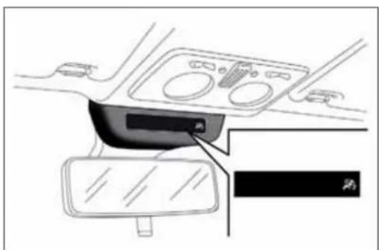
WARNINGLIGHTSONTRIMLOCATED ONINTERNALREARVIEWMIRROR
Passenger airbag/side bags deactivated (amber)
The warning light 📋 on the trim located on the internal rear view mirror (see fig. 4) switches on when the front passenger's airbag and side bag are disabled.
With front passenger airbag on, when the ignition key is turned to MAR, the warning light switches on constantly for several seconds, flashes for another few seconds and then should switch off.

Afailureofthewarninglightisindicatedbythe warninglight switching-onontheinstrument panel.Inaddition,theairbagsystemautomatically
disabletheairbagsonthepassenger'sside(frontandsidebags whereprovided).Beforeproceeding,contactAlfaRomeo AuthorizedServicestohavethesystemcheckedimmediately.
natural_image
Interior view of a car dashboard and steering wheel (no text or symbols visible)fig. 4
A0J0402
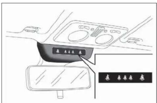
Seat belts not fastened (red) (green)
The warning lights 4 switch on in the trim located on the internal rear view mirror (see fig. 5) to warn passengers in the front and rear seats that their seat belts are not fastened.
The warning lights can be red and green: see paragraph "S.B.R. system" in the "Safety" section for the switching-on modes of the warning lights.
The car may be provided with a multifunction or reconfigurable multifunction display that shows useful information to the driver, according to the previous settings, when driving.
With the ignition key removed, the display lights up and shows the time and total odometer reading (in km or miles) for a few seconds when a door is opened/closed.
MULTIFUNCTIONDISPLAY "STANDARD" SCREEN
The following information appears on the display fig. 6:
A Date
B Milometer (distance covered in km or miles)
C Driving mode selected via "Alfa DNA" (dynamic car control system) (for versions/markets, where provided): d = Dynamic; n = Natural; a = All Weather

text_image
Mon 13 Nov 2:00 123456 km d SHIFT 20°C S 20:30 a A B H G C F E Dfig. 6
A0J1270
D Time (always displayed, even with key removed and doors closed)
E Start&Stop function indicator (for versions/markets where provided)
F Outside temperature
G Gear Shift Indicator (for versions/markets, where provided)
H Headlamp alignment position (only with dipped headlamps on)
RECONFIGURABLEMULTIFUNCTION DISPLAY"STANDARD"SCREEN
The following information appears on the display fig. 7:
A Time
B Trip mileage (in km or miles)
C Milometer (distance covered in km or miles)

text_image
A 20:30 F 20.5°C E 2 D S 1234,0 km 123456 km D Cfig. 7
A0J0333
D Car status indications (e.g. doors open, possible ice on road, etc.)/Start&Stop function indicator (for versions/markets, where provided)/Gear Shift Indicator (for versions/markets, where provided)
E Headlamp alignment position (only with dipped headlamps on)
F Outside temperature
On some versions, selecting "DYNAMIC" driving mode (see "Alfa DNA system" paragraph in this section) causes the display to show the turbine pressure fig. 8.
The instrument is calibrated for engines with higher supercharging pressures. Therefore, on some versions, it is normal for end of scale to be reached.
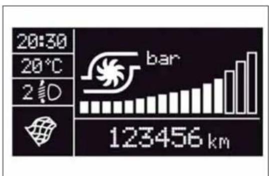
bar
| Metric | Value | | :--- | :--- | | Temperature (°C) | 20:30 | | Time Period (s) | 2 d | | Bar (km) | 123456 |fig. 8
A0J0228
GEARSHIFTINDICATOR
(for versions/markets, where provided)
The "GSI" (Gear Shift Indicator) system advises the driver to change gear through a special indication on the display fig. 9.
Through the GSI, the driver is notified that changing gear will allow a reduction in fuel consumption.
Therefore, for driving oriented towards reducing fuel consumption, it is recommended to stick to "Natural" or "All Weather" mode and to follow the suggestions of the Gear Shift Indicator, where the traffic conditions allow it.
When the SHIFT UP icon (▲ SHIFT) is shown on the display, the GSI is advising the driver to engage a higher gear, when the SHIFT DOWN (▼ SHIFT) icon is displayed, it advises the driver to engage a lower gear.
Note The indication in the instrument panel remains on until the driver shifts gear or the driving conditions go back to a situation where gearshifting is not required to improve consumption.
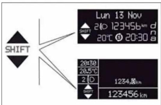
text_image
Lun 13 Nov 240 123456 km d 20°C 20:30 a SHIFT 28:30 28.5°C 2 D 1234.0 km SHIFT 123456 kmfig. 9
A0J0233
WELCOMEMOVEMENT
On some versions, when the key is turned to MAR-ON, the following occurs:
□ quick movement (up and down) of the speedometer and rpm gauge;
☐ lighting of graphic symbols/display;
□ displaying of an animated graphic representation of the vehicle profile.
Gauge movement
☐ If the key is removed from the ignition switch whilst the gauges are moving, they immediately go back to their initial position.
Once they have reached the full scale values, the gauges rest on the value indicated by the vehicle.
☐ The movement of the gauges stops when the engine is started.
Lighting of graphic symbols/display
A few seconds after the key is inserted, the gauges, graphic symbols and display light up in sequence.
Display of graphic animation
When the key is removed from the ignition switch (with the doors closed), the display remains lit up and shows a graphic animation.
The display lighting is then dimmed gradually until it goes out completely.
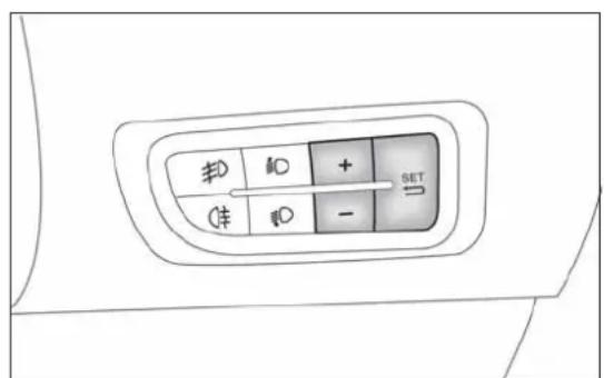
CONTROLBUTTONS
"+" or Ⓓ ▲ (versions with Start&Stop system): to scroll upwards through the screen and the related options or to increase the displayed value fig. 10.
SET/← : press briefly to access the menu and/or go to next screen or confirm the selection. Hold down to go back to the standard screen.
"-" or ▶▼ (versions with Start&Stop system): to scroll downwards through the screen and the related options or to decrease the displayed value.
IMPORTANT The "+" and "-" buttons (or ▲ and for ▼ versions with Start&Stop system) activate different functions according to the following situations:
□ within the menu, they allow you to scroll up or down;
□ during settings operations, they increase or decrease values.
The menu comprises a series of options which can be selected using the "+" and "-" buttons (or ▲ and for versions with Start&Stop system) to access the different selection and setting operations (Setup) indicated below.
Some options have a submenu. The menu can be activated by briefly pressing the SET/↔ button.
The menu comprises the following options:
□MENU
□SPEED BEEP
☐ LIGHT SENSOR (for versions/markets where provided)
☐ RAIN SENSOR (for versions/markets, where provided)
TRIP B ACTIVATION/DATA
SET TIME
□SET DATE
☐ FIRST PAGE (for versions/markets where provided)
□SEE RADIO
□AUTOCLOSE
□MEASUREMENT UNIT
□LANGUAGE
BUZZER VOLUME
☐BUTTON VOLUME
SEAT BELT BEEP/BUZZ
□SERVICE
□AIRBAG/PASSENGER BAG
□DAYTIME RUNNING LIGHTS
□COURTESY LIGHTS
□MENU EXIT
Selectinganoptionfromthemain menuwithoutasubmenu:
☐ press the SET/→ button briefly to select the main menu setting you wish to change;
☐ press the "+" or "-" buttons (with single presses) to select the new setting;
□press the SET/ ← button briefly to save the new setting and go back to the previous main menu option.
Selectinganoptionfromthemain menuwithasubmenu:
briefly press the SET/ ⇌ button to display the first submenu option;
☐ press the "+" or "-" buttons (with single presses) to scroll through all the submenu options;
□briefly press the SET/ ➕ button to select the displayed submenu option and to open the relevant settings menu;
☐ press the "+" or "-" buttons (with single presses) to select the new setting for this submenu option;
□press the SET/ ⇔ button briefly to save the new setting and go back to the previous submenu option.
MENUITEMS
Note With Uconnect™ 5" radio system (for versions/markets where provided), or Uconnect™ 5" Radio Nav system (for versions/markets, where provided), some Menu items are shown on the display of the latter and not on the instrument panel display.
Menu
This item allows you to access the Setup Menu.
Press the "+" or "-" button to select the various Menu options. Hold down the SET/← button to return to the standard screen.
SpeedBeep(Speedlimit)
With this function it is possible to set the car speed limit (km/h or mph); when this limit is exceeded the driver is alerted.
To set the desired speed limit, proceed as follows:
briefly press the SET/ ⇔ button: the display will show the wording "Speed Beep";
☐ press the "-" or "+" button to select speed limit activation ("On") or deactivation ("Off");
☐ if the function is On, press the "+" or "-" button to select the required speed limit and then press the SET/⇒ button to confirm.
IMPORTANT Setting is possible between 30 and 200 km/h, or 20 and 125 mph, according to the previously set unit. See the "Unit of Measurement" paragraph described below. The setting will increase/decrease by five units each time button +/- is pressed. Hold down the +/- button for fast automatic increase/decrease. Complete the adjustment with single presses of the button when you approach the desired value.
Briefly press the SET/↔ button to go back to the menu screen or hold the button down to go back to the standard screen without saving.
To cancel the setting, proceed as follows:
□briefly press the SET/ ⇌ button, "On" will flash in the display;
□ press the – button, the display flashes ("Off");
briefly press the SET/ ⇔ button to go back to the menu screen or hold the button down to go back to the standard screen without saving.
Headlightsensor(Automatic headlight/dusksensorsensitivity adjustment)
(for versions/markets, where provided)
This function enables the headlights to come on or go off depending on external lighting conditions.
The dusk sensor sensitivity can be adjusted according to 3 levels (level 1= minimum sensitivity, level 2= average sensitivity, level 3= maximum sensitivity).
The higher the sensitivity set, the lesser is the external light variation needed to switch the lights on (e.g. with a setting on level 3 at sunset the headlights come on in advance in relation to levels 1 and 2).
Proceed as follows to set the desired adjustment:
☐press the SET/ ⇌ button briefly to make the display flash the previously set level;
☐ press the "+" or "-" button to select;
briefly press the SET/ ➞ button to go back to the menu screen or hold the button down to go back to the standard screen without saving.
Rainsensor(Rainsensorsensitivity adjustment)
This function allows you to adjust the rain sensor sensitivity to 4 levels. To set the required sensitivity level proceed as follows:
□briefly press the SET/ ➕ button, the previously set sensitivity level will flash on the display;
☐ press the "+" or "-" button to adjust;
briefly press the SET/ ⇔ button to go back to the menu screen or hold the button down to go back to the standard screen without saving.
Activation/TripBdata (TripBenablement)
This function may be used to activate (On) or deactivate (Off) the Trip B (partial trip). For further information see "Trip computer".
Proceed as follows to switch the function on and off:
☐press the SET/ ⇌ button briefly to make the display flash "On" or "Off" according to what was previously set;
☐ press the "+" or "-" button to select;
briefly press the SET/ ⇔ button to go back to the menu screen or hold the button down to go back to the standard screen without saving.
Timeadjustment(Clockadjustment)
This function enables the clock to be set through two sub-menus: "Time" and "Format".
To carry out the adjustment, proceed as follows:
briefly press the SET/ button and two submenus ("Time" and "Format") will be displayed;
☐ press the "+" or "-" button to move between the two submenus;
☐ once you have selected a sub-menu to be modified, press SET/→ briefly;
☐ when the "Time" submenu is entered, by briefly pressing SET/→ the hours flash on the display;
☐ press the "+" or "-" button to adjust;
briefly press the SET/ ⇔ button, which makes the display flash the "minutes";
☐ press the "+" or "-" button to adjust.
IMPORTANT Each press on the "+" or "-" buttons causes an increase or decrease of one unit. Hold down the button to increase/decrease the setting rapidly and automatically. Complete the adjustment with single presses of the button when you approach the desired value.
☐ When you select "Format", pressing the SET/↔ button briefly makes the display mode flash on the display;
☐ press "+" or "-" to select "24h" or "12h".
When you have made the required settings, briefly press the SET/→ button to go back to the submenu screen or hold the button down to go back to the main menu screen without saving the new settings.
Hold the SET/↔ button down again to return to the standard screen or to the main menu according to where you are in the menu.
Setdate(Settingthedate)
Using this function it is possible to change the date (day - month - year).
Proceed as follows to start the update:
briefly press the SET/ ➕ button: the "year" starts flashing on the display;
☐ press the "+" or "-" button to adjust;
□briefly press the SET/ ➕ button: the "month" will flash on the display;
☐ press the "+" or "-" button to adjust;
□briefly press the SET/ ➕ button: the "day" will flash on the display;
☐ press the "+" or "-" button to adjust.
IMPORTANT Each press on the + or - buttons causes an increase or decrease of one unit. Hold the button down to increase/decrease the setting rapidly and automatically. Complete the setting by with single presses of the button when you approach the required value.
Briefly press the SET/↔ button to go back to the menu screen or hold the button down to go back to the standard screen without saving.
Firstpage(Displayofinformationon themainscreen)
(for versions/markets, where provided)
This function allows you to choose the information you would like to see on the main screen. You can view the date or the trip distance.
To make your choice, proceed as follows:
briefly press the SET/ ⇌ button: "Initial page" will be displayed;
☐ press the SET/↔ button again briefly to display the "date" and "engine info" options;
☐ press "+" or "-" to select the desired view on the main screen of the display;
briefly press the SET/ ⇌ button to go back to the menu screen or hold the button down to go back to the standard screen without saving.
When the key is turned to MAR-ON and the initial check stage is over, the display will show the information selected via the "First page" menu function.
Seeradio (audioinformationdisplay)
This function is used to display radio information.
☐ Radio: selected radio station frequency or RDS message, automatic tuning activation or AutoSTore;
☐ CD audio/CD MP3: track number.
To show the radio information on the display ("On") or clear it ("Off"), proceed as follows:
□briefly press the SET/ ➕ button, the display will show "On" or "Off" flashing depending on the previous setting;
☐ press the "+" or "-" button to select;
briefly press the SET/ ➞ button to go back to the menu screen or hold the button down to go back to the standard screen without saving.
Autoclose(Automaticdoorlock operationwithcarrunning)
When activated (On), this function locks the doors automatically when the vehicle speed exceeds 20 km/h.
Proceed as follows to activate or deactivate this function:
□press the SET/ ➕ button briefly to display a submenu;
□press the SET/ ➕ button briefly to make the display flash "On" or "Off" according to what was previously set;
☐ press the "+" or "-" button to select;
press the SET/ button briefly to return to the submenu screen or hold the button down to return to the main menu screen without saving;
☐ hold the SET/ ← button down again to return to the standard screen or to the main menu according to where you are in the menu.
Unitofmeasurement(Settingthe unitofmeasurement)
With this function it is possible to set the measurement units through three sub-menus: "Distance", "Consumption" and "Temperature".
To set the desired measurement unit, proceed as follows:
□briefly press the SET/ ⇌ button to display the three sub-menus;
☐ press the "+" or "-" button to move between the three submenus;
☐ once the submenu to be modified has been selected, briefly press the SET/ ⇌ button;
☐ when the "Distance" submenu is entered: briefly pressing SET/← displays "km" or "mi" depending on the previous setting;
☐ press the "+" or "-" button to select;
☐ when the "Consumption" submenu is entered, pressing SET/← displays km/l, l/100 km or mpg depending on the previous setting;
If the set distance unit is "km", the fuel consumption unit will be displayed in km/l or l/100 km.
If the distance unit set is "mi" the fuel consumption unit will be displayed in "mpg".
☐ press the "+" or "-" button to select;
☐ when the "Temperature" submenu is entered, pressing SET/→ displays "°C" or "°F" depending on the previous setting;
☐ press the "+" or "-" button to select;
When you have made the required settings, briefly press the SET/→ button to go back to the submenu screen or hold the button down to go back to the main menu screen without saving the new settings.
Hold the SET/→ button down again to return to the standard screen or to the main menu according to where you are in the menu.
Language(Languageselection)
Display messages can be shown in different languages: Italian, English, German, Portuguese, Spanish, French, Dutch, Turkish and Brazilian.
To set the desired language proceed as follows:
briefly press the SET/ ⇌ button: the previously set "language" starts flashing on the display;
☐ press the "+" or "-" button to select;
briefly press the SET/ ➞ button to go back to the menu screen or hold the button down to go back to the standard screen without saving.
Warningsvolume(Adjustingthe alert/warningacousticsignal volume)
With this function it is possible to adjust (to eight levels) the volume of the acoustic signal which sounds in the event of alerts and warning.
To set the desired volume proceed as follows:
□press the SET/ ← button briefly, making the display flash the previously set volume "level";
☐ press the "+" or "-" button to adjust;
briefly press the SET/ ⇌ button to go back to the menu screen or hold the button down to go back to the standard screen without saving.
Buttonvolume(Buttonvolume adjustment)
With this function it is possible to adjust (to eight levels) the volume of the acoustic signal when the SET/↔ button is held down to exit a submenu and return to the standard menu.
To set the desired volume proceed as follows:
briefly press the SET/ ⇔ button, the previously set volume "level" will be displayed;
☐ press the "+" or "-" button to adjust the volume; an acoustic signal equal to the volume level being selected is emitted during this adjustment;
briefly press the SET/ → button to go back to the previous screen or hold the button down to go back to the standard screen without saving.
On versions with reconfigurable multifunction display, the volume level is represented by bars.
Beltreminder (ReactivationofSBRbuzzer)
(for versions/markets, where provided)
This function will only be displayed after the SBR system has been deactivated by Alfa Romeo Authorised Services (see "SBR system" in the "Safety" chapter).
To reactivate this function, proceed as follows:
briefly press the SET/ ⇧ button, the display shows "OFF" flashing. Press the "+" or "-" button and "On" will be displayed;
briefly press the SET/ ➞ button to go back to the previous screen or hold the button down to go back to the standard screen without saving.
Service(Scheduledservicing)
With this function it is possible to view information on servicing deadlines depending on kilometres travelled or daily intervals.
With the Service function it is also possible to view the interval (in kilometres or miles) before the next engine oil change is due.
To consult this information, proceed as follows:
briefly press the SET/ button: the display shows when servicing is due in km or mi according to the previous setting (see paragraph "Units of measurement");
briefly press the SET/ ← button to go back to the menu screen or hold the button down to go back to the standard screen.
IMPORTANT According to the "Scheduled Servicing Plan", the car must be serviced every 30,000 km (petrol versions) or 35,000 km (diesel versions). This message is displayed automatically when the key is turned to MAR-ON, starting at 2,000 km (or equivalent value in miles) from when the next service is due and reappearing every 200 km (or equivalent value in miles). Below 200 km servicing indications are more frequent. The display will be in km or mi depending on the measurement unit settings. When the next scheduled service is approaching and the key is turned to MAR-ON, the word Service will appear on the display, followed by the number of kilometres or miles left. Contact Alfa Romeo Authorized Services where the "Scheduled Servicing Plan" operations will be performed and the message will be reset.
Passengerairbag/sidebag(front passengersideairbagandsidebag forpelvis, chestandshoulder protection-Sidebag-activation/deactivation)
This function is used to activate/deactivate the passenger side air bag.
Proceed as follows:
press the SET/ ⇔ button and, after the message (Bag pass: Off) (to deactivate) or (Bag pass: On) (to activate) is displayed by pressing buttons "+" or "-" , press the SET/ ⇔ button again;
☐ a confirmation request message will appear on the display;
☐ by pressing the "+" or "-" buttons select "Yes" (to confirm the activation/deactivation) or "No" (to quit);
☐press the SET/ ← button briefly, a message confirming the selection will be displayed and you will return to the menu screen or, pressing the button for longer, you will return to the standard screen without memorising.
Daytimerunninglights(DRL)
With this function is possible to turn the daytime running lights on and off.
Proceed as follows to activate or deactivate this function:
□press the SET/ ← button briefly to display a submenu;
□press the SET/ ➕ button briefly to make the display flash "On" or "Off" according to what was previously set;
☐ press the "+" or "-" button to select;
☐press the SET/ button briefly to return to the submenu screen or hold the button down to return to the main menu screen without saving;
☐ hold the SET/ ⇌ button down again to return to the standard screen or to the main menu according to where you are in the menu.
Courtesylights(Activation/deactivationof"Greetinglights")
(for versions/markets, where provided)
With this function it is possible to turn on the side lights, the number plate lights and the ceiling lights for approximately 25 seconds when the doors or boot are opened using the remote control, with the following exceptions:
☐ interruption after 5 seconds from when the door closes
☐ interruption after locking using the remote control
☐ interruption after a lock or other action using the remote control
Proceed as follows to activate or deactivate this function:
☐press the SET/ ⇌ button briefly to make the display flash "On" or "Off" according to what was previously set;
☐ press the "+" or "-" button to select;
□briefly press the SET/ ⇌ button to go back to the menu screen or hold the button down to go back to the standard screen without saving.
Menuexit
This is the last function that closes the cycle of settings listed in the menu screen.
Pressing the SET/↔ button briefly will return the display to the standard screen without saving.
Press the – button to return to the first menu option.
TRIPCOMPUTER
GENERALINFORMATION
The Trip computer is used to display information on car operation when the key is turned to MAR.
This function allows you to define two separate trips called "Trip A" and "Trip B" for monitoring the car's "complete journey" in a reciprocally independent manner.
Both functions are resettable (reset - start of a new journey).
"Trip A" is used to display the figures relating to:
□Range
Distance travelled
□Average fuel consumption
□Instant fuel consumption
□Average speed
☐ Trip time (driving time).
"Trip B" may be used to display the figures relating to:
Distance travelled B
□Average consumption B
□Average speed B
☐ Trip time B (driving time).
The "Trip B" function may be disabled (see "Activating Trip B").
"Range" and "Instant consumption" parameters cannot be reset.
VALUESDISPLAYED
Range
This indicates the indicative distance that may be travelled with the fuel in the tank, assuming that driving conditions do not change.
The display will show the reading '----' when the following events take place:
☐ range value lower than 50 km (or 30 mi)
□ car parked with engine running for a long period.
IMPORTANT The range can be affected by several factors: driving style (see "Driving style" in the "Starting and driving" section), type of route (motorway, towns and cities, mountain roads, etc.), conditions of use (load, tyre pressures, etc.). Trip planning must therefore take the above into account.
Distancecovered
Shows the distance covered since the start of the new journey.
Averageconsumption
Shows the approximate average fuel consumption since the start of the new journey.
Instantaneous consumption
This indicates the fuel consumption. The value is constantly updated.
The display will show "----" if the car is parked with the engine running.
Averagespeed
This shows the average car speed as a function of the overall time elapsed since the start of the new journey.
Triptime
The time elapsed since the start of a new journey.
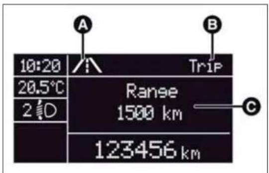
Indicationsondisplay
Each time a value is displayed, the following information is shown:
□animated icon in the upper part fig. 11;
☐ the word "Trip" (or "Trip A" or "Trip B") (B);
☐ the name, value and unit of measurement of the selected parameter (e.g. "Range 1500 km") (C).
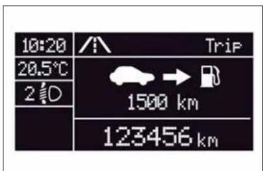
After a few seconds the name and value of the selected parameter are replaced by an icon fig. 12.
text_image
10:20 20.5°C 2 D A Trip Range 1500 km C 123456 kmfig. 11
A0J1223
The icons relating to the various parameters are the following:
□ → "Range";
☐ A "Average consumption A" (if Trip A is active, or "B" if Trip B is active);
☐ active); → ∽ A "Distance" (if Trip A is active, or "B" if Trip B is
☐ "Instantaneous consumption";
☐ ☐ ☐ "Average speed A" (if Trip A is active, or "B" if Trip B is active);
☐ ☑ A "Trip time" (if Trip A is active, or "B" if Trip B is active);
TRIPbutton0.00
The TRIP 0.00 button is located on the right hand stalk fig. 13. With the ignition key turned to MAR-ON, this button allows you to view the previously described values and also set them to zero to begin a new mission:
text_image
10:20 20.5°C 2 D Trip 1500 km 123456 kmfig. 12
A0J0033
□ short press: display various values;
□ long press: values reset and start of a new mission.
Newmission
This begins after a reset:
☐ "manual" resetting by the user, by pressing the relevant button;
☐ "automatic" resetting, when the "trip distance" reaches 99999.9 km or when the "Travel time" reaches 999:59 (999 hours and 59 minutes);
□ after disconnection/reconnection of the battery.
IMPORTANT The reset operation when "Trip A" details are being displayed only resets the information associated with this function.
IMPORTANT The reset operation when "Trip B" details are being displayed resets only the information associated with this function.

text_image
TRIP 0.00fig. 13
A0J0077
Startofjourneyprocedure
With the ignition key at MAR-ON, reset by pressing the TRIP 0.00 button and holding it down for more than 2 seconds.
TripExit
You can automatically exit the Trip function once all the values have been displayed or by holding the SET/ ⇔ button down for more than 1 second.
SYMBOLS
Some car components have coloured labels whose symbols indicate precautions to be observed when using this component. Under the bonnet there is also a label that summarises all the symbols.
ALFAROMEOCODESYSTEM
To further protect your car from theft, it has been fitted with an engine immobilising system. It is automatically activated when the ignition key is removed.
Each key contains an electronic device which modulates the signal emitted during ignition by an antenna built into the ignition device. The modulated signal, which changes each time the engine is started, is the "password", by means of which the control unit recognises the key and enables to start the engine.
OPERATION
Each time the car is started by turning the ignition key to MAR, the Alfa Romeo CODE system control unit sends an acknowledgement code to the engine management control unit to deactivate the inhibitor.
The code is sent only if the Alfa Romeo CODE system control unit has recognised the code transmitted from the key.
Each time the ignition key is turned to STOP, the Alfa Romeo CODE system deactivates the functions of the engine management control unit. If, during starting, the code is not correctly recognised, the warning light switches on in the instrument panel.
In this case, turn the key to STOP and then to MAR; if it is still locked, try again with the other keys that come with the vehicle. If you are still unable to start the engine contact Alfa Romeo Authorized Services.
Activation of warning light while driving
☐If the 📋 warning light switches on, this means that the system is running a self-diagnosis (for example due to a voltage drop).
☐If the 📋 warning light remains on, contact Alfa Romeo Authorized Services.

The electronic components inside the key may be damaged if the key is subjected to strong shocks.
THEKEYS
CODECARD
(for versions/markets, where provided)
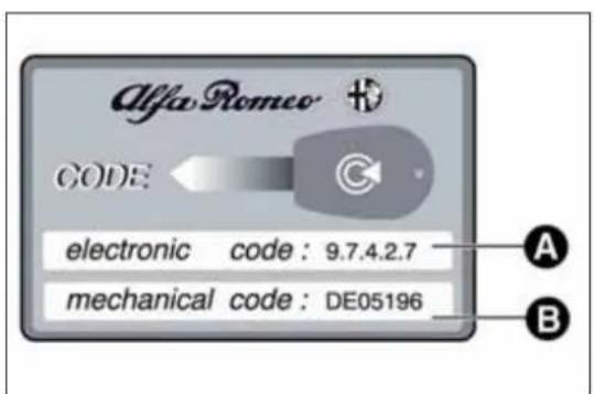
The CODE card fig. 14 is provided with the keys and bears the following:
□A - electronic code;
□B - mechanical code.
Keep the codes in a safe place, not in the car.
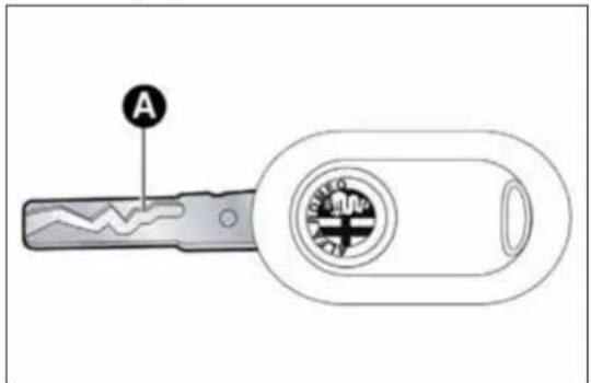
KEYWITHOUTREMOTECONTROL
The metal insert A fig. 15 operates:
□the ignition switch;
□the door lock.
text_image
Alfa Romeo CODE electronic code: 9.7.4.2.7 mechanical code: DE05196 A Bfig. 14
A0J0212
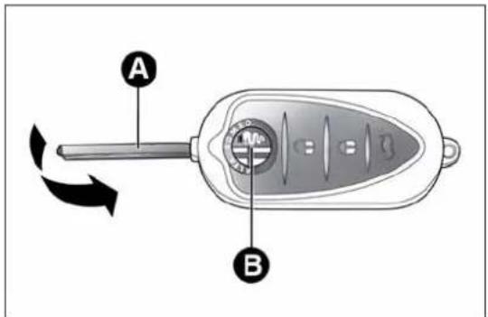
KEYWITHREMOTECONTROL
(for versions/markets, where provided)
The metal insert A fig. 16 operates:
□the ignition switch;
□the door lock.
Press button B to open/close the metal insert.
text_image
Afig. 15
A0J0211
text_image
A Bfig. 16
A0J0072

PressbuttonBfig. 16onlywiththekeyawayfromyour body,especiallyyoureyesandfromobjectswithwhichcould getdamaged(e.g.yourclothes).Donofleavethekey doavoidthebuttonbeingaccidentallypressedwhileitis led.e.g.byachid.
Unlocking the doors and the tailgate
Briefly press button 🔒: for unlocking of doors and luggage compartment, timed switching-on of internal roof lights and double flashing of direction indicators (for versions/markets, where provided). The doors are unlocked automatically if the fuel cut-off system intervenes.
Once the doors are locked, if one or more doors or the boot are not closed correctly, the LED and direction indicators start flashing quickly.
Locking the doors and the tailgate
Briefly press button 🔒: for locking of doors and luggage compartment, with switching-off of roof light and single flashing of direction indicators (for versions/markets, where provided).
If one or more doors are open, the doors will not be locked. This is indicated by a rapid flashing of the direction indicators (for versions/markets, where provided). If the luggage compartment is open, the doors will, however, be locked.
When a speed of over 20 km/h is reached, the doors are automatically locked if this specific function has been set (only on versions with multifunction reconfigurable display).
When the doors are locked, LED A fig. 17 switches on for a few seconds after which it starts to flash (deterrent function).
When the doors are locked from inside the car (by pressing the button) the LED will remain on constantly.
Opening the luggage compartment
Press the 🎨 button to open the luggage compartment remotely. The direction indicators will flash twice to indicate that the boot has been opened.
REQUESTING ADDITIONAL REMOTE CONTROLS
The system can recognise up to 8 remote controls. If you need to request a new remote control, contact Alfa Romeo Authorized Services, taking the CODE Card (for versions/markets, where provided), an identity document and documents proving ownership of the car with you.
text_image
Afig. 17
A0J0027
REPLACINGTHEBATTERYINTHEKEY WITHREMOTECONTROL
Proceed as follows:
☐ press button A fig. 18 and move the metal insert B to opening position; turn screw C to using a fine bit screwdriver;
☐ remove battery compartment D and replace battery E respecting the polarity; reinsert compartment D in the key and secure it by turning screw C to 🔒.

Usedbatteriesareharmfultotheenvironment. They must be disposed of a specified by lawinspecial containers ortakentoAlfaRomeoAuthorizedServices, which will
takecareoftheirdisposal.

text_image
A B C D Efig. 18
A0J0073
SAFELOCKDEVICE
(for versions/markets, where provided)
This safety device inhibits the operation of the interior door handles and the door locking/unlocking button.
We recommend that you activate this device each time you park the car.
Activating the device
The device is enabled on all the doors by pressing the 🔒 button on the key twice quickly.
The direction indicators flash 3 times and LED A fig. 19 flashes to indicate that the device has been activated. The device does not switch on if one or more doors are not properly shut.
text_image
Diagram showing a mechanical component with labeled point A and directional arrow, likely illustrating a motion or positioning concept.fig. 19
A0J0027
Deactivating the device
The device deactivates automatically when:
☐ the key insert is turned to opening position in the driver side door;
□the 🔒 button is pressed on the remote control;
□ the ignition key is turned to MAR.

Oncethesafelockdeviceisengageditisimpossibleto openthedoorsfrominsidethecar.Beforeengaging thedevice,checkthatthereisnooneleftonboard.If
theremotecontrolbatteryisflat, thedevicecanonlybe deactivatedbyusingthemetalinsertinoneofthedoorlocks.
The main functions that can be activated with the keys (with or without remote control) are the following:
| Type of key | Unlocking the doors | Locking the doors from the outside | Safe Lock activation (*) | Unlocking the tailgate | Lowering windows (*) | Raising windows (*) |
| Key without remote control/ Key with remote control | Anticlockwise key turn (driver side) | Clockwise key turn (driver side) | - | - | - | - |
| Key with remote control | Brief press of button | Brief press of button | Double press of button | Brief press of button | Long press (more than 2 seconds) of button | Long press (more than 2 seconds) of button |
| Flashing direction indicators (only with key with remote control) | 2 flashes | 1 flash | 3 flashes | 2 flashes | 2 flashes | 1 flash |
| Deterrent LED Switching off | Switching on constantly for about 3 seconds, followed by deterrence LED flashing | Double flash, followed by deterrence flashing | Deterrence flashing | Switching off | Deterrence flashing |
(*)For versions/markets, where provided.
IMPORTANT Window opening operation is a consequence of a door unlocking control; window closing operation is a consequence of a door locking control.
ALARM
(for versions/markets, where provided)
ALARMACTIVATION
The alarm activates in the following cases:
□ wrongful opening of a door/bonnet/luggage compartment (perimeter protection);
☐ wrongful operation of the ignition switch (key turned to MAR);
☐ cutting of the battery cables;
□ movement inside the passenger compartment (volumetric protection);
☐ anomalous lifting/tilting of the car (for versions/markets, where provided).
Operation of the alarm is indicated by an acoustic and visual signal (flashing of the direction indicators for several seconds). The alarm activation modes may vary according to the market. There is a maximum number of acoustic/visual cycles. When this is reached the system returns to normal operation.
IMPORTANT The engine locking function is guaranteed by the Alfa Romeo CODE, which is automatically activated when the ignition key is extracted from the ignition switch.
IMPORTANT The alarm is adapted to meet requirements in various countries.
SWITCHINGONTHEALARM
With the doors and bonnet closed and the ignition key either turned to STOP or removed, direct the key with the remote control towards the car, then press and release the 🔒 button. Except for specific markets, the system emits a visual and acoustic signal and enables door locking. A self-diagnosis stage precedes the switching on of the alarm: in the event of faults, the system will generate a further acoustic and/or visual signal through the LED on the dashboard.
If after the alarm is switched on, a second acoustic signal is emitted and/or a visual signal via the LED on the dashboard, wait about 4 seconds and switch off the alarm by pressing the 🔒 button, check that the doors, bonnet and luggage compartment are closed correctly and then reactivate the system by pressing the 🔒 button.
If the alarm emits an acoustic signal even when the doors, bonnet and boot are correctly closed, a fault has occurred in system operation: in this case, contact Alfa Romeo Authorized Services.
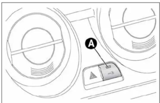
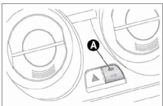
ALARMSELF-ACTIVATION
(for versions/markets, where provided)
If the alarm has not been activated using the remote control, once about 30 seconds have elapsed from when the ignition key was turned to STOP and a door or the tailgate was last opened and then closed, the alarm activates automatically.
This is indicated by the LED on the button A fig. 20 lighting up intermittently and the indications of activation described previously.
To deactivate the alarm, press the 🔒 button on the remote control.
The alarm also activates when the doors are closed by turning the metal insert of the key in the driver side door latch. If the system self-activates, the doors are not locked.
SWITCHINGOFFTHEALARM
Press the 🔒 button. The following operations are performed (excluding specific markets):
□ the direction indicators flash briefly twice;
☐ there are two brief acoustic signals;
□unlocking of the doors.
IMPORTANT The alarm does not switch off when the central opening is activated using the metal insert in the key.
VOLUMETRIC/ANTI-LIFTPROTECTION
To guarantee the correct operation of the protection, close the side windows and any sun roof completely (for versions/markets, where provided).
To disable the function, press button A fig. 20 before activating the alarm. When the function is disabled, this is indicated by the LED on the button flashing for several seconds.
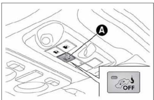
text_image
Diagram showing a vehicle interior with labeled components and an 'OFF' warning sign in the corner.fig. 20
A0J0226
Any disabling of the volumetric/anti-lift protection must be repeated each time the instrument panel is switched off.
DISABLINGTHEALARM
To permanently disable the alarm (e.g. during a lengthy period of car inactivity), lock the car by turning the metal insert of the key with remote control in the lock.
IMPORTANT If the batteries of the key with the remote control run out or there is a fault with the system, the alarm can be switched off by inserting the key in the ignition switch and turning it to MAR.
IGNITIONDEVICE
The key can be turned to three different positions fig. 21:
☐ STOP: engine off, key can be removed, steering column locked. Some electrical devices (e.g. car radio, central door locking system, alarm, etc.) are enabled;
☐ MAR: driving position. All electrical devices are enabled;
☐ AVV: engine start-up.
The ignition switch is fitted with a safety system that requires the ignition key to be turned back to STOP if the engine does not start, before the starting operation can be repeated.

Iftheignitionswitchistamperedwith(e.g.:attempted theft),haveitcheckedoverbyAlfaRomeoAuthorized Servicesbeforedrivingagain.
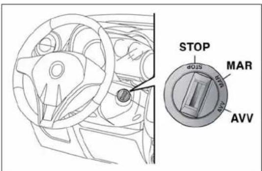
text_image
STOP MAR AVVfig. 21

Alwaysremovethekeywhenyouleavethecarto preventsomeonefromaccidentallyoperatingthe controls.Remembertoengagethenandbrake.Engage hecarisparkeduphillorreverseifthecarisparked Neverleavechildrenunattendedinthecar.
STEERINGLOCK
Engagement
When the key is at STOP, remove the key and turn the steering wheel until it locks.
Disengagement
Move the steering wheel slightly and turn the ignition key to MAR.

Itisabsolutelyforbiddentocarryoutanyafter-market operationinvolvingsteeringsystemorsteeringcolumn modifications(e.g.:installationofanti-theftdevice) badlyaffectperformanceandsafety,invalidatethe andalsoresultinnon-complianceofthecarwith covalrequirements.

Neverremovethekeywhilethecarismoving. The steeringwheelwilllockassoonasitisturned. This holdstrueforcarsbeingtowedaswell.
SEATS
FRONTSEATS

Alladjustmentsmustbemadewiththecarstationary.
Lengthwise adjustment
Lift the lever A fig. 22 and push the seat forwards or backwards: in driving position your arms should rest on the rim of the steering wheel.

Afterreleasingheadjustmentlever,alwayscheckthat theseatislockedontheguidesbytryingtomoveit backandforth.Iftheseatisnotlockedintoplace,
itmayunexpectedlyslideandcausethedrivertolosecontrolof thecar.
Height adjustment
(for versions/markets, where provided)
Move lever B fig. 22 up or down until the desired height is achieved.
IMPORTANT Carry out the adjustment whilst seated in the driver's seat.
Backrest angle adjustment
Turn knob C fig. 22 until the desired position is reached.

Formaximumsafety, keepthebackofyourseat upright, leanbackintoitandmakesuretheseatbelt fitscloselyacrossyourchestandpelvis.
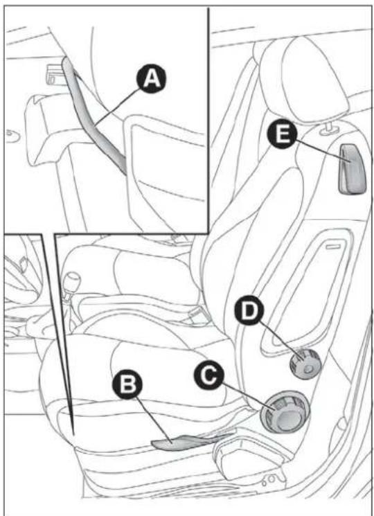
text_image
A E B C Dfig. 22
A0J0078
Lumbar adjustment
(for versions/markets, where provided)
Turn knob D fig. 22 until the desired position is reached.
Backrest folding
To access the rear seats, pull handle E upwards fig. 22: the backrest will fold and the seat will slide forwards when you push the backrest. Moving the backrest backwards will return the seat to its initial position.

Alwayscheckthattheseatisfirmlylockedonthe guides, tryingtopushitforwardsandbackwards.
Seat heating
(for versions/markets, where provided)
With key at MAR-ON, press button A fig. 23 (one per seat) to activate/deactivate the function.
When the function is enabled, the LED on the button switches on.

natural_image
Interior view of a car dashboard and seat area with labeled parts (no text or symbols present)fig. 23
A0J0301
SPORTSCONFIGURATIONFRONT SEATS
(for versions/markets, where provided)
Lengthwise adjustment
Lift the lever A fig. 24 and push the seat forwards or backwards: in driving position your arms should rest on the rim of the steering wheel.
Backrest angle adjustment
Turn knob B fig. 24 until the desired position is reached.
Backrest folding
To access the rear seats, pull handle C upwards (located behind the backrest) fig. 24. Then release the lever and, pushing on the backrest, slide the seat forward.
REARSEAT
On versions with sports configuration front seats, the rear seat is available with an integral or split seat and is only 2-seater.
EASYENTRY
This function allows easy access to the rear seats.
To access the rear seats, raise handle E and move the seat's backrest forwards: the seat moves forwards automatically.
Bringing the backrest back to its normal position will move the seat back to its initial position.
If the backrest encounters an obstacle when moving back (e.g. the knees of the passenger in the back seat), the seat will stop, move forwards by a few centimetres and then stop in this position.
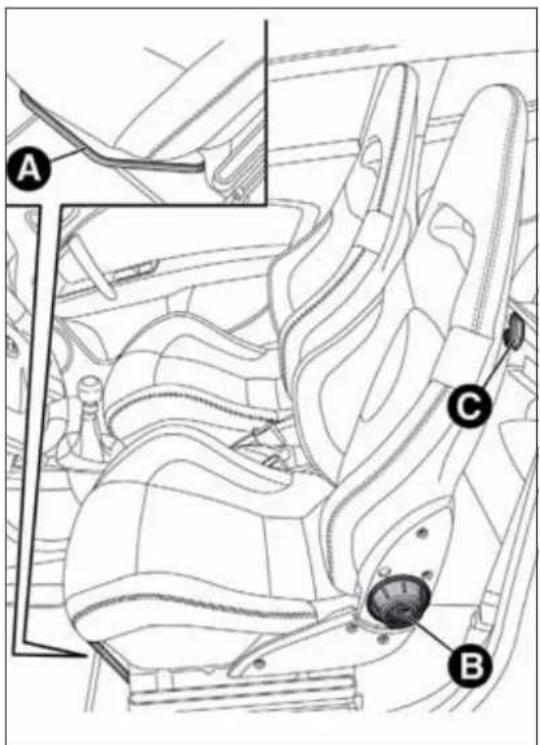
text_image
Technical diagram of a car seat assembly with labeled parts A, B, and Cfig. 24
A0J0163
HEADRESTRAINTS
FRONT
Head restraints are adjustable in height and they lock automatically into the desired position:
□ upwards adjustment: raise the head restraint until it clicks into place;
☐ downwards adjustment: press button A fig. 25 and lower the head restraint.

Headrestraintsmustbeadjustedsothatthehead, ratherthantheneck,restsonthem.Onlyinthiscase cantheyprotectyourheadcorrectly.
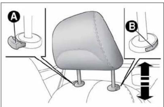
text_image
Diagram illustrating a mechanical or anatomical setup with labeled components A and B, showing structural elements and directional arrows.fig. 25
A0J0130
To remove the head restraints:
□ raise the head restraints to their maximum height;
☐ press buttons A and B fig. 25, then remove the head restraints by pulling them upwards.
"Anti-Whiplash" device
The head restraints are equipped with an "Anti-Whiplash" device, which reduces the distance between head and head restraint in the event of a rear impact, thus mitigating the "whiplash" effect.
The head restraint may move when the backrest is pressed by the occupant's torso or hand; this behaviour is caused by the system and should not be considered a malfunction.
REAR
Two height-adjustable head restraints are provided for the back seats (to adjust the height see the previous paragraph).
On some versions a head restraint is also provided for the central seat.
To remove the head restraints:
☐ raise the head restraints to their maximum height;
☐ press buttons A fig. 26, then remove the head restraints by pulling them upwards.

natural_image
Diagram of a car seat with a vertical post and directional arrow, no text or symbols presentfig. 26
A0J0083
STEERINGWHEEL
It can be adjusted axially and vertically.
To adjust, release A fig. 27 by pushing it forwards (position 1) and adjust the steering wheel. Then lock lever A by pulling it towards the steering wheel (position 2).

Alladjustmentsmustbecarriedoutonlywiththe vehiclestationaryandengineoff.

Itisabsolutelyforbiddentocarryoutanyafter-market operationinvolvingsteeringsystemorsteeringcolumn modifications(e.g.installationofanti-theftdevice)
that could badly affect performance and safety, invalidate the warranty and also result in the car not meeting type approval requirements.
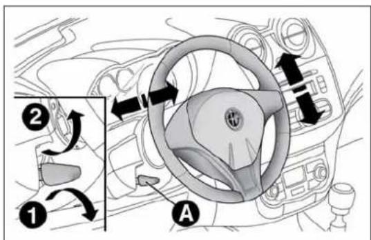
text_image
Diagram of car steering wheel with labeled parts and directional arrows indicating rotation or movementfig. 27
A0J0034
REARVIEWMIRRORS
INTERNALMIRROR
Operate lever A fig. 28 to adjust the mirror into two different positions: normal or anti-glare.
Electrochromic interior mirror
(for versions/markets, where provided)
Some versions feature an electrochromic mirror fig. 29 with an ON/OFF switch to activate/deactivate the electrochromic function.
When reverse gear is engaged, the mirror is automatically set for daytime use.

natural_image
Diagram of a car front mirror with labeled point A, showing no text or symbols beyond the labelfig. 28
A0J0108
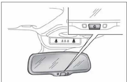
text_image
Diagram showing car interior with labeled buttons and a vehicle rearview mirror, likely illustrating a parking or navigation system.fig. 29
A0J0336
DOORMIRRORS

Asthedriver'sdoormirroriscurved,itmayslightly altertheperceptionofdistance.
Mirror adjustment
The mirrors can only be adjusted/folded with the ignition in the MAR position.
Choose the desired mirror using device A fig. 30:
□ device in position 1: left mirror selected
□ device in position 2: right mirror selected.
To adjust the selected mirror, press B button in the four directions shown by the arrows.
IMPORTANT Once adjustment is complete, rotate device A to position 0 to prevent accidental movements.

text_image
A C B 1 0 2fig. 30
A0J0022
Electric mirror folding
(for versions/markets, where provided)
To fold back the mirrors press C fig. 30. Press the button again to restore the mirrors to the driving position.
Mirror manual folding
If necessary, fold the mirrors by moving them from position 1 to position 2 fig. 31.
IMPORTANT When driving the mirrors must always be in position 1.

natural_image
Illustration of two mechanical components with directional arrows indicating rotation (no text or symbols)fig. 31
A0J0035
CLIMATICCOMFORT
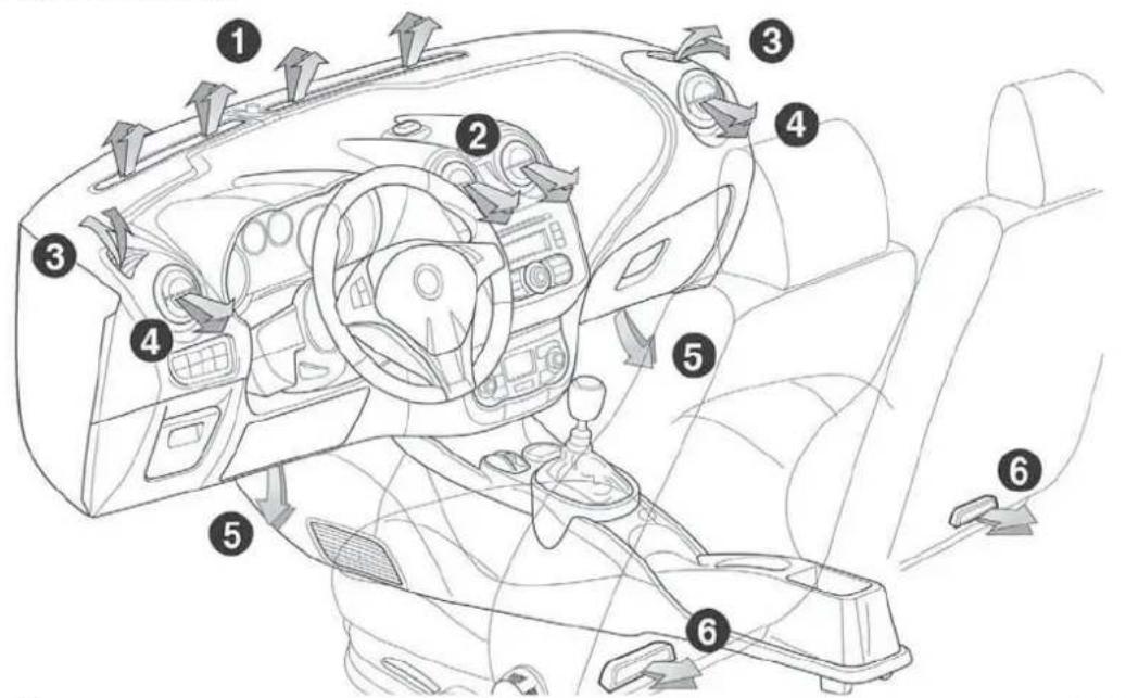
text_image
Diagram of car interior with numbered parts and directional arrows indicating flow or movementfig. 32
A0J0036
DIFFUSERS
- Fixed upper diffuser - 2. Adjustable centre vents - 3. Fixed side vents - 4. Adjustable side vents - 5. Lower diffusers for front seats - 6. Lower diffusers for rear seats
CLIMATECONTROL/HEATING SYSTEM
CONTROLS

text_image
A B C 1 2 3 4 0 # F E DA0J0074
fig. 33
A - Air temperature adjustment knob
□ blue section = cold air
□ red section = hot air
B - Fan activation/adjustment knob
□ 0 = fan off
□1-2-3 = fan speed
□4 = maximum fan speed
C - Air distribution knob
□ air flow towards driver/passenger body;
□ air flow towards driver/passenger body and footwell;
□_air flow towards front and rear footwell;
□ air flow towards footwell and windscreen;
□ air flow towards windscreen
□4 = maximum fan speed
D - Air recirculation on/off button
E - Climate control on/off button (only versions with manual climate control)
F - Heated rear window on/off button;
PASSENGERCOMPARTMENT VENTILATION
Proceed as follows to adjust the ventilation:
□ turn knob A to blue section;
☐ press button D to disable internal air recirculation (LED on button off);
□turn knob C to 7;
□ turn knob B to desired speed.
CLIMATECONTROL(cooling)(only presentonversionswithmanual climatecontrol)
To cool, proceed as follows:
□ turn knob A to blue section;
☐ press button D to enable internal air recirculation (LED on button on);
□turn knob C to 7;
☐ press button E to turn the climate control system on and turn knob B to at least 1 ( 1^st speed); for faster action, turn knob B to 4 (maximum fan speed).
Adjusting cooling
□ turn knob A to the right to increase the temperature;
☐ press button D to turn internal air recirculation off (circular LED around the button off);
□ turn knob B to reduce the fan speed.
PASSENGERCOMPARTMENTHEATING
For rapid heating, proceed as follows:
□ turn knob A to the red section;
□ turn knob C to the desired symbol;
□ turn knob B to desired speed.
Rapid heating
For rapid heating, proceed as follows:
□ turn knob A to the red section;
☐ press button D to activate internal air recirculation;
□turn knob C to ↓;
□ turn knob B to 4 🏠 (maximum fan speed).
Then use the controls to maintain the desired comfort conditions and press button D to turn internal air recirculation off (LED on button off) and to prevent misting.
IMPORTANT When the engine is cold, it takes a few minutes to obtain rapid heating.
FRONTWINDOWFAST DEMISTING/DEFROSTING (WINDSCREENANDSIDEWINDOWS)
The climate control system is very useful for making demisting faster. Adjust the controls as described previously and switch on the climate control system by pressing button E.
Proceed as follows:
□ turn knob A to the red section;
□ turn knob B to 4 🎨 (maximum fan speed);
□turn knob C to ,
☐ press button D to disable internal air recirculation (LED on button off).
After demisting/defrosting, operate the controls to restore the required comfort conditions.
Window demisting
The climate control system is very useful in preventing the windows from misting up in the event of high levels of humidity.
In the event of considerable outside moisture and/or rain and/or considerable differences in temperature inside and outside the passenger compartment, proceed as follows to demist the windows:
□ turn knob A to the red section;
☐ press button D to disable internal air recirculation (LED on button off);
□turn knob C to 📋 with the possibility of moving it to position 🌐 if demisting does not occur;
□ turn knob B to the 2^nd speed.
HEATEDREARWINDOW DEMISTING/DEFROSTING
Press button F (++) to turn the function on/off. The function is automatically deactivated after 20 minutes.
For versions/markets where provided, press the 📄 button to activate demisting/defrosting of door mirrors, heated windscreen (for versions/markets, where provided) and heated nozzles (for versions/markets, where provided).
IMPORTANT Do not affix stickers to the inside of the heated rear window over the heating filaments, to avoid damage that might cause them to stop working properly.
INTERNALAIRRECIRCULATION
Press button D (☐). It is advisable to switch air recirculation on while standing in traffic or in tunnels to prevent the introduction of polluted air.
Do not use the function for a long time, particularly if there are many passengers on board, to prevent the windows from misting up.
IMPORTANT Internal air recirculation makes it possible to reach the required heating or cooling conditions more quickly depending on the mode selected. Do not use the air recirculation function on rainy/cold days as it would considerably increase the possibility of the windows misting.
SYSTEMMAINTENANCE
In winter, the climate control system must be turned on at least once a month for about 10 minutes.
Have the system checked by Alfa Romeo Authorized Services before summer.
AUTOMATICDUALZONE CLIMATECONTROL
(for versions/markets, where provided)
CONTROLS

text_image
A B C D E F G MONO OFF MAX FULL AUTO FULL AUTO 20°C 22°C AUTO AUTO N M L I HA0J0037
fig. 34
A - driver/passenger side MONO function activation button (alignment of set temperatures);
B - climate control compressor on/off button;
C - internal air recirculation on/off button;
D - display;
E - climate control off button;
F - MAX-DEF function activation button (rapid defrosting/demisting of front windows);
G - heated rear window on/off button;
H - AUTO function activation button (automatic operation) and passenger side temperature adjustment knob;
I - passenger side air distribution selection button;
L - fan speed increase/decrease;
M - driver side air distribution selection button;
N - AUTO function (automatic operation) activation button and driver side temperature adjustment knob.
DESCRIPTION
The automatic dual zone climate control system regulates the air temperatures/distribution in the passenger compartment in two areas: driver side and passenger side.
The system keeps the passenger compartment comfort level constant and compensates for any variations in external conditions, including solar radiation detected by a specific sensor.
The automatically controlled parameters and functions are:
□ air temperature at the driver's/front passenger side vents;
☐ air distribution at the driver's/front passenger side vents;
☐ fan speed (continuous variation of the air flow);
☐ compressor engagement (for cooling/dehumidifying the air);
□air recirculation.
All these functions can be adjusted manually by operating the system and selecting one or more functions and modifying their parameters. Automatic control of the manually changed functions will be suspended: the system will only override the settings for safety reasons.
Manual selections always have higher priority than automatic settings and are stored until the AUTO button is pressed, except for cases in which the system intervenes for safety reasons.
You can adjust one function manually without affecting the automatic control of the others. The amount of air introduced into the passenger compartment is not affected by vehicle speed; it is electronically controlled by a fan.
The air temperature is always automatically controlled according to the temperature set on the display (except for when the system is off or in certain conditions when the compressor is not running).
The system allows the following to be set or adjusted manually:
□ driver's/passenger side air temperature;
□ fan speed (continuous variation);
□ air distribution to 7 positions (driver/passenger);
□compressor enabling;
□rapid defrosting/demisting function;
□air recirculation;
□heated rear window;
□system deactivation.
SWITCHINGONTHECLIMATE CONTROLSYSTEM
The climate control system can be switched on in different ways: we recommend pressing one of the AUTO buttons and turning the knobs to set the desired temperatures.
It is possible to select different temperatures for the driver and passenger, with a maximum difference of 7^ C.
In this way the system operates completely automatically to adjust the temperature, quantity and distribution of the air introduced into the passenger compartment. It also manages the air recirculation system and the activation of the air conditioning compressor.
During fully automatic operation the only manual intervention is the possible activation of the following functions:
☐ MONO, to align the air temperature and distribution set on the passenger side with that on the driver side;
☐ air recirculation (keeping the function always either on or off);
☐ to speed up demisting/defrosting of front windows, rear window and door mirrors;
☐ to demist/defrost heated rear window and door mirrors.
During automatic operation, you can change the set temperatures, air distribution and fan speed at any time by using the relevant buttons or knobs: the system will automatically change the settings to adjust to the new requirements.
In this way the climate control system will continue to automatically manage all functions except for those that have been manually adjusted. The fan speed is the same in all the zones of the passenger compartment.
Turn knob N or H to the right or left to adjust the air temperature: knob N for the front left area, knob H for the front right area of the passenger compartment. The set temperatures are shown on the display.
Press the MONO button to align the air temperature of the two areas: to set the same temperature, turn knob N.
To return to separate management of air temperature and distribution between the two areas, turn knob N or H or press the MONO button again (when the LED on the button is on).
Turn the knobs fully right or left to engage HI (maximum heating) or LO (maximum cooling) respectively. To deactivate these functions, turn the temperature knob to the desired temperature.
SETTINGTHEAIRDISTRIBUTION
By pressing the buttons (▲/▼/▶), it is possible to set one of the 7 possible air distributions manually:
Air flow to the windscreen and front side window diffusers to demist/defrost them.
Air flow at central and side dashboard vents to ventilate the chest and the face during the hot season.
Air flow to the front and rear footwell diffusers. This air distribution setting heats the passenger compartment most quickly, giving a prompt sensation of warmth.
Air flow distributed between footwell vents (hotter air) and central and side dashboard vents (cooler air). This distribution setting is useful in spring and autumn on sunny days.
Air flow distributed between footwell diffusers and windscreen and front side window defrosting/demisting diffusers. This distribution setting allows the passenger compartment to warm up efficiently and prevents the windows from misting up.
Air flow distribution between windscreen demisting/defrosting diffusers and side and central dashboard vents. This allows air to be sent to the windscreen in conditions of strong sunlight.
▲ ▶ ▼ Air flow distribution to all vents on the car.
In FULL AUTO mode, the climate control system automatically manages air distribution (the LEDs on buttons I and M are off). When set manually, the air distribution is shown by the LEDs on the selected buttons.
In combined function mode, functions are enabled together with those already set when the relevant button is pressed. If a button whose function is already active is pressed, the operation is cancelled and the corresponding LED switches off. To restore automatic control of the air distribution after a manual selection, press the AUTO button.
When the driver selects air distribution to the windscreen, the air distribution on the passenger side is also aligned to the windscreen.
The passenger can still select a different air distribution mode by pressing the corresponding buttons.
Press button L to increase/decrease the fan speed. The speed is shown by the lit bars on the display:
☐ maximum fan speed = all bars lit;
☐ minimum fan speed = one bar lit.
The fan can only be excluded if the climate control compressor has been switched off by pressing button B.
IMPORTANT To restore automatic control of the fan speed after a manual adjustment, press the AUTO button.
AUTOBUTTONS
Press the AUTO buttons to make the system automatically adjust the quantity and distribution of the air introduced into the respective areas of the passenger compartment; all previous manual settings will be cancelled (this condition is indicated by the text FULL AUTO on the display).
By manually adjusting at least one of the functions automatically managed by the system (air recirculation, air distribution, fan speed or switching off the air conditioner compressor), the word FULL will disappear from the display, indicating that the system is no longer automatically controlling all the functions (the temperature will still be controlled automatically).
IMPORTANT If the system is no longer able to reach/maintain the requested temperature in the various areas of the passenger compartment, the set temperature will flash and after approximately 1 minute the word AUTO will disappear.
To restore automatic control of the system after one or more manual adjustments, press the AUTO button.
MONOBUTTON
Press the MONO button to align the passenger side air temperature with that of the driver side. In this way it is also possible to set the air distribution between the two areas by turning knob N.
This function makes temperature regulation easier when the driver is travelling alone.
To return to separate management of the air temperature and distribution, turn knob H to set the passenger side temperature or press the MONO button when the LED on the button is on.
AIRRECIRCULATION
The air recirculation is managed according to the following operating logics:
□ automatic activation: press one of the AUTO buttons. Activation is indicated by the word AUTO appearing on the display;
□ override on (inside air recirculation always on): indicated by the LED on button C and the ≡ symbol on the display;
□ override off (air recirculation constantly off, air intake from the outside): signalled by the LED on button C switching off and by the symbol in the display disappearing. Forced activation/deactivation can be selected by pressing button C.
IMPORTANT The activation of recirculation makes it possible to reach the required passenger compartment heating/cooling conditions faster.
It is, however, inadvisable to use it on rainy/cold days as it would considerably increase the possibility of the windows misting up inside (especially if the climate control system is off).
When the outside temperature is low, recirculation is forced off (air drawn in from the outside) to prevent the windows from misting up. In automatic operation, air recirculation will be managed automatically by the system according to external environmental conditions.
When manual recirculation control is set, the word FULL disappears from the display and AUTO disappears from the icon.

Itisadvisablenottousetheairrecirculationfunction whentheoutsidetemperatureislowtopreventthe windowsfromrapidlymistingup.
CLIMATECONTROLCOMPRESSOR
Press button B to activate/deactivate the compressor. The system remembers that the compressor has been switched off, even after the engine has stopped.
When the compressor is switched off the system deactivates air recirculation to prevent the windows from misting up. In this case, although the system is capable of maintaining the required temperature, the word FULL will disappear from the display.
If, however, the system is unable to maintain the requested temperature, the temperature indications flash and the word AUTO disappears.
To restore automatic control of compressor engagement, press button B again or press the AUTO button.
With compressor off:
☐ if the outside temperature is higher than the set one, the system will not be able to satisfy the request. The temperature value will then flash on the display for a few seconds and the word AUTO will disappear;
☐ the fan speed can be reset manually.
With the compressor on and the engine running, the fan speed cannot be lower than one bar on the display.
IMPORTANT With the climate control compressor off, air cannot be introduced to the passenger compartment with a temperature lower than the outside temperature; moreover, under certain environmental conditions, windows could mist rapidly since the air is not dehumidified.
RAPIDWINDOWDEMISTING/DEFROSTING(MAX-DEFfunction)
Press button F to activate windscreen and side window demisting/defrosting. The climate control system carries out the following operations:
☐ switches on the air conditioning compressor when climatic conditions are suitable;
□deactivates air recirculation;
☐ sets maximum air temperature (HI) in both zones;
☐ sets fan speed according to the engine coolant temperature;
□ directs air flow to windscreen and front side windows diffusers;
□ activates the heated rear window.
IMPORTANT The MAX-DEF function remains on for about 3 minutes from when the engine coolant reaches the appropriate temperature.
When the function is active the words FULL AUTO disappear from the display. With the function active the only possible manual adjustments are adjusting the fan speed and turning the heated rear window off.
Pressing buttons B, C, F or AUTO switches off the MAX-DEF function and restores the settings that were present before the function was activated.
HEATEDREARWINDOW DEMISTING/DEFROSTING
Press the button to activate heated rear windscreen demisting/defrosting. This function switches off automatically after about 20 minutes or when the engine is turned off. It is not switched on automatically the next time the engine is started.
For versions/markets where provided, press the button to activate demisting/defrosting of door mirrors, heated windscreen (for versions/markets, where provided) and heated nozzles (for versions/markets, where provided).
IMPORTANT Do not affix stickers to the inside of the heated rear window over the heating filaments, to avoid damage that might cause them to stop working properly.
With climate control off:
☐ air recirculation is on, thus isolating the passenger compartment from the outside;
□the compressor is off;
□the fan is off;
□ the heated rear window can be switched on or off;
IMPORTANT The climate control system control unit stores the temperatures set before the system was switched off and restores them when any button of the system is pressed (except for button G). If the function of the pressed button was not active before switching off, that function will also be activated. If it was active, it will be restored.
To restart the climate control system in fully automatic mode press the AUTO button.
ADDITIONALHEATER
(only diesel versions)
(for versions/markets, where provided)
This allows the passenger compartment to be heated more quickly in cold weather conditions. The additional heater turns off automatically after the required comfort conditions are achieved.
Automatic dual zone climate control system
(for versions/markets, where provided)
The additional heater activates automatically when the ignition key is turned to MAR-ON.
Manual heater and manual climate control
The additional heater activates automatically when knob N is turned to the end of the red section and the fan is set to at least 1^st speed.
IMPORTANT The heater only works if the outside temperature and engine coolant temperature are low. The heater will not activate if the battery voltage is too low.
EXTERIORLIGHTS
LEFTSTALK
The left stalk fig. 35 operates most of the exterior lights. The external lights can only be switched on when the ignition key is at MAR.
The instrument panel and the various controls on the dashboard will come on when the external lights are switched on.
"Daytime Running Lights"
With the ignition key at MAR and ring nut A fig. 35 turned to O, the daytime running lights switch on. The other lights and interior lighting stay off.
For daytime running light functionality, see the "Menu Items" paragraph in this section. If the function is deactivated, no lights are switched on when ring nut A is turned to ○.

text_image
Afig. 35
A0J0063
SIDELIGHTS/DIPPEDBEAM HEADLIGHTS
With the ignition key turned to MAR, turn ring nut A fig. 35 to ☐. The daytime running lights are switched off and the side lights and dipped headlights are switched on. The warning light ≡0 o≈ switches on on the instrument panel.
PARKINGLIGHTS
These lights can only be switched on with ignition key at STOP or removed, by moving ring nut A first to position ○ and then to position ≡D.
When the parking lights are switched on, the number plate lights and the front and rear side lights switch on as well (the daytime running lights (DRLs) remain off however).
The warning light ≥0≤ switches on on the instrument panel.
When the direction indicator stalk is activated the side for the lights (left or right) can be selected.
AUTOMATICLIGHTINGCONTROL (AUTOLIGHT)(Dusksensor)
(for versions/markets, where provided)
This infrared LED sensor, combined with the rain sensor and located on the windscreen, detects the variations in outside brightness depending on the light sensitivity set with the Set-up Menu: the greater the sensitivity, the less external light is required to activate the exterior lights.
Activation
The dusk sensor activates when ring nut A fig. 35 is turned to ⚡️. In this way the side lights and dipped headlights are activated automatically according to the external light level.
IMPORTANT The sensor is unable to detect the presence of fog. Therefore under these circumstances, these lights must be turned on manually.
When the lights are turned on by the sensor, the fog lights (for versions/markets, where provided) and the rear fog lights may be turned on.
When the lights are automatically switched off, the front and rear fog lights (if activated) are also switched off. The next time the lights are switched on automatically, the fog lights must be reactivated manually (if required).
With the sensor active, it is possible to flash the headlights but the main beam headlights cannot be switched on. If you need to turn these lights on, turn ring nut A to position ☐ and turn the dipped headlights on.
When the lights have been activated automatically and are then switched off by the sensor, the dipped beam headlights are switched off first, followed by the side lights a few seconds later.
If the sensor is activated but is malfunctioning, the side lights and dipped beam headlights are switched on irrespective of the outside light level and the sensor failure is indicated on the instrument panel display.
It is also possible to deactivate the sensor and switch on these lights if necessary.
MAINBEAMHEADLIGHTS
To activate the main beam headlights, with ring nut A at ☐, pull the stalk towards the steering wheel beyond the end of travel position.
The warning light switches on the instrument panel.
When the stalk is pulled towards the steering wheel again, beyond the end of travel position, the main beam headlights deactivate, the dipped beam headlights reactivate and the warning light switches off.
FLASHING
To do this, pull the stalk towards the steering wheel (unstable position) regardless of the position of ring nut A.
The warning light D switches on on the instrument panel.
DIRECTIONINDICATORS
Bring the stalk into (stable) position:
□ upwards: activates right direction indicator;
☐ downwards: activates left direction indicator.
Warning light or will flash in the instrument panel.
The indicators are switched off automatically when the steering wheel is straightened.
"Lane change" function
If you want to signal that you are changing lane, hold the left stalk in the unstable position for less than half a second. The direction indicator on the selected side flashes 3 times and then switches off automatically.
"FOLLOWMEHOME"DEVICE
This device allows you to illuminate the area in front of the car for a certain amount of time.
Activation
With the ignition key at STOP or removed, pull stalk A towards the steering wheel and move it within 2 minutes of the engine switching off.
At each single movement of the stalk, the lights will remain on for an extra 30 seconds up to a maximum of 210 seconds; then the lights are switched off automatically.
The ≥0≤ warning light on the instrument panel will light up (and the corresponding message will appear on the display) as long as the function is active.
The light comes on when the stalk is first moved and stays on until the function is automatically deactivated. Each movement of the stalk only increases the amount of time the lights stay on.
Deactivation
Keep stalk A pulled towards the steering wheel for more than 2 seconds.
EXTERNALCOURTESYLIGHTS
This function lights up the car and the space in front of it when the doors are unlocked.
Activation
When the car is parked and the doors are unlocked by pressing the button on the remote control (or the luggage compartment is unlocked by pressing ), the dipped headlights, side lights and number plate lights are activated.
The lights remain lit for approximately 25 seconds unless the doors and boot are locked again with the remote control or the doors or boot are opened and reclosed. In these cases they go out after 5 seconds.
The exterior courtesy lights can be enabled/disabled using the Setup Menu (see the paragraph "Menu Items" in this chapter).
WINDOWCLEANING
WINDSCREENWASHER/WIPER
The right stalk controls windscreen wiper/washer and rear window wiper/washer operation.
This operates only with the ignition key turned to MAR.
Ring nut A fig. 36 has the following positions:
- windscreen wipers off;
AD intermittent operation (low speed);
AUTO rain sensor activation (for versions/markets, where provided) (the windscreen wipers adapt the operating speed automatically to suit the intensity of the rain)
AID intermittent operation;
continuous slow operation;
continuous fast operation.
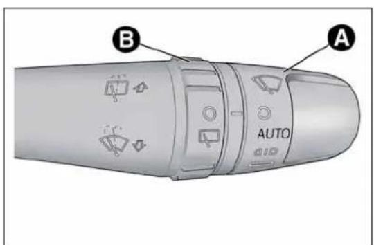
text_image
A AUTO Bfig. 36
A0J0064
Move the stalk upwards (unstable position) to limit operation to the time for which the stalk is held in this position. When released, the stalk will return to its default position and the wiper will be automatically stopped.

Donotusethewindscreenwipertoremovelayersof snoworicefromthewindscreen.Insuchconditions, thewindscreenwipermaybesubjectedtoexcessive
stressandthemotorprotection,whichpreventsoperationforafewseconds,mayintervene.Ifoperationisnotrestored,evenafterturningthekeyandrestartingtheengine,contactAlfaRomeoAuthorizedServices.

Donotoperatethewindscreenwiperwiththeblades liftedfromthewindscreen.
"Smart washing" function
Pull the lever towards the steering wheel (unstable position) to operate the windscreen washer. Keep the stalk pulled for more than half a second, with just one movement, to operate windscreen washer/wiper jet at the same time.
The wiper stops working three strokes after the stalk is released. A further stroke after approximately 6 seconds completes the cycle.
RAINSENSOR
(for versions/markets, where provided)
This is an infra-red LED sensor fitted on the car windscreen fig. 37.
It is able to detect the presence of rain and consequently manage windscreen wiping in accordance with the amount of water on the windscreen.
Activation
The sensor is activated when ring nut A fig. 36 is turned to "automatic" position ("AUTO" control): the windscreen wiper stroke frequency is thus adjusted in accordance with the amount of water on the windscreen.
This frequency can vary from no stroke (no rain - windscreen dry) up to the 2^nd constant speed operation (heavy rain - windscreen wet).
The sensitivity of the rain sensor can be adjusted through the Set-up menu (see paragraph "Menu Items" in this section).
If the engine is stopped with the lever in "automatic" position, when it is next started no wiping cycle will take place even if it is raining. This prevents accidental activation of the rain sensor when the engine is started (e.g. when the windscreen is being washed by hand or the wipers are stuck to the windscreen when there is ice).
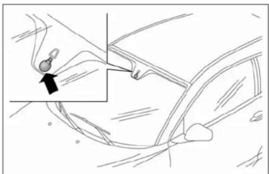
natural_image
Line drawing of a car interior showing a hand holding a small object near the wheel, with an arrow pointing to the part (no text or symbols present)fig. 37
A0J0189
Carry out any of the following manoeuvres to restore automatic operation of the system:
□ movement of left stalk from the automatic position to any other position and then back to automatic;
☐ sensitivity adjustment (by turning ring nut A to increase or decrease).
When the rain sensor is reactivated using any of the manoeuvres described above, reactivation is indicated by a single stroke of the windscreen wipers, regardless of the condition of the windscreen.
If the sensitivity is changed whilst the rain sensor is operating, a windscreen wiper stroke is carried out to confirm the change.
In the event of malfunction of the rain sensor whilst it is active, the windscreen wiper operates intermittently at a speed consistent with the sensitivity setting of the rain sensor, regardless of whether there is rain on the glass (sensor failure is indicated on the display).
The sensor continues to operate and it is possible to set the windscreen wiper to continuous mode ( 1^st or 2^nd speed). The failure indication remains for as long as the sensor is active.
REARWINDOWWASHER/WIPER
(for versions/markets, where provided)
Activation
This operates only with the ignition key turned to MAR.
Turn ring nut B fig. 36 from position ⬆ to position ☑ to operate the rear window wiper as follows:
☐ in intermittent mode when the windscreen wiper is not operating;
☐ in synchronous mode (at half the speed of the windscreen wiper) when the windscreen wiper is operating;
☐ in continuous mode with reverse gear engaged and the control active.
With reverse gear engaged and windscreen wiper on, the rear window wiper is activated in continuous mode. Pushing the stalk towards the dashboard (unstable position) will activate the rear window washer jet.
Keep the stalk pushed for more than half a second to activate the rear window wiper as well. Releasing the stalk will activate the smart washing function, as described for the windscreen wiper.
CRUISECONTROL
(for versions/markets, where provided)
GENERALINFORMATION
This is an electronically controlled driving assistance device which allows driving at a chosen speed above 30 km/h on long stretches of dry, straight roads with few variations (e.g. motorways), without having to depress the accelerator pedal.
The use of this device on extra-urban roads with traffic is not therefore recommended. Do not use it in town.
TURNINGTHEDEVICEON
Turn ring nut A fig. 38 to ON.
The device cannot be engaged in 1 ^st or reverse gear: it is advisable to engage it in 5 ^th gear or higher.
When travelling downhill with the device engaged, the car may slightly exceed the stored speed.

text_image
A OFF ON Bfig. 38
A0J0065
When the device is activated, the ⚫ warning light switches on together with the relevant message on the display (for versions/markets, where provided).
STORINGTHECARSPEED
Proceed as follows:
□ turn ring nut A fig. 38 to ON and press the accelerator to reach the required speed.
☐ move the stalk upwards (+) for at least 1 second, then release it: the car speed is now memorised and you can therefore release the accelerator.
If needed (when overtaking for instance), you can accelerate simply by pressing the accelerator; when you release the pedal, the car goes back to the speed set previously.
RESTORINGTHEMEMORISEDSPEED
If the device has been disengaged by pressing the brake or clutch pedal, the stored speed can be reset as follows:
□ accelerate gradually until a speed approaching the one stored is reached;
☐ engage the gear selected at the time that the speed was stored;
☐ press the RES button (B fig. 38).
INCREASINGTHEMEMORISEDSPPEED
Press the accelerator and store the new speed or move the lever upwards (+).
Each movement of the stalk corresponds to an increase in speed of about 1 km/h, while keeping the stalk held upwards will continuously increase the speed.
REDUCINGTHEMEMORISEDSPPEED
Deactivate the device and store the new speed or move the lever downwards (-) until the new speed is reached. It will then be stored automatically.
Each movement of the lever corresponds to a slight reduction in speed of about 1 km/h, while keeping the stalk held downwards will decrease the speed continuously.
TURNINGTHEDEVICEOFF
To disengage the device:
- turn ring nut A fig. 38 to OFF;
or
- switch the engine off;
or
- press the brake pedal, the clutch or the accelerator; in this last case the system is not effectively disengaged but the system gives priority to the acceleration request. The device still remains active, without the need to press the RES button to return to the previous conditions once acceleration is concluded.
Automatic deactivation
The device deactivates automatically in the following cases:
☐ if the ABS or ESC systems intervene;
□ with the car speed below the set limit;
□ in the event of system failure.

Whentravellingwiththedeviceactive,nevermovethe gearlevertoneutral.

Ifoperationisinadequateorthedeviceisfaulty,turn ringnutAfig.38toOFFandcontactAlfaRomeo AuthorizedServices.
ROOFLIGHTS
FRONTROOFLIGHT
Switch A fig. 39 switches the roof lights on/off.
A switch positions:
☐ central position (position 1): lights C and D switch on/off when the doors are opened/closed.
☐ pressed to the left (position 0): lights C and D are always switched off;
☐ pressed to the right (position 2): lights C and D are always switched on.
Lights switch on/off progressively.
switch B controls the spot light function.
B switch positions:
□ central position (position 1): lights C and D are always switched off;
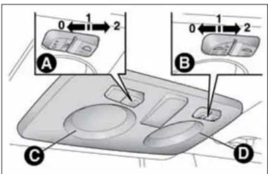
text_image
0 1 2 A B C D 0 1 2fig. 39
A0J0066
☐ pressed to the left (position 0): light C switches on;
☐ pressed to the right (position 2): light D switches on.
IMPORTANT Before getting out of the car, make sure that both switches are in the central position: when the doors are closed the lights will switch off to avoid draining the battery.
In any case, if the switch is left inadvertently in the permanently on position, the roof light will turn off automatically 15 minutes after the engine stopping.
ROOFLIGHTTIMING
On certain versions, to facilitate getting in/out of the car at night or in poorly-lit areas, two timed modes have been provided.
Timing when getting into the car
The roof lights switch on according to the following modes:
☐ for about 10 seconds when the doors are unlocked;
☐ for about 3 minutes when one of the doors is opened;
☐ for about 10 seconds when the doors are closed.
The timed period is interrupted when the ignition key is turned to MAR.
Timing when getting out of the car
After removing the key from the ignition switch, the roof lights switch on as follows:
□ within 2 minutes of the engine being switched off for a period of around 10 seconds;
☐ for about 3 minutes when one of the doors is opened;
☐ for about 10 seconds when one of the doors is closed.
The timing stops automatically when the doors are locked.
COURTESYLIGHTS
(for versions/markets, where provided)
On some versions, courtesy lights are fitted behind the sun visors.
Press switch A fig. 40 to switch the light on/off.
PUDDLELIGHTS
These are located in the doors fig. 41. They switch on when the doors are opened, regardless of the position of the ignition key.
The lights switch off when the doors are closed.
LUGGAGECOMPARTMENTROOF LIGHT
This is located on the left side of the luggage compartment fig. 42.

natural_image
3D diagram of a car intake tray with a labeled component (A), no text or symbols presentfig. 40
A0J0067
This switches on automatically when the luggage compartment is opened and switches off when it is closed.
The light switches on/off regardless of the ignition key position.
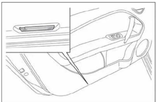
natural_image
Line drawing of a car interior showing the dashboard, seatbelt, and side panel (no text or symbols)fig. 41
A0J0176
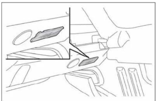
natural_image
Technical line drawing of a mechanical assembly with no visible text or symbolsfig. 42
A0J0270
This light comes on automatically when the glove compartment fig. 43 is opened and switches off when it is closed.
The light switches on/off regardless of the ignition key position.
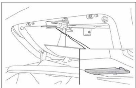
natural_image
Line drawing of a mechanical device with no visible text or symbolsfig. 43
A0J0177
CONTROLS
HAZARDWARNINGLIGHTS
Press switch A fig. 44 to switch on/off the lights.
Warning lights ⇔ and ⇒ on the panel are lit up when the lights are on.

TheuseofhazardlightsisgovernedbytheHighway Codeofthecountryyouarein.Complywithlegal requirements.
Emergency braking
In the event of emergency braking the hazard warning lights are lit up automatically as well as the ⇔ and ⇒ warning lights in the panel. The lights switch off automatically when emergency braking ceases.
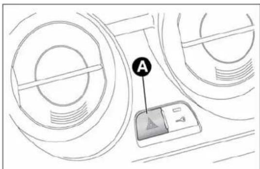
text_image
Afig. 44
A0J0028
FOGLIGHTS
(for versions/markets, where provided)
Press the #0 fig. 45 button to switch the lights on/off.
With the lights on, warning light #0 in the instrument panel switches on.
REARFOGLIGHT
Press the ⏻# fig. 45 button to switch the light on/off.
The rear fog light switches on only when the dipped headlights are switched on. With the light on, the Q warning light in the instrument panel switches on.
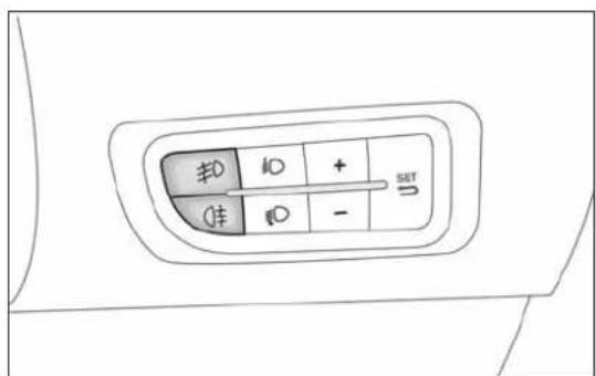
text_image
±0 ±0 + 1± ±0 - SET Ufig. 45
A0J0303
CENTRALLOCKING
Press button A fig. 46 to lock all doors at the same time.
Locking takes place irrespective of the position of the ignition key.
FUELCUT-OFFSYSTEM
This intervenes in the case of an impact causing:
☐ the interruption of the fuel supply with the engine consequently cutting out;
□ the automatic unlocking of the doors;
□ the interior lights being switched on.
The intervention of the system is indicated by a message shown on the display.
Carefully check the car for fuel leaks, for instance in the engine compartment, under the car or near the tank area.
After a collision, turn the ignition key to STOP to prevent the battery from running down.
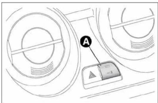
text_image
Afig. 46
A0J0030
To restore the correct operation of the car, proceed as follows:
□ turn the ignition key to the MAR position;
□ activate the right direction indicator;
□ deactivate the right direction indicator;
□ activate the left direction indicator;
□ deactivate the left direction indicator;
□ activate the right direction indicator;
□ deactivate the right direction indicator;
□ activate the left direction indicator;
□ deactivate the left direction indicator;
□ turn the ignition key to the STOP position.

If, afteracollision, yousmellfuelornoticeleaksfrom thefuelsystem, donotreactivatethesystemtoavoid firerisk.
INTERIORFITTINGS
GLOVECOMPARTMENT
Operate handle A fig. 47 to open the compartment. When the compartment is opened, a courtesy light switches on.
The glove compartment features a document holder.

Donottravelwiththeglovecompartmentopen:it couldinjurethepassengerintheeventofanaccident.

text_image
Afig. 47
A0J0060
FRONTARMREST
(for versions/markets, where provided)
This is located between the front seats. To bring it to its standard use position, push it downwards.
Press button A fig. 48 to raise the upper part of the armrest and access the compartment inside it. Press lever B to incline the armrest downwards relative to its standard use position.
POWERSOCKETS
These are located on the central tunnel A fig. 49 and on the left side of the luggage compartment B fig. 49 (for versions/markets, where provided). They only operate with the ignition key at MAR-ON.
If you request the smokers' kit, the socket on the central tunnel is replaced with a cigar lighter (see following paragraph).

natural_image
Diagram of a car seatbelt device showing two components labeled A and B, with no visible text or symbols beyond labels.fig. 48
A0J0194
IMPORTANT Do not connect devices with power higher than 180 W to the socket. Do not damage the socket by using unsuitable adaptors.
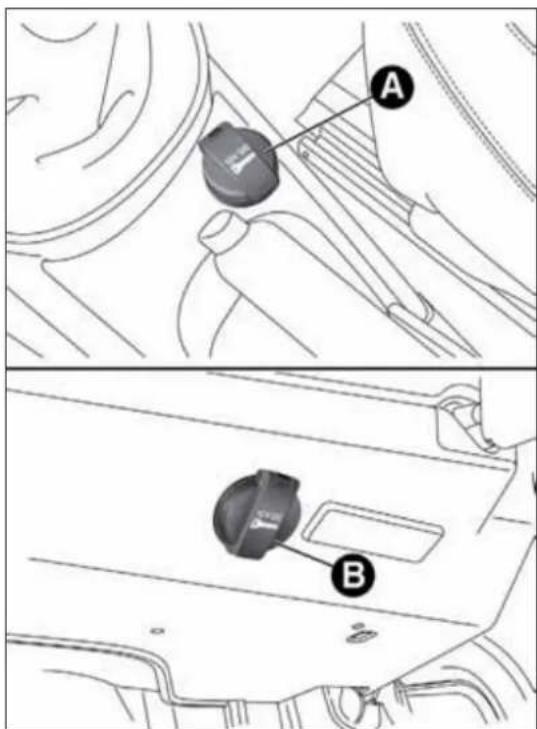
text_image
Technical diagram showing car gear shift lever with labeled parts A and Bfig. 49
A0J0068
CIGARLIGHTER
(for versions/markets, where provided)
This is located on the central tunnel. Press button A fig. 50 to activate the cigar lighter.
After a few seconds the button automatically returns to its initial position, and the cigarette lighter is ready for use.
IMPORTANT Always check that the cigar lighter is switched off.
IMPORTANT Do not connect devices with power higher than 180 W to the socket. Do not damage the socket by using unsuitable adaptors.

The cigarlightergetsveryhot. Handleitcarefully and makesurethatchildrendon'tuseit:riskoffire and/orburns.
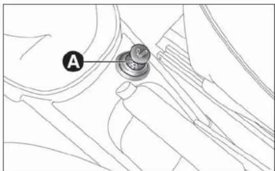
text_image
Afig. 50
A0J0304
ASHTRAY
The ashtray is a removable spring-loaded plastic box that can be fitted into the cup/can holders on the central tunnel fig. 51

Donotusetheashtrayasawastepaperbasket:it maycatchfireincontactwithcigarettestubs.
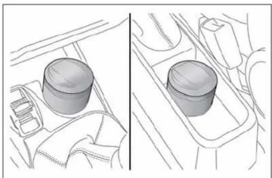
natural_image
Diagram showing two views of a car interior with a cylindrical component, no text or symbols presentfig. 51
A0J0070
SUNVISORS
These are located at the sides of the interior rear view mirror. They can be adjusted forwards and sideways.
A courtesy mirror with roof light is fitted on the back of the visors. The light allows the mirror to be used even in poor visibility conditions.
Lift cover A fig. 52 to access the mirror.
EXTINGUISHER
(for versions/markets, where provided)
This is located on the right side of the luggage compartment fig. 53.
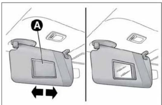
text_image
Afig. 52
A0J0071

natural_image
Line drawing of a mechanical device inside a vehicle (no text or symbols)fig. 53
A0J0190
ELECTRICSUNROOF
(for versions/markets, where provided)
The extensively glazed sun roof comprises a moving glass panel and a sun blind.
The glazed panel, when closed, allows light from the outside to enter and makes it possible to see the outside from the passenger compartment.
OPERATION
The sun roof can be operated only with the ignition key turned to MAR. The controls A and B fig. 54 on the trim next to the front courtesy light operate the sun roof opening/closing functions.
Roof opening
Pressing button A fig. 54 permits two opening modes for the front glass panel.

text_image
A Bfig. 54
Automatic
If button A is held down, the front glass panel is raised from completely closed to spoiler position.
If the button is pressed again, the panel will start to slide backwards until it is completely open.
After the initial opening command, the glass panel can be stopped in intermediate positions by pressing the button again.
Manual
If button A is pressed briefly, the front glass panel moves from completely closed position and stops in the position where the button is released. In this case, the panel is opened by pressing the button.
This function makes it possible to place the front panel in intermediate positions in relation to those produced through automatic opening.

Donotopenthesunroofifthereissnoworiceonit:you maydamageit.

Thesunroofmuststayclosedifatransversoofrackis fitted.

Whenleavingthevehicle,alwaysremovethekeyfrom theignitiontoavoidtheriskofinjurytothosestill insidethecarduetoaccidentaloperationofthe improperuseoftheroofcanbedangerous.Before alwayscheckthatno-oneisatriskofbeinginjuredby sunrooforbyobjectsgettingcaughtanddragged
Closing the sun roof
Pressing button B fig. 54 permits two closing modes for the front glass panel.
Automatic
With roof completely open, hold down button B: the front glass panel will move to spoiler position.
If the button is pressed again, the panel will start to slide forward until it is completely closed.
After the initial opening command, the glass panel can be stopped in intermediate positions by pressing the button again.
Manual
If button B is pressed briefly, the front glass panel moves from the completely open position and stops in the position where the button is released. In this case, the panel is closed by pressing the button.
This function makes it possible to place the front glass panel in intermediate positions in relation to those produced through automatic closing.
SUNBLIND
The brightness in the passenger compartment can be adjusted by using a sun blind.
Opening the blind: press button A fig. 55 to release the blind and then grip handle B in order to slide it backwards.
Closing the blind: grip handle B fig. 55 and slide the blind forwards, making sure that it clicks into place.
ROOFCLOSINGSAFETYDEVICES (anti-pinchfunction)
The anti-pinch system, which conforms to Directive 2000/4/EC, is active during the horizontal and vertical closing stage of the panel after an obstacle is encountered (e.g. finger, hand):
□ during horizontal closing movement it is active for the entire travel and, after an obstacle is encountered at the front of the glass panel, it reverses the movement;
□ during vertical closing movement it is active and, after an obstacle is encountered at the back of the glass panel, it reverses the movement until the spoiler position is reached.
The possibility of pinching from the inside of the passenger compartment in the side areas of the panel is avoided through the adoption of side guards that prevent access to risk areas.
IMPORTANT The anti-pinch system is deactivated by pressing button B continuously.

text_image
Diagram of car interior showing a door, seatbelt, and handle labeled A and Bfig. 55
A0J0157
INITIALISATIONPROCEDURE
After the battery has been disconnected or a fuse has blown, the operation of the sun roof must be initialised again.
Proceed as follows:
☐ press button B fig. 54 until the roof is completely closed. Release the button;
☐ press B button and keep it pressed for at least 10 seconds and/or until the glass panel clicks forwards. Release the button at this point;
☐ within 5 seconds of the previous operation, press button B and hold it down: the front glass panel will complete a full opening and closing cycle. Only release the button at the end of this cycle.
In the event of emergency or maintenance, the roof can be moved manually when there is no power supply (opening/closing of the front glass panel) by carrying out the following operations:
□ remove the protective cap A fig. 56 located on the internal lining, between the two sun blinds;
☐ take the Allen key B supplied, which is located in the on-board documentation container or in the tool container in the luggage compartment;
☐ introduce the key into housing C and turn it clockwise to open the roof or anticlockwise to close the roof.
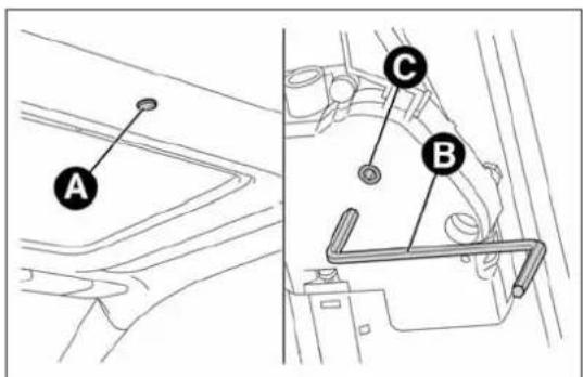
text_image
A C Bfig. 56
A0J0328
DOORS
DOORCENTRALLOCKING/ UNLOCKING
Locking from the outside
With the doors closed, press the 🔒 button on the key or turn the metal insert (located inside the key) in the driver side door lock.
The LED above fig. 57 button A switches on to indicate that the doors have been locked.
The door locking function is operated:
□ with all the doors closed;
□ with all the doors closed and the luggage compartment open:
Door unlocking from the outside
Press the 🔒 button on the key or turn the metal insert (located inside the key) in the driver side door lock.
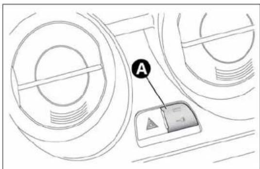
text_image
Afig. 57
A0J0030
Door locking/unlocking from the inside
Press fig. 57 button A. The button has an LED that indicates whether the car doors are locked or unlocked.
LED on: doors locked. Press button — once again to centrally unlock all doors. The LED will switch off.
LED off: doors unlocked. Press the button — again to centrally lock all doors. The doors will be locked only if all the doors are properly shut.
Once the doors have been locked via the remote control or the key pawl, it will no longer be possible to unlock them by pressing button
IMPORTANT With the central locking system on, pull the door lever of one of the doors to open that door only (the LED on button A will stay on if it is the passenger door).
In the absence of electrical power supply (blown fuse, battery disconnected, etc.) it is still possible to lock the doors manually.
PASSENGERSIDEEMERGENCYFRONT DOORLOCKINGDEVICE
The front passenger side door has a device to lock it when there is no current.
To lock it, fit the metal insert of the ignition key in the housing A fig. 58 and move it upwards.
IMPORTANT If the battery is disconnected or the protection fuse blows, the door opening/closing mechanism must be initialised as follows:
□close all the doors;
☐press button 🔒 on the key or button → for locking/unlocking the doors on the instrument panel;
☐press button 🔒 on the key or button — for locking/unlocking the doors on the instrument panel.

text_image
Technical diagram showing a mechanical component with labeled parts and an inset view of a detail with annotation 'A'fig. 58
A0J0309
ELECTRIC WINDOWS
These are equipped with an automatic function to raise and lower the driver side front window.
CONTROLS
☐ A - Front left window opening/closing;
□ B - Front right window opening/closing;
Windowopening
Push the buttons to open the desired window.
When one of the two buttons is pressed briefly, the window moves in "stages"; if the button is held down, "continuous automatic" operation is activated.

text_image
A Bfig. 59
A0J0023
If the control button is pressed again, the window will stop in the desired position. If the button is held down for several seconds, the window raises or lowers automatically (only with ignition key in MAR position).
Windowclosing
Lift the buttons to close the desired window.
The window closing stage occurs following the same logics described for the opening stage.
Passenger side door
The passenger side door is equipped with a button that controls the opening/closing of the passenger side window.
Continuous automatic operation
(for versions/markets, where provided)
This is activated by pressing one of the two buttons for longer than half a second. The window will stop when it is fully opened or closed, or when the button is pressed again:
□Driverside:raising/lowering.
□Passengerside:only lowering.
☐ Where anti-crush device is present: raising/lowering driver side and passenger side.
Anti-crush safety device
(for versions/markets, where provided)
The car's anti-crush function is active as the windows are being raised.
This safety system detects the presence of an obstacle during the window closing travel and intervenes by stopping and reversing the window travel, depending on its position. This device is also useful if the windows are activated accidentally by children on board the car.
The anti-crush safety function is active both during the manual and the automatic operation of the window. When the anti-crush system is activated, the window travel is immediately interrupted and then reversed. The window cannot be operated in any way during this time.
IMPORTANT If the anti-crush protection intervenes 5 consecutive times within a minute or is faulty, the automatic closing operation of the window is inhibited, only allowing it in steps of half a second with the button released for the subsequent manoeuvre.
In order to restore the correct operation of the system, the relevant window must be lowered.
IMPORTANT With ignition key at STOP or removed, the electric windows remain active for about 3 minutes and are deactivated when a door is opened.
IMPORTANT With the anti-crush system, when the 🔒 button on the remote control is pressed for longer than 2 seconds the windows will open, whilst if the 🔒 button is pressed for longer than 2 seconds the windows will close.

Thesystemconformstothe2000/4/ECstandardconcerning thesafetyofpassengersleaningoutofthepassenger compartment.

Incorrectuseoftheelectricwindowsmaybe dangerous. Beforeandduringoperation,alwayscheck thatnopassengerisatriskofbeinginjureddirectly
bythemovingwindoworbyobjectsgettingcaughtinor draggedbythewindow.Whenleavingthecar,alwaysremove thekeyfromtheignitiontopreventaccidentaloperationofthe electricwindowsfrombeingahazardforthosestillonboard.
Electric window system initialisation
The system must be re-initialised after disconnecting the battery or if the relevant protection fuse is blown.
Initialisation procedure:
☐ fully close the window to initialise with manual operation;
□ after the window has reached the upper end of travel, hold down the closing control for at least 1 second.
For versions/markets where provided, after a break in power supply for the control units (battery replaced or disconnected or protective fuses for the electric window control units replaced), the automatic operation of the windows must be restored.
The restoration procedure must be performed as described below with the doors closed:
□ completely open the driver's door window, holding the operating button down for at least three seconds after the (lower) end of travel position;
□ completely raise the driver side window and hold the button down for at least 3 seconds once the (upper) end of travel position has been reached;
☐ proceed in the same way as described in points 1 and 2 for the passenger side door;
☐ make sure that the initialisation is correct by checking that the windows work automatically.
IMPORTANT With the central locking on, pulling the internal opening lever for one of the doors switches the locking off for all the doors.
In the absence of electrical power supply (blown fuse, battery disconnected, etc.) it is still possible to lock the doors manually. In this case, the automatic lowering function of the windows is not available. Press the window towards the inside of the car (see fig. 60) to open or close the door with the window raised to ease the passage of the window into the moulding.
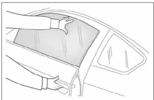
natural_image
Line drawing of a car interior showing hands cleaning the dashboard area (no text or symbols)fig. 60
A0J0170
LUGGAGECOMPARTMENT
The luggage compartment is unlocked electrically and cannot be unlocked when the car is in motion.
OPENING
When unlocked, the boot can be opened from outside the car by pressing the electric logo fig. 61 until a click is heard which indicates unlocking or by pressing the button on the remote control.
The direction indicators will flash twice and an internal light will switch on when the luggage compartment is opened: the light switches off automatically when the luggage compartment is closed. The light switches off automatically after a few minutes if the luggage compartment is left open.
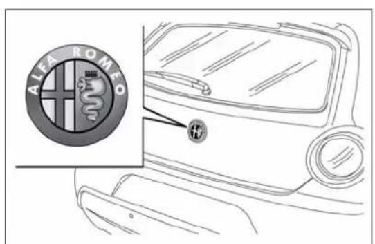
text_image
ALEI ROMEOfig. 61
A0J0058
Emergency opening from the inside
Proceed as follows:
☐ remove the rear head restraints and completely fold back the seats (see the paragraph "Expanding the luggage compartment");
□ push lever A fig. 62.
CLOSING
Lower the tailgate, pressing near the lock until you hear it click into place.
Pull the tab A fig. 63 and lower the tailgate, pressing next to the lock until it clicks.
IMPORTANT Before closing the luggage compartment make sure that you have the keys since the luggage compartment is automatically locked.

natural_image
Technical line drawing of a mechanical component with labeled section A (no text or symbols beyond label)fig. 62
A0J0178
LUGGAGECOMPARTMENT INITIALISATION
IMPORTANT If the battery is disconnected or the protection fuse blows, the luggage compartment opening/closing mechanism must be initialised as follows:
□ close all the doors and the luggage compartment;
□Press the 🔒 button on the remote control;
☐Press the 🔒 button on the remote control.
EXTENDINGTHELUGGAGE COMPARTMENT
The luggage compartment can be partially (1/3 or 2/3) or totally extended by splitting the rear seat. See the descriptions in "Removing the parcel shelf" and "Folding back the seats" paragraphs for how to expand the luggage compartment.
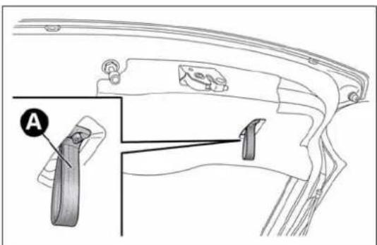
text_image
Technical diagram of a mechanical component with labeled parts and an inset view showing part Afig. 63
A0J0079
Removing the parcel shelf
Proceed as follows:
□ free the ends of the two parcel shelf B mounting links A fig. 64 by removing the eyelets C from the mounting pins;
☐ free the pins A fig. 65 on the outside of the shelf from the housings B in the side mountings, then remove the parcel shelf;
□ after removal, the parcel shelf can be loaded sideways into the luggage compartment or placed between the front seat backrests and the folded-back rear seat cushions (with the luggage compartment completely expanded).
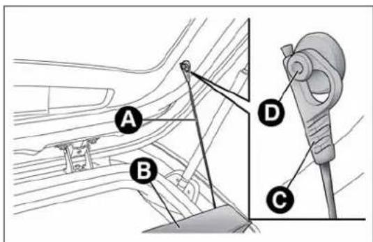
text_image
A B D Cfig. 64
A0J0080
Foldingtheseats
Proceed as follows:
☐ raise the head restraints to the maximum height, press both the buttons A fig. 66 to the side of the two supports, then remove the head restraints by sliding them upwards;
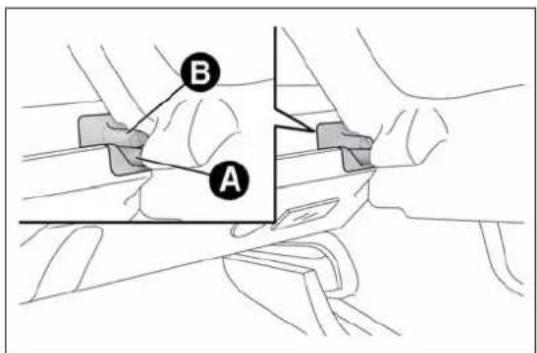
text_image
A Bfig. 65
A0J0081

natural_image
Diagram of a car seat with a vertical support and an upward arrow, no text or symbols presentfig. 66
A0J0083
☐ move the seat belts to the side, making sure that they are correctly extended and not twisted;
☐ lift the backrest retaining levers A fig. 67 and fold the desired cushion forwards (a red band indicates that lever A is raised).
Repositioning the rear seat
Move the seat belts to the side making sure that they are correctly extended and not twisted.
Raise the previously folded backrest until you hear the click of the locking mechanism, visually checking that the red band on lever A fig. 67 has disappeared. The red band indicates that the backrest is not secured.
Finally, reposition the head restraints, inserting them into their housings.
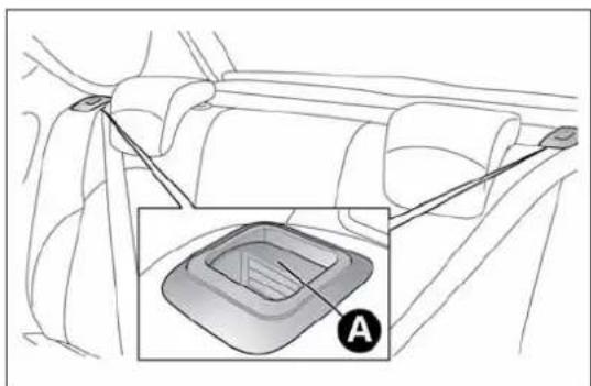
text_image
Diagram showing car gear shift lever with labeled component A, including a zoomed-in inset of the gear mechanism.fig. 67
A0J0082
BONNET
OPENING
Proceed as follows:
☐ pull lever A fig. 68 in the direction indicated by the arrow;
☐ pull lever B in the direction indicated by the arrow;
☐ lift the bonnet and, at the same time, release bonnet stay C fig. 69 from its locking device. Then, insert the end in housing D, making sure that the stay is engaged in the smallest opening of the retaining clip.
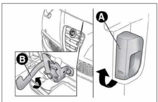
text_image
Diagram showing car interior components with labeled parts A and B, including a gear shift mechanism.fig. 68
A0J0085
IMPORTANT Before lifting up the bonnet make sure that the windscreen wipers are in the rest position and not operational.
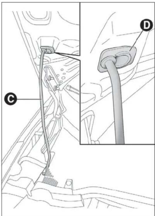
text_image
Technical diagram showing a car plug assembly with labeled parts C and D, including a close-up of the plug.fig. 69
A0J0086
CLOSING
Proceed as follows:
☐ hold the bonnet up with one hand and with the other remove rod C fig. 69 from housing D and fit it back into its locking device;
☐ lower the bonnet to about 20 cm from the engine compartment, then let it fall and check, by trying to raise it, that it is completely closed and not only attached in safety position. If it is not perfectly closed, open the bonnet and repeat the procedure. Do not simply press it.
IMPORTANT Always check that the bonnet is closed correctly to avoid it opening while the car is travelling.
For versions/markets where provided, the following plate is applied inside the engine compartment fig. 70:

Forsafetyreasons,thebonnetmustalwaysbe properlyclosedwhiledriving.Makesurethatthe bonnetisperfectlyclosedandthatthelockisengaged.
If you discover during travel that the lock is not fully engaged, stop immediately and close the bonnet in the correct manner.

text_image
SAFETY The bonnet, the bumper and the headlamps of this vehicle have been developed as integral part of the passive safety systems of your car to ensure an optimum protection to pedestrians and to all passengers. For this, in case of replacement, be sure to choose genuine parts of the bodywork which are specifically developed for your car.fig. 70
A0J1520

Performtheseoperationsonlywhenthecaris stationary.

Thebonnetmaydropsuddenlyifthesupportingrodis notpositionedcorrectly.
ROOFRACK/SKIRACK
To fit the roof rack/ski rack, raise the dedicated tabs A fig. 71 using the screwdriver provided to access the fixing housings B.
Lineaccessori Alfa Romeo includes a dedicated roof rack/ski rack for this car.
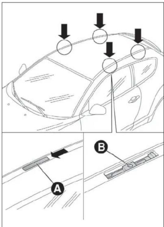
text_image
Diagram illustrating car safety inspection steps with labeled arrows and components A and Bfig. 71
IMPORTANT Take the greatest possible care in following the instructions on the bar kit to the letter.

Aftertravellingforashortdistance,checkthatthe fixingscrewsfortheattachmentsarecorrectly tightened.

Neverexceedthemaximumpermittedloads(seechapter "Technicalspecifications").

Evenlydistributetheloadandtakeintoaccount,when driving,theincreasedeffectofsidewindonthecar.

Fullycomplywiththeregulationsinforceconcerning maximumclearance.
HEADLIGHTS
LIGHTBEAMDIRECTION
The correct orientation of the headlights is important for the driver's comfort and safety as well as for all other road users. This is also covered by a specific rule of the highway code.
The headlights must be correctly aligned to ensure the best visibility conditions for yourself and others when driving with lights on. To check and, if necessary, adjust, contact Alfa Romeo Authorized Services.
HEADLIGHTALIGNMENTCORRECTOR
This device works with the ignition key in the MAR position and the dipped headlights on.
Headlight alignment adjustment
To adjust, press the ☐ and ☐ fig. 72 fig. 73 buttons. The adjustment position is shown on the display.

text_image
±0 ID + SET 0# ID - =fig. 72
A0J0305
Position 0 : one or two occupants in the front seats.
Position 1 : 4 people.
Position 2 : 4 people + load in luggage compartment.
Position 3 : driver + maximum permitted load stowed in the luggage compartment.
IMPORTANT Check the alignment every time that the load carried changes.
FOGLIGHTALIGNMENT
(for versions/markets, where provided)
To check and, if necessary, adjust, contact Alfa Romeo Authorized Services.
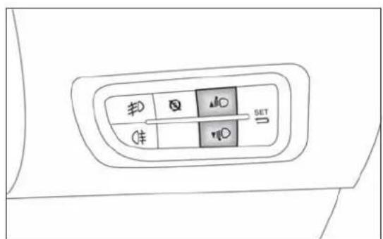
fig. 73 - Versions with Start&Stop system
A0J0306
ADJUSTINGTHEHEADLIGHTSABROAD
The dipped headlights are aligned to comply with the regulations of the country of purchase. When travelling in countries with opposite driving direction, to avoid dazzling the drivers on the other side of the road, you need to cover areas of the headlight according to the Highway code of the country you are travelling in.
ABSSYSTEM
The car is fitted with an ABS braking system, which prevents the wheels from locking when braking, makes the most of road grip and gives the best control when performing emergency braking under difficult road conditions.
The EBD system (Electronic Braking Force Distribution) completes the system allowing the brake force to be distributed between the front and rear wheels.
IMPORTANT To obtain the maximum efficiency of the braking system, a bedding-in period of about 500 km is needed: during this period it is better to avoid sharp, repeated and prolonged braking.
SYSTEMINTERVENTION
It can be detected because the brake pedal pulsates slightly and the system gets noisier: it means that the car speed should be altered to suit the type of road surface.
MECHANICALBRAKEASSIST (emergencybrakingassistance)
(for versions/markets, where provided)
This system, which cannot be deactivated, recognises emergency braking conditions (according to the brake pedal operation speed) and provides an additional hydraulic braking pressure to support that provided by the driver. This allows faster and more powerful operation of the braking system.
IMPORTANT When the Mechanical Brake Assist intervenes, noises may be heard from the system. This is normal. In any case, while braking keep the brake pedal firmly depressed.
If the ABS system intervenes, this indicates that the traction of the tetyresontheroadisnearing its limit. Slowdown to as speed compatible with the available traction.
TheABSgetsthemostfromtheavailablegrip, but it cannotimproveit; you should therefore fake every carewhendriving on slipper surface and not take unnecessary risks.
WhentheABScutsinandyoufeelthebrakepedal pulsating, donotremoveyourfoot, but keepthepedal pushdown; indoingsoyou, will stop in the shortest distance possible undertheroad conditions at the time.
ESC(ElectronicStability Control)SYSTEM
This is an electronic system controlling car stability in the event of tyre grip loss, helping to maintain directional control.
The system is capable of recognising potentially dangerous situations in terms of the stability and intervenes automatically on the brakes in a differentiated manner for the four wheels in order to provide a stabilising torque.
The ESC system also includes the following systems:
□Hill Holder
□ASR
□Brake Assist
□MSR
□CBC
□"ELECTRONIC Q2" ("E-Q2")
□DST
SYSTEMACTIVATION
The ESC system switches on automatically when the engine is started and cannot be switched off.
SYSTEMINTERVENTION
It is signalled by the blinking of the warning light ⚙ on the instrument panel, to inform the driver that the car is in critical stability and grip conditions.
HILLHOLDERSYSTEM
This system is an integral part of the ESC system and facilitates starting on slopes.
It is automatically activated in the following conditions:
☐ uphill: vehicle stationary on a road with a gradient higher than 5%, engine running, brake pedal pressed and gearbox in neutral or gear (other than reverse) engaged;
☐ downhill: vehicle stationary on a road with a gradient higher than 5%, engine running, brake pedal pressed and reverse gear engaged.
When setting off the ESC system control unit maintains the braking pressure at the wheels until the engine torque required for departure is reached or for approximately 2 seconds, allowing your right foot to be moved easily from the brake pedal to the accelerator.
If the vehicle has not departed after this time, the system will deactivate automatically by gradually releasing the brake force. A sound may be heard during this stage: this indicates that the vehicle is about to move off.
IMPORTANT The Hill Holder system is not a handbrake. Do not leave the vehicle without having engaged the handbrake, switched off the engine and engaged a gear.
ASR(AntiSlipRegulation)SYSTEM
It is an integral part of the ESC system. It automatically operates in the event of one or both drive wheels slipping, loss of grip on wet roads (aquaplaning) and acceleration on slippery, snowy or icy roads, etc.
Depending on the slipping conditions, two different control systems are activated:
☐ if the slipping involves both drive wheels, the ASR intervenes reducing the power transmitted by the engine;
☐ if the slipping only involves one of the drive wheels, the ASR intervenes automatically braking the wheel that is slipping.

ForthecorrectoperationoftheESCandASRsystems, theyresmustbethesamemakeandtypeonall wheels, imperfectconditionand, aboveall, ofthetype, sizerecommended.

TheESCsystemoperatesevenwhenthespace-saver wheelisbeingused.Alwaysrememberthatthe space-saverwheel,beingsmallerthantheoriginal provideslessgrip.

Donottakeunnecessaryrisks,evenifyourvehicleis fittedwiththeESCandASRsystems.Drivingstylemust alwaysbeadaptedtoroadconditions,visibilityand driverisalwaysresponsibleforroadsafety.
BRAKEASSIST
(assistance during emergency braking)
The system, which cannot be turned off, recognises emergency braking (on the basis of the brake pedal operating speed) and speeding up the response of the braking system. The Brake Assist device is deactivated if there is a ESC system failure.
MSRSYSTEM
This system is an integral part of the ABS, that intervenes, if there is a sudden downshifting, restoring torque to the engine, thereby preventing excessive drive at the drive wheels which, especially in poor grip conditions, could lead to a loss in stability of the car.
CBC(CorneringBrakeControl) SYSTEM
This function improves the distribution of the braking pressure at the four wheels (to fully exploit the grip available on the ground) when braking on bends if the ABS intervenes. This improves stopping distances and above all vehicle stability when cornering.
"ELECTRONICQ2" SYSTEM("E-Q2")
The "Electronic Q2" system uses the braking system to create an effect similar to a limited slip differential.
The front braking system, when accelerating around a curve, acts on the inside wheel to increase the drive to the outside wheel (increased load), dynamically and continuously distributing the torque between the front drive wheels according to driving and road conditions.
The system, combined with MacPherson front suspension, allows particularly effective and sports driving to be achieved.
DSTSYSTEM
(DynamicSteeringTorque)
This function integrates Dual Pinion active steering into the operation of ESC. For particular manoeuvres, the ESC system controls the steering to actuate a steering torque and assist the driver in the best possible way.
The system operates the brakes and steering in a coordinated manner to increase the suspension and safety level of the car as a whole. The steering provides additional torque on the steering wheel.
"AlfaDNA" SYSTEM (Car dynamic control system)
This device allows, using lever A fig. 74 (on the central tunnel), three car response modes to be selected according to driving style and road conditions:
□ d = Dynamic (sports driving mode);
☐ n = Natural (mode for driving in normal conditions);
☐ a = All Weather (mode for driving in poor grip conditions, such as rain and snow).
The device also acts on the dynamic car control systems (engine, steering, VDC system, instrument panel).

text_image
A d n afig. 74
A0J0090
DRIVINGMODES
Lever A is monostable type. In other words, it always remains in a central position.
The selected driving mode is indicated by the corresponding LED coming on in the panel and by an indication on the reconfigurable multifunction display, as illustrated below:
☐ Dynamic mode fig. 75 (display image available for versions/markets, where provided)
□AllWeatherModefig. 76
"Natural" mode
When "Natural" mode is selected, no messages or symbols are shown on the display.
ESC and ASR systems: intervention thresholds aimed at comfort and safety in normal grip and driving conditions.
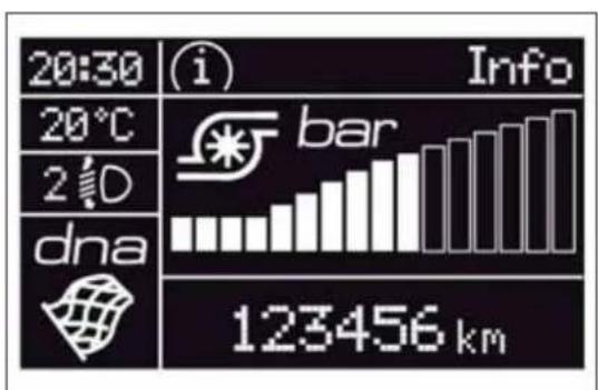
text_image
20:30 20°C 2°D dna Info bar 123456 kmfig. 75
A0J0227
Steering wheel tuning: functions aimed at comfort in normal conditions of use.
DST: braking standard control coordinated with ABS/ESC. Standard control over lateral acceleration. Oversteer compensation: a slight pulse on the steering wheel encourages the driver to carry out the most appropriate manoeuvre.
Engine: standard response.
ENGAGEMENT/DISENGAGEMENTOF "Dynamic"MODE
Engagement
Move the lever A fig. 74 upwards (next to the letter "d") and hold in this position for 0.5 seconds until the corresponding LED lights up or the word "Dynamic" appears on the display (see fig. 77). Upon release, lever A returns to the central position.
ESC and ASR: intervention thresholds that allow more enjoyable, sportier driving whilst guaranteeing stability of the vehicle.

text_image
10:20 (i) Info -10.0°C 30km/h 2 D dna 123456 kmfig. 76
A0J0290
Steering wheel tuning: uses the sports mode function.
DST: braking standard control coordinated with ABS/ESC. Standard control over lateral acceleration. Oversteering compensation depending on the ESC/ASR intervention thresholds: a slight movement on the steering wheel encourages the driver to carry out the most appropriate manoeuvre.
Engine: prompter response + Overboost to maximise torque (for versions/markets, where provided).
In the 1.4 Turbo MultiAir versions, selecting "Dynamic" operating mode activates the turbocharger supercharging function (overboost): depending on the accelerator pedal position and for a limited time, the engine management control unit allows the system to generate maximum pressure levels inside the turbocharger and the engine torque can reach higher values than usual.
This function is particularly useful whenever maximum performance is required for a short time (e.g. when overtaking).
IMPORTANT During acceleration, when the "Dynamic" function is used the steering may shudder, which is typical of a sports setting.
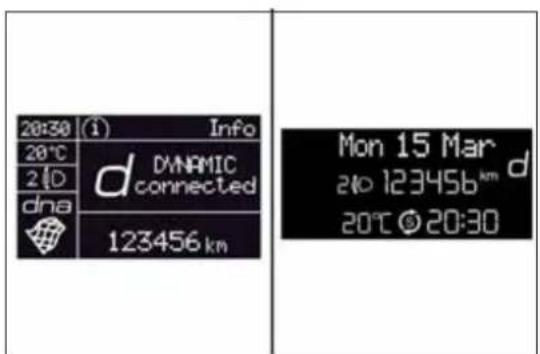
text_image
20:30 (1) Info 20°C 2 D dna d DYNAMIC connected 123456 km Mon 15 Mar 2 to 123456 km d 20°C © 20:30fig. 77
A0J1510
Disengagement
To deactivate "Dynamic" mode and return to "Natural", repeat the same movement of the lever within the same times. In this case, the LED corresponding to "Natural" mode will light up and the words "Natural on" will appear on the reconfigurable multifunction display (see fig. 78).
ENGAGEMENT/DISENGAGEMENTOF "AllWeather"MODE
Engagement
Move lever A fig. 74 downwards (to the letter "a") and hold in this position for 0.5 seconds until the corresponding LED lights up or the word "All Weather" appears on the display (see fig. 79).
ESC and ASR systems: intervention thresholds aimed at guaranteeing the maximum safety in low grip driving conditions. It is recommended to activate the "All Weather" mode when fitting snow chains.
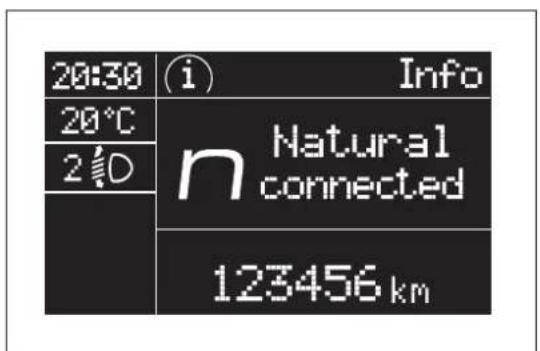
text_image
20:30 20°C 2° Info Natural connected 123456 kmfig. 78
A0J1059
Steering wheel tuning: maximum comfort.
DST: higher braking control coordinated with ABS/ESC. Standard control over lateral acceleration. Oversteering compensation depending on the ESC/ASR intervention thresholds: a slight movement on the steering wheel encourages the driver to carry out the most appropriate manoeuvre.
Engine: standard response.
Disengagement
To deactivate "All Weather" mode and return to "Natural", carry out the same procedure described for "Dynamic" mode, but move lever A fig. 74 to "a".
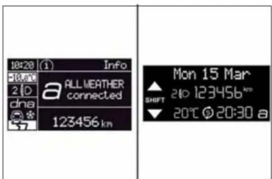
text_image
10:20 (1) Info -10:00 2 D dna a ALL WEATHER connected 123456 km Mon 15 Mar SHIFT 210 123456 km 20°C 20:30 afig. 79
A0J1511
IMPORTANT
☐ It is not possible to switch directly from "Dynamic" mode to "All Weather" mode and vice versa. You must always first go back to "Natural" mode and then select the other mode.
☐ The driving mode engaged before the engine stops is maintained when it is next started.
☐ In the event of system failure or a fault with lever A fig. 74, no driving modes can be selected. The display will show a warning message.
START&STOPSYSTEM
(for versions/markets, where provided)
The Start&Stop system automatically stops the engine each time the car is stationary and starts it again when the driver wants to move off. In this way, the efficiency of the car is increased, by reducing consumption, emissions of harmful gases and noise pollution.
OPERATINGMODES
Engine stopping mode
With the car stopped, the engine stops with gearbox in neutral and clutch pedal released.
Note The engine can only be stopped automatically over about 10 km/h, to prevent the engine from being repeatedly stopped when driving at walking pace.
The Ⓢ fig. 80 symbol appears on the display when the engine stops.
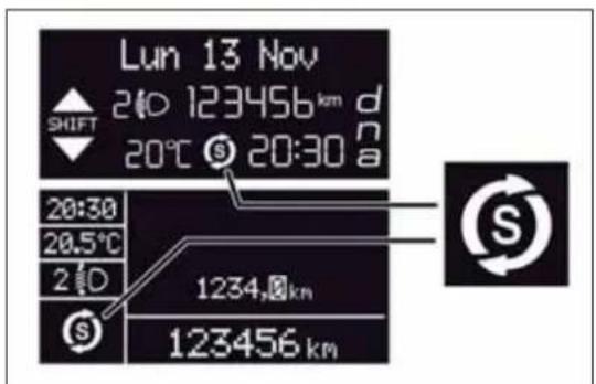
text_image
Lun 13 Nov 210 123456 km d SHIFT 20°C 20:30 a 20:30 20.5°C 2 D 1234,km 123456 kmfig. 80
A0J0279
Restarting the engine
Press the clutch pedal to restart the engine.
SYSTEMMANUALACTIVATION/DEACTIVATION
To activate/deactivate manually the system, press the ☒ fig. 81 button on the trim next to the steering wheel.
Start&Stop system activation
A message and a symbol will be displayed when the Start&Stop system is activated.
Turning the Start&Stop off
☐ Versions with multifunction display: a message is displayed when the Start&Stop system is deactivated.
□Versionswithreconfigurablemultifunctiondisplay:the symbol is displayed + a message when the Start&Stop system is deactivated.
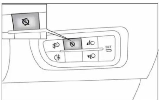
text_image
Diagram showing a car's seatbelt with labeled buttons and directional indicatorsfig. 81
A0J0307
When the system is deactivated, the warning light on the instrument panel switches on. For versions/markets where provided, a message and symbol are also displayed in the event of system activation/deactivation.
ENGINESTOPPINGFAILURE CONDITIONS
When the system is operating, due to comfort, emission control and safety reasons, the engine does not stop in some conditions, among which:
□engine still cold;
□ especially cold outside temperature;
☐ battery not sufficiently charged;
☐ particulate filter regeneration (DPF) in progress (diesel engines only);
□ driver's door not shut;
□ driver's seat belt not fastened;
□ reverse gear engaged (for example, for parking manoeuvres);
☐ for versions equipped with dual zone automatic climate control (for versions/markets, where provided), if an adequate level of thermal comfort has not been reached or with MAX-DEF function activation;
□ during the first period of use, to initialise the system.

If the climate comfort is befavoured, the Start & Stop system can be deactivated, for a continuous operation of the climate control system.
ENGINEERESTARTINGCONDITIONS
Due to comfort, emission control and safety reasons, the engine can restart automatically without any action by the driver, under special conditions, such as:
□ battery not sufficiently charged;
☐ reduced braking system vacuum (e.g. if the brake pedal is pressed repeatedly);
□ car moving (e.g. when driving on roads with a gradient);
□ engine stopping by Start&Stop system for over 3 minutes;
☐ for versions equipped with dual zone automatic climate control system (for versions/markets, where provided), if an adequate level of thermal comfort has not been reached or MAX-DEF function activation.
With gear engaged, automatic engine restarting is possible only by fully depressing the clutch pedal. The driver is informed by the displaying of a message on the display and - for versions/markets, where provided - by the flashing of the symbol ⑤.
Notes
If the clutch is not pressed, about 3 minutes after the engine stops, the engine can be restarted only using the ignition key.
In cases when the engine stops and this is not desired, due for example to the clutch pedal being released sharply with a gear engaged, if the Start&Stop system is activated, the engine can be restarted by fully depressing the clutch pedal or by placing the gear lever in neutral.
SAFETYFUNCTIONS
When the engine is stopped by the Start&Stop system, if the driver releases his/her seat belt and opens the driver's or passenger's door, the engine can be restarted only using the ignition key.
The driver is informed by a buzzer and by the flashing of the symbol on the display; on some versions, a message is displayed as well.
"ENERGYSAVING"FUNCTION
(for versions/markets, where provided)
If, following automatic engine restarting, the driver does not carry out any action on the car for over 3 minutes, the Start&Stop system stops the engine once and for all, to prevent fuel consumption. In these cases, the engine can be restarted only using the ignition key.
NOTE In any case, it is possible to keep the engine running by deactivating the Start&Stop system.
IRREGULAROPERATION
In the event of malfunction, the Start&Stop system is deactivated.
The driver is informed of the fault by the ⚠ warning light switching on in the instrument panel and, for versions/markets where provided, a message and symbol on the display.
In this case, contact Alfa Romeo Authorized Services.
CARINACTIVITY
In the event of car inactivity (or if the battery is replaced), special attention must be paid to the disconnection of the battery power supply.
The procedure must be carried out as follows: press button A fig. 82 to detach connector B from battery status monitoring sensor C (this is located on the negative pole of the battery itself).

Incaseofbatteryreplacement,alwayscontactAlfa RomeoAuthorizedServices.Replaceebatterywith oneofthesametype(HEAVYDUTY)andwiththesame
specifications.
IMPORTANT After turning the ignition key to STOP, wait at least 1 minute before disconnecting the electrical supply to the battery.

text_image
Technical diagram of an automotive electrical plug with labeled components A, B, and Cfig. 82
A0J0379
JUMPSTARTING
When jump starting, never connect the negative lead (-) of the auxiliary battery to the negative pole A fig. 83 of the car battery, but rather to an engine/gearbox earth point.

Beforeopeningthebonnet,makesuretheengineisoffand theignitionkeyisintheSTOPposition.Followthe indicationsontheplateunderneaththebonneffig.84.Itis
advisabletoextractthekeywhenthereareotherpeopleinthecar. Leavethecaronlyafterhavingremovedtheignitionkeyorhaving turnedittoSTOP.Duringrefuelling,makesurethattheengineisoff andthattheignitionkeyisintheSTOPposition.

text_image
Diagram of an automotive electrical plug with labeled components and wiring connectionsfig. 83
A0J0368
DYNAMICSUSPENSION(active shockabsorbersystem)
(for versions/markets, where provided)
This system interacts with the "Alfa DNA" system (see paragraph "Alfa DNA").
The "Alfa DNA" system lever allows you to choose three different driving settings depending on the route type and on the road surface:
□ d = Dynamic (sports driving mode);
□ n = Natural (mode for driving in normal conditions);
☐ a = All Weather (mode for driving in poor grip conditions, such as rain and snow).
In "Natural" and "All Weather" operating mode, the active shock absorbers adjust the car suspension to suit the route type and the driving stresses, thus considerably improving driving comfort in particular on rough terrain.
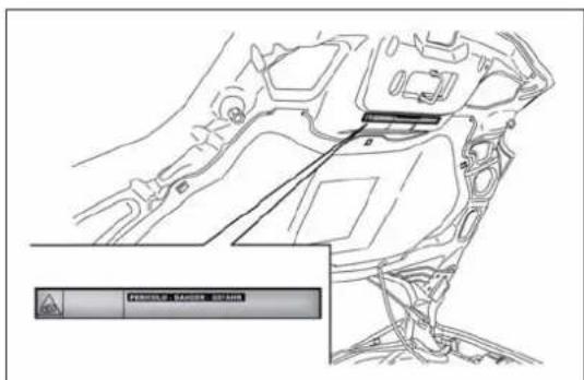
text_image
Technical diagram of a vehicle engine compartment with a warning panel and control buttons labeled in Chinese.fig. 84
A0J0341
The "Dynamic" operating mode produces a sports driving setting characterised by more responsive acceleration and greater effort on the steering wheel to give a sporty feeling. The shock absorber damping action is also adjusted and divided, to guarantee higher precision and reactivity of the car, while maintaining a good comfort level.
The car is more precise when entering bends and quicker in changing direction.
EOBDSYSTEM(EuropeanOn BoardDiagnosis)
(for versions/markets, where provided)
The aim of the EOBD system (European On Board Diagnosis) is to:
□ monitor the system efficiency;
□ indicate an increase in emissions;
□ indicate the need to replace damaged components.
The car also has a diagnostic connector that can be interfaced with appropriate tools, which makes it possible to read the error codes stored in the electronic control units together with a series of specific parameters for engine operation and diagnosis. This check can also be carried out by the traffic police.
IMPORTANT After eliminating a fault, to check the system completely, Alfa Romeo Authorised Services are obliged to run tests and, if necessary, road tests which may also call for a long journey.
ELECTRICPOWERSTEERING
This only operates with the key turned to MAR-ON and the engine started. Power steering allows the force required at the steering wheel to be adapted to driving conditions.
The different power assistance modes can be selected via the "d,n,a" positions of the "Alfa DNA System" lever (see "Alfa DNA System" paragraph).

Itisabsolutelyforbiddentocarryoutanyafter-market operationinvolvingsteeringsystemorsteeringcolumn modifications(e.g.:installationofanti-theftdevice)
that could badly affect performance and safety, invalidate the warranty and also results in non-compliance of the car with type-approval requirements.

Beforeperforminganymaintenanceoperations, alwaysturnofftheengineandremovethekeyfrom theignitiontolockthesteeringcolumn,especially
whenthecar'swheelsarenottouchingtheground.
INSTALLINGELECTRICAL/ELECTRONICDEVICES
Electrical and electronic devices installed after buying the car in the context of after-sales service must carry the following label: fig. 86
Fiat Group Automobiles S.p.A. authorises the installation of transceiver devices on condition that such installations are carried out in a workmanlike fashion, following the manufacturer's instructions, at a specialised centre.
IMPORTANT Traffic police may not allow the car on the road if devices have been installed which modify the features of the car. This may also cause invalidation of warranty in relation to faults caused by the change either directly or indirectly related to it.
Fiat Group Automobiles S.p.A. shall not be liable for damage caused by the installation of accessories either not supplied or recommended by Fiat Group Automobiles S.p.A. and/or not installed in compliance with the provided instructions.


fig. 85
DISPOSITIVI-ELETTRONICI
RADIOTRANSMITTERSANDMOBILE PHONES
Radio transmitter equipment (vehicle mobile phones, CB radios, amateur radio, etc.) cannot be used inside the car unless a separate aerial is mounted externally.
IMPORTANT The use of similar devices inside the passenger compartment (without separate aerial) produces radio-frequency electromagnetic fields which, amplified by the resonance effects inside the passenger compartment, may cause electrical systems equipping the car to malfunction. This could compromise safety in addition to constituting a potential hazard for the passengers.
In addition, transmission and reception of these devices may be affected by the shielding effect of the car body.
As far as the use of EC-approved mobile phones is concerned (GSM, GPRS, UMTS), follow the usage instructions provided by the mobile phone manufacturer.
PARKINGSENSORS
(for versions/markets, where provided)
The parking sensors are located in the car's rear bumper fig. 86 and their function is to inform the driver, through an intermittent acoustic signal, about the presence of obstacles behind the car.
ACTIVATION
The sensors are activated by engaging reverse gear. As the obstacle behind the vehicle gets closer to the car, the acoustic signal becomes more frequent.
INDICATIONSONDISPLAY
(for versions/markets, where provided)
When the sensor is activated, the "Reconfigurable multifunction display" (for versions/markets, where provided) shows the screen illustrated in fig. 87.
Obstacle presence and distance information is therefore provided both by the buzzer and the instrument panel display.
If there are several obstacles the closest one is indicated.

natural_image
Technical line drawing of a car front panel with arrows indicating component alignment (no text or symbols)fig. 86
A0J0088
ACOUSTIC SIGNAL
When reverse gear is engaged an acoustic signal is automatically activated if there is an obstacle within the range of operation.
The acoustic signal:
☐ increases as the distance between the car and the obstacle decreases;
□ becomes continuous when the distance between the car and the obstacle is less than 30 cm and stops immediately if the distance increases;
☐ remains constant if the distance remains unchanged; if this situation concerns the side sensors, the buzzer will stop after about 3 seconds to avoid, for example, warning indications in the event of manoeuvres along walls.
IMPORTANT The volume of the acoustic signal can be adjusted through the option "Warning volume" of the "Set-Up menu".

text_image
20:30 20.5°C 2 D 123456 kmfig. 87
A0J0370
Detection distances
☐ Central operating range: 140 cm
☐ Side operating range: 60 cm
If several obstacles are detected by the sensors, only the nearest one is considered.
Parking sensor operation is deactivated automatically when the trailer electric cable plug is fitted into the car tow hook socket. The sensors are automatically enabled again when the trailer's cable plug is removed.
Thesensormustbefreeofmud,dirt,snoworiceinorder forthesystemtowork.Becarefulnottoscratchordamage thesensorswhilecleaningthem.Avoidusingdry,rough orhardcloths.Thesensorsshouldbewashedusingcleanwaterwith theadditionofcarshampooifnecessary.Whenusingspecialwashing equipmentsuchashighpressurejetsorsteamcleaning,cleanthe sensorsveryquicklykeepingthejetmorethan10cmaway.
When repainting the bumpersortouchinguppaintin the sensor area, contact Alfa Romeo Authorized Services only. Incorrect paint application could affect the operation of the parkings sensors.
Parkingmanoeuvreshoweverarealwaysthedriver's responsibility. Whencarryingoutsuchmanoeuvres, alwaysensurethatthemanoeuvringareaisfreeof people(particularlychildren)andanimals.Theparkingsensoris designedtoassistdrivers,whomuststillneverallowtheir attentionolapseduringpotentiallydangerousmanoeuvreseven ifperformedatlowspeed.
GENERALWARNINGS
During parking manoeuvres, pay the utmost attention to any obstacles that could be located above or below the sensors.
Objects located near the rear of the car are not detected under certain circumstances and could therefore cause damage to the car or be damaged.
The following conditions may influence the performance of the parking sensor system:
☐ reduced sensor sensitivity and a reduction in the parking assistance system performance could be due to the presence on the surface of the sensor of: ice, snow, mud, thick paint
☐ the sensors may detect a non-existent obstacle (echo interference) due to mechanical interference, for example when washing the car, in rain (strong wind), hail;
☐ The signals sent by the sensors can also be altered by the presence of ultrasonic systems (e.g. pneumatic brake systems or pneumatic drills) near the vehicle.
☐ sensor performance can also be influenced by the position of the sensors. For example by a change in the ride setting (caused by the wear of the shock absorbers, suspension), overloading the vehicle and carrying out specific tuning operations that require the vehicle to be lowered;
☐ The detection of obstacles at the top part of the car may not be guaranteed because the system detects obstacles that could cause an impact with the car in the bottom part.
TPMS(TyrePressure MonitoringSystem)
(for versions/markets, where provided)
The car may be fitted with a tyre pressure monitoring system (TPMS), which informs the driver of the tyre inflation status via the "Check tyre pressure" and "Low tyre pressure" messages on the display.
This system comprises a radio frequency transmitter fitted to each wheel (on the wheel rim inside the tyre), which is able to send information on the tyre inflation pressure of each wheel to the control unit.
IMPORTANTINFORMATIONABOUT THETPMS
The fault indications are not stored and will therefore not be displayed after the engine has been switched off and then on again.
If the fault conditions persist, the control unit will send the relative indications to the instrument panel only after the car has been in motion for a short time.

The presence of the TPMS does not permit the driveto neglect regular check so that repressure, including for the spare wheel.

Tyrepressuremustbecheckedwithtyresrestedand cold.Shoulditbecomenecessaryforwhateverreason tocheckpressurewithwarmtyres,donotreduce
pressureeventhoughitishigherthantheprescribedvalue,but repeatthecheckwhentyresarecold.
Shouldoneormorewheelsbefittedwithoutsensors, thesystemwillnolongerbeavailableandawarning messagewillbeshownonthedisplay,until4wheels withsensorsarefittedagain.
TheTPMScannotwarnofsuddenecreasesintyre pressure(forexamplewhenatyrebursts).Inthiscase, stopthecar, brakingwithcautionandavoiding abruptsteering.
Replacingstandardtyreswithwintertyresandvice versarequiresTPMSsystemadjustmentthatmustonly beperformedbyAlfaRomeoAuthorisedServices.
Variationsinoutsidetemperaturemaycausetyre pressurestovary.TheTPMSmaytemporarilyindicate insufficientpressure.Inthiscase,checkthetry pressurewhencoldand,ifnecessary,restoretheinflationvalues.
Whenatyreisremoved,itisadvisabletoreplace the rubbervalvesealaswell:contactAlfaRomeo AuthorisedServices.Tyreandrimfitting/removal operationsrequirespecificprecautions;toavoiddamagingor fittingthesensorsincorrectly,tyreandwheelfitting/removal operationsshouldonlybecarriedoutbyspecialisedstaff. ContactAlfaRomeoAuthorisedServices.
Intenseradio-frequencyinterferencemaypreventthe correctoperationoftheTPMS.Thisconditionwillbe indicatedbyamessageonthedisplay.Themessage willdisappearautomaticallyassoonastheinterferenceceasesto affectthesystem.
In order to use the system properly, refer to the following table when you have to change wheels/tyres:
| Operation Presence of sensor | Failure indication | Alfa Romeo Authorised Services intervention | |
| -- YES | Contact Alfa Romeo Authorised Services | ||
| Wheel change with space-saver wheel | NO YES Repair the damaged wheel | ||
| Wheel change with winter tyres | NO | YES | Contact Alfa Romeo Authorised Services |
| Wheel change with winter tyres | YES | NO | - |
| Wheel change with others of a different size (*) | YES NO - | ||
| Switching wheels (front/rear)(**) | YES NO - | ||
(*)Given as an alternative in the Owner Handbook and available from Lineaccessori Alfa Romeo.
(**)Not cross-swapped (tyres must stay on the same side).
REFUELLINGTHECAR
Stop the engine before refuelling.
PETROLENGINES
Only use unleaded petrol. The petrol octane rating (RON) must not be lower than 95. In order to prevent damage to the catalytic converter never introduce even the smallest amount of leaded petrol, even in the event of an emergency.
DIESELENGINES
Use only diesel fuel compliant with European specification EN590. The use of other products or mixtures may damage the engine beyond repair and consequently invalidate the warranty, due to the damage caused.
Operation at low temperatures
If the outside temperature is very low, the diesel thickens due to the formation of paraffin clots with consequent defective operation of the fuel supply system.
In order to avoid these problems, different types of diesel fuel are distributed according to the season: summer type, winter type and arctic type (cold/mountain areas). If refuelling with diesel fuel whose features are not suitable for the temperature of use, it is advisable to mix TUTELA DIESEL ART additive with the fuel, in the proportions shown on the container. Pour the additive into the tank before the fuel.
When using or parking the vehicle for a long time in the mountains or cold areas, it is advisable to refuel using locally available fuel. In this case, it is also advisable to keep the tank over 50% full.
FUELTANKCAP
Opening
Open flap A fig. 88, pulling it outwards, hold cap B still, insert the ignition key in the lock and turn it anticlockwise. Then turn the cap anticlockwise and remove it.
The plug is provided with a loss prevention device C which secures it to the flap, so it cannot be lost. Attach the cap to device D during refuelling.

text_image
Diagram of a mechanical device with labeled parts A, B, C, D and directional arrow indicating rotation or movement.fig. 88
A0J0327
Closure
Fit the cap (complete with key) and turn it clockwise until it clicks once or more. Then turn the key clockwise and extract it, then close the flap. The sealing may cause a slight pressure increase in the tank. A little breathing off, while slackening the cap is absolutely normal.

Donotplacenakedflamesorlitcigarettesneartothe fuelfiller:firerisk.Also,keepyourfaceawayfrom thisfuelinlettoavoidinhalingharmfulfumes.
PROTECTINGTHEENVIRONMENT
The following devices are used for reducing petrol fuel engine emissions: catalytic converter, oxygen sensors and evaporation control system
The following devices are used for reducing diesel fuel engine emissions: oxidising catalytic converter, exhaust gas recirculation system (EGR) and particulate filter (DPF).
DIESELPARTICULATEFILTER(DPF) (Diesel Particulate Filter)
(for versions/markets, where provided)
The Diesel Particulate Filter is a mechanical filter, integral to the exhaust system, that physically traps carbon particles present in the exhaust gases of diesel engines.
The diesel particulate filter is needed to eliminate almost all carbon particle emissions in compliance with current/future regulations and standards.
During standard use of the vehicle, the engine control unit records a set of data (e.g.: travel time, type of route, temperatures, etc.) and it will then calculate how much particulate has been trapped by the filter.
Since this filter physically traps particulate, it should be periodically regenerated (cleaned) at regular intervals by burning carbon particles.
The regeneration procedure is controlled automatically by the engine management control unit according to the filter conditions and vehicle use conditions.
During the regeneration there may be a limited increase in the engine idle speed, fan activation, a limited increase in fumes and high temperatures at the exhaust.
These are not faults; they do not impair normal car performance or damage the environment. If the dedicated message is displayed, see contents of "Warning lights and messages" paragraph.

The catalytic converter and particulate filter (DPF) reach very high temperatures during operation. Therefore donotpark the caron flammable materials (grass, dry
leaves, pineneedles, etc.): firehazard.
SAFETY
SEATBELTS
USINGTHESEATBELTS
Wear the belt keeping the torso straight and rested against the backrest. To fasten the belts, hold the tongue A fig. 89 and insert it into the buckle B, until you hear it click into place.
On removal, if the belt jams, let it rewind for a short stretch, then pull it out again without jerking.
To release the belt, press button C. Guide the belt while it is rewinding to prevent it from twisting.

NeverpressbuttonCfig.89whentravelling.

text_image
Technical diagram showing car seatbelting mechanism with labeled parts A, B, and Cfig. 89
A0J0101
The rear seat is fitted with inertia seat belts with three anchor points and a reel. Fasten the rear seat belts as shown in fig. 90.

Rememberthatintheeventofanaccident,therear seatpassengersnotwearingseatbeltsareexposedto averyseriousriskandalsorepresentaserious thefrontseatoccupants.
IMPORTANT The backrest is correctly secured when the red band B fig. 91 on backrest folding handle A disappears. This red band indicates that the backrest is not secured.

natural_image
Line drawing of a car seatbelt with two straps attached to the rear seats (no text or symbols)fig. 90
A0J0102
IMPORTANT When putting the rear seat back in its normal position, make sure that the seat belts are positioned so that they are ready to use.
Makesurethatthebackrestiscorrectlysecuredon bothsides(redbandsBfig.91notvisible)topreventit frommovingforwardintheeventofsharpbraking, causinginjuriestooccupants.

text_image
A Bfig. 91
A0J0182
SBRSYSTEM
(SeatBeltReminder)
It consists of an acoustic warning which, switching on the ⚠ warning lights in the trim located on the internal rear view mirror (see fig. 92), warns passengers in the front and rear seats that the seat belt is not fastened.
Contact Alfa Romeo Authorised Workshops to deactivate the SBR system for a long period.
The SBR system can be reactivated at any time through the Setup Menu only (see "Menu Items" in "Knowing your car" section).
The warning lights may be red or green and operate as follows:
☐ 1 = front left seat (driver status for left-hand drive versions);
□ 2 = rear left seat (passenger);
☐ 3 = rear centre seat (passenger);
☐ 4 = rear right seat (passenger);
☐ 5 = front right seat (passenger status for left-hand drive versions).
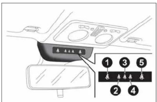
text_image
1 2 3 4 5fig. 92
A0J0308
NOTE On versions equipped with sports front seats, the passenger side seat belt fastened indication (warning light 1 for RHD versions or warning light 5 for LHD versions) will never be displayed.
FRONTSEATS(warninglightno.1=driverandno.5=passenger)
Driver
If the driver is the only occupant and their seat belt is not fastened, when 20 km/h is exceeded or when travelling at a speed between 10 and 20 km/h for longer than 5 seconds, an acoustic signal cycle will be started for the front seats (continuous acoustic signal for 6 seconds followed by a 90 second beep). The warning light will flash.
The warning lights will stay on constantly at the end of the cycle until the engine is stopped. The acoustic signal will be interrupted immediately when the driver's seat belt is fastened and the warning light will turn green.
The reminder cycle (acoustic and visual) will be repeated as described above and the red warning light will flash if the seat belt is unfastened again while travelling.
Passenger
A similar situation applies to the front passenger, with the difference that the warning light turns green and the indication is also interrupted when the passenger leaves the car.
If both front seat belts are unfastened a few seconds apart while the car is travelling, the acoustic signal will refer to the most recent event and the two warning lights will proceed with the visual indication independently.
REARSEATS(warninglightno.2,no.3andno.4)
For the rear seats, the reminder cycle is only activated when any seat belt is unfastened (flashing red).
In this condition, the warning light for the seat belt which has been unfastened will flash (red) for approximately 30 seconds. An acoustic signal is also emitted.
The visual indication (flashing red) will start and stop independently for each warning light if several seat belts are unfastened. The warning light will become green when the relevant seat belt is fastened again.
The rear seat warning lights will switch off, regardless of the state of the belt (red or green) approximately 30 seconds after the last signal.
IMPORTANT
The warning lights are all off if all seat belts (front and rear) are already fastened when the ignition key is turned to MAR.
All warning lights switch on when at least one belt changes from fastened to unfastened or vice versa.
PRETENSIONERS
The car is equipped with front seat belt pretensioners, which draw back the seat belts by several centimetres in the event of a violent frontal impact. This guarantees the perfect adherence of the seat belts to the occupants' bodies before the restraining action begins.
It is evident that the pretensioners have been activated when the belt withdraws towards the reel.
The car is also equipped with a second pretensioner (in the kick plate area). Its activation is signalled by the shortening of the metal cable.
A slight discharge of smoke may be produced during the activation of the pretensioner. This is not harmful and does not indicate the start of a fire.
IMPORTANT To obtain the highest degree of protection from the action of the pretensioner, wear the seat belt tight to the chest and pelvis.
The pretensioner does not require any maintenance or lubrication: any changes to its original conditions will invalidate its efficiency. If, due to exceptional natural events (floods, sea storms, etc.), the device has been affected by water and mud, it must be replaced.
Thepretensionermaybeusedonlyonce.Onceithas beenactivated,contactAlfaRomeoAuthorised Workshopstohaveitreplaced.Consulttheplateinthe glovecompartmenttocheckthestatusofthedevice.ContactAlfa RomeoAuthorisedWorkshopstohavethedevicereplacedas thisdateapproaches.

Operationswhichleadtoknocks,vibrationsorlocalised heating(over 100°Cforamaximumof6hours)inthearea aroundthepretensionersmaycausedamageortrigger
them.Thesedevicesarenotaffectedbyvibrationscausedby irregularitiesoftheroadsurfaceorlowobstaclessuchaskerbs,etc. ContactAlfaRomeoAuthorizedServicesforanyassistancenecessary.
LOADLIMITERS
To increase protection, the front seat belt reels contain a load limiter which controls the force acting on the chest and shoulders during the belt restraining action in the event of a head-on collision.
GENERALINSTRUCTIONSFORUSING THESEATBELTS
Comply with (and ensure that all the other occupants of the car comply with) the local laws in force regarding the use of seat belts. Always fasten the seat belts before starting off.
Seat belts must also be worn by pregnant women: the risk of injury in the event of an accident is reduced for them and the unborn child if they are wearing a seat belt.
Pregnant women must position the lower part of the belt very low down so that it passes over the pelvis and under the abdomen fig. 93. The belt must not be twisted. The upper part must pass over the shoulder and cross the chest diagonally. The lower part must adhere to the pelvis fig. 94, not to the abdomen of the occupant. Never use devices (clips, clamps, etc.) to hold the seat belt away from your body.
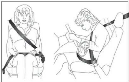
natural_image
Illustration of a person seated in a car seat using a seatbelt, with no text or symbols present.fig. 93
A0J0401
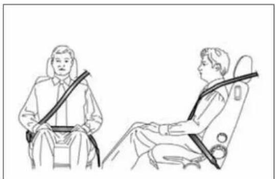
natural_image
Line drawing of two people seated in car seatbelt seats, no text or symbols presentfig. 94
A0J0095
Formaximumprotection, keepthebackrestupright, leanback into it and makes sure these seat belt fits closely across your chest and pelvis. Always fasten the seat belt on both the front and there are seats! Travelling without wearing seat belt will increase the risk of serious injury and even death in the event of an accident.
Each seat belt must be used by only one person. Never travel with a child sitting on a passenger's lap and a single belt to protect them both fig. 95. In general, do not place any objects between the person and belt.
Removingorotherwisetamperingwithsafetybeltand pretensionercomponentsisstrictlyprohibited.Any operationsonthesecomponentsmustbeperformedby qualifiedandauthorisedtechnicians.AlwayscontactAlfaRomeo AuthorizedServices.
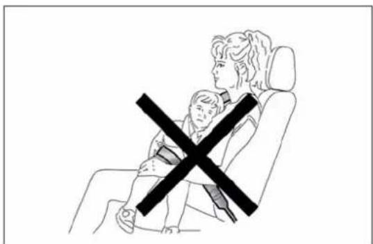
natural_image
Line drawing of a person sitting in a chair with a child crossed out, no text or symbols presentfig. 95
A0J0096
If the belthas beens subjected to high level of stress, example after an accident, it should be changed completely together with the attachments, attachment fixings crews and the pretensioner. Infact, even if the belthas no visible defects, it may havelost its resilience.
SEATBELTMAINTENANCE
□ Always use the belt with the strap well stretched and never twisted; make sure that it is free to run without obstructions;
☐ replace the belt after an accident of a certain severity even if it does not appear to be damaged. Always replace the belt if the pretensioners were deployed;
☐ hand wash the seat belts with water and neutral soap, rinse and leave to dry in the shade. Do not use strong detergents, bleach, colourants or any other substance which could damage the belt fibres;
☐ prevent the reels from getting wet: their correct operation is only guaranteed if water does not get inside;
□ replace the seat belt when there is wear or cuts.
CARRYINGCHILDRENSAFELY
For optimal protection in the event of an impact, all occupants must be seated and wearing adequate restraint systems, including newborn and other children!
This prescription is compulsory in all EC countries according to EC Directive 2003/20/EC.
Compared with an adult, a child's head is larger and heavier in proportion to his/her body and the child's muscular and bone structures are not fully developed. Therefore, correct restraint systems other than adult seat belts are necessary to reduce as much as possible the risk of injuries in case of accident, braking or sudden manoeuvre.
Children must be seated safely and comfortably. As far as the characteristics of the child restraint systems used allow, you are advised to keep children in rear facing restraint systems for as long as possible (at least until 2 years old), since this is the most protected position in the event of an impact.
The choice of the most suitable child restraint device depends on the weight of the child; there are various types of child restraint systems and you are advised always to choose the one that is most suitable for the child.
When over 1.50 m in height, from the point of view of restraint systems, children are considered as adults and wear seat belts normally.
In Europe the characteristics of children restraint systems are ruled by the regulation ECE-R44, dividing them into five weight groups:
Group Weight groups
| Group 0 upto 10 kg | |
| Group 0+ up to 13 kg | |
| Group 1 9-18 kg | |
| Group 2 15-25 kg | |
| Group 3 22-36 kg |
All restraint devices must bear the type-approval data along with the control mark on a label firmly secured to the child seat which must never be removed.
Lineaccessori Alfa Romeo includes child seats for each weight group. These devices are recommended having been specifically tested for Alfa Romeo cars.
Whenanactivepassengerairbagisfitted,DONOT installchildseatstobefittedfacingbackwardsonthe frontseat.Deploymentoftheairbaginanaccident couldcausefatalinjuriestothebabyregardlessoftheseverityof thecollision.Itisadvisabletoalwaysscarrychildreninachild seatontherearseat,whichisthemostprotectedpositioninthe eventofacollision.
Shoulditbeabsolutelynecessarytocarryachildonthe passengersidefrontseatinachildseattfacingbackwards, thepassengerfrontandsideairbags(pelvis/chest protectionfrontandsidebags)mustbedeactivated throughtheSetupmenu.Deactivationshouldbeverifiedby checkingthatthe warninglightison,inthetrimabovetheinternal rearviewmirror.Slidethepassengerseatbackasfaraspossibleto avoidcontactbetweenthechildseatandthedashboard.
FITTING"UNIVERSAL"CHILD SEAT(withseatbelts)
GROUPOandO+
Thediagramisindicativeandforassemblypurposes only.Fithechildseataccordingtotheinstructions, whichmustbeincluded.
Infants up to 13 kg must be carried with a child seat facing backwards of a type as shown in fig. 96 which, supporting the head, does not induce stress on the neck in the event of sudden decelerations.
The child seat is secured by the car seat belts, as shown in fig. 96 and it must restrain the child in turn with its own belts.
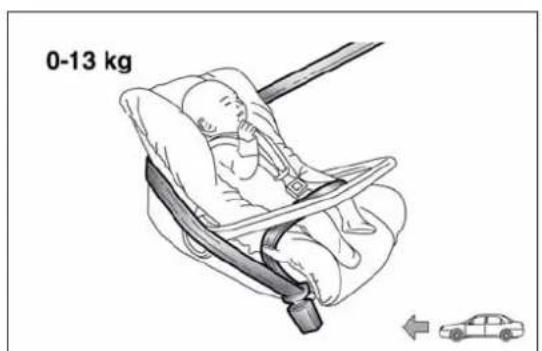
text_image
0-13 kgfig. 96
A0J0097
GROUP1
Thediagramisindicativeandforassemblypurposes only.Filthechildseataccordingtotheinstructions, whichmustbeincluded.
Children of weight from 9 to 18 kg may be carried in child seats facing forwards fig. 97.
ChildseatswithIsofixattachmentsareavailable, whichallowthemtobesecuredtotheseatsafely withoutusingthecarseatbelts.
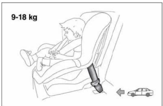
text_image
9-18 kgfig. 97
A0J0371
GROUP2

Thediagramisindicativeandforassemblypurposes only.Filthechildseataccordingtotheinstructions, whichmustbeincluded.
Children from 15 to 25 kg may use the car seat belts directly fig. 98. In this case, the child restraint system is used to position the child correctly with respect to the seat belts so that the diagonal belt section crosses the child's chest and not the neck, and the lower part is snug on the pelvis not the abdomen.

text_image
15-25 kgfig. 98
A0J0099
GROUP3

Thediagramisindicativeandforassemblypurposes only.Fithechildseataccordingtotheinstructions, whichmustbeincluded.
For children between 22 kg and 36 kg, there are dedicated restraint systems that allow the seat belt to be worn correctly.
fig. 99 shows an example of correct child seat positioning on the rear seat.
Children over 1.50 m in height can wear seat belts like adults.
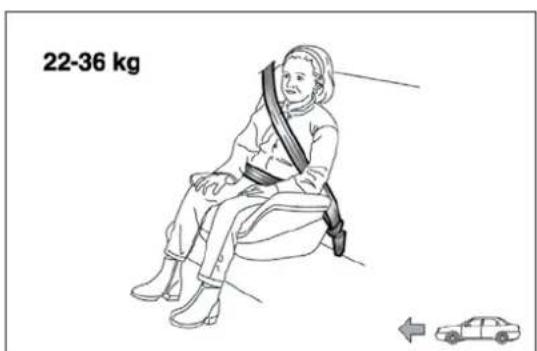
text_image
22-36 kgfig. 99
A0J0100
SUITABILITY OF PASSENGER SEATS FOR UNIVERSAL CHILDSE AT USE
According to the European Directive 2000/3/EC the suitability of each passenger seat position for the fixing of universal child seats is shown in the following table:
| Group Weight groups Front passenger | Rear side and central passenger | ||
| Group 0, 0+ | up to 13 kg | U | U |
| Group 1 9-18 kg | U | U | |
| Group 2 15-25 kg | U | U | |
| Group 3 22-36 kg | U | U | |
U= Suitable for child restraint systems in the "Universal" category, according to European Standard EEC-R44 for the specified "Groups".
PREPARATIONFOR"ISOFIX" CHILDSEAT
The car is equipped with ISOFIX anchorages, a new standard which makes fitting a child seat quick, simple and safe.
Isofix systems can be fitted alongside conventional child seats on different seats in the same car.
An example of a Universal Isofix child seat for weight group 1 is shown in fig. 100.

Thediagramisindicativeandforassemblypurposes only.Fithechildseataccordingtotheinstructions, whichmustbeincluded.
The other weight groups are covered by specific Isofix child seats, which can be used only if specifically tested for this car (see list of cars provided with the child seat).
IMPORTANT The central rear seat is not approved for any type of Isofix child seat.
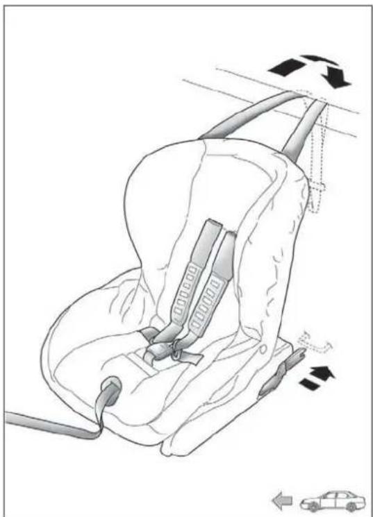
natural_image
Line drawing of a car seatbelt with directional arrows indicating movement (no text or symbols)fig. 100
A0J0093
INSTALLINGAUNIVERSALISOFIX CHILDSEAT
Proceed as follows:
☐ secure the child seat to the dedicated lower metal rings A fig. 101, positioned between the backrest and the cushion of the rear seat;
☐ fix the upper belt (available together with the seat) to the special attachments B fig. 102 located in the rear part of the backrest.
It is possible to have a mixed assembly of traditional seat and Universal Isofix ones. Remember that when using a Universal Isofix child seat, you can only use type-approved child seats with the marking ECE R44 (R44/03 or superior) "Universal Isofix".
The universal Isofix "Duo Plus" child seat is available from Lineaccessori Alfa Romeo.
For further details on child seat installation and/or use, refer to the instruction manual provided with the child seat.
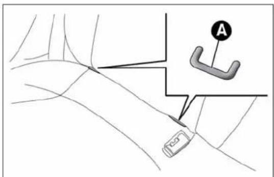
text_image
Diagram showing a car's steering wheel and steering wheel with labeled component Afig. 101
A0J0092

IfaUniversallsofixchildseatisnotfixedtoallthree anchorages,thechildseatwillnotbeabletoprotect thechildcorrectly.Inacrash,thechildcouldbe
seriouslyorfatallyinjured.

Fitthechildseatonlywhenthecarisstationary.The childseatiscorrectlysecuredtothebracketswhenyou heartheclick.Followtheinstructionsforfitting,
removing and positioning that the manufacturer must supply with the child seat.
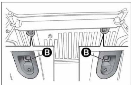
text_image
B Bfig. 102
A0J0335
SUITABILITY OF PASSENGER SEATS FOR ISOFIX CHILDSE AT USE
The table below shows the various installation possibilities for Isofix child seats on seats fitted with Isofix attachments in accordance with European standard ECE 16.
| Weight group | Child seat position | Isofix size class | Rear passenger | |
| left side right side | ||||
| Group 0 up to 10 kg | Facing backwards | E | X | X |
| Group 0+ up to 13 kg | Facing backwards E | X | X | |
| Facing backwards D | X | X | ||
| Facing backwards C | X | X | ||
| Group 1 from 9 up to 18 kg | Facing backwards D | X | X | |
| Facing backwards C | X | X | ||
| Facing forwards B | IUF IUF | |||
| Facing forwards BI | IUF IUF | |||
| Facing forwards A | X | X | ||
X: Isofix position not suitable for child seats in this weight group and/or size class.
IUF: Suitable for Isofix restraint systems to be positioned facing forwards, universal class (fitted with third upper mounting), type-approved for the relevant weight group.

Fitthechildseataccordingtotheinstructions, which mustbeincluded.
Main recommendations to carry children safely
☐ Install the child seats on the rear seat, which is the most protected position in the event of an accident.
□ Keep children in rear facing seats for as long as possible, until 2 years old.
☐ Should a rear facing child seat be installed on the rear seats, it is advisable to position it as far forward as the position of the front seat allows.
☐ If the passenger's front airbag is deactivated always check the permanent switching on of the dedicated warning light on the instrument panel to make sure that it has actually been deactivated.
□ Carefully follow the instructions supplied with the child seat itself. Keep the instructions in the car along with the other documents and this handbook. Do not use second-hand child seats without instructions.
☐ Only one child is to be strapped into each restraint system; never carry two children simultaneously.
□ Always check that the seat belts do not interfere with the child's throat.
□ Always check that the seat belt is well fastened by pulling on it.
□ While travelling, do not let the child sit incorrectly or unfasten the belts.
□ Never allow a child to put the belt's diagonal section under an arm or behind their back.
☐ Never carry children on your lap, even newborns. No-one can restrain a child in the event of an accident.
☐ In the event of an accident, replace the child seat with a new one.
FRONTAIRBAGS
The car is equipped with multi-stage front airbags ("Smart bags") for the driver and passenger and knee bags for the driver.
"SMARTBAG" SYSTEM (MULTISTAGE FRONTAIRBAGS)
The front airbags (driver's and passenger's) and the driver's knee bag have been designed to protect the occupants in the event of head-on crashes of medium-high severity, by placing cushions between the occupant and the steering wheel or dashboard.
Therefore non-deployment in other types of impacts (side impacts, rear shunts, roll-overs, etc.) does not indicate a system malfunction.
The airbags do not replace, but rather complement, the use of seat belts, which should always be worn. In the event of an impact, someone not wearing a seat belt could move forward and come into contact with a bag which is still in the opening phase. The protection offered by the bag is compromised in these circumstances.
Front airbags may not activate in the following situations:
☐ frontal impacts against highly deformable objects not involving the front surface of the car (e.g. wing collision against guard rail);
☐ car wedging under other vehicles or protective barriers (e.g. trucks or guard rails).
Failure to activate in the conditions described above is due to the fact that they may not provide any additional protection compared with seat belts, so their activation would be inappropriate.
In these cases, non-deployment does not indicate a system malfunction.
Donatapplystickersorotherobjectsonthesteering wheel,onthedashboardinthepassengersideairbag area,onsideupholsteryontherooforontheseats. Neverputobjects(e.g.mobilephones)onthepassenger'sside dashboardsincetheycouldinterferewithcorrectinflationofthe airbagandalsocauseseriousinjurytothepassengers.
FRONTDRIVERSIDEAIRBAG
This consists of an instantly inflating bag contained in a special compartment in the centre of the steering wheel fig. 103.
Alwaysdrivewithyourhandsonthesteeringwheel rimsothattheairbagcaninflatefreelyifnecessary. Donotdrivewithyourbodybentforward.Keepthe backofyourseatuprightandleanbackintoit.
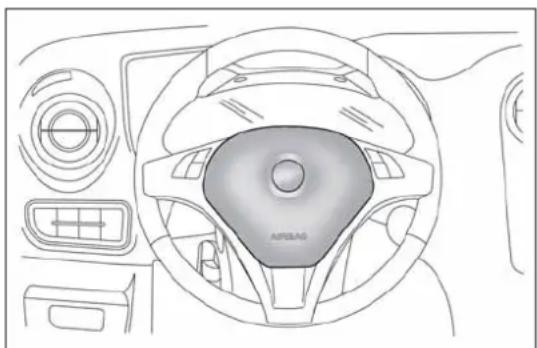
natural_image
Top-down technical line drawing of a car dashboard and steering wheel (no text or symbols)fig. 103
A0J0047
FRONTPASSENGERAIRBAG
This consists of an instantly inflating bag contained in a special recess in the dashboard fig. 104: this bag has a larger volume than that of the driver's.

text_image
AIR BAG AIRBAGfig. 104
A0J0050

When an active passenger air bag is fitted, DONOT install backwards-facing child seat on the front seat. Deployment of the air bag in an accident could cause fatal injuries to the baby regardless of these severity of the impact. Always deactivates the passengers side air bag when placing a child

seatonthefrontseat. The passenger seat must also be positioned back as far as possible in order to avoid the child seat from coming into contact with the dashboard. Though not required by law, we recommend that you are to activate this air bag as soon as the child no longer needs to be transported to ensure better protection for adults.
DRIVERSIDEKNEEBAG
This is located in a dedicated compartment under the steering wheel fig. 105. It provides additional protection in the event of a frontal impact.
Deactivatingpassengersideairbags: frontairbagandseat-mountedside bagforpelvis,chestandshoulders protection(Sidebag)
If a child must be carried on the front seat in a rear facing child seat, deactivate the passenger side front airbag and seat-mounted side bag for pelvis, chest and shoulder protection (side bag).
With airbags deactivated, warning light lights up in the trim located above the internal rearview mirror fig. 106.

Todeactivatetheairbags,seethe"Knowingyourcar" section,"Menuitems"paragraph.
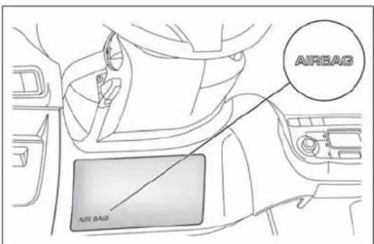
text_image
AIRBAG AIR BAGfig. 105
A0J0056
To increase protection of occupants in case of side collision, the car is equipped with front side bags for pelvis, chest and shoulder protection (side bags) for the driver and the passenger and airbags protecting the head of front and rear occupants (window bags).
Non-activation of side bags in other types of collisions (head-on collisions, rear shunts, roll-overs, etc...) is not an indication of system malfunction.
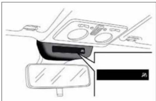
natural_image
Interior view of a car dashboard and steering wheel (no text or symbols visible)fig. 106
A0J0402
These comprise two types of bags located in the front seat backrests fig. 107 which protect the pelvic, chest and shoulder area of the occupants in the event of a side impact of medium-high severity.
SIDEAIRBAGSFORHEADPROTECTION (WINDOWBAGS)
This comprises two "curtain" bags housed behind the roof side linings and covered by special trims fig. 108.
It is designed to protect the head of front and rear occupants in the event of a side collision, thanks to the wide cushion inflation surface. The deployment of side bags in the event of side impacts of low severity is not required.
The airbags are not deployed in the event of low-severity impacts (for which the retaining action of the seat belts is sufficient). It is therefore always necessary to wear seat belts.
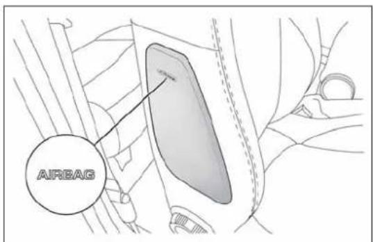
text_image
AIRBAGfig. 107
A0J0103
In the event of a side impact, the system provides optimum protection if the passenger assumes the correct position on the seat, thus allowing correct window bag deployment.

Donothookrigidobjectstothecoathooksortothe supporthandles.

Donotrestyourhead,armsorelbowsonthedoor, windowsortheareainwhichthewindowbagis locatedtoavoidpossibleinjuryduringinflation.

Neverleanyourhead, armsorelbowsoutofthe window.
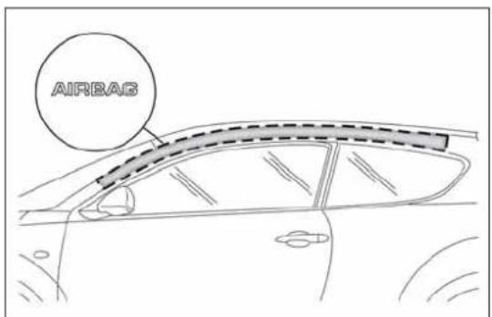
text_image
AIRBASfig. 108
A0J0051
IMPORTANT
Do not wash the seats with water or pressurised steam (by hand or at automatic seat washing stations).
The front airbags and/or side bags may be deployed if the car is subject to violent impacts involving the underbody area (e.g. violent impacts against steps or kerbs, big holes or dips in the road etc.).
When the airbag deploys it emits a small amount of dust: the dust is harmless and does not indicate the beginning of a fire. The dust may irritate the skin and eyes however: in this case, wash with neutral soap and water.
All operations on airbags (inspection, repair and replacement) must be carried out by Alfa Romeo Authorized Services.
If the car is to be scrapped, contact Alfa Romeo Authorized Services to have the airbag system deactivated.
Pretensioners and airbags are deployed in different ways, according to the type of impact. Failure to deploy of one of the devices does not necessarily indicate a system malfunction.

If the warning light does not switch on when the key is turned to MAR-ON, or stay on while driving on some versions together with a message on the
display)theremaybeafaultintherestraintsystems.Inthis case,airbagsorpretensionersmaynotbeactivatedinthecase ofanaccidentor(inalessernumberofcases)theymaybe activatedincorrectly.Beforeproceeding,contactAlfaRomeo AuthorisedServicestohavethesystemcheckedimmediately.

Theexpirydatesoftheexplosivechargeandtheclock springareshownonaspecificlabelcontainedinthe glovecompartment.Asthesdatesapproach,contact AuthorisedWorkshops.

Donotravelcarryingobjectsinyourlap,infrontof yourchestorbetweenyourlips(pipe,pencils,etc.): theycouldcauseseverinjuryiftheairbagis

Ifthecarhasbeensubjecttotheft, attemptedtheft, vandalism,orflooding,havetheairbagsystem inspectedatAlfaRomeoAuthorisedServices.
Theairbagsmayalsobedeployedwhenthecarisnot moving,ifthekeyisintheignitionandturnedto MAR-ON orwhentheengineisoff,ifthecar ishitbyanothermovingvehicle.Forthisreason, childrenmustneveroccupythefrontseatina rearwardfacingseatevenifthecarisnotmoving. Deploymentoftheairbagfollowinganimpactcould causefatalinjuriestothechild.Alwaysdeactivate thepassengerairbagifitisneededtoplaceachild seatonthefrontseat.Thepassengerseatmust alsobepositionedbackasfaraspossibleinorder toavoidthecildseatfromcomingintocontactwith thedashboard.Althoughthisisnotmandatoryby law,theairbagshouldbeimmediatelyreactivated whenchildrenarenolongertransportedtoensure betterprotectionforadults.Ontheotherhand,ifthe keyisturnedtoSTOP,noneofthesafetydevices (airbagsorpretensioners)willbedeployedinthe eventofcollision.Non-deploymentofthesedevices doesnotindicateasystemmalfunction.
When the ignition key is turned to MAR, the warning light (with passengersidefrontairbag activated) switches on and flashes for a few seconds to remind you that the passenger air bag will be deployed in crash, after which it should switch off.
Thefrontairbagisdesignedtobedeployedfor impactsofagreaterintensitythanforthe pretensioners.Forimpactswhoseintensityfalls betweenthetwolevels,itisnormalforonlythepretensionersto beactivated.
The airbag does not replace seat belts but increases the effectiveness. Because front air bags are not deployed for low-speed crashes, side collisions, rear-end shunts or rollovers, occupants are protected, in addition to any side bags, only by their seat belts, which must therefore always be fastened.
STARTINGANDDRIVING
STARTINGTHEENGINE
PROCEDUREFORPETROLVERSIONS (excluding Turbo TwinAir versions)
Proceed as follows:
☐ engage the handbrake and place the gearbox lever in neutral;
□ fully depress the clutch pedal, without touching the accelerator;
☐ turn the ignition key to AVV and release it as soon as the engine starts.
IMPORTANT
☐ If the engine does not start at the first attempt, return the ignition key to STOP before repeating the starting procedure.
☐ If, when the ignition key is at MAR, the instrument panel warning light (or the symbol on the display) remains on together with warning light, turn the key to STOP and then back to MAR. If the warning light remains on, try the other keys provided. If you are still unable to start the engine contact an Alfa Romeo Authorised Service Provider.
☐ Never leave the ignition key at MAR when the engine is stopped.
Engine starting for Turbo TwinAir versions
Proceed as follows:
☐ Engage the handbrake and place the gear lever in neutral or fully press the clutch pedal if a gear other than neutral is engaged;
☐ turn the ignition key to AVV and release it as soon as the engine starts.
Note If the vehicle does not start at the first attempt, return the ignition key to STOP and repeat the starting procedure placing the gear lever in neutral and fully pressing the clutch pedal.
IMPORTANT
☐ If, when the ignition key is at MAR, the instrument panel warning light 📄 (or the symbol on the display) remains on together with warning light 📄, turn the key to STOP and then back to MAR. If the warning light remains on, try the other keys provided. If you are still unable to start the engine contact an Alfa Romeo Authorised Service Provider.
☐ Never leave the ignition key at MAR when the engine is stopped.
PROCEDUREFORDIESELVERSIONS
Proceed as follows:
☐ engage the handbrake and place the gearbox lever in neutral;
□ turn the ignition key to MAR-ON: the warning lights 📄 and 📋 (or the symbol on the display) on the instrument panel will switch on;
☐ wait for the warning lights (or the symbol on the display) to switch off;
□ fully depress the clutch pedal, without touching the accelerator;
□ turn the ignition key to AVV; 00 warning light switches off. Waiting too long will waste the heating work carried out by the glow plugs. Release the key as soon as the engine starts.

Ifthewwrnglightflashesforabout 1 minuteafter startingorduringprolongedcranking,thisindicatesafault intheglowplugpreheatingsystem.Usethecarnormally startsandgotoAlfaRomeoAuthorizedServicesassoon

Itisdangeroustoruntheengineinenclosedareas. The enginetakesinoxygenandreleasescarbondioxide, carbonmonoxideandothertoxicgases.

Itisadvisablenottodemandmaximumperformancefrom yourcar(e.g.excessiveacceleration,longdistancesat maximumrpm,excessivelyintensebraking,etc.)whenitis
firstused.

Whentheengineisoff, donotleavetheignitionkeyturned toMARtopreventunnecessaryelectricalconsumptionfrom drainingthebattery.

Remember that the brakes servo and electromechanical power steering are not operational until the engine has been started, therefore much more effort than required on the brake pedaland steering wheel.

Neverstarttheenginebypushing,towingordriving downhill.Thesemanoeuvresmaydamagethecatalytic converter.
WARMINGUPTHEENGINEJUST AFTERITHASSTARTED
Proceed as follows:
□ drive off slowly, letting the engine turn at medium revs and without accelerating abruptly;
☐ do not demand maximum performance for the first few kilometres. It is advisable to wait until the engine coolant temperature indicator starts moving.
STOPPINGTHEENGINE
Turn the ignition key to STOP while the engine is idling.
IMPORTANT After a demanding drive, before turning the engine off you should allow it to idle to allow the temperature in the engine compartment to decrease.

Aquickburstontheacceleratorbeforestoppingtheengine servesabsolutelynopracticalpurpose.Itwastesfueland isespeciallydamagingtoturbochargedengines.
PARKING
Switch off the engine and pull up the handbrake. Engage a gear (1 ^st if the car is facing uphill or reverse if it is facing downhill) and leave the wheels steered to one side.
If the car is parked on a steep slope block the wheels with a wedge or stone. Always remove the ignition key when leaving the car.

Neverleavechildrenunattendedinthecar. Always removethekeyfromtheignitionwhenleavingthecar andtakeitwithyou.
HANDBRAKE
To engage the handbrake pull lever A fig. 109 upwards until the car is secured. To release the handbrake, raise lever A slightly, hold down button B and lower the lever.

text_image
A Bfig. 109
A0J0110
IMPORTANT Carry out these manoeuvres with the brake pedal pressed.
IMPORTANT For cars equipped with a front armrest, lift this up to ensure that it does not interfere with the action of the handbrake.

The car should be locked after a few notches: if this is not the case, contact Alfa Romeo Authorized Services to have the hand brake adjusted.
USINGTHEGEARBOX
To engage the gears, fully depress the clutch pedal and put the gear lever into the desired position (the diagram for gear engagement is shown on the knob of the lever fig. Y10, fig. Y11, fig. Y12).

text_image
A 1 3 5 2 4 6 Rfig. 110
A0J0265
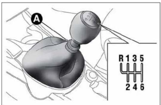
text_image
A R 1 3 5 2 4 6fig. 111
A0J0266
On models with 6 gears, to engage 6^th gear, press the lever slightly to the right to avoid changing into 4^th by mistake. The same applies to the shift from 6^th to 5^th gear.
To engage reverse (R) from neutral position, raise ring A underneath the knob and, at the same time:
☐ on 1.4 Turbo MultiAir 170 HP Quadrifoglio Verde and 1.6 JTD M versions, move the lever to the left and then forwards fig. 111;
☐ on Turbo TwinAir, 1.4 Petrol, 1.4 Turbo MultiAir and 1.3 JTD M-2 versions, move the lever to the right and then backwards fig. 110 and fig. 112.
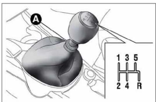
text_image
A 1 3 5 2 4 Rfig. 112
A0J0267
IMPORTANT Reverse can only be engaged when the car is completely stationary.

Presstheclutchpedalfullytochangegearscorrectly.It isthereforeessentialthatthereisnothingunderthe pedals:makesurethematsarelyingflatanddonot ayofthepedals.
getinthewayofthepedals.

Donotdrivewithyourhandrestingonthegearleveras theforceexerted,evenifslight,couldleadovertimeto prematurewearofthegearboxinternalcomponents.
SAVINGFUEL
Here are some suggestions which can help you to save fuel and lower harmful emissions.
GENERALCONSIDERATIONS
Car maintenance
Have checks and adjustments carried out in accordance with the "Scheduled Servicing Plan" (see chapter "Maintenance and care").
Tyres
Check the tyre pressure at least once every 4 weeks: if the pressure is too low, consumption levels increase as resistance to rolling is higher.
Unnecessary loads
Do not travel with an overloaded boot. The weight of the car and its arrangement greatly affect fuel consumption and stability.
Roof rack/ski rack
Remove the roof rack or the ski rack from the roof after use. These accessories lower aerodynamic penetration and adversely affect consumption levels. It is better to use a trailer to transport particularly bulky objects.
Electrical devices
Only use electrical devices for the time needed. The heated rear window, additional headlights, windscreen wipers and heater fan require a considerable amount of energy; increasing the current uptake increases fuel consumption (by up to +25% in an urban cycle).
Climate control system
Using the climate control system will increase consumption: use the air vents when the external temperature allows it.
Devices for aerodynamic control
The use of non-certified devices for aerodynamic control may adversely affect air drag and fuel consumption.
DRIVINGSTYLE
Starting
Do not warm up the engine at low or high revs when the vehicle is stationary; this causes the engine to warm up more slowly, thereby increasing fuel consumption and emissions. It is therefore advisable to move off immediately, slowly, avoiding high speeds: in this way the engine will warm up more quickly.
Unnecessary actions
Avoid revving up when at traffic lights or before switching off the engine. The latter action, like double-declutching, is unnecessary and causes increased fuel consumption and pollution.
Gear selection
Use a higher gear when traffic and road conditions allow it. Using a low gear for faster acceleration will increase consumption. In the same way improper use of a high gear increases consumption, emissions and engine wear.
Maximum speed
Fuel consumption considerably increases as speed increases. Keep your speed as even as possible, avoiding unnecessary braking and acceleration which cause excessive fuel consumption and increased emissions.
Acceleration
Accelerating violently severely affects consumption and emissions: acceleration should be gradual and should not exceed the maximum torque.
CONDITIONSOFUSE
Cold starting
Short distances and frequent cold start-ups will prevent the engine from reaching optimal running temperature. This results in a significant increase in consumption levels (from +15 to +30% on the urban cycle) and emissions.
Traffic and road conditions
High fuel consumption is caused by heavy traffic, for instance when travelling in a queue with frequent use of low gears or in large towns with many traffic lights. Winding mountain roads and rough road surfaces also adversely affect consumption.
Stops in traffic
During prolonged stops (e.g. level crossings) switch the engine off.
TOWINGTRAILERS
IMPORTANT
The vehicle must be provided with a type-approved tow hook and adequate electrical system to tow caravans or trailers. Installation must be carried out by a specialist.
Fit any specific and/or additional rear view mirrors as specified by the Highway Code.
Remember that, when towing a trailer, steep hills are harder to climb, braking distances increase and overtaking takes longer relative to the overall weight of the trailer.
Engage a low gear when driving downhill, rather than constantly using the brake.
The weight of the trailer reduces the load capacity of the car by the same amount. Consider the weight at full load, including accessories and luggage, to make sure you do not exceed the maximum towable weight (shown in the registration document).
Respect the speed limits specific to each country for vehicles towing trailers. In any case do not exceed 100 km/h.
INSTALLINGATOWHOOK
Contact Alfa Romeo Authorised Services to install a tow hook.

TheABSwithwhichthecarisequippedwillnotcontrol thebrakingsystemofthetrailer.Particularcautionis thereforerequiredonslipperyroads.

Donot, underanycircumstances, modifythevehicle's brakingsystem to control the trailer breakingsystem. The towingbreakingsystem must be completely entofthevehicle's hydraulic system.
SNOWTYRES
Use snow tyres of the same size as the normal tyres provided with the car: Alfa Romeo Authorized Services will be able to advise you on the most appropriate tyre to use.
Only use these tyres in the event of ice or snow on the roads.
For the type of snow tyre to be used, inflation pressures and the specifications, strictly follow the instructions given in the "Wheels" paragraph in the "Technical specifications" section.
The winter performance of these tyres is considerably reduced when the tread thickness is less than 4 mm. Replace them in this case.
Due to their specific features, the performance of snow tyres is much lower than that of normal types in normal conditions or long motorway stretches. Their usage should therefore be restricted in accordance with their type approval.
All four tyres should be the same (brand and track) to ensure greater safety when driving and braking and good driveability. Remember that it is inadvisable to change the rotation direction of tyres.

Themaximumspeedforsnowtyresmarked"Q"is 160km/h,whileitis 190km/hfor"T"tyresand210 km/hfor"H"tyres.Thehighwaycodespeedlimits
musthoweveralwaysbecompliedwith.
SNOWCHAINS
The use of snow chains should be in compliance with local regulations. The snow chains may be applied only onto the front wheel tyres (drive wheels).
Check the tension of the snow chains after the first few metres have been driven.
Use reduced size snow chains: on all versions, for 195/55 R16" and 205/55 R16" size tyres use low-clearance snow chains with a maximum projection beyond the tyre profile of 9 mm.
IMPORTANT The space-saver wheel cannot be fitted with snow chains. If a front (drive) wheel is punctured and snow chains must be used, you must remove a normal wheel from the rear and replace this one with the space-saver wheel. In this way, with two normal drive wheels, it is possible to use snow chains.

Keepyourspeeddownwhensnowchainsarefitted;donot exceed50km/h.Avoidpotholes,stepsandpavements andavoiddrivinglongdistancesonroadsnotcoveredwith biddamagingthecarandtheroadbed.
STORINGTHECAR
If the car is to be left inactive for longer than a month, the following precautions should be noted:
☐ park the vehicle in a dry, covered and, if possible, ventilated area; engage a gear and check that the handbrake is not engaged;
☐ disconnect the negative battery terminal and check the battery charge. Repeat this check once every three months during storage;
☐ if you have not disconnected the battery, check the battery charge every thirty days;
☐ clean and protect the painted parts using protective wax;
☐ clean and protect the shiny metal parts using special compounds available commercially;
□ sprinkle talcum powder on the windscreen and rear window wiper rubber blades and lift them off the glass;
□ slightly open the windows;
☐ cover the car with a cloth or perforated plastic sheet. Do not use compact plastic sheets which do not allow humidity to evaporate from the surface of the car.
☐ inflate tyres to +0.5 bar above the standard specified pressure and check it at intervals;
☐ do not drain the engine cooling system.
IMPORTANT After turning the ignition key to STOP, wait at least 1 minute before disconnecting the battery power supply.
INANEMERGENCY
In an emergency we recommend that you call the freephone number found in the Warranty Booklet. You can also consult www.alfaromeo.com to find your nearest Alfa Romeo Authorized Services.
STARTINGTHEENGINE
If the warning light on the instrument panel remains on constantly, contact Alfa Romeo Authorized Services immediately.
JUMPSTARTING
If the battery is flat, the engine may be started using an auxiliary battery with the same capacity or a little higher than the flat one.
Proceed as follows to start the vehicle:
□ connect the positive terminals (+ sign near the terminal) of the two batteries with a jump lead fig. 113;
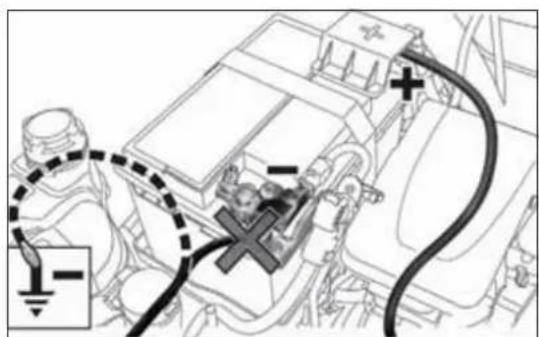
text_image
Diagram of an automotive electrical connector with labeled components and wiring connectionsfig. 113
A0J0392
☐ with a second cable, connect the negative terminal (−) of the auxiliary battery to an earthing point ↓ on the engine or the gearbox of the car to be started;
☐ start the engine; afterwards, follow the sequence above in reverse order to remove the cables.
For versions with Start&Stop system, to carry out the jump starting procedure, refer to the paragraph "Start&Stop system" in the "Getting to know your car" section.
Contact Alfa Romeo Authorized Services if you cannot start the engine after several attempts.
IMPORTANT Never connect the negative terminals of the two batteries directly! If the auxiliary battery is installed on another car, prevent accidental contact between metallic parts of the two cars.

Neveruseafastbattery-chargertostarttheengineasthis coulddamagetheelectronicsystemsofyourcar, particularlytheignitionandfuelsupplycontrolunits.

This starting procedure must be performed by expert personnel because incorrect actions could cause electrical discharge of considerable intensity.
Furthermore, batteryfluidispoisonousandcorrosive:avoid contactwithskinandeyes.Keepnakedflamesandlighted cigarettesawayfromthebatteryanddonotcausesparks.
BUMPSTARTING
Never start the engine by pushing, towing or coasting downhill.
REPLACINGAWHEEL
GENERALINSTRUCTIONS
The car is equipped with the "Fix&Go Automatic Kit": see the paragraph "Fix&Go Automatic Kit" for how to use this device. As an alternative to the "Fix&Go Automatic Kit" the car may be equipped with a space-saver wheel: see the instructions on the following pages for changing the tyre.

Thesparewheelisspecificforyourcar.Donotuseit oncarsofdifferentmodels.Donotusesparewheelsof differentmodelsonyourcar.Thespace-saverwheel mustonlybeusedincaseofemergency.Itmustonlybeusedfor thedistancenecessarytoreachaservicepointandthecarspeed mustnotexceed80km/h.Thespace-saverwheelhasanorange stickerthatsummarisesthemaincautionsforuseandlimitations. Neverremoveorcoverthelabel.Neverapplyanyhubcapto thespace-saversparewheel.

Alertotherdriversthatthecarisstationaryin compliancewithlocalregulations:hazardwarning lights, warningtriangle, etc. Anypassengersonboard shouldleavethecar,especiallyiftisheavilyladen.Passengers shouldstayawayfromon-comingtrafficwhilethewheelis beingchanged.Incaseofsteepslopesorroughslopes,place wedgesorothermaterialssuitabletostopthevehicleunderthe wheels.
The vehicle's driving characteristics will be modified with the space-saver wheel fitted. Avoid violent acceleration and braking, sharp steering and fast cornering. The total life of a space-saver wheel is approximately 3,000 km, after which it must be replaced by another wheel of the same type. Never attempt to fit a conventional tyreonarim designed for use as a space-saver wheel. Repair and refit the standard wheel as soon as possible. Twoormorespace-saver wheels should never be used together. Donot greasethethreads of bolts before refitting them: they might slip out.
Thejackprovidedisonlyintendedtobeusedfor replacingtyresonthevehiclewithwhichitissupplied, oronsame-modelvehicles.Neverusethejackfor otherpurposes,suchasliftingothercarmodels.Neveruseitfor repairoperationsunderthevehicle.Incorrectpositioningofthe jackmaycausethecartofall.Donotusethejackforloads higherthanthoseshownonthelabel.Neverinstallsnowchains onthesmallsparewheel;ifafronttyre(drivingwheel)is puncturedandyouneedtousesnowchains,useastandard wheelfromtherearaxleandinstallthesmallsparewheelonthe rearaxle.Inthisway,withtwonormalfrontdrivewheels,itis possibletousesnowchains.
Incorrectlyfittingthehubcapmaycauseittofalloff whenthevehicleisinmotion.Nevertamperwiththe inflatingvalve.Neverintroducetoolsofanykind betweenrimandtyre.Regularlychecktheinflationpressureof thetyresandspace-saverwheel(seechapter"Technical specifications").
JACK
Please note that:
□ the jack weight is 1.76 kg;
□ the jack requires no adjustment;
☐ the jack cannot be repaired and in the event of a fault it must be replaced by another original one;
☐ no tool other than its cranking device may be fitted on the jack.
To change a wheel proceed as follows:
□ stop the car in a position that is not dangerous for oncoming traffic where you can change the wheel safely. The ground must be flat and sufficiently compact;
□ switch off the engine, pull up the handbrake and engage 1 ^a gear or reverse; put on the high visibility jacket (required by law) before leaving the vehicle;
□ open the luggage compartment, pull tab A fig. 114 and lift up the mat;
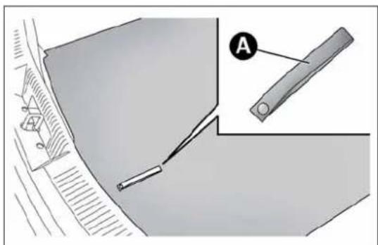
natural_image
Technical diagram showing a mechanical component with a labeled section A, no readable text or symbols present.fig. 114
A0J0104
□ unscrew locking device Afig. 115, take toolbox B and bring it next to the wheel to replace. Then take the space-saver wheel C;
☐ for versions with steel rims: insert the screwdriver in the opening A fig. 116 in order to trigger the hub cap retaining clip B;

text_image
A B Cfig. 115
A0J0105
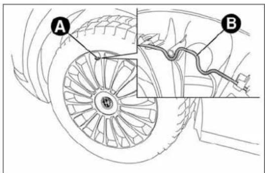
text_image
A Bfig. 116
A0J0236
☐ for versions with alloy rims: shake the car to facilitate detachment of the rim from the wheel hub. Some versions may be fitted with alloy wheels with a hub cap (fig. 117). To remove the hub cap, insert the screwdriver into housings A in order to access the fixing bolts. Replace the wheel as described previously;
☐ take wrench A fig. 118 and loosen the fixing bolts by about one turn;
☐ position the jack under the car, near the wheel to be changed. On versions where this is fitted, be careful not to damage the plastic aerodynamic guard;
☐ operate the device A fig. 119 so as to extend the jack, until the upper part B fig. 120 is inserted correctly inside the side member C;
☐ alert any bystander that the car is about to be raised; all persons should be kept away from the car and nobody must touch it until it has been lowered;
☐ fit handle D fig. 119 into the housing in device A, operate the jack and raise the car until the wheel is a few centimetres from the ground;

text_image
Technical diagram showing a car wheel with labeled component 'A' and directional arrows indicating motion or flow.fig. 117
A0J0238
☐ make sure the contact surfaces between space-saver wheel and hub are clean so that the fastening bolts will not come loose;
☐ fit the space-saver spare wheel by inserting the first bolt for two threads into the hole closest to the valve;
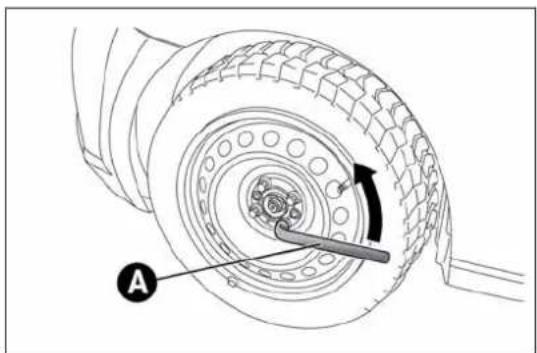
natural_image
Technical diagram of a tire assembly with labeled component A, showing tread pattern and mechanical assembly (no text or symbols beyond label)fig. 118
A0J0106
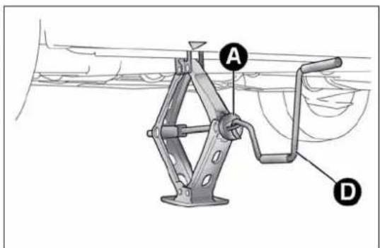
text_image
Technical diagram of a mechanical device with labeled parts A and D, showing structural components and assembly.fig. 119
A0J0062
☐ take the wrench A fig. 118 and fully tighten the fixing bolts;
☐ operate the jack handle D fig. 119 to lower the vehicle. Then extract the jack;
☐ use the wrench A fig. 118 provided to fully tighten the bolts in a criss-cross fashion as per the numerical sequence illustrated in fig. 121;
□ when replacing an alloy wheel it is advisable to place it upside down, with the aesthetic part facing upwards.

VisitAlfaRomeoAuthorizedServicesassoonaspossibleto checkthecorrecttighteningofthemainwheelbolts.
Restore the standard wheel as soon as possible, because, once placed in the associated compartment, the luggage compartment load platform is rendered uneven as the standard wheel is larger than the space-saver wheel.
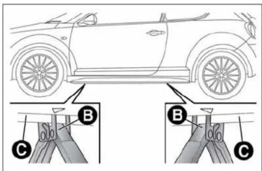
text_image
Diagram showing car front view with labeled parts A, B, and C, likely illustrating a parking or steering mechanism.fig. 120
A0J0061
REMOVINGTHESUBWOOFER (versionswithBoseHI-Flsystem)
(for versions/markets, where provided)
IMPORTANT The following procedure only applies to cars equipped with Bose HI-FI systems with subwoofer (for versions/markets, where provided).
Subwoofer and space-saver spare wheel
On these versions, the tools for replacing the wheel are located in a dedicated bag in the luggage compartment.
Proceed as follows to remove the Subwoofer:
☐ open the luggage compartment, pull tab A fig. 114 and lift up the mat;
□ unscrew locking device A fig. 122, raise the subwoofer and then remove connection cable B from the Velcro C;
□ rest the Subwoofer on one side in the luggage compartment, remove the container and take the space-saver wheel;
□ replace the wheel as described previously.
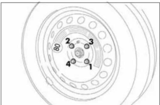
text_image
80 2 3 4 1fig. 121
A0J0271
At the end of the operation:
□ reposition the container (with the arrow pointing forwards) in its housing and place the subwoofer on top of it, taking care to arrange it according to the indications on the container (fig. 123) so that the word "BOSE" is read in the correct position;
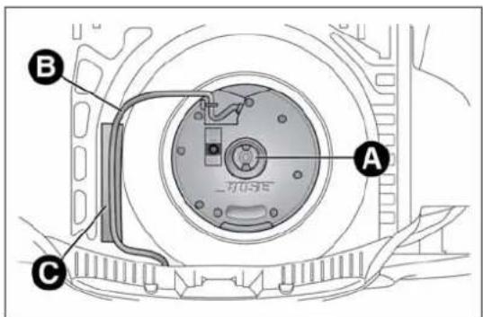
text_image
A B Cfig. 122
A0J0180
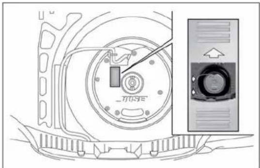
text_image
MUSEfig. 123
A0J0260
□ rest cable B fig. 122 on the Velcro C to avoid pinching it;
☐ screw in locking device A, and finally lower the luggage compartment mat.
Subwoofer and "Fix&Go Automatic Kit"
Locating the Automatic Fix&Go Kit:
□ open the luggage compartment, pull tab A fig. 114 and lift up the mat;
☐ take the "Fix&Go Automatic Kit" located on the left side of the luggage compartment (fig. 124);
☐ inflate the wheel (see paragraph entitled "Fix&Go Automatic Kit").
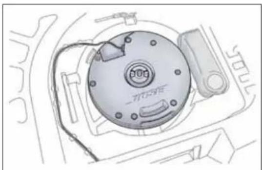
natural_image
Technical line drawing of a mechanical component with no visible text or symbolsfig. 124
A0J0239
REFITTINGTHEWHEEL
Following the procedure described previously, raise the car and remove the small spare wheel.
Proceed as follows:
☐ make sure the contact surfaces between standard wheel and hub are clean so that the fastening bolts will not come loose;
☐ for versions with steel rims: fix the hub cap on the rim, aligning the crescent hole with the bolt you have fitted, then insert the other 4 bolts;
□ tighten the retaining bolts using wrench A fig. 118;
☐ lower the car and remove the jack;
☐ use wrench A fig. 118 to fully tighten the bolts, following the sequence illustrated in
☐ for versions with alloy rims with hub cap: align the pin on the cap with the housing on the rim.
At the end of operation
□ stow the space-saver spare wheel in the compartment provided in the boot;
☐ insert the jack and the other tools in the container;
□ arrange the container and tools on the space-saver wheel;
□ correctly reposition the boot mat.
"Fix&GoAutomatic"kit
This is located in the luggage compartment.
The kit container also contains a screwdriver and the tow hook. The kit also contains:
☐ a bottle fig. 125 containing sealer and fitted with: filling tube B and adhesive label C with the wording "max. 80 km/h" to be placed in a clearly visible position (e.g. on the dashboard) after repairing the tyre;
☐ a compressor D complete with pressure gauge and connectors;
☐ an information leaflet fig. 126, providing instructions for using the kit correctly. This booklet should be given to the persons charged with handling the tyre treated with this kit;
□ a pair of gloves located in the side compartment of the compressor;
□ adapters for inflating different elements.
IMPORTANT The sealing liquid is suitable for use at temperatures in the range from -20^ to +50^ . The sealant has an expiry date.

text_image
Diagram of an air purifier with labeled parts A, B, C, and Dfig. 125
A0J0112
Givetheleaflettothetechnicianswhowillbehandling thetyrethatwastreatedusingthe"Fix&GoAutomatic" kit.
Intheeventofapuncturecausedbyforeignbodies, thekit maybeusedtorepairtyresshowingdamageonthetrack orshoulderuptomax4mmdiameter.
Holesanddamageonthetyresidewallscannotbe repaired.Donotusethetyreqquickrepairkitifthetyre isdamagedasresultofdrivingwithitdeflated.
Repairsarenotpossibleinthecaseofdamagetothe wheelrim(badgroovedistortioncausingairloss). Donotremoveforeignbodies(screwsornails)from thetyre.
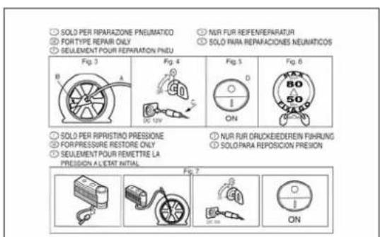
text_image
● SOLO PER REPARAZIONE PNEUMATICO ● FORTYPE REPAIR ONLY ● SELLEMENT POUR REPARATION PNDU ● NUR FUR REFEN/REPARATUR ● SOLO PARA REPARACIONES NEUNATICOS Fig. 3 Fig. 4 Fig. 5 Fig. 6 ● SOLO PER RIPRISTINO PRESSIONE ● FOR PRESSURE RESTORE ONLY ● SEULEMENT POUR REMETTRE LA PRECISION A L'ETAT INITIAL ● NUR FUR ORLICKEDEREN FIHRUNG ● SOLO PARA REPOSICION PREISON Fig. 7 ON ONfig. 126
A0J0113
GETTING TO KNOW YOUR CAR
SAFETY
STARTING AND DRIVING
IN AN EMERGENCY
SERVICING AND MAINTENANCE
TECHNICAL SPECIFICATIONS
INDEX
Neveroperatethecompressorforlongerthan20 consecutiveminutes.Riskofoverhealing.Thekitisnot suitablefordefinitiverepairs,sotherepairedtyres mayonlybeusedtemporarily.
Disposeofthebottleandthesealantliquidproperly.Have thesealingfluidandthecylinderdisposedofincompliance withnationalandlocalregulations.
Thebottlecontainsetyleneglycolandlatex:itmay causeanallergicreaction.Itisharmfulifswallowed.It isirritantfortheeyesincaseofcontact.Therecould beareactionintheeventofinhalationorcontact.Avoidcontact withtheeyes,skinandclothes.Intheeventofcontact,rinse immediatelywithplentyofwater.Ifingested,donotinduce vomiting.Rinseoutyourmouth,drinklargequantitiesofwater andseekimmediatemedicalattention.Keepoutofthereach ofchildren.Theproductmustnotbeusedbyasthmatics.Donot inhalethevapoursduringinsertionandsuction.Calladoctor immediatelyifallergicreactionsarenoted.Storethebottleinthe specificcompartment,awayfromsourcesofheat.Thesealant fluidhasanexpirydate.Replaceebottlecontainingout-of-datesealantfluid.
INFLATIONPROCEDURE
Weartheprotectiveglovesprovidedwiththekit.
Proceed as follows:
☐ engage the handbrake, unscrew the tyre valve cap, take out the flexible filler pipe A fig. 127 and tighten the ring nut B on the tyre valve;
☐ make sure that switch A fig. 128 for the compressor is in position 0 (off), start the engine, insert the plug A fig. 129 into the power socket on the central tunnel and switch on the compressor by bringing switch A fig. 128 to position I (on);
☐ inflate the tyre to the pressure indicated in the "Wheels" paragraph in the "Technical specifications" section. In order to obtain a more precise reading, check the pressure value on pressure gauge B fig. 128 with the compressor off;
☐ if after five minutes it is still impossible to reach at least 1.8 bar, disengage the compressor from the valve and power socket, then move the car forwards by approx. ten metres in order to distribute the sealing fluid inside the tyre evenly, then repeat the inflation operation;
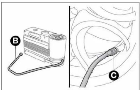
text_image
Diagram showing a device labeled B connected to a cable labeled C, with no visible text or symbols beyond labels.fig. 127
A0J0214
☐ if you still cannot obtain a pressure of at least 1.8 bar within 5 minutes from the compressor switching on, do not drive off and contact Alfa Romeo Authorized Services;
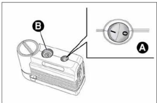
text_image
B Afig. 128
A0J0114

text_image
Afig. 129
□ after driving for about 10 minutes, stop and check the tyre pressure again; remember to put the handbrake on;
☐ if a pressure value of at least 1.8 bar is detected, restore the correct pressure (with the engine running and the handbrake engaged), resume driving and drive with great care to Alfa Romeo Authorized Services.

Applytheadhesivelabelwhereitcanbeeasilyseen bythedriverasareminderthatthetyrehasbeen treatedwiththequickrepairkit.Drivecarefully,
particularlyonbends.Donotexceed80km/h.Donotaccelerate orbrakesuddenly.

If the pressure has fallen below 1.8 bar, donot drive any further: the Fix & Go Automatic quickty rerepair kit cannot guarantee the correct hold because the treised. Contact Alfa Romeo Authorized Services.

Informthedealershipthatthetyrehasbeenpaired usingthequicktyrerepairkit.Givetheleaflettothe technicianswhowillbehandlingthetyrethatwas singthequickrepairkit.
CHECKINGANDRESTORINGTYRE PRESSURE
The compressor can also be used to check and, if necessary, adjust the tyre pressure.
Release quick connector A fig. 131 and connect it directly to the valve of the tyre to be inflated.
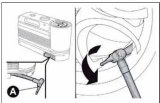
text_image
Diagram illustrating a mechanical device with labeled parts and directional arrows indicating motion or movement.fig. 130
A0J0225
REPLACINGTHEBOTTLE
Proceed as follows:
□ release connector A fig. 132 and disconnect tube B;
□ turn the bottle to be replaced anticlockwise and raise it;
☐ fit the new bottle and turn it clockwise;
☐ insert connector A and tube B in their housings.
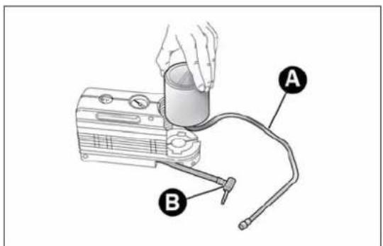
text_image
Diagram of a portable air purifier with labeled parts A and B, showing hand operating cylinder and plug connections.fig. 131
A0J0115
CHANGINGABULB
GENERALINSTRUCTIONS
☐ Before changing a bulb check the contacts for oxidation;
☐ blown bulbs must be replaced with others of the same type and power;
□ after replacing a headlight bulb, always check its alignment;
☐ when a light is not working, check that the corresponding fuse is intact before changing a bulb. For the location of fuses, refer to the paragraph "Replacing fuses" in this section.

Halogenbulbsmustbehandledholdingthemetalpart only.Touchingthetransparentpartofthebulbwithyour fingersmayreducetheintensityoftheemittedlightand
evenreducethelifespanofthebulb.Incaseofaccidentalcontact,wipe thebulbwithaclothmoistenedwithalcoholandletthebulbdry.

Modificationsorrepairstotheelectricsystemthatare notcarriedoutproperlyordonottakethesystem technicalspecificationsintoaccountcancause
malfunctionsleadingtotheriskoffire.

Halogenbulbscontainpressurisedgaswhichmay causesmallfragmentsofglasstobeprojected outwardsifthebulbisbroken.
IMPORTANT When the weather is cold or damp or after heavy rain or washing, the surface of headlights or rear lights, may steam up and/or form drops of condensation on the inside. This is a natural phenomenon due to the difference in temperature and humidity between the inside and the outside of the glass which does not indicate a fault and does not compromise the normal operation of lighting devices. The mist disappears quickly when the lights are turned on, starting from the centre of the diffuser, extending progressively towards the edges.
TYPESOFBULBS
The car has the following light bulbs:
Glass bulbs: (type A) they are press-fitted. Pull to extract.
Bayonet-type bulbs: (type B) to remove from its holder, press the bulb and turn it anti-clockwise, then extract it.
Tubular bulbs: (type C) release them from their contacts to remove.
Halogen bulbs: (type D) to remove the bulb, release the clip holding the bulb in place.
Halogen bulbs: (type E) to remove the bulb, release the clip holding the bulb in place.
A

B
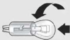
©

D
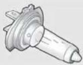
E
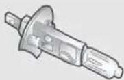
| Bulbs Type Power Re. Figure | |||
| Front side lights/Daytime running lights | W21/5W | 5/21W | A |
| Rear side lights LED -- | |||
| Dipped headlights H7 55W D | |||
| Main beam headlights H7 55W D | |||
| Front direction indicators | 24W module | 24W | B |
| Rear direction indicators | P21W | 21W | B |
| Side direction indicators | WY5W | 5W | A |
| Brake light | LED -- | ||
| 3rd brake light | LED -- | ||
| Number plate light | W5W | 5W | A |
| Fog lights | H1 55W | E | |
| Rear fog lights | P21W | 21W | B |
| Reversing lights | P21W | 21W | B |
| Front roof light | C10W | 10W | C |
| Luggage compartment roof light | W5W | 5W | A |
| Glove compartment light | C5W | 5W | C |
| Puddle light | W5W | 5W | A |
REPLACINGEXTERIORBULBS
FRONTLIGHTCLUSTERS
These contain the bulbs for the side lights/daytime running lights (DRL), dipped beams, main beams and direction indicators. The bulbs are arranged as follows fig. 132:
A Side lights/daytime running lights and main beam headlights
B Dipped headlights
c Direction indicators
SIDELIGHTS/DAYTIMERUNNING LIGHTS(DRL)
To change the bulb, proceed as follows:
□ remove cover A fig. 132;
□ remove bulb holder B fig. 133, remove the bulb and replace it;
□ refit bulb holder B, making sure it is correctly secured;
□ refit cover A fig. 132.

text_image
A B Cfig. 132
A0J0021
MAINBEAMHEADLIGHTS
To change the bulb, proceed as follows:
□ remove cover A fig. 132;
□ remove bulb holder C fig. 133, remove the bulb and replace it;
□ refit the bulb holder, making sure it is correctly secured;
□ refit cover A fig. 132.
DIPPEDHEADLIGHTS
With incandescent bulbs
To change the bulb, proceed as follows:
□ remove cover B fig. 132;
□ remove cover A fig. 134 protecting the bulb;
□ extract the bulb and replace it;
□ refit the bulb holder, making sure it is correctly secured;
□ refit cover B fig. 132.
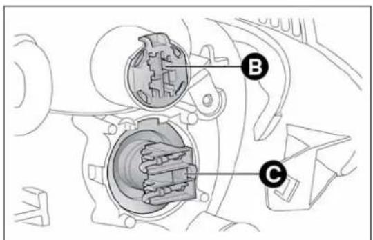
text_image
Technical diagram of a mechanical assembly with labeled parts B and Cfig. 133
A0J0041
DIRECTIONINDICATORS
Front
To replace the bulb, take wrench A fig. 135 (located in the document holder), insert it in housing B and turn the bulb holder anticlockwise.
Extract the bulb and replace it.
Side
To change the bulb, proceed as follows:
☐ operate lens A fig. 136 in order to compress clip B, then pull the unit outwards;
□ turn bulb holder C anticlockwise, remove the bulb and replace it;
□ refit bulb holder C in the lens, turning it clockwise;
□ refit the unit, making sure that internal clip B clicks into place.

text_image
Technical diagram of a mechanical component with labeled parts A and B, showing internal structure and assembly.fig. 134
A0J0040
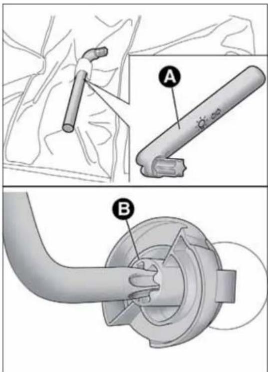
text_image
Medical procedure diagram showing two steps of a surgical tool installation, labeled A and B with component annotations.fig. 135
A0J0018
FOGLIGHTS
(for versions/markets, where provided)
For the replacement of these bulbs, contact Alfa Romeo Authorized Services.
REARLIGHTCLUSTERS
To access the light cluster, move the luggage compartment side trim (see fig. 137). The rear light cluster contains the bulbs for side lights, direction indicators and brake lights.
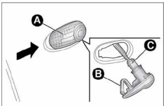
text_image
A B Cfig. 136
A0J0042
These are LED lights. Contact Alfa Romeo Authorized Services to replace these lights.
DIRECTIONINDICATORS
To replace the bulb, lift the luggage compartment side trim, turn bulb-holder A fig. 137 and replace the bulb.
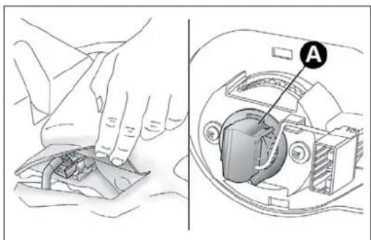
natural_image
Illustration showing hands using a tool to clean or adjust internal components, with a close-up view of the device's internal structure (no text or symbols present)fig. 137
A0J0043
REARFOGLIGHT/REVERSINGLIGHT
To replace the rear fog light A fig. 138 or reversing light B fig. 138 bulbs, contact Alfa Romeo Authorized Services.
3 ^rd BRAKELIGHTS
These are located in the tailgate and are LED bulbs. For replacement, contact Alfa Romeo Authorized Services.
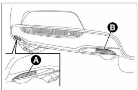
text_image
Technical diagram of a car's rearview and side door, labeled with parts A and B, showing structural details.fig. 138
A0J0044
NUMBERPLATELIGHTS
To replace the bulbs proceed as follows:
□ remove the number plate light units fig. 139;
☐ turn the bulb holder B fig. 140 anticlockwise, extract the bulb C and replace it;

text_image
Diagram showing a car interior with labeled points A and a sensor or sensor device, likely illustrating a vehicle or sensor system.fig. 139
A0J0046

text_image
Technical diagram showing two labeled components (B and C) of a mechanical or electrical connector assembly.fig. 140
A0J0045
REPLACINGINTERIORBULBS
FRONTROOFLIGHT
To change the bulb, proceed as follows:
☐ remove the roof light A fig. 141 working at the points indicated by the arrows;
☐ open the flap B fig. 142 and replace the bulbs C releasing them from the side contacts. Make sure that the new bulbs are correctly secured between the contacts;
□ reclose the flap B fig. 142 and fix the roof light A fig. 141 in its housing making sure that it is locked.
LUGGAGECOMPARTMENTROOF LIGHT
To change the bulb, proceed as follows:
☐ open the luggage compartment and extract the roof light A fig. 143 working in the point shown by the arrow;

natural_image
Interior view of a car dashboard with labeled components and directional arrows (no text or symbols beyond labels)fig. 141
A0J0120
□ open the protection B fig. 144 and replace the bulb;
□ re-close the protection B on the lens;
□ refit the roof light A fig. 143 by inserting it in its correct position firstly on one side and then pressing on the other until it clicks into place.
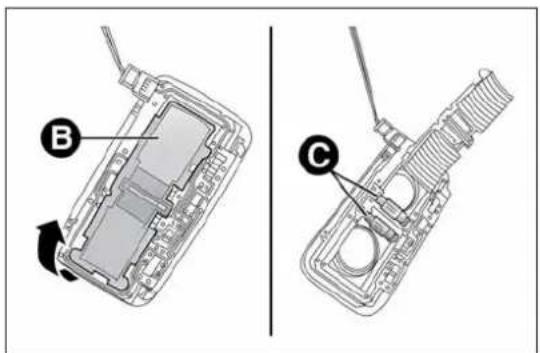
text_image
Technical diagram showing two views of a device with labeled parts B and C, likely illustrating a mechanical or electronic assembly.fig. 142
A0J0121
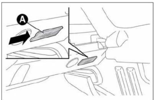
text_image
Afig. 143
A0J0119
To change the bulb, proceed as follows:
□ open the glove compartment and extract the light A fig. 145;
□ replace bulb B, releasing it from the side contacts and making sure the new bulb is correctly fastened between the contacts.
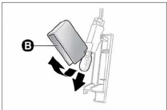
text_image
Bfig. 144
A0J0118
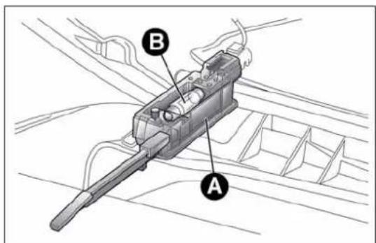
text_image
Technical diagram of a mechanical component with labeled parts A and B, showing internal structure and wiring connections.fig. 145
A0J0122
COURTESYLIGHT
(for versions/markets, where provided)
To change the bulb, proceed as follows:
☐ lower the sun visor and remove courtesy light A fig. 146, applying leverage at the point indicated by the arrow;
☐ remove protection B, releasing it from tabs C, then replace bulb D
fig. 147 by pulling it outwards and releasing it from the side contacts;
☐ insert the new bulb, making sure that it is positioned correctly and is secured between the contacts;
□ refit protection B fig. 146, inserting it correctly between tabs C;
□ refit the roof light, inserting it first from side E fig. 147, then press on the other side until you hear tab F click into place.

text_image
A B Cfig. 146
A0J0123
PUDDLELIGHT
To change the bulb, proceed as follows:
□ open the door and remove the roof light by pushing on clip A fig. 148 with a screwdriver;
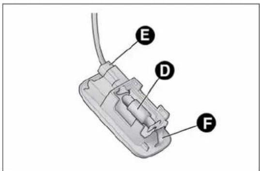
text_image
E D Ffig. 147
A0J0124

text_image
D A C Bfig. 148
A0J0125
☐ press the sides of protection B fig. 148 near the two fixing pins and replace bulb C;
□ refit the protection, locking the two fixing pins;
□ refit the roof light, inserting it first from side D and then pressing on the other side until you hear the clip click into place.
REPLACINGFUSES
GENERALINFORMATION
Fuses protect the electrical system: they intervene (blow) in the event of a failure or improper intervention on the system.
When a device does not work, check the condition of its protective fuse: the conductor element A fig. 149 must be intact.
If it is not, replace the blown fuse with another with the same amperage (same colour).
B = undamaged fuse.
C = fuse with damaged filament.

ContactAlfaRomeoAuthorizedServicesshouldthe fuseblowagain.

Neverreplaceafusewithmetalwiresoranythingelse.

text_image
A B Cfig. 149

Neverreplaceafusewithanotherwithahigheramp rating;DANGEROFFIRE.

Ifageneralprotectionfuse(MAXI-FUSE,MEGA-FUSE, MIDI-FUSE)blows,contactAlfaRomeoAuthorized Services.

Removethekeyfromtheignitionswitchandswitchoff allloadsbeforereplacingafuse.

ContactAlfaRomeoAuthorizedServicesifasafety system(airbags,brakes),enginesystem(engine, gearbox)orsteeringsystemgeneralprotectionfuse
blows.
FUSELOCATION
Fuses are grouped together in three fuse boxes located in the engine compartment, dashboard and luggage compartment.
Engine compartment fuse box
This is located next to the battery fig. 151: to access the fuses, undo the screws A fig. 150 and remove cover B.
The number identifying the electrical component corresponding to each fuse is on the back of the cover.
After replacing the fuse, make sure you close cover B on the fuse box.

If you havetowashtheenginecompartment, take care not to aim the jet of water directly at the fuse box or windscreen wiper motors.
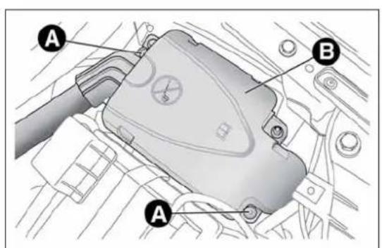
text_image
Technical diagram of a mechanical component with labeled parts A and B, likely for assembly or maintenance instructions.fig. 150
A0J0126
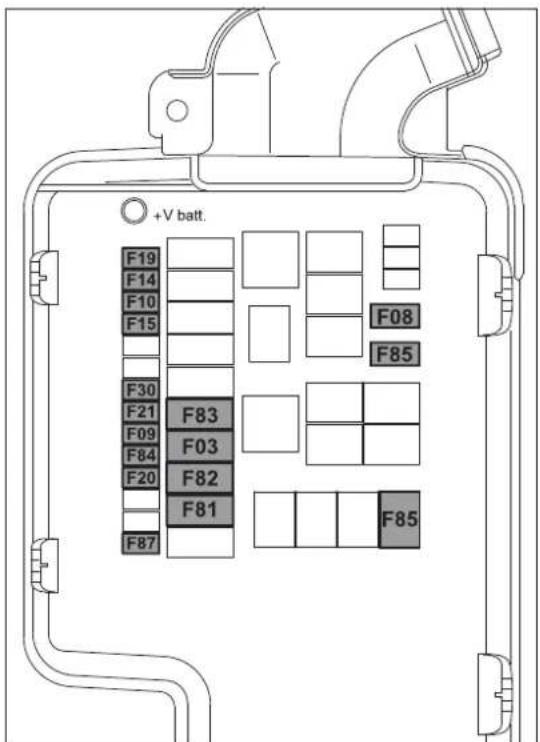
text_image
+V batt. F19 F14 F10 F15 F30 F21 F83 F09 F03 F84 F20 F82 F81 F87 F08 F85 F85fig. 151
A0J0417
Dashboard fuse box
To access the fuses fig. 153, lower lid A fig. 152, grip cover B with one hand in the area shown in the figure and remove it in the direction shown by the arrow, in order to release first the inner retainers C and then the tabs D.
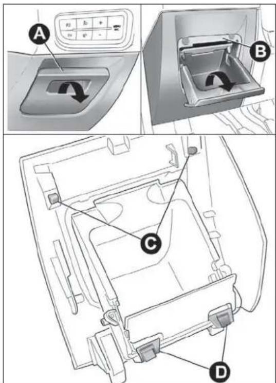
text_image
Technical diagram showing a car interior with labeled components A, B, C, and D, including a control panel and directional arrows.fig. 152
A0J0334

text_image
F12 F32 F53 F38 F36 F43 F48 F13 F51 F37 F49 F47fig. 153
A0J0205
GETTING TO KNOW YOUR CAR
SAFETY
STARTING AND DRIVING
IN AN EMERGENCY
SERVICING AND MAINTENANCE
TECHNICAL SPECIFICATIONS
INDEX
Luggage compartment fuse box
To access the fuse box fig. 155 located on the left side of the luggage compartment, open the relevant inspection lid (as illustrated in fig. 154).

natural_image
Technical line drawing of a car's side panel and internal battery pack (no text or symbols)fig. 154
A0J0264
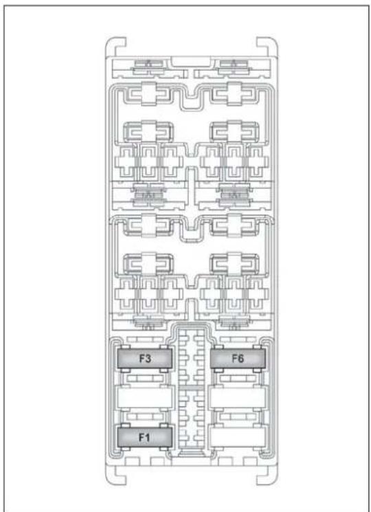
text_image
F3 F6 F1fig. 155
A0J0175
ENGINECOMPARTMENTFUSEBOX
fig. 151
| DEVICE PROTECTED FUSE AMPS | ||
| Starter F03 20 | ||
| Passenger compartment electric fan F08 40 | ||
| Additional heater (Turbo TwinAir 105 HP and 1.3 JTD_M-2 85 HP versions) F09 5 | ||
| Two-tone horns F10 15 | ||
| Main beam headlights F14 15 | ||
| Additional heater (PTC 1) F15 30 | ||
| Air conditioning compressor F19 7,5 | ||
| Heated rear windscreen, defrosting system | F20 | 30 |
| Electric fuel pump in tank | F21 | 15 |
| Fog lights | F30 15 | |
| Additional heater (PTC2) | F81 60 | |
| Additional heater (PTC1) | F82 40 | |
| Additional heater (PTC2) | F82 50 | |
| Free | F83 | - |
| HI-FI sound system (control units, Bassbox speaker) mechanical gearbox setup | F84 | 20 |
| Power socket on tunnel | F85 | 15 |
| Electric door mirror demisters, demisters on windscreen jets, relay switch coil for heated windscreen | F87 | 7,5 |
GETTING TO KNOW YOUR CAR
SAFETY
STARTING AND DRIVING
IN AN EMERGENCY
SERVICING AND MAINTENANCE
TECHNICAL SPECIFICATIONS
INDEX
INSTRUMENTPANELFUSEBOX
fig. 153
DEVICE PROTECTED FUSE AMPS
| Right dipped beam headlight F12 7,5 | ||
| Left dipped beam headlight F13 | 7,5/9*) | |
| Headlight alignment adjustment system F13 7,5 | ||
| Front roof light, Luggage compartment roof light, Sun visor courtesy light, Door puddle lights, Glove compartment light | F32 5 | |
| Radio, sound system setup system (for versions/markets, where provided), UconnectTM 5" radio (for versions/markets, where provided), climate control system control unit, alarm system control unit, volumetric system control unit, EOBD external diagnosis socket, tyre pressure monitoring control unit | F36 10 | |
| Instrument panel, brake light on switch | F37 | 5 |
| Door lock motor on doors, Safe Lock motor on doors, Tailgate unlocking motor | F38 | 15 |
| Windscreen/rear window washer pump | F43 | 20 |
| Electric window motor complete with control unit (driver side door) | F47 | 20 |
| Electric window motor complete with control unit (passenger side door) | F48 | 20 |
| Parking sensor control unit, rain/dusk sensor on interior rear view mirror, electrochromic sensor on interior rear view mirror, seat belts fastened warning light display on interior rear view mirror, control panel lighting (central control panel, driver side control panel, control panel on steering wheel), heater pad activation switches on front seats, alarm system volumetric sensor control unit, electric sun roof control unit | F49 5 | |
| Clutch activation switch, brake light switch, relay switch coils on engine fuse box control unit, control system on internal climate control/heater unit, flow meter, water presence in diesel sensor, radio, radio setup system (for versions/markets, where provided) | F51 5 | |
| Instrument panel | F53 5 |
(*) For versions/markets, where provided
LUGGAGECOMPARTMENTJUNCTION UNIT
fig. 155
DEVICE PROTECTED FUSE AMPS
| Electric roof opening system F1 20 | ||
| Luggage compartment power socket F3 15 | ||
| Front seat heater F6 15 |
GETTING TO KNOW YOUR CAR
SAFETY
STARTING AND DRIVING
IN AN EMERGENCY
SERVICING AND MAINTENANCE
TECHNICAL SPECIFICATIONS
INDEX
BATTERYRECHARGING
IMPORTANT The battery recharging procedure is given as information only. Contact Alfa Romeo Authorized Services to carry out this operation.
IMPORTANT After turning the ignition key to STOP, wait at least 1 minute before disconnecting the battery power supply.
We recommend recharging the battery slowly for approximately 24 hours at low amperage. Charging for a longer time may damage the battery.
VERSIONSWITHOUTStart&Stop SYSTEM
(for versions/markets, where provided)
Charge the battery as follows:
□ disconnect the negative battery terminal;
□ connect the charger cables to the battery terminals, observing the polarity;
□ turn on the battery charger;
□ when it is recharged, turn the charger off before disconnecting it from the battery;
□ reconnect the negative battery terminal.
VERSIONSWITHStart&StopSYSTEM
Charge the battery as follows:
□ disconnect the connector A fig. 156 (pressing the button B) from the sensor C monitoring the battery conditions, on the negative pole D of the battery;
☐ connect the positive cable (+) of the battery charger to the battery positive pole (+);
□ connect the negative cable (−) of the battery charger to the post D of the battery negative pole (−);
□ turn on the battery charger;
☐ when it is recharged, turn the charger off before disconnecting it from the battery;
□ reconnect the connector A to the sensor C of the battery.
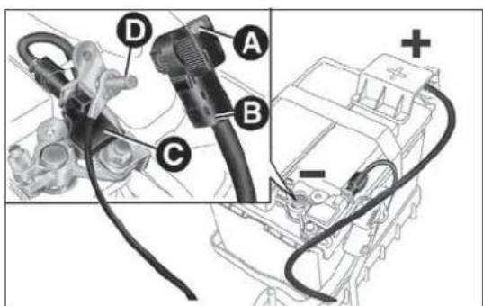
text_image
Technical diagram showing labeled components of an automotive electrical connector, including cable, plug, and motor assembly.fig. 156
A0J0389
RAISINGTHECAR
If you need to lift the car contact Alfa Romeo Authorized Services, who will be equipped with a workshop lift.
IMPORTANT Be careful when positioning the arm of the lift for versions with side skirts.
TOWINGTHECAR
The tow ring provided with the car is housed in the tool box in the boot.
ATTACHINGTHETOWHOOK
Release the plug A by pressing the lower part, take the tow hook B from its housing in the tool support and tighten it securely on the front threaded pin (fig. 157) or on the rear threaded pin (fig. 158).

Beforebeginningtotow,turntheignitionkeytoMAR andthentoSTOP,withoutextractingitThesteering columnwillautomaticallylockwhenthekeyis
removedandthewheelscannotbesteered.

text_image
Diagram showing a car interior with labeled points A and B, highlighting a mechanical component or device.fig. 157
A0J0038
Remember that whilst towing it is necessary to exert greater force when steering and braking because the brakeservo and electro-mechanical power steering will be in operative. Donot use wires for towing. Donot jerk. Be careful not to damage parts in contact with the car while towing. Whentowing the vehicle, you must comply with all specific traffic regulations and adopt an appropriate driving behaviour. Donot start the engine while towing the car. Cleanthethreaded seat carefully before fastening the hook. Makes sure that the hook is fully fastened in the housing before towing the car.
Thefrontandreatowhooksshouldbeusedonlyfor emergenciesontheroad.Youareallowedtotowthe vehicleforshortdistancesusinganappropriatedevice inaccordancewiththehighwaycode(arigidbar),tomovethe vehicleontheroadinreadinessfortowingortransportviaa breakdownvehicle.TowhooksMUSTNOTbeusedtotow vehiclesofftheroadorwherethereareobstaclesand/orfor towingoperationsusingcablesorothernon-rigiddevices. Respectingtheaboveconditions,towingmusttakeplacewiththe twovehicles(onetowing,theothertowed)alignedasmuchas possiblealongthesamecentreline.
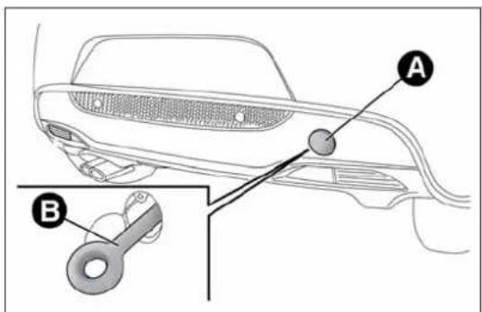
text_image
Diagram of a car interior with labeled parts A and B, showing structural components and a key inserted into the lower section.fig. 158
A0J0039
SERVICINGANDMAINTENANCE
SCHEDULEDSERVICING
Correct servicing is essential in guaranteeing a long life for the car under the best conditions.
That's why Alfa Romeo has prepared a series of checks and service operations to be carried out every 30,000 kilometres (petrol versions) or every 35,000 kilometres (diesel versions).
Check the items on the Scheduled Servicing Plan (e.g. periodically check level of liquids, tyre pressure, etc.) before 30,000/35,000 km and between these services deadlines.
Scheduled Servicing is carried out at Alfa Romeo Authorized Services according to a set time schedule. If, during each operation, in addition to the ones scheduled, the need arises for further replacements or repairs, these may be carried out only with the explicit agreement of the Customer. If your car is used frequently for towing, the interval between one service operation and the next should be reduced.
WARNING
At 2,000 km from the next service operation the display will show a message.
The Scheduled Services intervals are set out by the Manufacturer.
Failure to comply with the schedule may invalidate the warranty.
It is advisable to inform Alfa Romeo Authorized Services of any small faults without waiting for the next scheduled service.
SCHEDULEDSERVICINGPLAN
PETROLVERSIONS
Thousands of miles 18 36 54 72 90 108
Thousands of kilometres 30 60 90 120 150 180
Months 24 48 72 96 120 144
Check tyre conditions/wear and adjust pressure, if required
Check operation of lighting system (headlamps, direction indicators, hazard warning lights, passenger compartment, luggage compartment, instrument panel warning lights, etc.)
Check operation of windscreen washer/wiper system
Check the position/wear of the windscreen/rear window wiper blades
Check condition and wear of front disc brake pads and operation of pad wear indicator
Check rear disc brake pad condition and wear
Condition and status visual check: bodywork exterior, underbody protection, pipes and hoses (exhaust - fuel system - brakes), rubber elements (boots - sleeves - bushes etc.)
Check cleanliness of bonnet and boot locks, as well as cleanliness and lubrication of linkages
Check and, if necessary, top up fluid levels (engine cooling, hydraulic brakes/clutch, screen washer, battery, etc.)
Check handbrake lever travel and adjust, if required
Check of condition of timing drive belt (excluding TwinAir Turbo versions)
Visually inspect conditions of the accessory drive belt(s)
Check tension of accessory drive belts and adjust if necessary (versions with heater) (1.4 Petrol 8V 78 HP versions)
Check tappet clearance and adjust, if necessary (1.4 Petrol 8V 78 HP versions)
| ● | ● | ● | ● | ● | ● |
| ● | ● | ● | ● | ● | ● |
| ● | ● | ● | ● | ● | ● |
| ● | ● | ● | ● | ● | ● |
| ● | ● | ● | ● | ● | ● |
| ● | ● | ● | ● | ● | ● |
| ● | ● | ● | ● | ● | ● |
| ● | ● | ● | ● | ● | ● |
| ○ | ● | ● | ● | ● | ● |
| ● | ● | ● | ● | ● | ● |
| ● | ● | ● | |||
| ● | ● | ||||
| ● | ● | ● | ● |
Thousands of miles 18 36 54 72 90 108
| Thousands of kilometres 30 60 90 120 150 180 | ||||||
| Months 24 48 72 96 120 144 | ||||||
| Check exhaust emissions. ● ● ● ● ● | ||||||
| Check battery charge status and possibly recharge | ● | ● | ● | ● | ● | ● |
| Check engine management system operation (through the diagnosis socket) | ● | ● | ● | ● | ● | ● |
| Replace accessory drive belt(s) | ● | |||||
| Replacement of toothed timing drive belt (excluding TwinAir Turbo versions) (*) | ● | |||||
| Replace spark plugs (** ) | ● | ● | ● | ● | ● | ● |
| Replacement of air cleaner cartridge (every 30,000 km for TwinAir Turbo versions) | ● | ● | ● | |||
| Change engine oil and oil filter (or every 24 months) (***) | ● | ● | ● | ● | ● | ● |
| Change brake fluid (or every 24 months) | ● | ● | ● | |||
| Change pollen filter (or every 12 months) | ● | ● | ● | ● | ● | ● |
(*) Regardless of the distance covered, the timing belt must be changed every 4 years for particularly demanding use (cold climates, town driving, long periods of idling) or at least every 5 years.
(**) For 1.4 Turbo MultiAir versions, in order to guarantee correct operation and prevent serious damage to the engine, it is essential to observe the following: only use spark plugs specifically certified for these engines; all spark plugs should be of the same type and brand (see the "Engine" paragraph in the "Technical Specifications" section); strictly comply with the replacement intervals in the Scheduled Servicing Plan; it is advisable to contact Alfa Romeo Authorised Services to have plugs replaced.
(***) If the vehicle has an annual mileage of less than 10,000 km, the engine oil and engine oil filter should be changed every 12 months.
DIESELVERSIONS
| Thousands of miles 21 42 63 84 105 | |||||
| Thousands of kilometres 35 70 105 140 175 | |||||
| Months 24 48 72 96 120 | |||||
| Check tyre conditions/wear and adjust pressure, if required | ● | ● | ● | ● | ● |
| Check operation of lighting system (headlamps, direction indicators, hazard warning lights, passenger compartment, luggage compartment, instrument panel warning lights, etc.) | ● | ● | ● | ● | ● |
| Check operation of windscreen washer/wiper system | ● | ● | ● | ● | ● |
| Check the position/wear of the windscreen/rear window wiper blades | ● | ● | ● | ● | ● |
| Check condition and wear of front disc brake pads and operation of pad wear indicator | ● | ● | ● | ● | ● |
| Check rear disc brake pad condition and wear | ● | ● | ● | ● | ● |
| Condition and status visual check: bodywork exterior, underbody protection, pipes and hoses (exhaust - fuel system - brakes), rubber elements (boots - sleeves - bushes etc.) | ● | ● | ● | ● | ● |
| Check cleanliness of bonnet and boot locks, as well as cleanliness and lubrication of linkages | ● | ● | ● | ● | ● |
| Check and, if necessary, top up fluid levels (engine cooling, hydraulic brakes/clutch, screen washer, battery, etc.) | ● | ● | ● | ● | ● |
| Check handbrake lever travel and adjust, if required | ● | ● | ● | ● | ● |
| Check exhaust fumes/emissions | ● | ● | ● | ● | ● |
| Visually inspect conditions of the accessory drive belts | ● | ● | |||
| Check engine management system operation (through the diagnosis socket) | ● | ● | ● | ● | ● |
| Check battery charge status and possibly recharge | ● | ● | ● | ● | ● |
| Replace accessory drive belts | ● |
Thousands of miles 21 42 63 84 105
| Thousands of kilometres 35 70 105 140 175 | |||||
| Months 24 48 72 96 120 | |||||
| Replace toothed timing drive belt (excluding 1.3 JTD_M-2 engine)(*) | ● | ||||
| Replace fuel filter ● ● | |||||
| Replace air cleaner cartridge | ● | ● | ● | ● | ● |
| Replace engine oil and oil filter (or every 24 months) (**)(***) | |||||
| Change brake fluid (or every 24 months) | ● | ● | |||
| Change pollen filter (or every 12 months) | ● | ● | ● | ● | ● |
(*) Regardless of the distance covered, the timing belt must be changed every 4 years for particularly demanding use (cold climates, town driving, long periods of idling) or at least every 5 years.
(**) The engine oil and the oil filter must be changed when the instrument panel warning light comes on (see "Warning lights and messages" in "Getting to know your car" chapter) or in any case every 24 months.
(***) If the car is mainly used in towns and cities, change the engine oil and filter every 12 months.
PERIODICCHECKS
Every 1,000 km or before long journeys, check and restore the following if necessary:
☐ engine coolant, brake fluid and windscreen washer fluid level;
□ tyre inflation pressure and condition;
☐ operation of lighting system (headlamps, direction indicators, hazard warning lights, etc.);
☐ operation of window washer/wiper system and positioning/wear of windscreen/rear window wiper blades
Check and top up, if required, the engine oil level every 3,000 km.
HEAVY-DUTYUSEOFTHECAR
If you use the car mainly under one of the following conditions:
□ towing a trailer or caravan;
□dusty roads;
□ short, repeated journeys (less than 7-8 km) at sub-zero outside temperatures;
□ engine often idling or driving long distances at low speeds or long periods of idleness;
the following checks must be performed more frequently than indicated in the Scheduled Servicing Plan:
□ check front disc brake pad conditions and wear;
☐ check cleanliness of bonnet and boot locks, cleanliness and lubrication of linkage;
☐ visually inspect conditions of: engine, gearbox, transmission, pipes and hoses (exhaust - fuel system - brakes) and rubber elements (boots - sleeves - bushes - etc.);
□ check battery charge and battery fluid level (electrolyte);
□ visually inspect condition of the accessory drive belts;
□ check and, if necessary, change engine oil and replace oil filter;
□ check and, if necessary, replace pollen filter;
□ check and, if necessary, replace air cleaner.
CHECKINGLEVELS

Whentoppingup, takecarenottomixupthevariioustypes offluids: they are not compatible with each other and could seriously damage the car.

Neversmokewhileworkingintheengine compartment:gasandinflammablevapoursmaybe present,withtheriskoffire.

Beverycarefulwhenworkingintheengine compartmentwhentheengineishot:youmayget burned.Rememberthatthefanmaystartupif
theengineishot:thiscouldinjureyou.Makesurethatscarves, tiesandotherloosefittinggarmentsdonotgetcaughtupin movingparts.

text_image
Technical diagram of a vehicle engine bay with labeled components and exploded viewsfig. 159 - Turbo TwinAir versions
A0J0380
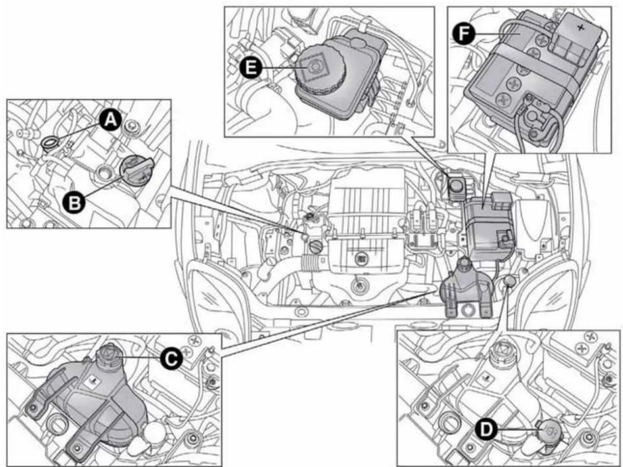
text_image
Technical diagram of automotive engine components with labeled parts A through F, showing internal wiring and assembly.fig. 160 - 1.4 Petrol versions
A0J0300

text_image
A B E F C D AUTO REVER MULTIAR TURBO BENSHAfig. 161 - 1.4 Turbo MultiAir versions
A0J0283
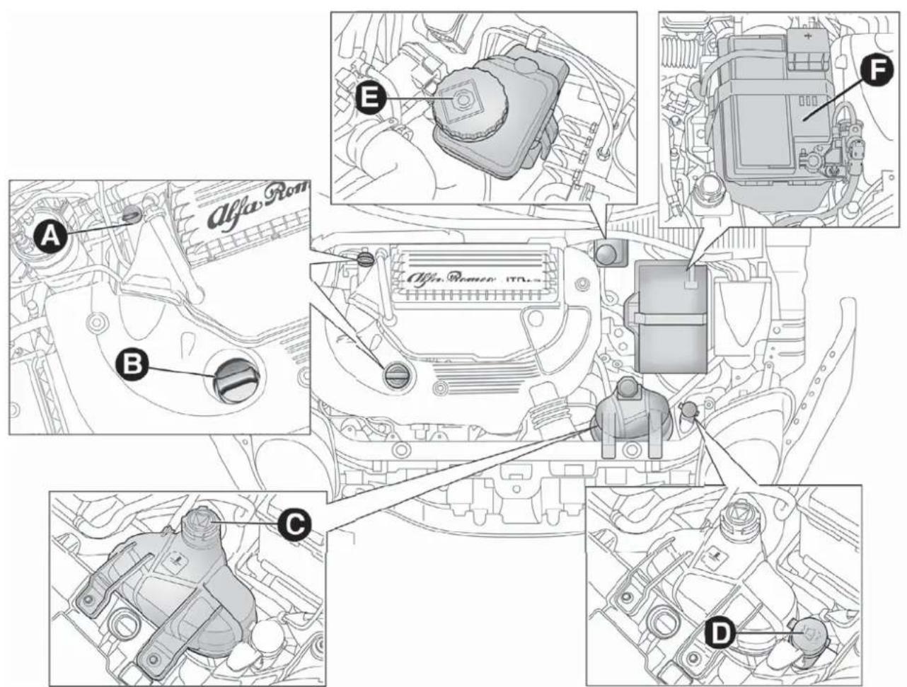
text_image
Alfa Rom A B E F Alfa Rom 10.0x C Dfig. 162 - 1.3 JTD _M-2
A0J0411

text_image
Technical diagram of automotive engine components with labeled parts A through Ffig. 163 - 1.6 JTD _M
A0J0200
ENGINEOIL
Check that the oil level is between the MIN and MAX references on the dipstick A.
If the oil level is near or under the MIN reference, add oil through the filler B until it reaches the MAX reference.

TheoillevelmustneverexceedtheMAXreference.
1.4 Petrol, 1.4 Turbo MultiAir, 1.3 JTD _M-2 and 1.6 JTD _M versions
Take out the engine oil dipstick A, clean it with a lint-free cloth and reinsert it. Take it out again and check that the engine oil level is between the MIN and MAX references on the dipstick.
Turbo TwinAir versions
Engine oil dipstick A is integral with plug B. Loosen the plug, clean the dipstick with a cloth that does not leave traces, refit the dipstick and re-tighten the plug.
Unscrew the cap again and check that the engine oil level is between the MIN and MAX marks on the dipstick.
Engine oil consumption
The maximum engine oil consumption is approximately 400 grams every 1,000 km. When the car is new, the engine needs to run in, therefore the engine oil consumption can only be considered stabilised after the first 5,000 - 6,000 km.

Donotaddoilwithspecificationsotherthanthoseoftheoil alreadyintheengine.

Usedengineoilandoilfilterscontainsubstanceswhichare harmfultotheenvironment.Werecommendhavingthe oilandoilfilterreplacedbyAlfaRomeoAuthorized
Services.
ENGINECOOLANT
If the level is too low, unscrew reservoir cap C and add the fluid described in the chapter "Technical Specifications".

PARAFLU ^UP anti-freezeisusedintheenginecooling system. Use the same fluid as in the coolingsystem when topping up. PARAFLU ^UP cannot be mixed with any other
typeoffluid.Ifthisaccidentallyoccurs,donotstarttheengineunder anycircumstances.ContactAlfaRomeoAuthorizedServices.

Thecoolingsystemispressurised. If necessary, only replacethecapwithanothergenuineoneorthe operationofthesystemmaybeadverselyaffected.Do
notremovethereservoircapwhentheengineishot:yourisk scaldingyourself.
WINDSCREEN/REARWINDOW WASHERFLUID
If the level is too low, lift reservoir cap D and add the fluid described in the chapter "Technical Specifications".
Donottravelifthewindscreenwasherreservoiris empty:usingthewindscreenwasheressentialfor improvingvisibility.Somecommercialwindscreen washeradditivesareflammable.Theenginecompartment containshotcomponentswhichmaysetitionfire.
BRAKEFLUID
Check that the fluid is at the maximum level. If the fluid level in the reservoir is too low, undo reservoir cap E and add the fluid described in the chapter "Technical Specifications".
Preventbrakefluid, which is highly corrosive, from coming into contact with painted parts. Should it happen, immediately wash with water.
Brakefluidispoisonousandhighlycorrosive.Inthe eventofaccidentalcontact,washtheparts immediatelywithwaterandneutralsoap,thenrinse withplentyofwater.Consultadoctorimmediatelyifyou swallowthefluid.
Symbol on the container identifieriessyntheticbrake fluids, distinguishing them from the mineral type. Using a mineral-type fluid will damage the special rubber seal of the brakingsystembeyondrepair.
AIRCLEANER/POLLEN FILTER/DIESELFILTER
Contact Alfa Romeo Authorized Services to replace the filters.
BATTERY
Battery F (see previous pages) does not require the electrolyte to be topped up with distilled water. A periodic check carried out at Alfa Romeo Authorized Services is, however, necessary to check efficiency.
REPLACINGTHEBATTERY
If necessary, replace the battery with another genuine battery with the same specifications. Follow the battery manufacturer's instructions for maintenance.
USEFULADVICEFOREXTENDINGTHE LIFEOFYOURBATTERY
To avoid draining your battery rapidly and maintain its efficiency over time, carefully observe the following instructions:
☐ when you park the car, ensure that the doors, bonnet and flaps are closed correctly, to prevent any roof lights from remaining on inside the passenger compartment;
☐ switch off all roof lights inside the car: the car is however equipped with a system which switches all internal lights off automatically;
☐ do not keep accessories (e.g. sound system, hazard lights, etc.) switched on for a long time when the engine is not running;
☐ before performing any operation on the electrical system, disconnect the negative battery pole;
IMPORTANT If the charge level remains under 50% for a long time, the battery is damaged by sulphation, reducing its capacity and efficiency at start-up.
The battery will also be more at risk of freezing (this can happen as early as -10^ ). Refer to "Storing the car" in "Starting and driving" if the car is left parked for a long time.
If after having purchased your car you decide to add accessories requiring permanent electrical power (alarm etc.) or accessories that require large amounts of power, contact Alfa Romeo Authorized Services. They can calculate the overall electrical requirement.
Batteryliquidispoisonousandcorrosive.Avoid contactwiththeskinandtheeyes.Keepnakedflames andsourcesofsparksawayfromthebattery:riskof explosionandfire.
Using the battery with insufficient fluid irreparably damage the battery and may cause an explosion.
Incorrect installation of electric and electronic devices may cause severe damage to your car. After purchasing your car, if you wish to install any accessories (anti-theft, radio phone etc.), contact Alfa Romeo Authorized Services, who will suggest them most appropriate devices for your vehicle and will, most importantly, advise you if higher capacity battery need stobe installed.

Batteriescontainssubstanceswhichareverydangerousfor theenvironment. Forthereplacementofthebattery, contactAlfaRomeoAuthorizedServices.
If the car will be unused for an extended period of time in extremely cold weather conditions, remove the battery and store it in a heated area to prevent it from freezing.
When performing any operation on the battery or near it, always protect you reyes with special goggles.
WHEELSANDTYRES
Before embarking on a long trip, and every two weeks, check the tyre inflation pressure and space-saver wheel. Check the tyres when cold.
While driving the car, the pressure increases under standard conditions: for the correct tyre inflation pressure, see "Wheels" paragraph in the "Technical specifications" chapter. Incorrect pressure causes abnormal tyre wear fig. 164:
A normal pressure: tread evenly worn;
B low pressure: tread particularly worn at the edges;
C high pressure: tread particularly worn in the centre.
The tyres must be replaced when the tread is less than 1.6 mm thick.
IMPORTANT
Take the following precautions to prevent damage to the tyres:
☐ avoid braking suddenly, racing starts and violent impact against the curb, potholes or other obstacles and driving for extended periods on uneven road surfaces;

text_image
A B Cfig. 164
A0J0136
☐ periodically check that the tyres have no cuts in the side wall, abnormal swelling or irregular tyre wear;
☐ avoid travelling with the car overloaded. If you puncture a tyre, stop immediately and replace it;
☐ change the position of the tyres every 10-15 thousand kilometres, keeping them on the same side of the car to avoid inverting the direction of rotation;
☐ tyres age even if they are not used much. Cracks in the tread and on the sidewalls are a sign of ageing. Have the tyres checked by specialised personnel if they have been fitted for longer than 6 years. Remember to check the space-saver wheel very carefully;
☐ In the case of replacement, always fit new tyres, avoiding those of dubious origin;
☐ if a tyre is replaced, also replace the inflation valve.

Remember that theroadholding qualities of your car alsodependonthecorrectinflationpressureofthe tyres.

If the pressure istoolowthetyreoverheatsandcanbe seriouslydamaged.

Donotcrossswitchthetyres, moving them from the right of the carto the left and vice versa.

Neversubmitalloyrimstorepainting treatments requiring the use of temperatures exceeding 150°C. Themechanical properties of the wheels could be
impaired.
WINDSCREEN/REARWINDOW WIPER
BLADES
We recommend replacing the blades once a year.
A few simple precautions can reduce the possibility of damage to the blades:
☐ if the temperature falls below zero, make sure that ice has not frozen the rubber against the glass. Use a de-icing product to release it if required;
□ remove any snow from the window;
☐ do not operate the windscreen/rear window wipers on dry glass.

Drivingwithwornwindscreen/rearwindowwiper bladesisaserioushazard,becausevisibilityisreduced inbadweather.
Replacingthewiperblades
Proceed as follows:
☐ raise the wiper arm, press tab A fig. 165 of the attachment spring and remove the blade from the arm;
☐ fit the new blade by inserting the tab into the special slot in the arm. Make sure that it is properly locked into place;
☐ lower the windscreen wiper arm on the windscreen.

Donotoperatethewindscreenwiperwiththebladeslifted fromthewindscreen.
Liftingthewiperblades
When the wiper blades have to be lifted from the windscreen (i.e. in the event of snow), proceed as follows:
□ turn the ignition key to the MAR position;
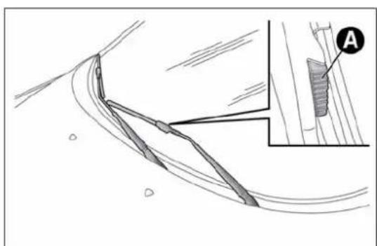
natural_image
Technical line drawing of a curved mechanical component with an inset showing a detail labeled 'A' (no text or symbols present)fig. 165
A0J0054
☐ operate the lever to the right of the steering wheel to activate a windscreen wiper stroke (see paragraph "Window washing" in chapter "Getting to know your car");
□ turn the ignition key to the STOP position when the driver's side wiper blade reaches the windscreen side pillar and lift the windscreen wiper to the rest position;
☐ bring the wiper blades back into contact with the windscreen before activating the windscreen wiper.
Replacingtherearwindowwiper blade
Proceed as follows:
☐ raise cover A fig. 166, undo nut B and remove arm C;
□ correctly position the new arm, fully tighten nut B then lower cover A.
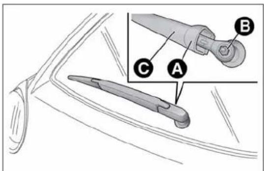
text_image
Technical diagram showing labeled parts of a mechanical component with annotations A, B, and Cfig. 166
A0J0057
SPRAYNOZZLES
Windscreen washer
The window washer jets are fixed fig. 167.
If the jet of fluid is inadequate, firstly check that there is fluid in the reservoir: see "Checking fluid levels" in this section).
Then check that the nozzle holes are not clogged, if necessary using a needle.
Rear Window Washer
The nozzle holder is on the rear window fig. 168.
The rear window washer jets are fixed.
HEADLIGHTWASHERS
(for versions/markets, where provided)
They are located inside the front bumper fig. 169.

natural_image
Diagram of a mechanical or aerodynamic system with fan-like structures and a separate inset showing a conical component (no text or symbols present)fig. 167
A0J0053
They are activated when the dipped beam and/or main beam headlights are on and the windscreen washer is activated.
Check the correct operation and cleanliness of nozzles at regular intervals.
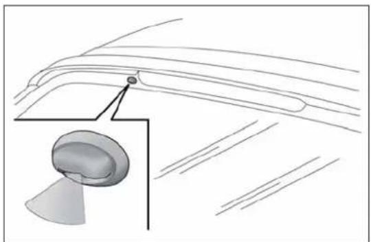
natural_image
Diagram of a car's roof structure with an inset showing a dome-shaped component (no text or labels)fig. 168
A0J0055

natural_image
Diagram showing a car's seatbelt with a black arrow pointing to the seat area (no text or symbols)fig. 169
A0J0029
BODYWORK
PROTECTIONAGAINSTATMOSPHERIC AGENTS
The car is equipped with the best available technological solutions to effectively protect the bodywork against corrosion.
These are the most important:
☐ painting products and systems which give the car resistance to corrosion and abrasion
☐ use of galvanised (or pretreated) steel sheets, with high resistance to corrosion;
□ spraying of plastic parts, with a protective function in the more exposed points: underdoor, inner wing, edges, etc;
☐ use of "open" boxed sections to prevent condensation and pockets of moisture which could favour the formation of rust inside;
☐ use of special films to protect against abrasion in exposed areas (e.g. rear wing, doors, etc.).
BODYANDUNDERBODYWARRANTY
The car is covered by warranty against perforation due to corrosion of any original element of the structure or body. For the general terms of this warranty, refer to the Warranty Booklet.
PRESERVINGTHEBODYWORK
Paint
Touch up abrasions and scratches immediately to prevent the formation of rust.
Maintenance of paintwork consists of washing the car: the frequency depends on the conditions and environment where the car is used. For example, it is advisable to wash the car more often in areas with high levels of atmospheric pollution or salted roads.
To correctly wash the car, follow these instruction:
☐ remove the aerial from the roof when using a carwash;
☐ if high pressure jets or cleaners are used to wash the car, maintain a distance of at least 40 cm from the bodywork to avoid damage or alteration. Bear in mind that a build up of water could cause damage to the car in the long term.
☐ wash the body using a low pressure jet of water;
☐ wipe a sponge with a slightly soapy solution over the bodywork, frequently rinsing the sponge;
☐ rinse well with water and dry with a jet of air or a chamois leather.
Dry the less visible parts (e.g. door frames, bonnet, headlight frames etc.) with special care, as water may stagnate more easily in these areas. Do not wash the car after it has been left in the sun or with the bonnet hot: this may alter the shine of the paintwork.
Exterior plastic parts must be cleaned in the same way as the rest of the car.

Detergentspollutetheenvironment. Only wash your carin are a equipped to collect and treat wastewater from this type of activity.

Inordertopreservetheaestheticpropertiesofthe paintwork,abrasiveproductsand/orpolishesshouldnot beusedtocleanthecar.
IMPORTANT
Avoid parking under trees; the resin dropped by trees makes the paintwork go opaque and increases the possibility of corrosion. Bird droppings must be washed off immediately and thoroughly as the acid they contain is particularly aggressive.
Windows
Use specific detergents and clean cloths to prevent scratching or altering the transparency.
IMPORTANT Wipe the inside surface of the rear window gently with a cloth in the direction of the filaments to avoid damaging the heating device.
Front headlights
Use a soft, damp cloth soaked in water and detergent for washing cars.
IMPORTANT Never use aromatic substances (e.g. petrol) or ketenes (e.g. acetone) for cleaning the plastic lenses of the front headlights.
IMPORTANT When cleaning the car with a pressure washer, keep the water jet at least 20 cm away from the headlights.
Engine compartment
At the end of every winter, wash the engine compartment thoroughly, taking care not to aim the jet of water directly at the electronic control units or at the windscreen wiper motors. Have this operation performed at a specialised workshop.
IMPORTANT The washing should take place with the engine cold and the ignition key in the STOP position. After washing, make sure that the various protective devices (e.g. rubber caps and guards) have not been removed or damaged.
INTERIORS
Periodically check for water puddles under the mats that could cause the panels to rust.
Neveruseflammableproducts,suchaspetroletheror rectifiedpetroltocleantheinsideofthecar.The electrostaticchargeswhicharegeneratedbyrubbing duringthecleaningoperationmaycauseafire.
Donotkeepaerosolcansinthecar:theymight explode.Aerosolcansmustnotbeexposedtoa temperatureexceeding50°C.Whenthecarisexposed tosunlight,theinternaltemperaturecangreatlyexceedthis value.
SEATSANDFABRICPARTS
Remove dust with a soft brush or a vacuum cleaner. It is advisable to use a moist brush on velvet upholstery. Rub the seats with a sponge soaked in a solution of neutral detergent and water.
CLEANINGALCANTARASEATS
Alcantara trim can be treated and cleaned easily in the same way as the other trims. The same indications given for cleaning fabrics are also therefore applicable for this trim.
LEATHERSEATS
(for versions/markets, where provided)
Remove the dry dirt with a buckskin or slightly damp cloth, without exercising too much pressure. Remove liquid or oil stains using a dry absorbent cloth, without rubbing. Then clean with a soft cloth or buckskin cloth dampened with water and neutral soap. If the stain persists, use specific products and observe the instructions carefully.
IMPORTANT Never use alcohol. Make sure that the cleaning products used contain no alcohol or alcohol derivatives, even in small quantities.
PLASTICANDCOATEDPARTS
Clean interior plastic parts with a damp cloth (if possible made from microfibre), and a solution of water and neutral, non-abrasive detergent. To clean oily or persistent stains, use specific products free from solvents and designed to maintain the original appearance and colour of the components.
Remove any dust using a microfibre cloth, if necessary moistened with water. The use of paper tissues is not recommended as these may leave residues.

Neverusealcohol, petrolsandderivativestocleanthe dashboard and instrument panellens.
LEATHERPARTS
(for versions/markets, where provided)
Use only water and neutral soap to clean these parts. Never use alcohol or alcohol-based products. Before using a specific product for cleaning interiors, make sure that it does not contain alcohol and/or alcohol based substances.
TECHNICALSPECIFICATIONS
IDENTIFICATIONDATA
The identification details of the car are:
□V.I.N. plate;
□Chassis marking;
☐ Body paintwork identification plate;
□Engine marking.

text_image
FIAT GROUP AUTOMOBILES S.p.A. B C D E Kg F Kg 1-G Kg 2-H Kg N BOTONE ENGINE I WISHERONE VERSION L S' FOR ISCA#N S' FOR SPACES Mfig. 170
A0J0161
V.I.N.PLATE
This is located on the left side of the rear luggage compartment floor and bears the following data fig. 170:
B Type-approval number.
C Vehicle type identification code
D Chassis serial number.
E Maximum authorised weight of vehicle fully laden
F Maximum authorised weight of vehicle fully laden plus trailer.
G Maximum permitted weight on first (front) axle
H Maximum permitted weight on second (rear) axle
1 Engine type.
L Bodywork version code.
M Spares number.
N Correct value of smoke coefficient (for diesel engines)
CHASSISMARKING
This is printed on the passenger compartment floor, near the front right seat.
Slide flap A fig. 171 to access.
The marking includes:
□ vehicle type (ZAR 955000);
□chassis serial number.
BODYWORKPAINTIDENTIFICATION PLATE
This is fitted to the inside of the tailgate and bears the following data fig. 172:
A Paint manufacturer.
B Colour name.
C Fiat colour code.
D Respray and touch up code.

text_image
Diagram showing a car seatbelt buckle with labeled component A and directional arrow indicating motionfig. 171
A0J0140
ENGINEMARKING
This is stamped on the cylinder block and gives the model and the chassis serial number.

text_image
Verniciatura originate Peinture originale/Original painting Originalkierung/Pintado original A Colore/Teinte/Colour Farbton/Color B Codice/Code/Codigo C PER RITOCCHI E VERNICIATURE Dfig. 172
A0J0138
ENGINECODES-BODYWORKVERSIONS
| Versions Engine code Body versions | ||
| Turbo TwinAir 105 HP | 199B6000 | 955AXY1B 18 (*) |
| 955AXY1B 18B (**) | ||
| 1.4 petrol 8V 70 HP | 955A9000 | 955AXV1A 16(*) |
| 955AXV1A 16B (**) | ||
| 1.4 Petrol 8V 78 HP | 350A1000 | 955AXU1A 15 (*) |
| 955AXU1A 15B (**) | ||
| 1.4 Turbo MultiAir 135 HP (***) | 955A2000 | 955AXM1A 09C (*) |
| 955AXM1A 09D (**) | ||
| 1.4 Turbo MultiAir 163 HP Quadrifoglio Verde (***) | 955A8000 | 955AXS1B 13 (*) |
| 955AXS1B 13B (**) | ||
| 1.4 Turbo MultiAir 170 HP Quadrifoglio Verde | 940A2000 | 955AXN1B 10 (*) |
| 955AXN1B 10B (**) |
(*) 4-seater versions
(**) 5-seater versions
(***) For versions/markets, where provided
| Versions Engine code Body versions | ||
| 1.3 JTD _M-2 85 HP 199B4000 | 955AXT1A 14C (*) | |
| 955AXT1A 14D (**) | ||
| 1.3 JTD _M-2 85 HP (***) | 199B4000 | 955AXT1A 14E (*) |
| 955AXT1A 14F (**) | ||
| 1.6 JTD _M 115 HP (***) | 955A4000 | 955AXE1B 04L (*) |
| 955AXHE1B 04M (**) | ||
| 1.6 JTD _M 120 HP 955A3000 | 955AXC1B 02G(*) | |
| 955AXC1B 02H (**) |
(*) 4-seater versions
(**) 5-seater versions
(***) For versions/markets, where provided
ENGINE
GENERAL INFORMATION Turbo TwinAir 105 HP
| Type code 199B6000 | ||
| Cycle Otto | ||
| Number and arrangement of cylinders | 2 in line | |
| Piston diameter and travel (mm) | 80.5x86 | |
| Total displacement (cm3) 875 | ||
| Compression ratio 10 | ||
| NATURAL DYNAMIC | ||
| Maximum power (EC) (kW) 72 77 | ||
| Maximum power (EC) (HP) 98 105 | ||
| corresponding engine speed (rpm) | 5750 | 5500 |
| NATURAL DYNAMIC | ||
| Maximum torque (EC) (Nm) | 120 | 145 |
| Maximum torque (EC) (kgm) | 12,2 | 14,8 |
| corresponding engine speed (rpm) | 1750 | 2000 |
| Spark plugs | NGK ILKR9G8 | |
| Fuel | Unleaded petrol 95 RON or 98 RON (EN 228 specification) | |
| GENERAL INFORMATION | 1.4 Petrol 8V 70 HP | 1.4 Petrol 8V 78 HP |
| Type code 955A9000 350A1000 | ||
| Cycle Otto Otto | ||
| Number and arrangement of cylinders | 4 in line | 4 in line |
| Piston bore and stroke (mm) | 72.0 x 80.4 | 72.0 x 80.4 |
| Total displacement ( cm^3 ) 1368 1368 | ||
| Compression ratio 11.1 | 11.1 | |
| Maximum power (EEC) (kW) | 51 | 57 |
| Maximum power (EEC) (HP) | 70 | 78 |
| corresponding engine speed (rpm) | 6000 | 6000 |
| Max torque (EEC) (Nm) | 115 | 115 |
| Maximum torque (EEC) (kgm) | 11.7 | 11.7 |
| corresponding engine speed (rpm) | 3000 | 3000 |
| Spark plugs | NGK ZKR7A-10 or Champion RA8MCX4 | NGK ZKR7AI-8 |
| Fuel | Unleaded petrol 95 RON(Specification EN 228) | Unleaded petrol 95 RON or 98 RON(EN 228 specification) |
GENERAL INFORMATION
1.4 Turbo MultiAir 135 HP (*)
| Type code 955A2000 | ||
| Cycle Otto | ||
| Number and arrangement of cylinders | 4 in line | |
| Piston bore and stroke (mm) | 72.0 x 80.4 | |
| Total displacement (cm3) 1368 | ||
| Compression ratio 9.8 | ||
| Maximum power (EC) (kW) 99 | ||
| Maximum power (EC) (HP) 135 | ||
| corresponding engine speed (rpm) 5500 | ||
| NATURAL DYNAMIC | ||
| Maximum torque (EC) (Nm) 190 206 | ||
| Maximum torque (EC) (kgm) | 19,3 | 21 |
| corresponding engine speed (rpm) | 4250 | 1750 |
| Spark plugs | NGK IKR9F8 | |
| Fuel | Unleaded petrol 95 RON or 98 RON (EN 228 specification) | |
(*) For versions/markets, where provided
GENERAL INFORMATION
| Type code | 955A8000 (*) | |
| 940A2000 | ||
| Cycle Otto | ||
| Number and arrangement of cylinders | 4 in line | |
| Piston bore and stroke (mm) | 72.0 x 80.4 | |
| Total displacement (cm3) 1368 | ||
| Compression ratio 9.8 | ||
| Maximum power (EC) (kW) | 120 (*) / 125 | |
| Maximum power (EC) (HP) | 163 (*) / 170 | |
| corresponding engine speed (rpm) | 5500 (*) / 5000 | |
| NATURAL DYNAMIC | ||
| Maximum torque (EC) (Nm) 230 250 | ||
| Maximum torque (EC) (kgm) 23.4 25.5 | ||
| corresponding engine speed (rpm) | 2500 | 2500 |
| Spark plugs | NGK IKR9F8 | |
| Fuel | Unleaded petrol 95 RON or 98 RON (EN 228 specification) | |
(*) For versions/markets, where provided
1.4 Turbo MultiAir 170 HP Quadrifoglio Verde
GENERAL INFORMATION 1.3 JTD
M-2 85 HP
| Type code 199B4000 | |
| Cycle Diesel | |
| Number and arrangement of cylinders | 4 in line |
| Piston diameter and travel (mm) | 69.6 x 82 |
| Total displacement (cm3) 1248 | |
| Compression ratio 16,8 | |
| Maximum power (EC) (kW) 62 | |
| Maximum power (EC) (HP) 85 | |
| corresponding engine speed (rpm) 3500 | |
| Maximum torque (EC) (Nm) 200 | |
| Maximum torque (EC) (kgm) 20,4 | |
| corresponding engine speed (rpm) 1500 | |
| Fuel | Diesel for automotive engines (EN 590 Specification) |
| GENERAL INFORMATION | 1.6 JTD _M 115 HP (*) | 1.6 JTD _M 120 HP | ||
| Type code 955A4000 955A3000 | ||||
| Cycle Diesel Diesel | ||||
| Number and arrangement of cylinders | 4 in line | 4 in line | ||
| Piston bore and stroke (mm) | 79.5 x 80.5 | 79.5 x 80.5 | ||
| Total displacement (cm ^3 ) 1598 1598 | ||||
| Compression ratio 16,5 16,5 | ||||
| Maximum power (EEC) (kW) | 85 | 88 | ||
| Maximum power (EEC) (HP) | 115 | 120 | ||
| corresponding engine speed (rpm) | 4000 | 3750 | ||
| NATURAL | DYNAMIC | NATURAL | DYNAMIC | |
| Max torque (EEC) (Nm) | 260 | 300 | 280 | 320 |
| Maximum torque (EC) (kgm) | 26.5 | 30.6 | 28.6 | 32.6 |
| corresponding engine speed (rpm) | 1500 | 1500 | 1500 | 1750 |
| Spark plugs | - | - | ||
| Fuel | Diesel for motor vehicles(EN 590 specification) | Diesel for motor vehicles(EN 590 specification) | ||
(*) For versions/markets, where provided
GETTING TO KNOW YOUR CAR
SAFETY
STARTING AND DRIVING
IN AN EMERGENCY
SERVICING AND MAINTENANCE
TECHNICAL SPECIFICATIONS
INDEX
FUELSUPPLY
| Versions Fuel supply | |
| Turbo TwinAir – 1.4 petrol | Timed, sequential Multipoint electronic injection with knock control |
| 1.4 Turbo MultiAir | Phased sequential electronic injection with knock control and variable intake valve actuation |
| 1.3 JTD_M-2 - 1.6 JTD_M | Electronically controlled Common Rail MultiJet direct injection with turbo and intercooler |

Modifications or repairs to the fuel supply system that are not carried out correctly or do not take the system's technical specifications into accountcancausemalfunctionsleadingtotheriskoffire.
TRANSMISSION
| Versions Gearbox Clutch Drive | |||
| 1.4 Petrol | Five forward gears and reverse with synchronizers for forward gear engagement | Self-adjusting pedal without idle stroke | Front |
| 1.4 Turbo MultiAir 135 HP | |||
| 1.3 JTD_M-2 | |||
| Turbo TwinAir | Six forward gears plus reverse with synchronisers for forward gear engagement | Self-adjusting pedal without idle stroke | Front |
| 1.4 Turbo MultiAir 170 HP Quadrifoglio Verde | |||
| 1.6 JTD_M |
BRAKES
Versions Front brakes Rear brakes Parking brake
| Turbo TwinAir | Self-ventilated discs Disc | Controlled by hand lever, acting on the rear brakes | |
| 1.4 petrol | |||
| 1.4 Turbo MultiAir | |||
| 1.3 JTD_M-2 | |||
| 1.6 JTD_M |
IMPORTANT Water, ice and salt spread on the roads may deposit on the brake disks reducing braking efficiency the first time the brakes are applied.
SUSPENSION
| Versions Front Rear | ||
| Turbo TwinAir | McPherson independent wheels with anti-roll bar | Interconnected wheels with torsion beam |
| 1.4 petrol | ||
| 1.4 Turbo MultiAir | ||
| 1.3 JTD_M-2 | ||
| 1.6 JTD_M |
GETTING TO KNOW YOUR CAR
SAFETY
STARTING AND DRIVING
IN AN EMERGENCY
SERVICING AND MAINTENANCE
TECHNICAL SPECIFICATIONS
INDEX
STEERINGSYSTEM
| Versions | Turning circle (kerb to kerb) | Type |
| Turbo TwinAir | 11.25 m | Rack and pinion with electric power steering |
| 1.4 petrol | ||
| 1.4 Turbo MultiAir | ||
| 1.3 JTD_M-2 | ||
| 1.6 JTD_M |
WHEELS
RIMSANDTYRES
Pressed steel or alloy rims. Tubeless radial carcass tyres. The vehicle registration document also lists all type-approved tyres.
For safe driving, the car must be fitted with tyres of the same make and type on all wheels.
IMPORTANT If there are any discrepancies between the Owner handbook and the registration document, take the information from the latter.
IMPORTANT Do not use tubes with tubeless tires.
SPACE-SAVERWHEEL
Pressed steel rim. Tubeless tyre.
READINGTHETYRECODE
Example fig. 173: 195/55 R 16 87H
195 Rated width (S, distance in mm between sidewalls)
55 Height/width ratio (H/S) as a percentage
R Radial tyre
16 Rim diameter in inches (∅)
91 Load rating (capacity)
V Maximum speed index
Maximum speed index
Q up to 160 km/h
R up to 170 km/h
s up to 180 km/h
T up to 190 km/h
U up to 200 km/h
H up to 210 km/h
v up to 240 km/h
w up to 270 km/h
Y up to 300 km/h
Maximum speed index for snow tyres
QM + S up to 160 km/h
TM + S up to 190 km/h
HM + S up to 210 km/h
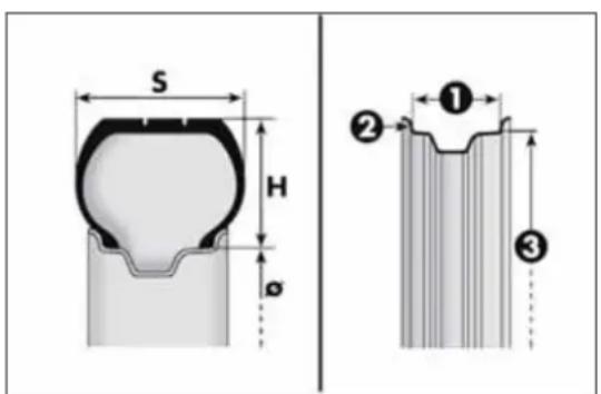
text_image
S H Ø ① ② ③fig. 173
A0J0139
Load rating (capacity)
| 60 = 250 kg | 76 = 400 kg |
| 61 = 257 kg | 77 = 412 kg |
| 62 = 265 kg | 78 = 425 kg |
| 63 = 272 kg | 79 = 437 kg |
| 64 = 280 kg | 80 = 450 kg |
| 65 = 290 kg | 81 = 462 kg |
| 66 = 300 kg | 82 = 475 kg |
| 67 = 307 kg | 83 = 487 kg |
| 68 = 315 kg | 84 = 500 kg |
| 69 = 325 kg | 85 = 515 kg |
| 70 = 335 kg | 86 = 530 kg |
| 71 = 345 kg | 87 = 545 kg |
| 72 = 355 kg | 88 = 560 kg |
| 73 = 365 kg | 89 = 580 kg |
| 74 = 375 kg | 90 = 600 kg |
| 75 = 387 kg | 91 = 615 kg |
CORRECTREADINGOFTHERIMCODE
Example fig. 173: 6Jx15H2ET40
6 rim diameter in inches (1).
J rim drop centre outline (side projection where the tyre bead rests) (2).
15 rim fitting diameter in inches (corresponds to diameter of the tyre to be mounted) (3 = ∅).
H2 shape and number of humps (circumference measurement which keeps the bead of tubeless tyres in position on the rim).
ET 40 wheel camber (distance between the disc/rim support plane and the wheel rim centre line).
RIMPROTECTORTYRES

DONOTfitwheelhubcapswhenusingintegralhub capsfixed(withsprings)tothesteelimandaftersale tyresprovidedwithRimProtector(fig.174).Useof
unsuitableyresandwheelcapsmaycausesuddenlossoftyre pressure.
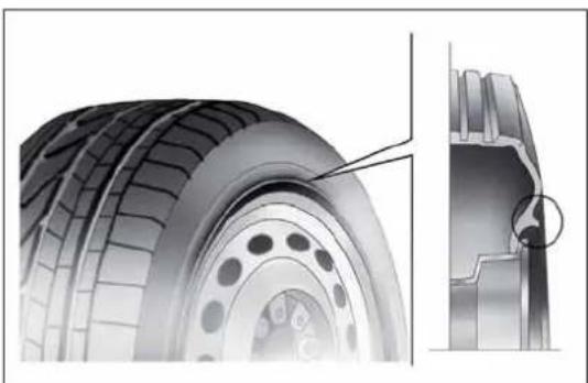
natural_image
Technical illustration of a tire and its cross-section showing internal components (no text or symbols)fig. 174
A0J0166
RIMSANDTYRESPROVIDEDASSTANDARD
| Versions Rims Tyres provided Snow tyres | Space-saver wheel | ||||
| Rim - Tyre | |||||
| Turbo TwinAir | 6Jx15 ET 40 | 185/65 R15 88H | 185/65 R15 88H (M+S) | 135/70 R16 | 4B x 16 ET 15 |
| 7Jx16 ET 39 | 195/55 R16 87H | 195/55 R16 87H (M+S) | |||
| 7Jx17 ET 39 | 215/45 R17 87W (*) | 215/45 R17 87H (M+S) | |||
| 7 1/2 Jx18 ET 42 | 215/40 R18 89W XL(*) | 215/40 R18 89H (M+S) | |||
| 1.4 Petrol | 6Jx15 ET 40 | 185/65 R15 88V (**) | 185/65 R15 88Q (M+S) | 135/70 R16 | 4B x 16 ET 15 |
| 6Jx15 ET 40 | 185/65 R15 88H (***) | 185/65 R15 88H (M+S) | |||
| 7Jx16 ET 39 | 195/55 R16 87H | 195/55 R16 87H (M+S) | |||
| 7Jx17 ET 39 | 205/45 R17 88W XL (**) | 205/45 R17 88H (M+S) | |||
| 7Jx17 ET 39 | 215/45 R17 87W (*) | 215/45 R17 87H (M+S) | |||
| 7 1/2 Jx18 ET 42 | 215/40 R18 89W XL(*) | 215/40 R18 99H (M+S) | |||
(*) Tyres which cannot be fitted with chains
(**) For versions/markets, where provided
(***) 1.4 Petrol versions
| Versions Rims Tyres provided Snow tyres | Space-saver wheel | ||||
| Rim - Tyre | |||||
| 1.4 Turbo MultiAir 135 HP 1.4 Turbo MultiAir 170 HP Quadrifoglio Verde | 6Jx15 ET 40 | 185/65 R15 88V (**) | 185/65 R15 88Q (M+S) | 135/70 R16 | 4B x 16 ET 15 |
| 7Jx16 ET 39 | 195/55 R16 87V | 195/55 R16 87H (M+S) | |||
| 7Jx17 ET 39 | 205/45 R17 88W XL (**) | 205/45 R17 88H (M+S) | |||
| 7Jx17 ET 39 | 215/45 R17 87W (*) | 215/45 R17 87H (M+S) | |||
| 7 1/2 Jx18 ET 42 | 215/40 R18 89W XL (*) | 215/40 R18 89H (M+S) | |||
| 1.3JTD_M-2 1.6JTD_M | 6Jx15 ET40 | 185/65 R15 88H (****) | 185/65 R15 88H (M+S) | 135/70 R16 | 4B x 16 ET 15 |
| 6Jx15 ET 40 | 185/65 R15 88T (**) | 185/65 R15 88T (M+S) | |||
| 7Jx16 ET 39 | 195/55 R16 87H | 195/55 R16 87H (M+S) | |||
| 7Jx16 ET 39 | 195/55 R16 87H Continental Premium Contact 2 (**) (***** ) | 195/55 R16 87H (M+S) | |||
| 7Jx17 ET 39 | 205/45 R17 88W XL (**) | 205/45 R17 88H (M+S) | |||
| 7Jx17 ET 39 | 215/45 R17 87W (*) | 215/45 R17 87H (M+S) | |||
| 7 1/2 Jx18 ET 42 | 215/40 R18 89W XL (*) | 215/40 R18 89H (M+S) | |||
(*) Tyres which cannot be fitted with chains
(**) For versions/markets, where provided
(^****) 1.6 JTD _M versions
(****) Otherwise use tyres offering equivalent performance
On versions with 185/65 R15 88H, 195/55 R16 and 205/45 R17 tyres, reduced size snow chains can be used, with a maximum projection of 9 mm beyond the tyre profile.
COLDTYREINFLATIONPRESSURE(bar)
(*)For versions/markets, where provided
(*)For versions/markets, where provided
Add +0.3 bar to the prescribed pressure when the tyres are warm. Check correct pressure on a cold tyre.
With snow tyres, add +0.2 bar to the inflation pressure value prescribed for standard tyres.
When travelling at speeds over 160 km/h, inflate the tyres to the values specified for fully laden conditions.
DIMENSIONS
Dimensions are expressed in mm and refer to the vehicle equipped with its original tyres. Height is measured with car unladen.
LUGGAGE COMPARTMENT VOLUME Unladen capacity (V.D.A. standards): = 270 dm ^3

fig. 175
A0J0202
| A | B | C | D | E | F | G | |
| 4063 904 | 2511 648 | 1446 | 1475 ( *) / 1483 ( *) | 1720 | 1469 ( *) / 1475 ( *) |
(*)With 195/55 R16 tyres
(**)With 215/40 R18 tyres
Small variations in size are possible depending on the dimensions of the rims
PERFORMANCE
| Versions Top speed (km/h) | Acceleration from 0-100 km/h (secs) | |
| Turbo TwinAir 105 HP | 184 | 11,4 |
| 1.4 petrol 8V 70 HP | 160 | 14,0 |
| 1.4 petrol 8V 78 HP | 165 | 13.0 |
| 1.4 Turbo MultiAir 135 HP | 207 | 8,4 |
| 1.4 Turbo MultiAir 170 HP Quadrifoglio Verde | 219 | 7,5 |
| 1.3 JTD_M-2 85 HP 174 12,9 | ||
| 1.6 JTD_M | 198 9,9 |
GETTING TO KNOW YOUR CAR
SAFETY
STARTING AND DRIVING
IN AN EMERGENCY
SERVICING AND MAINTENANCE
TECHNICAL SPECIFICATIONS
INDEX
WEIGHTS
| Weights (kg) | Turbo TwinAir 1.4 petrol | |||
| 4-seater 5-seater 4-seater 5-seater | ||||
| Unladen weight (with all fluids, fuel tank 90% full and without optional equipment): | 1130 1130 | 1065 (*) /1070 (**) | 1065 (*) /1070 (**) | |
| Payload including the driver: (***) | 480 560 480 560 | |||
| Maximum permitted loads (****) | ||||
| - front axle: 950 950 850 850 | ||||
| - rear axle: 850 850 850 850 | ||||
| - total: 1610 1690 1560 1640 | ||||
| Towable loads | ||||
| - trailer with brakes: 500 500 500 500 | ||||
| - trailer without brakes: 400 400 400 400 | ||||
| Maximum load on roof: 40 40 40 40 | ||||
| Maximum load on ball (trailer with brakes): | 60 | 60 | 60 | 60 |
(*) Version: 1.4 Petrol 8V 70 HP
(**) Version: 1.4 Petrol 8V 78 HP
(***) If special equipment is fitted (sunroof, tow hitch, etc.) the unladen car weight increases, thus reducing the effective payload with respect to the maximum permitted load.
(* * *) Loads not to be exceeded. The user is responsible for arranging goods in the luggage compartment and/or load platform within the maximum permitted loads.
| Weights (kg) | 1.4 Turbo MultiAir | |
| 4-seater 5-seater | ||
| Weight empty (with all fluids, fuel tank 90% full and without optional equipment): | 1135 / 1145 (*) | 1135 / 1145 (*) |
| Payload including the driver: (**) | 480 560 | |
| Maximum permitted loads (***) | ||
| - front axle: 950 950 | ||
| - rear axle: 850 850 | ||
| - total: 1625 1705 | ||
| Towable loads | ||
| - trailer with brakes: 500 500 | ||
| - trailer without brakes: 400 400 | ||
| Maximum load on roof: 40 40 | ||
| Maximum load on ball (trailer with brakes): | 60 | 60 |
(*) Version: 1.4 Turbo MultiAir 170 HP
(**) If special equipment is fitted (sunroof, tow hitch, etc.) the unladen car weight increases, thus reducing the effective payload with respect to the maximum permitted load.
(***) Loads not to be exceeded. The user is responsible for arranging goods in the luggage compartment and/or load platform within the maximum permitted loads.
GETTING TO KNOW YOUR CAR
SAFETY
STARTING AND DRIVING
IN AN EMERGENCY
SERVICING AND MAINTENANCE
TECHNICAL SPECIFICATIONS
INDEX
| Weights (kg) | 1.3 JTD_M-2 | 1.6 JTD_M | ||
| 4-seater 5-seater 4-seater 5-seater | ||||
| Unladen weight (with all fluids, fuel tank 90% full and without optional equipment): | 1150 1150 1205 1205 | |||
| Payload including the driver: (*) | 480 560 480 560 | |||
| Maximum permitted loads (***) | ||||
| – front axle: 950 950 1000 1000 | ||||
| – rear axle: 850 850 850 850 | ||||
| – total: 1630 1710 1685 1765 | ||||
| Towable loads | ||||
| – trailer with brakes: 1000 1000 1000 1000 | ||||
| – trailer without brakes: 400 400 400 400 | ||||
| Maximum load on roof: 40 40 40 40 | ||||
| Maximum load on ball (trailer with brakes): | 60 | 60 | 60 | 60 |
(*) If special equipment is fitted (sunroof, tow hitch, etc.) the unladen car weight increases, thus reducing the effective payload with respect to the maximum permitted load.
(**) Loads not to be exceeded. The user is responsible for arranging goods in the luggage compartment and/or load platform within the maximum permitted loads.
REFUELLING
| Turbo TwinAir 1.4 Petrol | Prescribed fuels and original lubricants | ||||
| litres kg litres kg | |||||
| Fuel tank 45 – 45 –including a reserve of | 5 - 7 | - | 5 - 7 | - | Unleaded petrol not less than 95 RON (EN 228 specification) |
| Engine cooling system (with climate control) | 5,4 | 5,3 | 5,2 | 4,6 | Mixture of 50% demineralised water and 50% PARAFLU^UP fluid (*) |
| Engine sump | 3,0 | 2,4 | 2,7 | 2,3 | SELENIA DIGITEK P.E. (Turbo TwinAir versions) |
| Engine sump and filter | 3,5 | 2,6 | 2,9 | 2,5 | SELENIA StAR P.E. (1.4 Petrol versions) |
| Differential/gearbox casing | 1,65 | 1,5 | 1,6 | 1,4 | TUTELA TRANSMISSION GEARFORCE |
| Hydraulic brake circuit with ABS anti-lock device | 0,53 | 0,5 | 0,53 | 0,5 | TUTELA TOP 4 |
| Windscreen/rear window/headlight washer fluid reservoir (**) | 2,2 (4,5) | 1,9 (4,0) | 2,8 (4,6) | 2,5 (4,1) | Mixture of water and TUTELA PROFESSIONAL SC 35 |
(*) For particularly harsh climate conditions, a mixture of 60% ^UP and 40% demineralised water is recommended.
(**) Values in brackets refer to versions with headlight washers
GETTING TO KNOW YOUR CAR
SAFETY
STARTING AND DRIVING
IN AN EMERGENCY
SERVICING AND MAINTENANCE
TECHNICAL SPECIFICATIONS
INDEX
| GETTING TO KNOW YOUR CAR | 1.4 Turbo MultiAir 1.3 JTD | M-2 | Prescribed fuels and original lubricants | |||
| litres kg litres kg | ||||||
| SAFETY | Fuel tank 45 - 45 - | Unleaded petrol not less than 95 RON (EN 228 specification) (1.4 Turbo MultiAir versions)Diesel for motor vehicles (EN590 specification) (1.3 JTD_M-2 versions) | ||||
| including a reserve of | 5 - 7 | - | 5 - 7 | - | ||
| STARTING AND DRIVING | Engine cooling system (with climate control) | 6,0 | 5,3 | 7,2 | 6,4 | Mixture of 50% demineralised water and 50% PARAFLU^UP fluid (*) |
| Engine sump | 3,1 | 2,6 | 3,0 | 2,5 | SELENIA StAR P.E. (1.4 Turbo MultiAir versions)SELENIA WR P.E. ( 1.3 JTD_M-2 versions) | |
| IN AN EMERGENCY | Engine sump and filter | 3,5 | 3,0 | 3,2 | 2,7 | |
| Differential/gearbox casing | 1,87 | 1,6 | 1,8 | 1,5 | TUTELA TRANSMISSION GEARFORCE | |
| SERVICING AND MAINTENANCE | Hydraulic brake circuit with ABS anti-lock device | 0,53 | 0,5 | 0,53 | 0,5 | TUTELA TOP 4 |
| Windscreen/rear window/headlight washer fluid reservoir (**) | 2,2 (4,5) | 1,9 (4,0) | 3,0 (6,0) | 2,8 (5,6) | Mixture of water and TUTELA PROFESSIONAL SC 35 | |
| TECHNICAL SPECIFICATIONS | (*) For particularly harsh climate conditions, a mixture of 60% UP and 40% demineralised water is recommended. (**) Values in brackets refer to versions with headlight washers | |||||
| INDEX | ||||||
| 1.6 JTD_M | Prescribed fuels and original lubricants | ||
| litres kg | |||
| Fuel tank 45 –including a reserve of | 5 - 7 | – | Diesel for automotive engines(EN 590 Specification) |
| Engine cooling system (with climate control) | 5,7 | 5,0 | Mixture of 50% demineralised water and 50% PARAFLU^UP fluid (*) |
| Engine sump 4,3 3,6 | SELENIA WR P.E. | ||
| Engine sump and filter 4,6 3,9 | |||
| Gearbox casing/differential 1,87 1,6 TUTELA TRANSMISSION GEARFORCE | |||
| Hydraulic brake circuit with ABS anti-lock device | 0,53 | 0,5 | TUTELA TOP 4 |
| Windscreen/rear window/headlight washer fluid reservoir (**) | 3,0 (6,0) | 2,8 (5,6) | Mixture of water and TUTELA PROFESSIONAL SC 35 |
(*) For particularly harsh climate conditions, a mixture of 60% UP and 40% demineralised water is recommended.
(**) Values in brackets refer to versions with headlight washers
FLUIDSANDLUBRICANTS
Your car is equipped with an engine oil that has been thoroughly developed and tested in order to meet the requirements of the Scheduled Servicing Plan. Constant use of the prescribed lubricants guarantees the fuel consumption and emission specifications. Lubricant quality is crucial for engine operation and duration.
PRODUCTSPECIFICATIONS
| Use | Fluid and lubricant features for a correct use of the car | Genuine fluids and lubricants | Replacement interval |
| Lubricant for petrol engines (Turbo TwinAir 105 HP version) | SAE 0W-30 ACEA C2 grade totally synthetic lubricant. FIAT 9.55535-GS1 classification | SELENIA DIGITEP.E. Contractual Technical Reference no. F020.B12 | According to Scheduled Servicing Plan |
| Lubricant for petrol engines (1.4 Petrol/1.4 Turbo MultiAir versions) | SAE 5W-40 ACEA C3 grade totally synthetic lubricant. FIAT 9.55535-S2 classification | SELENIA STAR P.E. Contractual Technical Reference no. F603.D08 | According to Scheduled Servicing Plan |
| Lubricant for diesel engines | SAE 5W-30 grade totally synthetic lubricant. FIAT 9.55535-S1 classification | SELENIA WR P.E. Contractual Technical Reference No. F510.D07 | According to Scheduled Servicing Plan |
In case of emergency, if lubricants with the prescribed specifications are not available, products with the minimum indicated ACEA performance can be used for topping up; in this case optimal performance of the engine is not guaranteed.
For Turbo TwinAir 105 HP and MultiAir system engines only use lubricants with indicated SAE grade and specifications.

The use of products with different specifications than those indicated above could cause damage to the engine not covered by the warranty.
| Use | Fluid and lubricant features for a correct use of the car | Genuine fluids and lubricants | Applications |
| Lubricants and greases for drive transmission system | SAE 75W grade synthetic lubricant.FIAT Classification 9.55550-MZ6. | TUTELA TRANSMISSION GEARFORCEContractual Technical Reference No. F002.F10 | Gearboxes and differentials (mechanical) |
| Molybdenum disulphide grease, for use at high temperatures. NL.G.I. 1-2 consistencyFIAT 9.55580 Classification | TUTELA ALL STARContractual Technical Reference No. F702.G07 | Wheel side constant velocity joints | |
| Grease for constant velocity joints with low friction coefficient. NL.GI. 0-1 consistencyFIAT 9.55580 Classification | TUTELA STAR 700Contractual Technical Reference No. F701.C07 | Differential side constant velocity joints | |
| Brake fluid | Synthetic fluid for brake and clutch systems. Exceeds specifications: FMVSS no. 116 DOT 4, ISO 4925, SAE J1704,FIAT 9.55597 Classification | TUTELA TOP 4Contractual Technical Reference No. F001.A93 | Brake and clutch hydraulic controls |
| Protective agent for radiators | Red protective agent with antifreeze action, based on inhibited monoethylene glycol with organic formula. Exceeds CUNA NC 956-16, ASTM D'3306 specifications. FIAT 9.55523 Classification | PARAFLU^JP (*)Contractual Technical Reference No. F101.M01 | Mixture: 50% water and 50% PARAFLU^JP (**) |
| Diesel fuel additive | Antifreeze additive for diesel, with protective action for diesel engines. | TUTELA DIESEL ARTContractual Technical Reference No. F601.L06 | To be mixed with the diesel (25 cc per 10 litres) |
| Washer fluid for windscreen/rear window/headlamps | Mixture of alcohol, water and surfactants CUNA NC 956-11FIAT 9.55522 Classification | TUTELA PROFESSIONAL SC 35Contractual Technical Reference No. F201.D02 | To be used diluted or undiluted in windscreen/rear window washer/wiper systems |
(*)IMPORTANT Do not use fluids with different specifications for topping up or mixing.
(**)For particularly harsh climate conditions, a mixture of 60% PARAFLU ^UP and 40% distilled water is recommended.
FUELCONSUMPTION
The fuel consumption figures given in the table below are determined on the basis of the type-approval tests laid down by specific European Directives.
The procedures below are followed for measuring consumption:
□ urban cycle: cold starting followed by driving that simulates urban use of the car;
□ extra-urban cycle: frequent accelerating in all gears, simulating extra-urban use of the car: speed varies between 0 and 120 km/h;
☐ combined fuel consumption: calculated with a weighting of approximately 37% of the urban cycle and 63% of the extra-urban cycle.
IMPORTANT The type of route, traffic conditions, weather conditions, driving style, general condition of the car, trim level/equipment/accessories, use of the climate control, car load, presence of roof racks and other situations that adversely affect the aerodynamics or wind resistance lead to different fuel consumption figures than those measured.
IMPORTANT The fuel consumption will get more regular only after having driven the first 3000 km.
FUELCONSUMPTIONACCORDINGTOTHECURRENTEUROPEANDIRECTIVE (litres/100km)
| Versions Urban Extra-urban Combined | |||
| 0.9 Turbo TwinAir 105 HP(*) (**) | 5,0 3,8 4,2 | ||
| 1.4 Petrol 8V 70 HP (***) | 7.6 4.7 5.8 | ||
| 1.4 Petrol 8V 78 HP (**) | 7.3 4.6 5.6 | ||
| 1.4 Turbo MultiAir 135 HP | 7,4 | 4,5 | 5,6 |
| 1.4 Turbo MultiAir 170 HP Quadrifoglio Verde | 8,1 | 4,8 | 6,0 |
| 1.3 JTD _M-2 85 HP (**) | 4.4 2.9 3.5 |
(*) Type approval test starting in 2^nd gear.
(**) Versions with Start&Stop
(***) Versions without Start&Stop
Versions Urban Extra-urban Combined
| 1.3 JTD _M-2 85 HP (**) (****) | 4.6 3.0 3.6 | ||
| 1.3 JTD _M-2 85 HP (**) (****) | 4,3 2,8 3,4 | ||
| 1.6 JTD _M (**) | 5.3 3.8 4.4 |
(**) Versions with Start&Stop
(* * *) For versions/markets, where provided
CO _2 EMISSIONS
The CO _2 emission levels given in the following tables refer to combined consumption.
| Versions | CO2 emissions according to the current European directive (g/km) |
| 0.9 Turbo TwinAir 105 HP(*) | 99 |
| 1.4 Petrol 8V 70 HP (**) | 134 |
| 1.4 Petrol 8V 78 HP (*) | 130 |
| 1.4 Turbo MultiAir 135 HP (***) | 128 |
| 1.4 Turbo MultiAir 170 HP Quadrifoglio Verde | 139 |
| 1.3 JTD M-2 85 HP 90 | |
| 1.3 JTD M-2 85 HP (***) | 95 |
| 1.3 JTD M-2 85 HP (***) | 88 |
| 1.6 JTD M | 114 |
(*) Versions with Start&Stop
(**) Versions without Start&Stop
(***) For versions/markets, where provided
GETTING TO KNOW YOUR CAR
SAFETY
STARTING AND DRIVING
IN AN EMERGENCY
SERVICING AND MAINTENANCE
TECHNICAL SPECIFICATIONS
INDEX
PRESCRIPTIONSFORHANDLINGTHEVEHICLEATTHEENDOFITS LIFE
For years, Alfa Romeo has pursued a global commitment to protect and respect the environment by continually improving its production processes and developing increasingly eco-compatible products. To ensure its customers the best possible service in compliance with environmental standards and in response to obligations arising out of European Directive 2000/53/EC on end of life vehicles, Alfa Romeo offers its customers the chance to hand back their vehicles (*) at the end of their life cycle at no additional cost.
The European Directive sets out that when the vehicle is handed over the last keeper or owner should not incur any expenses as a result of it having a zero or negative market value. In particular, in almost all European Union countries, until 1st January 2007, vehicles registered after 1st July 2002 will be collected free of charge, whilst from 2007 collection will be free of charge irrespective of the year of registration as long as the vehicle contains its basic components (in particular, the engine and bodywork) and has no additional waste.
To hand your vehicle over at the end of its life without extra cost, contact one of our dealerships or an Alfa Romeo authorised collection and scrapping centre. These centres have been carefully chosen to offer high-quality service for the collection, treatment and recycling of vehicles at their end of life, respecting the surrounding environment.
You can find further information on these collection and scrapping centres either from an Alfa Romeo Dealership or by calling the freephone number 00800 2532 0000 or on the Alfa Romeo website.
(*) Vehicle for transporting passengers with a maximum of nine seats and a total permitted weight of 3.5 t
DASHBOARD
The presence and position of controls, instruments and gauges may vary according to different versions.

text_image
Labeled diagram of a car dashboard with numbered parts for identificationfig. 1
A0J0393
1. Air vent for side windows - 2. Adjustable air vent - 3. Passenger front air bag - 4. Sound system (for versions/markets, where provided) - 5. Adjustable air vents - 6. Hazard warning lights, door lock/unlock button - 7. Exterior lighting control lever - 8. Instrument panel - 9. Windscreen wiper/rearscreen wiper/trip computer control lever - 10. Control panel - 11. Fuse box access flap - 12. Ignition device - 13. Driver front air bag - 14. Driver front knee air bag (for versions/markets, where provided) - 15. Cruise Control (for versions/markets, where provided) - 16. "Alfa DNA" system - 17. Gear lever - 18. Heating/ventilation/climate control system controls - 19. Glove compartment
CONTROL PANEL AND INSTRUMENTS
VERSIONS WITH MULTIFUNCTIONAL DISPLAY
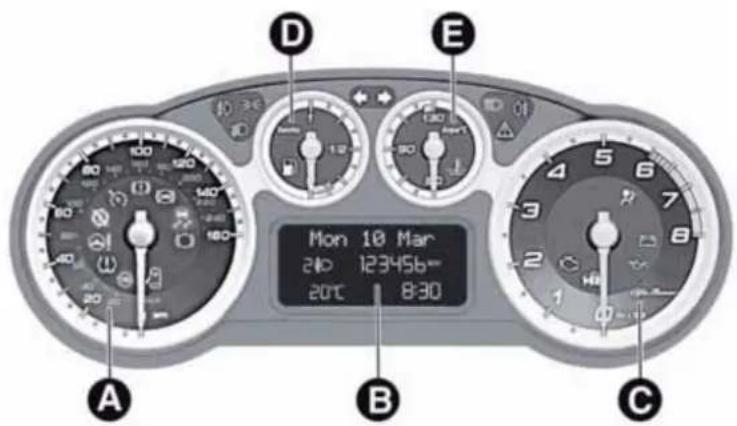
text_image
Mon 10 Mar 240 123456= 20°C 8:30fig. 2
A0J1542
A. Speedometer (speed indicator) B. Multifunctional display C. Rev counter D. Fuel level gauge with reserve warning light E. Engine coolant temperature gauge and excessive temperature warning light
00 = 3 and 27 warning lights supplied in diesel versions only. On diesel versions the rpm gauge end of scale is set at 6000 rpm. WARNING Instrument background colour and type may vary according to the version.
VERSIONS WITH RECONFIGURABLE MULTIFUNCTIONAL DISPLAY

text_image
A B C D E 100 180 160 20:30 Monclay 20 °C 10 240 March 123456 Kmfig. 3
A0J1543
A. Speedometer (speed indicator) B. Reconfigurable multifunctional display C. Rev counter D. Fuel level gauge with reserve warning light E. Engine coolant temperature gauge and excessive temperature warning light
and warning lights supplied in diesel versions only. On diesel versions the rpm gauge end of scale is set at 6000 rpm. WARNING Instrument background colour and type may vary according to the version.
page intentionally left blank

text_image
ALFA ROMEOS O U N D S Y S T E M
TABLE OF CONTENTS
INTRODUCTION 239
ADVICE 239
TECHNICAL CHARACTERISTICS.... 240
FUNCTIONS AND ADJUSTMENTS 247
SWITCHING ON THE RADIO 247
SWITCHING OFF THE RADIO 247
SELECTING THE RADIO FUNCTIONS....247
SELECTING CD FUNCTION.... 247
AUDIO SOURCE MEMORY FUNCTION 247
VOLUME ADJUSTMENT 247
MUTE/PAUSE FUNCTION (zeroing the volume) 247
AUDIO SETTINGS.... 248
TONE ADJUSTMENT (bass/treble) 248
BALANCE ADJUSTMENT 248
FADER ADJUSTMENT 248
LOUDNESS FUNCTION 249
PRESET/USER/CLASSIC/ROCK/JAZZ FUNCTIONS.... 249
USER EQ SETTINGS FUNCTION 249
MENU 249
AF SWITCHING function 250
TRAFFIC INFORMATION function 250
REGIONAL MODE function 251
MP3 DISPLAY function 252
SPEED VOLUME function 252
RADIO ON VOLUME function 252
PHONE FUNCTION....253
AUX OFFSET function 253
RADIO OFF function 253
SYSTEM RESET function 253
PHONE SET-UP 254
ANTI-THEFT PROTECTION.... 254
RADIO (TUNER) 255
INTRODUCTION....255
FREQUENCY BAND SELECTION.... 255
PRESET BUTTONS 256
STORING THE LAST STATION LISTENED TO.... 256
AUTOMATIC TUNING 256
MANUAL TUNING 256
AUTOSTORE FUNCTION 256
EMERGENCY ALARM RECEPTION 257
EON FUNCTION (Enhanced Other Network) 257
STEREOPHONIC BROADCASTERS.... 257
CD PLAYER 258
INTRODUCTION....258
SELECTING THE CD PLAYER 258
LOADING/EJECTING A CD 258
DISPLAY INFORMATION 259
TRACK SELECTION (forward/back) 259
TRACK FAST FORWARD/REWIND 259
PAUSE FUNCTION 259
MP3 CD PLAYER 260
INTRODUCTION....260
MP3 MODE 260
SELECTING MP3 SESSIONS ON HYBRID DISCS 260
DISPLAY INFORMATION 261
SELECTING NEXT/PREVIOUS FOLDER 261
STRUCTURE OF THE FOLDERS 261
AUX 262
INTRODUCTION....262
AUX MODE....262
TROUBLESHOOTING 263
GENERAL 263
CD PLAYER 263
MP3 FILE READING 263
INTRODUCTION
The radio has been designed according to the passenger compartment's specific characteristics and with a personalised design that complements the style of the dashboard.
The instructions for use are given below. We recommend that you read them carefully.
ADVICE
Road safety
Familiarise yourself with the various car radio functions (e.g. storing radio stations), before starting to drive.
Reception conditions
Reception conditions change constantly while driving. Reception may be interfered with by the presence of mountains, buildings or bridges, or when you are far away from the broadcaster.
Note The volume may be increased when receiving traffic alerts and news.

Ifthevolumeistooloudthiscouldbe dangerousforthedriverandforpassengers whendrivingintraffic.Alwaysadjustthe
volumesothatyoucanstillhearbackgroundnoises.
Maintenance and care
Only clean the cover with a soft, anti-static cloth. Cleaning and polishing products may damage the surface.
CD
Dirt, scratches or any distortions on CDs may cause skipping during playback and poor sound quality. Follow these tips for optimum playback conditions:
□ only use CDs with the following mark:

☐ clean every CD thoroughly removing any fingerprints or dust using a soft cloth. Hold CDs by the circumference and clean them from the centre towards the edge;
□ never use chemical products (e.g. antistatic or thinner spray cans) for cleaning as they could damage the surface of the CDs;
□ after listening to them place CDs back in their cases to avoid them being damaged;
☐ do not expose CDs to direct sunlight, high temperatures or moisture for long periods;
☐ do not stick labels on the surface of the CD and do not write on the recorded surface using pens or pencils;
☐ Never use CDs that are very scratched, cracked, distorted, etc. Their use could cause damage to the player or make it malfunction;
☐ to achieve the best quality audio reproduction we recommend the use of original CD media. Correct operation is not guaranteed when CD-R/RW media are used that were not correctly burnt and/or with a maximum capacity above 650 Mb;
☐ do not use commercially available protective sheets for CDs or discs with stabilisers as they could get stuck in the internal mechanism and damage the disc;
☐ if a copy-protected CD is used, it may take a few seconds before the system starts to play it. The CD player cannot be guaranteed to play all protected discs. The presence of copy protection is often indicated in small or difficult to read letters on the cover of the CD; like, for example, "COPY CONTROL", "COPY PROTECTED", "THIS CD CANNOT BE PLAYED ON A PC/MAC" or may be identified through the use of symbols, such as, for example:

☐ The CD player is able to read most of the compression systems currently on the market (e.g.: LAME, BLADE, XING, FRAUNHOFER) but as these systems are continually evolving, playback of all compression formats is not guaranteed.
TECHNICALCHARACTERISTICS
Maximum power: 4x40 W
BASICLEVELSYSTEM
Standard level audio
Frontspeakers
□2 × tweeters, ∅ 38 mm;
□2 × mid-woofer speakers, ∅ 165 mm.
Rearspeakers
□2 × full-range speakers, ∅ 165 mm.
QUICKGUIDE
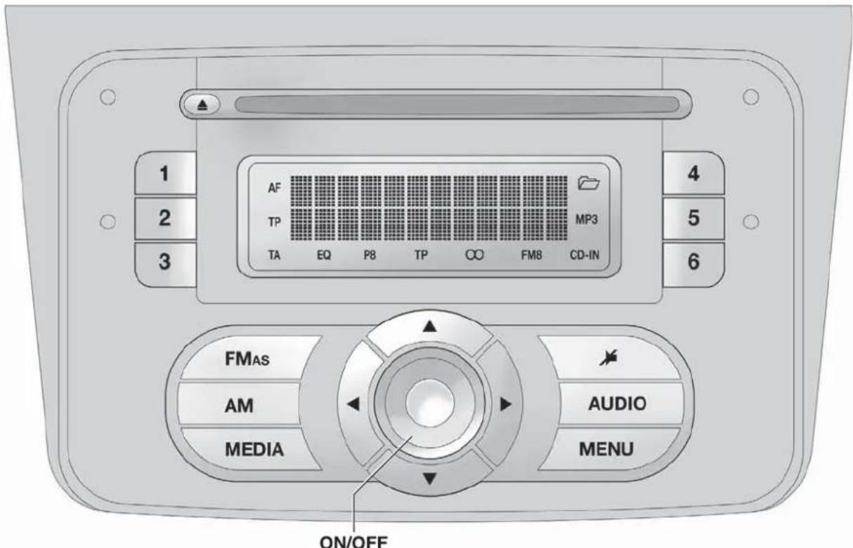
text_image
1 2 3 AF TP TA EQ P8 TP ∞ FM8 CD-IN 4 5 6 FMAs AM MEDIA AUDIO MENU ON/OFFfig. 1
A0J0001
GENERALFUNCTIONS
Button Functions Mode
| ON/OFF | Switching on Brief button press | |
| Switching off Brief button press | ||
| Volume adjustment LH/RH knob rotation | ||
| FM AS | Selection of radio source FM1, FM2, FM Autostore | Brief cyclical button press |
| AM | MW1, MW2 radio source selection | Brief cyclical button press |
| MEDIA | CD or AUX source selection (for versions/markets, where provided) | Brief cyclical button press |
| Volume activation/deactivation (MUTE/PAUSE) | Brief button press | |
| AUDIO | Audio adjustments: low tones (BASS), high tones (TREBLE), RH/LH balance (BALANCE), front/rear balance (FADER) | Menu activation: brief button pressSelection of adjustment type: pressing buttons▲ or▼Adjustment of values: pressing buttons ◄ ▶ |
| MENU | Advanced functions adjustment | Menu activation: brief button pressSelection of adjustment type: pressing buttons▲ or▼Adjustment of values: pressing buttons ◄ ▶ |
RADIOFUNCTIONS
Button Functions Mode
| ▲▼◀▶ | Radio station search:- Automatic search- Manual search | Automatic search: press buttons◀ or (hold down for fast forward)Manual search: press buttons▲ or (hold down for fast forward) |
| 1 2 3 4 5 6 | Store current radio station | Long button press for memory preset 1 to 6 respectively |
| Stored station recall | Brief button press for memory preset 1 to 6 respectively |
CDFUNCTIONS
Button Functions Mode
| ▲ | CD ejection Brief button press | |
| ◀▶ | Play previous/next track | Pressing ◀ or ▶ buttons briefly |
| CD track fast forward/rewind Pressing | ◀ or ▶ buttons briefly | |
| ▲▼ | Playing previous/next folder (for CD-MP3) | Pressing ▲ or ▼ buttons briefly |
STEERINGWHEELCONTROLS
(for versions/markets, where provided)
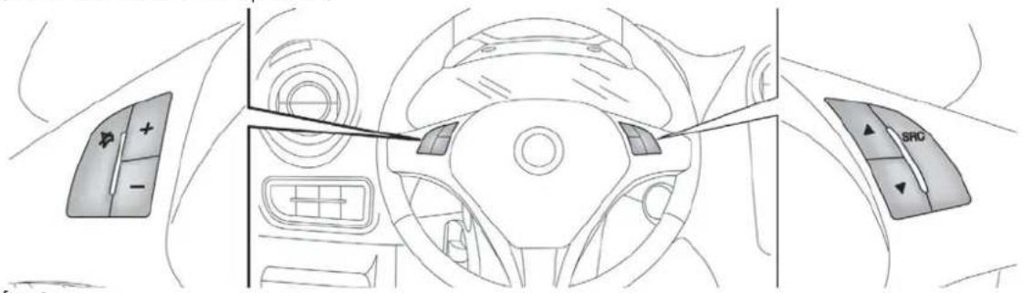
text_image
Diagram of car interior showing dashboard, steering wheel, and SRO controls with directional arrows and a cursor pointerfig. 2
A0J0052
Button Functions Mode
| AudioMute switching on/off (Radio mode) or Pause function (MP3 mode) | Brief button press | |
| + Volume increase Button press | ||
| - Volume decrease Button press | ||
| SRC | Radio frequency range selection (FM1, FM2, FMT, FMA, MW) and listening sources: Radio, MP3 or AUX (for versions/markets, where provided) | Button press |
| ▲ | Radio: recall stored stations (from 1 to 6) CD/CD MP3: select next track | Button press |
| ▼ | Radio: recall stored stations (from 6 to 1) CD/CD MP3: select previous track | Button press |
NOTE Starting from the FM or AM source set on the radio (e.g. FM1 or MW1), if you cycle through the audio sources using the SRC button among the steering wheel controls (stopping on a source other than radio) when the radio source is selected (FM or AM) using the buttons on the radio panel, the radio always switches to the last radio source (FMA or MW2).
GENERALINFORMATION
The radio offers the following functions:
Radio section
☐ PLL tuning with FM/AM/MW frequency bands;
☐ RDS (Radio Data System) with TA (traffic alerts) function - TP (traffic programmes) - EON (Enhanced Other Network) - REG (regional programmes);
☐ AF: search selection for alternative frequencies in RDS mode;
□provision for emergency alarm;
□ automatic/manual tuning of stations;
☐FM Multipath detector;
☐ manual storing of 30 stations: 18 on FM band (6 on FM1, 6 on FM2, 6 on FMT), 12 on MW band (6 on MW1, 6 on MW2);
□ automatic memorization (AUTOSTORE function) of 6 stations in the dedicated FM band;
☐ SPEED VOLUME function (excluding versions with Bose Hi-Fi system): speed-dependent automatic volume adjustment;
□automatic Stereo/Mono selection.
CD section
□ Direct selection of the disc;
☐Track selection (forward/back);
☐ Fast advance (forward/back) through tracks;
☐ CD Display function: display of disc name and time elapsed since the start of the track;
□ Playing of audio CDs, CD-Rs and CD-RWs.

MultimediaCDsincludedatatracksinaddition totheaudiotracks.PlayingthistypeofCDcan causehissingatavolumethatmayjeopardise
roadsafetyaswellascausingdamagetothefinal stagesandthespeakers.
MP3 CD section
□MP3-Info function (ID3-TAG);
☐Folder selection (previous/next);
□Track selection (forward/back);
☐ Fast advance (forward/back) through tracks;
☐ MP3 Display function: display of name of folder, ID3-TAG information, time elapsed since the start of the track, name of the file);
☐ Playing of audio or data CDs, CD-Rs and CD-RWs.
Audio section
□Mute/Pause function;
□Soft-Mute function;
☐ Loudness function (excluding versions with Bose HI-FI system);
☐ 7-band graphic equaliser (excluding versions with Bose HI-FI system);
Separate bass/treble adjustment;
Right/left channel balance.
AUX section
(for versions/markets, where provided)
□AUX source selection;
☐ AUX Offset function: alignment of the portable device volume with that of the other sources;
□Portable player playback.
FUNCTIONSANDADJUSTMENTS
SWITCHINGONTHERADIO
The radio switches on when the ON/OFF button is pressed briefly.
When the radio is turned on, the volume is limited to level 20 if it was set to a higher value when previously used or to level 5 if it was previously set to value 0 or to Mute/Pause. The previously set value is maintained in all other cases.
When the radio is switched on with the key extracted from the ignition, it switches off automatically after about 20 minutes. After the radio has switched itself off automatically it can be switched on for a further 20 minutes by pressing the ON/OFF button.
By pressing the FM AS button quickly and repeatedly, the following audio sources can be selected cyclically:
☐TUNER ("FM1", "FM2", "FMA").
By pressing the AM button briefly and repeatedly, the following audio sources can be selected cyclically:
☐TUNER ("MW1", "MW2").
SELECTINGCDFUNCTION
By pressing the MEDIA button briefly it is possible to select the CD function.
AUDIOSOURCEMEMORYFUNCTION
If another function (e.g. the radio) is selected whilst listening to a CD, playback is interrupted and is resumed from the same point when returning to the CD source.
If another function is selected whilst listening to the radio, the last station selected is tuned into when returning to Radio mode.
VOLUMEADJUSTMENT
To adjust the volume, turn the ON/OFF knob.
If the volume level is changed during the transmission of traffic news, the new setting will only be maintained until the update is finished.
MUTE/PAUSEFUNCTION (zeroingthevolume)
Press the ▶ button briefly to activate the Mute function. The volume will gradually decrease and the words "RADIO Mute" (in radio mode) or "PAUSE" (in CD mode) will be displayed.
Press the ➤ button again to deactivate the Mute function. The volume will gradually increase until it reaches the level set previously.
When the volume level is changed using the dedicated controls, the Mute function is deactivated and the volume is adjusted to the new level selected.
With the Mute function activated, it will be ignored when there is an incoming traffic alert (if the TA function is activated), or if an emergency alarm is received. The function will be reactivated when the alert is over.
AUDIO SETTINGS
The functions that can be selected from the audio menu change depending on the context: AM/FM/CD/AUX (for versions/markets, where provided).
Press the AUDIO button briefly to change the Audio functions.
After the AUDIO button is first pressed, the display will show the bass level value for the source activated at that time (e.g. in FM mode the display will show the wording "FM Bass + 2").
Use the ▲ or ▼ buttons to scroll through the menu functions. To change the setting of the function selected use the ◀ or ▶ buttons. The current status of the function selected will be shown on the display.
The functions managed by the Menu are:
☐ BASS (adjustment of bass tones);
☐ TREBLE (adjustment of high tones);
☐ BALANCE (right/left balance adjustment);
☐ FADER (front/back balance adjustment);
☐ LOUDNESS (LOUDNESS function activation/deactivation);
☐ EQUALISER (activation and selection of factory-set equaliser levels);
☐ USER EQUALISER (customised equaliser setting).
TONEADJUSTMENT(bass/treble)
Proceed as follows:
□Use ▲ or ▼ buttons to set the "Bass" or "Treble" in the AUDIO menu;
□press the ◀ or ▶ button to increase/decrease the bass or treble.
By pressing the buttons briefly, the levels will change progressively in steps. By pressing them for longer, the levels will change quickly.
BALANCEADJUSTMENT
Proceed as follows:
☐ Select the "Balance" setting in the AUDIO menu using the ▲ or ▼ button;
□press the ◀ button to increase the volume of the right speakers or the ▶ button to increase the volume of the left speakers.
By pressing the buttons briefly, the levels will change progressively in steps. By pressing them for longer, the levels will change quickly.
Select the value “◀ 0▶” to set the same level for the right and left audio outputs.
FADERADJUSTMENT
Proceed as follows:
☐ Select the "Fader" setting in the AUDIO menu using the ▲ or ▼ button;
□press the ◀ button to increase the sound from the rear speakers or the ▶ button to increase the sound from the front speakers.
By pressing the buttons briefly, the levels will change progressively in steps. By pressing them for longer, the levels will change quickly.
Select the value "◀ 0 ▶" to set the same level for the front and rear audio outputs.
LOUDNESSFUNCTION
The Loudness function improves the volume of the sound whilst listening at low volumes, increasing the bass and treble.
To activate/deactivate the function, select the Loudness setting of the AUDIO menu using the ◀ or ▶ buttons.
The condition of the function (on or off) is shown on the display for a few seconds by the wording "Loudness On" or "Loudness Off".
PRESET/USER/CLASSIC/ROCK/JAZZ FUNCTIONS
(equaliser activation/deactivation)
The built-in equaliser can be activated/deactivated. When the equaliser function is off, the audio settings can only be changed by adjusting the "Bass" and "Treble" settings, whereas when the function is on, the acoustic curves can be adjusted.
To deactivate the equaliser, select the "EQ Preset" function using the buttons ◀ or ▶.
To activate the equaliser, use the ◀ or ▶ buttons to select one of the adjustments:
☐ "FM/AM/CD...EQ User" (adjustment of 7 equaliser bands that can be changed by the user);
☐ "Classic" (equaliser preset for optimal classical music sound);
☐ "Rock" (equaliser preset for optimal rock and pop music sound);
☐ "Jazz" (equaliser preset for optimal jazz music sound).
When one of the equaliser settings is activated the letters "EQ" light up.
USEREQSETTINGSFUNCTION
(equaliser settings only if the USER setting is selected)
To set a personalised equaliser adjustment, set to "User" using the ▲ or ▼ button and press the MENU button.
A 7-bar graph appears on the display, in which each bar represents a frequency.
Select the bar to adjust using the ◀ or buttons; the selected bar will start to flash and it can be adjusted using the ▲ or buttons.
To store the setting, press the AUDIO button again. The display will show the active source at that time followed by the word "USER". If the mode is "FM", for example, the display will show the text "FM EQ User".
MENU
MENU button functions
Press the MENU button briefly to activate the Menu function. The display will show the first menu item that can be adjusted (AF) ("AF Switching On" on the display).
Use the ▲ or ▼ buttons to scroll through the menu functions. To change the setting of the function selected use the ◀ or Buttons.
The current status of the function selected will be shown on the display.
The functions managed by the Menu are:
□AF SWITCHING (ON/OFF);
□TRAFFIC INFORMATION (ON/OFF);
☐ REGIONAL MODE regional programmes (ON/OFF);
☐ MP3 DISPLAY (CD MP3 display settings);
☐ SPEED VOLUME (speed-dependent automatic volume control);
☐ RADIO ON VOLUME (radio volume limit activation/deactivation);
☐ SPEECH VOLUME (telephone volume adjustment) (for versions/markets, where provided);
☐ AUX OFFSET (alignment of the portable device volume to that of the other sources) (for versions/markets, where provided);
☐RADIO OFF (switching-off mode);
□SYSTEM RESET
Press the MENU button again to exit the Menu function.
Note The AF SWITCHING, TRAFFIC INFORMATION and REGIONAL MODE adjustments are only possible in FM mode.
AFSWITCHINGfunction (alternative frequency search)
The radio can operate in two different modes using RDS:
☐ "AF Switching On": search for alternative frequencies active (the letters "AF" appear on the display);
☐ "AF Switching Off": search for alternative frequencies not active. Proceed as follows to activate/deactivate the function:
☐ press the MENU button and select "AF Switching On";
□press the ◀/▶ buttons to activate/deactivate the function.
When the function is activated, the radio automatically tunes into the station with the strongest signal broadcasting the same programme. While driving, the same station can be continuously listened to without having to change the frequency when you change zones.
Obviously, it must be possible to receive the station that you are listening to in the area you are driving through.
If the AF function has been activated, "AF" will light up in the display.
If the AF function has been activated and the radio is not able to receive the current station, the radio activates the automatic search, during which "FM Search" appears on the display (only for top-of-the-range radios).
With the AF function deactivated, the remaining RDS functions, such as the display of the station name, still remain active.
The AF function can only be activated on FM bands.
TRAFFICINFORMATIONfunction (traffic information)
Some stations on the FM band (FM1, FM2 and FMA) can broadcast information about traffic conditions. In this case the letters "TA" appear on the display.
Proceed as follows to switch the TA function on/off:
☐ press the MENU button briefly and select "Traffic info";
□press the ◀/▶ buttons to activate/deactivate the function.
If the TA function has been activated, the "TA" icon lights up on the display.
Note If the TA function is activated with an audio source other than Tuner (Radio) (CD, MP3, telephone or Mute/Pause), the radio can carry out an automatic search and therefore it is possible, when reactivating the Tuner (Radio) source, that the frequency tuned into is different from the one previously set.
With the TA function, it is possible to:
□ search only for RDS stations that broadcast in FM and are enabled to broadcast traffic information;
□ receive traffic information even when the CD player is in operation;
□ receive traffic information at a minimum preset volume even with the radio volume off.
Note In some countries there are radio stations that, even with the TP function activated, do not transmit traffic information (the "TP" icon appears on the display).
If the radio is tuned to a station in the AM band, when TA is activated it will tune into the last selected station in the FM1 band.
The volume at which the traffic news is transmitted depends on the listening volume:
☐ listening volume below 5: traffic news volume 5 (fixed value);
☐ listening volume above 5: traffic news volume equal to listening volume +1.
If the volume is changed during traffic news, the level will not be shown on the display; the new level will only be maintained during the news.
While traffic information is being received, "TRAFFIC INFORMATION" will appear on the display.
The TA function can be interrupted by pressing any button on the radio.
REGIONALMODEfunction (regional transmission reception)
Some national broadcasters will transmit regional programmes at certain times of the day (that vary from region to region).
This function makes it possible to tune into local (regional) broadcasters automatically (see "EON function" paragraph).
If you want the radio to automatically tune into the regional stations being broadcast on the selected network, the function must be activated.
To activate/deactivate the function use the ◀ or buttons.
The current status of the function appears on the display:
☐“Regional On”: function activated;
□"Regional Off": function deactivated.
If the function is deactivated and you have tuned into a regional station working in a given area and you enter a different area, then the regional station received in the new area will be broadcast.
Note If the AF and REG functions are on at the same time, once a border between two regions is crossed, the radio may not switch correctly to a valid alternative frequency.
MP3DISPLAYfunction (MP3 CD data display)
This function makes it possible to select the information shown by the display when listening to a CD containing MP3 tracks.
The function can only be selected if an MP3 CD is inserted: in this case "MP3 Display" will appear on the display.
To change the function, use the ◀ or ▶ buttons.
The following settings are available:
☐ "Title" (track title, if the ID3-TAG is available);
☐ "Author" (track author, if the ID3-TAG is available);
☐ "Album" (track album, if the ID3-TAG is available);
☐ "Folder" name (name assigned to the folder);
☐ "File" name (name assigned to the MP3 file).
SPEEDVOLUMEfunction (speed-based volume change)
This function automatically adapts the volume level to the speed of the car, increasing the volume when the speed increases to maintain the ratio with the noise level inside the passenger compartment.
To activate/deactivate the function, press the ◀/buttons. The words "Speed volume" appear on the display, followed by the current status of the function:
☐Off: function deactivated
☐ Low: function activated (low sensitivity)
☐ High: function activated (high sensitivity).
RADIOONVOLUMEfunction (radio volume limit activation/deactivation)
This function makes it possible to activate/deactivate the volume limits when the radio is turned on.
The display shows the function status:
☐ "Radio on vol – Limit on": when the radio is switched on the volume level will be:
- if the volume level is equal to or higher than the maximum value, the radio will switch on at the maximum volume;
- if the volume level is between the minimum and maximum values, the radio will switch on at the same volume as before it was switched off.
☐ "Radio on vol – Limit off": the radio will switch on at the volume level it was at before switching off. The volume may be between 0 and 40.
To change the setting of the selected function, use the ▶/▶buttons.
NOTES
☐ Using the Menu it is only possible to adjust the activation/deactivation of the function and not the minimum or maximum volume value.
☐ If the "TA" or "TEL" functions or an external audio source are activated when the radio is turned on, the radio will switch on at the volume set for these sources. When the external audio source is deactivated, the volume can be adjusted between the minimum and maximum levels.
☐ If the battery charge is low, it will not be possible to adjust the volume between the minimum and maximum levels.
PHONEFUNCTION
(telephone volume adjustment)
With Speech volume function present in Menu
This function makes it possible to adjust (settings from 1 to 40), by turning the ON/OFF left knob/button or pressing the
◀/▶ buttons, or mute (OFF setting) the volume of the telephone.
The display shows the current function status:
☐"Speech Off": function deactivated.
☐ "Speech volume 23": function active with volume setting 23.
With Speech volume function not present on the Menu
When a phone call is received, the audio passes to the car's audio system through the radio.
The telephone audio always arrives at a fixed volume, but it can be adjusted during a conversation using the ON/OFF button/knob.
AUXOFFSETfunction
(alignment of the portable device volume with that of the other sources)
(for versions/markets, where provided)
This function enables the alignment of the volume of the AUX source, depending on its own portable player, with that of the other sources.
To activate the function, press the MENU button and select "AUX offset".
Press the ◀ or ▶ buttons to decrease or increase the volume value (set from -6 to +6).
RADIOOFFfunction
(on and off mode)
This function is used to set the radio switching-off mode to one of two different settings.
To activate the function, use the ◀ or ▶ button.
The selected mode will appear on the display:
☐ "00 MIN": the radio switches off automatically in connection with the ignition key; the radio switches off automatically as soon as the key is turned to STOP position;
☐ "20 MIN": the radio switches off independently of the ignition key; the radio remains switched on for a maximum period of 20 minutes after the key has been turned to STOP position.
SYSTEMRESETfunction
This function is used to restore all settings to the factory values.
The options are:
☐NO: no restore intervention;
☐ YES: the default parameters will be restored. During this operation, the word "Resetting" appears on the display. At the end of the operation, the source does not change and the previous situation will be displayed.
PHONESET-UP
If a hands-free kit is installed on the car, when there is an incoming phone call the radio audio will be connected to the telephone output. The telephone audio always arrives at a fixed volume, but it can be adjusted during a conversation using the ON/OFF button/knob.
The fixed telephone audio volume can be adjusted using the "SPEECH VOLUME" function in the Menu (where the function is provided). The word "PHONE" will appear on the display during the deactivation of the audio for the phone call.
ANTI-THEFTPROTECTION
The radio is equipped with an anti-theft protection system based on the exchange of information between the radio and the electronic control unit (Body Computer) on the car.
This system guarantees maximum safety and avoids the entry of the secret code each time the radio power supply is disconnected.
If the check has a positive outcome, the radio will start to function, whereas if the comparison codes are not the same or if the electronic control unit (Body Computer) is replaced, the device will ask the user to enter the secret code according to the procedure described in the paragraph below.
Entering the secret code
When the radio is switched on, if the code is requested, the display will show "Radio code" for about 2 seconds followed by four dashes "----".
The code is made up of four numbers from 1 to 6, each corresponding to one of the dashes.
To enter the first digit of the code, press the corresponding button of the pre-selected stations (from 1 to 6). Enter the other code numbers in the same way.
If the four digits are not entered within 20 seconds, the display will show "Enter code - - -". If this occurs, it is not considered an incorrect code entry.
After entering the fourth digit (within 20 seconds), the radio will start to operate.
If an incorrect code is entered, the radio will emit a sound and the display shows the text "Radio blocked/wait" to notify the user of the need to enter the correct code.
Each time the user enters an incorrect code, the waiting time will gradually increase (1 min, 2 min, 4 min, 8 min, 16 min, 30 min, 1 h, 2 h, 4 h, 8 h, 16 h, 24 h) up to a maximum of 24 hours.
The waiting time will be shown on the display with the text "Radio blocked/wait". After the text has disappeared it is possible to start the code entry procedure again.
Car radio passport
This document certifies ownership of the radio. The car radio passport shows the radio model, serial number and secret code.
Note Keep this car radio passport in a safe place so that you can give the information to the relevant authorities if the car radio is stolen.
In case of loss of the car radio passport, contact the Alfa Romeo Authorised Services, taking an ID document and the car ownership documents.
RADIO(TUNER)
INTRODUCTION
When the radio is switched on, the last function selected before it was switched off is activated: Radio, CD, CD MP3 or AUX (only with ) (for versions/markets, where provided).
To select the Radio function when another audio source is being listened to, briefly press the FM AS or AM buttons depending on the desired band.
Once the Radio mode has been activated, the display will show the name (RDS stations only) and the frequency of the selected radio station, the frequency band selected (e.g. FM1) and the preselect button number (e.g. P1).
With the Radio mode active, press the FM AS or AM button briefly and repeatedly to select the desired reception band.
Each time the button is pressed the following bands are selected cyclically:
☐ By pressing the FM AS button: "FM1", "FM2" or "FMA";
☐ By pressing the AM button: "MW1, MW2".
Each band is highlighted by the name in the display. The last station selected on the respective frequency band will be tuned into.
The FM band is divided into sections: FM1, FM2 or "FMA"; the FMA reception band is reserved for broadcasters stored automatically using the AutoSTore function.
PRESETBUTTONS
The buttons numbered from 1 to 6 are used to set the following preset stations:
☐ 18 in the FM band (6 in FM1, 6 in FM2, 6 in FMT or "FMA" (on some versions));
☐ 12 in the MW band (6 in MW1, 6 in MW2).
To listen to a preset station, select the desired frequency band and then briefly press the corresponding preset button (from 1 to 6).
By pressing the preset button for more than 2 seconds, the current station will be stored.
The storing phase is confirmed by an acoustic signal.
STORINGTHELASTSTATIONLISTENED TO
The radio automatically stores the last station that was selected for each reception band, which is then tuned into when the radio is turned on or when the reception band is changed.
AUTOMATICTUNING
Briefly press the ◀ or ▶ button to start the automatic tuning search for the next station that can be received in the selected direction.
If the ◀ or ▶ button is pressed down longer, the fast search starts. When the button is released, the tuner will stop on the next station that can be received.
If the TA function (traffic alerts) is on, the tuner will only search for stations that broadcast traffic news and alerts.
MANUALTUNING
This is used to manually search for stations in the preselected band.
Select the desired frequency band and then press the ▲ or ▼ button briefly and repeatedly to start to the search in the desired direction.
If the ▲ or ▼ buttons are pressed longer, the fast search will start and then stop when the button is released.
AUTOSTOREFUNCTION (automatic station storing)
To activate the AutoSTore function, hold the FM AS button down until an acoustic signal is heard. With this function, the radio automatically stores the 6 stations with the strongest signal in decreasing order on the FMA frequency band.
During the automatic storing process, the word "Autostore" flashes on the display.
Press the FM AS button again to interrupt the AutoSTore function: the radio will again tune into the station listened to before the activation of the function.
When the AutoSTore function has finished, the radio will automatically tune into the first preset station on the FMA band stored on the preset side 1.
The stations that have a strong signal in the preselected band at that moment, are then automatically stored on the buttons numbered from 1 to 6.
When the AutoSTore function is activated within the MW band, the FMA band is automatically selected and the function is performed there.
Note Sometimes the AutoSTore function is not able to find 6 stations with a strong signal. In this case, the strongest stations will be duplicated in the free preset buttons.
Note When the AutoSTore function is activated, the stations that were previously stored in the FMA band are deleted.
EMERGENCYALARMRECEPTION
The radio is configured to receive emergency alerts in RDS mode in exceptional circumstances or where dangerous situations are present (earthquakes, floods, etc.) if these are being transmitted by the current broadcaster.
This function is activated automatically and cannot be turned off.
The word "Alarm" will be shown in the display during the transmission of an emergency announcement. The volume of the radio will change during this announcement in the same way as during a traffic bulletin.
EONFUNCTION
(EnhancedOtherNetwork)
In some countries, there are circuits that group multiple broadcasters that transmit traffic information together. In this case, the programme of the station that is being listened to will be temporarily interrupted to:
□ receive traffic alerts (only with the TA function activated);
☐ listen to regional transmissions each time these are broadcast by one of the broadcasters on the same circuit.
STEREOPHONICBROADCASTERS
If the incoming signal is weak, playback is automatically switched from Stereo to Mono.
CDPLAYER
INTRODUCTION
This section describes the variants regarding the operation of the CD player: as far as the operation of the radio is concerned, refer to the description in the "Functions and Adjustments" chapter.
To activate the CD player built into the equipment, proceed as follows:
☐ insert a CD with the equipment switched on: the first track will start to play;
or
☐ if a CD has already been loaded, switch on the radio and then briefly press the CD button to select the "CD" operating mode: the last track listened to will start to play.
It is advisable to use original CDs to ensure optimum playback. If CD-R/RWs are used, we recommend using good quality media mastered at the slowest speed possible.
LOADING/EJECTINGACD
To load the CD, insert it gently into the slot to activate the motorised loading system, which will position it correctly.
The CD can be loaded with radio off and the ignition key turned to MAR: in this case the radio will remain off. When the radio is turned on, the last source listened to prior to switching off will be activated.
When a CD is inserted the display will show the symbol "CD-IN" and the text "CD Reading". They will remain displayed for the entire time required for the radio to read the CD tracks. When this time has elapsed the radio will automatically start to play the first track.
Press the ▲ button with the radio on to activate the motorised ejection of the CD. After ejection, the last audio source listened to before playing the CD will be heard.
If the CD is not removed from the radio, it will automatically be reloaded about 20 seconds later and the Tuner mode will be activated (Radio).
The CD cannot be ejected if the radio is off.
If the ejected CD is reloaded without having removed it completely from the slot, the radio will not switch to the CD source.
Possible error messages
If the CD loaded cannot be read (e.g. a CD ROM has been inserted or the CD is inserted upside down or there is reading error) the display will show the text "CD Disc error".
The CD will then be ejected and the audio source activated prior to the CD mode selection will be heard.
With an external audio source activated ("TA", "ALARM" or "Phone"), the CD that cannot be read will not be ejected until these functions have ended. At the end, with the CD mode activated, the display will show the text "CD Disc error" for a few seconds and then the CD will be ejected.
DISPLAYINFORMATION
When the CD player is working, the display will show the following information:
☐ "CD Track 5": indicates the number of the CD track;
☐ "03:42": indicates the time elapsed since the start of the track (if the relevant Menu function is activated).
TRACKSELECTION(forward/back)
Briefly press the ◀ button to play the previous CD track and the ▶ button to play the next track.
The tracks are selected cyclically: the first track is selected after the last track and vice versa.
If the track has been played for more than 3 seconds, pressing the ◀ button will cause the track to be started again from the beginning.
In this case, if you want to play the previous track, press the button twice consecutively.
TRACKFASTFORWARD/REWIND
The fast forward/rewind will stop once the button is released.
PAUSEFUNCTION
To pause the CD player, press the ➤ button. The text "CD Pause" appears on the display.
To resume listening to the track, press the ▶ button again. If another audio source is selected, the pause function is deactivated.
MP3CDPLAYER
INTRODUCTION
This section only describes the variants regarding the operation of the CD MP3 player: as far as the operation of the radio is concerned, refer to the description in the "Radio" and "CD MP3 Player" sections.
NOTE MPEG Layer-3 audio decoding technology licensed from Fraunhofer IIS and Thomson multimedia.
MP3MODE
In addition to playing regular audio CDs, the radio is also able to play CD-ROMs on which audio files have been stored using the MP3 compression format. The radio operates as described in the "CD Player" section when an ordinary audio CD is inserted.
To guarantee optimal playback quality it is advisable to use good quality CDs mastered at the lowest speed possible.
The files on an MP3 CD are structured by folder, creating lists of all the folders containing MP3 tracks (folders and subfolders are all displayed on the same level); the folders that do not contain MP3 tracks cannot be selected.
The operating conditions and specifications for playing MP3 files are as follows:
☐ the CD-ROMs used should be burnt according to the ISO 9660 standard;
☐ the music files must have an ".mp3" extension: files with a different extension cannot be played;
☐ the following sampling frequencies can be played: 44.1 kHz, stereo (96 to 320 kbit/s) - 22.05 kHz, mono or stereo (32 to 80 kbit/s);
☐ tracks with a variable bit-rate can be reproduced.
Note The names of tracks must not contain the following characters: spaces, ' (apostrophes), ( and ) (open and close brackets). When burning an MP3 CD, make sure that the names of the files do not contain these characters; if they do, the radio will not be able to play the tracks involved.
SELECTINGMP3SESSIONS ONHYBRIDDISCS
If a hybrid disc is inserted (Mixed Mode, Enhanced, CD-Extra) also containing MP3 files, the radio automatically starts playing the audio session. It is possible to switch to the MP3 session whilst playing by holding the MEDIA button down for more than 2 seconds.
Note When the function is activated the radio may take a few seconds to start playing. Whilst checking the disc the display will show "CD READING". If no MP3 files are detected, the radio will resume playing the audio session from the point where it was interrupted.
DISPLAYINFORMATION
ID3-TAG information display
In addition to the information relating to the time elapsed, the name of the folder and the name of the file, the radio is also capable of displaying ID3-TAG information relating to the Track Title, Artist and Author.
The name of the MP3 folder shown on the display corresponds to the name with which the folder was stored on the CD, followed by an asterisk.
Example of a complete MP3 folder name: BEST OF *.
When ID3-TAG data is chosen to be displayed (Title, Artist, Album) that has not been recorded for the track played, the information will be replaced by that relating to the name of the file.
SELECTINGNEXT/PREVIOUSFOLDER
Press the ▲ button to select a subsequent folder or press the ▼ button to select a previous folder.
The display will show the number and the name of the folder (e.g. "DIR 2 XXXXXX").
XXXXXX: name of the folder (the display will only show the first 8 characters).
The folders are selected cyclically: the first folder is selected after the last folder and vice versa.
If no other folder/track is selected in the next 2 seconds, the first track on the new folder will be played.
If the last track in the folder at that moment selected is played, the next folder will be played.
STRUCTURE OF THE FOLDERS
The radio with MP3 player:
☐ recognises only the folders that contain MP3 format files;
☐ if the MP3 files on a CD-ROM are structured in sub-folders, their structure is compressed to a single level structure where the sub-folders are taken to the level of the main folders.
AUX
(for versions/markets, where provided)
INTRODUCTION
This section describes the variants regarding the operation of the AUX source: as far as the operation of the radio is concerned, refer to the description in the "Functions and Adjustments" section.
AUXMODE
To activate the AUX source, press the MEDIA button or the SRC control on the steering wheel repeatedly until the corresponding source is displayed.
The AUX socket is located on the central tunnel next to the power socket (or next to the cigar lighter socket, depending on the versions) fig. 3.
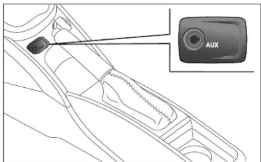
text_image
AUXfig. 3
A0J041
IMPORTANT
The functions of the device connected with the AUX socket are directly managed by the device itself; it is not possible to change track/folder/playlist with radio or steering wheel controls.
Do not leave the cable of your portable player connected to the AUX socket after disconnecting, to avoid possible hiss from the speakers.
TROUBLESHOOTING
GENERAL
Low volume
The Fader function should be adjusted only to the values "F" (front) to prevent a reduction in radio output power and the muting of the volume if the Fader level adjustment is equal to R+9.
Source cannot be selected
Nothing has been inserted.
Insert the CD or CD MP3 to be played.
CDPLAYER
The CD does not play
The CD is dirty. Clean the CD.
The CD is scratched. Try and use another CD.
The CD cannot be loaded
A CD is already loaded. Press the ▲ button and remove the CD.
MP3FILERREADING
Track skips during MP3 file playback
The CD is scratched or dirty. Clean the CD, referring to the contents of the "CD" paragraph in the "Introduction" section.
The duration of the MP3 tracks is not shown correctly
In some cases (due to the recording mode) the duration of the MP3 tracks may be displayed incorrectly.

In the heart of your engine.
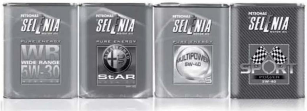
text_image
PETRONAS SELENIA MOTER 60 PURE ENERGY WB WIDE RANGE 5W-30 PETRONAS SELENIA MOTER 60 PURE ENERGY StAR PETRONAS SELENIA MOTER 60 PURE ENERGY MULTIPOWER 5W-40 PETRONAS SELENIA MOTER 60 SPORT POWER 5W-40Always ask your mechanic for

Oil change? The experts recommend Petronas Selenia
The engine of your car is factory filled with Petronas Selenia. This is an engine oil range which satisfies the most advanced international specifications. Its superior technical characteristics allow Petronas Selenia to guarantee the highest performance and protection of your engine.
The Petronas Selenia range includes a number of technologically advanced products:
SELENIA STAR PURE ENERGY
Fully synthetic lubricant capable of meeting the needs of high performance engines. Studied to protect the engine also in high thermal stress conditions, it prevents deposits on the turbine to achieve the utmost performance in total safety.
SELENIA WR PURE ENERGY
Fully synthetic lubricant that can meet the requirements of the latest diesel engines. Low ash content to protect the particulate filter from the residual products of combustion. High Fuel Economy System that allows considerable fuel saving. It reduces the danger of dirtying the turbine to ensure the protection of increasingly high performance diesel engines.
SELENIA MULTIPOWER GAS PURE ENERGY
Fully-synthetic lubricant designed for petrol engines also turbocharged, powered with methane or LPG. Its exclusive formulation improves valve protection against wear, neutralises the acid compounds formed by combustion and keeps engine performance levels unchanged.
SELENIA SPORT POWER
Fully synthetic lubricant capable of meeting the needs of high performance engines.
Studied to protect the engine also in high thermal stress conditions, it prevents deposits on the turbine to achieve the utmost performance in total safety.
The range also includes Petronas Selenia si completa con Selenia StAR, Selenia 20K AR, Selenia Turbo Diesel, Selenia Sport Selenia Racing.
For further information on Petronas Selenia products visit the web site www.pli-petronas.eu
NOTES
INDEX
ABS system....91
- Mechanical Brake Assist.... 91
- System intervention.... 91
Additional heater 61
Air cleaner 187
Alarm 41
"Alfa DNA" system.... 95
- Driving modes....95
- Engagement/disengagement of "All Weather" mode 97
- Engagement/disengagement of "Dynamic" mode.... 96
- "Natural" Mode.... 95
Alfa Romeo Code system 35
Ashtray 75
ASR system (AntiSlip Regulation) 93
Automatic dual zone climate control ..... 55
Battery 187
– advice for extending lifetime...... 187
-replacement....187
Battery (recharging).... 170
Body versions.... 198
Bodywork - body codes.... 198
- maintenance 193
– protection against atmospheric agents .... 193
-warranty....193
Bonnet....87
-Closing 88
- Opening....87
Brake Assist 94
Brakes....207
- brake fluid level.... 186
bulb replacement 158-159
- interior lights.... 160
Bulb replacement
- exterior lights.... 156
Bulbs
- types of bulbs.... 154
Carrying children safely 118
CBC (Cornering Brake Control) system ... 94
Central locking....72
Changing a bulb.... 153
- General instructions.... 153
Changing a wheel.... 143
Cigar lighter 75
Cleaning and maintenance
-bodywork 193
-car interior....194
- engine compartment.... 194
- plastic and coated parts.... 195
-seats and fabric parts 194
- windows.... 194
Climate control/heating system 52
Climatic comfort.... 51
- Diffusers 51
Clutch 206
CO2 emissions.... 229
Code Card.... 36
Control buttons.... 23
Control panel and instruments 4
- Multifunction display.... 4
- Reconfigurable multifunction display 5
Controls....71
Courtesy light
- bulb replacement.... 161
Cruise Control....67
Dashboard 3
Daytime running lights (DRL) 61
Diesel filter 187
Diesel particulate filter (DPF) 111
Dimensions.... 216
Dipped headlights - bulb replacement.... 156
Direction indicators 63-158
- bulb replacement.... 157
- "Lane change" function.... 63
Display....20
Doors....80
- Door central locking/unlocking ..... 80
DPF (particulate filter) 111
Driver side knee bag 129
DST system (Dynamic Steering Torque)....94
Dusk sensor 62
Dynamic Suspension (active shock absorber system).... 102
Electric power steering 103
Electric sun roof 77
Electric windows 81
- Controls....81
"Electronic Q2" system ("E-Q2") ..... 94
Engine codes.... 198
Engine compartment
-checking levels 179
- washing 194
Engine coolant temperature gauge ..... 6
Engine.... 200
- engine cooling system fluid level...... 185
- marking.... 197
Engine oil
-consumption 185
-level check.... 185
EOBD system 103
ESC (Electronic Stability Control) system....92
Exterior lights....61
- Left stalk 61
External courtesy lights 64
Extinguisher....76
Fitting "Universal" child seat.... 120
Fix&Go Automatic Kit.... 149
Flashing 63
Fluids and lubricants (specifications) ..... 224
Fog lights....72-158
"Follow Me Home" device 63
Front airbags.... 127
Front armrest 74
Front driver side airbag 127
Front passenger airbag.... 128
Front roof light
- bulb replacement.... 160
Fuel consumption.... 227
Fuel cut-off system 72
Fuel level gauge 6
Fuel supply 206
Fuel tank cap 110
Fuses (if a fuse blows).... 163
Gear Shift Indicator.... 22
Glove compartment....73
Glove compartment light
- bulb replacement.... 161
Handbrake 135
Hazard warning lights....71
Headlights 90
- Adjusting headlights abroad ..... 91
- bulb replacement.... 156
- Headlight alignment corrector ..... 90
– Light beam direction ..... 90
Headlight washers.... 192
Head restraints.... 47
- "Anti-Whiplash" device 47
-Front headrests....47
– Rear head restraints.... 48
Hill Holder system 93
Identification data
- bodywork paint plate.... 197
- Chassis marking.... 197
- engine marking.... 197
- identification data plate 196
Ignition device 43
- Steering lock.... 43
Installation of electrical/electronic devices.... 104
Installing a Universal Isofix child seat ..... 124
Interior fittings....73
Interiors (cleaning).... 194
Jack....144
Light clusters
- front light clusters (changing a bulb).... 156
- rear light clusters (changing a bulb).... 158
Lubricants (features).... 224
Luggage compartment 84
- Closing the luggage compartment..... 84
- Emergency luggage compartment opening....84
- Extending the luggage compartment.... 85
– Luggage compartment initialisation 85
- Opening the luggage compartment....84
Luggage compartment roof light - bulb replacement.... 160
Main beam headlights 63 – bulb replacement 15
Maintenance and care – heavy-duty use of the car 178
- periodic checks 178
– scheduled servicing ...... 173
– scheduled servicing plan.... 174
Menu options.... 24
MSR system 94
Multifunction display 20
Number plate lights - bulb replacement.... 159
Parking lights.... 62
Parking sensors.... 105
Performance 217
Pollen filter.... 187
Power sockets....74
Preparation for "Isofix" child seat ..... 123
Pretensioners.... 116
- Load limiters 116
Protecting the environment 111
Puddle light - bulb replacement.... 162
Radio transmitters and mobile phones.... 104
Rain sensor.... 65
Raising the car.... 171
Rear fog light....72
Rear fog light/reversing light.... 159
Rear view mirrors.... 49
- Door mirrors.... 50
- Internal mirror.... 49
Rear window washer jets 192
Rear window washer - rear window washer fluid level...... 186
Rear window washer/wiper 66
Rear Window Wiper - blade replacement.... 191 - blades .... 190
Reconfigurable multifunction display..... 21
Refuelling 221
Refuelling the car 110
Rev counter....6
Rim Protector (tyres)...... 211
Roof lights 69
- Courtesy lights 70
-Front roof light 69
-Glove compartment light....71
- Luggage compartment roof light ..... 70
-Puddle lights 70
Roof rack/ski rack....89
Safe Lock device.... 39
Saving fuel 138
SBR system (Seat Belt Reminder) 114
Scheduled Servicing Plan.... 174
Seat belts.... 113
- Use 113
Seats......44
- Easy Entry 46
-Front seats 44
- Sports configuration front seats...... 46
Setup menu 23
Side airbags (Side Bags - Window Bags) 129
Side bags (front side airbags) 130
Side lights/brake lights.... 158
Side lights/daytime running lights (DRL)
- bulb replacement.... 156
Side lights/dipped beam headlights ..... 62
"Smart Bag" system (Multistage front airbags) 127
Snow chains....141
Snow tyres.... 140
Spark plugs (type) 200
Speedometer (speed indicator) 6
Starting the engine 133
Starting the engine 142
-Bump starting....143
- Jump starting 142
Start&Stop system 98
Steering lock....43
Steering system 208
Steering wheel 48
Storing the car 141
Sun visors....76
Suspension 207
Symbols 34
Technical specifications 196
The keys 36
-Code Card 36
- Key without remote control 36
- Key with remote control.... 36
Third brake lights - bulb replacement.... 159
Towing the car 171
- Attaching the tow hook.... 171
Towing trailers 139
-Installing a tow hook.... 140
TPMS (Tyre Pressure Monitoring System) 107
Transmission 206
TRIP button 33
Trip Computer.... 31
Tyres
-Fix&Go Automatic (kit) 149
-inflation pressure....214
- reading the tyre code.... 209
- Rim Protector tyres 211
-snow tyres 212
- tyres provided.... 212
Tyres - maintenance.... 189
Using the Gearbox.... 136
Warning lights on panel 6
Weights.... 218
Welcome movement 22
Wheel rims
- correct reading of the rim code...... 210
- dimensions 212
- wheels and tyres.... 189
Wheels and tyres
- changing a wheel.... 143
-Fix&Go Automatic (kit) 149
- spare wheel 209
- tyre inflation pressure.... 214
- Wheels and tyres 189
Wheels
- rims and tyres 209
Window bags (side airbags for head protection).... 130
Window cleaning....64
Windows (cleaning) 194
Windscreen washer
- windscreen washer fluid level ...... 186
Windscreen washer sprays 192
Windscreen washer/wiper.... 64
- "Smart washing" function.... 65
Windscreen wiper
-blades 190
-replacing wiper blades 191

SERVICE
PARTS&SERVICES
TECHNICAL SERVICES - SERVICE ENGINEERING
All rights reserved. Reproduction, even partial, without written authorisation from
Fiat Group Automobiles S.p.A. is prohibited
SAFETY
The bonnet, the bumper and the headlamps of this vehicle have been developed as integral part of the passive safety systems of your car to ensure an optimum protection to pedestrians and to all passengers. For this, in case of replacement, be sure to choose genuine parts of the bodywork which are specifically developed for your car.

Alfa Services