SR6005 - Receiver MARANTZ - Free user manual and instructions
Find the device manual for free SR6005 MARANTZ in PDF.

User questions about SR6005 MARANTZ
0 question about this device. Answer the ones you know or ask your own.
Ask a new question about this device
Download the instructions for your Receiver in PDF format for free! Find your manual SR6005 - MARANTZ and take your electronic device back in hand. On this page are published all the documents necessary for the use of your device. SR6005 by MARANTZ.
USER MANUAL SR6005 MARANTZ
natural_image
Pure electrical circuit lines without any symbolsESPAÑOL FRANÇAIS ENGLISH
marantz®
AV Surround Receiver SR6005
User Guide
SAFETY PRECAUTIONS

CAUTION RISK OF ELECTRIC SHOCK DO NOT OPEN

CAUTION:
TO REDUCE THE RISK OF ELECTRIC SHOCK, DO NOT REMOVE COVER (OR BACK). NO USER-SERVICEABLE PARTS INSIDE. REFER SERVICING TO QUALIFIED SERVICE PERSONNEL.

The lightning flash with arrowhead symbol, within an equilateral triangle, is intended to alert the user to the presence of uninsulated "dangerous voltage" within the product's enclosure that may be of sufficient magnitude to constitute a risk of electric shock to persons.

The exclamation point within an equilateral triangle is intended to alert the user to the presence of important operating and maintenance (servicing) instructions in the literature accompanying the appliance.
WARNING:
TO REDUCE THE RISK OF FIRE OR ELECTRIC SHOCK, DO NOT EXPOSE THIS APPLIANCE TO RAIN OR MOISTURE.
SVENSKA
NEDERLANDS
ESPAÑOL
ITALIANO
FRANÇAIS
DEUTSCH
ENGLISH
IMPOTANT SAFETY INSTRUCTIONS
- Read these instructions.
- Keep these instructions
- Head all waning
d. Friday all in our rent - Do not use this apparatus, ocean water
- Close on the right, but
- Do not block new registration requirements
Install in accordance with the manufacturer's instructions. - Do not install near any heat sources such as radiators, heat registers, stoves, or other apparatus (including amplifiers) that produce heat.
- Protect the power cord from being walked on or pinched particularly at plugs, convenience receptacles, and the point where they exit from the apparatus.
- Only use attachments/accessories specified by the manufacturer.
- Use only with the cart, stand, tripod, bracket, or tab specified by the manufacturer, or sold with the apparatus. When a cart is used, use caution when moving the cart/ apparatus combination to avoid injury from tip-over.
- Unplug this apparatus during lightning storms or when unused for long periods of time.
- Refer all servicing to qualified service personnel. Servicing is required when the apparatus has been damaged in any way, such as power-supply cord or plug is damaged, liquid has been spilled or objects have fallen into the apparatus, the apparatus has been exposed to rain or moisture, does not operate normally, or has been dropped.
- Batteries shall not be exposed to excessive heat such as sunshine, fire or the like.

CAUTION:
To completely disconnect this product from the mains, disconnect the plug from the wall socket outlet.
The mains plug is used to completely interrupt the power supply to the unit and must be within easy access by the user.
VORSICHT:
- DECLARATION OF CONFORMITY
We declare under our sole responsibility that this product, to which this declaration relates, is in conformity with the following standards: EN60005, EN56013, EN56020, EN61000-3-2 and EN61000-3-3. Following the provisions of Low Voltage Directive 2006/95/EC and EMC Directive 2004/108/EC, the EC regulation 1275/2008 and its frame work Directive 2009/12ts/EC for Energy-related Products (ERP).
A division of D&M Europe B.V.
Beerndstraat 11, 5653 MA Eindhoven,
The Netherlands
A NOTE ABOUT RECYCLING:
This product's packaging materials are recyclable and can be reused. Please dispose of any materials in accordance with the local recycling regulations. When discarding the unit, comply with local rules or regulations.
Batteries should never be thrown away or incinerated but disposed of in accordance with the local regulations concerning battery disposal.
This product and the supplied accessories, excluding the batteries, constitute the applicable product according to the WEEE directive.
HINWEIS ZUM RECYCLING:
* For proper heat dispersal, do not install this unit in a confined space, such as a bookcase or similar enclosure.
- More than 0.3 m is recommended.
- Do not place any other equipment on this unit.
Thank you for purchasing this Marantz product. To ensure proper operation, please read this user guide carefully before using the product. After reading them, be sure to keep them for future reference.
Contents
| Getting started | 1 |
| Accessories | 2 |
| About this manual | 2 |
| Features | 2 |
| Cautions on handling | 3 |
Simple version (Simple setup guide)
| Basic version | 13 |
| Connections | 14 |
| Important information | 14 |
| Connecting an HDMI-compatible device | 15 |
| Connecting a TV | 17 |
| Connecting a Blu-ray Disc player / DVD player | 17 |
| Connecting a set-top box (Satellite tuner/cable TV) | 18 |
| Connecting a video cassette recorder | 18 |
| Connecting a digital camcorder | 19 |
| Connecting an iPod or USB memory device to the USB port | 19 |
| Connecting a CD player | 20 |
| Connecting an antenna | 20 |
| Connecting a wireless receiver (RX101) | 21 |
| Connect a device that has a multichannel output terminal | 21 |
| Connecting a external power amplifier | 22 |
| Playback (Basic operation) | 23 |
| Important information | 23 |
| Playing a Blu-ray Disc player/DVD player | 24 |
| Playing a CD player | 24 |
| Playing an iPod® | 25 |
| Playing a USB memory device | 26 |
| Tuning in radio stations | 28 |
| Selecting a listening mode (Surround mode) | 31 |
| Multi-channel playback | 31 |
| Stereo playback | 33 |
| Direct playback | 33 |
| Dolby Virtual Speaker/Dolby Headphone playback | 33 |
| Advanced version | 34 |
| Speaker installation/connection (Other than 7.1-channel system with surround back speakers) | 35 |
| Install | 35 |
| Connect | 36 |
| Set up speakers | 39 |
| Connections (Advanced connection) | 40 |
| REMOTE CONTROL jacks | 40 |
| RS-232C connector | 41 |
| DC OUT (TRIGGER OUT) jacks | 41 |
| Playback (Advanced operation) | 42 |
| Convenient functions | 42 |
| Playback in ZONE2 (Separate room) | 45 |
| 1 ZONE2 playback by speaker output | 45 |
| 2 ZONE2 playback by audio output | 45 |
| Playback | 46 |
| How to make detailed settings | 47 |
| Menu map | 47 |
| Examples of menu and front display | 48 |
| Inputting characters | 49 |
| Input Setup | 50 |
| Audio/Video Adjust | 56 |
| Manual Setup | 61 |
| Information | 68 |
| Other settings | 68 |
| Remote control settings | 68 |
| Operating the connected devices by remote control unit | 69 |
| Operating AV equipment | 69 |
| Registering preset codes | 70 |
| Operating components | 71 |
| Operating learn function | 72 |
| Operating macro function | 74 |
| Setting the back light | 75 |
| Information | 76 |
| Part names and functions | 77 |
| Front panel | 77 |
| Display | 78 |
| Rear panel | 79 |
| Remove control unit | 80 |
| Other information | 82 |
| Trademark information | 82 |
| Surround | 83 |
| Relationship between video signals and monitor output | 87 |
| Explanation of terms | 88 |
| Troubleshooting | 90 |
| Resetting the microprocessor | 92 |
| Specifications | 93 |
List of preset codes ...... End of this manual
ENGLISH

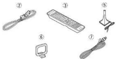
Accessories
Check that the following parts are supplied with the product.
① User guide....1
② Power cord 1
③ Remote control unit (BC011SB) 1
④ B03/AAA batteries 2
⑤ Setup microphone (ACM1HI) 1
⑥ AM loop antenna 1
⑦ FM indoor antenna ....1
natural_image
Illustration of seven different electronic devices and accessories (no text or symbols)About this manual
Operation buttons
The operations described in this guide are based mainly on remote control operation.
Symbols

This symbol indicates a reference page on which related information is described.

This symbol indicates a supplementary information and tips for operations.

This symbol indicates a supplementary information and tips for operations.
□ Illustrations
Note that the illustrations in these instructions are for explanation purposes and may differ from the actual unit.
Features
Fully Discrete, identical quality and power for all 7 channels (110 W x 7ch, 8 Ω)
The unit is equipped with a power amplifier that reproduces high-fidelity sound in surround mode with equal quality and power for all channels, true to the original sound.
The power amplifier circuit adopts a discrete-circuit configuration that achieves high-quality surround sound reproduction.
Supports HDMI 1.4a with 3D, ARC, Deep Color, x.v.Color, Auto Lipsync and HDMI control function
This unit can output 3D video signals input from a Blu-ray Display player to a TV that supports a 3D system. This unit also supports the ARC (Audio Return Channel) function, which reproduces TV sound with this unit via an HDMI cable used for connecting the unit and a TV *.
* The TV should support the ARC function.
6-HDMI inputs and 1-output
The unit is equipped with 6 HDMI input connectors for connecting devices with HDMI connectors, such as a Blu-ray Disc player, game machine, HD video camera, etc.
One of the 6 input connectors of this unit is provided on the front panel so that you can easily connect and display images and videos recorded in a digital still camera or digital video camera.
High definition audio support
The unit is equipped with a decoder which supports high-quality digital audio format for Blu-ray Disc players such as Dolby TrueHD, DTS-HD Master Audio, etc.
Dolby Pro Logic IIz
The unit is provided with a Dolby Pro Logic IIz decoder. When you play back the sound in Dolby Pro Logic IIz playback with front height speakers connected to the unit, you can enjoy playback sound with rich spacial expression.
Auto setup function
The unit is provided with an "Auto setup function" which automatically makes speaker settings best suited for the listening environment. The sound from the speakers is picked up with the supplied microphone. Reflecting sound and audio characteristics of speakers are measured, and settings for an optimum sound field are automatically made.
Easy to use, Graphical User Interface
This unit is equipped with an easy to see "Graphical User Interface" that uses menu displays and levels. The use of level displays increases operability of the unit.
All sources are up-scaled to 1080p
The unit is provided with an HDMI video up-scaling function that converts an analog video signal input to the unit to a 1080p (HD resolution) signal and supplies it to a TV via the HDMI connector. This enables the unit and a TV connected with a single HDMI cable and any video source to be reproduced precisely with HD level of quality.
Direct play for iPod® and iPhone® via USB
Music data from an iPod can be played back if you connect the USB cable supplied with the iPod via the USB port of this unit, and also an iPod can be controlled with the remote control unit for this unit.
M-XPort (Marantz-eXtension Port)
This unit is equipped with the M-XPort, a Marantz original innovation that provides outstanding expandability. You can connect the Wireless Receiver RX101 (sold separately) to this port.
Features
Speaker terminal for front height channel
The unit is equipped with dedicated front height channel speaker terminals on the rear panel. You can enjoy 7.1-channel playback using the front height channel and 7.1-channel playback using the surround back channel, without having to reconnect the speakers.
Other features
• Dolby Virtual Speaker (1-7 page 33)
• Dolby Headphone (2-9 page 33)
• DTS Neural Surround (page 32)
Cautions on handling
• Before turning the power switch on
Check once again that all connections are correct and that there are no problems with the connection cables.
- Power is supplied to some of the circuitry even when the unit is set to the standby mode. When going on vacation or leaving home for long periods of time, be sure to unplug the power cord from the power outlet.
- About condensation
If there is a major difference in temperature between the inside of the unit and the surroundings, condensation (dew) may form on the operating parts inside the unit, causing the unit not to operate properly.
If this happens, let the unit sit for an hour or two with the power turned off and wait until there is little difference in temperature before using the unit.
• Cautions on using mobile phones
Using a mobile phone near this unit may result in noise. If that occurs, move the mobile phone away from this unit when it is in use.
- Moving the unit
Turn off the power and unplug the power cord from the power outlet. Next, disconnect the connection cables to other system units before moving the unit.
- About Care
- Wipe the cabinet and control panel clean with a soft cloth.
- Follow the instructions when using a chemical cleaner.
- Benzene, paint thinner or other organic solvents as well as insecticide may cause material changes and discoloration if brought into contact with the unit, and should therefore not be used.
ENGLISHDEU
ENGLISH
Simple version
Simple version (Simple setup guide)
Here, we explain the entire setup procedure, from unboxing the unit to using it in a home theater.
The "Simple version" section provides the speaker installation, connection, and setup methods for the 7.1-channel system with surround back speakers. For the installing, connecting, and setup methods of speakers other than the 7.1-channel system (with surround back speakers), see page 35.
☐Before connecting the unit, turn off the power to all devices.
☐ For operation of the connected devices, refer to the user manuals for each device.
1
Install
(page 5)
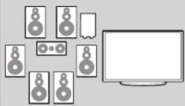
natural_image
Illustration of a set of speakers and a monitor, no text or symbols presentEnjoy better audio, using the correct install method.
2
Connect
(page 5)

Connect 7.1-channel speakers, a TV and Blu-ray Disc player equipped with an HDMI connector.
3
Turn on power
(page 7)
4
Set up speakers
( page 7)

Use the setup microphone (ACM1H) included with the product, for automatic setup.
5
Play back disc
( page 12)

Enjoy Blu-ray Disc and DVD in surround sound.
Set up speakers (Audyssey® Auto Setup)
STEP 1
Preparation
STEP 2
Speaker
Detection
STEP 3
Measurement
STEP 4
Calculation
STEP 5
Check
STEP 6
Store
Finish

Install

2
Connect
ENGLISHDEU

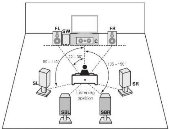
This unit can perform 2.0/2.1 to 7.1-channel surround playback. This page provides the speaker installation procedure for the 7.1-channel playback using surround back speakers as an example.
The default setting is 7.1-channel. You can also perform 5.1-channel playback. To perform 5.1-channel playback, connect 5.1-channel speakers only. Use Audyssey Auto Setup function of this unit to automatically detect the number of connected speakers and perform optimal settings for the speakers to be used.
flowchart
graph TD
    A["SL"] --> B["SBI"]
    B --> C["SBR"]
    C --> D["FR"]
    D --> E["FL"]
    E --> F["SW"]
    F --> G["C"]
    style A fill:#f9f,stroke:#333
    style B fill:#ccf,stroke:#333
    style C fill:#cfc,stroke:#333
    style D fill:#fcc,stroke:#333
    style E fill:#cff,stroke:#333
    style F fill:#ffc,stroke:#333
    style G fill:#fcf,stroke:#333
    note1["22 - 30°"] --> A
    note2["90 - 110°"] --> A
    note3["135 - 150°"] --> C
    note4["Listening position"] --> B
    note5["Listening position"] --> C
    note6["Listening position"] --> D
FL Front speaker (L)
FR Front speaker (R)
C Center speaker
SW Subwoofer
SL Surround speaker (L)
SR Surround speaker (R)
SBL Surround back speaker (L)
SBR Surround back speaker (R)
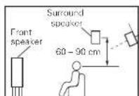
• Install the surround speakers in a position 60 to 90 cm higher than car level.
[Viewed from the side]
Speakers
Carefully check the left (L) and right (R) channels and + (red) and - (black) polarities on the speakers being connected to the this unit, and be sure to interconnect the channels and polarities correctly.
Connecting the speaker cables
Peel off about 10 mm of sheathing from the tip of the speaker cable, then either twist the core wire tightly or terminate it.
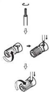
text_image
Diagram illustrating a mechanical assembly process with labeled steps and directional arrows indicating motion.NOTE
- Connect so that the speaker cable core wires do not protrude from the speaker terminal. The protection circuit may be activated if the core wires touch the rear panel or if the + and - sides touch each other ( page 89 "Protection Circuit").
- Never touch the speaker terminals while the power supply is connected. Doing so could result in electric shock.
- Use speakers with the speaker impedances shown below.
| Speaker terminals | Speaker impedance |
| FRONT A 6 - 8 Ω | |
| FRONT A + FRONT B 8 Ω | |
| CENTER | 6 - 8 Ω |
| SURROUND | |
| SURR_BACK / AMP ASSIGN | |
| FRONT B/HEIGHT |
The "Simple version" section provides the speaker installation, connection, and setup methods for the 7.1-channel system with surround back speakers. For the installing, connecting, and setup methods of speakers other than the 7.1-channel system (with surround back speakers), see page 35.
ENGLISH
D
Connect
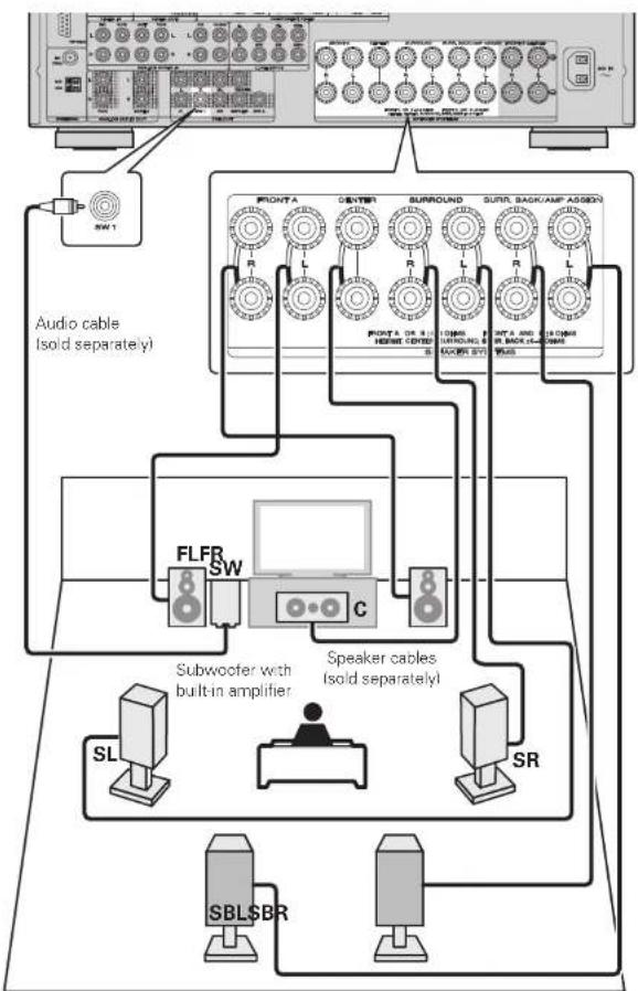
flowchart
graph TD
    A["Audio cable (sold separately)"] --> B["SW1"]
    B --> C["FLFR SW"]
    C --> D["Speaker cables (sold separately)"]
    D --> E["SL"]
    D --> F["SR"]
    D --> G["SBL$BR"]
    D --> H["SBL$BR"]
    D --> I["SL"]
    D --> J["SR"]
    D --> K["SL"]
    D --> L["SR"]
    D --> M["SL"]
    D --> N["SR"]
    D --> O["SL"]
    D --> P["SR"]
    D --> Q["SL"]
    D --> R["SR"]
    D --> S["SL"]
    D --> T["SR"]
    D --> U["SL"]
    D --> V["SR"]
    D --> W["SL"]
    D --> X["SR"]
    D --> Y["SL"]
    D --> Z["SR"]
    D --> AA["SL"]
    D --> AB["SR"]
    D --> AC["SL"]
    D --> AD["SR"]
    D --> AE["SL"]
    D --> AF["SR"]
    D --> AG["SL"]
    D --> AH["SR"]
    D --> AI["SL"]
    D --> AJ["SR"]
    D --> AK["SL"]
    D --> AL["SR"]
    D --> AM["SL"]
    D --> AN["SR"]
    D --> AO["SL"]
Blu-ray Disc player and TV
Use only an HDMI (High Definition Multimedia Interface) cable that bears the HDMI logo (a genuine HDMI product). Using a cable without the HDMI logo (a non-genuine HDMI product) may result in abnormal playback.
When outputting Deep Color or 1080p, etc., we recommend you use a "High Speed HDMI cable" or a "High Speed HDMI cable with Ethernet" for enhanced high-quality playback.
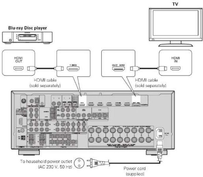
text_image
Blu-ray Disc player HDMI OUT 1 (ACD) HDMI cable (sold separately) OUT ARO HDMI IN HDMI cable (sold separately) To household power outlet (AC 230 V, 50 Hz) Power cord (supplied) TVNOTE
- Do not plug in the power cord until all connections have been completed.
- Do not bundle power cords together with connection cables. Doing so can result in humming or noise.
The "Simple version" section provides the speaker installation, connection, and setup methods for the 7.1-channel system with surround back speakers. For the installing, connecting, and setup methods of speakers other than the 7.1-channel system (with surround back speakers), see page 35.
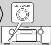
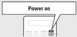
③ Turn on power

1 Turn on the TV and subwoofer power.

text_image
Power on2 Change the TV input to the input of this unit.
3 Press ON to turn on power to the unit The power indicator switches off, and power is supplied to the unit.
text_image
Power on
text_image
Power onNOTE
Before you use the remote control unit for the first time, be sure to insert the batteries (T page 81 "Inserting the batteries").
ENGLISHDEU
4 Set up speakers (Audyssey® Auto Setup)

The acoustic characteristics of the connected speakers and listening room are measured and the optimum settings are made automatically. This is called "Audyssey Auto Setup".
To perform measurement, place the setup microphone in multiple locations all around the listening area. For best results, we recommend you measure in six positions, as shown in the illustration (up to six positions).
- When performing Audyssey Auto Setup, MultE/Dynamic EO/Dynamic Volume functions become active (page 57, 58).
- To set up the speakers manually, use "Speaker Setup" (page 61) on the menu.
NOTE
- Make the room as quiet as possible. Background noise can disrupt the room measurements. Close windows, silence cell phones, televisions, radios, air conditioners, fluorescent lights, home appliances, light dimmers, or other devices as measurements may be affected by these sounds.
- Cell phones should be placed away from all audio electronics during the measurement process as Radio Frequency Interference (IRFI) may cause measurement disruptions (even if the cell phone is not in use).
- Do not unplug the setup microphone from the main unit until Audyssey Auto Setup is completed.
- Do not stand between the speakers and setup microphone or allow obstacles in the path while the measurements are being made. This will cause inaccurate readings.
- Loud test sounds may be played during Audyssey Auto setup. This is part normal operation. If there is background noise in room, these test signals will increase in volume.
- Operating VOLUME +, - during the measurements will cancel the measurements.
• Measurement cannot be performed when headphones are connected.
ENGLISH

Set up speakers (Audyssey® Auto Setup)
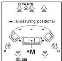
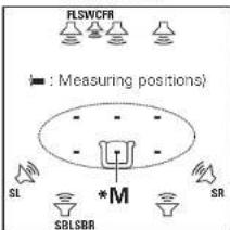
About setup microphone placement
- Measurements are performed by placing the setup microphone successively at multiple positions throughout the entire listening area, as shown in [Example ①]. For best results, we recommend you measure in six positions, as shown in the illustration (up to six positions).
- Even if the listening environment is small as shown in [Example 2], measuring at multiple points throughout the listening environment results in more effective correction.
[Example ①]
text_image
FLSW CFR ■ : Measuring positions) SL * M SR SBL SBR[Example ②]
text_image
FLSWCFR ■ : Measuring positions) SL *S M SR SBLSBRFL Front speaker (L)
FR Front speaker (R)
C Center speaker
SW Subwoofer
SL Surround speaker (L)
SR Surround speaker (R)
SBL Surround back speaker (L)
SBR Surround back speaker (R)
About the main listening position (\*M)
The main listening position is the position where listeners would normally sit or where one would normally sit alone within the listening environment. Before starting Audyssey Auto Setup, place the setup microphone in the main listening position, Audyssey MultEQ® uses the measurements from this position to calculate speaker distance, level, polarity, and the optimum crossover value for the subwoofer.
1 Prepare the setup microphone
Mount the setup microphone on a tripod or stand and place it in the main listening position.
When placing the setup microphone, adjust the height of the sound receptor to the level of the listener's ear.

text_image
Sound receptor Setup microphoneNOTE
- Do not hold the setup microphone in your hand during measurements.
- Avoid placing the setup microphone close to a seat back or wall as sound reflections may give inaccurate results.
2 Set up the subwoofer
If using a subwoofer capable of the following adjustments, set up the subwoofer as shown below.
When using a subwoofer with a direct mode
Set the direct mode to "On" and disable the volume adjustment and crossover frequency setting.
☐ When using a subwoofer without a direct mode
Make the following settings:
• Volume : "12 o'clock position"
• Crossover frequency : "Maximum/Highest Frequency"
- Low pass filter: "Off"
- Standby mode: "Off"
NOTE
When you use two subwoofers, please adjust the subwoofer volume controls individually so that each subwoofer level is as close as possible to 75 dB using the test tone (page 63) before Audyssey Auto Setup.
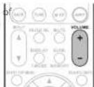
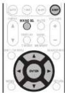
3 Set up the remote control unit
Set up the operation mode
Press AMP to set the remote control unit to amplifier operation mode.

text_image
3X 2X 3X 10X VDD 647 508 400 N1 19 10 00 MINT 100 80 00 AMP Press AMPThe "Simple version" section provides the speaker installation, connection, and setup methods for the 7.1-channel system with surround back speakers. For the installing, connecting, and setup methods of speakers other than the 7.1-channel system (with surround back speakers), see page 35.
STEP 1 Preparation
4 Connect the setup microphone to the SETUP MIC jack of this unit.

When the setup microphone is connected, the following screen is displayed.
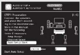
text_image
AUDIO OF LISP AUDIO OF LISP TO MISPUP AUDIO/800 MIMEQ STEP1 Preparation Connect the speakers and place them accord- ing to be recomprecu- tions in the manual Set the following forms for maintaining: stop Appain Charged Select Auto Setup Start Start Auto Setup 1.00 Kitter 5This screen provides the method for setting up 7.1-channel playback using surround back speakers. For the method of setting up speakers, other than the 7.1-channel system, select "Amp Assign" and perform step 3 and 4 of "Set up "Amp Assign" (page 39).
If unused channels are set with "Channel Select", measuring time can be shortened. For setting, perform steps 5 to 9 of "Set up "Channel Select" (page 39).
5 Use to select "Auto Setup Start" and then press ENTER.
STEP 2 Speaker Detection
- In STEP 2, you will perform measurements at the main listening position.
- This step automatically checks the speaker configuration and speaker size, and calculates the channel level, distance, and crossover frequency. It also corrects distortion in the listening area.
6 Select "Measure" and then press ENTER.
When measuring begins, a test tone is output from each speaker.
• Measurement requires several minutes.
7 The detected speakers are displayed.
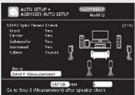
text_image
AUTO SETUP AUDYDNEY AUTO SETUP AUDYDNEY Multi Q 31192 Split/ Distant Check Front Yes Center Yes Subwoofer Yes Surround Yes 5 Blocks Features Entry Next = Measurement ENTER Enter Go to Step 3 (Measurement after speaker check)NOTE
If a connected speaker is not displayed, the speaker may not be connected correctly. Check the speaker connection.
8 Use △▽ to select "Next ► Measurement" and then press ENTER.
NOTE
If "Caution" is displayed:
Go to "Error messages" (page 11), check any related items, and perform the necessary procedures.
If the problem is resolved, return and restart "Audyssey Auto Setup".
When performing Audyssey Auto Setup over again
Press to select "Retry", and then press ENTER.
When measuring has stopped
Press RETURN, to the "Cancel Auto Setup?" prompt is displayed.
Press ◀ to select "Yes", then press ENTER.
Setting up the speakers again
Repeat the operation from step 4 of STEP1 Preparation
STEP 3 Measurement
- In STEP 2, you will perform measurements at multiple positions (two to six positions) other than the main listening position.
- You can achieve a more effective correction of distortion within the listening area by performing measurements at multiple positions.
9 Move the setup microphone to position 2, use △▽ to select "Measure", and then press ENTER.
The measurement of the second position starts. Measurements can be made in up to six positions.

text_image
AUTO SETUP ALOSSSY AUTO SETUP ALOSSSY MULTIQ SIFT PS Measurement Please place the most oscillings at our height of 2nd decelerating positions. Measure Next Consultation ENTER: 3 Start next measurement. Test Tone will start
If you want to omit measurements from the next position onward, select "Next ▶ Calculation".
(Go to STEP4 Calculation)
10 Repeat step 9, measuring positions 3 to 6.
When measurement of position 6 is completed, a "Measurements finished." message is displayed.

text_image
AUTO SETTUP AUTOSETTUP MANUAL SETTUP STEP3 Measurement Measurements / measured. Entry Next + Calculation ENTER Preced to Step 4 (Analysis)Remote control operation buttons
Move the cursor (Up/Down/Left/Right)
ENTER Confirm the setting
RETURN ○ Return to previous menu
ENGLISH

Set up speakers (Audyssey® Auto Setup)
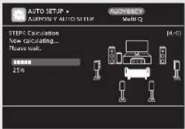
STEP 4
Calculation
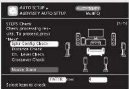
STEP 5
Check
11 On the STEP3 screen, use △▽ to select "Next ▶ Calculation", and then press ENTER.
Measuring results are analyzed, and the frequency response of each speaker in the listening room is determined.
text_image
AUTO SETUP + AUDITATE Y AUTO SETUP Multi-Q STEP Calculation Now concluding... Please walk. 25% (4:15)- Analysis takes several minutes to complete. The time required for this analysis depends on the number of speakers connected.
The more connected speakers there are, the longer it takes to perform analysis.
12 Use to select the item you want to check, and then press ENTER.
text_image
AUTO SETUP AUDIOSARY AUTO SETUP AUXRESS Multi-CL STEPS Check Check processing res- urs. To proceed press Next Spike Config Check Distance Check Ch. Level Check Crossover Check Next + Some Select item to check 100% lower 4- Subwoofers may measure a greater reported distance than the actual distance due to added electrical delay common in subwoofers.
- If you want to check another item, press RETURN.
13 Use △▽ to select "Next ► Store" and then press ENTER.
NOTE
- If the result differs from the actual connection status, or if "Caution!" is displayed, see "Error messages" (page 11). Then carry out Audyssey Auto Setup again.
- If the result still differs from the actual connection status after remeasurement or the error message still appears, it is possible that the speakers are not connected properly. Tum this unit off, check the speaker connections and repeat the measurement process from the beginning.
- If you change speaker positions or orientation, perform Audyssey Auto Setup again to find the optimal equalizer settings.
STEP 6
Store
14 Select "Store" and then press ENTER. Save the measurement results.

text_image
AUTO SETUP + AUTOSET MultiQ STI On Store Press 'Store' to store calculation results. Store ENTER Enter Apply and store measurement result

text_image
AUTO SETUP AUDIO/KEY AUTO SETUP AUDIO/KEY MULIQ STOPS Score: How training... Please start. 25%- Saving the results requires about 10 seconds. - If the measuring results are not to be saved, press RETURN. A message "Cancel Auto Setup?" will be displayed. Press ◀ then select "Yes". All the measured Audyssey Auto Setup data will be erased.
NOTE
During saving of measurement results, be sure not to turn off the power.
Finish
15 Unplug the setup microphone from the unit's SETUP MIC jack.
16 Set Dynamic Volume ^® .
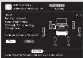
text_image
AUTO M T U P# AUDI OSSOY AUTO SETUP Audi Auto Setup Finish Starting complete. Auto Setup in now Finished. Rebe upping microphone. Turn on Dynamic Volume? Yes No ENTER Job Turn Dynamic Volume on end and one Auto Setup- For details of Dynamic Volume settings, see page 58.
□When turning Dynamic Volume on
Use ◀ to select "Yes", and then press ENTER.
The unit automatically enters "Evening" mode.
□When turning Dynamic Volume off
Use ▷ to select "No", and then press ENTER
NOTE
After performing Audyssey Auto Setup, do not change the speaker connections or subwoofer volume. In event of a change, perform Audyssey Auto Setup again.
Remote control operation
buttons

Move the cursor (Up/Down/Left/Right)

Confirm the setting

Return to previous menu
Error messages
An error message is displayed if Audyssey® Auto Setup could not be completed due to speaker placement, the measurement environment, etc. If this happens, check the relevant items, be sure to take the necessary measures, then perform Audyssey Auto Setup over again.
NOTE
Be sure to turn off the power before checking speaker connections.
| Examples Error details Measures | ||
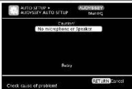 | The connected setup microphone is broken, or a device other than the supplied setup microphone is connected.Not all speakers could be detected.The front L speaker was not properly detected. | Connect the included setup microphone to the SETUP MIC jack of this unit.Check the speaker connections. |
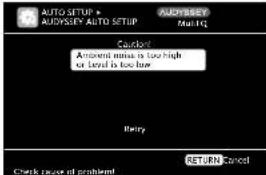 | There is too much noise in the room for accurate measurements to be made.Speaker or subwoofer sound is too low for accurate measurements to be made. | Either turn off any device generating noise or move it away.Perform again when the surroundings are quieter.Check the speaker installation and the direction in which the speakers are facing.Adjust the subwoofer's volume. |
 | The displayed speaker could not be detected | Check the connections of the displayed speaker. |
 | The displayed is connected with the polarities reversed. | Check the polarities of the displayed speaker.For some speakers, this error message may be displayed even if the speaker is properly connected. If you are sure the connection is correct, press to select "Skip", then press ENTER |
Parameter Check
This function enables you to check the measurement results and equalizer characteristics after Audyssey Auto Setup.
1 Use △▽ to select "Parameter Check" and then press ENTER or ▷.
2 Use △▽ to select the item you want to check, then press ENTER or ▷. Measurement results for each speaker are displayed.

text_image
AUTO SETUP + PARAMETER CHECK • MasterCheck Check • Distrance Check • Channel Level Check • Crossover Check EQ Check Restore Show speaker configuration resultSpeaker Config. Check
Check the speaker configuration.
Distance Check
Check the distance.
Channel Level Check
Check the channel level.
Crossover Check
Check the crossover frequency.
EQ Check
Check the equalizer
- If "EQ Check" is selected in step 2, press △▽ to select equalizing curve ("Audyssey" or "Audyssey Flat") to be checked. Use ◀▷ to switch the display between the different speakers.

Press RETURN.
The confirmation screen reappears. Repeat steps 2
Retrieving Audyssey Auto Setup settings
If you set "Restore" to "Yes", you can return to Audyssey Auto Setup measurement result (value calculated at the start by MultEQ ^® ) even when you have changed each setting manually.
Remote control operation buttons

Move the cursor (Up/Down/Left/Right)

Confirm the setting

Return to previous menu
ENGLISH


Play back disc

1 Press BD two times in a row to switch an input source for a player used for playback.
2 Play the component connected to this unit. Make the necessary settings on the player (language setting, subtitles setting, etc.) beforehand.
3 Adjust the sound volume.
VOLUME + Volume up VOLUME - Volume down MUTE ... Muting
text_image
MULICE I/O SET STRAWAY OFF I TEST HELP HDMI A/D TORD A/B Z3 Z4 BD DVO VOL SAT HDMI ALT1 WLDG TV CD COM SATE TAN M-2P ASP INPUT MUSIC REL MUTE VOLUME + - DISPLAY SUMO TENDE MERRY4 Set the listening mode. Set the listening mode according to the playback contents (cinema, music, etc.) or according to your liking list page 31 "Selecting a listening mode (Surround mode)".
When power is switched to standby
Press STANDBY.
[Power indicator status in standby mode] • Normal standby : Red
- When "HDMI Control" is set to "ON": Orange

You can also switch the power to standby by pressing ON/STANDBY on the main unit.

NOTE
During power standby, a minimal amount of power is consumed. To totally cut off the power, remove the power cord from the power outlet.
ENGLISHDEU
Basic version
Basic version
Here, we explain the connections and basic operation methods for this unit.
● Connections page 14
● Playback (Basic operation) page 23
- Selecting a listening mode (Surround mode) 📋 page 31
☐ Refer to the pages indicated below for information on connecting and playing back the various media and external devices.
| Audio and Video | PlaybackConnection | |
| TV | 以 page 16, 17 | - |
| Blu-ray Disc player | 以 page 16, 17 以 page 24 | |
| DVD player | 以 page 16, 17 以 page 24 | |
| Video cassette recorder | 以 page 16, 19 | - |
| Set-top box (Satellite tuner or cable TV) | 以 page 16, 18 | - |
| Game console | 以 page 16 | - |
| Digital camcorder | 以 page 19 | - |
| Audio | PlaybackConnection | |
| iPod® | 以 page 19 以 page 25 | |
| USB memory device | 以 page 19 以 page 26 | |
| CD player | 以 page 20 以 page 24 | |
| Radio | 以 page 20 以 page 28 | |
| Wireless receiver (RX101) | 以 page 21 | - |
For speaker connections, see page 5.
ENGLISH

Connections
Important information
- Make connections as follows before using this unit. Select an appropriate connection type according to the components to be connected.
- You may need to make some settings on this unit depending on the connection method. Refer to each description for more information.
- Select the cables (sold separately) according to the components being connected.
NOTE
- Do not plug in the power cord until all connections have been completed.
- When making connections, also refer to the operating instructions of the other components being connected
- Be sure to connect the left and right channels properly (left with left, right with right).
- Do not bundle power cords together with connection cables. Doing so can result in noise.
Converting input video signals for output (Video conversion function)
This unit is equipped with three types of video input connectors (HDMI, Component video and video) and three types of video output connectors (HDMI, Component video and video). Use the connectors corresponding to the components to be connected. This function automatically converts various formats of video signals input to this unit into the formats used to output the video signals from this unit to a monitor.
[Flow of video signals for MAIN ZONE]

flowchart
graph LR
    A["Video device"] --> B["Output"]
    B --> C["HDMI connector"]
    C --> D["Component video connectors"]
    D --> E["Video connector"]
    E --> F["Video connector"]
    F --> G["Output (IN)"]
    G --> H["HDMI connector"]
    H --> I["Component video connectors"]
    I --> J["Video connector"]
    J --> K["Output (MONITOR OUT)"]
    K --> L["HDMI connector"]
    L --> M["Component video connectors"]
    M --> N["Video connector"]
    N --> O["Output (MONITOR OUT)"]
    O --> P["Monitor"]
    P --> Q["Input"]
    Q --> R["HDMI connector"]
    R --> S["Component video connectors"]
    S --> T["Video connector"]
    T --> U["Output (MONITOR OUT)"]
in Set as Necessary
- Set when not using the video conversion function.
"Video Convert" (page 53) - Set when changing the resolution of the video signal.
"Resolution" (page 54)

- The video conversion function supports the NTSC, PAL, SECAM, NTSC 4.43, PAL-N, PAL-M and PAL-60 formats.
- The resolution of the video signal input to this unit's HDMI connector is the one set at "Resolution" (ICB page 54). (1080p HDMI signals and 1080p component signals are output at 1080p, regardless of the setting.)
- Resolutions of HDMI-compatible TVs can be checked at "HDMI Monitor Information" (page 68).
NOTE
• HDMI signals cannot be converted into analog signals.
- When a non-standard video signal from a game machine or some other source is input, the video conversion function might not operate.
- Component video input signals cannot be converted into Video format.
- A menu is output via the HDMI connector or component video connector.
Examples of screen display
- Menu screen • Status display screen
When the input source is switched When the volume is adjusted


Status display: The operating status appears briefly on the screen when the input source is switched or the volume is changed.
NOTE
- If you operate the menu while playing back 3D video content, the playback video is replaced by the menu screen. The playback video is not displayed behind the menu screen.
- This unit does not show the status display while playing back 3D video content.
ENGLISHDEU
Connecting an HDMI-compatible device
You can connect up to six HDMI-compatible devices to the unit.
HDMI function
This unit supports the following HDMI functions:
• 3D
• Deep Color (page 88)
• Auto Lip Sync (page 64, 88)
• x.v.Color, sYCC601 color, Adobe RGB color, Adobe YCC601 color (page BB, 89)
• High definition digital audio format
• ARC (Audio Return Channel)
- Content Type
- CEC (HDM) control
Copyright protection system
In order to play back digital video and audio such as BD-Video or DVD-Video via HDMI connection, both this unit and TV or the player need to support the copyright protection system known as HDCP (High-bandwidth Digital Content Protection System). HDCP is copyright protection technology comprised of data encryption and authentication of the connected AV device. This unit supports HDCP. • If a device that does not support HDCP is connected, video and audio are not output correctly. Read the user guide of your television or player for more information.
About HDMI cables
- When a device supporting Deep Color signal transfer is connected, use a cable compatible "High Speed HDMI cable" or "High Speed HDMI cable with Ethernet".
- When the ARC function is used, connect a device with a "Standard HDMI cable with Ethernet" or "High Speed HDMI cable with Ethernet" for HDMI 1.4a.
HDMI control function (page 42)
This function allows you to operate external devices from the receiver and operate the receiver from external devices.
NOTE
- The HDMI control function may not work depending on the device it is connected to and its settings.
- You cannot operate a TV or Blu-ray Disc player/DVD player that is not compatible with the HDMI control function.
About 3D function
This unit supports input and output of 3D (3 dimensionall) video signals of the HDMI 1.4a standards. For playing the 3D video content, a player, and a TV that support the 3D function of the HDMI 1.4 standards are required in addition to this unit.
NOTE
- If you operate the menu while playing back 3D video content, the playback video is replaced by the menu screen. The playback video is not displayed behind the menu screen.
- This unit does not show the status display while playing back 3D video content.
About ARC (Audio Return Channel) function
The Audio Return Channel in HDMI 1.4a enables a TV, via a single HDMI cable, to send audio data "upstream to this unit.
NOTE
- To enable the ARC function, set "HDMI Control" to "ON" (page 64).
- When connecting a TV that does not support the ARC function, a separate connection using an audio cable is required. In this case, refer to "Connecting a TV" (27 page 17) for the connection method.
About Content Type
The HDMI specification version 1.4a enables simple, automated picture setting selection with no user intervention.
NOTE
To enable the Content Type, set "Video Mode" to "Auto" (page 53).
ENGLISH

Connecting an HDMI-compatible device
Cables used for connections
Audio and video cable (sold separately)


- This interface allows transfer of digital video signals and digital audio signals over a single HDMI cable.
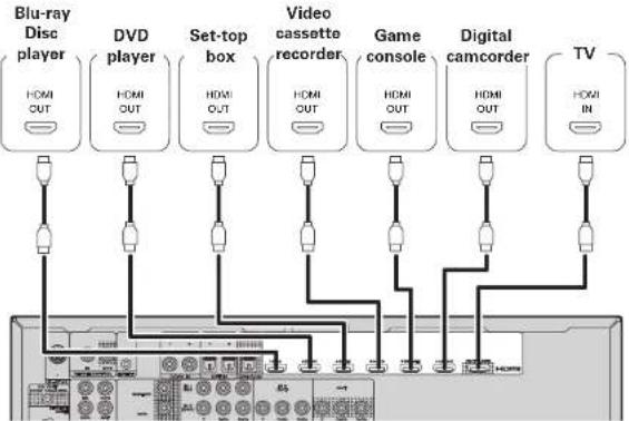
flowchart
graph TD
    A["Blu-ray Disc player"] -->|HDMI OUT| B["Video cassette recorder"]
    C["DVD player"] -->|HDMI OUT| B
    D["Set-top box"] -->|HDMI OUT| B
    E["Game console"] -->|HDMI OUT| B
    F["Digital camcorder"] -->|HDMI OUT| B
    G["TV"] -->|HDMI IN| B
    B --> H["Computer"]

- When this unit is connected to other devices with HDMI cables, connect this unit and TV also with an HDMI cable.
- When connecting a device that supports Deep Color transmission, please use a "High Speed HDMI cable" or "High Speed HDMI cable with Ethernet".
- Video signals are not output if the input video signals do not match the monitor's resolution. In this case, switch the Blu-ray Disc/DVD player's resolution to a resolution with which the monitor is compatible.
- When this unit and monitor are connected with an HDMI cable, if the monitor is not compatible with HDMI audio signal playback, only the video signals are output to the monitor.
NOTE
The audio signal from the HDMI output connector (sampling frequency, number of channels, etc.) may be limited by the HDMI audio specifications of the connected device regarding permissible inputs.
Connecting to a device equipped with a DVI-D connector
When an HDMI/DVI conversion cable (sold separately) is used, the HDMI video signals are converted to DVI signals, allowing connection to a device equipped with a DVI-D connector.
NOTE
- No sound is output when connected to a device equipped with a DVI-D connector. Make separate audio connections.
- Signals cannot be output to DVI-D devices that do not support HDCP.
- Depending on the combination of devices, the video signals may not be output.
□Settings related to HDMI connections
Set as necessary. For details, see the respective reference pages.
Input Assign (page 52)
Set this to change the HDMI input connector to which the input source is assigned.
HDMI Setup (page 64)
Make settings for HDMI video/audio output.
- RGB Range • Auto Lip Sync • HDMI Audio Out
• HDMI Control • Standby Source • Power Off Control
NOTE
The audio signals output from the HDMI connectors are only the HDMI input signals.
Connecting a TV
- Select the connector to use and connect the device.
- For video connections, see "Converting input video signals for output (Video conversion function)" (LFP page 14).
- For instructions on HDMI connections, see "Connecting an HDMI-compatible device" (2 page 15).

To listen to TV audio through this device, use the optical digital connection.
NOTE
This connection is not required when a TV compatible with the ARC function (Audio Return Channel (HDMI 1.4a standard function) is connected to this unit via an HDMI connection.
For details, see "About ARC (Audio Return Channel) function" It's page 151 or refer to the instruction manual for your TV.
Cables used for connections
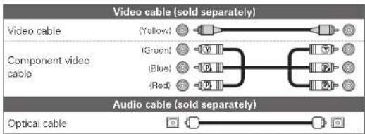
flowchart
graph LR
    A["Video cable (sold separately)"] --> B["(Yellow)"]
    C["Component video cable"] --> D["(Green)"]
    C --> E["(Blue)"]
    C --> F["(Red)"]
    G["Audio cable (sold separately)"] --> H["O"]
    I["Optical cable"] --> J["O"]
    B --> K["Orange Box"]
    D --> L["Orange Box"]
    E --> M["Orange Box"]
    F --> N["Orange Box"]
    H --> O["Orange Box"]
    J --> P["Orange Box"]
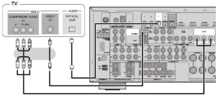
text_image
TV VIDEO COMPONENT VIDEO IN Y Pn-Pa VIDEO IN AUDIO- OPTICAL OUT 1200 1201 1202 1203 1204 1205 1206 1207 1208 1209 1210 1211 1212 1213 1214 1215 1216 1217 1218 1219 1220 1221 1222 1223 1224 1225 1226 1227 1228 1229 1230 1231 1232 1233 1234 1235 1236 1237 1238 1239 1240 1241 1242 1243 1244 1245 1246 1247 1248 1249 1250 1251 1252 1253 1254 1255 1256 1257 1258 1259 1260 1261 1262 1263 1264 1265 1266 1267 1268 1269 1270 1271 1272 1273 1274 1275 1276 1277 1278 1279 1280 1281 1282 1283 1284 1285 1286 1287 1288 1289 1290 1291 1292 1293 1294 1295 1296 1297 1298 1299 1300in Set as Necessary
Set this to change the digital input connector to which the input source is assigned.
"Input Assign" (page 52)
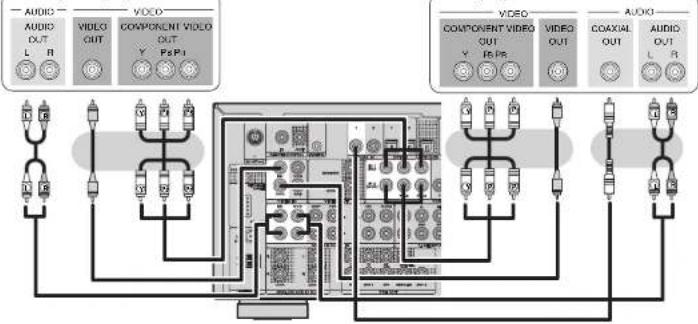
Connecting a Blu-ray Disc player / DVD player
- You can enjoy video and audio from a Blu-ray Disc or DVD.
- Select the connector to use and connect the device.
- For instructions on HDMI connections, see "Connecting an HDMI-compatible device" (12 page 15).
Cables used for connections

flowchart
graph LR
    subgraph_Video_cable["Video cable (sold separately)"]
        A1["Yellow"] --> B1["Green"]
        A2["Blue"] --> B2["Red"]
    end
    subgraph_Component_video_cable["Component video cable"]
        C1["Green"] --> D1["Blue"]
        C2["Red"] --> D2["Blue"]
    end
    subgraph_Audio_cable["Audio cable (sold separately)"]
        E1["White"] --> F1["R"]
        E2["Black"] --> F2["Black"]
    end
    A1 --> B1 --> C1 --> D1 --> E1
    A2 --> B2 --> C2 --> D2 --> E2
    A3 --> F1 --> F2
    A4 --> F1 --> F2
Blu-ray Disc player
flowchart
graph TD
    subgraph Audio
        A1["Audio OUT L"] --> B1["Component OUT Y"]
        A2["Audio OUT R"] --> B2["Component OUT Y"]
        A3["Audio OUT L"] --> B3["Component OUT Y"]
        A4["Audio OUT R"] --> B4["Component OUT Y"]
    end

    subgraph Video
        C1["Video OUT Y"] --> D1["Component OUT Y"]
        C2["Video OUT Y"] --> D2["Component OUT Y"]
        C3["Video OUT Y"] --> D3["Component OUT Y"]
        C4["Video OUT Y"] --> D4["Component OUT Y"]
        C5["Video OUT Y"] --> D5["Component OUT Y"]
    end

    subgraph Audio_K
        E1["Audio OUT L"] --> F1["Component OUT Y"]
        E2["Audio OUT R"] --> F2["Component OUT Y"]
        E3["Audio OUT L"] --> F3["Component OUT Y"]
        E4["Audio OUT R"] --> F4["Component OUT Y"]
        E5["Audio OUT L"] --> F5["Component OUT Y"]
        E6["Audio OUT R"] --> F6["Component OUT Y"]
    end

    A1 --> B1
    A2 --> B2
    A3 --> B3
    A4 --> B4
    A5 --> B5
    A6 --> B6
    A7 --> B7
    A8 --> B8
    A9 --> B9
    A10 --> B10
    A11 --> B11
    A12 --> B12
    A13 --> B13
    A14 --> B14
    A15 --> B15
    A16 --> B16
    A17 --> B17
    A18 --> B18
    A19 --> B19
    A20 --> B20
    A21 --> B21
    A22 --> B22
    A23 --> B23
    A24 --> B24
    A25 --> B25
    A26 --> B26
    A27 --> B27
    A28 --> B28
    A29 --> B29
    A30 --> B30
    A31 --> B31
    A32 --> B32
    A33 --> B33
    A34 --> B34
    A35 --> B35
    A36 --> B36
    A37 --> B37
    A38 --> B38
    A39 --> B39
    A40 --> B40
    A41 --> B41
    A42 --> B42
    A43 --> B43
    A44 --> B44
    A45 --> B45
    A46 --> B46
    A47 --> B47
    A48 --> B48
    A49 --> B49
    A50 --> B50
    A51 --> B51
    A52 --> B52
    A53 --> B53
    A54 --> B54
    A55 --> B55
    A56 --> B56
    A57 --> B57
    A58 --> B58
    A59 --> B59
    A60 --> B60
    A61 --> B61
    A62 --> B62
    A63 --> B63
    A64 --> B64
    A65 --> B65
    A66 --> B66
    A67 --> B67
    A68 --> B68
    A69 --> B69
    A70 --> B70
    A71 --> B71
    A72 --> B72
    A73 --> B73
    A74 --> B74
    A75 --> B75
    A76 --> B76
    A77 --> B77
    A78 --> B78
    A79 --> B79
    A80 --> B80
    A81 --> B81
    A82 --> B82
    A83 --> B83
    A84 --> B84
    A85 --> B85
    A86 --> B86
    A87 --> B87
    A88 --> B88
    A89 --> B89
    A90 --> B90
in Set as Necessary
Set this to change the digital input connector or component video input connector to which the input source is assigned.
"Input Assign" (page 52)

For HD audio (Dolby TrueHD, DTS-HD, Dolby Digital Plus and DTS Express) playback, connect with HDMI ( page 15 "Connecting an HDMI-compatible device").
ENGLISH

Connecting a set-top box (Satellite tuner/cable TV)
- You can watch satellite or cable TV.
- Select the connector to use and connect the device.
- For instructions on HDMI connections, see "Connecting an HDMI-compatible device" (27 page 15).
Cables used for connections

flowchart
graph LR
    subgraph_Video_cable["Video cable (sold separately)"]
        A1["Yellow"] --> B1["Blue"]
        A2["Green"] --> B2["Red"]
    end
    subgraph_Component_video_cable["Component video cable"]
        C1["Blue"] --> D1["P"]
        C2["Red"] --> D2["P"]
    end
    subgraph_Audio_cable["Audio cables (sold separately)"]
        E1["Whitol"] --> F1["R"]
        E2["Rod"] --> F2["P"]
        G1["C1"] --> H1["C"]
        G2["G"] --> H2["G"]
    end
    A1 --> B1 --> C1 --> D1 --> E1 --> F1 --> G1 --> H1 --> I1 --> J1 --> K1 --> L1 --> M1 --> N1 --> O1 --> P1 --> Q1 --> R1 --> S1 --> T1 --> U1 --> V1 --> W1 --> X1 --> Y1 --> Z1 --> AA1 --> AB1 --> AC1 --> AD1 --> AE1 --> AF1 --> AG1 --> AH1 --> AI1 --> AJ1 --> AK1 --> AL1 --> AM1 --> AN1 --> AO1 --> AP1 --> AQ1 --> AR1 --> AS1 --> AT1 --> AU1 --> AV1 --> AW1 --> AX1 --> AY1 --> AZ1 --> BA1 --> BB1 --> BC1 --> BD1 --> BE1 --> BF1 --> BG1 --> BH1 --> BI1 --> BJ1 --> BK1 --> BL1 --> BM1 --> BN1 --> BO1 --> BP1 --> BP2 --> BP3 --> BP4 --> BP5 --> BP6 --> BP7 --> BP8 --> BP9 --> BPA1
    end
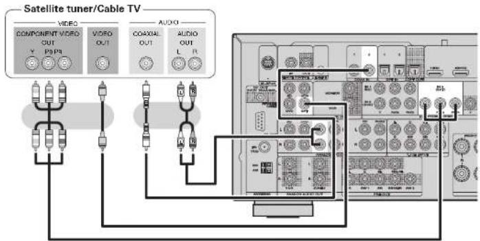
text_image
Satellite tuner/Cable TV VIDEO COMPONENT VIDEO OUT Y PAPR VIDEO OUT COAXIAL OUT AUDIO L R AUDIOIn Set as Necessary
Set this to change the digital input connector or component video input connector to which the input source is assigned.
"Input Assign" (page 52)
Connecting a video cassette recorder
- You can record video onto a video cassette tape.
- Select the connector to use and connect the device.
- When recording analog audio, use the analog connection.
- For instructions on HDMI connections, see "Connecting an HDMI-compatible device" (27 page 15).
Cables used for connections

text_image
Video cable (sold separately) Video cable (Yellow) Audio cable (sold separately) Audio cable (White) (Ired)Video cassette recorder

text_image
VIDEO OUT VIDEO OUT RL RL IN AUDIO AUDIO AUDIO AUDIO IN VIDEO VIDEO IN IN IN INin Set as Necessary
Set this to change the digital input connector or component video input connector to which the input source is assigned.
"Input Assign" (page 52)
NOTE
To record video signals through this unit, use the same type of video cable for connection between this unit and the player as used for connection between this unit and the recorder.
Connecting a digital camcorder
- You can enjoy video and audio from a digital camcorder.
- You can enjoy games by connecting a game machine via the AUX1 input connector. In this case, select the input source to "AUX1".
- For instructions on HDMI connections, see "Connecting an HDMI-compatible device" (page 15).
Cables used for connections

text_image
Video cable (sold separately) Video cable (Yellow) Audio cable (sold separately) Audio cable (Whitel Red) Optical cable
text_image
Digital camcorder VIDEO AUDIO VIDEO OUT OPTICAL OUT AUDIO OUT L R marantzin Set as Necessary
Set this to change the digital input connector to which the input source is assigned. "Input Assign" (127 page 52)

The front panel OPTICAL input terminal is displayed as "OPT3" in the "Input Setup" - "Input Assign" setting (page 52) in the menu.
NOTE
When a non-standard video signal from a game machine or some other source is input, the video conversion function might not operate. In this case, use the monitor output of the same connector as the input.
Connecting an iPod or USB memory device to the USB port
You can enjoy music stored on an iPod or USB memory device.
Cables used for connections
To connect an iPod to this unit, use the USB cable supplied with the iPod.
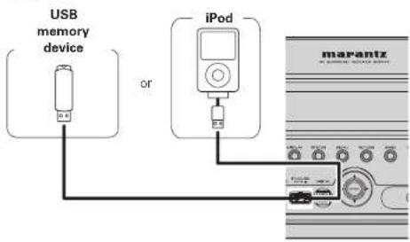
text_image
USB memory device or iPod marantzSupported iPod models
Made for
- iPod touch (2nd generation)
- iPod touch (1st generation)
- iPod classic
- iPod with video
- iPod nano (5th generation)
- iPod nano (4th generation)
- iPod nano (3rd generation)
- iPod nano (2nd generation)
- iPod nano (1st generation)
- iPhone
- iPhone 3G
- iPhone 3GS

pod touch
2nd generation
8GB 16GB 32GB 64GB

iPod classic
80GB

iPod nano
4th generation (video)
8GB 16GB

iPhone
4GB 8GB 16GB

iPod touch
1st generation
8GB 16GB 32GB

iPod
5th generation (video)

iPod nano
3rd generation
4GB 8GB

iPhone 3G
8GB 16GB

iPod classic
120GB 160GB (2009)

IPoB
(video)

iPod nano
2nd generation (Aluminum)
2GB 4GB 8GB

iPhone 3GS
16GB 32GB

iPod classic
16038 (2007)

iPod nano
5th generation (video camera)
8GB 16GB

iPod nano
1st generation
1GB 2GB 4GB
ENGLISH

Connecting a CD player
- You can enjoy CD sound.
- Select the connector to use and connect the device.
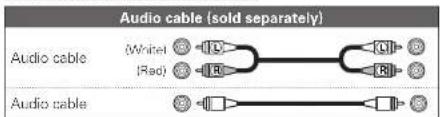
Cables used for connections

text_image
Audio cable (sold separately) Audio cable (White) (Red) Optical cable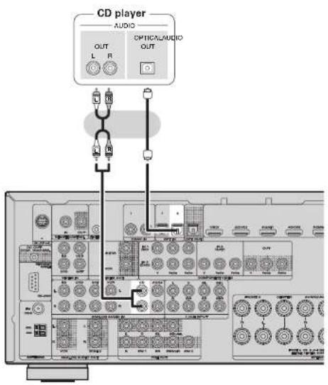
text_image
CD player AUDIO OPTICAL/AUDIO OUT L R L R L R L R L R L R L R L R L R L R L R L R L R L R L R L R L R L R L R L R L R L R L R L R L R L R L R L R L R L R L R L R L R L Rin Set as Necessary
Set this to change the digital input connector to which the input source is assigned. "Input Assign" (page 52)
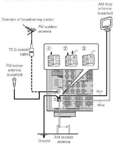
Connecting an antenna
- Connect the FM antenna or AM loop antenna supplied with the unit to enjoy listening to radio broadcasts.
- After connecting the antenna and receiving a broadcast signal (page 28 "Listening to FM/AM broadcasts"), fix the antenna with tape in a position where the noise level becomes minimal.
text_image
Direction of broadcasting station FM outdoor antenna 75 Ω coaxial cable FM indoor antenna (supplied) ① ② ③ AM loop antenna (supplied) Black White Ground AM outdoor antennaAM loop antenna (supplied)
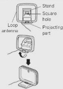
□AM loop antenna assembly
1 Put the stand section through the bottom of the loop antenna from the rear and bend it forward.
2 Insert the projecting part into the square hole in the stand.
text_image
Stand Square hole Projecting part Loop antenna□Using the AM loop antenna
Suspending on a wall
Suspend directly on a wall without assembling.
Standing alone
Use the procedure shown top to assemble.


NOTE
- Do not connect two FM antennas simultaneously.
- Even if an external AM antenna is used, do not disconnect the AM loop antenna.
- Make sure the AM loop antenna lead terminals do not touch metal parts of the panel.
- If the signal has noise interference, connect the ground terminal (GND) to reduce noise.
- If you are unable to receive a good broadcast signal, we recommend installing an outdoor antenna. For details, inquire at the retail store where you purchased the unit.
By connecting a wireless receiver RX101 (sold separately) to this unit, you can receive and playback audio signals from other devices using the Bluetooth Communication Function.
- Use a Bluetooth device that is A2DP compatible (page 88 "A2DP").
- You can also use wireless receiver RX101 as an external IR receiver.
- For instructions on the wireless receiver settings, refer to the RX101's operating instructions.
Wireless receiver RX101
Bluetooth device (A2DP Compatibility)
Remote control unit
You can enjoy listening to music by connecting a wireless receiver via the M-XPort input connector. In this case, set the input source to "M-XPort".
To use wireless receiver RX101 as external IR receiver, set the remote sensor function of this unit to "Remote Lock:ON" (I page 68 "Remote control settings").
- You can connect this unit to an external device fitted with multi-channel sound audio output jacks to enjoy music and video.
- The video signal can be connected in the same way as a Blu-ray Disc player / DVD player (12 page 17 "Connecting a Blu-ray Disc player / DVD player").
Cables used for connections
| Audio cable | (White) | L | L |
| (Red) | R | R |
Audio cable
Blu-ray Disc player / DVD player / External decoder
| SUS-WOOFER | AUDIO | ||||
| FRONT | CENTER | SURROUND | BACK | ||
| L | R | L | R | ||
| L | R | L | R | ||
| L | R | L | R | ||
To play analog signals input from 7.1CH INPUT terminals, set "Input Mode" (12 page 54) to "7.1CH IN".
"7.1CH IN" can also be selected with A/D on the remote control unit.
When a device is connected to the SBL/SBR terminal of 7.1CH INPUT terminals, set "Amp Assign" ( page 61) to "Normal".
ENGLISH

Connecting a external power amplifier
- You can use this unit as a pre-amp by connecting a commercially available power amp to the PRE OUT connector. Adding a power amp to each of the channels provides an even greater sound presence.
- Select the terminal to use and connect the device.
Cables used for connections
text_image
Audio cable (sold separately) Audio cable White (Rad) Audio cable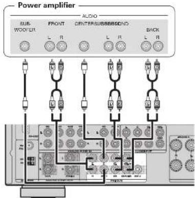
text_image
Power amplifier SUB- WOOF-ER FRONT AUDIO DENTERSUBBERGOND L R L R BACK L R L R
- When using just one surround back speaker, connect it to the left channel (L) terminal.
- Use the volume control on the subwoofer to control subwoofer volume.
- If the subwoofer volume sounds low, use the volume control provided on the subwoofer to adjust the volume.

- When an external power amp is connected to the PRE OUT terminal, do not connect speakers to the speaker terminals.
- Depending on the settings in the "Amp Assign" ( page 61) menu or listening mode, the channel output from the SBL terminal or SBR terminal of the PRE OUT terminal differs.
Playback (Basic operation)
☐ Selecting the input source (page 23)
□ Adjusting the master volume (page 24)
Turning off the sound temporarily (page 24)
Playing a Blu-ray Disc player/DVD player (page 24)
Playing a CD player (1 page 24) Playing an iPod (1 page 25)
□ Playing a USB memory device (page 26)
□ Tuning in radio stations (page 28)
Selecting a listening mode (Surround mode) (page 31)
Playback (Advanced operation) (page 42)
Important information
Before starting playback, make the connections between the different components and the settings on the receiver.
NOTE
Also refer to the operating instructions of the connected components when playing them.
Selecting the input source
Press the input source select button (BD, DVD, VCR, SAT, GAME, AUX1, NET/USB, TV, CD, TUNE, M-XP) twice to play back that source.
The desired input source can be selected directly.

You can also use the following operation to select an input source.
□Using the "Source Select" menu
① Press AMP and the press SOURCE SEL. Display the "Source Select" menu.

text_image
The currently selected input source is highlighted. Source Select -SAT/CBL Recent Source Select ENTER Enter① Input Source
The name of the highlighted input source is displayed.
② Recently used sources
The recently used input sources (up to five) are displayed.
③ Icons for the input sources in the different categories are displayed.
② Use to select the input source, then press ENTER. The input source is set and the source selection menu is turned off.

- When using with an iPod connected directly to the USB port of this unit, select "USB/iPod" for the input source.
- Input sources that are not going to be used can be set ahead of time. Make this setting at "Source Delete" (37 page 66).
- To turn off the source selection menu without selecting an input source, press SOURCE SEL again.
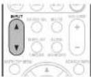
□Using the button on the remote control unit
Press INPUT ▲▼
- When INPUT ▲▼ is pressed, the input source is switched in the order shown below.

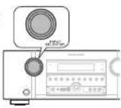
□Using the knob on the main unit
Turn INPUT SELECTOR
- Turning INPUT SELECTOR switches the input source, as shown below.

ENGLISH

Important information
Adjusting the master volume
text_image
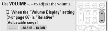
Use VOLUME +, - to adjust the volume. □ When the "Volume Display" setting ( page 66 ) is "Relative" [Adjustable range] - - - - -80.5dB - 18.0dBWhen the "Volume Display" setting (page 66) is "Absolute"
[Adjustable range] 0.0 - 99.0
- The adjustable range may vary depending on input signal and channel level settings.

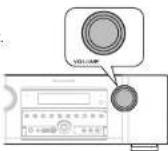
You can also operate via the main unit. In this case, perform the following operations.
Turn VOLUME to adjust the volume.
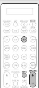
Turning off the sound temporarily
text_image
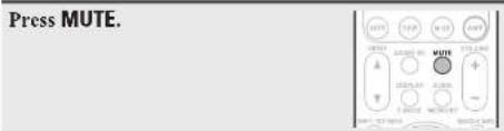
Press MUTE.
- The sound is reduced to the level set at "Mute Level" (37 page 66). - To cancel, press MUTE again. Muting can also be canceled by adjusting the master volume.
Set the front speakers to be used
Press SPKR A/B.
• Each time you press SPKR A/B, the front speaker setting will change as follows.
→ Front A Front A+B Front B

Playing a Blu-ray Disc player/DVD player
The following describes the procedure for playing Blu-ray Disc player/DVD player.

Prepare for playback.
① Turn on the power of the TV, subwoofer and player.
② Change the TV input to the input of this unit.
③ Load the disc in the player

Press ON to turn on power to the unit.

Press BD or DVD twice to switch the input source for the player used for playback.

Play the component connected to this unit.
Make the necessary settings on the player (language setting, subtitles setting, etc.) beforehand.
Playing a CD player
The following describes the procedure for playing CD player.

Prepare for playback.
① Turn on the power of the subwoofer and player
② Load the disc in the player

Press ON to turn on power to the unit.

Press CD twice to switch the input source to the CD player.

Play the component connected to this unit.

Playing an iPod®
You can play back audio only.
1 Connect the iPod® to the USB port ( page 19 "Connecting an iPod or USB memory device to the USB port").
2 Press ON to turn on power to the unit.
3 Press NET/USB twice to switch the input source to "USB/iPod".
NOTE
If the connections screen is not displayed, the iPod may not be properly connected. Reconnect it.

text_image
12.0 23.0 24.0 25.0 26.0 27.0 28.0 29.0 30.0 31.0 32.0 33.0 34.0 35.0 36.0 37.0 38.0 39.0 40.0 41.0 42.0 43.0 44.0 45.0 46.0 47.0 48.0 49.0 50.0 51.0 52.0 53.0 54.0 55.0 56.0 57.0 58.0 59.0 60.0 61.0 62.0 63.0 64.0 65.0 66.0 67.0 68.0 69.0 70.0 71.0 72.0 73.0 74.0 75.0 76.0 77.0 78.0 79.0 80.0 81.0 82.0 83.0 84.0 85.0 86.0 87.0 88.0 89.0 90.0 91.0 92.0 93.0 94.0 95.0 96.0 97.0 98.0 99.0 100.04 Press SEARCH/INFO and hold it down for 2 seconds or more to select the display mode.
- There are two modes for displaying the contents recorded on the iPod.
Remote mode Display iPod information on the TV screen.
- The unit display shows single-byte alphanumeric characters and some symbols only. “,” is displayed in place of incompatible characters.
- In "Remote mode", the iPod display is as shown at right.
Direct mode Display iPod information on the iPod screen.
- "Direct iPod" is displayed on the display of this unit.
| Display mode | Remote mode Direct mode | ||
| Playable files | Music file | √ | √ |
| Video file | * | ||
| Active buttons | Remote control unit (This unit) | √ | √ |
| iPod® | √ | ||
* Only the sound is played.
5 Use to select the item, then press ENTER or to select the file to be played.
6 Press ENTER, ▷ or ▶.
Playback starts.

- You can specify the duration of the on-screen display to be displayed (default: 30 sec) at menu "USB/iPod" (page 66). Press △▽◀▷ to return to the original screen.
- To play back compressed audio with extended bass or treble reproduction, we recommend playback in M-DAX mode (1 page 59). The default setting is "OFF".
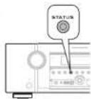
- In Remote mode, press STATUS during playback to check the title name, artist name, and album name.
NOTE
- Depending on the type of iPod and the software version, some functions may not operate.
- Note that Marantz will accept no responsibility whatsoever for any problems arising with the data on an iPod when using this unit in conjunction with the iPod.
ENGLISH
D
Playing an iPod®
iPod operation
| MAX4000 | ||||||||
| 12 | 13 | 14 | 15 | 16 | 17 | 18 | 19 | |
| 1 | 2 | 3 | 4 | 5 | 6 | 7 | 8 | |
| 1 | 2 | 3 | 4 | 5 | 6 | 7 | 8 | |
| 1 | 2 | 3 | 4 | 5 | 6 | 7 | 8 | |
| Operation buttons | Function |
| Cursor operation /Auto search (cue, |/Manual search (Press and hold, | | |
| ENTER(Press and release) | Enter / Pause |
| ENTER(Press and hold) | Stop |
| SEARCH(Fress and release) | Page search * 1 / Character search * 2 |
| SEARCH(Fress and hold) | Remote / Direct mode switching |
| RETURN | Return |
| ◀◀ ▶▶(Press and hold) | Manual search(fast-reverse/fast-forward) |
| ▶ | Playback / Pause |
| |◀◀ ▶▶| | Auto search (cue) |
| || | Pause |
| ■ | Stop |
| REPEAT | Repeat playbook |
| RANDOM | Random (Shuffle) playbook |
| TV POWER | TV power on/standby(Default : Marantz) |
| TV INPUT | Switch TV input(Default : Marantz) |
*1 When the menu screen is displayed, press SEARCH/INFO, then press ◀ (previous page) or ▷ (next page).
To cancel, press △▽ or SEARCH/INFO twice.
*2 When the menu screen is displayed, press SEARCH/INFO twice, then press ◀ ▷ to select the first letter you want to search mode.
- If it is not possible to search the list, "unsorted list." is displayed.
To cancel, press △▽ or SEARCH/INFO.

- Repeat playback and shuffle playback can also be set from "Input Setup" - "Playback Mode" (page 55) in the menu.
- If the list is not in alphabetical order, you may not be able to perform a character search.
Playing a USB memory device
Playing back music files recorded on a USB memory device.
Important information
□ USB memory devices
A USB memory device can be connected to the USB port of this unit to play music files stored on the USB memory device.
- Only USB memory devices conforming to mass storage class can be played on this unit.
- This unit is compatible with USB memory devices in "FAT16" or "FAT32" format.
[Compatible formats]
| USB memory devices *1 | |
| WMA (Windows Media Audio) | √*2 |
| MP3 (MPEG-1 Audio Layer-3) | √ |
| MPEG-4 AAC | √*3 |
| WAV | √ |
*1 USB
- This unit is compatible with MP3 ID3-Tag (Ver. 2) standards.
• This unit is compatible with WMA META tags.
*2 Copyright-protected files can not be played.
*3 Only files that are not protected by copyright can be played on this unit.
Also, files encoded in WMA format when ripped from a CD, etc. on a computer may be copyright protected, depending on the computer's settings.
[Compatible formats]
| Sampling frequency | Bit rate or Bit length | Extension | |
| WMA (Windows Media Audio) | 32/44.1/48 kHz | 48 – 192 kbps .wma | |
| MP3 (MPEG-1 Audio Layer-3) | 32/44.1/48 kHz | 32 – 320 kbps .mp3 | |
| MPEG-4 AAC 32/44 | 1/48 kHz 16 – 32 | 20 kbps .m4a | |
| WAV | 32/44.1/48 kHz | 16 bit | .wav |
Playing files stored on USB memory devices
1 Connect the USB memory device to the USB port (iT page 19 "Connecting an iPod or USB memory device to the USB port").
2 Press NET/USB twice to switch the input source to "USB/iPod".
3 Press △▽ to select the search item or folder, then press ENTER or ▷.
4 Press △▽ to select the file, then press ENTER. ▷ or ▶.
Playback starts.


- You can specify the duration of the on-screen display to be displayed (default: 30 sec) at menu "USB/iPod" (page 66). Press △▽◀◀ to return to the original screen.
- To play back compressed audio with extended base or treble reproduction, we recommend playback in M-DAX mode (127 page 59). The default setting is "OFF".
- If the USB memory device is divided into multiple partitions, only the top partition can be selected.
- This unit is compatible with MP3 files conforming to "MPEG-1 Audio Layer-3" standards.
NOTE
- Note that Marantz will accept no responsibility whatsoever for any problems arising with the data on a USB memory device when using this unit in conjunction with the USB memory device.
• USB memory devices will not work via a USB hub. - Marantz does not guarantee that all USB memory devices will operate or be supplied power. When using a USB portable hard disk that can draw power from an AC adapter, we recommend using the AC adapter.
- It is not possible to connect and use a computer via the USB port of this unit using a USB cable.
USB operation
| [IMAGE] | ||||||||||
| TENUS | POTATO | AVOCADO | MINI | SALAD | MINT | CAULIF | RADIO | LEMON | VANNY | |
| 100% | 45% | 30% | 25% | 20% | 15% | 10% | 8% | 6% | 4% | 3% |
| 95% | 40% | 25% | 20% | 15% | 10% | 8% | 6% | 4% | 3% | 2% |
| 90% | 35% | 20% | 15% | 10% | 8% | 6% | 4% | 3% | 2% | 1% |
| 85% | 30% | 15% | 10% | 8% | 6% | 4% | 3% | 2% | 1% | 0% |
| 80% | 25% | 10% | 8% | 6% | 4% | 3% | 2% | 1% | 0% | 0% |
| Operation buttons | Function |
| PRESET +, - | 'Preset channel selection |
| Cursor operation /Auto search (cuo, ) | |
| ENTER(Press and release) | Enter / Pause |
| ENTER(Press and hold) | Stop |
| SEARCH | Page search *1 / Character search *2 |
| RETURN | Return |
| ▶ | Playback / Pause |
| |◀◀ ▶▶▶| | Auto search (cue) |
| || | Pause |
| ■ | Stop |
| 1-8 | Preset channel selection |
| SHIFT | Preset channel block selection |
| REPEAT | Repeat playback |
| RANDOM | Random (Snuffle) playback |
| TV POWER | TV power on/standcy(Default : Marantz) |
| TV INPUT | Switch TV input(Default : Marantz) |
*1 When the menu screen is displayed, press SEARCH/INFO, then press ◀ (previous page) or ▷ (next page).
To cancel, press △▽ or SEARCH/INFO twice.
*2 When the menu screen is displayed, press SEARCH/INFO twice, then press ◀ ▷ to select the first letter you want to search mode.
- If it is not possible to search the list, "unsorted list." is displayed.
To cancel, press △▽ or SEARCH/INFO.

- Repeat playback and shuffle playback can also be set from "Input Setup" - "Playback Mode" (25 page 55) in the menu.
- If the list is not in alphabetical order, you may not be able to perform a character search.
ENGLISH

Tuning in radio stations
Listening to FM/AM broadcasts
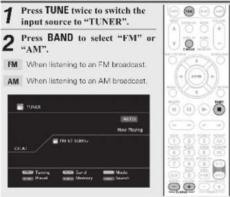
1 Press TUNE twice to switch the input source to "TUNER".
2 Press BAND to select "FM" or "AM".
FM When listening to an FM broadcast.
AM When listening to an AM broadcast.
3 Tune in the desired broadcast station.
① To tune in automatically (Auto tuning)
Press T.MODE to light the "AUTO" indicator on the display, then use TUNING + or TUNING - to select the station you want to hear.
② To tune in manually (Manual tuning)
Press T.MODE to turn off the display's "AUTO" indicator, then use TUNING + or TUNING - to select the station you want to hear.

- If the desired station cannot be tuned in with auto tuning, tune it in manually.
- When tuning in stations manually, press and hold TUNING + or TUNING – to change frequencies continuously.
- You can specify the duration of the on-screen display to be displayed (default: 30 sec) at menu "TUNER" (page 67). Press △▽◀▶ to return to the original screen.
- You can also operate via the main unit. In this case, perform the following operations. Press to select the radio station.

□Presetting radio stations (Manual preset)
Your favorite broadcast stations can be preset so that you can tune them in easily. Up to 56 stations can be preset.
- Stations can be preset automatically at "Auto Preset" (T page51). If "Auto Preset" is performed after performing "Manual Preset", the "Manual Preset" settings will be overwritten.
1 Tune in the broadcast station you want to preset.
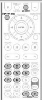
2 Press MEMORY.
3 Press SHIFT/TOP MENU to select the block (A to G) in which to preset the channel (1 to 8 per block), then press PRESET +, PRESET - or 1 - 8 to select the preset number.
4 Press MEMORY again to complete the setting.
- To preset other stations, repeat steps 1 to 4.
text_image
1 2 3 4 5 6 7 8 9 10 11 12 13 14 15 16 17 18 19 20 21 22 23 24 25 26 27 28 29 30 31 32 33 34 35 36 37 38 39 40 41 42 43 44 45 46 47 48 49 50 51 52 53 54 55 56 57 58 59 60 61 62 63 64 65 66 67 68 69 70 71 72 73 74 75 76 77 78 79 80 81 82 83 84 85 86 87 88 89 90 91 92 93 94 95 96 97 98 99 100Default settings
| Block (A - G) and Channel (1 - 8) | Default Settings |
| A1 - A8 | 87.5 / 89.1 / 98.1 / 108.0 / 90.1 / 90.1 / 90.1 / 90.1 MHz |
| B1 - B8 | 522 / 603 / 999 / 1404 / 1611 kHz, 90.1 / 90.1 / 90.1 MHz |
| C1 - C8 | 90.1 MHz |
| D1 - D8 | 90.1 MHz |
| E1 - E8 | 90.1 MHz |
| F1 - F8 | 90.1 MHz |
| G1 - G8 | 90.1 MHz |
Specify a name for the preset broadcast station (Preset Name) (page 51)
□Listening to preset stations
1 Press SHIFT/TOP MENU to select the memory block (A to G).
2 Press PRESET +, PRESET - or 1 - 8 to select the desired preset channel.
2 Press PRESET +, PRESET - or 1 - 8 to select the desired preset channel.
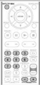
text_image
MINT/TOF MIND A B C D E F G H I J K L M N O P Q R S T U V W X Y Z 1 2 3 4 5 6 7 8 9 10 11 12 13 14 15 16 17 18 19 20 21 22 23 24 25 26 27 28 29 30 31 32 33 34 35 36 37 38 39 40 41 42 43 44 45 46 47 48 49 50 51 52 53 54 55 56 57 58 59 60 61 62 63 64 65 66 67 68 69 70 71 72 73 74 75 76 77 78 79 80 81 82 83 84 85 86 87 88 89 90 91 92 93 94 95 96 97 98 99 100
You can also operate via the main unit. In this case, perform the following operations. Press ◀ ▷ to select the preset radio station.
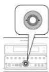
□Direct frequency tuning
You can enter the receiving frequency directly to tune in.
| 1 Press SEARCH/INFO. |
| 2 Input frequencies using the 0 – 9.If ◀ is pressed, the immediately preceding input is cancelled. |
| 3 When setting is completed, press ENTER. |
The preset frequency is tuned in.
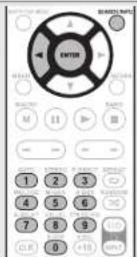
RDS (Radio Data System)
RDS (works only on the FM band) is a broadcasting service which allows a station to send additional information along with the regular radio program signal.
NOTE
The operations described as follows using SEARCH/INFO will not function in areas in which there are no RDS broadcasts.

□RDS search
Use this function to automatically tune to FM stations that provide the RDS service.
1 Press TUNE twice to switch the input source to "TUNER".
2 Press SEARCH/INFO to select "RDS SEARCH".

text_image
TUNER Program Category A: F D PCS - ILS Section PPY - Program Category IP - Traffic Information RT - Radio Test ON AS EM 05.12.12.12 START Mode PUST Tuning T: MNG E ... BrandTuning Mode RESET Project Manager Start Search3 Press PRESET + or PRESET -. The search for RDS stations begins automatically.
- If no RDS stations are found with the above operation, all the reception bands are searched.
- When a broadcast station is found, that station's name appears on the display.
- If no RDS station is found when all the frequencies have been searched, "NO RDS" is displayed.
PTY (Program Type)
n PTY identifies the type of RDS program.
The program types and their displays are as follows:
| NEWS | News | WEATHER | Weather |
| AFFAIRS | Current Affairs | FINANCE | Finance |
| INFO | Information | CHILDREN | Children's program |
| SPORT | Sports | ||
| EDUCATE | Education | SOCIAL | Social Affairs |
| DRAMA | Drama | RELIGION | Religion |
| CULTURE | Culture | PHONE IN | Phone In |
| SCIENCE | Science | TRAVEL | Travel |
| VARIED | Varied | LEISURE | Leisure |
| POP M | Pop Music | JAZZ | Jazz Music |
| ROCK M | Rock Music | COUNTRY | Country Music |
| EASY M | Easy Listening Music | NATION M | National Music Oldies Music |
| LIGHT M | Light Classical | OLDIES | Folk Music |
| CLASSICS | Serious Classical | FOLK M | Documentary |
| OTHER M | Other Music | DOCUMENT |
□PTY search
Use this function to find RDS stations broadcasting a designated program type (PTY).
1 Press TUNE twice to switch the input source to "TUNER".
2 Press SEARCH/INFO to select "PTY SEARCH".
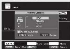
text_image
TURR Program Category AUTO P25 NTRS P10 N1000 P100 P100 P100 P100 AS FM 36.10kHz EXERC Mode FIRST Tuning Ch A TABLED: 10kHz Bend Tuning: Macs RESET Preset Mening/Offs SELECT SEARCH3 Watching the display, press to call out the desired program type.
| WEATHER | Weather |
| FINANCE | Finance |
| CHILDREN | Children's program |
| SOCIAL | Social Affairs |
| RELIGION | Religion |
| PHONE IN | Phone In |
| TRAVEL | Travel |
| LEISURE | Leisure |
| JAZZ | Jazz Music |
| COUNTRY | Country Music |
| NATION M | National Music |
| OLDIES | Oldies Music |
| FOLK M | Folk Music |
| DOCUMENT | Documentary |

text_image
START START START START M M M M M M M M M M M M M M M M M M M M M M M M M M M M M M M M M M M M M M M M M M M M M M M M M M 1 2 3 4 5 6 7 8 9 10 11 12 13 14 15 16 17 18 19 20 21 22 23 24 25 26 27 28 29 30 31 32 33 34 35 36 37 38 39 40 41 42 43 44 45 46 47 48 49 50 51 52 53 54 55 56 57 58 59 60 61 62 63 64 65 66 67 68 69 70 71 72 73 74 75 76 77 78 79 80 81 82 83 84 85 86 87 88 89 90 91 92 93 94 95 96 97 98 99 1004 Press PRESET + or PRESET -. PTY search begins automatically.
- If there is no station broadcasting the designated program type with the above operation, all the reception bands are searched.
- The station name is displayed on the display after searching stops.
- If no station broadcasting the designated program type is found when all the frequencies have been searched, "NO PROGRAMME" is displayed.
TP (Traffic Program)
TP identifies programs that carry traffic announcements. This allows you to easily find out the latest traffic conditions in your area before leaving home.
□TP search
Use this function to find RDS stations broadcasting traffic programs (ITP stations).
1 Press TUNE twice to switch the input source to "TUNER".
2 Press SEARCH/INFO to select "TP SEARCH".

text_image
TUNER Program Category AUTO RDS: RDS Station PVY: Program Database RF: Traffic Information RT: Radio Test ON AS RM 30.12MHz SATCH Mode POST Timing TURING DATA BANDTURN Mode RESET Project Number/SATM SEARCH Search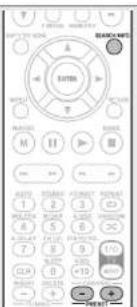
text_image
EUTRA M H I J K L M N O P Q R S T U A B C D E F G H I J K L M N O P Q R S T U A B C D E F G H I J K L M N O P Q R S T U A B C D E F G H I J K L M N o3 Press PRESET + or PRESET -. TP search begins automatically.
- If no TP station is found with the above operation, all the reception bands are searched.
- The station name is displayed on the display after searching stops.
- If no other TP station is found when all the frequencies have been searched, "NO PROGRAMME" is displayed.
ENGLISH

Tuning in radio stations
RT (Radio Text)
RT allows RDS stations to send text messages that appear on the display.
"RT" appears on the display when radio text data is received.
1 Press TUNE twice to switch the input source to "TUNER".
2 Press SEARCH/INFO to select "RT".
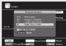
text_image
TUNER Program Category AUTO KOS: 00% Station PPI: Program Category IP: Traffic Information RT: Radio Test + OK+ AS RM 30.1MHz SUPPORT Mode START: 2.0 MHz Reset Turners Mode RESET: Project Number/OK SUPPORT Search- While receiving an RDS broadcast station, the text data broadcast from the station is displayed.
- To turn the display off, press ◀ ▷.
- If no text data is being broadcast, "NO TEXT DATA" is displayed.

□Tuner (FM/AM) operation
| MRSATE | |||||||||
| OFFICE | ONION | POTATO | SIGHT | RISK | TOLER | AVOCATION | MINISTRY | RETURN | |
| 1 | 320 | 325 | 330 | 335 | 340 | 345 | 350 | 355 | 360 |
| 2 | 325 | 330 | 335 | 340 | 345 | 350 | 355 | 360 | 365 |
| 3 | 325 | 330 | 335 | 340 | 345 | 350 | 355 | 360 | 365 |
| 4 | 325 | 330 | 335 | 340 | 345 | 350 | 355 | 360 | 365 |
| Operation buttons | Function |
| PRESET +, - Preset channel selection | |
| Cursor operation | |
| ENTER | Enter setting |
| SEARCH | Direct frequency tuning / RDS search |
| RETURN | Return |
| BAND | FM/AM switching |
| T.MODE | Switch search modes |
| TUNING +, - | Tuning (up/down) |
| 0 – 9 | Preset channel selection (1 – 8) / Direct frequency tuning (0 – 9) |
| SHIFT | Preset channel block selection |
| MEMORY Preset memory registration | |
| TV POWER | TV power on/standby(Default : Marantz) |
| TV INPUT | Switch TV input(Default : Marantz) |
Switching the tuning increment
The tuning increment factory settings are 9 kHz for AM, and 0.05 MHz for FM.

text_image
AUTODISPLAY ON/STANDBY1 While pressing down AUTO and DISPLAY, press ON/STANDBY to turn on the power. "AM9/FM50" appears on the display.
2 Press ◀ ▷. “AM10/FM200” appears on the display, and the tuning increment is switched to AM and FM are 10 kHz and 0.2 MHz.
3 Press ON/STANDBY.
- The tuner preset memory will be cleared if this operation is performed.
- This setting will not revert to the default values even when the microprocessor is reset.
Selecting a listening mode (Surround mode)
This unit can play input audio signals in multi-channel surround mode or in stereo mode.
Select a listening mode suitable for the playback contents (cinema, music, etc.) or according to your liking.
Listening mode
| Input audio signal | Playback | Listening mode | |
| 2-channelMulti channel | Surround | Multi-channel playback ( page 31) | For 2-channel signal input:Surround-channel signals are created and played with surround playback.For multichannel signal input:The surround signal recorded in source is played as surround playback.(The sound is played according to the settings of the speaker size in "Speaker Config." ( page 611.)Surround-back-channel or front-height-channel signals that are not recorded in source can be created. |
| 2-channelMulti channel | Stereo | Stereo playback ( page 33) | If multichannel signals are input, they are mixed down to 2-channel audio and are played.Subwoofer signals are also output. |
| 2-channelMulti channel | Stereo | Direct playback ( page 33) | Sound recorded in source is played as is:Surround back signals or front height signals are not created.In this mode, the following items cannot be adjusted.Tone ( page 57 ) · MultEO® ( page 57 )Dynamic EO® ( page 58 ) · Dynamic Volume® ( page 58 )M-DAX ( page 59 ) |
| 2-channelMulti channel | Virtual Surround | Dolby Virtual Speaker/Dolby Headphone playback ( page 33) | Virtual Surround processing is performed on 2-channel or multichannel input signals that are played back. |
#
- Some listening modes cannot be selected, depending on the audio format or number of channels of the input signal. For details, see "Types of input signals, and corresponding surround modes" (page 85).
- Adjust the sound field effect with the menu "Surround Parameter" (page 56) to enjoy your favorite sound mode.
- You can select the listening mode by pressing SURR. MODE on the main unit.
Press SURR. MODE and the modes are switched as shown below.
| AUTO*STEREO | STEREO | DOLEY PLIIz | DOLEY PLIII(x) Movie | DOLEY PLIII(x) Music | DOLEY PLIII(x) Game |
| DOLBY VS | NEURAL | MULTI CH STEREO | DTS NEO:6 music | DTS NEO:6 cinema |
* For "AUTO", press AUTO on the amplifier or remote control unit.
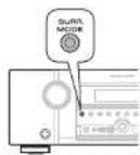
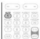

Multi-channel playback
□Surround playback of 2-channel sources
1 Playing the source (1 page 24 – 28).
2 Press SURR. to select the surround decoder to play back multichannel sound.
- If SURR. MODE on the main unit is pressed, the same function as with the remote control unit can be obtained.
- Each time SURR, is pressed, the surround mode is switched. Which decoder can be selected depends on the settings of "Amp Assign" (page 61) or "Speaker Config." (page 61).
DOLBY PLLIz *1 This mode is for 7.1-channel surround playback using the front height speakers.
- "PLIIz Height" is displayed.
DOLBY PLIIx *2 This mode is for 7.1-channel or 6.1-channel surround playback using the surround back speakers.
- "PLIIx Movie", "PLIIx Music" or "PLIIx Game" is displayed.
DOLBY PLII This mode is for 5.1-channel surround playback. Select this mode if no front height speaker nor surround back speaker is to be used.
- "PLII Movie", "PLII Music", "PLII Game" is displayed.
DTS NEO:6 This mode is for 7.1-channel, 6.1-channel or 5.1-channel surround playback using the surround back speakers.
- "DTS NEO:6 Cinema" or "DTS NEO:6 Music" is displayed.
MULTI CH STEREO This mode is for enjoying stereo sound from all speakers.
*1 This can be selected when the "Amp Assign" ( page 61) setting in the menu is set to "Normal" is set to "A". This cannot be selected when the "Speaker Config." - "F.Height" is set to "None".
*2 This can be selected when "Amp Assign" is set to "Normal" or "Speaker Config." - "S.Back" is not set to "None".
ENGLISH

Multi-channel playback
NEURAL
*3 This mode is for 7.1-channel, 6.1-channel or 5.1-channel surround playback using the surround back speakers.
- "NEURAL" is displayed.
*3 This mode supports analog 2-channel audio, and linear PCM 2 channel (44.1 kHz, 48 kHz) audio.
□ Surround playback of multi-channel sources (Dolby Digital, DTS etc.)
1
Playing the source (page 24-28).

2
Press SURR. to select the surround decoder to play back multichannel sound.
- If SURR. MODE on the main unit is pressed, the same function as with the remote control unit can be obtained.
- Select the surround mode while viewing the display on the screen (12 "Displaying the currently playing surround mode" at right).
- Which decoder can be selected depends on the input signal, the settings of "Amp Assign" ( page 61) or "Speaker Config." ( page 61).


Displaying the currently playing surround mode
| Input signal Surround mode Display | ||
| DOLBY DIGITAL(2ch) | NEURAL | NEURAL |
| DOLBY DIGITAL(other than 2ch) /DOLBY DIGITAL EX | DOLBY DIGITAL | DOLBY DIGITAL |
| DOLBY DIGITAL EX | DOLBY DIGITAL EX | |
| DOLBY DIGITAL + PLIIx Movie | DOLBY D + PLII x MV | |
| DOLBY DIGITAL + PLIIx Music | DOLBY D + PLII x MS | |
| DOLBY DIGITAL + PLIIz | DOLBY D + PLII z | |
| DOLBY DIGITAL Plus | DOLBY DIGITAL Plus | DOLBY DIGITAL + |
| DOLBY DIGITAL Plus + EX | DOLBY D + + EX | |
| DOLBY DIGITAL Plus + PLIIxMovie | DOLBY D + PLII x MV | |
| DOLBY DIGITAL Plus + PLIIxMusic | DOLBY D + PLII x MS | |
| DOLBY DIGITAL Plus + PLIIz | DOLBY D + + PLII z | |
| DOLBY TrueHD | DOLBY TrueHD | DOLBY TrueHD |
| DOLBY TrueHD + EX | DOLBY HD + EX | |
| DOLBY TrueHD + PLIIx Movie | DOLBY HD +PLII x MV | |
| DOLBY TrueHD + PLIIx Music | DOLBY HD +PLII x MS | |
| DOLBY TrueHD + PLIIz | DOLBY HD + PLII z | |
| DTS (5.1ch) /DTS-ES Discrete 6.1 /DTS-ES Matrix 6.1 /DTS 96/24 | DTS SURROUND | DTS SURROUND |
| DTS + PLIIx Movie | DTS + PLII x MV | |
| DTS + PLIIx Music | DTS + PLII x MS | |
| DTS + PLIIz HEIGHT | DTS + PLII z | |
| DTS + NEO:6 | DTS + NEO:6 | |
| DTS ES MTRX6.1*1 | DTS ES MTRX6.1 | |
| DTS ES DSCR6.1*2 | DTS ES DSCR6.1 | |
| DTS 96/24*3 | DTS 96/24 | |
| DTS-HD | DTS-HD HI RES | DTS-HD HI RES |
| DTS-HD MSTR | DTS-HD NSTR | |
| DTS-HD + NEO:6 | DTS-HD + NEO:6 | |
| DTS-HD + PLIIx MOVIE | DTS-HD + PLII x MV | |
| DTS-HD + PLIIx MUSIC | DTS-HD + PLII x MS | |
| DTS-HD + PLIIz HEIGHT | DTS-HD + PLII z | |
| DTS Express | DTS Express | |
| PCM (multi ch) | MULTI CH IN | MULTI CH IN |
| MULTI IN + Dolby EX | MULTI + Dolby EX | |
| MULTI IN + PLIIx MOVIE | MULTI IN + PLII x MV | |
| MULTI IN + PLIIx MUSIC | MULTI IN + PLII x MS | |
| MULTI IN + PLIIz HEIGHT | MULTI IN + PLII z | |
| MULTI CH IN 7.1 | MULTI CH IN 7.1 | |
| All Input signal Dolby VI | VIRTUAL SPEAKER | DOLBY VS |
*1 This is displayed when the input signal is "DTS-ES Matrix 6.1".
*2 This is displayed when the input signal is "DTS-ES Discrete 6.1".
*3 This is displayed when the input signal is "DTS 96/24".
[Views on the display]
① Shows a decoder to be used.
- A DOLBY DIGITAL Plus decoder is displayed as "DOLBY D +".
② Shows a decoder that creates sound output from the surround back speakers.
- “+ PLIIz” indicates the front height sound from front height speakers.
#
For an input signal that can be reproduced in each surround mode, see "Surround modes and surround parameters" (page 83).
ENGLISHDEU
Stereo playback
This is the mode for playing in stereo. The tone can be adjusted.
• Sound is output from the front left and right speakers and subwoofer.
- If multichannel signals are input, they are mixed down to 2-channel audio and are played.
1 Playing the source (page 24 - 28).
2 Press STEREO. Stereo playback begins.
Direct playback
Sound recorded in source is played as is.
- Surround back signals or front height signals are not created.
• In this mode, the following items cannot be adjusted.
• Tone II page 57) • MultEQ ^® (page 57)
• Dynamic EQ ^® (page 58) • Dynamic Volume ^® (page 58)
• M-DAX (page 59)
1 Playing the source ( page 24 - 28).
2 Press P.DIRECT to select the direct mode.
- If PURE DIRECT on the main unit is pressed, the same function as with the remote control unit can be obtained.
• Each time P.DIRECT is pressed, the direct mode is switched.
Source Direct This mode plays back tracks at high sound quality without passing through the sound quality adjustment circuits.
Pure Direct * This mode plays back tracks at the closest to the original sound quality.
Auto This mode detects the type of input digital signal, and automatically selects the corresponding mode for playback.
* The following circuits that affect sound quality are set to off.
- Main unit's display circuit (The display is turned off.)
• Analog video input/output circuit

• To cancel, press P.DIRECT again.
• Video signals are only output when HDMI signals are played in the PURE DIRECT mode.
NOTE
When in the PURE DIRECT mode, the menu screen is not displayed.
Dolby Virtual Speaker/Dolby Headphone playback
☐ Dolby Virtual Speaker mode
This delivers a full surround sound experience from two stereo speakers.
• Sound is output from the front left and right speakers.
- If multichannel signals are input, they are mixed down to 2-channel audio.
1 Playing the source (1 page 24 – 28).
2 Press SURR. to select "DOLBY VS".

☐ Dolby Headphone mode
You can enjoy listening to multi-channel surround sound through headphones using this mode.
Press SURR. to select the Dolby Headphone mode.
- If SURR. MODE on the main unit is pressed, the same function as with the remote control unit can be obtained.
• Each time SURR. is pressed, the Dolby Headphone mode is switched.
DOLBY
HEADPHONE This is the surround mode for listening with headphones.
The surround sound field is played through regular headphones.
DOLBY HP BYPASS The sound is played in the normal stereo mode rather than the surround mode when listening with headphones.
DOLBY HP This mode is best suited for movie sources.
DOLBY HP This mode is best suited for movie sources.
DOLBY HP This mode is best suited for music sources. PLII Music
NOTE
- The surround mode returns to the previous setting as soon as the plug is removed from the jack.
- You can select Dolby HP PLII Movie or Dolby HP PLII Music when a 2-channel source is played back.
ENGLISH
D
Advanced version
Advanced version
Here, we explain functions and operations that let you make better use of this unit.
● Speaker installation/connection
(Other than 7.1-channel system with surround back speakers) page 35
● Playback (Advanced operation) 📋 page 42
● Playback in ZONE2 (Separate room) page 45
● How to make detailed settings 📋 page 47
- Operating the connected devices by remote control unit page 69
Speaker installation/connection (Other than 7.1-channel system with surround back speakers)
This section explains a wide range of speaker installation/connection/setting procedures.
For details on installing/connecting/setting 7.1 channel audio that uses surround back speakers, see "Simple version (Simple setup guide)" (page 4).
Use the Audyssey® Auto Setup function of this unit to automatically detect the number of connected speakers and perform optimal settings for the speakers to be used.
Procedure for speaker settings

flowchart
graph TD
    A["Install"] --> B["Connect (page 36)"]
    B --> C["Set up speakers (page 39)"]
Install
This unit is compatible with Dolby Pro Logic IIz (I27 page 88), which offers an even wider and deeper surround sensation. When using Dolby Pro Logic IIz, install front height speakers.
When 7.1ch (Front height speaker) installed
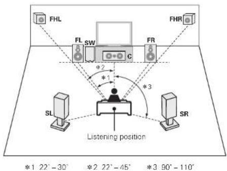
flowchart
graph TD
    A["FHL"] --> B["FL SW"]
    B --> C["C"]
    D["FHR"] --> E["FR"]
    E --> F["S"]
    G["SL"] --> H["SR"]
    H --> I["Listening position"]
    style A fill:#f9f,stroke:#333
    style D fill:#f9f,stroke:#333
    style G fill:#ccf,stroke:#333
    style H fill:#ccf,stroke:#333
    style I fill:#dfd,stroke:#333
When 5.1ch installed
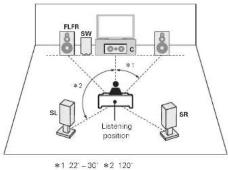
flowchart
graph TD
    A["FLFR"] --> B["SW"]
    B --> C["c"]
    D["SL"] --> E["Listening position"]
    F["SR"] --> E
    E --> G["*1 22°-30° *2 120°"]

Install the surround back speakers in a position 60 to 90 cm higher than ear level.

text_image
Front height speaker • Point slightly downwards At least 1 m* Front speaker [Viewed from the side] Surround speaker 60 - 90 cm Surround back speaker • Point slightly downwards * Recommended for Dolby Pro Logic IIzNOTE
It is not possible to use the surround back speakers and front height speakers simultaneously.
When 6.1ch (Surround back speaker) installed
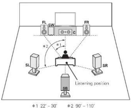
text_image
FL SW FR *2 *1 SL SR Listening position *1 22° - 30° *2 90° - 110°When 2.1ch installed
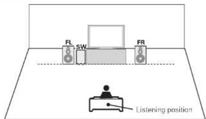
text_image
FL SW FR Listening positionFL Front speaker (L) SB Surround back speaker
FR Front speaker (R) FHL Front height speaker (L)
C Center speaker FHR Front height speaker (R)
SW Subwoofer
SL Surround speaker (L)
SR Surround speaker (R)
ENGLISH

Connect
- For the method of connecting the 7.1-channel system with surround back speakers, see page 5.
- For the method of connecting the TV, see page 6.
7.1-channel (Front height speaker) connection
For 7.1-channel (Front height speaker) playback, set "Set up "Amp Assign" (page 39) to "Normal".
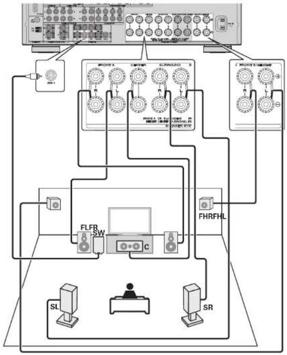
flowchart
graph TD
    A["Front Panel"] --> B["Switch 1"]
    A --> C["Switch 2"]
    A --> D["Switch 3"]
    A --> E["Switch 4"]
    A --> F["Switch 5"]
    A --> G["Switch 6"]
    A --> H["Switch 7"]
    A --> I["Switch 8"]
    A --> J["Switch 9"]
    A --> K["Switch 10"]
    A --> L["Switch 11"]
    A --> M["Switch 12"]
    A --> N["Switch 13"]
    A --> O["Switch 14"]
    A --> P["Switch 15"]
    A --> Q["Switch 16"]
    A --> R["Switch 17"]
    A --> S["Switch 18"]
    A --> T["Switch 19"]
    A --> U["Switch 20"]
    A --> V["Switch 21"]
    A --> W["Switch 22"]
    A --> X["Switch 23"]
    A --> Y["Switch 24"]
    A --> Z["Switch 25"]
    A --> AA["Switch 26"]
    A --> AB["Switch 27"]
    A --> AC["Switch 28"]
    A --> AD["Switch 29"]
    A --> AE["Switch 30"]
    A --> AF["Switch 31"]
    A --> AG["Switch 32"]
    A --> AH["Switch 33"]
    A --> AI["Switch 34"]
    A --> AJ["Switch 35"]
    A --> AK["Switch 36"]
    A --> AL["Switch 37"]
    A --> AM["Switch 38"]
    A --> AN["Switch 39"]
    A --> AO["Switch 40"]
    A --> AP["Switch 41"]
    A --> AQ["Switch 42"]
    A --> AR["Switch 43"]
    A --> AS["Switch 44"]
    A --> AT["Switch 45"]
    A --> AU["Switch 46"]
    A --> AV["Switch 47"]
    A --> AW["Switch 48"]
    A --> AX["Switch 49"]
    A --> AY["Switch 50"]
    A --> AZ["Switch 51"]
    A --> BA["Switch 52"]
    A --> BB["Switch 53"]
    A --> BC["Switch 54"]
    A --> BD["Switch 55"]
    A --> BE["Switch 56"]
    A --> BF["Switch 57"]
    A --> BG["Switch 58"]
    A --> BH["Switch 59"]
    A --> BI["Switch 60"]
    A --> BJ["Switch 61"]
    A --> BK["Switch 62"]
    A --> BL["Switch 63"]
    A --> BM["Switch 64"]
    A --> BN["Switch 65"]
    A --> BO["Switch 66"]
    A --> BP["Switch 67"]
    A --> BQ["Switch 68"]
    A --> BR["Switch 69"]
    A --> BS["Switch 70"]
    A --> BT["Switch 71"]
    A --> BU["Switch 72"]
    A --> BV["Switch 73"]
    A --> BW["Switch 74"]
    A --> BX["Switch 75"]
    A --> BY["Switch 76"]
    A --> BZ["Switch 77"]
    A --> CA["Switch 78"]
    A --> CB["Switch 79"]
    A --> CC["Switch 80"]
6.1-channel (Surround back speaker) connection
If using only one surround back speaker (with a 6.1-channel connection), connect to the "L" side of the SURR. BACK/AMP ASSIGN terminal. For speaker settings in this case, see "When 6.1ch (Surround back speaker) installed" (page 35). For 6.1-channel (Surround back speaker) playback, set "Set up " Amp Assign" (page 39) to "Normal"

flowchart
graph TD
    A["Audio System"] --> B["Control Panel"]
    B --> C["FLFB SW"]
    B --> D["SR"]
    B --> E["SL"]
    B --> F["SB"]
    B --> G["Control Panel"]
    G --> H["FLFB SW"]
    G --> I["SR"]
    G --> J["SL"]
    G --> K["SB"]
    G --> L["Control Panel"]
    L --> M["FLFB SW"]
    L --> N["SR"]
    L --> O["SL"]
    L --> P["SB"]
    L --> Q["Control Panel"]
    Q --> R["FLFB SW"]
    Q --> S["SR"]
    Q --> T["SL"]
    Q --> U["SB"]
    Q --> V["Control Panel"]
ENGLISHDEU
Connect
5.1-channel connection
For 5.1-channel playback, set "Set up "Amp Assign" (page 39) to "Normal",
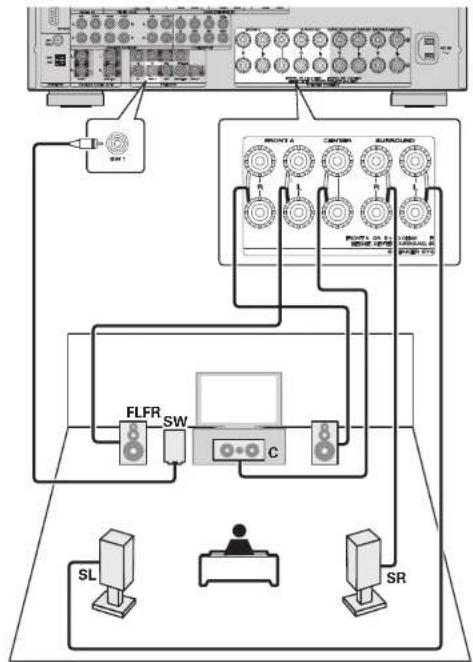
flowchart
graph TD
    A["Monitor"] --> B["PLC"]
    B --> C["FLFR"]
    B --> D["SW"]
    B --> E["C"]
    C --> F["SL"]
    D --> G["SR"]
    E --> H["Control Panel"]
    style A fill:#f9f,stroke:#333
    style B fill:#ccf,stroke:#333
    style C fill:#cfc,stroke:#333
    style D fill:#fcc,stroke:#333
    style E fill:#cff,stroke:#333
    style F fill:#ffc,stroke:#333
    style G fill:#fcc,stroke:#333
    style H fill:#ffc,stroke:#333
Front A/B connection
The second set of front speakers can be connected to the FRONT B/HEIGHT terminals. In this case, perform the settings using the SPKR A/B button on the remote control (CE) page 24 "Set the front speakers to be used").
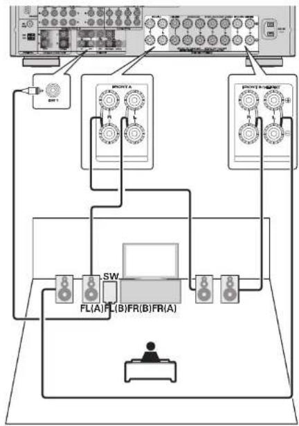
flowchart
graph TD
    A["Audio System"] --> B["Display Unit 1"]
    A --> C["Display Unit 2"]
    B --> D["Switch 1"]
    C --> E["Switch 2"]
    D --> F["Central Display Unit"]
    E --> F
    F --> G["User Device"]
    G --> H["Control Panel"]
    style A fill:#f9f,stroke:#333
    style B fill:#ccf,stroke:#333
    style C fill:#ccf,stroke:#333
    style D fill:#dfd,stroke:#333
    style E fill:#dfd,stroke:#333
    style F fill:#dfd,stroke:#333
    style G fill:#dfd,stroke:#333
    style H fill:#dfd,stroke:#333

For surround playback of a multichannel source, if you connect the center speaker, surround speakers, surround back speakers and subwoofers. 7.1-channel playback is available. Front speakers can be used separately, depending on the speaker's specifications or playback source such as front speakers (A) for multichannel playback and front speakers (B) for 2-channel playback.
NOTE
When using the A front speakers and B front speakers simultaneously, make sure you check the impedance of the connected speakers (12 page 5).
ENGLISH

Connect
2.1-channel connection
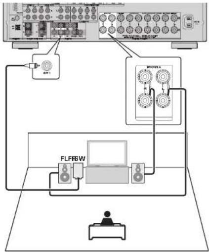
flowchart
graph TD
    A["Server"] --> B["PLC"]
    B --> C["Control Unit"]
    C --> D["FLFRW"]
    D --> E["Output Device"]
    style A fill:#f9f,stroke:#333
    style B fill:#ccf,stroke:#333
    style C fill:#cfc,stroke:#333
    style D fill:#fcc,stroke:#333
    style E fill:#ffc,stroke:#333
☐For connecting two subwoofers
Two subwoofers can be connected to this unit.
The same signal is output from each subwoofer terminal.

Bi-Amp connection
A bi-amp connection is to connect separate amplifiers to the tweeter terminals and woofer terminals of speakers compatible with the bi-amp function. This prevents the back electromotive force returned force without output of the woofer sent to the tweeter, which affects the sound quality of the tweeter, and you can enjoy playback with higher quality sound.
In this case, set "Set up "Amp Assign" (page 39) to "SPKR-C".

flowchart
graph TD
    A["Central Unit"] --> B["PLINT"]
    A --> C["SULA"]
    A --> D["FLFR"]
    A --> E["IR ICU"]
    B --> F["Control Unit"]
    C --> G["Control Unit"]
    D --> H["Control Unit"]
    E --> I["Control Unit"]

When making a bi-amp connection, the same signal is output from the FRONT A terminal and the SURR, BACK/AMP ASSIGN terminal.
For surround playback of a multichannel source, if you connect the center speaker, surround speakers and subwoofers, 5.1-channel playback is available.
NOTE
- Use speakers compatible with bi-amp connections.
- When making bi-amp connections, be sure to remove the short-circuiting plate or wire between the speaker's woofer and tweeter terminals.
Set up speakers
This section provides the setup methods of speaker systems other than the 7.1-channel system (with surround back speakers).
For the setup methods of the 7.1-channel system with surround back speakers, see "Simple version", "Set up speakers (Audyssey® Auto Setup)" (page 7) of "Simple version".
First install and connect the speakers to this unit.
Before Auto Setup measurement, the settings shown below can be made.
- Changing the amplifier assignment (Amp Assign)
The signal output from the SURR.BACK/AMP ASSIGN speaker terminal of this unit can be switched to match your speaker environment (page 39 "Set up "Amp Assign").
- Setting the channels to be used (Channel Select)
If channels that are not to be used are set in advance, measurement for the set channels is skipped, and measuring time can be reduced (page 39 "Set up "Channel Select").
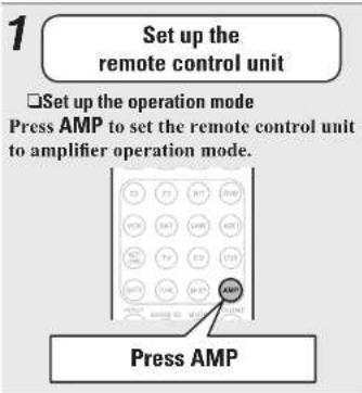
text_image
1 Set up the remote control unit □ Set up the operation mode Press AMP to set the remote control unit to amplifier operation mode. Press AMP
text_image
2 Connect the setup microphone. When the setup microphone is connected, the following screen is displayed. AUTO SETUP AUDYSEY AUTO SETUP AUDIO AudioEQ STEP1 Preparation Connect speakers and places them according to the recommendations in the manual. Set the following items if necessary. Amp Audio Physical Select Auto Setup Start NEW order 4 Start Auto Setup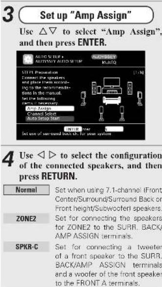
text_image
3 Set up "Amp Assign" Use △▽ to select "Amp Assign", and then press ENTER. 4 Use ◀▶ to select the configuration of the connected speakers, and then press RETURN. Normal Set when using 7.1-channel (Front/ Center/Surround/Surround Back or Front height/Subwoofer) speakers. ZONE2 Set for connecting the speakers for ZONE2 to the Surr. BACK/ AMP ASSIGN terminals. SPKR-C Set for connecting a tweeter of a front speaker to the Surr. BACK/AMP ASSIGN terminals and a woofer of the front speaker to the FRONT A terminals.around items indicate the settings.
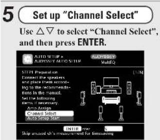
text_image
5 Set up "Channel Select" Use △▽ to select "Channel Select", and then press ENTER.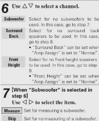
text_image
6 Use △▽ to select a channel. Subwoofer Select for no subwoofer's to be used. In this case, go to step 7. Surround Select for no surround back back speakers to be used. In this case, go to step 8. • "Surround Back" can be set when "Amp Assign" is set to "Normal". Front Select for no front height speakers to be used. In this case, go to step 9. • "Front Height" can be set when "Amp Assign" is set to "Normal". 7 [When "Subwoofer" is selected in step 6] Use ◀◀▶ to select the item. Measure Set for measuring a subwoofer. Skip Set for no measuring of a subwoofer.Remote control operation buttons
Move the cursor (Up/Down/Left/Right)
ENTER Confirm the setting
RETURN ○ Return to previous menu
ENGLISH

Set up speakers

[When "Surround Back" is selected in step 6]
Use ◀ ▷ to select the item.
Measure (2spkrs) Set for measuring two surround back speakers.
Measure Set for measuring a surround back speaker. (1spkr)
Skip Set for no measuring of a surround back speaker.

[When "Front Height" is selected in step 6]
Use ◀ ▷ to select the item.
Measure Set to measure the front height speakers.
Skip Set when you do not want to measure the front height speakers.

Press RETURN.
Proceed to page 9 STEP1 Preparation step 5.
NOTE
After performing Audyssey® Auto Setup, do not change the speaker connections or subwoofer volume. In event of a change, perform Audyssey Auto Setup again.
Connections (Advanced connection)
REMOTE CONTROL jacks
When you use this unit connected to Marantz audio components, it sends operation signals to operate each component.
Connection
Use the remote connection cable (supplied with a Marantz audio component you want to connect) to connect the REMOTE CONTROL OUT terminal of this unit to the REMOTE CONTROL IN terminal of the component to be connected.
Setting
Set the remote control switch located on the rear panel of the connected audio component to "EXTERNAL" or "EXT." to use this feature.
- This setting will disable remote sensor reception of the connected audio component.
• To operate the connected audio component, point the remote control at the remote sensor of this unit.
Wireless receiver RX101 (page 22)

text_image
Diagram showing connections between a device chassis, M-XPort, remote control, and power supply unit with labeled ports and components.Remote control unit
NOTE
To use wireless receiver RX101 as external IR receiver, set the remote sensor function of this unit to "Remote Lock:ON" (IP) page 68 "Remote control settings").
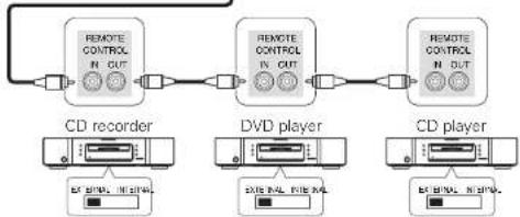
flowchart
graph LR
    A["CD recorder"] --> B["DVD player"]
    B --> C["CD player"]
    A --> D["Remote Control IN OUT"]
    B --> E["Remote Control IN OUT"]
    C --> F["Remote Control IN OUT"]
Remote control operation buttons
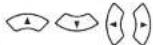
Move the cursor (Up/Down/Left/Right)

Confirm the setting Return to previous

ENGLISHDEU
RS-232C connector
When you connect an external control device, you can control the unit with the external control device. Perform the operation below beforehand.
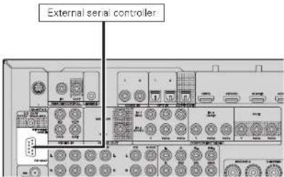
text_image
External serial controllerPerform the operation below beforehand.
① Turn on the power of this unit.
② Turn off the power of this unit from the external controller.
③ Check that the unit is in the standby mode.
DC OUT (TRIGGER OUT) jacks
When a device with DC IN jack is connected, the connected device's power on/standby can be controlled through linked operation to this unit.
The DC OUT jack outputs a maximum 12 V/150 mA electrical signal.

text_image
12 V/150 mA trigger-compatible devicein Set as Necessary
Set to change the conditions for linked operation via the DC OUT (TRIGGER OUT) jack.
"Trigger Out" (page 67)
NOTE
If the permissible trigger input level for the connected device is larger than 12V/150 mA, or has shorted, the DC OUT (ITRIGGER OUT) jack cannot be used.
In this case, turn off the power to the unit, and disconnect it.
ENGLISH

Playback (Advanced operation)
Playback (Basic operation) (page 23)
Selecting a listening mode (Surround mode)
page 31
☐ HDMI control function (1 page 42)
Sleep timer function (page 43)
Adjusting the volume of the speakers (1 page 43)
☐ Panel lock function ( page 44)
☐ Various memory functions (page 44)
Convenient functions
HDMI control function
When you make an HDMI connection with a TV or player compatible with this unit and HDMI control functions, you can perform the following operations by setting the HDMI control function of each device.
This unit power off can be linked to the TV power off step.
☐You can switch audio output devices with a TV operation.
When you set "Output audio from amp" in the TV audio output setup operation, you can switch the amp power on.
☐You can adjust this unit volume in the TV volume adjustment operation.
☐You can switch this unit input sources through linkage to TV input switching.
☐When playing the player, this unit input source switches to the source for that player.
NOTE
- When "HDMI Control" is set to "ON", it consumes more standby power.
- The HDMI control function controls operations of a TV that is compatible with the HDMI control function. Make sure that the TV and HDMI are connected when you perform HDMI control.
- Some functions may not operate depending on the connected TV or player. Check the user guide of each device for details beforehand.
- When "Power Off Control" on the menu is set to "OFF" in page 6, this unit is not set to standby even if the connected device is in the standby mode.
- When connection changes are implemented, such as adding connections to HDMI devices, linked operations may be initialized. In this case, you will need to reconfigure the settings.
- When "HDMI Control" is set to "ON", it is not possible to assign an HDMI connector to "TV" at "Input Assign" (page 52).
1 Set the HDMI output connector corresponding with the HDMI control function.
Set "HDMI Control" (27 page 64) to "ON".
2 Turn the power on for all the equipment connected by HDMI cable.
3 Set the HDMI control function for all equipment connected by HDMI cable.
- Please consult the operating instructions for the connected equipment to check the settings.
- Carry out steps 2 and 3 should any of the equipment be unplugged
4 Switch the television input to the HDMI input connected to this unit.
5 Switch this unit input to the HDMI input source and check if the picture from the player is ok.
6 When you turn the TV's power to standby, check that the power of this unit also goes to standby.

If the HDMI control function does not operate properly, check the following points.
- Is the TV or player compatible with the HDMI control function?
- Is "HDMI Control" ( page 64) set to "ON"?
- Is "Power Off Control" ( page 64) set to "All" or "Video"?
- Are the HDMI control function settings of all equipment correct?
NOTE
Should any of the operations below be performed, the interlocking function may be reset, in which case, repeat steps 2 and 3.
- "Input Assign" – "HDMI" (page 52) setting has changed.
- There is a change to the connection between the equipment and the HDMI, or an increase in equipment.
Sleep timer function
The power automatically goes into standby once the set time has elapsed.
This is convenient for playing sources while going to sleep.
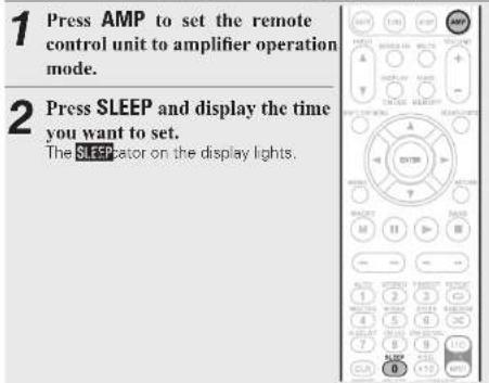
text_image
1 Press AMP to set the remote control unit to amplifier operation mode. 2 Press SLEEP and display the time you want to set. The SLEEP indicator on the display lights.- The time switches as shown below each time SLEEP is pressed.

To cancel the sleep timer
Press SLEEP to set "OFF"
The SLEEP cator on the display turns off.

- The sleep timer setting is canceled if this unit's power is set standby or turned off.
- When power to the main zone is turned off with the sleep timer, power in ZONE2 is also turned off.
Adjusting the volume of the speakers
You can adjust the channel level either according to the playback sources or to suit your taste, as described below.
□ Adjusting the volume of the different speakers

text_image
1 Press AMP to set the remote control unit to amplifier operation mode. 2 Press CH LVL. CHANNEL LEVEL Front L 0.0dB Front R 0.0dB Center 0.0dB Subway/air 0.0dB Surround L 0.0dB Surround R 0.0dB S.Shk L 0.0dB S.Shk R 0.0dB Reset From + > Reset Select2 Use to select the speaker.
The speaker that can be set switches each time one of the buttons is pressed.
4 Use ◀ ▷ to adjust the volume.
- In the case of a subwoofer, pressing ◀ when it is at "-12 dB" will change the setting to "OFF".

- When a headphone jack is inserted, the headphone channel level can be adjusted.
- When the input mode setting is "7.1CH IN", you can adjust the channel level while the 7.1CH INPUT connector is being used. In that case, "7.1CH IN Level" appears at the top of the screen.
□ Adjusting the volume of groups of speakers (Fader function)
This function lets you adjust (fade) the sound all at once from the front (front speaker / front height speaker / center speaker) or rear (surround speaker / surround back speaker).
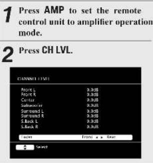
text_image
1 Press AMP to set the remote control unit to amplifier operation mode. 2 Press CH LVL. CHANNEL LEVEL Front L 0.0dB Front R 0.0dB Center 0.0dB Subwoofer 0.0dB Surround L 0.0dB Surround R 0.0dB S-Back L 0.0dB S-Back R 0.0dB Select Front + > Back Select3 Press ∇ to select "Fader", then select the item to be adjusting using ◀ ▷.
4 Use ◀ to adjust the volume of the speakers.
(◀: front, ▷: rear)

• The fader function does not affect the subwoofer.
- The fader can be adjusted until the volume of the speaker is adjusted to the lowest value of -12 dB.
ENGLISH

Convenient functions
Panel lock function
To prevent accidental operation of this unit, you can disable operation of the buttons on the front panel.
☐Disabling all key button operations

text_image
AUTO ON/STANDBYENTERPress ON/STANDBY while you press and hold AUTO and ENTER with the unit in standby mode.
"Panel Lock:ON" appears on the display and all button operations except ON/STANDBY are disabled.
☐Canceling the Panel lock function
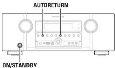
text_image
AUTORETURN ON/STANDBYPress ON/STANDBY while you press and hold AUTO and RETURN with the unit in standby mode.
The Panel lock function is canceled.

Even when the Panel lock function is set, you can operate the unit using the remote control unit.
□Disabling all button operations except VOLUME

text_image
AUTOVOLUME ON/STANDBYPress ON/STANDBY while you press and hold AUTO and ▷ with the unit in standby mode.
"Panel Lock ON" appears on the display and all button operations except ON/STANDBY and VOLUME are disabled.
Various memory functions
□Personal memory plus function
This function sets the settings input mode, surround mode, HDMI output mode, MultEQ®, Dynamic EQ®, Dynamic Volume®, audio delay etc.) last selected for the individual input sources.

The surround parameters, tone settings and the volumes of the different speakers are stored for the individual surround modes.
□Last function memory
This function stores the settings which were made before going into the standby mode.
When the power is turned back on, the settings are restored.
Playback in ZONE2 (Separate room)
- You can operate this unit so as to enjoy audio in a room (ZONE2) other than the MAIN ZONE (room where the unit is located).
- You can simultaneously play back the same source in both the MAIN ZONE and ZONE2. You can also play back separate sources in the MAIN ZONE and ZONE2.
- There are two methods to do this, as described below. Choose one of the methods.
① ZONE2 playback by speaker output
② ZONE2 playback by audio output (PRE OUT)
(using an external amplifier)
① ZONE2 playback by speaker output
The ZONE2 audio signals are output from this unit's SURR.BACK/AMP ASSIGN speaker terminals using the amplifier assignment function.
Connecting and setting the speakers
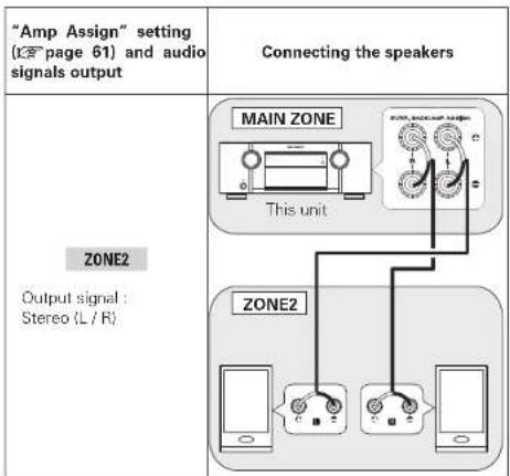
text_image
"Amp Assign" setting (13 page 61) and audio signals output Connecting the speakers ZONE2 Output signal : Stereo (L / R) MAIN ZONE This unit ZONE2② ZONE2 playback by audio output
The audio signals connected to this unit's ZONE2 output terminals (ZONE2 OUT) are output to the ZONE2's amplifier and played with that amplifier.
Connection (ZONE2)
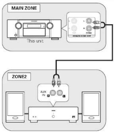
flowchart
graph TD
    A["MAIN ZONE"] --> B["This unit"]
    B --> C["AVIAND ROUNC ZONE"]
    C --> D["ZONE2"]
    D --> E["AUX IN 1"]
    E --> F["+"]
    E --> G["-"]
    E --> H["+"]
    E --> I["-"]

- We recommend using high quality pin-plug cables for audio connections in order to prevent noise.
- Also be sure to read the operating instructions of the connected devices.
NOTE
It is not possible to play the digital audio signals input from the HDMI, COAXIAL or OPTICAL terminals in ZONE2. Play using analog connections (in stereo).
ENGLISH

Playback
1 Press Z2 to switch the remote control operating mode. The remote control unit switches to the operating mode for ZONE2.
2 Press ON to turn on the ZONE2 power. The 72 lator on the display lights.
- When STANDBY is pressed, ZONE2 turns off.
- Power in ZONE2 can be turned on or off by pressing ZONE2 ON/OFF on the main unit.
3 Press INPUT ▲▼. The audio signal of the selected source is output to ZONE2.
- Turn INPUT SELECTOR after pressing ZONE SELECT on the main unit to select an input source.

text_image
STARTER INPUT VOLUME + - INPUT INPUT VOLUME + - OUTPUT INPUT OUTPUT INPUT OUTPUT OUTPUT OUTPUT OUTPUT OUTPUT OUTPUT OUTPUT OUTPUT OUTPUT OUTPUT OUTPUT OUTPUT OUTPUT OUTPUT OUTPUT OUTPUT OUTPUT OUTPUT OUTPUT OUTPUT OUTPUT OUTPUT OUTPUT OUTPUT OUTPUT OUTPUT OUTPUT OUTPUT OUTPUT OUTPUT OUTPUT OUTPUT OUTPUT OUTPUT OUTPUT OUTPUT OUTPUT OUTPUT OUTPUT OUTPUT OUTPUT OUTPUT OUTPUT OUTPUT OUTPUT OUTPUT OUTPUT OUTPUT OUTPUT OUTPUT OUTPUT OUTPUT OUTPUT OUTPUT OUTPUT OUTPUT OUTPUT OUTPUT OUTPUT OUTPUT OUTPUT OUTPUT OUTPUT OUTPUT OUTPUT OUTPUT OUTPUT OUTPUT OUT OUTPUT OUT OUTPUT OUT OUTPUT OUT OUTPUT OUT OUTPUT OUT OUTPUT OUT OUTPUT OUT OUTPUT OUT OUTPUT OUT OUTPUT OUT OUTPUT OUT OUTPUT OUT OUTPUT OUT OUTPUT OUT OUTPUT OUT OUTPUT OUT OUTPUT OUT
text_image
INPUT SELECTOR 20Hz SELECT 20Hz SELECT
When power for both MAIN ZONE and ZONE2 is set to ON, power of the MAIN ZONE only can be turned off. Press STANDBY.
Adjusting the volume
Use VOLUME + - to adjust the volume.
[Adjustable range] --- -80dB - 40dB - 18dB (When the "Volume Display" (25 page 66) setting is "Relative")
[Adjustable range] 0-41-99
(When the "Volume Display" (2 page 66) setting is "Absolute") - At time of purchase, "Volume Limit" (2 page 65) is set to "-10dB (71)".

Turn MASTER VOLUME after pressing ZONE SELECT on the main unit to adjust the sound volume.
Turning off the sound temporarily
Press MUTE.
The sound is reduced to the level set at "Mute Level" ( page 65) in
the menu.
• To cancel, either adjust the volume or press MUTE again.
- The setting is canceled when the zone's power is turned off.
ENGLISHDEU
How to make detailed settings
Menu map
For menu operation, connect a TV to this unit and display the menu on the TV screen. For menu operations, see the following page.
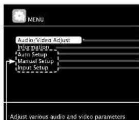
text_image
MENU Audio/Video Adjust Information Auto Setup Manual Setup Input Setup Adjust various audio and video parametersItems that only need to be set once
Set these for example upon purchase. Once these items are set, there is no need to set them again unless the speaker layout or the connected speakers have been changed.
| Setting items Detailed items | Description Page | ||
1. Audio/Video Adjust | Audio Adjust Adjusts various audio parameters. 56 | ||
| Picture Adjust Adjusts the picture quality. | 60 | ||
2. Information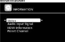 | Status | Shows information about current settings. | 68 |
| Audio Input Signal | Shows information about audio input signals. | 68 | |
| HDMI Information | Displays the HDMI input/output signals and HDMI monitor information. | 68 | |
| Preset Channel | Shows information about tuner preset channels. | 68 | |
3. Auto Setup | Audyssey Auto Setup | Makes the optimum settings for the speakers being used automatically. | 7 |
| Parameter Check | Checks Audyssey® Auto Setup measurement results.This item is only displayed after Audyssey Auto Setup procedure has been performed. | 11 | |
4. Manual Setup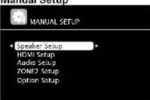 | Speaker Setup | Sets the speaker size and distance, the channel level, etc. | 61 |
| HDMI Setup | Makes settings for HDMI video/audio output. | 64 | |
| Audio Setup | Makes settings for audio playback. | 64 | |
| ZONE2 Setup | Makes settings for audio playback in a ZONE2 system. | 65 | |
| Option Setup | Makes various other settings. | 66 | |
| 5. Input Setup(Example: TUNER)[IMAGE]Displayed items of the "Input Setup" menu differs, depending on the selected input source. | Auto Preset | Uses the auto preset function to program radio stations. | 51 |
| Preset Skip | Sets the preset memories that you do not want to display when tuning. | 51 | |
| Preset Name | Assigns name to a preset memory. | 51 | |
| Input Assign | Changes input connector assignment. | 52 | |
| Video | Makes the video settings. | 53 | |
| Input Mode | Sets the audio input mode and decode mode. | 54 | |
| Rename | Changes the display name for this source. | 55 | |
| Source Level | Adjusts the playback level of the audio input | 55 | |
| Playback Mode | Makes settings for iPod and USB memory device playback. | 55 | |
Displayed items of the "Input Setup" menu differs, depending on the selected input source.
ENGLISH

Examples of menu and front display
Below we describe typical examples of displays on the TV screen and on the set's display window.
| Menu display Front display Description | ||||
| Top menu display | 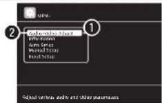 |  | 1 The menu items are displayed here.2 The selected line is displayed here.The currently selected item is displayed on the display.Use to move to the item you want to set. | |
| Display when changing settings | 2 | 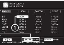 | 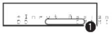 | 1 Use to move to the item you want to set.2 Press ENTER to set to the mode in which the setting can be made.3 ▶ and ▶ is displayed at the sides of item whose setting can be changed. Use to change to the desired setting. |
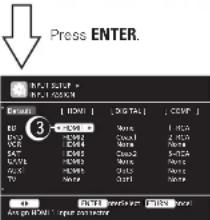 | 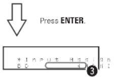 | |||
| Display when inputting characters | 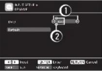 |  | 1 When is pressed, the cursor moves to the left or right.2 When is pressed at the position where you want to input the character, the character is input.For inputting characters on a keyboard screen or with the number buttons on the remote control unit, see page 49. | |
| Display when resetting | ‘ 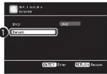 |  | 1 Press to select "Default", then press ENTER to set.2 Press to select "Yes", then press ENTER. | |
Inputting characters
You can change the names as desired using the "Preset Name" (1 page51), "Rename" (1 page55) and "ZoneRename" (1 page67). For inputting characters, there are three methods, as shown below.
Method for inputting characters
| Method Operations | |
| Using the cursor buttons(Normal screen) | ·Operating with the remote control unitor the main unit.·Use △▽◀ ▷ and ENTER to inputcharacters. |
| Using the keyboardscreen | ·Operating with the remote control unit.·Select a character on the TV screen toinput characters. |
Normal screen
□ Display of a normal input screen
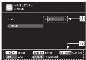
text_image
INPUT SETUP RENAME DVD Default DVD 1 2 ← Input SHIFT a/A ENTER SEARCH Enter Keyboard RETURN Cancel① Character input section
② Guide for operation buttons
Using the cursor buttons
1 Display the screen for inputting characters (page 47 "Menu map").
2 Use ◀▷ to set the cursor to the character you want to change.
3 Use to change the character, then press ENTER.
• The types of characters that can be input are as shown below.
[Upper case characters]
ABCDEFGHIJKLMNOPQRSTUVWXYZ
[Lower case characters]
abcdefghijklmnopqrstuvwxyz
[Symbols] ! " # \$ % & ' ( ) * + , - . / : ; <
=>?@[]^_{}|}
[Numbers] 0123456789 (Space)
- The input character type can be switched by pressing SHIFT/TOP MENU while the display name is being changed.
4 Repeat steps 2 and 3 to change the name then press ENTER to register it.
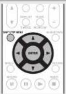
Keyboard screen
□ Display of a keyboard input screen
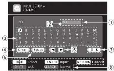
text_image
INPUT SETUP RENAME BD ② ① A B C D E F G H I J K L M N O P Q R S T U V W X Y 7 0 1 2 3 4 5 6 7 8 9 10 5 % & ' ( ) * + - < - - Clear Space 6 O K ⑦ ⑧ SELECT ENTER INPUT RETURN Cancel SHIFT a/A SEARCH Normal① Character input section
② Cursor
③ Keyboard section
④ Clear key
⑤ Space key
⑥ Cursor keys
⑦ OK key
⑧ Guide for operation buttons
ENGLISH

Inputting characters
1 Display the screen for inputting characters ( page 47 "Menu map").
2 Press SEARCH/INFO while a normal screen is displayed.
A keyboard screen is displayed.
3 Select a character to be changed. ① Press △▽◀ ▷ to select ▶ or ▶
② Press ENTER to place the cursor at the character to be changed. Each time ENTER is pressed, the cursor moves by one character.

4 Select a character to be input with △▽◀ ▷ then press ENTER.
- The types of characters that can be input are as shown below.
[Upper case characters/Numbers/Symbols] ABCDEFGHIJKLMNOPQRSTUVWXYZ 0123456789
!" # \$ % & ' () * + , ; < => [Lower case characters/Numbers/Symbols] abcdefghijklmnopqrstuvwxyz 0123456789 . @ - / : ^ ? [ \ ] ^ { | }
- The input character type can be switched by pressing SHIFT/TOP MENU while the display name is being changed.
5 Repeat steps 3 and 4 to change the name.
6 Use △▽◀▷ to select , then press ENTER.
Remote control operation buttons
Move the cursor (Up/Down/Left/Right)
Input Setup
Perform settings related to input source playback.
- You do not have to change the settings to use the unit. Make settings when needed.
Menu operation
1 Press AMP to set the remote control unit to amplifier operation mode.
2 Press MENU.
The menu is displayed on the TV screen.
3 Use to select the menu to be set or operated.
4 Press ENTER or ▷ to enter the setting.
• To return to the previous item, press RETURN
- Exiting the Menu, press MENU while the menu is displayed. The menu display disappears.

Important information
☐ About the display of input sources
In this section, the configurable input sources for each item are shown as follows.

NOTE
Input sources that have been set to "Delete" at "Source Delete" (page 66) cannot be selected.

Confirm the setting

Return to previous menu
Items that can be set with the Input Setup procedure
Auto Preset [page 51]
Preset Skip (page 51)
Preset Name (page 51)
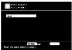


Input Mode (page 54)
Input Assign (page 52)
Video | page 53

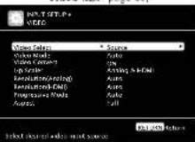

Playback Mode ( page 55)
Rename [page 55]
Source Level (page 55)
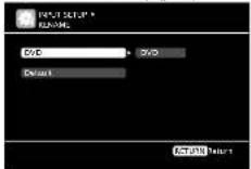
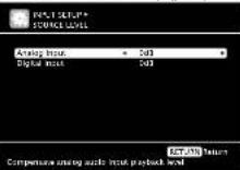

Auto Preset
Use the auto preset function to program radio stations.
Setting items
Setting details
Start
Start the auto preset process.

If an FM station cannot be preset automatically, select the desired station by tuning it in manually, then preset it manually.
TUNER
Preset Skip
Default settings are underlined.
Set preset channel to be skipped when selecting
Setting items
Setting details
A-G
Set the preset channels you do not want to display. You can set by preset memory block (A to GI or by preset channel (1 to 8)).
1 - 8 : Set by individual preset channels in the currently selected preset memory block.
• ON : Display the selected preset channel.
- Skip : Do not display the selected preset channel.
If you set "Block Presets" to "Skip", you can skip the preset memory blocks (A to G).
TUNER
Preset Name
Assign name to a preset memory.
Setting items
Setting details
A1-G8
Select the preset channel.
- Up to eight characters can be input.
• For character input, see page 49
TUNER
Default
The changed preset name is returned to the default setting.
Yes : Reset to the defaults.
No : Do not reset to the defaults.
Remote control operation
buttons


Move the cursor (Up/Down/Left/Right)
ENTER
Confirm the setting
RETURN
Return to previous menu
ENGLISH

Input Setup
Input Assign
Examples of input assign menu screen displays
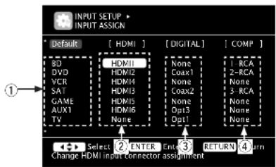
text_image
INPUT SETUP • INPUT ASSIGN Default [ HDMI ] [ DIGITAL] [ COMP ] BD [HDMI] None -RCA DVD HDMI1 None Coax1 2-RCA VER HDMI2 None None None SAT HDMI3 None Coax2 None GAME HDMI4 None None None AUX1 HDMI5 None Opt3 None None TV None Opt1 None Select ② ENTER ③ RETURN ④ Turn Change HDMI input connector assignment① Input Source
② HDMI input
③ Digital audio input
④ Component video input
Input assignments menu operations
1 Use to move the highlight to the item you want to set.
2 Press ENTER, then use ◀▷ to select the input connector to be assigned.
3 Press ENTER to register the setting.
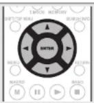
NOTE
If all "HDMI", "Digital" and "Component" assignment of the Game source are set to "None", Game source cannot be selected with the input source selection.
Setting items Setting details
HDMI
Set this to change the HDM input connectors assigned to the input sources.
| BD | DVD | VCR |
| SAT | GAME | AUX1 |
| TV |
HDMI 1 / HDMI 2 / HDMI 3 / HDMI 4 / HDMI 5 / HDMI 6
None : Do not assign an HDMI input connector to the selected input source.
- At time of purchase, the settings of the different input sources are as shown below.
| Input source | BD | DVD | VCR | SAT | GAME | AUX1 | TV |
| Default setting | HDMI 1 | HDMI 2 | HDMI 4 | HDMI 3 | HDMI 5 | HDMI 6 | None |

- An input source to which an HDMI input connector cannot be assigned is displayed as "---".
- To play the video signal assigned at "HDMI" combined with the audio signal assigned at "Input Assign" – "Digital", select "Digital" at "Input Mode" (page 54).
- The audio signals input from the analog and digital connectors are not output to the monitor.
- When "HDMI Control" (L2 page 64) is set to "ON", HDMI input connector cannot be assigned to "TV".
Coax1 - 2 (COAXIAL) / Opt1 - 3 (OPTICAL)
None : Do not assign a digital input connector to the selected input source.
- At time of purchase, the settings of the different input sources are as shown below.
| Input source | BD | DVD | VCR | SAT | GAME | AUX1 |
| Default setting | None | Coax 1 | None | Coax 2 | None | Opt 3 |
| Input source | TV | CD | AUX2 |
| Default setting | Opt 1 | Opt 2 | None |
Remote control operation buttons

Move the cursor (Up/Down/Left/Right)

Confirm the setting

Return to previous menu
Setting items Setting details
| Component Set this to change the component video input connectors assigned to the input sources. | 1-RCA / 2-RCA / 3-RCA (Component video) None: Do not assign a component video input connector to the selected input source. • At time of purchase, the settings of the different input sources are as shown below. | ||||||||
| BD | DVD | VCR | Input source | BD DVD VCR SAT GAME AUX1 | TV | ||||
| SAT | GAME | AUX1 | Default setting | 1-RCA | 2-RCA | None | 3-RCA | None | None |
| TV | An input source to which an component video input connector cannot be assigned is displayed as “—”. | ||||||||
| Default The "Input Assign" settings are returned to the default settings. | Yes: Reset to the defaults. No: Do not reset to the defaults. If you select "Default" and press ENTER, the message "Default Setting?" is displayed. Select "Yes" or "No", and then press ENTER. | ||||||||
1-RCA / 2-RCA / 3-RCA (Component video)
Video
Default settings are underlined.
* "GAME" or "TV" can be set when "HDMI" (page 52) or "Component" (page 53) has been assigned.
Setting items Setting details
| Video Select Video of another input source is played back combined with the playing audio. | Source: Play the picture and sound of the input source. BD / DVD / VCR / SAT / GAME / AUX1 / TV : Select video input source to view. This can be set for individual input sources. "GAME" and "TV" can be selected only when a component video is assigned as an input source. NOTE • It is not possible to select HDMI input signals. • Input sources for which "Delete" is selected at "Source Delete" (page 66) cannot be selected. • This can also be set by pressing V.SEL on the remote control unit. |
Setting items Setting details
| Video ModeMake settings for video processing. | ||
| BD | DVD | VCR |
| SAT | GAME * | AUX1 |
| TV | * | |
Remote control operation
buttons

Move the cursor
(Up/Down/Left/Right)

Confirm the setting
RETURN
O
Return to previous menu
ENGLISH

Input Setup
| Setting items Setting details | ||
| ResolutionSet the output resolution.Resolution (Analogl : Analog Video Resolution (HDMI) : HDMI)BD DVD VCRSAT GAME * AUX1TV * | Auto: The number of pixels the TV connected to the HDMI output connector supports is detected automatically and the appropriate output resolution is set.480p/576p/1080i/720p/1080p/1080p:24Hz: Set the output resolution.This item can be set when "i/p Scaler" is set to anything other than "OFF".When "i/p Scaler" is set to "Analog & HDMI", the resolution of both the analog video input signal and HDMI input signal can be set.To watch 1080p/24Hz pictures, use a TV that supports 1080p/24Hz video signals.When set to "1080p/24Hz", you can enjoy film-like pictures for film sources fin 24 Hz. For video sources and mixed sources, we recommend setting the resolution to "1080p".It is not possible to convert a 50 Hz signal into 1080p/24Hz. It is output at a resolution of 1080p/50Hz. | |
| Progressive ModeSet an appropriate progressive conversion mode for the source video signal.BD DVD VCRSAT GAME * AUX1TV * | Auto: The video signal is automatically detected and the appropriate mode is set.Video1: Select mode suitable for video playbackVideo2: Select mode suitable for video and 30-frame film material playback.This item can be set when "i/p Scaler" is set to anything other than "OFF". | |
| AspectSet the aspect ratio for the video signals output to the HDMI.BD DVD VCRSAT GAME * AUX1TV * | Full: Output at 16:9 aspect ratio.Normal: Output at 4:3 aspect ratio."Aspect" can be set when "i/p Scaler" is set to anything other than "OFF". | |
* "GAME" or "TV" can be set when "HDMI" (25 page 52) or "Component" (25 page 53) has been assigned.
Input Mode
Default settings are underlined.
| The input modes available for selection may vary depending on the input source. | |
| Setting items Setting details | |
| Input ModeSet the audio input modes for the different input sources. | Auto: Automatically detect input signal and perform playback.HDMI: Play only signals from HDMI input.Digital: Play only signals from digital input.Analog: Play only signals from analog input.7.1CH IN: Only signals input from the 7.1CH INPUT terminal will be played back.This can also be set by pressing A/D on the remote control unit.Each time A/D is pressed, the setting is changed as shown below.AutoHDMIDigitalAnalog7.1CH IN"HDMI" can be set for input sources for which "HDMI" is assigned at "Input Assign" (page 52)."Digital" can be set for input sources for which "Digital" is assigned at "Input Assign" (page 52).If the input source is set to "TV" or "Game", it cannot be set to "Analog"When digital signals are properly input, the DIG indicator lights on the display. If the DIG indicator does not light, check the digital input connector assignment and the connections.The surround mode cannot be set if the input mode is set to "7.1CH IN".If "HDMI Control" is set to "ON" and a TV compatible with the ARC is connected via the HDMI OUT connectors, the input mode whose input source is "TV" is fixed to ARC. |
| Decode ModeSet the decode mode for input source.BDDVDVCRSATGAMEAUX1TVCDAUX2 | Auto: Detect type of digital input signal and decode and play automatically PCM: Decode and play only PCM input signals.DTS: Decode and play only DTS input signals.This item can be set for input sources for which "HDMI" or "Digital" is assigned at "Input Assign" (page 52).Normally set this mode to "Auto". Set "PCM" and "DTS" when inputting the corresponding input signal. |
Remote control operation buttons

Move the cursor (Up/Down/Left/Right)

Confirm the setting

Return to previous menu
ENGLISHDEU
Rename
Change the display name of the selected input source.
| Setting items Setting details | |
| RenameChange the display name of the selected input source. | Up to eight characters can be input.For character input, see page 49. |
| DefaultThe input source name is returned to the default setting. | Yes: Reset to the defaults.No: Do not reset to the defaults. |
Source Level Default settings are underlined.
| This function corrects the playback level of the selected input source's audio input. |
| Make this setting if there are differences in the input volume levels between the different sources. |
Setting details
| -12dB - +12dB (0dB) |
| The analog input level and digital input level can be adjusted independently for input sources for which "HDMI" or "Digital" is assigned at "Input Assign" page 52). |
Playback Mode
| Make settings for repeat playback mode or random playback mode. | |
| Setting items Setting details | |
| RepeatMake settings for repeat mode.USB/iPod | □For iPod playbackAll: All files are played repeatedly.One:A file being played is played repeatedly.OFF: Repeat playback mode is canceled□For USB memory device playbackAll: All files are played repeatedly.One:A file being played is played repeatedly.Folder:A file in the folder being played is played repeatedly. |
| ShuffleMake settings for shuffle mode.USB/iPod | □For iPod playbackSongs: Shuffle songs.Albums: Shuffle albums.OFF: Shuffle playback mode is canceled□For USB memory device playbackON: Shuffle playback mode is enabled.OFF: Shuffle playback mode is canceled. |
Remote control operation buttons
Move the cursor (Up/Down/Left/Right)

Confirm the setting Return to previous

ENGLISH

Audio/Video Adjust
The sound being played in the surround mode can be adjusted to your liking.
The items (parameters) that can be adjusted depend on the signal being input and the currently set surround mode. For details on the adjustable parameters, see "Surround modes and surround parameters" (LFP page 83).
Menu operation
1 Press AMP to set the remote control unit to amplifier operation mode.
2 Press MENU. The menu is displayed on the TV screen.
3 Use to select the menu to be set or operated.
4 Press ENTER or ▷ to enter the setting.
• To return to the previous item, press RETURN
- Exiting the Menu, press MENU while the menu is displayed. The menu display disappears.
Items that can be set with the Audio Adjust procedure
Audio Adjust (page 56)
□ Surround Parameter (page 56)
LTone (page 57)
□ Audyssey Settings (1 page 57)
□ Manual EQ [查看 page 59]
UM-DAX [page 59]
□ Audio Delay (1 page 59)
Picture Adjust (page 60)
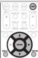
Audio Adjust
□Surround Parameter
Default settings are underlined.
Adjust surround sound parameters. It may not be possible to set this item depending on the input signal.
| Setting items Setting details | |
| HT-EQ Soften the treble range of movie soundtracks for better understanding. | ON: "HT-EQ" is used.OFF: "HT-EQ" is not used |
| DRC Compress dynamic range (difference between loud and soft sounds). | Auto: Automatic dynamic range compression on/off control according to source. This can be set in the Dolby TrueHD mode.Low / Mid / High: These set the compression level.OFF: Dynamic range compression always off. |
| D.Comp Compress dynamic range (difference between loud and soft sounds). | Low / Mid / High: These set the compression level.OFF: Turn dynamic range compression off. |
| LFE Adjust the low-frequency effects level (LFE). | -10dB - 0dBFor proper playback of the different sources, we recommend setting to the values below.Doloy Digital sources: "0dB"DTS movie sources: "0dB"DTS music sources: "-10dB" |
| C.Image Assign center channel signal to front left and right channels for wider sound. | 0.0 - 1.0 (0.3) |
| Panorama Assign front L/R signal also to surround channels for wider sound. | ON: Set.OFF: Do not set. |
| Dimension Shift sound image center to front or rear to adjust playback balance. | 0 - 6 (3) |
| C.Width Assign center channel signal to front left and right channels for wider sound. | 0 - 7 (3) |
Remote control operation buttons
Move the cursor (Up/Down/Left/Right)
ENTER Confirm the setting Return to previous menu RETURN
Audio/Video Adjust
| Setting items Setting details | |
| Height GainControl the front height channel volume. | Low: Reduce the front height channel volume.Mid: Front height channel sound is output with standard sound volume.High: Increase the front height channel volume.NOTE"Height Gain" is displayed for the following settings.When "Amp Assign" (23 page 61) is set to "Normal".When the "Speaker Config." - "F.Height" setting (23 page 62) is set other than to "None".When surround mode is "PLIiz" or the PLIiz decoder is used. |
| DefaultThe "Surround Parameter" settings are returned to the default settings. | Yes: Reset to the defaults.No: Do not reset to the defaults. |
Tone
Adjust the tonal quality of the sound.
Default settings are underlined.
| Setting items Setting details | |
| Tone ControlSet the tone control function to ON and OFF. | ON : Allow tone adjustment (bass, treble).OFF : Playback without tone adjustment."Tone Control" can be set when "Dynamic EQ" (35 page 58) is set to "OFF".NOTE."Tone Control" settings are not reflected to ZONE2.The tone cannot be adjusted in the direct mode. |
| BassAdjust low frequency range (bass). | -6dB - +6dB"Bass" can be set when "Tone Control" is set to "ON". |
| TrebleAdjust high frequency range (treble). | -6dB - +6dB"Treble" can be set when "Tone Control" is set to "ON". |
□Audyssey Settings
Default settings are underlined.
Set MultEQ ^® , Dynamic EQ ^® and Dynamic Volume ^® . These can be selected after Audyssey ^® Auto Setup has been performed. For additional information on Audyssey technology, please see page 88.
NOTE
If you have not performed Auto Setup, or if you change the speaker settings after performing Auto Setup, you may not be able to select Dynamic EQ/Dynamic Volume, and "Run Audyssey" may be displayed. In this case, either perform Audyssey Auto Setup over again or perform "Restore" (5 page 11) to return to the settings after Audyssey Auto Setup was run.
Setting items Setting details
MultEQ
Select one equalizer from three modes. MultEQ corrects both time and frequency response problems in the listening area based on Audyssey Auto Setup calibration. We recommend "Audyssey". MultEQ is the prerequisite function for Dynamic EQ and Dynamic Volume.
Audyssey: Optimize the frequency response of all speakers.
Audyssey Byp.L/R : Optimize frequency response of speakers except front L and R speakers.
Audyssey Flat : Optimize frequency response of all speakers to flat response.
Manual : Apply frequency response set with "Manual EQ" ( page 59) OFF : Turn "MultEQ" equalizer off.

- "Audyssey", "Audyssey Byp. L/R" and "Audyssey Flat" can be selected after Audyssey Auto Setup has been performed. "Audyssey" is automatically selected after performing Audyssey Auto Setup. When "Audyssey", "Audyssey Byp. L/R" or "Audyssey Flat" is selected, illuminates.
- After running Audyssey Auto Setup, if the Speaker Configuration, Distance, Channel Level, and Crossover Frequency have changed without increasing the number of speakers measured, only AUDYSEERY MUITED illuminates.
- Press MULTEQ on the remote control unit to set this setting.
NOTE
- "MultiEQ" and "Manual" cannot be selected when "EQ Customize" is set to "Not Used" (page 64).
- When using headphones, "MultEQ" is automatically set to "OFF".
Remote control operation
buttons
Move the cursor (Up/Down/Left/Right)

Confirm the setting Return to previous
RETURN
nenu
ENGLISH

Audio/Video Adjust
Setting items Setting details
| Dynamic EQ® |
| Solve the problem of deteriorating sound quality as volume is decreased by taking into account human perception and room acoustics. Works with MultEQ. |
| ON: Use Dynamic EQ. |
| OFF: Do not use Dynamic EQ. |

• Displayed when set to "ON".
- This can also be set by pressing DYN EQ/VOL on the remote control unit.
Each time DYN EQ/VOL is pressed, the setting is changed as shown below.
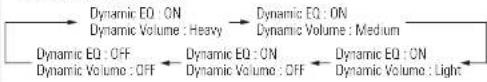
flowchart
graph LR
    A["Dynamic EQ : ON\nDynamic Volume : Heavy"] --> B["Dynamic EQ : ON\nDynamic Volume : Medium"]
    B --> C["Dynamic EQ : ON\nDynamic Volume : Light"]
    C --> D["Dynamic EQ : OFF\nDynamic Volume : OFF"]
    D --> E["Dynamic EQ : ON\nDynamic Volume : OFF"]
    E --> F["Dynamic EQ : ON\nDynamic Volume : Medium"]
    F --> G["Dynamic EQ : ON\nDynamic Volume : Heavy"]
Reference Level Offset
Audyssey Dynamic EQ is referenced to the standard film mix level. It makes adjustments to maintain the reference response and surround envelopment when the volume is turned down from 0 dB. However, film reference level is not always used in music or other non-film content. Dynamic EQ Reference Level Offset provides three offsets from the film level reference (5 dB, 10 dB, and 15 dB) that can be selected when the mix level of the content is not within the standard.
QdB (Film Ref) : This is the default setting and should be used when listening to movies.
5dB : Select this setting for content that has a very wide dynamic range, such as classical music.
10dB: Select this setting for jazz or other music that has a wider dynamic range. This setting should also be selected for TV content as that is usually mixed at 10 dB below film reference.
15dB: Select this setting for pop/rock music or other program material that is mixed at very high listening levels and has a compressed dynamic range.
Setting is enabled when "Dynamic EQ" is "ON" (page 58).
Setting items Setting details
Dynamic Volume®
Solve the problem of large variations in volume level between TV, movies and other content (between quiet passages and loud passages, etc.) by automatically adjusting to the user's preferred volume setting.
Heavy: Most adjustment to softest and loudest sounds.
Medium : Medium adjustment to loudest and softest sound. Light : Least adjustment to loudest and softest sounds.
OFF: Do not use "Dynamic Volume".


• displayed when set to "ON".
- If "Dynamic Volume" is set to "Yes" in Auto Setup (5 page 10), the setting is automatically changed to "Evening".
- This can also be set by pressing DYN EQ/VOL on the remote control unit.
Each time DYN EQ/VOL is pressed, the setting is changed as shown below.
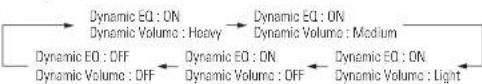
flowchart
graph LR
    A["Dynamic EQ : ON\nDynamic Volume : Heavy"] --> B["Dynamic EQ : ON\nDynamic Volume : Medium"]
    B --> C["Dynamic EQ : ON\nDynamic Volume : Light"]
    C --> D["Dynamic EQ : OFF\nDynamic Volume : OFF"]
    D --> E["Dynamic EQ : ON\nDynamic Volume : OFF"]
    E --> F["Dynamic EQ : ON\nDynamic Volume : Medium"]
    F --> G["Dynamic EQ : ON\nDynamic Volume : Heavy"]

Remote control operation buttons

Move the cursor (Up/Down/Left/Right)

Confirm the setting Return to previous

□Manual EQ
Default settings are underlined.
Use the graphic equalizer to adjust the tone of each speaker.
"Manual EQ" can be set when "MultEQ®" setting (page 57) is "Manual"
Setting items Setting details
Adjust CH
Correct the tone of each speaker.
① Select the speaker tone adjustment method.
All: Adjust the tone of all speakers together.
L/R: Adjust the tone of left and right speakers together.
Each : Adjust the tone of each speaker.
② Select the speaker.
③ Select the adjustment frequency band.
63Hz / 125Hz / 250Hz / 500Hz / 1kHz / 2kHz / 4kHz / 8kHz / 16kHz
- Select the speakers you want to adjust when "L/R" or "Each" is selected.
④ Adjust the level
-20.0dB - +6.0dB (0.0dB)
Base Curve Copy
Copy "Audyssey Flat" curve from MultEQ®.
Yes: Copy.
No : Do not copy.
"Base Curve Copy" is displayed after Audyssey® Auto Setup has been performed.
Default
The "Manual EQ" settings are returned to the default settings.
Yes : Reset to the defaults.
No : Do not reset to the defaults.
□M-DAX
Default settings are underlined.
Compressed audio formats such as MP3, WMA iWindows Media Audiol and MPEG-4 AAC reduce the amount of data by eliminating signal components that are hard for the human ear to hear. The M-DAX function generates the signals eliminated upon compression, restoring the sound to conditions near those of the original sound before compression. It also corrects the sense of volume of the bass to obtain richer sound with compressed audio signals.
Setting details
OFF: Do not use M-DAX.
LOW: Optimized mode for compressed sources with normal highs.
MID: Apply suitable bass and treble boost for all compressed sources.
HIGH: Optimized mode for compressed sources with very weak highs.
The image is too blurry to recognize any text content.
- This item can be set with analog signals or when a PCM signal (fs = 44.1/48 kHz) is input.
- This cannot be set when the surround mode is set to "DIRECT" or "PURE DIRECT".
- If a setting other than "OFF" is selected, the M-DAX indicator lights.
- This can also be set by pressing M-DAX on the remote control unit. Each time M-DAX is pressed, the setting is changed as shown below.


□Audio Delay
Default settings are underlined.
While viewing video, manually adjust the time to delay audio output.
Setting details
0ms - 200ms
1
- This item can be set within the range of 0 to 200 ms when "Auto Lip Sync" is set to "ON" and when a TV compatible with Auto Lip Sync is connected.
- Store "Audio Delay" for each input source.
- Audio Delay for game mode can be set when "Video Mode" (page 53) is set to "Auto" or "Game".
- This can also be set by pressing A.DELAY on the remote control unit.
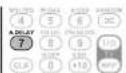
Remote control operation
buttons
Move the cursor (Up/Down/Left/Right)

Confirm the setting Return to previous
RETURN

ENGLISH

Audio/Video Adjust
Picture Adjust Default settings are underlined.
- This item can be set when the input source is BD DVD VCR SAT GAME AUX1 TV
- With input sources other than the ones above, this item can be set when "Video Select" is selected. In this case, the original input source settings are called out.
- Can be set when the "Video Convert" setting ( page 53) is "ON".
- "GAME" or "TV" can be set when "HDMI" (page 52) or "Component" (page 53) has been assigned.
Setting items Setting details
| ContrastAdjust picture contrast. | -6 - +6 (0) |
| BrightnessAdjust picture brightness. | 0 - +12 |
| Chroma LevelAdjust picture chroma level (saturation). | -6 - +6 (0) |
| HueAdjust color hue. | -6 - +6 (0) |
| DNRReduce overall picture noise. | OFF / Low / Mid / High |
| EnhancerEmphasize picture contours. | 0 - +12 |

- "DNR" and "Enhancer" are each effective with HDMI output.
- The value set at "Picture Adjust" is stored in the memory individually for each input source.
Remote control operation buttons

Move the cursor (Up/Down/Left/Right)

Confirm the setting Return to previous

Manual Setup
Set when changing Audyssey® Auto Setup settings, or when changing the audio, video, display or other settings.
- If you change the speaker settings after performing Audyssey Auto Setup, it will not be possible to set MultEQ®, Dynamic EQ® and Dynamic Volume® (page 57, 58).
- Can be used without changing the settings. Please set if necessary.
Menu operation
1 Press AMP to set the remote control unit to amplifier operation mode.
2 Press MENU. The menu is displayed on the TV screen.
3 Press to select the menu to be set or operated.
4 Press ENTER or ▷ to enter the setting.
• To return to the previous item, press RETURN
- Exiting the Menu, press MENU while the menu is displayed. The menu display disappears.
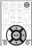
Items that can be set with the Manual Setup procedure
Speaker Setup (page 61)
HDMI Setup (page 64)
Audio Setup (page 64)
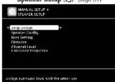


ZONE2 Setup (page 65)
Option Setup (page 66)
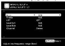
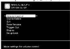
Speaker Setup
Default settings are underlined.
Perform when setting the speakers manually or when changing settings made in Audyssey Auto Setup.
- If you change the speaker settings after performing Audyssey Auto Setup, it will not be possible to select MultEQ, Dynamic EQ and Dynamic Volume (127 page 57, 58).
- Manual Setup can be used without changing the settings. Please set if necessary.
Setting items
Setting details
| Amp AssignSet the speakers connected to this unit. | Normal: Set when using 7.1-channel IFront/Center/Surround/Surround Back or Front height/Subwooferl speakers.ZONE2: Set for connecting the speakers for ZONE2 to the SURR BACK/AMP ASSIGN terminals.SPKR-C: Set for connecting a tweeter of a front speaker to the SURR. BACK/AMP ASSIGN terminals and a woofer of a front speaker to the FRONT terminals. |
Speaker Config.
Select speaker configuration and size loass reproduction capability.
NOTE
Do not use the outward shape of the speaker to determine selection of a "Large" or "Small" speaker. Instead, use the frequencies set in "Crossover Frequency" (12 page 63) as the standard for determining bass reproduction capability.
Front Set the front speaker size.
- Large : Use a large speaker that can adequately play back low frequencies.
- Small: Use a small speaker that has inadequate playback capacity for low frequencies.

- When "Subwoofer" is set to "No", "Front" is automatically set to "Large".
- When "Front" is set to "Small", "Center", "Surround", "S.Back" and "F.Height" can not be set to "Large".
Center : Set the presence and size of the center speaker.
• Large : Use a large speaker that can adequately play back low frequencies. - Small: Use a small speaker that has inadequate playback capacity for low frequencies.
- None: Select when a center speaker is not connected.
"Large" is not displayed when "Front" is set to "Small".
Subwoofer : Set the presence of a subwoofer. - Yes: Use a subwoofer.
- No : Select when a subwoofer is not connected.
When "Front" is set to "Small", "Subwoofer" is automatically set to "Yes".
Remote control operation buttons

ENGLISH
D
Manual Setup
| Setting items Setting details | ||
| Speaker Config.(Continued) | Surround : Set the presence and size of the surround speakers.•Large: Use a large speaker that can adequately play back low frequencies.•Small: Use a small speaker that has inadequate playback capacity for low frequencies.•None: Select when the surround speakers are not connected.➢When "Surround" is set to "Large", "S.Back" and "F.Height" can be set to "Large".•When "Surround" is set to "None", "S.Back" and "F.Height" can automatically set to "None". | Setting items Setting details |
| Bass SettingSet subwoofer and LFE signal range playback. SubwooferMode: Select low range signals to be reproduced by subwoofer.LFE: The low range signal of the channel set to "Small" speaker size is added to the LFE signal output from the subwoofer.LFE+Main: The low range signal of all channels is added to the LFE signal output from the subwoofer.“Subwoofer Mode” can be set when "Speaker Config." – "Subwoofer" IC57 page 611 is set to "Yes”.Play music or a movie source and select the mode offering the strongest bass.Select "LFE+Main" if you want the bass signals to always be produced from the subwoofer.NOTEIf "Front" and "Center" for "Speaker Config." are set to "Large", and "Subwoofer Mode" is set to "LFE", no sound may be output from the subwoofer, depending on the input signal or selected surround mode.LPF for LFE: Set LFE signal playback range.80Hz / 90Hz / 100Hz / 110Hz / 120Hz / 150Hz / 200Hz / 250Hz | ||
| S.Back: Set the presence, size and number of surround back speakers.•Large: Use a large speaker that can adequately play back low frequencies.•Small: Use a small speaker that has inadequate playback capacity for low frequencies.•None: Select when the surround back speakers are not connected.2spkrs: Use two surround back speakers.1spkr: Use only one surround back speaker. When you select this setting, connect the surround back speaker to the left (L) channel.Even when the "S.Back" setting is other than "None", sound may not be emitted from the surround back speaker, depending on the playback source.NOTEWhen "Amp Assign" setting IC57 page 611 is other than "Normal", you cannot make the "S.Back" setting. | DistanceSet distance from listening position to speakers.Measure beforehand the distance from the listening position to each speaker. Unit: Set the unit of distance.Meters/FeetStep: Set the minimum variable width of the distance.0.1m/0.01m1ft/0.1ftFront L / Front R / Center / Subwoofer / Surround L / Surround R / S.Back L* / S.Back R* / F.Height L / F.Height R: Select the speaker.*When the "Speaker Config." – "S.Back" setting IC57 page 621 is set to "1spkr", "S.Back" is displayed.0.00m - 18.00m / 0.0ft - 60.0ft: Set the distance. | |
| F.Height: Set the presence and size of the front height speakers.•Large: Use a large speaker that can adequately play back low frequencies.•Small: Use a small speaker that has inadequate playback capacity for low frequencies.•None: Select when the front height speakers are not connected.NOTEWhen "Amp Assign" setting IC57 page 611 is other than "Normal", you cannot make the "F.Height" setting. | ||
Remote control operation buttons

Move the cursor (Up/Down/Left/Right)

Confirm the setting Return to previous

| Setting items Setting details | Setting items Setting details | ||
| Distance(Continued) | The speakers that can be selected differ depending on the "Amp Assign" page 61 and "Speaker Config." page 61 settings.Default settings:Front L / Front R / Center / Subwoofer / F.Height L / F.Height R : 3.6 m (12.0 ft)Surround L / Surround R / S.Back L / S.Back R : 3.0 m (10.0 ft)Set the difference in the distance between the speakers to less than 6.0 m (20 ft).NOTESpeakers set to "None" in "Speaker Config." page 61 are not displayed. | Crossover FrequencySet the maximum frequency of the bass signal output from each channel to the subwoofer. Set the Crossover Frequency to suit the bass reproduction capability of the speaker being used. | Crossover: Set the crossover frequency.40Hz / 60Hz / 80Hz / 90Hz / 100Hz / 110Hz / 120Hz / 150Hz / 200Hz / 250HzAdvanced: Specify crossover frequency for each speaker.Front / Center / Surround / S.Back / F.Height: Select the speaker.40Hz / 60Hz / 80Hz / 90Hz / 100Hz / 110Hz / 120Hz / 150Hz / 200Hz / 250Hz: Set the crossover frequency."Crossover Frequency" can be set when the "Bass Setting" - "Subwoofer Mode" page 62 setting is "LFE+Main", or when you have a speaker that is set to "Small".Always set the crossover frequency to "80Hz". When using small speakers, however, we recommend setting the crossover frequency to a higher frequency.For speakers set to "Small", sound below the crossover frequency is cut from the sound output. The cut bass sound is output from the subwoofer or front speakers.The speakers that can be set when "Advanced" is selected differ depending on to the "Subwoofer Mode" setting page 62.When "LFE" is selected, speakers set to "Small" at "Speaker Config." can be set. If the speakers are set to "Large", "Full Band" is displayed and the setting cannot be made.If set to "LFE+Main", this setting can be made regardless of the speaker size. |
| Default: The "Distance" settings are returned to the default settings.Yes: Reset to the defaults.No: Do not reset to the defaults.When you select "Default" and press ENTER, the "Default Setting?" prompt is displayed. Select either "Yes" or "No", and press ENTER. | |||
| Channel LevelSet the volume of the test tone to be the same when it is output from each speaker. | Test Tone Start: Output test tone.Front L / F.Height L / Center / F.Height R / Front R / Surround R / S.Back R* / S_Back L* / Surround L / Subwoofer: Select the speaker.When the "Speaker Config" - "S.Back" setting page 62 is set to "1spkr", "S.Back" is displayed.-12.0dB - +12.0dB (0.0dB): Adjust the volume.Whenis pressed while the subwoofer volume is set to "-12 dB", the "Subwoofer" setting switches to "OFF",When "Channel Level" is adjusted, the adjusted values are set for all the surround modes. To adjust the channel level separately for the different surround modes, use the operation see page 43.When you press TEST TONE on the remote control unit, you can enter this setting item immediately.NOTESpeakers set to "None" in the "Speaker Config." page 61 settings are not displayed.When a headphones jack is inserted in the PHONES jack of this unit, the "Channel Level" is not displayed. | ||
| Default: The "Channel Level" settings are returned to the default settings.Yes: Reset to the defaults.No: Do not reset to the defaults.When you select "Default" and press ENTER, the "Default Setting?" prompt is displayed. Select either "Yes" or "No", and press ENTER | |||
Remote control operation buttons


ENGLISH

Manual Setup
HDMI Setup Default settings are underlined.
| Make settings for HDMI video/audio output. | |
| Setting items Setting details | |
| RGB RangeSet the video range of RGB output from the HDMI connector. | Normal: Output with RGB video range (16 (black) to 235 (white)).Enhanced: Output with RGB video range (0 (black) to 255 (white)).This setting is active when using a TV equipped with a DVI terminal. |
| Auto Lip SyncMake automatic compensation for timing shift in audio and video output. | ON: Compensated.OFF: Not compensated. |
| HDMI Audio OutSelect HDMI audio output device. | AMP: Play back through speakers connected to the receiver.TV: Play back through TV connected to the receiver.When the HDMI control function is activated, priority is given to the TV audio setting (12 page 42 "HDMI control function"). |
| HDMI ControlYou can link operations with devices connected to HDMI and compatible with HDMI Control. | ON: Use HDMI control function.OFF: Do not use HDMI control function.When a device that is not compatible with the HDMI control function is connected, set "HDMI Control" to "OFF".Please consult the operating instructions for each connected component to check the settings.Refer to "HDMI control function" (12 page 42) for more information about the HDMI control function.NOTEWhen "HDMI Control" is set to "ON", it consumes more standby power. If you are not using this unit for an extended period, it is recommended that you unplug the power card from the power outlet."HDMI Control" does not work when the power to the equipment is off. Either turn power on or set to standby.The HDMI control function controls operations of a TV that is compatible with the HDMI control function. Make sure that the TV and HDMI are connected when you perform HDMI control.If the "HDMI Control" settings have been changed, always reset the power to connected devices after the change. |
Setting items Setting details
| Standby SourceSets the HDMI input sources to put into standby when the power is on. | Last: This item is set at the last-used input source.HDMI1 / HDMI2 / HDMI3 / HDMI4 / HDMI5 / HDMI6: Put the respective input source into standby."Standby Source" can be set when "HDMI Control" is set to "ON". |
| Power Off ControlLinks the power standby of this unit to external equipment. | All: If power to a connected TV is turned off independently of the input source, power to this unit is automatically set to standby.Video: If power to a connected TV is turned off when the input source is BD / DVD / VCR / SAT / GAME / AUX1 / TV, power to this unit automatically set to standby.OFF: This unit does not link with power to a TV."Power Off Control" can be set when "HDMI Control" is set to "ON". |
Audio Setup Default settings are underlined.
Make settings for audio playback.
Setting items Setting details
| 7.1ch IN SW LevelSetup playback method for analog signals inputted from 7.1CH INPUT connectors. | Subwoofer Level : Set playback level of subwoofer signal input from the 7.1CH INPUT connector.+10dB : This is the recommended level.+15dB / +5dB / 0dB : Select the level according to the player being used. |
| EQ CustomizeSet so that unused equalizer settings are not displayed when MULTEQ is pressed.[IMAGE] | Audyssey Byp. L/R : Set when not using "Audyssey Byp. L/R" equalizer.-Used: Use.-Not Used: Do not use.-Set so that "Audyssey Byp. L/R" settings can be made when Audyssey® Auto Setup is performed. |
| Audyssey Flat : Set when not using "Audyssey Flat" equalizer.-Used: Use.-Not Used: Do not use.-Set so that "Audyssey Flat" settings can be made when Audyssey Auto Setup is performed. | |
| Manual : Set when not using the "Manual" equalizer.-Used: Use.-Not Used: Do not use. |
Remote control operation buttons

Move the cursor (Up/Down/Left/Right)

Confirm the setting Return to previous

ENGLISHDEU
Manual Setup
ZONE2 Setup Default settings are underlined.
| Setting items Setting details | |
| BassAdjust low frequency range(bass). | -10dB - +10dB (0dB) |
| TrebleAdjust high frequency range(treble). | -10dB - +10dB (0dB) |
| HPFMake settings for cuttingthe low range to reducedistortion in the bass. | ON: The low range is attenuated.OFF: The low range is not attenuated. |
| Level LchAdjust the left channeloutput level. | -12dB - +12dB (0dB)The "Level Lch" can be set when "Channel" (page 65) is set to "Stereo". |
| Level RchAdjust the right channeloutput level. | -12dB - +12dB (0dB)The "Level Rch" can be set when "Channel" (page 65) is set to "Stereo". |
| ChannelSet the signal output frommulti-zone. | Stereo: Select stereo output.Mono: Select mono output. |
| Volume LevelSet the volume output level. | Variable: Volume adjustment is enabled by main unit and remote control unit.-40dB (41): Fix volume at -40 dB. Set when adjusting volume by external amplifier.0dB (81): Fix volume at 0 dB. Set when adjusting volume by external amplifier.When "Amp Assign" (page 61) is set to "ZONE2", the "Volume Level" setting is automatically set to "Variable". |
| Volume LimitMake a setting formaximum volume. | OFF: Do not set a maximum volume.-20dB (61) / -10dB (71) / 0dB (81)This can be set when the multi-zone "Volume Level" setting (page 65 is "Variable").This is displayed from 0 to 99 when "Volume Display" (page 66) is set to "Absolute". |
| Setting items Setting details | |
| Power On LevelDefine the volume setting that is active when the power is turned on. | Last: Use the memorized setting from the last session.--- (0): Always mute when power is turned on.-80dB - 18dB (1 - 99): The volume is adjusted to the set level.This can be set when the multi-zone "Volume Level" setting (page 65 is "Variable".This is displayed from 0 to 99 when "Volume Display" (page 66) is set to "Absolute". |
| Mute LevelSet the amount of attenuation when muting is on. | Full: The sound is muted entirely.-40dB: The sound is attenuated by 40 dB down.-20dB: The sound is attenuated by 20 dB down. |
Remote control operation buttons

ENGLISH
D
Manual Setup
Option Setup Default settings are underlined.
| Make various other settings. | |
| Setting items Setting details | |
| Volume ControlSet the MAIN ZONE (roomwhere the unit is located)volume setting. | Volume Display: Set how volume is displayed.Relative: Display—dB (Min), in the range -80.5 dB – 18 dB.Absolute: Display in the range 0 (Min) – 99.The "Volume Display" setting is applied also to the "Volume Limit" and "Power On Level" display method.The "Volume Display" setting applies to all zones. |
| Volume Limit: Make a setting for maximum volume.OFF: Do not set a maximum volume.-20dB (61) / -10dB (71) / 0dB (81) | |
| Power On Level: Define the volume setting that is active when the power is turned on.Last: Use the memorized setting from the last session.----(0): Always use the muting on condition when power is turned on.-80dB – 18dB (1 – 99): The volume is adjusted to the set level. | |
| Mute Level: Set the amount of attenuation when muting is on.Full: The sound is muted entirely.-40dB: The sound is attenuated by 40 dB down.-20dB: The sound is attenuated by 20 dB down. | |
| Source DeleteRemove from the displayinput sources that are notused. | BD/DVD/VCR/SAT/GAME/AUX1/USB/iPod/TV/CD/AUX2/TUNER/M-XPort: Select input source that is not used.ON: Use this source.Delete: Do not use this source.NOTE: Input sources being used in the various zones cannot be deleted.Input sources set to "Delete" cannot be selected using SOURCE SEL |
| GUIMake the settings related to displays on the TV screen. | Screensaver: Make screensaver settings.ON: The screensaver is activated during menu display, USB/iPod, iPod or TUNER screen display if no operation is performed for an approximately 3-minute continuous period. When you press △▽◀D>, the screensaver is cancelled and the screen before that screen saver started is displayed.OFF: Screensaver is not activated. |
Setting items Setting details
| GUI(Continued) | Wall Paper: Set wallpaper to display in the background when playback is stopped, etc.•Picture: Set the background to a picture (Marantz logo).•Black: Set the background to black. |
| Format: Set the video signal format to be output for the TV you are using.NTSC: Select NTSC output.PAL: Select PAL output."Formal" can also be set by the following procedure. However, the menu screen is not displayed.1. Press and hold the main unit'sPURE DIRECTandRETURNfor at least 3 seconds."Video Format" appears on the display.2. Press <> and set the video signal format.3. Press the main unit'sENTER, MENUor RETURNto complete the setting.NOTEWhen a format other than the video format of the connected TV is set, the picture will not be displayed properly. | |
| Text: Display the details of operation when switching surround mode, input mode, etc.ON: Turn display on.OFF: Turn display off. | |
| Master Volume Display the master volume during adjustment.Bottom: Display at the bottom.Top: Display at the top.OFF: Turn display off.When the master volume display is hard to see when superimposed on movie subtitles, set to "Top". | |
| USB: Set the USB/iPod screen display time when the input source is "USB/iPod".Always: Show display continuously.30sec: Show display for 30 seconds after operation.10sec: Show display for 10 seconds after operation.OFF: Turn display off. |
Remote control operation buttons
Move the cursor (Up/Down/Left/Right)

Confirm the setting Return to previous

ENGLISHDE
Manual Setup
| Setting items Setting details | |||
| GUI(Continued) | TUNER: Set the tuner screen display time when the input source is "TUNER".• Always: Show display continuously.• 30sec: Show display for 30 seconds after operation.• 10sec: Show display for 10 seconds after operation.OFF: Turn display off. | Setting items Setting details | |
| DisplaySet the display on/off setting. | ON: Display is always on.Display Auto OFF: Display is off except when showing the status display.Display OFF: Display is always off.This can also be set by pressing DISPLAY on the remote control unit or main unit.Each time DISPLAY is pressed, the setting is changed as shown below.CN→ Display Auto Off→ Display OFF←  | ||
| iPod: Set the iPod screen display time when the input source is "USB/iPod".• Always: Show display continuously.• 30sec: Show display for 30 seconds after operation.• 10sec: Show display for 10 seconds after operation.• OFF: Turn display off. | |||
| Zone RenameChange the display title of each zone to one you prefer. | • Up to 10 characters can be input.• For character input, see page 49. | Setup LockProtect settings from inadvertent change. | ON: Turn protection on.OFF: Turn protection off.When canceling the setting, set "Setup Lock" to "OFF".NOTEWhen "Setup Lock" is set to "ON", the settings listed below can no longer be changed. Also, "SETUP LOCKED!" is displayed if you attempt to operate related settings.- Menu operations - Channel Level- M-DAX - MullFO®- Dynamic Volume® - Dynamic FO® |
| Trigger OutSelect the condition for activating Trigger Out for the input source, surround mode, etc.See "DC OUT (TRIGGER OUT) jacks" (GP page 41) for more information on trigger out. | Trigger OutWhen setting for zone (MAIN ZONE / ZONE2)Trigger out is activated through linkage to the power of the zone set to "CN".• When setting for input sourceActivate trigger out when the input source set to "ON" is selected.Active for the zone set to "ON" with "When Setting for Zone".• ON: Activate trigger on this mode.-- -- - Do not activate trigger on this mode. | ||
| Default: The "Trigger Out" settings are returned to the default settings.Yes: Reset to the defaults.No: Do not reset to the defaults. | |||
Remote control operation buttons

Move the cursor (Up/Down/Left/Right)

Confirm the setting Return to previous

ENGLISH
D
Information
Show information about receiver settings, input signals, etc.
| Items Setting details | |
| StatusShow information about current settings. | □MAIN ZONEThis item shows information about settings for MAIN ZONE.The information displayed differs according to the input source.Select Source / Name / Surround Mode / Input Mode /Decode Mode / HDMI / Digital / Component / Video Select /Video Mode / Content Type / Video Convert / i/p Scaler /Resolution / Progressive Mode / Aspect etc. |
| □ZONE2This item shows information about settings for ZONE2.Power / Select Source / Volume Level | |
| Audio Input SignalShow information about audio input signals. | Surround Mode : The currently set surround mode.Signal : The input signal type.fs : The input signal's sampling frequency.Format : The number of channels in the input signal (front, surround, LFEI.Offset : The dialogue normalization correction value.Flag : This is displayed when inputting signals including a surround back channel. "MATRIX" is displayed with Dolby Digital EX and DTS-ES Matrix signals, "DISCRETE" with DTS-ES Discrete signals. |
Dialogue normalization functionThis function is automatically activated when playing Dolby Digital sources.It automatically corrects the standard signal level for individual program sources.The correction value can be checked using the STATUS. The figure is the corrected value.This cannot be changed. The figure is the corrected value.This cannot be changed.  | |
| HDMI InformationShow information about HDMI input/output signals and monitor. | HDMI Signal Information• Resolution / Color Space / Pixel Depth |
| HDMI Monitor Information• Interface / Supported resol. | |
| Preset ChannelShow information about preset channels.TUNER | A / B / C / D / E / F / GA1 – A8 / B1 – B8 / C1 – C8 / D1 – D8 / E1 – E8 / F1 – F8 / G1 – G8 |
Other settings
Remote control settings
- When you connect a remote control receiver unit (purchased separately) to the REMOTE CONTROL IN terminal of this unit, use the following procedure to disable the remote sensor function of this unit.
- The remote sensor function of remote control signals is enabled by default.
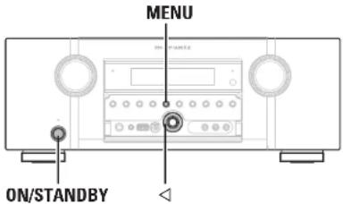
text_image
MENU ON/STANDBY☐Disabling the sensor function of the remote control unit
When the main unit is in standby mode, press ON/STANDBY while holding down ◀ and MENU on the main unit. "Remote Lock:ON" is shown on the display, and the infrared light receiving function is disabled.
□Enabling the remote sensor function
When the main unit is in standby mode, press ON/STANDBY while holding down and MENU on the main unit. The infrared light receiving function on the main unit is enabled.
NOTE
If a remote control receiver unit (purchased separately) is not connected, do not perform this setting. If you do, you will not be able to operate this unit using the remote control unit.
Operating the connected devices by remote control unit
Registering the supplied preset codes in the remote control unit enables you to operate devices made by other manufacturers.
Operating AV equipment

Press the input source select button (LFP page 23).
The remote control operating mode switches as shown in the table below, and the mode name is shown in the remote control display.
NOTE
Press the input source select buttons once to switch the operation mode of the remote control unit supplied with this unit. Press the input source select buttons twice consecutively to switch the operation mode of the remote control unit and input source of this unit.

| Input source select buttons | Input source of this unit | Devices controllable with the remote control unit (Operation mode) |
| BD * | BD | Device registered on the BD button |
| DVD * | DVD | Device registered on the DVD button |
| VCR | VCR | Device registered on the VCR button |
| SAT * | SAT | Device registered on the SAT button |
| GAM | GAME | Device registered on the GAME button |
| AUX1 | AUX1 | Device registered on the AUX1 button |
| NET USB | USB/iPod | iPod or USB memory device connected to the USB port |
| TV * | TV | Device registered on the TV button |
| CD * | CD | Device registered on the CD button |
| TUNE | TUNER Radio of this unit | |
| M-XP | M-XPort Device registered on the M-XP button | |
* If a preset code is registered for this button, the remote control unit of this unit can control another devices.
NOTE
If the mode of the remote control unit is set to other than amp-operation mode, press AMP to switch the remote control unit to the amp-operation mode to perform the following operations:
- For menu operation by pressing MENU
- For setting the channel level of the unit by pressing CH LVL
• For performing direct playback - For switching MultEQ®, Dynamic EQ® and Dynamic Volume® settings.
- For using the Video Select function
- For using the sleep timer function.
- For displaying the Source Select screen.
- For switching the M-DAX function.
- For directly selecting "AUTO" and "STEREO" of the listening modes.

Operate this unit or the device whose input source is switched.
- For details, refer to the operating instructions for each device. For operations of iPod and TUNER, see the following pages.
- iPod (137 page 25)
• TUNER (page 28)
ENGLISH
D
Registering preset codes
When preset codes are registered in the included remote control unit, it can then be used to operate any devices you have, such as DVD players or TVs made by different manufacturers.
NOTE
- No preset codes other than BD, DVD, TV, SAT and CD can be registered.
- In the factory settings, remote control codes for all Marantz products are registered.
☐Buttons used for operating the devices
① SOURCE ON/OFF
For switching power of each device on or off.
② △▽◀▷ ENTER
For menu operation of each device
③ MENU SETUP TOP MENU
For displaying the menu of each device.
④
⑤ Number button (0 - 9 +10)
⑤ Number button 10
⑥ PRESET - PRESET
⑥ PRESET +, PRESET -
⑦ TV POWER, TV INPUT
For operating a TV.
This button is enabled in any mode.
For details on operation with the remote control unit, see pages 26, 27, 30, 71.
Registering preset codes
The following two methods can be used for registering the reset code.
① Entering a 4-digit code
② Scanning the code table
① Entering a 4-digit code
See the preset code list table for the code to be input.
1 Press and hold down the input source select buttons for the appliance to control, and press SET until indicator blinks twice.
The back light flashes.
2 Press the 4-digit code for the appliance using the numeric buttons (code table at the end of this book).
- The 4-digit code is shown in the remote control display.
- When the settings are complete, "OK" is shown in the remote control display.
- If "NG" is displayed in the remote control display, repeat steps 1 and 2, and enter the same code again.

text_image
1 2 3 4 5 6 7 8 9 0 1 2 3 4 5 6 7 8 9 0 1 2 3 4 5 6 7 8 9 0 1 2 3 4 5 6 7 8 9 0 1 2 3 4 5 6 7 8 9 0 1 2 3 4 5 6 7 8 9② Scanning the code table
1 Switch the power on of the device for which you want to set the preset code.
2 Press and hold down the input source select buttons for the appliance to control, and press SET until indicator blinks twice.
The back light flashes
3 Aim the remote control at the appliance and slowly alternate between pressing INPUT ▲ and SOURCE ON/OFF for the appliance.
The preset code is shown in the remote control display.
4 Stop when the appliance turns off.
5 Press ENTER once to lock in the code.
Check the registered preset code
1 Press and hold down the input source select buttons for appliance to control, and press SET until indicator blinks twice and back light flashes.
The back light flashes.
2 Press SEARCH/INFO.
The ● display flashes twice, after which the set code is shown for 3 seconds in the remote control display.
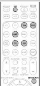
text_image
BAT U1 BAT U2 BAT U3 BAT U4 BAT U5 BAT U6 BAT U7 BAT U8 BAT U9 BAT U10 BAT U11 BAT U12 BAT U13 BAT U14 BAT U15 BAT U16 BAT U17 BAT U18 BAT U19 BAT U20 BAT U21 BAT U22 BAT U23 BAT U24 BAT U25 BAT U26 BAT U27 BAT U28 BAT U29 BAT U30 BAT U31 BAT U32 BAT U33 BAT U34 BAT U35 BAT U36 BAT U37 BAT U38 BAT U39 BAT U40 BAT U41 BAT U42 BAT U43 BAT U44 BAT U45 BAT U46 BAT U47 BAT U48 BAT U49 BAT U50 BATRegistering preset codes
Default settings for preset codes
The devices shown below are registered for each input source button as default. Settings can be changed according to the devices to be used.
| Input source select buttons | Category | Preset code |
| BD | Blu-ray Disc player | 5000 |
| DVD | DVD player 2000 | |
| TV | Television 1000 | |
| SAT | Satellite set top box | 4000 |
| CD | CD player 3000 | |
Operating components
The supplied remote control unit can control a component other than this unit.
| 1 | Switch the input source( page 23). |
| 2 | Operate the component. |
| For details, refer to the component's operating instructions. |
☐ Blu-ray Disc player / HD-DVD player / DVD player / DVD recorder operation
| Operation buttons | Function |
| SOURCE ON/OFF | Power on/standby |
| MENU | (Popup) Menu |
| TOP MENU | Top menu |
| Cursor operation | |
| ENTER | Enter |
| Manual search (fast-reverse/fast-forward) | |
| Playback | |
| Auto search [cus] | |
| Pause | |
| Stop | |
| 0-9 | Select title, chapter or channel selection |
| CLR | Clear the inputting |
| TV POWER | TV power on/standby (Default - Mantenti) |
| TV INPUT | Switch TV input (Default - Mantenti) |
□ CD player operation
| Operation buttons | Function |
| SOURCE ON/OFF | Power on/off |
| Manual search (fast-reverse/fast-forward) | |
| Playback | |
| Auto search [cue] | |
| Pause | |
| Stop | |
| CLR | Clear the inputting |
| TV POWER | TV power on/standby (Default: Marantz) |
| TV INPUT | Switch TV input (Default: Marantz) |
TV operation

| Operation buttons | Function |
| SOURCE ON/OFF | TV power on/standby[Default : Marantz] |
| CHANNEL +, - | Switch channels [up/down] |
| CLR | Clear the inputting |
| TV POWER | TV power on/standby[Default : Marantz] |
| TV INPUT | Switch TV input[Default : Marantz] |
ENGLISH
D
Operating components
☐Set top box for satellite (SAT) operation
| R | L | M | N | O | P | Q | R | S | T | U | V | W | X | Y | |
| 100% | |||||||||||||||
| R | R | R | R | R | R | R | R | R | R | R | R | R | R | R | R |
| 100% | |||||||||||||||
| 100% | |||||||||||||||
| 100% | |||||||||||||||
| 100% | |||||||||||||||
| 100% | |||||||||||||||
| 100% | 100% | ||||||||||||||
| 100% | 100% | ||||||||||||||
| 100% | 100% | ||||||||||||||
| 100% | 100% | ||||||||||||||
| 100% | |||||||||||||||
| Operation buttons | Function |
| SOURCE ON/OFF | Power on/standby |
| CHANNEL +,- Switch channels (up/down) | |
| Cursor operation | |
| ENTER | Enter |
| 0-9 | Channel selection |
| CLR | Clear the inputting |
| TV POWER | TV power on/standby[Default: Marantz] |
| TV INPUT | Switch TV input[Default: Marantz] |
Operating learn function
- If the AV device is not a Marantz device, or if the device does not operate even when the preset code is registered, use the learning function. Remote codes for different devices can be remembered for use by the Marantz remote control included with this device.
- This remote control unit is capable of learning around 160 codes.
Remembering remote control codes from other devices
1 Place the Marantz remote control and remote control from the other device approximately 5 cm apart, with the remote control signal transmission sections facing each other.

text_image
5 cm2 Press and hold down SET and SOURCE SEL until the LEARN indicator blinks.
3 Press input source select buttons to select the input source.
The input source is shown in the remote control display.
4 Select the button to be learned. LEARN indicator lights up.
5 Press and hold the button that you want to register on the other remote control until "OK" is displayed on the Marantz remote control display.
- If "NG" is shown on the remote control display, perform step 5 again. If "NG" is shown again on the remote control display, the remote control may not be able to learn the code correctly. In this case, use the specialized remote control for the device.
- If the remote control memory becomes full, "FULL" is shown on the remote control display. If you want to learn the code, you should erase other learned button.
6 Repeat steps 4 and 5 to learn other buttons for the same input source.
7 Repeat steps 3 to 6 to learn other input sources.
8 When programming of the remote control unit is completed, press SET.
The LEARN display disappears, and the remote control unit exits learn mode.
NOTE
- The learning function is unavailable for all SOURCE ON/OFF, MACRO and HDMI in any mode.
- The learning function is unavailable for all buttons in TUNER mode, AMP mode, NET/USB mode and M-XP mode.
• The learning procedure does not operate correctly if the batteries have become worn. - If no buttons are pressed for approximately 1 minutes while in the LEARN mode, the remote control unit automatically exits from the LEARN mode.
ENGLISHDEU
Delete saved remote control codes
Codes can be erased in three ways: by buttons, sources, and by all memory contents.
☐Delete remote control codes for each button
1 Press and hold down SET and SOURCE SEL until the LEARN indicator blinks.
2 Press input source select buttons to select the input source you want to delete. The input source is shown in the remote control display.
3 Press and hold down HDMI and press the learned button to be erased twice.
"ERASE" is shown in the remote control display, and the mode returns to learning mode.
• To return the normal mode, press SET.
text_image
SC VDD W0 WD SAT SNR TV CS CSR SWEI MUTY +/-☐Delete remote control codes for each input source
1 Press and hold down SET and SOURCE SEL until the LEARN indicator blinks.
2 Press and hold down HDMI and press the learned input source select buttons to be erased twice. "ERASE" is shown in the remote control display.
3 Press ENTER to continue erasing. The indicator blinks twice and the mode returns to LEARN mode.
- To cancel the erasing operation, do not press ENTER, and simply press any other button. - To return the normal mode, press SET.

text_image
ENTER ENTER☐Delete remote control codes for all input sources
1 Press and hold down SET and SOURCE SEL until the LEARN indicator blinks.
2 Press and hold down HDMI and press ON and STANDBY. LEARN indicator lights.
3 Press ENTER to continue erasing. "ERASE" is shown in the remote control display, and the mode returns to learning mode.
- To cancel the erasing operation, do not press ENTER and simply press any other button. - To return the normal mode, press SET.
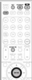
text_image
SET WHARSP I IN HDMI 22 61 80 197 VCC 947 948 357 RIO 79 331 139 SOUT 71.82 6.07 389 RANGE MS + - A B C D E F G H I J K L M N O P Q R S T U V W X Y Z A B C D E F G H I J K L M N O P Q R S T U V W X Y ZNOTE
Erasing codes will return to the factory preset code, or there will leave empty if the button has no factory preset code.
ENGLISH

Operating macro function
- When the macro function is used, operations that usually require a complicated series of multiple button operations can be performed easily just by pressing the MACRO button.
• This device can remember up to 6 macro functions.
• Each macro can record a maximum of 10 steps.
[Example] To playback a DVD
① Turn this unit's power on ↓
② Switch this unit's input source to DVD
↓
③ Tum the TV's power on
④ DVD Playback
Recording macro operations
[Example] Recording DVD playback operations to the number "1" button

1 Press and hold SET and MACRO together until "MACRO" flashes in the LEARN indicator, MACRO indicator and remote control display.
2 Press the macro operation number ("1") that you want to record to. "M1-01" is shown in the remote control display.
- If the number that you want to record to has already been recorded to, the recorded number flashes in the display.
3 Press the input source switch button ("DVD") of the operation that you want to record along with the command button ("▶"). The macro operation step number is shown in the remote control display.
- To record the amp input source, press AMP first, followed by the input source switching button.
4 When the macro operation recording is complete, press and hold ENTER until the LEARN indicator and MACRO indicator switch off.
NOTE
The RETURN, , ENTER, VOLUME+, - and CLR buttons cannot be recorded as macro operations.
Checking recorded macro operations
[Example] Checking the recorded macro operations to button "1"
1 Press and hold MACRO and MENU together until "MACRO" flashes in the LEARN indicator, MACRO indicator and remote control display.
2 Press the number button ("1") that you want to check.
The LEARN indicator, MACRO indicator and "M1-01" flashes in the remote control display.
2 Press the VOLUME +, -.
- The LEARN indicator switches off, and "M1-01" is shown in the remote control display.
• The recorded macro operation is performed.
4 Repeat step 3 until the final number of the macro operation is displayed.
• The display returns to that of step 1.
- When the macro operation number is displayed, the corresponding macro operation is performed.
5 When the macro operation check is complete, press and hold ENTER until the MACRO indicator switches off.
Editing recorded macro operations
[Example] Changing macro operation "1" recorded on number button "▶" to "II", and changing the number button to "2"
1 Press and hold MACRO and MENU together until "MACRO" flashes in the LEARN indicator, MACRO indicator and remote control display.
2 Press the number button ("1") that you want to change.
The LEARN indicator, MACRO indicator and "M1-01" flashes in the remote control display.
3 Press △▽ to select the macro operation button ("2") to edit. After the macro operation button is displayed, the recorded operation is performed.
- When the macro operation is updated as a recorded step, press the input source switching button, and then press the new step button ("2").
- To insert a new macro operation between recorded steps, after performing step 3, press MEMORY and then press the new step button ("2"). When a new step is introduced, if the total number of steps is already 10, the 10th step is deleted after the new step is introduced.
- To delete recorded macro operations, after step 3, call the step number that you want to delete, and press CLR.
• To return to step 1, press ENTER.
4 When the macro operation edit is complete, press and hold ENTER until the MACRO indicator switches off.

text_image
A M B C D E F G H I J K L M N O P Q R S T U V W X Y Z UNITED STATES OF AMERICA (1987-2003) ENTER M RCD M 1 2 3 4 5 6 7 8 9 10 11 12 13 14 15 16 17 18 19 20 21 22 23 24 25 26 27 28 29 30 31 32 33 34 35 36 37 38 39 40 41 42 43 44 45 46 47 48 49 50 51 52 53 54 55 56 57 58 59 60 61 62 63 64 65 66 67 68 69 70 71 72 73 74 75 76 77 78 79 80 81 82 83 84 85 86 87 88 89 90 91 92 93 94 95 96 97 98 99 100Using macro operations
[Example] Using the recorded macro operations to button "1"
1 Press the MACRO.
"MACRO" is shown in the MACRO indicator and remote control display.
2 Press the number button ("1") that you want to use.
Macro operations recorded to number button "1" are performed one at a time.
- The step number shown in the remote control display disappears after the step is performed.
- When all macro operations are completed, the remote control returns to the amp operation mode.
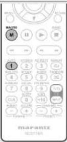
Deleting recorded macro operations
[Example] Deleting the macro operations recorded to button "2"
1 Press and hold MACRO and MENU together until "MACRO" flashes in the LEARN indicator, MACRO indicator and remote control display.
2 Press and hold CLR and the number ("2") that you want to delete for approximately 3 seconds.
"M2-CL" flashes in the remote control display.
3 Press the ENTER.
The recorded macro operation is deleted, and the remote control returns to step 1.
• To cancel the macro delete operation, press a different button without pressing ENTER.
4 When the macro operation delete is complete, press and hold ENTER until the MACRO indicator switches off.

text_image
ENTER M M M 2 1 3 5 6 8 9 10 11 12 13 14 15 16 17 18 19 20 21 22 23 24 25 26 27 28 29 30 31 32 33 34 35 36 37 38 39 40 41 42 43 44 45 46 47 48 49 50 51 52 53 54 55 56 57 58 59 60 61 62 63 64 65 66 67 68 69 70 71 72 73 74 75 76 77 78 79 80 81 82 83 84 85 86 87 88 89 90 91 92 93 94 95 96 97 98 99 100Operating macro function
Adjusting the interval time of macro operations transmitting
The macro operation transmission interval can be adjusted. • The factory setting is "1 second".
1 Press and hold MACRO and SOURCE SEL until "SETUP" is shown in the remote control display.
"SETUP" is shown for 3 seconds in the remote control display, after which "MCR05z" is displayed.
* The current transmission interval is shown.

2 Press ◀ ▷ to change to the desired transmission interval.
- The interval time can be changed from 0.5 to 5 seconds by 0.5 seconds step.
3 When the adjustment is complete, press and hold ENTER until the MACRO indicator switches off.
Setting the back light
Press the Light button on the side of the remote control, and the buttons on the remote control light for 2 seconds. If the Light button is pressed while the buttons are lit, the buttons remain lit for another 2 seconds.
- Backlight is set on in the factory settings.
□ Disabling the backlight
Press and hold both SET and STANDBY until indicator flashes twice.

□ Turning the backlight on
Press and hold both SET and ON until indicator flashes twice.

ENGLISH
D
Information
Information
Here, we list various information related to this unit. Please refer to this information as needed.
● Part names and functions 📋 page 77
● Other information 📋 page 82
● Troubleshooting page 90
Specifications page 93
● Index page 94
Part names and functions
Front panel
For buttons not explained here, see the page indicated in parentheses (1).

text_image
HOMI marantz -88 1 2 3 4 5 6 7 8 9① Power operation button
(ON/STANDBY)....(7, 12)
Turns power to this unit on and off (standby).
② Power indicator …… (12)
③ Door
When you are using buttons and/or terminals behind the door, press the bottom of the door to open it. When not using buttons and/or terminals behind the door, close it. Be careful not to catch your fingers when closing the door.
4 VOLUME control knob ..... (24)
⑤ Remote control sensor ……(81)
6 M-DAX indicator (59)
⑦ Display 1781
8 PURE DIRECT indicator (33)
⑨ INPUT SELECTOR knob …… (23)
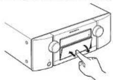
[With the door open]
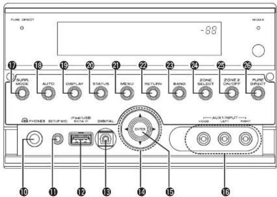
text_image
PURE DIRECT -88 17 18 19 20 21 22 23 24 25 26 SUNN MODE AUTO DISPLAY STATUS MENU RETURN BAND ZONE SELECT ZONE ON/OFF PURE DIRECT IP/USB SINTO DIGITAL EXTER AUX INPUT USB SINT⑩ Headphones jack
When the headphones are plugged into this jack, audio will no longer be output from the connected speakers or from the PRE OUT connectors.
NOTE
To prevent hearing loss, do not raise the volume level excessively when using headphones.
11 SETUP MIC jack 19,39)
⑫ iPod/USB port .....(19)
13 DIGITAL connector .....(19)
⑭ Cursor buttons (△▽◀▷) …… (48 - 50)
15 ENTER button (48 - 50)
16 AUX1 INPUT connectors ..... (19)
⑰ SURROUND MODE button …… (31)
18 AUTO button (30, 31, 44, 92)
⑲ DISPLAY button....(30, 67)
20 STATUS button (68)
② MENU button....(50)
② RETURN button (48 - 50)
23 BAND button 128
24 ZONE SELECT button 46
25 ZONE2 ON/OFF button 146
26 PURE DIRECT button (33)
ENGLISH

Display
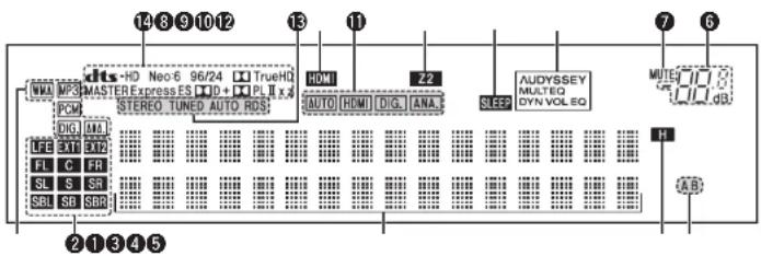
text_image
14 8 9 10 12 13 11 7 6 NWM MP3 MASTERExpress ES □□+□□PL II x X PCM STEREO TUNED AUTO RDS DIG MM LFE 3T LT2 FL C FR SL S SR SBL SB SBR 2 1 3 4 5 HDMI Z2 AUTO HDMI DIG ANA. AUDYSSEY MULTEO DYN VOL EQ MUTE H AB① Input signal indicators
② Input signal channel indicators
These light when digital signals are input. When playing HD Audio sources, the EXT1 indicator lights when a signal from an extension channel (a channel other than the front, center, surround, surround back or LFE channel) is input. If there are two or more extension channels, the EXT1 and EXT2 indicators light.
③ Information display
The input source name, surround mode, setting values and other information are displayed here.
4 Front height channel indicators
When audio is output from the front height channels, the "H" indicator lights.
⑤ Front speaker indicator
This lights according to the setting of the front A and B speakers.
⑥ Master volume indicator
⑦ MUTE indicator
This lights when the mute mode is select ( page 24).
8 AUDYSSEY indicators
Lighting is as follows, depending on the setting of "Dynamic EQ ^ " ( page 58) and "Dynamic Volume ^ " ( page 58).
| AUDYSSEYMULTEQDYN VOL |
| AUDYSSEYMULTEQDYN EQ |
| AUDYSSEYMULTEQ |
When "Dynamic EQ" and "Dynamic Volume" are "ON".
When "Dynamic EQ" is "ON" and "Dynamic Volume" is "OFF".
When "Dynamic EQ" and "Dynamic Volume" are "OFF".
9 Sleep timer indicator
This lights when the sleep mode is selected (1 page 43).
10 ZONE2 indicator
This lights up when ZONE2 (separate room) power is turned on Page 46.
⑪ Input mode indicators
Set the audio input modes for the different input sources (2-4 page 54).
⑫ HDMI indicator
This lights when playing using HDMI connections.
⑬ Tuner reception mode indicators
These light according to the reception conditions when the input source is set to "TUNER".
STEREO : In the FM mode, this light when receiving stereo broadcasts.
TUNED : Lights when the broadcast is properly tuned in.
AUTO : This light when in the auto tuning mode.
RDS : This light when receiving RDS broadcasts.
14 Decoder indicators
These light when the respective decoders are operating.
ENGLISHDEU
Rear panel
See the page indicated in parentheses (1).

text_image
15 14 13 12 109118 7 REMOATE CONTROL RUBER 1 2 1 2 1BDI 2DVDI 3SATI 4VCR 5GAMB 6AUXO OUT ARC HDMI MAXPort DC OUT DCTY VDMA MAX. SINAMT CABLE R0-2300 PM DSQ ADC AM ANTENA ANALOG RUDO IN VOR ZONE2 R SRLHL R SW1 SR SSR/SW2 PRE OUT MONITOR VCR DVD OUT VIDEO OUT COMPONENT VIDEO IN1 SODI IN2 IVDOS FVCR FVCR FVCR FVCR FVCR FVCR L L R R L R SL SR L R SL SR L R SL SR L R SL SR L R SL SR L R SL SR L R SL SR L R SL SR L R SL SR L R SL SR L R SL SR L R SL SR L R SL SR L R SL SR L R SL SR L R SL SR L R SL SR L R SL SR L R SL SR L R SL SR L R SL BR R L R L R L R L R L R L R L R L R L R L R L R L R L R L R L R L R L R L R L R L R L R L R L R L R L R L R L R L R L R L R L R L R L R L R L R L R L R L R L R L R L R L R L R L R L R L R L R L① FM/AM antenna terminals 120
② Analog audio connectors....(17 - 22)
③ PRE OUT connectors....(6, 22, 36 - 38)
4 7.1CH INPUT connectors ...... (21)
⑤ Speaker terminals (6, 36–38)
⑥ AC inlet (AC IN)....(6)
⑦ COMPONENT VIDEO connectors....(17, 18)
⑧ HDMI connectors....(16)
9 Digital audio connectors....(17 - 20)
⑩ VIDEO connectors ……(17 – 19)
⑪ FLASHER IN jack
Used when using a control BOX or other such control devices to control this unit.
⑫ REMOTE CONTROL jacks (40)
⑬ M-XPort jack (21)
14 DC OUT jacks (41)
⑮ RS-232C connector....(41)
NOTE
Do not touch the inner pins of the connectors on the rear panel. Electrostatic discharge may cause permanent damage to the unit.
ENGLISH

Remote control unit
For buttons not explained here, see the page indicated in parentheses ().
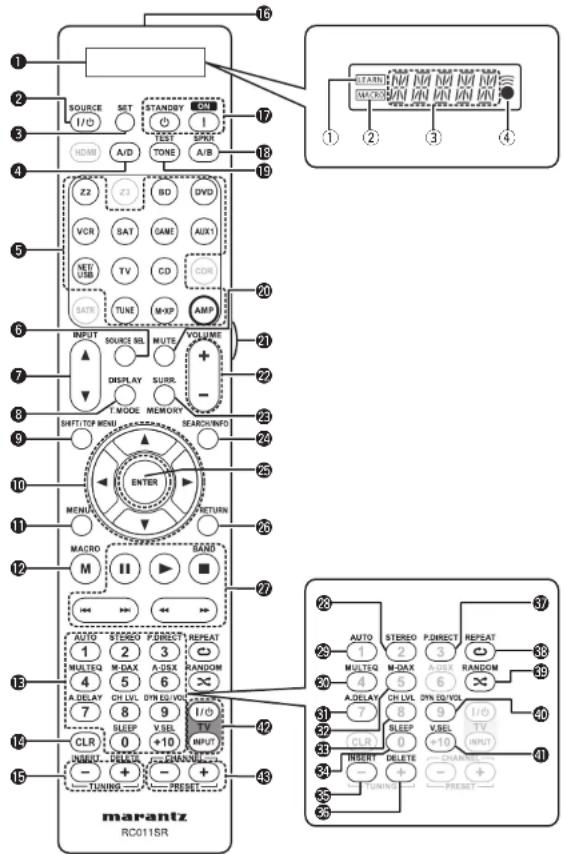
text_image
1 2 3 4 5 6 7 8 9 10 11 12 13 14 15 SOURCE I/O SET STANDOY ON I TEST SPR HDMI A/D TONE A/B Z2 Z3 BD DVD VCR SAT GNE AUXI MET/USB TV CD DDR SATE TUNE M-XF AMP INPUT SOURCE SEL MUTE VOLUME + - DISPLAY SURB. I MODE MEMORY SHIFT/TOP MENU SEARCH/INFO ENTER RETURN MACRO GAND M II > AUTO STEREO FOROUT REPEAT 1 2 3 MULTIQ M-DAX A-DSX RANDOM 4 5 6 A DELAY CH LVL SYN EQ VOL. 7 8 9 I/ou SLEEP VSEL TV CLR 0 +10 INPUT INPUT NURU DELE 20000000000000000000000000000000000000000000000000000000000000000000000000000000000000000000000000000 MARANTZ RC011SR① Display
① LEARN indicator .....(72)
② MACRU indicator ..... (74)
③ Information display
④ indicator …… (70)
② SOURCE power button …… (70, 71)
③ SET button (70 - 75)
④ Input mode button (A/D) ..... (54)
⑤ Input source select buttons ...... (23)
6 Source select button (SOURCE SEL) ..... (23)
⑦ INPUT buttons (▲, ▼) …… (23, 46, 70)
⑧ DISPLAY/ Tuner mode (T.MODE) button …… (28, 67)
9 SHIFT/TOP MENU button (28, 49)
⑩ Cursor buttons (△▽◀ ▷)……(48 - 50)
⑪ MENU button ...... (50)
⑫ MACRO button ..... (74)
13 Number buttons ...... (28, 70 – 72)
14 Clear button (CLR) ..... (71, 74, 75)
⑮ TUNING buttons (+, -) ...... (28)
16 Remote control signal transmitter
⑰ Power buttons (ON, STANDBY) ...... (7, 12)
18 Speaker A/B button (SPKR A/B) ...... (24)
19 TEST TONE button (63)
20 Muting button (MUTE) 124
② Light button ..... (75)
② Master volume control buttons (VOLUME +, -) …… (24)
23 Surround mode (SURR.) /
MEMORY button ...... (28, 31)
24 SEARCH/ Information (INFO) button ..... (25, 28, 50)
25 ENTER button (48 - 50)
26 RETURN button (48 - 50)
27 System buttons ......(26, 27, 71, 72)
- Pause button (III)
- Play button (▶)
- Stop button (■)
- Skip buttons (|◀◀, ▶▶▶)
- Search buttons (◀◀, ▶▶)
FM/AM band switching button (BAND) ... (28)
28 STEREO button (33)
29 AUTO buttons ...... (31)
30 MULTEQ ^® button (57)
③1 Audio delay button (A.DELAY) ...... (59)
32 M-DAX button 159
33 Channel level button (CH LVL) ...... (43)
34 SLEEP button (43)
35 INSERT button (49)
36 DELETE button .....(49)
37 Pure direct button (P.DIRECT) ..... (33)
38 REPEAT button .....(26, 27)
39 RANDOM button (26, 27)
40 Dynamic EQ®/Dynamic Volume® button (DYN EQ/VOL) ...... (58)
④1 Video select button (V.SEL) ...... (53)
42 TV operation buttons (TV POWER / INPUT) ...... (71, 72)
43 CHANNEL/ PRESET buttons (+,-) …… (28, 29, 71, 72)
NOTE
The HDMI, Z3, CDR, SATR and A-DSX buttons cannot be used.
Inserting the batteries
① Remove the rear lid in the direction of the arrow and remove it.
② Load the two batteries properly as indicated by the marks in the battery compartment.
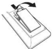

③ Put the rear cover back on.
NOTE
- Insert the specified batteries in the remote control unit.
- Replace the batteries with new ones if the set does not operate even when the remote control unit is operated close to the unit. (The supplied batteries are only for verifying operation.)
- When inserting the batteries, be sure to do so in the proper direction, following the and marks in the battery compartment.
• To prevent damage or leakage of battery fluid: - Do not use a new battery together with an old one.
- Do not use two different types of batteries
- Do not attempt to charge dry batteries.
- Do not short-circuit, disassemble, heat or dispose of batteries in flames.
- Do not keep the battery in a place exposed to direct sunlight or in places with extremely high temperatures, such as near a heater.
- If the battery fluid should leak, carefully wipe the fluid off the inside of the battery compartment and insert new batteries.
- Remove the batteries from the remote control unit if it will not be in use for long periods.
- Used batteries should be disposed of in accordance with the local regulations regarding battery disposal.
Operating range of the remote control unit
Point the remote control unit at the remote sensor when operating it.
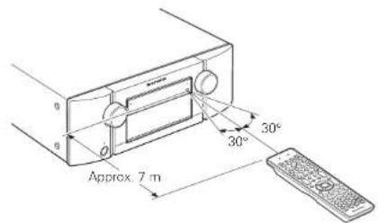
text_image
Approx. 7 m 30° 30°NOTE
The set may function improperly or the remote control unit may not operate if the remote control sensor is exposed to direct sunlight, strong artificial light from an inverter type fluorescent lamp or infrared light.
ENGLISH

Other information
□ Trademark information (page 82)
Surround (1 page 83)
☐Relationship between video signals and monitor output (1 page 87)
Explanation of terms (page 88)
Trademark information
This product uses the following technologies:
| AUDYSSEYMULTEQDYNAMIC VOLUME | Manufactured under license from Audyssey LaboratoriesTM, U.S. and foreign patents pending. Audyssey MultEQ® is a registered trademark of Audyssey Laboratories. Audyssey Dynamic EQ® is a registered trademark of Audyssey Laboratories. Audyssey Dynamic Volume® is a trademark of Audyssey Laboratories. |
| Manufactured under license from Dolby Laboratories. "Dolby", "Pro Logic" and the double-D symbol are trademarks of Dolby Laboratories. |

dts-HD
Master Audio

dts™
Neural Surround

Made for
iPod iPhone
Manufactured under license under U.S. Patent #s: 5,451,942; 5,956,674; 5,974,380; 5,978,762; 6,226,616; 6,497,535; 7,212,872; 7,333,929; 7,392,195; 7,272,567 & other U.S. and worldwide patents issued & pending. DTS and the Symbol are registered trademarks, & DTS-HD, DTS-HD Master Audio, and the DTS logos are trademarks of DTS, Inc. Product includes software. © DTS, Inc. All Rights Reserved.
Manufactured under license from DTS Licensing Limited. DTS and the Symbol are registered trademarks, & DTS Neural Surround and the DTS logos are trademark of DTS, Inc. Product includes software. © DTS, Inc. All Rights Reserved.
HDMI, the HDMI Logo and High-Definition Multimedia Interface are trademarks or registered trademarks of HDMI Licensing LLC in the United States and other countries.
"Made for iPod" and "Made for iPhone" mean that an electronic accessory has been designed to connect specifically to iPod, or iPhone, respectively, and has been certified by the developer to meet Apple performance standards.
Apple is not responsible for the operation of this device or its compliance with safety and regulatory standards.
iPhone, iPod, iPod classic, iPod nano, iPod shuffle, and iPod touch are trademarks of Apple Inc., registered in the U.S. and other countries.
- Individual users are permitted to use iPhone, iPod, iPod classic, iPod nano, iPod shuffle, and iPod touch for private copy and playback of non-copyrighted contents and contents whose copy and playback is permitted by law. Copyright infringement is prohibited by law.
This item incorporates copy protection technology that is protected by U.S. patents and other intellectual property rights of Rovi Corporation. Reverse engineering and disassembly are prohibited
ENGLISHDEU
Surround
This unit is equipped with a digital signal processing circuit that lets you play program sources in the surround mode to achieve the same sense of presence as in a movie theater.
Surround modes and surround parameters
This table shows the speakers that can be used in each surround mode and the surround parameters adjustable in each surround mode.
Symbols in the table
○ This indicates the audio output channels or surround parameters that can be set.
This indicates the audio output channels. The output channels depend on the settings of "Speaker Config." (12 page 61).
*1 A signal for each channel contained in an input signal is output as audio.
*2 Only when "Subwoofer Mode" is set to "LFE+Main" (含 page 62), sound is output from the subwoofer.
*3 For HD Audio whose sampling frequency of an input signal is more than 96kHz, this sound parameter cannot be set.
*4 This item can be selected when a Dolby TrueHD signal is played.
*5 This item can be selected when a Dolby Digital or DTC signal is
*5 This item can be selected when a Dolby Digital or DTS signal is played.
*6. This item can be selected when a Dolby Digital or DTS signal or DVD-Radio is played.
ENGLISH

Surround
| Surround mode (page 51) | Surround Parameter (page 56) | Long * 7 (page 57) | Aucysay Settings * 1 (page 57) | M-DAX * 10 (page 58) | ||||||
| Height Gain (page 57) | Panorama (page 56) | PRO LOGIC II/IIx Music mode only | NEO:3 Music mode only | MultiCO® (page 57) | Dynamic EO® * 8 (page 58) | Dynamic Volume® * 9 (page 58) | ||||
| Dimension (page 56) | C. Width (page 56) | C. Image (page 56) | ||||||||
| PURE DIRECT (2 channel) | ||||||||||
| PURE DIRECT (Multi-channel) | ||||||||||
| DIRECT (2 channel) | ||||||||||
| DIRECT (Multi-channel) | ||||||||||
| STREEO | ○○○○○ | |||||||||
| MULTI CHIN | ○○○○ | |||||||||
| DOLBY PRO LOGIC IIx ○○○○○○ | ||||||||||
| DOLBY PRO LOGIC IIx ○○○○○○○○ | ||||||||||
| DOLBY PRO LOGIC III○○○○○○○○ | ||||||||||
| DTS NEODE | ○○○○○ | |||||||||
| DOLBY DIGITAL | ○○○○ | |||||||||
| DOLBY DIGITAL Plus | ○○○○ | |||||||||
| DOLBY TrueHD | ○○○○ | |||||||||
| DTS SURROUND | ○○○○ | |||||||||
| DTS 96/24 | ○○○○ | |||||||||
| DTS HD | ○○○○ | |||||||||
| DTS Express | ○○○○ | |||||||||
| MULTI CH STREEO | ○○○○○ | |||||||||
| DOLBY VIRTUAL SPEAKER | ○○○○○ | |||||||||
| Neural | ○○○○○ | |||||||||
| Dolby Headphone | ○○○○○ | |||||||||
*7 This item cannot be set when "Dynamic EQ" (page 58) is set to "ON".
*8 This item cannot be set when "MultiEQ" ( page 57) is set to "OFF" or "Manual".
*9 This item cannot be set when "Dynamic EQ" (E2 page 581 is set to "OFF")
*10 This item can be set when the input signal is analog, PCM 48 kHz or 44.1 kHz.
*11 For HD Audio whose sampling frequency of an input signal is more than 96 kHz, this sound parameter cannot be set.
ENGLISHDEU
Surround
□Types of input signals, and corresponding surround modes
This table shows the input signal that can be played in each surround mode. Check the audio signal of the input source then select the surround mode.
Symbols in the table
○ This indicates the selectable surround mode.
*1 If "Speaker Config." - "S.Back" (87 page 62) is set to "None", this surround mode cannot be selected.
*2 If "Speaker Config." - "S.Back" (page 62) is set to "1spkr" or "None", this surround mode cannot be selected
*3 If "Speaker Config." - "F. Height" (page 62) is set to "None", this surround mode cannot be selected.
*4 This surround mode can be selected when "Amp Assign" (page 61) is set to "Normal"
ENGLISH

Surround
*1 If "Speaker Config." = "S.Back" (page 62) is set to "None", this surround mode cannot be selected.
*2 If "Speaker Config." - "S.Back" (page 62) is set to "1spkr" or "None", this surround mode cannot be selected.
*3 If "Speaker Config." - "F. Height" ( page 62) is set to "None", this surround mode cannot be selected.
*4 This surround mode can be selected when "Amp Assign" ( page 61) is set to "Normal".
ENGLISHDEU
Relationship between video signals and monitor output
○ Video signal input present
× No video signal input
*1 When no HDMI monitor is connected or the HDMI monitor's power is not on
× No video signal output
○ || Superimposed on the picture indicated in ||.
× (1 Only the picture in 1) is output
× Neither the picture nor the menu is output.
*2 Only the menu is displayed when no HDMI monitor is
connected or the HDMI monitor's power is not on.
*3 If an HDMI monitor is not connected or power of an HDMI monitor is not turned on, the menu is superimposed on a video image in parenthesis.

- The main zone video conversion function is compatible with the following formats: NTSC, PAL, SECAM, NTSC4.43, PAL-N, PAL-M and PAL-60.
- When SECAM signals of video input are up-converted, the signals are output in PAL format from the S-Video and Video connectors.
- The menu display cannot be superimposed when x.v.Color signals and computer's resolution (e.g. VGAI are input.
NOTE
- If you operate the menu while playing back 3D video content, the playback video is replaced by the menu screen. The playback video is not displayed behind the menu screen.
- This unit does not show the status display while playing back 3D video content.
ENGLISH
D
Explanation of terms
A
A2DP
A2DP is one profile of Bluetooth defined for in-car devices or AV devices that use wireless communication instead of a cable.
Adobe RGB color / Adobe YCC601 color
Like x.v.Color, each of these color spaces defines a palette of available colors that is larger than the traditional RGB color model.
Audyssey Dynamic EQ ^12
Audyssey Dynamic EQ solves the problem of deteriorating sound quality as volume is decreased by taking into account human perception and room acoustics. Audyssey Dynamic EQ works in tandem with Audyssey MultEQ® to provide well-balanced sound for every listener at any volume level.
Audyssey Dynamic Volume®
Audyssey Dynamic Volume solves the problem of large variations in volume level between television programs, commercials, and between the soft and loud passages of movies. Audyssey Dynamic EC is integrated into Dynamic Volume so that as the playback volume is adjusted automatically, the perceived bass response, tonal balance, surround impression, and dialog clarity remain the same.
Audyssey MultEQ®
Audyssey MultiEQ is a room equalization solution that calibrates any audio system so that it can achieve optimum performance for every listener in a large listening area. Based on several room measurements, MultiEQ calculates an equalization solution that corrects for both time and frequency response problems in the listening area and also performs a fully automated surround system setup.
Auto Lip Sync
If you connect the receiver to a TV that supports the Auto Lip Sync function, it can automatically correct delay between the audio and video.
B
Bluetooth
Bluetooth is a short-distance wireless communication technology used for connecting handheld devices several meters apart. This enables notebook computers, PDA s, mobile phones, etc. to connect without a cable for transmitting audio and data.
D
Deep Color
This technology allows expression of more number of colors than the conventional B bits and can reproduce colors close to natural ones without color streak.
Dolby Digital
Dolby Digital is a multi-channel digital signal format developed by Dolby Laboratories.
A total of 5.1 channels are played: 3 front channels ("FL", "FR" and "C"), 2 surround channels ("SL" and "SR") and the "LFE" channel for low frequencies.
Because of this, there is no crosstalk between channels and a realistic sound field with a "three-dimensional" feeling (sense of distance, movement and positioning) is achieved.
A realistic, powerful sense of presence is achieved when playing movie sources in AV rooms as well.
Dolby Digital EX
Dolby Digital EX is a 6.1-channel surround format proposed by Dolby Laboratories that allows users to enjoy in their homes the "DOLBY DIGITAL SURROUND EX" audio format jointly developed by Dolby Laboratories and Lucas Films.
The 6.1 channels of sound, including surround back channels, provide improved sound positioning and expression of space.
Dolby Digital Plus
Dolby Digital Plus is an improved Dolby Digital signal format that is compatible with up to 7.1 channels of discrete digital sound and also improves sound quality thanks to extra data bit rate performance. It is upwardly compatible with conventional Dolby Digital, so it offers greater flexibility in response to the source signal and the conditions of the playback equipment.
Dolby Headphone
The Dolby Headphone technology provides a surround sound listening experience over headphones. When listening to multichannel content such as DVD movies over headphones, the listening experience is fundamentally different than listening to speakers. Since the headphone speaker drivers are covering the pinna of the ear, the listening experience differs greatly from traditional speaker playback. Dolby utilizes patented headphone perspective curves to solve this problem and provides a non-fatiguing, immersive, home theater listening experience. Dolby Headphone also delivers exceptional 3D audio from stereo material.
Dolby TrueHD
Dolby TrueHD is a high definition audio technology developed by Dolby Laboratories, using lossless coding technology to faithfully reproduce the sound of the studio master.
This format provides the facility to support up to 8 audio channels with a sampling frequency of 96kHz/24bit resolution and up to 6 audio channels with a sampling frequency of 192kHz/24bit resolution. Dolby TrueHD is adopted for applications that put very high importance on sound quality.
Dolby Pro Logic II
Dolby Pro Logic II is a matrix decoding technology developed by Dolby Laboratories.
Regular music such as that on CDs is encoded into 5 channels to achieve an excellent surround effect. The surround channel signals are converted into stereo and full band signals (with a frequency response of 20Hz to 20kHz or greater) to create a "three-dimensional" sound image offering a rich sense of presence for all stereo sources.
Dolby Pro Logic IIx
Dolby Pro Logic IIx is a further improved version of the Dolby Pro Logic II matrix decoding technology. Audio signal's recorded in 2 channels are decoded to achieve a natural sound with up to 7.1 channels. There are three modes: "Music" suited for playing music, "Movie" suited for playing movies, and "Game" which is optimized for playing games.
Dolby Pro Logic IIz
Dolby Pro Logic IIz introduces a new dimension to Home Entertainment through the addition of a pair of front height channels. Compatible with stereo, 5.1-channel and 7.1-channel content. Dolby Pro Logic IIz provides enhanced spaciousness, depth and dimension to movies, concert video and video game playback while maintaining the full integrity of the source mix.
Dolby Pro Logic IIz identifies and decodes spatial cues that occur naturally in all content, directing this information to the front height channels, complementing the performance of left and right surround sound speakers. Content that is encoded with Dolby Pro Logic IIz height channel information can be even more revealing, with perceptually discrete height channel information bringing an exciting new dimension to home entertainment. Dolby Pro Logic IIz, with front height channels is also an ideal alternative for households that cannot support the placement of back surround speakers of a typical 7.1-channel system but may have bookshelf space available to support the addition of height speakers.
Dolby Virtual Speaker
Dolby Virtual Speaker is a technology certified by Dolby Laboratories that creates a virtualized surround sound experience from two speakers using a multichannel Dolby Digital source. Additionally, Dolby Virtual Speaker can simulate the surround sound effect produced by Dolby Pro Logic or Dolby Pro Logic II.
Dolby Virtual Speaker retains all the original Multichannel audio information and provides the listener with the sensation of being surrounded by additional speakers.
Downmix
This function converts the number of channels of surround audio to less number of channels and plays back.
DTS
This is an abbreviation of Digital Theater System, which is a digital audio system developed by DTS. When playing back audio by connecting this system with a device such as DTS amplifier, accurate sound field position and realistic sound effect as if you are in a movie theater can be obtained.
Explanation of terms
DTS 96/24
DTS 96/24 is a digital audio format enabling high sound quality playback in 5.1 channels with a sampling frequency of 96 kHz and 24 bit quantization on DVD-Video.
DTS Digital Surround
DTS Digital Surround is the standard digital surround format of DTS, Inc., compatible with a sampling frequency of 44.1 or 48 kHz and up to 5.1 channels of digital discrete surround sound.
DTS-ES™ Discrete 6.1
DTS-ESTM Discrete 6.1 is a 6.1-channel discrete digital audio format adding a surround back (SB) channel to the DTS digital surround sound. Decoding of conventional 5.1-channel audio signals is also possible according to the decoder.
DTS-ES™ Matrix 6.1
DTS-ESTM Matrix 6.1 is a 6.1-channel discrete digital audio format inserting a surround back (SBI) channel to the DTS digital surround sound through matrix encoding. Decoding of conventional 5.1-channel audio signals is also possible according to the decoder.
DTS Express
DTS Express is an audio format supporting low bit rates (max. 5.1 channels, 24 to 256 kbps).
DTS-HD
This audio technology provides higher sound quality and enhanced functionality than the conventional DTS and is adopted as an optional audio for Blu-ray Disc. This technology supports multi-channel, high data transfer speed, high sampling frequency, and lossless audio playback. Maximum 7.1-channels are supported in Blu-ray Disc.
DTS-HD High Resolution Audio
DTS-HD High Resolution Audio is an improved version of the conventional DTS, DTS-ES and DTS 96/24 signal formats, compatible with sampling frequencies of 96 or 48kHz and up to 7.1 channels of discrete digital sound. High data bit rate performance provides high quality sound. This format is fully compatible with conventional products, including conventional DTS digital surround 5.1-channel data.
DTS-HD Master Audio
DTS-HD Master Audio is a lossless audio format created by Digital Theater System (DTS). This format provides the facility to support up to 8 audio channels with a sampling frequency of 96kHz/24bit resolution and up to 6 audio channels with a sampling frequency of 192kHz/24bit resolution. It is fully compatible with conventional products, including conventional DTS digital surround 5.1-channel data.
DTS Neural Surround
DTS Neural Surround has been chosen as the surround sound format for XM Satellite Radio's "XM HD Surround", TV sports broadcasting, 7.1 games, Music Direct Internet streaming as well as leading FM/HD radio stations. It delivers the rich envelopment and discrete image detail of surround sound by unmasking the audio details, typically lost by other playback modes. Audiences will experience the deep ambience and subtle details of movies, music and games.
DTS NEO:6 ^TM Surround
DTS NEO:6 ^™ is a matrix decoding technology for achieving 6.1-channel surround playback with 2-channel sources. It includes "DTS NEO:6 Cinema" suited for playing movies and "DTS NEO:6 Music" suited for playing music.
Dynamic range
The difference between the maximum undistorted sound level and the minimum discernible level above the noise emitted by the device.
H
HDCP
When transmitting digital signals between devices, this copyright protection technology encrypts the signals to prevent content from being copied without authorization.
HDMI
This is an abbreviation of High-Definition Multimedia Interface, which is an AV digital interface that can be connected to a TV or amplifier. Video signal and audio signal can be connected using 1 cable.
L
LFE
This is an abbreviation of Low Frequency Effect, which is an output channel that emphasizes low frequency effect sound. Surround audio is intensified by outputting 20 Hz to 120 Hz deep bass.
M
MAIN ZONE
The room where this unit is placed is called the MAIN ZONE.
MP3 (MPEG Audio Layer-3)
This is an internationally standardized audio data compression scheme, using the "MPEG-1" video compression standard. It compresses the data volume to about one eleventh its original size while maintaining sound quality equivalent to a music CD.
MPEG (Moving Picture Experts Group), MPEG-2, MPEG-4
These are the names for digital compression format standards used for the encoding of video and audio. Video standards include "MPEG-1 Video", "MPEG-2 Video", "MPEG-4 Visual", "MPEG-4 AVC". Audio standards include "MPEG-1 Audio", "MPEG-2 Audio", "MPEG-4 AAC".
P
Pairing
Pairing is an operation required for settings to connect two Bluetooth devices. Pairing enables Bluetooth devices to access each other.
Protection Circuit
This is a function to prevent damage to components within the power supply when an abnormality such as an overload, excess voltage occurs or temperature for any reason.
In this unit, the power indicator blinks and the unit enters standby mode when an abnormality occurs.
S
Sampling frequency
Sampling involves taking a reading of a sound wave (analog signal) at regular intervals and expressing the height of the wave at each reading in digitized format (producing a digital signal).
The number of readings taken in one second is called the "sampling frequency". The larger the value, the closer the reproduced sound is to the original.
Speaker impedance
This is an AC resistance value, indicated in (ohms). Greater power can be obtained with this value smaller.
sYCC601 color
Like x.v.Color, each of these color spaces defines a palette of available colors that is larger than the traditional RGB color model.
W
WAV (Wave)
WAV is a standard audio format of Windows. The file size tends to increase, but sound near the original sound can be maintained.
WMA (Windows Media Audio)
This is audio compression technology developed by Microsoft Corporation.
WMA data can be encoded using Windows Media ^® Player Ver.7, 7.1, Windows Media ^® Player for Windows ^® XP and Windows Media ^® Player 9 Series.
To encode WMA files, only use applications authorized by Microsoft Corporation. If you use an unauthorized application, the file may not work properly.
m = 311
x.v.Color
This function lets HDTVs display colors more accurately. It enables display with natural, vivid colors. "x.v.Color" is a Sony registered trademark.
Z
ZONE2
This unit can operate in a room other than the room where this unit is placed (MAIN ZONE) (ZONE2 playback). The room for ZONE2 playback is called ZONE2.
ENGLISH
D
Troubleshooting
If a problem should arise, first check the following:
-
Are the connections correct?
-
Is the set being operated as described in the user guide?
-
Are the other components operating properly?
If this unit does not operate properly, check the items listed in the table below. Should the problem persist, there may be a malfunction.
In this case, disconnect the power immediately and contact your store of purchase.
[General]
| Symptom Cause/Solution Page | ||
| Power does not turn on. | Check whether the power plug is correctly inserted into the power outlet.The protection circuit is active. Disconnect the power plug from the electric outlet, wait 5 to 10 seconds and then insert it back into the pullet. | 54,89 |
| Display is off. Set "Display" on the menu to something other than "OFF".67 | ||
| The power indicator is blinking red in intervals of approximately 2 seconds. | The temperature inside the unit has risen. Please turn off power once, and re-apply the power after the temperature has fallen sufficiently.Please re-install this unit in a place having good ventilation. | IIIIII |
| The power indicator is blinking red in intervals of approximately 0.5 seconds. | Please use speakers which have the specified impedance.The speaker cable has shorted (is touching). Firmly twist the core wire in the speaker cable, and then re-connect it to the speaker terminal. | 44 |
| After turning on the power, the power indicator is blinking red in intervals of approximately 0.5 seconds. | This unit amplifier circuit has failed. Turn off the power and please contact the Marantz service adviser. | - |
| Set does not operate properly. | Reset the microprocessor. 92 | |
[Video]
| Symptom Cause/Solution Page | ||
| No picture appears. | Check the TV connection:Set the TV input correctly. | 67 |
[Audio]
| Symptom Cause/Solution Page | ||
| Audio is not output. | Check the connections for all devices.Check the speaker connections.Check whether the audio device power is turned on.Adjust the master volume.Cancel the mute mode.Select a suitable input source.Select a suitable input mode.Disconnect the headphones. No sound is output from the speakers or the PRE OUT connectors when headphones are connected. | 5, 14 – 225, 36 – 38–24, 4424, 4424, 445477 |
| No sound is produced from surround speaker. | Check if the surround speakers are connected to the SURROUND terminals. | – |
| No sound is produced from surround back speaker. | Set "Amp Assign" on the menu to "Normal".Set "Speaker Config." – "S.Back" on the menu to something other than "None".Set the surround mode to something other than "STEREO". | 616231 |
| No sound is produced from front height speaker. | Set "Amp Assign" on the menu to "Normal".Set "Speaker Config." – "F.Height" on the menu to something other than "None". | 6162 |
| No sound is produced from subwoofer. | Check the subwoofer connections.Turn on the subwoofer's power.Set "Speaker Config." – "Subwoofer" on the menu to "Yes".If "Front" and "Center" for "Speaker Config." are set to "Large", and "Subwoofer Mode" is set to "LFE", no sound may be output from the subwoofer, depending on the input signal or selected surround mode. | 5, 36 – 38/6161, 62 |
| DTS sound is not output. | Set "Decode Mode" on the menu to "Auto" or "DTS". | 54 |
| Dolby TrueHD, DTS-HD, Dolby Digital Plus audio is not output. | Make HDMI connections. | 16 |
[HDMI]
| Symptom Cause/Solution Page | ||
| No audio is output with HDMI connection. | Check the connection of the HDMI connectors.When outputting HDMI audio from the speakers, set "HDMI Audio Out" on the menu to "AMP".When outputting HDMI audio from a TV, set "HDMI Audio Out" on the menu to "TV". | 166464 |
| No video is output with HDMI connection. | Check the connection of the HDMI connectors.Set the input source to match the connected HDMI connector.Check whether the TV is compatible with copyright protection (HDCP). If connected to a device not compatible with HDCP, video will not be output correctly. | 1616, 23, 5215 |
| When the following operations are performed on devices compatible with HDMI control, the same operations occur on this unit.Power ON/OFFSwitching audio output devicesAdjust volumeSwitch input source | Set "HDMI Control" on the menu to "OFF". To operate power only for each device, set "Power Off Control" to "OFF". | 42, 64 |
[Radio]
| Symptom Cause/Solution Page | ||
| Reception fails, or there is a lot of noise or distortion. | Change the antenna orientation or position.Separate the AM loop antenna from the unit.Use an FM outdoor antennaSeparate the antenna from other connection cables. | 20202020 |
ENGLISHDEU
[iPod]
| Symptom Cause/Solution Page | ||
| iPod cannot be played. | Check the iPod connections.Switch the input source to "USB".Incompatible iPod types cannot be played back. | 192319 |
| "Connection Error" is displayed. | Unable to communicate properly. Turn off the power to this unit, disconnect the iPod and then reconnect it. | - |
| "Not Support" is displayed. | The iPod connected to the unit is not compatible. Please make sure the iPod you are connecting is compatible.The software version of the connected iPod is an old one. Please update to the latest version. | 19- |
| "Connection Error" is displayed. | The iPod is not responding. Turn off the power to this unit, disconnect the iPod and then reconnect it. | - |
| When an iPod is connected, "No Connection" is displayed. | "No Connection" may display if you connect an iPod that has only a small amount of charge remaining in its battery to this unit.Should this occur, charge the iPod before connecting it to this unit. | - |
[USB memory device]
| Symptom Cause/Solution Page | ||
| When a USB memory device is connected, "USB" is not displayed on the menu. | The set cannot recognize a USB memory device. Check the connection.A USB memory device not conforming to mass storage class is connected. Connect a USB memory device conforming to mass storage class.A USB memory device cannot be connected via a USB hub. | 19-19 |
| Files on a USB memory device cannot be played. | Set the USB memory device format to "FAT16" or "FAT32". For details, refer to the USB memory device's operating instructions.If the USB memory device is divided into multiple partitions, only files stored in the top partition can be played.The file is recorded in an incompatible format. Please record it in a compatible format.This unit cannot play back files covered by copyright protection. | ---- |
| The file names are not displayed properly ("...", etc.). | Characters that cannot be displayed on this unit are replaced by "." (periodi). | 25 |
| The sound quality is poor or there is noise during playback. | The file being played back has a low bit rate. | - |
| "Connection Error" is displayed. | Unable to communicate properly. Turn off the power to this unit, unplug the USB memory device and then plug it back in.The USB memory device is not responding. Turn off the power to this unit, unplug the USB memory device and then plug it back in. | -- |
| "Overcurrent" is displayed. | The USB memory device is consuming too much power. When using a USB portable hard disk that can be powered by an AC adapter, connect its AC adapter. | - |
ENGLISH

[M-XPort]
| Symptom Cause/Solution Page | ||
| Audio is not output when a wireless receiver (RX101 is connected). | • Check that the Bluetooth device and Wireless receiver (RX101) are correctly paired. | - |
[Remote control unit]
| Symptom Cause/Solution Page | ||
| The set cannot be operated with the remote control unit. | Batteries are worn out. Replace with new batteries.Operate the remote control unit within a distance of about 7 m from this unit and at an angle of within 30°.Remove any obstacle between this unit and the remote control unit.Insert the batteries in the proper direction, checking the ⊕ and ⊖ marks.The set's remote control sensor is exposed to strong light (direct sunlight, inverter type fluorescent bulb light, etc.). Move the set to a place in which the remote control sensor will not be exposed to strong light. | 8181818181 |
Resetting the microprocessor
Perform this procedure if the display is abnormal or if operations cannot be performed. When the microprocessor is reset, all the settings are reset to their default values. Various setting details can be saved and reset on this device. If setting details are saved before returning to the default values, after returning to the default settings, setting details can be returned to the same values as before returning to the defaults.
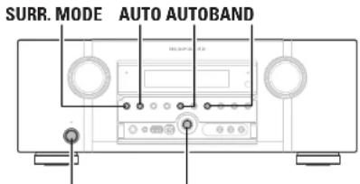
text_image
SURR. MODE AUTO AUTOBANDON/STANDBY ENTER
1 When the power is ON, press and hold BAND and ENTER for more than 3 seconds. After "MEMORY SAVING" is shown on the display, "COMPLETE" is shown to inform you that the settings have been saved.
2 Turn off the power using ON/STANDBY.
3 Press ON/STANDBY while simultaneously pressing SURROUND MODE and AUTO.
4 Once the display starts flashing at intervals of about 1 second, release the two buttons.
5 Press and hold BAND and MENU for more than 3 seconds.
After "MEMORY LOAD" is shown on the display, "COMPLETE" is shown to inform you that the settings have returned to those saved in step 1.

- To return all of the settings to the default values, perform steps 2 to 4 without performing step 1. - If in step 3 the display does not flash at intervals of about 1 second, start over from step 1.
Specifications
| □Audio sectionPower amplifierRated output: Front:110 W + 110 W/8 Ω, 20 Hz - 20 kHz with 0.08 % T.H.D.JCenter:110 W (8 Ω, 20 Hz - 20 kHz with 0.08 % T.H.D.)Surround:110 W + 110 W/8 Ω, 20 Hz - 20 kHz with 0.08 % T.H.D.JSurround back / Front height:110 W + 110 W/8 Ω, 20 Hz - 20 kHz with 0.08 % T.H.D.I | □Tuner section(FM)(Note: μV at 75 Ω, 0 dBI = 1 x 10-12 W)Receiving Range:87.5 MHz - 108.0 MHz522 kHz - 1611 kHzUsable Sensitivity:1.2 μV (12.8 dB)18 μV50 dB Quleting Sensitivity:MONO 2.0 μV (17.3 dB)STEREO 42 μV (34.5 dB)S/N (IHF-A):MONO 72 cBSTEREO 67 dBTotal harmonic Distortion (at 1 kHz):MONO 0.3 %STEREO 0.7 % | |
| □GeneralPower supply:AC 230 V, 50 HzPower consumption:650 W0.2 W (Standby)3.0 W (CEC standby)Maximum external dimensions:440 (W) x 161 (H) x 389 (DI mmWeight:11.8 kg | ||
ENGLISH
D
Index
| Numerics | |
| 2.1-channel | 35, 38 |
| 3D | 15 |
| 5.1-channel | 35, 37 |
| 6.1-channel | 35, 36 |
| 7.1-channel | 5, 35, 36 |
A
| A2DP | 21, 88 |
| Accessories | 2 |
| Adjust CH | 59 |
| Adjusting the master volume | 24 |
| Adobe RGB color / Adobe YCC601 color | 88 |
| AM loop antenna | 20 |
| Amp Assign | 61 |
| ARC | 15 |
| Aspect | 54 |
| Audio Adjust | 56 |
| Audio cable | 6, 17, 18, 19, 20, 21, 22 |
| Audio Delay | 59 |
| Audio Setup | 64 |
| Audio/Video Adjust | 56 |
| Audyssey Auto Setup | 7, 39 |
| Audyssey Dynamic EQ | 58, 88 |
| Audyssey Dynamic Volume | 58, 88 |
| Audyssey MultEQ | 57, 78, 88 |
| Audyssey Settings | 57 |
| Auto Lip Sync | 64, 88 |
| Auto Preset | 51 |
| Auto Setup | 7, 39 |
B
| Base Curve Copy | 59 |
| Bass | 57, 65 |
| Bass Setting | 62 |
| Bi-amp | 38 |
| Bluetooth | 21, 88 |
| Brightness | 60 |
C
| Cable | |
| Audio cable | 6, 17, 18, 19, 20, 21, 22 |
| Coaxial digital cable | 17, 18 |
| Component video cable | 17, 18 |
| HDMI cable | 6, 16 |
| Optical cable | 17, 19, 20 |
| Speaker cable | 6 |
| Video cable | 17, 18, 19 |
| Channel | 65 |
| Channel Level | 43, 63 |
| Characters | 49 |
| Chroma Level | 60 |
| C.Image | 56 |
| Coaxial digital cable | 17, 18 |
| Component video cable | 17, 18 |
| Condensation | 3 |
| Connection | |
| 7.1CH INPUT terminal | 21 |
| Antenna | 20 |
| Blu-ray Disc player | 6, 16, 17 |
| Cable TV | 18 |
| CD player | 20 |
| DC OUT (TRIGGER OUT) jacks | 41 |
| Digital carncorder | 16, 19 |
| DVD player | 16, 17 |
| External power amplifier | 22 |
| Game console | 16 |
| HDMI | 15 |
| (Pod (USB) | 19 |
| Power cord | 6 |
| Remote control jacks | 40 |
| RS-232C connector | 41 |
| Satellite tuner | 18 |
| Set-top box | 16, 18 |
| Speaker | 5, 36 |
| TV | 6, 16, 17 |
| USB memory device | 19 |
| Video cassette recorder | 16, 18 |
| Wireless receiver (RX101) | 21 |
| Contrast | 60 |
| Crossover Frequency | 63 |
| C.Width | 56 |
D
| D.Como | 56 |
| Decode Mode | 54 |
| Deep Color | 15, 88 |
| Dimension | 56 |
| Direct mode | 25 |
| Display | 67, 78 |
| Distance | 62 |
| DNR | 60 |
| Dolby | |
| Dolby Digital | 32, 88 |
| Dolby Digital EX | 32, 88 |
| Dolby Digital Plus | 32, 88 |
| Dolby Headphone | 33, 88 |
| Dolby Pro Logic II | 88 |
| Dolby Pro Logic IIX | 88 |
| Dolby Pro Logic IIZ | 35, 88 |
| Dolby TrueHD | 32, 88 |
| Dolby Virtual Speaker | 33, 88 |
| Downmix | 88 |
| DRC | 56 |
| DTS | 32, 88 |
| DTS 96/24 | 32, 89 |
| DTS Digital Surround | 89 |
| DTS-ES Discrete 6.1 | 32, 89 |
| DTS-ES Matrix 6.1 | 32, 89 |
| DTS Express | 89 |
| DTS-HD | 32, 89 |
| DTS-HD High Resolution Audio | 89 |
| DTS-HD Master Audio | 89 |
| DTS NEO:6TM Surround | 31, 89 |
| DTS Neural Surround | 32, 89 |
| Dynamic EQ | 58 |
| Dynamic range | 89 |
| Dynamic Volume | 58 |
E
| Enhancer | 60 |
| EQ Customize | 64 |
| Error messages (Auto Setup) | 11 |
F
| Fader function | 43 |
| F.Height | 62 |
| FM indoor antenna | 20 |
| Front A/B (connection) | 37 |
| Front height speaker | 35, 36 |
| Front Panel | 77 |
G
| GUI | 66 |
H
| HDCP | 15, 89 |
| HDMI | 15, 89 |
| HDMI 1.4a | 15 |
| HDMI Audio Out | 64 |
| HDMI cable | 6, 16 |
| HDMI Control | 42, 64 |
| HDMI Setup | 64 |
| Headphones | 77 |
| Height Gain | 57 |
| HPF | 65 |
| HT-EQ | 56 |
| Hue | 60 |
1
| Information | 68 |
| Audio Input Signal | 68 |
| HDMI Information | 68 |
| Preset Channel | 68 |
| Status | 68 |
| Input Assign | 52 |
| Input Mode | 54 |
| Input Setup | 50 |
| Input signal | 32, 85 |
| Inputting characters | 49 |
| vP Scaler | 53 |
GTL
| Learn function | 72 |
| Level Lch | 65 |
| Level Rch | 65 |
| LFE | 56, 89 |
| Listening mode | 31 |
| Listening position | 8 |
M
| Macro function | 74 |
| MAIN ZONE | 45, 89 |
| Manual EQ | 59 |
| Manual Setup | 61 |
| Master volume display | 66 |
| M-DAX | 59 |
| Menu map | 47 |
| MP3 | 89 |
| MPEG | 89 |
| MPEG-4 AAC | 89 |
| MultiFO | 57 |
| Mute Level | 65, 66 |
| M XPort | 21 |
0
| Optical cable | 17, 19, 20 |
| Option Setup | 66 |
| Display | 67 |
| GUI | 66 |
| Setup Lock | 67 |
| Source Delete | 66 |
| Trigger Out | 67 |
| Volume Control | 66 |
| Zone Rename | 67 |
P
Pairing 89
Panel lock function 44
Panorama: 50
Dermocore Check: 11
Picture Adjust 60
Playback
Blu-ray Disc player 24
CD player 24
Direct 33
DVD player 24
EM/AMI
FRYAM broadcasts 28
Pack/USB 25
MP2 26
MPEG-4 AAC 26
Multi-channel 31
Pure direct 33
Stereo 33
USB memory device 26
WMA 26
ZONEZ 46
Playback Mode 55
Playback Mode 55
Revers Off Control 61
Power On Level 65, 66
Power on 2015: 60, 60
Brogat cordas 70
Preset Name 51
Preset Skip 51
Presetting radio stations 28
Progressive Mode 54
Protection circuit 89
P1Y 29
R
RDS 29
Rear panel 79
Reference Level Offset 58
Remote control settings 68
remote control unit 69,80
Inserting the batteries 81
Operating AV equipment 63
Operating components 71
Registering Preset Codes 70
Remote Mode 25
Rename 55
Reputing the microassessor
Receiving the Thioprocessor: 52
RGB Range 64
BT 30
S
Sampling frequency 89
S.Back 62
Screensaver 66
Selecting the input source 23
Setup Lock 67
Chaff: 55
Shane 55
Sleep timer 45
George Delots 50
Source Delete 68
Source Level 55
Source Level 95
Speaker
connect 5,35
lastell 5,25
Set up 7,39
Speaker cable 6
Speaker Config. 61
Speaker impedance 5,89
Speaker Setup 61
Standby Source 64
Subwoofer setting 8
Surround back speaker 5,35,36
Surround Mode 31,83
Surround Parameter 56
Switching the front speakers 24
Switching the tuning increment 30
sYCC601 color 89
LFT
Tane 57
Tone Control 57
TP 29
Trademark 82
Treble 57,65
Trigger Out 67
Turning off the sound temporarily 24
Turn off power (standby) 12
Turn on power 7
V
Video 53
Video cable 17, 18, 19
Video conversion 14
Video Convert 53
Video Mode 53
Video Select 53
Volume Control 66
Volume Level 65
Volume Limit 65, 66
W
WAV 89
WMA 89
X
x.v.Color 15,89
Z
ZONE2 45,7B,89
Zone Rename 67
Zone Setup 65
ENGLISHDEU
List of preset codes / Liste de codes préréglés / Lista de códigos pre-ajustados / Liste von voreingestellten Codes Lista dei codici pre-regolati / Lijst van vooringestelde codes / Förteckning över förinställda koder
Device select : BD
Blu-ray Disc Player
D Deron 5034, 5035, 5036
H Hitachi F031 5132 F037
Hilas II 5031
J IMC 5014, 5015, 5017, 5018, 5019, 5020
L 10 5010 5011
M Marant 500 5026 502
- March 2, 2010, 10:46, 3
Mitsubishi 5024, 5025
0 Okyo 5013
P Panasonic 5001, 5002, 5003
1
Philips 5004
Pioneer 5005
B
n
3 Samsung 505
Sharp 5028, 5029. 5030
Sow: 5707, 5018, 5709, 5016
T
1 oshiba 2012
Y Yamaha 5021, 5022, 5023
Device select : DVD
DVD Player
A Aiva 2036, 2037 Aaex 2012, 2017, 2018, 2019, 2021, 2034
B BOSE 2008, 2009, 2063
D. Dano1 2017, 2018
E. 2019. 2019.
- Total 2015
GE 2009, 2020, 2029, 2033
H Hamian Karden 2061
Hitachi 2008, 2012, 2031
2006.2010.2017.2011
J JWC 2003, 2010, 2018, 2047, 2042, 2043
K Kenwood 2053, 2054
Koss 2063
M 4.1 (2007) 3007-2011 1975-2025
M. Magnavox 2007, 2011, 2023, 2025
Marantz 2025, 2065
Marantz (Blu-ray) 2064
Mitsubishi 2011.0215
- Delva 2002
U Oikyol 7.62
Oniun 2009, 2030
P Panasonic 2003, 2015, 2016, 2055
2017-2018
Philips 2007, 2011, 2036
Pioneer 2002, 2014, 2056
Proscan 2009, 2020, 2032
D. 2014 2005, 2009, 2020, 2035.
R Hua 2057
| Saripo | 2017 |
| Samsung | 2008, 2012, 2022, 2024, 2027 |
| Sanyc | 2050, 2052 |
| Sharp | 2044, 2045 |
| Sherwood | 2051 |
| Sony | 2051, 2013, 2059 |
| Toshiba 2004, 2008, 2026, 2029 | |
| Yamana | 2048, 2060 |
7 Zeitho 2010
Device select : SAT
Satellite Receiver
| A | Aphastar | 4027 |
| Anstrad 4015, 4017, 4050 | ||
| Atsky | 4048 | |
| B | B Sky B | 4021, 4045, 4046 |
| C | Cheparral | 4039 |
| D | DIRECTV | 4001, 4018, 4044 |
| DSI Network | 4030 | |
| Drake | 4026 | |
| E | Fchoster | 4007, 4017, 4018, 4019, 4020, 4062, 4063, 4064 |
Furosky 4047, 4256
Express VII 4/17
E Lepthal 405
1 PAXUS 405
- 4056
Fujitsu 4025
G GE 4002, 4008, 4009
General Instruments 4036.4037
Gradiente 404/4057
H. Kuchi 4701, 4015
H F1001, 1013
Hughes 4001.4016
4349, 4050, 4351, 4052,
14.163 2053
J Janeil 4025
JVC 4017
M. Mietu bisi
M. KREEDISH 4001
N Nokia 4058, 4059, 4060, 4061
0 Cotima 4048
P
- Ferrieste: 406,4015
Philips 4031, 4035, 4044, 4057
Prescan 4002, 4008, 4009, 4011
D Pass a Shock 4026-1021
H HalO shock -0.30,400
RCA 4002, 4008, 4009, 4029
Realistic 4040
Bural Cable 4736
Horsley State 1203 (752-1922/242-1947)
S Samsung 4322, 4023, 4142, 4043, 4760, 4051, 4766
1950, 4834, 4835 Corporate: 1941, 1912
2014年1月1日
| SKY | 4074, 4015, 4057 |
| Skyplus 4048 | |
| Skysar 4041, 4047, 4056 | |
| Sony | 4003, 4012, 4014, 4055, 4066, 4067 |
| Star Choice | 4032 |
| Star Trek | 4024 |
| STS | 4038 |
2014年1月1日
SUPERDISH 40/24
T Teac 4049
Thompson 4046 4056
Torbila 1001, 4036
- 2014年1月1日
U Unidan 4005, 2006, 4013
Universum 4056
V. Vödov Roll 4025
- Video call 1025
Zunith 4023, 4025, 4033
Device select : TV
Television
| Acer | 1141 |
| Admiral 1002, 1008, 1089 | |
| Akio 1050 | |
| Alwa | 1117, 1118 |
| Akai 1001 | |
| Ambron | 1023 |
| Anam | 1113 |
| Anam National | 1023, 1063, 1052 |
| AOC 1003, 1024, 1043, 1127 | |
| Audiovox | 1023 |
B Bell & Howell 1009.1025
Euro 1°04, 11:43
BEI Q 104, 142
Broksonic 1003.1097,1098.1113
C Celebrate 1991
1003 1713 1023 1726
Citizen 1058, 1963
Caloryme 1903.10/2
BLOO YIE: 1943, 16-4
Carter 1113
Cortec/Conv 1023.1045.1047
Craig 1970, 1982, 1983, 1:12
Dian: 1020, 1027, 1028, 1113
Crown 1023.1067
Curty Mathes 1003, 1013, 1025, 1026.
BORGES FINANCE 1062, 1103, 1110
D. 1003, 1013, 1024, 1035,
1036, 1059, 1084, 1101
Dayton 1003, 1013, 1016
Diyarca 1107, 1110
Dimeria 1.03, 1116
Dunichl 1003, 1010, 1153
E Elecuroband 1001
Electrohome 1967 1003 1969 1:31
Electronic 150:1,693,150:1163
| Emerson | 1003, 1013, 1015, 1020, 1021, 1022, 1023, 1025, 1038, 1044, 1045, 1048, 1055, 1061, 1064, 1066, 1068, 1101, 1113 |
Exclusion 1003
- 2017年1月1日
F Fisher 1025, 1051, 1087, 1160
Fujitsu 1038, 1124, 1175, 1155
Furai 1023.1025.1113
1.2.3.4.5.6.7.8.9.10.11.12.13.14.15.16.17.18.19.20.21.22.23.24.25.26.27.28.29.30.31.32.33.34.35.36.37.38.39.40.41.42.43.44.45.46.47.48.49.50.51.52.53.54.55.56.57.58.59.60.61.62.63.64.65.66.67.68.69.70.71.72.73.74.75.76.77.78.79.80.81.82.83.84.85.86.87.88.89.90.91.92.93.94.95.96.97.98.99.100
G Gateway 1150
1003, 1018, 1022, 1046,
1054, 1069, 1095, 1103,
1110.1113.1133.1136,
1193
-
-
- 1030.
-
Goldstar 1015, 1080, 1100
112, 115
H Hallmark 1003
Hisena 1116
1003 1827 1001 1832
1032, 1042, 1051, 1052, 1037, 1041, 1045, 1047.
Hitachi 1065, 1068, 1092, 1088
1094, 1139, 1140, 1145.
1159
I. Ieli minu 1767
- ( \mu_{0} ) , ( \mu_{1} ) , ( \mu_{2} ) , ( \mu_{3} ) , ( \mu_{4} ) , ( \mu_{5} ) , ( \mu_{6} ) , ( \mu_{7} ) , ( \mu_{8} ) , ( \mu_{9} ) , ( \mu_{10} ) , ( \mu_{11} ) , ( \mu_{12} ) , ( \mu_{13} ) , ( \mu_{14} ) , ( \mu_{15} ) , ( \mu_{16} ) , ( \mu_{17} ) , ( \mu_{18} ) , ( \mu_{19} ) , ( \mu_{20} ) , ( \mu_{21} ) , ( \mu_{22} ) , ( \mu_{23} ) , ( \mu_{24} ) , ( \mu_{25} ) , ( \mu_{26} ) , ( \mu_{27} ) , ( \mu_{28} ) , ( \mu_{29} ) , ( \mu_{30} ) , ( \mu_{31} ) , ( \mu_{32} ) , ( \mu_{33} ) , ( \mu_{34} ) , ( \mu_{35} ) , ( \mu_{36} ) , ( \mu_{37} ) , ( \mu_{38} ) , ( \mu_{39} ) , ( \mu_{40} ) , ( \mu_{41} ) , ( \mu_{42} ) , ( \mu_{43} ) , ( \mu_{44} ) , ( \mu_{45} ) , ( \mu_{46} ) , ( \mu_{47} ) , ( \mu_{48} ) , ( \mu_{49} ) , ( \mu_{50} ) , ( \mu_{51} ) , ( \mu_{52} ) , ( \mu_{53} ) , ( \mu_{54} ) , ( \mu_{55} ) , ( \mu_{56} ) , ( \mu_{57} ) , ( \mu_{58} ) , ( \mu_{59} ) , ( \mu_{60} ) , ( \mu_{61} ) , ( \mu_{62} ) , ( \mu_{63} ) , ( \mu_{64} ) , ( \mu_{65} ) , ( \mu_{66} ) , ( \mu_{67} ) , ( \mu_{68} ) , ( \mu_{69} ) , ( \mu_{70} ) , ( \mu_{71} ) , ( \mu_{72} ) , ( \mu_{73} ) , ( \mu_{74} ) , ( \mu_{75} ) , ( \mu_{76} ) , ( \mu_{77} ) , ( \mu_{78} ) , ( \mu_{79} ) , ( \mu_{80} ) , ( \mu_{81} ) , ( \mu_{82} ) , ( \mu_{83} ) , ( \mu_{84} ) , ( \mu_{85} ) , ( \mu_{86} ) , ( \mu_{87} ) , ( \mu_{88} ) , ( \mu_{89} ) , ( \mu_{90} ) , ( \mu_{91} ) , ( \mu_{92} ) , ( \mu_{93} ) , ( \mu_{94} ) , ( \mu_{95} ) , ( \mu_{96} ) , ( \mu_{97} ) , ( \mu_{98} ) , ( \mu_{99} ) , ( m^{2}, m^{3}, m^{4}, m^{5}, m^{6}, m^{7}, m^{8}, m^{9}, m^{10}, m^{11}, m^{12}, m^{13}, m^{14}, m^{15}, m^{16}, m^{17}, m^{18}, m^{19}, m^{20}, m^{21}, m^{22}, m^{23}, m^{24}, m^{25}, m^{26}, m^{27}, m^{28}, m^{29}, m^{30}, m^{31}, m^{32}, m^{33}, m^{34}, m^{35}, m^{36}, m^{37}, m^{38}, m^{39}, m^{40}, m^{41}, m^{42}, m^{43}, m^{44}, m^{45}, m^{46}, m^{47}, m^{48}, m^{49}, m^{50}, m^{51}, m^{52}, m^{53}, m^{54}, m^{55}, m^{56}, m^{57}, m^{58}, m^{59}, m^{60}, m^{61}, m^{62}, m^{63}, m^{64}, m^{65}, m^{66}, m^{67}, m^{68}, m^{69}, m^{70}, m^{71}, m^{72}, m^{73}, m^{74}, m^{75}, m^{76}, m^{77}, m^{78}, m^{79}, m^{80}, m^{81}, m^{82}, m^{83}, m^{84}, m^{85}, m^{86}, m^{87}, m^{88}, m^{89}, m^{90}, m^{91}, m^{92}, m^{93}, m^{94}, m^{95}, m^{96}, m^{97}, m^{98}, m^{99}, m^{\text{out}}
Jiefel 1132
JNJ 1067
1003.1013.1016.1019.
1024, 1026, 1046, 1047,
JC Penney 10:4, 1063, 1083, 1084,
1100, 1103, 1110, 1112.
1139.1154
Jensar 1003
1026.1029.1045.1047.
JVC 1050, 1060, 1065
K Kawashi 1001-1003
It is not to be a result of the
Kerwood 1003
Kloss Novabeam 1023, 1058, 1057, 1134
1013, 1023, 1033, 1034.
KIV 1073, 1099, 1113
L LG 1024.1030
M. 15 Lincoln 1997, 1950, 1928
R.Wards 1002, 1009, 1008
1013, 1152, 1053, 1156,
Magnavox 1057, 1063, 1057, 1081, 1109
108
Marant 1003, 1031, 1067, 1122
Mitsubishi 1003, 1024, 1051, 1115.
1122, 1133
Motorola 1014.1069
1003.1012.1024.1043.
N NEC 1069
NET-TV 1134.1150
1750-1975
U Union 1020, 1096
P. Panasonic 1017, 1067, 1069, 1095,
1111
103, 1011, 1045, 1052,
Philips 1051, 1056, 1057, 1058,
1053, 1067, 1059, 1106
1003, 1018, 1007, 1070.
Flueller 107, 1132, 1145, 1147, 1148
| Plasinovic | 1135 |
| Portland | 1003, 1013, 1024, 10:59 |
| Price Club | 1026 |
| Pisram | 1018 |
| Proscan | 1004, 1006, 1006, 1007, 1008, 1084, 1103, 1110 |
| Proton | 1003, 1045 |
0 1010.1063.10/3.1111.
d UJESAR 1153
1003.1013.1015.1023.
R Radio Shack 1024.1025.1045.1100.
1103.1110.1113
1003.1004.1005.1006.
1007, 1008, 1014, 1024,
PCA 1049, 1063, 1075, 1079.
1064 1065 1067, 1068, 1093.
1054, 1101, 1103, 1110,
1113.1153
Realistic 1013, 1015, 1023, 1025,
1045, 1100, 1103, 1710
Runco 1010,1153
S Servir 1150
2003.1013.1024.1026
1045, 1043, 1024, 1023, 1040, 1045, 1062, 1073
Sarosine 1083, 1190, 1170, 1105
GARISING 1026, 1039, 1126, 1135, 1114, 1120, 1121, 1146.
1148.1157
Sarsui 1:19
1975-1976 1971-1972
1013, 1023, 1051, 1072, 1077, 1091, 1156, 1157
Santo 1071, 1051, 1136-1137, 1158
1003 1013 2014 1015
Sharp 1045, 1059, 1064, 1066
1976.1883.1123
Signature 1009
Fig. 13
Scri: 1001, 1102, 1108
Surgdesing 1003, 1023, 1038, 1063.
0015681 1113
Starlix 1023
Sures, France 1134
Sep 1954 113-1075 1507 1042 1553
1053, 1059, 1042, 1052, Sukawa, 1053, 1056, 1057, 1162
Sylvania 105, 1059, 1057, 1063, 1057, 1080, 1151
1782-1975-174
Symphorc 1023, 1038, 1044
Tancy 1014
Tatung 1069
Technics 2015
TECHNES 2018
Techwood 1003, 1018
1003.1009.1013.1023.
1024.1026.1038.1045.
TECHKA 1047, 1059, 1063, 1111,
1113
Telecaption 10/4
1003.1019.1025.1026.
Toshiba 1042.10/4.1098.1107.
1111, 1135, 1136
Tolcsosom 1013
II. Universal 1945, 1754
U Contrerasal 10-2, 10-
V Video Concepts 1113
| Viewsoric | 1005, 1022, 1109, 11261129, 1130, 1131, 1138,1143, 1145, 1150 | |
| W | Wands | 1003, 1009, 1015, 1024,1038, 1044, 1045, 1052,1054, 1056, 1057, 1057,1086, 1103, 1110 |
| WhiteWestinghouse | 1001, 1101 | |
| Y | Yamaha 1003, 1024 | |
| Z | Zarith | 1003, 1009, 1010, 1132,1144, 1145 |
Device select : CD
CD Player
| A | AKWA 3001, 3002, 3003 | |
| AKAI 3004, 3005, 3006 | ||
| AUDIO 3007 | ||
| AUDIO LABS 3008 | ||
| C | CAI FORNA 3008 | |
| CARVER 3010, 3011, 3009 | ||
| CASO 3012, 3020 | ||
| CURTIS 3020, 3021 | ||
| D | DENION 3013 | |
| E | EMERSON 3014 | |
| F | FISHER | 3011, 3015, 3016, 3017, 3018 |
| G | GE 3019 | |
| GMINEXA 3014, 3021, 3020 | ||
| H | HARMON 3022, 3023, 3051 | |
| HITACHI 3020 | ||
| I | INKEL 3024 | |
| J | JC PENNLY | 3012, 3020, 3025 |
| JNC | 3026, 3027 | |
| K | KARDON | 3027, 3051, 3023 |
| KRELL | 3010 | |
| L | LUXMAN | 3035, 3036, 3037, 3038 |
| LXI | 3012, 3020, 3014 | |
| M | MAGNAVOX | 3010, 3033, 3040 |
| MARANTZ | 3010, 3041, 3042, 3043 | |
| MATHES | 3012, 3020 | |
| MCS | 3012, 3020 | |
| MRA | 3023 | |
| MISSION | 3010 | |
| MITSUBISHI 3023, 3044 | ||
| N | NAD | 3034, 3045 |
| NAKAMCHI 3016, 3047, 3048 | ||
| NLC MCS 3025 | ||
| O | NIKKC | 3007, 3016 |
| ONKYO | 3049, 3050, 3051, 3052, 3055, 3102, 3103 | |
| OPTIMUS | 3011, 3014, 3023, 3028, 3053, 3054, 3056, 3057, 3058, 3059 | |
| P | FANASONIC 3008, 3060, 3061 | |
| PHILIPS 3009, 3010, 3013, 3040 | ||
| FIONEER | 3025, 3027, 3062, 3063, 3064 | |
| Q | OLASAR | 3058 |
| R | ROA | 3011, 3014, 3065, 3066, 3067, 3068, 3069 |
| REALISTIC | 3011, 3014, 3020, 3042, 3044, 3057 | |
| ROTEC3010 | ||
| RS ORIGINAL | 3020 | |
| S | SAE | 3010, 3083 |
| SAMSIUNG | 3071 | |
| SANSUI | 3014, 3068, 3072, 3073 | |
| SANYO | 3011, 3018, 3074, 3075, 3076 | |
| SCOTTI 3014 | ||
| SLAHIS | 3012, 3014, 3020, 3028, 3029 | |
| SHARP | 3028, 3042, 3077 | |
| SHERWOOD | 3042, 3056, 3070, 3078, 3079 | |
| SHURE | 3025 | |
| SONY | 3033, 3079, 3082, 3081, 3082, 3087, 3098, 3099, 3100, 3101 | |
| SYLVANIA | 3010 | |
| SYMPHONIC | 3083 | |
| T | TEAC | 3016, 3042, 3057, 3063, 3064, 3065, 3066 |
| TECHNICA | 3007, 3008, 3061, 3067, 3068 | |
| THETA DIGITAL | 3040 | |
| TOSHIBA | 3045 | |
| V | VICTOR 3026 | |
| Y | YAMAHA | 3007, 3089, 3090, 3091, 3092 |
| Z | ZENITH | 3015, 3033, 3094, 3095, 3096 |
Dimensions / Dimensions / Dimensions / Abmessungen / Dimensioni / Afmetingen / Storlek

text_image
Unit : mm (in) 22.5 (15/16) 348.5/13 - 1/160 389.0/15-388 17.5 (17/16) 40.0 (17 3/8) marantz 146.5/15 348 161.0/16 348 14.5 (5/8)www.marantz.com
You can find your nearest authorized distributor or dealer on our website.
marantz®
is a registered trademark.
D&M Holdings, Inc.
Printed in China 5411 10482 031M