Bravo (2010) - Car FIAT - Free user manual and instructions
Find the device manual for free Bravo (2010) FIAT in PDF.

User questions about Bravo (2010) FIAT
0 question about this device. Answer the ones you know or ask your own.
Ask a new question about this device
Download the instructions for your Car in PDF format for free! Find your manual Bravo (2010) - FIAT and take your electronic device back in hand. On this page are published all the documents necessary for the use of your device. Bravo (2010) by FIAT.
USER MANUAL Bravo (2010) FIAT
O W N E R H A N D B O O K
WHY CHOOSING GENUINE PARTS
We really know your car because we invented, designed and built it: we really know every single detail.
At Fiat Service authorised workshops you can find technicians directly trained by us, offering quality and professionalism for all service operations.
Fiat workshops are always close to you for the regular servicing operations, season checks and practical recommendations by our experts.
With Fiat Genuine Parts you keep the reliability, comfort and performance features of your new car unchanged in time: that's why you bought it for.
Always ask for Genuine Parts for the components used on our cars; we recommend them because they come from our steady commitment in research and development of highly innovative technologies.
For all these reasons: rely on Genuine Parts, because they are the only ones designed by Fiat for your car.
LINEACCESSORI ROOF RACK BARS, WHEEL RIMS
CHOOSING GENUINE PARTS
IS THE MOST NATURAL CHOICE

text_image
Stylized barcode image of a car silhouette with visible text and circular cutouts


HOW TO RECOGNISE GENUINE PARTS
To recognise a Genuine Part, check that the component bears our brands, always clearly visible on Genuine Parts, from the braking system to windscreen wipers, from shock absorbers to pollen filter.
All Genuine Parts undergo strict controls, both during design and manufacturing stages, by specialists using vanguard materials, to test the component reliability.
This to guarantee performance and safety for you and your passengers on board, for a long time.
Always ask for and make sure a Genuine Part has been used.

text_image
Genuine PartsPollen filter
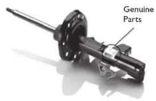
text_image
Genuine PartsShock absorber
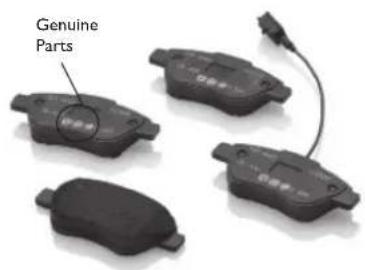
text_image
Genuine PartsBrake pads
DearCustomer,
We would like to congratulate and thank you for choosing a Fiat Bravo.
We have written this handbook to help you get to know all the features of your car and use it in the best possible way.
You are recommended to read it right through before taking to the road for the first time.
It contains important information, advice and instructions for the use of the car which will help you get the very best out of your Fiat. The handbook also provides a description of special features and tips as well as essential information for correct care, maintenance, safe car driving and use and preservation of your Fiat over time.
Carefully read the warnings and indications marked with the following symbols:

personal safety;

car safety;

environmental protection.
The enclosed Warranty Booklet lists the services that Fiat offers to its Customers:
□the Warranty Certificate with terms and conditions for maintaining its validity;
□the range of additional services available to Fiat Customers.
We are sure that these will help you familiarise with your new car and appreciate it and the care provided by the people at Fiat.
Enjoy reading. Happy motoring!
ThisOwnerHandbookdescribesalltheversionsoftheFiatBravo.Asa consequence,youshouldonlyconsidertheinformationwhichisrelatedtothetrim level,engineandversionthatyouhavepurchased.Alldatacontainedinthis publicationarepurelyindicative.FiatGroupAutomobilescanmodify the specificationsofthevehiclemodeldescribedinthispublicationatanytime,for technical or commercial reasons. For further information, contact a Fiat Dealership.
ESSENTIALINFORMATION!
REFUELLING

Only use diesel fuel compliant with European specification EN590. The use of other products or mixtures may damage the engine beyond repair and consequently invalidate the warranty.
STARTINGTHEENGINE

Make sure that the handbrake is engaged; place the gear lever in neutral. Fully depress the clutch pedal, without pressing the accelerator, then turn the ignition key to the MAR-ON position and wait for the 📞 and warning lights to switch off; turn the ignition key to AVV and release it as soon as the engine starts.
PARKINGONFLAMMABLEMATERIAL

The catalytic converter develops high temperatures during operation. Do not park the car on grass, dry leaves, pine needles or other flammable material: fire hazard.
RESPECTINGTHEENVIRONMENT

The car is fitted with a system that allows continuous diagnosis of the components related to emissions to ensure increased respect for the environment.
ELECTRICALACCESSORIES

If, after buying the car, you decide to add electrical accessories (with the risk of gradually draining the battery), contact a Fiat Dealership. They will calculate the overall electrical requirement and check that the car's electrical system can support the required load.
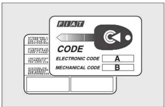
CODEcard
(for versions/markets, where provided)

Keep it in a safe place, not in the car. You should have the electronic code shown on the CODE card with you at all times.
SCHEDULEDSERVICING

Correct maintenance of the car is essential for ensuring that it maintains its performance and its safety features, its environmental friendliness and low running costs for a long time to come.
THEOWNERMANUALCONTAINS...

... important information, advice and warnings for correct use, driving safety and maintenance of your car over time. Special attention must be paid to the symbols provided (personal safety) (environmental protection) (car integrity).
GETTINGTOKNOWYOURCAR
DASHBOARD
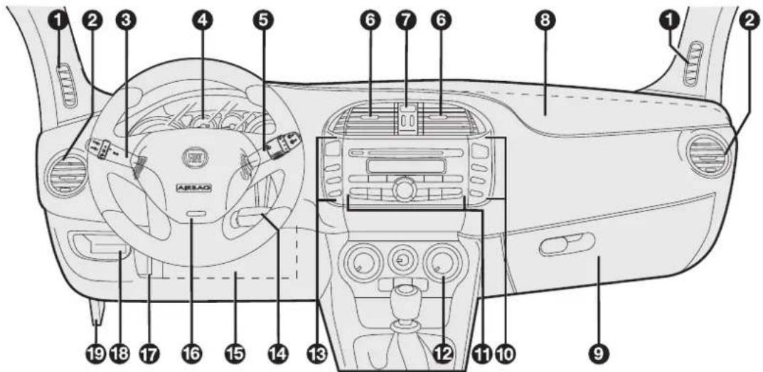
The presence and position of the controls, instruments and indicators may vary according to the different versions.
text_image
Diagram of car interior with numbered labels pointing to various components such as steering wheel, dashboard, and airbags.F0Q0639
fig. 1
F000639
1. Diffuser for directing air to the side windows - 2. Adjustable and directable air diffuser - 3. Exterior light control lever - 4. Instrument panel - 5. Windscreen wiper/rear window wiper/trip computer control lever - 6. Adjustable and dire air diffusers - 7. Hazard warning lights switch - 8. Passenger front airbag - 9. Glove compartment - 10. Fog lights/ fog lights and menu access/setting switch unit - 11. Radio controls - 12. Heating/ventilation/climate control system controls - 13. Electric power steering and ASR system (for versions/markets, where present)/front and rear parking sensors (for versions/markets, where present) on/off switch unit - 14. Ignition key and ignition switch - 15. Driver side front knee bag (for versions/markets, where provided) - 16. Driver front airbag - 17. Steering wheel locking lever 18. Fuse box access flap - 19. Bonnet release lever
CONTROLPANELAND INSTRUMENTS

text_image
A km/h B E F C H Lun 18 Giu 240 123456 km CITY 20°C 10:20 D x1000fig. 2
F0Q0909
A. Speedometer B. Fuel level gauge with reserve warning light C. Engine coolant temperature gauge with overheating warning light D. Rev counter E. Display
SPEEDOMETER
Shows the car speed (speedometer).
REVCOUNTER
This indicates the engine rpm.
When the engine is idling, the rev counter may indicate a gradual or sudden increase of the speed.
This behaviour is standard as it takes place during activation of the climate control system or the fan. It should not be considered as a fault. In these cases a slow change in revs is used to protect the battery charge.
IMPORTANT The electronic injection control system gradually shuts off the flow of fuel when the engine is “over-revving” resulting in a gradual loss of engine power.
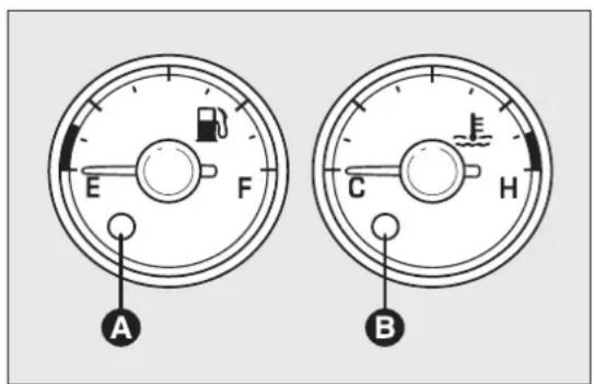
FUELLEVELGAUGE
This shows the amount of fuel left in the fuel tank. Warning light A fig. 3 comes on to indicate that approximately 8-10 litres of fuel are left in the tank E tank empty
F tank full (see the instructions provided in the "Refuelling the car" paragraph in this chapter).
Do not travel with the fuel tank almost empty: any gaps in fuel delivery could damage the catalytic converter.
IMPORTANT The needle will point to E and warni light A fig. 3 will flash to indicate a fault in the system. Contact a Fiat Dealership to have the syste checked.
text_image
E F A C H Bfig. 3
F0Q0608
ENGINECOOLANTTEMPERATURE INDICATOR
This shows the temperature of the engine coolant fluid and starts working when the fluid temperature exceeds approx. 50°C.
Under normal conditions, the needle assumes different positions within the scale depending on the usage conditions.
C Low engine coolant temperature
H High engine coolant temperature.
Warning light B fig. 3 may light up (and a message on the display may appear on certain versions) to indicate that the coolant fluid temperature is too high; in this case, stop the engine and contact a Fiat Dealership.

Iftheneedlefortheenginecoolant temperaturereachestheredarea,stop theengineimmediatelyandcontactaFiat
Dealership.
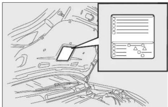
SYMBOLS
Some car components have coloured labels whose symbols indicate precautions to be observed when using this component.
A plate summarising these symbols fig. 4 can be found under the bonnet.
natural_image
Diagram of a car interior showing dashboard and dashboard panel, with an inset image of a vehicle's dashboard display (no text or symbols present)fig. 4
F0Q0640
THEFIATCODESYSTEM
To further protect your car from theft, it has been fitted with an engine immobilising system. It is automatically activated when the ignition key is removed.
There is an electronic device in each key which can identify the signal emitted, when the engine is started, from an aerial built into the ignition switch. The signal is the "password", different every time th vehicle is started, through which the control unit recognises the key and enables starting.
OPERATION
Each time the vehicle is started turning the ignition key to MAR-ON, the Fiat CODE system control unit sends an acknowledgement code to the engine control unit to deactivate the immobiliser. The code is sent only if the Fiat CODE system control unit has acknowledged the code received from the key.
Each time the ignition key is turned to STOP, the CODE system deactivates the functions of the engine management control unit.
If, during starting, the code is not correctly recognised, the warning light (or symbol on the display) switches on in the instrument panel.
In this case, turn the key to STOP and then to MAR-ON; if it is still locked, try again with the other keys that come with the vehicle. Contact a Fiat Dealership if you still cannot start the engine.
IMPORTANT Each key has its own code which must be stored by the system's control unit. To have new keys stored, up to a maximum number of eight keys, contact a Fiat Dealership and be ready to present all the keys you have in your possession, the CODE card, a personal identity document and the car ownership documents. The codes for keys not presented during the storing procedure will be deleted to ensure that any keys that are lost or stolen cannot be used to start the engine.

warninglight(orsymbolonthedisplay) whilstdriving
If the warning light (or symbol in the display) switches on, this means that the system is running self-diagnosis (caused, for example, by a voltage drop).
☐If the warning light (or symbol in the display) stays on, contact a Fiat dealership.

Theelectroniccomponentsinsidethekey maybedamagedifthekeyissubjected tostrongshocks.
THEKEYS
CODECARD
(for versions/markets, where provided)
A CODE card fig. 5 is provided together with the vehicle keys. This should be presented to a Fiat Dealership should you require any duplicate keys.
IMPORTANT In order to ensure complete efficiency of the electronic devices inside the keys, they should never be exposed to direct sunlight.

TheignitionkeyandtheCODEcardmust behandedovertothenewownerwhen sellingthecar.
KEYWITHOUTREMOTECONTROL
(for versions/markets, where provided)
The key is provided with a metal insert A fig. 6, which operates:
□the ignition switch
□the door lock
☐the fuel flap lock/release (on versions supplied with a lockable plug)
the safe lock device (deactivation only - for versions/markets, where provided).
To request duplicates of the key, go to a Fiat Dealership, taking an ID document and the car ownership documents.
text_image
FIAT CODE ELECTRONIC CODE A MECHANICAL CODE B ATTENUINIC SICUER, KAR L PER-LED BY MANUTENZION ATTENUINIC FOR TURBING, HAN PETER COUSE CAUTION/KEEP POTOMINATE PWR CODE USA ACQUISURE PER SHEMORUM SHEMORUM SHEMORUMfig. 5
F0Q0001
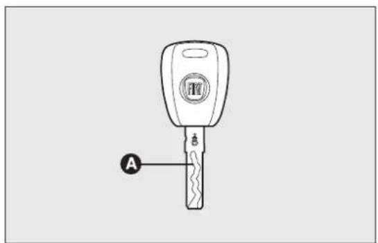
text_image
Afig. 6
F0Q0034
KEYWITHREMOTECONTROL
The key is provided with a metal insert A fig. 7, which operates:
□the ignition switch
□the door lock
□the fuel flap lock/unlock
☐the safe lock device (deactivation only - for versions/markets, where provided)
Pressing button B opens/closes metal insert A.
Button 🔒 remotely unlocks the doors and the tailgate.
Button 🔒 remotely locks the doors and the tailgate.
Button ≈ remotely opens the tailgate.
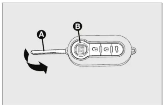
text_image
A Bfig. 7
F0Q0255

If the button for locking doors from the inside is accidentally pressed, only the doors opened forgetting out of the car arereleased;thetailgateremainslocked. For systemreset, pressthelock/releasebuttonsagain //.

WARNING
PressbuttonBfig.7onlywiththekey awayfromyourbody,specificallyfrom youreyesandfromobjectsswhichcouldget damaged(e.g.yourclothes).Donotleavethe keyunattendedtoavoidthebuttonbeing accidentallypressedwhileitisbeinghandled, e.g.byachild.
Unlockingthedoorsandthetailgate
Briefly press button for unlocking the doors and tailgate with the alarm being switched off at the same time (for versions/markets, where provided), timed switching-on of internal roof lights and double flashing of direction indicators (for versions/markets, where provided).
Pressing button for longer than 2 seconds: window opening.
Doors will be unlocked automatically if the fuel inertia cut-off switch is activated.
Lockingthedoorsandthetailgate
Briefly press button for locking the doors and tailgate with the alarm being switched on at the same time (for versions/markets, where provided), timed switching-off of internal roof lights and single flashing of direction indicators.
Pressing button for longer than 2 seconds: window closing. When the button is pressed twice quickly, the safe lock device is activated (for versions/markets, where provided) (see "Safe Lock Device" paragraph hereafter).
If one or more door are open, the doors will not locked. This is signalled by LED A fig. 8 in the cent panel and the direction indicators flashing rapidly. If the luggage compartment is open, the doors will, however, be locked.

text_image
MODE Afig. 8
Openingthetailgatebytheremotecontrol
Press button 🔒 to release (open) the tailgate remotely even with the alarm on (for versions/markets where provided).
The opening of the tailgate is signalled by the direction indicators flashing twice; when it is closed there is one flash (only with the alarm on).
If an alarm is fitted, when the tailgate is opened, the alarm system switches off the volume sensing protection and the perimeter sensor for the tailgate.
When the tailgate is closed again, the volume sensing of protection and perimeter sensor are restored.
LEDindicationsoncentralpanel
When locking the doors, LED A fig. 8 switches on for about 3 seconds and then starts flashing (deterrence function).
If one of the doors or the tailgate are not properly shut when the doors are being locked, the LED flashes quickly together with the direction indicators.
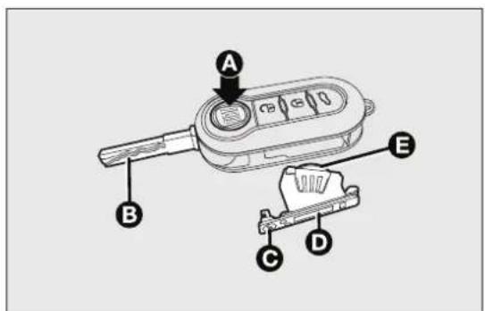
REPLACINGTHEBATTERYINTHEKEY WITHREMOTECONTROL
To replace the battery, proceed as follows fig. 9:
☐press button A and open the metal insert B;
□turn screw C to using a fine bit screwdriver;
☐take out the battery case D and replace the battery E making sure that polarities are correct;
□refit the battery case D inside the key and lock it turning the screw C to.
REQUESTFORADDITIONALREMOTE CONTROLS
The system can recognise up to 8 remote controls. Should a new remote control be necessary, contact Fiat Dealership, taking with you the CODE card, an ID document and the car ownership documents.

Usedbatteriesareharmfultothe environment. Youcand disposeofthem eitherinthecorrectcontainersas
specifiedbylaworbytakingthemtoaFiat Dealership,whichwilldealwiththeirdisposal.
REPLACING THEREMOTECONTROL COVER
Proceed as shown in figure fig. 10 to replace the remove control cover.
text_image
Diagram of a device with labeled parts A, B, C, D, and E pointing to a central display or control panel.fig. 9
F0Q0256
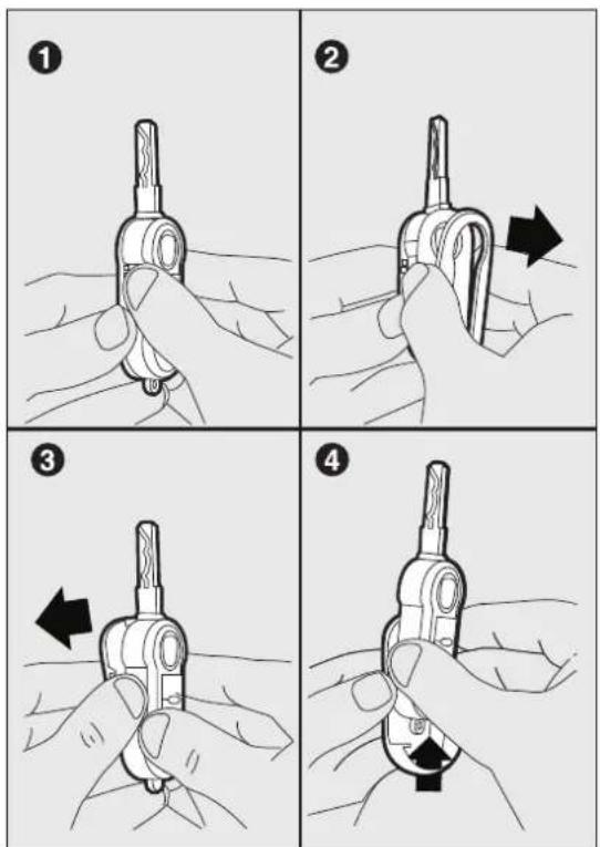
fig. 10
F0Q0257
SAFELOCKDEVICE
(for versions/markets, where provided)
This safety device inhibits the operation of:
□interior handles;
☐door locking/unlocking button on the central trim fig. 11;
thereby preventing the opening of the doors from inside the passenger compartment if there has been a break in attempt (e.g. a window has been broken).
The safe lock device therefore offers the best possible protection against break-in attempts. We recommend engaging it whenever the vehicle is parked and left unattended.

text_image
Diagram of car interior control panel with directional buttons and a black arrow pointing to the mode buttonfig. 11
F0Q0641

WARNING
If the key with remote control battery is flat, the system can be engaged by using themetal insert in the door catch as described previously: in this case, the device only remains active for thereard oors.

WARNING
Oncethesafelocksystemisengaged, it isimpossibletoopentedoorsfrom insidethecar. Therefore, beforegettingout of thecarchekthatthereisnooneleftonboard.
Deviceactivation
The system is automatically enabled on all the door by pressing button twice on the key with remote control.
Device activation is indicated by 3 flashes of the direction indicators and a flash of the LED on the door locking button on the dashboard.
If one or more of the doors is not closed correctly, the dead lock device will not activate, thus preventing a person from getting stuck inside the passenger compartment by entering the car through, and then closing, the open door.
Devidedeactivation
The system is disabled automatically on every door
□unlocking the doors;
☐ by turning the ignition key to the MAR-ON position.
ALARM
(for versions/markets, where provided)
The alarm, in addition to all the remote control functions described previously, is controlled by the receiver located under the dashboard near the fuse box.
ALARMACTIVATION
The alarm intervenes in the following instances:
□when a door, the bonnet or the tailgate is opened illegally (perimeter protection);
□when the ignition system is started up (ignition key turned to MAR-ON);
□cutting of the battery leads;
□movement inside the passenger compartment (volume sensing protection);
☐anomalous lifting/tilting of the vehicle.
Depending on the market, the activation of the alarm causes the activation of the siren and the direction indicators (for about 26 seconds). Alarm tripping and the number of cycles depend on the sales market.
There is a maximum number of acoustic/visual cycle. When this is reached the system returns to normal operation.
The volume sensing and anti-lift protection can be excluded by adjusting the dedicated control on the front roof light (see “Volume sensing/Anti-lift protection”).
IMPORTANT The engine stop function is guaranteed by the Fiat CODE which is automatically activated when the key is extracted from the ignition switch.
TURNINGTHEALARMON
With the doors, bonnet and tailgate closed and the ignition key either turned to STOP or removed, point the key with remote control towards the vehicle and press and release button.
Excluding some markets, the system produces an acoustic signal (beep) and enables door locking.
The switching on of the alarm is preceded by a self-diagnosis stage: if a fault is detected, the system emits a new acoustic signal together with the display of a message (see "Warning lights and messages" chapter).
In this case switch off the alarm by pressing check that all the doors, bonnet and tailgate are closed correctly; then switch the alarm back on by pressing the button.
If a door, the bonnet and the tailgate are not properly shut, they will be excluded from the check by the alarm system.
If the alarm emits an acoustic signal even when the doors, bonnet and tailgate are correctly closed, a failure has occurred in system operation. Go to a Fiat Dealership.
IMPORTANT The alarm does not come on when the central locking is activated using the metal insert in the key.
IMPORTANT The alarm is adapted to meet requirements in various countries.
TURNINGTHEALARMOFF
Press button on the key with remote control.
The following operations are performed (excluding some versions for specific markets):
☐direction indicators flash twice;
☐there are two short acoustic signals (beeps);
☐doors are unlocked.
IMPORTANT The alarm does not switch off when the central opening is activated using the metal insert in the key.
VOLUMESENSING/ANTI-LIFT PROTECTION
To guarantee the correct operation of the protection system it is advisable to shut all the side windows and the sun roof (for versions/markets, where provided).
If necessary, the function can be turned off (if, for example, you are leaving an animal in the car) by pressing button A fig. 12, located in the front roof light, before activating the alarm itself.
When the function is disabled, this is indicated by the LED on the button flashing for several seconds. Any disabling of the volume sensing/anti-lift protection must be repeated each time the instrument panel is switched off.
BREAK-INATTEMPTINDICATION
Any break-in attempt is indicated by the warning light (or symbol in the display) lighting up, together with a message shown in the display (see “Warning lights and messages” chapter).
DISABLINGTHEALARM
To turn the alarm off completely (for example, if the vehicle is not being used for a long time), the vehicle must be closed by turning the metal insert of the key with remote control in the lock.
IMPORTANT If the batteries of the key with remote control run out or the system fails, the alarm can be switched off by placing the key in the ignition switch and turning it to MAR-ON.

text_image
SOS NAV Afig. 12
F0Q0752
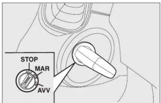
IGNITIONSWITCH
The key can be turned to 3 different positionsfig.
☐STOP: engine off, key can be removed, steering column locked. Some electrical devices (e.g. radio, central door locking system, electronic alarm, etc.) are enabled.
☐MAR-ON: driving position. All electrical devices are enabled.
□AVV: engine start-up.
The ignition switch is fitted with a safety system that requires the ignition key to be turned back to STOP if the engine does not start, before the starting operation can be repeated.

WARNING
Iftheignitionswitchistamperedwith (e.g.attemptedtheft),haveitchecked
overbyaFiatDealershipbeforedrivingagain.

WARNING
Alwaysremovethekeywhenyouleave yourcartopreventsomeonefrom accidentallyoperatingthecontrols.Remember toengagethehandbrake.Ifthecarisparkedon uphillslope,engagethefirstgear;ifthecaris facingdownhill,engagethereversegear.Never leavechildrenunattendedinthecar.
STEERINGLOCK
3Engagement
When at STOP, remove the key and turn the steering wheel until it locks.
Disengagement
Move the steering wheel slightly as you turn the ignition key to MAR-ON.
IMPORTANT In some parking conditions (e.g.: at wheels turned) the effort required to move the steering wheel and disengage the steering lock may be increased.
text_image
STOP MAR AVVfig. 13

WARNING
Itisabsolutelyforbiddentocarryout anyaftermarketoperationinvolving steeringsystemorsteeringcolumn modifications(e.g.:installationofanti-theft device)thatcouldbadlyaffectperformanceand safety,invalidatethewarrantyandalsoresult innon-complianceofthecarwithtype-approvalrequirements.

WARNING
Neverremovethekeywhilethecaris moving. Thesteeringwheelwilllock as soonasitisturned. Thisholdstrueforcars beingtowedaswell.
DISPLAY
The car is equipped with a multifunction display that according to the previously applied settings, will show useful driving information.
When one of the front doors is opened, the display is activated, showing the time and mileage for a few seconds.
NoteWith a low outside temperature (below 0^ C) it may take longer than normal for information to appear on the display.
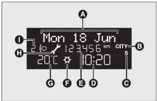
MULTIFUNCTIONDISPLAY"STANDARD" SCREEN
The standard screen fig. 14 can display the following information:
A Date
B Possible Dualdrive electric power steering engagement
C Sport driving mode indication (for versions/markets, where provided)
D Time
E Milometer (display of distance travelled in kilometres/miles)
F Possible ice on the road indication
G Outside temperature
H Scheduled servicing interval
I Headlight alignment position (only with dipped headlights on)
text_image
Mon 18 Jun 20°C 123456 km CITY B H 10:20 S G F E D Cfig. 14
F0Q3245
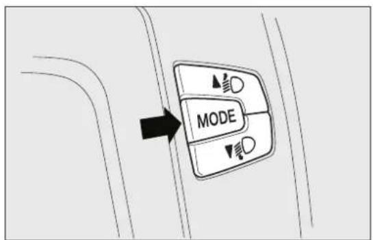
CONTROLBUTTONS
▲ fig.15: to scroll through the screen and the options upwards or to increase the value displayed.
MODE: press briefly to access the menu and/or go to next screen or confirm the desired selection. Hold down to go back to the standard screen.
▼: to scroll through the screen and the options downwards or to decrease the value displayed.
IMPORTANT The▲ and▼ buttons activate different functions according to the following situations:
□within the menu, they allow you to scroll up and down through the options;
□during settings operations, they increase or decrease values.
text_image
MODEfig. 15
F0Q0643
IMPORTANT When one of the front doors is opened, the display is activated, showing the time and mileage for a few seconds.
SETUPMENU
The menu comprises a series of functions which can be selected using the ▲ and ▼buttons to access the different selection and setting (setup) operations indicated below.
Some options have a submenu.
The Setup Menu can be activated by pressing the MODE button briefly.
If the Radionavigator is installed, only the following functions can be adjusted/set from the instrument panel: "Lighting", "Speed beep", "Headlight sensor" (for versions/markets, where provided), "Belt buzzer" and "Passenger airbag". The other functions are shown on the Radionavigator display. You can set an adjust them there.
The menu comprises the following options:
LIGHTING
□SPEED BEEP
☐HEADLIGHT SENSOR (for versions/markets, where provided)
□TRIP B ACTIVATION/DATA
SET TIME
SET DATE
☐FIRST PAGE (for versions/markets, where provided)
□SEE RADIO
□AUTOCLOSE
□UNITS OF MEASUREMENT
□LANGUAGE
□WARNINGS VOLUME
☐BUTTON VOLUME
□SEAT BELT BEEP/BUZZ.
□SERVICE
□AIRBAG/PASSENGER BAG
☐CORNERING LIGHTS (for versions/markets, where provided)
□EXIT MENU
Selectinganoptionfromthemainmenu withoutasubmenu:
briefly press the MODE button to select the main menu option that needs to be changed;
□press buttons ▲or ▼(with single presses) to select the new setting;
briefly press the MODE button to store the new setting and at the same time go back to the previously selected menu option.
Selectinganoptionfromthemainmenuwith asubmenu:
□briefly press the MODE button to display the first submenu option;
□press buttons ▲ or ▼ with single presses) to scroll through all the submenu options;
□briefly press the MODE button to select the displayed submenu option and to open the relevant settings menu;
□press buttons ▲ or ▼ with single presses) to select the new setting for this submenu option;
□briefly press the MODE button to store the new setting and at the same time go back to the previously selected submenu option.
MENUITEMS
Lighting(Interiorlightadjustment)
With the side lights on, this function is used to set the brightness of the instrument panel, radio controls and dual zone automatic climate control system controls (for versions/markets where provided) to 8 levels.
Proceed as follows to adjust the brightness:
□briefly press the MODE button: the previously set level flashes on the display;
□press button ▲ or ▼ to set the required brightness level;
□briefly press the MODE button to return to the menu screen or hold the button down to return to the standard screen without storing.
SpeedBeep(Speedlimit)
This function is used to set the car speed limit (km/h or mph); the driver is immediately alerted when this limit is exceeded (see section "Warning lights and messages").
To set the desired speed limit, proceed as follows:
☐press the MODE button briefly, the display shows the dedicated message;
□press the ▲or ▼utton to select speed limit activation (On) or deactivation (Off);
☐if the function has been activated (On), press the ▲or ▼buttons to select the desired speed limit and then press MODE to confirm.
IMPORTANT Setting is possible between 30 and 20 km/h, or 20 and 125 mph, according to the previously set unit. See the "Units of measurement adjustment (Units of measurement)" paragraph described below. The setting will increase/decrease by 5 units each time button/▼s pressed. Hold down the ▲ button to automatically increase/decrease the setting rapidly. Complete the adjustment with single presses of the button when you approach the desired value.
Briefly press the MODE button to return to the menu screen or hold the button down to return to the standard screen without storing.
To cancel the setting, proceed as follows:
□briefly press button MODE, (On) will flash on the display;
□press button ▼, (Off) will flash on the display;
☐ press the MODE button briefly to return to the menu screen or hold the button down to return to the standard screen without storing.
Headlightsensor(Automaticheadlight/dusk sensorsensitivity adjustment)
(for versions/markets, where provided)
This function is used to turn the headlights on or according to external lighting conditions.
The headlight sensor sensitivity can be adjusted according to 3 levels (level 1 = minimum sensitivity, level 2 = average sensitivity, level 3 = maximum sensitivity). The higher the sensitivity set, the lesser is the external light variation needed to switch
The lights on (e.g. with a setting on level 3 at suns the headlights come on in advance in relation to levels 1 and 2).
Proceed as follows to set the desired adjustment:
□briefly press the MODE button: the previously set level flashes on the display;
□press ▲ or ▼o make your choice;
☐press the MODE button briefly to return to the menu screen or hold the button down to return to the standard screen without storing.
Corneringlights(Activation/deactivation of "Corneringlights")
(foglightwithcorneringfunction)
(for versions/markets where provided)
This function activates/deactivates the cornering lights.
To activate/deactivate (On/Off) the lights, proceed follows:
☐press the MODE button briefly, the display will show "On" or "Off" flashing depending on the previous setting;
□press ▲ or ▼ to make your choice;
briefly press the MODE button to return to the menu screen or hold the button down to return to the standard screen without storing.
Activation/TripBdata(ActivatingTripB)
This function can be used to activate (On) or deactivate (Off) the Trip B display (partial trip). For further information see “Trip computer” in this section.
Proceed as follows to switch the function on/off:
□briefly press the MODE button: On or Off flashes on the display (according to the previous setting);
□press ▲or ▼o make your choice;
□briefly press the MODE button to return to the menu screen or hold the button down to return to the standard screen without storing.
Timeadjustment(Clockadjustment)
This function enables to set the clock through two submenus: "Time" and "Format".
To carry out the adjustment, proceed as follows:
□briefly press the MODE button and two submenus, "Time" and "Format", are displayed;
□press the ▲ or ▼utton to switch between the two submenus;
Once you have selected the submenu to be changed, press the MODE button briefly;
□when you select "Time", briefly pressing the MODE button makes the hours flash on the display;
□press the ▲ or ▼utton to make the adjustment;
□briefly press the MODE button: "minutes" starts flashing on the display;
□press the button ▲ or ▼or setting.
IMPORTANT The setting will increase or decrease by one unit each time the buttonor is pressed.
Hold down the button to increase/decrease the
setting rapidly and automatically. Complete the adjustment with single presses of the button when you approach the desired value.
If you enter the "Format" submenu, pressing the MODE button briefly makes the display format flash on the display;
□Press button ▲ or ▼ to select "24h" or "12h".
□when you have made the adjustment, briefly press the MODE button to go back to the submenu screen or hold the button down to go back to the main menu screen without storing.
☐hold down the MODE button again to return to the standard screen or to the main menu according to where you are in the menu.
When you have made the adjustment, briefly press the MODE button to go back to the submenu screen or hold the button down to go back to the main menu screen without storing.
Setdate(Settingthedate)
Using this function it is possible to update the date (day - month - year).
Proceed as follows to start the update:
□briefly press the SET button: the "year" will flash on the display;
□press the ▲ or ▼utton to make the adjustment;
briefly press the SET button: the "month" will flash on the display;
□press the ▲ or ▼utton to make the adjustment;
□briefly press the SET button: the "day" will flash the display;
□press the button ▲ or ▼or setting.
IMPORTANT The setting will increase or decrease by one unit each time the buttonor is pressed. Hold down the button to increase/decrease the setting rapidly and automatically. Complete the adjustment with single presses of the button when you approach the desired value.
Briefly press the MODE button to return to the menu screen or hold the button down to return to the standard screen without storing.
Firstpage(displayofinformationonthemain screen)
(for versions/markets, where provided)
This function allows you to choose the information you would like to display on the main screen.
You can choose to display the date or the turbocharger boost pressure.
To make your choice, proceed as follows:
briefly press the MODE button: "First page" will appear on the display;
□briefly press the MODE button again to display the "Date" and "Engine info" options;
□press ▲or ▼ to select the information you wish to see on the main page of the display;
☐ press the MODE button briefly to return to the menu screen or hold the button down to return to the standard screen without storing.
When the key is turned to MAR-ON and the initial check stage is over, the display will show the information set previously via the "First page" menu function.
Seeradio(Audioinformationdisplay)
With this function the display shows information about the sound system.
☐Radio: selected radio station frequency or RDS message, automatic tuning activation or AutoSTore;
☐Audio CD, MP3 CDs: track number;
☐CD Changer: CD number and track number;
To show the radio information on the display (On) or clear it (Off), proceed as follows:
briefly press the MODE button, the display will show "On" or "Off" flashing depending on the previous setting;
□press ▲or ▼o make your choice;
□briefly press the MODE button to return to the menu screen or hold the button down to return to the standard screen without storing.
Autoclose(Automaticcentrallockingwith thecarinmotion)
When activated (On), this function locks the doors automatically when the vehicle speed exceeds 20 km/h.
Proceed as follows to activate or deactivate this function:
□briefly press the MODE button to display a submenu;
briefly press the MODE button: "On" or "Off" flashes on the display according to the previous setting;
□press ▲ or ▼o make your choice;
☐press the MODE button briefly to return to the submenu screen or hold the button down to return to the main menu screen without storing;
☐hold down the MODE button again to return to the standard screen or to the main menu according to where you are in the menu.
Unitofmeasurement(Settingtheunitof measurement)
With this function it is possible to set the units through three submenus: "Distances",
"Consumption" and "Temperature". To set the desired unit, proceed as follows:
□briefly press the MODE button to display the three submenus;
□press button ▲ or ▼o navigate through the three submenus;
Once you have selected the submenu to be changed, press the MODE button briefly;
☐when you select the "Distances" submenu, briefly pressing the MODE button makes the display show "km" or "mi" depending on the previous setting;
□press or to▼make your choice;
□when you select the "Consumption" submenu, pressing the MODE button makes "km/l", "l/100 km" or "mpg" appear on the display depending on the previous setting;
If the set distance unit is "km", the fuel consumption unit will be displayed in km/l or l/100 km.
If the set distance unit is "mi" the fuel consumption unit will be displayed in "mpg".
□press ▲ or ▼ to make your choice;
□when you enter the "Temperature" submenu, briefly pressing the MODE button makes "°C" or "°F" appear on the display depending on the previous setting;
□press ▲ or ▼o make your choice;
When you have made the adjustment, briefly press the MODE button to go back to the submenu screen or hold the button down to go back to the main menu screen without storing.
Hold down the MODE button again to return to t standard screen or to the main menu according to where you are in the menu.
Language(Languageselection)
Display messages can be shown in different languages: Italian, German, English, Spanish, French, Portuguese and Dutch.
To set the desired language, proceed as follows:
briefly press the MODE button: the previously set language starts flashing on the display;
□press ▲ or ▼o make your choice;
□briefly press the MODE button to return to the menu screen or hold the button down to return to the standard screen without storing.
Warningsvolume(Adjustingthefailure/warningacousticsignalvolume)
With this function the volume of the buzzer which accompanies the display of any failure/warning can be adjusted to 8 levels.
To set the desired volume, proceed as follows:
☐ press the MODE button briefly, making the display flash the previously set volume "level";
□press the ▲or ▼utton to make the adjustment;
□briefly press the MODE button to return to the menu screen or hold the button down to return to the standard screen without storing.
Buttonvolume(adjustingthebuttonvolume)
This function allows the volume of the acoustic signal that accompanies MODE _▲ and button presses to 8 levels
To set the desired volume, proceed as follows:
☐ press the MODE button briefly, making the display flash the previously set volume "level";
□press the ▲ or ▼utton to make the adjustment;
☐press the MODE button briefly to return to the menu screen or hold the button down to return to the standard screen without storing.
Seatbeltbuzzer(BuzzeractivationforSBR indication)
This function can be displayed only after a Fiat Dealership has deactivated the SBR system (see the "Safety" section in the "SBR system" paragraph).
To reactivate this function, proceed as follows:
□briefly press the MODE button, the display shows "Off" flashing. Press the ▲ or ▼button and "On" will appear;
□briefly press the MODE button to return to the submenu screen or hold the button down to return to the main menu screen without storing.
Service(Scheduledservicing)
This function allows you to display the information about km/mileage intervals or, for versions/markets, where provided, time intervals for car servicing. To consult this information, proceed as follows:
briefly press the MODE button: the display shows when servicing is due in km/mi or days (where provided) or mi or days (where provided) according to the previous setting (see paragraph "Units of measurement");
□briefly press the MODE button to go back to the menu screen or hold the button down to go back to the standard screen.
Note The “Scheduled Servicing Plan” includes car maintenance at fixed intervals (refer to the "Maintenance and care" chapter). This is displayed automatically, with ignition key at MAR-ON, 2000 km (or equivalent value in miles) before servicing or, where provided, 30 days before servicing. It is also displayed each time the key is turned to MAR-ON or, for versions/markets, where provided, every 200 km (or equivalent value in miles). Below this threshold servicing indications are more frequent. The display will be in km or miles according to the unit of measurement set. When the following scheduled servicing is approaching, the word “Service” will appear on the display, followed by the number of kilometres/miles or days (where provided) left, when the key is turned to MAR-ON. Go to a Fiat Dealership, where the "Scheduled Servicing Plan" operations will be performed and the message will be reset.
When the service interval is reached and for about 1000 km/600 mi or 30 days, a service due message is displayed.
Airbag/Passengerbag
This function is used to activate/deactivate the passenger side airbag.
Proceed as follows:
□press the MODE button and, after the message "Bag pass: Off" (to deactivate) or "Bag pass: On" (to activate) is displayed by pressing the and buttons, press the MODE button again;
☐a confirmation request message will appear on the display;
□by pressing the▲or▼buttons, select ("Yes") (to confirm activation/deactivation) or ("No") (to cancel);
☐press the MODE button briefly and a message confirming the selection will be displayed, then you will return to the menu screen, or hold the button down to return to the standard screen without storing.
Exitmenu
The last function closing the cycle of settings listed the menu screen.
Press the MODE button briefly to return to the standard screen without storing.
Press the▼button to go back to the first menu option ("Speed Beep").
TRIPCOMPUTER
Generalinformation
The Trip computer is used to display information on This indicates the approximate distance which can be car operation when the key is turned to MAR-ON. travelled with the amount of fuel present in the Two separate trips, called "Trip A" and "Trip B", tank. "----" will appear on the display in the are provided to monitor the entire mission (journey) following cases:
in a reciprocally independent manner.
Both functions can be reset (reset - start of a new journey).
"Trip A" is used to display the figures relating to:
□Range
□Distance covered
□Average consumption
□Instantaneous consumption
□Average speed
☐Trip time (driving time).
"Trip B" is used to display the figures relating to:
☐Distance travelled B
□Average consumption B
□Average speed B
☐Trip time B (driving time).
NoteThe "Trip B" function may be disabled (see "Activating Trip B"). The "Range" and "Instant consumption" parameters cannot be reset.
Valuesdisplayed
Range
This indicates the approximate distance which can be travelled with the amount of fuel present in the tank. “- - - -” will appear on the display in the following cases:
☐range value lower than 50 km (or 30 mi)
☐car parked with engine running for an extended period.
IMPORTANT The range value variation can be affected by several factors: driving style, type of route (motorway, urban, mountain roads, etc.), conditions of use (load, tyre pressures, etc.). Trip planning must therefore take the above into account.
Distancecovered
Shows the distance covered since the start of the new journey.
Averageconsumption
Shows the approximate average fuel consumption since the start of the new journey.
Instantaneous consumption
This indicates the fuel consumption. The value is constantly updated. The display will show “----” if the car is parked with the engine running.
Averagespeed
This shows the average car speed as a function of overall time elapsed since the start of the new journey.
Triptime
The time elapsed since the start of a new journey.
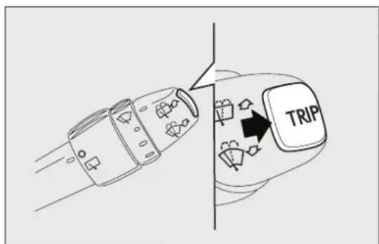
TRIPBUTTON
The TRIP button is located on the right hand stalkfig. 16. With the ignition key turned to MAR-ON, this button allows you to view the previously described parameters and also zero them to begin a new mission:
□short press: display various values;
□long press: reset values and start a new journey.
text_image
TRIPfig. 16
F0Q0647
Newmission
this begins after a reset:
☐“manual” resetting by the user, by pressing the relevant button;
□automatically when the distance travelled reaches 99,999.9 km or when the journey time reaches 99.59 (99 hours and 59 minutes);
□after disconnection/reconnection of the battery.
IMPORTANT The reset operation when "Trip A" of "Trip B" details are being displayed only resets the values associated with the function displayed.
Startofjourneyprocedure
With ignition key at MAR, press and hold down the TRIP button for more than 2 seconds to reset.
ExitingtheTripFunction
You can automatically exit the TRIP function once the values have been displayed or by holding the MODE button down for more than 1 second.
SEATS
FRONTSEATSWITHMANUAL ADJUSTMENT
Longitudinaladjustmentfig.17
Lift lever A (on the seat internal side) and push the seat forwards or backwards: in driving position your arms should rest on the rim of the steering wheel.
Heightadjustmentfig.17
Move lever B upwards or downwards to achieve the required height.
IMPORTANT Adjustment must be carried out only when seated in the relevant seat.
Backrestangleadjustmentfig.17
Turn knob C.
Lumbaradjustmentfig.17
(for versions/markets, where provided)
The position of the back against the seat backrest can be adjusted by turning knob D.

Alladjustmentsmustbemadewiththe carstationary.

text_image
Diagram of car interior showing labeled parts A, B, C, and D with directional arrows indicating movement or flow.fig. 17
F0Q0654

Thefabricupholsteryofyourcarhas beendesignedtowithstandwearderiving fromcommonuseofthecar.Youare
howeverrecommendedtoavoidstrongand/or continuoussscratchingwithclothingaccessories suchasmetalbuckles, studs, Velcrofasteningsand thelike, astheseitemscausestressofthecover fabricthatcouldleadtoyarnbreakingand damagetheupholstery.

Onceyouhavereleasedtheadjustment lever,alwayscheckthattheseatislocked ontheguidesbytryingtomoveitback
andforth. If theseatisnotlockedintoplace, it mayunexpectedlyslideandcausethedriver tolosecontrolofthecar.
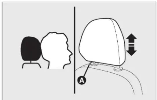
HEADRESTRAINTS
FRONT
These are height-adjustable and lock into place automatically.
☐Upward adjustment: lift the head restraint until it clicks into place.
☐Downward adjustment: press button A fig. 18 and lower the head restraint.
On some versions the front head restraints are equipped with an “Anti-Whiplash” device, which reduces the distance between head and head restraint in the event of a rear shunt, thus mitigating the “whiplash” effect.
The “Anti-Whiplash” type front head restraints may move when the backrest is pressed by the occupan torso or hand. This behaviour is caused by the system and should not be considered a malfunction.
text_image
Diagram illustrating head and neck positioning with labeled anatomical features and directional arrowsfig. 18
F0Q0655

WARNING
Headrestraintsmustbeadjustedsothat thehead,ratherthantheneck,restson them.Onlywhentheyareadjustedinthis mannercantheyservetheirintendedpurpose.

WARNING
Totakebestadvantageoftheprotection providedbytheheadrestraint,adjust theseatbackrestsothatyouaresittingup straightandyourheadisasclosetothehead restraintaspossible.
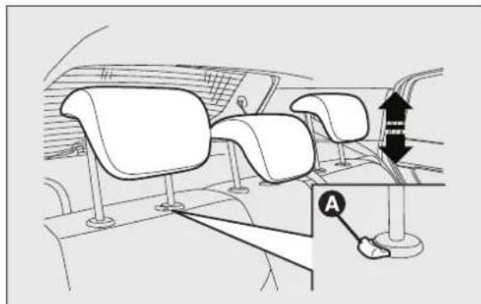
REAR
The car is equipped with two head restraints for the side seats and on some versions a head restraint is also provided for the central seat.
To extract the head restraints, raise them until you hear the click (which indicates they are in the position of use, 'fully raised').
To bring them back to the position of non-use, press button A fig. 19 and push them down into the backrest.
IMPORTANT If the rear seats are used, always set the head restraints in the "fully raised" position.
natural_image
Interior view of a car dashboard with seatbelt and steering wheel (no text or symbols)fig. 19
F0Q0656
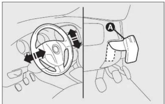
STEERINGWHEEL
It can be adjusted both axially and vertically.
Release the lever A fig. 20 pulling it towards the steering wheel, then adjust it in the most suitable position and lock it pushing the lever A fully forwards.

WARNING
Itisabsolutelyforbiddentocarryout anyaftermarketoperationinvolving
steeringsystemorsteeringcolumn modifications(e.g.installationofanti-theft device)thatcouldbadlyaffectperformance and safety,invalidatethewarrantyandalsoresult inthecarnotmeetingtype-approval requirements.
text_image
Diagram showing car steering wheel and belt switch with directional arrows and labeled component Afig. 20
F0Q0657

WARNING
Alladjustmentsmustbecarriedoutonly withthevehiclestationaryandengine
off.
REARVIEWMIRRORS
INTERNALMIRROR
The mirror is fitted with a safety device that causes its release in the event of a violent impact with the passenger.
Lever A fig. 21 can be used to move the mirror to two different positions: normal or antiglare.
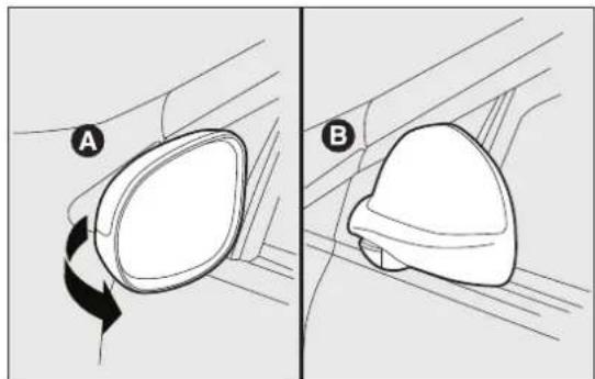
DOORMIRRORS
Mirrormanualfolding
If necessary (for example when the mirror causes difficulty in narrow spaces), it is possible to fold the mirrors by moving them from position A fig. 22 to position B.

Whendriving, thesemirrorsmustalways beinpositionA.

Asthedriver'sdoormirroriscurved, it mayslightlyaltertheperceptionof distance.

natural_image
Simple line drawing of a car front mirror with a labeled point A (no text or symbols on the mirror itself)fig. 21
F0Q0659
natural_image
Diagram showing two views (A and B) of a mechanical component with rotational motion, no text or symbols present.fig. 22
F0Q0658
Electricadjustment
You can adjust the door mirrors only when the ignition key is turned to MAR-ON.
Proceed as follows:
☐use selector A fig. 23 to select the mirror (left or right) to be adjusted;
□adjust the mirror using joystick B in the four directions.
Mirroelectricfolding
(for versions/markets, where provided)
You can fold the door mirrors only when the ignit key is turned to MAR-ON.
Proceed as follows:
□position selector A fig. 24 in neutral position (no mirror selection);
☐fold the mirror using joystick B in the side directions fig. 24;
□press joystick B again to restore the mirrors to driving position.

text_image
Diagram of car interior with labeled buttons and directional indicators, showing two labeled points A and B.fig. 23
F0Q0623
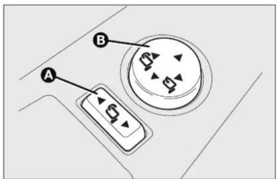
text_image
A Bfig. 24
F0Q0425
CLIMATECONTROL/HEATINGSYSTEM

text_image
Diagram of car interior with numbered parts indicating traffic flow or seatbelting, showing dashboard and steering wheel layout.fig. 25
F0Q0668
1. Fixed upper diffuser for windscreen defrosting or demisting - 2. Adjustable central diffuser - 3. Fixed diffusers for side window defrosting or demisting - 4. Adjustable and directable side diffusers - 5. Lower diffusers - 6. Directable and adjustable rear vent - 7. Fixed rear diffusers for footwell.
DIFFUSERS
ADJUSTABLESIDEVENTSANDDIFFUSERS
A Fixed diffuser for side window fig. 26.

text_image
Afig. 26
F0Q0626
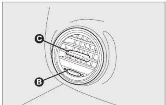
text_image
Diagram of a mechanical component with labeled parts C and B, showing internal structure and motion path.fig. 27
F0Q0625
B Air flow adjustment control fig. 27:
● = Fully closed
_o = Fully open.
C Lateral and vertical air flow adjustment control. fig. 27
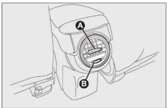
CENTRALDIFFUSERS
A Lateral and vertical air flow adjustment controls fig. 28.
B Air flow adjustment controls fig. 28:
● = Fully closed
_o = Fully open.

text_image
B Afig. 28
F0Q0627
REARDIFFUSER
(for versions/markets, where provided)
A Lateral and vertical air flow adjustment controls fig. 29.
B Air flow adjustment control fig. 29:
● = Fully closed
= Fully open.
On some versions, a storage compartment is fitted instead of the rear diffuser.
text_image
Technical diagram of a mechanical component with labeled parts A and B, showing internal structure and assembly.fig. 29
F0Q0750
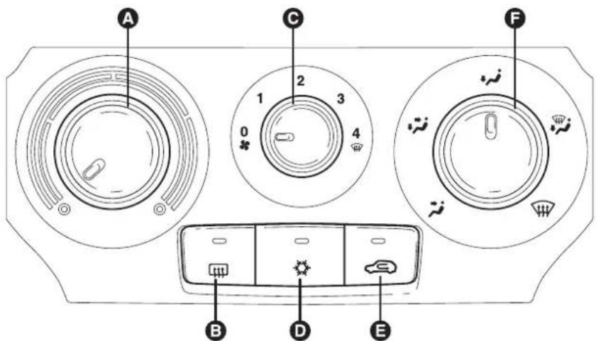
HEATINGANDVENTILATION
CONTROLS
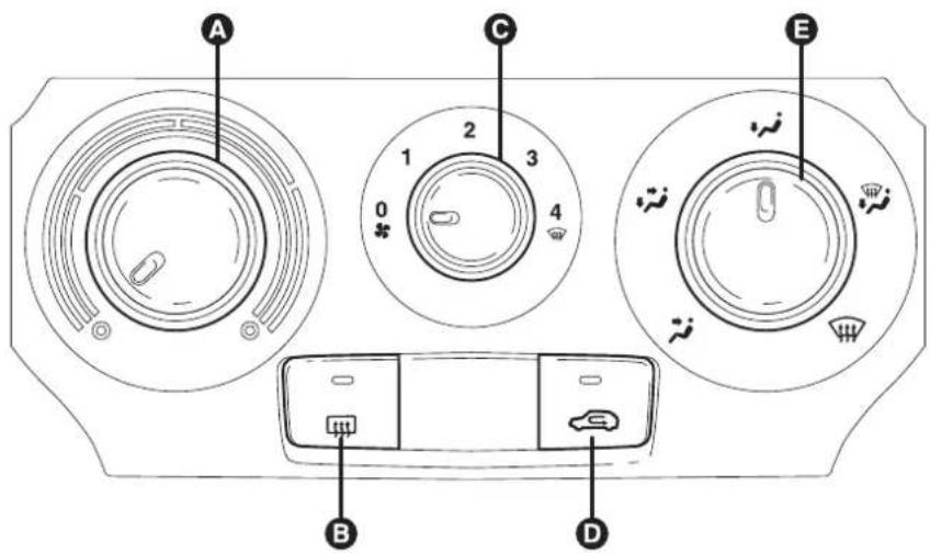
text_image
A C E 1 2 3 4 0 B Dfig. 30
F0Q0609
A air temperature adjustment knob (hot/cold air mixing)
B heated rear window on/off button
C fan activation knob
D internal air recirculation on/off button
E air distribution knob.
PASSENGERCOMPARTMENTHEATING
Proceed as follows:
□turn knob A to the red section;
□turn knob C to the required speed;
□turn knob E to:
to warm the feet and demist the windscreen at the same time
to warm the feet and keep the face cool (bi-level function)
to warm the feet of those in the front and rear seats
☐to turn off internal air recirculation (LED on button ☐ off).
FASTFRONTWINDOWDEMISTING/DEFROSTING
Proceed as follows:
□turn knob A fully to the right;
□turn knob C to;
□turn knob E to;
□turn off internal air recirculation (LED on button off).
After demisting/defrosting, operate the controls to maintain optimum visibility conditions.
Windowdemisting
In the event of considerable external moisture and/or rain and/or large differences in temperature inside and outside the passenger compartment, perform the following preventive window demisting procedure:
☐to turn off internal air recirculation (LED on button ☐ off);
□turn knob A to the red section;
return knob C to the second speed level;
□turn knob E to or to there is no sign of the windows steaming up.
HEATEDREARWINDOWANDDOOR MIRRORSDEMISTING/DEFROSTING
Press button to activate this function; when this function is activated, the button LED lights up.
This function is timed and will deactivate automatically after 20 minutes. Press the button again to switch the function off in advance.
IMPORTANT Do not apply stickers on the inside of the rear window over the heating filaments to avoid damage.
FANSPEEDADJUSTMENT
To ventilate the passenger compartment properly, proceed as follows:
☐fully open the central and side air diffusers;
□turn knob A to the blue section;
□turn knob C to the required speed;
□turn knob E to;
□turn off internal air recirculation (LED on button off).
INTERNALAIRRECIRCULATION ACTIVATION
Press button 📄: when the function is on, the button LED lights up. It is advisable to switch the internal air recirculation on while standing in queues or in tunnels to prevent the introduction of polluted air. However, it is better not to use the function for long periods, particularly if there are many people on board, to prevent the windows from misting.
IMPORTANT Internal air recirculation makes it possible to reach the required heating or cooling conditions more quickly depending on the mode selected. Do not use the internal air recirculation function on rainy/cold days as it would considerably increase the possibility of the windows misting.
ADDITIONALHEATER
(for versions/markets, where provided)
This device warms up the passenger compartment more quickly when it is very cold and the engine coolant temperature is low.
The additional heater comes on automatically when the engine is started, if knob A is turned to the last red sector and the fan (knob C) is at least at first speed level.
The heater switches off automatically when the required comfort conditions are achieved.
IMPORTANT The heater will not turn on if the battery voltage is too low.
MANUALCLIMATECONTROL SYSTEM
(for versions/markets, where provided)
CONTROLS
text_image
A C 1 2 3 4 0 B D E Ffig. 31
F0Q0610
A air temperature adjustment knob (hot/cold air mixing)
B heated rear window on/off button
C fan activation knob
D climate control system compressor on/off button
E internal air recirculation on/off button
F air distribution knob.
PASSENGERCOMPARTMENTHEATING
Proceed as follows:
□turn knob A to the red section;
□turn knob C to the required speed;
□turn knob F to:
to warm the feet and demist the windscreen at the same time
to warm the feet and keep the face cool (bi-level function)
to warm the feet of those in the front and rear seats
☐to turn off internal air recirculation (LED on button ☐ off).
FASTFRONTWINDOWDEMISTING/DEFROSTING
Proceed as follows:
□press the ✱button
□turn knob A fully to the right;
□turn knob C to;
□turn knob E to;
□turn off internal air recirculation (LED on button off).
After demisting/defrosting, operate the controls to maintain optimum visibility conditions.
Windowdemisting
In the event of considerable external moisture and/or rain and/or large differences in temperature inside and outside the passenger compartment, perform the following preventive window demisting procedure:
□press the ✝button
□turn off internal air recirculation (LED on button off);
□turn knob A to the red section;
return knob C to the second speed level;
□turn knob F to or to. If there is no sign of the windows steaming up.
The climate control system is very useful for demisting the windows more quickly: just carry out the above procedure and activate the system by pressing button*.
HEATEDREARWINDOWANDDOOR MIRRORSDEMISTING/DEFROSTING
Press button to activate this function: when this function is activated, the button lights up.
This function is timed and will deactivate automatically after 20 minutes. Press the button again to switch the function off in advance.
IMPORTANT Do not apply stickers on the inside of the rear window over the heating filaments to avoid damage.
FANSPEEDADJUSTMENT
To ventilate the passenger compartment properly, proceed as follows:
☐fully open the central and side air diffusers;
□turn knob A to the blue section;
□turn knob C to the required speed;
□turn knob E to;
□turn off internal air recirculation (LED on button off).
INTERNALAIRRECIRCULATION ACTIVATION
Press button: when the function is on, the button LED lights up.
It is advisable to switch the internal air recirculation on while standing in queues or in tunnels to prevent the introduction of polluted air. However, it is better not to use the function for long periods, particularly if there are many people on board, to prevent the windows from misting.
IMPORTANT Internal air recirculation makes it possible to reach the required heating or cooling of conditions more quickly depending on the mode selected. It is not advisable to switch the internal air recirculation on when it is rainy/cold or the windows might steam up, especially if the climate control system is not turned on.
CLIMATECONTROLSYSTEM(cooling)
Proceed as follows:
□turn knob A to the blue section;
□turn knob C to the required speed;
□turn knob F to;
□press ✝ and buttons (button LEDs on).
Coolingadjustment
Proceed as follows:
□deactivate the 🔊 button (LED on button off);
□turn knob A rightwards to increase the temperature;
□turn knob C leftwards to reduce the fan speed.
ADDITIONALHEATER
(for versions/markets, where provided)
This device warms up the passenger compartment more quickly when it is very cold and the engine coolant temperature is low.
The additional heater comes on automatically when the engine is started, if knob A is turned to the last red sector and the fan (knob C) is at least at the first speed level.
The heater switches off automatically when the required comfort conditions are achieved.
IMPORTANT The heater will not turn on if the battery voltage is too low.
SYSTEMMAINTENANCE
In winter, the climate control system must be turned on at least once a month for about 10 minutes. Before summer, have the system checked at a Fiat Dealership.
AUTOMATICDUALZONECLIMATE CONTROLSYSTEM
(for versions/markets, where provided)

text_image
A B C FULL AUTO MONO TEMP.EXT. 22.5°C 23.0 20.0 AQS OFF AUTO M L I H G F MONOfig. 32
F0Q0611
DESCRIPTION
The car is equipped with a dual zone climate control system which allows you to adjust the air temperature on the driver's and the passenger's side separately.
The system has an AQS function (Air Quality System) (for versions/markets, where provided) which automatically activates internal air recirculation when the outside air is polluted (e.g. traffic queues and tunnels).
CONTROLS
A AUTO function activation button (automatic operation) and driver side temperature adjustment knob
B air distribution selection button
C climate control system information display
D fan speed increase/decrease
E MONO function activation button (set temperature alignment) and passenger side temperature adjustment knob
F climate control system on/off button
G heated rear window on/off button
H MAX-DEF function activation button (rapid defrosting/demisting of front windows)
I internal air temperature sensor
L internal air recirculation and AQS function on/off button (for versions/markets, where provided)
M climate control system compressor on/off button
SWITCHINGONTHECLIMATECONTROL SYSTEM
The system can be activated by pressing any of the buttons; it is, however, advisable to set the desired temperatures on the
display, then press the AUTO button.
The climate control system allows you to customise the temperatures requested (driver side and passenger side) with a maximum difference of 7°C.
The climate control system compressor works only with the engine running and an outside temperature of above 4^ C.
AUTOMATICOPERATIONOFTHE CLIMATECONTROLSYSTEM(AUTO function)
Press the AUTO button; the system will automatically adjust:
□the amount of air introduced into the passenger compartment;
□the distribution of the air in the passenger compartment;
cancelling all previous manual adjustments.
During climate control system automatic operation, the words FULL AUTO appear on the display.
During automatic operation it is still possible to adjust the temperatures set and carry out the following operations manually:
□fan speed adjustment;
□air distribution selection;
□internal air recirculation and AQS function activation/deactivation;
□climate control system compressor activation.

WARNING
Itisadvisablenottousetheinternalair recirculationfunctionwhentheoutside temperatureislow,becausethewindowscould mistrapidly.
FANSPEEDADJUSTMENT
Press button to increase/decrease the fan speed.
The 12 possible speeds are indicated by bars lighting up on the display:
☐maximum fan speed = all bars lit
□minimum fan speed = one bar lit.
The fan can be disabled (no bars lit) only if the climate control system compressor has been switched off by pressing button.
To restore automatic fan speed control after a manual adjustment, press the AUTO button.
RAPIDFRONTWINDOW DEMISTING/DEFROSTING (MAX-DEFfunction)
Press button to automatically activate the timed operation of all the functions required to rapidly demist/defrost the windscreen and front side windows.
The functions are:
☐climate control system compressor activation (with an outside temperature of above 4^ C);
□switching off, if previously on, of the internal air recirculation (LED on button-off);
□activation of heated rear window (LED on button 📌 on) and door mirror heater coils;
□setting maximum air temperature;
□activation of air flow.
HEATEDREARWINDOWANDDOOR MIRRORSDEMISTING/DEFROSTING
Press button to activate: when this function is activated, the button LED switches on.
This function is timed and will deactivate automatically after 20 minutes. Press the button again to switch the function off in advance.
IMPORTANT Do not apply stickers on the inside of the rear window over the heating filaments to avoid damage.
IMPORTANT Press to introduce air from the outside (in this case the LED on the button should be off).
ACTIVATIONOFINTERNALAIR RECIRCULATIONANDENABLEMENTOF AQSFUNCTION(AirQualitySystem)
(for versions/markets, where provided)
Press button. Internal air recirculation is carried out according to three possible operating modes:
□automatic control, signalled by the AQS sign on the display and the LED on button being off;
☐forced deactivation (internal air recirculation always off with introduction of outside air), indicated by the LED on button being off;
☐forced activation (internal air recirculation always on), signalled by the LED on button being lit.
When OFF button is pressed, the climate control system automatically activates internal air recirculation (the LED on button T should be on). It is still possible to activate outside air recirculation (LED on the button off) and vice versa, by pressing button T.
With the OFF button pressed (LED on the button lit up), it is not possible to enable the AQS (Air Quality System) function.
IMPORTANT Internal air recirculation makes it possible to reach the required heating or cooling conditions more quickly depending on the mode selected. It is not advisable to switch the internal a recirculation on when it is rainy/cold to prevent the windows from misting, especially if the climate control system has not been activated. It is advisable to switch the internal air recirculation on whilst queuing or in tunnels to prevent the introduction of polluted air. Do not use the function for a long time, particularly if there are several passengers on board, to prevent the windows from misting.
AQS(AirQualitySystem)functionactivation (for versions/markets, where provided)
The AQS function (AQS sign on the display) automatically activates internal air recirculation when the outside air is polluted (e.g. in traffic queues and tunnels).
IMPORTANT With the AQS function active, after approx. 15 consecutive minutes of the internal air recirculation system functioning, the climate control system enables the intake of outside air for approximately 1 minute to freshen the air in the passenger compartment. This takes place regardless of the pollution level of the outside air.
SETTEMPERATUREALIGNMENT (MONOfunction)
Press the MONO button to align the temperature between the driver side and passenger side.
Then turn the AUTO or MONO knob to increase/decrease the temperature between the two areas by the same amount.
Press MONO again to deactivate the function.
CLIMATECONTROLSYSTEM COMPRESSORACTIVATION/ DEACTIVATION
Press the button to switch on the climate control system compressor.
Compressorengagement
□button LED ✦ on;
□ symbol appears on display.
Compressordeactivation
□button LED ✦ off;
□ symbol on display disappears;
□internal air recirculation excluded;
☐AQS function disabled (for versions/markets, where provided).
With the climate control system compressor switched off, air cannot be introduced into the passenger compartment that has a lower temperature than the outside air; in this case the symbol in the display will flash.
The deactivation of the climate control system compressor is memorised even after the engine has stopped. To reactivate the climate control system compressor, press the or AUTO button again: if you press AUTO, the other manual settings will be cancelled.
IMPORTANT In order to preserve the battery charge, the electronic climate control management permits a higher ventilation speed than minimum only if the engine is running at a speed greater than 750 rpm. When the speed drops below this threshold – possible when setting off, for example – the ventilation speed is automatically reduced to minimum.
AIRDISTRIBUTIONSELECTION
Press one or more of these buttons/→ t↓ manually select one of the seven possible air distribution settings for the passenger compartment:
Air flow to the windscreen and front side window diffusers to demist/defrost them.
Air flow to the front and rear footwell diffusers. This air distribution allows the passenger compartment to be warmed up quickly.
Air flow distribution between front and rear diffusers, centre/side dashboard diffusers, rear diffuser and windscreen and front side window demisting/defrosting diffusers.
→ Air flow distribution to centre/side dashboard diffusers (passenger's body).
Air flow distribution between footwell diffusers and windscreen and front side window defrosting/demisting diffusers. This distribution setting allows the passenger compartment to be warmed effectively and prevents the windows from misting.
Air flow distribution between footwell diffusers (hotter air) and centre/side dashboard diffusers and rear diffuser (cooler air).
Air flow distribution between centre/side dashboard diffusers, rear diffuser and windscreen and front side window demisting/defrosting diffusers. This distribution setting ventilates the passenger compartment well and prevents the windows from misting up.
IMPORTANT For the climate control system to function, at least one of the buttons/→ must be operated. The system does not allow the deactivation of all the button/→.
IMPORTANT Push the OFF button to turn the climate control system back on: in this way, all operating conditions memorised before switching off are restored.
To restore automatic control of the air distribution after a manual selection, press the AUTO button.
ADDITIONALHEATER
(for versions/markets, where provided)
This device warms up the passenger compartment more quickly when it is very cold and the engine coolant temperature is low.
In these conditions, the device comes on automatically when the engine is started and the fan is on.
The heater switches off automatically when the required comfort conditions are achieved.
IMPORTANT The heater will not turn on if the battery voltage is too low.
SWITCHINGOFFTHECLIMATECONTROL SYSTEM
Press the OFF button.
The following information is shown on the display: ☐OFF;
□outside temperature indication;
□internal air recirculation on indication (LED on button 📄 lit).
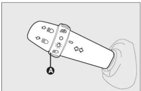
EXTERIORLIGHTS
The left lever fig. 33 includes the controls for the exterior lights.
The exterior lights can only be switched on when the ignition key is at MAR-ON.
LIGHTSOFF
Ring nut turned to position.
SIDELIGHTS
Turn the ring nut to position.
The warning light 00 switches on in the instrument panel.
DIPPEDHEADLIGHTS
Turn the ring nut to position.
natural_image
Illustration of a handheld device with control buttons and a labeled point A (no text or symbols on the device itself)fig. 33
F0Q0649
The warning light 00 switches on in the instrument panel.
MAINBEAMHEADLIGHTS
With the ring nut atD position, push the stalk forward towards the dashboard (stable position).
The warning lightED switches on in the instrument panel.
To turn the main beam headlights off, pull the stalk towards the steering wheel (dipped headlights will turn on).
PARKINGLIGHTS
These lights can be turned on only with the ignition key at STOP or extracted by turning the ring nut on the left stalk first to position and then to position 🌐 or 📋.
The warning light=00=switches on in the instrument panel. Operate the direction indicator stalk to select the side (right or left).
FLASHING
Pull the stalk towards the steering wheel (unstable position) regardless of the position of the ring nut. The warning light switches on in the instrument panel.
DIRECTIONINDICATORS
Place the stalk in the (stable) position fig. 34:
☐up (position 1): activates the right direction indicator
□down (position 2): activates the left direction indicator
Warning light ⇔ or ⇔ will flash in the instrument panel.
Direction indicators are switched off automatically when the steering wheel is straightened.
Lanechangefunction
If you wish to signal a lane change, put the left stall in the unstable position for less than half a second. The direction indicator on the side selected will flash five times and then switch off automatically.

text_image
Diagram of a handheld device with labeled buttons and icons, showing two directional arrows labeled ① and ②.fig. 34
F0Q0650
"Corneringlights"
When the dipped headlights are on and the speed below 40 km/h, if the steering wheel rotation angle large or the direction indicators are on, a light (incorporated in the fog light) will come on on the relevant side to improve visibility at nighttime.
"FOLLOWMEHOME"DEVICE
This allows the space in front of the car to be lit for a certain period of time.
Activation
With the ignition key turned to STOP or removed, pull the stalk fig. 35 towards the steering wheel within 2 minutes from when the engine is turned o
At each single movement of the stalk, the lights will remain on for an extra 30 seconds up to a maximum of 210 seconds; then the lights are switched off automatically.
Each action of the stalk corresponds with the light of the 0.0 warning light in the instrument panel (along with a message shown on the display) (see "Warning lights and messages" chapter).
Deactivation
Keep the stalk pulled towards the steering wheel for more than 2 seconds.
AUTOMATICHEADLIGHTSENSOR (dusksensor)
(for versions/markets, where provided)
Deactivation
The dipped headlights will switch off followed after approximately 10 seconds by the side lights, when
It detects variations in brightness outside the vehicle the sensor is deactivated.
depending on the light sensitivity setting: the greater the sensitivity, the less outside light needed to activate the exterior lights being turned on.
The sensor is not capable of detecting the presence of fog therefore, in these circumstances, the lights have to be turned on manually.
The sensitivity of the dusk sensor may be adjusted by means of the "Setup menu" on the instrument panel.
Activation
Turn the ring nut to position® fig. 36: this turns the side lights and the dipped headlights on simultaneously and automatically depending on the exterior brightness conditions.
The headlights can only be flashed with the sensor on.

natural_image
Illustration of a handheld device with icons and a hand holding it, showing a curved arrow indicating rotation (no text or symbols present)fig. 35
F0Q0651

natural_image
Line drawing of a handheld device with control buttons and indicator lights (no text or symbols)fig. 36
F0Q0652
WINDOWCLEANING
WINDSCREENWASHER/WIPER
They can be operated only with the ignition key turned to MAR-ON.
The right stalk can be moved to five different positions fig. 37:
A windscreen wiper off.
B intermittent operation.
With the stalk in position B, turn ring nut F to select one of four different speeds for the intermittent operation mode:
= intermittent low speed
■ = slow intermittent operation.
■ ■ = medium intermittent operation.
■ ■ ■ = fast intermittent operation.
C continuous slow operation;
D continuous fast operation;
E temporary fast operation (unstable position).
Temporary fast operation position E is limited to the time that the stalk is manually held in this position. The stalk returns to position A when it is released, automatically stopping the windscreen wipers.
IMPORTANT With the windscreen wipers in use, if reverse gear is engaged, the rear window wiper is automatically activated.

text_image
F E A B C Dfig. 37
F0Q0645

Neverusethewindscreenwipersto removelayersofsnoworicefromthe windscreen.Insuchconditions,the windscreenwipersmaybesubjectedtoexcessive stressandthemotorprotection,whichprevents operationforafewseconds,mayintervene.If operationisnotrestored,contactaFiat Dealership.
"Smartwashing" functionfig.38
Pull the stalk towards the steering wheel (unstable position) to operate the windscreen washer.
Keep the stalk pulled, with just one movement, to operate the washer jet and the windscreen wiper; the latter automatically turns on if you keep the stalk pulled for more than half a second.
The windscreen wiper stops operating a few strokes after releasing the stalk; a further “cleaning stroke”, after a few seconds, completes the wiping operation.
RAINSENSOR
(for versions/markets, where provided)
The rain sensor A fig. 39 is located behind the interior rear view mirror in contact with the windscreen and has the purpose of automatically adjusting the frequency of the windscreen wiper strokes depending on the intensity of the rain during intermittent operation.
The sensor has an adjustment range that varies progressively from wiper still (no stroke) when the windscreen is dry, to wiper at first continuous speed (slow continuous operation) with intense rain.
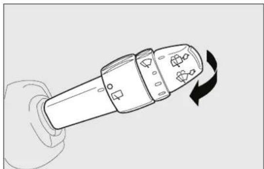
natural_image
Line drawing of a hand holding a device with a rotating arrow indicating rotation (no text or symbols)fig. 38
F0Q0646
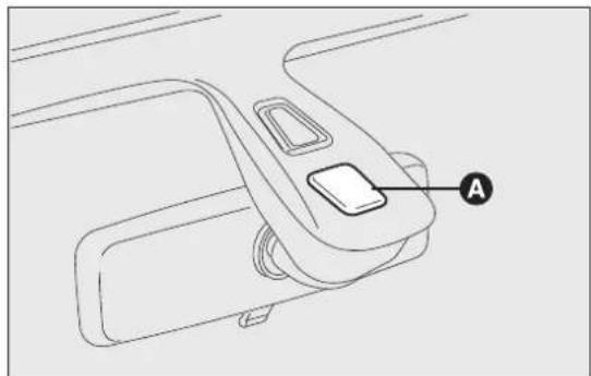
natural_image
Line drawing of a car seatbelt mechanism with labeled component A (no text or symbols beyond label)fig. 39
F0Q0014
Activation
Move the right stalk down by one click.
The activation of the sensor is signalled by a "stroke to show that the command has been acquired.
IMPORTANT Keep the glass in the sensor area clear
By turning ring nut F fig. 37 is it possible to increase the sensitivity of the rain sensor to obtain a more rapid variation between wiper still (no stroke) when the windscreen is dry, to wiper at first continuous speed (slow continuous operation).
The increasing of the rain sensor sensitivity is also signalled by a stroke of the wipers.
If the windscreen washer is used with the rain sensor activated, the normal washing cycle is performed, after which the rain sensor resumes its normal automatic operation.
Deactivation
Turn the ignition key to STOP.
At the next start-up (key at MAR-ON), the sensor will not be reactivated even if the stalk is at B fig. To activate the sensor, move the stalk to position A or C and then back to position B.
Rain sensor activation will be indicated by at least one wiper “stroke” even if the windscreen is dry.

Donotactivatetherainsensorwhen washingthecarinanautomaticcarwash.

Makesurethedeviceisswitchedoffif thereisiceonthewindscreen.

WARNING Makesurethedeviceisswitchedoff wheneverthewindscreenisbeing
REARWINDOWWASHER/WIPER
It can be operated only with the ignition key turn to MAR-ON. The function stops when the stalk is released.
Turning the stalk ring nut A fig. 40 from position to position will operate the rear window wiper as follows:
☐in intermittent mode when the rear window wipe is not operating;
☐ in synchronous mode (at half the speed of the windscreen wiper) when the windscreen wiper 37 is operating;
☐in continuous mode with reverse gear engaged and the control active.
With the windscreen wiper on and reverse gear engaged the rear window wiper is activated in continuous mode. Pushing the stalk towards the dashboard (unstable position) will activate the rear window washer jet.
Keep the stalk pushed for more than half a second activate the rear window wiper as well. Releasing the stalk will activate the smart washing function, as described for the windscreen wiper.
HEADLIGHTWASHERS
(for versions/markets, where provided)
The headlight washers fig. 41 are retractable, i.e. they are located inside the front bumper and work when the windscreen washer is activated with the dipped and/or main beam headlights on.
IMPORTANT Check the correct operation and cleanliness of nozzles at regular intervals.
to Donotusetherearwindowwiperto removelayersofsnoworice.In suchconditions,thewipermaybe subjectedtoexcessivestressandthemotor protection,whichpreventsoperationforafew seconds,mayintervene.Ifoperationisnot restored,contactaFiatDealership.
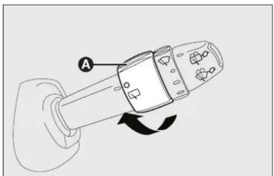
text_image
Afig. 40
F0Q0653

natural_image
Line drawing of a car interior showing dashboard, rearview, and side panels (no text or symbols)fig. 41
F0Q0018
CRUISECONTROL
(constantspeedregulator)
(for versions/markets, where provided)
This is an electronically controlled driving assistance device which allows the car to be driven at a chosen speed above 30 km/h on long stretches of dry, straight roads with few variations (e.g. motorways), without having to depress the accelerator pedal.
The use of this device on extra-urban roads with traffic is not therefore recommended. Do not use the device in town.
TURNINGTHEDEVICEON
Turn the ring nut A fig. 42 to the ON position.
The device must only be switched on in 4th gear higher. When travelling downhill with the device engaged, the vehicle speed may slightly exceed the preset one.

text_image
A B OFF ON Cfig. 42
F0Q0648
The activation is indicated by the turning on of warning light ^(6) on the instrument panel (together with the dedicated message on the display) (see “Warning lights and messages” chapter).
STORINGTHEVEHICLESPEED
Proceed as follows:
□turn ring nut A fig. 42 to ON and press the accelerator pedal so that the car reaches the desired speed;
□turn the ring nut B to (+) for at least three seconds, then release it. The vehicle speed is now memorised and you can therefore release the accelerator pedal.
If needed (when overtaking for instance), you can accelerate simply by depressing the accelerator pedal; when you release the pedal, the vehicle goes back to the speed set previously.
RESTORINGSTOREDSPEED
If the device has been switched off, for example by depressing the brake or clutch pedal, the memorise speed can be restored as follows:
□accelerate progressively until a speed close to that stored is reached;
☐engage the gear selected at the time that the speed was memorised (4th, 5th or 6th gear);
☐press button C fig. 42.
INCREASINGTHESTOREDSPEED
This can be done in two ways:
☐ by pressing the accelerator and memorising the new speed reached;
or
☐by temporarily turning ring nut B fig. 42 to (+).
Each movement of the ring nut will correspond to a slight increase in speed (about 1 km/h), while keeping the ring nut turned will correspond to a continuous speed increase.
REDUCINGTHESTOREDSPEED
This can be done in two ways:
☐by switching off the device and then memorising the new speed;
or
☐by keeping ring nut B fig. 42 turned to (−) until the new speed is reached; it will then be memorised automatically.
Each movement of the ring nut will correspond to a slight reduction in speed (about 1 km/h), while keeping the ring nut turned will correspond to a continuous reduction in speed.
TURNINGTHEDEVICEOFF
Turn the ring nut A fig. 42 to OFF or turn the ignition key to STOP. The device is automatically turned off in one of the following cases:
□when the brake or clutch pedal is pressed;
☐if the ASR or ESP system cuts in (for versions/markets, where provided);
If the gear is shifted in versions with Dualogic gearbox (for versions/markets, where provided) in Manual mode;
☐if the Dualogic gearbox lever (where provided) is inadvertently shifted to N or R.

WARNING
Whilstdrivingwiththedeviceon,never placethegearleverinneutralanddo notmovetheDialogicgearboxleverinto positionNorR.

WARNING
If the device is faulty, turning nut A fig. 42 to OFF, check the condition of the protective fuse and contact a Fiat Dealership.
ROOFLIGHTS
FRONTROOFLIGHTWITHSPOTLIGHTS
Switch A fig. 43 switches the roof lights on/off.
With the switch A in the central position, the lights C and D come on/go off when front doors are opened/closed.
With switch A pressed to the left, lights C and D always off. With switch A pressed to the right, the lights C and D are always on.
Lights switch on/off progressively.
Switch B controls the spot light function; when the roof light is off, it switches on individually:
□light C if pressed on the left side;
☐light D if pressed on the right side.
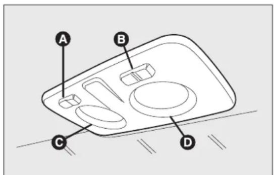
text_image
A B C Dfig. 43
F0Q0669
IMPORTANT Before getting out of the car, make sure that both switches are in the central position: when the doors are closed the lights will switch off to avoid draining the battery. In any case, if the switch is left in on position, the roof light switches off automatically 15 minutes after the engine switching off.
Rooflighttiming are
To make getting in and out the vehicle easier, especially at nighttime or in poorly lit areas, two timing logics are available.
Timingwhengettingintothecar
The roof lights switch on according to the following modes:
☐for around 10 seconds when the front doors are unlocked;
☐for about 3 minutes when one of the side doors opened;
☐for about 10 seconds when the doors are closed.
The timing is interrupted when the ignition key is turned to MAR-ON.
Timingwhengettingoutofthecar
After removing the key from the ignition switch, the roof lights switch on as follows:
□within 2 minutes of the engine being switched off for a period of around 10 seconds;
□when one of the side doors is opened for a period of around 3 minutes;
□when one of the doors is closed for a period of about 10 seconds.
☐if the fuel cut-off switch operates, they are on for about 15 minutes, then they switch off automatically.
Door locking switches the lights off immediately (unless the fuel cut-off switch is operating).
REARROOFLIGHT
Versionswithoutsunrooffig.44
In these versions, there are two rear roof lights. Press the point indicated by the arrow to switch the lights on/off (+ sign on the roof light lens cover).
The rear roof lights also come on in conjunction with events that cause the front roof light to come on.
Versionswithsunrooffig.45
In these versions, there is only one rear roof light. Press the point indicated by the arrow to switch the lights on/off (+ sign on the roof light lens cover).
The rear roof light also switches on in conjunction with events that cause the front roof light to switch on.
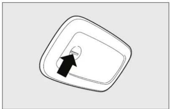
natural_image
Simple line drawing of a square container with an arrow pointing to the bottom circular hole (no text or symbols)fig. 44
F0Q0670

natural_image
Line drawing of a car interior showing a seatbelt and dashboard (no text or symbols)fig. 45
F0Q0740
CONTROLS
HAZARDWARNINGLIGHTS
They are turned on by pressing switch A fig. 46, regardless of the position of the ignition key. With the device on, warning lights and light up in the instrument panel.
Press button A again to switch the lights off.
IMPORTANT The use of hazard warning lights is governed by the highway code of the country you in. Comply with legal requirements.
Emergencybraking
During emergency braking, the hazard warning lights come on automatically and warning light and on the panel also come on.
The function switches off automatically when emergency braking ceases.

text_image
Diagram of a car air conditioner panel with labeled component A and warning symbolfig. 46
F0Q0637
FOGLIGHTS
(for versions/markets, where provided)
Press button B fig. 47 with the side lights on to tu the fog lights on.
Press the button again to turn the lights off.
REARFOGLIGHT
Press button C with the dipped beam headlights or front fog lights on to switch it on fig. 47.
Press the button again to switch it off.

text_image
MODE Φ Φ C Bfig. 47
F0Q0636
FUELCUT-OFFSWITCH
(as an alternative to the fuel cut-off system, for versions/markets where provided)
It is located in the bottom, near the passenger side pillar fig. 48. It is triggered in the event of an impact causing:
□the fuel supply cut-off with the engine consequently switching off;
□the automatic unlocking of the doors;
□the interior lights being switched on (for about 15 minutes).
The intervention of the switch is indicated by the switching on of the warning light on the instrument panel or the symbol on the display (together with a message) (see "Warning lights and messages" section).
Carefully check the car for fuel leaks, for instance in the engine compartment, under the car or near the tank area.
If no fuel leaks are found and the car can be started again, press button A to reactivate the fuel system and the lights.
After a collision, turn the ignition key to STOP to prevent the battery from running down.

WARNING
If, afteracollision, yousmellfuelor noticeleaksfromthefuelsupplysystem, esettheswitchtoavoidfirerisk.
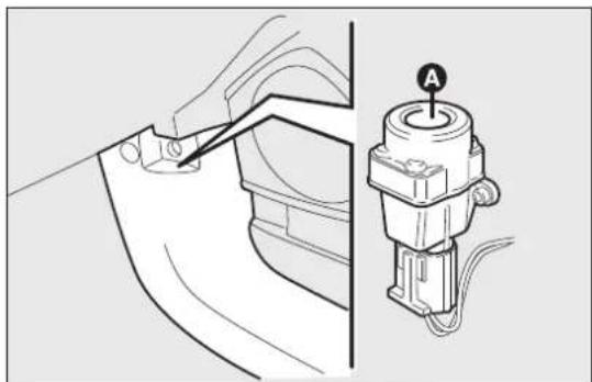
natural_image
Technical diagram showing a mechanical assembly with a tool inserted into a component and a labeled component (A) on the right side, no text or symbols present.fig. 48
F0Q0638
FUELCUT-OFFSYSTEM
(as an alternative to the fuel cut-off switch, for versions/markets where provided)
It is triggered in the event of a collision, causing:
☐the fuel supply cut-off with the engine consequently switching off;
□the automatic unlocking of the doors;
□the interior lights being switched on.
The intervention of the system is indicated by a message shown on the display.
Carefully check the car for fuel leaks, for instance in the engine compartment, under the car or near the tank area.
After a collision, turn the ignition key to STOP to prevent the battery from running down.
The following procedure should be carried out to restore the correct operation of the vehicle:
□turn the ignition key to the MAR-ON position;
□turn on the right direction indicator;
□turn off the right direction indicator;
□turn on the left direction indicator;
□turn off the left direction indicator;
□turn on the right direction indicator;
□turn off the right direction indicator;
□turn on the left direction indicator;
□turn off the left direction indicator;
□turn the ignition key to the OFF position;
□turn the ignition key to the MAR-ON position.

WARNING
If, afteranimpact, yousmellfuelor noticeleaksfromthefuelsupplysystem,
donotreactivatethesystemtoavoidtheriskof fire.
INTERIORFITTINGS
FRONTARMRESTWITHSTORAGE COMPARTMENTS
(for versions/markets, where provided)
This is located between the front seats. A storage compartment and cooled drinks compartment are located inside the armrest (for versions/markets, where provided) (see following paragraphs).
The armrest can be adjusted lengthwise through the cover A fig. 49.
Storagecompartment
Cover A fig. 49 can only be opened with the armrest fully lowered and attached.
To access storage compartment B fig. 50, lift up cover A.

Donotspillyourdrinks:inanycase,a holeatthebottomofthecompartment allows,ifnecessary,forspilledliquids
todrainoutsidethecar.

text_image
Diagram showing car seatbelt adjustment with labeled component A and directional arrows indicating movement or change.fig. 49
F0Q0631
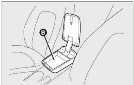
text_image
Bfig. 50
F0Q0632
Cooleddrinkscompartment
Press button A fig. 51 and lift up armrest B: you can then access the cooled drinks compartment fig. 52. IMPORTANT The function of the compartment is to maintain the temperature of the drinks that are put in, which should be heated or cooled beforehand.
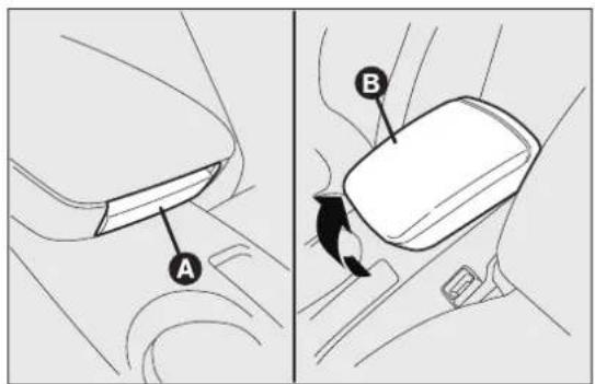
text_image
Diagram showing car seatbelt switch mechanism with labeled parts A and Bfig. 51

natural_image
Top-down line drawing of a car interior showing a square seat and hand placement (no text or symbols)fig. 52
REARARMREST
(for versions/markets, where provided) To use armrest A fig. 53, lower it as shown in the diagram.

text_image
Diagram showing car interior components with labeled parts A, B, and C, including directional arrows indicating movement or flow.fig. 53
F0Q0010
There are two cup and/or can holders B in the armrest. To use these, pull tab C in the direction shown by the arrow.
A storage compartment is available inside the armrest; this can be accessed by raising the flap.
STORAGECOMPARTMENTS
Passengersidecompartment
To open this compartment, operate handle A fig. 54 as shown by the arrow.
When the compartment is opened a courtesy light comes on inside which remains on for about 15 minutes with the ignition key in the STOP position.
If, during this period, a door or the tailgate is opened, the 15 minute timing is reset.
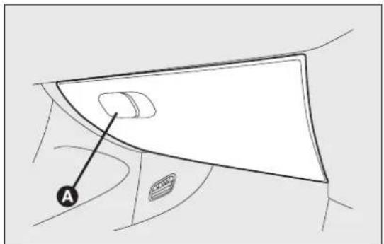
text_image
Afig. 54
F0Q0635

WARNING
Nevertravelwiththeglove compartmentopen:itcouldinjurethe
passengerintheeventofacrash.
Compartmentundertheseat
(for versions/markets, where provided)
On some versions, under the passenger's seat there is a storage compartment: do not use it for objects heavier than 1.5 kg.
To open the compartment, use handle A fig. 55.
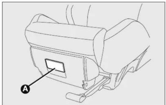
natural_image
Line drawing of a car seat assembly with labeled component A (no text or symbols beyond label)fig. 55
F0Q0012
POWERSOCKET(I2V)
It is located on the central tunnel and is only operational when the ignition key is turned to MAR-ON. If a smokers' kit is requested, the socket is replaced by a cigar lighter (see next paragraph).
On some versions an additional power socket A fig. 56 is provided in the luggage compartment.
CIGARLIGHTER
(for versions/markets, where provided)
This is located on the central tunnel.
Press button A fig. 57 to switch on the cigar light when the ignition key is turned to MAR-ON.
After a few seconds the button automatically return to its initial position, and the cigar lighter is ready for use.
IMPORTANT Always check that the cigar lighter is switched off.
IMPORTANT The cigar lighter becomes very hot. Handle it carefully and make sure that children don touch it: risk of fire and/or burning.
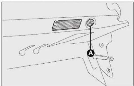
text_image
Technical diagram showing a mechanical component with labeled parts and a marked point Afig. 56
F0Q0016
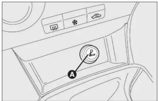
text_image
Diagram of car air intake system with labeled component A and directional indicatorsfig. 57
F0Q0629
ASHTRAY
(for versions/markets, where provided)
The ashtray is a removable spring-loaded plastic box near the handbrake lever fig. 61, on the front and fig. 58 that can be fitted into the cup/can holders rear doors fig. 62 and fig. 63. on the central tunnel.
IMPORTANT Do not use the ashtray as a waste paper basket: it may catch fire in contact with cigarette stubs.
GLASSHOLDER
The central tunnel has two cup and/or can holders fig. 59.
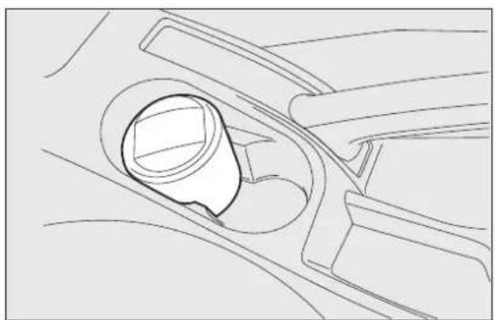
natural_image
Technical line drawing of a mechanical component with a central circular feature and handle (no text or symbols)fig. 58
F0Q0630
STORAGECOMPARTMENTS
These are located next to the cigar lighter fig. 60, near the handbrake lever fig. 61, on the front and rear doors fig. 62 and fig. 63.

natural_image
Diagram of a car interior showing a vehicle's seat and dashboard, with an arrow pointing to the seat area (no text or symbols present)fig. 59
F0Q0671
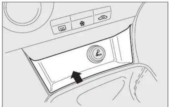
natural_image
Interior view of a car air conditioner unit with airflow direction indicator (no text or symbols)fig. 60
F0Q0672
SUNVISORS
Driver'sside
A courtesy mirror may be fitted to the sun visor some versions.
Passengerside
A courtesy mirror is fitted to the sun visor (on so versions, the mirror is lit by a courtesy light).
^on The driver and passenger sun visors can be moved back and forth and to the side fig. 64.

natural_image
Diagram of a car interior showing a handle and seatbelt with an arrow indicating direction (no text or symbols present)fig. 61
F0Q0673

natural_image
Diagram of a car interior showing a curved handle and seat, with an arrow pointing to the handle area (no text or symbols present)fig. 62
F0Q0674
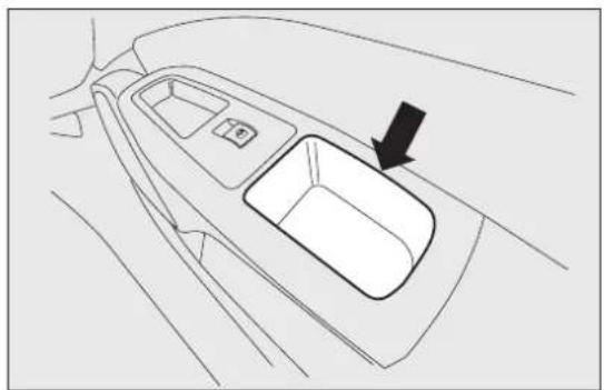
natural_image
Top-down line drawing of a car intake tray with a black arrow pointing to the drain (no text or symbols)fig. 63
F0Q0676
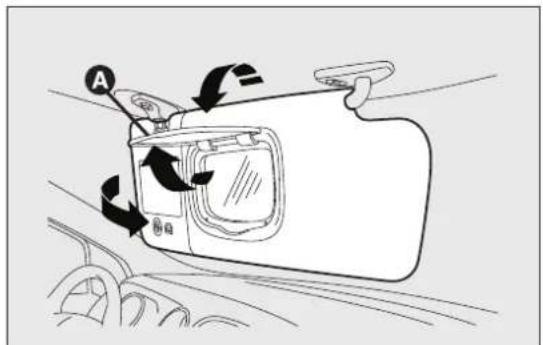
text_image
Diagram showing car door handle with labeled parts and directional arrows indicating movement or changefig. 64
F0Q0675
On some versions, a courtesy mirror with courtesy light is fitted on the back of the visors. The light allows the mirror to be used even in poor visibility conditions.
Lift cover A to access the mirror.
If the ignition key is at STOP position, the light sta on for about 15 minutes. If, during this period, a door or the tailgate is opened, the 15 minute timing is reset.
IMPORTANT On both sides of the sun visor there a label remembering that it is compulsory to deactivate the airbags if a rearward facing child restraint system is fitted. Always comply with the instructions on the sun visor. (see the "Front airbag paragraph in chapter "Safety").
SUNROOF
(for versions/markets, where provided)
The large electric sun roof comprises two panes of glass, one of which is mobile and the other fixed. These are equipped with two
Sun blinds (front and rear) that can be moved manually.
^5 The sun blinds be used in "fully closed" or "fully open" positions (they have no fixed intermediate positions).
To open the sun blinds: grip handle A fig. 65, release it and move it in the direction of the arrows to the "fully open" position.
To close them, carry out the procedure in reverse. The sun roof can be operated only with the ignition key turned to MAR-ON. The controls A and B fig. 66 on the trim next to the front roof light operate the sun roof opening/closing functions.
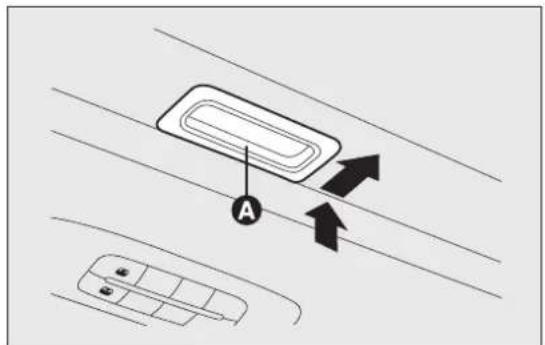
text_image
Diagram showing car interior layout with labeled components and directional arrows indicating movement or flow.fig. 65
F0Q0737
Opening
Press and hold down button B fig. 66. The front gla panel will move into the spoiler position; press button B once again and hold down for more than half a second to automatically move the sun roof to an intermediate position ("Comfort" position).
If the opening control is pressed again for more than half a second, the roof will automatically continue until it reaches the end of travel position; the roof glass can be stopped in an intermediate position by operating the button again.
Closing
With the roof in the fully open position, press button A fig. 66 and, if the button is operated for more than half a second, the front roof glass with automatically assume the intermediate position ("Comfort" position).

text_image
Diagram showing car interior with labeled buttons and a device panel, likely for navigation or testing instructions.fig. 66
F0Q0678
If the button is operated again for about half a second the roof will assume the spoiler position. Lastly, if the closing button is pressed again, the row will assume the fully closed position.

Usethesunroofonlyat"spoiler"position ifatransverseroofrackisfitted.

Donotopenthesunroofifthereissnow oriceonit:youmaydamageit.

WARNING
Whenleavingthevehicle,alwaysremove thekeyfromtheignitionswitchto avoidtheriskofinjurytothosestillinsidethe carduetoaccidentaloperationofthesunroof. Improperuseoftheroofcanbedangerous. Beforeandduringoperation,alwayscheckthat nooneisexposedtotheriskofbeinginjured bythemovingsunrooforbyobjectsgetting caughtorhitbyit.
ANTI-PINCHSAFETYDEVICE
The sun roof has an anti-pinch safety system capable of the switch does not work, the sun roof can be of detecting the presence of an obstacle whilst the operated manually as follows:
roof is closing: if this happens, the system intervenes and the movement of the glass is immediately reversed.
INITIALISATIONPROCEDURE
After the battery has been disconnected or a fuse has blown, the operation of the sun roof must be initialised again.
Proceed as follows:
☐press button A fig. 66 until the roof is completely closed. Release the button;
☐press button A and keep it pressed for at least 10 seconds and/or until the glass panel clicks forwards. Release the button at this point;
☐press button A within 5 seconds of this operation and keep it pressed: the glass panel will complete a full opening and closing cycle. Only release the button at the end of this cycle.
EMERGENCYMANOEUVRE
□remove the protective cap A fig. 67 located on the rear of the inner trim;
☐take the Allen key supplied located in the container housing the documentation or in the luggage compartment (versions with automatic Fix&Go);
□introduce the Allen key into housing B and turn:
- clockwise to open the roof;
- anti-clockwise to close the roof.
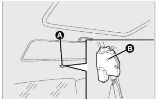
text_image
A Bfig. 67
F0Q0738
DOORS
CENTRALLOCKING
Fromoutside
With the doors closed, insert and turn the key in one of the front door locks.
Frominside
Press the door lock/release button fig. 68 located in the dashboard, from inside the car (with the doors shut).
If the electrical system has failed, it is still possible lock the doors manually.
IMPORTANT The rear doors cannot be opened from the inside when the child lock device is engaged.
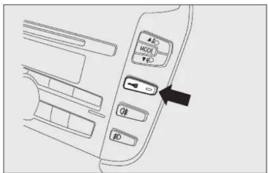
text_image
Diagram of car interior control panel with directional buttons and a black arrow pointing to the mode control knobfig. 68
F0Q0641
CHILDLOCKDEVICE
This prevents the rear doors from being opened from the inside.
Device fig. 69 can only be engaged with the doors open:
☐ position I - device engaged (door locked);
☐ position 2 - device not engaged (door may be opened from the inside).
The device remains on even if the doors are unlocked electrically.

Alwaysusethisdevicewhencarrying children.

text_image
Diagram showing car interior components with labeled parts and directional arrows indicating movement or positioning.fig. 69
F0Q0677

WARNING
Afterengagingthechildlockonboth reardoors,checkforproperengagement
bytryingtoopenareardoorwiththeinternal handle.
REARDOOREMERGENCYLOCKING DEVICE
The rear doors are fitted with an emergency device that allows the doors to be locked when there is no current.
Proceed as follows:
☐insert the metal insert of the ignition key into housing A fig. 70;
□turn the key clockwise and then remove it from housing A.

text_image
Diagram showing a mechanical component with labeled parts and an inset indicator labeled 'A'fig. 70
F0Q0679
The door lock knob can be realigned (only when the battery charge has been restored) as follows:
□press the 🔒 button on the key;
☐ press the button on the dashboard to lock/unlock the doors;
□open a front door by inserting the key into the door catch;
□operate the internal door handle.
IMPORTANT If the child lock device was engaged and the previously described locking procedure carried out, operating the internal handle will not open the door but will only realign the door lock knobs. To open the door, the outside handle must be used. The door central locking/unlocking button is not disabled by the engagement of the emergency lock.
IMPORTANT If the battery is disconnected or the protection fuse blows, the door opening/closing mechanism must be initialised as follows:
□close all the doors;
□press button 🔒 on the key or button for locking/unlocking the doors on the dashboard;
☐ press button 🔒 on the key or button for locking/unlocking the doors on the dashboard.

WARNING
Donotactivatethechildlockdeviceif thereardoorsemergencylockdevice isalreadyactivated. If both have been activated, you need to set the interior handle to disengage therearoorsemergencylocking system and then open the door from the outside.
ELECTRICWINDOWS
They are fitted with a security system that can det the presence of an obstacle whilst the window is closing; when this happens, the system kicks in and the movement of the glass is immediately reversed.
IMPORTANT In the event that the anti-crushing function is activated 5 times in only 1 minute, the system will automatically enter the “recovery” mode (self-protection). This condition is apparent from the window closing in stages.
If this occurs, restore the system as follows:
□open the windows;
or
□turn the ignition key to the STOP position and then to MAR-ON.
If no malfunction is present, the window returns to its normal operation automatically.
IMPORTANT With the ignition key at STOP or removed, the electric windows remain activated for about two minutes and are deactivated as soon as a door is opened.

WARNING
Thesystemconformstothe2000/4/EC standardconcerningthesafetyof
passengersleaningoutofthepassenger compartment.
IMPORTANT On some versions, when the button on the key with remote control is pressed for long than 2 seconds the windows will open, whilst if the button is pressed for longer than 2 seconds the windows will close.
CONTROLS
Driversidefrontdoorfig.71
Buttons have been provided on the driver's door panel to control the following functions with the ignition key turned to MAR-ON:
A opening/closing front left window; "continuous automatic" operation during window opening/closing stage;
B opening/closing front right window; "continuous automatic" operation during window opening/closing stage;

text_image
Diagram of car interior with labeled buttons and directional arrows, showing positions A, B, C, D, E.fig. 71
F0Q0622
C enabling/disabling of rear door electric windower controls;
D opening/closing rear left window (for versions/markets, where provided); "continuous automatic" operation during window opening/closing stage;
E opening/closing rear right window (for versions/markets, where provided); "continuous automatic" operation during window opening/closing stage.
Windowopening
Push the buttons to open/close the desired window. When one of the two buttons is pressed briefly, the window moves in "stages"; if the button is held down, "continuous automatic" operation is activated. If the button is pressed again the window will stop in its current position.
Windowclosing
Lift the buttons to close the desired window.
The window closing stage occurs following the same logics described for the opening stage.

WARNING
Improperuseoftheelectricwindows canbedangerous.Beforeandduring
theiroperationensurethatanypassengersare notatriskfromthemovingglasseitherby personalobjectsgettingcaughtinthe mechanismorbybeinghitbyitdirectly. When leavingthecar,alwaysremovetheignition keytopreventtheelectricwindowsfrombeing inadvertentlyactivated,asthiscouldpresent adangerforthepassengersremaininginthe vehicle.
Passengersidefrontdoor/reardoors
On the passenger side front door panel, and on some versions also on the rear doors, buttons A fig. 72 are provided to control the associated windows.
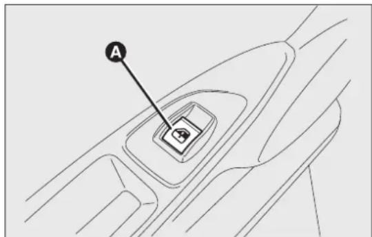
text_image
Afig. 72
F0Q0743
The system must be re-initialised after disconnecting the battery or if the relevant protection fuse is blown.
Proceed as follows to start the electric window initialisation:
☐fully close the window to be initialised manually;
□after the window has reached the upper end of travel, hold the up button pressed for at least one second.
MANUALREARWINDOWMECHANISM
(for versions/markets, where provided)
To open and to close the window, use the relevant handle.
LUGGAGECOMPARTMENT
OPENING
When unlocked, the luggage compartment can be opened from the outside the car by pressing the electric logo fig. 73.
The tailgate can be opened at any time, if the door are unlocked.
The key with remote control should be used to opt the tailgate.
If the tailgate is not closed properly, the warning light or the symbol switch on in the instrument panel (together with the dedicated message on the display) (see "Warning lights and messages" chapter).
Opening the tailgate will switch the luggage compartment light on: the light will go off automatically when closing the tailgate.

natural_image
Line drawing of a hand holding a circular object on a wall, no text or symbols presentfig. 73
The light will stay on for about 15 minutes after turning the key to STOP: if during this time, a door or the tailgate is opened, the light will switch on again for 15 minutes.
Openingthetailgateusingthekeywith remotecontrol
Press button even with alarm (for versions/markets where provided) on.
Luggage compartment opening is indicated by the double flashing of the direction indicators; tailgate dosing is indicated by single flashing (only with the alarm switched on).
If the tailgate is opened when the alarm is on, the system will:
□switch off the volume sensing protection;
□switch off the anti-lift protection;
□switch off the tailgate control sensor.
When the tailgate is closed again, all the functions are restored.
CLOSING
Lower the tailgate, pressing near the lock until you hear it click into place.

Donotfitadditionalobjectsontotherear parcelshelfortailgate(speakers, spoilers,etc.),exceptwhencontemplated
bythemanufacturer,toensurethecorrect operationofthesidegasshockabsorbersofthe tailgateitself.

WARNING
Neverexceedthemaximumallowed loadintheluggagecompartment(see
the"Technicaldata"chapter).Alsomakesure thattheobjectsyouplacedintheluggage compartmenthavebeenproperlysecured,to avoidthemfrombeingprojectedforward followingsuddenbraking,causinginjuryto passengers.

WARNING
Whentravelling, donotputanyobject ontherearparcelshelfbecausethey
caninjurepassengersintheeventofan accidentorsuddenbraking.
EXTENDINGTHELUGGAGE COMPARTMENT
The luggage compartment can be partially (1/3 or 2/3) or totally extended by splitting the rear seat.
Partiaextension(1/3or2/3)Fig.fig.74-fig.75
Extending the luggage compartment on the right side makes it possible to carry two passengers on the left part of the rear seat. Extending the left side of the luggage compartment allows you to carry one passenger on the right part of the rear seat.
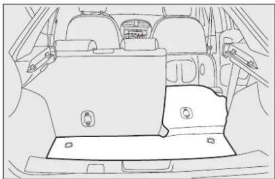
natural_image
Line drawing of a car backrest with rear seats and side-mounted equipment (no text or symbols)fig. 74
F0Q0681
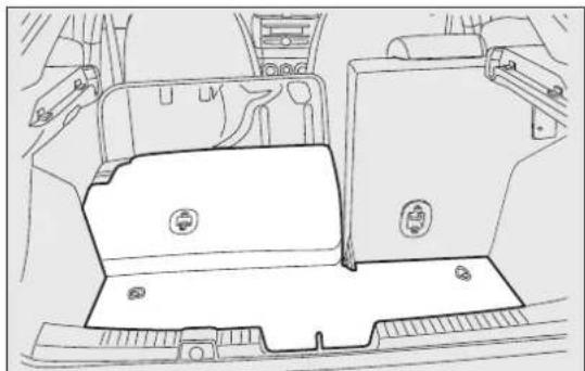
natural_image
Technical line drawing of a vehicle interior showing dashboard, seats, and structural components (no text or symbols)fig. 75
F0Q0682
Proceed as follows:
□completely lower the rear seat head restraints;
□move the seat belt to the side, making sure that it is fully extended and not twisted;
fold the desired cushion forwards fig. 76 working in the point shown by the arrow;
□lift lever A fig. 77 retaining the backrest and fold the latter forwards. When you lift the lever, you will see a red band B.
Fullextension
Tilting the rear seat completely forwards allows maximum loading volume.
Proceed as follows:
□completely lower the rear seat head restraints;
□move the seat belts to the side, making sure that they are correctly extended and not twisted;
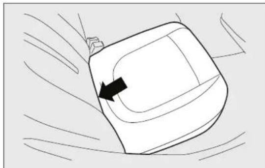
natural_image
Line drawing of a car interior with a black arrow indicating direction (no text or symbols)fig. 76
F0Q0684
☐fold the cushions forwards as described above;
☐ remove the rear parcel shelf fig. 78 and release upper ends of links A fig. 79 by removing the eyelets from the pins and pushing them in the direction indicated by the arrow;
□when the cushion is folded down, tilt the rear seat backrests completely forwards as described above so as to obtain a continuous loading surface.
REPOSITIONINGTHEREARSEAT
Move the seat belts to the side, making sure that they are correctly extended and not twisted.
Lift the backrests and push them back until you hear both fastening mechanisms click in. Check that the red band B fig. 80 on the side of levers A is no longer visible.

text_image
Diagram showing car seatbelt mechanism with labeled points A and B, indicating clockwise rotation and movement direction.fig. 77
F0Q0683
The red band B indicates that the backrest is not secured. Return the cushions to the horizontal position holding the central seat fastening tongue raised.

natural_image
Diagram of a vehicle interior showing a rectangular tray with an arrow pointing to it, no text or symbols present.fig. 78
F0Q0686
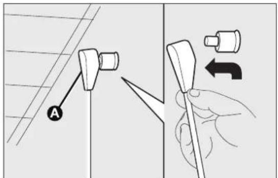
text_image
Diagram showing a hand holding a tool with labeled parts and directional arrows indicating movement or adjustment.fig. 79
F0Q0687

WARNING
Makesurethatthebackrestiscorrectly securedonbothsides(redbandsB fig.80notvisible)topreventitfrommoving forwardintheeventofsharpbraking, causing injuriestopassengers.
SECURINGYOURLOAD
The luggage compartment contains two attachments fig. 81 for the cables that secure the load transported and another two attachments are located on the rear crossmember fig. 82.
IMPORTANT Every attachment has a maximum load capacity of 100 kg.

text_image
Diagram showing car seatbelt mechanism with labeled points A and B, indicating left-hand rule for steering or lifting.fig. 80
F0Q0683

WARNING
Aheavyloadthathasnotbeensecured maycauseseriousinjuriestopassengers ventofanaccident.
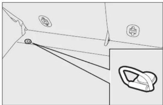
natural_image
Diagram showing a hand holding a device near a wall, with an inset view of a mechanical component (no text or symbols)fig. 81
F0Q0685

natural_image
Technical line drawing of a car interior showing structural components and a close-up detail (no text or symbols)fig. 82
F0Q0688

WARNING
If you are travelling in an area with limited opportunities for vehicle
refuellingandyouwishtobringfuelwithyouin apetrolcan,youmustdosoincompliance withcurrentregulationsandusinganapproved can,appropriatelysecuredtotheloadsecuring attachments.Anyway,bydoingso,youincrease theriskoffireincaseofanaccidentwith yourvehicle.
CARGOBOX
It consists of a preformed box fig. 83, which is located in the luggage compartment and can be used to store objects, making it possible to have a flat loading surface.
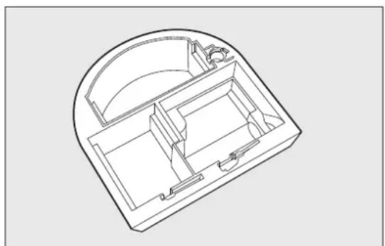
natural_image
Technical line drawing of a mechanical or electronic component with internal compartments and housing (no text or symbols)fig. 83
F0Q0002
BONNET
OPENING
Proceed as follows:
□pull lever A fig. 84 in the direction indicated by t arrow;
□pull lever B fig. 85 and lift the bonnet.
☐lift the bonnet and, at the same time, release the bonnet stay C fig. 86 from its locking device, the insert the end of the stay into the housing D.

WARNING
Thebonnetmaydropsuddenlyifthe supportingrodisnotpositioned
correctly.
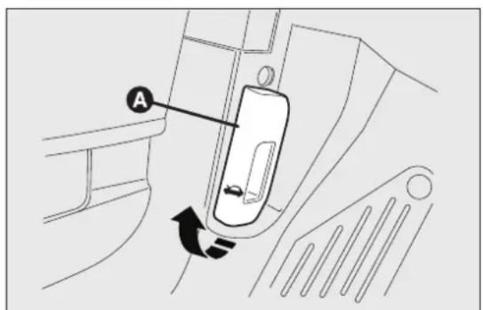
text_image
Technical diagram showing a mechanical component with labeled section A and directional arrow indicating rotation or movement.fig. 84
F0Q0689

Usebothhandstoliftthebonnet.Before lifting,checkthatthewindscreenwiper armsarenotraisedfromthewindscreen, thatthecarisstationaryandthatthehandbrake isengaged.
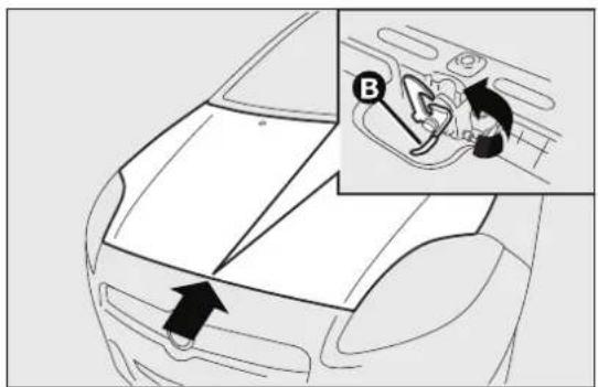
text_image
Diagram showing car interior with a black arrow pointing to the front and an inset of a car seatbelt mechanism labeled B.fig. 85
F0Q0690

natural_image
Technical line drawing of a mechanical assembly with no visible text or symbolsfig. 86

text_image
D CF0Q0748
CLOSING
Proceed as follows:
☐hold the bonnet up with one hand and with the other remove the stay C fig. 86 from the housing D and fit it back in its locking device;
☐lower the bonnet to approximately 20 centimetres from the engine compartment and let it drop. Make sure that the bonnet is completely closed and not only fastened by the safety catch by trying to open it. If it is not perfectly closed, do not try to press the bonnet lid down but open it and repeat the procedure.
If the bonnet is not closed properly, the warning light ☐ or the symbol switch on in the instrument panel (together with the dedicated message on the display) (see “Warning lights and messages” chapter).
IMPORTANT Always check that the bonnet is closed correctly to avoid it opening while the car is travelling.

WARNING
Performtheseoperationsonlywhenthe carisstationary.
ROOFRACK/SKIRACK
The attachments provided are located in the areas illustrated in fig. 87 and are only accessible with the doors open. Lineaccessori Fiat has a dedicated roof rack/ski rack for this car.

WARNING
Aftertravellingforafewkilometres, checktoensurethatthefixingscrews fortheattachmentsarewelltightened.

WARNING
Neverexceedthemaximumpermitted loads(seechapter"Technical specifications").
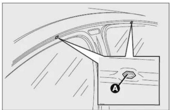
text_image
Technical diagram showing a car interior with labeled component 'A' and directional arrows indicating flow or movement.fig. 87
F0Q0785

WARNING
Evenlydistributetheloadandtakeinto account,whendriving,theincreased sivenessofthecartosidewind.

Fullycomplywiththeregulationsinforce concerningmaximumclearance.
HEADLIGHTS
LIGHTBEAMDIRECTION
The correct aiming of the headlights is important for position. the comfort and safety of not only the driver but The display shows the position while adjusting. all other road users. This is also covered by a specific
rule of the highway code.
The headlights must be correctly aligned to guarantee the best visibility conditions for all drivers while travelling with headlights on.
Contact a Fiat Dealership to have the lights checked and adjusted, if necessary.
IMPORTANT When the gas discharge (Xenon) headlamps (for versions/markets, where provided) are switched on, normally parabolas and light beam move vertically for about 2 seconds until headlamp alignment has stabilised.
HEADLIGHTALIGNMENTCORRECTOR
This device works with the ignition key in the MAR-ON position and the dipped beam headlights on.
The car will tilt backwards when it is loaded, raising the light beam. The beams must therefore be realigned in this case.
Adjustingheadlightsalignment
For adjusting, press buttons and fig. 88 on the dashboard.
Press button ▲D to increase the light beam of one position.
Press button▼D to decrease the light beam of one position.
The display shows the position while adjusting.
Correctpositionsdependingontheload
Position0 one or two occupants in the front seats.
Position I five people
Position2 five people with a load in the luggage compartment
Position3 driver + maximum permitted load stowed in the luggage compartment.
IMPORTANT Check the headlight alignment each time the weight of the load transported changes.
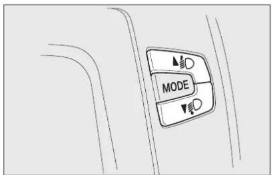
text_image
MODEfig. 88
F0Q0644
IMPORTANT If the car is equipped with (Xenon) discharge headlights, the headlight alignment is controlled electronically, as a consequence the ▲D and buttons are not present.
FOGLIGHTALIGNMENT
Contact a Fiat Dealership to have the lights checked and adjusted, if necessary.
ADJUSTINGTHEHEADLIGHTSWHEN ABROAD
The dipped beam headlights are aligned for operation in the country where the vehicle was originally purchased. When in countries where you drive on the other side of the road, you need to alter the beam direction by affixing a specially designed self-adhesive film in order not to dazzle the vehicles travelling in the opposite direction.
Such film is provided by Lineaccessori Fiat and is available at Fiat Dealerships.
ABSSYSTEM
ABS is an integral part of the braking system which prevents, whatever the road conditions and force applied to the brake pedal, the wheels from locking and consequently sliding under braking, thus ensuring that the vehicle remains under control even during emergency braking.
The EBD system (Electronic Braking Force Distribution) completes the system allowing the brake force to be distributed between the front and rear wheels.
IMPORTANT To obtain the maximum efficiency of the braking system, a bedding-in period of about 50 km is needed: during this period it is better to avoid sharp, repeated and prolonged braking.

WARNING
TheABSgetsthemostfromthe availablegrip,butitcannotimproveit; youshouldthereforetakeeverycarewhen drivingonslipperysurfacesandnottake unnecessaryrisks.
SYSTEMINTERVENTION
The driver can feel that the ABS system has come into action because the brake pedal pulsates slightly and the system gets noisier: it means that the car speed should be altered to suit the type of road surface.

WARNING
WhentheABScutsinandyoufeelthe brakepedalpulsating, donotraise yourfoot,butkeepitpressed;indoingsoyou willstopintheshortestamountofspace possibledependingonthecurrentroad conditions.

WARNING
IftheABSintervenes,itisasignthatthe gripbetweenyreandtheroadsurface hasreachedthelimit:youmustslowdownto adaptthespeedtotheroadgripavailable.
ABSFAILUREINDICATION
This is indicated by the warning light on the instrument panel together with the dedicated message on the multifunction display (for versions/markets where available) coming on (see “Warning lights and messages” section).
In the case, the braking system will work as normal without the extra capacity offered by the ABS system. Drive carefully to the nearest Fiat Dealership to have the system checked.
EBDFAILUREINDICATION
This is indicated by the warning lights and (31) the instrument panel together with the dedicated message on the multifunction display (for versions/markets where available) coming on (see "Warning lights and messages" section).
In this case, the rear wheels may suddenly lock and the vehicle may swerve when braking sharply. Drive carefully to the nearest Fiat Dealership to have the system checked.

WARNING
Ifonlythewarninglight (!) onthe instrumentpanelswitcheson-together withamessageinthemultifunctiondisplay(for versions/markets, whereprovided)-stopthe carimmediately and contactthenearest Fiat Dealership. Fluidleakingfromthehydraulic systemwillcompromisetheoperationofthe brakingsystem, whetheritisoftheconventional typeorwithABS.
BRAKEASSIST
(emergencybrakingassistance)
(for versions/markets, where provided)
The system, which cannot be turned off, recognises emergency braking (on the basis of the brake pedal operating speed) and speeds up the response of the braking system.
Brake Assist is deactivated on the versions equipped with ESP, in the event of ESP system failure, indicate by warning light coming on together with the message on the display.
ESPSYSTEM
(ElectronicStabilityProgram)
(for versions/markets, where provided)
This is an electronic system that controls car stabil in the event of tyre grip loss, helping maintain directional control.
The ESP system is therefore particularly useful when the grip conditions of road surfaces change.
With the ESP, the car is provided with ASR (tract control with interventions on brakes and engine), HILL HOLDER (device for starting on gradients without using the brakes), MSR (control of engine braking torque when shifting gear down) and HBA (automatic increase of braking pressure in the case emergency braking).
SYSTEMINTERVENTION
It is signalled by the blinking of the warning light Ⓐ on the instrument panel, to inform the driver that the car is in critical stability and grip conditions.
SYSTEMACTIVATION
The ESP system comes on automatically when the vehicle is started and cannot be turned off.
ESPSYSTEMFAILUREINDICATIONS
In the event of a failure, the ESP system will be automatically switched off and warning light will switch on constantly on the instrument panel (on some versions along with a message on the display, see “Warning lights and messages” chapter). In this case, contact a Fiat Dealership.

WARNING
Donottakeunnecessaryrisks, even if your vehicle is fitted with an ESP Your driving style must always be suited. Good conditions, visibility and traffic. Veris always responsible for roads safety.
HILLHOLDERSYSTEM
(for versions/markets, where provided)
It's integral to the ESP system. It automatically activates with the following conditions:
☐uphill: vehicle stationary on a road with a gradient higher than 5%, engine running, clutch and brake pedals pressed and gearbox in neutral or gear other than reverse engaged;
☐downhill: car stationary on a road with a gradient higher than 5%, engine running, clutch and brake pedal pressed and reverse gear engaged.
When setting off the ESP system control unit will keep brake force on wheels until the torque necessary for starting is reached, or in any case for max. 2 seconds in order to pass easily from the brake pedal to the accelerator pedal.
When two seconds have elapsed, without starting, the system is automatically deactivated, gradually releasing the braking pressure. During this release stage, the typical mechanical brake release noise can be heard, indicating that the car is about to move.
HILLHOLDERSYSTEMFAILURE INDICATIONS
A possible system failure is indicated by the Ⓐ warning light on the instrument panel - together with the dedicated message in the multifunction display (for versions/markets, where provided) - coming on (see "Warning lights and messages" chapter).
IMPORTANT The Hill Holder system is not a parking brake, therefore do not leave the car without activating the handbrake, switching off the engine and engaging first gear.

WARNING
If the space-saver wheel is used, the ESP system keeps operating. Always remember that the space-saver wheel, being smaller than the original wheel, provides less grip. For the correct operation of the ESP and ASR systems is vital that the types are the same make and the same type on all the wheels, imperfect condition and, above all, the recommended type, make and size.
ASRSYSTEM(AntislipRegulation)
This is integral to the ESP system and automatically intervenes if one or both drive wheels slip, helping the driver to control the car.
Depending on the slipping conditions, two different control systems are activated:
☐if the slipping involves both drive wheels, the ASR intervenes reducing the power transmitted by the engine;
☐if the slipping only involves one of the drive wheels, the ASR intervenes automatically braking the wheel that is slipping.
The action of the ASR system is particularly helpful in the following circumstances:
☐slipping of the inner wheel on bends due to dynamic variations in the load or excessive acceleration;
☐excessive power transmitted to the wheels, also in relation to road surface conditions;
□acceleration on slippery, snowy or icy road surfaces;
☐loss of grip on wet road surfaces (aquaplaning).
MSRSYSTEM(ENGINEEDRIVE REGULATION)
This is an integral part of the ASR system that, in the event of a sudden gear downshifting, cuts in and provides torque to the engine thus preventing excessive drive wheel drive which, especially in poor grip conditions, can lead to loss of stability.
ENGAGEMENT/DISENGAGEMENTOFTHE ASRSYSTEM
The ASR system switches on automatically each time the engine is started.
When the system is active, a message is shown on the display (see “Warning lights and messages” chapter).
Whilst driving, the ASR can be deactivated and subsequently activated again by pressing the ASR OFF button on the dashboard, next to the steering wheel.
Whilst driving, the ASR can be switched off and subsequently switched on again by pressing button

text_image
ABR OFFfig. 89
F0Q0694
Every time the ignition key is turned to MAR-ON the ASR OFF button LED switches on for a few seconds to indicate that the system is running a diagnosis. The LED activation should not be understood as a fault.
When the ASR is switched off, the button LED light up (along with a message on the display, see "Warning lights and messages" chapter).
If the ASR is switched off when driving, it is automatically switched on again when the vehicle is started up.
When travelling on snowy roads with snow chains, it may be helpful to turn the ASR off: in fact, in these conditions, slipping of the drive wheels when moving off makes it possible to obtain better traction.
Fault indications In the event of a fault, the ASR system will be deactivated automatically and the warning light will switch on constantly on the instrument panel (together with a message on the display) (see "Warning lights and messages" chapter). In this case, contact a Fiat Dealership as soon as possible.

WARNING
TheASRsystemwillnotoperatewhena sparewheelisfitted:inthiscase,the
A warninglightwillswitchonconstantlyinthe instrumentpanel(togetherwithamessageon thedisplay)(see“Warninglightsandmessages” chapter).

WARNING
ForthecorrectoperationoftheESPand ASRsystemsallfourtyresmustbethe
prescribedtypeandsize,beallthesamebrand andtypeoneachwheel,andmustbein excellentcondition.
EOBDSYSTEM
The EOBD system (European On Board Diagnostic) is a diagnosis system installed on the ECUs, which detects and reports possible malfunctions in the electronic systems that could worsen emissions.
The goal of the system is to:
□monitor the system efficiency;
☐indicate an increase in emissions due to vehicle malfunction;
□indicate the need to replace components which have deteriorated.
It also alerts the driver, by turning on the warning light ☐ on the instrument panel (together with relevant message on the display), when these components are damaged; it can also report any system malfunctions (see "Warning lights and messages" chapter).
Note The car also has a connector that can be interfaced with appropriate tools, which makes it possible to read the error codes stored in the electronic control units together with a series of specific parameters for engine operation and diagnosis. This check can also be carried out by the traffic police.
IMPORTANT After an operation at the Fiat Dealership, aimed at solving malfunctions linked to the EOBD system, some bench tests should be made, along with road tests if necessary, for a complete check of the system. The latter may also require the car to cover a long distance.
WIRINGFORRADIOSYSTEM
(for versions/markets, where provided)
The car may be equipped with a storage compartment on the dashboard.
The radio must be installed in the place occupied the central storage compartment A fig. 90, where you will find the wiring.
Press on the retaining devices under the central storage compartment to extract the compartment.

WARNING
Forconnectiontotheradiosystem set-up,contactaFiatDealership entanyproblemthatcouldimpaircar

text_image
Fiat Afig. 90
F0Q0691
ACCESSORIESPURCHASEDBYTHE OWNER
If after buying the car, you decide to install electric accessories that require a permanent electric supply (radio, satellite anti-theft system, etc.) or accessories that in any case burden the electric supply, contact a Fiat Dealership, whose qualified personnel, besides suggesting the most suitable devices from Lineaccessori Fiat, will also evaluate the overall electric consumption, checking whether the car's electrical system is able to withstand the load required, or whether it needs to be integrated with more powerful battery.

WARNING
Takecarewhenfittingadditional spoilers, alloywheelsornon-standard wheelhubs:theycouldreducetheventilationof thebrakesandaffectefficiencyundersharp, repeatedbrakingoronlongdescents.Make surethatnothingobstructsthepedalstroke (mats,etc.)
INSTALLING ELECTRICAL/ELECTRONIC DEVICES
Electrical and electronic devices installed after buying the car in the context of after-sales service must carry the label (see fig. 91):
Fiat Group Automobiles S.p.A. authorises the installation of transceiver devices on condition that such installations are carried out in a workmanlike fashion, following the manufacturer's instructions, at a specialised centre.
IMPORTANT Traffic police may not allow the car on the road if devices have been installed which modify the features of the car. This may also cause invalidation of warranty in relation to faults caused by the change either directly or indirectly related to it.
Fiat Group Automobiles S.p.A. shall not be liable for damage caused by the installation of accessories either not supplied or recommended by Fiat Group Automobiles S.p.A. and/or not installed in compliance with the provided instructions.

text_image
e CEfig. 91
DISPOSITIVI-ELETTRONICI
RADIOTRANSMITTERSANDMOBILE PHONES
Radio transmitter equipment (vehicle mobile phones, CB radios etc.) cannot be used inside the car unless a separate aerial is mounted externally.
IMPORTANT The use of these devices inside the passenger compartment (without an external aerial) may cause the electrical systems to malfunction. This could compromise the safety of the car in addition to constituting a potential hazard for passengers' health.
In addition, transmission and reception of these devices may be negatively affected by the shielding effect of the car body. As far as the use of EC-approved mobile phones is concerned (GSM, GPRS, UMTS), follow the usage instructions provided by the mobile phone manufacturer.
"DUALDRIVE"ELECTRICPOWER STEERINGSYSTEM
The car is equipped with an electrically controlled power steering system called "Dualdrive", working only with the ignition key at MAR-ON and the engine running, that customises steering force according to the driving conditions.
IMPORTANT When turning the ignition key quickly full power steering functionality can be achieved after 1-2 seconds.
ACTIVATION/DEACTIVATION (CITYfunction)
(for versions/markets, where provided)
To turn the function on/off, press button A fig. 92 the dashboard, next to the steering wheel.
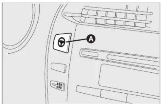
text_image
A ASR OFFfig. 92
F0Q0693
The activation of the function is signalled by the word CITY on the display (in some versions it is signalled by the switching on of the warning light CITY).
When the CITY function is on, the steering wheel effort is lighter and parking operations are easier: therefore this function is particularly useful for driving in city centres.
FAILUREINDICATIONS
Any failure of the electric power steering system is indicated by instrument panel warning light coming on together with a message on the display (on some versions together with a symbol on the display (see "Warning lights and messages" chapter).
In the event of electric power steering system failure, the car can be driven with mechanical steering.
SPORTFUNCTION
(for versions/markets, where provided)
The vehicle may be equipped with a system that allows a choice between two styles of driving, normal and sports.
Pressing the SPORT button fig. 93 produces a sporty driving setting characterised by higher acceleration response and more effort required at the steering wheel for a sporty driving sensation.
Pressing the SPORT button also activates the turbocharger supercharging function (overboost).
Via this function the engine management control unit allows - in relation to the position of the accelerator pedal and for a limited time - maximum pressure levels to be reached inside the turbocharger, with a consequent increase in engine torque with respect to that which is normally possible.
This function is particularly useful whenever maximum performance is required for a short time (e.g. when overtaking).
The letter S is lit up in the instrument panel display when the function is switched on. Press the button again to switch the function off and restore the normal driving setting.
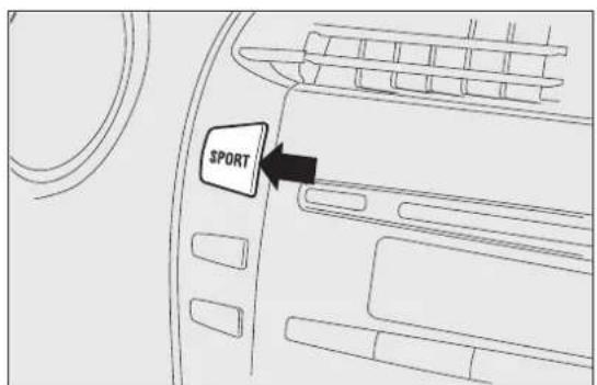
text_image
SPORTfig. 93
IMPORTANT When the SPORT button is pressed, the function is activated about 5 seconds later.
IMPORTANT During acceleration, when the SPORT function is used the steering may shudder which is typical of a sports setting.
IMPORTANT During parking manoeuvres requiring a lot of steering, the steering may become harder; this is normal and is due to the intervention of the system to protect the electric steering motor from overheating; so, no intervention is required. When the car is used again later on, the power steering w work normally.
Acceleration
Sudden acceleration has a very negative effect on fuel consumption and emissions: accelerate gradually to contain consumption.
When the SPORT function is used the consumption figures will be slightly higher than those stated.

WARNING
Undernocircumstances should aftermarket operations involving
weieringsystemorsteeringcolumn modifications(e.g.:installationofanti-theft device)becarriedoutthatcouldbadlyaffect performanceandsafety. Thisalsocausesthe warrantytobecomenullandvoidandresultsin vehiclenon-compliancewithtype-approval requirements.

WARNING
Beforestartinganyservicingoperation, stoptheengineandremovethekey
fromtheignitionswitchtooperatethesteering lock, particularlywhenthewheelsdonottouch theground.Ifthisisnotpossible(forexample ifthekeyneedstobeturnedtoMAR-ONor theenginemustberunning),removethemain fusethatprotectstheelectricpowersteering.
TPMS(TyrePressureMonitoring System)
(for versions/markets, where provided)
The car may be fitted with a tyre pressure monitoring system (TPMS), which informs the driver of the tyre inflation status via the "Check tyre pressure" and "Low tyre pressure" messages on the display. For a detailed description of the two messages, see the "Warning lights and messages" chapter.
The system comprises a radio-frequency transmitter fitted to each wheel (on the wheel rim inside the tyre), which is able to send information on the tyre inflation pressure of each wheel to the control unit.

WARNING
The presence of the TPMS does not permit the drivertoneglect regular
checkingofthepressureofthetyresandthe sparewheel(see"Wheels"inthe"Maintenance andcare"chapter).
WARNING
Sensor malfunctioning fault indications are not stored and will therefore not be displayed after the engine has been switched off and then on again. If the fault conditions persist, the control unit will send the relative indications to the instrument panel only after the vehicle has been in motion for a short time.
Tyre pressure must be checked with tyres rested and cold. Should it become necessary for whatever reason to check pressure with warm tyres, do not reduce pressure even though it is higher than the prescribed value, but repeat the check when tyres are cold (see "Wheels" in the "Technical data" chapter).
The TPMS is not able to warn you of sudden tyre pressure losses (for example when a tyre bursts). In this case, stop the car, braking with caution and avoiding abrupt steering.
Particularly strong radio-frequency interference may cause the TPMS to function incorrectly. This condition is indicated to the driver by a warning light (!) or symbol lighting up on the instrument panel together with a dedicated message. The message will disappear automatically as soon as the radio-frequency interference ceases to affect the system.
The TPMS requires the use of specific equipment. Contact a Fiat Dealership to find out which accessories are compatible with the system (wheels, hub caps, etc.). Using other accessories may hinder the normal operation of the system. Given the unique valve specifications, only use Fiat-approved sealers to repair the tyres. The use of other sealers may prevent the normal operation of the system.
If the vehicle is fitted with TPMS, when a tyre is removed, it is advisable to replace the rubber gasket for the valve as well as the ring nut fixing the senso Have this operation performed at a Fiat Dealership.
If the punctured tyre indication persists on the instrument panel after the initial conditions have been restored using the tyre repair kit ("Fix&Go Automatic"), contact a Fiat Dealership.
Changes in outside temperature may cause tyre pressures to vary. The TPMS may temporarily indicate insufficient pressure. In this case, check the tyre pressure when cold and, if necessary, restore the inflation values.
If the vehicle is fitted with TPMS, tyre and/or rims fitting/removal operations require specific precautions. To avoid damaging the sensors or fitting them incorrectly, tyre and/or rims fitting/removal operations should be carried out only by specialists. Contact a Fiat Dealership.

Thetyrerepairkit("Fix&GoAutomatic") provided with the car is compatible with the TPMS sensors; using sealants not equivalentwiththatintheoriginalkitmay adverselyaffectitsoperation.Ifsealantsnot equivalentwiththeoriginalaloneareused,it isrecommendedtohavetheTPMSsensors checkedbyaqualifiedrepaircentre.
In order to use the system properly, refer to the following table when you have to change wheels/tyres:
| OperationPresenceofsensorFailureindication | FiatDealership intervention | |
| -- YES Contact a Fiat Dealership | ||
| Replacing a wheel with the spare wheel | NO YES Repair damaged wheel | |
| Wheel change with winter tyres | NO YES Contact a Fiat Dealership | |
| Wheel change with winter tyres | YES NO - | |
| Wheel change with others of a different size(*) | YES NO Contact a Fiat Dealership | |
| Switching wheels (front/rear)(**) | YES NO - |
(*) Given as an alternative in the Owner Handbook and available from Lineaccessori Fiat.
(**) Not cross-swapped (tyres must stay on the same side).
PARKINGSENSORS
(for versions/markets, where provided)
Parking sensors provide the driver with information on the distance when approaching obstacles behind the vehicle (versions with 4 rear sensors) or in front of and behind the vehicle (versions with 4 fr and 4 rear sensors).
The system therefore provides a further aid during parking manoeuvres because it allows the identification of obstacles outside of the driver's field of vision.
The driver is notified of the presence and distance of the obstacle from the vehicle by an acoustic signal which varies depending on the distance from the obstacle (as the distance from the obstacle decreases the frequency of the acoustic signal increases).
SENSORS
In order to measure the distance of obstacles, the system uses 4 sensors located in the front bumper (for versions/markets, where provided) fig. 94 and 4 sensors located in the rear bumper fig. 95.
Versionwith4sensors
On the version with 4 rear sensors, the system is activated automatically when the reverse gear is engaged.
Versionwith8sensors
On the version with 4 front sensors and 4 rear sensors, the system is activated when reverse gear engaged or by pressing buttoR▲fig. 96.

natural_image
Line drawing of a car's front bumper with three arrows pointing to the grille (no text or symbols)fig. 94
F0Q0745
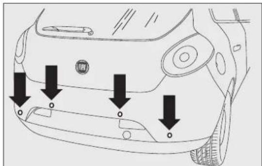
text_image
Diagram of car front bumper with arrows pointing to specific points on the side panel, including a logo and 'BMW' branding.fig. 95
F0Q0603
When reverse gear is released, the front and rear sensors remain activated until a speed of around km/h is exceeded to allow the parking manoeuvre be completed.
The system can also be activated by pressing the button P▲fig. 96 in the central panel: a warning light in the button comes on when the system is activated.
Every time the ignition key is turned to MAR-ON the LED on the button▲flashes briefly to indicate that the system is running a diagnosis. The LED activation should not be understood as a fault.
The sensors are deactivated by pressing the button again P▲ fig. 96 or when a speed of 15 km/h is exceeded: the warning light in the button is off wh the system is not active.
When the sensors are activated, the system starts to produce acoustic signals from the front or rear

text_image
ASR OFF Pfig. 96
F0Q0035
buzzers as soon as an obstacle is detected with the frequency increasing as the obstacle gets closer.
When the obstacle is less than about 30 cm away, the sound becomes continuous. Depending on the position of the obstacle (in front or behind) the sound is produced by the corresponding buzzers (front or rear). The obstacle closest to the vehicle is signalled.
The acoustic signal stops immediately if the distance of the obstacle increases. The sound cycle remains constant if the distance measured by the centre sensors remains unchanged, while if this situation occurs for the side sensors, the signal is interrupted after about 3 seconds (for example, to prevent signals in the case of manoeuvres alongside walls).

WARNING
Parkingandotherdangerous manoeuvreshoweverarealwaysthe
driver's responsibility. When making these manoeuvres, always makes sure that no people (especially children) or animals are present in your manoeuvringspace. The parkingsensors are designed to assist drivers: in any case, you must always pay the most attention during potentially dangerous manoeuvres, even when carried out at low speed.
ACOUSTIC SIGNAL
The information concerning the presence and distance of an obstacle from the vehicle is transmitted by means of acoustic signals from buzzers installed in the passenger compartment:
☐in the versions with 4 rear sensors, a buzzer in the front dashboard area warns of the presence of rear obstacles;
☐in the versions with 8 sensors (4 front and 4 rear sensors), a front buzzer warns of the presence of obstacles at the front and a buzzer located at the rear warns of the presence of obstacles at the rear. This notifies the driver of the direction (front/rear) of the obstacles.
When reverse gear is engaged an intermittent acoustic signal is automatically activated.
The acoustic signal:
☐increases as the distance between the car and the obstacle decreases;
becomes continuous when the distance between the car and the obstacle is less than 30 cm and stops immediately if the distance increases;
☐remains constant if the distance remains unchanged; if this situation concerns the side sensors, the buzzer will stop after about 3 seconds to avoid, for example, warning indications in the event of manoeuvres along walls.

WARNING
Forcorrectoperation, sensorsmust always be clean from mud, dirt, snowor ice.Becarefulnottoscratchordamagethe sensorswhilecleaningthem.Avoidusingdry,oughorhardcloths.Thesensorsshouldbe washedusingcleanwaterwiththeadditionof carshampooifnecessary.Inwashingstations, cleansensorsquicklykeepingthevapour jet/highpressurewashingnozzlesat10cmat leastfromthesensors.

WARNING
Only havethebumpersrepaintedorany retouchestothepaintworkinthearea nsorscarriedoutbyaFiatDealership. ctpaintapplicationcouldaffectthe onoftheparkingsensors.
SENSOROPERATINGRANGE
The sensors allow the system to check the front panel failures in the parking sensor system are (version with 8 sensors) and rear part of the vehicle signalled, when reverse gear is engaged, by the Their position covers the middle and side areas of warning light in the instrument panel lighting up or by the symbol together with a message in the display (see "Warning lights and messages" chapter).
detected when the distance (front) and 1.40 m (rear).
If the obstacle is located at the side, it is detected distances of less than 0.6 m.
The operation of the sensors is automatically deactivated when the trailer's electric cable plug is inserted in the car's tow hook socket.
The sensors are automatically enabled again when the trailer's cable plug is removed.
IMPORTANT If you wish to leave the tow hook fitted when there is no trailer, it is advisable to contact a Fiat Dealership to have the system updated because the tow hook could be detected as an obstacle by the central sensors.
FAILUREINDICATIONS
GENERALWARNINGS
During parking manoeuvres, pay the utmost attention to any obstacles that could be located above or below the sensors.
Under certain circumstances close objects located in front of or behind the car may not be detected and could therefore cause damage to the car or be damaged themselves.
The following conditions may influence the performance of the parking sensor system:
☐Reduced sensor sensitivity and a reduction in the parking assistance system performance could be due to the presence on the surface of the sensor of: ice, snow, mud, thick paint.
☐The sensors may detect a non-existent obstacle (echo interference) due to mechanical interference, for example when washing the car, in rain (strong wind), hail.
☐The signals sent by the sensors can also be altered by the presence of ultrasonic systems (e.g. pneumatic brake systems or pneumatic drills) near the vehicle.
☐The performance of the parking assistance system may also be affected by the position of the sensors. For example, if the geometry is altered (as a result of wear of the shock absorbers, suspension), the tyres are changed, the vehicle is too heavily laden or specific tuning is carried out that lowers the vehicle.
☐The detection of obstacles at the top part of the car may not be guaranteed because the system detects obstacles that could cause an impact with the car in the bottom part.
ATTHEFILLINGSTATION
MOTORIDIESEL-Operationatlow temperatures
If the outside temperature is very low, diesel thickens due to the formation of paraffin clots with consequent defective operation of the fuel supply system.
In order to avoid these problems, different types of diesel are distributed according to the season: summer type, winter type and arctic type (cold/mountain areas). If refuelling with diesel fuel whose specifications are not suitable for the current temperature, it is advisable to mix TUTELA DIESEL ART additive in the proportions shown on the container. Pour the additive into the tank before the diesel fuel.
When using or parking the car for a long time in mountains or cold areas, it is advisable to refuel using locally available diesel. In this case, it is also advisable to keep the tank over 50% full.

Fordieselengines, only used dieselfuelfor motor vehicles in accordance with EN590 Europeanspecifications. The use of other productsormixturesmaydamagetheengine beyondrepairandconsequentlyinvalidatethe warranty,duetothedamagecaused.Ifyou accidentallyrefuelwithanothertypeoffuel,do notstarttheengine,anddrainthetank.Ifthe enginehasbeenrunforevenanextremely limitedamountoftime,youmustnotonlydrain thefueltank,buttherestofthesupplycircuit aswell.
REFUELLINGCAPACITY
To fill the tank completely, top-up twice after the first click of the fuel delivery gun. Further top-ups could cause faults in the fuel feeding system.
FUELFILLERCAP
Openingfig.97
Open flap A pulling it outwards, hold cap B still, insert the ignition key in the lock and turn it anticlockwise.
Turn the cap anticlockwise and remove it. The cap has a device C that attaches it to the flap so it cannot be lost. When refilling, attach the cap to the flap, as shown.
Closing
Fit the cap (complete with key) and turn it clockwise until it clicks once or more.
Turn the key clockwise and extract it, then close the flap.
IMPORTANT The airtight sealing of the tank may cause a slight vacuum. A suction noise when you release the cap is therefore entirely normal.

WARNING
Donotbringnakedflamesorlit cigarettesneartothefueltankopening: firerisk. Keep your face away from the fuel fillertop prevent breathing in harmful vapours.
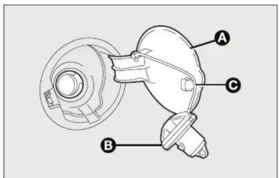
text_image
Technical diagram of a mechanical device with labeled parts A, B, and Cfig. 97
F0Q0695
PROTECTINGTHEENVIRONMENT
The following devices are used for reducing diesel fuel engine emissions:
☐oxidising catalytic converter
□exhaust gas recirculation system (EGR)
□particulate filter (DPF).

WARNING
Undernormaloperatingconditions, the silencerbecomesveryhot. Therefore
donotparkthecaronflammablematerials (grass,dryleaves,pineneedles,etc.):fire hazard.
Since this filter physically traps particulate, it should be regenerated (cleaned) at regular intervals by burning the carbon particles. The regeneration procedure is controlled automatically by the engine management control unit according to the filter conditions and vehicle use conditions. There may be a limited increase in the engine speed during the regeneration, a limited increase in fumes and high temperatures at the exhaust. These are not faults; they do not impair vehicle performance or damage the environment.
Particulatefilterclogged
If the warning light switches on on the instrument panel (along with the message on the display) refer to the "Warning lights and messages" chapter.
DIESELPARTICULATEFILTER(DPF)
(for versions/markets, where provided)
The Diesel Particulate Filter is a mechanical filter, integral with the exhaust system, that physically traps particulates present in the exhaust gases of diesel engines. The diesel particulate filter has been adopted to eliminate almost all particulates in compliance with current / future legal regulations.
During normal use of the vehicle, the engine control unit records a set of data (e.g.: travel time, type of route, temperatures, etc.) and it will then calculate how much particulate has been trapped by the filter.
SAFETY
SEATBELTS
USINGTHESEATBELTS
The seat belt should be worn keeping the torso straight and rested against the backrest.
To fasten the seat belts, hold the tongue A fig. 98 and insert it into the buckle B, until it clicks into place.
If the seat belt jams during removal, let it rewind for three anchor points and a reel for the side seats and a short stretch, then pull it out again without jerking the middle one.
To unfasten the seat belt, press button C. Guide Wear the rear seat belts as shown in fig. 99. the seat belt with your hand while it is rewinding, to prevent it from twisting.
Through the retractor, the seat belt automatically adapts to the body of the occupant wearing it, allowing freedom of movement.
The reel may lock when the car is parked on a steep slope: this is perfectly normal. Furthermore, the reel mechanism locks the belt if it is pulled sharply or in the event of sudden braking, collisions and high-speed bends.
The rear seat is fitted with inertia seat belts with three anchor points and a reel for the side seats and the middle one.
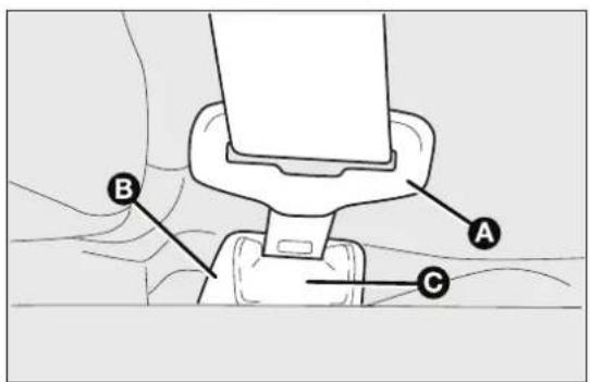
text_image
A B Cfig. 98
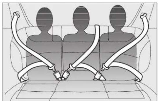
natural_image
Diagram of three human silhouettes seated in a car seat with attached medical tubing (no text or symbols)fig. 99
F0Q0267

WARNING
NeverpressbuttonCfig.98when travelling.
WARNING

Makesurethatthebackrestiscorrectly securedonbothsides(redbandsB
fig. 100notvisible)topreventitfrommoving forwardintheeventofsharpbraking, causing injuriestopassengers.
IMPORTANT The backrest is correctly secured when the red band B fig. 100 to the side of backrest folding handle A disappears. This red band indicates that the backrest is not secured.
IMPORTANT Remember that after a violent impact, rear-seat passengers who are not wearing their seat belts not only expose themselves to significant risk of injury, but also represent a danger to passengers occupying the front seats.
IMPORTANT When putting the rear seat back in its normal position, make sure that the seat belts are positioned so that they are ready to use.
ADJUSTINGTHEFRONTSEATBELT HEIGHT
(for versions/markets, where provided)
Four different adjustments in height are possible. To adjust, press button A fig. 101 and raise or low handle B.
Always adjust the height of the seat belts to fit the person wearing it: this precaution could greatly reduce the risk of injury in the event of collision.

text_image
Diagram showing a car interior with labeled parts A and B, indicating directional movement or movement of a device.fig. 100
F0Q0683
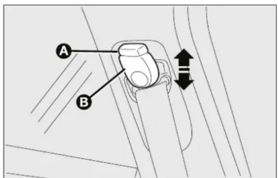
text_image
A Bfig. 101
F0Q0697
Correct adjustment is obtained when the belt passes SBRSYSTEM approximately half way between the shoulder and the neck.

WARNING
Makeheightadjustmentoftheseat beltswhenthecarisstationary.

WARNING
Afteradjustment,alwayscheckthatthe cursorowhichtheringisfastenedis
lockedinoneofthepresetpositions. Todothis, withthebuttonAfig. 10 I released, exerta furtherpressuretoallowtheanchordeviceto catchifreleasedidnottakeplaceatoneofthe presetpositions.
This system consists of a buzzer which, in conjunction with the warning light flashing on the instrument panel (initially in fixed mode with continuous acoustic signal and then in flashing mode with intermittent acoustic signal), warns the driver and front passenger that their seat belts have not been fastened.
For long-term deactivation of the SBR system, contact a Fiat Dealership. The SBR system can be reactivated at any time through the Setup Menu only (see the "Menu Items" paragraph in the "Knowing your car" chapter).
PRETENSIONERS
The car is equipped with front seat belts pretensioners, that reduce slack in the belts in the event of a severe frontal impact. This guarantees the perfect adherence of the seat belts to the occupants' bodies before the restraining action begins.
The retractors lock to indicate that the pretensioner has intervened.
This car is also equipped with a second pretensioner (in the kick plate area). Its activation is signalled by the shortening of the metal cable.
A slight discharge of smoke may be produced during the activation of the pretensioner which is not harmful and does not involve any fire hazard.
IMPORTANT To obtain the highest degree of protection from the action of the pretensioner, wear the seat belt tight to the chest and pelvis.
The pretensioner does not require any maintenance or lubrication: any changes to its original conditions will invalidate its efficiency. If, due to unusual natural events (floods, sea storms, etc.), the device has been affected by water and mud, it must be replaced

WARNING
Thepretensionermaybeusedonly once.ContactaFiatDealershiptohave
itreplacedafterithasbeendeployed.

Operationswhichleadtoimpacts, vibrationsorlocalisedheating(over100°C foramaximumofsixhours)inthearea
aroundthepretensionermaydamageordeploy it.ContactaFiatDealershipshouldintervention benecessaryonthesecomponents.
LOADLIMITERS
To increase passenger safety in an accident, the front and rear (for versions/markets where provided) seat belt reels contain a load limiter which controls the force acting on the chest and shoulders during the restraining action of the belts in the event of a head-on collision.
GENERALINSTRUCTIONSFORUSING THESEATBELTS
The driver must comply with (and have all car passengers follow) any local regulations in force concerning the use of seat belts. Always fasten the seat belts before setting off.
Seat belts are also to be worn by pregnant women: the risk of injury in the case of accident is greatly reduced for them and the unborn child if they are wearing a seat belt.
Pregnant women must position the lower part of the belt very low down so that it passes over the pelvis and under the abdomen (see fig. 102). The best way to protect the unborn child is to protect the mother. When a safety belt is worn properly, it is more likely that the unborn child will not be hurt in a crash. For pregnant women, as for anyone, the key to making safety belts effective is wearing them properly.

natural_image
Illustration of a person seated in a seat using a backbelt, with no text or symbols present.fig. 102
WARNING

Formaximumsafety, keeptheback of yourseatupright, leanback into it andmakesuretheseatbeltfitscloselyacross yourchestandpelvis.Alwaysfastentheseat beltsonboththefrontandtherearseats! Travellingwithoutwearingseatbeltswill increasetheriskofseriousinjuryorevendeath intheeventofanaccident.Removingor otherwisetamperingwithseatbeltand pretensionercomponentsisstrictlyprohibited. Anyoperationsonthesecomponentsmust beperformedbyqualifiedandauthorised technicians.AlwaysgotoaFiatDealership.
IMPORTANT The seat belt must not be twisted. The upper part must pass over the shoulder and cross the chest diagonally. The lower part must adhere to the pelvis (as shown in fig. 103) rather than the abdomen of the occupant. Never use devices (clips, clamps, etc.) to hold the seat belt away from your body.
IMPORTANT Each seat belt must be used by only one person. Never travel with a child sitting on the passenger's lap and a single belt to protect them both fig. 104. In general, do not place any objects between the person and the belt.

WARNING
Ifthebelthasbeensubjectedtoahigh levelofstress,forexampleafteran accident,itmustbecompletelyreplaced togetherwiththeattachments,attachment fixingscrewsandthepretensioner.Infact,even ifthebelthasnovisibledefects,itcouldhave lostitsresilience.
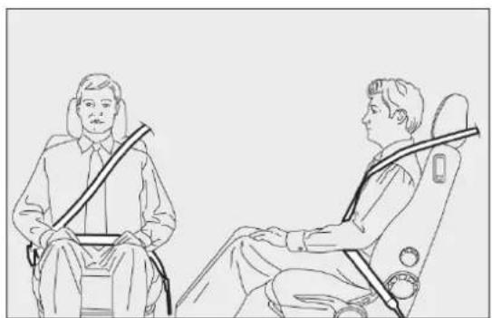
natural_image
Line drawing of two people seated in car seat positions, one wearing a seatbelt and the other with a belt (no text or symbols)fig. 103
F0Q0038
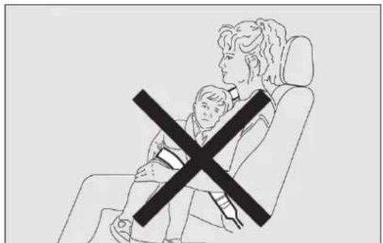
natural_image
Illustration of a person sitting in a car seat with a child crossed out, no text or symbols presentfig. 104
F0Q0039
SEATBELTSMAINTENANCE
Observe the following precautions for correct seat belt maintenance:
□always use the seat belt with the strap well stretched and not twisted; make sure that it is to run without obstructions;
□check seat belt operation as follows: attach the seat belt and pull it hard;
□replace the belt after an accident of a certain severity even if it does not appear to be damaged. Always replace the seat belt if the pretensioners were deployed;
to clean the seat belts, wash by hand with water and neutral soap, rinse and leave to dry in the shade. Never use strong detergents, bleach, paints or any other substance which could damage the belt fibres;
☐prevent the reels from getting wet: their correct operation is only guaranteed if water does not get inside;
☐replace the seat belt when it shows wear or cuts.
CARRYINGCHILDRENSAFELY
For optimal protection in the event of an impact, all occupants must be seated and wearing adequate restraint systems, including newborn and other children!
This prescription is compulsory in all EC countries according to EC Directive 2003/20/EC.
Compared with an adult, a child's head is larger and heavier in proportion to his/her body and the child's muscular and bone structures are not fully developed. Therefore, correct restraint systems other than adult seat belts are necessary to reduce as much as possible the risk of injuries in the event of an accident, braking or a sudden manoeuvre.
Children must be seated safely and comfortably. As far as the characteristics of the child restraint systems used allow, you are advised to keep children in rear facing restraint systems for as long as possible (at least until 3–4 years old), since this is the most protected position in the event of an impact.
The choice of the most suitable child restraint device depends on the weight of the child; there are various types of child restraint systems and you are advised always to choose the one that is most suitable for the child.
When over 1.50 m in height, from the point of view of restraint systems, children are considered as adults and wear seat belts normally.
In Europe the characteristics of children restraint systems are ruled by the regulation ECE-R44, dividing them into five weight groups:
GroupWeightgroups
| Group 0 up to 10 kg of weight |
| Group 0+ up to 13 kg of weight |
| Group 1 9-18 kg in weight |
| Group 2 15-25 kg in weight |
| Group 3 22-36 kg of weight |
All child restraint devices must bear the certification data, together with the control mark, on a label solidly fixed to the seat which must never be removed.
Lineaccessori Fiat offers child restraint systems for each weight group. These devices are recommended having been specifically designed for Fiat cars.

WARNING

SEVEREDANGER. When an active passenger air bag is fitted, DONOT install rear facing child restraints systems on the front seat. Deployment of the airbaginanaccidentcouldcausefatalinjuries tothechildregardlessoftheseverityofthe impact.Itisadvisabletoalwayscarrychildren inachildrestraintsystemontherearseat, whichisthemostprotectedpositioninthe eventofacollision.

WARNING
Onthesunvisorthereisalabelwith suitablesymbolsremindingtheuserthat itiscompulsorytodeactivatetheairbagifa rearfacingchildrestraintsystemisfitted. Alwayscomplywiththeinstructionsonthe passenger'ssidesunvisor(seethe"Front airbag"paragraph).

WARNING
Donotmovethefrontorrearseatifa childisseatedonitoronthededicated childrestraintsystem.
FITTING"UNIVERSAL" CHILDRESTRAINTSYSTEM (withseatbelts)
GROUP0and0+

WARNING
Thediagramisindicativeandforfitting purposesonly.Fitthechildrestraint
systemaccordingtotheinstructions,whichmust beincluded.
Children up to 13 kg must be carried with rearward facing restraint system of a type as shown in fig. 105 which, supporting the head, does not induce stress on the neck in the event of sudden decelerations.
The rearward facing infant seat is restrained by the car seat belts, as shown in fig. 105 and it must restrain the child in turn with its own belts.
GROUP I

WARNING
Thediagramisindicativeandforfitting purposesonly.Fitthechildrestraint accordingtotheinstructions,whichmust ded.
Children of weight from 9 to 18 kg may be carried in forward facing child restraint systems fig. 106.
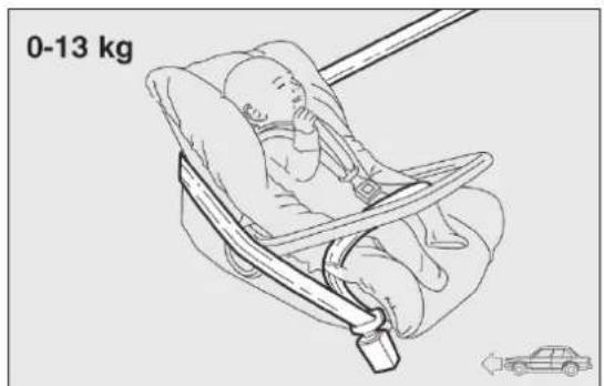
text_image
0-13 kgfig. 105
F0Q0429

text_image
9-18 kgfig. 106
F0Q0772

WARNING
ChildrestraintsystemswithIsofix attachmentsareavailableforasafe anchoringtotheseatwithoutusingthecarseat belts.
GROUP2

WARNING
Thediagramisindicativeandforfitting purposesonly.Fitthechildrestraint systemaccordingtotheinstructions,whichmust beincluded.
Children from 15 to 25 kg may use the car seat belts directly fig. 107.
In this case, the child restraint system is used to position the child correctly with respect to the seat belts so that the diagonal belt section crosses the child's chest and not the neck, and the lower part snug on the pelvis not the abdomen.

text_image
15-25 kgfig. 107
F0Q0431
The diagram is indicative and for fitting purposes only. Fit the child restraint system according to the instructions, which must be included.
For children between 22 kg and 36 kg, there are dedicated restraint systems that allow the seat belt to be worn correctly.
The fig. 108 shows the correct child positioning on the rear seat.
Children over 1.50 m in height can wear seat belts like adults.

text_image
22-36 kgfig. 108
F0Q0432
SUITABILITYOFPASSENGERSEATSFORUNIVERSALRESTRAINTSYSTEMUSE
According to the European Directive 2000/3/EC the suitability of each passenger seat position for the fix of universal child restraint systems is shown in the following table:
| GroupWeightrange | Frontpassenger | Rearcentral passenger |
| Group 0, 0+ up to 13 kg | U | U |
| Group 1 9–18 kg | U | U |
| Group 2 15–25 kg | U | U |
| Group 3 22–36 kg | U | U |
U= suitable for child restraint systems in the "Universal" category, according to European Regulation EEC-R44 for the specified "Groups".
ISOFIXCHILDRESTRAINTSYSTEM SETUP
The car is equipped with ISOFIX anchorages, a new standard which makes fitting a child restraint system quick, simple and safe.
Isofix systems can be fitted alongside conventional child restraint systems on different seats in the same car.
fig. 109An example of a Universal Isofix child restraint system for weight group I.

WARNING
The diagram is indicative and for fitting purposes only. Fit the child restraint system according to the instructions, which must be included.
The other weight groups are covered by specific Isofix child restraint systems, which can be used only if specifically tested for this car (see list of cars provided with the child restraint system).
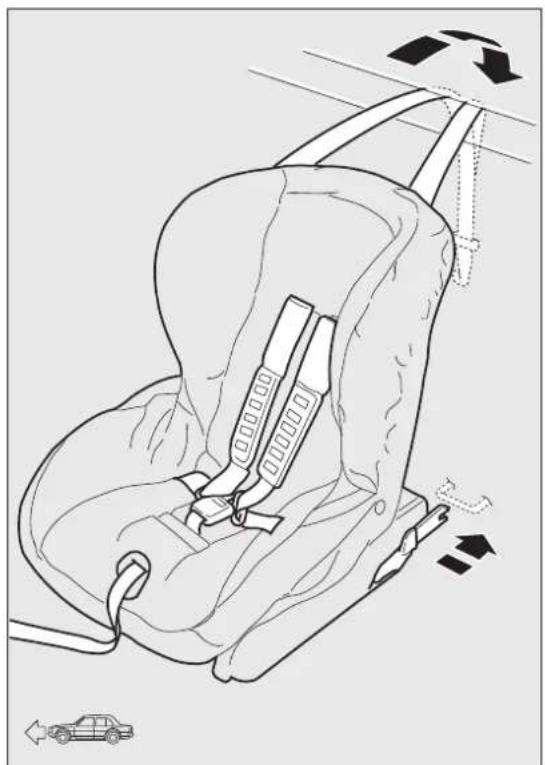
natural_image
Line drawing of a car seatbelt with directional arrows indicating movement (no text or symbols)fig. 109
F0Q0614
INSTALLINGAUNIVERSALISOFIXCHILD RESTRAINTSYSTEM
Attach the restraint system to the two metal anchorages A fig. 110 located where the rear seat cushion meets the backrest, then fix the upper strap (available together with the restraint system) to the dedicated anchorage B fig. 111 located at the bottom behind the backrest.
Remember that when using a Universal Isofix child restraint system, you can use approved child restraint systems with the marking ECE R44/03 (R44/03 or superior) "Universal Isofix".

WARNING
IfaUniversallsofixchildseatisnot fixedtoallthreeanchorages,thechild seatwillnotbeabletoprotectthechild correctly.Inacrash,thechildcouldbeseriously orfatallyinjured.
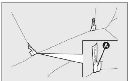
text_image
Medical diagram showing surgical procedure with labeled anatomical point A and measurement devicefig. 110
F0Q0698
The Universal Isofix "Duo Plus" child seat and the special "G 0/1" seat are available from Lineaccessori Fiat.
For any further details on installation/use, refer to the instruction manual for the child seat.

WARNING
Fitthechildseatwhenthecaris stationary. Thechildseatiscorrectly
anchoredtothebracketswhenyouhearthe click.Followtheinstructionsforassembly, disassemblyandpositioningthatthe manufacturermustsupplywiththechildseat.
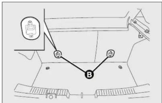
text_image
Diagram showing a vehicle interior with labeled points A and B, and a directional arrow pointing to point A.fig. III
F0Q0699
SUITABILITY OF PASSENGER SEATS FOR ISOFIX CHILD RESTRAINT SYSTEM USE
The table below shows the various installation possibilities for Isofix child restraint systems on seats fitted with Isofix attachments in accordance with European standard ECE 16.
| Weightgroup | Childrestraintsystem position | IsofixsizeclassRearsidepassengers |
| Group 0 up to 10 kg Rear facing E | IL | |
| Group 0+ up to 13 kg | Rear facing E | IL |
| Rear facing D | IL | |
| Rear facing C | IL (*) | |
| Group 1 from 9 up to 18 kg | Facing backwards D | IL |
| Facing backwards C | IL (*) | |
| Forward facing B | IUF | |
| Forward facing BI | IUF | |
| Forward facing A | IUF |
IL : suitable for ISOFIX child restraint systems of the categories for "specific vehicles", "restricted", or "semiuniversal", approved for this type of vehicle.
(*)The Isofix child seat can be installed by moving the front seat all the way up.
IL Suitable for special child restraint systems. Isofix type suitable and tested for this type of car. The seat can be installed by moving the front seat forward.
IUF: suitable for forward facing Isofix child restraint systems in the Universal category and type-approved for the use in the weight group.

WARNING
Fitthechildrestraintsystemaccording totheinstructions,whichmustbe
included.
Mainrecommendationstocarrychildren safely:
☐ Install the child restraint systems on the rear seat, which is the most protected position in the event of an accident.
☐Keep children in rear facing restraint systems for long as possible, until 3–4 years old if possible.
☐Should a rear facing child restraint system be installed on the rear seats, it is advisable to position it as far forward as the position of the front seat allows.
☐If the passenger's front airbag is deactivated always check the warning light on the instrument panel to make sure that it has actually been deactivated.
☐Carefully follow the child restraint manufacturer's instruction supplied with the child restraint system. Keep the instructions in the car along with the other documents and this handbook. Do not use second-hand child restraint systems without instructions.
☐Only one child is to be strapped into each retaining system; never carry two children using one child restraint system.
□Always check that the seat belts do not interfere with the child's throat.
□Always check that the seat belt is well fastened by pulling on it.
☐While travelling, do not let the child sit incorrect or unfasten the belts.
☐Never allow a child to put the belt's diagonal section under an arm or behind their back.
□Never carry children on your lap, even newborns.
: No-one can restrain a child in the event of an accident.
asIn the event of an accident, replace the child restraint system with a new one.
The car is fitted with front airbags for the driver a the passenger, and with a knee bag on the driver's side (for versions/markets, where provided).
The front driver/passenger airbags and the driver's knee bag (for versions/markets, where provided) have been designed to protect the front seat occupants in the event of frontal impacts of medium/high severity, by placing the bag between occupant and the steering wheel or dashboard.
Therefore non-deployment in other types of impacts (side impacts, rear shunts, roll-overs, etc.) does not indicate a system malfunction.
In the event of a frontal impact, an electronic control unit triggers the inflation of the bags if required. The cushions immediately inflate, placing themselves between the front occupants' bodies and structures that could cause injuries. Immediately after, the cushions deflate.
The front driver/passenger airbags and the driver's knee bag (for versions/markets, where provided) are not a replacement for, but rather complement the use of, seat belts, which should always be worn, as specified by law in Europe and most non-European countries.
In the event of an impact, those not wearing a seat belt will move forward and come into contact with the bag which is still inflating. The protection offered by the bag is compromised in these circumstances.
Front airbags may not be activated in the following situations:
frontal impacts against highly deformable objects not involving the front surface of the car (e.g. wing collision against guard rail, etc.);
□car wedging under other vehicles or protective barriers (e.g. trucks or guard rails);
Failure to activate in the conditions described above is due to the fact that they may not provide any additional protection compared with seat belts, so their activation would be inappropriate.
In these cases, non-deployment does not indicate a system malfunction.

WARNING
Donotapplystickersorotherobjects onthesteeringwheel,onthedashboard
inthepassengersideairbagarea,onside upholsteryontherooforontheseats.Never putobjects(e.g.mobilephones)onthe passenger'ssidedashboardsincetheycould interferewithcorrectinflationoftheairbag andalsocauseseriousinjurytothepassengers.
FRONTAIRBAGDRIVER'SSIDE
This consists of an instantly inflating bag contained in This consists of an instantly inflating bag contained a special compartment in the centre of the steering a special recess in the dashboard: this bag has a wheel fig. 112. larger volume than that of the driver fig. 113.
FRONTAIRBAGPASSENGER'SSIDE
The front driver and passenger airbags are designed and calibrated to best protect front-seat passengers wearing seat belts.

WARNING
Alwaysdrivewithbothhandsonthe steeringwheelsothat,iftheairbags mustbedeployed,theymaydosofreely.Donot drivewithyourbodybentforward.Keepyour backstraightagainstthebackrest.
The volume of the front airbags at max. inflation fil most of the space between the steering wheel and the driver and between the dashboard and the passenger.
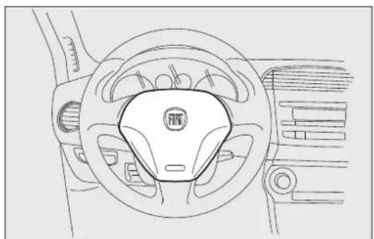
natural_image
Top-down line drawing of a car steering wheel and dashboard (no text or symbols)fig. 112
F0Q0624
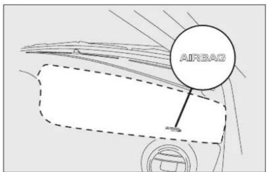
text_image
AIRBAGfig. 113
F0Q0700
WARNING

SEVEREDANGERWhenanactive passengerairbagisfitted,DONOT installrearwardfacingchildrestraint systemsonthefrontseat.Deployment oftheairbaginanaccidentcouldcausefatal injuriestothecildregardlessoftheseverityof theimpact. Therefore,alwaysdeactivatethe passengerairbagwhenarearwardfacingchild restraintsystemisinstalledonthefront passengerseat. Thefrontpassengerseatmust alsobepositionedbackasfaraspossiblein ordertoavoidthecildrestraintsystemfrom comingintocontactwiththedashboard. Immediatelyreactivatethepassengerairbagas soonasthechildrestraintsystemhasbeen removed.
FRONTPASSENGERAIRBAGANDCHILD RESTRAINTSYSTEMS

WARNING
Whenanactivepassengerairbagis fitted, DONOTinstallrearfacingchild restraintsystemsonthefrontseat.Deployment oftheairbaginanaccidentcouldcausefatal injuriestothechildregardlessoftheseverity of theimpact.
ALWAYScomply with the instructions on the label stuck on the passenger side sun visor fig. 114.

text_image
AIRBAG NO NO A B A G A B A G A B A G A B A Gfig. 114
F0Q0920
FRONTPASSENGERAIRBAGANDCHILDRESTRAINTSYSTEMS:WARNING
| I | RISCHIO DI FERITE GRAVI O MORTALL |
| I seggiolini bambino che si montano nel verso opposto a quello di marcia non vanno installati sui sedili anteriori in presenza di air bag passeggero attivo. | |
| GB | DEATH OR SERIOUS INJURY CAN OCCLR. |
| NEVER use a rearward facing child restraint on a seat protected by an ACTIVE AIRBAG in front of it, DEATH OR SERIOUS INJURY to the CHILD can occur | |
| F | RISQUE DE MORT OU DE BLESSURES GRAVES. |
| NE PAS positionner le siège pour enfant tourné vers l'arrière, en cas d'air bag passager actif. | |
| D | Nichtbeachtung kann TOO oder SCHWERE VERLETZUNGEN zur Folge haben. |
| Rückwärts gerichtece Kinderrückhaltesysteine (Babyschale) dürfen nicht in | |
| Verbindung mit aktiviertem Beifahrerairbag auf dem Beifahrersitz verwendet warden | |
| NL | DIT KAN DODELIJK ZIJN OF ERNSTIGE ONGELUKKEN VEROORZAKEN. |
| Plaats het kinderstoelje niet ruggelings op de voorstoel wanneer er een airbag aanwezig is. | |
| E | PUEDE OCACIONAR MUERTE O HERIDAS GRAVES. |
| NO ubicar el asiento para niños en sentido inverso al de marcha en el asiento delantero si hubiese airbag activo lado pasegero. | |
| PL | MOŽE GROZIĆ ŠMERCIA LUB CIEŽKIMI OBRAŽENAMI. |
| NIE WOLNO umieszczać foletica dzieciecego tylem do kierunku jazdy na przednim siedzeniu w przypadku zainstalowanej aktywnej poduszki powietrznej pasazera. | |
| TR | ÖLÜM VEYA AĞIR ŞEKILDE YARALANMAYA SEBEP OLABİLIR |
| Yolcu airbagi aktif halde ilken çocuk koltužunu araç gidq yönüne ters biçimde yerlegtirmeyin. | |
| DK | FARE FOR DODELIGE KVESTELSER OG LIVSTRUENDE SKADER. |
| Placer aldrig en bagudvendt barnestol på passagererszadet, hvis passager-airbagen er indstillet til at vare aktiv (on). | |
| EST | TAGAJÄRJEKS VÖIVAD OLLA TÖSISED KEHAVIGASTUSED VÖI SURM. |
| Turvapadja olemasolu korral arge asertage lapse turvaistet söidusuunaga vastassuunas. | |
| FIN | KUOLEMANVAARA TAI VAKAVIEN VAMMOJEN UHKA. |
| Áli aseta lasten turvaistunta niin, että lapsi on selkä menosuuntaan, kun matkustajan airbag on käytóssä. | |
| P | RISCO DE MORTE OU FERIMENTOS GRAVES. |
| Não posicionar o banco para crianças numa posição contrária ao sentido de marcha quando o airbag de passageiro estiver activo. | |
| LT | GALI IŠTIKTI MIRTIS ARBA GALITE RIMTAI SUSIŽEISTL. |
| Nedekice valko sedynes atgreżtos nugara i priekinj automobilio stiką ten, kur yra veikiant keleivio oro pagalve. | |
| S | KAN VARA LIVSHOTANDE ELLER LEDA TILL ALLVARLIGA SKADOR. |
| Placera aldrig en baktvänd barnstol i framsitet da passagerarsidans krockkudde är aktiv. | |
| H | HALÁSOS VAGY SÜLYOS BALESET KÖVETKEZHET BE. |
| Ne helyezzük a gyermekülést a menetiránnyal szembe, ha az utas oldalán légzsák működik. | |
| LV | VAR IZRAISIT NÄVI NAVI NOPIETNAS TRAUMAS. |
| Nenoviotot mazuja södelki prestji brauklanas virzienam, ja pasażiera pusě ir uztældīts gaia spilvens. | |
| CZ | HROZI NEBEZPEČI VAŽNÉHO UBŁIŽENÍ NA ZDRAVI NEBO DOKONCE SMRTI. |
| Neumistujte děskou sedačku do opačné polohy vůži směru jizdy v případě aktivního airbagu spolujezdce. | |
| SLO | LAHKO PRIDE DO SMRTI ALI HUDIH POŠKODB. |
| Otroškega avtomobilsega sedeža ne nameščajte v obratni smeri vožnje, će ima vozilo vgrajene zračne blazine za potnikė. | |
| RO | SE POATE PRODUCE DECESUL SAU LEZIUNI GRAVE. |
| Nu azejatı samul de mašiná pentru bebelugi in pozijie contrará directiei de mers atunci când airbag-ul passagerului este activat. | |
| GR | MIPOPEI NA PIPOKLHBOYN OÑANATOJ H SOBARA TRAYMATA. |
| Mnu topošteteite to kopeklāni autokvirjou yia mašiša će antitēstη προς την φόρα πορείας θέση σε περίπτωση που υπάρχει ασρόσικος εν ευμτήση στη θέση συνεπβάτη. | |
| BG | IMA OPAACHOCT OT СМЪРТ и СЕРИОЗНИ HAPANЯВАНИЯ. |
| He поставайте столчето за пренасяче на бебета в положение обратно на посоката на движение, при положение активно на въздушната възглавница за пътуване. | |
| SK | MÕZE NASTAT SMRT ALEBO VAŽNE ZRANENIA |
| Nedivajte autosedačku pre deti do polohy proti chodu vozidla, keď je aktivny airbag spolujazda. | |
| RUS | ВОЗМОЖНЫ ТРАВЫИ И ЛЕТАЛЬНЫЙ ИСХОД. |
| Детское кресло, устанавливавоється против направления движения, нельзя монтировать на месте переднего пассажири, если последнее оборудовано активной подушкой безопасности. |
F0Q0921
DRIVERSIDEKNEEBAG
(for versions/markets, where provided)
It is located in a special compartment under the dashboard and is protected by a dedicated cover fig. 116. It provides protection to the lower limbs the event of frontal impact.
Deactivationofpassengersideairbags:front airbagandsidebagforpelvis-chest-shoulder protection(forversions/markets,where provided)
In If a child must be carried on the front seat in backward-facing child restraint system, deactivate the passenger side front airbag and front side bag for pelvis, chest and shoulder protection (for versions/markets, where provided).
With the airbags deactivated, the warning light switches on in the instrument panel.
IMPORTANT To deactivate the airbags see the description in the "Knowing your car" chapter, "Menu Options" paragraph.

natural_image
Diagram of a car interior showing foot, seat, and dashboard components with an arrow indicating a specific area (no text or labels present)fig. 116
F0Q0702
SIDEAIRBAGS (Sidebag-Windowbag)
The car is fitted with front side bags for driver and passenger, protecting the chest/pelvis, and window bags for protecting front and rear passengers' heads.
Side airbags protect occupants from side impacts of medium/high severity by placing the bag between the occupant and the internal parts of the side structure of the car.
Non-activation of side bags in other types of collisions (frontal impacts, rear shunts, roll-overs, etc...) is not an indication of system malfunction.
In the event of a side impact, an electronic control unit triggers the inflation of the bag if required. The cushion immediately inflates, placing itself between the occupant's body and structures that could cause injuries. Immediately after, the cushion deflates.
Side bags are not a replacement of, but rather a complement to, seat belts, which you are recommended to wear at all times, as specified by law in Europe and most non-European countries.
SIDEBAGS
(for versions/markets, where provided)
These comprise two types of bags located in the front seat backrests fig. 117 which protect the pelvis, chest and shoulder area of the occupants in the event of a side impact of medium/high severity.
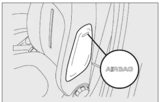
text_image
AIRBAGfig. 117
F0Q0701
WINDOWBAG
(for versions/markets, where provided)
This comprises a "curtain" bag housed behind the roof side linings and covered by special trims fig. 11 It is designed to protect the head of front and rear occupants in the event of a side collision, thanks to the wide cushion inflation surface.
The deployment of side bags in the event of side impacts of low severity is not required.
In the event of a side impact, the system provides best protection if the passenger sits on the seat in correct position, thus allowing correct window bag deployment.
For this reason, the seat belt must be worn at all times. In the case of side impacts, the seat belts ho occupants in the correct position and prevent them from being thrown out of the car by a very violent collision.
Therefore, front side bags (for versions/markets, where provided) are not a replacement of, but complementary to, seat belts, which you are recommended to always wear, as specified by law in Europe and most non-European countries.
IMPORTANT Do not affix rigid objects to the garment hooks or support handles.
IMPORTANT Do not rest your head, arms or elbows on the door, on the windows and on the window bag area to avoid injuries during inflation.
IMPORTANT Never lean your head, arms or elbows out of the window.
IMPORTANT In the event of a side impact, the system provides best protection if the passenger sits on the seat in a correct position, thus allowing correct window bag deployment.

natural_image
Side view of a car with a dashed arrow indicating upward motion or airflow direction (no text or symbols)fig. 118
WARNING

Donotcoverthebackrestofthefront seatswithcoverswhicharenotsuitable withsidebags.
IMPORTANT
Do not wash the seats with water or pressurised steam (wash by hand or at automatic seat washing stations).
The front airbags and/or front side bags (for versions/markets, where provided) may be deployed if the car is subject to heavy collisions or accidents involving the underbody area, such as for example violent shocks against steps, kerbs or low obstacles, car falling into big holes or sags in the road.
When the airbag deploys it emits a small amount of dust: the dust is harmless and does not indicate the beginning of a fire. The dust may irritate the skin and eyes however: in this case, wash with neutral soap and water.
Airbag checking, repair and replacement must be carried out at a Fiat Dealership.
If the car is scrapped, have the airbag system deactivated at a Fiat Dealership.
Pretensioners and airbags are deployed according to different logics on the basis of the type of collision. Failure to deploy of one or more of the devices does not indicate a system malfunction.

WARNING
If the warninglightdoesnotswitch onwhenthekeyisturnedtoMAR-ON, orstaysonwhiledriving(onsomeversions togetherwithamessageonthedisplay)there maybeafaultintherestraintsystems.Inthis case,theairbagsorthepretensionersmay notbeactivatedinthecaseofanaccidentor (inalessernumberofcases)theymaybe activatedincorrectly.ContactyourFiat Dealershipimmediatelytohavethissystem checked.

WARNING
Oncarswithsidebags, donotcoverthe frontseatbackrestswithextracovers.

WARNING
Donottravelcarryingobjectsinyour lap,infrontofyourchestorbetweens(pipe,pencils,etc.):theycouldcause injuryiftheairbagisdeployedinant.
WARNING
Ifthecarhasbeenstolenorinthecase ofattempttostegalit,ifithasbeen subjectedtovandalismorfloods,havethe airbagsystemcheckedbyaFiatDealership.

WARNING
When the ignition key is inserted and turned to MAR-ON, airbags maybe deployed if an other car crashes into the vehicle, even if the engine is not running and the car is stationary. Therefore, even if the car is stationary, when an active passenger air bag is fitted, DONOT install rearward facing child restraintsystem on the front passenger seat. Deployment of the airbag following an impact could cause fatal injury in the child. Therefore, always deactivates passenger air bag when are forward facing child restraints system is installed on the front passenger seat. The front passenger seat must also be positioned back as far as possible in order to avoid the child restraints system from coming into contact with the dashboard. Immediately reactivates passenger air bag as soon as the child restraint system has been removed. Also remember that, if the key is turned to STOP, none of the safety devices (air bags or pretensioners) will be deployed in the event of collision. Non-deployment insuch cases does not indicate a system malfunction.
WARNING

Whentheignitionkeyisturnedto MAR-ON, the warninglight 2 (with passenger'sfrontairbagactivated)turnsonand flashesforafewsecondstoremindyouthat thepassenger'sairbagwillbedeployedina crash,afterwhichitshouldgooff.

WARNING
Thefrontairbagisdesignedtobe deployedforimpactsofagreater tythanforthepretensioners.Forimpacts intensityfallsbetweenethetwo ionlevels,itisnormalforonlythe sionerstobeeactivated.

WARNING
Theairbagdoesnotreplaceseatbelts butincreasestheirefficiency.
Furthermore, since frontair bags are not deployed in low-speed frontal impacts, side impacts, rearshunts or roll-overs, the passengers are protected only by these seat belts which must therefore be fastened at all times.
STARTINGANDDRIVING
STARTINGTHEENGINE
The car is fitted with an electronic engine lock device: if the engine fails to start, see the paragraph "The Fiat CODE system" in the section "Knowing your car".
Engine starting is guaranteed to -18^ (Italy and central Europe) and -20^ (Northern Europe).

Werecommendthatduringtheinitial periodyoudonotdemandtofull performancefromthecar(e.g.excessive
acceleration, longjourneysattopspeed, sharp brakingetc.).

Whentheengineisswitchedoffnever leavethekeyturnedtoMARtoprevent uselesscurrentabsorptionfromdraining
thebattery.

WARNING
Itisdangeroustohavetheengine runningindoors. Theengineconsumes
oxygenandengineexhaustcontainscarbon dioxide,carbonmonoxideandothertoxic gasses.

WARNING
Remember that the brakeservo and powersteering are not operational until
theenginehasbeenstarted,thereforemuch effortthanusualisrequiredonthebrakepedal andsteeringwheel.
STARTINGPROCEDUREFORDIESEL VERSIONS
Proceed as follows:
☐engage the handbrake and place the gear lever in neutral;
□turn the ignition key to MAR: the warning lights and on the instrument panel will turn on;
□wait for the warning lights and to switch off;
☐ press the clutch pedal down to the floor without touching the accelerator;
□turn the ignition key to AVV as soon as warning light 00 switches off. Waiting too long will waste the heating work carried out by the glow plugs. Release the key as soon as the engine starts.
IMPORTANT With cold engine, the accelerator must be entirely released when turning the ignition key to position AVV.
If the engine does not start at the first attempt, return the ignition key to STOP before attempting start again.
If, when the ignition key is at MAR-ON the warning light remains lit, turn the key to STOP and then back to MAR-ON. If the warning light remains lit, try with the other keys provided with car.
If you still cannot start the engine, contact a Fiat Dealership.

Warninglightwithashfor60seconds afterstartingorduringprolonged crankingtoindicateafaultwiththeglow
plugheatingsystem.Youcanusethecarasusual iftheenginestartsbutyoushouldcontacta FiatDealershipassoonaspossible.

Whentheengineisswitchedoffnever leavethekeyturnedtoMARtoprevent uselesscurrentabsorptionfromdraining
thebattery.
HOWTOWARMUPTHEENGINEAFTERIT HASJUSTSTARTED
Proceed as follows:
☐Drive off slowly, letting the engine turn at medium revs. Do not accelerate abruptly;
☐Do not demand full performance at first. Wait until the engine coolant temperature gauge starts moving.

Neverjumpstarttheenginebypushing, towingorcoastingdownhill. Thiscould causefueltoflowintothecatalytic
converteranddamageitbeyondrepair.
the EMERGENCYSTART-UP
Contact a Fiat Dealership if instrument panel warning light 📋 (or the symbol on the display) stays on constantly.
STOPPINGTHEENGINE
Turn the ignition key to STOP while the engine is idling.
IMPORTANT After a taxing drive, you should allow the engine to "catch its breath" before turning it off by letting it idle to allow the temperature in the engine compartment to fall.

Aquickburstontheacceleratorbefore stoppingtheengineservesnopractical purpose;itwastesfuelandisespecially
damagingtoturbochargedengines.
PARKING
Proceed as follows:
□stop the engine and engage the handbrake;
☐engage a gear (on a slope, engage first gear if the car is facing uphill or reverse if it is facing downhill) and leave the wheels steered.
Block the wheels with a wedge or a stone if the car is parked on a steep slope.
Do not leave the key in the ignition switch to prevent the battery from running down.

WARNING
Neverleavechildrenunattendedinthe car.Alwaysremovethekeyfromthe
ignitionwhenleavingthecarandtakeitwith you.
HANDBRAKE
The handbrake is located between the front seats.
To use the handbrake pull the lever upwards until the car cannot be moved.
Four or five clicks are generally enough when the car is on level ground while nine or ten may be required if the car is on a steep slope and laden.
IMPORTANT If this is not the case, contact a Fiat Dealership for adjustment.
When the handbrake is engaged and the ignition key is at MAR-ON, the warning light will switch on in the instrument panel.
Proceed as follows to release the handbrake:
□slightly lift the handbrake and press release button A fig. 119;
□keep button A pressed and lower the lever. The car (!) warning light in the instrument panel will switch off.
Press the brake pedal when carrying out this operation to prevent the car from moving accidentally.
IMPORTANT For cars equipped with a front armrest, lift this up to ensure that it does not interfere with the action of the handbrake.
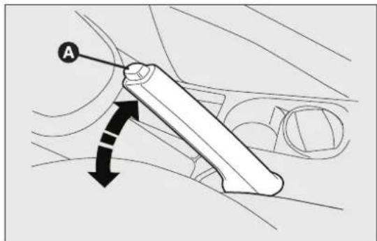
text_image
Afig. 119
F0Q0628
USINGTHEGEARBOX
To engage the gears, press the clutch pedal fully andy mistake. The same applies to the shift from 6 shift the gear lever into one of the required positions 5^th gear.
(the diagram for gear engagement is shown on the knob fig. 120 fig. 121).
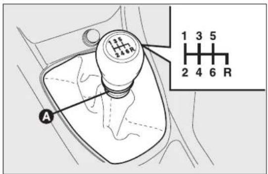
text_image
1 3 5 2 4 6 R Afig. 120 - 1.6 Multijet versions
F0Q0734
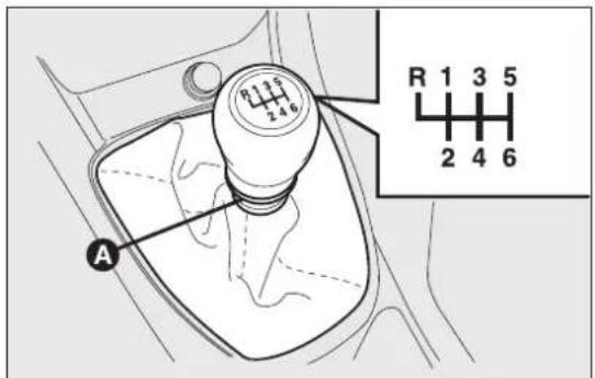
text_image
R 1 3 5 2 4 6 Afig. 121 - 2.0 Multijet versions (where provided)
To engage ^th gear, operate the lever by pressing it towards the right in order to avoid engaging gear
by mistake. The same applies to the shift from 6 to 5^th gear.
To engage reverse R from neutral, lift sliding ring A and, at the same time:
□move the lever to the right and then backwards (1.6 MultiJet versions) fig. 120;
or
☐move the lever to the left and then forwards (2.0 Multijet versions - for versions/markets, where provided) fig. 121.
IMPORTANT Reverse can only be engaged when the car is completely stationary. With the engine running, wait for at least 2 seconds with the clutch pedal fully pressed before engaging reverse to prevent damage to the gears and grating.
IMPORTANT The clutch pedal should be used only for gear changes. Do not drive with your foot resting on the clutch pedal, however lightly. For versions/markets where provided, the electronic clutch pedal control could cut in, interpreting the incorrect driving style as a fault.

WARNING
Depresstheclutchpedalfullytochange gearcorrectly.Itisthereforeessential thatthereisnothingunderthepdals:make surethematsarelyingflatandonotget inthewayofthepdals.

Donotdrivewithyourhandrestingon thegearleverastheforceexerted,evenif slight,couldleadovertimetopremature
wearofthegearboxinternalcomponents.
SAVINGFUEL
Some useful tips are given below for fuel saving and reducing harmful emissions of C₂ and other pollutants [nitrogen oxides, unburnt hydrocarbons, Particulate Matter (PM) etc.].
GENERALCONSIDERATIONS
The general factors that affect fuel consumption are listed below.
Carmaintenance
Have checks and adjustments carried out in accordance with the “Scheduled Servicing Plan”.
Tyres
Check the tyre pressures at least once every four weeks: if the pressure is too low, consumption level increase as resistance to rolling is higher.
Unnecessaryloads
Do not travel with an overloaded boot. The weight of the car (especially when driving in town) and its ride greatly affects consumption and stability.
Roofrack/skirack
Remove the roof rack or the ski rack from the roof after use. These accessories lower aerodynamic penetration and adversely affect consumption levels. When transporting particularly large objects, use a trailer if possible.
Electricdevices
Use electrical devices only for the amount of time necessary. The heated rear window, additional headlights, windscreen/rear window wipers and heater fan need a considerable amount of energy, therefore increasing fuel consumption (by up to 25 in the urban cycle).
Climatecontrolsystem
Air conditioning leads to higher fuel consumption average up to +20%). If the temperature outside permits, try and use the air vents.
Spoilers
The use of non-certified spoilers may adversely affect air drag and fuel consumption.
DRIVINGSTYLE
The main driving styles that affect fuel consumption are listed below.
Starting
Do not warm the engine with the car at a standstill or at idle or high speed: under these conditions the engine warms up much more slowly, increasing electrical consumption and emissions. It is therefore advisable to move off immediately, slowly, avoiding high speeds: in this way the engine will warm faster.
Unnecessaryactions
Avoid accelerating when starting at traffic lights or before switching off the engine. This and also double declutching is absolutely pointless on modern cars and also increases consumption and pollution.
Gearselection
As soon as the conditions of the traffic and road allow, use a higher gear. Using a low gear for faster acceleration will increase consumption.
In the same way improper use of a high gear increases consumption, emissions an engine wear.
Max.speed
Fuel consumption increases considerably with speed. Maintain a constant speed, avoiding unnecessary braking and acceleration, which cost in terms of both fuel consumption and emissions.
Acceleration
Accelerating violently severely affects consumption and emissions: acceleration should be gradual and should not exceed the maximum torque.
USAGECONDITIONS
The main usage conditions that negatively affect fuel consumption are listed below.
Coldstarting
Short journeys and frequent cold starts do not allow the engine to reach optimum operating temperature. This results in a significant increase in consumption levels (from +15 to +30% on the urban cycle) and emissions.
Trafficandroadconditions
Rather high consumption levels are linked to situations with heavy traffic, for instance when travelling in queues with frequent use of the lower gears or in cities with many traffic lights. Winding mountain roads and rough road surfaces also adversely affect consumption.
Traffichold-ups
During prolonged hold-ups (e.g. level crossings) the engine should be switched off.
TOWINGTRAILERS
IMPORTANTNOTES
For towing caravans or trailers the car must be fitted with a certified tow hook and an adequate electric system. Installation should be carried out by specialised personnel who will issue the required papers for travelling on roads.
Install any specific and/or additional rear view mirror as specified by the Highway Code.
Remember that when towing a trailer, steep hills are harder to climb, braking distances increase and overtaking takes longer depending on the overall weight.
Engage a low gear when driving downhill, rather than constantly using the brake.
The weight the trailer exerts on the car tow hook reduces the car's loading capacity by the same amount. To make sure that the maximum towable weight is not exceeded (given in the car registration document) account should be taken of the fully laden trailer, including accessories and luggage.
Respect the speed limits specific to each country for vehicles towing trailers.
In any case, the maximum speed must not exceed km/h.

WARNING
TheABSwithwhichthecarmmaybe equippedwillnotcontrolthebraking
systemofthetrailer.Particularcautionis requiredonslipperyroads.

WARNING
Nevermodifythebrakingsystemofthe cartocontrolthetailerbrake. The
trailerbrakingsystemmustbefully independentofthecar'shydraulicsystem.
INSTALLINGTHETOWHOOK
The towing device should be fastened to the bodywork by specialised personnel according to any additional and/or integrative information supplied by the Manufacturer of the device. The towing devi must meet current regulations with reference to Directive 94/20/EEC and subsequent amendments. For any version the towing device used must be right for the towable weight of the car on which it is to be installed.
IMPORTANT The use of auxiliary loads other than external lights (electric brake, winch, etc.) must be used with engine running.
For the electric connection a unified connector should be used, which is generally placed on a special bracket fastened to the towing device, and a special ECU should be installed on the car to control the trailer's exterior lights.
7 or 13-pole 12 V DC connections should be used (CUNA/UNI and ISO/DIN Standards). Follow any instructions provided by the car manufacturer and/or the towing device manufacturer.
An electric brake or winch should be powered directly by the battery through a cable with a cross-section of no less than 2.5 mm
IMPORTANT Electric brakes or other devices must be used with engine running.
In addition to the electrical branches, the vehicle's electrical system can be connected only to the supply cable for an electric brake and to the cable for an internal trailer light, though not more than 15 W. For connections use the preset control unit with battery cable no less than 2.5 mm
SNOWTYRES
Use snow tyres of the same size as the normal tyre provided with the car.
A Fiat Dealership will be happy to provide advice concerning the most suitable type of tyre for the customer's requirements.
For the type of tyre to be used, inflation pressures and the specifications of snow tyres, follow the instructions given in paragraph "Wheels" in section "Technical specifications".
The winter features of these tyres are reduced considerably when the tread depth is below 4 mm. Replace them in this case.
Due to snow tyre features, under normal conditions of use or on long motorway journeys, the performance of these tyres is much lower than that of standard tyres. Their usage should therefore be restricted in accordance with their type approval.
IMPORTANT When using snow tyres with a maximum speed index below the one that can be reached by the car (increased by 5%), place a notice in the passenger compartment, plainly in view, which states the maximum speed allowed by the snow tyres (as per EC Directive).
All four tyres should be the same (brand and track) to ensure greater safety when driving and braking and better driveability.
Remember that you should not change the rotation direction of the tyres.

WARNING
Themaximumspeedforsnowtyres marked“Q”is 160km/h, whileitis 190
km/hfor"T"tyresand210km/hfor"H"tyres. Youshould,however,alwayssticktothespeed limitsoftheRoadTrafficCode.
SNOWCHAINS
The use of snow chains should be in compliance with local regulations.
Snow chains may be fitted to the tyres of the front wheels (drive wheels) only.
Check the tension of the snow chains after the first few metres have been driven.
Use reduced size snow chains:
☐for 205/55 R16" tyres, use reduced size snow chains with a maximum projection of 9 mm beyond the tyre profile;
☐for 225/45 R17" tyres, use reduced size snow chains with a maximum projection of 7 mm beyond the tyre profile.
IMPORTANT 225/40 R18 92V tyres cannot be fitted with chains. Snow chains may cause interference with the surrounding elements.
IMPORTANT Snow chains cannot be fitted to the space-saver wheel. If a front tyre is punctured, replace a rear wheel with the space-saver wheel and move the rear wheel to the front axle. In this way, with two normal drive wheels at the front, snow chains can be fitted.

Keepyourspeeddownwhensnowchains arefitted;donotexceed50km/h.Avoid potholes,stepsandpavementsandavoid
forlongdistancesonroadsnotcovered owtopreventdamagingthecarand dbed.
CARINACTIVITY
If the car is to be left inactive for longer than a month, the following precautions should be observed:
☐park the car in covered, dry and if possible well-ventilated premises and slightly open the windows;
☐engage a gear and disengage the handbrake;
□disconnect the negative battery terminal and check charge (see paragraph “Battery - Charge and electrolyte level check” in chapter “Maintenance and care”);
□clean and protect the painted parts using protective wax;
□clean and protect the shiny metal parts using special compounds available commercially;
□sprinkle talcum powder on the rubber windscreen and rear window wiper blades and lift them off the glass;
☐cover the car with a cloth or perforated plastic sheet. Do not use sheets of non-perforated plast as they do not allow moisture on the car body to evaporate;
☐inflate tyres to +0.5 bar above the standard specified pressure and check it at intervals;
☐do not drain the engine cooling system.
IMPORTANT Where relevant, switch off the car alarm with the remote control.
WARNINGLIGHTSANDMESSAGES
WARNINGLIGHTSANDMESSAGES
GENERALWARNINGS
Warning lights are accompanied by a specific message and/or acoustic warning where provided by the control panel. These indications are concise and precautionary and, as such, must not be considered as exhaustive and/or an alternative to the information contained in this Owner Handbook, which you are advised to read carefully in all cases. The event of a failure indication, always referto the content so this chapter.
IMPORTANT Failure indications displayed are divided into two categories: veryserious and lessserious failures.
Veryserious failures are indicated by a repeated and prolonged warning "cycle".
Lessseriousfailures are indicated by a shorter warning "cycle".
The display cycle of both failure types can be stop by pressing the MODEbutton. The warning light (or symbol in the display) will remain on until the cause of the malfunction is eliminated.
Turning the key to the MAR-ON position the warning light switches on, but it should switch off after a few seconds.
LOWBRAKEFLUIDLEVEL
The warning light switches on when the level of the brake fluid in the reservoir falls below the minimum level due to a possible leak in the circuit. On some versions the display shows the dedicated message.

WARNING
If the Ⓔ warninglightswitchesonwhile driving, stopimmediately and contact
aFiatDealership.
e q HANDBRAKEAPPLIED
The warning light turns on when the handbrake is applied. If the car is moving the buzzer will also sound.
IMPORTANT If the warning light comes on when the car is in motion, check that the handbrake is not on.
BRAKEPADWEAR(amber)
The warning light switches on if the front brake pad are worn. In this case replace them as soon as possible.
The display will show the dedicated message.
IMPORTANT Because the car is equipped with a wear detection system only for the front brake pads, when these are replaced the rear brake pads should also be checked for wear.

AIRBAGFAILURE(red)
Turning the key to the MAR-ON position the warning light switches on, but it should switch off after a few seconds. The warning light stays on constantly if there is a failure in the airbag system.

WARNING
IfwhenturningthekeytoMAR-ONthe warninglight doesnotturnonor staysonwhilstdriving,afailuremayhave occurredintherestraintsystems.Inthiscase theairbagsorpretensionersmaynotbe deployedinanimpactor,inalowernumberof cases,theymaybedeployedaccidentally. ContactaFiatDealershipimmediatelytohave thesystemchecked.

WARNING
Afaultwiththe warninglight is indicated by flashing of the warning which signal the deactivation of the gersidefrontairbag. In addition, the system automatically disable the on the passenger's side (both front and pags for versions/markets, where d). In this case, the warning light may cateafault in therestraint systems. continuing, contact a Fiat Dealership iately to have the system checked.

PASSENGER/SIDEAIRBAGS DEACTIVATED(amber)
The warning light switches on when the front passenger's airbag and side bag are disabled. With front passenger airbag on, when the ignition key is turned to MAR-ON, the warning light switches on constantly for several seconds, it flashes for another few seconds and then it should switch off.

WARNING
Afailureofthe warninglightis indicatedbywarninglightswitching on. In addition, the airbagsystemautomatically disable the airbagsonthepassenger'sside (bothfrontandsideairbagswhereprovided). Before continuing, contactaFiatDealership immediately to havethesystemchecked.

UNFASTENEDSEATBELTS(red)
The warning light switches on constantly with the car stationary and the driver's side or passenger seat belt (when the passenger is present) not fastened.
The warning light will flash and a buzzer will sound if the car is in motion and the front seat belts are not correctly fastened.
The SBR (Seat Belt Reminder) system buzzer can only be permanently switched off by a Fiat Dealership.
The system can be reactivated using the Setup Menu.
LOWBATTERYCHARGE(red)
The warning light comes on when the ignition key is turned to MAR-ON, but it should go out as soon as the engine has started (with the engine running at idle speed a brief delay before going out is acceptable).
If the warning light stays on constantly or continues to flash, contact a Fiat Dealership immediately.

CONTINUOUSLYON:LOW ENGINEOILPRESSURE(red)
ONFLASHING: ENGINEOIL DETERIORATED
e(only MultiJet versions with DPF - red)
When the ignition key is turned to MAR-ON, the warning light switches on but should switch off as soon as the engine is started.
Lowengineoilpressure
The warning light switches on constantly together (for versions/markets, where provided) with a message on the display when the system detects that the engine oil pressure is too low.

WARNING
If the warning light turn on when the caristravelling (on certain inversions
togetherwiththemessageonthedisplay)stop theengineimmediatelyandcontactaFiat Dealership.
Engineoildegraded
(versions with DPF only)
The warning light will flash and a specific message wi appear on the display (for versions/markets, where provided). The warning light may flash in the following ways, depending on the version:
☐for 1 minute every two hours;
☐cycles of 3 minutes with intervals with the warning light off for 5 seconds until the oil is changed.
After the first indication, at each engine start-up the warning light will continue flashing as described above until the oil is changed. The display (for versions/markets, where provided), shows a dedicated message together with the warning light.
The flashing of this warning light should not be considered as a fault; it informs the customer that the oil needs to be changed following normal car
Note that engine oil degrades faster under the following circumstances:
□mainly town use of the car which makes the DPF regeneration process more frequent;
☐use of the car for short drives, in which the engine does not have time to reach its regular operating temperature;
☐repeated interruption of the regeneration process, signalled by the DPF warning light coming on.

WARNING
If the warning light switches on, the deteriorated engine oil must be changed
assoonaspossible,andnevermorethan500 kmfromthefirsttimethatthewarninglight switcheson.Failureretoobservetheabove indicationmayresultinseveredamagetothe engineandinvalidatethewarranty.Remember thattheoperationofthiswarninglightisnot relatedtotheamountofoilintheengine. Therefore,nevertopupwithoilwhenthe warninglightstartsflashing.

"DUALDRIVE"ELECTRICPOWER STEERINGFAILURE(red)
The warning light comes on when the ignition key turned to MAR-ON, but it should switch off after a few seconds.
The electric power steering system will not work when the warning light is on and considerably more effort is needed on the steering wheel. The car can still be steered. In this case, contact a Fiat Dealership.
The display will show the dedicated message.

"DUALDRIVE"ELECTRICPOWER STEERINGACTIVATION(indication ondisplay)
The indication CITY switches on when the "Dualdrive" electric power steering system is activated by pressing the button on the dashboard.
The indication CITY will switch off when the button is pressed again.

EXCESSIVEENGINECOOLANT TEMPERATURE(red)
Turning the key to the MAR-ON position the warning light switches on, but it should switch off after a few seconds. The warning light turns on when the engine is overheated. If the warning light comes on, proceed as follows:
☐whendrivingnormally:stop the car, switch off the engine and check that the water level in the reservoir is not below the MIN mark. If it is, wait for the engine to cool down, then slowly and carefully open the cap, top up with coolant and check that the level is between the MIN and MAX marks on the reservoir. Also check visually for any fluid leaks. If, when restarting, the warning light switches on again, contact a Fiat Dealership.
□Ifthecarisusedunderdemanding
conditions(e.g. towing trailers uphill or fully loaded): slow down and, if the light stays on, stop the car. Wait for 2 or 3 minutes with the engine running and slightly accelerated to further favour the coolant circulation. Then stop the engine. Check the correct coolant level as described above.
IMPORTANT Over demanding routes, it is advisable to keep the engine on and slightly accelerated for a few minutes before switching it off.
The display will show the dedicated message.
INCOMPLETEDOORLOCKING (red)
The warning light switches on when one or more doors are not completely shut. An acoustic signal is activated with the doors open and the car moving.
GENERICFAILUREINDICATION (amber)
Fuelcut-offinertiaswitchtripped
The warning light comes on when the inertial fuel cut-off switch is triggered. The display shows the dedicated message.
Engineoilpressuresensorfailure
The warning light comes on when the engine oil pressure sensor is faulty.
Dusksensorfailure
This warning light comes on when a dusk sensor fault is detected. The display shows the dedicated message.
Presetspeedlimitexceeded (forArabcountriesonly)
The warning light switches on when the vehicle speed exceeds 120 km/h.
Rainsensorfailure
The warning light switches on when a rain sensor fault is detected. The display shows the dedicated message.
Parkingsensorfailure
(for versions/markets, where provided)
The warning light turns on when failure is detected the parking sensors.
Tyrepressuremonitoringsystemfailure
(for versions/markets, where provided)
The warning light turns on when a failure is detect in the TPMS (for versions/markets where provided). Should one or more wheels without a sensor be fitted, the instrument panel warning light will come on and stay on until the initial conditions are restored. The display shows the dedicated message.
Notelf one of the above mentioned failures occurs, contact a Fiat Dealership as soon as possible.
DPF(DIESELPARTICULATE FILTER)CLEANINGINPROGRESS (onlyversionswithDPF)(amber)
When the key is turned to MAR-ON, the warning light switches on but should switch off after a few seconds. The warning light (together with a message and a symbol on the display on some versions) switches on constantly to notify the driver that the DPF system needs to eliminate captured pollutants (particulate) through the regeneration process.
The warning light does not switch on during every DPF regeneration, but only when driving conditions require that the driver is notified. To switch the warning light off, the car must be kept moving until the regeneration process is completed.
On average, the process lasts fifteen minutes. The best conditions to complete the regeneration process are reached driving the car at about 60 km/h with engine speed over 2000 rpm.
If this light switches on, it does not mean that the car is defective, so there is no need to take it to a workshop. On some versions, together with the warning light switching on, the display shows a dedicated message.
WARNING

The drivingspeedmustalwaysbe suitable for traffic and weather on sand the driver must always comply e HighwayCode. The engine maybe doffevenifthe DPF warning lightison: e interruptions of theregeneration could cause an early deterioration of oil. For this reason it always advisable forthelighttogo off before turning engine, following the instructions above. Good ideat o complete DPF ration with the car stationary.

FUELRESERVE(amber)
Turning the key to the MAR-ON position the warning light switches on, but it should switch off after a few seconds. The warning light turns on when 8-10 litres of fuel are left in the tank.
IMPORTANT The warning light will flash to indicate a system failure. If this is the case, go to the Fiat Dealership to have the system checked.
EOBD/INJECTIONSYSTEM FAILURE(amber)
In normal conditions, when the ignition key is turned to MAR-ON the warning light switches on, but should switch off as soon as the engine is started.
If the warning light remains on or comes on whilst driving, it means that the injection system is not working properly; in particular, if the warning light comes on constantly, this indicates a malfunction in the supply/ignition system that could cause excessive exhaust emissions, a possible loss of performance, poor driveability and high fuel consumption.
The display will show the dedicated message.
Under these conditions, you may continue travelling at moderate speed without demanding excessive effort from the engine. Prolonged use of the car with the warning light on may cause damage: contact a Fiat Dealership as soon as possible.
The warning light goes out after the fault disappears, but the notification is stored in the system.

ContactaFiatDealershipassoonas possibleifthe warninglighteitherdoes notswitchonwhenthekeyisturnedto
MAR-ONorifwhiledrivingthewarninglight switchesoneitherconstantlyorflashes(along withamessageandasymbolonthedisplay onsomeversions).Theoperationofwarninglight
maybecheckedbythetrafficpoliceusing specificdevices.Complywiththelawsand regulationsofthecountrywhereyouaredriving.
ESPSYSTEM/HILLHOLDER FAILURE(amber)
ESPsystem
Turning the key to the MAR-ON position the warning light switches on, but it should switch off after a few seconds.
If the warning light does not go off or stays on together with the LED on the ASR button when travelling, contact a Fiat Dealership.
On some versions, the display shows the dedicated message.
Flashing of the warning light while driving indicates the intervention of the ESP system.
HillHolderfailure
It is indicated by the warning light switching on.
On some versions, the display shows the dedicated message.

GLOWPLUGPREHEATING/GLOW PLUGPREHEATINGFAILURE (MultiJetversions-amber)
GLOWPLUGPREHEATING
The warning light switches on when the key is turned to MAR-ON and switches off when the plugs have reached the preset temperature. Start the engine as soon as the warning light switches off.
IMPORTANT At moderate or high ambient temperatures the warning light may stay on for an extremely short time.
GLOWPLUGPREHEATINGFAILURE
The warning light flashes if there is a fault in the preheating system. Contact a Fiat Dealership to have the fault fixed as soon as possible. The display will show the dedicated message.

WATERINDIESELFILTER(amber)
Turning the key to the MAR-ON position the warning light switches on, but it should switch off after a few seconds.
The warning light comes on when there is water in the diesel filter.
The display will show the dedicated message.

The presence of water in the fuel system circuit may cause severe damage to the injection system and irregular engine
operation.Ifthewarninglight switcheson(on someversionstogetherwiththededicated messageonthedisplay),contactaFiatDealership as soonaspossibletohavethesystembled. Watermayhaveenteredthetankifthisappears immediatelyafterrefuelling:ifthishappens, switchtheengineoffimmediatelyandcontacta FiatDealership.
ABSSYSTEMFAILURE(amber)
Turning the key to the MAR-ON position the warning light switches on, but it should switch off after a few seconds.
The warning light will switch on when the system is either not working or not available.
Under these circumstances, the braking system will work as normal but without the extra performance offered by the ABS system.
Drive carefully and contact a Fiat Dealership as soon as possible.
The display will show the dedicated message.

EBDFAILURE(red)(amber)
If warning lights(!) and (are) lit up at the same time with the engine running, this indicates an EBD system failure or that the system is not available. Early locking of the rear wheels may occur in the event of violent braking, causing the car to swerve. Drive very carefully to the nearest Fiat Dealership have the system inspected immediately. The display shows the dedicated message.
FIATCODESYSTEMFAILURE/ ALARMFAILURE/BREAK-IN ATTEMPT(amber)
FiatCODEsystemfailure
When the key is turned to MAR-ON the warning light will flash only once and then go off. If, with the ignition key at MAR-ON, the warning light stays on constantly, this indicates a possible failure (see "Fiat CODE system" in the "Knowing your car" section).
The display will show the dedicated message.
IMPORTANT Warning lights and (for the symbol on the display) will switch on at the same time to indicate a Fiat CODE system failure
If with the engine running the warning light flashes, this means that the car is not protected by the engine inhibitor device (see "Fiat CODE system" in the "Knowing your car" section). In this case, contact a Fiat Dealership to have all the keys stored in the memory.
Alarmfailure
(for versions/markets, where provided)
A fault in the alarm system is signalled by this warning light switching on. Contact a Fiat Dealership as soon as possible.
The display will show the dedicated message.
Break-inattempt
This warning light switches on when a break-in attempt is detected. Contact a Fiat Dealership as soon as possible.
The display will show the dedicated message.

INSUFFICIENTTYREPRESSURE (amber-red)/CHECKTYRE PRESSURE(amber)/TYRE PRESSUREUNSUITABLEFOR SPEED(amber)
(for versions/markets, where provided)
This warning light switches on when the ignition key is turned to MAR-ON, but it should switch off after a few seconds.
Insufficienttyrepressure
The warning light switches on when the pressure of one or more tyres falls below a preset level. In this way the TPMS warns the driver that one or more tyres may be dangerously flat and liable to puncture.
IMPORTANT Do not continue driving with one or more flat tyres as handling may be compromised. Stop the car, avoiding harsh braking and steering manoeuvres. Replace the wheel immediately with the space-saver wheel (for versions/markets, where provided) or carry out a repair using the dedicated kit (see "Changing a wheel" in the "In an emergency chapter) and contact a Fiat Dealership as soon as possible.
Checktyrepressure
This warning light switches on in the instrument panel to indicate that the tyre pressure is below value recommended to guarantee long tyre life and low fuel consumption. It may also indicate a loss of pressure.
Should two or more tyres be flat, the display will show the indications corresponding to each tyre in sequence.
Restore correct tyre pressures as soon as possible (see “Cold tyre pressures” in the “Technical specifications” chapter).
Tyrepressureunsuitableforspeed
Should you need to travel at a speed higher than 1 km/h, inflate the tyres to the pressures specified in "Tyre pressures" paragraph.
If the TPMS system (for versions/markets where provided) detects that the pressure of one or more tyres is unsuitable for the current speed, the warning light will turn on (together with the message on the display) (see “Tyre pressure low” in this chapter and it will stay on until the car slows down to a speed below the preset threshold.
theIMPORTANT In this case slow down immediately since tyre overheating could impair tyre performance and life beyond repair, and even make the tyre to blow-out.

WARNING
Particularlystrongradiofrequency interferencemaycausetheTPMSto functionincorrectly. Thisconditionisindicated tothedriverbyamessage(forversions/markets whereprovided). Themessagewilldisappear automaticallyassoonastheinterferenceceases toaffectthesystem.
EXTERNALIGHTFAILURE (amber)
The warning light switches on when a fault is detected on one of the following lights:
□side lights
□brake (stop) lights or corresponding fuse (see the description provided for this symbol).
□rear fog lights
□direction indicators
□number plate lights.
The failure relating to these lights could be: one or more blown bulbs, a blown protection fuse or a break in the electrical connection.
The display will show the dedicated message.
REARFOGLIGHTS(amber)
The warning light switches on when the rear fog lights are activated.

FRONTFOGLIGHTS(green)
The warning light comes on when the front fog lights are turned on.
LEFT-HANDDIRECTION INDICATOR(green)(intermittent)
The warning light comes on when the direction indicator control stalk is moved downwards or, together with the right-hand direction indicator, when the hazard warning light button is pressed.
RIGHT-HANDDIRECTION INDICATOR(green)(intermittent)
The warning light switches on when the direction indicator control stalk is moved upwards or, together with the left direction indicator, when the hazard warning light button is pressed.

SIDELIGHTSANDDIPPED HEADLIGHTS(green)/FOLLOWME HOME(green)
SIDELIGHTSANDDIPPEDHEADLIGHTS
The warning light switches on when side lights or dipped headlights are activated.
FOLLOWMEHOME
This warning light switches on (on some versions together with a message and a symbol in the display) when this device is used (see the "Follow Me Home" paragraph in the "Knowing your car" chapter).
The display will show the dedicated message.
MAINBEAMHEADLIGHTS(blue)
The warning light switches on when the main beam headlights are turned on.

CRUISECONTROL(green)(for versions/markets,whereprovided)
Turning the key to the MAR-ON position the warning light switches on, but it should switch off after a few seconds.
The warning light switches on when the Cruise Control ring nut is turned to ON.
The display will show the dedicated message.
POSSIBLEICEONROAD
The outside temperature indicator starts flashing when the outside temperature reaches or falls below 3^ C and the symbol lights up on the display to warn the driver of the possible presence of ice on the road.
The display will show the dedicated message.
LIMITEDRANGE
The display will show the dedicated message to wait the driver that the cruising range is less than 50 km (or the equivalent in miles).
ASRSYSTEM
The ASR system can be deactivated by pressing the ASR OFF button. The display will show a specific message to warn the driver that the system is off; the same time, the button LED will turn on.
When you press the ASR OFF button again, the LEDout. will turn off and the display will show a dedicated message to inform you that the system is on again.
SPEEDLIMITEXCEEDED
The display shows the dedicated message when the car exceeds the set speed limit.
ENGAGEMENTOFSPORTFUNCTION
The S indication appears on the display when the corresponding function is activated by pressing the relevant control button on the dashboard.
If the button is pressed again the S indication goes
INANEMERGENCY
STARTINGTHEENGINE
Contact a Fiat Dealership immediately if instrument panel warning light stays on constantly.
JUMPSTARTING
If the battery is flat, the engine may be started using an auxiliary battery with the same capacity or a little higher than the flat one.
Proceed as follows to start the car:
□connect the positive terminals (sign + near the terminal) of the two batteries with a jump lead fig. 122
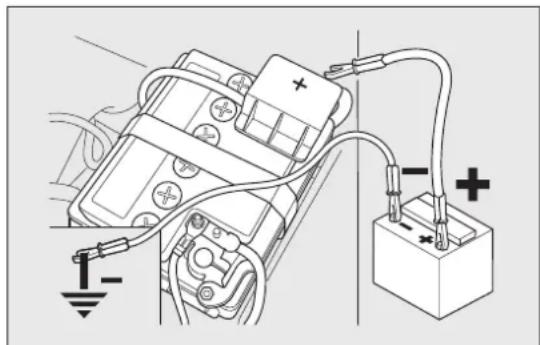
natural_image
Diagram of an electrical circuit with battery, resistor, and capacitor connected to a motor (no text or labels)fig. 122
F0Q0765
with a second lead, connect the negative terminal – of the auxiliary battery to an earth person the engine or the gearbox of the car to be start
□start the engine;
☐when the engine has been started, remove the leads reversing the order above.
If after a few attempts the engine does not start, do not persist but contact a Fiat Dealership.
IMPORTANT Do not directly connect the negative terminals of the two batteries: sparks could ignite explosive gas released from the battery. If the auxiliary battery is installed on another car, prevent accidental contact between metallic parts of the two cars.

Neveruseafastbattery-chargertostart theengineasthiscoulddamagethe electronicsystemsofyourcar, particularly
theignitionandfuelsupplycontrolunits.
WARNING

Thisproceduremustbeperformedby expertpersonnelbecauseincorrect couldcauseelectricaldischargeof erableintensity. Furthermore, battery poisonousandcorrosive:avoidcontact nandeyes. Keepnakedflamesand cigarettesawayfromthebatteryanddo sesparks.
BUMPSTARTING
Never bump start the engine by pushing, towing or coasting downhill.
IMPORTANT Remember that the brake servo and electrical power steering system are not active until the engine is started. A much greater effort will therefore be required to use the brake pedal or turn the steering wheel.
CHANGINGAWHEEL
GENERALINSTRUCTIONS
The car is equipped with the "Fix&Go Automatic Kit": see paragraph "Fix&Go Automatic Kit" for instructions on how to use this device. As an alternative to the "Fix&Go Automatic Kit" the car may be equipped with a space-saver wheel: see the instructions on the following pages for changing the wheel.

WARNING
Thespace-saverwheel(forversions/markets,whereprovided)isspecificto yourcar,donotuseitonothermodels,oruse thespace-saverwheelofothermodelsonyour car. Thespace-saverwheelmustonlybeused incaseofemergency.Itmustonlybeused 'forthedistancenecessarytoreachaservice pointandthecarspeedmustnotexceed80 km/h. Thespace-saverwheelhasanorange stickerthatsummarisesthemaincautionsfor useandlimitations.Neverremoveorcover thesticker. Thefollowinginformationis providedinfourlanguagesonthesticker: "Important!Fortemporaryuseonly!80km/h max.!Replacewithastandardwheelassoonas possible.Nevercoverthisindication". Never applyahubcaponaspace-saverwheel.

WARNING
Alertotherdriversthatthecaris stationaryincompliancewithlocal regulations:hazardwarninglights, warning triangle,etc.Anypassengersonboardshould leavethecar,especiallyifitisheavilyladen. Passengersshouldstayawayfromon-coming trafficwhilethewheelisbeingchanged.Onhills orunevenroads,usechocksorappropriate objectstoblockthewheelsofthecar.

WARNING
Thecar'sdrivingcharacteristicswillbe modifiedwiththespace-saverwheel fitted. Avoidsuddenstartingorstopping, sharp orfastturns. Thetotallifeofaspace-saver wheelisapproximately3000km, afterwhichit mustbereplacedbyanotherwheelofthe sametype. Neverinstallatraditionaltyreona rimdesignedtobeusedasaspace-saverwheel. Havethetyrerepairedandrefittedassoonas possible. Usingtwoormorespace-saverwheels atthesametimeisforbidden. Donotgreasethe threadsofboltsbeforefittingthem:theymight slipout.

WARNING
Thejackprovidedisonlyintendedtobe usedforreplacingwheelsonthecar withwhichitissupplied,oronsame-model vehicles.Neverusethejackforotherpurposes, suchasliftingothercarmodels.Neveruseit forrepairoperationsunderthecar.Incorrectly positioningthejackmaycausethecartofall. Donotusethejackforloadshigherthanthe oneshownonitslabel.Neverinstallsnow chainsonthespace-saverwheel;ifafronttyre (drivingwheel)ispuncturedandyouneedto usesnowchains,useastandardwheelfromthe rearaxleandinstallthespace-saverwheelon therearaxle.Inthisway,withtwonormaldrive wheels,itispossibletousesnowchains.

WARNING
Fitthehubcapcorrectlytopreventit fromcomingfreeinmotion.Never tamperwiththeinflatingvalve.Neverintroduce toolsofanykindbetweenrimandtyre.Check tyreandspace-saverwheelpressuresregularly, referringtothevaluesshowninthe"Technical data"chapter.
JACK
Please note that:
□the jack weight is 1.76 kg;
□the jack requires no adjustment;
□the jack cannot be repaired and in the event of a fault it must be replaced by another original one;
☐no tool other than its cranking device may be fitted on the jack.
To change a wheel proceed as follows:
□stop the car in a position that is not dangerous for on-coming traffic where you can change the wheel safely. the ground must be flat and sufficiently compact;
□turn the engine off and pull up the handbrake; engage first gear or reverse; use handle A to remove the rigid preformed cover B fig. 123;

text_image
Technical diagram showing labeled parts A and B with annotations and a magnified detail viewfig. 123
F0Q0732
☐loosen fastener E fig. 124;
☐for versions equipped with the "Fix&Go Automatic" kit, take the tool box from the luggage compartment;
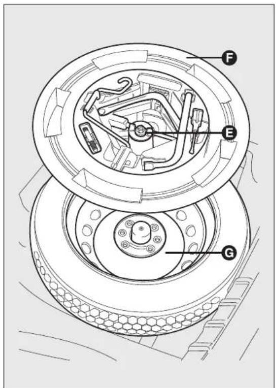
text_image
Technical diagram of a mechanical assembly with labeled components F, E, and Gfig. 124
F0Q0392
☐for versions equipped with space-saver wheel, loosen fastener E fig. 124, take tool box F, position it near the wheel to be changed and then take space-saver wheel G;
☐ remove hub cap H fig. 125 (versions with steel rims) or remove the hub cap (versions with alloy rims);
☐loosen the bolts of the wheel to be replaced by about one turn with the wrench provided L fig. 126; if you have alloy rims, rock the car to make it easier to separate the rim from the wheel hub;
☐ operate device M fig. 127 so as to extend the jack, until groove N on the upper part of the jack fits correctly into the lower profile P visible on the car body next to the indication Q (at approx. 72 cm from the centre of the front wheel or 75 cm from the centre of the rear wheel);
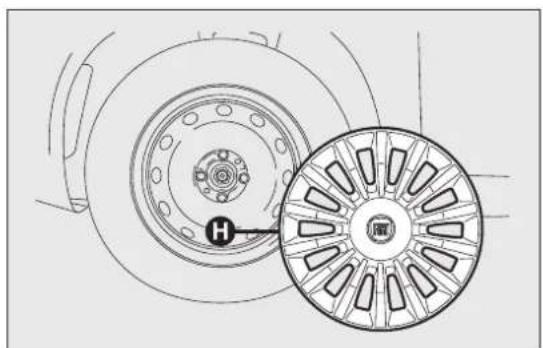
natural_image
Technical line drawing of a car wheel assembly with a highlighted component (no text or symbols)fig. 125
F0Q0393
☐alert any bystander that the car is about to be on raised; all persons should be kept away from the car and nobody must touch it until it has lowered;

natural_image
Diagram of a car tire with a lever and circular head, showing mechanical components without any text or symbols.fig. 126
F0Q0394

text_image
Technical diagram of a mechanical linkage system with labeled parts (Q, N, M, R) and an inset showing a joint detail.fig. 127
F0Q0395
☐fit handle R fig. 127 to operate the jack and raise the car until the wheel is a few centimetres above the ground;
□fully loosen the fastening bolts and remove the wheel.
☐make sure the contact surfaces between space-saver wheel and hub are clean so that the fastening bolts will not come loose;
☐fit the space-saver wheel aligning the openings S fig. 128 with the corresponding centering pins T;
□using the wrench provided, tighten the four fastening bolts;
□turn the jack handle R fig. 127 to lower the car a remove the jack;
☐use the wrench provided to fully tighten the bolts, passing alternately from one bolt to the opposite one, as per the numerical sequence illustrated in fig. 129.

text_image
T T S Sfig. 128
F0Q0396
REFITTINGTHESTANDARDWHEEL
Following the procedure described previously, raise the car and remove the space-saver wheel.
Versionswithsteelrims
Proceed as follows:
☐make sure the contact surfaces between standard wheel and hub are clean so that the fastening bolts will not come loose;
☐fit the standard wheel aligning the openings S fig. 128 with the corresponding centering pins T;
□using the wrench provided, tighten the fastening and bolts;
☐lower the car and remove the jack;
☐ using the wrench provided, fully tighten the bolts in the sequence shown in diagram fig. 129;
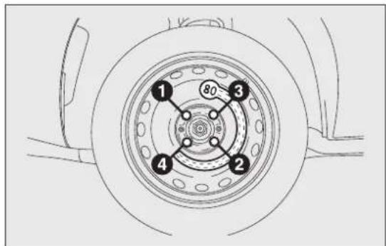
text_image
1 80 3 2 4fig. 129
F0Q0397
☐fit the hub cap so that the inflation valve can exit Versionswithalloyrims through the special slot visible on the cap itself; Proceed as follows:
☐ pressure-fit the hub cap starting from the parts nearest to the inflation valve and continue until it is completely fitted.
Proceed as follows:
IMPORTANT If it is not fitted properly, the hub cap may detach itself when the car is running.
□tighten centering pin A fig. 130 in one of the fixi bolt openings on the wheel hub;
☐place the wheel on the pin and tighten the bolts using the wrench provided. Bolt insertion is eased by the use of the extension B provided;
☐undo centering pin A and tighten the last fastenin bolt;
☐lower the car and remove the jack;
☐ using the wrench provided, fully tighten the bolts in the same sequence shown previously for the space-saver wheel (see fig. 129);
□refit the hub cap.
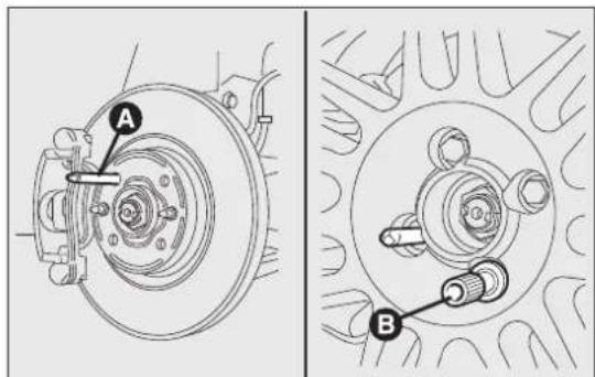
text_image
Technical diagram showing mechanical assembly with labeled parts A and B, likely illustrating a brake or clutch mechanism.fig. 130
F0Q0217
Attheendofoperation
Proceed as follows:
□arrange the space-saver wheel G fig. 131 in the specific compartment in the luggage compartment;
☐insert the partially open jack into container F and force it slightly into its housing so that it does not vibrate when the car is moving;
☐put the tools back into their places in the container;
☐stow the container complete with tools on the space-saver wheel and secure everything with clamping device E;
□correctly reposition the rigid preformed cover in the luggage compartment.
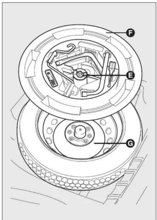
text_image
Technical diagram of a mechanical assembly with labeled components F, E, and Gfig. 131
F0Q0392
FIX&GOAutomaticKIT
The Fix&Go Automatic kit is located in a special container in the boot.
The kit includes fig. 132:
☐a cylinder A containing sealing fluid and fitted with: filling tube B and adhesive label C with the wording "max. 80 km/h" to be placed in a position clearly visible for the driver (e.g. on the dashboard) after repairing the tyre;
☐an information leaflet fig. 133, providing instructions for using the kit correctly. This booklet should be given to the persons charged with handling the tyre treated with this kit;
☐a compressor D including a pressure gauge and connections, found in the compartment;
☐a pair of protective gloves located in the side compartment of the compressor;
□adapters for inflating different elements.

text_image
Diagram of an air vent with labeled parts A, B, C, and Dfig. 132
F0Q0510

WARNING
Givethebooklettothetechnicianswho willbehandlingthetyrethatwas
treatedusingthekit.

Intheeventofapuncturecausedby foreignbodies, thekitmaybeusedto repairtyresshowingdamagesonthe shoulderuptomax4mmdiameter.

WARNING
Holesanddamageonthetyresidewalls cannotberepaired.Donotusethekit
ifthetyrewasdamagedasaresultofbeing usedwhenunderinflated.
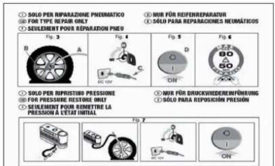
text_image
① SOLO PER RIPARAZIONE PNEUMATICO ② FOR TYPE REPAIR ONLY ③ SEULEMENT POUR RÉPARATION PNEU Fig. 3 B A C DC 10V Fig. 4 D ON Fig. 5 Fig. 6 80 50 AON ① SOLO PER RIPRUSTINO PRESSIONE ② FOR PRESSURE RESTORE ONLY ③ SEULEMENT POUR REMETTRE LA PRESSION À L'ÉTAT INITIAL Fig. 7 NUR FÜR REIFENREPARATUR SÓLO PARA REPARACIONES NEUMÁTICOS ① NUR FÜR DRUCKWIEDEREINFÜHRUNG ① SÓLO PARA REPOSICIÓN PRESIÓNfig. 133
F0Q0511
WARNING

If the wheel rim has been damaged (bent soast ocause air to leak), they re t bere paired. Donot remove foreign (screws or nails) from the tyre.
IMPORTANTINFORMATION:
The sealing fluid of the quick tyre repair kit is effective with external temperatures of between -20^ and +50^ .
WARNING

Neveroperatethecompressorforlonger than20consecutiveminutes.Riskofating. Thekitisnotsuitablefordefinitive,sotherepairedtyresmayonlybe mporarily.

Disposeofthecylinderandthesealing fluidproperly.Havethesealingfluidand thecylinderdisposedofincompliance tionalandlocalregulations.
WARNING

Thecylindercontainsethyleneglycol andlatex:itmaycauseanallergic in.Itisharmfulifswallowed.Itisirritant eyesincaseofcontact.Maycause onifinhaledoroncontact.Avoidcontact eeyes,skinandclothes.Intheeventof t,rinseimmediatelywithplentyofwater.ited,donotinducevomiting.Rinseout south,drinklargequantitiesofwaterand mediatemedicalattention.Keepaway children.Theproductmustnotbeused matics.Donotinhalethevapoursduring onandsuction.Calladoctorimmediately sicreactionsarenoted.Storetherinthespecificcompartment,away urcesofheat.Thesealingfluidhasan date.Replaceecylindercontaining datesealingfluid.
INFLATINGPROCEDURE

WARNING
Weartheprotectiveglovesprovided withthekit.
Proceed as follows:
☐operate the handbrake. Unscrew the tyre valve cap, take out the flexible filler pipe A fig. 134 and tighten the ring nut B on the tyre valve;
☐make sure that switch E fig. 136 for the compressor is in position 0 (off), start the engine, insert plug D fig. 135 into the cigar lighter socket and switch on the compressor by placing switch E fig. 136 in position I (on). Inflate the tyre to the pressure specified in the "Cold tyre pressures" paragraph in "Technical data" chapter. Check tyre pressure on pressure gauge F fig. 136 with

text_image
Diagram showing a car tire connected to a water heater with labeled parts A and Bfig. 134
F0Q0513
compressor off to obtain a more precise reading;
☐if after 5 minutes it is still impossible to reach at least 1.5 bar, disengage the compressor from the valve and power socket, then move the car forwards by approx. 10 metres in order to distribute the sealing fluid inside the tyre evenly, then repeat the inflation operation;
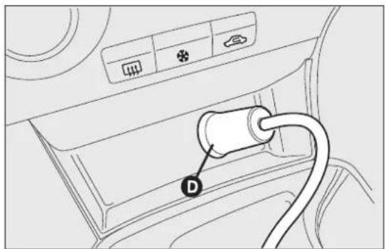
text_image
Diagram showing car air intake with labeled connector D and control buttonsfig. 135
F0Q0515

text_image
Diagram of a projector with labeled parts F and E, showing internal components and a close-up view of the screen.fig. 136
F0Q0516
☐if after this operation it is still impossible after 5 minutes to reach at least 1.8 bar, do not start driving since the tyre is excessively damaged and the kit cannot guarantee proper hold, contact a Fiat Dealership.
☐if reaching the tyre pressure specified in paragraph "Inflation pressure" in chapter "Technical Data", start driving immediately;
□after having driven for about 10 minutes, stop and recheck the tyre pressure; remember to apply the handbrake;
☐if, on the other hand, the pressure is at least 1.8 bar, restore the correct pressure (with the engine running and the handbrake applied) and resume driving;
□drive with the utmost care to the nearest Fiat Dealership.

WARNING
Applytheadhesivelabelwhereitcanbe easilyseenbythedriverasareminder thatthetyrehasbeentreatedwiththeFix&Go Automatickit.Drivecarefully,particularlyon bends.Donotexceed80km/h.Donot accelerateorbrakesuddenly.

WARNING
If the pressure has fallen below 1.8bar, donot drive any further: the Fix&Go
Automatickitcannotguaranteeproperhold becausethetyreistoodamaged.ContactaFiat Dealership.

WARNING
Youmustalwaysindicatethathetyre wasrepairedusingtheFix&Go
Automatickit.Givethebooklettothe technicianswhowillbehandlingthetyrethat wastreatedusingthekit.
CHECKINGANDRESTORINGTYRE PRESSURE
The compressor may also be used for restoring pressure only. Release the quick coupling and connect directly to the tyre valve fig. 137; in this the cylinder will not be connected to the compressor and no sealing fluid will be injected.
CYLINDERREPLACEMENT
To replace the cylinder, proceed as follows:
□disconnect coupling B fig. 138;
way, turn the cylinder to be replaced anticlockwise and raise it;
☐fit the new cylinder and turn it clockwise;
□connect coupling B to the cylinder and fit transparent pipe A in the specific compartment.

natural_image
Line drawing of a car tire being attached to a battery, no text or symbols presentfig. 137
F0Q0517

text_image
Diagram showing a hand operating a device labeled A and B with a tool, likely illustrating a mechanical or electrical setup.fig. 138
F0Q0512
CHANGINGABULB
GENERALINSTRUCTIONS
☐Before changing a bulb check the contacts for oxidation;
☐Burnt bulbs must be replaced by others of the same type and power;
□after replacing a headlight bulb, always check its alignment;
□when a light is not working, check that the corresponding fuse is intact before changing a bulb. For the location of fuses, refer to the paragraph "If a fuse blows" in this section;
WARNING

Modificationsorrepairstotheelectric systemthatarenotcarriedoutproperly
ordonottakethesystemtechnical specificationsintoaccountcancause malfunctionsleadingtotheriskoffire.

WARNING
Halogenbulbscontainpressurisedgas, inthecaseofbreakagetheymayburst.

Halogenbulbsmustbehandledholding themetallicpartonly.Touchingthe transparentpartofthebulbwithyour
fingersmayreducetheintensityoftheemitted lightandevenreducethelifespanofthebulb. In caseofaccidentalcontact, wipethebulbwith aclothmoistenedwithalcoholandletthebulb dry.

If possible, were recommend have bulbs replaced by a Fiat Dealership. The correct operation and aiming of the outer lights
areabsolutelyessentialforthesafetyofthecar andofcompliancewithlaw.

Duetotheghighsupplyvoltage,gas dischargebulbs(Bi-Xenon)(forversions/markets,whereprovided)mustonlybe
replacedbyaspecialisttechnician:dangerof death!ContactaFiatDealership.
IMPORTANT When the weather is cold or damp or after heavy rain or washing, the surface of headlights or rear lights, may steam up and/or form drops of condensation on the inside. This is a natural phenomenon due to the difference in temperature and humidity between the inside and the outside of the glass which does not indicate a fault and does not compromise the normal operation of lighting devices. The mist disappears quickly when the lights are turned on, starting from the centre of the diffuser, extending progressively towards the edges.
TYPESOFBULBS
Varioustypesofbulbsarefittedtoyourcar:
All-glassbulbs:(type A) press-fitted. Pull to remove.
Bayonettypebulbs:(type B) to remove them press the bulb and turn it anticlockwise.
Tubularbulbs:(type C) release them from their contacts to remove.
Halogenbulbs:(type D) to remove the bulb, release the clip holding the bulb in place.
Halogenbulbs:(type E) to remove the bulb, release the clip holding the bulb in place.
Gasdischargebulb(Xenon):(type F) to replace them contact a Fiat Dealership.
A

B
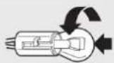
©
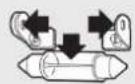
D
E
F
| GETTING TO KNOW YOURCAR |
| SAFETY |
| STARTING AND DRIVING |
| WARNING LIGHTS AND MESSAGES |
| IN AN EMERGENCY |
| SERVICING AND MAINTENANCE |
| TECHNICAL SPECIFICATIONS |
| INDEX |
Bulbs
UseTypePowerRe.Figure
| Main beam headlights HI 55 W E | |||
| Longlife dipped headlights HI 55 W D | |||
| Dipped headlights with gas discharge bulbs (for versions/markets, where provided) | D2R 35 W F | ||
| Longlife front side lights W5W 5 W | A | ||
| Front fog lights (for versions/markets, where provided) | H11 | 55 W E | |
| Front direction indicators | PY24W 24W | B | |
| Side direction indicators | WY5W | 5 W | A |
| Rear direction indicators | R10W | 10 W B | |
| Rear side lights/rear fog lights | P5/21W | 5 W/21 W | B |
| Rear side lights/break lights | P5/21W | 5 W/21 W | B |
| Third brake light (additional brake light) | W2.3W | 2.3 W | A |
| Reverse lights | P21W | 21 W B | |
| Number plate lights | W5W | 5 W | A |
| Front roof light | C10W | 2x10 W | C |
| Rear roof light (for versions/markets, where provided) | C10W | 10 W C | |
| Glove compartment light | C5W | 5W | C |
| Luggage compartment roof light | W5W 5W | A | |
| Courtesy mirror lights (for versions/markets, where provided) | C5W | 5 W | C |
REPLACINGEXTERIORBULBS
For the type of bulb and power rating, see "Changing a bulb" paragraph.
FRONTLIGHTCLUSTERS
The front light clusters contain side lights, dipped headlights, main beam headlights and direction indicator bulbs.
The bulbs are arranged inside the light cluster as follows fig. 139:
A Side lights/daytime running lights and main beam headlights
B Dipped headlights
c Direction indicators
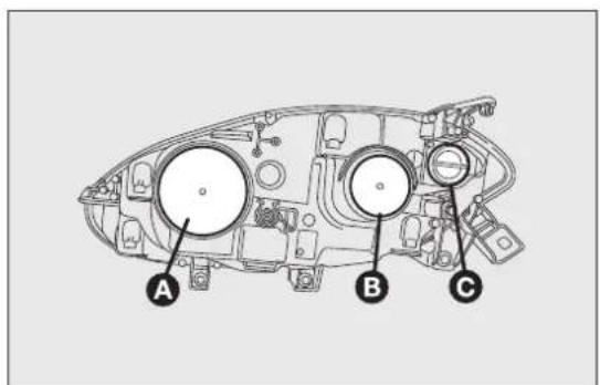
text_image
A B Cfig. 139
F0Q0704
DIPPEDHEADLIGHTS
To change the bulb, proceed as follows:
□remove the protective cover B fig. 139;
☐release the bulb holding clip A fig. 140;
□disconnect the electrical connector B;
□remove bulb C and replace it;
☐fit the new bulb, ensuring that the outline of the metal part coincides with the splining on the curve of the headlight. Then reconnect the electrical connector B and reattach the bulb holding clip A;
□refit the protective cover A fig. 139.
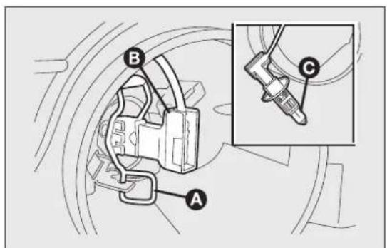
text_image
Technical diagram showing labeled mechanical components A, B, and C with an inset detail view of a tool or connector.fig. 140
F0Q0705
(for versions/markets, where provided)

WARNING
Duetothehighpowersupplyvoltage, gasdischargebulbs(Bi-Xenon)should onlybereplacedbyspecialisedpersonnel: dangerofdeath!ContactaFiatDealership.
SIDELIGHTS
To change the bulb, proceed as follows:
□remove the protective cover A fig. 139;
□turn the bulb holder A fig. 141 anticlockwise and remove it;
□remove the bulb B and replace it;
☐refit the new bulb, put the bulb holder A fig. 141 back into place and then refit the protective cover B fig. 139 properly.

text_image
Diagram showing mechanical components with labeled parts A and B, including a magnified inset of a connector or cable assembly.fig. 141
F0Q0706
MAINBEAMHEADLIGHTS
To change the bulb, proceed as follows:
□remove the protective cover A fig. 139;
☐release the bulb holding clip A fig. 142;
□remove bulb C and replace it;
☐fit the new bulb, ensuring that the outline of the metal part coincides with the splining on the curve of the headlight. Then reconnect the electrical connector B and reattach the bulb holding clip A;
□refit the protective cover B fig. 139.
DIRECTIONINDICATORS
Front
To change the bulb, proceed as follows:
□rotate the protective cover C fig. 139 anticlockwise;
□remove the bulb B fig. 143 and replace it;
□refit the protective cover A.

text_image
Technical diagram showing mechanical assembly with labeled parts A, B, and C, including a magnified inset view.fig. 142
F0Q0707
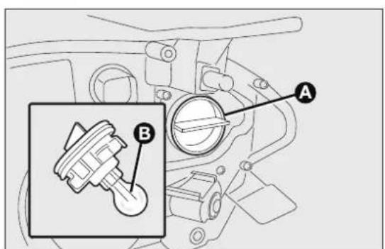
text_image
Technical diagram of a mechanical component with labeled parts A and B, showing internal components and a zoomed-in detail view.fig. 143
F0Q0708
Side
To change the bulb, proceed as follows:
□adjust the lens A fig. 144 to compress in the internal catch B, then pull the cluster outwards;
□turn the bulb holder C anticlockwise, extract the press-fitted bulb D and replace it;
☐refit the bulb holder C in the lens and turn it clockwise;
☐refit the cluster making sure that the internal catch B clips into position.
FOGLIGHTS
For replacing the bulb fig. 145 contact a Fiat Dealership.
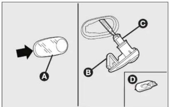
text_image
Diagram showing a device with labeled parts A, B, and C, alongside a separate view of a small object labeled D.fig. 144
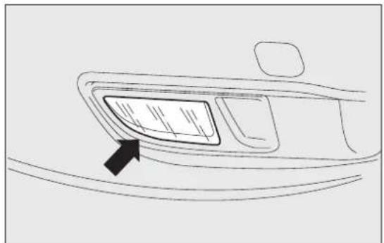
natural_image
Line drawing of a car rearview panel with a black arrow pointing to the front panel (no text or symbols)fig. 145
REARLIGHTCLUSTERS
The rear light clusters contain side lights, direction indicators and brake lights (stop) bulbs.
The bulbs are arranged inside the light cluster as follows fig. 146:
B Side lights/brake light (double light)
c Direction indicators
To change the bulb, proceed as follows:
□open the luggage compartment and loosen the two rear light cluster fastening screws A fig. 147;
☐extract the light cluster by removing it with both hands in the direction indicated by the arrows fig. 148;
□disconnect the electrical connector and, adjusting the three retaining tabs, remove the protective cover A fig. 149. Then, replace the concerned bulb.

text_image
B C Bfig. 146
F0Q0714
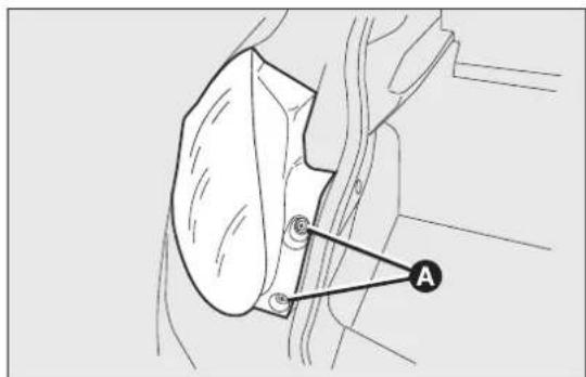
text_image
Technical diagram showing a mechanical component with labeled point A and directional arrowfig. 147
F0Q0715
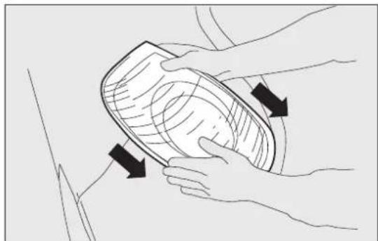
natural_image
Illustration of hands performing a medical or therapeutic procedure on a patient's abdomen (no text or symbols present)fig. 148
F0Q0739
REVERSELIGHT
For bulb replacement fig. 150, contact a Fiat Dealership.
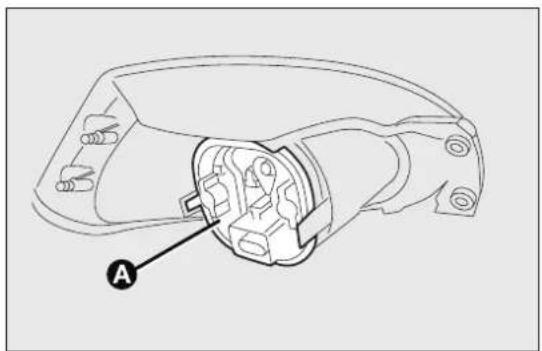
natural_image
Technical line drawing of a mechanical component with labeled point A (no text or symbols beyond label)fig. 149
F0Q0713
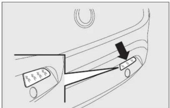
text_image
甲 乙 丙fig. 150
F0Q0711
REARFOGLIGHT
For bulb replacement fig. 151, contact a Fiat Dealership.
3 ^rd BRAKELIGHTS
To change the bulb proceed as follows:
□open the luggage compartment;
□remove the cover A fig. 152;
☐extract the lens unit B fig. 153 and disconnect the electrical connector;
☐press in the tabs C fig. 153 and remove the bulb holder;
□remove the snap-fitted bulb and replace it.
☐refit the cover A fig. 152 and close the luggage compartment.
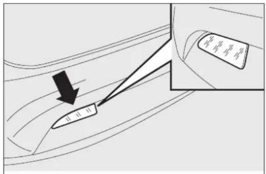
text_image
Diagram showing a car interior with a directional arrow and a magnified inset highlighting the vehicle's parts.fig. 151
F0Q0712
NUMBERPLATELIGHTS
To replace the bulbs proceed as follows:
☐ operate in the point indicated by the arrows and remove the lens units A fig. 154;
□turn the bulb holder B fig. 155 clockwise;
□remove bulb C and replace it.

text_image
Diagram showing car interior airflow with a traffic cone and labeled component A, likely illustrating vehicle dynamics or traffic flow.fig. 152

text_image
Diagram showing a hand using a tool to press or install a component labeled B and C, with a magnified view of the component.fig. 153
F0Q0751
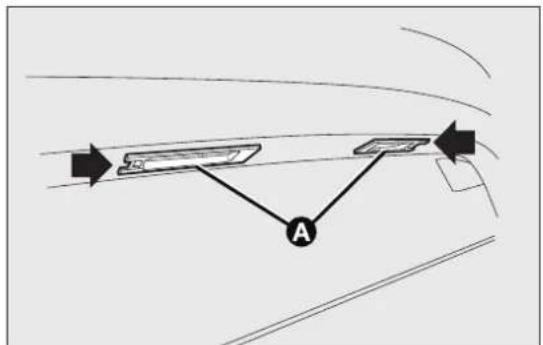
flowchart
graph TD
    A["Input Path"] --> B{Node}
    B --> C["Output Path"]
    style A fill:#f9f,stroke:#333
    style C fill:#bbf,stroke:#333
fig. 154
F0Q0718
REPLACINGINTERIORBULBS
For the type of bulb and corresponding power rating, see the paragraph "Changing a bulb".
FRONTROOFLIGHT
To change the bulbs, proceed as follows:
☐ operate in the points indicated by the arrows and remove light A fig. 156;
□open protective flap B fig. 157;
□replace the bulbs C releasing them from the side contacts and making sure that the new bulbs are correctly secured between the contacts;
☐close flap B fig. 157 and fix roof light A fig. 156 in its housing, making sure that it locks into place.
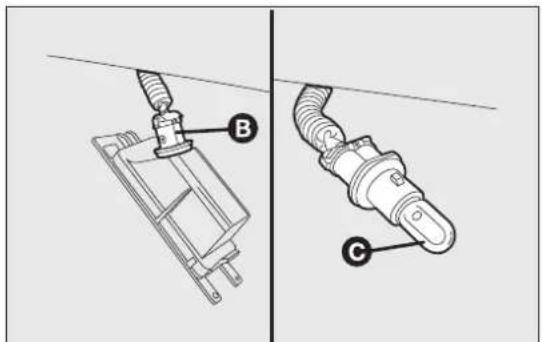
text_image
Technical diagram showing two mechanical components labeled B and C, with arrows indicating assembly or connection points.fig. 155

natural_image
Diagram of a car dashboard with directional arrows and labeled component A (no text or symbols beyond labels)fig. 156
F0Q0720
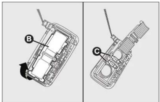
text_image
Technical diagram showing two views of a device's internal structure with labeled parts B and Cfig. 157
F0Q0721
REARROOFLIGHT
Versionswithoutsunroof
Proceed as follows to replace the bulbs:
☐operate in the point shown by the arrow and remove roof light A fig. 158;
☐replace bulb B releasing it from the side contacts and making sure the new bulb is correctly fastened between the contacts.
Versionswithsunroof
Proceed as follows to replace the bulbs:
☐operate in the point shown by the arrow and remove roof light A fig. 159;
☐replace bulb B releasing it from the side contacts and making sure the new bulb is correctly fastened between the contacts.

text_image
Technical diagram showing a component labeled A and B with an arrow pointing to a circular feature, alongside a mechanical assembly view.fig. 158

text_image
Diagram showing a car interior with labeled parts A and B, including an arrow pointing to a component.fig. 159
LUGGAGECOMPARTMENTROOFLIGHT
To replace the bulb, proceed as follows:
□open the luggage compartment;
□remove the light A fig. 160 levering in the point shown by the arrow;
□open protection B fig. 161 and replace the snap-fitted bulb;
□re-close the protection B on the lens;
☐refit the roof light A by inserting it in its correct position firstly on one side and then pressing on the other until it clicks into place.
To change the bulbs, proceed as follows:
□open the glove compartment and extract roof light A fig. 162;

text_image
Technical diagram showing a mechanical component with labeled parts and an arrow pointing to a grid-like feature, marked with point A.fig. 160
F0Q0724
☐replace bulb B releasing it from the side contacts and making sure the new bulb is correctly fastened between the contacts.
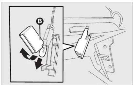
text_image
Diagram showing a device with labeled parts and directional arrows indicating motion or movement, including a component labeled 'B' and a connector labeled 'G'.fig. 161
F0Q0725
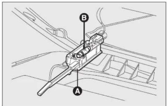
text_image
Technical diagram of a mechanical device with labeled parts A and B, showing internal components and wiring.fig. 162
F0Q0726
COURTESYMIRRORLIGHTS
(for versions/markets, where provided)
Replace the bulb as follows:
□open the mirror cover A fig. 163;
□extract light B levering in the points shown by arrows;
☐replace bulb C releasing the side contacts, insert the new bulb and make sure that it is correctly locked between the contacts.
REPLACINGFUSES
INTRODUCTION
Fuses protect the electrical system: they intervene (blow) in the event of a failure or improper intervention on the system.
When a device does not work, check the condition of its protective fuse: the conductor element A fig. 164 must be intact. If it is not, replace the blow fuse with another with the same amperage (same colour).
B = intact fuse;
C = fuse with damaged filament.
To facilitate fuse replacement, use the pliers D hooked inside the fuse box lid on the dashboard left-hand side.
Refer to the tables on the following pages to identify the protective fuse.

text_image
A B Cfig. 163
F0Q0753

text_image
A B C Dfig. 164
F0Q0220

WARNING
If thereplaced fuse blows again, contact a Fiat Dealership.

WARNING
Neverreplaceafusewithmetalwiresor othermaterial.

WARNING
Neverreplaceafusewithanotherwith ahigheramprating;DANGEROFFIRE.

WARNING
Ifageneralprotectivefuse(MEGA-FUSE,MIDI-FUSE,MAXI-FUSE)blows, taFiatDealership.

WARNING
Beforereplacingafuse, makesurethat theignitionkeyhasbeenremoved andthatalltheotherservicesareswitchedoff and/ordisengaged.

WARNING
ContactaFiatDealershipifasafety system(airbags, brakes), enginesystem (engine, gearbox)orsteeringsystemgeneral protectionfuseblows.
FUSELOCATION
The fuses are grouped in three fuse boxes:
□dashboard fuse box;
☐engine compartment fuse box;
☐luggage compartment fuse box.
Dashboardfusebox
fig.166
To access the dashboard fuse box, loosen the three screws A in fig. 165 and remove the flap B.

text_image
Technical diagram showing labeled parts of a car interior with annotations A and B pointing to different components.fig. 165
F0Q0727
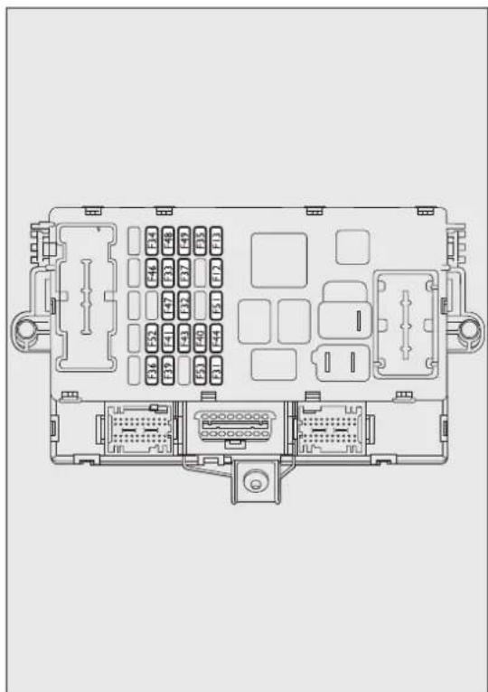
natural_image
Top-down schematic of an automotive electrical panel layout (no text or labels)fig. 166
F0Q0778
Enginecompartmentfusebox nexttothebattery
fig.168
(for versions/markets, where provided)
A second fuse box is located on the right-hand of the engine compartment, next to the battery; to reach it loosen the fixing screws and remove cover A fig. 167.
The number identifying the electrical component corresponding to each fuse is on the back of the cover.

natural_image
Technical line drawing of a mechanical assembly with labeled component A (no text or symbols beyond label)fig. 167
F0Q0816
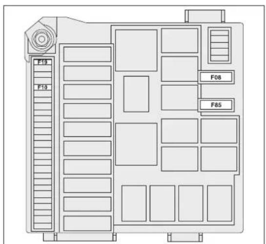
text_image
F10 F10 F08 F85fig. 168
F0Q0815
Enginecompartmentfusebox nexttothebattery
fig.170
(for versions/markets, where provided)
To access the fuse box next to the battery, press retaining clips A fig. 169 and remove protection cover B.
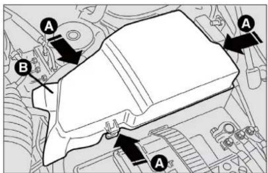
text_image
Technical diagram of a mechanical component with labeled parts A and B, showing assembly or assembly steps.fig. 169
F0Q0498
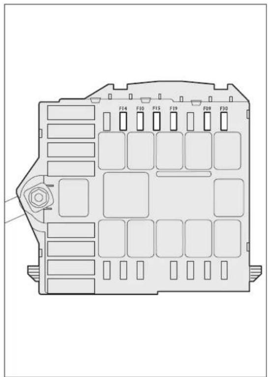
text_image
F14 F10 F15 F19 F09 F30fig. 170
F0Q0779
Luggagecompartmentfusebox fig.171
To access the fuse box located on the left side of the luggage compartment, open lid A fig. 172.
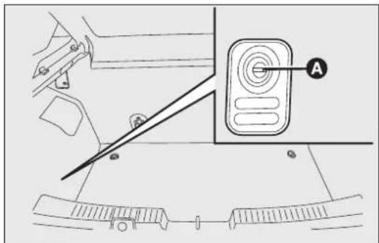
text_image
Technical diagram showing a mechanical assembly with labeled component A and directional arrows indicating motion or force.fig. 171
F0Q0747

text_image
F3 F2 F1 F6fig. 172
F0Q0776
FUSESUMMARYTABLE
| DashboardfuseboxFUSEAMPS | ||
| Right dipped headlight (halogen headlights) F12 7,5 | ||
| Right dipped headlight (Bi-Xenon headlights) F12 15 | ||
| Left dipped headlight (halogen headlights) F13 7,5 | ||
| Left dipped headlight (Bi-Xenon headlights) F13 15 | ||
| Reverse F35 5 | ||
| 3rd brake light | F37 7,5 | |
| Rear fog light (driver's side) | F53 7,5 | |
| Headlight alignment corrector system (halogen headlights) | F13 7,5 | |
| Relay switch coils on engine compartment fuse box (CVM)/Body Computer control unit (NBC) | F31 | 5 |
| HI-FI audio system subwoofer amplifier | F32 15 | |
| Left rear electric window | F33 20 | |
| Right rear electric window | F34 20 | |
| Control on brake pedal (NC contact)/Water presence in diesel sensor/Air flow meter | F35 | 5 |
| Central locking system control unit (CGP) (door opening/closing, safe lock, tailgate release) | F36 20 | |
| Control on brake pedal (normally open contact NO)/Instrument panel (NQS)/Gas discharge bulbs control units on front headlights | F37 7,5 |
| GETTINGOKNOW YOURCAR |
| SAFETY |
| STARTINGAND DRIVING |
| WARNINGLIGHTS ANDMESSAGES |
| INAN EMERGENCY |
| SERVICINGAND MAINTENANCE |
| TECHNICAL SPECIFICATIONS |
| INDEX |
DashboardfuseboxFUSEAMPS
| Radio and radio navigator /Radio setup//Blue&Me system/Alarm siren (CSA)/Alarm system on roof light Internal cooling unit/Tyre pressure monitoring system control unit (CPP)/Diagnosis socket connector/Rear roof lights | F39 10 | |
| Heated rear window F40 30 | ||
| Electric door mirror demisters/Demisters on windscreen jets | F41 7,5 | |
| Windscreen wiper/Bi-directional windscreen/rear window washer electric pump system on steering column stalk | F43 30 | |
| Current sockets/Cigar lighter F44 15 | ||
| Electric sun roof motor F46 20 | ||
| Front electric window (driver side) F47 20 | ||
| Front electric window (passenger side) F48 20 | ||
| Emergency control panel (lighting)/Right branch central control panel (lighting, ASR switch) and left branch/ Steering wheel controls (lighting)/Control panel on front roof light (lighting)/Volume sensing alarm system control unit (deactivation)/Electric sun roof system (control unit, control lighting)/Rain sensor/Dusk sensor on rear view mirror/Heating pad activation controls on front seats | F49 5 | |
| Dashboard fuse box FUSE AMPS | ||
| Internal cooling unit/Radio setup/Cruise Control lever Blue&MeTM system control unit/Parking sensor control unit (NSP)/Air pollution sensor (AQS)/Automatic climate control system/Electric door mirrors (adjustment, folding)/Tyre pressure monitoring system control unit (CPP) | F51 5 | |
| Rear window wiper F52 15 | ||
| Instrument Panel (NQS) F53 7,5 |
©
LuggagecompartmentfuseboxFUSEAMPS
| Front right seat movement F1 30 | ||
| Front left seat movement F2 30 | ||
| Front left seat heating F3 10 | ||
| Front right seat heating F6 10 |
BATTERYRECHARGING
IMPORTANT The battery recharging procedure is given as information only. You are advised to contact a Fiat Dealership to have this operation performed.
IMPORTANT After turning the ignition key to STOP and having closed the driver's side door, wait at least one minute before disconnecting and then reconnecting the battery electrical supply.
Low amperage slow recharging for approximately 24 hours is advised. Charging for a longer time may damage the battery.
Charge the battery as follows:
□disconnect the negative battery terminal;
□connect the charger cables to the battery terminals, observing the polarity;
□turn on the charger;
□when it is recharged, turn the charger off before disconnecting it from the battery;
□reconnect the negative battery terminal.
IMPORTANT If the car is equipped with an alarm system, this has to be disabled using the remote control (see the "Alarm" paragraph in "Knowing your car" chapter).

WARNING
Batteryfluidispoisonousandcorrosive: avoidcontactwithyourskinandeyes.
The battery should be charged in a well ventilated place, away from naked flames or possiblesources of sparks: danger of explosion and fire.

WARNING
Donotattempttochargeafrozen battery:itmustbethawedfirst, otherwiseitmayexplode.Iffreezinghas occurred,thebatteryshouldbecheckedby skilledpersonneltomakesurethattheinternal elementsarenotdamagedandthatthebody isnotcracked,withtheriskofleaking poisonousandcorrosiveacid.
RAISINGTHECAR
If the car needs to be jacked up, go to a Fiat Dealership which is equipped with jack arms or workshop lifts.
The car must only be lifted laterally by positioning the end of the arms or the workshop lift in the points illustrated in fig. 173
IMPORTANT For Sport versions, take care not to damage the side skirts when lifting the car with the workshop lift.
TOWINGTHECAR
The tow hook, which is supplied with the car, is housed in the tool box, under the carpet in the luggage compartment.
ATTACHINGTHETOWHOOK
Proceed as follows:
□release the cap by operating on tab A fig. 174–fig. 175;
☐take the tow hook B from its support;
□fully screw in the hook on the rear or front threaded pin.
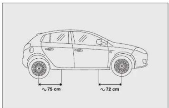
text_image
~75 cm ~72 cmfig. 173
F0Q0729
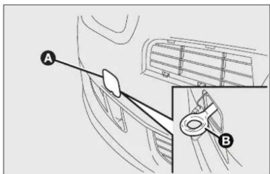
text_image
Technical diagram showing car interior components with labeled parts A and B, including a magnified view of the component.fig. 174
F0Q0730
WARNING
Beforetowing, turntheignitionkeyto MAR-ONandthentoSTOPwithout removing it. Thesteeringcolumnwill automaticallylockwhenthekeyisremoved and thewheelscannotbesteered.
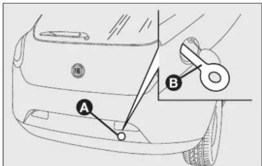
text_image
Diagram of a car's rearview side with labeled parts A and B, showing a tool interacting with the wheel.fig. 175
F0Q0731

WARNING
Whilsttowing, remember that the assistance of the brakes servo and the electric power steering is not available, greater forceneed stobe exerted on the brake pedal and more effort is required on the steering wheel. Donot use flexible cables when towing and avoid jerkymovements. During towing, makes sure that the trailer hitch does not damage any components it is touching. When towing the car, it is compulsory to respect specific highway coderegulations relating to the tow hook and procedures for towing on the road.

WARNING
Donotstarttheenginewhiletowingthe car.

WARNING
Beforetighteningthehookcleanthe threadedhousingthoroughly.Makesure thatthehookisfullyfastenedinthehousing beforetowingthecar.

WARNING
Thefrontandreartowhooksshouldbe usedonlyforemergenciesontheroad. Youareallowedtotowthecarforshort distancesusinganappropriatedevice inaccordancewiththehighwaycode(arigid bar),tomovethevehicleontheroadin readinessfortowingortransportingviaa breakdownvehicle.TowhooksMUSTNOTbe usedtotowvehiclesofftheroadorwherethere areobstaclesand/orfortowingoperations usingcablesorothernon-rigiddevices. Respectingtheaboveconditions,towingmust takeplacewiththetwovehicles(onetowing, theothertowed)alignedasmuchaspossible alongthesamecentreline.
SERVICINGANDMAINTENANCE
SCHEDULEDSERVICING
Correct servicing is essential in guaranteeing a long life for the car under the best conditions.
For this reason, Fiat has planned a series of checks and services at fixed distance intervals and, for versions/markets, where provided, at fixed time intervals, as described in the Scheduled Servicing Plan.
Regardless of the above, it is always necessary to carefully follow the instructions in the Scheduled Servicing Plan (e.g. periodically check level of liquids, tyre pressure, etc.).
Scheduled Servicing is offered by all Fiat Dealerships at fixed time or kilometres/miles intervals. If, during each operation, in addition to the ones scheduled, the need arises for further replacements or repairs, these may be carried out only with your explicit agreement. If your car is used frequently for towing, the interval between one service operation and the next should be reduced.
IMPORTANTINFORMATION
The Scheduled Servicing services are set out by the Manufacturer. Failure to have them carried out may invalidate the warranty.
It is advisable to inform a Fiat Dealership of any small operating irregularities without waiting for the following servicing.
For versions equipped with specific supply (e.g. LPG) and/or trim level, in addition to what is described in the following Scheduled Servicing Plan, refer to the relevant additional items in the dedicated supplements.
SCHEDULEDSERVICINGPLAN
The checks listed in the Scheduled Servicing Plan, after reaching 120,000 km/6 years, must be cyclically repeated starting from the first interval, thus following the same intervals as before.
| Thousandsofmiles122360728496108120 | 4648 | |||||||||||
| Thousandsofkm20406080100120140160180200 | ||||||||||||
| Years1 | 2 | 3 | 4 | 5 | 6 | 7 | 8 | 9 | 10 | |||
| Check tyre condition/wear and adjust pressure, if necessary; check “Fix&Go Automatic” kit recharge expiry date (for versions/markets, where provided) | ● | ● | ● | ● | ● | ● | ● | ● | ● | ● | ● | |
| Check operation of lighting system (headlights, direction indicators, hazard warning lights, luggage compartment, passenger compartment, glove compartment, instrument panel warning lights, etc.) | ● | ● | ● | ● | ● | ● | ● | ● | ● | ● | ● | |
| Check and, if necessary, top up fluid levels (engine coolant, hydraulic clutch/brakes, windscreen washer, battery, etc.) | ● | ● | ● | ● | ● | ● | ● | ● | ● | ● | ● | |
| Check exhaust emissions/smokiness | ● | ● | ● | ● | ● | ● | ● | ● | ● | ● | ● | |
| Use the diagnosis socket to check supply/engine management system operation, emissions and, for versions/markets, where provided, engine oil degradation | ● | ● | ● | ● | ● | ● | ● | ● | ● | ● | ● | |
| Visually inspect condition of: exterior bodywork, underbody protection, pipes and hoses (exhaust, fuel system, brakes), rubber elements (boots, sleeves, bushes, etc.) | ● | ● | ● | ● | ● | |||||||
| Check windscreen/rear window wiper blade position/wear | ● | ● | ● | ● | ● | |||||||
| Check operation of windscreen wiper/washer system and adjust jets, if necessary | ● | ● | ● | ● | ● | |||||||
| Thousandsofmiles12236789112 | 46480246080 | ||||||||||||||
| Thousandsofkm20406080100120140160180200 | |||||||||||||||
| Years1 | 2 | 3 | 4 | 5 | 6 | 7 | 8 | 9 | 10 | ||||||
| Check cleanliness of bonnet and luggage compartment locks, as well as cleanliness and lubrication of linkages | ● | ● | ● | ● | |||||||||||
| Check handbrake lever travel and adjust, if required | ● | ● | ● | ● | |||||||||||
| Visually inspect conditions and wear of front disc brake pads and operation of pad wear indicator | ● | ● | ● | ● | ● | ● | ● | ● | ● | ||||||
| Visual inspection of condition and wear of rear disc brake pads | ● | ● | ● | ● | ● | ● | ● | ● | ● | ||||||
| Visual inspection of condition and tensioning of accessory drive belt(s) (for versions without automatic tensioner only) | ● | ● | |||||||||||||
| Change engine oil and replace the oil filter (versions without DPF) | ● | ● | ● | ● | |||||||||||
| Change engine oil and replace oil filter (versions with DPF) (1) (2) | |||||||||||||||
(I) The actual interval for changing engine oil and replacing the engine oil filter depends on the vehicle usage conditions and is signalled by the warning light or message in the instrument panel. Anyway, it must never exceed 2 years.
(2) If the car is mainly used in towns and cities, change the engine oil and filter every year.
| Thousandsofmiles1225375062758799112124 | |||||||||||||||
| Thousandsofkm20406080100120140160180200 | |||||||||||||||
| Years1 | 2 | 3 | 4 | 5 | 6 | 7 | 8 | 9 | 10 | ||||||
| Replace accessory drive belt(s)(3) | ● | ||||||||||||||
| Replace toothed timing drive belt(3) | ● | ||||||||||||||
| Replace fuel filter(4) | ● | ● | ● | ||||||||||||
| Replace air cleaner cartridge(5) | ● | ● | ● | ● | ● | ||||||||||
| Replace brake fluid | ● | ● | ● | ● | ● | ||||||||||
| Passenger compartment filter replacement (5) | ○ | ● | ○ | ● | ○ | ● | ○ | ● | ○ | ||||||
(3) Areas that are not dusty: advised maximum mileage 120,000 km. Regardless of the mileage, the belt must be replaced every 6 years. Dusty areas and/or demanding use of the car (cold climates, town use, long periods of idling): advised maximum mileage 60,000 km. Regardless of the mileage, the belt must be replaced every 4 years.
(4) If the car runs on fuel with quality below the relevant European specification, this filter must be replaced every 20,000 km
(5) If the car is used in dusty areas, this cleaner must be replaced every 20,000 km.
(O) Recommended operations
(●) Mandatory operations
PERIODICCHECKS
Every 1,000 km or before long journeys, check and necessary, restore:
☐engine coolant, brake fluid and windscreen wash fluid level;
□tyre inflation pressure and condition;
☐operation of lighting system (headlamps, direct indicators, hazard warning lights, etc.);
☐operation of screen washer/wiper system anchositioning/wear of windscreen/rear window wiperlades.
Every 3,000 km, check and top up, if required, engine oil level.
HEAVY-DUTYUSEOFTHECAR
If the car is used mainly under one of the following conditions:
□towing a trailer or caravan;
□dusty roads;
□short, repeated journeys (less than 7-8 km) at sub-zero outside temperatures;
☐engine often idling or driving long distances at low speeds or long periods of idleness;
you need to perform the following inspections more frequently than shown in the Scheduled Servicing Plan:
☐check front disc brake pad conditions and wear;
☐check cleanliness of bonnet and boot locks, cleanliness and lubrication of linkage;
☐visually inspect conditions of: engine, gearbox, transmission, pipes and hoses (exhaust - fuel system - brakes) and rubber elements (boots - sleeves - bushes - etc.);
☐check battery charge and battery fluid level (electrolyte);
☐visually inspect condition of the accessory drive belts;
☐check and, if necessary, change engine oil and replace oil filter;
☐check and, if necessary, replace pollen filter.
CHECKINGFLUIDLEVELS

WARNING
Neversmokewhileworkinginthe enginecompartment:inflammablegases andvapoursmaybepresent,constitutingafire risk.

WARNING
Beverycarefulwhenworkinginthe enginecompartmentwhentheengineis hot:youmaygetburned.Rememberthatthe fanmaystartupiftheengineishot:thiscould injureyou.Makesurethatscarves,tiesand otherloosefittinggarmentsdonotgetcaught upinmovingparts.

Whentoppingup, takecarenottomixup thevarioustypesoffluids:theyarenot compatiblewitheachotherandcould
seriouslydamagethecar.
1.6MultiJetversion

text_image
MULTIET A B C D EF0Q0767
A. Engine oil dipstick B. Engine oil cap/filler C. Battery D. Brake fluid E. washer fluid for windscreen/rear window/headlights F. Engine coolant
2.0MultiJetversion(forversions/markets,whereprovided)
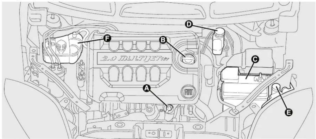
text_image
2.0 MULTIFET A B C D Efig. 177
F0Q0768
A. Engine oil dipstick B. Engine oil cap/filler C. Battery D. Brake fluid E. washer fluid for windscreen/rear window/headlights F. Engine coolant
ENGINEOIL
Engineoillevelcheck
Check the oil level a few minutes (about five) after the engine has stopped, with the vehicle parked on level ground.
Take out engine oil dipstick A, clean it and then fully reinsert it, take it out and check that the level is between the MIN and MAX marks on the dipstick.
The range between the MIN and MAX marks corresponds to approximately 1 litre of oil.
Toppinguptheengineoil
If the level of the oil is close to or below the MIN mark, add oil via filler B until the MAX mark is reached.
IMPORTANT If the engine oil level after the check over the MAX level, go to a Fiat Dealership to have the correct level restored.
IMPORTANT After adding or changing the oil, let the engine run for a few seconds and wait a few minutes after switching it off before checking the level.
Engineoilconsumption
The maximum engine oil consumption is approximately 400 grams every 1,000 km.
During the initial period of usage for the vehicle, the engine is bedding in, therefore the engine oil consumption may settle down only after the first 5,000 - 6,000 km.
IMPORTANT The oil consumption depends on driving style and the conditions under which the ca is used.
IMPORTANT Do not add oil with specifications other than those of the oil already in the engine.

WARNING
Whentheengineishot, take care when working inside the engine compartment toavoidburns.Rememberthatthefanmay startupiftheengineishot:thiscouldinjure you.Makesurethatscarves,tiesandother loosefittinggarmentsdonotgetcaughtupin movingparts.

Usedengineoilandoilfilterscontain substanceswhichareharmfultothe environment.Tochangetheoilandfilters, seyoutocontactaFiatDealership.
BRAKEFLUID
Check that the liquid is at the maximum level (the fluid level in the reservoir must not exceed the MAX mark).
If the fluid level in the tank is too low, undo reserved cap D (see previous pages) and add the fluid described in the chapter "Technical Specifications".
NoteCarefully clean the cap of the reservoir and the surrounding surface.
Take great care to ensure that impurities do not enter the reservoir when the cap is opened.
For topping-up, always use a funnel with integrated filter with mesh equal to or lower than 0.12 mm.
IMPORTANT Brake fluid is hygroscopic (i.e. it absorbs moisture). For this reason, if the car is mainly used in areas with a high degree of atmospheric humidity, the fluid should be replaced at more frequent intervals than specified in the "Scheduled Servicing Plan".

Preventbrakefluid, whichishly corrosive, from coming into contact with painted parts. Should it happen,
immediatelywashwithwater.

WARNING
Brakefluidispoisonousandhighly corrosive.Ifcontactaccidentallyoccurs, immediatelywashtheaffectedareaswith waterandaneutraldetergent,andthenrinse thoroughlywithwater.Calladoctor immediatelyifswallowed.

WARNING
Thesymbol ☐ onthecontainerindicates asyntheticbrakefluid,whichis differentfromamineralfluid. Using a mineral-typefluidwilldamagethespecial rubbersealsofthebrakingsystembeyond repair.
WASHERFLUIDFORWINDSCREEN/ REARWINDOW/HEADLIGHTS
If the level is too low, raise reservoir cap E (see previous pages) and add the fluid described in the chapter "Technical Specifications".

WARNING
Donottravelwiththewindscreen washerreservoiempty:thewindscreen washerisessentialforimprovingvisibility.Some commercialwindscreenwasheradditivesare flammable.Theenginecompartmentcontains hotcomponentswhichmaysetitonfire.
ENGINECOOLANT
The coolant level must be checked when the engine is cold and must range between the MIN and MAX marks on the reservoir.
If the level is too low, undo reservoir cap F (see previous pages) and add the fluid described in the chapter "Technical Specifications".

PARAFLU ^UP antifreezeisusedinthe enginecoolingsystem. Usethesamefluid asinthecoolingsystemwhentopping
up.PARAFLU ^UP cannotbemixedwithanyother typeoffluid.Ifthishappens,donotstartthe engine;contactaFiatDealership.

WARNING
Thecoolingsystemispressurised. If necessary, replacethecapwithanother
ofequivalentqualityandthesame specificationsastheoriginal,otherwisethe efficiencyofthesystemmaybeadversely affected.Donotremovethereservoircapwhen theengineishot:youriskscaldingyourself.
AIRCLEANER/POLLEN FILTER/DIESELFILTER
For filter replacement, contact a Fiat Dealership.
BATTERY
The battery does not require the electrolyte to be topped up with distilled water. A periodic check, which can be carried out at a Fiat Dealership is, however, necessary to check efficiency.
REPLACINGTHEBATTERY
If necessary, replace the battery with another of equivalent quality and the same specifications as the original. Follow the battery manufacturer's instructions for maintenance.
USEFULADVICEFOREXTENDINGTHE LIFEOFYOURBATTERY
To avoid draining your battery and make it last longer, observe the following instructions:
□when you park the car, ensure that the doors, tailgate and bonnet are closed properly, to prevent any roof lights from remaining on inside the passenger's compartment;
□switch off the internal roof lights. The car is, however, equipped with a system which switches the interior lights off automatically;
☐do not keep accessories (e.g. sound system, hazard lights, etc.) switched on for a long time when the engine is not running;
before performing any operation on the electrical system, disconnect the negative battery cable;
□completely tighten the battery terminals.
IMPORTANT If the charge level remains under 50% for a long time, the battery is damaged by sulphation reducing its capacity and efficiency at start-up.
The battery will also be more at risk of freezing (this can happen as early as -10°C). Refer to the paragraph "Car inactivity" in "Starting and driving" if the car is left parked for a long time.
If, after buying the car, you wish to install electrical accessories which require permanent electrical supply (alarm, etc.) or accessories which influence the electrical supply requirements, contact a Fiat Dealership, whose qualified staff will evaluate the overall electrical consumption.

WARNING
Batteryfluidispoisonous and corrosive. Avoidcontactwiththeskinandeyes.
Keepopenflamesawayfromthebatteryand donotuseobjectsthatmightcreatesparks:risk ofexplosionandfire.

WARNING
Using the battery with insufficient fluid irreparably damage the battery and
maycauseanexplosion.

Incorrectinstallationofelectricaland electronicdevicesmaycausesevere damagetoyourcar.Afterpurchasingyour
car, if you wisht install any accessories (anti-theft, carphone, etc.), contact a Fiat Dealership, which will suggest them most appropriated devices for your vehicle, and will, most importantly, advise you if higher capacity battery need to be installed.

Batteriescontainsubstanceswhichare verydangerousfortheenvironment. For batteryreplacement,contactaFiat
Dealership.

WARNING
Ifthecarwillbeunusedforanextended periodoftimeinextremelycold weatherconditions,removethebatteryand storeitinaheatedareatopreventitfrom freezing.

WARNING
Alwayswearappropriategoggleswhen workingonornearthebattery.
WHEELSANDTYRES
Before long trips, and every two weeks, check the tyre and space-saver wheel inflation pressure (for versions/markets, where provided). Check the tyres when cold.
While driving the car, the pressure increases under standard conditions: for the correct tyre inflation pressure, see "Wheels" paragraph in the "Technical specifications" chapter.
Incorrect pressure causes abnormal tyre wear fig. 178:
A normal pressure: tread evenly worn;
B low pressure: tread particularly worn at the edges;
C high pressure: tread particularly worn in the centre.
The tyres must be replaced when the tread is less than 1.6 mm thick. In any case, follow the laws in force in the country where you are driving.
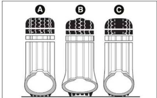
text_image
A B Cfig. 178
F0W0018
IMPORTANT
Take the following precautions to prevent damage to the tyres:
□avoid braking suddenly, racing starts and violent impact against the curb, potholes or other obstacles and driving for extended periods on uneven road surfaces;
☐periodically check that the tyres have no cuts in the side wall, abnormal swelling or irregular tyre wear;
☐ avoid travelling with the car overloaded. If you have a puncture, stop immediately and change the tyre;
☐tyres age even if they are not used much. Cracks the tread rubber and at the sides are a sign of ageing. In any case, if the tyres have been on the car for over 6 years, they should be checked by specialised personnel. Also remember to check the space-saver wheel very carefully (for versions/markets, where provided);
□change the position of the tyres every 10-15 thousand kilometres, keeping them on the same side of the car to avoid inverting the rotation direction;
☐In the case of replacement, always fit new tyres, avoiding those of dubious origin;
□if a tyre is changed, also change the inflation valve.

WARNING
Theroadholding qualities of the car alsodependon the correct inflation
pressureofthetyres.

WARNING
If the pressure istoolowthetyre overheats and can be seriously
damaged.
WARNING

Donotcrossswitchthetyres, moving themfromtherightofthecartothe viceversa.

WARNING
Neversubmitalloyrimstorepainting treatmentsrequiringtheuseof temperaturesexceeding 150°C. Themechanical propertiesofthewheelscouldbeimpaired.
WINDSCREEN/REARWINDOW WIPER
BLADES
Periodically clean the rubber part using special products; TUTELA PROFESSIONAL SC 35 is recommended.
Replace the blades if the rubber edge is deformed or worn. In any case, it is advisable to replace them approximately once a year. A few simple precautions can reduce the possibility of damage to the blades:
☐if the temperature falls below zero, make sure that ice has not frozen the rubber against the glass. Use an antifreeze product to release it if required;
☐remove any snow from the glass: in addition to protecting the blades, this prevents effort on the motor and overheating;
☐do not operate the windscreen/rear window wipers on dry glass.

WARNING
Drivingwithwornwindscreen/rear windowwiperbladesisaserioushazard, becausevisibilityisreducedinbadweather.
Replacingthewiperblades
Proceed as follows:
☐ lift up the windscreen wiper arm and position the blade so that it forms a 90° angle with the arm;
☐press tab A fig. 179 of the coupling spring and remove the blade to be replaced from the arm;
☐fit the new blade by inserting the tab into the special slot in the arm. Make sure that the new blade is secured in position.
Replacingtherearwindowwiperblade
Proceed as follows:
☐ raise cover A fig. 180 and remove the arm from the car undoing the nut B that fastens it to the pivot pin;
□correctly position the new arm and tighten the n fully;
☐lower the cover.
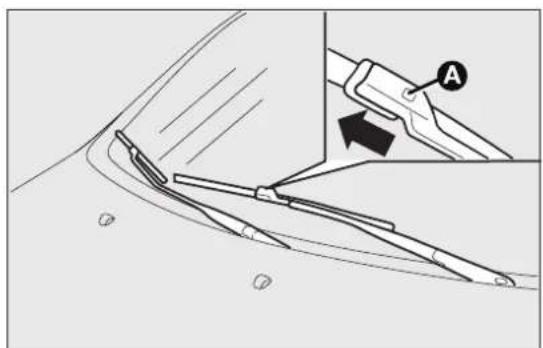
natural_image
Technical diagram showing a mechanical assembly with labeled parts (A) and numbered points (④, ⑦), no readable text or symbols present.fig. 179
F0Q0662

text_image
A Bfig. 180
F0Q0663
NOZZLES
Windscreen(washer)
If the jet is not coming out, firstly check that there fluid in the reservoir (see "Checking levels" in this chapter). Then check that the nozzle holes, marked by arrows in Fig. fig. 181, are not clogged; if necessary use a needle. The window washer nozzles are fixed.
Rearwindow(washer)
The rear window washer nozzles are fixed.
The nozzle holder is on the rear window fig. 182.
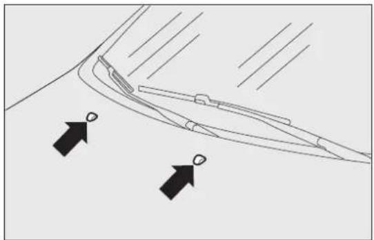
natural_image
Diagram of a curved road with directional arrows indicating flow or movement (no text or symbols)fig. 181
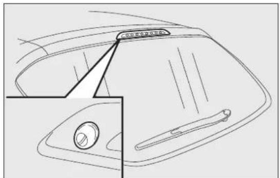
natural_image
Line drawing of a car's front bumper with a door and handle, showing no text or symbolsfig. 182
BODYWORK
PROTECTIONFROMATMOSPHERIC AGENTS
The main causes of corrosion are the following:
□atmospheric pollution
☐ salty air and humidity (coastal areas, or hot humid climates);
□seasonal environmental conditions.
The abrasive action of wind-borne atmospheric dust and sand, as well as mud and gravel raised by other vehicles is also not to be underestimated.
On your car, Fiat has adopted the best manufacturing technologies to effectively protect the bodywork against corrosion.
These are the most important:
□Painting products and systems which give the car particular resistance to corrosion and abrasion;
☐Use of galvanised (or pretreated) steel sheets, with high resistance to corrosion;
□spraying the underbody, engine compartment, wheel arch interiors and other parts with highly protective wax products;
□spraying of plastic parts, with a protective function in the more exposed points: underdoor, inner wing, edges, etc;
☐Use of “open” boxed sections to prevent condensation and pockets of moisture from 19g triggering rust inside.
BODYANDUNDERBODYWARRANTY
Your car is covered by warranty against perforation due to rust of any original element of the structure or body.
For the general terms of this warranty, refer to the Warranty Booklet.
ADVICEFORPRESERVINGTHE BODYWORK
Paint
Paintwork does not only serve an aesthetic purpose, but also protects the underlying sheet metal.
Touch up abrasions and scratches immediately to prevent rust formation. Use only original paint products for touch-ups (see "Bodywork paint identification plate" in the "Technical specifications" section).
Normal maintenance of paintwork consists in washing the car: the frequency depends on the conditions and environment where the car is used.
For example, in highly polluted areas, or if the road are spread with salt, it is advisable to wash the car more frequently.
To correctly wash the vehicle, proceed as follows:
☐remove the aerial from the roof to prevent damage to it if the car is washed in an automatic system;
☐if high pressure jets or cleaners are used to wash the vehicle, keep a distance of at least 40 cm from the bodywork to avoid damage or alteration. It should be remembered that the build up of water can damage the car over a period of time;
□wash the body using a low pressure jet of water;
☐wipe a sponge with a slightly soapy solution over the bodywork, frequently rinsing with the sponge;
☐rinse well with water and dry with a jet of air or a chamois leather.
Dry the less visible parts particularly carefully, such as the door frames, bonnet and the headlight frames, where water may stagnate more easily. The car should not be taken to a closed area immediately, but left outside so that residual water can evaporate.
Do not wash the car after it has been left in the sun or with the bonnet hot: this may alter the shine of the paintwork.
External plastic parts must be cleaned in the same way as the rest of the car.
Where possible, do not park under trees; the resinous substance that many species release give the paint a dull appearance and increase the possibility of triggering rusting processes.
IMPORTANT Bird droppings must be washed off immediately and thoroughly as the acid they contain is particularly aggressive.

Detergentspollutetheenvironment.
Thereforetheenginecompartments should bewashedinareasequipped for
collectingandpurifyingtheliquidusedinthe washingprocess.
Glasses
To clean glasses, use specific window cleaner products.
Also use clean cloths to avoid scratching the glass or damaging the transparency.
IMPORTANT Wipe the rear window inside gently with a cloth in the direction of the filaments to avoid damaging the heating device.
Enginecompartment
IMPORTANT The washing should take place with engine cold and the ignition key in the STOP position. After the washing operation, make sure that the various protections (e.g. rubber caps and guards) have not been removed or damaged.
Frontheadlights
IMPORTANT Never use aromatic substances (e.g. petrol) or ketenes (e.g. acetone) for cleaning the plastic lenses of the front headlights.
INTERIORS
Periodically check for water puddles under the mats that could cause the panels to rust.
Replace the worn carpet mats, if present, with genuine products and make sure they remain securely fastened to the passenger compartment carpet. It is not advisable to use non genuine mats that could move whilst driving.

WARNING
Neveruseflammableproducts,suchas petroletherorrectifiedpetroltoclean
theinsideofthecar. Theelectrostaticcharges whicharegeneratedbyrubbingduringthe cleaningoperationmaycauseafire.

WARNING
Donotkeepaerosolcansinthecar: theymightexplode.Aerosolcansmust
notbeexposedtoatemperatureexceeding 50°C. Whenthecarisexposedtosunlight, internaltemperaturecangreatlyexceedthis value.
SEATSANDFABRICPARTS
Remove dust with a soft brush or a vacuum cleaner. Rub the seats with a sponge and a solution of water and mild soap.
LEATHERSEATS
Remove the dry dirt with a buckskin or slightly dam cloth, without exercising too much pressure. Remove any liquid or grease stains using an absorbent dry cloth, without rubbing. Then clean with a soft cloth or buckskin cloth dampened with water and neutral soap.
If the stain persists, use specific products and observe the instructions carefully.
IMPORTANT Never use alcohol. Make sure that the cleaning products used contain no alcohol or alcohol derivatives, even in small quantities.

Thefabricupholsteryofyourcarhas beendesignedtowithstandwearderiving fromcommonuseofthecar.Youare
howeverrecommendedtoavoidstrongand/or continuoussscratchingwithclothingaccessories suchasmetalbuckles, studs, Velcrofasteningsand thelike, astheseitemscausestressofthecover fabricthatcouldleadtoyarnbreakingand damagetheupholstery.
PLASTICANDCOATEDPARTS
clean interior plastic parts with a damp cloth (if possible made from microfibre), and a solution of water and neutral, non-abrasive detergent. To clean oily or persistent stains, use specific products free from solvents and designed to maintain the original appearance and colour of the components.
Remove any dust using a microfibre cloth, if necessary moistened with water. The use of paper tissues is not recommended as these may leave
IMPORTANT Never use alcohol, petrol and derivatives to clean the instrument panel lens.
LEATHERSTEERINGWHEEL/GEAR KNOB/HANDBRAKE
These components must be cleaned with mild soap and water only. Never use alcohol or alcohol-based products.
Read the product label carefully before using specific products for cleaning the interiors: make sure the product does not contain alcohol or alcohol-based substances.
If, when cleaning the windscreen with special products, window cleaner accidentally drips onto the leather of the steering wheel/gear lever knob/hand brake, wipe away immediately and then wash the affected area with mild soap and water.
IMPORTANT Be careful when using a steering wheel lock device, where applicable, to avoid damaging the leather upholstery by rubbing.
TECHNICALSPECIFICATIONS
IDENTIFICATIONDATA
The identification data of the car are:
☐VIN plate;
□Chassis marking;
☐Bodywork paint identification plate;
□Engine marking.
VINPLATE
This plate is fitted to the engine compartment front crossmember and contains the following data fig. 183:
B Type-approval number.
C Vehicle type identification code.

text_image
FIAT GROUP AUTOMOBILES S.p.A. B C D E Kg F Kg 1- G Kg 2- H Kg N MOTORE-ENGINE I VERSION-VERSION L N° PER RICAMB N° FOR SPARES Mfig. 183
D Chassis serial number.
E Maximum authorised weight of vehicle fully laden.
F Maximum authorised weight of vehicle fully laden plus trailer.
G Maximum authorised weight on first (front) axle.
H Maximum authorised weight on second (rear) axle.
I Engine type.
L Bodywork version code.
M Number for spare parts.
N Correct value of smoke coefficient (for diesel engines).
CHASSISMARKING
This is printed on the passenger compartment floor, near the front right seat.
Slide flap A fig. 184 forward to access:
The marking includes:
□car model (ZFA 198000);
□chassis serial number.
BODYWORKPAINTIDENTIFICATION PLATE
This is fitted to the inside of the tailgate and bears the following data fig. 185:
APaint manufacturer.
BColour name.
CFiat colour code.
DRespray and touch up code.
ENGINEMARKING
This is stamped on the cylinder block and gives the model and the chassis serial number.

text_image
Afig. 184
F0Q0667
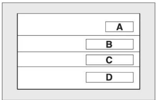
flowchart
graph TD
    A["A"] --> B["B"]
    B --> C["C"]
    C --> D["D"]
fig. 185
F0Q0100
ENGINECODE-BODYWORKVERSIONS
| VersionsEnginecodeBodyworkversions | ||
| 1.6MultiJetI05HP844A3000 | 198AXVIB 18 | |
| 198AXVIB 18B(*) | ||
| 1.6MultiJetI20HP198A2000 | 198AXLIB 08M | |
| 198AXLIB 08N(*) | ||
| 2.0MultiJetI65HP(**) | 198A8000 | 198AXTIB 16 |
| 198AXTIB 16B(*) | ||
(*) Versions where 18" tyres can be fitted
(**) For versions/markets, where provided
ENGINE
| 1.6Multijet105HPI.6Multijet120HP | ||
| Type code 844A3000 198A2000 | ||
| Cycle Diesel Diesel | ||
| Number and arrangement of cylinders | 4 in line 4 in line | |
| Piston bore and stroke (mm) 79.5 × 80.5 | 79.5 × 80.5 | |
| Total displacement (cm3) 1598 1598 | ||
| Compression ratio 16,5 16,5 | ||
| Maximum power (EC) (kW) | 77 | 88 |
| Maximum power (EC) (HP) 105 | 120 | |
| corresponding engine speed (rpm) | 4000 4000 | |
| Maximum torque (EC) (Nm) 300 | 300 | |
| Maximum torque (EC) (kgm) | 30,6 30,6 | |
| corresponding engine speed (rpm) | 1500 1500 | |
| Fuel | Diesel for automotive engines (Specification EN590) | |
| 2.0MultiJet165HP(*) | ||
| Type code 198A8000 | ||
| Cycle Diesel | ||
| Number and arrangement of cylinders | 4 in line | |
| Piston bore and stroke (mm) 83.0 x | 90.4 | |
| Total displacement (cm3) 1956 | ||
| Compression ratio 16,5 | ||
| Maximum power (EC) (kW) 121 | ||
| Maximum power (EC) (HP) 165 | ||
| corresponding engine speed (rpm) 4000 | ||
| Maximum torque (EC) (Nm) 350 | ||
| Maximum torque (EC) (kgm) 35,6 | ||
| corresponding engine speed (rpm) 1750 | ||
| Fuel Diesel for automotive engines (Specification EN590) | ||
(*) For versions/markets, where provided
FUELSUPPLY
VersionsFuelsupply
1.6MultiJet-2.0MultiJet
Electronically controlled Common Rail Multijet direct injection with turbo and intercooler

WARNING
Modificationsorrepairstothefuelsupplysystemthatarenotcarriedoutcorrectlyordonottakethesystem'stechnicalspecificationsintoaccountcancausemalfunctionsleadingtooffire.
TRANSMISSION
VersionsGearboxClutchDrive
1.6MultiJet-2.0MultiJet
Six forward gears plus reverse with synchronisers for forward gear engagement
Self-adjusting with pedal without idle stroke
Front
BRAKES
| Versions | Frontservice brakes | Rearservice brakes | Parkingbrake |
| 1.6MultiJet-2.0MultiJetSelf-ventilated disc Disc | Controlled by hand lever, acting on the rear brakes |
IMPORTANT Water, ice and salt spread on the roads may deposit on the brake discs reducing braking efficiency the first time the brakes are applied.
SUSPENSION
| VersionsFrontRear | ||
| 1.6MultiJet-2.0MultiJet | MacPherson independent wheels with anti-roll bar | Interconnected wheels with torsion beam |
STEERINGSYSTEM
| VersionsType | Turningcircle(kerbtokerb) (m) | |
| 1.6MultiJet-2.0MultiJet | Rack and pinion with electric power steering | 10.4 (11.0 with optional 18" alloy rims) |
WHEELS
16 Rim diameter in inches (∅)
91 Load rating (capacity)
v Maximum speed rating
RIMSANDTYRES
Pressed steel or alloy rims. Tubeless radial carcass tyres. The vehicle registration document also lists all type-approved tyres.
IMPORTANT If there are any discrepancies between the Owner Handbook and the registration document, take the information from the latter. For safe driving, the car must be fitted with tyres of the same make and type on all wheels.
IMPORTANT Do not use air chambers with Tubeles tyres.
SPAREWHEEL
Pressed steel rim. Tubeless tyre.
WHEELGEOMETRY
Front wheel toe-in measured from rim to rim: -1 mm + / -1 mm
The values refer to the car in running order.
CORRECTTYREREADING
Examplefig.186:195/55R169IV
195 Nominal width (S, distance in mm between sidewalls)
55 Height/width ratio (H/S) as a percentage
R Radial tyre
Maximumspeedrating
Q up to 160 km/h
R up to 170 km/h
S up to 180 km/h
T up to 190 km/h
U up to 200 km/h
H up to 210 km/h
s▼ up to 240 km/h
W up to 270 km/h
Y up to 300 km/h

text_image
S H Ø ① ② ③fig. 186
F0Q0200
| GETTINGTOKNOW YOURCAR |
| SAFETY |
| STARTINGAND DRIVING |
| WARNINGLIGHTS ANDMESSAGES |
| INANEMERGENCY |
| SERVICINGAND MAINTENANCE |
| TECHNICAL SPECIFICATIONS |
| INDEX |
Maximumspeedindexforsnowtyres
| QM + S up to 160 km/h |
| TM + S up to 190 km/h |
| HM + S up to 210 km/h |
Loadrating(capacity)
| 60= 250 kg 84= 500 kg | |
| 61= 257 kg 85= 515 kg | |
| 62= 265 kg 86= 530 kg | |
| 63= 272 kg 87= 545 kg | |
| 64= 280 kg 88= 560 kg | |
| 65= 290 kg 89= 580 kg | |
| 66= 300 kg 90= 600 kg | |
| 67= 307 kg 91= 615 kg | |
| 68= 315 kg 92= 630 kg | |
| 69= 325 kg 93= 650 kg | |
| 70= 335 kg 94= 670 kg | |
| 71= 345 kg 95= 690 kg | |
| 72= 355 kg 96= 710 kg | |
| 73= 365 kg 97= 730 kg | |
| 74= 375 kg 98= 750 kg | |
| 75= 387 kg 99= 775 kg | |
| 76= 400 kg 100= 800 kg |
Loadrating(capacity)
| 77= 412 kg 101= 825 kg | |
| 78= 425 kg 102= 850 kg | |
| 79= 437 kg 103= 875 kg | |
| 80= 450 kg 104= 900 kg | |
| 81= 462 kg 105= 925 kg | |
| 82= 475 kg 106= 950 kg | |
| 83= 487 kg |
CORRECTREADINGOFTHEWHEELRIM
Examplefig.186:7 J x 1 6 E T 3 I
7 rim diameter in inches (1).
J rim drop centre outline (side projection where the tyre bead rests) (2).
16 rim nominal diameter in inches (corresponds to diameter of the tyre to be mounted) (3 = ∅).
H2 shape and number of humps (circumference measurement which keeps the bead of Tubeless tyres in position on the rim).
ET31 wheel camber (distance between the disc/rim support plane and the wheel centre line).
RIMSANDTYRESPROVIDEDASSTANDARD
| VersionRims | TyresSnowtyres | Sparewheel | |||
| RimTyre | |||||
| 1.6MultiJet 105HP | 6J × 15 ET 31.5 (**) | 195/65 R15 91H (**) | 195/65 R15 91T (M+S) (**) | (***) (***) | |
| 7J × 16 ET 31 | 205/55 R16 91H | 205/55 R16 91T (M+S) | |||
| 7J × 17 ET 26 | 225/45 R17 91W | 225/45 R17 91T (M+S) | 7J × 16 ET 31 | 205/55 R16 91H 205/55 R16 91V (****) | |
| 7J × 17 ET 31 | 225/45 R17 91W | 225/45 R17 91T (M+S) | |||
| 7 1/2J × 18 ET 35 | 225/40 R18 92V REINFORCED (****) | 225/40 R18 92T (M+S) | |||
(**) For versions/markets, where provided
(***) On versions equipped with 195/65 R15 and 205/55 R16 tyres, a normal sized tyre may be ordered as an alternative to the Fix&Go.
(* * *) The 205/55 R16 91H (or 205/55 R16 91V) tyre has the same specifications as the space-saver wheel: the information in the "Replacing a wheel" paragraph therefore refers to the 205/55 R16 91H (or 205/55 R16 91V) tyre.
(****) Tyres which cannot be fitted with chains.
| VersionRims | TyresSnowtyres | Sparewheel | |||
| RimTyre | |||||
| 1.6MultiJet 120HP | 7J x 16 ET 31 | 195/55 R16 9IV | 195/55 R16 9IT (M+S) | (***) (***) | |
| 7J x 16 ET 31 | 205/55 R16 9IV | 205/55 R16 9IT (M+S) | |||
| 7J x 17 ET 31 | 225/45 R17 9IW | 225/45 R17 9IT (M+S) | 7J x 16 ET 31 | 205/55 R16 9IH 205/55 R16 9IV (****) | |
| 7 1/2J x 18 ET 35 | 225/40 R18 92W REINFORCED (***** ) | 225/40 R18 92T (M+S) | |||
(***) On versions equipped with 195/55 R16 and 205/55 R16 tyres, a normal sized tyre may be ordered as an alternative to the Fix&Go.
(**) The 205/55 R16 9IH (or 205/55 R16 9IV) tyre has the same specifications as the space-saver wheel: the information in the "Replacing a wheel" paragraph therefore refers to the 205/55 R16 9IH (or 205/55 R16 9IV) tyre.
(****) Tyres which cannot be fitted with chains.
| VersionRims | TyresSnowtyres | Sparewheel | |||
| RimTyre | |||||
| 2.0MultiJet165HP | 7J x 16 ET 31 | 195/55 R16 9IV | 195/55 R16 9IT(M+S) | (***) (***) | |
| 7J x 16 ET 31 | 205/55 R16 9IV | 205/55 R16 9IT(M+S) | |||
| 7J x 17 ET 26 | 225/45 R17 9IW | 225/45 R17 9IT(M+S) | 7J x 16 ET 31 | 205/55 R16 9IH205/55 R16 9IV(****) | |
| 7J x 17 ET 31 | 225/45 R17 9IW | 225/45 R17 9IT(M+S) | |||
| 7 1/2J x 18 ET 35 | 225/40 R18 92W REINFORCED(****) | 225/40 R18 92T(M+S) | |||
(***) On versions equipped with 195/55 R16 and 205/55 R16 tyres, a normal sized tyre may be ordered as an alternative to the Fix&Go.
(****) The 205/55 R16 91H (or 205/55 R16 91V) tyre has the same specifications as the space-saver wheel: the information in the "Replacing a wheel" paragraph therefore refers to the 205/55 R16 91H (or 205/55 R16 91V) tyre.
(****) Tyres which cannot be fitted with chains.
SPACE-SAVERWHEEL(forversions/markets,whereprovided)
Rim: 4B x 15H ET 35
Tyre: TI25/90 R15 96M
IMPORTANT Special techniques need to be adopted for 225/40 R18 92W tyres. For this reason, these can only be requested when the vehicle is purchased. Do not fit this tyre after the vehicle has been purchased!
TYREINFLATIONPRESSUREWHENCOLD(bar)
| Tyres | Unladen/mediumloadFullload | Space-saver wheel (*) | |||||||
| FrontRear | FrontRear | ||||||||
| 195/65 | R15 | 91H(*) | 2,3 | 2,3 | 2,6 | 2,6 | 4,2 | ||
| 195/55 | R16 | 91V 2,3 2,3 | 2,6 | 2,6 | |||||
| 205/55 | R16 | 91H 2.3 2.3 | 2.6 | 2.6 | |||||
| 205/55 | R16 | 91V 2.3 2.3 | 2.6 | 2.6 | |||||
| 225/45 | R17 | 91W 2.3 2.3 | 2.6 | 2.6 | |||||
| 225/40 | R18 | 92W 2,6 2,6 | 2,9 | 2,9 | |||||
(*) For versions/markets, where provided
Add +0.3 bar to the prescribed pressure when the tyres are warm.
Recheck pressure value with cold tyres. With snow tyres, add +0.2 bar to the pressure value prescribed for standard tyres.
When travelling at speeds above 160 km/h, inflate the tyres to the values specified for fully laden conditions.
DIMENSIONS
Dimensions are expressed in mm fig. 187 and refer to the vehicle equipped with its original tyres. Heig measured with car unladen.
LUGGAGECOMPARTMENTCAPACITYCapacity with car unladen (VDA standards): 400 ^3 with cargo box (for versions/markets, where provided). Capacity with rear seat backrest folded down: 1 ^3 175 with cargo box (for versions/markets, where provided).
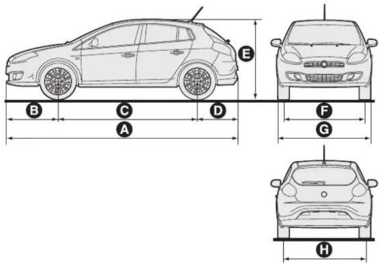
text_image
E B C D F G A Hfig. 187
F0Q0003
| A | B | C | D | E | F (*) | G | H(*) | ||||
| 4336 | 974 | 2600 | 762 | 1498 | 1538 | 1792 | 532 | ||||
(*) Small variations in size are possible depending on the dimensions of the rims.
PERFORMANCE
Max. speed in km/h that can be reached after initial car use.
Versionskm/h
| 1.6MultiJet I05HP | 187 (*) |
| 1.6MultiJet I20HP I94 | |
| 2.0MultiJet I65HP (**) | 215 |
(*) Top speed in sixth gear
(**) For versions/markets, where provided
WEIGHTS
| Weights(kg)1.6MultiJet | 2.0MultiJet (*) | |
| Unladen weight (with all fluids, fuel tank filled to 90% and without optional equipment) | 1320 1360 | |
| Payload including the driver(**) | 510 510 | |
| Maximum permitted loads(***) | ||
| - front axle: 1060 1060 | ||
| - rear axle: 860 860 | ||
| - total: 1830 1870 | ||
| Towable loads | ||
| - braked trailer: 1300 1300 | ||
| - non-braked trailer: 500 500 | ||
| Maximum load on roof(****) | 80 80 | |
| Maximum load on ball joint (braked trailer): | 60 60 |
(*) For versions/markets, where provided
(**) If special equipment is fitted (sun roof, tow hook, etc.) the unladen car weight increases, thus reducing the specified payload with respect to the maximum permitted loads.
(***) Loads not to be exceeded. The user is responsible for arranging goods in the luggage compartment and/or load platform within the maximum permitted loads.
(****) Lineaccessori Fiat roof rack bars, max capacity: 50 kg.
GETTINGTO KNOW YOURCAR
SAFETY
STARTING AND DRIVING
WARNINGLIGHTS AND MESSAGES
IN AN EMERGENCY
SERVICING AND MAINTENANCE
TECHNICAL SPECIFICATIONS
INDEX
REFUELLING
| 1.6MultiJet2.0MultiJet(*) | Prescribedfuelsand originallubricants | ||
| Fuel tank (litres): 58 58 | Diesel for motor vehicles (EN 590 Specification) | ||
| including a reserve of (litres): | 8 ÷ 10 8 ÷ 10 | ||
| Engine cooling system (litres): | 7,1 7,1 | Mixture of demineralised water and 50% PARAFLU^UP (**) | |
| Engine sump (litres): 4,3 4,3 | SELENIA WR FORWARD | ||
| Engine sump and filter (litres): | 4,6 4,9 | ||
| Gearbox/differential casing (litres): | 1,87 1,87 | TUTELA TRANSMISSION GEARFORCE | |
| Hydraulic brake circuit with ABS: | 0,56 0,56 TUTELA TOP 4 | ||
| Windscreen and rear window washer fluid reservoir (litres): | 3 (6) 3 (6) | Mixture of water and TUTELA PROFESSIONAL SC35 | |
(**) For particularly harsh climate conditions, a mixture of 60% PARAFbdd 40% demineralised water is recommended.
(*) For versions/markets, where provided
FLUIDSANDLUBRICANTS
Your car is equipped with an engine oil that has been thoroughly developed and tested in order to meet requirements of the Scheduled Servicing Plan. Constant use of the prescribed lubricants guarantees the fuel consumption and emission specifications. Lubricant quality is crucial for engine operation and duration
PRODUCTSPECIFICATIONS
| Use | Fluidandlubricantspecificationsfora correctuseofthecar | Genuinefluidsand lubricants | Replacementinterval |
| Lubricant for diesel engines | SAE 0W-30 grade fully synthetic lubricant. FIAT 9.55535-DSI, ACEA C2 classification. | SELENIAWR FORWARD Contractual Technical Reference No. F842.F13 | According to Scheduled Servicing Plan |
In case of emergency, if lubricants with the prescribed specifications are not available, products with the minimum indicated ACEA performance can be used for topping up; in this case optimal performance of engine is not guaranteed.

The useofproductswithdifferentspecificationsthanthoseindicatedabovecouldcause damagetotheenginethatisnotcoveredbythewarranty.
| Use | Fluidandlubricantspecificationsfora correctuseofthecar | Genuinefluidsand lubricants | Applications |
| Lubricants and greases for drive transmission | SAE 75W grade synthetic lubricant. FIAT 9.55550-MZ6 classification | TUTELA TRANSMISSION GEARFORCE Contractual Technical Reference No. F002.F10 | Manual gearboxes and differentials |
| Molybdenum disulphide grease, for use at high temperatures. NL.G.I. I-2 consistency. FIAT Classification 9.55580 | TUTELAALLSTAR Contractual Technical Reference No. F702.G07 | Wheel side constant velocity joints | |
| Grease for constant velocity joints with low friction coefficient. NL.G.I. 0-I consistency. FIAT Classification 9.55580 | TUTELASTAR700 Contractual Technical Reference No. F701.C07 | Differential side constant velocity joints | |
| Brake fluid | Synthetic fluid for brake and clutch systems. Exceeds specifications: FMVSS no. 116 DOT 4, ISO 4925 SAE J1704. FIAT Classification 9.55597 | TUTELATOP4 Contractual Technical Reference No. F001.A93 | Hydraulic brakes and hydraulic clutch controls |
| Protective agent for radiators | Red protective agent with antifreeze action, based on inhibited monoethylene glycol with organic formula. Exceeds CUNA NC 956-16 ASTM D 3306 specifications. FIAT 9.55523 classification | PARAFLU^UP (*)Contractual Technical Reference No.F101.M01 | Cooling circuit usage percentage: 50% demineralised water50% PARAFLU^UP (**) |
| Additive for diesel | Additive for diesel with antifreeze and protective action for diesel engines | TUTELA DIESELARTContractual Technical Reference No. F601.L06 | To be mixed with diesel (25 cc per 10 litres) |
| Windscreen/ rear window washer fluid | Mixture of alcohols and surfactants. Exceeds CUNA NC 956-11 specifications. FIAT Classification 9.55522 | TUTELA PROFESSIONAL SC35Contractual Technical Reference No.F201.D02 | To be used diluted or undiluted in windscreen/ rear window washer/wiper systems |
(*) IMPORTANT Do not use fluids with different specifications for topping up or mixing.
(**) For particularly harsh climate conditions, a mixture of 60% PARAFLud 40% demineralised water is recommended.
FUELCONSUMPTION
The fuel consumption figures given in the table below are determined on the basis of the type-approval tests laid down by specific European Directives.
The procedures below are followed for measuring consumption:
□urban cycle: cold starting followed by driving that simulates urban use of the car;
□ extra-urban cycle: frequent accelerating in all gears, simulating extra-urban use of the car: speed varies between 0 and 120 km/h;
☐ combined fuel consumption: calculated with a weighting of approximately 37% of the urban cycle and 63% of the extra-urban cycle.
IMPORTANT The type of route, traffic conditions, weather conditions, driving style, general condition of the car, trim level/equipment/accessories, use of the climate control system, car load, presence of roof racks and other situations that adversely affect the aerodynamics or wind resistance lead to different fuel consumption values than those measured.
FUELCONSUMPTIONACCORDINGTOTHECURRENTEUROPEANDIRECTIVE (litres/100km)
| VersionsUrbanExtra-urbanCombined | |||
| 1.6MultiJet I05HP5,3 3,7 4,3 | |||
| 1.6MultiJet I20HP5,6 3,8 4,5 | |||
| 2.0MultiJet (*) | 6,7 4,2 5,1 |
(*) For versions/markets, where provided
CO _2 EMISSIONS
The CO _2 emission levels given in the following table refer to combined consumption.
| VersionsCO | 2 emissionsaccordingtothecurrentEuropeandirective(g/km) |
| 1.6MultiJetI05HP113 | |
| 1.6MultiJetI20HP117 | |
| 2.0MultiJet (*) | 135 |
(*) For versions/markets, where provided
OFFICIALTYPEAPPROVALS
text_image
EMCC™ DR. RAŠEK Notified Body Directive 99/5/EC Competent Body EMC Directive 89/336/EEC Notified Body EMC Directive 89/336/EEC FCB under the Canada-EC MRA TCB under the USA-EC MRA EC Identification No. 0678
EC-R&TTE CERTIFICATE
to act as a Notified Body in accordance with the R&TTE Directive 1999/5/EC of 9. March 1999
G102952U
MAGNETI MARELLI SISTEMI ELETTRONICI SpA Via Aldo Borletti, 61/63 20011 Corbetta (MI) Italy
TRF 192.02, TRF 841.02, TRF S20.02
Low Power Device
MAGNETI MARELLI SISTEMI ELETTRONICI SpA Via Aldo Borletti, 61/63 20011 Corbetta (MI) Italy
Registration No. Certificate Holde
Product Description Manufacturer
| Essential Requirement | Applied Specifications / Standards | Documentary Evidence | Result | |
| Art. 3.1(a) | Health | Not assessed | ||
| Art. 3.1(a) | Safety | EN 60950 | Declaration of Conformity | conform |
| Art. 3.1(b) | EMC | EN 301 489-1/-3 | Test Report E20471 Edition 2 | conform |
| Art. 3.2 | Radio | EN 300 220-1/-3 | Test Report R20471 Edition 2 | conform |
C€ 0678
The product shall be marked with the CE conformity marking and our Notified Body number as shown on the right.
The scope of evaluation relates to the submitted documents only.
This Certificate is issued in accordance with Annex IV of the R&TTE Directive 1999/5/EC of 9^th March, 1999 and is only valid in conjunction with the attached Annex.

Ebermannstadt. 2006-05-23
The Ground Truth image displays a single, solid horizontal line. According to Rule 2 (UNDERSCORE & LINE RULES), this is a stylistic or background line, not a placeholder underscore. Therefore, the OCR result must ignore it and output nothing or only meaningful text. The provided OCR content is "____", which consists of four underscores. This is an incorrect interpretation of the line as a placeholder, violating the rule that stylistic lines must be ignored. The OCR has hallucinated underscores where none should exist based on the GT's visual context. Hence, the OCR result is inconsistent with the Ground Truth.
EMCCert DR, RASEK GmbH • Moggast, Boelwiese 5, 91320 Ebermannstadt, Germany Tel.: +49-9194-9016 • Fax: +49-9194-8125 • E-mail: omc.cert@emcc.do • Web: www.emcc.do

Notified Body Directive 99/5/EC Competent Body EMC Directive 89/336/EEC Notified Body EMC Directive 89/336/EEC FCB under the Canada-EC MRA TCB under the USA-EC MRA
EC Identification No. 0678
Designated by the German Regulator
to act as a Notified Body in accordance with the R&TTE Directive 1999/5/EC of 9. March 1999
EC-R&TTE CERTIFICATE
G103345U
Electronic immobilizer with inductive transponder at 125 kHz
The product shall be marked with the CE conformity marking and our Notified Body number as shown on the right.
The scope of evaluation relates to the submitted documents only.
This Certificate is issued in accordance with Annex IV of the R&TTE Directive 1999/5/EC of 9^th March, 1999 and is only valid in conjunction with the attached Annex.


Ebermannstadt, 2006-11-24
EMCCert DR. RASEK GmbH • Moggast, Boelwiese 5, 91320 Ebermannstadt, Germany Tel: +49-9194-9016 • Fax: +49-9194-8125 • E-mail: emc.cert@emcc.de • Web: www.emcc.de
page intentionally left blank
DASHBOARD
The presence and the position of the instruments and warning lights may vary according to the versions.

text_image
Diagram of car interior with numbered labels pointing to various components such as airbag, steering wheel, and dashboard.fig.1
FOQ0005
1. Adjustable and swivel air vent - 2. Side window air vent - 3. Front passenger air bag - 4. Adjustable and swivel air vents -5.Hazardlightswitch-6.Externallightstalk-7.Instrumentpanel-8.Windscreen/rearwindowwiper/tripcomputer stalk - 9. Bonnet opening lever - 10. Glovebox - 11. Ignition key and ignition device - 12. Steering wheel locking/release stalk - 13. Driver's air bag - 14. Driver's knees air bag (for versions/markets, where provided) - 15. Set of switches for front/rearfoglightsandmenuopening/setting-16.Controlsforheating/ventilation/climatecontrol-17.Soundsystem controls-18.SetofON/OFFswitchesforelectricpowersteeringandASRsystem(forversions/markets,where provided)-19.Oddmentcompartment
INSTRUMENTPANEL
A.Speedometer(speedindicator)B.FuellevelgaugewithreservewarninglightC.Enginecoolanttemperaturegaugeand
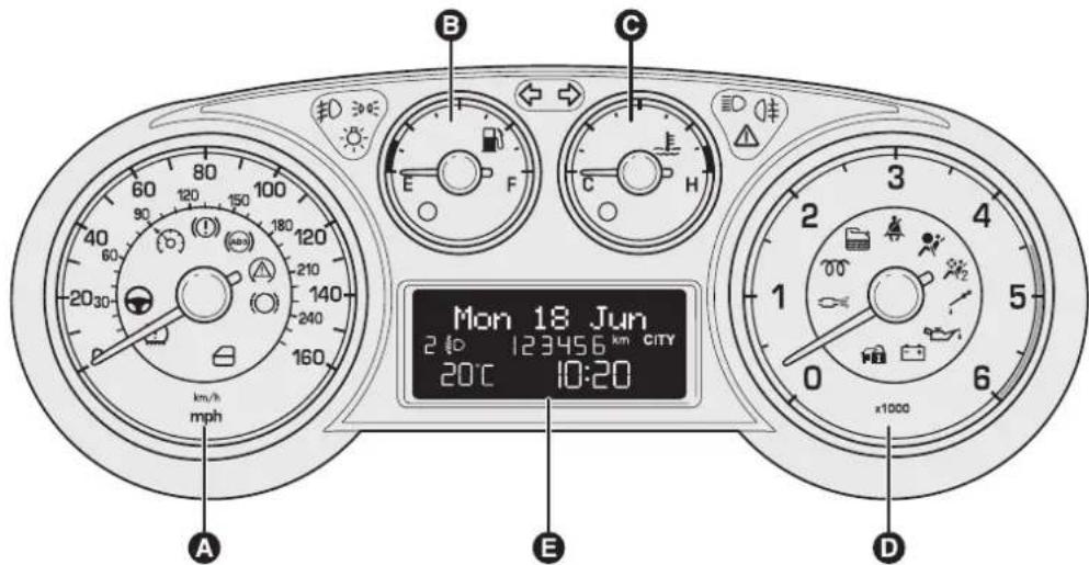
text_image
Mon 18 Jun 2:00 123456 km CITY 20°C 10:20 km/h mph A B C D Efig.2
excessivetemperaturewarninglightD.RevcounterE.Display
F0Q0911

In the heart of your engine.

text_image
PETRONAS SELENIA MOTOR Oil PURE ENERGY KW-4D MOSAIR AGE 03 PETRONAS SELENIA MOTOR Oil PURE ENERGY WR WIDE RANGE 5W-30 AGE 03 PETRONAS SELENIA MOTOR Oil PURE ENERGY MULTIPOWER SW-40 SAS PETRONAS SELENIA MOTOR Oil PURE ENERGY DIGITE ASCATE SAE 0W-30 PETRONAS SELENIA MOTOR Oil POWER SAE 5W-20PETRONAS Always ask your mechanic for SELENIJA MOTOR DIL
Oil change? The experts recommend Petronas Selenia
The engine of your car is factory filled with Petronas Selenia, This is an engine oil range which satisfies the most advanced international specifications. Its superior technical characteristics allow Petronas Selenia to guarantee the highest performance and protection of your engine.
The Petronas Selenia range includes a number of technologically advanced products:
SELENIA K PURE ENERGY
Fully synthetic lubricant designed for latest generation, low emission, petrol engines. Its specific formulation warrants the utmost protection also for high performance turbocharged engines with high thermal stress. Its low ash content helps to maintain the total cleanliness of modern catalysts.
SELENIA WR PURE ENERGY
Fully synthetic lubricant that can meet the requirements of the latest diesel engines. Low ash content to protect the particulate filter from the residual products of combustion. High Fuel Economy System that allows considerable fuel saving.
It reduces the danger of dirtying the turbine to ensure the protection of increasingly high performance diesel engines.
SELENIA MULTIPOWER GAS PURE ENERGY
Fully-synthetic lubricant designed for petrol engines also turbocharged, powered with methane or LPG. Its exclusive formulation improves valve protection against wear, neutralises the acid compounds formed by combustion and keeps engine performance levels unchanged.
SELENIA K POWER
Fully synthetic lubricant developed for American design petrol engines, specially formulated to allows an excellent resistance to oxidation and high level fuel economy. Excellent protection at high temperatures.
SELENIA DIGITEK PURE ENERGY
Fully synthetic lubricant for petrol engines. High fuel economy characteristics. Specific formulation for the TwinAir two-cylinder engines, Selenia Digitech Pure Energy allows maximum protection of the engine even under high mechanical stress caused by severe stop and go conditions of city traffic.
The range also includes Selenia K, Selenia 20K, Selenia Turbo Diesel,
Selenia Sport, Selenia Sport Power, Selenia Racing.
For further information on Petronas Selenia products visit the web site www.pli-petronas.eu
NOTE
The Ground Truth image displays a single, solid horizontal line. According to Rule 2 (UNDERSCORE & LINE RULES), this is a stylistic or background line, not a placeholder underscore. Therefore, the OCR result must ignore it. The provided OCR content is "____", which consists of four underscores. This is an incorrect interpretation of the line as a placeholder, violating the rule that stylistic lines must be ignored. The OCR has hallucinated underscores where none should exist based on the GT's visual context. Hence, the OCR result is inconsistent with the Ground Truth.
The Ground Truth image displays a single, continuous horizontal line, which is a stylistic or background element (like a ruled paper line or separator), not a placeholder for text. According to Rule 2, such stylistic/background lines must be ignored by the OCR result. The OCR content provided is "", which consists of no characters. This correctly represents the line in the GT by ignoring it entirely. Since the OCR output includes no underscores for this line, this complies with the “Stylistic/Background Lines (Ignore)” rule. Therefore, the OCR result is consistent with the Ground Truth.
[Non-Text]
(1) 2017年,公司与上海浦东发展银行股份有限公司签订了《关于使用部分闲置募集资金进行现金管理的协议》。
The Ground Truth image displays a single, continuous horizontal line, which is a stylistic or background element (like a ruled paper line or separator), not a placeholder for text. According to Rule 2, such stylistic/background lines must be ignored by the OCR result. The OCR content provided is "", which consists of no characters. This correctly represents the line in the GT by ignoring it entirely. Since the OCR output includes no underscores for this line, this complies with the “Stylistic/Background Lines (Ignore)” rule. Therefore, the OCR result is consistent with the Ground Truth.
(1) AD = BD = 1
(1) 2017年,公司与上海浦东发展银行股份有限公司签订了《关于使用部分闲置募集资金进行现金管理的协议》。
The Ground Truth image displays a single, continuous horizontal line, which is a stylistic or background element (like a ruled paper line or separator), not a placeholder for text. According to Rule 2, such stylistic/background lines must be ignored by the OCR result. The OCR content provided is "", which consists of no characters. This correctly represents the line in the GT by ignoring it entirely. Since the OCR output includes no underscores for this line, this complies with the “Stylistic/Background Lines (Ignore)” rule. Therefore, the OCR result is consistent with the Ground Truth.
(一)公司董事会对董事会的授权范围、授权期限、授权内容、授权范围、授权期限、授权内容、授权期限、授权内容、授权期限、授权内容、授权期限、授权内容、授权期限、授权内容、授权期限、授权内容、授权期限、授权内容、授权期限、授权内容、授权期限、授权内容、授权期限、授权内容、授权期限、授权内容、授权期限、授权内容、授权期限、授权内容、授权期限、授权内容、授权期限、授权内容、授权期限、授权内容、授权期限、授权内容、授权期限
[Non-Text]
The Ground Truth image displays a single, continuous horizontal line, which is a stylistic or background element (like a ruled paper line or separator), not a placeholder for text. According to Rule 2, such stylistic/background lines must be ignored by the OCR result. The OCR content provided is "", which consists of no characters. This correctly represents the line in the GT by ignoring it entirely. Since the OCR output includes no underscores for this line, this complies with the “Stylistic/Background Lines (Ignore)” rule. Therefore, the OCR result is consistent with the Ground Truth.
The Ground Truth image displays a single, solid horizontal line. According to Rule 2 (UNDERSCORE & LINE RULES), this is a stylistic or background line, not a placeholder underscore. Therefore, the OCR result must ignore it and output nothing or only meaningful text. The provided OCR content is "____", which consists of four underscores. This is an incorrect interpretation of the line as a placeholder, violating the rule that stylistic lines must be ignored. The OCR has hallucinated underscores where none should exist based on the GT's visual context. Hence, the OCR result is inconsistent with the Ground Truth.
[Non-Text]
(No text)
(No text)
The Ground Truth image displays a single, solid horizontal line. According to Rule 2 (UNDERSCORE & LINE RULES), this is a stylistic or background line, not a placeholder underscore. Therefore, the OCR result must ignore it and output nothing or only meaningful text. The provided OCR content is "____", which consists of four underscores. This is an incorrect interpretation of the line as a placeholder, violating the rule that stylistic lines must be ignored. The OCR has hallucinated placeholder underscores where none should exist in the GT. Hence, the OCR result is inconsistent with the Ground Truth.
The Ground Truth image displays a single, continuous horizontal line, which is a stylistic or background element (like a ruled paper line or separator), not a placeholder for text. According to Rule 2, such stylistic/background lines must be ignored by the OCR result. The OCR content provided is "", which consists of no characters. This correctly represents the line in the GT by ignoring it entirely. Since the OCR output includes underscores for a stylistic line, this complies with Rule 2. Therefore, the OCR result is consistent with the Ground Truth.
The Ground Truth image displays a single, continuous horizontal line, which is a stylistic or background element (like a ruled paper line or separator), not a placeholder for text. According to Rule 2, such stylistic/background lines must be ignored by the OCR result. The OCR content provided is "", which consists of no characters. This correctly represents the line in the GT by ignoring it entirely. Since the OCR output includes no underscores for this line, this complies with the “Stylistic/Background Lines (Ignore)” rule. Therefore, the OCR result is consistent with the Ground Truth.
(三) 本次股东大会的召集和召开程序
(1) 2017年,公司与上海浦东发展银行股份有限公司签订了《关于使用部分闲置募集资金进行现金管理的协议》。
The Ground Truth image displays a single, continuous horizontal line, which is a stylistic or background element (like a ruled paper line or separator), not a placeholder for text. According to Rule 2, such stylistic/background lines must be ignored by the OCR result. The OCR content provided is "", which consists of no characters. This correctly represents the line in the GT by ignoring it entirely. Since the OCR output includes no underscores for this line, this complies with the “Stylistic/Background Lines (Ignore)” rule. Therefore, the OCR result is consistent with the Ground Truth.
INDEX
ABS(system)......89
Accessoriespurchasedby theowner....96
Activation/Deactivation (CITYfunction)....97
Activationofinternalair recirculationand enablementofAQS function(AirQuality System)....49
Additionalheater......41-45-51
Adjustablesideventsand diffusers....37
Aircleaner....212
Airdistributionselection......50
Alarm....14
Anti-pinchsafetydevice......74
Ashtray....70
ASR(system)....93
Automaticdualzoneclimate controlsystem......46
Automaticheadlightsensor (dusksensor)....54
Automaticoperationofthe climatecontrolsystem (AUTOfunction)....47
Battery....212
-adviceforextending lifetime....212
-replacement....212
Battery(recharging)....198
Bodywork —maintenance....220
-protectionagainst atmosphericagents......219
—warranty....219
Bonnet......85
BrakeAssist....91
Brakefluid....210
Brakes —specifications....231
Bulbreplacement......180-182
Bulbreplacement —exteriorlights....177 —interiorlights....184
Bulbs -bulbs(replacement)....174
-generalinstructions......174
-typesofbulbs....175
Capacities....242
Carryingchildrensafely....116 —childrestraintsystems.....124
-"Isofix"childrestraint systemsetup......122
Centraldiffusers......37
Centrallocking....75
Changingawheel......162
Checkingfluidlevels......206
Childlockdevice....75
Childrestraintsystems (complianceforuse)......121
Cigarlighter....69
Cleaningandmaintenance -bodywork......219
-carinterior....222
—enginecompartment......221
-frontheadlights....221
—Plasticandcoatedparts.....223
-seats....222-223
-windows....221
Climatecontrol/heating system....36
Climatecontrolsystem compressor activation/deactivation......50
Clutch....230
CO2emissions......247
CODECard......8
Controlbuttons(display)......18
Controlpaneland instruments....4
Controls....39-42-47-63-78
Courtesy mirrorlights -bulbreplacement......187
CruiseControl....59
Dashboard....3
Description......47
Dieselfilter....212
Diffusers....37
Dippedheadlights....52 -bulbreplacement....177
Directionindicators....53 —bulbreplacement....179
Display....17
Doormirrors....34
Doors....75
DPF(DieselParticulate Filter)....109
Driverfrontairbag......127
Driver'ssidekneebag......130
"Dualdrive"electricpower steeringsystem....97
EBD(system)....90
Electricwindows....77
Emergencymanoeuvre....74
Enginecode-bodywork versions....227
Enginecompartment -opening/closing....85 -washing....221
Enginecoolant......211
Enginecoolanttemperature indicator....6
Engine -marking....226 -technicaldata....228
Engineoil -Consumption....209 -Levelcheck....209 -specifications....243
EOBDsystem....95
ESP(system)......91
ESPsystem....91
Exteriorlights....52
Failureindications......98
Fanspeedadjustment.....41-44-48
Fastfrontwindow demisting/defrosting......40-43
FiatCODE(system)......7
FiatCODEsystem......7
Fitting"Universal"child restraintsystem....118
Fix&GoAutomaticKit......169
Flashing....52
Fluidsandlubricants (specifications)......243
Foglights....63-180
"Followmehome"device.....53
Frontairbags....126
Frontarmrest......66
Frontlightclusters (changingabulb)......177
Frontrooflight —bulbreplacement......184
Frontrooflightwithspot lights....61
Fuelcut-offswitch....64
Fuelcut-offsystem......65
Fuel —savingfuel....139
Fuellevelgauge....5
Fuelsupply......230
Fuseboxes(location)......188
Fuses
—dashboardfusebox......189
—enginecompartmentfuse boxnexttothebattery...... 190-191
—fuselist....193
-luggagecompartment fusebox....192
-replacingfuses....187
Glüssler....70
Glovecompartmentlight —bulbreplacement......186
Handbrake....137
Hazardwarninglights......63
Headlightalignment corrector......88
Headlights....88
-bulbreplacement....177
Headlightwashers....58
Headrestraints....31
Heatedrearwindowand doormirrors demisting/defrosting.....40-44-48
Heatingandventilation....39
HillHolder(system)......92
Identificationdata
-bodyworkpaintplate......226
-chassismarking......226
—enginemarking....226
-identificationdataplate.....225
Ignitionswitch....16
Initialisationprocedure......74
Installing
electrical/electronicdevices...96
Installingthetowhook......142
Interiorfittings......66
Interiors(cleaning)......222
Internalairrecirculation activation....41-44
Internalmirror....34
Jack....164
Keywithoutremote control....8
Keywithremotecontrol......9
Lightclusters
—rearlightclusters (changingabulb)....181
Lightsoff....52
Loadlimiters....113
Luggagecompartment......80
-Extending......81
-Opening....80
—Securingyourload......84
Luggage compartmentroof light
-bulbreplacement....186
Mainbeamheadlights....52
-bulbreplacement....179
Maintenanceandcare
—Scheduledservicing......202
–scheduledservicingplan.....203
-bulbreplacement....183
Parking....137
Parkinglights....52
Parkingsensors....103
Passengercompartment
heating....40-43
Passengerfrontairbag......127
Performance(topspeed)......240
Pollenfilter....212
Powersocket......69
Pretensioners....113
Protectingtheenvironment....109
Rainsensor....56
Raisingthecar....199
Rapidfrontwindow demisting/defrosting (MAX-DEFfunction)......48
Reararmrest......67
Reardiffuser....38
Reardooremergency lockingdevice....76
Rearfoglight....63-182
Rearrooflight....62 -bulbreplacement....185
Rearviewmirrors....34
Rearwindowwasher nozzles....218
Rearwindowwasher/wiper.....57
Rearwindowwiper -bladereplacement....217 -blades....216
Refuellingthecar....107
Replacingfuses....187
Replacingthebatteryinthe keywithremotecontrol......11
Replacingtheremote controlcover......11
Revcounter......5
Reverselight....182
Rimsandtyres....233
Rims —wheelsandtyres....214
Rooflights....61
Roofrack/skirack......87
Safelock(device)....12
Safety —carryingchildrensafely......116
Savingfuel....139
SBRsystem....112
ScheduledServicingPlan......203
Seatbelts....110
—loadlimiters....113
—maintenance....116
-pretensioners......113
Seats......30
-Backrestangle adjustment....30
-Heightadjustment......30
-Longitudinaladjustment.....30
-Lumbaradjustment....30
Servicingandcare
- heavy-duty use of the car... 206 -periodicchecks....205
Settemperaturealignment (MONOfunction)....50
Setupmenu(display)......19
Sideairbags(sidebag-windowbag)....131
Sidebags....131
Sidelights....52 -bulbreplacement....178
Snowchains....144
Snowtyres....143
Sparkplugs(type)......228
Speedometer....5
Startingtheengine......135-161
Steeringlock....16
Steeringsystem......232
Steeringwheel....33
Storagecompartments......68-70
Storingthecar....145
Sunroof....72
Sunvisors....71
Suspension....231
Switchingofftheclimate controlsystem......51
Switchingontheclimate controlsystem......47
Technicaldata......225
Thekeys......8
Thirdbrakelight....182
Towingthecar....199
Towingtrailers......141
TPMS....100
Transmission......230
TRIPbutton....29
Tripcomputer
-TRIPbutton....29
-TripComputer......28
-TripComputervalues......28
Tyres
—correcttyrereading......233
-Fix&GoAutomatic(kit).....169
-inflationpressures......238
—snowtyres....234
-tyresprovided....234
Tyres-maintenance......214
Usingthegearbox....138
Volumesensing/Anti-lift protection....15
Warninglightsonpanel......146
Washerfluidfor
windscreen/rear
window/headlights......211
Weightsandloads......241
Wheelgeometry......233
Wheelrims
—correctreadingofthe
wheelrim....234
-dimensions....234
Wheelsandtyres
—changingawheel....162
-Fix&GoAutomatic-kit.....169
—Wheelsandtyres......214
Windowcleaning....55
Windows(cleaning)......221
Windscreenwashernozzles...218
Windscreenwasher/wiper.....55
Windscreenwiper
-blades....216
-bladesreplacement......217
Wiringforradiosystem......95
Fiat Group Automobiles S.p.A. - Parts&Services - Technical Services - Service Engineering Largo Senatore G. Agnelli, 3 - 10040 Volvera - Torino (Italia) Print no. 603.99.521 - 04/2014 - I Edition
ENGLISH
The data contained in this publication is intended merely as a guide. FIAT reserves the right to modify the models and versions described in this booklet at any time for technical and commercial reasons.
If you have any further questions please consult your FIAT dealer.
Printed in recycled paper without chlorine.