R6250 - Router NETGEAR - Free user manual and instructions
Find the device manual for free R6250 NETGEAR in PDF.

User questions about R6250 NETGEAR
0 question about this device. Answer the ones you know or ask your own.
Ask a new question about this device
Download the instructions for your Router in PDF format for free! Find your manual R6250 - NETGEAR and take your electronic device back in hand. On this page are published all the documents necessary for the use of your device. R6250 by NETGEAR.
USER MANUAL R6250 NETGEAR
natural_image
Black NETGEAR wireless router device with purple LED and control buttons (no visible text beyond branding)April 2015
202-11544-01
350 East Plumeria Drive
San Jose, CA 95134
USA

natural_image
Abstract geometric composition with overlapping colored triangles (no text or symbols)R6250 Smart WiFi Router
Support
Thank you for selecting NETGEAR products.
After installing your device, locate the serial number on the label of your product and use it to register your product at https://my.netgear.com. You must register your product before you can use NETGEAR telephone support. NETGEAR recommends registering your product through the NETGEAR website.
For product updates and web support, visit http://support.netgear.com.
Phone (US & Canada only): 1-888-NETGEAR.
Phone (Other Countries): Check the list of phone numbers at http://support.netgear.com/general/contact/default.aspx.
Trademarks
© NETGEAR, Inc., NETGEAR and the NETGEAR Logo are trademarks of NETGEAR, Inc. Any non-NETGEAR trademarks are used for reference purposes only.
Compliance
For regulatory compliance information, visit http://www.netgear.com/about/regulatory/.
See the regulatory compliance document before connecting the power supply.
Contents
Chapter 1 Hardware Setup
Unpack Your Router 8
Hardware Features 8
Front and Side Panel....9
Rear Panel 10
Label 11
Position Your Router 11
Chapter 2 Getting Started
Router Setup Preparation....13
Use Standard TCP/IP Properties for DHCP 13
Gather ISP Information 13
Wireless Devices and Security Settings....13
Types of Logins and Access 13
NETGEAR genie Setup....14
Use NETGEAR genie After Installation 15
Upgrade the Firmware 15
Dashboard (Basic Home Screen)....15
Join Your Wireless Network 16
Manual Method....17
Wi-Fi Protected Setup (WPS) Method 17
Access the Router with NETGEAR the genie App 17
Chapter 3 Basic Settings
Internet Setup 20
Internet Setup Screen Fields 21
Basic Wireless Settings 22
Wireless Settings Screen Fields. 24
Change the Wireless Security Option 25
Set Up a Guest Network....25
View Attached Devices....26
Chapter 4 Advanced Home Settings
NETGEAR genie Advanced Home Screen 29
Internet Connection Setup Wizard 29
WAN Setup 30
Default DMZ Server 31
Change the MTU Size 32
R6250 Smart WiFi Router
LAN Setup....33
LAN Setup Screen Settings 34
The Role of the Router as a DHCP Server....35
Address Reservation....36
WPS Wizard for WiFi Connections 36
Quality of Service (QoS) Setup....37
WMM QoS for Wireless Multimedia Applications 37
Optimize Internet Gaming with Upstream QoS 38
Set Up QoS for Internet Access 39
Chapter 5 USB Storage
Connect a USB Storage Device to the Router....44
Safely Remove a USB Drive 44
Access the USB Storage Device. 44
File-Sharing Scenarios 47
Share Photos 47
Store Files in a Central Location for Printing. 47
Share Large Files over the Internet 48
Back Up Windows Computers with ReadySHARE Vault. 48
View a USB Device Attached to the Router....49
USB Storage Device Network and Access Settings 49
Available Network Folders 51
Specify Approved USB Devices....52
Back Up Windows Computers with ReadySHARE Vault. 53
Chapter 6 Share a USB Printer
Install the Printer Driver and Cable the Printer....57
Download the ReadySHARE Printer Utility 57
Install the ReadySHARE Printer Utility 57
Use the Shared Printer 59
View or Change the Status of a Printer 60
Use the Scan Feature of a Multifunction USB Printer 61
Change NETGEAR USB Control Center Settings 62
Chapter 7 Security
Set Up Parental Controls 66
Keyword Blocking of HTTP Traffic 69
Block Services (Port Filtering)....70
Port Triggering to Open Incoming Ports 72
Port Forwarding to Permit External Host Communications 73
How Port Forwarding Differs from Port Triggering 74
Set Up Port Forwarding to Local Servers....74
Add a Custom Service 75
Edit or Delete a Port Forwarding Entry 76
Set Up Port Triggering 77
Schedule Blocking 79
Security Event Email Notifications 80
Chapter 8 Administration
Upgrade the Router Firmware 83
View Router Status 84
Router Information 84
Internet Port 84
Wireless Settings (2.4 GHz and 5 GHz) 87
View Logs of Web Access or Attempted Web Access 87
Manage the Configuration File 88
Back Up Settings 89
Restore Configuration Settings....89
Erase the Current Configuration Settings 89
Change the Password 90
Password Recovery 90
Chapter 9 Advanced Settings
Advanced Wireless Settings 93
Control the Wireless Radio 93
Set Up a Wireless Schedule 94
Set up the Router in Bridge Mode 95
View or Change WPS Settings 97
Set Up a Wireless Access List by MAC Address 97
Wireless Access Point (AP)....99
Dynamic DNS 100
Set Up a New Dynamic DNS Account....100
Specify a DNS Account That You Already Have 101
Change the Dynamic DNS Settings 103
Static Routes 104
Remote Management 106
Universal Plug and Play....107
IPv6....108
Requirements for Entering IPv6 Addresses. 109
Auto Detect 109
IPv6 Auto Config....110
IPv6 6to4 Tunnel....111
IPv6 Pass Through....113
IPv6 Fixed....113
IPv6 DHCP 114
IPv6 PPPoE....115
Traffic Meter 117
Chapter 10 Troubleshooting
Quick Tips....120
Sequence to Restart Your Network 120
Check Ethernet Cable Connections 120
R6250 Smart WiFi Router
Wireless Settings.... 120
Network Settings 120
Troubleshoot with the LEDs. 121
Power LED Is Off or Blinking....121
Power LED Stays Amber 121
LEDs Never Turn Off 122
Internet or Ethernet Port LEDs Are Off. 122
WiFi LED Is Off 122
Cannot Log In to the Router 122
Cannot Access the Internet 123
Troubleshoot PPPoE 124
Troubleshoot Internet Browsing 125
Changes Not Saved 125
Wireless Connectivity 125
Wireless Signal Strength 126
Troubleshoot Your Network Using the Ping Utility 126
Test the LAN Path to Your Router....126
Test the Path from Your Computer to a Remote Device 127
Appendix A Supplemental Information
Factory Settings 129
Technical Specifications 131
Getting to know your router
The R6250 Smart WiFi Router with AC dual band delivers AC1600 WiFi and Gigabit Ethernet speeds. It offers the best wireless coverage for large homes and is ideal for homes with ten or more wireless devices.
The router automatically uses NETGEAR Beamforming+ technology to enhance WiFi performance. Because it's automatic, you don't have to turn on Beamforming+ or configure it. When you connect to the WiFi network, Beamforming+ focuses on your location for even better WiFi performance and speed. Beamforming+ locks onto your laptop, tablet, or smartphone, and follows as you move from place to place, so you keep your optimal WiFi connection.
Compatible with next generation WiFi devices and backward compatible with 802.11 a/b/g/n devices, it enables HD streaming throughout your home. With up to 300 ^1 to 1300 ^2 Mbps speed and simultaneous dual band WiFi technology, the R6250 avoids wireless interference, ensuring top WiFi speeds and reliable connections. This technology also provides the best connectivity for dual band wireless devices like iPad and iPhone5. The dual-core 800 MHz processor delivers high-performance connectivity, while the USB 3.0 port provides up to 10X faster USB hard drive access.
If you already set up your router, you can skip this chapter. If you have not done that yet, this chapter covers the hardware setup. Chapter 2, Getting Started, explains how to access your router to view or change its settings.
This chapter contains the following sections:
- Unpack Your Router
- Hardware Features
- Position Your Router
For more information about the topics covered in this manual, visit the support website at http://support.netgear.com.
Unpack Your Router
Open the box and remove the router, cables, and installation guide.
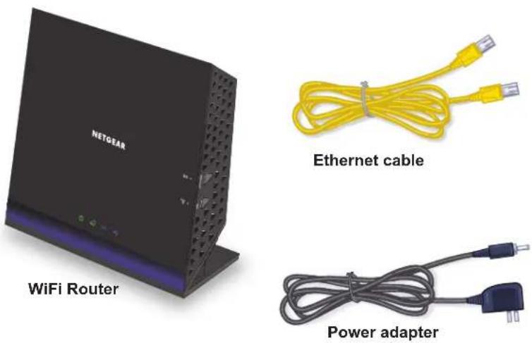
Figure 1. Check the package contents
Your box contains the following items:
• R6250 Smart WiFi Router
• AC power adapter (plug varies by region)
• Category 5 (Cat 5) Ethernet cable
• Installation guide with cabling and router setup instructions
If any parts are incorrect, missing, or damaged, contact your NETGEAR dealer. Keep the carton and original packing materials, in case you return the product for repair.
Hardware Features
Before you cable your router, take a moment to become familiar with the front, side, and back panels and the label. Pay particular attention to the LEDs on the front panel.
Front and Side Panel
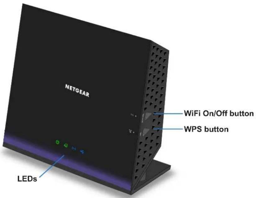
The router front panel has the status LEDs and icons shown in the following figure.
text_image
NETGEAR WiFi On/Off button WPS button LEDsFigure 2. Router front and side view
Table 1. Front panel LED descriptions
| LED Description | |
Power  | Solid amber. The router is starting.Blinking amber. The firmware is upgrading, or the Restore Factory Settings button was pressed.Solid green. The router is ready.Blinking green. The firmware is corrupted. See www.netgear.com/support.Off. Power is not supplied to the router . |
Internet  | Solid green. The Internet connection is ready.Solid amber. The Ethernet cable connection to the modem has been detected.Off. No Ethernet cable is connected to the modem. |
Wireless  | Solid blue. The wireless radio is operating in either 2.4 GHz or 5 GHz mode.Blinking. Someone is trying to join the WiFi network using the WPS method.Off. The wireless radios are off for both 2.4 GHz and 5 GHz. |
USB  | Solid blue. The router has accepted the USB device. The USB device is ready to be used.Blinking blue. A USB device is plugged in and is trying to connect.Off. No USB device is connected; someone clicked the Safely Remove Hardware button, and it is now safe to remove the attached USB device. |
The WiFi and WPS buttons toggle the WiFi and WPS functions on and off.
- W iFi On/Off button. Pressing and holding this button for 2 seconds turns on and off the 2.4 GHz and 5 GHz wireless radios. If the Wireless LED is lit, the wireless radios are on. If this LED is off, the wireless radios are turned off and you cannot connect wirelessly to the router.
- WPS button. You can use this button to use WPS to add a wireless device or computer to your wireless network. The Wireless LED blinks blue when the router is trying to add the wireless device or computer. The LED stays solid blue when wireless security is enabled in the router.
Rear Panel
The rear panel has the connections and buttons shown in the following figure.

text_image
USB 3.0 Ethernet Internet LAN ports 1-4 Port Reset buttonport Reset On/Off Power DC Power connectorFigure 3. Router rear panel
The Reset button restores the factory settings. See Factory Settings on page 129.
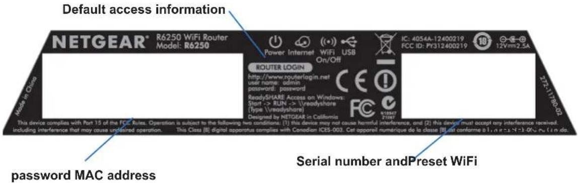
Label
The label on the bottom of the router shows the WPS PIN, login information, MAC address, and serial number.
text_image
Default access information NETGEAR® R6250 WiFi Router Model: R6250 IC: 4054A-12400219 FCC ID: Py312400219 12V=2.3A POWER INTERNET WiFi USB On/Off ROUTER LOGIN http://www.routerlogin.net user name: admin password: password ReadySHARE Access on Windows: Start -> RUN -> \readyshare (Type \readyshare) Designed by NETGEAR in California This device complies with Part 15 of the FCC Rules. Operation is subject to the following two conditions: (1) this device may not cause harmful interference, and (2) this device must accept any interference received. including interference that may cause undesired operation. This Class [8] digital apparatus complies with Canadian ICES-003. Cet appareil numérique de la classe [8] est conforme a 1.0.0.1.1.0.0.0.0.0.0.0.0.0.0.0.0.0.0.0.0.0.0.0.0.0.0.0.0.0.0.0.0.0.0.0.0.0.0.0.0.0.0.0.0.0.0.0.0.0.0.0.0.0.0.1786-02 Password MAC address Serial number andPreset WiFiFigure 4. The label shows unique information about your router
Position Your Router
The router lets you access your network from anywhere within the operating range of your wireless network. However, the operating distance or range of your wireless connection depends on the physical placement of your router. For example, the thickness and number of walls the wireless signal passes through can limit the range. For best results, place your router:
- Near the center of the area where your computers and other devices operate, and preferably within line of sight to your wireless devices.
- So it is accessible to an AC power outlet and near Ethernet cables for wired computers.
- In an elevated location such as a high shelf, keeping the number of walls and ceilings between the router and your other devices to a minimum.
- A way from electrical devices that are potential sources of interference. Equipment that might cause interference includes ceiling fans, home security systems, microwaves, computers, the base of a cordless phone, or a 2.4 GHz cordless phone.
- A way from any large metal surfaces, such as a solid metal door or aluminum studs. Large expanses of other materials such as glass, insulated walls, fish tanks, mirrors, brick, and concrete can also affect your wireless signal.
Getting Started
2
Connecting to the router
This chapter explains how to use NETGEAR genie to set up your router after you complete cabling as described in the installation guide.
This chapter contains the following sections:
- Router Setup Preparation
- Types of Logins and Access
• NETGEAR genie Setup - Use NETGEAR genie After Installation
- Upgrade the Firmware
- Dashboard (Basic Home Screen)
- Join Your Wireless Network
- Access the Router with NETGEAR the genie App
Router Setup Preparation
You can set up your router with the NETGEAR genie automatically, or you can use the genie menus and screens to set up your router manually. Before you start the setup process, get your ISP information and make sure the computers and devices in the network have the settings described here.
Use Standard TCP/IP Properties for DHCP
If you set up your computer to use a static IP address, change the settings so that it uses Dynamic Host Configuration Protocol (DHCP).
Gather ISP Information
If you have DSL broadband service, you might need the following information to set up your router and to check that your Internet configuration is correct. When your Internet service starts, your Internet service provider (ISP) typically gives you all the information needed to connect to the Internet. If you cannot locate this information, ask your ISP to provide it. When your Internet connection is working, you no longer need to launch the ISP's login program on your computer to access the Internet. When you start an Internet application, your router automatically logs you in.
- The ISP configuration information for your DSL account
- ISP login name and password
- Fixed or static IP address settings (special deployment by ISP; this is rare)
Wireless Devices and Security Settings
Make sure that the wireless device or computer that you are using supports WPA or WPA2 wireless security, which is the wireless security that the router uses.
Types of Logins and Access
Separate types of logins have different purposes. It is important that you understand the difference so that you know which login to use when.
- Router login logs you in to the router interface from NETGEAR genie. For details about this login, see Use NETGEAR genie After Installation on page 15.
- ISP login logs you in to your Internet service. Your service provider has provided you with this login information in a letter or some other way. If you cannot find this login information, contact your service provider.
- Wireless network key or password. Your router is preset with a unique wireless network name (SSID) and password for wireless access. This information is on the label on the bottom of your router.
NETGEAR genie Setup
NETGEAR genie runs on any device with a web browser. Installation and basic setup takes about 15 minutes to complete.
To use NETGEAR genie to set up your router:
- Turn the router on by pressing the On/Off button.
- Make sure that your computer or wireless device is connected to the router with an Ethernet cable (wired) or wirelessly with the preset security settings listed on the bottom label.
- Launch your Internet browser.
The screen that displays depends on whether you accessed the router before:
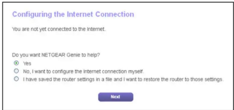
- The first time you set up the Internet connection for your router, the browser goes to http://www.routerlogin.net, and the NETGEAR genie screen displays.
text_image
Configuring the Internet Connection You are not yet connected to the Internet. Do you want NETGEAR Genie to help? Yes No, I want to configure the internet connection myself. I have saved the router settings in a file and I want to restore the router to those settings. Next- If you already used the NETGEAR genie, type http://www.routerlogin.net in the address field for your browser to display the NETGEAR genie screen. See Use NETGEAR genie After Installation on page 15.
4. Follow the onscreen instructions.
NETGEAR genie guides you through connecting the router to the Internet.
If the browser cannot display the web page:
- Make sure that the computer is connected to one of the four LAN Ethernet ports or wirelessly to the router.
- Make sure that the router has full power, and that its WiFi LED is lit.
- T o make sure that the browser does not cache the previous page, close and reopen the browser.
- Browse to http://www .routerlogin.net.
- If the computer is set to a static or fixed IP address (this is uncommon), change it to obtain an IP address automatically from the router.
If the router does not connect to the Internet:
- Review your settings to be sure that you have selected the correct options and typed everything correctly.
- Contact your ISP to verify that you have the correct configuration information.
- Read Chapter 10, Troubleshooting. If problems persist, register your NETGEAR product and contact NETGEAR technical support.
Use NETGEAR genie After Installation
When you first set up your router, NETGEAR genie automatically starts when you launch an Internet browser on a computer that is connected to the router. If you want to view or change settings for the router, you can use genie again.
- Launch your browser from a computer or wireless device that is connected to the router.
- Type http://www.routerlogin.net or http://www.routerlogin.com.
A login window displays.
- Enter admin for the router user name and password for the router password, both in lowercase letters.
Note: The router user name and password are different from the user name and password for logging in to your Internet connection. For more information, see Types of Logins and Access on page 13.
Upgrade the Firmware
When you set up your router and are connected to the Internet, the router automatically checks for you to see if newer firmware is available. If it is, a message is displayed on the top of the screen. For more information, see Upgrade the Router Firmware on page 83.
Click the message when it shows up, and click Yes to upgrade the router with the latest firmware. After the upgrade, the router restarts.

CAUTION:
Do not try to go online, turn off the router, shut down the computer, or do anything else to the router until the router restarts and the Power LED has stopped blinking for several seconds.
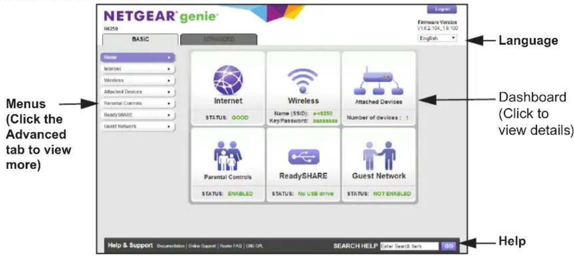
Dashboard (Basic Home Screen)
The router Basic Home screen has a dashboard that lets you see the status of your Internet connection and network at a glance. You can click any of the six sections of the dashboard to
view and change the settings. The left column has menus. You can use the Advanced tab to access more menus and screens.
text_image
NETGEAR® genie® R6250 BASIC Advanced Home Internet Wireless Attached Devices Parental Controls Ready SHARE Guest Network Language Dashboard (Click to view details) Help Help & Support Documentation Online Support Router FAQ OMI OPL SEARCH HELP Enter Search Item GOFigure 5. Basic Home screen with dashboard, language, and online help
• Home. This dashboard screen displays when you log in to the router.
- Internet. Set, update, and check the ISP settings of your router.
- W wireless. View or change the wireless settings for your router.
- Attached Devices. View the devices connected to your network.
- Parental Controls. Download and set up parental controls to prevent objectionable content from reaching your computers.
- ReadySHARE. If you connected a USB storage device to the router, then it is displayed here.
- Guest Network. Set up a guest network to allow visitors to use your router's Internet connection.
- Advanced tab. Set the router up for unique situations such as when remote access by IP or by domain name from the Internet is needed. See Chapter 9, Advanced Settings. You need a solid understanding of networking to use this tab.
- Help & Support. V isit the NETGEAR support site for information, help, and product documentation. These links work once you have an Internet connection.
Join Your Wireless Network
You can use the manual or the WPS method to join your wireless network. For instructions about how to set up a guest network, see Set Up a Guest Network on page 25.
Manual Method
With the manual method, choose the network that you want and type its password to connect.
To connect manually:
- On your computer or wireless device, open the software that manages your wireless connections.
This software scans for all wireless networks in your area. - Look for your network and select it.
The unique WiFi network name (SSID) and password are on the router label. If you changed these settings, look for the network name that you used. - Enter the router password and click Connect.
Wi-Fi Protected Setup (WPS) Method
Wi-Fi Protected Setup (WPS) lets you connect to a secure WiFi network without typing its password. Instead, press a button or enter a PIN. NETGEAR calls WPS Push 'N' Connect.
Some older WiFi equipment is not compatible with WPS. WPS works only with WPA2 or WPA wireless security.
To use WPS to join the wireless network:
- Press the WPS button on the side of the router.
- Within 2 minutes, press the WPS button on your wireless device, or follow the WPS instructions that came with the device.
The WPS process automatically sets up your wireless computer with the network password and connects you to the wireless network.
Access the Router with NETGEAR the genie App
The genie app is the easy dashboard for managing, monitoring, and repairing your home network. The genie app can help you with the following:
- Automatically repair common wireless network problems.
- Easily manage router features like Live Parental Controls, guest access, Internet traffic meter, speed test, and more.
To use the genie app to access the router:
- Visit the NETGEAR genie web page at www.NETGEAR.com/genie.
- Follow the onscreen instructions to install the app on your smartphone, tablet, or computer.
- Launch the genie app.
R6250 Smart WiFi Router
The genie app dashboard screen displays.
Basic Settings
3
Your Internet connection and WiFi network
This chapter contains the following sections:
- Internet Setup
- Basic Wireless Settings
- Set Up a Guest Network
• View Attached Devices
For information about the ReadySHARE feature on the Basic Home tab, see Chapter 5, USB Storage and Chapter 6, Share a USB Printer.
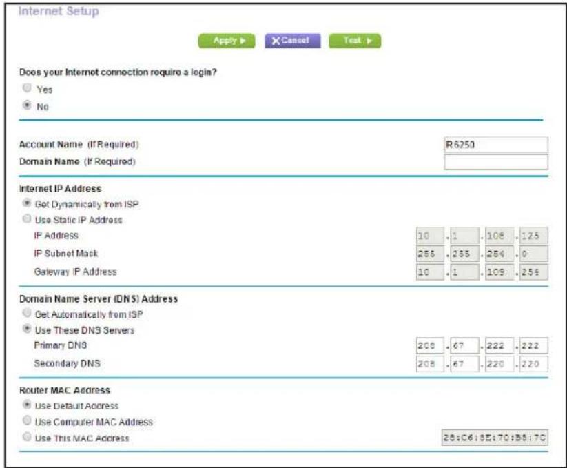
Internet Setup
The Internet Setup screen is where you view or change basic ISP information.
Note: You can use the Setup Wizard to detect the Internet connection and automatically set up the router. See Internet Connection Setup Wizard on page 29.
To view or change the basic Internet setup:
- From the Home screen, select Internet.
text_image
Internet Setup Apply ▶ Cancel Test ▶ Does your Internet connection require a login? Yes No Account Name (If Required) R6250 Domain Name (If Required) Internet IP Address ● Get Dynamically from ISP ○ Use Static IP Address IP Address 10 .1 .108 .125 IP Subnet Mask 255 .255 .254 .0 Gateway IP Address 10 .1 .109 .254 Domain Name Server (DNS) Address ● Get Automatically from ISP ○ Use These DNS Servers Primary DNS 208 .67 .222 .222 Secondary DNS 208 .67 .220 .220 Router MAC Address ● Use Default Address ○ Use Computer MAC Address ○ Use This MAC Address 28:C6:5E:70:B5:70The fields that display in the Internet Setup screen depend on whether your Internet connection requires a login.
-
Yes. Select the encapsulation method and enter the login name. If you want to change the login time-out, enter a new value in minutes.
• No. Enter the account and domain names, only if needed. -
Enter the settings for the IP address and DNS server.
The default settings usually work fine. If you have problems with your connection, check the ISP settings.
- Click Apply.
Your settings are saved.
- Click Test to test your Internet connection.
If the NETGEAR website does not display within 1 minute, see Chapter 10, Troubleshooting.
Internet Setup Screen Fields
The following descriptions explain all of the possible fields in the Internet Setup screen. The fields that display in this screen depend on whether tan ISP login is required.
Does Your Internet connection require a login? Answer either yes or no.
These fields display when no login is required:
- Account Name (If required). Enter the account name provided by your ISP. This might also be called the host name.
- Domain Name (If required). Enter the domain name provided by your ISP.
These fields display when your ISP requires a login:
- Internet Service Provider. PPPoE or PPPoA.
- Login. The login name provided by your ISP. This login name is often an email address.
- Password. The password that you use to log in to your ISP.
• Service Name (if Required). If your ISP provided a service name, enter it here. - Connection Mode. Always On, Dial on Demand, or Manually Connect.
- Idle Timeout (In minutes). If you want to change the login time-out, enter a new value in minutes. This setting determines how long the router keeps the Internet connection active when no one on the network is using the Internet. A value of 0 (zero) means never log out.
Internet IP Address.
- Get Dynamically from ISP. Your ISP uses DHCP to assign your IP address. Your ISP automatically assigns these addresses.
- Use Static IP Address. Enter the IP address, IP subnet mask, and the gateway IP address that your ISP assigned. The gateway is the ISP router to which your router will connect.
Domain Name Server (DNS) Address. The DNS server is used to look up site addresses based on their names.
- Get Automatically from ISP. Your ISP uses DHCP to assign your DNS servers. Your ISP automatically assigns this address.
- Use These DNS Servers. If you know that your ISP requires specific servers, select this option. Enter the IP address of your ISP's primary DNS server. If a secondary DNS server address is available, enter it also.
NAT (Network Address Translation). NAT allows computers on your home network to share the router Internet connection. NAT is enabled by default because it is needed in most situations. The following settings are available:
- Enable
- Disable
- Disable Port Scan and DoS Protection
Router MAC Address. The Ethernet MAC address that the router uses on the Internet port. Some ISPs register the MAC address of the network interface card in your computer when your account is first opened. They accept traffic only from the MAC address of that computer. This feature allows your router to use your computer's MAC address (also called cloning).
- Use Default Address. Use the default MAC address.
- Use Computer MAC Address. The router captures and uses the MAC address of the computer that you are now using. You have to use the one computer that the ISP allows.
• Use This MAC Address. Enter the MAC address that you want to use.
Basic Wireless Settings
The Wireless Settings screen lets you view or configure the wireless network setup.
The router comes with preset security. This means that the Wi-Fi network name (SSID), network key (password), and security option (encryption protocol) are preset in the factory. You can find the preset SSID and password on the bottom of the unit.
The preset SSID and password are uniquely generated for every device to protect and maximize your wireless security.
NETGEAR recommends that you do not change your preset security settings. If you change your preset security settings, make a note of the new settings and store it in a safe place where you can easily find it.
If you use a wireless computer to change the wireless network name (SSID) or other wireless security settings, you are disconnected when you click Apply. To avoid this problem, use a computer with a wired connection to access the router.
To view or change basic wireless settings:
1. Select Basic > W wireless.

text_image
Wireless Setup Apply ▶ X Cancel Region Selection Region: North America ▼ Wireless Network (2.6GHz b/g/n) Enable SSD Broadcast Name (SSID): a+6250 Channel: Auto ▼ Mode: Up to 145 Mbps ▼ Security Options None WPA2-PSK [AES] WPA-PSK [TKF] + WPA2-PSK [AES] WPAWPA2 Enterprise Passphrase: asasasasa (8-83 characters or 64 hex digits) Wireless Network (5GHz a/mac) Enable SSD Broadcast Name (SSID): a+6250-5G Channel: 153 ▼ Mode: Up to 1300 Mbps ▼ Security Options None WPA2-PSK [AES] WPA-PSK [TKF] + WPA2-PSK [AES] WPAWPA2 Enterprise Passphrase: asasasasa (8-83 characters or 64 hex digits)The screen sections, settings, and procedures are explained in the following sections.
2. (Optional) Change the settings.
The settings are explained in the following section Wireless Settings Screen Fields on page 24.
3. Click Apply.
Your settings are saved.
If you were connected wirelessly to the router and you changed the SSID or wireless security, you are disconnected from the network.
4. If you changed the settings, make sure that you can connect wirelessly to the network with its new settings.
If you cannot connect wirelessly, check the following:
- Is your computer or wireless device connected to another wireless network in your area? Some wireless devices automatically connect to the first open network (without wireless security) that they discover.
- Is your computer or wireless device trying to connect to your network with its old settings (before you changed the setting)? If so, update the wireless network selection in your computer or wireless device to match the current settings for your network.
Wireless Settings Screen Fields
You can use this screen to view or change the wireless network settings and the security option.
Enable SSID Broadcast. This feature allows the router to broadcast its SSID so wireless stations can see this wireless name (SSID) in their scanned network lists. This check box is selected by default. To turn off the SSID broadcast, clear this check box, and click Apply.
Name (SSID). The SSID is also known as the wireless network name. Enter a 32-character (maximum) name in this field. This field is case-sensitive. The default SSID is randomly generated, and NETGEAR strongly recommends that you do not change this setting.
Region. The location where the router is used. Select from the countries in the list. In the United States, the region is fixed to United States and is not changeable.
Channel. The wireless channel the router uses. For 2.4 GHz, select a value from 1 through 13. (For products in the North America market, only Channels 1 through 11 can be operated.) Do not change the channel unless you experience interference (shown by lost connections or slow data transfers). If this happens, experiment with different channels to see which is the best.
When you use multiple access points, it is better if adjacent access points use different radio frequency channels to reduce interference. The recommended channel spacing between adjacent access points is 4 channels (for example, use Channels 1 and 5, or 6 and 10).
Mode. For 2.4 GHz, Up to 145 Mbps is the default setting, which allows 802.11n and 802.11g wireless devices to join the network. The other settings are Up to 54 Mbps, and Up to 300 Mbps.
At 5GHz, Up to 1300 Mbps is the default setting, which allows 802.11ac, 802.11a wireless devices to join the network. The other settings are Up to 289 Mbps and 600 Mbps.
Security Options. The router comes with unique preset wireless security. These settings are on the product label. NETGEAR recommends that you use preset security so that you can refer to the label if you forget the WiFi password. However, you can change the security option and passphrase.
Wireless Security Options
A security option is the type of security protocol applied to your wireless network. The security protocol in force encrypts data transmissions and ensures that only trusted devices receive authorization to connect to your network. Wi-Fi Protected Access (WPA) has several options including pre-shared key (PSK) encryption.
WPA encryption is built into all hardware that has the Wi-Fi-certified seal. This seal means that the Wi-Fi Alliance (http://www.wi-fi.org/) authorized the product because it complies with the worldwide single standard for high-speed wireless local area networking.
WPA uses a passphrase for authentication and to generate the initial data encryption keys. Then it dynamically varies the encryption key. WPA-PSK uses Temporal Key Integrity Protocol (TKIP) data encryption, implements most of the IEEE 802.11i standard, and works with all wireless network interface cards, but not all wireless access points.
WPA2-PSK is stronger than WPA-PSK. It is advertised to be theoretically indecipherable due to the greater degree of randomness in encryption keys that it generates. WPA2-PSK gets higher speed because it is implemented through hardware, while WPA-PSK is usually implemented through software. WPA2-PSK uses a passphrase to authenticate and generate the initial data encryption keys. Then it dynamically varies the encryption key.
WPS-PSK + WPA2-PSK Mixed Mode can provide broader support for all wireless clients. WPA2-PSK clients get higher speed and security, and WPA-PSK clients get decent speed and security. For help with WPA settings on your wireless computer or device, see the instructions that came with your product.
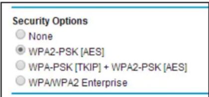
Change the Wireless Security Option
NETGEAR recommends that you do not disable security.
To change the WPA settings:
- Select Basic > W wireless Settings.
- Under Security Options, select the WP A option you want.
text_image
Security Options None WPA2-PSK [AES] WPA-PSK [TKIP] + WPA2-PSK [AES] WPA/WPA2 Enterprise- In the Passphrase field that displays when you select a WPA security option, enter the network key (password) that you want to use. It is a text string from 8 to 63 characters.
- Write down the new password and keep it in a secure place for future reference.
- Click Apply.
Your changes are saved.
A guest network allows visitors at your home to use the Internet without revealing your wireless security key. You can add a guest network to each wireless network: 2.4 GHz b/g/n and 5.0 GHz a/n.
To set up a guest network:
1. Select Basic > Guest Network.

text_image
Guest Network Settings Apply ▶ X Cancel Wireless Network (2.4GHz big/n) - Profile Enable Guest Network: Enable SSID Broadcast Allow guests to see each other and access my local network Guest Wireless Network Name (SSID): NETGEAR-Guest Security Options - Profile None WPA2-PSK [AES] WPA-PSK [TKIP] - WPA2-PSK [AES] Wireless Network (5GHz a/niac) - Profile Enable Guest Network: Enable SSID Broadcast Allow guests to see each other and access my local network Guest Wireless Network Name (SSID): NETGEAR-6G-Guest Security Options - Profile None WPA2-PSK [AES] WPA-PSK [TKIP] - WPA2-PSK [AES]2. Select any of the following wireless settings:
Enable Guest Network. When this check box is selected, the guest network is enabled, and guests can connect to your network using the SSID of this profile.
Enable SSID Broadcast. If this check box is selected, the wireless access point broadcasts its name (SSID) to all wireless stations. Stations with no SSID can adopt the correct SSID for connections to this access point.
Allow guest to access My Local Network. If this check box is selected, anyone who connects to this SSID has access to your local network, not just Internet access.
3. Give the guest network a name.
The guest network name is case-sensitive and can be up to 32 characters. You then manually configure the wireless devices in your network to use the guest network name in addition to the main SSID.
4. Select a security option from the list.
The security options are described in Wireless Security Options on page 24.
5. Click Apply.
Your settings are saved.
View Attached Devices
Use the Attached Device screen to view all computers or devices that are currently connected to your network.
To go to the Attached Devices screen:
- From the Basic Home screen, select Attached Devices.

text_image
Attached Devices C:\Refresh Wired DevicesIP Address Device Name MAC Address
1 192.168.12 IMPANLAN F0 DE F1 OF 35 FE Wireless Devices (Wireless intruders also show up here)IP Address Device Name MAC Address
Wired devices are connected to the router with Ethernet cables. Wireless devices have joined the wireless network. The following information is displayed:
-
(number). The order in which the device joined the network.
- IP Address. The IP address that the router assigned to this device when it joined the network. This number can change if a device is disconnected and rejoins the network.
- MAC Address. The unique MAC address for each device does not change. The MAC address is typically shown on the product label.
-
Device Name. If the device name is known, it is shown here.
-
Click Refresh to update this screen.
Advanced Home Settings
4
Specify custom settings
This chapter contains the following sections:
• NETGEAR genie Advanced Home Screen
- Internet Connection Setup Wizard
- WAN Setup
• LAN Setup
• WPS Wizard for WiFi Connections
• Quality of Service (QoS) Setup
Some selections on the Advanced Home screen are described in separate chapters:
• USB Storage. See Chapter 5, USB Storage.
• Security. See Chapter 7, Security.
• Administration. See Chapter 8, Administration.
• Advanced Setup. See Chapter 9, Advanced Settings.
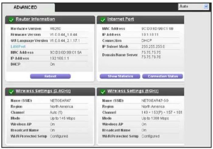
NETGEAR genie Advanced Home Screen
The genie Advanced Home dashboard presents status information. The content is the same as what is on the Router Status screen available from the Administration menu. The genie Advanced Home screen is shown in the following figure:
text_image
ADVANCED Auto ✓ Router Information Hardware Version R6250 Firmware Version V1.0.0.44_1.0.44 GUI Language Version V1.0.0.44_2.1.17.1 LANPort MAC Address 9C:D3:6D:99:C1 9A IP Address 192:168.1.1 DHCP On Reboot ✓ Internet Port MAC Address 9C:D3:6D:99:C1 9B IP Address 10.1.10.11 Connection DHCP IP Subnet Mask 295:255:255.0 Domain Name Server 75:75:75:75 75:75:78:76 Show Statistics Connection Status ✓ Wireless Settings (2.4GHz) Name (SSID) NET0EAR47 Region North America Channel Auto (T) Mode Up to 146 Mbps Wireless AP On Broadcast Name On Wi-Fi Protected Setup Configured ✓ Wireless Settings (5GHz) Name (SSID) NET0EAR47-5G Region North America Channel 149 + 153(P) + 157 + 161 Mode Up to 1300 Mbps Wireless AP On Broadcast Name On Wi-Fi Protected Setup Configuredprobably show menus too
Internet Connection Setup Wizard
You can use the Setup Wizard to detect your Internet settings and automatically set up your router. The Setup Wizard is not the same as the genie screens that display the first time you connect to your router to set it up.
To use the Setup Wizard:
- Select Advanced > Setup Wizard.

text_image
Setup Wizard The Smart Setup Wizard can detect the type of Internet connection that you have. Do you want the Smart Setup Wizard to try and detect the connection type now? Yes No. I want to configure the router myself. Next- Select either Yes or No, I want to configure the router myself.
If you select No, you are taken to the Internet Setup screen (see Internet Setup on page 20).
- Select Ye s and select your location.
- Click Next.
The Setup Wizard searches your Internet connection for servers and protocols to determine your ISP configuration.
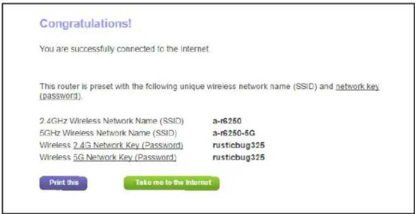
text_image
Congratulations! You are successfully connected to the Internet. This router is preset with the following unique wireless network name (SSID) and network key (password). 2.4GHz Wireless Network Name (SSID) a-r6250 5GHz Wireless Network Name (SSID) a-r6250-5G Wireless 2.4G Network Key (Password) rusticbug325 Wireless 5G Network Key (Password) rusticbug325 Print this Take me to the internetWAN Setup
The WAN Setup screen lets you configure a DMZ (demilitarized zone) server, change the maximum transmit unit (MTU) size, and enable the router to respond to a ping on the WAN (Internet) port.
To view or change the WAN settings:
1. Select Advanced > Setup > W AN Setup.
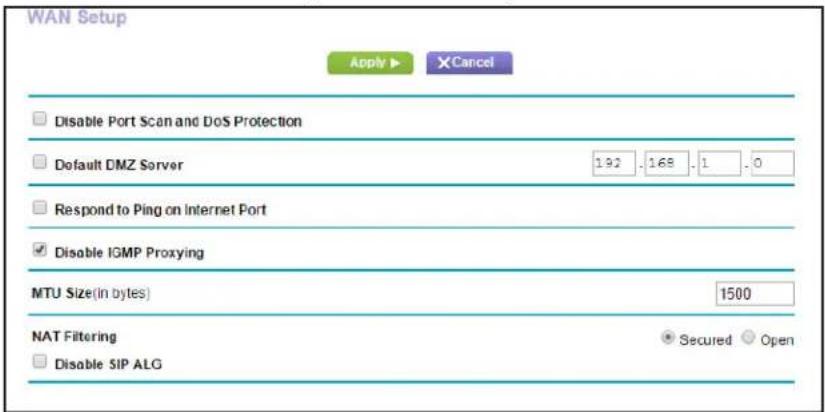
text_image
WAN Setup Apply ▶ XCancel Disable Port Scan and DoS Protection Default DMZ Server 192 .168 .1 .0 Respond to Ping on Internet Port Disable IGMP Proxying MTU Size(in bytes) 1500 NAT Filtering Secured Open Disable SIP ALG2. Specify the following settings:
- Disable Port Scan and DoS Protection. DoS protection protects your LAN against denial of service attacks such as Syn flood, Smurf Attack, Ping of Death, Teardrop Attack, UDP Flood, ARP Attack, Spoofing ICMP, Null Scan, and many others. This should be disabled only in special circumstances.
-
Default DMZ Server. This feature is sometimes helpful when you are playing online games or videoconferencing. Be careful when using this feature because it makes the firewall security less effective. See the following section, Default DMZ Server.
-
Respond to Ping on Internet Port. If you want the router to respond to a ping from the Internet, select this check box. Use this setting only as a diagnostic tool because it allows your router to be discovered. Do not select this check box unless you have a specific reason.
- Disable IGMP Proxying. IGMP proxying allows a computer on the local area network (LAN) to receive the multicast traffic it is interested in from the Internet. If you do not need this feature, you can select this check box to disable it.
- MTU Size (in bytes). The normal MTU (maximum transmit unit) value for most Ethernet networks is 1500 bytes, or 1492 bytes for PPPoE connections. For some ISPs, you might need to reduce the MTU. This is rarely required. Reduce the MTU only if you are sure that it is necessary for your ISP connection. See Change the MTU Size on page 32.
- NAT Filtering. Network Address Translation (NAT) determines how the router processes inbound traffic. Secured NAT provides a secured firewall to protect the computers on the LAN from attacks from the Internet, but might prevent some Internet games, point-to-point applications, or multimedia applications from functioning. Open NAT provides a much less secured firewall, but allows almost all Internet applications to function.
3. Click Apply.
Your changes are saved.
Default DMZ Server
The default DMZ server feature is helpful when you are using some online games and videoconferencing applications that are incompatible with Network Address Translation (NAT). The router is programmed to recognize some of these applications and to work correctly with them, but other applications might not function well. In some cases, one local computer can run the application correctly if the IP address for that computer is entered as the default DMZ server.

WARNING:
DMZ servers pose a security risk. A computer designated as the default DMZ server loses much of the protection of the firewall and is exposed to exploits from the Internet. If compromised, the DMZ server computer can be used to attack other computers on your network.
The router usually detects and discards incoming traffic from the Internet that is not a response to one of your local computers or a service that you have configured in the Port Forwarding/Port Triggering screen. Instead of discarding this traffic, you can have the router forward the traffic to one computer on your network. This computer is called the default DMZ server.
To set up a default DMZ server:
- Select Advanced > Setup > WAN Setup.
- Select the Default DMZ Server check box.
- Type the IP address.
- Click Apply.
Your change takes effect.
Change the MTU Size
The maximum transmission unit (MTU) is the largest data packet a network device transmits. When one network device communicates across the Internet with another, the data packets travel through many devices along the way. If a device in the data path has a lower MTU setting than the other devices, the data packets have to be split or “fragmented” to accommodate the device with the smallest MTU.
The best MTU setting for NETGEAR equipment is often just the default value. In some situations, changing the value fixes one problem but causes another. Leave the MTU unchanged unless one of these situations occurs:
- You have problems connecting to your ISP or other Internet service, and the technical support of either the ISP or NETGEAR recommends changing the MTU setting. These web-based applications might require an MTU change:
- A secure website that does not open, or displays only part of a web page
- Yahoo email
- MSN portal
- America Online's DSL service
- You use VPN and have severe performance problems.
- You used a program to optimize MTU for performance reasons, and now you have connectivity or performance problems.
Note: An incorrect MTU setting can cause Internet communication problems. For instance, you might not be able to access certain websites, frames within websites, secure login pages, or FTP or POP servers.
If you suspect an MTU problem, a common solution is to change the MTU to 1400. If you are willing to experiment, you can gradually reduce the MTU from the maximum value of 1500
until the problem goes away. The following table describes common MTU sizes and applications.
Table 2. Common MTU sizes
| MTU Application | |
| 1500 The largest | Ethernet packet size. This setting is typical for connections that do not use PPPoE or VPN, and is the default value for NETGEAR routers, adapters, and switches. |
| 1492 Used in PPPoE environments. | |
| 1472 Maximum size to use for pinging. (Larger packets are fragmented.) | |
| 1468 Used in some DHCP environments. | |
| 1460 Usable by AOL if you do not have large email attachments, for example. | |
| 1436 Used in PPTP environments or with VPN. | |
| 1400 Maximum size for AOL DSL. | |
| 576 Typical value to connect to dial-up ISPs. | |
To change the MTU size:
- Select Advanced > Setup > WAN Setup.
- In the MTU Size field, enter a value from 64 to 1500.
- Click Apply.
Your change is saved.
LAN Setup
The LAN Setup screen allows configuration of LAN IP services such as Dynamic Host Configuration Protocol (DHCP) and Routing Information Protocol (RIP).
The router is shipped preconfigured to use private IP addresses on the LAN side and to act as a DHCP server. The router's default LAN IP configuration is:
• LAN IP address. 192.168.1.1
- Subnet mask. 255.255.255.0
These addresses are part of the designated private address range for use in private networks and are suitable for most applications. If your network requires a different IP addressing scheme, you can change these settings in the LAN Setup screen.
Note: If you change the LAN IP address of the router while connected through the browser, you are disconnected. You will have to open a new connection to the new IP address and log in again.
To change the LAN settings:
1. Select Advanced > Setup > LAN Setup.
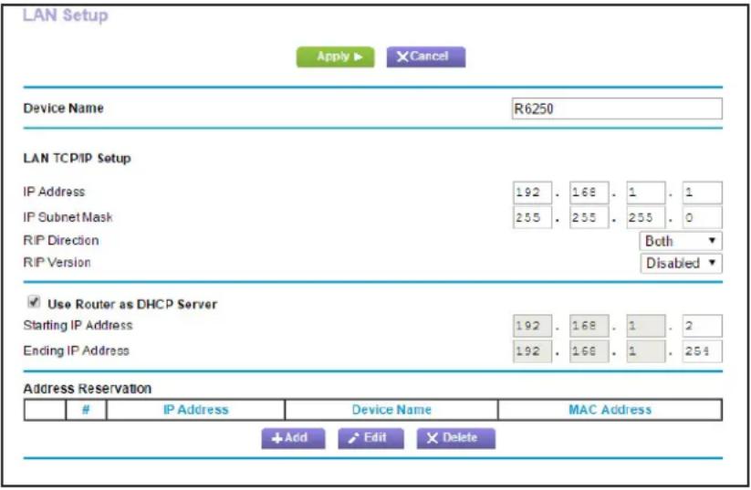
text_image
LAN Setup Apply ▶ XCancel Device Name R6250 LAN TCP/IP Setup IP Address 192 . 168 . 1 . 1 IP Subnet Mask 255 . 255 . 255 . 0 R/P Direction Both R/P Version Disabled ▼ ✓ Use Router as DHCP Server Starting IP Address 192 . 168 . 1 . 2 Ending IP Address 192 . 168 . 1 . 254 Address ReservationIP Address Device Name MAC Address
+ Add Edit Delete- Enter the settings that you want to customize.
These settings are described in the following section, LAN Setup Screen Settings.
- Click Apply.
Your changes are saved.
LAN Setup Screen Settings
LAN TCP/IP Setup
- IP Address. The LAN IP address of the router.
- IP Subnet Mask. The LAN subnet mask of the router. Combined with the IP address, the IP subnet mask allows a device to know which other addresses are local to it, and which have to be reached through a gateway or router.
- RIP Direction. Router Information Protocol (RIP) allows a router to exchange routing information with other routers. This setting controls how the router sends and receives RIP packets. Both is the default setting. With the Both or Out Only setting, the router broadcasts its routing table periodically. With the Both or In Only setting, the router incorporates the RIP information that it receives.
-
RIP V ersion. This setting controls the format and the broadcasting method of the RIP packets that the router sends. It recognizes both formats when receiving. By default, the RIP function is disabled.
-
RIP-1 is universally supported. It is adequate for most networks, unless you have an unusual network setup.
- RIP-2 carries more information. Both RIP-2B and RIP-2M send the routing data in RIP-2 format. RIP-2B uses subnet broadcasting. RIP-2M uses multicasting.
Use Router as DHCP Server
For most home networks, this check box is selected so that the router acts as a Dynamic Host Configuration Protocol (DHCP) server.
- Starting IP Address. Specify the start of the range for the pool of IP addresses in the same subnet as the router.
- Ending IP Address. Specify the end of the range for the pool of IP addresses in the same subnet as the router.
Address Reservation
When you specify a reserved IP address for a computer on the LAN, that computer receives the same IP address each time it accesses the router's DHCP server. Assign reserved IP addresses to servers that require permanent IP settings.
The Role of the Router as a DHCP Server
By default, the router acts as a DHCP server. The router assigns IP, DNS server, and default gateway addresses to all computers connected to the LAN. The assigned default gateway address is the LAN address of the router. The router assigns IP addresses to the attached computers from a pool of addresses specified in this screen. Each pool address is tested before it is assigned to avoid duplicate addresses on the LAN. For most applications, the default DHCP and TCP/IP settings of the router are satisfactory.
You can specify the pool of IP addresses that the router assigns by setting the starting IP address and ending IP address. These addresses should be part of the same IP address subnet as the router's LAN IP address. Using the default addressing scheme, define a range between 192.168.1.2 and 192.168.1.254, although you might want to save part of the range for devices with fixed addresses.
The router delivers the following parameters to any LAN device that requests DHCP:
- An IP address from the range that you have defined
- Subnet mask
- Gateway IP address (the router's LAN IP address)
- DNS server IP address (the router's LAN IP address)
You can use another device on your network as the DHCP server, or specify the network settings of all of your computers
To use disable the DHCP Server feature in the router:
- Select Advanced > Setup > LAN Setup.
- Clear the Use Router as DHCP Server check box.
- Click Apply.
- (Optional) If this service is disabled and no other DHCP server is on your network, set your computer IP addresses manually so that the can access the router.
Address Reservation
When you specify a reserved IP address for a computer on the LAN, that computer always receives the same IP address each time it accesses the router's DHCP server. Assign reserved IP addresses to computers or servers that require permanent IP settings.
To reserve an IP address:
- Select Advanced > Setup > LAN Setup.
- In the Address Reservation section of the screen, click the Add button.
- In the IP Address field, type the IP address to assign to the computer or server.
Choose an IP address from the router's LAN subnet, such as 192.168.1.x.
- Type the MAC address of the computer or server.
Tip: If the computer is already on your network, you can copy its MAC address from the Attached Devices screen and paste it here.
- Click Apply.
The reserved address is entered into the table.
The reserved address is not assigned until the next time the computer contacts the router's DHCP server. Reboot the computer, or access its IP configuration and force a DHCP release and renew.
To edit or delete a reserved address entry:
- Select the radio button next to the reserved address you want to edit or delete.
- Click Edit or Delete.
WPS Wizard for WiFi Connections
The WPS Wizard helps you add a wireless computer or device to your WiFi network. On the computer or wireless device, either press its WPS button or locate its WPS PIN.
- Select Advanced > WPS Wizard.
- Click Next.
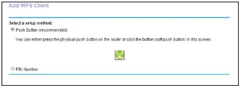
The following screen lets you select the method for adding the WPS client (a wireless device or computer).
Add WPS Client
New and easy way to connect to the wireless router using Wi-Fi Protected Setup (WPS)
A wireless client has to support the WPS function if you want to use this wizard to add the client to your WPS-enabled wireless router.
Please check the user manual and gift box of your wireless client to see whether it supports the WPS function. If your wireless client does not support the WPS function, you have to configure your wireless client manually so that it has the same SSID and wireless security settings as this router.
Next
You can use either the push button or PIN method.
3. Select either Push Button or PIN Number.
- T o use the push button method, either click the WPS button on this screen, or press the WPS button on the side of the router. Within 2 minutes, go to the wireless client and press its WPS button to join the network without entering a password.
- T o use the PIN method, select the PIN Number radio button, enter the client security PIN, and click Next.
text_image
Add WPS Client Select a setup method: ● Push Button (recommended) You can either press the physical push button on the router or click the button (soft push button) in this screen. PIN NumberWithin 2 minutes, go to the client device and use its WPS software to join the network without entering a password.
The router attempts to add the WPS-capable device. The WPS LED on the front of the router blinks green. When the router establishes a WPS connection, the LED is solid green, and the router WPS screen displays a confirmation message.
Quality of Service (QoS) Setup
QoS is an advanced feature that can be used to prioritize some types of traffic ahead of others. The router can provide QoS prioritization over the wireless link and on the Internet connection.
WMM QoS for Wireless Multimedia Applications
The router supports Wi-Fi Multimedia Quality of Service (WMM QoS) to prioritize wireless voice and video traffic over the wireless link. WMM QoS provides prioritization of wireless data packets from different applications based on four access categories: voice, video, best effort, and background. For an application to receive the benefits of WMM QoS, both it and
the client running that application have to have WMM enabled. Legacy applications that do not support WMM and applications that do not require QoS, are assigned to the best effort category, which receives a lower priority than voice and video. WMM QoS is enabled by default.
To disable WMM QoS:
1. Select Advanced > Setup > QoS Setup.
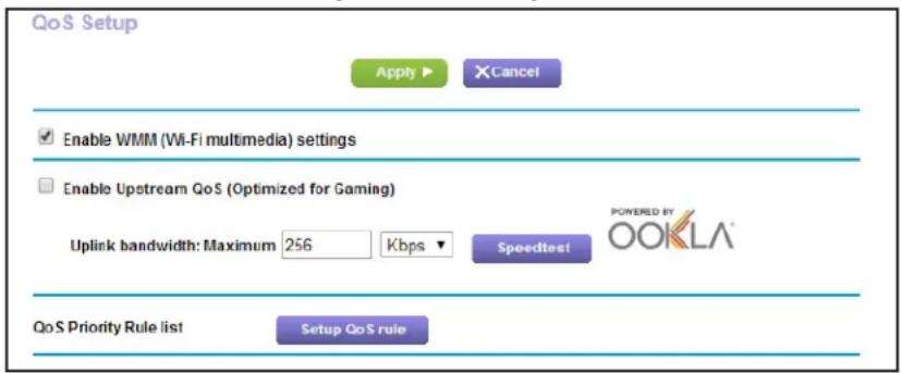
text_image
QoS Setup Apply ▶ XCancel Enable WMM (Wi-Fi multimedia) settings Enable Upstream QoS (Optimized for Gaming) Uplink bandwidth: Maximum 256 Kbps Speedtest QoS Priority Rule list Setup QoS rule POWERED BY OOKLA®- Clear the Enable WMM check box
- Click Apply.
Optimize Internet Gaming with Upstream QoS
Upstream Quality of Service (QoS) assigns high priority to Internet traffic from your Xbox gaming system
NETGEAR recommends that only gamers enable the Upstream QoS feature. If you do not game and you turn on this feature, some applications might not perform as well as usual.
To enable upstream QoS:
- Launch an Internet browser from a computer or wireless device that is connected to the network.
- Type http://www.routerlogin.net or http://www.routerlogin.com.
A login screen displays.
- Enter the router user name and password.
The user name is admin. The default password is password. The user name and password are case-sensitive.
The BASIC Home screen displays.
- Select ADV ANCED > Setup > QoS Setup.
The QoS Setup screen displays:
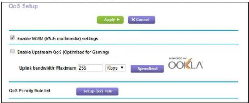
text_image
QoS Setup Apply ▶ Cancel Enable WMM (Wi-Fi multimedia) settings Enable Upstream QoS (Optimized for Gaming) Uplink bandwidth: Maximum 256 Kbps Speedtest QoS Priority Rule list Setup QoS rule POWERED BY OOKLA®- Select the Enable Upstream QoS (Optimized for Gaming) check box.
-
Specify the maximum uplink bandwidth for your Internet connection:
-
If you know what your uplink bandwidth is, type it in the Uplink bandwidth Maximum field and select either Kbps or Mbps from the drop-down list.
- If you are not sure, click the Speedtest button.
Speedtest verifies the upstream speed of your Internet connection. The Uplink bandwidth Maximum field displays the result of the test.
- Click the Apply button.
The router assigns a high priority to Internet traffic from your gaming devices to the Internet.
Set Up QoS for Internet Access
You can give prioritized Internet access to the following types of traffic:
- Specific applications
• Specific online games
• Individual Ethernet LAN ports of the router
• A specific device by MAC address
To specify prioritization of traffic, create a policy for the type of traffic and add the policy to the QoS Policy table in the QoS Setup screen. For convenience, the QoS Policy table lists many common applications and online games that can benefit from QoS handling.
QoS for Applications and Online Gaming
To create a QoS policy for applications and online games:
- Select Advanced > Setup > QoS Setup.
- Click the Setup QoS rule button.
The QoS Priority Rule list displays.
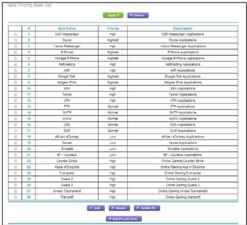
text_image
QoS Priority Rule list Apply CancelP QoS Policy Priority Desorption
1 ISN Messenger High ISN Messenger Applications 2 Skype Highest Skype Applications 3 Yahoo Messenger High Yahoo Messenger Applications 4 IP Phone Highest IP Phone Applications 5 Vonage IP Phone Highest Vonage IP Phone Applications 6 NetVesting High NetVesting Applications 7 AM High AIM Applications 8 Google Tek Highest Google Tek Applications 9 Netgear EVA Highest Netgear EVA Applications 10 SSH High SSH Applications 11 Telnet High Telnet Applications 12 VPN High VPN Applications 13 FTP Normal FTP Applications 14 SMTP Normal SMTP Applications 15 WWW Normal WWW Applications 16 DNS Normal DNS Applications 17 CMP Normal ICMP Applications 18 eMule / eDonkey Low eMule / eDonkey Applications 19 Kazea Low Kazea Applications 20 Gnutella Low Gnutella Applications 21 BT / Azureus Low BT / Azureus Applications 22 Counter Strike High Online Gaming Counter Strike 23 Ages of Empires High Online Gaming Age of Empires 24 Everquest High Online Gaming Everquest 25 Quake 2 High Online Gaming Quake 2 26 Quake 3 High Online Gaming Quake 3 27 Unreal Tournament High Online Gaming Unreal Tournament 28 Warcraft High Online Gaming Warcraft Edit Delete Delete All + Add Priority RuleYou can edit or delete a rule by selecting its radio button and clicking either the Edit or Delete button. You can also delete all the rules by clicking the Delete All button.
- To add a priority rule, scroll down to the bottom of the QoS Setup screen and click Add Priority Rule.

text_image
GoS - Priority Rules Apply ▶ Cancel Priority GoS Policy for Priority Category Applications Add a new application ▼ Priority Normal ▼ Specified Port Range Connection Type TCP/UDP ▼ Starting Port (1=85535) Ending Port (1=85535)- In the QoS Policy for field, type the name of the application or game.
- In the Priority Category list, select either Applications or Online Gaming.
A list of applications or games displays.
- Scroll and select Add a New Application, or Add a New Game, as applicable.
-
If prompted, in the Connection Type list, select either TCP, UDP, or both (TCP/UDP). Specify the port number or range of port numbers that the application or game uses.
-
From the Priority list, select the priority for Internet access for this traffic relative to other applications and traffic. The options are Low, Normal, High, and Highest.
- Click Apply.
The rule is saved in the QoS Policy list.
QoS for a Router LAN Port
To create a QoS policy for a device connected to one of the router's LAN ports:
- Select Advanced > Setup > QoS Setup.
- Click the Setup QoS rule button.
- Click the Add Priority Rule button.
- From the Priority Category list, select Ethernet LAN Port.
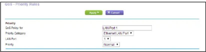
text_image
QoS - Priority Rules Apply ▶ Cancel Priority QoS Policy for LAN Port 1 Priority Category Ethernet LAN Port ▼ LAN Port 1 ▼ Priority Normal ▼- From the QoS Policy for list, select the LAN port.
- From the Priority list, select the priority for Internet access for this port's traffic relative to other applications. The options are Low, Normal, High, and Highest.
- Click Apply.
The rule is saved in the QoS Policy list.
QoS for a MAC Address
To create a QoS policy for traffic from a specific MAC address:
- Select Advanced > Setup > QoS Setup, and click the Setup QoS rule button. The QoS Setup screen displays.
- Click Add Priority Rule.
- From the Priority Category list, select MAC Address.
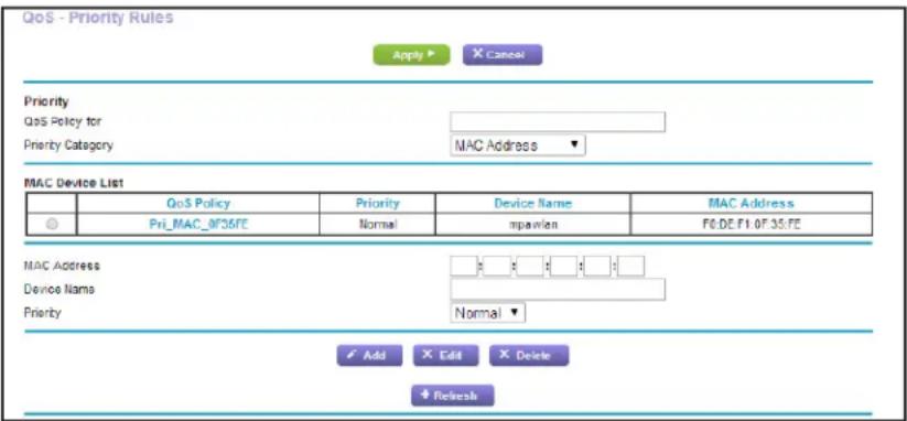
text_image
QoS - Priority Rules Apply ▶ X Cancel Priority QoS Policy for Priority Category MAC Address ▼ MAC Device List QoS Policy Priority Device Name MAC Address Pri_MAC_0F36FE Normal mpavlen F0:DE F1:0F 35:FE MAC Address Device Name Normal ▼ Priority Add X Edit X Delete + Refresh- If the device to be prioritized is in the MAC Device List, select its radio button.
The information from the MAC Device List populates the policy name, MAC Address, and Device Name fields. If the device is not in the MAC Device List, click Refresh. If it still does not display, fill in these fields manually.
-
From the Priority list, select the priority for Internet access for this device's traffic relative to other applications and traffic. The options are Low, Normal, High, and Highest.
-
Click Apply.
This rule is saved in the QoS Policy list.
Edit or Delete a QoS Policy
To edit or delete a QoS policy:
- Select Advanced > Setup > QoS Setup.
- Click the Setup QoS rule button.
- Select the radio button next to the QoS policy that you want to edit or delete, and do one of the following:
- Click Delete to remove the QoS policy.
- Click Edit to edit the QoS policy and change the policy settings.
- Click Apply.
Your changes are saved.
Access and Configure a USB Storage Device
This chapter describes how to access and configure a USB storage drive attached to your router. The USB port on the router can be used only to connect USB storage devices like flash drives or hard drives, or a printer. Do not connect computers, USB modems, CD drives, or DVD drives to the router USB port.
This chapter contains the following sections:
- Connect a USB Storage Device to the Router
- Safely Remove a USB Drive
- Access the USB Storage Device
- File-Sharing Scenarios
• View a USB Device Attached to the Router
• USB Storage Device Network and Access Settings
• Available Network Folders - Specify Approved USB Devices
- Back Up Windows Computers with ReadySHARE Vault
For information about using the ReadySHARE Printer feature, see Chapter 6, Share a USB Printer.
For more about ReadySHARE features, visit www.netgear.com/readyshare.
Connect a USB Storage Device to the Router
ReadySHARE lets you access and share or a USB drive connected the router USB port. If your USB device has special drivers, it is not compatible.
To connect a USB storage device:
- Insert your USB storage device into the USB port on the rear panel of the router.

text_image
USB 4 3 Ethernet 2 1 Internet Reset Power DC- If your USB device has a power supply, you must use it when you connect the USB device to the router.
It might take up to 2 minutes before the USB device is ready for sharing.
Safely Remove a USB Drive
If you want to physically disconnect a USB drive from the router USB port, first, log in to the router and safely remove it.
To remove a USB disk drive safely:
-
Select USB Storage > Basic Settings.
-
Click the Safely Remove USB Device button.
This takes the drive offline.
- Physically disconnect the USB drive.
Access the USB Storage Device
When you connect the USB device to the router USB port, it might take up to 2 minutes before it is ready for sharing. By default, the USB storage device is available to all computers on your local area network (LAN).
To access the USB device from a Mac:
-
Select Go > Connect to Server.
-
Enter smb://readyshare as the server address.
-
Click Connect.
To access the USB device from a Windows computer:
Use any of these methods to access the USB device:
- Select Start > Run. Enter \readyshare in the dialog box and click OK.
- Open a browser and enter \readyshare in the address bar .
- Open My Network Places and enter \readyshare in the address bar .
To map the USB device to a Windows network drive:
- Connect your USB storage device to the USB port on the router.
If your USB device uses a power supply, you must use it when you connect the USB device to the router.
When you connect the USB device to the router's USB port, it might take up to two minutes before it is ready for sharing. By default, the USB drive is available to all computers on your local area network (LAN).
- Select Start > Run.
- Enter \readyshare in the dialog box.
- Click the OK button.
A screen automatically opens and displays the USB Storage device.
- Right-click the USB storage device and select Map network drive.

text_image
Network > readyshare > Search active directory Network and Sharing Center View remote printers USB_Storage Share Open Open in new window Browse in Adobe Bridge CS6 Add to backup ReadySHARE Vault Always available offline Send to other devices with SHAREit Add to archive... Add to "USB_Storage.rar" Compress and email... Compress to "USB_Storage.rar" and email Shared Folder Synchronization Restore previous versions Combine supported files in Acrobat... Scan for Viruses... Upload using WS_FTP Upload Wizard Map network drive... Copy Create shortcut PropertiesThe Map Network Drive screen displays:
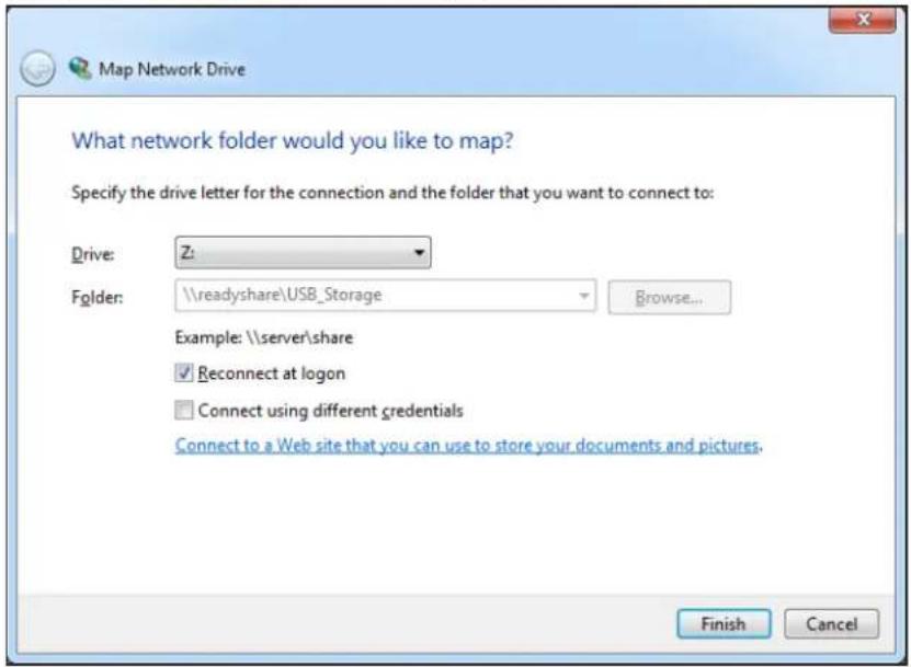
text_image
Map Network Drive What network folder would you like to map? Specify the drive letter for the connection and the folder that you want to connect to: Drive: Z: Folder: \readyshare\USB_ Storage Browse... Example: \server\share Reconnect at logon Connect using different credentials Connect to a Web site that you can use to store your documents and pictures. Finish Cancel- Select the drive letter to map to the network folder.
- Click the Finish button.
The USB device is mapped to the drive letter that you specified.
- To connect to the USB storage device as a different user, select the Connect using different credentials check box, click the Finish button, and do the following:
a. Type the user name and password.
b. Click the OK button.
The USB storage device is mapped to the drive letter that you specified.
To access the USB drive from a remote computer:
- Launch a web browser.
- Connect using the router's Internet port IP address.
If you are using Dynamic DNS, you can type the DNS name, rather than the IP address. You can view the router's Internet IP address on the Basic Home screen (see Dashboard (Basic Home Screen) on page 15).
To access the USB drive with FTP from a remote computer:
- Make sure that the FTP check box is selected in the Access Method section of the USB Storage (Advanced Settings) screen (see USB Storage Device Network and Access Settings on page 49).
- Launch a web browser.
- Type ftp:// and the Internet port IP address in the address field of the browser.
For example, type ftp://10.1.65.4.
If you are using Dynamic DNS, you can type the DNS name rather than the IP address.
- Type the account name and password for the account that has access rights to the USB drive.
The user name (account name) for All – no password is guest.
The directories of the USB drive that your account has access to display. For example, you could see: share/partition1/directory1. You can now read and copy files from the USB directory.
File-Sharing Scenarios
You can share files on the USB drive for a wide variety of business and recreational purposes. The files can be any Windows, Mac, or Linux file type including text, Word, PowerPoint, Excel, MP3, pictures, and multimedia files. USB drive applications include:
- Sharing multimedia with friends and family such as MP3 files, pictures, and other multimedia with local and remote users.
- Sharing resources on your network. You can store files in a central location so that you do not have to power up a computer to perform local sharing. In addition, you can share files between Macintosh, Linux, and Windows computers by using the USB drive as a go-between across the systems.
- Sharing files such as Word documents, PowerPoint presentations, and text files with remote users.
A few common uses are described in the following sections.
Share Photos
You can create your own central storage location for photos and multimedia. This method eliminates the need to log in to (and pay for) an external photo-sharing site.
To share files with your friends and family:
-
Insert your USB drive into the USB port on the router either directly or with a USB cable.
Computers on your local area network (LAN) can automatically access this USB drive using a web browser or Microsoft Networking. -
If you want to specify read-only access or to allow access from the Internet, see USB Storage Device Network and Access Settings on page 49.
Store Files in a Central Location for Printing
This scenario is for a family that has one high-quality color printer directly attached to a computer, but not shared on the local area network (LAN). This family does not have a print server.
• One family member has photos on a Macintosh computer that she wants to print.
- The photo-capable color printer is directly attached to a PC, but not shared on the network.
- The Mac and PC are not visible to each other on the network.
To print photos from a Mac on the printer attached to a PC:
- On a Mac, access the USB drive by typing \readyshare in the address field of a web browser. Then copy the photos to the USB drive.
- On a Window computer, use a web browser or Microsoft Networking to copy the files from the USB drive to the computer. Then print the files.
Share Large Files over the Internet
Sending files that are larger than 5 MB can pose a problem for many email systems. The router allows you to share large files such as PowerPoint presentations or .zip files over the Internet. FTP can be used to download shared files from the router.
Sharing files with a remote colleague involves the following considerations:
- There are two user accounts: admin and guest. The password for admin is the same one that you use to access the router. By default, it is password. The guest user account has no password.
- On the FTP site, the person receiving the files uses the guest user account and enters the password. (FTP requires that you type something in the password field.)
- Be sure to select the FTP (via Internet) check box in the USB Storage (Advanced Settings) screen. This option supports both downloading and uploading of files.
Note: You can enable the HTTP (via Internet) option on the USB Storage (Advanced Settings) screen to share large files. This option supports downloading files only.
Back Up Windows Computers with ReadySHARE Vault
Your router comes with free backup software for all the Windows computers in your home. Connect a USB hard disk drive (HDD) to the USB port on your router for centralized, continuous, and automatic backup.
To back up your Windows computer:
- Connect a USB HDD to the USB port on the router.
- Download ReadySHARE Vault from www.netgear.com/readyshare and install it on each Windows computer.
- Launch ReadySHARE Vault.
- Use the dashboard or the Backup tab to set up and run your backup jobs.
View a USB Device Attached to the Router
To view basic information about the USB storage device:
1. Select Basic > ReadySHARE.

text_image
USB Storage (Basic Settings) C Refresh Basic ReadySHARE Printer Natgear ReadySHARE Vault Network/Device Name: \readyshare Available Network Folders Share Name Read Access Write Access Folder Name Volume Name Total Space Free Space \readyshare\USB_Storage All All U\\ U Drive (1.9G) 1.9G 1.8G Edit Safely Remove USB DeviceBy default, the Basic radio button is selected, and the screen displays a USB storage device if it is attached to the router USB port.
If you logged in to the router before you connected your USB device, you might not see your USB device in this screen. If this happens, log out and then log back in.
- (Optional) To view the files and folders on the USB device, click the network device name or the share name.
- (Optional) To view more detail or to change the USB device settings, click Edit.
The USB Storage (Advanced Settings) screen displays. See USB Storage Device Network and Access Settings on page 49.
USB Storage Device Network and Access Settings
You can set up the device name, workgroups, and network folders for your USB device.
To view or change the USB storage advanced settings:
- Select Advanced > USB Storage > Advanced Settings.
USB Storage (Advanced Settings)
Apply ▶
c Refresh
Network/Device Name :
readyshare
Workgroup :
Workgroup
| Enable | Access Method | Link | Port |
| Network Neighborhood/MacShare | \readyshare | - | |
| HTTP | http://readyshare.routerlogin.net/shares | 80 | |
| HTTPS (via internet) | https://10.1.108.125/shares | 443 | |
| FTP | ftp://readyshare.routerlogin.net/shares | 21 | |
| FTP (via internet) | ftp://10.1.108.125/shares | 21 |
Available Network Folders
| Share Name | Read Access | Write Access | Folder Name | Volume Name | Total Space | Free Space | |
| ◎ | \readyshare\USB_Storage | All - no password | All - no password | U:1 | U Drive (1.9G) | 1.9G | 1.8G |
Edit
Create Network Folder
× Delete
Safely Remove USB Device
-
Specify access to the USB storage device.
-
Network Device Name. The default is readyshare. This is the name used to access the USB device connected to the router.
- W orkgroup. If you are using a Windows workgroup rather than a domain, the workgroup name is displayed here. The name works only in an operating system that supports NetBIOS, such as Microsoft Windows.
- Access Method. Select the check boxes for the access methods that you want.
- Network Neighborhood/MacShare. Enabled by default.
- HTTP. Enabled by default. You can type http://readyshare.routerlogin.net/shares to access the USB drive.
- HTTP (via Internet). Disabled by default. If you enable this feature, remote users can type http://public IP address/shares> (for example, http://1.1.10.102/shares) or a URL domain name to access the USB drive over the Internet. This feature supports file uploading only.
- FTP. Disabled by default.
-
FTP (via Internet). Disabled by default. If you select this feature, remote users can access the USB drive through FTP over the Internet. This feature supports both downloading and uploading of files.
-
If you changed the settings, click Apply.
Your changes are saved.
Available Network Folders
You can view or change the network folders on the USB storage device.
To view network folders:
- Select Advanced > USB Storage > Advanced Settings.
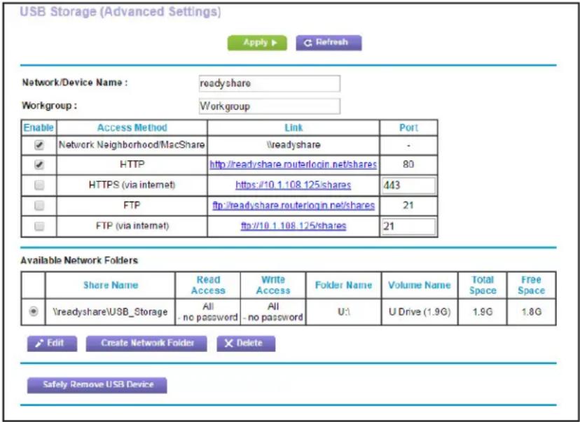
text_image
USB Storage (Advanced Settings) Apply ▶ Refresh Network/Device Name : readyshare Workgroup : Workgroup Enable Access Method Link Port ✓ Network Neighborhood/MacShare \readyshare - ✓ HTTP http://readyshare.routerlogin.net/shares 80 ☐ HTTPS (via internet) https://10.1.108.125/shares 443 ☐ FTP ftp://readyshare.routerlogin.net/shares 21 ☐ FTP (via internet) ftp://10.1.108.125/shares 21 Available Network Folders Share Name Read Write Folder Volume Total Free Access Access Access U: U Drive (1.9G) Space Space Space ✓ \readyshare\USB_Storage All All U: U Drive (1.9G) 1.9G 1.8G - no password - no password Edit Create Network Folders Delete Safely Remove USB Device- Scroll down to the Available Networks Folder section of the screen.
- Share Name. If only one device is connected, the default share name is USB_Storage. (Some router models have more than one USB port.)
You can click the name, or you can type it in the address field of your web browser. If Not Shared is shown, the default share has been deleted, and no other share for the root folder exists. Click the link to change this setting.
- Read Access and Write Access. Show the permissions and access controls on the network folder: All - no password (the default) allows all users to access the network folder. The password for admin is the same one that you use to log in to the router.
- Folder Name. Full path of the network folder .
• V olume Name. Volume name from the storage device (either USB drive or HDD). - Total Space and Free Space. Show the current utilization of the storage device.
To add a network folder:
- Select Advanced > ReadySHARE.
- Click Edit.
3. Click Create Network Folder.
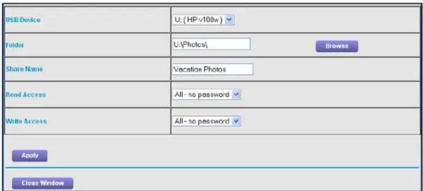
text_image
USB Device U: (HP v100w) Folder U:\Photos\ Browse Share Name Vacation Photos Read Access All - no password Write Access All - no password Apply Close WindowIf the Add a Network Folder screen does not display, your web browser might be blocking pop-ups. If it is, then change the browser settings to allow pop-ups.
- In the Folder field, browse and select the folder.
- Fill in the Share Name field.
- In the Read Access list and the Write Access list, select the setting that you want.
The user name (account name) for All – no password is guest. The password for admin is the same one that is used to log in to the router. By default, it is password.
- Click Apply.
The folder is added on the USB device.
To edit a network folder:
- Select Advanced > ReadySHARE.
- Click the Edit button.
The Edit Network Folder screen displays the same settings shown in the Add a Network Folder screen.
- Change the settings in the fields as needed.
- Click Apply.
Your changes are saved.
Specify Approved USB Devices
For more security, you can set up the router to share only approved USB devices.
To set up approved USB devices:
- Select Advanced > Advanced Setup > USB Settings.
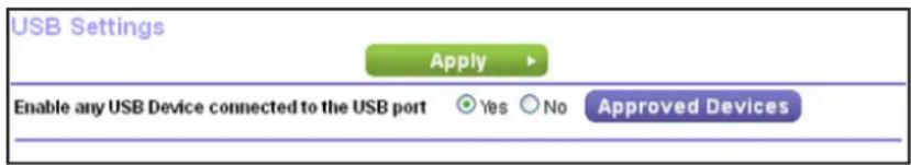
text_image
USB Settings Apply Enable any USB Device connected to the USB port Yes No Approved Devices- Click the Approved Devices button.

text_image
USB Drive Approved Devices Apply ▶ C Refresh Allow only approved devices Approved USB Devices Volume Name Device Name Capacity × Delete Available USB Devices Volume Name Device Name Capacity U Drive (1.9G) SMI USB DISK 1.9GB +AddThis screen shows the approved USB devices and the available USB devices. You can remove or add approved USB devices.
- In the Available USB Devices list, select the drive that you want to approve.
- Click Add.
- Select the Allow only approved devices check box.
- Click Apply.
Your change takes effect.
If you want to work with another USB device, first click the Safely Remove USB Device button for the currently connected USB device. Connect the other USB device, and repeat this process.
Back Up Windows Computers with ReadySHARE Vault
Your router comes with free backup software for all the Windows computers in your home. Connect a USB hard disk drive (HDD) to the USB port on your router for centralized, continuous, and automatic backup.
To back up your Windows computer:
- Connect a USB HDD to a USB port on the router.
R6250 Smart WiFi Router
The blue, USB 3.0 port on the front of the router performs faster than the USB 2.0 port on the rear panel of the router.
- Download ReadySHARE Vault from www.netgear.com/readyshare and install it on each Windows computer.
- Launch ReadySHARE Vault.
- Use the dashboard or the Backup tab to set up and run your backup jobs.
R6250 Smart WiFi Router
The ReadySHARE Printer utility lets you share a USB printer that is connected to the USB port on your router. You can share this USB printer among the Windows and Mac computers on your network.
This chapter contains the following sections:
• Install the Printer Driver and Cable the Printer
- Download the ReadySHARE Printer Utility
• Install the ReadySHARE Printer Utility
- Use the Shared Printer
• View or Change the Status of a Printer
- Use the Scan Feature of a Multifunction USB Printer
- Change NETGEAR USB Control Center Settings
Install the Printer Driver and Cable the Printer
Some USB printer manufacturers (for example, HP and Lexmark) request that you do not connect the USB cable until the installation software prompts you to do so.
To install the driver and cable the printer:
-
On each computer on your network that shares the USB printer, install the driver software for the USB printer. If you cannot find the printer driver, contact the printer manufacturer.
-
Use a USB printer cable to connect the USB printer to the router USB port.
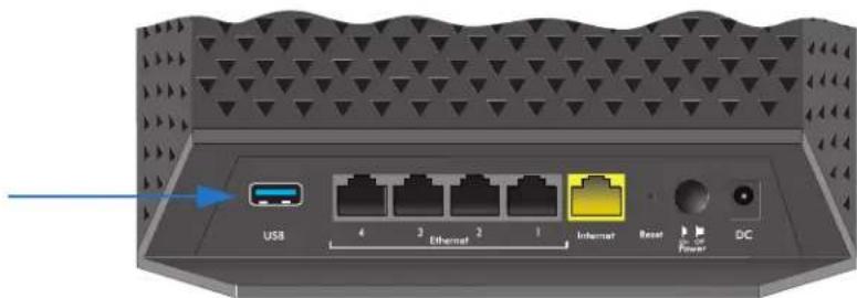
text_image
USB 4 3 Ethernet 2 1 Internet Reset Power DCDownload the ReadySHARE Printer Utility
The utility works on Windows and Mac computers.
To download the utility:
- Visit www.netgear.com/readyshare.
-
Scroll down to the Print From the Comfort of Your Home Network section at the bottom of the screen.
-
- Click one of the following links: • Download PC installer and get started. This is the utility for Windows computers. • Download Mac installer and get started. This is the utility for MAC computers. • Download the genie App and get started. This is the utility for smart phones and tablets.
-
Follow the onscreen instructions to download the ReadySHARE Printer utility setup file.
Install the ReadySHARE Printer Utility
You must install the ReadySHARE Printer utility on each computer that will share the printer. After you install it, the utility displays as NETGEAR USB Control Center on your computer.
To install the utility:
- If necessary, unzip the ReadySHARE Printer utility setup file.
- Double-click the ReadySHARE Printer utility setup file that you downloaded.

text_image
NETGEAR USB Control Center - InstallShield Wizard Welcome to the InstallShield Wizard for NETGEAR USB Control Center The InstallShield(R) Wizard will install NETGEAR USB Control Center on your computer. To continue, click Next. WARNING: This program is protected by copyright law and international treaties.- Follow the wizard instructions to install NETGEAR USB Control Center.
After the InstallShield Wizard completes the installation, the NETGEAR USB Control Center prompts you to select a language:

text_image
NetGear USB Control Center NETGEAR USB Control Center English OK- Select a language from the list and click the OK button.
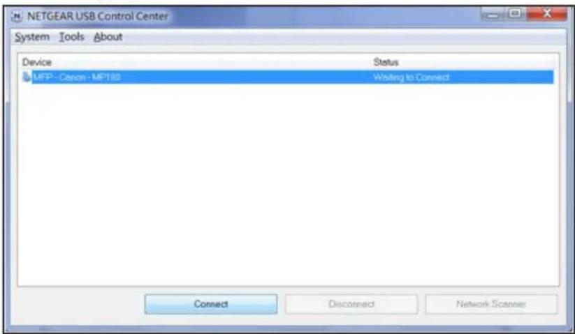
text_image
NETGEAR USB Control Center System Tools About Device Status MFP - Canon - MP180 Wasting to Connect Connect Disconnect Network ScannerSome firewall software, such as Comodo, blocks NETGEAR USB Control Center from accessing the USB printer. If you do not see the USB printer displayed in the screen, you can disable the firewall temporarily to allow the utility to work.
- Select the printer and click the Connect button.
The printer status changes to Manually connected by Mycomputer. Now, only your computer that can use the printer.
- Click the Disconnect button.
The status changes to Available. Now all computers on the network can use the printer.
- To exit the utility, select System > Exit.
Use the Shared Printer
For each computer, after you click the Connect and Disconnect buttons once, the utility automatically manages the printing queue and handling. By default, the utility starts automatically whenever you log on to Windows and runs in the background.
To manually connect and print:
- Click the NETGEAR USB Control Center icon
The main screen displays.
- Click the Connect button.
The printer status changes to Manually connected by Mycomputer. Now, only the computer you are using can use this printer.
-
Use the print feature in your application to print your document.
-
To release the printer so that all computers on the network can use it, click the Disconnect button.
To print and release the printer to any computer on the network:
- To print your document, use the print feature in your application.
The NETGEAR USB Control Center automatically connects your computer to the USB printer and prints the document. If another computer is already connected to the printer, your print job goes into a queue to wait to be printed.
- If your document does not print, use the NETGEAR USB Control Center to check the status. See View or Change the Status of a Printer on page 60.
View or Change the Status of a Printer
To view or change the status:
1. Click the NETGEAR USB Control Center icon

The main screen displays.

text_image
NETGEAR USB Control Center System Tools About Device Status Audio - Logitech Speaker Manually Connected by netgear-8dc0086 MFP - HP - Photosmart C5200 series Available Connect Disconnect Network ScannerThe Status column shows the status for each device:
- A vailable. No print jobs are in progress. You can use the USB printer from any computer in the network.
- Connected. Your computer is connected to the printer and will be released when your print job is done.
• Manually Connected by. Only the connected computer can use the printer. -
W aiting to Connect. Your computer is not connected to the shared printer yet.
-
To print from your computer when the status shows Manually connected by another computer, click the Disconnect button.
The printer is released from the connection and the status changes to Available.
- To print from your computer when the status shows Waiting to Connect, do the following: a. Click the Connect button.
The printer status changes to Manually connected by Mycomputer. Now, only your computer can use the printer.
b. To allow the printer to be shared, click the Disconnect button.
The printer is released from the connection and the status changes to Available.
Use the Scan Feature of a Multifunction USB Printer
If your USB printer supports scanning, you can also use the USB printer for scanning. For example, the USB printer displayed in the Windows Printers and Faxes window is ready for print jobs.

text_image
Printers and Faxes File Edit View Favorites Tools Help Back Search Folders Address Printers and Faxes Printer Tasks Add a printer Set up faxing See Also Troubleshoot printing Get help with printing Other Places HP Photosmart CS200 series 0 PausedTo use the scan feature of a multifunction USB printer:
- Click the NETGEAR USB Control Center icon


text_image
NETGEAR USB Control Center System Tools About Device Status Audio - Logitech Speaker Manually Connected by netgear-8dc0086 MFP - HP - Photosmart C5200 series Available Connect Disconnect Network Scanner- Make sure that the printer status shows as Available.
- C lick the Network Scanner button.

text_image
NETGEAR USB Control Center System Tools About Device Status MFP - Canon - MP180 Available Connect Disconnect Network ScannerThe scanner screen displays so that you can use the USB printer for scanning.
Change NETGEAR USB Control Center Settings
You can stop the NETGEAR USB Control Center from starting automatically when you log in to Windows. You can also change the language and specify the time-out to release the printer connection.
To turn off automatic NETGEAR USB Control Center startup:
1. Click the NETGEAR USB Control Center icon


text_image
NETGEAR USB Control Center System Tools About Device Status Audio - - Logitech Speaker Manually Connected by netgear-8dc0086 MFP - HP - Photosmart C5200 series Available Connect Disconnect Network Scanner2. Select Tools > Configuration.
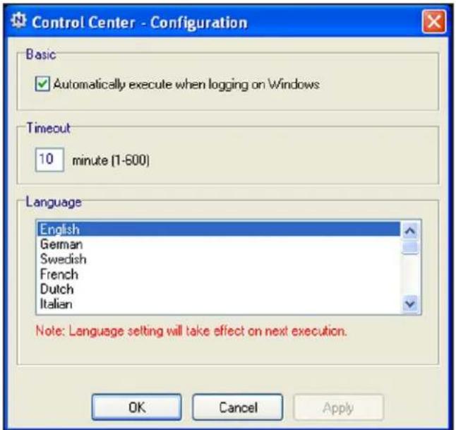
text_image
Control Center - Configuration Basic ✓ Automatically execute when logging on Windows Timeout 10 minute (1-500) Language English German Swedish French Dutch Italian Note: Language setting will take effect on next execution. OK Cancel Apply- Clear the Automatically execute when logging on Windows check box.
- Click the OK button.
Your change is saved.
To change the language:
- Select Tools > Configuration.
- In the Language list, select a language.
- Click the OK button.
The next time NETGEAR USB Control Center starts, the language changes.
To specify the time-out:
- Select Tools > Configuration.
- In the Timeout field, type the number of minutes.
The time-out is the number of minutes that a computer holds its connection to the printer when the connection isn't being used.
- Click the OK button.
Your change is saved.
Customize the Firewall Settings
This chapter explains how to use the basic firewall features of the router to prevent objectionable content from reaching the computers and devices on your network.
This chapter includes the following sections:
- Set Up Parental Controls
- Keyword Blocking of HTTP Traffic
• Block Services (Port Filtering) - Port Triggering to Open Incoming Ports
- Port Forwarding to Permit External Host Communications
• How Port Forwarding Differs from Port Triggering - Set Up Port Forwarding to Local Servers
- Set Up Port Triggering
- Schedule Blocking
• Security Event Email Notifications
Set Up Parental Controls
The first time that you select Parental Controls from the BASIC Home screen, your browser goes to the Parental Controls website, where you can learn more about Parental Controls. To set up Parental Controls, you must download the genie app.
To set up Live Parental Controls:
- Launch a web browser from a computer or wireless device that is connected to the network.
- Type http://www.routerlogin.net or http://www.routerlogin.com.
A login screen displays.
- Enter the router user name and password.
The user name is admin. The default password is password. The user name and password are case-sensitive.
The BASIC Home screen displays.
- Select Parental Controls.
The Parental Controls website opens.
- Click the button for the genie app version that you want to download and use.
- Follow the onscreen instructions to download and install the genie app.
- Open the genie app and select Parental Controls.
Live Parental Controls automatically starts.
Parental Controls
Powered by OpenDNS
You're about to setup NETGEAR Live Parental Controls Powered by OpenDNS on your router to filter websites visited on your computers and other networked devices.

flowchart
graph LR
    A["THE INTERNET"] --> B["CABLE/DSL MODEM"]
    B --> C["LIVE PARENTAL CONTROLS ENABLED NETGEAR ROUTER"]
    C --> D["FILTERING: HIGH"]
    C --> E["FILTERING: NONE"]
    C --> F["FILTERING: LOW"]
    style A fill:#fff,stroke:#000
    style B fill:#fff,stroke:#000
    style C fill:#999,stroke:#000
    style D fill:#fff,stroke:#000
    style E fill:#fff,stroke:#000
    style F fill:#fff,stroke:#000
    subgraph "NETGEAR ROUTER"
        C
        D
        E
        F
    end
    style A fill:#fff,stroke:#000
    style B fill:#fff,stroke:#000
    style C fill:#999,stroke:#000
    style D fill:#fff,stroke:#000
    style E fill:#fff,stroke:#000
    style F fill:#fff,stroke:#000
Our custom settings let you relax security settings for some users or at some times of the day. Learn more
Next
- Click the Next button, read the note, and click the Next button again.
Because Live Parental Controls uses free OpenDNS accounts, you are prompted to log in or create a free account.
Setting up Live Parental Controls
Welcome, this setup wizard will quickly configure NETGEAR Live Parental Controls Powered by OpenDNS on your NETGEAR router.
In order to use Live Parental Controls, you need a free OpenDNS account. Do you already have one?
Yes, use my existing OpenDNS account.
○ No, I need to create a free OpenDNS account.
-
Select the radio button that applies to you:
-
If you already created an OpenDNS account, leave the Ye s radio button selected.
• If you did not yet create an OpenDNS account, select the No radio button.
If you are creating an account, the following screen displays:
Create a free OpenDNS account
Please enter your information below.
Username
Password
Confirm Password
Confirm Email


1

a. Complete the fields.
b. Click the Next button.
After you log on or create your account, the filtering level screen displays:
Live Parental Controls: choose a filtering level for your network
All computers connected to your router will be protected from the content you select below. You can customize your Live Parental Controls later on our website.
None
Nothing blocked.
Minimal
Protects only against phishing attacks.
Low
Protects against pornography and phishing attacks.
Moderate
Protects against all adult-related sites, illegal activity and phishing attacks.
High
Previous
Next
- Select a radio button for a filtering level that you want and click the Next button.
Setup is complete!
You have successfully setup NETGEAR Live Parental Controls Powered by OpenDNS. Next time you run the Management Utility it will take you to the status screen where you can:
check whether Live Parental Controls are enabled
disable or enable Live Parental Controls
modify basic settings
change custom settings such as per-user and time-of-day based Live Parental Controls
Take me to the status screen
- Click the Take me to the status screen button.
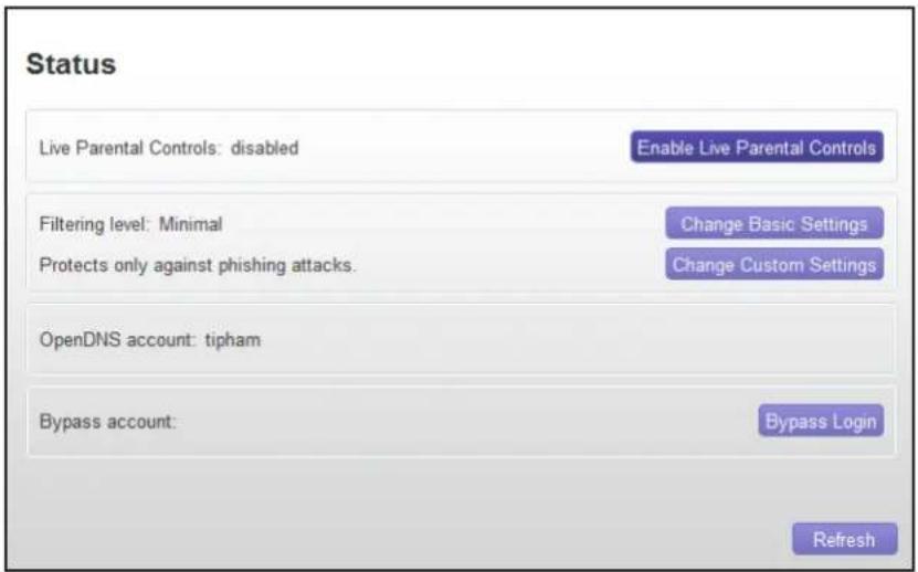
text_image
Status Live Parental Controls: disabled Enable Live Parental Controls Filtering level: Minimal Change Basic Settings Protects only against phishing attacks. Change Custom Settings OpenDNS account: tipham Bypass account: Bypass Login RefreshParental Controls are now set up for the router.
- To enable Parental Controls, click the Enable Live Parental Controls button.
Keyword Blocking of HTTP Traffic
Use keyword blocking to prevent certain types of HTTP traffic from accessing your network. The blocking can be always or according to a schedule.
To set up keyword blocking:
- Select Advanced > Security > Block Sites.
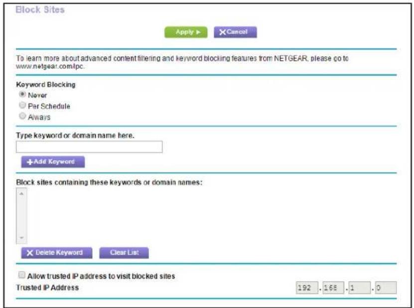
text_image
Block Sites Apply ▶ Cancel To learn more about advanced content filtering and keyword blocking features from NETGEAR, please go to www.netgear.com/lpc. Keyword Blocking ● Never ○ Par Schedule ○ Always Type keyword or domain name here. +Add Keyword Block sites containing these keywords or domain names: × Delete Keyword Clear List □ Allow trusted IP address to visit blocked sites Trusted IP Address 192 .168 .1 .0- Select one of the keyword blocking options:
• Per Schedule. Turn on keyword blocking according to the Schedule screen settings.
• Always. Turn on keyword blocking all the time, independent of the Schedule screen.
- In the Keyword field, enter a keyword or domain, click Add Keyword, and click Apply.
The Keyword list supports up to 32 entries. Here are some sample entries:
- Specify XXX to block http://www.badstuff.com/xxx.html.
- Specify .com if you want to allow only sites with domain suffixes such as .edu or .gov.
- Enter a period (.) to block all Internet browsing access.
To delete a keyword or domain:
- Select the keyword you want to delete from the list.
- Click Delete Keyword.
- Click Apply.
Your changes are saved.
To specify a trusted computer:
You can exempt one trusted computer from blocking and logging. The computer you exempt has to have a fixed IP address.
- In the Trusted IP Address field, enter the IP address.
- Click Apply.
Your changes are saved.
Block Services (Port Filtering)
Services are functions that server computers perform at the request of client computers. For example, web servers serve web pages, time servers serve time and date information, and game hosts serve data about other players' moves. When a computer on the Internet sends a request for service to a server computer, a service or port number identifies the requested service. This number is the destination port number in the transmitted IP packets. For example, a packet that is sent with the destination port number 80 is an HTTP (web server) request.
The Internet Engineering Task Force (IETF at http://www.ietf.org/) has defined and published the service numbers for many common protocols in RFC1700, “Assigned Numbers.” Service numbers for other applications are typically chosen from the range 1024 - 65535 by the authors of the application. Although the router already holds a list of many service port numbers, you are not limited to these choices. You can often determine port number information by contacting the publisher of the application, by asking user groups or newsgroups, or by searching.
The Block Services screen lets you add and block specific Internet services by computers on your network. This is called service blocking or port filtering. To add a service for blocking, first determine which port number or range of numbers the application uses.
To block services:
- Select Advanced > Security > Block Services.
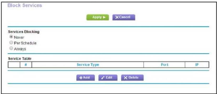
text_image
Block Services Apply ▶ × Cancel Services Blocking ● Naver ○ Par Schedule ○ Always Service TableService Type Port IP
+ Add Edit × Delete- Select either Per Schedule or Always.
- If you selected Per Schedule, specify a time period in the Schedule screen.
- Click Add to add a service.
The Block Services Setup screen displays:
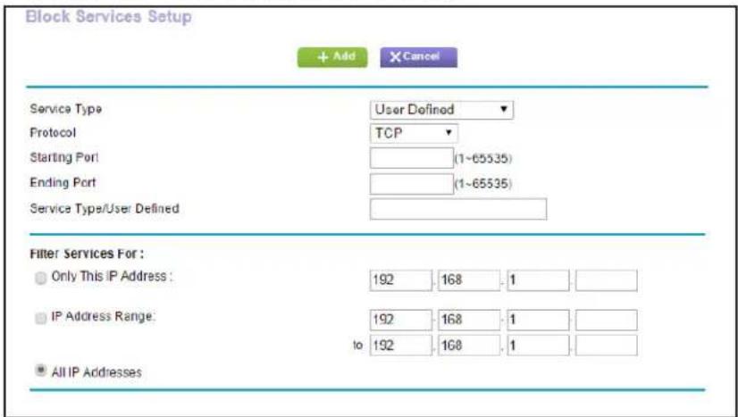
text_image
Block Services Setup + Add Cancel Service Type User Defined Protocol TCP Starting Port (1-65535) Ending Port (1-65535) Service Type/User Defined Filter Services For : Only This IP Address: 192 168 1 IP Address Range: 192 168 1 to 192 168 1 All IP Addresses- From the Service Type list, select the application or service to allow or block.
The list displays several common services, but you are not limited to these choices. To add any additional services or applications that are not in the list, select User Defined.
- If you know that the application uses either TCP or UDP, select the appropriate protocol. If you are not sure, select Both.
- Enter the starting and ending port numbers.
If the application uses a single port number, enter that number in both fields.
- Select the radio button for the IP address configuration you want to block, and enter the IP addresses.
You can block the specified service for a single computer, a range of computers with consecutive IP addresses, or all computers on your network.
- Click Add.
Your changes are saved.
Port Triggering to Open Incoming Ports
Some application servers (such as FTP and IRC servers) send replies to multiple port numbers. Using the port triggering function of your router, you can tell the router to open more incoming ports when a particular outgoing port originates a session.
An example is Internet Relay Chat (IRC). Your computer connects to an IRC server at destination port 6667. The IRC server not only responds to your originating source port, but also sends an “identify” message to your computer on port 113. Using port triggering, you can tell the router, “When you initiate a session with destination port 6667, you have to also allow incoming traffic on port 113 to reach the originating computer.”
Using steps similar to the preceding example, the following sequence shows the effects of the port triggering rule you have defined:
- You open an IRC client program to start a chat session on your computer.
- Your IRC client composes a request message to an IRC server using a destination port number of 6667, the standard port number for an IRC server process. Your computer then sends this request message to your router.
- Your router creates an entry in its internal session table describing this communication session between your computer and the IRC server. Your router stores the original information, performs Network Address Translation (NAT) on the source address and port, and sends this request message through the Internet to the IRC server.
- Noting your port triggering rule and having observed the destination port number of 6667, your router creates an additional session entry to send any incoming port 113 traffic to your computer.
- The IRC server sends a return message to your router using the NAT-assigned source port (for example, port 33333) as the destination port. The IRC server also sends an "identify" message to your router with destination port 113.
- Upon receiving the incoming message to destination port 33333, your router checks its session table for an active session for port number 33333. IF so, the router restores the original address information replaced by NAT and sends this reply message to your computer.
-
Upon receiving the incoming message to destination port 113, your router checks its session table and finds an active session for port 113, associated with your computer. The router replaces the message's destination IP address with your computer's IP address and forwards the message to your computer.
-
When you finish your chat session, your router eventually senses a period of inactivity in the communications. The router then removes the session information from its session table, and incoming traffic is no longer accepted on port numbers 33333 or 113.
To configure port triggering, you need to know which inbound ports the application needs. Also, you need to know the number of the outbound port that triggers the opening of the inbound ports. You can usually determine this information by contacting the publisher of the application or the relevant user groups or news groups.
Only one computer at a time can use the triggered application.
Port Forwarding to Permit External Host Communications
In both of the preceding examples, your computer initiates an application session with a server computer on the Internet. However, you might need to allow a client computer on the Internet to initiate a connection to a server computer on your network. Normally, your router ignores any inbound traffic that is not a response to your own outbound traffic. You can configure exceptions to this default rule by using the port forwarding feature.
A typical application of port forwarding can be shown by reversing the client-server relationship from the previous web server example. In this case, a remote computer's browser needs to access a web server running on a computer in your local network. Using port forwarding, you can tell the router, "When you receive incoming traffic on port 80 (the standard port number for a web server process), forward it to the local computer at 192.168.1.123." The following sequence shows the effects of the port forwarding rule you have defined:
- The user of a remote computer opens a browser and requests a web page from www.example.com, which resolves to the public IP address of your router. The remote computer composes a web page request message with the following destination information:
Destination address. The IP address of www.example.com, which is the address of your router.
Destination port number. 80, which is the standard port number for a web server process.
The remote computer then sends this request message through the Internet to your router.
- Your router receives the request message and looks in its rules table for any rules covering the disposition of incoming port 80 traffic. Your port forwarding rule specifies that incoming port 80 traffic should be forwarded to local IP address 192.168.1.123. Therefore, your router modifies the destination information in the request message:
The destination address is replaced with 192.168.1.123.
Your router then sends this request message to your local network.
-
Your web server at 192.168.1.123 receives the request and composes a return message with the requested web page data. Your web server then sends this reply message to your router.
-
Your router performs Network Address Translation (NAT) on the source IP address, and sends this request message through the Internet to the remote computer, which displays the web page from www.example.com.
To configure port forwarding, you need to know which inbound ports the application needs. You can usually find this information by contacting the publisher of the application or the relevant user groups or news groups.
How Port Forwarding Differs from Port Triggering
The following points summarize the differences between port forwarding and port triggering:
- Any computer on your network can use port triggering, but only one computer can use it at a time.
- Port forwarding is allowed only for the computer that you specify on your network.
- With port triggering, you do not need to specify the computer's IP address. The IP address is captured automatically.
- Port forwarding requires that you specify the computer's IP address during configuration, and the IP address can never change.
- Port triggering requires specific outbound traffic to open the inbound ports, and the triggered ports are closed after a period of no activity.
- Port forwarding is always active and does not need to be triggered.
Set Up Port Forwarding to Local Servers
The port forwarding feature lets you allow certain types of incoming traffic to reach servers on your local network. For example, you might want to make a local web server, FTP server, or game server visible and available to the Internet.
Use the Port Forwarding/Port Triggering screen to configure the router to forward specific incoming protocols to computers on your local network. In addition to servers for specific applications, you can also specify a default DMZ server to which all other incoming protocols are forwarded.
Before you start, determine which type of service, application, or game you want to provide, and the local IP address of the computer that will provide the service. The server computer has to always have the same IP address.
To ensure that your server computer always has the same IP address, use the reserved IP address feature of your product. See Address Reservation on page 36.
To forward specific incoming protocols:
- Select Advanced > Advanced Setup > Port Forwarding/Port Triggering.

text_image
Port Forwarding / Port Triggering Please select the service type. ● Port Forwarding ○ Port Triggering Service Name FTP Server IP Address 192 168 1 Add # Service Name External Start Port Internal Start Port Internal IP address Edit Service Delete Service Add Custom Service Arrange by Internal IP- Leave the Port Forwarding radio button selected as the service type.
- In the Service Name list, select the service name.
If the service is not in the list, see Add a Custom Service on page 75
- Fill in the Server IP Address field
- Click Add.
The list now includes the service.
Add a Custom Service
To define a service, game, or application that is not in the Service Name list, first determine which port number or range of numbers the application uses. You can usually determine this information by contacting the publisher of the application or user groups or news groups. When you have the port number information, follow these steps.
To add a custom service:
- Select Advanced > Advanced Setup > Port Forwarding/Port Triggering.
-
Select the Port Forwarding radio button as the service type.
-
Click the Add Custom Service button.

text_image
Ports - Custom Services Apply ▶ X Cancel Service Name Protocol TCP/UDP ▼ External Port Range (1~65534) (Specify ports and/or port ranges split by commas, example: 30, 50-60, 65500-65510) ✓ Use the same port range for Internal port Internal Port Range (1~65534) (Specify ports and/or port ranges split by commas, example: 30, 50-60, 65500-65510) Internal IP address 192 168 1 Or select from currently attached devices IP Address Device Name 192.168.1.3 TIPHAM-T440P- In the Service Name field, enter a descriptive name.
- In the Service Type field, select the protocol. If you are unsure, select TCP/UDP.
-
In the Eternal Starting Port field, enter the beginning port number.
-
If the application uses a single port, enter the same port number in the Ending Port field.
-
If the application uses a range of ports, enter the ending port number of the range in the External Ending Port field.
-
Fill in the Internal IP address field or select the radio button from the list of currently attached devices.
- Click Apply.
The service is now included in the list.
Edit or Delete a Port Forwarding Entry
To edit or delete a port forwarding entry:
- Select Advanced > Advanced Setup > Port Forwarding/Port Triggering.
- Select the Port Forwarding radio button as the service type
- In the table, select the radio button next to the service name.
- Click Edit Service or Delete Service.
Application Example: Make a Local Web Server Public
If you host a web server on your local network, you can use port forwarding to allow web requests from anyone on the Internet to reach your web server.
To make a local web server public:
- Assign your web server either a fixed IP address or a dynamic IP address using DHCP address reservation.
In this example, your router always gives your web server an IP address of 192.168.1.33.
- In the Port Forwarding/Port Triggering screen, configure the router to forward the HTTP service to the local address of your web server at 192.168.1.33.
HTTP (port 80) is the standard protocol for web servers.
- (Optional) Register a host name with a Dynamic DNS service, and configure your router to use the name.
To access your web server from the Internet, a remote user has to know the IP address that your ISP assigned. However, if you use a Dynamic DNS service, the remote user can reach your server by a user-friendly Internet name, such as mynetgear.dyndns.org.
Set Up Port Triggering
Port triggering is a dynamic extension of port forwarding that is useful in these cases:
- More than one local computer needs port forwarding for the same application (but not simultaneously).
- An application needs to open incoming ports that are different from the outgoing port.
When port triggering is enabled, the router monitors outbound traffic looking for a specified outbound “trigger” port. When the router detects outbound traffic on that port, it remembers the IP address of the local computer that sent the data. The router then temporarily opens the specified incoming port or ports and forwards incoming traffic on the triggered ports to the triggering computer.
Port forwarding creates a static mapping of a port number or range to a single local computer. Port triggering can dynamically open ports to any computer that needs them and can close the ports when they are no longer needed.
Note: If you use applications such as multiplayer gaming, peer-to-peer connections, real-time communications such as instant messaging, or remote assistance (a feature in Windows XP), you should also enable Universal Plug and Play (UPnP).
To configure port triggering, you need to know which inbound ports the application needs, and the number of the outbound port that triggers the opening of the inbound ports. You can usually determine this information by contacting the publisher of the application or user groups or news groups.
To enable port triggering:
- Select Advanced > Advanced Setup > Port Forwarding/Port Triggering.
2. Select the Port Triggering radio button.
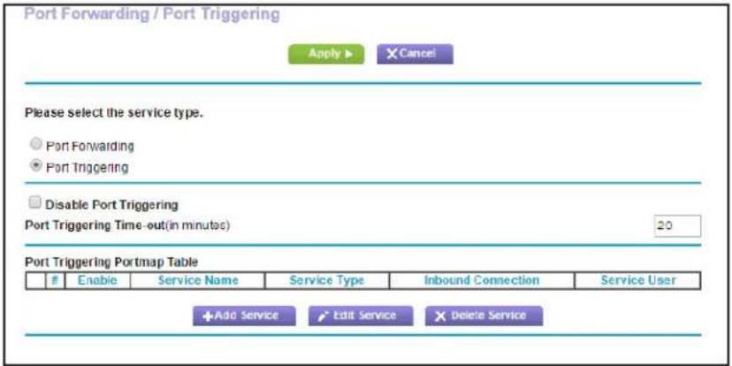
text_image
Port Forwarding / Port Triggering Apply ▶ Cancel Please select the service type. ● Port Forwarding ● Port Triggering □ Disable Port Triggering Port Triggering Time-out(in minutes) 20 Port Triggering Portmap TableEnable Service Name Service Type Inbound Connection Service User
+Add Service Edit Service Delete Service3. Clear the Disable Port Triggering check box.
Note: If the Disable Port Triggering check box is selected after you configure port triggering, port triggering is disabled. However, any port triggering configuration information you added to the router is retained even though it is not used.
4. In the Port Triggering Timeout field, enter a value up to 9999 minutes.
This value controls the inactivity timer for the designated inbound ports. The inbound ports close when the inactivity time expires. This is required because the router cannot be sure when the application has terminated.
To add a port triggering service:
1. On the Port Triggering screen, click Add Service.

text_image
Port Triggering - Services Apply ▶ X Cancel Service Service Name Service User Any Service Type Triggering Port TCP (1-65534) Inbound Connection Connection Type TCP/UDP Starting Port (1-65534) Ending Port (1-65534)2. In the Service Name field, type a descriptive service name.
3. In the Service User list, select Any, or select Single address and enter the IP address of one computer.
- Any (the default), allows any computer on the Internet to use this service.
- Single address restricts the service to a particular computer.
- Select the service type, either TCP or UDP or both (TCP/UDP). If you are not sure, select TCP/UDP.
- In the Triggering Port field, enter the number of the outbound traffic port to open the ause the inbound ports to be opened.
- Enter the inbound connection port information in the Connection Type, Starting Port, and Ending Port fields.
- Click Apply.
The service is added in to the Portmap Table.
- Make sure that you enable port triggering so that the service that you added takes effectwillis used.
Schedule Blocking
You can specify the days and time that you want to block Internet access.
To schedule blocking:
- Select Advanced > Security > Schedule.

text_image
Schedule Apply ▶ X Cancel Days to Block: Every Day Sunday Monday Tuesday Wednesday Thursday Friday Saturday Time of day to block: (use 24-hour clock) All Day Start Blocking 0 Hour 0 Minute End Blocking 2.4 Hour 0 Minute Time Zone (GMT-08.00) Pacific Time (US & Canada): Tijuana Automatically adjust for daylight savings time Current Time: Wednesday, 08 Apr 2015 17:04:07-
Set up the schedule for blocking keywords and services.
-
Days to Block. Select days on which you want to apply blocking by selecting the appropriate check boxes, or select Every Day to select the check boxes for all days.
• T time of Day to Block. Select a start and end time in 24-hour format, or select All Day for 24-hour blocking. -
Select your time zone from the list. If you use daylight savings time, select the Automatically adjust for daylight savings time check box.
- Click Apply.
Your settings are saved.
Security Event Email Notifications
To receive logs and alerts by email, provide your email information in the E-mail screen, and specify which alerts you want to receive and how often.
To set up email notifications:
- Select Advanced > Security > E-mail.

text_image
E-mail Apply ▶ Cancel Turn E-mail Notification On Send alerts and logs through e-mail Your Outgoing Mail Server Send to This E-mail Address Outgoing Mail Server Port Number 25 My mail server requires authentication User Name Password Send Alert Immediately When someone attempts to visit a blocked site Send logs according to this schedule None Day Sunday Time 12:00 a.m. p.m.- Select the Turn Email Notification On check box.
- In the Your Outgoing Mail Server field, enter the name of your ISP's outgoing (SMTP) mail server (such as mail.myISP.com).
You might be able to find this information in the configuration screen of your email program. If you leave this field blank, log and alert messages are not sent.
- Enter the email address to which logs and alerts are sent in the Send to This Email Address field.
This email address is also used for the From address. If you leave this field blank, log and alert messages are not sent.
- If your outgoing email server requires authentication, select the My Mail Server requires authentication check box. Fill in the User Name and Password fields for the outgoing email server.
- (Optional) Select the Send Alerts Immediately check box.
Email alerts are sent immediately when someone attempts to visit a blocked site.
R6250 Smart WiFi Router
- (Optional) Fill in the fields in the Send logs according to this schedule section of the screen.
Logs are sent automatically. If the log fills up before the specified time, the log is emailed. After the log is sent, the log is cleared from the router memory. If the router cannot email the log file, the log buffer might fill up. In this case, the router overwrites the log and discards its contents.
- Click Apply.
Your settings are saved.
Manage your network
This chapter describes the router settings for administering and maintaining your router and home network.
This chapter includes the following sections:
- Upgrade the Router Firmware
• View Router Status
• View Logs of Web Access or Attempted Web Access - Manage the Configuration File
- Change the Password
- Password Recovery
For information about upgrading or checking the status of your router over the Internet, see Remote Management on page 106. For information about monitoring Internet traffic, see Traffic Meter on page 117
Upgrade the Router Firmware
The router firmware (routing software) is stored in flash memory. You can update the firmware from the Administration menu on the Advanced tab. You might see a message at the top of the genie screens when new firmware is available for your product.
You can use the Check button on the Router Update screen to check if new firmware is available, and to update your product.
To check for new firmware and update your router:
1. Select Advanced > Administration > Router Update.
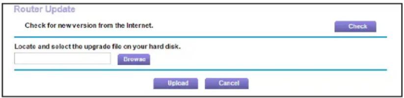
text_image
Router Update Check for new version from the Internet. Check Locate and select the upgrade file on your hard disk. Browse Upload Cancel2. Click Check.
The router finds new firmware information if any is available.
3. Click Ye s.
The router locates the firmware you downloaded (the file ends in .img) and begins the update.

WARNING:
When uploading firmware to the router, do not interrupt the web browser by closing the window, clicking a link, or loading a new page. If the browser is interrupted, it could corrupt the firmware.
When the upload is complete, your router restarts. The upgrade process typically takes about 1 minute. Read the new firmware release notes to determine whether you need to reconfigure the router after upgrading.
View Router Status
To view router status and usage information:
Select Advanced Home or select Administration > Router Status.

text_image
Router Information Hardware Version R6250 Firmware Version V1.0.0.44_1.0.44 GUI Language Version V1.0.0.44_2.1.17.1 LAN Port MAC Address 9C:D3:6D:99:C1:9A IP Address 192.168.1.1 DHCP On Reboot Internet Port MAC Address 9C:D3:6D:99:C1:9B IP Address 10.1.10.11 Connection DHCP IP Subnet Mask 255.255.255.0 Domain Name Server 75.75.75.75 75.75.76.76 Show Statistics Connection Status Wireless Settings (2.4GHz) Name (SSID) NETGEAR47 Region North America Channel Auto (1) Mode Up to 145 Mbps Wireless AP On Broadcast Name On Wi-Fi Protected Setup Configured Wireless Settings (5GHz) Name (SSID) NETGEAR47-5G Region North America Channel 149 + 153(P) + 157 + 161 Mode Up to 1300 Mbps Wireless AP On Broadcast Name On Wi-Fi Protected Setup ConfiguredRouter Information
Hardware Version. The router model.
Firmware Version. The version of the router firmware. It changes if you upgrade the router firmware.
GUI Language Version. The localized language of the user interface.
LAN Port.
- MAC Address. The Media Access Control address. This is the unique physical address used by the Ethernet (LAN) port of the router.
- IP Address. The IP address used by the Ethernet (LAN) port of the router. The default is 192.168.1.1.
- DHCP. Identifies whether the router's built-in DHCP server is active for devices on the LAN.
Internet Port
MAC Address. The Media Access Control address, which is the unique physical address used by the Internet (WAN) port of the router.
IP Address. The IP address used by the Internet (WAN) port of the router. If no address is shown or the address is 0.0.0, the router cannot connect to the Internet.
Connection. This shows if the router is using a fixed IP address on the WAN. If the value is DHCP Client, the router obtains an IP address dynamically from the ISP.
IP Subnet Mask. The IP subnet mask used by the Internet (WAN) port of the router.
Domain Name Server. The Domain Name Server addresses used by the router. A Domain Name Server translates human-language URLs such as www.netgear.com into IP addresses.
Show Statistics Button
To view statistics:
- Select Advanced Home or select Administration > Router Status.
- In the Internet Provider (W AN) Setup pane, click the Show Statistics button.
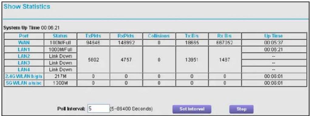
text_image
Show Statistics System Up Time 00:06:21 Port Status TxPkts RxPkts Collisions Tx B/s Rx B/s Up Time WAN 100M/Full 94846 148992 0 18685 667052 00:05:37 LAN1 1000M/Full 5802 4757 0 13951 1487 00:06:21 LAN2 Link Down LAN3 Link Down LAN4 Link Down 2.4G WLAN b/g/n 217M 0 0 0 0 0 00:06:01 5G WLAN a/n/ac 1300M 0 0 0 0 0 00:06:01 Poll Interval: 5 (5~86400 Seconds) Set Interval StopThe following information is displayed:
System Up Time. The time elapsed since the router was last restarted.
Port. The statistics for the WAN (Internet) and LAN (Ethernet) ports. For each port, the screen displays:
• Status. The link status of the port.
- TxPkts. The number of packets transmitted on this port since reset or manual clear.
- RxPkts. The number of packets received on this port since reset or manual clear.
• Collisions. The number of collisions on this port since reset or manual clear.
- Tx B/s. The current transmission (outbound) bandwidth used on the WAN and LAN ports.
- Rx B/s. The current reception (inbound) bandwidth used on the WAN and LAN ports.
- Up T ime. The time elapsed since this port acquired the link.
- Poll Interval. The interval at which the statistics are updated in this screen.
To change the polling frequency, enter a time in seconds in the Poll Interval field and click Set Interval.
To stop the polling entirely, click Stop.
Connection Status Button
To view the Internet connection status:
- Select Advanced Home or select Administration > Router Status.
- In the Internet Connection pane, click the Connection Status button.
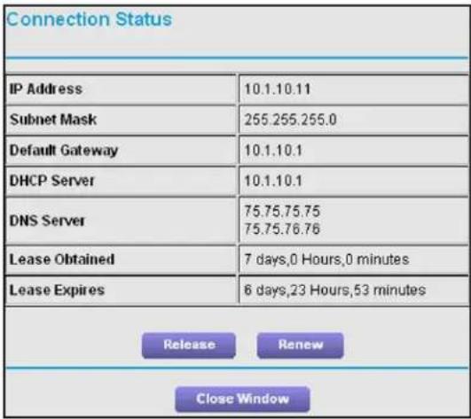
text_image
Connection Status IP Address 10.1.10.11 Subnet Mask 255.255.255.0 Default Gateway 10.1.10.1 DHCP Server 10.1.10.1 DNS Server 75.75.75.75 75.75.76.76 Lease Obtained 7 days,0 Hours,0 minutes Lease Expires 6 days,23 Hours,53 minutes Release Renew Close WindowThe following information displays:
- IP Address. The IP address that is assigned to the router.
- Subnet Mask. The subnet mask that is assigned to the router.
- Default Gateway. The IP address for the default gateway that the router communicates with.
- DHCP Server. The IP address for the Dynamic Host Configuration Protocol server that provides the TCP/IP configuration for all the computers that are connected to the router.
- DNS Server. The IP address of the Domain Name Service server that provides translation of network names to IP addresses.
- Lease Obtained. The date and time when the lease was obtained.
- Lease Expires. The date and time that the lease expires.
Click the Release button to return the status of all items to 0.
Click the Renew button to refreshes the items.
Click the Close Window button to close the Connection Status screen.
Wireless Settings (2.4 GHz and 5 GHz)
The following settings are displayed:
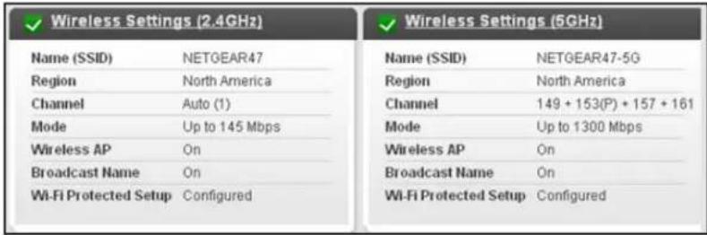
text_image
Wireless Settings (2.4GHz) Name (SSID) NETGEAR47 Region North America Channel Auto (1) Mode Up to 145 Mbps Wireless AP On Broadcast Name On Wi-Fi Protected Setup Configured Wireless Settings (5GHz) Name (SSID) NETGEAR47-5G Region North America Channel 149 + 153(P) + 157 + 161 Mode Up to 1300 Mbps Wireless AP On Broadcast Name On Wi-Fi Protected Setup ConfiguredName (SSID). The wireless network name (SSID) that the router uses.
Region. The geographic region where the router is being used. It might be illegal to use the wireless features of the router in some parts of the world.
Channel. The operating channel of the wireless port being used. The default channel is Auto. When Auto is selected, the router finds the best operating channel available. Channels 1, 6, and 11 do not interfere with each other.
Mode. The wireless communication mode. At 2.4 GHz, 300 Mbps, 145 Mbps, or Up to 54 Mbps. At 5 GHz 1300 Mbps, 600 Mbps, or Up to 289 Mbps.
Wireless AP. Indicates whether the radio feature of the router is enabled. If this feature is not enabled, the WiFi LED on the front panel is off.
Broadcast Name. Indicates whether the router is broadcasting its SSID.
Wi-Fi Protected Setup. Indicates whether WPS is configured for this network.
View Logs of Web Access or Attempted Web Access
The log is a detailed record of the websites you have accessed or attempted to access. Up to 256 entries are stored in the log. Log entries display only when keyword blocking is enabled and no log entries are made for the trusted user.
To view logs:
Select Advanced > Administration > Logs.
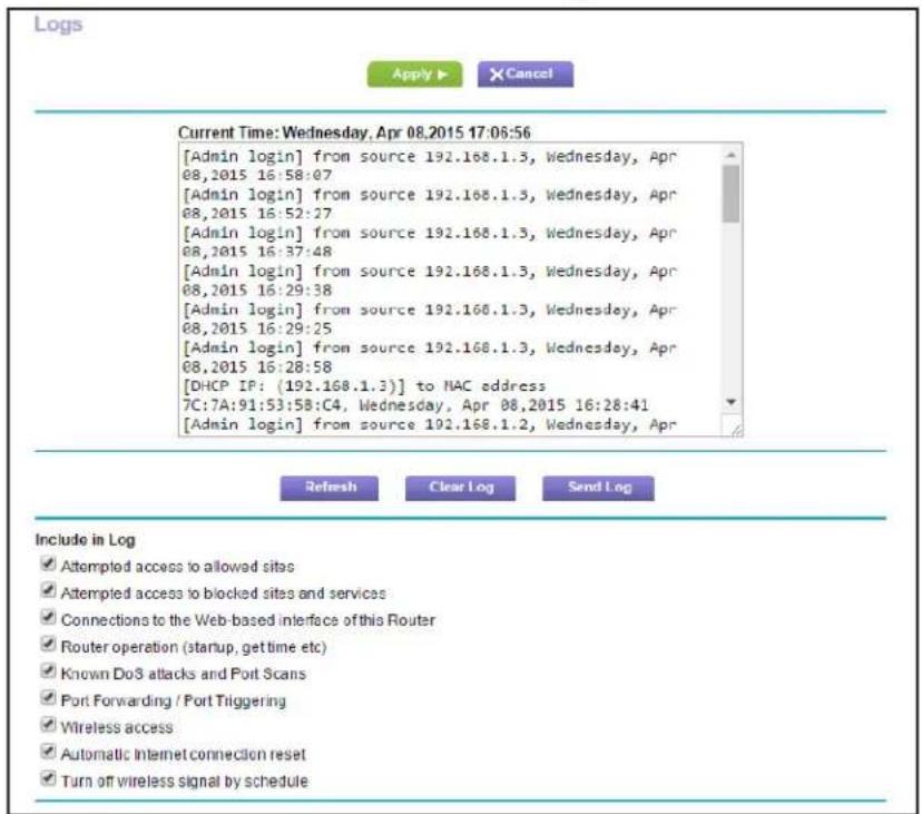
text_image
Logs Apply ▶ × Cancel Current Time: Wednesday, Apr 08.2015 17:06:56 [Admin login] from source 192.168.1.3, Wednesday, Apr 08.2015 16:58:07 [Admin login] from source 192.168.1.3, Wednesday, Apr 08.2015 16:52:27 [Admin login] from source 192.168.1.3, Wednesday, Apr 08.2015 16:37:48 [Admin login] from source 192.168.1.3, Wednesday, Apr 08.2015 16:29:38 [Admin login] from source 192.168.1.3, Wednesday, Apr 08.2015 16:29:25 [Admin login] from source 192.168.1.3, Wednesday, Apr 08.2015 16:28:58 [DHCP IP: (192.168.1.3)] to MAC address 7C:7A:91:53:58:C4, Wednesday, Apr 08.2015 16:28:41 [Admin login] from source 192.168.1.2, Wednesday, Apr Refresh Clear Log Send Log Include in Log ✓ Attempted access to allowed sites ✓ Attempted access to blocked sites and services ✓ Connections to the Web-based interface of this Router ✓ Router operation (startup, get time etc) ✓ Known Do3 attacks and Port Scans ✓ Port Forwarding / Port Triggering ✓ Wireless access ✓ Automatic Internet connection reset ✓ Turn off wireless signal by scheduleThe log screen shows the following information:
- Date and time. The date and time the log entry was recorded.
- Source IP. The IP address of the initiating device for this log entry.
- T target address. The name or IP address of the website or news group visited or to which access was attempted.
• Action. Whether the access was blocked or allowed.
To refresh the log screen, click the Refresh button.
To clear the log entries, click the Clear Log button.
To email the log immediately, click the Send Log button.
Manage the Configuration File
The configuration settings of the router are stored within the router in a configuration file. You can back up (save) this file to your computer, restore it, or reset it to the factory default settings.
Back Up Settings
To back up the router's configuration settings:
1. Select Advanced > Administration > Backup Settings.

text_image
Backup Settings Save a copy of current settings Back Up Restore saved settings from a file Browse Restore Revert to factory default settings Erase2. Click Backup Settings.
A copy of the current settings is saved.
- Choose a location to store the .cfg file that is on a computer on your network.
Restore Configuration Settings
To restore configuration settings that you backed up:
- Click the Browse button to find the cfg file.
- Click the Restore button.
The files is uploaded to the router and the router reboots.

WARNING:
Do not interrupt the reboot process.
Erase the Current Configuration Settings
You can use the Erase button to erase the configuration and restore the factory default settings. You might want to do this if you move the router to a different network. You can also use the Reset button on the back of the router to erase the configuration and restore the factory settings. (See Factory Settings on page 129).
To erase the configuration settings:
Click the Erase button.
The factory default settings are restored. The user name is admin, the password to password, and the LAN IP address is 192.168.1.1. DHCP is enabled.
Change the Password
This feature let you change the default password that is used to log in to the router with the user name admin.
This is not the same as changing the password for wireless access. The label on the bottom of your router shows your unique wireless network name (SSID) and password for wireless access (see Label on page 11).
To set the password for the user name admin:
1. Select Advanced > Administration > Set Password.
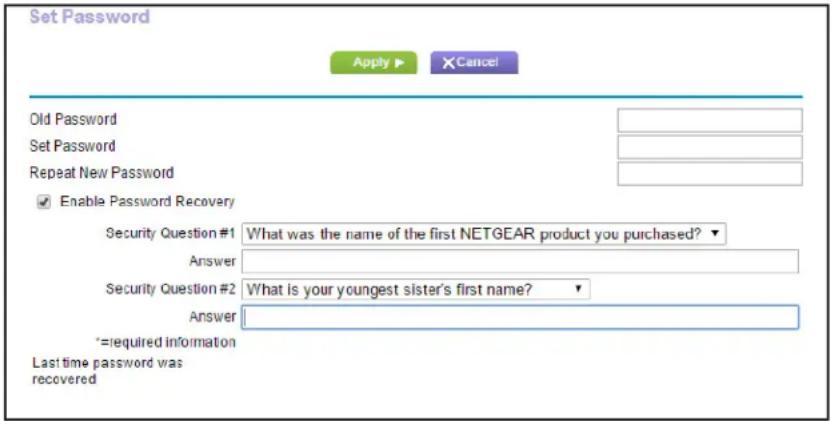
text_image
Set Password Apply ▶ ×Cancel Old Password Set Password Repeat New Password Enable Password Recovery Security Question #1 What was the name of the first NETGEAR product you purchased? Answer Security Question #2 What is your youngest sister's first name? Answer *=required information Last time password was recovered- On the Set Password screen, type the old password, and type the new password twice.
- If you want to be able to recover the password, select the Enable Password Recovery check box.
- Click Apply.
Your changes take effect.
Password Recovery
NETGEAR recommends that you enable password recovery if you change the password for the router user name admin. Then you can recover the password if it is forgotten. This recovery process is supported in Internet Explorer, Firefox, and Chrome browsers, but not in the Safari browser.
To set up password recovery:
- Select Advanced > Administration > Set Password.
- Select the Enable Password Recovery check box.
- Select two security questions, and provide answers to them.
- Click Apply.
Your changes are saved.
To recover your password:
- In the address field of your browser, type www.routerlogin.net.
A login screen displays.
- Click the Cancel button.
If password recovery is enabled, you are prompted to enter the serial number of the router.
The serial number is on the product label.
-
Enter the serial number of the router.
-
Click the Continue button.
A screen displays requesting the answers to your security questions.
-
Enter the saved answers to your security questions.
-
Click the Continue button.
A screen displays your recovered password.
- Click the Login again button.
A login screen displays.
- With your recovered password, log in to the router.
Advanced Settings

Setting up unique situations
This chapter describes the advanced features of your router. Networking knowledge is needed to implement some of these features.
This chapter includes the following sections:
• Advanced Wireless Settings
• Wireless Access Point (AP)
- Dynamic DNS
- Static Routes
- Remote Management
• Universal Plug and Play
• IPv6
- Traffic Meter
For information about the Approve USB feature, see Specify Approved USB Devices on page 52.
Advanced Wireless Settings
You can use this screen to turn the wireless radio on and off, to specify WPS settings, to use AP mode, and to set up a wireless access list.
The Fragmentation Length, CTS/RTS Threshold, and Preamble Mode options in this screen are reserved for wireless testing and advanced configuration only. Do not change these settings unless you have a specific reason to do so.
Control the Wireless Radio
By default, the wireless radio is enabled so that you can connect wirelessly to the router. You can turn the wireless radio on or off in the Advanced Wireless Settings screen or by using the WiFi On/Off button on the router front panel. When the wireless radio is off, you can still use an Ethernet cable for a LAN connection to the router
To turn the wireless radio on or off:
1. Select Advanced > Advanced Setup > Wireless Settings.
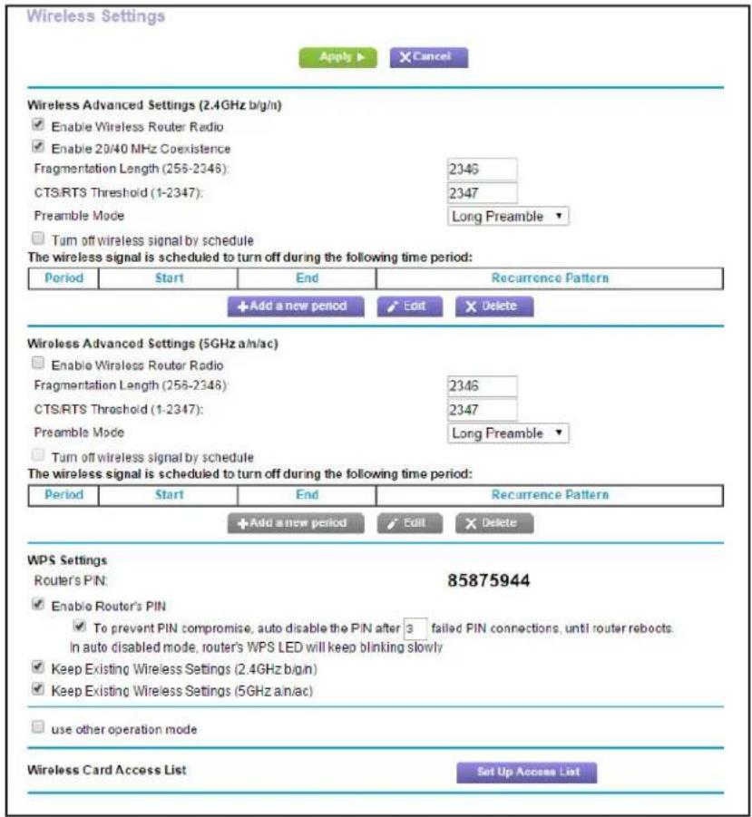
text_image
Wireless Settings Apply ▶ × Cancel Wireless Advanced Settings (2.4GHz b/g/n) ✓ Enable Wireless Router Radio ✓ Enable 20/40 MHz Coexistence Fragmentation Length (256-2346): 2346 CTS/RTS Threshold (1-2347): 2347 Preamble Mode Long Preamble ▼ □ Turn off wireless signal by schedule The wireless signal is scheduled to turn off during the following time period: Period Start End Recurrence Pattern + Add a new period ✓ Edit ✗ Delete Wireless Advanced Settings (5GHz a/n/ac) □ Enable Wireless Router Radio Fragmentation Length (256-2346): 2346 CTS/RTS Threshold (1-2347): 2347 Preamble Mode Long Preamble ▼ □ Turn off wireless signal by schedule The wireless signal is scheduled to turn off during the following time period: Period Start End Recurrence Pattern + Add a new period ✓ Edit ✗ Delete WPS Settings Router's PIN: 85875944 ✓ Enable Router's PIN ✓ To prevent PIN compromise, auto disable the PIN after 3 failed PIN connections, until router rebocts. in auto disabled mode, router's WPS LED will keep blinking slowly ✓ Keep Existing Wireless Settings (2.4GHz b/g/n) ✓ Keep Existing Wireless Settings (5GHz a/n/ac) □ use other operation mode Wireless Card Access List Set Up Access ListBy default, the Enable Wireless Router Radio check box is selected.
- Select or clear the Enable Wireless Router Radio check box.
Clearing this check box turns off the WiFi feature of the wireless router.
- (Optional) Select the T urn off wireless signal by schedule check box and fill in the fields to specify the times when you do not need a wireless connection.
For example, you could turn off the wireless signal for the weekend if you leave town.
- Click Apply.
Your changes take effect.
Set Up a Wireless Schedule
You can use this feature to turn off the wireless signal from your router at times when you do not need a wireless connection. For example, you could turn it off for the weekend if you leave town.
To configure and enable the wireless schedule:
- Select Advanced > Advanced Setup > Wireless Settings.
The Advanced Wireless Settings screen displays.
- Click the Add a new period button.
The screen adjusts:

text_image
Turn off wireless signal by schedule Apply ▶ X Cancel When to turn off wireless signal Start: 12:00midnight End: 12:00noon Recurrence Pattern ● Daily ○ Select Days □ Sunday □ Monday □ Tuesday □ Wednesday □ Thursday □ Friday □ Saturday- Use the menus, radio buttons, and check boxes to set up a period during which you want to turn off the wireless signal.
- Click the Apply button.
The Advanced Wireless Settings screen displays.
- Select the T urn off wireless signal by schedule check box.
This activates the schedule.
- Click the Apply button.
Set up the Router in Bridge Mode
You can set up your R6250 Smart WiFi Router to run in Bridge mode. This mode lets you connect multiple devices wirelessly at the faster 802.11ac speed. To use the router in Bridge mode, you need two WiFi Routers: one set up as a router and the other set up as a bridge.
R6250 Smart WiFi Router in Bridge modeR6300 Smart WiFi Router

text_image
Diagram showing two network device connections: one with a router and Internet connection, the other with a network device connected to a computer.Figure 6. Router in Bridge mode with an 802.11ac WiFi connection
Installing your R6250 Smart WiFi Router as a bridge offers the following benefits:
- Y ou can take advantage of gigabit WiFi speeds on current devices.
- Use Gigabit WiFi for applications like video and gaming.
- Connect multiple devices like NAS, Smart TV, NeoTV, Blu-ray Player, game console at gigabit WiFi speeds using a WiFi link.
- A void the need for separate WiFi adapters for each device.
For example, you could install the first router in a room like a home office that has your Internet connection. After this router is powered on and set up, set up the second router in Bridge mode. Then place the router in Bridge mode in a different room that has your home entertainment center. Cable the router in Bridge mode to your Smart TV, DVR, game console or Blu-ray player and use its 802.11ac WiFi connection to the first R6300 router.
To set up Bridge mode:
- Make a note of the WiFi settings of the other router to which this router will connect: You need to know the SSID, WiFi security mode, wireless password, and operating frequency (either 2.4 GHz or 5 GHz).
-
On the R6250 Smart WiFi Router that will run in Bridge mode, select Advanced > Advanced Setup > Wireless Settings.
-
Scroll down and select the Use other operation mode check box and the Enable Bridge mode radio button.
The screen adjusts.
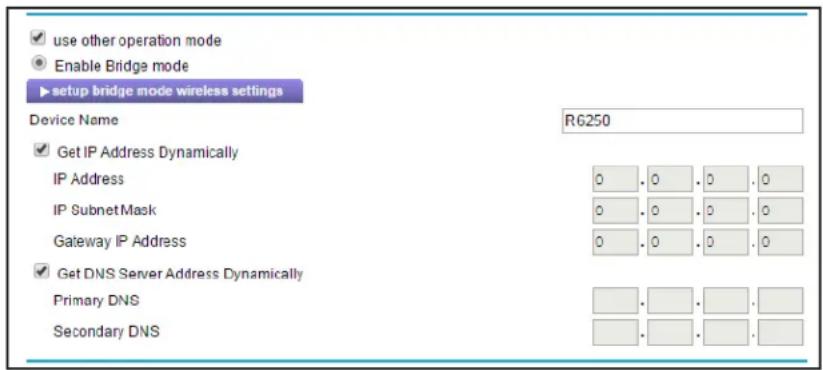
text_image
use other operation mode Enable Bridge mode setup bridge mode wireless settings Device Name R6250 Get IP Address Dynamically IP Address 0 . 0 . 0 . 0 IP SubnetMask 0 . 0 . 0 . 0 Gateway IP Address 0 . 0 . 0 . 0 Get DNS Server Address Dynamically Primary DNS . . . . Secondary DNS- Click the setup bridge mode wireless settings button.

text_image
Wireless Settings Apply ▶ X Cancel Choose a Wireless Networks: Wireless Networks (2.4Ghz b/g/n) Name (SSID): NETGEAR65 Security Options None WEP WPA-PSK [TKIP] WPA2-PSK [AES] WPA-PSK [TKIP] + WPA2-PSK [AES] Password (Network Key): rusticbug325 (8-63 characters or 84 hex digits)- Specify the settings of the other router to which this router will connect.
a. Select the wireless network frequency (2.4 GHz or 5 GHz).
For 802.11ac mode, select 5 GHz.
b. In the Name (SSID) field, enter the wireless network name (SSID).
c. In the Security Option section, select a radio button.
d. If prompted, type the passphrase (the WiFi password that you use to connect wirelessly to the other router).
- Click Apply.
The settings for the other router are saved and the Advanced Wireless Settings screen displays.
- Click Apply on the Wireless Settings screen.
Your changes take effect.
View or Change WPS Settings
To specify WPS Settings:
- Select Advanced > Advanced Setup > Wireless Settings.
The Router's PIN field displays the PIN that you use on a registrar (for example, from the Network Explorer on a Vista Windows computer) to configure the router's wireless settings through WPS.
- (Optional) Select or clear the Disable Router's PIN check box.
The PIN function might temporarily be disabled when the router detects suspicious attempts to break into the router's wireless settings by using the router's PIN through WPS. You can manually enable the PIN function by clearing the Disable Router's PIN check box.
- (Optional) Select or clear the Keep Existing Wireless Settings check box.
By default, the Keep Existing Wireless Settings check box is selected. NETGEAR recommends that you leave this check box selected.
If you clear this check box, the next time a new wireless client uses WPS to connect to the router, the router wireless settings change to an automatically generated random SSID and security key.
- Click Apply.
Your changes are saved.
Set Up a Wireless Access List by MAC Address
You can set up a list of computers and wireless devices that are allowed to join the wireless network. This list is based on the unique MAC address of each computer and device.
Each network device has a MAC address, which is a unique 12-character physical address, containing the hexadecimal characters 0–9, a–f, or A–F only, and separated by colons (for example, 00:09:AB:CD:EF:01). Typically, the MAC address is on the label of the wireless card or network interface device. If you do not have access to the label, you can display the MAC address using the network configuration utilities of the computer. You might also find the MAC addresses in the Attached Devices screen.
To restrict access based on MAC addresses:
- Select Advanced > Advanced Setup > Wireless Settings.
- Click the Setup Access List button.

text_image
Wireless Card Access List Apply ▶ ×Cancel Turn Access Control On Device Name MAC Address Add Edit Delete3. Click Add.
The Wireless Card Access Setup screen opens and displays a list of currently active wireless cards and their Ethernet MAC addresses.
- If the computer or device you want is in the Available Wireless Cards list, select that radio button; otherwise, type a name and the MAC address.
You can usually find the MAC address on the bottom of the wireless device.
Tip: You can copy and paste the MAC addresses from the Attached Devices screen into the MAC Address field of this screen. To do this, use each wireless computer to join the wireless network. The computer should then display in the Attached Devices screen.
5. Click Add.
The screen changes back to the list screen.
- Add each computer or device you want to allow to connect wirelessly.
- Select the T urn Access Control On check box.
- Click Apply.
To edit a wireless device or delete it from the access list:
- Select Advanced > Advanced Setup > Wireless Settings.
The Advanced Wireless Settings screen displays.
- In the table, select the radio button next to the wireless device that you want to edit or delete.
- Do one of the following:
- Click the Edit button.
The Edit Wireless Card screen displays.
a. Edit the address information.
b. Click the Accept button.
- Click the Delete button.
The address is removed from the table.
Wireless Access Point (AP)
You can set up the router to run as an access point (AP) on the same local network as another router.
To set up the router as an AP:
- Use an Ethernet cable to connect the Internet port of this router to a LAN port in the other router.
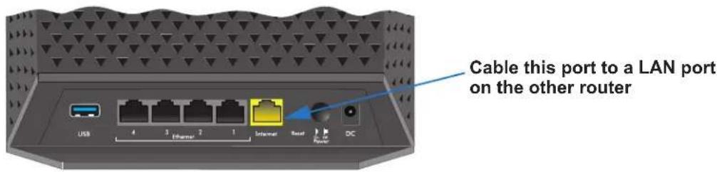
text_image
Cable this port to a LAN port on the other router- Select Advanced > Advanced Setup > Wireless AP.
- Select the Enable Access Point Mode check box.
The AP Mode section of the screen expands.
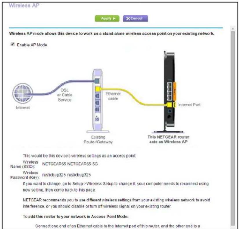
text_image
Wireless AP Apply ▶ X Cancel Wireless AP mode allows this device to work as a stand-alone wireless access point on your existing network. Enable AP Mode Internet DSL or Cable Service Ethernet cable Internet Port Existing Router/Gateway This NETGEAR router acts as Wireless AP This would be this device's wireless settings as an access point Wireless NETGEAR65 NETGEAR65-5G Name (SSID): NETGEAR65 NETGEAR65-5G Wireless rusticbug325 rusticbug325 Password (Key): If you want to change, go to Setup->Wireless Setup to change it your computer needs to reconnect using new setting, then come back to this page NETGEAR recommends you to use different wireless settings from your existing wireless network to avoid interference, or you should disable or turn off wireless signal on your existing router. To add this router to your network in Access Point Mode: Connect one end of an Ethernet cable to the Internet port of this router, and the other end to a-
Scroll down and select the check box for the IP address setting that you want to use:
-
Get an IP address dynamically from the other router. The other router on the network assigns an IP address to this router while this router is in AP mode.
- Fixed IP address (not recommended). Use this setting if you want to manually assign a specific IP address to this router while it is in AP mode. Using this option effectively requires advanced network experience.
Note: If the other router or gateway in your network has wireless capability, NETGEAR recommends that you use different wireless settings on this router to avoid interference. You can also disable the wireless radio on the other router or gateway and use your router only for wireless client access.
5. Click the Apply button.
The IP address of the router changes, and you are disconnected. To reconnect, close and restart your web browser, and type http://www.routerlogin.net.
Dynamic DNS
Internet service providers (ISPs) assign numbers called IP addresses to identify each Internet account. Most ISPs use dynamically assigned IP addresses. This means that the IP address can change at any time. You can use the IP address to access your network remotely, but most people don't know what their IP addresses are or when this number changes.
To make it easier to connect, you can get a free account with a Dynamic DNS service that lets you use a domain name to access your home network. To use this account, you must set up the router to use Dynamic DNS. Then the router notifies the Dynamic DNS service provider whenever its IP address changes. When you access your Dynamic DNS account, the service finds the current IP address of your home network and automatically connects you.
If your ISP assigns a private WAN IP address (such as 192.168.x.x or 10.x.x.x), the Dynamic DNS service does not work because private addresses are not routed on the Internet.
Set Up a New Dynamic DNS Account
To set up Dynamic DNS and register for a free NETGEAR account:
- Launch an Internet browser from a computer or wireless device that is connected to the network.
- Type http://www.routerlogin.net or http://www.routerlogin.com.
A login screen displays.
- Enter the router user name and password.
The user name is admin. The default password is password. The user name and password are case-sensitive.
The BASIC Home screen displays.
- Select ADV ANCED > Advanced Setup > Dynamic DNS.
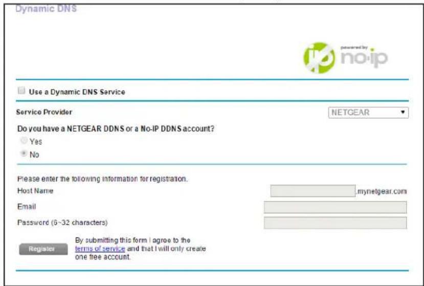
text_image
Dynamic DNS Use a Dynamic DNS Service Service Provider NETGEAR Do you have a NETGEAR DDNS or a No-IP DDNS account? Yes No Please enter the following information for registration. Host Name mynetgear.com Email Password (6-32 characters) Register By submitting this form I agree to the terms of service and that I will only create one free account.- Select the Use a Dynamic DNS Service check box.
- In the Service Provider list, select NETGEAR.
- Select the No radio button.
- In the Host Name field, type the name that you want to use for your URL.
The host name is sometimes called the domain name. Your free URL includes the host name that you specify, and ends with mynetgear.com. For example, specify MyName.mynetgear.com.
- In the Email field, type the email address that you want to use for your account.
- In the Password (6-32 characters) field, type the password for your account.
- Click the Register button.
- Follow the onscreen instructions to register for your NETGEAR Dynamic DNS service.
- To check that Dynamic DNS is enabled in the router, click the Show Status button.
A message displays the Dynamic DNS status.
Specify a DNS Account That You Already Have
If you already have a Dynamic DNS account with NETGEAR no-ip, www.NoIP.com, or www.DynDNS.org, you can set up the router to use your account.
To set up Dynamic DNS if you already have an account:
- Launch an Internet browser from a computer or wireless device that is connected to the network.
- Type http://www.routerlogin.net or http://www.routerlogin.com.
A login screen displays.
- Enter the router user name and password.
The user name is admin. The default password is password. The user name and password are case-sensitive.
The BASIC Home screen displays.
- Select ADV ANCED > Advanced Setup > Dynamic DNS.

text_image
Dynamic DNS Use a Dynamic DNS Service Service Provider NETGEAR Do you have a NETGEAR DDNS or a No-IP DDNS account? Yes No Please enter the following information for registration. Host Name mynetgear.com Email Password (6-32 characters) Register By submitting this form I agree to the terms of service and that I will only create one free account.- Select the Use a Dynamic DNS Service check box.
- In the Service Provider list, select one of the following:
• NETGEAR
- NoIP .com
- www .DynDNS.org
- Select the Ye s radio button.
The screen adjusts and displays the Show Status, Cancel, and Apply buttons.
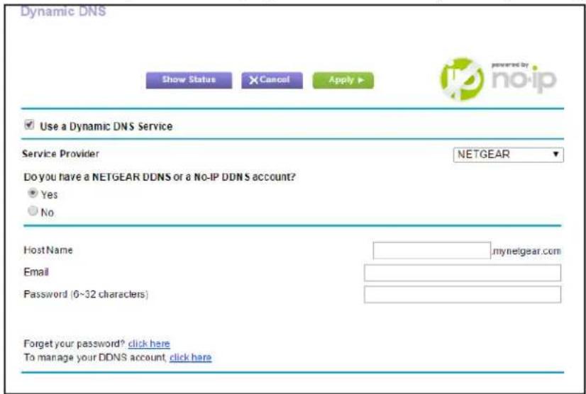
text_image
Dynamic DNS Show Status Cancel Apply Use a Dynamic DNS Service Service Provider NETGEAR Do you have a NETGEAR DDNS or a No-IP DDNS account? Yes No HostName mynetgear.com Email Password (6~32 characters) Forget your password? click here To manage your DDNS account click here- In the Host Name field, type the host name (sometimes called the domain name) for your account.
- For a www .NoIP or www.DynDNS account, in the User Name field, enter the user name for your account.
- For a NETGEAR account at www.no-ip, in the Email field, type the email address for your account.
- In the Password (6-32 characters) field, type the password for your DDNS account.
- Click the Apply button.
Your changes are saved.
- To verify that your Dynamic DNS service is enabled in the router, click the Show Status button.
A message displays the Dynamic DNS status.
Change the Dynamic DNS Settings
To change your settings:
- Launch an Internet browser from a computer or wireless device that is connected to the network.
- Type http://www.routerlogin.net or http://www.routerlogin.com.
A login screen displays.
- Enter the router user name and password.
The user name is admin. The default password is password. The user name and password are case-sensitive.
The BASIC Home screen displays.
- Select ADVANCED > Advanced Setup > Dynamic DNS.
- Change your DDNS account settings as necessary.
- Click the Apply button.
Your changes are saved.
Static Routes
Static routes provide more routing information to your router. Typically, you do not need to add static routes. You have to configure static routes only for unusual cases such as multiple routers or multiple IP subnets on your network.
As an example of when a static route is needed, consider the following case:
- Your primary Internet access is through a cable modem to an ISP.
- You have an ISDN router on your home network for connecting to the company where you are employed. This router's address on your LAN is 192.168.1.100.
- Your company's network address is 134.177.0.0.
When you first configured your router, two implicit static routes were created. A default route was created with your ISP as the gateway, and a second static route was created to your local network for all 192.168.1.x addresses. With this configuration, if you attempt to access a device on the 134.177.0.0 network, your router forwards your request to the ISP. The ISP forwards your request to the company where you are employed, and the request is likely to be denied by the company's firewall.
In this case you have to define a static route, telling your router that 134.177.0.0 should be accessed through the ISDN router at 192.168.1.100. In this example:
- The Destination IP Address and IP Subnet Mask fields specify that this static route applies to all 134.177.x.x addresses.
- The Gateway IP Address field specifies that all traffic for these addresses should be forwarded to the ISDN router at 192.168.1.100.
- A metric value of 1 works because the ISDN router is on the LAN.
- Private is selected only as a precautionary security measure in case RIP is activated.
To set up a static route:
- Select Advanced > Advanced Setup > Static Routes.
2. Click Add.

text_image
Static Routes Apply ▶ XCancel Route Name Private Active Destination IP Address IP Subnet Mask Gateway IP Address Metric- In the Route Name field, type a name for this static route (for identification purposes only.)
- Select the Private check box if you want to limit access to the LAN only.
If Private is selected, the static route is not reported in RIP.
- Select the Active check box to make this route effective.
- Type the IP address of the final destination.
- Type the IP subnet mask for this destination. If the destination is a single host, type 255.255.255.255.
- Type the gateway IP address, which has to be on the same LAN segment as the router.
- Type a number from 1 through 15 as the metric value.
This value represents the number of routers between your network and the destination. Usually, a setting of 2 or 3 works, but if this is a direct connection, set it to 1.
- Click the Apply button.
The static route is added.
To edit or delete a static route:
- Select Advanced > Advanced Setup > Static Routes.
The Static Routes screen displays. - In the table, select the radio button next to the route that you want to edit or delete.
- Do one of the following:
- Click the Edit button.
The Static Routes screen adjusts.
a. Edit the route information.
b. Click the Apply button.
- Click the Delete button.
The route is removed from the table.
Remote Management
The remote management feature lets you access your router over the Internet to view or change its settings.
Note: Be sure to change the router default login password to a secure password. The ideal password contains no dictionary words from any language and contains uppercase and lowercase letters, numbers, and symbols. It can be up to 30 characters. See Change the Password on page 90.
To set up remote management:
- Select Advanced > Advanced Setup > Remote Management.
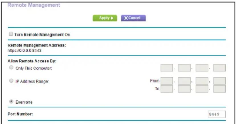
text_image
Remote Management Apply ▶ X Cancel Turn Remote Management On Remote Management Address: https://0.0.0.8443 Allow Remote Access By: Only This Computer: IP Address Range: From To: Everyone Port Number: 8443- Select the Turn Remote Management On check box.
- Under Allow Remote Access By, specify the external IP addresses to be allowed to access the router's remote management.
Note: For enhanced security, restrict access to as few external IP addresses as practical.
- T o allow access from a single IP address on the Internet, select Only This Computer. Enter the IP address that will be allowed access.
- T o allow access from a range of IP addresses on the Internet, select IP Address Range. Enter a beginning and ending IP address to define the allowed range.
- T o specify IP addresses, select IP Address List and type in the allowed IP addresses.
-
T o allow access from any IP address on the Internet, select Everyone.
-
Specify the port number for accessing the web management interface.
Normal web browser access uses the standard HTTP service port 80. For greater security, enter a custom port number for the remote web management interface. Choose a number from 1024 to 65535, but do not use the number of any common service port. The default is 8080, which is a common alternate for HTTP.
- Click the Apply button.
Your changes take effect.
- When you access your router from the Internet, type your router's WAN IP address into your browser's address or location field followed by a colon (:) and the custom port number.
For example, if your external address is 134.177.0.123 and you use port number 8080, enter http://134.177.0.123:8080 in your browser.
Universal Plug and Play
Universal Plug and Play (UPnP) helps devices, such as Internet appliances and computers, access the network and connect to other devices as needed. UPnP devices can automatically discover the services from other registered UPnP devices on the network.
If you use applications such as multiplayer gaming, peer-to-peer connections, or real-time communications such as instant messaging or remote assistance (a feature in Windows XP), you should enable UPnP.
To turn on Universal Plug and Play:
- Select Advanced > Advanced Setup > UPnP.
The UPnP screen displays.
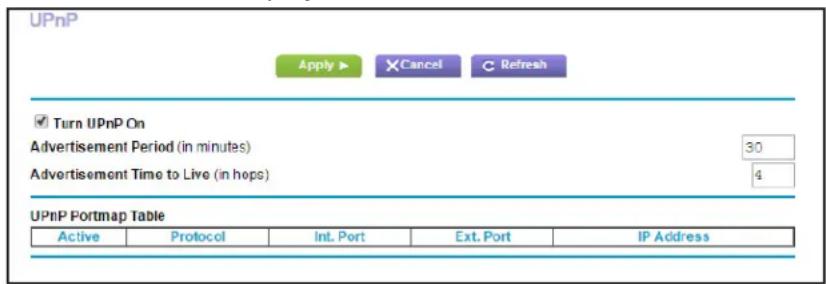
text_image
UPnP Apply ▶ XCancel C Refresh ✓ Turn UPnP On Advertisement Period (in minutes) 30 Advertisement Time to Live (in hops) 4 UPnP Portmap Table Active Protocol Int. Port Ext. Port IP Address- Select the Turn UPnP On check box.
By default, this check box is selected. UPnP for automatic device configuration can be enabled or disabled. If the Turn UPnP On check box is cleared, the router does not allow any device to automatically control the resources, such as port forwarding (mapping), of the router.
- Type the advertisement period in minutes.
The advertisement period specifies how often the router broadcasts its UPnP information. This value can range from 1 to 1440 minutes. The default period is 30 minutes. Shorter durations ensure that control points have current device status at the expense of more
network traffic. Longer durations can compromise the freshness of the device status, but can significantly reduce network traffic.
- Type the advertisement time to live in hops.
The time to live for the advertisement is measured in hops (steps) for each UPnP packet sent. The time to live hop count is the number of steps a broadcast packet is allowed to propagate for each UPnP advertisement before it disappears. The number of hops can range from 1 to 255. The default value for the advertisement time to live is 4 hops, which should be fine for most home networks. If you notice that some devices are not being updated or reached correctly, it might be necessary to increase this value.
- Click the Apply button.
The UPnP Portmap Table displays the IP address of each UPnP device that is accessing the router and which ports (internal and external) that device has opened. The UPnP Portmap Table also displays what type of port is open and whether that port is still active for each IP address.
- (Optional) To refresh the information in the UPnP Portmap Table, click the Refresh button.
IPv6
You can use this feature to set up an IPv6 Internet connection type if genie does not detect it automatically.
To set up an IPv6 Internet connection type:
- Select Advanced > Advanced Setup > IPv6.

text_image
Basic Settings Apply ▶ X Cancel Internet Connection Type Disabled Disabled Auto Detect 6104 Tunnel Pass Through Fixed DHCP PPPoE Auto Config- In the Internet Connection Type list, select the IPv6 connection type.
Your Internet service provider (ISP) can provide this information.
- If your ISP did not provide details, you can select IPv6 T unnel.
- If you are not sure, select Auto Detect so that the router detects the IPv6 type that is in use.
- If your Internet connection does not use PPPoE, DHCP , or fixed, but is IPv6, select Auto Config.
For more detailed information about Internet connection types, see the following sections.
3. Click the Apply button.
Your changes take effect.
Requirements for Entering IPv6 Addresses
IPv6 addresses are denoted by eight groups of hexadecimal quartets that are separated by colons. Any four-digit group of zeroes within an IPv6 address can be reduced to a single zero or altogether omitted.
The following errors invalidate an IPv6 address:
• More than eight groups of hexadecimal quartets
• More than four hexadecimal characters in a quartet
• More than two colons in a row
Auto Detect
To set up an IPv6 Internet connection through auto detection:
- Select Advanced > Advanced Setup > IPv6.
The IPv6 screen displays.
- In the Internet Connection Type list, select Auto Detect.
The screen adjusts:
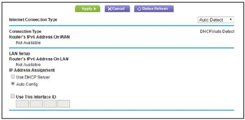
text_image
Apply ▶ XCancel G Status Refresh Internet Connection Type Auto Detect ▼ Connection Type DHCP/Auto Detect Router's IPv6 Address On WAN Not Available LAN Setup Router's IPv6 Address On LAN Not Available IP Address Assignment Use DHCP Server Auto Config Use This Interface IDThe router automatically detects the information in the following fields:
- Connection Type. This field indicates the connection type that is detected.
- Router 's IPv6 Address on WAN. This field shows the IPv6 address that is acquired for the router's WAN (or Internet) interface. The number after the slash (/) is the length of the prefix, which is also indicated by the underline (_) under the IPv6 address. If no address is acquired, the field displays Not Available.
- Router's IPv6 Address on LAN. This field shows the IPv6 address that is acquired for the router's LAN interface. The number after the slash (/) is the length of the prefix,
which is also indicated by the underline (_) under the IPv6 address. If no address is acquired, the field displays Not Available.
- Specify how the router assigns IPv6 addresses to the devices on your home network (the LAN) by selecting one of the following radio buttons:
- Use DHCP Server. This method passes more information to LAN devices, but some IPv6 systems might not support the DHCv6 client function.
• Auto Config. This is the default setting.
- (Optional) Select the Use This Interface ID check box, and specify the interface ID that you want to be used for the IPv6 address of the router's LAN interface.
If you do not specify an ID here, the router generates one automatically from its MAC address.
- Click the Apply button.
IPv6 Auto Config
To set up an IPv6 Internet connection through auto configuration:
- Select Advanced > Advanced Setup > IPv6.
The IPv6 screen displays.
- In the Internet Connection Type list, select Auto Config.
The screen adjusts:
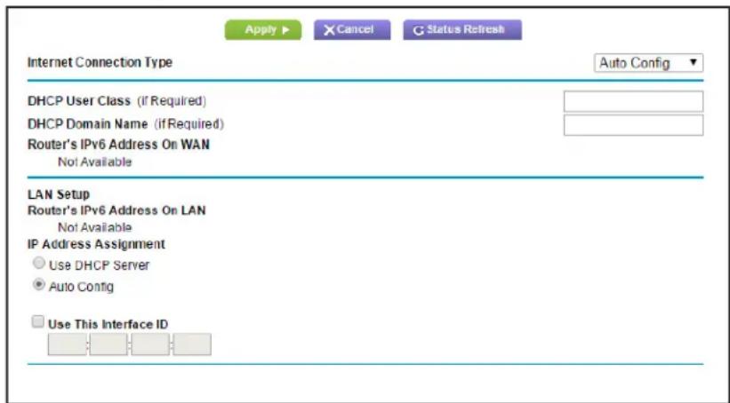
text_image
Apply ▶ X Cancel G Status Refresh Internet Connection Type Auto Config ▼ DHCP User Class (if Required) DHCP Domain Name (if Required) Router's IPv6 Address On WAN Not Available LAN Setup Router's IPv6 Address On LAN Not Available IP Address Assignment Use DHCP Server Auto Config Use This Interface IDThe router automatically detects the information in the following fields:
- Router 's IPv6 Address on WAN. This field shows the IPv6 address that is acquired for the router's WAN (or Internet) interface. The number after the slash (/) is the length of the prefix, which is also indicated by the underline (_) under the IPv6 address. If no address is acquired, the field displays Not Available.
- Router's IPv6 Address on LAN. This field shows the IPv6 address that is acquired for the router's LAN interface. The number after the slash (/) is the length of the prefix,
which is also indicated by the underline (_) under the IPv6 address. If no address is acquired, the field displays Not Available.
- (Optional) In the DHCP User Class (If Required) field, enter a host name.
Most people do not need to fill in this field, but if your ISP has given you a specific host name, enter it here.
- (Optional) In the Domain Name (If Required) field, enter a domain name.
You can type the domain name of your IPv6 ISP. (Do not enter the domain name for the IPv4 ISP here.) For example, if your ISP's mail server is mail.xxx.yyy.zzz, you would type xxx.yyy.zzz as the domain name. If your ISP provided a domain name, type it in this field. (For example, Earthlink Cable might require a host name of home, and Comcast sometimes supplies a domain name.)
- Specify how the router assigns IPv6 addresses to the devices on your home network (the LAN) by selecting one of the following radio buttons:
- Use DHCP Server. This method passes more information to LAN devices, but some IPv6 systems might not support the DHCv6 client function.
- Auto Config. This is the default setting.
- (Optional) Select the Use This Interface ID check box, and specify the interface ID that you want to be used for the IPv6 address of the router's LAN interface.
If you do not specify an ID here, the router generates one automatically from its MAC address.
- Click the Apply button.
IPv6 6to4 Tunnel
The remote relay router is the router to which your router creates the 6to4 tunnel. Make sure that the IPv4 Internet connection is working before you apply the 6to4 tunnel settings for the IPv6 connection.
To set up an IPv6 Internet connection by using a 6to4 tunnel:
- Select Advanced > Advanced Setup > IPv6.
The IPv6 screen displays.
- In the Internet Connection Type list, select 6to4 Tunnel.
The screen adjusts:
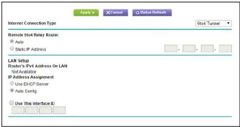
text_image
Apply ▶ XCancel Q Status Refresh Internet Connection Type 6to4 Tunnel Remote 6to4 Relay Router • Auto • Static IP Address LAN Setup Router's IPv6 Address On LAN Not Available IP Address Assignment • Use DHCP Server • Auto Config □ Use This Interface IDThe router automatically detects the information in the following fields:
- Router 's IPv6 Address on WAN. This field shows the IPv6 address that is acquired for the router's WAN (or Internet) interface. The number after the slash (/) is the length of the prefix, which is also indicated by the underline (_) under the IPv6 address. If no address is acquired, the field displays Not Available.
- Router 's IPv6 Address on LAN. This field shows the IPv6 address that is acquired for the router's LAN interface. The number after the slash (/) is the length of the prefix, which is also indicated by the underline (_) under the IPv6 address. If no address is acquired, the field displays Not Available.
- Configure the remote 6to4 relay router settings by selecting one of the following buttons:
- Auto. Your router uses any remote relay router that is available on the Internet. This is the default setting.
- Static IP Address. Enter the static IPv4 address of the remote relay router. This address is usually provided by your IPv6 ISP.
- Specify how the router assigns IPv6 addresses to the devices on your home network (the LAN) by selecting one of the following radio buttons:
- Use DHCP Server. This method passes more information to LAN devices, but some IPv6 systems might not support the DHCv6 client function.
• Auto Config. This is the default setting.
- (Optional) Select the Use This Interface ID check box, and specify the interface ID that you want to be used for the IPv6 address of the router's LAN interface.
If you do not specify an ID here, the router generates one automatically from its MAC address.
- Click the Apply button.
IPv6 Pass Through
In pass-through mode, the router works as a Layer 2 Ethernet switch with two ports (LAN and WAN Ethernet ports) for IPv6 packets. The router does not process any IPv6 header packets.
To set up a pass-through IPv6 Internet connection:
- Select Advanced > Advanced Setup > IPv6.
The IPv6 screen displays.
- In the Internet Connection Type list, select Pass Through.
The screen adjusts, but no additional fields display.
- Click the Apply button.
IPv6 Fixed
To set up a pass-through IPv6 Internet connection:
- Select Advanced > Advanced Setup > IPv6.
The IPv6 screen displays.
- Select Fixed from the menu.
The screen adjusts:
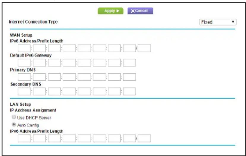
text_image
Apply ▶ ×Cancel Internet Connection Type Fixed WAN Setup IPv6 Address/Prefix Length Default IPv6 Gateway Primary DNS Secondary DNS LAN Setup IP Address Assignment Use DHCP Server Auto Config IPv6 Address/Prefix Length- Configure the fixed IPv6 addresses for the WAN connection.
The following fields are included in this screen:
- IPv6 Address/Prefix Length. The IPv6 address and prefix length of the router WAN interface.
- Default IPv6 Gateway. The IPv6 address of the default IPv6 gateway, which is supposed to be on the router's WAN interface.
- Primary DNS Server. The primary DNS server that resolves IPv6 domain name records for the router.
- Secondary DNS Server. The secondary DNS server that resolves IPv6 domain name records for the router.
Note: If you do not specify the DNS servers, the router uses the DNS servers that are configured for the IPv4 Internet connection on the Internet Setup screen. (See Internet Setup on page 20.)
-
Specify how the router assigns IPv6 addresses to the devices on your home network (the LAN) by selecting one of the following radio buttons:
-
Use DHCP Server. This method passes more information to LAN devices, but some IPv6 systems might not support the DHCv6 client function.
-
Auto Config. This is the default setting.
-
In the IPv6 Address/Prefix Length fields, specify the static IPv6 address and prefix length of the router's LAN interface.
If you do not specify an ID here, the router generates one automatically from its MAC address.
- Click the Apply button.
IPv6 DHCP
To set up an IPv6 Internet connection with a DHCP server:
- Select Advanced > Advanced Setup > IPv6.
The IPv6 screen displays.
- In the Internet Connection Type list, select DHCP.
The screen adjusts:
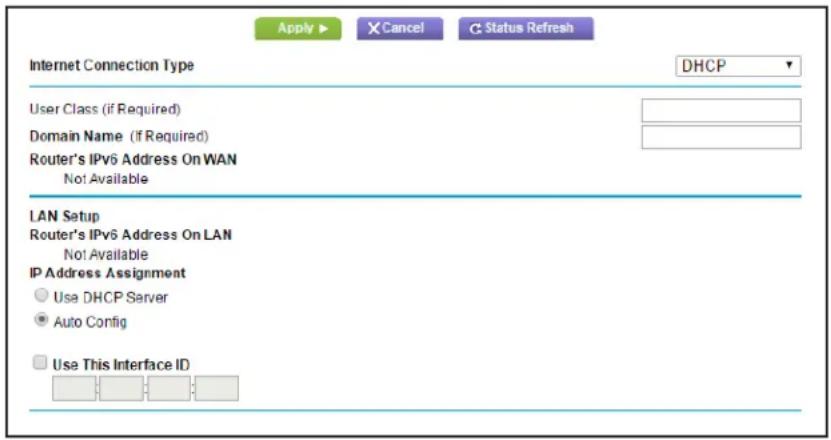
text_image
Apply ▶ X Cancel C Status Refresh Internet Connection Type DHCP User Class (if Required) Domain Name (if Required) Router's IPv6 Address On WAN Not Available LAN Setup Router's IPv6 Address On LAN Not Available IP Address Assignment Use DHCP Server Auto Config Use This Interface IDThe router automatically detects the information in the following fields:
- Router's IPv6 Address on WAN. This field shows the IPv6 address that is acquired for the router's WAN (or Internet) interface. The number after the slash (/) is the length of the prefix, which is also indicated by the underline (_) under the IPv6 address. If no address is acquired, the field displays Not Available.
-
Router's IPv6 Address on LAN. This field shows the IPv6 address that is acquired for the router's LAN interface. The number after the slash (/) is the length of the prefix, which is also indicated by the underline (_) under the IPv6 address. If no address is acquired, the field displays Not Available.
-
(Optional) In the DHCP User Class (If Required) field, enter a host name.
Most people do not need to fill in this field, but if your ISP has given you a specific host name, enter it here.
- (Optional) In the Domain Name (If Required) field, enter a domain name.
You can type the domain name of your IPv6 ISP. (Do not enter the domain name for the IPv4 ISP here.) For example, if your ISP's mail server is mail.xxx.yyy.zzz, you would type xxx.yyy.zzz as the domain name. If your ISP provided a domain name, type it in this field. (For example, Earthlink Cable might require a host name of home, and Comcast sometimes supplies a domain name.)
-
Specify how the router assigns IPv6 addresses to the devices on your home network (the LAN) by selecting one of the following radio buttons:
-
Use DHCP Server. This method passes more information to LAN devices, but some IPv6 systems might not support the DHCv6 client function.
-
Auto Config. This is the default setting.
-
(Optional) Select the Use This Interface ID check box, and specify the interface ID that you want to be used for the IPv6 address of the router's LAN interface.
If you do not specify an ID here, the router generates one automatically from its MAC address.
- Click the Apply button.
IPv6 PPPoE
To set up a PPPoE IPv6 Internet connection:
- Select Advanced > Advanced Setup > IPv6.
The IPv6 screen displays.
- In the Internet Connection Type list, select PPPoE.
The screen adjusts:
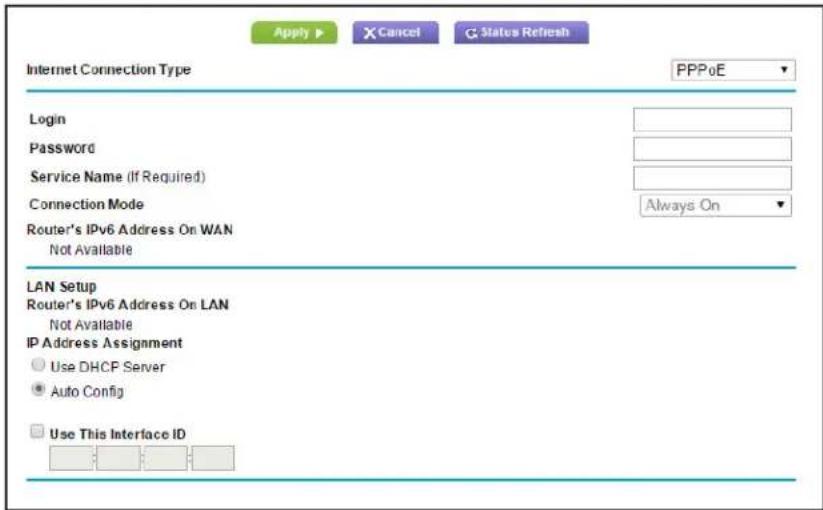
text_image
Apply ▶ X Cancel G Status Refresh Internet Connection Type PPPoE Login Password Service Name (If Required) Connection Mode Always On Router's IPv6 Address On WAN Not Available LAN Setup Router's IPv6 Address On LAN Not Available IP Address Assignment Use DHCP Server Auto Config Use This Interface IDThe router automatically detects the information in the following fields:
- Router 's IPv6 Address on WAN. This field shows the IPv6 address that is acquired for the router's WAN (or Internet) interface. The number after the slash (/) is the length of the prefix, which is also indicated by the underline (_) under the IPv6 address. If no address is acquired, the field displays Not Available.
- Router 's IPv6 Address on LAN. This field shows the IPv6 address that is acquired for the router's LAN interface. The number after the slash (/) is the length of the prefix, which is also indicated by the underline (_) under the IPv6 address. If no address is acquired, the field displays Not Available.
- In the Login fields, enter the login information for the ISP connection.
This is usually the name that you use in your email address. For example, if your main mail account is JerAB@ISP.com, then you would type JerAB in this field. Some ISPs (like Mindspring, Earthlink, and T-DSL) require that you use your full email address when you log in. If your ISP requires your full email address, type it in this field.
-
In the Password field, enter the password for the ISP connection.
-
In the Service Name name field, enter a service name.
If your ISP did not provide a service name, leave this field blank.
Note: The default setting of the Connection Mode field is Always on to provide a steady IPv6 connection. The router never terminates the connection. If the connection is terminated, for example, when the modem is turned off, the router attempts to reestablish the connection immediately after the PPPoE connection becomes available again.
- Specify how the router assigns IPv6 addresses to the devices on your home network (the LAN) by selecting one of the following radio buttons:
• Use DHCP Server. This method passes more information to LAN devices, but some IPv6 systems might not support the DHCv6 client function.
• Auto Config. This is the default setting.
- (Optional) Select the Use This Interface ID check box, and specify the interface ID that you want to be used for the IPv6 address of the router's LAN interface.
If you do not specify an ID here, the router generates one automatically from its MAC address.
- Click the Apply button.
Traffic Meter
Traffic metering allows you to monitor the volume of Internet traffic that passes through the router Internet port. You can set limits for traffic volume.
To monitor Internet traffic:
- Click Advanced > Advanced Setup > Traffic Meter.

text_image
Traffic Meter Apply ▶ X Cancel Internet Traffic Meter Enable Traffic Meter Traffic volume control by No limit Monthly limit 0 (Mbytes) Round up data volume for each connection by 0 (Mbytes) Connection time control Monthly limit 0 (hours) Traffic Counter Restart traffic counter at 00:00 am On the 1st day of each month Restart Counter Now Traffic Control Pop up a warning message 0 Mbytes/Minutes before the monthly limit is reached When the monthly limit is reached Turn the Internet LED to flashing white/amber Disconnect and disable the Internet connection Internet Traffic Statistics Start Date/Time: Wednesday, 01 Apr 2015 00:00 Current Date/Time: Wednesday, 08 Apr 2015 17:38 Traffic Volume Left: No limit Period Connection Time Traffic Volume (Mbytes) Scroll to view more settings- Select the Enable Traffic Meter check box.
- (Optional) Control the volume of Internet traf fic.
You can use either the traffic volume control feature or the connection time control feature to do this.
- Select the T traffic volume control by radio button and then select one of the following options:
- No Limit. No restriction is applied when the traffic limit is reached.
- Download only. The restriction is applied to incoming traffic only.
- Both Directions. The restriction is applied to both incoming and outgoing traffic.
- Select the Connection time control radio button and enter the allowed hours in the Monthly limit field.
-
(Optional) If your ISP charges an amount of extra data volume when you make a new connection, enter the extra data volume in MB in the Round up data volume for each connection by field.
-
In the Traffic Counter section, set the traffic counter to begin at a specific time and date.
If you want the traffic counter to start immediately, click the Restart Counter Now button.
- In the Traffic Control section, specify whether the router should issue a warning message before the monthly limit of Mbytes or hours is reached.
By default, the value is 0 and no warning message is issued. You can select one of the following to occur when the limit is attained:
- The Internet LED flashes green or amber.
- The Internet connection is disconnected and disabled.
- Click the Apply button.
The Internet Traffic Statistics section helps you to monitor the data traffic.
Click the Refresh button to update the Traffic Statistics section.
Click the Traffic Status button to display more information about the data traffic on your router and to change the poll interval.
This chapter provides information to help you diagnose and solve problems you might have with your router. If you do not find the solution here, check the NETGEAR support site at http://support.netgear.com for product and contact information.
This chapter contains the following sections:
- Quick Tips
- Troubleshoot with the LEDs
- Cannot Log In to the Router
- Cannot Access the Internet
- Changes Not Saved
- Wireless Connectivity
- Troubleshoot Your Network Using the Ping Utility
Quick Tips
This section describes tips for troubleshooting some common problems.
Sequence to Restart Your Network
When you need to restart your network, follow this sequence:
- Turn off and unplug the modem.
- Turn off the router.
- Plug in the modem and turn it on. Wait 2 minutes.
- Turn on the router and wait 2 minutes.
Check Ethernet Cable Connections
If your device does not power on, make sure that the Ethernet cables are securely plugged in.
- The Internet LED on the router is on if the Ethernet cable connecting the router and the modem is plugged in securely and the modem and router are turned on.
- For each powered-on computer connected to the router by an Ethernet cable, the corresponding numbered router LAN port LED is on.
Wireless Settings
Make sure that the wireless settings in the computer and router match exactly.
- For a wirelessly connected computer, the wireless network name (SSID) and wireless security settings of the router and wireless computer need to match exactly.
- If you set up an access list in the Advanced Wireless Settings screen, you have to add each wireless computer's MAC address to the router's access list.
Network Settings
Make sure that the network settings of the computer are correct.
- Wired and wirelessly connected computers need to have network (IP) addresses on the same network as the router. The simplest way to do this, is to configure each computer to obtain an IP address automatically using DHCP.
- Some cable modem service providers require you to use the MAC address of the computer initially registered on the account. You can view the MAC address in the Attached Devices screen.
Troubleshoot with the LEDs
After you turn on power to the router, the following sequence of events should occur:
- When power is first applied, verify that the Power/T est LED ⏻it.
- Verify that the Power LED lights amber within a few seconds, indicating that the self-test is running.
- After approximately 30 seconds, verify the following:
• The Powert LED lights solid green.
• The Internet LED is lit.
The LEDs on the front panel of the router can be used for troubleshooting.
Power LED Is Off or Blinking
- Make sure that the power cord is securely connected to your router and that the power adapter is securely connected to a functioning power outlet.
- Check that you are using the 12V DC, 2.5A power adapter that NETGEAR supplied for this product.
- If the Power LED blinks slowly and continuously, the router firmware is corrupted. This can happen if a firmware upgrade is interrupted, or if the router detects a problem with the firmware. If the error persists, you have a hardware problem. For recovery instructions, or help with a hardware problem, contact technical support at www.netgear.com/support.
Power LED Stays Amber
When the router is turned on, the Power LED lights amber for about 20 seconds and then lights green. If the LED does not turn green, the router has a problem.
If the Power LED is still amber one minute after you turn on power to the router:
- Turn off the power and then turn it back on to see if the router recovers.
- Press and hold the Reset button to return the router to its factory settings.
See Troubleshoot Your Network Using the Ping Utility on page 126.
If the error persists, you might have a hardware problem. Contact technical support at www.netgear.com/support.
LEDs Never Turn Off
When the router is turned on, the LEDs turn on for about 10 seconds and then turn off. If all the LEDs stay on, there is a fault within the router.
If all LEDs are still on 1 minute after power-up:
- Cycle the power to see if the router recovers.
- Press and hold the Reset button to return the router to its factory settings. For more information, see Troubleshoot Your Network Using the Ping Utility on page 126.
If the error persists, you might have a hardware problem. Contact technical support at www.netgear.com/support.
Internet or Ethernet Port LEDs Are Off
If either the Ethernet port LEDs or the Internet LED does not light when the Ethernet connection is made, check the following:
- Make sure that the Ethernet cable connections are secure at the router and at the modem or computer.
- Make sure that power is turned on to the connected modem or computer.
- Be sure that you are using the correct cable.
When connecting the router's Internet port to a cable or DSL modem, use the cable that was supplied with the cable or DSL modem. This cable could be a standard straight-through Ethernet cable or an Ethernet crossover cable.
WiFi LED Is Off
If the WiFi LED stays off, check to see if the WiFi On/Off button on the router has been pressed. This button turns the wireless radios in the router on and off. The Wireless LED is lit when the wireless radio is turned on.
Cannot Log In to the Router
If you are unable to log in to the router from a computer on your local network, check the following:
- If you are using an Ethernet-connected computer, check the Ethernet connection between the computer and the router as described in the previous section.
- Make sure that the IP address of your computer is on the same subnet as the router. If you are using the recommended addressing scheme, your computer's address should be in the range of 192.168.1.2 to 192.168.1.254.
- If your computer's IP address is shown as 169.254.x.x, recent versions of Windows and Mac OS generate and assign an IP address if the computer cannot reach a DHCP server. These autogenerated addresses are in the range of 169.254.x.x. If your IP address is in
this range, check the connection from the computer to the router, and reboot your computer.
- If your router's IP address was changed and you do not know the current IP address, clear the router's configuration to factory defaults. This sets the router's IP address to 192.168.1.1. For more information, see Factory Settings on page 129.
- Make sure that your browser has Java, JavaScript, or ActiveX enabled. If you are using Internet Explorer, click Refresh to be sure that the Java applet is loaded.
- Try quitting the browser and launching it again.
- Make sure that you are using the correct login information. The factory default login name is admin, and the password is password. Make sure that Caps Lock is off when you enter this information.
- If you are attempting to set up your NETGEAR router as an additional router behind an existing router in your network, consider replacing the existing router. NETGEAR does not support such a configuration.
- If you are attempting to set up your NETGEAR router as a replacement for an ADSL gateway in your network, the router cannot perform many gateway services. For example, the router cannot convert ADSL or cable data into Ethernet networking information. NETGEAR does not support such a configuration.
Cannot Access the Internet
If you can access your router but not the Internet, check to see if the router can obtain an IP address from your Internet service provider (ISP). Unless your ISP provides a fixed IP address, your router requests an IP address from the ISP. You can determine whether the request was successful using the Router Status screen.
To check the WAN IP address:
- Start your browser, and select an external site such as www.netgear.com.
- Access the router interface at www.routerlogin.net.
- Select Administration > Router Status.
- Check that an IP address is shown for the Internet port. If 0.0.0.0 is shown, your router has not obtained an IP address from your ISP.
If your router cannot obtain an IP address from the ISP, you might need to force your cable or DSL modem to recognize your new router by restarting your network. For more information, see Sequence to Restart Your Network on page 120.
If your router is still unable to obtain an IP address from the ISP, the problem might be one of the following:
- Your Internet service provider (ISP) might require a login program.
Ask your ISP whether they require PPP over Ethernet (PPPoE) or some other type of login.
- If your ISP requires a login, the login name and password might be set incorrectly.
- Your ISP might check for your computer's host name.
Assign the computer host name of your ISP account as the account name in the Internet Setup screen.
- Your ISP allows only one Ethernet MAC address to connect to Internet and might check for your computer's MAC address. In this case, do one of the following:
- Inform your ISP that you have bought a new network device, and ask them to use the router's MAC address.
- Configure your router to clone your computer's MAC address.
If your router can obtain an IP address, but your computer is unable to load any web pages from the Internet:
- Your computer might not recognize any DNS server addresses.
A DNS server is a host on the Internet that translates Internet names (such as www addresses) to numeric IP addresses. Typically, your ISP provides the addresses of one or two DNS servers for your use. If you entered a DNS address during the router's configuration, reboot your computer, and verify the DNS address. You can configure your computer manually with DNS addresses, as explained in your operating system documentation.
- Your computer might not have the router configured as its TCP/IP gateway.
If your computer obtains its information from the router by DHCP, reboot the computer, and verify the gateway address.
- You might be running login software that is no longer needed.
If your ISP provided a program to log you in to the Internet (such as WinPoET), you no longer need to run that software after installing your router. You might need to go to Internet Explorer and select Tools > Internet Options, click the Connections tab, and select Never dial a connection.
Troubleshoot PPPoE
If you are using PPPoE, try troubleshooting your Internet connection.
To troubleshoot a PPPoE connection:
- Select Administration > Router Status.
- Click Connection Status.
- Check the Connection Status display to see if your PPPoE connection is up and working.
- If any of the field s on the Connection Status screen indicate Failed, you can attempt to reconnect by clicking Connect. The router continues to attempt to connect indefinitely.
- If you cannot connect after several minutes, you might be using an incorrect service name, user name, or password. There might also be a provisioning problem with your ISP.
Unless you connect manually, the router does not authenticate using PPPoE until data is transmitted to the network.
Troubleshoot Internet Browsing
If your router can obtain an IP address but your computer is unable to load any web pages from the Internet, check the following:
- Your computer might not recognize any DNS server addresses. A DNS server is a host on the Internet that translates Internet names (such as www addresses) to numeric IP addresses.
Typically, your ISP provides the addresses of one or two DNS servers for your use. If you entered a DNS address during the router's configuration, restart your computer.
Alternatively, you can configure your computer manually with a DNS address, as explained in the documentation for your computer.
- Your computer might not have the router configured as its default gateway.
Reboot the computer and verify that the router address (www.routerlogin.net) is listed by your computer as the default gateway address.
- You might be running log in software that is no longer needed. If your ISP provided a program to log you in to the Internet (such as WinPoET), you no longer need to run that software after installing your router. You might need to go to Internet Explorer and select Tools > Internet Options, click the Connections tab, and select Never dial a connection.
Changes Not Saved
If the router does not save the changes you make in the router interface, check the following:
- When entering configuration settings, always click the Apply button before moving to another screen or tab, or your changes are lost.
- Click the Refresh or Reload button in the web browser. The changes might have occurred, but the old settings might be in the web browser's cache.
Wireless Connectivity
If you are having trouble connecting wirelessly to the router, try to isolate the problem.
- Does the wireless device or computer that you are using find your wireless network?
If not, check the WiFi LED on the router. If it is off, you can press the WiFi On/Off button on the router to turn the router wireless radios back on.
If you disabled the router's SSID broadcast, then your wireless network is hidden and does not display in your wireless client's scanning list. (By default, SSID broadcast is enabled.)
- Does your wireless device support the security that you are using for your wireless network (WPA or WPA2)?
- If you want to view the wireless settings for the router, use an Ethernet cable to connect a computer to a LAN port on the router. Then log in to the router, and select Wireless see (Basic Wireless Settings on page 22).
Note: Be sure to click Apply if you change settings.
Wireless Signal Strength
If your wireless device finds your network, but the signal strength is weak, check these conditions:
- Is your router too far from your computer, or too close? Place your computer near the router, but at least 6 feet (1.8 meters) away, and see whether the signal strength improves.
- Are objects between the router and your computer blocking the wireless signal?
Troubleshoot Your Network Using the Ping Utility
Most network devices and routers contain a ping utility that sends an echo request packet to the designated device. The device then responds with an echo reply. You can easily troubleshoot a network is easy using the ping utility in your computer or workstation.
Test the LAN Path to Your Router
You can ping the router from your computer to verify that the LAN path to your router is set up correctly.
To ping the router from a Windows computer:
-
From the Windows toolbar, click Start and select Run.
-
In the field provided, type ping followed by the IP address of the router, as in this example: ping www.routerlogin.net
-
Click OK.
You should see a message like this one:
Pinging
If the path is working, you see this message:
Reply from < IP address>: bytes=32 time=NN ms TTL=xxx
If the path is not working, you see this message:
Request timed out
If the path is not functioning correctly, you could have one of the following problems:
- Wrong physical connections
For a wired connection, make sure that the numbered LAN port LED is lit for the port to which you are connected.
Check that the appropriate LEDs are on for your network devices. If your router and computer are connected to a separate Ethernet switch, make sure that the link LEDs are lit for the switch ports that are connected to your computer and router.
- Wrong network configuration
Verify that the Ethernet card driver software and TCP/IP software are both installed and configured on your computer.
Verify that the IP address for your router and your computer are correct and that the addresses are on the same subnet.
Test the Path from Your Computer to a Remote Device
After verifying that the LAN path works correctly, test the path from your computer to a remote device.
- From the Windows toolbar, click the Start button and select Run.
- In the Windows Run window, type:
ping -n 10
where
If the path is functioning correctly, replies like those shown in the previous section are displayed.
If you do not receive replies:
- Check that your computer has the IP address of your router listed as the default gateway. If the IP configuration of your computer is assigned by DHCP, this information is not visible in your computer Network Control Panel. Verify that the IP address of the router is listed as the default gateway.
- Check to see that the network address of your computer (the portion of the IP address specified by the subnet mask) is different from the network address of the remote device.
- Check that your cable or DSL modem is connected and functioning.
- If your ISP assigned a host name to your computer, enter that host name as the account name in the Internet Setup screen.
- Your ISP could be rejecting the Ethernet MAC addresses of all but one of your computers.
Many broadband ISPs restrict access by allowing traffic only from the MAC address of your broadband modem. Some ISPs additionally restrict access to the MAC address of a single computer connected to that modem. If so, configure your router to “clone” or “spoof” the MAC address from the authorized computer.
Supplemental Information
A
This appendix covers the following topics:
- Factory Settings
• Technical Specifications
Factory Settings
You can return the router to its factory settings. Use the end of a paper clip or a similar object to press and hold the Reset button on the back of the router for at least 7 seconds. The router resets, and returns to the factory configuration settings shown in the following table.
Table 3. Factory default settings
| Feature Default behavior | ||
| Router login User | login URL www.routerlogin.com or | www.routerlogin.net |
| User name (case-sensitive) admin | ||
| Login password (case-sensitive) password | ||
| Internet connection | WAN MAC address Use default hardware address | |
| WAN MTU size 1500 | ||
| Port speed AutoSensing | ||
| Local network (LAN) | LAN IP 192.168.1.1 | |
| Subnet mask 255.255.255.0 | ||
| DHCP server Enabled | ||
| DHCP range 192.168.1.2 to 192.168.1.254 | ||
| Time zone | Pacific time | |
| Time zone daylight savings time | Disabled | |
| Allow a registrar to configure this router | Enabled | |
| Local network (LAN) continued | DHCP starting IP address | 192.168.1.2 |
| DHCP ending IP address | 192.168.1.254 | |
| DMZ | Disabled | |
| Time zone | GMT for WW except NA and GR, GMT+1 for GR, GMT-8 for NA | |
| Time zone adjusted for daylight savings time | Disabled | |
| SNMP | Disabled | |
| Firewall | Inbound (communications coming in from the Internet) | Disabled (except traffic on port 80, the HTTP port) |
| Outbound (communications going out to the Internet) | Enabled (all) | |
| Source MAC filtering | Disabled | |
| Wireless Wireless | communication Enabled | |
| SSID name See router label | ||
| Security WPA2-PSK (AES) | ||
| Broadcast SSID Enabled | ||
| Transmission speed Auto | * | |
| Country/region United States in the | US; otherwise varies by region | |
| RF channel 6 until region selected | ||
| Operating mode Up to 145 Mbps at | 2.4 GHz, 1300 Mbps at 5 GHz | |
| Firewall Inbound | (communications coming in from the Internet) | Disabled (bars all unsolicited requests) |
| Outbound (communications going out to the Internet) | Enabled (all) | |
^k . Maximum wireless signal rate derived from IEEE Standard 802.11 specifications. Actual throughput can vary. Network conditions and environmental factors, including volume of network traffic, building materials and construction, and network overhead, lower actual data throughput rate.
Technical Specifications
Table 4. R6250 Router specifications
| Feature Description | |
| Data and routing protocols TCP/IP, RIP-1, RIP-2, DHCP, PPPoE, PPTP, Bigpond, Dynamic DNS, UPnP, and SMB | |
| Power adapter • North America: 120V, 60 Hz, input• UK, Australia: 240V, 50 Hz, input• Europe: 230V, 50 Hz, input• All regions (output): 12V DC @ 2.5A, output | |
| Dimensions Dimensions: 195 x 199 x 65 mm (7.68 x 7.84 x 2.56 in) | |
| Weight Weight: 417 (0.92l b) | |
| Operating temperature 0° to 40°C (32° to 104°F) | |
| Operating humidity | 90% maximum relative humidity, noncondensing |
| Electromagnetic emissions | FCC Part 15 Class BVCCI Class BEN 55 022 (CISPR 22), Class B C-Tick N10947 |
| LAN | 10BASE-T or 100BASE-TX or 1000BASE-T, RJ-45 |
| WAN | 10BASE-T or 100BASE-TX or 1000BASE-T, RJ-45 |
| Wireless | Maximum wireless signal rate complies with the IEEE 802.11 standard. See the footnote for the previous table. |
| Radio data rates | Auto Rate Sensing |
| Data encoding standards | IEEE 802.11ac 2.0IEEE 802.11n version 2.0IEEE 802.11n, IEEE 802.11g, IEEE 802.11b 2.4 GHzIEEE 802.11n, IEEE 802.11a 5.0 GHz |
| Maximum computers per wireless network | Limited by the amount of wireless network traffic generated by each node (typically 50–70 nodes). |
| Operating frequency range 2.4 | GHz2.412–2.462 GHz (US)2.412–2.472 GHz (Japan)2.412–2.472 GHz (Europe ETSI)5 GHz5.18–5.24 + 5.745–5.825 GHz (US)5.18–5.24 GHz (Europe ETSI)FCC:5.25–5.35 GHz (DFS band)5.47–5.725 GHz (DFS band) 5600–5650 MHz is disabled and unavailable for useCE (Europe ETSI):5.25–5.35 GHz (DFS band)5.47–5.725 GHz (DFS band) |
| 802.11 security WPA-PSK, WPA2-PSK, and WPA/WPA2 | |