WRVS4400n - Router CISCO - Free user manual and instructions
Find the device manual for free WRVS4400n CISCO in PDF.

User questions about WRVS4400n CISCO
0 question about this device. Answer the ones you know or ask your own.
Ask a new question about this device
Download the instructions for your Router in PDF format for free! Find your manual WRVS4400n - CISCO and take your electronic device back in hand. On this page are published all the documents necessary for the use of your device. WRVS4400n by CISCO.
USER MANUAL WRVS4400n CISCO
A Division of Cisco Systems, Inc.
natural_image
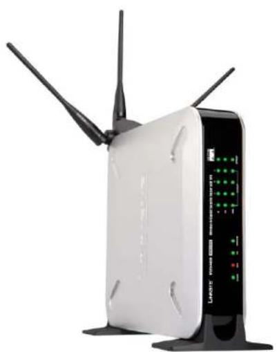
White wireless router with two antennas and a control panel (no visible text or symbols)Wireless-N Gigabit Security Router with VPN
USER GUIDE
BUSINESS SERIES
Cisco SYSTEMS

Wireless-N Gigabit Security Router with VPN
Copyright and Trademarks
Specifications are subject to change without notice. Linksys is a registered trademark or trademark of Cisco Systems, Inc. and/or its affiliates in the U.S. and certain other countries. Copyright © 2006 Cisco Systems, Inc. All rights reserved. Other brands and product names are trademarks or registered trademarks of their respective holders.
WARNING: This product contains chemicals, including lead, known to the State of California to cause cancer, and birth defects or other reproductive harm. Wash hands after handling.
How to Use this Guide
This User Guide has been designed to make understanding networking with the Router easier than ever. Look for the following items when reading this Guide:

This checkmark means there is a note of interest and is something you should pay special attention to while using the Router.

This exclamation point means there is a caution or warning and is something that could damage your property or the Router.

This question mark provides you with a reminder about something you might need to do while using the Router.
In addition to these symbols, there are definitions for technical terms that are presented like this:
word: definition.
Also, each figure (diagram, screenshot, or other image) is provided with a figure number and description, like this: Figure 0-1: Sample Figure Description
Figure 0-1: Sample Figure Description
Figure numbers and descriptions can also be found in the "List of Figures" section in the "Table of Contents".
WRVS4400N-UG-50426NC RR
Wireless-N Gigabit Security Router with VPN

Chapter 1: Introduction 1
Welcome 1
What's in this Guide? 2
Chapter 2: Networking and Security Basics 4
An Introduction to LANs 4
The Use of IP Addresses 5
The Intrusion Prevention System (IPS) 7
Chapter 3: Planning Your Virtual Private Network (VPN) 9
Why do I need a VPN? 9
What is a VPN? 10
Chapter 4: Getting to Know the Router 12
The Front Panel 12
The Back Panels 14
Antennas and Positions 15
Chapter 5: Connecting the Router 16
Overview 16
Connection Instructions 17
Placement Options
Chapter 6: Setting Up and Configuring the Router 20
Overview 20
Basic Setup 20
How to Access the Web-based Utility 21
How to Navigate the Utility 21
Setup Tab 25
Wireless Tab 38
Firewall Tab 47
VPN Tab 58
QoS Tab 65
Administration Tab 67
IPS Tab 72
L2 Switch Tab 76
Status Tab 80
Appendix A: Troubleshooting 85
Wireless-N Gigabit Security Router with VPN
Common Problems and Solutions 85
Frequently Asked Questions 95
Appendix B: Using the Linksys QuickVPN Software for Windows 2000 or XP 99
Overview 99
Before You Begin 99
Installing the Linksys QuickVPN Software 100
Using the Linksys QuickVPN Software 101
Appendix C: Configuring a Gateway-to-Gateway IPSec Tunnel 103
Overview 103
Before You Begin 103
Configuring the VPN Settings for the VPN Routers 104
Configuring the Key Management Settings 106
Configuring PC 1 and PC 2 107
Appendix D: Finding the MAC Address and IP Address for
Your Ethernet Adapter 108
Windows 98 or Me Instructions 108
Windows 2000 or XP Instructions 108
For the Router's Web-based Utility 109
Appendix E: Glossary 110
Appendix F: Specifications 116
Appendix G: Warranty Information 119
Appendix H: Regulatory Information 120
Appendix I: Contact Information 126
Wireless-N Gigabit Security Router with VPN

Figure 2-1: Example network 5
Figure 2-2: IPS Scenarios 7
Figure 3-1: VPN Router to VPN Router 11
Figure 3-2: Computer to VPN Router 11
Figure 4-1: Front Panel 12
Figure 4-2: Back Panel 14
Figure 4-3: Stackable Position and its Antenna Setup 15
Figure 4-4: Standalone Position and its Antenna Setup 15
Figure 5-1: Example of a Typical Network 16
Figure 5-2: Connect a PC 17
Figure 5-3: Connect the Internet 17
Figure 5-4: Connect the Power 17
Figure 5-5: The Stand Option 18
Figure 5-6: Stand 18
Figure 5-7: Mounting Dimensions 19
Figure 5-8: Wall Mounting Hardware 19
Figure 6-1: Router's IP Address 21
Figure 6-2: Login Screen for Web-based Utility 21
Figure 6-1: Setup - IP Versions 25
Figure 6-2: Setup - WAN (DHCP) 26
Figure 6-3: Setup - WAN (Static IP) 26
Figure 6-4: Setup - WAN (PPPoE) 27
Figure 6-5: Setup - WAN (PPTP) 27
Figure 6-6: Setup - WAN (Heart Beat Signal) 28
Figure 6-7: Setup - WAN (L2TP) 29
Figure 6-8: Setup - WAN (Optional Settings) 30
Figure 6-9: Setup - WAN (DynDNS.org) 31
Figure 6-10: Setup - WAN (TZO.com) 31
Wireless-N Gigabit Security Router with VPN
Figure 6-11: Setup - LAN 32
Figure 6-12: Setup - DMZ 34
Figure 6-13: Setup - MAC Address Clone 34
Figure 6-14: Setup - Advanced Routing 35
Figure 6-15: Setup - Advanced Routing (Routing Table) 36
Figure 6-16: Setup - Time 37
Figure 6-17: Wireless - Basic Wireless Settings 38
Figure 6-18: Wireless - Wireless Security (Disabled) 40
Figure 6-19: Wireless - Wireless Security (WPA-Personal) 40
Figure 6-20: Wireless - Wireless Security (WPA2-Personal) 41
Figure 6-21: Wireless - Wireless Security (WPA2-Personal Mixed) 41
Figure 6-22: Wireless - Wireless Security (WPA-Enterprise) 42
Figure 6-23: Wireless - Wireless Security (WPA2-Enterprise) 42
Figure 6-24: Wireless - Wireless Security (WPA2-Enterprise Mixed) 43
Figure 6-25: Wireless - Wireless Security (WEP) 43
Figure 6-26: Wireless - Wireless Connection Control 44
Figure 6-27: Select MAC Address from Wireless Client List 44
Figure 6-28: Wireless - Advanced Wireless Settings 45
Figure 6-29: Firewall - Basic Settings 47
Figure 6-30: Firewall - IP Based ACL 49
Figure 6-31: Firewall - IP Based ACL (pre-defined services) 49
Figure 6-32: Firewall - IP Based ACL (Service definition) 50
Figure 6-33: Firewall - Edit IP ACL Rule 50
Figure 6-34: Firewall - Internet Access Policy 52
Figure 6-35: Firewall - Internet Access Policy Summary 53
Figure 6-36: Firewall - Internet Access Policy (List of PCs to apply policy) 53
Figure 6-37: Firewall - Single Port Forwarding 54
Figure 6-38: Port Range Forwarding 55
Figure 6-39: Port Range Triggering 56
Figure 6-40: Firewall - Services 57
Wireless-N Gigabit Security Router with VPN
Figure 6-41: VPN - IPsec VPN 58
Figure 6-42: VPN Tunnel Summary 58
Figure 6-43: View VPN Tunnel Log 60
Figure 6-44: IPsec VPN Advanced Settings 61
Figure 6-45: VPN - VPN Client Accounts 63
Figure 6-46: VPN - VPN Passthrough 64
Figure 6-47: QoS - Application Based 65
Figure 6-48: Port-based 66
Figure 6-49: Administration - Management 67
Figure 6-50: Administration - Log 68
Figure 6-51: View Log pop-up window 68
Figure 6-52: Administration - Diagnostics 69
Figure 6-53: Ping Test Screen 69
Figure 6-54: Trace Route Test Screen 70
Figure 6-55: Administration - Config Management 70
Figure 6-56: Administration - Factory Default 71
Figure 6-57: Administration - Firmware Upgrade 71
Figure 6-58: IPS - Configuration 72
Figure 6-59: IPS - P2P / IM 73
Figure 6-60: IPS - Report 74
Figure 6-61: IPS Log Raw Data 74
Figure 6-62: IPS - Information 75
Figure 6-63: L2 Switch - VLAN 76
Figure 6-64: L2 Switch - RADIUS 77
Figure 6-65: L2 Switch - RADIUS 77
Figure 6-66: L2 Switch - Port Settings 78
Figure 6-67: L2 Switch - Cable Diagnostics 79
Figure 6-68: Status - WAN / Gateway 80
Figure 6-69: Status - LAN 81
Figure 6-70: LAN DHCP Client Table 81
Wireless-N Gigabit Security Router with VPN
Figure 6-71: LAN ARP Table 81
Figure 6-72: Status - Wireless LAN 82
Figure 6-73: Status - System Performance 83
Figure 6-74: Status - VPN Clients 84
Figure 6-75: Status - IPsec VPN 84
Figure B-1: VPN Client Accounts Screen 99
Figure B-2: QuickVPN Desktop Icon 101
Figure B-3: QuickVPN Tray Icon - No Connection 101
Figure B-4: QuickVPN Software - Profile 101
Figure B-5: Connecting 101
Figure B-6: Activating Policy 101
Figure B-7: Verifying Network 101
Figure B-8: QuickVPN Software - Status 102
Figure B-9: QuickVPN Tray Icon - Connection 102
Figure B-10: QuickVPN Tray Icon - No Connection 102
Figure B-11: QuickVPN Software - Change Password 102
Figure C-1: Diagram of Gateway-to-Gateway VPN Tunnel 103
Figure C-2: Login Screen 104
Figure C-3: VPN - IPsec VPN Configuration 104
Figure C-4: Advanced IPsec VPN Tunnel Settings 106
Figure C-5: Auto (IKE) Advanced Settings Screen 106
Figure D-1: IP Configuration Screen 108
Figure D-2: MAC Address/Adapter Address 108
Figure D-3: MAC Address/Physical Address 109
Figure D-4: MAC Address Clone 109
Wireless-N Gigabit Security Router with VPN

Welcome
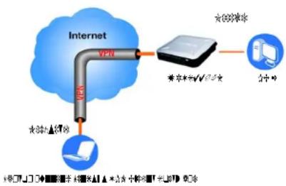
Thank you for choosing the Wireless-N Gigabit Security Router with VPN. The Wireless-N Gigabit Security Router with VPN is an advanced Internet-sharing network solution for your small business needs. The Router features a built-in 4-Port full-duplex 10/100/1000 Ethernet switch to connect four PCs directly, or you can connect more hubs and switches to create as big a network as you need. Like any wireless router, it lets multiple computers in your office share an Internet connection through both wired and wireless connections. It can also be used as an intranet router to aggregate traffic to a company backbone network.
The Router has a built-in access point that supports the latest 802.11n draft specification by IEEE. It also supports 802.11g and 802.11b clients in a mixed environment. The access point can support an 11n data rate of up to 300 Mbps. Besides having a higher data rate, 802.11n technology also promises longer coverage by using multiple antennas to transmit and receive data streams in different directions. Users are encouraged to upgrade their firmware through www.linksys.com when 802.11n specification is finalized by IEEE to ensure compatibility with all the wireless-N devices.
The Wireless-N Gigabit Security Router with VPN is equipped with advanced security technologies like Intrusion Prevention System (IPS), Stateful Packet Inspection (SPI) Firewall, IP based Access List (IP ACL), and Network Address Port Translation (NAPT, also called NAT as a more generic term). These technologies work together by providing self-defensive strategy. Malicious attack traffic is identified, classified, and stopped in real time while passing through the Router. Users are encouraged to update their IPS signature file to stay current on stopping malicious worms. The SPI Firewall provides deep packet inspection to analyze packets in network layer (IP) and transport layer (TCP, UDP) to block illegal packet transactions. Users can also use IP based ACL to limit traffic to a specific source, destination and protocol. NAPT allows users to open specific TCP/UDP port numbers to the Internet to provide limited service while minimizing harmful traffic at the same time.
The Virtual Private Network (VPN) capability is another security feature that creates encrypted “tunnels” through the Internet, allowing up to five remote offices and five traveling users to securely connect into your office network from off-site. Users connecting through a VPN tunnel are attached to your company's network with secure access to files, e-mail, and your intranet as if they were in the building. You can also use the VPN capability to allow users on your small office network to securely connect out to a corporate network. The QoS features provide consistent voice and video quality throughout your business.
This user guide will give you all the information you need to connect, set up, and configure your Router.
Ethernet: a network protocol that specifies how data is placed on and retrieved from a common transmission medium.
Chapter 1: Introduction
Welcome
Wireless-N Gigabit Security Router with VPN
What's in this Guide?
This user guide covers the steps for setting up and using the Wireless-N Gigabit Security Router with VPN.
• Chapter 1: Introduction
This chapter describes the Wireless-N Gigabit Security Router with VPN applications and this User Guide.
• Chapter 2: Networking and Security Basics
This chapter describes the basics of networking and network security.
• Chapter 3: Planning Your Virtual Private Network (VPN)
This chapter describes a VPN and its various applications.
• Chapter 4: Getting to Know the Router
This chapter describes the physical features of the Router.
• Chapter 5: Connecting the Router
This chapter instructs you on how to connect the Router to your network.
• Chapter 6: Setting Up and Configuring the Router
This chapter explains how to use the Web-Based Utility to perform basic setup and configure its advanced settings.
• Appendix A: Troubleshooting
This appendix describes some problems and solutions, as well as frequently asked questions, regarding installation and use of the Wireless-N Gigabit Security Router with VPN.
- Appendix B: Using the Linksys QuickVPN Software for Windows 2000 or XP
This appendix instructs you on how to use the Linksys QuickVPN software if you are using a Windows 2000 or XP PC.
- Appendix C: Configuring a Gateway-to-Gateway IPSec Tunnel
This appendix describes how to configure an IPSec VPN Tunnel between two VPN Routers.
- Appendix D: Finding the MAC Address and IP Address for your Ethernet Adapter.
This appendix describes how to find the MAC address for your computer's Ethernet adapter so you can use the MAC filtering and/or MAC address cloning feature of the Router. It also explains how to find the IP address for your computer.
- Appendix E: Glossary
This appendix gives a brief glossary of terms frequently used in networking.
Chapter 1: Introduction
What's in this Guide?
Wireless-N Gigabit Security Router with VPN
- Appendix F: Specifications
This appendix provides the technical specifications for the Router.
• Appendix G: Warranty Information
This appendix supplies the warranty information for the Router.
• Appendix H: Regulatory Information
This appendix supplies the regulatory information regarding the Router.
• Appendix I: Contact Information
This appendix provides contact information for a variety of Linksys resources, including Technical Support.
Wireless-N Gigabit Security Router with VPN
A Router is a network device that connects multiple networks together and forward traffic based on IP destination of each packet.
The Wireless-N Gigabit Security Router can connect your local area network (LAN) or a group of PCs interconnected in your home or office to the Internet. You can use one public IP address from the ISP through WAN port and use the router's Network Address Translation (NAT) technology to share this single IP address among all the users.
The Router's Network Address Port Translation (NAPT or NAT) technology protects your network of PCs so users on the Internet cannot "see" your PCs. This is how your LAN remains private. The Router protects your network by inspecting the first packet coming in through the Internet port before delivery to the final destination on one of the Ethernet ports. The Router inspects Internet port services like the web server, ftp server, or other Internet applications, and, if allowed, it will forward the packet to the appropriate PC on the LAN side.
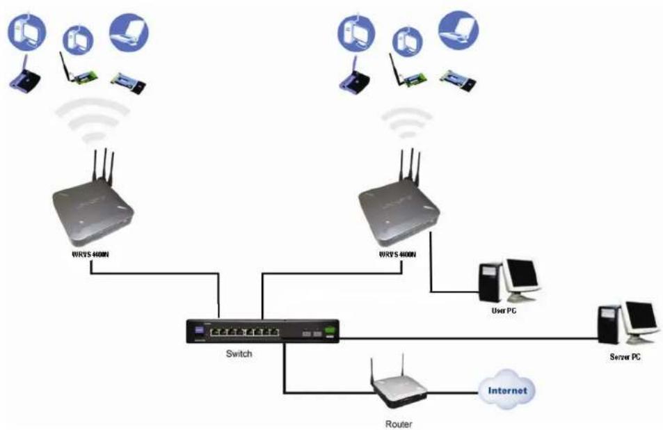
Multiple Wireless-N Gigabit Security Routers can also be used to connect multiple LANs together. This usually applies to a medium-sized or larger company where you want to divide your network into multiple IP subnets to increase the intranet throughput and reduce the size of the IP broadcast domain and its interference. In this case, you need one WRVS4400N for each subnetwork and you can connect all the WAN ports to a second level Router or switch to the Internet. Note that the second level Router only forwards data packets through a wired network so you don't have to use the Wireless-N Gigabit Security Router. You can use any wired router in the Linksys family, e.g. RVS4000, which has 4 LAN ports and 1 WAN port.
The following diagram shows an example that consists of two levels of routers and multiple LANs inter-connected together. The wireless network is only available at the first level of router to provide end user connections. The second level router can connect to dedicated Server PCs or routers that aggregates traffic from different LANs.
NAT (Network Address Translation):
NAT technology translates IP addresses of a local area network to a different IP address for the Internet.
LAN: the computers and networking products that make up your local network
Wireless-N Gigabit Security Router with VPN
flowchart
graph TD
    A["Router"] --> B["Switch"]
    C["User PC"] --> B
    D["Server PC"] --> B
    E["Mbps 400N"] --> B
    F["Mbps 400N"] --> B
    G["Internet"] --> B
    H["Wi-Fi"] --> I["Wireless Device"]
    J["Wi-Fi"] --> K["Wireless Device"]
    L["Wi-Fi"] --> M["Wireless Device"]
Figure 2-1: Example network
The Use of IP Addresses
IP stands for Internet Protocol. Every device in an IP-based network, including PCs, print servers, and routers, requires an IP address to identify its location, or address, on the network. This applies to both the Internet and LAN connections.
There are two ways of assigning IP addresses to your network devices.

NOTE: Since the Router is a device that connects two networks, it needs two IP addresses—one for the LAN, and one for the Internet. In this User Guide, you'll see references to the "Internet IP address" and the "LAN IP address."
Since the Router uses NAT technology, the only IP address that can be seen from the Internet for your network is the Router's Internet IP address. However, even this Internet IP address can be hidden on the Internet by suppressing PING response.
Chapter 2: Networking and Security Basics
The Use of IP Addresses
Wireless-N Gigabit Security Router with VPN
A static IP address is a fixed IP address that you assign manually to a PC or other device on the network. Since a static IP address remains valid until you disable it, static IP addressing ensures that the device assigned it will always have that same IP address until you change it. Static IP addresses are commonly used with dedicated network devices such as server PCs or print servers. Since a user's PC is moving around in a network and is being powered on or off, it does not require a dedicated IP address that could be a precious resource in your network.
If you use the Router to share your cable or DSL Internet connection, contact your ISP to find out if they have assigned a static IP address to your account. If so, you will need that static IP address when configuring the Router. You can get the information from your ISP.
A dynamic IP address is automatically assigned to a device on the network. This IP address is called dynamic because it is only temporarily assigned to the PC or other device. After a certain time period, it expires and may change. If a PC logs onto the network (or the Internet) and its dynamic IP address has expired, the DHCP server will assign it a new dynamic IP address. Most ISPs use dynamic IP addresses for their customers. By default, the Router's Internet Connection Type Is Obtain an IP automatically (DHCP).
For DSL users, many ISPs may require you to log on with a user name and password to gain access to the Internet. This is a dedicated, high-speed connection type called Point-to-Point Protocol over Ethernet (PPPoE). PPPoE is similar to a dial-up connection, which establishes a PPP session with an ISP server through the DSL connection. The server will also provide the Router with a dynamic IP address to establish a connection to the Internet.
A DHCP server can either be located on a designated PC on the network or another network device, such as the Router. The PC or network device obtaining an IP address is called the DHCP client. DHCP frees you from having to assign IP addresses manually every time a new user is added to your network. For this Wireless-N Router, a DHCP client is running on a WAN port for most configurations. A DHCP server is running on the LAN side to provide services.
By default, a DHCP server is enabled on the Router. If you already have a DHCP server running on your network, you MUST disable one of the two DHCP servers. If you run more than one DHCP server on your network, you will experience network errors, such as conflicting IP addresses. To disable DHCP on the Router, refer to the Basic Setup section in "Chapter 6: Setting Up and Configuring the Router."
Static IP address: a fixed address assigned to a computer or device that is connected to a network.
Dynamic IP address: a temporary IP address assigned by a DHCP server.
DHCP (Dynamic Host Configuration Protocol): a protocol that lets one device on a local network, known as a DHCP server, assign temporary IP addresses to the other network devices, typically computers.
Wireless-N Gigabit Security Router with VPN
The Intrusion Prevention System (IPS)
flowchart
graph TD
    A["Small Office"] --> B["Office"]
    B --> C["Desktop PC"]
    B --> D["Attacker/Hacker"]
    D --> E["Intruder Attempt"]
    D --> F["DoS/DDoS"]
    D --> G["Worm Attacks"]
    D --> H["Web Attacks"]
    D --> I["IP fragmentation"]
    D --> J["Trojan Horse / Back Door"]
    D --> K["Port Scan"]
    D --> L["Buffer Overflow"]
    D --> M["Vulnerabilities Attacks"]
    N["1000+ Signatures"] --> O["Buffer Overflow = 208"]
    N --> P["DDoS = 51"]
    N --> Q["Scan = 51"]
    N --> R["Spam = 4"]
    N --> S["Trojan Horse = 57"]
    N --> T["Worm/Virus = 417"]
    N --> U["Web Attacks = 20"]
    N --> V["Other = 29"]
    N --> W["Access Control = 166"]
    N --> X["IM = 107"]
    N --> Y["P2P = 35"]
    Z["Internet"] --> AA["VPN"]
    AA --> AB["Small Office"]
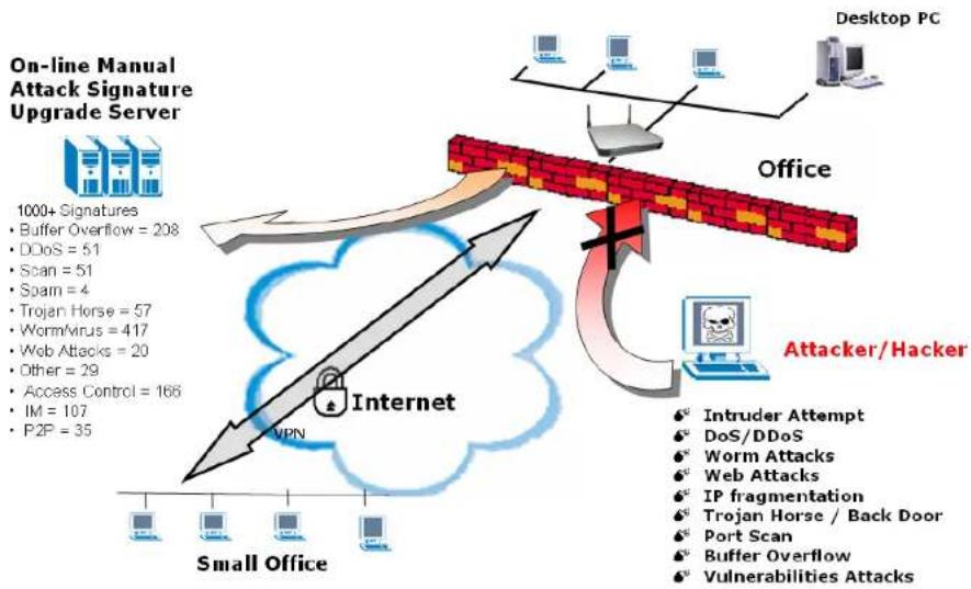
Figure 2-2: IPS Scenarios
IPS is an advanced technology to protect your network from malicious attacks. IPS works together with your SPI Firewall, IP Based Access List (IP ACL), Network Address Port Translation (NAPT), and Virtual Private Network (VPN) to achieve the highest amount of securities.
IPS works by providing real-time detection and prevention as an in-line module in a router. The Wireless-N Security Router has hardware-based acceleration for real-time pattern matching for malicious attacks. It actively filters and drops malicious TCP/UDP/ICMP/IGMP packets and can reset TCP connections. This protects your client PCs and servers running various operating systems including Windows, Linux, and Solaris from network worm attacks. However, this system does not prevent viruses attached emails.
Chapter 2: Networking and Security Basics The Intrusion Prevention System (IPS)
Wireless-N Gigabit Security Router with VPN
The P2P (peer to peer) and IM (instant messaging) control allows the system administrator to prevent network users from using those protocols to communicate with people over the Internet. This helps the administrators to set up company policies on how to use their Internet bandwidth wisely.
The signature file is the heart of the IPS system. It is similar to the Virus definition files on your PC's Anti-Virus programs. IPS uses this file to match against packets coming in to the Router and performs actions accordingly. As of today, the Wireless-N Router is shipped with signature file version 1.1.4 and with a total of 1048 rules. The rules cover the following categories: DDoS, Buffer Overflow, Access Control, Scan, Trojan Horse, Misc., P2P, IM, Virus, Worm, and Web Attacks.
Customers are encouraged to update their IPS signature file regularly to prevent any new type of attacks on the Internet.
Wireless-N Gigabit Security Router with VPN
◆◆◆◆□▼◆□√+☆◆■■■\*★□◆□★◆□▼◆☆◆◆◆▽※☆※▽D□□\*+★☆☆
Why do I need a VPN?
Computer networking provides a flexibility not available when using an archaic, paper-based system. With this flexibility, however, comes an increased risk in security. This is why firewalls were first introduced. Firewalls help to protect data inside of a local network. But what do you do once information is sent outside of your local network, when e-mails are sent to their destination, or when you have to connect to your company's network when you are out on the road? How is your data protected?
That is when a VPN can help. VPNs are called Virtual Private Networks because they secure data moving outside of your network as if it were still within that network.
When data is sent out across the Internet from your computer, it is always open to attacks. You may already have a firewall, which will help protect data moving around or held within your network from being corrupted or intercepted by entities outside of your network, but once data moves outside of your network—when you send data to someone via e-mail or communicate with an individual over the Internet—the firewall will no longer protect that data.
At this point, your data becomes open to hackers using a variety of methods to steal not only the data you are transmitting but also your network login and security data. Some of the most common methods are as follows:
1) MAC Address Spoofing
Packets transmitted over a network, either your local network or the Internet, are preceded by a packet header. These packet headers contain both the source and destination information for that packet to transmit efficiently. A hacker can use this information to spoof (or fake) a MAC address allowed on the network. With this spoofed MAC address, the hacker can also intercept information meant for another user.
2) Data Sniffing
Data "sniffing" is a method used by hackers to obtain network data as it travels through unsecured networks, such as the Internet. Tools for just this kind of activity, such as protocol analyzers and network diagnostic tools, are often built into operating systems and allow the data to be viewed in clear text.
3) Man in the middle attacks
Once the hacker has either sniffed or spoofed enough information, he can now perform a "man in the middle" attack. This attack is performed, when data is being transmitted from one network to another, by rerouting the
Chapter 3: Planning Your Virtual Private Network (VPN)
Why do I need a VPN?
vpn (virtual private network): a security measure to protect data as it leaves one network and goes to another over the Internet
packet: a unit of data sent over a network
Wireless-N Gigabit Security Router with VPN
data to a new destination. Even though the data is not received by its intended recipient, it appears that way to the person sending the data.
These are only a few of the methods hackers use and they are always developing more. Without the security of your VPN, your data is constantly open to such attacks as it travels over the Internet. Data travelling over the Internet will often pass through many different servers around the world before reaching its final destination. That's a long way to go for unsecured data and this is when a VPN serves its purpose.
What is a VPN?
A VPN, or Virtual Private Network, is a connection between two endpoints—a VPN Router, for instance—in different networks that allows private data to be sent securely over a shared or public network, such as the Internet. This establishes a private network that can send data securely between these two locations or networks.
This is done by creating a “tunnel”. A VPN tunnel connects the two PCs or networks and allows data to be transmitted over the Internet as if it were still within those networks. Not a literal tunnel, it is a connection secured by encrypting the data sent between the two networks.
There are two popular ways to establish a secured tunnel over the Internet — IPsec (IP Security) and SSL (Secure Sockets Layer). IPsec runs on top of the IP layer and SSL runs over HTTP sessions. IPsec provides better data throughput and SSL offers ease of use without the need of VPN client applications. The Wireless-N Gigabit Security Router supports IPsec VPN for maximum throughput on data security.
VPN was created as a cost-effective alternative to using a private, dedicated, leased line for a private network. Using industry standard encryption and authentication techniques—IPsec, short for IP Security—the VPN creates a secure connection that, in effect, operates as if you were directly connected to your local network. Virtual Private Networking can be used to create secure networks linking a central office with branch offices, telecommuters, and/or professionals on the road (travelers can connect to a VPN Router using any computer with the Linksys VPN client software.)
There are two basic ways to create a VPN connection:
• VPN Router to VPN Router
- Computer (using the Linksys VPN client software) to VPN Router
The VPN Router creates a "tunnel" or channel between two endpoints, so that data transmissions between them are secure. A computer with the Linksys VPN client software can be one of the two endpoints (refer to "Appendix C: Using the Linksys QuickVPN Software for Windows 2000 or XP"). If you choose not to run the VPN client software, any computer with the built-in IPsec Security Manager (Microsoft 2000 and XP) allows the VPN Router
Chapter 3: Planning Your Virtual Private Network (VPN) What is a VPN?
encryption: encoding data transmitted in a network
Ip (internet protocol): a protocol used to send data over a network
software: instructions for the computer

IMPORTANT: You must have at least one VPN Router on one end of the VPN tunnel. At the other end of the VPN tunnel, you must have a second VPN Router or a computer with the Linksys VPN client
Wireless-N Gigabit Security Router with VPN
to create a VPN tunnel using IPsec (refer to "Appendix C: Configuring IPsec between a Windows 2000 or XP PC and the Router"). Other versions of Microsoft operating systems require additional, third-party VPN client software applications that support IPsec to be installed.
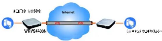
VPN Router to VPN Router
An example of a VPN Router-to-VPN Router VPN would be as follows. At home, a telecommuter uses his VPN Router for his always-on Internet connection. His router is configured with his office's VPN settings. When he connects to his office's router, the two routers create a VPN tunnel, encrypting and decrypting data. As VPNs utilize the Internet, distance is not a factor. Using the VPN, the telecommuter now has a secure connection to the central office's network, as if he were physically connected. For more information, refer to "Appendix C: Configuring a Gateway-to-Gateway IPsec Tunnel."
Computer (using the Linksys VPN client software) to VPN Router
The following is an example of a computer-to-VPN Router VPN. In her hotel room, a traveling businesswoman dials up her ISP. Her notebook computer has the Linksys VPN client software, which is configured with her office's IP address. She accesses the Linksys VPN client software and connects to the VPN Router at the central office. As VPNs utilize the Internet, distance is not a factor. Using the VPN, the businesswoman now has a secure connection to the central office's network, as if she were physically connected.
For additional information and instructions about creating your own VPN, please visit Linksys's website at www.linksys.com. You can also refer to "Appendix B: Using the Linksys QuickVPN Software for Windows 2000 or XP" and "Appendix C: Configuring a Gateway-to-Gateway IPsec Tunnel."
flowchart
graph LR
    A["数据采集"] --> B["WRVS4400N"]
    B --> C["Internet"]
    C --> D["路由器"]
    D --> E["服务器"]
    style C fill:#99ccff,stroke:#333
    style D fill:#99ccff,stroke:#333
Figure 3-1: VPN Router to VPN Router
flowchart
graph TD
    A["Internet"] -->|VPN| B["VPH"]
    B --> C["VMH"]
    C --> D["Computer Interface"]
    A -->|VPH| E["VMH"]
    E --> F["VMH"]
    style A fill:#f9f,stroke:#333
    style B fill:#ccf,stroke:#333
    style C fill:#cfc,stroke:#333
    style D fill:#fcc,stroke:#333
    style E fill:#cff,stroke:#333
Figure 3-2: Computer to VPN Router
Wireless-N Gigabit Security Router with VPN

text_image
Row of symbolic and stylized geometric icons including asterisks, squares, stars, and chevronsThe Front Panel
The Router's LEDs are located on the front panel of the Router.

natural_image
Front view of a wireless router with network ports and indicator lights (no readable text or symbols beyond branding)Figure 4-1: Front Panel
LEDs
POWER
Green. The POWER LED lights up when the Router is powered on. The LED flashes when the Router runs a diagnostic test.
Chapter 4: Getting to Know the Router The Front Panel
Wireless-N Gigabit Security Router with VPN
| DIAG | Red. The DIAG LED lights up when the system is not ready. The LED light goes off when the system is ready. The Diag LED blinks during Firmware upgrades. |
| IPS | Green/Red. The IPS LED lights up when the IPS function is enabled. The LED light is off when the IPS functions are disabled. The IPS LED flashes green when an external attack is detected. The IPS LED flashes red when an internal attack is detected. |
| WIRELESS | Green. The WIRELESS LED lights up when the wireless module is enabled. The LED is off when the wireless module is disabled. The WIRELESS LED flashes green when the data is transmitting or receiving on the wireless module. |
| 1-4 (ETHERNET) | Green. For each port, there are three LEDs. If the corresponding LED is continuously lit, the Router is connected to a device at the speed indicated through the corresponding port (1, 2, 3, or 4). The LED flashes when the Router is actively sending or receiving data. |
| INTERNET | Green. The INTERNET LED lights up the appropriate LED depending upon the speed of the device that is attached to the Internet port. If the Router is connected to a cable or DSL modem, typically the 10 LED will be the only LED lit up (i.e. 10Mbps). The LED Flashes during activity. |
Wireless-N Gigabit Security Router with VPN
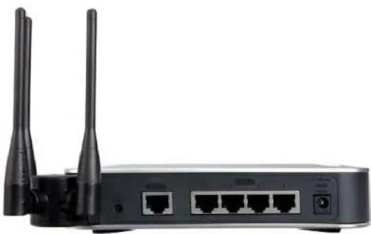
The Back Panels
The Router's ports and Reset button are located on the back panel of the Router.
natural_image
Front view of a wireless router with two antennas and ports (no visible text or labels)Figure 4-2: Back Panel
Reset Button The Reset button can be used in one of two ways:
If the Router is having problems connecting to the Internet, press the Reset button for just a second with a paper clip or a pencil tip. This is similar to pressing the Reset button on your PC to reboot it.
If you are experiencing extreme problems with the Router and have tried all other troubleshooting measures, press and hold in the Reset button for 10 seconds. This will restore the factory defaults and clear all of the Router's settings, such as port forwarding or a new password.
Ports
INTERNET The INTERNET port connects to a cable or DSL modem.
1-4 (ETHERNET) The four ETHERNET ports connect to network devices, such as PCs, print servers, or additional switches.
POWER The POWER port is where you will connect the included AC power cable.
Chapter 4: Getting to Know the Router
The Back Panels
Wireless-N Gigabit Security Router with VPN
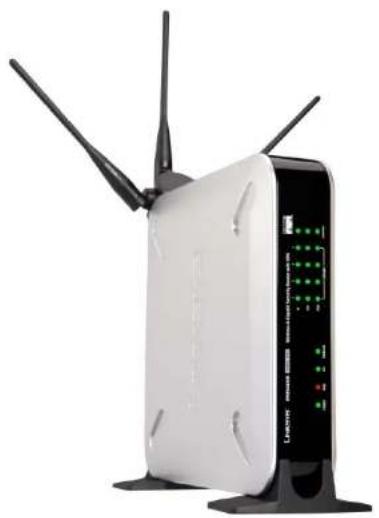
Antennas and Positions
The Access Point can be placed in three different positions. It can be either stackable, standalone, or wall-mount.
Antenna
The Access Point has three non-detachable 2dBi omni-directional antennas. The three antennas have a base that can rotate 90 degrees when in the standing position. The three antennas will all be used to support 2X3 MIMO diversity in wireless-N mode.

natural_image
Exterior view of a wireless router with three antennas and a display screen (no readable text or symbols)Figure 4-3: Stackable Position and its Antenna Setup
natural_image
White wireless router with black antennas and control panel (no visible text or symbols)Figure 4-4: Standalone Position and its Antenna Setup
Chapter 4: Getting to Know the Router Antennas and Positions
Wireless-N Gigabit Security Router with VPN
◆◆◆□▼◆□×◆◆□■■※▼◆■▼◆◆◆□◆▼◆□
Overview
To set up your network, you will do the following:
- Connect the Router to one of your PCs according to the instructions in this chapter.
- By default, Windows 98, 2000, Millennium, and XP computers are set to obtain an IP address automatically, so unless you have changed the default setting, then you will not need to configure your PCs. (If you do need to configure your PCs, refer to Windows Help for more information.)
- Set up and configure the Router with the setting(s) provided by your Internet Service Provider (ISP) according to "Chapter 6: Setting Up and Configuring the Router."
The installation technician from your ISP should have left the setup information with you after installing your broadband connection. If not, you can call your ISP to request the information. Once you have the setup information for your specific type of Internet connection, then you can begin installation and setup of the Router.

flowchart
graph LR
    A["Internet"] --> B["Cable or DSL Modem"]
    B --> C["Wireless-N Gigabit Security Router"]
    C --> D["PC with Ethernet Adapter"]
    C --> E["Notebook with Ethernet Adapter"]
Figure 5-1: Example of a Typical Network
Chapter 5: Connecting the Router Overview
Wireless-N Gigabit Security Router with VPN
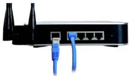
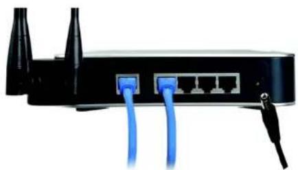
Connection Instructions
- Before you begin, make sure that all of your hardware is powered off, including the Router, PCs, hubs, switches, and cable or DSL modem.
- Connect one end of an Ethernet network cable to one of the numbered ports on the back of the Router. Connect the other end to an Ethernet port on a network device, e.g., a PC, print server, hub, or switch.
Repeat this step to connect more PCs or other network devices to the Router. - Connect your cable or DSL modem's Ethernet cable to the Router's Internet port.
- Power on the cable or DSL modem and the other network device if using one.
- Connect the included AC power cable to the Router's Power port on the side of the Router, and then plug the power adapter into an electrical outlet.
The Power LED on the front panel will light up as soon as the power adapter is connected properly.
Proceed to "Chapter 6: Setting Up and Configuring the Router."

natural_image
Close-up of a black wireless router with two antennas and a blue USB cable inserted (no text or symbols visible)Figure 5-2: Connect a PC
natural_image
Front view of a black wireless router with two Ethernet ports and a blue USB cable (no text or symbols visible)Figure 5-3: Connect the Internet
natural_image
Close-up of a black wireless router with two blue cables, no visible text or symbolsFigure 5-4: Connect the Power
Wireless-N Gigabit Security Router with VPN
Placement Options
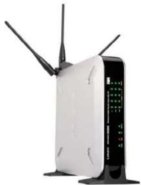
There are three ways to place the Wireless-N Router. The first way is to place it horizontally on a surface, so it sits on its four rubber feet. The second way is to stand the Wireless Router vertically on a surface. The third way is to mount it on a wall. The stand and wall-mount options are explained in further detail below.
Stand Option
- Locate the Router's left side panel.
- The Router includes two stands. With the two large prongs facing outward, insert the short prongs into the little slots in the Router, and push the stand upward until it snaps into place.
Repeat this step with the other stand.
Now that the hardware installation is complete, proceed to "Chapter 6: Setting up and Configuring the Wireless-N Router," for directions on how to set up the Wireless-N Router."
natural_image
White wireless router with multiple antennas and a control panel (no visible text or symbols)Figure 5-5: The Stand Option

text_image
Large ProngsFigure 5-6: Stand
Chapter 5: Connecting the Router Placement Options
Wireless-N Gigabit Security Router with VPN
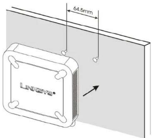
Wall-Mount Option
You will need two suitable screws (See Figure 5-7) to mount the Router. Make sure the screw size can fit into the criss-cross wall-mount slots.
- On the Wireless Router's back panel are two criss-cross wall-mount slots.
- Determine where you want to mount the Wireless Router, and install two screws that are 2-9/16 in (64.5mm) apart.
- Line up the Wireless Router so that the wall-mount slots line up with the two screws.
- Place the wall-mount slots over the screws and slide the Wireless Router down until the screws fit snugly into the wall-mount slots.
Now that the hardware installation is complete, proceed to "Chapter 6: Setting up and Configuring the Wireless-N Router," for directions on how to set up the Wireless-N Router."

text_image
Suggested Mounting Hardware 5-6 mm 1.5-2.0 mm NOTE: LINKSYS is not responsible for damages incurred by insecure wall-mounting hardwareFigure 5-7: Mounting Dimensions
text_image
64.5mm LINKSYS®Figure 5-8: Wall Mounting Hardware
Wireless-N Gigabit Security Router with VPN
◆◆◆□▼◆□×↑★◆■◆□◆◆◆□◆◆◆□◆◆◆□
Overview
The Wireless Router has been designed to be functional right out of the box with the default settings. However, if you'd like to change these settings, the Wireless Router can be configured through your web browser with the Web-based Utility. This chapter explains how to use the Utility to perform the most basic settings.
The Utility can be accessed via web browsers, such as Microsoft Internet Explorer or Mozilla Firefox through the use of a computer that is networked with the Wireless Router.
Basic Setup
For a basic network setup, most users only need to use the following screens of the Utility:
- Setup->WAN
Click the Setup tab and then select the WAN screen. Select the appropriate Internet Connection Type according to your ISP if connecting your WAN port to the WAN (DSL or cable modem). Otherwise, most cases can leave the default setting to get a WAN port IP address from a DHCP server.
- Setup->Advanced Routing Click the Setup tab and then select the Advanced Routing screen. If you are connecting the Router to the Internet, leave the default setting. Otherwise, choose the Intranet Router Operation Mode to disable NAT (Network Address Translation).
- Management Click the Administration tab and then select the Management screen. Change the access password for the Router's Web-based Utility. The default username and password are admin.
Most users will also customize their wireless settings:
- Wireless On the Wireless screen, change the default SSID on the Basic Wireless Settings Tab. Select the level of security under the Wireless Security Tab and complete the options for the selected security mode. When the appropriate security mode is configured, disable SSID Broadcast on the Basic Wireless Settings Tab.
Chapter 6: Setting Up and Configuring the Router Overview
Wireless-N Gigabit Security Router with VPN
How to Access the Web-based Utility
There are two ways to connect to your Wireless Router for the first time.
- Connect your PC to one of the four LAN ports on the Router. (Refer to "Chapter 5: Connecting the Router.") Then, configure your PC to obtain IP address automatically through a DHCP server.
- Although it is not recommended, you can also connect your PC wirelessly to the Wireless Router. Then, configure the wireless interface of your PC to obtain IP address automatically through a DHCP server. It is not recommended, because you can easily lose your connection through wireless configuration changes.
To access the Web-based Utility of the Router:
- Launch a web browser, such as Internet Explorer or Mozilla Firefox, and enter the Router's default IP address, 192.168.1.1, in the Address field. Press the Enter key.
- A screen will appear asking you for your User name and Password. Enter admin in the User Name field, and enter your password (default password is admin) in the Password field. Then click the OK button.
How to Navigate the Utility
The Web-based Utility consists of the following nine main tabs: Setup, Wireless, Firewall, VPN, QoS, Administration, IPS, L2 Switch and Status. Additional screens (sub tabs) will be available from most of the main tabs.
The following briefly describes the main & sub tabs of the Utility.
Setup
You will use the Setup tabs to define the Router's basic functionality.
- IP Version. This screen provides options for IPv4 mode or Dual-Stack IPv4 and IPv6 mode.
- WAN. The Internet connection settings are entered and displayed on this screen.
• LAN. The Local Area Network (LAN) settings are entered and displayed on this screen. - DMZ. The DMZ (Demilitarized Zone) Host feature allows one local user to be exposed to the Internet to use a special-purpose service such as Internet gaming or video conferencing.
Chapter 6: Setting Up and Configuring the Router How to Access the Web-based Utility
Address
http://192.168.1.1
Figure 6-1: Router's IP Address

text_image
Connect to 192.168.1.1 Linksys WRVSH400N User name: admin Password: ****** Remember my password OK CancelFigure 6-2: Login Screen for Web-based Utility
Wireless-N Gigabit Security Router with VPN
- MAC Address Clone. Some ISPs require that you register a MAC address. This feature clones your network adapter's MAC address onto the Router, which prevents you from having to call your ISP to change the registered MAC address to the Router's MAC address.
- Advanced Routing. Select the Router's operation mode either connecting to the Internet or Intranet (NAT is only enabled while connecting to the Internet). Configure dynamic or static routing. The Router support RIP version 1 and 2 to automatically exchange routing information and establish its routing table.
- Time. Change the time settings on this screen.
Wireless
You will use the Wireless tabs to enter a variety of wireless settings for the built-in access point of the Router.
- Basic Wireless Settings. Choose the wireless network mode (e.g. B/G/N-Mixed), SSID, and radio channel on this screen.
- Wireless Security. Use this screen to configure the built-in access point's security settings.
- Wireless Connection Control. Use this screen to control the wireless connections from client devices to the Router.
- Advanced Wireless Settings. Use this screen to configure the built-in access point's more advanced wireless settings (e.g. Tx Rate Limiting, Channel Bandwidth, etc.).
Firewall
You will use the Firewall tabs to configure basic firewall settings, IP access list, and Network Address Port Translation settings for your network's security.
- Basic Settings. Basic Firewall settings are configured from here.
- IP Based ACL. Define IP based Access List to block specific hosts, networks, and protocols (services).
- Internet Access Policy. This screen defines the time schedule to allow or block complete Internet access or to specific URLs from the Router.
- Single Port Forwarding. Use this screen to set up public services or other specialized Internet applications with a single port on your network.
- Port Range Forwarding. Use this screen to set up public services or other specialized Internet applications on your network using a port range.
Chapter 6: Setting Up and Configuring the Router How to Navigate the Utility
Wireless-N Gigabit Security Router with VPN
- Port Range Triggering. Use this screen to set up triggered ranges and forwarded ranges to allow special Internet applications to pass through this NAT Router.
- Service. Use this screen to define customized IP applications based on TCP or UDP. The user-defined service type will be available when defining IP based ACL rules.
VPN
You will use VPN tabs to configure VPN tunnels and accounts to establish a secured channel through Internet.
- IPSec VPN. The VPN Router can create one or multiple tunnels (or secure channel) that each connect between two endpoints, so that the transmitted data or information between these endpoints is secure.
• VPN Client Accounts. Use this screen to designate VPN clients and their passwords. - VPN Pass Through. This tab allows you to disable IPSec Passthrough, PPTP Passthrough, and L2TP Passthrough.
QoS
The Router support two types of Quality of Service (QoS) traffic.
- Application-based QoS. This allows you to assign different traffic priorities for different types of applications.
- Port-based QoS. This allows you to assign traffic priorities on different LAN ports.
Administration
You will use Administration tabs for systems administration purposes.
- Management. You can alter the Router's password, its access privileges, SNMP settings, and UPnP settings on this screen.
- Log. This screen allows the configuration of Log settings.
- Diagnostics. On this screen, you can check the connection between the Router and another network device on the LAN or Internet.
- Config Management. This screen allows you to save and restore Router configuration settings.
- Factory Defaults. If you need to restore the Router's factory defaults, use this screen.
Chapter 6: Setting Up and Configuring the Router How to Navigate the Utility
Wireless-N Gigabit Security Router with VPN
- Firmware Upgrade. Use this screen to upgrade the Router's firmware.
IPS
You will use this tab for advanced configuration on built-in Intrusion Prevention System (IPS) inside the Router.
- Configure. Enable or disable IPS functions from this screen.
- P2P/IM. Allows or blocks specific Peer to Peer (P2P) networks and Instant Messaging (IM) applications.
• Report. Provides reports of network traffic and malicious attacks.
• Information. Provides the signature file version and the Protection Scope of the IPS system.
L2 Switch
You will use this tab to configure layer 2 switching features on the 4 port Ethernet Switch (LAN ports only).
• VLAN. Virtual Local Area Network (VLAN) assignment is done on this screen.
- RADIUS. Used for configuration of Remote Authorization Dial-In User Service (RADIUS) settings.
- Port Setting. Allows configuration of port speeds and duplex.
- Cable Diagnostics. Used for testing the cables that are connected to the LAN ports.
Status
You will use this tab to get the current status on the Router.
- WAN / Gateway. This screen provides basic information like firmware version and status information on the WAN port.
- Local Network. This screen provides status information about the local network (four Ethernet Ports).
- Wireless LAN. This screen provides status information on Wireless LAN.
- System Performance. This screen provides traffic statistics on LAN and Wireless LAN ports.
- VPN Clients. This screen provides status information about the Router's VPN clients (gateway-to-client).
- IPsec. This screen provides status information about the Router's IPsec VPN tunnels (gateway-to-gateway).
Chapter 6: Setting Up and Configuring the Router How to Navigate the Utility
Wireless-N Gigabit Security Router with VPN
Setup Tab
The Setup screen contains all of the Router's basic setup functions. The Router can be used in most network settings without changing any of the default values. Some users may need to enter additional information in order to connect to the Internet through an ISP (Internet Service Provider) or broadband (DSL, cable modem) carrier.
IP Versions
IPv4 Only. This option utilizes IPv4 on the Internet and local network.
Dual-Stack IP. This options utilize IPv4 over the Internet and IPv4 and IPv6 on the local network.
Click the Save Settings button to save the network settings or click the Cancel Changes button to undo your changes.

text_image
LINKSYS A Setup of LinkSYS, Inc. Windows NT-Skipable Security Locator with VTPS systemset Setup Network Firewall VPN QoS Administration IPS L2 Switch Status IP Options Mode FWR LAN Link Port Port Port Dual-StackAP Port PortandPort Link: 16.0 percent to select System: 16.0 percent to select None... More... Data Settings Cancel ChangesFigure 6-1: Setup - IP Versions
Chapter 6: Setting Up and Configuring the Router Setup Tab
Wireless-N Gigabit Security Router with VPN
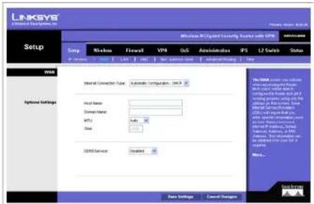
WAN
The WAN Setup screen provides Internet Connection Type and DDNS configurations on the WAN port of the Wireless Router. Before starting, you need to find out the Internet Connection Type and settings used by your ISP. If the Router is used as an Intranet Router, you can mostly use the default settings. If you want to use the dynamic DNS feature, you will need to sign up for a DDNS service.
Internet Connection Type
The Router supports six connection types. Each WAN Setup screen and available options will differ depending on what kind of connection type you select.
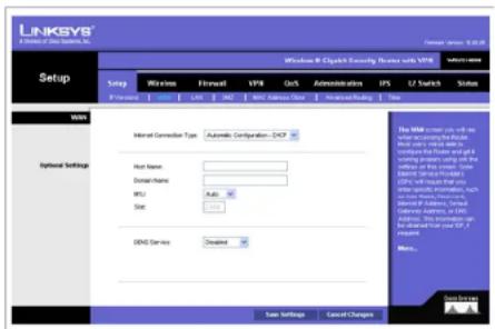
Automatic Configuration - DHCP
By default, the Router's Configuration Type is set to Automatic Configuration - DHCP. The Router will get its IP address from a DHCP server of the ISP. Most cable modem ISPs use this option.
text_image
LINKSYS Microsoft Office System, Inc. Setup Link Network Flowell VPR Out Administration PS L2 Switch Status Watts Advanced Connection Type: Automatic Connection - 3.0.4.3 Host Name: Domain Name: MPT: Size: SPR/Service Created The Watts are used to access the network to a specific network. The network is designed to be a network-based configuration with the following functions: - All networks must include the network's own IP address, which is required to access the network to a specific IP address, which is required to access the network to a specific IP address. - All networks must have a network name: SPR/Service - All networks must have a network name: SPR/Service - All networks must have a network name: SPR/Service - All networks must have a network name: SPR/Service - All networks must have a network name: SPR/Service - All networks must have a network name: SPR/Service - All networks must have a network name: SPR/Service - All networks must have a network name: SPR/Service - Additional settings Save Settings Cancel Settings OK Cancel OptionsFigure 6-2: Setup - WAN (DHCP)
Static IP
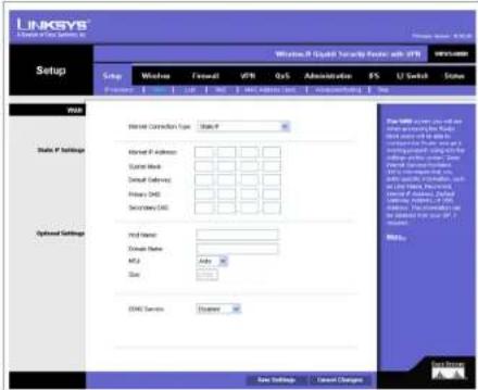
If your connection uses a permanent IP address to connect to the Internet, then select Static IP.
Internet IP Address. This is the Router's IP address on the WAN port that can be reached from the Internet. Your ISP will provide you with the IP Address you need to specify here.
Subnet Mask. This is the Router's Subnet Mask on the WAN port. Your ISP will provide you this information and your IP Address.
Default Gateway. Your ISP will provide you with the Default Gateway (Router) to reach the Internet.
Primary DNS (Required) and Secondary DNS (Optional). Your ISP will provide you with at least one DNS (Domain Name System) Server IP Address to resolve host name to IP address mapping.
text_image
LINKSYS Setup Windows 8.0 System Security Router with IFRS Setup Windows Forward VPS QS Administration FS U Switch Stone Status: P Settings Model Connection Type: State P Model P Address: Custom Work: Default Delivery: Primary DNS: Secondary DNS: Optimal Settings Prod Name: Domain Name: M2.2 Auto... Size DNS Services: Default New Settings Cancel Changes Data Tools: www.lntz.com.cn or www.lntz.com.cn (http://www.lntz.com.cn) Data Tools: www.lntz.com.cn or www.lntz.com.cn (http://www.lntz.com.cn) Data Tools: www.lntz.com.cn or www.lntz.com.cn (http://www.lntz.com.cn) Data Tools: www.lntz.com.cn or www.lntz.com.cn (http://www.lntz.com.cn) Data Tools: www.lntz.com.cn or www.lntz.com.cn (http://www.lmtz.com.cn) Data Tools: www.lntz.com.cn or www.lntz.com.cn (http://www.lntz.com.cn) Data Tools: www.lntz.com.cn or www.lntz.com.cn (http://www.lntz.com.cn) Data Tools: www.lntz.com.cn or www.lntz.com.cn (http://www.lntz.com.cn) Data Tools: www.lntz.com.cn or www.lntz.com.cn (https://www.lntz.com.cn) Data Tools: www.lntz.com.cn or www.lntz.com.cn (http://www.lntz.com.cn) Data Tools: www.lntz.com.cn or www.lntz.com.cn (http://www.lntz.com.cn) Data Tools: www.lntz.com.cn or www.lntz.com.cn (http://www.lntz.com.cn) Data Tools: www.lntz.com.cn or www.lntZ.com.cn (http://www.lntz.com.cn) Data Tools: www.lntz.com.cn or www.lntz.com.cn (http://www.lntz.com.cn) Data Tools: www.lntz.com.cn or www.lntz.com.cn (http://www.lntz.com.cn) Data Tools: www.lntz.com.cn or www.lntz.com.cn (http://www.lntz.com.cn) Data Tools: www.lntz.com.cn Data Tools: www.lntz.com.cn or www.lntz.com.cn (http://www.lntz.com.cn) Data Tools: www.lntz.com.cn or www.lntz.com.cn (http://www.lntz.com.cn) Data Tools: www.lntz.com.cn or www.lntz.com.cn (http://www.lntz.com.cn) Data Tools: www.lntz.com.cn or www.lntz.com.cn (http://www.bjrc.org/10000000000000000000000000000000000000000000000000000000000000000000000000000000000000000000000000000 Data Tools: www.lntz.com.cn or www.lntz.com.cnFigure 6-3: Setup - WAN (Static IP)
Wireless-N Gigabit Security Router with VPN
PPPoE
Most DSL-based ISPs use PPPoE (Point-to-Point Protocol over Ethernet) to establish Internet connections. If you are connected to the Internet through a DSL line, check with your ISP to see if they use PPPoE. If they do, you will have to enable PPPoE.
User Name and Password. Enter the User Name and Password provided by your ISP for PPPoE authentication.
Connect on Demand: Max Idle Time. You can configure the Router to cut the Internet connection after it has been inactive for a specified period of time (Max Idle Time). If your Internet connection has been terminated due to inactivity, Connect on Demand enables the Router to automatically re-establish your connection as soon as you attempt to access the Internet again. If you wish to activate Connect on Demand, click the Connect on Demand option and enter the number of minutes you want to have elapsed before your Internet connection terminates in the Max Idle Time field. Use this option to minimize your DSL connection time if it is charged based on time. This option is disabled by default.
Keep Alive Redial period. This option allows the Router will periodically check your Internet connection. If you are disconnected, then the Router will automatically re-establish your connection. To use this option, click the option next to Keep Alive. In the Redial Period field, you specify how often you want the Router to check the Internet connection. This option is enabled by default and the default Redial Period is 30 seconds. Use this option to minimize your Internet connection response time since it will always be connected.
PPTP
Point-to-Point Tunneling Protocol (PPTP) is a service that applies to connections in Europe and Israel only.
IP Address. This is the Router's IP address, when seen from the WAN, or the Internet. Your ISP will provide you with the IP Address you need to specify here.
Subnet Mask. This is the Router's Subnet Mask. Your ISP will provide you the Subnet Mask and your IP address.
Default Gateway. Your ISP will provide you with the Default Gateway IP Address.
PPTP Server. Enter the IP address of the PPTP server.
User Name and Password. Enter the User Name and Password provided by your ISP.

text_image
LINKSYS Details of the Windows, Inc. Windows 90 Capital Security Subnet, VPR Intricate Setup Setup Network Forward VPR QoS Allocation EPS L2 Switch Status P. Inserer USB LAN TCP MSY Address Name Advanced Modging New Windows Internal Connection Type: PPPoL Username: Personal: Connect on Ethernet Media Time: Mobile Help Active/Radial packet: 35 MHz/PS Optional Settings: Host Name: Domain Name: MPIU Sub: DIME Service Created Do NOT Use Use Settings Cancel Changes For MSY: www.rsc.org.cn or more information available in this system. We will use a local server to access to the Internet. We will use a local server to access to the Internet. We will use a local server to access to the Internet. We will use a local server to access to the Internet. We will use a local server to access to the Internet. We will use a local server to access to the Internet. We will use a local server to access to the Internet. We will use a local server to access to the Internet. We will use a local server to access to the Internet. We will not use any other information, such as any other information, or any other information. We will not use any other information, such as any other information. We will not use any other information, such as any other information. We will not use any other information, such as any other information. We will not use any other information, such as any other information. We will not use any other information, such as any other information. We will not use any other information, such as any other information. We will not use any other information, such as any other information. We will not use any other information, such as any others. © 2016Figure 6-4: Setup - WAN (PPPoE)

text_image
LINKSYS A Software for Data Systems, Inc. Setup Windows X Capital Currently Receiver with USB www.rkgs.com Setup Window Forward VPR QoS Administrative IPS U2 Switch Status Internet Connection Type: USB IP address: Submit Mio Default Delivery: PHP Service: Username: Password: Connect via Default Name (Name) Keep All Redgegrees 30 Seconds Host Name: Domain Name: Mia: Size: ODNS Services Download File List Save Settings Cancel Changes File List Internet User will not use any access to the Web or any other web. The Web will be used to complete the Web and get a Web application. Web is not using any other Web. Some Web is available to the Web or any other Web. Web is not using any other Web. Web is not using any other Web. Web is not using any other Web. Web is not using any other Web. Web is not using any other Web. Web is not using any other Web. Web is not using any other Web. Web is not using any other Web. Web is not using any other Web. Web is not using any other Web. Web is not using any other Web. Web is not using any other Web. Web is not using any other Web.Figure 6-5: Setup - WAN (PPTP)
Wireless-N Gigabit Security Router with VPN
Connect on Demand: Max Idle Time. You can configure the Router to cut the Internet connection after it has been inactive for a specified period of time (Max Idle Time). If your Internet connection has been terminated due to inactivity, Connect on Demand enables the Router to automatically re-establish your connection as soon as you attempt to access the Internet again. If you wish to activate Connect on Demand, click the Connect on Demand option and enter the number of minutes you want to have elapsed before your Internet connection terminates in the Max Idle Time field. Use this option to minimize your DSL connection time if it is charged based on time. This option is disabled by default.
Keep Alive Redial period. If you select this option, the Router will periodically check your Internet connection. If you are disconnected, then the Router will automatically re-establish your connection. To use this option, click the option next to Keep Alive. In the Redial Period field, you specify how often you want the Router to check the Internet connection. This option is enabled by default and the default Redial Period is 30 seconds. Use this option to minimize your Internet connection response time since it will always be connected.
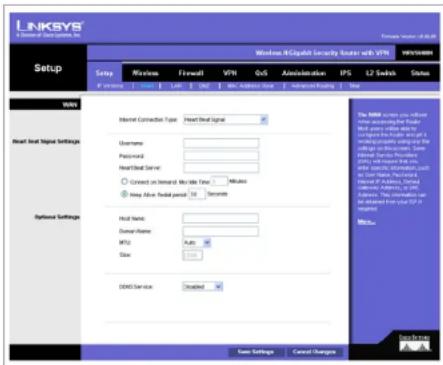
Heart Beat Signal
Heart Beat Signal is a service used in Australia. Check with your ISP for the necessary setup information.
User Name and Password. Enter the User Name and Password provided by your ISP.
Heart Beat Server. Enter the IP address of the Heart Beat server.
Connect on Demand: Max Idle Time. You can configure the Router to cut the Internet connection after it has been inactive for a specified period of time (Max Idle Time). If your Internet connection has been terminated due to inactivity, Connect on Demand enables the Router to automatically re-establish your connection as soon as you attempt to access the Internet again. If you wish to activate Connect on Demand, click the Connect on Demand option and enter the number of minutes you want to have elapsed before your Internet connection terminates in the Max Idle Time field. Use this option to minimize your DSL connection time if it is charged based on time. This option is disabled by default.
Keep Alive Redial period. If you select this option, the Router will periodically check your Internet connection. If you are disconnected, then the Router will automatically re-establish your connection. To use this option, click the option next to Keep Alive. In the Redial Period field, you specify how often you want the Router to check the Internet connection. This option is enabled by default and the default Redial Period is 30 seconds. Use this option to minimize your Internet connection response time since it will always be connected.
text_image
LINKSYS A Division of User Systems, Inc. Windows - iOS-Caspalt Security Router with VTR VRS: 58800 Setup Network Forward VPN GoS Administration IPS L2 Switch Status Watts Internet Connection Type Front Signal Username: Password: Front Signal Name: Connect on Serial Mode Time Mobile Play Alive Packet Period 10 Second Optional Settings Host name: DSL32 Auto Shift DDMS Service Created New Settings Cancel Options The MSU covers you without access to the E&P. Note that your network is currently available in the OS. The OS will not be used to access any other OS. This is also available in the OS. For example, it is recommended to be obtained from your TCP or Windows. Please note that this is available in the OS. The OS will not be obtained from your TCP or Windows. Please note that this is available in the OS.Figure 6-6: Setup - WAN (Heart Beat Signal)
Wireless-N Gigabit Security Router with VPN
L2TP
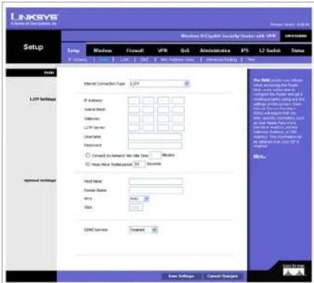
Layer 2 Tunneling Protocol (L2TP) is a service that tunnels Point-to-Point Protocol (PPP) across the Internet. It is used mostly in European countries. Check with your ISP for the necessary setup information.
IP Address. This is the Router's IP address, when seen from the WAN, or the Internet. Your ISP will provide you with the IP Address you need to specify here.
Subnet Mask. This is the Router's Subnet Mask. Your ISP will provide you with the Subnet Mask and your IP address.
Gateway. Your ISP will provide you with the Default Gateway IP Address.
L2TP Server. Enter the IP address of the L2TP server.
User Name and Password. Enter the User Name and Password provided by your ISP.
Connect on Demand: Max Idle Time. You can configure the Router to cut the Internet connection after it has been inactive for a specified period of time (Max Idle Time). If your Internet connection has been terminated due to inactivity, Connect on Demand enables the Router to automatically re-establish your connection as soon as you attempt to access the Internet again. If you wish to activate Connect on Demand, click the Connect on Demand option and enter the number of minutes you want to have elapsed before your Internet connection terminates in the Max Idle Time field. Use this option to minimize your DSL connection time if it is charged based on time. This option is disabled by default.
Keep Alive Redial period. If you select this option, the Router will periodically check your Internet connection. If you are disconnected, then the Router will automatically re-establish your connection. To use this option, click the option next to Keep Alive. In the Redial Period field, you specify how often you want the Router to check the Internet connection. This option is enabled by default and the default Redial Period is 30 seconds. Use this option to minimize your Internet connection response time since it will always be connected.
text_image
LinkSYS Setup Network Internal Connection Type: L2F IP Address: Select Switch Deluxe: L2F Server Uniprotte Accessories: Correct on ambient light time Time Help More than power 25 seconds Host Address: Domain Address: MFC: Data: COM Services: Transport User Settings Cancel Options Windows X Capital Security Server 4.087 Internet L2 Switch Status New Settings Cancel Options One NET user will choose new access the network which will switch to a network or switch to another network with the network's access. One network will switch to a network with the network's access. One network will switch to a network with the network's access. One network will switch to a network with the network's access. One network will switch to a network with the network's access. One network will switch to a network with the network's access. One network will switch to a network with the network's access. One network will switch to a network with the network's access. One network will switch to a network with the internet will switch to a network with the internet's access. One network will switch to a network with the internet's access. One network will switch to a network with the internet's access. One network will switch to a network with the internet's access. One network will switch to a network with the internet's access. One network will switch to a network with the internet's access. One network will switch to a network with the internet's access. One network will switch to a network with the internet's access. One network will switches to a network with the internet's access. One network will switch to a network with the internet's access. One network will switch to a network with the internet's access. One network will switch to a network with the internet's access. One network will switch to a network with the internet's access. One network will switch to a network with the internet's access. One network will switch to a network with the internet's access. One network will switch to an additional network in the Internet (1.087) or other networks (1.087). The Internet will switch to an additional network in the Internet (1.087) or other networks (1.087). One network will switch to an additional network in the Internet (1.087) or other networks (1.087). One network will switch to an additional network in the Internet (1.087) One network will switch to an additional network in the Internet (1.087) One network will switch to an additional network in the Internet (1.087) One network will switch to an additional network in the Internet (1.087) One network will switch to an additional network in the Internet (1.087) One network will switch to an additional network in the Internet (1.087) One network will switch to an additional network in this Internet (1.087) One network will switch to an additional network in this Internet (1.087) One network will switch to an additional network in this Internet (1.087) One network will switch to an additional network in this Internet (1.087) One network will switch to an additional network in this Internet (1.087) One network will switch to an additional network in this Internet (1.087) One Network will switch to an additional network in this Internet (1.087) One Network will switch to an additional network in this Internet (1.087) One Network will switch to an additional network in this Internet (1.087) One Network will switch to an additional network in this Internet (1.087) One Network will switch to an additional network in this Internet (1.087) One Network will switch to an additional network in this Internet(1.087) One Network will switch to an additional network in this Internet(1.087) One Network will switch to an additional network in this Internet(1.087) One Network will switch to an additional network in this Internet(1.087) One Network will switch to an additional network in this Internet(1.087) One Network will switch to an additional network in this Internet(1.087) One Network will switches to an additional network in this Internet(1.087) One Network will switch to an additional network in this Internet(1.087) One Network will switch to an additional network in this Internet(1.087) One Network will switch to an additional network in this Internet(1.087) One Network will switch to an additional network in this Internet(1.087) One Network will switch to an additional network in this Internet(1,087) One Network will switch to an additional network in this Internet(1,087) One Network will switch to an additional network in this Internet(1,087) One Network will switch to an additional network in this Internet(1,087) One Network will switch to an additional network in this Internet(1,087) One Network will switch to an additional network in this Internet(1,087) One Network will switch to another additional network in this Internet(1,087) One Network will switch to another additional network in this Internet(1,087) One Network will switch to another additional network in this Internet(1,087) One Network will switch to another additional network in this Internet(1,087) One Network will switch to another additional network in this Internet(1,087) One Network will switch to another additional network in this Internet(1,0Figure 6-7: Setup - WAN (L2TP)
Wireless-N Gigabit Security Router with VPN
Optional Settings (Required by some ISPs)
This section is common for all the Internet Connection Types. Some of these settings may be required by your ISP. Verify with your ISP before making any changes.
Host Name: Some ISPs, usually cable ISPs, require a host name as identification. You may need to check with your ISP to see if your broadband Internet service is configured with a host name. In most cases you can leave this field blank.
Domain Name: Some ISPs, usually cable ISPs, require a domain name as identification. You may need to check with your ISP to see if your broadband Internet service is configured with a domain name. In most cases you can leave this field blank.
MTU: MTU is the Maximum Transmission Unit. It specifies the largest packet size permitted for Internet transmission. Select Manual if you want to manually enter the largest packet size that is transmitted. To have the Router select the best MTU for your Internet connection, keep the default setting, Auto.
Size: When Manual is selected in the MTU field, this option is enabled. The recommended setting for this field is 1500 (standard MTU size on Ethernet media).
text_image
LINKSYS A Security System, Inc. Forman version: 6.0.28 Setup Windows R Cliphark Security Server with VPR Winbase Setup Winbase Forward VPR GenS Administration IPS 12 Search Status IP Address USB CHN MSCI Database Order Analyzed Debug True WIN Optional Settings Internal Connection Type Automatic Configuration - DHCP Host Name: Domain Name: MSU Size: Auto... Size Service: Created The WIN server can will use the Windows OS to access the network to the Internet. The network is used to create a network connection using the network to access the Internet. The network is used to access the Internet. The network is used to access the Internet. The Internet is used to access the Internet. The Internet is used to access the Internet. The Internet is used to access the Internet. The Internet is used to access the Internet. The Internet is used to access the Internet. The Internet is used to access the Internet. The Internet is used to access the Internet. The Internet is used to access the Internet. The Internet is used to access the Internet. The Internet is used to access the Internet. The Internet is used to access the Internet. The Internet has been installed in the Windows OS. Copyright... Save Settings Cancel ChangesFigure 6-8: Setup - WAN (Optional Settings)
Wireless-N Gigabit Security Router with VPN
DDNS
The Router offers a Dynamic Domain Name System (DDNS) feature. DDNS lets you assign a fixed host and domain name to a dynamic Internet IP address. It is useful when you are hosting your own website, FTP server, or other server behind the Router.
Before you can use this feature, you need to sign up for DDNS service at DynDNS.org or TZO.com.
DDNS Service. If your DDNS service is provided by DynDNS.org, then select DynDNS.org from the drop-down menu. If your DDNS service is provided by TZO.com, then select TZO.com from the drop-down menu. To disable DDNS Service, select Disabled.
DynDNS.org
- User Name, Password, and Host Name. Enter the User Name, Password, and Host Name of the account you set up with DynDNS.org.
- Status. The status of the DDNS service connection is displayed here.
TZ0.com
- E-mail Address, TZO Password, and Domain Name. Enter the E-mail Address, Password, and Domain Name of the account you set up with TZO.
- Status. The status of the TZO service connection is displayed here.
After entering the necessary information, the Router will advise the DDNS Service of your current WAN (Internet) IP address whenever this address changes. If using TZO, you should NOT use the TZO software to perform this "IP address update".
Connect button: When DDNS is enabled, the Connect button is displayed. Use this button to manually update your IP address information on the DDNS server. The Status area on this screen also updates.
Click the Save Settings button to save the network settings or click the Cancel Changes button to undo your changes.

text_image
LINKSYS Setup Group Mission Forward VPR GPS Administrator IPS U Search Value Internet Connection Type Automatic Configuration: DHCP Host Name: Custom Name: Mly: Size: Auto... COSI Services SendTo.org Address: Password: Host Name: Name: Connect New Settings Cancel Compuses © 2015 Microsoft Windows Server 9.0.0.0.0.0.0.0.0.0.0.0.0.0.0.0.0.0.0.0.0.0.0.0.0.0.0.0.0.0.0.0.0.0.0.0.0.0.0.0.0.0.0.0.0.0.0.0.0.0.0.1 The Web is used to access the network, which is used to create a network from the Internet Explorer (IPES) and is used to create a network in the Internet Explorer (IIP) or to access the Internet Explorer (IIP). The Web is used to create a network from the Internet Explorer (IIP) or to access the Internet Explorer (IIP). The Web is not using any other connection to the Internet Explorer (IIP). The Web is not using any other connection to the Internet Explorer (IIP). The Web is not using any other connection to the Internet Explorer (IIP). The Web is not using any other connection to the Internet Explorer (IIP). The Web is not using any other connection to the Internet Explorer (IIP). The Web is not using any other connection to the Internet Explorer (IIP). The Web is not using any other connection to the Internet Explorer's Internet Explorer (IIP). The Web is not using any other connection to the Internet Explorer's Internet Explorer (IIP). The Web is not using any other connection to the Internet Explorer's Internet Explorer (IIP). The Web is not using any other connection to the Internet Explorer's Internet Explorer (IIP). The Web is not using any other connection to the Internet Explorer's Internet Explorer (IIP). The Web is not using any other connection to the Internet Explorer's Internet Explorer (IAP). The Web is not using any other connection to the Internet Explorer's Internet Explorer (IAP). The Web is not using any other connection to the Internet Explorer's Internet Explorer (IAP). The Web is not using any other connection to the Internet Explorer's Internet Explorer (IAP). The Web is not using any other connection to the Internet Explorer's Internet Explorer (IAP). The Web is not using any other connection to the Internet Explorer's Internet Explorer (IAP). The Web is also not using any other connection to the Internet Explorer's Internet Explorer (IAP). The Web is also not using any other connection to the Internet Explorer's Internet Explorer (IAP). The Web is also not using any other connection to the Internet Explorer's Internet Explorer (IAP). The Web is also not using any other connection to the Internet Explorer's Internet Explorer (IAP). The Web is also not using any other connection to the Internet Explorer's Internet Explorer (IAP). The Web is not using any other connection to the Internet Explorer's Internet Explorer (IAP). The Web is also not using any other connection to the Internet Explorer's Internet Explorer (IAP). The Web is also not using any other connection to the Internet Explorer's Internet Explorer (IAP). The Web is also not using any other connection to the Internet Explorer's Internet Explorer (IAP). The Web is also non-users. Other settings Cancel CompusesFigure 6-9: Setup - WAN (DynDNS.org)

text_image
LINKSYS A Software Setup (SPT)... Setup Setup Windows Forward VPS GS Administration PS L2 Switch Status OK Cancel Help Help OK Cancel Help Help OK Cancel Help OK Cancel Help OK Cancel Help OK Cancel Help OK Cancel Help OK Cancel Help OK Cancel Help OK Cancel Help OK Cancel Help OK Cancel Help OK Cancel Help OK Cancel Help OK Cancel Help OK Cancel Help OK Cancel Help OK Cancel Help OK Cancel Help Ok Cancel Help OK Cancel Help OK Cancel Help OK Cancel Help OK Cancel Help OK Cancel Help OK Cancel Help OK Cancel Help OK Cancel Help OK Cancel Help OK Cancel Help OK Cancel Help OK Cancel Help OK Cancel Help OK Cancel Help OK Cancel Help OK Cancel Help Settings Cancel Settings Cancel Settings Cancel Settings Cancel Settings Cancel Settings Cancel Settings Cancel Settings Cancel Settings Cancel Settings Cancel Settings Cancel Settings Cancel Settings Cancel Settings Cancel Settings Cancel Settings Cancel Settings Cancel Settings Cancel Settings Cancel Settings Cancel Settings Cancel Settings Cancel Settings Cancel Settings Cancel Settings Cancel Settings Cancel Settings Cancel Settings Cancel Settings Cancel Settings Cancel Settings Cancel Settings Cancel Settings Cancel Settings Cancel settings Cancel settings Cancel settings Cancel settings Cancel settings Cancel settings Cancel settings Cancel settings Cancel settings Cancel settings Cancel settings Cancel settings Cancel settings Cancel settings Cancel settings Cancel settings Cancel settings Cancel settings Cancel settings Cancel settings Cancel settings Cancel settings Cancel settings Cancel settings Cancel settings Cancel settings Cancel settings Cancel settings Cancel settings Cancel settings Cancel settings Cancel settings Cancel settings Cancel settings, Cancel settings, Cancel settings, Cancel settings, Cancel settings, Cancel settings, Cancel settings, Cancel settings, Cancel settings, Cancel settings, Cancel settings, Cancel settings, Cancel settings, Cancel settings, Cancel settings, Cancel settings, Cancel settings, Cancel settings, Cancel settings, Cancel settings, Cancel settings, Cancel settings, Cancel settings, Cancel settings, Cancel settings, Cancel settings, Cancel settings, Cancel settings, Cancel settings, Cancel settings, Cancel settings, Cancel settings, Cancel settings, Cancel settings, Next step to start the system with a network security. Next step is completed by the system to complete the network security. Next step is completed by the system to complete the network security. Next step is completed by the system to complete the network security. Next step is completed by the system to complete the network security. Next step is completed by the system to complete the network security. Next step is completed by the system to complete the network security. Next step is completed by the system to complete the network security. Next step is completed by the system to complete the network security. Next step is completed by: Next step in the system to complete the network security. Next step is completed by: Next step in the system to complete the network security. Next step is completed by: Next step in the system to complete the network security. Next step is completed by: Next step in the system to complete the network security. Next step is completed by: Next step in the system to complete the network security. Next step is completed by: Next step in the system to complete the network security. Next step is completed by: No OK Next step in the system to complete the network security. Next step is completed by: Next step in the system to complete the network security. Next step is completed by: Next step in the system to complete the network security. Next step is completed by: Next step in the system to complete the network security. Next step is completed by: Next step in the system to complete the network security. Next step is completed by: Next step in the system to complete the network security. Next step is CompletedFigure 6-10: Setup - WAN (TZO.com)
Wireless-N Gigabit Security Router with VPN
LAN
The LAN Setup section allows you to change the Router's local network settings for the four Ethernet ports.
IPv4
The Router's Local IPv4 Address and Subnet Mask are shown here. In most cases, you can keep the defaults.
Local IP Address. Enter the IPv4 address on the LAN side. The default value is 192.168.1.1.
Subnet Mask. Select the subnet mask from the drop-down menu. The default value is 255.255.255.0.
Server Settings (DHCP)
The Router can be used as your network's DHCP (Dynamic Host Configuration Protocol) server, which automatically assigns an IP address to each PC on your network. Unless you already have one, it is highly recommended that you leave the Router enabled as a DHCP server.
DHCP Server. DHCP is enabled by default. If you already have a DHCP server on your network, or you don't want a DHCP server, then select Disabled (no other DHCP features will be available). If you already have a DHCP server on your network, and you want the Router to act as a Relay for that DHCP Server, select DHCP Relay, then enter the DHCP Server IP Address.
Starting IP Address. Enter a value for the DHCP server to start with when issuing IP addresses. This value will automatically follow your local IP address settings. Normally, you assign the first IP address for the Router (e.g. 192.168.1.1) so that you can assign an IP address to other devices starting from the 2nd IP address (e.g. 192.168.1.2). The last address in the subnet is for subnet broadcast (e.g. 192.168.1.255) so that the address cannot be assigned to any host.
Maximum Number of DHCP Users. Enter the maximum number of PCs that you want the DHCP server to assign IP addresses to. This number cannot be greater than the available host addresses in the subnet (e.g. 253 for /24 subnet). In order to determine the DHCP IP Address range, add the starting IP address (e.g., 100) to the number of DHCP users.
Client Lease Time. This is the amount of time a DHCP client can keep the assigned IP address before it sends a renewal request to the DHCP server. The default value is 0, which actually means one day.
Static DNS 1-3. If applicable, enter the IP address(es) of your DNS server(s).
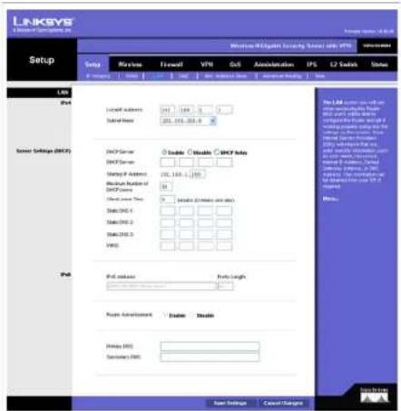
text_image
LINKSYS Network Security System: VTR Setup LinkSYS System Settings (DACF) PID Network Security Network Security System Settings (DACF) PID System Security System Security System Security System Security System Security System Security System Security System Security System Security System Security System Security System Security System Security System Security System Security System Security System Security System Security System Security System Security System Security System Security System Security System Security System Security System Security System Security System Security System Security System Security System Security System Security System Security System SecurityFigure 6-11: Setup - LAN
Wireless-N Gigabit Security Router with VPN
WINS. The Windows Internet Naming Service (WINS) performs name resolution function (similar to DNS) in the Windows network environment. It can help you to determine the IP address of a remote Windows PC from its computer name. If you have a WINS server, enter that server's IP Address here. Otherwise, leave this blank.
IPv6
IPv6 Address. If you selected dual-stack option under IP Versions Setup screen, enter the IPv6 address on the LAN side of the Router.
Prefix Length. Enter the IPv6 prefix length. The default is 64, which should not need to be changed.
Router Advertisement. Enabling this option allows the Router to send out IPv6 Router Advertisement packets periodically. This helps IPv6 hosts to learn their IPv6 prefix and setup their IPv6 Address automatically.
Primary DNS. Enter the Primary IPv6 DNS server address.
Secondary DNS. Enter the Secondary IPv6 DNS server address.
Click the Save Settings button to save the network settings or click the Cancel Changes button to undo your changes.
Wireless-N Gigabit Security Router with VPN
DMZ
The DMZ screen allows one local PC to be exposed to the Internet for use of a special-purpose service, such as Internet gaming and video-conferencing. DMZ hosting forwards traffic to all the ports for the specified PC simultaneously, unlike Port Range Forwarding that can only forward a maximum of 10 ranges of ports.
DMZ Hosting. This feature allows one local PC to be exposed to the Internet for use of a special-purpose service such as Internet gaming and video-conferencing. To use this feature, select Enabled. To disable the DMZ feature, select Disabled.
DMZ Host IP Address. To expose one PC, enter the computer's IP address.
Click the Save Settings button to save the network settings or click the Cancel Changes button to undo your changes.
MAC Address Clone
Some ISPs require that you register a MAC address. This feature clones your PC network adapter's MAC address onto the Router, and prevents you from having to call your ISP to change the registered MAC address to the Router's MAC address. The Router's MAC address is a 6-byte hexadecimal number assigned to a unique piece of hardware for identification.
Mac Address Clone. Select Enabled or Disabled. The default is Enabled.
Mac Address. Enter the MAC Address registered with your ISP in this field.
Clone My PC's MAC button. When Mac Address Clone is enabled, click this to copy the MAC address of the network adapter in the computer that you are using to connect to the Web-based utility.
Click Save Settings to save the MAC Cloning settings or click the Cancel Changes button to undo your changes.
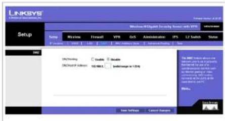
text_image
LINKSYS Setup Setup Browse Frmell VTR OS Administration IPS LV Switch Status 100% 100% 100% 100% 100% 100% 100% 100% 100% 100% 100% 100% 100% 100% 100% 100% 100% 100% 100% 100% 100% 100% 100% 100% 100% 100%Figure 6-12: Setup - DMZ
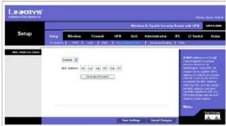
text_image
LINKSYS www.rlinkSYS.com Setup Windows 8 Open Security Route with USB Setup Link Network Forward USB Ctrl Administration F1 U Work Status MAC Address Client Network MAC Address 40 12 58 09 34 97 New Settings New Settings Cancel Changes MAC Server: A:\My\newark\Software\Microsoft\Microsoft\Microsoft\Microsoft\Microsoft\Microsoft\Microsoft\Microsoft\Microsoft\Microsoft\Microsoft\Microsoft\Microsoft\Microsoft\Microsoft\Microsoft\Microsoft\Microsoft\Microsoft\Microsoft\Microsoft\Microsoft\Microsoft\Microsoft\Microsoft\Microsoft\Microsoft\Microsoft\Microsoft\Microsoft\Microsoft\Microsoft\Microsoft\Microsoft\Microsoft\Microsoft\Microsoft\Microsoft\Microsoft\Microsoft\Microsoft\Microsoft\Microsoft\Microsoft\Microsoft\Microsoft\Microsoft\Microsoft\Microsoft\Microsoft\ Microsoft Windows Server New Settings Cancel ChangesFigure 6-13: Setup - MAC Address Clone
Wireless-N Gigabit Security Router with VPN
Advanced Routing
Operating Mode
Select the Operating mode in which the Router will function.
Internet Gateway. This is the normal mode of operation. This allows all devices on your LAN to share the same WAN (Internet) IP address. In the Internet Gateway mode, the NAT (Network Address Translation) mechanism is enabled.
Intranet Router. You either need another Router to act as the Internet Gateway, or all PCs on your LAN must be assigned (fixed) Internet IP addresses. In Intranet Router mode, the NAT mechanism is disabled.
Dynamic Routing
The Router's dynamic routing feature can be used to automatically establish a routing table through a database exchange with peer routers (running the same routing protocol). The Router supports RIP (Routing Information Protocol) versions 1 & 2.
RIP (Routing Information Protocol. The Router, using the RIP protocol, calculates the most efficient route for the network's data packets to travel between the source and the destination based upon the shortest paths.
RIP Send Packet Version. Choose the version of RIP packets you want to send to peers: RIPv1 or RIPv2. This should match the version supported by other Routers on your LAN.
RIP Recv Packet Version. Choose the version of RIP packets you want to receive from peers: RIPv1 or RIPv2. This should match the version supported by other Routers on your LAN.
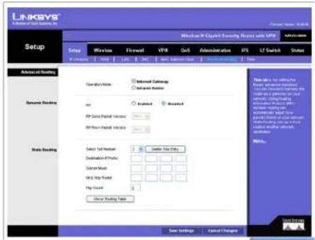
text_image
LINKSYS A Software Setup Setup Setup Group Network Formset VPR Out Administration IPS U2 Switch Status Advanced Settings System Loading Data Loading Operation Mode Internal Settings Advanced Mode on Reserved Reserved IP Data Packet Version IP Data Packet Version Select Data Version Destination Protocol Select Model Hot Hot Policy Play Method Other Setting Help New Settings Cancel Changes Show to: To setting the Power, Advanced Settings, Circuit Options, For Windows 1.0.1.1.1.1.1.1.1.1.1.1.1.1.1.1.1.1.1.1.1.1.1.1.1.1.1.1.1.1.1.1.1.1.1.1.1.1.1.1.1.1.1.1.1.1.1.1.1.1.1.1.2 Save Settings Cancel ChangesFigure 6-14: Setup - Advanced Routing
Wireless-N Gigabit Security Router with VPN
Static Routing
Sometimes you will prefer to use static routes to build your routing table instead of using dynamic routing protocols. Static routes do not require CPU resources to exchange routing information with a peer router. You can also use static routes to reach peer routers that do not support dynamic routing protocols. Static routes can be used together with dynamic routes. Be careful not to introduce routing loops in your network.
To set up static routing, you should add route entries in the routing table that tell the Router where to forward packets to specific IP destinations.
Enter the following data to create a static route entry:
- Select Set Number. Select the set number (routing table entry number) that you wish to view or configure. If necessary, click Delete This Entry to clear the entry.
- Destination IP Prefix. Enter the network address of the remote LAN segment. For a standard Class C IP domain, the network address is the first three fields of the Destination LAN IP; the last field should be zero.
- Subnet Mask. Enter the Subnet Mask used on the destination LAN IP domain. For Class C IP domains, the Subnet Mask is 255.255.255.0.
- Next Hop Router. Enter the next hop router used to reach your destination LAN, as defined in Step (2).
- Hop Count (max. 15). This value gives the number of routers that a data packet passes through before reaching its destination. It is used to define the priority on which route to use if there is a conflict between a static route and dynamic route.
Show Routing Table button. Click this button to show the routing table established either through dynamic or static routing methods.
Click the Save Settings button to save the Routing settings, click the Cancel Changes button to undo your changes or click the Show Routing Table button to view the current routing table.

text_image
LINKSYS A network of List Openers, LLC Routing Table Routing Table Entry List Instructions URL: Subset Mask Currency Interface 102.168.1.0 255.355.255.0 9.5.0.0 LAK 102.168.0.0 255.355.255.0 9.5.0.0 WAN 25.34.26.3 255.355.255.0 102.168.07.08 WAN 259.0.0.0 255.6.0.0 9.5.0.0 LAK 03.6.0 03.6.0 102.199.0.1 WAN CacheFigure 6-15: Setup - Advanced Routing (Routing Table)
Wireless-N Gigabit Security Router with VPN
Time
You can either define your Router's time manually or automatically through Time Server. The default is Automatically.
Manually
If you wish to enter the time and date manually, select the Date from the drop-down fields and enter the hour, minutes, and seconds in the Time field using 24 hour format (example 10:00pm would be entered 22:0:0).
Automatically
Time Zone. Select the time zone for your location and your setting synchronizes over the Internet with public NTP (Network Time Protocol) Servers.
User Defined NTP Server. If you want to use your own NTP server, select the Enabled option. The default is Disabled.
NTP Server IP Address. Enter the IP address of your own NTP server.
Click the Save Settings button to save the Routing settings, click the Cancel Changes button to undo your changes or click the Show Routing Table button to view the current routing table.
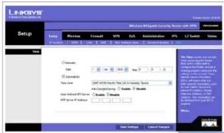
text_image
LINKSYS Setup Windows 800000 Security Server w/1.0 Setup LinkSYS File Edit View Tools Help Add/Remove IPs / 1/2 Switch Status Options AutoCAD Type: 100 40 90 255 35 3 Automatic Type: 100 40 90 255 35 3 AutoCAD Use Selected ISP Server ISP Server Of Address Custom Security Default Security User Settings Cancel Options The Time Series will not use any security or security data. The time series will be a 100% configuration. The system is designed to allow the configuration to access the IP address. The IP address is set to include: Windows - Open Access (Windows), Open Security (Windows), and other security types. The IP address is set to include: Windows - Open Access (Windows), Open Security (Windows), and other security types. The IP address is set to include: Windows - Open Access (Windows), Open Security (Windows), and other security types. The IP address is set to include: Windows - Open Access (Windows), Open Security (Windows), and other security types. The IP address is set to include: Windows - Open Access (Windows), Open Security (Windows), and other security type. The IP address is set to include: Windows - Open Access (Windows), Open Security (Windows), and other security type. The IP address is set to include: Windows - Open Access (Windows), Open Security (Windows), and other security type. The IP address is set to include: Windows - Open Access (Windows), Open Security (Windows), and other security type. The IP address is set to include: Windows - Open Access (Windows), Open Security (Windows), and other security types. The IP address is set to include: Windows - Open Access (Windows), Open Security (Windows), and other security type. The IP address is set to include: Windows - Open Access (Windows), Open Security (Windows), and other security type. The IP address is set to include: Windows - Open Access (Windows), Open Security (Windows), and other security types. The IP address is set to include: Windows - Open Access (Windows), Open Security (Windows), and other security types. The IP address is set to include: Windows - Open Access (Windows), Open Security (Windows), and other security types. The IP address is set to include: Windows - Open Access (Windows), Open Security (Windows), and other security categories. The IP address is set to include: Windows - Open Access (Windows), Open Security (Windows), and other security types. The IP address is set to include: Windows - Open Access (Windows), Open Security (Windows), and other security types. The IP address is set to include: Windows - Open Access (Windows), Open Security (Windows), and other security types. The IP address is set to include: Windows - Open Access (Windows), Open Security (Windows), and other security Type. The IP address is set to include: Windows - Open Access (Windows), Open Security (Windows), and other security Type. The IP address is set to include: Windows - Open Access (Windows), Open Security (Windows), and other security Type. The IP address is set to include: Windows - Open Access (Windows), Open Security (Windows), and other security Type. The IP address is set to include: Windows - Open Access (Windows), Open Security (Windows), and other security type. The IP address is set to include: Windows - Open Access (Windows), Open Security (Windows), and other security Type. The IP address is set to include: Windows - Open Access (Windows), Open Security (Windows), and other security Type. The IP address is set to include: Windows - Open Access (Windows), Open Security (Windows), and other security Type. The IP address is set to include: Windows - Open Access (Windows), Open Security (Windows), and other security types. The IP address is set to include: Windows - Open Access (Windows), Open Security (Windows), and other security types. The IP address is set to include: Windows - Open Access (Windows), Open Security (Windows), and other security types. The IP address is set to include: Windows - Open Access (Windows), Open Security (Windows), and other security Types. The IP address is set to include: Windows - Open Access (Windows), Open Security (Windows), and other security types. The IP address is set to include: Windows - Open Access (Windows), Open Security (Windows), and other security types. The IP address is set to include: Windows - Open Access (Windows), Open Security (Windows), and other security types. The IP address is set to include: Windows - Open Access (Windows), Open Security (Windows), and other security Tages. User Selected OSives Cancel Settings Help Settings Cancel OptionsFigure 6-16: Setup - Time
Wireless-N Gigabit Security Router with VPN
Wireless Tab
Basic Wireless Settings
Change the basic wireless network settings on this screen.
Basic Settings
Configure the basic Wireless Network attributes for this Wireless Router.
SSID Name. The SSID is the unique name shared between all devices in a wireless network. It is case-sensitive, must not exceed 32 alphanumeric characters, and may be any keyboard character. Make sure this setting is the same for all devices in your wireless network. The default SSID name is linksys-n.
Wireless Network Mode. Select one of the following modes. The default is B/G/N-Mixed.
B-Only: All the wireless client devices can be connected to the Wireless Router at Wireless-B data rates with a maximum speed of 11Mbps.
G-Only: Both Wireless-N and Wireless-G client devices can be connected at Wireless-G data rates with a maximum speed of 54Mbps. Wireless-B clients cannot be connected in this mode.
N-Only: Only Wireless-N client devices can be connected at Wireless-N data rates with a maximum speed of 300Mbps.
B/G-Mixed: Both Wireless-B and Wireless-G client devices can be connected at their respective data rates. Wireless-N devices can be connected at Wireless-G data rates.
G/N-Mixed: Both Wireless-G and Wireless-N client devices can be connected at their respective data rates. Wireless-B clients cannot be connected in this mode.
B/G/N-Mixed: All the wireless client devices can be connected at their respective data rates in this mixed mode.
Disabled: To disable wireless connectivity completely. This might be useful during system maintenance.
Wireless Channel. Select the appropriate channel to be used between your Wireless Router and your client devices. The default is channel 6. You can also select Auto so that your Wireless Router will select the channel with the lowest amount of wireless interference while the system is booting up. Auto channel selection will start
Chapter 6: Setting Up and Configuring the Router Wireless Tab

text_image
LINKSYS Wireless LinkSYS Wireless Network-8 Internet Security Server with VTS Setup Wireless Microsoft Windows USB Gait Administration R2 LT Control Status Data Wireless Settings Wireless Data (DDS) Wireless Wireless Network Mode Wireless Wireless Channel 0.24GHz Wireless SSL Standard Enable Enable File name: www.linksys.com Location: 123-567-0000 Access Settings Cancel ChangesFigure 6-17: Wireless - Basic Wireless Settings
Wireless-N Gigabit Security Router with VPN
when you click the Save Settings button, and it will take several seconds to scan through all the channels to find the best channel. For the Wireless-N 40MHz channel option (see Wireless - Advanced Wireless Settings Tab), the Wireless Router will automatically select the adjacent 20MHz channel to combine them into a wider channel.
SSID Broadcast. This option allows the SSID to be broadcast on your network. You may want to enable this function while configuring your network, but make sure that you disable it when you are finished. With this enabled, someone could easily obtain the SSID information with site survey software or Windows XP and gain unauthorized access to your network. Click Enabled to broadcast the SSID to all wireless devices in range. Click Disabled to increase network security and prevent the SSID from being seen on networked PCs. The default is Enabled in order to help users configure their network before use.
Change these settings as described here and click Save Settings to apply your changes, or click Cancel Changes to cancel your changes. Help information is displayed on the right-hand side of the screen, and click More for additional details.
Wireless-N Gigabit Security Router with VPN
Wireless Security
Change the Wireless Router's wireless security settings on this screen.
Wireless Security
Security Mode. Select the wireless security mode you want to use, WPA-Personal, WPA2-Personal, WPA2-Personal Mixed, WPA-Enterprise, WPA2-Enterprise, WPA2-Enterprise Mixed, or WEP. (WPA stands for Wi-Fi Protected Access, which is a security standard stronger than WEP encryption and forward compatible with IEEE 802.11e. WEP stands for Wired Equivalent Privacy, Enterprise refers to using RADIUS server for authentication, while RADIUS stands for Remote Authentication Dial-In User Service.) Refer to the appropriate instructions below after you select the Authentication Type and SSID Interoperability settings. To disable wireless security completely, select Disabled. The default is Disabled.
Wireless Isolation (within SSID). When disabled, wireless PCs that are associated to the same network name (SSID), can see and transfer files between each other. By enabling this feature, Wireless PCs will not be able to see each other. This feature is very useful when setting up a wireless hotspot location. The default is Disabled.
The following section describes the detailed options for each Security Mode.
Disabled
To disable wireless security completely, select Disabled.
WPA-Personal (also known as WPA-PSK)
WPA Algorithms. WPA offers you two encryption methods, TKIP and AES for data encryption. Select the type of algorithm you want to use, TKIP or AES. The default is TKIP.
WPA Shared Key. Enter a WPA Shared Key of 8-63 characters.
Key Renewal Timeout. Enter a Key Renewal Timeout period, which instructs the Wireless Router how often it should change the encryption keys. The default is 3600 seconds.
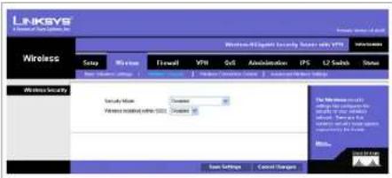
text_image
LINKSYS Wireless Security Network Security Network Security Security Value Network Security Network Security Network Security Network Security Network Security Network Security Network Security Network Security Network Security Network Security Network Security Network Security Network Security Network Security Network Security Network Security Network Security Network Security Network Security Network Security Network Security Network Security Network Security Network Security Network Security Network Security Network Security Network Security Network Security Network Security Network Security Network Security Network Security Network SecurityFigure 6-18: Wireless - Wireless Security (Disabled)
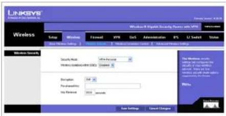
text_image
LINKEYS Wireless Network 8.0000 Security Phone with VPS Setup Wireless Format VPS Grid Administration ES U2 Security Status Wireless Security Security Port: VPS Per session PROFESSIONAL DATA (SD) Access Description: 196.25 Performance: VPS Period: 2019 seconds New Settings Cancel SettingsFigure 6-19: Wireless - Wireless Security (WPA-Personal)
Wireless-N Gigabit Security Router with VPN
WPA2-Personal
WPA Algorithms. WPA2 always uses AES for data encryption.
WPA Shared Key. Enter a WPA Shared Key of 8-63 characters.
Key Renewal Timeout. Enter a Key Renewal Timeout period, which instructs the Wireless Router how often it should change the encryption keys. The default is 3600 seconds.
WPA2-Personal Mixed
This security mode supports the transition from WPA-Personal to WPA2-Personal. You can have client devices that use either WPA-Personal or WPA2-Personal. The Wireless Router will automatically choose the encryption algorithm used by each client device.
WPA Algorithms. Mixed Mode automatically chooses TKIP or AES for data encryption.
WPA Shared Key. Enter a WPA Shared Key of 8-63 characters.
Key Renewal Timeout. Enter a Key Renewal Timeout period, which instructs the Wireless Router how often it should change the encryption keys. The default is 3600 seconds.

text_image
LINKSYS Wireless Wireless R Us/Shift Security Router with VPN SNP Wireless Forward VPN QS Administration IFS U Tech3 Status Wireless Security Security Mode: WPC/Service Wireless Security (with SWS) Access Wireless Security (with SWS) Wireless Security (with SWS) Wireless Security (with SWS) Wireless Security (with SWS) Wireless Security (with SWS) Wireless Security (with SWS) Wireless Security (with SWS) Wireless Security (with SWS) Wireless Security (with SWS) Wireless Security (with SWS) Wireless Security (with SWS) Wireless Security (with SWS) Wireless Security (with SWS) Wireless Security(without SWS) Wireless Security(without SWS) Wireless Security(without SWS) Wireless Security(without SWS) Wireless Security(without SWS) Wireless Security(without SWS) Wireless Security(without SWS) Wireless Security(without SWS) Wireless Security(without SWS) Wireless Security(without SWS) Wireless Security(without SWS) Wireless Security(without SWS) Wireless Security(without SWS) Wind Settings Cancel Changes Wireless Security Wireless Security Wireless Security Wireless Security Wireless Security Wireless Security Wireless Security Wireless Security Wireless Security Wireless Security Wireless Security Wireless Security Wireless Security Wireless Security Wireless Security Wireless Security Wireless Security Wireless Security Wireless Security Wireless Security Wireless Security Wireless Security Wireless Security Wireless Security Wireless Security WirelessSecurity WirelessSecurity WirelessSecurity WirelessSecurity WirelessSecurity WirelessSecurity WirelessSecurity WirelessSecurity WirelessSecurity WirelessSecurity WirelessSecurity WirelessSecurity WirelessSecurity WirelessSecurity WirelessSecurity WirelessSecurity WirelessSecurity WirelessSecurity WirelessSecurity WirelessSecurity WirelessSecurity WirelessSecurity WirelessSecurity WirelessSecurity WirelessSecurity WirelessSeverity WirelessSeverity WirelessSeverity WirelessSeverity WirelessSeverity WirelessSeverity WirelessSeverity WirelessSeverity WirelessSeverity WirelessSeverity WirelessSeverity WirelessSeverity WirelessSeverity WirelessSeverity WirelessSeverity WirelessSeverity WirelessSeverity WirelessSeverity WirelessSeverity WirelessSeverity WirelessSeverity WirelessSeverity WirelessSeverity WirelessSeverity WirelessSeverity WirelessSecurity WirelessSecurity WirelessSecurity WirelessSecurity WirelessSecurity WirelessSecurity WirelessSecurity WirelessSecurity WirelessSecurity WirelessSecurity WirelessSecurity WirelessSecurity WirelessSecurity WirelessSecurity WirelessSecurity WirelessSecurity WirelessSecurity WirelessSecurity WirelessSecurity WirelessSecurity WirelessSecurity WirelessSecurity WirelessSecurity WirelessSecurity WirelessSwitch10000000000000000000000000000000000000000000000000000000000000000000000000000000000000000000000000000Figure 6-20: Wireless - Wireless Security (WPA2-Personal)

text_image
LINKSYS Wireless Switch Wireless Firewall VPR OS Administration IPS 12 Switch Status Wireless Security Security Mask VPA Configuration Wireless Status within 3000 Access Networks TCP-85 Telephone Key Services TCP-85 Send Settings Cancel Changes Send Settings Cancel ChangesFigure 6-21: Wireless - Wireless Security (WPA2-Personal Mixed)
Wireless-N Gigabit Security Router with VPN
WPA-Enterprise
This option features WPA used in coordination with a RADIUS server for client authentication. (This should only be used when a RADIUS server is connected to the Wireless Router.)
RADIUS Server IP Address. Enter the RADIUS server's IP address.
RADIUS Server Port. Enter the port number used by the RADIUS server. The default is 1812.
WPA Algorithms. WPA offers you two encryption methods, TKIP and AES for data encryption. Select the type of algorithm you want to use, TKIP or AES. The default is TKIP.
Shared Secret. Enter the Shared Secret key used by the Wireless Router and RADIUS server.
Key Renewal Timeout. Enter a Key Renewal Timeout period, which instructs the Wireless Router how often it should change the encryption keys. The default is 3600 seconds.
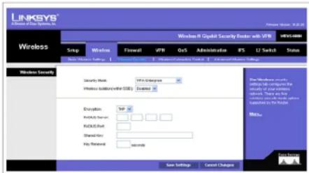
text_image
LINKSYS A Series of One System, Inc. Windows H Capital Security Router with VTR SNP Wireless Forward VPR QoS Administration IFS U Switch Status Wireless Security Security Work VTR (Connects) Wireless Subscribers (SOS) Location: Encryption SNP Analog Network RNDU/Red Shared Web Key Renewal seconds Wireless Security Wireless Security Router with VTR Wireless Security Router with VTR Wireless Security Router with VTR Wireless Security Router with VTR Wireless Security Router with VTR Wireless Security Router with VTR Wireless Security Router with VTR Wireless Security Router with VTR Wireless Security Router with VTR Wireless Security Router with VTR Wireless Security Router with VTR Wireless Security Router with VTR Wireless Security Router with VTR Wireless Safety Control Wireless Safety Control Wireless Safety Control Wireless Safety Control Wireless Safety Control Wireless Safety Control Wireless Safety Control Wireless Safety Control Wireless Safety Control Wireless Safety Control Wireless Safety Control Wireless Safety Control Wireless Safety Control Wireless Safety Control Wireless Safety Control Wireless Safety Control Wireless Safety Control Wireless Safety Control Wireless Safety Control Wireless Safety Control Wireless Safety Controller Wireless Safety Controller Wireless Safety Controller Wireless Safety Controller Wireless Safety Controller Wireless Safety Controller Wireless Safety Controller Wireless Safety Controller Wireless Safety Controller Wireless Safety Controller Wireless Safety Controller Wireless Safety Controller Wireless Safety Controller Wireless Safety Controller Wireless Safety Controller Wireless Safety Controller Wireless Safety Controller Wireless Safety Controller Wireless Safety Controller Wireless Safety Controller Wireless SafetyController Wireless SafetyController Wireless SafetyController Wireless SafetyController Wireless SafetyController Wireless SafetyController Wireless SafetyController Wireless SafetyController Wireless SafetyController Wireless SafetyController Wireless SafetyController Wireless SafetyController Wireless SafetyController Wireless SafetyController Wireless SafetyController Wireless SafetyController Wireless SafetyController Wireless SafetyController Wireless SafetyController Wireless SafetyController Wireless SafetyConfiguration Wireless Security Server 10.0000000000000000000000000000000000000000000000000000000000000000000000000000000000000000000000000000Figure 6-22: Wireless - Wireless Security (WPA-Enterprise)
WPA2-Enterprise
This option features WPA2 used in coordination with a RADIUS server for client authentication. (This should only be used when a RADIUS server is connected to the Wireless Router.)
RADIUS Server IP Address. Enter the RADIUS server's IP address.
RADIUS Server Port. Enter the port number used by the RADIUS server. The default is 1812.
WPA Algorithms. WPA2 always uses AES for data encryption.
Shared Secret. Enter the Shared Secret key used by the Wireless Router and RADIUS server.
Key Renewal Timeout. Enter a Key Renewal Timeout period, which instructs the Wireless Router how often it should change the encryption keys. The default is 3600 seconds.
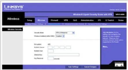
text_image
LINKSYS 1 Division of the Systems, Inc. Windows 8 Cyassistant Security Router with VPR WINS-8004 Wireless Snap Wireless Forward VPR Out Administration IPS U Switch Status Wireless Security Security Mode: VRSQ Security Wireless Network(online OS) Custom Wireless Security Wireless Security Wireless Security Wireless Security Wireless Security Wireless Security Wireless Security Wireless Security Wireless Security Wireless Security Wireless Security Wireless Security Wireless Security Wireless Security Wireless Security Wireless Security Wireless Security Wireless Security Wireless Security Wireless Security Wireless Security Wireless Security Wireless Security Wireless Security Wireless Security Wireless Safety Wireless Safety Wireless Safety Wireless Safety Wireless Safety Wireless Safety Wireless Safety Wireless Safety Wireless Safety Wireless Safety Wireless Safety Wireless Safety Wireless Safety Wireless Safety Wireless Safety Wireless Safety Wireless Safety Wireless Safety Wireless Safety Wireless Safety Wireless Safety Wireless Safety Wireless Safety Wireless Safety Wireless Safety Wireless Security Wireless Security Wireless Security Wireless Security Wireless Security Wireless Security Wireless Security Wireless Security Wireless Security Wireless Security Wireless Security Wireless Security Wireless Security Wireless Security Wireless Security Wireless Security Wireless Security Wireless Security Wireless Security Wireless Security Wireless Security Wireless Security Wireless Security Wireless Security Wireless Service Wireless Service Wireless Service Wireless Service Wireless Service Wireless Service Wireless Service Wireless Service Wireless Service Wireless Service Wireless Service Wireless Service Wireless Service Wireless Service Wireless Service Wireless Service Wireless Service Wireless Service Wireless Service Wireless Service Wireless Service Wireless Service Wireless Service Wireless Service Wireless Service Wireless ServicesFigure 6-23: Wireless - Wireless Security (WPA2-Enterprise)
Wireless-N Gigabit Security Router with VPN
WPA2-Enterprise Mixed
This security mode supports the transition from WPA-Enterprise to WPA2-Enterprise. You can have client devices that use either WPA-Enterprise or WPA2-Enterprise. The Wireless Router will automatically choose the encryption algorithm used by each client device.
RADIUS Server IP Address. Enter the RADIUS server's IP address.
RADIUS Server Port. Enter the port number used by the RADIUS server. The default is 1812.
WPA Algorithms. Mixed Mode automatically chooses TKIP or AES for data encryption.
Shared Secret. Enter the Shared Secret key used by the Wireless Router and RADIUS server.
Key Renewal Timeout. Enter a Key Renewal Timeout period, which instructs the Wireless Router how often it should change the encryption keys. The default is 3600 seconds.
WEP
This security mode is defined in the original IEEE 802.11. This mode is not recommended now due to its weak security protection. Users are urged to migrate to WPA or WPA2.
Authentication Type. Choose the 802.11 authentication type as either Open System or Shared Key. The default is Open System.
Default Transmit Key. Select the key to be used for data encryption.
WEP Encryption. Select a level of WEP encryption, 64 bits (10 hex digits) or 128 bits (26 hex digits).
Passphrase. If you want to generate WEP keys using a Passphrase, then enter the Passphrase in the field provided and click the Generate key.
Key 1-4. If you want to manually enter WEP keys, then complete the fields provided. Each WEP key can consist of the letters "A" through "F" and the numbers "0" through "9". It should be 10 characters in length for 64-bit encryption or 26 characters in length for 128-bit encryption.
Tx Key. Select one of the keys to be used for data encryption (when you manually enter multiple WEP keys).
Change these settings as described here and click Save Settings to apply your changes, or click Cancel Changes to cancel your changes. Help information is displayed on the right-hand side of the screen, and click More for additional details.

text_image
LINKSYS A limited data security, LLC Wireless Networks & Chipset Security schemes with VPR VPS/100000 Setup Wireless Flowell VPR Out Administration IPS LZ Switch Status Basic Wireless Settings Basic Wireless Settings Wireless Generator Control Wireless Privacy Settings Wireless Security Security Mode: VPA/Chassis Model Wireless Connection/within SBO: Created Enclosure: POP + IES Connected Server: □ □ □ Fixed Port: □ □ □ SharePort: □ □ □ Key Retrieval: seconds Wireless Settings Cancel Changes The Wireless Security Settings are completely closed for security of IP, which will be otherwise. The IP has been necessary. Any other security modes are notably the User. Wireless Save Asurbs Cancel ChangesFigure 6-24: Wireless - Wireless Security (WPA2-Enterprise Mixed)
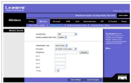
text_image
LINKSYS A Technical Data Operating Inc. Forma version: 4.0.28 Wireless Windows & Embedded Security Receiver with VTP Setup Wireless Forward VTP Out Administration IP3 LT Scan Status Max. Minimum: 1/6 Wireless Security Security Note: 400 Wireless Information (SD) Creates Administration Type: Open System Extension: 45.19 MB (7.5% or 8.5%) Passphone: Delete Key 1: Key 2: Key 3: Key 4: 71 Mbps: Save Settings Cancel Changes Wireless Security The Windows system is not a type of connection to the Windows. It is also that the Windows will not use any other connection to the Windows. MioNo. SystemFigure 6-25: Wireless - Wireless Security (WEP)
Wireless-N Gigabit Security Router with VPN
Wireless Connection Control
This screen allows you to configure the Connection Control List to either permit or block specific wireless client devices connecting to (associating with) the Wireless Router.
Wireless Connection Control
Enabled/Disabled. Enable or disable wireless connection control. The default is Disabled.
Connection Control
There are two ways to control the connection (association) of wireless client devices. You can either prevent specific devices from connecting to the Wireless Router, or you can allow only specific client devices to connect to the Wireless Router. The client devices are specified by their MAC addresses. The default is to allow only specific client devices.
Wireless Client List
Instead of manually entering the MAC addresses of each client, the Wireless Router provides a convenient way to select a specific client device from the client association table. Click this button and a window appears to let you select a MAC address from the table. The selected MAC address will be entered into the Connection Control List.
Connection Control List
MAC 01-20. Enter the MAC addresses of the wireless client devices you want to control.
Change these settings as described here and click Save Settings to apply your changes, or click Cancel Changes to cancel your changes. Help information is displayed on the right-hand side of the screen.

text_image
LINKSYS Wireless LinkSYS @ Cable Security Services Intl. VPS Settings Setup Wireless Forward VPS Out Administration PS LF Switch Status Wireless Connection Control Connected Connection Connected Connection to U4 Connected Connection Connected Connection to U4 Connected Connection Connected Connection to U4 Connected Connection to U4 Connected Connection to U4 Connected Connection to U4 Connected Connection to U4 Connected Connection to U4 Connected Connection to U4 Connected Connection to U4 Connected Connection to U4 Connected Connection to U4 Connected Connection to U4 Connected Connection to U4 Connected Connection to U4 Connected Connection to U4 Connected Connection to U4 Connected Connection to U4 Connected Connection to U4 Connected Connection TO U4 Connected Connection TO U4 Connected Connection TO U4 Connected Connection TO U4 Connected Connection TO U4 Connected Connection TO U4 Connected Connection TO U4 Connected Connection TO U4 Connected Connection TO U4 Connected Connection TO U4 Connected Connection TO U4 Connected Connection TO U4 Connected Connection TO U4 Connected Connection TO U4 Connected Connection TO U4 Connected Connection TO U4 Connected Connection TO U4 Sorted Settings Cancel ChangesFigure 6-26: Wireless - Wireless Connection Control

text_image
LINKSYS Wireless Client List to Start Access Customer Name: 95102348 Network Address: COMMAND.MAP 102.16.1.200 RMS-000000000 Access CancelFigure 6-27: Select MAC Address from Wireless Client List
Wireless-N Gigabit Security Router with VPN
Advanced Wireless Settings
This screen allows you to configure the advanced settings for the Wireless Router. The Wireless-N Router adopts several new parameters to adjust the channel bandwidth and guard Intervals to improve the data rate dynamically. Linksys recommends to let your Wireless Router automatically adjust the parameters for maximum data throughput.
Advanced Wireless
You can change the following advanced parameters (some only for Wireless-N) for this Wireless Router. Wireless-N data rates are classified into 16 MCS numbers (0-15). MCS stands for Modulation and Coding Scheme. For the same MCS number, the data rate changes according to the Channel Bandwidth and Guard Interval settings. You can see the change through the drop-down menu of Tx Rate Limiting (11n clients).
Channel Bandwidth. You can select the channel bandwidth manually for Wireless-N connections. When it is set to 20MHz, only the 20MHz channel is used. When it is set to 40MHz, Wireless-N connections will use 40MHz channel but Wireless-B and Wireless-G will still use 20MHz channel. The default is Auto.
Guard Interval. You can select the guard interval manually for Wireless-N connections. The two options are Short (400ns) and Long (800ns). The default is Auto.
Tx Rate Limiting (11b clients). This option provides rate limiting on Wireless-B connections. Wireless-B clients can be limited to data rate specified by IEEE 802.11b. The default is Auto.
Tx Rate Limiting (11g clients). This option provides rate limiting on Wireless-G connections. Wireless-G clients can be limited to data rates specified by IEEE 802.11g and 802.11b. The default is Auto.
Tx Rate Limiting (11n clients). This option provides rate limiting on Wireless-N connections. Wireless-N clients can be limited to data rates specified by draft IEEE 802.11n, IEEE 802.11g, and 802.11b. The data rate associated with each MCS number (0-15) changes according to your selection on Channel Bandwidth and Guard Interval. The default is Auto.
CTS Protection Mode. CTS (Clear-To-Send) Protection Mode function boosts the Wireless Router's ability to catch all wireless transmissions, but will severely decrease performance. Keep the default setting, Auto, so the Wireless Router can use this feature as needed, when the Wireless-N/G products are not able to transmit to the Wireless Router in an environment with heavy 802.11b traffic. Select Disabled if you want to permanently disable this feature.
WMM. Wi-Fi Multimedia is a QoS feature defined by WIFI Alliance before IEEE 802.11e was finalized. Now it is part of IEEE 802.11e. When it is enabled, it provides four priority queues for different types of traffic. It automatically maps the incoming packets to the appropriate queues based on QoS settings (in IP or layer 2

text_image
LINKSYS Windows & Internet Security Border with VPN Wireless Setup Wireless Flowmail VPN DNS Administration IFS LF Switch Value Advanced Wireless Settings Normal Downloads Auto Default Auto Total Power (100 MHz) Auto Default Auto No To-Pack Loading Auto Default Auto To To-Pack Loading Auto Default Auto To To-Pack Loading Auto Default Auto 250 Audio Mode Auto Default Auto 5000 Standard Default Default (anned) 350 Mode Standard Default (anned) Basic Protocol: 1:000 (Default 100 MHz, Range: 25 - 600) 2:000/1.000 (Default 1, Range: < 200) 3:000/2.000 (Default 200, Range: 205 - 2346) Data Settings Cancel ChangesFigure 6-28: Wireless - Advanced Wireless Settings
Wireless-N Gigabit Security Router with VPN
header). WMM provides the capability to prioritize traffic in your environment. The default in Enabled. Select High Performance (N-Only) if you want to achieve highest throughput on 11n connections. Note that 11b and 11g clients performance will be affected by setting to this mode.
IOT Mode. Interoperability Mode. Enabling this mode will help this AP to communicate with Linksys retail client cards (e.g. WPC300N) at 11n rates. This mode is a temporary measure to cope with implementation differences on 802.11n draft specification. This option will be removed eventually when IEEE802.11n is finalized. The default is disabled.
Beacon Interval. This value indicates the frequency interval of the beacon. A beacon is a packet broadcast by the Wireless Router to keep the network synchronized. A beacon includes the wireless networks service area, the Wireless Router address, the Broadcast destination addresses, a time stamp, Delivery Traffic Indicator Maps, and the Traffic Indicator Message (TIM). The default is 100 ms.
DTIM Interval. This value indicates how often the Wireless Router sends out a Delivery Traffic Indication Message (DTIM). Lower settings result in more efficient networking, while preventing your PC from dropping into power-saving sleep mode. Higher settings allow your PC to enter sleep mode, thus saving power, but interferes with wireless transmissions. The default is 1 ms.
RTS Threshold. This setting determines how large a packet can be before the Wireless Router coordinates transmission and reception to ensure efficient communication. This value should remain at its default setting of 2347. If you encounter inconsistent data flow, only minor modifications are recommended.
Change these settings as described here and click Save Settings to apply your changes, or click Cancel Changes to cancel your changes. Help information is displayed on the right-hand side of the screen, and click More for additional details.
Wireless-N Gigabit Security Router with VPN
Firewall Tab
The Firewall Tab allows you to configure software security features like SPI (Stateful Packet Inspection) Firewall, IP based Access List, restriction LAN users on Internet (WAN port) access, and NAPT (Network Address Port Translation) Settings (only works when NAT is enabled) to limited services to specific ports.
Note that for WAN traffic, NAPT settings are applied first, then it will pass the SPI Firewall settings, followed by IP based Access List (which requires more CPU power).
Basic Settings
Firewall: SPI (Stateful Packet Inspection) Firewall, when you enable this feature, the Router will perform deep packet inspection on all the traffic going through the Router and drop the packets that do not follow the pre-defined protocol behavior. The default is Enable.
DoS Protection: When enabled, the Router will prevent DoS (Denial of Service) attacks coming in from the Internet. DOS attacks are making your Router's CPU busy such that it cannot provide services to regular traffic. The default is Enable.
Block WAN Request: When enabled, the Router will ignore PING Request from the Internet so it seems to be hidden. The default is Enable.
Remote Management: When enabled, the Router will allow the Web-based Utility to be accessed from the Internet. The default is Disable.
HTTPS: This option is only useful when Remote Management is enabled. When enabled, the Web based Utility can be accessed only through HTTPS session from WAN side instead of regular HTTP. This will have your remote Web session protected by SSL encryption algorithms. The default is Enable.
Multicast Pass-through: When enabled, the Router will allow IP Multicast traffic to come in from the Internet. The default is Disable.
MTU: Set your data packet maximum size at the IP layer manually or automatically from negotiation. The maximum size on Ethernet is 1500 bytes. The default is auto.
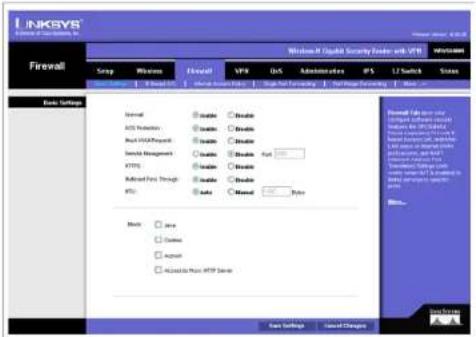
text_image
LinkSYS Firewall Windows Xilinx Security Driver with VPN Version Setup Winbase Fileset VPN DNS Administrative IPS LT Switch Status Basic Settings Normal Disable Disable DNS Protection Disable Disable Post UDP/Prepaid Disable Disable System Management Disable Disable FTP Disable Disable Advanced Plus Through Disable Disable Auto Disabled Byte Back Save Enable Import Access to Web FTP Server Base Settings Load Changes Standard Dev. User Standard Dev. User Service Standard Dev. User Service Standard Dev. User Service Standard Dev. User Service Standard Dev. User Service Standard Dev. User ServiceFigure 6-29: Firewall - Basic Settings
Wireless-N Gigabit Security Router with VPN
Restrict WEB Features
Block. Select the Web features that you wish to restrict. All those features could place security concern to your PCs on the LAN side. You have to balance your needs on those applications and security. The default is unselected.
- Java: Java is a programming language for websites. If you deny Java, you run the risk of not having access to Internet sites created using this programming language.
- Cookies: A cookie is data stored on your PC and used by Internet sites when you interact with them, so you may not want to deny cookies.
- ActiveX: ActiveX is a Microsoft (Internet Explorer) programming language for websites. If you deny ActiveX, you run the risk of not having access to Internet sites using this programming language. Also, Windows Update uses ActiveX, so if this is blocked, Windows update will not work.
- Proxy: If local users have access to WAN proxy servers, they may be able to circumvent the Router's content filters and access Internet sites blocked by the Router. Denying Proxy will block access to any WAN proxy servers.
Change these settings as described here and click Save Settings to apply your changes, or click Cancel Changes to cancel your changes. Help information is displayed on the right-hand side of the screen, and click More for additional details.
Wireless-N Gigabit Security Router with VPN
IP Based ACL
This screen shows a summary of configured IP based Access List. The Access List is used to restrict traffic going through the Router either from WAN or LAN port. There are two ways to restrict data traffic. You can block specific types of traffic according to your ACL definitions. Or you can allow only specific types of traffic according to your ACL definition. The ACL rules will be read according to its priority. If there is a match for a packet, the action will be taken and following lower priority rules will not be checked against this packet.
Note that the higher the number of rules that need to be checked against packets, the lower the throughput. Use ACL rules with caution.
There are two default rules in the table that cannot be deleted. The first rule will allow all traffic coming in from LAN port to pass the Router. The second rule will allow all traffic coming in from WAN port. These two rules have the lowest priority, so without adding any user defined rules, all the packets can be passed through from both WAN and LAN sides.
The rule will be enabled when the Enable button is checked, and when Date and Time are matched. If any of conditions are not met, the rule will not be used to check against packets.
The following are descriptions on each of the fields in the ACL Table:
Priority: This defines the order on which rule is checked against first. The smaller number has higher priority. The default rules will always be checked last.
Enable: This tells the Router if the rule is active or not. You can have rules defined in the ACL Table but in an inactive state. The administrator can decide on when to enable specific ACL rules manually.
Action: This defines how the rule is to affect the traffic. It can be either Allow or Deny. If the rule is matched and the action is Allow, the packet will be forwarded. If the rule is matched and the action is Deny, the packet will be dropped.
Service: You can either select one of the pre-defined services in the drop-down menu or you can define new services by clicking the Service Management button. Once you defined your own service, it will be listed on the top of the drop-down menu. You can also select ALL to allow or block all types of IP traffic.
The User-defined Service GUI page can be either accessed from the New Rule screen by clicking Service Management button, or you can access it directly from the 2nd layer tab under Firewall.
Source Interface: Select LAN, WAN, or ANY interface.
Chapter 6: Setting Up and Configuring the Router Firewall Tab
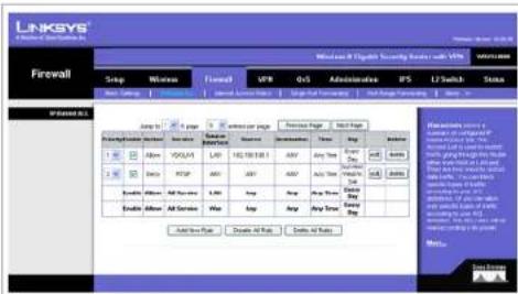
Figure 6-30: Firewall - IP Based ACL

text_image
ALL AIM BGP BOOTP CLIENT BOOTP SERVER CU SEIME DNS FINGLE FTP HS23 HTTP HTTPS ICQ IRC NBVS NFS NNTP POP3 PPTP RCMD REAL AUDIO REXEC RLOON RTLNET RSTP SFTP SMTP SNMP SNMP TRAPS SQL NETFigure 6-31: Firewall - IP Based ACL (pre-defined services)
Wireless-N Gigabit Security Router with VPN
Source: This is the source IP address to be matched against. You can define a Single IP address, a Range of IP addresses (start IP and end IP), a Network (IP Prefix and Network Mask), or ANY IP addresses.
Destination: This is the destination IP address to be matched against. You can define a Single IP address, a Range of IP addresses (start IP and end IP), a Network (IP Prefix and Network Mask), or ANY IP addresses.
Time: Displays the time period this rule will be enabled (used together with Date). It can be set to Any Time.
Date: Displays the days in a week this rule will be enabled (used together with Time). It can be set to Any Day.
Edit button: Use this button to go to Edit IP ACL Rule screen and modify this rule.
Delete button: Use this button to delete the ACL rule from the list.
Following is a description of the buttons in the IP Based ACL screen:
Page Selections: You can select specific page of ACL list from the drop-down menu to be displayed. Or you can navigate them page by page through Previous Page and Next Page button.
Add New Rule: Click this button to enter the page to define a new ACL rule.
Disable All Rule: Click this page to disable all the user defined rules.
Delete All Rule: Click this page to delete all the user defined rules.
Edit IP ACL Rule
This Web page can be entered only through IP Based ACL Tab. You can enter this page by clicking Add New Rule button on that page.
New Rule
Action: Select either Allow or Deny. Default is Allow.
Service: Select ALL or pre-defined (or user-defined) services from the drop-down menu.
Log: If checked, this ACL rule will be logged when a packet match happens.

text_image
LINKSYS Security Server 8.0.23.01.02.03.04.05.06.07.08.09.10.11.12.13.14.15.16.17.18.19.20.21.22.23.24.25.26.27.28.29.30.31.32.33.34.35.36.37.38.39.40.41.42.43.44.45.46.47.48.49.50.51.52.53.54.55.56.57.58.59.60.61.62.63.64.65.66.67.68.69.70.71.72.73.74.75.76.77.78.79.80.81.82.83.84.85.86.87.88.89.90.91.92.93.94.95.96.97.98.99.100.Figure 6-32: Firewall - IP Based ACL (Service definition)

text_image
LINKSYS A Flights of Connection Firewall Wireless Security System with VPN Network B: Default Security System with VPN Network B: Default Security System with VPN Network B: Default Security System with VPN Network B: Default Security System with VPN Network B: Default Security System with VPN Network B: Default Security System with VPN Network B: Default Security System with VPN Network B: Default Security System with VPN Network B: Default Security System with VPN Network B: Default Security System with VPN Network B: Default Security System with VPN Network B: Default Service Management Network B: Default Service Management Network B: Default Service Management Network B: Default Service Management Network B: Default Service Management Network B: Default Service Management Network B: Default Service Management Network B: Default Service Management Network B: Default Service Management Network B: Default Service Management Network B: Default Service Management Network B: Default Service Management Network B: Default Service Management Network B: Default Service Management Network B: Default Service Management System IP: Target System IP: Target System IP: Target System IP: Target System IP: Target System IP: Target System IP: Target System IP: Target System IP: Target System IP: Target System IP: Target System IP: Target System IP: Target System IP: Target System IP: Target System IP: Target System IP: Target System IP: Target System IP: Target System IP: Target System IP: Total System IP: Total System IP: Total System IP: Total System IP: Total System IP: Total System IP: Total System IP: Total System IP: Total System IP: Total System IP: Total System IP: Total System IP: Total System IP: Total System IP: Total System IP: Total System IP: Total System IP: Total System IP: Total System IP: Total System IP:TotalFigure 6-33: Firewall - Edit IP ACL Rule
Chapter 6: Setting Up and Configuring the Router Firewall Tab
Wireless-N Gigabit Security Router with VPN
Log Prefix: This string will be attached in front of the log for the matched event.
Source Interface: Select LAN, WAN, or ANY interface.
Source: The source IP address to be matched against. You can define a Single IP address, a Range of IP addresses (start IP and end IP), a Network (IP Prefix and Network Mask), or ANY IP addresses.
Destination: The destination IP address to be matched against. You can define a Single IP address, a Range of IP addresses (start IP and end IP), a Network (IP Prefix and Network Mask), or ANY IP addresses.
Service Management Button: Click this button and the Service Tab to add new service type to the Service drop-down menu.
Scheduling
Time: Enter the time period this rule will be applied (used together with Date). It can be set to Any Time.
Date: Enter the days in a week this rule will be applied (used together with Time). It can be set to Any Day.
Change these settings as described here and click Save Settings to apply your changes, or click Cancel Changes to cancel your changes. Help information is displayed on the right-hand side of the screen, and click More for additional details.
Wireless-N Gigabit Security Router with VPN
Internet Access Policy
Access to the Internet can be managed by policies. A policy consists of four components. You need to define the PCs (MAC or IP address) to apply this policy, either Deny or Allow Internet service, what time and date to enable this policy, and what URLs or Keywords to apply this policy.
Use the settings on this screen to establish an access policy. Selecting a policy from the drop-down menu will display that policy's settings. You can then perform the following operations:
- Create a Policy - see instructions below.
- Delete the current policy - click the Delete button.
- View all policies - click the Summary button. On the Summary screen, the policies are listed with the following information: No., Policy Name, Days, Time, and a checkbox to delete (clear) the policy. To delete a policy, check the checkbox in the Delete column, and click the Delete button
• View or change the PCs covered by the current policy - click the Edit List of PCs button.
On the List of PCs screen, you can define PCs by MAC Address or IP Address. You can also enter a range of IP Addresses if you want this policy to affect a group of PCs.
To create an Internet Access policy:
- Select the desired policy number from the Internet Access Policy drop-down menu.
- Enter a Policy Name in the field provided.
- To enable this policy, select the Enable option.
- Click the Edit List of PCs button to select which PCs will be affected by the policy. The List of PCs screen will appear in a sub-window. You can select a PC by MAC Address or IP Address. You can also enter a range of IP Addresses if you want this policy to affect a group of PCs. After making your changes, click the Save Settings button to apply your changes.
- Click the appropriate option, Deny or Allow, depending on whether you want to block or allow Internet access for the PCs you listed on the List of PCs screen.
- Decide what Days and what Times you want this policy to be enforced. Select the individual days during which the policy will be in effect, or select Everyday. Enter a range of hours and minutes during which the policy will be in effect, or select 24 Hours.
Chapter 6: Setting Up and Configuring the Router Firewall Tab

text_image
LINKEYS Firewall Windows 8 (Fileset Security Header with VPS) Network Access Policy Send to: Windows Send to: Windows Send to: Windows Send to: Windows Send to: Windows Send to: Windows Send to: Windows Send to: Windows Send to: Windows Send to: Windows Send to: Windows Send to: Windows Send to: Windows Send to: Windows Send to: Windows Send to: Windows Send to: Windows Send to: Windows Send to: Windows Send to: Windows Send to:Windows Send to:Windows Send to:Windows Send to:Windows Send to:Windows Send to:Windows Send to:Windows Send to:Windows Send to:Windows Send to:Windows Send to:Windows Send to:Windows Send to:Windows Send to:Windows Send to:Windows Send to:Windows Send to:Windows Send to:Windows Send to:Windows Send to:Windows Send to:Winch Send to:Winch Send to:Winch Send to:Winch Send to:Winch Send to:Winch Send to:Winch Send to:Winch Send to:Winch Send to:Winch Send to:Winch Send to:Winch Send to:Winch Send to:Winch Send to:Winch Send to:Winch Send to:Winch Send to: - - - - - - - - - - - - - - - - - - - - - - - - - - - - - - - - - - - - - - - - - - - - - - - - - - - - - - - - - - - - - - - - - - - - - - - - - - - - - - - - - - - - - - - - - - - - - - - - - - - - - - - - - - - - - - - - - - - - - - - - - - - - - - - - - - - - - - - - - - - - - - - - - - - - - - - Reserved Reserved Reserved Reserved Reserved Reserved Reserved Reserved Reserved Reserved Reserved Reserved Reserved Reserved Reserved Reserved Reserved Reserved Reserved Reserved Reserved Reserved Reserved Reserved Reserved Reserved Reserved Reserved Reserved Reserved Reserved Reserved Reserved Reserved Reserved Reserved Reserved Reserved Reserved Reserved Reserved Reserved Reserved Reserved Reserved Reserved Reserved Reserved Reserved Reserved ReservedFigure 6-34: Firewall - Internet Access Policy
Wireless-N Gigabit Security Router with VPN
-
If you wish to block access to Web sites, use the Website Blocking by URL Address or Website Blocking by Keyword feature.
-
Website Blocking by URL Address. Enter the URL or Domain Name of the web sites you wish to block.
-
Website Blocking by Keyword. Enter the keywords you wish to block in the fields provided. If any of these Keywords appears in the URL of a web site, access to the site will be blocked. Note that only the URL is checked, not the content of each Web page.
-
Click the Save Settings button to save the policy settings.

text_image
LINKSYS Internet Policy Summary Summary Internet Policy Summary Name Layout Name Open Path: 324 Flow of Path: 100000 Access 1. LinkSYS.COM.L 000000000 000000000 000000000 000000000 2. 3. 4. 5. 6. 7. 8. 9. 10. 11. 12. 13. 14. 15. 16. 17. 18. 19. 20. 21. 22. 23. 24. 25. 26. 27. 28. 29. 30. 31. 32. 33. 34. 35. 36. 37. 38. 39. 40. 41. 42. 43. 44. 45. 46. 47. 48. 49. 50. 51. 52. 53. 54. 55. 56. 57. 58. 59. 60. 61. 62. 63. 64. 65. 66. 67. 68. 69. 70. 71. 72. 73. 74. 75. 76. 77. 78. 79. 80. 81. 82. 83. 84. 85. 86. 87. 88. 89. 90. 91. 92. 93. 94. 95. 96. 97. 98. 99. 100. Browse...Figure 6-35: Firewall - Internet Access Policy Summary
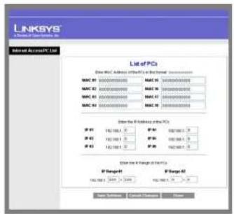
text_image
LINKSYS A B C D E F S T A N List of PCs Select MAC Address (or PC) to be a terminal. Inseraee MAC #1 00000000000 MAC #1 0000000000 MAC #2 00000000000 MAC #2 0000000000 MAC #3 00000000000 MAC #3 0000000000 Select the following port: PCs P #1 182 184 1.5 P #1 182 184 1.5 P #2 182 184 1.5 P #2 182 184 1.5 P #3 182 184 1.5 P #3 182 184 1.5 Select the Port of PCs P Target 182 184 1.5 Target 182 184 1.5 Target Final Settings: Select PCs Next PageFigure 6-36: Firewall - Internet Access Policy (List of PCs to apply policy)
Wireless-N Gigabit Security Router with VPN
Single Port Forwarding
This is one of the NAPT (Network Address Port Translation) feature. Use the Single Port Forwarding screen when you want to open specific services (that use single port). This allows users on the Internet to access this server by using the WAN port address and the matched external port number. When users send these types of request to your WAN port IP address via the Internet, the NAT Router will forward those requests to the appropriate servers on your LAN.
Application Name. Enter the name of the application you wish to configure.
External Port. This is the port number used by the service or Internet application. Internet users must connect using this port number. Check with the software documentation of the Internet application for more information.
Internal Port. This is the port number used by the Router when forwarding Internet traffic to the PC or server on your LAN and is usually the same as the External Port number. If it is different, the Router performs a Port Translation, so that the port number used by Internet users is different from the port number used by the server or Internet application.
For example, you could configure your Web Server to accept connections on both port 80 (standard) and port 8080. Then, enable Port Forwarding, set the External Port to 80 and the Internal Port to 8080. Now, any traffic from the Internet to your Web server will be using port 8080, even though the Internet users used the standard port, 80. (Users on the local LAN can and should connect to your Web Server using the standard port 80.)
Protocol. Select the protocol used for this application, TCP and/or UDP.
IP Address. For each application, enter the IP address of the PC running the specific server application.
Enabled. Select Enabled to enable port forwarding for the relevant server application.
Change these settings as described here and click Save Settings to apply your changes, or click Cancel Changes to cancel your changes. Help information is displayed on the right-hand side of the screen, and click More for additional details.
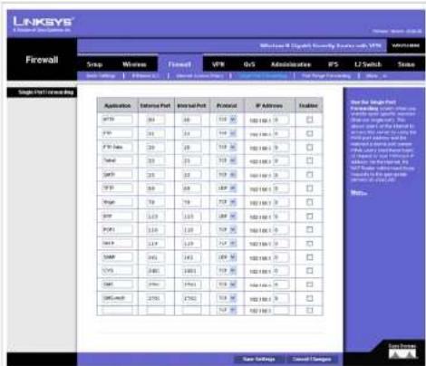
text_image
LINKGYS Wireless Security Service with VPN Firewall Setup Windows Formed VPN Ors Administration FPS U2 Switch Status Network Settings Connected To: Connected To: 100% Connected To: 100% Net Range Forwarding Wise... Single Print Review Box Application Satellite Port Internal Port Protocol IP Address Kodging FTP 36 38 519 36 MD1000 7 FTP 36 54 519 36 MD1000 7 FTP Max 59 59 519 36 MD1000 7 Temp 59 59 519 36 MD1000 7 TCP 36 59 59 519 36 MD1000 7 TCP 36 59 59 519 36 MD1000 7 Temp 79 79 519 36 MD1000 7 TCP 1.29 1.29 519 36 MD1000 7 TCP1 1.29 519 36 MD1000 7 TCP1 1.29 519 36 MD1000 7 TCP 1.29 1.29 519 36 MD1000 7 TCP 1.29 1.29 519 36 MD1000 7 TCP 1.29 1.29 519 36 MD1000 7 TCP 1.29 1.29 519 36 MD1000, 7) TCP 1.29 1.29 519 36 MD1000, 7) TCP 1.29 1.29 519 36 MD1000, 7) TCP 1.29 1.29 519 36 MD1000, 7) TCP 1.29 1.29 519, 36 MD1000, 7) TCP 1.29 1.29 519, 36Figure 6-37: Firewall - Single Port Forwarding
Wireless-N Gigabit Security Router with VPN
Port Range Forwarding
This is one of the NAPT (Network Address Port Translation) features. The Port Range Forwarding screen allows you to set up public services on your network, such as web servers, ftp servers, e-mail servers, or other specialized Internet applications that use one or multiple port numbers (e.g. video conference). The port numbers being used will not change while forwarding to the local network. This allows users on the Internet to access this server by using the WAN port IP address and the pre-defined port numbers. When users send these types of requests to your WAN port IP address via the Internet, the NAT Router will forward those requests to the appropriate servers on your LAN.
Application. Enter the name of the application you wish to configure.
Start. This is the beginning of the port range. Enter the beginning of the range of port numbers (external ports) used by the server or Internet application. Check with the software documentation of the Internet application for more information if necessary.
End. This is the end of the port range. Enter the end of the range of port numbers (external ports) used by the server or Internet application. Check with the software documentation of the Internet application for more information if necessary.
Protocol. Select the protocol(s) used for this application, TCP and/or UDP.
IP Address. For each application, enter the IP address of the PC running the specific application.
Enabled. Select Enabled to enable port range forwarding for the relevant application.
Change these settings as described here and click Save Settings to apply your changes, or click Cancel Changes to cancel your changes. Help information is displayed on the right-hand side of the screen, and click More for additional details.

Figure 6-38: Port Range Forwarding
Wireless-N Gigabit Security Router with VPN
Port Range Triggering
This is one of the NAPT (Network Address Port Translation) feature. Port Range Triggering is used for special applications that can request a port to be opened on demand. For this feature, the Wireless Router will watch outgoing packets for specific port numbers. This will trigger the Wireless Router to allow the incoming packets within the specified forwarding range and forward those packets to the triggering PC. One of the example applications is QuickTime. It would use port 1000 for outgoing packets and 2000 for incoming packets.
Application Name. Enter the name of the application you wish to configure.
Triggered Range. For each application, list the triggered port number range. These are the ports used by outgoing traffic. Check with the Internet application documentation for the port number(s) needed. In the first field, enter the starting port number of the Triggered Range. In the second field, enter the ending port number of the Triggered Range.
Forwarded Range. For each application, list the forwarded port number range. These are the ports used by incoming traffic. Check with the Internet application documentation for the port number(s) needed. In the first field, enter the starting port number of the Forwarded Range. In the second field, enter the ending port number of the Forwarded Range.
Enabled. Select Enabled to enable port range triggering for the relevant application.
Change these settings as described here and click Save Settings to apply your changes, or click Cancel Changes to cancel your changes. Help information is displayed on the right-hand side of the screen, and click More for additional details.
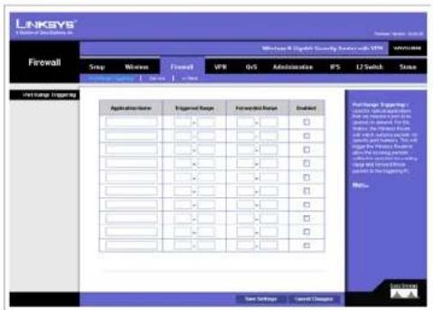
text_image
LINKSYS Firewall Snap Windows Final VPR OS Administrative IFS LT Switch State Initiate Trapping Applications Triggered Range Forward Range Enzyme □ □ □ □ □ □ □ □ □ □ □ □ □ □ □ □ □ □ □ □ □ □ □ □ □ □ □ □ □ □ □ □ □ □ □ □ □ □ □ □ □ □ □ □ □ □ □ □ Package: Targeting: start traffic from the network to the network. The network is ready for the start traffic. The start traffic from the network is ready for the start traffic. The start traffic from the network is ready for the start traffic. The start traffic from the network is ready for the start traffic. Status: StatusFigure 6-39: Port Range Triggering
Wireless-N Gigabit Security Router with VPN
Service
This screen allows users to define new service types based on TCP or UDP. The new service will be added to the summary table below. It will also show up in the service drop-down menu under Edit IP ACL Rule screen.
Name: Define the new service name. The service name must be different from existing pre-defined or user-defined services.
Type: The service can rely on UDP only, TCP only, or both UDP and TCP.
Start Port: Enter the starting port number.
Finish Port: Enter the finishing port number. The finishing port number must be greater or equal to starting port number.
Save button: Click this button to save a new defined service.
Delete button: To delete an existing service, click the Edit button at the end of each row in the summary table.
Edit button: Use this button to select a service to modify or delete.
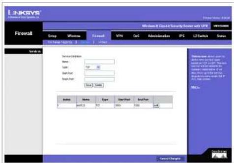
text_image
LINKSYS Firewall Setup Wireless Forward VTM DoS Administration IP3 LT Switch Status Service Settings Name: Type: Start Port: Start Port: Save... Address Name Type Start Port End Port 9 600120 500 10000 5000 4x8 Control Changes Microsoft Office System for the system, which is not a system to access the system to the Windows Server. The system is not a system to access the system to the Windows Server. The system is not a system to access the system to the Windows Server. The system is not a system to access the system to the Windows Server. The system is not a system to access the system to the Windows Server. The system is not a system to access the system to the Windows Server. The system is not a system to access the system to the Windows Server. The system is not a system to access the system to Windows Server 1.0.1.1.1.1.1.1.1.1.1.1.1.1.1.1.1.1.1.1.1.1.1.1.1.1.1.1.1.1.1.1.1.1.1.1.1.1.1.1.Figure 6-40: Firewall - Services
Wireless-N Gigabit Security Router with VPN
VPN Tab
IPsec VPN
Use this screen to create VPN tunnels between the Router to the remote Router. All Linksys Routers with IPsec VPN support can be used as a remote Router (e.g. RVS4000, WRV54G, RV042). The Router supports VPN tunnels using IPsec (IP Security) technologies. You can create, delete, or modify a VPN tunnel on this page.
Select Tunnel Entry. Select a tunnel to configure or create a new tunnel.
Delete Button. Click this button to delete the selected tunnel.
Summary Button. Clicking this button shows the settings of all existing tunnels.
IPsec VPN Tunnel. Select Enable to enable this tunnel.
Tunnel Name. Enter a name for this tunnel, such as "Anaheim Office".
Local Security Group
Local Security Group Type. Select the local LAN user(s) behind the Router that can use this VPN tunnel. This may be a single IP address or Sub-network. Notice that the Local Security Group must match or cover the other router's Remote Security Group.
IP Address. Enter the IP address on the local network.
Subnet Mask. If the Subnet option is selected, enter the mask to determine the IP prefix on the local network.
Remote Security Group
Remote Security Group. Select the remote LAN user(s) behind the remote gateway who can use this VPN tunnel. This may be a single IP address, a Sub-network, or any addresses. If Any is set, the Router acts as responder and accepts request from any remote user. Notice that the Remote Security Group must match or cover the other Router's Local Security Group.
IP Address. Enter the IP address on the remote network.
Subnet Mask. If the Subnet option is selected, enter the mask to determine the IP prefix on the remote network.

Figure 6-41: VPN - IPsec VPN
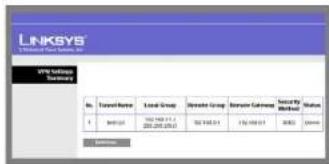
text_image
LINKSYS Solutions Care Services, Inc. SPX Solutions Cotimes No. Travel Name Local Group Remote Group Remote Camera Security Mitsubishi Market Status 1 300000 102 1488 11.1 152 1488 11 176 1488 11 300000 AccessoriesFigure 6-42: VPN Tunnel Summary
Chapter 6: Setting Up and Configuring the Router VPN Tab
Wireless-N Gigabit Security Router with VPN
Remote Security Gateway. Select the remote gateway WAN port IP Address that can use this VPN tunnel. This may be a Single IP address or Any addresses. If is set, the Router acts as responder and accepts request from any remote Gateway.
IP Address. Enter the IP address on the remote WAN port.
Key Management
Key Exchange Method. The Router supports both automatic and manual key management. When choosing automatic key management, IKE (Internet Key Exchange) protocols are used to negotiate key material for SA (Security Association). If manual key management is selected, no key negotiation is needed. Basically, manual key management is used in small static environments or for troubleshooting purpose. Notice that both sides must use the same Key Management method (both Auto or both Manual). For Manual key management, all the configurations need to match on both sides.
Auto IKE
Encryption. The Encryption method determines the complexity to encrypt/decrypt data packets. Only 3DES is supported. Notice that both sides must use the same Encryption method.
Authentication. Authentication determines a method to authenticate the data packets to make sure they come from a trusted source. Either MD5 or SHA1 may be selected. Notice that both sides (VPN endpoints) must use the same Authentication method.
- MD5: A one way hashing algorithm that produces a 128-bit digest.
- SHA1: A one way hashing algorithm that produces a 160-bit digest.
PFS (Perfect Forward Secrecy). If PFS is enabled, IKE Phase 2 negotiation will generate a new key material for IP traffic encryption and authentication. Note: that both sides must have this selected.
Pre-Shared Key. IKE uses the Pre-shared Key field to authenticate the remote IKE peer. Both characters and hexadecimal values are acceptable in this field. e.g. "My_@123" or "0x4d795f40313233" Note that both sides must use the same Pre-shared Key.
Key Life Time. This field specifies the lifetime of the IKE generated key. If the time expires, a new key will be renegotiated automatically. The Key Life Time may range from 300 to 100,000,000 seconds. The default Life Time is 3600 seconds.
Wireless-N Gigabit Security Router with VPN
Manual
Encryption Algorithm. The Encryption method determines the complexity to encrypt/decrypt data packets. Only 3DES is supported. Notice that both sides must use the same Encryption method.
Encryption Key. This field specifies a key used to encrypt and decrypt data packets. Both characters and hexadecimal values are acceptable in this field. Note: that both sides must use the same Encryption Key.
Authentication Algorithm. Authentication determines a method to authenticate the data packets to make sure they come from a trusted source. Either MD5 or SHA1 may be selected. Notice that both sides (VPN endpoints) must use the same Authentication method.
- MD5: A one way hashing algorithm that produces a 128-bit digest.
- SHA1: A one way hashing algorithm that produces a 160-bit digest.
Authentication Key. This field specifies a key used to authenticate IP traffic. Both characters and hexadecimal values are acceptable in this field. Note: that both sides must use the same Authentication Key.
Inbound SPI/Outbound SPI. The SPI (Security Parameter Index) is carried in the IPsec ESP header. This enables the receiver to select the SA (Security Association), under which a packet should be processed. The SPI is a 32-bit value. Both decimal and hexadecimal values are acceptable. e.g. "987654321" or "0x3ade68b1". Each tunnel must have unique an Inbound SPI and Outbound SPI. No two tunnels share the same SPI. Notice that Inbound SPI must match the other Router's Outbound SPI, and vice versa.
Status
Status. This field shows the connection status for the selected tunnel. The state is either connected or disconnected.
Connect button. Use this to establish a connection for the current VPN tunnel. If you have made any changes, click Save Settings to first apply your changes.
Disconnect button. Use this to break a connection for the current VPN tunnel.
View Log button. Click this to view the VPN log, which shows details of each tunnel established. You can change the Log type to show only VPN tunnel related events.
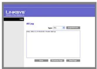
text_image
LINKSYS All Log Type: ALL Page/10/2016-03.04 - Mouse Startup Close Business Post Build PageFigure 6-43: View VPN Tunnel Log
Wireless-N Gigabit Security Router with VPN
Advanced Settings button. If the Key Exchange Method is Auto (IKE), this button provides access to some additional settings relating to IKE. Use this if the Router is unable to establish a VPN tunnel to the remote VPN Gateway; ensure the Advanced Settings match those on the remote VPN Gateway. Note that Phase 1 is used for key negotiation and Phase 2 is used for actual data exchange.
Advanced Settings (Phase 1 and Phase 2)
Operation Mode. Select the method to match the remote VPN endpoint.
- Main: Main Mode is slower but more secure.
- Aggressive: Aggressive mode is faster but less secure.
Local Identity. Select the desired option to match the "Remote Identity" setting at the other end of this tunnel.
- Local IP address: Your WAN IP Address.
• Name: Your domain name.
Remote Identity. Select the desired option to match the "Local Identity" setting at the other end of this tunnel.
- Local IP address: WAN IP Address of the remote VPN endpoint.
- Name: Domain name of the remote VPN endpoint.
Encryption. Encryption Algorithm used for the IKE SA. This setting must match the setting used at the other end of this tunnel.
Authentication. Authentication Algorithm used for the IKE SA. This setting must match the setting used at the other end of this tunnel.
- MD5: A one way hashing algorithm that produces a 128-bit digest.
- SHA1: A one way hashing algorithm that produces a 160-bit digest.
Group. The Group setting determines the bit size used in the IKE exchange. This value must match the value used at the other end of this tunnel.
Key Life Time. This determines the time interval before the IKE SA (Security Association) expires. (It will automatically be re-established if necessary.) While using a short time period increases security, it also
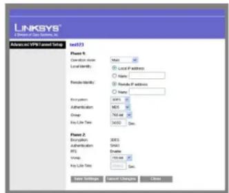
text_image
LINKSYS A License of Class Services, Inc. Advanced vVPS license Setup mod203 Phase 1: Duration: None Location: Local IP Address Pseudo Identity: Name Recirculation: 5476.2 Administration: MSN Order: Toil at Any Life Time: 34000.0000 Phase 2: Recirculation: 2003 Administration: Shift FPE: Enable Write: 100.00.00 Key Life Time: 100.00.00 Save Settings: Cancel Changes CloseFigure 6-44: IPsec VPN Advanced Settings
Wireless-N Gigabit Security Router with VPN
degrades performance. While this unit is in seconds, it is common to use periods over an hour (3600 seconds) for the SA Life Time.
Change these settings as described here and click Save Settings to apply your changes, or click Cancel Changes to cancel your changes. Help information is displayed on the right-hand side of the screen, and click More for additional details.
Chapter 6: Setting Up and Configuring the Router VPN Tab
Wireless-N Gigabit Security Router with VPN
VPN Client Accounts
You can allow remote users to easily establish a VPN connection to your Router using the Linksys QuickVPN client utility without using a compatible VPN Router with IPsec VPN settings. This is achieved by creating user accounts on the Router and authenticate users through Username and Password. After creating user accounts, it will be summarized in the table below.
For users using QuickVPN, it will first establish an SSL connection with remote Wireless Router to get authenticated. Then QuickVPN will automatically negotiate IPsec settings with the remote Router. All the data packets will be encrypted using IPsec thereafter.
The Wireless Router supports up to five Linksys QuickVPN clients by default. Additional QuickVPN Client licenses can be purchased separately.
Username. Enter the username using any combination of keyboard characters.
Password. Enter the password you would like to assign to this user.
Re-enter to Confirm. Retype the password to ensure that it has been entered correctly.
Allow User to Change Password. This option determines whether the user is allowed to change their password.
VPN Client List Table
No. Displays the user number.
Active. When checked, the designated user can connect, otherwise the VPN client account is disabled.
Username. Displays the username.
Edit button. This button is used to modify the username, password, or toggle between whether the user is allowed to change their password.
Remove button. This button is used to delete a user account.
Change these settings as described here and click Save Settings to apply your changes, or click Cancel Changes to cancel your changes. Help information is displayed on the right-hand side of the screen, and click More for additional details.
Chapter 6: Setting Up and Configuring the Router VPN Tab
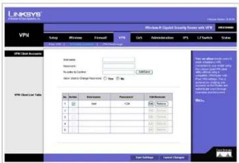
text_image
LINKSYS Windows 8 Capital Security Forum with VPN VPN Setup Windows Final VPN GNS Administration IPS C:\Network Status FVCS Cloud Accounts Newspire: Password: New to Account Sub-Service New Status Change Request: Yes No FVCS Cloud List Table File Edit Print Button Password Edit Reserve 1 2 Sat CN 3 4 5 6 7 8 9 10 11 12 13 14 15 16 17 18 19 20 21 22 23 24 25 26 27 28 29 30 31 32 33 34 35 36 37 38 39 40 41 42 43 44 45 46 47 48 49 50 51 52 53 54 55 56 57 58 59 60 61 62 63 64 65 66 67 68 69 70 71 72 73 74 75 76 77 78 79 80 81 82 83 84 85 86 87 88 89 90 91 92 93 94 95 96 97 98 99 100 Save Settings Cancel ChangesFigure 6-45: VPN - VPN Client Accounts
Wireless-N Gigabit Security Router with VPN
VPN Passthrough
This screen allows users to use their own VPN algorithms to connect to their remote Routers. The Wireless Router will just pass the traffic through.
IPsec Passthrough. Internet Protocol Security (IPsec) is a suite of protocols used to implement secure exchange of packets at the IP layer. IPsec Passthrough is enabled by default to allow IPsec tunnels to pass through the Router. To disable IPsec Passthrough, select Disabled.
PPTP Passthrough. Point-to-Point Tunneling Protocol (PPTP) allows the Point-to-Point Protocol (PPP) to be tunneled through an IP network. PPTP Passthrough is enabled by default. To disable PPTP Passthrough, select Disabled.
L2TP Passthrough. Layer 2 Tunneling Protocol is the similar to PPP but allows Layer 2 and the PPP session to terminate at different servers or locations. L2TP Passthrough is enabled by default. To disable L2TP Passthrough, select Disabled.
Change these settings as described here and click Save Settings to apply your changes, or click Cancel Changes to cancel your changes. Help information is displayed on the right-hand side of the screen, and click More for additional details.

text_image
LINKSYS Security Server, Inc. Windows NT Capital Security Server with VPN VPN Setup Authentication Forward VPN DNA Administration IPS CI Switch Scale VMH Platform FOS: Fast Through (D) Update (C) Update FTP: Fast Through (D) Update (C) Update USB: Fast Through (D) Update (C) Update System Status Cancel Changes Win: Win Win: WinFigure 6-46: VPN - VPN Passthrough
Chapter 6: Setting Up and Configuring the Router VPN Tab
Wireless-N Gigabit Security Router with VPN
QoS Tab
QoS (Quality of Service) allows you to prioritize network traffic using either Application-based priority (such as Web browsing applications, FTP applications, etc.) or Port-based priority, which allows you to assign priorities to the four physical network ports. Higher priority traffic will be allocated more bandwidth, which results in lower latency (or delay).
Application-based
The Application-based QoS controls priority differentiation for data packets between LAN (including WLAN) and WAN ports. Application-based QoS is achieved by software running on the CPU so it cannot control traffic between LANs that are switched directly by a hardware switch chipset.
Application-based QoS. QoS (Quality of Service) is disabled by default. When enabled, this option allows you to assign priority based on the application type.
Set Internet Bandwidth. Enter approximate bandwidth number for your WAN connection. This will help the software-based algorithm to allocate bandwidth to different priorities.
Table 1: Application-based QoS
| Application Name | Port(s) Primary Use | |
| FTP | TCP Port 20 | FTP (File Transfer Protocol) is used for transferring files over the Internet. |
| HTTP TCP Port 80 | HTTP (HyperText Trans | Transfer Protocol) is used for browsing the Internet. |
| Telnet TCP Port 23 | Telnet is a client-server protocol used to communicate over a network or the Internet. | |
| SMTP TCP Port 25 | SMTP (Simple Mail | Transfer Protocol) is used for sending e-mail. |
| POP3 TCP Port 110 | POP3 (Post Office | Protocol version 3) is used for retrieving e-mail. |
| Specific Port User | Defined User Defined | (0-65535) |

IMPORTANT: If you don't assign different priorities to applications, there will be no differentiation between different traffic types.
- Select the desired option for each application: High priority, Medium priority, or Low priority.
Chapter 6: Setting Up and Configuring the Router QoS Tab

text_image
LINKSYS A Division of Our Systems, Inc. Windows 9 Guide Security Router with VTR 100% 100% QoS Switch Network Firewall GPR OS Administrative 8% LJ Switch Status Application Status Application Name: GOS Enable Snacks Set Internal Bandwidths: Snacks Service A Priority High Networks Low FSP ○ ○ ○ MTP ○ ○ ○ Target ○ ○ ○ MMP ○ ○ ○ PORTS ○ ○ ○ Specific Point ○ ○ ○ Specific Point ○ ○ ○ Specific Point ○ ○ ○ New Settings Cancel Changes Data SummaryFigure 6-47: QoS - Application Based
Wireless-N Gigabit Security Router with VPN
Change these settings as described here and click Save Settings to apply your changes, or click Cancel Changes to cancel your changes. Help information is displayed on the right-hand side of the screen, and click More for additional details.
Port-based
Port-based QoS is implemented in hardware so it can achieve better throughput. It can only control traffic among the four LAN ports.
LAN ports 1-4 can be assigned High, Medium, Normal, or Low priority. Lower priority traffic will be slowed down to allow greater throughput for higher priority traffic.
Change these settings as described here and click Save Settings to apply your changes, or click Cancel Changes to cancel your changes. Help information is displayed on the right-hand side of the screen, and click More for additional details.

text_image
LINKSYS A Discount of Our Systems, Inc. Windows 8 Cryptical Security Server with VPN QoS Swap Wireless Frequencies VPN QoS Administrative IPS L2 Switch Status Start menu Port 1 Port 2 Port 3 Front The MNI Guide of the Next Networks, Web Services, and Internet Networks primarily needs, will be used to access the network. The Recommended Web Services are and you can use your files for different types. Win... Save Settings Refresh Loss ReviewFigure 6-48: Port-based
Wireless-N Gigabit Security Router with VPN
Administration Tab
Management
Local Gateway Access
This configures the administrator user accounts to manage the Wireless Router through Web based Utility. Only the first user is created by default. Other accounts are not created by default so you can leave them alone. Make sure to change the first user account username and password when you configure your Wireless Router for the first time.
Gateway Userlist. Select a user to configure from the drop-down menu.
Gateway Username. Enter the user name here.
Gateway Password. Enter the password.
Re-enter to Confirm. Retype the password in this field.
SNMP
This configures the Simple Network Management Protocol settings. Users can use management software to read or write information from or to the device.
Device Name. Enter a suitable name. This name will be used to identify this device, and will be displayed by your SNMP software.
SNMP. Select Enable if you wish to use SNMP. To use SNMP, you need SNMP software on your PC.
Read Community. Enter the SNMP community name for SNMP "Get" commands.
Write Community. Enter the SNMP community name for SNMP "Set" commands.
Trap To. Enter the IP Address of the SNMP Manager where traps will be sent. If desired, this may be left blank.
UPnP. Universal Plug and Play allows Windows MP and XP to automatically configure the Internet Gateway on its routing table. If you want to use UPnP, keep the default setting, Enable. Otherwise, select Disable.
IGMP Proxy. IGMP (Internet Group Membership Protocol) Proxy can facilitate the communication between IGMP clients and IGMP Routers. Enable this feature if you are using IP multicast services in your network.
Chapter 6: Setting Up and Configuring the Router
Administration Tab

text_image
LINKSYS A Microsoft Group System, Inc. Administration Microsoft Not Applicable Security Server with VPS Settings Setup Welcome Forward VPS Get Administrative access IPS 1.2 Numbers Value Accession Log Parameters Data Management Form Details User Manager(s) Address: (e.g.) Address: (e.g.) Address: Password: Address to Account: Address: Name Name: Unit: Read Community: Write Community: Home: Auto: Outflow: Outflow: Outflow: Test Settings Cancel Settings Management Local Banking Access DBGP The service is the following functions: the admin application to the management functions to the security and the information that is available for the management functions to the security and the management functions to the security and the management functions to the security and the management functions to the security and the management functions to the security and the management functions to the security and the management functions to the security and the management functions to the security and the management functions to the security and the management functions to the security and the management functions to the security and the management functions to the security and .commodities the security and .commodities the security and .commodities the security and .commodities the security and .commodities the security and .commodities the security and .commodities the security and .commodities the security and .commodities the security and .commodities the security and .commodities the security and .commodities the security and .commodities the security and. commodities the security and .commodities the security and .commodities the security and .commodities the security and .commodities the security and .commodities the security and .commodities the security and .commodities the security and .commodities the security and .commodities the security and .commodities the security and .commodities the security and .commodities The security and .commodities The security and .commodities The security and .commodities The security and .commodities The security and .commodities The security and .commodities The security and .commodities The security and .commodities The security and .commodities The security and .commodities The security and .commodities The security and .commodities The security and .conmodities The security and .commodities The security and .commodities The security and .commodities The security and .commodities The security and .commodities The security and .commodities The security and .commodities The security and .commodities The security and .commodities The security and .commodities The security and .commodities The security and .commodities This is not a data source. This is not a data source. This is not a data source. This is not a data source. This is not a data source. This is not a data source. This is not a data source. This is not a data source. This is not a data source. This is not a data source. This is not a data source. This is not a data source. This is not a data source. This is not a data source. This is not a data source. Thisis is not a data source. This is not a data source. This is not a data source. This is not a data source. This is not a data source. This is not a data source. This is not a data source. This is not a data source. This is not a data source. This is not a data source. This is not a data source. This is not a data source. This is not a data source. This is not a data source. This isnot a data source. This is not a data source. This is not a data source. This is not a data source. This is not a data source. This is not a data source. This is not a data source. This is not a data source. This is not a data source. This is not a data source. This is not a data source. This is not a data source. This is not a data source. This is not a data source. This is not adata source. This is not a data source. This is not a data source. This is not a data source. This is not a data source. This is not a data source. This is not a data source. This is not a data source. This is not a data source. This is not a data source. This is not a data source. This is not a data source. This is not a data source. This is not a data source. This is not a data source。 This is not a data source. This is not a data source. This is not a data source. This is not a data source. This is not a data source. This is not a data source. This is not a data source. This is not a data source. This is not a data source. Thisis is not a data source. Thisis is not a data source. Thisis is not a data source. Thisis is not a data source. Thisis is not a data source. Thisis is not a data source. Thisis is not a data source. Thisis is not a data source. Thisis is not a data source. Thisis is not a data source. Thisis is not a data source. Thisis is not a data source. Thisis isnot a data source. Thisis isnot a data source. Thisis isnot a data source. Thisis isnot a data source. Thisis isnot a data source. Thisis isnot a data source. Thisis isnot a data source. Thisis isnot a data source. Thisis isnot a data source. Thisis isnot a data source. Thisis isnot a data source. Thisis isnot a data source. Thisis isnot a data source.Figure 6-49: Administration - Management
Wireless-N Gigabit Security Router with VPN
Change these settings as described here and click Save Settings to apply your changes, or click Cancel Changes to cancel your changes. Help information is displayed on the right-hand side of the screen, and click More for additional details.
Log
This screen provides you options on how you want to manage your system logs. The Wireless Router provides four categories of event logging (Firewall, VPN, System, and ACL). You can configure the Wireless Router to send the event log to you through e-mail, upload the log to syslog server, or view the log locally on the Wireless Router.
Email Alerts. If enabled, an e-mail will be sent when the number of DoS events exceeds the defined threshold or the total events number exceed 100. If enabled, the e-mail address information (below) must be provided.
Denial of Service Thresholds. Enter the number of DoS (Denial of Service) attacks that need to be detected (and blocked) by the software firewall before an e-mail alert is sent. The minimum value is 20, the maximum value is 100. Note that if IPS has been enabled, IPS would block DoS attacks before they reach the firewall. In that case, please check the IPS Report to know event details.
SMTP Mail Server. Enter the address (domain name) or IP address of the SMTP (Simple Mail Transport Protocol) server you use for outgoing e-mails.
Email Address for Alert Logs. Enter the e-mail address the log is to be sent to.
Return Email Address. The e-mail will show this address as the sender's address.
Enable Syslog. Select Enable if you want to use this feature.
Syslog Server. Enter the IP Address in the Syslog Server field when Enable Syslog is checked.
Local Log. Enable this if you want to see the log locally on the Wireless Router.
View Log button. If Local Log is enabled, click View Log to view the event log on the Wireless Router.
Change these settings as described here and click Save Settings to apply your changes, or click Cancel Changes to cancel your changes. Help information is displayed on the right-hand side of the screen, and click More for additional details.

text_image
LINKSYS A Division of Social Systems, Inc. Administration Windows-8/Spatch Security Server with VPN MSV10400 Group Wireless Forward VPN iOS Administration IPS L2 Switch Status Management Google Using Management Factory Network Network Manager Log Send Events: Enable Disable Default Service Threshold: several (2) - 100 OM Digital Server: Send Address to Alert Log: Return Email Address: Browse Shipping Supply Server: None or IP Address: LocalLog Enable Disable Send Settings Cancel Changes The Lang is not provided for any details or data transfer. Any other link or ID has been updated. For any additional information, it will be required for IP and external links.Figure 6-50: Administration - Log

text_image
LINKSYS I Drive a Data System, N: Log AI Leg Type: All Page/Description 2014, 1986-15, 2014-03-01 - Linear Start-up Close Remove Page Back StopFigure 6-51: View Log pop-up window
Wireless-N Gigabit Security Router with VPN
Diagnostics
Ping Test Parameters
Ping Target IP. Enter the IP address or URL that you want to ping.
Ping Size. Enter the size of the packet you want to use.
Number of Pings. Enter the number of times you wish to ping the target device.
Ping Interval. Enter the time period (in milliseconds) between each ping.
Ping Timeout. Enter the desired time period (in milliseconds). If a response is not received within the defined ping period, the ping is considered to have failed.
Start Test button. Click this button to begin the test. A new screen will appear and display the test results. A summary of the PING results will be shown on the bottom of this screen.
Ping Result. It displays the Ping status.
Traceroute Test Parameters
TraceRoute Target. Enter the IP address or Host name to perform the traceroute testing.
Start Test button. Click this button to begin the test. A new screen will appear and display the test results.
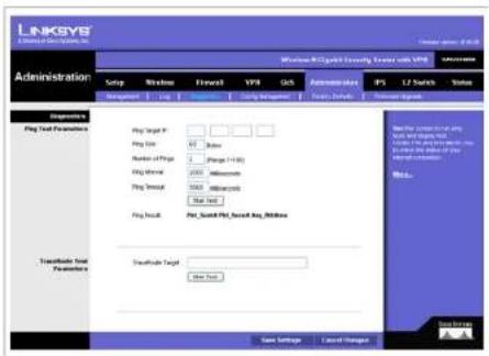
Figure 6-52: Administration - Diagnostics
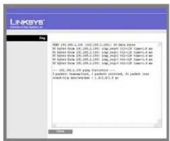
text_image
LINKSYS Tender: https://linksys.com/ File MBD (10, 100, 1, 100) (100, 100, 1, 100) -- all data packets All packets flow (10, 100, 1, 100) shagkey (52+/-) team-4 air All packets flow (10, 100, 1, 100) shagkey (7+/-) team-4 air All packets flow (10, 100, 1, 100) shagkey (9+/-) team-4 air All packets flow (10, 100, 1, 100) shagkey (9+/-) team-4 air --- 100, 100, 1, 100 pop filterator --- I packets transflow, I packets received, all packets load load-top synchronization : 1, 3, 5, 8, 9, 10Figure 6-53: Ping Test Screen
Wireless-N Gigabit Security Router with VPN
Config Management
Save Configuration
Save Configuration to File button. Click this button to save your Wireless Router's current configuration to a file on your PC. Enter the file name on the Windows screen that appears.
Restore Configuration
Select a previously saved configuration file to restore the configuration to the Wireless Router. This could be helpful if you want to use the same configuration on a new hardware or after resetting to the factory defaults. You can either enter the file path name yourself or use the Browse button to select a file from the Windows file system.
Browse button. Click this button to select a previously saved configuration from the Windows file system.
Load button. Click this button to start the restoration process.
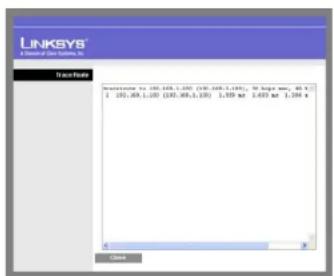
text_image
LINKSYS LinkedUp Services Database Accession to: 190.468.1.100 (190.468.1.100); 30 large empty; 85% [ 190.468.1.100 (190.468.1.100) 1.458 ms 1.458 ms 1.388 s ] CloseFigure 6-54: Trace Route Test Screen
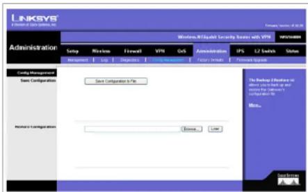
text_image
LINKSYS A Division of System Systems, Inc. Windows NT Equity Security Manager with VTP WINSTREAMS Administration Setup Windows Finalool VTP CAS Administration IPS L2 Switch Sales Management Help Install Help Help Help Help Help Help Config Management Save Configuration Save Configuration 5.1Ps The Debug Effector is only which has up and the system is available to Use the Windows NT Equity Security Manager Name: Method 1 Configuration Browse Use SystemFigure 6-55: Administration - Config Management
Wireless-N Gigabit Security Router with VPN
Factory Defaults
Restore Factory Defaults. Click this button to reset all configuration settings to their default values. All settings that have been saved will be lost when the default settings are restored. After clicking the button, another screen will appear. Click OK to continue. Another screen will appear while the system reboots.
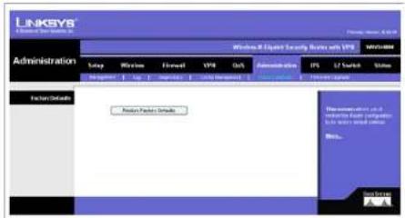
text_image
LINKSYS Internet Security System Administration Windows X Digital Security System with VPS MOS-884 System Network Security Network Security System Network Security System Network Security System Network Security System Network Security System Network Security System Network Security System Network Security System Network Security System Network Security System Network Security System Network Security System Network Security System Network Security System Network Security System Network Security System Network Security System Network Security System Network Security System Network Security System Network Security System Network Security System Network Security System Network Security System Network Security System Network Security Systems Network Security Systems Network Security Systems Network Security Systems Network Security Systems Network Security Systems Network Security Systems Network Security Systems Network Security Systems Network Security Systems Network Security Systems Network Security Systems Network Security Systems Network Security Systems Network Security Systems Network Security Systems Network Security Systems Network Security Systems Network Security Systems Network Security Systems Network Security Systems Network Security Systems Network Security Systems Network Security Systems Network Security Systems Network Security System Network Security System Network Security System Network Security System Network Security System Network Security System Network Security System Network Security System Network Security System Network Security System Network Security System Network Security System Network Security System Network Security System Network Security System Network Security System Network Security System Network Security System Network Security System Network Security System Network Security System Network Security System Network Security System Network Security System Network Security PlatformFigure 6-56: Administration - Factory Default
Firmware Upgrade
To upgrade firmware, download the latest firmware for the product from Linksys.com, extract it to your computer, and perform the steps below:
- File. Type in the name of the extracted firmware upgrade file or click Browse to locate the file from the file system.
- Start to Upgrade. Once you have selected the appropriate file, click the Start to Upgrade button and follow the on-screen instructions to upgrade your firmware.

text_image
LINKSYS Management Manager, Inc. Administration Setup Window FlowCell UPR OS Administration PS L2 Switch Status Enter your account Power Detect a Pkt to logate File Browse Send to logate Browse the system for the system. The system is designed to the system is designed to be used in the system. The system is designed to be used to logate.Figure 6-57: Administration - Firmware Upgrade
Wireless-N Gigabit Security Router with VPN
IPS Tab
The Wireless Router supports advanced Intrusion Prevention Systems (IPS), which is an integral part of the self-defending strategy. It allows you to stay current on the latest threats so that malicious or damaging traffic is accurately identified, classified, and stopped in realtime. You can use IPS together with Firewall, IP based ACL, and IPsec VPN to achieve maximum securities. The IPS is hardware-accelerated on this Wireless Router.
Configure IPS functions on this screen after enabling IPS.
Configuration
IPS Function. Enable or Disable the IPS Function as desired.
Abnormally Detection
- HTTP. Web attacks use weaknesses on HTTP protocol to trigger the buffer overflow on Web servers. The default is Disable.
- FTP. FTP attacks use weaknesses on FTP protocol to generate illegal FTP commands to the FTP server. The default is Disable.
- TELNET. Telnet attacks use weakness on TELNET protocol to execute illegal commands on the TELNET server. The default is Disable.
- RPC. Remote Procedure Call allows attackers to issue illegal commands to be executed on RPC server. The default is Disable
Signature Update. To protect your local network from the latest Internet threats, you are encouraged to upgrade the IPS Signature file bi-weekly. First, you need to download the Signature file from www.linksys.com to your PC. Then you can select this file by clicking the Browse button. Use the Upgrade button to start an upgrade.
Browse button. Enter the path name of the new signature file in the field provided, or click the Browse button to find this file from your Windows file system.
Update button. After you have selected the file, click this button to start an upgrade.
Change these settings as described here and click Save Settings to apply your changes, or click Cancel Changes to cancel your changes. Help information is displayed on the right-hand side of the screen, and click More for additional details.
Chapter 6: Setting Up and Configuring the Router IPS Tab

text_image
LINKSYS IP3 Setup Windows External VPP Out Administration IPS USB Switch Status Configuration Application Security Internal External Internal Internal Internal Internal Internal Internal Internal Internal Internal Internal Internal Internal Internal Internal Internal Internal Internal Internal Internal Internal Internal Internal Internal Internal Internal Internal Internal Internal Internal Internal Internal Internal Internal Internal Internal Internal Internal Internal Internal Internal Internal Internal Internal Internal Internal Internal Internal Internal Internal Internal External External External External External External External External External External External External External External External External External External External External External External External External External External External External External External External External External External External External External External External External External External External External External External External External External External InternalFigure 6-58: IPS - Configuration
Wireless-N Gigabit Security Router with VPN
P2P/IM
This tab allows the system administrator to set up policies on using P2P or IM software across the Internet.
Peer to Peer
When users download files from the Internet by Peer to Peer (P2P) software, the WAN port bandwidth will be occupied. You can enable the blocking to the following P2P software applications. The defaults are non-block for the following applications:
GNUTELLA(EZPEER), FASTTRACK, KURO, EDONKEY2000, BITTORRECT, DIRECTCONNECT, PIGO, and WINMX.
Instant Messenger
Users might use IM software to chat with friends or transferring files (bandwidth hogging). You can enable the blocking to the following IM software applications. The defaults are non-block for the following applications.
MSN, ICQ, YAHOO MESSEGER, SKYPE, IRC, ODIGO, REDIFF, GOOGLE TALK, and IM QQ.
Change these settings as described here and click Save Settings to apply your changes, or click Cancel Changes to cancel your changes. Help information is displayed on the right-hand side of the screen, and click More for additional details.

text_image
LINKSYS IP3 Windows Of Cpatria Security Server with VPS Status: 12 Switch Status Group Windows Forward VPR Out Administration IFS Compcen | 12 Switch Help Part to Port INTUULA POWER ● Back ● Non-Black FASTBACK ● Back ● Non-Black APCC ● Back ● Non-Black RICHARDIOS ● Back ● Non-Black BETTLEMENT ● Back ● Non-Black DIRECTORATE ● Back ● Non-Black PRO ● Back ● Non-Black GROW ● Back ● Non-Black Send Message MSI ● Back ● Non-Black ICG ● Back ● Non-Black TAHOO MODEMISTRY ● Back ● Non-Black SPRING ● Back ● Non-Black PS ● Back ● Non-Black GOOGO ● Back ● Non-Black REPORT ● Back ● Non-Black ORANGE-TIME ● Back ● Non-Black REACH ● Back ● Non-Black New Settings Cancel Changes Next StepFigure 6-59: IPS - P2P / IM
Wireless-N Gigabit Security Router with VPN
Report
This screen provides the network history status, including network traffic and attack counts, through diagram and tables.
Report Diagram: Twenty-four hour diagram displays network traffic and attacks.
Attacker
Displays the IP Address of attackers and the frequency (number of times) of the attacks in a table.
Attacked Category
Displays the category (type) of attack and the frequency (number of times) of the attacks in a table.
Click the View Log button to view the log.

text_image
LINKSYS IP3 Setup Wireline Forward VPR Out Administration IP3 LT Search Status Description Data Network Data PERS & Scales Count 100 99 98 97 96 95 94 93 92 91 90 89 88 87 86 85 84 83 82 81 80 79 78 77 76 75 74 73 72 71 70 69 68 67 66 65 64 63 62 61 60 59 58 57 56 55 54 53 52 51 50 49 48 47 46 45 44 43 42 41 40 39 38 37 36 35 34 33 32 31 30 29 28 27 26 25 24 23 22 21 20 19 18 17 16 15 14 13 12 11 10 9 10 11 12 13 14 15 16 17 18 19 20 21 22 23 24 25 26 27 28 29 30 31 32 33 34 35 36 37 38 39 40 41 42 43 44 45 46 47 48 49 50 51 52 53 54 55 56 57 58 59 60 61 62 63 64 65 66 67 68 69 70 71 72 73 74 75 76 77 78 79 80 81 82 83 84 85 86 87 88 89 90 91 92 93 94 95 96 97 98 99 100Figure 6-60: IPS - Report

text_image
LINKSYS Sales Date Buy Hold Cancel Buy CancelFigure 6-61: IPS Log Raw Data
Chapter 6: Setting Up and Configuring the Router IPS Tab
Wireless-N Gigabit Security Router with VPN
Information
Signature Version. The Signature Version displays the version of the signature patterns file loaded in the Wireless Router that protects against malicious threats.
Last Time Upload. This displays when the signature patterns file in the Wireless Router were last updated.
Protect Scope. Displays a list of the categories of attacks that the IPS feature in the Router protects against. Those includes DoS/DDoS, Buffer Overflow, Web Attack, Scan, Trojan Horse, and IM / P2P.

text_image
LINKSYS IP3 Windows & Cloud Security Services with ITPS Internet Network Server Status: 1.13 Last New Address: 2008007 (2008) Report Status: Web Out Of Email Short Interface Home Address Size Experience In TCP Network IP3 Internet security: http://www.inksys.org/10.1.1/ Internet security: http://www.inksys.org/10.1.1/ Internet security: http://www.inksys.org/10.1.1/ Internet security: http://www.inksys.org/10.1.1/ Internet security: http://www.inksys.org/10.1.1/ Internet security: http://www.inksys.org/10.1.1/ Internet security: http://www.inksys.com/10.1.1/ Internet security: http://www.inksys.com/10.1.1/ Internet security: http://www.inksys.com/10.1.1/ Internet security: http://www.inksys.com/10.1.1/ Internet security: http://www.inksys.com/10.1.1/ Internet security: http://www.inksys.com/10.1.1/ Internet SecurityFigure 6-62: IPS - Information
Chapter 6: Setting Up and Configuring the Router IPS Tab
Wireless-N Gigabit Security Router with VPN
L2 Switch Tab
The Layer 2 Switch Tab provides configurations to the layer 2 switching features on the four Ethernet LAN ports of the Wireless Router. They include VLAN, port configuration, cable diagnostics, and RADIUS authentication.
VLAN
VLAN Configuration
The Wireless Router supports Port-based VLAN. You can assign each port to one of the four VLANs or VLAN Trunk. The VLAN tags are attached internally inside the switch. No packets will leave the switch with VLAN tags.
VLANs are broadcast and multicast domains. Broadcast and multicast traffic is transmitted only within the VLAN in which the traffic is generated. The Wireless Router currently supports only one IP subnet so PCs on different VLANs cannot communicate with each other. PCs connected to the VLAN Trunk port can be accessed on all VLANs.
Trunk Port. Select one of the LAN ports to accept traffic from and to all VLANs. The default is None.
Change these settings as described here and click Save Settings to apply your changes, or click Cancel Changes to cancel your changes. Help information is displayed on the right-hand side of the screen, and click More for additional details.

text_image
LINKSYS Switch Windows NT Exchange Security Server with VPS Internal: 12 Switch Sung Windows Fiscal VPR Out Administration PS U2 Switch Status S.00 S.00 Configurations Port 35.00 35.00 1 35.00 2 35.00 3 35.00 4 Port 1 Port 2 Port 3 Port 4 Port 5 35.00 1 35.00 2 35.00 3 35.00 4 35.00 5 35.00 6 35.00 7 35.00 8 35.00 9 35.00 10 35.00 11 35.00 12 35.00 13 35.00 14 35.00 15 35.00 16 35.00 17 35.00 18 35.00 19 35.00 20 35.00 21 35.00 22 35.00 23 35.00 24 35.00 25 35.00 26 35.00 27 35.00 28 35.00 29 35.00 30 35.00 31 35.00 32 35.00 33 35.00 34 35.00 35 Track Port: 2799 -28Figure 6-63: L2 Switch - VLAN
Wireless-N Gigabit Security Router with VPN
RADIUS
RADIUS mode provides authentication on devices connecting to the LAN ports. It requires installation of a RADIUS server on your local network.
Mode. Select Enabled or Disabled, as desired.
RADIUS IP. Enter the RADIUS server IP address.
RADIUS UDP Port. Identifies the UDP port. The UDP port is used to verify the RADIUS server authentication.
RADIUS Secret. Indicates the Key string used for authenticating and encrypting all RADIUS communications between the Wireless Router and the RADIUS server. This key must match the RADIUS server's configuration.
Administration State. Specifies if each port needs RADIUS authentication. The defaults are Force Authorized so no authentication is needed. The possible field values are:
• Auto. The controlled port state is set by the RADIUS Mode.
- Force Authorized. The controlled port state is set to Force-Authorized (forward traffic). All connections can be made.
- Force Unauthorized. The controlled port state is set to Force-Unauthorized (discard traffic). All connections are blocked.
Parameters button. Click this button to configure RADIUS re-authentication and timeout period for re-authentication and EAP.
Change these settings as described here and click Save Settings to apply your changes, or click Cancel Changes to cancel your changes. Help information is displayed on the right-hand side of the screen, and click More for additional details.

text_image
LINKSYS Switch Networks & Quick Security Provider with VPN Configuration Setup Wireless Fileback VPN OrS Administration SPS 12 Switch Status AVERAGE Node: Downloaded 30 LINKSYS IP: 3.0 5.0 1.0 LINKSYS USB Field: 1912 LINKSYS Server: Port Administration Name: Port Name: 1 Cross Authorized 802 No Continued 2 Cross Authorized 802 No Continued 3 Cross Authorized 802 No Continued 4 Cross Authorized 802 No Continued Parameters Send Insign Cancel Changes Remote Authentication & Bending Service (EAD) Send the following details: Send the following details: Send the following details: Send the following details: Send the following details: Send the following details: Send the following details: Send the following details: Send the following details: Send the following details: Send the following details: Send the following details: Send the following details: Send the following details: Send the following details: Send the following details: Send the following details: Send the following details: Send the following details: Send the following details: Send the following details: Send the following details: Send the following details: Send the following details: Send the following details: Send the following details: Send the following details: Send the following details: Send the following details: Send the following details: Send the following details: Send the following details: Send the following details: Send the following details: Send the following details: Send the following details: Send the following details: Send the following data: Send the following data: Send the following data: Send the following data: Send the following data: Send the following data: Send the following data: Send the following data: Send the following data: Send the following data: Send the following data: Send the following data: Send the following data: Send the following data: Send the following data: Send the following data: Send the following data: Send a a b c d e f f g h i n t o r e s t y o u t h e r e s t o r e s t y o u t h e r e s t y o u t h e r e s t y o u t h e r e s t y o u t h e r e s t y o u t h e r e s t y o u t h e r e s t y o u t h e r e s t y o u t h e r e s t y o u t h e r e s t y o u t h e r e s t y o u t h o u t h o u t h o u t h o u t h o u t h o u t h o u t h o u t h o u t h o u t h o u t h o u t h o u t h o u t h o u t h o u t h o u t h o u t h o u t h o u t h o u t h o u t h o u t h o u t h o u t u l e a d i n : a d i n : a d i n : a d i n : a d i n : a d i n : a d i n : a d i n : a d i n : a d i n : a d i n : a d i n : a d i n : a d i n : a d i n : a d i n : a d i n : a d i n : a d i n : a d i n : a d i n / a d i n / a d i n / a d i n / a d i n / a d i n / a d i n / a d i n / a d i n / a d i n / a d i n / a d i n / a d i n / a d i n / a d i n / a d i n / a d i n / a d i n / a d i n / a d i n / a d i n/ a d i n / a d i n / a d i n / a d i n / a d i n / a d i n / a d i n / a d i n / a d i n / a d i n / a d i n / a d i n / a d i n / a d i n / a d i n / a d i n / a d i n / a d i n / a d i n / a d i n Source: LinkSYS Save Insign Cancel ChangesFigure 6-64: L2 Switch - RADIUS

text_image
LINKSYS Aircraft Properties to Financials Redistribution Engine Reallocation Period (2-300 seconds) EVI Period (2 - 30 seconds) Control buttons Cancel ControlFigure 6-65: L2 Switch - RADIUS
Wireless-N Gigabit Security Router with VPN
Port Settings
Port. Specifies the number of the four LAN ports.
Link. Displays the port duplex mode (Full or Half) and speed (10/100/1000 Mbps). Full indicates that the interface supports transmission between the device and its link partner in both directions simultaneously. Half indicates that the interface supports transmission between the device and the client in only one direction at a time.
Mode. Specifies port duplex mode (Full or Half) and speed (10/100/1000 Mbps). Auto Negotiation is a protocol between two link partners that enables a port to advertise its transmission rate, duplex mode and flow control abilities to its partner. Default is Auto Negotiation.
Flow Control. Configure the flow control setting on the port. Select to enable. The default is disabled.
MaxFrame. Configure the maximum ethernet frame size sent or received on the port. Default is 1518. You can set only to a value lower than 1518.
Change these settings as described here and click Save Settings to apply your changes, or click Cancel Changes to cancel your changes. Help information is displayed on the right-hand side of the screen, and click More for additional details.
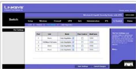
text_image
LINKSYS Switch Setup Windows Fileval VPN Ors Administration IP3 U Switch Status Part Settings Pair Last Basic Flow Control Maintenance 1 Start Auto Regulation 1 1200 2 1000000000000000000000000000000000000000000000000000000000000000000000000000000000 1 Start Settings Auto Regulation 1 1200 2 1500 3 1700 4 1800 5 1900 6 2000 7 2100 8 2200 9 2300 10 2400 11 2500 12 2600 13 2700 14 2800 15 2900 16 3000 17 3100 18 3200 19 3300 20 3400 21 3500 22 3600 23 3700 24 3800 25 3900 26 4000 27 4100 28 4200 29 4300 30 4400 31 4500 32 4600 33 4700 34 4800 35 4900 36 5000 37 5100 38 5200 39 5300 40 5400 41 5500 42 5600 43 5700 44 5800 45 5900 46 6000 47 6100 48 6200 49 6300 50 6400 51 6500 52 6600 53 6700 54 6800 55 69Figure 6-66: L2 Switch - Port Settings
Wireless-N Gigabit Security Router with VPN
Cable Diagnostics
This screen provides a utility to help troubleshoot ethernet-cable-related connectivity issues.
Port. Select the port number, then click the Apply button and the diagnostics will start.
Pair. Each cable consists of eight pins (four pairs).
Cable Length. The length of the cable.
Status. The status of the pair.

text_image
LINKSYS® A Software For Systems, Inc. Switch Setup Windows F16x87 VPA GS Administration PS 120kHz Status USB USB USB Length USB Duration Cable Settings Web 1.50 Access Pin Cable Length Status A B C D E F G H I J K L M N O P Q R S T U V W X Y Z A B C D E F G H I J K L M N O P Q R S T U V W XFigure 6-67: L2 Switch - Cable Diagnostics
Wireless-N Gigabit Security Router with VPN
Status Tab
The Status Tab provides current status on this Wireless Router including WAN, LAN, Wireless LAN, System Performance, VPN client connections, and IPsec VPN connections.
WAN / Gateway
This screen provides some basic information on the Wireless Router (e.g. firmware version, time) and WAN port MAC/IP address and connection status.
Firmware Version. Displays the current firmware version.
MAC Address. Displays the WAN port MAC Address, as seen by your ISP.
Current Time. Displays the time on this Wireless Router according to your settings on the Setup->Time tab.
Internet Connection
Connection Mode. Displays the Internet connection type setting on WAN port.
Interface. Displays the WAN port Interface status (Up or Down).
IP Address. Displays the WAN port IP Address.
Subnet Mask. Displays the WAN port IP subnetmask.
Default Gateway. Displays the default Router to reach Internet or other networks from the WAN port.
DNS. Shown here are the DNS (Domain Name System) IP addresses currently used by this Wireless Router.
DHCP Release button. Click this button to release IP address on WAN port if using DHCP.
DHCP Renew button. Click this button to renew IP address on the WAN port if using DHCP.
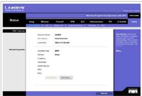
text_image
LINKKEY C:\Users Of Data\Systems Status Setup Welcome Flowell VIR Dr1 Administration PS LT Switch Value WIN - Accession Accession Version: USB 08.07 WNT Service: maintenance Current Time: USB 01:21:16:08 Connection Type: USB2 Interface: Down F Address: Send Mail Send Delivery: MND: MND: USB2 Response Network Internet Connection The following system is in the Web, which is also used to access the Internet. The Web is also used to access the Internet. The Web is also used to access the Internet. The Web is also used to access the Internet. The Web is also used to access the Internet. The Web is also used to access the Internet. The Web is also used to access the Internet. The Web is also used to access the Internet. The Web is also used to access the Internet. The Web is also used to access the Internet. The Web is also used to access the Internet. The WNT Internet Connection Start SubFigure 6-68: Status - WAN / Gateway
Wireless-N Gigabit Security Router with VPN
LAN
This screen provides some basic information on the LAN ports of this Wireless Router.
IP Versions. Displays the IP versions configured on the LAN side.
MAC Address. Displays the LAN port MAC Address. All four LAN ports share the same MAC address.
IP Address. Displays the LAN port IPv4 Address. All four LAN ports share the same MAC address.
Subnet Mask. Displays the LAN port IPv4 subnetmask.
IPv6 Address. Displays the LAN port IPv6 IP address, if IPv6 is enabled.
DHCP Server. Displays the status of the Router's DHCP server.
Start IP Address. Displays the beginning of the range of IP addresses used by the DHCP Server.
End IP Address. Displays the end of the range of IP addresses used by the DHCP Server.
DHCP Client Table button. Click this button to open the DHCP Client Table screen, which shows you which PCs have been assigned an IP address from the Wireless Router's DHCP server. You will see a list of DHCP clients (PCs and other network devices) with the following information: Client Host Name, IP Address, MAC Address, and the length of time (in second) before its assigned IP address expires.
ARP Table button. Click this button will open the ARP Table screen, which shows you the ARP Table on the Wireless Router. The ARP Table provides IP address to MAC address mapping. On the ARP Table screen, you will see a list of address mapping between IP (layer 3) and MAC (layer 2).
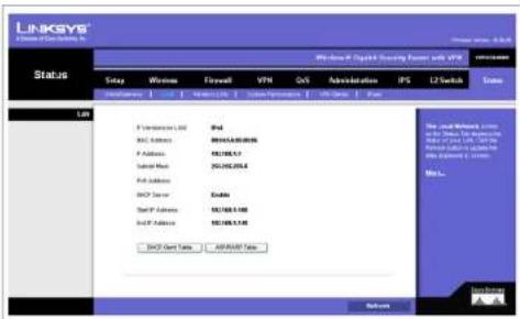
text_image
LINKSYS Windows IP Control Security Power with VPN Status Setup Windows Firewall VPN OS Administration IPS L2 Switch Status F:\Documents\LSD 94d MAC Address 80165.8.00.00& F Address 80165.8.1 Send Host 250-500-354.6 FID Address MAC Server Codes Send FID Address 80165.8.100 Send FID Address 80165.8.140 TCP Open Data 80165.8.1 Return The Cloud Network Access to the Windows 9.0.0.0.0.0.0.0.0.0.0.0.0.0.0.0.0.0.0.0.0.0.0.0.0.0.0.0.0.0.0.0.0.0.0.0.0.0.0.0.Figure 6-69: Status - LAN
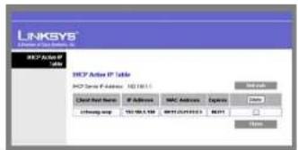
text_image
LINKSYS USE Server IP Address HKEY Active IP Table HKEY Active IP Address: HKEY10111 Add new Add New Name: IP Address: MAC Address: Express Off Track: 750-823-569: MAC Address: 000000000000000000000000000000000000000000000000000000000000000000000000000000000000000000000000 Add new Add New Name: IP Address: MAC Address: Express Off Track: 750-823-569: MAC Address: 00000000000: 4233 Add New Add New Name: IP Address: MAC Address: Express Add New Add New Name: IP Address: MAC Address: ExpressFigure 6-70: LAN DHCP Client Table
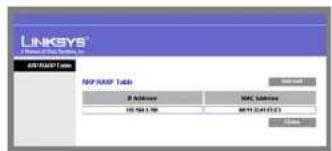
text_image
LINKSYS LinkSYS Network All NAPS Table NIP NAPS Table P Address MAC Address 10.561.388 MAC 24471533 CloseFigure 6-71: LAN ARP Table
Wireless-N Gigabit Security Router with VPN
Wireless LAN
This screen provides some basic information on the Wireless LAN of this Wireless Router.
MAC Address. Displays the MAC address on the Wireless LAN interface.
Network Mode. Displays the Wireless network operating mode (e.g. B/G/N-Mixed).
Wireless SSID. Displays the Wireless network name.
Channel Bandwidth. Displays the wireless channel bandwidth setting.
Wireless Channel. Displays the radio channel number used.
Security. Displays the Wireless Security mode.
SSID Broadcast. Displays the setting on SSID Broadcast.

text_image
LINKSYS Microsoft Security Services Status Windows 1244 Security Service w/ PS Setup Wireless Tensile USB OS Administration PS U Switch Status Wireless List Wireless List Wireless List Wireless List Wireless List Wireless List Wireless List Wireless List Wireless List Wireless List Wireless List Wireless List Wireless List Wireless List Wireless List Wireless List Wireless List Wireless List Wireless List Wireless List Wireless List Wireless List Wireless List Wireless List Wireless List Wireless LTR Wireless LTR Wireless LTR Wireless LTR Wireless LTR Wireless LTR Wireless LTR Wireless LTR Wireless LTR Wireless LTR Wireless LTR Wireless LTR Wireless LTR Wireless LTR Wireless LTR Wireless LTR Wireless LTR Wireless LTR Wireless LTR Wireless LTR Wireless LTr Wireless LTr Wireless LTr Wireless LTr Wireless LTr Wireless LTr Wireless LTr Wireless LTr Wireless LTr Wireless LTr Wireless LTr Wireless LTr Wireless LTr Wireless LTr Wireless LTr Wireless LTr Wireless LTr Wireless LTr Wireless LTr Wireless LTr Wireless LTR Wireless LTR Wireless LTR Wireless LTR Wireless LTR Wireless LTR Wireless LTR Wireless LTR Wireless LTR Wireless LTR Wireless LTR Wireless LTR Wireless LTR Wireless LTR Wireless LTR Wireless LTR Wireless LTR Wireless LTR Wireless LTR Wireless Ltr Wireless Ltr Wireless Ltr Wireless Ltr Wireless Ltr Wireless Ltr Wireless Ltr Wireless Ltr Wireless Ltr Wireless Ltr Wireless Ltr Wireless Ltr Wireless Ltr Wireless Ltr Wireless Ltr Wireless Ltr Wireless Ltr Wireless Ltr Wireless Ltr Wireless Ltr Wireless LTr Wireless LTr Wireless LTr Wireless LTr Wireless LTr Wireless LTr Wireless LTr Wireless LTr Wireless LTr Wireless LTrFigure 6-72: Status - Wireless LAN
Wireless-N Gigabit Security Router with VPN
System Performance
This screen provides data packet statistics on the LAN switch and Wireless LAN of the Router.
All LAN Ports / WLAN
The All LAN Ports column shows the aggregate traffic statistics from all four LAN ports.
Packets Received. This shows the number of packets received.
Packets Sent. This shows the number of packets sent.
Bytes Received. This shows the number of bytes received.
Bytes Sent. This shows the number of bytes sent.
Error Packets Received. This shows the number of error packets received.
Drop Received Packets. This shows the number of packets being dropped after they were received.
L2 Switch Ports
Tx Bytes. Displays the number of Bytes transmitted from the selected port.
Tx Frames. Displays the number of Ethernet Frames transmitted from the selected port.
Rx Bytes. Displays the number of Bytes received on the selected port.
Rx Frames. Displays the number of Ethernet frames received on the selected port.
Tx Errors. Displays the number of error frames transmitted from the selected port.
Rx Errors. Displays the number of error frames received from the selected port.
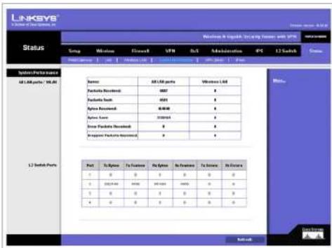
text_image
LINKSYS A Series of Windows, Inc. Status: English Language Starting Server and USB Group Windows Fldxwell USB SnX Administration IPC 12 Switch System Performance 1.1.1.00 ports / 100.00 Name:A#LAM ports Windows LAN Fuzhou Laihui: 8887 # Fuzhou Laihui: 8885 # Fuzhou Laihui: 88848 # Fuzhou Laihui: 232064 # Inou Fuzhou Laihui: 0 # Kuopun Fuzhou Laihui: 0 # Port To System To Function To System To Function To System To Function 0 0 0 0 0 0 0 0 202.2.00 9999 24.1.2001 9999 0 0 0 0 0 0 0 0 0 * * * * * * * *Figure 6-73: Status - System Performance
Wireless-N Gigabit Security Router with VPN
VPN Clients
This screen displays the VPN Clients' connection status. VPN Clients are configured under VPN->VPN Client Accounts and provide users that are running Linksys QuickVPN to establish a IPsec connection with a remote Wireless Router.
Username. Displays the username of the VPN Client.
Status. Displays the connection status of the VPN Client.
Start Time. Displays the start time of the most recent VPN session for the specified VPN Client.
End Time. Displays the end time of a VPN session, if the VPN Client has disconnected.
Duration. Displays the total connection time of the latest VPN session.
Refresh button. Updates the screen with the latest VPN Client information.
Disconnect button. Select the Disconnect box at the end of each row in the VPN Clients Table and then click the Disconnect button to disconnect a VPN Client session.
IPsec VPN
This screen displays the IPsec VPN (gateway to gateway) connection status. IPsec VPN are configured under VPN->IPsec VPN to establish a IPsec connection with a remote Linksys VPN Router.
Tunnel Name. Displays the Tunnel Name of the IPsec VPN connection.
Status. Displays the connection status of the VPN Client.
Action. Use the Connect and Disconnect button to manage your IPsec VPN connection.
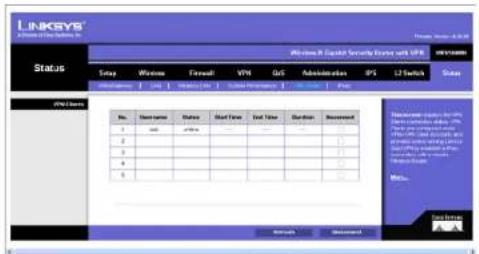
text_image
LINKSYS Security System Status Windows 8 Capital Security System with USB Status Setup Windows Forward VMH QoS Administration SPS LT Switch Status No. User name Status Start Time End Time Duration Received 1 2 3 4 5 Maintenance: 100% or 100% or 100% or 100% or 100% or 100% or 100% or 100% or 100% or 100% or 100% or 100% or 100% or 100% or 100% or 100% or 100% or 10 Maintenance: 100% or 100% or 100% or 100% or 100% or 100% or 100% or 100% or 100% or 100% or 100% or 100% Maintenance: 100% or 100% or 100% or 100% or 100% or 100% or 100% or 100% or 100% Maintenance: 100% or 100% or 100% or 100% or 100% or 100% or 100% or 1Figure 6-74: Status - VPN Clients
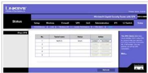
text_image
LINKSYS Microsoft Internet Security Server with VPN Status Setup Windows Fircaell VPN GoS Administration PS LT Switch Status Access VPN No. Tanned name Status Action 1 Mail (2) Bank Contact Accessnel 2 3 4 5 6 7 8 9 10 11 12 13 14 15 16 17 18 19 20 21 22 23 24 25 26 27 28 29 30 31 32 33 34 35 36 37 38 39 40 41 42 43 44 45 46 47 48 49 50 51 52 53 54 55 56 57 58 59 60 61 62 63 64 65 66 67 68 69 70 71 72 73 74 75 76 77 78 79 80 81 82 83 84 85 86 87 88 89 90 91 92 93 94 95 96 97 98 99 100Figure 6-75: Status - IPsec VPN
Wireless-N Gigabit Security Router with VPN
\*□□※■※■ \*□□◆○※▲※□□▼※■
This appendix provides solutions to problems that may occur during the installation and operation of the Router. Read the descriptions below to help solve your problems. If you can't find an answer here, check the Linksys website at www.linksys.com.
Common Problems and Solutions
1. I need to set a static IP address on a PC.
The Router, by default, assigns an IP address range of 192.168.1.100 to 192.168.1.149 using the DHCP server on the Router. To set a static IP address, you can only use the ranges 192.168.1.2 to 192.168.1.99 and 192.168.1.150 to 192.168.1.254. Each PC or network device that uses TCP/IP must have a unique address to identify itself in a network. If the IP address is not unique to a network, Windows will generate an IP conflict error message. You can assign a static IP address to a PC by performing the following steps:
For Windows 98 and Millennium:
A. Click Start, Setting, and Control Panel. Double-click Network.
B. In The following network components are installed box, select the TCP/IP-> associated with your Ethernet adapter. If you only have one Ethernet adapter installed, you will only see one TCP/IP line with no association to an Ethernet adapter. Highlight it and click the Properties button.
C. In the TCP/IP properties window, select the IP address tab, and select Specify an IP address. Enter a unique IP address that is not used by any other computer on the network connected to the Router. You can only use an IP address in the ranges 192.168.1.2 to 192.168.1.99 and 192.168.1.151 to 192.168.1.254. Make sure that each IP address is unique for each PC or network device.
D. Click the Gateway tab, and in the New Gateway prompt, enter 192.168.1.1, which is the default IP address of the Router. Click the Add button to accept the entry.
E. Click the DNS tab, and make sure the DNS Enabled option is selected. Enter the Host and Domain names (e.g., John for Host and home for Domain). Enter the DNS entry provided by your ISP. If your ISP has not provided the DNS IP address, contact your ISP to get that information or go to its website for the information.
F. Click the OK button in the TCP/IP properties window, and click Close or the OK button for the Network window.
G. Restart the computer when asked.
For Windows 2000:
A. Click Start, Settings, and Control Panel. Double-click Network and Dial-Up Connections.
B. Right-click the Local Area Connection that is associated with the Ethernet adapter you are using, and select the Properties option.
C. In the Components checked are used by this connection box, highlight Internet Protocol (TCP/IP), and click the Properties button. Select Use the following IP address option.
D. Enter a unique IP address that is not used by any other computer on the network connected to the Router. You can only use an IP address in the ranges 192.168.1.2 to 192.168.1.99 and 192.168.1.151 to 192.168.1.254.
E. Enter the Subnet Mask, 255.255.255.0.
F. Enter the Default Gateway, 192.168.1.1 (Router's default IP address).
6. Toward the bottom of the window, select Use the following DNS server addresses, and enter the Preferred DNS server and Alternative DNS server (provided by your ISP). Contact your ISP or go on its website to find the information.
H. Click the OK button in the Internet Protocol (TCP/IP) Properties window, and click the OK button in the Local Area Connection Properties window.
I. Restart the computer if asked.
For Windows XP:
The following instructions assume you are running Windows XP with the default interface. If you are using the Classic interface (where the icons and menus look like previous Windows versions), please follow the instructions for Windows 2000.
A. Click Start and Control Panel.
B. Click the Network and Internet Connections icon and then the Network Connections icon.
C. Right-click the Local Area Connection that is associated with the Ethernet adapter you are using, and select the Properties option.
D. In the This connection uses the following items box, highlight Internet Protocol (TCP/IP). Click the Properties button.
E. Enter a unique IP address that is not used by any other computer on the network connected to the Router. You can only use an IP address in the ranges 192.168.1.2 to 192.168.1.99 and 192.168.1.151 to 192.168.1.254.
F. Enter the Subnet Mask, 255.255.255.0.
G. Enter the Default Gateway, 192.168.1.1 (Router's default IP address).
H. Toward the bottom of the window, select Use the following DNS server addresses, and enter the Preferred DNS server and Alternative DNS server (provided by your ISP). Contact your ISP or go on its website to find the information.
I. Click the OK button in the Internet Protocol (TCP/IP) Properties window. Click the OK button in the Local Area Connection Properties window.
Wireless-N Gigabit Security Router with VPN
2. I want to test my Internet connection.
A. Check your TCP/IP settings.
For Windows 98 and Millennium:
Refer to Windows Help for details. Make sure Obtain IP address automatically is selected in the settings.
For Windows 2000:
- Click Start, Settings, and Control Panel. Double-click Network and Dial-Up Connections.
- Right-click the Local Area Connection that is associated with the Ethernet adapter you are using, and select the Properties option.
- In the Components checked are used by this connection box, highlight Internet Protocol (TCP/IP), and click the Properties button. Make sure that Obtain an IP address automatically and Obtain DNS server address automatically are selected.
- Click the OK button in the Internet Protocol (TCP/IP) Properties window, and click the OK button in the Local Area Connection Properties window.
- Restart the computer if asked.
- Click the OK button in the Internet Protocol (TCP/IP) Properties window, and click the OK button in the Local Area Connection Properties window.
- Restart the computer if asked.
For Windows XP:
The following instructions assume you are running Windows XP with the default interface. If you are using the Classic interface (where the icons and menus look like previous Windows versions), please follow the instructions for Windows 2000.
- Click Start and Control Panel.
- Click the Network and Internet Connections icon and then the Network Connections icon.
- Right-click the Local Area Connection that is associated with the Ethernet adapter you are using, and select the Properties option.
- In the This connection uses the following items box, highlight Internet Protocol (TCP/IP), and click the Properties button. Make sure that Obtain an IP address automatically and Obtain DNS server address automatically are selected.
B. Open a command prompt.
- For Windows 98 and Millennium, click Start and Run. In the Open field, type command. Press the Enter key or click the OK button.
Wireless-N Gigabit Security Router with VPN
- For Windows 2000 and XP, click Start and Run. In the Open field, type cmd. Press the Enter key or click the OK button.
C. In the command prompt, type ping 192.168.1.1 and press the Enter key.
- If you get a reply, the computer is communicating with the Router.
- If you do NOT get a reply, check the cable, and make sure Obtain an IP address automatically is selected in the TCP/IP settings for your Ethernet adapter.
D. In the command prompt, type ping followed by your Internet IP address and press the Enter key. The Internet IP Address can be found in the web interface of the Router. For example, if your Internet IP address is 1.2.3.4, you would enter ping 1.2.3.4 and press the Enter key.
- If you get a reply, the computer is connected to the Router.
- If you do NOT get a reply, try the ping command from a different computer to verify that your original computer is not the cause of the problem.
E. In the command prompt, type ping www.linksys.com and press the Enter key.
- If you get a reply, the computer is connected to the Internet. If you cannot open a webpage, try the ping command from a different computer to verify that your original computer is not the cause of the problem.
- If you do NOT get a reply, there may be a problem with the connection. Try the ping command from a different computer to verify that your original computer is not the cause of the problem.
- I am not getting an IP address on the Internet with my Internet connection.
A. Refer to "Problem #2, I want to test my Internet connection" to verify that you have connectivity.
B. If you need to register the MAC address of your Ethernet adapter with your ISP, please see "Appendix E: Finding the MAC Address and IP Address for Your Ethernet Adapter." If you need to clone the MAC address of your Ethernet adapter onto the Router, see the MAC Address Clone section of "Chapter 6: Setting Up and Configuring the Router" for details.
C. Make sure you are using the right Internet settings. Contact your ISP to see if your Internet connection type is DHCP, Static IP Address, or PPPoE (commonly used by DSL consumers). Please refer to the Basic Setup section of "Chapter 6: Setting Up and Configuring the Router" for details on Internet Connection Type settings.
D. Make sure you use the right cable. Check to see if the Internet LED is solidly lit.
E. Make sure the cable connecting from your cable or DSL modem is connected to the Router's Internet port. Verify that the Status page of the Router's Web-based Utility shows a valid IP address from your ISP.
F. Turn off the computer, Router, and cable/DSL modem. Wait 30 seconds, and then turn on the Router, cable/DSL modem, and computer. Check the System Summary tab of the Router's Web-based Utility to see if you get an IP address.
- I am not able to access the Router's Web-based Utility Setup page.
A. Refer to "Problem #2, I want to test my Internet connection" to verify that your computer is properly connected to the Router.
B. Refer to "Appendix E: Finding the MAC Address and IP Address for Your Ethernet Adapter" to verify that your computer has an IP Address, Subnet Mask, Gateway, and DNS.
C. Set a static IP address on your system; refer to "Problem #1: I need to set a static IP address."
D. Refer to "Problem #10: I need to remove the proxy settings or the dial-up pop-up window (for PPPoE users)."
- I can't get my Virtual Private Network (VPN) to work through the Router.
Access the Router's web interface by going to http://192.168.1.1 or the IP address of the Router, and go to the VPN => VPN Pass Through tab. Make sure you have IPsec passthrough and/or PPTP passthrough enabled.
VPNs that use IPSec with the ESP (Encapsulation Security Payload known as protocol 50) authentication will work fine. At least one IPSec session will work through the Router; however, simultaneous IPSec sessions may be possible, depending on the specifics of your VPNs.
VPNs that use IPSec and AH (Authentication Header known as protocol 51) are incompatible with the Router. AH has limitations due to occasional incompatibility with the NAT standard.
Change the IP address for the Router to another subnet to avoid a conflict between the VPN IP address and your local IP address. For example, if your VPN server assigns an IP address 192.168.1.X (X is a number from 1 to 254) and your local LAN IP address is 192.168.1.X (X is the same number used in the VPN IP address), the Router will have difficulties routing information to the right location. If you change the Router's IP address to 192.168.2.1, that should solve the problem. Change the Router's IP address through the Basic Setup tab of the Web-based Utility. If you assigned a static IP address to any computer or network device on the network, you need to change its IP address accordingly to 192.168.2.Y (Y being any number from 1 to 254). Note that each IP address must be unique within the network.
Your VPN may require port 500/UDP packets to be passed to the computer that is connecting to the IPSec server. Refer to "Problem #7, I need to set up online game hosting or use other Internet applications" for details.
Check the Linksys website at www.linksys.com for more information.
- I need to set up a server behind my Router.
To use a server like a web, ftp, or mail server, you need to know the respective port numbers they are using. For example, port 80 (HTTP) is used for web; port 21 (FTP) is used for FTP, and port 25 (SMTP outgoing) and port 110 (POP3 incoming) are used for the mail server. You can get more information by viewing the
Appendix A: Troubleshooting
Common Problems and Solutions
Wireless-N Gigabit Security Router with VPN
documentation provided with the server you installed. Follow these steps to set up port forwarding through the Router's Web-based Utility. We will be setting up web, ftp, and mail servers.
A. Access the Router's Web-based Utility by going to http://192.168.1.1 or the IP address of the Router. Go to the Firewall => Single Port Forwarding tab.
B. Enable one of the pre-defined applications in the Table or you can add or modify existing entries for your application.
C. Enter the IP Address of the server that you want the Internet users to access. For example, if the web server's Ethernet adapter IP address is 192.168.1.100, you would enter 100 in the field provided. Check "Appendix E: Finding the MAC Address and IP Address for Your Ethernet Adapter" for details on getting an IP address. Then check the Enable checkbox for the entry. Consider the examples below:
| Application Start and End Protocol IP Address Enable | ||||
| Web server 80 to 80 | Both 192.168.1.100 X | |||
| FTP server 21 to 21 | TCP 192.168.1.101 X | |||
| SMTP (outgoing) | 25 to 25 Both 192.168.1.102 X | |||
| POP3 (incoming) | 110 to 110 | Both 192.168.1.102 X | ||
When you have completed the configuration, click the Save Settings button.
7. I need to set up online game hosting or use other Internet applications.
If you want to play online games or use Internet applications, most will work without doing any port forwarding or DMZ hosting. There may be cases when you want to host an online game or Internet application. This would require you to set up the Router to deliver incoming packets or data to a specific computer. This also applies to the Internet applications you are using. The best way to get the information on what port services to use is to go to the website of the online game or application you want to use. Follow these steps to set up online game hosting or use a certain Internet application:
A. Access the Router's Web-based Utility by going to http://192.168.1.1 or the IP address of the Router. Go to the Firewall => Port Range Forwarding tab.
B. Enter the Service Application Name, Range of Port used by this Application, and Layer 4 Protocol used by this Application to the Table.
C. Enter the IP Address of the server that you want the Internet users to access. For example, if the web server's Ethernet adapter IP address is 192.168.1.100, you would enter 100 in the field provided. Check
"Appendix E: Finding the MAC Address and IP Address for Your Ethernet Adapter" for details on getting an IP address. Then check the Enable checkbox for the entry. Consider the examples below:
| Application Start and End Protocol IP Address Enabled | ||||
| UT 7777 to 27900 Both 192.168.1.100 X | ||||
| Halflife 27015 to 27015 Both 192.168.1.105 X | ||||
| PC Anywhere | 5631 to 5631 | UDP | 192.168.1.102 | X |
| VPN IPSEC | 500 to 500 UDP | 192.168.1.100 X | ||
D. Configure as many entries as you like.
When you have completed the configuration, click the Save Settings button.
- I can't get the Internet game, server, or application to work.
If you are having difficulties getting any Internet game, server, or application to function properly, consider exposing one PC to the Internet using DeMilitarized Zone (DMZ) hosting. This option is available when an application requires too many ports or when you are not sure which port services to use. Make sure you disable all the forwarding entries if you want to successfully use DMZ hosting, since forwarding has priority over DMZ hosting. (In other words, data that enters the Router will be checked first by the forwarding settings. If the port number that the data enters from does not have port forwarding, then the Router will send the data to whichever PC or network device you set for DMZ hosting.) Follow these steps to set DMZ hosting:
A. Access the Router's Web-based Utility by going to http://192.168.1.1 or the IP address of the Router. Go to the Firewall => Single Port Forwarding tab.
B. Disable or remove the entries you have entered for forwarding. Keep this information in case you want to use it at a later time.
C. Go to the Setup => DMZ tab.
D. Enter the Ethernet adapter's IP address of the computer you want exposed to the Internet. This will bypass the NAT security for that computer. Please refer to "Appendix E: Finding the MAC Address and IP Address for Your Ethernet Adapter" for details on getting an IP address.
Once completed with the configuration, click the Save Settings button.
Wireless-N Gigabit Security Router with VPN
- I forgot my password, or the password prompt always appears when saving settings to the Router. Reset the Router to factory defaults by pressing the Reset button for ten seconds and then releasing it. If you are still getting prompted for a password when saving settings, then perform the following steps:
A. Access the Router's web interface by going to http://192.168.1.1 or the IP address of the Router. Enter the default password admin, and click the Administration => Management tab.
B. Enter the old password in the Old Password field.
C. Enter a different password in the New Password field, and enter the new password in the Confirm New Password field to confirm the password.
D. Click the Save Settings button.
- I am a PPPoE user, and I need to remove the proxy settings or the dial-up pop-up window. If you have proxy settings, you need to disable these on your computer. Because the Router is the gateway for the Internet connection, the computer does not need any proxy settings to gain access. Please follow these directions to verify that you do not have any proxy settings and that the browser you use is set to connect directly to the LAN.
For Microsoft Internet Explorer 5.0 or higher:
A. Click Start, Settings, and Control Panel. Double-click Internet Options.
B. Click the Connections tab.
C. Click the LAN settings button and remove anything that is checked.
D. Click the OK button to go back to the previous screen.
E. Click the option Never dial a connection. This will remove any dial-up pop-ups for PPPoE users.
For Netscape 4.7 or higher:
A. Start Netscape Navigator, and click Edit, Preferences, Advanced, and Proxies.
B. Make sure you have Direct connection to the Internet selected on this screen.
C. Close all the windows to finish.
-
To start over, I need to set the Router to factory default. Hold the Reset button for up to 30 seconds and then release it. This will return the password, forwarding, and other settings on the Router to the factory default settings. In other words, the Router will revert to its original factory configuration.
-
I need to upgrade the firmware. In order to upgrade the firmware with the latest features, you need to go to the Linksys website and download the latest firmware at www.linksys.com. Follow these steps:
Appendix A: Troubleshooting
Common Problems and Solutions
Wireless-N Gigabit Security Router with VPN
A. Go to the Linksys website at http://www.linksys.com and download the latest firmware. Select the Router from the pull-down menu and choose the firmware from the options.
B. Extract the firmware file on your computer.
C. To upgrade the firmware, follow the steps in the Upgrade section found in "Chapter 6: Setting Up and Configuring the Router".
13. The firmware upgrade failed.
The upgrade could have failed for a number of reasons. Follow these steps to upgrade the firmware:
A. Use the Linksys TFTP program to upgrade the firmware. Go to the Linksys website at http://www.linksys.com and download the TFTP program, which will be listed with the firmware.
B. Set a static IP address on the PC; refer to "Problem #1, I need to set a static IP address." Use the following IP address settings for the computer you are using:
IP Address: 192.168.1.50
Subnet Mask: 255.255.255.0
Gateway: 192.168.1.1
C. Perform the upgrade using the TFTP utility.
If the firmware upgrade failed, the Router will still work using its current firmware.
14. My DSL service's PPPoE is always disconnecting.
PPPoE is not actually a dedicated or always-on connection. The DSL ISP can disconnect the service after a period of inactivity, just like a normal phone dial-up connection to the Internet. There is a setup option to "keep alive" the connection. This may not always work, so you may need to re-establish connection periodically.
A. To connect to the Router, go to the web browser, and enter http://192.168.1.1 or the IP address of the Router.
B. Enter the password, if asked. (The default password is admin.)
C. On the Setup => WAN tab, select the option Keep Alive, and set the Redial Period option at 20 (seconds).
D. Click the Save Settings button.
If the connection is lost again, follow steps E and F to re-establish connection.
Wireless-N Gigabit Security Router with VPN
- I can't access my email, web, or VPN, or I am getting corrupted data from the Internet.
The Maximum Transmission Unit (MTU) setting may need to be adjusted. By default, the MTU is set at 1500. For most DSL users, it is strongly recommended to use MTU 1492. If you are having some difficulties, perform the following steps:
A. To connect to the Router, go to the web browser, and enter http://192.168.1.1 or the IP address of the Router.
B. Enter the password, if asked. (The default password is admin.)
C. Go to Setup => WAN tab
D. Look for the MTU option, and select Enable. In the Size field, enter 1492.
E. Click the Save Settings button to continue.
If your difficulties continue, change the Size to different values. Try this list of values, one value at a time, in this order, until your problem is solved:
1462
1400
1362
1300
- I need to use port triggering.
Port triggering looks at the outgoing port services used and will trigger the Router to open a specific incoming port, depending on which port an Internet application uses. Follow these steps:
A. To connect to the Router, go to the web browser, and enter http://192.168.1.1 or the IP address of the Router.
B. Enter the password, if asked. (The default password is admin.)
C. Click the Firewall => Port Range Triggering tab.
D. Enter any name you want to use for the Application Name.
E. Enter the Start and End Ports of the Triggered Port Range. Check with your Internet application provider for more information on which outgoing port services it is using.
F. Enter the Start and End Ports of the Forwarded Port Range. Check with your Internet application provider for more information on which incoming port services are required by the Internet application.
Once completed with the configuration, click the Save Settings button.
- When I enter a URL or IP address, I get a time-out error or am prompted to retry.
- Check if other PCs work. If they do, ensure that your workstation's IP settings are correct (IP Address, Subnet Mask, Default Gateway, and DNS). Restart the computer that is having a problem.
Wireless-N Gigabit Security Router with VPN
- If the PCs are configured correctly, but still not working, check the Router. Ensure that it is connected and powered on. Connect to it and check its settings. (If you cannot connect to it, check the LAN and power connections.)
- If the Router is configured correctly, check your Internet connection (DSL/cable modem, etc.) to see if it is working correctly. You can remove the Router to verify a direct connection.
- Manually configure the TCP/IP with a DNS address provided by your ISP.
- Make sure that your browser is set to connect directly and that any dial-up is disabled. For Internet Explorer, click Tools, Internet Options, and then the Connection tab. Make sure that Internet Explorer is set to Never dial a connection. For Netscape Navigator, click Edit, Preferences, Advanced, and Proxy. Make sure that Netscape Navigator is set to Direct connection to the Internet.
18. I'm trying to access the Router's Web-based Utility, but I do not see the login screen. Instead, I see a screen saying, "404 Forbidden."
If you are using Windows Explorer, perform the following steps until you see the Web-based Utility's login screen (Netscape Navigator will require similar steps):
A. Click File. Make sure Work Offline is NOT checked.
B. Press CTRL + F5. This is a hard refresh, which will force Windows Explorer to load new webpages, not cached ones.
C. Click Tools. Click Internet Options. Click the Security tab. Click the Default level button. Make sure the security level is Medium or lower. Then click the OK button.
Frequently Asked Questions
What is the maximum number of IP addresses that the Router will support?
The Router will support up to 253 IP addresses if the subnetmask is set to 255.255.255.0.
Is IPSec Passthrough supported by the Router?
Yes, enable or disable IPSec Passthrough on the VPN => VPN Pass Through tab.
Where is the Router installed on the network?
In a typical environment, the Router is installed between the cable/DSL modem and the LAN. Plug the Router into the cable/DSL modem's Ethernet port.
Does the Router support IPX or AppleTalk?
No. TCP/IP is the only protocol standard for the Internet and has become the global standard for communications. IPX, a NetWare communications protocol used only to route messages from one node to another, and AppleTalk, a communications protocol used on Apple and Macintosh networks, can be used for LAN to LAN connections, but those protocols cannot connect from the Internet to the LAN.
Appendix A: Troubleshooting
Frequently Asked Questions
Wireless-N Gigabit Security Router with VPN
What is Network Address Translation and what is it used for?
Network Address Translation (NAT) translates multiple IP addresses on the private LAN to one public address that is sent out to the Internet. This adds a level of security since the address of a PC connected to the private LAN is never transmitted on the Internet. Furthermore, NAT allows the Router to be used with low cost Internet accounts, such as DSL or cable modems, when only one TCP/IP address is provided by the ISP. The user may have many private addresses behind this single address provided by the ISP.
Does the Router support any operating system other than Windows 98, Millennium, 2000, or XP?
Yes, but Linksys does not, at this time, provide technical support for setup, configuration or troubleshooting of any non-Windows operating systems.
I set up an Unreal Tournament Server, but others on the LAN cannot join. What do I need to do?
If you have a dedicated Unreal Tournament server running, you need to create a static IP for each of the LAN computers and forward ports 7777, 7778, 7779, 7780, 7781, and 27900 to the IP address of the server. You can also use a port forwarding range of 7777 to 27900. If you want to use the UT Server Admin, forward another port (8080 usually works well but is used for remote admin. You may have to disable this.), and then in the [UWeb.WebServer] section of the server.ini file, set the ListenPort to 8080 (to match the mapped port above) and ServerName to the IP assigned to the Router from your ISP.
Can multiple gamers on the LAN get on one game server and play simultaneously with just one public IP address?
It depends on which network game or what kind of game server you are using. For example, Unreal Tournament supports multi-login with one public IP.
How do I get Half-Life: Team Fortress to work with the Router?
The default client port for Half-Life is 27005. The computers on your LAN need to have “+clientport 2700x” added to the HL shortcut command line; the x would be 6, 7, 8, and on up. This lets multiple computers connect to the same server. One problem: Version 1.0.1.6 won’t let multiple computers with the same CD key connect at the same time, even if on the same LAN (not a problem with 1.0.1.3). As far as hosting games, the HL server does not need to be in the DMZ. Just forward port 27015 to the local IP address of the server computer.
How can I block corrupted FTP downloads?
If you are experiencing corrupted files when you download a file with your FTP client, try using another FTP program.
The web page hangs; downloads are corrupt, or nothing but junk characters are being displayed on the screen. What do I need to do?
Force your Ethernet adapter to 10Mbps or half duplex mode, and turn off the "Auto-negotiate" feature of your Ethernet adapter as a temporary measure. (Please look at the Network Control Panel in your Ethernet adapter's
Appendix A: Troubleshooting
Frequently Asked Questions
Wireless-N Gigabit Security Router with VPN
Advanced Properties tab.) Make sure that your proxy setting is disabled in the browser. Check our website at www.linksys.com for more information.
If all else fails in the installation, what can I do?
Reset the Router by holding down the Reset button for ten seconds. Reset your cable or DSL modem by powering the unit off and then on. Obtain and flash the latest firmware release that is readily available on the Linksys website, www.linksys.com.
How can I be notified of new Router firmware upgrades?
All Linksys firmware upgrades are posted on the Linksys website at www.linksys.com, where they can be downloaded for free. The Router's firmware can be upgraded using the Web-based Utility. If the Router's Internet connection is working well, there is no need to download a newer firmware version, unless that version contains new features that you would like to use. Downloading a more current version of Router firmware will not enhance the quality or speed of your Internet connection, and may disrupt your current connection stability.
Will the Router function in a Macintosh environment?
Yes, but the Router's setup pages are accessible only through Internet Explorer 5.0 or Netscape Navigator 5.0 or higher for Macintosh.
I am not able to get the web configuration screen for the Router. What can I do?
You may have to remove the proxy settings on your Internet browser, e.g., Netscape Navigator or Internet Explorer. Or remove the dial-up settings on your browser. Check with your browser documentation, and make sure that your browser is set to connect directly and that any dial-up is disabled. Make sure that your browser is set to connect directly and that any dial-up is disabled. For Internet Explorer, click Tools, Internet Options, and then the Connection tab. Make sure that Internet Explorer is set to Never dial a connection. For Netscape Navigator, click Edit, Preferences, Advanced, and Proxy. Make sure that Netscape Navigator is set to Direct connection to the Internet.
What is DMZ Hosting?
Demilitarized Zone (DMZ) allows one IP address (computer) to be exposed to the Internet. Some applications require multiple TCP/IP ports to be open. It is recommended that you set your computer with a static IP if you want to use DMZ Hosting. To get the LAN IP address, see "Appendix E: Finding the MAC Address and IP Address for Your Ethernet Adapter."
If DMZ Hosting is used, does the exposed user share the public IP with the Router?
No.
Does the Router pass PPTP packets or actively route PPTP sessions?
The Router allows PPTP packets to pass through.
Appendix A: Troubleshooting
Frequently Asked Questions
Wireless-N Gigabit Security Router with VPN
Is the Router cross-platform compatible?
Any platform that supports Ethernet and TCP/IP is compatible with the Router.
How many ports can be simultaneously forwarded?
Theoretically, the Router can establish 4,000 sessions at the same time, but you can only forward 30 ranges of ports.
Does the Router replace a modem? Is there a cable or DSL modem in the Router?
No, this version of the Router must work in conjunction with a cable or DSL modem.
Which modems are compatible with the Router?
The Router is compatible with virtually any cable or DSL modem that supports Ethernet.
What is the maximum number of VPN sessions allowed by the Router?
The maximum number depends on many factors. At least one IPSec session will work through the Router; however, simultaneous IPSec sessions may be possible, depending on the specifics of your VPNs.
How can I check whether I have static or DHCP IP addresses?
Ask your ISP to find out.
How do I get mIRC to work with the Router?
Under the Firewall => Single Port Forwarding tab, set port forwarding to 113 for the PC on which you are using mIRC.
If your questions are not addressed here, refer to the Linksys website, www.linksys.com.
Wireless-N Gigabit Security Router with VPN

text_image
Collection of symbolic and geometric symbols including stars, squares, triangles, and circles with standard line notationOverview
The Linksys Wireless-N Gigabit Security Router with VPN offers a free QuickVPN software program for computers running Windows 2000 or XP. (Computers running other operating systems will have to use a third-party VPN software program.) This guide describes how to install and use the Linksys QuickVPN software.
Before You Begin
The QuickVPN software program only works with a 4-Port Gigabit Security Router with VPN that is properly configured to accept a QuickVPN connection. Follow these instructions for configuring the VPN client settings for the Router:
- Click the VPN tab.
- Click the VPN Client Accounts tab.
- Enter the username in the Username field.
- Enter the password in the Password field, and enter it again in the Re-enter to confirm field.
- Click the Add/Save button.
- Click the Active checkbox for VPN Client No. 1.
Click the Save Settings button.
vpn (virtual private network): a security measure to protect data as it leaves one network and goes to another over the Internet.
software: instructions for the computer.
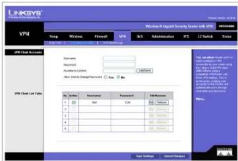
text_image
LINKSYS Windows II Capital Security Router with VPN VPN Group Wireless Final VPN O/S Administrative IPS L2 Switch Status VPN Cloud Accounts Application: Recommended: Whether to Control Show Data to Change Password: Yes No VPN Cloud List Table No. Address Name/Address Password LinkServer 1 100 100 100 100 100 100 100 100 100 100 100 100 100 100 100 100 100 100 100 100 100 100 100 100 100 10 A □ □ □ □ □ □ □ □ □ □ □ □ □ □ □ B □ □ □ □ □ □ □ □ □ □ □ □ □ □ C □ □ □ □ □ □ □ □ □ □ □ □ □ D □ □ □ □ □ □ □ □ □ □ □ □ E □ □ □ □ □ □ □ □ □ □ □ Test Settings Cancel ChangesFigure B-1: VPN Client Accounts Screen
Appendix B: Using the Linksys QuickVPN Software for Windows 2000 or XP Overview
Wireless-N Gigabit Security Router with VPN
Installing the Linksys QuickVPN Software
Installing from the CD-ROM
- Click Install QuickVPN and follow the on-screen instructions.
Downloading and Installing from the Internet - Go to www.linksys.com and select Products.
- Click Business Solutions.
- Click Router/VPN Solutions.
- Click RVS4000.
- Click Linksys QuickVPN Utility in the More Information section.
- Save the zip file to your PC, and extract the .exe file.
- Double-click the .exe file, and follow the on-screen instructions. Then proceed to the next section, "Using the Linksys QuickVPN Software."
Wireless-N Gigabit Security Router with VPN
Using the Linksys QuickVPN Software

NOTE: You can change your password only if you have been granted that privilege by your system administrator.
- Double-click the Linksys QuickVPN software icon on your desktop or in the system tray.
- The login screen will appear. Enter a name for your profile.
Then enter the User Name and Password you have been assigned.
In the Server Address field, enter the IP address or domain name of the Wireless-G VPN Router with RangeBooster. To save this profile, click the Save button. Multiple profiles can be set up if you want to establish a tunnel to multiple sites. Note that only one tunnel can be active at a time. To delete this profile, click the Delete button. For information, click the Help button.
- To begin your QuickVPN connection, click the Connect button and the Connecting, Activating Policy, and Verifying Network screens appear.

Figure B-2: QuickVPN Desktop Icon

Figure B-3: QuickVPN Tray Icon - No Connection
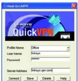
text_image
Linksys QuickVPN LINKSYB QuickVPN Profile Name Office User Name linksys Password Server Address linksys.vpn.com Connect Save Delete HelpFigure B-4: QuickVPN Software - Profile

Figure B-5: Connecting
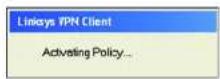
Figure B-6: Activating Policy

Figure B-7: Verifying Network
Wireless-N Gigabit Security Router with VPN
- When your QuickVPN connection is established, the status screen will appear, and the QuickVPN tray icon will turn green. It will display the IP address of the remote end of the VPN tunnel, the time and date the VPN tunnel began, and the total length of time the VPN tunnel has been active.
To terminate the VPN tunnel, click the Disconnect button. If you want to change your password, click the Change Password button. For information, click the Help button.
- If you clicked the Change Password button and have permission to change your own password, you will see the Connect Virtual Private Connection screen. Enter your password in the Old Password field. Enter your new password in the New Password field. Then enter the new password again in the Confirm New Password field. Click the OK button to save your new password. Click the Cancel button to cancel your change. For information, click the Help button.
text_image
Linksys QuickFPN Connected to: 69.105.48.21 Connected at: 15:02, September 08, 2004 Total Time Connected: 00:00:04 Disconnect Change Password HelpFigure B-8: QuickVPN Software - Status

Figure B-9: QuickVPN Tray Icon - Connection

Figure B-10: QuickVPN Tray Icon - No Connection

text_image
Connect Virtual Private Connection Old Password : New Password : Confirm New Password : OK Cancel HelpFigure B-11: QuickVPN Software - Change Password
Wireless-N Gigabit Security Router with VPN

text_image
Collection of symbolic and stylized icons including stars, squares, and asterisks with various line stylesOverview
This appendix explains how to configure an IPSec VPN tunnel between two VPN Routers by example. Two PCs are used to test the liveliness of the tunnel. You can think of the VPN Router1, Internet, VPN Router2 as a big virtual router that connects PC1 on LAN1 and PC2 on LAN2.
flowchart
graph LR
    PC1["PC1"] -->|VPN Router1| Internet["Internet"]
    Internet -->|VPN| Router1["VPN Router1"]
    Router1 -->|VPN| Router2["VPN Router2"]
    Router2 --> PC2["PC2"]
Figure C-1: Diagram of Gateway-to-Gateway VPN Tunnel
Before You Begin
The following is a list of equipment you need:
- Two Windows desktop PCs (each PC will be connected to a VPN Router)
- Two VPN Routers that are both connected to the Internet

NOTE: Each computer must have a network adapter installed.
Appendix C: Configuring a Gateway-to-Gateway IPSec Tunnel Overview
Wireless-N Gigabit Security Router with VPN
Configuring the VPN Settings for the VPN Routers
Configuring VPN Router 1
Follow these instructions for the first VPN Router, designated VPN Router 1. The other VPN Router is designated VPN Router 2.
- Launch the web browser for a networked PC, designated PC 1.
- Enter the VPN Router's local IP address in the Address field (default is 192.168.1.1). Then press Enter.
-
A password request page will appear. (Non-Windows XP users will see a similar screen.) Complete the User Name and Password fields (admin is the default user name and password). Then click the OK button.
-
Click the VPN tab.
-
Click the IPSec VPN tab.
-
For the VPN Tunnel setting, select Enabled.
-
Enter a name in the Tunnel Name field.
-
For the Local Secure Group, select Subnet. Enter VPN Router 1's local network settings in the IP Address and Mask fields.
-
For the Remote Secure Group, select Subnet. Enter VPN Router 2's local network settings in the IP Address and Mask fields. Note that the subnet of Router 2 must be different than the subnet of Router 1.
-
For the Remote Secure Gateway, select IP Addr. Enter VPN Router 2's WAN IP address in the IP Address field.
-
Click the Save Settings button.

text_image
Connect to 192.168.1.1 Linksys MRVSH00N User name: admin Password: ****** Remember my password OK CancelFigure C-2: Login Screen

text_image
LINKSYS A Wireless of the Security, Inc. Windows H: Copyright Security Provider with VPN VPN SNPs Wireless Firewire VPN DNS Administration IPS LT Switch Status SNPs: VPN Wireless network Wireless network Select TCP/IPs Select TCP/IPs Focal TCP/IPs Enable TCP/IPs Enable TCP/IPs Local Security Group Local Security Group Type Subnet 30 P Address: 1292.1.4.6.7.8.9 Subnet Net: 2595.1.4.6.7.8.9 Local Security Group Local Security Group Type: P Address P Address: 1292.1.4.6.7.8.9 Local Security Group Type: P Address P Address: 1292.1.4.6.7.8.9 Local Security Group Type: P Address Local Security Group Type: P Address Local Security Group Type: P Address Local Security Group Type: P Address Local Security Group Type: P Address Local Security Group Type: P Address Local Security Group Type: P Address Local Security Group Type: P Address Local Security Group Type: P Address Local Security Group Type: P Address Local Security Group Type: P Address Local Security Group Type: P Address Local Security Group Type: P Address Local Security Groups Local Security Groups Local Security Groups Local Security Groups Local Security Groups Local Security Groups Local Security Groups Local Security Groups Local Security Groups Local Security Groups Local Security Groups Local Security Groups Local Security Groups Local Security Groups Local Security Groups Local Security Groups Local Security Groups Local Security Groups Local Security Groups Local Security Groups Local Security Groups Local Security Groups Local Security Groups Local Security Groups Local Security Groups Local Security Group Local Security Group Local Security Group Local Security Group Local Security Group Local Security Group Local Security Group Local Security Group Local Security Group Local Security Group Local Security Group Local Security Group Local Security Group Local Security Group Local Security Group Local Security Group Local Security Group Local Security Group Local Security Group Local Security Group Local Security Group Local Security Group Local Security Group Local Security Group Local Security Group Local SecurityGroup Local SecurityGroup Local SecurityGroup Local SecurityGroup Local SecurityGroup Local SecurityGroup Local SecurityGroup Local SecurityGroup Local SecurityGroup Local SecurityGroup Local SecurityGroup Local SecurityGroup Local SecurityGroup Local SecurityGroup Local SecurityGroup Local SecurityGroup Local SecurityGroup Local SecurityGroup Local SecurityGroup Local SecurityGroup Local SecurityGroup Local SecurityGroup Local SecurityGroup Local SecurityGroup Local SecurityGroup Local SecurityGripes: Local SecurityGripes: Local SecurityGripes: Local SecurityGripes: Local SecurityGripes: Local SecurityGripes: Local SecurityGripes: Local SecurityGripes: Local SecurityGripes: Local SecurityGripes: Local SecurityGripes: Local SecurityGripes: Local SecurityGripes: Local SecurityGripes: Local SecurityGripes: Local SecurityGripes: Local SecurityGripes: Local SecurityGrips: Local SecurityGrips: Local SecurityGrips: Local SecurityGrips: Local SecurityGrips: Local SecurityGrips: Local SecurityGrips: Local SecurityGrips: Local SecurityGrips: Local SecurityGrips: Local SecurityGrips: Local SecurityGrips: Local SecurityGrips: Local SecurityGrips: Local SecurityGrips: Local SecurityGrips: Local SecurityGrips: Local SecurityGiRis: Local SecurityGiRis: Local SecurityGiRis: Local SecurityGiRis: Local SecurityGiRis: Local SecurityGiRis: Local SecurityGiRis: Local SecurityGiRis: Local SecurityGiRis: Local SecurityGiRis: Local SecurityGiRis: Local SecurityGiRis: Local SecurityGiRis: Local SecurityGiRis: Local SecurityGiRis: Local SecurityGiRis: Local SecurityGiRis: Local SecurityGrips: Local SecurityGrips: Local SecurityGrips: Local SecurityGrips: Local SecurityGrips: Local SecurityGrips: Local SecurityGrips: Local SecurityGrips: Local SecurityGrips: Local SecurityGrips: Local SecurityGrips: Local SecurityGiRis: Local SecurityGiRis: Local SecurityGiRis: Local SecurityGiRis: Local SecurityGiRis: Local SecurityGrips: Local SecurityGiRis: Local SecurityGiRis: Local SecurityGiRis: Local SecurityGiRis: LocalSecurityGiRis: Mid-Size Size: 120000000000000000000000000000000000000000000000000000000000000000000000000000000000000000000000000000Figure C-3: VPN - IPsec VPN Configuration
Wireless-N Gigabit Security Router with VPN
Configuring VPN Router 2
Follow similar instructions for VPN Router 2.
- Launch the web browser for a networked PC, designated PC 2.
- Enter the VPN Router's local IP address in the Address field (default is 192.168.1.1). Then press Enter.
- A password request page will appear. (Non-Windows XP users will see a similar screen.) Complete the User Name and Password fields (admin is the default user name and password). Then click the OK button.
- If the LAN IP address is still the default one, change it to 172.168.1.1 and save the setting.
- Click the VPN tab.
- Click the IPSec VPN tab.
- For the VPN Tunnel setting, select Enabled.
- Enter a name in the Tunnel Name field.
- For the Local Secure Group, select Subnet. Enter VPN Router 2's local network settings in the IP Address and Mask fields.
- For the Remote Secure Group, select Subnet. Enter VPN Router 1's local network settings in the IP Address and Mask fields.
- For the Remote Secure Gateway, select IP Addr. Enter VPN Router 1's WAN IP address in the IP Address field.
- Click the Save Settings button.
Wireless-N Gigabit Security Router with VPN
Configuring the Key Management Settings
Configuring VPN Router 1
Following these instructions for VPN Router 1.
- On the IPSec VPN screen, select 3DES from the Encryption drop-down menu.
- Select MD5 from the Authentication drop-down menu.
- Keep the default Key Exchange Method, Auto(IKE).
- Select Pre-Shared Key, and enter a string for this key., e.g. 13572468.
- For the PFS setting, select Enabled.
- If you need more detailed settings, click the Advanced Settings button. Otherwise, click the Save Settings button and proceed to the next section, "Configuring VPN Router 2."
- On the Advanced VPN Tunnel Setup screen, keep the default Operation Mode, Main.
- For Phase 1, select 3DES from the Encryption drop-down menu.
- Select MD5 from the Authentication drop-down menu.
- Select 1024-bit from the Group drop-down menu.
- Enter 3600 in the Key Life Time field.
- For Phase 2, the Encryption, Authentication, and PFS settings were set on the VPN screen.
Select 1024-bit from the Group drop-down menu.
- Keep the default Key Life Time value, 28800.
- Click the Save Settings button on the Advanced VPN Tunnel Setup screen.
- Click the Save Settings button on the IPSec VPN screen.
text_image
LINKSYS A Number of Datasets, Inc. Advanced VFM Tunnel Settings KartU23 Phase 1: Operation mode: None Local Identity: Local IP address Remote identity: Remote IP address Destination: SARS IN Administration: SARS IN Oral: Pmb pad NC Any Type: 20000000000000000000000000000000000000000000000000000000000000000000000000000000000000000000 Phase 2: Description: 2685 Administration: Direct PSL: Enable Oral: Pmb pad NC Any Type: Sync Data Settings: Forward Changes: CloseFigure C-4: Advanced IPsec VPN Tunnel Settings
Wireless-N Gigabit Security Router with VPN
Configuring VPN Router 2
For VPN Router 2, follow the same instructions in the previous section, "Configuring VPN Router 1."
Configuring PC 1 and PC 2
- Set PC 1 and PC 2 to be DHCP clients (refer to Windows Help for more information).
- Verify that PC 1 and PC 2 can ping each other (refer to Windows Help for more information).
If the computers can ping each other, then you know the VPN tunnel is configured correctly. You can select different algorithms for the encryption, authentication, and other key management settings for VPN Routers 1 and 2. Refer to the previous section, "Configuring the Key Management Settings," for details.
Congratulations! You have successfully configured a VPN tunnel between two VPN Routers.
Wireless-N Gigabit Security Router with VPN
\*□□※■※■ ◆◆\*■※■※▼※※ ☆☆◆☆※※□※▲▲ ※※ ☆☆※※□※▲▲ ※□ ※□◆□ ◆▼※※□■※▼ ☆※※□▼※□
This section describes how to find the MAC address for your computer's Ethernet adapter so you can use the MAC address cloning feature of the Router. You can also find the IP address of your computer's Ethernet adapter. This IP address is used for the Router's filtering, forwarding, and/or DMZ features. Follow the steps in this appendix to find the adapter's MAC or IP address in Windows 98, Me, 2000, or XP.
Windows 98 or Me Instructions
- Click Start and Run. In the Open field, enter winipcfg. Then press the Enter key or the OK button.
- When the IP Configuration screen appears, select the Ethernet adapter you have connected to the Router via a CAT 5 Ethernet network cable. See Figure D-1.
- Write down the Adapter Address as shown on your computer screen (see Figure D-2). This is the MAC address for your Ethernet adapter and is shown as a series of numbers and letters.
The MAC address/Adapter Address is what you will use for MAC address cloning or MAC filtering.
The example in Figure D-2 shows the Ethernet adapter's IP address as 192.168.1.100. Your computer may show something different.

NOTE: The MAC address is also called the Adapter Address.
Windows 2000 or XP Instructions
- Click Start and Run. In the Open field, enter cmd. Press the Enter key or click the OK button.
- At the command prompt, enter ipconfig /all. Then press the Enter key.
Appendix D: Finding the MAC Address and IP Address for Your Ethernet Adapter Windows 98 or Me Instructions

text_image
IP Configuration Ethernet Adapter Information Adapter Address Linksys LNE100TX Fast Ethernet Linksys LNE100TX Fast Ethernet &d PPP Adapter. IP Address 192.168.1.45 Subnet Mask 255.255.255.0 Default Gateway 192.168.1.254 OK Release Relew Release All Renew All More Info >>Figure D-1: IP Configuration Screen

text_image
IP Configuration Ethernet Adapter Information Linksys LNE100TX Fast Ethernet Adapter Address 00-00-00-00-00-00 IP Address 192.168.1.100 Subnet Mask 255.255.255.0 Default Gateway 192.168.1.1 OK Release Repsw Release All Renew All More Info >>Figure D-2: MAC Address/Adapter Address
Wireless-N Gigabit Security Router with VPN
- Write down the Physical Address as shown on your computer screen (Figure D-3); It is the MAC address for your Ethernet adapter. This appears as a series of numbers and letters.
The MAC address/Physical Address is what you will use for MAC address cloning or MAC filtering.

NOTE: The MAC address is also called the Physical Address.
The example in Figure D-3 shows the Ethernet adapter's IP address as 192.168.1.100. Your computer may show something different.

text_image
Windows 2008 IF Card Inverter Start Name: ...... Primary DNS Suffix. ...... Note Type: ...... IF Loading Enabled. ...... UINS Privacy Enabled. ...... Ethernet adapter Local from Connection: Connection specific DNS Suffix. ...... Description: ...... Logical Address: ...... DNS Enabled. ...... Advanced Operation Enabled. ...... IF Address: ...... Subnet Back: ...... Default Gateway: ...... HCP Server: ...... DNS Server: ...... Primary UINS Server: ...... Secondary UINS Server: ...... Launch Open: ...... Leave Expires: ...... Linkless LNC100X(v5) Fast Ethernet 0 100 00 00 30 00 00 Yes 197.168.1.100 255.155.255.8 197.168.1.1 197.168.1.1 Monday, February 11, 2002 2/31/47 PM Tuesday, February 12, 2002 2/31/47 P TuesFigure D-3: MAC Address/Physical Address
For the Router's Web-based Utility
For MAC address cloning, enter the MAC Address in the MAC Address field or select Clone My PCs MAC. See Figure D-4.
Click Save Settings to save the MAC Cloning settings or click the Cancel Changes button to undo your changes.
text_image
LINKSYS A GROUP OF EXXICO SYSTEMS Setup Windows 9 Copyright Security Bureau with VPN WIN:2488 Setup Wire Network Frontset VPN Units Administration IPS LF Switch Value 100% 200% 300% 400% 500% 600% 700% 800% 900% 1000% 1100% 1200% 1300% 1400% 1500% 1600% 1700% 1800% 1900% 2000% 2100% 2200% 2300% 2400% 2500% 2600% 2700% 2800% 2900% 3000% 3100% 3200% 3300% 3400% 3500% 3600% 3700% 3800% 3900% 4000% 4100% 4200% 4300% 4400% 4500% 4600% 4700% 4800% 4900% 5000% 5100% 5200% 5300% 5400% 5500% 5600% 5700% 5800% 5900% 6000% 6100% 6200% 6300% 6400% 6500% 6600% 6700% 6800% 6900% 7000% 7100% 7200% 7300% 7400% 7500% 7600% 7700% 7800% 7900% 8000% 8100% 8200% 8300% 8400% 8500% 8600% 8700% 8800% 8900% 9000% 9100% 9200% 9300% 9400% 9500% 9600% 9700% 9800% 9900% 100 WIN:2488 Wire Network Frontset VPN Units Administration IPS LF Switch Value 1. NET Server (1.1.1) 2. Net Server (1.1.1) 3. Net Server (1.1.1) 4. Net Server (1.1.1) 5. Net Server (1.1.1) 6. Net Server (1.1.1) 7. Net Server (1.1.1) 8. Net Server (1.1.1) 9. Net Server (1.1.1) 1. NET Server (1.1.1) 2. NET Server (1.1.1) 3. NET Server (1.1.1) 4. NET Server (1.1.1) 5. NET Server (1.1.1) 6. NET Server (1.1.1) 7. NET Server (1.1.1) 8. NET Server (1.1.1) 9. NET Server (1.1.1) 1. NET Server (1.1.1) 2. NET Server (1.1.1) 3. NET Server (1.1.1) 4. NET Server (1.1.1) 5. NET Server (1.1.1) 6. NET Server (1.1.1) 7. NET Server (1.1.1) 8. NET Server (1.1.1) 9. NET server (1.1.1) Total Settings Final SettingsFigure D-4: MAC Address Clone
Wireless-N Gigabit Security Router with VPN

Adapter - A device that adds network functionality to your PC.
AES (Advanced Encryption Standard) - A security method that uses symmetric 128-bit block data encryption.
Backbone - The part of a network that connects most of the systems and networks together, and handles the most data.
Bandwidth - The transmission capacity of a given device or network.
Beacon Interval - Data transmitted on your wireless network that keeps the network synchronized.
Bit - A binary digit.
Boot - To start a device and cause it to start executing instructions.
Bridge - A device that connects different networks.
Broadband - An always-on, fast Internet connection.
Browser - An application program that provides a way to look at and interact with all the information on the World Wide Web.
Buffer - A shared or assigned memory area that is used to support and coordinate different computing and networking activities so one isn't held up by the other.
Byte - A unit of data that is usually eight bits long
Cable Modem - A device that connects a computer to the cable television network, which in turn connects to the Internet.
CSMA/CA (Carrier Sense Multiple Access/Collision Avoidance) - A method of data transfer that is used to prevent data collisions.
Daisy Chain - A method used to connect devices in a series, one after the other.
Database - A collection of data that is organized so that its contents can easily be accessed, managed, and updated.
Wireless-N Gigabit Security Router with VPN
DDNS (Dynamic Domain Name System) - Allows the hosting of a website, FTP server, or e-mail server with a fixed domain name (e.g., www.xyz.com) and a dynamic IP address.
Default Gateway - A device that forwards Internet traffic from your local area network.
DHCP (Dynamic Host Configuration Protocol) - A networking protocol that allows administrators to assign temporary IP addresses to network computers by "leasing" an IP address to a user for a limited amount of time, instead of assigning permanent IP addresses.
DMZ (Demilitarized Zone) - Removes the Router's firewall protection from one PC, allowing it to be "seen" from the Internet.
DNS (Domain Name Server) - The IP address of your ISP's server, which translates the names of websites into IP addresses.
Domain - A specific name for a network of computers.
Download - To receive a file transmitted over a network.
DSL (Digital Subscriber Line) - An always-on broadband connection over traditional phone lines.
Dynamic IP Address - A temporary IP address assigned by a DHCP server.
EAP (Extensible Authentication Protocol) - A general authentication protocol used to control network access. Many specific authentication methods work within this framework.
EAP-PEAP (Extensible Authentication Protocol-Protected Extensible Authentication Protocol) - A mutual authentication method that uses a combination of digital certificates and another system, such as passwords.
EAP-TLS (Extensible Authentication Protocol-Transport Layer Security) - A mutual authentication method that uses digital certificates.
Encryption - Encoding data transmitted in a network.
Ethernet - A networking protocol that specifies how data is placed on and retrieved from a common transmission medium.
Finger - A program that tells you the name associated with an e-mail address.
Firewall - A set of related programs located at a network gateway server that protects the resources of a network from users from other networks.
Wireless-N Gigabit Security Router with VPN
Firmware - The programming code that runs a networking device.
Fragmentation -Breaking a packet into smaller units when transmitting over a network medium that cannot support the original size of the packet.
FTP (File Transfer Protocol) - A protocol used to transfer files over a TCP/IP network.
Full Duplex - The ability of a networking device to receive and transmit data simultaneously.
Gateway - A device that interconnects networks with different, incompatible communications protocols.
Half Duplex - Data transmission that can occur in two directions over a single line, but only one direction at a time.
Hardware - The physical aspect of computers, telecommunications, and other information technology devices.
HTTP (HyperText Transport Protocol) - The communications protocol used to connect to servers on the World Wide Web.
Infrastructure - A wireless network that is bridged to a wired network via an access point.
IP (Internet Protocol) - A protocol used to send data over a network.
IP Address - The address used to identify a computer or device on a network.
IPCONFIG - A Windows 2000 and XP utility that displays the IP address for a particular networking device.
IPSec (Internet Protocol Security) - A VPN protocol used to implement secure exchange of packets at the IP layer.
ISP (Internet Service Provider) - A company that provides access to the Internet.
LAN - The computers and networking products that make up your local network.
LEAP (Lightweight Extensible Authentication Protocol) - A mutual authentication method that uses a username and password system.
MAC (Media Access Control) Address - The unique address that a manufacturer assigns to each networking device.
Mbps (MegaBits Per Second) - One million bits per second; a unit of measurement for data transmission.
mIRC - An Internet Relay Chat program that runs under Windows.
Wireless-N Gigabit Security Router with VPN
Multicasting - Sending data to a group of destinations at once.
NAT (Network Address Translation) - NAT technology translates IP addresses of a local area network to a different IP address for the Internet.
Network - A series of computers or devices connected for the purpose of data sharing, storage, and/or transmission between users.
NNTP (Network News Transfer Protocol) - The protocol used to connect to Usenet groups on the Internet.
Node - A network junction or connection point, typically a computer or work station.
Packet - A unit of data sent over a network.
Ping (Packet INternet Groper) - An Internet utility used to determine whether a particular IP address is online.
POP3 (Post Office Protocol 3) - A standard mail server commonly used on the Internet.
Port - The connection point on a computer or networking device used for plugging in cables or adapters.
Power over Ethernet (PoE) - A technology enabling an Ethernet network cable to deliver both data and power.
PPPoE (Point to Point Protocol over Ethernet) - A type of broadband connection that provides authentication (username and password) in addition to data transport.
PPTP (Point-to-Point Tunneling Protocol) - A VPN protocol that allows the Point to Point Protocol (PPP) to be tunneled through an IP network. This protocol is also used as a type of broadband connection in Europe.
RADIUS (Remote Authentication Dial-In User Service) - A protocol that uses an authentication server to control network access.
RJ-45 (Registered Jack-45) - An Ethernet connector that holds up to eight wires.
Router - A networking device that connects multiple networks together.
RTS (Request To Send) - A networking method of coordinating large packets through the RTS Threshold setting.
Server - Any computer whose function in a network is to provide user access to files, printing, communications, and other services.
SMTP (Simple Mail Transfer Protocol) - The standard e-mail protocol on the Internet.
SNMP (Simple Network Management Protocol) - A widely used network monitoring and control protocol.
Wireless-N Gigabit Security Router with VPN
Software - Instructions for the computer. A series of instructions that performs a particular task is called a "program".
SOHO (Small Office/Home Office) - Market segment of professionals who work at home or in small offices.
SPI (Stateful Packet Inspection) Firewall - A technology that inspects incoming packets of information before allowing them to enter the network.
Static IP Address - A fixed address assigned to a computer or device that is connected to a network.
Static Routing - Forwarding data in a network via a fixed path.
Subnet Mask - An address code that determines the size of the network.
Switch - 1. A data switch that connects computing devices to host computers, allowing a large number of devices to share a limited number of ports. 2. A device for making, breaking, or changing the connections in an electrical circuit.
TCP (Transmission Control Protocol) - A network protocol for transmitting data that requires acknowledgement from the recipient of data sent.
TCP/IP (Transmission Control Protocol/Internet Protocol) - A set of instructions PCs use to communicate over a network.
Telnet - A user command and TCP/IP protocol used for accessing remote PCs.
TFTP (Trivial File Transfer Protocol) - A version of the TCP/IP FTP protocol that has no directory or password capability.
Throughput - The amount of data moved successfully from one node to another in a given time period.
Topology - The physical layout of a network.
TX Rate - Transmission Rate.
UDP (User Datagram Protocol) - A network protocol for transmitting data that does not require acknowledgement from the recipient of the data that is sent.
Upgrade - To replace existing software or firmware with a newer version.
Upload - To transmit a file over a network.
URL (Uniform Resource Locator) - The address of a file located on the Internet.
Appendix E: Glossary
Wireless-N Gigabit Security Router with VPN
VPN (Virtual Private Network) - A security measure to protect data as it leaves one network and goes to another over the Internet.
WAN (Wide Area Network)- The Internet.
WINIPCFG - A Windows 98 and Me utility that displays the IP address for a particular networking device.
Wireless-N Gigabit Security Router with VPN

Model WRVS4400N
Standards IEEE802.11n draft, 802.11g, 802.11b, 802.3u, 802.1X
Ports 10/100/1000 Base-T Ethernet, 12VDC Power
Buttons Reset
Cabling Type UTP CAT 5
LEDs Power, Diag, IPS (Blinks RED - Internal attack,
Blinks Green - external attack), Wireless, LAN 1-4, Internet
Wireless
Radio Transmit Power 19dBm for 802.11b, 16dBm for 802.11g and 802.11n
Wireless Securities WEP, WPA-Personal, WPA-Enterprise, WPA2-Personal, WPA2-Enterprise
Antenna 3 external 2dBi omni-directional antennas, 2x3 MIMO diversity
Performance
NAT Throughput 800 Mb/s
Setup/Config
WebUI Built in Web UI for Easy browser-based configuration (HTTP/HTTPS)
Management
SNMP Version SNMP Version 1, 2c
Wireless-N Gigabit Security Router with VPN
Event Logging Event Logging: Local, Syslog, E-mail Alerts
Web F/W upgrade Firmware Upgradable Through Web-Browser
Diagnostics DIAG LED for Flash and RAM failure; Ping Test for network diagnostics
Security
VPN 5 QuickVPN Tunnels for remote client access
5 IPSec Gateway-to-Gateway Tunnels for branch office connectivity
3DES Encryption
MD5/SHA1 Authentication
IPSec NAT-T
VPN Passthrough of PPTP, L2TP, IPSec
Access Control IP-based ACL, Internet Access Policy Control
Firewall SPI stateful packet inspection firewall
Content Filtering URL blocking, keyword blocking
IPS (Intrusion Prevention System) IP Sweep Detection, Application Anomaly Detection
(HTTP, FTP, Telnet, RCP), P2P Control, Instant Messenger Control,
L3-L4 Protocol (IP, TCP, UDP, ICMP) Normalization, L7 Signature Matching
Signature Update Manual download from the web (Free download for 1 year)
Secure Management HTTPS, Username/Password
802.1x Port-based Radius Authentication (EAP-MD5, EAP-PEAP)
NAT
PAT, NAPT, ALG support, NAT Traversal
QoS
Prioritization types
Port-based and Application-based Priority
Wireless-N Gigabit Security Router with VPN
Queues 4 queues
Network
VLAN Support Port-based VLAN
DHCP DHCP Server, DHCP Client, DHCP Relay Agent
DNS DNS Relay, Dynamic DNS (DynDNS, TZO)
DMZ Any host IP address on LAN side
Routing Static and RIP v1,v2
Environmental
Device Dimensions 7.8 x 5.16 x 7.8 inches
(W x H x D) 198 x 131 x 198 mm
Weight 0.99 lbs (0.45kg)
Power 12V 1A
Certification FCC class B, CE, ICES-003
Operating Temp. 0°C to 40°C (32°F to 104°F)
Storage Temp. -20°C to 70°C (-4°F to 158°F)
Operating Humidity 10% to 85% Non-Condensing
Storage Humidity
5% to 90% Non-Condensing
Wireless-N Gigabit Security Router with VPN
\*□□※■※■ ☆★☆□○▼□■
LIMITED WARRANTY
Linksys warrants to You that, for a period of three years (the "Warranty Period"), your Linksys Product will be substantially free of defects in materials and workmanship under normal use. Your exclusive remedy and Linksys' entire liability under this warranty will be for Linksys at its option to repair or replace the Product or refund Your purchase price less any rebates. This limited warranty extends only to the original purchaser.
If the Product proves defective during the Warranty Period call Linksys Technical Support in order to obtain a Return Authorization Number, if applicable. BE SURE TO HAVE YOUR PROOF OF PURCHASE ON HAND WHEN CALLING. If You are requested to return the Product, mark the Return Authorization Number clearly on the outside of the package and include a copy of your original proof of purchase. RETURN REQUESTS CANNOT BE PROCESSED WITHOUT PROOF OF PURCHASE. You are responsible for shipping defective Products to Linksys. Linksys pays for UPS Ground shipping from Linksys back to You only. Customers located outside of the United States of America and Canada are responsible for all shipping and handling charges.
ALL IMPLIED WARRANTIES AND CONDITIONS OF MERCHANTABILITY OR FITNESS FOR A PARTICULAR PURPOSE ARE LIMITED TO THE DURATION OF THE WARRANTY PERIOD. ALL OTHER EXPRESS OR IMPLIED CONDITIONS, REPRESENTATIONS AND WARRANTIES, INCLUDING ANY IMPLIED WARRANTY OF NON-INFRINGEMENT, ARE DISCLAIMED. Some jurisdictions do not allow limitations on how long an implied warranty lasts, so the above limitation may not apply to You. This warranty gives You specific legal rights, and You may also have other rights which vary by jurisdiction.
This warranty does not apply if the Product (a) has been altered, except by Linksys, (b) has not been installed, operated, repaired, or maintained in accordance with instructions supplied by Linksys, or (c) has been subjected to abnormal physical or electrical stress, misuse, negligence, or accident. In addition, due to the continual development of new techniques for intruding upon and attacking networks, Linksys does not warrant that the Product will be free of vulnerability to intrusion or attack.
TO THE EXTENT NOT PROHIBITED BY LAW, IN NO EVENT WILL LINKSYS BE LIABLE FOR ANY LOST DATA, REVENUE OR PROFIT, OR FOR SPECIAL, INDIRECT, CONSEQUENTIAL, INCIDENTAL OR PUNITIVE DAMAGES, REGARDLESS OF THE THEORY OF LIABILITY (INCLUDING NEGLIGENCE), ARISING OUT OF OR RELATED TO THE USE OF OR INABILITY TO USE THE PRODUCT (INCLUDING ANY SOFTWARE), EVEN IF LINKSYS HAS BEEN ADVISED OF THE POSSIBILITY OF SUCH DAMAGES. IN NO EVENT WILL LINKSYS' LIABILITY EXCEED THE AMOUNT PAID BY YOU FOR THE PRODUCT. The foregoing limitations will apply even if any warranty or remedy provided under this Agreement fails of its essential purpose. Some jurisdictions do not allow the exclusion or limitation of incidental or consequential damages, so the above limitation or exclusion may not apply to You.
Please direct all inquiries to: Linksys, P.O. Box 18558, Irvine, CA 92623.
Wireless-N Gigabit Security Router with VPN

natural_image
Collection of black geometric symbols on white background, no text or labels presentFCC Statement
This product has been tested and complies with the specifications for a Class B digital device, pursuant to Part 15 of the FCC Rules. These limits are designed to provide reasonable protection against harmful interference in a residential installation. This equipment generates, uses, and can radiate radio frequency energy and, if not installed and used according to the instructions, may cause harmful interference to radio communications. However, there is no guarantee that interference will not occur in a particular installation. If this equipment does cause harmful interference to radio or television reception, which is found by turning the equipment off and on, the user is encouraged to try to correct the interference by one or more of the following measures:
• Reorient or relocate the receiving antenna
- Increase the separation between the equipment or devices
- Connect the equipment to an outlet other than the receiver's
- Consult a dealer or an experienced radio/TV technician for assistance
FCC Radiation Exposure Statement
This equipment complies with FCC radiation exposure limits set forth for an uncontrolled environment. This equipment should be installed and operated with minimum distance 20cm between the radiator and your body.
Safety Notices
Caution: To reduce the risk of fire, use only No.26 AWG or larger telecommunication line cord.
Do not use this product near water, for example, in a wet basement or near a swimming pool.
Avoid using this product during an electrical storm. There may be a remote risk of electric shock from lightning.
Industry Canada (Canada)
This device complies with Canadian ICES-003 and RSS210 rules. Cet appareil est conforme aux normes NMB-003 et RSS210 d'Industrie Canada.
IC Statement
Operation is subject to the following two conditions:
- This device may not cause interference and
- This device must accept any interference, including interference that may cause undesired operation of the device.
Wireless-N Gigabit Security Router with VPN
User Information for Consumer Products Covered by EU Directive 2002/96/EC on Waste Electric and Electronic Equipment (WEEE)
This document contains important information for users with regards to the proper disposal and recycling of Linksys products. Consumers are required to comply with this notice for all electronic products bearing the following symbol:
English
Environmental Information for Customers in the European Union
European Directive 2002/96/EC requires that the equipment bearing this symbol on the product and/or its packaging must not be disposed of with unsorted municipal waste. The symbol indicates that this product should be disposed of separately from regular household waste streams. It is your responsibility to dispose of this and other electric and electronic equipment via designated collection facilities appointed by the government or local authorities. Correct disposal and recycling will help prevent potential negative consequences to the environment and human health. For more detailed information about the disposal of your old equipment, please contact your local authorities, waste disposal service, or the shop where you purchased the product.
Ceština/Czech
natural_image
Symbol of a trash bin crossed with diagonal lines and a blank rectangular block below (no text or labels)Wireless-N Gigabit Security Router with VPN
Dansk/Danish
Miljøinformation for kunder i EU
Appendix H: Regulatory Information
Español/Spanish
Wireless-N Gigabit Security Router with VPN
Français/French
Appendix H: Regulatory Information
Lietuvškai/Lithuanian
Aplinkosaugos informacija, skirta Europos Sajungos vartotojams
Wireless-N Gigabit Security Router with VPN
Nederlands/Dutch
Appendix H: Regulatory Information
Wireless-N Gigabit Security Router with VPN
Suomi/Finnish
Wireless-N Gigabit Security Router with VPN

natural_image
Collection of black and white geometric symbols on white background, no text or labels presentNeed to contact Linksys?
Visit us online for information on the latest products and updates
to your existing products at: http://www.linksys.com or
ftp.linksys.com
Can't find information about a product you want to buy
on the web? Do you want to know more about networking
with Linksys products? Give our advice line a call at: 800-546-5797 (LINKSYS)
Or fax your request in to: 949-823-3002
If you experience problems with any Linksys product,
you can call us at: 800-326-7114
Don't wish to call? You can e-mail us at: support@linksys.com
If any Linksys product proves defective during its warranty period,
you can call the Linksys Return Merchandise Authorization
department for obtaining a Return Authorization Number at: 949-823-3000
(Details on Warranty and RMA issues can be found in the Warranty
Information section in this Guide.)