BDL5530EL - Monitor PHILIPS - Free user manual and instructions
Find the device manual for free BDL5530EL PHILIPS in PDF.

User questions about BDL5530EL PHILIPS
0 question about this device. Answer the ones you know or ask your own.
Ask a new question about this device
Download the instructions for your Monitor in PDF format for free! Find your manual BDL5530EL - PHILIPS and take your electronic device back in hand. On this page are published all the documents necessary for the use of your device. BDL5530EL by PHILIPS.
USER MANUAL BDL5530EL PHILIPS
natural_image
Black-framed television displaying a white Ferris wheel against a clear blue sky, with no visible text or symbols on the structure itself.www.philips.com/welcome
EN User manual
Cleaning and troubleshooting
SAFETY AND TROUBLESHOOTING INFORMATION
Safety precautions and maintenance

WARNING: Use of controls, adjustments or procedures other than those specified in this documentation may result in exposure to shock, electrical hazards and/or mechanical hazards.
Read and follow these instructions when connecting and using your display:
Operation:
- Keep the display out of direct sunlight and away from stoves or any other heat sources.
- Remove any object that could fall into ventilation holes or prevent proper cooling of the display's electronics.
- Do not block the ventilation holes on the cabinet.
- When positioning the display, make sure the power plug and outlet are easily accessible.
- When turning off the display by detaching the power cord, wait 6 seconds before re-attaching the power cord for normal operation.
- Ensure the use of an approved power cord provided by Philips at all times. If your power cord is missing, please contact your local service center.
- Do not subject the display to severe vibration or high impact conditions during operation.
- Do not knock or drop the display during operation or transportation.
Maintenance:
- To protect your display from possible damage, do not put excessive pressure on the LCD panel. When moving your display, grasp the frame to lift; do not lift the display by placing your hand or fingers on the LCD panel.
- Unplug the display if you are not going to use it for an extensive period of time.
- Unplug the display if you need to clean it with a slightly damp cloth. The screen may be wiped with a dry cloth when the power is off. However, never use organic solvent, such as, alcohol, or ammonia-based liquids to clean your display.
- To avoid the risk of shock or permanent damage to the set, do not expose the display to dust, rain, water or an excessively moist environment.
- If your display becomes wet, wipe it with dry cloth as soon as possible.
- If a foreign substance or water gets in your display, turn the power off immediately and disconnect the power cord. Then remove the foreign substance or water, and send the unit to the maintenance center.
- Do not store or use the display in locations exposed to heat, direct sunlight or extreme cold.
-
In order to maintain the best performance of your display and ensure a longer lifetime, we strongly recommend using the display in a location that falls within the following temperature and humidity ranges.
-
Temperature: 0 \~ 40°C 32-104°F
- Humidity: 20-80% RH
IMPORTANT: Always activate a moving screen saver program when you leave your display unattended. Always activate a periodic screen refresh application if the unit will display unchanging static content. Uninterrupted display of still or static images over an extended period may cause “burn in”, also known as “after-imaging” or “ghost imaging”, on your screen. This is a well-known phenomenon in LCD panel technology. In most cases, the “burned in” or “after-imaging” or “ghost imaging” will disappear gradually over a period of time after the power has been switched off.
WARNING: Severe "burn-in" or "after-image" or "ghost image" symptoms will not disappear and cannot be repaired. This is also not covered under the terms of your warranty.
Service:
- The casing cover should be opened only by qualified service personnel.
- If there is any need for repair or integration, please contact your local service center.
- Do not leave your display under direct sunlight.

If your display does not operate normally, having followed the instructions set out in this document, please contact a technician or your local service center.
Read and follow these instructions when connecting and using your display:

natural_image
Black triangular warning symbol with exclamation mark (no text or numbers)- Unplug the display if you are not going to use it for an extensive period of time.
- Unplug the display if you need to clean it with a slightly damp cloth. The screen may be wiped with a dry cloth when the power is off. However, never use alcohol, solvents or ammonia-based liquids.
- Consult a service technician if the display does not operate normally after having followed the instructions in this manual.
- The casing cover should be opened only by qualified service personnel.
- Keep the display out of direct sunlight and away from stoves or any other heat sources.
- Remove any object that could fall into the vents or prevent proper cooling of the display's electronics.
- Do not block the ventilation holes on the cabinet.
- Keep the display dry. To avoid electric shock, do not expose it to rain or excessive moisture.
- When turning off the display by detaching the power cable or DC power cord, wait for 6 seconds before re-attaching the power cable or DC power cord for normal operation.
- To avoid the risk of shock or permanent damage to the set do not expose the display to rain or excessive moisture.
- When positioning the display, make sure the power plug and outlet are easily accessible.
- IMPORTANT: Always activate a screen saver program during your application. If a still image in high contrast remains on the screen for an extended period of time, it may leave an “after-image” or “ghost image” on the front of the screen. This is a well-known phenomenon that is caused by the shortcomings inherent in the LCD technology. In most cases the afterimage will disappear gradually over a period of time after the power has been switched off. Be aware that after-image symptoms cannot be repaired and are not covered under warranty.
REGULATORY INFORMATION
CE DECLARATION OF CONFORMITY
MMD declares under our responsibility that the product is in conformity with the following standards
• EN60950-1:2006+AII:2009 (Safety requirement of Information Technology Equipment)
• EN55022:2006+AI:2007 (Radio Disturbance requirement of Information Technology Equipment)
• EN55024:1998+A1:2001+A2:2003 (Immunity requirement of Information Technology Equipment)
• EN61000-3-2:2006 (Limits for Harmonic Current Emission)
• EN61000-3-3:1995+A1:2001+A2:2005 (Limitation of Voltage Fluctuation and Flicker)
- EN55013:2001+A1:2003 +A2:2006 (Limits and Methods of Measurement of Radio Disturbance Characteristics of Broadcast Receivers and Associated Equipment)
• EN55020:2007 (Electromagnetic Immunity of Broadcast Receivers and Associated Equipment)
following provisions of directives applicable
• 2006/95/EC (Low Voltage Directive)
• 2004/108/EC (EMC Directive)
- 93/68/EEC (Amendment of EMC and Low Voltage Directive) and is produced by a manufacturing organization on ISO9000 level.
FEDERAL COMMUNICATIONS COMMISSION (FCC) NOTICE (U.S. Only)

This equipment has been tested and found to comply with the limits for a Class B digital device, pursuant to Part 15 of the FCC Rules. These limits are designed to provide reasonable protection against harmful interference in a residential installation. This equipment generates, uses and can radiate radio frequency energy and, if not installed and used in accordance with the instructions, may cause harmful interference to radio communications. However, there is no guarantee that interference will not occur in a particular installation. If this equipment does cause harmful interference to radio or television reception, which can be determined by turning the equipment off and on, the user is encouraged to try to correct the interference by one or more of the following measures:
- Reorient or relocate the receiving antenna.
- Increase the separation between the equipment and receiver.
- Connect the equipment into an outlet on a circuit different from that to which the receiver is connected.
- Consult the dealer or an experienced radio/TV technician for help.

Changes or modifications not expressly approved by the party responsible for compliance could void the users' authority to operate the equipment.
Use only RF shielded cable that was supplied with the display when connecting this unit to a computer device. To prevent damage which may result in fire or shock hazard, do not expose this appliance to rain or excessive moisture.
THIS CLASS B DIGITAL APPARATUS MEETS ALL REQUIREMENTS OF THE CANADIAN INTERFERENCE-CAUSING EQUIPMENT REGULATIONS.
FCC DECLARATION OF CONFORMITY
Trade Name: Philips

Declaration of Conformity for Products Marked with FCC Logo, United States Only: This device complies with Part 15 of FCC Rules. Operation is subject to the following two conditions: (1) this device may not cause harmful interference, and (2) this device must accept any interference received, including interference that may cause undesired operation.
POLISH CENTER FOR TESTING AND CERTIFICATION NOTICE
The equipment should draw power from a socket with an attached protection circuit (a three-prong socket). All equipment that works together (computers, monitors, printers and so on) should have the same power supply source.
The phasing conductor of the room's electrical installation should have a reserve short-circuit protection device in the form of a fuse with a nominal value no larger than 16 Amperes (A).
To completely switch off the equipment, the power supply cable must be removed from the power supply socket, which should be located near the equipment and easily accessible.
A protection mark "B" confirms that the equipment is in compliance with the protection usage requirements of standards PN-93/T-42107 and PN-89/E-06251.
I. MMD manufactures and sells many products targeted at consumers, which, like any electronic apparatus, in general have the ability to emit and receive electromagnetic signals.
2. One of MMD's leading Business Principles is to take all necessary health and safety measures for our products, to comply with all applicable legal requirements and to stay well within the EMF standards applicable at the time of producing the products.
3. MMD is committed to developing, producing and marketing products that cause no adverse health effects.
4. MMD confirms that if its products are handled properly for their intended use, they are safe to use according to scientific evidence available today.
5. MMD plays an active role in the development of international EMF and safety standards, enabling MMD to anticipate further developments in standardization for early integration in its products.
INFORMATION FOR UK ONLY
text_image
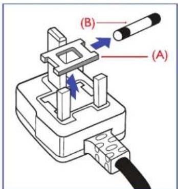
(B) (A)WARNING - THIS APPLIANCE MUST BE EARTHED.
Important:
This apparatus is supplied with an approved moulded 13A plug. To change a fuse in this type of plug proceed as follows:
I. Remove fuse cover and fuse.
2. Fit new fuse which should be a BS 1362 5A, A.S.T.A. or BSI approved type.
3. Refit the fuse cover.
If the fitted plug is not suitable for your socket outlets, it should be cut off and an appropriate 3-pin plug fitted in its place.
If the mains plug contains a fuse, this should have a value of 5A. If a plug without a fuse is used, the fuse at the distribution board should not be greater than 5A.
Note: Any severed plug must be destroyed to avoid a possible shock hazard should it be inserted into a 13A socket elsewhere.

natural_image
Diagram of a battery pack with colored wires (green, blue, red) connecting components (no text or labels)How to connect a plug
The wires in the mains lead are colored in accordance with the following code:
BLUE - "NEUTRAL" ("N")
BROWN - "LIVE" ("L")
GREEN & YELLOW - "EARTH" ('E')
- The GREEN AND YELLOW wire must be connected to the terminal in the plug which is marked with the letter "E" or by the Earth symbol or coloured GREEN or GREEN AND YELLOW.
- The BLUE wire must be connected to the terminal which is marked with the letter "N" or coloured BLACK.
- The BROWN wire must be connected to the terminal which marked with the letter "L" or coloured RED.
Before replacing the plug cover, make certain that the cord grip is clamped over the sheath of the lead - not simply over the three wires.
Your display contains materials that can be recycled and reused. Specialized companies can recycle your product to increase the amount of reusable materials and to minimize the amount to be disposed of.
Please find out about the local regulations on how to dispose of your old display from your local Philips dealer.
(For customers in Canada and U.S.A.)
This product may contain lead and/or mercury. Dispose of in accordance to local state and federal regulations. For additional information on recycling contact www.eia.org (Consumer Education Initiative)
WASTE ELECTRICAL AND ELECTRONIC EQUIPMENT-WEEE
Attention users in European Union: private households


This marking on the product or on its packaging illustrates, under European Directive 2002/96/EG governing used electrical and electronic appliances, that this product may not be disposed of with normal household waste. You are responsible for the disposal of this equipment through a designated waste electrical and electronic equipment collection. To determine the locations for dropping off such electrical and electronic waste, contact your local government office or the waste disposal organization that serves your household area.
Attention users in United States:
Like all LCD products, this set contains a lamp with Mercury. Please dispose of according to all Local, State and Federal Laws. For the disposal or recycling information, contact: www.mygreenelectronics.com or www.eiae.org.

END OF LIFE DIRECTIVES - RECYCLING
Your display contains several materials that can be recycled for new uses.
Like all LCD products, this set contains a lamp with Mercury, please dispose of according to all local State and Federal laws.

As an ENERGY STAR® Partner, MMD has determined that this product meets the ENERGY STAR® guidelines for energy efficiency.
TABLE OF CONTENTS
I. UNPACKING AND INSTALLATION
I.I. UNPACKING
1.2. PACKAGE CONTENTS
I.3. INSTALLATION NOTES
I.4. PORTRAIT MOUNTING
2. PARTS AND FUNCTIONS
2.1. FRONT VIEW
2.2. REAR VIEW
2.3. INPUT/OUTPUT TERMINALS
2.4. REMOTE CONTROL
2.4.1. GENERAL FUNCTIONS
2.4.2. INSERTING THE BATTERIES IN THE REMOTE CONTROL
2.4.3. OPERATING RANGE OF THE REMOTE CONTROL
3. CONNECTIONS TO EXTERNAL EQUIPMENT
3.1. USING THE CABLE RETAINER
3.2. CONNECTING EXTERNAL EQUIPMENT (DVD/VCR/VCD)
3.2.1. USING COMPONENT VIDEO INPUT
3.2.2. USING S-VIDEO INPUT
3.2.3. USING VIDEO INPUT
3.2.4. USING HDMI INPUT
3.3. CONNECTING A PC
3.3.1. USING VGA INPUT
3.3.2. USING DVI INPUT
3.3.3. USING HDMI INPUT
3.4. EXTERNAL AUDIO CONNECTION
3.4.1. CONNECTING EXTERNAL SPEAKERS
3.4.2. CONNECTING EXTERNAL AUDIO DEVICE
3.5. CONNECTING ANOTHER BDL5530EL DISPLAY
4. OSD MENU
4.1. NAVIGATING THE OSD MENU
4.1.1. NAVIGATING THE OSD MENU USING THE REMOTE CONTROL
4.1.2. NAVIGATING THE OSD MENU USING THE DISPLAY'S CONTROL BUTTONS
4.2. OSD MENU OVERVIEW
4.2.1. PICTURE MENU
4.2.2. SCREEN MENU
4.2.3. AUDIO MENU
4.2.4. PIP MENU
4.2.5. CONFIGURATION I MENU
4.2.6. CONFIGURATION 2 MENU
4.2.7. ADVANCED MENU
5. INPUT MODE
6. PIXEL DEFECT POLICY
6.1. PIXELS AND SUB-PIXELS
6.2. TYPES OF PIXEL DEFECTS + DOT DEFINITION
6.3. BRIGHT DOT DEFECTS
6.4. DARK DOT DEFECTS
6.5. PROXIMITY OF PIXEL DEFECTS
6.6. PIXEL DEFECT TOLERANCES
7. CLEANING AND TROUBLESHOOTING
7.1. CLEANING
7.2. TROUBLESHOOTING
8. TECHNICAL SPECIFICATIONS
2011 © Koninklijke Philips Electronics N.V. All rights reserved.
Philips and the Philips Shield Emblem are registered trade marks of Koninklijke Philips Electronics N.V. and are used under license from Koninklijke Philips Electronics N.V.
Specifications are subject to change without notice.
I. UNPACKING AND INSTALLATION
I.I. UNPACKING
- This product is packed in a carton, together with the standard accessories.
- Any other optional accessories will be packed separately.
- Due to the size and weight of this display it is recommended for two people to move it.
- The protective glass and glass substrate are installed on the front of the product. Since glass can be both broken and scratched easily, the product should be handled with care. Never place the product with the glass faced down unless with proper protection and padding.
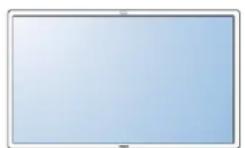
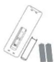
Verify that you received the following items with your package content:
|
2

3

4

5

6

7
I. LCD display
2. Remote control with batteries
3. CD-ROM (EDFU and SICP)
4. Quick Start Guide
5. Cable retainer (x 3)
6. Power cords
7. VGA cable
- For regions not covered by our standard power plugs, apply a power cord that conforms to the AC voltage of the power socket and has been approved by and complies with the safety regulations of the particular country.
- The package box and material can be saved for any event where the unit needs to be shipped to another location.
- External speakers and table stands are offered as optional extras, and are not included with your display.
I.3. INSTALLATION NOTES
- Due to the high power consumption of the display, always use the plug exclusively designed for this product. If an extended line is required, please consult your service agent.
- The product should be installed on a flat surface to avoid tipping. Maintain a distance of at least 6cm between the back of the display and the wall for proper ventilation. Avoid installing the unit in a kitchen, bathroom or any other place with high humidity so as not to shorten the service life of the electronic components.
- Do not place this product on the floor and keep away from children.
- The product can normally operate only under 4000m in altitude. In installations at altitudes above 4000m, some abnormalities may be experienced.
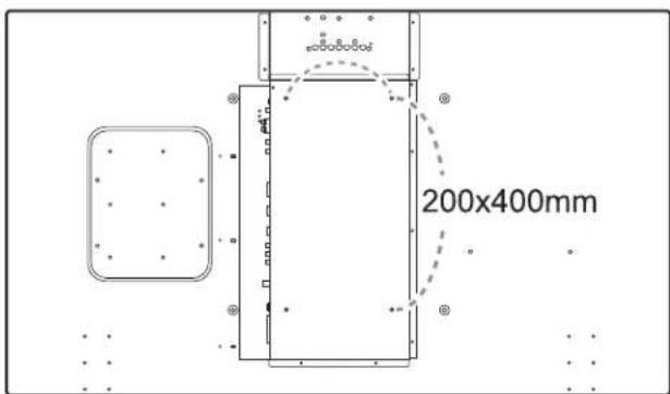
I.4. PORTRAIT MOUNTING
Wall mounting holes
text_image
200x400mmNotes:
- M6 (10mm) screws (with a length 10-15mm longer than the thickness of the mounting bracket) are needed for wall mounting (not included). Tighten the screws securely (recommended torque: 470 - 635N·cm)
- The mounting interface should comply with the UL1678 standard in North America. The mounting means should be strong enough to bear the weight of the display (approx. 29 kg (63.9 lb) without stands).
Allowable tilting angle in Portrait Mode
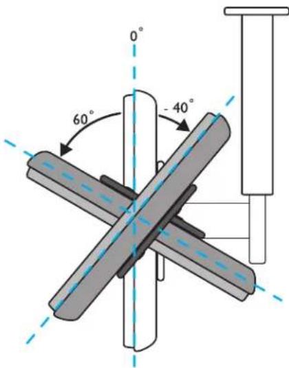
text_image
0° 60° 40°
natural_image
Diagram showing a tilted rectangular frame with an 90-degree rotation arrow (no text or symbols)Note: The remote control sensor should be on the right side when rotating your display.
Note: When installing the display on the wall, please consult a professional technician for proper installation. The manufacturer accepts no liability for installations not performed by a professional technician.
2. PARTS AND FUNCTIONS
2.1. FRONT VIEW
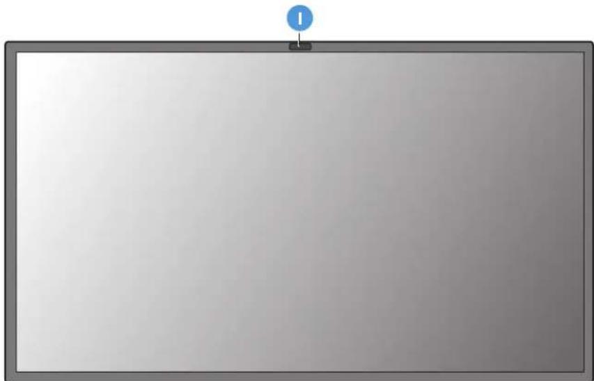
natural_image
Blank whiteboard with a blue circular icon at the top (no text or symbols)I. Remote control sensor, ambient light sensor and power indicator
- Receives command signals from the remote control.
- Detects the ambient lighting conditions around the display.
- Indicates the operating status of the unit: - lights green when the display is turned on - lights red when the display is in standby mode - blinks green when remote control signal is received - blinks red when the display enters DPMS mode - off when the main power of the display is turned off
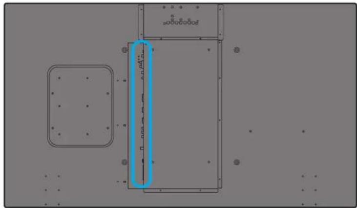
2.2. REAR VIEW

text_image
1 3 4 VIDEO SOURCE MENU 290.4 mm Dent depth: 6.5 mm 100 mm 100 mm 100 mm 280 mm 38 mm 225 mm 235 mm 7 8I. VIDEO SOURCE button
- Use this button to select the input source.
- When the On Screen Display menu is active, this is also used as the SET button.
2. MENU button
- Use this button to engage the On Screen Display menu.
- When the On Screen Display menu is active, use this button to return to the previous menu.
3. ▲/▼ button
- When the On Screen Display menu is active, use these as the UP/DOWN menu buttons.
- Press and hold the ▲ and ▼ buttons simultaneously for 3 seconds to lock or unlock all buttons.
4. ◀ / ▶ button
- When the On Screen Display menu is active, use these as the PLUS/MINUS menu buttons.
5. POWER button
Use this button to turn the display on or into standby mode.
6. Power indicator
Indicates the operating status of the unit:
- lights green when the display is turned on
- lights red when the display is in standby mode
- blinks red when the display enters DPMS mode
- off when the main power of the display is turned off
7. Smart Insert installation holes
Location for the Smart Insert (for integration of a small form factor PC) and M4 screws. (Maximum load: 2kg)
8. Cable retainer installation holes
Install the cable retainer using these holes.
2.3. INPUT/OUTPUT TERMINALS
natural_image
Pure electrical circuit lines without any symbols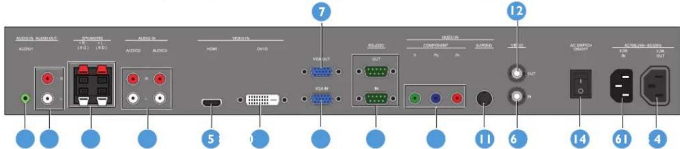
text_image
AUDIO AUDIO OUT AUDIO STRAVETER 4.8 (10) 4.1 (50) AUDIO AUDIO AUDIO AUDIO AUDIO AUDIO AUDIO AUDIO AUDIO AUDIO AUDIO AUDIO AUDIO AUDIO AUDIO AUDIO AUDIO AUDIO AUDIO AUDIO AUDIO AUDIO AUDIO AUDIO AUDIO AUDIO AUDIO AUDIO AUDIO AUDIO AUDIO AUDIO AUDIO AUDIO AUDIO AUDIO AUDIO AUDIO AUDIO AUDIO AUDIO AUDIO AUDIO AUDIO AUDIO AUDIO AUDIO AUDIO AUDIO AUDIO AUDIOI. AUDIO IN (AUDIO I)
Connects to the audio output of a computer.
2. AUDIO OUT R/L
Outputs the audio signal from the AUDIO IN (AUDIO1/AUDIO2/AUDIO3) or HDMI jack.
3. SPEAKERS R/L
Outputs the audio signal from the AUDIO IN (AUDIO1/AUDIO2/AUDIO3) or HDMI jack to external speakers.
4. AUDIO IN (AUDIO2/AUDIO3)
Connects to the audio output of an AV device.
5. VIDEO IN (HDMI)
Connects to the HDMI output of an AV device or to the DVI-D output of a PC. (Using a DVI-HDMI cable)
6. VIDEO IN (DVI-D)
Connects to the DVI-D output of a PC or to the HDMI output of an AV device (Using a DVI-HDMI cable).
7. VGA OUT
Outputs the VGA signal from the VGA IN jack.
8. VGA IN
Connects to the VGA output of a computer.
9. RS-232C (OUT/IN)
RS232C network connection input/output for the use of loop through function.
10. VIDEO IN (COMPONENT)
Component video input (YPbPr) for connecting to the component output of an AV device.
II. VIDEO IN (S-VIDEO)
S-Video input for connecting to the S-Video output of an AV device.
12. VIDEO OUT
Connects to the video input of an AV device or another BDL5530EL unit.
13. VIDEO IN
Connects to the video output of an AV device or another BDL5530EL unit.
14. Main power switch
Press to switch the main power on/off.
15. AC IN (4.0 A)
Connects the supplied power cord to the wall outlet.
16. AC OUT (2.0 A)
Can be used to power an external media device.
2.4. REMOTE CONTROL
2.4.1. GENERAL FUNCTIONS
text_image
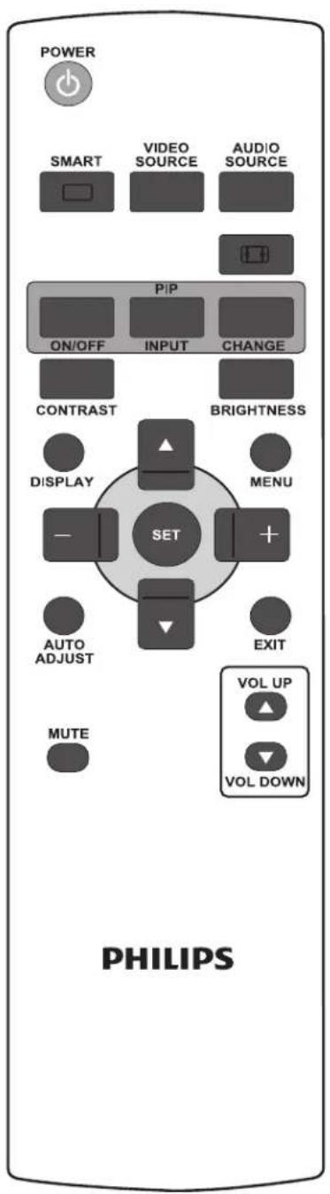
POWER SMART VIDEO SOURCE AUDIO SOURCE P/P ON/OFF INPUT CHANGE CONTRAST BRIGHTNESS DISPLAY MENU SET AUTO ADJUST EXIT MUTE VOL UP VOL DOWN PHILIPSPOWER

POWER button
Press to switch on the display from standby mode. Press again to turn it to standby mode.
SMART

SMART button
To select smart picture mode from:
• Highbright: for moving images such as Video
- Standard: for images (factory setting)
• sRGB: for text based images
• Cinema: for movies.
- User: create your own picture settings. This mode is automatically selected after you change the settings in the Picture menu.

VIDEO SOURCE button
Press to open the video source selection menu and then press UP/DOWN to select from HDMI, DVI-D, VGA, Component, S-Video, and Video.

AUDIO SOURCE button
Press to open the audio source selection menu and then press UP/DOWN to select from HDMI, Audio 1, Audio 2, and Audio 3.

Picture format button
To switch screen aspect ratio between Full, Normal, Dynamic, Custom, Real, and 21:9.
PIP (Picture In Picture) buttons
• ON/OFF button: To turn PIP mode on/off.
- INPUT button: To select the input signal for the sub-picture.
- CHANGE button: To toggle between the main picture and sub picture.
Note: "PIP" mode does not work if the screen size is set to "Custom", "Dynamic", "Real" or "21:9".

CONTRAST button
Press to open the Contrast OSD selection, and then press the PLUS or MINUS button to adjust the value.

BRIGHTNESS button
Press to open the Brightness OSD selection, and then press the PLUS or MINUS button to adjust the value.
text_image
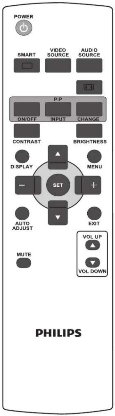
POWER SMART VIDEO SOURCE AUDIO SOURCE P/P ON/OFF INPUT CHANGE CONTRAST BRIGHTNESS DISPLAY MENU SET AUTO ADJUST EXIT MUTE VOL UP VOL DOWN PHILIPS
DISPLAY button
DISPLAY
To turn on/off the setting information displayed on the upper right corner of the screen.

MENU button
MENU
To turn the OSD menu on/off.

UP button
• To move the highlight bar up to adjust the selected item when OSD menu is on.
- To move the sub-picture up in "PIP" mode.

DOWN button
• To move the highlight bar down to adjust the selected item when OSD menu is on.
- To move the sub-picture down in "PIP" mode.

PLUS button
• To increase the adjustment with OSD menu.
- To move the sub-picture right in "PIP" mode.

MINUS button
• To decrease the adjustment with OSD menu.
- To move the sub-picture left in "PIP" mode.

SET button
To activate the changed settings inside OSD menu.

AUTO ADJUST button
AUTO ADJUST
Note: For VGA input only.
To execute the Auto adjust function.

EXIT button
To turn to the previous OSD menu.
MUTE

MUTE button
To turn the mute function on/off.
VOL UP

VOL UP button
To increase the audio output level.

VOL DOWN button
VOL DOWN
To decrease the audio output level.
natural_image
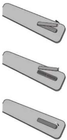
Three-step illustration of a tool or device with a clip and handle, shown in different angles (no text or symbols)2.4.2. INSERTING THE BATTERIES IN THE REMOTE CONTROL
- Remove the cover on the rear of the remote control.
- Insert two AAA size 1.5V batteries ensuring that the “+” and “-” ends of the batteries are correctly aligned.
- Replace the cover.
Note: Do not mix battery types, e.g. alkaline and manganese.
2.4.3. OPERATING RANGE OF THE REMOTE CONTROL
When pressing a remote control button, point the top of the remote control towards the remote control sensor.
Use the remote control within a distance of about 10m/32ft from the display's remote control sensor and within a horizontal and vertical angle of 45 degrees.

text_image
45° 45° PHILIPSNote: The remote control may not function properly if the remote control sensor on the display is under direct sunlight, in a location with strong illumination, or if there is an obstacle in the path of signal transmission.
3. CONNECTIONS TO EXTERNAL EQUIPMENT
3.1. USING THE CABLE RETAINER

natural_image
Diagram of a door with arrows indicating movement or force (no text or symbols)
natural_image
Diagram of a cable clamp securing wires, no text or symbols present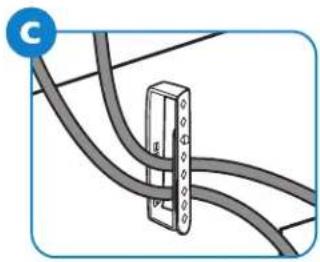
natural_image
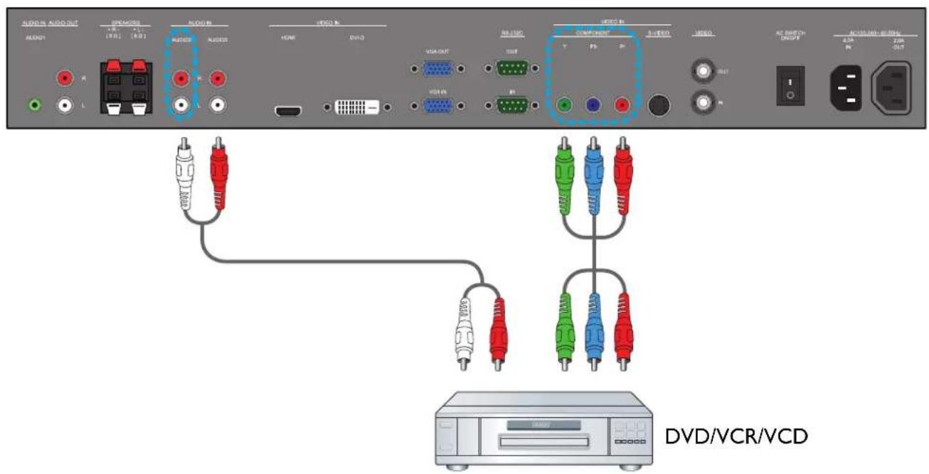
Diagram of a cable or wire connection with a connector and cable (no text or symbols)3.2. CONNECTING EXTERNAL EQUIPMENT (DVD/VCR/VCD)
3.2.1. USING COMPONENT VIDEO INPUT
I. Connect the green-colored (labeled as "Y") jack of the device to the green-colored "Y" jack of the display.
2. Connect the blue-colored (labeled as "Pb") jack of the device to the blue-colored "Pb" jack of the display.
3. Connect the red-colored (labeled as "Pr") jack of the device to the red-colored "Pr" jack of the display.
4. Connect the red (R) and white (L) audio jacks of the device to the AUDIO IN (AUDIO2 or AUDIO3) jacks of the display.
text_image
AUDIO AUDIO OUT AUDIO AUDIO AUDIO AUDIO AUDIO AUDIO AUDIO AUDIO AUDIO AUDIO AUDIO AUDIO AUDIO AUDIO AUDIO AUDIO AUDIO AUDIO AUDIO AUDIO AUDIO AUDIO AUDIO AUDIO AUDIO AUDIO AUDIO AUDIO AUDIO AUDIO AUDIO AUDIO AUDIO AUDIO AUDIO AUDIO AUDIO AUDIO AUDIO AUDIO AUDIO AUDIO AUDIO AUDIO AUDIO AUDIO AUDIO AUDIO AUDIO AUDIO DVD/VCR/VCD3.2.2. USING S-VIDEO INPUT
I. Connect the S-Video connector of the external device to the S-VIDEO input of the display.
2. Connect the red (R) and white (L) audio jacks of the device to the AUDIO IN (AUDIO2 or AUDIO3) jacks of the display.

text_image
AUDIO AUDIO OUT AUDIO AUDIO AUDIO AUDIO AUDIO AUDIO AUDIO AUDIO AUDIO AUDIO AUDIO AUDIO AUDIO AUDIO AUDIO AUDIO AUDIO AUDIO AUDIO AUDIO AUDIO AUDIO AUDIO AUDIO AUDIO AUDIO AUDIO AUDIO AUDIO AUDIO AUDIO AUDIO AUDIO AUDIO AUDIO AUDIO AUDIO AUDIO AUDIO AUDIO AUDIO AUDIO AUDIO AUDIO AUDIO AUDIO AUDIO AUDIO AUDIO AUDIO DVD/VCR/VCD3.2.3. USING VIDEO INPUT
I. Connect the Video connector of the external device to the VIDEO IN input of the display.
2. Connect the red (R) and white (L) audio jacks of the device to the AUDIO IN (AUDIO2 or AUDIO3) jacks of the display.

text_image
AUDIO AUDIO OUT AUDIO BRAGGER (R) (LR) LCCB B AUDIO AUDIO VIDEO B HOME ECHO VGA/OUT VGA/R VGA/IN VGA/IN VGA/IN VGA/IN VGA/IN VGA/IN VGA/IN VGA/IN VGA/IN VGA/IN VGA/IN VGA/IN VGA/IN VGA/IN VGA/IN VGA/IN VGA/IN VGA/IN VGA/IN VGA/IN VGA/INA COMPONENT 3 VCD0 OUT AC SWITCH ON/OFF 4.2K R 2.0K OUT DVD/VCR/VCD3.2.4. USING HDMI INPUT
Connect the HDMI connector of the external device to the HDMI input of the display.

text_image
AUDIO IN AUDIO OUT AUDIO IN AUDIO IN AUDIO IN AUDIO IN AUDIO IN AUDIO IN AUDIO IN AUDIO IN AUDIO IN AUDIO IN AUDIO IN AUDIO IN AUDIO IN AUDIO IN AUDIO IN AUDIO IN AUDIO IN AUDIO IN AUDIO IN AUDIO IN AUDIO IN AUDIO IN AUDIO IN AUDIO IN AUDIO IN AUDIO IN AUDIO IN AUDIO IN AUDIO IN AUDIO IN AUDIO IN AUDIO IN AUDIO IN AUDIO IN3.3. CONNECTING A PC
3.3.1. USING VGA INPUT
I. Connect the 15-pin VGA connector of the PC to the VGA IN connector of the display.
2. Insert the audio cable to the AUDIO IN (AUDIO I) input of the display and connect to the corresponding PC connector.

text_image
AUDIO IN AUDIO OUT AUDIO IN AUDIO IN AUDIO IN AUDIO IN AUDIO IN AUDIO IN AUDIO IN AUDIO IN AUDIO IN AUDIO IN AUDIO IN AUDIO IN AUDIO IN AUDIO IN AUDIO IN AUDIO IN AUDIO IN AUDIO IN AUDIO IN AUDIO IN AUDIO IN AUDIO IN AUDIO IN AUDIO IN AUDIO IN AUDIO IN AUDIO IN AUDIO IN AUDIO IN AUDIO IN AUDIO IN AUDIO IN AUDIO IN AUDIO IN3.3.2. USING DVI INPUT
I. Connect the DVI-D connector of the PC to the DVI-D connector of the display.
2. Insert the audio cable to the AUDIO IN (AUDIO1) input of the display and connect to the corresponding PC connector.

text_image
AUDIO OUT AUDIO IN AUDIO OUT AUDIO IN AUDIO IN AUDIO IN AUDIO IN AUDIO IN AUDIO IN AUDIO IN AUDIO IN AUDIO IN AUDIO IN AUDIO IN AUDIO IN AUDIO IN AUDIO IN AUDIO IN AUDIO IN AUDIO IN AUDIO IN AUDIO IN AUDIO IN AUDIO IN AUDIO IN AUDIO IN AUDIO IN AUDIO IN AUDIO IN AUDIO IN AUDIO IN AUDIO IN AUDIO IN AUDIO IN AUDIO IN AUDIO IN AUDIO IN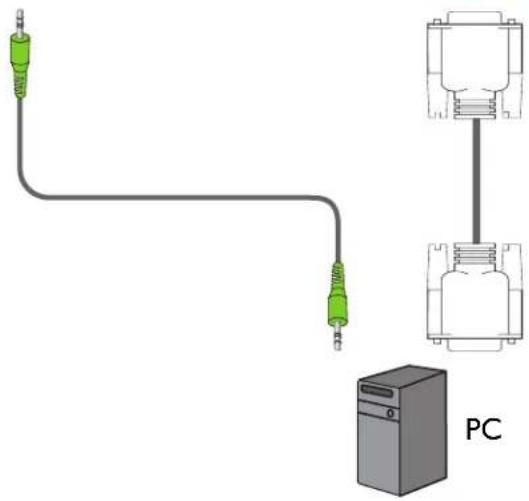
natural_image
Pure electrical circuit lines without any symbols3.3.3. USING HDMI INPUT
I. Connect the DVI-D connector of the PC to the HDMI connector of the display using a DVI-HDMI cable.
2. Insert the audio cable to the AUDIO IN (AUDIO1) input of the display and connect to the corresponding PC connector.

text_image
AUDIO IN AUDIO OUT AUDIO IN AUDIO IN AUDIO IN AUDIO IN AUDIO IN AUDIO IN AUDIO IN AUDIO IN AUDIO IN AUDIO IN AUDIO IN AUDIO IN AUDIO IN AUDIO IN AUDIO IN AUDIO IN AUDIO IN AUDIO IN AUDIO IN AUDIO IN AUDIO IN AUDIO IN AUDIO IN AUDIO IN AUDIO IN AUDIO IN AUDIO IN AUDIO IN AUDIO IN AUDIO IN AUDIO IN AUDIO IN AUDIO IN AUDIO IN
natural_image
Pure electrical circuit lines without any symbols3.4. EXTERNAL AUDIO CONNECTION
3.4.1. CONNECTING EXTERNAL SPEAKERS
I. Connect the speaker wires to the external speaker (SPEAKERS) output of the display.
2. Turn on the unit.
Note: Make sure your display is turned off before connecting the speaker wires.

text_image
AUDIO IN AUDIO OUT AUDIO IN AUDIO IN AUDIO IN AUDIO IN AUDIO IN AUDIO IN AUDIO IN AUDIO IN AUDIO IN AUDIO IN AUDIO IN AUDIO IN AUDIO IN AUDIO IN AUDIO IN AUDIO IN AUDIO IN AUDIO IN AUDIO IN AUDIO IN AUDIO IN AUDIO IN AUDIO IN AUDIO IN AUDIO IN AUDIO IN AUDIO IN AUDIO IN AUDIO IN AUDIO IN AUDIO IN AUDIO IN AUDIO IN AUDIO IN EXTERNAL SPEAKERS3.4.2. CONNECTING EXTERNAL AUDIO DEVICE
Connect the red (R) and white (L) audio jacks of the external audio device to the AUDIO OUT R/L jacks of the display.

text_image
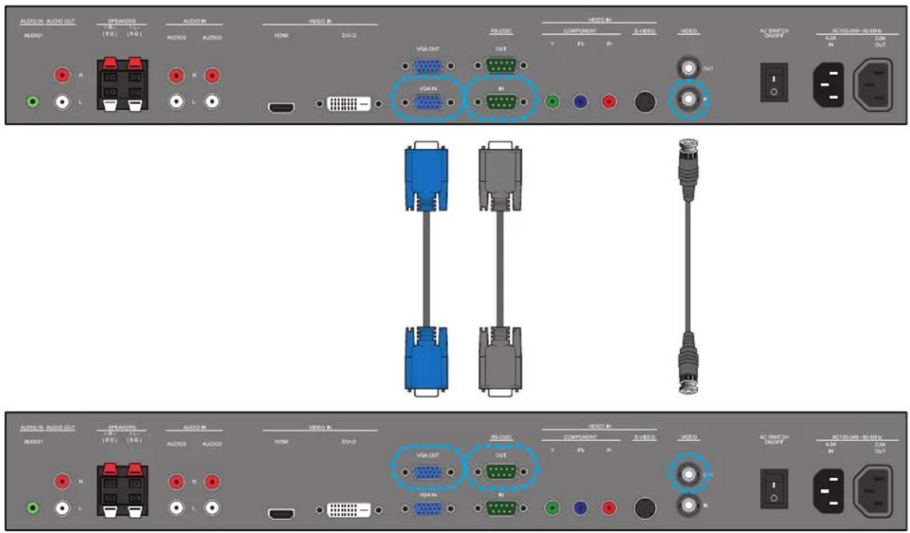
AUDIO IN AUDIO OUT AUDIO IN AUDIO IN AUDIO IN AUDIO IN AUDIO IN AUDIO IN AUDIO IN AUDIO IN AUDIO IN AUDIO IN AUDIO IN AUDIO IN AUDIO IN AUDIO IN AUDIO IN AUDIO IN AUDIO IN AUDIO IN AUDIO IN AUDIO IN AUDIO IN AUDIO IN AUDIO IN AUDIO IN AUDIO IN AUDIO IN AUDIO IN AUDIO IN AUDIO IN AUDIO IN AUDIO IN AUDIO IN AUDIO IN AUDIO IN AUDIO IN AUDIO IN AUDIO IN AUDIO IN AUDIO IN AUDIO IN AUDIO IN AUDIO IN AUDIO IN AUDIO IN AUDIO IN AUDIO IN AUDIO IN AUDIO IN AUDIO IN AUDIO IN AUDIO IN AUDIO IN AUDIO IN AUDIO IN AUDIO IN AUDIO IN AUDIO IN AUDIO IN AUDIO IN AUDIO IN AUDIO IN AUDIO IN AUDIO IN AUDIO IN AUDIO IN AUDIO IN AUDIO IN Audio OUT Audio OUT Audio OUT Audio OUT Audio OUT Audio OUT Audio OUT Audio OUT Audio OUT Audio OUT Audio OUT Audio OUT Audio OUT Audio OUT Audio OUT Audio OUT Audio OUT Audio OUT Audio OUT Audio OUT Audio OUT Audio OUT Audio OUT Audio OUT Audio OUT Audio OUT Audio OUT Audio OUT Audio OUT Audio OUT Audio OUT Audio OUT Audio OUT Audio OUT3.5. CONNECTING ANOTHER BDL5530EL DISPLAY
You can interconnect multiple BDL5530EL units to create a daisy-chain configuration for applications such as a video wall.
Note: The number of displays that can be used in a daisy-chain configuration will depend on the resolution of the input signal being used.
- Connect the VGA OUT connector of the display to the VGA IN connector of additional BDL5530EL unit.
- Connect the RS-232C OUT connector of the display to the RS-232C IN connector of additional BDL5530EL unit.
- Connect the VIDEO OUT connector of the display to the VIDEO IN connector of additional BDL5530EL unit.
- Connect the AC OUT connector of the display to the AC IN connector of an external media player only.
Additional BDL5530EL display
text_image
AUDIO IN AUDIO OUT AUDIO1 AVOCATION AUDIO2 AUDIO3 AUDIO4 AUDIO5 AUDIO6 AUDIO7 AUDIO8 AUDIO9 AUDIO10 AUDIO11 AUDIO12 AUDIO13 AUDIO14 AUDIO15 AUDIO16 AUDIO17 AUDIO18 AUDIO19 AUDIO20 AUDIO21 AUDIO22 AUDIO23 AUDIO24 AUDIO25 AUDIO26 AUDIO27 AUDIO28 AUDIO29 AUDIO30 AUDIO31 AUDIO32 AUDIO33 AUDIO34 AUDIO35 AUDIO36 AUDIO37 AUDIO38 AUDIO39 AUDIO40 AUDIO41 AUDIO42 AUDIO43 AUDIO44 AUDIO45 AUDIO46 AUDIO47 AUDIO48 AUDIO49 AUDIO50 AUDIO51 AUDIO52 AUDIO53 AUDIO54 AUDIO55 AUDIO56 AUDIO57 AUDIO58 AUDIO59 AUDIO60 AUDIO61 AUDIO62 AUDIO63 AUDIO64 AUDIO65 AUDIO66 AUDIO67 AUDIO68 AUDIO69 AUDIO70 AUDIO71 AUDIO72 AUDIO73 AUDIO74 AUDIO75 AUDIO76 AUDIO77 AUDIO78 AUDIO79 AUDIO80 AUDIO81 AUDIO82 AUDIO83 AUDIO84 AUDIO85 AUDIO86 AUDIO87 AUDIO88 AUDIO89 AUDIO90 AUDIO91 AUDIO92 AUDIO93 AUDIO94 AUDIO95 AUDIO96 AUDIO97 AUDIO98 AUDIO99 AUDIO1004. OSD MENU
An overall view of the On-Screen Display (OSD) structure is shown below. This can be used as a reference for further adjusting your display.
4.1. NAVIGATING THE OSD MENU
4.1.1. NAVIGATING THE OSD MENU USING THE REMOTE CONTROL
I. Press the MENU button on the remote control to display the OSD menu.
-
Press the UP/DOWN button to choose the item you want to adjust.
-
Press the PLUS/SET button to enter the submenu.
-
In the submenu, press the UP/DOWN button to toggle between items, or press PLUS/MINUS button to adjust settings. If there is a submenu, press the PLUS button to enter it.
-
Press the MINUS/EXIT button on the remote control to return to the previous menu, or press the MENU button to exit the OSD menu.
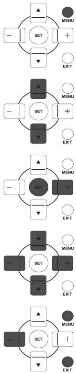
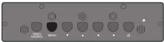
4.1.2. NAVIGATING THE OSD MENU USING THE DISPLAY'S CONTROL BUTTONS
text_image
VOLD SOURCE MENUI. Press the MENU button to display the OSD menu.

text_image
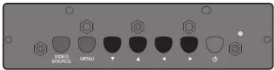
VIDEO SOURCE MENU- Press the ▲/▼ button to choose the item you want to adjust.

text_image
VIDEO SOURCE MENU- Press the ▶ button to enter the submenu.
text_image
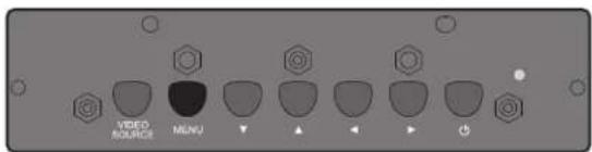
VIDEO SOURCE MENU- In the submenu, press the ▲/▼ button to toggle between items, or press ◀/▶ button to adjust settings. If there is a submenu, press the ▶ button to enter it.
text_image
VIDEO SOURCE MENU- Press the MENU button on the remote control to return to the previous menu, or press the MENU button repeatedly to exit the OSD menu.
4.2. OSD MENU OVERVIEW
4.2.1. PICTURE MENU

text_image
Picture Screen Audio PHP Configuration1 Configuration2 Advanced option Brightness Contrast Sharpness Black level Noise reduction Tint Color Color temperature 10000K Color control Action Light sensor Off Smart contrast OffBrightness
Note: This function is not available when Smart contrast, Light sensor or Brightness under Panel saving is turned on. Disable these functions to make Brightness accessible from the OSD menu.
Adjust the overall image brightness by changing the intensity of the LCD panel's backlight.
Use the PLUS/MINUS button to adjust.
Contrast
Adjust to sharpen the picture quality. The black portions of the picture become richer and the whites become brighter.
Use the PLUS/MINUS button to adjust.
Sharpness
Adjust to improve detail.
Use the PLUS/MINUS button to adjust.
Black level
Adjust to change the image brightness.
Use the PLUS/MINUS button to adjust.
Noise reduction
Note: For Video, S-Video, Component and HDMI inputs with interlaced video only.
Adjust to remove the noise in the image. You can select a suitable noise reduction level.
Use the UP/DOWN button to make selection.
Tint
Note: For Video, S-Video, Component, and HDMI inputs with YUV color space only. (YUV is a color space typically used as part of a color image pipeline.)
Adjust to change the color tint of the image.
Use the PLUS/MINUS button to adjust. Press the PLUS button and the flesh tone color turns slightly green. Press the MINUS button and the flesh tone color turns slightly purple.
Color
Note: For Video, S-Video, Component, and HDMI inputs with YUV color space only. (YUV is a color space typically used as part of a color image pipeline.)
Adjust to increase or decrease the intensity of colors in the image.
Press the PLUS button to increase color intensity, or press the MINUS button to decrease it.
Color temperature
Select a color temperature for the image. The image has a reddish tint with a lower color temperature, whilst a higher color temperature gives off a more bluish tint.
Use the UP/DOWN button to make selection.
Color control
Note: This function is only available when Color temperature is set to User.
With this function you can adjust the color tones of the image precisely by changing the R (Red), G (Green) and B (Blue) settings independently.
Press the UP/DOWN button to select R, G or B, and press the PLUS/MINUS button to adjust.
Light sensor
Note: This function is not available when Smart contrast or Brightness under Panel saving is turned on. Disable these functions to make Light sensor accessible from the OSD menu.
Choose to enable or disable the ambient light sensor. Once enabled, the image brightness will adjust automatically as the ambient lighting conditions change.
Use the UP/DOWN button to make selection.
Smart contrast
Note: This function is not available when Light sensor or Brightness under Panel saving is turned on. Disable these functions to make Smart contrast accessible from the OSD menu.
When turned on, this function helps enhance image contrast when displaying dark scenes.
Use the UP/DOWN button to make selection.
Smart picture
Select a smart picture mode from:
• Highbright: for moving images such as Video
- Standard: for images (factory setting)
- sRGB: for text based images
• Cinema: for movies.
- User: create your own picture settings. This mode is automatically selected after you change the settings in the Picture menu.
Use the UP/DOWN button to make selection.
Video source
Select a video input source.
Use the UP/DOWN button to toggle between
• HDMI • DVI-D
• VGA • Component
• S-Video • Video
Picture reset
Reset all settings in the Picture menu.
Use the PLUS/MINUS button to make selection. Select Reset and press the SET button to restore settings to factory preset values. Press the EXIT button to cancel and return to the previous menu.
4.2.2. SCREEN MENU

text_image
Picture Screen Audio PIP Configuration1 Configuration2 Advanced option H position V position Clock Clock phase Zoom mode Full Custom zoom Action Screen reset ActionH position
Note: For VGA input only.
Adjust the horizontal placement of the picture.
Press the PLUS button to move the image to the right, or press the MINUS button to move the image to the left.
V position
Note: For VGA input only.
Adjust the vertical placement of the picture.
Press the PLUS button to move the image up, or press the MINUS button to move the image down.
Clock
Note: For VGA input only.
Adjust the width of the image.
Press the PLUS button to expand the width of the image, or press the MINUS button to shrink it.
Clock phase
Note: For VGA input only.
Adjust to improve the focus, clarity and stability of the image.
Use the PLUS/MINUS button to adjust.
Zoom mode
The pictures you receive may be transmitted in 16:9 format (widescreen) or 4:3 format (conventional screen). 16:9 pictures sometimes have a black band at the top and bottom of the screen (letterbox format). This function allows you to optimize the picture display on screen. The following zoom modes are available:
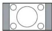
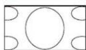
- Full - This mode restores the correct proportions of pictures transmitted in 16:9 using the full screen display.
- Normal - The picture is reproduced in 4:3 format and a black band is displayed on either side of the picture.
-
Dynamic - Fill the entire screen by stretching 4:3 pictures non-proportionally.
-
Custom - Choose to apply the custom zoom settings in the Custom zoom submenu. Note: This mode does not support deinterlacing. The screen may flicker when displaying interlaced video.
• Real - This mode displays the image pixel-by-pixel on screen without scaling the original image size.
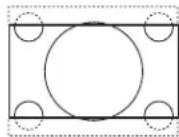
- 21:9 - The picture is enlarged to 16:9 format. This mode is recommended when displaying pictures that have black bands at the top and bottom (letterbox format).
Note: This mode does not support deinterlacing. The screen may flicker when displaying interlaced video.
Custom zoom
Note: This item is only available when Zoom mode is set to Custom.
You can use this function to further customize the zoom settings to suit the image you want to display.
Use the UP/DOWN button to toggle between the following items, and use the PLUS/MINUS button to adjust.
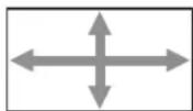
- Zoom - Expands the horizontal and vertical sizes of the image simultaneously.
- H zoom - Expands the horizontal size of the image only.
- V zoom - Expands the vertical size of the image only.
- H position - Moves the horizontal position of the image left or right.
- V position - Moves the vertical position of the image up or down.
Screen reset
Reset all settings in the Screen menu.
Use the PLUS/MINUS button to make selection. Select Reset and press the SET button to restore settings to factory preset values. Press the EXIT button to cancel and return to the previous menu.
4.2.3. AUDIO MENU

text_image
Picture Screen Audio PJP Configuration1 Configuration2 Advanced option Speaker Volume Mute Audio source Audio reset Internal On Audio 1 ActionSpeaker
Set the display to play audio using the built-in (internal) speaker, external speakers or external audio devices (if connected).
Use the UP/DOWN button to toggle between
- Internal • External
- Line-out
Volume
Adjust to increase or decrease the audio output level.
Use the PLUS/MINUS button to adjust.
Mute
To turn the mute function on/off.
Use the UP/DOWN button to make selection.
Audio source
To select the audio input source according to the source connected to the audio input and HDMI sockets on the display.

text_image
Audio 3 Audio 1 Audio 2 HDMIUse the UP/DOWN button to toggle between
• Audio 1 • Audio 2
• Audio 3 • HDMI
Audio reset
Reset all settings in the Audio menu.
Use the PLUS/MINUS button to make selection. Select Reset and press the SET button to restore settings to factory preset values. Press the EXIT button to cancel and return to the previous menu.
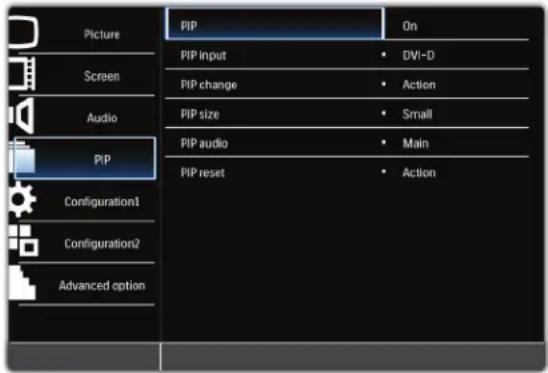
4.2.4. PIP MENU
Notes:
- For Component, VGA, DVI-D and HDMI inputs only.
- For Full and Normal zoom modes only.
- The PIP function is turned off by default. Press the PIP ON/OFF button on the remote control to turn on PIP and make it accessible from the OSD menu.
text_image
Picture Screen Audio PIP Configuration1 Configuration2 Advanced option PIP On PIP input • DVI-D PIP change • Action PIP size • Small PIP audio • Main PIP reset • ActionPIP
To turn PIP mode on/off.
Use the UP/DOWN button to make selection.
PIP input
Select the input signal for the sub-picture.
Use the UP/DOWN button to make selection.
PIP change
To exchange between the main picture and sub picture.
Use the PLUS/MINUS button to make selection. Select Reset and press the SET button to restore settings to factory preset values. Press the EXIT button to cancel and return to the previous menu.
PIP size
Select the size of the sub picture in the PIP mode.
Use the UP/DOWN button to toggle between
- Large • Middle
- Small
PIP audio
Select the audio source in the PIP mode.
Use the UP/DOWN button to toggle between
- Main - Select audio from the main picture
- Sub - Select audio from the sub picture.
PIP reset
Reset all settings in the PIP menu.
Use the PLUS/MINUS button to make selection. Select Reset and press the SET button to restore settings to factory preset values. Press the EXIT button to cancel and return to the previous menu.
Notes:
- The PIP function is only available under certain signal source combinations as shown in the table below.
| Main picture signal source | |||||||
| Video S-Video Component VGA DVI-D HDMI | |||||||
| Subpicturesignalsource | Video | X | X | X | X | X | X |
| S-Video | X | X | X | X | X | X | |
| Component | X | X | X | X | O | O | |
| VGA | X | X | X | X | O | O | |
| DVI-D | X | X | O | O | X | X | |
| HDMI | X | X | O | O | X | X | |
(○PIP function available, : NP function unavailable)
- The availability of the PIP function will also depend on the resolution of the input signal being used.
4.2.5. CONFIGURATION I MENU

text_image
Picture Screen Audio PIP Configuration1 Configuration2 Advanced option Switch on state Last status Auto adjust Action Power save Action Language English Panel saving Action Color system Auto MEMC effect Off Configuration reset Action Factory reset ActionSwitch on state
Set the display to turn on or remain off when the power cord is connected to a wall outlet.
Use the UP/DOWN button to toggle between
- Last status - The display will return to the previous power status (on/off/standby) when removing and replacing the power cord.
- Forced on - The display will turn on when the power cord is connected to a wall outlet.
- Power off - The display will remain off when the power cord is connected to a wall outlet.
Auto adjust
Note: For VGA input only.
Use this function to automatically optimize the display of the VGA image. Press the SET button to adjust.
Power save
Set the display to reduce the power automatically.
Use the UP/DOWN button to toggle between
- RGB - Select On to let the display enter DPMS (Display Power Management Signaling) mode when no signal can be detected from the HDMI, DVI-D, and VGA inputs after three successive cycles. Use the PLUS/MINUS button to make selection.
- Video - Select On to let the display enter power saving mode when no signal is detected from the Video, S-Video, and Component inputs after three successive cycles. Use the PLUS/MINUS button to make your selection.
Language
Select the language for the OSD menu.
Use the UP/DOWN button to select a language.
Panel saving
Choose to enable the panel saving functions to reduce the risk of the "image persistence". Use the PLUS/MINUS button to toggle between
- Brightness - Select On and the brightness of the image will be reduced to an appropriate level, and the Brightness setting in the Picture menu will become unavailable. Use the PLUS/MINUS button to make selection.
- Pixel shift - Select the time interval for the display to slightly expand the image size and shift the pixel position in four directions (up, down, left, and right). Use the PLUS/MINUS button to make selection (Off-900 seconds from current time). This helps to alleviate the issues of ghost imaging.
IMPORTANT: It is not recommended to keep a single static image displayed on your unit for long periods of time. This can cause image sticking, or ghost images, which will decrease the quality of your images. In
some instances, ghost image damage can be permanent. To avoid such issues, we strongly recommend one of the following actions:
- Change the picture periodically
- Enable Pixel shift (See Pixel shift under Section 4.2.5.CONFIGURATION I MENU)
- Use a screen saver with changing images
Color system
Note: For Video and S-Video inputs only.
Select the color system depending on the input video format.
Use the UP/DOWN button to make selection.
• Auto • PAL 4.4 3
• PAL 3.58 • SECAM
• NTSC 4.43 • NTSC 3.58
MEMC effect
To turn the Motion Estimation, Motion Compensation (MEMC) effect on/off.
Use the UP/DOWN button to make selection.
Configuration reset
Reset all settings in the Configuration I menu.
Use the PLUS/MINUS button to make selection. Select Reset and press the SET button to restore settings to factory preset values. Press the EXIT button to cancel and return to the previous menu.
Factory reset
Reset all settings in the Picture, Screen, Audio, PIP, Configuration 1, Configuration 2, and Advanced option menus. Use the PLUS/MINUS button to make selection. Select Reset and press the SET button to restore settings to factory preset values. Press the EXIT button to cancel and return to the previous menu.
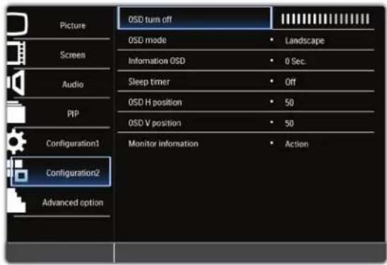
4.2.6. CONFIGURATION 2 MENU
text_image
Picture Screen Audio PIP Configuration1 Configuration2 Advanced option OSD turn off OSD mode • Landscape Information OSD • 0 Sec. Sleep timer • Off OSD H position • 50 OSD V position • 50 Monitor information • ActionOSD turn off
Set the period of time the OSD menu stays on the screen (from 5 to 120 seconds) Use the PLUS/MINUS button to adjust.
OSD mode
Select the orientation of the OSD according to the orientation the display is installed. Use the UP/DOWN button to toggle between
- Portrait • Landscape
Information OSD
Set the period of time the information OSD stays on the screen. The information OSD will display when input signal is changed.
Use the UP/DOWN button to adjust. The information OSD will not appear when Off is selected. If 0 is selected, the information OSD will remain on the screen.
Sleep timer
Set the display to turn itself off to standby mode within a user-specified amount of time. (Off-24 hours from current time)
Use the UP/DOWN button to adjust.
Note: When the Sleep timer is activated, Schedule settings will be disabled.
OSD H position
Adjust the horizontal position of the OSD menu.
Use the UP/DOWN button to adjust.
OSD V position
Adjust the vertical position of the OSD menu.
Use the UP/DOWN button to adjust.
Monitor information
Shows the information about your display, including model name, serial number, operating hours and software version.
Press the PLUS button to view the information. Press the EXIT button to return to the previous menu.
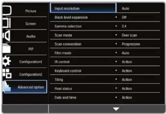
4.2.7. ADVANCED MENU
text_image
Picture Screen Audio PIP Configuration1 Configuration2 Advanced option Input resolution Auto Black level expansion Off Gamma selection 2.4 Scan mode Over scan Scan conversion Progressive Film mode Auto IR control Action Keyboard control Action Tiling Action Heat status Action Date and time ActionInput resolution
Note: For VGA input only.
Set the resolution of the VGA input. This is only required when the display is unable to detect the VGA input resolution correctly.
Use the UP/DOWN button to toggle between
• Auto
- 1024×768
- 1280×768
• 1360x768 • 1366x768
Black level expansion
Note: For Video, S-Video, Component, and HDMI (video mode) inputs only.
This feature offers deeper blacks for an even better image quality. Select a suitable black level expansion setting to reveal more details in the dark parts of an image.
Use the UP/DOWN button to toggle between
- Off - Low
- Middle • High
Gamma selection
Gamma is what controls the overall brightness of an image. Images which are not corrected properly can appear too white or too dark, so controlling the gamma properly can have a huge influence on the overall picture quality of your display.
Select a display gamma value to best suit the image and optimize image brightness and contrast.
Use the UP/DOWN button to toggle between
· 2.2 · 2.4
- Native
Scan mode
Note: For Video, S-Video, Component, and HDMI (video mode) inputs only.
Change the display area of the image.
Use the UP/DOWN button to toggle between
• Over scan - Displays about 95% of the original size of the image. The rest of the areas surrounding the image will be cut off.
- Under scan - Displays the image in its original size.
Scan conversion
Note: For Video, S-Video, Component, and HDMI (video mode) inputs only.
Choose to enable or disable the IP (Interlace to Progressive) conversion function.
Use the UP/DOWN button to toggle between
- Progressive - Enable the IP conversion function (recommended). Once enabled, the interlace input signal will be converted to progressive format for better display quality.
- Interlace: Disable the IP function. This mode is suitable for displaying motion pictures, but increases the chance of image retention.
Film mode
Note: For Video, S-Video, Component, and HDMI (video mode) inputs only.
Choose to turn on or off the film mode frame conversion function.
Use the UP/DOWN button to toggle between
- Auto - Enable the film mode frame conversion function for movies and motion pictures. The display converts a 24 frames-per-second (24 fps) input signal format to DVD video signal format. Once this function is enabled, it is recommended that you set the Scan conversion function to Progressive.
- Off - Disable the film mode frame conversion function. This mode is suitable for TV broadcasting and VCR signals.
IR control
Select the operation mode of the remote control when multiple BDL5530EL units are connected via RS232C cables.
Use the UP/DOWN button to toggle between
- Normal - All units can be operated normally by the remote control.
- Primary - Designate this display as the primary unit for remote control operation. Only this display will be operated by the remote control.
- Secondary - Designate this display as the secondary unit. This display can not be operated by the remote control, and will only receive the control signal from the primary unit via the RS232C connection.
- Lock - Lock the remote control function of this display. To unlock, press and hold the DISPLAY button on the remote control for 5 seconds.
Keyboard control
Choose to enable or disable the function of the keyboard (control buttons) on the display.
Use the UP/DOWN button to toggle between
- Lock - Disable the keyboard.
- Unlock - Enable the keyboard.
Tiling
Notes:
- For VGA input only.
- This function is not available when PIP is turned on. Disable PIP to make Tiling accessible from the OSD menu.
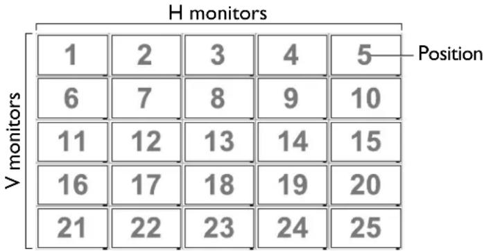
With this function you can create a single large screen matrix (display wall) that consists of up to 25 BDL5530EL displays (5 units on the vertical side and 5 units on the horizontal side). This requires you to connect each BDL5530EL unit in a daisy-chain configuration.
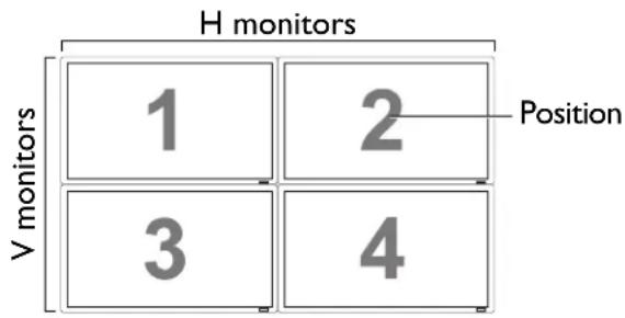
Example:
2 x 2 screen matrix (4 displays)
H monitors = 2
V monitors = 2
text_image
H monitors 1 2 Position V monitors 3 45 x 5 screen matrix (25 displays)
H monitors = 5
V monitors = 5
heatmap
H monitors | Position | V monitors | Value | | :--- | :--- | :--- | | 1 | 1 | 1 | | 1 | 2 | 2 | | 1 | 3 | 3 | | 1 | 4 | 4 | | 1 | 5 | 5 | | 6 | 6 | 6 | | 6 | 7 | 7 | | 6 | 8 | 8 | | 6 | 9 | 9 | | 6 | 10 | 10 | | 11 | 11 | 11 | | 11 | 12 | 12 | | 11 | 13 | 13 | | 11 | 14 | 14 | | 11 | 15 | 15 | | 16 | 16 | 16 | | 16 | 17 | 17 | | 16 | 18 | 18 | | 16 | 19 | 19 | | 16 | 20 | 20 | | 21 | 21 | 21 | | 21 | 22 | 22 | | 21 | 23 | 23 | | 21 | 24 | 24 | | 21 | 25 | 25 | Position- H monitors - Select the number of displays on the horizontal side.
- V monitors - Select the number of displays on the vertical side.
- Position - Select the position of this display in the screen matrix. Position is defined by the total number of displays in the video wall counting from the top, left hand display and counting horizontally. The number is then continued on the next row down, and the procedure is continued until the final display is reached. See examples above for further explanation.
- Frame comp. - Choose to turn frame compensation on or off. If turned on, the display will adjust the image to compensate for the width of the bezels in order to accurately display the image.
Frame comp. - Off Frame comp. - On

text_image
PHILIPS
text_image
PHILIPS- Enable: Choose to enable or disable the Tiling function. If enabled, the display will apply the settings in H monitors, V monitors, Position, and Frame comp..
Note: PIP function is disabled when Tiling is enabled.
- Switch on delay: Choose to enable or disable a sequence in turning on the screen matrix. If enabled, the display will turn on one horizontal matrix at a time starting from the top row.
Heat status
This function allows you to check the thermal status of the display at any time. The accuracy of the temperature indicated is 5 degrees Celsius.
Press the PLUS button to view the heat status. Press the EXIT button to return to the previous menu.
Date and time
Adjusts current date and time for the display's internal clock.
Press the UP/DOWN button to toggle between the Year, Month, Day, Hour, Minute, and Daylight saving time settings, and then press the PLUS/MINUS button to adjust.
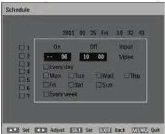
Schedule
Note: We recommend setting up current date and time in Date and time before using the Schedule function.
This function allows you to program up to seven different scheduled time intervals for the display. You can select the time the unit turns on and turns off, the days in a week it is activated, and which input source the display will use for each scheduled activation period.
For example, if you wish to turn the display on automatically at 7:30 AM and off at 10:30 PM on Tuesdays and Wednesdays and display the signal from the HDMI input:
| Time | ||||||||||||||||||||||||||||||
| 0:00 | 1:00 | 2:00 | 3:00 | 4:00 | 5:00 | 6:00 | 7:00 | 8:00 | 9:00 | 10:00 | 11:00 | 12:00 | 13:00 | 14:00 | 15:00 | 16:00 | 17:00 | 18:00 | 19:00 | 20:00 | 21:00 | 22:00 | 23:00 | |||||||
| Day | MON | Off | ||||||||||||||||||||||||||||
| TUE | Off On | |||||||||||||||||||||||||||||
| WED | Off | On | ||||||||||||||||||||||||||||
| THU | Off | |||||||||||||||||||||||||||||
| FRI | Off | |||||||||||||||||||||||||||||
| SAT | Off | |||||||||||||||||||||||||||||
| SUN | Off | |||||||||||||||||||||||||||||
Perform the following steps:
I. With the Schedule item highlighted in the Advanced option menu, press the PLUS button to open the submenu.
text_image
Schedule On Off Xi#i 10 32 40 --- 00 10 00 □ Every day □ Mon □ Tue □ Wed □ Thu □ Fri □ Sat □ Sun □ Every week Set Adjust SSet Exit Back MENU Quit-
Press the UP/DOWN button to select schedule item #1 (☐ 1), and then press the SET button. A check mark will appear in the box indicating that the schedule item has been selected.
-
With the On item highlighted, press the SET button and then press the UP/DOWN button to set the power on hour to "07".
-
Press the PLUS button to move to the minute slot. Press the UP/DOWN button to set the power on minute to "30", then press the EXIT button.
-
Press the PLUS button to highlight the Off item. Press the SET button, and then press the UP/DOWN button to set the power off hour to "22".
-
Press the PLUS button to move to the minute slot. Press the UP/DOWN button to set the power off minute to "30", then press the EXIT button.
-
Press the PLUS button to highlight the Input item, and then press the UP/DOWN button to select HDMI.
-
Press the PLUS button to select □ Tue and then press the SET button. A check mark will appear in the box indicating that it has been selected.
-
Press the PLUS button to select □ Wed and then press the SET button. A check mark will appear in the box indicating that it has been selected.
-
Now you have completed the schedule settings. The on-screen display should look like the illustration below:
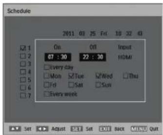
text_image
Schedule On Off.Input 07:30 22:30 HDMI Every day Mon Tue SWed Thu Fri Sat Sun Every week Set Adjust Sat Exit Back MENU QuitII. Press the EXIT button and the menu will close and the schedule settings will take effect.
To set up more schedule items, repeat the steps above except that a different schedule item should be selected (schedule item #2 (☐) through #7 ( ☐) in step 2.
Notes:
- Seven scheduling options are available so that you can choose between different video input modes for different schedules during the week. For example, VGA input on a Monday, HDMI on Tuesday to Friday, S-Video for weekends.
- If you do not want to use a power on time, select "-" for the power on hour slot, and "00" for the minute slot. The display will only turn off at the time you set.
- If you do not want to use a power off time, select "--" for the power off hour slot, and "00" for the minute slot. The display will only turn on at the time you set.
- If no input source is selected, the default input source (Video) will be used.
- If Every day is selected, the display will turn on everyday regardless of other day settings (e.g Mon, Tue, Wed..., etc.).
- Should schedule periods overlap, the power on time has priority over power off time. For example, if schedule item #1 sets the display to power on at 10:00 AM and off at 5:00 PM, and schedule item #2 sets the display to power on at 4:00 PM and off at 9:00 PM on the same day, then the display will power on at 10:00 AM and off at 9:00 PM.
- If there are multiple schedule items programmed for the same time period, then the highest numbered schedule item has priority. For example, if schedule items #1 and #2 both set the display to power on at 7:00 AM and off at 5:00 PM, then only schedule item #1 will take effect.
Monitor ID
Set the ID number for controlling the unit via the RS232C connection. Each display must have a unique ID number when multiple BDL5530EL units are connected.
See table under "Tiling" for more information. Use the PLUS/MINUS button to select an ID.
DDC/CI
Choose to turn On or Off the DDC/CI communication function. Select ON for normal use.
Use the UP/DOWN button to make selection.
Smart power
Set the display to reduce the power consumption automatically. Setting to High will bring the most power savings.
Use the UP/DOWN button to toggle between
- Off - Medium
• High
Auto signal detection
Select to let the unit detect and display available signal source automatically.
- On - Set the unit to display the image automatically once a signal is connected.
- Off - Once a signal is connected, it can only be selected manually. Use the UP/DOWN button to make selection.
Advanced option reset
Reset all settings in the Advanced option menu.
Press the PLUS button to open the submenu, and then press the PLUS/MINUS button to make selection. Select Reset and press the SET button to restore settings to factory preset values. Press the EXIT button to cancel and return to the previous menu.
5. INPUT MODE
VGA Resolution
| Standard Resolution | Active Resolution | Refresh Rate P | Pixel Rate Aspect | Ratio Stand for | Mode | |
| H Pixels V Lines | ||||||
| VGA 640 | 480 | 60 Hz 25.175 MHz | 4:3 Video | Graphic Array72 Hz 31.5 M | ||
| 75 Hz 31.5 MHz | ||||||
| WVGA 720 | 400 70 Hz 33 | 75 MHz 16:9 | Wide Video Graphic Array | |||
| SVGA | 800 600 | 60 Hz | 40 MHz | 4:3 | Super VGA | |
| 75 Hz 49.5 MHz | ||||||
| XGA | 1024 | 768 | 60 Hz | 65 MHz | 4:3 | Extended Graphic Array |
| 75 Hz 78.75 MHz | ||||||
| WXGA | 1280 | 768 | 60 Hz | 79.5 MHz | 5:3 | Wide XGA |
| WXGA | 1280 | 800 | 60 Hz | 79.5 MHz | 16:10 | Wide XGA |
| SXGA | 1280 | 960 | 60 Hz | 108 MHz | 4:3 | Super XGA |
| SXGA | 1280 | 1024 | 60 Hz | 108 MHz | 5:4 | Super XGA |
| WXGA | 1360 | 768 | 60 Hz | 85.5 MHz | 16:9 | Wide XGA |
| WXGA | 1366 | 768 | 60 Hz | 85.5 MHz | 16:9 | Wide XGA |
| UXGA | 1600 | 1200 | 60 Hz | 162 MHz | 4:3 | Ultra XGA |
| HD1080 | 1920 | 1080 | 60 Hz | 148.5 MHz | 16:9 | HD1080 |
SDTV Resolution
| Standard Resolution | Active Resolution | Refresh Rate P | Pixel Rate Aspect | Ratio Stand for | Mode | |
| H Pixels V | Lines | |||||
| 480i | 720 480 | 29.97 Hz | 13.5 MHz | 4:3 | Modified NTSC Standard | |
| 480p | 59.94 Hz 27 MHz | |||||
| 576i | 720 480 | 25 Hz 13.5 MHz | 4:3 Modified PAL Standard | |||
| 576p | 50 Hz | 27 MHz | ||||
HDTV Resolution
| Standard Resolution | Active Resolution | Refresh Rate P | Pixel Rate Aspect | Ratio Stand for | Mode | |
| H Pixels V | Lines | |||||
| 720p | 1280 | 720 | 50 Hz | 74.25 MHz 16:9 | Normally DVB Mode | |
| 60 Hz | ||||||
| 1080i | 1920 | 1080 | 25 Hz | 74.25 MHz 16:9 | Normally ATSC Mode | |
| 30 Hz | ||||||
| 1080p | 1920 | 1080 | 50 Hz | 148.5 MHz | 16:9 | Normally ATSC Mode |
| 60 Hz | ||||||
- PC text quality is optimum in HD 1080 mode (1920 x 1080, 60Hz).
- Your PC monitor may appear differently depending on the manufacturer (and your particular version of Windows). Check your PC instruction book for information about connecting your PC to a display.
- If a vertical and horizontal frequency-select mode exists, select 60Hz (vertical) and 31.5KHz (horizontal). In some cases, abnormal signals (such as stripes) might appear on the screen when the PC power is turned off (or if the PC is disconnected). If this happens, press the INPUT button to enter the video mode. Also, make sure that the PC is connected.
- If horizontal synchronous signals seem irregular in RGB mode, check PC power saving mode or cable connections.
- The display settings table complies with IBM/VESA standards, and based on analog input.
6. PIXEL DEFECT POLICY
We strive to deliver the highest quality products and use some of the industry's most advanced manufacturing processes whilst practicing stringent quality control. However, pixel or sub-pixel defects on the PDP / TFT panels used in Plasma- & LCD- displays are sometimes unavoidable. No manufacturer can guarantee that all panels will be free from pixel defects, but Philips guarantees that any LCD display with an unacceptable number of defects will be repaired during the warranty period in line with your local guarantee conditions.
This notice explains the different types of pixel defects and defines the acceptable defect level for the BDL5530EL LCD screen. In order to qualify for repair under warranty, the number of pixel defects must exceed a certain level as shown in the reference table. If the LCD screen is within specification a warranty exchange / claim back will be refused.
Additionally, because some types or combinations of pixel defects are more noticeable than others, Philips sets even higher quality standards for those.
6.1. PIXELS AND SUB-PIXELS
A pixel, or picture element, is composed of three sub-pixels in the primary colors of red, green and blue. Many pixels together form an image. When all sub-pixels of a pixel are lit, the three colored sub-pixels together appear as a single white pixel. When all are dark, the three colored sub-pixels together appear as a single black pixel. Other combinations of lit and dark sub-pixels appear as single pixels of other colors.

text_image
subpixel subpixel R G B pixel6.2. TYPES OF PIXEL DEFECTS + DOT DEFINITION
Pixel and sub-pixel defects appear on the screen in different ways. There are three categories of pixel defects and several types of sub-pixel defects within each category.
Dot definition = What is a defective "Dot"? :
One or more defective, adjacent sub-pixel is defined as one "dot". The number of defective sub-pixels is not relevant to define a defective dot. This means that a defective dot can consist of one, two or three defective sub-pixels which can be dark or lit.

text_image
R G BOne dot = One Pixel; consists of three sub-pixels of Red; Green and Blue
6.3. BRIGHT DOT DEFECTS
Bright dot defects appear as pixels or sub-pixels that are always lit or "on". These are the examples of bright dot defects:
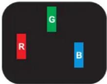 |  |  |
| One lit red, green or blue sub-pixel | Two adjacent lit sub-pixels:- Red + Blue = Purple- Red + Green = Yellow- Green + Blue = Cyan (Light Blue) | Three adjacent lit sub-pixels (one white dot) |
6.4. DARK DOT DEFECTS
Black dot defects appear as pixels or sub-pixels that are always dark or "off". These are the examples of black dot defects:
 |  |  |
| One dark dot | Two adjacent dark dots = 1 pair of dark dots | Two dark dots, specifications define the minimum distance between dark dots |
6.5. PROXIMITY OF PIXEL DEFECTS
Because pixel and sub-pixels defects of the same type that are nearby one another may be more noticeable, Philips also specifies tolerances for the proximity of pixel defects. In the table below you can find specifications about:
- Allowed amount of adjacent dark dots = (adjacent dark dots = 1 pair of dark dots)
• Minimum distance between dark dots
• Total no. of all defective dots
6.6. PIXEL DEFECT TOLERANCES
In order to qualify for repair due to pixel defects during the warranty period, a PDP/TFT panel in a Philips LCD display must have pixel or sub-pixel defects exceeding the tolerances listed in the following table.
| BRIGHT DOT EFFECT ACCEPTABLE LEVEL | |
| MODEL BDL5530EL | |
| I lit sub pixel 0 | |
| BLACK DOT EFFECT ACCEPTABLE LEVEL | |
| I dark sub pixel 8 | |
| TOTAL DOT DEFECTS OF ALL TYPES 8 | |
Note: * 1 or 2 adjacent sub pixel defects = 1 dot defect
7. CLEANING AND TROUBLESHOOTING
7.1. CLEANING
Caution When Using the Display
- Do not place your hands, face or objects close to the ventilation holes of the display. The top of the display is usually very hot due to the high temperature of air being expelled through the ventilation holes. Burns or personal injuries may occur if any body parts are brought too close. Placing any object near the top of the display could also result in heat related damage to the object as well as the display itself.
- Be sure to disconnect all cables before moving the display. Moving the display with its cables attached may damage the cables and thus cause fire or electric shock.
- Disconnect the power plug from the wall outlet as a safety precaution before carrying out any type of cleaning or maintenance procedure.
Front Panel Cleaning Instructions
- The front of the display has been specially treated. Wipe the surface gently using only a cleaning cloth or a soft, lint-free cloth.
- If the surface becomes dirty, soak a soft, lint-free cloth in a mild detergent solution. Wring the cloth to remove excess liquid. Wipe the surface of the display to remove dirt. Then use a dry cloth of the same type to dry.
- Do not scratch or hit the surface of the panel with fingers or hard objects of any kind.
- Do not use volatile substances such as sprays, solvents and thinners.
Cabinet Cleaning Instructions
- If the cabinet becomes dirty, wipe with a soft, dry cloth.
- If the cabinet is extremely dirty, soak a lint-free cloth in a mild detergent solution. Wring the cloth to remove as much moisture as possible. Wipe the cabinet. Use another dry cloth to wipe over until the surface is dry.
- Do not allow any water or detergent to come into contact with the surface of the display. If water or moisture gets inside the unit, operating problems, or electrical and shock hazards may result.
- Do not scratch or hit the cabinet with fingers or hard objects of any kind.
- Do not use volatile substances such as sprays, solvents and thinners on the cabinet.
- Do not place anything made from rubber or PVC near the cabinet for any extended periods of time.
7.2. TROUBLESHOOTING
| Symptom Possible | Cause Remedy | |
| No picture is displayed I. The power cord is disconnected.2. The main power switch on the back of the display is not switched on.3. The selected input has no connection.4. The display is in standby mode with VGA.Interference displayed on the display or audible noise is heardColor is abnormalPicture is distorted with abnormal patternsDisplay image doesn’t fill up the full size of the screenCan hear sound, but no pictureCan see picture but no sound is heardSome picture elements do not light upAfter-Images can still be seen on the screen after the display is powered off.(Examples of still pictures include logos, video games, computer images, and images displayed in 4:3 normal mode) | The power cord is disconnected.2. The main power switch on the back of the display is not switched on.3. The selected input has no connection.4. The display is in standby mode with VGA.Caused by surrounding electrical appliances, traffic or fluorescent lights.The signal cable is not connected properly.I. The signal cable is not connected properly.2. The input signal is beyond the capabilities of the display.The zoom mode is not correctly set.Improperly connected source signal cable.1. Improperly connected source signal cable.2. Volume is turned all the way down.3. Mute is turned on.4. No external speaker connected.Some pixels of the display may not turn on.A still picture is displayed for an over extended period of time | Plug in the power cord.Make sure the power switch is switched on.3. Connect a signal connection to the display.Move the display to another location to see if the interference is reduced.Make sure that the signal cable is attached firmly to the back of the display.Make sure that the signal cable is attached firmly.Check the video signal source to see if it is beyond the range of the display. Please verify its specifications with this display’s specification section.Use theZoom mode or Custom zoom function in theScreenmenu to fine-tune display geometry and time frequency parameter.Make sure that both video inputs and sound inputs are correctly connected.Make sure that both video and sound inputs are correctly connected.Use VOL UP/VOL DOWNbutton to hear sound.SwitchMuteoff by using theMUTE button.Connect external speakers and adjust the volume to a suitable level.This display is manufactured using an extremely high level of precision technology: however, sometimes some pixels of the display may not display. This is not a malfunction.Do not allow a still image to be displayed for an extended period of time as this can cause a permanent after-image to remain on the display. Refer to 4.2.5.CONFIGURATION I MENU for further details. |
8. TECHNICAL SPECIFICATIONS
Display
| Item Specifications | |
| Screen size (Active Area) 54.6” (138.68 cm) LCD | |
| Aspect ratio 16:9 | |
| Number of pixels 1920 (H) x 1080 (V) | |
| Pixel pitch 0.21 (H) x 0.63 (V) [mm] | |
| Displayable colors 1073.7M colors | |
| Brightness 400 cd/m | ^2 |
| Smart contrast 19500:I | |
| Contrast ratio (typical) 4000:I | |
| Viewing angle 178 degrees |
In/Out Terminals
| Item Specifications | ||
| Speaker Output Internal | Speaker | 12W (L) + 12W (R) [RMS]/8ΩI Way I Speaker System82 dB/W/M/160 Hz ~ 13 KHz |
| Audio Output | RCA Jack x I | 0.5V [rms] (Normal)/ 2 Channel (L+R) |
| Audio Input | RCA Jack x 2 | 0.5V [rms] (Normal)/ 2 Channel (L+R) |
| RS232C | D-Sub Jack x 2 (9 pin) | TXD + RXD (I:I) |
| HDMI Input | HDMI Jack x I (Type A) | Digital RGB: TMDS (Video + Audio)MAX: Video - 720p, 1080p, 1920 x 1080/60 Hz (WUXGA)Audio - 48 KHz/ 2 Channel (L+R) |
| DVI-D Input | DVI-D jack x I | Digital RGB: TMDS (Video) |
| RGB Input | D-Sub Jack x I (15 pin) | Analog RGB: 0.7V [p-p] (75Ω), H/CS/V: TTL (2.2kΩ), SOG: IV [p-p] (75Ω)MAX: 720p, 1080p, 1920 x 1080/60 Hz (WUXGA) |
| 3.5mm Mini-jack x I | Audio: 0.5V [rms] (Normal)/2 Channel (L+R) | |
| RGB Output | D-Sub Jack x I (15 pin) | Analog RGB: 0.7V [p-p] (75Ω), H/CS/V: TTL (2.2kΩ), SOG: IV [p-p] (75Ω)MAX: 720p, 1080p, 1920 x 1080/60 Hz (WUXGA) |
| Component Input | RCA Jack x I | Y: IV [p-p] (75Ω), Pb: 0.7V [p-p] (75Ω), Pr: 0.7V [p-p] (75Ω)MAX: 480i, 576i, 480p, 576p, 720p, 1080i, 1080p |
| S-Video Input | Mini DIN Jack x I (4 pin) | Y: IV [p-p] (75Ω), C: 0.286V [p-p] (75Ω) [NTSC]Y: IV [p-p] (75Ω), C: 0.300V [p-p] (75Ω) [PAL/SECAM] |
| Video Input | BNC Jack x I | Video: IV [p-p] (75Ω) [NTSC/PAL/SECAM] |
| Video Output | BNC Jack x I | Video: IV [p-p] (75Ω) [NTSC/PAL/SECAM] |
General
| Item Specifications | |
| Power Supply AC 100V ~ 240V, 50/60 Hz | |
| Power Consumption (Max) | 175W |
| Dimension [W x H x D mm] | |
| With Stand | 1530 x 778 x 405 mm |
| Without Stand | 1530 x 732 x 59 mm |
| Weight | |
| With Stand | 31 Kg |
| Without Stand | 29 Kg |
Environmental Condition
| Item Specifications | ||
| Temperature | Operational Storage | 0 ~ 40°C-20 ~ 60°C |
| Humidity | Operational Storage | 20 ~ 80% RH (No condensation)5 ~ 95% RH (No condensation) |
| Pressure | Operational Storage / Shipment | 800 ~ 1100 hPa (Altitude: 0 ~ 4,000 m)700 ~ 1100 hPa (Altitude: 0 ~ 15,000 m) |
Internal Speaker
| Item Specifications | |
| Type I Way I Speaker | |
| Input 12 W (RMS) | |
| Impedance | 8Ω |
| Output Sound Pressure 82 dB/W/M | |
| Frequency Response 160 Hz ~ 13 KHz |

text_image
PHILIPS2011 © Koninklijke Philips Electronics N.V. All rights reserved.
Philips and the Philips Shield Emblem are registered trade marks of Koninklijke Philips Electronics N.V. and are used under license from Koninklijke Philips Electronics N.V.
Specifications are subject to change without notice.