94A151132 - Phone charger DATALOGIC - Free user manual and instructions
Find the device manual for free 94A151132 DATALOGIC in PDF.

User questions about 94A151132 DATALOGIC
0 question about this device. Answer the ones you know or ask your own.
Ask a new question about this device
Download the instructions for your Phone charger in PDF format for free! Find your manual 94A151132 - DATALOGIC and take your electronic device back in hand. On this page are published all the documents necessary for the use of your device. 94A151132 by DATALOGIC.
USER MANUAL 94A151132 DATALOGIC
text_image
start pictures music phone voicemail 4:22 PM 5:04:00 Modellone UK text e-mail calendar favorites Contacts Set CATALOGIC SCANUser's Manual
DATALOGIC™
Datalogic Mobile S.r.l.
Via S. Vitalino 13
Elf™ - User's Manual
Software Version: 1.00
Ed.: 05/2010
©2010 Datalogic Mobile S.r.l. • ALL RIGHTS RESERVED. • Protected to the fullest extent under U.S. and international laws. • Copying, or altering of this document is prohibited without express written consent from Datalogic Mobile S.r.l.
Datalogic and the Datalogic logo are registered trademarks of Datalogic S.p.A. in many countries, including the U.S.A. and the E.U.
Elf and the Elf logo are trademarks of Datalogic Mobile S.r.l.
All other brand and product names mentioned herein are for identification purposes only and may be trademarks or registered trademarks of their respective owners.
REFERENCES......V
Conventions ......v
Reference Documentation ......v
Services and Support....v
GENERAL VIEW......VI
1 INTRODUCTION.... 1
1.1 Elf™ Description 1
1.2 Models Description....1
1.3 Package Contents....3
1.4 Inserting a Micro SD Card....4
1.4.1 Removing the Micro SD Card 5
1.5 Installing the SIM Card....6
1.5.1 Removing the SIM Card....8
1.6 Accessories....9
2 BATTERIES AND MAINTENANCE.... 10
2.1 Charging the Battery Pack 10
2.2 Replacing the Battery Pack....12
2.3 Cleaning the Mobile Computer.... 15
3 CONNECTIONS.... 16
3.1 USB Connection.... 16
3.2 Connection to USB peripherals 18
3.3 RS232 Connection 20
3.4 WLAN Connection....21
3.5 WPAN Connection 23
3.6 WWAN Connection 24
3.7 Wireless and Radio Frequencies Warnings 26
4 USE AND FUNCTIONING 28
4.1 Startup....28
4.1.1 Using the Stylus 30
4.2 Windows Mobile Welcome Wizard 31
4.3 Data Capture 32
4.3.1 Laser Data Capture 32
4.3.2 Imager Data Capture....34
4.4 Description of the Keys 36
4.4.1 Alphanumeric Keyboard 36
4.4.2 Numeric Keyboard....38
4.4.3 Resetting the ELF 40
4.5 Status Indicators 42
4.5.1 LED Status 42
4.5.2 Taskbar 43
4.6 Data Capture Configuration.... 44
4.6.1 Configuration Control Panels 44
4.7 Control Panel 49
4.7.1 Buttons 50
4.7.2 Wireless Communications....51
4.7.3 Stylus Calibration 52
4.7.4 Volume Settings 54
4.8 Windows Connections....56
4.8.1 Windows Mobile® Device Center....56
4.8.2 Bluetooth® Manager Device Setup 58
4.8.3 Windows Mobile Phone 63
4.9 Datalogic Firmware Utility....64
4.9.1 Retrieving a Firmware Image Update....64
4.9.2 Installing DFU on the Host PC 65
4.9.3 Updating the Firmware 66
4.9.4 Restoring the Firmware....67
4.10 Datalogic Configuration Utility 69
5 TECHNICAL FEATURES 70
5.1 Technical Data 70
5.2 Reading Diagram 73
6 TEST CODES 75
SAFETY REGULATIONS 79
General Safety Rules 79
Power Supply 79
Laser Safety 80
LED Class 86
Radio Compliance....86
FCC Compliance 88
RF Exposure Information (SAR) 89
Industry Canada Compliance....90
SAR Compliance 91
Patents 91
CTIA Compliance 92
WEEE Compliance....93
GLOSSARY 95
INDEX 99
CONVENTIONS
This manual uses the following conventions:
"User" refers to anyone using an Elf PDA.
"PDA" and "Elf" refer to Elf PDA.
"You" refers to the System Administrator or Technical Support person using this manual to install, configure, operate, maintain or troubleshoot an Elf mobile computer.
"Single Dock" refers to the Elf Single Slot Dock.
REFERENCE DOCUMENTATION
For further information regarding Elf refer to the SDK Help on-Line.
SERVICES AND SUPPORT
Datalogic provides several services as well as technical support through its website.
Log on to www.mobile.datalogic.com and click on thelinks indicated for further information including:
- PRODUCTS
Search through the links to arrive at your product page where you can download specific Manuals and Software & Utilities
- SERVICES & SUPPORT
- Datalogic Services Warranty Extensions and Maintenance Agreements
- Authorised Repair Centres
- CONTACT US
E-mail form and listing of Datalogic Subsidiaries
text_image
B C D H elf A L I M K J N O P G E Q ODATALOGICA) Color Display*
B) ON/OFF Power Key
C) LEDs
D) Receiver
E) Front Scan Key
F) Keyboard
G) Guitar Pick Stylus
H) HSDPA antenna, present in HSDPA model only
* Remove protective film cover before use
I) Laser Safety Label
J) Loudspeaker
O) Reset Key (under battery)
P) Micro-SD Card Slot (under battery)
Q) SIM Card Slot (under battery)
text_image
R S TALKR) Side Scan Key (right)
S) Push-to-talk Key
text_image
T UT) Side Scan Key (left)
U) Up/down Volume Keys
natural_image
Close-up of a black electronic device with a labeled component 'V' and a display screen (no readable text or symbols beyond the label)V) Data Capture/Laser Output Window *
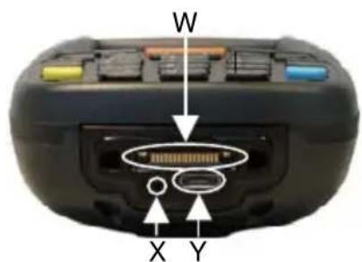
text_image
W X YW) Handylink™ Connector (host/slave)
X) Microphone
Y) Micro USB Communication Connector (host/slave) for supplying power and data transfer
1 INTRODUCTION
1.1 ELF™ DESCRIPTION
Datalogic Mobile's new PDA, Elf is designed with the technology and ruggedness needed in Field Service, Field Sales, Delivery, Retail and Logistics applications. Capitalizing on Datalogic Mobile's legendary ergonomics, the new PDA packs unprecedented features into a compact form factor built for single handed operation.
Elf's Power ^3 construction starts with a parallel microprocessor architecture using a PXA310 and ARM-7 processors combined with 256 MB RAM & Flash and Windows Mobile 6.5.
Elf 1D laser scanner and 2D imager both come equipped with Datalogic's patented Green Spot good read feedback. An HF RFID interrogator provides a third data capture option. Every Elf is also outfitted with an autofocus 3MPixel camera with flash.
A complete set of radios keeps the users connected through out the day: HSDPA UMTS for voice and data, Summit's latest Wi-Fi 802.11a/b/g wireless radio with CCX v4 certification. Elf's GPS receiver helps with route planning and proof of delivery.
The Micro USB port facilitates charging with a phone industry standard power supply or On-the-Go (OTG) communications.
Datalogic's software tools and strategic software alliances fit Elf to the business practice. Datalogic Desktop and Configuration utilities offer full control over the on device experience. Wavelink Avalanche enables rapid deployment and central management of Elf installation. Finally Datalogic's comprehensive service programs protect the Elf investment.
1.2 MODELS DESCRIPTION
The brand new Elf is available in different models depending on the options it is equipped with. All options are listed below:
- communication options: 802.11 a/b/g radio, Bluetooth®, GSM
- capture options: laser, 2D imager
- compute options: Windows Mobile 6.5.
For further details about the Elf models refer to the web site: http://www.mobile.datalogic.com.
For further information regarding Windows Mobile refer to the website: http://www.microsoft.com/windowsmobile.
The currently available models are:
• 944301000 Elf 00A0LS-1N1-MENO
Elf with Bluetooth v2.0, 802.11 a/b/g CCX V4, Std Laser w/ Green Spot, Camera 3MPixel, Windows Mobile 6.5, 256MB RAM/256MB Flash, 27-Key Numeric
• 944301001 Elf 00A0WI-1N1-MENO
Elf with Bluetooth v2.0, 802.11 a/b/g CCX V4, Std 2D Imager w/ Green Spot, Camera 3MPixel, Windows Mobile 6.5, 256MB RAM/256MB Flash, 27-Key Numeric
• 944301002 Elf U2A0LS-1Q1-MEN0
Elf with Bluetooth v2.0, 802.11 a/b/g CCX V4, 3.5G UMTS HSDPA, GPS, Std Laser w/ Green Spot, Camera 3MPixel, Windows Mobile 6.5, 256MB RAM/256MB Flash, 46-Key QWERTY
• 944301003 Elf U2A0LS-1N1-MENO
Elf with Bluetooth v2.0, 802.11 a/b/g CCX V4, 3.5G UMTS HSDPA, GPS, Std Laser w/ Green Spot, Camera 3MPixel, Windows Mobile 6.5, 256MB RAM/256MB Flash, 27-Key Numeric
• 944301004 Elf U2A0WI-1N1-MEN0
Elf with Bluetooth v2.0, 802.11 a/b/g CCX V4, 3.5G UMTS HSDPA, GPS, Std 2D Imager w/ Green Spot, Camera 3MPixel, Windows Mobile 6.5, 256MB RAM/256MB Flash, 27-Key Numeric
• 944301005 Elf U2A0WI-1Q1-MEN0
Elf with Bluetooth v2.0, 802.11 a/b/g CCX V4, 3.5G UMTS HSDPA, GPS, Std 2D Imager w/ Green Spot, Camera 3MPixel, Windows Mobile 6.5, 256MB RAM/256MB Flash, 46-Key QWERTY
• 944301008 Elf00A0LS-1Q1-MEN0
Elf with Bluetooth v2.0, 802.11 a/b/g CCX V4, Std Laser w/ Green Spot, Camera 3MPixel, Windows Mobile 6.5, 256MB RAM/256MB Flash, 46-Key QWERTY
• 944301009 Elf 00A0WI-1Q1-MEN0
Elf with Bluetooth v2.0, 802.11 a/b/g CCX V4, Std 2D Imager w/ Green Spot, Camera 3MPixel, Windows Mobile 6.5, 256MB RAM/256MB Flash, 46-Key QWERTY
1.3 PACKAGE CONTENTS
The Elf package contains:
- 1 Elf mobile computer
- 1 Elf Quick Start Guide
- 1 AC/DC power supply
- 1 EU plug adapter
- 1 AUS. Plug Adapter
- 1 UK Plug Adapter
- 1 US Plug Adapter
- 1 std-A to micro-B USB 2.0 cable *
- 1 CD-ROM Getting Started Disk
- 1 guitar pick stylus
- 1 rechargeable standard battery pack
- 1 hand-strap with stylus holder
– 1 Windows Mobile End User License Agreement (depending on models) - 1 belt clip
– elastic strap for stylus
Any other packages will contain the accessories necessary for the Elf connection to the host computer and to the network: the cradle, one or more connection cables.
Remove all the components from their packaging; check their integrity and congruity with the packing documents.

CAUTION
Keep the original packaging for use when sending products to the technical assistance center. Damage caused by improper packaging is not covered under the warranty.

NOTE
Rechargeable battery packs are not initially charged. Therefore the initial operation to perform is to charge them. See paragraph 2.1.
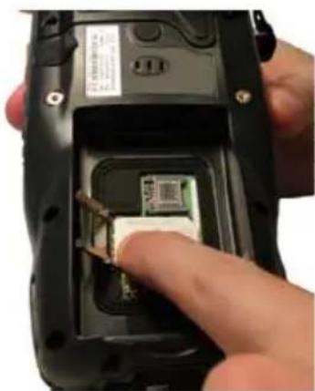
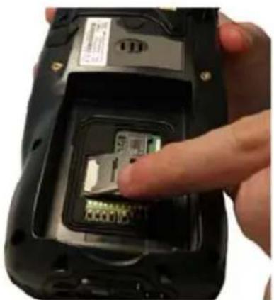
1.4 INSERTING A MICRO SD CARD
Elf provides the possibility to add a Micro SD memory storage card. To access the Micro SD card slot and insert the card, proceed as follows:
- Turn off the Elf.
- Pull the battery latch down and remove the battery pack:
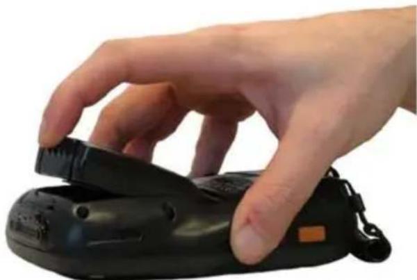
natural_image
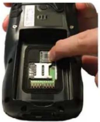
Hand holding a black handheld device with a scroll wheel (no visible text or symbols)- Shift the cardholder to the left and then pull it up:
natural_image
Close-up of a hand inserting a small electronic component into a black mobile phone case (no visible text or symbols)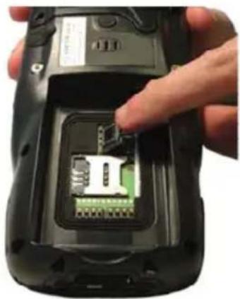
natural_image
Close-up of a hand inserting a small electronic component into a black mobile phone case (no visible text or symbols)- Insert the Micro SD card with the written part upward
natural_image
Close-up of a hand inserting a small electronic component into a black flip phone case (no visible text or symbols)- Lock the card into place by pushing the cardholder down and then shifting it to the right:
natural_image
Close-up of a hand inserting a small electronic component into a black mobile phone case (no visible text or symbols)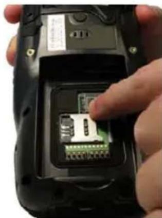
natural_image
Close-up of a hand inserting a small electronic component into a black handheld device (no visible text or symbols)- First insert the bottom and then the upper (contacts) side of the battery pack into the slot and press it back until the battery latch is automatically closed.
natural_image
Close-up of a hand pressing a black remote control device on a white surface (no text or symbols visible)1.4.1 Removing the Micro SD Card
To remove the Micro SD card, follow the steps above to access the SD area, and remove it from its slot.

CAUTION
Follow proper ESD precautions to avoid damaging the SD. Proper ESD precautions include, but are not limited to, working on an ESD mat and ensuring that the operator is properly grounded.
Do not force the card. If you feel resistance, remove the card, check the orientation, and reinsert it.
Do not use the Micro SD card slot for any other accessories.
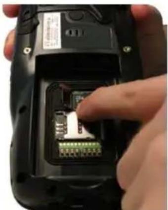
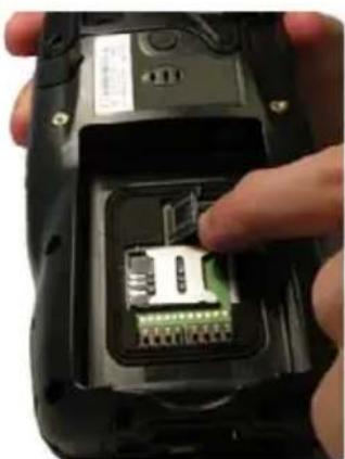
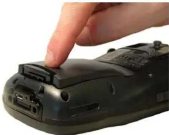
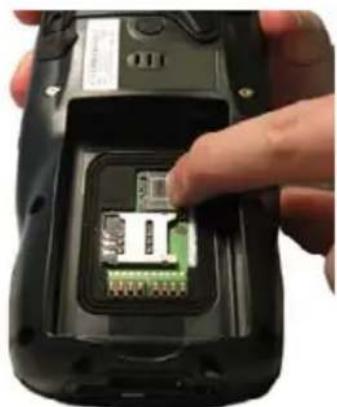
1.5 INSTALLING THE SIM CARD
To correctly insert the SIM Card, proceed as follows:
-
Turn off the Elf.
-
Pull the battery latch down and remove the battery pack.

natural_image
Hand holding a black handheld device with a scroll wheel (no visible text or symbols)- Shift the cardholder to the left and then pull it up:
natural_image
Close-up of a hand inserting a green internal component into a black flip phone case (no visible text or symbols)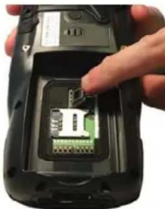
natural_image
Close-up of a hand inserting a small electronic component into a black mobile phone casing (no visible text or symbols)- Insert the SIM card with the contacts downward:
natural_image
Close-up of a hand inserting a small electronic component into a black handheld device (no visible text or symbols)- Lock the card into place by pushing the cardholder down and then shifting it to the right:
natural_image
Close-up of a hand inserting a small electronic component into a black mobile phone case (no visible text or symbols)
natural_image
Close-up of a hand inserting into a smartphone into a slot (no visible text or symbols)- First insert the bottom and then the upper (contacts) side of the battery pack into the slot and press it back until the battery latch is automatically closed.
natural_image
Close-up of a hand pressing down on a black remote control device (no text or symbols visible)
CAUTION
Follow proper ESD precautions to avoid damaging the SIM card. Proper ESD precautions include, but are not limited to, working on an ESD mat and ensuring that the operator is properly grounded. Do not force the card. If you feel resistance, remove the card, check the orientation, and reinsert it.
Do not use the SIM card slot for any other accessories.

NOTE
The SIM Card option is not available in 802.11b/g radio and batch models.
1.5.1 Removing the SIM Card
To remove the SIM card, follow the steps above to access the SIM area, and remove it from its slot.

NOTE
All the basic functionalities normally associated to the SIM card are managed by the terminal (GPRS connectivity, phone calls, SMS handling).
It is possible that not all the services connected to the SIM card can be used or can be managed by the terminal.
1.6 ACCESSORIES
Cradles
94A151124 Dock, Single Slot, Elf 94A151130 Dock, Powered Mobile, Elf 94A151132 Dock, Ethernet 4 Slot, Elf 94A151134 Charger, 4 Slot Dock, Elf 94A151136 Charger, 4 Slot Battery, Elf
Batteries
94ACC1376 Battery, High Capacity, Elf 94ACC1377 Battery, Standard Capacity, Elf
Power Supply
94A051975 Power Adapter, 12 to 24v Pwr Plug 2.1mm 94A051976 Adapter, Pwr Jack 2.1mm To Handylink 94ACC1380 Power Supply, Micro USB 94ACC1381 Power Supply, Dock, PWR Plug 2.1mm
Cables
94A051020 Cable for dock-PC (RS232) communication 94A051968 Cable, Micro USB, Client 94A051969 Cable, Micro USB, Host 94A051970 Cable, USB Handylink, Client 94A051971 Cable, USB Handylink, Host 94A051972 Cable, RS232 Handylink, Client 94A051973 Cable, RS232 Handylink, Host 94A051974 Cable, Dex Handylink
□ Various
95ACC1033 Screen Protector Kit, 5 Pack 94ACC1230 Swivel for Functional Case (10pcs) 94ACC1345 Stylus Pen (10 pcs.) 94ACC1371 Module, Ethernet, Single Slot Dock 94ACC1372 Module, Modem, Single Slot Dock 94ACC1378 Handle, Elf 94ACC1379 Belt Holster, Elf 94ACC1382 Stylus, Guitar Pick W/ Cord (5pcs)

NOTE
Use only a Datalogic Mobile-approved power supply and cables. Use of an alternative power supply will invalidate any approval given to this device and may be dangerous.
2 BATTERIES AND MAINTENANCE

NOTE
Rechargeable backup batteries and battery packs are not initially charged. Therefore the initial operation to perform is to charge them. See below.

CAUTION
By default, the battery pack is disconnected at the factory to avoid damage due to excessive draining. Annual replacement of rechargeable battery pack avoids possible risks or abnormalities and ensures maximum performance.
2.1 CHARGING THE BATTERY PACK

NOTE
The battery pack autonomy varies according to many factors, such as the frequency of barcode scanning, RF usage, battery life, storage, environmental conditions, etc.
The battery icon on the Taskbar indicates when the battery pack is low.
It is possible to recharge the battery pack by connecting the power supply directly to the Elf.
Alternatively, it is also possible to recharge the battery pack by using the single slot dock, the powered mobile dock, the Ethernet four slot dock or the four slot battery charger.
Moreover recharging is possible by USB Direct connection with the host computer, but with longer charging times and only if the mobile computer is off.
During the charging process the LED positioned at the left side of the display is red constant. Once the charging process has been completed this LED is green constant (see par. 4.5).
If the battery pack is removed from the mobile computer, it can be recharged by inserting it into the rear slot of the single slot dock, the powered mobile dock, the Ethernet four slot dock or the four slot battery charger.

CAUTION
Do not use the Elf until batteries are charged for minimum 4 hours.

CAUTION
Risk of explosion if battery is replaced by an incorrect type.
Dispose of used batteries according to the instructions.

ATTENTION
Even if the storage temperature range is wider, In order to achieve the longest battery life, store the terminal and the spare batteries between 20 to 30 °C (68 to 86 °F).
Large batteries must be charged at a temperature ranging from 0^ to +40^ ( +32^ to +104^ ).
Small batteries must be charged at a temperature ranging from 0^ to +45^ ( +32^ to +113^ ).

NOTE
The battery level may not be displayed correctly for some minutes after the disconnection if the Elf is disconnected from power supply before the charging cycle is completed.

NOTE
The Elf could get warm during charging, this is normal and does not mean a malfunction.

NOTE
Use only a USB-IF compliant USB port as a charging source.
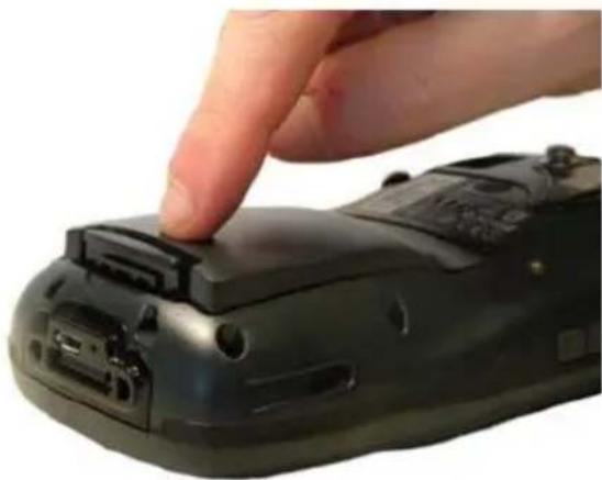
2.2 REPLACING THE BATTERY PACK
To correctly replace the battery pack, proceed as follows.
-
Turn off the Elf.
-
Pull the battery latch down as indicated in the figure below:
natural_image
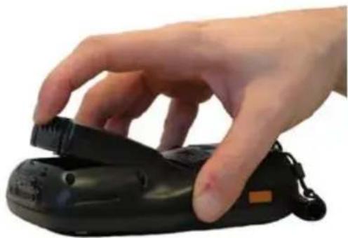
Hand holding a black handheld device with a small orange tag (no visible text or symbols)- Remove the battery pack.
natural_image
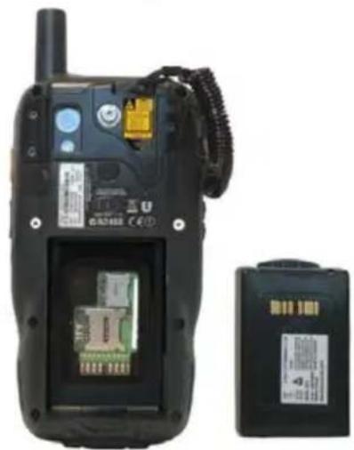
Black mobile phone case with attached electronic components and a separate battery pack (no visible text or symbols)- Install the new battery pack, first insert the bottom side, then the upper (contacts) side of the battery pack into the slot and press it back until the battery latch is automatically closed:

natural_image
Hand holding a black handheld device with a strap, against a white background (no text or symbols visible)
natural_image
Close-up of a hand pressing a black electronic device on a remote control (no visible text or symbols)
WARNING
Installing, charging and/or any other action should be done by authorized personnel and following this manual.
The battery pack may get hot, explode, ignite, and/or cause serious injury if exposed to abusive conditions.
If the battery pack is replaced with an improper type, there is risk of explosion.
Do not place the battery pack in or near a fire or heat; do not place the battery pack in direct sunlight, or use or store the battery pack inside unventilated areas in hot weather; do not place the battery pack in microwave ovens, dryer, high pressure containers, on induction cookware or similar device. Doing so may cause the battery pack to generate heat, explode or ignite. Using the battery pack in this manner may also result in a loss of performance and a shortened life expectancy.
Use only a Datalogic Mobile approved power supply. The use of an alternative power supply will void the product warranty, may cause product damage and may cause heat, explode or ignite.
The area in which the units are charged should be clear of debris and combustible materials or chemicals.
Do not use the battery pack of this terminal for power devices different from this mobile computer.
Immediately discontinue use of the battery pack if, while using, charging or storing the battery pack, the battery pack emits an unusual smell, feels hot, changes colour or shape, or appears abnormal in any other way.
Do not short-circuit the battery pack contacts connecting the positive terminal and negative terminal. This might happen, for example, when you carry a spare battery pack in your pocket or purse; accidental short-circuiting can occur when a metallic object such as a coin, clip, or pen causes direct connection of the contacts of the battery pack (these look like metal strips on the battery pack). Short-circuiting the terminals may damage the battery pack or the connecting object

WARNING
Do not apply voltages to the battery pack contacts.
Do not pierce the battery pack with nails, strike it with a hammer, step on it or otherwise subject it to strong impacts or shocks.
Do not disassemble or modify (i.e. bend, crush or deform) the battery pack. The battery pack contains safety and protection devices, which, if damaged, may cause the battery pack to generate heat, explode or ignite.
In case of leakage of liquid from the battery, avoid contact with liquid the skin or eyes. If the contact occurs, immediately wash the affected area with water and consult a doctor.
Do not solder directly onto the battery pack.
Do not expose the battery pack to liquids.
Avoid any knocks or excessive vibrations. If the device or the battery is dropped, especially on a hard surface, you should take it to the nearest Authorised Repair Centre for inspection before continuing to use it.
Do not replace the battery pack when the device is turned on.
Do not remove or damage the battery pack's label.
Do not use the battery pack if it is damaged in any part.
Battery pack usage by children should be supervised.
Collect and recycle waste batteries separately from the device in comply with European Directive 2006/66/EC, 2002/95/EC, 2002/96/EC and subsequent modifications, US and China regulatory and others laws and regulations about environment.

NOTE
In order to guarantee an adequate operating autonomy, when replacing the battery pack the mobile computer checks the battery energy level. If the battery is not sufficiently charged, Elf does not turn on (when pressing the ON/OFF key).
In this case, either substitute the battery pack with a charged one (sufficiently charged) or insert Elf into a powered cradle or plug it into the direct power supply.

NOTE
To achieve the best battery life, turn off the radios not in use.
2.3 CLEANING THE MOBILE COMPUTER
Periodically clean the Elf with a slightly dampened cloth.
Do not use alcohol, corrosive products or solvents.
3 CONNECTIONS
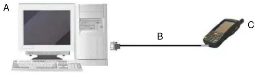
3.1 USB CONNECTION
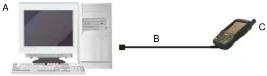
You can use any standard micro USB cable or the Datalogic Handylink cable 94A051970 to directly connect the Elf to a host computer to transfer data through the USB interface.
text_image
A B CKey:
Connection through the cable is compliant to 2.0 USB standard.
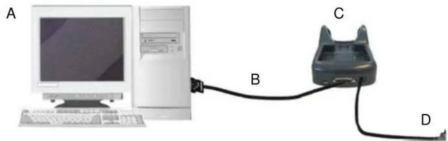
The Single Dock can be connected to the Host by means of a Micro-B USB cord, such as Datalogic 94A051968 cable.
Once the host has been turned on, insert the Elf mobile computer into the cradle.
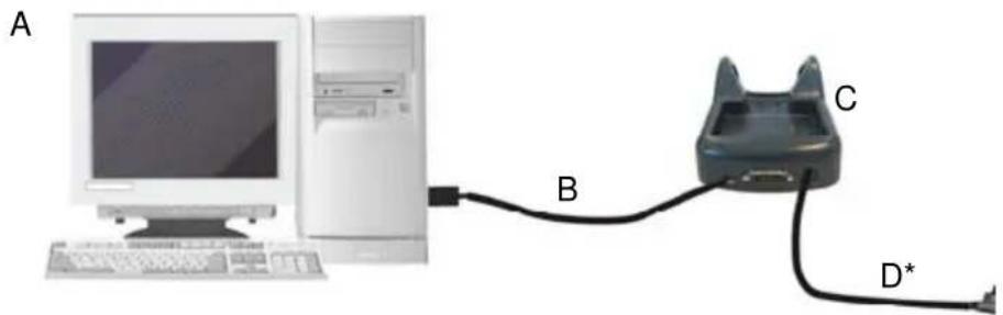
text_image
A B C D*Key:
A) Host Computer C) Elf Single Slot Dock
B) 94A051968 Micro USB Client D) 94ACC1381 Power Adapter Cable

NOTE
Connection through the cradle is compliant to 2.0 USB standard.

NOTE
The actual data transfer speed can be appreciably lower than the maximum theoretical speed.
3.2 CONNECTION TO USB PERIPHERALS
To connect the Elf to a keyboard or a memory, connect the terminal to the Datalogic 94A051969 cable or to the Datalogic 94A051971 cable (together with a standard A to micro A USB cable).
For all these devices maximum current withdrawal must be below 100mA.
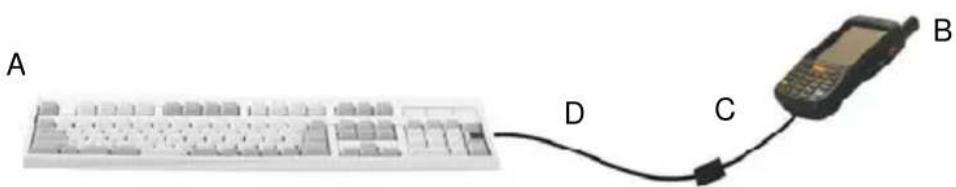
text_image
A D C BKey:
A) Keyboard with USB interface
C) 94A051969 Micro USB Host Cable/94A051971 Handylink Micro USB Host Cable
B) Elf D) Standard A to Micro A USB Cable
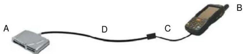
text_image
A D C BKey:
A) USB hard memory source
drive/
external) 94A051969 Micro USB Host Cable/94A051971 Handylink Micro USB Host Cable
B) Elf D) Standard A to Micro A USB Cable
Connect the Single Slot Dock to the peripheral by means of a Micro-A USB cord, or use a Micro-A to Std-A receptacle USB adapter such as Datalogic 94A051969 (together with a standard USB cable if needed).
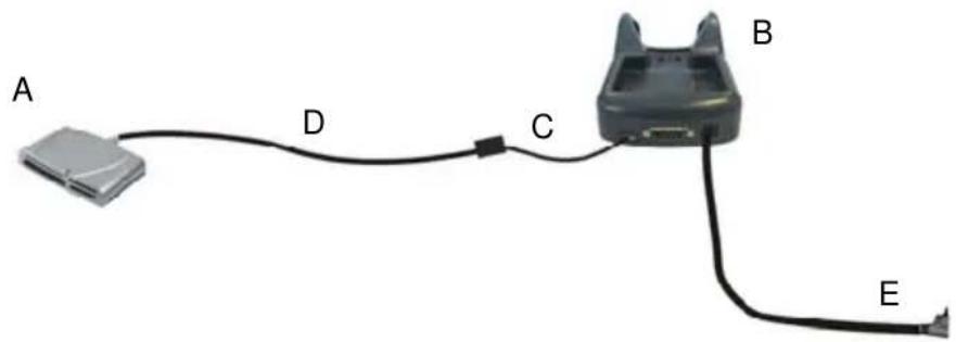
text_image
A D C B EA) USB Peripheral (memory) D) Standard A to Micro A USB Cable
B) Elf Single Slot Dock E) 94ACC1381 Power Adapter
C) 94A051969 Micro USB Host Cable

NOTE
Elf works with most of mentioned USB peripherals. In any case, we can't guarantee good operations with all devices available on market place.

NOTE
Connection is compliant to 1.1 USB standard.

NOTE
The actual data transfer speed can be appreciably lower than the maximum theoretical speed.
3.3 RS232 CONNECTION
You can use the Datalogic 94A051972 cable to directly connect the Elf to a host computer to transfer data through the RS232 interface.
text_image
A B CKey:
The Single Slot Dock can be connected to the Host by means of a standard null modem cable such as Datalogic 94A051020 CAB-427 for 9-pin connections.
Once the Host has been turned on, insert the Elf mobile computer into the cradle.
natural_image
Computer setup with monitor, tower, and cable connector (no visible text or symbols)Key:
Elf 802.11b/g radio models can communicate with the host using the on-board radio frequency component and an Access Point connected to the host computer.
For models using the 802.11g radio, you can find information about the applet for radio configuration: http://www.summitdatacom.com/SCU.htm.
To launch this utility you can tap the specific icon if it's visible on the taskbar or:
- On Windows CE devices, you can open Connections folder or Control Panel from desktop and select the 'Summit Client Utility' icon.
- On Windows Mobile devices, you can select the menu item: Start->Programs->Summit and tap the 'Summit Client Utility' icon.
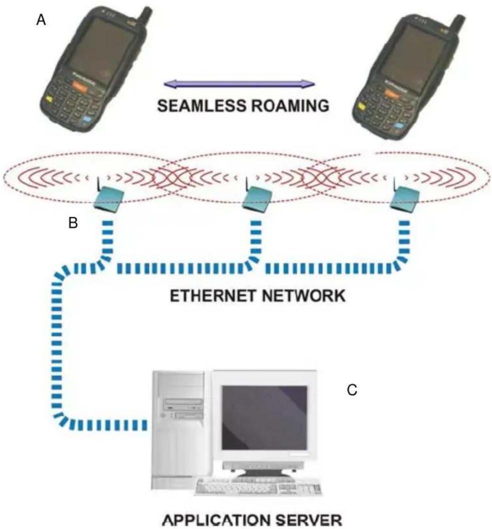
flowchart
graph TD
    A["Mobile Phone A"] <-->|SEAMLESS ROAMING| B["Mobile Phone B"]
    B --> C["Ethernet Network"]
    C --> D["Application Server C"]
Key:
A) Elf
B) Access Point
C) Host – Application Server

NOTE
802.11g radio module is on by default, in order to avoid wasting energy, you can switch it off using the Wireless Communications applet.

NOTE
Suspending the terminal powers off the 802.11b/g radio and drops the radio connection. When the terminal resumes, depending on the radio power mode and security protocol selected, it may take up to 30 seconds for the 802.11b/g radio driver to re-associate the radio to the network.

NOTE
Area coverage and radio performance may vary, due to environmental conditions, access points types or interference caused by other devices (microwave ovens, radio transmitters, etc.)

NOTE
In case of heavy usage the Elf could get warm, this is normal and does not mean a malfunction.
3.5 WPAN CONNECTION
Elf mobile computer models with Bluetooth® can communicate with other Bluetooth® enabled devices, such as a printer, within a range of 10 m, using the onboard Bluetooth® module.
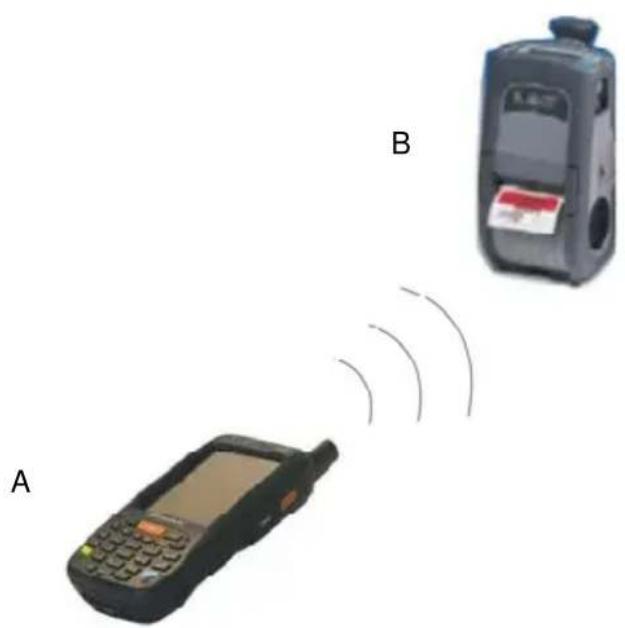
text_image
A BKey:

NOTE
In order to avoid wasting energy, the Bluetooth® module is off by default. If you need to have Bluetooth® working, the module must be powered on using the Wireless Communications applet (see par. 4.7.2), and perform the Discovery procedure (see par. 4.8.2).

NOTE
Suspending the terminal powers off the Bluetooth® radio and drops the piconet (Bluetooth® connection). When the terminal resumes, it takes approximately 10 seconds for the Bluetooth® radio driver to re-initialize the radio.

NOTE
Area coverage and Bluetooth® radio performance may vary, due to environmental conditions or interference caused by other devices (microwave ovens, radio transmitters, etc.), etc.
3.6 WWAN CONNECTION
Elf GSM models enhance your connectivity solutions giving you an opening to an international wireless infrastructure that is the global standard.
GSM (Global System for Mobile communications) is a digital mobile phone system based on TDMA; it utilizes the 850, 900, 1800 and 1900 MHz bands.
In order to use a WWAN Connection you have to install a SIM Card* (see instructions on par. 1.5).

NOTE
In order to avoid wasting energy, the GSM module is off by default. If you need to have GSM working, the module must be powered on using the Wireless Communications applet (see par. 4.7.2).

NOTE
Suspending the terminal powers off the GSM radio and drops the connection. When the terminal resumes, if the connection was managed by Microsoft Internet Explorer, it is automatically restored, otherwise, the radio connection must be manually re-initialized.

NOTE
The GSM voice capability of this mobile computer has to be addressed to occasional use, in well covered areas. If the coverage is poor, the voice quality can be highly affected.

NOTE
Calls can be made or received using the Elf as a phone handset, by the Elf headset or by a Bluetooth® headset.

NOTE
During a call, you can set the speaker volume by pressing the arrow navigation keys.

NOTE
In case of heavy usage the Elf could get warm, this is normal and does not mean a malfunction.
3.7 WIRELESS AND RADIO FREQUENCIES WARNINGS

WARNING
Use only the supplied or an approved replacement antenna. Unauthorized antennas, modifications or attachments could damage the product and may violate laws and regulations.

WARNING
Most modern electronic equipment is shielded from RF signals. However, certain electronic equipment may not be shielded against the RF signals generated by Elf.

WARNING
Datalogic recommends persons with pacemakers or other medical devices to follow the same recommendations provided by Health Industry Manufacturers Associations for mobile phones.
Persons with pacemakers:
- Should ALWAYS keep this device more than twenty five (25) cm from their pacemaker and/or any other medical device;
- Should not carry this device in a breast pocket;
- Should keep the device at the opposite side of the pacemaker and/or any other medical device;
- Should turn this device OFF or move it immediately AWAY if there is any reason to suspect that interference is taking place.
- Should ALWAYS read pacemaker or any other medical device guides or should consult the manufacturer of the medical device to determine if it is adequately shielded from external RF energy.
In case of doubt concerning the use of wireless devices with an implanted medical device, contact your doctor.

WARNING
Turn this device OFF in health care facilities when any regulations posted in these areas instruct you to do so. Hospitals or health care facilities may use equipment that could be sensitive to external RF energy.

WARNING
RF signals may affect improperly installed or inadequately shielded electronic systems in motor vehicles. Check with the manufacturer or its representative regarding your vehicle. You should also consult the manufacturer of any equipment that has been added to your vehicle.

WARNING
An air bag inflates with great force. DO NOT place objects, including either installed or portable wireless equipment, in the area over the air bag or in the air bag deployment area. If vehicle's wireless equipment is improperly installed and the air bag inflates, serious injury could result.

WARNING
Turn off the device when in any area with a potentially explosive atmosphere. Observe restrictions and follow closely any laws, regulations, warnings and best practices on the use of radio equipment near fuel storage areas or distribution fuel areas, chemical plants or where some operation involves use of explosive materials.
Do not store or carry flammable liquids, explosive gases or materials with the device or its parts or accessories.
Areas with a potentially explosive atmosphere are often, but not always, clearly marked or showed.
Sparks in such areas could cause an explosion or fire, resulting in injury or even death.
4 USE AND FUNCTIONING
The use of the Elf depends on the application software loaded. However there are several parameters that can be set and utilities that can be used to perform some basic functions such as data capture, communications, file management, etc.
4.1 STARTUP
The Elf turns on when the battery pack or the external supply is inserted.
After the battery pack is installed, use the [ON/OFF] key to turn the mobile computer on and off.
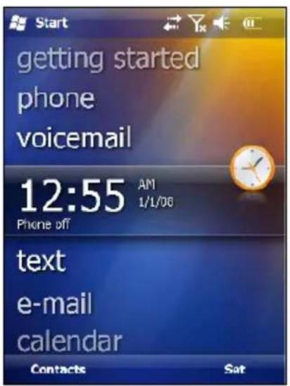
As soon as the mobile computer is on, the Windows Mobile 6.5 desktop configuration will appear on the screen. Wait a few seconds before starting any activity so that the mobile computer completes its startup procedure.
text_image
Starting getting started phone voicemail 12:55 AM 1/L/06 Phone off text e-mail calendar Contacts Sat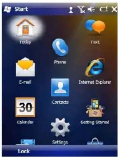
text_image
Start Today Text Phone E-mail Internet Explorer 30 Contacts Calendar Getting Started Settings LockToday Screen Start Menu
Use the stylus (par. 4.1.1) as suggested to select icons and options.
The mobile computer goes into power-off (low power with display and keyboard backlight off), when it is no longer used for more than a programmable timeout, which is defined in the POWER applet of the Control Panel. In this mode it can be awakened (resuming operation) by the [ON/OFF] key.

NOTE
The mobile computer can also be awakened or turned off by the application program.
4.1.1 Using the Stylus
The stylus selects items and enters information. The stylus functions like a mouse.
| Tap: | Touch the screen once with the stylus to open items and select options |
| Drag: | Hold the stylus on the screen and drag across the screen to select text and images. Drag in a list to select multiple items. |
| Tap-and-hold: | Tap and hold the stylus on an item to see a list of actions available for that item. On the pop-up menu that appears, tap the action you want to perform. |
To recalibrate the touch screen use the Stylus Applet (see par. 4.7.3)

CAUTION
Use only original Datalogic styluses supplied with the product itself.
In harsh applications, use of screen protectors should be taken into consideration, in order to extend the touch screen operating life.
To prevent damage to the screen, do not use sharp devices or any device other than the Datalogic Mobile-provided stylus.
Do not apply not necessary high pressures on the screen.
For applications where an intensive use of the touch screen is foreseen, please consider that touch screen components are subject to progressive wear.
4.2 WINDOWS MOBILE WELCOME WIZARD
In Windows Mobile, at the very first Elf startup, following a clean boot or following a registry restore to default values, the mobile computer startup (see par. 4.1 is preceded by the Welcome Wizard.

text_image
Windows® Tap the screen to set up your Windows® phone. © 2009 Microsoft Corporation. All rights reserved. This computer program is protected by U.S. and international copyright laws.Welcome Wizard Screen
The Welcome Wizard allows the user to calibrate the touch screen (see par. 4.7.3) and to configure an email account and a password to protect the terminal.

text_image
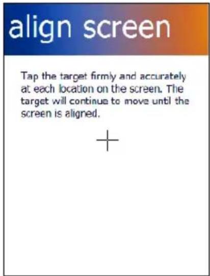
align screen Tap the target firmly and accurately at each location on the screen. The target will continue to move until the screen is aligned. +Touch Screen Calibration Screen
4.3 DATA CAPTURE
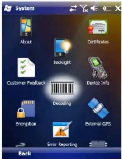
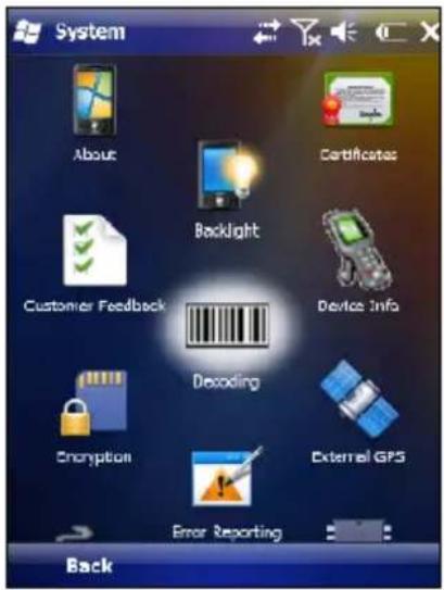
To capture data first of all tap Start > Settings > System > Decoding:
text_image
System About Certificates Backlight Device Info Customer Feedback Decoding Encryption External GPS Error Reporting BackTo configure and enable data capture parameters refer to par. 4.6.
4.3.1 Laser Data Capture
To scan barcodes, point the Elf laser model onto the code from a distance within the reading range while pressing the SCAN key.
The lighted band emitted by the laser must completely intercept the barcode as shown in the figure below.
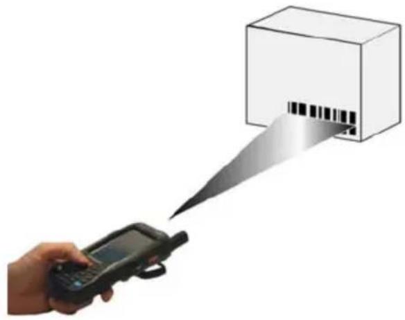
natural_image
Hand holding a handheld electronic device emitting a barcode scanner from a box (no text or symbols visible)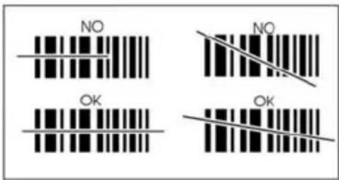
text_image
NO NO OK OKIf the scan has taken place correctly:
- the Good Read LED gets constant Green for a configurable time;
- if enabled, the GoodReadSound emits an acoustic signal;
- if enabled, the GreenSpot projects a green spot onto the bar code image.

NOTE
Remove the protective film cover over the Laser Output Window before use.
4.3.2 Imager Data Capture
The Elf Imager captures a picture of the entire bar code. The omni-directional scanning does not require that the operator orient the bar code to align with the scan pattern.
To read a 1D or 2D code, simply point the Elf Imager model onto the code and press the SCAN Key.
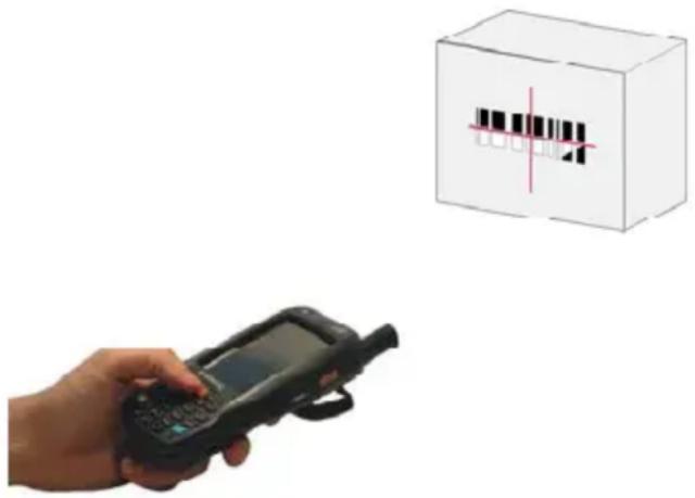
natural_image
Hand holding a handheld device next to a barcode box (no text or symbols visible)The Elf Imager uses an intelligent aiming system pattern, similar to those on cameras, indicating the field of view, which should be positioned over the code:

natural_image
Simple cross formed by two red lines on a gray background (no text or symbols)Aiming System
If the aiming system pattern is centered over the entire symbology as shown in the following figure, either wait for the timeout or release the Scan key to capture the image.
A red beam illuminates the code, which is captured and decoded. You will get a good read.
Linear barcode 2D Matrix symbol
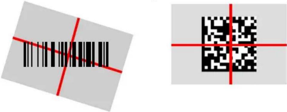
text_image
Two barcode symbols: one with red diagonal lines and black bars, the other with red crosshairs and a black QR code.Relative Size and Location of Aiming System Pattern
The field of view changes its size as you move the reader closer or farther away from the code. The field of view indicated by the aiming system pattern will be smaller when the Elf Imager is closer to the code and larger when it is farther from the code.
Symbologies with smaller bars or elements (mil size) should be read closer to the unit. Symbologies with larger bars or elements (mil size) should be read farther from the unit. (See par. 5.1 for further details).
If the scan has taken place correctly:
- the Good Read LED gets constant Green for a configurable time;
- if enabled, the GoodReadSound emits an acoustic signal.
4.4 DESCRIPTION OF THE KEYS
The Elf provides two different keyboards, an alphanumeric keyboard and a numeric keyboard, having a total of respectively 46 and 27 keys.
4.4.1 Alphanumeric Keyboard
text_image
SCAN Q & W + E - R1 T2 Y3 U _ I % O u P Sym A ( S ) D / F4 G5 H6 J ! K : L , ← ↑ Z = X * C7 V8 B9 N # M ? @ ENT TAB 0 SPACE SIPMain Keys Function
KEY
SCAN


FUNCTION
It starts barcode data capture.
They let you move forwards, backwards, upwards or downwards within text fields, scroll through a Menu list or browse among folder files.
Yellow modifier (toggle key): when pressed before a standard key, it enables the character or function printed in yellow above the key.
Blue modifier (one shot key): when pressed before a standard key, it enables the character or function printed in blue above the key.
It powers the Elf ON or OFF. It is placed on the upper left side of the terminal.
The hang up key normally generates the VK_TEND virtual key code, used to hang-up phone calls.and to exit applications.
In blue mode, the hang up key generates a VK_ESCAPE virtual key code for applications that uses this specific virtual key code to exit (e.g. touch screen calibration application).
4.4.2 Numeric Keyboard
text_image
SCAN Ctrl TAB 1* F1 2 abc F2 3 def F3 Del Caps # ↑ 4 f4 ghi 5 jkl F5 6 mno F6 ENT Alt 7 F7 pqrs 8 tuv F8 9w F9 xyz • Sym 0, F10 SPCMain Keys Function
KEY


FUNCTION
It starts barcode data capture.
They let you move forwards, backwards, upwards or downwards within text fields, scroll through a Menu list or browse among folder files.
Yellow modifier (toggle key): when pressed before a standard key, it enables the character or function printed in yellow above the key.
Blue modifier (one shot key): when pressed before a standard key, it enables the character or function printed in blue above the key.
It powers the ELF ON or OFF. It is placed on the upper left side of the terminal.
The hang up key normally generates the VK_TEND virtual key code, used to hang-up phone calls.and to exit applications.
In blue mode, the hang up key generates a VK_ESCAPE virtual key code for applications that uses this specific virtual key code to exit (e.g. touch screen calibration application).
4.4.3 Resetting the ELF
There are several reset methods for the Elf.
A warm boot terminates an unresponsive application and clears the working RAM, but preserves the file system. Registry is restored from persistent memory if available or returned to factory default.
A cold boot forces all applications to close reinitializing completely the system. It clears the working RAM, but the file system is preserved. Registry is restored from persistent memory.
A clean boot restores the Elf to a clean configuration: both the registry and the file system returns to a clean status that conforms to factory default.
Warm Boot
To perform a warm boot, press and hold the following keys simultaneously:

natural_image
Three abstract color shapes (yellow, blue, black) with no text or symbolsCold Boot
To perform a cold boot, do the following steps:
- Turn off the Elf by pressing the on-off key.
- Pull the battery latch down and remove the battery pack.
- Press the reset button.
- Insert the battery pack.
- Turn on the Elf by pressing the on-off key.
Clean Boot
To perform a clean boot, do the following steps:
- Perform a Cold Boot (see Cold Boot).
- Press and hold down the 0 and hang up keys simultaneously and then press the on-off key:

natural_image
Three abstract icons: a gray square with '0', a red telephone handset, and a gray button with a white power symbol (no text or numbers)A dialog box will appear asking for confirmation. Press the Enter Key.
| Warm Boot Cold Boot Clean Boot | |||
| Registry | Restored from flash P | Preserved Clean configuration(no user config) | |
| File System | Restored from flash P | Preserved Clean Installation(no user files) | |
4.5 STATUS INDICATORS
4.5.1 LED Status
The Elf provides three different LEDs signaling the mobile computer status.
| LED | STATUS | |
| Good Read(right side) | Red | Scanning LED is ON from the time the user hits the scan button (Trigger) until the bar code is decoded (laser models)Time-out (imager models) |
| Green Scanning LED is ON, showing a good decode. | ||
| Charging Status(left side) | Green It is constant once the charging process has been completed (full charge). | |
| Red It is constant while charging. | ||
| Red blinking charge fault | ||
| Keyboard Status(center) | Off | Keyboard in primary |
| Yellow solid | Yellow alternate key mode | |
| Blue | Blue alternate key mode solid | |
| Pink CapsLock available for use by the application, cause and duration | ||
4.5.2 Taskbar
The Taskbar provides information about the time, the battery level, the keyboard function, and the decoding status.
| ICONS | DESCRIPTION |
| Time and Battery Icons | |
 | It displays the system battery status. |
 | It indicates that the battery is charging |

text_image
StartWindows Mobile Taskbar
4.6 DATA CAPTURE CONFIGURATION
You can configure the Elf's decoding options by tapping Start -> Settings -> System -> Decoding.
text_image
System About Certificates Backlight Customer Feedback Device Info Decoding Encryption External GPS Error Reporting BackThere are two sections in the Decoding control panel, each containing additional pages. There are six General Configuration pages and multiple Barcode symbology pages.
4.6.1 Configuration Control Panels
Select the desired configuration from the options shown in the figure below, and the other Decoding Properties figures on the following pages.
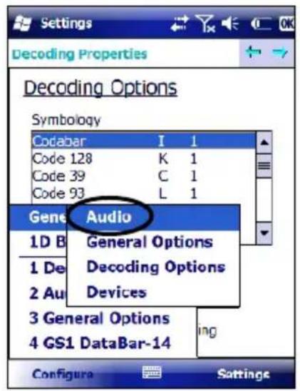
Select General or 1D Bar Code, then use the menu or tap the left and right arrow keys to navigate the different pages of the Decoding utility. The menu options will change to reflect the items most recently selected.
Audio
From the Decoding menu, tap Configure > General > Audio. Use to set volume, tone, duration, and number of various types of beeps.
text_image
Settings Decoding Properties Decoding Options Symbology Codabar 1 1 Code 128 K 1 Code 39 C 1 Code 93 L 1 Gene Audio 1D B General Options 1 De Decoding Options 2 Au Devices 3 General Options 4 GS1 DataBar-14 Configura Satings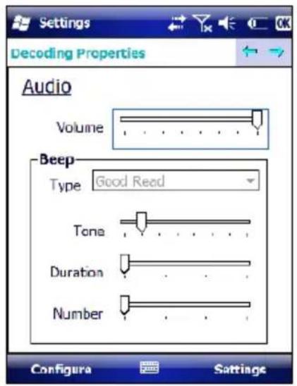
text_image
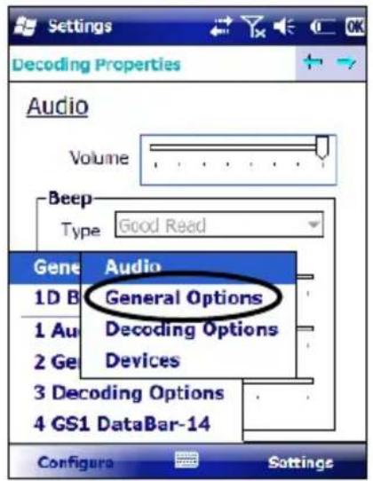
Settings Decoding Properties Audio Volume Beep Type Good Read Tone Duration Number Configura SettingsGeneral Options
From the Decoding menu, tap Configure > General > General Options. Select from Label Programming Enable, Symbology IDs, Label Prefix, Label Suffix, and Data Separator.
text_image
Settings Decoding Properties Audio Volume Beep Type Good Read Gene Audio 1D B General Options 1 Au Decoding Options 2 Ge Devices 3 Decoding Options 4 GS1 DataBar-14 Configura Settings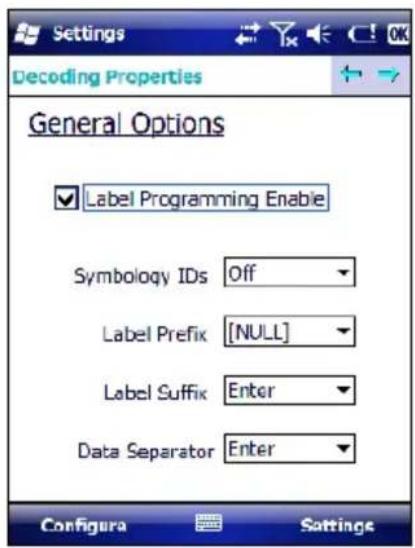
text_image
Settings Decoding Properties General Options ✓ Label Programming Enable Symbology IDs Off Label Prefix [NULL] Label Suffix Enter Data Separator Enter Configura SettingsDevices
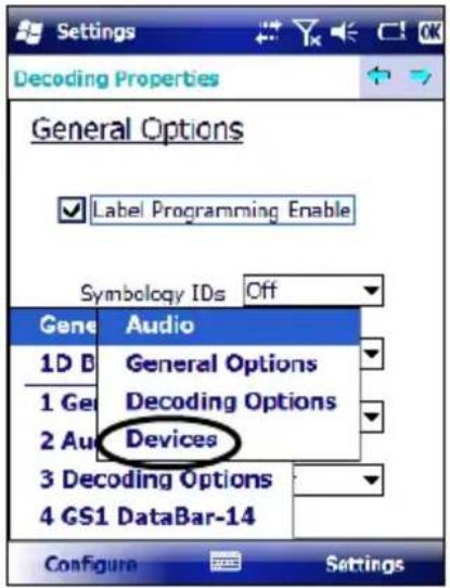
From the Decoding menu, tap Configure > General > Devices. Use to enable or disable the keyboard wedge for Barcode scanner.
text_image
Settings Decoding Properties General Options Label Programming Enable Symbolology IDs Off Gene Audio 1D D General Options 1 Ge Decoding Options 2 Au Devices 3 Decoding Options 4 GS1 DataBar-14 Configure Settings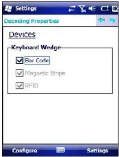
text_image
Settings Decoding Properties Devices Keyboard Wedge ✓ Bar Code ✓ Magnetic Stripe ✓ RFID Configure SettingsDecoding Options
From the Decoding menu, tap Configure > General > Decoding Options. Select a symbology to view or change the available properties settings.

text_image
Settings Decoding Properties Devices Keyboard Wedge ✓ Bar Code ✓ Magnetic Stripe Gene Audio 1D B General Options 1 De Decoding Options 2 Ge Devices 3 Audio 4 Decoding Options Configura Settings
text_image
Decoding Options Symbology Codabar I 1 Code 128 K 1 Code 39 C 1 Code 93 L 1 EAN-13 M 1 EAN-8 G 1 CCL Data Box 14 B 1 User ID 1 Redundancy L Aggressive Decoding Configura SettingsSelect Configure > General from the menu to view other configuration options.
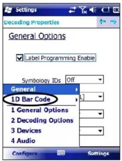
1D Barcode Symbology Pages
Use the drop-down menus from Configure > 1D Barcode, or tap the left and right arrow keys to navigate the different pages of the barcode symbology pages.
text_image
Settings Decoding Properties General Options Label Programming Enable Symbology IDs Off General 1D Bar Code L] 1 General Options 2 Decoding Options 3 Devices 4 Audio Configure Settings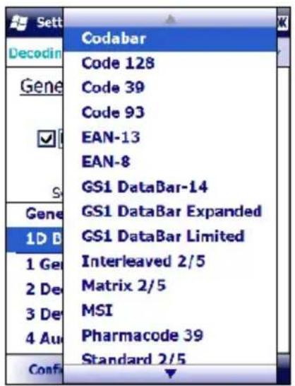
text_image
Sett Decodin Gene ✓ S Gene 1D B 1 Ge 2 De 3 De 4 Au Conf: Codabar Code 128 Code 39 Code 93 EAN-13 EAN-8 GS1 DataBar-14 GS1 DataBar Expanded GS1 DataBar Limited Interleaved 2/5 Matrix 2/5 MSI Pharmacode 39 Standard 2/5Select Configure > General from the menu to view other configuration options.
Each barcode symbology opens to its own page, as shown in the figure below. Refer to the sample symbology control panels for examples of the types of fields and options you can modify.
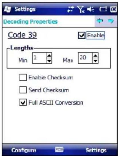
text_image
Settings Decoding Properties Code 39 Enable Lengths Min 1 Max 20 Enable Checksum Send Checksum Full ASCII Conversion Configure Settings- Code 39: Select Enable, Min/Max Lengths, Enable Checksum, Send Checksum, Full ASCII Conversion, and Concatenate.
Decoding Settings
Select from the Decoding Properties Settings menu to restore previous configurations and/or other available default settings. Choose from:
- Factory Defaults
- Minimum Settings
• Maximum Settings - Save (New Settings)
- Revert to Saved Settings
The settings are saved when you tap OK.
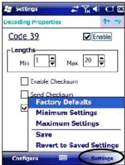
text_image
Settings Decoding Properties Code 39 Enable Lengths Min 1 Max 20 Enable Checksum Send Checksum Factory Defaults Minimum Settings Maximum Settings Save Revert to Saved Settings Configura Settings4.7 CONTROL PANEL
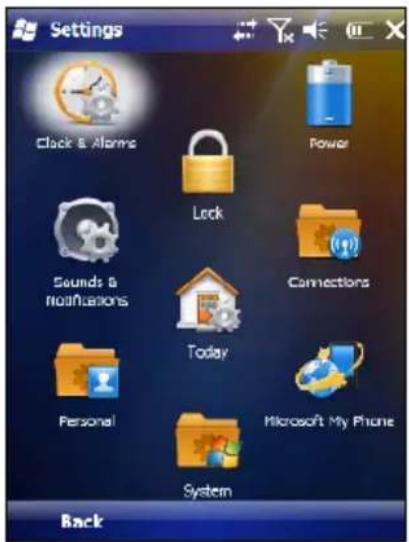
From the Start menu, tap Settings. The Control Panel is split into three sections: Personal, System, Connections.
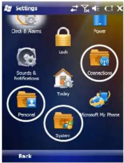
text_image
Settings Clock & Alarms Lock Power Sounds & Notifications Connections Today Personal Microsoft My Phone System BackAPPLET programs are displayed as icons; one icon corresponds to each APPLET:
text_image
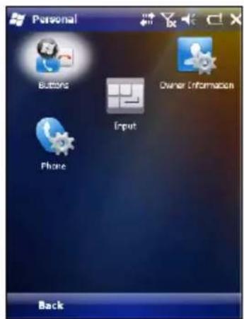
Personal Buttons Owner Information Phone Input Back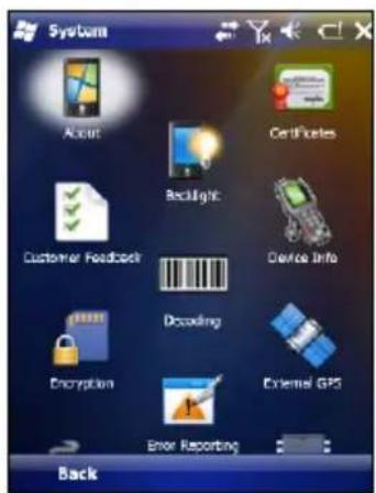
text_image
System Accounts Certificates Backlight Device Info Customer Feedback Decoding Encryption External GPS Error Reporting Back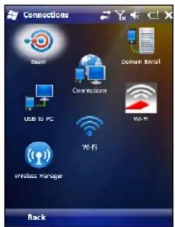
text_image
Connections Mail Email Connections USB to PC WiFi WiFi Wireless Manager BackWindows Mobile Control Panel
4.7.1 Buttons
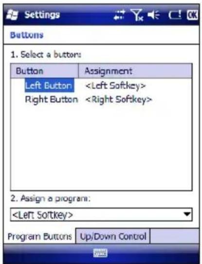
From the Start menu, tap Settings > Personal > Buttons > Program Buttons. On the Program Buttons tab, customize the program hardware buttons to launch your most used applications. Under Select a button, tap the button you want to assign a program to, and then select a program from Assign a program.
text_image
Settings Buttons 1. Select a buttons: Button Assignment Left Button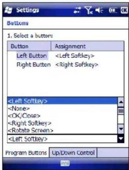
text_image
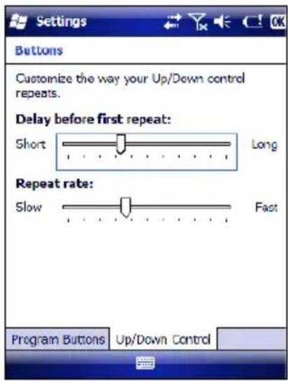
Settings Buttons 1. Select a buttons: Button Assignment Left ButtonTo configure the way up/down and the rest of keys control repeats, use the Up/Down Control applet (Start > Settings > Personal > Buttons > Up/Down Control).
text_image
Settings Buttons Customize the way your Up/Down control repeats. Delay before first repeat: Short Long Repeat rate: Slow Fast Program Buttons Up/Down ControlYou can also select to wake up the terminal by the SCAN key. B
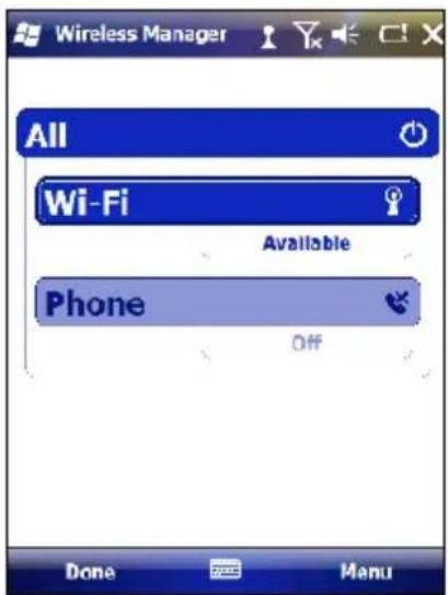
4.7.2 Wireless Communications
The WIRELESS COMMUNICATIONS applet provides management of the 802.11b/g radio, the Bluetooth® and GSM modules.

Connectivity Icon
The Wireless Manager application manages access to wireless connections.
The 'Wireless Manager' is a sort of 'Control Panel' for bluetooth and phone modules. From here it's possible to turn on or off bluetooth and phone radio stacks.
Open the Wireless Manager by tapping Start -> Settings -> Connections -> Wireless Manager, or by tapping the Connectivity icon located at the top of the screen. The following window will appear:
text_image
Wireless Manager All Wi-Fi Available Phone Off Done MenuWireless Communications Window
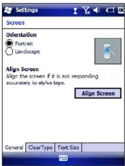
4.7.3 Stylus Calibration
You might need to recalibrate the touch screen (i.e. when you attempt to select one item with the stylus, another item is erroneously selected).
To recalibrate the touch screen, complete the following steps:
- Select Start > Settings > System > Screen to open the Screen Settings dialog as shown in the figure below:
text_image
Settings Screen Orientation ● Portrait ○ Landscape Align Screen Align the screen if it is not responding accurately to stylus tops. Align Screen General ClearType Text Size- Tap Align Screen to open the Calibration screen shown in the figure below.
- Carefully press and briefly hold stylus on the center of the target. Repeat as the target moves around the screen.
- By completing the calibration procedure you implicitly accept the new calibration settings.
- New calibration settings are persistently saved in registry.
text_image
align screen Tap the target firmly and accurately at each location on the screen. The target will continue to move until the screen is aligned. +Startup stylus calibration
When starting the terminal, a Welcome Wizard (with Stylus Calibration) comes up if valid calibration settings are not available. This happens in the following circumstances:
- At the first startup of the terminal.
- After restoring registry default settings using the applet Registry Admin and performing a boot.
- After a Clean Boot.
4.7.4 Volume Settings
From the Start Menu, select Settings > Sounds and Notifications:
text_image
Settings Clock & Alarme Lock Power Sounds & Notifications Connections Today Personal Microsoft My Phone System BackSounds and Notifications Window
The Audio applet allows to set the recording volumes of the main microphone and of the headset microphone. Also, it allows to set the headset volume when the user is listening to an audio file.

text_image
Settings Sounds & Notifications Enable sounds for ✓ Events (warnings, system events) ✓ Programo ✓ Notifications (alarms, reminders) □ Screen taps ○ Soft ● Loud □ Hardware buttons ○ Soft ● Loud Sounds Notifications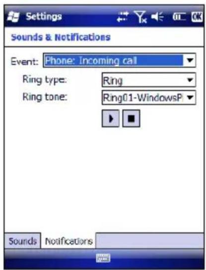
text_image
Settings Sounds & Notifications Event: Phone: Incoming call Ring type: Ring Ring tone: Ring01-WindowsP Sounds NotificationsTo set the speaker volume during a call, click the icon on the right top of the Windows Mobile Start Menu. To set the front speaker or the headset speaker volume, use the right bar or move the joystick up and down. To set the rear speaker volume, use the left bar.
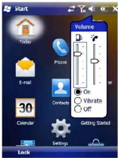
text_image
Start Volume Today Phone E-mail Contacts 30 Calendar Getting Started Settings LockTo set the Bluetooth® headset volume, tap
Start > Settings > System > Bluetooth Manager > Connections and select the headset. The following window will appear:
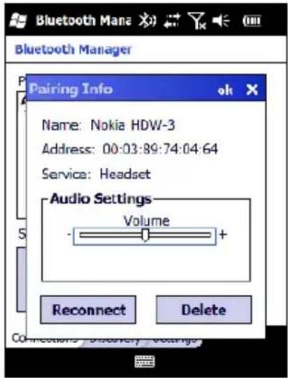
text_image
Bluetooth Manager Pairing Info Name: Nokia HDW-3 Address: 00:03:89:74:04:64 Service: Headset Audio Settings Volume + Reconnect Delete Connections: Discovery Voltage4.8 WINDOWS CONNECTIONS
To connect the Elf to another device (i.e. Host PC) from Windows, several programs are available. These programs require specific electrical connections in order to function properly.
4.8.1 Windows Mobile® Device Center
Windows Mobile® Device Center gives you the possibility to connect your desktop computer to your Elf and synchronize the information on them. Synchronization compares the data on the Elf with that on the desktop computer and updates both computers with the most recent information.
With Windows Mobile® Device Center" it is possible to:
- Back up and restore Elf data.
- Copy files between Elf and desktop computer.
- Synchronize files by selecting a synchronization mode.
You can establish a connection to your Elf through the following electrical interfaces:
- USB either directly or through the Single Dock
- Bluetooth® (see par. 4.8.2)
Synchronizing lets you transfer e-mail, contacts, appointments, tasks, Web favorites, and media files from your computer to your device or from your device to your computer. You must accept an update to Windows Mobile Device Center (WMDC) on your computer before you can use WMDC to synchronize the Elf with a host PC or with a Microsoft Exchange Server.
To establish a connection between the Elf and a host PC, start Windows Mobile® Device Center, which is pre-installed on the PDA, and follow the steps below:
- Connect the Elf to the host PC. Windows Mobile® Device Center configures itself and then opens.
- On the licence agreement screen, click Accept.
- On the Windows Mobile Device Center's Home screen, click Set up your device.
- Select the information types that you want to synchronise, then click Next.
- Enter a device name and click Set Up.
When you finish the setup wizard, Windows Mobile Device Center synchronises the PDA automatically. Microsoft® Office Outlook® emails and other information will appear on your device after synchronisation.

NOTE
Visit the following Microsoft Web site for the latest in updates and technical information:
http://www.microsoft.com/windowsmobile/en-us/help/synchronize/device-synch.mspx
4.8.2 Bluetooth® Manager Device Setup

NOTE
The Bluetooth Device Properties icon will only be visible if Bluetooth hardware has been installed on the unit.
Before turning on Bluetooth®, ensure that the two devices are within close range and that both Bluetooth-enabled devices are discoverable.
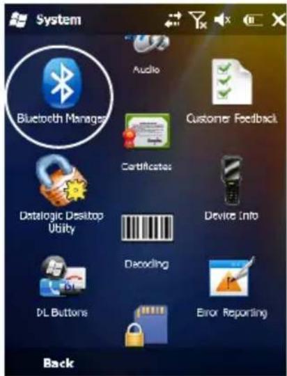
- Tap Start > Settings > System > Bluetooth Manager to open the Bluetooth® control panel.
text_image
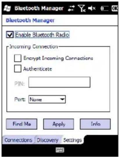
System Bluetooth Manager Audio Customer Feedback Certificates Datalogic Desktop Utility Device Info Decoding DL Buttons Error Reporting Back- Tap Settings. The Settings tab allows you to enable or disable the Bluetooth radio and specify settings for Incoming Connections.
- Select or clear the "Enable Bluetooth Radio" check box:
text_image
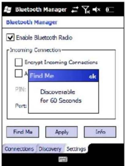
Bluetooth Manager Enable Bluetooth Radio Incoming Connection Encrypt Incoming Connections Authenticate PIN: Port: None Find Ma Apply Info Connections Discovery Settings- Tap Find Me if you want to make the Elf visible to other Bluetooth devices for 60 seconds, allowing them to set up a connection.
text_image
Bluetooth Manager Enable Bluetooth Radio Incoming Connection Encrypt Incoming Connections A Find Me ok PIN: Discoverable for 60 Seconds Port: Find Ma Apply Info Connections Discovery Settings
NOTE
By default, Bluetooth® is turned off. If you turn it on, and then turn off your device, Bluetooth® also turns off. When you turn on your device again, Bluetooth® turns on automatically.
To create a Bluetooth® partnership between your device and another device that has Bluetooth® capabilities, ensure that the two devices are turned on, discoverable, and within close range.
- Open the Bluetooth® control panel by tapping Start > Settings > System > Bluetooth Manager. > Connections
- Search for available Bluetooth® Devices by tapping the button for the type of device you want (Printer, Serial or All) or tap Discovery > Discover to skip this step. The Elf will search for Bluetooth® Devices within range.
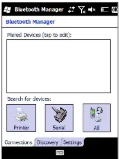
text_image
Bluetooth Manager Bluetooth Manager Paired Devices (tap to edit): Search for devices: Printer Serial All Connections Discovery Settings
NOTE
If you attempt to set up a connection when the Bluetooth® Radio is disabled, you will receive a message reminding you that the radio is turned off, and asking you if you want to turn it on. Tap Yes if you need to enable the Bluetooth® Radio.
- Once searching is complete, Bluetooth® Device Profiles will be displayed in the Discovery tab. You can set up a connection to a device on the list, or clear it from the list by tapping the Clear button:
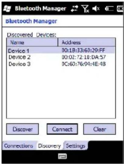
text_image
Bluetooth Manager Discovered Devices: Name Address Device 1 00:1B:33:60:29:FF Device 2 00:02:72:10:DA:57 Device 3 0C:60:76:94:4E:48 Discover Connect Clear Connections Discovery SettingsTo set up a connection:
- Double tap the device you want to activate, or select and then tap Connect. The resulting dialog will display services that are available on the device:
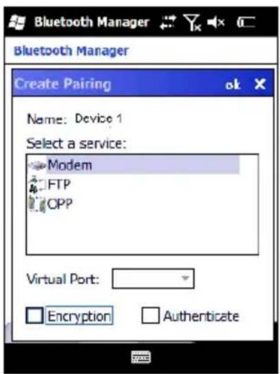
text_image
Bluetooth Manager Bluetooth Manager Create Pairing Name: Device 1 Select a service: Modem FTP CPP Virtual Port: Encryption Authenticate- Select the service you want to connect to. The following table shows the icons that display for different types of service.
| Icon | Service |
 | Dialup Networking |
 | Printer |
 | File Transfer Protocol (FTP) Object Exchange (OBEX) |
 | Object Push (OPP) Object Exchange (OBEX) |
 | ActiveSync |
 | Human Interface Device (HID) - Keyboard |
 | Serial |
Virtual Port allows you to specify the incoming port, which is used to communicate serially with an incoming device just as if it were a physical COM port. This option is available only if you have selected a Printer or Serial service.
You can also select Encrypt or Authenticate from the Bluetooth® control panel to apply or modify those settings.
- To require Authentication, tap the checkbox, then tap OK.
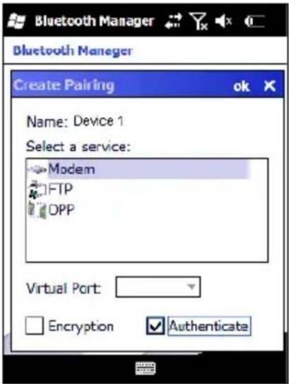
text_image
Bluetooth Manager Bluetooth Manager Create Pairing ok Name: Device 1 Select a service: Modem FTP OPP Virtual Port: Encryption Authenticate- The Authentication Request dialog will then open, requesting that you enter a PIN. Use the Input Panel to type in the PIN.
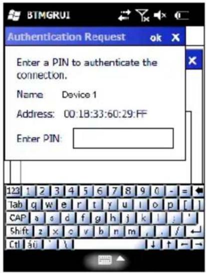
text_image
BTMGRUI Authentication Request ok X Enter a PIN to authenticate the connection. Name Device 1 Address: 00:18:33:60:29:FF Enter PIN: 123 1 2 3 4 5 6 7 8 9 0 - = Tab q w e r t y u l o p [ ] CAP a s d f g h j k l ; ' Shift z x c v b n m , . / Ctrl si ' \ ↓ ↑ →3. Tap OK to complete.
The dialog will also appear when an Authentication request is received from another device.
Once you have set up a Pairing, you can view the settings by double-tapping its name from the Connections tab. Tap the arrow to change the Virtual Port, or Delete to remove the device pairing. Tap Sync to initiate a Sync (available only if the service is an ActiveSync connection).
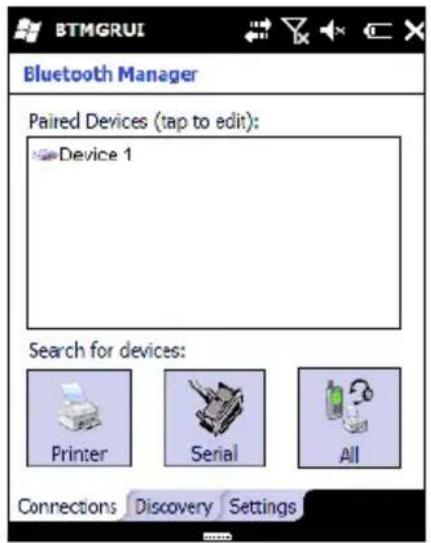
text_image
BTMGRUI Bluetooth Manager Paired Devices (tap to edit): Device 1 Search for devices: Printer Serial All Connections Discovery Settings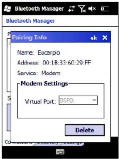
text_image
Bluetooth Manager Bluetooth Manager Pairing Info Name: Eucarpio Address: 00:1B:33:60:29:FF Service: Modem Modem Settings Virtual Port: BSP0: Delete4.8.3 Windows Mobile Phone
For information on Windows Mobile Phone use and functioning, refer to the Windows Mobile web site: http://www.microsoft.com/windowsmobile.
4.9 DATALOGIC FIRMWARE UTILITY
The Datalogic devices are equipped with a field upgradeable firmware mechanism. Firmware updates are available on the Datalogic Mobile website (http://www.mobile.datalogic.com/). After you have downloaded the desired update, there are several ways you can update the firmware on your device.
- Use Wavelink Avalanche™ if you have multiple Datalogic mobile devices to update. Refer to the Product CD included with your device for more information.
- If Wavelink Avalanche™ is not available or you have only a few Datalogic Mobile devices to update, use the Datalogic Firmware Utility (DFU), described below, to install or update the firmware using an ActiveSync connection. Refer to "Installing & Setting Up Microsoft ActiveSync" for more information.
DFU can also be used to restore the firmware onto a device that has become corrupted, such as would happen if the device were powered down during an ActiveSync firmware update (see par. 4.9.4).
The following sections provide procedures for the retrieval and installation of the most current firmware image onto a Datalogic device.
4.9.1 Retrieving a Firmware Image Update
The following instructions use Internet Explorer to retrieve the most current firmware image.
- Launch Internet Explorer on your PC and navigate to the Datalogic Mobile website.
- Navigate to the Downloads section of the website.
- Select the file you want to download, then click Save to begin copying the files to your local machine (or local network location).
4.9.2 Installing DFU on the Host PC
The Datalogic Firmware Utility (DFU) provides administrators with a field upgrade mechanism. You must have Microsoft® ActiveSync already loaded and running on the host PC to use DFU. Refer to "Installing & Setting Up Microsoft ActiveSync" and "Using ActiveSync" for more information about ActiveSync.

NOTE
Prior to installing, you must remove any previous versions of DFU installed on the host PC.
To install the Datalogic Firmware Utility, complete the following steps on the PC:
- Insert the CD ROM shipped with your device and click on the link to Datalogic Firmware Utility.
OR
Go to the Datalogic Mobile website and download the most current version of the Datalogic Firmware Utility. Unzip the file, then double-click to run DFU_Seup. texe
Click OK to continue once you have removed previous versions of DFU.
-
The Welcome to DFU Setup Program screen opens.
-
Please exit all Windows applications before running this setup.
- Click Cancel to quit Setup and close any programs you have running.
- Click Next to continue the Setup.
. Follow the onscreen instructions to complete the installation. 3
4.9.3 Updating the Firmware
After copying the firmware image to the host PC (see par. 4.9.1) and installing DFU (see par. 4.9.2), you can upgrade the firmware on your Datalogic device.

NOTE
The following steps require that you have already established an ActiveSync connection between the host computer and the Datalogic device. To establish an ActiveSync connection with the device, refer to "Installing & Setting Up Microsoft ActiveSync" and "Using ActiveSync", for more information on ActiveSync.
- Go Start > Programs > DFU > Datalogic Firmware Utility.
- Verify that ActiveSync is selected by clicking Communications > ActiveSync.
- Click browse (…) and navigate to the location where you saved the firmware file for your terminal.
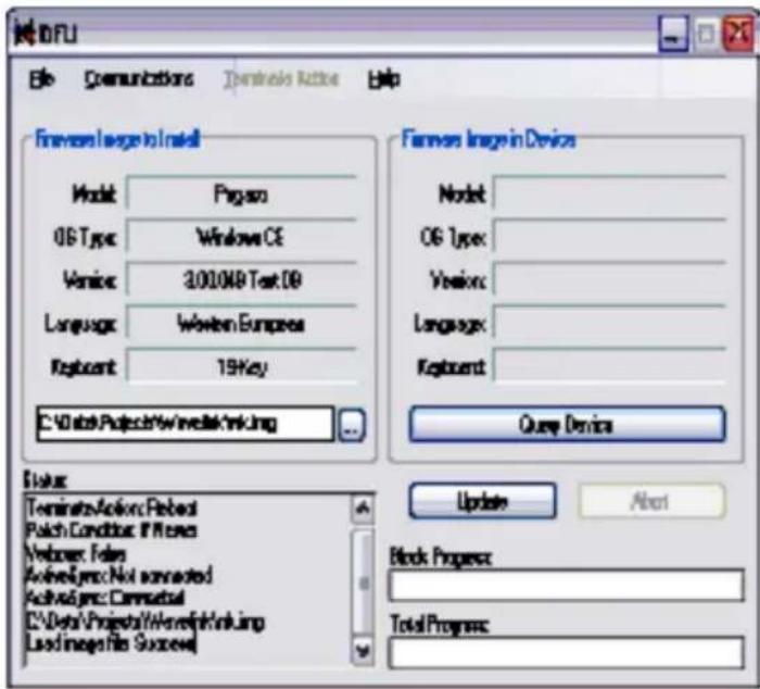
text_image
BOSI File Communications Destination Help Formes Image to Install Model: Program OS Type: Windows CE Version: 3.00108 Test OD Language: Western Europeas Keypent: 19 Key C:\Users\Projects\Windows\Linking Formes Image in Device Model: OS Type: Version: Language: Keypent: Query Devices Status Terminate Action: Perfect Patch Condition: If Yes Webbox: Fains ActiveLogic: Not connected ActiveLogic: Commandual C:\Data Project\Worelfinkling Load Images file Success! Update About Block Process: Total Process:- Select the current *.img file and click Open.
- Verify that your device is turned on. Insert the device into a powered dock connected to the host computer.
-
Click Update on DFU on the host PC.
-
DFU will compare the selected firmware image with the firmware already loaded on the device; if the images are different, DFU will proceed to update the firmware image on your device.

NOTE
The following steps require that you have already established an ActiveSync connection between the host computer and the Datalogic device. To establish an ActiveSync connection with the device, refer to "Installing & Setting Up Microsoft ActiveSync" and "Using ActiveSync", for more information on ActiveSync.
- After the firmware of your device has been updated, you must perform a warm reset of the device. Refer to the device user's manual for reset instructions.
4.9.4 Restoring the Firmware
If the firmware image on your device becomes corrupted, the device will beep twice and show a blank screen when powered on. This can happen if a firmware update is aborted, such as during a power loss or if the device is removed from the Dock before completion of the procedure.
To reinstall the firmware, complete the following steps:
- On the PC, click Start > Programs > DFU > Datalogic Firmware Utility.
- From the Communications menu, select the communication mode you are using to attach your dock to the PC - USB or Serial.
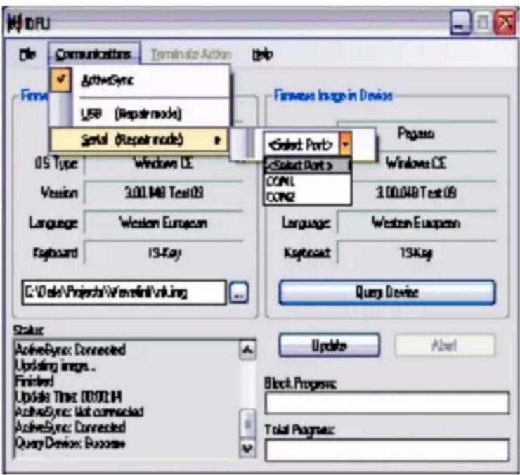
text_image
MIRU File Communications Terminate Action Help ActiveSync USB (Repair mode) Serial (Repair mode) Finewave Image in Devices 05 Type Windows CE Version 3.00.048 Test 03 Language Western European Keyboard 13-Ray C:\Vola\Projects\Wavefront\viking Select Port > Select Port > COML COM2 3.00.048 Test 09 Language Western European Krypton 13Ksg Query Device Status: ActiveSync: Connected Updating images... Finished Update Time: 00:00:14 ActiveSync: Not connected ActiveSync: Connected Query Device: Success Update About Block Progress: Total Progress:- If you are using serial, then select the specific COM port to which the dock is connected. DFU will display the COM ports available on your PC in a drop down list.
- Click browse ( ...) and navigate to the file location.
- Select the current *.img file and click Open.
- Verify that the device is turned on. Insert the device into a powered dock connected to the host computer.
- Click Update on DFU on the host PC.
- DFU will restore the firmware on your device.

NOTE
Please be patient and do not remove the device from the Dock during this procedure. The firmware image of the device can take as long as:
• 12 minutes to download using a USB connection.
- 22 minutes to download using a serial connection with 115K baud rate.
- 130 minutes to download using a serial connection with 19.2K baud rate.
- After the firmware has been restored, your device will automatically reset.
4.10 DATALOGIC CONFIGURATION UTILITY
Datalogic Configuration Utility (DCU) is a Datalogic Windows-based utility tool allowing the uploading, modifying and downloading of a Datalogic brand Windows CE device. Configuration settings include Scanner, Control Panel, and Datalogic Desktop Utility (DDU). The DCU installer is available on the product CD which came with your device or from the Datalogic Mobile web page (http://www.datalogic.mobile.com/).
DCU functions in both direct (with an ActiveSync connection) and indirect (with Wavelink Avalanche ^TM ) modes.
In direct mode, connect a device through ActiveSync (follow the ActiveSync connection procedure in "Setting Up ActiveSync"), and then click on the Get from Device icon to receive the device's current configuration.
Once loaded, the Configuration Tree (on the left side of the window) is used to navigate the device's configuration. The right side of the window is a work area where the values of different parameters may be set for each branch of the configuration tree. Click on the parameter group branch to open it and visualize the parameters you wish to modify.
After altering the device's configuration, the new configuration can be sent to the terminal by clicking on the Send to Device icon.
Reference the Wavelink Avalanche™ documentation on your Datalogic CD for a description of indirect mode for DCU, which will allow you to update the configuration of multiple devices simultaneously over Wi-Fi.
5 TECHNICAL FEATURES
5.1 TECHNICAL DATA
Elf Common Features
| PHYSICAL CHARACTERISTICS | |
| DIMENSIONS (LXWXH) 157 x 81x | 42 mm (6.18 x 3.18 x 1.65 in) |
| WEIGHT (DEPENDING ON MODEL) | 415 to 440 g (14.6 to 15.5 oz) depending on model (incl. battery) |
| AUDIO | Loudspeaker Headset |
| LEDS | Six LEDs Decoding Status/ Keyboard Status/ Charging Status |
| DISPLAY | Reflective TFT daylight readable color display, allowing both resolution 320 x 240 pixels and 640 x 480, 89 mm (3.5 in) diagonal, 65K color, backlight, touch screen |
| KEYBOARD | 27-key Numeric or 46-key QWERTY backlit keyboard standard. Side scan keys, push to talk and volume setting |
| OPERATING TEMPERATURE* -1 | 10^ +50^ ( 14^ to 122^ ) |
| STORAGE TEMPERATURE -20° | +70^ (-4° to 158^ ) |
| HUMIDITY** | 10 to 80% non condensing for temperatures < 40 °C |
| DROP RESISTANCE*** | Withstands 18 drops from 1.5 m (5 ft) onto concrete |
| ENVIROMENTAL SEALING | IP64 standard for water and dust resistance |
| ESD PROTECTION | 4 KV contact discharge, 8 KV air discharge |
* Battery must be charged at a temperature ranging from 0° to +40 °C.
For the GSM models the maximum recommended temperature is +35^ . At higher values the charging may slow down.
Close to the limits of the working temperature, some display and/or battery performance degradation may occur.
When the battery is exhausted, the GSM turns off and it is not working until the battery is charged or changed.
** Multiple rapid humidity and/or temperature variations may cause condensing.
*** Multiple drops can permanently damage the device.
| SYSTEM | |
| OPERATING SYSTEM | Microsoft Windows Mobile 6.5 with Office Mobile 2010: Outlook, Word Mobile, Excel Mobile, PowerPoint Mobile, One Note Mobile and Internet Explorer Mobile 6.0 |
| MICROPROCESSOR XScaleTM PXA310 @ 624 MHz | |
| SYSTEM RAM MEMORY 256 MB | |
| SYSTEM FLASH MEMORY | 256 MB (including backup directory for user data & program permanent storage) |
| POWER SUPPLY | Removable battery pack with rechargeable Li-ion batteries; 3.7 V 3000/5000 mAh (11.10/18.50 Watt hours) |
| COMMUNICATIONS | |
| INTERFACES | Micro USB connector: USB 2.0 Client, USB 1.1 Host and Client OTG, also for supplying power; Integrated RS232 up to 115.2 Kbps, USB 2.0 Client, USB 1.1 Host |
| WIDE AREA NETWORK (WAN) | UMTS HSDPA 850 1900 2100 - GSM/GPRS/EDGE 850 900 1800 1900 MHz for voice and data communication SIM socket under the battery |
| LOCAL AREA NETWORK (LAN) | Summit IEEE 802.11a/b/gFrequency range: Country dependent, typically 2.4 and 5.2 GHzCCX v4 Security |
| PERSONAL AREA NETWORK (PAN) | Bluetooth® Wireless Technology IEEE 802.15 Class 2 with EDR |
| GLOBAL POSITIONING SYSTEM (GPS) | Integrated GPS |
| READING OPTIONS | |
| LASER CHARACTERISTICS | |
| SCANNING RATE 104 ± 12 scan/sec | |
| MINIMUM RESOLUTION 0.10 mm / 4 mils | |
| DEPTH OF FIELD 5 to 64 cm (2 to 25 in), depending on bar code density | |
| SKEW ANGLE ± 50° | |
| PITCH ANGLE ± 65° | |
| AIMING LASER VLD, wavelength 630~680 nm | |
| BAR CODES | GS1 Databar, EAN/UPC, Code 39, 2/5 Codes, Plessey, Codabar, Code 128, EAN128, MSI, Code 93, Code 11 |
| LASER CLASSIFICATION VLD - Class | 2/II EN 60825-1/CDHR |
| LED CLASSIFICATION IEC Class 1M | |
| IMAGER CHARACTERISTICS | |
| SCANNING RATE 60 frames/sec maximum | |
| MINIMUM RESOLUTION | Linear codes at 3 mils; 2D codes at 5 mils |
| AIMING LASER VLD, wavelength 645~665 nm | |
| BAR CODES | UPC A, UPC E, EAN 8, EAN 13, Interleaved 2 of 5, Code 39, Code 39 Full ASCII, Codabar, Code 128, EAN 128, Code 93, MSI, PDF417, Micro PDF, DataMatrix, QR, GS1 Databar, Aztec, Maxicode, POSTNET, PLANET, Japan Post, Australia Post, KIX Code, Royal Mail RM4SCC, USPS 4CB, UPU FICS |
| LASER CLASSIFICATION CDRH/IEC Class II | |
| LED CLASSIFICATION IEC Class 1M | |
| ILLUMINATION SYSTEM LEDs 620~630 nm | |
5.2 READING DIAGRAM
Elf 1D
Typical Reading Diagram - Reading Zones (10° skew angle)
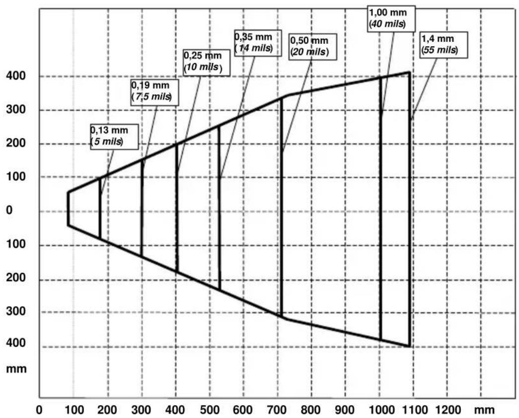
line
| Depth (mm) | Distance (mils) | | ---------- | --------------- | | 0.13 | 5 | | 0.19 | 7.5 | | 0.25 | 10 | | 0.35 | 14 | | 0.50 | 20 | | 1.00 | 40 | | 1.4 | 55 |Elf SE4500-DL
Typical Reading Diagram - Reading Zones (10° skew angle)
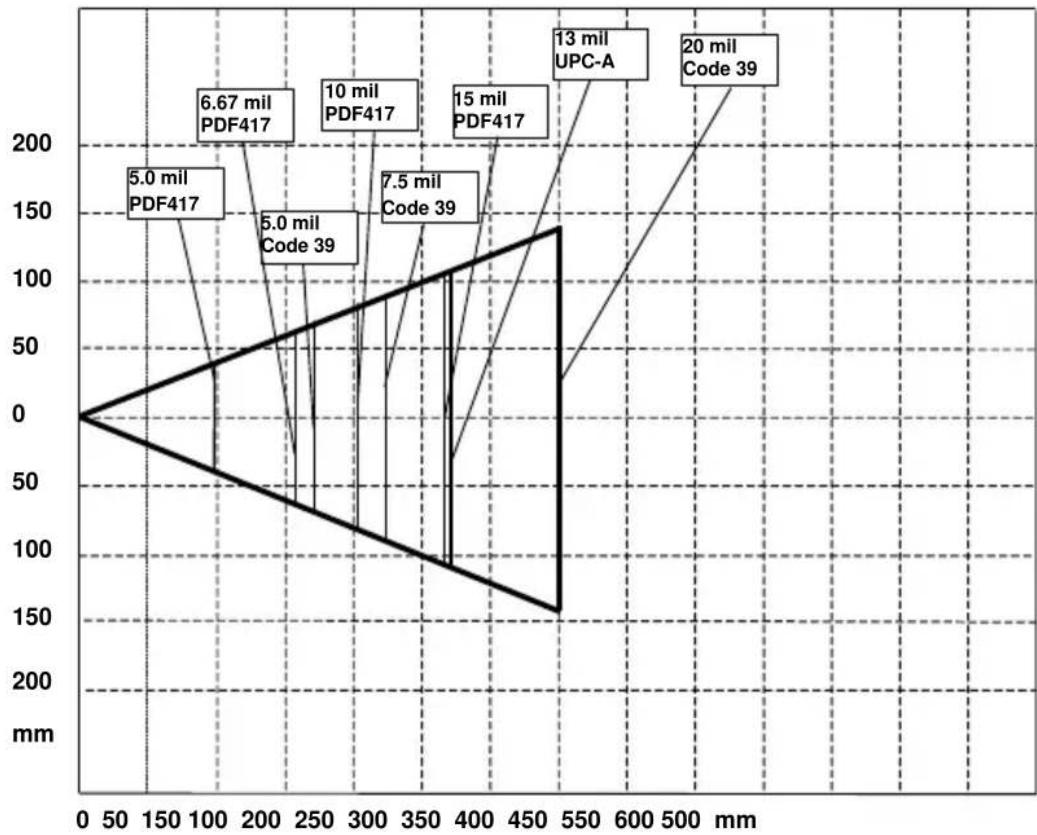
line
| Label | Value (mm) | | :--- | :--- | | 5.0 mil PDF417 | 6.67 mil PDF417 | | 5.0 mil Code 39 | 5.0 mil Code 39 | | 10 mil PDF417 | 10 mil PDF417 | | 7.5 mil Code 39 | 7.5 mil PDF417 | | 15 mil PDF417 | 15 mil PDF417 | | 13 mil UPC-A | 13 mil UPC-A | | 20 mil Code 39 | 20 mil Code 39 |6 TEST CODES
0.25 mm (10 mils)
Code 39
High Density Codes

17162
2/5 Interleaved

0123456784
Code 128

test
80%
EAN 13

text_image
8 012345 000012EAN 8

text_image
80% 64509723Medium Density Codes
0.38 mm (15 mils)
Code 39

text_image
Barcode image containing encoded digital information17162
Interleaved 2/5

text_image
Black and white barcode image with vertical lines on both sides0123456784
Code 128

text_image
Black and white barcode image with vertical lines on both sidestest
100%
EAN 13

text_image
8 012345 000012EAN 8

text_image
100% 6450 9723Low Density Codes
0.50 mm (20 mils)
Code 39

text_image
17162Interleaved 2/5

text_image
0123456784Code 128

text_image
test120%
EAN 13

text_image
8 012345 000012EAN 8

text_image
120% 645097232D Codes
Datamatrix ECC200
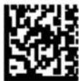
Example
Inverse
Datamatrix ECC200

text_image
QR code image containing encoded data, no visible human-readable textExample

NOTE
Read this manual carefully before performing any type of connection to the Elf mobile computer.
The user is responsible for any damages caused by incorrect use of the equipment or by inobservance of the indication supplied in this manual.
GENERAL SAFETY RULES
- Use only the components supplied by the manufacturer for the specific Elf being used.
- Do not attempt to disassemble the Elf mobile computer, as it does not contain parts that can be repaired by the user. Any tampering will invalidate the warranty.
- When replacing the battery pack or at the end of the operative life of the Elf mobile computer, disposal must be performed in compliance with the laws in force.
– Before using the devices and the battery packs, read par. 2.2. - Do not submerge the Elf in liquid products.
- For further information, refer to this manual and to the Datalogic Mobile web site: www.mobile.datalogic.com.
POWER SUPPLY
This device is intended to be connected to a UL Listed/CSA Certified computer which supplies power directly to the Elf or else be supplied by a UL Listed/CSA Certified Power Unit marked “Class 2” or LPS power source rated 5 V, 3.0 A, which supplies power directly to the Elf via the power connector of the cable.
The package includes three international plug adapters. The adapters must be plugged in the power supply before the power supply itself is plugged on the wall outlet.
LASER SAFETY
The laser light is visible to the human eye and is emitted from the window indicated in the figure.
This information applies to both laser models and the Elf Imager Aiming System.
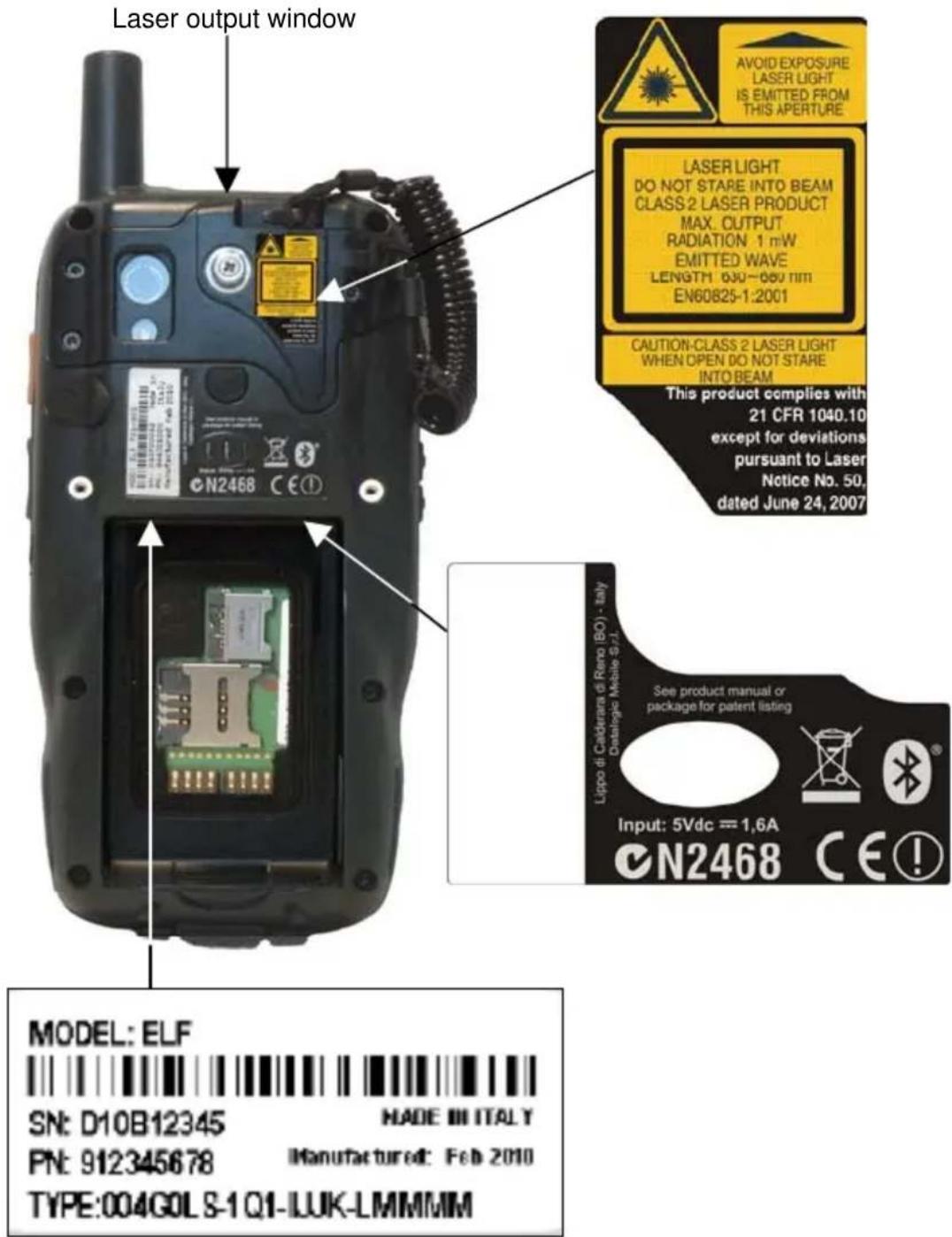
text_image
Laser output window N2468 CE① Laser LIGHT DO NOT STARE INTO BEAM CLASS 2 LASER PRODUCT MAX. OUTPUT RADIATION 1 mW EMITTED WAVE LENGTH 030~060 nm EN60825-1:2001 CAUTION-CLASS 2 LASER LIGHT WHEN OPEN DO NOT STARE INTO BEAM This product complies with 21 CFR 1040.10 except for deviations pursuant to Laser Notice No. 50, dated June 24, 2007 Lippo di Calderara di Reno (BO) - italy Cataloglio Mobile S.r.l. Input: 5Vdc = 1,6A N2468 CE! MODEL: ELF SN: D10B12345 MADE III ITALY PN: 912345678 Manufactured: Feb 2010 TYPE:004G0LS-1Q1-IJUK-LMMMMM| I | D | F | E |
| La luce laser è visibile all'occhio umano e viene emessa dalla finestra indicata nella figura. | Die Laserstrahlung ist für das menschliche Auge sichtbar und wird am Strahlaustrittsfenster ausgesendet (siehe Bild). | Le rayon laser est visible à l'oeil nu et il est émis par la fenêtre désignée sur l'illustration dans la figure. | La luz láser es visible al ojo humano y es emitida por la ventana indicada en la figura. |
| LUCE LASERNON FISSARE IL FASCIOAPPARECCHIOLASER DI CLASSE 2 MASSIMA POTENZA DI USCITA: 1 mWLUNGHEZZA D'ONDA EMESSA: 630~680 nmCONFORME A EN 60825-1 (2001) | LASERSTRAHLUNG NICHT IN DER STRAHL BLINKENPRODUKT DER LASERKLASSE 2 MAXIMALEAUSGANGLEISTUNG: 1 mWWELLENLÄNGE: 630~680 nmENTSPR. EN 60825-1 (2001) | RAYON LASEREVITER DER REGARDERLE RAYONAPPAREIL LASER DE CLASSE 2MAXIMUM PUISSANCE DE SORTIE: 1 mWLONGUER D'ONDEEMISE: 630~680 nmCONFORME A EN 60825-1 (2001) | RAYO LÁSERNO MIRAR FIJO ELRAYOAPARATO LÁSER DE CLASE 2MÁXIMA POTENCIA DE SALIDA: 1 mWLONGITUD DE ONDA EMITIDA: 630~680 nmCONFORME A EN 60825-1 (2001) |
ENGLISH
The following information is provided to comply with the rules imposed by international authorities and refers to the correct use of your mobile computer.
STANDARD LASER SAFETY REGULATIONS
This product conforms to the applicable requirements of both CDRH 21 CFR 1040 Subchapter J and EN 60825-1:2001 at the date of manufacture.
For installation, use and maintenance, it is not necessary to open the device.

CAUTION
Do not attempt to open or otherwise service any components in the optics cavity. Opening or servicing any part of the optics cavity by unauthorized personnel may violate laser safety regulations. The optics system is a factory only repair item.

CAUTION
Use of controls or adjustments or performance of procedures other than those specified herein may result in exposure to hazardous visible laser light.
The product utilizes a low-power laser diode. Although staring directly at the laser beam momentarily causes no known biological damage, avoid staring at the beam as one would with any very strong light source, such as the sun. Avoid that the laser beam hits the eye of an observer, even through reflective surfaces such as mirrors, etc.

CAUTION
Use of optical systems with the scanner will increase eye hazard. Optical instruments include binoculars, microscopes, eye glasses and magnifying glasses.
ITALIANO
According to EN60825-1:2001, the Elf 1D models which use the green spot LED are also CLASS 1 LED PRODUCTS.
APPARECCHIO LED CLASSE 1 IEC PRODUIT LED DE CLASSE 1 IEC PRODUKT LED KLASSE 1 IEC PRODUCTO LED DE CLASE 1 IEC
According to EN60825-1:2001, the Elf 2D models which use the illuminator LED are also CLASS 1M LED PRODUCTS.
LED LIGHT
DO NOT VIEW DIRECTLY
WITH OPTICAL INSTRUMENTS
CLASS 1M LED PRODUCT
LUCE LED
NON OSSERVARE DIRETTAMENTE
CON STRUMENTI OTTICI
APPARECCHIO LED DI CLASSE 1M
LAMPE LED
NE PAS OBSERVER DIRECTEMENT
AVEC INSTRUMENTS OPTIQUES
APPAREIL LED DE CLASSE 1M
LUZ LED
NO OBSERVAR DIRECTAMENTE
CON INSTRUMENTOS ÓPTICOS.
PRODUCTO LED DE CLASE 1M
LED-LICHT
In radio systems configured with mobile computers and access points, the frequencies to be used must be allowed by the spectrum authorities of the specific country in which the installation takes place. Be absolutely sure that the system frequencies are correctly set to be compliant with the spectrum requirements of the country.
The Radio modules used in this product automatically adapt to the frequencies set by the system and do not require any parameter settings.
The following shows the correspondence between ELF ^™ types and radio modules:
TYPE: xxGxxx-xxx-xxxx-xxxxxx 802.11 a/b/g radio card (where x is alphanumeric).

Information for the User
ENGLISH
Contact the competent authority responsible for the management of radio frequency devices of your country to verify any possible restrictions or licenses required.
Refer to the web site http://europa.eu.int/comm/enterprise/rtte/spectr.htm for further information.
ITALIANO
- This device complies with part 15 of the FCC Rules. Operation is subject to the following two conditions: (1) This device may not cause harmful interference, and (2) this device must accept any interference received, including interference that may cause undesired operation.
- This device has been tested and found to comply with the limits for a Class B digital device, pursuant to Part 15 of the FCC Rules. These limits are designed to provide reasonable protection against harmful interference in a residential installation. This equipment generates, uses and can radiated radio frequency energy and, if not installed and used in accordance with the instructions, may cause harmful interference to radio communications. However, there is no guarantee that interference will not occur in a particular installation. If this equipment does cause harmful interference to radio or television reception, which can be determined by turning the equipment off and on, the user is encouraged to try to correct the interference by one or more of the following measures:
- Reorient or relocate the receiving antenna.
- Increase the separation between the equipment and receiver.
- Connect the equipment into an outlet on a circuit different from that to which the receiver is connected
- Consult the dealer or an experienced radio/TV technician for help.
Changes or modifications not expressly approved by the party responsible for compliance could void the user's authority to operate the equipment.
- The antenna(s) used for this transmitter must not be co-located or operating in conjunction with any other antenna or transmitter.
RF EXPOSURE INFORMATION (SAR)
This model device meets the government's requirements for exposure to radio waves. This device is designed and manufactured not to exceed the emission limits for exposure to radio frequency (RF) energy set by the Federal Communications Commission of the U.S. Government.
The exposure standard for wireless devices employs a unit of measurement known as the Specific Absorption Rate, or SAR. The SAR limit set by the FCC is 1.6W/kg. •Tests for SAR are conducted using standard operating positions accepted by the FCC with the device transmitting at its highest certified power level in all tested frequency bands. Although the SAR is determined at the highest certified power level, the actual SAR level of the device while operating can be well below the maximum value. This is because the device is designed to operate at multiple power levels so as to use only the poser required to reach the network. In general, the closer you are to a wireless base station antenna, the lower the power output.
While there may be differences between the SAR levels of various devices and at various positions, they all meet the government requirement.
The FCC has granted an Equipment Authorization for this model device with all reported SAR levels evaluated as in compliance with the FCC RF exposure guidelines. SAR information on this model device is on file with the FCC and can be found under the Display Grant section of http://www.fcc.gov/oet/fccid after searching on the below FCC IDs:
FCC ID: U4G-0040.
This device is compliant with SAR for general population /uncontrolled exposure limits in ANSI/IEEE C95.1-1999 and had been tested in accordance with the measurement methods and procedures specified in OET Bulletin 65 Supplement C.
INDUSTRY CANADA COMPLIANCE
Operation is subject to the following two conditions: (1) this device may not cause interference, and (2) this device must accept any interference, including interference that may cause undesired operation of the device.
This device and its antenna(s) must not be co-located or operating in conjunction with any other antenna or transmitter.
The County Code Selection feature is disabled for products marketed in the US/Canada.
This EUT is compliant with SAR for general population/uncontrolled exposure limits in IC RSS-102 and had been tested in accordance with the measurement methods and procedures specified in IEEE 1528. This equipment should be installed and operated with minimum distance 1,5cm between the radiator & your body.
SAR COMPLIANCE
This product has been tested and found to comply with the following standards:
- OET BULLETIN 65 SUPPLEMENT C: evaluating compliance with FCC guidelines for human exposure to radio frequency electromagnetic fields.
- EN 50360:2001: product standard to demonstrate the compliance of mobile phones with the basic restrictions related to human exposure to electromagnetic fields (300 MHz – 3 GHz).
- EN 62311:2008: assessment of electronic and electrical equipment related to human exposure restrictions for electromagnetic fields (0 Hz – 300 GHz).
PATENTS
This product is covered by one or more of the following patents.
Design Pat.: EP 1,180,681.
US Pat.: 5,198,649; 5,311,000; 5,440,110; 5,481,098; 5,493,108; 5,686,716;
5,992,740; 6,412,698; 6,415,978; 6,454,168; 6,478,224; 6,513,714; 6,561,427;
6,585,157; 6,808,114 B1; 6,997,385 B2; 7,108,170; 7,387,246 B2.
European Pat.: 681,257 B1; 789,315 B1; 1,128,315 B1; 1,396,811 B1; 1,413,971 B1.
Additional patents pending.
CTIA COMPLIANCE
- Do not disassemble or open crush, bend or deform, puncture or shred
- Do not modify or remanufacture, attempt to insert foreign objects into the battery, immerse or expose to water or other liquids, expose to fire, explosion or other hazard.
- Only use the battery for the system for which it is specified
- Only use the battery with a charging system that has been qualified with the system per this standard. Use of an unqualified battery or charger may present a risk of fire, explosion, leakage, or other hazard.
- Do not short circuit a battery or allow metallic conductive objects to contact battery terminals.
- Replace the battery only with another battery that has been qualified with the system per this standard, IEEE-Std-1725-2006. Use of an unqualified battery may present a risk of fire, explosion, leakage or other hazard.
- Promptly dispose of used batteries in accordance with local regulations
- Battery usage by children should be supervised.
- Avoid dropping the phone or battery. If the phone or battery is dropped, especially on a hard surface, and the user suspects damage, take it to a service center for inspection.
- Improper battery use may result in a fire, explosion or other hazard.
- The device shall only be connected to products that bear the USB-IF logo or have completed the USB-IF compliance program.
WEEE COMPLIANCE

natural_image
Symbol of a trash bin with no text or labelsInformation for the user in accordance with the European Commission Directive 2002/96/EC
At the end of its useful life, the product marked with the crossed out wheeled wastebin must be disposed of separately from urban waste.
Disposing of the product according to this Directive:
- avoids potentially negative consequences to the environment and human health which otherwise could be caused by incorrect disposal
■ enables the recovery of materials to obtain a significant savings of energy and resources.
For more detailed information about disposal, contact the supplier that provided you with the product in question or consult the dedicated section at the website www.mobile.datalogic.com.
A device that provides transparent access between Ethernet wired networks and IEEE 802.11 interoperable radio-equipped mobile units. Hand-held mobile computers, PDAs or other devices equipped with radio cards, communicate with wired networks using Access Points (AP). The mobile unit (mobile computer) may roam among the APs in the same subnet while maintaining a continuous, seamless connection to the wired network.
Applet
Diminutive form of app (application), it refers to simple, single-function programs that often ship with a larger product. Programs such as Windows' Calculator, File Manager, and Notepad are examples of applets.
Barcode
A pattern of variable-width bars and spaces which represents numeric or alphanumeric data in binary form. The general format of a barcode symbol consists of a leading margin, start character, data or message character, check character (if any), stop character, and trailing margin. Within this framework, each recognizable symbology uses its own unique format.
Baud Rate
A measure for data transmission speed.
Bit
Binary digit. One bit is the basic unit of binary information. Generally, eight consecutive bits compose one byte of data. The pattern of 0 and 1 values within the byte determines its meaning.
Bluetooth®
A standard radio technology using a proprietary protocol. The onboard Bluetooth® module in the mobile computer is compatible with the 1.1 protocol.
Byte
On an addressable boundary, eight adjacent binary digits (0 and 1) combined in a pattern to represent a specific character or numeric value. Bits are numbered from the right, 0 through 7, with bit 0 the low-order bit. One byte in memory can be used to store one ASCII character.
Decode
To recognize a bar code symbology (e.g., Codabar, Code 128, Code 3 of 9, UPC/EAN, etc.) and analyze the content of the bar code scanned.
Depth of Field (DOF)
The portion of a scene that appears acceptably sharp in the image. Although a lens can precisely focus at only one distance, the decrease in sharpness is
gradual on each side of the focused distance, so that within the DOF, the unsharpness is imperceptible under normal viewing conditions.
EDGE
Enhanced Data rates for GSM Evolution (EDGE) is a backward-compatible digital mobile phone technology that allows improved data transmission rates, as an extension on top of standard GSM. EDGE is considered a 3G radio technology and is part of ITU's 3G definition.
EEPROM
Electrically Erasable Programmable Read-Only memory. An on-board non-volatile memory chip.
Ethernet
The standard local area network (LAN) access method. A reference to "LAN," "LAN connection" or "network card" automatically implies Ethernet. Defined by the IEEE as the 802.3 standard, Ethernet is used to connect computers in a company or home network as well as to connect a single computer to a cable modem or DSL modem for Internet access.
Firmware
Firmware is a software program or set of instructions programmed on a hardware device. It provides the necessary instructions for how the device communicates with the other computer hardware. Firmware is typically stored in the flash ROM of a hardware device. While ROM is "read-only memory," flash ROM can be erased and rewritten because it is actually a type of flash memory.
Flash Disk
Non-volatile memory for storing application and configuration files.
GSM
Global System for Mobile communication. It is a standard for digital cellular communications, currently used in the 900 MHz and 1800 MHz bands.
Host
A computer that serves other mobile computers in a network, providing services such as network control, database access, special programs, supervisory programs, or programming languages.
WLAN
A Wireless Local Area Network links devices via a wireless distribution method (typically spread-spectrum or OFDM radio), and usually provides a connection through an access point to the wider internet. This gives users the mobility to move around within a local coverage area and still be connected to the network.
IEEE 802.11
A set of standards carrying out wireless local area network (WLAN) computer communication in the 2.4, 3.6 and 5 GHz frequency bands. They are created and maintained by the IEEE LAN/MAN Standards Committee.
Liquid Crystal Display (LCD)
A display that uses liquid crystal sealed between two glass plates. The crystals are excited by precise electrical charges, causing them to reflect light outside according to their bias. They use little electricity and react relatively quickly. They require external light to reflect their information to the user.
Light Emitting Diode (LED)
A low power electronic light source commonly used as an indicator light. It uses less power than an incandescent light bulb but more than a Liquid Crystal Display (LCD).
Null modem cable
RS-232 serial cable where the transmit and receive lines are crosslinked. In some cables there are also handshake lines crosslinked. In many situations a straight through serial cable is used, together with a null modem adapter. The adapter contains the necessary crosslinks between the signals.
Pairing
A Bluetooth pairing occurs when two Bluetooth devices agree to communicate with each other and establish a connection.
Piconet
A piconet is a Bluetooth PAN that links up to eight devices. Each piconet is controlled by one master device, and up to seven slave devices at any one time. Any device may be a member of more than one piconet, changing its membership as a user moves from one area to another.
RAM
Random Access memory. Data in RAM can be accessed in random order, and quickly written and read.
RF
Radio Frequency.
RTC
Real Time Clock.
TDMA
Time division multiple access (TDMA) is digital transmission technology that allows a number of users to access a single radio-frequency (RF) channel without interference by allocating unique time slots to each user within each channel. The TDMA digital transmission scheme multiplexes three signals over a single channel. The current TDMA standard for cellular divides a single
channel into six time slots, with each signal using two slots, providing a 3 to 1 gain in capacity over advanced mobile-phone service (AMPS). Each caller is assigned a specific time slot for transmission.
USB
Universal Serial Bus. Type of serial bus that allows peripheral devices (disks, modems, printers, digitizers, data gloves, etc.) to be easily connected to a computer. A “plug-and-play” interface, it allows a device to be added without an adapter card and without rebooting the computer (the latter is known as hot-plugging). The USB standard, developed by several major computer and telecommunications companies, supports data-transfer speeds up to 12 megabits per second, multiple data streams, and up to 127 peripherals.
WWAN
Stands for "Wide Area Network." It is similar to a Local Area Network (LAN), but it is not limited to a single location and it uses Mobile telecommunication cellular network technologies such as UMTS, GPRS, CDMA2000, GSM, CDPD, Mobitex, HSDPA or 3G to transfer data. WWAN connectivity allows a user with a laptop and a WWAN card to surf the web, check email, or connect to a Virtual Private Network (VPN) from anywhere within the regional boundaries of cellular service.
WPAN
A Wireless Personal Area Network is a personal area network - a network for interconnecting devices centered around an individual person's workspace - in which the connections are wireless. Typically, a wireless personal area network uses some technology that permits communication within about 10 meters - in other words, a very short range.
A
Accessories; 9
B
Batteries and Maintenance; 10
Bluetooth® Manager Device
Setup; 58
Buttons; 50
C
Charging the Batteries; 10
Cleaning the Mobile Computer; 15
Connections; 16
Connection to USB peripherals; 18
Control Panel; 49
Conventions; vi
CTIA Compliance; 92
D
Data Capture; 32
Imager Data Capture; 34
Laser Data Capture; 32
Data Capture Configuration; 44
Datalogic Configuration Utility; 69
Datalogic Firmware Utility; 64
Description of the Keys; 36
E
Elf™ Description; 1
F
FCC Compliance; 88
G
General View; vii
Glossary; 95
|
Industry Canada Compliance; 90
L
Laser Safety; 80
LED Class; 86
M
Micro SD Card Insertion; 4
Models Description; 1
P
Package Contents; 3
Patents; 91
R
Radio Compliance; 86
Reading Diagram; 73
Reference Documentation; vi
References; vi
Replacing the Batteries; 12
Resetting the Elf; 40
RF Exposure Information (SAR); 89
RS232 Connection; 20
S
Safety Regulations; 79
SAR Compliance; 91
Services and Support; vi
SIM Card; 6
Startup; 28
Status Indicators; 42
Stylus Calibration; 52
T
Taskbar; 43
Technical Features; 70
Test Codes; 75
U
USB Connection; 16
Using the Stylus; 30
v
Volume Settings; 54
W
WEEE Compliance; 93
Windows Connections; 56
Windows Mobile Phone; 63
Windows Mobile Welcome Wizard; 31
Windows Mobile® Device Center; 56
Wireless and Radio Frequencies Warnings; 26
Wireless Communications; 51
WLAN Connection; 21
WPAN Connections; 23
WWAN Connections; 24
Datalogic Mobile S.r.l.
Via S. Vitalino, 13
models with 802.11a/b/g+BT radio feature
are in conformity with the requirements of the European Council Directives listed below
This declaration is based upon compliance of the products to the following standards:
LIMITS AND METHODS OF MEASUREMENTS
EN 55024: 1998
AMENDMENT A1:2001
AMENDMENT A2:2003
INFORMATION TECHNOLOGY EQUIPMENT
IMMUNITY CHARACTERISTICS
LIMITS AND METHODS OF MEASUREMENT
ETSI EN 301 489-17 v1.2.1, AUGUST 2002 :
ELECTROMAGNETIC COMPATIBILITY AND RADIO SPECTRUM
MATTERS (ERM); ELECTROMAGNETIC COMPATIBILITY (EMC)
STANDARD FOR RADIO EQUIPMENT AND SERVICES; PART 17:
SPECIFIC CONDITIONS FOR 2.4GHz WIDEBAND
TRANSMISSION SYSTEMS AND 5GHz HIGH PERFORMANCE
RLAN EQUIPMENT
ETSI EN 300 328 v1.7.1, OCTOBER 2006 :
ELECTROMAGNETIC COMPATIBILITY AND RADIO SPECTRUM
Lippo di Calderara, May 14th 2010
Paolo Clientard!
Paola Chientaroli
Quality Assurance Manager
DATALOGIC™
www.mobile.datalogic.com
World wide Sales Network available from: www.mobile.datalogic.com/contacts
Datalogic Mobile S.r.l.
Via S. Vitalino, 13