SRD-470D - VCR SAMSUNG - Free user manual and instructions
Find the device manual for free SRD-470D SAMSUNG in PDF.

User questions about SRD-470D SAMSUNG
0 question about this device. Answer the ones you know or ask your own.
Ask a new question about this device
Download the instructions for your VCR in PDF format for free! Find your manual SRD-470D - SAMSUNG and take your electronic device back in hand. On this page are published all the documents necessary for the use of your device. SRD-470D by SAMSUNG.
USER MANUAL SRD-470D SAMSUNG
©2009 Samsung Techwin Co., Ltd. All rights reserved.
Trademark

SAMSUNG TECHWIN is the registered logo of Samsung Techwin Co., Ltd.
The name of this product is the registered trademark of Samsung Techwin Co., Ltd.
Other trademarks mentioned in this manual are the registered trademark of their respective company.
Restriction
Samsung Techwin Co., Ltd shall reserve the copyright of this document. Under no circumstances, this document shall be reproduced, distributed or changed, partially or wholly, without formal authorization of Samsung Techwin.
Disclaimer
Samsung Techwin makes the best to verify the integrity and correctness of the contents in this document, but no formal guarantee shall be provided. Use of this document and the subsequent results shall be entirely on the user's own responsibility. Samsung Techwin reserves the right to change the contents of this document without prior notice.
Warranty
Samsung Techwin Co., Ltd shall reserve the copyright of this document. Under no circumstances, this document shall be reproduced, distributed or changed, partially or wholly, without formal authorization of Samsung Techwin.


IMPORTANT SAFETY INSTRUCTIONS
Read these operating instructions carefully before using the unit.
Follow all the safety instructions listed below.
Keep these operating instructions handy for future reference.
1) Read these instructions.
2) Keep these instructions.
3) Heed all warnings.
4) Follow all instructions.
5) Do not use this apparatus near water.
6) Clean only with dry cloth.
7) Do not block any ventilation openings, Install in accordance with the manufacturer's instructions.
8) Do not install near any heat sources such as radiators, heat registers, stoves, or other apparatus (including amplifiers) that produce heat.
9) Do not defeat the safety purpose of the polarized or grounding-type plug. A polarized plug has two blades with one wider than the other. A grounding type plug has two blades and a third grounding prong. The wide blade or the third prong are provided for your safety. if the provided plug does not fit into your outlet, consult an electrician for replacement of the obsolete outlet.
10) Protect the power cord from being walked on or pinched particularly at plugs, convenience receptacles, and the point where they exit from the apparatus.
11) Only use attachments/accessories specified by the manufacturer.
12) Use only with the cart, stand, tripod, bracket, or table specified by the manufacturer, or sold with the apparatus. When a cart is used, use caution when moving the cart/apparatus combination to avoid injury from tip-over.
13) Unplug this apparatus during lightning storms or when unused for long periods of time.
14) Refer all servicing to qualified service personnel. Servicing is required when the apparatus has been damaged in any way, such as power-supply cord or plug is damaged, liquid has been spilled or objects have fallen into the apparatus, the apparatus has been exposed to rain or moisture, does not operate normally, or has been dropped.

natural_image
Symbolic icon of a person climbing a ladder inside a circle with no text or symbolsEnglish _3
overview
BEFORE START
This user manual provides Information for using the DVR such as brief introduction, part names, functions, connection to other equipment, menu setup, etc.
You have to keep in mind the following notices :
• SAMSUNG retains the copyright on this manual.
- This manual cannot be copied without SAMSUNG's prior written approval.
- We are not liable for any or all losses to the product incurred by your use of non-standard product or violation of instructions mentioned in this manual.
- Prior to opening the case, please consult a qualified technician first. Whenever this is needed power must be removed from the unit.
- Before installing an additional HDD or connecting an external storage device (USB memory or USB HDD) to this DVR, check the compatibility. Consult your provider for the compatibility list.
Warning
Battery
It is essential that when changing the battery in the unit, the replacement battery must be of the same type otherwise there may be a possibility of an explosion.
The following are the specifications of the battery you are using now.
- Normal voltage : 3V
• Normal capacity : 170mAh
• Continuous standard load : 0.2mA - Operating temperature: -20^ +85^ (-4^ +185^)
CALIFORNIA USA ONLY
This Perchlorate warning applies only to primary CR (Manganese Dioxide) Lithium coin cells in the product sold or distributed ONLY in California USA. "Perchlorate Material - special handling may apply, See www.dtsc.ca.gov/hazardouswaste/perchlorate."

■ Connect the power cord into a grounded outlet.
■ The Mains plug is used as a disconnect device and shall stay readily operable at any time.
■ Batteries shall not be exposed to excessive heat such as sunshine, fire or the like.
System Shutdown
Turning off the power while the product is in operation, or undertaking improper actions may cause damage or malfunction to the hard drive or the product.
Please turn off the power using the Power button on the front of your DVR.
After selecting
You may want to install a UPS system for safe operation in order to prevent damage caused by an unexpected power stoppage. (Any questions concerning UPS, consult your UPS retailer.)
Operating Temperature
The guaranteed operating temperature range of this product is 0°C \~ 40°C (32°F \~ 104°F).
This product may not work properly if you run right after a long period of storage at a temperature below the guaranteed one.
Prior to using a device that has been stored for a long period in low temperatures, allow the product to stand at room temperature for a period.
Especially for the built-in HDD in the product, its guaranteed temperature range is 5^ C \~ 55^ C ( 41^ F \~ 131^ F). Likewise, the hard drive may not work at a temperature below the guaranteed one.
Ethernet Port
This equipment is in door use and all the communication wirings are limited to inside of the building.
4\_ overview
CONTENTS
OVERVIEW

4 Before Start
7 Features
9 Part Names and Functions (Rear)
10 Part Names and Functions (Front)
12 Remote Control
INSTALLATION
13
13 Checking the installation environment
14 HDD Addition
CONNECTING WITH OTHER DEVICE
17
17 Connecting the Video, Audio, and Monitor
17 Connecting the USB
17 Connecting POS Device
18 Connecting the Alarm Input/Output
18 Connecting the RS485 Device
19 Connecting the Network
LIVE
21
21 Getting Started
23 Live Screen Configuration
27 Live Mode
29 Spot Out
29 Zoom
30 Audio ON/OFF
30 Freeze
30 Event Monitoring
USING THE DVR
32
32 System Setup
42 Setting the Device
50 Setting the Recording
53 Setting the Event
56 Backup
57 Network Configuration
64 Controlling a PTZ device
English _5
overview
SEARCH & PLAY

66 Search
69 Playback
WEB VIEWER

70 Introducing Web Viewer
71 Connecting Web Viewer
73 Using Live Viewer
79 Using Search Viewer
83 Viewer Setup
93 About
BACKUP VIEWER

94 SEC Backup Viewer
APPENDIX

96 Product Specification
99 Product Overview
100 Default Setting
103 Troubleshooting
6_ overview
FEATURES
The SRD DVR (Digital Video Recorder) employs H.264 video encoding for 4 channel inputs and G.723 audio encoding for 4 channels while simultaneously supports hard disc recording and playback.
These DVRs also supports network connectivity, providing remote monitoring from a remote PC transferring video and audio data.
• 4 CH Composite Input Connectors
• CIF(S)/2CIF(M)/4CIF(L) Recording
• Network transfer regardless of the recording conditions using network specifi c codec
- Improved quality using de-interlace chip
• HDD information and status with HDD SMART
- Record at 4CIF Size (NTSC: 704*480, PAL: 704*576) 120(NTSC)/100(PAL)IPS
• 4 CH Loop Through video port
- HDD Overwrite
• Massive HDD backup via USB 2.0
- Backup using USB 2.0 memory and/or external CD/DVD writer (DVD writer not supported in SRD-470)
- Record and play 4 CH video data simultaneously
- Various search modes (time, event, backup, POS, motion detection)
- Lots of storage modes (time lapse, event, timed recording)
• HDD extension (USB 2.0)
- Alarm connection (input: 4, output:2, reset: 1)
- Remote monitoring via Windows Network Viewer
English _7
overview
Standards Approvals
FC CE

This equipment has been tested and found to comply with the limits for a Class A digital device, pursuant to part 15 of the FCC Rules. These limits are designed to provide reasonable protection against harmful interference when the equipment is operated in a commercial environment.
This equipment generates, uses, and can radiate radio frequency energy and, if not installed and used in accordance with the instruction manual, may cause harmful interference to radio communications. Operation of this equipment in a residential area is likely to cause harmful interference in which case the user will be required to correct the interference at his own expense.
Package Contents
Please unwrap the product, and place the product on a flat place or in the place to be installed.
Please check the following contents are included in addition to the main unit.

Remote Control Adaptor Power Cable
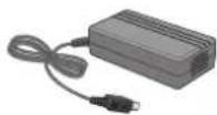
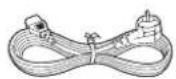
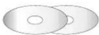

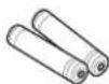
Network Viewer Software / User Manual CD
User Manual Remote Control Battery (AAA)
HDD Fixing Screw (Only applicable for SRD-470 : 4EA)
SATA Cable (Only applicable for SRD-470 : 1EA)

- For models that are not equipped with the HDD, one SATA cable is provided for HDD installation.
8\_ overview
PART NAMES AND FUNCTIONS (REAR)
text_image
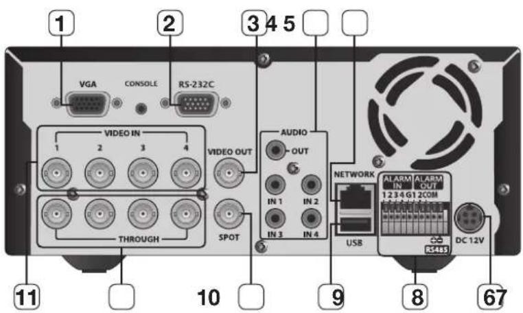
1 2 3 4 5 VGA CONSOLE RS-232C VIDEO IN 1 2 3 4 VIDEO OUT THROUGH SPOT AUDIO OUT IN 1 IN 2 IN 3 IN 4 NETWORK USB NARM IN NARM OUT 1.234G12COM RS485 DC 12V 11 10 9 8 67| Part Names Functions | ||
| 1 | VGA Output port for VGA video signal. | |
| 2 | RS-232C RS-232C communications port. | |
| 3 | VIDEO OUT BNC type of output port for the composite video signal. | |
| 4 | AUDIO OUT | Output port (RCA jack) for the audio signal.It is recommended to use an amplifi er-integrated speaker for the output of the audio signal. |
| AUDIO IN 1~4 Output ports (RCA jacks) for the audio signal. | ||
| 5 | NETWORK Network connection port. | |
| 6 | DC 12V Port to be connected to the 12V power source. | |
| 7 | ALARM IN 1~4, G : Alarm input ports. | |
| ALARM OUT 1, 2, COM : Alarm output ports. | ||
| RS485 Used to establish RS485 communications. (TX+, TX-) | ||
| 8 | USB USB connection port. | |
| 9 | SPOT BNC type of output port for the Spot signal. | |
| 10 | THROUGH Port to transfer the video signal to other video devices. | |
| 11 | VIDEO IN | Input port for the composite video signal.Supports both NTSC and PAL video signal. |
English _9
overview
PART NAMES AND FUNCTIONS (FRONT)
SRD-470

text_image
135 2 SAMSUNG DIGITAL VIDEO RECORDER SRD-470 DUAL CODE AVI MODE AUDIO ALARM REC /1/1 /1/1 PZZ ZOOM FREEZE SEARCH MENU TILE — WIDE — VIEW 87 69SRD-470D
text_image
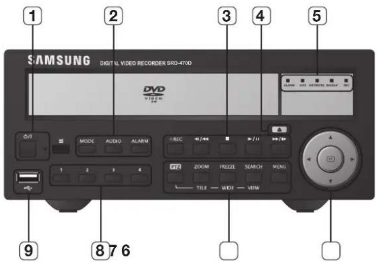
SAMSUNG DIGITAL VIDEO RECORDER SRD-470D DVD VIDEO V2 MODE AUDIO ALARM REC 1 2 3 4 FZZ ZOOM FREEZ SEACH MENU TILE — WIDE — VIEW ALARM HSS NETWORKS GROUP REC 9 8 7 610_overview
| Part Names Functions | ||
| 1 | Power | Power LED: Displays the power ON/OFF status. |
| Power Button: Used to turn the DVR ON/OFF. | ||
| 2 | MODE | In Live mode, pressing it will switch the mode to 4-split, PIP, and Auto Sequence in sequence.In Search mode, pressing it will switch the mode to 9-split and 4-split in sequence.For the Play Screen mode, refer to "Play". (page 69)■ |
| AUDIO Sets Audio ON/OFF. | ||
| ALARM | Cancels the ALARM LED and the audible alarm when the alarm is going off, and to remove the icon. | |
| 3 | REC Starts or ends the recording. | |
| ◀/◀◀ | Step Rewind (<1): Used for backward frame-by-frame search while in PAUSE.Fast Rewind (<◀): Used for quick backward search while in Play.(-x2, -x4, -x8, -x16, -x32, -x64) | |
| ■ | Stop: Used to stop the playback. | |
| ▶/II | Play/Pause: Used to pause or resume the screen. | |
| ▶▶/I▶ | Fast Forward (▶▶): Used for quick forward playback. (x2, x4, x8, x16, x32, x64)Step Forward (I▶): Used for forward frame-by-frame search while in PAUSE. | |
| 4 | Open/Close Used to open and close the DVR-RW disc tray. (available for SRD-470D only) | |
| 5 | LED Indicator | ALARM: Lights on when an event occurs. |
| HDD: Displays the normal access to HDD.Upon access to HDD, LED repeats on and off. | ||
| NETWORK: Displays both network connection and data transfer status. | ||
| BACKUP: Displays when Backup is in progress. | ||
| REC: Lights on when recording is in progress. | ||
| 6 | Direction & Select Button | Used to change a value or move the cursor up/down/left/right (▲▼◀▶).Selects a menu item or executes the selected menu. |
| 7 | Camera Control | PTZ: Sets PTZ Mode ON/OFF. |
| ZOOM(TELE): Sets the screen to the x2 digital zoom.Runs the TELE function in the PTZ Mode. | ||
| FREEZE(WIDE): Runs the FREEZE function in the Live Mode.Runs the WIDE function in the PTZ Mode. | ||
| SEARCH(VIEW): This is the function that switches over to the Search mode.(Perform the VIEW function when selecting the PTZ button.) | ||
| MENU: Used to access the Menu screen or move to the previous menu. | ||
| 8 | Channel | Used to select channel numbers directly in the Live Mode, or numbers in the numeric input mode. |
| 9 | USB Port Connects the USB devices. | |
English _11
overview
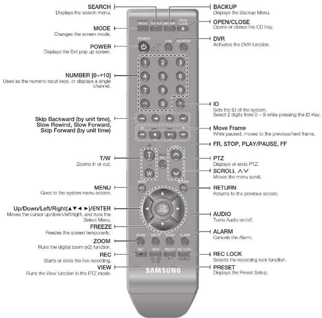
REMOTE CONTROL
text_image
SEARCH Displays the search menu. MODE Changes the screen mode. POWER Displays the Exit pop up screen. NUMBER [0~+10] Used as the numeric input keys, or displays a single channel. Skip Backward (by unit time), Slow Rewind, Slow Forward, Skip Forward (by unit time) T/W Zooms in or out. MENU Gocs to the system menu screen. Up/Down/Left/Right(▲▼◄►)/ENTER Moves the cursor up/down/left/right, and runs the Select Menu. FREEZE Freezes the screen temporarily. ZOOM Runs the digital zoom (x2) function. REC Starts or ends the live recording. VIEW Runs the View function in the PTZ mode. BACKUP Displays the Backup Menu. OPEN/CLOSE Opens or closes the CD tray. DVR Activates the DVR function. ID Sets the ID of the system. Select 2 digits from 0 ~ 9 while pressing the ID Key. Move Frame While paused, moves to the previous/next frame. FR, STOP, PLAY/PAUSE, FF PTZ Displays or ends PTZ. SCROLL ∧V Moves the menu scroll. RETURN Returns to the previous screen. AUDIO Turns Audio on/off. ALARM Cancels the Alarm. REC LOCK Selects the recording lock function. PRESET Displays the Preset Setup. SAMSUNGUsing the Numeric buttons
- Press any button among 1 to 4.
- Move to the selected channel number.
Changing the Remote Control ID
- Press the ID button of the remote control and check the ID displayed on the DVR screen. The factory default ID of the remote control is 00.
- Enter 2 digits of your selection in order, while pressing the system [ID] button.
- When ID input is done, press the system [ID] button again to check the setting.

If you want to change the remote control ID to 08: Press 0 and 8 in order while the system [ID] button is pressed. Remote control's ID and DVR's ID should be matched for proper operation. Refer to "Remote Devices". (Page 46)
12\_overview
installation
Please take note of the followings before using this product.
- Do not use the product outdoor.
- Do not spill water or liquid in the connection part of the product.
- Do not impose the system to excessive shock or force.
- Do not pull out the power plug forcefully.
- Do not disassemble the product on your own.
- Do not exceed the rated input/output range.
- Use a certified power cord only.
- For the product with an input ground, use a grounded power plug.
CHECKING THE INSTALLATION ENVIRONMENT
Samsung Digital Video Recorder ("DVR" hereinafter) is a state-of-art security device, and contains mass storage hard disk(s) and critical circuits inside.
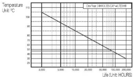
When the temperature rises inside the product, the product may breakdown and the product life be shortened. Please pay attention to the following recommendations before installation.
line
| Life (Hours) | Temperature (°C) | |---|---| | 2,000 | 105 | | 5,000 | 90 | | 10,000 | 80 | | 20,000 | 70 | | 50,000 | 60 | | 100,000 | 45 | | 200,000 | 30 | One Year: 24HR X 285 (CAV) = 6.793 HR[Figure 1]
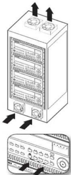
The followings are the recommendations when Samsung DVR is installed on a rack.
- Please ensure that the rack inside is not sealed.
- Please ensure the air is circulated through the inlet/outlet as shown in the picture.
- If the DVR or other devices on a rack is to be stacked as in the picture, provide a suitable space or install a ventilating opening for air circulation.
- For natural air convection, place the inlet at the bottom of the rack and the outlet on top.
- It is strongly recommended that a fan motor is installed at the inlet and the outlet for air circulation. (Please fit a filter at the inlet to screen dust or foreign substances.)
- Please maintain the temperature inside the rack or surrounding areas between 0^ C \~ 40^ C ( 32^ F \~ 104^ F) as shown in the figure 1.
Rack Mount Instructions - The following or similar rack-mount instructions are included with the installation instructions :
A) Elevated Operating Ambient - If installed in a closed or multi-unit rack assembly, the operating ambient temperature of the rack environment may be greater than room ambient. Therefore, consideration should be given to installing the equipment in an environment compatible with the maximum ambient temperature (Tma) specified by the manufacturer.
B) Reduced Air Flow - Installation of the equipment in a rack should be such that the amount of air flow required for safe operation of the equipment is not compromised.
C) Mechanical Loading - Mounting of the equipment in the rack should be such that a hazardous condition is not achieved due to uneven mechanical loading.
D) Circuit Overloading - Consideration should be given to the connection of the equipment to the supply circuit and the effect that overloading of the circuits might have on overcurrent protection and supply wiring. Appropriate consideration of equipment nameplate ratings should be used when addressing this concern.
E) Reliable Earthing - Reliable earthing of rack-mounted equipment should be maintained. Particular attention should be given to supply connections other than direct connections to the branch circuit (e.g. use of power strips).
text_image
Diagram showing server rack with two switches and a control panel with buttons, annotated with arrows indicating signal flow.[Figure 2]
English _13
installation
HDD ADDITION
You can install additional HDDs.
Make sure to unplug the power cord from the wall outlet to prevent possible electric shock, injury or product damage.
Please consult your provider for further information on HDD installation since improper installation or settings may damage the product.
■ Number of HDDs supported : SRD-470 : Default 1 HDD + Up to 1 HDD added
SRD-470D : Default 1 HDD
■ Make sure to unplug the power cord from the wall outlet before proceeding with the installation.
■ Cautions for data loss (HDD care)
Please pay attention so that the data inside the HDD is not damaged.
Before adding a HDD, please check the compatibility with this DVR product.
HDD is vulnerable to malfunction due to its sensitive nature especially against shock when operating.
Please ensure that the HDD is free from such shock.
We are not liable for any damage to the HDD incurred by user's carelessness or miss use..
■ Cases might cause damage to HDD or recorded data
To minimize the risk of data loss from a damaged HDD, please backup data as often as possible.
Data may be lost due to external impacts during disassembly or installation of the DVR.
HDD may be damaged if the DVR is suddenly stopped by a power cut or power off during operation.
HDD or fi les stored inside may be damaged if the main body is moved or impacted during the HDD operation.
Cautions when adding a HDD
- When adding a HDD, ensure that the cable does not get caught or the insulation does not come off.
- Pay attention so as not to lose the disassembly screws or accessories.
If the screws or accessories are not put together correctly, the product may breakdown or not operate properly.
- Please check the HDD compatibility before adding a HDD.
- Please contact your nearest dealer to obtain the list of compatible devices.
14_ installation
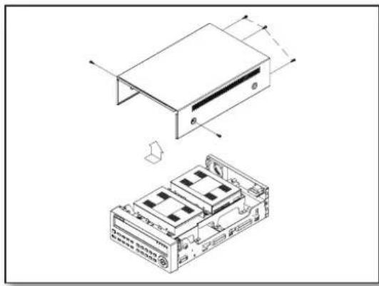
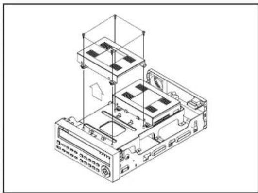
- First, loosen the screws on both sides and remove the cover.
natural_image
Technical line drawing of a device with two views: top shows a rectangular component, bottom shows a multi-chambered electronic device (no text or symbols)- Loosen the left and right screws on the lower hard disk bracket to remove it.
natural_image
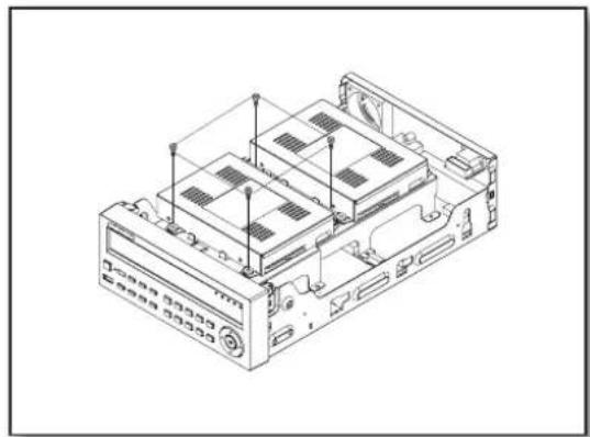
Isometric technical diagram of a computer chassis with labeled components and internal structure (no text or symbols)- Insert the additional hard disk into the bracket and fix it using the provided screws.

text_image
Hard disk bracket Master hard diskEnglish _15
installation
- Insert the bracket where the additional hard disk is inserted into the lower bracket and fix it using the provided screws.
natural_image
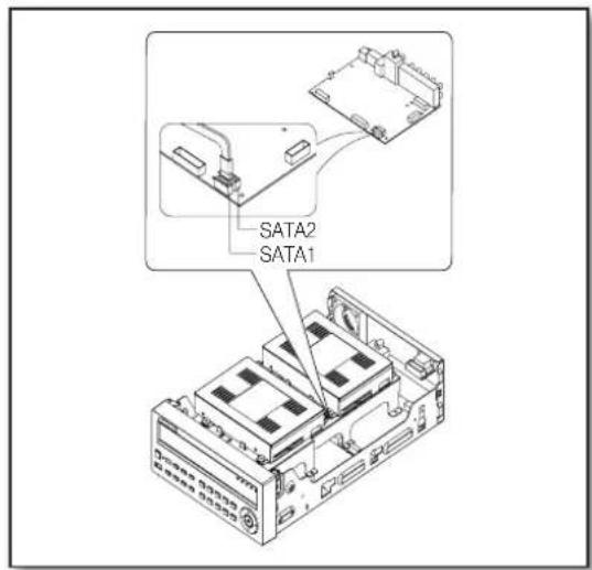
Isometric line drawing of a computer chassis with multiple drive units and ventilation slots (no text or symbols)- When done, connect the power cable and connect the signal cable (SATA cable) to the connector for the main board.
text_image
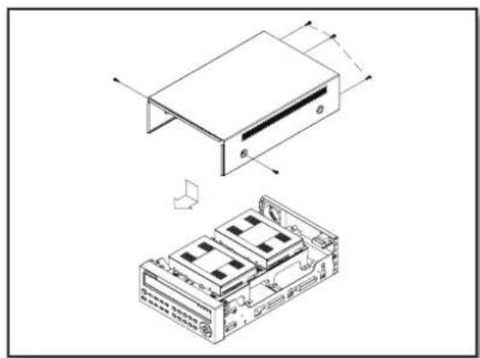
SATA2 SATA1- Check if the connectors are properly connected and there is no problem with wiring, and close the cover and fix it with screws.
natural_image
Technical line drawing of a device with two views: top shows a rectangular component, bottom shows a multi-chambered rack (no text or symbols)16_ installation
connecting with other device
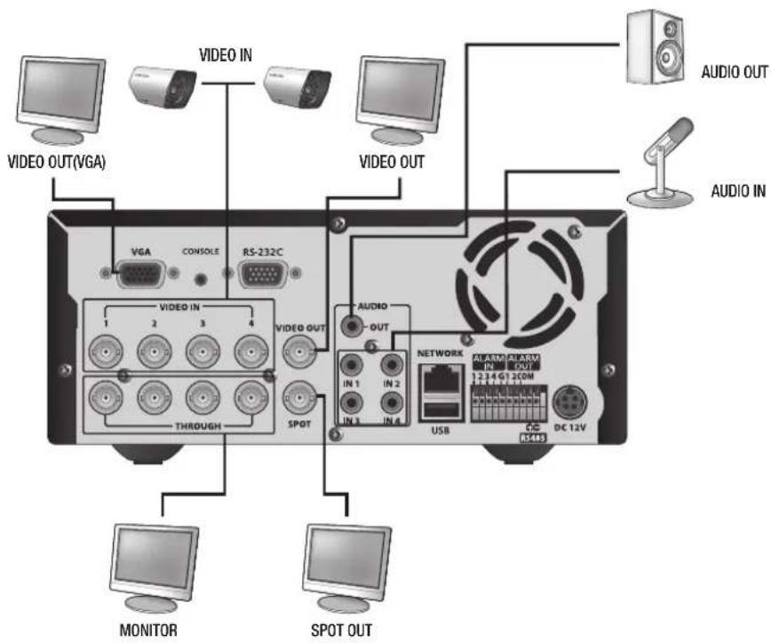
CONNECTING THE VIDEO, AUDIO, AND MONITOR
text_image
VIDEO OUT(VGA) VIDEO IN VIDEO OUT AUDIO OUT AUDIO IN VGA CONSOLE RS-232C VIDEO IN 1 2 3 4 VIDEO OUT THROUGH SPOT AUDIO OUT IN 1 IN 2 IN 3 IN 4 NETWORK ASLAM/BLARM IN OUT 1.2.1.4 G T 2COM USB DC 12V RS485 MONITOR SPOT OUTCONNECTING THE USB
- There is one USB port at the front and one at the back of the product.
- You can connect a USB HDD, USB CD/DVD player, USB memory or mouse to the USB port.
- If a USB HDD is connected to the system, recognition and settings are available in "Menu > Setting the Device > Storage Device". (Page 44)
- This product supports hot-plugging, which connects/removes the USB device during the system operation.

If you use the USB device for Backup purposes, format it with FAT32 on PC if it is not formatted on the DVR.
CONNECTING POS DEVICE
- You can connect a POS device to the RS-232C port on the product's rear side when you connect it directly with a RS-232C cable.
- Connection setup for the RS-232C port is available in "Menu > Device > POS Devices", press the
button and set
English _17
connecting with other device
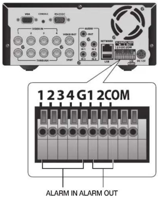
CONNECTING THE ALARM INPUT/OUTPUT
Connecting the alarm input signal
Connection port for the alarm input signal.
Connect one strand of the sensor signal line (two strands) to the alarm input port and connect the other to the [G] port.
Connecting the alarm output signal
Connection port for the alarm output signal.
Connect one strand of the sensor signal line (two strands) to the alarm output port and connect the other to the [COM] port.
text_image
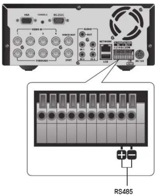
VGA CONSOLE RS-232C VIDEO IN 1 2 3 4 THROUGH VIDEO OUT AUDIO OUT IN 1 IN 2 IN 3 IN 4 NETWORKS 1234G12COM 1234G12COM USB DC 12V 1 2 3 4 G1 2COM ALARM IN ALARM OUTCONNECTING THE RS485 DEVICE
Connect the rear [RS485 +, -] ports to the external device.

■ ex) you can connect and control the PTZ camera which supports the RS485 communication.
- Check if the RS485 device is compatible with the product first.
- Pay attention not to change the polarity (+/-) of the RS485 device when connecting it.
- Depending on camera's type, connection polarity can be different.
For further information, refer to the respective PTZ Camera's documentation.
text_image
VGA CONOCOLI RS-232C VIDEO IN 1 2 3 4 THROUGH VIDEO OUT IN 1 IN 2 SPOT AUDIO IN 3 IN 4 NETWORK USB DC 12V RS48518_ connecting with other device
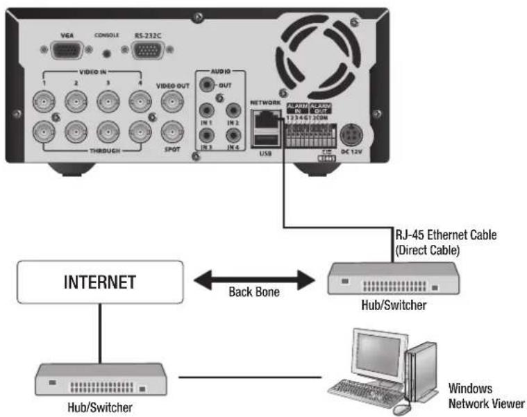
CONNECTING THE NETWORK
Connecting to Internet through Ethernet (10/100/1000BaseT)
flowchart
graph TD
    A["Internet"] -->|Back Bone| B["RJ-45 Ethernet Cable (Direct Cable)"]
    B --> C["Hub/Switcher"]
    C --> D["Windows Network Viewer"]
    A --> E["USB"]
    E --> F["AC 12V"]
    F --> G["Network"]
    G --> H["VIDEO OUT"]
    H --> I["VIDEO IN"]
    I --> J["VISA"]
    J --> K["CONSOLE"]
    K --> L["RS-232C"]
    L --> M["THROUGH"]
    M --> N["SPOIT"]
    N --> O["AUDIO OUT"]
    O --> P["IN 1"]
    O --> Q["IN 2"]
    O --> R["IN 3"]
    O --> S["IN 4"]
Connecting to the Internet using the router
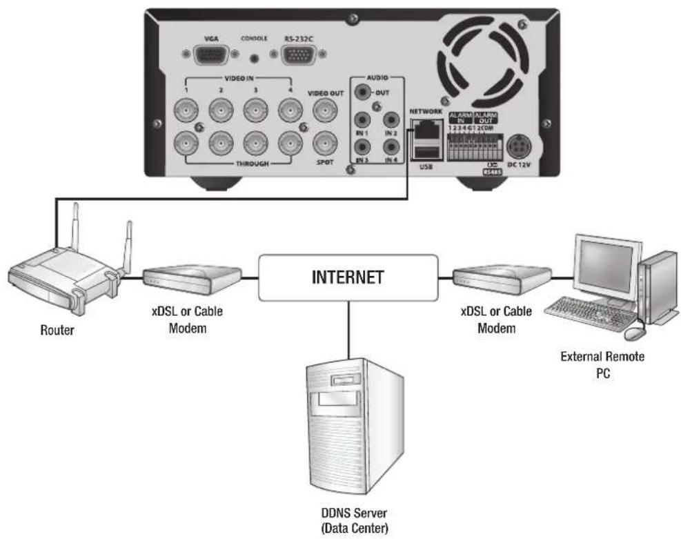
flowchart
graph TD
    A["Router"] --> B["xDSL or Cable Modem"]
    B --> C["INTERNET"]
    C --> D["DDNS Server (Data Center)"]
    D --> E["xDSL or Cable Modem"]
    E --> F["External Remote PC"]
    G["USB"] --> H["NETWORK"]
    I["RS485"] --> H
    J["DISCOV"] --> H
    K["AVIO"] --> H
    L["VIDEO OUT"] --> M["THROUGH"]
    N["VGA"] --> O["1-4"]
    P["CONSOLE"] --> Q["2-3"]
    R["RS-232C"] --> S["4"]
    T["UN 1"] --> U["2"]
    V["UN 2"] --> W["4"]
    X["UN 3"] --> Y["4"]
    Z["UN 4"] --> AA["4"]
English _19


connecting with other device
Connecting to Internet through ADSL
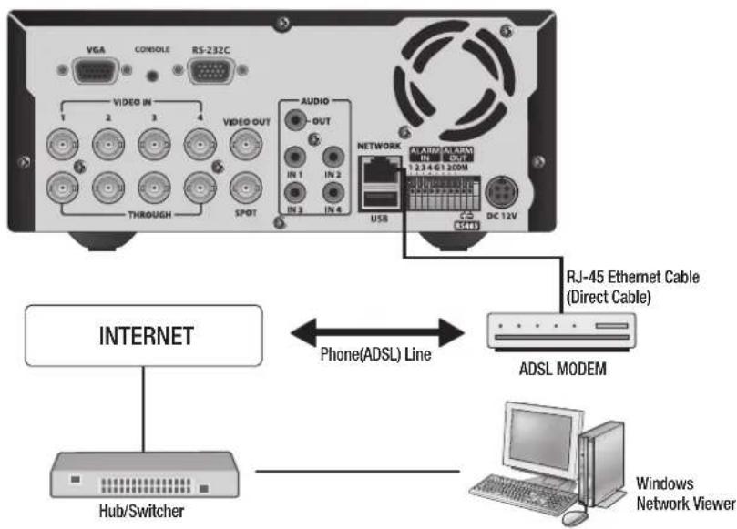
flowchart
graph TD
    A["Device 1"] -->|VGA| B["Video IN"]
    C["Device 2"] -->|VGA| D["Video OUT"]
    E["Device 3"] -->|VGA| F["Audio OUT"]
    G["Device 4"] -->|VGA| H["Through"]
    I["Device 5"] -->|VGA| J["SpOT"]
    K["Device 6"] -->|VGA| L["Through"]
    M["Device 7"] -->|VGA| N["Through"]
    O["Device 8"] -->|VGA| P["Through"]
    Q["Device 9"] -->|VGA| R["Through"]
    S["Device 10"] -->|VGA| T["Through"]
    U["Device 11"] -->|VGA| V["Through"]
    W["Device 12"] -->|VGA| X["Through"]
    Y["Device 13"] -->|VGA| Z["Through"]
    AA["Device 14"] -->|VGA| AB["Through"]
    AC["Device 15"] -->|VGA| AD["Through"]
    AE["Device 16"] -->|VGA| AF["Through"]
    AG["Device 17"] -->|VGA| AH["Through"]
    AI["Device 18"] -->|VGA| AJ["Through"]
    AK["Device 19"] -->|VGA| AL["Through"]
    AM["Device 20"] -->|VGA| AN["Through"]
    AO["Device 21"] -->|VGA| AP["Through"]
    AQ["Device 22"] -->|VGA| AR["Through"]
    AS["Device 23"] -->|VGA| AT["Through"]
    AU["Device 24"] -->|VGA| AV["Through"]
    AW["Device 25"] -->|VGA| AX["Through"]
    AY["Internet"] --> AZ["Hub/Switcher"]
    BA["RJ-45 Ethernet Cable (Direct Cable)"] --> BB["ADSL MODEM"]
    BC["Windows Network Viewer"] --> BD["Computer"]
20_ connecting with other device
GETTING STARTED
Starting the system
- Connect the power cable of the DVR to the wall outlet.
-
Press the Power button on the front panel.
-
You will see the initialization screen.
The initialization process will last about 1 minute. If a new HDD is installed, the initialization process may take longer.
- The live screen appears with a beep.

text_image
SAMSUNG
text_image
SAMSUNG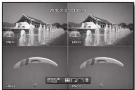
text_image
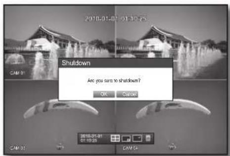
2018-01-07 01:10:25 CAM 01 CAM 02 CAM 03 CAM 04 2018-01-08 01:10:23 CAM 04Shutting Down the System
You can shut down the system only if you have logged in to the DVR.
You require permission to shut down the system if you are not logged in as admin.
- Press the [POWER] button on the remote control or the front panel, or right-click to display the context sensitive menu and select
. - The "Shutdown" confirmation window appears.
- Use the arrow keys on the remote control or the front panel to move to
and press the [ENTER] button or click .
The system will shut down.

- For the permission management, refer to "Permission Management > Setting Permissions". (Page 37)
text_image
2010-01-01 01:10:25 SHUTDOWN Are you sure to shutdown? OK Cancel SHUTDOWN 01:10:25 01:10:25 CAM 01 CAM 02 CAM 03English _21

text_image
• LIVE


live
Login
To access a DVR or restricted menu, you should have logged in to the DVR.
- In live mode, right-click any area of the screen. You will see the context sensitive menu as in the right figure.
text_image
2018-01-01 01:16:55 CAM 01 CAM 02 Score Mode ▶ Audio Cut Freeze Sup Alarm Rouchl Play Search Backup Main Venu Shutdown Hide Launcher Login CAM 03 CAM 04 2018-01-01 01:16:55- Click
.
The login dialog appears.
You can also see the login dialog to access a desired menu by pressing the [MENU] button on the remote control or the front panel.
- The login dialog will also appear if you press a menu button on the remote control or the front panel of the DVR when the corresponding menu requires logging in.
■ After logged in, press [RETURN] on the remote control to display the logout dialog.
By default, initial ID and password are set to "admin", and "4321".
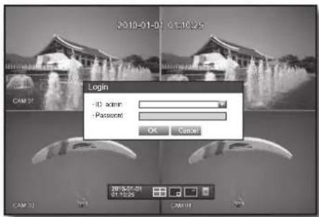
text_image
2010-01-01 01:10:25 CAM 01 Login -ID admin -Password OK Cancel 3010-01-01 01:10:25 CAM 01 CAM 02
For the restricted permission, refer to "Permission Management > Setting Permissions". (Page 37)
Locking All Buttons
This will restrict access to all buttons available in the DVR.
- In Live mode, press buttons in the order of [STOP]→[FREEZE]→[STOP]→[FREEZE]→[MENU].
All buttons will be locked.
- In the lock condition, press any button to display a dialog where you are prompted to enter the password for unlocking the buttons.
The button lock will be released if you enter the admin password.

text_image
2018-01-03 01:10:25 Key Lock Password ID screen Password OK Cancel 2018-01-03 01:10:25 CAM 01 CAM 0122_ live
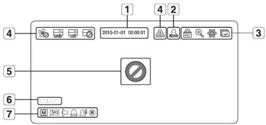
Icons on the Live Screen
You can check the status or operation of the DVR with the icons on the live screen.
flowchart
graph TD
    A["1"] --> B["2010-01-01 00:00:01"]
    C["2"] --> D["Warning Icon"]
    E["3"] --> F["REC Check"]
    G["4"] --> H["No Sign"]
    I["5"] --> J["No Sign"]
    K["6"] --> L["GAM01"]
    M["7"] --> N["MPT2"]
| Name Description | |||
| 1 | Current Date, Time | Displays the current time and date. | |
| 2 | Login Information | When you are logged in, the “LOG ON” icon will be displayed. | |
| 3 | Screen Mode | Displayed if the zoom function is activated. | |
| Displayed if you press the Pause button. | |||
| Displayed in Auto Sequence mode where all channels are switched at the specific time interval. | |||
| Displayed if the recording is in process.To cancel the recording, enter the password. | |||
| 4 | System Operation | Displayed if there is a problem with the cooling fan. | |
| Displayed if the HDD is full and the DVR has an insufficient client space to record. | |||
| Displayed if no HDD is installed or the existing HDD should be replaced. | |||
| Displayed if the HDD needs a technical examination. | |||
| Displayed if a new fi rmware is found from the network. | |||
| 5 | Video Input Status | Displayed if no input is entered in the condition that the camera is set to.<ON>. | |
| Nothing will be displayed on the screen if the camera is set to<OFF>. | |||
| 6 | Camera Name/ Channel | Displays the camera name and the changed channel, if any. | |
| 7 | Camera Operation | Displays the resolution of the recording screen. (Page 52) | |
| Displayed in PTZ setting, and highlighted yellow if PTZ is in operation. | |||
| Displays AUDIO ON/MUTE.Not displayed in video mode if deactivated. | |||
| If the sensor is set to<ON>, the input signal will be displayed on the screen of the connected channel. | |||
| Displayed if a motion detected in the condition that the motion detection is set to<ON>. | |||
| Displays the current record mode from Record/Event/Schedule. | |||

text_image
LIVEEnglish _23
live
Error Information
- If you turn on the system when the internal HDD is not connected or an error occurs, the "HDD FAIL" icon (☐) will be displayed on the top left corner. In this case, make sure you contact the service center for assistance as this may cause a failure of recording, playback or backup.
- If the cooling fan does not work properly or has a problem, the
window will appear and the fan error icon (⑤) will be displayed on the top left corner. In this case, check to see if the internal fan works.
As a fan error can shorten the product life, make sure you contact the service center for assistance.

If you see the fan error icon or No HDD, HDD FAIL icons on the screen, contact the service center for more details.
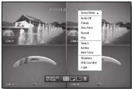
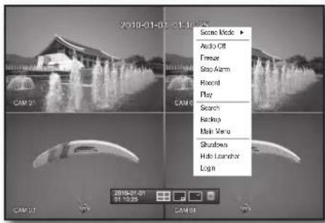
Live Screen Menu
In addition to the buttons on the front panel or the remote control, you can access a desired menu by right-clicking the mouse any area in live mode.
The context sensitive menu that appears by right-clicking the screen may differ, depending on the login/logout, screen split mode and DVD operation mode.

■ Menu items of Search, Record, Backup, Shutdown and PTZ can be deactivated, depending on the user permission.
text_image
2018-01-01 01:10:00 CAM 01 CAM 02 Score Mode ▶ Audio Off Freeze Snap Arm Record Play Search Backup Main Menu Shutdown Hide Launcher Login< Split Mode Menu >

text_image
2010-01-01 01:16 Score Mode ▶ PIT2 Control ZOOM Audio ▶ Capture Stop Alarm Record Play Search Backup Main Menu Shutdown Hide Launcher Lock< Single Mode Menu >
Split Mode Menu
The context sensitive menu in split mode differs, depending on the login/logout status.
text_image
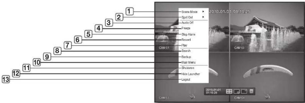
1 2 3 4 5 6 7 8 9 10 11 12 13 2010-01-01 01:10:25 Scene Mode Spot Out Audio Off Freeze Stop Alarm Record Play Search Backup Main Menu Shutdown Hide Launcher Logout CAM 01 CAM 02 CAM 03 2010-01-01 01:10:25 CAM 0424_ live
| Menu Description | ||
| 1 | Scene Mode Refer to "Live Mode". (Page 27) | |
| 2 | Spot Out Refer to "Spot Out". (Page 29) | |
| 3 | Audio On/Off | Refer to "Audio ON/OFF". (Page 30) |
| 4 | Freeze Refer to "Freeze". (Page 30) | |
| 5 | Stop Alarm | Stops the alarm output and the event monitoring. Refer to "Event Monitoring". (Page 30) |
| 6 | Record/Stop Starts/stops the standard recording. | |
| 7 | Play | Plays the search result (data). Refer to "Search & Play > Play". (Page 69) |
| 8 | Search | Refer to "Search & Play > Search". (Page 66) |
| 9 | Backup | Refer to "Using the DVR > Setting the Backup". (Page 56) |
| 10 | Main Menu | Accesses the main menu. Refer to the Using the DVR section. (Page 32) |
| 11 | Shutdown | Turns down the DVR. |
| 12 | Show/Hide Launcher | Shows or hides the launcher. Refer to "View the Launcher Menu". (Page 26) |
| 13 | Login/Logout You can log in or out. | |
Single Mode Menu
The single mode menu is available only in Single Mode.
The context sensitive menu for the One Channel mode, in Split mode is different from that of the Single mode.
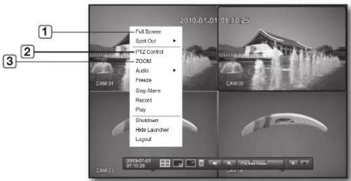
text_image
Full Screen Spot Out PTZ Control ZOOM Audio Freeze Stop Alarm Record Play Shutdown Hide Launcher Logout CAM 01 2010-01-01 01:10:25 CAM 03 CAM 03 2010-01-01 01:10:25 CAM 04| Menu Description | ||
| 1 | Full Screen | Select and click a desired channel in Split mode to switch to the full screen of the selected channel. |
| 2 | PTZ Control | Accesses the PTZ Control menu. The PTZ menu is activated only in One-Channel Live mode. (Page 64) |
| 3 | ZOOM Enlarges the selected image. (Page 29) | |
English _25
live
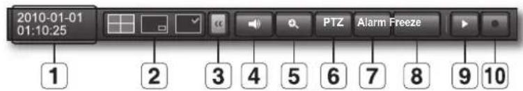
View the Launcher Menu
The Launcher menu appears on the bottom of the live screen.
-
In Live mode, right-click to display the context menu and select
. -
Move the cursor to the bottom and click a desired item in the Launcher menu.

If no input is entered for 10 seconds, the menu will disappear.
■ The Launcher menu can be accessed only by using the mouse.
natural_image
Four-panel black-and-white photo collage showing a fountain in water, with camera monitors displaying time and position (no readable text or symbols)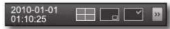
text_image
2010-01-01 01:10:25 PTZ Alarm Freeze 1 2 3 4 5 6 7 8 9 10| Menu Description | ||
| 1 | Date/Time | Displays the current time and date.The indication of AM/PM is displayed if you set 12 hours for the time format in “System > Date/Time/Language > Time”. (Page 32) |
| 2 | Screen Mode Displays in the sequence of 4-split, PIP and Auto Sequence. | |
| 3 | Menu Expansion Button Click to display the hidden menu to the right. | |
| 4 | Audio Turns ON/OFF the sound of the selected channel. | |
| 5 | Zoom Enlarges the selected area. This is available only in Single Live mode. | |
| 6 | PTZ Runs the PTZ Control launcher. | |
| 7 | Alarm Stops the alarm if it's activated. | |
| 8 | Freeze Freezes the Live screen temporarily. | |
| 9 | Play Enters Play mode if a file to play exist, and if not, enters Search mode. | |
| 10 | Record Start/End recording the Live screen. | |
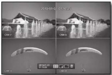
LIVE MODE
Displays 4 live video images in 3 different modes.
Switching the screen mode
To switch the split mode, select a screen mode in the launcher menu, or right-click to select a screen mode in the context menu.
Press the [MODE] button on the front panel or the remote control to switch the mode in the sequence of the launcher menu items.
flowchart
graph LR
    A["2x2 Grid"] --> B["3x2 Grid"]
    B --> C["3x2 Grid"]
4-split mode PIP Auto Sequence
Switching the screen automatically
With SRD-470/470D, you can display 4 live single screens in sequence.
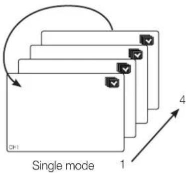
text_image
CH1 Single mode 1 4
In Single mode, If you have set
English _27


text_image
LIVE

live
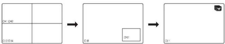
Channel Setting
You can display the channel in a desired area of a split screen.
- Place the cursor over the camera name of each channel to display the <▼> key to the right on the screen.
- Click a camera name to display a channel list where you can select a different channel.
- Select a desired channel and click it.
The current channel will be switched to the selected one.
Use the cursor to select a channel to move, and drag and drop it to a desired channel; this can also change the channel position.
Ex : if switching CH 1 to CH 4

text_image
CH1 CH2 CH3 CH4 → CH1 CH2 CH3 CH1Switching to Single Mode
When in split mode, select and double-click a desired channel to switch to its Single mode.
Press the number corresponding to a desired channel on the front panel or the remote control to switch to its Single mode.
Refer to "Remote Control > Using the numeric buttons". (Page 12)
Ex : If double-clicking CH 3 or pressing the number "3" on the remote control or the front panel.
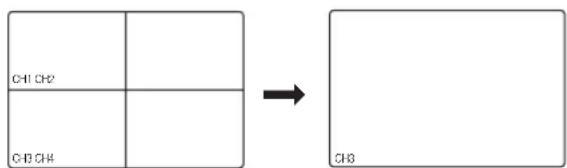
flowchart
graph LR
    A["Rectangle with three sides: CH1 CH2, CH3 CH4"] --> B["Single rectangle with label CH3"]
SPOT OUT
The Spot Out monitoring is independent of the Live mode, which monitors a specific channel through the Spot Out port.
Selecting a Spot Out mode
If an event occurs such as sensor, motion or alarm from the Spot Out port in connection with a monitor, you can select a output screen mode.
- In Live mode, right-click any area on the screen. The Live menu appears.
- Click Spot Out. Supports the Spot output in Single screen with Auto Sequence mode.
- The Spot output is supported only for a designated channel. For the Spot Out port of a model, refer to "Part Names and Functions (Rear)". (Page 9)

text_image
Scene Mode Audio Off Freeze Snap Alarm Record Play Search Kingsp Mac Venu Shadow Huto Launcher Liquel 2010-01-05 01:16:23 Auto Sequence Single CH1 CH2 CH3 CH4 CAM 01 CAM 01 CAM 01 CAM 01< Multichannel Live Menu >
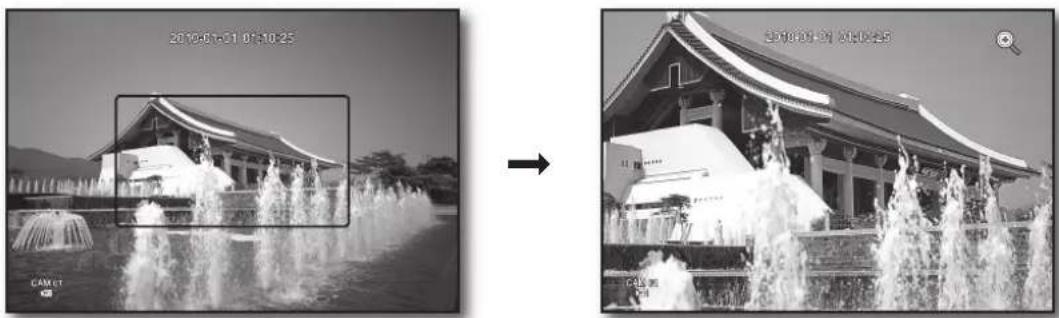
ZOOM
This is available only in Single Live mode. In Single mode, select a desired area and use the Zoom function to enlarge it twice.
- Select
in the right-click menu. Press the [ZOOM] button on the front panel or the remote control, or simply click < 🔒> in the launcher menu. The zoom box appears. - Use the direction keys, or drag and drop to specify an area to enlarge.
- Press the [ENTER] button, or double-click the selected area to enlarge it twice. ■ In the enlarged image, use the direction buttons (▲▼◀▶) on the remote control or the front panel to move the enlarged area.
- Press the [ZOOM] button on the front panel or the remote control, or simply click < a > in the launcher menu to release the zoom.
natural_image
Two black-and-white photos showing a traditional-style building with fountains in the foreground and its exterior view, both without any visible text or symbols.English _29
AUDIO ON/OFF
You can turn the sound on/off corresponding to the channel in Live mode.
AUDIO ON/OFF in Single mode
Click the audio icon (☐) on the screen, or press the [AUDIO] button on the front panel or the remote control to turn it on/off.

- Only the channel where
FREEZE
This is available only in Live mode, this pauses playing the Live image temporarily.
- Press the [FREEZE] button on the front panel or the remote control, or click < Freeze > in the launcher menu. The playback of the image is stopped temporarily.
- Press the [FREEZE] button again, or click < Freeze >. This will release the freeze.
EVENT MONITORING
This will display the channel in sync with a specific event (Sensor/Motion/Video Loss) if it occurs. In "Monitor > Event Display", set the event monitoring to ON/OFF and specify the event display time. (Page 48)
- If multiple events occur simultaneously, the screen will switch to a split mode.
- 2\~4 events : 4-split mode
- If the second event occurs within the set time of
, the first event will last until the second one is terminated. (Page 48)
Ex : If you setto 5 seconds, and only one event occurs in CH 1.
Event occurrence 5 seconds
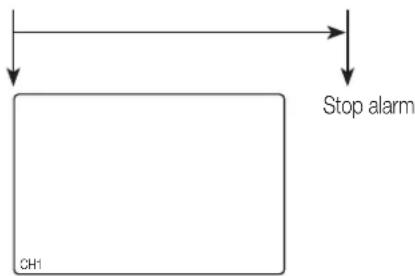
flowchart
graph TD
    A["Stop alarm"] --> B["CH1"]
30_ live


Ex: If you set
Event occurrence 4 seconds 9 seconds
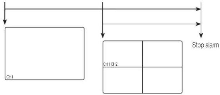
flowchart
graph TD
    A["CH1"] --> B["Stop alarm"]
    C["CH1 CH2"] --> B
    B --> D["Stop alarm"]

- Press the [ALARM] button to reset the alarm settings and to release the event mode.
If an alarm activates in the condition you have set the event record, and pre/post alarm times, the event record will be performed.

text_image
• LIVE
English_31
using the DVR
You can setup the system properties, devices, and options for recording, event, backup and network.
SYSTEM SETUP
You can setup Date/Time/Language, Permission, System Properties and Log.
Date/Time/Language
You can check and setup the current Date/Time and time related properties, as well as the language used for the interface on the screen.
Setting the Date/Time/Language
Set the Date/Time/Language
Using the mouse may help make setup easier.
- Press the [MENU] button on the remote control or on the front panel.
If not logged in, it prompts with login window. Refer to "Login". (Page 22)

text_image
2018-01-07 01:10:25 CAM 01 CAM 02 CAM 03 2018-01-06 01:10:29 CAM 04-
Use the left/right buttons (◀▶) to select the
. System property setup menu is selected. -
Use the up/down buttons (▲▼) to select
and press the [ENTER] button. -
Select
. A dialog to setup Date, Time and Language. -
Use direction buttons (▲▼◀▶) to select an item to set and make your changes.
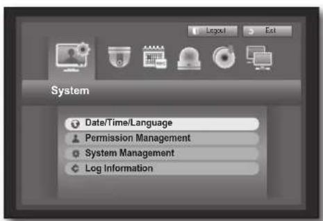
text_image
System Date/Time/Language Permission Management System Management Log Information- Date : Sets the date that will appear on the screen. You can select the date format.
- Time : Sets the time and its format that will appear on the screen. Select either one from <24 Hours, 12 Hours (AM/PM)>.
- Time Zone: Sets the time zone of your area based on the Greenwich Mean Time (GMT).
■ GMT (Greenwich Mean Time) is standard World Time and the basis of world time zone.
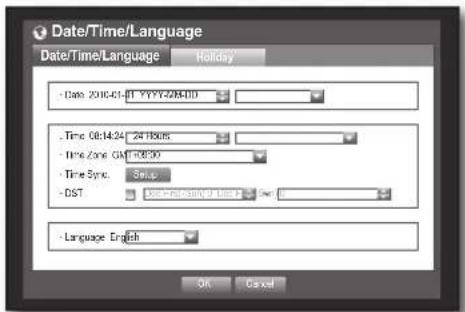
text_image
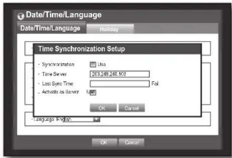
Date/Time/Language Date/Time/Language Holiday - Date: 2016-01-01 YYYY-MM-DD - Time: 08:14:24 24 KBUS - Time Zone GM: 14 KB - Time Sync: Setup - DST: Select Service Tools Help - Language English OK Cancel- Time Sync.: You can set the DVR's current time synchronized to a selected
32\_ using the DVR


- Time Server : Enter an IP or URL address of the time server.
- Last Sync Time : Displays the most recent synchronization time from the selected time server.
- Activate as Server : Set to
- DST : Set up Daylight Saving Time with its period to make the time earlier than the GMT of its time zone by 1 hour during the set period.
- Language : Select your language. Sets the language for the interface.
text_image
Date/Time/Language Date/Time/Language Holiday Time Synchronization Setup • Synchronization • Time Server • Last Sync Time • Active as Server Use Usa 203.248.246.103 Fail OK Cancel Language English OK CancelEnglish, French, German, Spanish, Italian, Chinese, Russian, Korean, Polish, Japanese, Dutch, Portuguese, Turkish, Czech, Danish, and Swedish are available.
- When the Date/Time/Language setup is done, press
.

- You can also use numeric buttons on the remote control or front panel to enter values for Date, Time and other numeric fi elds.
Setting Holiday
You can set specific dates to Holidays according to your preferences.
Holidays are applied to
Using the mouse may help make setup easier.
-
Use the up/down buttons (▲▼) in
window to select , and press the [ENTER] button. -
Select
.
A calendar for Holiday setup appears.
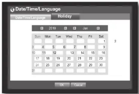
- Use the left/right <◀▶> buttons to select year or month, and press the [ENTER] button.
text_image
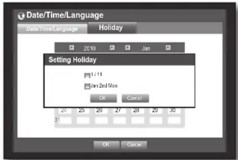
Date/Time/Language Date/Time/Language Holiday 2010 Jan Sun Mon Tue Wed Thu Fri Sat 3 4 5 6 7 8 9 10 11 12 13 14 15 16 17 18 19 20 21 22 23 24 25 26 27 28 29 30 31 OK Cancel- Use direction buttons (▲▼◀▶) to select a desired date, and press the [ENTER] button.
You will see the "Setting Holiday" screen.
Ex : Select January 11th and check on <1/11> only to make every January 11th a holiday. Check both on <1/11> and
- When the Holiday setup is done, press
.
text_image
Date/Time/Language Date/Time/Language Holiday 2010 Jan Setting Holiday 1/11 Jan 2nd Mon OK Cancel 31 OK CancelUsing the Calendar
Using the mouse may help make setup easier.
① Select year and month. Select the left/right <◀▶> key on the left/right side of year/month and press [ENTER] button to adjust by 1 year/month.
② Use direction buttons to select a date and press [ENTER] button.
A date with recorded data to be searched will appear in yellow in the System Log, Event Log, Time Search and Event Search.
English _33

using the DVR
Permission Management
You can set permissions of each user over the DVR's specific function and settings.
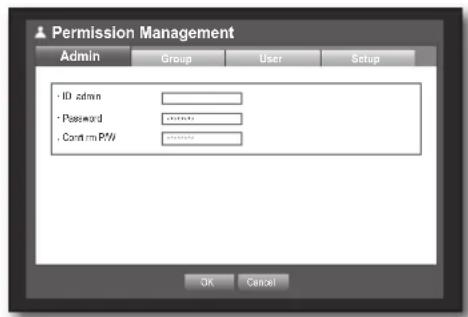
Setting the Administrator
You can set and change Administrator's ID and password.
The administrator can use and set all menu items and functions.
Using the mouse may help make setup easier.
- Use the up/down buttons (▲▼) in
window to move to , and press [ENTER] button. - Select
.
A dialog for Admin ID and Password input appears.
- Use direction buttons (▲▼◀▶) to move to a desired item, and set the ID and password.

- By default, initial ID and password are set to "admin", and "4321".
text_image
Permission Management Admin Group User Setup - ID admin + Password . Confirm PW OK Cancel- When the administrator setup is done, press
.
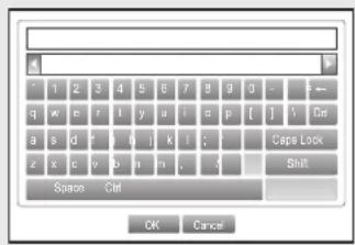
Using Virtual Keyboard
① For alphanumeric inputs, the virtual keyboard window appears.
② Use direction buttons (▲▼◀▶) to move to a desired character, and press the [ENTER] button.
③ In the upper text input box of the virtual keyboard, there displays a list of candidate words containing the selected character.
④ Select a word from the list, or use the keyboard to enter the whole word.
If there are many of candidate words, use < □ □> buttons to move between them forward and backward.
- You can use mouse wheel and jog shuttle button too.
⑤ Select
Entered word is applied.
- For upper case letters, use
button. - For special characters, use
button.
■ Using the virtual keyboard is the same to a normal keyboard use in your region. - You can enter only lower-case alphabets and numeric values for the user ID.
- For the password, use alphabets and special characters excluding < and <
- You can use number buttons on the remote control or front panel.
text_image
1 2 3 4 5 6 7 8 9 0 - q w e r f y a i a p [ ] y Cie a s d f y o j k i ; z x c v b n r , Space Ctrl OK Cancel34\_ using the DVR
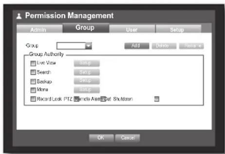
Setting the Group
You can create user groups and setup permissions for those user groups.
You can register a user for each group in
Using the mouse may help make setup easier.
-
Use the up/down buttons (▲▼) in
window to move to , and press [ENTER] button. -
Select
. A window for , , , and setup appears. -
Use direction buttons (▲▼◀▶) to move to a desired item, and set the value.
- Add, Delete, Rename: You can add, delete, rename a group or modify the permissions given to the group.
text_image
Permission Management Admin Group User Setup Group Add Delete Rename Group Authority Live View Simp Search Simp Backup Simp Menu Simp Record Lock PTZ Controls Available Shutdown OK CancelThe virtual keyboard appears when
You can add up to 10 groups.
- Add : When you first run the DVR with the admin account, only the admin account exists. Add has already been deactivated. Select to display the virtual keyboard. Enter a group name. You can add up to 10 groups.
- Delete : Deletes a user group that is already registered. Selecting Delete will delete all user accounts belonging to that group.
- Rename : Renames a group that is already registered. Select
- For entering a group name, refer to "Using Virtual Keyboard". (Page 34)
- Group Authority: Sets permissions to access menu items of each group.
Users of a group can access checked functions.
- When the group setup is done, press
.
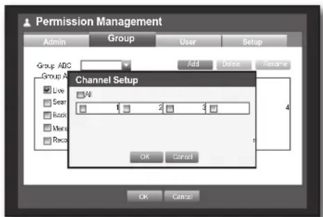
To set the group authority
You can set the permissions of the group users to access the menu according to the channel.
- Select a menu to which the group permission is assigned. The menu where the group permission is assigned will be displayed in the Live menu when a group user logs in.
• Live View : You can set the permission to access the Live screen according to the channel.
- Search : You can set the permission to access the Search menu according to the channel.
- Backup : You can set the permission to access the Backup menu according to the channel.
- Menu : You can set menus accessible with a specific permission.
Group users can access the permitted menus only. Select a menu to display the Menu Permission screen.
- Record Lock, PTZ, Remote Alarm Out, Shutdown: Select an item so that the item will be added to the permissions.
- Select
.
Select and assign a group user so that the user can access the specified menu.
text_image
Permission Management Admin Group User Setup Group ABC Add Dose Rename Group A Channel Setup Live All Gear 1 2 3 Recs Menu Recs OK Cancel OK Cancel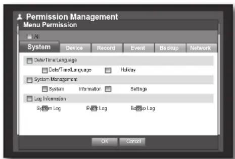
text_image
Permission Management Menu Permission All System Device Record Event Backup Network DeleteTimeLanguage DeleteTimeLanguage Holiday System Management System Information Settings Log Information System Log Event Lag Backup Log OK CancelEnglish _35
using the DVR
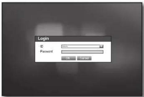
To restrict the user permissions
If the admin restricts all permissions of an added group, the users belonging to that group can access only the default minimum menus and can change the user's own password only.
- Start the DVR. If all permissions are restricted, only the Login dialog should appear.
- Log in with a registered user ID.
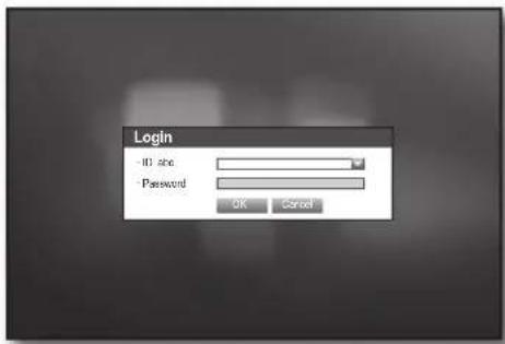
text_image
Login ID site Password OK Cancel- Right-click any area on the screen. If all permissions are restricted, only the accessible context menus should appear.
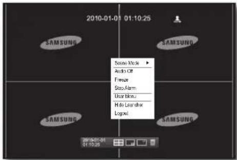
text_image
2010-01-03 01:10:25 SAMSUNG SAMSUNG SAMSUNG SAMSUNG 2010-01-04 01:10:25 Sound Mode ▶ Audio Off Fresor Stop Alarm User Menu Hide Lauder LogoutTo change the user password
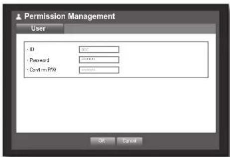
If you log in with a user account that is restricted to access the menu, you can change your own password only.
- Log in with your account.
- Select
. The Permission Management setup screen appears. - Select
. The Password setup dialog appears. - Enter a new password.
- Select
. You change to the password will be applied.
text_image
Permission Management User ID Password Confirm PFW OK Cancel36_ using the DVR
Setting the User
Users can be added only if a group was created in
Using the mouse may help make setup easier.
- Use the up/down buttons (▲▼) in
window to move to , and press [ENTER] button. - Select
.
A window for Add User appears.
- Use direction buttons (▲▼◀▶) to select
from the window.
A window for "Add User" appears.
You can configure the Network Viewer settings including name, ID, viewer, Select Group and password.
Result of the user setup appears in the
To change the user property, use "Edit User".
The "Edit User" window appears when you select a desired item to be changed in the
- Viewer : If you select
■ Refer to "Connecting Web Viewer". (Page 71)
- For more information about use of Network Viewer, refer to the Network Viewer's user guide. (Page 8)
- When the user setup is done, press
.
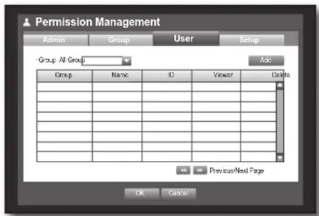
text_image
Permission Management Admin Group User Setup Group All Group Add Group Name ID Viewer Delita Previous/Next Page OK Cancel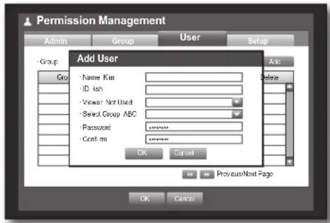
text_image
Permission Management Admin Group User Setup - Group Go - Name Kim - ID ksh - Viewer Not Used - Select Group ABC - Password - Confirm Add User Ask Delete OK Cancel Provision/Next Page OK CancelSetting Permissions
You can set restricted access for all general users.
Items with restrictions will require logging in for use.
Using the mouse may help make setup easier.
- Use the up/down buttons (▲▼) in
window to move to , and press [ENTER] button. - Select
.
The Restricted Access, Restriction on Network Access, Auto Log out, Manual Input of ID setup screen appear.
- Use direction buttons (▲▼◀▶) to move to a desired item, and set the value.
- Restricted Access : All menu items allowed for a user can be set with restricted access.

text_image
Permission Management Admin Group User Setup Restricted Access Live View Back Record Lock Switch PT2 Remoto Alarm Out Shutatzen All Restriction on Network Access All Network Web Viewer Auto Log out 3 min Manual Input of ID On OK Cancel- Checked ( ▼ ) : Restricted
- Not checked (☐): Accessible
If it is not checked (☐) in
If it is checked (☑) in
- Restriction on Network Access: Restricts remote access from a
network. - All Network : Restricts all access instances via Network Viewer and Web Viewer.
- Web Viewer : Restricts access via the Web Viewer.
- Auto Log out : A user will be automatically logged out if there is no operation on DVR for over set period of time.
English _37
using the DVR
- Manual Input of ID : Prompts you to enter the user ID manually for the login process.
-
Checked (☑): Encloses the registered user IDs with the [*] symbols. Use the virtual keyboard to enter the user ID.
-
When the permission setup is done, press
.
text_image
Login ID: 100% Password: OK CancelSystem Management
You can check the system version, update to a newer version, as well as data backup and initialization.
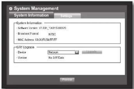
Checking the System Information
You can check the current system version, broadcasting system, MAC address. You can update the system. Using the mouse may help make setup easier.
- Use the up/down buttons (▲▼) in
window to move to , and press [ENTER] button. - Check the Version, Broadcast Format, and MAC Address.
- System Information: Shows the current system's information.
The values can not be changed by a user.
- S/W Upgrade : Updates the DVR's software up to date.
Ex : If you connect to a storage device that has upgradable software installed, and return to the
text_image
System Management System Information Settings System Information - Software Version: V1.00p_130015188029 - Broadcast Format RTSC - MAC Address: 0630F054FF-FF S/W Upgrade - Device Network - Version No S/W Data Previous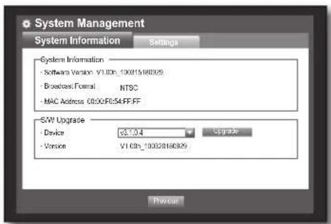
text_image
System Management System Information Settings System Information - Software Version: V1.00h_100015180325 - Broadcast Format: NTSC - MAC Address: C030F054FF-FF SWI Upgrade - Device: V3.0.4 Upgrade - Version: V1.00h_100020180325 Previous38_ using the DVR
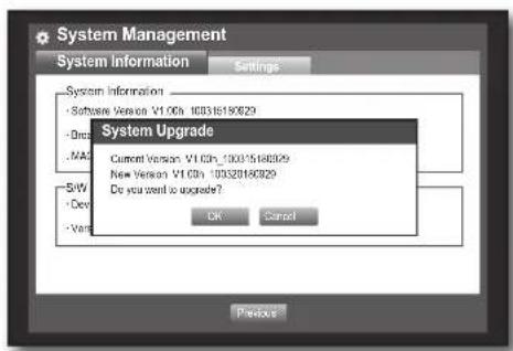
- Updating the Software
- Connect a device storing the software to be updated. (It may take about 10 seconds to recognize the device.)
■ Upgradeable devices include USB memory, CD/DVD and network device.
■ To update the network, the current DVR should have been connected to the network.
Upgrade via the proxy server may not be enabled due to the restricted access.
text_image
System Management System Information Settings System Information - Software Version V1.00h 10B36180929 - Dscs - MAX - SW - Dev - Vee System Upgrade Current Version: V1.00h_100315168099 New Version: V1.00h_100328180929 Do you want to upgrade? OK Cancel Previous- Select
from window. - Select
. - When the recognized device appears, select
.
The .
- Press
in the "System Upgrade" window.
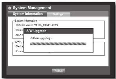
■ While updating, it shows the progress.
- Updating progresses with 3 steps as shown in the figure.
text_image
System Management System Information Settings - System Information - Software Version V1.00b_1635180829 - Break - MAC A S/W Upgrade Software upgrading... S/W U - Device - Version Previous
text_image
System Management System Information Settings - System Information - Software Version V1.00b_16035180829 - Break - MAC A S/W Upgrade Software upgrading... Do not turn off during the upgrade. S/W U - Device - Version Product- When the updating is done, it automatically restarts. Do not turn the power off until it finishes restarting.

If "Upgrade Failed" appears, retry from the step 4. When you experience continued failure, consult the service center for assistance.

text_image
SAMSUNGEnglish _39
using the DVR
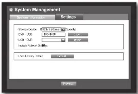
Settings
You can copy and import the DVR settings by using a storage media.
Using the mouse may help make setup easier.
- Use the up/down buttons (▲▼) in
window to move to , and press [ENTER] button. - Select
.
A window of storage device and load factory default appears.
- Use direction buttons (▲▼◀▶) to move to a desired item, and export or import settings data to a storage device.
text_image
System Management System Information Settings • Storage Device: 1037 MB (Roman × Capacity) • DVR = USB 10051400 Export • USB • DVR Import Include Network Settings • Load Factory Default: Default Previous- Storage Device : Shows the connected storage device.
- Export : Exports DVR settings to the connected storage device.
- Import : Imports DVR settings from the storage device and applies to the DVR.
If
- Load Factory Default : If
is selected, a confirmation dialog for "Load Factory Default" prompts. Press to initialize the system to the factory default. - To move to the previous menu, press
.
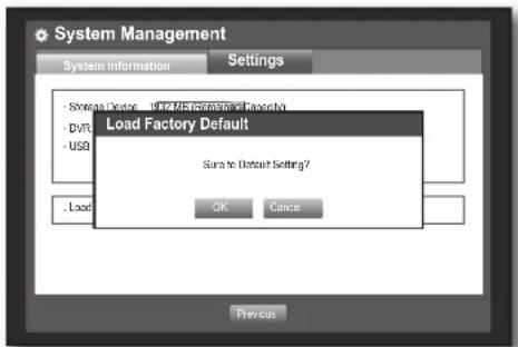
text_image
System Management System Information Settings - Strategic Factory - Internal Application & Security - DVRS - USD Load Factory Default Turn to Default Setting? Load OK Cancel PreviousLog Information
You can browse logs on the system and events.
System Log
System Log shows log and timestamp on every system start up, system shutdown, and changes on system settings.
Using the mouse may help make setup easier.
- Use the up/down buttons (▲▼) in
window to move to , and press [ENTER] button. - Select
.
- Refer to "Using the Calendar". (Page 33) Click on the calendar <图标> to display the calendar window.
- Type : When there are too many logs, you can display logs of the desired format by selecting the type.
- Use direction buttons (▲▼◀▶) to move to a desired item, and press
.
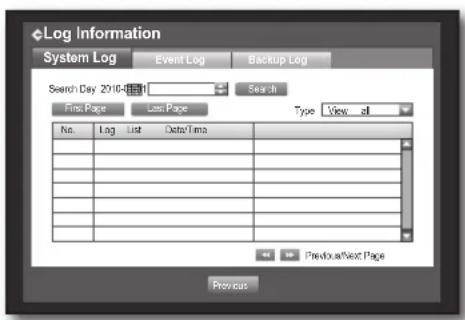
text_image
Log Information System Log Event Log Backup Log Search Day 2010-11-11 Search First Page Last Page Type View all No. Log List Data/Time Previous Next Page Previous40_ using the DVR
Event Log
Event log shows recorded events on alarms, motion detections and video loss.
It also shows the log and its timestamp.
Using the mouse may help make setup easier.
- Use the up/down buttons (▲▼) in
window to move to , and press [ENTER] button. - Select
. - Use direction buttons (▲▼◀▶) to move to the desired item.
- Set Search Day, Channel and Type and the press
.
- Refer to "Using the Calendar". (Page 33) Click on the calendar < □ to display the calendar window.

text_image
Log Information System Log Event Log Backup Log Search Day 2010-08 Search First Page Last Page CH A/C C/S Type View all No Log List Date/Time 7 Voice Detection [CH 1] 2019-31-01 00:02:14 8 Voice Detection [CH 2] 2019-31-01 00:02:14 5 Voice Detection [CH 3] 2019-31-01 00:02:14 4 Voice Detection [CH 4] 2019-31-01 00:02:14 3 Voice Detection [CH 5] 2019-31-01 00:02:14 2 Voice Detection [CH 6] 2019-31-01 00:02:14 1 Voice Detection [CH 7] 2019-31-01 00:02:14 Previous Next Page PreviousBackup Log
You can find out who backed up and the details (backup time, channel, device to use, file format, etc.). Using the mouse may help make setup easier.
- In the
window, press the up/down (▲▼) button to move to and press the [ENTER] button. - Select
. - Use the four direction buttons (▲▼◀▶) to move to a desired item.
- Specify a search term and select
in the right corner. Backup details for the search term will be listed.
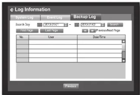
text_image
Log Information System Log Event Log Backup Log Search Day 2410-01-01 2410-01-02 Search First Page Last Page PreviousNext Page No User DataTime Prevo#English _41
using the DVR
SETTING THE DEVICE
You can setup Camera, Storage Device, Remote Device, POS Device and Monitor.
Camera
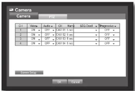
Setting the Camera
You can set Video, Audio, Channel Name and Dwell Time of a Camera.
Using the mouse may help make setup easier.
- Press the [MENU] button on the remote control or front panel.
- Use the left/right button (◀▶) to select
. Device setting menu is selected. - Use the up/down buttons (▲▼) to move to
, and press [ENTER] button.
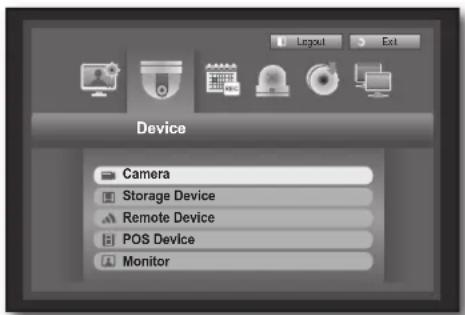
text_image
Device Camera Storage Device Remote Device POS Device Monitor- Select
.
You will see a window where you can configure the camera settings including Video, Audio, Channel Name, Dwell Time and Progressive.
- Use direction buttons (▲▼◀▶) to move to a desired item, and set the value.
- Video
: You can turn ON/OFF the selected channel's camera. : Shows information other than the video of the selected channel.
- For privacy protection, it does not display the video while the recording continues.
-
text_image
Camera Camera PTZ CH Voice Audio CH Name SEQ-Overl TProgression 1 ON OFF CAM 01 5 sec OFF 2 ON OFF CAM 02 5 sec OFF 3 ON OFF CAM 03 5 sec OFF 4 ON OFF CAM 04 5 sec OFF Screen Setup OK Cancel- Audio
- If set to
, you can turn the audio of the channel ON/OFF on the Live screen. - If set to
, the channel's audio is off on the Live screen and not recorded.
■ Audio output is available for only 1 channel.
- CH Name: Up to 15 characters including blanks are allowed.
■ Refer to "Using Virtual Keyboard". (Page 34) - SEQ-Dwell Time: You can set the dwell time between channels for the Live screen and Spot Out.
If set to, the channel is not listed in the Auto Sequence mode.
42\_ using the DVR
• Progressive : You can set the progressive camera to ON/OFF.
If you set it to
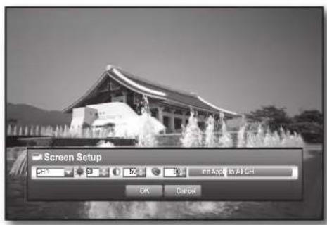
- Screen Setup : The video appeared on the screen may vary depending on the channel's camera, configure the DVR display to your preferences.
Select a channel and adjust the <●(Brightness)>, <○(Contrast)>, and <●(Color)> of the selected channel.
- Press the
- When the camera setup is done, press
.
text_image
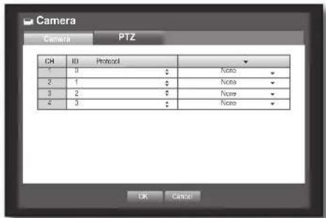
Screen Setup CMYK CMYK 50% 30% FF Apply to All CMYK OK CancelSetting the PTZ
To use Camera's PTZ functions, ID and protocols of each camera and DVR should be matched. For other settings, refer to the "Remote Devices" settings. (Page 46)
Using the mouse may help make setup easier.
-
Use the up/down buttons (▲▼) in
window to move to , and press [ENTER] button. -
Select
. A window of PTZ settings appears. -
Use direction buttons (▲▼◀▶) to move to a desired item, and select it.
- ID : Set the ID of the connected camera of each channel. You can easily setup by using the numeric buttons on the remote control or front panel.
- Protocol: Set the protocol of the connected camera of each channel.
text_image
Camera PTZ CH ID Protocol 1 0 None 2 1 None 3 2 None 4 3 None OK Cancel
You can check the camera's ID and protocol if you turn the camera off and on after connecting it to the DVR. (Page 65)
- When the PTZ setup is done, press
.
English _43
using the DVR
Storage Device
You can check information on storage devices.
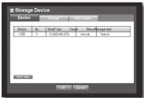
Confirming Devices
You can check storage devices and their free space, usage as well as status. Devices available are HDD, and USB devices (Memory, HDD, CD/DVD). Refer to "Product Specifications > Backup". (Page 96)
Using the mouse may help make setup easier.
-
Use the up/down buttons (▲▼) in
window to move to , and press [ENTER] button. -
Select
. -
No. : Shows the assigned number of the internal HDD.
- To see the detailed positioning of the HDD according to the number, refer to
. - Used/Total : Shows the used/total capacity of the storage device.
- Usage : Sets the storage device's usage.
- USB memory and storage media such as CD/DVD are used for backup purpose only.
-
Status/Management : Shows the current status of the HDD, as in Normal/Check/Replace.
-
Normal : Available to use
- Check : Available to use but recommended to replace
- Replace : Requires immediate replacement.
- HDD Map : Shows the internal HDD's locations according to assigned numbers.
■ Refer to this for servicing or additional HDD installation.
- To move to the previous menu, press
.
text_image
Storage Device Device Format HDD Alarm Device No Used/Total Usage Status/Management HDD 1 12.28G/499.07G Internal Normal HDD Step OK Cancel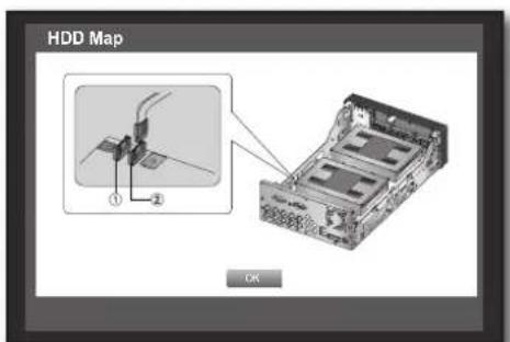
text_image
HDD Map ① ② OK
text_image
HDD Map ① (5V) OK44_ using the DVR
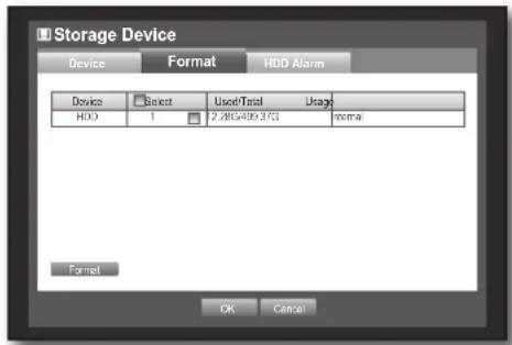
Formatting
You can format a storage device.
Using the mouse may help make setup easier.
- Use the up/down buttons (▲▼) in
window to move to , and press [ENTER] button. - Select
.
A window for selection of device for formatting appears.
- Use direction buttons (▲▼◀▶) to select a device to be formatted.
text_image
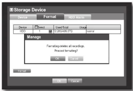
Storage Device Device Format HDD Alarm Device Select Used/Total Usage HDD 1 2.28G499 375 normal Format OK Cancel- Select
on the bottom of the screen. Press on the "Manage" confirmation window will start formatting the selected device. - When the formatting is done, press
.
text_image
Storage Device Device Format HDD Alarm Device Select Used/Total Usage HDD 1 2.28G499.37G normal Manage Formatting deletes all recordings. Processed formatting? OK Cancel Format OK CancelHDD Alarm
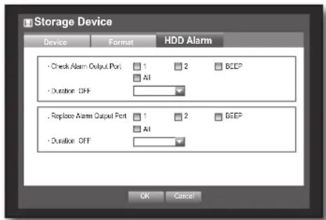
You can set alarm settings for HDD defects such as Check Alarm Output Port, Replace Alarm Output Port, and its duration.
Using the mouse may help make setup easier.
- Use the up/down buttons (▲▼) in
window to move to , and press [ENTER] button. - Select
.
A window for setting HDD check and replace output ports and their durations appears.
- Use direction buttons (▲▼◀▶) to move to the desired item.
- Alarm
- Alarm signal will output through the alarm out port on the rear side when selected <1>, <2>.
- If
- If
- Check Alarm Output Port : If HDD generates check alarm, the alarm signal will output to the specified alarm output port.
- Replace Alarm Output Port : If HDD generates replace alarm, the alarm signal will output to the specified alarm output port.
text_image
Storage Device Device Format HDD Alarm • Check Alarm Output Port 1 2 BEEP All • Duration OFF • Replace Alarm Output Port 1 2 BEEP All • Duration OFF OK CancelEnglish _45
using the DVR
- Duration: Sets the alarm duration for the alarm signal and beep sound.
- If
was selected, a beep will sound. - If
was selected, both beep sound and alarm signal through rear side ports will output.

-
(☐) appears on the Live screen.
-
( ) appears on the Live screen.
- When the HDD Alarm setup is done, press
.
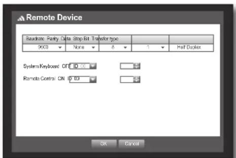
Remote Devices
You can set the RS-485 communication for use of PTZ Camera and system keyboard with the DVR.
Using the mouse may help make setup easier.
- Use the up/down buttons (▲▼) in
window to move to , and press [ENTER] button. - Use direction buttons (▲▼◀▶) to move to the desired item, and press [ENTER] button.
- Set the values of each communication setup of the remote device.
- Baudrate: Baud rate settings of the DVR, PTZ camera and system keyboard should be matched for proper operations.
- Make sure to match IDs of the DVR, System Keyboard and Remote Control, and press
.
text_image
Remote Device Baudate: Parity Data Stop Bit Transfer type 9600 None 8 1 Half Duplex System Keyboard OFF ID 20 Remote Control CN ID 30 OK Cancel
For changing the remote control's ID, refer to "Changing the Remote Control ID". (Page 12)
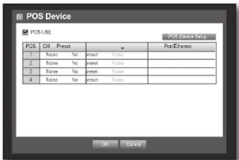
POS Devices
You can set properties of POS devices connected to the DVR.
A POS device connection requires channel, preset, and Port/Ethernet settings.
Using the mouse may help make setup easier.
- Use the up/down buttons (▲▼) in
window to move to , and press [ENTER] button. - Use direction buttons (▲▼◀▶) to move to a desired item, and set the value.
- POS USE: When selected
, DVR and POS will be connected.

If you change settings for the device and press
text_image
POS Device POS USE POS Device Setup POS CH Presset PortEthernet 1 Nano No presset None 2 Nano No presset None 3 Nano No presset None 4 Nano No presset None OK Cancel46_ using the DVR
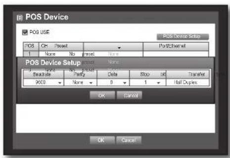
- POS Device Setup : Sets the communication setups for the POS device and DVR.
It is independent to the Remote Device setup.
text_image
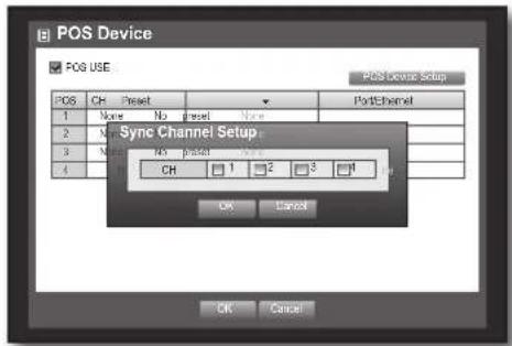
POS Device POS USE Post Channel Setup POS CH Preset Port/Channel 1 None No Preset None POS Device Setup Preset None: Sequence No Preset Data Stop Off Transfer 960 None 8 1 Half Duplex OK Cancel OK Cancel- CH: Select the camera to be synchronized to the POS device.
If selected a channel input fi eld, "Sync Channel Setup" window appears.
■ One POS device can be synchronized to up to 4 cameras (channels), however one channel cannot be synchronized to multiple POS devices.
Channels to be synchronized to a POS device should be set to "Event" in "Main Menu > Record > Recording Schedule". (Page 50)
text_image
POS Device POS USE POS receive setup POS CH Preset 1 None No Preset None 2 None No Preset 3 None NO Preset 4 Sync Channel Setup CH 1 2 3 4 OK Cancel OK Cancel- Preset : Sets the name, start and end strings of the receipt for the preset.
■ Preset name should be unique.
- Use
- Port/Ethernet : Sets the port number for the DVR and POS device connection.
■ COM1 : For RS-232C connections
7001\~7016: For Ethernet connections

text_image
POS Device Preset Setup Add Preset Name: Start Keyword End Keyword OK Cancel OK Cancel OK Cancel- When the POS Device setup is done, press
.
English _47
using the DVR
Monitor
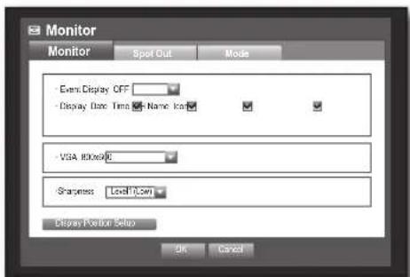
You can configure information to be displayed and its format for Spot Out monitor.
Setting the Monitor
Using the mouse may help make setup easier.
- Use the up/down buttons (▲▼) in
window to move to , and press [ENTER] button. - Select
. - Use direction buttons (▲▼◀▶) to move to a desired item, and set the value.
- Event Display : Sets the dwell time of the event channel display on the monitor when an event occurs.
If selected
- Display : Displays only checked items on the monitor screen.
- VGA: The current monitor may not display the video if the
- Sharpness: You can adjust the sharpness of the video output signal.
- When the monitor setup is done, press
.
Setting Display position
Some monitors many not display information (camera name, icon, time information, etc.) about the DVR, depending on the condition. Then, you can change the display position of the data.
- In the
window, press the up/down (▲▼) button to move to and press the [ENTER] button. - Select the
item. - Select
in the bottom. You will move to the window. - Use the four direction buttons or the number buttons on the front panel or the remote control to adjust the data position.
text_image
Monitor Monitor Spot Out Mode - Event Display OFF - Display Date Time - Name Icon - VGA Interface Sharpness Level Copy Display Position Setup OK Cancel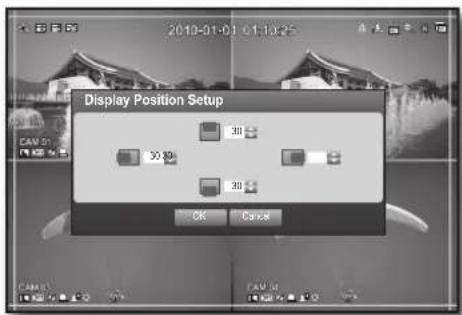
text_image
2010-01-01 01:10:25 Display Position Setup 30 30 30 OK Cancel48_ using the DVR
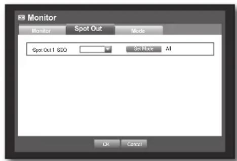
Setting the Spot Out
You can set the DVR to output information / video apart from the monitor out.
Using the mouse may help make setup easier.
- Use the up/down buttons (▲▼) in
window to move to , and press [ENTER] button. - Select
.
- The number of Spot Out terminals differs according to the model.
-
Use direction buttons (▲▼◀▶) to move to a desired item, and set the value.
-
Spot Out 1: You can select between Auto Sequence, and Single.
- Set Mode: A window for "Set Spot Out" appears and you can set the channel for it. You can set the dwell time between the screen switching in "Setting the Device > Camera > SEQ-Dwell Time". (Page 42)

- You can setup using the mouse right button in Live screen. Refer to "Spot Out". (Page 29)
- When the Spot Out is done, press
.
text_image
Monitor Monitor Spot Out Mode Spot Out 1 SEQ Set Mode All Ok Cancel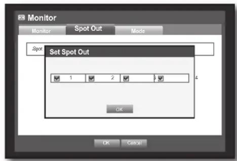
text_image
Monitor Monitor Spot Out Mode Spot Set Spot Out 1 2 3 OK CancelSetting the Screen Mode
You can configure the Live screen and Split Screens.
Using the mouse may help make setup easier.
- Use the up/down buttons (▲▼) in
window to move to , and press [ENTER] button. - Select
. - Use direction buttons (▲▼◀▶) to move to a desired item, and set the value.
• Live Screen : Select split modes for the Live screen. 4-split screens are included by default.
- Play Screen: Select split modes for the playback screen. Single screen and 4-split screen are provided by default.
6. When the screen mode setup is done, press
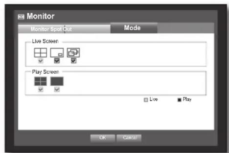
text_image
Monitor Monitor Spot Out Mode Live Screen Play Screen Live Play OK CancelEnglish _49
using the DVR
SETTING THE RECORDING
You can setup scheduled recording, event recording and other recording related settings.
Recording Schedule
Make your reservation on a date and time to schedule the recording on specified time.
Using the mouse may help make setup easier.
- Press the [MENU] button on the remote control or front panel.
- Use the left/right button (◀▶) to select
. Record menu is selected. - Use the up/down buttons (▲▼) to move to
, and press [ENTER] button.
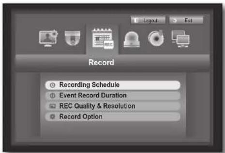
text_image
Record Recording Schedule Event Record Duration REC Quality & Resolution Record Option- Select
. A window of scheduled recording setup appears. - Use direction buttons (▲▼◀▶) to move to a desired item, and set the value.

text_image
Recording Schedule CH1 At 0 1 2 3 4 5 6 7 8 9 0 1 2 3 4 5 6 7 8 9 10 Sun = Win = Tue = Wed = Thu = Fri = Sat = Thu = No Recording Coordinate Event By Carish Apply to A1 C# OK Cancel- Apply to All CH: If selected
, "Apply to All CH" window appears.
Pressto apply the setup to all channels. - When the recording schedule setup is done, press
.
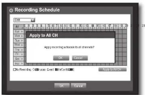
text_image
Recording Schedule CH Apply to All CH Apply recording schedule to all channels? OK Cancel No Recording Call user Event In Cor NS Apply to All CH OK Cancel50_ using the DVR
Recording Color Tags
| Color Function Description | |
| White No Recording No schedule / event recording | |
| Orange Continuous Scheduled recording only | |
| Blue Event Event recording only | |
| Green Both(Cont&Evnt) Both scheduled / event recordings | |
Each press of a selected cell will cycle through
Event Record Duration
You can set the beginning and ending point of a recording on an event. Using the mouse may help make setup easier.
- Use the up/down buttons (▲▼) in
window to move to , and press [ENTER] button. - Use direction buttons (▲▼◀▶) to move to a desired item, and set the value.
- Pre Event: The recording of an event will start at a pre-determined time prior to the actual occurrence of the event. If it is set to 5 seconds, the recording begins from 5 seconds before the event.
- POST Event : The recording will continue for a pre-determined time after the actual end of an event. If it is set to 5 seconds, the recording ends in 5 seconds after an event.
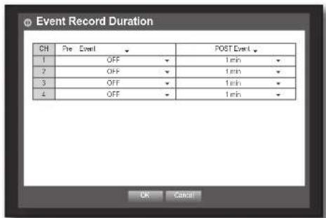
text_image
Event Record Duration CH Pre Event POST Event 1 OFF 1 min 2 OFF 1 min 3 OFF 1 min 4 OFF 1 min OK Cancel- When the event recording duration setup is done, press
.
REC Quality / Resolution
You can set resolution, IPS, and quality of recordings by channel, and by recording type of standard / event.
Setting Standard Recording Properties
You can set each channel's resolution, quality and IPS for normal recordings. Using the mouse may help make setup easier.
- Use the up/down buttons (▲▼) in
window to move to , and press [ENTER] button. - Select
. - When the recording setup is done, press
.
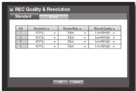
text_image
REC Quality & Resolution Standard Event CH Resolution▼ Record Ratio▼ Record Quality▼ 1 4CIF(L) 30us Low@High▼ 2 4CIF(L) 30us Low@High▼ 3 4CIF(L) 30us Low@High▼ 4 4CIF(L) 30us Low@High▼ OK CancelEnglish _51
using the DVR
Setting Event Recording Properties
You can set each channel's resolution, quality and IPS for event recordings.
Using the mouse may help make setup easier.
-
Use the up/down buttons (▲▼) in
window to move to , and press [ENTER] button. -
Select
. Event recording setup window appears. -
Use direction buttons (▲▼◀▶) to move to a desired item, and select it.
- Resolution : Sets the resolution of the recorded screen.
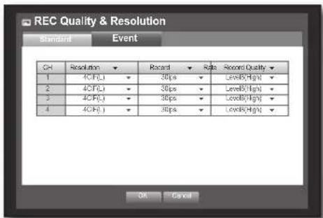
text_image
REC Quality & Resolution Standard Event CH Resolution Record Ratio Record Quality 1 4CFU 30ps LevelB(High) 2 4CFU 30ps LevelB(High) 3 4PUJ 30ps LevelB(High) 4 4CHJ 30ps LevelB(High) OK CancelResolution
| Name Resolution Description | |
| CIF(S) NTSC: 352 X 240, PAL: 352 X 288 | Samples each half of horizontal and vertical screen. |
| 2CIF(M) NTSC: 704 X 240, PAL: 704 X 288 Samples half of the horizontal screen. | |
| 4CIF(L) NTSC: 704 X 480, PAL: 704 X 576 Samples original screen size. | |
- Record Rate : Image Per Second, means the frames recorded per a second.
• Record Quality : Sets the recording quality.
- When the Event recording setup is done, press
.
Record Option
You can set the recording to stop or overwrite when the HDD is full.
Using the mouse may help make setup easier.
-
Use the up/down buttons (▲▼) in
window to move to , and press [ENTER] button. -
Use direction buttons (▲▼◀▶) to move to a desired item, and set the value.
- Disk End Mode : If selected
- Disk End Beep : If selected
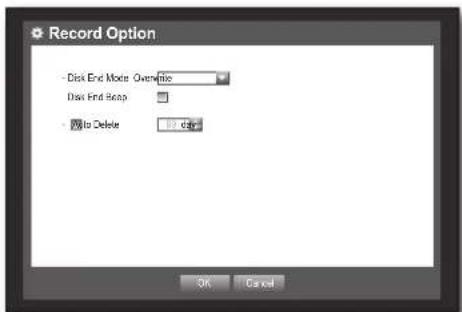
text_image
Record Option Disk End Mode: Optimize Disk End Stamp To Delete OK Cancel52_ using the DVR
- Auto Delete : If you check it, Record Period setup is activated. If you setup the auto delete, recorded data only in the configured period are searchable.
- When the recording option setup is done, press
.
SETTING THE EVENT
You can set recording options for sensor, motion, and video loss event.
Sensor Detection
You can set the sensor's operating condition and connected camera, as well as alarm output and its duration. Using the mouse may help make setup easier.
-
Press the [MENU] button on the remote control or front panel.
-
Use the left/right button (◀▶) to select
. Event setting menu is selected.
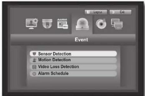
text_image
Event Sensor Detection Motion Detection Video Loss Detection Alarm Schedule-
Use the up/down buttons (▲▼) to move to
, and press [ENTER] button. A window of sensor detection setup appears. -
Use direction buttons (▲▼◀▶) to move to a desired item, and set the value.
- Sensor Operation: Sets the operation mode of sensors.
: Sensor does not operate. : Sensor is opened. If the sensor is closed, it generates alarm. : Sensor is closed. If the sensor is open by interruption, it generates alarm.
- Cam : Select a channel to be connected to the sensor. If selected camera, "Cam Preset setup" window appears. Select a channel and setup the preset.
■ Preset setup can be done in PTZ mode.
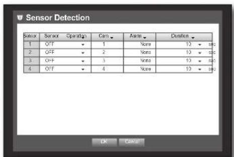
text_image
Sensor Detection Sensor Operation Cam Asms Duration 1 OFF 1 None 10 # 2 OFF 2 None 10 # 3 OFF 3 None 10 # 4 OFF 4 None 10 OK Cancel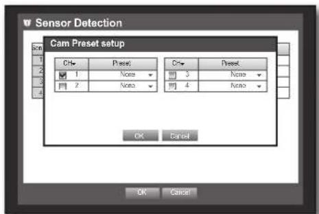
text_image
Sensor Detection Cam Preset setup CH# Preset 1 None 2 None Ch# Preset 3 None 4 None OK Cancel OK CancelEnglish _53
using the DVR
• Alarm : Sets the alarm output method.
- For further information on alarm output, refer to "HDD Alarm > Alarm". (Page 45)
- Duration: Sets the duration of alarm signal and alarm sound.
- When the sensor detection setup is done, press
.
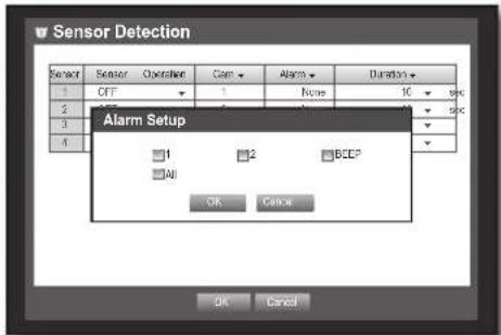
text_image
Sensor Detection Sensor Sensor Operation Cam Alarm Duration 1 CFF 1 None 10 sec 2 2 BCEP 3 3 4 4 Alarm Setup 1 2 BCEP All OK Cancel OK CancelMotion Detection
You can set target detection region and motion, as well as the alarm signal output.
When the motion detection region is set, it detects motion within the area.
Using the mouse may help make setup easier.
-
Use the up/down buttons (▲▼) in
window to move to , and press [ENTER] button. A window of motion detection area setup appears. -
Use direction buttons (▲▼◀▶) to move to a desired item, and set the value.
- Mode: Sets whether to activate motion detection.
- Sensitivity: Sets the sensitivity level of the motion detection.
- Alarm: Sets the alarm output method.
- For further information on alarm output, refer to "HDD Alarm > Alarm". (Page 45)
- Alarm Duration : Sets the duration of alarm signal and alarm sound.
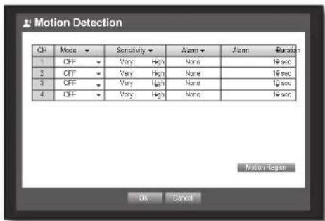
text_image
Motion Detection CH Mode ✓ Sensitivity ✓ Alarm ✓ Alarm # Duration 1 OFF ✓ Very High None No sec 2 OFF ✓ Very High None No sec 3 OFF ✓ Very Light None 12 sec 4 OFF ✓ Very High None No sec Motion Region OK Cancel- When the motion detection setup is done, press
.
Setting the Motion Detection Area
① Select
② When "Motion Region" window appears, select a channel for detection and set the area of motion detection.
- To set the area in "Motion Region" window
In the "Motion Region" window, select desired region from <.
- To set the area using
In the "Motion Region" window, you can select cells individually by using
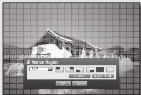
text_image
Motion Region 1 CH Pakual Apply to CH OK CancelWhen selected
- Select : Selected cell is set to be a part of motion detection area.
- Unselect : Selected cell is removed from the motion detection area.
- Inverse : Unselected cells are set to be the motion detection area.
- Menu : After selecting individual motion areas, move to the "Motion Region" window.
If selected, selected motion area is applied to all channels.
③ When the motion detection setup is done, press
Select Unselect Inverse Menu
54_ using the DVR
Video Loss Detection
You can set the alarm to be generated on a camera disconnection, which causes a video loss.
Using the mouse may help make setup easier.
- Use the up/down buttons (▲▼) in
window to move to
A window of video loss detection area setup appears.
- Use direction buttons (▲▼◀▶) to move to a desired item, and set the value.
• Video Loss State : Sets whether to activate video loss detection.
- Alarm : Sets the alarm output method.
- For further information on alarm output, refer to "HDD Alarm > Alarm". (Page 45)

text_image
Video Loss Detection CH Video Loss State ▼ Alarm ▼ Alarm ▼ Duration 1 OFF ▼ None 10 sec ▼ 2 OFF ▼ None 10 sec ▼ 3 OFF ▼ None 10 sec ▼ 4 OFF ▼ None 10 sec ▼ OK Cancel- Alarm Duration: Sets the duration of alarm signal and alarm sound.
- When the video loss detection setup is done, press
.
Alarm Schedule
You can set the conditions and operating hours for scheduled alarms.
Using the mouse may help make setup easier.
- Use the up/down buttons (▲▼) in
window to move to , and press [ENTER] button. - A window of
settings appears. - Alarm : Sets the alarm output method.
- For further information on alarm output, refer to "HDD Alarm > Alarm". (Page 45)
: Marked in orange, and always generates alarm on scheduled time. : Marked in white, no alarm is generated even if an event occurs. - Event Sync : Marked in Blue, generates alarm only when an event occurs.
- Apply to All Alarm: Applies the configured schedule to all alarms.

- When the alarm is generated on the scheduled time, you can stop the alarm by canceling the schedule.
- When the Alarm Schedule setup is done, press
.
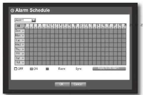
text_image
Alarm Schedule Alarm1 All 0 1 2 3 4 5 6 7 8 9 10 11 12 13 14 15 16 17 18 19 20 21 22 23 Sum = Mon = Tue = Wed = Thu = Fri = Sat = Vol = OFF ON Event Sync Apply to All Alarm OK Cancel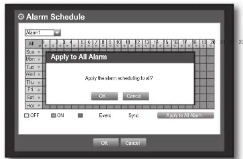
text_image
Alarm Schedule Alarm1 All Sun = Mon = Tue = Wed = Thu = Fri = Sat = Hol = Apply to All Alarm Apply the alarm scheduling to all? OK Cancel Apply to All Alarm OFF ON Event Sync OK CancelEnglish _55
using the DVR
BACKUP
You can check the backup device and set the backup schedule by channel or by time. The product only supports external HDD of USB memory/DVD and USB type. (Page 96)
Setting the Backup
You can backup the desired data to a connected device. Using the mouse may help make setup easier.
-
Press the [MENU] button on the remote control or front panel.
-
Use the left/right button (◀▶) to select
. Backup menu is selected.
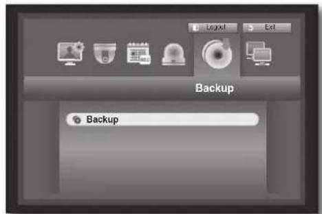
text_image
Backup Backup-
Press the [ENTER] button. A backup window appears. You can directly access it from the "Live screen menu". (Page 24)
-
Use direction buttons (▲▼◀▶) to move to a desired item, and set the value.
- Backup Range : Sets the
- Channel; Sets the channel to backup. You can select multiple channels.
- Device : Select a backup device from the recognized devices. If the built-in internal CD/DVD or external USB CD/DVD is used for the backup, you can select the format of recording between AVI and SEC.
■ Since SRD-470 model does not have built-in internal DVD Writer, internal CD/DVD backup is not available.
- Type: Sets the backup data format.
- AVI : Saves the CODEC information provided by the DVR with the recording data, and saved data can be played back by using external viewers (such as Windows Media Player) on a PC.
- DVR : Saved data can be played back only by the DVR.
- SEC : Saves data in the Samsung's proprietary format with built-in viewer, which supports immediate playback on a PC.
- Filename: You can set the back file name.
■ Refer to "Using Virtual Keyboard". (Page 34)
- Check capacity: Shows the size of the selected backup data, used and available capacity of the selected backup device.
- Checking will stop if the backup size is over 200%.
• Overlap : Shows a list of overlapping data on a same time according to the number of data. It appears when one channel has multiple data on a certain time point due to changing of time or time zone settings, etc.
■ Refer to time and time zone of "Setting the Date/Time/Language". (Page 32)

text_image
Backup Start End 2010-01-01 02:31:08 - 2019:01-01 08:25:45 1 2 3 4 ALL Device USB Storage Folder (0/10/10) Type 2VR Filename 0001 Change Backup Used Free OK Cancel56_ using the DVR
- When the backup setup is done, press
.
If no available device is recognized for backup,

■ The application may slow down during the backup.
- You can switch to the menu screen during the backup in operation, but playback of data is not available.
- When a CD/DVD or memory device is used for backup, it is not available to use the full capacity of the media since the system consumes a part of its capacity.
If a CD or DVD media causes errors, the disc tray opens and closes a several times, and eventually backup process will fail. In this case, replace the CD/DVD media and try again.

- Pressing the
It provides networked monitoring of Live screen from a remote place, and supports mail forwarding function with events. You can configure the network environment which enables such functions.
Connection Mode
You can set the network connection route and protocol.
Setting the Connection
Sets the protocol and environment of the network.
Using the mouse may help make setup easier.
- Press the [MENU] button on the remote control or front panel.
- Use the left/right button (◀▶) to select
. Network menu is selected. - Use the up/down buttons (▲▼) to move to
, and press [ENTER] button.
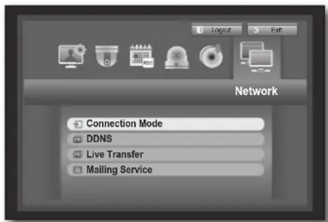
text_image
Network Connection Mode DDNS Live Transfer Mailing Service- Select
.
A window of connection mode setup appears.
-
Use direction buttons (▲▼◀▶) to move to a desired item, and set the value.
-
Connection Mode: Sets the network connection mode.
- Bandwidth : Sets the maximum data flow to be transferred. (Upload speed)
Options will vary depending on the selected connection mode.
- For
- For
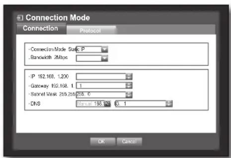
text_image
Connection Mode Connection Protocol • Connection Mode Safe P . Bandwidth 2Mbps • IP 192.168, 1.200 • Gateway 192.168, 1.1 • Subnet Mask 265.268/265.6 • DNS Manual 188.168 63.1 OK CancelEnglish _57
using the DVR
• IP, Gateway, Subnet Mask, and DNS
- For
- For
- For
- User ID, Password: In case you selected ADSL, provide the "User ID" and its "Password".
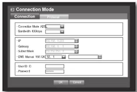
text_image
Connection Mode Connection Protocol • Connection Mode ADS_ • Bandwidth 600kbps • IP 98.158.1.300 • Gateway 98.158.1.1 • Subnet Mask 98.756.756.3 • DNS Manual 158.126.53.1 • User ID: • Password Password OK Cancel
DNS server for
- When the connection setup is done, press
.
Setting the Protocol
-
Use the up/down buttons (▲▼) in
window to move to , and press [ENTER] button. -
Select
. -
Use direction buttons (▲▼◀▶) to move to a desired item, and set the value.
- Protocol Type : Select the protocol type between TCP and UDP.
If selected UDP, selections of Port (TCP), Port (UDP), and Unicast/Multicast are activated.
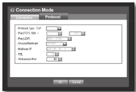
text_image
Connection Mode Connection Protocol + Protocol Type TCP + Pon(TCP) 554 ~ + Pon(LDP) . Unicast/Multicast + Multicast IP + TTL + Webserver Port OK Cancel- Port (TCP) : Initially, <554\~557> is set. It increases / decreases by 4.
- TCP: It has better stability and lower speed when compared to UDP, and recommended for internet environments.
- Port (UDP) : Initially, <8000\~8159> is set. It increases / decreases by 160.
- UDP: It has less stability and faster speed when compared to TCP, and recommended for local area network (LAN) environments.
- Unicast/Multicast : Select one between Unicast and Multicast. If selected Multicast, Multicast IP and TTL are activated.
- Unicast : Transfers data (UDP, TCP) individually to each connecting client.
- Multicast : Multiple client can receive the data (only in UDP) without putting additional traffic load to the network.
- Multicast IP : User can directly input.
- TTL: Select from 0 \~ 255. Initial value for the TTL is set to <5>.
- Webviewer Port : Enter the port number for the Web Viewer. Initially, it is set to <80>.
- When the protocol setup is done, press
.
58_ using the DVR
DDNS
You can set the DDNS site for a remote user's network connection.
Using the mouse may help make setup easier.
-
Use the up/down buttons (▲▼) in
window to move to , and press [ENTER] button. -
Use virtual keyboard to enter user inputs.
■ Refer to "Using Virtual Keyboard". (Page 34)
If selected
- When the DDNS setup is done, press
.

■ Refer to
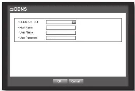
text_image
DDNS • DDNS Size: OFF • Host Name • User Name • User Password OK CancelConnecting and Setting the Network
Networking may differ from the connection method, check your environment before setting the connection mode.
When no router is used
- Static IP mode
- Internet connection : Static IP ADSL, leased line, and LAN environments allows connection between the DVR and remote user.
- DVR Network Settings : Set the
- Consult your network manager for IP, Gateway and Subnet M
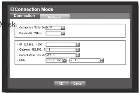
text_image
Connection Mode Connection Protocol . Connection Mode Static IP . Bandwidth 2Mbps IP 192.168, 1.200 Gateway 192.168, 1, 1 Subnet Mask 255.255.255, 0 DNS 43.168, 168, 168, 168, 168, 168, 168, 168, 168, 168, 168, 168, 168, 168, 168, 168, 168, 168, 168, 168, 168, NC OK Cancel• Dynamic IP (DHCP) mode
- Internet connection : Connect the DVR directly to a cable modem, DHCP ADSL modem or FTTH network.
- DVR Network Settings : Set the
- ADSL (PPPoE: ID and password certification)
- Internet connection : An ADSL modem is directly connected to the DVR, where the ADSL connection requires user ID and password.
- DVR Network Settings : Set the
- ADSL
If you don't know the ID and password, consult your ADSL provider.
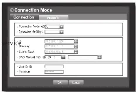
text_image
Connection Mode Connection Protocol . Connection Mode A26L . Bandwidth 900kbps . IP 182.185.1.200 . Gateway 182.185.1.1 . Subnet Mask 265.265.265.0 . DNS Manual 168.128.63.1 . User ID ID . Password OK CancelEnglish _59
using the DVR
When a router is used
To avoid IP address conflict with the DVR's static IP, check followings :
- Setting the DVR with a static IP
- Internet connection : You can connect the DVR to a router which is connected to an ADSL/Cable modem or a router in a Local Area Network (LAN) environment.
-
Setting the DVR Network
-
Set the
in menu of the connected DVR to . - Check whether the set IP address is in the static IP range provided by the IP router.
IP, Gateway, and Subnet Mask : Consult your network manager.
- Check whether the set IP address is in the static IP range provided by the IP router.
If a DHCP server is configured with starting address (192.168.0.100) and end address (192.168.0.200), you should set the IP address out of the configured DHCP range (192.168.0.2 \~ 192.168.0.99 and 192.168.0.201 \~ 192.168.0.254).
- Check the Gateway address and subnet mask are equal to those set in the IP router.
- Setting the DHCP IP Address of the IP router
- To access the IP router's configurations, open a web browser on the local PC that is connected to the IP router and enter the router's address (ex: http://192.168.1.1).
- At this stage, make the local PC's windows network configurations to the below example :
- Once connected to the IP router, it prompts with password. While entering nothing to the User Name fi eld, enter "admin" into the password field and press
to access the router configurations. - Access the router's DHCP configuration menu and set its DHCP server activation, and provide the start and end address.
Set the start address (192.168.0.100) and end address (192.168.0.200).
■ Above steps may differ from the router devices depending on the manufacturer.
- Setting Router's Port Forwarding
- Set the protocol to
. - External Port Range : Enter the TCP Port set in the
menu of the connected DVR. If more than one DVRs are connected to the router, the TCP port can be different. - Internal PC IP Address : Enter the IP address set to the
in menu of the connected DVR. - Internal Port Range : Set the same to the "External Port Range".
■ Above steps may differ from the router devices depending on the manufacturer.
Port forwarding is required when you want to access the DVR connected to the router from outside of the router's network.
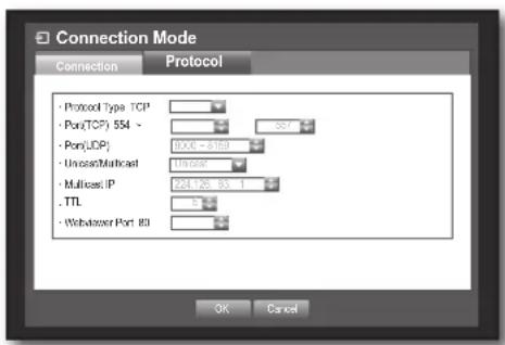
text_image
Connection Mode Connection Protocol Protocol Type TCP Port(TCP) 554 - Port(UDP) Unreal/Multaneous Multicost IP . TTL Webserver Port 80 OK Cancel60_ using the DVR
DDNS Setting
DDNS is a short form of Dynamic Domain Naming System.
DNS (Domain Name System) is a service that routes a domain name consisting of user friendly characters (ex : www.google.com) to an IP address consisting of numbers (64.233.189.104).
DDNS (Dynamic DNS) is a service that registers a domain name and the floating IP address with the DDNS server so that the domain name can be routed to the IP address even if the IP is changed in a dynamic IP system.
- Setting DDNS in the DVR
Set
Ex) Protocol Type : TCP
Port (TCP) : 0554,0555,0556,0557
• DDNS Settings of the Router
Select the corresponding menu for the network transfer protocol of the router.
Live Transfer
Sets the quality of the image that is transferred from the DVR to the network. Using the mouse may help make setup easier.
-
In the
setting window, press the up/down (▲▼) button to move to and press the [ENTER] button. The Live Transfer window appears. -
Use the direction buttons (▲▼◀▶) to move to a desired item and set the value.
-
When the live transfer is done, press
. For the resolution of the live transfer, refer to "Resolution". (Page 52)
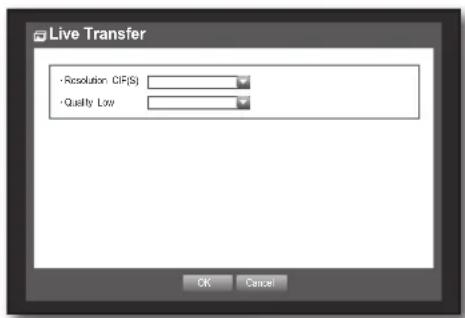
text_image
Live Transfer • Resolution: CIF(S) • Quality Low OK CancelEnglish _61
using the DVR
Mailing Service
You can send an e-mail to a DVR-registered user at a specific time interval, or if an event occurs.

If an event occurs with a channel where the camera's video is set to
SMTP Setting
Sets the SMTP mail server.
Using the mouse may help make setup easier.
- In the
setting window, press the up/down (▲▼) button to move to and press the [ENTER] button. - Select
. You will see the SMTP setting window. -
Use direction buttons (▲▼◀▶) to move to a desired item and set the value.
-
ServerType : Displays the connected server type.
- Server : Enter a server to connect to.
- Port : Sets the communication port.
- Use Authentication : Check this if the SMTP server uses user authentication. The account input box will be activated.
- User : Enter a user to use authentication when connecting to the SMTP server.
- Password : Enter the password of the SMTP server user.
- Secure Transfer : Select one from
and - Sender: Use the virtual keyboard to enter the sender's e-mail address.
■ Refer to "Using Virtual Keyboard". (Page 34)
- TEST : Conducts the test on the server settings.
- When the SMTP setting is done, press
.
Event Setting
You can set the interval and type of the event that will be sent to the user.
Using the mouse may help make setup easier.
- In the
setting window, press the up/down (▲▼) button to move to and press the [ENTER] button. - Select
. - Use direction buttons (▲▼◀▶) to move to a desired item and set the value.
• Event Interval : Set the event interval.
If a series of events occurs, the e-mail will be sent at the specified interval, not on each event.
- Use Event Transfer : Select an event type to send if an event occurs. If the selected event occurs, the e-mail will be sent to the group that has the recipient authority.
- When the event setting is done, press
.

text_image
Mailing Service SMTP Event Group Recipient Server Type SMTP mail Server Server Port: 25 Use Authentication User Password Secure Transfer None Sender ex notes@example.net. TEST UK Cancel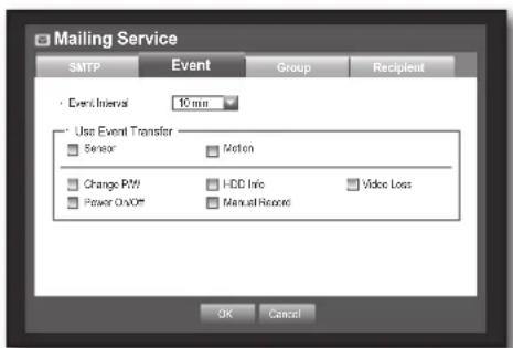
text_image
Mailing Service SMTP Event Group Recipient Event Interval 10 min Use Event Transfer Sensor Motion Change P/W HDD Info Video Loss Power On/Off Manual Record OK Cancel62_ using the DVR
Group Setting
You can set the group to whom the e-mail is sent, and specify the permission for each group.
You can add recipients for each group in the
The recipient is set separately from the DVR user group.
Using the mouse may help make setup easier.
-
In the
setting window, press the up/down (▲▼) button to move to and press the [ENTER] button. -
Select
. -
Use direction buttons (▲▼◀▶) to move to a desired item and set the value.
- Add : Select
■ Refer to "Using Virtual Keyboard". (Page 34)
- Delete : Deletes the selected group.
- Rename: You can reset the recipient permission of an existing group.
- Recipient Permission: Set the permission of the recipient group.
- When the group setting is done, press
.
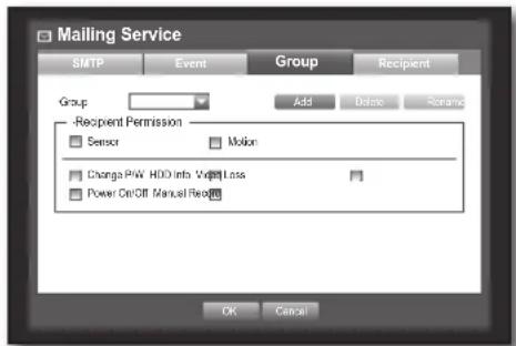
text_image
Mailing Service SMTP Event Group Recipient Group Add Delete Retname -Recipient Permission Sensor Motion Change P/W HDD Info Vr/V Loss Power On/Off Manual Reset OK CancelRecipient Setting
You can add a user to the group or delete him/her from the group, or change the group.
Using the mouse may help make setup easier.
-
In the
setting window, press the up/down (▲▼) button to move to and press the [ENTER] button. -
Select
. -
Use direction buttons (▲▼◀▶) to move to a desired item and set the value.
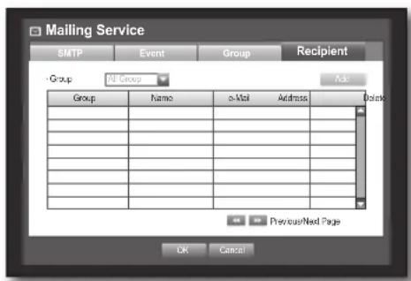
text_image
Mailing Service SMTP Event Group Recipient Group All Group Ask Group Name o-Mail Address Address Previous/Next Page OK Cancel- Add: You can select a recipient name, e-mail address or group.
You should have created a group in the
- Refer to "Using Virtual Keyboard" for input of the user name and the e-mail address. (Page 34)
- When the recipient setting is done, press
.
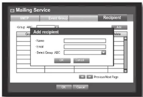
text_image
Mailing Service SMTP Event Group Recipient - Group ABC Go Add Name - Email - Select Group ABC OK Cancel Previous/Next Page OK CancelEnglish _63
using the DVR
CONTROLLING A PTZ DEVICE
The DVR enables you to adjust the settings of a PTZ camera as well as an ordinary one to your preference.
PTZ Device
The PTZ device can be activated only if a channel in connection with the PTZ camera is selected.
Getting started with PTZ
The PTZ camera is available, only if a channel is selected, in the following way :
■ Using the button on the remote control or the front panel Select the [PTZ] button on the remote control or the front panel.
■ Using the launcher menu Click PTZ < PTZ > to display the live launcher.
- Using the right-click menu in Live mode
Right-click any area on the screen to display the context menu, and select
■ Using icons on the live screen Click the PTZ < PTZ > icon on the live screen.

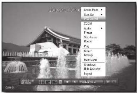
text_image
2018-06-01 01:00 Some Mask Spot Out Fitz Control ZOOM Audio Freeze Sup Alarm Roccef Play Search Backlog Main Menu Shutdown Hide Launcher Logout CAM 01 2018-06-01 01:10:25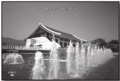
natural_image
Black-and-white photo of a traditional-style building with fountains in front, no visible text or symbolsUsing the PTZ camera
You can use one camera to perform all functions of PAN, TILT and ZOOM for monitoring multiple places and set the preset to your preference in a desired mode.
-
Launch the
menu. As the PTZ < PTZ > icon on the bottom right corner turns yellow, you access the "PTZ Control" mode to display the "PTZ Control" menu. -
Use direction keys in the launcher menu or use direction buttons (▲▼◀▶) on the remote control or the front panel to move the target area to record.
- PTZ Wheel: Clicking a nearer point to the center will move in that direction slowly; clicking a farther point from the center will move fast.
- Keep clicking left to rotate the lens counter clockwise; keep clicking right to rotate the lens clockwise.
- Zoom: You can use the Zoom function of the PTZ camera.
- IRIS: Adjusts the intensity of radiation incoming to the iris.
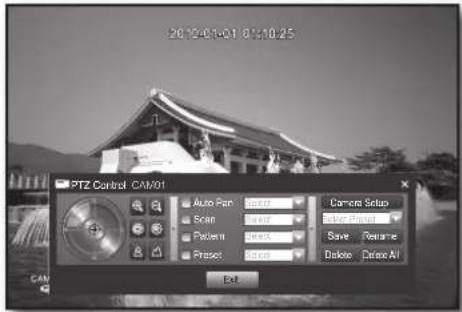
text_image
2012-01-01 01:10:25 PTZ Control CAM/01 Auto Pair Scan Pattern Præset Camera Setup Enter Præset Save Rename Desktop Delete All Exit64_ using the DVR
- Focus: Enables you to adjust the focus manually.
- Auto Pan: The camera automatically runs between the two points that you selected.
- Scan: The camera moves to the preset points in the specified sequence. If multiple presets are specified, the PTZ camera will automatically move to all of the preset points one at a time.
- Pattern: Makes the PTZ camera remember and follow the past route.
The functions of Auto Pan, Scan and Pattern are supported in the protocols of Samsung, Panasonic and Pelco, and are different in terms of the name and setting, depending on the protocols of Samsung, Panasonic and Pelco. (Panasonic : Auto Pan, Sequence, Sort / Pelco : Auto Pan, Frame Scan, Pattern)

Before entering the PTZ device control mode, set the values of the PTZ device in the
Preset Setting
A preset is a set of specific target points of a PTZ camera, and up to 20 presets per a camera can be stored. Using the mouse may help make setup easier.
-
In PTZ Control mode, use the direction buttons to adjust the camera in a desired direction.
-
Select the
key. The virtual keyboard for inputting the preset will appear. ■ Refer to "Using Virtual Keyboard". (Page 34) -
Save: You can save the preset settings.
- Rename: You can change the settings of the existing presets.
- Delete : Deletes the selected preset.
- Delete All : Deletes all existing presets.

If you replace the camera of the channel that stores the preset list with a new one, you should reset the preset accordingly.
- Press
. The preset will be saved as a name that you entered.
Camera Setting
A PTZ camera has its own menu system. Optimize the PTZ camera according to the DVR. Using the mouse may help make setup easier.
- Connect the PTZ camera to the DVR and run the PTZ camera again to display the camera's protocol setting window.
- Check the protocol ID of the camera.
In "Device > Setting the PTZ", enter the PTZ camera ID in the ID input box of the channel that is connected to the PTZ camera. (Page 43)
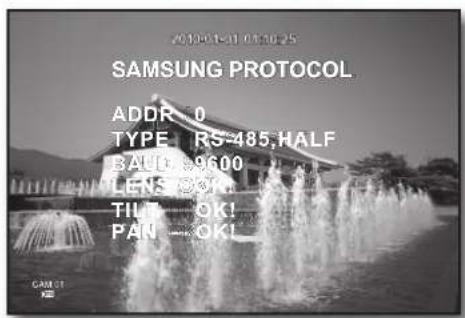
text_image
2019-01-01 03:30:25 SAMSUNG PROTOCOL. ADDR: 0 TYPE: RS-485,HALF BALD: 9600 LENS ⓐ TIL: OK! PAN: OK! GAM: 51 K-
Select
in the PTZ Control menu. The camera-specific menu appears. -
You can configure the settings of only those cameras that support the protocols of Samsung, Pelco D/P, AD and Panasonic.
If you are setting Auto Pan or Pattern in the camera menu, press and hold the appropriate button for a certain time so that the button operation can be different from that in normal PTZ setting.
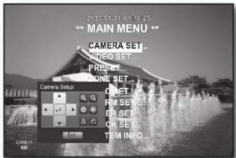
text_image
2010-01-01 01:10:25 ** MAIN MENU ** CAMERA SET... VIDEO SET... PRESET... ZONE SET... Camera Setup OFFSET... RMI SET... ER SET... OK SET... TEM INFO... CancelEnglish _65
search & play
SEARCH
You can perform the search for recorded data by the time or by the search criteria such as an event. You can access the
- In Live mode, right-click any area of the screen. The Live menu appears.
- Select
. Or, press the [SEARCH] button on the remote control or the front panel.
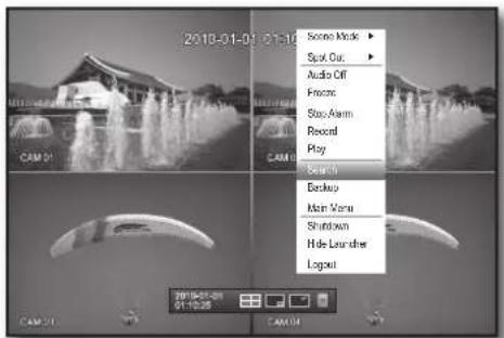
text_image
2018-01-01 07:16 CAM 01 Score Mode ▶ Spot Cut ▶ Audio Off Create Stop Alarm Record Play Search Backup Main Venu Shutdown Hide Launcher Logout CAM 01 07:16:25 CAM 04- The Search menu appears.
If you have not checked "POS USE" in the "Main Menu > Device > POS Device" menu, the Search menu does not include the "POS Search" item. (Page 46)
- The search can be restricted by the Auto Delete function. Refer to "Setting the Recording > Record Option". (Page 52)

- Overlapped data : It only appears if there exists overlapped data on a certain time, produced due to the change of DVR's time setup. The latest data comes fi rst, from
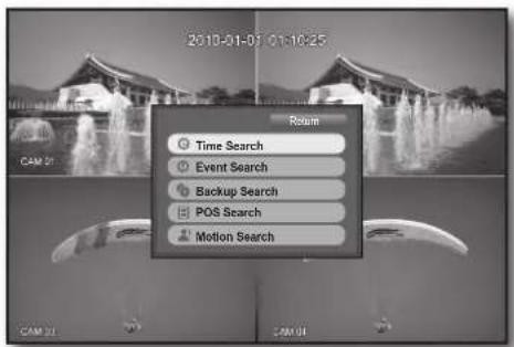
text_image
2010-01-01 01:10:25 CAM 21 Return Time Search Event Search Backup Search POS Search Motion SearchTime Search
You can search for recorded data of a desired time.
As the time to display may be different depending on the time zone and the DST standard time, the time of data recorded in the same time can be displayed differently depending on time zone and DST settings.
Using the mouse may help make setup easier.
- Select
- Select a date to search.
■ Refer to "Using the Calendar". (Page 33)
- The record data on the specific date will be listed. The display bar is different according to the data type. So check the data type for the color in the left pane.
-
Use direction buttons (▲▼◀▶) to set the search criteria and press the [ENTER] button.
-
Go to First: Moves to the earliest date.
- Go to Last: Moves to the most recent date.
- Time : Enter a time to perform the search or use the up/down button <◆> to select one.
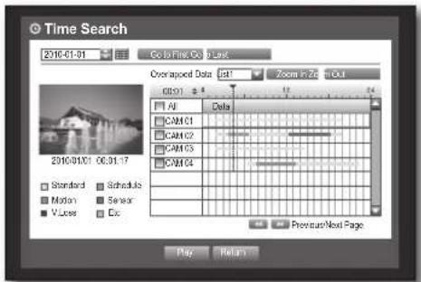
text_image
Time Search 23/10-01-01 Color to Fine Color Last Overrapped Data: 101 Zoom in Zric in Out GDS1 AI Cels CAM C1 CAM C2 CAM C3 CAM C4 Standard Schedule Motion Sensor Vuses Cic Previous Next Page Play Return66_ search & play
- Zoom In : The map enlarges in detail. It will switch in the sequence of 24 hours - 4 hours - 1 hour - 5 minutes.
- Zoom Out : The map will switch in the reverse order of the detailed mode above. It will switch in the sequence of 5 minutes - 1 hour - 4 hours - 24 hours.
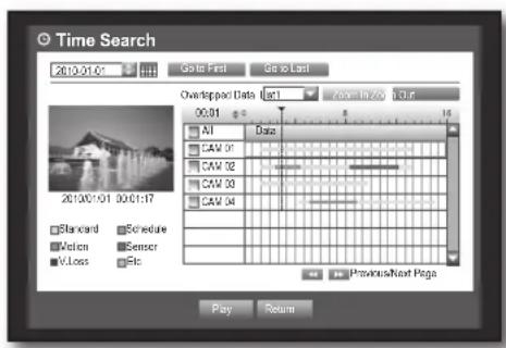
text_image
Time Search 2010/01/04 Go to Last Go to Last Overlapged Data List Zone to Last 00:01 All Data CAV 01 CAV 02 CAV 03 CAV 04 Standard Schedule Vision Sensor VLoss Esc Previous Next Rags Play ReturnDouble-click a desired time to zoom it in/out.
- Preview : Click
- If the selected channel does not contain any recorded data, it will be marked black.
- Select a data item and click
. The screen switches to the data playback mode.
Event Search
You can search for events by the channel and play them. Using the mouse may help make setup easier.
-
Select
in the menu. -
Use direction buttons (▲▼◀▶) to set the search criteria and press the [ENTER] button.
All record events on a specific date will be found. (Normal/ Schedule recording included)
- Date/Time Preview : If you select a data item in the list, the still image of the selected data will be displayed in the left preview pane.
• Event : Displays the type of the event that occurred.
- Select a data item and click
. The screen switches to the event data playback mode.
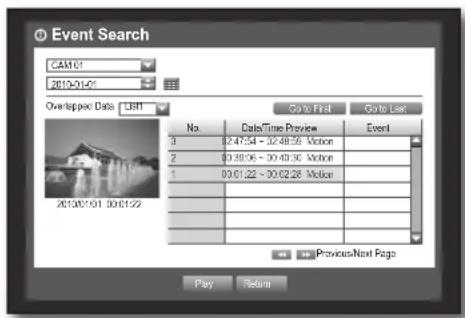
text_image
Event Search CAM:01 2610-01-01 Overlapped Data LEFT Go to First Go to Last No. Data/Time Preview Event 3 02:47:54 - 02:48:59 Voice 2 00:38:06 - 00:48:36 Voice 1 00:01:22 - 00:02:28 Voice 201307.01 00:01:22 Previous/Next Page Play ReturnBackup Search
Searches for backup data in the connected backup device. Only data in the format of DVR is included in the search. Refer to
Using the mouse may help make setup easier.
-
Select
in the menu. -
Use direction buttons (▲▼◀▶) to set the search criteria and press the [ENTER] button.
-
Record Period : Displays the record period.
- Channel : Displays the recorded channel.
-
Play Start Time: Select a time that you start playing.
-
Select a data item and click
. The screen switches to the backup data playback mode.
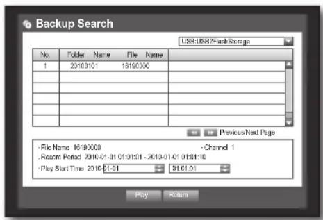
You can search for data in the POS device that is connected to the DVR.
You can use the mouse to select the related items.
-
Select
in the menu. -
Use direction buttons (▲▼◀▶) to set the search criteria and press the [ENTER] button.
■ You can enter specifi c text to refi ne your search.
- Keyword : Use the virtual keyboard to enter a keyword.
-
Search Criteria :
-
: If selected, search will be performed case-sensitively. : If selected, only the exact matches with the keyword will be found.
- Preview : Select a data item in the list to display the preview image.
Information about the image will be displayed on the bottom of the screen.
• : You can use these buttons to accelerate your search if you have a huge list of search results.
6. Select a data item and click
The screen switches to the POS data playback mode.
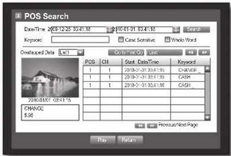
text_image
POS Search Date/Time 2019-12-25 03:41:18 2019-01-01 03:41:18 Keyword: Case Sensitive Whole Word Overlaced Data List1 Go To Time Go to Case POS CH Start Date/Time Keyword 1 1 2019-01-01 03:41:18 CHANGE_ 1 1 2019-01-01 03:41:18 CASH_ 1 1 2019-01-01 03:41:18 CASH_ 2019/01/01 03:41:18 CHANGE_ 6.96 Previous Next Page Play ReturnMotion Search
If a motion is detected in each channel, you can set a desired area to perform the search.
You can use the mouse to select the related items.
-
Select
in the menu. -
Use direction buttons (▲▼◀▶) to set the search criteria and press the [ENTER] button.
If you set the motion area to
- Motion Region : Select an area to perform the search.
- All Area : Searches for all areas of the selected channel.
- Current Area : Searches for the motion area for each channel specified in "Motion Detection > Setting the Motion Detection Area". (Page 54)
-
Manual Area : You can set the motion area manually.
-
Setup : The Setup button will be activated only if you have set the motion area to Manual. Press this button to display the area setting window.
- Date/Time : The Date/Time will be automatically set by the hour, and the end time will be automatically set to one hour later than the start time if it is set.
- Preview : Select a data item in the list to display the still image of the item.
- Select a data item and click
.
The screen switches to the motion data playback mode.
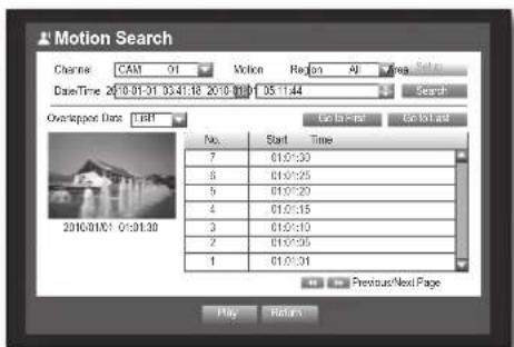
text_image
Motion Search Channel: CAM 01 Motion Region All Area Sel Date/Time 2010-01-31 05:41:18 2010-01-31 05:11:44 Search Overlap/pose Data: IBDI Go to - for Go to last No. Start Time 7 01:01:30 8 01:01:25 5 01:01:20 4 01:01:15 3 01:01:10 2 01:01:05 1 01:01:01 Previous/Next Page Play Return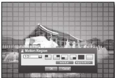
text_image
Motion Region 1:31 Apply to All Us OK Cancel68_ search & play


PLAYBACK
Play
You can play data stored in the HDD and backup a desired portion of the data. Using the mouse may help make setup easier.
-
In Live mode, click
in the right-click menu or <▶> in the launcher menu, or press the Play button on the remote control or the front panel. -
Use the up/down button (▲▼) to select a menu.
■ For data search, refer to
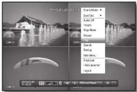
text_image
2019-01-01 01:37 Scene Mode Spot Out Audio Off Private Stop Name Record Play Search Backup Main Menu Stroke Hide Launcher Logout CAM 01 2019-01-01 01:38 CAM 01- Select a data item and click
in the Search menu. The selected data is played and the play launcher appears on the screen.
If there is an existing data,
• : You can play up to 4 channels in real time.
- In a split mode, the real time playback may not be supported, depending on the record quality, resolution and number of channels. And some frame rates may be supported.
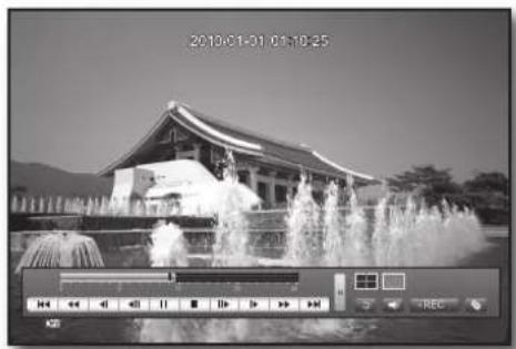
natural_image
Black-and-white photo of a modern building with fountains in front, no visible text or symbols on the structure itself.- Playback Information : Displays the date and time of the current data in the top corner.
- Mode Switch: Select a desired play mode, or press the [MODE] button to switch the screen mode to 4-split and Single in that sequence.
■ The default channel of the Live mode is CH1, which can be changed later.
• ■ : Switches to Live mode.
• REC : Records all channels in Live mode.
- Play Time: Displays the time and date of the current video.
- Play Bar : Displays the time of recorded data in the selected channel for the past 24 hours; the red gridline indicates the current play time.

■ Speed : Supports various speed options of x1, x2(-2), x4(-4), x8(-8), x16(-16), x32(-32) and x64(-64).
■ Slow : Supports slow speed options of x1/2(-1/2), x1/4(-1/4) and x1/8(-1/8).
- Backup : Click < to set the current time to the start time of backup; you can specify a backup area using the mouse (yellow triangle).
Click < > again to set the current time to the end time of the backup and the "Backup Range" window appears.
- Type : Supports formats of DVR, AVI and SEC. Refer to a list of formats in "Setting the Backup". (Page 56)
- Device : Select a backup device.
-
Check Capacity : Enables you to check the capacity of the selected storage device.
-
If you want to return to the Live screen in Play mode, click < ■ > in the launcher menu or press the [■] button on the remote control or the front panel.
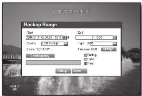
text_image
2010-01-31 01:10:25 Backup Range Start 2510.01.01 06:31:08 2010.01.31 Device USB Storage Folder (2010.01) Check capacity End 31:12:25 Type OVB Filename 0001 Change Backup Load Free Backup CancelEnglish _69
web viewer
INTRODUCING WEB VIEWER
What is Web Viewer?
Web Viewer allows remote access to your DVRs. You have access to live video, archived video, PTZ control (if configured), etc.
PRODUCT FEATURES
- Remote access from a standard browser
• Supports PTZ camera controls - Supports 1, 4 camera viewing formats (maximum of 4 cameras in the list).
- Gets JPEG, BMP format images to print and save to "Print or Save JPEG, BMP format images".
- Record video in AVI format-compatible with popular media players. (needed the Xvid codec)
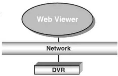
flowchart
graph TD
    A["Web Viewer"] --> B["Network"]
    B --> C["DVR"]
SYSTEM REQUIREMENTS
The following lists the minimum suggested hardware and operating system requirements needed to run the Web Viewer.
| OS | Windows XP ProfessionalWindows 2000Windows Vista Home Basic /PremiumWindows 7 |
| Web Browser Internet Explorer | 6.0.2900.2180 or higher |
| CPU Intel Pentium 4.2 GHz | |
| Memory 512 MB | |
| Monitor High Color 16-bit | 1024 x 768 |
| HDD | 50 MB(Installation space required)* Additional HDD space required for recording.Recorded file size will vary depending on recording quality settings. |
70_ web viewer
CONNECTING WEB VIEWER
- Open your web browser and type the IP address or URL of DVR into the URL address box.

The basic URL of the DVR is as following in case of MAC address :
00-00-F0-ab-cd-ef : nabcdef.websamsung.net
00-16-6c-ab-cd-ef : mabcdef.websamsung.net
■ 00-68-36-ab-cd-ef : pabcdef.websamsung.net
- You can also use registered URL which setups up in the Setup menu of your DVR.
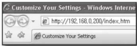
text_image
Customize Your Settings - Windows Internet http://192.168.0.200/index.htm Customize Your Settings- Set the Admin ID and password same to those of the DVR Admin.
For general users, enter the DVR user ID and password.
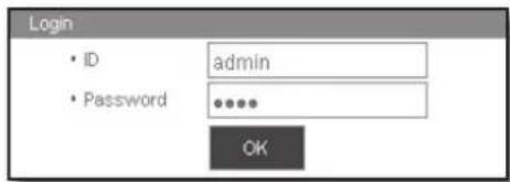
text_image
Login • ID admin • Password ***** OK
It allows up to 10 simultaneous access including the Admin and general users.
It does not allow multiple login of the Admin user.
■ Initial password of the Admin user is set to "4321".
- All settings are applied by the DVR's settings.
- Password of the Admin and general users can be changed in
- Normal users should have set
- Click
.
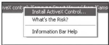
text_image
Install ActiveX Control... What's the Risk? Information Bar Help- Click
.
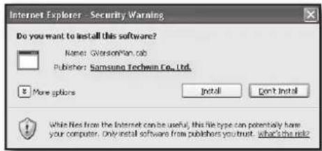
text_image
Internet Explorer - Security Warning Do you want to install this software? Name: GversionMan.com Publisher: Samsung Techwin Co., Ltd. More options Install Don't Install While files from the Internet can be useful, this file type can potentially have your computer. Only install software from publishers you trust. what's the role?- Click
.
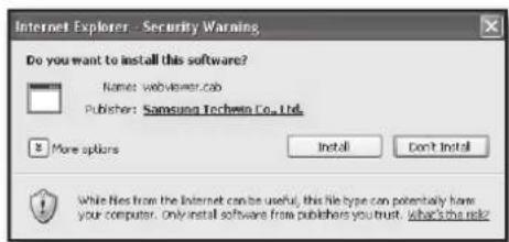
text_image
Internet Explorer - Security Warning Do you want to install this software? Name: webviewer.cab Publisher: Samsung Techeiro Co., Ltd. More options Install Don't Install While files from the Internet can be useful, this file type can potentially have your computer. Only install software from publishers you trust. What's the role?English _71
web viewer
- You may have "Windows Security Alert" that attempts to block this with the Windows Firewall. In that case, click
to start Web Viewer.

text_image
Windows Security Alert To help protect your computer. Windows Firewall has blocked some features of this program. Do you want to keep blocking this program? Name: Internet Explorer Publisher: Microsoft Corporation Keep Blocking Unlock Ask Me Later Windows Firewall has blocked this program how accepting connections from the Internet or a network. If you recognize the program or trust the publisher, you can unlock it. When should I unlock a program?- Installation is complete. Now you can see the main screen of Live Viewer.
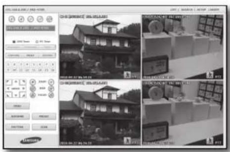
text_image
Screenshot of a surveillance camera interface displaying three real estate images with Chinese labels and control panel controls.72_ web viewer
USING LIVE VIEWER
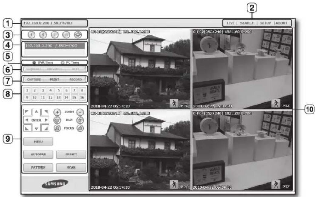
text_image
192.168.0.200 / SRD-470D 1 2 3 4 5 6 7 8 192.168.0.200 / SRD-470D UVR Time PC Time CAPTURE PRINT RECORD 1 2 3 4 5 6 7 8 9 10 11 12 13 14 15 16 ZOOH IRIS FOCUS MENU AUTOPAR PRESET PATTERN SCAR SAMSUNG LIVE | SEARCH | SETUP | ABOUT 2010.04.22 06:34:33 PTZ 2010.04.22 06:34:33 PTZ 2010.04.22 06:34:33 PTZ CII-50[252240] 195.150.0.200 CII-02[352240] 192.160.0.200 CII-04[352240] 192.160.0.200 CII-04[352240] 192.160.0.200 PTZ PTZ PTZ PTZ 10The Live Viewer screen consists of following :
① This displays the IP address and the model name of the connected DVR.
② These menus consist of
③ These buttons are used for the screen split and full screen mode.
④ Shows the IP address and model name of the connected DVR.
⑤ Select
⑥ These buttons are used for sequence and changing the screen channel.
⑦ These buttons are used for capture, print, and save the image.
⑧ Shows the channel of the connected DVR.
⑨ These buttons are used for PTZ related functions.
10 This displays the screen for connected camera with DVR.

■ The resolution is set to 1024X768 pixels.
The initial split-screen mode is set according to the number of channels connected to DVR. You can change the split-screen mode by clicking buttons for split-screen modes.
English _73
web viewer
OSD INFORMATION DISPLAY
① The channel number, video size, and IP address of the connected DVR are displayed.
② The current date and time will be displayed according to the selected time information display setting
③ Alarm icon appears when alarm is issued.
It disappears when pressed the [ALARM] button of the DVR.
④ Motion icon appears when motion is detected. It disappears when pressed the [ALARM] button of the DVR.
⑤ It displays whether the PTZ controls are active.

If you have set PTZ cameras for the DVR, "PTZ" is displayed on the screen. Select a PTZ camera channel and use the [PTZ] button for camera control.
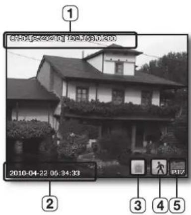
text_image
1 CH-01[5:20:10] 192.168.0.200 2010-04-22 06:34:33 2 3 4 5SPLIT-SCREEN
You can change the split mode by clicking each number icon.
natural_image
Exterior view of a two-story residential house with traditional roof and surrounding greenery (no visible signage or text)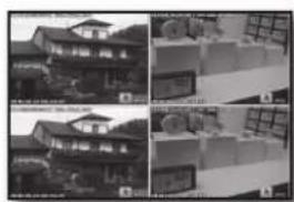
natural_image
Black-and-white photo collage showing two identical building views with windows and ceiling fixtures (no visible text or symbols)SINGLE MODE QUAD MODE
- Click <1> button.
The screen displays the selected camera connected to the DVR in "SINGLE MODE". - Click <4> button.
The screen displays the selected camera connected to the DVR in "QUAD MODE". - Click
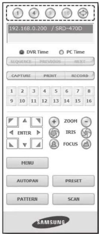
text_image
192.168.0.200 / SRD-470D DVTR Time PC Time SEQUENCE PREVIOUS NEXT CAPTURE PRINT RECORD 1 2 3 4 5 6 7 8 9 10 11 12 13 14 15 16 ENTER ZOOM - IRIS FOCUS MENU AUTOPAN PRESET PATTERN SCAN SAMSUNG74_ web viewer
CONNECTED DVR
This displays the IP address and the status of the connecting DVR.

■ Connection failure message
No Response : Appears when the DVR does not respond.
Access Denied : Appears when the maximum number of users is exceeded.
■ The number of simultaneous connections are limited to 10.
Setting the display of the OSD time information
Select
• DVR Time : Based on the time of the connected DVR
• PC Time : Based on the time of the PC currently running the Web Viewer.

text_image
192.168.0.200 / SRD-470D DVTR Time PC Time SEQUENCE PREVIOUS NEXT CAPTURE PRINT RECORD 1 2 3 4 5 6 7 8 9 10 11 12 13 14 15 16 ENTER ZOOM - IRIS FOCUS MENU AUTOPAN PRESET PATTERN SCAN SAMSUNG
text_image
WEB VIEWERCHANGING THE LIVE SCREEN MODE
4-split mode does not support "SEQUENCE", "PREVIOUS" and "NEXT".
- SEQUENCE: When this button is clicked, screens are switched at a preset interval.
In SINGLE MODE, the channel numbers are sequentially switched from 1 to 4.
In QUAD MODE, the screen refreshes at the preset interval.
■ Preset interval (10 seconds)
- PREVIOUS: When this button is clicked, the previous screen appears.
In QUAD MODE, the screen is refreshed.
- NEXT: When this button is clicked, the next screen appears.
In SINGLE MODE, the channel numbers are sequentially switched from 1 to 4.
In QUAD MODE, the screen is refreshed.
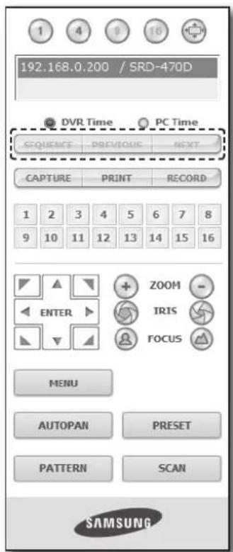
text_image
192.168.0.200 / SRD-470D DVTR Time PC Time SEQUENCE PREVIOUS NEXT - CAPTURE PRINT RECORD 1 2 3 4 5 6 7 8 9 10 11 12 13 14 15 16 ZOOM - ENTER IRIS FOCUS MENU AUTOPAN PRESET PATTERN SCAN SAMSUNGEnglish _75


web viewer
- CAPTURE : Saves the current screen into a BMP or JPEG file.

- The default saving path is "C:\Program Files\Samsung\Dvr Web Viewer\SnapShot Live". To change the saving path, click
- The file is automatically named as following: "IP address_Port number_YYYYMMDD_HHMMSS_camera number_index" Ex) 192.168.0.200_554_20100414_093118_01_00
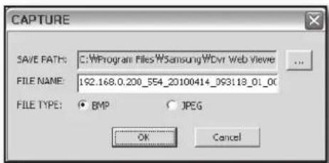
text_image
CAPTURE SAVE PATHS: C:\Program Files\WSamsung\WDvr Web Viewer ... FILE NAME: 192.168.0.200_554_20100414_093118_01_00 FILE TYPE: BMP JPEG OK Cancel- PRINT: Prints out the selected screen out of the currently displayed live screens. It also prints the IP address, time, camera number and the current event status together.
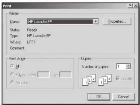
text_image
Print Printer Name: HP Laneslet SP Status: Ready Type: HP Laneslet SP Where: LPT1 Comment Print range: All Pages: form Selection Copies: Number of copies: 1 OK Cancel- RECORD : Saves the current image on the screen and saves it as a avi video file.

■ To record it, it is required at least 1GB of available space.
- The default saving path is "C:\Program Files\Samsung\Dvr Web Viewer\VideoClip\Live". To change the saving path, click
The file is automatically named as following: "IP address_Port number_YYYYMMDD_HHMMSS_camera number_index" Ex) 192.168.0.200_554_20100406_070455_01_00
■ For AVI Save, you need the Xvid codec for playing saved fi les.
- HDD Minimum Free Size : During the recording, if there is no more capacity available in the HDD than set free space will prompt with a popup message : "Cannot record due to insufficient disc space in the HDD".
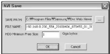
text_image
AVI Save SAVE PATH: C:\Program Files\WSamsung\WDvr Web Viewe FILE NAME: 192.168.0.200_554_20100406_070455_01_00 HDD Minimum Free Size: 1 Giga bytes OK CancelCHANGING THE LIVE SCREEN CHANNEL
- Blue numbers : Indicates that the current channel is connected to a camera.
- Gray numbers : Indicates that the current channel is not connected to any camera.
If you select 4-split mode, the channel button for each of cameras 1 \~ 4 will turn blue.

text_image
1 2 3 4 5 6 7 8 9 10 11 12 13 14 15 16USING PTZ CAMERA
Click the direction buttons to control the camera.
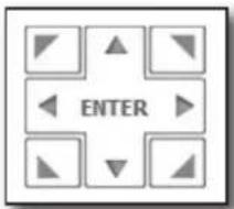
text_image
ENTER• < + ZOOM - >
You can zoom in or out an image by using the ZOOM button.
• < IRIS >
You can adjust the entering light amount by using the IRIS button.
• < FOCUS >
You can adjust the focus by using the FOCUS button.
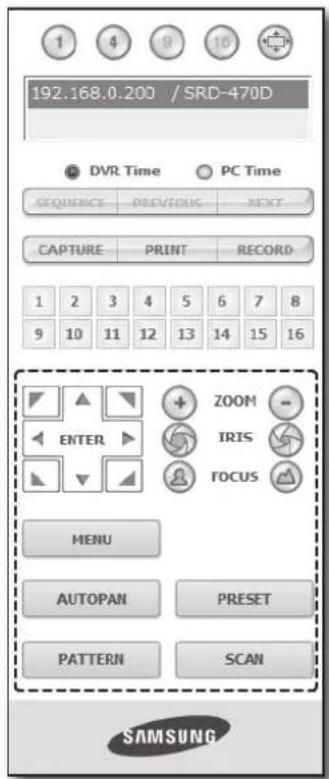
text_image
192:168.0.200 / SRD-470D DVTR Time PC Time SEQUENCE PREVIOUS NEXT CAPTURE PRINT RECORD 1 2 3 4 5 6 7 8 9 10 11 12 13 14 15 16 ENTER ZOOM - IRIS FOCUS MENU AUTOPAN PRESET PATTERN SCAN SAMSUNG- MENU : Appears the camera menu screen.
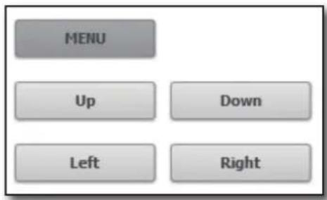
text_image
MENU Up Down Left RightEnglish _77
web viewer
- PRESET: Moves the lens direction to a preset direction.
- If you click a preset, the camera moves to the selected preset's position.
- You can delete the selected preset or all presets.
- You can save a new preset number and name.

■ You can save presets up to 20.
- AUTOPAN: Moves the camera lens direction between 2 points set for the camera.
- SCAN: Moves the camera lens direction between 2 preset points of the camera.
- PATTERN: You can set camera various movement patterns such as zoom, move, etc. so that a camera automatically moves according to the pattern.

■ While the DVR controls a PTZ camera, Web Viewer cannot control the camera.
■ Camera menu setup is only available for camera supporting the function.
■ Each function of PTZ is same to that of the DVR.
- Pan/Tilt of the Smart dome camera is manipulated automatically to center the camera to the mouse clicked point.
If you drag the mouse using the left button on a certain point, Pan/Tilt of the Smart dome camera is manipulated automatically to center the camera to the middle point between the dragging start and end position. Upward dragging will zoom out, while downward dragging will zoom in.
■ Tilt of Power PTZ operates properly within 45°.
■ Power and Pan Tilt functions are only available for camera supporting the functions. Ex : Samsung SCC-C6475
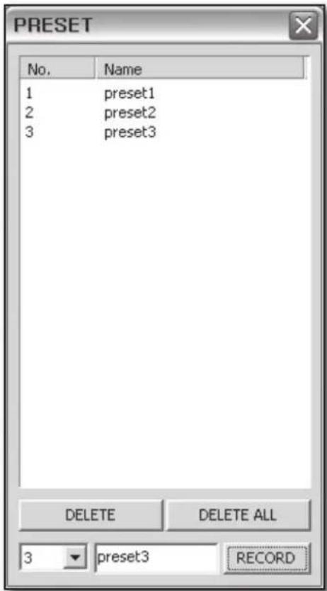
text_image
PRESET No. Name 1 preset1 2 preset2 3 preset3 DELETE DELETE ALL 3 preset3 RECORDUSING SEARCH VIEWER

text_image
192.168.0.200 / SRD-4700 192.168.0.200 / SRD-4700 CAPTURE PRINT RECORD 2010 04 S M T W T F S 1 2 3 4 6 6 7 8 9 10 11 12 13 14 15 16 17 18 19 20 21 22 23 24 25 26 27 28 29 30 Today C:401 C:402 C:403 C:404 11:58:23 SAMSUNG LIVE | SEARCH | SETUP | ABOUT CH-02[35X/240] 192.168.0.200 CH-04[35X/240] 192.168.0.200 CH-04[35X/240] 192.168.0.200 2010.04-22 06:34:33 CH-04[35X/240] 192.168.0.200 2010.04-22 06:34:33 2010.04-22 06:34:33 2010.04-22 06:34:33 SAMSUNGThe Search Viewer screen consists of following :
① This displays the IP address and the model name of the connected DVR.
② There are 4 tabs available:
③ Switch to a split mode.
④ Shows the IP address and model name of the connected DVR.
⑤ These buttons are used for capture, print, and save the image.
⑥ This displays a calendar at which you can search the recorded video.
⑦ This displays a timeline at which you can search the recorded video by the time.
⑧ These buttons are used for controlling playback.
⑨ This displays the screen for playback of recorded video.
English _79
web viewer
SPLIT-SCREEN
You can change the split mode by clicking each number icon.
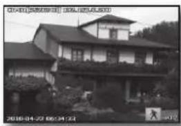
natural_image
Exterior view of a two-story residential house with balconies and trees (no signage)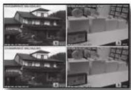
natural_image
Exterior view of a modern building with large windows and solar panels (no visible text or symbols)SINGLE MODE QUAD MODE
- Click <1> button.
The screen displays the selected camera connected to the DVR in "SINGLE MODE". - Click <④> button.
The screen displays the selected camera connected to the DVR in "QUAD MODE".
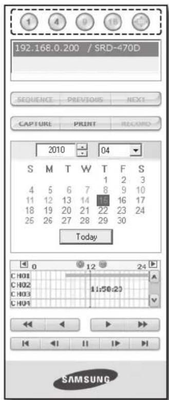
text_image
192.168.0.200 / SRD-470D SEQUENCE PREVIOUS NEXT CAPTURE PRINT RECORD 2010 04 S M T W T F S 4 5 6 7 8 9 10 11 12 13 14 15 16 17 18 19 20 21 22 23 24 25 26 27 28 29 30 Today CH01 CH02 CH03 CH04 1:50:23 SAMSUNGCONNECTED DVR
This displays the IP address and the status of the connecting DVR.

■ Connection failure message
No Response : Appears when the DVR does not respond.
Access Denied : Appears when the maximum number of users is exceeded.
■ The number of simultaneous connection is limited to 3.
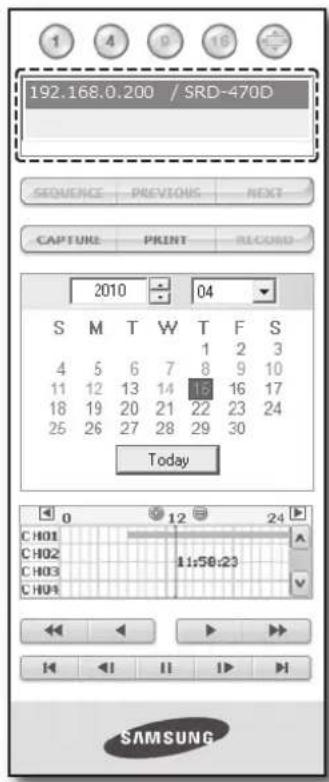
text_image
192.168.0.200 / SRD-470D SEQUENCE PREVIOUS NEXT CAPTURE PRINT RECORD 2010 04 S M T W T F S 1 2 3 4 5 6 7 8 9 10 11 12 13 14 15 16 17 18 19 20 21 22 23 24 25 26 27 28 29 30 Today CH01 CH02 CH03 CH04 11:50:23 SAMSUNG80_ web viewer
- CAPTURE : Saves the current screen into a BMP or JPEG file.

- The default saving path is "C:\Program Files\Samsung\Dvr Web Viewer\SnapShot\Search". To change the saving path, click <SAVE PATH ( [ ] button and then select the path you want. For Windows Vista or 7, the saving path is "C:\users\user ID\AppData\LocalLow\Samsung\DVR Web Viewer\SnapShot\"and it cannot be modified.
- The file is automatically named as following: "IP address_Port number_YYYYMMDD_HHMMSS_camera number_index" Ex) 192.168.0.200_554_20100414_093118_01_00
- PRINT: Prints the playback screen that is now being displayed. It also prints IP address, time, camera number, and current event state.
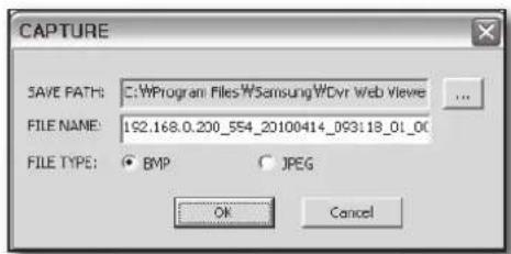
text_image
CAPTURE SAVE PATH: C:\Program Files\WSamsung\WDvr Web Viewie FILE NAME: 192.168.0.200_554_20100414_093118_01_00 FILE TYPE: BMP JPEG OK Cancel
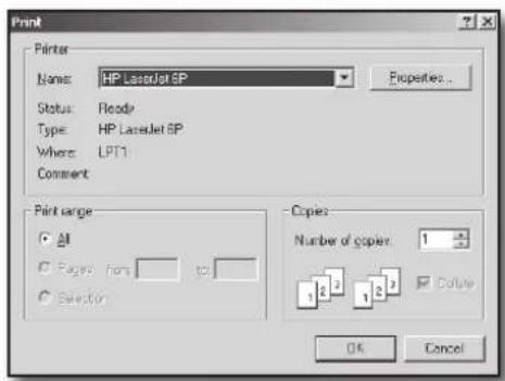
text_image
Print Printer Name: HP LaserJet 6P Status: Record Type: HP LaserJet 6P Where: LPT1 Comment: Print range All Pages from to Selection Copies Number of copies: 1 1 2 3 1 2 3 Date OK Cancel- RECORD : If you select a channel and click this button during playback (only play), the video data is saved in a DVR file. (It is saved in the designated folder on your PC.) To stop recording, click this button again.

■ To record it, it is required at least 1GB of available space.
The default saving path is "C:\Program Files\Samsung\Dvr Web Viewer\VideoClip\Search". To change the saving path, click
- The file is automatically named as following: "IP address_Port number_YYYYMMDD_HHMMSS_camera number_index"
Ex) 192.168.0.200_554_20100406_070455_01_00
■ For AVI save, you need the Xvid codec for playing saved fi les.
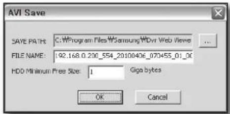
text_image
AVI Save SAVE PATH: C:\Program Files\WSamsung\WDvr Web Views FILE NAME: 192.168.0.200_554_20100406_070455_01_00 HDD Minimum Free Size: 1 Giga bytes OK CancelEnglish _81
web viewer
SEARCHING THE RECORDED VIDEO IN THE CALENDAR
If the video data has been recorded on a date, the date is distinguished in green. If you click the date, the recorded video information is displayed in the time line. When you click
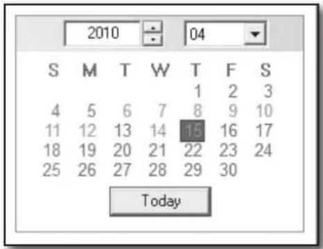
text_image
2010 S M T W T F S 4 5 6 7 8 9 10 11 12 13 14 15 16 17 18 19 20 21 22 23 24 25 26 27 28 29 30 TodaySEARCHING THE RECORDED VIDEO IN THE TIMELINE
It displays the recorded video data status on the DVR after a date is selected. The normal mode displays the time ranging from 0 to 24 Hours while the extension mode displays the time every 2 hours.
[Normal Mode]
- If you click <+> button, it changes to the extension mode.
• Each time line represents 1 hour.
[Extension Mode]
- If you click <@> button, it changes to the normal mode.
• Each time line represents 5 minutes.

■ The channels are ranging from CH01 to CH04.
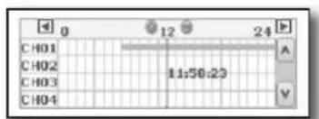
text_image
CH01 CH02 CH03 CH04 12 24 A 11:56:23 V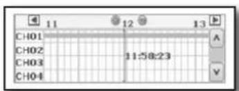
text_image
CH01 CH02 CH03 CH04 11:58:23 A V
text_image
192.168.0.200 / SRD-470D SEQUENCE PREVIOUS NEXT CAPTURE PRINT RECORD 2010 04 S M T W T F S 4 5 6 7 8 9 10 11 12 13 14 15 16 17 18 19 20 21 22 23 24 25 26 27 28 29 30 Today CH01 12 24 CH02 11:50:23 CH03 CH04 SAMSUNG① Fast Backward : Reverse-plays faster(2x).
② Reverse Play : Performs Reverse Play.
③ Play : Performs playback.
④ Fast Forward : Plays faster(2x).
⑤ Go to First : Moves the beginning time of recorded video in the time line.
⑥ Step Backward : Performs one step reverseplay by one frame.
⑦ Stop : Stops playing.
⑧ Step Forward : Performs one step forward by one frame.
⑨ Go to Last : Moves the last time of recorded video in the time line.
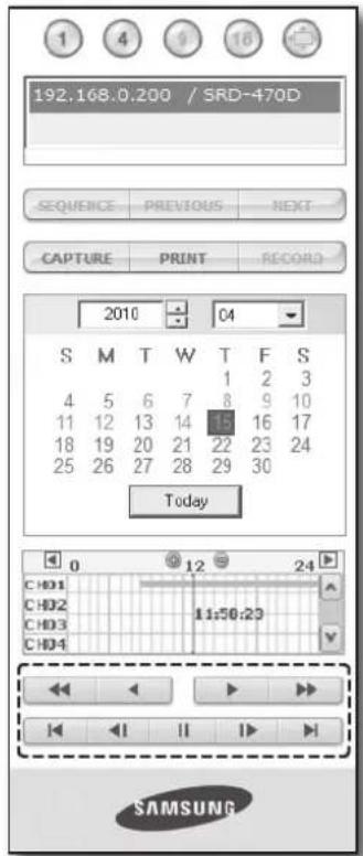
text_image
192.168.0.200 / SRD-470D SEQUENCE PREVIOUS NEXT CAPTURE PRINT RECORD 2010 C4 S M T W T F S 4 5 6 7 8 9 10 11 12 13 14 15 16 17 18 19 20 21 22 23 24 25 26 27 28 29 30 Today 0 12 24 CHD1 CHD2 CHD3 CHD4 11:50:23 SAMSUNG
text_image
● WEB VIEWERVIEWER SETUP
You can confi gure the DVR settings remotely on the network. To confi gure the DVR settings, click
System
You can configure the various settings of the DVR system.
Date/Time/Language
For more information, refer to
- Select
in the System menu. - Configure the DVR settings according to your system environment.
- Date/Time
Set the date and time.
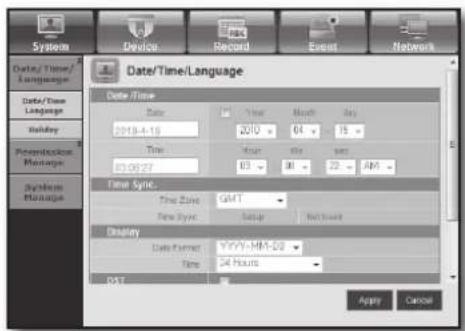
text_image
System Device Record Event Network Data/Time/ Language Data/Time Language Mailay Precession Manage Systems Manage Date/Time/Language Date / Time Date 2018-4-19 200 04 15 Time 03 01 02 AM Time Sync Time Sync GMT New Sync Setup Net Insert Display Date Format YYYY-MM-DD Time 24 Hours RST Apply CancelEnglish _83
web viewer
• Time Synchronization Setup
Set the time synchronization.
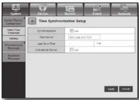
text_image
System Device Record Event Network Date/Time/ Language Data/Time Language Holiday Performance Manage System Manage Time Synchronization Setup Synchronization Use Time Server 293.248.240.103 Last Sync Time - Fast Activate as Server Use Apply Cancel- Display
Date Format : Set the date type.
Time : Select a time format to display on the screen.
• DST (Daylight Saving Time)
DST is displayed an hour ahead of the standard time of the time zone.
- Language
Select a preferred language for the DVR.
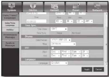
text_image
System Device Record Event Network Data/ Times / Language Data/Time Language Holiday Permission Manage Systical Manage 12.08.25 Time 92.08.33 Time Sync. Time Sync: GMT Time Sync: Default Display Date Format: YYYY-MM-DD Time: 24 Hours DST Start Dec First Sun 24 End Dec First Sun 24 Language Language English Apply CancelHoliday
You can set specifi c dates to Holidays according to your preferences.
For more information, refer to
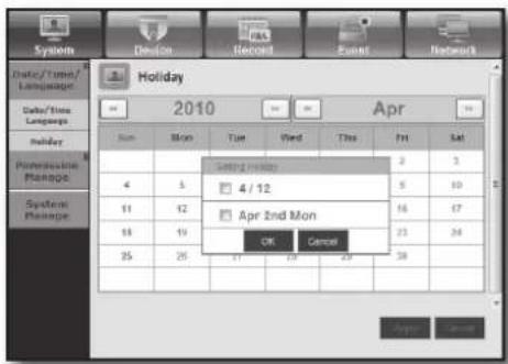
text_image
Holiday 2010 Apr Sun Mon Tue Wed Thu Fri Sat 4 5 11 12 13 14 25 26 Setting home 4/12 Apr 2nd Mon OK Cancel Apply CancelPermission Management
For more information, refer to
- Admin
You can change the admin ID or the password.
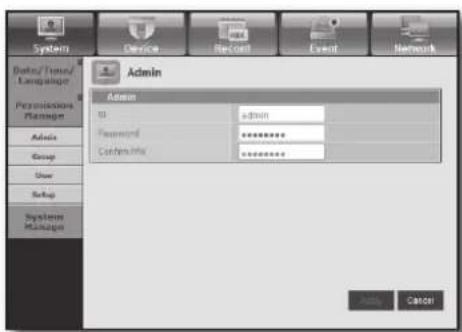
text_image
System Device Record Event Network Admin Admin U: admin Password ****** Confirm Info ****** Add Cancel84_ web viewer


- Group
Users are classified into groups and the permission can be set according to the group.
■ First of all, add a group.
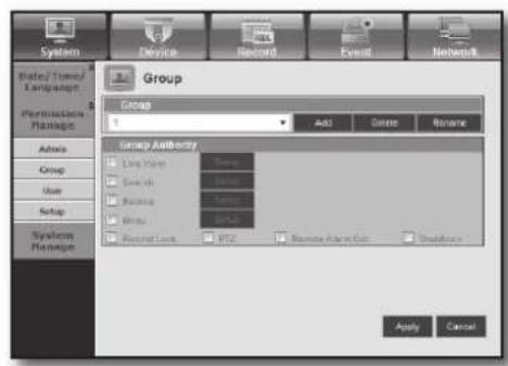
text_image
System Device Record Event Network Date/Time/ Language Group Permutation Plants Admins Group User Setup System Plants Group Authority Line Name User ID User ID Status Status Status Status Status Status Status Status Status Status Status Status Status Status Status Status Status Status Status Status Status Status Status Status Status Status Status Status Status Status Status Status Status Status Status Status Status Status Status Status Status Status Status Status Status Status Status Status Status Status Success Apply Cancel- User
You can add, change or remove a user or users.
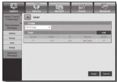
text_image
System Device Record Event Network Baby/Time/ Language 8 Permission Manage Admin Group User Setup System Manage User Group All Group Add User Name 0 Viewers Better Add Apply Cancel- Setup
You can set the user permission.
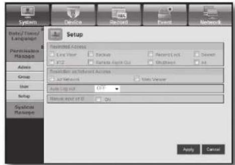
text_image
System Data/Time/ Language Permissible Manage Admin Group Main Setup Systems Ratuge Device Record Event Network Setup Restricted Access Line View Backup Recent Link Down YTD Random Engine Out Outpage All Resolution on Referent Access Air Systems Visa Viewer Auto Log kit OFF Remote App of ID On Apply CancelSystem Management
For more information, refer to
• System Information
You can see information of the current system.
Check the software version, broadcast format and MAC address.
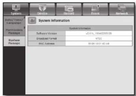
text_image
System Device Record Event Network Bete/Time/ Language Peripherals Manage System Manage System information Software Version v5.016_10040229135 Broadcast Format NTSC MAC Address 00:00:15:01:42.48English _85

text_image
• WEB VIEWERweb viewer
Device
You can check a list of devices that are connected to the DVR and configure the necessary settings.
Click
For more information, refer to "Setting the Device". (Page 42)
Camera
- Camera
You can configure the settings of the camera that is connected to the DVR.
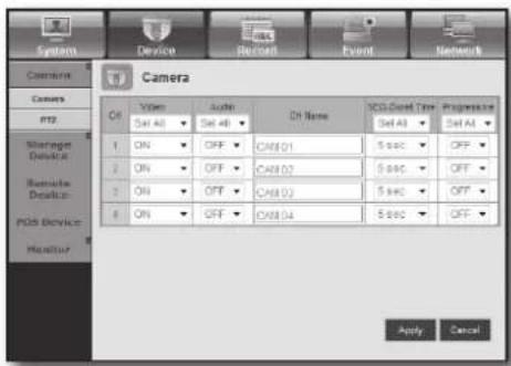
text_image
Camera System Device Record Event Network Camera Camers http Storage Device Remove Device PDS Device Monitor Cfs Video Audio Ch Name VCD/Cond Time Progressive Set All Set All ON OFF CA#01 5 sec OFF ON OFF CA#02 5 sec OFF ON OFF CA#03 5 sec OFF ON OFF CA#04 5 sec OFF Apply Cancel• PTZ
You can configure the settings of the PTZ camera that is connected to the DVR.
Set the ID and protocol.

text_image
System Device Record Event Network PTZ PTZ Port Port Port 1 2 3 4 Apply CancelStorage Device
You can check and change the settings of the storage device.
- Device
You will see a list of storage devices that are connected to the DVR.
You can check the type, used/total, usage and status of the device.
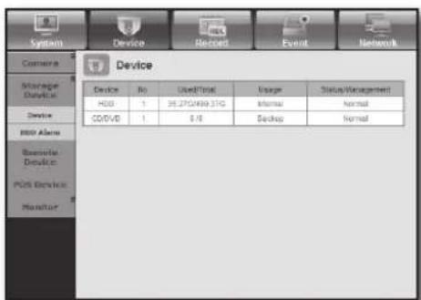
text_image
System Device Record Event Network Camera Storage Device1 Device HDD Alarm Binary Device2 PDS Device3 Monitor Device No Used/Total Usage Status/Management HGB 1 36.2701499.37G Internal Normal CODVD 1 0 /8 Backup Normal86_ web viewer
- HDD Alarm
You can set the alarm output channel and the alarm duration for an error.
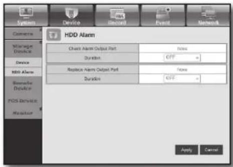
text_image
System Device Record Event Network Camera Storage Device Device HDD Alarm Bluetooth Device FOS Device Monitor HDD Alarm Check Alarm Output Port Duration OFF Replace Alarm Output Port Duration OFF Apply CancelRemote Device
You can see a list of remote devices including PTZ cameras and system keyboards that are connected to the RS-485 port of the DVR and configure the necessary settings.
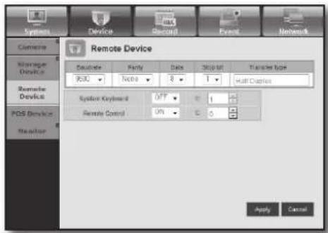
text_image
System Device Electrical Event Networks Remote Device Balance 950C Note 8 1 Half Digital System Keyboard OFF 1 Remote Control ON C Apply CancelPOS Device
You can set the channel, preset and communication port of the POS device that is connected to the DVR.

■ You cannot set to use the POS device remotely.
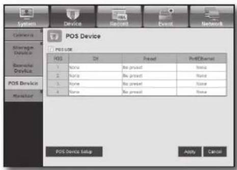
text_image
POS Device POS USE POS DH Preset PostChannel 1 None Bis preset None 2 None Bis preset None 3 None Bis preset None 4 None Bis preset None POS Device Setup Apply CancelMonitor
- Monitor
You can configure the monitoring screen settings and set the output system.
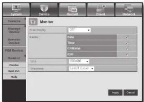
text_image
Monitor Field Display OFF Display Date ✓ Time ✓ C:\Name ✓ IUP ✓ Status 500x600 Status Level Level ✓ Apply CancelEnglish _87

text_image
• WEB VIEWER


web viewer
- Spot Out
With the monitor connected via the SPOT port, if there occurs an event such as Sensor, Motion, or Alarm, you can select a video output mode for external monitoring.
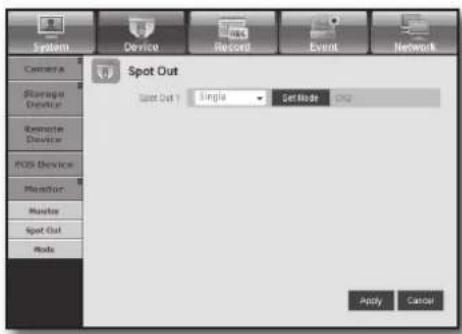
text_image
Spot Out Spot Out 1: Single Get Mode CM2 Apply Cancel- Mode
You can switch between live mode and play mode.

text_image
System Camera Storage Device Remote Device PDS Device Monitor Monitor Spot Out Mode Device Record Event Network Mode User Screen File Screen Apply CancelRecord
For more information, refer to
Recording Schedule
If you set a recording schedule for a specific date and time, the recording will start at that specific time.
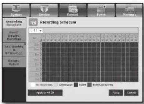
text_image
Recording Schedule Event Record Duration REC Quality & Resolution Record Option Hi Recording Continuous Event Both(Cert&2*) Apply to All Ch Apply Cancel- Apply to All CH : Click
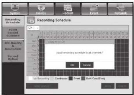
text_image
Recording Schedule CH1 Apply to ACH Apply recording schedule to all channels? OK Cancel No Recording Cancelase Event Both(Cert&End)88_ web viewer
Event Record Duration
You can set the start and end times of recording that will be activated if an event occurs.
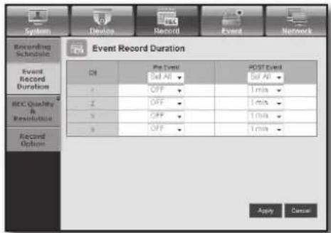
text_image
Recording Schedule Event Record Duration Event Record Duration BCC Quality & Resolution Record Option Off Pre Event Set All POST Event Set All 1 min OFF OFF 1 min OFF OFF 1 min Apply CancelREC Quality & Resolution
- Standard/Event
You can set the resolution, frame rate and recording quality for each channel.
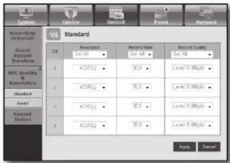
text_image
System Device Record Event Network Recording to include Record Record Functions REC Quality & Reconciliation Standard Level 0 (High) Record Options OK Resolution Set All Record Rate Set All Record Quality Set All 1 4C(RU) 30.0 Level 0 (High) 2 4C(RU) 30.0 Level 0 (High) 3 4C(RU) 30.0 Level 0 (High) 4 4C(RU) 30.0 Level 0 (High) Apply Cancel
text_image
WEB VIEWERRecord Option
You can set the Disk End Mode.
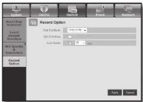
text_image
System Device Record Event Network Memory/olog Scheduler Event Record Duration REC Quality & Resolution Record Option Record Option Disk End Mode Only with Disk End Loop Auto Drive ON Apply CancelEvent
For more information, refer to
Sensor Detection
You can set the sensor operation mode and the synchronized camera as well as the alarm output type and the duration.
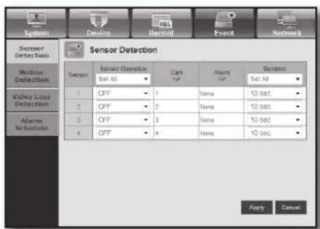
text_image
Sensor Detection Sensor Detection Sensor Sensor Operator Cans Alarms Balance Sensor All Set All Video Loss Detection 1 OFF 2 OFF 3 OFF 4 OFF Name Name Name 10 sec 10 sec 10 sec 10 sec Apply CancelEnglish _89
web viewer
Motion Detection
You can set the motion detection mode and the sensitivity as well as the alarm output type and the duration.
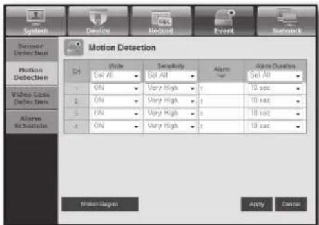
text_image
System Device Record Event Network Recover Detection Motion Detection CH Mode Sensitivity Alarms Alarm Duration Set All 1 ON Very High 10 sec 2 ON Very High 10 sec 3 ON Very High 10 sec 4 ON Very High 10 sec Motion Detection Apply Cancel- Motion Region
Set the target motion detection area
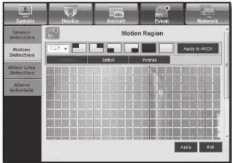
text_image
System Device Record Event Network Sensor Detection Motion Detection Voice Loss Detection Alarms Schematic Motion Region Apply to AFCR Select Paste Apply ExitVideo Loss Detection
You can set the alarm output time if a video loss occurs.
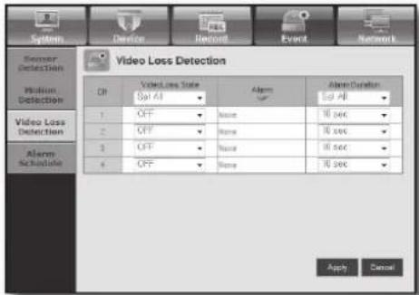
text_image
Sensor Detection Medium Detection Video Loss Detection Alarm Schedule Video Loss Detection ON OFF OFF OFF OFF Volume Alarm 1 None 2 None 3 None 4 None 10 sec 10 sec 10 sec Apply CancelAlarm Schedule
You can schedule the alarm output according to the day of the week and the time.
The default setting is Event Sync, which activates the alarm only if an event occurs.

text_image
System Sensor Detection Medium Detection Video Loss Detection Alarms Schedule Alarm Schedule Alarm Time Apply to all Alarm Apply the alarm in Schmaling to off OK Cancel OFF OK Cancel Sync ACK Cancel90_ web viewer
Network
For more information, refer to
Connection
A remote user can access the DVR via the network to check the current mode and the IP address.
- Connection
You can set the network connection route.
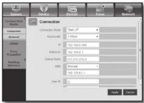
text_image
Connection Connection Mode Connection Protocol D00s Line Transfer Pairing Service Connection Mode Status: IP Data Rate: 2 Mbps IP: 192.168.0.206 Satency: 192.168.0.1 Serial Link: 255.255.255.6 DNS: Manual DNS: 158.128.63.1 User ID: Apply Cancel
text_image
WEB VIEWER- Protocol
You can configure the protocol related settings.
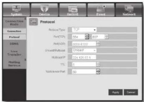
text_image
System Device Record Event Network Connection Mode Connection Protocol Others New Transfer Holding Service Protocol Protocol Type: TCP RawTCPs: 554 2 657 PortIDp: 9008-6199 UnrealMosaic: Unicast - Rifecoid IP: 224 126.63.1 TLS: 6 Vacciaiser Part: 50 Apply CancelDDNS
You can check the DDNS settings.
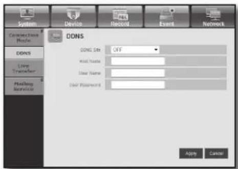
text_image
System Device Record Event Network Connection Mode DONS Live Transfer Healing Monitor DONS Site OFF Host Mode Door Name Door Password Apply CancelLive Transfer
A remote user can set the images of the DVR.
• Live Transfer
A remote user can set the image resolution of the transferred data.
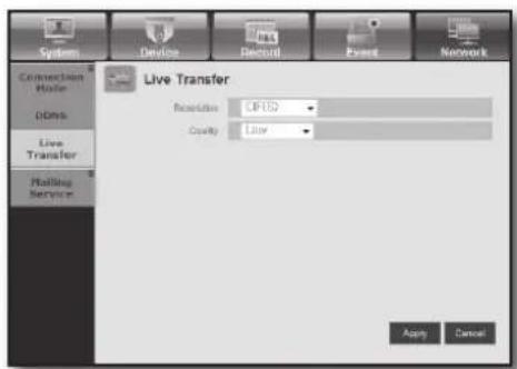
text_image
System Device Rectal Power Network Connection Driver Data Live Transfer Rolling Service Live Transfer Resolution: CP152 Quality: Litter Apply CancelEnglish _91
web viewer
Mailing Service
You can specify the SMTP server that sends a mail if an event occurs and set the recipient group and users.
- SMTP
You can set the server that sends mails and specify if you use the authentication process.
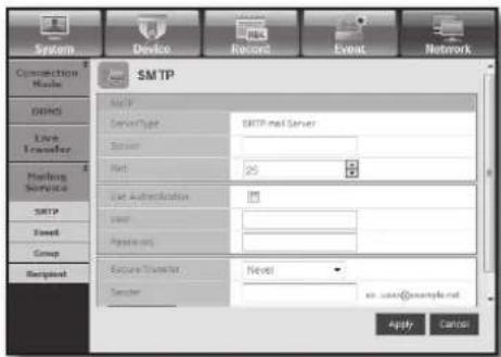
text_image
System Device Record Event Network Connection Mode SMTP Live Transfer Routing Service SMTP Fillet Group Recipient SMTP Audio ServerType SMTP mail Server Server Net 25 Web Authentication User Password Secure Transfer Sender Next ex. user@example.net Apply Cancel- Event
You can set the event interval and specify which events the server sends mails for.
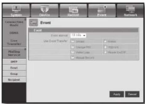
text_image
System Device Record Event Network Connection Mode DDMS Live Transfer Holding Service SMTP Event Group Recipient Event Event format: 10 tabs Use Event Transfer: □ Select □ Image □ Change Print □ Print info □ Value Loss □ Power ULERT □ Visual Security Apply Cancel- Group
You can add a group to receive the mail if an event occurs and set the permission to receive the event mail for each group.
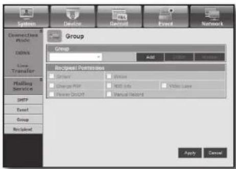
text_image
System Connection Profile Codes Line Transfer Holding Service SMTP Event Group Recipient Permission Server Power Charge PDF HDD Info Video Lane Power Discount Manual Record Apply Cancel- Recipient
You can add a user or users who will receive the mail.

text_image
System Device Record Event Network Connection Mode ODNS Live Transfer Mailing Service SMTP Event Group Recipient Recipient Group Name A-All Address Addict Apply Cancel92\_ web viewer
ABOUT
Click
Displays the model name of connected DVR and the version of Web Viewer.
text_image
http://192.168.0.200 - Web Viewer for Sa... SAMSUNG WEB VIEWER for SRD-470D Web Viewer Version: 1.0 Create Date: 2010. 4. 2 Copyright Samsung Techwin Co.Ltd.,2008
text_image
WEB VIEWEREnglish _93
backup viewer
SEC BACKUP VIEWER
You can play a file that is backed up in the format of SEC.
Backup in the format of SEC will involve in generating two fi les: one for the backup data and one for the viewer. If you run the backup fi le viewer, the backup data fi le will be automatically played.
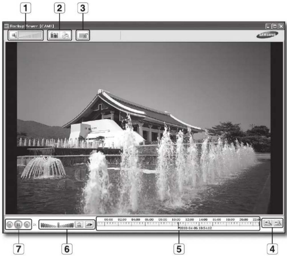
text_image
1 2 3 Backup Viewer [CAMI] SAMSUNG 00:00 02:00 04:00 06:00 08:00 10:00 12:00 14:00 16:00 18:00 20:00 22:00 2010-04-06 10:5:12 7 6 5 4Recommended System Requirements
PCs with a lower specification than the recommended below may not fully support forward/backward and high-speed playback.
• OS : Windows XP professional, Windows Vista, Windows 7
• CPU : Intel Core2-Duo 2.4GHz or higher
• RAM : DDR PC-3200 1G or more
• VGA : Geforce 6200 or higher
94_ backup viewer
| Name Description | |||
| 1 | Audio |  | A toggle button. Each time you press this button, the audio output will toggle between activated and deactivated. |
 | You can adjust the volume level from 0 to 100. | ||
| 2 | Screen Printout |  | Saves the current screen as an image fi le. Supported fi le formats include BMP and JPEG. |
 | Prints out the current screen. You should have installed the appropriate printer driver before you can print out the screen. | ||
| 3 | File Tamper Detection |  | A toggle button. Each time you press this button, it will toggle between activated and deactivated. The closed lock icon indicates activation of the fi le tamper detection, which will blink the screen three times and stop playing if an unauthorized manipulation of a data fi le is detected.▪ A message of "The fi le is forged" will display in the menu bar. |
| 4 | Zoom In/Out | [AZWc] | Collapses the time range that is displayed on the range bar of the storage time. You can collapse the range bar until the overall range is shortened to 24 hours. |
| [KS23] | Enlarges the time range that is displayed on the range bar of the storage time. You can enlarge the range bar until the overall range is extended to 1 minute. | ||
| [GXCX] | Displays the time range of a stored video fi le.You can move the gridline of the range bar to select a time point to play. | ||
| 6 | Speed |  | A toggle button; each time you press this button, the "Slow Playback " icon changes its color to display it's activated/deactivated. If it is activated, you can use the play speed control to adjust the play speed up to x1/32 forward and backward respectively, whereas if deactivated, you can adjust up to x32 forward and backward. |
 | A toggle button; each time you press this button, the "Lock Speed" icon changes its color to display it's activated/deactivated.If activated, the adjusted speed will be kept even if you release the mouse on the speed bar. If deactivated, the adjusted speed will be applied only while you use the mouse to hold the adjusted speed, and if you release the mouse, the speed will restore to x1. | ||
 | You can adjust the play speed up to x32 forward and backward respectively, which varies according to the frame rate per second of the source.If the frame rate per second is between 20 and 30, the maximum speed is limited to x4, if the FPS is between 11 and 19, it is limited to x16, and if the FPS is 6 or less, it supports up to x32. | ||
| 7 | Play | [20WA] | Displays the next frame. This is available only if the playback is stopped. |
| [HTSD] | A toggle button. Press it once to start playing the video and switch the button mode to 'Pause', and press it again to switch the button mode to Play and stop playing temporarily. | ||
| [CZZB] | Displays the previous frame. This is available only if the playback is stopped. | ||
English _95
appendix
PRODUCT SPECIFICATION
| Item Details Note | |||||
| Operating System Embedded OS | |||||
| Broadcast Format NTSC/PAL System | |||||
| Input Voltage AC 100~240V | |||||
| Power Consumption | 59W | ||||
| Video | Video In | Composite 4 Channel- 1.0Vp-p- 75Ω Hi Z TerminationBNC TypeLoop Through Out 4 Channel-Auto Termination | |||
| Video Out | Composite 2 Channel- Normal Video Output 1 Channel-Spot Output 1-BNC TypeVGA 1 Channel | ||||
| Audio | Audio In | Mono 4 Channel4 Channel : RCA Type- 5dBm, 600Ω | |||
| Audio Out | Mono 1 Channel- 6dBmRCA Type | ||||
| Live Screen | Resolution & Frame Rate | NTSC PAL | |||
| Resolution 704x480 | 704x576 | ||||
| Frame Rate | 120ips 100ips | ||||
| Display Mode | SingleSplit Modes: 4-splitsPIPMode sequenceFreeze2 X Zoom | ||||
96_ appendix
| Item Details Note | |||||
| Record | Compression Method | Video : H.264Audio : G.723 | |||
| Resolution & Quality | Resolution Spec. | (Quality) Max Recording Rate | |||
| CIF(S)352X240(NTSC)/352X288(PAL) | Level8 (high)~ Level1 (low) | CIF(S)120ips(NTSC)/100ips(PAL) | |||
| 2CIF(M)704x240(NTSC)/704x288(PAL) | Level8 (high)~ Level1 (low) | 2CIF(M)120ips(NTSC)/100ips(PAL) | |||
| 4CIF(L)704x480(NTSC)/704x576(PAL) | Level8 (high)~ Level1 (low) | 4CIF(L)120ips(NTSC)/100ips(PAL) | |||
| Record Mode | Normal Recording → REC buttonScheduled Recording → Schedule TableEvent Recording- Alarm Detection- Motion Detection- Video Loss- Pre & Post Recording | ||||
| Frame Rate | NTSC : 0.9, 1.9, 3.8, 7.5, 15, 30ipsPAL : 0.8, 1.6, 3.1, 6.2, 12.5, 25ips | ||||
| Storage Internal | SRD-470D : SATA HDDx1(MAX)MAX HDD size : 500GB x 1= 500GBSRD-470 : SATA HDDx2(MAX)MAX HDD size : 500GB x 2 = 1TB | If you want to add an internal HDD, please refer to "Adding a HDD". (Page 14) | |||
| Play | Search Mode | Calendar SearchEvent Search- Alarm, Motion, Video LossTime/Date SearchGo to FirstGo to LastBackup SearchText Search(for POS)Motion SearchPreview | |||
| Resolution & Specification | Resolution Specification | ||||
| CIF(S)352X240(NTSC)/352X288(PAL) | CIF(S)120ips(NTSC)/100ips(PAL) | ||||
| 2CIF(M)704x240(NTSC)/704x288(PAL) | 2CIF(M)120ips(NTSC)/100ips(PAL) | ||||
| 4CIF(L)704x480(NTSC)/704x576(PAL) | 4CIF(L)120ips(NTSC)/100ips(PAL) | ||||

text_image
● APPENDIXEnglish _97
appendix
| Item Details Note | |||
| Play | Display Mode | Single /4-splits | |
| Play Mode | Play, Pause, Stop, 2xDigital ZoomFast Forward/Fast Reverse- 2x, 4x, 8x,16x, 32x, 64x | ||
| Backup | USB External HDDUSB CD/DVD Writer, Internal DVD(SRD-470D only)USB MemoryUSB HDD-MAX 1(USB hub not supported) | ||
| Network Ethernet : 10/100/1000 BaseT, ADSL(PPPoE), DHCP | |||
| Serial Communication | RS-485 → PTZ Device ControlRemote Control DevicERS-232C → POS | ||
| Alarm | Input: 4 channels | ||
| Remote Viewer | PC Requirements | CPU : Intel Core 2 Quad 2.5GHz or higherRAM : 2GVGA : 32M RAM(64M or more)DirectX 8.1 | |
| Operating Systems | Windows XP(Pro),Windows-2000(Pro)Windows Vista(Home Basic/Premium)Windows 7 | ||
| Features | Live Image Monitoring ModeLocal File Search & Play Back ModeRemote File Search & Play Back Mode | ||
| Temperature (Operation) 0°C ~ 40°C (32°F ~ 104°F) | |||
| Temperature (Storage) -20°C ~ 60°C (-4°F ~ 140°F) | |||
| Humidity (Operation) 20% to 85% RH | |||
| Humidity (Storage) 20% to 85% RH | |||
| Dimension (W x H x D) 215 x 353 x 88mm | (8.46 x 13.88 x 3.64 inch) | H (leg not included) | |
| Weight | SRD-470 : ~4Kg(8.82lb)SRD-470D : ~4.85Kg(10.69lb) | ||

It needs extra H/W to support ATM/POS function. So please contact your vendor to obtain H/W.
98_ appendix
PRODUCT OVERVIEW
- SRD-470/470D
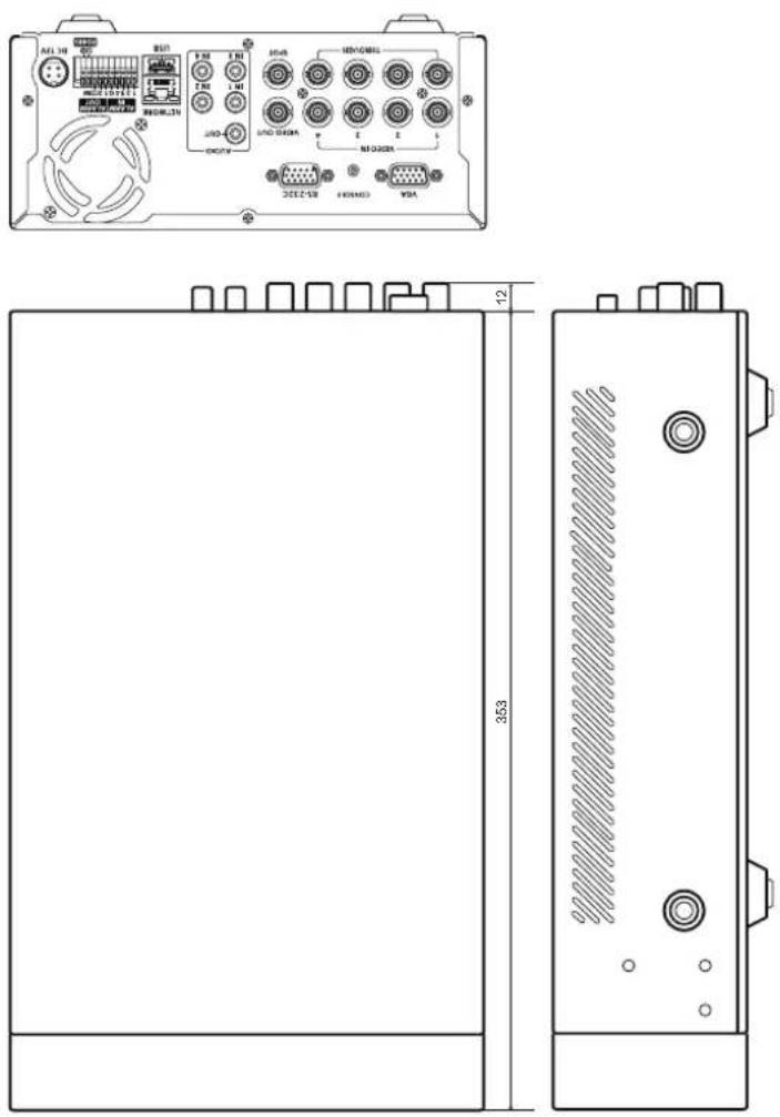
text_image
Technical diagram of an electronic device rear panel with labeled ports and dimensions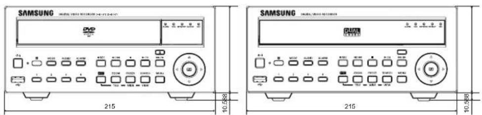
text_image
SAMSUNG DVQ 215 10.588 SAMSUNG DVQ 215 10.588English _99


text_image
● APPENDIX

appendix
DEFAULT SETTING
This returns the factory default settings.
The settings are made as follows;
- Use System/Load Factory Default in MENU
■ The default settings are based on SRD-470D.
| Category | Details Factory Default | |||
| Date YYYY-MM-DD | ||||
| Time Format 24 hours | ||||
| Date/Time/Language Date/Time/Language | Time Zone GMT | |||
| Time Synchronize OFF | ||||
| DST OFF | ||||
| System Settings | Language English | |||
| ID admin | ||||
| Permission Management | Admin | New Password 4321 | ||
| Setting | Restricted Access All | |||
| Auto Logout 3 Min | ||||
| System Management System Information Broadcast Format NTSC/PAL | ||||
| Video | ON | |||
| Audio | OFF | |||
| Camera | CH Name | CAM 01 ~ CAM 04 | ||
| SEQ-Dwell Time | 5sec | |||
| Camera | Progressive | OFF | ||
| ID | Camera No. | |||
| PTZ | Protocol | None | ||
| Brightness | 50 | |||
| Screen Setup | Contrast | 50 | ||
| Color | 50 | |||
| Device | Check Alarm Output Port | OFF | ||
| Storage Device | HDD Alarm | Duration | OFF | |
| Replace Alarm Output Port | OFF | |||
| Duration | OFF | |||
| Baudrate | 9600 | |||
| Parity | None | |||
| Data | 8 | |||
| Remote Device | Stop bit | 1 | ||
| Transfer Type | Half Duplex | |||
| System Keyboard | OFF | |||
| Remote Control | ON(00) | |||
100_ appendix
| Category | Details Factory Default | |||
| Device | POS Device OFF | |||
| Monitor | Monitor | Event Display OFF | ||
| Display All | ||||
| VGA 800x600 | ||||
| Sharpness Level1 (Low) | ||||
| Display Position Setup 30 | ||||
| Spot Out Spot Out | 1 CH1 ~ CH4 | |||
| Mode | Live Mode ALL | |||
| Play Mode ALL | ||||
| Recording | Recording Schedule Channel 1 Event | |||
| Event Record Duration | PRE Event OFF | |||
| POST Event 1 min | ||||
| REC Quality/Resolution | Normal Recording | Resolution CIF(S) | ||
| Frame Rate | 7.5 ips | |||
| Record Quality | Level 4 | |||
| Event | Resolution 4CIF(L) | |||
| Frame Rate | 30 ips | |||
| Record Quality | Level 4 | |||
| Record Option | Disk End Mode | Setup | Overwrite | |
| Disk End Beep | OFF | |||
| Auto Delete OFF | ||||
| Event | Sensor Detection | Sensor Operation | OFF | |
| Camera | Camera No. | |||
| Alarm | None | |||
| Duration | 10 sec | |||
| Motion Detection | Mode OFF | |||
| Sensitivity | Very High | |||
| Alarm | None | |||
| Duration | 10 sec | |||
| Motion Region | All Area | |||
| Video Loss Detection | Video Loss State | OFF | ||
| Alarm | None | |||
| Duration | 10 sec | |||

text_image
● APPENDIXEnglish _101
appendix
| Category | Details Factory Default | |||
| Network | Connection Mode | Connection | Connection Mode Static IP | |
| Bandwidth 2Mbps | ||||
| IP 192.168.1.200 | ||||
| Gateway 192.168.1.1 | ||||
| Subnet Mask 255.255.255.0 | ||||
| DNS 168.126.63.1 | ||||
| Protocol | Protocol Type TCP | |||
| Port (TCP) 554~557 | ||||
| Webviewer Port 80 | ||||
| DDNS DDNS Site OFF | ||||
| Live Transfer | Resolution CIF(S) | |||
| Quality Low | ||||
| Mailing Service | SMTP | Server OFF | ||
| Port 25 | ||||
| Use Authentication | OFF | |||
| Secure Transfer Never | ||||
| Event | Event Interval | 10 min | ||
| Use Event Transfer | OFF | |||
| Group | Group | OFF | ||
| Recipient Permission | OFF | |||
102_ appendix
TROUBLESHOOTING
| Symptom Countermeasures | |
| The system does not turn on and the indicator on the front panel does not work at all. | Check if the power supply system is properly connected.Check the system for the input voltage from the power source.If the problem persists even after you have taken the above actions, check the power supplier and replace it with a new one if necessary. |
| Some channels display just a black screen even if they receive video sources. | Check if the camera connected to the system properly displays the image. Sometimes, this problem may occur on a camera that is not properly connected to the video source.Check if the camera is properly supplied with power.Sometimes, this problem may occur on a channel with weak video signal from a video distributor that is connected to multiple systems. In this case, input the video source of the camera directly into the DVR. This may find the cause and solve the problem. |
| If I press the [REC] button on the front panel, the REC indicator does not flash, nor the player start recording. | Check if there is a free space on the HDD for the recording.Check if the record mode is set to ON in the record mode setting. |
| The screen displays the logo image repeatedly. | This may occur from a problem with the main board, or the related software is corrupt.Contact the nearest service center for more information. |
| The Channel button does not work on the Live screen. | The Channel button does not work if the current screen is in the event monitoring mode.In the event monitoring screen, press the [ALARM] button to exit the screen and select a channel. |
| The cursor will not move to the Start button when I start the calendar search. | Check if the channel and the date that you want to play are marked with the V symbol.Both channel and date should be checked before you can start playing with the Start button. |
| When the alarm sounds, I press the [ALARM] button on the front panel to release the alarm but it does not work. The alarm persists and I could not set it off in any way. | Press the [MENU] button on the front panel to release the alarm in the following way:1) To release the event monitoring mode : Monitoring Mode - set the duration of the event monitoring to Off.2) To release the alarm sound : Event Record Mode - Alarm (Motion Detection/Video Loss) - deactivate the alarm sound.3) To release the event : Event Record Mode - Alarm (Motion Detection/Video Loss) - set the mode to Off. |
| No response is made even if I press the [PTZ] button on the Live screen. | Menu → Camera → Check if the current protocols and other settings in the PTZ device are properly configured according to the PTZ camera. |
English _103
appendix
| Symptom Countermeasures | |
| I've found that the DVR does not recognize as many disks as installed when I have connected multiple external HDDs to the DVR. | It takes time for the DVR to recognize multiple external HDDs. Try again in a moment and if the problem (of failure to recognize as many HDDs as connected) persists, it may occur due to a mechanical error of the HDD installed. Try again with a different HDD. |
| A message of "Need to reset date/time." Is displayed on the screen. | This message is displayed if there occurs a problem with the time setting of the internal clock or an error in the clock itself.Contact the retailer or the service center for more information. |
| The time bar is not displayed in Search mode. The timeline can switch between normal and extension mode.In extension mode, the time bar may not be displayed in the current timeline. Switch to normal mode or use the left or right button to navigate through the time bar. | |
| The "NO HDD" icon and an error message are displayed. | Check the HDD for connection. If the problem persists in a normal condition, contact the nearest service center to have the HDD checked by the service personnel. |
| I have installed an additional HDD on the DVR but it does not recognize the HDD. | See the compatibility list to check if the additional HDD is supported by the DVR. For the compatibility list, contact the retailer where you purchased the DVR. |
| I have connected an external storage device (external SATA HDD) to the DVR but the DVR seems not to recognize it. | See the compatibility list of external storage devices to check if the connected device is supported by the DVR.For the compatibility list, contact the retailer where you purchased the DVR. |
| If I press the ESC key in full screen mode of the WebViewer, the system does not switch to a normal split mode. | Press the ALT+TAB keys to select 'ACTIVE MOVIE' and press the ESC key again. The system will switch to a normal split mode. |
| I found it diffi cult to confi gure the network settings if using the default search, backup and router settings. | For more information, refer to the user manual.If you want to check the basics of the product for a quick start, refer to the quick start guide (backup, search). |
| I forgot the password. | Contact the DVR administrator for help. |
| Backup data is just not played by the PC or DVR. | When you are backing up data, you have choices about the player either: PC or DVR. Make your selection before proceeding.If you are using the PC to play the data, the format of the backup fi le should be either AVI or SEC.If you are using the DVR for this purpose, formatting backup fi les should be done by the DVR. |
| My player does not switch to Live mode while in playback. | Press the Stop [■] button on the DVR or the remote control, or click the [■] icon on the launcher to switch to Live mode. |
| Recording does not work. If your player does not display | Live image at all, that indicates recording does not work so fi rst check if you see an image on the screen.Recording does not work if the recording settings are not properly confi gured.1) Manual Record: Press the [REC] button on the front panel of the DVR or on the remote control to start recording.Scheduled Record: Specify a desired time in Menu – Record - Recording Schedule. Recording will start at the specifi ed time.-Record: Recording will proceed in any conditions at the specifi ed time.-Record: When an event occurs, recording will perform only if the event is of alarm, motion detection and video loss. If there is no event found, recording will not perform.-Record: If there is no event found, Continuous recording will perform. Whereas, if an event occurs, Event recording will perform. |
| The image quality of the recording data is not good. | Increase the resolution and quality level in Menu – Record – Quality / Resolution.1) Resolution: Select a bigger size when specifying the recording size. (4CIF>2CIF>CIF)The recording image in the CIF format shows a deteriorated quality as it is enlarged from a small-sized image.2) Record Quality: Specify a bigger level for the recording quality.If you increase the resolution and the recording quality, the data size increases accordingly. So the HDD will be fi lled faster. Overwriting will overwrite the existing data so recording will proceed at a shorter interval. |
English _105


Correct Disposal of This Product (Waste Electrical & Electronic Equipment)
(Applicable in the European Union and other European countries with separate collection systems)
This marking on the product, accessories or literature indicates that the product and its electronic accessories (e.g. charger, headset, USB cable) should not be disposed of with other household waste at the end of their working life. To prevent possible harm to the environment or human health from uncontrolled waste disposal, please separate these items from other types of waste and recycle them responsibly to promote the sustainable reuse of material resources.
Household users should contact either the retailer where they purchased this product, or their local government office, for details of where and how they can take these items for environmentally safe recycling.
Business users should contact their supplier and check the terms and conditions of the purchase contract. This product and its electronic accessories should not be mixed with other commercial wastes for disposal.

Correct disposal of batteries in this product
(Applicable in the European Union and other European countries with separate battery return systems.)
This marking on the battery, manual or packaging indicates that the batteries in this product should not be disposed of with other household waste at the end of their working life. Where marked, the chemical symbols Hg, Cd or Pb indicate that the battery contains mercury, cadmium or lead above the reference levels in EC Directive 2006/66. If batteries are not properly disposed of, these substances can cause harm to human health or the environment.
To protect natural resources and to promote material reuse, please separate batteries from other types of waste and recycle them through your local, free battery return system.
SAMSUNG
SALES NETWORK
SAMSUNG TECHWIN CO., LTD.
Samsungtechwin R&D Center, 701, Sampyeong-dong, Bundang-gu, Seongnam-si, Gyeonggi-do, Korea, 463-400
TEL: +82-70-7147-8740\~60 FAX: +82-31-8018-3745
Samsung House, 1000 Hillswood Drive, Hillswood Business
Park Chertsey, Surrey, UNITED KINGDOM KT16 OPS
TEL: +44-1932-45-5300 FAX: +44-1932-45-5325
www.samsungtechwin.com
www.samsungsecurity.com
www.samsungipolis.com