DS1100-2100 HI-RES - Barcode Reader DATALOGIC - Free user manual and instructions
Find the device manual for free DS1100-2100 HI-RES DATALOGIC in PDF.

User questions about DS1100-2100 HI-RES DATALOGIC
0 question about this device. Answer the ones you know or ask your own.
Ask a new question about this device
Download the instructions for your Barcode Reader in PDF format for free! Find your manual DS1100-2100 HI-RES - DATALOGIC and take your electronic device back in hand. On this page are published all the documents necessary for the use of your device. DS1100-2100 HI-RES by DATALOGIC.
USER MANUAL DS1100-2100 HI-RES DATALOGIC
Datalogic reserves the right to make modifications and improvements without prior notification.
Datalogic shall not be liable for technical or editorial errors or omissions contained herein, nor for incidental or consequential damages resulting from the use of this material.
Product names mentioned herein are for identification purposes only and may be trademarks and or registered trademarks of their respective companies.
Datalogic is a registered trademark of Datalogic S.p.A. in many countries and the Datalogic logo is a trademark of Datalogic S.p.A.
© Datalogic S.p.A. 1999 - 2006
REFERENCES ...... v
Conventions ...... v
Reference Documentation ...... v
Services and Support.... v
SAFETY REGULATIONS......vi
Laser Safety......vi
Power Supply......vii
CE Compliance......vii
FCC Compliance......viii
GENERAL VIEW ix
GUIDE TO INSTALLATION ....X
1 INTRODUCTION .... 1
1.1 Product Description.... 1
1.1.1 Indicators 2
1.2 Model Description 2
1.3 Accessories....3
2 INSTALLATION....4
2.1 Package Contents....4
2.2 Mechanical Installation....5
2.2.2 Reading Position....7
2.3 Electrical Connections 8
2.3.1 Power Supply 9
2.3.2 Main Serial Interface - RS485 Half-Duplex 9
2.3.3 Auxiliary Interface - RS232 11
2.3.4 Inputs 12
2.3.5 Outputs 13
2.4 User Interface 15
2.5 Positioning 16
2.6 Typical Layouts 17
2.6.1 Point-to-Point 18
2.6.2 RS485 Master/Slave 18
2.6.3 Multiplexer....20
3 READING FEATURES....21
3.1 Step-Ladder Mode 21
3.2 Picket-Fence Mode 22
3.3 Performance 23
3.3.1 Raster 23
3.4 Reading Diagrams 24
4 MAINTENANCE 26
4.1 Cleaning....26
5 TROUBLESHOOTING 27
5.1 General Guidelines 27
6 TECHNICAL FEATURES....30
GLOSSARY 32
INDEX 36
CONVENTIONS
This manual uses the following conventions:
"User" or "Operator" refers to anyone using a DS1100.
"Device" refers to the DS1100.
"You" refers to the System Administrator or Technical Support person using this manual to install, mount, operate, maintain or troubleshoot a DS1100.
REFERENCE DOCUMENTATION
For further details refer to the WinHost Help On Line.
SERVICES AND SUPPORT
Datalogic provides several services as well as technical support through its website. Log on to www.datalogic.com and click on the links indicated for further information including:
- PRODUCTS
Search through the links to arrive at your product page where you can download specific Manuals and Software & Utilities
• SERVICES & SUPPORT
- Datalogic Services - Warranty Extensions and Maintenance Agreements
- Authorised Repair Centres
- CONTACT US
E-mail form and listing of Datalogic Subsidiaries
LASER SAFETY
The following information is provided to comply with the rules imposed by international authorities and refers to the correct use of the DS1100 scanner.
Standard Regulations
This scanner utilizes a low-power laser diode. Although staring directly at the laser beam momentarily causes no known biological damage, avoid staring at the beam as one would with any very strong light source, such as the sun. Avoid that the laser beam hits the eye of an observer, even through reflective surfaces such as mirrors, etc.
This product conforms to the applicable requirements of both EN 60825-1 and CDRH 21 CFR 1040 at the date of manufacture. The scanner is classified as a Class 2 laser product according to EN 60825-1 regulations and as a Class II laser product according to CDRH regulations.
There is a safety device which allows the laser to be switched on only if the motor is rotating above the threshold for its correct scanning speed.
The motor and the laser beam can be switched off through a software command (see also «Beam Shutter» in the WinHost Help On Line).

WARNING
Use of controls or adjustments or performance of procedures other than those specified herein may result in exposure to hazardous visible laser light.
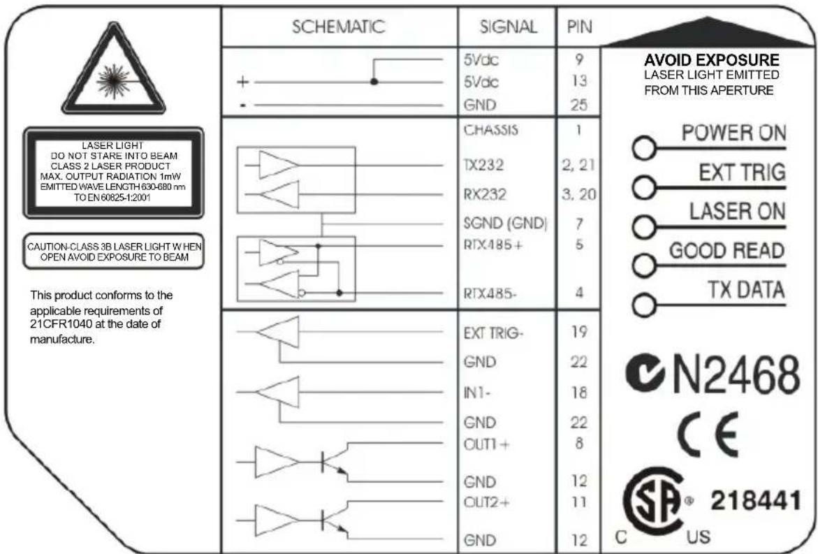
The laser light is visible to the human eye and is emitted from the window on the front of the scanner (Figure A, 1).
The warning label indicating exposure to laser light and the device classification is applied onto the body of the scanner (Figure A, 7).
text_image
SCHEMATIC 5Vdc 5Vdc GND CHASSIS TX232 RX232 SGND (GND) RTX485+ RTX485- EXT TRIG- GND IN1- GND OUT1+ GND OUT2+ GND PIN 9 13 25 1 2, 21 3, 20 7 5 4 19 22 18 22 8 12 11 12 AVOID EXPOSURE LASER LIGHT EMITTED FROM THIS APERTURE POWER ON EXT TRIG LASER ON GOOD READ TX DATA This product conforms to the applicable requirements of 21CFR1040 at the date of manufacture. N2468 CE 218441 C USWarning and Device Class Label
For installation, use and maintenance it is not necessary to open the scanner. The laser diode used in this device is classified as a class 3B laser product according to EN 60825-1 regulations and as a Class IIIb laser product according to CDRH regulations.
Any violation of the optic parts in particular can cause radiation up to the maximum level of the laser diode (7 mW at 630 to 680 nm).
POWER SUPPLY
This device is intended to be supplied by a UL Listed or CSA Certified Power Unit with "Class 2" or LPS power source which supplies power directly to the scanner via the 25-pin connector.
CE COMPLIANCE
Warning:
This is a Class A product. In a domestic environment this product may cause radio interference in which case the user may be required to take adequate measures.
FCC COMPLIANCE
Modifications or changes to this equipment without the expressed written approval of Datalogic could void the authority to use the equipment.
This device complies with PART 15 of the FCC Rules. Operation is subject to the following two conditions: (1) This device may not cause harmful interference, and (2) this device must accept any interference received, including interference which may cause undesired operation.
This equipment has been tested and found to comply with the limits for a Class A digital device, pursuant to part 15 of the FCC Rules. These limits are designed to provide reasonable protection against harmful interference when the equipment is operated in a commercial environment. This equipment generates, uses, and can radiate radio frequency energy and, if not installed and used in accordance with the instruction manual, may cause harmful interference to radio communications. Operation of this equipment in a residential area is likely to cause harmful interference in which case the user will be required to correct the interference at his own expense.
DS1100

text_image
CATALOGIC DSIHOO ①
text_image
65432 SICEMA AVOD EXPOSURE POWER ON EXT TRIG LASER ON GOOD READ TX DATA N2468 CE 218441 7 8Figure A
① Laser Beam Output Window
② TX Data LED
③ Good Read LED
④ Laser On LED
⑤ Ext Trig LED
⑥ Power On LED
⑦ Laser Warning and Device Class Label
⑧ Mounting Holes
The following can be used as a checklist to verify all of the steps necessary for complete installation of the DS1100 scanner.
1) Read all information in the section "Safety Precautions" at the beginning of this manual.
2) Correctly mount the reader using the bracket provided according to the information in par. 2.2.1.
3) Position the reader at the correct reading distance according to your model as shown in paragraphs 2.2.2 and 2.5.
4) Make electrical connections to your DS1100 scanner by either:
a) Connecting the test cable to the DS1100 scanner as described in par. 2.4
b) Providing correct and complete system cabling according to the signals necessary for the layout of your application.
- Layout: Point-to-point, RS485 Master/Slave, Multiplexer. See subparagraphs under 2.6 for reference.
- Cabling: Power, Main Serial Interface - RS485 Half Duplex, Auxiliary Interface - RS232, Inputs, Outputs, etc. For further details, see all subparagraphs under 2.3.
5) Configure the DS1100 scanner by installing and running the WinHost configuration program from the CD-ROM provided. The main steps are:
- Select the codes to be read
- Set-up the communication parameters
- Define data formatting parameters
- Fine tune your DS1100 scanner using the Test Mode as described in WinHost.
Specific parameter details are available in the Help On Line. See also the Guide To Rapid Configuration link.
6) Exit the configuration program and run your application.
The installation is now complete.
1 INTRODUCTION
1.1 PRODUCT DESCRIPTION
The DS1100 scanner with decoder offers the best cost-effective solution for demanding industrial applications.
The DS1100 ultra compact dimensions, based on Datalogic experience in miniaturized laser components, have been specifically designed to make the scanner's integration into automated equipment extremely easy.
The Windows-based user-friendly WinHost utility program provided on CD-ROM simplifies the scanner's setup. The DS1100 can also be configured from a Host PC through the Host Mode procedure.
Some of the main features of DS1100 are listed below:
- miniaturized dimensions, light weight;
• scanning speed: 500 scans/sec; - raster version available;
- motor and the laser beam can be switched off through a software command (see also «Beam Shutter» in the WinHost Help On Line).
- 2 serial communication interfaces: RS232 + RS485;
- reads all popular codes;
• supply voltage: 5 Vdc (4 to 30 Vdc with converter);
- test mode to verify the reading features and exact positioning of the scanner without the need for external tools;
- programmable in 4 different operating modes to suit the most various barcode reading system requirements;
- code verifier;
• programmable input and output signals;
- light source: visible laser diode; the light emitted has a wavelength in the range 630 \~ 680 nm. For laser safety precautions refer to the “Safety Precautions” section at the beginning of this manual;
- low power consumption;
- IP65 protection class of the enclosure; the reader is therefore suitable for industrial environments where high protection against harsh external conditions is required;
The laser beam output window is on the side of the scanner in DS1100-XXX0 models and on the upper part of the scanner in DS1100-XXX1 models, (Figure A, 1).
A security system allows the laser to activate only once the motor has reached the correct rotational speed; consequently, the laser beam is generated after a slight delay from the power on of the scanner.
1.1.1 Indicators
The five LEDs on the scanner indicate the following:
| POWER ON | (red) indicates the reader is connected to the power supply. (Figure A, 6). |
| EXT TRIG | (yellow) indicates external trigger activity. Refer to par. 2.3.4. (Figure A, 5). |
| LASER ON | (green) indicates laser ON state. (Figure A, 4). |
| GOOD READ | (red) is used to signal the possibility of a successful barcode reading. (Figure A, 3). |
| TX DATA | (green). When blinking, it indicates data transmission. (Figure A, 2). |
The screw holes on the body of the reader are for mechanical fixture (Figure A, 8).
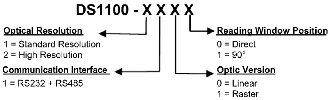
1.2 MODEL DESCRIPTION
The DS1100 scanner is available in versions that differ in regard to the following parameters:
- Resolution.
- Reading window position.
- Linear or raster models.
flowchart
graph TD
    A["DS1100 - XXXX"] --> B["Optical Resolution"]
    A --> C["Reading Window Position"]
    A --> D["Optic Version"]
    B --> E["1 = Standard Resolution\n2 = High Resolution"]
    C --> F["0 = Direct\n1 = 90°"]
    D --> G["0 = Linear\n1 = Raster"]
    H["Communication Interface"] --> I["1 = RS232 + RS485"]
The following tables display each version's reading performance.
| Version | Max | Code | Resolution | Speed |
| mm | (mils) | |||
| 1XXX | 0.20 | (8) | 500 | |
| 2XXX | 0.12 | (5) | 500 |
| Version | Reading | Distance |
| 1XXX 30 mm (1.2 in) - 220 mm (8.7 in) on 0.50 mm (20 mils) codes | ||
| 2XXX 10 mm (0.4 in) - 110 mm (4.3 in) on 0.30 mm (12 mils) codes | ||
See reading diagrams in par. 3.4 for further details.
1.3 ACCESSORIES
The following accessory is available on request:
| Name | Description | Part |
| DC5-2200 DC converter | 4-30 Vdc to 5 Vdc 93ACC1040 |
2 INSTALLATION
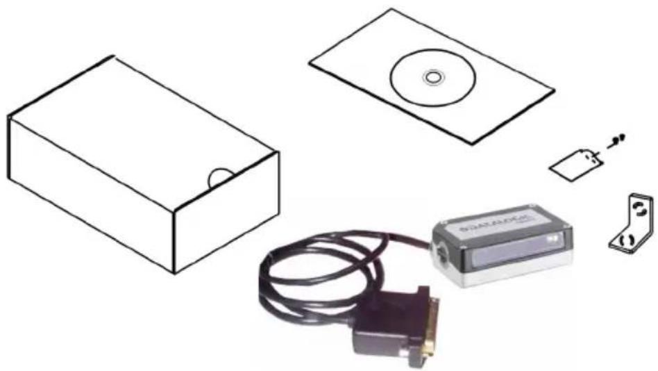
2.1 PACKAGE CONTENTS
Verify that the DS1100 reader and all the parts supplied with the equipment are present and intact when opening the packaging; the list of parts includes:
☐ DS1100 reader with cable
Quick Reference Guide
WinHost CD-ROM
☐ Barcode test chart (PCS = 0.9)
Mounting kit:
- bracket
- screws
natural_image
Illustration of electronic components including a box, CD, connector, and cable (no text or symbols)DS1100 can be installed to operate in any position. There are three screw holes (M3 x 5) on the body of the reader for mounting. The diagram below gives all the information required for installation; refer to pars. 2.2.1, 2.2.2, and 2.5 for correct positioning of the scanner with respect to the code passage zone.
DS1100

mm
inch
* The quote refers to the scan line
MOUNTING BRACKET

mm/inch
Using the DS1100 mounting bracket you can obtain the most suitable position for the reader as shown in the figure below:
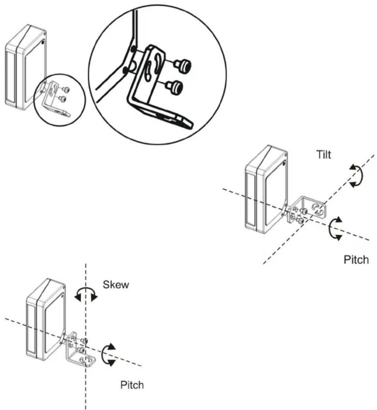
Figure 3 - Positioning with Mounting Bracket
2.2.2 Reading Position
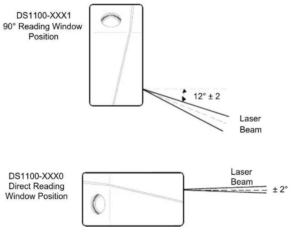
In DS1100-XXX1 models the laser beam is emitted from the output window with a 12^ ( ± 2 ) skew angle.
This allows installation with minimum overall dimensions.
text_image
DS1100-XXX1 90° Reading Window Position 12° ± 2 Laser Beam DS1100-XXX0 Direct Reading Window Position Laser Beam ± 2°Figure 4 - Reading Position
2.3 ELECTRICAL CONNECTIONS
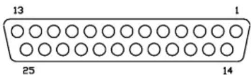
The DS1100 cable is equipped with a 25-pin female D-sub connector for connection with the power supply and input/output signals:

CAUTION
Do not connect GND and SGND to different (external) ground references. GND and SGND are internally connected through filtering circuitry which can be permanently damaged if subjected to voltage drops over 0.8 Vdc.
text_image
13 25 1 14Figure 5 – 25-pin Female D-sub Connector
| 25-pin D-sub connector pinout | ||
| Pin | Name | Function |
| 9,13 VS Power supply input voltage +25 GND Power supply input voltage -1 * CHASSIS Chassis Ground2, 21 TXAUX TX RS232 Aux. Interface3, 20 RXAUX RX RS232 Aux. Interface4 RTX485- RTX- RS485 Main Interface5 RTX485+ RTX+ RS485 Main Interface78 OUT1 +11 OUT2 +18 IN1 -19 EXT TRIG-12, 2223, 246, 10, 14, 15, 16, 17 | SGNDOutput 1 +Output 2 +Input 1 -External trigger -GND Input/Output referenceN.U.NC | Signal Ground |
* Pins 1 and 25 are connected together internally.
2.3.1 Power Supply
The following pins of the DS1100 connector are used:

flowchart
graph LR
    A["DS1100"] --> B["VS"]
    A --> C["GND"]
    A --> D["CHASSIS"]
    B --> E["13/9"]
    C --> F["25"]
    D --> G["1"]
    H["USER INTERFACE"] --> I["V+ (5 Vdc)"]
    H --> J["GND"]
Figure 6 - Power Supply Connections
The power must be 5 Vdc only.
2.3.2 Main Serial Interface - RS485 Half-Duplex
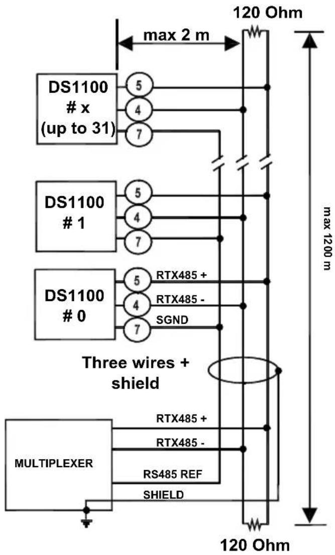
The RS485 half-duplex interface (3 wires + shield) is used for polled communication protocols.
It can be used for Multidrop connections in a Master/Slave layout or with a Datalogic Multiplexer, (see par. 2.6.2 and 2.6.3) exploiting a proprietary protocol based on polled mode called MUX32 protocol, where a master device polls slave devices to collect data.
The connector pinout follows:
| Pin | Name | Function |
| 5 RTX485+ | RS485 transmitted/received data + | |
| 4 RTX485 - | RS485 transmitted/received data - | |
| 7 | SGND | signal ground |

text_image
DS1100 USER INTERFACE RTX485 + RTX485 + RTX485 - SGND RS485 Ref 5 4 7Figure 7 - RS485 Half-Duplex Connections
For this interface type, the Multidrop Address must also be set via serial channel by the WinHost utility or by ESC sequences.
Figure 8 shows an example of a multidrop configuration between a Multiplexer and DS1100 scanners.

CAUTION
This is an example of multidrop wiring. Consult the multiplexer manual for complete wiring instructions.
The auxiliary serial interface is used exclusively for RS232 point-to-point connections. It is also used for configuring the DS1100.
The parameters relative to the auxiliary interface (baud rate, data bits, etc.) can be defined using the WinHost utility program or "Host Mode Programming", installed from the CD-ROM.
The following pins of the 25-pin connector are used to connect the RS232 auxiliary interface:
| Pin | Name | Function | ||
| 3, 20 | RXAUX | received data | ||
| 2, 21 | TXAUX | transmitted data | ||
| 7 | SGND | signal | ground | |

text_image
DS1100 3/20 RXAUX 2/21 TXAUX 7 SGND USER INTERFACE TXD RXD SGNDFigure 9 - RS232 Auxiliary Interface Connections
2.3.4 Inputs
The inputs available on the connector are indicated below:
| Pin | Name | Function |
| 18 IN1 - input 1 -19 EXT TRIG- external trigger -12, 22 GND I/O reference | ||
The EXT TRIG input is used to connect the external trigger which tells the scanner to scan for a code. The active state of this input is selected in software. Refer to the WinHost Help On Line.
The yellow LED (Figure A, 5) is on when EXT TRIG- is shorted to GND.
This input is driven by an NPN type command. The connections are indicated in the following diagram:

text_image
DS1100 + 5 V 47 K 13/9 VS 5 Vdc 19 EXT TRIG - 12/22 GND EXTERNAL TRIGGER V Ground SignalFigure 10 - External Trigger Input Command (5 Vdc Photocell)

text_image
DS1100 VS 5 Vdc Vmax 30 Vdc max EXTERNAL TRIGGER + 5 V 47 K 13/9 19 EXT TRIG - 12/22 GND Ground SignalFigure 11 - External Trigger Input Command (Photocell max 30 Vdc)
The general purpose input IN1, in the Standard Application Program, can be used to store the code verifier (see "Store Verifier Hw" in the WinHost Help On Line).

text_image
DS1100 + 5 V 47 K 18 IN1 - 12/22 GND User Interface GroundFigure 12 - IN1 - Input Command
An anti-disturbance hardware filter is implemented on the External Trigger input (about 1 millisecond delay).
An additional 15 ms (typical) delay can be implemented through a dedicated software parameter (refer to WinHost Help On Line).
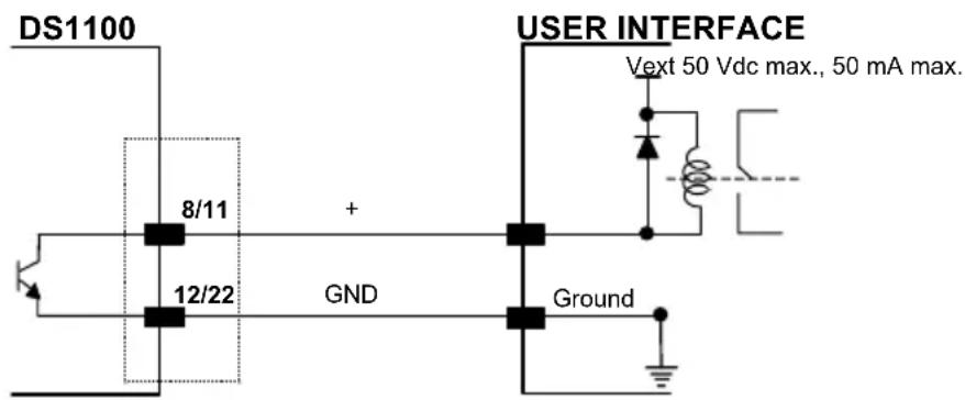
2.3.5 Outputs
Two general purpose outputs are available. These outputs can only be connected as open collector configurations. The following pins are present on the 25-pin connector of the scanner:
| Pin | Name | Function |
| 8 | OUT1+ | output 1 + |
| 11 | OUT2+ | output 2 + |
| 12, 22 | GND | I/O reference |
The meaning of the two outputs OUT1 and OUT2 can be defined by the user (No Read, Right, Wrong, or a combination). Refer to the WinHost Help On Line.
By default, OUT1 is associated with the No Read event, which activates when the code signaled by the external trigger is not decoded, and OUT2 is associated with the Right event, which activates when the code is correctly decoded.
text_image
DS1100 8/11 + 12/22 GND USER INTERFACE Vext 50 Vdc max., 50 mA max. Ground$$ I \max = 5 0 \mathrm{mA} \text { continuous } $$
These outputs are both level or pulse configurable.
2.4 USER INTERFACE
The following table contains the pinout for standard RS232 PC Host interface. For other user interface types, please refer to their own manual.
| RS232 PC-side connections | |||
 9-pin male connector 9-pin male connector | 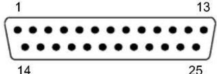 25-pin male connector 25-pin male connector | ||
| Pin | Name | Pin | Name |
| 2 | RX | 3 | RX |
| 3 | TX | 2 | TX |
| 5 | GND | 7 | GND |
| 7 | RTS | 4 | RTS |
| 8 | CTS | 5 | CTS |
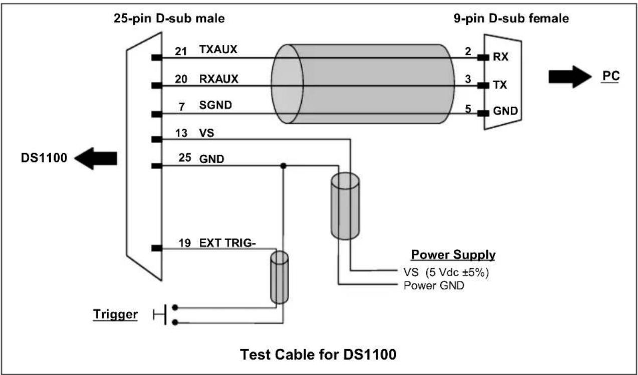
How To Build A Simple Interface Test Cable:
The following wiring diagram shows a simple test cable including power, external (push-button) trigger and PC RS232 COM port connections.
flowchart
graph LR
    A["25-pin D-sub male"] --> B["21 TXAUX"]
    A --> C["20 RXAUX"]
    A --> D["7 SGND"]
    E["9-pin D-sub female"] --> F["2 RX"]
    E --> G["3 TX"]
    E --> H["5 GND"]
    I["DS1100"] --> J["13 VS"]
    I --> K["25 GND"]
    L["Trigger"] --> M["19 EXT TRIG-"]
    N["Power Supply"] --> O["VS (5 Vdc ±5%)"]
    N --> P["Power GND"]
    Q["Test Cable for DS1100"] --> R["PC"]
2.5 POSITIONING
The scanner must be positioned so that the laser beam is aligned to completely intersect the codes passing in front of it. This positioning must also be within its reading distance (see par. 3.4).
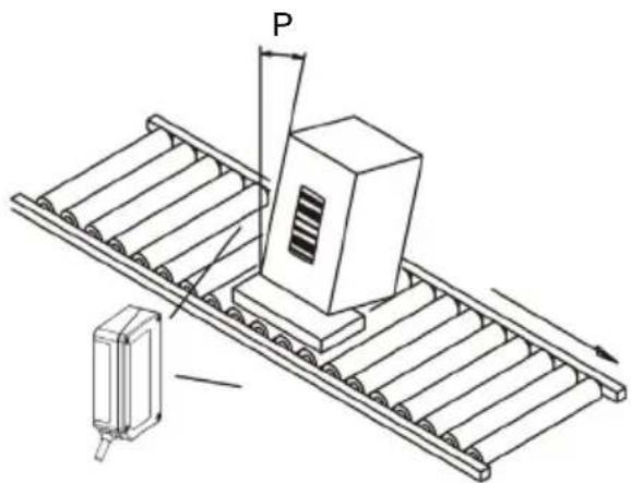
The DS1100 scanner is able to decode barcode labels at a variety of angles, however significant angular distortion may degrade reading performance. When mounting the DS1100 take into consideration these three ideal label position angles: Pitch 0°, Skew 15° to 30° and Tilt 0°.
Follow the suggestions for the best orientation:
The Pitch angle is represented by the value P in Figure 14. Position the reader in order to minimize the Pitch angle.
natural_image
Technical line drawing of a conveyor belt system with a moving cart and a labeled point P (no text or symbols beyond label)Figure 14 - Pitch Angle
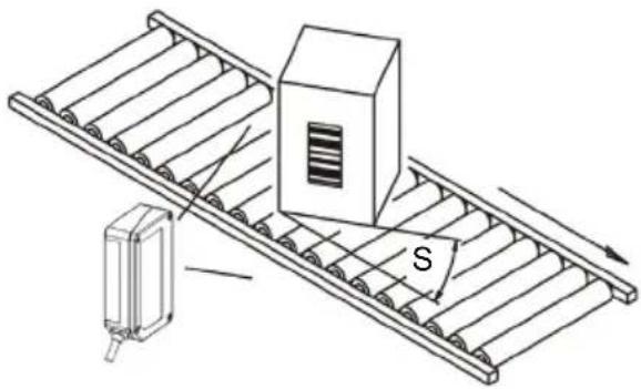
The Skew angle is represented by the value S in Figure 15. Position the reader to assure about 15^ for the Skew angle. This avoids the direct reflection of the laser light emitted by the DS1100.
For the raster version, this angle refers to the most inclined or external raster line, so that all other raster lines assure more than 15^ Skew.
For the skew angle value with DS1100 90° versions, refer to par. 2.2.2.
natural_image
Diagram of a conveyor belt system with a box and directional arrow, no text or symbols presentFigure 15 - Skew Angle
The Tilt angle is represented by the value T in Figure 16. Position the reader in order to minimize the Tilt angle.

natural_image
Diagram of a conveyor belt system with a box and a mechanical device, showing motion direction (no text or symbols)Figure 16 - Tilt Angle
2.6 TYPICAL LAYOUTS
The following typical layouts refer to system hardware configurations. Dotted lines in the figures refer to optional hardware configurations within the particular layout.
These layouts also require the correct setup of the software configuration parameters. Complete software configuration procedures can be found in the Guide To Rapid Configuration in the WinHost Help On Line.
2.6.1 Point-to-Point
In this layout data is transmitted to the Host on the RS232 Auxiliary serial interface. The Local Echo communication mode must be enabled (default) See the WinHost Help On Line.
When On-Line Operating mode is used, the scanner is activated by an External Trigger (photoelectric sensor) when the object enters its reading zone.
flowchart
graph TD
    A["Host"] --> B["RS232 Auxiliary Serial Interface"]
    B --> C["External Trigger (for On-Line mode)"]
    style A fill:#f9f,stroke:#333
    style B fill:#ccf,stroke:#333
    style C fill:#cfc,stroke:#333
Figure 17 – Point-to-Point Layout
2.6.2 RS485 Master/Slave
The RS485 Master/Slave connection is used to collect data from several scanners to build a multi-point or a multi-sided reading system; there can be one master and up to 5 slaves connected together.
The Slave scanners are connected together using the RS485 half-duplex main serial interface. Every slave scanner must have a multidrop address in the range 0-4.
The master scanner is also connected to the Host on the RS232 auxiliary serial interface.
The External Trigger signal is unique to the system; there is a single reading phase and a single message from the master scanner to the Host computer.
It is necessary to bring the External Trigger signal to all the scanners.
The main and auxiliary ports are connected as shown in the following figure.

flowchart
graph TD
    A["Slave"] --> B["Slave"]
    B --> C["Master"]
    C --> D["Host"]
    style A fill:#f9f,stroke:#333
    style B fill:#ccf,stroke:#333
    style C fill:#cfc,stroke:#333
    style D fill:#fcc,stroke:#333
    note1["① RS232 Auxiliary Serial Interface\n② RS485 HD Main Serial Interface\n③ External Trigger"] --> A
    note1 --> B
    note2["②"] --> C
    note3["①"] --> C
Figure 18 – RS485 Master/Slave Layout

NOTE
The auxiliary serial port of the slave scanners can be used in Local Echo communication mode to control any single scanner (visualize collected data) or to configure it using the WinHost utility or Host Mode programming procedure.
The termination resistors of the RS485 bus must not be installed.
2.6.3 Multiplexer
Each scanner is connected to a Multiplexer (for example MX4000) with the RS485 half-duplex main interface.
flowchart
graph TD
    A["MX4000 Host"] --> B["Host"]
    B --> C["1: RS485 HD Main Interface"]
    B --> D["2: RS232 Auxiliary Interface (Local Echo)"]
    B --> E["3: External Trigger (for On-Line mode)"]
    B --> F["1: 31: /"]
    B --> G["2: /"]
    B --> H["3: /"]
    B --> I["3: /"]
Figure 19 - Multiplexer Layout
The auxiliary serial interface can be used in Local Echo mode to control any single scanner (visualize collected data) or to configure it using the WinHost utility or Host Mode programming procedure.
When On-Line Operating mode is used, the scanner is activated by an External Trigger (photoelectric sensor) when the object enters its reading zone.
3 READING FEATURES
The number of scans performed on the code by the DS1100 and therefore the decoding capability is influenced by the following parameters:
• number of scans per second
• code motion speed
- label dimensions
- scan direction with respect to code motion
Typically, 5 scans should be allowed during the code passage to ensure a successful read.
3.1 STEP-LADDER MODE

text_image
DS1100 Direction of code movement at LS speed LH Laser beamFigure 20 - "Step-Ladder" Scanning Mode
If scanning is perpendicular to the code motion direction (Figure 20), the number of effective scans performed by the reader is given by the following formula:
$$ \mathbf {S N} = \left[ (\mathrm{LH/LS}) * \mathbf {S S} \right] - 2 $$
These symbols signify:
SN = number of effective scans
LH = label height (in mm)
LS = label movement speed (in mm/s)
SS = number of scans per second
For example, the DS1100 (500 scans/sec.) for a 25 mm high code moving at 1000 mm/s, performs:
$$ [ (2 5 / 1 0 0 0) * 5 0 0 ] - 2 = 1 0 \text { scans. } $$
3.2 PICKET-FENCE MODE
text_image
Direction of code movement at LS speed Laser beam DS1100 LW FWFigure 21 - "Picket-Fence" Scanning Mode
If scanning is parallel to the code motion, (Figure 21), the number of effective scans is given by:
$$ \mathsf {S N} = [ ((\mathsf {F W - L W}) / \mathsf {L S}) * \mathsf {S S} ] - 2 $$
These symbols signify:
SN = number of effective scans
FW = reading field width (in mm)
LW = label width (in mm)
LS = label movement speed (in mm/s)
SS = scans per second
For example, for a 50 mm wide code moving in a point where the reading field is 180 mm wide at a 3000 mm/s speed, the DS1100 (500 scans per sec.), performs:
$$ [ ((1 8 0 - 5 0) / 3 0 0 0) * 5 0 0 ] - 2 = 2 0 \text { scans } $$
3.3 PERFORMANCE
The DS1100 scanner is available in different versions according to the reading performance.
other
| Version | Max Code Resolution Speed (mils) | Distance (mils) | | :--- | :--- | :--- | | 1XXX | 0.20 (8) | 500 | | 2XXX | 0.12 (5) | 500 |Refer to the diagrams given in par. 3.4 for further details on the reading features. These diagrams are taken on various resolution sample codes at a 25^ C ambient temperature, depending on the conditions listed under each diagram.
3.3.1 Raster
Raster versions are available. If standard devices do not satisfy specific requirements, contact your nearest Datalogic distributor, supplying code samples, to obtain complete information on the reading possibilities.
The max. capture of raster versions is 15 mm (0.6 in) at 220 mm (8.7 in).
3.4 READING DIAGRAMS
The following diagrams show the reading distance for barcodes with different densities.
Note: (0,0) is the center of the laser beam output window.
CONDITIONS:
Code = Interleaved 2/5 or Code 39
PCS = 0.90
"Pitch" angle = 0°
"Skew" angle = 15°
"Tilt" angle = 0°
Note: (0,0) is the center of the laser beam output window.
CONDITIONS:
Code = Interleaved 2/5 or Code 39
PCS = 0.90
"Pitch" angle = 0°
"Skew" angle = 15°
Tilt" angle = 0°
4 MAINTENANCE
4.1 CLEANING
Clean the windows periodically for continued correct operation of the reader.
Dust, dirt, etc. on the windows may alter the reading performance.
Repeat the operation frequently in particularly dirty environments.
Use soft material and alcohol to clean the windows and avoid any abrasive substances.

WARNING
Clean the window of the DS1100 when the scanner is turned off or, at least, when the laser beam is deactivated.
5 TROUBLESHOOTING
5.1 GENERAL GUIDELINES
When wiring the device, pay careful attention to the pin number of the signals.
If you need information about a certain reader parameter you can refer to the WinHostprogram help files. Either connect the device and select the parameter you're interested in by pressing the F1 key, or select Help/Contents/DS1100 Configuration from the command menu.
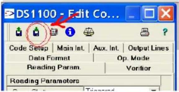
If you're unable to fix the problem and you're going to contact your local Datalogic office or Datalogic Partner or ARC, we suggest providing (if possible) the Device Configuration files (*.cfg). Connect through WinHostand click the Save icon from the edit configuration window. Also note the exact Model, Serial Number and Order Number of the device.
text_image
DS1100 - Edit Co... Code Setup | Main Int. | Aux. Int. | Output Lines Data Format | Op. Mode Reading Param. | Verifier Reading Parameters| TROUBLESHOOTING GUIDE | |
| Problem Suggestions | |
| Power On: the “Power On”/“Ready” LED is not lit | Is power connected?If using a power adapter (like PG 220), is it connected to wall outlet?If using rail power, does rail have power?If using C-Box 100, does it have power (check switch and LED)? (DS1100 10 – 30 Vdc versions only)Measure Voltage at pin 13 and pin 25 |
| On line Mode:EXT TRIGGER LED is not lit (when external trigger activates) | Is sensor connected to EXT TRIG pins (19 and 22)?Is power supplied to photo sensor?Are the photo sensor LEDs (if any) working correctly?Is The sensor/reflector system aligned? |
| On line Mode:EXT TRIGGER LED is correctly lit but nothing happens (no reading results) | Is the software configuration consistent with the application condition (operating mode etc.)?In the WinHost program select the OPERATING MODE tab and check for related parameters |
| Serial On line Mode:the reader is not triggered (no reading results) | In the WinHost program select the OPERATING MODE tab and check if serial on line is enabled as operating modeAre the Start – Stop characters correctly assigned?Is the serial trigger source correctly connected and configured? |
| On line Mode and Serial On Line:Reader doesn’t respond correctly to the expected external signals end | In the WinHost program select the OPERATING MODE tab and check the TIMEOUT parameterisation. |
| Reading:Not possible to read the target barcode (always returns No Read) | Check synchronization of reading pulse with object to readIs the scan line correctly positioned?Place barcode in the center of scan line and run TEST MODE. If you still have trouble, check the following:Is the reading distance within that allowed (see reading diagrams)?Is the Tilt angle too big?Is the Skew angle less than 10° (direct reflection)?Choose the CODE tab and enable different code types (except Pharmacode). LENGTH = VariableIs the Bar Code quality sufficient?If you had no success, try to perform the test using the BARCODE TEST CHART included with the product. |
| Communication:Device is not transmitting anything to the host | Is serial cable connected?Is correct wiring respected?Are serial host settings equivalent to serial device setting? |
| Communication:Data transferred to the host are incorrect, corrupted or incomplete | In the WinHost program select the DATA FORMAT tab and check for values of HEADER, TERMINATOR, SEPARATOR, FILL CharactersAlso check the CODE FIELD LENGTH valueAre the COM port parameters correctly assigned? |
| Communication:Always returns the Reader Failure Character (<BEL> char as default) | Contact your local Datalogic office or Datalogic Partner or ARC, because either a Motor or Laser failure has occurred.Note the exact model and Serial Number of the device |
| How do I obtain my units' serial numbers? | The device's serial number is printed on a label that is affixed to the reader.Serial numbers consist of 9 characters: one letter, 2 numbers, another letter followed by 5 numbers. |
6 TECHNICAL FEATURES
| DS1100-1XXX | ||
| ELECTRICAL FEATURES | ||
| PowerMaximum input voltage 5 Vdc ± 5%Power consumption max. 0.4 A; 2 W | ||
| Serial InterfacesMainAuxiliaryBaud Rates 150 to 115200 baud | RS485RS232 | |
| Inputs External Trigger; IN1 | ||
| Outputs User-defined OUT1 and OUT2VCE max.Collector current max. 50 mA continuousVCE saturationPower dissipation max. | 50 Vdc0.3V at 10 mA max.200 mW at 40 °C (Ambient temp.) | |
| OPTICAL FEATURES | ||
| Light source Semiconductor laser diodeWave length (Note 1)Safety class Class 2 - EN 60825-1; | 630 ~ 680 nmClass II - CDRH | |
| READING FEATURES (Note 2) | ||
| Scan rate 500 scans/secAperture angle 70°Max. Reading distanceMaximum resolution | 220 mm, (8.7 in)0.20 mm (8 mils) | 110 mm (4.3 in)0.12 mm (5 mils) |
| USER INTERFACE | ||
| LED indicators | Power On,Good Read,Ext Trig,TX Data,Laser On | |
DS1
| SOFTWARE FEATURES | |
| READABLE CODE SYMBOLOGIES• EAN/UPC (including Add-on 2 and Add-on 5) • Code 93• 2/5 Interleaved • Code 128• Code 39 (Standard and Full ASCII) • EAN 128• Codabar • PharmacodeOther symbologies available on request. | |
| CODE SELECTION up to six different codes during one reading phase | |
| DECODING SAFETY can enable multiple good reads of same code | |
| HEADERS AND TERMINATORS up to four headers and four terminators | |
| OPERATING MODES On-Line, Automatic, Serial-On-Line, Test | |
| SPECIAL FUNCTIONS Motor On/Off sw commandsLaser On/Off sw commands | |
| CONFIGURATION MODES | • through menus using WinHost utility• receiving commands from one of the serial ports (HOST MODE) |
| PARAMETER STORAGE Non-volatile internal EEPROM | |
| ENVIRONMENTAL FEATURES | |
| Operating temperature (Note 3) | 0° to 45 °C (32° to 113 °F) |
| Storage temperature | -20° to 70 °C (-4° to 158 °F) |
| Humidity max. 90% non condensing | |
| Vibration resistance 14 mm @ 2-10 HzEN 60068-2-6 1.5 mm @ 13-55 Hz | 2 g @ 70-200 Hz2 hours on each axis |
| Shock resistance 30g; 11 ms;EN 60068-2-27 3 shocks on each axis | |
| Protection classEN 60529 | IP65 |
| PHYSICAL FEATURES | |
| Mechanical dimensions | 80 x 50 x 22 mm (3.15 x 1.97 x 0.89 in.) |
| Weight without cable | <100 g. (<3.53 oz.) |
Note 1: The features given are typical at a 25 °C ambient temperature (if not otherwise indicated).
Note 2: Further details given in par. 3.3 and 3.4.
Note 3: If the reader is used for a long period of time in high temperature environments (over 40 °C), use of the Beam Shutter is advised (see the WinHost configuration program).
Aperture
Term used on the required CDRH warning labels to describe the laser exit window.
Barcode
A pattern of variable-width bars and spaces which represents numeric or alphanumeric data in machine-readable form. The general format of a barcode symbol consists of a leading margin, start character, data or message character, check character (if any), stop character, and trailing margin. Within this framework, each recognizable symbology uses its own unique format.
Barcode Label
A label that carries a barcode and can be affixed to an article.
Baud Rate
A unit used to measure communications speed or data transfer rate.
CDRH (Center for Devices and Radiological Health)
This organization (a service of the Food and Drug Administration) is responsible for the safety regulations governing acceptable limitations on electronic radiation from laser devices. Datalogic devices are in compliance with the CDRH regulations.
Code Positioning
Variation in code placement that affects the ability of a scanner to read a code. The terms Pitch, Skew, and Tilt deal with the angular variations of code positioning in the X, Y and Z axes. See pars. 2.2.1 and 2.5. Variations in code placement affect the pulse width and therefore the decoding of the code. Pulse width is defined as a change from the leading edge of a bar or space to the trailing edge of a bar or space over time. Pulse width is also referred to as a transition. Tilt, pitch, and skew impact the pulse width of the code.
Decode
The process of translating a barcode into data characters using a specific set of rules for each symbology.
Decoder
As part of a barcode reading system, the electronic package which receives the signals from the scanner, performs the algorithm to interpret the signals into meaningful data and provides the interface to other devices. The decoder is normally integrated into the scanner.
EAN
European Article Number System. The international standard barcode for retail food packages.
EEPROM
Electrically Erasable Programmable Read-Only Memory. An on-board non-volatile memory chip.
Full Duplex
Simultaneous, two-way, independent transmission in both directions.
Half Duplex
Transmission in either direction, but not simultaneously.
Host
A computer that serves other terminals in a network, providing services such as network control, database access, special programs, supervisory programs, or programming languages.
Interface
A shared boundary defined by common physical interconnection characteristics, signal characteristics and meanings of interchanged signals.
LED (Light Emitting Diode)
A low power electronic device that can serve as a visible or near infrared light source when voltage is applied continuously or in pulses. It is commonly used as an indicator light and uses less power than an incandescent light bulb but more than a Liquid Crystal Display (LCD). LEDs have extremely long lifetimes when properly operated.
Multidrop Line
A single communications circuit that interconnects many stations, each of which contains terminal devices. See RS485.
Parameter
A value that you specify to a program. Typically parameters are set to configure a device to have particular operating characteristics.
Picket-Fence Orientation
When the barcode's bars are positioned vertically on the product, causing them to appear as a picket fence. The first bar will enter the scan window first. See par. 3.2.
Pitch
Rotation of a code pattern about the X-axis. The normal distance between center line or adjacent characters. See pars. 2.2.1 and 2.5.
Position
The position of a scanner or light source in relation to the target of a receiving element.
Protocol
A formal set of conventions governing the formatting and relative timing of message exchange between two communicating systems.
Raster
The process of projecting the laser beam at varied angles spaced evenly from each other. Typically, the mirrored rotor surfaces are angled to create multiple scan lines instead of a single beam.
Resolution
The narrowest element dimension which can be distinguished by a particular reading device or printed with a particular device or method.
RS232
Interface between data terminal equipment and data communication equipment employing serial binary data interchange.
RS485
Interface that specifies the electrical characteristics of generators and receivers for use in balanced digital multipoint systems such as on a Multidrop line.
Scanner
A device that examines a printed pattern (barcode) and either passes the uninterpreted data to a decoder or decodes the data and passes it onto the Host system.
Serial Port
An I/O port used to connect a scanner to your computer, identifiable by a 9-pin or 25-pin connector.
Signal
An impulse or fluctuating electrical quantity (i.e.: a voltage or current) the variations of which represent changes in information.
Skew
Rotation about the Y-axis. Rotational deviation from correct horizontal and vertical orientation; may apply to single character, line or entire encoded item. See pars. 2.2.1 and 2.5.
Step-Ladder orientation
When the barcode's bars are positioned horizontally on the product, causing them to appear as a ladder. The ends of all bars will enter the scan window first. See par. 3.1.
Symbol
A combination of characters including start/stop and checksum characters, as required, that form a complete scannable barcode.
Tilt
Rotation around the Z axis. Used to describe the position of the barcode with respect to the laser scan line. See pars. 2.2.1 and 2.5.
Trigger Signal
A signal, typically provided by a photoelectric sensor or proximity switch, which informs the scanner of the presence of an object within its reading zone.
UPC
Acronym for Universal Product Code. The standard barcode type for retail food packaging in the United States.
Visible Laser Diode
A light source used in scanners to illuminate the barcode symbol. Generates visible red light at wavelengths between 630 and 680 nm.
A
Accessories; 3
Auxiliary Interface - RS232; 11
C
CE Compliance; vii
Cleaning; 26
E
Electrical Connections; 8
F
FCC Compliance; viii
G
General View; ix
Glossary; 32
Guide to Installation; x
|
Inputs; 12
L
Laser Safety; vi
Layouts; 17
Multiplexer; 20
Point-to-Point; 18
RS485 Master/Slave; 18
LED Indicators; 2
M
Main Serial Interface - RS485 Half-
Duplex; 9
Maintenance; 26
Mechanical Installation; 5
Model Description; 2
Mounting DS1100; 6
0
Outputs; 13
P
Package Contents; 4
Performance; 23
Picket-Fence Mode; 22
Positioning; 16
Power Supply; vii; 9
R
Raster; 23
Reading Diagrams; 24
Reading Features; 21
Reading Position; 7
Reference Documentation; v
s
Safety Regulations; vi
Services and Support; v
Step-Ladder Mode; 21
T
Technical Features; 30
Troubleshooting; 27
U
User Interface; 15
dichiara che
declares that the
déclare que le
are in conformity with the requirements of the European Council Directives listed below:
89/336/EEC EMC Directive
On the approximation of the laws of Member States relating to electromagnetic compatibility and product safety.
This declaration is based upon compliance of the products to the following standards:
EN 55022 (Class A ITE), September 1998:
INFORMATION TECHNOLOGY EQUIPMENT
RADIO DISTURBANCE CHARACTERISTICS
LIMITS AND METHODS OF MEASUREMENTS
EN 61000-6-2, September 2005:
ELECTROMAGNETIC COMPATIBILITY (EMC)
PART 6-2: GENERIC STANDARDS - IMMUNITY FOR
INDUSTRIAL ENVIRONMENTS
Lippo di Calderara, January 29th, 2008 Lorenzo Girotti
Product & Process Quality Manager