AIR-ANT2547V-N - WiFi antenna CISCO - Free user manual and instructions
Find the device manual for free AIR-ANT2547V-N CISCO in PDF.

User questions about AIR-ANT2547V-N CISCO
0 question about this device. Answer the ones you know or ask your own.
Ask a new question about this device
Download the instructions for your WiFi antenna in PDF format for free! Find your manual AIR-ANT2547V-N - CISCO and take your electronic device back in hand. On this page are published all the documents necessary for the use of your device. AIR-ANT2547V-N by CISCO.
USER MANUAL AIR-ANT2547V-N CISCO
natural_image
Black-and-white photo of a man sitting on a sofa, looking upward (no text or symbols visible)Cisco Aironet Dual-Band Omnidirectional Antenna (AIR-ANT2547V-N)
This document describes the Cisco Aironet AIR-ANT2547V-N Dual-Band Omnidirectional Antenna and provides instructions for mounting it. The antenna is designed for outdoor use with Cisco Aironet Outdoor Access Points (hereafter referred to as access points) with radios operating in the 2.4-GHz and 5-GHz frequency bands.
The following information is provided in this document:
• Technical Specifications, page 2
• System Requirements, page 4
• Safety Precautions, page 4
• Installation Notes, page 5
- Obtaining Documentation and Submitting a Service Request, page 6
Technical Specifications
| Antenna type Omnidirectional | colinear array |
| Operating frequency range 24 | 00–2483 MHz;5150–5875 MHz |
| 2:1 VSWR bandwidth 2400–2483 MHz;5150–5875 MHz | |
| Nominal input impedance 50Ω | |
| Gain (2400–2483 MHz) 4-dBi | |
| Gain (5250–5875 MHz) 7-dBi | |
| Polarization Linear | |
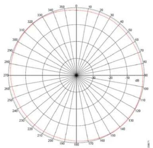
| E-plane 3-dB beamwidth 30° | for 2.4-GHz;14° for 5-GHz |
| H-plane 3-dB bandwidth Omnidirectional | |
| Length 11.1 in. (28.2 cm) | |
| Diameter 1.25 in. (3.17 cm) | |
| Weight 6.0 oz. (170.0 g) | |
| Connector type N-Male | |
| Operating temperature -22°F | to 185°F(-40°C to 85°C) |
| Wind rating 100 mph (161 kph) | operational165 mph (265 kph)survival |

natural_image
Pure diagram of a cylindrical mechanical component with no text or symbolsAzimuth Radiation Pattern (2.4 GHz) Elevation Radiation Pattern (2.4 GHz)
radar
| Angle (°) | Value | |-----------|-------| | 0 | 0 | | 30 | 10 | | 60 | 20 | | 90 | 30 | | 120 | 40 | | 150 | 50 | | 180 | 60 | | 210 | 70 | | 240 | 80 | | 270 | 90 | | 300 | 100 | | 330 | 110 | | 360 | 120 | | 390 | 130 | | 420 | 140 | | 450 | 150 | | 480 | 160 | | 510 | 170 | | 540 | 180 | | 570 | 190 | | 600 | 200 | | 630 | 210 | | 660 | 220 | | 690 | 230 | | 720 | 240 | | 750 | 250 | | 780 | 260 | | 810 | 270 | | 840 | 280 | | 870 | 290 | | 900 | 300 | | 930 | 310 | | 960 | 320 | | 990 | 330 | | 1020 | 340 | | 1050 | 350 | | 1080 | 360 | | 1110 | 370 | | 1140 | 380 | | 1170 | 390 | | 1200 | 400 | | 1230 | 410 | | 1260 | 420 | | 1290 | 430 | | 1320 | 440 | | 1350 | 450 | | 1380 | 460 | | 1410 | 470 | | 1440 | 480 | | 1470 | 490 | | 1500 | 500 | | 1530 | 510 | | 1560 | 520 | | 1590 | 530 | | 1620 | 540 | | 1650 | 550 | | 1680 | 560 | | 1710 | 570 | | 1740 | 580 | | 1770 | 590 | | 1800 | 600 | | 1830 | 610 | | 1860 | 620 | | 1890 | 630 | | 1920 | 640 | | 1950 | 650 | | 1980 | 660 | | 2010 | 670 | | 2040 | 680 | | 2070 | 690 | | 2100 | 700 | | Note: The values in the 'Value' column are estimated based on the provided code. The 'Radial' label is 'Radial' and the 'Angle' label is 'Radial'. The 'Number of Circles' is also labeled on the chart.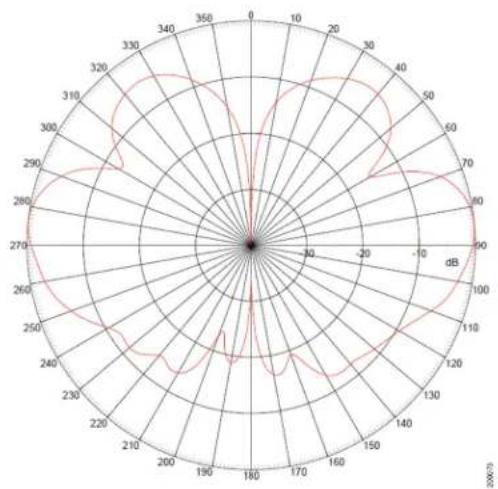
radar
| Angle (°) | Value | | --------- | ----- | | 0 | 0 | | 30 | 30 | | 60 | 60 | | 90 | 90 | | 120 | 120 | | 150 | 150 | | 180 | 180 | | 210 | 210 | | 240 | 240 | | 270 | 270 | | 300 | 300 | | 330 | 330 | | 360 | 360 |Azimuth Radiation Pattern (5 GHz) Elevation Radiation Pattern (5 GHz)

radar
| Angle (degrees) | Value | |---|---| | 0 | 0 | | 10 | 20 | | 20 | 40 | | 30 | 60 | | 40 | 80 | | 50 | 100 | | 60 | 120 | | 70 | 140 | | 80 | 160 | | 90 | 180 | | 100 | 200 | | 110 | 220 | | 120 | 240 | | 130 | 260 | | 140 | 280 | | 150 | 300 | | 160 | 320 | | 170 | 340 | | 180 | 360 | | 190 | 380 | | 200 | 400 | | 210 | 420 | | 220 | 440 | | 230 | 460 | | 240 | 480 | | 250 | 500 | | 260 | 520 | | 270 | 540 | | 280 | 560 | | 290 | 580 | | 300 | 600 | | 310 | 620 | | 320 | 640 | | 330 | 660 | | 340 | 680 | | 350 | 700 | | 360 | 720 |
radar
| Angle (°) | Value (dB) | | --------- | ---------- | | 0 | 0 | | 30 | 10 | | 60 | 20 | | 90 | 30 | | 120 | 40 | | 150 | 50 | | 180 | 60 | | 210 | 70 | | 240 | 80 | | 270 | 90 | | 300 | 100 | | 330 | 110 | | 360 | 120 |System Requirements
This antenna is designed for use with the Cisco Aironet Outdoor Access Points. The antenna is designed specifically for use with Cisco Aironet 1550 Series Outdoor Access Points.
Safety Precautions

Do not locate the antenna near overhead power lines or other electric light or power circuits, or where it can come into contact with such circuits. When installing the antenna, take extreme care not to come into contact with such circuits, as they may cause serious injury or death. For proper installation and grounding of the antenna, please refer to national and local codes (e.g. U.S.: NFPA 70, National Electrical Code, Article 810, Canada: Canadian Electrical Code, Section 54). Statement280
For your safety, read and follow these safety precautions.
- Before you install an antenna, contact your Cisco account representative to explain which mounting method to use for the size and type of antenna that you are about to install.
- Find someone to help you—installing an antenna is often a two-person job.
- Select your installation site with safety, as well as performance, in mind. Remember that electric power lines and phone lines look alike. For your safety, assume that any overhead line can kill you.
- Contact your electric power company. Tell them your plans and ask them to come look at your proposed installation.
- Plan your installation carefully and completely before you begin. Each person involved in an installation should be assigned to a specific task and should know what to do and when to do it. One person should be in charge of the operation to issue instructions and watch for signs of trouble.
- When installing your antenna, follow these guidelines:
a. Do not use a metal ladder.
b. Do not work on a wet or windy day.
c. Do dress properly—wear shoes with rubber soles and heels, rubber gloves, and a long-sleeved shirt or jacket.
- If the assembly starts to drop, move away from it and let it fall. Because the antenna, mast, cable, and metal guy wires are all excellent conductors of electrical current, even the slightest touch of any of these parts to a power line completes an electrical path through the antenna and the installer.
- If any part of the antenna system should come in contact with a power line, do not touch it or try to remove it yourself. Call your local power company to have it removed safely.
- If an accident should occur with the power lines, call for qualified emergency help immediately.
Installation Notes
The antenna is designed to connect to a dedicated antenna port on the access point. No special tools are required to install the antenna.
The antenna is resistant to the full range of outdoor environments. Therefore, we do not recommend that you use cable or antenna waterproofing materials. Using such materials may cause important drainage holes to be blocked. Two drain holes are located on the antenna base.
Three drain holes are also located under the cap at the top of the antenna. These holes allow for proper drainage if the antenna is deployed with the cap pointing toward the ground.

Note Ensure that the cap is not damaged.
Figure 1 shows the location of the drain holes in both the antenna base and under the antenna cap.
Figure 1 Antenna Drain Hole Locations

text_image
1 2 232096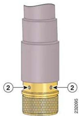
text_image
2320951 Antenna drain hole under the cap 2 Antenna drain holes at the base
Choosing a Mounting Location
The antenna is designed to create an omnidirectional broadcast pattern. To achieve this pattern, the access point should be mounted clear of any obstructions to the sides of the radiating element. If the mounting location is on the side of a building or tower, the antenna pattern is degraded on the building or tower side.
Generally, the higher an antenna is above the ground, the better it performs. A practice is to install your antenna about 5 to 10 ft (1.5 to 3 m) above the roof line and away from all power lines and obstructions.
Tools and Equipment Required
No tools are required to mount the antenna to the access point. However, you may need a 34 -in. (19-mm) open end or combination wrench (or adjustable wrench) to remove the antenna port covers.
For information about tools required to mount the access point, see the appropriate access point documentation.
Mounting the Antenna
To connect the antenna to the access point, follow these steps:
Step 1 If necessary, remove the antenna port cover.
Step 2 Align the antenna's N connector with the appropriate antenna port.
Step 3 Gently push the antenna into the port.
Step 4 Tighten the antenna hand tight.
Obtaining Documentation and Submitting a Service Request
For information on obtaining documentation, submitting a service request, and gathering additional information, see the monthly What's New in Cisco Product Documentation, which also lists all new and revised Cisco technical documentation, at:
http://www.cisco.com/en/US/docs/general/whatsnew/whatsnew.html
Subscribe to the What's New in Cisco Product Documentation as a Really Simple Syndication (RSS) feed and set content to be delivered directly to your desktop using a reader application. The RSS feeds are a free service and Cisco currently supports RSS Version 2.0.
Cisco and the Cisco Logo are trademarks of Cisco Systems, Inc. and/or its affiliates in the U.S. and other countries. A listing of Cisco's trademarks can be found at www.cisco.com/go/trademarks. Third party trademarks mentioned are the property of their respective owners. The use of the word partner does not imply a partnership relationship between Cisco and any other company. (1005R)
© 2011 Cisco Systems, Inc. All rights reserved.