Wind Box DC100-009EU - Desktop computer MSI - Free user manual and instructions
Find the device manual for free Wind Box DC100-009EU MSI in PDF.

User questions about Wind Box DC100-009EU MSI
0 question about this device. Answer the ones you know or ask your own.
Ask a new question about this device
Download the instructions for your Desktop computer in PDF format for free! Find your manual Wind Box DC100-009EU - MSI and take your electronic device back in hand. On this page are published all the documents necessary for the use of your device. Wind Box DC100-009EU by MSI.
USER MANUAL Wind Box DC100-009EU MSI
Copyright Notice ....iii
Trademarks ....iii
Revision ....iii
Upgrade and Warranty .... iv
Acquisition of Replaceable Parts .... iv
Technical Support iv
Green Product Features ....v
Environmental Policy ....v
Safety Instructions ...... vi
CE Conformity ......viii
FCC-B Radio Frequency Interference Statement ......viii
WEEE Statement ix
1. Overview ...... 1-1
Packing Contents ....1-2
System Overview 1-3
System Specifications 1-8
Component Replacement & Upgrade 1-10
2. Getting Started 2-1
Safety & Comfort Tips 2-2
Connecting Peripheral Devices 2-3
Hardware Setup 2-7
3. System Operations ...... 3-1
System Booting Setup for the first time 3-2
Creating System Recovery Disc 3-3
Network Connection under Windows 3-8
Power Management 3-13
System Recovery 3-15
Copyright Notice
The material in this document is the intellectual property of MICRO-STAR INTERNATIONAL. We take every care in the preparation of this document, but no guarantee is given as to the correctness of its contents. Our products are under continual improvement and we reserve the right to make changes without notice.
Trademarks
All trademarks are the properties of their respective owners.
■ MSI is a registered trademark of Micro-Star Int'l Co., Ltd.
■ AMD is a registered trademark of Advanced Micro Devices, Inc.
■ Realtek is a registered trademark of Realtek Semiconductor Corporation.
■ Windows is a registered trademark of Microsoft Corporation.
Revision
Revision Date
V1.0 2011/05

flowchart
graph TD
    A["iii"] --> B
    B --> C
Upgrade and Warranty
Please note that certain components preinstalled in the product may be upgradable or replaceable by user's request. To learn more about upgrade limitation, please refer to the specifications in the User's Manual. For any further information about the product users purchased, please contact the local dealer. Do not attempt to upgrade or replace any component of the product if you are not an authorized dealer or service center, since it may cause the warranty void. It is strongly recommended that you contact the authorized dealer or service center for any upgrade or replace service.
Acquisition of Replaceable Parts
Please be noticed that the acquisition of replaceable parts (or compatible ones) of the product users purchased in certain countries or territories may be fulfilled by the manufacturer within 5 years at most since the product has been discontinued, depending on the official regulations declared at the time.
Please contact the manufacturer via http://support.msi.com/ for the detailed information about the acquisition of spare parts.
Technical Support
If a problem arises with your system and no solution can be obtained from the user's manual, please contact your place of purchase or local distributor. Alternatively, please try the following help resources for further guidance.
Visit the MSI website for technical guide, BIOS updates, driver updates and other information via http://www.msi.com/service/download/
Contact our technical staff viahttp://support.msi.com/
Green Product Features
○ Reduced energy consumption during use and stand-by
Limited use of substances harmful to the environment and health
Easily dismantled and recycled
☐ Reduced use of natural resources by encouraging recycling
- Extended product lifetime through easy upgrades
- Reduced solid waste production through take-back policy
Environmental Policy

The product has been designed to enable proper reuse of parts and recycling and should not be thrown away at its end of life.
Users should contact the local authorized point of collection for recycling and disposing of their end-of-life products.
Visit the MSI website and locate a nearby distributor for further recycling information.
Users may also reach us at gpgreenteam@msi.com for information regarding proper Disposal, Take-back, Recycling, and Disassembly of MSI products.
Safety Instructions

Read the safety instructions carefully and thoroughly.
All cautions and warnings on the equipment or user's manual should be noted.

Keep the User's Guide that comes with the package for future reference.

Keep this equipment away from humidity and high temperature.
Lay this equipment on a reliable fl at surface before setting it up.

Make sure that the power voltage is within its safety range and has been adjusted properly to the value of 100\~240V before connecting the equipment to the power outlet. Do not disable the protective earth pin from the plug. The equipment must be connected to an earthed mains socket-outlet.
Always unplug the AC power cord before installing any add-on card or module to the equipment.
Always disconnect the AC power cord or switch the wall socket off if the equipment would be left unused for a certain time to achieve zero energy consumption.

The ventilator on the enclosure is used for air convection and to prevent the equipment from overheating. Do not cover the ventilator.

Do not leave the equipment in an unconditioned environment with a storage temperature above 60 ^ ( 140 ^ ) or below 0 ^ ( 32 ^ ), which may damage the equipment.
NOTE: The maximum operating temperature is around 35^ C.

Never pour any liquid into the opening that could damage or cause electrical shock.

Place the power cord in a way that people are unlikely to step on it. Do not place anything on the power cord.

When installing the coaxial cable to the TV Tuner, it is necessary to ensure that the metal shield is reliably connected to protective earthing system of the building.
Cable distribution system should be grounded (earthed) in accordance with ANSI/NFPA 70, the National Electrical Code (NEC), in particular Section 820.93, Grounding of Outer Conductive Shield of a Coaxial Cable.

Always keep the strong magnetic or electrical objects away from the equipment.

If any of the following situations arises, get the equipment checked by service personnel:
The power cord or plug is damaged.
Liquid has penetrated into the equipment.
The equipment has been exposed to moisture.
The equipment does not work well or you can not get it work according to user's manual.
The equipment has dropped and damaged.
The equipment has obvious sign of breakage.
- The optical storage devices are classified as CLASS 1 LASER PRODUCT. Use of controls or adjustments or performance of procedures other than those specified is prohibited.
- Do not touch the lens inside the drive.

廢電池請回收
For better environmental protection, waste batteries should be collected separately for recycling or special disposal.

CAUTION:
Danger of explosion if battery is incorrectly replaced. Replace only with the same or equivalent type recommended by the manufacturer.
CE Conformity
Hereby, Micro-Star International CO., LTD declares that this device is in compliance with the essential safety requirements and other relevant provisions set out in the European Directive.

FCC-B Radio Frequency Interference Statement
This equipment has been tested and found to comply with the limits for a Class B digital device, pursuant to Part 15 of the FCC Rules. These limits are designed to provide reasonable protection against harmful interference in a residential installation. This equipment generates, uses and can radiate radio

frequency energy and, if not installed and used in accordance with the instruction manual, may cause harmful interference to radio communications. However, there is no guarantee that interference will not occur in a particular installation. If this equipment does cause harmful interference to radio or television reception, which can be determined by turning the equipment off and on, the user is encouraged to try to correct the interference by one or more of the measures listed below:
■ Reorient or relocate the receiving antenna.
■ Increase the separation between the equipment and receiver.
■ Connect the equipment into an outlet on a circuit different from that to which the receiver is connected.
■ Consult the dealer or an experienced radio/television technician for help.
Notice 1
The changes or modifications not expressly approved by the party responsible for compliance could void the user's authority to operate the equipment.
Notice 2
Shielded interface cables and AC power cord, if any, must be used in order to comply with the emission limits.
VOIR LA NOTICE D'INSTALLATION AVANT DE RACCORDER AU RESEAU.
This device complies with Part 15 of the FCC Rules. Operation is subject to the following two conditions:
- this device may not cause harmful interference, and
- this device must accept any interference received, including interference that may cause undesired operation.
WEEE Statement

(English) Under the European Union ("EU") Directive on Waste Electrical and Electronic Equipment, Directive 2002/96/EC, which takes effect on August 13, 2005, products of "electrical and electronic equipment" cannot be discarded as municipal waste anymore and manufacturers of covered electronic equipment will be obligated to take back such products at the end of their useful life.
Congratulations for purchasing the Wind Box DC100 (MS-B023) System. This system is your best slim PC choice. With the fantastic appearance and ultrasmall form factor, it can easily be set anywhere. The feature packed platform also gives you an exciting PC experience.
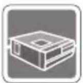
Packing Contents

natural_image
Simple line drawing of a rectangular frame with a hexagonal top and internal markings (no text or symbols)Wind Box Series AC/DC Adapter AC Power Cord
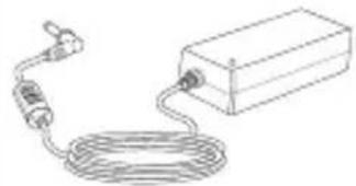
natural_image
Simple line drawing of a cable and plug connected to a rectangular device (no text or symbols)
natural_image
Line drawing of a U-shaped cable with two connectors (no text or symbols)
Driver/ Utility Disk

natural_image
Simple line drawing of a closed book with a rectangular cover (no text or symbols)User Manual & Quick Guide
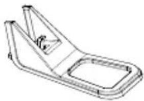
natural_image
Technical line drawing of a mechanical bracket or clamp (no text or symbols)Stand
* Please contact us immediately if any of the items is damaged or missing.
* The illustrations are for reference only and your packing contents may slightly vary depending on the model you purchased.
System Overview
▶ Front View
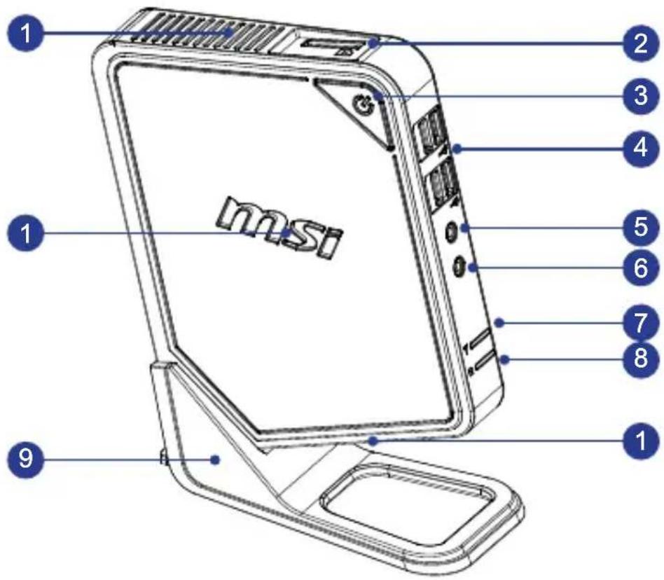
text_image
1 2 3 4 1 5 6 7 8 1 9 msi1 Ventilator
The ventilator on the enclosure is used for air convection and to prevent the equipment from overheating. Do not cover the ventilator.
2 Card Reader Drive
The built-in card reader may support various types of memory cards.
Power Button/ LED
Press the power button to turn the system on and off. The power LED glows when the system is turned on and goes off when the system is shut down. In terms of power saving, the LED blinks in S3 (Suspend to RAM) mode and goes off in S4 (Suspend to Disk) mode. Pressing the system power button will wake the system up from power saving mode.
USB 2.0 Port
The USB (Universal Serial Bus) port is for attaching USB devices such as keyboard, mouse, or other USB-compatible devices. It supports up to 480Mbit/s (Hi-Speed) data transfer rate.
5 Headphone Jack
This is a connector for headphones.
6 Microphone Jack
This is a connector for microphones.
7 WLAN LED
This indicator glows green when WLAN function is enabled and glows blue when WiMax function is enabled. The indicator goes out when this function is disabled.
HDD LED
This indicator shows the activity status of the HDD. It fl ashes when the system is accessing data on the HDD and remains off when no disk activity is detected.
Stand
Use this stand to position your system on a flat and stable surface. Another way to position your system without stand is to lay your system horizontally on the surface with the Power Button faces up to the top.
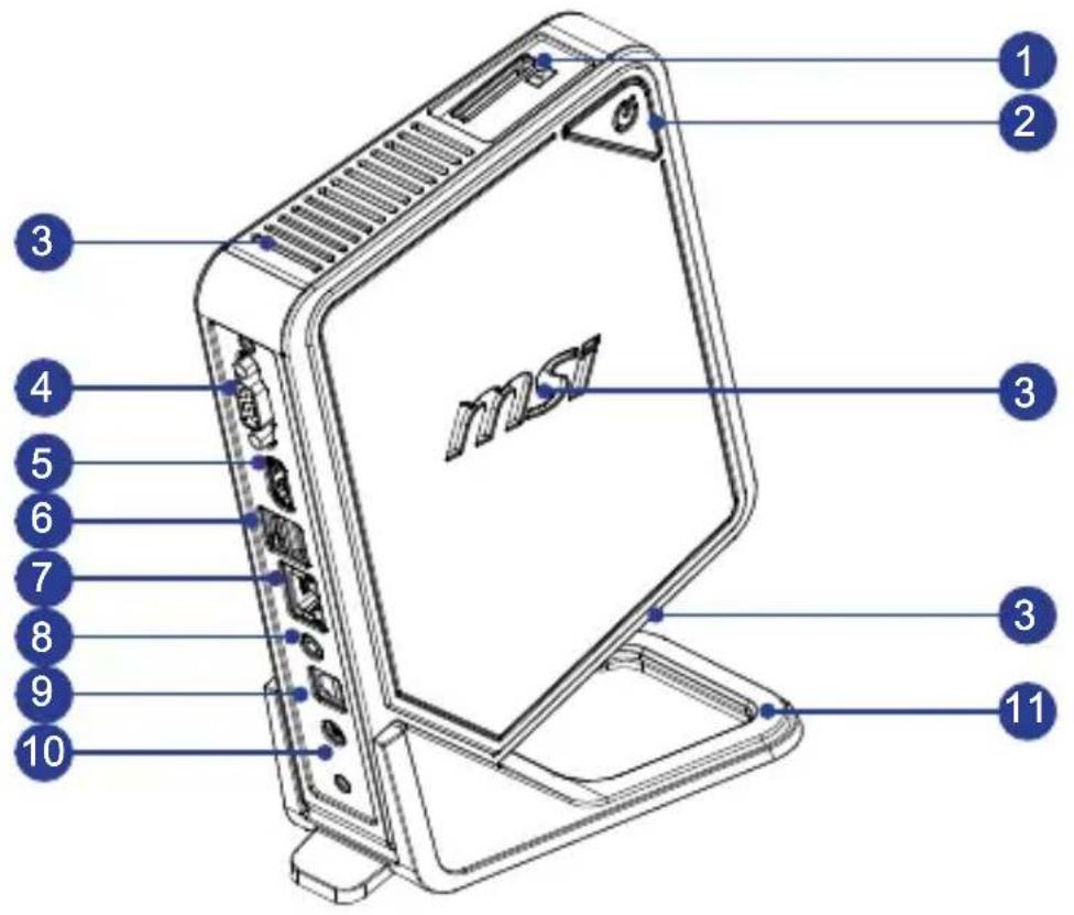
> Rear View
text_image
1 2 3 4 5 6 7 8 9 10 3 3 111 Card Reader Drive
The built-in card reader may support various types of memory cards.
Power Button/ LED
Press the power button to turn the system on and off. The power LED glows when the system is turned on and goes off when the system is shut down. In terms of power saving, the LED blinks in S3 (Suspend to RAM) mode and goes off in S4 (Suspend to Disk) mode. Pressing the system power button will wake the system up from power saving mode.
Ventilator
The ventilator on the enclosure is used for air convection and to prevent the equipment from overheating. Do not cover the ventilator.
4 VGA-Out Port
The DB15-pin female connector is provided for monitor.
5
HDMI-Out Port
The High-Defi nition Multimedia Interface (HDMI) is an all-digital audio/video interface capable of transmitting uncompressed streams. HDMI supports all TV format, including standard, enhanced or high-defi nition video, plus multi-channel digital audio on a single cable.
6
USB 2.0 Port
The USB (Universal Serial Bus) port is for attaching USB devices such as keyboard, mouse, or other USB-compatible devices. It supports up to 480Mbit/s (Hi-Speed) data transfer rate.
7
RJ-45 LAN Jack
The standard RJ-45 LAN jack is provided for connection to the Local Area Network (LAN). You can connect a network cable to it.
YellowGreen/ Orange
| LED Color LED State Condition | |||
| Right Yellow Off | LAN link is not established. | ||
| On (steady state) LAN link is established. | |||
| On (brighter & pulsing) The computer is communicating with another computer on the LAN. | |||
| Left Green Off 10 | Mbit/sec data rate is selected. | ||
| On 100 Mbit/sec data rate is selected. | |||
| Orange | On 1000 Mbit/sec data rate is selected. | ||
8
Speaker Jack
This is a connector for speakers.
9
Optical S/PDIF-Out Jack
This S/PDIF (Sony & Philips Digital Interconnect Format) jack is provided for digital audio transmission to external speakers through an optical fi ber cable.
10
Power Jack
The AC/DC adapter converts AC power to DC power for this jack. Power supplied through this jack supplies power to your personal computer. To prevent damage to the PC, always use the supplied power adapter.
11
Stand
Use this stand to position your system on a flat and stable surface. Another way to position your system without stand is to lay your system horizontally on the surface with the Power Button faces up to the top.
Important
We suggest that you connect the AC/DC adapter to your system first and then connect the AC power cord to the socket-outlet for safety concerns.
System Specifications
Processor
AMD® Brazos Fusion APU (Accelerated Processing Unit)
Chipset
AMD® Hudson-M1 Chipset■
Memory
■ 1 DDR3 1066 SO-DIMM slot
■ Supports the maximum of 4GB
LAN
■ Wired LAN: supported by Realtek® RTL8111E Gigabit Ethernet controller
■ Wireless LAN: optionally supported through USB WLAN module
Audio
■ HDA Codec by Realtek® ALC662
■ Flexible 5.1-channel audio with jack sensing
■ Compliant with Azalia 1.0 spec
Input/Output (I/O)
■ 6 USB 2.0 ports
■ 1 DC power jack
■ 1 RJ-45 LAN jack
■ 1 speaker jack
■ 1 headphone jack
■ 1 microphone jack
■ 1 VGA-out port
■ 1 HDMI-out port
■ 1 Optical S/PDIF-out jack
Storage
■ Hard Disk Drive: 2.5", SATAII
■ Card Reader: all-in-one card reader
Power Supply
■ 40 watt AC/DC adapter with active PFC
■ Input: 100-240V\~, 50-60Hz, 1.2A
■ Output: 19V --- 2.1A
Dimension
■ 186 mm (W) x 222 mm (H) x 76 mm (D) (with stand)
■ 150 mm (W) x 191 mm (H) x 36 mm (D) (without stand)
Component Replacement & Upgrade
Please note that certain components preinstalled in the product may be upgradable or replaceable by user's request depending on the models users purchased.

text_image
msiTo learn more about upgrade limitation, please refer to the specifications in the User's Manual. For any further information on the product users purchased, please contact the local dealer.
Do not attempt to upgrade or replace any component of the product if you are not an authorized dealer or service center, since it may cause the warranty void. It is strongly recommended that you contact the authorized dealer or service center for any upgrade or replace service.
Chapter 2
Getting Started
This chapter provides you with the information on hardware setup procedures. While connecting peripheral devices, be careful in holding the devices and use a grounded wrist strap to avoid static electricity.
Safety & Comfort Tips
The Wind Box DC100 is a portable platform that allows you to work anywhere. However, choosing a good workspace is important if you have to work with your PC for a long period of time.
- Your work area should have enough illumination.
- Choose the proper desk and chair and adjust their height to fit your posture when operating.
- When sitting on the chair, sit straight and keep a good posture. Adjust the chair's back (if available) to support your back comfortably.
- Place you feet fl at and naturally on the floor, so that your knees and elbows have the proper position (about 90-degree) when operating.
- Put your hands on the desk naturally to support your wrists.
- Avoid using your PC in a place where discomfort may occur (such as on the bed).
- The Wind Box DC100 is an electrical device. Please treat it with great care to avoid personal injury.
Connecting Peripheral Devices
The I/O (input/output) ports on the rear panel allow you to connect peripheral devices. All devices listed here are for reference only.
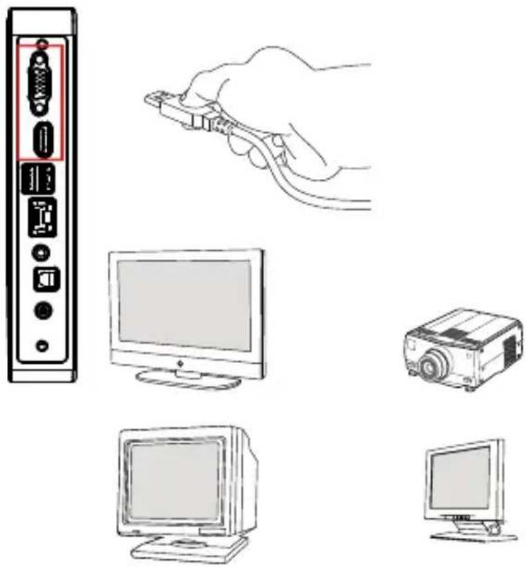
Connecting VGA-Out & HDMI-Out Devices
This Wind Box DC100 provides a VGA port and an HDMI port for connection to external monitors, projectors, set-top boxes, DVD players, digital video cameras, mini notebooks, digital cameras, etc.
VGA (Video Graphics Array) is a graphics display system for PCs. VGA connectors and their associated cabling are always used solely to carry analog video signals along with digital clock and data.
HDMI (High Defi nition Multimedia Interface) is a new interface standard for PCs, displays and consumer electronics devices that supports standard, enhanced and high-defi nition video, plus multi-channel digital audio on a single cable.
natural_image
Illustration of various electronic devices including a monitor, projector, and keyboard (no text or symbols present)To connect the VGA/ HDMI device, first make sure the Wind Box DC100 and the targeted device are both powered off, and then connect the cable of the device to the VGA/ HDMI port of your Wind Box DC100.
Connecting the USB Devices
This Wind Box DC100 provides USB ports for connecting various USB devices, such as mouse, keyboard, digital camera, webcam, printer, external optical storage device, and etc. To connect these devices, install the drivers for each device first if necessary, and then connect the device to the Wind Box DC100. This Wind Box DC100 is capable of auto detecting the USB devices installed, and if there is no detection of the devices, please manually enable the USB devices by going to Start Menu / Control Panel / Add Hardware to add the new device.

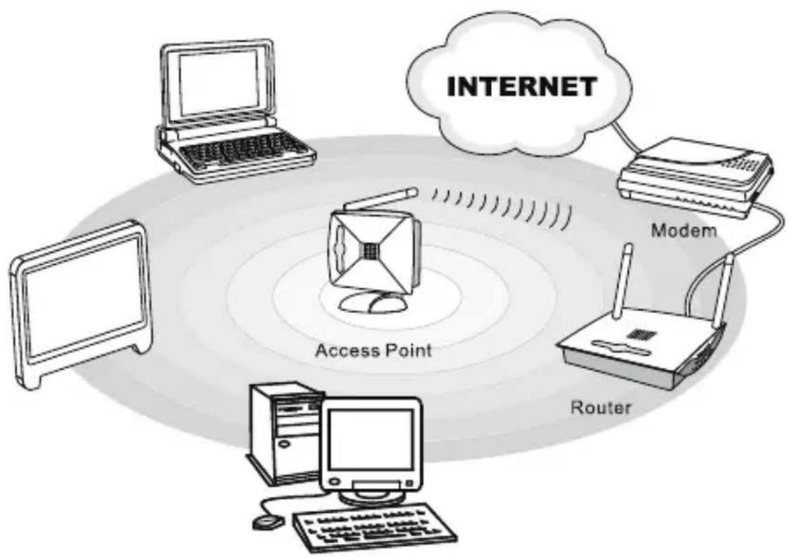
Connecting the Network Device
The RJ-45 connector of the Wind Box DC100 allows you to connect the LAN (local area network) devices, such as a hub, switch and gateway, to build a network connection.
For more instructions or detailed steps on connecting to the LAN, please ask your MIS staff or network manager for help.
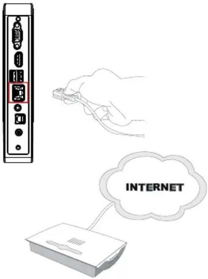
text_image
INTERNET▶ Wireless LAN (Optional)
This Wind Box DC100 is equipped with wireless LAN module which allows users to perform fast data transmission with standard IEEE 802.11 technology for wireless LAN. This gives users the mobility to move around within a broad coverage area and still be connected to the network.
By using the 64-bit/128-bit Wired Equivalent Privacy (WEP) encryption technology and Wi-Fi Protected Access feature, the optional built-in wireless LAN is capable to achieve a more efficient and a more secure solution to the wireless communication.
For more instructions or detailed steps on connecting to the Wireless LAN, please ask your MIS staff or network manager for help.
flowchart
graph TD
    A["Laptop"] --> B["Internet"]
    C["Modem"] --> B
    D["Router"] --> B
    B --> E["Access Point"]
    style B fill:#f9f,stroke:#333
    style E fill:#ccf,stroke:#333
Hardware Setup
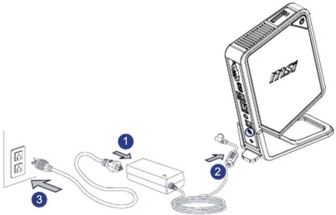
Connecting the AC Power
- Assemble the AC/DC adapter and the AC power cord.
- Plug the DC end of the adapter to the Wind Box DC100.
- Plug the male end of the AC power cord to the electrical outlet.
text_image
Diagram showing three connected devices: a power outlet, a network device, and a server unit with cable routing.Important
We suggest that you connect the AC/DC adapter to your Wind Box DC100 first and then connect the AC power cord to the socket-outlet for safety concerns.
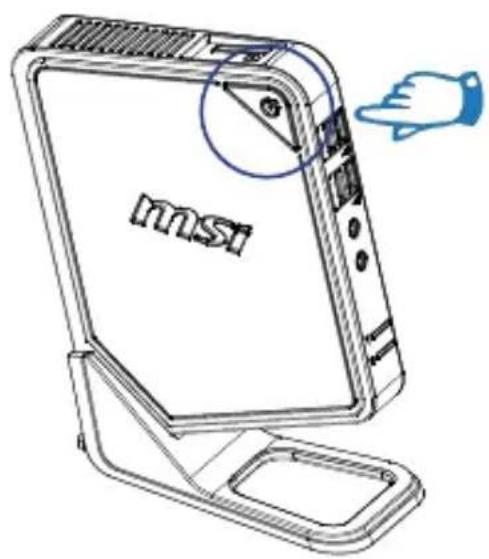
▶ Powering on the System
Press the power button to power on the system.
text_image
msiChapter 3
System Operations
This chapter provides you with essential information on system operations, such as system boot setup, recovery disc creation, network connection, and so on.
important
- It is highly recommended that you create a system recovery disc as the backup solution in the event of a catastrophic disk failure or other accidents.
- All information is subject to change without prior notice.
System Booting Setup for the first time
For the first-time use, you will need to go over the following steps to start using your Wind Box Series. The entire booting setup will take you around 30 minutes.
- Windows setup starts running. Please wait until Windows setup finishes the progress loading.
- Select the language of the operating system and click [Next] to continue.
- Choose the "Country or region", "Time and currency", and "Keyboard layout" you need. Click [Next] to continue.
- Choose a user name for your account and name your computer to distinguish it on the network. Click [Next] to continue.
- Set a password for your account to protect your user account from unwanted users. (Leave this fi eld blank if no need for password.) Click [Next] to continue.
- Please read the license terms. Check the "I accept the license terms" box and click [Next] to continue.
- Select [Use recommended settings] for "Help protect your computer and improve Windows automatically."
- Review your time and date settings. Click [Next] to continue.
- Please choose a wireless network you intend to join from the provided WLAN list. Click [Next] to continue. You may also click [Skip] to skip this step and set up the WLAN later.
- (Optional) Followingly comes the anti-virus software screen. Click [Agree] to accept the license agreement terms and activate the anti-virus software. Alternatively, choose [Stay Unprotected] and click [Next] to proceed without activating the anti-virus software.
- The "Software Installation Menu" pops up. Click [Install] to continue.
- The software is being installed. Please do not turn off the computer when software installation is running. When the progress bar completes loading, click [Finish] to continue.
- The system enters the Windows 7 OS to start its personalized settings. Get ready to explore your Wind Box Series after the personalized settings are done. Have fun with it!
Creating System Recovery Disc
For the first-time use, it is highly recommended that you create a system recovery disc as the backup solution in the event of a catastrophic disk failure or other accidents. Before moving forward, please make sure your system booting setup is complete and go over the following procedures to get it done.
- Double-click the "BurnRecovery" icon on the desktop to launch the Recovery Disc Creation Tool. Please note that it may take a while for the operating system to prepare recovery files.
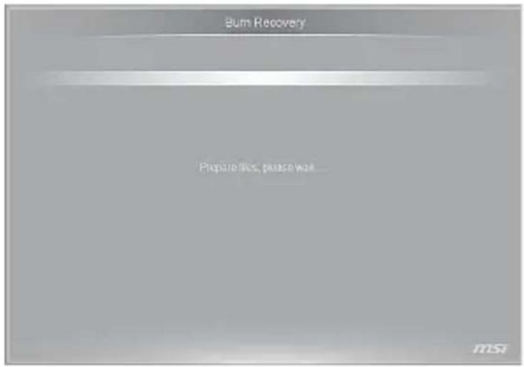
text_image
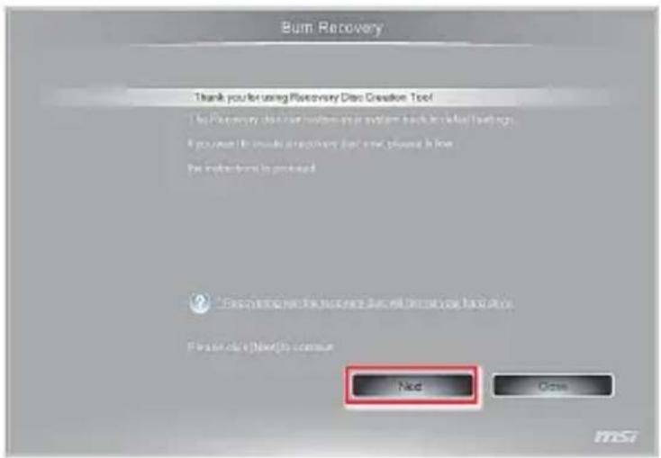
Burn Recovery Prepare files, please wait msi- Click [Next] to start the image creation of the recovery disc.
text_image
Bum Recovery Thank you for using Bumcovery Disc Creation Tool The Bumcovery disc tool version is your system back to default settings. If you must be made a supplementary tool, you should be done. For the items found is completed. ?Recognition that the Bumcovery Disc will not use your hand colors.
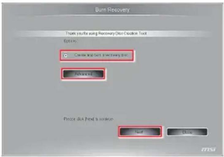
Please click (Enter) to continue Next Open- Select [Create and burn a recovery disc] and click [Next] to continue. Alternatively, choose [Advanced] to bring forth advanced options.
text_image
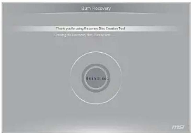
Burn Recovery Thank you're using Recovery Disk Creation Tool Options: Create and end to be necessary to add. Finish Please click Next to continue. Next Close F1550- The image of recovery disc is being created. It takes some time to finish the processing.
text_image
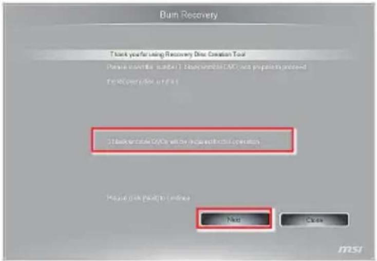
Burn Recovery Thank you for using Recovery Disc Creation Tool Creating the Recovery disc. Please wait... 4 min-11 sec ms- Follow the on-screen instructions to prepare enough number of blank DVD discs. Insert the blank DVD disc into the optical disc drive and click [Next] to continue.
text_image
Burn Recovery Thank you for using Recovery Disc Creation Tool Please check this tool (e.g. 1) .Disassembled MAC not prepare in previous Test/Operator/for updates 3. Check remote by: Yes will be done to complete operation Please click next to online Next Cancel msi- The Windows Disc Image Burner pops up. Click [Burn] to start the burning progress. It takes a while to finish the processing.

text_image
Windows Disc Image Burner Disc image file: recovery_dvd.iso Disc burner: DVD R Drive (E) Status To start burning the disc image, click Burn. □ Verify disc after burning Burn Cancel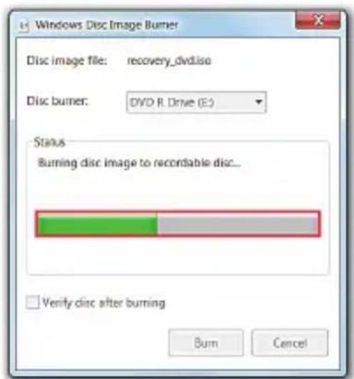
text_image
Windows Disc Image Burner Disc image file: recovery_dvd.iso Disc burner: DVD R Drive (E) Status Burning disc image to recordable disc... ✓ Verify disc after burning Burn Cancel- On completion of the disc creation, click [Close] to exit and take out the disc. Follow the on-screen instructions to create all recovery discs.
text_image
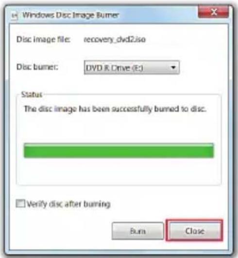
Windows Disc Image Burner Disc image file: recovery_dvd2.iso Disc burner: DVD R Drive (E:) Status The disc image has been successfully burned to disc. □ Verify disc after burning Burn Close- All recovery discs have been successfully created. Please store the discs carefully and click [Next] to continue.
text_image
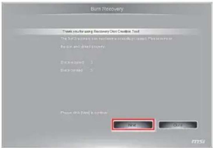
Burn Recovery Thank you for using Recovery Over Creation Tool The quick purchase tool has been used to create a new product or the product and build property. Discounted: 1 Discounted: 2 Please click (check) in continue Next Next MSI- Check the following box if you want to remove the temporary fi les. Click [Fin- ish] to complete recovery disc creation.
text_image
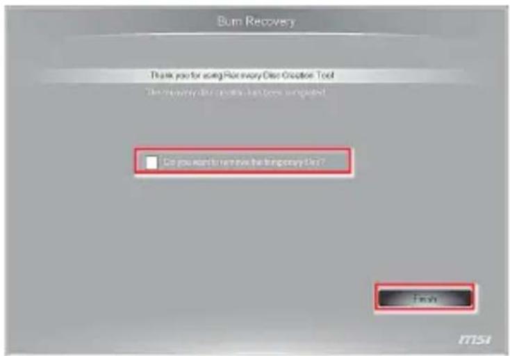
Burn Recovery Thank you for using Place every One Creation Tool The currently active tool has been completed □ Do you want to move the temporary file? Finish 1754Network Connection under Windows
Wired LAN
- Go to [Start] > [Control Panel].

text_image
Getting Started Paint Windows Media Center Calculator Sticky Notes Snipping Tool Magazines Suitable Colorline moi Wind Match All Programs Control Panel Devices and Printers Default Programs Help and Support Shut down- Select [Connect to the Internet] under [Network and Internet].
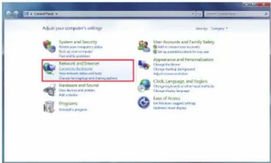
text_image
Adjust your computer's settings System and Security Review your computer's status Back-up your computer Find and go problems Network and Internet Connect to the network View network status and links Choose home/group and trading options Hardware and Sound View devices and printers Add a device Projectors Uninstall a program View by: Category * User Accounts and Family Safety Add or install your accounts Set up personal controls for any use Appearance and Personalization Change the remote Change backup background Adjust screen resolution Clock, Language, and Region Change key boards or other input methods Change display language Ease of Access Let windows target settings Optimize virtual display- Select [Broadband (PPPoE)] to connect using DSL or cable that requires a user name and password.
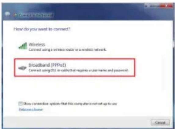
text_image
How do you want to connect? Wireless Connect using a wireless router or a wireless network. Broadband (PPPoE) Connect using DSL or cable that requires a user name and password. Show connection options that this computer is not set up to use Welcome a home Cancel- Type the information from your Internet Service Provider (ISP) and click [Connect] to establish your LAN connection.

text_image
Connect to this Internet Type the information from your Internet service provider (ISP) User name: [Users your ISP gain you] Password: [Password your ISP gain you] Show characters Remember this personnel Connection name: Broadband Connection Allow other people to use this connection This option allows anyone with access to this computer to use this connection. Link these as IP Connect Cancel> Wireless LAN
- Go to [Start] > [Control Panel].
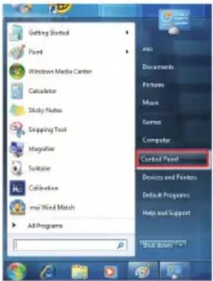
text_image
Getting Startbox Paint Windows Media Center Calculator Sticky Notes Snipping Tool Magnifier So-Rise Collination msr Wind Match All Programs control Panel Documents Pictures Music Barnes Computer Devices and Printers Default Programs Help and Support Shut down- Select [Connect to the Internet] under [Network and Internet].

text_image
Adjust your computer's settings System and Security Receive your computer's data Back up your computer Find and It's problems Network and Internet Connect to the Internet View network status and mode Choose From-group and sharing options Hardware and Bound View devices and printers Make a device Programs Uninstall a program User Accounts and Family Safety Add or remove user accounts. Set up personal controls for any user Appearance and Personalization Change the theme Change desktop background Adjust more resolution Clock, Language, and Region Change keywords or other input methods Change display language Ease of Access Get Windows support settings Optimize visual display- Select [Wireless] to connect using a wireless router or a wireless network.
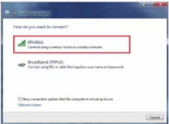
text_image
Connect to the record How do you want to connect? Wireless Connect using a wireless router or a wireless network. Broadband (PFPoE) Connect using iOS to cable that requires a user name and password. Show connection options that this computer is not set up to use Welcome close Cancel- A list of available WLAN connections pops up. Choose a connection from the list or click [Open Network and Sharing Center] to establish a new connection.
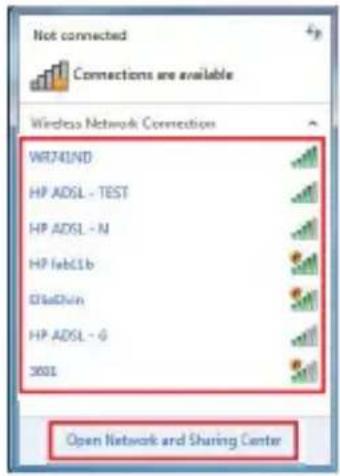
text_image
Not connected Connections are available Wireless Network Connection WR741ND HP ADSL - TEST HP ADSL - N HP febC1b BlaDNin HP ADSL - 6 3001 Open Network and Sharing Center- To establish a new WLAN connection, select [Set up a new connection or network] in [Network and Sharing Center].
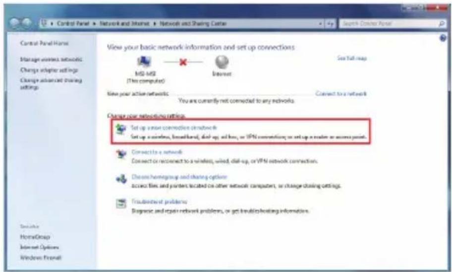
text_image
Control Panel Home Manage wireless networking Change adapter settings Change advanced sharing settings View your basic network information and set up connections MSI-MSI (This computer) Internet See Tall map New your active networks You are currently not connected to any networks. Connect to a network Change your networking settings Set up a wireless connection network Set up a wireless, broadband, dial-up, and how, or VPN connections or set up a reader or access point. Connect to a network Connect or reconnect to a wireless, wired, dial-up, or VPN network connections. Choose homegroup and sharing options access files and printers located on other network computers, or change sharing settings. Troubustout problems Diagnostic and repair network problems, or get breakouts/looking information.- Followingly, choose [Manually connect to a wireless network] and click [Next] to continue.

text_image
Set up a connection to Internet Choose a connection option Connect to the Internet Set up a wireless, broadband, or dial-up connection to the Internet. Set up a new network Cartricate a new router or access points. Connect to a wireless network Connect to a network or client's new wireless profile Connect to a workplace Set up a dial-up or VPN connection to your workplace. Set up a dial-up connection Connect to the Internet using a dial-up connectors. Next Cancel- Enter information for the wireless network you intend to add and click [Next] to proceed.

text_image
Enter information for the wireless network you want to add Network name: Security type: [Choose an option] Encryption type: Security Type: Hide characters Start this connection automatically Connect even if the network is not broadcasting Warning: If you select this option, your computer's privacy might be at risk Next Cancel- A new WLAN connection has been made. Click [Close] to exit or select [Change connection settings] to modify the WLAN settings.
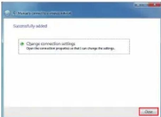
text_image
Manually connect to a wireless device Successfully added Change connection settings Open the connection properties so that I can change the settings. ClosePower Management
Power management of personal computers (PCs) and monitors has the potential to save significant amounts of electricity as well as deliver environmental benefits. To be energy efficient, turn off your display or set your PC to sleep mode after a period of user inactivity.
Power Management in Windows OS
■ [Power Options] in Windows OS allow you to control the power management features of your display, hard drive, and battery. Go to [Start] > [Control Panel] > [System and Security].
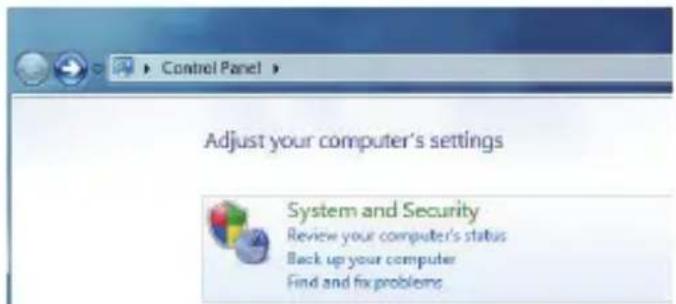
text_image
Control Panel Adjust your computer's settings System and Security Review your computer's status Back up your computer Find and fix problemsThen click on the [Power Options] link.

Power Options
Require a password when the computer wakes Change what the power buttons do Change when the computer sleeps
Select a power plan that suits your personal needs. You may also fi netune the settings by clicking [Change plan settings].
Select a power plan
Power plans can help you maximize your computer's performance or conserve energy. Make a plan active by selecting it, or choose a plan and customize it by changing its power settings. Tell me more about power plans
Preferred plans
Balanced (recommended)
Change plan settings
Automatically balances performance with energy consumption on capable hardware.
Power saver
Change plan settings
Saves energy by reducing your computer's performance where possible.
Show additional plans

■ The Shut Down Computer menu presents the options of Sleep (S3/S4) & Shut Down (S5) for rapid and easy management of your system power.

text_image
Magnetier Solitaire Calibration msi Wind Match All Programs Search programs and files Control Panel Devices and Printers Default Program Help and Support Switch user Log off Lock Roftset Shut down SleepPower Management through ENERGY STAR qualified monitors (Optional)
The power management feature allows the computer to initiate a low-power or "Sleep" mode after a period of user inactivity. When used with an external ENERGY STAR qualified monitor, this feature also supports similar power management features of the monitor. To take advantage of these potential energy savings, the power management feature has been preset to behave in the following ways when the system is operating on AC power:
■ Turn off the display after 15 minutes
■ Initiate Sleep after 30 minutes
Waking the System Up
The computer shall be able to wake up from power saving mode in response to a command from any of the following:
■ the power button,
■ the network (Wake On LAN),
■ the mouse,
■ the keyboard.

Energy Saving Tips:
■ Turn off the monitor by pressing the LCD power button after a period of user inactivity.
- Tune the settings in Power Options under Windows OS to optimize your PC's power management.
- Install power saving software to manage your PC's energy consumption.
■ Always disconnect the AC power cord or switch the wall socket off if your PC would be left unused for a certain time to achieve zero energy consumption.
System Recovery
Important
The System Recovery Function is only available on systems bundled with Windows OS and MSI utilities by default.
The purposes for using the System Recovery Function may include:
- Restore the system back to the initial status of original manufacturer's default settings.
■ When some errors have occurred to the operating system in use.
■ When the operating system is affected by virus and is not able to work normally.
■ When you want to install the OS with other built-in languages.
Before using the System Recovery Function, please backup the important data saved on your system drive to other storage devices.
If the following solution fails to recover your system, please contact the authorized local distributor or service center for further assistance.
> Recovering the System with the F3 Hotkey
If the system encounters non-recoverable problems, it is always recommended that you try the F3 hotkey to recover your system with the recovery partition of the hard disk drive fi rst.
Follow the instructions below to continue:
- Restart the system.
- Press the F3 hotkey on the keyboard when the following image appears.

text_image
msi Press Did to enter BIOS. Printed 11: To run Excel Server- Select [MSI Recovery Manager] to start the System Recovery Function; or select [EXIT] to restart the system.

flowchart
graph LR
    A["System Recovery Option"] --> B["MSI Recovery Manager"]
    A --> C["Exit"]
- The System Recovery Function will get your system back to default settings. Press [OK] to confirm.

text_image
This action will get your system back to default settings. All fires and settings on C drive will be lost. Are you sure to continue? Ok Cancel- Press [OK] to reconfir rm and start the System Recovery Function. Alternatively, press [Cancel] to stop.

text_image
This action will format your hard disk and all data on C drive will be lost. Please be sure to continue again.- The System Recovery Function is proceeding now.

text_image
Operating System: Windows 7 Elapsed Time: 2 min 5 sec- The following message indicates successful system recovery. Press [OK] to restart the system and access the Windows operating system as usual.
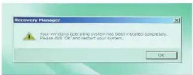
text_image
Recovery Manager Your Windows operating system has been installed completely. Please click OK and restart your system.> Recovering the System with the Recovery Discs
If the F3 hotkey recovery cannot work, try recovering your system with the recovery discs that you created beforehand.
Follow the instructions below to continue:
- Insert the recovery disc into the optical disc drive and restart the system.
- Press the F11 hotkey on the keyboard when the following image appears.

text_image
msi Press Del to order BIOS Press F15 to run Next Menu- Select the [CD/DVD] device as the boot device and press [Enter] to confirm the selection.
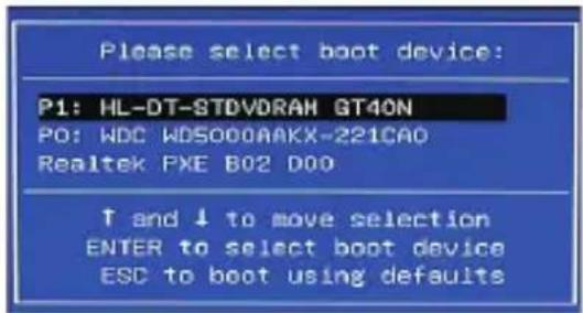
text_image
Please select boot device: P1: HL-DT-STDVDRAH GT40N PO: WDC WD5000AAKX-221CAO Realtek PXE B02 D00 ↑ and ↓ to move selection ENTER to select boot device ESC to boot using defaultsPress any key to reconfirm the selection when the following message appears.
Press any key to boot from CD or DVD ...
- The Windows OS starts loading fi les.
Windows is loading files ...
- The system recovery menu pops up. [Hard Disk Recovery] will format the whole HDD. All data on the HDD will be erased while all settings will be restored to manufacturer default. Select [Hard Disk Recovery] only when your HDD is infected with fatal viruses and no solution can be found except a clear cleanup of the HDD.

text_image
msi Hard Disk Recovery System Partition Recovery Exit The whole hard disk will be formatted. All the data will be detersegmented and restored to factory default settings.[System Partition Recovery] will format the C drive only. Only the C drive will be restored to manufacturer default. Other drives will not be affected. It is highly recommended that users select [System Partition Recovery] to restore the system.

text_image
msi Hard Disk Recovery System Partition Recovery Exit Only OS Install drive will be formatted. Other drives will not be affected. OS Install drive will be restored to factory default settings- The system recovery will format your HDD partition. Make sure that the important data have been backed up. Click [YES] to continue; click [NO] to stop the system recovery.

text_image
msi All files and setting will be reset and lost on this computer. Are you sure to continue ? YES NOClick [YES] again to reconfi rm; click [NO] to stop the system recovery.

text_image
msi Please sure to continue again ? YES NO- DO NOT turn off the system power while performing the system recovery function, or it may cause unknown damage to the system.

text_image
msi Express Operating System Windows 7 Elapsed Time : 0 min 36 sec Time Left : 34 min 24 sec Progress : ■- The following message indicates successful system recovery. Press [OK] to restart the system and access the Windows operating system as usual.
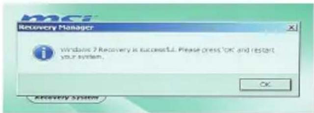
text_image
Windows 7 Recovery is successful. Please press 'OK' and restart your system. OK Recovery System- If the recovery process is interrupted or failed, please repeat the recovery procedures from the beginning.