H55A - Motherboard FOXCONN - Free user manual and instructions
Find the device manual for free H55A FOXCONN in PDF.

User questions about H55A FOXCONN
0 question about this device. Answer the ones you know or ask your own.
Ask a new question about this device
Download the instructions for your Motherboard in PDF format for free! Find your manual H55A - FOXCONN and take your electronic device back in hand. On this page are published all the documents necessary for the use of your device. H55A by FOXCONN.
USER MANUAL H55A FOXCONN
H55A Series Motherboard
User's Manual
Statement:
This manual is the intellectual property of Foxconn, Inc. Although the information in this manual may be changed or modified at any time, Foxconn does not obligate itself to inform the user of these changes.
Trademark:
All trademarks are the property of their respective owners.
Version:
User's Manual V1.0 for H55A Series motherboard.
P/N: 3A2224N00-000-G
Symbol description:

Caution: refers to important information that can help you to use motherboard better, and tells you how to avoid problems.

Warning: indicating a potential risk of hardware damage or physical injury may exist.

WEEE:
The use of this symbol indicates that this product may not be treated as household waste. By ensuring this product is disposed of correctly, you will help prevent potential negative consequences for the environment and human health, which could otherwise be caused by inappropriate waste handling of this product. For more detailed information about recycling of this product, please contact your local city office, your household waste disposal service or the shop where you purchased this product.
More information:
If you want more information about our products, please visit Foxconn's
website: http://www.foxconnchannel.com
Declaration of conformity
CE
HON HAI PRECISION INDUSTRY COMPANY LTD 66, CHUNG SHAN RD., TU-CHENG INDUSTRIAL DISTRICT, TAIPEI HSIEN, TAIWAN, R.O.C.
declares that the product
Motherboard H55A
is in conformity with
(reference to the specification under which conformity is declared in accordance with 89/336 EEC-EMC Directive)
■ EN 55022: 1998/A2: 2003 Limits and methods of measurements of radio disturbance characteristics of information technology equipment
■ EN 61000-3-2/:2000 Electromagnetic compatibility (EMC)
Part 3: Limits
Section 2: Limits for harmonic current emissions
(equipment input current <= 16A per phase)
■ EN 61000-3-3/A1:2001 Electromagnetic compatibility (EMC)
Part 3: Limits
Section 2: Limits of voltage fluctuations and flicker in low voltage supply systems for equipment with rated current <= 16A
■ EN 55024/A2:2003 Information technology equipment-Immunity characteristics limits and methods of measurement
Signature :

text_image
James Lian Place / Date : TAIPEI/2010Printed Name : James Liang
Declaration of conformity

text_image
FCTrade Name: FOXCONN
Model Name: H55A
Responsible Party: PCE Industry Inc.
Address: 458 E. Lambert Rd.
Fullerton, CA 92835
Telephone: 714-738-8868
Facsimile: 714-738-8838
Equipment Classification: FCC Class B Subassembly
Type of Product: Motherboard
Manufacturer: HON HAI PRECISION INDUSTRY
COMPANY LTD
Address: 66, CHUNG SHAN RD., TU-CHENG
INDUSTRIAL DISTRICT, TAIPEI HSIEN,
TAIWAN, R.O.C.
Supplementary Information:
This device complies with Part 15 of the FCC Rules. Operation is subject to the following two conditions: (1) this device may not cause harmful interference, and (2) this device must accept any interference received, including interference that may cause undesired operation.
Tested to comply with FCC standards.
Signature :

text_image
James CianDate : 2010
Installation Precautions

Electrostatic discharge (ESD) is the sudden and momentary electric current that flows between two objects at different electrical potentials. Normally it comes out as a spark which will quickly damage your electronic equipment. Please wear an electrostatic discharge (ESD) wrist strap when handling components such as a motherboard, CPU or memory.
■ Ensure that the DC power supply is turned off before installing or removing CPU, memory, expansion cards or other peripherals. It is recommended to unplug the AC power cord from the power supply outlet. Failure to unplug the power supply cord may result in serious damage to your system.

Please carefully read the following procedures to install your computer :
■ It is suggested to select high-quality, certified fans in order to avoid damage to the motherboard and CPU due to high temperature. Never turn on the computer if the CPU fan is not properly installed.
■ We cannot guarantee that your system can operate normally when your CPU is overclocked. Normal operation depends on the overclocking capacity of your device.
■ If there is any, when connecting USB, audio, 1394a, RS232 COM, IrDA or S/PDIF cables to the internal connectors on the motherboard, make sure their pinouts are matching with the connectors on the motherboard. Incorrect connections might damage the motherboard.
■ When handling the motherboard, avoid touching any metal leads or connectors.
■ If there is a PCI Express x16 graphics card installed in your system, we recommend using a 24-pin ATX power supply to get the best performance.
■ Before turning on the power, please make sure the power supply AC input voltage setting has been configured to the local standard.
■ To prevent damage to the motherboard, do not allow screws to come in contact with the motherboard circuit or its components. Also, make sure there are no leftover screws or metal components placed on the motherboard or within the computer casing.
■ If you are uncertain about any installation steps or have a problem related to the use of the product, please consult a certified computer technician.
TABLE OF CONTENTS
Chapter 1 Product Introduction
Product Specifications....2
Layout....4
Back Panel Connectors ....5
Chapter 2 Hardware Install
Install the CPU and CPU Cooler 8
Install the Memory ....11
Install an Expansion Card ....13
Install other Internal Connectors ....14
Jumpers 18
Chapter 3 BIOS Setup
Enter BIOS Setup 21
Main Menu....21
System Information ....23
Advanced BIOS Features....25
Fox Central Control Unit 27
Advanced Chipset Features ....32
Integrated Peripherals ....33
Power Management Setup 37
PC Health Status 39
BIOS Security Features....40
Load Optimal Defaults ....41
Save Changes and Exit ....41
Discard Changes and Exit ....41
Chapter 4 CD Instruction
Install driver and utility ....44
FOX ONE
Main Page 46
CPU Control 50
Frequency Control ....52
Limit Setting....53
Voltage Control 55
Fan Control....56
FOX LiveUpdate
Local Update ....57
Online Update ....59
Configure 62
About & Help 64
FOX LOGO 65
FOX DMI 66
Technical Support :

Support
Website :
http://www.foxconnchannel.com
Support Website :
http://www.foxconnsupport.com
Worldwide online contact Support :
http://www.foxconnsupport.com/inquiry.aspx
CPU Support List :
http://www.foxconnsupport.com/cpusupportlist.aspx
Memory, VGA Compatibility List :
http://www.foxconnsupport.com/complist.aspx

natural_image
Circular image with a white number '1' and fireworks streaks in the background (no readable text or symbols)Thank you for buying Foxconn H55A Series motherboard. Foxconn products are engineered to maximize computing power, providing only what you need for break-through performance.
With advanced overclocking capability and a range of connectivity features for today multi-media computing requirements, H55A enables you to unleash more power from your computer.
This chapter includes the following information:
■ Product Specifications
Layout
■ Back Panel Connectors
1-1 Product Specifications

| CPU Support LGA 1156 socket Intel®CPU, Max processor power up to 95wFor the latest CPU information, please visit:http://www.foxconnchannel.com |
| Chipset Intel®H55 |
| Memory 4 x 240-pin DDR3 DIMM socketsSupport up to 16GB of system memoryDual channel DDR3 1600(oc*)/1333/1066 MHz architecture(oc:Overclocking) |
| Expansion Slots 1 x PCI Express x16 slot3 x PCI Express x1 slots3 x PCI slots |
| Storage H55 chipset:- 6 x SATAII connectors2 x ESATA ports300MB/s data transfer rate- 1 x IDE connector |
| LAN Realtek RTL8111DL Gigabit LAN chip |
| Audio VIA VT1828S audio chip:- High Definition Audio- 2/4/5.1/7.1-channel- Support for S/PDIF OUT- Support Jack- Sensing function |
| USB Support hot plugSupports up to 12 x USB 2.0 ports (6 rear panel ports, 3 onboard USBheaders supporting 6 extra ports)Support USB 2.0 protocol up to 480Mb/s |
| Internal Connectors 1 x 24-pin ATX main power connector1 x 8-pin ATX 12V power connector1 x CPU fan header (4-pin)2 x System fan headers (4-pin)1 x Front Audio connector1 x CD-IN connector1 x SPDIF-OUT connector1 x Speaker connector1 x COM1 connector3 x USB 2.0 connectors (supporting 6 x USB devices)1 x Front Panel connector6 x SATA connectors1 x Chassis Intrusion Alarm header(INTR) |
(Continued on the next page)
| Back Panel 1 x PS/2 portConnectors 1 x DVI-I port1 x HDMI port2 x eSATA ports6 x USB 2.0 ports1 x RJ-45 LAN port8-channel Audio Ports |
| Hardware Monitor System voltage detectionCPU/System temperature detectionCPU/System fan speed detectionCPU/System overheating shutdownCPU/System fan speed control |
| PCI Express x1 Support 250MB/s (500MB/s concurrent) bandwidthLow power consumption and power management features |
| PCI Express x16 Gen2.0 Support 8GB/s (16GB/s concurrent) bandwidthLow power consumption and power management features |
| Green Function Support ACPI (Advanced Configuration and Power Interface)Support S0 (normal), S1 (power on suspend), S3 (suspend to RAM), S4(suspend to disk), and S5 (soft - off)Support EuP function |
| Bundled Software FOX ONEFOX LiveUpdateFOX LOGOFOX DMI |
| Operating System Support for Microsoft ® Windows® Vista/XP/Win7 |
| Form Factor ATX Form Factor, 12 inches x 8.6 inches (30.5cm x 21.9cm) |

1-2 Layout


text_image
Labeled diagram of a computer motherboard with numbered components and connectors- 8-pin ATX 12V Power Connector
- SYS_FAN2 Header
- PCI Express x1 Slot
- PCI Express x16 Slot
- PCI Slots
- S/PDIF Out Connector
- CD-IN Connector
- Front Audio Connector
- Speaker Connector
- Intel® ME Jumper
- Front USB Connectors
-
Front Panel Connector
-
COM1 Connector
- INTR Connector
- Clear CMOS Jumper
- SATA Connectors
- SYS_FAN1 Header
- Chipset: Intel® H55
- IDE Connector
- 24-pin ATX Power Connector
- DDR3 DIMM Slots
- CPU_FAN Header
- LGA1156 CPU Socket
Note : The above motherboard layout is for reference only, please refer to the physical motherboard for detail.
1-3 Back Panel Connectors
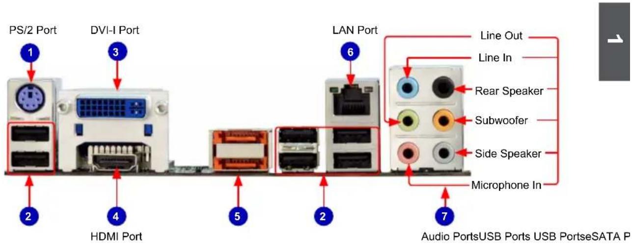
text_image
PS/2 Port DVI-I Port LAN Port Line Out Line In Rear Speaker Subwoofer Side Speaker Microphone In Audio PortsUSB Ports USB PortseSATA P HDMI Port 2 3 4 5 2 6 71. PS/2 Port
Use the PS/2 port to connect a PS/2 mouse or keyboard.
2. USB Ports
The USB port supports the USB 2.0/1.1 specification. Use this port for USB devices such as an USB keyboard/mouse, USB printer, USB flash drive and etc.
3. DVI-I Port
The DVI-I port supports DVI-I specification. Connect a monitor that supports VGA or DVI-I connection to this port.
4. HDMI Port
The HDMI (High-Definition Multimedia Interface) provides an all-digital audio/video interface to transmit the uncompressed audio/video signals and is HDCP compliant. Connect the HDMI audio/video device to this port. The HDMI Technology can support a maximum resolution of 1920x1080p but the actual resolutions supported depend on the monitor being used.
5. External SATA Port
To connect external SATA device(s) to your system by expanding the internal SATA port(s) to the chassis back pannel. External SATA device shall provide power by its own.
6. RJ-45 LAN Port
The Ethernet LAN port provides Internet connection at up to 10/100/1000Mb/s data rate.
| LAN Type | Left: Active Right: Link | |||
| Status D | Description Status Description | |||
| 1000M | Off No | Link Off No Link | ||
| Green Blinking | Data Activity | Off 10Mb/s Connection | ||
| Green 100Mb/s Connection | ||||
| Orange 1000Mb/s Connection | ||||

text_image
Active LED Link LED7. Audio Ports
For the definition of each audio port, please refer to the table below :

| Port 2-channel 4-channel 5.1-channel 7.1-channel | ||||
| Blue Line In Line In Line In Line In | ||||
| Green Line Out Front Speaker Out Front Speaker Out | ||||
| Pink Microphone In Microphone In Microphone In Microphone In | ||||
| Orange | - | - | Center/Subwoofer Out | Center/Subwoofer Out |
| Black | - | Rear Speaker Out | Rear Speaker Out | Rear Speaker Out |
| Grey | - | - | - | Side Speaker Out |

text_image
2This chapter introduces the hardware installation process, including the installation of the CPU, memory, power supply, slots, pin headers and the mounting of jumpers. Caution should be exercised during the installation of these modules. Please refer to the motherboard layout prior to any installation and read the contents in this chapter carefully.
This chapter includes the following information :
■ Install the CPU and CPU Cooler
Install the Memory
■ Install an Expansion Card
■ Install other Internal Connectors
■ Jumpers

Please visit the following website for more supporting information about your motherboard.
CPU Support List:
http://www.foxconnsupport.com/cpusupportlist.aspx
Memory, VGA Compatibility List:
http://www.foxconnsupport.com/complist.aspx
2-1 Install the CPU and CPU Cooler

Read the following guidelines before you begin to install the CPU :
■ Make sure that the motherboard supports the CPU.
■ Always turn off the computer and unplug the power cord from the power supply before installing the CPU to prevent hardware damage.
- Locate the pin one of the CPU. The CPU cannot be inserted if oriented incorrectly. (Or you may locate the notches on both sides of the CPU and alignment keys on the CPU socket.)
■ Apply an even and thin layer of thermal grease on the surface of the CPU.
■ Do not turn on the computer if the CPU cooler is not installed, otherwise overheating and damage of the CPU may occur.
■ Set the CPU host frequency in accordance with the CPU specifications. It is not recommended that the system bus frequency be set beyond hardware specifications since it does not meet the standard requirements for the peripherals. If you wish to set the frequency beyond the standard specifications, please do so according to your hardware specifications including the CPU, graphics card, memory, hard drive, etc.
Hyper-Threading Technology System Requirements:
(Go to Intel's website for more information about the Hyper-Threading Technology)
■ An Intel® CPU that supports HT Technology
■ A chipset that supports HT Technology
■ An operating system that is optimized for HT Technology
■ A BIOS that supports HT Technology and has it enabled
Install the CPU
Locate the alignment keys on the motherboard CPU socket and the notches on the CPU.
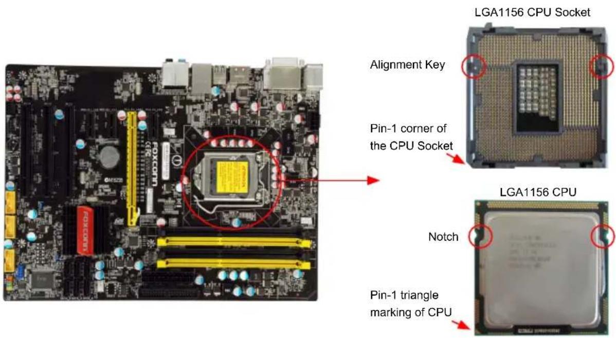
text_image
LGA1156 CPU Socket Alignment Key Pin-1 corner of the CPU Socket LGA1156 CPU Notch Pin-1 triangle marking of CPUFollow the steps to install the CPU onto the CPU socket :

Before installing the CPU, make sure to turn off the computer and unplug the power cord from the power outlet to prevent damage to the CPU.
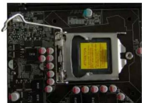
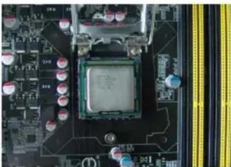
natural_image
Close-up of a computer motherboard with visible CPU socket and circuit board (no text or symbols)- Release the CPU socket lever.

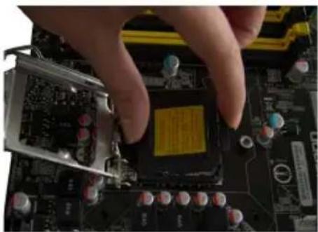
natural_image
Close-up of a hand pressing a CPU socket on a motherboard (no visible text or symbols)- Lift the metal cover on the CPU socket.
natural_image
Close-up of hands installing a computer motherboard with a highlighted chip (no visible text or symbols)- Remove protective socket cover.
natural_image
Close-up of a computer motherboard with CPU socket and surrounding components (no visible text or symbols)- Check pin one marking (triangle) with the pin one corner of the CPU socket, align the CPU notches with the socket alignment keys and gently put the CPU onto the socket.
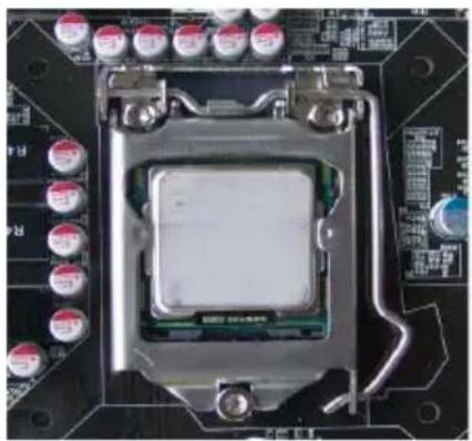
natural_image
Close-up of a computer motherboard with CPU socket and surrounding hardware (no readable text or symbols)- When CPU is properly seated, replace the metal cover and push the CPU socket lever back to its locked position.
Install the CPU Cooler
Follow the steps below to correctly install the CPU cooler on the motherboard.

natural_image
Close-up of a computer processor on a circuit board with visible pins and wiring (no text or symbols)- Apply and spread an even thermal grease on the surface of CPU.
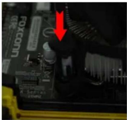
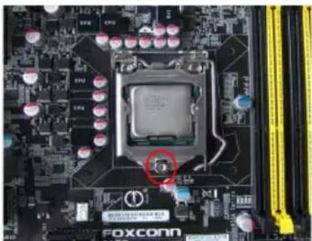
natural_image
Close-up of a computer motherboard with visible circuit board and connectors, featuring a red downward arrow pointing to a component (no readable text or symbols)- Place the four bolts of the CPU cooler to the holes of the motherboard, push them straight down from the top, and the bolts will be fastened on the motherboard. That's it.

natural_image
Close-up of a printed circuit board with visible traces and mounting holes (no text or symbols)- Check the solder side of the motherboard, the push pin should be fixed as depicted in the picture.
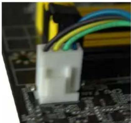
natural_image
Close-up of a white plastic connector inserted into a motherboard with colorful wires (no visible text or symbols)- Attach the 4-wire CPU cooler connector to the CPU FAN header on the motherboard.
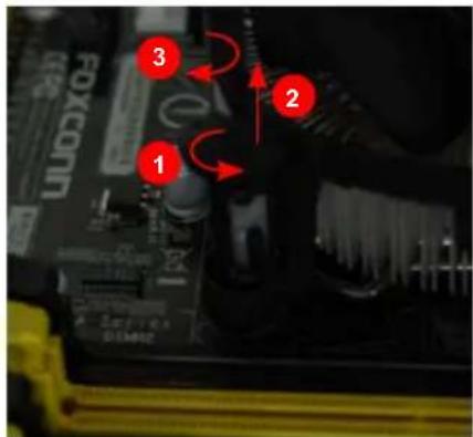
text_image
1 2 3Release bolts of CPU cooler from motherboard :
- Turning the push pin (bolt) along with the direction of arrow (counterclockwise).
- Pull the push pin straight up.
- Turning push pin clockwise to its default position.

Use extreme care when removing the CPU cooler because the thermal grease may adhere to the CPU. Inadequately removing the CPU cooler may damage the CPU.
2-2 Install the Memory

Read the following guidelines before you begin to install the memory :
■ Make sure that the motherboard supports the memory. It is recommended that memory of the same capacity, brand, speed, and chips be used.
■ Always turn off the computer and unplug the power cord from the power outlet before installing the memory to prevent hardware damage.
■ Memory modules have a foolproof design. A memory module can be installed in only one direction. If you are unable to insert the memory, switch the direction.
Dual Channel Memory Configuration
This motherboard provides Four DDR3 memory sockets and supports Dual Channel Technology. When memory is installed, the BIOS will automatically check the memory in your system.
Four DDR3 memory sockets are divided into two channels :
Channel 0 : DIMM1 , DIMM2
Channel 1 : DIMM3 , DIMM4
The combinations of DIMM modules are :
| DIMM1 DIM | MM2 DIMM3 DIMM4 | ||
| Single Channel DS/SS - - - | |||
| Single Channel DS/SS DS/SS - - | |||
| Single Channel - DS/SS - - | |||
| Single Channel - - DS/SS - | |||
| Single Channel - - DS/SS | |||
| Single Channel - - DS/SS DS/SS | |||
| Dual Channel DS/SS - DS/SS - | |||
| Dual Channel DS/SS - - DS/SS | |||
| Dual Channel - DS/SS DS/SS - | |||
| Dual Channel - DS/SS - DS/SS | |||
| Dual Channel DS/SS DS/SS DS/SS DS/SS |
(DS : Double Side, SS : Single Side, - : No Memory)

For this motherboard, DIMM(1,2), DIMM(3,4) are two pairs of channels. For Lynnfield CPU, in each pair of DIMM channel, you need to install yellow DIMM first, then install black DIMM the second. Black DIMM can not function if no yellow DIMM is installed. (Please refer to the silkscreen next to the DIMM slots to identify the sequence of DIMM(1,2, 3, 4) on the motherboard.)
Installing a Memory

■ Before installing a memory module, make sure to turn off the computer and unplug the power cord from the power outlet to prevent damage to the memory module. Be sure to install DDR3 DIMMs on this motherboard.
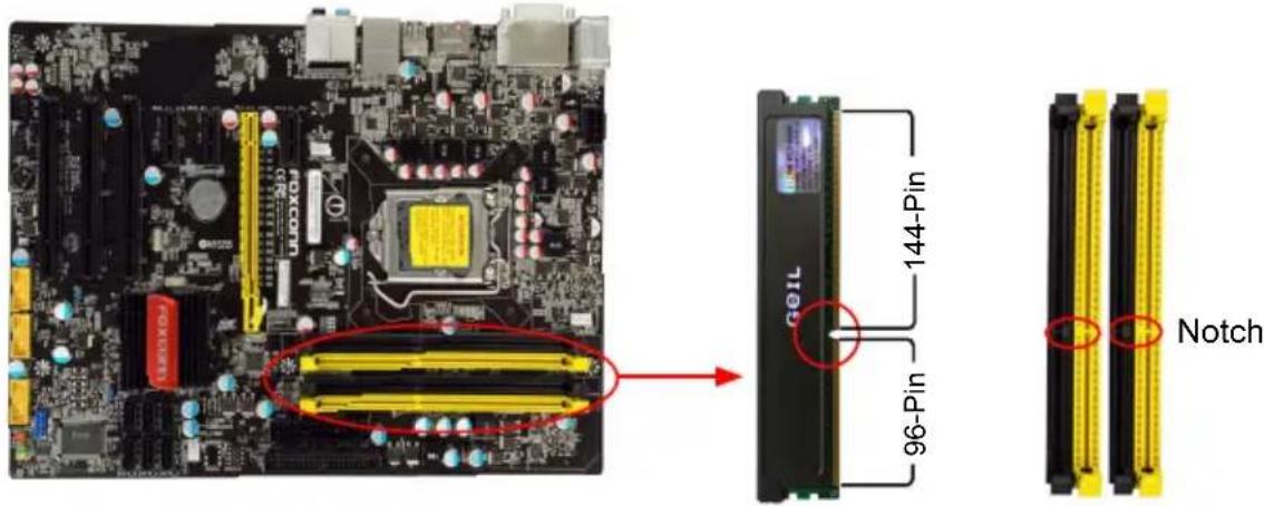
text_image
144-Pin 96-Pin G01L NotchIf you take a look at front side of memory module, it has asymmetric pin counts on both sides separated by a notch in the middle, so it can only fit in one direction. Follow the steps below to correctly install your memory modules into the sockets.

natural_image
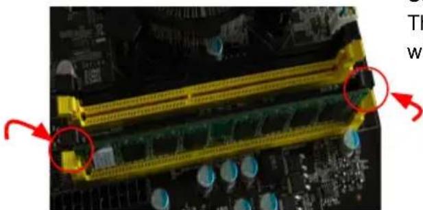
Close-up of a computer motherboard with yellow connectors and red arrows indicating ports (no readable text or symbols)Step 1:
Spread the clips at both ends of the memory socket. Place the memory module onto the socket, then put your fingers on top edge of the module, and push it down firmly and seat it vertically into the memory socket.
natural_image
Close-up of a computer motherboard with visible RAM slots and circuit board (no text or symbols)Step 2:
The clips at both ends of the socket will snap into place when the memory module is securely inserted.
2-3 Install an Expansion Card

■ Make sure the motherboard supports the expansion card. Carefully read the manual that came with your expansion card.
■ Always turn off the computer and unplug the power cord from the power outlet before installing an expansion card to prevent hardware damage.
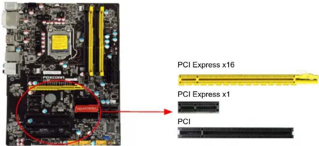
text_image
PCI Express x16 PCI Express x1 PCIFollow the steps below to correctly install your expansion card in the expansion slot.
- Locate an expansion slot that supports your card. Remove the metal slot cover from the chassis back panel.
- Align the card with the slot, and press down on the card until it is fully seated in the slot.
- Make sure the metal contacts on the card are completely inserted into the slot.
- Secure the card's metal bracket to the chassis back panel with a screw.
- After installing all expansion cards, replace the chassis cover.
- Turn on your computer. If necessary, go to BIOS Setup to make any required BIOS changes for your expansion card(s).
- Install the driver provided with the expansion card in your operating system.
Installing and Removing a PCI Express x16 Graphics Card :

natural_image
Close-up of a green computer motherboard with visible CPU socket and heatsink (no text or symbols)• Installing a Graphics Card:
Gently insert the graphics card into the PCI Express x16 slot. Make sure the graphics card is locked by the latch at the end of the PCI Express x16 slot.
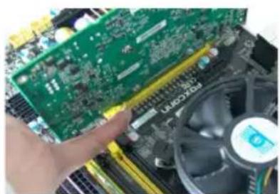
natural_image
Close-up of a hand holding a green printed circuit board with a CPU fan nearby (no visible text or symbols)- Removing the Card:
Push the latch at the end of the PCI Express x16 slot to release the card and then pull the card straight up from the slot.
2-4 Install other Internal Connectors
Power Connectors
This motherboard uses an ATX power supply. In order not to damage any device, make sure all the devices have been installed properly before applying the power supply.
24-pin ATX Power Connector : PWR1
PWR1 is the ATX power supply connector. Make sure that the power supply cable and pins are properly aligned with the connector on the motherboard. Firmly plug the power supply cable into the connector and make sure it is secure.
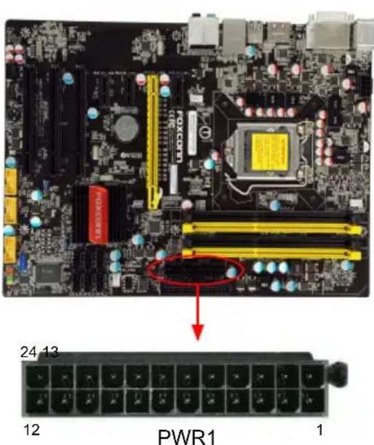
text_image
24 13 12 PWR1 1| Pin # | Definition | Pin # Definition | ||
| 1 3.3 | V 13 | 3.3V | ||
| 2 3.3 | V 14 | -12V | ||
| 3 | GND | 15 | GND | |
| 4 | +5V | 16 | PS_ON(Soft On/Off) | |
| 5 | GND | 17 | GND | |
| 6 | +5V | 18 | GND | |
| 7 | GND | 19 | GND | |
| 8 | Power Good | 20 | NC | |
| 9 | +5V SB(Stand by +5V) | 21 | +5V | |
| 10 | +12V | 22 | +5V | |
| 11 | +12V | 23 | +5V | |
| 12 3.3 | V | 24 | GND |

We recommend you using a 24-pin power supply. If you are using a 20-pin power supply, you need to align the ATX power connector according to the picture.

text_image
Pin No. 24 20-Pin Power8-pin ATX 12 V Power Connector : PWR2
Connect the 8-pin ATX 12V power supply to PWR2 and provides power to the CPU.
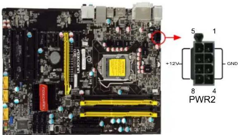
text_image
5 1 +12V GND 8 4 PWR2| Pin # | Definition | Pin | # Definition |
| 1 | GND 5 +12V | ||
| 2 | GND 6 +12V | ||
| 3 | GND 7 +12V | ||
| 4 | GND 8 +12V |

We recommend you using an 8-pin ATX 12V power supply. If you are using a 4-pin power supply, you need to align the ATX power connector according to the picture on the right.
Connect a 4-pin power plug

N
COM Connector : COM1
This motherboard supports one serial RS232 COM port for legacy compatibility. User must purchase another RS232 cable with a 9-pin D-sub connector at one end to connect with the external RS232 device and another end with 10-pin female connector to connect with COM1 connector in the motherboard.
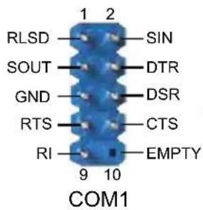
text_image
RLSD 1 2 SOUT SIN GND DTR RTS DSR RTS CTS RI EMPTY 9 10 COM1Fan Connectors : CPU\_FAN, SYS\_FAN1/2
There are three main fan headers on this motherboard. The fan speed can be controlled and monitored in "PC Health Status" section of the BIOS Setup. These fans can be automatically turned off after the system enters 3, S4 and S5 sleeping states.

text_image
1 GND POWER SENSE CONTROL CPU_FAN/SYS_FAN1/2/3
natural_image
Close-up of a computer motherboard with visible CPU socket, RAM slots, and heatsink (no readable text or symbols)IDE Connector : PIDE
With the provided Ultra DMA IDE ribbon cable, you can connect to any IDE type of hard disk and CD/DVD ROM/RW drive.
Audio Connector : F\_AUDIO
The audio connector supports HD Audio standard. It provides the Front Audio output choice.
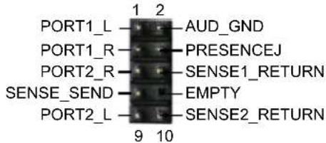
text_image
PORT1_L 1 2 AUD_GND PORT1_R PRESENCEJ SENSE1_RETURN PORT2_R EMPTY SENSE_SEND SENSE2_RETURN PORT2_L 9 102
Speaker Connector : SPEAKER
The speaker connector is used to connect speaker of the chassis.
S/PDIF OUT Connector : SPDIF\_OUT
The connector is used for S/PDIF output.
USB Connectors : F\_USB1/2/3
In addition to the USB ports on the rear panel, this product also provides 10-pin USB headers on its motherboard. By connecting through USB cables with them, user can quickly expand another USB ports on the front panel.
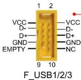
text_image
VCC D- D+ GND EMPTY 1 2 9 10 F_USB1/2/3 VCC D- D+ GND NCSerial ATA Connectors : SATA\_1/2/3/4/5/6
The Serial ATA connector is used to connect with SATA Hard Disk or CD devices which support this feature. The current Serial ATA II interface allows up to 300MB/s data transfer rate.
Chassis Intrusion Alarm Header : INTR
The connector can be connected to a security switch on the chassis. The system can detect the chassis intrusion through the function of this connector. If eventually the chassis was closed, the system will send a message out.
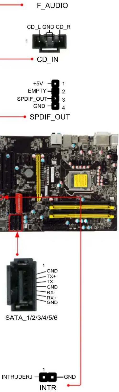
text_image
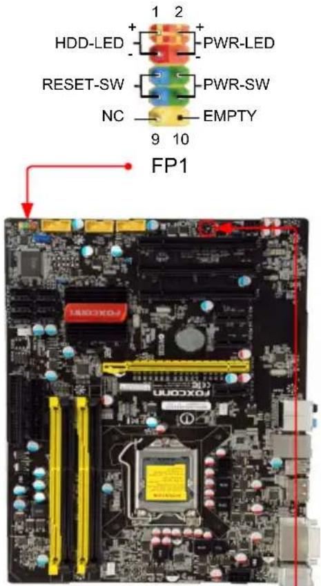
F_AUDIO CD_L GND CD_R 1 CD_IN +5V 1 EMPTY 2 SPDIF_OUT 3 GND 4 SPDIF_OUT SATA_1/2/3/4/5/6 1 GND TX+ TX- GND RX- RX+ GND INTRUDERJ 1 GND INTRFront Panel Connector : FP1
This motherboard includes one connector for connecting the front panel switch and LED Indicators.
Hard Disk LED Connector (HDD-LED)
Connect to the chassis front panel IDE indicator LED. It indicates the active status of the hard disks. This 2-pin connector is directional with +/- sign.
Reset Switch (RESET-SW)
Attach the connector to the Reset switch on the front panel of the case; the system will restart when the switch is pressed.
Power LED Connector (PWR-LED)
Connect to the power LED indicator on the front panel of the chassis. The Power LED indicates the system's status. When the system is in operation (S0 status), the LED is on. When the system gets into sleep mode (S1), the LED is blinking; When the system is in S3/S4 sleep state or power off mode (S5), the LED is off. This 2-pin connector is directional with +/- sign.
Power Switch Connector (PWR-SW)
Connect to the power button on the front panel of the chassis. Push this switch allows the system to be turned on and off rather than using the power supply button.
Speaker Connector : SPEAKER
The speaker connector is used to connect speaker of the chassis.
text_image
1 2 HDD-LED + - PWR-LED RESET-SW - PWR-SW NC - EMPTY 9 10 FP1
2-5 Jumpers
For some features needed, users can change the jumper settings on this motherboard to modify them. This section explains how to use the various functions of this motherboard by changing the jumper settings. Users should read the following content carefully prior to modifying any jumper setting.
Description of Jumpers
-
For any jumper on this motherboard, pin 1 can be identified by the bold silkscreen next to it. However, in this manual, pin 1 is simply labeled as "1".
-
The following table explains different types of the jumper settings. "Closed" means placing a jumper cap on the two pins to temporarily short them. The shorting can also be done by touching two pins by a screwdriver for a few seconds, but using jumper cap is recommended. It can prevent hazardous ESD (Electrical Static Discharge) problem.
| Jumper Diagram Definition Description | |||
 | 1  | 1-2 Set Pin 1 and Pin 2 closed | |
1  | 2-3 Set Pin 2 and Pin 3 closed | ||
Clear CMOS Jumper: CLR\_CMOS
The motherboard uses CMOS RAM to store the basic hardware information (such as BIOS data, date, time information, hardware password... etc.). Clear CMOS data is the fast way to go back to factory default when the BIOS settings were mistakenly modified.
The steps to clear CMOS data are :
- Turn off the computer, unplug the power cord from the power outlet.
- Remove jumper cap from pins 2-3, put it onto pins 1-2 to short them. This will clear CMOS data.
- Return the setting to its original with pins 2-3 closed.
- Plug in the power cord to your computer and turn it on.
- Go to BIOS Setup to configure new system as described in next chapter.

text_image
Clear Normal (Default)CLR_CMOS

natural_image
Close-up of a computer motherboard with visible CPU socket, RAM slots, and surrounding hardware (no readable text or symbols)
■ Disconnect the power cable before adjusting the jumper settings.
■ Do not clear the CMOS while the system is turned on.
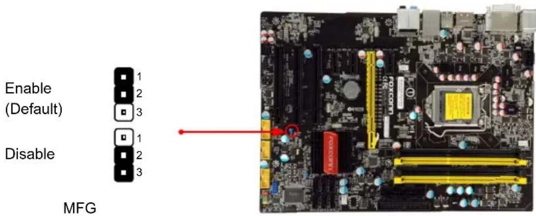
Intel® ME Jumper: MFG
This motherboard uses MFG jumper to enable or disable Intel® Management Engine function. Intel® Management Engine (ME) is an embedded microcontroller located in Intel chipset. It provides latest IT management features such as Intel® AMT, that allows to improve management of corporate assets.
Set the jumper to pins 1-2, you can enable the Intel® Management Engine function. Set the jumper to pins 2-3, you can disable the Intel® Management Engine function.
N
text_image
Enable (Default) Disable MFG
Before flashing BIOS ROM, you need to set MFG jumper to pins 2-3 first.

text_image
3This chapter tells how to change system settings through the BIOS Setup menus. Detailed descriptions of the BIOS parameters are also provided.
You have to run the Setup Program when the following cases occur :
-
An error message appears on the screen during the system Power On Self Test (POST) process.
-
You want to change the default CMOS settings.
This chapter includes the following information :
■ Enter BIOS Setup
■ Main Menu
■ System Information
■ Advanced BIOS Features
Fox Central Control Unit
■ Advanced Chipset Features
■ Integrated Peripherals
■ Power Management Setup
■ PC Health Status
■ BIOS Security Features
■ Load Optimal Defaults
■ Save & Exit Setup
■ Exit Without Saving

Since BIOS could be updated some other times, the BIOS information described in this manual is for reference only. We do not guarantee the content of this manual will remain consistent with the newly released BIOS at any given time in the future. Please visit our website for updated manual if it is available.
Enter BIOS Setup
The BIOS is the communication bridge between hardware and software, correctly setting up the BIOS parameters is critical to maintain optimal system performance. Power on the computer, when the message "Press to enter Setup, key to enter Setup.

We do not suggest that you change the default values in the BIOS Setup, and we shall not be responsible for any damage which resulted from the change you made.
ω
Main Menu
The main menu allows you to select from a list of setup functions together with two exit choices. Use the arrow keys to select a specific item and press
Each item in the main menu is explained below:
| ► System Information ► Advanced BIOS Features ► Fox Central Control Unit ► Advanced Chipset Features ► Integrated Peripherals ► Power Management Setup | ► PC Health Status ► BIOS Security Features Load Optimal Defaults Save & Exit Setup Exit Without Saving |
| ↑↓←→:Move Enter:Select +/-:Value F10:Save ESC:Exit F1:General Help F9:Optimized Defaults | |
| Configure Time and Date. Display System Information... v02.67 (c) Copyright 1985-2009, American Megatrends, Inc. | |
▶ System Information
It displays the basic system configuration, such as BIOS Version, memory size plus system date, time and Floppy drive. They all can be viewed or set up through this menu.
▶ Advanced BIOS Features
The advanced system features can be set up through this menu. There are boot up settings.
▶ Fox Central Control Unit
Some special proprietary features (such as overclocking) can be set up through this menu.
▶ Advanced Chipset Features
The values for the chipset can be changed through this menu, and the system performance can be optimized.
▶ Integrated Peripherals
All onboard peripherals can be set up through this menu. There are IDE devices, Super I/O devices such as Serial I/O and other USB devices... etc.

▶ Power Management Setup
All the items related with Green function features can be set up through this menu.
▶ PC Health Status
This setup enables you to read/change Fan speeds, and displays temperatures and voltages of your CPU/System.
▶ BIOS Security Features
The Supervisor/User password can be set up through this menu to prevent unauthorized use of your computer. If you set a password, the system will ask you to key in correct password before boot or access to Setup.
▶ Load Optimal Defaults
The optimal performance settings can be loaded through this menu. However, it may offer better performance in some ways (such as less I/O cards, less memory ...etc.), still, it may cause problem if you have more memory or I/O cards installed. It means, if your system loading is heavy, set to optimal default may sometimes come out an unstable system. What you need now is to adjust BIOS setting one by one, trial and error, to find out the best setting for your current system.
▶ Save & Exit Setup
Save setting values to CMOS and exit.
▶ Exit Without Saving
Do not change anything and exit the setup.
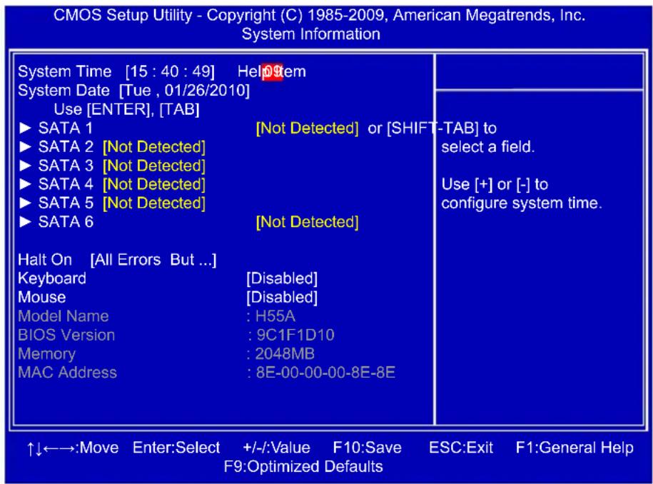
System Information
This sub-menu is used to set up the standard BIOS features, such as the date, time, memory and so on. Use the arrow up/down keys to select an item, then use the <+> or <-> keys to change the setting.
text_image
CMOS Setup Utility - Copyright (C) 1985-2009, American Megatrends, Inc. System Information System Time [15 : 40 : 49] HelpItem System Date [Tue , 01/26/2010] Use [ENTER], [TAB] ► SATA 1 [Not Detected] or [SHIFT-TAB] to ► SATA 2 [Not Detected] ► SATA 3 [Not Detected] ► SATA 4 [Not Detected] ► SATA 5 [Not Detected] ► SATA 6 [Not Detected] Halt On [All Errors But ...] Keyboard [Disabled] Mouse [Disabled] Model Name : H55A BIOS Version : 9C1F1D10 Memory : 2048MB MAC Address : 8E-00-00-00-8E-8E ↑↓←→:Move Enter:Select +/-:Value F10:Save ESC:Exit F1:General Help F9:Optimized Defaults▶ System Time
This item allows you to configure the desired time. Use [ENTER], [TAB] or [SHIFT-TAB] to select a field. Use [+] or [-] to input the value.
The three fields of the setting are
▶ System Date
Day—weekday from Sun. to Sat., this message is automatically displayed by BIOS (Read Only).
Month—month from 1 to 12.
Date—date from 1 to 31. Year—year, set up by users.
Use [ENTER], [TAB] or [SHIFT-TAB] to select a field. Use [+] or [-] to input the value.
▶ SATA 1/2/3/4/5/6
While entering setup, BIOS automatically detects the presence of SATA devices. This item displays the drive information of SATA devices.
▶ Halt On
This category determines whether or not the computer will stop if an error is detected during powering up.
[All Errors] : All errors can result in system halt.
[All Errors But...] : All errors but keyboard or mouse can result in system halt. The halt condition can be enabled/disabled in the next two settings.
▶ Keyboard
The system boot will not stop for a keyboard error if you enabled this item.
▶ Mouse
The system boot will not stop for a mouse error if you enabled this item.
▶ Model Name
Model name of this product.
▶ BIOS Version
It displays the current BIOS version. User can check this information and discuss with the field service people if a BIOS upgrade is needed.
▶ Memory
This item displays the current memory size. The size is depending on how many memory modules were installed in your system before powering on.
▶ MAC Address
This item shows the onboard LAN MAC address.

Advanced BIOS Features

text_image
CMOS Setup Utility - Copyright (C) 1985-2009, American Megatrends, Inc. Advanced BIOS Features Quiet Boot [Enabled Help Item [Enabled] Bootup Num-Lock [On] PCI Latency Timer [64] ► Intel VT-d Configuration [Press Enter] ► Boot Device Priority [Press Enter] ► Hard Disk Drives [Press Enter] ► Removable Drives [Press Enter] ► CD/DVD Drives [Press Enter] Disabled: Displays normal POST messages. Enabled: Displays OEM Logo instead of POST messages. ↑↓←→:Move Enter:Select +/-:Value F10:Save ESC:Exit F1:General Help F9:Optimized Defaults▶ Quiet Boot
This item is used to enable/disable the quiet boot.
[Disabled] : Displays the normal POST messages.
[Enabled] : Displays OEM customer logo instead of POST messages.
▶ Bootup Num-Lock
This item defines if the keyboard Num Lock key is active when your system is started. The available settings are: On (default) and Off.
▶ PCI Latency Timer
This item is used to set the value in units of PCI clocks for PCI device latency timer register.
Intel VT-d Configuration
Press
▶ Boot Device Priority
This option is used to select the priority for boot devices. After pressing
▶ Hard Disk Drives
This option is used to specify the boot priority sequence from available hard disk drives.
▶ Removable Drives
This option is used to specify the boot priority sequence from available removable drives.
▶ CD/DVD Drives
This option is used to specify the boot priority sequence from available CD/DVD drives.
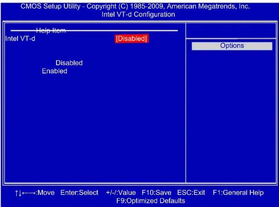
Intel VT-d Configuration

text_image
CMOS Setup Utility - Copyright (C) 1985-2009, American Megatrends, Inc. Intel VT-d Configuration Help Item Intel VT-d [Disabled] Disabled Enabled Options ↑↓←→:Move Enter:Select +/-:Value F10:Save ESC:Exit F1:General Help F9:Optimized DefaultsIntel VT-d
Intel® Virtualization Technology for Directed I/O (VT-d) can improve performance of I/O devices in virtualized environment. This item is used to enable/disable the VT-d feature.
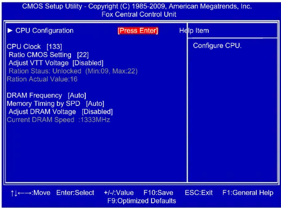
Fox Central Control Unit
text_image
CMOS Setup Utility - Copyright (C) 1985-2009, American Megatrends, Inc. Fox Central Control Unit ►CPU Configuration [Press Enter] Help Item CPU Clock [133] Ratio CMOS Setting [22] Adjust VTT Voltage [Disabled] Ration Staus: Unlocked (Min.09, Max:22) Ration Actual Value:16 DRAM Frequency [Auto] Memory Timing by SPD [Auto] Adjust DRAM Voltage [Disabled] Current DRAM Speed :1333MHz ↑↓←→:Move Enter:Select +/-:Value F10:Save ESC:Exit F1:General Help F9:Optimized Defaults▶ CPU Configuration
Press
▶ CPU Clock
This item is used to adjust the CPU Clock.
▶ Ratio CMOS Setting
This item is used to set the ratio between CPU Core Clock and the FSB Frequency. You can use [+] or [-] to adjust the value.
▶ Adjust VTT Voltage
This item is used to set the CPU VTT voltage.
▶ DRAM Frequency
This item is used to adjust the memory speed. Select [Auto] for SPD enable mode. You can select a value manually such as [800 MHz], [1067 MHz] and [1333MHz].
▶ Memory Timing by SPD
This item is used to enable/disable provision of DRAM timing by SPD device. The Serial Presence Detect (SPD) device is a small EEPROM chip, mounted on a memory module. It contains important information about the module's speed, size, addressing mode and various other parameters, so that the motherboard memory controller (chipset) can better access the memory device.
Select [Auto] for SPD enable mode.
Select [Manual] to set the parameters by yourself.
The following 10 settings are valid only when the Memory Timing by SPD is set to [Manual].
▶ DRAM tCL
The number of memory clocks it takes a DRAM to return data after the read CAS_L is asserted depends on the memory clock frequency. The value that BIOS programs into the memory controller is a function of the target clock frequency. The target clock frequency is determined from the supported CAS latencies at given clock frequencies of each DIMM.
▶ DRAM tRAS (Active-to-Precharge Delay)
This item allows you to set the minimum RAS# active time (in clock cycles).
▶ DRAM tRP (Precharge Command Period)
This item allows you to select the row precharge time (in clock cycles).
▶ DRAM tRCD (RAS-to-CAS Delay)
This item allows you to select a delay time (in clock cycles) between the CAS# and RAS# strobe signals.
▶ DRAM tWR (Write Recovery)
This item allows you to select the write recovery time (in clock cycles).
▶ DRAM tRFC(Auto-Refresh-to-Active/Auto-Refresh Command Period)
Refresh to Refresh or Refresh to Active command interval.
▶ DRAM tWTR (Internal Write to Read Command Delay)
This item allows you to select a delay time (in clock cycles) between sending the last data from a write operation to the memory and issuing a read command.
▶ DRAM tRRD (Active-to-Active of a Different Bank)
This item allows you to select a delay time (in clock cycles) between the RAS# and RAS# strobe signals.
▶ DRAM tRTP (Internal Read to Precharge Command Delay)
This item allows you to set the delay time (in clock cycles) between read command and pre-charge command.
▶ DRAM tFAW(Four Active Window Delay)
Specifies the time window in which four activates are allowed the same rank.
▶ Adjust DRAM Voltage
This item is used to change the memory voltage.

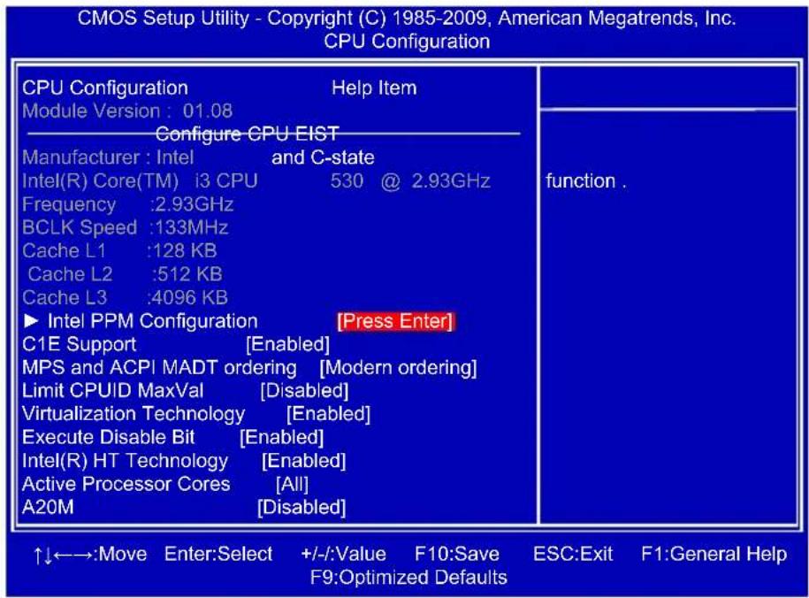
CPU Configuration
text_image
CMOS Setup Utility - Copyright (C) 1985-2009, American Megatrends, Inc. CPU Configuration CPU Configuration Help Item Module Version : 01.08 Configure CPU EIST Manufacturer : Intel and C-state Intel(R) Core(TM) i3 CPU 530 @ 2.93GHz Frequency :2.93GHz BCLK Speed :133MHz Cache L1 :128 KB Cache L2 :512 KB Cache L3 :4096 KB ► Intel PPM Configuration [Press Enter] C1E Support [Enabled] MPS and ACPI MADT ordering [Modern ordering] Limit CPUID MaxVal [Disabled] Virtualization Technology [Enabled] Execute Disable Bit [Enabled] Intel(R) HT Technology [Enabled] Active Processor Cores [All] A20M [Disabled] function . ↑↓←→:Move Enter:Select +/-/::Value F10:Save ESC:Exit F1:General Help F9:Optimized DefaultsIntel PPM Configuration
Press
▶ C1E Support (Appears only when CPU supports)
C1E represents Enhanced HALT State. It is a feature which CPU uses to reduce power consumption when in halt state. C1E drops the CPU's multiplier and voltage to lower levels when a HLT (halt) command is issued. This item is used to enable/disable the C1E support.
▶ MPS and ACPI MADT ordering
[Modern ordering] : for Windows XP or later OSes.
[Legacy ordering] : for Windows 2000 or earlier OSes.
▶ Limit CPUID MaxVal
This item is used to enable or disable CPUID maximum value limit configuration. Set [Disabled] for WinXP.
▶ Virtualization Technology
Virtualization (i.e. Intel® Vanderpool Technology) allows a platform to run multiple operating systems and applications in independent partitions or “containers.” One physical compute system can function as multiple “virtual” systems. Vanderpool Technology can help improve future virtualization solutions. This item will be displayed only when the CPU is supporting this feature and the setting is used to enable/disable it.
▶ Execute Disable Bit
This item is used to enable/disable the Execute Disable Bit feature.
Intel's Execute Disable Bit functionality can help prevent certain classes of malicious buffer overflow attacks when combined with a supporting operating system.
Execute Disable Bit allows the processor to classify areas in memory by where application code can execute and where it cannot. When a malicious worm attempts to insert code in the buffer, the processor disables code execution, preventing damage and worm propagation.
Replacing older computers with Execute Disable Bit-enabled systems can halt worm attacks, reducing the need for virus-related repairs. By combining Execute Disable Bit with anti-virus, firewall, spyware removal, e-mail filtering software, and other network security measures, IT managers can free IT resources for other initiatives.

▶ Intel(R) HT Technology
This item is used to enable/disable the Hyper Threading Technology feature.
▶ Active Processor Cores
This item is used to set the number of cores to enable in each processor package.
▶ A20M
Legacy OSes and APs may need A20M enabled.
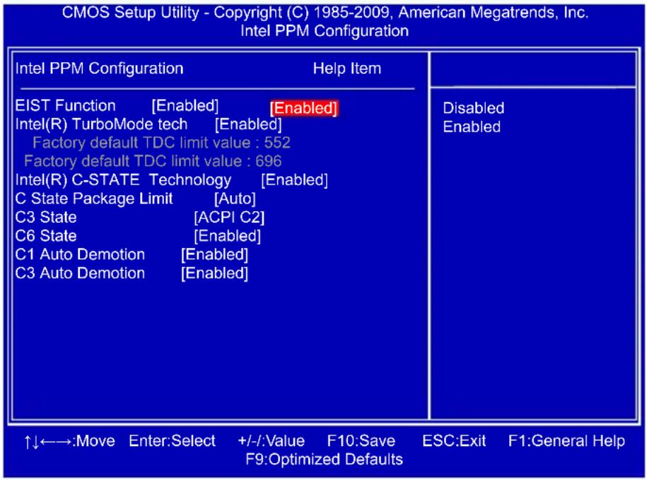
Intel PPM Configuration
text_image
CMOS Setup Utility - Copyright (C) 1985-2009, American Megatrends, Inc. Intel PPM Configuration Intel PPM Configuration Help Item EIST Function [Enabled] [Enabled] Intel(R) TurboMode tech [Enabled] Factory default TDC limit value : 552 Factory default TDC limit value : 696 Intel(R) C-STATE Technology [Enabled] C State Package Limit [Auto] C3 State [ACPI C2] C6 State [Enabled] C1 Auto Demotion [Enabled] C3 Auto Demotion [Enabled] ↑↓←→:Move Enter:Select +/-:Value F10:Save ESC:Exit F1:General Help F9:Optimized Defaults▶ EIST Function
You can select the EIST (Processor Power Management, PPM) through this item.

Enhanced Intel SpeedStep® technology (EIST) allows the system to dynamically adjust processor voltage and core frequency, which can result in decreased average power consumption and decreased average heat production. There are some system requirements must be met, including CPU, chipset, motherboard, BIOS and operation system. Please refer to Intel Website for more information.
Intel(R) TurboMode tech
Turbo mode allows processor cores to run faster than its marked frequency in specific condition.
▶ Intel(R) C-STATE Technology
This item is used to enable/disable C-State. C-State means CPU idle is set to C2/C3/C4.
▶ CState package limit setting
This item appears only when the Intel(R) C-STATE Technology is set to "Enabled". It is used to select the C-State mode, set to "Auto" can allow BIOS to detect the C-State mode that supported by your CPU.
▶ C3 State
This item is used to enable/disable C3 State.
▶ C6 State
This item is used to enable/disable C6 State.
▶ C1 Auto Demotion
When enabled, CPU will conditionally demote C3/C6/C7 requests to C1 based on uncore auto-demote information.
▶ C3 Auto Demotion
When enabled, CPU will conditionally demote C6/C7 requests to C3 based on uncore autodemote information.
Advanced Chipset Features

text_image
CMOS Setup Utility - Copyright (C) 1985-2009, American Megatrends, Inc. Advanced Chipset Features IMC Type : *Dale Family IMC Management Engine Version : N/A Memory Remap Feature [ [Disabled] PCI MMIO Allocation: 4GB To 3328MB Initiate Graphic Adapter [PEG/IGD] SLP_S4# Min. Assertion Width [1 to 2 seconds] Help Item ENABLE: Allow remapping of overlapped PCI memory above the total physical memory. DISABLE: Do not allow remapping of memory. ↑↓←→:Move Enter:Select +/-:Value F10:Save ESC:Exit F1:General Help F9:Optimized Defaults▶ Memory Remap Feature
This item is used to enable/disable memory remapping around memory hole.
PCI doesn't actually care much which addresses are used, but by convention the PC platform puts them at the top of the 32-bit address space. For many years it wasn't possible or practical to put that much RAM into a PC. But now it is, so it's up to the memory controller and host bridge to figure out what to do. Many systems cause that high RAM to simply be ignored, resulting in the loss of effective RAM. More complex systems will take the RAM that would occupy that 3.5-4GB address space and re-map it into the 4.0-4.5GB address space. The RAM doesn't care because it's just an array of storage cells, it's up to the memory controller to associate addresses with those storage cells. Of course, that only works if you're using a 64-bit (or 32bit physical address extension (PAE) enabled) OS that can deal with physical addresses larger than 32 bits. Once this option is enabled, BIOS will display the true size of memory installed.
▶ Initiate Graphic Adapter
This item is used to select which graphics controller is used as the primary boot device.
▶ SLP\_S4# Min. Assertion Width
SLP_S4# is a signal for power plane control. This signal shuts off power to all non-critical systems when in the S4 (Suspend to Disk) or S5 (Soft Off) state.
This setting indicates the minimum assertion width of the SLP_S4# signal to ensure that the DRAMs have been safely power-cycled. Setting values are: [4 to 5 seconds], [3 to 4 seconds], [2 to 3 seconds], [1 to 2 seconds].

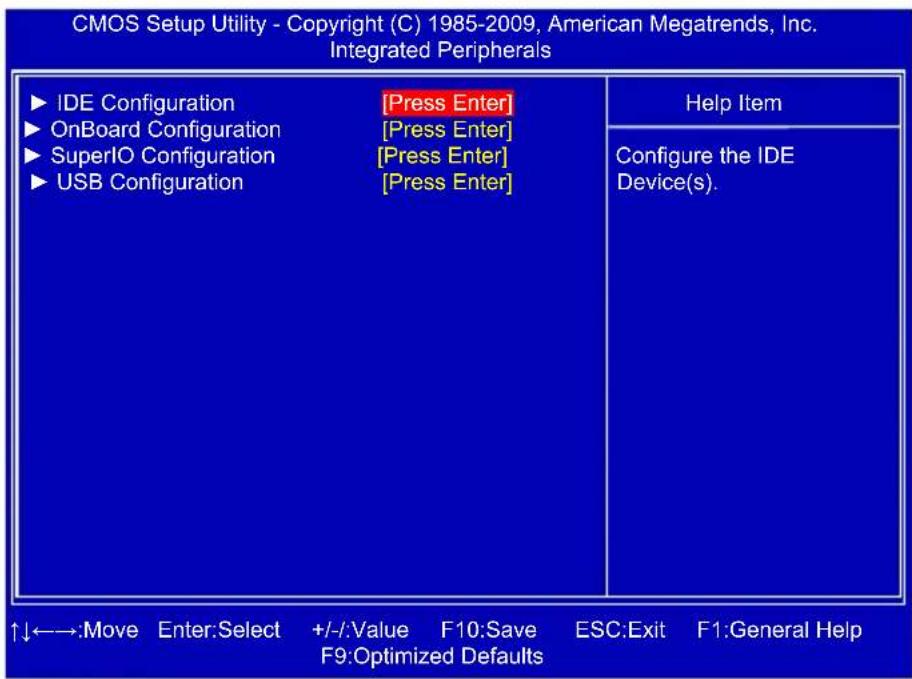
Integrated Peripherals
text_image
CMOS Setup Utility - Copyright (C) 1985-2009, American Megatrends, Inc. Integrated Peripherals ►IDE Configuration [Press Enter] ►OnBoard Configuration [Press Enter] ►SuperIO Configuration [Press Enter] ►USB Configuration [Press Enter] ↑↓←→:Move Enter:Select +/-:Value F10:Save ESC:Exit F1:General Help F9:Optimized Defaults Help Item Configure the IDE Device(s).▶ IDE Configuration/OnBoard Configuration/SuperIO Configuration/USB Configuration
Press
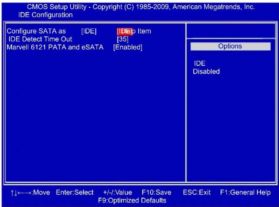
IDE Configuration
text_image
CMOS Setup Utility - Copyright (C) 1985-2009, American Megatrends, Inc. IDE Configuration Configure SATA as [IDE] [DE]p Item IDE Detect Time Out [35] Marvell 6121 PATA and eSATA [Enabled] Options IDE Disabled ↑↓←→:Move Enter:Select +/-:Value F10:Save ESC:Exit F1:General Help F9:Optimized Defaults▶ Configure SATA as
This item is used to set the operation mode of your SATA ports 1, 2, 3, 4, 5, 6. Set to [IDE] can configure the SATA ports to support IDE mode.
▶ IDE Detect Time Out
This item is used to select the time out value for detecting ATA/ATAPI devices. If the checking time is over the set value, the system will skip it.
▶ Marvell 6121 PATA and eSATA
This item is used to enable or disabled the IDE devices and eSATA.

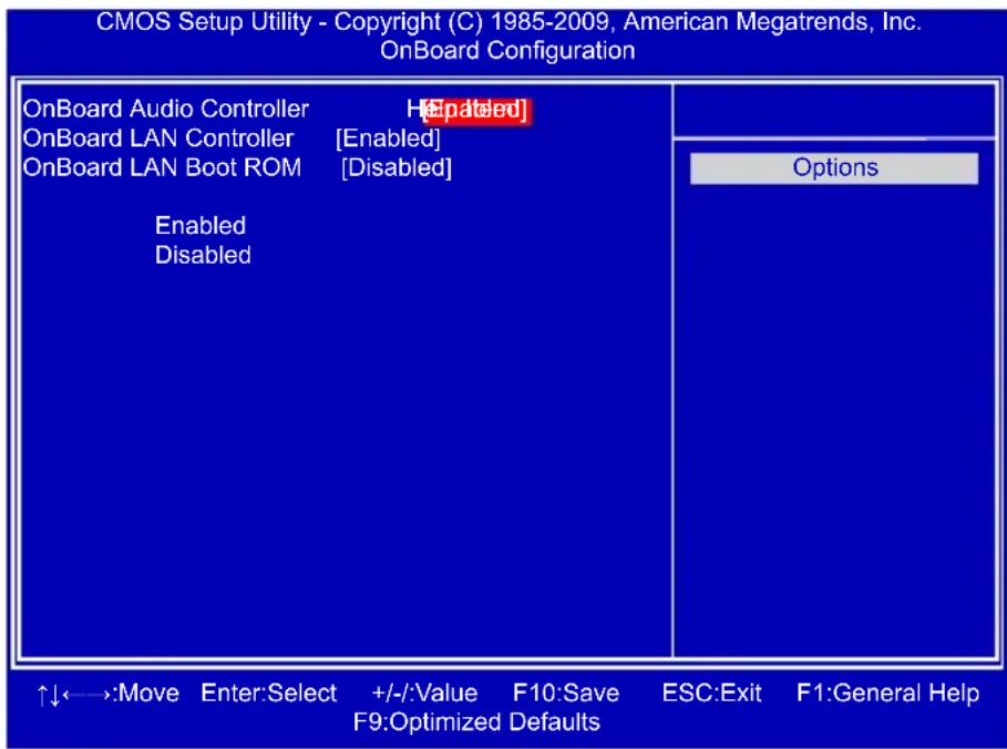
OnBoard Configuration
text_image
CMOS Setup Utility - Copyright (C) 1985-2009, American Megatrends, Inc. OnBoard Configuration OnBoard Audio Controller H[Enabled] OnBoard LAN Controller [Enabled] OnBoard LAN Boot ROM [Disabled] Enabled Disabled Options ↑↓←→:Move Enter:Select +/-:Value F10:Save ESC:Exit F1:General Help F9:Optimized Defaults▶ OnBoard Audio Controller
This item is used to enable or disable the HD Audio controller.
▶ OnBoard LAN Controller
This item is used to enable or disable the onboard LAN controller.
▶ OnBoard LAN Boot ROM
This item is used to enable or disable the onboard LAN boot optional ROM. A LAN boot ROM lets you set up a diskless workstation on the network. By installing a boot ROM in the network board, you can enable a client PC system on the network to be booted remotely.

SuperIO Configuration

text_image
CMOS Setup Utility - Copyright (C) 1985-2009, American Megatrends, Inc. SuperIO Configuration SuperIO Configuration Help Item Serial Port1 Address [3F8/IRQ4][3F8/IRQ4] Allows BIOS to Select Serial Port1 Base Addresses. ↑↓←→:Move Enter:Select +/-:Value F10:Save ESC:Exit F1:General Help F9:Optimized Defaults▶ Serial Port1 Address
This item is used to assign the I/O address and interrupt request (IRQ) for the onboard serial port 1.

USB Configuration

text_image
CMOS Setup Utility - Copyright (C) 1985-2009, American Megatrends, Inc. USB Configuration USB Configuration Help Item Module Version - 2.24.5-13.4 USB Devices Enabled : 2 Hubs Legacy USB Support [Enabled] USB 2.0 Controller Mode [HiSpeed] BIOS EHCI Hand-Off [Enabled] ↑↓←→:Move Enter:Select +/-/::Value F10:Save ESC:Exit F1:General Help F9:Optimized Defaults▶ Legacy USB Support
This item is used to enable the support for USB devices on legacy OS. If you have a USB keyboard or mouse, set to auto or enabled.
▶ USB 2.0 Controller Mode
This item is used to set the transmission rate mode of USB 2.0. The available settings are : [HiSpeed] in 480Mbps; [Full Speed] in 12Mbps.
▶ BIOS EHCI Hand-Off
Windows XP supports a number of features in the Enhanced Host Controller Interface (EHCI) specification, but there are a few features that are not implemented. Microsoft said preliminary support for EHCI BIOS handoff will be available in Windows XP SP2.
This item allows you to enable support for OS without EHCI hand-off feature.
This is a workaround for OS without EHCI hand-Off support.
The EHCI ownership change should claim by EHCI driver.

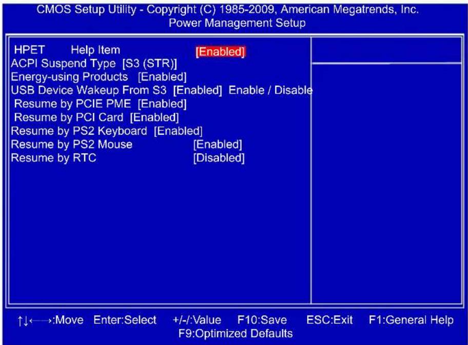
Power Management Setup
text_image
CMOS Setup Utility - Copyright (C) 1985-2009, American Megatrends, Inc. Power Management Setup HPET Help Item [Enabled] ACPI Suspend Type [S3 (STR)] Energy-using Products [Enabled] USB Device Wakeup From S3 [Enabled] Enable / Disable Resume by PCIE PME [Enabled] Resume by PCI Card [Enabled] Resume by PS2 Keyboard [Enabled] Resume by PS2 Mouse [Enabled] Resume by RTC [Disabled] ↑↓←→:Move Enter:Select +/-:/Value F10:Save ESC:Exit F1:General Help F9:Optimized DefaultsACPI (Advanced Configuration and Power Interface) is an open industry standard interfaces enabling OS-directed configuration, power management, and thermal management of mobile, desktop, and server platforms. It defines five sleeping states, they are :
S1 - The S1 sleeping state is a low wake latency sleeping state. In this state, no system context is lost (CPU or chip set) and hardware maintains all system context. (also called Power On Suspend)
S2 - The S2 sleeping state is a low wake latency sleeping state. This state is similar to the S1 sleeping state except that the CPU and system cache context is lost (the OS is responsible for maintaining the caches and CPU context). Control starts from the processor's reset vector after the wake event.
S3 - The S3 sleeping state is a low wake latency sleeping state where all system context is lost except system memory. CPU, cache, and chip set context are lost in this state. Hardware maintains memory context and restores some CPU and L2 configuration context. Control starts from the processor's reset vector after the wake event. (also called Suspend to RAM)
S4 - The S4 sleeping state is the lowest power, longest wake latency sleeping state supported by ACPI. In order to reduce power to a minimum, it is assumed that the hardware platform has powered off all devices. Platform context is maintained. (also called Suspend to Disk)
S5 - The S5 state is similar to the S4 state except that the OS does not save any context. The system is in the “soft” off state and requires a complete boot when it wakes. Software uses a different state value to distinguish between the S5 state and the S4 state to allow for initial boot operations within the BIOS to distinguish whether or not the boot is going to wake from a saved memory image.

HPET
HPET stands for High Precision Even Timer. If you have the HPET disabled, then windows does not have access to it and therefore falls back to less accurate timing methods. This item is used to enable or disable the HPET Support.
▶ ACPI Suspend Type
This item is used to set the energy saving mode of the ACPI function. When you select "S1 (POS)" mode, the power is always on and computer can be resumed at any time. When you select "S3 (STR)" mode, the power will be down after a period of time. The status of the computer before it entering STR will be saved in memory, and the computer can quickly return to previous state when the STR function wakes.
When you select "Auto", it means OS will automatically take care and assign which mode is the most suitable now.
▶ Energy-using Products
This item is used to enable/disable the EuP(Energy-using Products) feature. When enable, the suspend power of the chipset will be cut off in S5 suspend mode in order to reduce the power consumption of motherboard.
Enable: S1/S3/S4 is normal, S5 wake up only by pressing the power button.
Disable: Normal ACPI function.
▶ USB Device Wakeup From S3
This item is used to wake up the system by a USB device when it is staying at S3 state.
▶ Resume by PCIE PME
This item is used to enable/disable the PCI Express device to generate a wake up.
▶ Resume by PCI Card
This item is used to enable/disable the PCI card to generate a wake up.
▶ Resume by PS2 Keyboard
This item is used to enable/disable the PS2 keyboard to generate a wake up.
▶ Resume by PS2 Mouse
This item is used to enable/disable the PS2 mouse to generate a wake up.
▶ Resume by RTC
This item is used to enable/disable RTC alarm event to generate a wake up. RTC is system real time clock.
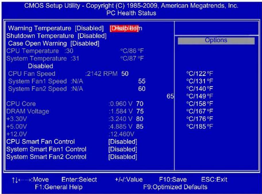
PC Health Status
text_image
CMOS Setup Utility - Copyright (C) 1985-2009, American Megatrends, Inc. PC Health Status Warning Temperature [Disabled] Disabled Shutdown Temperature [Disabled] Case Open Warning [Disabled] CPU Temperature :30 °C/86 °F System Temperature :31 °C/87 °F Disabled CPU Fan Speed :2142 RPM 50 System Fan1 Speed :N/A 55 System Fan2 Speed :N/A 60 CPU Core :0.960 V 70 DRAM Voltage :1.584 V 75 +3.30V :3.240 V 80 +5.00V :4.885 V 85 +12.0V :12.460V CPU Smart Fan Control [Disabled] System Smart Fan1 Control [Disabled] System Smart Fan2 Control [Disabled] Options °C/122 °F °C/131 °F °C/140 °F °C/149 °F °C/158 °F °C/167 °F °C/176 °F °C/185 °F ↑↓←→:Move Enter:Select +/-:Value F10:Save ESC:Exit F1:General Help F9:Optimized Defaults▶ Warning Temperature
This option is used to set the warning temperature for the system. When the temperature of CPU is higher than the set value, the motherboard will send out warning information.
▶ Shutdown Temperature
This item is used to set the system temperature upper limit. When the temperature exceeds the set value, the system will shut down automatically. This function works only when your operating system is supporting ACPI.
▶ Case Open Warning
This item is used to enable or disable case open warning function.
▶ CPU/System Temperature
The CPU/System temperature are automatically detected and displayed by the system.
▶ CPU/System Fan1 Speed/System Fan2 Speed
The CPU/System fan speed are automatically detected and displayed by the system.
▶ CPU Core/DRAM Voltage/+3.30V/+5.00V/+12.0V
The current voltages are automatically detected and displayed by the system.
▶ CPU Smart Fan/System Smart Fan1/ System Smart Fan2 Control
This option is used to enable or disable smart fan function.
The following 4 settings are valid only when Smart Fan Control is set to [Enabled].
▶ Fan OFF Temperature
It allows you set a temperature value from which smart fan stops its operation.
▶ PWM Start Temperature
It allows you set a temperature value from which smart fan starts its operation.
▶ Start PWM Value
It allows you to set an initial PWM value to drive the fan when the temperature reaches Start value and smart fan begins its operation. The higher PWM value can achieve the faster fan speed.
▶ Slope PWM Value
The slope controls the PWM value being stepped up or down versus temperature changes.
BIOS Security Features

text_image
CMOS Setup Utility - Copyright (C) 1985-2005, American Megatrends, Inc. BIOS Security Features Security Settings Help Item Supervisor Password : Installed Install or Change the User Password : Installed password. Change Supervisor Password [Press Enter] User Access Level [Full Access] Change User Password [Press Enter] Clear User Password [Press Enter] Password Check [Setup] ↑↓←→:Move Enter:Select +/-:Value F10:Save ESC:Exit F1:General Help F9:Optimized Defaults▶ Change Supervisor Password
This item is used to install or change supervisor password.
After you input Supervisor password, it then will ask you to input user password optionally.

text_image
Enter New Password :▶ User Access Level
This item is used to set user access level.
The available settings are:
[No Access]: Prevent user access to the setup utility.
[View Only]: Allow access to the setup utility but the fields can not be changed.
[Limited]: Allow only limited fields to be changed, such as date and time.
[Full Access]: Allow any field to be changed except the supervisor password.
▶ Change User Password
This item is used to install or change user password.
▶ Clear User Password
This item will be displayed only when a User Password was set before. It is used to clear the user password.
▶ Password Check
When it is set to [Setup], a password is required to enter the BIOS setup; select [Always], a password is required not only to enter BIOS setup, but also on each boot of your PC.

Load Optimal Defaults
Optimal defaults are the best settings of this motherboard. Always load the Optimal defaults after updating the BIOS or after clearing the CMOS values.
Select this option and press Enter, it will pop out a dialogue box to let you load the defaults. Select
Load Optimal Defaults?

[Cancel]
By this default, BIOS have set the optimal performance parameters of system to improve the performances of system components. But if the optimal performance parameters to be set cannot be supported by your hardware devices (for example, too many expansion cards were installed), the system might fail to work.
Save & Exit Setup
When you select this option and press
Select [OK] to save your changes to CMOS and exit the program, select [Cancel] or
Save configuration changes and exit setup?

[Cancel]
Exit Without Saving
If you select this option and press
Select [OK] to exit CMOS without saving your modifications, select [Cancel] or
Discard changes and exit setup?

[Cancel]

text_image
4The utility CD that came with the motherboard contains useful software and several utility drivers that enhance the motherboard features.
This chapter includes the following information:
■ Install driver and utility
FOX ONE
FOX LiveUpdate
FOX LOGO
FOX DMI
Note : Because each module is independent, so the section number will be reorganized and unique to each module, please understand.
Install driver and utility
This motherboard comes with one Utility CD, after installing the Oprating System, You can simply put it into your CD/DVD-ROM drive, and the main menu will be displayed on your PC screen to guide you how to install.
1. Driver
Use these options to install all the drivers for your system. You must click "Intel Chipset Driver" to install it first. After that, you can click "One Click Setup" and then choose the items you want to install, or you can click on each individual driver to install it manually.

text_image
Driver Please install the drivers from top to bottom in turn Intel Chipset Driver VIA HDA Audio Driver Resitek LAN Driver Intel VBA Driver Intel Management Engine Driver One Click Setup Click to visit Foxconn's website Select to Install Utilities Select to Install Drivers Browse CD Drop to System Tray Manual Installation Step by Step Automatic Installation by One Click. Exit the program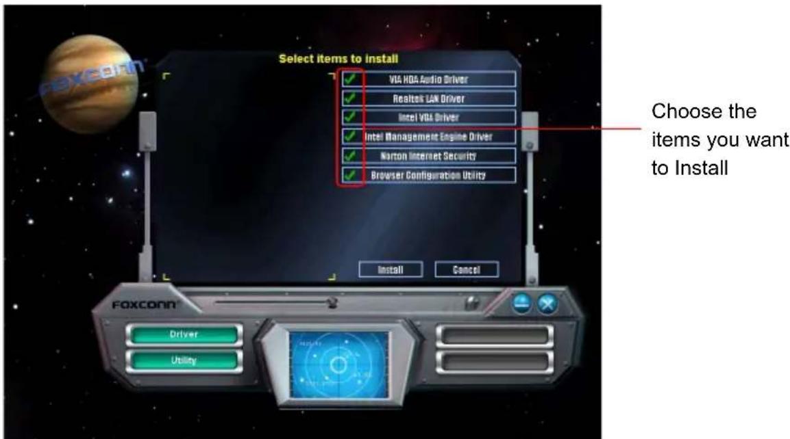
text_image
Select items to install VIA HDA Audio Driver Realtek LAN Driver Intel VGA Driver Intel Management Engine Driver Norton Internet Security Browser Configuration Utility Choose the items you want to Install Install Cancel Foxconn Driver Utility2. Utility
Use these options to install additional software programs.


text_image
Utility FOX ONE FOX LiveUpdate FOX LOGO FOX OM Microsoft Direct2.9.0 Adobe Acrobat Reader Norton Internet Security Browser Configuration Utility Foxconn® Driver UtilityFOX ONE
FOX ONE is a powerful utility for easily modifying system settings. It also allows users to monitor various temperature values, voltage values, frequencies and fan speeds at any time.
With FOX ONE, you can :
■ Modify system performance settings, such as the CPU and memory bus speeds, CPU voltages, fan speeds, and other system performance options.
■ Monitor hardware temperatures, voltages, frequencies and fan speeds.

Depending on hardware support, voltage monitoring and Fox Intelligent Stepping features are optional and only supported in some models. If the option is selectable, it also means the feature is supported.
■ Voltage Monitoring is supported only in FOX ONE Premium & Deluxe products.
■ Fox Intelligent Stepping is supported only in FOX ONE Deluxe products.
Supporting Operating Systems :
■ Windows 2000 ■ Windows XP (32-bit and 64-bit)
■ Windows 2003 (32-bit and 64-bit) ■ Windows Vista (32-bit and 64-bit)
■ Windows 7 (32-bit and 64-bit)
Using FOX ONE :
The very first time you run FOX ONE, F.I.S. Calibration function (FOX Intelligent Stepping) will require you to calibrate the CPU's loading. Click "OK" to proceed and start the Utility. F.I.S. is a feature of FOX ONE, which can automatically adjust your

text_image
F.I.S. Calibration (FOX Intelligent Stepping) To run this program for the very first time, it need to calibrate the CPU's loading. And it may take several minutes to process. Please keep the system as calm as possible during calibrating.
Before you running the FOX ONE program, the system parameters (such as CPU clock, voltage...etc.) are controlled by BIOS settings. After you run FOX ONE, it will take over, and the controlling right will be transferred to FOX ONE. Later, if you exit FOX ONE, then BIOS control will be back again.

1. Main Page

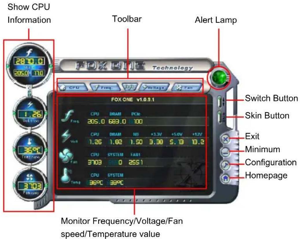
text_image
Show CPU Information 2870.0 205.0 170 Toolbar Alert Lamp FOX ONE v1.0.9.1 Switch Button Skin Button Exit Minimum Configuration Homepage Monitor Frequency/Voltage/Fan speed/Temperature valueToolbar
Use the toolbar to navigate to other pages.
Alert Lamp
When the system is in healthy state, the color of alert lamp is green. When the system is in abnormal state, the alert lamp color is red.
Switch Button
Click this button, it will simplify the whole FOX ONE control panel to a smaller information bar (i.e. Simple Mode) as depicted below, you can drag this bar to any place on your screen to help you monitoring system status.

text_image
Exit FOX ONE CPU Frequency 2870 MHz Click here to go back to FOX ONE full screen Click here will drop the FOX ONE to Windows system traySkin Button
There are more choices of FOX ONE screen panels. Click this button, you can select your favorite skin (FOX ONE Panel).

text_image
FOX ONE Technology Select Skin Current Select Default Click the new skin picture to select the new skin Crystal OK Cancel Apply the changes Cancel the changesExit
Click this button to exit the program.
Minimum
Click this button to drop the FOX ONE to Windows system tray located at the lower

text_image
7:38 PMright corner of your screen.
Homepage
Click this button to visit Foxconn motherboard website :
http://www.foxconnchannel.com
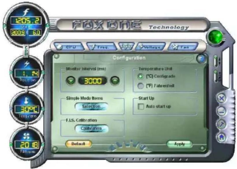
Configuration
This menu allows you to configure :
1). Monitor interval (ms):
This is to define the interval of different messages of system settings which are to

text_image
FOX ONE Technology CPU Freq. Voltage Fan Configuration Monitor Interval (ms) 3000 Temperature Unit (°C) Configrade (°F) Fahrenheit Simple Mode Items Selection Start Up Auto start up F.I.S. Calibration Calibration Default Applybe displayed on Simple Mode screen. Minimum value is 1 second.
2). Simple Mode :
To select which message of system settings are to be displayed in the Simple Mode. Messages such as CPU frequency, voltage...etc., they can be displayed one
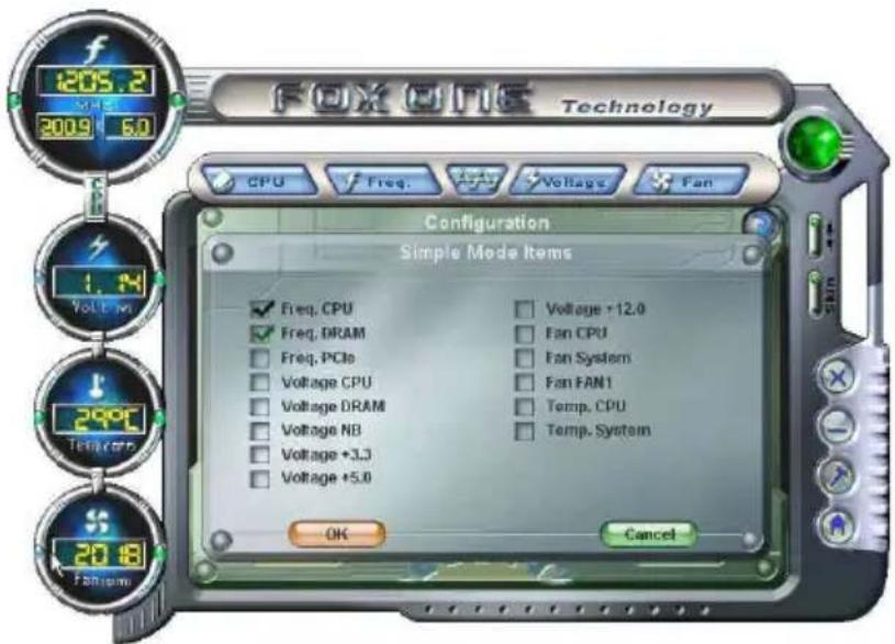
text_image
FOX ONE Technology CPU Freq. Voltage Fan Configuration Simple Mode Items Freq. CPU Freq. DRAM Freq. PCIe Voltage CPU Voltage DRAM Voltage NB Voltage +3.3 Voltage +5.0 Voltage +12.0 Fan CPU Fan System Fan FRN1 Temp. CPU Temp. System OK Cancelby one in Simple Mode.
3). F.I.S. Calibration (FOX Intelligent Stepping, Optional)
This function will re-calibrate the CPU's loading, and it may take several minutes to proceed. The FOX ONE calibration process will apply different loadings to your CPU, record PWM IC voltage together with the CPU clock running at these loadings, so it can define and estimate within a particular range of system loading,
what the CPU clock should be.
Step 1 : Click Calibration icon, a message pops out to ask for continue. Select Yes.

text_image
FOXONE Technology CPU Freq. Voltage Fan Configuration F.I.S. Calibration (FOX Intelligent Stepping) This function will re-calibrate the CPU's loading. And it may take several minutes to process. Please keep the system as calm as possible during calibration. On get ways to continue? Yes No
Step 2 : After data is collected, it will ask you to restart your computer now.

text_image
FOX ONE Technology CPU Freq Voltage Fan Configuration Monitor Interval (ms) - Torporation Unit Question To apply the new setting, you need to restart your computer. Do you want to repeat the computer now. Yes No Default ApplyLater on, when the FOX ONE program is activated, and F.I.S. feature (in CPU Page) is also enabled, FOX ONE will automatically adjust your CPU clock according to your system loadings. (Loadings are like Power Gaming, Data Mining...etc.)
2. CPU Page - CPU Control
This page lets you select (or overclock) CPU clock to meet the current performance level of the system. The fastest and suitable CPU clock running for current system can be calculated by FOX ONE automatically or manually input by yourselves.
Manual :
You can press the up/down button to adjust your CPU clock.
Auto :
Click this button to let FOX ONE check the highest CPU clock you can use. System will raise the CPU clock step by step until it hangs, you can then push the RESET button on your PC panel to restart the system. When system restarts, run FOX ONE again, it will display a recommended highest CPU clock for you, click
Go to CPU page Adjust by manual

text_image
FOX ONE Technology CPU Control Manual Auto Adjustment 20:1 (MHz) FOX Intelligent Stepping Auto Power Generation Data Mining Other Default ApplyReset the changes
FIS Features : Select the different benchmarks
Apply the changes
Press Auto button to let FOX ONE check the highest CPU clock you can use.

text_image
FOX ONE Technology CPU Control Auto OverClock This function will overclock the CPU automatically. Note: if the system hangs during the over-cloching process, please reset the system by providing theA message informs you to push RESET button later if the system hangs finally. Click Yes to continue.

text_image
FOX ONE Technology PressYou can see the system is raising CPU clock until the system hangs.
Push RESET button on the front panel of your system to restart the computer.


text_image
FOXONE Technology Auto OverClock The suggested CPU frequency of the Auto Overclocking process is: CPU Frequency 255 MHz Do you want to apply this frequency now! +12V 11.7 Yes No CPU SYSTEM Temp 33°C 34°CRun FOX ONE program again, it will inform you the previous test found that 255MHz is the recommended CPU clock for your system. Click Yes to apply it to your system.
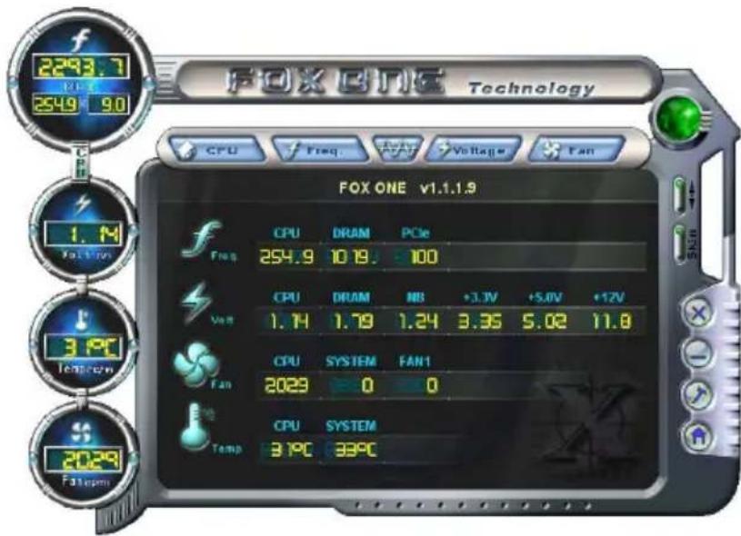
text_image
FOX ONE Technology CPU Freq Fan Voltage Fan FOX ONE v1.1.1.9 CPU DRAM PCIe 254.9 10.19: 100 CPU DRAM NB +3.3V +5.0V +12V 1.14 1.79 1.24 3.35 5.02 11.8 3.9°C Fan 2023 0 0 CPU SYSTEM Temp 3.9°C 33°CNow, your system is running at a CPU clock of 255MHz.
FOX Intelligent Stepping (F.I.S., Optional)
Select FOX Intelligent Stepping will allow your system to automatically adjust your CPU clock rate based on different system loadings. For example, if you select Power Gaming, CPU clock will be driven to run at its maximum speed. While in Energy Saving, CPU will lower down its speed to a minimum. The four benchmarks - Power Gaming, Data Mining, Office and Energy Saving, the references of their system loading were calculated and defined in the FIS Calibration option of Configuration menu. Select Auto, CPU will automatically adjust its clock according to current system loading.


text_image
FOX ONE Technology CPU Freq Voltage Fan 1.22 Volts-on 30°C Temp/cur 20:40 Fareuping CPU Control Manual/Auto Adjustment (MHz) Control at Stopping Auto Power Gaming Data Mining Office Energy Saving Default Apply3. Frequency Page - Frequency Control
This page lets you set memory and PCI Express frequencies by manual.
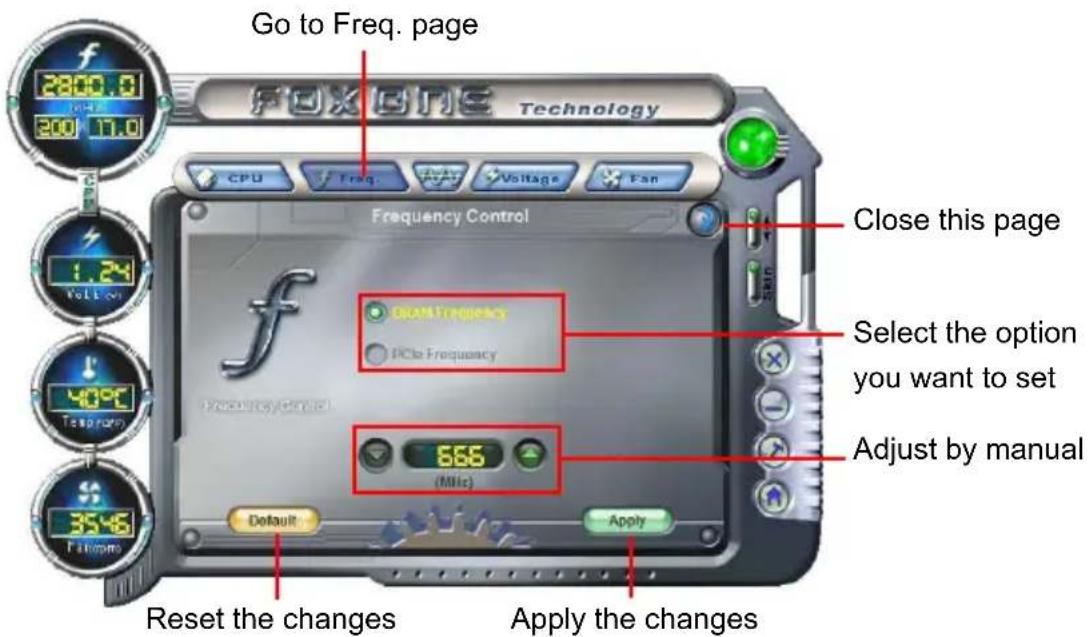
text_image
Go to Freq. page Fox One Technology CPU Freq. Voltage Fan Frequency Control Close this page Select the option you want to set Adjust by manual 666 (MHz) Default Apply Reset the changes Apply the changes4. Limit Setting
4.1 Limit Setting - CPU Temperature
This page lets you to set CPU high limit temperature and enable the alert function.
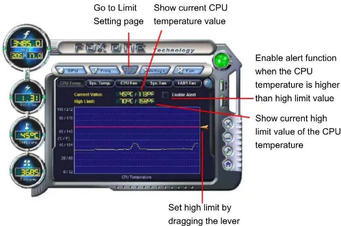
text_image
Go to Limit Setting page Show current CPU temperature value Enable alert function when the CPU temperature is higher than high limit value Show current high limit value of the CPU temperature Set high limit by dragging the lever
4.2 Limit Setting - System Temperature
This page lets you to set system high limit temperature and enable the alert function.
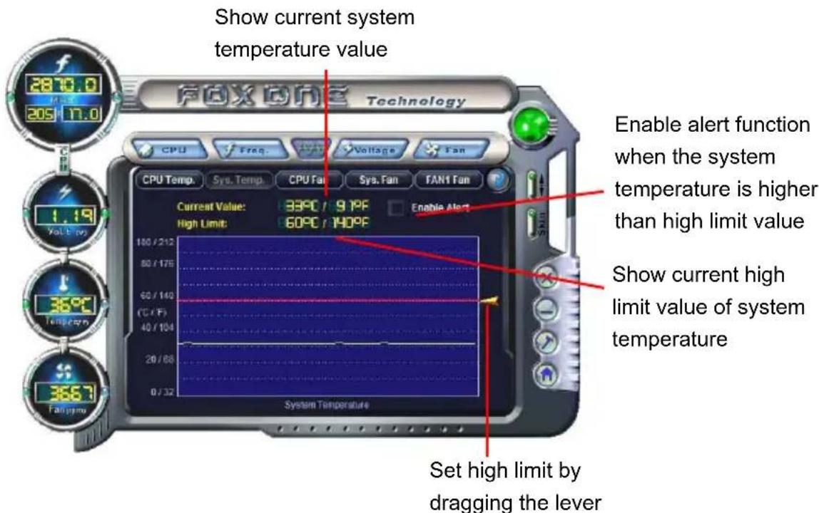
text_image
Show current system temperature value 2870.0 205 17.0 Fox One Technology CPU Freq. Voltage Fan CPU Temp. Sys. Temp. CPU Fan Sys. Fan FAN1 Fan Current Value: 33°C / 9.1°F Enable Alert High Limit: 60°C / 140°F 100 / 212 50 / 175 60 / 140 (°C / °F) 40 / 104 20 / 68 0 / 32 System Temperature Enable alert function when the system temperature is higher than high limit value Show current high limit value of system temperature Set high limit by dragging the lever4.3 Limit Setting - CPU Fan
This page lets you to set CPU fan low limit rpm and enable the alert function.

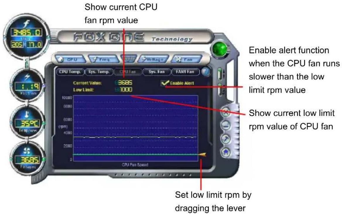
text_image
Show current CPU fan rpm value FOX ONE Technology CPU Temp. Sys. Temp. CPU Fan Sys. Fan FAN1 Fan Current Value: 9685 Low Limit: 97000 Enable Alert when the CPU fan runs slower than the low limit rpm value Show current low limit rpm value of CPU fan Set low limit rpm by dragging the lever4.4 Limit Setting - System Fan
This page lets you to set system fan low limit rpm and enable the alert function.

text_image
Show current system fan rpm value CPU Temp. Sys. Temp. CPU Fan Sys. Fan FAN1 Fan Enable alert function when the system fan runs slower than low limit rpm value Current Value: 8000 0 Low Limit: 91000 Enable Alert Show current low limit rpm value of system fan Set low limit rpm by dragging the lever4.5 Limit Setting - FAN1 Fan
This page lets you to set FAN1 fan low limit rpm and enable the alert function.

text_image
Show current FAN1 fan rpm value Enable alert function when the FAN1 fan runs slower than low limit rpm value Show current low limit rpm value of FAN1 fan Set low limit rpm by dragging the lever
5. Voltage Page - Voltage Control (Optional)
This page lets you set CPU voltage, memory voltage and North Bridge voltage manually. CPU voltage can be stepped up/down by a unit of 12.5mV, while memory is 0.05V/step, and North Bridge is 0.04V/step.

text_image
Go to Voltage page 2870.0 205 17.0 Technology CPU Freq Voltage Fan Voltage Control CPU Voltage Vccrsh DRAM Voltage NB Voltage 0.000 (V) Select the option you want to set Adjust by manual Default Apply Reset the changes Apply the changes6. Fan Page - Fan Control
This page lets you enable Smart Fan function or set the fan speed by manual. When Smart Fan is selected, you must use a 4-pin CPU cooler in your system.

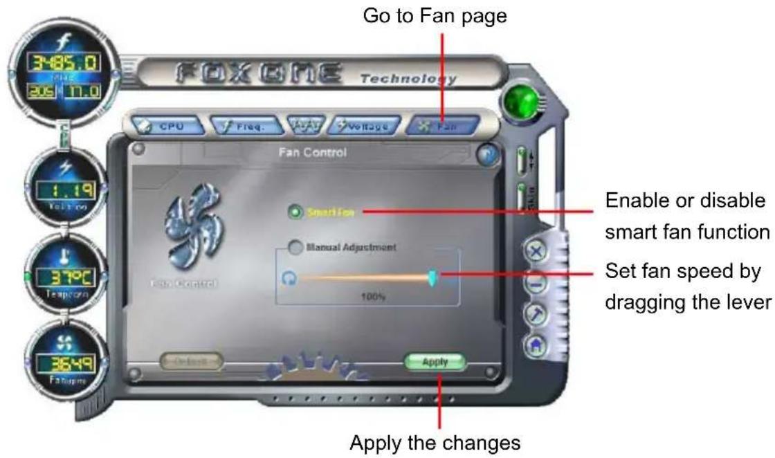
text_image
GO to Fan page FOXONE Technology CPU Freq. A#V Voltage Fan Fan Control Smart Fan Manual Adjustment 100% Enable or disable smart fan function Set fan speed by dragging the lever Apply the changesFOX LiveUpdate
FOX LiveUpdate is a useful utility to backup and update your system BIOS, drivers and utilities by local or online.
Supporting Operating Systems :
Windows 2000
■ Windows XP (32-bit and 64-bit)
■ Windows 2003 (32-bit and 64-bit)
■ Windows Vista (32-bit and 64-bit)
■ Windows 7 (32-bit and 64-bit)

Please set the BIOS setting "BIOS Write Protect" or "Super BIOS Protect" to [Disabled] when running this application.

Using FOX LiveUpdate :
1. Local Update
1-1 Local Update - BIOS Information
This page lets you know your system BIOS information.

text_image
Link to website Minimum FOX LiveUpdate Stronger/Faster and Mare Powerful FOX LiveUpdate Exit Local Update BIOS Info Backup BIOS Update BIOS Current BIOS Information MainBoard Type *** BIOS Version *** Release Date *** BIOS Size *** ROM Part *** Toolbar Show current BIOS information About&Help*** : please refer to the physical motherboard for detail.
1-2 Local Update - Backup
This page can backup your system BIOS. You can click "Backup", and key in a file name, then click "Save" to finish the backup operation. The extension of this backup file is ".BIN" for Award BIOS and ".ROM" for AMI BIOS. Default directory is "C:\Desktop\My Documents" in Windows XP and "Documents" in Vista. Make sure you can remember the file name together with the directory which it is stored, prevented that you may need them to recover your BIOS later.


text_image
FOX LiveUpdate Enter/Faster and More Powerful Save As Save In: Documents Name Date modified Type Size Tags My Music My Pictures My Videos Visual Studio 2005 File name: F.ROM Save Save as type: ROM File (*.ROM) Cancel Configure About&Help Key in a BIOS name Click here1-3 Local Update - Update
This page helps you to update your BIOS from a local file. After click "Update", An alert message will be displayed to ensure if you really want to continue, click "Yes" to confirm. A setup wizard will guide you to load a local BIOS file to finish the operation. You must remember from which directory to load your new BIOS file (with an extension of ".BIN" for Award BIOS, ".ROM" for AMI BIOS) before the setup wizard starts.
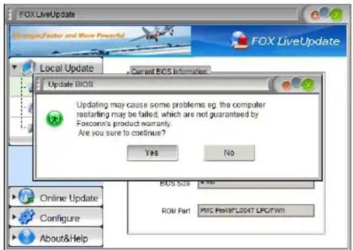
text_image
FOX LiveUpdate Options, Faster and More Powerful Local Update Current BIOS Information Update BIOS Updating may cause some problems eg. the computer restarting may be failed, which are not guaranteed by Foxconn's product warranty. Are you sure to continue? Yes No BIOS Size 4 MB ROW Part PMC Ptn49*L004T LPC/TW1 Online Update Configure About&Help
FOX LiveUpdate can automatically backup old BIOS before update. This feature can be enabled in the "Configure-System" setup. Please refer to "Configure-System" section for more detail. The default backup directory is C:\LiveUpdate_Temp, but the backup file name will be automatically generated. It is hard to find it out from a backup directory and we recommend you using Explorer to check date/time message of this backup file to find it out and write its name down to remember it.
2. Online Update
2-1 Online Update - Update BIOS
This page lets you update your system BIOS from Internet. Click "start", it will search the new BIOS from Internet. Then follow the wizard to finish the update operation.

text_image
Click here FOX LiveUpdate Stronger/Faster and More Powerful FOX LiveUpdate Local Update Online Update Update BIOS Update Driver Update Utility Update All Configure About&Help Current System Information: Operating System: Windows Vista (TM) Ultimate BIOS Information: BIOS Version:P01 Release Date: 01/13/2007 Current information Search new BIOS from server. Start Search new BIOS from Internet
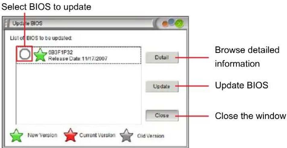
text_image
Select BIOS to update Update BIOS List of BIOS to be updated: 0B3F1P32 Release Date: 11/17/2007 Detail Browse detailed information Update Close the window New Version Current Version Old Version2-2 Online Update - Update Driver
This page lets you update your system drivers from Internet. Click "start", it will search the new drivers from Internet. Then follow the wizard to finish the update operation.

text_image
Click here FOX LiveUpdate Local Update Online Update Update BIOS Update Driver Update Utility Update All Configure About&Help FOX LiveUpdate Current System Information: Operating System: Windows Vista (TM) Ultimate Driver Information: Realtek HDA Audio Driver Version 6.0.1.5464 Current information Search new drivers from Internet Start >Select the driver to update
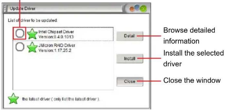
text_image
Update Driver List of driver to be updated: Intel Chipset Driver Version:8.4.0.1013 JMicron RAID Driver Version:1.17.25.2 Detail Install Close the latest driver ( only list the latest driver ) Browse detailed information Install the selected driver Close the window
2-3 Online Update - Update Utility
This page lets you update utilities from Internet. Click "start", it will search the new utilities from Internet. Then follow the wizard to finish the update operation.
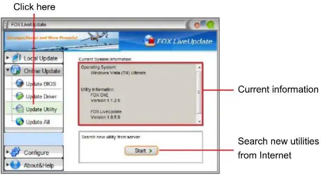
text_image
Click here FOX LiveUpdate Sensors, Faster and More Powerful FOX LiveUpdate Local Update Online Update Update BIOS Update Driver Update Utility Update All Current System Information: Operating System: Windows Vista (TM) Ultimate. Utility Information: FOX ONE Version: 1.1.2.5 FOX LiveUpdate Version: 1.0.5.9 Current information Search new utility from server. Start > Configure About&Help Search new utilities from InternetSelect the utility to update
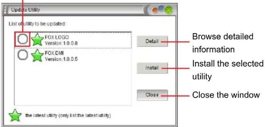
text_image
Update Utility List of utility to be updated: FOX LOGO Version:1.0.0.8 FOX DMI Version:1.0.0.5 Detail Install the selected utility Close the window the latest utility (only list the latest utility)2-4 Online Update - Update All
This page lets you update your system drivers from Internet. Click "start", it will search all new BIOS/drivers/utilities from Internet. Then follow the wizard to finish the update operation.
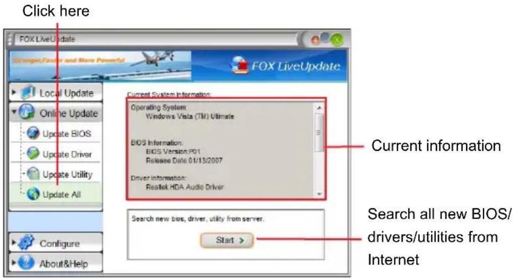
text_image
Click here FOX LiveUpdate Stronger, Factor and More Powerful FOX LiveUpdate Local Update Online Update Update BIOS Update Driver Update Utility Update All Current System Information: Operating System: Windows Vista (TM) Ultimate BIOS Information: BIOS Version: P01 Release Date 01/13/2007 Driver Information: Rastek HDA Audio Driver Current information Search all new BIOS/ drivers/utilities from Internet Start Configure About&Help
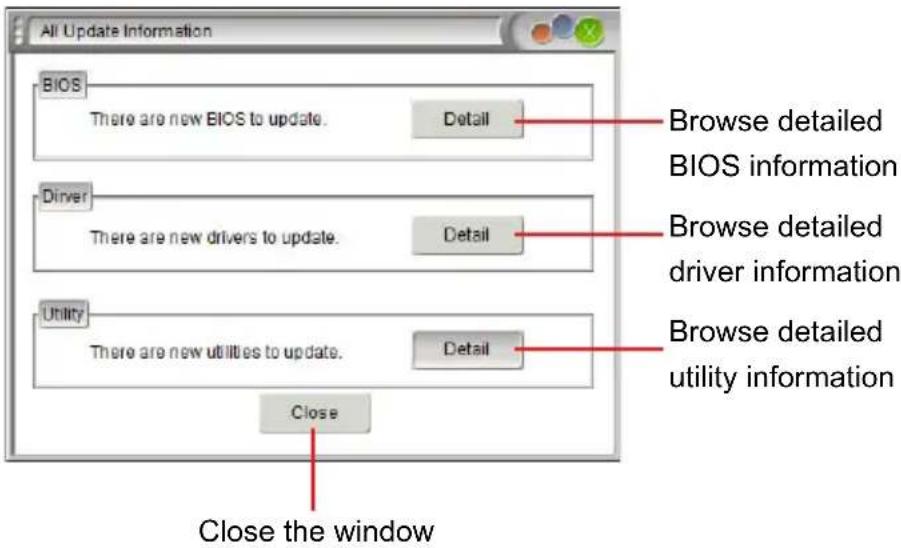
text_image
All Update Information BIOS There are new BIOS to update. Detail Browse detailed BIOS information Driver There are new drivers to update. Detail Browse detailed driver information Utility There are new utilities to update. Detail Browse detailed utility information Close Close the window3. Configure
3-1 Configure - option
This page lets you set auto search options. After you enable the auto search function, FOX LiveUpdate will start its searching from Internet and if any qualified item found, it will pop out a message on the task bar to inform you to do the next step.


text_image
Click here FOX LiveUpdate Analog/Faster and More Powerful FOX LiveUpdate Local Update Online Update Configure Option System Advance About&Help Auto Search Options Enable auto search function Auto Search All Auto Search BIOS Auto Search Driver Auto Search Utility Auto Search FOX LiveUpdate Auto Search Latest FOX LiveUpdate Version Filter Search for all available versions. Search for different versions only. Search for the latest version only. Apply > Default > Apply the changes Reset to default value Set auto search options Set auto search the latest FOX LiveUpdate Select search which kind of versionsDouble click on the icon as show below, you can see the detailed information.
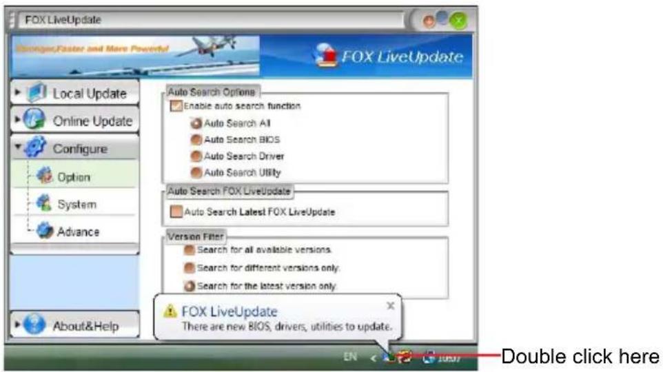
text_image
FOX LiveUpdate Stronger,Faster and More Powerful FOX LiveUpdate Local Update Online Update Configure Option System Advance About&Help Auto Search Options Enable auto search function Auto Search All Auto Search BIOS Auto Search Driver Auto Search Utility Auto Search FOX LiveUpdate Auto Search Latest FOX LiveUpdate Version Filter Search for all available versions. Search for different versions only. Search for the latest version only FOX LiveUpdate There are new BIOS, drivers, utilities to update. Double click hereWhen you enable "Auto Search FOX LiveUpdate", if your FOX LiveUpdate version is older, it will auto search from internet and prompt you to install the new version.
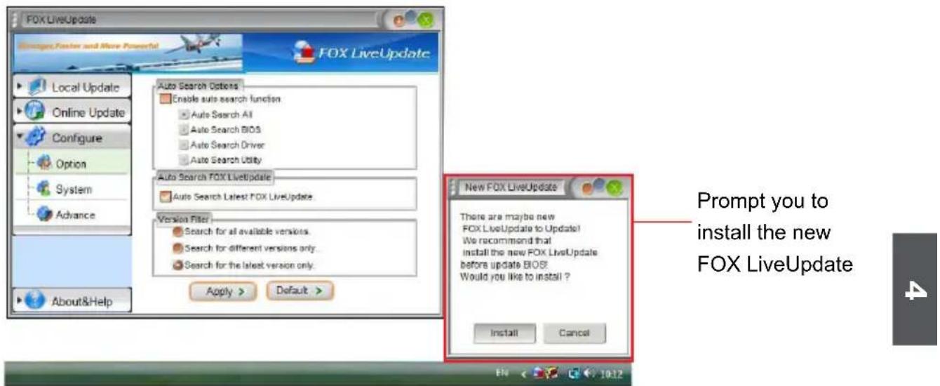
text_image
FOX LiveUpdate Messages,Foster and More Powerful FOX LiveUpdate Local Update Online Update Configure Option System Advance About&Help Auto Search Options Enable auto search function Auto Search All Auto Search BIOS Auto Search Driver Auto Search Utility Auto Search FOX LiveUpdate Auto Search Latest FOX LiveUpdate Version Filter Search for all available versions. Search for different versions only. Search for the latest version only. Apply > Default > New FOX LiveUpdate There are maybe new FOX LiveUpdate to Update! We recommend that install the new FOX LiveUpdate before update BIOS? Would you like to install ? Install Cancel Prompt you to install the new FOX LiveUpdate3-2 Configure - System
This page lets you set the backup BIOS location.
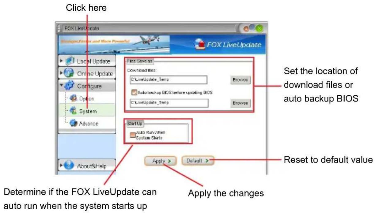
text_image
Click here FOX LiveUpdate Browse/Factor and More Powerful FOX LiveUpdate Local Update Online Update Configure Option System Advance About&Help Files Save as Download files: LiveUpdate_Temp Auto backup BIOS before updating BIOS LiveUpdate_Temp Browse Set the location of download files or auto backup BIOS Start Up Auto Run When System Starts Apply > Default > Reset to default value Determine if the FOX LiveUpdate can auto run when the system starts up Apply the changes3-3 Configure - Advance
This page lets you select to flash BIOS / Boot Block and clear CMOS. If you choose Flash Boot Block, it means BIOS is not protective, and you must make sure the flash process is continuous and without any interruption.

text_image
Click here FOX LiveUpdate Select which BIOS ROM to flash(Only available to motherboard with backup BIOS ROM ) Local Update Main BIOS ROM Backup BIOS ROM Flash BIOS To Flash Boot Block Clear CMOS Apply > Default > Apply the changes Reset to default value
We recommend that you had better keep the default setting unchanged to avoid any damage.
4. About & Help
This page shows some information about FOX LiveUpdate.

text_image
Click here FOX LiveUpdate Younger, Foster and More Powerful Local Update Online Update Configure About&Help About&Help FOX LiveUpdate Foxconn Fox LiveUpdate Version: 1.0.5.7 Home Page: http://www.foxconnchannel.com Contact Us: Technical Support Team Website Copyright (C) 2005 by FoxconnTechnology Group All Rights Reserved(R) Show information about FOX LiveUpdate
FOX LOGO
FOX LOGO is a simple and useful utility to backup, change and delete the boot time Logo. The boot Logo is the image that appears on screen during POST (Power-On Self-Test).
You can prepare a JPG image (1024x768) file, then use FOX LOGO to open it and change the boot time Logo. Boot time Logo will be displayed if you enable the BIOS "Quiet Boot" setting in "Advanced BIOS Features" menu.
Supporting Operating Systems :
Windows 2000
■ Windows XP (32-bit and 64-bit)
■ Windows 2003 (32-bit and 64-bit)
■ Windows Vista (32-bit and 64-bit)
■ Windows 7 (32-bit and 64-bit)

Using FOX LOGO:
Main Page

text_image
FOX LOGO Main screen Backup Change Delete FOXCONN® Exit Exit Minimize Website About About
When you change Logo or delete current Logo, the system will flash BIOS file automatically. During this time, please DO NOT shut down the application and the system, or the motherboard will be damaged seriously.
FOX DMI
FOX DMI is a full Desktop Management Interface viewer, and it provides three DMI data formats: Report, Data Fields and Memory Dump.
With DMI information, system maker can easily analyze and troubleshoot your motherboard if there is any problem occurred.
Supporting Operating Systems :
Windows 2000
■ Windows XP (32-bit and 64-bit)
■ Windows 2003 (32-bit and 64-bit)
■ Windows Vista (32-bit and 64-bit)
■ Windows 7 (32-bit and 64-bit)
Using FOX DMI:
Please operate this utility as the comments shows.
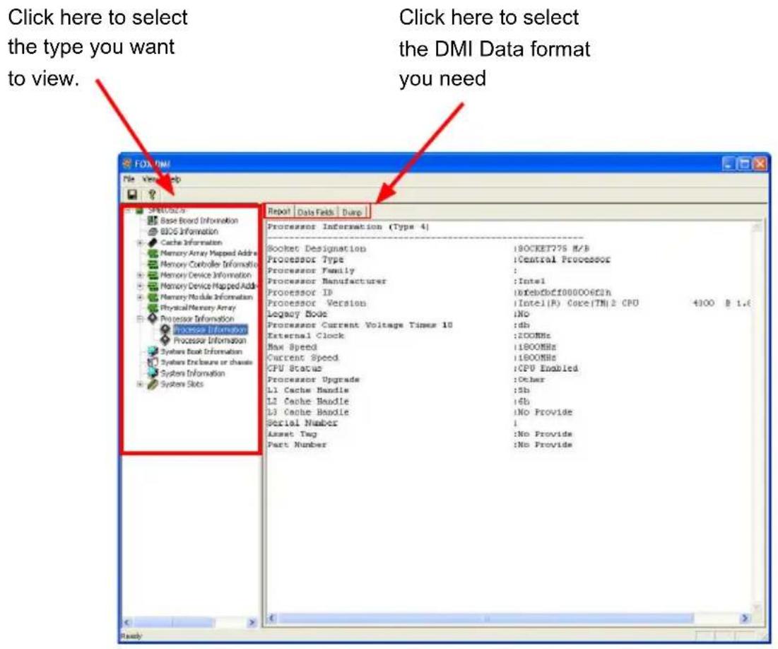
text_image
Click here to select the type you want to view. Click here to select the DMI Data format you need File View Help SP60.025 Base Board Information BIOS Information Cache Information Memory Array Mapped Address Memory Controller Information Memory Device Information Memory Device Mapped Address Memory Module Information Physical Memory Array Processor Information Process Information Processor Information Systems Book Information Systems Enclosure or channels System Information Systems Slots Report | Data Sets | Dump Processor Information (Type 4) Socket Designation :1BOCKET775 H/B Processor Type :Central Processor Processor Family : Processor Manufacturer :Intel Processor ID :10fcbcbf000006f3h Processor Version :1Intel(R) Core(TM) 2 CPU 4300 B 1.6 Legacy Block :INO Processor Current Voltage Times 10 :db External Clock :2COMHz Max Speed :1800MHz Current Speed :1800MHz CPU Status :CPU Enabled Processor Upgrade :Other L1 Cache Handle :5b L2 Cache Handle :6b L3 Cache Handle :No Provide Serial Number :I Asset Tag :No Provide Part Number :No Provide