L-758 Cine - Luxmètre SEKONIC - Free user manual and instructions
Find the device manual for free L-758 Cine SEKONIC in PDF.

User questions about L-758 Cine SEKONIC
0 question about this device. Answer the ones you know or ask your own.
Ask a new question about this device
Download the instructions for your Luxmètre in PDF format for free! Find your manual L-758 Cine - SEKONIC and take your electronic device back in hand. On this page are published all the documents necessary for the use of your device. L-758 Cine by SEKONIC.
USER MANUAL L-758 Cine SEKONIC
Before using your light meter, please read this “Safety Precautions” carefully and use it properly.

WARNING
Indicates hazard or unsafe use that can result in personal injury or death.

CAUTION
Indicates hazard or unsafe use that can result in personal injury or damage to your light meter.
NOTE: Indicates a caution or limitation that accompanies operation. Please read the note to avoid incorrect operation.
Reference: Provides the reference information and related functions that are useful in operating. We recommend that you read these references.

WARNING
- Please place light meter in a location where an infant cannot reach and accidentally get the strap wrapped around his or her neck. There is danger of strangulation.
- Keep the synchro terminal cap out of reach of young children, as swallowing such objects can cause suffocation.
- Never place batteries in fire, short, disassemble, heat or charge them. The batteries might break down, and cause damage, injury or pollute the environment.

CAUTION
- There is a danger of electric shock and damage to product if your meter is handled with wet hands, in the rain, near water or where there is a lot of moisture, when you use cord flash mode. If you are using flash mode in these conditions, we recommend Cordless Flash mode or Radio Triggering mode. Always attach the synchro terminal cap on to the synchro connector when the light meter is exposed to wet or rainy conditions.
- Do not look directly at the sun through the viewfinder, because of potential eye injury.
- Do not attempt to disassemble the product for modification or parts replacement. Refer servicing only to qualified and authorized Personnel in case of product's malfunction.
Safety Precautions
Table of Contents
1. Parts Designation .... 1
- Light Meter Parts .... 1
- Supplied Accessories 2
2. Explanation of the Liquid Crystal Display(LCD) 3
3. Before Using 7
- Attach the strap .... 7
- Inserting the battery .... 7
- Checking battery capacity .... 7
- Replacing the battery during measurement or when using the memory function .. 8
- Auto Power Off function 8
- Setting ISO 1 sensitivity .... 8
- Setting ISO 2 sensitivity .... 8
- Jog Wheel Lock or Lock Off 9
- Setting the Measuring and Memory button configuration .... 10
4. Basic Operation 11
- Incident or reflected spot measuring 11
- Setting measuring mode 12
- Incident Measurement Mode .... 13
- Reflected Measurement Mode (spot metering) 14
5. Measurement 15
- Measuring ambient light 15
1-1 Shutter Speed Priority mode 15
1-2 Aperture Priority mode 17
1-3 EV mode 18
1-4 Cinematography 19
- Measuring electronic flash 21
2-1 Cord Flash mode 21
2-2 Auto-reset cordless flash mode 22
2-3 Cord multiple flash (cumulative) mode 24
2-4 Cordless multiple flash (cumulative) mode 25
2-5 Flash analyzing function 27
2-6 Wireless Flash Radio Triggering 28
6. Advanced Functions ...... 31
- Memory function 31
- Averaging function 32
- Contrast Function ...... 32
- How to use an incident illuminance (LUX or FC) meter (L-758DR/758D) ...... 34
- How to use a reflected luminance (cd/m² or FL) meter (L-758DR/758D) ..... 35
- How to use the Exposure compensation function 36
- How to use Calibration compensation function ...... 37
- Filter compensation 38
8-1 Filter compensation (1) 38
8-2 Filter factor number compensation (2) (L-758CINE only) 39
9. Custom setting function 40
7. Camera Exposure Profiling 42
- Calibration testing for exposure profiling 42
- How to set the Camera Exposure Profiling .... 44
2-1 Sekonic Application software 44
2-1-1 Outline of software 44
2-2 Manual Input of Exposure Profile 45
- How to use Camera Exposure Profiling .... 48
3-1 Selecting Camera Exposure Profiling 48
3-2 Analog scale 48
3-2-1 Aperture scale.... 48
3-2-2 EV scale 48
3-2-3 MID.TONE button 50
8. Optional Accessories 52
9. Technical Data 54
10.Care and Maintenance 56
FCC & IC compliance information .... 57
1. Parts Designation
- Light Meter Parts

⑬ RT-32N Radio transmitter module
⑰ Battery Compartment
⑲Incident/Reflected Spot Selector Dial
②Eyepiece (with Diopter Adjustment)
⑭ Measuring button*
⑮ Battery Compartment Cover
⑯ Battery Cover Latch.
*Measuring button and memory button can be swithced in Custom settings.
1. Parts Designation
2. Supplied Accessories
②Synchro Terminal Cap (Attached to meter)

⑳Strap
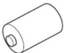
⑳Lens Cap (Attached to meter)
natural_image
Simple line drawing of a cylindrical object connected to a curved cable or strap (no text or symbols)⑲USB Cable

natural_image
Line drawing of a USB cable with two connectors (no text or symbols)③0CD-ROM for Software (Data Transfer Software, USB driver, Operating manual and Software guide)
text_image
SEKONIC Data: Enixter Software - 100% Linear & Dynamic Periods- POTATOLOGY MATERIALS R.Q. 12345 MATERIALS MATERIALS MATERIALS MATERIALS MATERIALS MATERIALS MATERIALS MATERIALS MATERIALS MATERIALS MATERIALS MATERIALS MATERIALS MATERIALS MATERIALS MATERIALS MATERIALS MATERIALS MATERIALS MATERIALS MATERIALS MATERIALS MATERIALS MATERIALS MATERIALS MATERIAL S MATERIAL S MATERIAL S MATERIAL S MATERIAL S MATERIAL S MATERIAL S MATERIAL S MATERIAL S MATERIAL S MATERIAL S MATERIAL S MATERIAL S MATERIAL S MATERIAL S MATERIAL S MATERIAL S MATERIAL S MATERIAL S MATERIAL S MATERIAL S MATERIAL S MATERIAL S MATERIAL S MATERIAL S MATERIALS MATERIALS MATERIALS MATERIALS MATERIALS MATERIALS MATERIALS MATERIALS MATERIALS MATERIALS MATERIALS MATERIALS MATERIALS MATERIALS MATERIALS MATERIALS MATERIALS MATERIALS MATERIALS MATERIALS MATERIALS MATERIALS MATERIALS MATERIALS MATERIALSS③1 Sticker for Multi-key Operation and CS (Custom Setting)

text_image
Black-and-white image of an abacus with visible numerical data and Chinese characters on the faces③2Quick Guide (in Japanese/English) ③3Operating Manual
text_image
SEKONIC E. TOMATOZIEK CHIKU ZHOU
text_image
SEKONIC DIGITALMASTER L-2500R L-RAD L-358.00E Copyright © Manual③4Battery (CR-123A) ③5Soft Case
natural_image
Simple line drawing of a cylindrical battery (no text or symbols)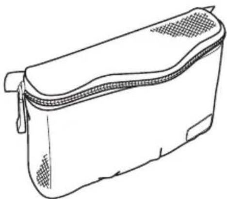
natural_image
Line drawing of a rectangular box with a zipper and textured side (no text or symbols)LCD for L-758DR/L-758D

text_image
⑨ ① ⑪ ⑤ ② ⑬ ③ ISO1 100 ISO2 MLT 8 CH 17 ABCD 8.8 CAMERA 3 20% ⑩ ④ ⑧ T ms f/s 125 F ΔEV 16.0 A ⑥ 0.7 1 1.4 2 2.8 4 5.6 8 11 16 22 32 45 64 90 U -7 -6 -5 -4 -3 -2 -1 0 +1 +2 +3 +4 +5 +6 +7 ⑬ ⑦LCD for L-758CINE

text_image
ISO1 100 ISO2 MLT 8 CH 17 ABC =8.8 CAMERA 3 20% Ang ms f/s F ΔEV 16.0 A FCLUX FLcd/m² 15 125 160 0.5 0.7 1 1.4 2 2.8 4 5.6 8 11 16 22 32 45 64 U -7 -6 -5 -4 -3 -2 -1 0 +1 +2 +3 +4 +5 +6 +7 ⑭⑦ ⑮⑯NOTE:
For explanation purposes, the display illustrated here shows all icons and readouts simultaneously. Actual LCD screen will not show all icon as above during normal use.
Auto Electro-Luminescent Display (EL)
- In low light (EV 6 or less), a green backlight will automatically illuminate the entire LCD.
- The LCD will not be automatically illuminated during measurements, in Cordless Flash or Wireless flash radio triggering mode.
• The Electro-luminescent backlight will automatically turn off 20 seconds after last operation.
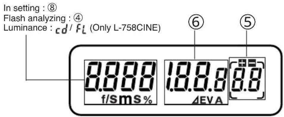
Display in viewfinder
text_image
In setting : ⑧ Flash analyzing : ④ Luminance : cd / FL (Only L-758CINE) 0.000 f/sms % 10.0.0 ΔEVA 0.0 ⑥ ⑤*Not displayed in Incident reading.
① Measuring Mode Icons
Ambient (see page 15)
Auto-Reset Cordless Flash (see page 22)
Cord Flash (see page 21)
Wireless flash radio triggering mode (see page 28)
② Incident / Reflected Spot Mode Icons (see page 11)
Appears when in Incident mode
Appears when in Reflected Spot mode
③ ISO Display (see page 8)
ISO 1 Displays ISO 1 setting
ISO2 Displays second ISO setting when ISO 2 button is pressed
④ Flash Analyzing indicator (see page 27)
% 0 to 100% in 10% increments (percentage of the flash in the total exposure)
⑤ +/- Exposure/Calibration Compensation display (see page 36)
Exposure compensation--- appears on the upper side of the main LCD. Calibration compensation--- appears only in the calibration setting mode.
⑥ Digital aperture value, Aperture Priority, EV Brightness Difference, Average function, EV display
Appears when Aperture Priority (f/stop) mode is selected (see page 17)
EV Appears when using Contrast function (see Page 32)
A Appears when using Averaging function and Contrast function (see page 32)
EV Appears when using EV mode (see page 18)
⑦ Analog Scale
Displays measured values as icons along the apertures or Latitude EV scale. The scale is graduated in full or 1/3 stop increments for measurements. Memorized and averaged values are also display along the scale.
- Aperture scale (upper scale) displays in all mode except Aperture priority mode.
f 0.7 to f 90 in full stops appears in all modes except aperture priority mode (L-758)
f 0.5 to f 64 in full stops appears in all modes except aperture priority mode (L-758CINE)
- EV scale (lower scale) displays in all mode except Multiple flash cumulative mode.
+/-7 stops from Mid.Tone (0) appears in aperture priority mode, or other modes if selected.
- Value display scale
Appear to indicate last measured/ memorized/ averaged values and brightness difference value below the aperture scale or above the latitude scale depending on which scale has been selected.
u Appears when measurement is below display range
Blinks when measurement is below measurement range
o Appears when measurement is above display range
Blinks when measurement is above measurement range
▲ Dynamic range/clipping point icons
Indicates dynamic range and clipping point of a selected camera exposure profiling.
⑧ Shutter priority indicator, shutter speed display for still photography or frames per second (f/s) for cinematography
T Appears when Shutter Priority (T) is selected mode (see page 15)
m Appears when shutter speed is in minutes
s Appears when shutter speed is in full seconds
f/s Appears when cine speed is set in frames per second (see page 19)
⑨ Battery Power Indicator (see page 7)
⑩ Memory / Multiple Flash Indicator Display
MLT 9 Appears when Multi (cumulative) flash measurement mode is selected and shows the cumulated number of flash measurements (see page 24)
m 9 Appears when reading is memorized and shows the number in memory (see page 31)
⑪ Radio triggering channel and Quad-triggering zone display (see page 28)
ch 17 Triggering Channel Numbers
ABCD Selective Quad-Triggering Zone
⑫ Camera profile selector display
⑬ USB icon
Appears when a USB cable is connected to the light meter and a computer.
2. Explanation of the Liquid Crystal Display
⑭ Shutter angle (L-758CINE)
Ang Appears when shutter angle is set to a value other than 180 degrees (see page 19)
⑮ Illuminance mark / Luminance mark (L-758CINE)
FC Appears when Foot-Candle is selected
LUX Appears when Lux is selected
FL Appears when Foot-Lambert is selected
cd/m ^2 Appears when cd/m ^2 is selected
1. Attach the strap
Attach the Strap ⑳ by passing the small loop end through the eyelet ⑨ and passing the other end of strap through it.
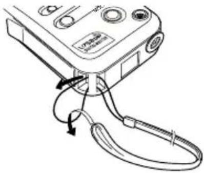
natural_image
Line drawing of a handheld electronic device with cable and connector (no text or symbols)
WARNING
- To avoid a danger of strangulation, please keep the strap in a location where an infant cannot reach it and accidentally get the strap wrapped around his or her neck.
2. Inserting the battery
- Requires one 3.0 v CR123A lithium battery (included).
- Open the Battery compartment cover latch ⑯, and remove the Battery compartment cover ⑮.
- Insert the battery, observing the polarity with the +,- marks in the battery compartment ⑰.
- Align the tabs of the Battery compartment cover with the notches in the back of the meter, and press down to close the Battery compartment cover latch.

natural_image
Technical line drawing of a device interior with a rectangular housing and cable, showing no text or symbolsNOTE:
• To prevent loss of All-weather seal, be careful that dirt does not get stuck on the rubber seal and that the seal is not damaged.
- Remove battery if meter is not used for an extended period. Batteries can leak and damage the light meter. Dispose of used batteries properly.
- If the LCD does not light, check that the battery capacity is sufficient, and check that the battery positive and negative terminals are not reversed.
- The L-758D/L-758CINE has a connector for a plug-in radio transmitter module. Do not remove the connector cover unless you are installing the radio module, failure to do so could cause the electronic circuit board to be exposed to damaging static electricity.
3. Checking battery capacity
- When the Power button ⑫ is ON, the battery power indicator on the LCD is displayed.

(Displayed) Battery power level is good.
(Displayed) Battery power level is low. Have a spare battery ready.
(Blinking) Replace battery immediately.
Reference:
- If the LCD screen turns off immediately after the display appears when power is first applied, that is an indication that the battery is dead. Please promptly replace the battery. We recommend you always have a spare battery on hand.
- A spare battery can be stored in a provided compartment of the L-758DR's case (see sticker "OPEN END TO BACK".
- Under our testing condition, the battery life is approximately 60 hours with continuous use under normal temperature.
- The battery supplied with this light meter, may not be able to meet battery life mentioned above because of undetermined shelf life or storage condition.
4. Replacing the battery during measurement or when using the memory function
- Always turn the power OFF before replacing the battery. If the battery is removed with the power ON, measurements and settings in memory can no longer be recalled.
- If after replacing the battery, or during measurements, strange screens (displays that have not been set) appear on the LCD, or nothing happens, no matter what button is pushed, remove the battery and wait at least ten seconds and then replace the battery. This allows the software to automatically reset.

WARNING:
- Never place batteries in fire, short, disassemble, or heat them. The batteries might break down, and cause an accident, injury or pollute the environment.
NOTE:
• A three second pause between power on and off is recommended to avoid damage to the meter.
5. Auto Power Off function
- To conserve battery power, the meter will turn off about twenty minutes after last use.
- Whether the Auto Power Saving feature turns the power off or the Power button ⑫ is pressed, the settings and measured values remain stored in memory. When the Power button is pressed again the last settings are displayed.
Reference:
- The power shuts off automatically after 1 minute when the power button is pressed and held.
- Auto power off time is adjustable in Custom settings. (See page 40 for details)
6. Setting ISO 1 sensitivity
- Hold down the ISO1 button ⑪ and turn the Jog wheel ⑤ to select the desired ISO sensitivity.
- You can also change the ISO sensitivity after taking measurements. The new value is automatically displayed.
7. Setting ISO 2 sensitivity
-
This feature is useful when using a different ISO sensitivity (film or digital), Polaroid proofing film, or for exposure correction (when using a filter, extension tubes, bellows factor or another camera etc.).
-
Hold down the ISO 2 button ⑥ and turn the Jog wheel to select the desired ISO sensitivity.
-
Once this is set, after taking a measurement, the measured value for the second ISO sensitivity will be displayed when the ISO 2 button is pressed.
-
You can also change the second ISO sensitivity after taking measurements. The new value is automatically displayed.
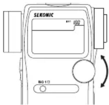
text_image
SEKONIC B01 100 B0 10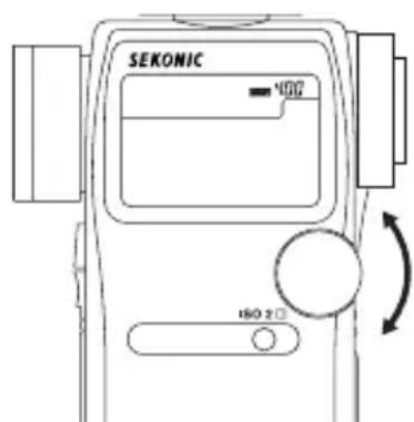
text_image
SEKONIC 400 ISO 2Reference:
- The following settings are possible when using custom setting function P40.
- It is possible to set ISO 2 for Filter compensation. These values can be set within a range of ±5 EV in 1/10 steps and are displayed in the ISO 2 area.
- Filter factor number compensation enables you to set seven types of filters frequently used in the CINE industry. (Kodak Wratten Filters)(L-758CINE only)
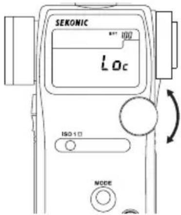
8. Jog Wheel Lock or Lock Off
- Hold down the Mode button ⑩ and ISO1 button ⑪ and "LOC" will appear to indicate that the Jog Wheel is locked. The last measurement is held until the lock is released, even if the Jog wheel ⑤ is accidentally moved.
However, if the measurement button ⑭ is pressed, a new measurement is displayed with the same locked settings.
text_image
SEKONIC 80° 100 Loc ISO-1 NODE- To release the Jog Wheel lock, perform the same operation for the Jog Wheel lock, Hold down the Mode set button and ISO1 button and "Off" will appear to indicate that the Jog Wheel lock is released.

text_image
SEKONIC OFF ISO-10 MODEReference:
- If power of the meter is turned off or auto off is activated when in the Jog Wheel locked position, the lock function will continue operating when the meter is turned on again.
9. Setting the Measuring and Memory button configuration
In the custom settings mode (refer to P40), the Measuring button and the Memory button can be set as follows.
1. For Incident measuring
The Measuring button and Memory button is set in the standard configuration. (Described on Page 1 in Light Meter Parts) Please make sure that the default value in the Custom settings mode is set to .(Custom No.17, Item No. 0)

text_image
Memory button Measuring button Configuration 1)2. For Reflected (Spot) measuring
If the standard buttons configuration is inconvenient for spot metering, the Measuring button and Memory button can be switched. Set the Custom settings mode to Custom No. 17, Item No. 1

text_image
Measuring button Configuration 2) Memory button3. For both Incident/Reflected (Spot) measuring simultaneously
You can set the buttons configuration automatically according to light measuring method. In incident mode, the buttons configuration is 1), but in reflected mode, the buttons configuration is 2). For this setting, please set (Custom settings mode No. 17 and Item No 2).

text_image
Automatically switched ReflectedIncident Memory button Measuring button Configuration 3) Measuring button Memory button1. Incident or reflected spot measuring
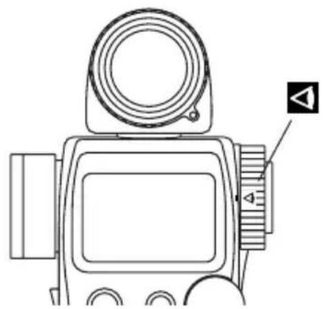
- To set for either incident or reflected light operation, turn the Incident / Reflected Spot Selector Dial ⑲ on the eye piece, to the desired position (or mark) until it clicks.
natural_image
Line drawing of a digital camera with lens and control panel (no text or symbols)Incident operation
natural_image
Line drawing of a digital camera with lens and control panel (no text or symbols)Reflected Spot operation
- When incident operation is selected, the ▲ mark will blink for ten seconds and when Reflected Spot operation is selected the ◀ mark will blink for ten seconds on the LCD.

natural_image
Simple line drawing of a folder icon with a small square symbol on top (no text or labels)Incident operation
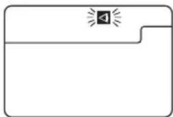
natural_image
Simple line drawing of a folder icon with a speaker symbol and sound waves (no text or labels)Reflected Spot operation
NOTE:
- Before taking measurements, always make sure that the desired measurement mode ( △ or ◆ is chosen by checking the LCD or that the Incident/Reflected Spot Selector Dial is clicked in proper position.
- Do not rotate the Spot lens ring. There is danger of damage.
2. Setting measuring mode
- Hold down the Mode button ⑩ and turn the Jog wheel ⑤ to select the desired mode. The mode switching sequence is shown in the chart below:

text_image
SEKONIC 125-3 MODE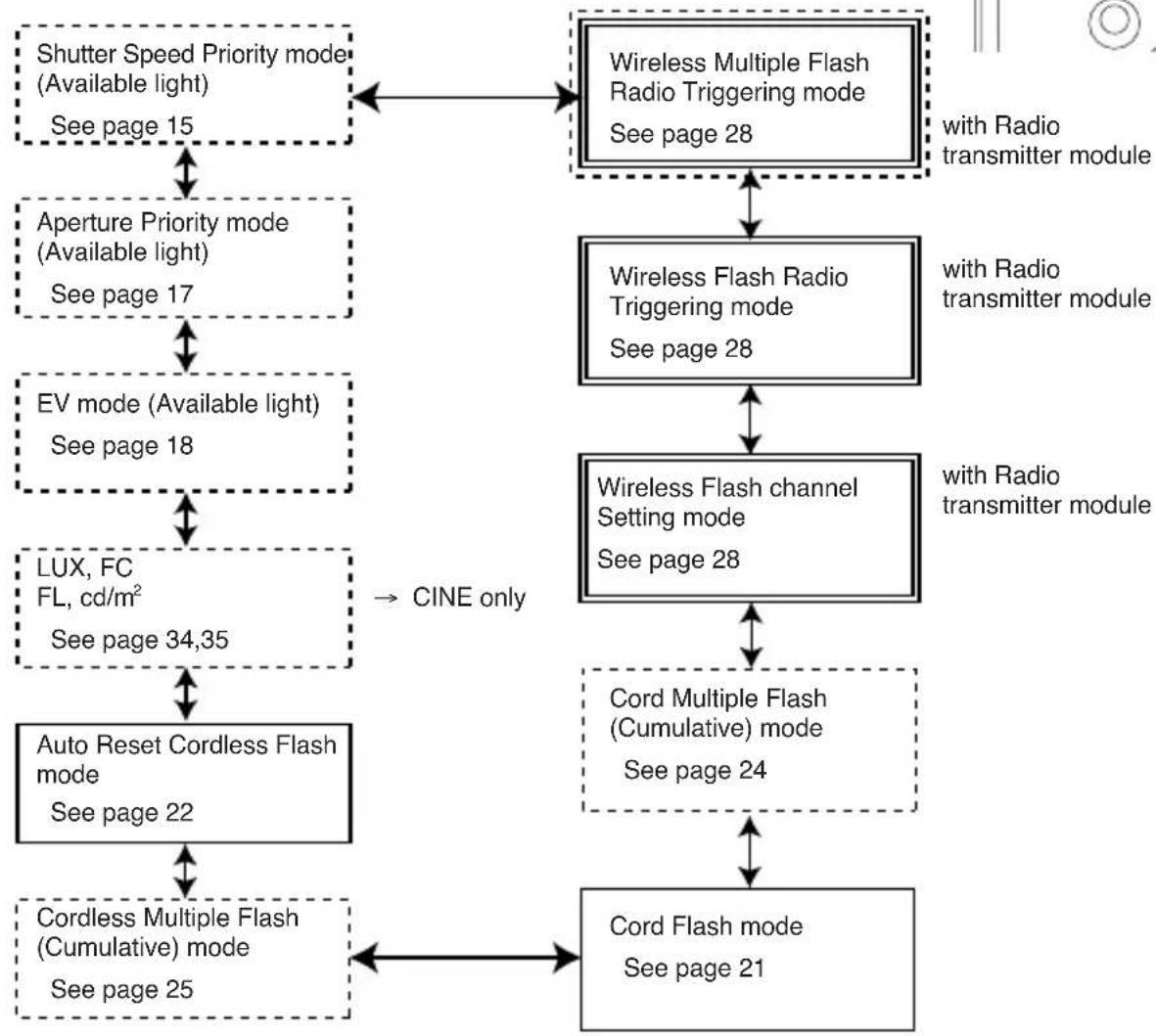
flowchart
graph TD
    A["Shutter Speed Priority mode\n(Available light)\nSee page 15"] --> B["Aperture Priority mode\n(Available light)\nSee page 17"]
    B --> C["EV mode (Available light)\nSee page 18"]
    C --> D["LUX, FC\nFL, cd/m²\nSee page 34,35"]
    D --> E["Auto Reset Cordless Flash mode\nSee page 22"]
    E --> F["Cordless Multiple Flash (Cumulative) mode\nSee page 25"]
    F --> G["Cord Flash mode\nSee page 21"]
    G --> H["Cord Multiple Flash (Cumulative) mode\nSee page 24"]
    H --> I["Wireless Flash Radio Triggering mode\nSee page 28"]
    I --> J["Wireless Flash Radio Triggering mode\nSee page 28"]
    J --> K["Wireless Flash channel Setting mode\nSee page 28"]
    K --> L["Wireless Multiple Flash Radio Triggering mode\nSee page 28"]
    L --> M["Wireless Multiple Flash Radio Triggering mode\nSee page 28"]
    M --> N["Wireless Multiple Flash Radio Triggering mode\nSee page 28"]
    N --> O["Wireless Multiple Flash Radio Triggering mode\nSee page 28"]
    O --> P["Wireless Multiple Flash Radio Triggering mode\nSee page 28"]
    P --> Q["Wireless Multiple Flash Radio Triggering mode\nSee page 28"]
    Q --> R["Wireless Multiple Flash Radio Triggering mode\nSee page 28"]
    R --> S["Wireless Multiple Flash Radio Triggering mode\nSee page 28"]
    S --> T["Wireless Multiple Flash Radio Triggering mode\nSee page 28"]
    T --> U["Wireless Multiple Flash Radio Triggering mode\nSee page 28"]
    U --> V["Wireless Multiple Flash Radio Triggering mode\nSee page 28"]
    V --> W["Wireless Multiple Flash Radio Triggering mode\nSee page 28"]
    W --> X["Wireless Multiple Flash Radio Triggering mode\nSee page 28"]
    X --> Y["Wireless Multiple Flash Radio Triggering mode\nSee page 28"]
    Y --> Z["Wireless Multiple Flash Radio Triggering mode\nSee page 28"]
    Z --> AA["Wireless Multiple Flash Radio Triggering mode\nSee page 28"]
    AA --> AB["Wireless Multiple Flash Radio Triggering mode\nSee page 28"]
    AB --> AC["Wireless Multiple Flash Radio Triggering mode\nSee page 28"]
    AC --> AD["Wireless Multiple Flash Radio Triggering mode\nSee page 28"]
    AD --> AE["Wireless Multiple Flash Radio Triggering mode\nSee page 28"]
    AE --> AF["Wireless Multiple Flash Radio Triggering mode\nSee page 28"]
    AF --> AG["Wireless Multiple Flash Radio Triggering mode\nSee page 28"]
    AG --> AH["Wireless Multiple Flash Radio Triggering mode\nSee page 28"]
    AH --> AI["Wireless Multiple Flash Radio Triggering mode\nSee page 28"]
    AI --> AJ["Wireless Multiple Flash Radio Triggering mode\nSee page 28"]
    AJ --> AK["Wireless Multiple Flash Radio Triggering mode\nSee page 28"]
    AK --> AL["Wireless Multiple Flash Radio Triggering mode\nSee page 28"]
    AL --> AM["Wireless Multiple Flash Radio Triggering mode\nSee page 28"]
    AM --> AN["Wireless Multiple Flash Radio Triggering mode\nSee page 28"]
    AN --> AO["Wireless Multiple Flash Radio Triggering mode\nSee page 28"]
    AO --> AP["Wireless Multiple Flash Radio Triggering mode\nSee page 28"]
    AP --> AQ["Wireless Multiple Flash Radio Triggering mode\nSee page 28"]
    AQ --> AR["Wireless Multiple Flash Radio Triggering mode\nSee page 28"]
    AR --> AS["Wireless Multiple Flash Radio Triggering mode\nSee page 28"]
    AS --> AT["Wireless Multiple Flash Radio Triggering mode\nSee page 28"]
    AT --> AU["Wireless Multiple Flash Radio Triggering mode\nSee page 28"]
    AU --> AV["Wireless Multiple Flash Radio Triggering mode\nSee page 28"]
    AV --> AW["Wireless Multiple Flash Radio Triggering mode\nSee page 28"]
    AW --> AX["Wireless Multiple Flash Radio Triggering mode\nSee page 28"]
    AX --> AY["Wireless Multiple Flash Radio Triggering mode\nSee page 28"]
    AY --> AZ["Wireless Multiple Flash Radio Triggering mode\nSee page 28"]
    AZ --> BA["Wireless Multiple Flash Radio Triggering mode\nSee page 28"]
    BA --> BB["Wireless Multiple Flash Radio Triggering mode\nSee page 28"]
    BB --> BC["Wireless Multiple Flash Radio Triggering mode\nSee page 28"]
    BC --> BD["Wireless Multiple Flash Radio Triggering mode\nSee page 28"]
    BD --> BE["Wireless Multiple Flash Radio Triggering mode\nSee page 28"]
    BE --> BF["Wireless Multiple Flash Radio Triggering mode\nSee page 28"]
    BF --> BG["Wireless Multiple Flash Radio Triggering mode\nSee page 28"]
    BG --> BH["Wireless Multiple Flash Radio Triggering mode\nSee page 28"]
    BH --> BI["Wireless Multiple Flash Radio Triggering mode\nSee page 28"]
    BI --> BJ["Wireless Multiple Flash Radio Triggering mode\nSee page 28"]
    BJ --> BK["Wireless Multiple Flash Radio Triggering mode\nSee page 28"]
    BK --> BL["Wireless Multiple Flash Radio Triggering mode\nSee page 28"]
    BL --> BM["Wireless Multiple Flash Radio Triggering mode\nSee page 28"]
    BM --> BN["Wireless Multiple Flash Radio Triggering mode\nSee page 28"]
    BN --> BO["Wireless Multiple Flash Radio Triggering mode\nSee page 28"]
    BO --> BP["Wireless Multiple Flash Radio Triggering mode\nSee page 28"]
    BP --> BQ["Wireless Multiple Flash Radio Triggering mode\nSee page 28"]
    BQ --> BR["Wireless Multiple Flash Radio Triggering mode\nSee page 28"]
    BR --> BS["Wireless Multiple Flash Radio Triggering mode\nSee page 28"]
    BS --> BT["Wireless Multiple Flash Radio Triggering mode\nSee page 28"]
    BT --> BU["Wireless Multiple Flash Radio Triggering mode\nSee page 28"]
    BU --> BV["Wireless Multiple Flash Radio Triggering mode\nSee page 28"]
    BV --> BW["Wireless Multiple Flash Radio Triggering mode\nSee page 28"]
    BW --> BX["Cord Pulse Mode with Radio Transmitter Module"]

    style A fill:#f9f,stroke:#333
    style B fill:#f9f,stroke:#333
    style C fill:#f9f,stroke:#333
    style D fill:#f9f,stroke:#333
    style E fill:#f9f,stroke:#333
    style F fill:#f9f,stroke:#333
    style G fill:#f9f,stroke:#333
    style H fill:#f9f,stroke:#333
    style I fill:#f9f,stroke:#333
    style J fill:#f9f,stroke:#333
    style K fill:#f9f,stroke:#333
    style L fill:#f9f,stroke:#333
    style M fill:#f9f,stroke:#333
    style N fill:#f9f,stroke:#333
    style O fill:#f9f,stroke:#333
    style P fill:#f9f,stroke:#333
    style Q fill:#f9f,stroke:#333
- Modes enclosed in dotted lines can only be selected with custom setting. (See page 40)
- Modes enclosed in lines can only be selected with L-758DR. For L-758D and L-758CINE, they can be selected when Optional Radio Transmitter Module is installed. (See page 28)
- In addition to exposure reading, L-758CINE displays FC or LUX in incident light mode, and FL or cd/m² in reflected light mode.(See page 34)
Reference:
• Available light is continuous light like natural light (sunlight) or tungsten lamps and florescent lamps like pulsing light sources.
- Flash light is a brief, intense burst of light made by such as electronic flash units or flash bulbs.
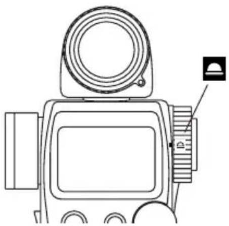
3. Incident Measurement Mode
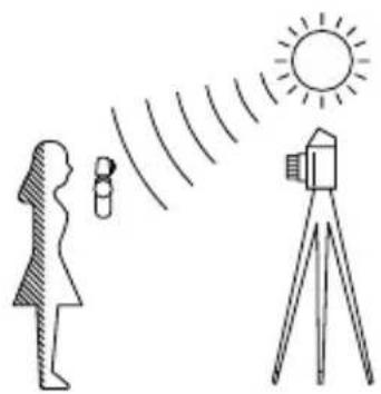
Incident light measuring is the measurement method that employs either the Lumisphere or Lumidisc functions. Measurements should be with the Lumisphere aimed towards the camera direction from the subject position.
natural_image
Illustration of a person using a sun to observe a camera and surveying instrument (no text or symbols)- You can select extended or retracted lumisphere measuring positions by rotating the Lumisphere retracting ring ① (clockwise or counter-clockwise) until it clicks into position.
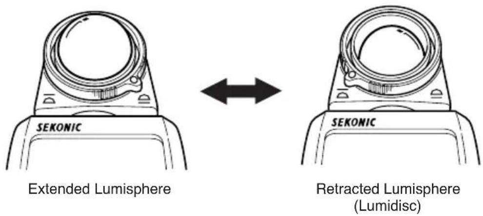
text_image
SEKONIC Extended Lumisphere SEKONIC Retracted Lumisphere (Lumidisc)- When the Lumisphere is extended. (3-D Light Measurement)
This is used to measure people, buildings, and other three dimensional objects.
Measurements are basically made by the method of measuring with the lumisphere aimed in the camera direction (more precisely, in the direction of the lens axis) at the position of the subject.
- When the Lumisphere is retracted (flat diffuser function)
This is used to measure manuscripts, paintings or other flat copy. It can also be used for Contrast function (see page 32) or measuring illumination (see page 34).
NOTE:
- If the light meter is used with the Lumisphere retracting ring in a middle position, distributed light quality will change, and suitable measurements cannot be made.
- Do not push the Lumisphere down with your finger or hand. Always use the Lumisphere retracting ring.
- If the lumisphere becomes soiled, wipe it with a soft, dry cloth. Organic solutions (paint thinner, benzene, etc.) must not be used under any circumstances.
4. Reflected Measurement Mode (spot metering)
This method measures the brightness (luminance) of the light reflected from the subject. It is useful for distant objects such as landscapes, when you cannot go to the position of the subject, or for metering subjects that generate light (neon signs, etc.), highly reflective surfaces or translucent subjects (stained glass, etc.).
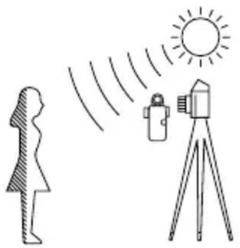
natural_image
Illustration showing a person observing a sun and a camera on a tripod, with no text or symbols present.- Take the measurement by aligning the circle inside the viewfinder with the subject area to be measured.
- The black circle A in the finder indicates the measurement range. The light receiving angle is 1 degree.
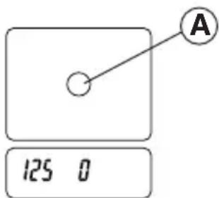
text_image
A 125 0(Display in spot viewfinder)
< Diopter Adjustment >
Turn the eyepiece ② and adjust the diopter so that the circle in the finder is clearly visible when you look into the finder.
< Step-Up Ring (Lens Hood)>(optional)
The step-up ring (30.5mm → 40.5mm), available as an optional accessory, makes it possible to mount step-up rings and filters. This simplifies the setting of exposure without the troublesome correction calculation of polarizing filters, etc. (see page 52)
The step-up ring can also be used as a lens hood to prevent lens flare and erroneous light measurements from glare, it also protects the spot lens from scratching, soiling, etc.
1. Measuring ambient light
In this measurement mode, we have the choice of shutter priority mode, aperture priority mode or EV mode. Hold down the Mode button ⑩ and turn the Jog wheel ⑤ to select ambient measurement mode ⚙️.
1-1 Shutter Speed Priority mode
- Hold down the Mode button ⑩ and turn the Jog wheel ⑤ to select Shutter Speed Priority mode T.

text_image
SEKONIC 125 MODE-
Turn the Jog wheel to set the desired shutter speed.
-
Press the Measuring button ⑭ to take a measurement. Release the Measuring button to complete the measurement. The measured value (aperture value) at that time will be displayed.
While pressing the Measuring button, the meter measures continuously until it is released.

text_image
Set shutter speed Measured f stop value 1301 100 T 125 F 2.83 1/10 f stop Measured f stop(blinking)Reference:
- It is possible to switch between full, 1/2 and 1/3 shutter speeds with custom setting (see page 36).
- You can set shutter speeds from 30 minutes to 1/8000 seconds. After 1/8000 the shutter speeds of 1/200 and 1/400 can be set.
• After taking a measurement, the F stop value corresponding to the shutter speed is displayed. The measured F stop value automatically corresponds to the shutter speed if the shutter speed is changed by rotating Jog wheel. - The L-758DR/758D displays the measured aperture value in either full or 1/3 stop increments on the analog scale from f/0.7 to 90, while L-758 CINE displays it in either full or 1/3 stop increments on the analog scale from F0.5 to F64.
-
You can select aperture scale or EV scale by holding MODE button and pressing AVE. / ΔEV.
-
“E.u” (Exposure under) or “E.o” (Exposure over) appears when the combination of shutter speed and aperture is outside the display range.
When E.O (Exposure Over) is displayed, it indicates that the measured exposure is outside the display range, changing the shutter speed to a faster setting with the Jog wheel will allow you to find a combination of proper aperture and shutter speed.
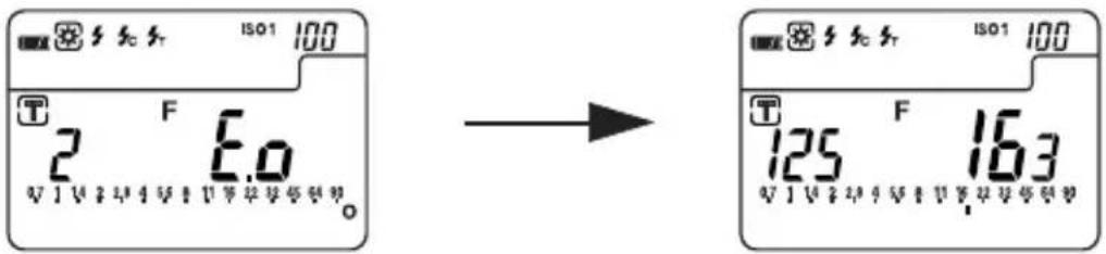
text_image
ISO1 100 T F E.0 2 V 1 V 2 V 3 V 4 V 5 V 6 V 7 V 8 V 9 V 10 → ISO1 100 T F 125 163 V 1 V 2 V 3 V 4 V 5 V 6 V 7 V 8 V 9 V 10When E.U (Exposure Under) is displayed, it indicates that the measured exposure is outside the display range, changing the shutter speed to a slower shutter speed with the Jog wheel will allow you to find a combination of proper aperture and shutter speed.
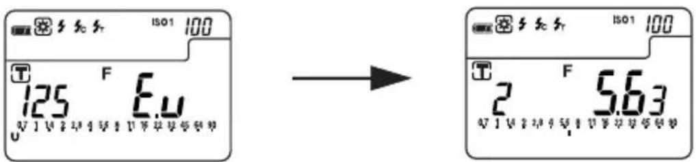
text_image
ISO1 100 T F E.u 125 U V 2.4 V 1 U V 3.6 V 5.9 V → ISO1 100 T F 5.63 U V 2.4 V 1 U V 3.6 V 5.9 V- If the “E.u” or “E.o” readout blinks, this indicates that the light level is beyond the measurement range of the light meter. Adjust lighting in this case.

text_image
ISO1 100 T 125 F E.U U U U U U U U U U U U U U U U U U U U U U U U U U U U U U U U U U U U U U U U U U U U U U U U U U U U U U U U U U U U U U U U U U U U U U U U U U U U U U U U U U U U U U U U U U U U U U U U U U U U U U ISO1 100 T 2 F E.O U V I V I V I V I V I V I V I V I V I V I V I V I V I V I V I V I V I V I V I V I V I V I V I V I V I V I V I V I V I V I V I V I V I O1-2 Aperture Priority mode
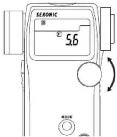
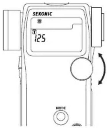
- Hold down the Mode button ⑩ and turn the Jog wheel to select aperture priority mode F
- Turn the Jog wheel ⑤ to set the desired f stop value.
text_image
SEKONIC 5.6 MODE- Press the Measuring button ⑭ to take a measurement.
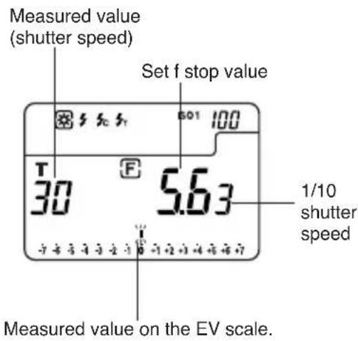
Release the Measuring button to complete the measurement. The measured value (shutter speed) at the time will be displayed.
While pressing the Measuring button, the meter measures continuously until it is released.
text_image
Measured value (shutter speed) Set f stop value 30 5.63 1/10 shutter speed Measured value on the EV scale.Reference:
- It is possible to switch between full, 1/2 or 1/3 F stop values with the custom setting mode (see page 40).
- You can set aperture from 0.5 to F161. Please note that in 1/3 stop increments F0.56 is displayed as 06 and F0.63 is displayed as 86
- In aperture priority mode, only EV scale appears on the analog scale. The measured shutter speed is displayed in 1/3 step. For details, see page 48.
• After measurement, the shutter speed corresponding to the F stop is displayed when the F stop is changed with Jog Wheel. - Readings outside the display range or beyond the measuring range are similar to the previous instruction (see page 16).
1-3 EV mode
- To activate EV mode, please set Custom setting no.5 and Item no.1. (See page 40)
- Hold down the Mode button ⑩ and turn the Jog wheel ⑤ to select EV mode EV

text_image
SEKONIC # EV 0 MODE- Press the Measuring button ⑭ to take a measurement. Release the Measuring button to complete the measurement. The measured value (EV=Exposure Value) at that time will be displayed.
At the same time, the shutter speed will be displayed in the digital display area, and the corresponding f stop will be displayed on the analog scale.
While pressing the measuring button, the meter measures continuously until it is released.

text_image
Shutter speed ISO1 100 T 125 EV 10.3 67 1 14 2 28 4 56 6 11 18 22 25 45 64 90 f stop(blinking) EV valueReference:
- EV (Exposure Value) is the reading that logarithmically expresses the constant quantity of light combined from the shutter speed and aperture value. With 1 EV change the quantity of light doubles (or halves).
• To display EV mode, please set custom setting number 5 and item number 1. (See page 40) - Readings outside the display range or beyond the measuring range are similar to the previous instruction (see page 16).
- You can select aperture scale or EV scale by holding MODE button and pressing AVE. / △ EV.
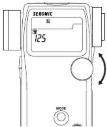
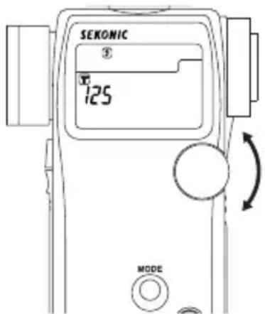
1-4 Cinematography
- Hold down the Mode button ⑩ and turn the Jog wheel ⑤ to select ambient light shutter speed priority mode T.
text_image
SEKONIC 125° MODE- Turn the Jog wheel to select the Cine Speed for the camera that will be used. Cine Speed are displayed after 1/8000, 1/200, 1/400 and the unit is in frames per second (f/s).
[L-758DR/758D]
The following Cine Speeds will be displayed: 2, 3, 4, 6, 8, 12, 16, 18, 24, 25, 30, 32, 36, 40, 48, 50, 60, 64, 72, 96, 120, 128, 150, 200, 240, 256, 300 and 360 f/s.
[L-758CINE]
The following Cine Speeds will be displayed: 1, 2, 3, 4, 6, 8, 10, 12, 14, 16, 18, 20, 24, 25, 30, 32, 36, 40, 48, 50, 60, 64, 72, 75, 90, 96, 100, 120, 125, 128, 150, 180, 200, 240, 250, 256, 300, 360, 375, 500, 625, 750 and 1000 f/s.
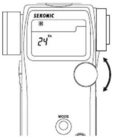
text_image
SEKONIC ® 24" MODE- The shutter angle that these speeds are based on, is 180 degrees. For other angles make the following ISO sensitivity corrections (L-758DR/758D only).
| Shutter angle | Amount of ISO sensitivity correction |
| 160 degrees | -1/3 |
| 220 degrees | +1/3 |
* Example of correction value
-1/3: Decrease ISO sensitivity by 1/3 stop, example: ISO 80 -1/3 stop = ISO 64
+1/3: Increase ISO sensitivity by 1/3 stop, example: ISO 80 +1/3 stop = ISO 100
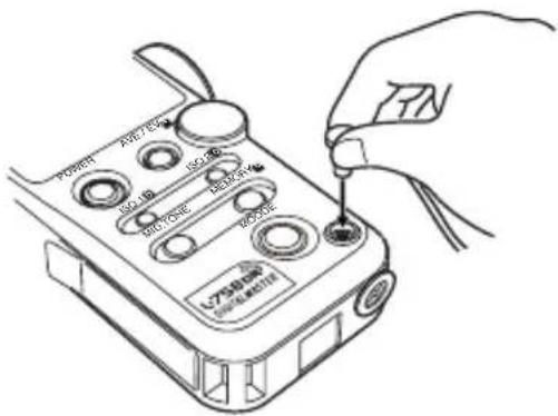
- Setting the shutter angle (L-758CINE only).
It is possible to set the shutter angle by turning the Jog wheel ⑤ while pressing Mode button ⑩ and ISO2 button ⑥.
Note:
- Shutter angle: The angle can be set in the range of 1^ to 10^ (in 1^ steps), 15^ - 270^ (in 5^ steps) as well as, 12^(=11.25^) , 17^ , 22^(=22.5^) , 144^ and 172^ .
- "Ang" is displayed continuously on the LCD display if the shutter angle is set to any value other than 180^ .
- Press both the Mode button and ISO2 button to confirm the shutter angle since it is not displayed.
Reference:
- This setting is only valid when the shutter speed is set to display cine speed (f/s).
- Press the Measuring button ⑭ to take a measurement. Release the Measuring button to complete the measurement. The measured value (f stop value) will be displayed. While pressing the measuring button, the meter measures continuously until it is released.
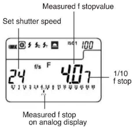
text_image
Measured f stopvalue Set shutter speed f/s F 4.07 1/10 f stop Measured f stop on analog displayReference:
- You can select aperture scale or EV scale by holding Mode button and pressing AVE./ △EV.
- The L-758DR/758D displays the measured aperture value in either full or 1/3 stop increments on the analog scale from f/0.7 to 90, while L-758CINE displays it in either full or 1/3 stop increments on the analog scale from F0.5 to F64.
- Readings outside the display range or beyond the measuring range are similar to the previous instruction (see page 16).
2. Measuring electronic flash
This method of measurement can be done in the following modes; with cord, without cord, and Wireless flash radio triggering mode (cumulative or non-cumulative). When Measuring flash light, the shutter speed and F stop value (value combining ambient light and flash light: total amount of light) are displayed. The ambient light and flash light are each displayed as separate values together with the total amount of light on the analog scale. In addition, the ratio of flash light to the total amount of light is displayed at that time as a value in 10% steps. The flash reading is displayed as a blinking mark above the analog scale. (See page 27 for details)
2-1 Cord Flash mode
Connect the meter to the flash with a synchro cord. Be sure to replace Synchro terminal cap ^26 after your measurement.
- Connect the flash synchro cord to the Synchro terminal ⑧ on the light meter.
text_image
POWER AVEN 100Ω 150Ω 200Ω 300Ω 400Ω LVS驱动 驱动电源-
Hold down the Mode button ⑩ and turn the Jog wheel ⑤ to select cord flash mode.
-
Turn the Jog wheel to set shutter speed. When setting shutter speed, first check the settings to confirm that they correspond to the settings on the camera.
text_image
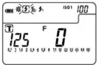
SEKONIC 125 MODE- Press the Measuring button ⑭ to trigger the flash. The measured value (f stop value) will be displayed.
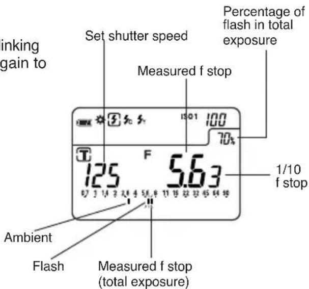
Percentage of flash in total exposure

text_image
Set shutter speed Measured f stop value 1/10 f stop Ambient Flash Measured f stop value (total exposure)
WARNING:
- T o avoid a danger of choking, please place Synchro terminal cap in a location where an infant cannot reach and accidentally swallow it.

CAUTION:
- There is danger of electric shock if the meter is handled with wet hands, during rain, in areas splashed by water or where there is a lot of moisture. Under such conditions, it is recommended that you use the meter in the cordless flash mode or Wireless flash radio triggering mode, and keep the Synchro terminal cap in place.
NOTE:
- The electronic flash unit may trigger when you connect the Synchro cord or operate the Power button.
- T riggering voltage is 2.0 to 400 volts. Below 2.0V, trigger flash with the cordless flash mode (see page 22) or wireless flash radio triggering mode (see page 28), not with synchro cord.
- If you measure flashbulb, be sure to cheek the synchronized range and set the proper shutter speed.
Reference:
- It is possible to switch the shutter speed between full, 1/2 and 1/3 stops by custom setting (See page 40).
- The shutter speed can be set from 30 minutes to 1/1000 of a second. After 1/1000 sec, the meter can be set at the following intermediate speeds: 1/75, 1/80, 1/90, 1/100, 1/200, or 1/400.
- If the ISO sensitivity is changed after the measurement is taken, the new converted measured value (f stop value) will be displayed.
- After measurement, the F stop value corresponding to the shutter speed is displayed when the shutter speed is changed with Jog Wheel.
- Readings outside the display range or beyond the measuring range are similar to the previous instruction (see page 16).
- You can select aperture scale or EV scale by holding Mode button and pressing AVE. /Δ EV.
2-2 Auto-reset cordless flash mode
Measurements are made by the meter receiving the light from the flash. This measurement mode is used when the Synchro cord will not reach because of the distance between the flash and meter or when use of the Synchro cord is inconvenient.
-
Hold down the Mode button ⑩ and turn the Jog wheel ⑤ to set Auto-reset Cordless Flash mode ③.
-
Turn the Jog wheel to set shutter speed. When setting shutter speed, first check the settings to confirm that they correspond to the settings available on the camera (camera flash synchronization).
text_image
SEKONIC ③ 125 MODE- When the Measuring button ⑭ is pressed, the mode mark ⚡ will blink and the meter is ready to measure. The ready to measure mode will continue for approximately 90 seconds. During this time, trigger the flash to make a measurement.
text_image
125 F 0 ISO1 100- If the 90 second period is exceeded and the blinking mark stops, press the Measuring button again to return to ready to measure status.
text_image
inking gain to Set shutter speed Measured f stop Percentage of flash in total exposure 1/10 f stop Ambient Flash Measured f stop (total exposure)- When the light from the flash is received, the measured value (f stop) is displayed. Even after measurement, the mode mark ⚣ continues to blink and the meter is in ready state and a new measurement can be made. (Auto-reset function)
NOTES:
- When firing a flash, if the flash brightness is 8EV lower than the ambient light, the meter may fail to detect the light. In this case, make measurements using the cord flash mode (see page 21).
- Rapid start fluorescent lamps and special lighting are sometimes mistaken for flash, and accidentally measured. In this case, make measurements using the cord flash mode (see page 21).
- The waveform of flashbulb have a slight slope and there is a possibility that light meter cannot recognize the flashbulb in Cordless flash mode. In this case, be sure to take measurement in Cord flash mode (see page 21).
Reference:
• After measurement, the F stop value corresponding to the shutter speed is displayed when the shutter speed is changed.
- Setting the shutter speed is similar to the previous instruction. (see page 21) of "Cord flash mode" of section 2-1.
- A new converted value is displayed when the ISO sensitivity is changed after taking the measurement.
- Readings outside the display range or beyond the measuring range are similar to the previous instruction. (see page 16) of "Shutter speed priority mode" of section 1-1.
- You can select aperture scale or EV scale by holding Mode button and pressing AVE. /ΔEV button.
- The meter's tripod socket permits mounting it to a tripod or light stand and placing it strategically when using cordless flash mode.
2-3 Cord multiple flash (cumulative) mode
These measurements are used when the light generated by the flash is inadequate for proper exposure. The repeated flash pops can be accumulated until the desired aperture is displayed. The cumulative number is infinite. Only one digit is displayed if the cumulative number is ten or
more. Display returns 0 (0=10, 1=11, 2=12, etc.) To activate Multiple cumulative mode, please set custom setting no.6 and Item no.1.
- Hold down the Mode button ⑩ and turn the Jog wheel ⑤ to select cord multiple flash (cumulative) mode ⚠ MLT.
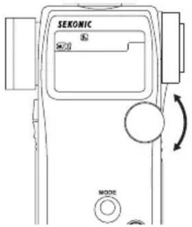
text_image
SEKONIC S M20 MODE-
Turn the Jog wheel to set shutter speed. When setting shutter speed, first check the settings to confirm that they correspond to the settings available on the camera.
-
Connect the Flash synchro cord to the meter's synchro terminal ⑧ .

text_image
MLT 0 T 125- Press the Measuring button ⑭ to trigger a flash. The measured f stop value at that time will be displayed. Each time this is repeated, the accumulated f stop value and the number of cumulative flashes is displayed.
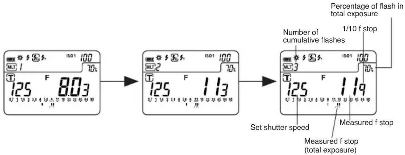
flowchart
graph LR
    A["125 F 8.03"] --> B["125 F 113"]
    B --> C["125 F 119"]
    D["Set shutter speed"] --> E["Measured f stop (total exposure)"]
    F["Number of cumulative flashes"] --> G["Percentage of flash in total exposure"]
    H["1/10 f stop"] --> G
1st. time 2nd. time 3rd. time
- To clear the cumulative value, press M. CLEAR button ②3 or switch to another mode by turning the Jog wheel while pressing the Mode button.

CAUTION:
- There is danger of electric shock if the meter is handled with wet hands, during rain, in areas splashed by water or where there is a lot of moisture. Under such conditions, it is recommended that you use the meter in the cordless flash mode, or wireless flash radio triggering mode and keep the Synchro terminal cap in place.
NOTE:
- The flash unit may flash when you connect the Synchro cord or operate the Power button.
- When firing a flash to take measurements, check the camera's synchronizing range and set the proper shutter speed.
- For flash units with low electric trigger voltage, the flash may not fire. In this case, make measurements in cordless multiple flash mode (see page 25) or wireless multiple flash radio triggering mode (see page 29).
• EV scale cannot display in flash cumulative mode.
Reference:
- Setting the shutter speed is similar to the previous instruction (see page 22).
- Readings outside the display range or beyond the measuring range are similar to the previous instruction (see page 16) of “Shutter speed priority mode” of section 1-1.
- If the ISO sensitivity film speed is changed after the measurement is taken, the new converted measured value (f stop value) will be displayed.
2-4 Cordless multiple flash (cumulative) mode
These measurements are used when the light generated by the flash is inadequate for proper exposure. The repeated flash pops can be accumulated until the desired aperture is displayed. The cumulative number is infinite. Only one digit is displayed if the cumulative number is ten or more. Display returns 0 (0=10, 1=11, 2=12 etc.) To activate Multiple cumulative mode, please set Custom setting no.6 and Item no.1.
- Hold down the Mode button ⑩ and turn the Jog wheel ⑤ to select flash measurement cordless multiple flash (cumulative) mode 📄 MT. Turn the Jog wheel to set shutter speed. When setting shutter speed, first check the settings to confirm that they correspond to the settings available on the camera.

text_image
SEKONIC 125 °F 0 MODE- When the light from the flash is received, the measured value (f stop) is displayed. Each time this is repeated, the accumulated value for the aperture and the number of cumulative flashes is displayed.

text_image
ISO1 100 MLT 1 70% 125 F 8.03 0.7 1 1.4 2 2.8 4 5.6 6 7.9 8 11 16 22 22 45 64 90 ISO1 100 MLT 2 70% 125 F 1.13 0.7 7 1.4 2 2.8 4 5.6 6 7.9 8 11.15 22 22 45 64 90 ISO 100 MLT 3 70% Number of cumulative flashes Measured f stop 1/10 f stop Set shutter speed Measured f stop (total exposure) Percentage of flash in total exposure1st. time 2nd. time 3rd. time
- The ready to measure mode will be displayed for approximately 90 seconds. If the 90 second period is exceeded and the blinking mark stops, press the Measuring button ⑭ again. The measured value (f stop) of the previous time reverts to 0 and the meter is in ready to measure mode.
NOTE:
- When firing a flash, if the flash brightness is 8 EV lower than the ambient light, the meter may fail to detect the light. In this case, make measurements using the flash with cord multiple flash (cumulative) mode (see page 24) or wireless multiple flash radio triggering mode (see page 29).
- Rapid start fluorescent lamps and special lighting are sometimes mistaken for flash, and accidentally measured. In this case, make measurements using the flash with cord multiple flash (cumulative) mode (see page 24) or wireless multiple flash radio triggering mode (see page 29).
- W aveform of flashbulb is gentle slope and there is a possibility that light meter cannot recognize the flashbulb in Cordless flash mode. In this case, be sure to take measurement in cord multiple flash (cumulative) mode (see page 24) or wireless multiple flash radio triggering mode (see page 29).
- EV scale cannot display in flash cumulative mode.
Reference:
- Setting the shutter speed is similar to the previous instruction (see page 22).
- Readings outside the display range or beyond the measuring range are similar to the previous instruction. (See page 16) of "Shutter speed priority mode" of section 1-1.
- If the ISO sensitivity is changed after the measurement is taken, the new converted measured value (f stop value) will be displayed.
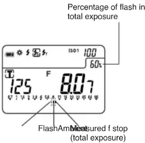
2-5 Flash analyzing function
When measuring flash light, the shutter speed and F stop value (combining ambient light and flash light: total amount of light) are displayed on the LCD screen and the ambient light and flash light are each displayed as separate values along with the total amount of light (combined flash and ambient) on the analog scale. In addition, the ratio of flash light to the total amount of light is displayed as a percentage (in 10% steps) at the sametime. The ratio of flash to the total amount of light is useful when a desired flash to ambient lighting ratio is needed.
Under certain conditions, if the flash light output is 60% and the available light output is 40%, the LCD screen will display the flash measured value on the analog scale with a faster blinking icon than the total exposure blinking icon.
-
To emphasize the ambient light (to create a more natural lighting condition) increase the ratio of ambient light,(use the Jog wheel ⑤) by changing the shutter speed to a slower setting.The ratio of flash light in the total exposure will be reduced (as shown in the diagram to the right - 20%).The analog scale also shows the ambient output to be about 2.5 stops higher than the flash light output.As a result,images will exhibit a natural lighting quality with flash filled shadows without an over powering presence of flash.
-
Toreduce the effect of ambient light decrease the ratio of ambient light, (use the Jog wheel) by changing the shutter speed to a faster setting. The ratio of flash in the total exposure will be increased (as shown in the diagram to the right – 80%) The analog scale also shows the flash light output to be about 1.5 stops higher than the ambient light output.
text_image
Percentage of flash in total exposure 125 F 8.07 FlashAm Measured f stop (total exposure)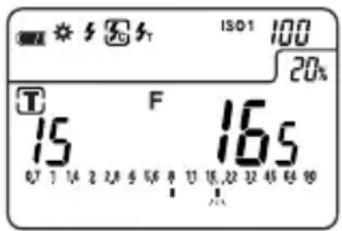
text_image
15 F 16s ISO1 100 20% T 15 16s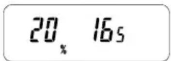
text_image
20, 16s(Display in spot viewfinder)

text_image
ISO1 100 80% T F 8.04 250 8.04 07 1 14 2 28 5 6.0 10 12 22 32 42 52 62 92Reference:
- Slower shutter speeds allow more available light to reach the film or digital camera sensor, and faster shutter speeds reduce the amount of available reaching the film or sensor.
- The settings above are made by adjusting the ambient light by the shutter speed. It is also possible to modify the ratio by adjusting the flash light (when changing the distance between the flash and the subject or when changing the amount of light of the flash). When using this method, re-measure each time the flash light is adjusted.
2-6 Wireless Flash Radio Triggering
With the Radio Transmitter module plugged into the meters radio socket and a Receiver or Transceiver (PocketWizard ^® ) connected to one or more electronic flash units, the meter provides a convenient system that enables one person working alone to measure flash output without the need of a sync cord. Pressing the Measuring button simultaneously triggers the flash and measures the flash output.
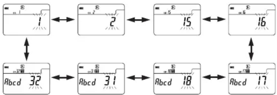
The L-758DR/758D/758CINE has 32 triggering channels with the RT-32N radio triggering module (built-in for L-758DR, optional for L-758D/758CINE). Channels 1-16 provide single triggering, while channels 17-32 offer Selective Quad-Triggering control. Selecting one of the Quad-Triggering channels (17-32) provides control of up to four zones of lighting indicated as a Zone letter (A, B, C and D). Selecting or deselecting a zone is quick and easy with the Quad-Triggering buttons (A,B, C or D). In order to trigger a flash units set for Quad-Triggering, the electronic flash unit must be connected to a PocketWizard MultiMax or a n electronic flash that already has a PocketWizard built-in. The PocketWizard Plus or Plus II can be triggered by the L-758DR using channels 1-4.
< Example with optional 32 channels receiver >
For L-758D/758CINE: Open the battery compartment cover ⑮, remove connector cover ⑲ and set the RT-32 Radio Transmitter module (optional) by aligning the connector with the pins.
- Select the Wireless Flash Radio Triggering setting mode by using the Jog wheel ⑤ while pressing the Mode button ⑩.

text_image
SEKONIC S c# MODE- The set channel number will blink, turn the Jog wheel to select the channel desired.
- In the Channel setting mode, "ch" and channel number appear on the upper left side of the LCD. The channel numbers (1 to 16 or 17 to 32) will appear in the F-stop display area. When the channel number is set to 17 - 32, Quad-Triggering zones (A, b, c and d) are displayed in the T (shutter speed) display area. In the absence of a Quad-Triggering setting (A,b,c or d), a "-" will appears in it's place.
flowchart
graph TD
    A["1"] --> B["2"]
    B --> C["15"]
    C --> D["16"]
    D --> E["17"]
    E --> F["18"]
    F --> G["31"]
    G --> H["32"]
    H --> I["Abcd"]
    style A fill:#f9f,stroke:#333
    style B fill:#f9f,stroke:#333
    style C fill:#f9f,stroke:#333
    style D fill:#f9f,stroke:#333
    style E fill:#f9f,stroke:#333
    style F fill:#f9f,stroke:#333
    style G fill:#f9f,stroke:#333
    style H fill:#f9f,stroke:#333
    style I fill:#f9f,stroke:#333
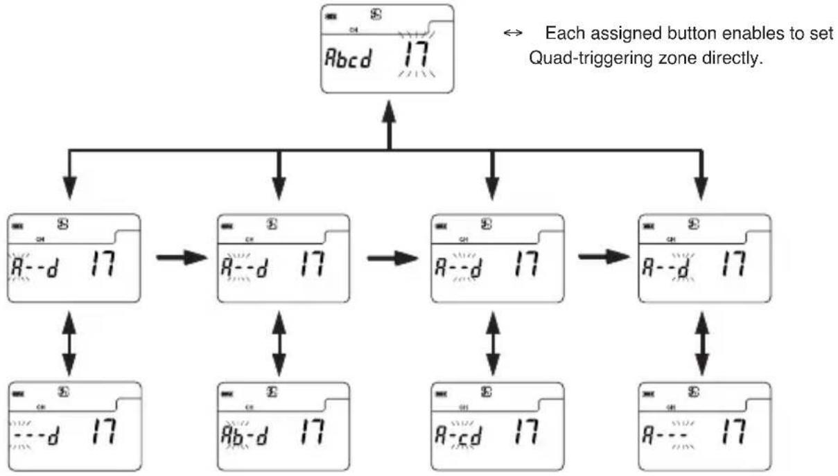
- In the Quad-Triggering zone setting, after the channel is set to 17 to 32, the assigned buttons below are pressed. Pressing each of the buttons activates or deactivates the Quad-Triggering zone (A, b, c or d). When a Quad-Triggering zone is activated, the corresponding Quad-Triggering zone letter appears on the display. If a Quad-Triggering zone is deactivated, a "-" is displayed in its place.
flowchart
graph TD
    A["Keyboard Layout"] --> B["Keyboard Layout 17"]
    B --> C["Keyboard Layout 17"]
    C --> D["Keyboard Layout 17"]
    D --> E["Keyboard Layout 17"]
    E --> F["Keyboard Layout 17"]
    F --> G["Keyboard Layout 17"]
    G --> H["Keyboard Layout 17"]
    H --> I["Keyboard Layout 17"]
    I --> J["Keyboard Layout 17"]
    J --> K["Keyboard Layout 17"]
    K --> L["Keyboard Layout 17"]
    L --> M["Keyboard Layout 17"]
    M --> N["Keyboard Layout 17"]
    N --> O["Keyboard Layout 17"]
    O --> P["Keyboard Layout 17"]
    P --> Q["Keyboard Layout 17"]
    Q --> R["Keyboard Layout 17"]
    R --> S["Keyboard Layout 17"]
    S --> T["Keyboard Layout 17"]
    T --> U["Keyboard Layout 17"]
    U --> V["Keyboard Layout 17"]
    V --> W["Keyboard Layout 17"]
    W --> X["Keyboard Layout 17"]
    X --> Y["Keyboard Layout 17"]
    Y --> Z["Keyboard Layout 17"]
ISO 1 M.CLEARMID.TONEISO 2
"A" "d" "c" "b"

CAUTION:
- It is not possible to activate Quad-Triggering control without first selecting a channel 17-32, and a Quad-Triggering zone (A, b, c or d).
-
To prevent damage due to static electricity, release any static electricity from your body by touching a metal object nearby (door knob, aluminum window frame, etc.) before touching the radio transmitter module.
-
Upon setting the channel and Quad-Triggering zones, press the Measuring button ⑭ to enter your settings. The display will automatically go to the main LCD screen and Wireless Flash Radio Triggering mode will be activated or rotate Jog wheel ⑤ to set wireless flash radio triggering mode or wireless multiple flash radio triggering mode.
- Confirm that the meter and the radio Receiver or Transceiver are set to the same channel number. The flash unit will fire and measure the light output when the measuring button on the meter is pressed.
NOTES:
- When firing a flash, if the flash brightness is 8EV lower than the ambient light, the meter may fail to detect the light. In this case, make measurements using the cord flash mode (see page 21).
- Rapid start fluorescent lamps and special lighting are sometimes mistaken for flash, and accidentally measured. In this case, make measurements using the cord flash mode (see page 21).
- The waveform of flashbulb have a slight slope and there is a possibility that light meter cannot recognize the flashbulb in Cordless flash mode. In this case, be sure to take measurement in Cord flash mode (see page 21).
Reference:
- Refer to the radio Receiver or Transceiver instruction manual for the recommended operating method.
-
Maximum distance of the wireless flash radio triggering system can vary depending on the placement of the remote Receiver or Transceiver, direction of the radios antenna, distance from a large body of water or concrete wall and other possible factors.
-
Confirm the range between the meter (transmitter) and Receiver or Transceiver.
- Place the meter and Receiver or Transceiver away from large metal objects, concrete, objects, large moisture content (both people and trees fall into the category) and so forth.
- Secure the radio Receiver or Transceiver in place by using Velcro tape or a 1/4-20 mounting screw. Be sure that the entire length of the Receiver or Transmitter antenna is higher than the flash pack. Avoid contact between the Receiver or Transceiver antenna and metal objects at all times.
- Depending on the location, there may be cases when the Receiver or Transceiver is incapable of receiving any radio signals whatsoever. There are several possible causes for this such as radio signals reflected off of nearby objects. This can generally be resolved by shifting the meter (Transmitter) or the Receiver or Transceiver slightly in one direction or another. In addition, confirm that the Receiver or Transceiver is not placed behind objects that readily absorb or deflect radio signals such concrete, metal, low hills, etc.
NOTE:
- The Wireless flash triggering system may be used only in countries where a permit for the control frequency has been issued by the government office in charge. There are several kinds of frequencies in the world, and we recommend you check if your transmitter(s) and receiver(s) or Transcevers are compatible with each other.

flowchart
graph TD
    A["L-758D or L-758CINE (FCC & IC version)"] --> B["RT-32FCC (for FCC & IC)"]
    C["L-758D or L-758CINE (CE version)"] --> D["RT-32N"]
    E["Sticker on the back indicates "Use RT-32N for radio transmitter module""] --> B
    F["Sticker on the back indicates "CE""] --> D
    B <--> G["No compatible"]
    D <--> G
    G <--> H["RT-32CE (for CE)"]
    I["RT-32CE"] --> J["Compatible"]
    style A fill:#f9f,stroke:#333
    style C fill:#f9f,stroke:#333
    style E fill:#f9f,stroke:#333
    style F fill:#f9f,stroke:#333
    style I fill:#ccf,stroke:#333
    style J fill:#ccf,stroke:#333
1. Memory function
This meter can store up to nine measured values in memory for incident light and reflected light simultaneously. This feature can be used in the following modes;
Ambient light : shutter speed priority, aperture priority or EV mode.
Electronic Flash light : cord, cordless or wireless flash radio triggering mode.
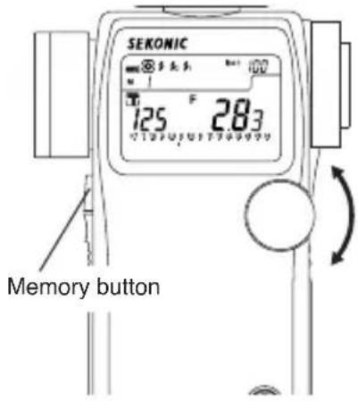
- Press the Measuring button ⑭ and take a measurement. The Current measured value on the analog scale will blink.
- Press the Memory button ⑦ and store the measured value in memory, and the memorized value on the analog scale will stop blinking.
The number of values in memory is displayed on the LCD. The memorized value is displayed on the analog scale. By repeating this operation, up to nine values can be stored in memory.

text_image
SEKONIC 125 F 2.83 Memory button- To clear the memory, press the memory clear button ②3 or switch to another measurement mode.
Reference:
- When pressing Memory clear button ②3 once, the last memorized value is cleared. If you want to clear all memorized values, please hold down the Mode button ⑩ and press the Memory clear button.
text_image
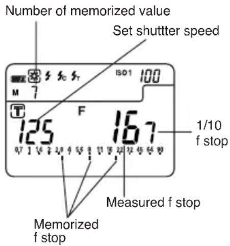
Number of memorized value Set shutter speed ISO1 100 M 7 T 125 F 167 0.7 1 1/4 2 2/8 4 5/5 6 11 15 22 32 45 64 90 1/10 f stop Measured f stop Memorized f stop4. Memory Recall
To enter Memory recall mode, hold down the Mode button and press the Memory button, and the "M" icon and number of stored measurements will blink. Rotate Jog wheel to recall memorized value. To exit Memory recall mode, hold down the Mode button and press the Memory button again, and "M" icon and number of stored measurements will stop blinking.
Reference:
- During Memory recall mode, when you press Memory clear button, the currently recalled value is cleared.
NOTE:
- The memory function cannot be used in "Multiple flash (cumulative) mode."
- Measured values for ten times or more measurements will be displayed but cannot be stored in memory.
2. Averaging function
This function displays the average of up to nine of the values in memory.
- Press the Measuring button ⑭ and take a measurement. Current measured value on the analog scale will blink.
- Press the Memory button ⑦ and store the measured value in memory, and memorized value on the analog scale stops blinking.
- When the AVE./ EV button ④ is pressed, an averaged value for up to nine measurements will be displayed on the LCD. The values in memory and the averaged value are displayed on the analog scale (The averaged value blinks). An "A" appears in LCD to indicate this is an average.
- The average mode can be canceled by pressing the AVE./Δ EV button.
Reference:
- When the EV scale is selected, the averaged exposure value will be displayed in the center of the scale.
text_image
SEKONIC 125 F 283 Memory button
text_image
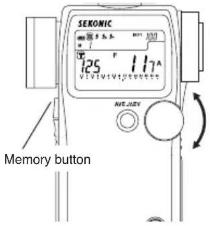
Averaging indicator Averaged f stop Number of memorized value SENONIC 1/10 f stop AVERaged f stop Memorized f stop Set shutter speed3. Contrast function
This function is useful for evaluating studio lighting and checking the evenness of the lighting set-up across the subject area.
Take a measured value at a certain point as a standard value. The difference between the standard value and a new measured value is displayed in EV and the measurements are displayed on the analog scale.
Example of adjusting lights using Contrast function in shutter speed priority mode (incident light).
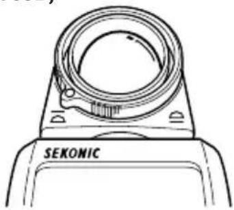
- Turn the Lumisphere retracting ring ① to lower it to the (retracted) mark position.

natural_image
Line drawing of a mechanical component with a circular top and base (no text or symbols)-
Turn any secondary light source off. Point the Lumisphere toward the main light source, from the position of the subject and take a measurement. Press the Memory button ⑦ and store the value in memory.
-
Press the AVE./ EV button ④ and display the “A” mark on the LCD indicating a standard value.
-
Turn the main lighting off. Now, point the Lumisphere toward the secondary light source. While pressing and holding the Measuring button ^14 , the indicated difference between the main and secondary light source is displayed in EV. At the same time, the standard value and a new measured value are displayed on the analog scale.
text_image
SEKONIC 125 °F 117° VIVI VIVI VIVI VIVI VIVI NVE MEV Memory button
text_image
SEKONIC Set shutter speed Indicator of reading 125 -2.0 A Contrast in EV Anx.0EV Memorized f stop value f stop value being measured| EV difference of Δ EV value | Contrast ratio |
| 1 | 2 : 1 |
| 1.5 | 3 : 1 |
| 2 | 4 : 1 |
| 3 | 8 : 1 |
| 4 | 16 : 1 |
- The Standard value can be cleared by pressing the Memory clear button ②3, or AVE./ EV button.
Reference:
- To determine exposure after adjusting lights, turn both main and secondary light sources on, raise the Lumisphere to the △ mark position, then take a reading with the Lumisphere aimed in the direction of camera's lens axis in incident light.
• This function can also be used for reflected light. - You can select aperture scale or latitude scale by holding Mode button ⑩ and pressing AVE. / ΔEV.
4. How to use an incident illuminance (LUX or FC) meter (L-758DR/758D)
- Turn the Lumisphere retracting ring ① to lower it to the retracted) mark position.
- Make sure that any compensation Exposure/Calibration compensation: see page 36 & 37, Compensation of camera exposure profile: see page 46 is canceled.
- Set the meter to EV mode and ISO 100.
- Place the meter parallel to the subject and take a measurement.
- The measured EV can be converted to find the brightness level with the conversion table below.
natural_image
Line drawing of a SEKONIC device component with no visible text or symbols on the body itself
text_image
ISO1 100 EV* EV value → Lux conversion table
| EV\Decimal places | 0 0.5 | EV\Decimal places | 0 | 0.5 | |
| -2 | 0.63 | 0.88 | 9 | 1300 | 1800 |
| -1 | 1.3 | 1.8 | 10 | 2600 | 3600 |
| 0 | 2.5 | 3.5 | 11 | 5100 | 7200 |
| 1 | 5.0 | 7.1 | 12 | 10000 | 14000 |
| 2 | 10 | 14 | 13 | 20000 | 29000 |
| 3 | 20 | 28 | 14 | 41000 | 58000 |
| 4 | 40 | 57 | 15 | 82000 | 120000 |
| 5 | 80 | 110 | 16 | 160000 | 230000 |
| 6 | 160 | 230 | 17 | 330000 | 460000 |
| 7 | 320 | 450 | 18 | 660000 | 930000 |
| 8 | 640 | 910 | 19 | 1300000 | 1900000 |
* EV value → Foot candle (FC) conversion table
| EV\Decimal places | 0 0.5 | EV\Decimal places | 0 | 0.5 | |
| -2 | 0.06 | 0.08 | 9 | 120 | 170 |
| -1 | 0.12 | 0.16 | 10 | 240 | 340 |
| 0 | 0.23 | 0.33 | 11 | 480 | 670 |
| 1 | 0.46 | 0.66 | 12 | 950 | 1300 |
| 2 | 0.93 | 1.3 | 13 | 1900 | 2700 |
| 3 | 1.9 | 2.6 | 14 | 3800 | 5400 |
| 4 | 3.7 | 5.3 | 15 | 7600 | 11000 |
| 5 | 7.4 | 11 | 16 | 15000 | 22000 |
| 6 | 15 | 21 | 17 | 30000 | 43000 |
| 7 | 30 | 42 | 18 | 61000 | 86000 |
| 8 | 59 | 84 | 19 | 120000 | 170000 |
Reference:
- L-758CINE can read LUX or FC directly when the custom setting function is used (refer to page 40).
5. How to use a reflected luminance (cd/m ^2 or FL) meter (L-758DR/758D)
- Exposure/Calibration compensation: see page 36 & 37, Compensation of camera exposure profile: see page 46.
- Set the meter to EV mode and ISO 100.
- Set meter to spot reading for reflected light.
Take the measurement by looking through the finder and aligning so the subject that will be measured is inside the circle.
- The measured EV can be converted to find the brightness level with the conversion table below.
* EV value → cd/m² conversion table
| EV\Decimal places | 0 | 0.5 | EV\Decimal places | 0 | 0.5 |
| 1 | 0.25 | 0.35 | 11 | 260 | 360 |
| 2 | 0.5 | 0.7 | 12 | 510 | 720 |
| 3 | 1 | 1.4 | 13 | 1000 | 1400 |
| 4 | 2 | 2.8 | 14 | 2000 | 2900 |
| 5 | 4 | 6 | 15 | 4100 | 5800 |
| 6 | 8 | 11 | 16 | 8200 | 12000 |
| 7 | 16 | 23 | 17 | 16000 | 23000 |
| 8 | 32 | 45 | 18 | 33000 | 46000 |
| 9 | 64 | 91 | 19 | 66000 | 93000 |
| 10 | 130 | 180 |
* EV value → Foot-lambert (FL)conversion table
| EV\Decimal places | 0 | 0.5 | EV\Decimal places | 0 | 0.5 |
| 1 | 0.073 | 0.10 | 11 | 75 | 110 |
| 2 | 0.15 | 0.20 | 12 | 150 | 210 |
| 3 | 0.30 | 0.40 | 13 | 300 | 420 |
| 4 | 0.60 | 0.80 | 14 | 600 | 850 |
| 5 | 1.2 | 1.7 | 15 | 1200 | 1700 |
| 6 | 2.3 | 3.3 | 16 | 2400 | 3400 |
| 7 | 4.7 | 6.6 | 17 | 4800 | 7000 |
| 8 | 9.3 | 13 | 18 | 9000 | 14000 |
| 9 | 19 | 26 | 19 | 19000 | 27000 |
| 10 | 37 | 53 |
Reference:
- L-758CINE can read cd/m ^2 or FL directly when the custom setting function is used (refer to page 40).
6. How to use the Exposure compensation function
Exposure compensation can be made in precise 1/10 step increments in a +/- 9.9 EV range. Exposure compensation may be necessary when compensation for filters, bellows, extension tube, etc is required.
-
Set the measurement mode (incident light, reflected light) for the desired compensation. You can make calibration compensation independently for both incident, and reflected light. It is not possible to switch between measurement modes if the setting is not completed.
-
Making a plus compensation will increase the exposure. Hold the ISO1 button ⑪ and the ISO 2 button ⑥ and turn the Jog wheel ⑤ counter clockwise. The ⨗ will appear in the upper section of the LCD screen. The compensation will change in +0.1 EV steps up to +9.9.
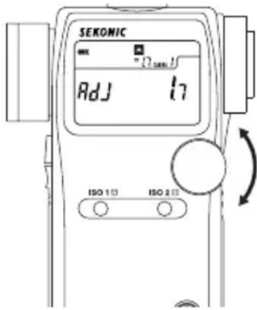
text_image
SEKONIC Adj 17 ISO 1 ISO 2- Making a minus compensation will decrease the exposure. Hold the ISO1 button and the ISO 2 button and turn the Jog wheel clockwise.
The ■ will appear in the upper section of the LCD screen. The compensation will change in -0.1 EV steps up to -9.9.
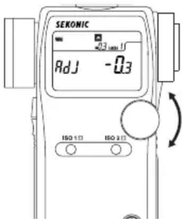
text_image
SEKONIC 03 mm H Adj -0.3 ISO 1□ ISO 2□NOTE:
- When making compensations, be sure that it satisfies your needs based on the results of your digital camera sensor or film be used.
- While incident and reflected light can be set independently, be aware that both ambient light and flash exposure are corrected uniformly.
- Compensation effects every mode of the meter. If recalibration has been made for specific purpose do not forget to return to original zero settings.
Reference:
- When compensation is activate, a plus ( ) or minus ( ) sign as well as the amount of compensation is displayed continuously on the LCD. You can set custom settings so that a plus ( ) or minus ( ) sign as well as the amount of compensation doesn't appear on the LCD. (See page 40)
- You can also set custom setting so that making a plus compensation results in a decreased exposure (increasing the value of the aperture or shutter speed value) and making a minus compensation results in and increased exposure (decreasing the value of the aperture or shutter speed).
7. How to use Calibration compensation function
Calibration compensation can be made in precise 1/10 step increments in a +/- 1.0 EV. It provides the ability to match exposure measurements with meters to meters, correct exposure for special requirements, adjusts for film or digital cameras, etc.
-
Set the measurement mode (incident light, reflected light) for the desired compensation. You can make calibration compensation independently for both incident, and reflected light. It is not possible to switch between measurement modes if the setting is not completed.
-
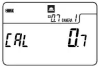
To enter the calibration setting of the meter it must first be turned off. Press the power button on while holding down the ISO1 and ISO2 buttons simultaneously. You can release the power button, however please keep pressing both ISO1 and ISO2 buttons; the screen will display CAL 0.0 (for calibration).
text_image
CAL 0.7 "0.7 CAMERA 1"- The calibration setting can be changed by rotating the Jog wheel while pressing and holding down the ISO 1 and ISO 2 buttons simultaneously. A range of +/- 1.0 EV in 1/10 step increments is possible for calibration.
NOTE:
- When making calibration compensations, be sure that it satisfies your needs based on the results of digital camera sensor or film being used.
- While incident and reflected light can be set independently, be aware that both ambient light and flash exposure are corrected uniformly.
- Compensation effects every mode of the meter. If recalibration has been made for specific purpose, do not forget to return to original zero settings.
Reference:
- The calibration setting is not displayed on the main screen once it is set.
- You can also set custom setting so that making a plus compensation results in a decreased exposure (increasing the value of the aperture or shutter speed value) and making a minus compensation results in and increased exposure (decreasing the value of the aperture or shutter speed).
8. Filter compensation
8-1 Filter compensation (1)
It is possible to compensate for filter factor within a range of ±5.0 EV in 1/10 steps. The measurement corresponding to the set compensation and can be displayed while pressing ISO2 button ⑥. Highlight and shadow compensation values can also be enter for quick exposure metering.
-
Select setting number 1 and item number 1 in the custom setting mode (see page 40).
-
Set the desired compensation by turning the Jog wheel ⑤ while pressing ISO2 button.
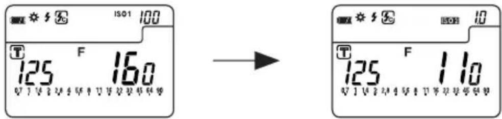
• In case of filter compensation
When attaching the filter with 1.0 step exposure factor to the camera, set "1.0" in ISO2 indicator by rotating Jog wheel while pressing ISO2 button.
text_image
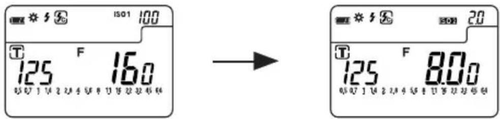
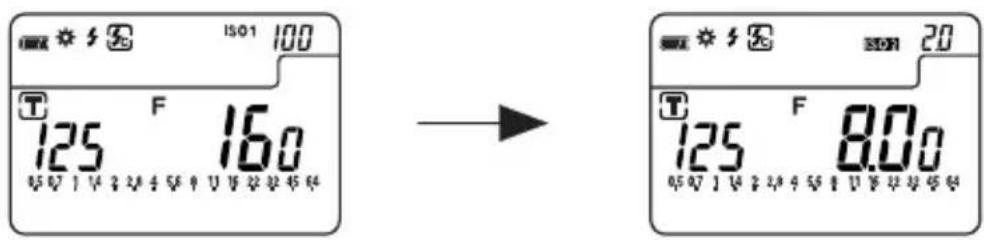
ISO1 100 T F 16.0 125 16.0 → T F 11.0 125 11.0• In case of highlight measurement compensation
When compensating plus 2 steps from highlight measurement, set "2.0" in ISO2 indicator by rotating Jog wheel while pressing ISO2 button.
text_image
ISO1 100 T F 16.0 125 16.0 0.07 1 14 2 24 4 56 8 10 12 22 46 64 → T F 8.00 125 8.00 0.07 1 14 2 24 4 56 8 10 12 22 46 648-2 Filter factor number compensation (2) (L-758CINE only)
When using the L-758DR for Cine/Video exposures, in cine industry, it is possible to set 7 different frequently used types of filters.
- Select setting number 1 and item number 2 in the custom setting mode (see page 40).
- The symbol of the desired filter from among the 7 types can be selected by turning the Jog wheel ⑤ while pressing ISO2 button ⑥.
- After setting filter compensation, the filter symbol and compensated F value or EV value are displayed while pressing ISO2 button.
text_image
ISO1 100 125 F 16.0 05 07 1 14 2 24 3 56 4 1 16 22 22 45 64 → 125 F 8.0Filters, LCD Display and Corrected Value
| Filter Factor No. 85 ND0.3 N | ND0.6 ND | 0.9 85N3 | 85N6 85 | N9 | |||
| LCD display 85- n3- n6- n9- | A3- A6- | A9- | |||||
| Compensated value (EV) | -0.7 | -1 | -2 | -3 | -1.7 | -2.7 | -3.7 |
(Filter factor numbers are Kodak Wratten filter numbers.)
9. Custom setting function
The following Custom Settings provide a quick and easy setup of individual meter preferences. All preferences are stored on a memory chip and can not be deleted, they can only be changed back to default settings.
| No. | Model | Custom setting name | Item number | |||
| 0 | 1 | 2 | 3 | |||
| 1 | 758 | ISO 2 | Film sensitivity in 1/3 step | Filter compensation (1) in 1/10 step (+/-5EV) | - | - |
| CINE | Film sensitivity in 1/3 step | Filter compensation (1) in 1/10 step (+/-5EV) | Filter Factor compensation (2) 7 filter factor numbers | - | ||
| 2 | 758 & CINE | Exposure compensation display setting | Always Displayed | Not display | - | |
| 3 *1 | 758 & CINE | Increments of Shutter Speed (T) + Aperature (A) | Full step | 1/3 step | 1/2 step | - |
| 4 | 758 & CINE | Exposure Priority settings | T + F | T only | F only | - |
| 5 | 758 & CINE | EV mode | Not available | Available | - | - |
| 6 | 758 & CINE | Multiple flash mode (cumulative) | Not available | Available | - | - |
| 7 | 758 & CINE | Dynamic range/ Clipping point icons | Three dots | Within range | Outside range | No display |
| 8 | 758 & CINE | Standard value if Mid. Tone memory is not set | First memorized value | Current Measured value | Last memorized value | - |
| 9 | 758 & CINE | Average | Weighted mean average | Simple averaging | - | - |
| 10 | 758 & CINE | Auto save on Power off | Available | Not available | - | - |
| 11 | 758 & CINE | Auto power off time | 20 min. | 10 min. | 5 min. | Not available |
| 12 | 758 & CINE | Jog Wheel Function (clockwise direction) | Decreases value (T or F) | Increases value (T or F) | - | |
| 13 | 758 & CINE | Compensation +/- preference | Additive Compensation | Subtractive Compensation | - | - |
| 14 *2 | CINE | Illuminance or Luminance display | Selectable Individual or Combined | Combined T+F+(Lux /FC) Combined T+F+(FL/cd/m2) | Individual only | - |
| 15 | CINE | Illuminance measurement in incident mode | LUX, FC | LUX | FC | Not available |
| 16 | CINE | Luminance measurement in reflected mode | cd/m2, FL | cd/m2 | FL | Not available |
| 17 *3 | 758 & CINE | Switching Measuring/ Memory Buttons | Standard | Reverse | Auto-Switching | - |
*1 1/10 stop fractions are displayed in full, 1/2 and 1/3 step increments.
*2 Individual: LUX, FC, cd/m ^2 or FL
Compound: LUX+T+F, FC+T+F, cd/m²+T+F or FL+T+F (combination)
*3 Auto-Switching: In incident mode, Measuring/Memory buttons are standard (as they are), however, in reflected mode, automatically two buttons are switched.
Reference:
- Default settings are all set to zero (0).
-
To enter the custom setting mode, the meter must first be turned off. Press Mode button ⑩ and turn the power on.
-
In the custom setting mode, 'CS' (custom setting) is displayed in the ISO display area, a setting number between 01-14 (L-758DR/758D) or 01-17 (L-758CINE) is displayed in the shutter speed display area and item number 0, 1, 2 or 3 is displayed in the aperture display area.

text_image
01 0 Custom setting item no. Custom setting no.- Turn the Jog wheel ⑤ and select the desired setting number and the custom setting name (see page 40).

text_image
08 1 CS- The item number will change each time the Mode button is pressed.
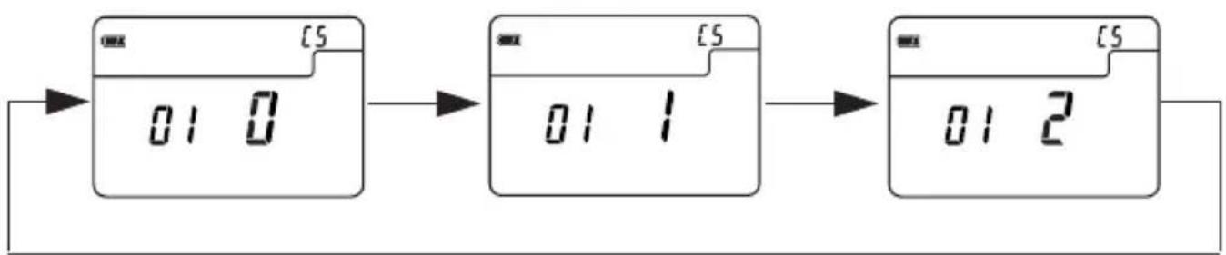
flowchart
graph LR
    A["01 0"] --> B["01 1"]
    B --> C["01 2"]
-
Pressing the Memory clear button ②3 in the custom setting mode will reset all settings to default.
-
After completing the custom setting, terminate the custom setting mode by turning the power off. This operation will also automatically turn off the power.
1. Calibration testing for exposure profiling
A camera exposure profile plays two main roles.
[1] It can be used to display on a light meter the unique dynamic range and clipping point of the digital camera you are using.
[2] To display more accurate exposure values on the light meter, it records unique variations in the camera, lens shutter speed, aperture, etc. that you are using and reflects them in the exposure display.
The L-758DR/L-758D/L-758CINE can be programmed to stored, recall and display up to three different digital cameras.
Below are the following settings that can be programmed into the L-758DR/L-758D/L-758CINE.
1. Compensation value
Compensation value (aperture and shutter speed) can be programmed for a specific camera and hand-held meter. Compensation adjustment is within a +/- 5EV range in 1/10 step increments.
2. Dynamic range (-)
The point at which a given lighting situation (pre-exposure) has surpassed the responds level of a sensor and alerts the shooter of a under exposure situation (Pre-Exposure Warning). These point can be custom set from -7EV to 0EV in 1/10 increments.
3. Clipping point (-)
The point at which the sensor has reached its maximum reproducible shadow details without pixel noise or grain. Dynamic range (-) adjustment is set from -7EV to 0EV in 1/10 step increments.
4. Clipping point (+)
The point at which the sensor has reached its maximum reproducible highlight details without blooming or highlight block up. Dynamic range (+) adjustment is set from 0EV to +7EV in 1/10 step increments.
5. Dynamic range (+)
The point at which a given lighting situation (pre-exposure) has surpassed the responds level of a sensor and alerts the shooter of an over exposure situation (Pre-Exposure Warning). These point can be custom set from 0EV to +7EV in 1/10 increments.

line
| Exposure(ΔEV) | OUTPUT TONES(6bit) | | ------------- | ----------------- | | -6.0 | 10 | | -5.0 | 15 | | -4.0 | 25 | | -3.0 | 40 | | -2.0 | 60 | | -1.0 | 90 | | 0 | 120 | | +1.0 | 160 | | +2.0 | 200 | | +3.0 | 240 | | +4.0 | 250 |It is necessary to test the cameras sensitivity, measure the actual dynamic range and know the clipping points of your digital camera and processing used before programming the L-758DR (L-758D/L-758CINE) meter for Exposure Profiling.
Reference:
- The dynamic range settings and the clipping point settings can be switched, if it is necessary to create clipping points within the dynamic range. In this case, simple enter the dynamic range data in the clipping point cells and the clipping points in the dynamic range cells.
- For details, please refer to the Software Guide found on the CD-ROM included with this product.
Note:
- Data Transfer Software and Software Guide (Testing procedure, Image analyzing and so on) are preliminary for digital still photography use.
2. How to set the Camera Exposure Profiling
There are two ways to input the result of the test target data into the light meter: 1) Sekonic Data Transfer Software - install application software from the included CD-ROM and connect the computer and light meter via USB, and 2) Direct Input - Manually enter the test target data directly into the light meter.
2-1 Sekonic Application Software
Data Transfer Software is included with the L-758DR, L-758D and L-758CINE. Data Transfer Software is an application software for creating and editing the Camera Exposure Profiles and transferring the data to the light meter.
2-1-1 Outline of software
1) The software makes it possible to create the following items of camera exposure profile easily by automated calculation from testing data.
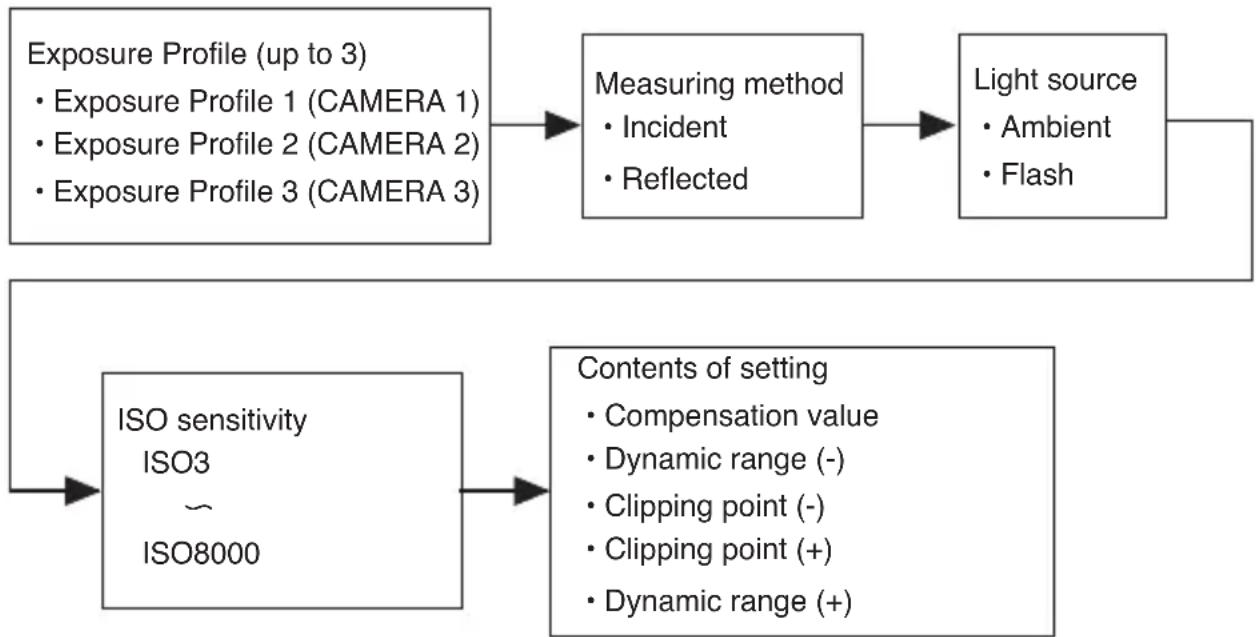
flowchart
graph TD
    A["Exposure Profile (up to 3)<br>• Exposure Profile 1 (CAMERA 1)<br>• Exposure Profile 2 (CAMERA 2)<br>• Exposure Profile 3 (CAMERA 3)"] --> B["Measuring method<br>• Incident<br>• Reflected"]
    B --> C["Light source<br>• Ambient<br>• Flash"]
    D["ISO sensitivity<br>ISO3 ~<br>ISO8000"] --> E["Contents of setting<br>• Compensation value<br>• Dynamic range (-)<br>• Clipping point (-)<br>• Clipping point (+)<br>• Dynamic range (+)"]
Reference:
- For detailed information on Sekonic Data Transfer Software, please refer to the Software Guide found on the Sekonic Application Software CD-ROM included with this product.
2-2 Manual Input of Exposure Profile
It situations where it is not possible or convenient to use a computer or the Sekonic Data Transfer Software, Exposure Profile data can be entered into the L-758DR (L-758D or L-758CINE) directly. Below is the step by step process for manually entering a specific Exposure Profile.
1) With the meter turned off, enter the Camera Exposure Profiling mode by pressing the Power button ⑫ while pressing the AVE../ △ EV button ④ at the same time.
2) In the Camera Exposure Profiling mode, the current (or default) contents are displayed.
3) Setting Individual Exposure Profiles (Camera 1, 2 and 3) Press MID.TONE button ⑳ while pressing ISO1 button ⑪ to select the desired camera exposure profile.
4) Setting measuring mode Rotate the Jog wheel ⑤ while pressing the Mode button ⑩ to select measuring mode (ambient or flash including all flash mode)
5) Setting light receiving method Turn the Incident/reflected spot selector dial ⑲ to select incident or reflected light.
6) Setting ISO sensitivity Rotate the Jog wheel ⑤ while pressing the ISO1 button ⑪ to select ISO sensitivity.
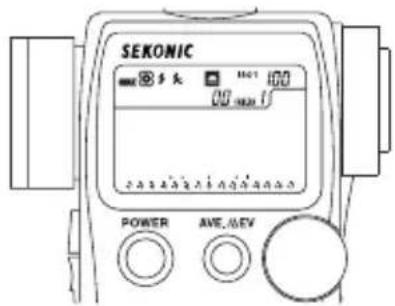
text_image
SEKONIC 多头 100 100 POWER AVE, A/EV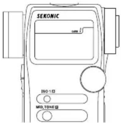
text_image
SEKONIC ISO 10 MID, TONE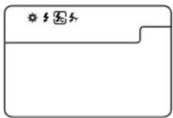
text_image
Simple diagram with a window and icons, likely representing a status or status indicator in a document or layout.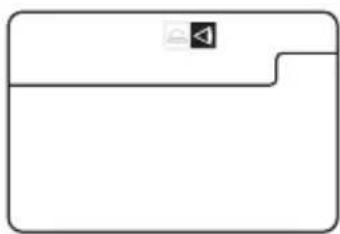
natural_image
Simple line drawing of a folder icon with a speaker symbol (no text or labels)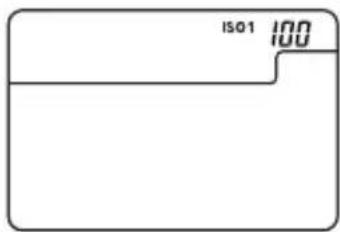
text_image
ISO1 1007. Camera Exposure Profiling
7) Setting compensation value
Rotate the Jog wheel ⑤ while holding down ISO1 button ⑪ and ISO2 button ⑥ simultaneously. Compensation values can be made in 1/10 step increments in +/-5.0EV.

text_image
SEKONIC +03 AdJ ISO 1 ISO 28) Setting Dynamic range (-)
Rotate the Jog wheel ⑤ while pressing AVE./ △ EV button ④ . Dynamic range can be set from -7 to 0EV in 1/10 step increments.
Note:
- Only when you enter the data manually, the setting value is not the step from the middle tone (0), but the step from the edge of clipping point (-).
Ex) When the clipping point (-) is -2.5 and the dynamic range (-) is -3.5, the step of dynamic range (-) to enter is -1.0.
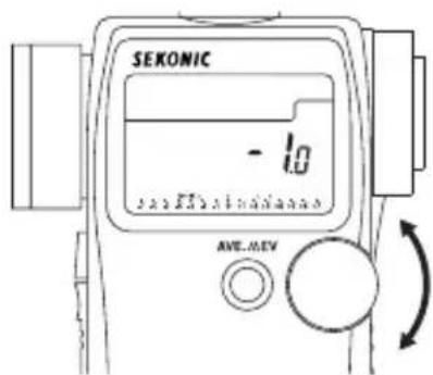
text_image
SEKONIC - 1.0 AWE.AEV9) Setting Clipping point (-)
Rotate the Jog wheel ⑤ while pressing MID.TONE button ⑳ . Clipping point can be set from -7 to 0EV in 1/10 step increments.
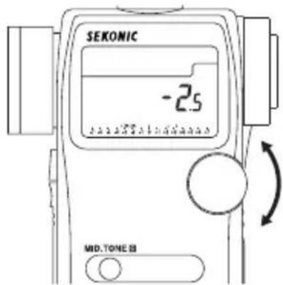
text_image
SEKONIC -2.5 MID.TONE Ⅲ10) Setting Clipping point (+)
Rotate the Jog wheel ⑤ while pressing Memory clear button ②3. Clipping point can be set from 0 to +7EV in 1/10 step increments.

text_image
SEKONIC 2.5 M.CLEAR11) Setting Dynamic range (+)
Rotate the Jog wheel ⑤ while pressing ISO2 button ⑥. Dynamic range can be set from 0 to +7EV in 1/10 step increments.
Note:
- Only when you enter the data manually, the setting value is not the step from the middle tone (0), but the step from the edge of clipping point (+).
Ex) When the clipping point (+) is 2.5 and the dynamic range (+) is 3.5, the step of dynamic range (+) to enter is 1.0.
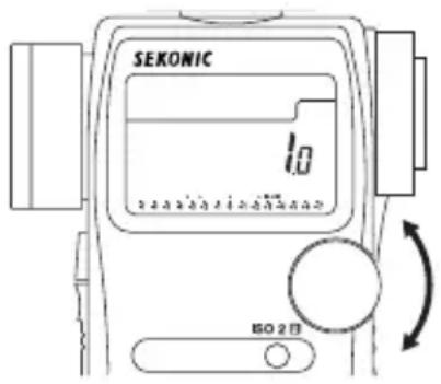
text_image
SEKONIC 1.0 ISO 2 日12) Press the Measuring button ⑭ if you want to copy this ISO setting to all ISO setting (from ISO 3 to 8000)
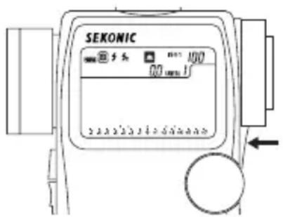
text_image
SEKONIC 5.5 100 00 mm 1Reference:
- To cancel the current setting being edited and return to a previous setting, press the ISO1 button ⑪ and the Memory clear button ② simultaneously.
- To return to the default for all setting of Camera Exposure Profile (CAMERA 1 to 3), press the Mode button ⑩ and the Memory clear button ② simultaneously.
- To return to the default for one of the cameras, please use the application software instead of manual input.
If we update firmware, we don't need to mention this explanation here.
3. How to use Camera Exposure Profiling
3-1 Selecting Camera Exposure Profiling
Preset Camera Exposure Profiles (Camera 1, 2 and 3) can be recalled.
1) Hold down the ISO 1 button ⑪, and press the MID.TONE button ⑳ to select the desired Camera profile (Camera 1, 2 or 3).
NOTE:
- Holding down the MID.TONE button first and pressing ISO1 button makes the last measurement value "Mid.Tone" as standard value. Be sure to hold the ISO1 button first and press the MID.TONE button to select the desired camera profile.
3-2 Analog scale
The analog scale indicates the last measured value, memorized, contrast, and averaged value, clipping point and dynamic range on the LCD. As you can see in the figure on the right, it is composed of four scales.
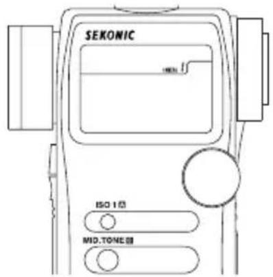
The Aperture scale can be displayed in all mode except Aperture priority mode. Aperture values are displayed as measured values (last measured value, memorized, contrast and averaged value) on this scale.

text_image
ISO1 100 T F 2.83 125 Aperture scale3-2-2 EV scale
It can be displayed in all modes except multiple flash mode. Aperture scale or EV scale can be switched by holding the Mode button ⑩ and pressing the AVE./△EV button ④. The EV scale can display a memorized measured value (ex. Incident reading) as a standard value (Mid.Tone), and display up to nine memorized values on the EV scale as +/- 7EV from the MID.TONE in 1/3 step increments.

text_image
SEKONIC 125 F 5.6s AVE..DEV Memory button MID.TONE B1) After taking a measurement by pressing the Measuring button ⑭, pressing either the Memory button ⑦, MID.TONE button ⑩ or AVE./ △ EV button ④ stores the measured value as zero in the middle of the EV scale representing the MID.TONE value. Pressing MID.TONE button will display a blinking “▲” on the scale. Pressing AVE./ △ EV button will display a blinking “■” on the scale. If the MID.TONE button is not pressed, the measured value will be set automatically in the middle of the EV scale. (See the section “3-2-3”)
Reference:
- In custom setting (see page 40), it is possible to select which value (last measurement, first memorized value or last memorized value) will become the middle of the EV scale if the MID.TONE button is not pressed.
2) The EV scale displays Clipping points(+/-), Dynamic range(+/-) and Mid. Tone with a triangle "▲" icon.
3) Measured value exceeding Clipping point will be displayed as a slow blinking "▲" icons. Measurements that exceed the Dynamic range will be displayed as fast blinking "▲" icons.
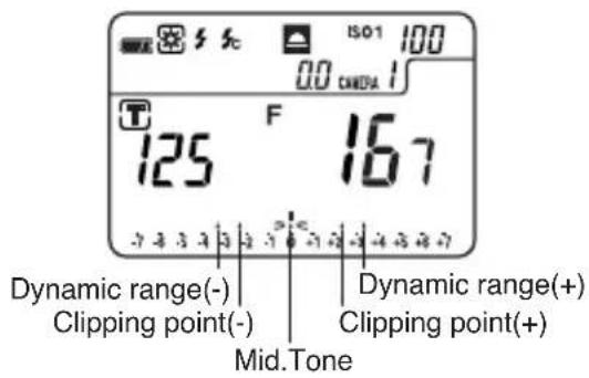
text_image
ISO1 100 0.0 CMDA 1 T F 125 167 Dynamic range(-) Dynamic range(+) Clipping point(-) Clipping point(+) Mid.Tone
text_image
ISO1 100 M 3 00 CAMERA 1 T 125 222 7 3 3 3 3 3 3 3 3 3 3 3 3 3 Exceed Clipping point (blinking slowly) Exceed Dynamic range (blinking faster) Mid. Tone (blinking)Reference:
- In the custom setting mode (see page 40), it is possible to select how to indicate the clipping points and the dynamic range. Below are the three display choices.
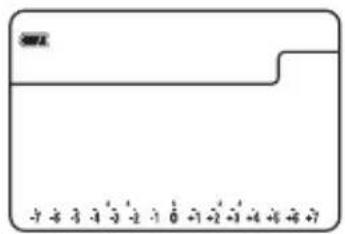
text_image
Image of a credit card with visible serial number and partial card faceFive point

text_image
Cropped image of a credit card showing partial numeric display and a small 'S' mark at the top left corner.Inside Range
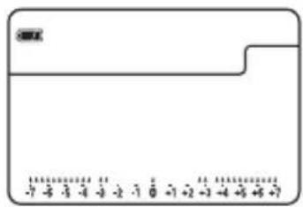
text_image
-7 -3 -4 -3 -2 -1 0 -1 +2 -3 -4 +5 +6 +7Outside Range
3-2-3 MID.TONE button
This button is used to set the measured value in the middle of EV scale.
1) Take a measurement by pressing the Measuring button ⑭. Press MID.TONE button ⑳ to set the Mid.Tone on the scale. "▲" in the middle of the EV scale will blink continuously twice to indicate that the Mid.Tone has been set.
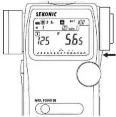
text_image
SEKONIC 125 °F 5.6s MD. TONE 82) By measuring and memorizing the highlights and/or shadows in a subject with spot metering, it is possible to determine numerically whether the measured area falls within the dynamic range and/or clipping points, that is, can be reproduced photographically without blooming or highlight block-up or pixel noise or grain in shadow.

text_image
Mid. Tone F5.65 Measure and memorize the Highlight F160 Measure and memorize the Shadow F2.033) Changing Mid.Tone Value
If it becomes necessary to change the measured mid-tone value, for instance, to make the highlight or shadow within dynamic range or clipping points, press and hold down the MID.TONE button while pressing the MODE button (M 0 will start to blink) this will lock the mid-tone value on the scale. After the mid-tone is locked press and hold down the MID.TONE button and rotating the Jog wheel until the mid-tone value is positioned where it is desired.
NOTE:
- If you do not lock the mid-tone value (MODE than MID.TONE = "M 0" blinking) the mid-tone scale will shift to the last measured value when you press the MID.TONE button.
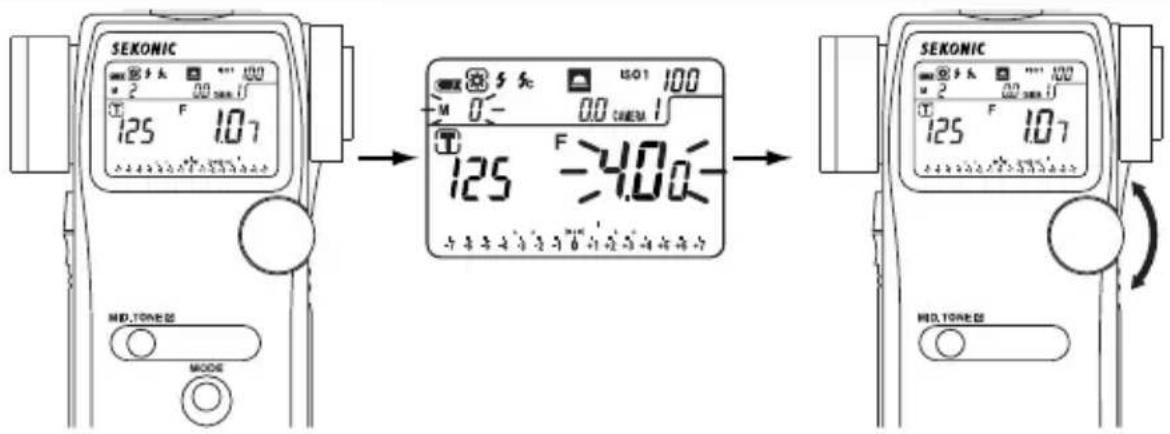
text_image
SEKONIC 125 F 1.07 M 0- ISO1 100 125 F 4.00 SEKONIC 125 F 1.07 MID.TONEES MODEMid-tone recall mode Mid-Tone adjustment
with Jog Wheel
4) Setting Mid.Tone Value from Memorized Values
After storing some measurements in memory, it is possible to set Mid-Tone value from memorized values. First enter the memory recall mode by holding the MODE button, and pressing the Memory button. Select one of the memorized values by rotating the Jog wheel and then press the MID.TONE button to set it as the Mid-tone value.
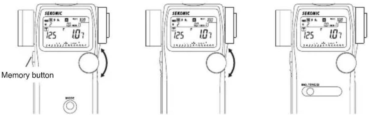
text_image
SEKONIC 125 107 2423321980464 Memory button SEKONIC 125 107 2423321980464 MOO. POWERMemory recall mode Press MID.TONE to select desired memorized value as Mid.Tone
NOTE:
- Depending on the lighting conditions, type of photographic equipment and the exposure standard adopted your exposure result may differ. Please test your setup before shooting under any conditions.
- It is possible that your set exposure values are not the desired effect for the given subject matter or shooting situation. Under these situations, please compensate the values to achieve the desired effect. See section 2-2 "Manual Exposure Profile Input" (See page 45)
Synchro cord
- This is a five-meter long cord with three plugs. An exposure meter, a camera, and a flash can all be connected at the same time. This is convenient when measurements are made, because it is not necessary to plug and unplug the synchro cord.

natural_image
Line drawing of two connectors with coiled wires and connectors (no text or symbols)18% Gray Card
- 18% gray card with cover (110mm x 102mm, 4 1/4" x 3 1/2"), folds to 2 3/4" x 4 3/4", and fits in a shirt pocket.
- It provides accurate exposures regardless of reflected ratio of the subject and surroundings.

natural_image
Simple 3D illustration of a blank folded paper or document (no text or symbols)Lens Hood/Step-Up Ring (30.5mm ⇒ 40.5mm)
- The step-up ring, available as an optional accessory, makes it possible to mount step rings and filters of other manufacturers. This simplifies the setting of exposure without the troublesome correction calculation of PL filters, etc. The step-up ring can also be used as a Lens hood to protect the spot lens from scratching, soiling, and avoids lens glare which could cause incorrect light measurements etc.
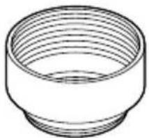
natural_image
Line drawing of a cylindrical mechanical component with concentric grooves (no text or symbols)Exposure Profile Target
- This is a Gray Scale Test target for Exposure Profiling and meter calibration. (The size is 260 x 160mm. 10.2" x 6.3"). One side is nine gray patches including black and white, and the other side is an: 18% gray card for digital camera white balancing and spot metering.
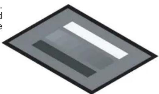
natural_image
Abstract geometric shape with two horizontal stripes inside a diamond frame (no text or symbols)Exposure Profile Target II
- This is a chart to make the Camera Exposure Profile by using Data Transfer Software version 2.0. This target consists of central 18% gray patch that is surrounded by 24 patches arranged in 1/6th stop values that are successively +2EV brighter and -2EV darker.
(Size: 350mm X 120mm)
The other side is 18% gray card for digital camera white balancing and spot metering.
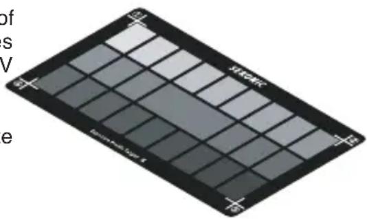
natural_image
Close-up of a dark, grid-patterned surface with no visible text or symbolsRadio transmitter module (32 channels) (For the L-758D or L-758CINE.)
• Electronic flash units and/or cameras can be triggered wireless from the L-758D or L-758CINE with optional radio module using PocktWizard Receiver or Trans ceivers connected to them.

RT-32N
(for US, Canada and EU countries)
Radio frequency
FCC & IC (indicating "Use RT-32N for radio transmitter module" on the back of body)
CE (indicating "CE" on the back of body)
CH1 \~ 16 : 433.62MHz CH17 \~ 32 : 434.22MHz
Reference:
- R T -32N transmitter module, old Sekonic RR-4 and RR-32 receivers are compatible with PocketWizard® products from LPA Design (www.pocketwizard.com), and other manufacturers with same system.
NOTE:
- Before purchasing PocketWizard wireless (radio frequency) your light meter's is compatible equipment, be sure that it is correct radio frequency for the country that will be used in and is the same radio frequency as the light meter.
- PocketWizard and Sekonic's Radio Triggering system may be used only in countries where a permit for the approved frequency has been issued by the government office in charge. There are several kinds of approved frequencies in the world, and we recommend you to be sure that check your Sekonic light meter Transmitter and Receiver(s) or Transceiver (s) are compatible with each other.
| · Type | : Digital exposure meter equipped with 1° spot viewfinder for ambient and flash light |
| · Light receiving method : Incident light and reflected light | |
| · Light ReceptorsIncident light : Convertible to flat diffuser (with retracted Lumisphere)Reflected light : 1° spot with display in finderMetering distance 1m ~∞ | |
| · Light receptor element : 2-Silicon photo diodes (incident and reflected) | |
| · Metering modesAmbient light : Aperture priority meteringShutter priority meteringEV meteringSimple illumination measurement (lux, foot-candle)(758CINE only)Simple brightness measurement (foot-lambert, cd/m2)(758CINE only)Flash : With synchro cord (cumulative, non-cumulative)Without synchro cord (cumulative, non-cumulative)Measurement using the wireless flash radio triggering sysytem (cumulative, non-cumulative) (optional for L-758D/758CINE) | |
| · Measuring Range (ISO 100)Ambient lightIncident light : EV-2 to EV 22.9Reflected light : EV 1 to EV 24.4 (with 1° spot viewfinder)FlashIncident light : f0.5 to f161.2 (approx. f175)Reflected light : f2.0 to f161.2 (approx. f175) (with 1° spot viewfinder)Illumination (direct measurement is possible only in 758CINE): 0.63 - 190,000 lux (2 significant digits)0.10 - 180,000 foot-candle (2 significant digits)Brightness (direct measurement is possible only in 758CINE): 0.25 - 190,000 cd/m2(2 significant digits)0.10 - 190,000 foot-lambert (2 significant digits) | |
| · Repeat Accuracy : +/- 0.1 EV or less | |
| · Calibration ConstantIncident light metering : Lumisphere C = 340 Flat diffuser C = 250Reflected light metering : K = 12.5 | |
| · Display RangeFilm speed : ISO 3 to 8000 (in 1/3 steps)Shutter SpeedsAmbient light : 30 minutes to 1/8000 seconds(in 1, 1/2 or 1/3 steps)also 1/200, 1/400Cine speeds- 2, 3, 4, 6, 8, 12, 16, 18, 24, 25, 30, 32, 36, 40, 48, 50, 60, 64, 72, 96, 120, 128, 150, 200, 240, 256, 300, 360 frames per second (at a 180 degree shutter angle)Additional Cine speeds to 758CINE1, 10, 14, 20, 75, 90, 100, 125, 180, 250, 375, 500, 625, 750, 1000 (at a 180 degree shutter angle)Flash : 30 minutes to 1/1000 second (in 1, 1/2 or 1/3 steps),also 1/75, 1/80, 1/90, 1/100, 1/200, 1/400 | |
Aperture : f/0.5 to f/161.2 (in 1, 1/2 or 1/3 steps)
EV : EV -9.9 to EV 46.6 (in 1/10 steps)
Analog scale : F-scale F0.7 - F90 (in 1/3 steps), (for 758DR/758D)
F0.5 - F64 (in 1/3 steps), (for 758CINE)
EV scale -7.0EV to +7.0EV (in 1/3 steps)
Contrast function : +/- 9.9 EV (in 1/10 steps)
Shutter angle (758CINE only)
: 1° \~ 10° (in 1° steps), 15° \~ 270° (in 5° steps), plus 12°, 17°, 22°, 144°, 172°
Filter compensation : +/- 5.0 EV (in 1/10 steps)
Filter factor number compensation (758CINE only)
(only one digit is displayed when the cumulated number is ten or more.)
Exposure compensation : +/- 9.9 EV (in 1/10 steps)
Calibration compensation : +/- 1.0 EV (in 1/10 steps)
Flash analyzing function : 0 to 100% in 10% increments
- Other features :
All-weather feature : JIS standard water resistance class 4, splash-proof type
Memory function : 9 readings
Memory clear · recall function
Average function : up to 9 readings can be averaged.
Out of display or measurement range
: Eu (underexposure) or Eo (overexposure) indication
Battery Power Indicator display
: with 3 level status icon
Auto Power Off : Selectable in Custom Setting
Auto illumination : EV 6 and under
Custom setting function : 14 items (for L-758DR/758D), 17 items (for L-758CINE)
Diopter adjustment : -2.5 to 1.0D
Tripod socket : 1/4" and 20 threads
(for placing meter in subject area for cordless flash measuring).
Second ISO film speed setting: ISO 3 to 8000 (in 1/3 steps)
· Battery used : one of CR123A battery 3V, (lithium dry cell)
· Operating temperature range : -10 \~ 50°C
- Storage temperature range : -20 \~ 60°C
· Weight : 268 g (with battery)
- Standard accessories supplied : Soft case, strap, lens cap, USB-cable, synchro terminal cap, CR-123A lithium battery x 1, quick guide, Sticker for multi-key operation and CS, software in CD-ROM
· Radio triggering range : approx. 30 meters (approx. 100 feet)
· Radio wave frequency
| FCC & IC | : CH1 ~ 16 344.0MHz | |
| CH17 ~ 32 | 346.5 ~ 354.0MHz | |
| CE | : CH1 ~ 16 433.62MHz | |
| CH17 ~ 32 | 434.22MHz | |
Features and specifications are subject to change without notice.
NOTE:
- Although this meter has an All-weather design for everyday use (JIS standard water resistance class 4), do not place it in water or use it underwater. This will cause it to malfunction.

text_image
Splashed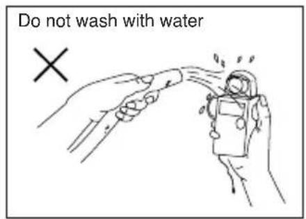
text_image
Do not wash with water ×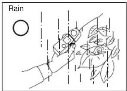
text_image
Rain
text_image
Do not submerge or use under water ו T o avoid damaging this meter, never drop it or subject it to shock.
• A void storing it in places with high temperatures or humidity.
- A void excessive temperature changes which could cause internal condensation, resulting in malfunction.
- If the temperature of the meter drops to -10 deg. C or beyond, response of the LCD becomes extremely slow and displays are difficult to read. At temperatures between 0 and 10 deg. C the LCD will become somewhat slower than normal but this does not hinder usage. Also, when the temperature exceeds 50 deg. C, the LCD will turn black and will be hard to read. This will return to normal when the temperature returns to normal.
- Do not place the meter in direct sunlight during midsummer or near heaters, etc., as the temperature of the meter will rise beyond that of the air temperature. Be careful when using the meter in hot locations.
Maintenance Notes
- If your meter is splashed with water, wipe immediately with a soft dry cloth. This will cause rust or corrosion.
- A void applying excessive force on the rubber seal of the battery compartment cover or attempting to remove it. This will cause inundation, corrosion or malfunction.
- If the rubber seal's surface is damaged, water or moisture may enter and damage the meter. If this has happened, you must send your meter to the Sekonic Sevice Center in your country.
- When light meter get dirty, clean it with soft dry cloth. Never use organic cleaners (like thinner or benzene).
- Do not operate with battery door open.
Warning: Changes or modifications to this unit not expressly approved by the party responsible for compliance could void the user's authority to operate the equipment.
Note: This equipment has been tested and found to comply with the limits for a Class B digital device, pursuant
To Part 15 of the FCC Rules. These limits are designed to provide reasonable protection against harmful interference in a residential installation. This equipment generates, uses, and can radiate radio frequency energy and, if not installed and used in accordance with the instruction, may cause harmful interference to radio communication.
However, there is no guarantee that interference will not occur in a particular installation. If this equipment does cause harmful interference to radio or television reception, which can be determine by turning the equipment off and on, the user is encouraged to try to correct the interference by one or more of the following measures:
* Reorient or relocate the receiving antenna.
* Increase the separation between the equipment and receiver.
* Consult the dealer or an experienced radio/TV technician for help.
This device complies with Part 15 of the FCC rules and also with RSS-210 of Industry Canada.
Operation is subject to the following two conditions: (1) This device may not cause harmful interference, and (2) this device must accept any interference received, including interference that may cause undesired operation.
| ledoM | DICCFrebmuN | ICrebmuN | Note |
| L-758DR | PFK-758-02 | 3916A-758002 | ehtrednudentialcondition that radio transmitter module is installedreturnni |
| ENIC857-br | 10-23TRFPor20-23TRFP | 1028TRFalling radio transmitter module into the meter,be sure to put the sticker indicating FCC ID and IC23TRFner on the back of meter which is enclosed inthe package of the module. For details, please referto the instruction manual of transmitter module. | |
SEKONIC
SEKONIC CORPORATION
7-24-14, Oizumi-Gakuen-cho, Nerima-ku, Tokyo 178-8686, Japan
Phone: ++81-3-3978-2335 Facsimile: ++81-3-3978-5229
http://www.sekonic.co.jp
| MANUFACTURERSEC DECLARATION OF CONFORMITY | |
| Product identification | |
| Product | : Digital Exposure Meter |
| Brand | : SEKONIC |
| Type | : L-758D, L-758DR and L-758CINE |
| Explanation of product | : Device for use in determining the optimum exposure of a photographic subject. The reading is given in digital form. And device is capable wireless flash triggering with an radio module. |
| Means of conformityThe product is in conformity with the essential requirements of the R & TTE Directive 1999/5/EC. | |
| Test carried out by(EMI Test) | : Japan Quality Assurance Organization (JQA)21-25, Kinuta 1-Chome, Setagaya-Ku, Tokyo 157-8573, Japan |
| (EMC Test) | : Japan Quality Assurance Organization (JQA)2096, Ohata, Tsuru-shi, Yamanashi 402-0045, Japan |
| (Safety Test) | : SEKONIC CORPORATION2714, Oaza Ikeda, Ikeda Machi, Kita Azumi Gun, Nagano Ken 399-8601, Japan |
| Standards used(EMI Test) | : EN 300 220-1 V1.3.1(2000-09), EN55022:1998+A1:2000+A2:2003EN 300 220-3 V1.1.1(2000-09) |
| (EMC Test) | : EN 301 489-03 V1.4.1(2002-08), EN55024:1998+A1:2001+A2:2003EN 301 489-01 V1.5.1(2004-11) |
| (Safety Test) | : EN 60950(3rd) |
| Test report number(EMI) | : 400-60006, 441-60298 |
| (EMC) | : 441-60021, 441-60299 |
| (Safety) | : LAA0420 |
| Manufacturer | : SEKONIC CORPORATION7-24-14, Oizumi-Gakuen-cho, Nerima-ku, Tokyo 178-8686 Japan |
| Function | : Quality Control Dept. General Manager |
| Signature | :Y. Kiguchi(YUKITOSHI KIGUCHI) |
| Date of issue | : July 10, 2006 |
| Number | : LAA0421 |
SEKONIC
SEKUNIC CORPORATION
7-24-14, Oizumi-Gakuen-cho, Nerima-ku, Tokyo 178-8686, Japan
Phone:++81-3-3978-2335 Facsimile:++81-3-3978-5229
http://www.sekonic.co.jp
| MANUFACTURERSEC DECLARATION OF CONFORMITY | |
| Product identification | |
| Product | : Digital Exposure Meter |
| Brand | : SEKONIC |
| Type | : L-758Series(L-758DR,L-758D and L-758CINE) |
| Explanation of product | : Device for use in determining the optimum exposure of a photographic subject. The reading is given in digital form. And device is capable wireless flash triggering with an radio module. |
| Means of conformityThe product is in conformity with the essential requirements of the R & TTE Directive 1999/5/EC. | |
| Test carried out by(EMI, EMC) | : RETLIF TESTING LABORATORIES101 New Boston Road Goffstown NH 03045 |
| (Safety) | : SEKONIC CORPORATION2714,Oaza Ikeda, Ikeda Machi, Kita Azumi Gun, Nagano Ken 399-8601, Japan |
| Standards used(EMI) | : EN300 220-1 V2.1.1(2006), EN61000-4-2:1995/A1:1998/A2:2001EN300 220-2 V2.1.2(2007) |
| (EMC) | : EN301 489-03 V1.4.1(2002), EN61000-4-3:2002/A1:2002EN301 489-01 V1.4.1(2002) |
| (Safety) | : EN60950 3^rd (2000) |
| Test report number(EMI, EMC) | : R-5005N-2 |
| (Safety) | : LAA0420 |
| Manufacturer | : SEKONIC CORPORATION7-24-14, Oizumi-Gakuen-cho, Nerima-ku, Tokyo 178-8686 Japan |
| Function | : Total Quality Management Dept. General Manager |
| Signature | : Akiyoshi Takehara(AKIYOSHI TAKAHARA) |
| Date of issue | : September 01, 2008 |
| Number | : LAA0516 |
Memo
Blank page
SEKONIC CORPORATION
7-24-14, OIZUMI-GAKUEN-CHO, NERIMA-KU, TOKYO 178-8686 JAPAN
TEL:+81(0)3-3978-2335 FAX:+81(0)3-3978-5229
http://www.sekonic.co.jp