DCS-7010L - Surveillance Camera D-LINK - Free user manual and instructions
Find the device manual for free DCS-7010L D-LINK in PDF.

User questions about DCS-7010L D-LINK
0 question about this device. Answer the ones you know or ask your own.
Ask a new question about this device
Download the instructions for your Surveillance Camera in PDF format for free! Find your manual DCS-7010L - D-LINK and take your electronic device back in hand. On this page are published all the documents necessary for the use of your device. DCS-7010L by D-LINK.
USER MANUAL DCS-7010L D-LINK
natural_image
Exterior view of a silver D-Link security camera with visible lens and port (no text or symbols on body)User Manual
HD Mini Bullet Outdoor Network Camera
DCS-7010L
Preface
D-Link reserves the right to revise this publication and to make changes in the content hereof without obligation to notify any person or organization of such revisions or changes. Information in this document may become obsolete as our services and websites develop and change. Please refer to the www.mydlink.com website for the most current information.
Manual Revisions
| Revision Date Description | |
| 1.1 August 23, 2012 DCS-7010L Revision A1 with firmware version 1.00 | |
| 1.2 April 09, 2013 modify mydlink function section | |
Trademarks
D-Link and the D-Link logo are trademarks or registered trademarks of D-Link Corporation or its subsidiaries in the United States or other countries. All other company or product names mentioned herein are trademarks or registered trademarks of their respective companies.
Copyright © 2017 D-Link Corporation.
All rights reserved. This publication may not be reproduced, in whole or in part, without prior expressed written permission from D-Link Corporation.
Table of Contents
Product Overview....5
Package Contents......5
Introduction......6
System Requirements....6
Features....7
Hardware Overview 8
Front 8
Cable Harness....9
Internal 10
Installing an SD Card 11
Installation 12
Zero Configuration Setup....12
Camera Installation Wizard 15
Windows Users 15
Mac Users....16
Manual Hardware Installation....17
Mounting the Camera....18
Positioning the Camera....19
mydlink....21
Live Video 22
Playback....23
Settings 24
Recording Settings......25
Advanced Settings 27
Configuration....28
Using the Configuration Interface....28
Live Video 29
Setup 31
Setup Wizard 31
Network Setup....37
Dynamic DNS 40
Image Setup 41
Audio and Video....43
Preset....45
Motion Detection 47
Time and Date....48
Event Setup....49
SD Card....57
Advanced....58
Digital Input/Output....58
ICR and IR....59
HTTPS....60
Access List....61
SNMP 62
Maintenance....63
Device Management 63
System 64
Firmware Upgrade....65
Status 66
Device Info 66
Logs 67
Help....68
DI/DO Specifications 69
Technical Specifications....70
Safety Statements....73
Product Overview Package Contents

DCS-7010L HD Mini Bullet Outdoor Network Camera

CAT5 Ethernet cable

Power adapter

CD-ROM with User Manual and software

Quick Installation Guide

Mounting Bracket and Mounting Kit

natural_image
Exterior view of a D-Link security camera with visible lens and mounting flange (no text or symbols on body)If any of the above items are missing, please contact your reseller.
Note: Using a power supply with a different voltage than the one included with your product will cause damage and void the warranty for this product.
Introduction
Congratulations on your purchase of the DCS-7010L HD Mini Bullet Outdoor Network Camera. The DCS-7010L is a versatile and unique solution for your small office or home. Unlike a standard webcam, the DCS-7010L is a complete system with a built-in CPU and web server that transmits high quality video images for security and outdoor surveillance. The DCS-7010L can be accessed remotely, and controlled from any PC/Notebook over your local network or through the Internet via a web browser. The simple installation and intuitive web-based interface offer easy integration with your Ethernet/Fast Ethernet network. The DCS-7010L weatherproof housing and Power over Ethernet make it an ideal solution for a complete and cost-effective surveillance solution with an easy clutter-free installation. The remote monitoring, infrared, motion detection and event notifications features enable you be truly responsive to your surveillance deployment.
System Requirements
- Computer with Microsoft Windows® 7/8/Vista/XP, or Mac with OS X 10.6 or higher
• PC with 1.3GHz or above; at least 128MB RAM - Internet Explorer 7, Firefox 12, Safari 4, or Chrome 20 or higher version with Java installed and enabled
- Existing 10/100 Ethernet-based network or 802.11n wireless network
- A MicroSD memory card (optional) is required for recording to onboard storage. SDHC Class 6 or above is recommended.
• Broadband Internet connection
Features
Simple to Use
The DCS-7010L is a stand-alone system with a built-in CPU, requiring no special hardware or software. The DCS-7010L supports both ActiveX mode for Internet Explorer and Java mode for other browsers such as Firefox® and Safari®.
Supports a Variety of Platforms
Supporting TCP/IP networking, HTTP, and other Internet related protocols. The DCS-7010L can also be integrated easily into other Internet/Intranet applications because of its standards-based features. The DCS-7010L offers Ethernet/Fast Ethernet connectivity, making the DCS-7010L easy to integrate into your existing network environment. The DCS-7010L works with a 10Mbps Ethernet based network or 100Mbps Fast Ethernet based network for traditional wired environments.
Web Configuration
Using a standard Web browser, administrators can configure and manage the Network Camera directly from its own Web page via Intranet or Internet. This means you can access your DCS-7010L anytime, anywhere in the world.
Broad Range of Applications
With today's high-speed Internet services, the Network Camera can provide the ideal solution for delivering live video images over the Intranet and Internet for remote monitoring. The Network Camera allows remote access using a Web browser for live image viewing, and allows the administrator to manage and control the Network Camera anytime, anywhere in the world. Many applications exist, including industrial and public monitoring of homes, offices, banks, hospitals, child-care centers, and amusement parks.
Remote Monitoring Utility
The D-ViewCam application adds enhanced features and functionality for the Network Camera and allows administrators to configure and access the Network Camera from a remote site via Intranet or Internet. Other features include image monitoring, recording images to a hard drive, viewing up to 32 cameras on one screen, and taking snapshots.
IR LED for Day and Night Functionality
The built-in infrared LEDs enables night time viewing of up to 32 feet (10 meters).
IP66 Weatherproof Housing
The DCS-7010L uses an IP66 weatherproof housing, allowing you to rest assured that in the toughest of conditions, it will continue to provide round-the-clock surveillance.
PoE (Power over Ethernet) for Flexible Installation
The DCS-7010L can draw all the power it needs from a powered Ethernet port meaning installation is simple and clutter free.
Hardware Overview
Front
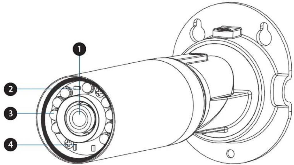
text_image
Technical diagram of a mechanical assembly with numbered components for identification| 1 Camera Lens | Records video of the surrounding area |
| 2 ICR Sensor | The IR-Cut Removable sensor measures the lighting conditions and switches between color and infrared accordingly |
| 3 IR LEDs | Infrared LEDs illuminate the camera's field of view at night |
| 4 Power/Status LED | Indicates the camera's current status |
Cable Harness
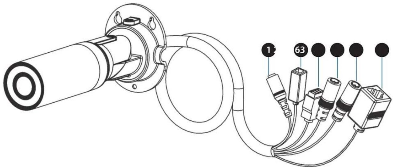
natural_image
Technical line drawing of a mechanical assembly with labeled components (no text or symbols present)| 1 Power Connector Power receptor for | the provided power adapter |
| 2 Reset Button | Press and hold the recessed button for 10 seconds to reset the camera |
| 3 DI/DO Connector | I/O connectors for external devices |
| 4 Audio Out (Green) | Connects to a speaker |
| 5 Audio In (Red) Connects to a microphone | |
| 6 Ethernet Port | Connects to an RJ45 Ethernet cable or PoE cable to connect to your network |

text_image
Internal 1| 1 Micro SD Card Slot | Insert a MicroSD card for Local storage for storing recorded image and video |
Note: For step-by-step instruction on how to insert an SD card please skip to "Installing an SD Card" on page 1.
Installing an SD Card
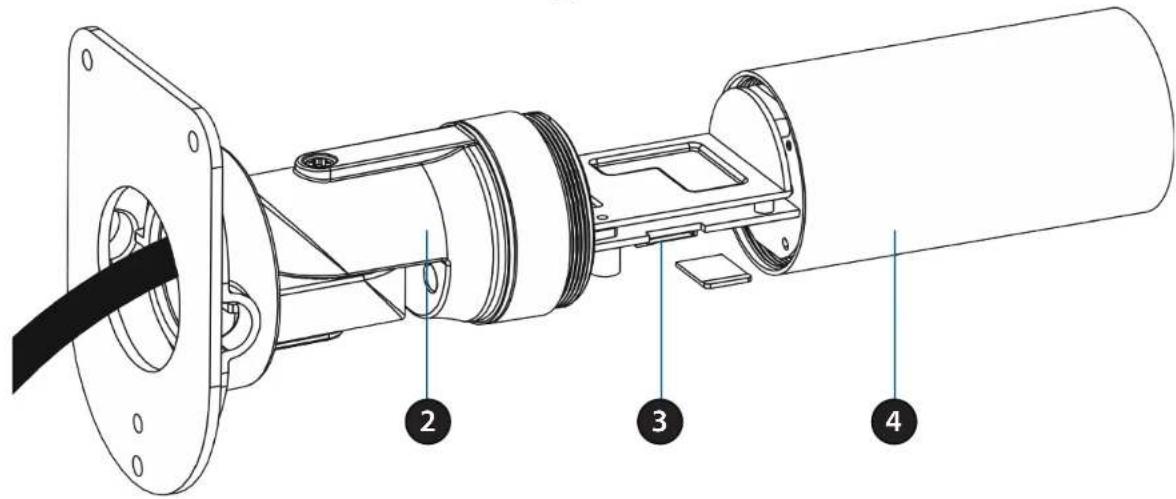
text_image
Technical diagram of a mechanical assembly with numbered parts labeled 2, 3, and 4Step 1:
Place the camera face down on a non-slip flat surface.
Step 2:
Unscrew the weatherproof sheath by holding the base of the camera firmly and rotating the barrel counter-clockwise. Exercise caution when removing the weatherproof sheath to avoid damaging the internal components.
Step 3:
Insert your MicroSD card into the slot with the notch oriented to the rear of the camera.
Step 4:
Replace the weatherproof sheath ensuring a tight fit.
Note: To ensure that the camera stays weatherproof, users are advised to ensure that the weatherproof sheath is secured firmly in place.
Installation Zero Configuration Setup
If you have a mydlink-enabled Cloud Router, you can take advantage of Zero Configuration. Zero Configuration automatically configures your camera's settings for you, and adds it to your mydlink account automatically. This type of setup allows you to set up your camera by simply plugging it in and connecting it to your router.
Connect your camera to your mydlink-enabled Cloud Router and Zero Configuration will automatically configure your DCS-7010L and automatically add the camera to your mydlink account. After the short time it takes to do this you can remotely access your camera from the www.mydlink.com website to manage and monitor your DCS-7010L.
Connect the Ethernet Cable
Connect the provided Ethernet cable to the cable harness Ethernet coupler.
Connect the other end of the provided Ethernet cable to your network.
Attach the External Power Supply
Attach the external power supply to the cable harness power coupler. Connect the adapter to a wall outlet or power strip.
| 1 Power Cable | Pre attached power cable |
| 2 Ethernet Cable | Pre attached Ethernet cable |
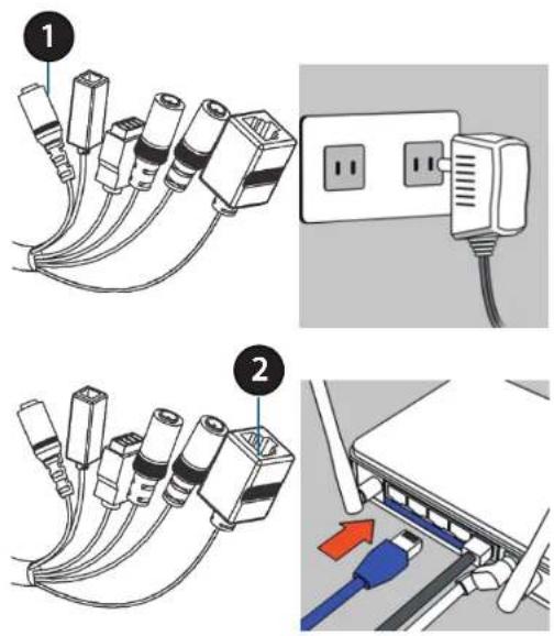
text_image
Diagram showing cable installation and connection to a network device, with numbered components and color-coded connectors.Check Your mydlink Account
From any computer, open a web browser, go to http://www.mydlink.com and log into your account. Once mydlink detects your camera, a New Device Found! notice will appear in the bottom-left corner. Click on the device name to continue.

A summary and confirmation notification will appear with the automatically configured details. Make a note of the details and click OK to add the camera to your account.

text_image
Confirming New Device Do you want to add this new device to your mydlink account? Device Name: DCS-7010L mydlink Number: 44441252 Network name (SSID): ddddddd Admin Password: oic953XZ You can change these default settings by going to Advanced Settings after add it to your device list. Not now YesSection 2: Installation
Zero Configuration is now complete and your camera has been added to your mydlink account. You can now view your camera on the mydlink Live View tab.
Your camera is now set up, and you can skip to "mydlink" on page 21 to learn more about the mydlink features of this camera, or to "Configuration" on page 37 for advanced configuration of your camera.
text_image
mydlink My Devices Shared Devices My Services My Profile DIR 60PL 2019552 Live Video Playback Settings DCS-701BL 44187672 Welcome, NextCamera Installation Wizard Windows Users
Insert the Installation CD-ROM into your computer's optical drive to start the autorun program.
Simply click Set up your Cloud Camera to go through the Setup Wizard, which will guide you step-by-step through the installation process from connecting your hardware to configuring your camera and registering it with your mydlink account.
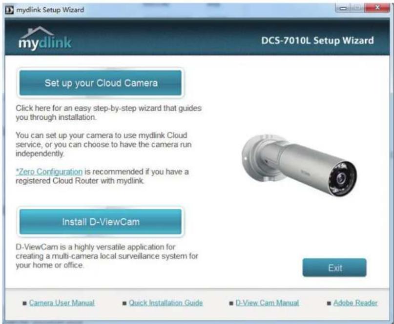
text_image
mydlink Setup Wizard DCS-7010L Setup Wizard Set up your Cloud Camera Click here for an easy step-by-step wizard that guides you through installation. You can set up your camera to use mydlink Cloud service, or you can choose to have the camera run independently. *Zero Configuration is recommended if you have a registered Cloud Router with mydlink. Install D-ViewCam D-ViewCam is a highly versatile application for creating a multi-camera local surveillance system for your home or office. Exit Camera User Manual Quick Installation Guide D-View Cam Manual Adobe ReaderNote: If the autorun program does not open, go to My Computer, browse to your CD drive, and double-click on the autorun.exe file.
Mac Users
Insert the Installation CD-ROM into your computer's CD drive. On the desktop, open your CD drive and double-click on the SetupWizard file.

SETUP_WIZARD
Within 20-30 seconds, the Setup Wizard will open, which will guide you step-by-step through the installation process from connecting your hardware to configuring your camera and registering it with your mydlink account.

text_image
mydlink Setup Wizard DCS-7010L Setup Wizard Welcome You will be able to set up your Cloud Camera to use mydlink Cloud service, or you can choose to have the camera run independently. Select your language: English Start Troubleshooting Downloads About Exit Copyright © 2012 D-Link Corporation All rights reserved.Note: mydlink portal requires Java ^TM to function correctly.
For more guidelines, please refer to mydlink FAQ pages at https://eu.mydlink.com/faq/mydlink
Manual Hardware Installation
If you wish to set up your camera without using the Camera Setup Wizard, please follow these steps.
Note: In order to use the mydlink features of this product, you will need to go through the Camera Setup Wizard.
Connect the Ethernet Cable
Connect the provided Ethernet cable to the cable harness Ethernet coupler.
Connect the other end of the provided Ethernet cable to your network.
Attach the External Power Supply
Attach the external power supply to the cable harness power coupler. Connect the adapter to a wall outlet or power strip.
| 1 Ethernet Cable | Pre attached Ethernet cable |
| 2 Power Cable | Pre attached power cable |
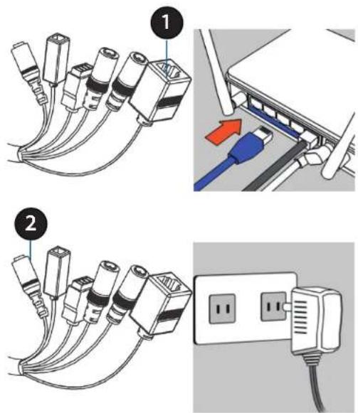
text_image
Diagram showing two installation steps of USB cable connectors, with numbered annotations and a close-up of the plug being inserted.Mounting the Camera
The DCS-7010L is suitable for mounting to a wall using the bracket provided.
Note: In order to use the mydlink features of this product, you will need to go through the Camera Setup Wizard.
Step 1
Position the mounting bracket in the desired location.
Step 2
Mark the surface behind the mounting bracket with a pencil
Step 3
Use a 6mm drill bit to make required holes approximately 25mm deep.
Step 4
Insert wall anchors and affix the bracket using the screws provided.
Step 5
Ensure the cable is seated in the cable channel.
Step 6
Suspend the camera from the two protruding studs near the top of the mounting bracket.
Step 7
Insert and tighten the remaining screw into the hole on the camera base.

natural_image
Technical line drawing of a mechanical assembly with screws and flanges, shown from two views (no text or symbols)
text_image
Technical diagram of a mechanical assembly with numbered components and directional arrows indicating motion or force.Positioning the Camera
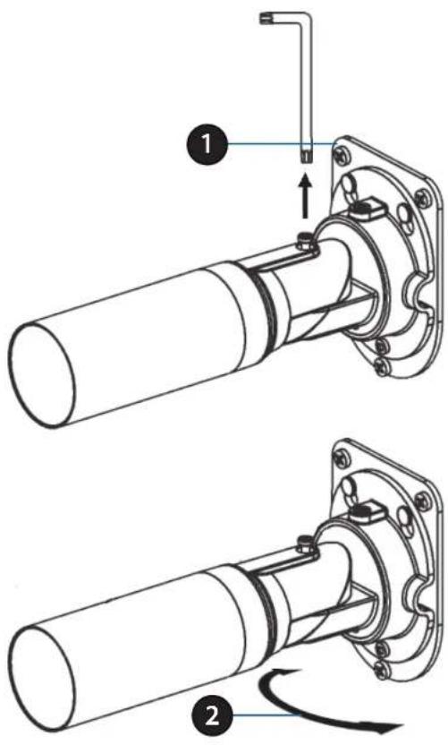
The DCS-7010L can be adjusted to ensure optimal viewing when mounted by following the steps outlined..
Step 1
Using a Torx Security screwdriver, loosen the screw on the top of the camera housing.
Step 2
Swivel the camera along it's horizontal axis until you achieve the desired angle.
Step 3
Using a Torx Security screwdriver, tighten the screw on the top of the camera housing firmly.
text_image
Technical diagram showing two mechanical assembly steps with labeled components and directional arrowsStep 4
Rotate the camera around its vertical axis by adjusting the base.
Step 5
Rotate the camera to adjust for positioning by rotating the barrel.

text_image
Technical diagram of a mechanical assembly with numbered components and directional arrows indicating motion or flow.mydlink
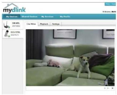
After registering your DCS-7010L camera with a mydlink account in the Camera Installation Wizard. You will be able to remotely access your camera from the www.mydlink.com website. After signing in to your mydlink account, you will see a screen similar to the following:

text_image
mydlink My Devices Shared Devices My Services My Profile DCS-7010L 44441672 Live View Playback Settings #NCE #GAMESNote: The above screenshot is representative only. The mydlink website is constantly improving and so may appear different.
Live Video
In the main part of the screen, the Live Video tab will be selected by default. If the camera is available, a Live Video feed will be displayed. Video will be shown at VGA resolution (640x480) if viewing your camera from a PC on the same local network, or at QVGA resolution (320x240) if viewing your camera from a PC on a remote network.
| Options Toggle | Click on this icon to to reveal the various Live View options. | |
| Motion Detection | This icon indicates whether motion detection is in process. | |
| Recording This icon indicates whether recording is in process. | ||
| Snapshot | Click on this button to take a snapshot from the video stream. | |
| Day/Night Mode Click on this button to engage the infrared | ||
| Audio | Click on this button to toggle the audio stream on or off. | |
| Brightness Adjust the slider control to account for brightness. | ||
| Zoom Adjust the slider control to zoom in or out. | ||

text_image
mydlink My dimes Isured dimes. My dimes. My dimes DCS-DRK Live View Playback Settings 48/01/22 About 100% Add NewPlayback
The Playback tab allows you to review pre-recorded footage captured to an inserted microSD card.
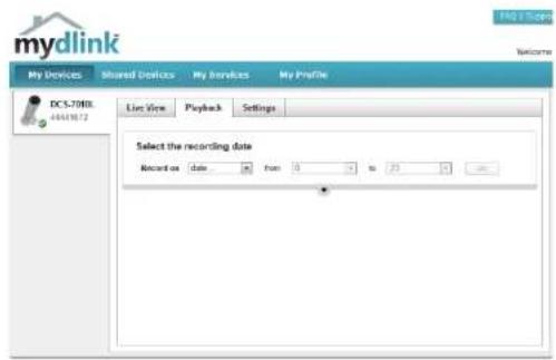
text_image
mydlink My Devices Shared Devices My Services My Profile DC5.7083 44618172 Live View Playback Settings Select the recording date Record as date from 3 to 23 —Select the date of the footage you wish to preview from the drop down menu, then choose from the recordings available for playback.

text_image
mydlink DCS-70ML 64A11672 Selected the recording clip Record on 2012/05/10 from 8 to 23 00 3D matching video clips were found Search View View View "Saved as the video" Please understand and edit the group.Settings
The Settings tab contains several options for you to control how your DCS-7010L operates.
Camera Name: Click on the Edit button to change how the camera name appears.
mydlink No: This is the unique mydlink number for your device.
Model name: This shows the model name of the camera.
MAC: The shows the Media Access Control (MAC) address of the camera.
Camera Activated on: The date the camera was registered to the mydlink service.
Event Notification E-mail notification of events can be switched on or off. Settings:

text_image
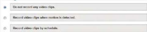
mydlink Shared Devices My Services My Profile Live Time Playback Settings General Information Camera Name: DCS-701L readlink No.: 44441672 Model Name: DCS-701L MAC: PS750500/4899 Camera activated on: 2013-05-28 14:33:53 Event Notification Send new alert notifications S-mail Save You can switch to check your event notifications by clicking the Events list on the menu for action. However, by adding the clickor, and notification is made to be sent to your registered email address where important alert events please request, such as motion detection for network cameras or related wireless connection for routers. Event Trigger Settings with Recording Do not record any video clips. Record video clips by motion detection. Record video clips by schedule. Advanced Settings You can click the Advanced Settings button to access your camera's advanced settings. After clicking the button, you have a name and password before to log it. Username: search Camera Password: **** Show (password) Advanced Setting You can remove new DCS-701L by clicking Reserve Device buttons. Remove DeviceEach of the recording settings will open a further menu. Recording Settings:
text_image
Do not record any video clips. Record video clips when motion is detected. Record video clips by schedule.Recording Settings
Record video clips Select this option to enable the automatic recording when motion is detected. detected:

Add Detection Area: Click on this icon to draw areas that will trigger automatic recording when motion is detected.

Remove Detection Area: Click on this icon to erase areas from regions that trigger automatic recording when motion is detected.

Clear Detection Area: This will remove all detection areas

Refresh Snapshot: This will refresh the current snapshot of the monitored area.

Increase/Decrease Sensitivity Increase the motion detection sensitivity

text_image
Do not record any video clips. Record video clips by motion detection. 1 Motion detection 2 Video clips recording mode The inserted MicroSD card can store about @ days of video maximum. When the MicroSD card is full: ○ Continue recording & override to the oblast video. ● Stop recording & notify me.Email Notification: Toggles notification by email on or off.
Video Clips Recording In the event that the microSD card can not store further recordings, Mode: the user can choose to record over previous recordings or to be notified and cease recording.
Record Video Clips by This option enables either continuous or recurring scheduled Schedule: recording.
Toggles notification by email on or off.Email Notification:
Video Clips Recording In the event that the microSD card can not store further recordings, Mode: the user can choose to record over previous recordings or to be notified and cease recording.

text_image
Record video clips by schedule. 1 Schedule setup Record video: ● Continuously ○ Only on: □ Sut □ Mon □ Tue □ Wed □ Thu □ Fri □ Sat From: 0:00 to: 23:59 2 E-mail notification ● Enable e-mail notification I want to send e-mail from: Other Sundat E-mail Address: SMTP Mail Server: Port: orange 1.10 60538) User Name: Password: Use SSL-TLB: None ?The notification will be sent to the email address, registered in styles: I want the e-mail notification to include: Simple snapshot, with notifications sent every seconds 3 Video clips recording mode The inserted MicroSD card can store about 0 days of video maximum. When the MicroSD card is full: ○ Continue recording & overwrite the ordered video. ● Stop recording & notify me. Save CancelAdvanced Settings
Checking this box will show the password.Show password:

text_image
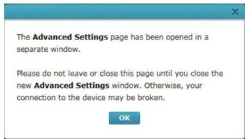
Advanced Settings Select your camera mounting mode: On cooling You can click the Advanced Settings button to access your camera's advanced settings. After clicking the button, use the username and password below to log in. Username: admin: Camera Password: ............ Show password Advanced setting You can remove your camera by clicking Delete Camera button. Delete CameraAdvanced Setting: Clicking on the Advanced Setting button will open a secondary window allowing full configuration of the DCS-7010L
text_image
The Advanced Settings page has been opened in a separate window. Please do not leave or close this page until you close the new Advanced Settings window. Otherwise, your connection to the device may be broken. OK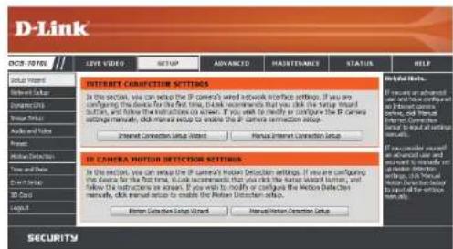
text_image
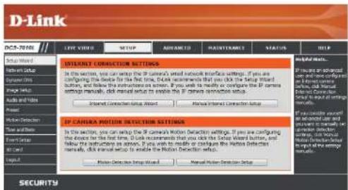
D-Link OCB-10705 LIVE VIDE SETUP ADVANCED MAJISTANCE STATUS HELP Internet CORNIFICATION SETTINGS In the section, you can attach the IP camera's network interface settings. If you are configuring the device for the first time, I can recommend that you click the setup instead button, and follow the instructions to review. If you will check to modify or configure the IP Camera settings manually, click manual setup to enable the IP camera connection setup. Internet Connection Setup Manual Internet Connection Setup IN CAMERA MOTOR DETECTOR SETTINGS In the section, you can attach the IP camera Motion Detection settings. If you are configuring the device for the first time, I can recommend that you click the setup instead button, and follow the instructions to review the IP Motion Detection settings manually, click manual setup to enable the Rocket Detection setup. Power Detection Setup Wizard Manual Rocket Detection Setup SecurityConfiguration Using the Configuration Interface
After completing the Camera Installation Wizard, you are ready to use your camera. The camera's built-in Web configuration utility is designed to allow you to easily access and configure your DCS-7010L. At the end of the wizard, enter the IP address of your camera into a web browser, such as Mozilla Firefox. To log in, use the User name admin and the password you created in the Installation Wizard. If you did not create a password, the default password is blank. After entering your password, click OK.

text_image
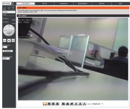
Windows Security The server 192.168.0.103 at DCS-7010L requires a username and password. Warning: This server is requesting that your username and password be sent in an insecure manner (basic authentication without a secure connection). User name Password Remember my credentials OK CancelLive Video
This section shows your camera's live video. You may select any of the available icons listed below to operate the camera. You may also select your language using the drop-down menu on the left side of the screen.
You can zoom in and out on the live video image using your mouse. Right-click to zoom out or left-click to zoom in on the image.
SD Status: This option displays the status of the SD card. If no SD card has been inserted, this screen will display the message "Card Invalid."
IO Status: This option displays the status of your I/O device if a device has been connected.
| Digital Input Indicator | This indicator will change color when a digital input signal is detected. | |
| Motion Trigger Indicator | This indicator will change color when a trigger event occurs.Note: The video motion feature for your camera must be enabled. | |
| Recording Indicator | When a recording is in progress, this indicator will change color. | |
| Control Pad | This control pad can be used to electronically pan, tilt, and zoom (ePTZ) within the camera's predefined view area, if one has been defined. | |
| Auto Pan Starts the automatic panning function. The ROI will pan from back and forth within the FOV | ||
| Stop Stops the camera ePTZ motion | ||
| Preset Path Starts the camera's motion along the predefined path | ||
text_image
LIVE VIEW This version photos new: content in key values. You can start your settings using the business database. Current installed at 30kV / 100. LIVE VIEW 02/07/2013 19:00:30 KNS -741ELePTZ Speed: You may select a value between 0 and 64.0 is the slowest and 64 is the fastest.
Global View: This window indicates the total field of view (FOV) of the camera. The red box indicates the visible region of interest (ROI).
Language: You may select the interface language using this menu.

Video Profile 1

Video Profile 2

Video Profile 3

Full screen mode

Taking a Snapshot

Record a Video Clip

Set a Storage Folder

Listen/Stop Audio In (from microphone)

Start/Stop Audio Out (to speaker)

Start/Stop Digital Output
Go To: If any presets have been defined, selecting a preset from this list will (Preset List) display it.
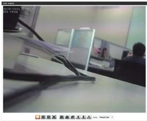
text_image
02/07/2011 07:30-5:4 05:78:06Setup Setup Wizard
To configure your Network Camera, click Internet Connection Setup Wizard. Alternatively, you may click Manual Internet Connection Setup to manually configure your Network Camera and skip to "Network Setup" on page 37.
To quickly configure your Network Camera's motion detection settings, click Motion Detection Setup Wizard. If you want to enter your settings without running the wizard, click Manual Motion Detection Setup and skip to "Motion Detection" on page 47.
text_image
D-Link DCS-T010 LIFE VIDEO STOP ADVANCED MAUTOMANCE STATUS HELP INTERNET CONNECTION SETTINGS In the section, you can wrap the IP camera's web network interface settings. If you are configuring the device for the first time, I can recommend that you click the Setup Wizard button, and follow the instructions on screen. If you need to modify or configure the IP camera session manually, click manual setup to enable the IP camera connection setup. Internet Connection Wizard Press IP CANA Motion Detection Settings In the section, you can wrap the IP camera's Motion Detection settings. If you are configuring the device for the first time, I can recommend that you click the Setup Wizard button, and follow the instructions on screen. If you need to modify or configure the Motion Detection manually, click manual setup to enable the Motion Detection setup. Press Connection Wizard Manual Motion Detection Setup If you are configured with advanced user and using currently in order to measure detection. If you are configured with Manual Use Detection Setup in order to allow the session settings. SecurityInternet Connection Setup Wizard
This wizard will guide you through a step-by-step process to configure your new D-Link Camera and connect the camera to the internet. Click Next to continue.

text_image
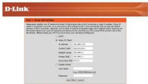
D-Link integrated to all D-Link update request / smart connection update The link is a key, which is used to close the D-Link frame and create the D-Link frame by the prompt. It can open your network connection settings, please click and button to close the link and write the network connection request. • Step 1: Setup Link Settings • Step 2: Setup Edge Settings • Step 3: Use Frame Settings • Step in Setup Time Zone End Next CancelNote: Select DHCP if you are unsure of which settings to choose.
Click Next to continue.

text_image
D-Link Setup 1. Setup LAM Settings Please select whether your IP server will connect to the Internet with a DNO converter in local IP address. If your IP server is connected to a router or an LAN switch, then switch to a local IP server, then to a local IP server. If you need the default selection of DNO converter. Otherwise, did this IP address be manually assigned and IP address is clearly on the network. If you use your IP server, please press your IP address using DNO converter and then add on the local IP address. Please check your IP address using your computer and Printout.DNO
Static IP Direct IP address: 83.000.000 Subtest mask: 83.000.000 Default mask: 83.000.000 Primary DNS: 83.000.000 Secondary DNS: 83.000.000 Enable FPHC User Phone: 16.6. 694218996444444444444444444444444444444444444444444444444444444444444444444444444444444444 Password: Set Back CancelSelect Static IP if your Internet Service Provider has provided you with connection settings, or if you wish to set a static address within your home network. Enter the correct configuration information and click Next to continue.
If you are using PPPoE, select Enable PPPoE and enter your user name and password, otherwise click Next to continue.
If you have a Dynamic DNS account and would like the camera to update your IP address automatically, Select Enable DDNS and enter your host information. Click Next to continue.
Enter a name for your camera and click Next to continue.
text_image
D-Link Step 1: Setup LINK Settings Please select whether your IP Camera will connect to the interface with A-Link connection or Data ID address. If your IP Camera is connected to a subnet, or in any connection which setting this link. This environment that you may be useful for default version of their generation. However, this is not a custom option to access your IP device before closing on the next button. Here can enter your IP Camera and Password in the case that your ISP is using PDF and then click on the second button. These selected your ISP if you are not based on the Software and Printout. ○ (S43) ● Static IP Client IP Address: 106, 108, 0.0 Subscript name: 275,575,975.0 Default source: 106, 108, 0.0 Primary Disk: 106, 108, 0.0 Secondary Disk: 106, 108, 0.0 □ Enable Filter: User Name: (e.g.: 65421@link.net) Password: Back Now Cancel
text_image
D-Link Step 3: Setup SNMP Settings If you have a Dynamic DNS account and would be the IP server to update your IP address automatically, enable DNS and enter in your host information below. Please click on the next button to continue. Enable SNMP Server Address: www.xdb.com/ Host Name: User Name: Project: Verify Password: Timeout: 0 (Avon) Ask Now Cancel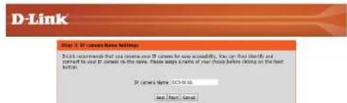
text_image
D-Link Your 3.0 IP comes here Settings Don't install them that you have our 30 comes for new availability. You can select and connect to your 30 comes in this case. Please help me of your these before clicking on the last button. IP comes here: iOS will be Add: Remove: CancelSection 4: Configuration
Configure the correct time to ensure that all events will be triggered as scheduled. Click Next to continue.

text_image
D-Link Step 4. Setup Time Power Please configure the correct time to ensure that all events are triggered, formatted and scheduled at the correct time and day and then set up the next button. Time Zone: [0]x+6.8.15 (T) Reset Enable Default Savings Back Next CancelConfirm the settings are correct and click Apply to save them..

text_image
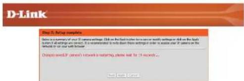
D-Link Step 3: Delay template Below the summary of our IP camera settings, click on the field before to move or shift settings job on the right. Auth for all settings is required. It is recommended to show that settings include to access your IP camera in the settings or use this setup. at address: http if camera name installed Time: 2000 (Ctrl+Alt+F) Type COMS: Disable PPAIC: Disable Text: Text: CancelThe settings will be saved to the DCS-7010L and the camera will restart.
text_image
D-Link Step 1: Setting complete Below a summary of your D-Link settings. Click on the first letter to ensure or verify settings did not use the daily survey of settings on next. It is recommended to help them based on these settings or if it access your D-Link on the website or your web following. Change we'll need a network to switch, please call for 19 seconds... Next step.Motion Detection Setup Wizard
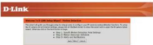
This wizard will guide you through a step-by-step process to configure your camera's motion detection functions.
Click Next to continue.
text_image
D-Link Welcome To D-Link Setup Wizard - Internet Security This will call you through a long-to-long process to configure your IP general version. This will help you use the Internet Security, or any other on the Web Button to close this version and again on the Internet Security system. Sometimes, these will be the network to target. • Step 1: Specific Version Connection Area Settings • Step 2: Minimum Update Schedule • Step 3: Quick Update and Networks Back Event / BackStep 1
This step will allow you to enable or disable motion detection, specify the detection sensitivity, and adjust the camera's ability to detect movement.

text_image
D-Link Step 3: Sample Before Detection Area Settings The season will allow you to enable in double-meter detection as well as control the specificity of your system is able to detect movement. ✓ Enable video motion □ standard ● Value On Sensitivity 50 0% <100% Percentage 5 0% <100% Add / Next CancelYou may specify whether the camera should capture a snapshot or a video clip when motion is detected.
Please see the Motion Detection section on "Motion Detection" on page 47 for information about how to configure motion detection.

text_image
D-Link Search 2. Photo (Search) Manager The find step should not specify how you access a notification of content assets. Choose between an email account or other sites that you can be the email account. You will read your email account. settings to FTR details. If you are aware of this information, please contact your ID. Once you have saved this information, please click or link your email. Name: Size: Size: 100 Size: 50 Size: 100 Size: 100 Size: 100 Size: 100 Size: 100 Size: 100 Size: 100 Size: 100 Size: 100 Size: 100 Size: 100 Size: 100 Size: 100 Size: 100 Size: 100Step 2
This step allows you to enable motion detection based on a customized schedule. Specify the day and hours. You may also choose to always record whenever motion is detected.
Step 3
This step allows you to specify how you will receive event notifications from your camera. You may choose not to receive notifications, or to receive notifications via e-mail or FTP.
Please enter the relevant information for your e-mail or FTP account.
Click Next to continue.
Step 4
You have completed the Motion Detection Wizard.
Please verify your settings and click Apply to save them.
Please wait a few moments while the camera saves your settings and restarts.

text_image
D-Link Step 3: Alerts and Notifications The first key allows you to specify how you receive certification of users at which these features are mentioned in the following: recipients who can link your FTP information, then send your email account or settings for FTP details. If you are aware of the information, please contact your FTP. Once you have entered the information, please click on the next author. Do not modify this * Small Sender email address Recipient email address Server address User name Password Part 28 FTP Server address Part 5 User name Password Remove Texter name Back menu Cancel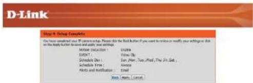
text_image
D-Link Step 4: Debug Examples You have completed your D-Link setup. Please click the Debug Button (you need to press or modify your instructions for this) on the Apply Button to create and apply your settings. MODE Selection: Enable OK? Use Open Schedule Dev: Run, More, Try, Mixed, The Find, Schedule Time: Always Help and Modulation: Cancel Read: Apply / Cancel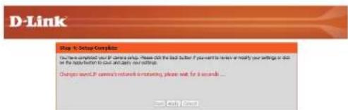
text_image
D-Link Step 1: Delay Complete Do you complete your D-Link shop. Please ask the bad order if you want to render or modify your writing on this for the help/when to our email, my setup. Change only if you want a network or moving phone will be 4 seconds... OK OKNetwork Setup
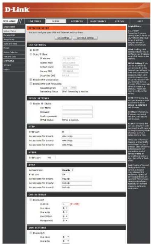
Use this section to configure the network connections for your camera. All relevant information must be entered accurately. After making any changes, click the Save Settings button to save your changes.
LAN Settings: This section lets you configure settings for your local area network.
DHCP: Select this connection if you have a DHCP server running on your network and would like your camera to obtain an IP address automatically.
If you choose DHCP, you do not need to fill out the IP address settings.
Static IP Client: You may obtain a static or fixed IP address and other network information from your network administrator for your camera. A static IP address may simplify access to your camera in the future.
IP Address: Enter the fixed IP address in this field.
Subnet Mask: This number is used to determine if the destination is in the same subnet. The default value is 255.255.255.0.
Default Gateway: The gateway used to forward frames to destinations in a different subnet. Invalid gateway settings may cause the failure of transmissions to a different subnet.
Primary DNS: The primary domain name server translates names to IP addresses.
Secondary DNS: The secondary DNS acts as a backup to the primary DNS.
text_image
D-Link DNS: IP/HL LINK VIDEO SETMP ADVANCED HADJETMARCH STATUS HELP Network SETTINGS You can configure your LAF and Internet settings here. Save settings Open Save settings LAN SETTINGS DCSP Static IP Client: IP address: 391.166.5.01 Submit mask: 391.273.000.00 Default mode: 391.166.5.01 Primary DNS: 391.166.5.01 Secondary DNS: 8.4.4.4.4 Enable UPref presentation Enable UPref post Forwarding Forwarding Part: 2014 Forwarding Status: UPref forwarding a inactive. PPPOP SETTINGS Enable Enable User Name: Password: Confirm answered: PPPOP Status: PPPOP is inactive. HTTP HTTP port: Access name for account1 Access name for account2 Access name for account3 HTTP HTTPS port: HTTP port: Access name for account1 Access name for account2 Access name for account3 HTTP Authentication: Address name: http://www.https.org/ Access name: http://www.https.org/ HTTP port: Access name: http://www.https.org/ Access name: http://www.https.org/ HTTP port: Access name: http://www.https.org/ Access name: http://www.https.org/ HTTP port: Access name: http://www.https.org/ Access name: http://www.https.org/ HTTP port: Access name: http://www.https.org/ Access name: http://www.https.org/ HTTP port: Access name: http://www.https.edu/ Access name: http://www.https.edu/ HTTP port: Access name: http://www.https.edu/ Access name: http://www.https.edu/ HTTP port: Access name: http://www.https.edu/ Access name: http://www.https.edu/ HTTP port: Access name: http://www.https.edu/ Access name: http://www.https.edu/ HTTP port: Access name: http://www.https.edu/ Access name: http://www.https.edu/ HTTP port: Access name: https://www.https.edu/ Access name: http://www.https.edu/ HTTP port: Access name: http://www.https.edu/ Access name: http://www.https.edu/ HTTP port: Access name: http://www.https.edu/ Access name: http://www.https.edu/ HTTP port: Access name: http://www.https.edu/ Access name: http://www.https.edu/ HTTP port: Access name: http://www.https.edu/ Access names: http://www.https.edu/ HTTP port: Access name: http://www.https.edu/ Access names: http://www.https.edu/ HTTP port: Access name: http://www.https.edu/ Access names: http://www.https.edu/ HTTP port: Access name: http://www.https.edu/ Access names: http://www.https.edu/ HTTP port: Access name: http://www.https.edu/ Access names: http://www.https.edu/Enable UPnP Presentation: Enabling this setting allows your camera to be configured as a UPnP device on your network.
Enable UPnP Port Forwarding: Enabling this setting allows the camera to add port forwarding entries into the router automatically on a UPnP capable network.
Enable PPPoE: Enable this setting if your network uses PPPoE.
User Name / Password: Enter the username and password for your PPPoE account. Re-enter your password in the Confirm Password field. You may obtain this information from your ISP.
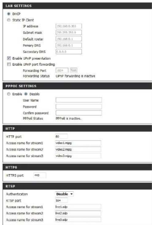
HTTP Port: The default port number is 80.
Access Name for Stream 1\~3: The default name is video#.mjpg, where # is the number of the stream.
HTTPS Port: You may use a PC with a secure browser to connect to the HTTPS port of the camera. The default port number is 443.
RTSP Port: The port number that you use for RTSP streaming to mobile devices, such as mobile phones or PDAs. The default port number is 554. You may specify the address of a particular stream. For instance, live1.sdp can be accessed at rtsp://x.x.x.x/video1.sdp where the x.x.x.x represents the ip address of your camera.
text_image
LAN SETTINGS DHCP Static IP Client IP address 192.160.0.30 Subnet mask 155.265.255.0 Default router 192.160.0.1 Primary DNS 192.160.0.1 Secondary DNS 6.8.8.0 Enable UPnP presentation Enable UPnP port forwarding Forwarding Port .024 Test Forwarding Status UPnP forwarding is inactive PPPOE SETTINGS Enable Disable User Name Password Confirm password PPPoE Status PPPoE is inactive. HTTP HTTP port 80 Access name for stream1 vdeo1.mpg Access name for stream2 vdeo2.mpg Access name for stream3 vdeo3.mpg HTTPS HTTPS port +43 RTSP Authentication Disable RTSP port 554 Access name for stream1 live1.sdp Access name for stream2 live2.sdp Access name for stream3 live3.sdpEnable CoS: Enabling the Class of Service setting implements a best-effort policy without making any bandwidth reservations.
Enable QoS: Enabling QoS allows you to specify a traffic priority policy to ensure a consistent Quality of Service during busy periods. If the Network Camera is connected to a router that itself implements QoS, the router's settings will override the QoS settings of the camera.
Enable IPv6: Enable the IPV6 setting to use the IPV6 protocol. Enabling the option allows you to manually set up the address, specify an optional IP address, specify an optional router and an optional primary DNS.
Enable Multicast for stream The DCS-7010L allows you to multicast each of the available streams via group address and specify the TTL value for each stream. Enter the port and TTL settings you wish to use if you do not want to use the defaults.

text_image
COS SETTINGS Enable CoS VLAN ID 1 [0~4095] Live video 0 Live audio 0 Event/Alarm 0 Management 0 QOS SETTINGS Enable QoS Live video 0 Live audio 0 Event/Alarm 0 Management 0 IPVG Enable IPv6 IPv6 Information Manually setup the IP address Optional IP address / Prefix length / 64 Optional default router Optional primary DNS MULTICAST Enable multicast for stream 1 Multicast group address 239.1.1.1 Multicast video port 8550 Multicast RTP video port 6551 Multicast audio port 8552 Multicast RTP audio port 6553 Multicast TTL [1~255] 64 Enable multicast for stream 2 Multicast group address 239.1.1.2 Multicast video port 6554 Multicast RTP video port 6555 Multicast audio port 6556 Multicast RTP audio port 6557 Multicast TTL [1~255] 64 Enable multicast for stream 3 Multicast group address 239.1.1.3 Multicast video port 6558 Multicast RTP video port 6559 Multicast audio port 8560 Multicast RTP audio port 6561 Multicast TTL [1~255] 64 Save Settings Don't Save SettingsDynamic DNS
DDNS (Dynamic Domain Name Server) will hold a DNS host name and synchronize the public IP address of the modem when it has been modified. A user name and password are required when using the DDNS service. After making any changes, click the Save Settings button to save your changes.
Enable DDNS: Select this checkbox to enable the DDNS function.
Server Address: Select your Dynamic DNS provider from the pull down menu or enter the server address manually.
Host Name: Enter the host name of the DDNS server.
User Name: Enter the user name or e-mail used to connect to your DDNS account.
Password: Enter the password used to connect to your DDNS server account.
Timeout: Enter the DNS timeout values you wish to use.
Status: Indicates the connection status, which is automatically determined by the system.

text_image
D-Link DORI NAME LINK ITEMS MATCH ADJUSTED MAINTRODUCTION STATUS HELP System Alert Network Setup Dynamic DNS Images Setup Auto and Move Search User Detection Time and Settings Work Call Layout Dynamic DNS Settings Enable Options Server Address: www.12348.com Host Name: User Name: Password: Very Password: Timeout: Status: NotOne Save Settings Done Save Settings Dynamic DNS feature allows you to use a domain name that you have purchased any random items to access your IP domain with a dynamically assigned IP address. Most broadcast internet service providers use dynamic DNS services, by using a DNS service, you can either use the domain name to connect to your IP domains or matter what your IP address is. Save as for the link from DNS services or www.12348.com. Save Settings Cancel Save Settings Helpful Notes. Dynamic DNS include if you have DNS so call on or write your data. The other features are not available. You can also use the website to download any of your IP domains or more of developing a link or a link to the website. Save Settings Cancel Save SettingsImage Setup
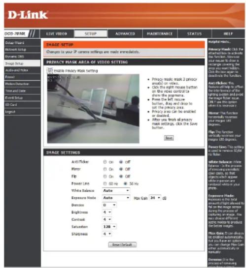
In this section, you may configure the video image settings for your camera. A preview of the image will be shown in Live Video.
Enable Privacy Mask: The Privacy Mask setting allows you to specify up to 3 rectangular areas on the camera's image to be blocked/excluded from recordings and snapshots.
You may click and drag the mouse cursor over the camera image to draw a mask area. Right clicking on the camera image brings up the following menu options:
Disable All: Disables all mask areas
Enable All: Enables all mask areas
Reset All: Clears all mask areas.
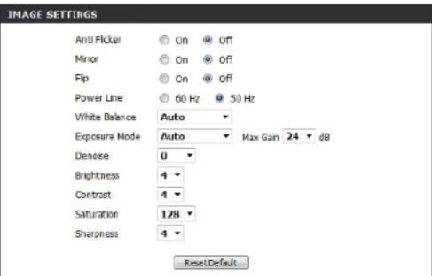
Anti Flicker: If the video flickers, try enabling this setting.
Mirror: This will mirror the image horizontally.
Flip: This will flip the image vertically. When turning Flip on, you may want to consider turning Mirror on as well.
Power Line: Select the frequency used by your power lines to avoid interference or distortion.
White Balance: Use the drop-down box to change white balance settings to help balance colors for different environments. You can choose from Auto, Outdoor, Indoor, Fluorescent, and Push Hold.
text_image
D-Link DOD - 2018E LIVE VIDEO SETUP ADVANCED MAINTERANCE STATUS HELP COLOR WIND Network Setup Dynamic Bits Video Tools Audio and Audio Forest Video Detection Time and Time Forest Setup CD Card Input IMAGE SETUP Changes to your IP camera settings are made immediately. PRIVACY MASK AREA OF VIDEO SETTING ■ Privacy mask setting ■ Privacy mask mask 2 privacy audio on video. ■ Click the right mouse button on this mice control to show the payments. ■ Press the left mouse button, drop and drop to set the privacy area. ■ Privacy area Can be enabled or disabled. ■ After you finish all any mask settings, click the Save button. ■ Skip IMAGE SETTINGS Anti-Talker Mmpo Flip Power Line White Balance Expense Mode Distance Brightness Contrast Saturation Sharpness On On On 60 Hz 50 Hz Max Gain 34 °C Exposure Mode: Measure the total amount of input received by the top line image sensor using the pinion of sounder on image. You can change the output of audio mode to product the video format. Exposure Mode: Use allowed to be isolated automatically, but you can use a video mode to change how can be simultaneously or highly. Exposure Mode: Use in the process of maintainingExposure Mode: Changes the exposure mode. Use the drop-down box to set the camera for Indoor, Outdoor, or Night environments, or to Moving to capture moving objects. The Low Noise option will focus on creating a high-quality picture without noise. You can also create 3 different custom exposure modes. The Max Gain setting will allow you to control the maximum amount of gain to apply to brighten the picture.
Denoise: This setting controls the amount of noise reduction that will be applied to the picture.
Brightness: Adjust this setting to compensate for backlit subjects.
Contrast: Adjust this setting to alter the color intensity/strength.
Saturation: This setting controls the amount of coloration, from grayscale to fully saturated.
Sharpness: Specify a value from 0 to 8 to specify how much sharpening to apply to the image.
Reset Default: Click this button to reset the image to factory default settings.
text_image
IMAGE SETTINGS Anti Flicker On Off Mirror On Off Flip On Off Power Line 60 Hz 50 Hz White Balance Auto Exposure Mode Auto Max Gain 24 dB Denoise 0 Brightness 4 Contrast 4 Saturation 128 Sharpness 4 Reset DefaultAudio and Video
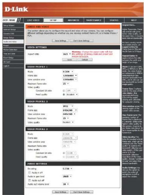
You may configure up to 3 video profiles with different settings for your camera. Hence, you may set up different profiles for your computer and mobile display. In addition, you may also configure the two-way audio settings for your camera. After making any changes, click the Save Settings button to save your changes.
Aspect ratio: Set the aspect ratio of the video to 4:3 standard or 16:9 widescreen.
Mode: Set the video codec to be used to JPEG, MPEG-4, or H.264.
Frame size: Frame size determines the total capture resolution, and View window area determines the Live Video viewing window size. If the Frame size is larger than the Live Video size, you can use the ePTZ controls to look around.
16:9 1280 × 800, 1280 × 720, 800 × 450, 640 × 360, 480 × 270, 320 × 176, 176 × 144
4:3 1024 x 768, 800 x 600, 640 x 480, 480 x 360, 320 x 240, 176 x 144
Note: If your View window area is the same as your Frame size, you will not be able to use the ePTZ function.
Maximum frame rate: A higher frame rate provides smoother motion for videos, and requires more bandwidth. Lower frame rates will result in stuttering motion, and requires less bandwidth.
text_image
D-Link COP: PRINL LIVE VIDEO SETUP ADVANCED MAJETRANCE STATUS HELP Audio AND VIDEO The action allows you to configure the sound and voice of their camera. You can configure different settings depending on whether you are varying context from PC or a plastic phone / PCA. Save Settings Can Save Settings Audio Audio Delete Audio Ret Audio Drop Audio Cut Logic VIDEO SETTINGS Aspect size: 10.9 Warning: Change the aspect size will reduce the settings of empty mask and press and process settings. Save... Default VIDEO PROFILES 1 Mode: H264 H264 H264 H264 H264 H264 H264 H264 H264 H264 H264 H264 H264 H264 H264 H264 H264 H264 H264 H264 H264 H264 H264 H264 H264 H264 H264 H264 H264 H264 H264 H264 H264 H264 H264 H264 H264 H264 H264 H264 H264 H264 H264 H264 H264 H264 Video quality: Constant bit rate: 100% Excellent: Video PROFILES 2 Mode: 3F15 3F15 3F15 3F15 3F15 3F15 3F15 3F15 3F15 3F15 3F15 3F15 3F15 3F15 3F15 3F15 3F15 3F15 3F15 3F15 3F15 H264 H264 H264 H264 H264 H264 H264 H264 H264 H264 H264 H264 H264 H264 H264 H264 H264 H264 H264 H264 H264 H264 H264 H264 H26 3F15 H264 H264 H264 H264 H264 H264 H264 H264 H264 H264 H264 H264 H264 H264 H264 H264 H264 H264 H264 H264 H264 H264 H264 H26 3F18 H264 H264 H264 H264 H264 H264 H264 H264 H264 H264 H264 H264 H264 H264 H264 H264 H26 3F18 H264 H264 H264 H264 H264 H264 H26 3F18 H264 H264 H264 H264 H26 3F18 H264 H26 3F18 H26 3F18 H26 3F18 H26 3F18 H26 3F18 H26 3F18 3F18 3F18 3F18 3F18 3F18 3F18 3F18 3F18 3F18 3F18 3F18 3F18 3F18 3F18 3F18 3F18 3F18 3F18 3F18 3F17 3F17 3F17 3F17 3F17 3F17 3F17 3F17 3F17 3F17 3F17 3F17 3F17 3F17 3F17 3F17 3F17 3F17 3F17 3F17 3F18 3F18 3F18 3F18 3F18 3F18 3F18 3F18 3F18 3F18 3F18 3F18 3F18 3F18 3F18 3F18 3F18 3F18 3F18 3F19 3F19 3F19 3F19 3F19 3F19 3F19 3F19 3F19 3F19 3F19 3F19 3F19 3F19 3F19 3F19 3F19 3F19 3F19 3F19 3F18 3F18 3F18 3F18 3F18 3F18 3F18 3F18 3F18 3F18 3F18 3F18 3F18 3F18 3F18 3F18 3F18 3F18 3F18 3F15 3F15 3F15 3F15 3F15 3F15 3F15 3F15 3F15 3F15 3F15 3F15 3F15 3F15 3F15 3F15 3F15 3F0.0000000000000000000000000000000000000000000000000000000000000000000000000000000000000000000000000000. Audio Settings: Audio in off: Audio in open level: Audio out off: Audio out volume level: Audio Settings: Audio in off: Audio in open level: Audio out off: Audio out volume level: Audio Settings: Audio in off: Audio in open level: Audio out off: Audio out volume level: Audio Settings: Audio in off: Audio in open level: Audio out off: Audio out volume level: Audio Settings: Audio in off: Audio in open level: Audio out off: Audio out volume level: Audio Settings: Audio in off: Audio in open level: Audio out off: Radio buttons: Radio buttons: Radio buttons: Radio buttons: Radio buttons: Radio buttons: Radio buttons: Radio buttons: Radio buttons: Radio buttons: Radio buttons: Radio buttons: Radio buttons: Radio buttons: Radio buttons: Radio buttons: Radio buttons: Radio buttons: Radio buttons: Radio buttons: Radio buttons: Radio buttons: Radio buttons: Radio buttons: Radio buttons: Radio buttons: Radio buttons: Radio buttons: Radio buttons: Radio buttons: Radio buttons: Radio buttons: Radio buttons: Radio buttons: Audio buttons: Audio buttons: Audio buttons: Audio buttons: Audio buttons: Audio buttons: Audio buttons: Audio buttons: Audio buttons: Audio buttons: Audio buttons: Audio buttons: Audio buttons: Audio buttons: Audio buttons: Audio buttons: Audio buttons: Audio buttons: Audio buttons: Audio buttons: Audio buttons: Audio buttons: Audio buttons: Audio buttons: Audio buttons: Audiou button: Audiou button: Audiou button: Audiou button: Audiou button: Audiou button: Audiou button: Audiou button: Audiou button: Audiou button: Audiou button: Audiou button: Audiou button: Audiou button: Audiou button: Audiou button: Audiou button: Aidiou button: Aidiou button: Aidiou button: Aidiou button: Aidiou button: Aidiou button: Aidiou button: Aidiou button: Aidiou button: Aidiou button: Aidiou button: Aidiou button: Aidiou button: Aidiou button: Aidiou button: Aidiou button: Aidiou button: AUDIO PROFILES Mode: H264 H264 H264 H264 H264 H264 H264 H264 H264 H264 H264 H264 H264 H264 H264 H264 H264 H264 H264 H259 H259 H259 H259 H259 H259 H259 H259 H259 H259 H259 H259 H259 H259 H259 H259 H259 H259 H259 H259 H258 H258 H258 H258 H258 H258 H258 H258 H258 H258 H258 H258 H258 H258 H258 H258 H257 H257 H257 H257 H257 H257 H257 H257 H257 H257 H257 H257 H257 H257 H257 H257 H257 H257Video Quality: This limits the maximum frame rate, which can be combined with the "Fixed quality" option to optimize the bandwidth utilization and video quality. If fixed bandwidth utilization is desired regardless of the video quality, choose "Constant bit rate" and select the desired bandwidth.
Constant bit rate: The bps will affect the bit rate of the video recorded by the camera. Higher bit rates result in higher video quality.
Fixed quality: Select the image quality level for the camera to try to maintain. High quality levels will result in increased bit rates.
Encoding Select the audio encoding codec to fine tune bandwidth usage, storage and recording quality.
Audio in off: Selecting this checkbox will mute incoming audio.
Audio in gain level: This setting controls the amount of gain applied to incoming audio to increase its volume.
Audio out off: Selecting this checkbox will mute outgoing audio.
Audio out volume level: This setting controls the amount of gain applied to outgoing audio to increase its volume.

text_image
D-Link LIVE VIDEO SETUP ADVANCED MAJETEMANCE STATUS HELP ABOUT AND VIDEO This version allows you to configure the sound and voice of your camera. You can configure different settings (disordinating on whether you are wrong contact from a PC or a slice icon / PC). Save Settings Can't Save Settings VIDEO SETTINGS Audio ratio 16:9 Warning: Change the aspect ratio will be true. The settings of primary mark and sound and previous instructions Save Default VIDEO PROFILES 1 Media H.264 Frame size 120x8000 View window area 120x8000 Maximum frame rate 25 Video quality Constant bit rate 181 Fixed quality Excellent VIDEO PROFILES 2 Mode: HYG Frame size 840x260 View window area 040x760 Maximum frame rate 25 Video quality Excellent VIDEO PROFILES 3 Mode: H.764 Frame size 220x878 View window area 130x370 Maximum frame rate 25 Video quality Constant bit rate 51.08 Fixed quality Excellent AUDIO SETTINGS Recording: G.736 Audio in soft Audio in deep level Audio out off Audio out volume load 28:88 18 Weighting Tools... Power fan size, Power line and line type, Power line and line type, Power line and line type, Power line and line type, Power line and line type, Power line and line type, Power line and line type, Power line and line type, Power line and line type, Power line and line type, Power line and line type, Power line and line type, Power line and line type, Power line and line type, Power line and line type, Power line and line type, Power line and line type, Power line, Power line, Power line, Power line, Power line, Power line, Power line, Power line, Power line, Power line, Power line, Power line, Power line, Power line, Power line, Power line, Power line, Power line, Power line, Power line, Power line, Power line, Power line, Power line, Power line, Power line, Power line, Power line, Power line, Power line, Power line, Power line, Power line, Power line, Audio Settings: The audio set is required to apply the external component of the audio set by the power set.Preset
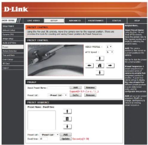
This screen allows you to set preset points for the ePTZ function of the camera, which allows you to look around the camera's viewable area by using a zoomed view. Presets allow you to quickly go to and view a specific part of the area your camera is covering, and you can create preset sequences, which will automatically change the camera's view between the different presets according to a defined order and timing you can set.
Note: If your View window area is the same as your Frame size, you will not be able to use the ePTZ function.
Video Profile: This selects which video profile to use.
ePTZ Speed: You may select a value between 0 and 64.0 is the slowest and 64 is the fastest.
Arrow Buttons and Home Button: Use these buttons to move to a specific part of the viewing area, which you can then set as a preset. Click the Home button to return to the center of the viewing area.
Input Preset Name: Enter the name of the preset you want to create, then click the Add button to make a new preset. If an existing preset has been selected from the Preset List, you can change its name by typing in a new name, then clicking the Rename button.
Preset List: Click this drop-down box to see a list of all the presets that have been created. You can select one, then click the GoTo button to change the displayed camera view to the preset. Clicking the Remove button will delete the currently selected preset.
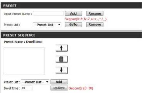
Preset Sequence: This section allows you to create a preset sequence, which automatically moves the camera's view between a set of preset views.
text_image
D-Link DOT-TOTAL LIVE VIDEO SETUP ADVANCED HAUSTINANCE STATUS HELP PREST CONTROL Using the Plan and TIC controls, move the camera axis to the required position. There are provide the tools for crowning and swing Preset positions & Preview Sequence. PREST CONTROL VIDEO PROFILES: +1 +2 +3 +4 +5 +6 +7 +8 +9 +10 +11 +12 +13 +14 +15 +16 +17 +18 +19 +20 +21 +22 +23 +24 +25 +26 +27 +28 +29 +30 +31 +32 +33 +34 +35 +36 +37 +38 +39 +40 +41 +42 +43 +44 +45 +46 +47 +48 +49 +50 +51 +52 +53 +54 +55 +56 +57 +58 +59 +60 +61 +62 +63 +64 +65 +66 +67 +68 +69 +70 +71 +72 +73 +74 +75 +76 +77 +78 +79 +80 +81 +82 +83 +84 +85 +86 +87 +88 +89 +90 +91 +92 +93 +94 +95 +96 +97 +98 +99 +100 PREST PRIEF: Input Preset Name: Add... Remove... Support(0 - 0, 0 - 0, 0 - 0, 0)... Preset List: - Preset List: - Go to... Remove... PREST SEQUENCE: Preset Name: Dwell Size: + - + - + - + - + - + - + - + - + - + - + - + - + - + - + - + - + - + - + - + - + - + - + - + - + - + - + - + - + - + - + - + - + - + - + - + - + - + - + - + - + - + - + - + - + - + - + - + - + - + - + + - + - + - + - + - + - + - + - + - + - + - + - + - + - + - + - + - + - + - + - + - + - + - + - + - + - + - + - + - + - + - + - + - + - + - + - + - + - + - + - + - + - + - + - + - + - + - + - + - + -Preset List: To add a preset to the sequence, select it from the drop-down box at the bottom of this window, set the Dwell time to determine how long the camera view will stay at that preset, then click the Add button. The preset name will appear in the list, followed by the dwell time to view that preset for.
You can rearrange your presets in the sequence by selecting a preset in the sequence, then clicking the arrow buttons to move it higher or lower in the current sequence.
Clicking the trash can button will remove the currently selected preset from the sequence.
If you want to change the dwell time for a preset, select it from the list, enter a new dwell time, then click the Update button.
text_image
PRESET Input Preset Name : Add Rename Support(0~9,A~2,a~2,*,-)_ Preset List : -Preset List GoTo Remove PRESET SEQUENCE Preset Name : Dwell Time ↑ ↓ Preset List : -Preset List Add Dwell time : 10 Update Second(s)[3-30]Motion Detection
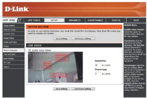
Enabling Video Motion will allow your camera to use the motion detection feature. You may draw a finite motion area that will be used for monitoring. After making any changes, click the Save Settings button to save your changes.
Enable Video Motion: Select this box to enable the motion detection feature of your camera.
Sensitivity: Specifies the measurable difference between two sequential images that would indicate motion. Please enter a value between 0 and 100.
Percentage: Specifies the amount of motion in the window being monitored that is required to initiate an alert. If this is set to 100%, motion is detected within the whole window will trigger a snapshot.
Draw Motion Area: Draw the motion detection area by dragging your mouse in the window (indicated by the red square).
Erase Motion Area: To erase a motion detection area, simply click on the red square that you wish to remove.
Right clicking on the camera image brings up the following menu options:
Select All: Draws a motion detection area over the entire screen.
Clear All: Clears any motion detection areas that have been drawn.
Restore: Restores the previously specified motion detection areas.
text_image
D-Link DOOR-TREL LIVE VIDEO SETUP ADVANCED MAINTENANCE STATUS HELP MOTION DECEPTION In order to use motion detections, you must first check the checkboxes, then draw the areas you want to monitor for motion. Live Settings Don't Live Settings Live video Live video motion Live video Sensitivity 88 3=100% Percentage 5 9=100% Line Settings Don't Live Settings Ins Retours Enable Video Motion Select the return to move motion detection for your camera. Sensitivity Select the sensitivity for motion detection. The text also indicates the level of action detection. An action can be used to do all the words will be recognized by the Environment of the Detection. Percentage Adjusting the percentage about you and the percentage from each much of the motion detection must be used by the movement detection if it is not at 10% below the selected window must be filled by the moving object before moving motion detectors.Time and Date
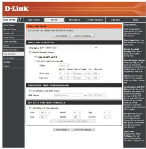
This section allows you to automatically or manually configure, update, and maintain the internal system clock for your camera. After making any changes, click the Save Settings button to save your changes.
Time Zone: Select your time zone from the drop-down menu.
Enable Daylight Saving: Select this to enable Daylight Saving Time.
Auto Daylight Saving: Select this option to allow your camera to configure the Daylight Saving settings automatically.
Set Date and Time Manually: Selecting this option allows you to configure the Daylight Saving date and time manually.
Offset: Sets the amount of time to be added or removed when Daylight Saving is enabled.
Synchronize with NTP Server: Enable this feature to obtain time automatically from an NTP server.
NTP Server: Network Time Protocol (NTP) synchronizes the DCS-7010L with an Internet time server. Choose the one that is closest to your location.
Set the Date and Time Manually: This option allows you to set the time and date manually.
Copy Your Computer's Time This will synchronize the time information from your PC. Settings:
text_image
D-Link DCS-TNHL Live Video SETUP ADVANCED MADYTESANCE STATUS HELP Help Tools... Used Implications in the Internet for Active Users were unselected. Manual mode. Time Zone Select Your Time Save from the downloads menu. Double Daylight Save Select This is needed to drive the downloads menu. Auto Daylight Service with a key, if the clock is automatically installed and is required for the downloads saving time of the selected data save. Offsite Select The time offset of the frames observed as light saving time. Automatic Time Configuration Syncrualize with RTP Server: MTP Server: Intra-dial.com.br Select RTP Save Set Date and Time Manually Set Date and Time Manually Year 2012 Month 8 Day 7 Hour 16 Minute 20 Second 34 Copy The Computer's Time Settings Save Settings Can't Save Settings Copy Your Computer's Time Settings That can be completed in the Internet for Active Users. Copy Your Computer's Time Settings That can be completed in the Internet for Active Users. Copy Your Computer's Time Settings That can be completed in the Internet for Active Users.Event Setup
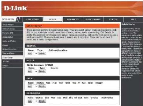
In a typical application, when motion is detected, the DCS-7010L sends images to a FTP server or via e-mail as notifications. As shown in the illustration below, an event can be triggered by many sources, such as motion detection. When an event is triggered, a specified action will be performed. You can configure the Network Camera to send snapshots or videos to your e-mail address or FTP site.

flowchart
graph TD
    A["Event Condition"] --> B["Action"]
    B --> C["Media (what to send)"]
    B --> D["Server (where to send)"]
    C -->|ex. Motion detection, Periodically, Digital input, System reboot| A
    D -->|ex. Email, FTP| B
    C -->|ex. Snapshot, Video Clips| B
To start plotting an event, it is suggested to configure server and media columns first so that the Network Camera will know what action shall be performed when a trigger is activated.
The Event Setup page includes 4 different sections.
• Event
- Server
• Media
- Recording
- To add a new item - "event, server or media," click Add. A screen will appear and allow you to update the fields accordingly.
- To delete the selected item from the pull-down menu of event, server or media, click Delete.
- Click on the item name to pop up a window for modifying.
text_image
D-Link OCS - TOTAL // LIVE VIDEO SETUP ADVANCED MAJHITMANCE STATUS HELP EVENT SETUP EVENT Setup: There are four categories in various name labels: They are absent, some, media and recording, dark. Not to press a reminder to add a new form of event, server, media or recording, dark. Details to divide the selected item from event, server, media or recording, dark on the next winner to pass a window to add it. There can be at most 2 events and 1 recording. There can be at most 3 server and 3 media configurations. Server Name: Type Address/Location Add: Delete MEDIA Media Inverse: 6709MB Name: Type Source Add: Delete EVENT Name: Status Sun Max Time Used The Fri Sat Time Trigger Add: Delete RECORDING Name: Status Sum Sun Time Used The Fri Sat Time Source Destination Add: Delete Help Help (Help) Recommended setting and include the first file for the video and record system. You will be able to make up your own file. To you need to access your own file. You need to access your own file. You need to access your own file. You need to access your own file. You need to access your own file. You need to access your own file. You need to access your own file. You need to access your own file. You need to access your own file. You need to access your own file. You need to access your own file. You need to access your own file. You need to access your own file. You need to access you with the same data in you with the same data in you with the same data in you with the same data in you with the same data in you with the same data in you with the same data in you with the same data in you with the same data in you with the same data in you with the same data in you with the same data in you with the same data in you with the same data in you with the same data in you with all other items. You need to access your own file. You need to access your own file. You need to access your own file. You need to access your own file. You need to access your own file. You need to access your own file. You need to access your own file. You need to access your own file. You need to access your own file. You need to access your own file. You need to access your own file. You need to access your own file. You need not to access your own file. You need not to access your own file. You need not to access your own file. You need not to access your own file. You need not to access your own file. You need not to access your own file. You need not to access your own file. You need not to access your own file. You need not to access your own file. You need not to access your own file. You need not to access your own file. You need not unbranded out of which the main model does not use any other model. You need not unbranded out of which the main model does not use any other model. You need not unbranded out of which the main model does not use any other model. You need not unbranded out of which the main model does not use any other model.Add Server
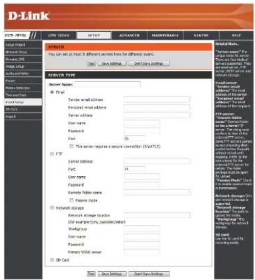
You can configure up to 5 servers to save snapshots and/or video to. After making any changes, click the Save Settings button to save your changes.
Server Name: Enter the unique name of your server.
E-mail: Enter the configuration for the target e-mail server account.
FTP: Enter the configuration for the target FTP server account.
Network Storage: Specify a network storage device. Only one network storage device is supported.
SD Card: Use the camera's onboard SD card storage.
text_image
D-Link DNS: 10000 TYPE VIDEO MUTIP ADVANCED MASSACHANCE STATUS HELP Server Type Server Name: □ Email □ Server email address: □ Exposed email address: □ Server allows: □ User name: □ Password: □ Part: 25 □ This server requires a secure connection (StartTLS) □ FTP □ Server address: □ Part: 24 □ User name: □ Password: □ Remote folder name: □ Passive mode: □ Network storage Network storage location (for example):any_isolate(rider) Workgroup: User name: Password: Primary WORK server SD Card Send Settings Read Save Settings Digital Tools... "Server name": the existing FTP server. These are four key components of the server. "Exposed email address" is also required to be used in the FTP server. FTP server: "Server static double server". Created from the website: FTP server. The existing FTP server is available for the website. The existing FTP server is available for the website. The existing FTP server is available for the website. The existing FTP server is available for the website. The existing FTP server is available for the website. The existing FTP server is available for the website. The existing FTP server is available for the website. The existing FTP server is available for the website. The existing FTP server is available for the website. The existing FTP server is available for the website. The existing FTP server is available for the web page. The existing FTP server is available for the web page. The existing FTP server is available for the web page. The existing FTP server is available for the web page. The existing FTP server is available for the web page. The existing FTP server is available for the web page. The existing FTP server is available for the web page. The existing FTP server is available for the web page. The existing FTP server is available for the web page. The existing FTP server is available for the web page. Network Storage Only on own network storage as an authorized network storage provider. The existing network storage provider has been carried out by the website. The existing network storage provider has been carried out by the website. The existing network storage provider has been carried out by the website. The existing network storage provider has been carried out by the website. The existing network storage provider has been carried out by the website. The existing network storage provider has been carried out by the website. The existing network storage provider has been carried out by the website. The existing network storage provider has been carried out by the website. The existing network storage provider has been carries out by the website. The existing network storage provider has been carries out by the website. The existing network storage provider has been carries out by the website. The existing network storage provider has been carries out by the website. The existing network storage provider has been carries out by the website. The existing network storage provider has been carries out by the website. The existing network storage provider has been carries out by the website. The existing network storage provider has been carries out by the website. The existing network Storage Provider (the existing network storage provider) is also carried out by the website. The existing network storage Provider (the existing network storage provider) is also carried out by the website. The existing network storage Provider (the existing network storage provider) is also carried out by the website. The existing network Storage Provider (the existing network storage provider) is also carried out by the website. The existing network Storage Provider (the existing network storage provider) is also carried out by the website. The existing network Storage Provider (the existing network storage provider) is also carried out by the website. The existing network Storage Provider (the existing network storage provider) is also carried out by the website. The existing network Storage Provider (the existing network storage provider) is also carried out by the website. The existing network Store Provider (the existing network store provider) is also carried out by the website. The existing network Store Provider (the existing network store provider) is also carried out by the website. The existing network Store Provider (the existing network store provider) is also carried out by the website. The existing Network Storage Provider (the existing Network Storage Provider) is also carried out by the website. The existing Network Storage Provider (the existing Network Storage Provider) is also carried out by the website. The existing Network Storage Provider (the existing Network Storage Provider) is also carried out by the website. The existing Network Storage Provider (the existing Network Storage Provider) is also carried out by the website. The existing Network Storage Provider (the existing Network Storage Provider) is also carried out by the website. The existing Network Storage Provider (the existing Network Storage Driver) is also carried out by the website. The existing Network Storage Provider (the existing Network Storage Driver) is also carried out by the website. The existing Network Storage Provider (the existing Network Storage Driver) is also carried out by the website. The existing Network Storage Provider (the existing Network Storage Provider) is also carried out by the website. The existing Network Storage Provider (the existing Network Storage Provider) is also carried out by the website. The existing Network Storage Provider (the existing Network Storage Provider) is also carried out by the website. The existing Network Storage Provider (the existing Network Storage Provider) is also carried out by the website. The existing Network Storage Provider (the existing Network Storage Carrier) is also carried out by the website. The existing Network Storage Provider (the existing Network Storage Provider) is also carried out by the website. The existing Network Storage Provider (the existing Network Storage Provider) is also carried out by the website. The existing Network Storage Provider (the existing Network Storage Provider) is also carried out by the website. The existing Network Storage Provider (the existing Network Storage Provider) is also carried out by the website. The existing Network Storage Provider (the existing Network Storage Sensor) is also carried out by the website. The existing Network Storage Provider (the existing Network Storage Provider) is also carried out by the website. The existing Network Storage Provider (the existing Network Storage Provider) is also carried out by the website. The existing Network Storage Provider (the existing Network Storage Provider) is also carried out by the website. The existing Network Storage Provider (the existing Network Storage Provider) is also carried out by the website. The existing Network Storage Provider (the existing Network Storage Period) is also carried out by the website. The existing Network Storage Provider (the existing Network Storage Period) is also carried out by the website. The existing Network Storage Provider (the existing Network Storage Period) is also carried out by the website. The existing Network Storage Provider (the existing Network Storage Period) is also carried out by the website. The existing Network Storage Provider (the existing Network Storage Period) is also carried out by the website. The existing Network Storage Provider (the existing Network Storage Provider) is also carried out by the website. The existing Network Storage Provider (the existing Network Storage Period) is also carried out by the website. The existing Network Storage Provider (the existing Network Storage Period) is also carried out by the website. The existing Network Storage Provider (the existing Network Storage Period) is also carried out by the website. The existing Network Storage Provider (the existing Network Storage Provider) is also carried out by the website. The existing Network Storage Provider (the existing Network Storage Provider) is also carried out by the website. The existing Network Storage Provider (the existing Network Storage Period) is also carried out by the website. The existing Network Storage Provider (the existing Network Storage Period) is also carried out by the website. The existing Network Storage Provider (the existing Network Storage Provider) is also carried out by the website. The existing Network Storage Provider (the existing Network Storage Period) is also carried out by the website. The existing Network Storage Provider (the existing Network Storage Provider) is also carried out by the website. The existing Network Storage Provider (the existing Network Storage Period) is also carried out by the website. The existing Network Storage Provider (the existing Network Storage Period) is also carried out by the website. The existing Network Storage Provider (the existing Network Storage Provider) is also carried out by the website. The existing Network Storage Provider (the existing Network Storage Provider) is also carried out by the website. The existing Network Storage Provider (the existing Network Storage Provider) is also carried out by the website. The existing Network Storage Provider (the existing Network Storage Period) is also carried out by the website. The existing Network Storage Provider (the existing Network Storage Provider) is also carried out by the website. The existing Network Storage Provider (the existing Network Storage Period) is also carried out by the website. The existing Network Storage Provider (the existing Network Storage Provider) is also carried out by the website. The existing Network Storage Provider (the existing Network Storage Provider) is also carried out by the website. The existing Network Storage Provider (the existing Network Storage Period) is also carried out by the website. The existing Network Storage Provider (the existing Network Storage Provider) is also carried out by the website. The existing Network Storage Provider (the existing Network Storage Provider) is also carried out by the website. The existing Network Storage Provider (the existing Network Storage Provider) is also carried out by the website. The existing Network Storage Provider (the existing Network Storage Provider) is also carried out by the website. The existing Network Storage Provider (the existing Network Storage Series) is also carried out by the website. SD card Send Settings Read Save SettingsAdd Media
There are three types of media, Snapshot, Video Clip, and System Log. After making any changes, click the Save Settings button to save your changes.
Media Name: Enter a unique name for media type you want to create.
Snapshot: Select this option to set the media type to snapshots.
Source: Set the video profile to use as the media source. Refer to Audio and Video on "Audio and Video" on page 43 for more information on video profiles.
Send pre-event image(s) [0\~3]: Set the number of pre-event images to take. Pre-event images are images taken before the main event snapshot is taken.
Send post-event image(s) [0\~7]: Set the number of post-event images to take. Post-event images are images taken after the main event snapshot is taken. You can set up to 7 post-event images to be taken.
File name prefix: The prefix name will be added on the file name.
Add date and time suffix to file Check it to add timing information as file name suffix.
name:
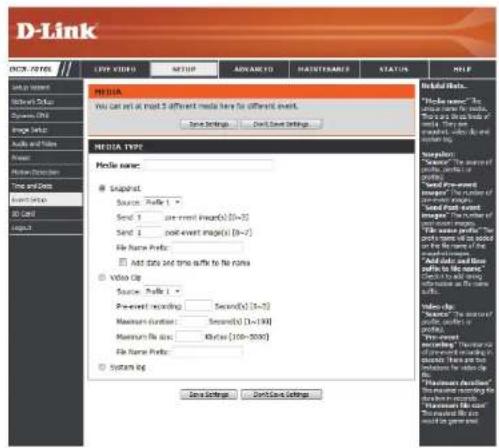
text_image
D-Link ICON-ITEMS LFP VIDEO MATCH ADVANCED MAINTIMABLE STATUS HELP USE NAME: Media name: ● Snapshot Source: Profile 1 Send: 1 post-event image(s) [0=7] Send: 2 post-event image(s) [0=7] File Name Profile: □ Add data and time offset to No name □ Video Clip Source: Profile 2 Pre-event recording: Second(s) [3=5] Maximum duration: Second(s) [1=194] Maximum file size: 8K bytes (100x-5000) File Name Profile: □ Screen Clip Save Settings Don't Save Settings Add Data Links ■ Preview name: "The number of images, sets, or profiles" ■ Open dialog with image: The number of images, sets, or profiles ■ Shared font event image: The number of images, sets, or profiles ■ File name profile: The number of images, sets, or profiles on the name of the image. ■ Add data and time offset to No name Check to add shipping to the name as the name. See highlights ■ Preview: "The number of images, sets, or profiles" ■ View words: "The number of images, sets, or profiles in accordance with instructions." Then are this instance for the video Clip. ■ Preview: "The number of images, sets, or profiles in accordance with instructions." Then are this instance for the video Clip.Video clip: Select this option to set the media type to video clips.
Source: Set the video profile to use as the media source. Refer to "Audio and Video" on page 43 for more information on video profiles.
Pre-event recording: This sets how many seconds to record before the main event video clip starts. You can record up to 4 seconds of pre-event video.
Maximum duration: Set the maximum length of video to record for your video clips.
Maximum file size: Set the maximum file size to record for your video clips.
File name prefix: This is the prefix that will be added to the filename of saved video clips.
System log: Select this option to set the media type to system logs. This will save the event to the camera system log, but will not record any snapshots or video.

text_image
D-Link ICON-ITEMS LFP VIDEO MATCH ADVANCED MAINTIMABLE STATUS HELP USE NAME: Media name: ● Snapshot Source: Profile 1 Send: 1 post-event image(s) [0=7] Send: 2 post-event image(s) [0=7] File Name Profile: □ Add data and time offset to No name □ Video Clip Source: Profile 2 Pre-event recording: Second(s) [3=5] Maximum duration: Second(s) [1=194] Maximum file size: 8K bytes (100=5000) File Name Profile: □ Screen Clip Save Settings Don't Save Settings Add Data... Remove Content: ■ Note to the name of the video clips. ■ Note to the name of the video clips. ■ Note to the name of the video clips. ■ Note to the name of the video clips. ■ Note to the name of the video clips. ■ Note to the name of the video clips.Add Event
Create and schedule up to 2 events with their own settings here. After making any changes, click the Save Settings button to save your changes.
Event name: Enter a name for the event.
Enable this event: Select this box to activate this event.
Priority: Set the priority for this event. The event with higher priority will be executed first.
Delay: Select the delay time before checking the next event. It is being used for both events of motion detection and digital input trigger.
Trigger: Specify the input type that triggers the event.
Digital Input: Initiates recording after receiving a digital input event.
Video Motion Detection: Motion is detected during live video monitoring. Select the windows that need to be monitored.
Periodic: The event is triggered in specified intervals. The trigger interval unit is in minutes.
System Boot: Triggers an event when the system boots up.
Network Lost: Triggers an event when the network connection is lost.
Time: Select Always or enter the time interval.
Server: Specify the location where the event information should be saved to.
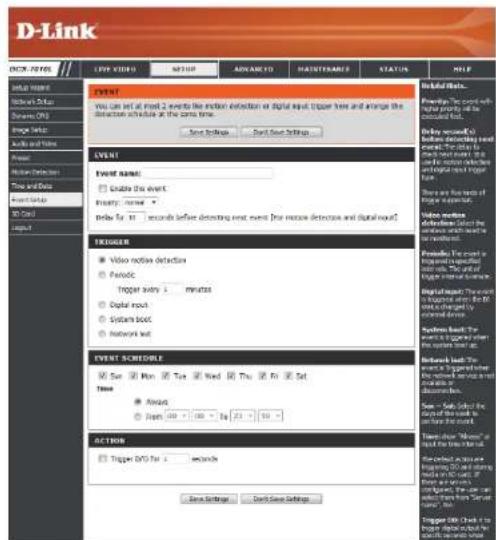
text_image
D-Link ONION ITEMS LIFE VIDEO ITEMS NAME Number SQL Server Sequence: ON Page Number On Call Input EVENT You can set at next 2 events like motion detection or digital input, trigger lines and arrange the detection activity at the same time. Start Settings Start Set Settings Event Name ■ Enable the event Inventory: none Delay by 10 seconds before detecting next event [the motion detection and digital input] TROGGER ■ Video receive detection ■ Periodic Trigger every 1 minute Digital input System block Network web EVENT SCHEDULE ■ Save □ Mon □ Tue □ Wed □ Thu □ Fri □ Sat Time ■ Avoid ■ Open □ 100 - 100 - 100 - 25 - 50 ACTION Trigger DVD for 1 second Save Settings... Don't Save Settings Help/Help Tools... Preview The event with high priority will be completed for: □ Check up a button to confirm the event. □ Select the event to get your attention to the event. ■ Select the event to get your attention to the event. Video receive detection select the event. Please check it or wait. Possible The event is performed in the context. □ Select the event to get your attention to the event. Digital input: The event must be checked for the system. If you are required to check the event. □ Select the event to get your attention to the system. If you are required to check the event. ■ Select the event to get your attention to the system. If you are required to check the event. ■ Select the event to get your attention to the system. If you are required to check the event. ■ Select the event to get your attention to the system. If you are required to check the event. ■ Select the event to get your attention to the system. If you are required to check the event. ■ Select the event to get your attention to the system. If you are required for the event. ■ Select the event to get your attention to the system. If you are required for the event. ■ Select the event to get your attention to the system. If you are required for the event. ■ Select the event to get your attention to the system. If you are required for the event. ■ Select the event to get your attention to the system. If you are required for the event. ■ Select the event to get your attention to the system. If you are required to check the event. ■ Select the event to get your attention to the system. If you are required for the event. ■ Select the event to get your attention to the system. If you are required for the event. ■ Select the event to get your attention to the system. If you are required for the event. ■ Select the event to get your attention to the system. If you are needed for the event. ■ Select the event to get your attention to the system. If you are needed for the event. ■ Select the event to get your attention to the system. If you are needed for the event. ■ Select the event to get your attention to the system. If you are needed for the event. ■ Select the event to get your attention to the system. If you are needed for the event. ■ Select the event to get your attention to the system. If you are required for the event. ■ Select the event to get your attention to the system. If you are required for the event. ■ Select the event to get your attention to the system. If you are required for the event. ■ Select the event to get your attention to the system. If you are required for the event. ■ Select the event to get your attention to the system. If you are needed for the event. ■ Select the event to get your attention to the system. If you are required for the event. ■ Select the event to get your attention to the system. If you are required for the event. ■ Select the event to get your attention to the system. If you are required for the event. ■ Select the event to get your attention to the system. If you are needed for the event. ■ Select the event to get your attention to the system. If you are needed until it is necessary. ■ Select the event to get your attention to the system. If you are needed until it is necessary. ■ Select the event to get your attention to the system. If you are needed until it is necessary. ■ Select the event to get your attention to the system. If you are needed until it is necessary. ■ Select the event to get your attention to the system. If you are needed until it is necessary. ■ Select the event to get your attention to the system. If you have been done until it is necessary. ■ Select the event to get your attention to the system. If you have been done until it is necessary. ■ Select the event to get your attention to the system. If you have been done until it is necessary. ■ Select the event to get your attention to the system. If you have been done until it is necessary. ■ Select the event to get your attention to the system. If you have been done until it is necessary. ■ Select the event to get你的 attention to all other events. ■ Select that's how much of our events must be done on this day. ■ Select that's how much of our events must be done on this day. ■ Select that's how much of our events must be done on this day. ■ Select that's how much of our events must be done on this day. ■ Select that's how much of our events must be done on this day. ■ Select that's how much of our events must be done on this day. ■ Select that's how much of our events must be done on this day. ■ Select what's how much of our events must be done on this day. ■ Select what's how much of our events must be done on this day. ■ Select what's how much of our events must be done on this day. ■ Select what's how much of our events must be done on this day. ■ Select what's how much of our events must be done on this day. ■ Select what's how much of our events must be done on this day. ■ Select what's how much if our events must be done on this day. ■ Select what's how much if our events must be done on this day. ■ Select what's how much if our events must be done on this day. ■ Select what's how much if our events must be done on this day. ■ Select what's how much if our events must be done on this day. ■ Select what's how much if our events must be done on this day. ■ Select what's how much if our events must not be done on this day. ■ Select what's how much if our events must not be done on this day. ■ Select what's how much if our events must not be done on this day. ■ Select what's how much if our events must not be done on this day. ■ Select what's how much if our events must not be done on this day. ■ Select what's how much if our events must not be done on this day. ■ Select what's how much if our things must be done on this day. ■ Select what's how much if our things must be done on this day. ■ Select what's how much if our things must be done on this day. ■ Select what's how much if our things must be done on this day. ■ Select what's how much if our things must be done on this day. ■ Select what's how much if our things must be done on this day. ■ Select what's how much if our things must be done on his own days. ■ Select what's how much if our things must be done on his own days. ■ Select what's how much if our things must be done on his own days. ■ Select what's how much if our things must be done on his own days. ■ Select what's how much if our things must be done on his own days. ■ Select what's how much if our things must be done on his own days. ■ Select what's how much if our things must be done on my own days. ■ Select what's how much if our things must be done on my own days. ■ Select what's how much if our things must be done on my own days. ■ Select what's how much if our things must be done on my own days. ■ Select what's how much if our things must be done on my own days. ■ Select what's how much if our things must be done on my own days. ■ Select what's how much if our things must be made out from my own days. ■ Select what's how much if our things must be made out from my own days. ■ Select what's how much if our things must be made out from my own days. ■ Select what's how much if our things must be made out from my own days. ■ Select what's how much if our things must be made out from my own days. ■ Select what's how much if our things must be made out from my own days. ■ Select what's how many of our things must be made out from my own days. ■ Select what's how many of our things must be made out from my own days. ■ Select what's how many of our things must be made out from my own days. ■ Select what's how many of our things must be made out from my own days. ■ Select what's how many of our things must be made out from my own days. ■ Select what's how many of our things must be made out from my own day.Add Recording
Here you can configure and schedule the recording settings. After making any changes, click the Save Settings button to save your changes.
Recording entry name: The unique name of the entry.
Enable this recording: Select this to enable the recording function.
Priority: Set the priority for this entry. The entry with a higher priority value will be executed first.
Source: The source of the stream.
Recording schedule: Scheduling the recording entry.
Recording settings: Configuring the setting for the recording.
Destination: Select the folder where the recording file will be stored.
Total cycling recording size: Please input a HDD volume between 1MB and 2TB for recording space. The recording data will replace the oldest record when the total recording size exceeds this value. For example, if each recording file is 6MB, and the total cyclical recording size is 600MB, then the camera will record 100 files in the specified location (folder) and then will delete the oldest file and create new file for cyclical recording.
Please note that if the free HDD space is not enough, the recording will stop. Before you set up this option please make sure your HDD has enough space, and it is better to not save other files in the same folder as recording files.
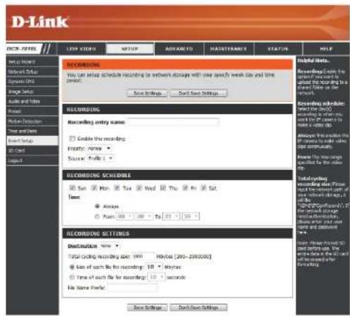
text_image
D-Link CNC - ITEMS LOOP VIDEO MATCH ADVANCED MAINTUSTRANCE STATUS HELP LOGIC NAME LOGIC NAME LOGIC NAME LOGIC NAME LOGIC NAME LOGIC NAME LOGIC NAME LOGIC NAME LOGIC NAME LOGIC NAME LOGIC NAME LOGIC NAME LOGIC NAME LOGIC NAME LOGIC NAME LOGIC NAME LOGIC NAME LOGIC NAME LOGIC NAME LOGIC NAME LOGIC NAME LOGIC NAME LOGIC NAME LOGIC NAME LOGIC NAME LOGIC NUTCH LOGIC NUTCH LOGIC NUTCH LOGIC NUTCH LOGIC NUTCH LOGIC NUTCH LOGIC NUTCH LOGIC NUTCH LOGIC NUTCH LOGIC NUTCH LOGIC NUTCH LOGIC NUTCH LOGIC NUTCH LOGIC NUTCH LOGIC NUTCH LOGIC NUTCH LOGIC NUTCH LOGIC SCHEDULES Total Recording Record Size: 1900 99658 (2005-2010000) Size of each file for recording: 10 Mybox Time of each file for recording: 10 seconds File Name: Postal. Save Settings Cancel Save Settings Help to Edit... Revised: Get to the Web from the Web to the Internet. Downloading the Web from the Web to the Internet. Ascending schedule: where the Web is available, when you want to access to the Web or to the Internet. Allowing this download the Web to a lower Web or to the Internet. Have the Web name specified by the Web name. Cataloging: Recording size: 1900; 1900; 1900; 1900; 1900; 1900; 1900; 1900; 1900; 1900; 1900; 1900; 1900; 1900; 1900; 1900; 1900; 1947. (P.O.) (P.O.) (P.O.) (P.O.) (P.O.) (P.O.) (P.O.) (P.O.) (P.O.) (P.O.) (P.O.) (P.O.) (P.O.) (P.O.) (P.O.) (P.O.) (P.O.) (P.O.) (P.O.) (P.O.) (P.O.) (P.O.) (P.O.) (P.O.) (P.O.) (P.O.) Data encoding: Database name: Database name: Database name: Database name: Database name: Database name: Database name: Database name: Database name: Database name: Database name: Database name: Database name: Database name: Database name: Database name: Database name: Database name: Database name: Database name: Database name: Database name: Database name: Database name: Database name: Database Name: Database Name: Database Name: Database Name: Database Name: Database Name: Database Name: Database Name: Database Name: Database Name: Database Name: Database Name: Database Name: Database Name: Database Name: Database Name: Database Name: Database Name: Database Name: Database Name: Database Name: Database Name: Database Name: Database Name: Database Name: Database Label: Database Label: Database Label: Database Label: Database Label: Database Label: Database Label: Database Label: Database Label: Database Label: Database Label: Database Label: Database Label: Database Label: Database Label: Database Label: Database Label: Database Label: Database Label: Database Label: Database Label: Database Label: Database Label: Database Label: Database Label: Database Label: Database Label: Database Label: Database Label: Database Label: Database Label: Database Label: Database Label: Database Label: Software Name: Software Name: Software Name: Software Name: Software Name: Software Name: Software Name: Software Name: Software Name: Software Name: Software Name: Software Name: Software Name: Software Name: Software Name: Software Name: Software Name: Software Name: Software Name: Software Name: Software Name: Software Name: Software Name: Software Name: Software Name: Software Name: Software Name: Software Name: Software Name: Software Name: Software Name: Software Name: Software Name: Software Name:Size of each file for recording: If this is selected, files will be separated based on the file size you specify.
Time of each file for recording: If this is selected, files will be separated based on the maximum length you specify.
File Name Prefix: The prefix name will be added on the file name of the recording file(s).

text_image
D-Link NEW ITEMS LOOP VIDEO MATCH ADVANCED MAINTUSTRANS STATUS HELP LOGIC ITEMS WINN LINE MAYA LINE MAYA LINE SHEET LINE TITLE LINE DATA NET DATA NET DATA NET DATA NET DATA NET DATA NET DATA NET DATA NET DATA NET DATA NET DATA NET DATA NET DATA NET DATA NET DATA NET DATA NET DATA NET DATA NET DATA NET DATA NET DATA NET DATA NET DATA NET DATA NET DATA NET DATA NET DATA NET DATA NET DATA NET DATA NET DATA NET DATA NET DATA NET DATA NETSD Card
Here you may browse and manage the recorded files which are stored on the SD card.
Format SD Card: Click this icon to automatically format the SD card and create "picture" & "video" folders.
View Recorded Picture: If the picture files are stored on the SD card, click on the picture folder and choose the picture file you would like to view.
Playback Recorded Video: If video files are stored on the SD card, click on the video folder and choose the video file you would like to view.
Refresh: Reloads the file and folder information from the SD card.
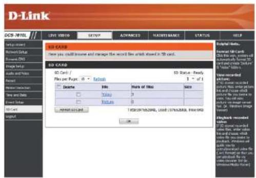
text_image
D-Link DCS-708L Live video setup SETUP ADVANCED MAINTS BANK STATUS HELP SD CARD Here you could become and manage the record file which stored in SD card. SD CARD SD Card / File per Page: 0 - Refresh Delete Share of Bits Size Value 3 Picture 0 Send to Web TSC(19/55.2006, USD: 19/55.2004, USD: 0) SD Status: Fully 1 - of 1 Name recorded all rights: No record recorded this code is not available for any other which contains any other code or this code. The code is not available for any other code. This code is not available for any other code. This code is not available for any other code. This code is not available for any other code. This code is not available for any other code. This code is not available for any other code. This code is not available for any other code. This code is not available for any other code. This code is not available for any other code. This code is not available for any other code. This code is not available for any other code. The code is not available for any other code. This code is not available for any other code. This code is not available for any other code. This code is not available for any other code. This code is not available for any other code. This code is not available for any other code. This code is not available for any other code. This code is not available for any other code. This code is not available for any other code. This code is not available for any others. You can access your website (http://www.docm.com) http://www.docm.com/ http://www.docm.com/ http://www.docm.com/ http://www.docm.com/ http://www.docm.com/ http://www.docm.com/ http://www.docm.com/ http://www.docm.com/ http://www.docm.com/ http://www.docm.com/ http://www.docm.com/ http://www.docm.com/ http://www.docm.com/ http://www.bocm.com/ http://www.bocm.com/ http://www.bocm.com/ http://www.bocm.com/ http://www.bocm.com/ http://www.bocm.com/ http://www.bocm.com/ http://www.bocm.com/ http://www.bocm.com/ http://www.bocm.com/ http://www.bocm.com/ http://www.bocm.com/ http://www.bocm.com/Advanced Digital Input/Output
This screen allows you to control the behavior of digital input and digital output devices. The I/O connector provides the physical interface for digital output (DO) and digital input (DI) that is used for connecting a variety of external alarm devices such as IR-Sensors and alarm relays. The digital input is used for connecting external alarm devices and once triggered images will be taken and e-mailed. After making any changes, click the Save Settings button to save your changes.
Select D/I or D/O Mode: The camera will send a signal when an event is triggered, depending upon the type of device connected to the DI circuit.
N.C. stands for Normally Closed. This means that the normal state of the circuit is closed. Therefore events are triggered when the device status changes to "Open."
N.O. stands for Normally Open. This means that the normal state of the circuit is open. Therefore events are triggered when the device status changes to "Closed."
You may specify whether or not to illuminate the status LED on the camera.

text_image
D-Link DOO /FDEL LIVE VIDEO SETUP ADVANCED MAINTENANCE STATUS HELP DI AND DO The DI driver provides the physical interface for digital output (DO) and digital input (DI). That is used for connecting a hierarchy of external arm devices such as AI sensors and alarm relays. The digital output is used for connecting external alarm devices and once triggered images will be taken and e-mated. Save Settings Done Save Settings DI AND DO Digital Input: The active state is "N.O."; The current state detected in Normal Open Digital Outputs: The active state is "N.O."; Live Settings Done Save Settings Workload status: All provided an external DI being tested with the digital input and one link with the internal control on DI and pin data to the external sensor and the internal interface, which is then mounted from the internal mode tool. This role is not using any DI or pin data to test or use the external device. Please refer to manual for additional connection degrees. DI AND DO DI AND DO Digital Input: The active state is "N.O."; The current state detected in Normal Open Digital Outputs: The active state is "N.O."; Live Settings Done Save Settings DI AND DO DI AND DO Digital Input: The active state is "N.O."; The current state detected in Normal Open Digital Outputs: The active state is "N.O."; Live Settings Done Save SettingsICR and IR
Here you can configure the ICR and IR settings. An IR(Infrared) Cut-Removable(ICR) filter can be disengaged for increased sensitivity in low light environments.
Automatic: The Day/Night mode is set automatically. Generally, the camera uses Day mode and switches to Night mode when needed.
Day Mode: Day mode enables the IR Cut Filter.
Night Mode: Night mode disables the IR Cut Filter.
Schedule Mode: Set up the Day/Night mode using a schedule. The camera will enter Day mode at the starting time and return to Night mode at the ending time.
IR Light Control: The camera can enable or disable the IR (infrared) light according to your preferences. This setting provides additional controls depending on your specific application.
Off: The IR light will always be off.
On: The IR light will always be on.
Sync: The IR light will turn on when the ICR sensor is on.
Schedule: The IR light will turn on or off according to the schedule that you specify below.
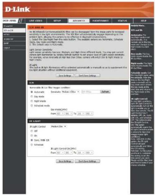
text_image
D-Link DCS-7015 LIVE VIDEO SUPPORT ADVANCED HAUSTHWARE STATUS HELP LANO DO LANO OR MINI MINI-OUT SFP AIR Light Sensor Sensitivity Light sensor sensitivity has Low, Medium, and High three different levels. You may get current camera light illumination by closing light button to set proper level of light sensor sensitivity. For example, when detail is off high than 20Hz, camera will switch dark & right mode to light mode. Light mode in Light dimensions will be activated automatically or manually as to complement the low light situation without additional equipment. Save Settings Send/Save Settings Habitat Home. SCS and TB. Automatics The Day Light mode is set up from 300 MHz to the Dark Current at the Dark Time for the Dark Time in the Dark Time. See mode: The Light mode is set up from 300 MHz to the Dark Time. See mode: The Light mode is set up from 300 MHz to the Dark Time. See mode: The Light mode is set up from 300 MHz to the Dark Time. See mode: The Light mode is set up from 300 MHz to the Dark Time. See mode: The Light mode is set up from 300 MHz to the Dark Time. See mode: The Light mode is set up from 300 MHz, see mode: The Light mode is set up from 300 MHz to the Dark Time. See mode: The Light mode is set up from 300 MHz to the Dark Time. See mode: The Light mode is set up from 300 MHz to the Dark Time. See mode: The Light mode is set up from 300 MHz to the Dark Time. See mode: The Light mode is set up from 300 MHz to the Dark Time. Severance OK Light Control OK Light Control On(24hr) OK Light Control On(24hr) OK Light Control On(24hr) OK Light Control On(24hr) OK Light Control On(24hr) OK Light Control On(24hr) OK Light Control On(24hr) OK Light Control On(24hr) OK Light Control On(24hr) OK Light Control On(24hr) OK Light Control On(24hr) OK Light Control On(24hr) ON ON Sync, With IQR Schedule Start Control On(24hr) Start Control On(24hr) Start Control On(24hr) Start Control On(24hr) Start Control On(24hr) Start Control On(24hr) Start Control On(24hr) Start Control On(24hr) Start Control On(24hr) Start Control On(24hr) Start Control On(24hr) Start Control On(24hr) Start Control On(24hr) Start Control On (24hr) Start Control On(24hr) Start Control On(24hr) Start Control On(24hr) Start Control On(24hr) Start Control On(24hr) Start Control On(24hr) Start Control On(24hr) Start Control On(24hr) Start Control On(24hr) Start Control On(24hr) Start Control On(24hr) Start Control On(24hr)HTTPS
This page allows you to install and activate an HTTPS certificate for secure access to your camera. After making any changes, click the Save Settings button to save your changes.
Enable HTTPS Secure Connection: Enable the HTTPS service.
Create Certificate Method: Choose the way the certificate should be created. Three options are available:
Create a self-signed certificate automatically Create a self-signed certificate manually Create a certificate request and install
Status: Displays the status of the certificate.
Note: The certificate cannot be removed while the HTTPS is still enabled. To remove the certificate, you must first uncheck Enable HTTPS secure connection.

text_image
D-Link ACO-7016L LIVE VIDEO SETUP ADVANCED MAINTENANCE STATUS HELP HKEYING ITEMS Enable HTTPS secure connections about you to enable HTTPS or link http://www.10.1.1234/ HTTPS Enable HTTPS secure connection Create certificate method Create self-signed certificate automatically Create self-signed certificate manually Create certificate request and install Create certificate Practe key inserted CERTIFICATE INFORMATION Status Active Country TW State or province Texas Locality Texas Organization D-JFK Taiwan Organization unit NMI Dept. Common Name: www.dlk.com.tw CIR Project: Certificate Property: Remove: Save Settings Done Save SettingsAccess List
Here you can set access permissions for users to view your DCS-7010L.
Allow list: The list of IP addresses that have the access right to the camera.
Start IP address: The starting IP Address of the devices (such as a computer) that have permission to access the video of the camera. Click Add to save the changes made.
Note: A total of seven lists can be configured for both columns.
End IP address: The ending IP Address of the devices (such as a computer) that have permission to access the video of the camera.
Delete allow list: Remove the customized setting from the Allow List.
Deny list: The list of IP addresses that have no access rights to the camera.
Delete deny list: Remove the customized setting from the Delete List.
For example:
When the range of the Allowed List is set from 1.1.1.0 to 192.255.255.255 and the range of the Denied List is set from 1.1.1.0 to 170.255.255.255. Only users with IPs located between 171.0.0.0 and 192.255.255.255 can access the Network Camera.

text_image
D-Link ORDER LIST Here you can set access parts before you to view your IP camera. ALLOW LIST Start IP address End IP address Delete after list DELY LIST Start IP address End IP address Delete delay list Help lists: "Start IP Address" The starting IP address of the computer, which is considered by a member to access the value of the IP address. "End IP Address" is called as: Additional for the division of the IP address. The first IP address is called as: Additional for the division of the IP address. "Deloy Address List" is called as: Additional for the division of the IP address. "Deloy Date List" the starting IP address of the computer, which is considered by a member to access the value of the IP address. "End IP Address" is called as: Additional for the division of the IP address. "Deloy Date List" is called as: Additional for the division of the IP address. "Deloy Date List" is called as: Additional for the division of the IP address.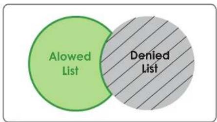
text_image
Alowed List Denied ListSNMP
Here you can enable and name SNMP settings.
Enable SNMP: Enable this option to allow local SNMP management.
Read/Write Community Enter a name for the read community of your SNMP server.
Read Only Community Enter a name for the write community of your SNMP server.
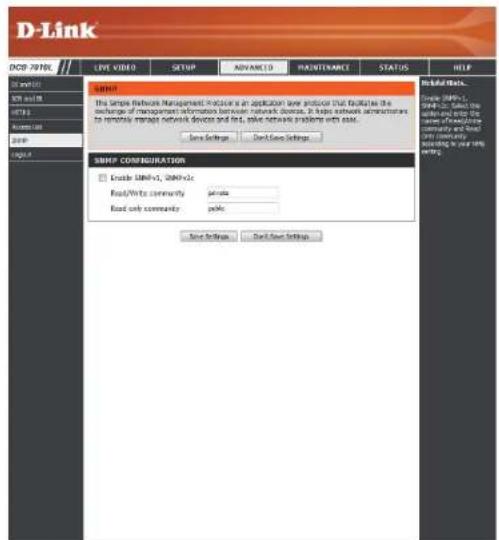
text_image
D-Link DOCP 707BL LIVE VIDEO SETUP ADVANCED MAUTENANCE STATUS HELP SUPPORT This simple network management procedure is an application based procedure that facilitates the exchange of management information between network devices. It helps network administrators to respond to network device and first, save network problems with ease. Save Settings Send Setup Settings SUPPORT CONFIGURATION Enable UNHv3, UNHv2c Read/Write community private Read only community private Save Settings Send Setup Settings Initial Links... Simple UNHv3, UNHv2c Select the software and help the new Internet Community and Save any continuity according to your own setting.Maintenance Device Management
You may modify the name and administrator's password of your camera, as well as add and manage the user accounts for accessing the camera. You may also use this section to create a unique name and configure the OSD settings for your camera.
Admin Password Setting: Set a new password for the administrator's account.
Add User Account: Add new user account.
User Name: The user name for the new account.
Password: The password for the new account.
User List: All the existing user accounts will be displayed here. You may delete accounts included in the list, but you may want to reserve at least one as a guest account.
Camera Name: Create a unique name for your camera that will be added to the file name prefix when creating a snapshot or a video clip.
Enable OSD: Select this option to enable the On-Screen Display feature for your camera.
Label: Enter a label for the camera, which will be shown on the OSD when it is enabled.
Show Time: Select this option to enable the time-stamp display on the video screen.
LED: You may specify whether or not to illuminate the status LED on the camera.
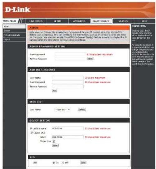
text_image
D-Link OFFS NAME LIVE VIDEO SETMP ADVANCED FAUTENANCE STATUS HELP ADMIN Home Software upgrade Input AUTHOR How you can change the administrator to password for your IP camera as well as add and/or adding your password. You can complete the information, such as IP camera's name and time on the page. You can also deliver the OFF (Download Display) feature in order to display the IP camera name and time stamp for your video recordings. AUTHOR PASSWORD SETTING New Password: 83 characters maximum Refuge Password: None ADD USER ACCOUNT User Name: 20 store maximum New Password: 63 characters maximum Refuge Password: None HNER LIST User Name: User list: Delete DEVICE SETTING IP Camera Name: DCS-7016 63 characters maximum © Enable ODD Label: DCS-7016 63 characters maximum Show time: None LIO USB OK OFF SaveSystem
In this section, you may backup, restore and reset the camera configuration, or reboot the camera.
Save To Local Hard Drive: You may save your current camera configuration as a file on your computer.
Load From Local Hard Drive: Locate a pre-saved configuration by clicking Browse and then restore the pre-defined settings to your camera by clicking Load Configuration.
Restore to Factory Default: You may reset your camera and restore the factory settings by clicking Restore Factory Defaults.
Reboot Device: This will restart your camera.
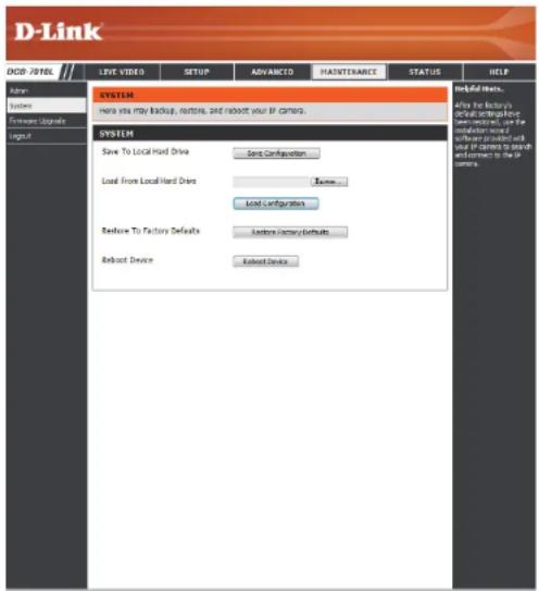
text_image
D-Link DOB / 70TEL LIVE VIDEO SETUP ADVANCED HATERNANCE STATUS HELP Admin: System Foreword Upgrade Layout SYSTEM Have you may backup, buttons, and robust your IP camera. System Save To Local Hard Drive Save Configuration Load From Local Hard Drive Review... Local Configuration Restore To Factory Defaults Restore Summary Defaults Reboot Device Reboot Device Helpful Hosts. After the factory's control engineering or safety test tool, use the maintenance and software provided with user IP camera to boost environment in the IP camers.Firmware Upgrade
The camera's current firmware version will be displayed on this screen. You may visit the D-Link Support Website to check for the latest available firmware version.
To upgrade the firmware on your DCS-7010L, please download and save the latest firmware version from the D-Link Support Page to your local hard drive. Locate the file on your local hard drive by clicking the Browse button. Select the file and click the Upload button to start upgrading the firmware.
Current Firmware Version: Displays the detected firmware version.
Current Product Name: Displays the camera model name.
File Path: Locate the file (upgraded firmware) on your hard drive by clicking Browse.
Upload: Uploads the new firmware to your camera.

text_image
D-Link DCS-701NL LIVE VIDEO SETUP ADVANCED FAIRITERABLE STATUS HELP Flash System Fireware Upgrade Logic FIREWARE UPGRADE A new Fireware upgrade may be enabled for your IP camera. It is recommended to keep your IP device features up-to-date to maintain and improve the functionality and performance of your internal IP camera. Click here: Quick Support Page to check for the latest Fireware version available. To upgrade the Fireware or your IP camera, please download and send the latest Fireware Version from the Digital Support Page to your local hard drive. Locate the file on your local hard drive by closing the license button. Once you have been and opened the file using the browser button, click the "global" button to start the Fireware upgrade. FIREWARE INFORMATION Current Fireware Version: (8.3.1) Current Product Name: DCS-701NL FIREWARE UPGRADE File Path: Down Help Help Links... Fireware upgrade are required (excluded) to ensure the final installation of your IP camera and/or use to add some features if you run in a problem with a few features of the IP camera, check for necessary data by displaying. To check for an update, I know if needed from a product for your IP camera.Status Device Info
This page displays detailed information about your device and network connection.
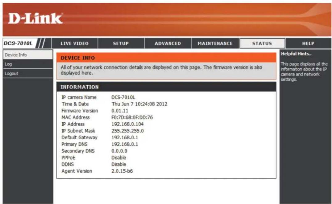
text_image
D-Link DCS-7010L LIVE VIDEO SETUP ADVANCED MAINTENANCE STATUS HELP Device Info Log Logout DEVICE INFO All of your network connection details are displayed on this page. The firmware version is also displayed here. INFORMATION IP camera Name DCS-7010L Time & Date Thu Jun 7 10:24:08 2012 Firmware Version 0.01.11 MAC Address F0:7D:68:0F:DD:76 IP Address 192.168.0.104 IP Subnet Mask 255.255.255.0 Default Gateway 192.168.0.1 Primary DNS 192.168.0.1 Secondary DNS 0.0.0.0 PPPoE Disable DDNS Disable Agent Version 2.0.15-b6 Helpful Hints.. This page displays all the information about the IP camera and network settings.Logs
This page displays the log information of your camera. You may download the information by clicking Download. You may also click Clear to delete the saved log information.

text_image
D-Link DCS-7010L LIVE VIDEO SETUP ADVANCED MAINTENANCE STATUS HELP Device Info Log Logout SYSTEM LOG The system log records IP camera events that have occurred. CURRENT LOG 1. 2012-06-07 10:15:38 admin LOGIN OK FROM 192.168.0.100 2. 2012-06-06 19:15:05 SYSTEM SET IR LIGHT ON 3. 2012-06-06 19:14:29 SYSTEM SET IR LIGHT OFF 4. 2012-06-06 19:14:04 SYSTEM SET IR LIGHT ON 5. 2012-06-06 19:13:51 SYSTEM SET IR LIGHT OFF 6. 2012-06-06 18:40:59 admin LOGIN OK FROM 192.168.0.100 7. 2012-06-06 18:39:58 IP CAMERA ACQUIRE DHCP IP 192.168.0.104 8. 2012-06-06 18:39:54 SYSTEM SET IR LIGHT ON 9. 2012-06-06 18:39:54 SYSTEM BOOTING 10. 2012-06-06 18:39:22 Hardware Restore Factory Default 11. 2012-06-06 18:36:49 admin FROM 192.168.0.100 SET VIDEO CODEC Need Reset 12. 2012-06-06 18:36:49 admin FROM 192.168.0.100 SET PROFILE 1 Viewer window area 800x600 13. 2012-06-06 18:36:49 admin FROM 192.168.0.100 SET PROFILE 1 Frame Size 800x600 14. 2012-06-06 18:36:31 admin FROM 192.168.0.100 SET VIDEO CODEC Need Reset 15. 2012-06-06 18:36:31 admin FROM 192.168.0.100 SET ASPECT RATIO 4:3 16. 2012-06-06 18:35:22 SYSTEM SET IR LIGHT ON 17. 2012-06-06 18:35:02 SYSTEM SET IR LIGHT OFF 18. 2012-06-06 18:29:46 admin LOGIN OK FROM 192.168.0.100 19. 2012-06-06 18:27:37 IP CAMERA ACQUIRE DHCP IP 192.168.0.104 20. 2012-06-06 18:27:31 NETWORK RECONNECT First Page Previous 20 Next 20 Clear Download Helpful Hints... You can save the log to your local hard IP camera by clicking the Download button, and you can clear the log by clicking on the Clear button.Help
This page provides helpful information regarding camera operation.

text_image
D-Link DCS-7010L HELP • LIVE VIDEO • SETUP • MAINTENANCE • ADVANCED • STATUS HELP • Camera SETUP • Setup Wizard • Network Setup • Dynamic DNS • Image Setup • Audio and Video • Preset • Motion Detection • Time and Date • Event Setup • SD Card ADVANCED • DI and DO • ICR and IR • HTTPS • Access List MAINTENANCE • Admin • System • Firmware Upgrade STATUS • Device Info • Log SECURITYDI/DO Specifications
Pin 1

| PIN | FUNCTION | NOTE |
| 1 | Digital Out (DO) | Uses an open-drain NFET transistor with the source connected to GND in camera. If used with an external relay, a diode must be connected in parallel with the load for protection against voltage transients. Max loading is 100 mA. |
| 2 | Digital In (DI) | A switch from DI to DC 5 V, activated by setting NO. or NC. |
| 3 | DC5V OUTPUT | DC 5 V Output / Max. 100 mA |
| 4 | GND | GND |
Internal 5V Power External 3\~12V Power
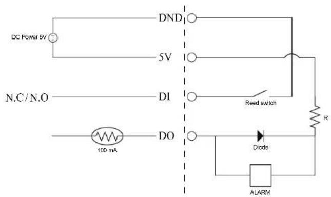
text_image
DC Power 5V 5V N.C/N.O DI 100 mA DO DND Reed switch R Dode ALARM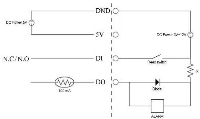
text_image
DC Power 5V 5V N.C/N.O DI DO 100 mA DND DC Power 3V-12V Reed switch R Diode ALARMTechnical Specifications
| Camera Camera | Hardware Profile | 1/4" Megapixel progressive CMOS sensor10 meter IR illumination distanceMinimum illumination: 0 lux with IR LED onBuilt-in Infrared-Cut Removable (ICR) Filter module10x digital zoom | Focal length: 4.3 mmAperture: F2.0Angle of view:(D) 60°(H) 47°(V) 37° |
| Camera Housing | IP-66 compliant weatherproof housing | Wire-in bracket | |
| Image Features | Configurable image size, quality, frame rate, and bit rateTime stamp and text overlaysConfigurable motion detection windows | Configurable privacy mask zonesConfigurable shutter speed, brightness, saturation, contrast, and sharpness | |
| Video Compression | Simultaneous H.264/MPEG-4/MJPEG format compressionH.264/MPEG-4 multicast streaming | JPEG for still images | |
| Video Resolution 16:9 | -1280 x 800, 1280 x 720, 800 x 450, 640 x 360, 480 x 270, 320 x 176, 176 x 144 | 4:3 - 1024 x 768, 800 x 600, 640 x 480, 480 x 360, 320 x 240, 176 x 144 | |
| Audio Support G.726 | G.711 | ||
| External Device Interface | 10/100 BASE-TX Fast Ethernet portSupports 802.3af PoE | MicroSD/SDHC card slot | |
| Network Network Protocols | IPv6IPv4TCP/IPUDPICMPDHCP clientNTP client (D-Link)DNS clientDDNS client (D-Link)SMTP clientFTP client | HTTP / HTTPSSamba clientPPPoEUPnP port forwardingRTP / RTSP/ RTCPP filteringQoSCoSMulticastIGMPONVIF compliant | |
| Security Administrator | and user group protectionPassword authentication | HTTP and RTSP digest encryption | |
Appendix A: Technical Specifications
| System Management | System Requirements for Web Interface | Browser: Internet Explorer, Firefox, Chrome, Safari | |
| Event Management | Motion detectionEvent notification and uploading of snapshots/video clips via e-mail or FTP | Supports multiple SMTP and FTP serversMultiple event notificationsMultiple recording methods for easy backup | |
| Remote Management | Take snapshots/video clips and save to local hard drive or NAS via web browser | Configuration interface accessible via web browser | |
| Mobile Support | Windows 7/Vista/XP system, Pocket PC, or mobile phone | mydlink mobile app for iOS and Android mobile devices | |
| D-ViewCamTM System Requirements | Operating System: Microsoft Windows 7/Vista/XPWeb Browser: Internet Explorer 7 or higher | Protocol: Standard TCP/IP | |
| D-ViewCamTM Software Functions | Remote management/control of up to 32 camerasViewing of up to 32 cameras on one screen | Supports all management functions provided in web interfaceScheduled motion triggered, or manual recording options | |
| General Weight | 267 g +-5% | ||
| External Power Adapter | Input: 100 to 240 V AC, 50/60 Hz Output: 5 V DC, 1.2 A | ||
| Power Consumption | 5.4 watts +-5% | ||
| Temperature | Operating: -25 to 50 °C (-13 to 122 °F) Storage: -20 to 70 °C (-4 to 158 °F) | ||
| Humidity Operating: 20% to 80% non-condensing Storage: 5% to 95% non-condensing | |||
| Certifications | CECE LVD | FCCC-Tick | |
Dimensions

text_image
65 37 80.5 26 33
text_image
176.5 100 87.5 54.4 Ø44Safety Statements
CE Mark Warning:
This is a Class B product. In a domestic environment, this product may cause radio interference, in which case the user may be required to take adequate measures.
FCC Statement:
This equipment has been tested and found to comply with the limits for a Class B digital device, pursuant to part 15 of the FCC Rules. These limits are designed to provide reasonable protection against harmful interference in a residential installation. This equipment generates, uses, and can radiate radio frequency energy and, if not installed and used in accordance with the instructions, may cause harmful interference to radio communication. However, there is no guarantee that interference will not occur in a particular installation. If this equipment does cause harmful interference to radio or television reception, which can be determined by turning the equipment off and on, the user is encouraged to try to correct the interference by one or more of the following measures:
- Reorient or relocate the receiving antenna.
- Increase the separation between the equipment and receiver.
- Connect the equipment into an outlet on a circuit different from that to which the receiver is connected.
- Consult the dealer or an experienced radio/TV technician for help.
FCC Caution:
Any changes or modifications not expressly approved by the party responsible for compliance could void the user's authority to operate this equipment.
This device complies with Part 15 of the FCC Rules. Operation is subject to the following two conditions:
(1) This device may not cause harmful interference, and (2) this device must accept any interference received, including interference that may cause undesired operation.
IMPORTANT NOTICE:
FCC Radiation Exposure Statement:
This equipment complies with FCC radiation exposure limits set forth for an uncontrolled environment. This equipment should be installed and operated with minimum distance 20cm between the radiator & your body. This transmitter must not be co-located or operating in conjunction with any other antenna or transmitter.
The availability of some specific channels and/or operational frequency bands are country dependent and are firmware programmed at the factory to match the intended destination. The firmware setting is not accessible by the end user.
For detailed warranty information applicable to products purchased outside the United States, please contact the corresponding local D-Link office.
Industry Canada Notice:
This device complies with RSS-210 of the Industry Canada Rules. Operation is subject to the following two conditions:
(1) This device may not cause harmful interference, and (2) this device must accept any interference received, including interference that may cause undesired operation.
IMPORTANT NOTE:
Radiation Exposure Statement:
This equipment complies with IC radiation exposure limits set forth for an uncontrolled environment. This equipment should be installed and operated with minimum distance 20cm between the radiator & your body.