DCS-2310L - Surveillance Camera D-LINK - Free user manual and instructions
Find the device manual for free DCS-2310L D-LINK in PDF.

User questions about DCS-2310L D-LINK
0 question about this device. Answer the ones you know or ask your own.
Ask a new question about this device
Download the instructions for your Surveillance Camera in PDF format for free! Find your manual DCS-2310L - D-LINK and take your electronic device back in hand. On this page are published all the documents necessary for the use of your device. DCS-2310L by D-LINK.
USER MANUAL DCS-2310L D-LINK
natural_image
White smart camera with black lens mounted on a stand (no visible text or symbols)User Manual
HD PoE Outdoor Cube Network Camera
DCS-2310L
Preface
D-Link reserves the right to revise this publication and to make changes in the content hereof without obligation to notify any person or organization of such revisions or changes. Information in this document may become obsolete as our services and websites develop and change. Please refer to the www.mydlink.com website for the most current information.
Manual Revisions
| Revision Date Description | |
| 1.0 July 10, 2012 DCS-2310L Revision | A1 with firmware version 1.00 |
Trademarks
D-Link and the D-Link logo are trademarks or registered trademarks of D-Link Corporation or its subsidiaries in the United States or other countries. All other company or product names mentioned herein are trademarks or registered trademarks of their respective companies.
Copyright © 2012 D-Link Corporation.
All rights reserved. This publication may not be reproduced, in whole or in part, without prior expressed written permission from D-Link Corporation.
Table of Contents
Product Overview 5
Package Contents 5
Introduction 6
System Requirements 6
Features 7
Hardware Overview 8
Front 8
Rear: External 9
Rear: Internal 10
Removing the Top Panel ....11
Removing the Power Cable 12
Replacing the Ethernet Cable 13
Reattaching the Top Panel 14
Removing the Bottom Panel ....15
Using the Reset Button 15
Installing an SD Memory Card ....16
Reattaching the Bottom Panel 16
Installation 17
Zero Configuration Setup ....17
Camera Installation Wizard ....20
Manual Hardware Installation 28
SD Memory Card Installation 29
mydlink 30
Camera Status 31
Live Video 32
Playback 33
Settings 34
Recording Settings 35
Advanced Settings 37
Events 38
Configuration 39
Using the Configuration Interface 39
Live Video 40
Setup 42
Setup Wizard 42
Internet Connection Setup Wizard ....43
Motion Detection Setup Wizard ....46
Network Setup 48
Dynamic DNS 51
Image Setup 52
Audio and Video 54
Preset....56
Motion Detection ....58
Time and Date 59
Event Setup 60
Add Server 62
Add Media 63
Add Event 65
Add Recording 67
SD Card 69
Advanced 70
ICR and IR 70
HTTPS 71
Access List....72
Maintenance 73
Device Management 73
Backup and Restore 74
Firmware Upgrade 75
Status 76
Device Info 76
Logs 77
Help 78
Technical Specifications ....79
Safety Statements 82
Contacting Technical Support 83
Warranty 84
Registration 89
Product Overview Package Contents
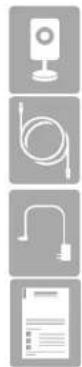
DCS-2310L HD PoE Outdoor Cube Network Camera
CAT5 Ethernet cable (Pre-Attached)
Power adapter (Pre-Attached)
Quick Installation Guide
If any of the above items are missing, please contact your reseller.
Note: Using a power supply with a different voltage than the one included with your product will cause damage and void the warranty for this product.

natural_image
White smart camera with black lens and green indicator lights on a white base (no text or symbols visible)Introduction
Congratulations on your purchase of the DCS-2310L HD PoE Outdoor Cube Network Camera. The DCS-2310L is a versatile and unique solution for your small office or home. Unlike a standard webcam, the DCS-2310L is a complete system with a built-in CPU and web server that transmits high quality video images for security and outdoor surveillance. The DCS-2310L can be accessed remotely, and controlled from any PC/Notebook over your local network or through the Internet via a web browser. The simple installation and intuitive web-based interface offer easy integration with your Ethernet/Fast Ethernet network. The DCS-2310L weatherproof housing and Power over Ethernet make it an ideal solution for a complete and cost-effective surveillance solution with an easy clutter-free installation. The remote monitoring, infrared, motion detection and event notifications features enable you to be truly responsive to your surveillance deployment.
System Requirements
- Computer with Microsoft Windows ^ 7, Vista ^ , or XP (for Setup Wizard) or Mac OS ^ X
• PC with 1.3GHz or above; at least 128MB RAM - Internet Explorer 7 or above, Firefox 3.5 or above, Safari 4 and Chrome 8.0 or above
• Existing 10/100 Ethernet-based network - A MicroSD memory card (optional) is required for recording to onboard storage. SDHC Class 6 or above is recommended.
• Broadband Internet connection
Features
Simple to Use
The DCS-2310L is a stand-alone system with a built-in CPU, requiring no special hardware or software. The DCS-2310L supports both ActiveX mode for Internet Explorer and Java mode for other browsers such as Firefox ^® and Safari ^® .
Supports a Variety of Platforms
Supporting TCP/IP networking, HTTP, and other Internet related protocols. The DCS-2310L can also be integrated easily into other Internet/Intranet applications because of its standards-based features. The DCS-2310L offers Ethernet/Fast Ethernet connectivity, making the DCS-2310L easy to integrate into your existing network environment. The DCS-2310L works with a 10Mbps Ethernet based network or 100Mbps Fast Ethernet based network for traditional wired environments.
Web Configuration
Using a standard Web browser, administrators can configure and manage the Network Camera directly from its own Web page via Intranet or Internet. This means you can access your DCS-2310L anytime, anywhere in the world.
Broad Range of Applications
With today's high-speed Internet services, the Network Camera can provide the ideal solution for delivering live video images over the Intranet and Internet for remote monitoring. The Network Camera allows remote access using a Web browser for live image viewing, and allows the administrator to manage and control the Network Camera anytime, anywhere in the world. Many applications exist, including industrial and public monitoring of homes, offices, banks, hospitals, child-care centers, and amusement parks.
Remote Monitoring Utility
The D-ViewCam application adds enhanced features and functionality for the Network Camera and allows administrators to configure and access the Network Camera from a remote site via Intranet or Internet. Other features include image monitoring, recording images to a hard drive, viewing up to 32 cameras on one screen, and taking snapshots.
IR LED for Day and Night Functionality
The built-in infrared LEDs enables night time viewing of up to 16 feet (5 meters).
IP65 Weatherproof Housing
The DCS-2310L uses an IP65 weatherproof housing, allowing you to rest assured that in the toughest of conditions, it will continue to provide round-the-clock surveillance.
PoE (Power over Ethernet) for Flexible Installation
The DCS-2310L can draw all the power it needs from a powered Ethernet port meaning installation is simple and clutter free.
Hardware Overview
Front
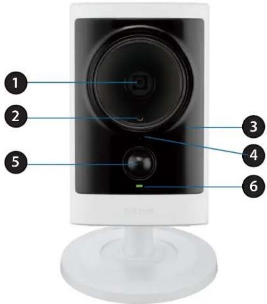
text_image
1 2 3 4 5 6| 1 Camera Lens Records video of the surrounding area. | |
| 2 ICR Sensor | The IR-Cut Removable sensor measures the lighting conditions and switches between color and infrared accordingly. |
| 3 IR LED Infrared LED illuminates the camera's field of view at night. | |
| 4 Microphone Records audio from the surrounding area. | |
| 5 PIR Passive Infrared sensor for motion detection. | |
| 6 Power/Status LED Indicates the camera's current status. | |
Rear: External
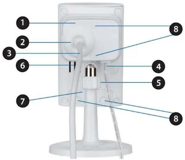
text_image
Labeled diagram of a device component with numbered parts for identification| 1 Weatherproof Cover Weatherproof protective panel. | |
| 2 Protective Cable Cover Weatherproof cable connection cover. | |
| 3 Ethernet Cable RJ45 Ethernet cable to connect to your network. | |
| 4 Power Cable Connected to the included DC 5 V power adapter. | |
| 5 Adjustment Ring | Tighten or loosen the adjustment ring to adjust the camera's position. |
| 6 Speaker Audio output. | |
| 7 Weatherproof Cover Weatherproof cover for the MicroSD Card slot and reset button. | |
| 8 Weatherproof Screw Covering | Weatherproof protective covering for enclosure screws. |
Rear: Internal
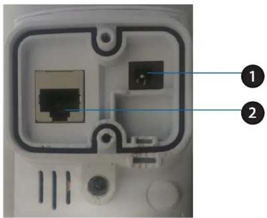
text_image
Diagram of a device rear panel showing internal components with labeled parts 1 and 2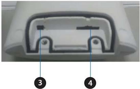
natural_image
Cross-sectional view of a device casing with numbered annotations (3 and 4) pointing to internal components (no text or symbols beyond labels)| 1 DC Power Connector Connected to the included DC 5 V power adapter. | |
| 2 RJ45 Ethernet Port RJ45 connector for Ethernet. | |
| 3 Reset Button | Use a paperclip or similar tool to press and hold the recessed button for 10 seconds to reset the camera. |
| 4 SD Memory Card Slot Insert a MicroSD card for for storing recorded images and video. | |
Removing the Top Panel
text_image
Technical diagram of a mechanical assembly with numbered parts for identificationStep 1:
Place the camera face down on a non-slip flat surface.
Step 2:
Carefully remove the two protective rubber screw coverings using a thin flat blade.
Step 3:
Undo the two screws using a Phillips #00 Screwdriver.
Step 4:
Lift off the protective panel.
Note: To ensure that the camera stays weatherproof, users are advised to ensure that all the rubber seals are secured firmly in place.
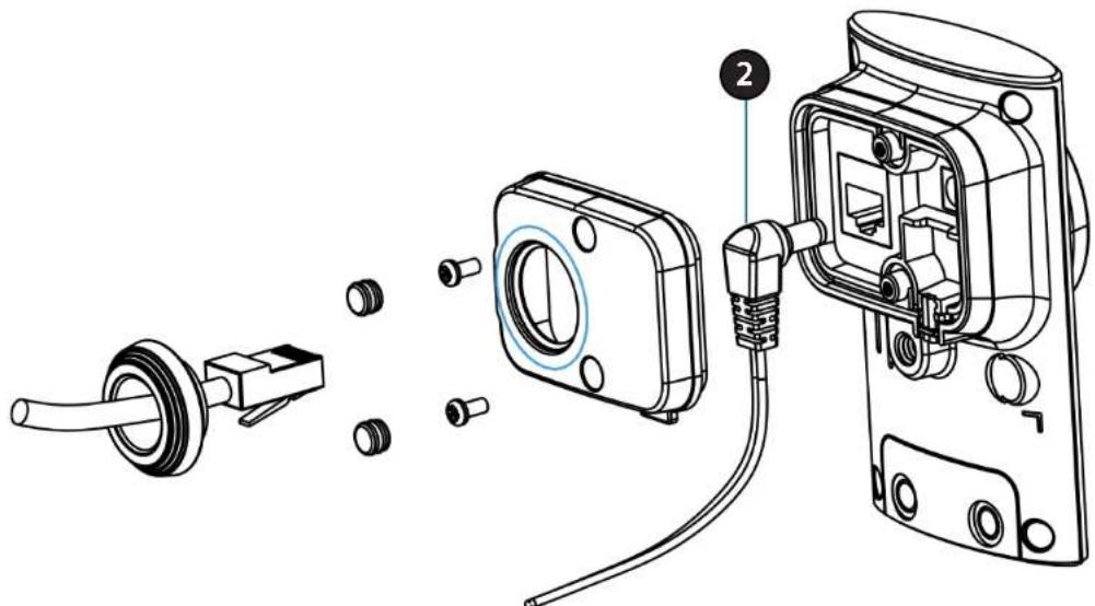
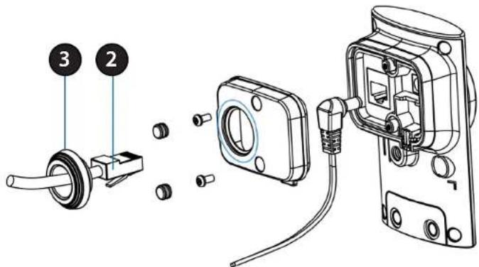
Removing the Power Cable
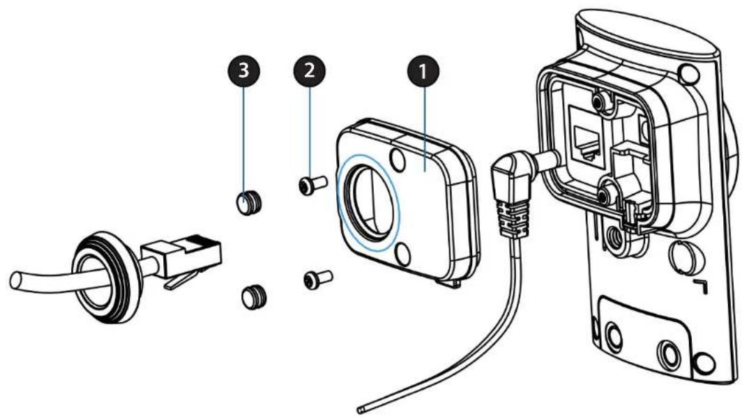
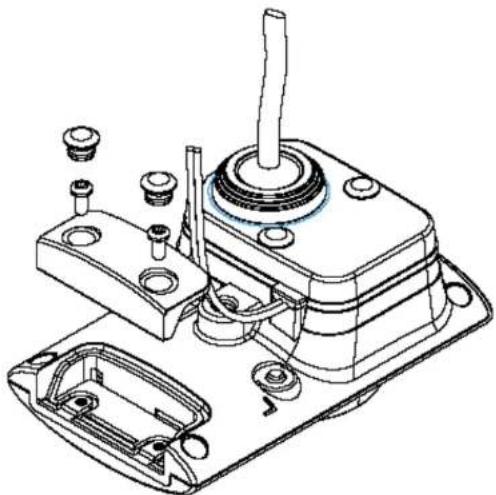
text_image
Technical diagram showing exploded view of a mechanical assembly with labeled parts and numbered annotationStep 1:
Follow the steps outlined in "Removing the Top Panel" on page 11.
Step 2:
Unplug the power cable from the DC power connector.
Step 3:
Insert the rubber weatherproof plug ensuring it aligns with the space left by the power cable.
Step 4:
Follow the steps outlined in "Reattaching the Top Panel" on page 14
Note: To avoid damage to the weatherproof aspects of the camera, users are advised to ensure the weatherproof plug is seated correctly.
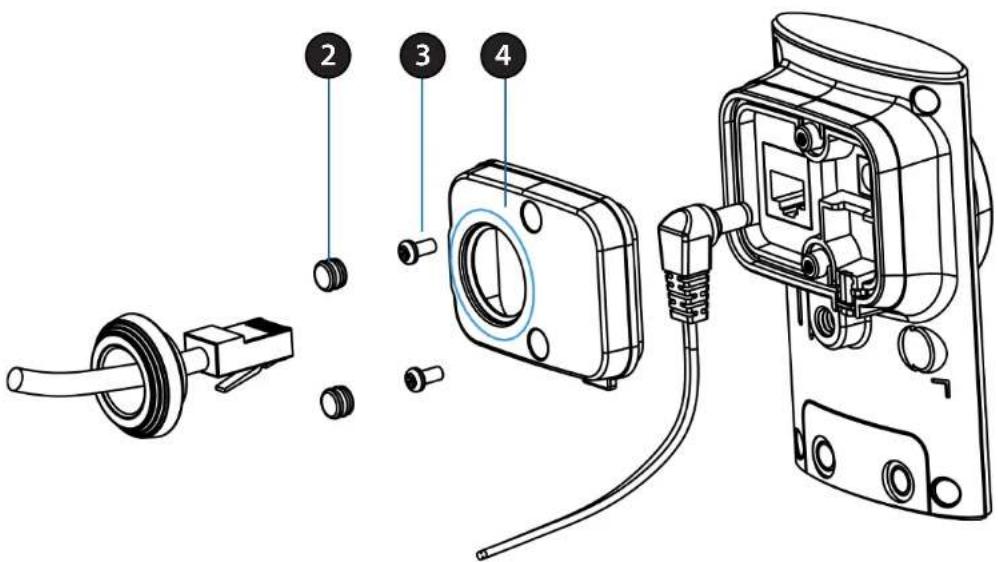
Replacing the Ethernet Cable
text_image
Technical diagram showing exploded view of mechanical assembly with numbered components and exploded view of internal componentsStep 1:
Follow the steps outlined in "Removing the Top Panel" on page 11
Step 2:
Unplug the Ethernet cable from the RJ45 connector.
Step 3:
Carefully remove the weatherproof cable connection cover.
Step 4:
Attach the weatherproof cable connection cover to the new Ethernet cable.
Step 5:
Plug the new Ethernet cable into the RJ45 connector.
Step 6:
Follow the steps outlined in "Reattaching the Top Panel" on page 14
Note: To avoid damage to the weatherproof aspects of the camera, users are advised not to remove the rear cable connection covering. To use a longer Ethernet cable install a coupling adaptor.
Reattaching the Top Panel
text_image
Technical diagram of a mechanical assembly with numbered parts for identificationStep 1:
Seat the protective panel, ensuring a tight fit with the inlaid rubber seal.
Step 2:
Replace the two screws. Ensure that the screws are tightened firmly.
Step 3:
Firmly replace the protective rubber screw coverings.
Note: To ensure that the camera stays weatherproof, users are advised to ensure that all the rubber seals are secured firmly in place.
Removing the Bottom Panel
Step 1:
Place the camera face down on a non-slip flat surface.
Step 2:
Carefully pry out the two protective rubber screw coverings using a thin flat blade.
Step 3:
Undo the two screws using a Philips #00 Screwdriver.
Step 4:
Lift off the protective panel.

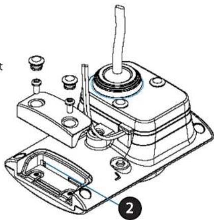
text_image
Technical diagram of a mechanical assembly with numbered parts labeled 2, 3, and 4Using the Reset Button
Step 1:
Follow the steps outlined in "Removing the Bottom Panel" above.
Step 2:
Using a paperclip or similar tool, press and hold the Reset Button for 10 seconds. This will reset the device to its factory settings.
Step 3:
Follow the steps outlined in "Reattaching the Bottom Panel" on page 16
natural_image
Technical line drawing of a mechanical assembly with no visible text or symbolsInstalling an SD Memory Card
Step 1:
Follow the steps outlined in "Removing the Bottom Panel" on page 15.
Step 2:
Insert a MicroSD Memory card into the slot, with the notch facing right.
Step 3:
Follow the steps outlined in "Reattaching the Bottom Panel" below.
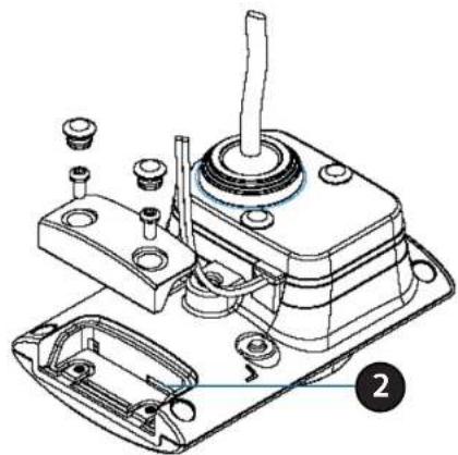
natural_image
Technical line drawing of a mechanical assembly with no visible text or symbolsReattaching the Bottom Panel
Step 1:
Seat the protective panel in place and ensure a tight fit with the inlaid rubber seal.
Step 2:
Replace the two screws. Ensure that the screws are tightened firmly.
Step 3:
Firmly replace the protective rubber screw coverings.
Note: To ensure that the camera stays weatherproof, users are advised to ensure that all the rubber seals are secured firmly in place.
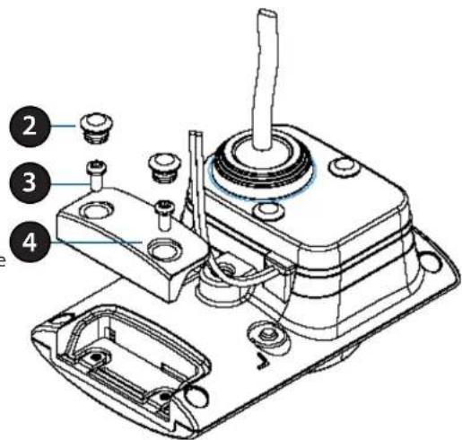
text_image
Technical diagram of a mechanical assembly with numbered parts labeled 2, 3, and 4Installation
Zero Configuration Setup
If you have a mydlink-enabled Cloud Router, you can take advantage of Zero Configuration. Zero Configuration automatically configures your camera's settings for you, and adds it to your mydlink account automatically. This type of setup allows you to set up your camera by simply plugging it in and connecting it to your router.
Connect your camera to your mydlink-enabled Cloud Router and Zero Configuration will automatically configure your DCS-2310L and automatically add the camera to your mydlink account. After the short time it takes to do this you can remotely access your camera from the www.mydlink.com website to manage and monitor your DCS-2310L.
Connect the Ethernet Cable
Using the pre-attached Ethernet cable connect the free end to your network.
Note: To avoid damage to the weatherproof aspects of the camera, users are advised not to remove the rear cable connection covering. To use a longer ethernet cable or power cord install a coupling adaptor, or power extension strip.

natural_image
Close-up of a white electronic device with concentric circular patterns and a central knob (no visible text or symbols)
natural_image
Diagram of a router with blue and orange cables, showing connection points and arrows (no text or symbols)Attach the External Power Supply
Attach the external power supply to your wall outlet or power strip. Please skip this step if your camera is connected using PoE (Power over Ethernet).
Note: If you choose to take advantage of the Power over Ethernet feature you may unplug the power cable. However, to avoid water ingress ensure the provided rubber weatherproof plug is used to fill the gap. See "Removing the Power Cable" on page 12 for further instructions.

natural_image
Close-up of a white wall-mounted electronic device with a circular button and a ruler (no visible text or symbols)
natural_image
Illustration of a wall-mounted power plug connected to a cable (no text or symbols)Check Your mydlink Account
Open a web browser and log into your mydlink account. The mydlink page will check for new devices and display a New device Found! pop-up notification in the bottom-left corner. Click the notification to continue.

text_image
mydlink My Devices Shared Devices My Services My Profile CRR-44SL 00019832 Router Status Settings Model Name: 004.6001 Network Name(55R) Internet SP 160 160.1 103 LORSP 160 160.1 Connected Devices 0 (unknown) Router Connection List Device Device Name IP Address MAC Address Block ScanServerBox 182 182.0.519 00:30:22:27:27 F2 — 182 182.0.519 04:34:52:52:52 F1 NetDay 182 182.0.518 09:14:40:52:40:52 F3 — 182 182.0.529 29:33:30:30:34:35 F4 — 182 182.0.561 78:42:35:44:36 F5 Standard List Device Device Name Time MAC Address Block New Launch DCS-2432LA summary and confirmation notification will appear with the automatically configured details. Make a note of the details and click OK to add the camera to your account.
text_image
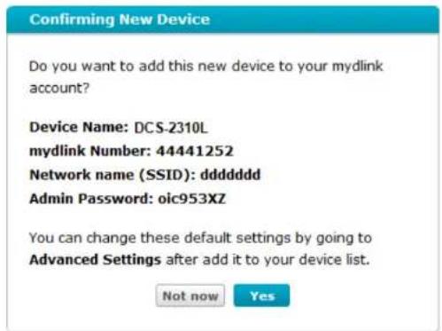
Confirming New Device Do you want to add this new device to your mydlink account? Device Name: DCS-2310L mydlink Number: 44441252 Network name (SSID): ddddddd Admin Password: oic953XZ You can change these default settings by going to Advanced Settings after add it to your device list. Not now YesZero Configuration will navigate to the mydlink Live View tab for your camera where you will see a screen similar to the following.
Your camera is now set up, and you can skip to "mydlink" on page 30 to learn more about the mydlink features of this camera, or for advanced configuration go to the "Configuration" section on page 39.
text_image
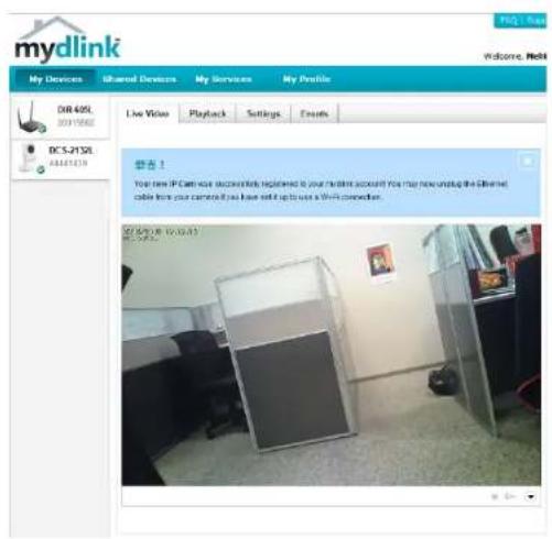
mydlink My Devices Shared Devices My Services My Profile Live Video Playback Settings Events DIR 40SL 2011562 DCS-21SL 83421379 否! You have IP Camera wise successfully registered to your client account. You may now setup the Internet cable from your camera if you have sell up to use a Wi-Fi connection. 02/09/28 16:09:41 02/09/28 16:09:41Camera Installation Wizard
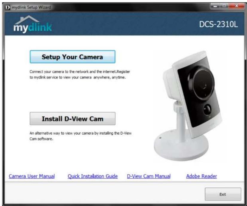
Note: If you have purchased an open box or resold unit, or if you experience issues registering this camera with your mydlink account, perform a hard reset by using an unfolded paperclip to press and hold the reset button on the back of the camera for 6 seconds while the camera is powered on. If you are returning the product to the place of purchase, please perform the hard reset procedure to clear the product of any personal data. Insert the Installation CD-ROM into your computer's optical drive to start the autorun program.
Open a web browser and go to http://www.mydlink.com/download. Click your camera model and then under Wizard, click the link of the version (Windows or Mac) you want to download. Depending on your web browser, you may need to right-click the link and select Save link as. Once it is downloaded, double-click the file to launch the wizard.
text_image
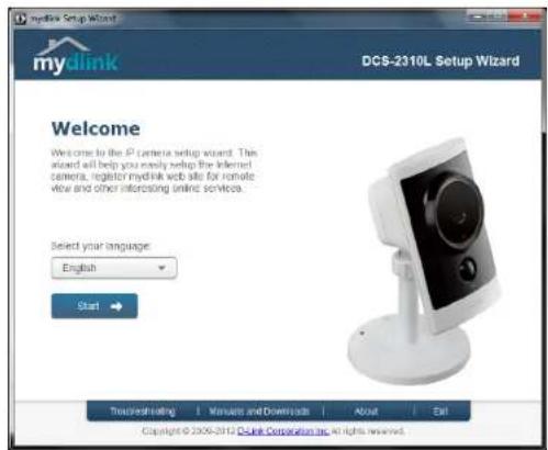
mydlink Setup Wizard DCS-2310L mydlink Setup Your Camera Connect your camera to the network and the internet.Register to mydlink service to view your camera anywhere, anytime. Install D-View Cam An alternative way to view your camera by installing the D-View Cam software. Camera User Manual Quick Installation Guide D-View Cam Manual Adobe Reader ExitSelect your preferred language for the installation from the drop-down menu and click on Start to proceed.
text_image
mydlink Setup Wizard DCS-2310L Setup Wizard Welcome Welcome to the P camera setup wizard. This wizard will help you easily setup the Infested camera, register mydlink web site for remote view and other interesting online services. Select your language: English Start → Trustsudrading 1 Manuals and Downloads About Exit Copyright © 2006-2012 Dclk Corporation Inc. All rights reserved.Locate the pre-attached Ethernet and power cables on the rear of your camera.
Click Next to continue.
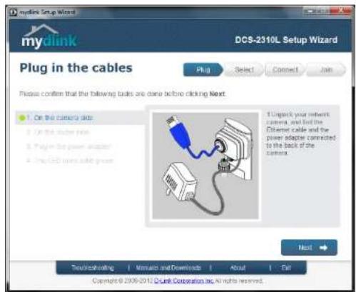
text_image
mydlink Setup Wizard DCS-2310L Setup Wizard Plug in the cables Plug Select Connect Join Please confirm that the following tasks are done before clicking Next. On the camera data On the camera rows Plug-in the power socket Plug CAD power cable grid 1. Unpack your network camera, and find the Ethernet cable and the power adapter connected to the back of the camera. Next Touch/Boosting | Monaco and Downloads | About | Exit Copyright © 2006-2012 Dink Corporation Inc. All rights reserved.Connect the Ethernet cable to a router.
Click Next to continue..
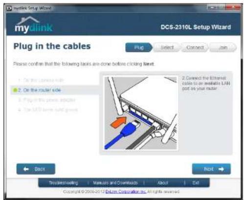
text_image
Mydlink Setup Wizard DCS-2310L Setup Wizard Plug in the cables Please confirm that the following tasks are done before clicking Next: 1. On the router side 2. On the router side 3. Plug-in the ports socket 4. Use USB home solid gates 2. Connect the Ethernet cable to an available LAN not on your router. Back Next Truckoverloading | Manuals and Downloads | About | Exit Copyright © 2006-2012 DCMS Corporation Inc. All rights reservedAttach the external power supply to your wall outlet or power strip.
Click Next to continue.

text_image
mydlink Setup Wizard DCS-2310L Setup Wizard Plug in the cables Plug Select Connect Tools Please confirm that the following tasks are done before clicking Next. 1. On the cable's side 2. On the motor side 3. Plug in the power adapter 4. The USB home after growth 3. Plug the power adapter into the power outlet. Please ship this step if your IP camera is connected with PoE (Power over Ethernet). Back Next Imprimeheadering Manuals and Downloads About Exit Copyright © 2008/2012 Bluek Corporation Inc. All rights reservedThe LED located in the front of the DCS-2310L will blink, then turn solid green once it successfully connects to your network. Click Next to proceed.
If the LED continues to blink, check your connections or click on the "What should I do if the LED stays red?" link for more information.
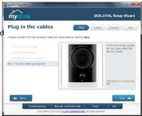
text_image
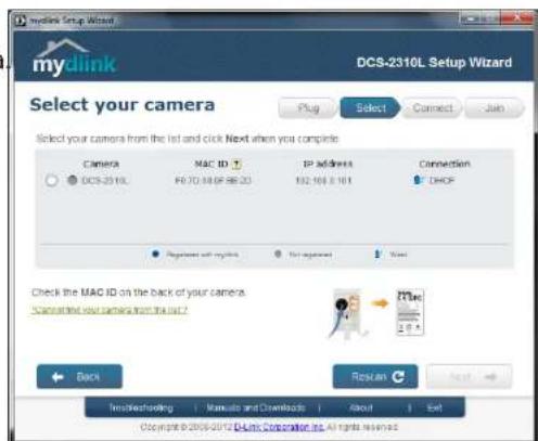
Mydlink Setup Wizard DCS-2310L Setup Wizard Plug in the cables Please confirm that the following tasks are done before clicking Next 1. On the correct task 2. On the mode task 3. Plug in the power output 4. The LED turns solid green 4. The LED on the cables will turn goes when the device is mainly. This point is at the LCD press Back Next Trade-seeking | Manuals and Downloads | About | Exit Copyright © 2016-2017 DC8-2310L Setup Wizard, All rights reserved.Select your camera from the list, then click Next. If you have multiple cameras, you can identify them by the MAC ID printed on the label on the back of your camera
Click Next to continue.
text_image
mydlink Setup Wizard DCS-2310L Setup Wizard Select your camera Plug Select Connect Join Select your camera from the list and click Next when you complete. Camera MAC ID IP address Connection DCS-2310L F0.70.14F 98:23 192.10/3.10/1 DHOP Connect with mydlink For app access Start Check the MAC ID on the back of your camera. Cancel this your camera from the list? Back Rename/Helping Manual and Downloads About Exit Copyright © 2005-2012 DCs Setup Wizard Inc. All rights reserved.If you wish to remove the camera from a previously registered mydlink account, press and hold the reset button on the rear panel for at least 10 seconds and click Restart to restart the Setup Wizard.

text_image
Press and hold the Reset button for at least 10 seconds while your camera is plugged in. After resetting your camera, click Restart to continue. RESET Restart ✓ Close ✗After you have selected your camera from the list, you will be asked to create and confirm a password for it. The password is case sensitive and must contain at least 2 letters.
Click Next to continue.

text_image
mydlink Setup Wizard DCS-2310L Setup Wizard Select your camera Plug Select Connect Join Select your camera from the list and click Next when you complete Camera MAC 3D [J] IP address Connection DCS-2310L F:70.68.89 A3 CF 172.18.195.63 DnCP Registered with Cyprus Set against Next Enter a password to secure your camera Cased but your camera from the list ? Admin account: admin Password: Confirm password: Back Remove C Next Troubleshooting Manuals and Downloads About Exit Copyright © 2006-2012 Blue Corporation Inc. All rights reservedSection 2: Installation
Click Next to continue.
text_image
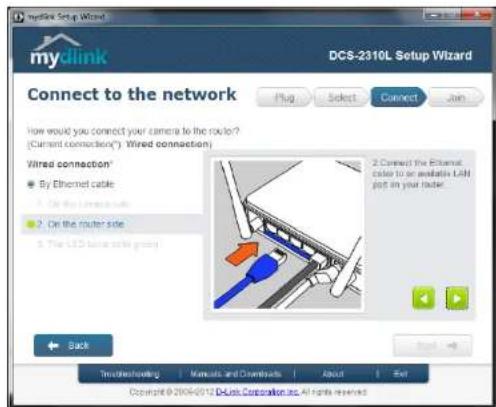
Mydlink Setup Wizard DCS-2310L Setup Wizard Connect to the network How would you connect your camera to the router? (Current connection*) Wired connection) Wired connection* By Ethernet cable On the router side On the router side The LCD panel is also good 2 Connect the Ethernet color to an available LAH get in your folder. Back Truck/Drawholding | Manuals and Downloads | About | Exit Copyright © 2004/02/13 DcLink Corporation Inc. All rights reservedComplete the mydlink account registration with your details and make sure to check the I accept mydlink terms and conditions box.
Click Next to continue.

text_image
mydlink Setup Wizard DCS-2310L Setup Wizard Join mydlink service Do you have a mydlink account ? Yes, I already have a mydlink account. Please enter your mydlink account E-Mail: Password: Send account? No, I need to sign up for a new account. I don't want to sign up right now. Back Next Transfer/Ordering Manuals and Downloads About Exit Copyright © 2310-2017 DCMS Corporation Inc. All rights reserved.If you already have a mydlink account, enter your login details and click Next to proceed.

text_image
mydlink Setup Wizard DCS-2310L Setup Wizard Join mydlink service Plug Select Connect Join Do you have a mydlink account ? Yes, I already have a mydlink account No. I need to sign up for a new account E-Mail First Name Password Last Name Confirm Password I would like to receive emails for latest services and products from mydlink. I accept mydlink terms and conditions I don't want to sign up right now Back Tremeshaving Manuals and Downloads About Exit Copyright © 2000-2010 Dublin Corporation, All rights reservedConfirm your mydlink account details and give the camera a unique name and click Done.
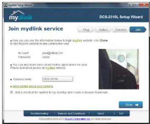
text_image
mydlink Setup Wizard DCS-2310L Setup Wizard Join mydlink service • Now you can use the information below to login mydlink website. click Done to visit mydlink website to see camera live view Account: pax@nland.me Password: xzzzzz • You can also learn more about mobile applications for your iPhone & Android phone on mydlink website. • Camera name: DCS-2310L • More details about your camera. • Add a shortcut for mydlink to my desktop and create a browser bookmark. Done: Imidashending | Manuals and Downloads | About | Exit Copyright © 2005-2013 DCS Corporation Inc. All rights reservedConfirm your camera login details and IP address details and click Done.
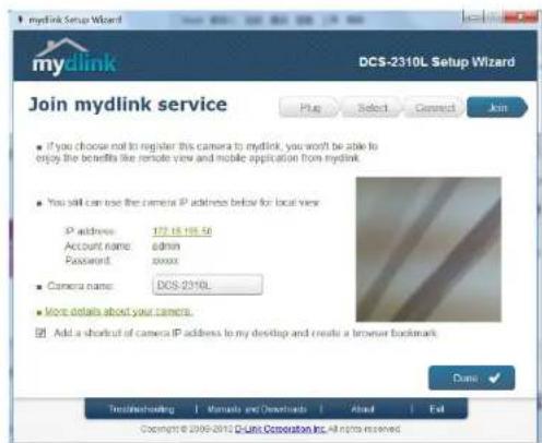
text_image
mydlink Setup Wizard DCS-2310L Setup Wizard Join mydlink service ■ If you choose not to register this camera to mydlink, you won't be able to enjoy the benefits like remote view and mobile application from mydlink. ■ You still can use the camera IP address below for local view IP address: 172.15.195.56 Account name: admin Password: xxxx ■ Camera name: DOS-2310L ■ More details about your camera. ■ Add a shortcut of camera IP address to my desktop and create a browser bookmark Done Test/Testing: Manual and Download: About End Copyright © 2006-2012 DCUnit Corporation Inc. All rights reservedYour DCS-2310L camera is now set up. Log on to your mydlink account and explore the exciting benefits available to you.
Your camera is now set up, and you can skip to "mydlink" on page 30 to learn more about the mydlink features of this camera, or to "Configuration" on page 39 for advanced configuration of your camera.

text_image
mydlink My Devices My Profile DC-2019L 4441711 Live View Playback Settings 75/06/2019/07/18:30 DC-2019LManual Hardware Installation
If you wish to set up your camera without using the Camera Setup Wizard, please follow these steps.
Note: In order to use the mydlink features of this product, you will need to go through the Camera Setup Wizard.
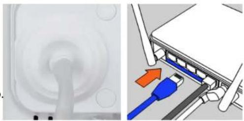
Connect the Ethernet Cable
Using the pre-attached Ethernet cable connect the free end to your network.
Note: To avoid damage to the weatherproof aspects of the camera, users are advised not to remove the rear cable connection covering. To use a longer ethernet cable or power cord install a coupling adaptor, or power extension strip.
natural_image
Two-panel image showing a device with a circular port and a close-up of a blue USB cable inserted into a server rack (no text or symbols visible)Attach the External Power Supply
Attach the external power supply to your wall outlet or power strip. Please skip this step if your camera is connected using PoE (Power over Ethernet).

natural_image
Two-panel image: left shows a wall-mounted device with circular components, right shows a plug socket with two switches (no text or symbols visible)Note: If you choose to take advantage of the Power over Ethernet feature you may unplug the power cable. However, to avoid water ingress ensure the provided rubber weatherproof plug is used to fill the gap. See "Removing the Power Cable" on page 12 for further instructions.
SD Memory Card Installation
The SD memory card slot is housed behind the lower protective panel on the rear of the device. See. "Rear: Internal" on page 10
Step 1:
Place the camera face down on a non-slip flat surface
Step 2:
Carefully remove the two lower protective rubber grommets using a thin flat blade.
Step 3:
Undo the two screws using a Philips #00 Screwdriver.
Step 4:
Lift off the protective panel.
Step 5:
Insert a MicroSD Memory Card.
Step 6:
Replace the protective panel.
Step 7:
Replace the two screws. Ensure that the screws are tightened firmly.
Step 8:
Firmly replace the protective rubber grommets.
Note: To ensure that the camera stays weatherproof, users are advised to ensure that all the rubber seals are secured firmly in place.
natural_image
Technical line drawing of a mechanical assembly with no visible text or symbolsmydlink
After registering your DCS-2310L camera with a mydlink account in the Camera Installation Wizard. You will be able to remotely access your camera from the www.mydlink.com website. After signing in to your mydlink account, you will see a screen similar to the following:

text_image
mydlink My Devices My Profile DCS-2310L Live View Playback Settings 02/01/2012 02:18:00 DCS-2310L News 2011/09/15 07:00 mydlink Server Shutdown Notifications... 2011/6/30 6:00 mydlink Server Shutdown Notifications... Support Setup wizard User manual Firmware Quick Installation Guide mydlink mydlink no mobile... Global D-Link | About mydlink | Terms of Use | Privacy Policy | Contact Us Copyright©2008-2012 D-Link Corp. All rights reserved.Camera Status
Here, you can see the online status of each of your cameras. Your online status may be one of the following:
A green checkmark indicates that your camera is online and ready to use.
A yellow exclamation point indicates that your camera is online, but the camera password has changed. You will need to enter your new camera password to access your camera again.

A red X indicates that your camera is offline and currently cannot be accessed remotely.
If your camera is offline, try the following:
- Check to make sure that the Internet connection to your camera is working properly.
- Try restarting your Internet router.
- Check your camera's cable connections and make sure they are secure.
- Check to make sure that the LED on your camera is lit solid green.
If you still cannot access your camera, reset your camera and run the Camera Installation Wizard again from the CD-ROM included in your package.
Live Video
In the main part of the screen, the Live Video tab will be selected by default. If the camera is available, a Live Video feed will be displayed. Video will be shown at VGA resolution (640x480) if viewing your camera from a PC on the same local network, or at QVGA resolution (320x240) if viewing your camera from a PC on a remote network.

text_image
mydlink My Devices My Profile DCS-2310L 44441711 Live View Playback Settings 02/03/2012 02:18:06 DCS-2310L FAQ | Support Welcome, + - + - - -Section 3: mydlink
Playback
The Playback tab allows you to review pre-recorded footage captured to the microSD card.

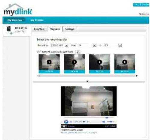
text_image
mydlink My Devices My Profile DCS-2310K 5541711 Live View Playback Settings Select the recording clip Record on: 2012/06/08 non: 0 to: 23 SAT: Marketing video clips were found: 18.22.10 19.30.10 20.27.10 21.33.10Select the date of the footage you wish to preview from the drop-down menu, then choose from the recordings available for that date.
text_image
mydlink My Overview DC$ 2310L 4484:711 Live View Playback Settings Select the recording clip Record on: 2012/05/09 from 0 to 23 HPT matching video clip(s) was found 16.25.48 16.25.48 16.27.48 16.00.48 Cpspd 007-004 * Cannot see the video? Music channel and click the song.Settings
The Settings tab contains several options for you to control how your DCS-2310L operates.
Camera Name: Click on the Edit button to change how the camera name appears.
mydlink No: This is the unique mydlink number for your device.
Model name: This shows the model name of the camera.
MAC: The shows the Media Access Control (MAC) address of the camera.
Camera Activated on: The date the camera was registered to the mydlink service.
Event Notification Email notification of events can be switched on or off Settings:

text_image
mydlink My Devices My Profile Live View Playback Settings General Information Camera Name: DCB-2318L mydlink No.: 44441711 Model Name: DCB-2318L MAC1: FJ/T0000F0000 Camera activated set: 2013-05-22 15:20:39 Recording Settings Do not record any video clips. Record video clips where mode is detected. Record video clips by schedule. Advanced Settings You can click the Advanced Settings button to access your cameras advanced settings. After clicking the button, use the software and download button to log in. Username errors Camera Password: Show password Advanced Settings You can receive your camera to clicking Delete Camera Button. Remove CameraGlobal Dolar | Access policy | Terms of Use | Privacy Policy | Contact On Copyright 2008-2012 D-LINK Corp. All rights reserved.
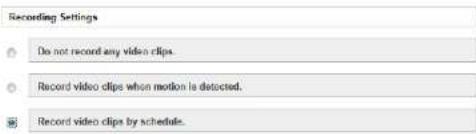
Each of the recording settings will open a further menuRecording Settings
text_image
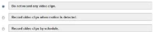
Do not record any video clips. Record video clips when motion is detected. Record video clips by schedule.Recording Settings
Record video clips Select this option to enable the automatic recording when motion is detected. detected:

Add Detection Area: Click on this icon to draw areas that will trigger automatic recording when motion is detected.

Remove Detection Area: Click on this icon to erase areas from regions that trigger automatic recording when motion is detected.

Clear Detection Area: This will remove all detection areas

Refresh Snapshot: This will refresh the current snapshot of the monitored area.

Increase/Decrease Sensitivity Increase the motion detection sensitivity
Email Notification: Toggles notification by email on or off.
Video Clips Recording In the event that the microSD card cannot store further recordings, Mode: the user can choose to record over previous recordings or to be notified and cease recording.
Recording Settings
Do not record any video clips.
Record video clips when motion is detected
1 Motion detection

2 E-mail notification
Enable e-mail notification
3 Video clips
The inserted MicroSD card can store about 0 days of video maximum.
When the MicroSD card is full
Continue recording & overwrite the closest video.
■ Stop recording & notify me.


Record video clips by schedule.
Record Video Clips by This option enables either continuous or recurring scheduled Schedule: recording.
text_image
Recording Settings Do not record any video clips. Record video clips when motion is detected. Record video clips by schedule.Toggles notification by email on or off.Email Notification:
1 Schedule setup
Record video
Continuously
Only on Sun Mon Tue Wed Thu Fri Sat
From 0:00 to 23:59
2 E-mail notification
Enable e-mail notification
Video Clips Recording In the event that the microSD card cannot store further recordings, Mode: the user can choose to record over previous recordings or to be notified and cease recording.
3 Video clips recording mode
The inserted MicroSD can still store about 0 days of video maximum
When the MicroSD card is full
Continue recording & overwrite the oldest video.
Stop recording & notify me.

Cancel
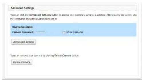
Advanced Settings
You can click the Advanced Settings button to access your camera's advanced settings. After clicking the button, use the username and password below to log in.
Username: admin
Camera Password
Show password
Advanced Setting
Advanced Settings
Show password: Checking this box will show the password.
text_image
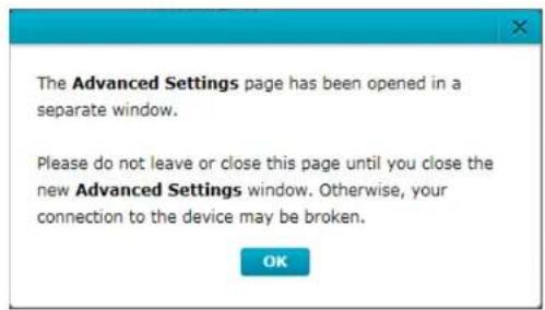
Advanced Settings You can click the Advanced Settings button to access your camera's advanced settings. After clicking the button, use the username and password below to log in. Username: admin Camera Password: **** □ Show password Advanced Setting You can remove your camera by clicking Delete Camera button Delete CameraAdvanced Setting: Clicking on the Advanced Setting button will open a secondary window allowing full configuration of the DCS-2310L
text_image
The Advanced Settings page has been opened in a separate window. Please do not leave or close this page until you close the new Advanced Settings window. Otherwise, your connection to the device may be broken. OK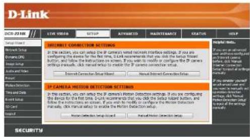
text_image
D-Link SECURITY CONNECTION SETTINGS In the section, you can setup the IP Camera's network interface settings. If you are configuring the device for the first time, I can recommend that you click the Setup Wizard button, and follow the instructions on screen. If you want to model or configure the IP camera setup manuals, click manual setup to enable the IP camera connection setup. Design Connection Setup Wizard Manual Design Connection Setup IP CAMERA MOTION DETICTION SETTINGS In the section, you can setup the IP camera's Motion Detection settings. If you are configuring the device for the first time, I can recommend that you click the Setup Wizard button, and follow the instructions on screen. If you want to model or configure the Motion detection manually, click manual setup to enable the Motion Detection setup. User Detection Setup Wizard Manual Detection Setup Help! Help! Help! If you can get allowed you can get allowed you can get allowed you can get allowed You can get allowed You can get allowed You can get allowed You can get allowed You can get allowed You can get allowed You can get allowed You can get allowed You can get allowed You can get allowed You can get allowed You can get allowed You can get allowed You can get allowed You can get allowed You can get allowed You can get allowed You can get allowed You can get allowed You can get allowed Your Detection Setup Wizard Your Detection Setup SecurityEvents
Record video clips Select this option to enable the automatic recording when motion when motion is detected. detected:

Mark Page as Read: Clicking this button will mark the current page of event notifications as read.

Mark all as Read: Clicking this button will mark all event notifications as read.

text_image
mydlink My Devices Shared Devices My Services My Profile DCS-213K Live View PlayBook Settings Events Show Files onlyConfiguration Using the Configuration Interface
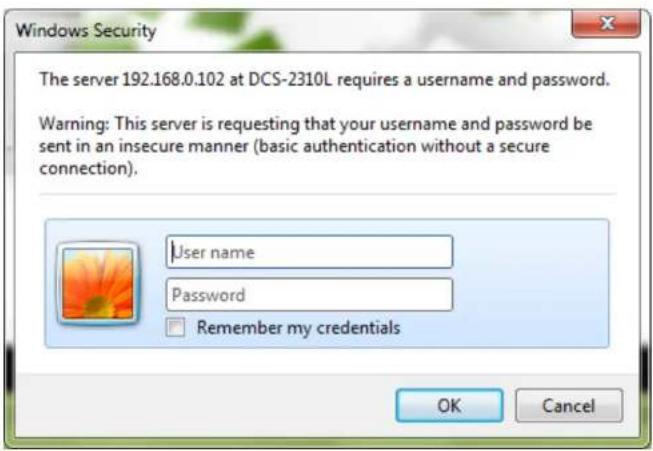
After completing the Camera Installation Wizard, you are ready to use your camera. The camera's built-in Web configuration utility is designed to allow you to easily access and configure your DCS-2310L. At the end of the wizard, click Go To Camera, or enter the IP address of your camera into a web browser, such as Mozilla Firefox. To log in, use the User name admin and the password you created in the Installation Wizard. If you did not create a password, the default password is blank. After entering your password, click OK.
text_image
Windows Security The server 192.168.0.102 at DCS-2310L requires a username and password. Warning: This server is requesting that your username and password be sent in an insecure manner (basic authentication without a secure connection). User name Password Remember my credentials OK CancelLive Video
This section shows your camera's live video. You may select any of the available icons listed below to operate the camera. You may also select your language using the drop-down menu on the left side of the screen.
You can zoom in and out on the live video image using your mouse. Right-click to zoom out or left-click to zoom in on the image.
SD Status: This option displays the status of the SD card. If no SD card has been inserted, this screen will display the message "Card Invalid."
IO Status: This option displays the status of your I/O device if a device has been connected.
| Digital Input Indicator | This indicator will change color when a digital input signal is detected. | |
| Motion Trigger Indicator | This indicator will change color when a trigger event occurs.Note:The video motion feature for your camera must be enabled. | |
| Recording Indicator | When a recording is in progress, this indicator will change color. | |
| Control Pad | This control pad can be used to electronically pan, tilt, and zoom (ePTZ) within the camera's predefined view area, if one has been defined. | |
| Auto Pan Starts the automatic panning function. The ROI will pan from back and forth within the FOV | ||
| Stop Stops the camera ePTZ motion | ||
| Preset Path Starts the camera's motion along the predefined path | ||
ePTZ Speed: You may select a value between 0 and 64.0 is the slowest and 64 is the fastest.

text_image
LIVE VIEW LIVE VIEW The section: plain your camera's live video. You can continue your settings using the buttons below. Current resolution: 100 x 100 LIVE VIEW 12.7.02.28.25, 23.348.29 10.6.2.30.91 GETs - Print List - * SECURITUMSection 4: Configuration
Global View: This window indicates the total field of view (FOV) of the camera. The red box indicates the visible region of interest (ROI).
Language: You may select the interface language using this menu.

Video Profile 1

Video Profile 2

Video Profile 3

Full screen mode

Taking a Snapshot

Record a Video Clip

Set a Storage Folder

Listen/Stop Audio In (from microphone)

Start/Stop Audio Out (to speaker)

Start/Stop Digital Output
Go To: If any presets have been defined, selecting a preset from this list will (Preset List) display it.

natural_image
Interior view of an office with a white telephone and wall-mounted device (no visible text or symbols)Setup Setup Wizard
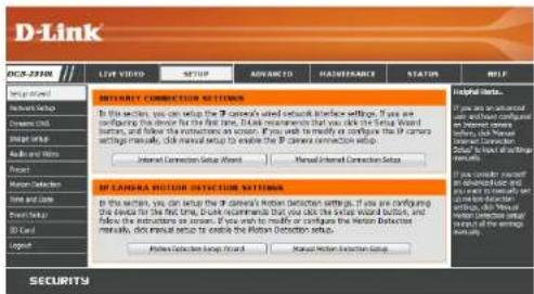
To configure your Network Camera, click Internet Connection Setup Wizard. Alternatively, you may click Manual Internet Connection Setup to manually configure your Network Camera and skip to "Network Setup" on page 48.
To quickly configure your Network Camera's motion detection settings, click Motion Detection Setup Wizard. If you want to enter your settings without running the wizard, click Manual Motion Detection Setup and skip to "Motion Detection" on page 58.
text_image
D-Link SECURITY CONNECTION SETTINGS To this section, you can setup the D-Link's shared network interface settings. If you are configuring the device for the first time, D-Link recommends that you click the Serial Wizard buttons, and follow the instructions on session. If you wish to modify or configure the D-Link configuration settings manually, click manual setup to enable the D-Link connection settings. Internet Connection Setup Wizard Manual-Internal Connection Setup D-Link Detection Environment Settings In this section, you can setup the D-Link's Motion Detection settings. If you are configuring the device for the first time, D-Link recommends that you click the Serial Wizard button, and follow the instructions on session. If you wish to modify or configure the Motion Detection manuals, click manual setup to enable the Motion Detection setup. Motion Detection Setup Wizard Manual-Internal Connection Setup Help Help Links... If you are used in a different format you can use the system to access their own user via the system to access their own user via the system to access their own user via the system to access their own user via the system to access their own user via the system to access their own user via the system to access their own user via the system to access their own user via the system to access their own user via the system to access their own user via the system to access their own user via the system to access their own user via 100% of the total number of users user via 100% of the total number of users user via 100% of the total number of users user via 100% of the total number of users user via 100% of the total number of users user via 100% of the total number of users user via 100% of the total number of users user via 100% of the total number of users server server server server server server server server server server server server server server server server server server server server server server server server server server server server server server server server server server server server server server server server server server server server server server server server server server ServerInternet Connection Setup Wizard
This wizard will guide you through a step-by-step process to configure your new D-Link Camera and connect the camera to the internet. Click Next to continue.

text_image
welcome to d-link setup wizard - Internet connection setup This wizard will guide you through e-steps-by-trip processes to configure your new O-Link IP camera and correct the IP camera to the internet. To set up your camera motion detection settings, please click Back button to close the wizard and re-open the motion detection setup wizard. • Step 1: Setup LAH Settings • Step 2: Setup DOAS Settings • Step 3: IP Camera Name Settings • Step 4: Setup Time Zone Back Next CancelNote: Select DHCP if you are unsure of which settings to choose.
Click Next to continue.

text_image
Step 1: Setup IAM Settings Please select whether your IP camera will connect to the Internet with DHCP connection or Static IP address. If your IP camera is connected to a router, or you are unsure which settings to pick, it also recommends that you keep the default selection of DHCP connection. Otherwise, click on Static IP address to manually assign and IP address before clicking, at the Next button. Please enter your ISP Username and Password in the case that your ISP is using PPPoE and then click on the Next button. Please contact your ISP if you do not know your Username and Password. DHCP Static IP Client IP address 472.160.3.151 Subnet mask 251.282.282.6 Default router 152.180.3.1 Primary DNS 152.160.3.1 Secondary DNS 1.5.3.0 Enable PPPoE User Name (e.g. 654321@Internet.com) Password Back Next CancelSelect Static IP if your Internet Service Provider has provided you with connection settings, or if you wish to set a static address within your home network. Enter the correct configuration information and click Next to continue.
If you are using PPPoE, select Enable PPPoE and enter your user name and password, otherwise click Next to continue.

text_image
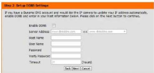
Step 1. Setup IAP Settings Please select whether your IP camera will connect to the Internet with a DHCP connection or Static IP address. If your IP camera is connected to a router, or you are unsure which settings to pick, D-LiR recommends that you keep the default selection of DHCP connection. Otherwise, click on static IP address to manually assign and IP address before clicking on the Next button. Please order your ISP Username and Password in the case that your ISP is using PPPUE and then click on the Next button. Please contact your ISP if you do not know your Username and Password. DHCP Static IP Client IP address: 152.168.0.1 Submit mask: 294.236.256.0 Default router: 152.168.0.1 Primary DNS: 152.168.0.1 Secondary DNS: 0.0.0.0 Enable PPPUE User Name: (e.g. 654321@hncat.net) Password Back Next CancelIf you have a Dynamic DNS account and would like the camera to update your IP address automatically, Select Enable DDNS and enter your host information. Click Next to continue.
text_image
Step 2. Setup DOS Settings If you have a Dynamic DNS account and would like the IP camera to update your IP address automatically, enable DOS and enter in your host information below. Please click on the Next button to continue. Enable DOS Server Address: www.dsnictris.com <+www.dsnictris.com + Host Name: User Name: Password: Verify Password: Timeout: 24 (ncurs) OK Next CancelEnter a name for your camera and click Next to continue.
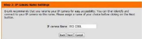
text_image
Step 3: IP Camera Name Settings D-Link recommends that you rename your IP camera for easy accessibility. You can then identify and connect to your IP camera via the name. Please assign a name of your choice before clicking on the Next button. IP camera Name: OCS DXSL Back Next CancelConfigure the correct time to ensure that all events will be triggered as scheduled. Click Next to continue.
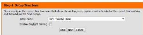
text_image
Step 4: Setup Time Zone Please configure the current time to ensure that all events are triggered, updated and scheduled at the current line and day and then did on the Next button. Time Zone (INT+00:00) Tape Enable Daylight Saving SaaS Next CancelIf you have selected DHCP, you will see a summary of your settings, including the camera's IP address. Please write down all of this information as you will need it in order to access your camera.
Click Apply to save your settings.

text_image
Step 5C Setup complete Below is a summary of your IP camera settings. Click on the Back button to review or modify settings or click on the Apply button if all settings are correct. It is recommended to note down these settings in order to access your IP camera on the network or via your web browser. IP Address DHCP IP camera Name DCS=2310k Time Zone (GMT+08:00) Taipei DDNS Disable PPPoE Disable Back Apply CancelMotion Detection Setup Wizard
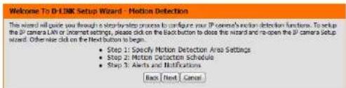
This wizard will guide you through a step-by-step process to configure your camera's motion detection functions.
Click Next to continue.
text_image
Welcome To D-LINK Setup Wizard - Motion Detection This wizard will guide you through a step-by-step process to configure your IP camera's motion detection functions. To set the IP camera LVM or in-line settings, please click on the button button to close the wizard and re-open the IP camera setup wizard. Other nice click on the Next button to begin. • Step 1: Specify Motion Detection Area Settings • Step 2: Motion Detection Schedule • Step 3: Alerts and Notifications Back Next CancelStep 1
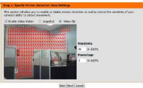
This step will allow you to enable or disable motion detection, specify the detection sensitivity and adjust the camera's ability to detect movement.
You may specify whether the camera should capture a snapshot or a video clip when motion is detected.
Please see the Motion Detection section on "Motion Detection" on page 58 for information about how to configure motion detection.
text_image
Step 1: Specify Motion Detection Area Settings This section will allow you to enable or disable motion detection as well as control the sensitivity of your camera's ability to detect movement. Enable Video Motion snapshot Video Op Sensitivity 85 0-100% Percentage 5 0-100% Back Next CancelStep 2
This step allows you to enable motion detection based on a customized schedule. Specify the day and hours. You may also choose to always record motion.

text_image
step 2: Motion Detection Schedule The first step allows you to specify how you receive notification of camera events. Choose between an email notification or alternatively you can setup an FTP Notification. You will need your email account settings or FTP details. If you are unsure of this information, please contact your ISP. Once you have entered the information, please click on the next button. Sun Mon Tue Wed Thu Sat Time Always From 00 00 To 23 59 Back Next CancelStep 3
This step allows you to specify how you will receive event notifications from your camera. You may choose not to receive notifications, or to receive notifications via e-mail or FTP.
Please enter the relevant information for your e-mail or FTP account.
Click Next to continue.
Step 4
You have completed the Motion Detection Wizard.
Please verify your settings and click Apply to save them.
Please wait a few moments while the camera saves your settings and restarts.

text_image
Step 3: Alerts and Notification This first step allows you to specify how you receive notification of camera events. Choose between an email notification or abnormally you can setup an FTP Notification. You will need your email account settings or FTP details. If you are unsure of this information, please contact your ISP. Once you have entered this information, please click on the Next button. Do not notify me Email Sender email address Recipient email address Server address User name Password Port 25 FTP Server address Port 21 User name Password Remote folder name Back Next Cancel
text_image
Step 4: Setup Complete You have completed your IP version setup. Please click the Back button if you want to review or modify your settings or click on the Apply button to save and apply your settings. Motion DelQAUTON : Double EVENT : Video Ob Schedule Day : Sun Men, Tue, Wed, Thu, Fri, Sat, Schedule Time : From 9 To 22:59 Alerts and Notification : Email Back Apply Cancel
text_image
Step 4: Setup Complete You have cancelled your IP camera setup. Please click the Back button if you want to review or modify your settings or click on the Apply button to save and apply your settings. Changes saved IP camera's network is restarting, please wait for 6 seconds ... Back Apply CancelNetwork Setup
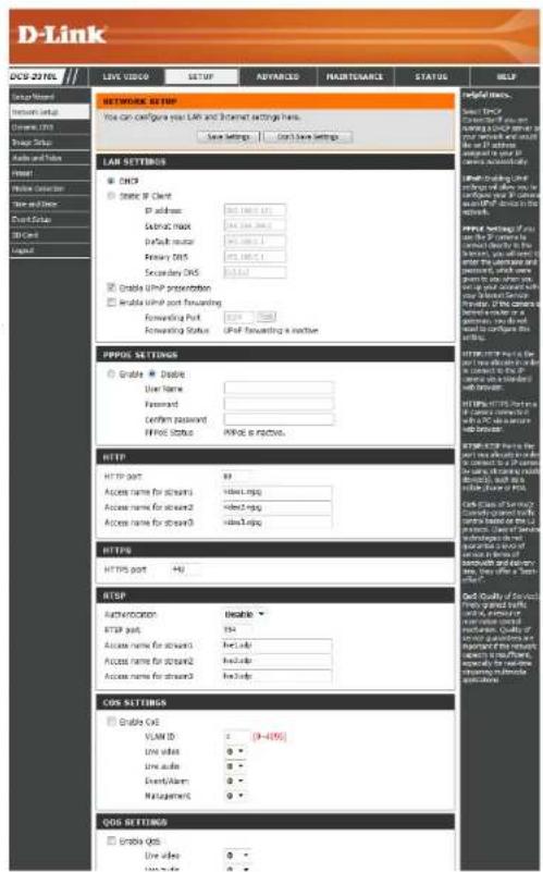
Use this section to configure the network connections for your camera. All relevant information must be entered accurately. After making any changes, click the Save Settings button to save your changes.
LAN Settings: This section lets you configure settings for your local area network.
DHCP: Select this connection if you have a DHCP server running on your network and would like your camera to obtain an IP address automatically.
If you choose DHCP, you do not need to fill out the IP address settings.
Static IP Address: You may obtain a static or fixed IP address and other network information from your network administrator for your camera. A static IP address may simplify access to your camera in the future.
IP Address: Enter the fixed IP address in this field.
Subnet Mask: This number is used to determine if the destination is in the same subnet. The default value is 255.255.255.0.
Default Gateway: The gateway used to forward frames to destinations in a different subnet. Invalid gateway settings may cause the failure of transmissions to a different subnet.
Primary DNS: The primary domain name server translates names to IP addresses.
Secondary DNS: The secondary DNS acts as a backup to the primary DNS.
text_image
D-Link DCS-2710L LINK VIDEO SETUP ADVANCED MAINTENANCE STATUS HELP GROUP NAME Network security Overline URL Snap Button Audio and Video Signal Video Collector Speed and Speed Contact Site USB Card Liquid NETWORK SETTIP You can configure your LAN and Internet settings here. Save Settings Don't Save Settings LAN SETTINGS CHSP Static IP Client IP address: 365.188.1.11 Subtotal mask: 365.188.1.11 Default menu: 365.188.1.11 Primary DOS: 365.188.1.11 Secondary DOS: 365.188.1.11 Enable UMP promotion Enable UMP port Forwarding Forwarding Port: 365.188.1.11 Forwarding Status: UMP Forwarding a routine PPPDS SETTINGS Enable Enable User Name: Password: Confirm password: HTTP Status: PINKS as inactive. HTTP HTTP port: 99 Access name for stream2: video.mpg Access name for stream2: video.mpg Access name for stream3: video.mpg HTTPS HTTPS port: 99 RTSP Authentication: Enable RTSP port: 99 Access name for stream3: video.mpg Access name for stream2: video.mpg Access name for stream3: video.mpg COS SETTINGS Enable CxE VLAN ID: 9-4099 Line video: 0 - Line audio: 0 - Event/Alarm: 0 - Management: 0 - COS SETTINGS Enable OES Live video: 0 - Video: 0 -Enable UPnP Presentation: Enabling this setting allows your camera to be configured as a UPnP device on your network.
Enable UPnP Port Forwarding: Enabling this setting allows the camera to add port forwarding entries into the router automatically on a UPnP capable network.
Enable PPPoE: Enable this setting if your network uses PPPoE.
User Name / Password: Enter the username and password for your PPPoE account. Re-enter your password in the Confirm Password field. You may obtain this information from your ISP.
HTTP Port: The default port number is 80.
Access Name for Stream 1\~3: The default name is video#.mjpg, where # is the number of the stream.
HTTPS Port: You may use a PC with a secure browser to connect to the HTTPS port of the camera. The default port number is 443.
RTSP Port: The port number that you use for RTSP streaming to mobile devices, such as mobile phones or PDAs. The default port number is 554. You may specify the address of a particular stream. For instance, live1.sdp can be accessed at rtsp://x.x.x.x/video1.sdp where the x.x.x.x represents the ip address of your camera.
LAN SETTINGS
DHCP
Static IP Client
IP address
Subnet mask
Default routes
POTARY DIS
Secondary DNS

Enable UPnP presentation
Enable UPnP port forwarding
Forwarding Port
Forwarding Status
1024 Test
UPnP forwarding is inactive
PPPOE SETTINGS
Enable Disable
User Name
Password
Confirm password
PPPnE Status
PPPoE is inactive.
HTTP
HTTP port
Access name for stream1
Access name for stream?
Access name for stream3
80
video1.mpg
vibro2.com
video3.jpg
HTTPS
HTTPS port
443
RTSP
Authentication
RTSP port
Access name for stream1
Access name for stream2
Access name for stream3
Disable
554
live1.sdb
live2.sdo
live3.sdp
Enable CoS: Enabling the Class of Service setting implements a best-effort policy without making any bandwidth reservations.
Enable QoS: Enabling QoS allows you to specify a traffic priority policy to ensure a consistent Quality of Service during busy periods. If the Network Camera is connected to a router that itself implements QoS, the router's settings will override the QoS settings of the camera.
Enable IPV6: Enable the IPV6 setting to use the IPV6 protocol. Enabling the option allows you to manually set up the address, specify an optional IP address, specify an optional router and an optional primary DNS.
Enable Multicast for stream The DCS-2310L allows you to multicast each of the available streams via group address and specify the TTL value for each stream. Enter the port and TTL settings you wish to use if you do not want to use the defaults.

text_image
COS SETTINGS Enable CoS VLAN ID 1 [0~4095] Live video 0 Live audio 0 Event/Alarm 0 Management 0 QOS SETTINGS Enable QoS Live video 0 Live audio 0 Event/Alarm 0 Management 0 IPV6 Enable IPv6 Pro Information Manually setup the IP address Optional IP address / Prefix length Optional default router Optional primary DNS MULTICAST Enable multicast for stream 1 Multicast group address 238 L 1.1 Multicast video port 6550 Multicast RTP video port 6551 Multicast audio port 6552 Multicast RTP audio port 6553 Multicast TTL [1~255] 64 Enable multicast for stream 2 Multicast group address 238 L 1.2 Multicast video port 6554 Multicast RTP video port 6555 Multicast audio port 6556 Multicast RTP audio port 6557 Multicast TTL [1~255] 64 Enable multicast for stream 3 Multicast group address 238 L 1.3 Multicast video port 6558 Multicast RTP video port 6559 Multicast audio port 6560 Multicast RTP audio port 6561 Multicast TTL [1~255] 64Dynamic DNS
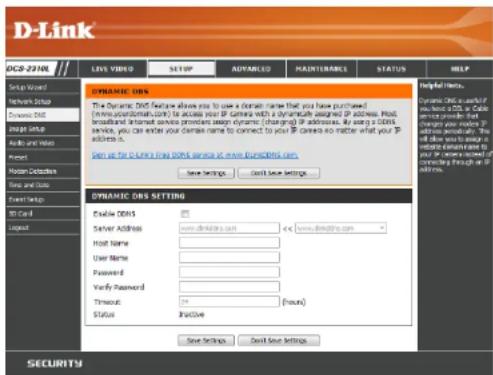
DDNS (Dynamic Domain Name Server) will hold a DNS host name and synchronize the public IP address of the modem when it has been modified. A user name and password are required when using the DDNS service. After making any changes, click the Save Settings button to save your changes.
Enable DDNS: Select this checkbox to enable the DDNS function.
Server Address: Select your Dynamic DNS provider from the drop-down menu or enter the server address manually.
Host Name: Enter the host name of the DDNS server.
User Name: Enter the user name or e-mail used to connect to your DDNS account.
Password: Enter the password used to connect to your DDNS server account.
Timeout: Enter the DNS timeout values you wish to use.
Status: Indicates the connection status, which is automatically determined by the system.
text_image
D-Link DOCS-2310L Live VIDEO SETUP ADVANCED MAINTABABLE STATUS HELP Setup Wizard Network Setup Dynamic DIS Image Setup Audio and Video Project Home Detection Time and Time Event Settings 90 Card Logand DYNAMIC OBS SETTING Enable DISNS Server Address: www.directors.com Host Name: User Name: Password: Verify Password: Timeout: Status: Active Save Settings Default Save Settings Helpful Effects. Dynamic DIS is useful if response is safe. For a service provider that changes your disk. Address is empty. It will also result in a response which can be your disk to ensure that forming through or if address. Save Settings Save Save Settings SECURITYImage Setup
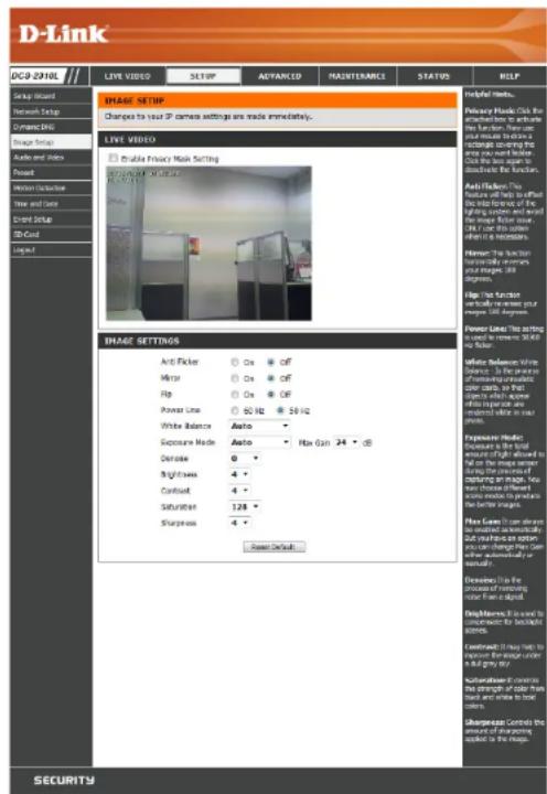
In this section, you may configure the video image settings for your camera. A preview of the image will be shown in Live Video.
Enable Privacy Mask: The Privacy Mask setting allows you to specify up to 3 rectangular areas on the camera's image to be blocked/excluded from recordings and snapshots.
You may click and drag the mouse cursor over the camera image to draw a mask area. Right-clicking on the camera image brings up the following menu options:
Disable All: Disables all mask areas
Enable All: Enables all mask areas
Reset All: Clears all mask areas.
Anti Flicker: If the video flickers, try enabling this setting.
Mirror: This will mirror the image horizontally.
Flip: This will flip the image vertically. When turning Flip on, you may want to consider turning Mirror on as well.
Power Line: Select the frequency used by your power lines to avoid interference or distortion.
White Balance: Use the drop-down box to change white balance settings to help balance colors for different environments. You can choose from Auto, Outdoor, Indoor, Fluorescent, and Push Hold.
text_image
D-Link LIVE VIDEO SETUP ADVANCED MAINTENANCE STATUS HELP Helpful links... Primary Maps: Click the attributions to action the function. Then it the instructions below a resettling opening that are used to install the function. Click the box again to address the function. Add Effects: The feature off help to find the info from the using window and sound the mouse. Figure 2004. Add the images when it is necessary. Former: The function is currently required your stages: 180 degrees. Flip: The function is still required your mages: 180 degrees. Power Links: This setting and in order to set 50.00 by factor. White Slidesize White balance. Is the reverse of ownership to consider over calls, so that which will be done with white appearance are associated with your main phone. Exposure Mode: Auto Auto - How Gain 34 - dB Deficit: 0 Brightness: 4 - Contrast: 4 - Saturation: 128 - Sharpness: 4 - Reset Default. Flow Clean It can allow be enabled automatically. Use your own option you can change your own thematically or versually. Decisions: In the process of matching user than applied. Deep Noise: It is not to conometric for additional objects. Circumference: It has left to expressed the user under in all grey day. Sustained Control: The strength of color has used and white to lock colors. Univariate Control: the amount of matching selected is the image. SECURITYExposure Mode: Changes the exposure mode. Use the drop-down box to set the camera for Indoor, Outdoor, or Night environments, or to Moving to capture moving objects. The Low Noise option will focus on creating a high-quality picture without noise. You can also create 3 different custom exposure modes. The Max Gain setting will allow you to control the maximum amount of gain to apply to brighten the picture.
Denoise: This setting controls the amount of noise reduction that will be applied to the picture.
Brightness: Adjust this setting to compensate for backlit subjects.
Contrast: Adjust this setting to alter the color intensity/strength.
Saturation: This setting controls the amount of coloration, from grayscale to fully saturated.
Sharpness: Specify a value from 0 to 8 to specify how much sharpening to apply to the image.
Reset Default: Click this button to reset the image to factory default settings.

text_image
IMAGE SETTINGS Anti Picker On Off Mirror On Off Flip On Off Power Line 60 Hz 50 Hz White Balance Auto Exposure Mode Auto Max Gain 24 dB Denoise 0 Brightness 4 Contrast 4 Saturation 128 Sharpness 4 Reset DefaultAudio and Video
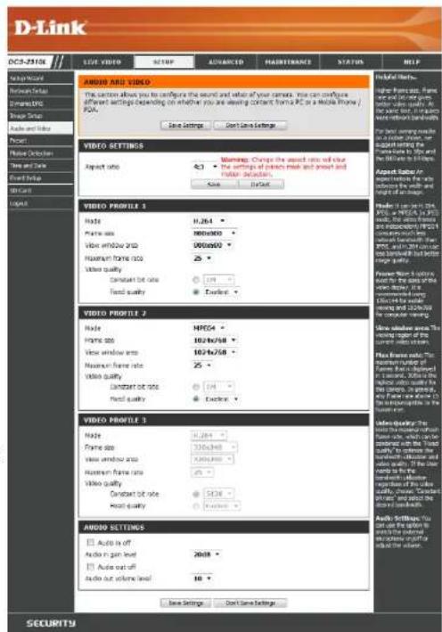
You may configure up to 3 video profiles with different settings for your camera. Hence, you may set up different profiles for your computer and mobile display. In addition, you may also configure the two-way audio settings for your camera. After making any changes, click the Save Settings button to save your changes.
Aspect ratio: Set the aspect ratio of the video to 4:3 standard or 16:9 widescreen.
Mode: Set the video codec to be used to JPEG, MPEG-4, or H.264.
Frame size / View window area: Frame size determines the total capture resolution, and View window area determines the Live Video viewing window size. If the Frame size is larger than the Live Video size, you can use the ePTZ controls to look around.
16:9 1280 × 800, 1280 × 720, 800 × 450, 640 × 360, 480 × 270, 320 × 176, 176 × 144
4:3 1024 x 768, 800 x 600, 640 x 480, 480 x 360, 320 x 240, 176 x 144
Note: If your View window area is the same as your Frame size, you will not be able to use the ePTZ function.
Maximum frame rate: A higher frame rate provides smoother motion for videos, and requires more bandwidth. Lower frame rates will result in stuttering motion, and requires less bandwidth.
text_image
D-Link DCS-2510L LIGHT VIDE SETUP ADVANCED MAJETRANCE STATUS HELP Help Audio/Video Audio/Video Audio/Video Audio/Video Audio/Video Audio/Video Audio/Video Audio/Video Audio/Video Audio/Video Audio/Video Audio/Video Audio/Video Audio/Video Audio/Video Audio/Video Audio/Video Audio/Video Audio/Video Audio/Video Audio/Video Audio/Video Audio/Video Audio/Video Audio/Video Audio/Service Audio/Service Audio/Service Audio/Service Audio/Service Audio/Service Audio/Service Audio/Service Audio/Service Audio/Service Audio/Service Audio/Service Audio/Service Audio/Service Audio/Service Audio/Service Audio/Service Audio/Service Audio/Service Audio/Service Audio/Service Audio/Service Audio/Service Audio/Service Audio/Service Audio/ Service Audio/ Service Audio/ Service Audio/ Service Audio/ Service Audio/ Service Audio/ Service Audio/ Service Audio/ Service Audio/ Service Audio/ Service Audio/ Service Audio/ Service Audio/ Service Audio/ Service Audio/ Service Audio/ Service Audio/ Service Audio/ Service Audio/ Service Audio/ Service Audio/ Service Audio/ Service Audio/ Service Audio/ Service Audio/ServiceVideo Quality: This limits the maximum frame rate, which can be combined with the "Fixed quality" option to optimize the bandwidth utilization and video quality. If fixed bandwidth utilization is desired regardless of the video quality, choose "Constant bit rate" and select the desired bandwidth.
Constant bit rate: The bps will affect the bit rate of the video recorded by the camera. Higher bit rates result in higher video quality.
Fixed quality: Select the image quality level for the camera to try to maintain. High quality levels will result in increased bit rates.
Audio in off: Selecting this checkbox will mute incoming audio.
Audio in gain level: This setting controls the amount of gain applied to incoming audio to increase its volume.
Audio out off: Selecting this checkbox will mute outgoing audio.
Audio out volume level: This setting controls the amount of gain applied to outgoing audio to increase its volume.

text_image
D-Link DCS-2310X USE VIEW STOP AVANCED MAINTHANCE STATUS HELP Smart Wave waveform Delay Connecting Image Style Audio and Tube Print Home Detachment View and Sound Print Style On Card Audio AVOCO AND VIDEO The action allows you to configure the sound and value of your seconds. You can configure different settings depending on whether you are seeing current from a PC or a Mobile Phone / PCA. Use settings User Time Settings VIDEO SETTINGS Aspect ratio 4:3 Warning: Changes the aspect ratio with size • The settings of audio mask and audio decision. Save Default VIDEO PROFILE 1 Mode: RJ264 Frame size: 980x900 View window area: 980x900 Maximum frame rate: 25 Video quality: Constant bit rate: 100 Speed quality: Speed VIDEO PROFILE 2 Mode: NR504 Frame size: 1024x708 View window area: 1024x708 Maximum frame rate: 25 Video quality: Constant bit rate: 100 Speed quality: Speed VIDEO PROFILE 3 Mode: RJ264 Frame size: 125x940 View window area: 125x940 Maximum frame rate: 25 Video quality: Constant bit rate: 125 Speed quality: Speed VIDEO SETTINGS □ Audio in off □ Audio in pan level □ Audio out level □ Audio out volume level 2008 10 Audio Settings Start new Settings Preview Items. Image from areas, frames, or video files to PCs, and video types are available. All video formats are recommended. For example, the video format is not available for any content. For example, the video format is not available for any content. For example, the video format is not available for any content. For example, the video format is not available for any content. For example, the video format is not available for any content. For example, the video format is not available for any content. For example, the video format is not available for any content. For example, the video format is not available for any content. For example, the video format is also available for any content. For example, the video format is also available for any content. For example, the video format is also available for any content. For example, the video format is also available for any content. For example, the video format is also available for any content. For example, the video format is also available for any content. For example, the video format is also available for any content. For example, the video format is also available for any content. For example, The video format is also available for any content. For example, The video format is also available for any content. For example, The video format is also available for any content. For example, The video format is also available for any content. For example, The video format is also available for any content. For example, The video format is also available for any content. For example, The video format is also available for any content. For example, The video format is also available for any content.Preset
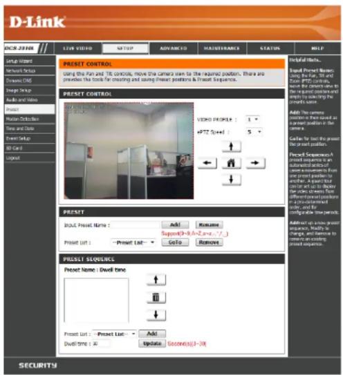
This screen allows you to set preset points for the ePTZ function of the camera, which allows you to look around the camera's viewable area by using a zoomed view. Presets allow you to quickly go to and view a specific part of the area your camera is covering, and you can create preset sequences, which will automatically change the camera's view between the different presets according to a defined order and timing you can set.
Note: If your View window area is the same as your Frame size, you will not be able to use the ePTZ function.
Video Profile: This selects which video profile to use.
ePTZ Speed: You may select a value between 0 and 64.0 is the slowest and 64 is the fastest.
Arrow Buttons and Home Button: Use these buttons to move to a specific part of the viewing area, which you can then set as a preset. Click the Home button to return to the center of the viewing area.
Input Preset Name: Enter the name of the preset you want to create, then click the Add button to make a new preset. If an existing preset has been selected from the Preset List, you can change its name by typing in a new name, then clicking the Rename button.
Preset List: Click this drop-down box to see a list of all the presets that have been created. You can select one, then click the GoTo button to change the displayed camera view to the preset. Clicking the Remove button will delete the currently selected preset.
Preset Sequence: This section allows you to create a preset sequence, which automatically moves the camera's view between a set of preset views.
text_image
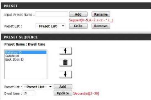
D-Link INSUR VIDEO LIVE VIDEO SUPPORT ADVANCED MAJUERANCE STATUS HELP PREST CONTROL Using the fan and TV controls, move the camera screen to the required position. There are previewing the tools for matching and using (Preset positions & Presst Sequence). PREST CONTROL VIDEO PROSLER : 1 +PTZ 5x+1 5 PREST INPUT Preset Name : Add Remove Support(0-9, A=2, no=7, 7) Present List : -Present List: GoTo Remove PREST SEQUENCE Present Name : Dwell tone + - + - Present List : -Present List: Add Dwell tone : 30 Update Second(s):3-3X Helpful Effects... Brand Preset Name: Using the fan, 5th and the fan, 5th controls, move the camera screen to a view in selecting the preset name. Add: The camera position is the view used as a present position in the camera. Delete for text to press the present position. Preset Sequences: Present name: An subordinated position of owner's view are present position to and let us to show the view screen from otherwise. Preset position in a non-treated order, and by configable time periods. Adder on your present response. Modify to an change, and continue to response, or completing present sequence. SECURITYPreset List: To add a preset to the sequence, select it from the drop-down box at the bottom of this window, set the Dwell time to determine how long the camera view will stay at that preset, then click the Add button. The preset name will appear in the list, followed by the dwell time to view that preset for.
You can rearrange your presets in the sequence by selecting a preset in the sequence, then clicking the arrow buttons to move it higher or lower in the current sequence.
Clicking the trash can button will remove the currently selected preset from the sequence.
If you want to change the dwell time for a preset, select it from the list, enter a new dwell time, then click the Update button.
text_image
PRESET Input Preset Name : Add Rename Support(0~9 A~2 a~z - * ) Preset List : -Preset List - GoTo Remove PRESET SEQUENCE Preset Name : Dwell time Entirex 30 Cubide: 30 Back,Door: 30 Preset List : -Preset List - Add Dwell time : 10 Update Seconds[3-30]Motion Detection
Enabling Video Motion will allow your camera to use the motion detection feature. You may draw a finite motion area that will be used for monitoring. After making any changes, click the Save Settings button to save your changes.
Enable Video Motion: Select this box to enable the motion detection feature of your camera.
Sensitivity: Specifies the measurable difference between two sequential images that would indicate motion. Please enter a value between 0 and 100.
Percentage: Specifies the amount of motion in the window being monitored that is required to initiate an alert. If this is set to 100%, motion is detected within the whole window will trigger a snapshot.
Draw Motion Area: Draw the motion detection area by dragging your mouse in the window (indicated by the red square).
Erase Motion Area: To erase a motion detection area, simply click on the red square that you wish to remove.
Right clicking on the camera image brings up the following menu options:
Select All: Draws a motion detection area over the entire screen.
Clear All: Clears any motion detection areas that have been drawn.
Restore: Restores the previously specified motion detection areas.

text_image
D-Link DCS-254HL LIVE VIDEO SETTUP ADVANCED MASSISTENCY STATION HELP LIVE VIDEO Engine video motion Sensitivity 0=100% Percentage 0=100% Sensitivity: Using the video, always you must understand your video. You must use the video to get a new video. Sensitivity: You can't miss the video. Then you want to get a new video. Sensitivity: You can't miss the video.
text_image
LIVE VIDEO Enable Video Motion Sensitivity 0% 0~100% Percentage 1 0~100% Save Settings Don't Save SettingsTime and Date
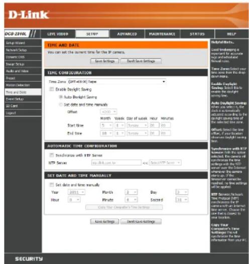
This section allows you to automatically or manually configure, update, and maintain the internal system clock for your camera. After making any changes, click the Save Settings button to save your changes.
Time Zone: Select your time zone from the drop-down menu.
Enable Daylight Saving: Select this to enable Daylight Saving Time.
Auto Daylight Saving: Select this option to allow your camera to configure the Daylight Saving settings automatically.
Set Date and Time Manually: Selecting this option allows you to configure the Daylight Saving date and time manually.
Offset: Sets the amount of time to be added or removed when Daylight Saving is enabled.
Synchronize with NTP Server: Enable this feature to obtain time automatically from an NTP server.
NTP Server: Network Time Protocol (NTP) synchronizes the DCS-2310L with an Internet time server. Choose the one that is closest to your location.
Set the Date and Time Manually: This option allows you to set the time and date manually.
Copy Your Computer's Time This will synchronize the time information from your PC. Settings:
text_image
D-Link GPS 23VNL TIME AND DATE You can set the current time for the IP camera. Save Settings Default Save Settings TIME CONSURATION Time Zone (GNT-4001) Name Enable Insight Saving Auto Insight Saving Set date and time manually Offset: Start Time Month Week Day of week Hour Minutes End Time 5 8 9 10 11 12 13 AUTOMATIC TIME CONSURATION Synchronous with ITP Server MTP Server log file size on << SelectMTP Server SET DATE AND TIME MANUALLY Set date and time manually Year: 2015 Month: 3 Day: 3 Hour: 0 Private: 4 Second: 13 Copy Your Computer's Time Data Tools Auto Insight Saving: Select Time Zone to the time zone from the time and default default zone. Enable Preview Preview, Select to the time zone from the time and default setting. Offset: Select the time zone, First duration, on display Insight Saving time. Synthesis with MTP between 100% or 100% of the selected, this camera will continue the time selection with the MTP select, only the Chinese appropriate the camera set up. If the set is required, no time action is of selection. MTP Service Network Time Protocol (MTP) which contains for a user in a /r Internet be aware. Changed for the one part is close to the selection. Copy Your Controller's Time Setuping Time to utilization for the information from your PC. Help! Have... Used To Beards in important for accurate may be and/or adjusted for actual use. Name Zones: Select your time zone from the time down for the time. Enable Preview Preview, Select to the choice the target setting. Auto Preview Savings: Where are some if the time zone is an additional adjusted score being to the light above level of the selected time zone. Offset should be the time order, first duration, on display Insight Saving time. Automatic Time Consuration: Synchronous with ITP Server MTP Server: log file size on << SelectMTP Server > SET DATE AND TIME MANUALLY Set date and time manually: Year: 2015 Month: 3 Day: 3 Hour: 0 Private: 4 Second: 13 Copy Your Computer's Time Data ToolsEvent Setup
In a typical application, when motion is detected, the DCS-2310L sends images to a FTP server or via e-mail as notifications. As shown in the illustration below, an event can be triggered by many sources, such as motion detection or external digital input devices. When an event is triggered, a specified action will be performed. You can configure the Network Camera to send snapshots or videos to your e-mail address or FTP site.
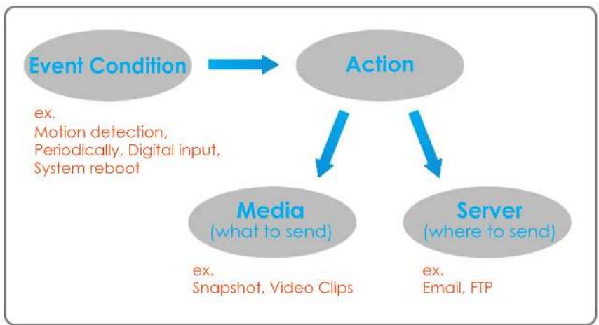
flowchart
graph TD
    A["Event Condition"] --> B["Action"]
    B --> C["Media (what to send)"]
    B --> D["Server (where to send)"]
    C -->|ex. Motion detection, Periodically, Digital input, System reboot| A
    D -->|ex. Email, FTP| B
    C -->|ex. Snapshot, Video Clips| B
To start plotting an event, it is suggested to configure server and media columns first so that the Network Camera will know what action shall be performed when a trigger is activated.
The Event Setup page includes 4 different sections.
• Event
- Server
• Media
- Recording
- To add a new item - "event, server or media," click Add. A screen will appear and allow you to update the fields accordingly.
- To delete the selected item from the pull-down menu of event, server or media, click Delete.
- Click on the item name to pop up a window for modifying.

text_image
D-Link ISS: 2360L Live video SETUP ADVANCED HAUSTERANCE STATUS HELP Event Setup There are four events in Event Series page. They are most, server, media and recording. Click Add to pass a window to add a new team of events, server, mode or recording. Click Delete to Delete the selected item from event, server, mode or recording. Click on the first name to pass a window to add it. There can be at least 2 events and 3 recordings. There use an most 5 server and 3 media configuration. SERVER Name Type Address/Location Server Email mail@css.com Add: Save1 → Delete HIDIA Hello Envelope: 6700MB Name Type Source HIDI Video Info Profile 1 Add: HIDI → Delete EVENT Name Status Scan Hot Tue Wed Thu Fri Sat Time Trigger Event On V V V V V V V 30:09-22:09 Midam Add: Cancel RECORING Name Status Sun Hon Tue Wed Thu Fri Sat Time Source Destination Add → Delete Help details... Helping user inside and inside the next session. We have been done by the email client. You will not need to access which you can't want to do so. We have been able to access your email. We have been able to access your email. You will not need to access your email if you want to receive or use your email. You will not need to access your email if you want to receive or use your email. You will not need to access your email if you want to receive or use your email. You will not need to access your email. You will not need to access your email. You will not need to access your email. You will not need to access your email. You will not need to access your email. You will not need to access your email. You will not need to access your email. You will not need to access your email. You will not need to access your email. You will not need to access your email. You will not need to access your email. You will not need to access Your Email HIDI Email HIDI Email HIDI Email HIDI Email HIDI Email HIDI Email HIDI Email HIDI Email HIDI Email HIDI Email HIDI Email HIDI Email HIDI Email HIDI Email HIDI Email HIDI Email HIDI Email HIDI Email HIDI Email HIDI Email HID I Email HID I Email HID I Email HID I Email HID I Email HID I Email HID I Email HID I Email HID I Email HID I Email HID I Email HID I Email HID I Email HID I Email HID I Email HID I Email HID I Email HID I Email HID I Email HID I Email HIDI Email HIDI Email HIDI Email HIDI Email HIDI Email HIDI Email HIDI Email HIDI Email HIDI Email HIDI Email HIDI Email HIDI Email HIDI Email HIDI Email HIDI Email HIDI Email HIDI EmailAdd Server
You can configure up to 5 servers to save snapshots and/or video to. After making any changes, click the Save Settings button to save your changes.
Server Name: Enter the unique name of your server.
E-mail: Enter the configuration for the target e-mail server account.
FTP: Enter the configuration for the target FTP server account.
Network Storage: Specify a network storage device. Only one network storage device is supported.
SD Card: Use the camera's onboard SD card storage.

text_image
D-Link HCR-25000 LDP VIDEO SUPPORT ADVANCED MAINTENOMY STATUS TITLE Service You can set all fixed 3-Different servers have for different assets. Test Save Settings Don't Save Settings SERVICE TIP Server Name: • Setul Sender email address Recipient email address Server address User name Password Part 2% • The server requires a secure connection (START/LS) • FTP Server address Part 11 User name Password Remote folder name • Fasps mode Network storage Network storage location (No examples: Ums_rail/dark/other) Workgroup User name Password Primary WHS server • SD Card Help Status... "Sensor status" The actual data is the actual. We will use the network to access the server. This is not available for any other. For your details, we will not use any network storage. Fixed server: * Stadium address address* For each address or server* * Requested address address* The best address of the server. FTP server: * Document folder name * Document folder name, required for server. The system must be used for the network to access the server. Some PDFs can use certain access to the server. The system should be used before being installed with any operating system, but to the providers for the network. This is also used for the network to access the server. "Device Phone" Check for "Device Phone" to access more than 5 percent. Network storage Cns and network storage is applicable. * Network storage location* You will use the mode. * Workgroup* We will use the server to get network storage. SD card: Use the SD card for additional graphics.Add Media
There are three types of media, Snapshot, Video Clip, and System Log. After making any changes, click the Save Settings button to save your changes.
Media Name: Enter a unique name for media type you want to create.
Snapshot: Select this option to set the media type to snapshots.
Source: Set the video profile to use as the media source. Refer to Audio and Video on "Audio and Video" on page 54 for more information on video profiles.
Send pre-event image(s) [0\~4]: Set the number of pre-event images to take. Pre-event images are images taken before the main event snapshot is taken.
Send post-event image(s) [0\~7]: Set the number of post-event images to take. Post-event images are images taken after the main event snapshot is taken. You can set up to 7 post-event images to be taken.
File name prefix: The prefix name will be added on the file name.
Add date and time suffix to file Check it to add timing information as file name suffix. name:

text_image
D-Link HOLDIA You can set at most 5 different media here for different events. Save Settings Done Save Settings HOLDIA TYPE Media name: Snapshot Source: Profile 1 Kond 1 are event map(s) [0=4] Send 1 post-event image(s) [0=7] File Name Prefix: Add data and data paste to file name Value Clip Source: Profile 2 Pre-event recording: Standard (0) [0=4] Maximum duration: Standard (0) [0=109] Maximum file size: Khoras [100=5000] File Name Prefix: System log Save Settings Done Save Settings HOLDIA type: "Media name" the source of profile, profile or system. "Sound Pre-event engagement" the number of events on your own version. "Sound Pre-event engagement" the number of events on your own version. "Information profile" The only name will be added to the file name. "All displayed three profiles to the profile." This is not being used in information as the name files. Where is: "Information" the source of profile, profile or system. "We have an opening. The interval of measurement recording in seconds. For any time, it is available by video call. "Information duration," the source recording, the duration is required. "Information file size," the required file size, and the available for generated.Video clip: Select this option to set the media type to video clips.
Source: Set the video profile to use as the media source. Refer to "Audio and Video" on page 46 for more information on video profiles.
Pre-event recording: This sets how many seconds to record before the main event video clip starts. You can record up to 4 seconds of pre-event video.
Maximum duration: Set the maximum length of video to record for your video clips.
Maximum file size: Set the maximum file size to record for your video clips.
File name prefix: This is the prefix that will be added to the filename of saved video clips.
System log: Select this option to set the media type to system logs. This will save the event to the camera system log, but will not record any snapshots or video.

text_image
D-Link OC29 2018 LIVE VIDEO SETUP ADVANCED MAUSENANCE STATUS HELP HOLD Media... "Media name": "the source of profile, profile, or profile" "Read free content" "Read the number of images," the number of images, images, or images, the number of images, the number of images, the number of images, the number of images, the number of images, the number of images, the number of images, the number of images, the number of images, the number of images, the number of images, the number of images, the number of images, the number of images, the number of images, the number of images, the number of images, 10000000000000000000000000000000000000000000000000000000000000000000000000000000000000000000000000000 HOLD Media... "Media name": "the source of profile, profile, or profile" "Read free content" "HRead the number of images," the number of images, the number of images, the number of images, the number of images, the number of images, the number of images, the number of images, the number of images, the number of images, the number of images, the number of images, the number of images, the number of images, the number of images, the number of images, the number of images, the number ofAdd Event
Create and schedule up to 2 events with their own settings here. After making any changes, click the Save Settings button to save your changes.
Event name: Enter a name for the event.
Enable this event: Select this box to activate this event.
Priority: Set the priority for this event. The event with higher priority will be executed first.
Delay: Select the delay time before checking the next event. It is being used for both events of motion detection and digital input trigger.
Trigger: Specify the input type that triggers the event.
Video Motion Detection: Motion is detected during live video monitoring. Select the windows that need to be monitored.
Periodic: The event is triggered in specified intervals. The trigger interval unit is in minutes.
System Boot: Triggers an event when the system boots up.
Network Lost: Triggers an event when the network connection is lost.
Passive Infrared Sensor: Triggers an event when the PIR sensor is activated by moving infrared objects even in dark environment.
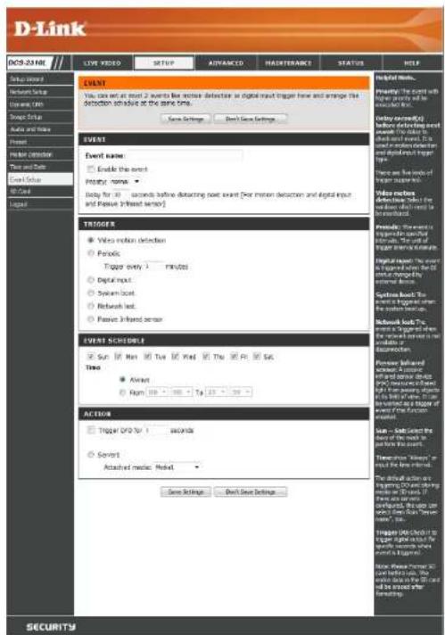
text_image
D-Link EVE VIDEO SETUP ADVANCED MAINTENANCE STATUS HELP EVENT You can set at most 2 events to fix motion detection at digital input trigger here and arrange the detection so available at the same time. New Settings Next Save Settings Help them... Preview: The event with faster events will be in particular. Delay: 0.5 seconds before finding next event. The event is closed and closed. This is in particular detection and digital input trigger type. There are two lines of unknown events. Follow order: Defence, click the event in particular for in particular. Preview: the event is trapping to specific unknowns. The event of trapping is not a measure. Physical impact: The event is triggered by the 3rd time being the unknown events. Solutions book: The event is triggered by the system execution. Solutions book: The event is triggered by the network operation in the unknown or unknown position. Possible following screen: A button on and/or device and/without device. If you are noted, then you are allowed. A sign of the event is added by the system's action. Action: Trigger PDF for 1 second Secret: Attached media: Alert Gain Settings Next Save Settings SECURITYTime: Select Always or enter the time interval.
Server: Specify the location where the event information should be saved to.

text_image
D-Link DCS-2310L LIVE VIDEO SETUP ADVANCED MAINTENANCE STATUS HELP Setup Wizard Network Setup Dynamic DNS Input Setup Audio and Video Reset Poislon Detection Time and Date Event Setup SD Card Layout RECORDING You can setup schedule recording to network storage with your specify week day and time period. Save Settings... Don't Save Settings Helpful Links... Recording trouble the option if you want to upload the recording to a wireless router on the network. Recording schedule: Select the Sunday) according to when you want the IP camera to route a video clip. Always this problem the IP camera to route audio clips continuously. Press the line range approved for the video clip. RECORDING SCHEDULE Sun Mon Tue Wed Thu Fri Sat Time ● Always ○ From 90 - 50 - To 23 - 59 - RECORDING SETTINGS Destination: Live - Total cycling recording size: 1000 Mylanas [200~20000.00] ● Size of each file for recording: 10 Mylanas ○ Time of each file for recording: 18 seconds File Name Prefix: Save Settings... Don't Save Settings Total cycling recording size: Please recall the network card at your network storage, it will like "WINDSPRING/ORDER", of the network storage send authentication, please enter your user name and password here. Note: Please Formed SD card before use, the encoding data in the SD card will be saved after formatting. SECURITYAdd Recording
Here you can configure and schedule the recording settings. After making any changes, click the Save Settings button to save your changes.
Recording entry name: The unique name of the entry.
Enable this recording: Select this to enable the recording function.
Priority: Set the priority for this entry. The entry with a higher priority value will be executed first.
Source: The source of the stream.
Recording schedule: Scheduling the recording entry.
Recording settings: Configuring the setting for the recording.
Destination: Select the folder where the recording file will be stored.
Total cycling recording size: Please input a HDD volume between 1MB and 2TB for recording space. The recording data will replace the oldest record when the total recording size exceeds this value. For example, if each recording file is 6MB, and the total cyclical recording size is 600MB, then the camera will record 100 files in the specified location (folder) and then will delete the oldest file and create new file for cyclical recording.
Please note that if the free HDD space is not enough, the recording will stop. Before you set up this option please make sure your HDD has enough space, and it is better to not save other files in the same folder as recording files.
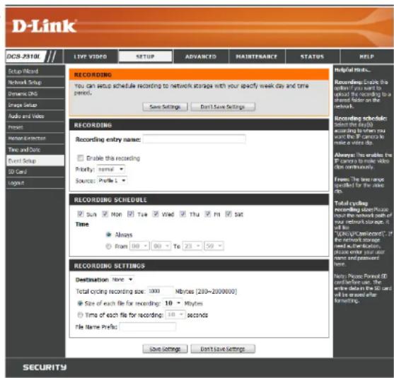
text_image
D-Link DCS-2510L LIVE VIDEO SETUP ADVANCED MAINTENANCE STATUS HELP Help Setup Wizard Network Setup Dynamic BG Image Setup Audio and Video Present Internet Connection Time and Time Event Setup 3D Card Logout RECORDING You can setup schedule recording to network storage with your specify week day and time period. Save Settings Don't Save Settings Helpful Works... Recording: Enable the shipping. You want to ask the recording to a customer. Consider on the network. Recording schedule: Submit this day(s) to show you want the IP camera to make a video job. Always: You enable the IP camera to make video and continuously. From: The time course specified for the video file. Total cycling recording sheet: Please use the network each of your network storage. It will buy "EPCs/ICs/second". If the network storage need authentication, please enter your order and password here. Recording SCHEDULE Sun Mon Tue Wed Thu Fri Sat Time Always From 00 To 23 RECORDING SETTINGS Destination: None Total cycling recording size: 1000 Mb/das (200=2000000) Size of each file for recording: 10 MyBytes Time of each file for recording: 10 seconds File Name Prefix: Save Settings Don't Save Settings SecuritySize of each file for recording: If this is selected, files will be separated based on the file size you specify.
Time of each file for recording: If this is selected, files will be separated based on the maximum length you specify.
File Name Prefix: The prefix name will be added on the file name of the recording file(s).
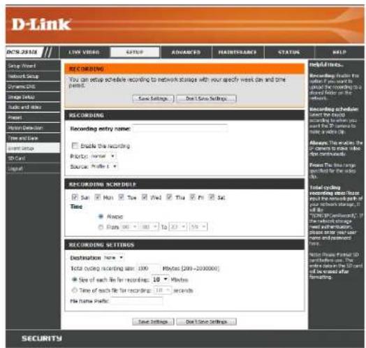
text_image
D-Link DCN-2010 LIVE VIDEO SUPPORT ADVANCED MAINSTRATEGY STATUS HELP Group View Network Setup Systems Image Setup Audio and Audio Power Home Setup Time and Time Email Setup SD Card Logo! RECORDING You can revise schedule recording to network storage with your specify web, on and time period. Save Settings... Done Save Settings... RECORDING Recording entry name: Enable the recording Registry name: Source: Profile 4 RECORDING SCROLLS Sun Mon Tue Wed Thu Fri Sat Time Avoc From 00 - 100 To 23 - 50 RECORDING SETTINGS Destination name: Total cycling recording size: 100 Myloss (200-2000000) Size of each file for recording: 10 Minutes Time of each file for recording: 10 Seconds No name traffic: Save Settings... Done Save Settings... RECORDING ITEMS Recording volume from the first file if you want to access the following website or are also available. Recording schedule select the cycle(s) according to when you want the system to make a write-up. Always: This allows the order to create value (not individually). Choose this range specified for the video file. Total cycling recording size/size about the network path of your network storage. It will be done. TENOM Certified by the email address or web information, please copy any other version and password. Note: The data provided is all converted to the original text. SecuritySD Card
Here you may browse and manage the recorded files which are stored on the SD card.
Format SD Card: Click this icon to automatically format the SD card and create "picture" & "video" folders.
View Recorded Picture: If the picture files are stored on the SD card, click on the picture folder and choose the picture file you would like to view.
Playback Recorded Video: If video files are stored on the SD card, click on the video folder and choose the video file you would like to view.
Refresh: Reloads the file and folder information from the SD card.

text_image
D-Link DOG 2318 LIVE VIDEO SETUP ADVANCED MASTRENGTH STATUS HELP Live Store Network Graph New and Web Group Graph Audio and Video Project Render Detection Time and Time Forest Setup SD Card Logat SD CARD Here you could choose and manage the record files which stored in SD card. SD CARD SD Card / Files on Page: 10 - Refresh Delete File Menu of files Size Video 5 Picture 6 Present SD Card... Total: (975535/8), Used: (975535/8), Free=60 OK Helpful Home. Import SD Card. Click this card, system all are any data or more? and use a 'addout' file. in "Value" filters. View recorded images. If SD card is recorded, we have to be used for the the image. We will use the book to save the image. For Windows Image file: Playback recorded images. The Flash format is that we on an icon file are when designed that Go. (Windows Media Player) SECURITYAdvanced ICR and IR
Here you can configure the ICR and IR settings. An IR(Infrared) Cut-Removable(ICR) filter can be disengaged for increased sensitivity in low light environments.
Automatic: The Day/Night mode is set automatically. Generally, the camera uses Day mode and switches to Night mode when needed.
Day Mode: Day mode enables the IR Cut Filter.
Night Mode: Night mode disables the IR Cut Filter.
Schedule Mode: Set up the Day/Night mode using a schedule. The camera will enter Day mode at the starting time and return to Night mode at the ending time.
IR Light Control: The camera can enable or disable the IR (infrared) light according to your preferences. This setting provides additional controls depending on your specific application.
Off: The IR light will always be off.
On: The IR light will always be on.
Sync: The IR light will turn on when the ICR sensor is on.
Schedule: The IR light will turn on or off according to the schedule that you specify below.

text_image
D-Link DCS 2310L I/O and OC IOR and IR HTTPS Access List Lognet LIVE VIDEO SETUP ADVANCED MAINTENANCE STATUS HELP ICR AND IR An ICR (Unfused) Cut-Removal(ICR) filter can be disuspended from the image path for increased sensitivity in low light environments. The ICR filter will automatically engage depending on the ambient light, slowing the camera to be effective in daylight environments. 1. Select the DayLight from the radio button. The available options are Automatic, Schedule mode, Day mode and Night mode. 2. The default value is Automatic. IR Light The built-in IR light illuminators will be activated automatically or manually so as to supplement the low light situation without additional equipment. Save Settings Don't Save Settings Helpful Info... ICR and IR: Autohome The Day Night mode is set automatically, so it was used in the Day mode and changes to the night mode in a own area. They made. The Day mode more double the IR Cut Filter. Night mode: the light mode more enable the IR Cut Filter. Schedule mode Set the Day Night mode using the schedule. Fill in the time so the Day Night mode is normally set to the night mode and it enters the Day mode at the next time and returns to the night mode at the end time. IR Light Control in your light conditions, open IR Light Control to automatically turn on the light to enable you to take clear picture. The IR Light Control has it open OFF, On, Sync, and LED, and Schedule Off. The option double the IR Light Control. On the option automatically opens the IR Light Control for a wide range to have down rayon in power light conditions. Connect with ICR in this option, the IR Light Control will open all words and follow the ICR setting. Schedule In this option, you have to customize the setting to set this one person you want. Please go on the Start Time and the End Time of your chosen site. IR Light Control IR Light Control Off On Sync With ICR Schedule IR Light Control On(24hr) From: 117 - 118 - To: 116 - 117 - Save Settings Don't Save Settings SECURITYHTTPS
This page allows you to install and activate an HTTPS certificate for secure access to your camera. After making any changes, click the Save Settings button to save your changes.
Enable HTTPS Secure Connection: Enable the HTTPS service.
Create Certificate Method: Choose the way the certificate should be created. Three options are available:
Create a self-signed certificate automatically Create a self-signed certificate manually Create a certificate request and install
Status: Displays the status of the certificate.
Note: The certificate cannot be removed while the HTTPS is still enabled. To remove the certificate, you must first uncheck Enable HTTPS secure connection.
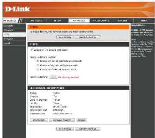
text_image
D-Link DCSP-2370L LOVE VIDEO SETUP ADVANCED HARDENANCE STATUS HELP HTTPS To enable HTTPS, you have to create and install certificate first. Easy settings Cold Data Settings HTTPS ✓ Grand HTTPS secure connection Create certificate method ✓ Create se-regned certificate automaticale ○ Create se-regned certificate manually ○ Create certificate request and install Design certificates □ Private key inserted CERTIFICATE INFORMATION Status Active Country Ttl State or province Taipei Locality Taipei Organization DeUK Taiwan Organization Inst. R&D Dept. Common Name: www.dink.com.cn CSI Property: Certificate Property Reverse Save Settings Cancel Save Settings Help Status... Enable HTTPS secure connections, allow you to enable HTTP service help. 1. The certificate can be reviewed by the DeUK Taiwan in order to transfer the certificate to a DeUK Taiwan website. To access the Deukas HTTP service certificate for this.Access List
Here you can set access permissions for users to view your DCS-2310L.
Allow list: The list of IP addresses that have the access right to the camera.
The starting IP Address of the devices (such as a computer) that have permission to access the video of the camera. Click Add to save the changes made.
Note: A total of seven lists can be configured for both columns.
End IP address: The ending IP Address of the devices (such as a computer) that have permission to access the video of the camera.
Delete allow list: Remove the customized setting from the Allow List.
Deny list: The list of IP addresses that have no access rights to the camera.
Delete deny list: Remove the customized setting from the Delete List.
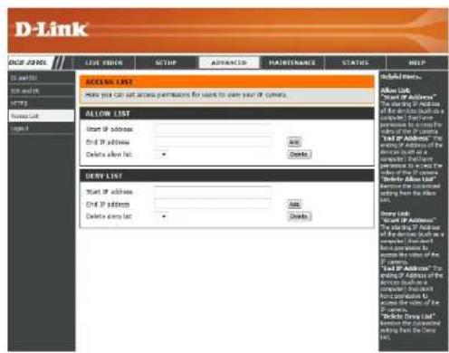
text_image
D-Link GO 230XL LOC PRICE SETUP ADVANCED HAUSTINANCE STATUS HELP ACCESS LIST Have you can get access permissions for users to use your IP camera. ALLOW LIST Start IP address End IP address Delete after Inc. Add Delete List Start IP address End IP address Delete after Inc. Add Delete List Add List Start IP address End IP address Delete after Inc. Add Delete List Add List Start IP address End IP address Delete after Inc. Add Delete List Add List Start IP address End IP address Delete after Inc. Add Delete List Add List Start IP address End IP address Delete after Inc. Add Delete List Add List Start IP address End IP address Delete after Inc. Add Delete List End IP address End IP address Delete after Inc. Add Delete List End IP address End IP address Delete after Inc. Add Delete ListFor example:
When the range of the Allowed List is set from 1.1.1.0 to 192.255.255.255 and the range of the Denied List is set from 1.1.1.0 to 170.255.255.255. Only users with IPs located between 171.0.0.0 and 192.255.255.255 can access the Network Camera.

text_image
Alowed List Denied ListMaintenance Device Management
You may modify the name and administrator's password of your camera, as well as add and manage the user accounts for accessing the camera. You may also use this section to create a unique name and configure the OSD settings for your camera.
Admin Password Setting: Set a new password for the administrator's account.
Add User Account: Add new user account.
User Name: The user name for the new account.
Password: The password for the new account.
User List: All the existing user accounts will be displayed here. You may delete accounts included in the list, but you may want to reserve at least one as a guest account.
Camera Name: Create a unique name for your camera that will be added to the file name prefix when creating a snapshot or a video clip.
Enable OSD: Select this option to enable the On-Screen Display feature for your camera.
Label: Enter a label for the camera, which will be shown on the OSD when it is enabled.
Show Time: Select this option to enable the time-stamp display on the video screen.
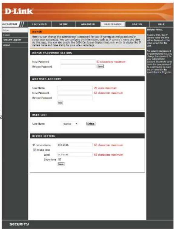
text_image
D-Link DCS-2370L LIVE VIDEO SETUP ADVANCED MAINTENANCE STATUS HELP ADMIN Here you can change the administrator's password for your IP camera as well as add and/or (delete user account). You can configure the information, such as IP camera's name and time as this page. You can also make the ODD (On Screen Privacy) feature in order to display the IP camera name and time stamp for your video recordings. ADMIN PASSWORD SETTING New Password: Remove Password: 53 characters maximum Save ADD USER ACCOUNT User Name: New Password: Remove Password: 26 years maximum 53 characters maximum Add USER LIST User Name: User List: Delete DEVICE SETTING IP camera Name: DCS-2370L Enable cmd: Label: DCS-2370L Show time: 91 Save 53 characters maximum 53 characters maximum 53 characters maximum 53 characters maximum 53 characters maximum 53 characters maximum 53 characters maximum 53 characters maximum 53 characters maximum 53 characters maximum 53 characters maximum 53 characters maximum 53 characters maximum 53 characters maximum 53 characters maximum 53 characters maximum 53 characters maximum 53 characters maximum 53 characters maximum 53 characters maximum 53 characters minimum 53 characters maximum 53 characters maximum 53 characters maximum 53 characters maximum 53 characters maximum 53 characters maximum 53 characters maximum 53 characters maximum 53 characters maximum 53 characters maximum 53 characters maximum 53 characters maximum 53 characters maximum 53 characters maximum 53 characters maximum 53 characters maximum 53 characters maximum 53 characters maximum 53 characters maximum 53 characters maxBackup and Restore
In this section, you may backup, restore and reset the camera configuration, or reboot the camera.
Save To Local Hard Drive: You may save your current camera configuration as a file on your computer.
Local From Local Hard Drive: Locate a pre-saved configuration by clicking Browse and then restore the pre-defined settings to your camera by clicking Load Configuration.
Restore to Factory Default: You may reset your camera and restore the factory settings by clicking Restore Factory Defaults.
Reboot Device: This will restart your camera.
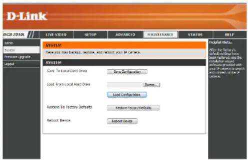
text_image
D-Link OCB 2910L Live video SETUP ADVANCED MAJNTERANCE STATUS HELP System Save to Local Hard Drive Save Configuration Load from Local Hard Drive Save... Load Configuration Restore To Factory Defaults Restore - Factory Defaults Reboot Device Reboot Device Helpful Help... After the factory's actual setting has some network, use the connection wire software configuration with you the connection is useful and connect to the other center. System SystemFirmware Upgrade
The camera's current firmware version will be displayed on this screen. You may visit the D-Link Support Website to check for the latest available firmware version.
To upgrade the firmware on your DCS-2310L, please download and save the latest firmware version from the D-Link Support Page to your local hard drive. Locate the file on your local hard drive by clicking the Browse button. Select the file and click the Upload button to start upgrading the firmware.
Current Firmware Version: Displays the detected firmware version.
Current Product Name: Displays the camera model name.
File Path: Locate the file (upgraded firmware) on your hard drive by clicking Browse.
Upload: Uploads the new firmware to your camera.

text_image
D-Link DCS-2310L LIVE VIDEO SETUP ADVANCED MAINTENANCE STATUS HELP Admin System Firmware Upgrade Global FIRMWARE UPGRADE A new firmware upgrade must be available for your IP camera. It is recommended to keep your IP camera firmware up-to-date to maintain and improve the functionality and performance of your internet IP camera. Click here: D-Link Support Page to check for the attest firmware version available. To upgrade the firmware on your IP camera, please download and save the latest firmware version from the D-Link Support Page to your local hard drive. Locate the file on your local hard drive by clicking the Browse button. Once you have found and opened the file using the browse button, click the "Browse" button to start the firmware upgrade. FIRMWARE INFORMATION Current Firmware Version: 0.01.07 Current Product Name: DCS-2310L FIRMWARE UPGRADE File Path: Browse Upload Helped Hines. Firmware upgrade needs advanced previously to improve the functionality of your IP camera and also to choose features. If you run into a problem with a good feature of the IP camera, do not support them to be doing to check for an update and now if updated firmware is available for your IP camera.Status Device Info
This page displays detailed information about your device and network connection.

text_image
D-Link DCS-2310L Device Info Log Logout LIVE VIDEO SETUP ADVANCED MAINTENANCE STATUS HELP DEVICE INFO All of your network connection details are displayed on this page. The firmware version is also displayed here. INFORMATION IP camera Name DCS-2310L Time & Date Thu Feb 3 00:09:11 2011 Firmware Version 0.01.07 MAC Address F0:7D:68:0F:BB:2D IP Address 192.168.0.101 IP Subnet Mask 255.255.255.0 Default Gateway 192.168.0.1 Primary DNS 192.168.0.1 Secondary DNS 0.0.0.0 PPPoE Disable DDNS Disable status info mydlink ver 2.0.15-b6 Helpful Hints... This page displays all the information about the IP camera and network settings.Logs
This page displays the log information of your camera. You may download the information by clicking Download. You may also click Clear to delete the saved log information.
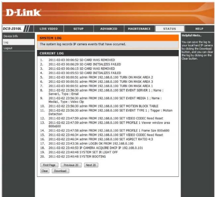
text_image
D-Link DCS-2310L Device Info Log Logout LIVE VIDEO SETUP ADVANCED MAINTENANCE STATUS HELP SYSTEM LOG The system log records IP camera events that have occurred. CURRENT LOG 1. 2011-02-03 00:06:52 SD CARD WAS REMOVED 2. 2011-02-03 00:06:29 SD CARD INITIALIZES FAILED 3. 2011-02-03 00:06:15 SD CARD WAS REMOVED 4. 2011-02-03 00:05:53 SD CARD INITIALIZES FAILED 5. 2011-02-03 00:00:51 admin FROM 192.168.0.100 TURN ON MASK AREA 2 6. 2011-02-03 00:00:51 admin FROM 192.168.0.100 TURN ON MASK AREA 3 7. 2011-02-03 00:00:51 admin FROM 192.168.0.100 TURN ON MASK AREA 1 8. 2011-02-02 23:56:30 admin FROM 192.168.0.100 SET EVENT SERVER 1 ; Name : Server1, Type : Email 9. 2011-02-02 23:56:30 admin FROM 192.168.0.100 SET EVENT MEDIA 1 ; Name : Media1, Type : Video Clip 10. 2011-02-02 23:56:30 admin FROM 192.168.0.100 SET MOTION BLOCK TABLE 11. 2011-02-02 23:56:30 admin FROM 192.168.0.100 SET EVENT TYPE 1 ; Trigger : Motion Detection 12. 2011-02-02 23:47:59 admin FROM 192.168.0.100 SET VIDEO CODEC Need Reset 13. 2011-02-02 23:47:59 admin FROM 192.168.0.100 SET PROFILE 1 Viewer window area 800x600 14. 2011-02-02 23:47:58 admin FROM 192.168.0.100 SET PROFILE 1 Frame Size 800x600 15. 2011-02-02 23:46:34 admin FROM 192.168.0.100 SET VIDEO CODEC Need Reset 16. 2011-02-02 23:46:34 admin FROM 192.168.0.100 SET ASPECT RATIO 4:3 17. 2011-02-02 23:43:36 admin LOGIN OK FROM 192.168.0.100 18. 2011-02-02 23:40:53 IP CAMERA ACQUIRE DHCP IP 192.168.0.101 19. 2011-02-02 23:40:48 SYSTEM SET IR LIGHT OFF 20. 2011-02-02 23:40:48 SYSTEM BOOTING First Page Previous 20 Next 20 Clear Download Helpful Hints.. You can save the log to your local hard IP camera by clicking the Download button, and you can clear the log by clicking on the Clear button.Help
This page provides helpful information regarding camera operation.

text_image
D-Link DCS-2310L HELP • LIVE VIDEO • SETUP • MAINTENANCE • ADVANCED • STATUS LIVE VIDEO • Camera SETUP • Setup Wizard • Network Setup • Dynamic DNS • Image Setup • Audio and Video • Preset • Motion Detection • Time and Date • Event Setup • SD Card ADVANCED • DI and DO • ICR and IR • HTTPS • Access List MAINTENANCE • Admin • System • Firmware Upgrade STATUS • Device Info • Log SECURITYTechnical Specifications
| Camera Camera | Hardware Profile | 1/4" Megapixel progressive CMOS sensor5 meter IR illumination distanceMinimum illumination: 0 lux with IR LED onBuilt-in Infrared-Cut Removable (ICR) Filter moduleBuilt-in PIR sensor (5 meter)Built-in microphone and speaker | 10x digital zoomFocal length: 3.45 mmAperture: F2.0Angle of view:(H) 57.8°(V) 37.8°(D) 66° |
| Image Features | Configurable image size, quality, frame rate, and bit rateTime stamp and text overlaysConfigurable motion detection windows | Configurable privacy mask zonesConfigurable shutter speed, brightness, saturation, contrast, and sharpness | |
| Video Compression | Simultaneous H.264/MPEG-4/MJPEG format compressionH.264/MPEG-4 multicast streaming | JPEG for still images | |
| Video Resolution 16:9 | - 1280 x 800, 1280 x 720, 800 x 450, 640 x 360, 480 x 270, 320 x 176, 176 x 144 | 4:3 - 1024 x 768, 800 x 600, 640 x 480, 480 x 360, 320 x 240, 176 x 144 | |
| Audio Support | G.726 | G.711 | |
| External Device Interface | 10/100 BASE-TX Fast Ethernet port | MicroSD/SDHC card slot | |
| Network Network Protocols | IPv6IPv4TCP/IPUDPICMPDHCP clientNTP client (D-Link)DNS clientDDNS client (D-Link)SMTP clientFTP client | HTTP / HTTPSSamba ClientPPPoEUPnP port forwardingRTP / RTSP/ RTCPIP filteringQoSCoSMulticastIGMPONVIF compliant | |
| Security | Administrator and user group protectionPassword authentication | HTTP and RTSP digest encryption | |
Appendix B: Technical Specifications
| System Management | System Requirements for Web Interface | ▪ Operating System: Microsoft Windows 7/Vista/XP/2000 | ▪ Browser: Internet Explorer, Firefox, Chrome, Safari |
| Event Management | ▪ Motion detection▪ Event notification and uploading of snapshots/video clips via e-mail or FTP | ▪ Supports multiple SMTP and FTP servers▪ Multiple event notifications▪ Multiple recording methods for easy backup | |
| Remote Management | ▪ Take snapshots/video clips and save to local hard drive or NAS via web browser | ▪ Configuration interface accessible via web browser | |
| Mobile Support | Windows 7/Vista/XP system, Pocket PC, or mobile phone | mydlink mobile app for iOS and Android mobile devices | |
| D-ViewCamTM System Requirements | ▪ Operating System: Microsoft Windows 7/Vista/XP▪ Web Browser: Internet Explorer 7 or higher | ▪ Protocol: Standard TCP/IP | |
| D-ViewCamTM Software Functions | ▪ Remote management/control of up to 32 cameras▪ Viewing of up to 32 cameras on one screen | ▪ Supports all management functions provided in web interface▪ Scheduled motion triggered, or manual recording options | |
| General Weight | 235 g | ||
| External Power Adaptor | Input: 100 to 240 V AC, 50/60 Hz Output: 5 V DC, 1.2 A, 50/60 Hz | ||
| Power Consumption | 3.7 Watts | ||
| Temperature | Operating: -25 to 50 °C (-13 to 122 °F) Storage: -20 to 70 °C (-4 to 158 °F) | ||
| Humidity Operating: | 20% to 80% non-condensing Storage: 5% to 95% non-condensing | ||
| Certifications | CECE LVD | FCCC-TickIP65 | |
Dimensions

text_image
93 45.7 20 81.6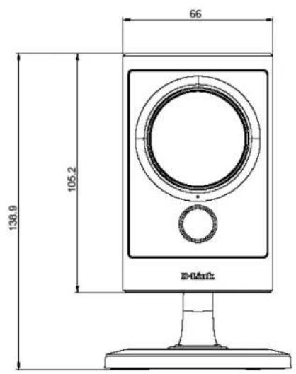
text_image
66 105.2 138.9 D-MarkSafety Statements
CE Mark Warning:
This is a Class B product. In a domestic environment, this product may cause radio interference, in which case the user may be required to take adequate measures.
FCC Statement:
This equipment has been tested and found to comply with the limits for a Class B digital device, pursuant to part 15 of the FCC Rules. These limits are designed to provide reasonable protection against harmful interference in a residential installation. This equipment generates, uses, and can radiate radio frequency energy and, if not installed and used in accordance with the instructions, may cause harmful interference to radio communication. However, there is no guarantee that interference will not occur in a particular installation. If this equipment does cause harmful interference to radio or television reception, which can be determined by turning the equipment off and on, the user is encouraged to try to correct the interference by one or more of the following measures:
- Reorient or relocate the receiving antenna.
- Increase the separation between the equipment and receiver.
- Connect the equipment into an outlet on a circuit different from that to which the receiver is connected.
- Consult the dealer or an experienced radio/TV technician for help.
FCC Caution:
Any changes or modifications not expressly approved by the party responsible for compliance could void the user's authority to operate this equipment.
This device complies with Part 15 of the FCC Rules. Operation is subject to the following two conditions:
(1) This device may not cause harmful interference, and (2) this device must accept any interference received, including interference that may cause undesired operation.
Contacting Technical Support
U.S. and Canadian customers can contact D-Link technical support through our web site or by phone.
Before you contact technical support, please have the following ready:
- Model number of the product (e.g. DCS-2130L)
- Hardware Revision (located on the label on the bottom of the Network Camera (e.g. rev A1))
- Serial Number (s/n number located on the label on the bottom of the Network Camera).
You can find software updates and user documentation on the D-Link website as well as frequently asked questions and answers to technical issues.
For customers within the United States:
Phone Support:
(877) 453-5465
Internet Support:
http://support.dlink.com
Warranty
Subject to the terms and conditions set forth herein, D-Link Systems, Inc. ("D-Link") provides this Limited Warranty:
- Only to the person or entity that originally purchased the product from D-Link or its authorized reseller or distributor, and
- Only for products purchased and delivered within the fifty states of the United States, the District of Columbia, U.S. Possessions or Protectorates, U.S. Military Installations, or addresses with an APO or FPO.
Limited Warranty:
D-Link warrants that the hardware portion of the D-Link product described below ("Hardware") will be free from material defects in workmanship and materials under normal use from the date of original retail purchase of the product, for the period set forth below ("Warranty Period"), except as otherwise stated herein.
- Hardware: One (1) year
• Power supplies: One (1) year - Spare parts and spare kits: Ninety (90) days
The customer's sole and exclusive remedy and the entire liability of D-Link and its suppliers under this Limited Warranty will be, at D-Link's option, to repair or replace the defective Hardware during the Warranty Period at no charge to the original owner or to refund the actual purchase price paid. Any repair or replacement will be rendered by D-Link at an Authorized D-Link Service Office. The replacement hardware need not be new or have an identical make, model or part. D-Link may, at its option, replace the defective Hardware or any part thereof with any reconditioned product that D-Link reasonably determines is substantially equivalent (or superior) in all material respects to the defective Hardware. Repaired or replacement hardware will be warranted for the remainder of the original Warranty Period or ninety (90) days, whichever is longer, and is subject to the same limitations and exclusions. If a material defect is incapable of correction, or if D-Link determines that it is not practical to repair or replace the defective Hardware, the actual price paid by the original purchaser for the defective Hardware will be refunded by D-Link upon return to D-Link of the defective Hardware. All Hardware or part thereof that is replaced by D-Link, or for which the purchase price is refunded, shall become the property of D-Link upon replacement or refund.
Limited Software Warranty:
D-Link warrants that the software portion of the product ("Software") will substantially conform to D-Link's then current functional specifications for the Software, as set forth in the applicable documentation, from the date of original retail purchase of the Software for a period of ninety (90) days ("Software Warranty Period"), provided that the Software is properly installed on approved hardware and operated as contemplated in its documentation. D-Link further warrants that, during the Software Warranty Period, the magnetic media on which D-Link delivers the Software will be free of physical defects. The customer's sole and exclusive remedy and the entire liability of D-Link and its suppliers under this Limited Warranty will be, at D-Link's option, to replace the non-conforming Software (or defective media) with software that substantially conforms to D-Link's functional specifications for the Software or to refund the portion of the actual purchase price paid that is attributable to the Software. Except as otherwise agreed by DLink in writing, the replacement Software is provided only to the original licensee, and is subject to the terms and conditions of the license granted by D-Link for the Software. Replacement Software will be warranted for the remainder of the original Warranty Period and is subject to the same limitations and exclusions. If a material non-conformance is incapable of correction, or if D-Link determines in its sole discretion that it is not practical to replace the non-conforming Software, the price paid by the original licensee for the non-conforming Software will be refunded by D-Link; provided that the non-conforming Software (and all copies thereof) is first returned to D-Link. The license granted respecting any Software for which a refund is given automatically terminates.
Non-Applicability of Warranty:
The Limited Warranty provided hereunder for Hardware and Software portions of D-Link's products will not be applied to and does not cover any refurbished product and any product purchased through the inventory clearance or liquidation sale or other sales in which D-Link, the sellers, or the liquidators expressly disclaim their warranty obligation pertaining to the product and in that case, the product is being sold "As-Is" without any warranty whatsoever including, without limitation, the Limited Warranty as described herein, notwithstanding anything stated herein to the contrary.
Submitting A Claim (USA):
The customer shall return the product to the original purchase point based on its return policy. In case the return policy period has expired and the product is within warranty, the customer shall submit a claim to D-Link as outlined below:
- The customer must submit with the product as part of the claim a written description of the Hardware defect or Software nonconformance in sufficient detail to allow DLink to confirm the same, along with proof of purchase of the product (such as a copy of the dated purchase invoice for the product) if the product is not registered.
- The customer must obtain a Case ID Number from D-Link Technical Support at 1-877-354-6555, who will attempt to assist the customer in resolving any suspected defects with the product. If the product is considered defective, the customer must obtain a Return Material Authorization ("RMA") number by completing the RMA form and entering the assigned Case ID Number at https://rma.dlink.com/.
Appendix E: Warranty
- After an RMA number is issued, the defective product must be packaged securely in the original or other suitable shipping package to ensure that it will not be damaged in transit, and the RMA number must be prominently marked on the outside of the package. Do not include any manuals or accessories in the shipping package. DLink will only replace the defective portion of the product and will not ship back any accessories.
- The customer is responsible for all in-bound shipping charges to D-Link. No Cash on Delivery ("COD") is allowed. Products sent COD will either be rejected by D-Link or become the property of D-Link. Products shall be fully insured by the customer and shipped to D-Link Systems, Inc., 17595 Mt. Herrmann, Fountain Valley, CA 92708. D-Link will not be held responsible for any packages that are lost in transit to D-Link. The repaired or replaced packages will be shipped to the customer via UPS Ground or any common carrier selected by D-Link. Return shipping charges shall be prepaid by D-Link if you use an address in the United States, otherwise we will ship the product to you freight collect. Expedited shipping is available upon request and provided shipping charges are prepaid by the customer. D-Link may reject or return any product that is not packaged and shipped in strict compliance with the foregoing requirements, or for which an RMA number is not visible from the outside of the package. The product owner agrees to pay D-Link's reasonable handling and return shipping charges for any product that is not packaged and shipped in accordance with the foregoing requirements, or that is determined by D-Link not to be defective or non-conforming.
What Is Not Covered:
The Limited Warranty provided herein by D-Link does not cover:
Products that, in D-Link's judgment, have been subjected to abuse, accident, alteration, modification, tampering, negligence, misuse, faulty installation, lack of reasonable care, repair or service in any way that is not contemplated in the documentation for the product, or if the model or serial number has been altered, tampered with, defaced or removed; Initial installation, installation and removal of the product for repair, and shipping costs; Operational adjustments covered in the operating manual for the product, and normal maintenance; Damage that occurs in shipment, due to act of God, failures due to power surge, and cosmetic damage; Any hardware, software, firmware or other products or services provided by anyone other than D-Link; and Products that have been purchased from inventory clearance or liquidation sales or other sales in which D-Link, the sellers, or the liquidators expressly disclaim their warranty obligation pertaining to the product.
While necessary maintenance or repairs on your Product can be performed by any company, we recommend that you use only an Authorized D-Link Service Office. Improper or incorrectly performed maintenance or repair voids this Limited Warranty.
Disclaimer of Other Warranties:
EXCEPT FOR THE LIMITED WARRANTY SPECIFIED HEREIN, THE PRODUCT IS PROVIDED "AS-IS" WITHOUT ANY WARRANTY OF ANY KIND WHATSOEVER INCLUDING, WITHOUT LIMITATION, ANY WARRANTY OF MERCHANTABILITY, FITNESS FOR A PARTICULAR PURPOSE AND NONINFRINGEMENT.
Appendix E: Warranty
IF ANY IMPLIED WARRANTY CANNOT BE DISCLAIMED IN ANY TERRITORY WHERE A PRODUCT IS SOLD, THE DURATION OF SUCH IMPLIED WARRANTY SHALL BE LIMITED TO THE DURATION OF THE APPLICABLE WARRANTY PERIOD SET FORTH ABOVE. EXCEPT AS EXPRESSLY COVERED UNDER THE LIMITED WARRANTY PROVIDED HEREIN, THE ENTIRE RISK AS TO THE QUALITY, SELECTION AND PERFORMANCE OF THE PRODUCT IS WITH THE PURCHASER OF THE PRODUCT.
Limitation of Liability:
TO THE MAXIMUM EXTENT PERMITTED BY LAW, D-LINK IS NOT LIABLE UNDER ANY CONTRACT, NEGLIGENCE, STRICT LIABILITY OR OTHER LEGAL OR EQUITABLE THEORY FOR ANY LOSS OF USE OF THE PRODUCT, INCONVENIENCE OR DAMAGES OF ANY CHARACTER, WHETHER DIRECT, SPECIAL, INCIDENTAL OR CONSEQUENTIAL (INCLUDING, BUT NOT LIMITED TO, DAMAGES FOR LOSS OF GOODWILL, LOSS OF REVENUE OR PROFIT, WORK STOPPAGE, COMPUTER FAILURE OR MALFUNCTION, FAILURE OF OTHER EQUIPMENT OR COMPUTER PROGRAMS TO WHICH D-LINK'S PRODUCT IS CONNECTED WITH, LOSS OF INFORMATION OR DATA CONTAINED IN, STORED ON, OR INTEGRATED WITH ANY PRODUCT RETURNED TO D-LINK FOR WARRANTY SERVICE) RESULTING FROM THE USE OF THE PRODUCT, RELATING TO WARRANTY SERVICE, OR ARISING OUT OF ANY BREACH OF THIS LIMITED WARRANTY, EVEN IF D-LINK HAS BEEN ADVISED OF THE POSSIBILITY OF SUCH DAMAGES. THE SOLE REMEDY FOR A BREACH OF THE FOREGOING LIMITED WARRANTY IS REPAIR, REPLACEMENT OR REFUND OF THE DEFECTIVE OR NONCONFORMING PRODUCT. THE MAXIMUM LIABILITY OF D-LINK UNDER THIS WARRANTY IS LIMITED TO THE PURCHASE PRICE OF THE PRODUCT COVERED BY THE WARRANTY. THE FOREGOING EXPRESS WRITTEN WARRANTIES AND REMEDIES ARE EXCLUSIVE AND ARE IN LIEU OF ANY OTHER WARRANTIES OR REMEDIES, EXPRESS, IMPLIED OR STATUTORY.
Governing Law:
This Limited Warranty shall be governed by the laws of the State of California. Some states do not allow exclusion or limitation of incidental or consequential damages, or limitations on how long an implied warranty lasts, so the foregoing limitations and exclusions may not apply. This Limited Warranty provides specific legal rights and you may also have other rights which vary from state to state.
Trademarks:
D-Link is a registered trademark of D-Link Corporation/D-Link Systems, Inc. Other trademarks or registered trademarks are the property of their respective owners.
Copyright Statement:
No part of this publication or documentation accompanying this product may be reproduced in any form or by any means or used to make any derivative such as translation, transformation, or adaptation without permission from D-Link Corporation/D-Link Systems, Inc., as stipulated by the United States Copyright Act of 1976 and any amendments thereto. Contents are subject to change without prior notice.
Copyright ©2012 by D-Link Corporation/D-Link Systems, Inc. All rights reserved.
FCC Statement:
This equipment has been tested and found to comply with the limits for a Class B digital device, pursuant to part 15 of the FCC Rules. These limits are designed to provide reasonable protection against harmful interference in a residential installation. This equipment generates, uses, and can radiate radio frequency energy and, if not installed and used in accordance with the instructions, may cause harmful interference to radio communication. However, there is no guarantee that interference will not occur in a particular installation. If this equipment does cause harmful interference to radio or television reception, which can be determined by turning the equipment off and on, the user is encouraged to try to correct the interference by one or more of the following measures:
- Reorient or relocate the receiving antenna.
- Increase the separation between the equipment and receiver.
- Connect the equipment into an outlet on a circuit different from that to which the receiver is connected.
- Consult the dealer or an experienced radio/TV technician for help.
FCC Caution:
Any changes or modifications not expressly approved by the party responsible for compliance could void the user's authority to operate this equipment.
This device complies with Part 15 of the FCC Rules. Operation is subject to the following two conditions:
(1) This device may not cause harmful interference, and
(2) this device must accept any interference received, including interference that may cause undesired operation.
If this device is going to be operated in 5.15 \~ 5.25GHz frequency range, then it is restricted in indoor environment only.
IMPORTANT NOTICE:
FCC Radiation Exposure Statement:
This equipment complies with FCC radiation exposure limits set forth for an uncontrolled environment. This equipment should be installed and operated with minimum distance 20cm between the radiator & your body. This transmitter must not be co-located or operating in conjunction with any other antenna or transmitter.
The availability of some specific channels and/or operational frequency bands are country dependent and are firmware programmed at the factory to match the intended destination. The firmware setting is not accessible by the end user.
For detailed warranty information applicable to products purchased outside the United States, please contact the corresponding local D-Link office.
Registration
Register your product online at registration.dlink.com

natural_image
Woman in red dress using laptop on white sofa (no text or symbols visible)Product registration is entirely voluntary and failure to complete or return this form will not diminish your warranty rights.
Version 1.0
July 10, 2012