
SC-HTB550 - Home Theater System PANASONIC - Free user manual and instructions
Find the device manual for free SC-HTB550 PANASONIC in PDF.


| Product Type | Home Theater Audio System |
| Brand | Panasonic |
| Model | SC-HTB550 |
| Main Unit Dimensions (W x H x D) | 310 mm x 45 mm x 202 mm |
| Main Unit Weight | Approx. 1.1 kg |
| Active Subwoofer Dimensions (W x H x D) | 180 mm x 406 mm x 316 mm |
| Active Subwoofer Weight | Approx. 5.2 kg |
| Front Speaker Weight (Horizontal with stands) | 1.61 kg (pair) |
| Power Consumption (Main Unit) | 33 W |
| Power Consumption (Active Subwoofer) | 23 W |
| Standby Power Consumption (Both) | Approx. 0.2 W each |
| Power Supply | AC 220 V to 240 V, 50 Hz |
| RMS Output Power (Total Dolby Digital Mode) | 240 W |
| Subwoofer Output Power | 120 W per channel (100 Hz, 8 Ω) |
| Front Speaker Output Power | 60 W per channel (1 kHz, 6 Ω) |
| Audio Decoding Formats | LPCM, Dolby Digital, DTS |
| Wireless Connectivity | Bluetooth® V2.1 + EDR, 5 GHz wireless subwoofer link |
| Inputs | 2 x HDMI, 2 x Optical digital audio (TV, AUX2) |
| Outputs | 1 x HDMI (ARC) |
| Speaker Configuration | 2.1 channel (left, right, active subwoofer) |
| Speaker Placement Options | Wall-mount horizontal/vertical, table stands, bases, or support legs |
| Special Sound Features | 3D surround effect, Clear-mode dialog, Dolby Virtual Speaker, Auto gain control |
| VIERA Link (HDMI CEC) | HDAVI Control 5 compatible |
| Cleaning Instructions | Wipe with soft dry cloth; gentle damp cloth for heavy dirt. No alcohol or solvents. |
| Safety Precautions | Do not expose to rain/moisture; ensure ventilation; use only supplied AC mains lead; keep battery away from children. |
| Spare Parts / Repairability | Contact dealer for replacement fuse (5 A). No user-serviceable parts inside; refer servicing to qualified personnel. |
| Supplied Accessories | Remote control (battery), 2 AC mains leads, 2 speaker cables, speaker joint, screws, speaker feet, ornaments, support legs, stands, speaker bases |
Frequently Asked Questions - SC-HTB550 PANASONIC
User questions about SC-HTB550 PANASONIC
0 question about this device. Answer the ones you know or ask your own.
Ask a new question about this device
Download the instructions for your Home Theater System in PDF format for free! Find your manual SC-HTB550 - PANASONIC and take your electronic device back in hand. On this page are published all the documents necessary for the use of your device. SC-HTB550 by PANASONIC.
USER MANUAL SC-HTB550 PANASONIC
Operating Instructions Home Theater Audio System
Model No. SC-HTB550

Thank you for purchasing this product.
For optimum performance and safety, please read these instructions carefully.
Please keep this manual for future reference.
Model number suffix "EB" denotes UK models.
Safety precautions
WARNING CAUTION
Unit
- To reduce the risk of fire, electric shock or product damage,
—Do not expose this unit to rain, moisture, dripping or splashing.
—Do not place objects filled with liquids, such as vases, on this unit.
—Use only the recommended accessories.
—Do not remove covers.
—Do not repair this unit by yourself. Refer servicing to qualified service personnel.
AC mains lead
- To reduce the risk of fire, electric shock or product damage,
—Ensure that the power supply voltage corresponds to the voltage printed on this unit.
—Insert the mains plug fully into the socket outlet.
—Do not pull, bend, or place heavy items on the lead.
—Do not handle the plug with wet hands.
—Hold onto the mains plug body when disconnecting the plug.
—Do not use a damaged mains plug or socket outlet. - Install this unit so that the AC mains lead can be unplugged from the socket outlet immediately if any problem occurs.
Button-type battery (Lithium battery)
- Risk of fire, explosion and burns. Do not recharge, disassemble, heat above 60 °C or incinerate.
- Keep the Button-Type battery out of the reach of children. Never put Button-Type battery in mouth. If swallowed call your doctor.
Unit
- Do not place sources of naked flames, such as lighted candles, on this unit.
- This unit may receive radio interference caused by mobile telephones during use. If such interference occurs, please increase separation between this unit and the mobile telephone.
- This unit is intended for use in moderate climates.
Placement
- Place this unit on an even surface.
- To reduce the risk of fire, electric shock or product damage,
- Do not install or place this unit in a bookcase, built-in cabinet or in another confined space. Ensure this unit is well ventilated.
- Do not obstruct this unit's ventilation openings with newspapers, tablecloths, curtains, and similar items.
—Do not expose this unit to direct sunlight, high temperatures, high humidity, and excessive vibration.
Button-type battery (Lithium battery)
- Danger of explosion if battery is incorrectly replaced. Replace only with the type recommended by the manufacturer.
- When disposing the batteries, please contact your local authorities or dealer and ask for the correct method of disposal.
- Insert with poles aligned.
- Mishandling of batteries can cause electrolyte leakage and may cause a fire.
- Remove the battery if you do not intend to use the remote control for a long period of time. Store in a cool, dark place.
- Do not heat or expose to flame.
- Do not leave the battery(ies) in a car exposed to direct sunlight for a long period of time with doors and windows closed.
Caution for AC Mains Lead
(For the United Kingdom and Ireland)
For your safety, please read the following text carefully.
This appliance is supplied with a moulded three pin mains plug for your safety and convenience. A 5-ampere fuse is fitted in this plug.
Should the fuse need to be replaced please ensure that the replacement fuse has a rating of 5-ampere and that it is approved by ASTA or BSI to BS1362.
Check for the ASTA mark 📂 or the BSI mark 🌼 on the body of the fuse.
If the plug contains a removable fuse cover you must ensure that it is refitted when the fuse is replaced.
If you lose the fuse cover the plug must not be used until a replacement cover is obtained.
A replacement fuse cover can be purchased from your local dealer.
CAUTION!
IF THE FITTED MOULDED PLUG IS UNSUITABLE FOR THE SOCKET OUTLET IN YOUR HOME THEN THE FUSE SHOULD BE REMOVED AND THE PLUG CUT OFF AND DISPOSED OF SAFELY.
THERE IS A DANGER OF SEVERE ELECTRICAL SHOCK IF THE CUT OFF PLUG IS INSERTED INTO ANY 13-AMPERE SOCKET.
If a new plug is to be fitted please observe the wiring code as stated below.
If in any doubt please consult a qualified electrician.
IMPORTANT
The wires in this mains lead are coloured in accordance with the following code:
Blue: Neutral, Brown: Live.
As these colours may not correspond with the coloured markings identifying the terminals in your plug, proceed as follows:
The wire which is coloured Blue must be connected to the terminal which is marked with the letter N or coloured Black or Blue.
The wire which is coloured Brown must be connected to the terminal which is marked with the letter L or coloured Brown or Red.
WARNING: DO NOT CONNECT EITHER WIRE TO THE EARTH TERMINAL WHICH IS MARKED WITH THE LETTER E, BY THE EARTH SYMBOL
OR COLOURED GREEN OR GREEN/YELLOW.
THIS PLUG IS NOT WATERPROOF—KEEP DRY.
Before use
Remove the connector cover.
How to replace the fuse
The location of the fuse differ according to the type of AC mains plug (figures A and B). Confirm the AC mains plug fitted and follow the instructions below. Illustrations may differ from actual AC mains plug.
- Open the fuse cover with a screwdriver.
Figure A Figure B


- Replace the fuse and close or attach the fuse cover.
Figure A Figure B


Fuse
(5 ampere)
Table of contents
Safety precautions.... 2
Caution for AC Mains Lead.... 3
Before use
Supplied items 5
System (SC-HTB550) 5
Accessories.... 5
Control reference guide 6
Main unit and active subwoofer (Front).... 6
Main unit and active subwoofer (Rear) 6
Remote control....7
Getting started
Step 1 Selecting the placement method....8
Speaker system 9
Active subwoofer....9
Wireless interference 9
Step 2 Assembling the speakers.... 10
When attaching the speakers to a wall 10
When placing the speakers on a table.... 14
Additional speaker fall prevention measures 17
Step 3 Connections.... 19
Connection with the TV 19
Connection with other devices 20
Speaker cable connection.... 21
AC mains lead connection 21
Active subwoofer wireless connection 22
Bluetooth® connection.... 22
Operations
Using this unit.... 23
3D sound.... 24
Audio output modes 24
Linked operations with the TV (VIERA Link “HDAVI Control™”)...... 25
Advanced operations 26
Reference
Troubleshooting 28
Indicator illumination 30
Specifications 31
Unit care 32
Licenses 32
About Bluetooth ® 32
• The illustrations shown may differ from your unit.
- These operation instructions are applicable to model SC-HTB550 for variety of regions. Unless otherwise indicated, illustrations in these Operating Instructions are of the model for the United Kingdom and Ireland.
- Operations in this Operating Instructions are described mainly with the remote control, but you can perform the operations on the main unit if the controls are the same.
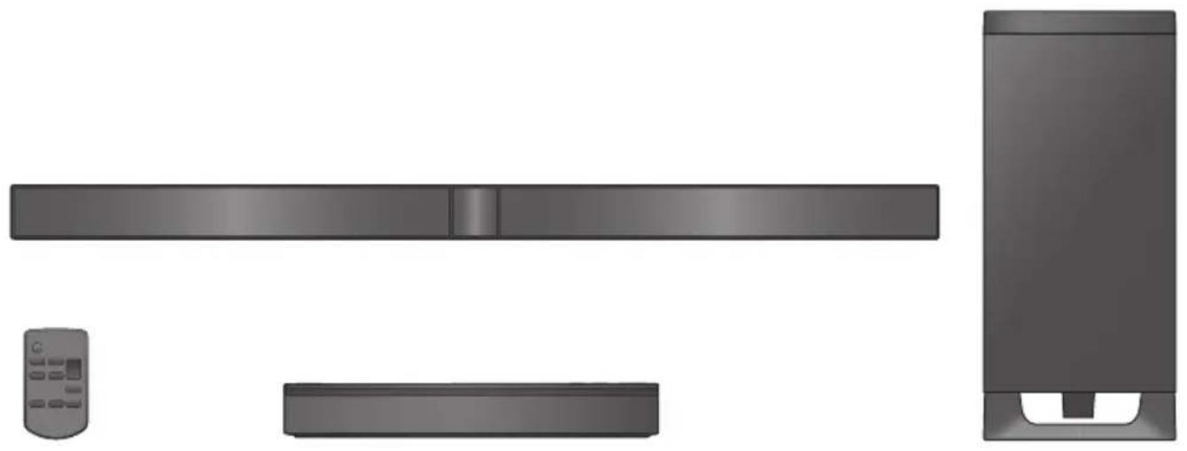
Supplied items
System (SC-HTB550)
□ 1 Main unit (SU-HTB550)

□ 1 Active subwoofer (SB-HWA550)

2 Front speakers (SB-HTB550)

Accessories
Check the supplied accessories before using the system.
□ 1 Remote control(with a battery)(N2QAYC000063) | □ AC mains lead2 For the United Kingdom and Ireland(K2CZ3YY00024)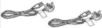 | 2 For Continental Europe(K2CQ2CA00007) | 2 For Australia and New Zealand(K2CJ2DA00008)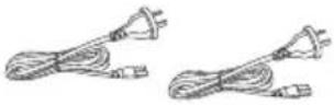 |
□ 2 Speaker cables(REEX1266A: RED)(REEX1267A: WHITE)Length: 3 m | □ 1 Speaker joint(RAQ0085)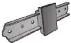 | □ 6 Screws(XYN5+J14FJK)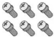 | □ 2 Speaker feet(RKAX0028-K) |
□ 2 Front ornaments(RAQ0089) | □ 2 Support legs(RYQ0970-K) | □ 2 S t a n d s(RYQ0853-KJ) | □ 2 Speaker bases(RAQ0086) |
[Non-Text]
- Product numbers are correct as of January 2012. These may be subject to change.
- The supplied AC mains lead is for use with this unit and the active subwoofer only.
Do not use it with other equipment. Also, do not use cords from other equipment with this unit or active subwoofer.
Control reference guide
Main unit and active subwoofer (Front)

1 Standby/on switch (⏻/I)
Press to switch the unit from on to standby mode or vice versa. In standby mode, the unit is still consuming a small amount of power.
2 Adjust the volume of the speakers
3 Select the input source
" TV" → " BD / DVD" → " AUX 1"
“ ” ← “AUX2” ←
4 Remote control signal sensor ( ⇒ 7)
5 Input selector indicators *1
Ⓐ TV indicator
Lights green when the TV is the audio source
⑧ BD/DVD indicator
Lights amber when the device connected to the BD/DVD terminal is the audio source
© AUX1 indicator
Lights amber when the device connected to the AUX1 terminal is the audio source
(D) AUX2 indicator Lights amber when the device connected to the AUX2 terminal is the audio source
⑤ Bluetooth® indicator Lights blue when the Bluetooth® device is the audio source
6 Audio format indicators ※1
⑤ Dolby Digital indicator Lights when Dolby Digital is the current audio format
G DTS indicator Lights when DTS is the current audio format
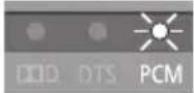
H PCM indicator Lights when PCM (2ch, Multi-channel) is the current audio format
7 WIRELESS LINK indicator ( ⇒ 22)
Main unit and active subwoofer (Rear)
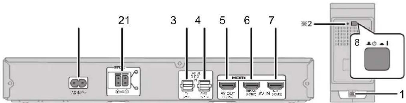
1 AC IN terminal ( ⇒ 21)
2 Speaker terminals ( ⇒ 21)
3 TV terminal ( ⇒ 19)
4 AUX2 terminal ( ⇒ 20)
5 HDMI OUT terminal (ARC compatible) ( ⇒ 19)
6 BD/DVD terminal ( ⇒ 20)
7 AUX1 terminal ( ⇒ 20)
8 Active subwoofer on/off button
※1 The indicators will also blink in various conditions (⇒ 30)
※2 The I/D SET button is only used when the main unit is not paired with the active subwoofer (⇒ 29)
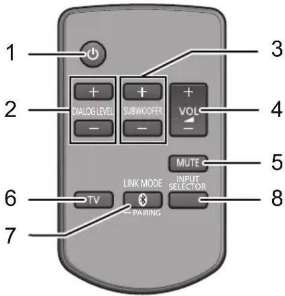
1 Turn the main unit on or off (⇒ 23)
2 Adjust the dialog effect level ( ⇒ 23)
3 Adjust the output level of the active subwoofer (bass sound) ( ⇒ 23)
4 Adjust the volume of this system (→ 23)
5 Mute the sound ( ⇒ 23)
6 Select the TV as the source ( ⇒ 23)
7 Select the Bluetooth device as the source
(⇒ 23)
8 Select the input source (→ 23)
" TV" → " BD / DVD" → " AUX1"
“ ” ← “AUX2” ←
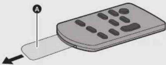
Remove the insulation sheet A before using.
■ To replace a button-type battery
① While pressing the stopper B, pull out the battery holder.

② Set the button-type battery with its (+) mark facing upward and then put the battery holder back in place.

- When replacing the battery, use: CR2025 (Lithium battery)
- Keep the button-type battery out of reach of children to prevent swallowing.
■ Remote control operation range
The remote control signal sensor is located on the main unit.
- Use the remote control within the correct operation range.

© Remote control signal sensor
- Operation range
Distance: Within approx. 7 m directly in front
Angle: Approx. 30° left and right
Step 1 Selecting the placement method
- Choose a placement method that suits you best.
When attaching the speakers to a wall

Place the speakers horizontally
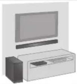

Page 10

Place the speakers vertically


Page 12
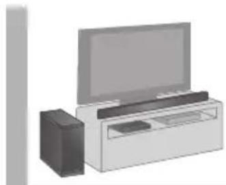
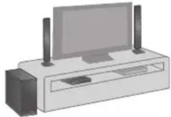
When placing the speakers on a table

Place the speakers using the stands


Page 14

Place the speakers using the support legs and speaker feet
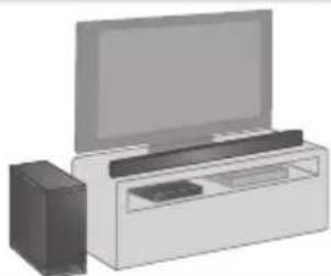

Page 15

Place the speakers using the speaker bases
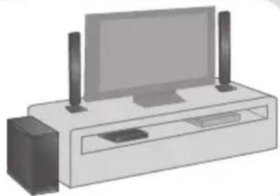

Page 16
Caution
- This system is to be used only as indicated in these instructions. Failure to do so may lead to damage to the amplifier and/or the speakers, and may result in the risk of fire. Consult a qualified service person if damage has occurred or if you experience a sudden change in performance.
- Do not attempt to attach these speakers to a wall using methods other than those described in this manual.
Speaker system
- Use a screwdriver (+) for assembling the speakers.
- Do not hold the speakers in one hand to avoid injury, you may drop the speakers when carrying them.
■ When attaching the speakers to a wall
The wall or pillar on which the speakers are to be attached should be capable of supporting 33 kg per screw. Consultation with a qualified installation specialist is recommended when attaching the speakers to a wall. Improper attachment may result in damage to the wall and speakers, and personal injury.
■ When placing the speakers in front of the TV
The speakers may block or interfere with the TV's various sensors (C.A.T.S. (Contrast Automatic Tracking System) sensor, remote control sensor, etc.) and the 3D Eyewear transmitters on a 3D compatible TV.
- If the stands are being used
Move the speakers further away from the TV. If the TV still does not function properly, try removing the stands. - If the stands are not used
Move the speakers further away from the TV. If the TV still does not function properly, try placing them beside the TV ( ⇒ 8).
Active subwoofer
When carrying the active subwoofer

A Do not hold the active subwoofer from this opening.
The parts inside (speaker unit) may be damaged.
B Always hold the bottom of the active subwoofer when moving it.
Wireless interference
To avoid interference, maintain the following distances between the main unit/active subwoofer and other electronic devices that use the same radio frequency (2.4 GHz and 5 GHz band).

© Main unit/active subwoofer
D Wireless LAN: approx. 2 m
E Cordless phone and other electronic devices: approx. 2 m

- Place the active subwoofer within a few meters of the main unit and in a horizontal position with the top panel faced upward.
- Do not use the main unit or active subwoofer in a metal cabinet.
- Placing the active subwoofer and the speakers too close to the walls and corners can result in excessive bass. Cover walls and windows with thick curtains.
- If irregular colouring occurs on your TV, turn the TV off for about 30 minutes. If it persists, move the speakers further away from the TV.
- Keep magnetised items away. Magnetised cards, watches, etc., can be damaged if placed too close to the active subwoofer and the speakers.
Step 2 Assembling the speakers
When attaching the speakers to a wall

Place the speakers horizontally

- For a safety measure to prevent the speakers from falling, refer to page 17.
● To prevent damage or scratches, lay down a soft cloth and perform the assembly on it.

Assemble the speakers.
• The two speakers are interchangeable.

A "C" shaped slit
- Insert the speaker joint fully into the slit.
B Screw (supplied)
- Be sure to insert the screws following the order as indicated in the illustration.
- Keep the screws out of reach of children to prevent swallowing.

Connect the speaker cables.
- Use the "Panasonic" logo to identify the left and right speakers, then connect the cables (as illustrated).


① Insert the wire fully.
+: White
—: Blue line
② Press into the groove.
A RED: Right speaker channel (R)
B WHITE: Left speaker channel (L)
- Insert the wire fully, taking care not to insert beyond the wire insulation.

Drive a screw into the wall.
- Use the measurements indicated below to identify the screwing positions on the wall.
- Leave at least 20 mm of space above and on each side of the speaker to allow enough space for fitting the speaker.
- The position on the wall where the screw is to be attached, as well as the screw, should be capable of supporting over 33 kg.
- Keep the screws out of reach of children to prevent swallowing.

© At least 30 mm
D ∅4.0 mm
E ∅7.0 mm to ∅9.4 mm
F Wall or pillar
G 5.5 mm to 6.5 mm
Front view (semi-transparent image)

H 326 mm
316 mm
J 316 mm
K 26 mm
L Wall mounting hole

Fit the speaker securely onto the screw(s).
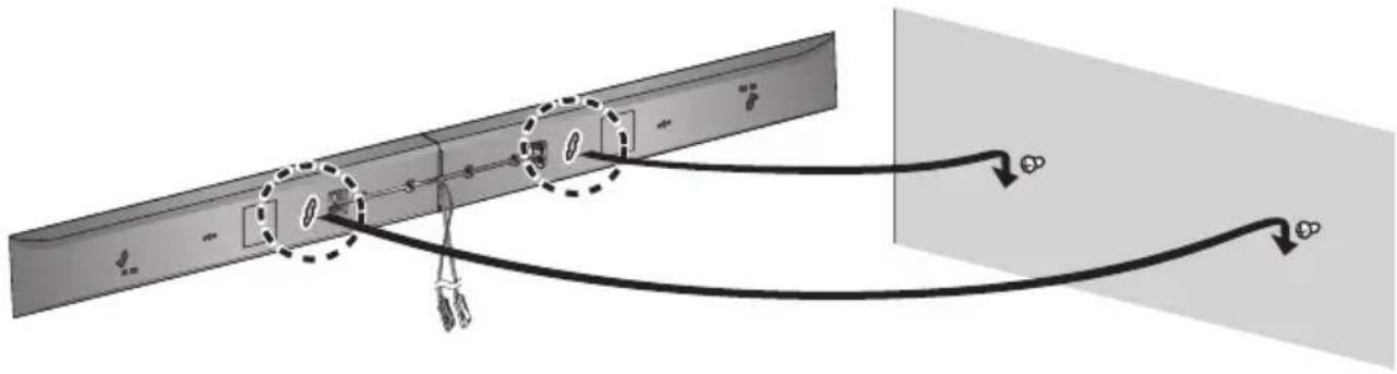
| DO DO NOT | |||
 | • Move the speaker so that the screw is in this position. |  | • In this position, the speaker will likely fall if moved to the left or right. |
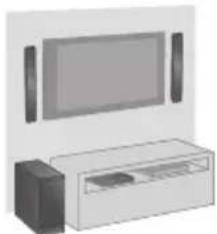
Place the speakers vertically

- For a safety measure to prevent the speakers from falling, refer to page 17.
- To prevent damage or scratches, lay down a soft cloth and perform the assembly on it.

Attach the front ornaments.
• The two speakers are interchangeable.
- Keep the screws out of reach of children to prevent swallowing.
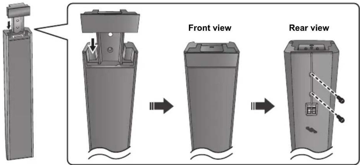

Connect the speaker cables.
- Insert the wire fully, taking care not to insert beyond the wire insulation.

① Insert the wire fully.
+: White
一: Blue line
② Press into the groove.

Drive a screw into the wall.
- Use the measurements indicated below to identify the screwing positions on the wall.
- Leave at least 20 mm of space above and on each side of the speaker to allow enough space for fitting the speaker.
- The position in the wall where the screw is to be attached as well as the screw should be capable of supporting over 33 kg.
- Keep the screws out of reach of children to prevent swallowing.
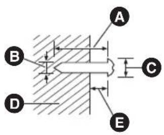
At least 30 mm
B ∅4.0 mm
© 7.0 mm to 9.4 mm
D Wall or pillar
E 5.5 mm to 6.5 mm

F Front speaker (Rear view)
G 102 mm
H 37 mm
- Wall mounting hole

Fit the speaker(s) securely onto the screw(s).
- Place the speaker that is connected with the speaker cable with a red connector on the observers' right, and connect with the speaker cable with a white connector on the observers' left.
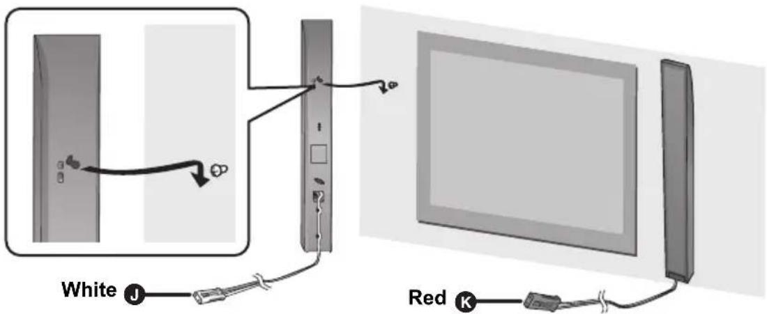
J WHITE: Left speaker channel (L)
K RED: Right speaker channel (R)
| DO DO NOT | |
 |  |
| • Move the speaker so that the screw is in this position. | • In this position, the speaker will likely fall if moved to the left or right. |
When placing the speakers on a table

Place the speakers using the stands

- For a safety measure to prevent the speakers from falling, refer to page 17.
- To prevent damage or scratches, lay down a soft cloth and perform the assembly on it.
1 Assemble the speakers following steps 1 and 2 of “Place the speakers horizontally” ( ⇒ 10).
2 Attach the stands.
- Use the "Panasonic" logo to identify the top and bottom of the speaker.
- Keep the screws out of reach of children to prevent swallowing.
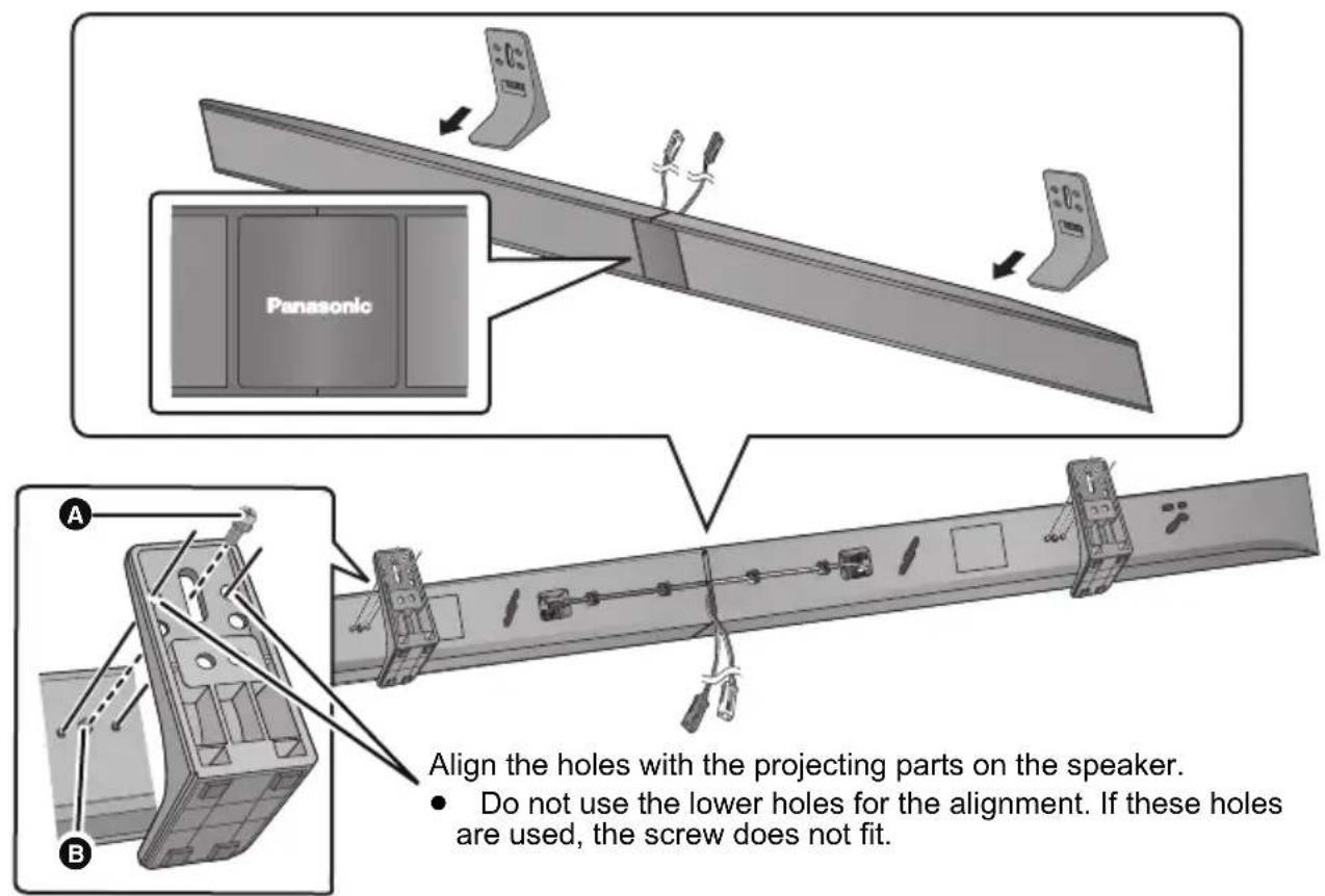
A Screw (supplied)
B Screw hole
Place the speakers using the support legs and speaker feet

- For a safety measure to prevent the speakers from falling, refer to page 17.
- To prevent damage or scratches, lay down a soft cloth and perform the assembly on it.
1 Assemble the speakers following steps 1 and 2 of “Place the speakers horizontally” ( ⇒ 10).
2 Attach the support legs and speaker feet.
- Use the "Panasonic" logo to identify the top and bottom of the speaker.
- Keep the screws and the speaker feet out of reach of children to prevent swallowing.

A Screw (supplied)
B Screw hole
© Speaker foot (supplied)
- Attach the speaker foot directly below the wall mounting hole (as illustrated).
Place the speakers using the speaker bases

- For a safety measure to prevent the speakers from falling, refer to page 17.
- To prevent damage or scratches, lay down a soft cloth and perform the assembly on it.
1 Assemble the speakers following step 1 of “Place the speakers vertically” ( ⇒ 12).
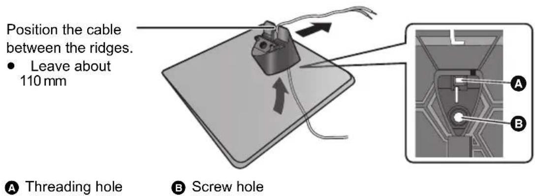
2 Insert the speaker cable through the base.
- Be sure to insert the speaker cable through the threading hole as indicated in the illustration. (If the speaker cable is twisted, it might not fit through the opening. Straighten the speaker cable before inserting.)
3 Attach the speaker to the base.
• The two speakers are interchangeable.
- Keep the screws out of reach of children to prevent swallowing.

Align the projecting parts with the holes on the speaker.

Connect the speaker cables.
- Insert the wire fully, taking care not to insert beyond the wire insulation.
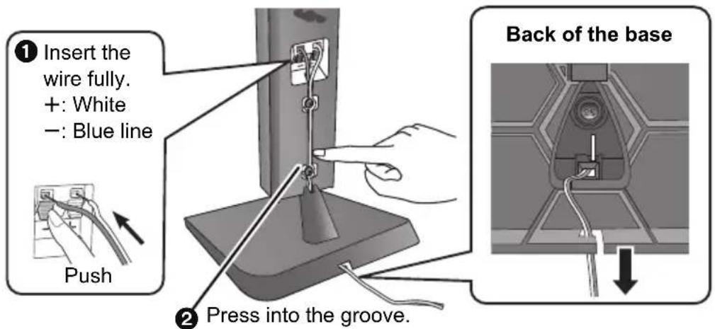
- Place the speaker that is connected with the speaker cable with a red connector on the observers' right, and connect with the speaker cable with a white connector on the observers' left.
Additional speaker fall prevention measures
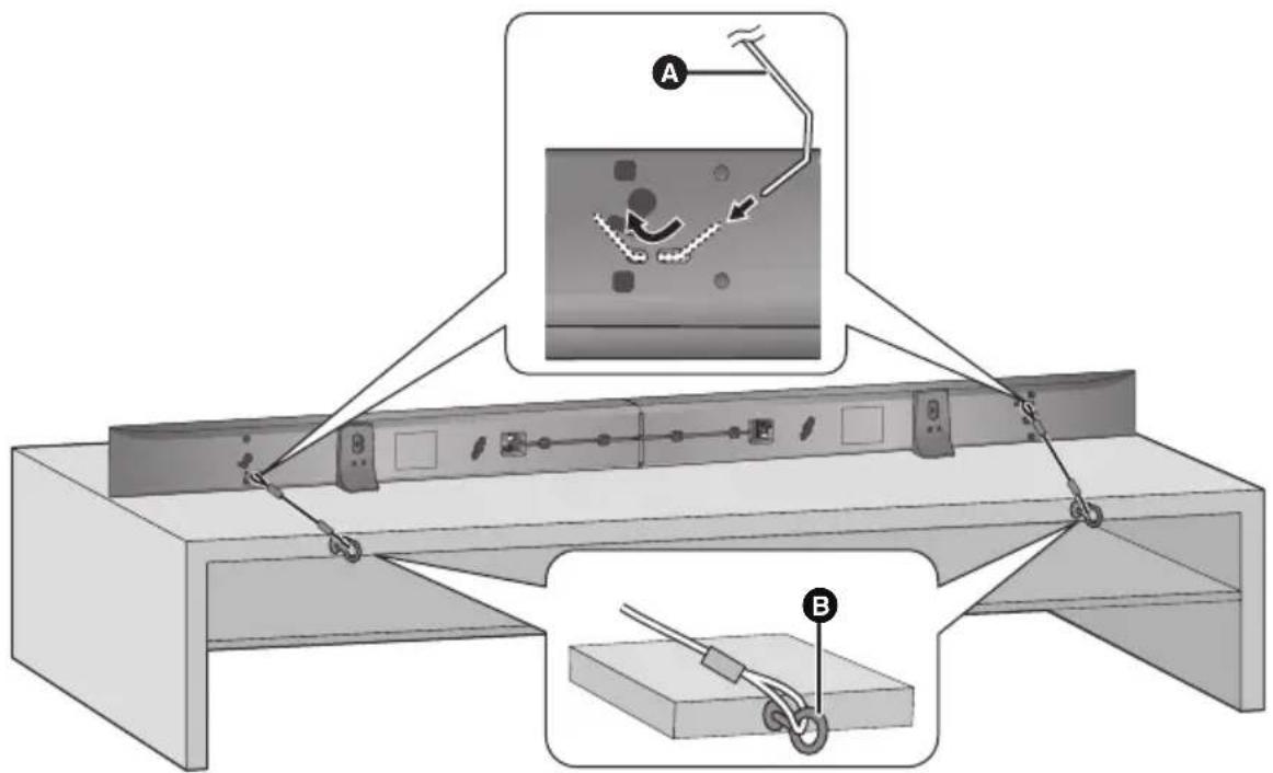
To prevent the speakers from falling, it is recommended, as an additional protection measure, to attach the speakers to the wall or table with a fall prevention cord (hereafter “cord”).

- Consultation with a qualified installation specialist concerning the appropriate procedure when attaching to a concrete wall or a surface that may not have strong enough support is recommended ( ⇒ 11, 13). Improper attachment may result in damage to the wall and speakers, and personal injury.
- Use a cord that is capable of supporting over 10 kg (with a diameter of about 1.5 mm).
- Keep the screws out of reach of children to prevent swallowing.
• Make sure that the slack of the cord is minimal.
When attaching the speakers to a wall


A Cord*
B Screw eye
© Wall
D Wall-mounted speakers
※ If the cord cannot be threaded through the holes, try bending the cord in 2 locations, about 10 mm apart from the tip, at an angle of 45° (as illustrated above).
Horizontal placement
Vertical placement

A Cord*
© Wall
B Screw eye
D Approx. 150 mm
- Depending on the placement of the speakers, the screwing position of the screw eye may differ.
※ If the cord cannot be threaded through the holes, try bending the cord in 2 locations, about 10 mm apart from the tip, at an angle of 45° (as illustrated above).
Step 3 Connections
- Turn off all equipment before connection and read the appropriate operating instructions. Do not connect the AC mains lead until all other connections are complete.
HDMI
The HDMI connection supports VIERA Link "HDAVI Control" ( ⇒ 25) when used with a compatible Panasonic TV.
- Use the High Speed HDMI Cables. It is recommended that you use Panasonic's HDMI cable.
Recommended part number (High Speed HDMI cable):
RP-CDHS15 (1.5 m), RP-CDHS30 (3.0 m), RP-CDHS50 (5.0 m), etc.
- Non-HDMI-compliant cables cannot be utilised.
Connection with the TV
1 Verify if the TV's HDMI terminal is labelled "HDMI (ARC)".
Connection differs depending on the label printed next to the HDMI terminal.
Labelled "HDMI (ARC)": Connection A
Not Labelled "HDMI (ARC)": Connection B
■ What is ARC?
ARC is an abbreviation of Audio Return Channel, also known as HDMI ARC. It refers to one of the HDMI functions. When you connect the main unit to the terminal labelled "HDMI (ARC)", the optical digital audio cable that is usually required in order to listen to sound from a TV is no longer required, and TV pictures and sound can be enjoyed with a single HDMI cable.

Make the connection.
A Labelled "HDMI (ARC)"
![graph TD A["TV"] --> B["HDMI IN (ARC)"] B --> C["Main unit"] B --> D["AV OUT TV (ARC)"] D --> E["Be sure to connect to the TV's ARC compatible terminal. (Refer to the operating instructions for the TV.)"]](/content/2026/06/1236457/images/85e4dca5bc0de3e71a8983f7ff9aea8aec1d18d8c83c4622797d11fe96e533c5.jpg)
A HDMI cable
B Not labelled "HDMI (ARC)"
![graph TD A["TV"] --> B["OPTICAL OUT"] B --> C["HDMI IN"] C --> D["Main unit"] D --> E["AV OUT TV (ARC)"] E --> F["HDMI"] F --> G["Main unit"] style A fill:#f9f,stroke:#333 style D fill:#ccf,stroke:#333 style G fill:#cfc,stroke:#333](/content/2026/06/1236457/images/93e4a77f5195de7512862a5bbc1645cdf64dfb593f2fb430a1d31fc13f448384.jpg)
A HDMI cable
B Optical digital audio cable
- When you use the optical digital audio cable, insert the tip correctly into the terminal.
Connection with other devices
You can direct the audio signal from the connected Blu-ray Disc™ player, DVD player, Set Top Box, etc. to this system.
When the device has an HDMI terminal
Preparation
- Connect the main unit to the TV ( ⇒ 19).
A HDMI cable
![graph TD A["Main unit"] --> B["Blu-ray Disc™ player"] A --> C["Video game console"] B --> D["HDMI OUT"] C --> E["HDMI OUT"] D --> F["AV IN"] E --> F F --> G["BD/DVD (HDMI1)"] F --> H["AUX1 (HDMI2)"]](/content/2026/06/1236457/images/6441866c9ddb8fe2d656ad1f7fd7b824e422051f59f6fa99bb0480004297c1bb.jpg)
■ HDMI standby pass-through
Even if the main unit is in standby mode, the audio and/or video signal from the device connected to the BD/DVD or AUX1 terminal will be sent to the TV connected to the HDMI OUT terminal (the sound will not be output from this system). When devices are connected to both BD/DVD and AUX1 terminals, audio and/or video signal of the device whose input is lastly selected is output.
■ 3D compatibility
Compatible with FULL HD 3D TV and Blu-ray Disc™ player.
- The main unit can pass the 3D video signal from a 3D compatible Blu-ray Disc™ player to a FULL HD 3D TV.
When the device has an optical digital audio output terminal
![graph TD A["TV"] -->|B| B["e.g., Set top box"] B --> C["OPTICAL OUT"] C --> D["Main unit"] D --> E["DIGITAL AUDIO IN AUX2 (OPT2)"] E --> F["OUTPUT"] style A fill:#f9f,stroke:#333 style B fill:#ccf,stroke:#333 style C fill:#cfc,stroke:#333 style D fill:#fcc,stroke:#333 style E fill:#cff,stroke:#333 s…](/content/2026/06/1236457/images/5ed7ef629c5bd91ebbc76046bf269c9bc94e87c31837bba26543c9f8ea118dc4.jpg)
B Refer to the operating instructions of the respective devices for the optimal connection C Optical digital audio cable
Speaker cable connection
Match the connector shape and connect to the terminals of the same colour.

A RED
Right speaker channel (R)
B WHITE
Left speaker channel (L)
AC mains lead connection
- Connect only after all other connections are complete.

C AC mains lead D To a household mains socket
- The main unit and active subwoofer consume a small amount of AC power, even when it is turned off (this unit: approx. 0.2 W, active subwoofer: approx. 0.2 W). In the interest of power conservation, if you will not be using this system for a long time, unplug it from the household mains socket.
For the United Kingdom and Ireland

BE SURE TO READ THE CAUTION FOR THE AC MAINS LEAD ON PAGE 3 BEFORE CONNECTION.
Saving energy
The main unit is designed to conserve its power consumption and save energy.
- This unit can be set to automatically switch to standby mode after 2 hours, if no signal is input and no operation is performed. To turn this function on, refer to page 27.
Active subwoofer wireless connection
Preparation
- Turn on the main unit.
1 Press [■ ⏻ ▼I].

Unit on/off button [■ ⏻, ■ I]
Use this button to turn the unit on and off.
1:
The active subwoofer is on.
1 Ⓧ:
The active subwoofer is off.
2 Check that the wireless link is activated.

WIRELESS LINK indicator lights
- Red:
The wireless link is not activated.
- Green:
The wireless link is activated.
The unit will still consume a small amount of power even when it is turned off (■, ⏻)
Bluetooth® connection
With the Bluetooth® connection you can output the audio from the connected wireless device.
Preparation
- Turn on the Bluetooth® feature of the device and place the device near this unit.
Pairing a device
1 Press [®, - PAIRING].
- “*” indicator will blink quickly.
2 Select "SC-HTB550" from the Bluetooth® device's Bluetooth® menu.
- Once the Bluetooth® device is connected, the "indicator stops flashing and lights up.

Refer to the operating instructions of the Bluetooth ® device for further instruction on how to connect a Bluetooth ® device. If prompted for the passkey on the Bluetooth ® device, enter "0000".
Pairing additional devices
1 Press [*, - PAIRING].
2 Press and hold the [✗, — PAIRING] until the “✗ indicator flashes quickly.
3 Repeat step 2 of "Pairing a device".

- You can register up to 6 devices with this unit. If a 7th device is paired, the device that has not been used for the longest time will be replaced.
- This unit can only be connected to one device at a time.
- To change the sound quality, refer to "Bluetooth® communication mode" on page 26.
Using this unit
Preparation
- Turn on the TV and/or connected device.
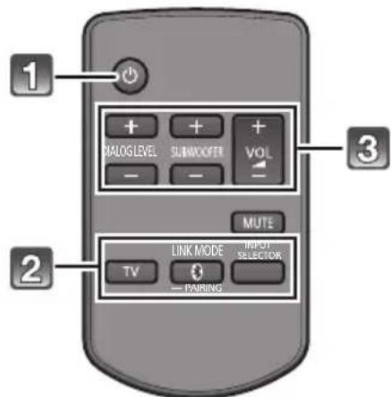
1 Press [💡] to turn on the main unit.
2 Select the source.
| Press To select | |
| [TV] “TV” | |
| [IMAGE] | “Bluetooth ®” |
| [INPUT SELECTOR] | “TV”→“BD/DVD”→“AUX1”↑—“×”←“AUX2”← |
- This remote control cannot be used to control the operations of the connected devices.
■ When “” is selected as the source
On the Bluetooth ® device:
Select this unit as the output source of the Bluetooth® device and start the playback.
- Make sure that the Bluetooth ® device is already paired with this unit. ( ⇒ 22)
- Playback may pause when a different source is selected.
■ When "BD/DVD" or "AUX1" is selected as the source
On the connected device:
Select the TV's input for this unit and start the playback on the connected device.
■ When "AUX2" is selected as the source
On the connected device:
Select the TV's input for the device connected to "AUX2" terminal and start the playback on the connected device.
3 Adjust the volume and sound effect level.
■ To adjust the volume of the system
Press [+ VOL -].
• Volume range: 1 to 100*
■ To adjust the dialog effect level
This setting will change the level of the Clear-mode dialog effect. ( ⇒ 24)
1 Press [+ DIALOG LEVEL -] to display the current level.
2 While the level is displayed: Press [+ DIALOG LEVEL -] to adjust the level.*
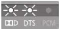
| Indication Effect level | ||
 | 4 Highest | |
 | 3 | |
 | 2 | |
 | 1 Lowest | |
■ To adjust the subwoofer level
1 Press [+ SUBWOOFER -] to display the current level.
2 While the level is displayed: Press [+ SUBWOOFER -] to adjust the level.*
- The level indication pattern is the same as dialog effect level.
■ To mute the sound
Press [MUTE].
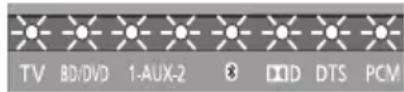
- While muting, the audio format indicators blink simultaneously.
- To cancel, press the button again or adjust the volume.
- Muting is cancelled if the main unit is turned off.

If the main unit does not operate as expected or sound is unusual, return the settings to the factory preset and operate the system again. ( ⇒ 28)
※ The audio format indicators blink from left to right (+) or from right to left (−) while adjusting. The indicators will not blink when it has reached the maximum or minimum.
- If there is sound coming out of the TV's speakers, reduce the volume of the TV to its minimum.
- If the main unit is turned off with the volume setting in the greater half (above 50), the main unit will automatically lower the volume to the middle (50) when the main unit is turned on (Volume limitation).
To turn this function off, refer to page 27.
3D sound
This system provides a feeling that the sound and the image are as one. The 3D sound effect will be applied to Multi-channel audio sources as a factory preset.
e.g., Image of 3D sound field

| 3D sound | |
| Dolby Virtual Speaker | With this effect you can enjoy a surround sound effect similar to 5.1ch. |
| 3D surround effect | Adding to the Dolby Virtual Speaker effect, Panasonic has applied its own sound field controlling technology to expand the sound field forwards, backwards, upwards, and downwards, providing a sound with depth and force that better matches 3D images. |
| Clear-mode dialog | Sports commentary and dialogs from TV dramas are heard as if the sound is coming from the TV, giving the feeling that the sound and the image are one.Also, the dialog will stand out from the other sounds during normal volume playback and when the volume is lowered for night time viewing. |

Dolby Virtual Speaker and the 3D surround effects can be turned off and on by changing the audio output mode settings.
Audio output modes
As a factory preset, Dolby Virtual Speaker and the 3D surround effects will be applied to Multi-channel audio sources, such as those from a Blu-ray Disc™ player or DVD player, etc.
By changing the audio output setting, it is possible to apply the Dolby Virtual Speaker and 3D surround effects to 2ch audio sources, such as the audio from the TV.
To change the audio output mode
1 Press and hold [MUTE] for more than 2 sec.
- The indicator for the current setting blinks for 10 sec.
2 While the indicator is blinking, press [MUTE] again to change the setting.
- The setting changes each time [MUTE] is pressed.
| Audio output mode | Dolby Virtual Speaker and 3D surround effect |
Multi-channel mode![PANASONIC SC-HTB550 - While the indicator is blinking, press [MUTE] again to change the setting. - 1](/content/2026/06/1236457/images/61ead9626f8ce1b91f704788ef203c2fbd3d98ea86455ffcce5bced602579d68.jpg) | The effects are applied to all audio sources. |
Auto mode (Direct mode) *1 (Factory preset)![PANASONIC SC-HTB550 - While the indicator is blinking, press [MUTE] again to change the setting. - 2](/content/2026/06/1236457/images/1fa0cb1227aac6d2f81d3cb9b3567cc7313e48de8a542eba7fb1e58178acbd4d.jpg) | The effects are applied to Multi-channel audio sources.The effects are not applied to 2 channel audio sources. |
2ch mode![PANASONIC SC-HTB550 - While the indicator is blinking, press [MUTE] again to change the setting. - 3](/content/2026/06/1236457/images/00d14d8f033bff530cafa7f110c1e256805e4e569e5c260b7b43929cab0bc180.jpg) | The effects are not applied to any audio source. |
※1 Depending on the audio source, Dolby Virtual Speaker and 3D surround effect settings are automatically adjusted.
※2 This indicator will also light when the audio source is Multi-channel audio.
![PANASONIC SC-HTB550 - While the indicator is blinking, press [MUTE] again to change the setting. - 4](/content/2026/06/1236457/images/204ee94d7b22c6e74f2238509d075a0712e85fed5a5e94a0af321f424de0090e.jpg)
When using the optical digital audio cable, Dolby Virtual Speaker and the 3D surround effect will be temporarily cancelled if the audio signal's sampling frequency is greater than 48 kHz.
Linked operations with the TV (VIERA Link “HDAVI Control™”)
What is VIERA Link "HDAVI Control"?
VIERA Link “HDAVI Control” is a convenient function that offers linked operations of this unit, and a Panasonic TV (VIERA) under “HDAVI Control”.
You can use this function by connecting the equipment with an HDMI cable. See the operating instructions for connected equipment for operational details.
Preparation
① Confirm that the HDMI connection has been made. ( ⇒ 19, 20)
② Set the "HDAVI Control" operations on the connected equipment (e.g., TV).
③ For the optimal "HDAVI Control" operations change the following settings on the connected TV※1.
- Set the default speaker settings to this system. 2
- Set the speaker selection settings to this system.
④ Turn on all “HDAVI Control” compatible equipment and select the TV’s input for this system so that the “HDAVI Control” function works properly.
⑤ If a device is connected to the HDMI IN terminal, start play to check that the picture is displayed on the TV correctly.
When the connection or settings are changed, repeat this procedure.
※1 The availability and function of the settings may vary depending on the TV. Refer to the operating instructions for the TV for details.
※2 If the TV has a default speaker setting within the VIERA Link setting items, choosing this system as the default speaker will automatically change the speaker selection to this system.

- VIERA Link "HDAVI Control", based on the control functions provided by HDMI which is an industry standard known as HDMI CEC (Consumer Electronics Control), is a unique function that we have developed and added. As such, its operation with other manufacturers' equipment that supports HDMI CEC cannot be guaranteed.
- This unit supports "HDAVI Control 5" function. "HDAVI Control 5" is the newest standard (current as of November, 2011) for Panasonic's HDAVI Control compatible equipment. This standard is compatible with Panasonic's conventional HDAVI equipment.
- Please refer to individual manuals for other manufacturers' equipment supporting VIERA Link function.
What you can do with VIERA Link "HDAVI Control"
To make sure that the audio is output from this system, select home cinema speaker from the speaker menu of VIERA Link menu using the TV's remote control to turn this system on. The availability and function of the settings may vary depending on the TV. Refer to the operating instructions for the TV for details.
■ Speaker control
You can select whether audio output is from this system or the TV speakers by using the TV menu settings.
Home cinema
This system is active.
- When this system is in standby mode, changing the TV speakers to this system in the VIERA Link menu will automatically turn this system on and select TV as the source.
- You can control the volume setting of this system using the volume or mute button on the TV remote control.
- If you turn off this system, TV speakers will be automatically activated.
- Audio will automatically be output from this system if the TV is compatible to VIERA Link "HDAVI Control 4" or later.
TV
TV speakers are active.
- The volume of this system is set to its minimum.
■ Automatic input switching
When the following operations are performed, this system will automatically change the input to the corresponding source.
—When play starts on an HDMI connected device. 4
—When the TV input or the TV channel is changed.
※3 If the speaker output setting on the TV is set to this system, the TV and this system turn on automatically (Power on link).
Power off link
When the TV is turned off, the main unit also turns off automatically. (This function does not work when Bluetooth ® is the source.)
■ Automatic lip-sync function
(for HDAVI Control 3 or later)
Delay between audio and video is automatically adjusted by adding time-lag to the audio output, enabling you to enjoy smooth audio for the picture.

The delay information is automatically set if the TV is compatible to VIERA Link "HDAVI Control 3" or later and the VIERA Link is set to on.
Advanced operations
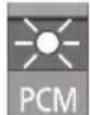
Changing the dual audio
Change the dual audio from main to secondary.

Confirm the digital audio output setting on the connected TV or player, etc. is set to "Bitstream".

Press and hold [TV] for more than 2 sec.

While the indicator of the current setting is blinking, press [TV] to change the setting.
- The indicator for the current setting blinks for 10 sec.

A : Main
B : Secondary
A, B : Main and secondary
- The setting works only when the dual audio is available in the audio source.
• The setting is maintained until it is changed again. - The same setting is used for all digital audio sources.
Auto gain control
With this function, you can prevent sudden loud sounds. The output will be reduced automatically when the input exceeds a certain level.

Press and hold [INPUT SELECTOR] on remote controller for more than 2 sec.
- The indicator for the current setting blinks for 10 sec.

Dolby Digital indicator blinks: Auto gain control is on.

PCM indicator blinks: Auto gain control is off.

While the indicator is blinking, press [INPUT SELECTOR] to change the setting.
- The setting changes each time [INPUT SELECTOR] is pressed.
• The setting is maintained until it is changed again. - Default setting of this function is OFF.
Bluetooth® communication mode
You can select different modes to suit the type of connections which emphasis on connectivity or high quality audio.
- Make sure that a Bluetooth device is already paired with this unit. ( ⇒ 22)

Disable the Bluetooth ® connection of the device.

indicator will blink slowly.

Press [LINK MODE, 📋 to display the current mode.
- The indicator for the current setting blinks for 10 sec.

MODE1: (Factory preset) Emphasis on connectivity

MODE2: Emphasis on audio quality

While the mode is displayed, press [LINK MODE, R to select the mode.
- The setting changes each time [LINK MODE] is pressed.
- The setting is maintained until it is changed again.
To turn off the 3D surround effect and clear-mode dialog effect
Depending on your preference, It is possible to use only the Dolby Virtual Speaker effect by turning off the 3D surround effect and the clear-mode dialog effect.

Press and hold [TV] on the remote control and followed by [VOL+] on the main unit for more than 2 sec.
- The indicator for the current setting blinks for 10 sec.

Dolby Digital indicator blinks: 3D surround effect and clear-mode dialog effect is on.

PCM indicator blinks: 3D surround effect and clear-mode dialog effect is off.

While the indicator is blinking, press [TV] to change the setting.
• The setting changes each time [TV] is pressed.
- This setting will be reset to on when this system is turned off.
- When off is selected, the dialog effect level cannot be adjusted.
Auto standby function
With this function turned on, this unit can be set to automatically switch to standby mode if there is no signal input and no operation is performed for 2 hours.

Press and hold [INPUT SELECTOR] on the main unit for more than 2 sec.
- The indicator for the current setting blinks for 10 sec.
![PANASONIC SC-HTB550 - Press and hold [INPUT SELECTOR] on the main unit for more than 2 sec. - 1](/content/2026/06/1236457/images/714acf806ecddea2a2ad3f8c93bf773f95e1200e2424da90ccc10475293f9f46.jpg)
Dolby Digital indicator blinks: Auto standby function is on.
![PANASONIC SC-HTB550 - Press and hold [INPUT SELECTOR] on the main unit for more than 2 sec. - 2](/content/2026/06/1236457/images/64938610f06c0db4d3465872828c78857039c0d69d24e1c8782d3bf9da8cc2d6.jpg)
PCM indicator blinks: Auto standby function is off.
![PANASONIC SC-HTB550 - Press and hold [INPUT SELECTOR] on the main unit for more than 2 sec. - 3](/content/2026/06/1236457/images/1468c57b5e41b1f64910dc648d21d2c60e177f57cfb16b614443bceaf0dc2100.jpg)
While the indicator is blinking, press [INPUT SELECTOR] to change the setting.
- The setting changes each time [INPUT SELECTOR] is pressed.
Others
The following settings are unnecessary under general usage conditions of the system.
■ Remote control code
When other Panasonic devices respond to this system's remote control, change the remote control code on the main unit and the remote control.
Preparation
- Turn off all other Panasonic products.
- Turn on the main unit.
Change the remote control code to code 2:
1 Aim the remote control at this system's remote control sensor.
2 Press and hold [MUTE] and [ ] on the remote control for more than 4 sec.
- All the indicators will blink for 10 sec when the code of this system is changed.

- The setting is maintained until it is changed again.

- If this system does not operate after changing the code, repeat steps 1 and 2.
- To change the remote control code to code 1, repeat the steps above, but replace [✗] with [TV].
■ To reduce the clear-mode dialog effect
When the dialog does not sound natural while the volume is set low, for example, It is possible to reduce the dialog enhancing effect as follows:
Press and hold [TV] on the remote control and followed by [-VOL] on the main unit for more than 2 sec.
- All the indicators will blink once when the clear-mode dialog effect is reduced.

- Even if clear-mode dialog effect is reduced, dialog effect level is still adjustable.
■ To turn off VIERA Link "HDAVI Control"
When "HDAVI Control" compatible equipment does not work well with this system, for example, it is possible to turn off this function as follows:
- When VIERA Link is turned off the ARC function is not available. Be sure to connect the optical digital audio cable. ( ⇒ 19)
1 Press and hold [MUTE] on the remote control and followed by [- VOL] on the main unit for more than 2 sec.
2 After the setting has changed, turn off all the connected devices and then turn them on again.
- All the indicators will blink once when VIERA Link "HDAVI Control" is turned off.
■ To turn off the volume limitation
If a state of the lowered volume disturbs you every time this system turns on, for example, it is possible to turn off this function as follows:
Press and hold [MUTE] on the remote control and followed by [VOL+] on the main unit for more than 2 sec.
- All the indicators will blink once when the volume limitation is turned off.


The settings of the clear-mode dialog effect, VIERA Link "HDAVI Control", and the volume limitation remain intact even if you switch this system to standby mode. To turn these 3 functions back on, this system must be set back to the factory preset. ( ⇒ 28)
Troubleshooting
Before requesting service, make the following checks. If you are in doubt about some of the check points, or if the solutions indicated in the following guide do not solve the problem, consult your dealer for instructions.
To return to the factory preset.
While the main unit is on, press [⏻/l] on the main unit for more than 4 sec.
(All the indicators will blink twice when the main unit is reset.)
If the system does not operate as expected, returning the settings to the factory preset may solve the problem.
- The remote control code will return to "1" when the main unit is returned to the factory preset. To change the remote control code, refer to page 27.
General operation
No power.
- Insert the AC mains lead securely. (→ 21)
- After turning the main unit on, if the indicators blink and the main unit immediately turns off, unplug the AC mains lead and consult your dealer.
The remote control does not work properly.
- The battery is depleted. Replace it with a new one. (⇒ 7)
- It is possible that the insulation sheet has not been removed. Remove the insulation sheet. ( ⇒ 7)
- It may be necessary to set the code of the remote control again after changing the battery of the remote control. ( ⇒ 27)
- Use the remote control within the correct operation range. ( ⇒ 7)
The "TV" indicator blinks.
Remove the AC mains lead and consult your dealer. If there are any other indicators blinking, be sure to inform your dealer about the blinking indicators.
The main unit is automatically switched to standby mode.
The auto standby function is on.
The main unit will automatically switch to standby mode when no signal is input and no operation is performed for approx. 2 hours. Refer to page 27 to turn this function off.
The main unit is turned off when the TV's speakers are selected in the speaker control.
This is a normal feature when using VIERA Link (HDAVI Control 4 or later). Please read the operating instructions for the TV for details about its power save feature. ( ⇒ 25)
HDMI
This system does not operate correctly.
If the HDMI cable is connected to the wrong terminal (HDMI IN or HDMI OUT), this system will not operate correctly. Turn the main unit off, disconnect the AC mains lead and reconnect the HDMI cable(s). ( ⇒ 19, 20)
VIERA Link related operations no longer function properly.
- Check the VIERA Link setting on the connected devices.
- Have you turned the VIERA Link settings off? (→ 27)
- When the HDMI connections are changed, after a power failure or after the AC mains lead has been removed, VIERA Link operations may not function properly.
- Turn on all the devices that are connected to the TV with an HDMI cable and then turn the TV on.
- Turn off the VIERA Link settings of the TV and turn it on again. For details refer to the operating instructions for the TV.
- While this system and the TV are connected with the HDMI cable, turn on the TV and then remove the main unit's AC mains lead and reconnect it again.
The first few seconds of audio cannot be heard when using the HDMI connection.
This may occur during DVD-Video chapter playback. Change the digital audio output setting on the connected device from "Bitstream" to "PCM".
When operating an HDMI compatible device of a different brand, the main unit reacts in an unwanted manner.
HDAVI Control commands may use a different signal depending on the brand of the device. In this case, turn VIERA Link off. ( ⇒ 27)
Bluetooth®
Pairing cannot be done.
Check the Bluetooth ® device condition.
The device cannot be connected.
- The pairing of the device was unsuccessful. Try pairing the device again.
- The pairing of the device has been replaced. Pair the device again. ( ⇒ 22)
- The system might be connected to a different device. Disconnect the other device and try pairing the device again.
The device is connected but audio cannot be heard through the system.
For some built-in Bluetooth ® devices, you have to set the audio output to “SC-HTB550” manually. Read the operating instructions for the device for details.
Sound from the device is uneven.
- The device is out of the 10 m communication range. Bring the device closer to the main unit.
- Remove any obstacle between the main unit and the device.
- Switch off any wireless LAN device.
- Select "MODE1" for stable communication. (→ 26)
Sound
No sound (or image).
- Turn muting off. (→ 23)
- Check the connections to the other devices. ( ⇒ 19, 20)
- Make sure that the received audio signal is compatible with this system. ( ⇒ 31)
- Turn this system off and then on again.
- If this system is connected to the TV with only an HDMI cable, make sure that the TV's HDMI terminal is labelled "HDMI (ARC)". If not, connect using the optical digital audio cable. ( ⇒ 19)
- If this system is connected to a Panasonic TV and turned on using the button on the main unit or the remote control, sound might not be output from this system. In this case, turn the main unit on using the TV's remote control. ( ⇒ 25)
- If the connections are correct, there might be a problem with the cables. Redo the connections with different cables.
- Check the audio output settings on the connected device.
- If the AUX1 indicator flashes and there is no audio output, try the following.
① Turn the connected device off and then on.
② Turn off this system, remove the HDMI cable, then reconnect the HDMI cable and turn this system back on.
The dual audio cannot be changed from main to secondary.
If the audio received from the connected device is not "Dolby Dual Mono" or the output setting is not "Bitstream", the setting cannot be changed from this system. Change the setting on the connected device.
The volume is lowered when this system is turned on.
If the main unit is turned off with the volume setting in the greater half (above 50), the main unit will automatically lower the volume to the middle (50) when the main unit is turned on. ( ⇒ 27)
The dialog is too persistent or the dialog does not sound natural.
This system has a function to make the dialog stand out when the volume is low. ( ⇒ 27)
There is no audio.
The power of the main unit turns off automatically.
(When the main unit detects a problem, a safety measure is activated and the main unit automatically switches to standby mode.)
- There is a problem with the amplifier.
- Is the volume extremely high? If so, lower the volume.
- Is this system placed in an extremely hot place? If so, move this system to a cooler place and wait a few moments and then try to turn it on again.
If the problem persists, confirm the TV indicator and AUX1 indicator blink, turn the system off, remove the AC mains lead and consult your dealer. Please be sure to remember the indicators that were blinking and inform the dealer.
Active Subwoofer
No power.
Ensure the AC mains lead of the active subwoofer is connected properly.
After turning the subwoofer on, it immediately turns off.
Unplug the AC mains lead and consult your dealer.
No sound from the subwoofer.
- Check that the active subwoofer is turned on.
- Check that the wireless link indicator lights green. ( ⇒ 22)
The wireless link indicator lights red.
- There is no link between this unit and the active subwoofer.
- Check that this unit is turned on.
- Turn the active subwoofer off and then back on. Alternatively, turn the active subwoofer off, disconnect the AC mains lead and then reconnect it.
- The active subwoofer and the main unit may not be paired correctly. Try the following operation. (Wireless pairing)
① Turn on the main unit and active subwoofer.
② Press [ID SET] on the rear of the active subwoofer. (The WIRELESS LINK indicator will light red and green alternately.)
③ Press and hold [INPUT SELECTOR] on remote control and followed by [VOL +] on the main unit for more than 2 sec. (The BD/DVD indicator will blink and audio format indicators light up in sequence.) - When the wireless pairing is successful, BD/DVD indicator will stop flashing and WIRELESS LINK indicator lights green.
④ Turn the main unit off and on. - Consult your dealer if the problem persists.
Indicator illumination
The indicators display the condition of this system by flashing. The indicator patterns illustrated below are displayed during normal operational conditions. They do not refer to the indications of a problem. Refer to “Troubleshooting” ( ⇒ 28) if the indicators do not light up as illustrated below.
Indicator Description
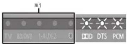
The indicators blink simultaneously.
- When "MUTE" is on (→ 23)

The BD/DVD indicator blinks ×2 and audio format indicators light up in sequence for 1 minute.
- When the main unit is in wireless pairing mode with the active subwoofer (⇒ 29)

The indicator blinks for 10 sec.
- When the dialog effect level or the subwoofer level is 1 (⇒ 23)
- When the audio output mode is Multi-channel mode ( ⇒ 24)
- When the dual audio setting is Main ( ⇒ 26)
- When the auto gain control is on (⇒ 26)
- When the Bluetooth communication is mode 1 ( ⇒ 26)
- When 3D surround effect and clear-mode dialog effect are on (→ 26)
- When the auto standby function is on (⇒ 27)

The indicators blinks for 10 sec.
- When the dialog effect level or the subwoofer level is 2 (→ 23)
- When the audio output mode is Auto mode ( ⇒ 24)
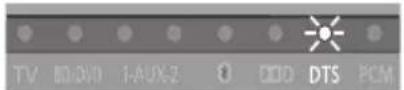
The indicator blinks for 10 sec.
- When the audio output mode is Auto mode (→ 24)

The indicators blinks for 10 sec.
- When the dialog effect level or the subwoofer level is 3 (⇒ 23)

The indicator blinks for 10 sec.
- When the dialog effect level or the subwoofer level is 4 ( ⇒ 23)
- When the audio output mode is 2ch mode ( ⇒ 24)
- When the dual audio setting is Secondary ( ⇒ 26)
- When the auto gain control is off (⇒ 26)
- When the Bluetoothcommunication is mode 2 (⇒ 26)
- When 3D surround effect and clear-mode dialog effect are off ( ⇒ 26)
- When the auto standby function is off ( ⇒ 27)

The indicators blink for 10 sec.
- When the dual audio setting is Main and Secondary ( ⇒ 26)
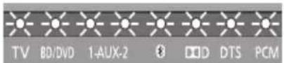
The indicators blink for 10 sec.
- When the remote control code is changed (→ 27)
The indicators blink once.
- When changing the setting ("To reduce the clear-mode dialog effect", "To turn off VIERA Link "HDAVI Control"', and "To turn off the volume limitation") ( ⇔ 27)

Bluetooth® indicator blinks quickly.
- When the main unit is ready for pairing
Bluetooth® indicator blinks slowly.
- When the main unit is waiting to connect
Bluetooth® indicator turns on.
- When the main unit is connected with a Bluetooth device
※1 The selected source indicator will also light.
※2 The BD/DVD indicator stops blinking and lights once the wireless pairing is successful.
Specifications
AMPLIFIER SECTION
RMS output power
10 % total harmonic distortion
Subwoofer ch
120 W per channel (100 Hz, 8 Ω)
Front ch (L, R ch)
60 W per channel (1 kHz, 6 Ω)
Total RMS Dolby Digital mode power
240 W
WIRELESS SECTION
Wireless module
Frequency Range 5.180 GHz to 5.240 GHz
Number of channels 4
Restriction of use For indoor use only
TERMINAL SECTION
HDAVI Control
This unit supports "HDAVI Control 5" function.
HDMI AV input (BD/DVD, AUX1) 2
Input connector Type A (19 pin)
HDMI AV output (TV (ARC)) 1
Output connector Type A (19 pin)
Digital audio input
Optical digital input (TV, AUX2) 2
Sampling frequency
32 kHz, 44.1 kHz, 48 kHz
88.2 kHz, 96 kHz (only LPCM)
Audio format
LPCM, Dolby Digital, DTS
SPEAKER SECTION
Front speakers
2 way, 2 speaker system (Bass reflex type)
Speaker unit(s) Impedance 6 Ω
Woofer 6.5 cm cone type×1
Tweeter 2.5 cm semi-dome type×1
Frequency range 100 Hz to 30 kHz (-16 dB)
150 Hz to 25 kHz (-10 dB)
Active subwoofer
1 way, 1 speaker system (Bass reflex type)
Woofer 16 cm cone type×1
Frequency range 30 Hz to 180 Hz (-16 dB)
35 Hz to 160 Hz (-10 dB)
GENERAL
Power consumption Main unit: 33 W
Active subwoofer: 23 W
In standby condition Main unit: Approx. 0.2 W
Active subwoofer: Approx. 0.2 W
Power supply AC 220 V to 240 V, 50 Hz
Dimensions (W×H×D)
Main unit
Cabinet dimension
310 mm×44 mm×195 mm
Maximum outer dimension
310 mm×45 mm×202 mm
Active subwoofer
Main unit Approx. 1.1 kg
Active subwoofer Approx. 5.2 kg
Operating temperature range
0°C to +40°C
Operating humidity range
20 % to 80 % RH (no condensation)
SPEAKER GENERAL
Horizontal placement using the stands
Dimensions (W×H×D)
956 mm×102 mm×74 mm
Mass 1.61 kg
Horizontal placement using the speaker feet and the support legs
Dimensions (W×H×D)
956 mm×78 mm×55 mm
Mass 1.57 kg
Horizontal placement (for wall mount)
Dimensions (W×H×D)
956 mm×75 mm×35 mm
Mass 1.54 kg
Vertical placement using the speaker bases
Dimensions (W×H×D)
148 mm×528 mm×145 mm
Mass 0.88 kg
Vertical placement (for wall mount)
Dimensions (W×H×D)
75 mm×478 mm×35 mm
Mass 0.77 kg
Bluetooth® system specification
V2.1 + EDR
Wireless equipment classification
Class 2 (2.5 mW)
Supported profiles
A2DP, AVRCP
Frequency band
2402 MHz to 2480 MHz
(Adaptive Frequency Hopping)
Operating distance
10 m Line of Sight

1 Specifications are subject to change without notice.
2 Weight and dimensions are approximate.
3 Total harmonic distortion is measured by a digital spectrum analyzer.
Unit care
■ Clean the system with a soft, dry cloth
- When dirt is heavy, wring a cloth moistened in water tightly to wipe the dirt, and then wipe it with a dry cloth.
- When cleaning the system, use a fine cloth. Do not use tissues or other materials (towels, etc.) that can fall apart. Small grains may get stuck inside the speaker cover.
- Never use alcohol, paint thinner or benzine to clean the system.
- Before using chemically-treated cloth, carefully read the instructions that came with the cloth.
Licenses
Manufactured under license from Dolby Laboratories. Dolby, Pro Logic, and the double-D symbol are trademarks of Dolby Laboratories.
Manufactured under license under U.S. Patent Nos: 5,956,674; 5,974,380; 6,487,535 & other U.S. and worldwide patents issued & pending.
DTS, the Symbol, & DTS and the Symbol together are registered trademarks & DTS Digital Surround and the DTS logos are trademarks of DTS, Inc. Product includes software.
© DTS, Inc. All Rights Reserved.
HDMI, the HDMI Logo, and High-Definition Multimedia Interface are trademarks or registered trademarks of HDMI Licensing LLC in the United States and other countries.
HDAVI Control™ is a trademark of Panasonic Corporation.
The Bluetooth ® word mark and logos are owned by the Bluetooth SIG, Inc. and any use of such marks by Panasonic Corporation is under license. Other trademarks and trade names are those of their respective owners.
About Bluetooth®
Panasonic bears no responsibility for data and/or information that is compromised during a wireless transmission.
■ Frequency band used
This unit uses the 2.4 GHz frequency band.
■ Certification of this device
- This system conforms to frequency restrictions and has received certification based on frequency laws. Thus, a wireless permit is not necessary.
- The action below are punishable by law in some countries:
— Taking apart or modifying the unit.
– Removing specification indications.
■ Restrictions of use
- Wireless transmission and/or usage with all Bluetooth equipped devices is not guaranteed.
- All devices must conform to standards set by Bluetooth SIG, Inc.
- Depending on the specifications and settings of a device, it can fail to connect or some operations can be different.
- This system supports Bluetooth security features. But depending on the operating environment and/or settings, this security is possibly not sufficient. Transmit data wirelessly to this system with caution.
- This system cannot transmit data to a Bluetooth device.
■ Range of use
Use this device at a maximum range of 10 m.
The range can decrease depending on the environment, obstacles or interference.
■ Interference from other devices
- When other devices use the same frequency as this system, this system may operate incorrectly or the sound may be distorted.
- To prevent interference from other devices:
- Keep the system away from other devices that emit radio frequency interference.
- Do not use this system and a wireless LAN device at the same time. Switch off any wireless LAN device.
■ Intended usage
- This unit is for normal, general use only.
- Do not use this system near an equipment or in an environment that is sensitive to radio frequency interference (example: airports, hospitals, laboratories, etc).
Declaration of Conformity (DoC)
Hereby, "Panasonic Corporation" declares that this product is in compliance with the essential requirements and other relevant provisions of Directive 1999/5/EC.
Customers can download a copy of the original DoC to our R&TTE products from our DoC server:
http://www.doc.panasonic.de
Contact to Authorised Representative: Panasonic Marketing Europe GmbH,
Panasonic Testing Centre, Winsbergring 15, 22525 Hamburg, Germany
This product is intended to be used in the following countries. SC-HTB550EB: GB, IE
SC-HTB550EG: AT, BE, BG, CH, CY, CZ, DE, DK, EE, ES, FI, FR, GR, HU, IS, IT, LT, LU, LV, MT, NL, NO, PL, PT, RO, SE, SI, SK
This product is intended for general consumer. (Category 3)
Suomi
Panasonic Testing Centre, Winsbergring 15, 22525 Hamburg, Germany
These symbols on the products, packaging, and/or accompanying documents mean that used electrical and electronic products and batteries should not be mixed with general household waste.
For proper treatment, recovery and recycling of old products and used batteries, please take them to applicable collection points, in accordance with your national legislation and the Directives 2002/96/EC and 2006/66/EC.
By disposing of these products and batteries correctly, you will help to save valuable resources and prevent any potential negative effects on human health and the environment which could otherwise arise from inappropriate waste handling.
For more information about collection and recycling of old products and batteries, please contact your local municipality, your waste disposal service or the point of sale where you purchased the items.
Penalties may be applicable for incorrect disposal of this waste, in accordance with national legislation.

For business users in the European Union
If you wish to discard electrical and electronic equipment, please contact your dealer or supplier for further information.
[Information on Disposal in other Countries outside the European Union]
These symbols are only valid in the European Union. If you wish to discard these items, please contact your local authorities or dealer and ask for the correct method of disposal.
![PANASONIC SC-HTB550 - [Information on Disposal in other Countries outside the European Union] - 1](/content/2026/06/1236457/images/09f4164dbe75a048a7d843bcd179106b33926842659edbfd2a5f38191f2f007d.jpg)
Note for the battery symbol (bottom two symbol examples):
This symbol might be used in combination with a chemical symbol. In this case it complies with the requirement set by the Directive for the chemical involved.
Safety information for customers in Norway
NORSK
ADVARSEL FORSIKTIG
Produkt
For the United Kingdom and Ireland customers
Sales and Support Information
Customer Communications Centre
• For customers within the UK: 0844 844 3899
- For customers within Ireland: 01 289 8333
- For further support on your product, please visit our website:
www.panasonic.co.uk
Direct Sales at Panasonic UK
- Order accessory and consumable items for your product with ease and confidence by phoning our Customer Communications Centre
Monday–Thursday 9:00 a.m.–5:30 p.m.,
Friday 9:30 a.m.–5:30 p.m. (Excluding public holidays) - Or go on line through our Internet Accessory ordering application at www.pas-europe.com.
- Most major credit and debit cards accepted.
● All enquiries transactions and distribution facilities are provided directly by Panasonic UK. - It couldn't be simpler!
- Also available through our Internet is direct shopping for a wide range of finished products. Take a browse on our website for further details.
EU
Pursuant to at the directive 2004/108/EC, article 9(2)
Panasonic Testing Centre
Panasonic Marketing Europe GmbH
Winsbergring 15, 22525 Hamburg, Germany
EU



- OPERATING INSTRUCTIONS HOME THEATER AUDIO SYSTEM
- SAFETY PRECAUTIONS
- WARNING CAUTION
- UNIT
- AC MAINS LEAD
- BUTTON-TYPE BATTERY (LITHIUM BATTERY)
- PLACEMENT
- CAUTION FOR AC MAINS LEAD
- (FOR THE UNITED KINGDOM AND IRELAND)
- CAUTION
- IMPORTANT
- WARNING: DO NOT CONNECT EITHER WIRE TO THE EARTH TERMINAL WHICH IS MARKED WITH THE LETTER E, BY THE EARTH SYMBOL
- THIS PLUG IS NOT WATERPROOF—KEEP DRY
- BEFORE USE
- HOW TO REPLACE THE FUSE
- TABLE OF CONTENTS
- GETTING STARTED
- OPERATIONS
- REFERENCE
- SUPPLIED ITEMS
- SYSTEM (SC-HTB550)
- ACCESSORIES
- [NON-TEXT]
- CONTROL REFERENCE GUIDE
- MAIN UNIT AND ACTIVE SUBWOOFER (FRONT)
- 1 STANDBY/ON SWITCH (⏻/I)
- MAIN UNIT AND ACTIVE SUBWOOFER (REAR)
- TO REPLACE A BUTTON-TYPE BATTERY
- REMOTE CONTROL OPERATION RANGE
- STEP 1 SELECTING THE PLACEMENT METHOD
- WHEN ATTACHING THE SPEAKERS TO A WALL
- WHEN PLACING THE SPEAKERS ON A TABLE
- SPEAKER SYSTEM
- WHEN PLACING THE SPEAKERS IN FRONT OF THE TV
- ACTIVE SUBWOOFER
- WIRELESS INTERFERENCE
- STEP 2 ASSEMBLING THE SPEAKERS
- PLACE THE SPEAKERS HORIZONTALLY
- ASSEMBLE THE SPEAKERS
- CONNECT THE SPEAKER CABLES
- DRIVE A SCREW INTO THE WALL
- FIT THE SPEAKER SECURELY ONTO THE SCREW(S)
- PLACE THE SPEAKERS VERTICALLY
- ATTACH THE FRONT ORNAMENTS
- FIT THE SPEAKER(S) SECURELY ONTO THE SCREW(S)
- PLACE THE SPEAKERS USING THE STANDS
- 1 ASSEMBLE THE SPEAKERS FOLLOWING STEPS 1 AND 2 OF “PLACE THE SPEAKERS HORIZONTALLY” ( ⇒ 10)
- 2 ATTACH THE STANDS
- PLACE THE SPEAKERS USING THE SUPPORT LEGS AND SPEAKER FEET
- 2 ATTACH THE SUPPORT LEGS AND SPEAKER FEET
- PLACE THE SPEAKERS USING THE SPEAKER BASES
- 1 ASSEMBLE THE SPEAKERS FOLLOWING STEP 1 OF “PLACE THE SPEAKERS VERTICALLY” ( ⇒ 12)
- 2 INSERT THE SPEAKER CABLE THROUGH THE BASE
- 3 ATTACH THE SPEAKER TO THE BASE
- ADDITIONAL SPEAKER FALL PREVENTION MEASURES
- HORIZONTAL PLACEMENT
- VERTICAL PLACEMENT
- STEP 3 CONNECTIONS
- HDMI
- CONNECTION WITH THE TV
- 1 VERIFY IF THE TV'S HDMI TERMINAL IS LABELLED "HDMI (ARC)
- WHAT IS ARC
- MAKE THE CONNECTION
- A LABELLED "HDMI (ARC)
- A HDMI CABLE
- B NOT LABELLED "HDMI (ARC)
- B OPTICAL DIGITAL AUDIO CABLE
- CONNECTION WITH OTHER DEVICES
- WHEN THE DEVICE HAS AN HDMI TERMINAL
- PREPARATION
- HDMI STANDBY PASS-THROUGH
- 3D COMPATIBILITY
- WHEN THE DEVICE HAS AN OPTICAL DIGITAL AUDIO OUTPUT TERMINAL
- SPEAKER CABLE CONNECTION
- AC MAINS LEAD CONNECTION
- FOR THE UNITED KINGDOM AND IRELAND
- SAVING ENERGY
- ACTIVE SUBWOOFER WIRELESS CONNECTION
- WIRELESS LINK INDICATOR LIGHTS
- BLUETOOTH® CONNECTION
- PAIRING A DEVICE
- PAIRING ADDITIONAL DEVICES
- USING THIS UNIT
- IF THE MAIN UNIT DOES NOT OPERATE AS EXPECTED OR SOUND IS UNUSUAL, RETURN THE SETTINGS TO THE FACTORY PRESET AND OPERATE THE SYSTEM AGAIN. ( ⇒ 28)
- 3D SOUND
- AUDIO OUTPUT MODES
- TO CHANGE THE AUDIO OUTPUT MODE
- 1 PRESS AND HOLD [MUTE] FOR MORE THAN 2 SEC
- 2 WHILE THE INDICATOR IS BLINKING, PRESS [MUTE] AGAIN TO CHANGE THE SETTING
- LINKED OPERATIONS WITH THE TV (VIERA LINK “HDAVI CONTROL™”)
- WHAT IS VIERA LINK "HDAVI CONTROL
- WHEN THE CONNECTION OR SETTINGS ARE CHANGED, REPEAT THIS PROCEDURE
- WHAT YOU CAN DO WITH VIERA LINK "HDAVI CONTROL
- SPEAKER CONTROL
- HOME CINEMA
- TV
- AUTOMATIC INPUT SWITCHING
- POWER OFF LINK
- AUTOMATIC LIP-SYNC FUNCTION
- ADVANCED OPERATIONS
- CHANGING THE DUAL AUDIO
- AUTO GAIN CONTROL
- BLUETOOTH® COMMUNICATION MODE
- TO TURN OFF THE 3D SURROUND EFFECT AND CLEAR-MODE DIALOG EFFECT
- AUTO STANDBY FUNCTION
- PRESS AND HOLD [INPUT SELECTOR] ON THE MAIN UNIT FOR MORE THAN 2 SEC
- WHILE THE INDICATOR IS BLINKING, PRESS [INPUT SELECTOR] TO CHANGE THE SETTING
- OTHERS
- THE FOLLOWING SETTINGS ARE UNNECESSARY UNDER GENERAL USAGE CONDITIONS OF THE SYSTEM
- REMOTE CONTROL CODE
- CHANGE THE REMOTE CONTROL CODE TO CODE 2
- TO REDUCE THE CLEAR-MODE DIALOG EFFECT
- TO TURN OFF VIERA LINK "HDAVI CONTROL
- TO TURN OFF THE VOLUME LIMITATION
- TROUBLESHOOTING
- TO RETURN TO THE FACTORY PRESET
- IF THE SYSTEM DOES NOT OPERATE AS EXPECTED, RETURNING THE SETTINGS TO THE FACTORY PRESET MAY SOLVE THE PROBLEM
- GENERAL OPERATION
- NO POWER
- THE REMOTE CONTROL DOES NOT WORK PROPERLY
- THE "TV" INDICATOR BLINKS
- THE MAIN UNIT IS AUTOMATICALLY SWITCHED TO STANDBY MODE
- THE MAIN UNIT IS TURNED OFF WHEN THE TV'S SPEAKERS ARE SELECTED IN THE SPEAKER CONTROL
- THIS SYSTEM DOES NOT OPERATE CORRECTLY
- VIERA LINK RELATED OPERATIONS NO LONGER FUNCTION PROPERLY
- THE FIRST FEW SECONDS OF AUDIO CANNOT BE HEARD WHEN USING THE HDMI CONNECTION
- WHEN OPERATING AN HDMI COMPATIBLE DEVICE OF A DIFFERENT BRAND, THE MAIN UNIT REACTS IN AN UNWANTED MANNER
- BLUETOOTH®
- PAIRING CANNOT BE DONE
- THE DEVICE CANNOT BE CONNECTED
- THE DEVICE IS CONNECTED BUT AUDIO CANNOT BE HEARD THROUGH THE SYSTEM
- SOUND FROM THE DEVICE IS UNEVEN
- SOUND
- NO SOUND (OR IMAGE)
- THE DUAL AUDIO CANNOT BE CHANGED FROM MAIN TO SECONDARY
- THE VOLUME IS LOWERED WHEN THIS SYSTEM IS TURNED ON
- THE DIALOG IS TOO PERSISTENT OR THE DIALOG DOES NOT SOUND NATURAL
- THERE IS NO AUDIO
- THE POWER OF THE MAIN UNIT TURNS OFF AUTOMATICALLY
- AFTER TURNING THE SUBWOOFER ON, IT IMMEDIATELY TURNS OFF
- NO SOUND FROM THE SUBWOOFER
- THE WIRELESS LINK INDICATOR LIGHTS RED
- INDICATOR ILLUMINATION
- INDICATOR DESCRIPTION
- THE INDICATORS BLINK SIMULTANEOUSLY
- THE BD/DVD INDICATOR BLINKS ×2 AND AUDIO FORMAT INDICATORS LIGHT UP IN SEQUENCE FOR 1 MINUTE
- THE INDICATOR BLINKS FOR 10 SEC
- THE INDICATORS BLINKS FOR 10 SEC
- THE INDICATORS BLINK FOR 10 SEC
- THE INDICATORS BLINK ONCE
- BLUETOOTH® INDICATOR BLINKS QUICKLY
- BLUETOOTH® INDICATOR BLINKS SLOWLY
- BLUETOOTH® INDICATOR TURNS ON
- SPECIFICATIONS
- AMPLIFIER SECTION
- WIRELESS SECTION
- TERMINAL SECTION
- SPEAKER SECTION
- GENERAL
- SPEAKER GENERAL
- UNIT CARE
- CLEAN THE SYSTEM WITH A SOFT, DRY CLOTH
- LICENSES
- ABOUT BLUETOOTH®
- FREQUENCY BAND USED
- CERTIFICATION OF THIS DEVICE
- RESTRICTIONS OF USE
- RANGE OF USE
- INTERFERENCE FROM OTHER DEVICES
- INTENDED USAGE
- DECLARATION OF CONFORMITY (DOC)
- SUOMI
- FOR BUSINESS USERS IN THE EUROPEAN UNION
- [INFORMATION ON DISPOSAL IN OTHER COUNTRIES OUTSIDE THE EUROPEAN UNION]
- NOTE FOR THE BATTERY SYMBOL (BOTTOM TWO SYMBOL EXAMPLES)
- SAFETY INFORMATION FOR CUSTOMERS IN NORWAY
- NORSK
- ADVARSEL FORSIKTIG
- PRODUKT
- FOR THE UNITED KINGDOM AND IRELAND CUSTOMERS
- SALES AND SUPPORT INFORMATION
- CUSTOMER COMMUNICATIONS CENTRE
- DIRECT SALES AT PANASONIC UK
- EU
Brand : PANASONIC
Model : SC-HTB550
Category : Home Theater System