PMR XTNiD - Talkie Walkie MOTOROLA - Free user manual and instructions
Find the device manual for free PMR XTNiD MOTOROLA in PDF.

User questions about PMR XTNiD MOTOROLA
0 question about this device. Answer the ones you know or ask your own.
Ask a new question about this device
Download the instructions for your Talkie Walkie in PDF format for free! Find your manual PMR XTNiD - MOTOROLA and take your electronic device back in hand. On this page are published all the documents necessary for the use of your device. PMR XTNiD by MOTOROLA.
USER MANUAL PMR XTNiD MOTOROLA
Motorola, the Stylized M Logo, and all other trademarks indicated as such herein are Trademarks of Motorola, Inc. Reg. U.S. Pat. & Tm. Off. © 2007 Motorola, Inc. All rights reserved. Printed in the U.S.A.
CONTENTS
Contents 1
Computer Software Copyrights ..... 4
Safety 5
Product Safety and RF
Exposure Compliance 5
Batteries and Chargers Safety Information 6
Operational Safety Guidelines 7
Radio Overview 8
Parts of the radio 8
ON/OFF/Volume Knob 9
Microphone 9
Antenna. 9
Accessory Connector 9
Model Label. 9
LED Indicator 9
Side Buttons 10
The Lithium-Ion (Li-Ion) Battery ..... 10
Batteries and Chargers 12
Battery Features and Charging Options ..12
About the Li-Ion Battery .....12
Battery Recycling and Disposal .....13
Installing the Lithium-Ion (Li-Ion) Battery . 14
Removing the Lithium-Ion (Li-Ion) Battery. . 14
Alkaline Battery Pack (optional accessory). 15
Installing Alkaline Battery .....15
Removing Alkaline Batteries.....15
Power Supply, Adaptors and Drop-in Tray Charger....16
Installing Spring Action Belt Clip. . . . . .17
Battery Life Information .....17
Charging the Battery....19
Charging with the Drop-in Tray Single Unit Charger....19
Charging a Stand-Alone Battery.....20
Charging a Standard Battery .....20
Identifying the Drop-In Charger's Position
Before Charging Battery .....21
Charging a High Capacity Battery....22
Drop-in Tray Charger LED Indicators. 23
Estimated Charging Time 24
Charging a Radio and Battery Using a Multi-Unit Charger-MUC (Optional Accessory) 24
Getting Started 26
Turning radio ON/OFF 26
Adjusting volume 26
Reading the Display 26
Selecting a Channel 27
Talking and Monitoring. 27
Receiving a Call....27 Signal Strength Indicator and Channel Busy Indicators....28
Talk Range.... 28
Hands-Free Use/VOX 31
With Compatible VOX Accessories... 31
Hands Free without Accessories (iVOX). 32
Battery Save 32
Reset To Factory Defaults .....32
End of Transmission Tone (Roger Beep Tone) 33
Keypad Beeps 33
MENU Options ....33
Setting VOX / iVOX sensitivity .....34
Programming Features .....38
Entering Programming Mode.....38
Programming RX (Reception) Frequencies. 39
Programming RX (Reception) Codes (CTCSS/DPL) 39
Programming RX (Reception) Bandwidth .40
Programming Scramble L....41
Programming Maximum Number of Channels. 41
Programming Call Tones.....42
Programming Microphone Gain Level . . . .43
Programming Microphone Accessory Gain Level 44
Programming Scan List .....44
Programming Buttons 45
Editing Channel Alias Name 46
Nuisance Channel Delete 47
CPS (Computer Programming Software). 48
Bandwidth Select 48
Time-Out Timer 48
Battery Type Setting 49
Call Tones 49
Scramble.... 49
Cloning Radios.... 50
What to do if cloning fails 52
Troubleshooting.... 54
Use and Care 57
Frequency and Code Charts ..... 58
Motorola Limited Warranty 62
Warranty information 62
What Is Not Covered By The Warranty . . 62
Accessories 64
Audio Accessories 64
Battery 64
Carry Accessories 64
Software Applications .....64
Cables 64
Chargers 65
COMPUTER SOFTWARE COPYRIGHTS
The Motorola products described in this manual may include copyrighted Motorola computer programs stored in semiconductor memories or other media. Laws in the United States and other countries preserve for Motorola certain exclusive rights for copyrighted computer programs, including, but not limited to, the exclusive right to copy or reproduce in any form the copyrighted computer program. Accordingly, any copyrighted Motorola computer programs contained in the Motorola products described in this manual may not be copied, reproduced, modified, reverse-engineered, or distributed in any manner without the express written permission of Motorola.
Furthermore, the purchase of Motorola products shall not be deemed to grant either directly or by implication, estoppel, or otherwise, any license under the copyrights, patents or patent applications of Motorola, except for the normal non-exclusive license to use that arises by operation of law in the sale of a product.
SAFETY
PRODUCT SAFETY AND RF EXPOSURE COMPLIANCE

Before using this product, read the operating instructions and RF energy awareness information contained in the Product Safety and RF Exposure booklet enclosed with your radio.
ATTENTION!
This radio is restricted to occupational use only to satisfy FCC RF energy exposure requirements.
For a list of Motorola-approved antennas, batteries, and other accessories, visit the following website which lists approved accessories:
http://www.motorola.com/XTNi
BATTERIES AND CHARGERS SAFETY INFORMATION
This document contains important safety and operating instructions. Read these instructions carefully and save them for future reference.
Before using the battery charger, read all the instructions and cautionary markings on
- the charger,
-
the battery, and
• the radio using the battery. -
To reduce risk of injury, charge only the rechargeable Motorola-authorised batteries. Other batteries may explode, causing personal injury and damage.
- Use of accessories not recommended by Motorola may result in risk of fire, electric shock, or injury.
-
To reduce risk of damage to the electric plug and cord, pull by the plug rather than the cord when disconnecting the charger.
-
An extension cord should not be used unless absolutely necessary. Use of an improper extension cord could result in risk of fire and electric shock. If an extension cord must be used, make sure that the cord size is 18AWG for lengths up to 6.5 feet (2.0 m), and 16AWG for lengths up to 9.8 feet (3.0 m).
- To reduce risk of fire, electric shock, or injury, do not operate the charger if it has been broken or damaged in any way. Take it to a qualified Motorola service representative.
- Do not disassemble the charger; it is not repairable and replacement parts are not available. Disassembly of the charger may result in risk of electrical shock or fire.
- To reduce risk of electric shock, unplug the charger from the AC outlet before attempting any maintenance or cleaning
OPERATIONAL SAFETY GUIDELINES
- Turn the radio OFF when charging battery.
- The charger is not suitable for outdoor use. Use only in dry locations/conditions.
- Connect charger only to an appropriately fused and wired supply of the correct voltage (as specified on the product).
- Disconnect charger from line voltage by removing main plug.
-
The outlet to which this equipment is connected should be nearby and easily accessible.
-
Maximum ambient temperature around the power supply equipment must not exceed 40°C (104°F).
- Make sure the cord is located where it will not be stepped on, tripped over, or subjected to water, damage, or stress.
RADIO OVERVIEW
PARTS OF THE RADIO

text_image
Antenna LED Indicator Microphone ON/ OFF/ Volume Accessory Connector LED Indicator Model Label Use 'Menu' button to lock keypad Front Buttons Use /to scroll up/down through channels and menu setting Lithium-Ion Battery PTT (Push-to- Talk) Button SB1 - Monitor Button SB2 - Scan/ Nuisance Channel DeleteON/OFF/Volume Knob
Used to turn the radio ON or OFF and to adjust the radio's volume.
Microphone
Speak clearly into the microphone when sending a message.
Antenna
The radio's antenna is non-removable.
Accessory Connector
Used to connect compatible audio accessories.
Model Label
Indicate the model of the radio
LED Indicator
Used to give battery status, power-up status, radio call information and scan status.
Front Buttons
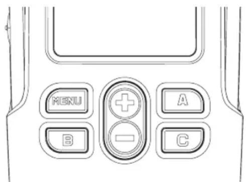
text_image
MENU A B C
This button gives you access to set up features like VOX/iVOX levels, battery type, etc. It also allows you to move through all the features while in Programming Mode

Allows you to scroll up/down the menu options or set up programming values. These buttons are not programmable buttons.
- Programmable Button
Default set to generate the current programmed call tone.
- Programmable Button
Default set to preset channel 1
- Programmable Button
Default set to preset channel 2
Note: A short press of either preset button (B or C) tunes the radio to the preset channel and the radio will play a good chirp. You can assign different functions to these buttons via the CPS. For example: Backlight Time Out, Reverse Burst, Power Select, Scan/Nuisance Channel Delete, Monitor and Call Tones. To learn more about how to program these buttons refer to “Entering Programming Mode” on page 38 and “CPS
(Computer Programming Software)" on page 48.
Side Buttons
- Push-to-Talk (PTT) Button
Press and hold down this button to talk, release it to listen.
- Side Button 1 (SB1)
The Side Button 1 is a general button that can be configured by the CPS. The default setting of the SB1 button is "Monitor".
- Side Button 2 (SB2)
The Side Button 2 is a general button that can be configured by the CPS. The SB2 button default setting is 'Scan/Nuisance Channel Delete'.
The Lithium-Ion (Li-Ion) Battery
XTNi™ Series provides different types of batteries. For more information, see "Battery Features and Charging Options" on page 12.
This User Guide covers multiple radio models, and may detail some features your radio does not have. The model number of the radio is shown on the front of the radio, underneath the
speaker, and tells you the following information:
| Model | Frequency Band | Transmit Power (Watts) | Number of Channels | Antenna |
| XTNiD | PMR446 | 0.5 | 8 | Non-removable |
BATTERIES AND CHARGERS
XTNi™ Series radios provide Lithium-Ion (Li-Ion) batteries that comes in different capacities that will define the battery life. It also offers the option to use Alkaline batteries. The radio comes equipped with a rapid charger.
BATTERY FEATURES AND CHARGING OPTIONS
About the Li-Ion Battery
The XTNi ^™ radio series come equipped with a rechargeable Li-Ion battery. This battery should be charged before initial use to ensure optimum capacity and performance.
Battery life is determined by several factors. Among the more critical are the regular overcharge of batteries and the average depth of discharge with each cycle. Typically, the greater the overcharge and the deeper the average discharge, the fewer cycles a battery will last. For example, a battery which is overcharged and discharged 100% several
times a day, lasts fewer cycles than a battery that receives less of an overcharge and is discharged to 50% per day. Further, a battery which receives minimal overcharging and averages only 25% discharge, lasts even longer.
Motorola batteries are designed specifically to be used with a Motorola charger and vice versa. Charging in non-Motorola equipment may lead to battery damage and void the battery warranty. The battery should be at about 77°F (25°C) (room temperature), whenever possible. Charging a cold battery (below 50°F [10°C]) may result in leakage of electrolyte and ultimately in failure of the battery. Charging a hot battery (above 95°F [35°C]) results in reduced discharge capacity, affecting the performance of the radio. Motorola rapid-rate battery chargers contain a temperature-sensing circuit to ensure that batteries are charged within the temperature limits stated above.
Battery Recycling and Disposal
Li-Ion rechargeable batteries can be recycled. However, recycling facilities may not be available in all areas. Under various U.S. state laws and the laws of several other countries, batteries must be recycled and cannot be disposed of in landfills or incinerators. Contact your local waste management agency for specific requirements and information in your area. Motorola fully endorses and encourages the recycling of Li-Ion batteries. In the U.S. and Canada, Motorola participates in the nationwide Rechargeable Battery Recycling Corporation (RBRC) program for Li-Ion battery collection and recycling.
Many retailers and dealers participate in this program. For the location of the drop-off facility closest to you, access RBRC's Internet web site at www.rbrc.com or call 1-800-8-BATTERY. This internet site and telephone number also provides other useful information concerning recycling options for consumers, businesses and governmental agencies.
Installing the Lithium-Ion (Li-Ion) Battery

text_image
battery latch slots- Turn OFF the radio.
- With the Motorola logo side up on the battery pack, fit the tabs at the bottom of the battery into the slots at the bottom of the radio's body.
- Press the top part of the battery towards the radio until a click is heard.
Note: To learn about the Li-Ion Battery Life features, refer to "About the Li-Ion Battery" on page 12.
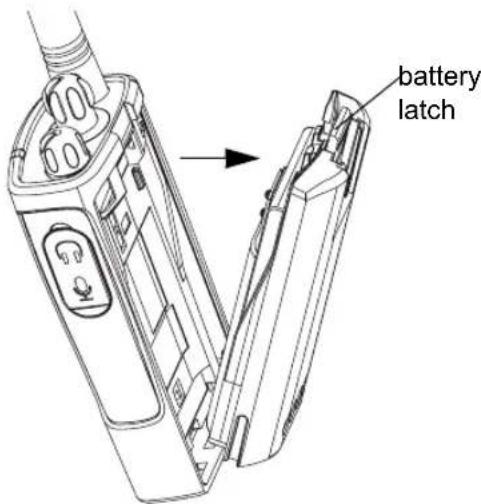
Removing the Lithium-Ion (Li-Ion) Battery
text_image
battery latch- Turn OFF the radio.
- Push down the battery latch and hold it depressed while removing the battery.
- Pull the battery away from the radio.
Alkaline Battery Pack (optional accessory) Installing Alkaline Battery
natural_image
Line drawing of a mobile phone with attached device and cable (no text or symbols)- Turn OFF the radio, if it is turned ON.
- Remove Li-Ion battery
- Assemble alkaline battery pack (optional accessory) in the same steps as installing the Li-Ion battery pack.
- Remove battery door from alkaline battery pack.
- Slide the 5 AA alkaline batteries into the frame, matching the markings inside the compartment.
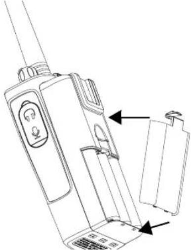
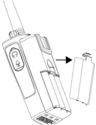
Removing Alkaline Batteries
natural_image
Line drawing of a walkie-talkie device with an arrow pointing to its side panel (no text or symbols present)- Turn OFF the radio, if it is turned ON.
- Slide the battery latches, on both sides of the battery, downwards.
- Pull the top of the battery away from the radio's body, and lift the battery from the radio's body.
Power Supply, Adaptors and Drop-in Tray Charger

natural_image
Line drawing of a mechanical housing or enclosure with internal components (no text or symbols)Drop-in Tray Charger
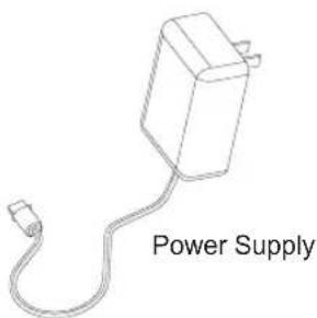
text_image
Power SupplyYour radio comes with one Drop-in Tray Charger, one Power Supply (also known as "transformer") and a set of adaptors.
Your power supply, has a "switchable" capability which allows to suit any of the adaptors that comes with your radio package. The adaptor you should choose to install depends on the region you're located.
Once you have identified the adaptor that matches your electrical outlet, proceed to install it as follows:
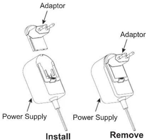
text_image
Adaptor Power Supply Install Adaptor Power Supply Remove- Slide down the adaptor grooves into the power supply until it snaps into place.
- Slide the adaptor upward to remove.
Note: The adaptor shown in the pictures are just for illustration purposes. The adaptor you should install may be different.
When acquiring additional chargers or power supplies, make sure you have similar drop-in tray chargers and power supplies set. For part number details refer to “Chargers” on page 65.
Installing Spring Action Belt Clip
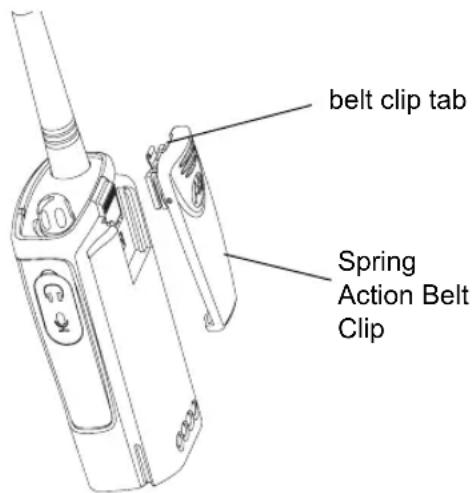
text_image
belt clip tab Spring Action Belt Clip-
Slide the spring action belt clip rails into the belt clip grooves on the back of the battery pack and slide it down until the belt clip tab snaps into place.
-
To remove, pull back the metal release tab on the belt clip tab and push the spring action belt clip upward to remove.
Battery Life Information
Li-Ion Battery Life
Depending on the radio model and/or region the battery capacity will be different. This feature will determine the estimated battery life. When the Battery Save feature is ON (enabled by default) the battery life will be longer.
The following chart summarizes battery life estimations:
Li-Ion Battery Life
| Li-Ion Battery Life with Battery Save feature ON | |
| Battery 0.5 Watt | |
| Standard 16 hours | |
| High Capacity 32 hours | |
Note: Battery life is estimated based on 5% transmit/ 5% receive/ 90% standby standard duty cycle.
Alkaline Battery Life
The following chart provides estimations about the Battery Life using the Alkaline Batteries:
| Alkaline Battery Life | |
| Battery Save Feature 0.5 | Watt |
| ON 35 hours | |
Note:
- Battery life are being estimated based on 5% transmit/ 5% receive/ 90% standby standard duty cycle.
Battery Meter
The battery meter located in the upper left corner of the display indicates how much battery power you have remaining.
 |
Charging the Battery
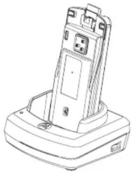
To charge the battery (with the radio attached), place it in a Motorola-approved Drop-in Tray Single Unit Charger or Drop-in Tray Multi-Unit Charger.
Charging with the Drop-in Tray Single Unit Charger
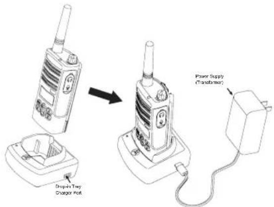
text_image
Drop-in Twy Charger Port Power Supply (Transformer)- Place the drop-in tray charger on a flat surface.
- Insert the connector of the power supply into the port on the side of the drop-in tray charger.
- Plug the AC adaptor into a power outlet.
- Insert the radio into the tray with the front of the radio facing the front of the charger, as shown.
Note: When charging a battery attached to a radio, turn the radio OFF to ensure a full charge. See "Operational Safety Guidelines" on page 7 for more information.
Charging a Stand-Alone Battery
natural_image
Line drawing of a mobile phone chassis with base and top casing (no text or symbols)To charge a battery whilst not attached to the radio - at step 4 above, insert the battery into the tray, with the inside surface of the battery facing the front of the charger, as shown.
Ensure the slots in the battery correctly engage in the charger.
Important: Ensure that the bracket in the charger is adjusted to the correct position for either Standard or High-capacity battery. See "Charging a Standard Battery" on page 20.
Charging a Standard Battery
The drop-in tray charger has a removable bracket that is adjustable depending on the type of battery that needs to be charged. It is designed to charge either the battery (with the radio) or a standalone battery. The drop-in tray charger comes by default set up to charge a standard battery. The following image on page page 21 shows the orientation for each battery:
Identifying the Drop-In Charger's Position Before Charging Battery
Adjustable bracket

natural_image
Diagram of a device interior with a labeled component (no text or symbols present)Standard
Adjustable bracket

natural_image
Diagram of a device interior with labeled ports and a circular symbol (no text or labels)High and Ultra High Capacity
Charging a High Capacity Battery
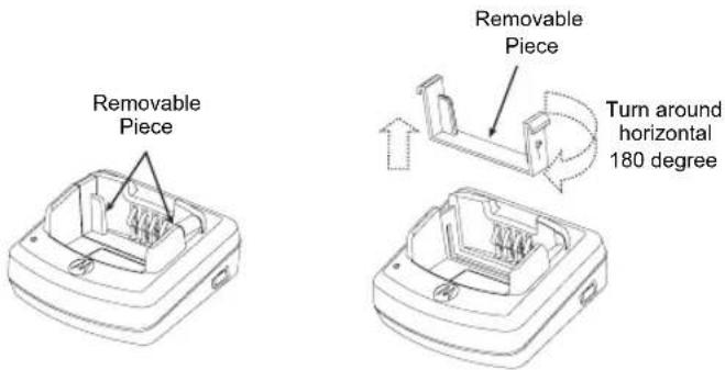
To convert the charger from the default setup to accommodate the high capacity:
- Squeeze both tabs on each side of the removable bracket in the drop-in charger tray carefully and lift the bracket from the charger tray.
-
Rotate the removable bracket 180 degrees and replace it by fitting it in the charger slot until it clicks. The label on the removable bracket should show "High & Ultra Capacity Battery" facing front of the charger.
-
Repeat same procedure to return position back to charging a Standard Battery. Label on the removable bracket should show "Standard Battery" facing front.
Note: Make sure the bracket is assembled correctly for both standalone battery and battery (with radio) to be properly charged.
Drop-in Tray Charger LED Indicators
| Standard Charger LED Indicator | ||
| Status LED | Status Comments | |
| Power ON | Steady red indication for 3 seconds | The charger has powered up |
| Charging Blinking | red (slow) The charger is currently charging | |
| Charging Complete | Steady red indication Battery is fully charged | |
| Battery Fault(*) Blinking red (fast) Battery had a fault when battery was inserted | ||
Notes:
• (*) Normally re-seating the battery pack will correct this issue.
- (**) Battery temperature is too warm or too cold or wrong power supply is being used
| Rapid Charger LED Indicator | ||
| Status LED | Status Comments | |
| Power ON | Steady green indication for 3 seconds | The charger has powered up |
| Charging Blinking | green The charger is currently charging | |
| Top-off Charging | Blinking green (slow) | Battery is near fully charged |
| Charge Complete | Steady green indication | Battery is fully charged |
| Battery Fault (*) | Blinking red (fast) | Battery has a fault when battery was inserted |
| Waiting to Charge (**) | Double-blink yellow indications | Battery charging conditions not suitable |
Notes:
- (*) Normally re-seating the battery pack will correct this issue.
- (***) Battery temperature is too warm or too cold or wrong power supply is being used
Estimated Charging Time
The following table gives the estimated times to charge the battery. For further details, see "Accessories" on page 64.
| Estimated Charging Time | ||
| Charging Solution | Battery Capacity | |
| Standard High | ||
| Rapid Charging Solution | 1.5 hours 3 hours | |
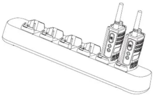
Charging a Radio and Battery Using a Multi-Unit Charger-MUC (Optional Accessory)
natural_image
Technical line drawing of a multi-pin electrical connector base (no text or symbols)The Multi-Unit Charger (MUC) allows drop-in charging of up to 6 radios or batteries.
Batteries can be charged with the radios or removed and placed in the MUC separately.
Each of the 6 charging pockets can hold a radio or battery, but not both.
- Place the charger on a flat surface.
- Insert the power cord plug into the jack on the MUC.
- Plug the cord into an AC outlet.
-
Turn the radio OFF.
-
Adjust the removable bracket for battery type, if necessary.
- Insert the radio or battery into the charging pocket.
Notes:
- This Multi-Unit Charger will also allow you to clone up to 3 radios (3 "Source" radios and 3 "Target" radios).
- When cloning, the MUC does not need to be plugged into a power source, but all radios require charged batteries. Further details on MUC's operation are explained in the Instructions Sheet provided with the MUC. Please refer to the Accessories section in order to identify the part number for ordering the MUC.
Notes:
- This Multi-Unit Charger will also allow you to clone up to 3 radios (3 "Source" radios and 3 "Target" radios).
- When cloning, the MUC does not need to be plugged into a power source, but all radios require charged batteries. Further details on how to clone units are explained in the Instructions Sheet provided with the MUC. Refer to the "Accessories" section in order to identify the part number for ordering the MUC.
Detailed information is available with the MUC operation instructions leaflet.
| MUC LED Indicator | ||
| Status LED Status Comments | ||
| Charging | Steady Red Indication | The charger is currently charging |
| Charge Complete | Steady Green Indication | Battery is fully charged |
| Battery Fault (*) | Red Fast Blinking | Battery had a fault when battery was inserted |
* Normally reseating the battery pack will correct the issue.
GETTING STARTED
For the following explanation refer to “Parts of the radio” on page 8.
Turn the ON/OFF/Volume Knob clockwise to turn ON the radio. The radio chirps and the LED briefly blinks red.
To turn the radio OFF rotate the ON/OFF/Volume Knob counterclockwise until you hear a "click" and the radio LED indicator turns OFF.
ADJUSTING VOLUME
Turn the ON/OFF/Volume Knob clockwise to increase the volume, or counterclockwise to decrease the volume.
Note: Do not hold the radio too close to your ear when adjusting the volume or if it is at a high volume setting.
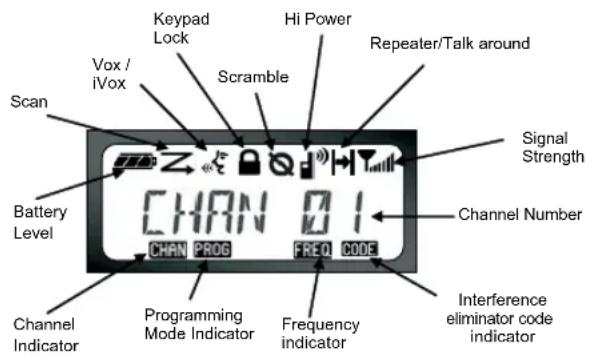
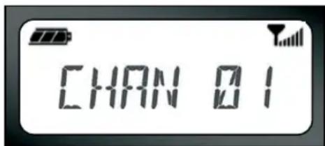
READING THE DISPLAY
text_image
Scan Battery Level Channel Indicator Keypad Lock Scramble Hi Power Repeater/Talk around Signal Strength Channel Number CHANNEL PROG FREQ CODE Programming Mode Indicator Frequency indicator Interference eliminator code indicatorNotes:
- The radio display shown here is for icon location only. Each radio display may appear different (channel and code) based on the pre-programmed radio defaults and features available in the model or region. Pressing any button, except the PTT button, will turn on the backlight.
- Repeater/Talk Around capability is not available for all Radio Models
SELECTING A CHANNEL
Your radio offers different number of conventional channels. To select a channel, press the + / buttons until you reach the desired channel.
Program each channel separately. Each channel has its own Frequency, Interference Eliminator Code and Scan Settings.
TALKING AND MONITORING
It is important to monitor for traffic before transmitting to ensure that you do not "talk over" someone who is already transmitting
To monitor, press and hold the SB1(*) button to access channel traffic. If no activity is present, you will hear "static". Press the SB1 button again to release.
Once channel traffic has cleared, proceed with your call by pressing the PTT button.
When transmitting, the radio LED will be solid red.
Note: In order to listen to all activity on a current channel, short press the SB1 in order to set the CTCSS/DPL code to 0. This feature is called "CTCSS/DPL Defeat (Squelch set to SILENT)".
(*) This assumes SB1 is not being programmed for a different mode.
RECEIVING A CALL
-
Select a channel by rotating the ON/OFF/Volume Knob and press the + /buttons until you reach the desired channel.
-
Make sure the PTT button is released and listen for voice activity.
-
The LED indicator blinks RED while your radio is receiving.
-
To respond, hold the radio vertically 1 to 2 inches (2.5 to 5cm) from your mouth. Press the PTT button to talk; release it to listen.
Note: Please notice that when the radio is receiving or transmitting, the LED is always red.
Signal Strength Indicator and Channel Busy Indicators
When there is activity on a frequency the radio displays the strength indicator icon 📁 while the radio LED blinks rapidly. The radio signal strength icon can change from 1 (weakest) to 6 (strongest) depending on the radio reception coverage. This can help determine when a radio is moving out of range.
Note: Obstacles that block the signal path may affect the strength of the incoming signal.
text_image
CHANNELTALK RANGE
XTNi™ Series radios have been designed to maximize performance and improve transmission range in the field. It is recommended that you do not use the radios closer than 1.5 meters apart, to avoid interference.
Talk range depends on the terrain. It will be affected by concrete structures, heavy foliage and by operating radios indoors or in vehicles.
Optimal range occurs in flat, open areas with up to 9 kilometres of coverage. Medium range occurs when buildings and trees are in the way. Minimal range occurs when dense foliage and mountains obstruct the communication path.
To establish proper two-way radio communication, the channel, frequency, and interference eliminator codes must be the same on both radios. This will depend on the stored profile that has been preprogrammed on the radio:
- Channel: Current channel that the radio is using, depending upon radio model.
- Frequency: The frequency your radio uses to transmit/receive.
-
Interference Eliminator Code: These codes help minimize interference by providing you with a choice of code combinations.
-
Scramble Code: Codes that make your transmissions sound garbled to anyone listening who is not set to that specific code.
-
Bandwidth: Some frequencies have selectable channel spacing, which must match other radios for optimum audio quality.
For details of how to set up frequencies and CTCSS/DPL codes in your channels, "Entering Programming Mode" on page 38.
RADIO LED INDICATORS
| RADIO STATUS LED INDICATION | |
| Channel Alias Edit Red heartbeat | |
| Channel Busy | Solid orange |
| Cloning Mode | Two orange heartbeats |
| Cloning In Progress | Solid orange |
| Fatal Error at Power up | One green blink, one orange blink, one green blink, then repeat for 4 seconds |
| Low Battery | Orange blink |
| Low Battery Shutdown | Orange heartbeat |
| Monitor | LED is OFF |
| Power-Up | Solid red for 2 seconds |
| ‘Idle’ Programming Mode / Channel Mode | Green heartbeat |
| Scan Mode | Red heartbeat) |
| Transmit (Tx)/Receive (RX) | Red heartbeat |
Note: Channel Alias Edit only applies to Display Models
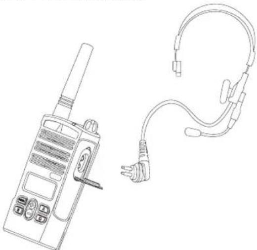
HANDS-FREE USE/VOX
natural_image
Line drawing of a walkie-talkie and a handheld ear device (no text or symbols)Motorola XTNi™ Series radios can operate hands-free (VOX) when used with compatible VOX accessories. A short delay occurs between when you start talking and the radio transmits.
With Compatible VOX Accessories
The default factory setting for VOX is OFF. In order to enable it, please make sure it is enabled by using the CPS (Computer Programming Software).
- Turn radio OFF.
- Open accessory cover.
- Insert plug of audio accessory firmly into accessory jack.
- Turn radio ON. Radio will beep and LED will blink double red. The display will show the VOX 📋 icon.
- Lower radio volume BEFORE placing accessory near ear.
- To transmit, speak into accessory microphone and to receive, stop talking.
- You can disable VOX operation by pressing M or removing the audio accessory.
Note: To order accessories, contact your Motorola dealer.
Hands Free without Accessories (iVOX)
- Enable iVOX by pressing the PTT button while turning the radio ON and the will
- iVOX operation can be temporarily disabled by pressing the PTT button.
- A short press of PTT will re-enable iVOX.
Note:
- The iVOX feature is available only on display models RDU2080d, RDV2080d.
- To learn how to set VOX/iVOX sensitivity levels please refer ahead to "Menu Options" in this same section.
- There is a short delay between when you start talking and when the radio transmits. To learn how to set VOX/iVOX sensitivity levels, please refer to "MENU Options" on page 33".
- Note: The iVOX feature is available only on display models XTNiD.
Battery Save
Battery Save feature extends the battery life as your radio goes into "idle" state each time there is no radio activity. To enable/disable, press SB1 and SB2 buttons simultaneously for 2 or 3 seconds while powering up the radio until you hear a quick series of beeps. To have a slightly better attack time, set "Battery Save" feature to OFF so that the radio is always ready to transmit or receive without any delays.
Note: Battery Save feature is set to ON by default
Reset To Factory Defaults
Reset to Factory Defaults will set back all radio features to the original factory default settings. To do so, press PTT, SB2 and SB1 simultaneously while turning ON the radio until you hear a high tone chirp beep.
End of Transmission Tone (Roger Beep Tone)
Short press the SB1 button while turning ON the radio to enable/disable End of Transmission Tone.
Note: This setting is set to OFF by default.
Keypad Beeps
Keypad Beeps can be enabled/disabled by short pressing SB2 button (until radio beeps a "chirp") while turning ON the radio.
Setting VOX/iVOX Sensitivity
The sensitivity of the radio's accessory or microphone can be adjusted during VOX/iVOX operation to suit different operating environments. VOX/iVOX sensitivity can be programmed via the CPS.
1 = Low sensitivity
2 = Medium sensitivity
3 = High sensitivity
Keypad Lock/Unlock
You can lock the keypad to avoid accidentally changing your radio settings. Press and hold MENU for 4 seconds to lock the radio keypad. To unlock, press MENU for 4 seconds.
Note: The only buttons that will be not locked using this feature will be PTT and Button A (if Call Tone feature has been assigned).

text_image
CHANNELMENU Options
To enter MENU, short press MENU button. The radio will take you to the next feature option.
For each feature, you can navigate with the Ⓕ /buttons. After selecting your desired settings, you can:
- press MENU to save and go to the next option
- long press the PTT button to save and exit or
- turn OFF radio to exit without saving changes.
When there is no activity for more than ten seconds, MENU mode will time out.
Setting VOX / iVOX sensitivity
The VOX/iVOX sensitivity can be adjusted via the MENU as well as the CPS. To modify via the MENU, first make sure you have enabled either VOX or iVOX. (See page 31). Once VOX/iVOX has been enabled, short press MENU.
If you have iVOX enabled and press MENU, your radio will display the following:

text_image
IVOXIf you have VOX enabled (with accessory connected) and press MENU, your radio will display the following:

text_image
IVOX 1 -To change the sensitivity level, use the /⊕ - buttons:
0 = OFF (For VOX accessories only)
1 = Low sensitivity (suitable for noisy environments)
2 = Medium sensitivity
3 = High sensitivity (suitable for quiet environments)
Once you have selected the value you want, press MENU again to go to the next step or turn OFF radio to exit without saving changes.
Battery Type Menu
Only if the battery pack is not detected, the radio will allow changes to the battery type setting from either Lithium-Ion or Alkaline. To change the setting, press the MENU button as many times as needed until the radio flashes the current battery type (either "LITHIUM" or "ALKALINE"). A full battery icon will be shown as follows:

text_image
- LITHIUM -Use the /buttons to choose wither "LITHIUM" and "ALKALINE". Once you have selected the value you want, press MENU again to save and go to the next step or turn
OFF radio to exit without saving changes. Battery Type can also be programmed using the CPS.
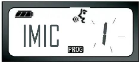
Microphone Gain Menu
The sensitivity of the microphone can be adjusted to fit different users or operating environments.
Press MENU buttons as many times as needed until the radio displays the solid letters "IMIC" on and blinks the current radio microphone gain. The VOX icon will be displayed:

text_image
IMIC PROG 1 -Press the toggle /+button to cycle through the microphone gain settings:
1 = Low gain,
2 = Medium gain
3 = High gain.
Once you have selected the value you want to set, press MENU again to save and go to the next step or turn the radio OFF to exit without saving changes. Microphone gain can be also be configured using CPS.
Accessory Microphone Gain
In the Accessory Microphone Gain Menu, you can configure the microphone gain level for the accessory.

text_image
MIC PROGPress MENU buttons as many times as needed until the radio displays the solid letters "MIC" on and blinks the current radio microphone gain.
The VOX icon will be displayed. Press the toggle up/down button to cycle through the microphone gain settings which are similar to the Microphone Gain Menu. Once you have selected the value you want to set (1=low gain,2=Medium gain or 3=high gain), press MENU again to save and go to the next step or turn the radio OFF to exit without saving changes. Microphone Accessory Gain can be also be configured using CPS.
Scan List Menu
Note: If the MAX CHAN setting in the radio is set up to 1 (which can be done using CPS) the Scan Menu will be disabled.
In Scan List Menu you can enable the Channel Scanning feature for a specific channel frequency for the radio. To enter Scan Menu, press MENU button as many times as needed until the radio display the channel number with the solid CHAN icon and blink the current setting "YES" or "NO". The SCAN icon will be also displayed solid:
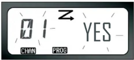
text_image
01 Z YES CHAN PROGPress the toggle /buttons to cycle through all the channels. Press SB2 button to set SCAN to "YES" or "NO" settings. Once you have selected the value you want to set, press MENU again to save and go to the next step or Turn OFF radio to exit without saving changes. Scan List Menu can be also be configured using CPS.
PROGRAMMING FEATURES
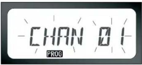
ENTERING PROGRAMMING MODE
To enter ‘Programming Mode’, press and hold both the PTT button and the SB1 button simultaneously for three seconds, while turning ON the radio. A unique tone will sound, indicating that the radio has entered ‘Programming Mode’ and the radio LED will blink a green heartbeat. Once the radio enters the ‘Programming Mode’, which defaults to ‘Idle’ Programming Mode, the radio LED will be blinking green heartbeat.
Whenever you enter 'Programming Mode' the PROG icon will be displayed and the current channel aliasing name will be blinking to indicate that you can select the channel you want to program. You can scroll up/down to
select the different channels by pressing the + / buttons.
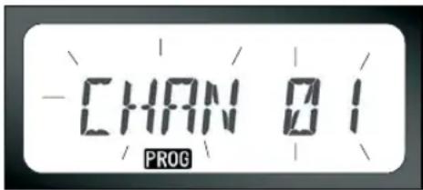
text_image
-CHAN 01 PROGIn 'Programming Mode' your radio is capable of setting values for each channel by moving between the different programming modes available: Frequencies, CTCSS/DPL codes (Interference Eliminator Code), Scramble, Bandwidth, Maximum Channels, Call Tone, Microphone Gain and Scan.
- To move along the different Programming Selection Modes without saving changes, short press the PTT or MENU buttons.
- To save changes, long press the PTT button. The radio will return to 'Idle'
Programming Mode.
- If you're in 'Idle' Programming Mode and wish to exit the 'Programming Mode', long press the PTT button (to be back to normal radio operation).
- Whenever you wrap around to the beginning of the Programming Mode options, your radio's changes will be automatically saved, even if you turn OFF the radio.
- You can exit any Programming Mode without saving changes (as long as you haven't wrapped around yet to the beginning) by turning the radio OFF.
PROGRAMMING RX (RECEPTION) FREQUENCIES
Once you have chosen the channel you want to program, short press the PTT button or MENU to scroll through the options until you reach 'Frequency Programming Mode'. The
radio display will show the frequency code as follows:
To program the desired frequency, scroll up/down with the ⭕ / buttons until you find the frequency code you need. Long press the PTT button to exit and save, or short press the PTT button to move to the next programming feature without saving.
PROGRAMMING RX (RECEPTION) CODES (CTCSS/DPL)
Once you have chosen the channel you want to program, short press the PTT button or

text_image
01 Rx 01 CHAN PROG FREQMENU to scroll through the options until you reach the 'Code Programming Mode'. The radio display will show the blinking CTCSS/DPL code as follows:.
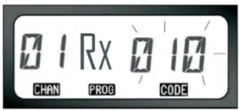
text_image
0.1 Rx 0.10 CHAN PROG CODETo program the desired code, scroll up/down with the ⊕ / buttons until you get the CTCSS/DPL code value you want to set up. Long press the PTT button to exit and save.
PROGRAMMING RX (RECEPTION) BANDWIDTH
Some frequencies have selectable channel spacing, which must match other radios for optimum audio quality.
Once you have chosen the channel you want to program, short press the PTT button or
MENU to scroll through the options until you reach the 'Bandwidth Programming Mode'. The radio display will show the current bandwidth setting as follows:
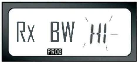
text_image
Rx BW PROG 311-To program the desired bandwidth (HI = 25Khz, LOW = 12.5 Khz), use the ⭕ / ⊖ buttons until to select the value. Long press the PTT button to exit and save or short press the PTT button to move to the next programming feature without saving.
Note: If the value of the bandwidth cannot be changed, the display setting remain solid.
PROGRAMMING SCRAMBLE
The scramble feature makes your transmissions sound garbled to anyone listening without the same scramble code. It doesn't guarantee confidentiality, but it adds an extra layer of privacy. Scramble default value is OFF.
Once you have entered 'Programming Mode' and selected the channel in which you want to enable scramble (Q), scroll up/down through the programming options by short pressing the PTT button, until your radio reaches the 'Scramble Programming Mode':
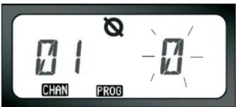
text_image
01 Q CHAN PROG 0The current scramble setting will blink. You can select the desired scramble value (0,1,2 or 3) by pressing the + / buttons. Long press the PTT button to exit and save or short press the PTT button to move to the next programming feature without saving.
Note: The values available for scrambling are dependent upon the values programmed via the CPS. When the scramble setting is "0" it means it is disabled.
PROGRAMMING MAXIMUM NUMBER OF CHANNELS
You can configure the maximum number of channels for the radio.
Once you have entered 'Programming Mode' scroll up/down by short pressing the PTT
button until you reach the 'Max Channel Programming Mode':.
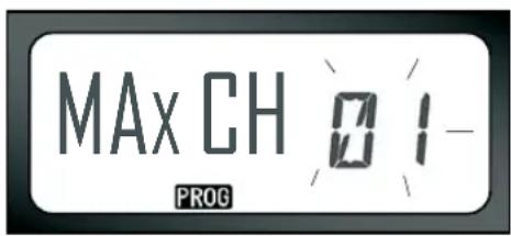
text_image
MAX CH 01- PROGThe radio display will blink the current maximum number of channels programmed. To program the maximum number of channels use the + / buttons until you locate the desired setting. Long press the PTT button to save and exit.
Note: The value settings available are dependent upon the maximum number of channels the radio supports.
English
PROGRAMMING CALL TONES
Call Tones will enable you to transmit to other radios in your group in such way that you can alert them that you are about to talk or alert them without speaking.
In ‘Call Tone Selection Mode’, you can configure the call tone type for the radio. The settings available will depend on the maximum number of call tones your radio supports.
To program call tones, enter 'Programming Mode' and scroll through the programming options until your display radio shows the Programming Call Tones selection:

text_image
TONE PROGThe current call tone setting will be blinking. You can select the desired call tone value
(0,1,2 or 3) by pressing the

buttons. Each time you select a different setting your radio will sound the call tone selected (except for setting "0"). Once you have selected the tone you want to program, long press the PTT button to exit and save or short press the PTT button to move to the next programming feature without saving
Note: The values available for call tones are dependent upon the values programmed via the CPS. When the call tone setting is "0" it means it is disabled.
PROGRAMMING MICROPHONE GAIN LEVEL
To configure the microphone gain level, enter 'Programming Mode' and scroll through the programming options by short pressing the PTT button. When you reach the 'Microphone Gain Level Programming Mode' the display will read as follows:
text_image
IMIC PROGThe current microphone gain level setting will blink. You can select the desired microphone gain level by pressing the ⭕ / buttons (1=low gain,2= Medium gain or 3= high gain). Once you have selected the gain level you want to program, long press the PTT button to exit and save or short press the PTT button to move to the next programming feature without saving.
Note: The values available for microphone gain level are dependent upon maximum levels the radio supports.
PROGRAMMING MICROPHONE ACCESSORY GAIN LEVEL
To configure the Accessory Microphone Gain Level, enter 'Programming Mode' and scroll through the programming options by short pressing the PTT button.

text_image
MIC PROGThe current accessory microphone gain level setting will be blinking. You can select the desired gain level (1=Low gain,2=Medium gain or 3=High gain) by pressing the ⊕ / ⏻ buttons. Once you have selected the gain level you want to program, long press the PTT button to exit and save or short press the PTT button to move to the next programming feature without saving.
Note: The values available for accessory microphone gain level are dependent upon maximum levels the radio supports.
PROGRAMMING SCAN LIST
You can enable/disable the Channel Scanning feature for each one of the channels in your radio. To do so, enter 'Programming Mode' and select the channel you want to program. Scroll through the programming options by short pressing the PTT button until you reach the 'Scan Programming Mode'. The radio display will show the scan icon Z as follows:

text_image
01 Z YES CHAN PROGBoth the channel number and current scan setting (YES=ON or NO=OFF) will be blinking
on the display, indicating that you can choose your setting. To set the channel number, press the ⭕ / buttons until you reach the desired channel number. Once you have selected the channel, proceed to enable ("YES") or disable ("NO") the scan feature by toggling the SB2 (*) button. Once you have set the values you need, long press the PTT button to save an exit.
Note: (*)This assumes the SB2 button is not being programmed for a different mode.
Note: If the MAX CHAN setting in the radio is set to 1, the Scan Programming option will not show (will be disabled).
PROGRAMMING BUTTONS
You can map any channel to either button B or C as a preset channel. To enable, enter 'Programming Mode' and choose the channel you want to set as preset channel using the
⊕ / buttons. Once you have selected your channel, press and hold the B or C button for 2-3 seconds.
A short press of either preset button (B and C) will play a good key chirp. When scanning, a short press of either preset button will change the home channel to the preset channel. The radio will display FREQ/PL and will continue to scan from the new home channel.
EDITING CHANNEL ALIAS NAME
To edit a channel's alias, turn ON the radio and press and hold the PTT button and the ⭕ / - buttons for 3 seconds. Upon entering the 'Channel Alias Mode', the radio will generate a special beep. You will see the current channel alias name and channel number blinking as follows:
text_image
CHAN 01 PROGChoose the channel number you want to edit by pressing the ⭕ / buttons. Once you have selected the channel number, press the PTT button or MENU to start editing the
channel name. If you want to exit the Channel Aliasing Mode long press the PTT button.
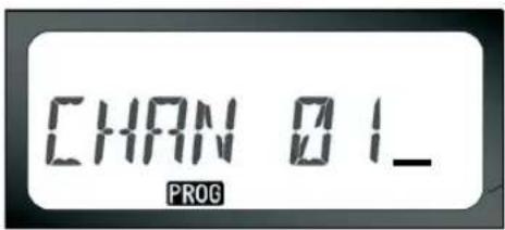
text_image
CHAN 01_ PROG- A cursor will blink at the end of the channel name. Use button B to move the cursor to the left. If you're in the first character, the radio will give you a bonk tone. Whenever you press button B and the cursor is positioned in a valid character, the button B will delete the current character and replace it with a blank space.
- Use the / buttons to change the current selected character to the next ASCII value in alphabetical order (from A to Z). The characters will be uppercase letters.
• To toggle character between uppercase
and lower case, press the A button. Note that the supported lower case characters are: b, c, d, g, h, i, l, o, r, u.
- Pressing the C button will allow you to insert special characters and numbers in the following order: 0 - 9 * {}? &%. + / - _ '. Character '' is a space character.
Long press the PTT button to save and go back to the 'Channel Aliasing Selection Mode' to choose other channel to edit the alias name or exit without saving changes by turning OFF the radio.
Note:
- If the channel alias name is left blank, the radio will play a bad key chirp and will stay in the editing menu mode until the channel name is edited and saved.
- When editing the channel alias name, if the radio is left idle after 3 seconds, the radio
will accept the existing character and advance the cursor one space to the right.
NUISANCE CHANNEL DELETE
Nuisance Channel Delete allows you to temporarily remove channels from the "Scan List". This feature is useful when irrelevant conversations on a "nuisance" channel tie up your radio's scanning features. To delete a channel from the scan list:
- Start "Scan Mode" by short pressing the SB2 button (*)
- Wait until the radio stops on the channel you wish to eliminate, then long press the SB2 button to delete it.
- The channel will be removed until you exit "Scan Mode" by pressing the SB2 button again or if radio is turned OFF.
Note: (*)Assumes the SB2 button is not programmed to another function different from the default.
CPS (COMPUTER PROGRAMMING SOFTWARE)

text_image
Radio to be programmed Drop-in Charger Tray Mini-connector USB Connector CPS Programming Cable CPS SoftwareXTNi™ Series radios have the capability to be programmed by using the CPS.
To do so, connect the radio via the Drop-in Charger Tray and CPS Programming Cable as shown in the picture above.
The CPS allows the user to program frequencies, PL/DPL codes, as well as other features such as: Direct Frequency Input, Repeater/Talk Around, Bandwidth Select, Time-out Timer, Power Select, Battery Type
Select, Scan List, Call Tones, Scramble, Reverse Burst etc.
CPS is a very useful tool as it can also lock the frontpanel radio programming or restrict any specific radio feature to be changed (to avoid preset radio values to be accidentally erased). It also provides security by giving the option to set up a password for profile radio's management.
Note: (*) CPS Programming Cable is an accessory sold separately. For part number information refer to the Accessories Section.
Bandwidth Select
Default setting for Bandwidth select is 12.5 KHz. Some frequencies have selectable channel spacing, which must match other radios for optimum audio quality.
Time-Out Timer
When pressing PTT button, transmissions can be terminated by setting up a 'time-out' timer. Radio can be programmed to turn the radio
"OFF" in either 60, 120 or 180 seconds. The "time-out" timer can also be disabled.
Battery Type Setting
The XTNi ^™ series radio can be powered by either Alkaline, Lithium-Ion cells or battery pack. The battery pack can be detected at power-up and the corresponding battery level will be shown on the radio's display.
Call Tones
See "Programming Call Tones" on page 42.
Scramble
See "Programming Scramble L" on page 41.
Note:
- The features described are just some of the features CPS has. There are many more capabilities that this software offers. For more information please refer to the HELP file in the CPS.
- Some of the features available with the CPS software will vary depending on the Radio Model.
CLONING RADIOS
You can copy XTNi™ Series radio profiles from one Source radio to a Target radio by using:
- One Multi Unit Charger (optional accessory)
-
T wo single unit chargers and a Radio-to-Radio cloning cable (optional accessory)
-
the C PS
Cloning with a Multi-Unit Charger (MUC)
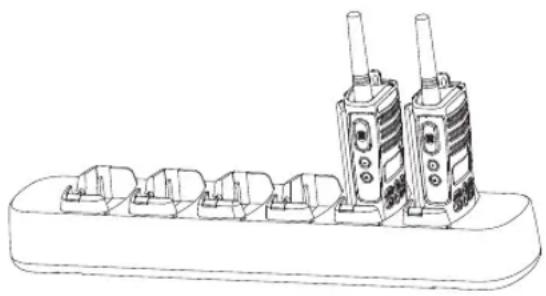
natural_image
Line drawing of a walkie-talkie rack with two speakers and multiple base stations (no text or symbols)To clone radios using the MUC, there must be at least two radios:
- a Source radio(radio to be cloned) and
- a Target radio (radio to which the configuration of the “source radio” will be copied or cloned)
The Source radio has to be in Pocket 1, 3 or 5 while the Target radio to be cloned has to be in Pockets 2, 4 or 6, matching the MUC's pockets by pairs as follows: 1 and 2 or 3 and 4 or 5 and 6.
When cloning, the MUC does not need to be plugged into a power source, but ALL radios require charged batteries.
Follow cloning instructions explained in pages 51-52 from step 4 through step 8 (take into account that when instructions refer to "SUC", this is equivalent in the MUC instructions to "pocket".
Further details on how to clone units are explained in the instructions sheet provided with the MUC.
To order the MUC, see “Chargers” on page 65 for the MUC part number.
| WARNING | Paired target radios and source radios must be of the same band (UHF or VHF), type (Display or non-Display) and region. |
Cloning Radio using the Radio to Radio (R2R) Cloning Cable (optional accessory)

natural_image
Line drawing of two walkieh machines connected by a cable (no text or symbols)Operating Instructions
-
Before beginning the cloning process, make sure you have:
-
A fully charged battery on each one of the radios.
- Two Single Unit Chargers (SUC).
- Turned OFF the radios and,
-
Both radios are of the same radio model.
-
Unplug any cables (power supply or USB cables) from the SUCs.
-
Plug one side of the cloning cable mini connector to one SUC. Plug the other end to the second SUC.
Note: During the cloning process no power is being applied to the SUC. The batteries will not be charged. A data communication is being established between the two radios.
-
Turn ON the Target radio and place it into one of the SUCs.
-
On the Source radio, power the radio following the sequence below:
-
Long press the PTT button and SB2 simultaneously while turning the radio ON.
-
Wait for 3 seconds before releasing the buttons until a distinctive audible tone is heard.
-
Place the Source radio" in its SUC, press and release SB1.
- After cloning is completed, the Source radio will sound either a “pass” tone (cloning was successful) or a “fail” tone (cloning process has failed). The ‘pass’ tone sounds like a good key ‘chirp’ whereas the ‘fail’ tone sounds similar to a ‘bonk’ tone. If the Source radio is a display model it will either show ‘Pass’ or ‘Fail’ on the display (a tone will be heard in no more than 5 seconds).
- Once you have completed the cloning process, turn the radios OFF and ON in order to exit 'clone' mode.
What to do if cloning fails
The radio will emit an audible ‘bonk’ indicating that the cloning process has failed. In the event that cloning fails, try performing each of the following before trying to start the cloning process again:
- Ensure that the batteries on both radios are fully charged.
- Check the cloning cable connection on both SUCs.
- Ensure that the battery is engaged properly on to the radio.
- Ensure that there is no debris in the charging tray or on the radio contacts.
- Ensure that the Source radio is in cloning mode.
- Ensure that the Target radio is turned ON.
- Ensure both radios are both from the same type. (same frequency band, same front panel (display/non display), same region and same transmission power).
Attention: This cloning cable is designed to operate only with compatible Motorola RLN6170 (Rapid) Single Unit Charger.
When ordering Cloning Cable please refer to P/N RLN6303. For details about accessories refer to "Accessories" section.
To order the CPS, see 'Software Applications on page 64' for the CPS part number.
Cloning Radios using the CPS (Computer Programming Software)
You will need to have the CPS, Drop-in Tray Charger and the CPS Programming Cable.
Information on how to clone using the CPS is available in the CPS Programming Cable Accessory Leaflet as well as the CPS Help menu.
Note: (*) CPS Programming Cable is an accessory sold separately. For part number information refer to the Accessories Section.
TROUBLESHOOTING
| Symptom Try this | |
| No Power | Recharge or replace Li-Ion battery. Replace or reposition AA batteries. Extreme operating temperatures affect battery life. Refer to "About the Li-Ion Battery" on page 12. |
| Hearing other noises or conversation on a channel | Confirm Interference Eliminator Code is set. Frequency or Interference Eliminator Code may be in use. Change Code on all radios if possible. |
| Message Scrambled | Scramble Code might be ON, and/or setting does not match other radios' settings. Refer to "Programming Scramble L" on page 41. |
| Limited talk range | Steel and/or concrete structures, heavy foliage, buildings or vehicles decrease range. Check for clear line of sight to improve transmission. Wearing radio close to body such as in a pocket or on a belt decreases range. Change location of radio. Refer to "Talking and Monitoring" on page 27. |
Symptom Try this
| Message not transmitted/received | Confirm radios have the same Channel, Frequency, Interference Eliminator Code and Scramble Code settings. Recharge, replace and/or reposition batteries. Refer to ""About the Li-Ion Battery" on page 12. Obstructions and operating indoors, or in vehicles, may interfere: change location. Refer to "Talking and Monitoring" on page 27. Verify that the radio is not in Scan mode. Refer to "Programming Scan List" on page 44 and "Nuisance Channel Delete" on page 47. |
| Heavy static or interference | Radios are too close, they must be at least five feet apart. Radios are too far apart or obstacles are interfering with transmission. Refer to "Talking and Monitoring" on page 27. |
| Low batteries | Recharge or replace Li-Ion battery. Replace AA batteries. Extreme operating temperatures affect battery life. Refer to "About the Li-Ion Battery" on page 12. |
| Drop-in Charger LED light does not come on | Check radio/battery is properly inserted and check battery/charger contacts to be sure they are clean and charging pin is inserted correctly. Refer to "Charging the Battery" on page 19, "Drop-in Tray Charger LED Indicators" on page 23 and "Installing the Lithium-Ion (Li-Ion) Battery" on page 14. |
| Low battery LED blinking although new batteries are installed | Verify that the radio is set to the correct battery type. Refer to "Installing the Lithium-Ion (Li-Ion) Battery" on page 14, "Installing Alkaline Battery" on page 15 and "About the Li-Ion Battery" on page 12. |
| Symptom Try this | |
| Cannot activate VOX | VOX feature might not have been set ON. VOX Sensitivity might be set to 0. Accessory not working or not compatible. Refer to "Hands-Free Use/VOX" on page 31. |
| Battery doesn't charge although it has been placed in the drop-in charger for a while | Check drop-in charger is connected and correspond to a compatible power supply. Check you have the drop-in charger adjustable piece, placed on the right position (refer to "Charging with the Drop-in Tray Single Unit Charger" on page 19 and "Charging a Stand-Alone Battery" on page 20). Check the charger LEDs indicators to see if battery has a problem. Refer to ""Drop-in Tray Charger LED Indicators" on page 23. |
Note: XTNi ^™ series radios can be programmed using CPS software. This special software can set up features or restrict values in your radio. Whenever a feature in your radio seems not to correspond to the default or preprogrammed values, find out if your radio have been programmed using CPS with a customized profile.
USE AND CARE

natural_image
Simple line drawing of a stylized object resembling a flame or smoke emerging from a digital calculator (no text or symbols)Use a soft damp cloth to clean the exterior

natural_image
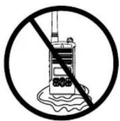
Prohibition sign of a ship crossing water with bubbles and surfactant (no text)Do not immerse in water

text_image
Prohibition sign showing a hand spraying water from a device, crossed out by a diagonal lineDo not use alcohol or cleaning solutions
If the radio is submerged in water...
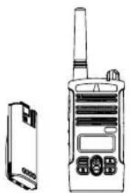
natural_image
Line drawing of a walkie-talkie device with a rectangular case beside it (no text or symbols visible)Turn radio OFF and remove batteries
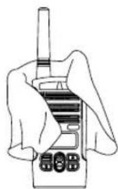
natural_image
Line drawing of a hand holding a walkie-talkie device (no text or symbols visible)Dry with soft cloth Do not use radio until completely dry
text_image
Prohibition sign with a radio station icon and crossed-out line, indicating no prohibition or prohibition against the water surface.FREQUENCY AND CODE CHARTS
The charts in this section provide Frequency and Code information. These charts are useful
when using Motorola XTNi™ Series two-way radios with other business radios. Most of the frequency position are the same as Spirit M, GT, S, XTN Series Frequencies.
8 Channel Radios PMR 446 Defaults
| Freq # Frequency Code Bandwidth | |||
| 1 446.00625 67.0 Hz 12.5kHz | |||
| 2 446.01875 67.0 Hz 12.5kHz | |||
| 3 446.03125 67.0 Hz 12.5kHz | |||
| 4 445.04375 67.0 Hz 12.5kHz | |||
| 5 446.05625 67.0 Hz 12.5kHz | |||
| 6 446.06875 67.0 Hz 12.5kHz | |||
| 7 446.08125 67.0 Hz 12.5kHz | |||
| 8 446.09375 67.0 Hz 12.5kHz | |||
| 9 446.00625 754.0 Hz 12.5kHz | |||
| 10 446.01875 754.0 Hz 12.5kHz | |||
| 11 446.03125 754.0 Hz 12.5kHz | |||
| 12 445.04375 754.0 Hz 12.5kHz | |||
| 13 446.05625 754.0 Hz 12.5kHz | |||
| 14 446.06875 754.0 Hz 12.5kHz | |||
| 15 446.08125 754.0 Hz 12.5kHz | |||
| 16 446.09375 754.0 Hz 12.5kHz | |||
Note: Code 754 corresponds to PL Code 121.
| CTCSS | |||||
| CTCSS Khz CTCSS Kh | TCSS Khz | ||||
| 1 | 67.0 | 14 | 107.2 | 27 | 167.9 |
| 2 | 71.9 | 15 | 110.9 | 28 | 173.8 |
| 3 | 74.4 | 16 | 114.8 | 29 | 179.9 |
| 4 | 77.0 | 17 | 118.8 | 30 | 186.2 |
| 5 | 79.7 | 18 | 123 | 31 | 192.8 |
| 6 | 82.5 | 19 | 127.3 | 32 | 203.5 |
| 7 | 85.4 | 20 | 131.8 | 33 | 210.7 |
| 8 | 88.5 | 21 | 136.5 | 34 | 218.1 |
| 9 | 91.5 | 22 | 141.3 | 35 | 225.7 |
| 10 94.8 | 23 146.2 36 23 3.6 | ||||
| 11 97.4 | 24 151.4 37 24 1.8 | ||||
| 12 100.0 | 25 156.7 38 25 0.3 | ||||
| 13 | 103.5 | 26 | 162.2 | 122 (*) | 69.3 |
Note: (*) New CTCSS code.
DPL Codes
| DPL Code DPL Code | |
| 39 23 61 | 152 83 343 |
| 40 25 62 | 155 84 346 |
| 41 26 63 | 156 85 351 |
| 42 31 64 | 162 86 364 |
| 43 32 65 | 165 87 365 |
| 44 43 66 | 172 88 371 |
| 45 47 67 | 174 89 411 |
| 46 51 68 | 205 90 412 |
| 47 54 69 | 223 91 413 |
| 48 65 70 | 226 92 423 |
| 49 71 71 | 243 93 431 |
| 50 72 72 | 244 94 432 |
| 51 73 73 | 245 95 445 |
| 52 74 74 | 251 96 464 |
| 53 114 75 | 261 97 465 |
| 54 115 76 | 263 98 466 |
| 55 116 77 | 265 99 503 |
| 56 125 78 | 271 100 506 |
| Code | |
| DPL Code DPL Code | ||||
| 57 | 131 | 79 | 306 101 516 | |
| 58 | 132 | 80 | 311 102 532 | |
| 59 | 134 | 81 | 315 103 546 | |
| 60 | 143 | 82 | 331 104 565 | |
| 105 | 606 | 112 | 662 119 734 | |
| 106 | 612 | 113 | 664 120 743 | |
| 107 | 624 | 114 | 703 121 754 | |
| 108 | 627 | 115 | 712 | |
| 109 | 631 | 116 | 723 | |
| 110 | 632 | 117 | 731 | |
| 111 | 654 | 118 | 732 | |
DPL Codes (cont.)
| Code | |
MOTOROLA LIMITED WARRANTY
WARRANTY INFORMATION
The authorised Motorola dealer or retailer where you purchased your Motorola two-way radio and/or original accessories will honour a warranty claim and/or provide warranty service. Please return your radio to your dealer or retailer to claim your warranty service. Do not return your radio to Motorola. To be eligible to receive warranty service, you must present your receipt of purchase or a comparable substitute proof of purchase bearing the date of purchase. The two-way radio should also clearly display the serial number. The warranty will not apply if the type or serial numbers on the product have been altered, deleted, removed, or made illegible.
WHAT IS NOT COVERED BY THE WARRANTY
- Defects or damage resulting from use of the Product in other than its normal and customary manner or by not following the instructions in this user manual.
- Defects or damage from misuse, accident or neglect.
- Defects of damage from improper testing, operation, maintenance, adjustment, or any alteration or modification of any kind.
- Breakage or damage to aerials unless caused directly by defects in material or workmanship.
-
Products disassembled or repaired in such a manner as to adversely affect performance or prevent adequate inspection and testing to verify any warranty claim.
-
Defects or damage due to range.
- Defects or damage due to moisture, liquid or spills.
-
All plastic surfaces and all other externally exposed parts that are scratched or damaged due to normal use.
-
Products rented on a temporary basis.
- Periodic maintenance and repair or replacement of parts due to normal usage, wear and tear.
ACCESSORIES
AUDIO ACCESSORIES
| Part No. Description | |
| 00115 Remote Speaker Mic BR | |
| 00168 Lightweight headset | |
| 00117 Headset w/Swivel Boom Mic | |
| 00118 Earbud w/Clip PTT Mic BR |
BATTERY
| Part No. Description | |
| RLN6306 Alkaline Battery Frame | |
| RLN6351 Standard Li-Ion Battery | |
| RLN6305 | High Capacity Li-IonBattery |
CARRY ACCESSORIES
| Part No. Description | |
| RLN6302 Hard Leather Carry Case | |
| RLN6307 Spring Action Belt Clip |
SOFTWARE APPLICATIONS
| Part No. Description | |
| IXEN4007AR | Computer Programming Software (CPS) and Programming Cable |
CABLES
| Part No. Description | |
| RLN6303 Radio To Radio Cloning Cable |
CHARGERS
| Part No. Description | |
| IXPN4019 AR | Rapid Charging Kit - European (**) |
| IXPN4020 AR | Multi-Unit Charger (MUC) Kit - European |
Note:
(*) Attention: Certain accessories may be or may not be available at the time of purchase. Please contact your Motorola point of purchase or visit www.motorola.com/XTNi or www.motorola.com/radios/business for latest information on accessories.
(**) European Rapid Charging Kit includes Power Supply, Drop-in Tray Charger, and AC Pin adaptors. Contact your Motorola authorized dealer for availability and accessories new models information
MOTOROLA, the Stylized M Logo, XTNi™ Series and all other trademarks indicated as such herein are trademarks of Motorola, Inc. ® Reg. U.S. Pat. & Tm. Off. All other product or service names are the property of their respective owners. © 2001, 2002, 2005, 2007 Motorola, Inc. All rights reserved. Printed in the U.S.A. Motorola® XTNi™ Series

6871663M05-A
