
TL-SC2020N - Surveillance Camera TP-LINK - Free user manual and instructions
Find the device manual for free TL-SC2020N TP-LINK in PDF.


| Product Type | Wireless N Network Camera |
| Model | TL-SC2020N |
| Brand | TP-Link |
| Resolution | Up to 640 x 480 pixels |
| Compression | Motion JPEG |
| Frame Rate | Up to 30 fps at 640x480 |
| Lens | F2.4 fixed lens |
| Audio | Built-in microphone; one-way audio; G.711 μ-law |
| Wireless | IEEE 802.11b/g/n, up to 150 Mbps |
| Wi-Fi Protected Setup (WPS) | Yes (Push Button & PIN) |
| Power Supply | 5V DC, 1A |
| Operating Temperature | 0°C to 40°C (32°F to 104°F) |
| Security | Password protection; HTTPS; WEP, WPA, WPA2 |
| Mounting | Wall and ceiling mount (bracket included) |
| Viewing | Web browser, 3G/2.5G mobile phone, iPhone |
| Recording | Local (via browser), FTP, email (snapshot or video clip) |
| Motion Detection | Yes, with 3 configurable zones (threshold & sensitivity) |
| Protocols | TCP/IP, DHCP, PPPoE, DDNS, UPnP, RTSP, FTP, SMTP, HTTP |
| Maintenance | Clean with soft dry cloth; do not use alcohol or solvents |
| Certifications | FCC, CE, RoHS |
Frequently Asked Questions - TL-SC2020N TP-LINK
User questions about TL-SC2020N TP-LINK
0 question about this device. Answer the ones you know or ask your own.
Ask a new question about this device
Download the instructions for your Surveillance Camera in PDF format for free! Find your manual TL-SC2020N - TP-LINK and take your electronic device back in hand. On this page are published all the documents necessary for the use of your device. TL-SC2020N by TP-LINK.
USER MANUAL TL-SC2020N TP-LINK
Wireless N Network Camera
COPYRIGHT & TRADEMARKS
Specifications are subject to change without notice. TP-LINK® is a registered trademark of
TP-LINK TECHNOLOGIES CO., LTD. Other brands and product names are trademarks or registered trademarks of their respective holders.
No part of the specifications may be reproduced in any form or by any means or used to make any derivative such as translation, transformation, or adaptation without permission from TP-LINK TECHNOLOGIES CO., LTD. Copyright © 2012 TP-LINK TECHNOLOGIES CO., LTD.
All rights reserved.
http://www.tp-link.com
FCC STATEMENT
FC
This equipment has been tested and found to comply with the limits for a Class B digital device, pursuant to part 15 of the FCC Rules. These limits are designed to provide reasonable protection against harmful interference in a residential installation. This equipment generates, uses and can radiate radio frequency energy and, if not installed and used in accordance with the instructions, may cause harmful interference to radio communications. However, there is no guarantee that interference will not occur in a particular installation. If this equipment does cause harmful interference to radio or television reception, which can be determined by turning the equipment off and on, the user is encouraged to try to correct the interference by one or more of the following measures:
➢ Reorient or relocate the receiving antenna. - Increase the separation between the equipment and receiver. Consult the dealer or an experienced radio/TV technician for help.
➢ Connect the equipment into an outlet on a circuit different from that to which the receiver is connected.
This device complies with part 15 of the FCC Rules. Operation is subject to the following two conditions:
1) This device may not cause harmful interference. 2) This device must accept any interference received, including interference that may cause undesired operation.
Any changes or modifications not expressly approved by the party responsible for compliance could void the user's authority to operate the equipment.
Note: The manufacturer is not responsible for any radio or TV interference caused by unauthorized modifications to this equipment. Such modifications could void the user's authority to operate the equipment.
FCC RF Radiation Exposure Statement:
This equipment complies with FCC RF radiation exposure limits set forth for an uncontrolled environment. This device and its antenna must not be co-located or operating in conjunction with any other antenna or transmitter.
"To comply with FCC RF exposure compliance requirements, this grant is applicable to only Mobile Configurations. The antennas used for this transmitter must be installed to provide a separation distance of at least 20 cm from all persons and must not be co-located or operating in conjunction with any other antenna or transmitter."
CE Mark Warning
CE1588!
This is a class B product. In a domestic environment, this product may cause radio interference, in which case the user may be required to take adequate measures.
National Restrictions
This device is intended for home and office use in all EU countries (and other countries following the EU directive 1999/5/EC) without any limitation except for the countries mentioned below:
| Country | Restriction | Reason/remark |
| Bulgaria | None | General authorization required for outdoor use and public service |
| France | Outdoor use limited to 10 mW e.i.r.p. within the band 2454-2483.5 MHz | Military Radiolocation use. Refarming of the 2.4 GHz band has been ongoing in recent years to allow current relaxed regulation. Full implementation planned 2012 |
| Italy | None | If used outside of own premises, general authorization is required |
| Luxembourg | None | General authorization required for network and service supply(not for spectrum) |
| Norway | Implemented | This subsection does not apply for the geographical area within a radius of 20 km from the centre of Ny-Ålesund |
Russian Federation None Only for indoor applications Note: Please don't use the product outdoors in France.
Industry Canada Statement:
This device complies with RSS-210 of the Industry Canada Rules. Operation is subject to the following two conditions:
1) This device may not cause harmful interference, and 2) This device must accept any interference received, including interference that may cause undesired operation.
IMPORTANT NOTE:
Radiation Exposure Statement:
This equipment complies with Canada radiation exposure limits set forth for an uncontrolled environment. This equipment should be installed and operated with minimum distance 20cm between the radiator & your body.
Korea Warning Statements:
DECLARATION OF CONFORMITY
For the following equipment:
Product Description: Wireless N Network Camera
Model No.: TL-SC2020N
Trademark: TP-LINK
We declare under our own responsibility that the above products satisfy all the technical regulations applicable to the product within the scope of Council Directives:
Directives 1999/5/EC, Directives 2004/108/EC, Directives 2006/95/EC, Directives 1999/519/EC,
Directives 2011/65/EU
The above product is in conformity with the following standards or other normative documents
ETSI EN 300 328 V1.7.1: 2006
ETSI EN 301 489-1 V1.8.1:2008& ETSI EN 301 489-17 V2.1.1:2009
EN 55022:2010
EN 55024:2010
EN 61000-3-2:2006+A1:2009+A2:2009
EN 61000-3-3:2008
EN60950-1:2006+A11:2009+A1:2010+A12:2011
EN62311:2008
The product carries the CE Mark:
CE1588①
Person is responsible for marking this declaration:

Yang Hongliang
Product Manager of International Business
Date of issue: 2012
CONTENTS
Package Contents....1
Chapter 1 Safety Instructions....2
Chapter 2 Minimum System Requirement & Product Feature....3
2.1 System Requirement .... 3 2.2 Product Features .... 3 2.3 Physical Overview 4
2.3.1 Front View 4
2.3.2 Rear View 5
2.4 Mount the Camera....6
2.4.1 The Screw Size 6 2.4.2 Wall and Ceiling Mount....6
2.5 Hardware Connection....6
2.5.1 Wired Connection....7 2.5.2 Wireless Connection (by WPS) 7
Chapter 3 Using Camera via Web Browser....8
3.1 Obtain the IP Address 8 3.2 Windows Web Browser.... 10
Chapter 4 Operating Camera via Mobile Phone....12
4.1 Mobile Phone Viewing 12
4.1.1 3G Mobile Phone Streaming Viewing.... 12 4.1.2 2.5G Mobile Phone WAP Viewing 12 4.1.3 2.5G Mobile Phone Browser Viewing.... 12
4.2 Using Camera via iPhone 12
Chapter 5 Configuration of Main Menu ....14
5.1 Home 14
5.1.1 Video play buttons.... 14 5.1.2 Snapshot 15 5.1.3 Digital zoom in/out the image via the monitor window.... 15 5.1.4 Audio buttons 15
5.2 Information.... 16 5.3 Basic setup 16
5.3.1 Account.... 16 5.3.2 Network 18 5.3.3 Image Setting 30 5.3.4 Video 31 5.3.5 Audio 31 5.3.6 Camera setting 32 5.3.7 Events.... 32
5.4 System....37
5.4.1 Initialize.... 37 5.4.2 Date Time 38
5.5 Language....39
Appendix 40
A. Frame-rate and Bitrate Table – Help to set Camera with your network environment to access Internet. 40 B. Storage Requirement Table - Help to set Recording Storage System...... 40 C. System Requirement – Help to setup System 40
Europe – EU Declaration of Conformity....42
Federal Communication Commission Interference Statement....45
Package Contents
The following items should be found in your package:
TL-SC2020N Wireless N Network Camera Power Adapter Mounting Bracket with three screws, a Lock Ring, a Brace and a Base Plate RJ45 Cable Quick Installation Guide ➢ Resource CD, including:
- This User Guide
- Application Guide • Other helpful information

Note:
Make sure that the package contains the above items. If any of the listed items is damaged or missing, please contact your distributor.
Chapter 1 Safety Instructions
Before you use this product
This product has been designed with safety in mind. However, electrical products can cause fires which may lead to serious body injury if not used properly. To avoid such accidents, be sure to heed the following.
▶ Legal Caution
Video and audio surveillance can be forbidden by laws that vary from country to country. Check the laws in your local region before using this product for surveillance purposes.
- Don't open the housing of the product
Don't try to open the housing or remove the covers, for it may expose you to dangerous voltage or other hazards.
Don't use the accessories not recommended by the manufacturer
➢ Heed the safety precautions
Be sure to follow the general safety precautions and the “Operation Notice.”
➢ Operation Notice - Operating or storage location
Avoid operating or storing the Camera in the following locations:
• Extremely hot or cold places (Operating temperature: 0 °C to + 40 °C [32 °F to 104°F]) - Exposed to direct sunlight for a long time, or close to heating equipment (e.g., near heaters) - Close to water (e.g., near a bathtub, kitchen sink, laundry tub) - Close to sources of strong magnetism - Close to sources of powerful electromagnetic radiation, such as radios or TV transmitters - Locations subject to strong vibration or shock
In case of a breakdown
In case of system breakdown, discontinue use and contact your authorized dealer.
In case of abnormal operation
- If the unit emits smoke or an unusual smell,
- If water or other foreign objects enter the cabinet, or
- If you drop the unit or damage the cabinet: 1. Disconnect the cable and the connecting cables.
- Contact your authorized dealer or the store where you purchased the product.
Transportation
When transporting the camera, repack it as originally packed at the factory or in materials of equal quality.
> Ventilation
To prevent heat buildup, do not block air circulation around the device.
Cleaning
- Use a soft, dry cloth to clean the external surfaces of the device. Stubborn stains can be removed using a soft cloth dampened with a small quantity of detergent solution, then wipe dry.
- Do not use volatile solvents such as alcohol, benzene or thinners as they may damage the surface.
Chapter 2 Minimum System Requirement & Product Feature
2.1 System Requirement
For normal operation and viewing of the network camera, it's recommended that your system meets these minimum requirements for proper operation:
| Item | Requirements |
| CPU Pentium | 4 2.8GHz (or equivalent AMD) |
| Graphic Card | 256 MB RAM graphic cards (or equivalent on-board graphic cards) |
| RAM 2 GB RAM | |
| Operating System | Windows 2000 / Windows 2003 / Windows XP / Windows Vista / Windows 7 |
| Web Browser Internet Explore 8 or higher | |

Note:
Please keep updating the latest Windows software and service package. (E.g.: Net Framework, Windows Media Player, Enhance ActiveX Security)
2.2 Product Features
These easy-to-follow instructions make it quick and simple for setup and operation, so you'll also soon be enjoying the benefits of these product features:
| SYSTEM | |
| Resolutions Up to 640 x | 480 |
| Compressing format Motion JPEG | |
| Frame Rate Up to 30 fps | at 640 x 480 |
| Image settings | Brightness / Contrast / Saturation / Sharpness/ Exposure |
| Overlay capabilities: time, date, text | |
| Image snapshot Yes | |
| Video Recording Yes | |
| Full Screen Viewing Yes | |
| Digital Zoom | 10x digital |
| Audio | One-way with built-in microphone |
| Audio compression: G.711 μ law | |
| Security | Password Protection / HTTPS encryption |
| Alarm Buffer | Recording image and audio file pre-and-post disconnection up to 5 sec. |
| Supported protocols | TCP/IP, DHCP, PPPoE, ARP, ICMP, FTP, SMTP, DNS, NTP, UPnP, RTSP, RTP, RTCP, HTTP, TCP, UDP |
| Simultaneous Connection | Up to 3 users |
| Operating conditions | 0°C ~ 40 °C (32°F ~ 104 °F) |
| HARDWARE | |
| Lens F 2.4 fixed lens | |
| Audio Output 1 | |
| Power 5V DC, 1A | |
| Wireless IEEE 802.11b/g/n with WEP/WPA/WPA2. Up to 150 Mbps | |
| WPS 1 (Wi-Fi Protected Setup) | |
2.3 Physical Overview
2.3.1 Front View
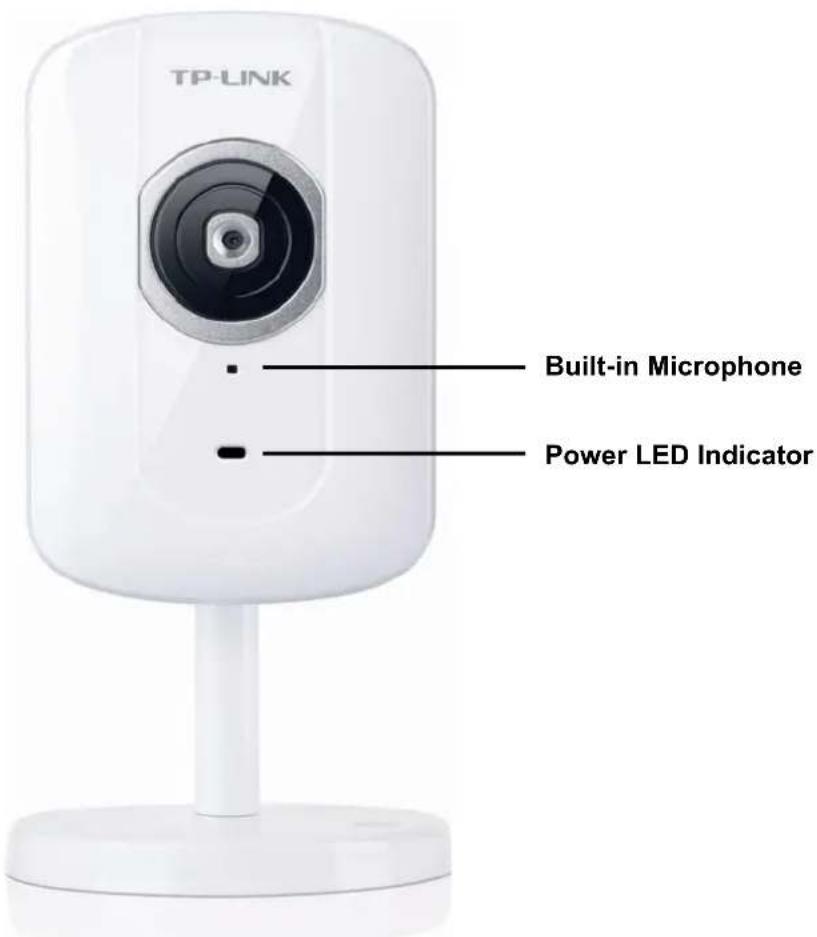
Network LED Indicator: It lights up when the Camera is well connected to the network. It flashes when there are data being transmitted.
Power LED Indicator
Solid Red: The Camera boots up. Flash Red: The Camera has finished booting up, but it isn't connected to any network.
Solid Blue: The Camera has been connected to a network.
Built-in Microphone: The location where the voice from your partner comes out.
2.3.2 Rear View

Power Jack: The power connector is where you connect the power adapter.
RESET: Press the button for more than 15 seconds, and the Camera will be restored to factory defaults.
LAN Port: Through this port, you can connect the Camera to your computer or other Ethernet network devices.
WPS (Wi-Fi Protected Setup): This button is used to easily set up a wireless connection with a Router that supports WPS.
Step 1. Press the WPS button on the router that supports WPS for 2 seconds.
Step 2. Within 2 minutes, press the WPS button on the Camera for 2 seconds.
Lock Ring: It is used to adjust the angle of the Camera.
Base Plate: It is used to support the Camera and can be fixed to a flat surface with the supplied screws.
2.4 Mount the Camera
2.4.1 The Screw Size
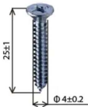
There are three supplied screws for mounting the Camera. The length of the screws is 25 ± 1 mm and the diameter is 4 ± 0.2 mm.
2.4.2 Wall and Ceiling Mount
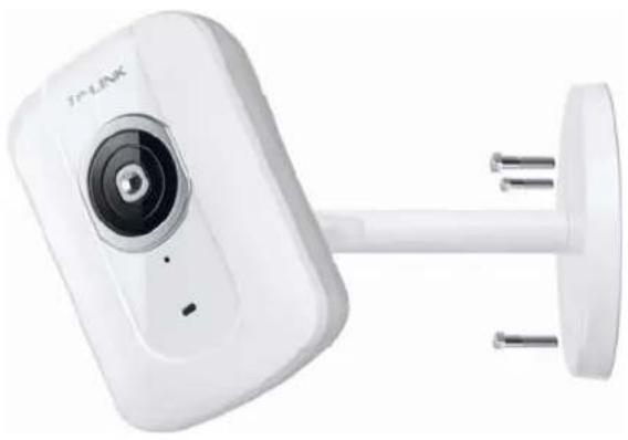
There are two ways to mount the Camera. See the following two pictures.
| Ceiling Mount | Wall Mount |
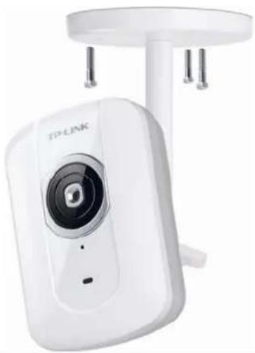 |  |
To mount the Camera, please follow the steps below:
- Use the three supplied screws to fix the base plate to a flat surface.
- Loosen the lock ring to adjust the desired angle of the Camera.
- Tighten the lock ring.
2.5 Hardware Connection
Before proceeding, confirm that your PC is connected to your router and can access the Internet. Make sure that your router's DHCP feature is enabled. If not, please refer to your router's instruction to enable it.
For TL-SC2020N, you can set up either a Wired Connection or a Wireless Connection. To set up a wireless connection, if your Router supports WPS (Wi-Fi Protected Setup), please follow 2.5.2 Wireless Connection (by WPS) to finish connection; if your Router doesn't support WPS, please refer to the
Wireless section of 5.3.2 Network.
Please connect the Camera according to the following steps.
![graph TD PC["PC"] -->|Wireless Connection| Router["Router"] Router -->|WPS Connect| WPS["WPS"] Router -->|Ethernet Cable| External["External Device"] External -->|Wireless Connection| Internet["Internet"] Internet --> Router External -->|Wireless Connection| Phone["Phone"] Phone -->|Wireless Connect…](/content/2026/06/1236393/images/4370fe2f8729f33ac28754a31c07058303fd7a47b0aaad6d99a2c0209a365888.jpg)
2.5.1 Wired Connection
- Connect the Camera to the LAN network (Router or Switch) via Ethernet cable.
- Connect the power adapter cord to the Power Jack.
- Plug the power adapter into the power outlet.
2.5.2 Wireless Connection (by WPS)
Power on the Camera and make sure that the Power LED is flash red. Then take the following steps.
A. Press the WPS button on the Router supporting WPS for 2 seconds. B. Within 2 minutes, press the WPS button on the Camera for 2 seconds.
After you press the WPS button on the Camera, the WPS LED will turn flash blue. Once the WPS Connection is successfully established, it will turn solid blue.
Chapter 3 Using Camera via Web Browser
3.1 Obtain the IP Address
- Insert the provided CD into your CD-ROM drive. The Setup Wizard will automatically pop up on your computer's screen as shown in the figure below.
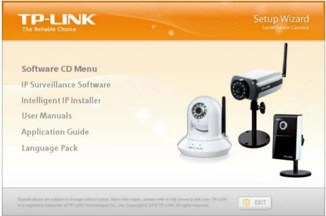
Figure 3-1
- Choose the Intelligent IP Installer, and then the next screen appears. Click on Intelligent IP Installer to begin the installation.
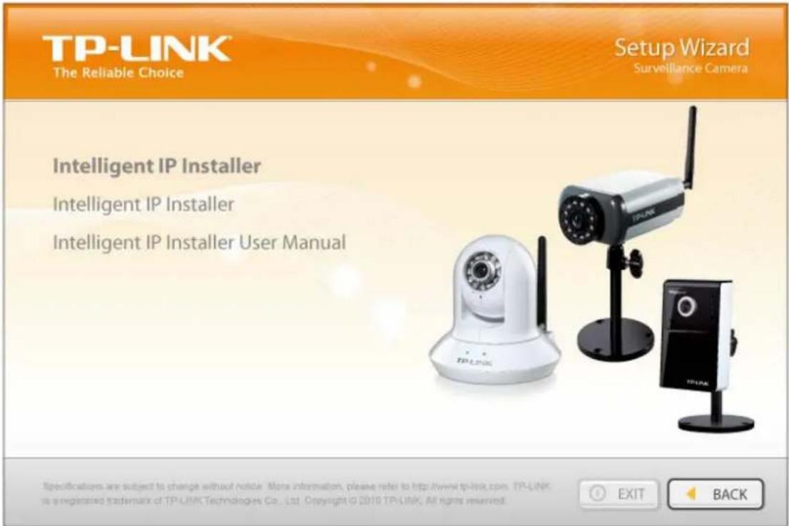
Figure 3-2
- After the installation is finished, click Start > All Programs > TP-LINK > Intelligent IP Installer to start using the program.

Figure 3-3
- The following screen will then display. Click the Search button to search for Network Cameras in the network; it displays Network Cameras information including IP Address.
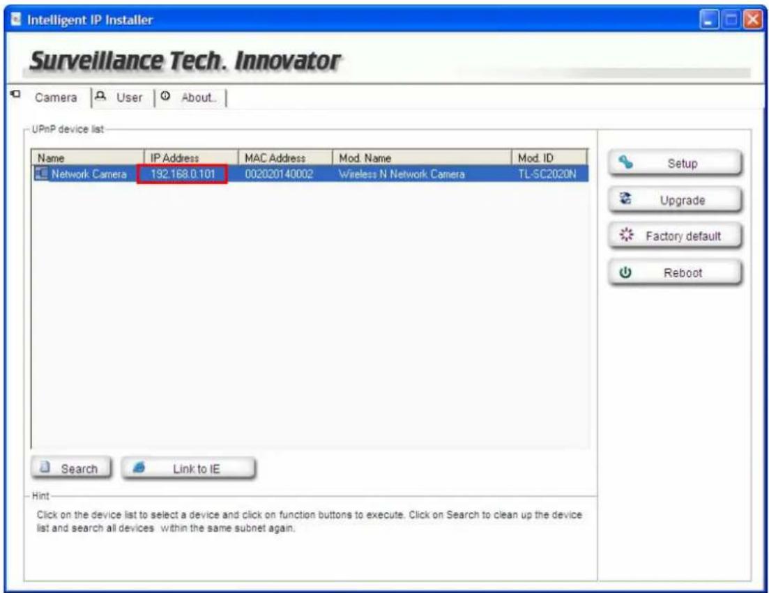
Figure 3-4
3.2 Windows Web Browser
The configuration of the browser is similar in Windows XP/Vista/7. Here we take IE browser in Windows XP for example.
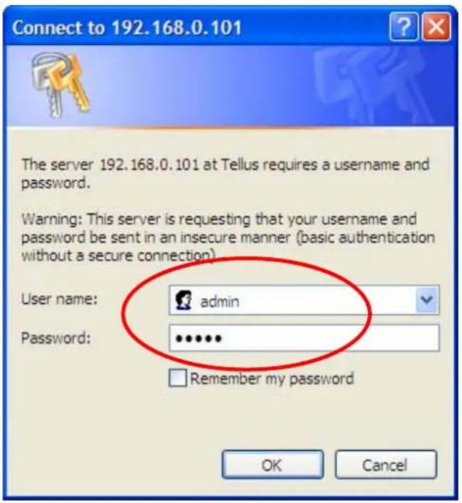
1 Click the Link to IE button in Figure 3-4 directly. You can also launch your web browser and then enter the IP address or host name of the Camera in the Location / Address field of your browser.

2 Use the default User name admin and default Password admin.
Note:
The default User name "admin" and the Password "admin" are set at the factory for the administrator. You can change them in the Account Menu. (Please check "Basic setup → Account")
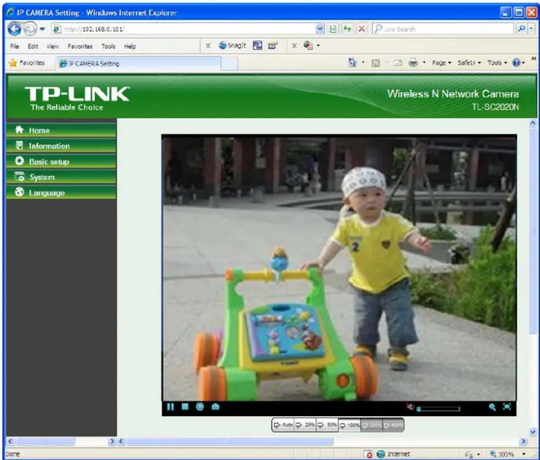
3 The monitor image will be displayed in your browser. In the far left side of the main configuration are Home, Information, Basic setup, System and Language.
Chapter 4 Operating Camera via Mobile Phone
4.1 Mobile Phone Viewing
4.1.1 3G Mobile Phone Streaming Viewing
For 3G mobile phone viewing, type "rtsp:// : /video.3gp" into your 3G Streaming Link. is the Public IP address of your Camera; is the RTSP port of your Camera (Default value is 554.) Example: rtsp://100.10.10.1:554/video.3gp.

Note:
You can also use RTSP clients (RealPlayer, VLC, QuickTime Player...etc.) to view RTSP streaming, just type in "rtsp:// : /video.3gp" as the Player URL.
4.1.2 2.5G Mobile Phone WAP Viewing
For 2.5G mobile phone viewing, type "http:// /mobile.wml" into your 2.5G WAP Browser. is the Public IP address of your Camera.
4.1.3 2.5G Mobile Phone Browser Viewing
For 2.5G mobile phone viewing, type "http:// /mobile.htm" into your 2.5G Web Browser. is the Public IP address of your Camera.
4.2 Using Camera via iPhone
You can use TP-LINK Web User Interface via iPhone. Please follow the setting process below. Then you can use TP-LINK Web UI via iPhone.
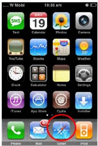
1. Select Safari function. 2. Enter IP address in your web link.

3. Enter name and password. Default values are both admin. Then click Log in.

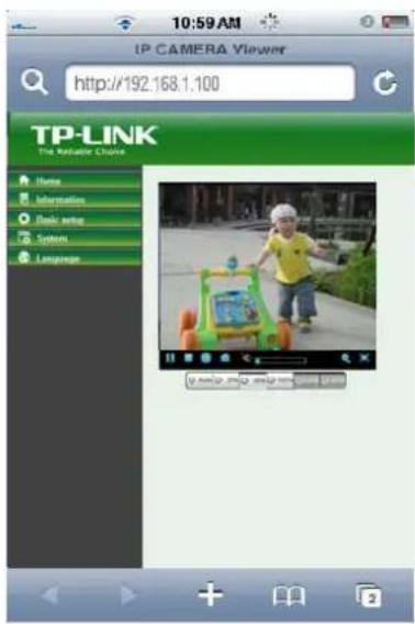
4. The TP-LINK User Interface and live image will show up in the middle of the screen.

Note:
It will show continuous snapshots, not real-time video streaming. Therefore, the recording feature is disabled.
Chapter 5 Configuration of Main Menu
In the left side of the main configuration are Home, Information, Basic setup, System, and Language.
5.1 Home
In the right side, you can control Live View in your main Browser. The functions include: Snapshot, Open digital zoom, Audio, and Video Play.
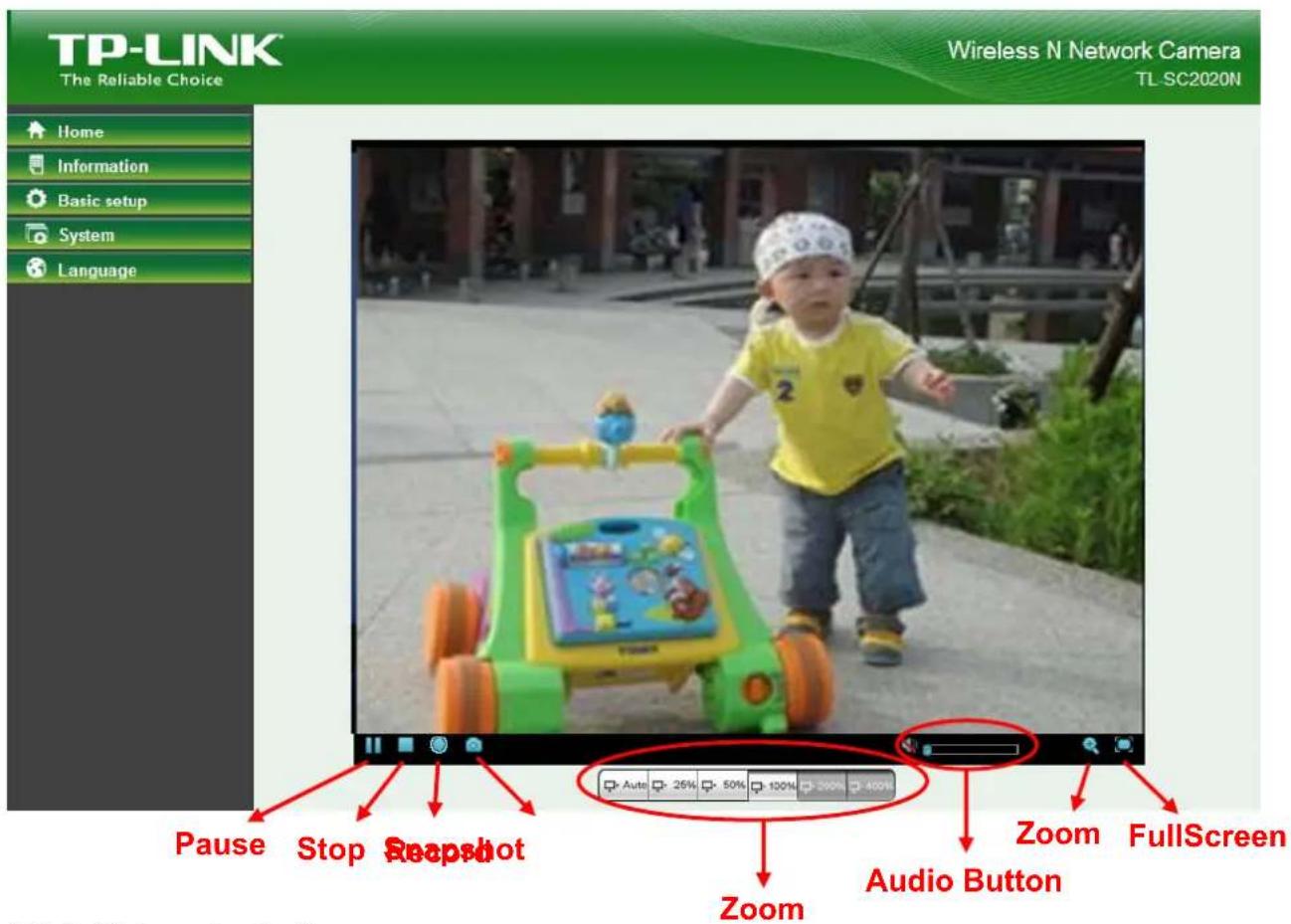
5.1.1 Video play buttons
| Symbols | Meaning |
 | Pause the current video |
 | Stop the current video |
 | Record the current video |
 | Full Screen |

Note:
Concerning the recording storage requirement of your hard disk, please refer to the APPENDIX / B. Storage Requirement Table.
5.1.2 Snapshot
You can capture a still image shot by clicking the Camera icon and save it in the operating computer.
| Symbols | Meaning |
 | A snapshot window appears after clicking the icon |
| Save Image | Save the picture captured by snapshot into your computer |
| Close Return to the view screen | |
5.1.3 Digital zoom in/out the image via the monitor window
- Click to display the digital zoom in window.
- Pull the W to adjust the digital zoom range, and it will be shown on the above window. Use the left click of your mouse to move to anywhere in the window area.
5.1.4 Audio buttons
| Symbols | Meaning | Note |
 | Mute off | mean you can broadcast to the connected Camera(s) via the Ethernet using your microphone |
 | Mute on | mean you can't broadcast to the connected Camera(s) via the Ethernet using your microphone |
 | Volume control bar | mean you can adjust the sound volume by the control bar |
5.2 Information
The Information screen provides the product factory information which includes Product Name, Current Version, Firmware current Date/Time, Image Setting, Video and Network.

5.3 Basic setup
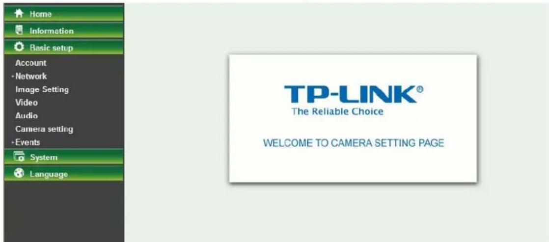
This function is only for the Administrator. Click Basic setup to display the submenus: Account, Network, Image Setting, Video, Audio, Camera setting and Events.
5.3.1 Account
The device fault account and password setting is "admin / admin". That means everyone who knows IP address can access the device including all configuration. It is necessary to assign a password if the device is intended to be accessed by others.

Add: Click this button to add a new account. Modify: Click this button to edit the selected account. Remove: Click this button to delete the selected account. ➢ Anonymous Viewer: Select Disable and the anonymous viewers cannot access the Camera. Select Enable to and the anonymous users can access the Camera in Viewer mode.
To add a new account, please follow the steps below:
- Click the Add button.
- On the account-setting window as shown in the following figure, enter a User name and Password for the account, then select a Role from the drop-down list. Click Save to apply the settings.

User Name: Set a user name for the account.
➢ Password: Set a password for the account. Re-type Password: Re-type the password to confirm. Viewer Mode: Set the user mode among Viewer, Operator and Administrator. Different viewer mode has different limits of authority.
• The Viewer mode only can view the Live View. - The Operator mode can not only view the Live View but also the Information page. • The Administrator mode has all authority of configuration.
5.3.2 Network
Click the Network to display the submenus including TCP/IP, PPPoE, DDNS, UPnP, Wireless and WPS.

5.3.2.1 TCP/IP
This page displays the MAC address of the camera and is also used for TCP/IP configuration.

Obtain an IP address automatically (DHCP): If a DHCP server is installed on the network, select this option and the IP address is assigned by the DHCP server.
Obtain DNS server address automatically: Select this option to obtain the address of the DNS server automatically.

Use the following IP address: Select this option when a fixed IP address is set as the IP address.
• IP address: Enter the IP address of the device. - Subnet mask: Enter the subnet mask. - Default gateway: Enter the default gateway.
Use the following DNS server address: Select this option when you set a fixed address as the IP address of the DNS server.
- Preferred DNS server: Enter the IP address of the preferred DNS server. • Alternate DNS server: Enter the IP address of the alternate DNS server, if necessary.
HTTP Port Number: Select 80 in general situations. If you want to use a port number other than 80, select the text box and enter a port number between 1124 and 65534.
When you have set the HTTP port number to a number other than 80 on the Network setting page or in the Setup Program, access the device by typing the IP address of the device on the web browser as follows: for example, when the HTTP port number is set to 2000 and the IP address of your camera is set to 192.168.1.100, you should type in http://192.168.1.100:2000 to access the device.
5.3.2.2 PPPoE
If your ISP provides Dynamic IP with authentication by username and password, type all PPPoE information in this part. When using the PPPoE function, you need to turn on the DDNS or IP Notification function at the same time.
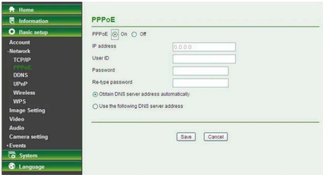
IP Address: The IP address obtained at the PPPoE connection with the network. User ID: Enter the user ID for authentication necessary for PPPoE connections. Type it up to 64 characters. ➢ Password: Enter the password for authentication necessary for PPPoE connections. Type it up to 32 characters. Re-type Password: Re-type the password to confirm. Obtain DNS server address automatically: Select this to obtain the address of the DNS server automatically. Use the following DNS server address: Select this when you set a fixed address as the IP address of the DNS server.
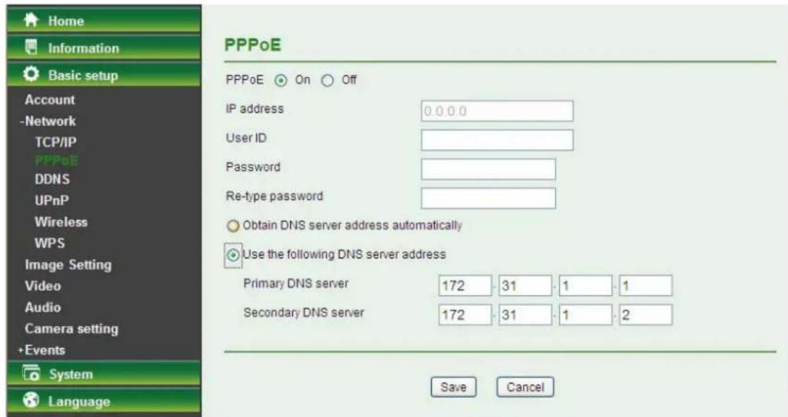
• Primary DNS server: Enter the IP address of the primary DNS server. • Secondary DNS server: Enter the IP address of the secondary DNS server.

Note:
1) PPPoE (Point-to-Point Protocol over Ethernet): PPPoE is a network protocol for encapsulating Point-to-Point Protocol frames inside Ethernet frames. PPPoE connection is used mainly with ADSL service where individual users connect to the ADSL transceiver (modem) over Ethernet
work. It is also widely used in XDSL (digital subscriber line such as ADSL, VDSL or SDSL).
2) The Camera needs to be rebooted after it finishes changing the network completely. For more details, please refer to 5.4.1 Initialize. 3) You can reset the Camera to its factory default settings by pressing the Reset button. Then the Camera can be found by Intelligent IP Installer.
5.3.2.3 DDNS (Dynamic DNS)
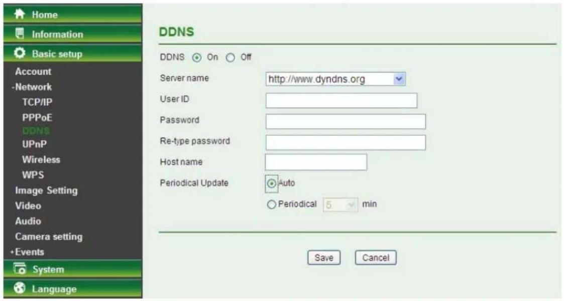
DDNS is a system which allows the domain name data held in a name server to be updated in real time. The most common use for DDNS is allowing an Internet domain name to be assigned to a computer with a varying/dynamic IP Address. This makes it possible for other sites on the Internet to establish connection to the machine without needing to track the IP Address themselves.

Server Name: Choose the DDNS Server from the list. User ID: Enter the user ID for authentication necessary for DDNS connections. Type it up to 64 characters. ➢ Password: Enter the password for authentication necessary for DDNS connections. Type it up to 32 characters. Re-type Password: Re-type the password to confirm. Host Name: Enter the host name that is registered to the DDNS server. Periodical Update:
• Auto: The domain name data will be updated automatically. - Periodical: The domain name data will be updated once in a period. The period can be chosen among 5, 10, 15, 30 and 60 minutes.

Note:
How to apply DDNS username and Host name? You can apply DDNS username and Host name by the following steps:
- Login http://www.dyndns.org, click the Creat Account.

- Input all information and follow step by step with DynDNS.

- Login with new account and click Account → My Hosts → Add Host Services.
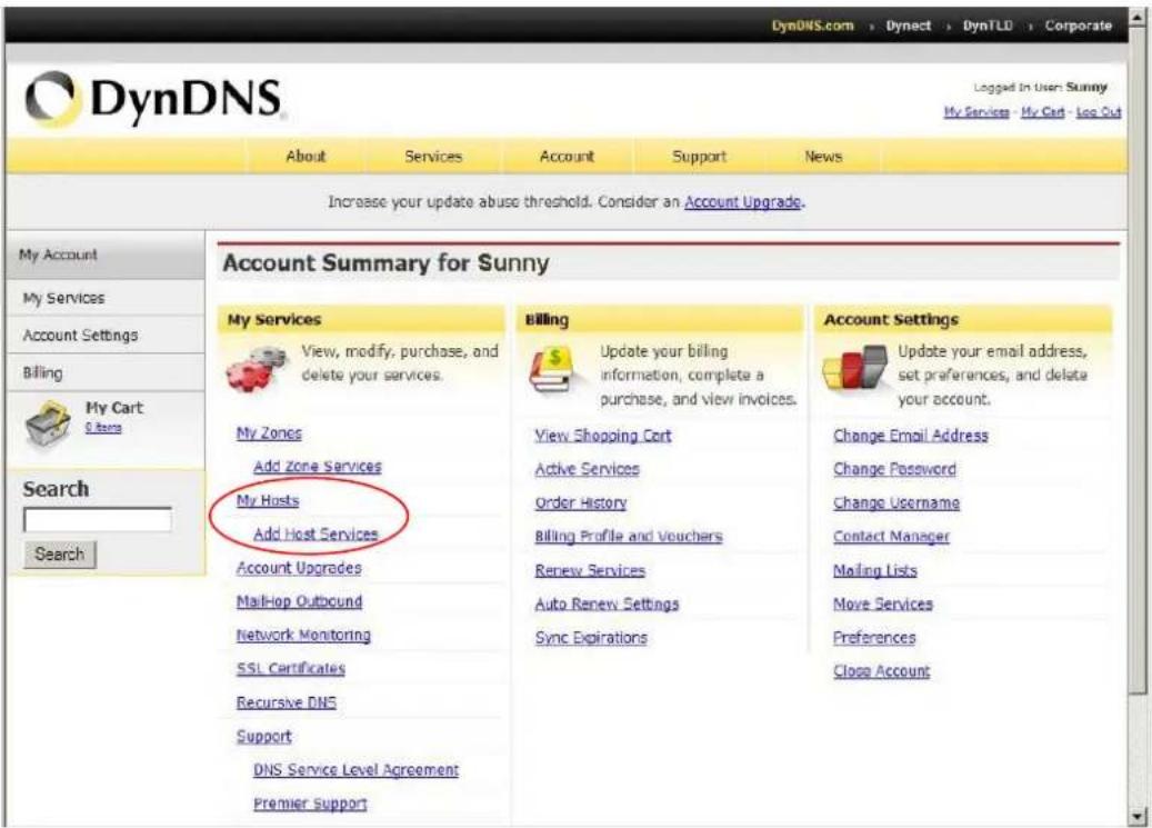
- Type domain in the Hostname field and select sub-domain.
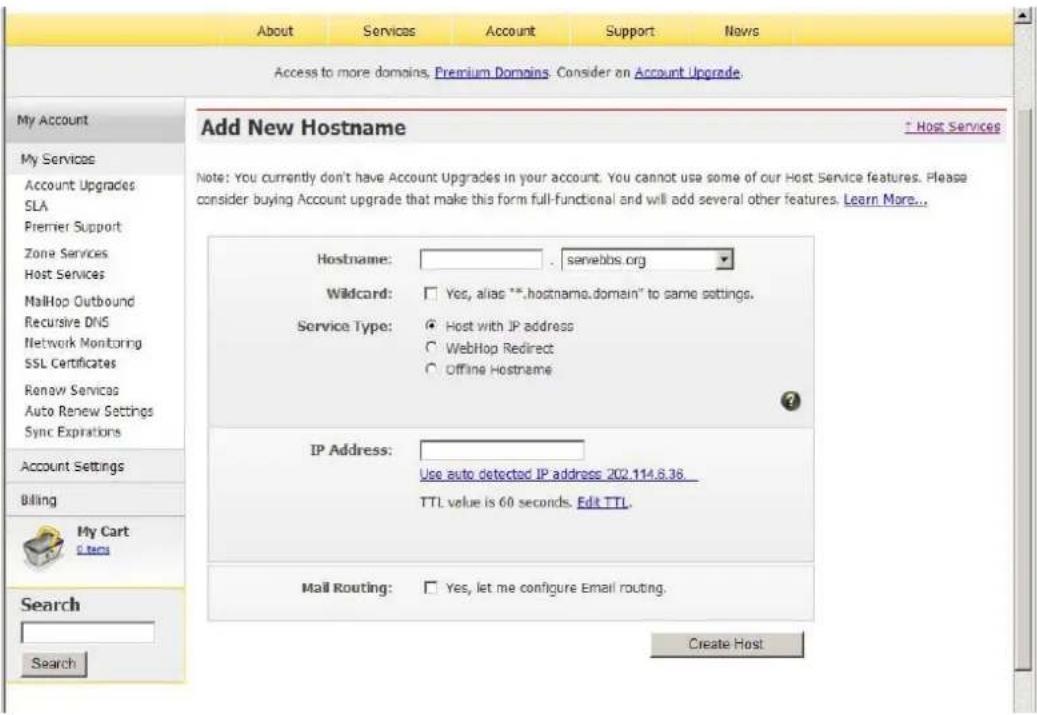
- After typing information, check your DDNS service

- Type your DDNS User ID, Password, and Host name in Setting → Network → DDNS. After completing the setting, reboot the Camera.
5.3.2.4 UPnP (Universal Plug and Play)
If you have a Router to access the Internet and the Router supports the UPnP IGD function, you need to turn on the UPnP Port Forwarding function.
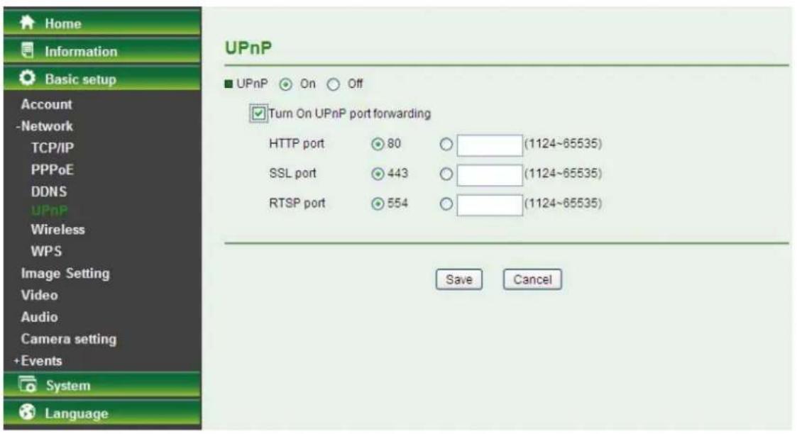
HTTP Port: Enter the HTTP port number; the default HTTP port is 80. SSL Port: Enter the SSL port number; the default SSL port is 443. RTSP Port: Enter the RTSP port; the default value is 554 for computer view.
Note:
UPnP (Universal Plug and Play): UPnP is a set of computer network protocols. It allows devices to connect seamlessly and simplifies the implementation of networks in home and corporate environments.
5.3.2.5 Wireless
The wireless network has to be set up using a cable network connection. After setting the Camera correctly, the wireless function can work without a cable network connection. Wireless settings must be the same as the access point or ad-hoc device. When changing the settings, they should always be made first in the Camera and then in the wireless access point. This ensures that the Camera is always accessible when making changes.
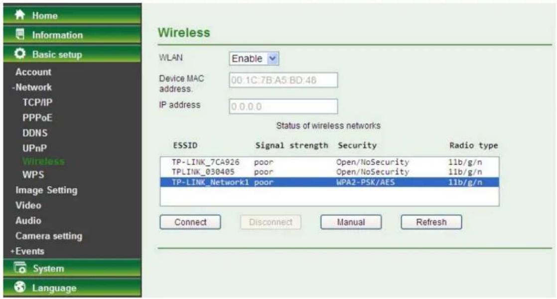
WLAN: Select Enable to enable the wireless function; select Disable to disable the function.
Device MAC address: This displays the MAC address of the Camera.
IP address: This displays the IP address of the Camera. It displays blank, 0.0.0.0, or an IP Address. When it is blank, the Camera doesn't establish a physical link with the access point. 0.0.0.0 means that the physical link is established and that the Camera is trying to get an IP address. When it displays an IP address, users can use the wireless network.
➢ Status of Wireless Networks
The list above is the result of a network scan. The network currently linked to will be shown in blue. The following information is provided.
- ESSID - The name of a wireless network (or ad-hoc device). If the same name occurs several times, this means that several access points for that network were found. The Camera cannot be configured to only associate with one particular access point. ● Signal strength - Shows the signal strength. ● Security - Shows which type of security the network uses. See below for the security types supported by the Camera. ● Radio Type - Displays the radio type of the wireless network.
- Mode - Shows if the network type is Managed (access point or router) or Ad-Hoc (another client). ● Channel - Shows the wireless channel currently in use.
Click the Connect button to connect the Camera to the selected wireless network. The ESSID will be automatically filled in and the IP address of the Camera will be obtained automatically.
Click the Disconnect button to disconnect the Camera from the wireless networks.
Click the Manual button to connect the Camera to a wireless network. The ESSID can be manually filled in; the IP address of the Camera can be obtained automatically or assigned manually.
Click the Refresh button to rescan the existing wireless networks in the local area.
To connect to a network, please follow the instructions below:
If you want to automatically obtain the IP address of the Camera, you can select a wireless network and then click Connect. The network wireless setting page will display. Enter the Passphrase twice and click "Save" to apply the settings.

If you want to manually fill in the ESSID of the wireless network, you can click the Manual button. The network wireless setting page will display. Then enter the ESSID of the wireless network, select a mode, select the corresponding authentication and encryption, get an IP address for the Camera and click "Save".
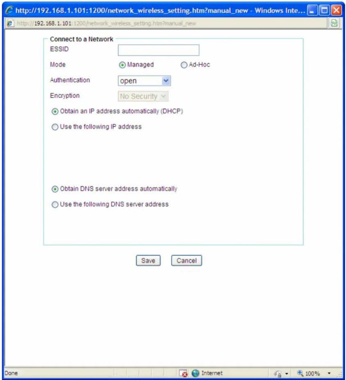
➢ ESSID – Enter the name of a wireless network (or ad-hoc device). Mode – The Managed option means the Camera will attempt to connect to an access point. The Ad-hoc option allows the Camera to connect to other wireless device clients. Authentication – The authentication of the wireless network. All the parameters for authentication must be the same as that of the desired AP or Router. Open, Open/Share, WPA-PSK and WPA2-PSK encryption security are supported by the Camera. Enter the ESSID of the desired wireless network, the corresponding option should be selected as same as that of the desired AP or Router.
Here we take the wireless network with the ESSID of TP-LINK_Network1 as an example. Its Authentication is WPA2-PSK. The figure will display as shown below:
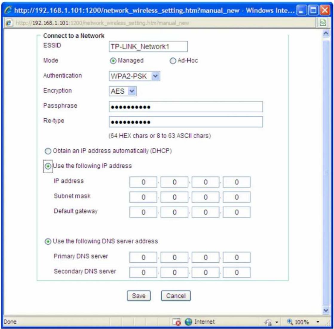
- Encryption – You can select TKIP or AES. Keep this option the same as that of the wireless network.
- Passphrase - Enter the desired AP/ Router's password here.
- Re-type – Enter the password above again to confirm it.
- Obtain an IP address automatically (DHCP) – If a DHCP server is installed and enabled on the network, select this so that the IP address can be assigned by the DHCP server.
- Use the following IP address - Select this when the fixed IP address is set.
IP address: Enter the IP address of the Camera, which must be in the same subnet as that of the desired AP/Router. Subnet mask: Enter the subnet mask. Default gateway: Enter the default gateway.
Obtain DNS server address automatically: If you selected 'Obtain an IP address automatically (DHCP)' above, this option will appear. Select this to automatically obtain the DNS server address.
Use the following DNS server address: Select this when you want to set a fixed IP address for the DNS server.
Primary DNS server: Enter the IP address of the primary DNS server.
Secondary DNS server: Enter the IP address of the secondary DNS server, if necessary.
5.3.2.6 WPS
The WPS (Wi-Fi Protected Setup) function allows you to quickly add a new wireless device to an existing network.
If the router supports Wi-Fi Protected Setup (WPS) or Quick Setup Security (QSS), you can establish a wireless connection between the wireless Camera and the router using either the Push Button Configuration (PBC) method or the PIN method.
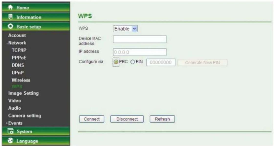
I. PBC (Push Button Configuration) method
- Press the WPS/QSS button on the router.
- Press the WPS button on the Camera within two minutes.
II. PIN method
- First, check the PIN on the following screen. You can also click 'Generate new PIN' to get a new PIN.
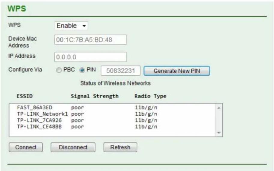
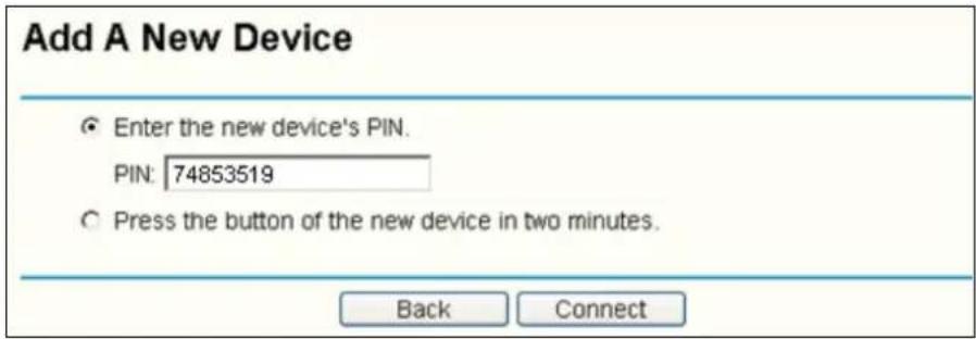
- Second, open the router's web-based utility and click the WPS/QSS link on the left of the main menu. The following screen will appear. Click 'Add device', then select 'Enter the new device's PIN', enter the PIN value of the Camera, and click 'Connect'.

5.3.3 Image Setting
The tool bar can be adjusted to optimize video Brightness, Saturation, Contrast, Sharpness and White Balance.
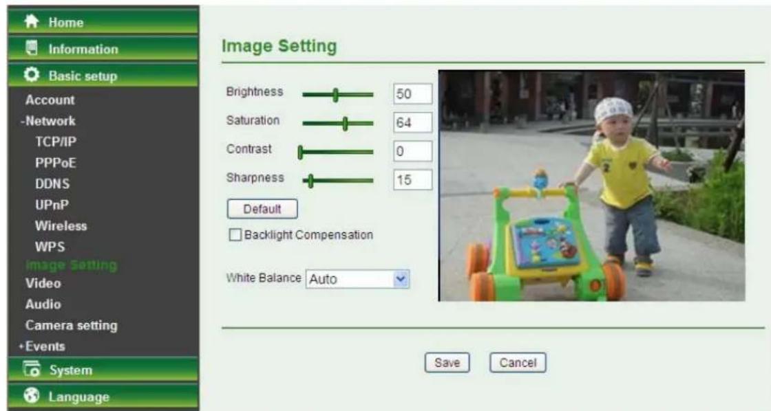
➢ Brightness: The value range is 0~100. The higher the value, the brighter the image. Contrast: The value range is 0~100. Contrast is a measure of a display system, defined as the ratio of white to black that the system is capable of producing. The higher the value, the more delicate the colors. Saturation: The value range is 0~100. The saturation of a color is determined by a combination of light intensity and how much it is distributed across the spectrum of different wavelengths. The higher the value, the more colorful the image.
Sharpness: The value range is 0~100. It applies image processing techniques to adjust the sharpness of the live view. However, the higher the value, the more noise there is.
Default: After adjusting all settings, you can still click Default to revert to the original settings. Backlight Compensation: Tick the box to enable the backlight compensation function. White Balance: Choose the white balance among Auto, Fluorescent, Incandescent, Sunny, and Cloudy.
5.3.4 Video
On this page, you can optimize the video by adjusting its Resolution, Maximum Frame rate, and Light Frequency.
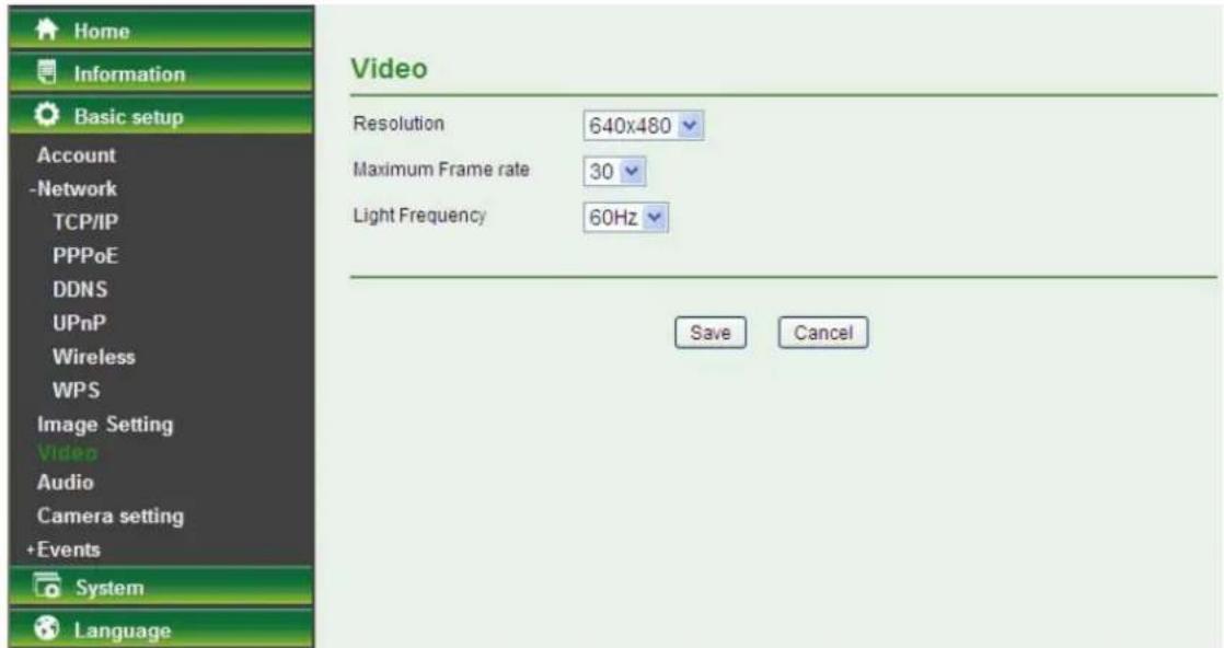
➢ Resolution: Select the video resolution among 640×480, 320×240, and 160×120. Maximum Frame rate: Select the maximum frame rate among 30, 20, 15, 10, 7, 5, and 1. Light Frequency: Select the light frequency among Auto, 60Hz, and 50Hz.
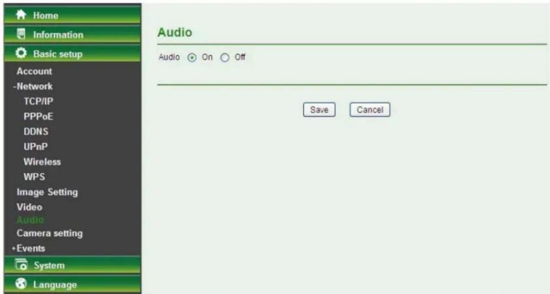
5.3.5 Audio
Select On to enable the audio; select Off to disable it.
5.3.6 Camera setting
On this page, you can set the Camera Name and whether the LED is on or off.
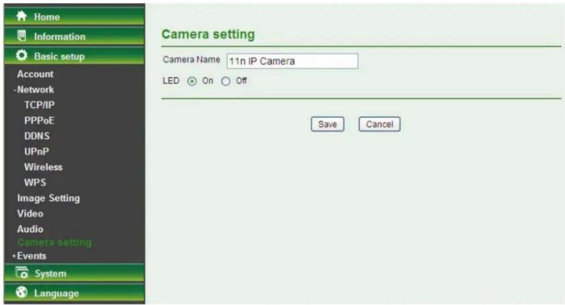
Camera Name: You can enter a new name for the Camera. LED: Select On to enable the LEDs; select Off to disable the LEDs.
5.3.7 Events
Click Events to display the submenus including Motion detection, e-Mail (SMTP), and FTP.
5.3.7.7 Motion detection
There are three Motion Detection functions available as sensors, each set for different detecting zones. Each one has Threshold and Sensitivity inputs that you can adjust for the specific zone sequentially.
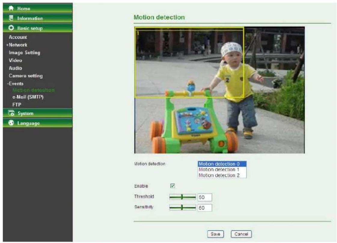
Motion Detection: Click to select motion detection.
- Motion Detection 1: Click it on to use Motion Detection 1 function as a sensor. You can adjust and move the detecting zone using the mouse.
- Motion Detection 2: Click it on to use Motion Detection 2 function as a sensor. You can adjust and move the detecting zone using the mouse.
- Motion Detection 3: Click it on to use Motion Detection 3 function as a sensor. You can adjust and move the detecting zone using the mouse.
Enable: Tick the box to enable the selected motion detection. Threshold: This indicates the extent to which the alarm will be triggered. The default value is 50, and the value range is 0~100. The larger the value, the higher the threshold. Sensitivity: This indicates how often the sensor will scan for image differences. The higher the sensitivity, the more frequently it scans. The default value is 50, and the value range is 0~100. The larger the value, the higher the sensitivity.
5.3.7.8 e-Mail (SMTP)
Set the e-Mail (SMTP) menu when you want to send an image or video clip via e-mail. By using the e-Mail (SMTP) function, you can send a mail with an attached file that has been captured in connection with an external sensor input or with the built-in motion detection function. The file can also be sent periodically.
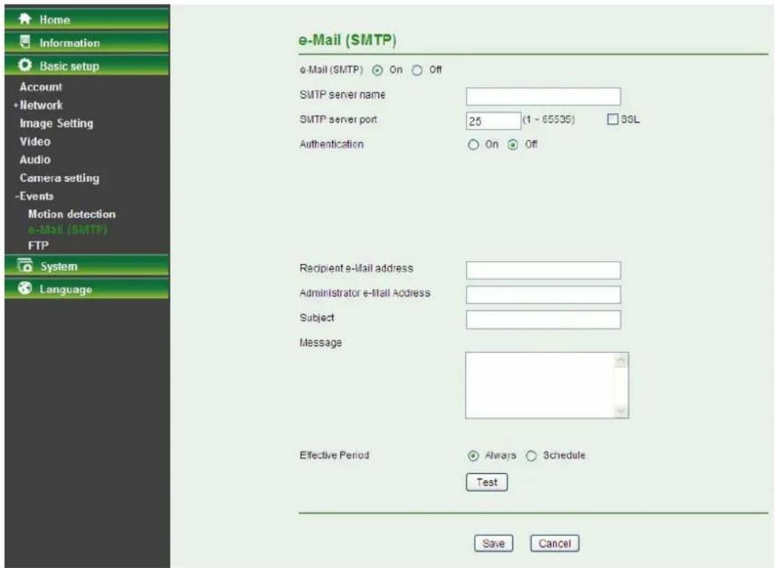
Select On when you use the e-Mail (SMTP) function. The common setting options are displayed below. Select Off if you do not wish to use the e-Mail (SMTP) function.
SMTP Server Name: Type the SMTP server name up to 64 characters, or the IP address of the SMTP server. SMTP Server Port: You can set the port number from 1~65535 according to your mail server. The default value is 25. - SSL: Tick the SSL box if the mail server you use has security restrictions.
Note:
If you use Gmail as your mail server, you should set 25 as your port number and tick the SSL box.
Authentication: Select the authentication required when you send an email.
- Off: Select this if no authentication is necessary when an email is sent.
- On: If authentication is necessary when an e-mail is sent, select one of the authentication methods from the following.
SMTP: Select if SMTP authentication is necessary for sending e-mail.
POP Before SMTP: Select when POP before SMTP authentication is necessary for sending e-mail.
Note:
When you set to On, be sure to select either or both SMTP or / and POP before SMTP.
- POP server name: It is necessary when the POP before SMTP is selected in Authentication. Type the POP (receiving mail) server name up to 64 characters, or type the IP address of the POP server. This setting is necessary when the SMTP server which sends e-mails performs authentication using the POP user account.
- User name, Password: Type the user name and Password of the user who has the mail account. This setting is necessary when the SMTP server which sends e-mails performs authentication.
Recipient E-mail Address: Type the recipient e-mail address up to 64 characters. You can specify
up to three recipient e-mail addresses.
Administrator E-mail Address: Type the administrator e-mail address up to 64 characters. This address is used for reply mail and sending system messages from the SMTP server. Attached File Type: You can choose snapshot or video clip for alarm sending. Select "Snapshot," one snapshot will be transmitted to the administrator's e-mail address while motion detection / audio detection triggered. Select "Video Clip," one 5-seconds video clip will be transmitted. Subject: Type the subject/title of the e-mail up to 64 characters. With respect to mail which is sent according to the alarm detection when Alarm sending of the alarm tab is set to On, the characters standing for the sensor type added to the subject. Message: Type the text of the e-mail up to 384 characters. (A line break is equivalent to 2 characters.) Test: After setting the SMTP server information, you can tick the test key to test if the connection between IP CAM and the SMTP server works. Effective Period: Set the period when the periodical sending is effective.
• Always: The periodical sending is always effective. - Schedule: You can specify the period when the periodical sending is effective in the schedule setting in the other section.
Select Schedule and click the Schedule button, and the Schedule setting page will appear.
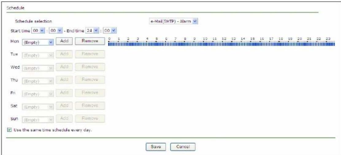
- Schedule Selection: Select the list box to specify the schedule you want to set.
√ FTP -Alarm / E-mail (SMTP) -Alarm
- Start Time, End Time: Specify the Start Time and the End Time.
- Use the same time schedule every day: When this is checked, the Start Time and End Time set to Mon (Monday) are applied to all days. In this case, the Start Time and End Time of the other days than Mon (Monday) cannot be input.
Mon (Monday) to Sun (Sunday): The time period on the right of the checked day is the effective period of the schedule.
5.3.7.9 FTP
Use this menu to set up capturing and sending an image or video clip to an FTP server. By using the FTP client function, you can send files that have been shot and recorded, linked with the external sensor input or with the built-in motion detection function, to the FTP server.
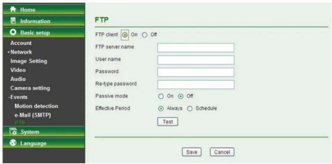
Select On when you use the FTP function. The FTP client Setting screen appears.
Select Off when you do not wish to use the FTP client function.
Note:
The frame rate and operability on the main viewer may decrease while a file is being transmitted by the FTP client function.
FTP Server Name: Type the FTP server name to upload still images, up to 64 characters, or the IP address of the FTP server. User Name: Type the user name for the FTP server. Password: Type the password for the FTP server. Re-type Password: To confirm the password, type the same characters as you typed in the Password box. Passive Mode: Set whether you use the passive mode of the FTP server or not when connecting to the FTP server. Select On to connect to the FTP server using the passive mode. Test: After setting the FTP server information, you can click the test key to test if the connection between the IP CAM and the FTP server works. Effective Period: Set the period when the periodical sending is effective.
Always: The periodical sending is always effective. Schedule: You can specify the period when the periodical sending is effective in the schedule setting in the other section.
Select Schedule and click the Schedule button, and the Schedule setting page will appear.
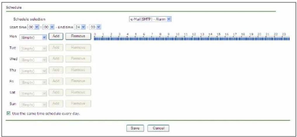
Schedule Selection: Select the list box to specify the schedule you want to set.
FTP - Alarm / E-mail (SMTP) - Alarm
Start Time, End Time: Specify the Start Time and the End Time.
Use the same time schedule every day: When this is checked, the Start Time and End Time set to Mon (Monday) are applied to all days. In this case, the Start Time and End Time of the other days than Mon (Monday) cannot be input.
Mon (Monday) to Sun (Sunday): The time period on the right of the checked day is the effective period of the schedule.
5.4 System
Click System to display the sub-folders including Initialize and Date Time.
5.4.1 Initialize
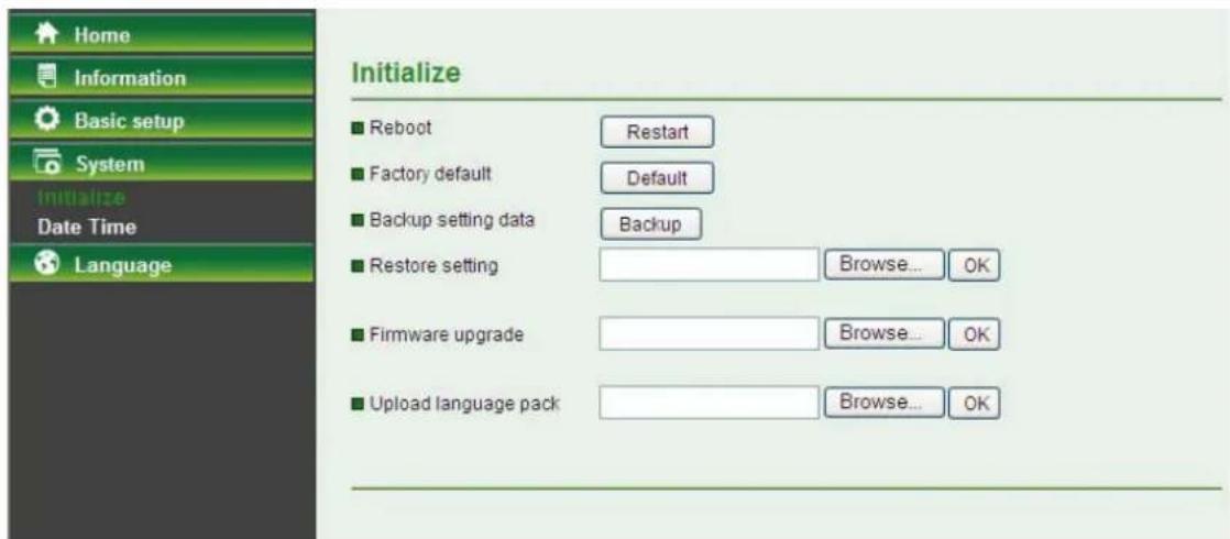
Reboot: Click this button to reboot this Camera. It takes one minute to complete the reboot process.
Factory Default: Click this button to recover this Camera to the factory default setting. A confirmation dialogue will appear and then click "OK" to execute. The network indicator on this Camera will start to blink. This Camera will reboot automatically after completing adjustments to the default setting. Don't turn off this Camera until the device finishes rebooting. Backup Setting: Click this button to save the setting data of this Camera into a file. Click "Save" and follow the instructions on the browser to save the setting data file to the location you specified. Restore Setting: Download the saved setting data of this Camera. Click "Browse" and select
the saved file. Click "OK" and this Camera is adjusted according to the loaded data and then restarted.
Firmware Update: Update the device software. Click "Browse" and select the file for updating. A confirmation dialogue will appear. Click "OK" to start. This Camera will reboot upon completion. Upload language pack: Click "Browse" and select the file for updating, and then the present language display of WEB User Interface could be changed. A confirmation dialogue will appear. Click "OK", then the update will be applied immediately. The default language is "English".

Note:
When updating the firmware version, please use the file specific for the model. Otherwise, some problems may occur. Unless the updating is completed, please don't turn off the power or disconnect the network.
5.4.2 Date Time
The Date Time screen displays all options of time setting.
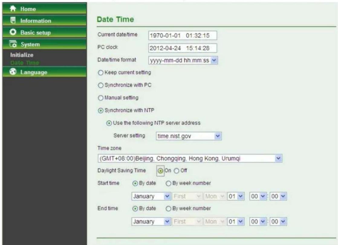
Current Date / Time: This displays the current date and time of this Camera. PC Clock: This displays the date and time of the monitoring PC clock. Date/Time Format: You can click the drop-down list to select different time display formats. Keep current setting: Select this mode to keep the current date and time of this Camera. ➢ Synchronize with PC: Select this mode to keep the date and time of this Camera the same as the monitoring PC. Manual setting: Select this mode to adjust manually the date and time of this Camera. Synchronize with NTP: Specify the NTP server name and the Refresh Interval to synchronize the date and time of this Camera with those of the time server, known as the NTP server.

Note:
The NTP server (Network Time Protocol) is the time server which is an Internet standard protocol built on the top of TCP / IP. This assures accurate synchronization to the millisecond of computer clock times in a network of computers.
Time Zone: Select the Time Zone format of Greenwich Mean Time among different cities. The time display will be the same as the current date / time option. Daylight Saving Time: There are two modes to choose for setting up daylight saving time.
- By Date: Set the start and end time by selecting month, day, hour, and minute.
- By Week Number: Set the start and end time by selecting month, week, hour, and minute.
5.5 Language
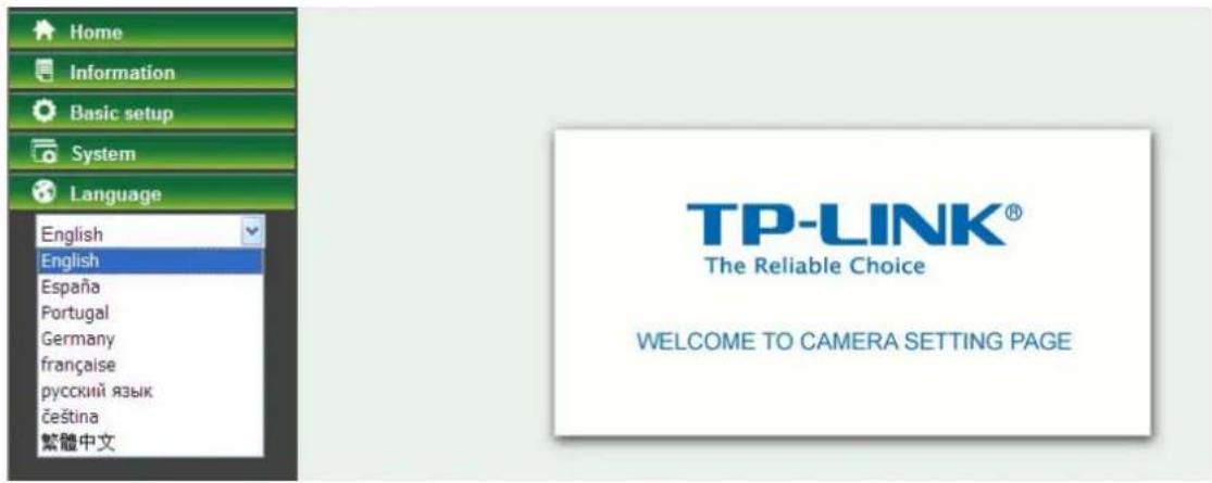
Select a language from the drop-down list; the current display language of the Web User Interface will be changed.
Appendix
A. Frame-rate and Bitrate Table – Helps to set up the camera with your network environment to access the Internet.
Based on your network upload environment, choose the suitable image-quality setting. For example, if the network environment is ADSL 256Kb (upload) / 2Mb (download), the most fluent image quality needs to be set up under 256Kb situation.
MJPEG / Kbps, fps
| Image Size | Frame Rate Setting(FPS) | Current Bitrate(Kbps) | Current Frame Rate(FPS) |
| 640*480 | 30 | 9746 | |
| 640*480 | 20 | 6419 | |
| 640*480 | 15 | 4970 | |
| 640*480 | 10 | 3162 | |
| 640*480 | 7 | 2427 | |
| 640*480 | 5 | 1961 | |
| 640*480 | 1 | 392 | |
| 320*240 | 30 | 3416 | |
| 320*240 | 20 | 2270 | |
| 320*240 | 15 | 1770 | |
| 320*240 | 10 | 1188 | |
| 320*240 | 7 | 900 | |
| 320*240 | 5 | 706 | |
| 320*240 | 1 | 147 | |
| 160*120 | 30 | 1493 | |
| 160*120 | 20 | 989 | |
| 160*120 | 15 | 756 | |
| 160*120 | 10 | 499 | |
| 160*120 | 7 | 346 | |
| 160*120 | 5 | 302 | |
| 160*120 | 1 | 62 |
B. Storage Requirement Table – Helps to set up the recording storage system.
Please refer to the following table to find out the capability for recording into your hard disk.
MJPEG Storage Requirement GB /1 Channel / Day
| Image Size | Frame Rate Setting(FPS) | Current Bitrate(Kbps) | GB /1Channel / 1Day |
| 640*480 | 30 | 9746 | |
| 640*480 | 20 | 6419 | |
| 640*480 | 15 | 4970 | |
| 640*480 | 10 | 3162 | |
| 640*480 | 7 | 2427 | |
| 640*480 | 5 | 1961 | |
| 640*480 | 1 | 392 | |
| 320*240 | 30 | 3416 | |
| 320*240 | 20 | 2270 | |
| 320*240 | 15 | 1770 | |
| 320*240 | 10 | 1188 | |
| 320*240 | 7 | 900 | |
| 320*240 | 5 | 706 | |
| 320*240 | 1 | 147 | |
| 160*120 | 30 | 1493 | |
| 160*120 | 20 | 989 | |
| 160*120 | 15 | 756 | |
| 160*120 | 10 | 499 | |
| 160*120 | 7 | 346 | |
| 160*120 | 5 | 302 | |
| 160*120 | 1 | 62 |
C. System Requirement – Helps to set up the system.
| Item | Requirements |
| CPU Pentium | 4 2.8GHz (or equivalent AMD) |
| Graphic Card | 256 MB RAM graphic cards (or equivalent on-board graphic cards) |
| RAM 2 GB RAM | |
| Operating System | Windows 2000 / Windows 2003 / Windows XP / Windows Vista / Windows 7 |
| Web Browser Internet Explore 8 or higher | |
Europe – EU Declaration of Conformity
This device complies with the essential requirements of the R&TTE Directive 1999/5/EC. The following test methods have been applied in order to prove presumption of conformity with the essential requirements of the R&TTE Directive 1999/5/EC:
| Clause | Description |
| EN 60950-1: 2001 | Safety of Information Technology Equipment |
| EN 50392: 2004 | Generic standard to demonstrate the compliance of electronic and electrical apparatus with the basic restrictions related to human exposure to electromagnetic fields (0 Hz - 300 GHz) |
| EN 300 328 V1.6.1 (2004-11) | Electromagnetic compatibility and Radio spectrum Matters (ERM); Wideband transmission systems; Data transmission equipment operating in the 2,4 GHz ISM band and using wide band modulation techniques; Harmonized EN covering essential requirements under article 3.2 of the R&TTE Directive |
| EN 301 489-17 V1.2.1 (2002-08) and EN 301 489-1 V1.5.1 (2004-11) | Electromagnetic compatibility and Radio spectrum Matters (ERM); ElectroMagnetic Compatibility (EMC) standard for radio equipment and services; Part 17: Specific conditions for 2,4 GHz wideband transmission systems and 5 GHz high performance RLAN equipment |
This device is a 2.4 GHz wideband transmission system (transceiver), intended for use in all EU member states and EFTA countries, except in France and Italy where restrictive use applies.
In Italy, the end-user should apply for a license from the national spectrum authorities in order to obtain authorization to use the device for setting up outdoor radio links and/or for supplying public access to telecommunications and/or network services.
This device may not be used for setting up outdoor radio links in France, and in some areas the RF output power may be limited to 10 mW EIRP in the frequency range of 2454 – 2483.5 MHz. For detailed information, the end-user should contact the national spectrum authority in France.
| Česky[Czech] | [Jméno výrobce] tímto prohlašuje, že tento [typ zařízení] je ve shodě se základními požadavky a dalšími příslušnými ustanoveními směrnice 1999/5/ES. |
| Dansk[Danish] | Undertegnede [fabrikantens navn] erklærer herved, at følgende udstyr [udstyrets typebetegnelse] overholder de væsentlige krav og øvrige relevante krav i direktiv 1999/5/EF. |
| Deutsch[German] | Hiermit erklärt [Name des Herstellers], dass sich das Gerät [Gerätetyp] in Übereinstimmung mit den grundlegenden Anforderungen und den übrigen einschlägigen Bestimmungen der Richtlinie 1999/5/EG befindet. |
| Eesti[Estonian] | Käesolevaga kinnitab [tootja nimi = name of manufacturer] seadme [seadme tüüp = type of equipment] vastavust direktiivi 1999/5/EÜ põhinõuetele ja nimetatud direktiivist tulenevatele teistele asjakohastele sätetele. |
| English | Hereby, [name of manufacturer], declares that this [type of equipment] is in compliance with the essential requirements and other relevant provisions of Directive 1999/5/EC. |
| esEspañol [Spanish] | Por medio de la presente [nombre del fabricante] declara que el [clase de equipo] cumple con los requisitos esenciales y cualesquiera otras disposiciones aplicables o exigibles de la Directiva 1999/5/CE. |
| elΕλληνική [Greek] | ME THN ΠΑΡΟΥΣΑ [name of manufacturer] ΔΗΛΩΝΕΙ ΟΤΙ [type of equipment] ΣΥΜΜΟΡΦΩΝΕΤΑΙ ΠΡΟΣ ΤΙΣ ΟΥΣΙΩΔΕΙΣ ΑΠΑΙΤΗΣΕΙΣ ΚΑΙ ΤΙΣ ΛΟΙΠΕΣ ΣΧΕΤΙΚΕΣ ΔΙΑΤΑΞΕΙΣ ΤΗΣ ΟΔΗΓΙΑΣ 1999/5/EK. |
| frFrançais [French] | Par la présente [nom du fabricant] déclare que l'appareil [type d'appareil] est conforme aux exigences essentielles et aux autres dispositions pertinentes de la directive 1999/5/CE. |
| itItaliano [Italian] | Con la presente [nome del costruttore] dichiara che questo [tipo di apparecchio] è conforme ai requisiti essenziali ed alle altre disposizioni pertinenti stabilite dalla direttiva 1999/5/CE. |
| Latviski [Latvian] | Ar šo [name of manufacturer / izgatavotāja nosaukums] deklarē, ka [type of equipment / iekārtas tips] atbilst Direktīvas 1999/5/EK būtiskajām prasībām un citiem ar to saistītajiem noteikumiem. |
| Lietuvių [Lithuanian] | Šiuo [manufacturer name] deklaruoja, kad šis [equipment type] atitinka esminius reikalavimus ir kitas 1999/5/EB Direktyvos nuostatas. |
| nlNederlands [Dutch] | Hierbij verklaart [naam van de fabrikant] dat het toestel [type van toestel] in overeenstemming is met de essentiële eisen en de andere relevante bepalingen van richtlijn 1999/5/EG. |
| mtMalti [Maltese] | Hawnhekk, [isem tal-manifattur], jiddikjara li dan [il-mudel tal-prodott] jikkonforma mal-ħtiġijiet essenzjali u ma provvedimenti oħrajn relevanti li hemm fid-Dirrettiva 1999/5/EC. |
| huMagyar [Hungarian] | Alulírott, [gyártó neve] nyilatkozom, hogy a [... típus] megfelel a vonatkozó alapvető követelményeknek és az 1999/5/EC irányelv egyéb előírásainak. |
| plPolski [Polish] | Niniejszym [nazwa producenta] oświadcza, że [nazwa wyrobu] jest zgodny z zasadniczymi wymogami oraz pozostałymi stosownymi postanowieniami Dyrektywy 1999/5/EC. |
| ptPortuguês [Portuguese] | [Nome do fabricante] declara que este [tipo de equipamento] está conforme com os requisitos essenciais e outras disposições da Directiva 1999/5/CE. |
| slSlovensko [Slovenian] | [lme proizvajalca] izjavlja, da je ta [tip opreme] v skladu z bistvenimi zahtevami in ostalimi relevantnimi določili direktive 1999/5/ES. |
| Slovensky [Slovak] | [Meno výrobcu] týmto vyhlasuje, že [typ zariadenia] spĺňa základné požiadavky a všetky príslušné ustanovenia Smernice 1999/5/ES. |
| fiSuomi [Finnish] | [Valmistaja = manufacturer] vakuuttaa täten että [type of equipment = laitteen tyyppimerkintä] tyyppinen laite on direktiivin 1999/5/EY oleellisten vaatimusten ja sitä koskevien direktiivin muiden ehtojen mukainen. |
| Svenska [Swedish] | Härmed intygar [företag] att denna [utrustningstyp] står l överensstämmelse med de väsentliga egenskapskrav och övriga relevanta bestämmelser som framgår av direktiv 1999/5/EG. |
Federal Communication Commission Interference Statement
This equipment has been tested and found to comply with the limits for a Class B digital device, pursuant to Part 15 of the FCC Rules. These limits are designed to provide reasonable protection against harmful interference in a residential installation. This equipment generates, uses, and can radiate radio frequency energy and, if not installed and used in accordance with the instructions, may cause harmful interference to radio communications. However, there is no guarantee that interference will not occur in a particular installation. If this equipment does cause harmful interference to radio or television reception, which can be determined by turning the equipment off and on, the user is encouraged to try to correct the interference by one of the following measures:
- Reorient or relocate the receiving antenna.
- Increase the separation between the equipment and receiver.
- Consult the dealer or an experienced radio/TV technician for help.
Connect the equipment into an outlet on a circuit different from that to which the receiver is connected.
This device complies with Part 15 of the FCC Rules. Operation is subject to the following two conditions:
(1) This device may not cause harmful interference, and (2) this device must accept any interference received, including interference that may cause undesired operation.
FCC Caution:
Any changes or modifications not expressly approved by the party responsible for compliance could void the user's authority to operate this equipment.
IMPORTANT NOTE:
FCC Radiation Exposure Statement:
This equipment complies with FCC radiation exposure limits set forth for an uncontrolled environment. This equipment should be installed and operated with a minimum distance of 20 cm between the radiator and your body.
This transmitter must not be co-located or operating in conjunction with any other antenna or transmitter.


- COPYRIGHT & TRADEMARKS
- FCC STATEMENT
- FC
- FCC RF RADIATION EXPOSURE STATEMENT
- CE MARK WARNING
- CE
- NATIONAL RESTRICTIONS
- INDUSTRY CANADA STATEMENT
- IMPORTANT NOTE
- KOREA WARNING STATEMENTS
- DECLARATION OF CONFORMITY
- CE1588①
- CONTENTS
- PACKAGE CONTENTS
- CHAPTER 1 SAFETY INSTRUCTIONS
- CHAPTER 2 MINIMUM SYSTEM REQUIREMENT & PRODUCT FEATURE
- CHAPTER 3 USING CAMERA VIA WEB BROWSER
- CHAPTER 4 OPERATING CAMERA VIA MOBILE PHONE
- CHAPTER 5 CONFIGURATION OF MAIN MENU
- APPENDIX
- EUROPE – EU DECLARATION OF CONFORMITY
- FEDERAL COMMUNICATION COMMISSION INTERFERENCE STATEMENT
- NOTE
- BEFORE YOU USE THIS PRODUCT
- LEGAL CAUTION
- DON'T OPEN THE HOUSING OF THE PRODUCT
- DON'T USE THE ACCESSORIES NOT RECOMMENDED BY THE MANUFACTURER
- ➢ HEED THE SAFETY PRECAUTIONS
- ➢ OPERATION NOTICE - OPERATING OR STORAGE LOCATION
- IN CASE OF A BREAKDOWN
- IN CASE OF ABNORMAL OPERATION
- TRANSPORTATION
- VENTILATION
- CLEANING
- SYSTEM REQUIREMENT
- PRODUCT FEATURES
- PHYSICAL OVERVIEW
- FRONT VIEW
- POWER LED INDICATOR
- REAR VIEW
- MOUNT THE CAMERA
- THE SCREW SIZE
- WALL AND CEILING MOUNT
- HARDWARE CONNECTION
- WIRED CONNECTION
- WIRELESS CONNECTION (BY WPS)
- OBTAIN THE IP ADDRESS
- WINDOWS WEB BROWSER
- MOBILE PHONE VIEWING
- G MOBILE PHONE STREAMING VIEWING
- G MOBILE PHONE WAP VIEWING
- G MOBILE PHONE BROWSER VIEWING
- USING CAMERA VIA IPHONE
- SELECT SAFARI FUNCTION. 2. ENTER IP ADDRESS IN YOUR WEB LINK
- ENTER NAME AND PASSWORD. DEFAULT VALUES ARE BOTH ADMIN. THEN CLICK LOG IN
- THE TP-LINK USER INTERFACE AND LIVE IMAGE WILL SHOW UP IN THE MIDDLE OF THE SCREEN
- HOME
- VIDEO PLAY BUTTONS
- SNAPSHOT
- DIGITAL ZOOM IN/OUT THE IMAGE VIA THE MONITOR WINDOW
- AUDIO BUTTONS
- INFORMATION
- BASIC SETUP
- ACCOUNT
- TO ADD A NEW ACCOUNT, PLEASE FOLLOW THE STEPS BELOW
- NETWORK
- TCP/IP
- PPPOE
- DDNS (DYNAMIC DNS)
- UPNP (UNIVERSAL PLUG AND PLAY)
- WIRELESS
- ➢ STATUS OF WIRELESS NETWORKS
- TO CONNECT TO A NETWORK, PLEASE FOLLOW THE INSTRUCTIONS BELOW
- WPS
- PBC (PUSH BUTTON CONFIGURATION) METHOD
- PIN METHOD
- IMAGE SETTING
- VIDEO
- AUDIO
- CAMERA SETTING
- EVENTS
- MOTION DETECTION
- E-MAIL (SMTP)
- FTP
- SYSTEM
- INITIALIZE
- DATE TIME
- LANGUAGE
- FRAME-RATE AND BITRATE TABLE – HELPS TO SET UP THE CAMERA WITH YOUR NETWORK ENVIRONMENT TO ACCESS THE INTERNET
- STORAGE REQUIREMENT TABLE – HELPS TO SET UP THE RECORDING STORAGE SYSTEM
- SYSTEM REQUIREMENT – HELPS TO SET UP THE SYSTEM
- FCC CAUTION
- FCC RADIATION EXPOSURE STATEMENT
Brand : TP-LINK
Model : TL-SC2020N
Category : Surveillance Camera