DCS-5222L - Surveillance Camera D-LINK - Free user manual and instructions
Find the device manual for free DCS-5222L D-LINK in PDF.

User questions about DCS-5222L D-LINK
0 question about this device. Answer the ones you know or ask your own.
Ask a new question about this device
Download the instructions for your Surveillance Camera in PDF format for free! Find your manual DCS-5222L - D-LINK and take your electronic device back in hand. On this page are published all the documents necessary for the use of your device. DCS-5222L by D-LINK.
USER MANUAL DCS-5222L D-LINK
natural_image
White Dianak 3.0 smart camera with black lens and white antenna, no visible text or symbols on device bodyUser Manual
HD Wireless N Pan/Tilt Network Camera
DCS-5222L
Manual Overview
D-Link reserves the right to revise this publication and to make changes in the content hereof without obligation to notify any person or organization of such revisions or changes. Information in this document may become obsolete as our services and websites develop and change. Please refer to the www.mydlink.com website for the most current information.
Manual Revisions
| RevisionDateDescription | ||
| 2.0 2013 | /11/19 DCS-5222L Revision | B1 with firmware version 2.00 |
Trademarks
D-Link and the D-Link logo are trademarks or registered trademarks of D-Link Corporation or its subsidiaries in the United States or other countries. All other company or product names mentioned herein are trademarks or registered trademarks of their respective companies.
Copyright © 2013 by D-Link Corporation.
All rights reserved. This publication may not be reproduced, in whole or in part, without prior expressed written permission from D-Link Corporation.
Table of Contents
Product Overview 1
Package Contents 1
System Requirements 2
Introduction ....3
Features 4
Hardware Overview 5
Front 5
LEDs 6
Back....7
Left and Right Side 8
Adjusting Camera Focus 9
Installation ....10
Zero Configuration Setup ....11
Camera Setup Wizard 14
Wireless Installation Considerations ....17
WPS - Push Button Setup ....18
mydlink 19
Configuration 21
Configuration Utility 21
Live Video 22
Setup 24
Setup Wizard 24
Internet Connection Setup Wizard 25
Motion Detection Setup Wizard 29
Network Setup 33
Wireless Setup 36
Dynamic DNS 37
Image Setup 38
Audio and Video 40
PTZ 42
Motion Detection ....44
Sound Detection 45
Time and Date 46
SD Management ....56
Advanced 57
Digital Input/Output 57
ICR and IR 58
HTTPS 59
Access List....60
Maintenance 61
Admin 61
System 63
Firmware Upgrade 64
Status 65
Device Info 65
Log 66
Help 67
Configuring the DCS-5222L with a Router ....68
Troubleshooting ....74
Table of Contents
Networking Basics ....77
Check your IP address ....77
Statically Assign an IP Address 78
Technical Specifications 80
Product Overview Package Contents
DCS-5222L Network Camera

Power Supply ^1

Camera Base and Mounting Kit

CD-ROM

CAT5 Ethernet Cable
^1 Using a power supply with a different voltage rating than the one included with the DCS-5222L will cause damage and void the warranty for this product. If any of the above items are missing from your package, please contact your retailer.
System Requirements
| Network Requirements · 10/10 | Ethernet network or a 802.11n/g/b wireless network |
| CD Setup Wizard Requirements | An Internet connectionA router connected to your broadband modemComputer with the following:A PC with a wired connection to your routerWindows® 8 (32/64bit), Windows® 7 (32/64bit), XP (32/64bit), Vista® (32/64bit), Mac OS®X 10.5 or above |
| Web-based Configuration Utility Requirements | Browser Requirements:Internet Explorer 8 or higherFirefox 12 or higherSafari 4 or higherChrome 20 or higherNote:Make sure you have the latest version of Java installed.Visit www.java.com to download the latest version. |
| mydlink Website Requirements | Broadband Internet connectionComputer with:Internet Explorer 7 or higher (ActiveX)Firefox 12 or higherSafari 4 or higherChrome 20 or higher |
Introduction
Congratulations on your purchase of the DCS-5222L HD Wireless N Pan/Tilt Network Camera. The DCS-5222L is a versatile solution for your small office or home. The DCS-5222L is a complete system with a built-in CPU and web server that transmits high quality video for security and surveillance. It can be accessed remotely, and controlled from any PC/Notebook over your local network or across the Internet via a web browser. The DCS-5222L features 802.11n wireless connectivity, allowing the camera to be placed anywhere within range of your wireless network. The DCS-5222L comes with remote monitoring and motion detection features for a complete and cost-effective home security solution.
Features
Simple to Use
The DCS-5222L is a stand-alone system with a built-in CPU, requiring no special hardware or software such as PC frame grabber cards. The DCS-5222L supports both ActiveX mode for Internet Explorer and Java mode for other browsers such as Firefox, Chrome, and Safari.
Supports a Variety of Platforms
The DCS-5222L supports TCP/IP networking, HTTP, and other Internet related protocols. It can also be integrated easily into other Internet/Intranet applications because of its standards-based features.
Web Configuration
Using a standard web browser, administrators can configure and manage the network camera directly from its own web page via an Intranet or the Internet.
Broad Range of Applications
With today's high-speed Internet services, the DCS-5222L network camera can provide an ideal solution for live video over the Internet and for remote monitoring. The DCS-5222L allows remote access from a web browser for live image viewing and management of the network cameras anytime, from anywhere in the world. The network camera has a wide range of applications, including industrial and public monitoring of homes, offices, banks, hospitals, child-care centers, and amusement parks.
802.11n Wireless or Ethernet/Fast Ethernet Support
The DCS-5222L offers wireless 802.11n and Ethernet/Fast Ethernet connectivity, making the DCS-5222L easy to integrate into your existing network environment. The DCS-5222L works with a 10Mbps Ethernet based network or 100Mbps Fast Ethernet based network for traditional wired environments, and works with 802.11n routers or access points for added flexibility. The Site Survey feature also allows you to view and connect to any available wireless networks.
Remote Monitoring Utility
The D-ViewCam application adds enhanced features and functionality for the network camera and allows administrators to configure and access the network camera from a remote site via Intranet or Internet. Other features include image monitoring, recording images to a hard drive, viewing up to 32 cameras on one screen, and taking snapshots. Note that D-ViewCam works on Windows® computers only.
IR LED for day and night functionality
The built-in infrared LEDs enables night time viewing of up to 26 feet (8 meters).
Hardware Overview
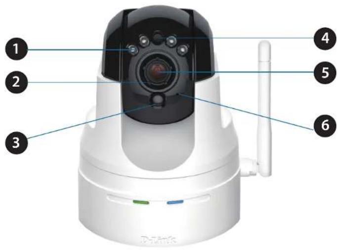
Front
text_image
1 2 3 4 5 6 Datedk| 1 IR LEDs for night vision Used to illuminate the camera's field of view at night | |
| 2 Focus Adjustment Ring Enables manual adjustment of the cameras focal length | |
| 3 Passive Infrared Sensor Passive Infrared (PIR) sensor for motion detection | |
| 4 Light Sensor Detects light levels and adjusts IR-LEDS accordingly | |
| 5 Camera Lens Records video of the surrounding area | |
| 6 Microphone Records audio from the surrounding area |
Hardware Overview LEDs

natural_image
White digital security camera with attached antenna and control buttons (no visible text or symbols)| 1 Power & Link LED | The LED will be solid red while the camera boots, performs a self test, and searches for a network connection. The LED will switch to solid green when a proper connection has been achieved. The LED will blink green during data transfer |
| 2 WPS Status LED Indicates the WPS (Wi-Fi Protected Setup) connection status of the camera | |
Hardware Overview
Back

text_image
1 2 3 AUDIO -12/34 ETHERNET 5V=2.8A RESET 4 5| 1 Ethernet Port Connect 10/100 Ethernet devices such as computers, switches, and hubs |
| 2 Audio 3.5 mm jack for audio I/O devices such as microphones and speakers |
| 3 Reset Button Press the reset button to return the device back to it's factory conditions |
| 4 DI/DO Attach digital I/O devices such as alarms or motion sensors |
| 5 Power Receptor Connects to the power adapter |
Hardware Overview Left and Right Side

| 1 Built in Speaker | The speaker can be used in conjunction with the built-in microphone to enable the camera to acts as an intercom. |
| 2 Antenna The external antenna increases the device's range of connectivity. | |
| 3 WPS Button | Use WPS (Wi-Fi Protected Setup) to easily create a secure connection to your network. |
| 4 microSD Slot Insert a microSD card to store recorded images and video. | |
Adjusting Camera Focus
To manually adjust the camera focus, rotate the focusing ring around the lens clockwise or anti-clockwise.

natural_image
White DLink 3D headset with black dome and white frame, showing camera module and antenna (no text or symbols visible)Installation
There are three ways to set up your camera:
- Zero Configuration Setup: If you have a mydlink-enabled router, this is the easiest way to set up your camera. Refer to page 11.
- Camera Setup Wizard: If you do not have a mydlink-enabled router, use the Camera Installation Wizard to guide you through setup and initial configuration of your camera. Refer to page 14.
- Manual Hardware Installation: This section shows you how to manually set up your camera, though in order to use the mydlink features of your camera, you will still need to run the Camera Installation Wizard. Refer to page 16.
Zero Configuration Setup
If you have a mydlink-enabled Cloud Router, you can take advantage of Zero Configuration. Zero Configuration automatically configures your camera's settings for you, and adds it to your mydlink account automatically. This type of setup allows you to set up your camera by simply plugging it in and connecting it to your router.
Connect your camera to your mydlink-enabled Cloud Router and Zero Configuration will automatically configure your DCS-5222L and automatically add the camera to your mydlink account. After the short time it takes to do this you can remotely access your camera from the www.mydlink.com website to manage and monitor your DCS-5222L.
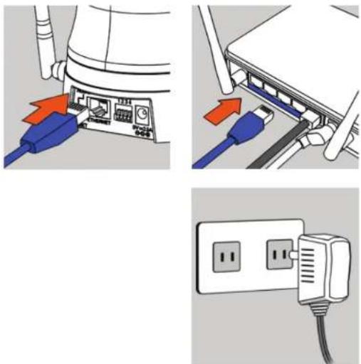
Connect the Ethernet Cable
Use the included Ethernet cable and plug it into the camera. Plug the other end into an available port on your router. If you wish to use your camera wirelessly, you will be able to remove the cable after Zero Configuration Setup is complete.

natural_image
Diagram showing two installation steps of a server or network device, with blue cables and connectors inserted (no text or symbols visible)Attach the External Power Adapter
Connect the power adapter to the power connector on your camera, then plug the power adapter into a wall outlet.

natural_image
Illustration of a wall-mounted power plug with three slots and a cable (no text or symbols)Section 1 - Product Overview
Check Your mydlink Account
Open a web browser and login to your mydlink account. The mydlink page will check for new devices and display a New device Found! pop-up notification in the bottom-left corner. Click the notification to continue.

text_image
mydlink Welcome, Mobile P My Devices Shared Devices My Services My Profile DMS-805R 20618862 Reverse Status Settings Model Name DOS-805L Network Name(SOD) Tasket Infected IP 192.900.1.143 LAN IP 192.900.6.1 Connected Devices 3 devices(s) Reset Connection List Device Device Name IP Address MAC Address Block CardboardBus 192.900.1.19 06:30:00:07:00:00:00:00:00:00:00:00:00:00:00:00:00:00:00:00:00:00:00:00:00:00:00:00:00:00:00:00:00:00:00:00:00:00 - - 192.900.1.19 64.54.53.54.55.55.55.55.55.55.55.55.55.55.55.55.55.55.55.55.55.55.55.55.55.55.55.55.55.55.55.55.55.55.55.55.55.55 - - 192.900.1.19 34.14.32.33.43.43.43.43.43.43.43.43.43.43.43.43.43.43.43.43.43.43.43.43.43.43.43.43 - - 192.900.1.19 26.66.26.26.66.66.66.66.66.66.66.66.66.66.66.66.66.66.66.66 192. - FE 422 78 88 88 88 88 88 88 88 88 88 88 88 88 88 88 88 88 88 88 88 88 88 88 88 88 88 88 88 88 88 88 88 88 88 8A summary and confirmation notification will appear with the automatically configured details. Make a note of the details and click Yes to add the camera to your account.

text_image
Confirming New Device Do you want to add this new device to your mydlink account? Device Name: DCS-5222L mydlink Number: 44441252 Network name (SSID): dddddddd Admin Password: oic953XZ You can change these default settings by going to Advanced Settings after add it to your device list. Not now YesSection 1 - Product Overview
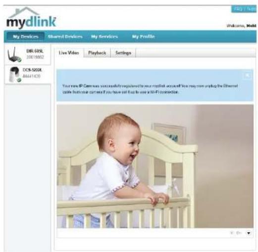
Zero Configuration will navigate to the mydlink Live View tab for your camera where you will see a screen similar to the following.
If you wish to connect your camera to your router wirelessly, you can simply disconnect the Ethernet cable and move the camera to its intended location; your router's wireless settings have been automatically transferred to the camera, and no further configuration is required.
Your camera is now set up, and you can skip to "mydlink" on page 19 to learn more about the mydlink features of this camera, or to "Configuration" on page 21 for advanced configuration of your camera.
text_image
mydlink My Devices Shared Devices My Services My Profile DRL-609L 20019902 Live Video Playback Settings DCS-SZQXL 44411439 Your new IP Camera was successfully registered to your mcdink accia## You may now upgrade the Ethernet cable from your carneta if you have sell it as to use a 51-FI connection.Camera Setup Wizard
If you do not have a mydlink-enabled Cloud Router, you can use the Camera Setup Wizard to guide you through the process of adding your camera to the mydlink service.
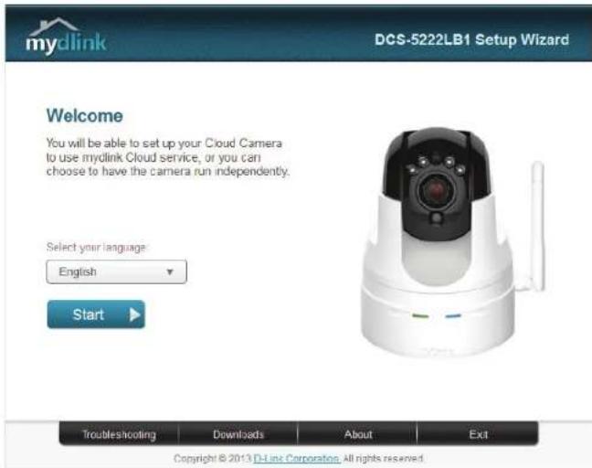
Windows Users
Insert the Installation CD-ROM into your computer's optical drive to start the autorun program. If the autorun program does not open, go to My Computer, browse to your CD drive, and double-click on the autorun.exe file. Once the wizard has started simply click Set up your Cloud Camera to go through the Setup Wizard, which will guide you step-by-step through the installation process from connecting your hardware to configuring your camera and registering it with your mydlink account.

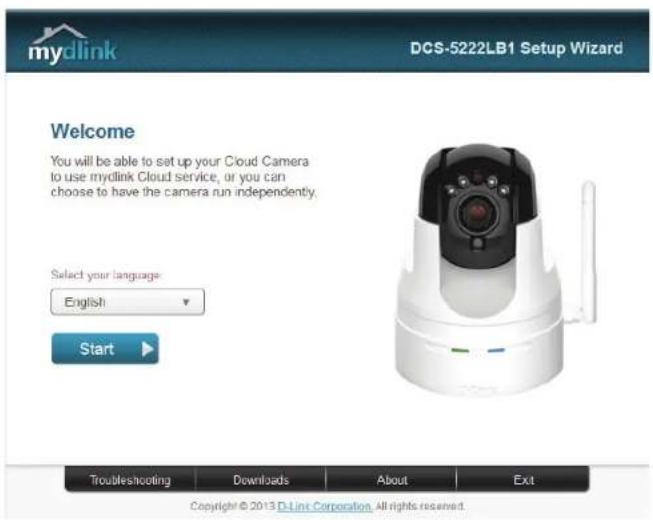
text_image
mydlink DCS-5222LB1 Setup Wizard Welcome You will be able to set up your Cloud Camera to use mydlink Cloud service, or you can choose to have the camera run independently. Select your language English Start Troubleshooting Downloads About Exit Copyright © 2013 D-Link Corporation. All rights reserved.Mac Users
Insert the Installation CD-ROM into your computer's optical drive. On the desktop, open your CD drive and double-click on the SetupWizard file.

SetupWizard
After about 20-30 seconds, the Setup Wizard will open, which will guide you step-by-step through the installation process from connecting your hardware to configuring your camera and registering it with your mydlink account.
text_image
mydlink DCS-5222LB1 Setup Wizard Welcome You will be able to set up your Cloud Camera to use mydlink Cloud service, or you can choose to have the camera run independently. Select your language: English Start Troubleshooting Downloads About Exit Copyright © 2013 D-Link Corporation. All rights reserved.Manual Hardware Installation
If you wish to set up your camera without using the Camera Setup Wizard, please follow these steps.
Note: In order to use the mydlink features of this product, you will need to go through the Camera Setup Wizard or Zero Configuration Setup.
Connect the Ethernet Cable and Power Cable
Use the included Ethernet cable and plug it into the camera. Plug the other end into an available LAN port on your router. Plug the supplied power adapter into the back of the camera
Plug in the External Power Adapter
Plug the power adapter into a wall outlet.
Configure Your Camera
Refer to "Configuration" on page 21 for information on how to configure your camera.
Optional: Use WPS to Connect Wirelessly
You can use WPS to connect your camera to your network wirelessly. For more information, refer to "WPS - Push Button Setup" on page 18. If your router does not support WPS, you will still be able to set up your camera's wireless settings in the camera's web interface.
Wireless Installation Considerations
The D-Link Wireless Network Camera lets you access your network using a wireless connection from anywhere within the operating range of your wireless network. However, the number, thickness and location of walls, ceilings, or other objects that the wireless signals must pass through, may limit the range. Typical ranges vary depending on the types of materials and background RF (radio frequency) noise in your home or business. The key to maximizing wireless range is to follow these basic guidelines:
- Minimize the number of walls and ceilings between your adapter and other network devices (such as your network camera) - each wall or ceiling can reduce your adapter's range from 3-90 feet (1-30 meters).
- Be aware of the direct line between network devices. A wall that is 1.5 feet thick (.5 meters), at a 45-degree angle appears to be almost 3 feet (1 meter) thick. At a 2-degree angle, it looks over 42 feet (14 meters) thick. Position your devices so that the signal will travel straight through a wall or ceiling (instead of at an angle) for better reception.
- Building materials make a difference. A solid metal door or aluminum studs may weaken the wireless signal. Try to position your access points, wireless routers, and other networking devices where the signal passes through drywall or open doorways. Materials and objects such as glass, steel, metal, walls with insulation, water (fish tanks), mirrors, file cabinets, brick, and concrete will degrade your wireless signal.
- Keep your product at least 3-6 feet or 1-2 meters away from electrical devices or appliances that generate RF noise.
- If you are using 2.4GHz cordless phones or other radio frequency sources (such as microwave ovens), your wireless connection may degrade dramatically or drop completely. Make sure your 2.4GHz phone base is as far away from your wireless devices as possible. The base transmits a signal even if the phone in not in use.
WPS - Push Button Setup
You may create a connection to the camera using the Wi-Fi Protected Setup (WPS) feature.
To create a WPS connection:
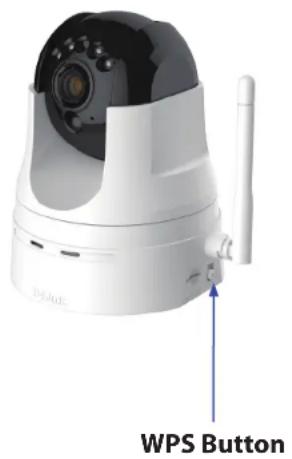
Step 1
Press and hold the WPS button for three seconds. The blue WPS status LED above the button will blink.
Step 2
Press the WPS button on your router or access point within 120 seconds. The WPS button is usually on the front or side of your router. On some routers and access points, you may need to log in to the web interface and click on an on-screen button to activate the WPS feature. If you are not sure where the WPS button is on your router/AP, please refer to your router or AP's user manual.
The DCS-5222L will automatically create a wireless connection to your router or access point. While connecting, the green LED will flash and your camera will reboot.
text_image
WPS Buttonmydlink
After registering your DCS-5222L camera with a mydlink account in the Camera Setup Wizard. You will be able to remotely access your camera from the www.mydlink.com website. After signing in to your mydlink account, you will see a screen similar to the following:

text_image
mydlink FAQ | Support : | Language: English▼ Welcome, TWQA Demo Tester | Sign out My Devices My Profile CloudCam 44441364 Test1 30567086 Live Video Playback Settings News 2011/09/15 07:00 mydlink Server Shutdown Notificati... 2011/8/30 6:00 mydlink Server Shutdown Notificati... Support Setup wizard User manual Firmware Quick Installation Guide GO mydlink mydlink on mobile... Global D-Link | About mydlink | Terms of Use | Privacy Policy | Contact Us Copyright©2008-2011 D-Link Corp. All rights reserved.For more details on using your camera with mydlink, go to the Support section of the mydlink website and check the User Manual section for your product to find the latest instruction guide for your camera's mydlink features.
Camera Status
Here, you can see the online status of each of your cameras. Your online status may be one of the following:

A green checkmark indicates that your camera is online and ready to use.
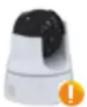
A yellow exclamation point indicates that your camera is online, but the camera password has changed. You will need to enter your new camera password to access your camera again.

A red X indicates that your camera is offline and currently cannot be accessed remotely.
If your camera is offline, try the following:
- Check to make sure that the Internet connection to your camera is working properly.
- Try restarting your Internet router.
- Check your camera's cable connections and make sure they are secure.
- Check to make sure that the LED on your camera is lit solid green.
If you still cannot access your camera, reset your camera and run the Camera Installation Wizard again from the CD-ROM included in your package.
Configuration Configuration Utility
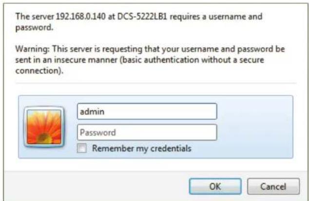
After completing the Camera Installation Wizard, you are ready to use your camera. The camera's built-in Web configuration interface is designed to allow you to easily access and configure your DCS-5222L. At the end of the wizard, enter the IP address of your camera into a web browser, such as Internet Explorer®. To log in, use the User name admin and the password you created in the Installation Wizard. If you did not create a password, the default password is blank. After entering your password, click OK.
Note: If you are directly connecting your PC to the camera, or if you are using the camera on a closed network, the default IP is 192.168.0.20.
text_image
The server 192.168.0.140 at DCS-5222LB1 requires a username and password. Warning: This server is requesting that your username and password be sent in an insecure manner (basic authentication without a secure connection). admin Password Remember my credentials OK CancelLive Video
A live feed from the camera is displayed upon logging into the camera's web interface.
P/T/Z Action Pad: Use the Pan / Tilt / Zoom action pad to control the camera's movement and zoom. The large arrow icons will move the camera up, down, left or right while the small arrow icons will move the camera position diagonally in the direction they are pointed. The Home button will move the camera to the preset "Home" position.
Pan: Press this button and the camera will pan from left-most position to the right-most position and then return to its original position.
Preset Sequence: Click this button to quickly move the camera to the desired patrol setup according to preset positions. Please refer to "PTZ" on page 42 to create preset positions.
Stop: This will stop pan and patrol.
Go To: Select from the preset drop-down list to quickly move the camera to the desired preset position. Please refer to "PTZ" on page 42 to create preset positions.
Pan/Tilt/Auto Pan These setting can change the camera's pan/tilt and auto pan speed. Speed:
Dwell Time: Set the length of time in seconds for the camera to remain at each preset point on a path.
Language Select the default language for the user interface. Selection:
The next page contains several icons which can be used to control the camera's main functions.

text_image
D-Link DCS-5222L81 LIVE VIDEO SETEP ADVANCED MAINTENANCE STATUS HELP LIVE VIDEO This section shows your current's live video. You can control your settings using the buttons below. Current resolutions are 645 x 448. LIVE VIDEO 2013/10/30 16:05:44 DCS-5222L81Section 4 - Configuration
| Icon Button Name Function | ||
 | Profile buttons | Use these buttons to switch between video profiles. Refer to "Audio and Video" on page 40 for more information on setting up profiles. |
 | Full Screen button Displays the video at full screen. | |
 | Snapshot button | Takes a snapshot of the image currently displayed on the screen and will save it to a file on the hard drive in a folder specified using the Storage folder button. |
 | Video recording button | Triggers the camera's recording function. This will record the video displayed on the screen and will save it to a file on the hard drive in a folder specified using the Storage folder button. |
 | Storage folder button Sets the location to save snapshots and video recordings. | |
 | Listen button | Sends the audio received from the camera's microphone through to the PC's speakers. Click again to turn off. |
 | Talk button | Sends audio from a microphone connected to your PC through to the speakers connected to the camera. |
 | Start Digital Input Press this button to initiate the connected digital input. | |
 | Digital Input Indicator | This indicator will change color when a digital input signal is detected. |
 | Motion Trigger Indicator | This indicator will change color when a motion trigger event occurs if enabled. |
 | Recording Indicator | When a recording is in progress, this indicator will change color. |
 | Auto Pan | Starts the automatic panning function. The ROI will pan from back and forth within the FOV |
 | Stop Stops automatic panning. | |
| [KS5D] | Preset Path Starts the camera's motion along the predefined path. | |
Setup Setup Wizard
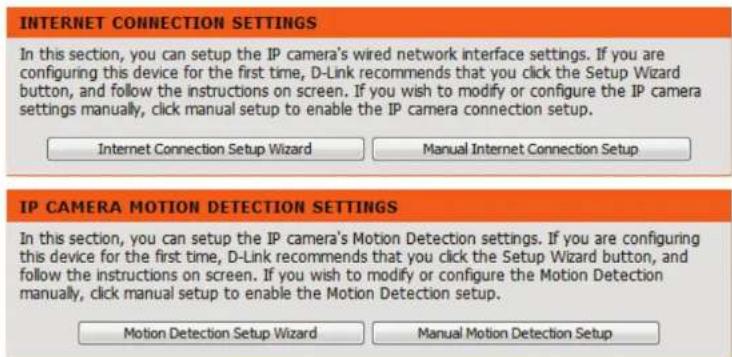
This section allows you to begin setup wizards which will guide you through the process of getting your camera's various functions configured. If you comfortable with adjusting the settings manually, you may skip the wizards and adjust the necessary as needed.
Internet You may choose to configure your network by Connection using the Internet Connection Setup Wizard Setup Wizard: that includes step-by-step instructions. Please refer to page "Internet Connection Setup Wizard" on page 25 for more details.
Manual If you would rather manually setup the camera Internet internet connection, you can refer to "Network Connection Setup" on page 33 which provides more details Setup: on the information required.
Motion You may choose to configure motion detection Detection by using the Motion Detection Setup Wizard Setup Wizard: that includes step-by-step instructions. Please refer to page "Motion Detection Setup Wizard" on page 29 for more details.
Manual If you would rather manually setup the camera's Motion motion detection features, you can refer to Detection page "Motion Detection" on page 44 which Setup: provides more details on the information required.
text_image
INTERNET CONNECTION SETTINGS In this section, you can setup the IP camera's wired network interface settings. If you are configuring this device for the first time, D-Link recommends that you click the Setup Wizard button, and follow the instructions on screen. If you wish to modify or configure the IP camera settings manually, click manual setup to enable the IP camera connection setup. Internet Connection Setup Wizard Manual Internet Connection Setup IP CAMERA MOTION DETECTION SETTINGS In this section, you can setup the IP camera's Motion Detection settings. If you are configuring this device for the first time, D-Link recommends that you click the Setup Wizard button, and follow the instructions on screen. If you wish to modify or configure the Motion Detection manually, click manual setup to enable the Motion Detection setup. Motion Detection Setup Wizard Manual Motion Detection SetupInternet Connection Setup Wizard
This wizard will guide you through a step-by-step process to configure your new D-Link Camera and connect the camera to the Internet. Note that this wizard will not register your camera with mydlink.com.
Click Next to continue.
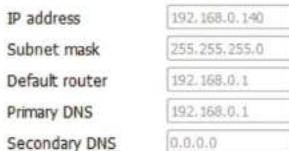
Select DHCP if you want your DHCP server (usually enabled on your router) to assign the camera its IP settings. If you want to manually assign the IP settings, select Static IP Address and enter the following details:
IP Address: Enter an IP address for your camera.
Subnet Mask: Enter the subnet mask of your network.
Default Gateway: Enter the default gateway address. This is usually the IP address of your router.
Primary DNS: Enter the primary DNS server's IP address. This is usually the IP address of your router.
Secondary DNS: Enter the secondary DNS server's IP address. This is optional.
If you are required to connect using PPPoE, select Enable PPPoE and enter the Username and Password for your PPPoE connection. Only select this option if your camera is directly connected to your broadband modem. If it is on a network with a router or gateway, do not select this option. Click Next to continue.
welcome to d-link setup wizard - internet connection setup
This wizard will guide you through a step-by-step process to configure your new D-Link IP camera and connect the IP camera to the internet. To set-up your camera motion detection settings, please click Back button to close this wizard and re-open the motion detecti
• Step 1: Setup LAN Settings
• Step 2: Setup DDNS Settings
• Step 3: IP camera Name Settings
- Step 4: Setup Time Zone
Back Next Cancel
Step 1: Setup LAN Settings
Please select whether your IP camera will connect to the Internet with a DHCP connection or Static IP address. If your IP camera is connected to a router, or you are unsure which settings to pick, D-Link recommends that you keep the default selection of DHCP connecPlease enter your ISP Username and Password in the case that your ISP is using PPPoE and then click on the Next button. Please contact your ISP if you do not know your Username and Password.
DHCP
Static IP Client
IP address
Subnet mask
Default router
Primary DNS
Secondary DNS
Enable PPPoE
User Name
Password
Back Next Cancel
192.168.0.140
255.255.255.0
192.168.0.1
192.168.0.1
(e.g. 654321@hinet.net)
ext Cancel
Section 4 - Configuration
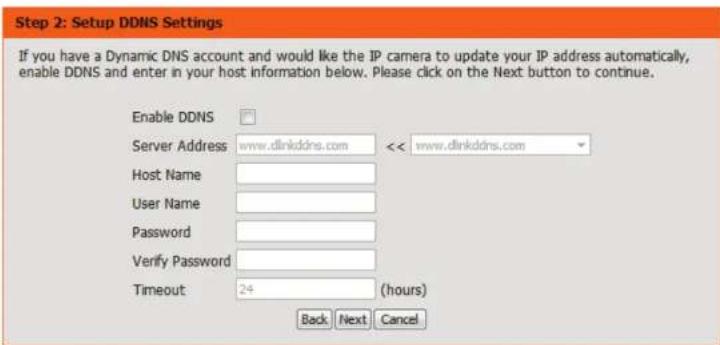
A Dynamic DNS account allows you to access your camera over the Internet when you have an IP address that changes each time you connect to the Internet. If you have a Dynamic DNS account, click Enable and enter the following details:
Enable: Click to enable the DDNS function.
DDNS: (Dynamic Domain Name Server) will hold a DNS host name and synchronize the public IP address of the modem when it has been modified. The username and password are required when using the DDNS service.
Server Address: Select your Dynamic DNS Server from the drop down menu.
Host Name: Enter the host name of the DDNS server.
User Name: Enter your username or e-mail address used to connect to the DDNS.
Password: Enter your password used to connect to the DDNS server.
Timeout: You can setup how often the camera notifies the DDNS server of its current global IP address by entering a whole number in hours.
Click Next to continue.
text_image
Step 2: Setup DDNS Settings If you have a Dynamic DNS account and would like the IP camera to update your IP address automatically, enable DDNS and enter in your host information below. Please click on the Next button to continue. Enable DDNS Server Address: www.dlinkddns.com << www.dlinkddns.com Host Name User Name Password Verify Password Timeout: 24 (hours) Back Next CancelSection 4 - Configuration
Create a unique name for your camera. Click Next to continue.
Step 3: IP camera Name Settings
D-Link recommends that you rename your IP camera for easy accessibility. You can then identify and connect to your IP camera via this name. Please assign a name of your choice before clicking on the Next button.
IP camera Name DCS-5222LB1
Back Next Cancel
Select the time zone that the camera is geographically located in so that scheduled events occur at the correct time. If your time zone observes daylight saving, check the Enable Daylight Saving box and select Auto Daylight Saving to have DST set automatically or select Set date and time manually to enable the drop-down menu so that you can set the start and end time of daylight saving yourself.
Step 4: Setup Time Zone
Please configure the correct time to ensure that all events are triggered, captured and scheduled at the correct time and day and then click on the Next button.
Time Zone
(UTC+09:00) Irkutsk
Enable Daylight Saving
Back Next Cancel
Click Next to continue.
Section 4 - Configuration
A summary of the options you selected is displayed for confirmation. If you are happy with the selected configuration, click Apply otherwise click Back to make the required changes.
Step 5: Setup complete
Below is a summary of your IP camera settings. Click on the Back button to review or modify settings or click on the Apply button if all settings are correct. It is recommended to note down these settings in order to access your IP camera on the network or via your
IP Address DHCP
IP camera Name DCS-5222L81
Time Zone (UTC+09:00) Irkutsk
DDNS Disable
PPPoE Disable
Back Apply Cancel
Motion Detection Setup Wizard
This wizard will guide you through a step-by-step process to configure the motion detection feature of your new D-Link Camera
Click Next to continue.
Welcome To D-LINK Setup Wizard - Motion Detection
This wizard will guide you through a step-by-step process to configure your IP camera's motion detection functions. To setup the IP camera LAN or Internet settings, please click on the Back button to close this wizard and re-open the IP camera Setup wizard. Otherwise d
• Step 1: Specify Motion Detection Area Settings
• Step 2: Motion Detection Schedule
• Step 3: Alerts and Notifications
Back Next Cancel
Section 4 - Configuration
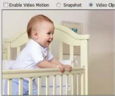
Enabling the Video Motion option will allow your camera to use the motion detection feature. You may draw a finite motion area that will be used for monitoring in a selected area.
Enable Video Select this box to enable the motion detection Motion: feature of your camera, and specify whether the camera should capture a snapshot or a video clip when motion is detected.
Sensitivity: Specifies the measurable difference that would indicate motion. Enter a value between 0 and 100.
Click Next to continue.
Step 1: Specify Motion Detection Area Settings
This section will allow you to enable or disable motion detection as well as control the sensitivity of your camera's ability to detect movement.
natural_image
Baby in a white baby crib with blue trim, no visible text or symbols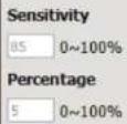
Back Next Cancel
Step 1: Specify Motion Detection Area Settings
This section will allow you to enable or disable motion detection as well as control the sensitivity of your camera's ability to detect movement.
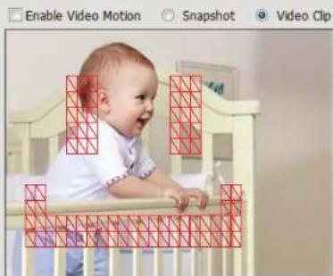
natural_image
Baby in a baby crib with red grid overlay, no text or symbols visible
Back Next Cancel
Section 4 - Configuration
This step allows you to enable motion detection based on a customized schedule. Specify the day and hours. You may also choose to always record whenever motion is detected.
step 2: Motion Detection Schedule
This final step allows you to specify how you receive notification of camera events. Choose between an email notification or alternatively you can setup an FTP Notification. You will need your email account settings or FTP details. If you are unsure of th
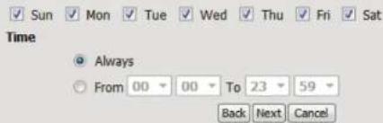
text_image
Sun Mon Tue Wed Thu Fri Sat Time Always From 00 00 To 23 59 Back Next CancelStep 3
This step allows you to specify how you will receive event notifications from your camera. You may choose not to receive notifications, or to receive notifications via e-mail or FTP.
Please enter the relevant information for your e-mail or FTP account.
Click Next to continue.
Step 3: Alerts and Notification
This final step allows you to specify how you receive notification of camera events. Choose between an email notification or alternatively you can setup an FTP Notification. You will need your email account settings or FTP details. If you are unsure of th
Do not notify me
Email

text_image
Sender email address d@link.com Recipient email address d@link.com Server address mail.dink.com User name hi Password •••••••••• Port 25FTP
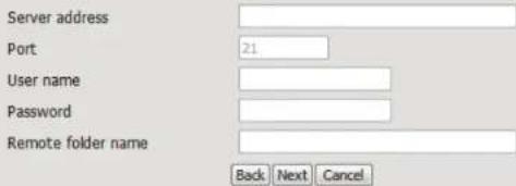
text_image
Server address Port 21 User name Password Remote folder name Back Next CancelSection 4 - Configuration
A summary of the options you selected is displayed for confirmation. If you are happy with the selected configuration, click Apply otherwise click Back to make the required changes.
Step 4: Setup Complete
You have completed your IP camera setup. Please click the Back button if you want to review or modify your settings or click on the Apply button to save and apply your settings.
Motion Detection :
Disable
EVENT:
Video Clip
Schedule Day :
Sun,Mon,Tue,Wed,Thu,Fri,Sat,
Schedule Time :
Always
Alerts and Notification :
Back Apply Cancel
Network Setup
Use this section to configure the network connections for your camera. All relevant information must be entered accurately. After making any changes, click the Save Settings button to save your changes.
DHCP: Select this connection if you have a DHCP server running on your network and would like your camera to obtain an IP address automatically.
If you choose DHCP, you do not need to fill out the IP address settings.
Static IP Client: You may obtain a static or fixed IP address and other network information from your network administrator for your camera. A static IP address may simplify access to your camera in the future.
IP Address: Enter the fixed IP address in this field.
Subnet Mask: This number is used to determine if the destination is in the same subnet. The default value is 255.255.255.0.
Default Router: Specify the router used to forward frames to destinations in a different subnet. Invalid gateway settings may cause the failure of transmissions to a different subnet.
Primary DNS: The primary domain name server translates names to IP addresses.
Secondary The secondary DNS acts as a backup to the primary DNS: DNS.
DHCP
Static IP Client
IP address
Subnet mask
Default router
Primary DNS
Secondary DNS
192,168,0,140
255,255,255.0
192.168.0.1
192.168.0.1
0.0.0.0
√ Enable UPnP presentation
Enable UPnP port forwarding
Forwarding Port
Forwarding Status
1024 Test
UPnP forwarding is inactive
PPPOE SETTINGS
Enable
Disable
User Name
Password
Confirm password
PPPoE Status

PPPoE is inactive.
HTTP
HTTP port
80
Access name for stream1
video1.mjpg
Access name for stream2
video2.mjpg
Access name for stream3
video3.mjpg
Section 4 - Configuration
Enable UPnP Enabling this setting allows your camera to be Presentation: configured as a UPnP device on your network.
Enable Enabling this setting allows the camera to add port UPnP Port forwarding entries into the router automatically Forwarding: on a UPnP capable network.
Enable PPPoE: Enable this setting if your network uses PPPoE.
User Name / Enter the username and password for your PPPoE Password: account. Re-enter your password in the Confirm Password field. You may obtain this information from your ISP.
HTTP Port: The default port number is 80.
Access Name The default name is video#.mjpg, where # is the for Stream 1\~3: number of the stream.
HTTPS Port: You may use a PC with a secure browser to connect to the HTTPS port of the camera. The default port number is 443.
DHCP
Static IP Client
text_image
IP address 192.168.0.140 Subnet mask 255.255.255.0 Default router 192.168.0.1 Primary DNS 192.168.0.1 Secondary DNS 0.0.0.0√ Enable UPnP presentation
Enable UPnP port forwarding
Forwarding Port 1024 Test Forwarding Status UPnP forwarding is inactive
PPPOE SETTINGS
Enable Disable

text_image
User Name Password Confirm password PPPoE Status PPPoE is inactive.HTTP
| HTTP port | 80 |
| Access name for stream1 | video1.mjpg |
| Access name for stream2 | video2.mjpg |
| Access name for stream3 | video3.mjpg |
HTTPS
HTTPS port 443
Section 4 - Configuration
RTSP Port: The port number that you use for RTSP streaming to mobile devices, such as mobile phones or PDAs. The default port number is 554. You may specify the address of a particular stream. For instance,
Enable CoS: live1.sdp can be accessed at rtsp://x.x.x.x/video1.sdp where the x.x.x.x represents the ip address of your camera.
Enable QoS: Enabling the Class of Service setting implements a best-effort policy without making any bandwidth reservations.
Enabling QoS allows you to specify a traffic priority policy to ensure a consistent Quality of Service during busy periods. If the network camera is
Enable IPV6: connected to a router that itself implements QoS, the router's settings will override the QoS settings of the camera.
Enable the IPV6 setting to use the IPV6 protocol.
Enable Enabling the option allows you to manually set up Multicast for the address, specify an optional IP address, specify stream: an optional router and an optional primary DNS.
The DCS-5222L allows you to multicast each of the available streams via group address and specify the TTL value for each stream. Enter the port and TTL settings you wish to use if you do not want to use the defaults.
RTSP
| Authentication | Digest |
| RTSP port | 554 |
| Access name for stream1 | live1.sdp |
| Access name for stream2 | live2.sdp |
| Access name for stream3 | live3.sdp |
COS SETTINGS
| Enable CoS | ||
| VLAN ID | 1 | [0~4095] |
| Live video | 0 | |
| Live audio | 0 | |
| Event/Alarm | 0 | |
| Management | 0 | |
QOS SETTINGS
| Enable QoS | |
| Live video | 0 ▼ |
| Live audio | 0 ▼ |
| Event/Alarm | 0 ▼ |
| Management | 0 ▼ |
IPV6
| Enable IPv6 | |
| IPv6 Information | |
| Manually setup the IP address | |
| Optional IP address / Prefix length | / 54 |
| Optional default router | |
| Optional primary DNS | |
Wireless Setup
To set up your Network camera's wireless network interface settings, enable Wireless Settings in this window first.
Enable Wireless: Check the box to enable wireless functionality or uncheck the box to disable wireless functionality.
Site Survey: Click the Rescan button to scan for available wireless networks. After scanning, select a wireless network from the drop-down box that you want to connect to.
SSID: The name of the wireless network.
Wireless Mode: Use the drop-down box to select the mode of the wireless network you wish to connect to. Infrastructure is normally used to connect to an access point or router. Ad-Hoc is usually used to connect directly to another computer.
Channel: If you are using Ad Hoc mode, select the channel of the wireless network you wish to connect to, or select Auto.
Authentication: Select the type of authentication you are using on your wireless network (Open, Shared (WEP), WPA-PSK, or WPA-PSK2).
Encryption: If you are using WPA-PSK or WPA-PSK2 authentication, you will need to specify whether your wireless network uses TKIP or AES encryption. If you use Open or Shared authentication, this setting will be automatically set.
Key: Enter the key or passphase to access a secure network.
After making any changes, click the Save Settings button to save your changes, or click the Don't Save Settings button to discard your changes.
Dynamic DNS
This section allows you to configure the DDNS setting for your camera. DDNS will allow all users to access your camera using a domain name instead of an IP address.
Enable DDNS: Click to enable the DDNS function.
Server Address: Select your Dynamic DNS Server from the dropdown menu.
Host Name: Enter the host name of the DDNS server.
User Name: Enter your username or e-mail address used to connect to the DDNS.
Password: Enter your password used to connect to the DDNS server.
Verify Enter your password again for verification.
Password:
Timeout: You can setup how often the camera notifies the DDNS server of its current global IP address by entering a whole number in hours.
Status: Displays the connection status of your DDNS account.
DYNAMIC DNS SETTING

text_image
Enable DDNS Server Address www.dlinkddns.com << www.dlinkddns.com Host Name User Name Password Verify Password Timeout 24 (hours) Status InactiveImage Setup
This section allows you to adjust the image and sensor settings for your camera.
Enable Privacy The Privacy Mask setting allows you to specify 3 Mask: rectangular areas on the camera's image to be blocked/excluded from recordings and snapshots.
You may click and drag the mouse cursor over the camera image to draw a mask area. Right click on the camera image to bring up the following menu options:
Disable All: Disables all mask areas Enable All: Enables all mask areas Reset All: Clears all mask areas.
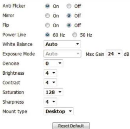
Anti Flicker: If the video flickers, try enabling this setting.
Mirror: This will flip the image horizontally.
Flip: This will flip the image vertically.
Power Line: Select the frequency used by your power lines to avoid interference or distortion.
White Balance: Use the drop-down menu to change the white balance settings to help balance colors in different lighting environments. You can choose from Auto, Outdoor, Indoor, Fluorescent, and Push Hold.
PRIVACY MASK AREA OF VIDEO SETTING
√ Enable Privacy Mask Setting

natural_image
Baby sitting in a baby crib, smiling at the camera (no text or symbols visible)- Privacy mask: mask 3 privacy area(s) on video.
- Click the right mouse button on the video control to show the popmenu.
- Press the left mouse button, drag and drop to set the privacy area.
- Privacy area can be enabled or disabled.
- After you finish all privacy mask settings, click the Save button.
Save
IMAGE SETTINGS
text_image
Anti Flicker On Off Mirror On Off Flip On Off Power Line 60 Hz 50 Hz White Balance Auto Exposure Mode Auto Max Gain 24 dB Denoise 0 Brightness 4 Contrast 4 Saturation 128 Sharpness 4 Mount type Desktop Reset DefaultExposure Mode: Changes the exposure mode. Use the drop-down box to set the camera for Indoor, Outdoor, or Night environments, or to Moving to capture moving objects. The Low Noise option will focus on creating a high-quality picture without noise. You can also create 3 different custom exposure modes. The Max Gain setting will allow you to control the maximum amount of gain to apply to brighten the picture.
Denoise: This setting controls the amount of noise reduction that will be applied to the picture.
Brightness: This adjusts the brightness of the camera image.
Contrast: This adjusts the contrast of the camera image, making a washed out image clearer or reducing the brightness in an over exposed image.
Saturation: This adjusts the color saturation. Saturation controls the strength of color in the image.
Sharpness: Specify a value from 0 to 8 to specify how much sharpening to apply to the image.
Mount type: Select the correct mounting type from either Ceiling or Desktop to ensure the PTZ controls respond accurately.
Note: Mirror and Flip can be used if you have mounted the DCS-5222L on the ceiling.
PRIVACY MASK AREA OF VIDEO SETTING
√ Enable Privacy Mask Setting

natural_image
Baby sitting in a baby crib, smiling at the camera (no text or symbols visible)- Privacy mask: mask 3 privacy area(s) on video.
- Click the right mouse button on the video control to show the popmenu.
- Press the left mouse button, drag and drop to set the privacy area.
- Privacy area can be enabled or disabled.
- After you finish all privacy mask settings, click the Save button.
Save
IMAGE SETTINGS

text_image
Anti Flicker On Off Mirror On Off Flip On Off Power Line 60 Hz 50 Hz White Balance Auto Exposure Mode Auto Max Gain 24 dB Denoise 0 Brightness 4 Contrast 4 Saturation 128 Sharpness 4 Mount type Desktop Reset DefaultAudio and Video
You may configure up to 3 video profiles with different settings for your camera. Hence, you may set up different profiles for your computer and mobile display. In addition, you may also configure the two-way audio settings for your camera. After making any changes, click the Save button to save your changes. There are three sensor output selections (VGA, XGA, and SXGA). Do not select SXGA if you want to turn on the motion detection feature.
Aspect ratio: Set the aspect ratio of the video to 4:3 standard or 16:9 widescreen.
Mode: Set the video codec to be used to JPEG or H.264.
Frame size / View window area: Frame size determines the total capture resolution, and View window area determines the Live Video viewing window size. If the Frame size is larger than the Live Video size, you can use the ePTZ controls to view the full area.
16:9 1280 x 800, 1280 x 720, 800 x 450, 640 x 360, 480 x 270, 320 x 176
4:3 1024 x 768, 800 x 600, 640 x 480, 480 x 360, 320 x 240
Note: If your view window area is the same as your frame size, you will not be able to use the ePTZ function.
Maximum A higher frame rate provides smoother motion for videos, and requires more bandwidth. Lower frame rates will result in stuttering motion, and requires less bandwidth.
VIDEO SETTINGS

text_image
Aspect ratio 4:3 Warning: Change the aspect ratio will clear the settings of privacy mask and preset and motion detection. Save DefaultVIDEO PROFILE 1
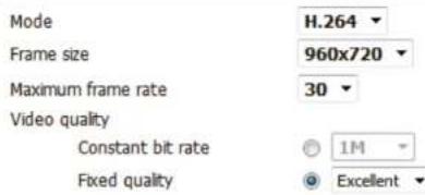
text_image
Mode H.264 Frame size 960x720 Maximum frame rate 30 Video quality Constant bit rate 1M Fixed quality ExcellentVIDEO PROFILE 2

text_image
Mode JPEG Frame size 640x480 Maximum frame rate 30 Video quality ExcellentVIDEO PROFILE 3

text_image
Mode H.264 Frame size 320x240 Maximum frame rate 30 Video quality Constant bit rate 512K Fixed quality ExcellentSection 4 - Configuration
| Video Quality: | This limits the maximum frame rate, which can be combined with the “Fixed quality” option to optimize the bandwidth utilization and video quality. If fixed bandwidth utilization is desired regardless of the video quality, choose “Constant bit rate” and select the desired bandwidth. |
| Constant bit rate: | The bps will affect the bit rate of the video recorded by the camera. Higher bit rates result in higher video quality. |
| Fixed quality: | Select the image quality level for the camera to try to maintain. High quality levels will result in increased bit rates. |
| Encoding: | Choose between G.711, G.726 or AAC. |
| Audio in off: | Selecting this checkbox will mute incoming audio. |
| Audio in gain level: | This setting controls the amount of gain applied to incoming audio to increase its volume. |
| Audio out off: | Selecting this checkbox will mute outgoing audio. |
| Audio out volume level: | This setting controls the amount of gain applied to outgoing audio to increase its volume. |
VIDEO PROFILE 3
| Mode | H.264 |
| Frame size | 320x240 |
| Maximum frame rate | 30 |
| Video quality | |
| Constant bit rate | 512K |
| Fixed quality | Excellent |
AUDIO SETTINGS
| Encoding | 6.711 |
| Audio in off | |
| Audio in gain level | 20dB |
| Audio out off | |
| Audio out volume level | 7 |
Note: Higher frame size, frame rate and bit rates will give you better video quality, but they will also require more network bandwidth. For best viewing results on a mobile phone, we suggest setting the frame rate to 5 fps and the bit rate to 20 Kbps. Similarly, select appropriate audio encoding for your bandwidth requirements.
After making any changes, click the Save Settings button to save your changes, or click the Don't Save Settings button to discard your changes.
PTZ
This section allows you to configure the pan and tilt operations of your camera. You can specify the lens location for the Home button, and specify up to 24 pre-set lens locations, allowing you to quickly view these pre-determined areas of the camera's range from the Live Video screen.
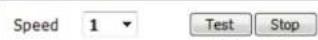
Pan Speed: Select the speed at which the camera will pan for a full cycle from the drop-down list. Select a value between 0 and 10, 0 being the slowest setting.
Tilt Speed: Select the speed at which the camera will tilt for a full cycle from the drop-down menu. Select a value between 0 and 10, 0 being the slowest.
Preset Name: Enter a name for your camera location and click Add.
Present List: To add a preset to the sequence, select it from the drop-down box at the bottom of this window, then click the Add button. The preset name will appear in the list.
You can rearrange your presets in the sequence by selecting a preset in the sequence, then clicking the arrow buttons to move it higher or lower in the current sequence.
Clicking the trash can button will remove the currently selected preset from the sequence.
Choose as Click to set the Home position with the default Home: setting.
Auto Pan Select the speed at which the camera will pan from the drop-down menu. Select a value between 0 and 10, 0 being the slowest.
LIVE VIDEO

natural_image
Baby in a baby crib with a circular speed control panel showing pan and tilt speed settings (no text or symbols on the image itself)PRESET

text_image
Support(0=9,A=2,a=2,*,/...) Name Add Rename GoTo Remove Set Default Preset --Preset No-- ▼ Preset List --Preset List-- ▼ Choose --Preset List-- ▼ as Home position.AUTO PAN
PresetThis section allows you to create a preset sequence:quence, which automatically moves the camera's view between a set of preset views.
To add a preset to the sequence, select it from the drop-down box at the bottom of this window, set the Dwell time to determine how long the camera view will stay at that preset, then click the Add button. The preset name will appear in the list, followed by the dwell time to view that preset for.
You can rearrange your presets in the sequence by selecting a preset in the sequence, then clicking the arrow buttons to move it higher or lower in the current sequence.
Clicking the trash can button will remove the currently selected preset from the sequence.
If you want to change the dwell time for a preset, select it from the list, enter a new dwell time, then click the Update button.
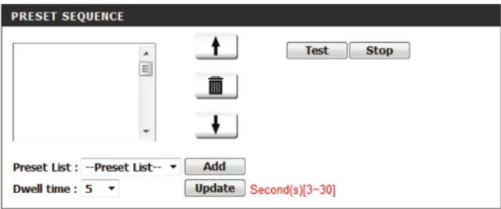
text_image
PRESET SEQUENCE Test Stop Preset List : --Preset List-- Add Dwell time : 5 Update Second(s)[3~30]Motion Detection
This option allows you to set up Motion Detection on your network camera.
Enable Video Check this box to enable the motion detection feature of your Motion: camera.
Sensitivity: This setting adjusts how sensitive the camera will be to motion, where 100% will be the most sensitive setting and 0% will be the least sensitive setting.
Drawing Mode: Select Draw Motion Area to select the area of the picture to monitor for movement to trigger recording or snapshot. Use your mouse to click on the blocks that you would like to monitor for motion. Select Erase Motion Area to remove the blocks and stop the camera from monitoring that area of the picture.
Clear: Clicking this button will clear all motion detection zones.
After making any changes, click the Save Settings button to save your changes, or click the Don't Save Settings button to discard your changes.
The red grid on the right indicates an area that has been selected for motion detection. When motion is detected, the LIVE VIDEO page will display a blinking orange motion video icon like the one below.


MotionNo Motion
The motion notification will continue to blink as long as motion is detected. If no additional motion is detected, it will return to its original state after eight seconds.
LIVE VIDEO

natural_image
Baby in a white baby crib with blue pants, no visible text or symbols on the image itself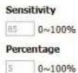

natural_image
Baby in a baby crib with a red grid overlay showing a close-up of the child's abdomen (no text or symbols visible)
Sound Detection
Enabling Sound Detection will allow your camera to use the built-in microphone to trigger events with audio. If this option is selected, the trigger by option under SD recording, Video Clip, or Snapshot should also be selected.
Enable Sound Check this box to enable the motion detection feature Detection: of your camera.
Detection Level: Specifies the measurable level that would indicate sound. Please enter a value between 50 and 90, the higher the number the more sensitive the camera will be to sound.
After making any changes, click the Save Settings button to save your changes, or click the Don't Save Settings button to discard your changes.
SOUND DETECTION
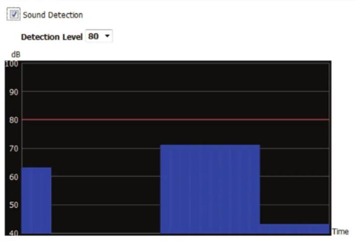
bar
| Time | dB | |---|---| | 1 | 63 | | 2 | 71 | | 3 | 43 | Sound Detection Level 80Time and Date
This section allows you to configure the settings of the internal system clock for your camera.
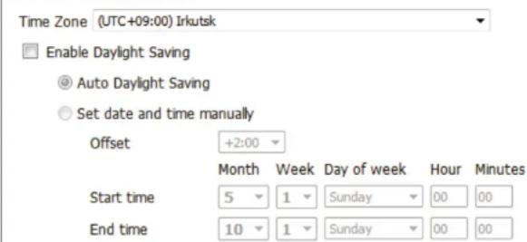
Time Zone: Select the time zone for your region from the drop-down menu.
Enable Daylight Check this if the camera is in a region where Saving: daylight saving is observed.
Auto Daylight This option will adjust Daylight Saving Time Saving: automatically.
Synchronize Network Time Protocol will synchronize your NTP Server: camera with an Internet time server. You can enter an IP address of a server or select from the drop-down menu.
Set the Date and Select this to set the time manually. Time Manually:
Copy your Click to synchronize the time information Computer's from your PC. Time Settings:
After making any changes, click the Save Settings button to save your changes, or click the Don't Save Settings button to discard your changes.
TIME CONFIGURATION
text_image
Time Zone (UTC+09:00) Irkutsk Enable Daylight Saving Auto Daylight Saving Set date and time manually Offset +2:00 Month Week Day of week Hour Minutes Start time 5 1 Sunday 00 00 End time 10 1 Sunday 00 00SET DATE AND TIME MANUALLY
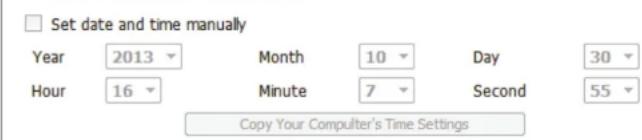
text_image
Set date and time manually Year 2013 Month 10 Day 30 Hour 16 Minute 7 Second 55 Copy Your Computer's Time SettingsEvent Setup
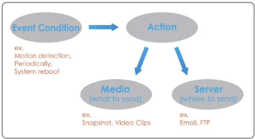
In a typical application, when motion is detected, the DCS-5222L sends images to a FTP server or via e-mail as notifications. As shown in the illustration below, an event can be triggered by many sources, such as motion detection or external digital input devices. When an event is triggered, a specified action will be performed. You can configure the network camera to send snapshots or videos to your e-mail address or FTP site.
flowchart
graph TD
    A["Event Condition"] --> B["Action"]
    B --> C["Media (what to send)"]
    B --> D["Server (where to send)"]
    C -->|ex. Motion detection, Periodically, System reboot| A
    D -->|ex. Email, FTP| B
    C -->|ex. Snapshot, Video Clips| B
To start plotting an event, it is suggested to configure server and media columns first so that the network camera will know what action shall be performed when a trigger is activated.
Section 4 - Configuration
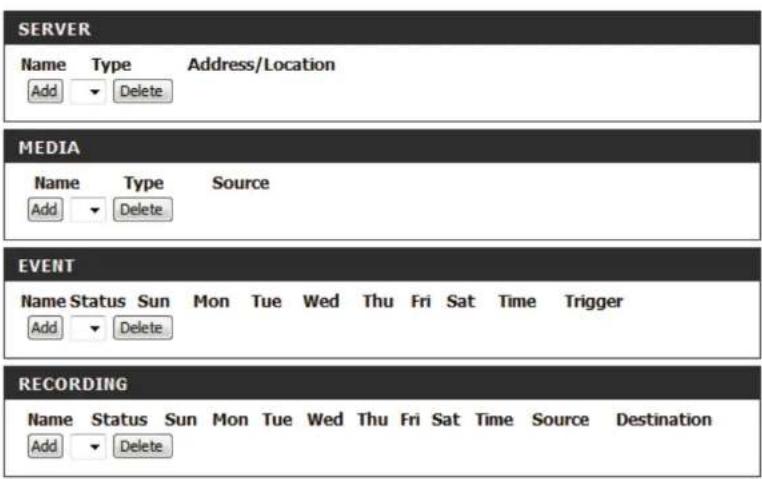
The Event Setup page includes 4 different sections.
- Server
• Media - Event
-
Recording
-
To add a new item - "event, server or media," click Add. A screen will appear and allow you to update the fields accordingly.
- To delete the selected item from the pull-down menu of event, server or media, click Delete.
- Click on the item name to pop up a window for modifying.
text_image
SERVER Name Type Address/Location Add Delete MEDIA Name Type Source Add Delete EVENT Name Status Sun Mon Tue Wed Thu Fri Sat Time Trigger Add Delete RECORDING Name Status Sun Mon Tue Wed Thu Fri Sat Time Source Destination Add DeleteAdd Server
You can configure up to 5 servers to save snapshots and/or video to. After making any changes, click the Save Settings button to save your changes.
Server Name: Enter the unique name of your server.
E-mail: Enter the configuration for the target e-mail server account.
FTP: Enter the configuration for the target FTP server account.
Network Storage: Specify a network storage device. Only one network storage device is supported.
SD Card: Use the camera's onboard SD card storage.

text_image
SERVER TYPE Server Name: Email Sender email address Recipient email address Server address User name Password Port 25 This server requires a secure connection (StartTLS) FTP Server address Port 21 User name Password Remote folder name Passive mode Network storage Network storage location (for example:\my_nas\desk\folder) Workgroup User name Password Primary WINS server SD Card Test Save Settings Don't Save SettingsAdd Media
There are three types of media, Snapshot, Video Clip, and System Log. After making any changes, click the Save Settings button to save your changes.
Media Name: Enter a unique name for media type you want to create.
Snapshot: Select this option to set the media type to snapshots.
Source: Set the video profile to use as the media source. Refer to Audio and Video on "Audio and Video" on page 40 for more information on video profiles.
Send pre-event Set the number of pre-event images to take. image(s) [0\~3]: Pre-event images are images taken before the main event snapshot is taken.
Send post-event Set the number of post-event images to take. image(s) [0\~7]: Post-event images are images taken after the main event snapshot is taken. You can set up to 7 post-event images to be taken.
File name prefix: The prefix name will be added on the file name.
Add date and Check this to add timing information as file time suffix to file name suffix. name:
MEDIA TYPE
Media name:
Snapshot
Source: Profile1
Send 1 pre-event image(s) [0\~3]
Send 1 post-event image(s) [0\~7]
File Name Prefix:
☐ Add date and time suffix to file name
© Video Clip
Source: Profile1
Pre-event recording: Second(s) [0\~3]
Maximum duration: Second(s) [1\~100]
Maximum file size: Kbytes [100\~5000]
File Name Prefix:
System log
Save Settings
Don't Save Settings
Section 4 - Configuration
Video clip: Select this option to set the media type to video Source: clips. Set the video profile to use as the media source.
Refer to "Audio and Video" on page 40 for more information on video profiles.
Pre-event This sets how many seconds to record before the recording: main event video clip starts. You can record up to 3 seconds of pre-event video.
Maximum Set the maximum length of video to record for duration: your video clips.
Maximum file Set the maximum file size to record for your size: video clips.
File name This is the prefix that will be added to the file-prefix: name of saved video clips.
System log: Select this option to set the media type to system logs. This will save the event to the camera system log, but will not record any snapshots or video.
MEDIA TYPE
Media name:
Snapshot
Source: Profile1
Send 1 pre-event image(s) [0\~3]
Send 1 post-event image(s) [0\~7]
File Name Prefix:
☐ Add date and time suffix to file name
Video Clip
Source: Profile1
Pre-event recording: Second(s) [0\~3]
Maximum duration: Second(s) [1\~100]
Maximum file size: Kbytes [100\~5000]
File Name Prefix:
System log
Save Settings
Don't Save Settings
Add Event
Create and schedule up to 2 events with their own settings here. After making any changes, click the Save Settings button to save your changes.
Event name: Enter a name for the event.
Enable this Select this box to activate this event. event:
Priority: Set the priority for this event. The event with higher priority will be executed first.
Delay: Select the delay time before checking the next event. It is being used for both events of motion detection and digital input trigger.
Trigger: Specify the input type that triggers the event.
Video Motion Detection: Motion is detected during live video monitoring. Select the windows that need to be monitored.
Periodic: The event is triggered in specified intervals. The trigger interval unit is in minutes.
Digital input: The external trigger input to the camera.
System Boot: Triggers an event when the system boots up.
Network Lost: Triggers an event when the network connection is lost.
EVENT
Event name:
Enable this event
Priority: normal
Delay for 10 seconds before detecting next event [For motion detection and digital input]
TRIGGER
Video motion detection
Periodic
Trigger every 1 minutes
Digital input
System boot
Network lost
Sound Detection
EVENT SCHEDULE
Sun Mon Tue Wed Thu Fri Sat
Time
Always
From 00 00 To 23 59
ACTION
Trigger D/O for 1 seconds
Save Settings Don't Save Settings
Section 4 - Configuration
Passive Infrared Triggers an event when the PIR sensor is activated by moving infrared objects even in dark environment.
Sound Detection: Triggers an event when an audio trigger is recorded.
Time: Select Always or enter the time interval.
Trigger D/O: Select to trigger the digital output for a specific number of seconds when an event occurs.
EVENT
Event name:
Enable this event
Priority: normal
Delay for 10 seconds before detecting next event [For motion detection and digital input]
TRIGGER
Video motion detection
Periodic
Trigger every 1 minutes
Digital input
System boot
Network lost
Sound Detection
EVENT SCHEDULE
Sun Mon Tue Wed Thu Fri Sat
Time
Always
From 00 00 To 23 59
ACTION
Trigger D/O for 1 seconds
Save Settings
Don't Save Settings
Add Recording
Here you can configure and schedule the recording settings. After making any changes, click the Save Settings button to save your changes.
Recording entry The unique name of the entry. name:
Enable this Select this to enable the recording function. recording:
Priority: Set the priority for this entry. The entry with a higher priority value will be executed first.
Source: The source of the stream.
Recording Scheduling the recording entry. schedule:
Recording Configuring the setting for the recording. settings:
Destination: Select the folder where the recording file will be stored.
RECORDING
Recording entry name:
Enable this recording
Priority: normal
Source: Profile 1
RECORDING SCHEDULE
Sun Mon Tue Wed Thu Fri Sat
Time
Always
From 00 00 To 23 59
RECORDING SETTINGS
Destination None
Total cycling recording size: 1000 Mbytes [200\~2000000]
Size of each file for recording: 10 ▼ Mbytes
Time of each file for recording: 10 seconds
File Name Prefix:
Save Settings
Don't Save Settings
Section 4 - Configuration
Total cycling recording size:
Please input a HDD volume between 1MB and 2TB for recording space. The recording data will replace the oldest record when the total recording size exceeds this value. For example, if each recording file is 6MB, and the total cyclical recording size is 600MB, then the camera will record 100 files in the specified location (folder) and then will delete the oldest file and create new file for cyclical recording.
Please note that if the free HDD space is not enough, the recording will stop. Before you set up this option please make sure your HDD has enough space, and it is better to not save other files in the same folder as recording files.
Size of each file for recording:
If this is selected, files will be separated based on the file size you specify.
Time of each file for recording:
If this is selected, files will be separated based on the maximum length you specify.
File Name Prefix:
The prefix name will be added on the file name of the recording file(s).
RECORDING
Recording entry name:
Enable this recording
Priority: normal
Source: Profile 1
RECORDING SCHEDULE
Sun Mon Tue Wed Thu Fri Sat
Time
Always
From 00 00 To 23 59
RECORDING SETTINGS
Destination None ▼ Total cycling recording size: 1000 Mbytes [200\~2000000]
Size of each file for recording: 10 Mbytes
Time of each file for recording: 10 seconds
File Name Prefix:
Save Settings Don't Save Settings
SD Management
This page allows you to browse and manage the recorded files on an SD card which has been inserted into the camera.
Note: It is recommended to use the Format SD Card function when inserting an SD card for the first time.
Format SD Click to automatically format the SD Card and Card: create a folder for video. Formatting your SD Card will erase all data currently saved.
Delete: Click the checkbox in front of the Delete button to select files meant for deletion. The Delete button is used to delete the files which are selected.
Name: The name of file recording.
Size: The file's size.
Refresh: Click to refresh the page.
Files per page: Select the number of files to be displayed on a single page. The maximum is 100 files.
Pages: Show the current and total number of pages.

text_image
SD CARD Here you could browse and manage the record files which stored in SD card. SD CARD SD Card: / Files per Page: 10 Refresh SD Status : Ready 1 of 1 Delete File Num of files Size Video 0 Picture 0 Format SD Card Total:3865192KB, Used:12KB, Free:3865180KB OKAdvanced Digital Input/Output
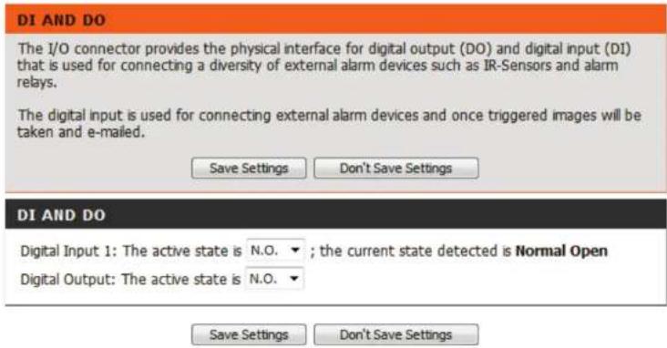
This screen allows you to control the behavior of digital input and digital output devices. The I/O connector provides the physical interface for digital output (DO) and digital input (DI) that is used for connecting a variety of external alarm devices such as IR-Sensors and alarm relays. The digital input is used for connecting external alarm devices and once triggered images will be taken and e-mailed. After making any changes, click the Save Settings button to save your changes.
Select D/I or The camera will send a signal when an event is D/O Mode: triggered, depending upon the type of device connected to the DI circuit.
N.C. stands for Normally Closed. This means that the normal state of the circuit is closed. Therefore events are triggered when the device status changes to "Open."
N.O. stands for Normally Open. This means that the normal state of the circuit is open. Therefore events are triggered when the device status changes to "Closed."
text_image
DI AND DO The I/O connector provides the physical interface for digital output (DO) and digital input (DI) that is used for connecting a diversity of external alarm devices such as IR-Sensors and alarm relays. The digital input is used for connecting external alarm devices and once triggered images will be taken and e-mailed. Save Settings Don't Save Settings DI AND DO Digital Input 1: The active state is N.O. ▼ ; the current state detected is Normal Open Digital Output: The active state is N.O. ▼ Save Settings Don't Save SettingsICR and IR
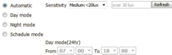
Here you can configure the ICR and IR settings. An IR(Infrared) Cut-Removable(ICR) filter can be disengaged for increased sensitivity in low light environments.
Automatic: The Day/Night mode is set automatically. Generally, the camera uses Day mode and switches to Night mode when needed.
Day Mode: Day mode enables the IR Cut Filter.
Night Mode: Night mode disables the IR Cut Filter.
Schedule Mode: Set up the Day/Night mode using a schedule. The camera will enter Day mode at the starting time and return to Night mode at the ending time.
IR Light Control: Select from the options to enable or disable the IR (infrared) light according to your preferences. This setting provides additional controls depending on your specific application.
Off: The IR light will always be off.
On: The IR light will always be on.
Sync: The IR light will turn on when the ICR sensor is on.
Schedule: The IR light will turn on or off according to the schedule that you specify below.
ICR
Removable IR-Cut filter trigger condition:
text_image
Automatic Sensitivity Medium: <20lux over 30 lux Refresh Day mode Night mode Schedule mode Day mode(24hr) From 07 00 To 18 00IR LIGHT
IR Light Control Medium
Off
On
Sync. With ICR
Schedule
IR Light Control On(24hr)
From 07 00 To 18 00
Save Settings Don't Save Settings
HTTPS
This page allows you to install and activate an HTTPS certificate for secure access to your camera. After making any changes, click the Save Settings button to save your changes.
Enable HTTPS Enable the HTTPS service.
Secure Connection:
Create Certificate Choose the way the certificate should be created. Three options are available:
Create a self-signed certificate automatically Create a self-signed certificate manually Create a certificate request and install
Status: Displays the status of the certificate.
Note: The certificate cannot be removed while the HTTPS is still enabled. To remove the certificate, you must first uncheck Enable HTTPS secure connection.
HTTPS
√ Enable HTTPS secure connection
Create certificate method
Create self-signed certificate automatically
© Create self-signed certificate manually
○ Create certificate request and install
Create certificate: Create Private key existed
CERTIFICATE INFORMATION
Status Active
Country TW
State or province Taiwan
Locality Taipei
Organization D-Link
Organization Unit DHPD Dept.
Common Name www.dlink.com
CSR Property Certificate Property Remove
Save Settings Don't Save Settings
Access List
Here you can set access permissions for users to view your DCS-5222L.
Allow list: The list of IP addresses that have the access right to the camera.
Start IP address: The starting IP Address of the devices (such as a computer) that have permission to access the video of the camera. Click Add to save the changes made.
Note: A total of seven lists can be configured for both columns.
End IP address: The ending IP Address of the devices (such as a computer) that have permission to access the video of the camera.
Delete allow Remove the customized setting from the Allow list: List.
Deny list: The list of IP addresses that have no access rights to the camera.
Delete deny list: Remove the customized setting from the Delete List.
For example:
When the range of the Allowed List is set from 1.1.1.0 to 192.255.255.255 and the range of the Denied List is set from 1.1.1.0 to 170.255.255.255. Only users with IPs located between 171.0.0.0 and 192.255.255.255 can access the Network Camera.

text_image
ALLOW LIST Start IP address End IP address Delete allow list Add Delete DENY LIST Start IP address End IP address Delete deny list Add Delete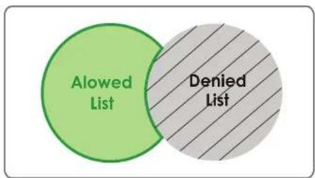
text_image
Alowed List Denied ListMaintenance Admin
This section allows you to change the administrator's password and configure the server settings for your camera. You can also manage the user account(s) that enable access to your camera.
Admin Password This section lets you change the admin password setting: used to log into the camera and change settings. After installing the camera for the first time, it is highly recommended that you change the admin password for security purposes.
Enter the existing password, then enter your new password. Click Save to apply your new settings.
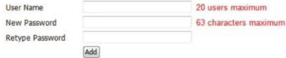
Add User Account: You may create user accounts to allow others to log into your camera to view the live camera feed. Users cannot change any settings.
Enter the User Name you wish to use for the new user account and then create a password for that account. Click Add to save your account.
User List: Select a user from the drop-down menu and click Delete to remove the user account from having access to the camera images.
Camera Name: Enter the name of your camera. This is useful if you have multiple cameras.
Enable OSD: This will enable the information bar On Screen Display (OSD) to appear when viewing video.
Label: This is the text label that will appear on the OSD.
ADMIN PASSWORD SETTING

ADD USER ACCOUNT
text_image
User Name New Password Retype Password Add 20 users maximum 63 characters maximum AddUSER LIST

DEVICE SETTING

text_image
IP camera Name DCS-5222LB1 63 characters maximum ✓ Enable OSD Label DCS-5222LB1 30 characters maximum Show time ✓ Save Calibration Device CalibrationSection 4 - Configuration
Time Stamp: If checked, the current time will be displayed on the OSD.
Calibrate the Device: Clicking this button will calibrate the camera so that the P/T/Z apparatus functions correctly. The camera is automatically calibrated whenever it is powered on and initialized or reset. Should the camera's pan, tilt, and zoom functions begin to behave incorrectly, or if the device has been jarred or handled improperly, you may need to recalibrate the camera manually by pressing this button.
LED Light: This will turn the camera's front LED indicator on or off.
Privacy Mode: Select the privacy mode for your camera as on or off to ensure privacy. When the privacy mode is turned on, the camera hides the lens by rolling it back into the unit.
After making any changes, click the Save button to save your changes.
DEVICE SETTING

text_image
IP camera Name DCS-5222LB1 63 characters maximum Enable OSD Label DCS-5222LB1 30 characters maximum Show time ✓ Save Calibration Device CalibrationLED


PRIVACY CONTROL
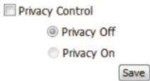
System
This screen allows you to save and restore the camera's current configuration. You can also reset all settings to the factory default or reboot the device.
Save to Local Click on the Save Configuration button to Hard Drive: save the current configuration to your hard drive.
Load from Local To load a saved configuration, click on the Hard Drive: Browse button to select a configuration file from your hard drive. Then, click the Load Configuration button to load the new configuration.
Restore Click this button to reset all settings to their to Factory factory defaults. If you select to reset your Defaults: settings, you will need to set up your camera again.
Reboot Device: Clicking the Reboot button will reboot your device.
Schedule Select this option to schedule a time for the Reboot: device to reboot.
After making any changes, click the Save button to save your changes.
SYSTEM
Save To Local Hard Drive
Save Configuration
Load From Local Hard Drive
Browse...
Load Configuration
Restore To Factory Defaults
Your current firmware version and date will be displayed on this page. You can also upgrade your firmware with a new version.
To upgrade your firmware, go to support.dlink.com and download the latest firmware to your computer's hard drive.
Click on Browse, select the firmware file, then click the Upload button.
While the firmware is being upgraded, do not turn off your computer or camera, and do not disconnect your network connection from your computer or camera. Upgrading the firmware will not change any of your system settings, but it is recommended that you save your system configuration before doing a firmware upgrade.
Note: It is recommended that you use a wired connection for your computer and camera when upgrading the firmware.

text_image
FIRMWARE INFORMATION Current Firmware Version: 1.00.01 Current Product Name: DCS-5222LB1 FIRMWARE UPGRADE File Path: Browse... UploadStatus Device Info
This screen displays various information about your camera and its current settings.
DEVICE INFO
All of your network connection details are displayed on this page. The firmware version is also displayed here.
INFORMATION
IP camera Name DCS-5222LB1
Time & Date Wed Oct 30 16:08:40 2013
MAC Address 0A:CA:CA:CA:76:46
IP Address 192.168.0.140
IP Subnet Mask 255.255.255.0
Default Gateway 192.168.0.1
Primary DNS 192.168.0.1
Secondary DNS 0.0.0.0
PPPoE Disable
DDNS Disable
Agent Version 2.0.17-b36
Log
The log shows you a list of events that have happened recently. You can download the log by clicking the Download button, or you can empty the log by clicking the Clear button.
CURRENT LOG
- 2013-10-30 16:04:33 admin LOGIN OK FROM 192.168.0.100
- 2013-10-30 15:35:25 SYSTEM SET IR LIGHT ON
- 2013-10-30 15:23:17 admin LOGIN OK FROM 192.168.0.100
- 2013-10-29 11:38:39 DCS-5222LB1 ACQUIRE DHCP IP 192.168.0.140
- 2013-10-29 11:38:35 NETWORK INTERFACE CHANGE TO ETHERNET
- 2013-10-25 15:46:04 admin FROM 192.168.0.100 SET TIMEZONE (UTC+09:00) Irkutsk
- 2013-10-25 15:46:04 admin FROM 192.168.0.100 SET NTP SERVER ntp1.dlink.com
- 2013-10-25 15:45:14 admin LOGIN OK FROM 192.168.0.100
- 2013-10-25 15:42:29 DCS-5222LB1 ACQUIRE DHCP IP 192.168.0.140
- 2013-10-25 15:42:23 NETWORK RECONNECT
- 2013-10-25 15:42:22 NETWORK LOSS
- 2013-10-25 15:42:21 NETWORK INTERFACE CHANGE TO WLAN
- 2013-10-25 15:42:02 DCS-5222LB1 ACQUIRE DHCP IP 192.168.0.140
- 2013-10-25 15:41:57 NETWORK INTERFACE CHANGE TO ETHERNET
- 2013-10-25 15:22:31 DCS-5222LB1 ACQUIRE DHCP IP 192.168.0.140
- 2013-10-25 15:22:21 NETWORK RECONNECT
- 2013-10-25 15:22:18 NETWORK LOSS
- 2013-10-25 15:22:04 DCS-5222LB1 ACQUIRE DHCP IP 192.168.0.140
- 2013-10-25 15:21:58 NETWORK RECONNECT
- 2013-10-25 15:21:57 NETWORK LOSS
First Page Previous 20 Next 20
Clear Download
Help
Online help is available at any time by clicking on the Help tab.
| HELP |
| LIVE VIDEO SETUP MAINTENANCE ADVANCED STATUS |
| LIVE VIDEO |
| Camera |
| SETUP |
| Setup Wizard Network Setup Wireless Setup Dynamic DNS Image Setup Audio and Video Motion Detection Time and Date Event Setup SD Card |
| ADVANCED |
| DI and DO ICR and IR HTTPS Access List |
| MAINTENANCE |
| Admin System Firmware Upgrade |
| STATUS |
| Device Info Log |
Configuring the DCS-5222L with a Router
D-Link's DCS-5222L is a versatile and cost effective network camera offering both video and audio monitoring. It can also serve as a powerful surveillance system in security applications. The DCS-5222L can be used with any wired or 802.11n/g wireless router. This section explains how to view the camera from either the Internet or from inside your internal network. This step is only needed if you do not wish to take advantage of the built in mydlink functions.
Components Needed:
• 1 DCS-5222L Network Camera
• 1 Ethernet Cable
- A wired or wireless router such as the D-Link DIR-655 Wireless Router
- Ethernet-based PC for system configuration
Setting up the DCS-5222L for Use Behind a Router
Installing a DCS-5222L Network Camera on your network is an easy 4-step procedure:
- Assign a local IP address to your network camera.
- View the network camera using your Internet Explorer web browser.
- Access the router with your web browser.
- Open virtual server ports to enable remote image viewing.
Note: These are manual steps; however, if you decide to use the wizard, it will perform every step automatically.
This section is designed to walk you through the setup process for installing your camera behind a router and enable remote video viewing. For the basic setup of the DCS-5222L, follow the steps outlined in the Quick Installation Guide.
After you have completed the setup of the DCS-5222L outlined in the Quick Installation Guide you will have an operating camera that has an assigned IP Address. Because you are using a router to share the Internet with one or more PCs, the IP Address assigned to the network camera will be a local IP Address. This allows viewing within your Local Area Network (LAN) until the router is configured to allow remote viewing of the camera over the Internet.
1. Assign a Local IP Address to Your Camera
Run the setup wizard from the CD included with the DCS-5222L. Follow the steps in the Quick Installation Guide to configure the DCS-5222L. The camera will be assigned a local IP Address that allows it to be recognized by the router. Write down this IP Address for future reference.
2. View the network camera Using Your Internet Explorer Web Browser
Open a Web browser. In the address bar, type in the IP Address that was assigned to the network camera. The DCS-5222L Live Video Page appears with a window displaying live video from the camera.
Click on the Setup button on the top menu bar. Select Network Setup from the left menu and scroll down the Network Setup page to find the ports used by HTTP and Streaming audio and video.

text_image
D-Link DCB-5222LB LIVE VIDEO SETUP Network Setup Network Setup Windows Setup Windows DNS Image Setup Audio and Voice PTZ Setup Motion Detection Sound Detection Time and Date Event Setup SD Card Logout NETWORK SETUP You can configure your LAN and Inces Save Set LAN SETTINGS DHCP Static IP Client IP address Subnet mask Default router Primary DNS Secondary DNS Enable UP-P presentation Enable UP-R post presentation
text_image
HTTP HTTP port: 80 Access name for stream1 video1.mzip Access name for stream2 video2.mzip Access name for stream3 video3.mzip HTTPS HTTPS port 443 RISP Authentication Reset RTSP port 351 Access name for stream1 live1.mzip Access name for stream2 live2.mzip Access name for stream3 live3.mzip COS SETTINGS Enable COS VLAN ID 1 [0~4095] Live video 0 Live audio 0 Event/Alarm 0 Management 0Section 5 - Security
The Setup > Network page displays the port settings for your camera. If necessary, these ports can be changed if they are already in use by other devices (e.g. in a multiple camera environment).
Note: Both the HTTP port and RTSP port are required to be opened for the DCS-5222L.
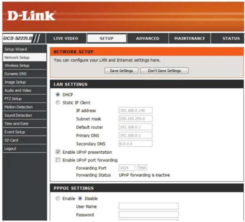
text_image
D-Link DCS-5222LB // LIVE VIDEO SETUP ADVANCED MAINTENANCE STATUS SETUP Wizard Network Setup Wireless Setup Dynamic DNS Image Setup Audio and Video PTZ Setup Motion Detection Sound Detection Time and Date Event Setup SD Card Logout NETWORK SETUP You can configure your LAN and Internet settings here. Save Settings Don't Save Settings LAN SETTINGS DHCP Static IP Client IP address 192.168.0.140 Subnet mask 255.255.255.0 Default router 192.168.0.1 Primary DNS 192.168.0.1 Secondary DNS 0.0.0.0 Enable UPnP presentation Enable UPnP port forwarding Forwarding Port 1024 Test Forwarding Status UPnP forwarding is inactive PPPOE SETTINGS Enable Disable User Name PasswordRouter Set-Up and Installation
The following steps generally apply to any router that you have on your network. The D-Link DIR-655 is used as an example to clarify the configuration process. Refer to the router's user manual for more information on router operation and configuration.
3. Access the Router with Your Web Browser
If you have cable or DSL Internet service, you will most likely have a dynamically assigned WAN IP Address. 'Dynamic' means that your router's WAN IP address can change from time to time depending on your ISP. A dynamic WAN IP Address identifies your router on the public network and allows it to access the Internet. To find out what your router's WAN IP Address is, go to the Status page on your router and locate the WAN information for your router (as shown on the next page). The WAN IP Address will be listed. This will be the address that you will need to type in your web browser to view your camera over the Internet.
Your WAN IP Address will be listed on the router's Status > Device Info page.
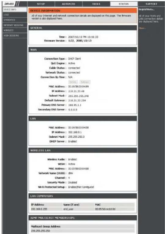
text_image
DEVICE INFORMATION All of your Internet and network connection details are displayed on this page. The firmware version is also displayed here. GENERAL Time: 2007/10/10 PM 10:38:33 Firmware Version: 1.02, 2006, 10v 13 WAN Connection Type: DHCP Client QoS Engine: Active Cable Status: connected Network Status: connected Connection Up Time: N/A MAC Address: 00:19:38:03:04:59 IP Address: 210.21.33.44 Subset Mask: 255.255.255.248 Default Gateway: 210.21.33.254 Primary DNS Server: 168.95.1.1 Secondary DNS Server: 0.0.0.0 LAN MAC Address: 00:19:38:03:04:58 IP Address: 192.168.0.1 Subset Mask: 255.255.255.0 DHCP Server: Enabled WIRELESS LAN Wireless Radio: Enabled WISH: Active MAC Address: 00:19:38:03:04:58 Network Name (DSID): dink Channel: 4 Security Mode: Disabled Wi-Fi Protected Setup: Enabled/Not Configured LAN COMPUTERS IP Address Name (if any) MAC 192.168.0.155 end user 60.05 Sdcoe b3b8d COMP MULTICRAT MEMBERSHIPS Multicast Group Address 259.255.255.250Section 5 - Security
Note: Because a dynamic WAN IP can change from time to time depending on your ISP, you may want to obtain a Static IP address from your ISP. A Static IP address is a fixed IP address that will not change over time and will be more convenient for you to use to access your camera from a remote location. The Static IP Address will also allow you to access your camera attached to your router over the Internet.
4. Open Ports to Enable Remote Image Viewing (Port Forwarding)
The firewall security features built into the DIR-655 router prevent users from accessing the video from the DCS-5222L over the Internet. The router connects to the Internet over a series of numbered ports. The ports normally used by the DCS-5222L are blocked from access over the Internet. Therefore, these ports need to be made accessible over the Internet. This is accomplished using the Virtual Server function on the DIR-655 router. The Virtual Server ports used by the camera must be opened through the router for remote access to your camera. Virtual Server is accessed by clicking on the Advanced tab of the router screen.
Follow these steps to configure your router's Virtual Server settings:
- Click Enabled.
- Enter a different name for each entry.
- Enter your camera's local IP Address (e.g., 192.168.0.120) in the Private IP field.
- Select TCP for HTTP port, both (TCP and UDP) for RTSP and both (TCP and UDP) for 5556 - 5559 ports.
- If you are using the default camera port settings, enter 80 into the Public and Private Port section, click Apply.
- Scheduling should be set to Always so that the camera images can be accessed at any time.
Section 5 - Security
Repeat the previous steps adding the port 554 to both the Public and Private Port sections. A check mark appearing before the entry name will indicate that the ports are enabled.
Important: Some ISPs block access to port 80 and other commonly used Internet ports to conserve bandwidth. Check with your ISP so that you can open the appropriate ports accordingly. If your ISP does not pass traffic on port 80, you will need to change the port the camera uses from 80 to something else, such as 8080. Not all routers are the same, so refer to your user manual for specific instructions on how to open ports.
Enter valid ports in the Virtual Server section of your router. Please make sure to check the box next to the camera name on the Virtual Server List to enable your settings.
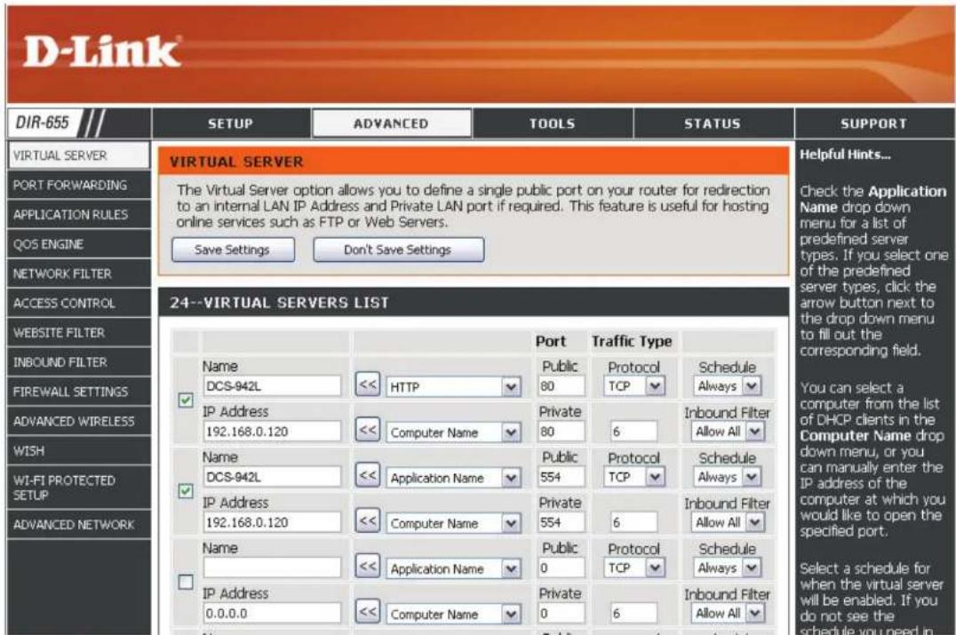
text_image
DIR-655 SETUP ADVANCED TOOLS STATUS SUPPORT VIRTUAL SERVER The Virtual Server option allows you to define a single public port on your router for redirection to an internal LAN IP Address and Private LAN port if required. This feature is useful for hosting online services such as FTP or Web Servers. Save Settings Don't Save Settings Helpful Hints... Check the Application Name drop down menu for a list of predefined server types. If you select one of the predefined server types, click the arrow button next to the drop down menu to fill out the corresponding field. 24--VIRTUAL SERVERS LIST Name DCS-942L << HTTP Public 80 Protocol TCP Schedule Always IP Address 192.168.0.120 << Computer Name Private 80 6 Inbound Filter Allow All Name DCS-942L << Application Name Public 554 Protocol TCP Schedule Always IP Address 192.168.0.120 << Computer Name Private 554 6 Inbound Filter Allow All Name << Application Name Public 0 Protocol TCP Schedule Always IP Address 0.0.0.0 << Computer Name Private 0 6 Inbound Filter Allow All Select a schedule for when the virtual server will be enabled. If you do not see the schedule you need inTroubleshooting
This chapter provides solutions to problems that can occur during the installation and operation of the DCS-5222L. Read the following descriptions if you are having problems. (The examples below are illustrated in Windows Vista® and XP. If you have a different operating system, the screenshots on your computer will look similar to the following examples.)
1. What can I do if I forget my password?
If you forget your password, you will need to perform a hard reset of your camera. This process will change all your settings back to the factory defaults.
To reset your camera, please use an unfolded paperclip to press and hold the RESET button for at least 10 seconds while your camera is plugged in.
2. Why does the LED not light up?
The power supply might be faulty. Confirm that you are using the provided DC 5V power supply for this network camera. Verify that the power supply is correctly connected. If the camera is functioning normally, the LED may have been disabled. See "Admin" on page 61 for information about how to enable the LED.
3. Why is the camera's network connection unreliable?
There might be a problem with the network cable. To confirm that the cables are working, PING the address of a known device on the network. If the cabling is OK and your network is reachable, you should receive a reply.
Another possible problem may be that the network device such as a hub or switch utilized by the network camera is not functioning properly. Please confirm the power for the devices are well connected and functioning properly.
4. Why does the network camera work locally but not remotely?
This might be caused by a routers firewall protection. Check the Internet firewall with your system administrator. The firewall may need to have some settings changed in order for the network camera to be accessible outside your local LAN. For more information, please refer to the section about installing your camera behind a router.
Make sure that the network camera isn't conflicting with any Web server you may have running on your network.
The default router setting might be a possible reason. Check that the configuration of the router settings allow the network camera to be accessed outside your local LAN.
5. Why does a series of broad vertical white lines appear through out the image?
It could be that the CMOS sensor (a square panel situated behind the lens that measures the light signals and changes it into a digital format so your computer can present it into an image that you are familiar with) has become overloaded when it has been exposed to bright lights such as direct exposure to sunlight or halogen lights. Reposition the network camera into a more shaded area immediately as prolonged exposure to bright lights will damage the CMOS sensor.
6. The camera is producing noisy images. How can I solve the problem?
The video images might be noisy if the network camera is used in a very low light environments.
7. The images are poor quality, how can I improve the image quality?
Make sure that your computer's display properties are set to at least 6-bit color. Using 16 or 256 colors on your computer will produce dithering artifacts in the image, making the image look as if it is of poor quality.
The configuration on the network camera image display is incorrect. The Web Configuration Video section of the Web management allows you to adjust the related-parameters for improved images such as: brightness, contrast, hue and light frequency. Please refer to the Web Configuration section for detailed information.
8. Why are no images available through the Web browser?
ActiveX might be disabled. If you are viewing the images from Internet Explorer make sure ActiveX has been enabled in the Internet Options menu. You may also need to change the security settings on your browser to allow the ActiveX plug-in to be installed.
If you are using Internet Explorer with a version number lower than 6, then you will need to upgrade your Web browser software in order to view the streaming video transmitted by the network camera.
If you are using another browser such as Google's Chrome or Apple's Safari, you may need to install the appropriate plugin before the streaming video will work.
If you are using Java, you may need to update to the latest version of the Java application. Please visit Sun's website in order to obtain the newest version Java for your computer platform (http://www.java.com).
You browser may also have 3rd party applications blocked. Please make sure that the browser you are using does not have 3rd party plugin support disabled. You may need to refer to your particular browsers help function in order to turn this functionality on or off.
9. The PIR is not operating well, how can I improve the PIR quality?
- For the Passive Infrared Sensor (PIR) to function properly it is required to have direct line of site to the object. When the room has many obstacles or the line of site is obstructed by glass, the PIR will not function properly.
- When the environment temperature is too high, the PIR detection will slow down and should not be mistaken for a faulty PIR.
- This network camera can only be installed indoors. Do not install this camera in a place where IR interference can be a problem. IR interference can be found close to glass doors or windows, where direct sunlight can cause interference or in the path of car headlights.
- Do not install this camera next to or in front of an air conditioner outlet or vent.
- Do not install this camera close to wireless devices with high frequencies as the PIR is easily affected by RF radiation.
- The PIR functions at best when detecting lateral movements. Radial movements cannot be detected as well as lateral movements.
- Do not install this camera directly under an extreme bright light. The PIR cannot fully suppress a bright white light.
- Any movements from an object with a normal body temperature, like humans or animals, can be detected. To avoid any malfunctions, install this camera at the proper height.
- To avoid any malfunctions, install this camera in an environment with an average temperature of 25^ C. Only within a distance of 2.5 meters can smaller movements of an object, with the average adult human's height, be detected. Between a distance of 2.5 and 5 meters, a larger movement of an object is required for detection.
- Install this camera on a firm, static, anti-shock surface.
Networking Basics
Check your IP address
By default, the TCP/IP settings should be set to obtain an IP address from a DHCP server (i.e. wireless router) automatically. To verify your IP address, please follow the steps below.
Click on Start > Run. In the run box type cmd and click OK. (Windows® 7/Vista® users type cmd in the Start Search box)
At the prompt, type ipconfig and press Enter.
This will display the IP address, subnet mask, and the default gateway of your adapter.
If the address is 0.0.0.0, check your adapter installation, security settings, and the settings on your router. Some firewall software programs may block a DHCP request.
If you are connecting to a wireless network at a hotspot (e.g. hotel, coffee shop, airport), please contact an employee or administrator to verify their wireless network settings.
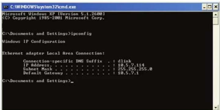
text_image
C:\WINDOWS\system32\cmd.exe Microsoft Windows XP [Version 5.1.2600] (C) Copyright 1985-2001 Microsoft Corp. C:\Documents and Settings>ipconfig Windows IP Configuration Ethernet adapter Local Area Connection: Connection-specific DNS Suffix . : dlink IP Address. . . . . . . . . . . . . . : 10.5.7.114 Subnet Mask . . . . . . . . . . . . . : 255.255.255.0 Default Gateway . . . . . . . . . . . : 10.5.7.1 C:\Documents and Settings>Statically Assign an IP Address
If you are not using a DHCP capable gateway/router, or you need to assign a static IP address, please follow the steps below:
Step 1
Windows® 7- Click on Start > Control Panel > Network and Internet > Network and Sharing Center.
Windows® Vista - Click on Start > Control Panel > Network and Internet > Network and Sharing Center > Manage Network Connections.
Windows XP - Click on Start > Control Panel > Network Connections.
Step 2
Right-click on the Local Area Connection which represents your D-Link network adapter and select Properties.
Step 3
Highlight Internet Protocol (TCP/IP) and click Properties.
Step 4
Click Use the following IP address and enter an IP address that is on the same subnet as your network or the LAN IP address on your router.
Example: If the router's LAN IP address is 192.168.0.1, make your IP address 192.168.0.X where X is a number between 2 and 99. Make sure that the number you choose is not in use on the network. Set Default Gateway to the same as the LAN IP address of your router (192.168.0.1).
Set Primary DNS to the same as the LAN IP address of your router (192.168.0.1). The Secondary DNS is not needed or you may enter a DNS server from your ISP.
Step 5
Click OK twice to save your settings.
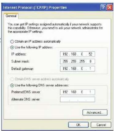
text_image
Internet Protocol (TCP/IP) Properties General You can get IP settings assigned automatically if your network supports this possibility. Otherwise, you need to ask your network administrator for the appropriate IP settings. ○ Obtain an IP address automatically ○ Use the following IP address: IP address: 192 . 168 0 . 52 Subnet mask: 255 . 255 . 255 0 Default gateway: 192 . 168 0 . 1 ○ Obtain DNS server address automatically ○ Use the following DNS server addresses: Preferred DNS server: 192 . 168 0 . 1 Alternate DNS server: Advanced... OK CancelDI/DO Specifications

text_image
Pin 1 Pin 4 Pin 3P| PIN FUNCTION | NOTE | |
| 1 | Digital Out (DO) | Uses an open-drain NFET transistor with the source connected to GND in camera. If used with an external relay, a diode must be connected in parallel with the load for protection against voltage transients. Max loading is 100 mA. |
| 2 DC5V OUTPUT DC 5 V Output / Max. 100 mA | ||
| 3 Digital In (DI) A switch from DI to GND, activated by setting NO. or NC. | ||
| 4 GND GND | ||
Internal 5V Power External 3\~12V Power
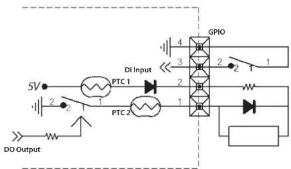
text_image
5V DO Output PTC 1 DI Input PTC 2 GPIO 4 3 2 1 2 1 1 2 1 3 4 DO OUTPUT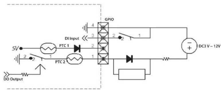
text_image
5V DI Input GPIO 2 1 3 4 2 1 PTC 1 2 1 3 4 2 1 PTC 2 1 2 1 DC3 V - 12V DO OutputTechnical Specifications
| General Specifications | ||
| Camera Specifications • 1/4" Megapixel Progressive CMOS sensor• 8 meter IR illumination distance• Minimum illumination 0 lux with IR LED on• Built-in Infrared-Cut Removable (ICR) Filter module• Focal length 3.6 mm• Aperture: F2 | • Exposure Time: 1/7.5 sec. to 1/10,000 sec.• Angle of view:• (H) 70°• (V) 53°• (D) 92°• Built-in microphone and speaker | |
| Video Features • Configurable image size, quality, frame rate, and bit rate• Time stamp and text overlays | • Configurable motion detection windows• Configurable shutter speed, brightness, saturation, contrast, mirror, flip | |
| Video Compression • H.264/MJPEG format simultaneous compression• H.264 multicast streaming | • JPEG for still images | |
| Video Resolution • 16:9 (supports frame rates up to 30 fps)• 1280 x 720, 800 x 450, 640 x 360, 480 x 270, 320 x 176 | • Others (supports frame rates up to 30 fps)• 1024 x 768, 800 x 600, 640 x 480, 480 x 360, 320 x 240 | |
| Pan/Tilt/Zoom • Pan Range: -170° to 170° | • Tilt Range: -20° to 100°• Digital Zoom: 10x | • Manual Pan Speed: 5-80° per second• Manual Tilt Speed: 5-80° per second• Position Presets: 32 points |
| Audio Compression • G.711, G.726, AAC | ||
| Network Protocol Support • IPv6 | • IPv4• TCP/IP• UDP• ICMP• DHCP client• NTP client (D-Link)• DNS client• DDNS client (D-Link)• SMTP client• FTP client | • HTTP / HTTPS• Samba client• PPPoE• UPnP port forwarding• RTP / RTSP/ RTCP• IP filtering• QoS• CoS• Multicast• IGMP• ONVIF compliant |
| Network Interface • IEEE 802.11n • 10/100 BASE-TX Fast Ethernet | ||
| External Device Interface | • MicroSD/SDHC Slot• Single audio input/output port | • DI/DO Port |
Appendix AC - Technical Specifications
| Advanced Features | ||
| Remote Management | ·Take snapshots/video clips and save to local hard drive via web browser | ·Configuration accessible via web browser |
| Security ·Administrator and user group protected | ·Password authentication | ·HTTP and RTSP authentication |
| Surveillance ·Record video continuously | ·Record video according to a weekly schedule | ·Upload snapshots/video clips via e-mail |
| ·Record video when motion is detected | ·Upload snapshots/video clips via FTP | |
| Mobile App Support ·mydlink Lite app for iOS and Android devices | ||
| System Requirements | ||
| Operating System ·Microsoft Windows 8/7/Vista/XP SP3 | ||
| Compatible Browsers ·Microsoft Internet Explorer 8, Firefox 12, Chrome 20, Safari 4 ·Other Java-enabled browser | ||
| Supported Mobile Devices ·mydlink Lite/mydlink+ mobile app for iPhone, iPad, and Android mobile devices | ||
| Physical | ||
| Dimensions ·120 x 103.2 x 130 mm (4.72 x 4.06 x 5.11 inches) | ||
| Weight | ·340 grams (0.75 lb) | |
| Power Input | ·Input: 5 V DC, 2.5 A | |
| Temperature | ·Operating: 0 to 40 °C (32 to 104 °F) | ·Storage: -20 to 70 °C (-4 to 158 °F) |
| Humidity | ·Operating: 20% to 80% non-condensing | |
| Certifications | ·CE | ·C-Tick |
| ·FCC Class B | ·CE LVD | |
^1 An SDHC Class 6 card or above is recommended. Card capacities of up to 32GB supported.