BC 2209 MHR STS - Counter SIGMA - Free user manual and instructions
Find the device manual for free BC 2209 MHR STS SIGMA in PDF.

User questions about BC 2209 MHR STS SIGMA
0 question about this device. Answer the ones you know or ask your own.
Ask a new question about this device
Download the instructions for your Counter in PDF format for free! Find your manual BC 2209 MHR STS - SIGMA and take your electronic device back in hand. On this page are published all the documents necessary for the use of your device. BC 2209 MHR STS by SIGMA.
USER MANUAL BC 2209 MHR STS SIGMA
1 Introduction and packaging contents 31
2 Installation on the bike 32
2.1 Installation of the 2 nd bike 33
3 Start-up 33
4 Display change/Key functions/Function overview 34
6 The basic settings 35
6.1 Setting the language 36
6.2 Setting KMH/MPH 36
6.3 Setting air pressure to sea level (SEA LEVEL) 37
6.4 Setting actual altitude 37
6.5 Setting home altitude 38
6.6 Calculating wheel size 38
6.7 Set wheel size bike 1 and bike 2 39
6.8 Setting the clock 40
6.9 Setting your age 40
6.10 Setting your weight 41
6.11 Setting your gender 41
6.12 Setting the total odo for bike 1 or bike 2 42
6.13 Setting the total trip time for bike 1 or bike 2 42
6.14 Setting the total altitude for bike 1 or bike 2 43
6.15 Setting the contrast 43
6.16 Exiting basic settings 44
7 General functions 44
7.1 Display illumination 44
7.2 Compare Speed 44
7.3 Showing/hiding the cadence/heart rate functions 45
7.4 Calibrating the home altitude 45
7.5 Stopwatch 45
7.6 Countdown 46
7.7 Trip up/down 47
7.8 Reset Display 48
7.9 Totals bike 1 and bike 2 48
7.10 Service interval 48
7.11 Transport mode 49
7.12 PC interface 49
7.13 Cable-connected universal bracket 49
8 Measuring the Altitude 49
8.1 Introduction 49
8.2 Calibration possibilities of the BC 2209 MHR 50
9 The hiking mode 51
9.1 Introduction 51
9.2 Synchronisation 51
9.3 Setting of the hiking time 52
9.4 Setting the target time 52
9.5 Reset Display 53
9.6 Showing/hiding the heart rate functions 53
10 Technical Data 54
10.1 Default/Min/Max values 54
10.2 Battery Change 55
10.3 Trouble Shooting 56
10.4 Warranty 57
1 INTRODUCTION AND PACKAGING CONTENTS
Congratulations on having chosen a bicycle computer from SIGMA SPORT®. Your new BC 2209 MHR will provide you reliable service in riding your bike for many years to come.
The BC 2209 MHR is a state-of-the-art measuring instrument. Please read instructions carefully to become familiar with the functions and usage of this bicycle computer.
SIGMA wishes you an enjoyable time using your BC 2209 MHR.
The BC 2209 MHR is fitted with an automatic Start/Stop. As soon as this is assembled on the mounting bracket a movement sensor activates the BC 2209 MHR at the smallest movement of the bicycle or the hiking mounting. This automatically starts the connection.
1 INTRODUCTION AND PACKAGING CONTENTS
1 PACKAGING CONTENTS
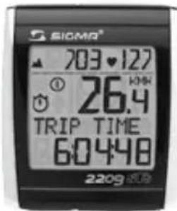
text_image
SIOMA® 703.127 ① 26.4 TRIP TIME 6:04:48 2209Bike computer BC 2209 MHR


STS chest belt
including elastic belt
STS speed
transmitter


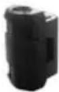
natural_image
Black electronic device with 'SIGMA' branding and a triangular top (no visible text or symbols beyond branding)STS cadence transmitter

natural_image
Three black circular components with square tops and rings, no text or symbols present→ Spoke magnet
→ Cadence magnet
→ Handlebar bracket
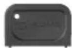
→ Battery compartment key
→ Wrist strap
→ Fastening material
2 INSTALLATION ON THE BIKE
The illustrations for these installation texts can be found on the enclosed folding sheet!
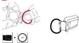
INSTALLING THE BIKE BRACKET
1 2 3 4
→ The bracket can either be installed with cable ties (permanent attachment) or optionally using the O-rings.
→ Handelbars or front end.
→ Remove the yellow foil.
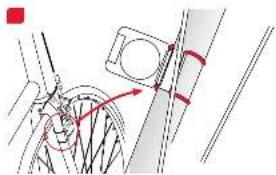
INSTALLING THE TRANSMITTERS - SPEED AND CADENCE

Both transmitters can either be installed with cable ties (permanent attachment) or optionally using the O-rings.
→ In order to achieve the necessary 12mm or less install the transmitter and the magnet closer to the wheel hub.
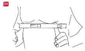
INSTALLING THE MAGNETS - SPEED AND CADENCE/ PUTTING ON THE CHEST BELT

→ Rub water or cardio-gel on the electrodes.
2.1 INSTALLATION OF THE 2 ^nd BIKE
Switching between BIKE 1 and BIKE 2 is automatic. A second speed transmitter must be used (Accessory set "BIKE 2" Ref.-No. 00417, "BIKE 2 incl. cadence" Ref.-No. 00415)

3 START-UP
For reasons of energy consumption, the BC 2209 MHR is supplied without a battery.
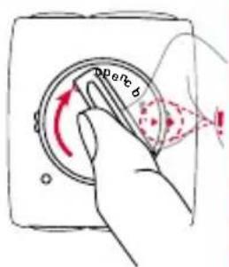
Please insert the battery by opening the battery compartment cover with the tool provided. Once you have inserted the battery, close the battery compartment with the aid of the tool.
The display automatically jumps to setting mode.
text_image
perc b
text_image
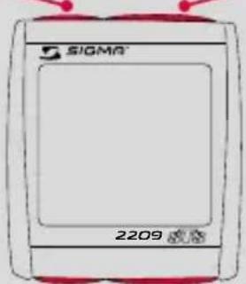
SIGMA® ENGLISH 2209RESET
MODE 2
Reset the functions listed below or scroll backwards in a menu level.
text_image
SIGMA 2209Access the functions listed below or scroll forwards in a menu level.
SET
MODE 1
Set and save the entered values.
Access the functions listed below.
MODE 1 MODE 2
BIKE MODE TRIP DIST CADENCE TRIP UP +/-
TRIP TIME AVG. PULSE TEMPERATUR
AVG. SPEED MAX. PULSE TOTAL ODO*
MAX. SPEED KCAL TOTAL TIME*
AVG. CAD CLOCK TOTAL ALTI*
TRIP CLIMB +/- STOPWATCH
MAX. ALTI COUNTDOWN
HIKING MODE HIKINGTIME AVG. PULSE STOPWATCH TARGETTIME MAX. PULSE TEMPERATUR TRIP CLIMB +/- KCAL TOTAL TIME MAX. ALTI CLOCK TOTAL ALTI
* not whilst moving
5 SYNCHRONISATION
text_image
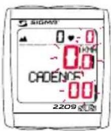
SIGMS 0:0 0.0 CADENOS -00 2209→ Installation of the BC 2209 MHR into the mounting bracket - a pairing is only possible if the bike computer is locked onto the mounting bracket.
→ The zeros on the speed, cadence and pulse displays are flashing.
5 SYNCHRoNISAtIoN
→ To synchronise the speed, cadence and heart rate, there are 2 options:
-
Set off, usually the receiver has paired with the transmitter within 3 or 4 wheel turns.
-
Turn front wheel or pedals until the KMH or cadence display stops flashing.

text_image
Diagram showing bicycle wheel and wheel with rotation arrows, indicating rotational motion→ While wearing the chest strap either go close to the BC 2209 MHR or climb on the bicycle. As a rule, the BC 2209 MHR pairs with the chest belt in less than 10 seconds.
The pulse display is no longer flashing.
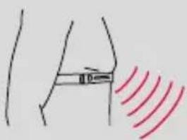
text_image
Diagram showing a human leg with a measurement line and red wave pattern, likely illustrating a physical or medical concept.6 tHE BASIC SETTINGS
→ Hold down SET button until the preset LANGUAGE (English) appears on the display (SETTINGS OPEN flashes).

text_image
SIGMA 0 - 0 © 274 CADENCE 8.1 2209
text_image
SIOMO 0 - 0 27.4 CADENDF 8.1 2209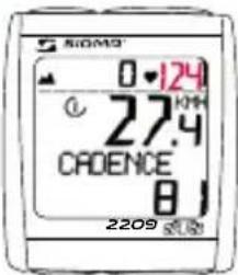
text_image
SiOMO 0·124 27.4 CADENCE 8 2209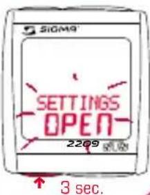
text_image
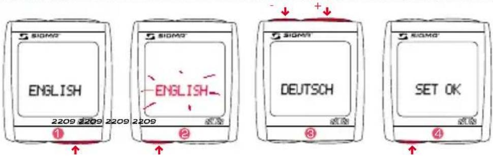
SIGM9 SETTINGS OPEN 2209 3 sec.6.1 SETTING THE LANGUAGE
text_image
SIOMO ENGLISH 2209 2209 2209 2209 1 SIOMO ENGLISH DEUTSCH SET OK 2 SIOMO ENGLISH 3 SIOMO SET OK 4→ Use MODE 1 button to switch to the preset LANGUAGE (as standard the BC 2209 MHR is preset to English).
→Press the SET button briefly. Display flashes.
3 → Set the desired language using the MODE 2 button (+) or the RESET button (-).
④ → Confirm by pressing the SET button. SET OK appears on the display.
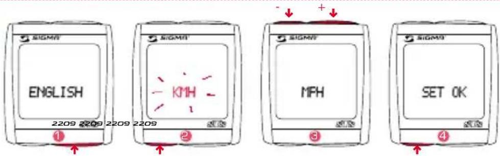
6.2 SETTING KMH/MPH
text_image
SIGMS ENGLISH 2209 2209 2209 2209 ① SIGMS KMH ② SIGMS MPH ③ SIGMS SET OK ④→ Change the display to KMH/MPH using the MODE 1 button.
2 → Press the SET button briefly. Display flashes.
3 → Select MPH or KMH using MODE 2 button (+) or the RESET button (-).
4 → Confirm by pressing the SET button. SET OK appears on the display.
By switching from KMH to MPH, the distance format automatically changes from km to mi, the temperature from ^ C to ^ F, the time from 24 h mode to 12 h mode, the altitude from m to ft and the weight from kg to lb.
6.3 SEttING the AIR PRESSURE to SEA LEVEL (SEA LEVEL)

You can find explanations about this function in Chapter "8 MEASURING THE ALTITUDE"
1 → Change the display to SEA LEVEL using the MODE 1 button.
2 → Press the SET button briefly. Display flashes.
B → Set the value using the MODE 2 button (+) or the RESET button (-).
→ Confirm by pressing the SET button. SET OK appears on the display.
6.4 SETTING ACtUAL ALtItUDE
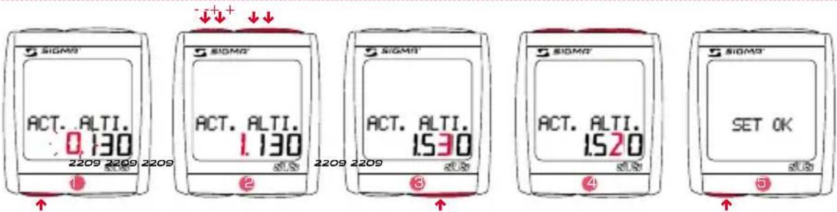
You can find explanations about this function in Chapter "8 MEASURING THE ALTITUDE".
→ Change the display to ACT. ALTI. using the MODE 1 button
→ Press the SET button briefly. The first settings number is flashing.
→ Set the value using the MODE 2 button (+) or the RESET button (-).
3 → Move to the next figure using the MODE 1 button.
4 → Set the value using the MODE 2 button (+) or the RESET button (-).
→ Confirm by pressing the SET button. SET OK appears on the display.
6.5 SETTING HOME ALTI.

You can find explanations about this function in Chapter "8 MEASURING THE ALTITUDE".
1 → Change the display to HOME ALTI. using the MODE 1 button.
→ Press the SET button briefly. The first input figure is flashing.
2 → Set the value using the MODE 2 button (+) or the RESET button (-).
3 → Move to the next figure using the MODE 1 button.
4 → Set the value using the MODE 2 button (+) or the RESET button (-).
→ Confirm by pressing the SET button.
SET OK appears on the display.
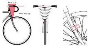
6.6 CALCULATING WHEEL SIZE
→ Determine the correct value for your wheel size from Table "WHEEL SIZE CHART" (Tab. C).
→ Alternatively: calculate/determine WS (Tab. A oder Tab. B)
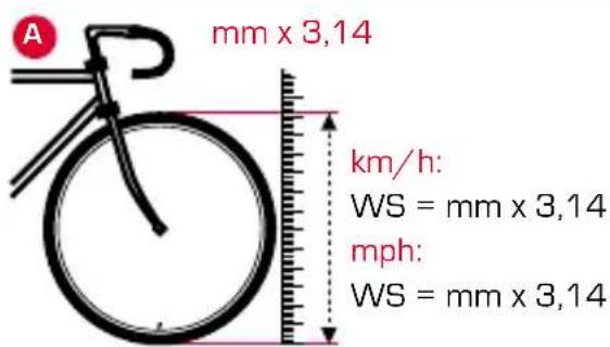
text_image
A mm x 3,14 km/h: WS = mm x 3,14 mph: WS = mm x 3,14
text_image
B 1x km/h: WS = mm mph: WS = mm = WS (mm)
ETRTO ETRTO

kmh mph
| 47-305 | 16x1.75x2 | 1272 |
| 47-406 | 20x1.75x2 | 1590 |
| 37-540 | 24x1 3/8 A | 1948 |
| 47-507 | 24x1.75x2 | 1907 |
| 23-571 | 26x1 | 1973 |
| 40-559 | 26x1.5 | 2026 |
| 44-559 | 26x1.6 | 2051 |
| 47-559 | 26x1.75x2 | 2070 |
| 50-559 | 26x1.9 | 2089 |
| 54-559 | 26x2.00 | 2114 |
| 57-559 | 26x2.125 | 2133 |
| 37-590 | 26x1 3/8 | 2105 |
| 37-584 | 26x1 3/8x1 1/2 | 2086 |
| 20-571 | 26x3/4 | 1954 |

kmh mph
| 32-630 | 27x1 1/4 | 2199 |
| 28-630 | 27x1 1/4 Fifty | 2174 |
| 40-622 | 28x1.5 | 2224 |
| 47-622 | 28x1.75 | 2268 |
| 40-635 | 28x1 1/2 | 2265 |
| 37-622 | 28x1 3/8x1 5/8 | 2205 |
| 18-622 | 700x18C | 2102 |
| 20-622 | 700x20C | 2114 |
| 23-622 | 700x23C | 2133 |
| 25-622 | 700x25C | 2146 |
| 28-622 | 700x28C | 2149 |
| 32-622 | 700x32C | 2174 |
| 37-622 | 700x35C | 2205 |
| 40-622 | 700x40C | 2224 |
6.7 SET WHEEL SIZE WS BIKE 1 OR WS BIKE 2

text_image
SIOM® WHEEL SIZE : 2.155 2209
text_image
SIGMA WHEEL SIZE 1.155 2209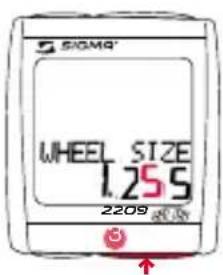
text_image
SIOMA® WHEEL SIZE 1.255 2209
text_image
SIGMA WHEEL SIZE 1.235 2209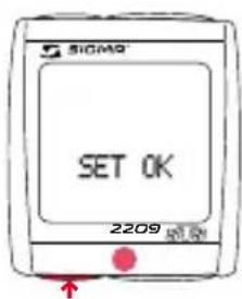
text_image
SIGMA SET OK 2209→ Change the display to WS BIKE 1 or WS BIKE 2 using the MODE 1 button.
→ Press the SET button briefly. The first input figure is flashing.
2 → Set the value using the MODE 2 button (+) or the RESET button (-).
→Move to the next figure using the MODE 1 button.
→ Set the value using the MODE 2 button (+) or the RESET button (-).
→ Confirm by pressing the SET button.
SET OK appears on the display.
6.8 SETTING THE CLOCK
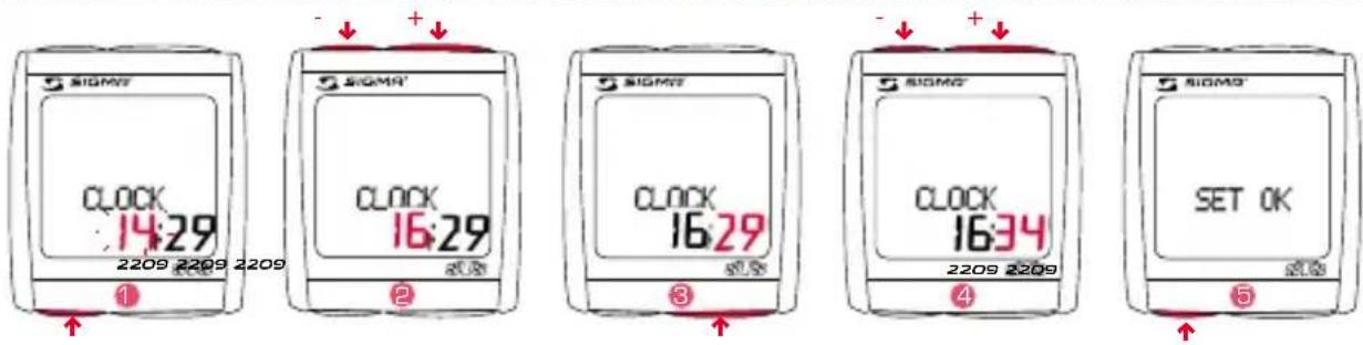
1 → Change the display to CLOCK using the MODE 1 button.
→ Press the SET button briefly. The hour display will blink.
2 → Set the value using the MODE 2 button (+) or the RESET button (-).
3 → Move to the next figure using the MODE 1 button.
4 → Set the value using the MODE 2 button (+) or the RESET button (-).
→ Confirm by pressing the SET button. SET OK appears on the display.
6.9 SETTING YOUR AGE
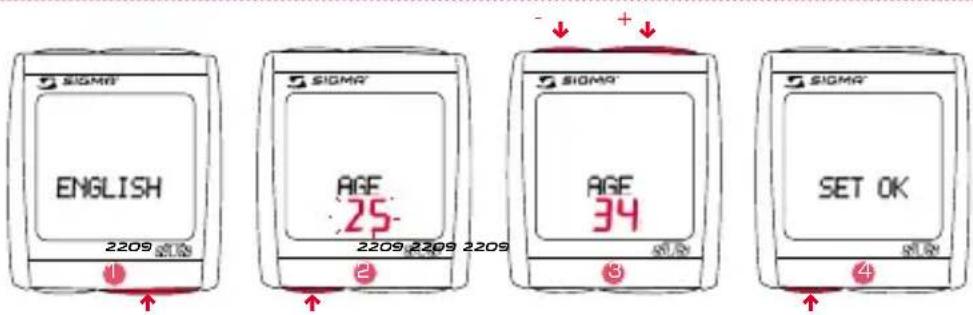
→ Use MODE 1 button to switch to AGE display.
2 → Press the SET button briefly. Display flashes.
3 → Set the value using the MODE 2 button (+) or the RESET button (-).
→ Confirm by pressing the SET button. SET OK appears on the display.
6.10 SEttING YoUR WEIGHT

→ Use MODE 1 button to switch to WEIGHT display.
→ Press the SET button briefly. Display flashes.
3 → Set the value using the MODE 2 button (+) or the RESET button (-).
4 → Confirm by pressing the SET button. SET OK appears on the display.
6.11 SEttING YoUR GENDER
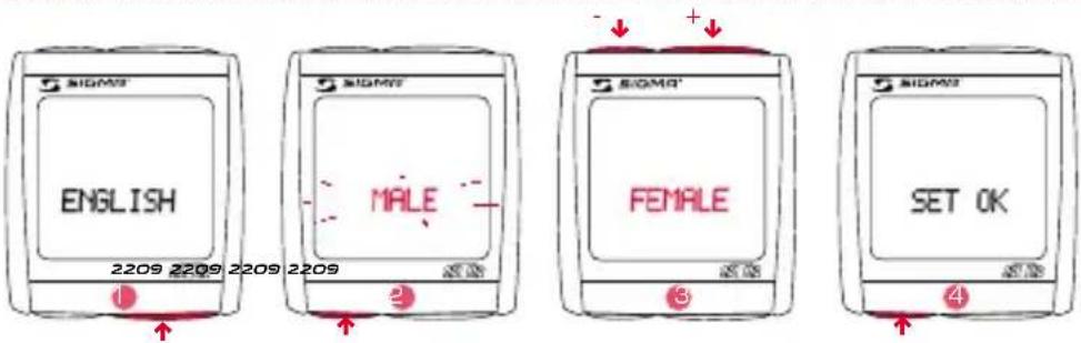
→ Use MODE 1 button to switch to the preset GENDER (as standard the BC 2209 MHR is preset to MALE).
2 → Press the SET button briefly. Display flashes.
3 → Set the gender using the MODE 2 button (+) or the RESET button (-).
→ Confirm by pressing the SET button.
SET OK appears on the display.
6.12 SETTING THE TOTAL ODO BIKE 1 OR BIKE 2
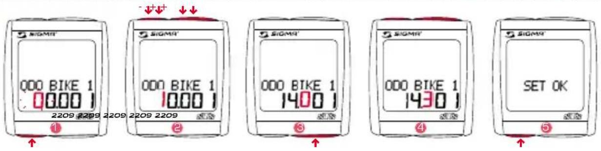
→ Change the display to ODO BIKE 1 or ODO BIKE 2 using the MODE 1 button.
→ Press the SET button briefly. The first settings number is flashing.
2 → Set the value using the MODE 2 button (+) or the RESET button (-).
→Move to the next figure using the MODE 1 button.
4 → Set the value using the MODE 2 button (+) or the RESET button (-).
→ Confirm by pressing the SET button. SET OK appears on the display.
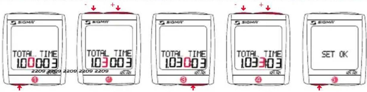
6.13 SETTING THE TOTAL TRIP TIME BIKE 1 OR BIKE 2
text_image
SIGMA' TOTAL TIME 100003 2209 2209 2209 2209 2209 ① SIGMA' TOTAL TIME 103003 ② SIGMA' TOTAL TIME 103003 ③ SIGMA' TOTAL TIME 103303 ④ SIGMA' SET OK ⑤→ Change the display to TIME BIKE 1 or TIME BIKE 2 using the MODE 1 button.
→ Press the SET button briefly. The first settings number is flashing.
→ Set the value using the MODE 2 button (+) or the RESET button (-).
→Move to the next figure using the MODE 1 button.
4 → Set the value using the MODE 2 button (+) or the RESET button (-).
→ Confirm by pressing the SET button.
SET OK appears on the display.
6.14 SEttING tHE totAL ALtl BIkE 1 oR BIkE 2
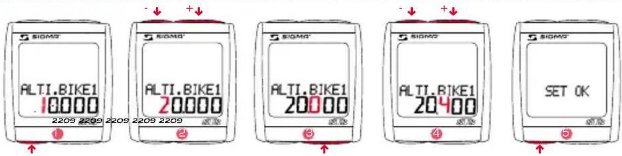
1 → Change the display to ALTI BIKE 1 or ALTI BIKE 2 using the MODE 1 button.
→ Press the SET button briefly. The first settings number is flashing.
2 → Set the value using the MODE 2 button (+) or the RESET button (-).
→Move to the next figure using the MODE 1 button.
4 → Set the value using the MODE 2 button (+) or the RESET button (-).
→ Confirm by pressing the SET button.
SET OK appears on the display.
6.15 SEttING tHE CoNtRASt
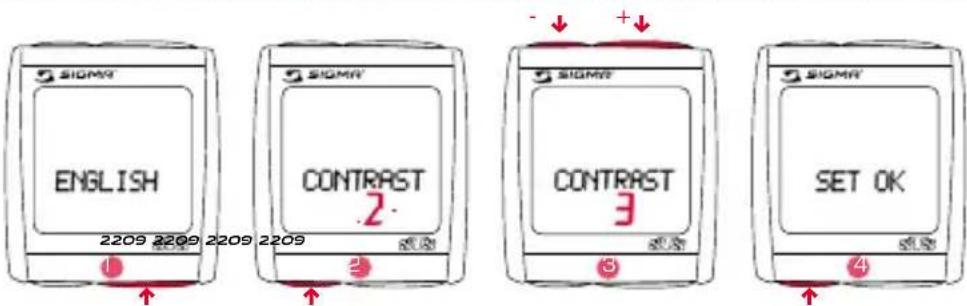
→ Change the display to CONTRAST using the MODE 1 button.
→ Press the SET button briefly. Display flashes.
3 → Set the value using the MODE 2 button (+) or the RESET button (-). (1 = weak / 3 = strong)
4 → Confirm by pressing the SET button. SET OK appears on the display.
6.16 EXITING BASIC SETTINGS
text_image
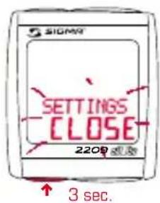
SIGMA SETTINGS CLOSE 2200 s.5s 3 sec.→ Press the SET button down for 3 seconds in order to stop entering settings (SETTINGS CLOSE flashes).
7 GENERAL FUNCTIONS
7.1 DISPLAY ILLUMINATION

text_image
SIGMA LIGHT ON 2209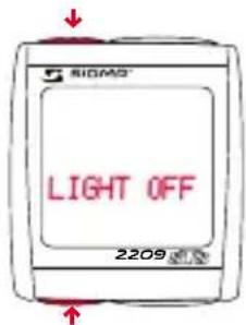
text_image
SIGMS LIGHT OFF 2209→ The lighting function is switched on/off when you press the SET and RESET button at the same time. LIGHT ON/OFF is shortly displayed. → The display is illuminated when you press any button and the function is switched on when you press it again.
The illumination is not available during pairing! Protect the battery by avoiding unnecessary illumination!
7.2. COMPARE SPEED
text_image
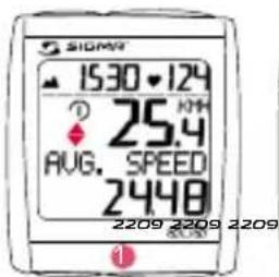
SIOMY 15:30-12:4 ? 25.4 AUG. SPEED 2448 2209 2209 2209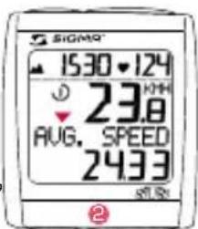
text_image
SIGMA 1530 124 ↓ 23.8 AUG. SPEED 243.3 ST.5N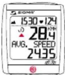
text_image
SIGMA 15:30 • 124 28.4 AUG. SPEED 24.35 87.5% ③1 → If the speed is nearly the same
is displayed.
2 → If lower speed will be displayed.
3 → If higher speed will be displayed. It is displayed for all functions except in the basic settings.
7 GENERAL FUNCtIoNS
7.3 SHoWING/HIDING tHE CADENCE/HEARt RAtE FUNCtIoN
When the BC 2209 MHR is operated without cadence signal transmitter and/or chest belt, all cadence/heart rate functions (CADENCE, AVG. CAD, PULSE, AVG. PULSE, MAX. PULSE, KCAL) are hidden for this trip.
7.4 CALIBRAtING tHE HoME ALtl.
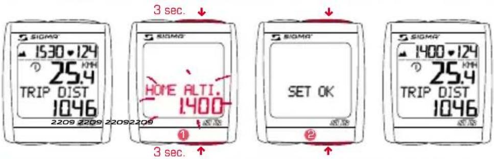
text_image
SIGMA 1530-124 ① 25.4 TRIP DIST 1046 2209 2209 22092209 3 sec. SIGMA HORE ALTI. 1400 SET OK 3 sec. SIGMA 1400-124 ① 25.4 TRIP DIST 1046→ Hold down the MODE 1 and MODE 2 buttons simultaneously for 3 seconds to calibrate the HOME ALTI.
→ "HOME ALTI." will blink in the display.
2 → SET OK appears on the display.
7.5 StoPWAtCH
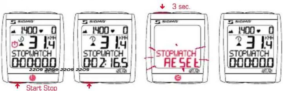
text_image
SIGMA 1400 3.14 STOPWATCH 000:000 2209 2209 2209 2209 Start Stop SIGMA 1400 3.14 STOPWATCH 002:16.5 3 sec. SIGMA 1400 3.14 STOPWATCH RESET 2→ Change the setting to STOPWATCH using the MODE 2 button.
→ Start or stop the stopwatch using the SET button.
→ The icon ⚙ in the display means the stopwatch is running.
2 → To reset the stopwatch: hold down the RESET button for 3 seconds.
7.6 COUNTDOWN

→ Use MODE 2 to switch to COUNTDOWN +/- display.
→ Hold down SET button for 3 seconds (COUNTDOWN SET flashes).
2 → Set the value using the MODE 2 button (+) or the RESET button (-).
→Move to the next figure using the MODE 1 button.
Set the value as described above.
4 → Confirm by pressing the SET button.
SET OK appears on the display.
5 → Use the SET button to start or stop COUNTDOWN.
The 🎨 icon on the display means the countdown is running.
6 → Setting the countdown to zero: Hold down RESET button for 3 seconds
(the display switches back to the preset value).
7.7 tRIP UP/DoWN

→ Change the display to TRIP UP/DOWN using the MODE 2 button.
→ Hold down the SET button for 3 seconds. The display flashes "+" or "-"
→ Set to "+" or "-" using the MODE 2 button.
→ Confirm by pressing the SET button.
The display will jump to the distance setting.
4 → Set the value using the MODE 2 button (+) or the RESET button (-).
→Move to the next figure using the MODE 1 button.
Set the value as described above.
6 → Confirm by pressing the SET button.
SET OK appears on the display.
7.8 RESET DISPLAY

→Press MODE1/2 until the desired function is displayed.
→ Hold down the RESET button. Display flashes. After 2 seconds only the function displayed is reset to 0.
→ Hold down the RESET button for longer than 4 seconds to set the display from: TRIP DIST, TRIP TIME, AVG. SPEED, MAX. SPEED, AVG. CAD, TRIP CLIMB, MAX. ALTI, AVG. PULSE, MAX. PULSE, KCAL to zero.
7.9 TOTALS FOR BIKE 1 AND BIKE 2

text_image
SIGMY 1400 0 0.0 TOTAL TIME 100037 2209The totals are first displayed separately for BIKE 1, BIKE 2 and BIKE 1+2, if a second bike is added. If only one bike is ridden, only the totals for the first bike are displayed.
7.10 SERVICE INTERVAL

text_image
SIOMY INSPECTION 2209Any button must be pressed briefly
The service interval tells you when the mileage until the next bike inspection is reached.
The service interval can only be set by your dealer. After reaching the preset mileage, INSPECTION appears on the display.
Pressing any button makes this display disappear.
7 GENERAL FUNCtIoNS
7.11 tRANSPoRt MoDE
If the bike is transported on a bike carrier or in the car (if clipped on the bracket), the BC 2209 MHR will be put into so-called transport mode by the integrated movement sensor. TRANSPORT appears on the display. To exit this mode, you must press any button briefly.
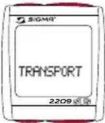
text_image
SIGMA TRANSPORT 2209Any button must be pressed briefly
7.12 PC INtERFACE
The BC 2209 MHR is PC-compatible. After purchasing the SIGMA DATA CENTER SOFTWARE and its Docking Station (Ref. No. 00432), you can quickly and easily download the total and daily values onto your PC. Furthermore, you can quickly and easily set your BC 2209 MHR.

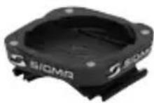
natural_image
Close-up of a black square electronic device with a circular top and two small holes, no visible text or symbols.7.13 CABLE-CoNNECtED UNIVERSAL BRACKEt
The BC 2209 MHR can be retrofitted with a cable-connected universal bracket only for measuring the speed (the cadence and chest belt remain wireless) Ref. No. 00433.
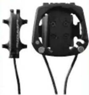
natural_image
Two black mechanical components with connectors and wires, no visible text or symbols8 MEASURING tHE ALtItUDE
8.1 INtRoDUCtIoN
The BC 2209 MHR measures the altitude using barometric air pressure. Every change in weather means a change in air pressure, which can lead to a change of the actual altitude. In order to compensate for this change in air pressure one must input a reference altitude in the BC 2209 MHR (the so-called calibration). The BC 2209 MHR has a special function that makes this calibration almost unnecessary:
When the equipment is “sleeping” (clock and model name in the display) the last displayed actual altitude is saves. When it “wakes” the computer adopts this saved actual altitude as the reference altitude. The BC 2209 MHR thus „calibrates itself“.
The barometric air pressure measurement is activated by movement of the bike or of the BC 2209 MHR, even if the BC 2209 MHR is in sleep mode. This means that the actual altitude is updated regularly when the bike is moved. The built-in movement sensor is so sensitive that the system also works in a car.
There are three holes underneath the BC 2209 MHR for air pressure measurement. This holes must always stay open and therefore require regular cleaning.
NOTE: Do not push any sharp objects into the measurement hole.
8.2 CALIBRATION POSSIBILITIES OF THE BC 2209 MHR
1. THE HOME ALTITUDE
The “home altitude” is the altitude of your regular location (usually your residence). This value can be found on road maps or national maps. It is programmed in the BC 2209 MHR one time and can be calibrated within 3 seconds. The home altitude stays saved by the BC 2209 MHR (even after a battery change).
2. THE ACTUAL ALTITUDE
The “actual altitude” is the altitude of the place where you are currently located, independent of your home altitude (where you started your tour, an alpine hut or other place). The “actual altitude” is used when you are travelling by bike and you have altitude information.
3. THE AIR PRESSURE AT SEA LEVEL
In the event that you are in an unknown place (no information is available on actual altitude) then you can enter so-called “air pressure reduced to sea level” in order to calibrate the actual altitude. The air pressure reduced to sea level can be found in the Internet or at the airport.
NOTE: The air pressure of your weather station is the actual air pressure, not the air pressure reduced to sea level.
9 HIKING MODE
9.1 INTRODUCTION
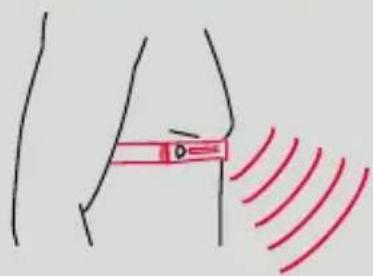
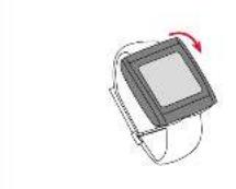
The BC 2209 MHR can also be used as a hiking computer. For this purpose a separate wrist strap is included in delivery. When the BC 2209 MHR is fitted onto this wrist strap, all bike functions are hidden (these remain saved, however, and can be accessed again when cycling). Only the functions relevant for hiking are maintained. You can therefore also use your BC 2209 MHR with altitude and heart rate details when hiking, climbing, skiing or doing other sports.

text_image
0·124 HIKINGTIME 6:29:56 22099.2 SYNCHRONISATION
→ Place the BC 2209 MHR into the wrist strap. The zeros on the current heart rate flash.
→ The BC 2209 MHR will have paired with the chest belt after approx. 10 seconds, and the data will be displayed.
natural_image
Simple line drawing of a human torso with a red bandage and red wave pattern (no text or symbols)
text_image
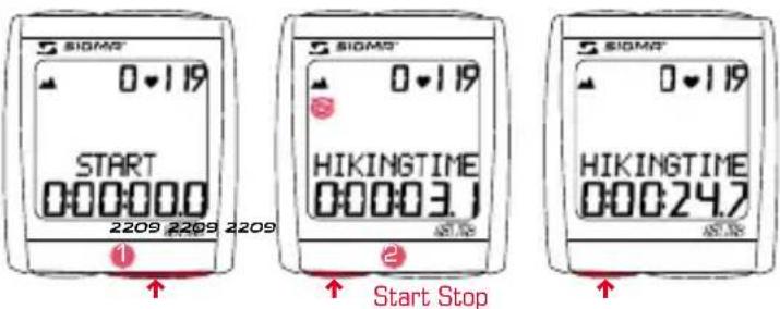
HIKINGTIME 000000.0 22099.3 SETTING THE HIKING TIME
text_image
SIOMR 0-119 START 000000.0 2209 2209 2209 HIKINGTIME 00003.1 Start Stop SIOMR 0-119 HIKINGTIME 00024.7→ Use the MODE 1 button to switch to the HIKING TIME display.
→ Use the SET button to start or stop the hiking time.
The icon on the display means the hiking time is running.
9.4 SETTING THE TARGET TIME

text_image
SIGMA TARGETTIME SET 2209 2209 2209 2209 3 sec. SIGMA' TARGETTIME 00000 SIGMA' TARGETTIME 60000 SIGMA' TARGETTIME 6:30:00 SET OK→ Use the MODE 1 button to switch to the TARGET TIME display.
→ Hold down the SET button for 3 seconds (TARGET TIME SET flashes).
→ Set the value using the MODE 2 button (+) or the RESET button (-).
3 → Move to the next figure using the MODE 1 button. Set the value as described above.
→ Confirm by pressing the SET button.
The change is save when SET OK is displayed.
→ Use the SET button to start or stop the TARGET TIME.
9.5 RESET DISPLAY

→Press MODE1/2 until the desired function is displayed.
2 → Hold down the RESET button. Display flashes.
The word „RESET“ appears on the bottom part of the display and flashes.
After 2 seconds only the function displayed is reset to 0.
3 → Hold down the RESET button for longer than 4 seconds to set the display from: HIKINGTIME, TARGETTIME, TRIP CLIMB, MAX. ALTI, AVG. PULSE, MAX. PULSE, KCAL to zero.
9.6 SHoWING/HIDING tHE HEARt RAtE FUNCtloNS
When the BC 2209 MHR is used without a chest belt, all heart rate functions (PULSE, AVG. PULSE, MAX. PULSE, KCAL) for this one hike are hidden.
10.1 DEFAULT/MIN/MAX VALUES
| Default Max. Min. Units | ||||
| Speed 0,0 199,8 0,0 km/hmph | ||||
| Trip Distance 0,00 9999,99 0,00 km/mi | ||||
| Trip Time 0:00:00 999:59:59 00:00:00 h:mm:ss | ||||
| Average speed | 0,00 199,99 | 0,00 km/hmph | ||
| Max. speed | 0,00 199,99 | 0,00 km/hmph | ||
| Cadence | 0 | 180 | 0 | upm |
| Max. cadence | 0 | 180 | 0 | upm |
| Current heart rate | 40 | 240 | 40 | bpm |
| Average heart rate | 40 | 240 | 0 | bpm |
| Max. heart rate | 40 | 240 | 0 | bpm |
| Calories | 0 | 9.999 0 | Kcal | |
| Current altitude | 0 | 4.999/19.999 | -999 | m / ft |
| Day's altitude 0 | 99.999 | 0 | m / ft | |
| Max. altitude | 4.999/19.999 | -999 | m / ft | |
| Stopwatch | 00:00,0 | 9:59:59 | 00:00:00 | h:mm:ss,1/10 |
| Countdown | 0:00:00 | 9:59:59 | 00:00:00 | h:mm:ss |
| Separate kilometre counter | 0,00 | 999,99 | -99,99 | km/mi |
| Temperatur | 0 | +70/+158 | -10,0 °C/°F | |
| Total distance | 0 | |||
| Bike 1/2 | 99.999 | 00:00 | km/mi | |
| Bike 1+2 | 999.999 | 00:00 | ||
| Total time | 0:00 | |||
| Bike 1/2 | 9.999:59 | 00:00 | hhhh:mm | |
| Bike 1+2 | 19.999 | 00:00 | hhhhh | |
| Total altitude | 0 | |||
| Bike 1/2 | 99.999 | 00:00 | m / ft | |
| Bike 1+2 | 999.998 | 00:00 | ||
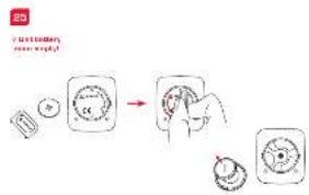
10.2 BATTERY CHANGE

text_image
SIGMO SPD TRANS. 2209 2209 2209 2209 SIGMO CAD TRANS. 2209 SIGMO CHESTBELT 2209 SIGMO LOWThe battery change on the computer head and the transmitters (speed, cadence, and/or chest belt) is shown on the display. After changing the battery, only the time has to be entered again.
Computer head:
25 26
→ Open cover with tool.
→ Take note of polarity. When the battery compartment is open, you must see the plus side of the battery.
→ If the sealing ring is loose, put it back in place.
→ Close cover with tool.
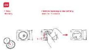
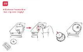
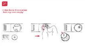
Transmitters:
27 28 29 30 31 32
→ Open cover with tool.
→ Remove battery from cover.
→ Take note of polarity.
→ Insert new battery in the cover.
→ Close cover with tool.
Battery:
Computer head: Lithium button battery CR 2450
Transmitter: Lithium button battery CR 2032
Battery lifespan:
Computer head: approx. 1 year*
Transmitter: approx. 1 year*
* if used one hour a day


10.3 TROUBLE SHOOTING
No speed display
→ Is the computer correctly clicked onto the bracket?
→ Have you checked the contacts for oxidation/corrosion?
→ Have you checked the magnet/transmitter distance (max. 12 mm)?
→ Have you checked whether the magnet is magnetized?
→ Have you checked the battery status on the speed transmitter?
No cadence display
→ Have you checked the magnet/transmitter distance (max. 12 mm)?
→ Have you checked whether the magnet is magnetized?
→ Have you checked the battery status on the transmitter?
No pulse display
→ Are the electrodes damp enough?
→ Have you checked the battery status?
No display
→ Have you checked the battery status on the BC 2209 MHR?
→ Is the battery inserted correctly (+ facing up)?
→ Are the battery contacts ok? (If not, bend carefully)?
Wrong speed display
→ Are 2 magnets fitted?
→ Is the magnet correctly positioned [parallel to the transmitter and centered with the transmitter]?
→ Is the wheel circumference set correctly?
→ Is the transmitter set on the right bicycle (bicycle 1 or 2)?
Display black/dull
→ Is the temperature too high (> 60°C) or too low (< 0°C)?
No synchronization
→ Have you checked the magnet/transmitter(s) distance?
→ Is/are the battery/batteries on the transmitter(s) empty?
→ Have you checked the range on the respective transmitter?
→ When using a hub dynamo, please change the position of the transmitter.
Display "TOO MANY SIGNALS"
→ Please increase the distance to the other transmitters and press any button.
10.4 WARRANTY
We are liable to our contracting partners for defects as defined by law. Batteries are excluded from the guarantee.
SIGMA Elektro GmbH
The manufacturer reserves the right to make technical changes.
After usage the batterie can be returned.


NOTICES
You can find the CE Declaration under: www.sigmasport.com
Asia, Australia, South America, Africa
7F-1, No. 193, Ta-Tun 6th Street,
Taichung City 408, Taiwan
natural_image
Illustration of two mechanical components with a red arrow indicating a joint or force (no text or symbols present)3

text_image
Technical diagram showing mechanical assembly steps with red arrows indicating direction and a magnified inset detail view.4

text_image
Close Close8
text_image
Mn 45° Mn 45° 25°5
natural_image
Diagram showing a mechanical component with a red ring and a magnified inset of a device (no text or symbols)6

natural_image
Mechanical diagram showing a bicycle wheel with red arrows indicating motion or force direction (no text or symbols)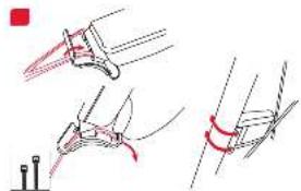
natural_image
Technical line drawing showing mechanical assembly steps with no visible text or symbols10
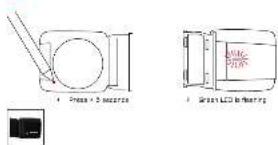
text_image
4 Press + 2 in series 5 Green LED to heating11

12

text_image
Technical diagram showing a red circle with a magnified inset of a mechanical component, likely illustrating a turning or cutting process.natural_image
Simple line drawing of a mechanical component with no text or symbols
natural_image
Two mechanical components with red connectors and a small inset diagram (no text or symbols)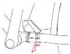
natural_image
Mechanical assembly diagram showing a lever mechanism with a red arrow indicating force or movement (no text or labels)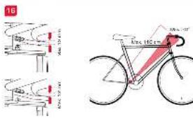
text_image
16 40m 25m 40m 40m 40m 40m 40m 40m 40m 40m 40m 40m 40m 40m 40m 40m 40m 40m 40m 40m 40m 40m 40m 40m 40m 40m 40m 45m 45m 45m 45m 45m 45m 45m 45m 45m 45m 45m 45m 45m 45m 45m 45m 45m 45m 45m 45m 45m 45m 45m 45m 45m 40m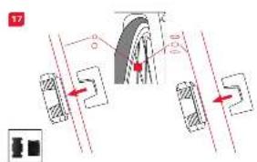 | 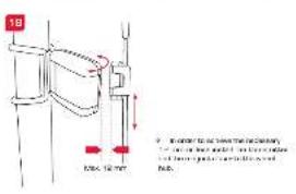 |  | 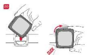 | 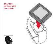 |
 |  |  |  |  |
 |  |  |  |  |
 |  |  |  |  |