17-y000 - Laptop HP - Free user manual and instructions
Find the device manual for free 17-y000 HP in PDF.

User questions about 17-y000 HP
0 question about this device. Answer the ones you know or ask your own.
Ask a new question about this device
Download the instructions for your Laptop in PDF format for free! Find your manual 17-y000 - HP and take your electronic device back in hand. On this page are published all the documents necessary for the use of your device. 17-y000 by HP.
USER MANUAL 17-y000 HP
HP Notebook PC (AMD)
Models: HP 17-y000 - 17-y099
Maintenance and Service Guide
© Copyright 2016 HP Development Company, L.P.
AMD is a trademark of Advanced Micro Devices, Inc. Bluetooth is a trademark owned by its proprietor and used by HP Inc. under license. Intel is a U.S. registered trademark of Intel Corporation. Microsoft and Windows are U.S. registered trademarks of Microsoft Corporation. SD Logo is a trademark of its proprietor.
The information contained herein is subject to change without notice. The only warranties for HP products and services are set forth in the express warranty statements accompanying such products and services. Nothing herein should be construed as constituting an additional warranty. HP shall not be liable for technical or editorial errors or omissions contained herein.
First Edition: April 2016
Document Part Number: 855103-001
Product notice
This guide describes features that are common to most models. Some features may not be available on your computer.
Not all features are available on all editions of Windows. This computer may require upgraded and/or separately purchased hardware, drivers, and/or software to take full advantage of Windows 8.1 functionality. See http://www.microsoft.com for details.
Safety warning notice
⚠ WARNING! To reduce the possibility of heat-related injuries or of overheating the device, do not place the device directly on your lap or obstruct the device air vents. Use the device only on a hard, flat surface. Do not allow another hard surface, such as an adjoining optional printer, or a soft surface, such as pillows or rugs or clothing, to block airflow. Also, do not allow the AC adapter to contact the skin or a soft surface, such as pillows or rugs or clothing, during operation. The device and the AC adapter comply with the user-accessible surface temperature limits defined by the International Standard for Safety of Information Technology Equipment (IEC 60950).
Table of contents
1 Product description .... 1
2 External component identification .... 7
Display 7
Right side 8
Left side 9
Top 10
TouchPad 10
Lights 11
Button 12
Keys 13
Using the action keys 14
Bottom 15
Service tag 16
3 Illustrated parts catalog 17
Computer major components 17
Display assembly subcomponents 21
Miscellaneous parts 23
Mass storage devices 24
Cables 25
4 Removal and replacement procedures preliminary requirements 27
Tools required 27
Service considerations 27
Plastic parts 27
Cables and connectors 27
Drive handling 28
Grounding guidelines 28
Electrostatic discharge damage 28
Packaging and transporting guidelines 29
Workstation guidelines 29
5 Removal and replacement procedures for Customer Self-Repair parts 31
Component replacement procedures 31
Battery 32
Optical drive 33
6 Removal and replacement procedures for Authorized Service Provider parts 35
Component replacement procedures 35
Display subcomponents (bezel, webcam, panel) 35
Bottom cover 39
Hard drive 41
WLAN module 44
RTC battery 46
Memory module 47
Solid-state drive 49
Solid-state drive holder and board 50
Optical drive connector 52
TouchPad click board 53
USB board 54
Speakers 55
Fan/heat sink assembly 56
System board 61
Display assembly 64
Power button board 73
Power connector 74
Cable locations 75
Top cover/keyboard 76
7 Using Setup Utility (BIOS) in Windows 10 77
Starting Setup Utility (BIOS) 77
Updating Setup Utility (BIOS) 77
Determining the BIOS version 77
Downloading a BIOS update 78
8 Backing up, restoring, and recovering in Windows 10 79
Creating recovery media and backups 79
Creating HP Recovery media (select products only) 79
Using Windows tools 80
Restore and recovery 81
Recovering using HP Recovery Manager 81
What you need to know before you get started 81
Using the HP Recovery partition (select products only) 82
Using HP Recovery media to recover 82
Changing the computer boot order 83
Removing the HP Recovery partition (select products only) 83
9 Using HP PC Hardware Diagnostics (UEFI) 85
Downloading HP PC Hardware Diagnostics (UEFI) to a USB device 85
10 Specifications 87
Computer specifications 87
43.9-cm (17.3-in) display specifications 88
Hard drive specifications 88
DVD±RW SuperMulti DL Drive specifications 89
11 Power cord set requirements 91
Requirements for all countries 91
Requirements for specific countries and regions 92
12 Recycling 95
Index 97
1 Product description
| UMA Discrete Discrete Discrete UMA | |||||
| Category Description A8, A6, E2 | processors | A8, A6, E2 (R16M-M1-30) | A8, A6, E2 (R16M-M1-70) | A10 (R16M-M1-70) | A10 |
| Product name HP Notebook PC | √√√√√ | ||||
| Models: HP 17-y000 - 17-y099 | |||||
| Processors AMD Quad-Core A-Series Processor (FT3 BGA) | √√ | ||||
| A10-9600P (2.4GHz, turbo up to 3.3GHz), 1866MHz/2MB L2, Quad 15W | |||||
| A9-9410 (2.3GHz, turbo up to 2.4GHz), 1600MHz/2MB L2, Quad 15W | √ | √ | |||
| A8-7410 (2.2GHz, turbo up to 2.5GHz), 1600MHz/2MB L2, Quad 15W | √ | √ | |||
| A6-7310 (2.0GHz, turbo up to 2.4GHz), 1600MHz/2MB L2, Quad 15W | √√ | ||||
| E2-7110 (1.8GHz), 1600MHz/2MB L2, Quad 15W | √ | ||||
| E1-7010 (1.5GHz), 1333MHz/1MB L2, Quad 10W | √ | ||||
| Chipset Integrated SoC FCH | √√√√√ | ||||
| Graphics Internal graphics | √ | √√√ | |||
| AMD RadeonTM R5 Graphics (A10, A8) | |||||
| AMD Radeon R4 Graphics (A6) | √ | √ | |||
| AMD Radeon R2 Graphics (E2, E1) | √ | ||||
| Switchable discrete graphics | √ | ||||
| AMD RadeonTM R7 M440 R16M-M1-70 with up to 4096 MB of dedicated video memory (512Mx16 DDR3 x 4 PCs) | |||||
| AMD RadeonTM R7 M440 R16M-M1-70 with up to 2048 MB of dedicated video memory (256Mx16 DDR3 x 4 PCs) | √√ | ||||
| AMD Radeon R5 M430 R16M-M1-30 with up to 2048 MB of dedicated video memory (256Mx16 DDR3 x 4 PCs) | √ | ||||
| Support HD Decode, DX12, HDMI, and PX7 | √ | √ | √ | ||
| Supports PX7 | √ | √ | |||
| Dual graphics | √ | ||||
| AMD Radeon R6 M445DX Dual Graphics | |||||
| AMD Radeon R8 M445DX Dual Graphics | |||||
| Panel 16:9 Ultra Wide Aspect Ratio, 43.9-cm (17.3-in) | √√√√√ | ||||
| HD+, white light-emitting diode (WLED), eDP, SVA, BrightView, (1600×900) flat-flat (4.2 mm); typical brightness: 220 nits (non-touch panel) | |||||
| HD+, WLED, eDP, SVA, BrightView (1600×900) flat-flat (4.2 mm), typical brightness: 220 nits (touch panel) | |||||
| FHD, white light-emitting diode (WLED), eDP, UWVA, antiglare, (1920×1080) flat-flat (4.2 mm); typical brightness: 300 nits (non-touch panel) | |||||
| FHD, WLED, eDP, UWVA, antiglare (1920×1080) flat-flat (4.2 mm), typical brightness: 300 nits (touch panel) | |||||
| Memory Two SODIMM slots - customer accessible / upgradeable | √√ | ||||
| DDR4-2133 dual channel support 1.2V | |||||
| Two SODIMM slots - non-accessible/non-upgradeable | |||||
| DDR4-1866 dual channel support 1.2V(DDR4-2133 downgraded to DDR4-1866)Supports up to 16 GB of system RAM in the following configurations:16384-MB total system memory (8192×2)12288-MB total system memory (8192×1)+(4096×1)8192-MB total system memory (8192×1) or(4096×2)6144-MB total system memory (4096×1)+(2048×1)4096-MB total system memory (4096×1) or(2048×2) | |||||
| Two SODIMM slots - customer accessible/ upgradeable | √√√ | ||||
| DDR3L-1600 single channel support 1.35VSupports up to 16 GB of system RAM in the following configurations:16384-MB total system memory (8192×2)12288-MB total system memory (8192×1)+(4096×1)8192-MB total system memory (8192×1) or(4096×2)6144-MB total system memory (4096×2)+(2048×1) | |||||
| UMA Discrete Discrete Discrete UMA | ||||||
| Category Description A8, A6, E2 | processors | A8, A6, E2 (R16M-M1-30) | A8, A6, E2 (R16M-M1-70) | A10 (R16M-M1-70) | A10 | |
| 4096-MB total system memory (4096×1) or (2048×2) | ||||||
| Hard drives | Supports 6.35-cm (2.5-in) SATA hard drives in 9.5 mm (.37 in) and 7.0 mm (.28 in) thicknesses7.0mm/9.5 mm share the same bracketAccelerometer/HDD protection supportSingle HDD configurations2-TB, 5400-rpm, 9.5-mm1-TB, 5400-rpm, 9.5-mm500-GB, 5400-rpm, or 7.2-mmHybrid HDD configurations1-TB, 5400-rpm, 9.5-mm SSHD w/8GB NAND500-GB, 5400-rpm, 7.0-mm SSHD w/8GB NANDM.2 SATA-3 SSD128-GB | √√√√√ | ||||
| Fixed optical drive | Fixed, serial SATA, 9.5-mm tray loadDVD+/-RW Double-Layer SuperMultiSupports zero power optical drive | √√√√√ | ||||
| Camera and microphone | HP TrueVision HDHD camera (fixed, no tilt with activity LED, USB 2.0, BSI, 1280×720 by 30 frames per second)Single digital microphoneHP Webcam: VGA camera640×480 by 24 frames per secondSingle digital microphone | √√√√√ | ||||
| Audio Dual speakers | √√√√√ | |||||
| DTS Studio Sound | ||||||
| Ethernet | Integrated 10/100 network interface card (NIC) | √ | √ | √ | √ | √ |
| Wireless networking | Integrated wireless options with dual antennas (M.2/PCIe):Intel Dual Band Wireless-AC 3165 802.11 ac 1x1 WiFi + BT 4.2 Combo AdapterIntegrated Wireless options with single antenna (M.2/PCIe):Realtek RTL8723BE-VB 802.11b/g/n 1x1 Wi-Fi + BT4.0 Combo Adapter | √√√√√ | ||||
| UMA Discrete Discrete Discrete UMA | |||||
| Category Description A8, A6, E2 | processors | A8, A6, E2(R16M-M1-30) | A8, A6, E2(R16M-M1-70) | A10(R16M-M1-70) | A10 |
| Realtek RTL8188EE 802.11b/g/n 1x1 Wi-Fi Adapter | |||||
| Realtek RTL8188EE-VJ 802.11b/g/n 1x1 Wi-Fi Adapter | |||||
| Intel WiDi support | |||||
| Compatible with Miracast-certified devices | |||||
| External media card | HP Multi-Format Digital Media Card ReaderSupport SD/SDHC/SDXCPush-pull insertion/removal | ||||
| Ports HDMI version 1.4 supporting 1920 ×1200 @ 60HzRJ-45 (Ethernet, includes link and activity lights)USB 3.0 (1)USB 2.0 (2)AC Smart Pin adapter plugCombo audio jack (headphone/microphone) | |||||
| Keyboard/ pointing devices | KeyboardFull size standard textured island-style keyboard with numeric keypadFull size backlit 2 coat paint island-style keyboard with numeric key padTouchPadImage sensorMultitouch gestures enabledTaps enabled by defaultSupport Modern Trackpad Gestures | ||||
| Power requirements | Battery4-cell, 41-Whr, 2.8Ah, li-ion battery | ||||
| 3-cell, 31-Whr, 2.8Ah, li-ion battery | |||||
| AC adapters: | |||||
| AC Adapter 65-W Smart nPFC, 3 pin, RC 4.5mm connector | |||||
| AC Adapter 65-W EM Smart nPFC, 3 pin, RC 4.5mm connector (India/People's Republic of China only) | |||||
| AC Adapter 45-W Smart nPFC, 3 pin, RC 4.5mm connector (models with UMA graphics only) | |||||
| 1 meter power cord | |||||
| Security | TPM 2.0 | ||||
| UMA Discrete Discrete Discrete UMA | ||||||
| Category Description A8, A6, E2 | processors | A8, A6, E2 (R16M-M1-30) | A8, A6, E2 (R16M-M1-70) | A10 (R16M-M1-70) | A10 | |
| Kensington Security Lock | ||||||
| Operating system | Preinstalled | √√√√√ | ||||
| • Windows 10 | ||||||
| • Windows 10 Pro | ||||||
| • Windows 10 Home ML | ||||||
| • Windows 10 Home EM/SL | ||||||
| • FreeDOS 2.0 | ||||||
| • Windows 10 Home High End ML | √√√√ | |||||
| • Windows 10 Home High End EM/SL/China | ||||||
| • Windows 10 Home Value India Notebook √√√ | ||||||
| Serviceability | End-user replaceable parts: | √√√√√ | ||||
| • AC adapter | ||||||
| • Battery | ||||||
| • Optical drive | ||||||
2 External component identification
Display

text_image
① ② ③ ④| Component Description | ||
| (1) | WLAN antennas (1 or 2)* | Send and receive wireless signals to communicate with wireless local area networks (WLANs). |
| (2) | Webcam light On: The webcam is in use. | |
| (3) | Webcam– or –3D camera (select products only) | Records video and captures photographs. Some products allow you to video conference and chat online using streaming video.To use a webcam (integrated camera):▲ Type camera in the taskbar search box, and then select Camera. |
| (4) | Internal microphone Records sound. | |
| *The antennas are not visible from the outside of the computer. For optimal transmission, keep the areas immediately around the antennas free from obstructions.For wireless regulatory notices, see the section of the Regulatory, Safety, and Environmental Notices that applies to your country or region.To access this guide:▲ Select the Start button, select All apps, select HP Help and Support, and then select HP Documentation. | ||
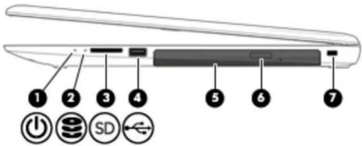
Right side
text_image
① ② ③ ④ ⑤ ⑥ ⑦Component Description
| (1) Power light[DSTA] | On: The computer is on.Blinking: The computer is in the Sleep state, a power-saving state. The computer shuts off power to the display and other unneeded components.Off: The computer is off or in Hibernation. Hibernation is a power-saving state that uses the least amount of power. |
(2) Drive | Blinking white: The hard drive is being accessed.Amber: HP 3D DriveGuard has temporarily parked the hard drive. |
| (3) Memory card reader Reads optional memory cards that enable you to store, manage,[YKBX] | share, or access information.To insert a card:Hold the card label-side up, with connectors facing the computer.Insert the card into the memory card reader, and then press in on the card until it is firmly seated.To remove a card:Press in on the card, and then remove it from the memory card reader. |
(4) USB 2.0 port Connects an optional USB device, such as a keyboard, mouse, | external drive, printer, scanner or USB hub. |
(5) Opt  e Depending on your computer, reads an optical disc or reads andwrites to an optical disc.NOTE: For disc compatibility information, type help in the taskbar search box, select Help and Support, and then typedisc compatibility in the search box. e Depending on your computer, reads an optical disc or reads andwrites to an optical disc.NOTE: For disc compatibility information, type help in the taskbar search box, select Help and Support, and then typedisc compatibility in the search box. | |
| (6) Optical drive eject button Opens the optical drive. | |
(7) Security cable slot Attaches an optional security cable to the computer. | NOTE: The security cable is designed to act as a deterrent, but it may not prevent the computer from being mishandled or stolen. |
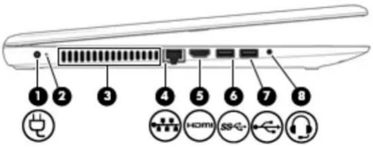
text_image
Diagram of a router or device with numbered labels pointing to ports and icons including plug, network, USB, and USB.| Component Description | ||
(1) Power connector Connects an AC adapter.  | ||
| (2) AC adapter and battery light | White: The AC adapter is connected and the battery is fully charged.Blinking white: The AC adapter is disconnected and the battery has reached a low battery level.Amber: The AC adapter is connected and the battery is charging.Off: The battery is not charging. | |
| (3) Vent Enables air flow to cool internal components. | NOTE: The computer fan starts up automatically to cool internal components and prevent overheating. It is normal for the internal fan to cycle on and off during routine operation. | |
(4) RJ-45 (network) jack/status lights Connects a network cable.  | White: The network is connected.Amber: Activity is occurring on the network. | |
(5) HDMI port  | Connects an optional video or audio device, such as a high-definition television, any compatible digital or audio component, or a high-speed High-Definition Multimedia Interface (HDMI) device. | |
| (6) USB 3.0 port Connects an optional USB device, such as a keyboard, mouse, external drive, printer, scanner or USB hub. | ||
| (7) USB 2.0 port Connects an optional USB device, such as a keyboard, mouse, external drive, printer, scanner or USB hub. | ||
| (8) Audio-out (headphone)/Audio-in (microphone) combo jack | Connects optional powered stereo speakers, headphones, earbuds, a headset, or a television audio cable. Also connects an optional headset microphone. This jack does not support optional standalone microphones. | |
Component Description
WARNING! To reduce the risk of personal injury, adjust the volume before putting on headphones, earbuds, or a headset. For additional safety information, refer to the Regulatory, Safety, and Environmental Notices.
To access this guide:
Select the Start button, select All apps, select HP Help and Support, and then select HP Documentation.
NOTE: When a device is connected to the jack, the computer speakers are disabled.
Top TouchPad

text_image
Diagram of a device panel with labeled components: two labeled parts and one highlighted, above a grid-like layout.Component Description
| (1) | TouchPad zone | Reads your finger gestures to move the pointer or activate items on the screen. |
| (2) | Left TouchPad button Functions like the left button on an external mouse. | |
| (3) | Right TouchPad button Functions like the right button on an external mouse. | |
Lights

text_image
Laptop keyboard diagram with labeled buttons and speaker iconComponent Description
(1) Caps lock light On: Caps lock is on, which switches the key input to all capital letters.

• Amber: Computer sound is off.
• Off: Computer sound is on.
Button
natural_image
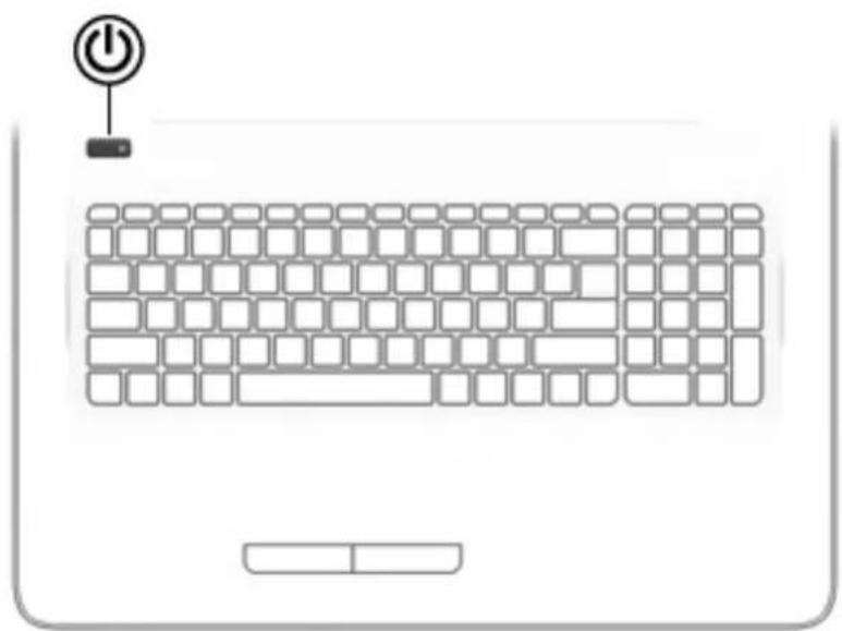
Laptop keyboard layout with a power button icon above it (no text or symbols on the keys)Component Description
Power button

- When the computer is off, press the button to turn on the computer.
- When the computer is on, press the button briefly to initiate Sleep.
- When the computer is in the Sleep state, press the button briefly to exit Sleep.
- When the computer is in Hibernation, press the button briefly to exit Hibernation.
CAUTION: Pressing and holding down the power button results in the loss of unsaved information.
If the computer has stopped responding and shutdown procedures are ineffective, press and hold the power button down for at least 5 seconds to turn off the computer.
To learn more about your power settings, see your power options.
▲ Type power in the taskbar search box, and then select Power and sleep settings.
-or-
Right-click the Start button, and then select Power Options.
Keys

text_image
Diagram illustrating a keyboard layout with labeled UI elements and numbered positions for function call, navigation, and display.| Component Description | ||
| (1) | esc key | Displays system information when pressed in combination with the fn key. |
| (2) | fn key | Executes frequently used system functions when pressed in combination with the esc key, action keys, or the spacebar. |
| (3) Windows key Opens the Start menu. | NOTE: Pressing the Windows key again will close the Start menu. | |
| (4) Action keys Execute frequently used system functions. | NOTE: On select products, the f5 action key turns the keyboard feature off or on. | |
| (5) | num lock key | Alternates between the navigational and numeric functions on the integrated numeric keypad. |
| (6) | Integrated numeric keypad | When num lock is on, the keypad can be used like an external numeric keypad. |
Using the action keys
An action key performs an assigned function.
The icon on each action key illustrates the function for that key.
• To use an action key, press and hold the key.
| Icon Description | |
| ? | Opens Help and Support, which provides tutorials, information about the Windows operating system and your computer, answers to questions, and updates to your computer.Help and Support also provides automated troubleshooting tools and access to support. |
| * | Decreases the screen brightness incrementally as long as you hold down the key. |
| * | Increases the screen brightness incrementally as long as you hold down the key. |
| 101 | Switches the screen image between display devices connected to the system. For example, if a monitor is connected to the computer, repeatedly pressing this key alternates the screen image from the computer display to the monitor display to a simultaneous display on both the computer and the monitor. |
| ### | Turns the keyboard backlight off or on (select products only).NOTE: To conserve battery power, turn off this feature. |
| Mutes or restores speaker sound. | |
| Decreases speaker volume incrementally while you hold down the key. | |
| Increases speaker volume incrementally while you hold down the key. | |
| Plays the previous track of an audio CD or the previous section of a DVD or a Blu-ray Disc (BD). | |
| Starts, pauses, or resumes playback of an audio CD, a DVD, or a BD. | |
| Plays the next track of an audio CD or the next section of a DVD or a BD. | |
| Turns the airplane mode and wireless feature on or off.NOTE: The airplane mode key is also referred to as the wireless button.NOTE: A wireless network must be set up before a wireless connection is possible. | |
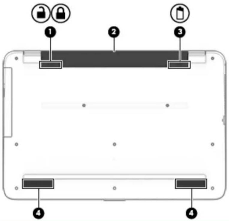
Bottom
text_image
Diagram of a tablet device showing labeled components including lock, battery, and status indicatorsComponent Description
(1) Battery lock Locks the battery in the battery bay.


(2) Battery bay Holds the battery.
(3) Battery release latch Releases the battery.

(4) Speakers Produce sound.
Service tag
When ordering parts or requesting information, provide the computer serial number and model number provided on the service tag.

text_image
1 hp XXXXXXXXX 2 Serial: XXXXXXXX 3 Product: XXXXXXXX 4 Warranty: 1y1y0y 5 Model: XXXXXXXX Serial: XXXXXXXX Warranty: 1y1y0y Model: XXXXXXXX| Item Description Function | ||
| (1) Product name This is the product name affixed to the front of the computer. | ||
| (2) | Serial number (s/n) | This is an alphanumeric identifier that is unique to each product. |
| (3) | Part number/Product number (p/n) | This number provides specific information about the product's hardware components. The part number helps a service technician to determine what components and parts are needed. |
| (4) Warranty period This number describes the duration of the warranty period for the computer. | ||
| (5) | Model description | This is the alphanumeric identifier used to locate documents, drivers, and support for the computer. |
3 Illustrated parts catalog
Computer major components
NOTE: HP continually improves and changes product parts. For complete and current information on supported parts for your computer, go to http://partsurfer.hp.com, select your country or region, and then follow the on-screen instructions.

text_image
Exploded view diagram of a laptop with numbered parts for identificationItem Component Spare part
number
(1) Display assembly [43.9-cm 17.3-in]
NOTE: Displays are only spared at the subcomponent level.
NOTE: For display assembly spare part information, see Display assembly subcomponents on page 21.
(2) Top cover/keyboard (ash silver) (includes TouchPad)
NOTE: For a detailed list of keyboard country codes, see Top cover/keyboard on page 76.
For use in models without a backlight:
Black 856698-xx1
Turbo silver 856699-xx1
White silver 856700-xx1
Red 856757-xx1
Teal 856758-xx1
Blue 856759-xx1
Purple 900153-xx1
For use in models with a backlight:
Black 856771-xx1
Turbo silver 856772-xx1
White silver 856773-xx1
Red 856775-xx1
Teal 856776-xx1
Blue 856777-xx1
Purple 900154-xx1
(3) USB board 856613-001
(4) Power connector cable 856680-001
(5) Power button board 856612-001
(6) TouchPad board 858259-001
Heat sink assembly (includes replacement thermal materials):
(7) For use in models with UMA graphics 856761-001
(8) For use in models with discrete graphics 856762-001
(9) Solid-state drive board 856614-001
(10) Solid-state drive 128 GB 827560-025
(11) Solid-state drive holder 858260-001
(12) Hard drive (does not include bracket) 2-TB, 5400-rpm, 2.5-inch 801808-005
| Item Component Spare part | number |
| 1-TB, 5400-rpm, 2.5-inch, hybrid 8 GB SSD 731999-005 | |
| 1-TB, 5400-rpm, 2.5-inch 778192-005 | |
| 500-GB, 5400-rpm, 2.5 inch 778188-005 | |
| (13) Hard drive cover 856584-001 | |
| (14) RTC battery 858288-001 | |
| (15) Speakers (includes left and right speakers and cable) 856617-001 | |
| (16) WLAN module | |
| Broadcom BCM43142 802.11 b/g/n 1x1 Wi-Fi + BT4.0 Combo Adapter 792608-005 | |
| Intel Dual Band Wireless-AC 3165 802.11 ac 1x1 WiFi + BT 4.2 Combo 806723-005 | |
| Realtek RTL8188EE-VJ 802.11b/g/n 1x1 Wi-Fi Adapter 857334-855 | |
| Intel Dual Band Wireless-AC 3168 802.11 ac 1x1 WiFi + BT 4.2 Combo 863934-855 | |
| (17) Memory module | |
| PC4, 17000, 2133-MHz | |
| For use in models with AMD A10 processors | |
| 8-GB | 820570-005 |
| 4 GB | 820569-005 |
| 2 GB | 851379-005 |
| PC3L, 12800, 1600-MHz | |
| For use in models with AMD A8, A6, E2, and E1 processors | |
| 8-GB | 693374-005 |
| 4 GB | 691740-005 |
| 2 GB | 691739-005 |
| (18) System board (includes replacement thermal materials) | |
| All system boards use the following part numbers: | |
| xxxxxx-001: Windows 7 or non-Windows operating system | |
| xxxxxx-601: Windows 10 | |
| For use in models with discrete graphics: | |
| AMD A10-9600P processor and 4 GB of dedicated video memory | 856770-xxx |
| AMD A10-9600P processor and 2 GB of dedicated video memory | 856769-xxx |
| AMD A8-7410 processor and 2 GB of dedicated video memory | 856767-xxx |
| AMD A6-7310 processor and 2 GB of dedicated video memory | 856766-xxx |
| For use in models with UMA graphics: | |
| AMD A10-9600P processor | 856768-xxx |
| AMD A9-9410 processor | 859287-xxx |
| AMD A8-7410 processor 856765-xxx | |
| AMD A6-7310 processor 856764-xxx | |
| AMD E2-7110 processor 856763-xxx | |
| (19) Optical Drive Connector Cable Kit 856609-001 | |
| (20) DVD+/-RW Double-Layer SuperMulti Drive 756564-037 | |
| Optical drive bracket (not illustrated) 856610-001 | |
| Optical drive bezel (not illustrated) 856598-001 | |
| (21) Battery | |
| 4-cell, 41-Whr, 2.8-Ah Li-ion 807957-001 | |
| 3-cell, 31-Whr, 2.8-Ah Li-ion 807956-001 | |
| (22) Bottom cover 856601-001 | |
| (23) Rubber Kit 856615-001 |
Display assembly subcomponents
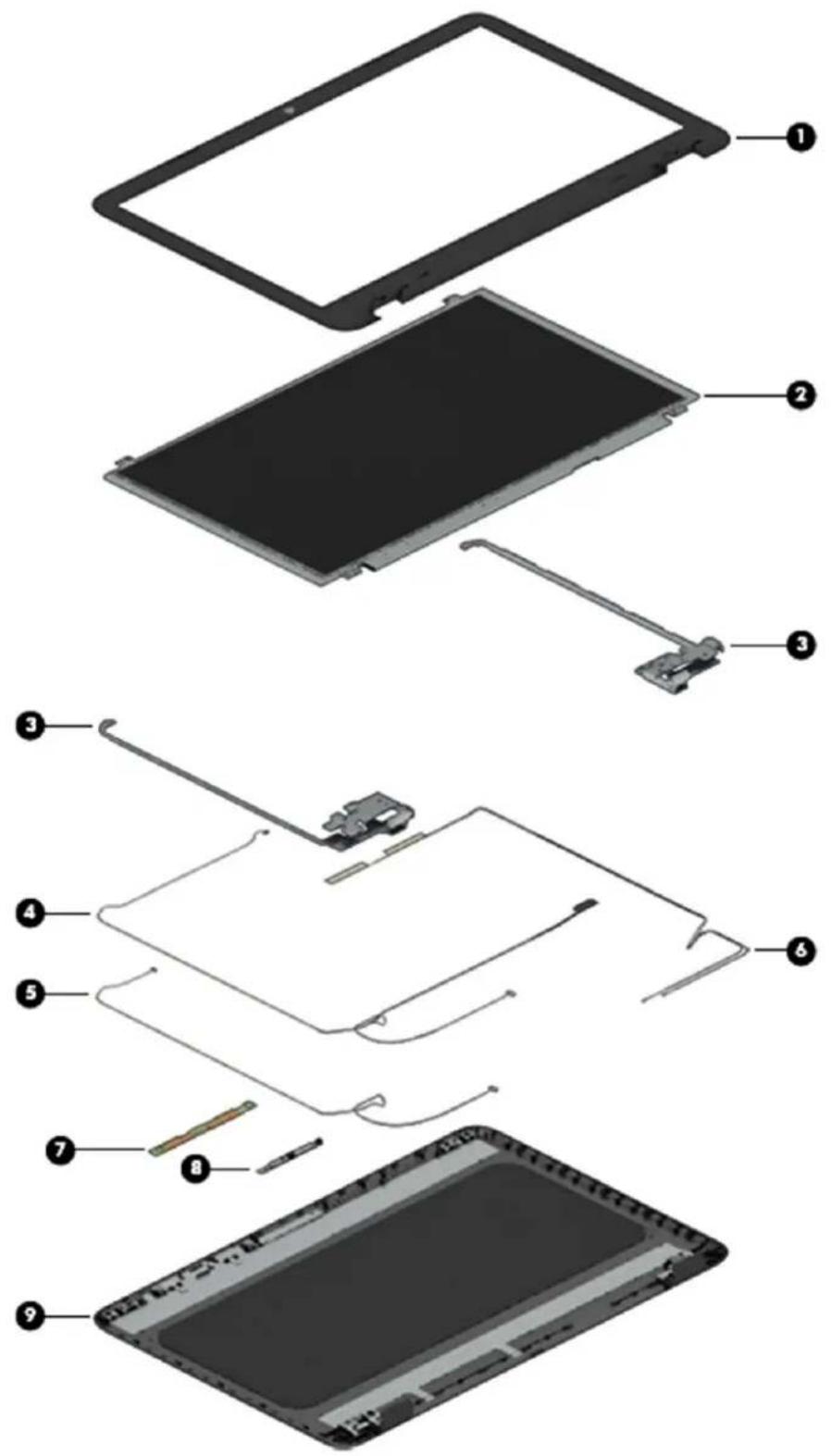
text_image
Exploded view diagram of a tablet device with numbered parts for identification| Item Component Spare part number | |
| (1) Display bezel 856597-001 | |
| (2) Raw display panel (16:9 Ultra Wide Aspect Ratio [43.9-cm 17.3-in]; includes screw covers and touch sensor) | |
| FHD, anti glare 798926-007 | |
| FHD, Touch On Panel (TOP) 851048-001 | |
| HD, Touch On Panel (TOP) 851049-001 | |
| HD+, BrightView 851051-002 | |
| (3) Hinges touch screen (left and right, includes screw covers) 809299-001 | |
| Display cable | |
| (4) Touch displays 856608-001 | |
| (5) Non-touch displays 856607-001 | |
| (6) Antennas 856611-001 | |
| (7) Touch control board 856600-001 | |
| (8) Webcam/microphone module | |
| HD | 709372-032 |
| VGA | 766523-021 |
| (9) Display enclosure (non touch models) | |
| Red models | 856594-001 |
| White silver models | 856593-001 |
| Blue models | 856596-001 |
| Turbo silver models | 856592-001 |
| Black models | 856591-001 |
| Teal models | 856595-001 |
| Purple | 900660-001 |
| (9) Display enclosure (touch models) | |
| Red models | 856588-001 |
| White silver models | 856587-001 |
| Blue models | 856590-001 |
| Turbo silver models | 856586-001 |
| Black models | 856585-001 |
| Teal models | 856589-001 |
| Purple | 900659-001 |
Miscellaneous parts
| Component Spare part number | |
| HP Smart AC adapter | |
| 65-W EM 714635-850 | |
| 65-W 710412-001 | |
| 45-W 741553-850 | |
| Power cord (3-pin, black, 1.0-m) for use in: | |
| Australia 213356-008 | |
| Denmark 213353-008 | |
| Germany, France, Spain, Nordic countries, Portugal, Greece, Arabia, Netherlands, Belgium, Russia, Poland, Hungary, Serbia, Adriatic countries, Czech/Slovakia, African English | 213350-009 |
| orth America 213349-009 | |
| Switzerland 213354-008 | |
| United Kingdom, Arabia, and African English 213351-008 | |
| Rubber Kit (includes front and rear feet) 856615-001 | |
| Screw Kit 856616-001 | |
| HDMI to VGA adapter 701943-001 | |
Mass storage devices
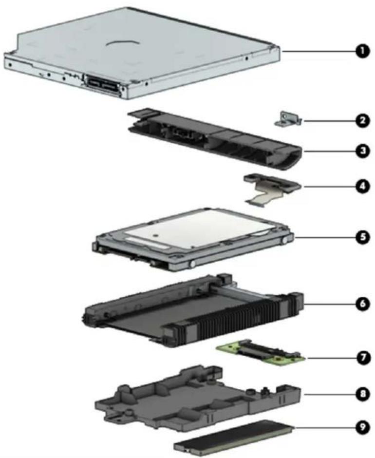
text_image
Exploded view diagram of a hard disk drive with numbered parts for identificationItem Component Spare part number
| (1) DVD+/-RW Double-Layer SuperMulti Drive 756564-037 | |
| (2) Optical drive bracket 856610-001 | |
| (3) Optical drive bezel 856598-001 | |
| (4) Optical drive connector 856609-001 | |
| (5) Hard drive (does not include bracket) | |
| 2-TB, 5400-rpm, 2.5-inch 801808-005 | |
| 1-TB, 5400-rpm, 2.5-inch, hybrid 8 GB SSD 731999-005 | |
| 1-TB, 5400-rpm, 2.5-in 778192-005 | |
| 500-GB, 5400-rpm, 2.5 inch 778188-005 | |
| (6) Hard drive cover 856584-001 | |
| (7) Solid-state drive board | 856614-001 |
| (8) Solid-state drive holder | 858260-001 |
Item Component Spare part number
(9) Solid-state drive
128 GB 827560-025
Cables
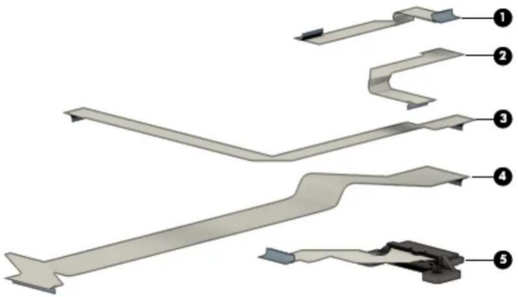
text_image
Diagram of a mechanical component with numbered parts labeled 1 to 5Item Description Spare part number
(1) TouchPad cable 856605-001
(2) Touch click board cable 856606-001
(3) Power button board cable 856604-001
(4) USB board cable 856603-001
(5) Optical drive connector cable 856609-001
Display cable for use in non-touch models (not illustrated) 856607-001
Display cable for use touch models (not illustrated) 856608-001
4 Removal and replacement procedures preliminary requirements
Tools required
You will need the following tools to complete the removal and replacement procedures:
Flat-bladed screwdriver
• Magnetic screwdriver
• Phillips P0 and P1 screwdrivers
Service considerations
The following sections include some of the considerations that you must keep in mind during disassembly and assembly procedures.

NOTE: As you remove each subassembly from the computer, place the subassembly (and all accompanying screws) away from the work area to prevent damage.
Plastic parts

CAUTION: Using excessive force during disassembly and reassembly can damage plastic parts. Use care when handling the plastic parts. Apply pressure only at the points designated in the maintenance instructions.
Cables and connectors

CAUTION: When servicing the computer, be sure that cables are placed in their proper locations during the reassembly process. Improper cable placement can damage the computer.
Cables must be handled with extreme care to avoid damage. Apply only the tension required to unseat or seat the cables during removal and insertion. Handle cables by the connector whenever possible. In all cases, avoid bending, twisting, or tearing cables. Be sure that cables are routed in such a way that they cannot be caught or snagged by parts being removed or replaced. Handle flex cables with extreme care; these cables tear easily.
Drive handling
CAUTION: Drives are fragile components that must be handled with care. To prevent damage to the computer, damage to a drive, or loss of information, observe these precautions:
Before removing or inserting a hard drive, shut down the computer. If you are unsure whether the computer is off or in Hibernation, turn the computer on, and then shut it down through the operating system.
Before handling a drive, be sure that you are discharged of static electricity. While handling a drive, avoid touching the connector.
Before removing a diskette drive or optical drive, be sure that a diskette or disc is not in the drive and be sure that the optical drive tray is closed.
Handle drives on surfaces covered with at least one inch of shock-proof foam.
Avoid dropping drives from any height onto any surface.
After removing a hard drive, an optical drive, or a diskette drive, place it in a static-proof bag.
Avoid exposing an internal hard drive to products that have magnetic fields, such as monitors or speakers.
Avoid exposing a drive to temperature extremes or liquids.
If a drive must be mailed, place the drive in a bubble pack mailer or other suitable form of protective packaging and label the package "FRAGILE."
Grounding guidelines
Electrostatic discharge damage
Electronic components are sensitive to electrostatic discharge (ESD). Circuitry design and structure determine the degree of sensitivity. Networks built into many integrated circuits provide some protection, but in many cases, ESD contains enough power to alter device parameters or melt silicon junctions.
A discharge of static electricity from a finger or other conductor can destroy static-sensitive devices or microcircuitry. Even if the spark is neither felt nor heard, damage may have occurred.
An electronic device exposed to ESD may not be affected at all and can work perfectly throughout a normal cycle. Or the device may function normally for a while, then degrade in the internal layers, reducing its life expectancy.
CAUTION: To prevent damage to the computer when you are removing or installing internal components, observe these precautions:
Keep components in their electrostatic-safe containers until you are ready to install them.
Before touching an electronic component, discharge static electricity by using the guidelines described in this section.
Avoid touching pins, leads, and circuitry. Handle electronic components as little as possible.
If you remove a component, place it in an electrostatic-safe container.
The following table shows how humidity affects the electrostatic voltage levels generated by different activities.
CAUTION: A product can be degraded by as little as 700 V.
| Typical electrostatic voltage levels | |
| Relative humidity | |
| Event 10% 40% 55% | |
| Walking across carpet 35,000 V 15,000 V 7,500 V | |
| Walking across vinyl floor 12,000 V 5,000 V 3,000 V | |
| Motions of bench worker 6,000 V 800 V 400 V | |
| Removing DIPS from plastic tube 2,000 V 700 V 400 V | |
| Removing DIPS from vinyl tray 11,500 V 4,000 V 2,000 V | |
| Removing DIPS from Styrofoam | 14,500 V 5,000 V 3,500 V |
| Removing bubble pack from PCB | 26,500 V 20,000 V 7,000 V |
| Packing PCBs in foam-lined box | 21,000 V 11,000 V 5,000 V |
Packaging and transporting guidelines
Follow these grounding guidelines when packaging and transporting equipment:
• To avoid hand contact, transport products in static-safe tubes, bags, or boxes.
- Protect ESD-sensitive parts and assemblies with conductive or approved containers or packaging.
- Keep ESD-sensitive parts in their containers until the parts arrive at static-free workstations.
- Place items on a grounded surface before removing items from their containers.
• Always be properly grounded when touching a component or assembly.
- Store reusable ESD-sensitive parts from assemblies in protective packaging or non-conductive foam.
- Use transporters and conveyors made of antistatic belts and roller bushings. Be sure that mechanized equipment used for moving materials is wired to ground and that proper materials are selected to avoid static charging. When grounding is not possible, use an ionizer to dissipate electric charges.
Workstation guidelines
Follow these grounding workstation guidelines:
• Cover the workstation with approved static-shielding material.
- Use a wrist strap connected to a properly grounded work surface and use properly grounded tools and equipment.
• Use conductive field service tools, such as cutters, screwdrivers, and vacuums.
- When fixtures must directly contact dissipative surfaces, use fixtures made only of static-safe materials.
- Keep the work area free of nonconductive materials, such as ordinary plastic assembly aids and Styrofoam.
- Handle ESD-sensitive components, parts, and assemblies by the case or PCM laminate. Handle these items only at static-free workstations.
- Avoid contact with pins, leads, or circuitry.
• Turn off power and input signals before inserting or removing connectors or test equipment.
Equipment guidelines
Grounding equipment must include either a wrist strap or a foot strap at a grounded workstation.
- When seated, wear a wrist strap connected to a grounded system. Wrist straps are flexible straps with a minimum of one megohm ± 10% resistance in the ground cords. To provide proper ground, wear a strap snugly against the skin at all times. On grounded mats with banana-plug connectors, use alligator clips to connect a wrist strap.
- When standing, use foot straps and a grounded floor mat. Foot straps (heel, toe, or boot straps) can be used at standing workstations and are compatible with most types of shoes or boots. On conductive floors or dissipative floor mats, use foot straps on both feet with a minimum of one megohm resistance between the operator and ground. To be effective, the conductive must be worn in contact with the skin.
The following grounding equipment is recommended to prevent electrostatic damage:
- Antistatic tape
• Antistatic smocks, aprons, and sleeve protectors
• Conductive bins and other assembly or soldering aids
• Nonconductive foam
• Conductive tabletop workstations with ground cords of one megohm resistance
• Static-dissipative tables or floor mats with hard ties to the ground
Field service kits
• Static awareness labels
• Material-handling packages
• Nonconductive plastic bags, tubes, or boxes
• Metal tote boxes
• Electrostatic voltage levels and protective materials
The following table lists the shielding protection provided by antistatic bags and floor mats.
Material Use Voltage protection level
| Antistatic plastics Bags 1,500 V |
| Carbon-loaded plastic Floor mats 7,500 V |
| Metallized laminate Floor mats 5,000 V |
5 Removal and replacement procedures for Customer Self-Repair parts
CAUTION: The Customer Self-Repair program is not available in all locations. Installing a part not supported by the Customer Self-Repair program may void your warranty. Check your warranty to determine if Customer Self-Repair is supported in your location.
NOTE: HP continually improves and changes product parts. For complete and current information on supported parts for your computer, go to http://partsurfer.hp.com, select your country or region, and then follow the on-screen instructions.
Component replacement procedures
NOTE: Please read and follow the procedures described here to access and replace Customer Self-Repair parts successfully.
NOTE: Details about the computer, including model, serial number, product key, and length of warranty, are on the service tag one the bottom of the computer. See Service tag on page 16 for details.
This chapter provides removal and replacement procedures for Customer Self-Repair parts.
There are as many as 2 screws that must be removed, replaced, or loosened when servicing Customer Self-Repair parts. Make special note of each screw size and location during removal and replacement.
Battery
Description Spare part number
4-cell, 41-Whr, 2.8-Ah Li-ion battery 807957-001
3-cell, 31-Whr, 2.8-Ah Li-ion battery 807956-001
Before disassembling the computer, follow these steps:
- Shut down the computer. If you are unsure whether the computer is off or in Hibernation, turn the computer on, and then shut it down through the operating system.
- Disconnect all external devices connected to the computer.
- Disconnect the power from the computer by first unplugging the power cord from the AC outlet and then unplugging the AC adapter from the computer.
To remove the battery:
-
Position the computer upside down on a flat surface.
-
Slide the battery lock latch (1) to unlock the battery, and then slide the battery release latch (2) to release the battery.

NOTE: The battery release latch automatically returns to its original position.
- Remove the battery (3) from the computer.
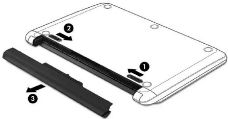
text_image
Diagram of a device showing labeled parts: battery pack, switch, and battery casing with numbered annotations.Optical drive
| Description Spare part number |
| Optical drive (DVD+/-RW Double-Layer SuperMulti) 756564-037 |
| Optical drive bracket 856610-001 |
| Optical drive bezel 856598-001 |
Before removing the optical drive, follow these steps:
- Shut down the computer. If you are unsure whether the computer is off or in Hibernation, turn the computer on, and then shut it down through the operating system.
- Disconnect all external devices connected to the computer.
- Disconnect the power from the computer by first unplugging the power cord from the AC outlet and then unplugging the AC adapter from the computer.
- Remove the battery (see Battery on page 32).
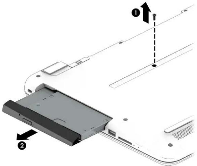
To remove the optical drive:
- Remove the Phillips PM2.5×8.0 screw (1) that secures the optical drive to the computer.
- Remove the optical drive (2) by sliding it out of the optical drive bay.
text_image
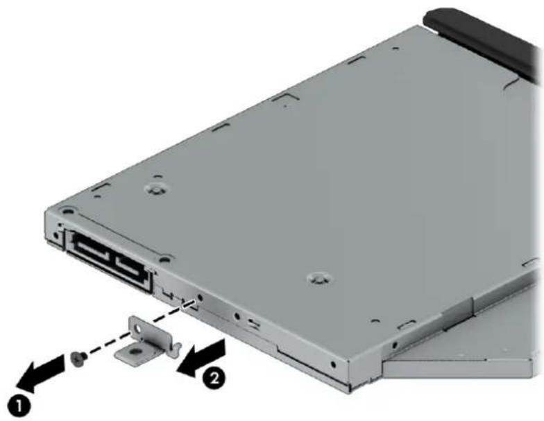
Diagram of a device showing two labeled parts with arrows indicating assembly or positioning, likely illustrating a mechanical or electronic component.- If it is necessary to replace the bracket on the rear of the optical drive, remove the Phillips PM2.0×2.5 screw (1) that secures the bracket to the drive, and then remove the bracket (2).
natural_image
3D diagram of a computer drive showing internal components and mounting bracket (no text or symbols)Reverse this procedure to reassemble and install the optical drive.
6 Removal and replacement procedures for Authorized Service Provider parts
CAUTION: Components described in this chapter should only be accessed by an authorized service provider. Accessing these parts can damage the computer or void the warranty.
NOTE: HP continually improves and changes product parts. For complete and current information on supported parts for your computer, go to http://partsurfer.hp.com, select your country or region, and then follow the on-screen instructions.
NOTE: Details about the computer, including model, serial number, product key, and length of warranty, are on the service tag one the bottom of the computer. See Service tag on page 16 for details.
Component replacement procedures
NOTE: Details about your computer, including model, serial number, product key, and length of warranty, are on the service tag at the bottom of your computer.
This chapter provides removal and replacement procedures for Authorized Service Provider only parts.
There are as many as 58 screws that must be removed, replaced, or loosened when servicing Authorized Service Provider only parts. Make special note of each screw size and location during removal and replacement.
Display subcomponents (bezel, webcam, panel)
This section describes removing display subcomponents that do not require that you remove the entire display assembly from the computer. You can remove the display bezel, webcam/microphone module, and display panel while the display assembly is still attached to the computer.
To remove the remaining display subcomponents, you must remove the entire display assembly from the computer. See Display assembly on page 64 for more information about removing the display assembly in its entirety.
| Description Spare part number |
| Raw display panel |
| FHD, anti glare 798926-007 |
| FHD, Touch On Panel (TOP) 851048-001 |
| HD, Touch On Panel (TOP) 851049-001 |
| HD+, BrightView 851051-002 |
| Display bezel 856597-001 |
| Webcam/microphone module |
| HD 709372-032 |
| VGA 766523-021 |
Before removing display subcomponents while the display assembly is still attached to the computer, follow these steps:
- Shut down the computer. If you are unsure whether the computer is off or in Hibernation, turn the computer on, and then shut it down through the operating system.
- Disconnect all external devices connected to the computer.
- Disconnect the power from the computer by first unplugging the power cord from the AC outlet and then unplugging the AC adapter from the computer.
- Remove the battery (see Battery on page 32).
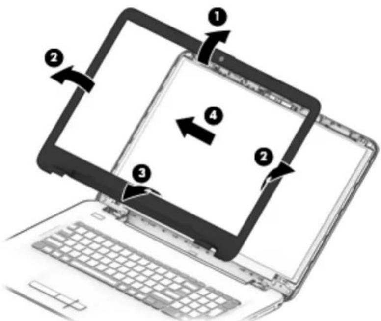
To remove the display bezel, webcam/microphone module, and raw display panel:
- Position the computer upright with the front toward you, and then open it.
- Flex the inside of the top edge (1), left and right sides (2), and the inside of the bottom edge (3) of the display bezel until the bezel disengages from the display enclosure.
- Remove the display bezel (4).

text_image
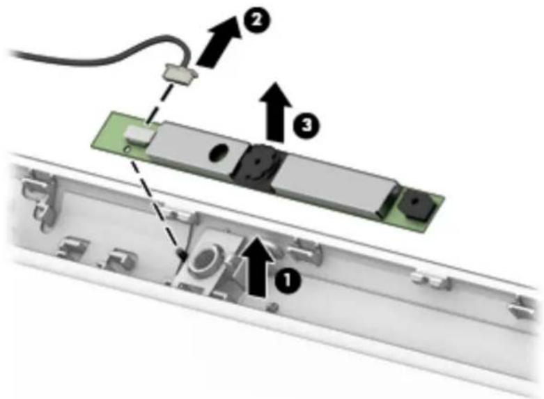
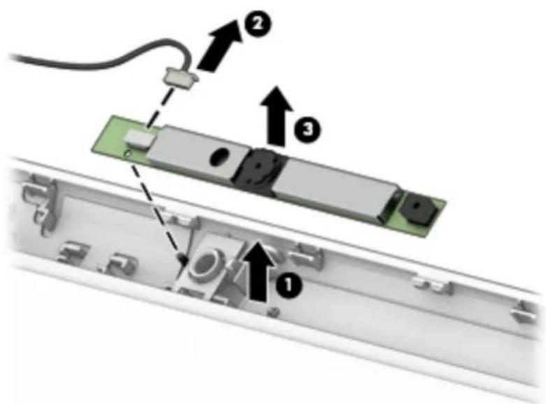
Diagram showing a laptop with four labeled arrows indicating directional movement or navigation, numbered 1 to 4.- To remove the webcam/microphone module:
a. Position the display assembly with the top edge toward you.
b. Lift to disengage the adhesive that secures the webcam/microphone module to the display (1).
c. Disconnect the cable (2) from the module.
d. Remove the module (3).
text_image
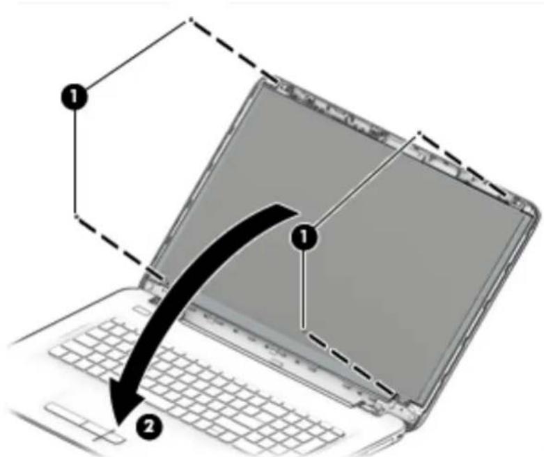
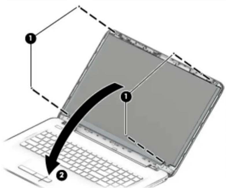
Diagram showing a device assembly with numbered components and directional arrows indicating parts of the main structure.- To remove the display panel:
a. Remove the four Phillips PM2.0×3.0 screws (1) that secure the display panel to the enclosure.
b. Rotate the display panel onto the keyboard (2) to gain access to the display cable connection on the back of the panel.
text_image
Diagram showing a laptop with labeled parts and a curved arrow indicating motion or transformation, numbered 1 and 2.c. On the back of the display panel, release the adhesive strip that secures the display panel cable to the display panel, and then disconnect the cable (1).
d. Remove the display panel from the computer (2).

text_image
Diagram of an open laptop with labeled parts, showing front and back views and a numbered component.Reverse this procedure to reassemble and install the display bezel, webcam/microphone module, and display panel.
Bottom cover
Description Spare part number
Bottom cover 856601-001
Before removing the bottom cover, follow these steps:
- Shut down the computer. If you are unsure whether the computer is off or in Hibernation, turn the computer on, and then shut it down through the operating system.
- Disconnect all external devices connected to the computer.
- Disconnect the power from the computer by first unplugging the power cord from the AC outlet and then unplugging the AC adapter from the computer.
- Remove the battery (see Battery on page 32).
- Remove the optical drive (see Optical drive on page 33).
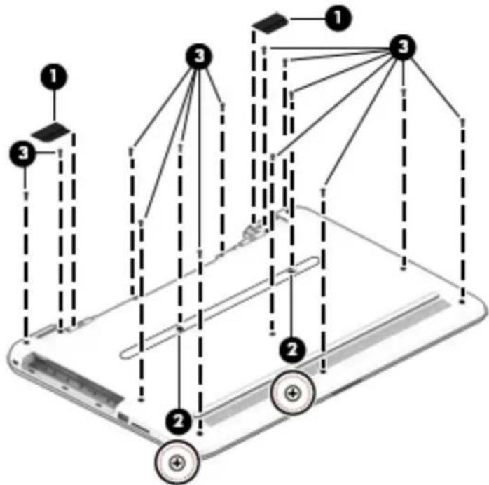
To remove the bottom cover:
- Position the computer upside down with the front toward you.
-
Remove the two rubber feet (1).
-
Remove the service label screw cutouts from above the two screws under the label (2).

NOTE: Two screws that are located under the regulatory label are marked with a dashed circle and “+” sign
Do not remove the regulatory label – only remove or punch holes through the circular cutouts above the screws.
- Remove the 14 Phillips PM PM2.5×8.0 screws (3) that secure the top cover to the computer.
flowchart
graph TD
    A["1"] --> B["2"]
    C["3"] --> D["2"]
    E["1"] --> F["3"]
    G["3"] --> H["2"]
    I["1"] --> J["3"]
    K["2"] --> L["+"]
    M["3"] --> N["+"]
- Start at the front of the computer and pry to separate the bottom cover from the computer (1). Work your way around prying to disengage the bottom cover from the computer, and then remove the cover (2).
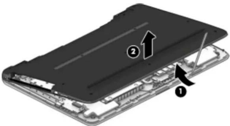
text_image
Diagram of a device showing two labeled parts (1 and 2) with arrows indicating assembly or movement, likely illustrating a mechanical or electronic component.Reverse this procedure to install the bottom cover.

NOTE: The hard drive spare part kit does not include the hard drive cover.
Description Spare part number
| 2-TB, 5400-rpm, 2.5-inch 801808-005 |
| 1-TB, 5400-rpm, 2.5-inch, hybrid 8 GB SSD 731999-005 |
| 1-TB, 5400-rpm, 2.5-in 778192-005 |
| 500-GB, 5400-rpm, 2.5 inch 778188-005 |
| Hard drive cover 856584-001 |
Before removing the hard drive, follow these steps:
- Shut down the computer. If you are unsure whether the computer is off or in Hibernation, turn the computer on, and then shut it down through the operating system.
- Disconnect all external devices connected to the computer.
- Disconnect the power from the computer by first unplugging the power cord from the AC outlet and then unplugging the AC adapter from the computer.
- Remove the battery (see Battery on page 32).
- Remove the optical drive (see Optical drive on page 33).
- Remove the bottom cover (see Bottom cover on page 39).
To remove the hard drive:
- Remove the USB board cable from atop the hard drive as follows:
a. Lift the ZIF connector (1), and then disconnect the cable from the system board (2).
b. Lift the ZIF connector (3), and then disconnect the cable from the USB board (4).
c. Remove the USB board cable from atop the hard drive (5).

text_image
Technical diagram of an electronic device with numbered components and directional arrows indicating assembly or component layout.- Rotate the hard drive upward (1).
- Pull the drive away from the connector, and then remove it from the computer (2).
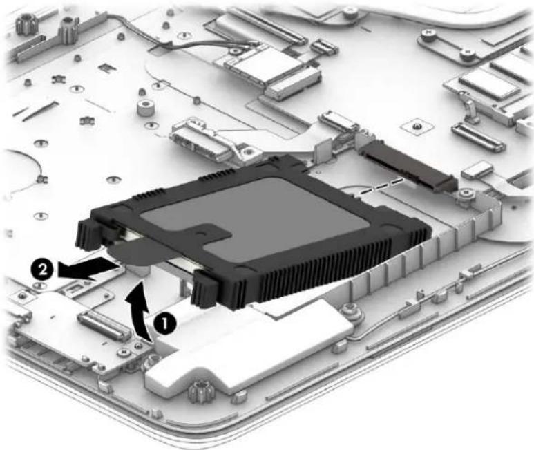
text_image
Technical diagram of an electronic circuit board with labeled components, showing a central processor and surrounding hardware.- To disassemble the hard drive, lift the cover off the hard drive
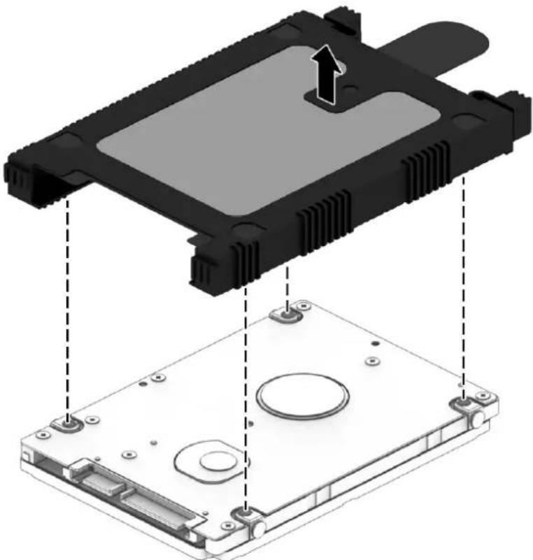
natural_image
3D diagram of a computer hard drive showing internal components and mounting points (no text or symbols)Reverse this procedure to reassemble and install the hard drive.
Description Spare part number
| Broadcom BCM43142 802.11 b/g/n 1x1 Wi-Fi + BT4.0 Combo Adapter 792608-005 |
| Intel Dual Band Wireless-AC 3165 802.11 ac 1x1 WiFi + BT 4.2 Combo 806723-005 |
| Realtek RTL8188EE-VJ 802.11b/g/n 1x1 Wi-Fi Adapter 857334-855 |
| Intel Dual Band Wireless-AC 3168 802.11 ac 1x1 WiFi + BT 4.2 Combo 863934-855 |

CAUTION: To prevent an unresponsive system, replace the wireless module only with a wireless module authorized for use in the computer by the governmental agency that regulates wireless devices in your country or region. If you replace the module and then receive a warning message, remove the module to restore device functionality, and then contact support.
Before removing the WLAN module, follow these steps:
- Shut down the computer. If you are unsure whether the computer is off or in Hibernation, turn the computer on, and then shut it down through the operating system.
- Disconnect all external devices connected to the computer.
- Disconnect the power from the computer by first unplugging the power cord from the AC outlet and then unplugging the AC adapter from the computer.
- Remove the battery (see Battery on page 32).
- Remove the optical drive (see Optical drive on page 33).
- Remove the bottom cover (see Bottom cover on page 39).
To remove the WLAN module:
- Disconnect the WLAN antenna cables (1) from the terminals on the WLAN module.

NOTE: The #1 WLAN antenna cable is connected to the WLAN module Main terminal. The #2 WLAN antenna cable is connected to the WLAN module Aux terminal.
-
Remove the Phillips PM2.0×3.0 screw (2) that secures the WLAN module to the system board. (The WLAN module tilts up.)
-
Remove the WLAN module by pulling the module away from the slot at an angle (3).
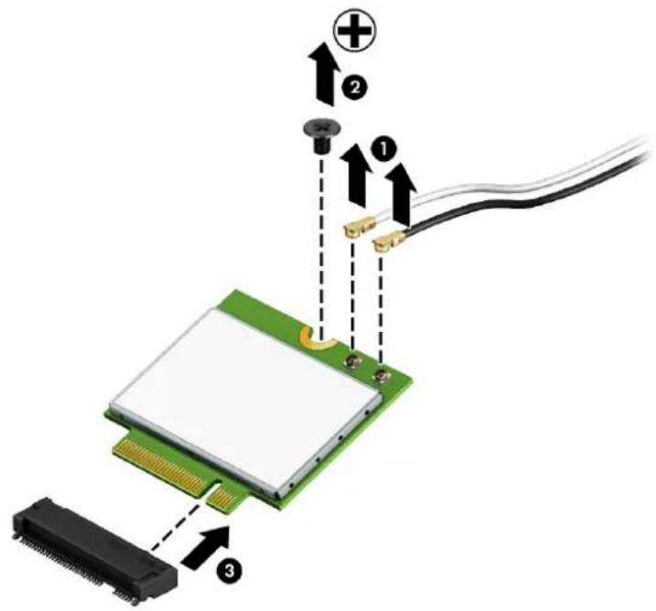
text_image
Diagram of an electronic component with labeled parts and connection arrows, showing connections to a green circuit board.
NOTE: If the WLAN antennas are not connected to the terminals on the WLAN module, the protective sleeves must be installed on the antenna connectors, as shown in the following illustration.

natural_image
Diagram of a curved cable with a black arrow indicating direction (no text or symbols)Reverse this procedure to install the WLAN module.
Description Spare part number
RTC battery 858288-001
Before removing the RTC battery, follow these steps:
- Shut down the computer. If you are unsure whether the computer is off or in Hibernation, turn the computer on, and then shut it down through the operating system.
- Disconnect all external devices connected to the computer.
- Disconnect the power from the computer by first unplugging the power cord from the AC outlet and then unplugging the AC adapter from the computer.
- Remove the battery (see Battery on page 32).
- Remove the optical drive (see Optical drive on page 33).
- Remove the bottom cover (see Bottom cover on page 39).
To remove the RTC battery:
Using a thin tool or screwdriver, disengage the battery from the socket (1), and then remove the battery (2).

text_image
Diagram of a mechanical device with labeled parts and directional arrows, showing component positioning and assembly.Reverse this procedure to install the RTC battery.
| Description Spare part number |
| Memory module (PC4, 17000, 2133-MHz) |
| For use in models with AMD A10 processors |
| 8-GB 820570-005 |
| 4-GB 820569-005 |
| 2-GB 851379-005 |
| Memory module (PC3L, 12800, 1600-MHz) |
| For use in models with AMD A8, A6, E2, and E1 processors |
| 8-GB 693374-005 |
| 4-GB 691740-005 |
| 2-GB 691739-005 |
Before removing a memory module, follow these steps:
- Shut down the computer. If you are unsure whether the computer is off or in Hibernation, turn the computer on, and then shut it down through the operating system.
- Disconnect all external devices connected to the computer.
- Disconnect the power from the computer by first unplugging the power cord from the AC outlet and then unplugging the AC adapter from the computer.
- Remove the battery (see Battery on page 32).
- Remove the optical drive (see Optical drive on page 33).
- Remove the bottom cover (see Bottom cover on page 39).
To remove a memory module:
-
Spread the retaining tabs (1) on each side of the memory module slot to release the memory module. (The memory module tilts up.)
-
Remove the memory module (2) by pulling it away from the slot at an angle.
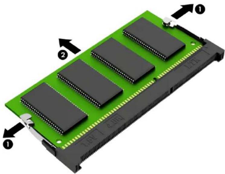
natural_image
Green electronic component with multiple black integrated circuits and labeled pins (no readable text or symbols beyond labels)Reverse this procedure to install a memory module.
Description Spare part number
128-GB solid-state drive 827560-025
Before removing the solid-state drive, follow these steps:
- Turn off the computer. If you are unsure whether the computer is off or in Hibernation, turn the computer on, and then shut it down through the operating system.
- Disconnect the power from the computer by unplugging the power cord from the computer.
- Remove the battery (see Battery on page 32).
- Remove the optical drive (see Optical drive on page 33).
- Remove the bottom cover (see Bottom cover on page 39).
Remove the solid-state drive:
- Remove the Phillips PM2.0×2.0 screw (1) that secures the drive to the system board.
- Remove the drive (2) by pulling it away from the connector.

NOTE: Solid-state drives are designed with notches to prevent incorrect insertion.
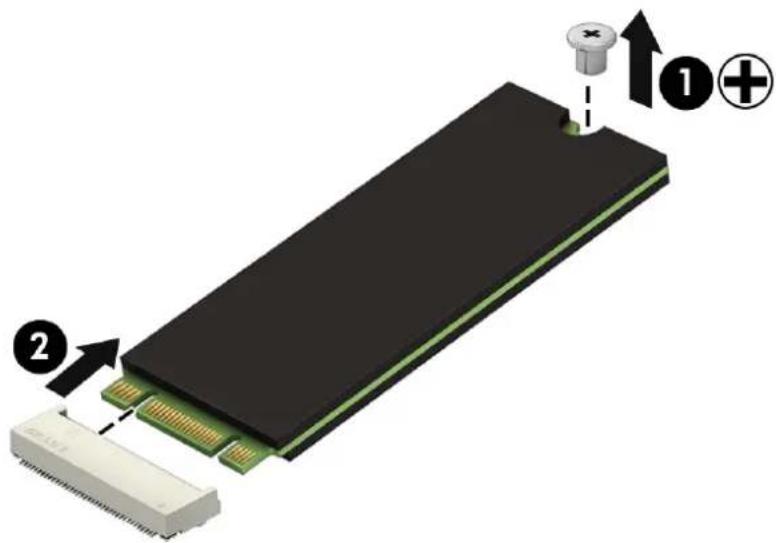
text_image
Diagram of a physical electronic component with labeled parts and directional arrows indicating assembly or process.Reverse this procedure to install the solid-state drive.
Description Spare part number
Solid-state drive holder 858260-001
Solid-state drive board 856614-001
Before removing the solid-state drive holder and board, follow these steps:
- Shut down the computer. If you are unsure whether the computer is off or in Hibernation, turn the computer on, and then shut it down through the operating system.
- Disconnect all external devices connected to the computer.
- Disconnect the power from the computer by first unplugging the power cord from the AC outlet and then unplugging the AC adapter from the computer.
- Remove the battery (see Battery on page 32).
- Remove the optical drive (see Optical drive on page 33).
- Remove the bottom cover (see Bottom cover on page 39).
- Remove the solid-state drive (see Solid-state drive on page 49).
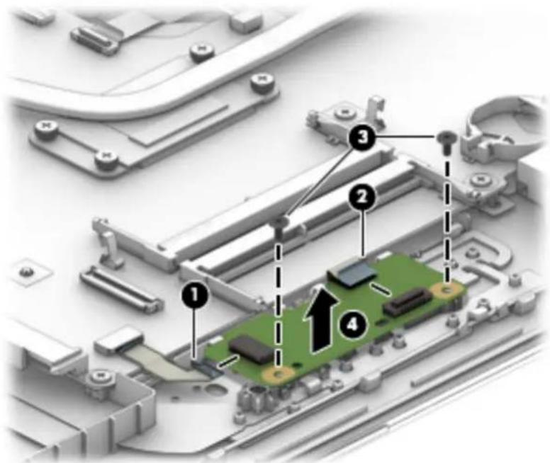
To remove the solid-state drive holder and board:
- Remove the Phillips PM2.0×4.5 screws (1) that secures the solid-state drive holder to the computer.
- Pull the board away from the connector on system board (2), and then remove the solid-state drive holder and board assembly (3).

text_image
Technical diagram of an electronic device with labeled components and directional arrows indicating assembly or installation steps.-
To remove the solid-state drive board from the holder, remove the two Phillips PM2.0×4.0 screws (1) that secure the board to the holder.
-
Lift the board out of the holder (2).
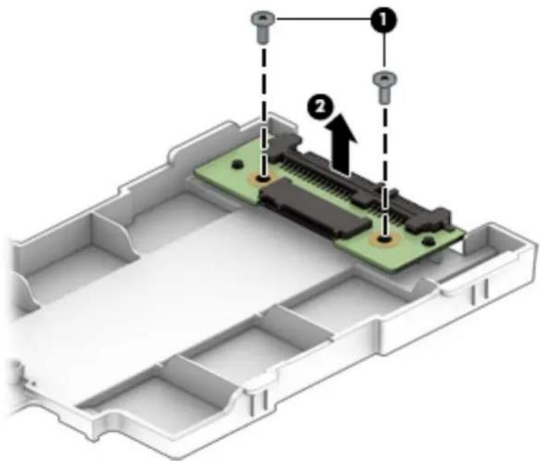
text_image
Technical diagram of a device's internal structure with labeled components and assembly stepsReverse this procedure to install the solid-state drive holder and board.
Description Spare part number
Optical drive connector 856609-001
Before removing the optical drive connector, follow these steps:
- Shut down the computer. If you are unsure whether the computer is off or in Hibernation, turn the computer on, and then shut it down through the operating system.
- Disconnect all external devices connected to the computer.
- Disconnect the power from the computer by first unplugging the power cord from the AC outlet and then unplugging the AC adapter from the computer.
- Remove the battery (see Battery on page 32).
- Remove the optical drive (see Optical drive on page 33).
- Remove the bottom cover (see Bottom cover on page 39).
To remove the optical drive connector:
- Disconnect the optical drive connector cable from the system board (1).
- Remove the Phillips PM2.0×3.0 screw (2) that secures the optical drive connector to the computer.
- Remove the optical drive connector and cable (3).

text_image
Diagram of an electronic device with labeled components, showing a connector and cable assembly.Reverse this procedure to install the optical drive connector.
TouchPad click board
| Description Spare part number |
| TouchPad click board 858259-001 |
| TouchPad click board cable 856606-001 |
| TouchPad cable 856605-001 |
Before removing the TouchPad click board, follow these steps:
- Shut down the computer. If you are unsure whether the computer is off or in Hibernation, turn the computer on, and then shut it down through the operating system.
- Disconnect all external devices connected to the computer.
- Disconnect the power from the computer by first unplugging the power cord from the AC outlet and then unplugging the AC adapter from the computer.
- Remove the battery (see Battery on page 32).
- Remove the optical drive (see Optical drive on page 33).
- Remove the bottom cover (see Bottom cover on page 39).
To remove the TouchPad click board:
- Disconnect the cables from the TouchPad cable (1) and the TouchPad click board cable (2).
-
Remove the two Phillips PM2.0×4.0 screws (3) that secure the TouchPad to the computer.
-
Remove the board (4).
text_image
Technical diagram of an electronic device with numbered components and an upward arrow indicating a specific area.Reverse this procedure to install the TouchPad click board.
Description Spare part number
USB board 856613-001
Before removing the USB board, follow these steps:
- Shut down the computer. If you are unsure whether the computer is off or in Hibernation, turn the computer on, and then shut it down through the operating system.
- Disconnect all external devices connected to the computer.
- Disconnect the power from the computer by first unplugging the power cord from the AC outlet and then unplugging the AC adapter from the computer.
- Remove the battery (see Battery on page 32).
- Remove the optical drive (see Optical drive on page 33).
- Remove the bottom cover (see Bottom cover on page 39).
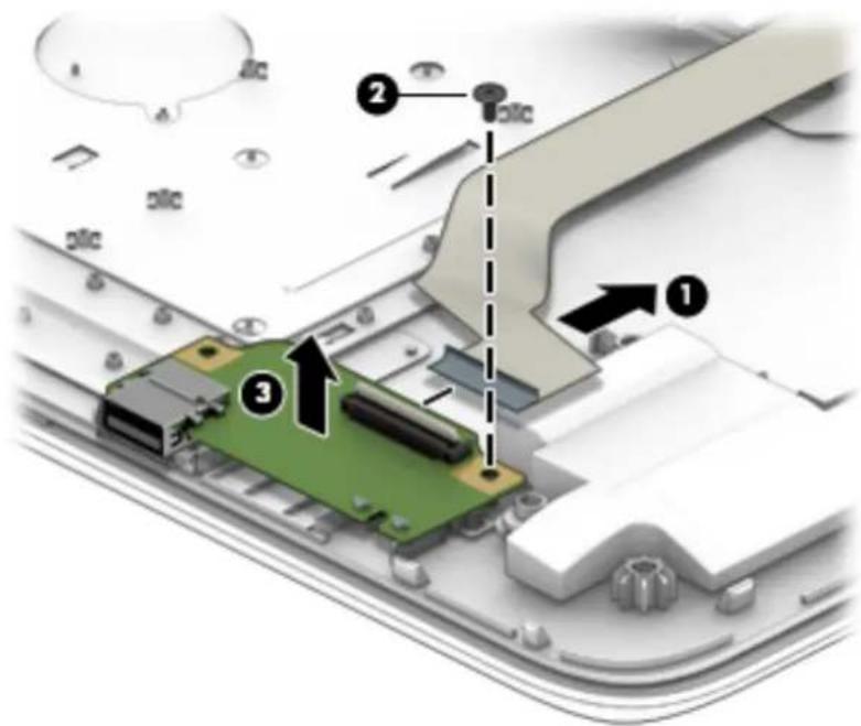
To remove the USB board:
- Disconnect the cable from the USB board (1)
- Remove the Phillips PM2.0×4.0 screw (2) that secures the USB board to the computer.
- Remove the USB board (3).
text_image
Technical diagram showing a green circuit board with labeled components and directional arrows indicating assembly or installation steps.Reverse this procedure to install the USB board.
Description Spare part number
Speakers (includes left and right speakers and cable) 856617-001
Before removing the speakers, follow these steps:
- Shut down the computer. If you are unsure whether the computer is off or in Hibernation, turn the computer on, and then shut it down through the operating system.
- Disconnect all external devices connected to the computer.
- Disconnect the power from the computer by first unplugging the power cord from the AC outlet and then unplugging the AC adapter from the computer.
- Remove the battery (see Battery on page 32).
- Remove the optical drive (see Optical drive on page 33).
- Remove the bottom cover (see Bottom cover on page 39).
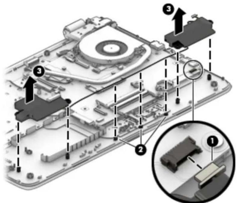
To remove the speakers:
- Disconnect the speaker cable from the system board (1).
- Remove the cable from the routing path (2).
- Lift the speakers out of the computer (3).
text_image
Technical diagram of a device with numbered annotations indicating assembly or component locationsReverse this procedure to install the speakers.

NOTE: The heat sink assembly spare part kit includes replacement thermal materials.
Description Spare part number
Fan/heat sink assembly for use in models with discrete graphics 856762-001
Fan/heat sink assembly for use in models with UMA graphics 856761-001

NOTE: To properly ventilate the computer, allow at least 7.6 cm (3.0 in) of clearance on the left side of the computer. The computer uses an electric fan for ventilation. The fan is controlled by a temperature sensor and is designed to turn on automatically when high temperature conditions exist. These conditions are affected by high external temperatures, system power consumption, power management/battery conservation configurations, battery fast charging, and software requirements. Exhaust air is displaced through the ventilation grill located on the left side of the computer.
Before removing the heat sink assembly, follow these steps:
- Shut down the computer. If you are unsure whether the computer is off or in Hibernation, turn the computer on, and then shut it down through the operating system.
- Disconnect all external devices connected to the computer.
- Disconnect the power from the computer by first unplugging the power cord from the AC outlet and then unplugging the AC adapter from the computer.
- Remove the battery (see Battery on page 32).
- Remove the optical drive (see Optical drive on page 33).
- Remove the bottom cover (see Bottom cover on page 39).
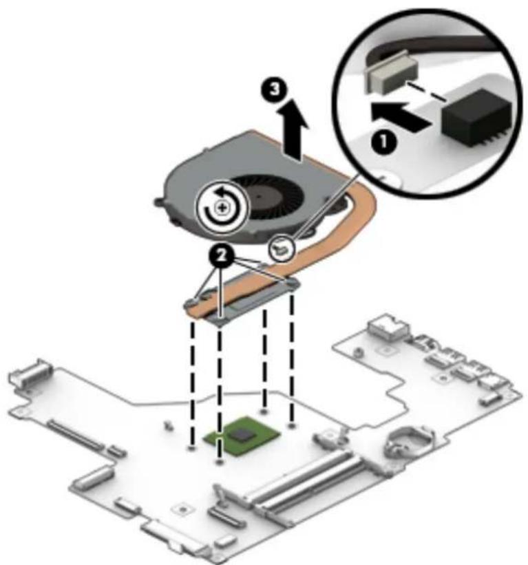
To remove the fan/heat sink assembly:
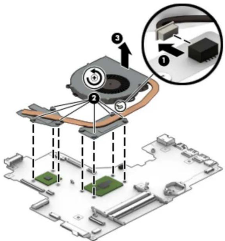
- If you have a model with discrete graphics:
a. Disconnect the fan cable from the system board (1).
b. In the order indicated, remove the six Phillips PM2.0×3.0 screws (2) that secure the heat sink to the system board.
c. Remove the heat sink (3) from the system board.
text_image
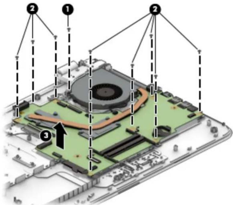
Diagram illustrating a device's internal structure with labeled components and an inset showing close-up of the circuit board.- If you have a model with UMA graphics and a fan integrated in the heat sink:
a. Disconnect the fan cable from the system board (1).
b. In the order indicated, remove the four Phillips PM2.0×3.0 screws (2) that secure the heat sink to the system board.
c. Remove the heat sink (3) from the system board.
text_image
Diagram illustrating the installation of a computer motherboard with labeled components and an inset showing a close-up of the circuit board.
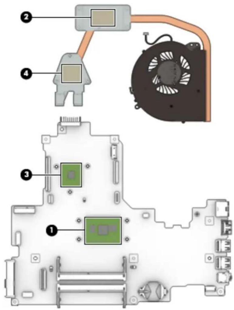
NOTE: The thermal material must be thoroughly cleaned from the surfaces of the heat sink and the system board components each time the heat sink is removed. Replacement thermal material is included with the heat sink, processor, and system board spare part kits.
The following illustrations show the replacement thermal material locations.
- Discrete graphics: Thermal paste is used on the processor (1) and associated heat sink area (2), as well as the graphics chip (3) and associated heat sink area (4).
text_image
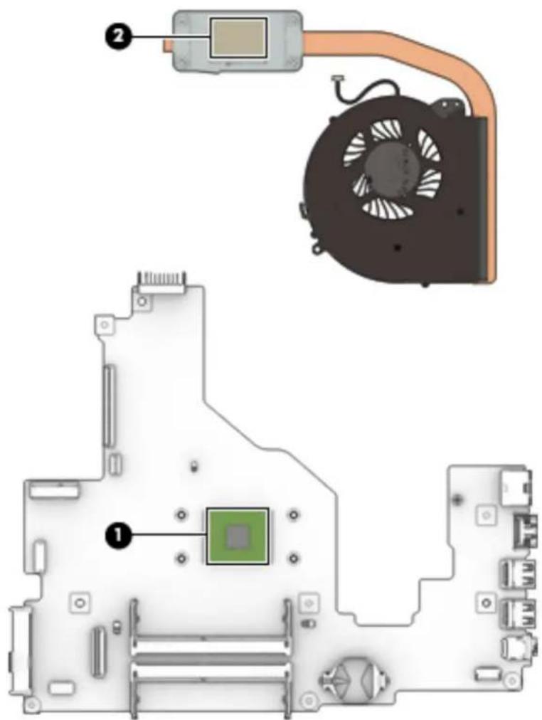
Diagram of a computer motherboard with labeled components including CPU socket, fan, and heatsinkUMA graphics: Thermal paste is used on the processor (1) and associated heat sink area (2).
text_image
Diagram of a computer motherboard showing CPU socket, fan, and drive components with numbered labelsReverse this procedure to reassemble and install the heat sink assembly.

NOTE: The system board spare part kit includes replacement thermal materials.
Description Spare part number
System board (includes replacement thermal materials):
All system boards use the following part numbers:
xxxxxx-001: Windows 7 or non-Windows operating system
xxxxxx-601: Windows 10
For use in models with discrete graphics:
AMD A10-9600P processor and 4 GB of dedicated video memory 856770-xxx
AMD A10-9600P processor and 2 GB of dedicated video memory 856769-xxx
AMD A8-7410 processor and 2 GB of dedicated video memory 856767-xxx
AMD A6-7310 processor and 2 GB of dedicated video memory 856766-xxx
For use in models with UMA graphics:
AMD A10-9600P processor 856768-xxx
AMD A9-9410 processor 859287-xxx
AMD A8-7410 processor 856765-xxx
AMD A6-7310 processor 856764-xxx
AMD E2-7110 processor 856763-xxx
Before removing the system board, follow these steps:
- Shut down the computer. If you are unsure whether the computer is off or in Hibernation, turn the computer on, and then shut it down through the operating system.
- Disconnect all external devices connected to the computer.
- Disconnect the power from the computer by first unplugging the power cord from the AC outlet and then unplugging the AC adapter from the computer.
- Remove the battery (see Battery on page 32).
- Remove the optical drive (see Optical drive on page 33).
- Remove the bottom cover (see Bottom cover on page 39).

NOTE: When replacing the system board, be sure that the following components are removed from the defective system board and installed on the replacement system board:
• Memory modules (see Memory module on page 47)
• WLAN module (see WLAN module on page 44)
• Fan/heat sink assembly (see Fan/heat sink assembly on page 56)
Solid-state drive (if installed) (see Solid-state drive on page 49)
To remove the system board:
- Position the computer upright, and then disconnect the following cables from the system board:
(1): Keyboard cable
(2): Keyboard backlight cable
(3): Optical drive connector cable
(4): USB board cable
(5): TouchPad cable
(6): Power connector cable
(7): Display cable
(8): Power button board
(9): Speaker cable

text_image
Labeled diagram of an electronic device interior with numbered components for identification- Remove the Phillips PM2.0×3.0 screw (1) that secures the system board to the computer.
-
Remove the eight Phillips PM2.5×7.0 screws (2) that secure the system board to the computer.
-
Lift the system board out of the computer (3).
text_image
Diagram of a device's internal structure with numbered annotations indicating components and directional arrows.Reverse this procedure to install the system board.
Display assembly
| Description Spare part number | |
| Raw display panel (43.9-cm [17.3-in]; includes screw covers) | |
| FHD, anti glare 798926-007 | |
| FHD, Touch On Panel (TOP) 851048-001 | |
| HD, Touch On Panel (TOP) 851049-001 | |
| HD+, BrightView 851051-002 | |
| Display bezel 856597-001 | |
| Display cable | |
| Non-touch displays 856607-001 | |
| Touch displays 856608-001 | |
| Display enclosure for use in non-touch models | |
| Red models 856594-001 | |
| White silver models 856593-001 | |
| Blue models 856596-001 | |
| Turbo silver models 856592-001 | |
| Black models 856591-001 | |
| Teal models 856595-001 | |
| Purple models 900660-001 | |
| Display enclosure for use in touch models | |
| Red models 856588-001 | |
| White silver models 856587-001 | |
| Blue models 856590-001 | |
| Turbo silver models 856586-001 | |
| Black models 856585-001 | |
| Teal models 856589-001 | |
| Purple models 900659-001 | |
| Hinges (left and right) | 856599-001 |
| Webcam/microphone module | |
| HD | 709372-032 |
| VGA | 766523-021 |
| Antennas | 856611-001 |
| Touch control board | 856600-001 |
Before removing the display assembly, follow these steps:
- Shut down the computer. If you are unsure whether the computer is off or in Hibernation, turn the computer on, and then shut it down through the operating system.
- Disconnect all external devices connected to the computer.
- Disconnect the power from the computer by first unplugging the power cord from the AC outlet and then unplugging the AC adapter from the computer.
- Remove the battery (see Battery on page 32).
- Remove the optical drive (see Optical drive on page 33).
- Remove the bottom cover (see Bottom cover on page 39).
- Remove the fan/heat sink (see Fan/heat sink assembly on page 56).
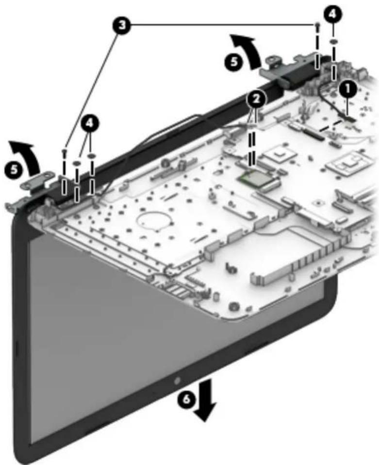
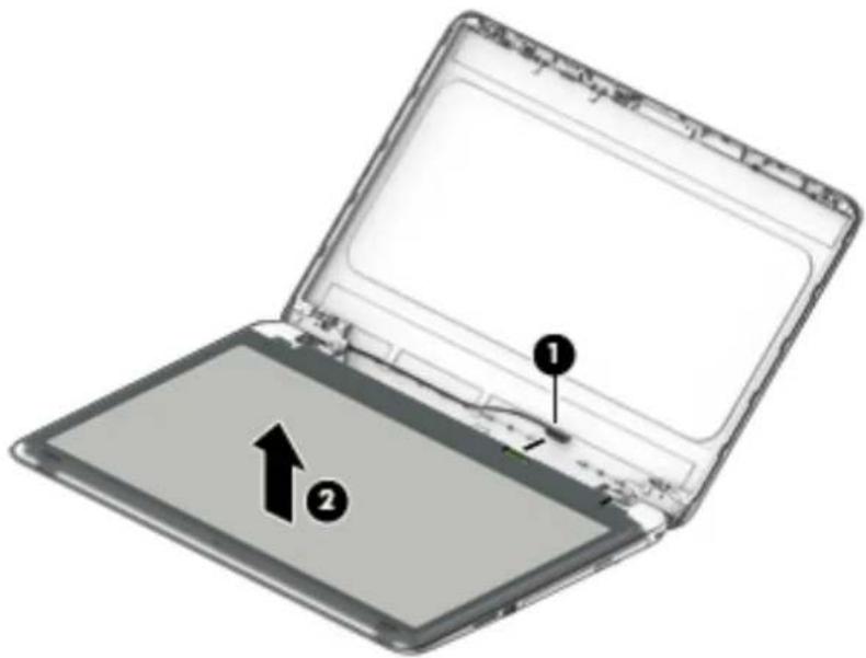
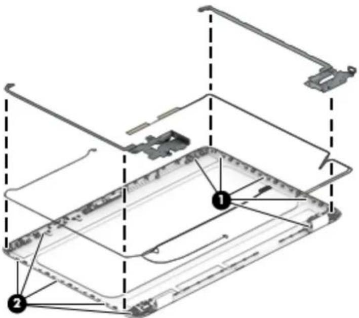
To remove the display assembly:
- Position the computer with the display open and hanging down off the edge of a table.
- Disconnect the display cable from the system board (1).
- Disconnect the wireless antenna cables from the WLAN module (2).
- Remove the two Phillips PM2.5×7.0 screws (3) that secure the display assembly to the computer.
- Remove the three Phillips broadhead PM2.0×2.0 screws (4) that secure the display assembly to the computer.
-
Open the display to rotate the hinges upward to an angle (5).
-
Separate the display assembly from the computer (6).
text_image
Labeled diagram of an electronic device showing internal components and structural featuresIf it is necessary to replace any of the display assembly subcomponents:
-
Flex the inside of the top edge (1), left and right sides (2), and the inside of the bottom edge (3) of the display bezel until the bezel disengages from the display enclosure.
-
Remove the display bezel (4).

NOTE: In this procedure the display will not be connected to the computer as shown in the following image.
text_image
Diagram showing a laptop with labeled arrows indicating directional movement or navigation, numbered 1 to 4.- To remove the webcam/microphone module:
a. Position the display assembly with the top edge toward you.
b. Lift to disengage the adhesive that secures the webcam/microphone module to the display (1).
c. Disconnect the cable (2) from the module.
d. Remove the module (3).
text_image
Diagram showing a device assembly with numbered components and directional arrows indicating parts of the main structure.- To remove the display panel:
a. Remove the four Phillips PM2.0×3.0 screws (1) that secure the display panel to the enclosure.
b. Rotate the display panel onto the keyboard (2) to gain access to the display cable connection on the back of the panel.

NOTE: In this procedure the display will not be connected to the computer as shown in the following image.
text_image
Diagram showing a laptop with labeled parts and a curved arrow indicating motion or transformation, numbered 1 and 2.c. On the back of the display panel, release the adhesive strip that secures the display panel cable to the display panel, and then disconnect the cable (1).
d. Remove the display panel from the computer (2).

NOTE: In this procedure the display will not be connected to the computer as shown in the following image.
text_image
Diagram of an open laptop with labeled parts, showing front and back views and a numbered component.- To remove the touch control board from the display:
a. Remove the two Phillips PM2.0×2.0 screws (1) that secure the touch control board to the top of the display assembly.
b. Rotate the board upside down to access the connectors underneath (2).

text_image
Diagram of a device's internal structure with numbered annotations indicating componentsc. Disconnect the cable from the end of the board (1).
d. Disconnect the two larger cables from the board (2).
e. Remove the touch control board from the display assembly (3).

text_image
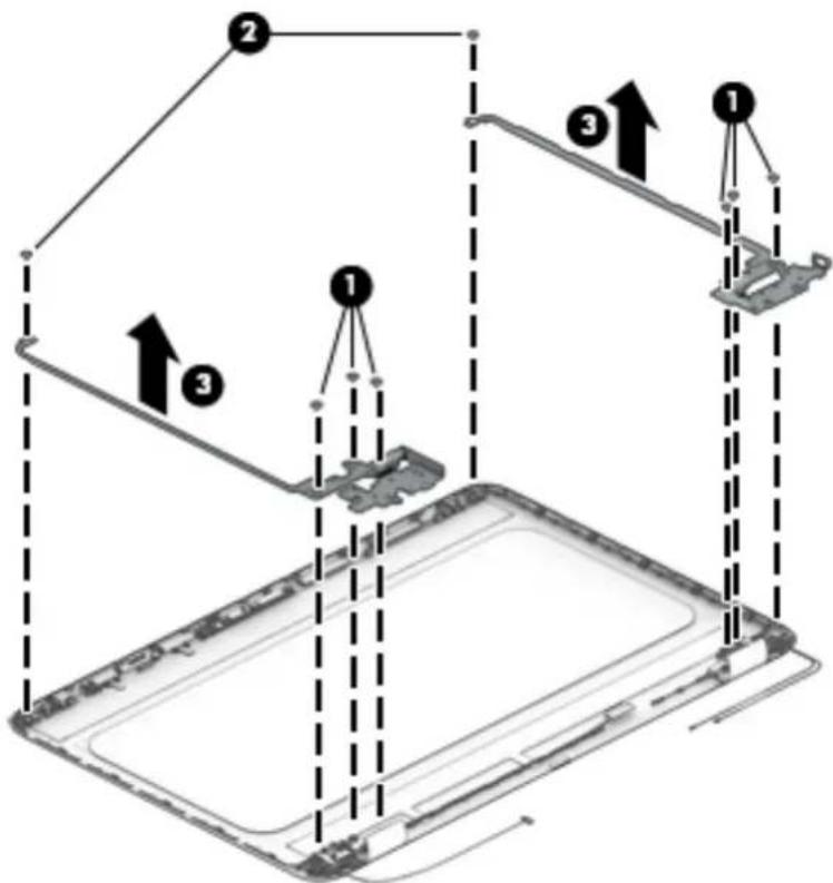
Diagram of a device's internal structure with numbered components, showing labeled parts 1, 2, and 3.- To remove the display hinges:
a. Remove the three Phillips broadhead PM2.5×3.0 screws (1) from the bottom of each hinge and the Phillips broadhead PM2.5×3.0 screw (2) from the top of each hinge.
b. Remove the display hinges from the panel (3).
text_image
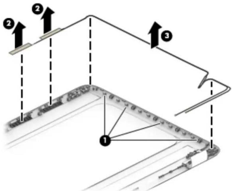
Diagram illustrating three-step assembly or installation process with labeled components and directional arrows- To remove the wireless antenna cables and transceivers, release the wireless antenna cables from the clips (1) built into the back of the display, peel off the transceivers (2), and then remove the antenna cables and transceivers (3).

NOTE: Number of antennas and transceivers may vary.
text_image
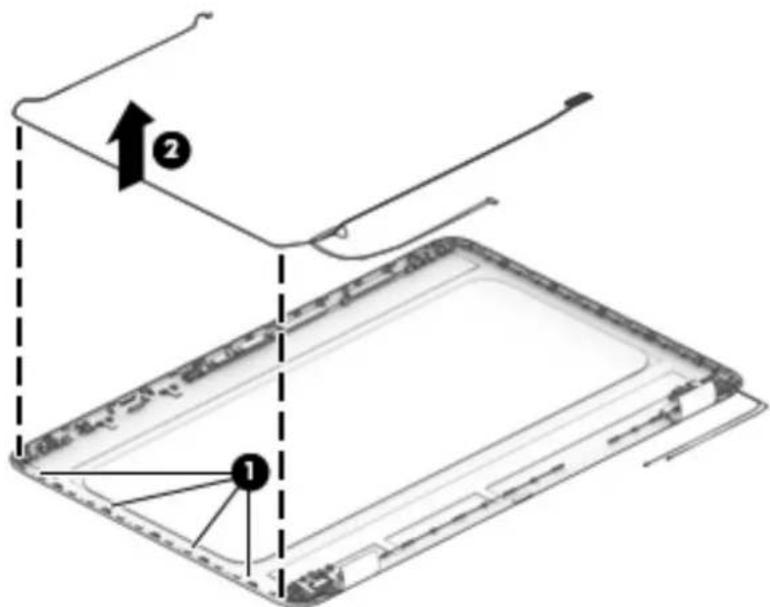
Diagram illustrating a mechanical or electrical system with numbered components and directional arrows, likely representing a device or component layout.- To remove the display/webcam cable, remove the cable from the clips built into the display panel (1), and then remove the cable from the display (2).
text_image
Diagram showing a device with labeled parts and directional arrows, including numbered annotations 1 and 2.- If replacing the display enclosure, be sure that the subcomponents (including the webcam/microphone module, the antenna receivers, and all associated cables and hardware) are transferred to the new enclosure.
Reverse this procedure to reassemble and install the display assembly.
When reassembling and reinstalling the display assembly, note the routing of the antenna cable (1) and display/webcam cable (2) as shown in the following image.
text_image
Technical diagram of a device casing with labeled components, showing internal structure and assembly lines.Description Spare part number
Power button board 856612-001
Power button board cable 856604-001
Before removing the power button board, follow these steps:
- Shut down the computer. If you are unsure whether the computer is off or in Hibernation, turn the computer on, and then shut it down through the operating system.
- Disconnect all external devices connected to the computer.
- Disconnect the power from the computer by first unplugging the power cord from the AC outlet and then unplugging the AC adapter from the computer.
- Remove the battery (see Battery on page 32).
- Remove the optical drive (see Optical drive on page 33).
- Remove the bottom cover (see Bottom cover on page 39).
- Remove the fan/heat sink (see Fan/heat sink assembly on page 56).
- Remove the display (see Display assembly on page 64).
To remove the power button board:
- Disconnect the cable from the power button board (1).
- Remove the Phillips PM2.0×4.0 screw (2) that secures the power button board to the computer.
- Remove the power button board from the computer (3).

text_image
Technical diagram showing a mechanical assembly with labeled components and directional arrows indicating assembly steps.Reverse this procedure to install the power button board.
Description Spare part number
Power connector cable 856680-001
Before removing the power connector cable, follow these steps:
- Shut down the computer. If you are unsure whether the computer is off or in Hibernation, turn the computer on, and then shut it down through the operating system.
- Disconnect all external devices connected to the computer.
- Disconnect the power from the computer by first unplugging the power cord from the AC outlet and then unplugging the AC adapter from the computer.
- Remove the battery (see Battery on page 32).
- Remove the optical drive (see Optical drive on page 33).
- Remove the bottom cover (see Bottom cover on page 39).
- Remove the fan/heat sink (see Fan/heat sink assembly on page 56).
- Remove the display (see Display assembly on page 64).
To remove the power connector cable:
- Pull the tabs away from the connector (1).
- Remove the power connector (2) from the computer.
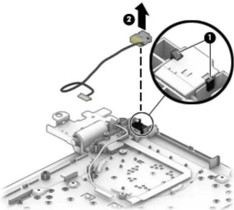
text_image
Diagram showing a mechanical assembly with labeled components and an inset magnified view of a device interior.Reverse this procedure to install the power connector cable.
Cable locations
| Description Spare part number |
| Power button board cable 856604-001 |
| Optical drive cable 856609-001 |
| USB board cable 856603-001 |
| TouchPad cable 856605-001 |
| Touch click board cable 856606-001 |
Use the following image to determine proper cable routing in the computer.
(1) Power button board cable
(2) Optical drive cable
(3) USB board cable
(4) TouchPad cable
(5) TouchPad click board cable
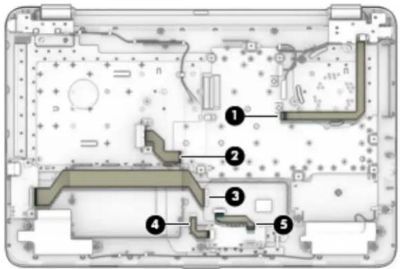
text_image
Technical diagram of an electronic device interior with numbered components for identificationTop cover/keyboard
In this section, the first table provides the main spare part number for the top cover/keyboard. The second table provides the country codes. All top cover/keyboard spare part kits include TouchPad.
| Description Spare part number |
| Models without a backlit keyboard: |
| Black 856698-xx1 |
| Turbo silver 856699-xx1 |
| White silver 856700-xx1 |
| Red 856757-xx1 |
| Teal 856758-xx1 |
| Blue 856759-xx1 |
| Purple 900153-xx1 |
| Models with a backlit keyboard: |
| Black 856771-xx1 |
| Turbo silver 856772-xx1 |
| White silver 856773-xx1 |
| Red 856775-xx1 |
| Teal 856776-xx1 |
| Blue 856777-xx1 |
| Purple 900154-xx1 |
| Country or region Spare part number | Country or region Spare part number | Country or region Spare part number | |||
| Belgium -A41 | Greece | -151 | Saudi Arabia | -171 | |
| Bulgaria | -261 | Hungary | -211 | Slovenia | |
| Canada | -DB1 | Israel | -BB1 | South Korea | |
| Czech Republic and Slovakia | -FL1 | The Netherlands | -B31 | Spain | |
| Denmark, Finland, and Norway | -DH1 | Portugal | -131 | Switzerland | |
| France | -051 | Romania | -271 | United Kingdom | |
| Germany | -041 | Russia | -251 | United States | |
The top cover/keyboard spare part kit includes the keyboard, keyboard cable and the keyboard backlight cable.
The top cover/keyboard spare part remains after all other spare parts have been removed.
7 Using Setup Utility (BIOS) in Windows 10
Setup Utility, or Basic Input/Output System (BIOS), controls communication between all the input and output devices on the system (such as disk drives, display, keyboard, mouse, and printer). Setup Utility (BIOS) includes settings for the types of devices installed, the startup sequence of the computer, and the amount of system and extended memory.

NOTE: To start Setup Utility on convertible computers, your computer must be in notebook mode and you must use the keyboard attached to your notebook.
Starting Setup Utility (BIOS)

CAUTION: Use extreme care when making changes in Setup Utility (BIOS). Errors can prevent the computer from operating properly.
▲ Turn on or restart the computer, quickly press esc, and then press f10.
Updating Setup Utility (BIOS)
Updated versions of Setup Utility (BIOS) may be available on the HP website.
Most BIOS updates on the HP website are packaged in compressed files called SoftPaqs.
Some download packages contain a file named Readme.txt, which contains information regarding installing and troubleshooting the file.
Determining the BIOS version
To decide whether you need to update Setup Utility (BIOS), first determine the BIOS version on your computer.
To reveal the BIOS version information (also known as ROM date and System BIOS), use one of these options.
HP Support Assistant
- Type support in the taskbar search box, and then select the HP Support Assistant app.
-or-
Click the question mark icon in the taskbar.
- Select My PC, and then select Specifications.
Setup Utility (BIOS)
- Start Setup Utility (BIOS) (see Starting Setup Utility (BIOS) on page 77).
- Select Main, select System Information, and then make note of the BIOS version.
- Select Exit, select No, and then follow the on-screen instructions.
To check for later BIOS versions, see Downloading a BIOS update on page 78.
Downloading a BIOS update

CAUTION: To reduce the risk of damage to the computer or an unsuccessful installation, download and install a BIOS update only when the computer is connected to reliable external power using the AC adapter. Do not download or install a BIOS update while the computer is running on battery power, docked in an optional docking device, or connected to an optional power source. During the download and installation, follow these instructions:
- Do not disconnect power from the computer by unplugging the power cord from the AC outlet.
- Do not shut down the computer or initiate Sleep.
- Do not insert, remove, connect, or disconnect any device, cable, or cord.

NOTE: If your computer is connected to a network, consult the network administrator before installing any software updates, especially system BIOS updates.
- Type support in the taskbar search box, and then select the HP Support Assistant app.
-or-
Click the question mark icon in the taskbar.
- Click Updates, and then click Check for updates and messages.
- Follow the on-screen instructions.
- At the download area, follow these steps:
a. Identify the most recent BIOS update and compare it to the BIOS version currently installed on your computer. If the update is more recent than your BIOS version, make a note of the date, name, or other identifier. You may need this information to locate the update later, after it has been downloaded to your hard drive.
b. Follow the on-screen instructions to download your selection to the hard drive.
Make a note of the path to the location on your hard drive where the BIOS update is downloaded. You will need to access this path when you are ready to install the update.
BIOS installation procedures vary. Follow any instructions that appear on the screen after the download is complete. If no instructions appear, follow these steps:
- Type file in the taskbar search box, and then select File Explorer.
- Click your hard drive designation. The hard drive designation is typically Local Disk (C:).
- Using the hard drive path you recorded earlier, open the folder that contains the update.
- Double-click the file that has an .exe extension (for example, filename.exe).
The BIOS installation begins. - Complete the installation by following the on-screen instructions.

NOTE: After a message on the screen reports a successful installation, you can delete the downloaded file from your hard drive.
8 Backing up, restoring, and recovering in Windows 10
This chapter provides information about the following processes. The information in the chapter is standard procedure for most products.
- Creating recovery media and backups
• Restoring and recovering your system
For additional information, refer to the HP support assistant app.
▲ Type support in the taskbar search box, and then select the HP Support Assistant app.
-or-
Click the question mark icon in the taskbar.

IMPORTANT: If you will be performing recovery procedures on a tablet, the tablet battery must be at least 70% charged before you start the recovery process.
IMPORTANT: For a tablet with a detachable keyboard, connect the keyboard to the keyboard dock before beginning any recovery process.
Creating recovery media and backups
The following methods of creating recovery media and backups are available on select products only. Choose the available method according to your computer model.
- Use HP Recovery Manager to create HP Recovery media after you successfully set up the computer. This step creates a backup of the HP Recovery partition on the computer. The backup can be used to reinstall the original operating system in cases where the hard drive is corrupted or has been replaced. For information on creating recovery media, see Creating HP Recovery media (select products only) on page 79. For information on the recovery options that are available using the recovery media, see Using Windows tools on page 80.
• Use Windows tools to create system restore points and create backups of personal information.
For more information, see Recovering using HP Recovery Manager on page 81.

NOTE: If storage is 32 GB or less, Microsoft System Restore is disabled by default.
Creating HP Recovery media (select products only)
If possible, check for the presence of the Recovery partition and the Windows partition. From the Start menu, select File Explorer, and then select This PC.
- If your computer does not list the Windows partition and the Recovery partition, you can obtain recovery media for your system from support. See the Worldwide Telephone Numbers booklet included with the computer. You can also find contact information on the HP website. Go to http://www.hp.com/support, select your country or region, and follow the on-screen instructions.
You can use Windows tools to create system restore points and create backups of personal information, see Using Windows tools on page 80.
- If your computer does list the Recovery partition and the Windows partition, you can use HP Recovery Manager to create recovery media after you successfully set up the computer. HP Recovery media can be used to perform system recovery if the hard drive becomes corrupted. System recovery reinstalls the original operating system and software programs that were installed at the factory and then configures the settings for the programs. HP Recovery media can also be used to customize the system or restore the factory image if you replace the hard drive.
— Only one set of recovery media can be created. Handle these recovery tools carefully, and keep them in a safe place.
— HP Recovery Manager examines the computer and determines the required storage capacity for the media that will be required.
— To create recovery discs, your computer must have an optical drive with DVD writer capability, and you must use only high-quality blank DVD-R, DVD+R, DVD-R DL, or DVD+R DL discs. Do not use rewritable discs such as CD±RW, DVD±RW, double-layer DVD±RW, or BD-RE (rewritable Blu-ray) discs; they are not compatible with HP Recovery Manager software. Or, instead, you can use a high-quality blank USB flash drive.
If your computer does not include an integrated optical drive with DVD writer capability, but you would like to create DVD recovery media, you can use an external optical drive (purchased separately) to create recovery discs. If you use an external optical drive, it must be connected directly to a USB port on the computer; the drive cannot be connected to a USB port on an external device, such as a USB hub. If you cannot create DVD media yourself, you can obtain recovery discs for your computer from HP. See the Worldwide Telephone Numbers booklet included with the computer. You can also find contact information on the HP website. Go to http://www.hp.com/support, select your country or region, and follow the on-screen instructions.
— Be sure that the computer is connected to AC power before you begin creating the recovery media.
— The creation process can take an hour or more. Do not interrupt the creation process.
— If necessary, you can exit the program before you have finished creating all of the recovery DVDs. HP Recovery Manager will finish burning the current DVD. The next time you start HP Recovery Manager, you will be prompted to continue.
To create HP Recovery media:

IMPORTANT: For a tablet with a detachable keyboard, connect the keyboard to the keyboard dock before beginning these steps.
- Type recovery in the taskbar search box, and then select HP Recovery Manager.
- Select Create recovery media, and then follow the on-screen instructions.
If you ever need to recover the system, see Recovering using HP Recovery Manager on page 81.
Using Windows tools
You can create recovery media, system restore points, and backups of personal information using Windows tools.

NOTE: If storage is 32 GB or less, Microsoft System Restore is disabled by default.
For more information and steps, see the Get started app.
Select the Start button, and then select the Get started app.
Restore and recovery
There are several options for recovering your system. Choose the method that best matches your situation and level of expertise:

IMPORTANT: Not all methods are available on all products.
- Windows offers several options for restoring from backup, refreshing the computer, and resetting the computer to its original state. For more information see the Get started app.
▲ Select the Start button, and then select the Get started app. - If you need to correct a problem with a preinstalled application or driver, use the Reinstall drivers and/or applications option (select products only) of HP Recovery Manager to reinstall the individual application or driver.
▲ Type recovery in the taskbar search box, select HP Recovery Manager, select Reinstall drivers and/or applications, and then follow the on-screen instructions. - If you want to recover the Windows partition to original factory content, you can choose the System Recovery option from the HP Recovery partition (select products only) or use the HP Recovery media. For more information, see Recovering using HP Recovery Manager on page 81. If you have not already created recovery media, see Creating HP Recovery media (select products only) on page 79.
- On select products, if you want to recover the computer's original factory partition and content, or if you have replaced the hard drive, you can use the Factory Reset option of HP Recovery media. For more information, see Recovering using HP Recovery Manager on page 81.
- On select products, if you want to remove the recovery partition to reclaim hard drive space, HP Recovery Manager offers the Remove Recovery Partition option.
For more information, see Removing the HP Recovery partition (select products only) on page 83.
Recovering using HP Recovery Manager
HP Recovery Manager software allows you to recover the computer to its original factory state by using the HP Recovery media that you either created or that you obtained from HP, or by using the HP Recovery partition (select products only). If you have not already created recovery media, see Creating HP Recovery media (select products only) on page 79.
What you need to know before you get started
HP Recovery Manager recovers only software that was installed at the factory. For software not provided with this computer, you must either download the software from the manufacturer's website or reinstall the software from the media provided by the manufacturer.

IMPORTANT: Recovery through HP Recovery Manager should be used as a final attempt to correct computer issues.
- HP Recovery media must be used if the computer hard drive fails. If you have not already created recovery media, see Creating HP Recovery media (select products only) on page 79.
- To use the Factory Reset option (select products only), you must use HP Recovery media. If you have not already created recovery media, see Creating HP Recovery media (select products only) on page 79.
- If your computer does not allow the creation of HP Recovery media or if the HP Recovery media does not work, you can obtain recovery media for your system from support. See the Worldwide Telephone Numbers booklet included with the computer. You can also find contact information from the HP
website. Go to http://www.hp.com/support, select your country or region, and follow the on-screen instructions.
IMPORTANT: HP Recovery Manager does not automatically provide backups of your personal data. Before beginning recovery, back up any personal data you want to retain.
Using HP Recovery media, you can choose from one of the following recovery options:
NOTE: Only the options available for your computer display when you start the recovery process.
- System Recovery—Reinstalls the original operating system, and then configures the settings for the programs that were installed at the factory.
- Factory Reset—Restores the computer to its original factory state by deleting all information from the hard drive and re-creating the partitions. Then it reinstalls the operating system and the software that was installed at the factory.
The HP Recovery partition (select products only) allows System Recovery only.
Using the HP Recovery partition (select products only)
The HP Recovery partition allows you to perform a system recovery without the need for recovery discs or a recovery USB flash drive. This type of recovery can be used only if the hard drive is still working.
To start HP Recovery Manager from the HP Recovery partition:
IMPORTANT: For a tablet with a detachable keyboard, connect the keyboard to the keyboard dock before beginning these steps (select products only).
- Type recovery in the taskbar search box, select Recovery Manager, and then select HP Recovery Environment.
- or-
For computers or tablets with keyboards attached, press f11 while the computer boots, or press and hold f11 as you press the power button.
For tablets without keyboards:
Turn on or restart the tablet, and then quickly hold down the volume down button; then select f11.
- or -
Turn on or restart the tablet, and then quickly hold down the Windows button; then select f11.
- Select Troubleshoot from the boot options menu.
- Select Recovery Manager, and then follow the on-screen instructions.
Using HP Recovery media to recover
You can use HP Recovery media to recover the original system. This method can be used if your system does not have an HP Recovery partition or if the hard drive is not working properly.
- If possible, back up all personal files.
- Insert the HP Recovery media, and then restart the computer.
NOTE: If the computer does not automatically restart in HP Recovery Manager, change the computer boot order. See Changing the computer boot order on page 83.
- Follow the on-screen instructions.
Changing the computer boot order
If your computer does not restart in HP Recovery Manager, you can change the computer boot order, which is the order of devices listed in BIOS where the computer looks for startup information. You can change the selection to an optical drive or a USB flash drive.
To change the boot order:

IMPORTANT: For a tablet with a detachable keyboard, connect the keyboard to the keyboard dock before beginning these steps.
- Insert the HP Recovery media.
- Access BIOS:
For computers or tablets with keyboards attached:
▲ Turn on or restart the computer or tablet, quickly press esc, and then press f9 for boot options.
For tablets without keyboards:
▲ Turn on or restart the tablet, and then quickly hold down the volume down button; then select f9.
- or -
Turn on or restart the tablet, and then quickly hold down the Windows button; then select f9.
- Select the optical drive or USB flash drive from which you want to boot.
- Follow the on-screen instructions.
Removing the HP Recovery partition (select products only)
HP Recovery Manager software allows you to remove the HP Recovery partition to free up hard drive space.

IMPORTANT: After you remove the HP Recovery partition, you will not be able to perform System Recovery or create HP recovery media from the HP Recovery partition. So before you remove the Recovery partition, create HP Recovery media; see Creating HP Recovery media (select products only) on page 79.

NOTE: The Remove Recovery Partition option is only available on products that support this function.
Follow these steps to remove the HP Recovery partition:
- Type recovery in the taskbar search box, and then select HP Recovery Manager.
- Select Remove Recovery Partition, and then follow the on-screen instructions.
9 Using HP PC Hardware Diagnostics (UEFI)
HP PC Hardware Diagnostics is a Unified Extensible Firmware Interface (UEFI) that allows you to run diagnostic tests to determine whether the computer hardware is functioning properly. The tool runs outside the operating system so that it can isolate hardware failures from issues that are caused by the operating system or other software components.
When HP PC Hardware Diagnostics (UEFI) detects a failure that requires hardware replacement, a 24-digit Failure ID code is generated. This ID code can then be provided to support to help determine how to correct the problem.

NOTE: To start diagnostics on a convertible computer, your computer must be in notebook mode and you must use the keyboard attached.
To start HP PC Hardware Diagnostics (UEFI), follow these steps:
- Turn on or restart the computer, and quickly press esc.
- Press f2.
The BIOS searches three places for the diagnostic tools, in the following order:
a. Connected USB drive

NOTE: To download the HP PC Hardware Diagnostics (UEFI) tool to a USB drive, see Downloading HP PC Hardware Diagnostics (UEFI) to a USB device on page 85.
b. Hard drive
c. BIOS
- When the diagnostic tool opens, select the type of diagnostic test you want to run, and then follow the on-screen instructions.

NOTE: If you need to stop a diagnostic test, press esc.
Downloading HP PC Hardware Diagnostics (UEFI) to a USB device

NOTE: The HP PC Hardware Diagnostics (UEFI) download instructions are provided in English only, and you must use a Windows computer to download and create the HP UEFI support environment because only .exe files are offered.
There are two options to download HP PC Hardware Diagnostics to a USB device.
Download the latest UEFI version
- Go to http://www.hp.com/go/techcenter/pcdiags. The HP PC Diagnostics home page is displayed.
- In the HP PC Hardware Diagnostics section, select the Download link, and then select Run.
Download any version of UEFI for a specific product
- Go to http://www.hp.com/support.
-
Select Get software and drivers.
-
Enter the product name or number.
-or-
Select Identify now to let HP automatically detect your product.
-
Select your computer, and then select your operating system.
-
In the Diagnostic section, follow the on-screen instructions to select and download the UEFI version you want.
10 Specifications
Computer specifications
| Metric U.S. | ||
| Dimensions (touch models) | ||
| Depth 261.1 mm 10.28 in | ||
| Width 384.5 mm 15.14 in | ||
| Height (rear) 25.15 mm 0.99 in | ||
| Weight | 2.499 kg | 5.51 lb |
| Touch | 2.299 kg | 5.07 lb |
| Non-touch | ||
| Input power | ||
| Operating voltage and current 19.5 V dc @ 2.31 A - 45 W | 18.5 V dc @ 3.5 A or 19.5 V dc @ 3.33 A - 65 W | |
| Temperature | ||
| Operating 5°C to 35°C 41°F to 95°F | ||
| Nonoperating -20°C to 60°C -4°F to 140°F | ||
| Relative humidity (noncondensing) | ||
| Operating 10% to 90% | ||
| Nonoperating 5% to 95% | ||
| Maximum altitude (unpressurized) | ||
| Operating | -15 m to 3,048 m | -50 ft to 10,000 ft |
| Nonoperating | -15 m to 12,192 m | -50 ft to 40,000 ft |
| NOTE: Applicable product safety standards specify thermal limits for plastic surfaces. The device operates well within this range of temperatures. | ||
43.9-cm (17.3-in) display specifications
| Metric U.S. |
| Active diagonal size 43.9-cm 17.3-in |
| Thickness 6.0 mm or 4.0 mm 0.157 inch or 0.236 inch |
| Resolution 1920x1080 (FHD) |
| 1920x1080 (HD) |
| Surface treatment AntiGlare or BrightView |
| Contrast ratio 300:1 (typical) |
| Brightness 220 nits (typical) |
| Viewing angle SVA |
| Backlight WLED |
| Companion standard eDP |
Hard drive specifications
| 2-TB* 1-TB* 500-GB* | |||
| Dimensions | |||
| Height 9.5 mm | 9.5 mm | 7.0 mm or 9.5 mm | |
| Length | 100.4 mm | 100.4 mm | 100.6 mm |
| Width | 69.9 mm | 69.9 mm | 70.1 mm |
| Weight | 115.0 g | 115.0 g | 92.0 g |
| Interface type | SATA | SATA | SATA |
| Transfer rate | |||
| Synchronous (maximum) | 300 MB/sec | 300 MB/sec | 300 MB/sec |
| Security | ATA security | ATA security | ATA security |
| Seek times (typical read, including setting) | |||
| Single track | 1.4 ms | 1.4 ms | 3 ms |
| Average (read/write) | 10 ms | 10 ms | 13 ms |
| Maximum | 12 ms | 12 ms | 24 ms |
| Logical blocks | 3,877,842,922 | 1,938,921,461 | 1,048,576,000 |
| Disk rotational speed | 5400 rpm | 5400 rpm | 5400 rpm |
| Operating temperature | 0^ to 60^ (32°F to 140°F) | ||
| *1 GB = 1 billion bytes when referring to hard drive storage capacity. Actual accessible capacity is less. | |||
| NOTE: Certain restrictions and exclusions apply. Contact technical support for details. | |||
DVD±RW SuperMulti DL Drive specifications
| Component Value | ||
| Applicable disc Read: | Write: | |
| CD-DA, CD+(E)G, CD-MIDI, CD-TEXT, CD-ROM, CD-ROM XA, MIXED MODE CD, CD-I, CD-I Bridge (Photo-CD, Video CD), Multisession CD (Photo-CD, CD-EXTRA, Portfolio, CD-R, CD-RW), CD-R, CD-RW, DVD-ROM (DVD-5, DVD-9, DVD-10, DVD-18), DVD-R, DVD-RW, DVD+R, DVD+RW, DVD-RAM | CD-R and CD-RWDVD+R, DVD+RW, DVD-R, DVD-RW, DVD-RAM | |
| Center hole diameter 1.5 cm (0.59 in) | ||
| Disc diameter | ||
| Standard disc 12 cm (4.72 in) | ||
| Mini disc 8 cm (3.15 in) | ||
| Disc thickness 1.2 mm (0.047 in) | ||
| Track pitch 0.74 μm | ||
| Access time CD DVD | ||
| Random < 175 ms < 230 ms | ||
| Full stroke < 285 ms < 335 ms | ||
| Audio output level Line-out, 0.7 Vrms | ||
| Cache buffer | 2 MB | |
| Data transfer rate | ||
| 24X CD-ROM | 3,600 KB/sec | |
| 8X DVD-ROM | 10,800 KB/sec | |
| 24X CD-R | 3,600 KB/sec | |
| 16X CD-RW | 2,400 KB/sec | |
| 8X DVD+R | 10,800 KB/sec | |
| 4X DVD+RW | 5,400 KB/sec | |
| 8X DVD-R | 10,800 KB/sec | |
| 4X DVD-RW 5,400 KB/sec | ||
| 2.4X DVD+R(9) 2,700 KB/sec | ||
| 5X DVD-RAM | 6,750 KB/sec | |
| Transfer mode | Multiword DMA Mode | |
| Startup time | < 15 seconds | |
| Stop time | < 6 seconds | |
11 Power cord set requirements
The wide-range input feature of the computer permits it to operate from any line voltage from 100 to 120 volts ac, or from 220 to 240 volts ac.
The 3-conductor power cord set included with the computer meets the requirements for use in the country or region where the equipment is purchased.
Power cord sets for use in other countries and regions must meet the requirements of the country or region where the computer is used.
Requirements for all countries
The following requirements are applicable to all countries and regions:
The length of the power cord set must be at least 1.5 m (5.0 ft) and no more than 2.0 m (6.5 ft).
- All power cord sets must be approved by an acceptable accredited agency responsible for evaluation in the country or region where the power cord set will be used.
The power cord sets must have a minimum current capacity of 10 A and a nominal voltage rating of 125 or 250 V ac, as required by the power system of each country or region.
The appliance coupler must meet the mechanical configuration of an EN 60 320/IEC 320 Standard Sheet C13 connector for mating with the appliance inlet on the back of the computer.
Requirements for specific countries and regions
| Country/region Accredited agency Applicable note number | ||
| Argentina IRAM 1 | ||
| Australia SAA 1 | ||
| Austria OVE 1 | ||
| Belgium CEBEC 1 | ||
| Brazil ABNT 1 | ||
| Canada CSA 2 | ||
| Chile IMQ 1 | ||
| Denmark | DEMKO 1 | |
| Finland FIMKO 1 | ||
| France | UTE 1 | |
| Germany VDE 1 | ||
| India ISI | 1 | |
| Israel | SII | 1 |
| Italy | IMQ 1 | |
| Japan | JIS | 3 |
| The Netherlands | KEMA 1 | |
| New Zealand | SANZ | 1 |
| Norway | NEMKO 1 | |
| The People's Republic of China | CCC | 4 |
| Saudi Arabia | SASO | 7 |
| Singapore | PSB 1 | |
| South Africa | SABS | 1 |
| South Korea | KTL 5 | |
| Sweden | SEMKO | 1 |
| Switzerland | SEV 1 | |
| Taiwan | BSMI 6 | |
| Thailand | TISI | 1 |
| The United Kingdom | ASTA 1 | |
| The United States | UL | 2 |
- The flexible cord must be Type H05VV-F, 3-conductor, 0.75mm^2 conductor size. Power cord set fittings (appliance coupler and wall plug) must bear the certification mark of the agency responsible for evaluation in the country or region where it will be used.
- The flexible cord must be Type SVT/SJT or equivalent, No. 18 AWG, 3-conductor. The wall plug must be a two-pole grounding type with a NEMA 5-15P (15 A, 125 V ac) or NEMA 6-15P (15 A, 250 V ac) configuration. CSA or C-UL mark. UL file number must be on each element.
Country/region Accredited agency Applicable note number
- The appliance coupler, flexible cord, and wall plug must bear a "T" mark and registration number in accordance with the Japanese Dentori Law. The flexible cord must be Type VCTF, 3-conductor, 0.75mm^2 or 1.25mm^2 conductor size. The wall plug must be a two-pole grounding type with a Japanese Industrial Standard C8303 (7 A, 125 V ac) configuration.
- The flexible cord must be Type RVV, 3-conductor, 0.75mm^2 conductor size. Power cord set fittings (appliance coupler and wall plug) must bear the CCC certification mark.
- The flexible cord must be Type H05VV-F 3X0.75mm ^2 conductor size. KTL logo and individual approval number must be on each element. Corset approval number and logo must be printed on a flag label.
- The flexible cord must be Type HVCTF 3X1.25mm² conductor size. Power cord set fittings (appliance coupler, cable, and wall plug) must bear the BSMI certification mark.
- For 127 V ac, the flexible cord must be Type SVT or SJT 3 x 18 AWG, with plug NEMA 5-15P (15 A, 125 V ac), with UL and CSA or C-UL marks. For 240 V ac, the flexible cord must be Type H05VV-F 3X0.75/1.00mm² conductor size, with plug BS 1363/A with BSI or ASTA marks.
12 Recycling
When a non-rechargeable or rechargeable battery has reached the end of its useful life, do not dispose of the battery in general household waste. Follow the local laws and regulations in your area for battery disposal.
HP encourages customers to recycle used electronic hardware, HP original print cartridges, and rechargeable batteries. For more information about recycling programs, see the HP Web site at http://www.hp.com/recycle.
Index
Symbols/Numerics
3D camera, identifying 7
A
AC adapter and battery 9
action keys 13, 14
airplane mode key 14
antennas
illustrated 22
removing 71
audio, product description 3
audio-out (headphone)/audio-in
(microphone) jack, identifying 9
B
backups 79
battery
illustrated 20
removing 32
battery cover, identifying 15
battery lock, identifying 15
battery release latch 15
BIOS
determining version 77
downloading an update 78
starting the Setup Utility 77
updating 77
boot order
changing 83
bottom cover
illustrated 20
removing 39
buttons
left TouchPad 10
optical drive eject 8
power 12
right TouchPad 10
C
cable locations
removing 75
cables
illustrated 25
cables, service considerations 27
caps lock light, identifying 11
chipset, product description 1
components
bottom 15
display 7
left side 9
right side 8
top 10
computer major components, illustrated 17
computer specifications 87
connector, power 9
connectors, service considerations 27
D
display assembly
illustrated 18
removing 35, 64
spare part numbers 18
display assembly subcomponents
illustrated 21
removing 35, 64
display bezel
illustrated 22
removing 36, 66
display cable
illustrated 22
removing 72
display enclosure
illustrated 22
removing 72
display panel
illustrated 22, 64
product description 2
removing 37, 68
display specifications 88
drive light 8
DVD±RW SuperMulti DL Drive
specifications 89
E
electrostatic discharge 28
equipment guidelines 30
esc key, identifying 13
Ethernet, product description 3
external media cards 4
F
fan/heat sink assembly
removing 56
fn key, identifying 13
G
graphics, product description 1
grounding guidelines 28
guidelines
equipment 30
grounding 28
packaging 29
transporting 29
workstation 29
H
hard drive
illustrated 18, 24
precautions 28
product description 3
removing 41
specifications 88
hard drive cover
illustrated 19, 24
removing 43
HDMI port
identifying 9
heat sink assembly
illustrated 18
removing 18
hinges
illustrated 22
removing 37, 68, 70
HP PC Hardware Diagnostics (UEFI)
using 85
HP Recovery Manager
correcting boot problems 83
starting 82
HP Recovery media
creating 79
recovery 82
HP Recovery partition recovery 82 removing 83
|
integrated numeric keypad, identifying 13 internal microphone, identifying 7
J
jacks audio-out (headphone)/audio-in (microphone) 9 network 9 RJ-45 (network) 9
K
keyboard illustrated 18 product description 4 keys action 13 airplane mode 14 esc 13 fn 13 Windows 13
L
latch, battery release 15 lights AC adapter and battery light 9 caps lock 11 drive 8 mute 11 power 8 RJ-45 (network) status 9
M
mass storage devices illustrated 24 precautions 28 memory card reader, identifying 8 memory card, identifying 8 memory module illustrated 19 product description 2 removing 47 microphone illustrated 22 product description 3 minimized image recovery 82
minimized image, creating 81 model name 1 mute light, identifying 11
N
network jack, identifying 9
0
operating system 5 optical drive illustrated 20, 24 precautions 28 product description 3 removing 33 specifications 89
optical drive cable illustrated 20 optical drive connector illustrated 24 removing 52 spare part number 52 optical drive eject button 8 optical drive rear bracket removing 34 optical drive, identifying 8 original system recovery 81
P
packaging guidelines 29 plastic parts, service considerations 27 pointing device 4 ports HDMI 9 product description 4 USB 2.0 8, 9 USB 3.0 9
power button board illustrated 18 removing 73
power button, identifying 12 power connector cable illustrated 18 removing 74
power connector, identifying 9 power cord requirements for all countr 91 requirements for specific countries and regions 92 set requirements 91
power lights, identifying 8 power requirements 4 processor product description 1 product description audio 3 chipset 1 display panel 2 Ethernet 3 external media cards 4 graphics 1 hard drive 3 keyboard 4 memory module 2 microphone 3 operating system 5 optical drive 3 pointing device 4 ports 4 power requirements 4 processor 1 product name 1 security 4 serviceability 5 video 3 wireless 3 product name 1
R
recover options 81 recovery discs 80, 82 HP Recovery Manager 81 media 82 starting 82 supported discs 80 system 81 USB flash drive 82 using HP Recovery media 80 recovery media creating 79 creating using HP Recovery Manager 80 recovery partition removing 83 removal/replacement preliminaries 27 procedures 31, 35 RJ-45 (network) jack, identifying
RJ-45 (network) status lights, identifying 9
RTC battery illustrated 19 removing 46
Rubber Kit illustrated 20
S
security cable slot, identifying 8
security, product description 4
service considerations cables 27
connectors 27
plastic parts 27
service tag 16
serviceability, product description 5
slots memory card reader 8 security cable 8
solid-state drive
illustrated 18
removal 49
spare part numbers 49
solid-state drive board
illustrated 18, 24
removing 50
spare part number 50
solid-state drive holder
illustrated 18, 24, 25
removing 50
spare part number 50
speakers illustrated 19
removing 55
speakers, identifying 15
specifications computer 87
display 88
DVD±RW SuperMulti DL Drive 89
hard drive 88
optical drive 89
supported discs, recovery 80
system board removing 61
spare part number 19, 61
system recovery 81
system restore point creating 80
system restore point, creating 79
T
tools required 27
top cover illustrated 18
top cover/keyboard 76
touch control board illustrated 22
removing 69
spare part number 64
TouchPad
buttons 10
TouchPad board illustrated 18
TouchPad click board removing 53
spare part number 53
TouchPad zone, identifying 10
transporting guidelines 29
U
USB 2.0 port, identifying 8, 9
USB 3.0 port, identifying 9
USB board
removing 54
spare part number 18
V
vents, identifying 9
video, product description 3
W
webcam
identifying 7
illustrated 22
webcam cable
removing 72
webcam light, identifying 7
webcam/microphone cable removing 37, 68
webcam/microphone module removing 36, 67
Windows
system restore point 79, 80
Windows key, identifying 13
Windows tools using 80
wireless antennas
illustrated 22
removing 71
wireless, product description 3
WLAN antennas, identifying 7
WLAN module
illustrated 19
removing 44
workstation guidelines 29