VE 355N3 - Measurement PCE Instruments - Free user manual and instructions
Find the device manual for free VE 355N3 PCE Instruments in PDF.

User questions about VE 355N3 PCE Instruments
0 question about this device. Answer the ones you know or ask your own.
Ask a new question about this device
Download the instructions for your Measurement in PDF format for free! Find your manual VE 355N3 - PCE Instruments and take your electronic device back in hand. On this page are published all the documents necessary for the use of your device. VE 355N3 by PCE Instruments.
USER MANUAL VE 355N3 PCE Instruments
Southpoint Business Park
Ensign way
Hampshire / Southampton
United Kingdom, SO31 4RF
From outside UK: +44
Tel: (0) 2380 98703 0
Fax: (0) 2380 98703 9
info@pce-instruments.co.uk
www.pce-instruments.com/english
www.pce-instruments.com
Manual
Video endoscope PCE-VE 3xxN Series
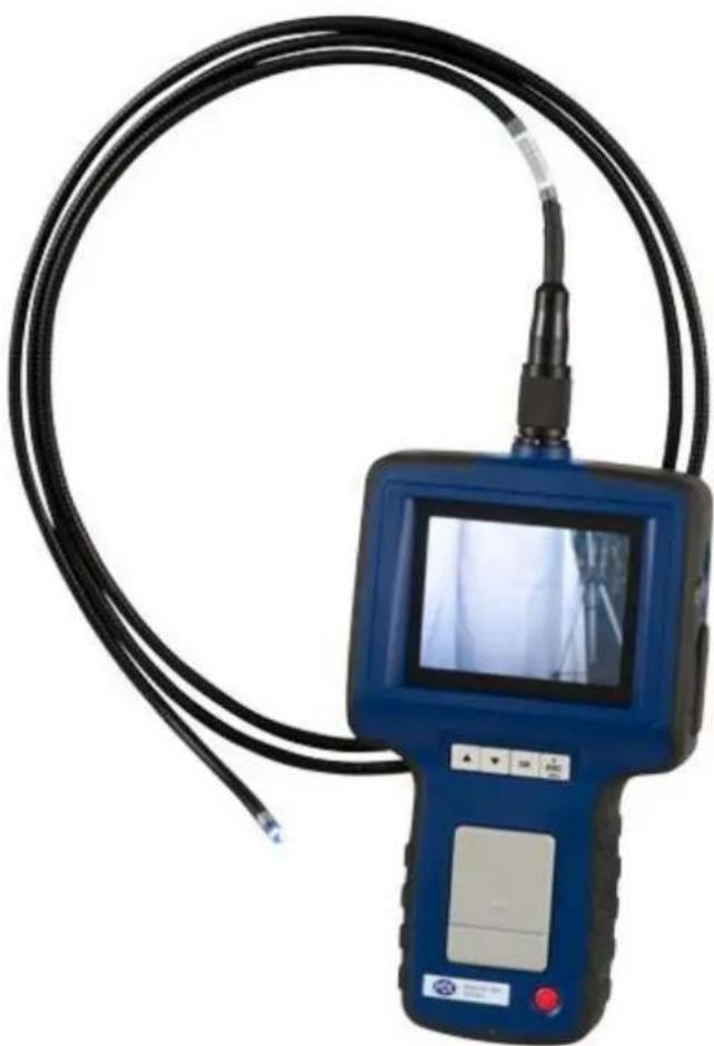
natural_image
Blue endoscopic medical device with black cable and display screen, no visible text or symbolsContents
1 Safety notes.... 3
2 Specifications....4
2.1 Technical specifications....4
2.2 Delivery contents 6
3 System description....6
4 Getting started 7
5 Operation....7
5.1 Take a picture....7
5.2 Record a video 7
5.3 View data 7
5.4 Settings....8
6 HR camera cable (PCE-VE 3xxHR or optional)....9
7 Articulating camera cable (PCE-VE 350N / HR / N3 / HR3 only or optional)....15
8 HR camera cable with 360° articulating camera head (PCE-VE 370HR3 or optional) ...... 18
9 PCE-VE 380N....22
9.1 Safety notes....22
9.2 Technical specifications.... 22
9.3 System description 23
9.4 Getting started 24
9.5 Operation....26
9.6 Locator PCE-VE-LOC (optional or PCE-VE 380N-LOC) 29
10 PCE-VE 390N....34
10.1 Safety instructions 34
10.2 Technical specifications.... 35
10.3 System description 36
10.4 Getting started 36
11 Disposal 38
12 Contact....38
12.1 PCE Instruments UK 38
12.2 PCE Americas 38
Thank you for purchasing a video endoscope from PCE Instruments.
1 Safety notes
Please read this manual carefully and completely before you use the device for the first time. The device may only be used by qualified personnel and repaired by PCE Instruments personnel. There is no warranty of damages or injuries caused by non-observance of the manual.
- This device may only be used in the way specified in this manual. If used otherwise, this may cause dangerous situations.
- Do not expose the device to extreme temperatures, direct sunlight, extreme air humidity or moisture.
- The case should only be opened by qualified personnel of PCE Instruments.
- Do not touch the instrument with wet hands.
- Do not expose the device to shocks or strong vibrations.
- You should not make any technical changes to the device.
- The appliance should only be cleaned with a damp cloth / use only pH-neutral cleaner without solvents or abrasives.
- The device must only be used with original PCE accessories or equivalent.
- Before each use, please inspect the case for damage. In case of any visible damage, please do not use the device.
- The device must not be used to be used when the environmental conditions (temperature, air humidity,...) are outside the limit values stated in the specifications.
- Do not expose the instrument to explosive atmospheres.
- Do not use the endoscope near uninsulated current-carrying conductors.
- The instrument should never be placed with the user interface facing an object (e.g. keyboard side on a table).
- This product has been produced for industrial use only. Do not use it for medical or any other biological purposes.
This user's handbook is published by PCE Instruments without any guarantee.
We expressly point to our general guarantee terms which can be found in our general terms of business. If you have any questions please contact PCE Instruments.
2 Specifications
2.1 Technical specifications
General specifications
| Sensor | CMOS |
| Resolution videos / pictures | 640 x 480 |
| Frame rate | 30 fps |
| Lighting | Automatic |
| White balance | Fixed |
| Field of view | 67°PCE-VE 380N / PCE-VE 390N: 150.8° |
| Depth of field | 1.5 ... 10 cmPCE-VE 380N / PCE-VE 390N:10 ... mm |
| Bending radius | 90 mmPCE-VE 380N / PCE-VE 390N: ∅ 30 cm |
| Display | 3.5 “ (88.9 mm) TFT display |
| Interface | Mini-USB 1.1AV out |
| Memory | 8 GB SD card |
| Compression format | MPEG4 |
| Video format | ASF |
| Video output system | NTSC / PAL |
| Picture format | JPEG |
| Power supply | Rechargeable 3.7 V Li-ion battery |
| Environmental conditions | 0 ... +60 °CPCE-VE 350N: -10 ... +50 °CPCE-VE 380N: -10 ... +60 °C |
| Weight | 450 g (incl. carrying case) |
Camera cable specifications
| Model | Cable length | Cable type | Cable | Boost function* | Lighting | Articulation camera head |
| PCE-VE 320N | 1000 mm | Semi-flexible | 5.5 mm | No | 4 LEDs | Front view only |
| PCE-VE 320HR | 1000 mm | Semi-flexible | 5.5 mm | Yes | 4 LEDs on the front2 LEDs on the side | Front view only |
| PCE-VE 330N | 2000 mm | Semi-flexible | 5.5 mm | No | 4 LEDs | Front view only |
| PCE-VE 333HR | 3000 mm | Semi-flexible | 5.5 mm | Yes | 4 LEDs on the front2 LEDs on the side | Front view only |
| PCE-VE 340N | 10000 mm | Flexible | 5.5 mm | No | 3 LEDs | 4-way articulation |
| PCE-VE 350N | 1000 mm | Flexible | 6.0 mm | No | 4 LEDs | 2-way articulation |
| PCE-VE 350N3** | 3000 mm | Flexible | 6.0 mm | No | 4 LEDs | 2-way articulation |
| PCE-VE 350HR | 1000 mm | Flexible | 6.0 mm | Yes | 4 LEDs on the front2 LEDs on the side | 2-way articulation |
| PCE-VE 350HR3 | 3000 mm | Flexible | 6.0 mm | Yes | 4 LEDs on the front2 LEDs on the side | 2-way articulation |
| PCE-VE 355N | 1500 mm | Flexible | 4.5 mm | No | 5 LEDs | 2-way articulation |
| PCE-VE 355N3 | 3000 mm | Flexible | 4.5 mm | No | 5 LEDs | 2-way articulation |
| PCE-VE 360N | 1000 mm | Semi-flexible | 3.9 mm | No | 3 LEDs | Front view only |
| PCE-VE 370HR | 1000 mm | Semi-flexible | 6.0 mm | Yes | 3 LEDs | 4-way articulation |
| PCE-VE 370HR3 | 3000 mm | Flexible | 6.0 mm | Yes | 3 LEDs | 4-way articulation |
| PCE-VE 380N | 30000 mm | Semi-flexible | 28 mm | No | 8 LEDs | Front view only |
| PCE-VE 390N | 10000 mm | Semi-flexible | 28 mm | No | 8 LEDs | Front view only |
*The boost function improves the quality of pictures and videos in dark environments.
**This model is no longer available.
2.2 Delivery contents
1 x endoscope PCE-VE 3xxN or HR (one of the models)
1 x 8 GB SD card
1 x USB cable
1 x mains adaptor
1 x carrying case (PCE-VE 390 N: + carrying belts)
1 x instruction manual
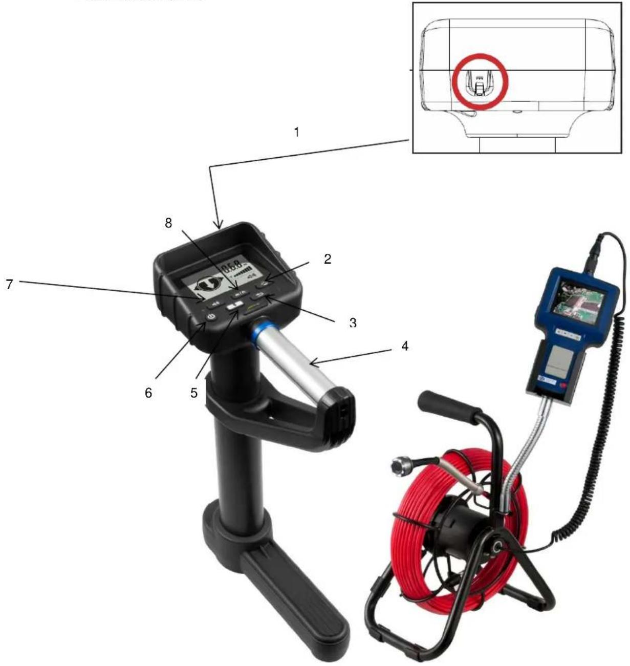
3 System description
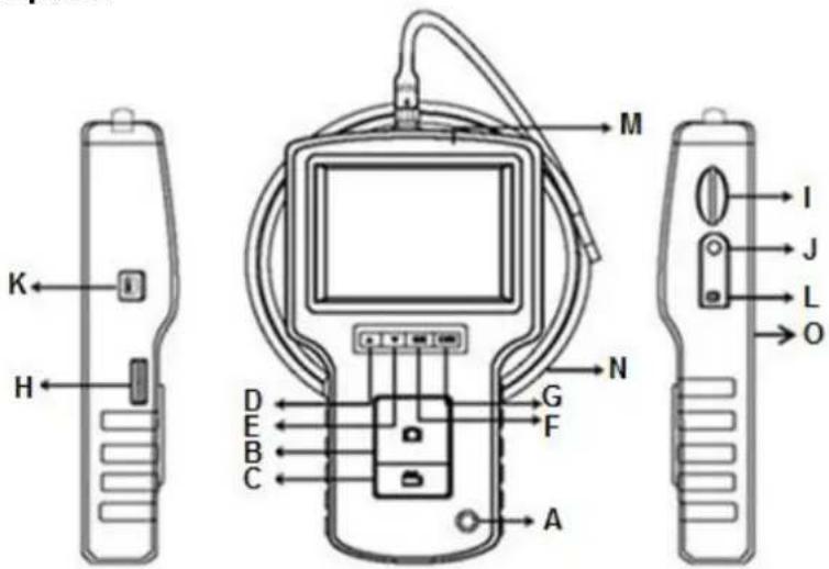
text_image
Diagram of a medical device with labeled parts including front, side, and top views with Chinese letters.Function keys
A power button
B. photo button
C. video button
D up button ▲
E down button ▼
F OK button OK-
G escape button ESC
H illumination switch
I SD card slot
J AV out
K USB interface
L mains connection
M Display
N camera cable/tube
O reset button
4 Getting started

natural_image
Simple line drawing of a bottle with liquid and arrows indicating movement (no text or symbols)Connect the camera cable to the display unit and screw it tightly. Make sure that the indication on the connector is on the upper side (see picture above).
After that, press and hold the power button for approx. 5 seconds to turn on the device.
Now the display shows the following:

text_image
CAMERA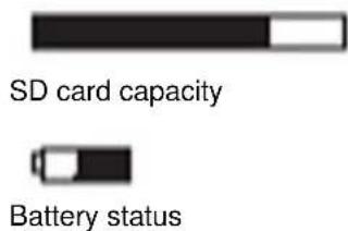
text_image
SD card capacity Battery statusTo turn off the device, press and hold the power button for 3 to 5 seconds.
5 Operation
5.1 Take a picture
To take a picture of the current image on the display, simply press the photo button. The picture is stored on the SD card. After saving the picture, the device returns to the standard viewing mode.
You can press the escape button ESC to zoom in (2x digital zoom).
If you press and hold the escape button ESC for a few seconds, the image on the screens gets mirrored.
5.2 Record a video
To start recording a video, press the video button. An indication appears on the display showing that video recording is in progress. Press the video button again to stop the recording. The video is stored on the SD card automatically.
You can press the escape button ESC to zoom in (2x digital zoom).
If you press and hold the escape button ESC for a few seconds, the image on the screens gets mirrored.
5.3 View data
To view the stored pictures and videos, press the up ▲ or down ▼ button in standard viewing mode. Now you can use these buttons to navigate through all pictures and videos. The data is sorted by date of recording.
To delete a file, select it and press the OK button. A confirmation window appears on the display. Use the up ▲ or down ▼ button to choose "Yes" if you want to delete the file or choose "No" to cancel. After selecting the desired option, press the OK button to confirm.
5.4 Settings
Press the OK button in standard viewing mode to enter the settings menu. Here you have the following options:
- DELETE ALL FILES
- AV OUTPUT
- DATE / TIME
- LANGUAGE
• TV SYSTEM - AUTO POWER OFF
Reset
To set the device back to factory default settings, press the reset button on the back of the device.
Delete all files
To delete all files, select the "DELETE ALL FILES" option in the settings and press the OK button. After that, use the up ▲ and down ▼ button to select "Yes" if you want to delete all files or select "No" to cancel. After selecting the desired option, press the OK button to confirm.
AV output
Connect the AV out to an external display unit, choose the "AV OUTPUT" option and press the OK button. The display of the endoscope turns black and the image is shown on the external display unit. To exit this mode, press the OK button again.
Date / Time
To adjust the time and date settings, select the "DATE / TIME" option and press the OK button. Now you can use the up ▲ and down ▼ button to move between the parameters year, month and day, as well as hours, minutes and seconds. Move to the desired parameter and use the photo and video button to adjust the value.
If you want the date and time to be displayed on each picture and video, move to the "Display" option and choose "Yes". Choose "no" if you do not want date and time to be shown on each picture and video.
Language
To change the language of the device, select the "LANGUAGE" option and press the OK button. Now you are in the language selection screen. Use the up ▲ and down ▼ button to select the desired language and press the OK button to confirm.
TV system
To change the TV system / video output format, select the "TV SYSTEM" option and press the OK button. Here you can choose between "PAL" and "NTSC". Use the up ▲ and down ▼ button to select the desired option and press the OK button to confirm.
Auto power off
To adjust the auto power off settings, select the "AUTO POWER OFF" option and press the OK button. Now you can choose between different time settings. Select the desired option by using the up ▲ and down ▼ button and press the OK button to confirm.
6 HR camera cable (PCE-VE 3xxHR or optional)
6.1 Safety notes
In addition to the general safety notes of the PCE-VE 3xxN device, please mind the following safety notes to prevent damage and injuries when using the HR camera cable.
- To avoid dangerous situations, make sure that the probe does not get in touch with inflammable liquids or gases.
- The HR cable includes various small cables which control the optics and electronics of the camera tip. To ensure high reliability, do not bend the cable to an angle of more than 90° and store the cable as little bent as possible.
- Do not disassemble the device as this can cause damage and electric shocks.
- Do not expose the device to direct sunlight and store it in a cool, dry, sufficiently ventilated place.
- To protect the camera module, make sure the protection ring is on the camera head as long as no accessories are in use.
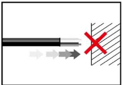
- Do not apply force to the end of the cable and do not bend it. This can deteriorate your vision and even damage the probe.
- When you roll up the cable, the inner diameter must be at least 15 cm.
- Put the protection ring back on and tighten it when not using the device for a longer period of time.
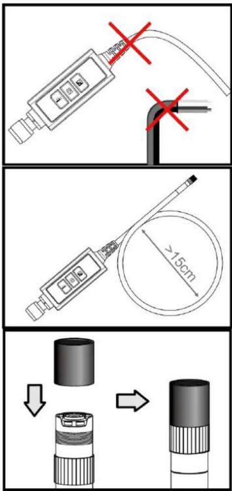
text_image
Technical diagram showing three-step installation of a device with a 15cm diameter dimension and a magnified view of the component being rotated.- Do not crash the probe head.
- Make sure that the camera does not get in contact with the following liquids: lead-free petrol, diesel oil, machine oil, brake fluid, transmission oil and water.
- Do not screw the accessories on too tightly. Only screw it slightly until it is fixed.
- To clean the camera head, use the cleaning liquid and the swabs provided in the cleaning kit.
natural_image
Diagram showing a black cable passing through a channel with directional arrows and a red X mark (no text or symbols)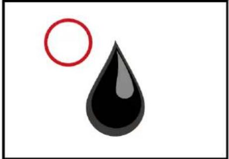
natural_image
Simple illustration of a black droplet with a red circle nearby (no text or symbols)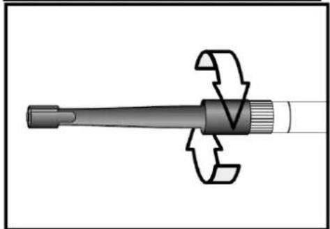
natural_image
Mechanical component diagram showing a shaft with flanged ends and a curved arrow indicating rotation (no text or symbols)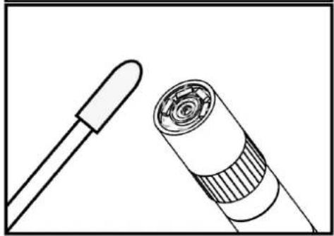
natural_image
Line drawing of a dropper and a coiled cable connector (no text or symbols)6.2 Technical specifications
| Length of camera head | 20 mm |
| Diameter with protection ring | 6 mm |
| Depth of field | 10 ... 60 mm |
| Field of view | 60.7 ° |
| Protection class | IP67 |
6.3 System description
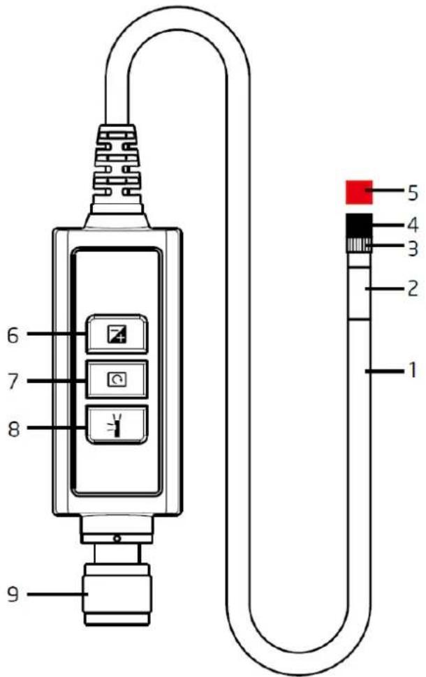
text_image
6 7 8 9 5 4 3 2 1- Probe: to guide the camera
- Camera head: for illumination and capturing
- Assembly ring: to attach accessories
- Protection ring: to protect the thread
- Red cap: protects the camera when not in use
- Boost key: for better illumination in dark environments
- Rotation key: Press once to turn the display counter-clockwise by 90°. The red LED will light up. The LED will stop glowing when the original position has been reached.
- Light key: This key activates a mirror which enables particle-free vision.
- Connector
6.4 Getting started
Connection
Step 1: Connect the main unit with the connector and fix it with the screw mechanism.
Step 2: Switch on the system. You should now see a picture in the display.
Attachment of the accessories
Mirror
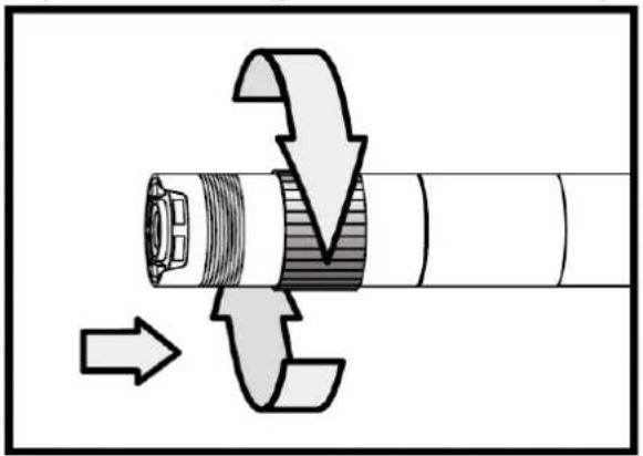
Step 1: Unscrew the thread protection ring.
Step 2: Screw the assembly ring down to the bottom.
Step 3: Screw the mirror attachment onto the thread until the thread is completely covered.
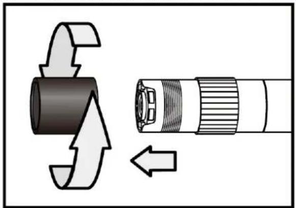
natural_image
Diagram showing a mechanical component with directional arrows indicating motion or assembly (no text or symbols)
natural_image
Diagram showing a device being inserted into a plug, with arrows indicating direction of movement (no text or symbols present)Step 4: Align the lateral LED opening of the mirror attachment in a way that the LEDs are uncovered.
Step 5: Turn the assembly ring upwards in order to fix the mirror attachment.

natural_image
Diagram of a mechanical component with directional arrows indicating motion or force (no text or symbols)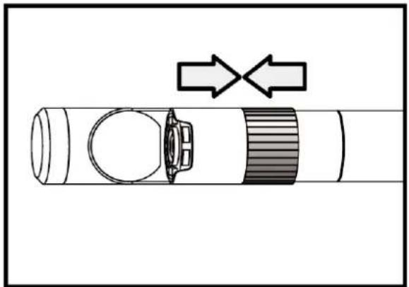
natural_image
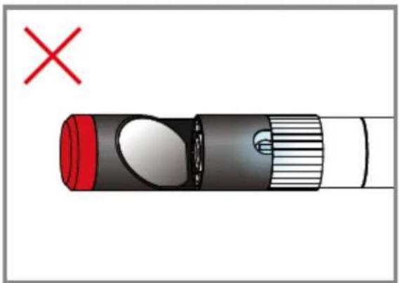
Diagram of a mechanical component with two arrows indicating direction, no text or symbols presentStep 6: Press the light key to activate the lateral light.
Step 7: Adjust the light intensity as required to ensure ideal vision to the side.

natural_image
Diagram of a flashlight with a red cross mark and a white handle, no text or symbols present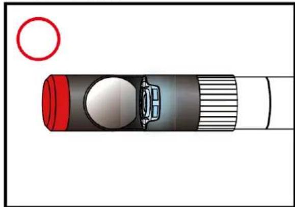
natural_image
Diagram of a flashlight with a red circular head and a black body, showing internal components (no text or symbols)(Steps 4-5 must be repeated until the right position is reached)
Magnetic hook
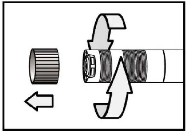
Step 1: Turn the assembly ring down to the bottom.
Step 2: Screw the magnetic hook on until it snaps in.
natural_image
Mechanical assembly diagram showing a cylindrical component with internal threading and directional arrows indicating motion (no text or symbols)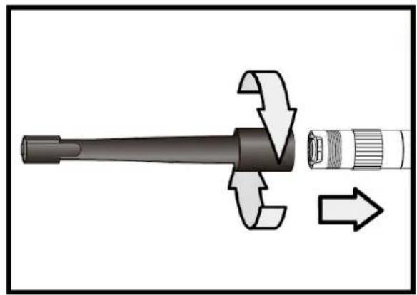
natural_image
Diagram of a mechanical component with directional arrows indicating motion or force (no text or symbols)Climbing ball
Step 1: Remove the assembly ring.
Step 2: Screw the climbing ball on until it snaps in.
natural_image
Mechanical assembly diagram showing a cylindrical component being inserted into a threaded shaft with directional arrows indicating motion (no text or symbols)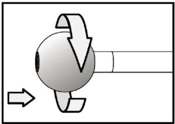
natural_image
Diagram of a rotating mechanical component with directional arrows indicating motion (no text or symbols)6.5 Operation
Boost key

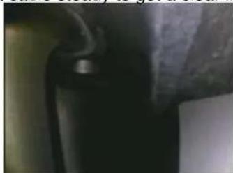
Use this key in a dark environment. The red LED indicates that the Boost function has been activated. The image will be lightened up.
Note: Hold the probe steady.

natural_image
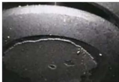
Close-up of a curved metallic object against a dark textured background (no visible text or symbols)Before "boosting"

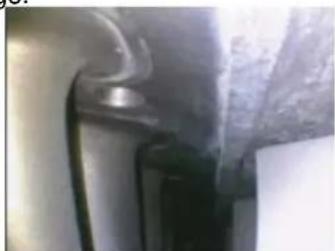
natural_image
Close-up of a curved pipe or pipe with textured surface and dark circular opening (no visible text or symbols)After "boosting"
Rotation key
You can use this key to turn the image by 90° four times, for instance, when trying to read an inscription completely.
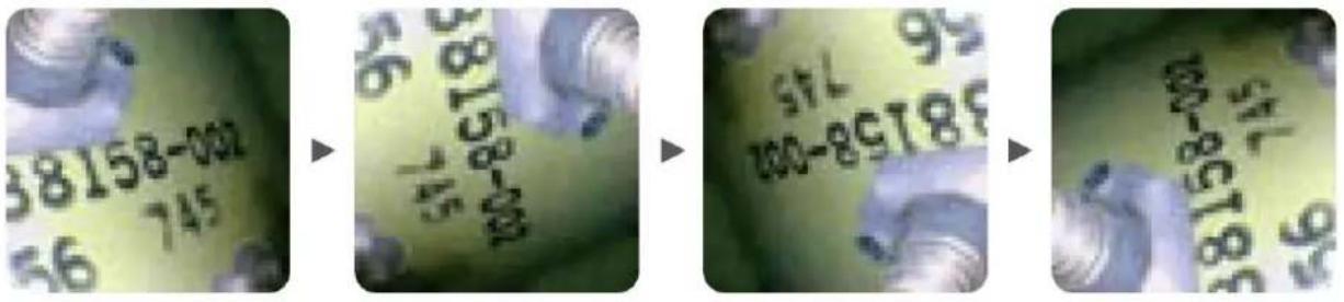
text_image
38158-002 56 745 → 56 5L-8918 100-8918 → 56 5L-8918 100-8918 → 56 5L-8918 100-8918Light key
When using the mirror attachment, this key improves the vision which will not be impeded by particles, dust, etc.
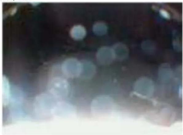
natural_image
Blurred close-up of a dark, indistinct object with light reflections (no visible text or symbols)Without "particle free" function

natural_image
Close-up of a dark, textured surface with a curved dark line and small white specks (no text or symbols visible)With "particle free" function
7 Articulating camera cable (PCE-VE 350N / HR / N3 / HR3 only or optional)
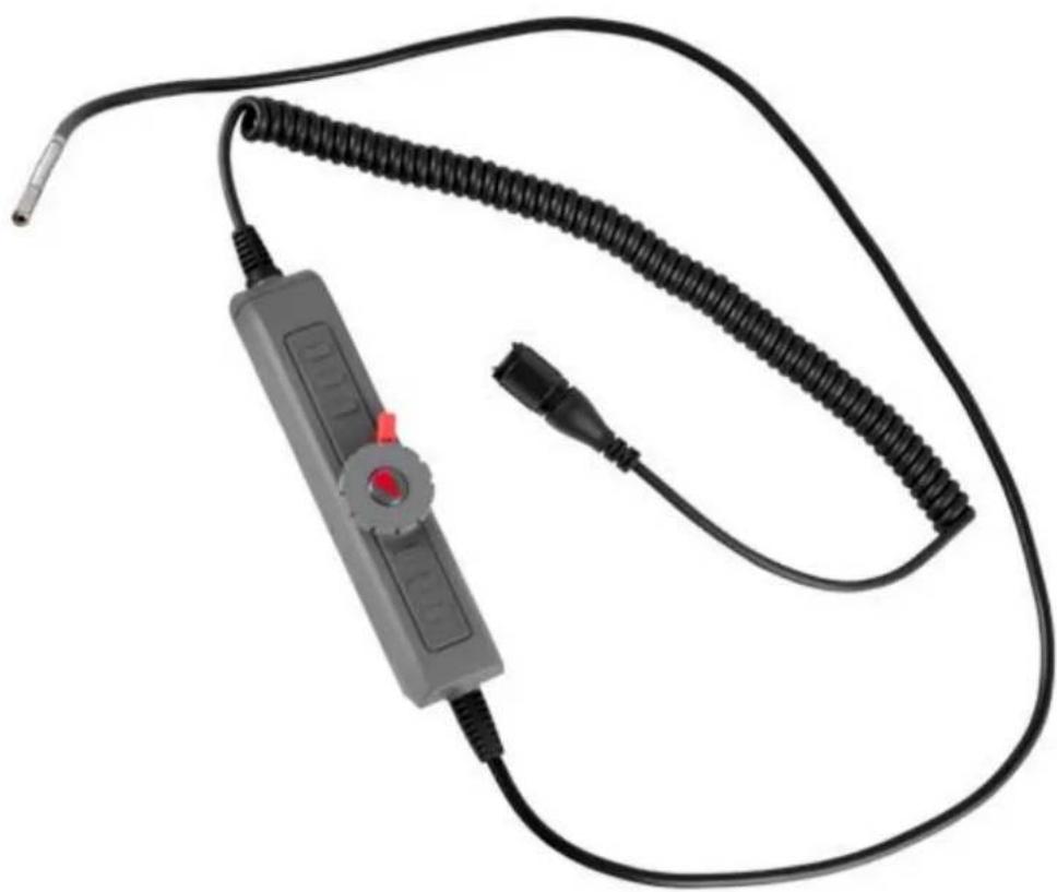
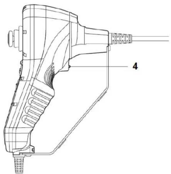
natural_image
Close-up of a black and gray handheld electrical device with coiled cable and connector (no visible text or symbols)7.1 Safety notes
In addition to the general safety notes of the PCE-VE 3xxN device, please mind the following safety notes to prevent damage and injuries when using the pivoting camera head.
• Do not bend the pivoting camera head by hand. Only use the rotary switch to adjust the angle.
- Do not try to rotate the rotary switch any further when it has already been rotated all the way to the stop.
- Do not expose the device to extreme temperatures, direct sunlight, extreme air humidity or moisture. Only use the pivoting camera head at temperatures between 0 and +55 °C.
- If you coil up the camera cable for storing, make sure the diameter is at least 15 cm and that the camera head is in a straight position.
- Do not expose the camera head to mechanical strains and stresses.
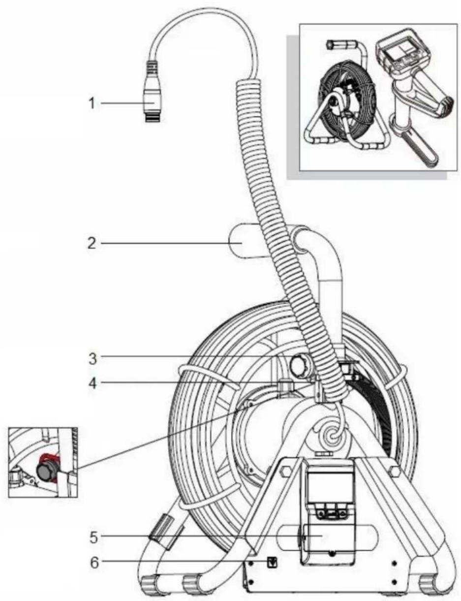
7.2 System description

text_image
(1) (2) (3) (4) (5) (6) (7)- Camera cable
- Camera head
- Gooseneck
- Operating unit
- Rotary switch for gooseneck
- Connecting cable
- Connector
- Locking lever
7.3 Getting started
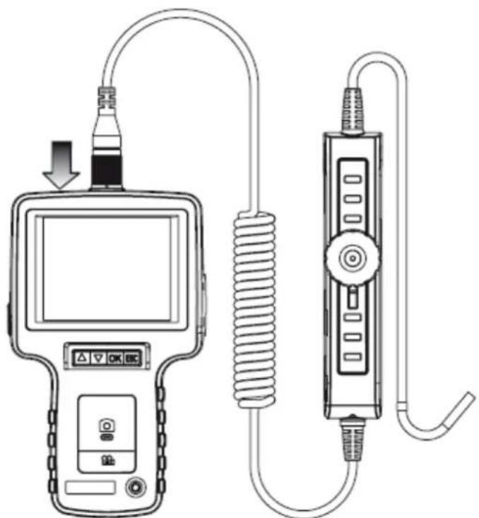
natural_image
Diagram of a medical device connected to a coiled spring and a rectangular device (no text or symbols visible)Connect the connecting cable to the display unit of the endoscope and screw it tightly. Make sure that the indication on the connector is on the upper side.
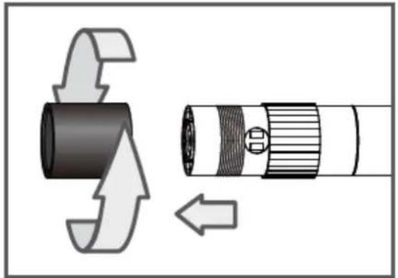
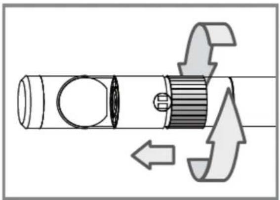
7.4 Operation
- By using the rotary switch, you can pivot the camera head. Turn the switch in a clockwise motion to pivot the camera head to the right or in a counter-clockwise motion to pivot the camera head to the left.

- You can lock the pivoting angle of the camera head by using the red locking lever. To lock the camera head, carefully push the lever clockwise all the way to the stop. To unlock the camera head carefully push the lever counter-clockwise, until it reaches its starting point.

natural_image
Diagram of a mechanical component with a red lever and arrow indicating motion (no text or symbols)
natural_image
Close-up of a metallic U-shaped pipe fitting with a black end cap (no text or symbols visible)8 HR camera cable with 360° articulating camera head (PCE-VE 370HR3 or optional)
8.1 Safety notes
In addition to the general safety notes of the PCE-VE 3xxN device, please mind the following safety notes to prevent damage and injuries when using the HR camera cable with 360^ articulating camera head.
- To avoid dangerous situations, make sure that the probe does not get in touch with inflammable liquids or gases.
- Do not disassemble the device as this can cause damage and electric shocks.
- To protect the camera module, make sure the protection ring is on the camera head as long as no accessories are in use.
- Do not bend the articulating camera head by hand. Only use the joystick to adjust the angle.
- Do not expose the device to extreme temperatures, direct sunlight, extreme air humidity or moisture. Only use the device at temperatures between 0 and +60 °C. Store it in a cool, dry, sufficiently ventilated place.
- If you coil up the camera cable for storing, make sure the diameter is at least 15 cm and that the camera head is in a straight position.
- Do not expose the camera head to mechanical strains and stresses.
8.2 Technical specifications
| Camera head diameter | 6 mm |
| Camera cable | Length: 3 m; water proof |
| Swivel mechanism | Camera head can be swivelled by 110° in all directions |
| Illumination | 3 LEDs |
| Operating and storing temperature | 0 ... +60 °C |
| Weight | 800 g |
8.3 System description

text_image
1 2 3-
Joystick
-
Rotation key
natural_image
Technical line drawing of a handheld electric shaver with labeled component (no text or symbols beyond label)-
Light key
-
Boost key
8.4 Getting started
Attachment of the accessories
Mirror
Step 1: Unscrew the thread protection ring.
Step 2: Screw the assembly ring down to the bottom.
Step 3: Screw the mirror attachment onto the thread until the thread is completely covered.
natural_image
Diagram showing a mechanical component with directional arrows indicating motion or force (no text or symbols)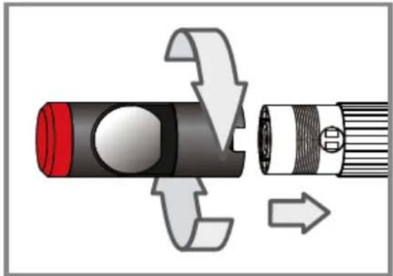
natural_image
Diagram of a flashlight being inserted into a flash bulb, showing internal components and directional arrows (no text or symbols)Step 4: Align the lateral LED opening of the mirror attachment in a way that the LEDs are uncovered.
Step 5: Turn the assembly ring upwards in order to fix the mirror attachment.
natural_image
Mechanical component diagram showing a shaft and gear assembly with directional arrows indicating motion (no text or symbols)
natural_image
Diagram of a cylindrical device with internal components and directional arrows indicating flow or movement (no text or symbols)Step 6: Press the light key to activate the lateral light.
natural_image
Illustration of a flashlight with a red cross mark and a white handle, no text or symbols present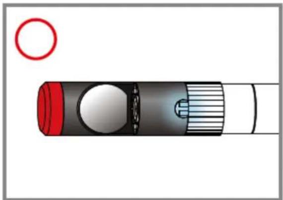
natural_image
Diagram of a cylindrical device with a red lid and a white handle, showing internal components and a red circle on the top (no text or symbols)(Steps 4-5 must be repeated until the right position is reached)
8.5 Operation

natural_image
Line drawing of two hands operating a handheld device, one pointing at the screen and the other holding a handheld device (no text or symbols present)Hold the device with one hand and use your thumb for operating the joystick and the function keys. With your index finger, you can use the boost key.
Use the joystick to adjust the swivelling angle and direction of the camera head.

natural_image
Four sequential illustrations showing a curved tube with internal structures, each with an arrow indicating direction (no text or symbols present)Boost key

Use this key in dark environments to lighten up the image.
Note: Hold the camera cable steady to get a clear image.
natural_image
Close-up of a black cylindrical object with a curved line above it, partially visible against a light background (no text or symbols)before "boosting"
natural_image
Close-up of a metallic mechanical component with a curved top and flange (no visible text or symbols)after "boosting"
Rotation key
Use this key to rotate the image by 90°, for instance, when trying to read an inscription completely.

Light key

Use this key in combination with the mirror attachment to improve the vision which will not be impeded by particles, dust, etc.

natural_image
Close-up of a dark, textured surface with scattered light spots and bokeh effects (no visible text or symbols)without "particle free" function
natural_image
Close-up of a dark, curved metallic object with a small white mark on its surface (no text or symbols visible)with "particle free" function
9 PCE-VE 380N
9.1 Safety notes
In addition to the general safety notes of the PCE-VE 3xxN device, please mind the following safety notes to prevent damage and injuries when using the camera cable and the accessories of the PCE-VE 380N.
- When rolling the camera cable out or in, be very careful to prevent mechanical damage due to tensile or compressive strain.
- You can move the camera cable around corners from 90° upwards. If the corner is narrower than 90°, this might interfere your measurement and even cause damage to the product.
- Do not use the camera cable to inspect fuel tanks or other environments with explosive or inflammable atmospheres.
- To clean the whole set, wash it with water and dry it with a cloth or let it dry. Do not sluice it with a hose or a high-pressure cleaner.
- Do not expose the device to direct sunlight and store it in a cool, dry, sufficiently ventilated place.
9.2 Technical specifications
Cable drum
| Diameter | 300 mm |
| Operating temperature | -10 ... +60 °C |
| Weight | 3.5 kg |
Cable
| Diameter | 6 mm |
| Length | 30 m |
| Bending radius | 150 mm |
| Weight | 100 g/m |
Camera head
| Camera diameter | 28 mm |
| Camera length | 24.3 mm |
| Depth of field | 10 mm ... |
| Field of view | 150.8 ° (diagonal) |
| Lighting | 8 LEDs (white) |
| Operating temperature | -10 ... +60 °C |
| Fitting pipe diameters | 40 ... 100 mm |
Cable measuring device
| Measuring units | m / ft |
| Counting | Forward / backward |
| Accuracy | ±0.4 m (±1.3 ft) |
| Display | 3 digits (1 decimal place) |
| Protection class | IP 55 |
| Power supply | 2 x 1.5 V AAA batteries |
| Battery life | ≥ 90 hours |
| Dimensions | 62 x 110 x 24 mm |
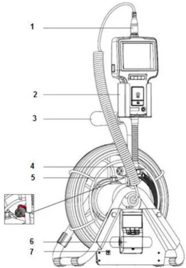
9.3 System description
PCE-VE 380N
text_image
Technical diagram of a medical or industrial device with numbered components and an inset close-up view of a small component.- Connection to display unit
- Support for display unit
- Handle
- Camera head
- Support for camera head
- Cable measuring device
- Power button for transmitter
Cable measuring device
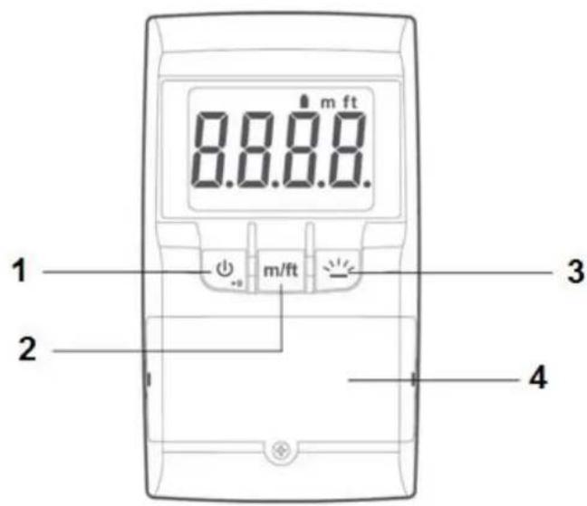
text_image
m ft 8.8.8.8. 1 m/ft 2 3 4- ON/OFF/RESET button
- m/ft button
- Display backlight button
- Battery compartment


Camera cable

text_image
1 2 3 4 5- Camera head
- Semi-flexible camera cable
- Connection
- Camera cable
- Mounting ring
9.4 Getting started
Battery replacement
Transmitting unit
natural_image
Technical line drawing of a mechanical assembly with hoses and a switch (no text or symbols)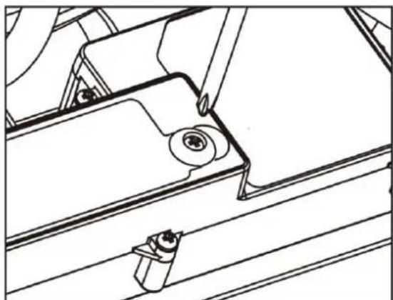
natural_image
Technical line drawing of a mechanical assembly with no visible text or symbolsThe battery compartment of the transmitting unit is located at the back of the unit. To open it, you have to loosen a screw first. After that, you can open the battery compartment and replace the batteries.
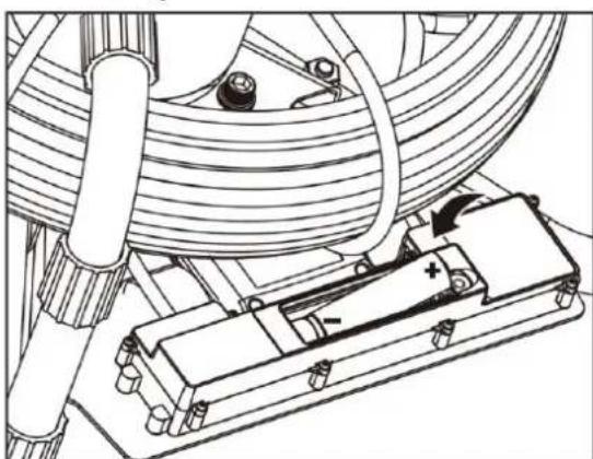
Cable measuring device

text_image
Diagram showing battery charging mechanism with labeled components and polarity indicators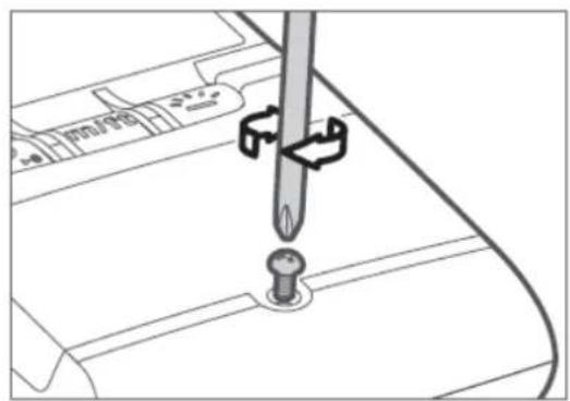
text_image
Technical diagram showing a screwdriver inserted into a component with directional arrows indicating movement or force.The battery compartment of the cable measuring device is located at the front, right below the function keys. To open it, you have to loosen a screw first. After that, you can open the battery compartment and replace the batteries.
Installation
natural_image
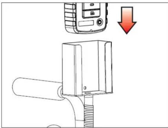
Diagram of a mobile phone mounted on a cylindrical device with a red downward arrow indicating action (no text or symbols present)
natural_image
Illustration of a medical device with a coiled tube and a downward arrow indicating pressure or discharge (no text or symbols)- Place the display unit in the support.
- Connect the camera cable to the display unit and screw it tightly.

text_image
90°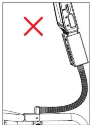
natural_image
Diagram of a mechanical device with a red X mark and a curved cable, no text or symbols presentYou can adjust the angle of the display support at any time, but do not use angles smaller than 90^ cause this might damage the support.
natural_image
Technical line drawing of a coiled electrical device with coiled cable and sensor (no text or symbols)The PCE-VE 380N can also be used in horizontal position.
9.5 Operation
Pulling out the cable
natural_image
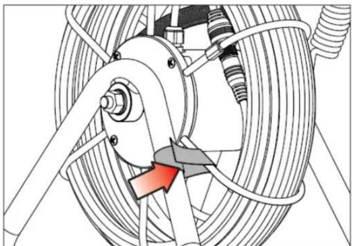
Mechanical assembly diagram showing a car wheel and suspension system with no visible text or symbols- Before pulling out the camera cable, loosen the cable drum fixing first.
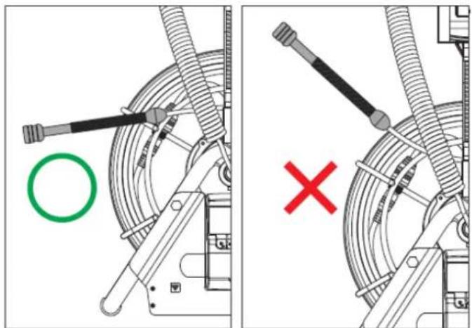
text_image
Technical diagram showing mechanical assembly with labeled components and a red X symbol indicating failure or rejection.- Pull out the camera cable horizontally. Do not pull it out in an angle larger than 45^ to the camera head support.
natural_image
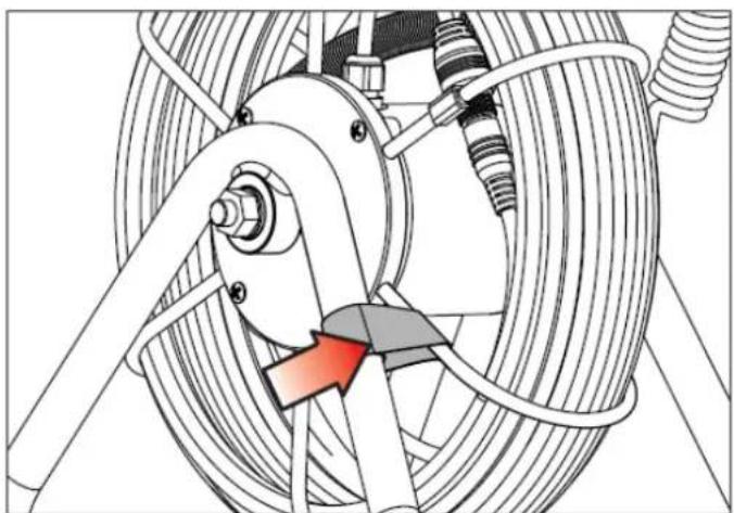
Mechanical assembly diagram showing a coiled spring and belt drive mechanism (no text or labels)- Once you have reached the desired cable length, fix the cable drum to prevent it from rolling out any further.
Coiling up the cable

text_image
Technical diagram showing a hand operating a cable with a red arrow indicating direction, likely illustrating a mechanical or electrical component.- Hold the camera head horizontally and carefully coil up the cable.

natural_image
Technical diagram of a car suspension system with hoses, springs, and a central connector (no text or labels)-
When the camera cable is coiled up completely, place the camera head in the camera head support.
-
Fix the cable drum to prevent the cable from rolling out.
Cable measuring device
To turn on the device, press and hold the OF/OFF button for 3 seconds.
You can reset/restart the device at any time by pressing and holding the ON/OFF button for 1 second.
To switch the measuring unit between m and ft, press the "m/ft" button.
Press the backlight button to activate the display backlight. The display backlight is active for 10 seconds.
To turn off the device, press and hold the ON/OFF button for 3 seconds.
The device also has an automatic power-off function which turns it off automatically after 1 hour of idling time.
If the display shows a battery indication, please replace the batteries.
Centring star

natural_image
Diagram of a mechanical linkage or wheel assembly with four blades and central hub (no text or symbols)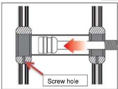
text_image
Screw hole
natural_image
Pure mechanical assembly diagram showing two shafts connected to a central shaft with a textured base (no text or symbols)- Put the camera head in the centring star attachment and align the mounting ring with the screw holes.
- Put the screws in the screw holes and fasten the camera head.

natural_image
Mechanical assembly diagram showing a shaft and gear mechanism with multiple bolts (no text or symbols)Cleaning

natural_image
Two-step diagram showing a device being inserted into a red cap, with an upward arrow indicating the process (no text or symbols present)- Remove the display unit from the support.
- Put the protecting hood on the connector of the camera cable.
- Wash the cable drum with water and let it dry for a few minutes.
- If necessary, dry the cable drum with a dry cloth before putting it back into the carrying case.
9.6 Locator PCE-VE-LOC (optional or PCE-VE 380N-LOC)
Safety notes
- This product is designed for industrial use only. Do not use the system for human or biological inspection.
- Do not use the camera cable to inspect fuel tanks or other environments with explosive or inflammable atmospheres.
- Do not try to disassemble this product to avoid damage or electric shocks.
- Only use original or recommended components or accessories. Unapproved accessories and components may cause damage.
Product description
text_image
Technical diagram of a handheld device with labeled parts and an inset showing a close-up of the device's internal structure.1 DC jack 5 Depth measurement key
2 Backlight key 6 On / Off key
3 Reset key 7 Buzzer key
4 Handle 8 Unit key (m / ft)
| DC jack | To connect mains adaptor for charging |
| Backlight key | Backlight can be switched on or off |
| Reset key | Reset, e. g. when depth measurement failed |
| Handle | |
| Depth measurement key | To identify the depth of the transmitter |
| On / Off key | To switch on / off |
| Buzzer key | To switch on / off buzzer sound that occurs when locator is switched on and when moving closer to the transmitter |
| Unit key (m / ft) | To switch the units of depth measurement |
Mounting
text_image
Technical diagram of a mechanical device with numbered components and an inset photo showing a handheld device.1 Main system connector 4 Camera head stopper
2 Handle 5 Meter
3 Camera head 6 Power button for transmitter
Display

text_image
Diagram of a device control panel with labeled components and display screen showing 71° angle and measurement indicators1 Detection icon 2 Signal strength 3 Low battery alert
The battery must be charged whenever the low battery alert appears on the screen.
| Icon | Description | |
 | Weak signal, hard to verify directions | |
| You can follow the directions of the arrow to move on | ||
 | Depth measurement icon: appears when you are within the measurable range (horizontal 4.5 m / 15 f, vertical 1.8 m / 5.9 f), i. e. a depth measurement can be made and the reading is displayed along with peak signal strength | |
 | Depth measurement failed. Reset and wait a few seconds for the reading to stabilise. A stable reading is indicated by an icon. | |
Operation
- Turn on the borescope as well as the locator.
- Before placing the transmitter in the target location, move the locator to check the signal strength (see "Quick calibration"). Also check the depth measurement icon as well as the battery level.
- The lamp next to the power button for the transmitter should glow in green. If the lamp glows in red, the battery voltage is insufficient and the instrument is not ready to work. The battery will last no longer than 15 minutes when the red lamp starts glowing.

natural_image
Technical diagram of a mechanical assembly with a highlighted circular component (no text or symbols)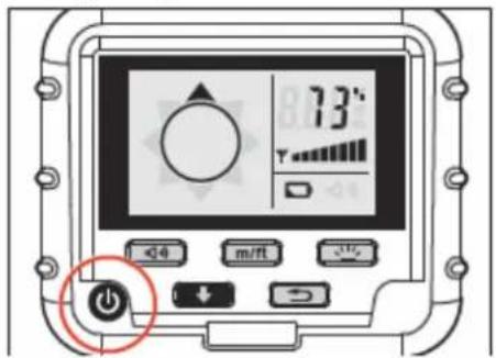
text_image
73° m/ft- Move the locator carefully and do not change the height, if possible.
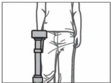
natural_image
Anatomical illustration of a human leg with a mechanical device inserted, showing bone structure and vascular patterns (no text or labels)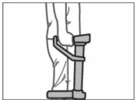
natural_image
Illustration of a person using a resistance band device (no text or symbols)- Localisation every 5 m is recommended.

text_image
TRANSMITTER
text_image
Locator Ground level video camera TRANSMITTER• To find the best signal strength, follow the arrows on the screen.
- When you come closer to the transmitter, the intervals of the beeping sound will become shorter.
- When you have reached the signal peak, turn the locator counterclockwise until the depth measurement icon pops up. Then press the depth measurement key to get the result.
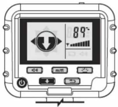
text_image
89° m/ft
text_image
1.5 m m/ftQuick calibration
- Place the antenna of the locator approx. 100 cm / 3 f away from the transmitter.
- Check the signal strength.
- If the signal strength is below 60 %, press the reset key. Repeat these steps until the signal strength is sufficient.

text_image
Locator 100cm TRANSMITTERTechnical specifications
| Locator PCE-VE-LOC | |
| Dimensions | L : 293.5 mmW : 144 mmH : 486.5 mm |
| Weight | 2 kg |
| Power supply | 3.7 V / 2000 mA Li battery |
| Power consumption | 282 mA |
| Charging duration | 3 ... 4 h |
| Battery life | 6 ... 7 h |
| Power adaptor | 5.5 V, 1.8 A |
| Humidity | 95 % RH, non-condensing |
| Working temperature | -10 ... 60 °C |
| Storage temperature | -20 ... 80 °C |
| Drop resistance | 60 cm |
| IP protection | IP55 |
| Transmitter | |
| Power supply | 2 x AAA batteries |
| Power consumption | 3.4 V / 230 mA |
| Battery life | Approx. 3 ... 4 h |
10 PCE-VE 390N
10.1 Safety instructions
- Do not use the camera cable to inspect fuel tanks or other environments with explosive or inflammable atmospheres.
- When bending or rolling up the camera tube make sure that the bending diameter is more than 30 cm. Otherwise it can cause damage to the tube.
- Pay attention when pushing the camera tube in the object to be inspected or when pulling it back out. The camera tube is a high-strength structure which can be used for pushing obstacles in pipes. However, due to its rigidity, it might unwind from the carrying system when pulling it out.
- Do not expose the device to direct sunlight and store it in a cool, dry, sufficiently ventilated place.
- The display unit is not waterproof. Remove the display unit and the connector before cleaning the camera tube and the carrying system.
10.2 Technical specifications
Carrying system
| Dimensions | 490 x 450 x 60 mm |
| Weight | 1222 g (without display unit and camera tube) |
Camera tube
| Length | 10 m |
| Diameter | 6 mm |
| Bending diameter | 30 cm |
| Weight | 100 g / meter |
Camera head
| Diameter | 28 mm |
| Length | 24.3 mm |
| Depth of field | 10 mm ... |
| Field of view | 150.8 ° |
| Illumination | 8 LEDs (white) |
| Environmental temperature | -10 ... +70 °C |
| Protection class | IP 68 (10 m) |
| Pipe diameter | 40 mm ... 100 mm |
10.3 System description
Carrying system

text_image
Technical diagram of a mechanical assembly with labeled components and rotational motion arrows- Neck strap
- Carrying system
- Hip belt
10.4 Getting started
Inserting the display unit

natural_image
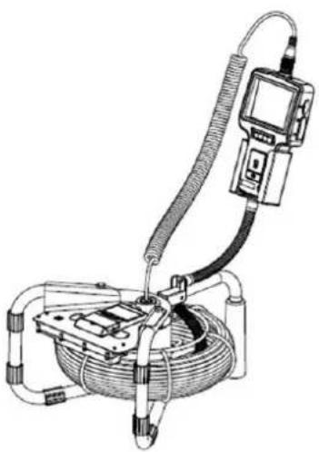
Diagram of a car electrical plug with cable, showing wiring routing around a vehicle (no text or labels)Insert the display unit into the carrying system as seen in the picture above. Use the connecting cable to connect the display unit to the camera tube, Roll up the camera tube on the carrying system.
Attaching and wearing the carrying straps

text_image
STEP2 STEP1 STEP3 STEP1 STEP2 STEP1 STEP4Step 1 / 2:
- Attach the neck strap to one of the upper supports, put it around your neck and attach the other end to the other upper support of the carrying system.
- Attach the hip belt to one of the lower supports, put it around your hip and attach the other end to the other lower support of the carrying system.
Step 3:
- Turn on the device.
Step 4:
- Unwind the camera tube until you have reached the desired length.
11 Disposal
For the disposal of batteries, the 2006/66/EC directive of the European Parliament applies. Due to the contained pollutants, batteries must not be disposed of as household waste. They must be given to collection points designed for that purpose.
In order to comply with the EU directive 2012/19/EU we take our devices back. We either re-use them or give them to a recycling company which disposes of the devices in line with law.
If you have any questions, please contact PCE Instruments.

12 Contact
If you have any questions about our range of products or measuring instruments please contact PCE Instruments.
12.1 PCE Instruments UK
By post:
PCE Instruments UK Ltd.
Unit 11 Southpoint Business Park
Ensign Way, Southampton
Hampshire
United Kingdom, SO31 4RF
By phone:
02380 987 035
12.2 PCE Americas
By post:
PCE Americas Inc.
711 Commerce Way
Suite 8
Jupiter
33458 FL
USA
By phone:
561 3209162